
TSGR3#7(99)A82 - 3GPP
63
3GPP TSG-RAN Working Group 3, meeting #7 TSGR3#7(99)A82 Sophia Antipolis, France, 20 th – 24 th September 1999 Agenda Item: 10 Source: Editor (Nokia) Title: UMTS 25.413: UTRAN Iu Interface RANAP Signalling, v.1.2.2 Document for: Approval Note: Revision marks reflect the changes made based on decisions in WG3 meeting #6 in Sophia Antipolis.
-
Upload
khangminh22 -
Category
Documents
-
view
1 -
download
0
Transcript of TSGR3#7(99)A82 - 3GPP

3GPP
TSG-RAN Working Group 3, meeting #7 TSGR3#7(99)A82Sophia Antipolis, France, 20th – 24th September 1999
Agenda Item: 10
Source: Editor (Nokia)
Title: UMTS 25.413: UTRAN Iu Interface RANAP Signalling, v.1.2.2
Document for: Approval
Note: Revision marks reflect the changes made based on decisions in WG3 meeting #6 in Sophia Antipolis.

3GPP
TS 25.413 V1.2.21.2 (1999-097)Technical Specification
3rd Generation Partnership Project (3GPP);Technical Specification Group (TSG) RAN
UTRAN Iu Interface RANAP Signalling
[UMTS 25.413]
<

3GPP
TS 25.413 V1.2.21.2 (1999-097)2[UMTS 25.413]
Reference<Workitem> (<Shortfilename>.PDF)
Keywords<keyword[, keyword]>
3GPP
Postal address
Office address
Individual copies of this deliverablecan be downloaded fromhttp://www.3gpp.org
Copyright Notification
No part may be reproduced except as authorized by written permission.The copyright and the foregoing restriction extend to reproduction in all media.
©All rights reserved.

3GPP
TS 25.413 V1.2.21.2 (1999-097)3[UMTS 25.413]
Contents
Intellectual Property Rights ............................................................................................................................... 9
Foreword ............................................................................................................................................................ 9
1 Scope ....................................................................................................................................................... 9
2 References ............................................................................................................................................... 9
3 Definitions and abbreviations ................................................................................................................ 103.1 Definitions........................................................................................................................................................ 103.2 Abbreviations ................................................................................................................................................... 11
4 General................................................................................................................................................... 11
5 RANAP Services ................................................................................................................................... 11
6 Services expected from signalling transport .......................................................................................... 12
7 Functions of RANAP ............................................................................................................................. 12
8 RANAP procedures ............................................................................................................................... 138.1 Elementary Procedures .................................................................................................................................... 138.2 Relocation ........................................................................................................................................................ 158.2.1 General ....................................................................................................................................................... 158.2.2 Relocation Preparation ............................................................................................................................... 168.2.2.1 Successful operation ............................................................................................................................. 168.2.2.2 Unsuccessful operation ......................................................................................................................... 168.2.2.3 Relocation co-ordination in source RNC .............................................................................................. 178.2.3 Relocation resource allocation ................................................................................................................... 178.2.3.1 Successful operation ............................................................................................................................. 178.2.3.2 Unsuccessful operation ......................................................................................................................... 188.2.3.3 Relocation co-ordination in target RNC ............................................................................................... 188.2.4 Relocation Detect ....................................................................................................................................... 198.2.5 Relocation Complete .................................................................................................................................. 208.2.6 Relocation Cancel................................................................................................................................... 21208.3 Radio Access Bearer Assignment ................................................................................................................ 22218.3.1 Normal operation .................................................................................................................................... 25248.4 RAB Release Request .................................................................................................................................. 27268.5 Iu Release Request ....................................................................................................................................... 28268.6 Iu Release ..................................................................................................................................................... 28278.7 Overload Control ......................................................................................................................................... 30298.7.1 General ................................................................................................................................................... 30298.7.2 Philosophy .............................................................................................................................................. 30298.7.3 Overload at the CN ................................................................................................................................. 31298.7.4 Overload at the UTRAN ......................................................................................................................... 31308.8 Reset ............................................................................................................................................................ 31308.8.1 General ................................................................................................................................................... 31308.8.2 Reset at the UTRAN ............................................................................................................................... 31308.8.3 Reset at the CN ....................................................................................................................................... 32318.8.4 Abnormal Conditions ............................................................................................................................. 32318.8.4.1 Abnormal Condition at the UTRAN ................................................................................................. 32318.8.4.2 Abnormal Condition at the CN ......................................................................................................... 33318.8.4.3 Crossing of Reset messages .............................................................................................................. 33318.9 Common Id .................................................................................................................................................. 33318.10 Paging .......................................................................................................................................................... 33328.11 CN Invoke Trace .......................................................................................................................................... 34338.12 Cipher Mode Control ................................................................................................................................... 35338.12.1 Successful operation ............................................................................................................................... 35338.12.2 Unsuccessful operation ........................................................................................................................... 35348.13 CN Information Broadcast ........................................................................................................................... 3635

3GPP
TS 25.413 V1.2.21.2 (1999-097)4[UMTS 25.413]
8.14 Direct Transfer ............................................................................................................................................. 36358.15 Initial UE Message ....................................................................................................................................... 37368.16 Location Reporting Control ......................................................................................................................... 38368.16.1 Normal operation .................................................................................................................................... 38368.16.2 Abnormal conditions .............................................................................................................................. 38378.16.2.1 Abnormal conditions in RNC ........................................................................................................... 38378.17 Location Report ........................................................................................................................................... 38378.17.1 Successful operation ............................................................................................................................... 38378.17.2 Unsuccessful operation ........................................................................................................................... 39378.17.3 Abnormal conditions .............................................................................................................................. 39378.17.3.1 Abnormal conditions in CN .............................................................................................................. 39378.18 Error Indication ............................................................................................................................................ 39378.18.1 General ................................................................................................................................................... 39378.18.2 CN originated Error Indication ............................................................................................................... 39378.18.3 RNC originated Error Indication ............................................................................................................ 3938
9 Elements for RANAP communication .............................................................................................. 40389.1 Message contents ......................................................................................................................................... 40389.1.1 RAB ASSIGNMENT REQUEST .......................................................................................................... 41399.1.2 RAB ASSIGNMENT RESPONSE ........................................................................................................ 41409.1.3 RAB RELEASE REQUEST .................................................................................................................. 42419.1.4 COMMON ID ........................................................................................................................................ 43429.1.5 DIRECT TRANSFER ............................................................................................................................ 43429.1.6 INITIAL UE MESSAGE ....................................................................................................................... 43429.1.7 LOCATION REPORTING CONTROL ................................................................................................ 44429.1.8 LOCATION REPORT ........................................................................................................................... 44429.1.9 CIPHER MODE COMMAND ............................................................................................................... 44439.1.10 CIPHER MODE COMPLETE ............................................................................................................... 44439.1.11 CIPHER MODE REJECT ...................................................................................................................... 44439.1.12 PAGING ................................................................................................................................................. 45439.1.13 IU RELEASE COMMAND ................................................................................................................... 45439.1.14 IU RELEASE COMPLETE ................................................................................................................... 45449.1.15 IU RELEASE REQUEST ...................................................................................................................... 45449.1.16 RELOCATION REQUIRED ................................................................................................................. 45449.1.17 RELOCATION REQUEST.................................................................................................................... 46449.1.18 RELOCATION REQUEST ACKNOWLEDGE .................................................................................... 46459.1.19 RELOCATION COMMAND ................................................................................................................ 46459.1.20 RELOCATION DETECT ...................................................................................................................... 47459.1.21 RELOCATION COMPLETE ................................................................................................................ 47459.1.22 RELOCATION PREPARATION FAILURE ........................................................................................ 47469.1.23 RELOCATION FAILURE ..................................................................................................................... 47469.1.24 RELOCATION CANCEL ...................................................................................................................... 47469.1.25 RELOCATION CANCEL ACKNOWLEDGE ...................................................................................... 47469.1.26 RESET ................................................................................................................................................... 48469.1.27 RESET ACKNOWLEDGE .................................................................................................................... 48469.1.28 OVERLOAD .......................................................................................................................................... 48479.1.29 CN INVOKE TRACE ............................................................................................................................ 48479.1.30 CN INFORMATION BROADCAST REQUEST .................................................................................. 48479.1.31 CN INFORMATION BROADCAST CONFIRM.................................................................................. 49479.1.32 CN INFORMATION BROADCAST REJECT ..................................................................................... 49479.1.33 ERROR INDICATION .......................................................................................................................... 49489.2 Information element definitions ................................................................................................................... 49489.2.1 Message type .......................................................................................................................................... 53519.2.2 RAB ID .................................................................................................................................................. 53519.2.3 NAS Binding Information ...................................................................................................................... 53519.2.4 RAB parameters ..................................................................................................................................... 53519.2.5 Transport address ................................................................................................................................... 53519.2.6 Iu transport association ........................................................................................................................... 53519.2.7 Cause ...................................................................................................................................................... 53519.2.8 Priority level and pre-emption indication ............................................................................................... 53519.2.9 RAB linking ........................................................................................................................................... 5351

3GPP
TS 25.413 V1.2.21.2 (1999-097)5[UMTS 25.413]
9.2.10 Location Identifier .................................................................................................................................. 53519.2.11 Permanent NAS Identity ......................................................................................................................... 53519.2.12 CN Domain Indicator ............................................................................................................................. 54529.2.13 IMSI ....................................................................................................................................................... 54529.2.14 Temporary UE ID ................................................................................................................................... 54529.2.15 Paging Cause .......................................................................................................................................... 54529.2.16 Trace Type ............................................................................................................................................. 54529.2.17 Trigger ID............................................................................................................................................... 54529.2.18 Trace Reference...................................................................................................................................... 54529.2.19 UE Identity ............................................................................................................................................. 54529.2.20 OMC ID ................................................................................................................................................. 54529.2.21 Encryption Information .......................................................................................................................... 54529.2.22 Chosen Encryption Algorithm ................................................................................................................ 54529.2.23 NAS Bit String ....................................................................................................................................... 54529.2.24 Broadcast Area ....................................................................................................................................... 54529.2.25 Categorisation parameters ...................................................................................................................... 55539.2.26 NAS PDU ............................................................................................................................................... 55539.2.27 Request Type .......................................................................................................................................... 55539.2.28 Location Information .............................................................................................................................. 55539.2.29 NAS Layer 3 Information ....................................................................................................................... 55539.2.30 User Plane Mode .................................................................................................................................... 55539.2.31 Paging Area ID ....................................................................................................................................... 55539.2.32 Source ID ............................................................................................................................................... 55539.2.33 Target ID ................................................................................................................................................ 55539.2.34 Source RNC to Target RNC Transparent Container .............................................................................. 55539.2.35 Target RNC to Source RNC Transparent Container .............................................................................. 55539.2.36 Number of steps...................................................................................................................................... 55539.3 Message and Information element abstract syntax (with ASN.1)................................................................. 56549.4 Message transfer syntax ............................................................................................................................... 58569.5 Timers .......................................................................................................................................................... 5856
10 Handling of unknown, unforeseen and erroneous protocol data ....................................................... 5856
11 Annex A (normative): ........................................................................................................................ 5957Annex A Document Stability Assessment Table ......................................................................................................... 5957
12 History ............................................................................................................................................... 5957
Intellectual Property Rights ............................................................................................................................... 8
Foreword............................................................................................................................................................ 8
1 Scope ....................................................................................................................................................... 8
2 References ............................................................................................................................................... 8
3 Definitions, symbols and abbreviations .................................................................................................. 93.1 Definitions.......................................................................................................................................................... 93.2 Symbols.............................................................................................................................................................. 93.3 Abbreviations..................................................................................................................................................... 9
4 General..................................................................................................................................................... 9
5 RANAP Services ..................................................................................................................................... 9
6 Services expected from signalling transport.......................................................................................... 10
7 Functions of RANAP............................................................................................................................. 10
8 RANAP procedures ............................................................................................................................... 108.1 Elementary Procedures .................................................................................................................................... 108.1.1 Definition of Elementary Procedure........................................................................................................... 108.1.2 Interaction between Elementary Procedures............................................................................................... 108.1.3 List of Elementary procedures.................................................................................................................... 118.2 Relocation ........................................................................................................................................................ 12
3GPP
TS 25.413 V1.2.21.2 (1999-097)6[UMTS 25.413]
8.2.1 General ....................................................................................................................................................... 128.2.2 Relocation Preparation ............................................................................................................................... 128.2.2.1 Successful operation ............................................................................................................................. 128.2.2.2 Unsuccessful operation ......................................................................................................................... 138.2.3 Relocation resource allocation ................................................................................................................... 138.2.3.1 Successful operation ............................................................................................................................. 138.2.3.2 Unsuccessful operation ......................................................................................................................... 148.2.4 Relocation Detect ....................................................................................................................................... 148.2.5 Relocation Complete .................................................................................................................................. 158.2.6 Relocation Cancel....................................................................................................................................... 168.2.7 Source RNC synchronisation...................................................................................................................... 168.2.8 Target RNC synchronisation ...................................................................................................................... 168.3 Radio Access Bearer Assignment .................................................................................................................... 168.4 Iu Release Request ........................................................................................................................................... 218.5 Iu Release......................................................................................................................................................... 228.5.1 General ....................................................................................................................................................... 228.5.2 Iu Release due to completion of transaction between UE and CN ............................................................. 228.5.3 Iu Release due to UTRAN generated reasons ............................................................................................ 238.5.4 Iu Release due successful handover or SRNS relocation ........................................................................... 238.6 Overload Control ............................................................................................................................................. 248.6.1 General ....................................................................................................................................................... 248.6.2 Philosophy.................................................................................................................................................. 248.6.3 Overload at the CN..................................................................................................................................... 248.6.4 Overload at the UTRAN............................................................................................................................. 258.7 Reset ................................................................................................................................................................ 258.7.1 General ....................................................................................................................................................... 258.7.2 Reset at the UTRAN................................................................................................................................... 268.7.3 Reset at the CN........................................................................................................................................... 268.7.4 Abnormal Conditions ................................................................................................................................. 278.7.4.1 Abnormal Condition at the UTRAN..................................................................................................... 278.7.4.2 Abnormal Condition at the CN ............................................................................................................. 278.7.4.3 Crossing of Reset messages .................................................................................................................. 278.8 Common Id ...................................................................................................................................................... 278.9 Paging .............................................................................................................................................................. 278.10 Trace Invocation .............................................................................................................................................. 288.11 Cipher Mode Control ....................................................................................................................................... 298.11.1 Successful operation................................................................................................................................... 298.11.2 Abnormal conditions .................................................................................................................................. 298.12 CN Information Broadcast ............................................................................................................................... 308.13 Direct Transfer ................................................................................................................................................. 308.14 Initial UE Message........................................................................................................................................... 318.15 Location Reporting Control ............................................................................................................................. 318.15.1 Normal operation........................................................................................................................................ 328.15.2 Abnormal conditions .................................................................................................................................. 328.15.2.1 Abnormal conditions in RNC ............................................................................................................... 328.16 Location Report ............................................................................................................................................... 328.16.1 Successful operation................................................................................................................................... 328.16.2 Unsuccessful operation............................................................................................................................... 328.16.3 Abnormal conditions .................................................................................................................................. 338.16.3.1 Abnormal conditions in CN .................................................................................................................. 338.17 Error Indication................................................................................................................................................ 338.17.1 General ....................................................................................................................................................... 338.17.2 CN originated Error Indication................................................................................................................... 338.17.3 RNC originated Error Indication ................................................................................................................ 33
9 Elements for RANAP communication .................................................................................................. 349.1 Message functional definition and content....................................................................................................... 349.1.1 Message Contents....................................................................................................................................... 359.1.1.1 RADIO ACCESS BEARER ASSIGNMENT REQUEST.................................................................... 359.1.1.2 RADIO ACCESS BEARER ASSIGNMENT RESPONSE.................................................................. 359.1.1.3 RADIO ACCESS BEARER ASSIGNMENT FAILURE..................................................................... 36

3GPP
TS 25.413 V1.2.21.2 (1999-097)7[UMTS 25.413]
9.1.1.4 RADIO ACCESS BEARER RELEASE REQUEST............................................................................ 369.1.1.5 QUEUEING INDICATION ................................................................................................................. 379.1.1.6 COMMON ID....................................................................................................................................... 379.1.1.7 DIRECT TRANSFER .......................................................................................................................... 379.1.1.8 INITIAL UE MESSAGE...................................................................................................................... 379.1.1.9 LOCATION REPORTING CONTROL............................................................................................... 389.1.1.10 LOCATION REPORT.......................................................................................................................... 389.1.1.11 CIPHER MODE COMMAND ............................................................................................................. 389.1.1.12 CIPHER MODE COMPLETE ............................................................................................................. 399.1.1.13 CIPHER MODE REJECT .................................................................................................................... 399.1.1.14 PAGING ............................................................................................................................................... 399.1.1.15 IU RELEASE COMMAND ................................................................................................................. 409.1.1.16 IU RELEASE COMPLETE.................................................................................................................. 409.1.1.17 IU RELEASE REQUEST..................................................................................................................... 409.1.1.18 RELOCATION REQUIRED................................................................................................................ 409.1.1.19 RELOCATION REQUEST.................................................................................................................. 419.1.1.20 RELOCATION REQUEST ACKNOWLEDGE .................................................................................. 419.1.1.21 RELOCATION COMMAND............................................................................................................... 419.1.1.22 RELOCATION DETECT .................................................................................................................... 429.1.1.23 RELOCATION COMPLETE............................................................................................................... 429.1.1.24 RELOCATION PREPARATION FAILURE....................................................................................... 429.1.1.25 RELOCATION FAILURE ................................................................................................................... 429.1.1.26 RELOCATION CANCEL .................................................................................................................... 429.1.1.27 RELOCATION CANCEL ACKNOWLEDGE .................................................................................... 429.1.1.28 RESET.................................................................................................................................................. 439.1.1.29 RESET ACKNOWLEDGE .................................................................................................................. 439.1.1.30 OVERLOAD ........................................................................................................................................ 439.1.1.31 CN INVOKE TRACE .......................................................................................................................... 439.1.1.32 CN INFORMATION BROADCAST REQUEST ................................................................................ 449.1.1.33 CN INFORMATION BROADCAST CONFIRM................................................................................ 449.1.1.34 CN INFORMATION BROADCAST REJECT.................................................................................... 449.1.1.36 ERROR INDICATION......................................................................................................................... 449.2 Information element functional definition and contents................................................................................... 459.2.1 RANAP coding standard ............................................................................................................................ 459.2.2 Signaling Element Coding.......................................................................................................................... 479.2.2.1 Message type ........................................................................................................................................ 569.2.2.2 Radio Access Bearer ID........................................................................................................................ 569.2.2.3 NAS Binding Information..................................................................................................................... 569.2.2.4 Bearer parameters ................................................................................................................................. 569.2.2.5 Transport address.................................................................................................................................. 569.2.2.6 Iu transport association ......................................................................................................................... 569.2.2.7 Cause .................................................................................................................................................... 569.2.2.8 Priority level and pre-emption indication ............................................................................................. 569.2.2.9 Bearer linking ....................................................................................................................................... 569.2.2.10 Location Identifier ................................................................................................................................ 569.2.2.11 Common ID .......................................................................................................................................... 569.2.2.12 CN Domain Indicator............................................................................................................................ 569.2.2.13 IMSI...................................................................................................................................................... 579.2.2.14 TMSI .................................................................................................................................................... 579.2.2.15 Paging Cause ........................................................................................................................................ 579.2.2.16 Trace Type............................................................................................................................................ 579.2.2.17 Trigger ID............................................................................................................................................. 579.2.2.18 Trace Reference.................................................................................................................................... 579.2.2.19 UE Identity ........................................................................................................................................... 579.2.2.20 OMC ID................................................................................................................................................ 579.2.2.21 Encryption Information......................................................................................................................... 579.2.2.22 Chosen Encryption Algorithm .............................................................................................................. 579.2.2.23 NAS Bit String...................................................................................................................................... 579.2.2.24 Broadcast Area ..................................................................................................................................... 579.2.2.25 Categorisation parameters..................................................................................................................... 57

3GPP
TS 25.413 V1.2.21.2 (1999-097)8[UMTS 25.413]
9.2.2.26 NAS PDU ............................................................................................................................................. 579.2.2.27 Request Type ........................................................................................................................................ 589.2.2.28 Location Information ............................................................................................................................ 589.2.2.29 NAS Layer 3 Information ..................................................................................................................... 589.3 Message and Information element abstract syntax (with ASN.1)..................................................................... 589.4 Message transfer syntax ................................................................................................................................... 619.5 Timers .............................................................................................................................................................. 61
10 Handling of unknown, unforeseen and erroneous protocol data........................................................... 61
11 Annex A (normative):............................................................................................................................ 61Annex A Document Stability Assessment Table ............................................................................................................. 61
12 History ................................................................................................................................................... 62

3GPP
TS 25.413 V1.2.21.2 (1999-097)9[UMTS 25.413]
Intellectual Property Rights
ForewordThis Technical Specification has been produced by the 3rd Generation Partnership Project, Technical SpecificationGroup <TSG name>.
The contents of this TS may be subject to continuing work within the 3GPP and may change following formal TSGapproval. Should the TSG modify the contents of this TS, it will be re-released with an identifying change of releasedate and an increase in version number as follows:
Version m.t.e
where:
m indicates [major version number]
x the second digit is incremented for all changes of substance, i.e. technical enhancements, corrections, updates,etc.
y the third digit is incremented when editorial only changes have been incorporated into the specification.
1ScopeThe present document specifies the radio network layer signalling procedures between RNC and CN.
2References[Editor's note: To be updated.]
The following documents contain provisions which, through reference in this text, constitute provisions of the presentdocument.
• References are either specific (identified by date of publication, edition number, version number, etc.) ornon-specific.
• For a specific reference, subsequent revisions do not apply.
• For a non-specific reference, the latest version applies.
• A non-specific reference to an ETS shall also be taken to refer to later versions published as an EN with the samenumber.
[1] UMTS 25.931, UTRAN Functions, Examples on Signalling Procedures
[2] UMTS 25.401, UTRAN Overall Description

3GPP
TS 25.413 V1.2.21.2 (1999-097)10[UMTS 25.413]
3Definitions, symbols and abbreviations
3.1DefinitionsFor the purposes of the present document, the [following] terms and definitions [given in … and the following] apply.
<defined term>: <definition>.
Example: text used to clarify abstract rules by applying them literally.
Relocation of SRNS: Relocation of SRNS is a UMTS functionality used to relocate the serving RNS role from oneRNS to another RNS. This UMTS functionality is realised by several elementary procedures executed in severalinterfaces and by several protocols and it may involve a change in the radio resources used between UTRAN and UE.
It is also possible to relocate the serving RNS role from one RNS to another relocation target external to UMTS orfunctionality equivalent to the serving RNS role from another relocation source external to UMTS to another RNS.
Serving RNS (SRNS): A role an RNS can take with respect to a specific connection between an UE and UTRAN.There is one Serving RNS for each UE that has a connection to UTRAN. The Serving RNS is in charge of the radioconnection between a UE and the UTRAN. The Serving RNS terminates the Iu for this UE.
Serving RNC (SRNC): SRNC is the RNC belonging to SRNS.
Source RNS: A role, with respect to a specific connection between an UE and UTRAN, that RNS takes when it decidesto initiate a relocation of SRNS.
Source RNC: Source RNC is the RNC belonging to source RNS.
Target RNS: A role an RNS gets with respect to a specific connection between UE and UTRAN when it is being asubject of a relocation of SRNS which is being made towards that RNS.
Target RNC: Target RNC is the RNC belonging to target RNS.
Elementary Procedure: The RANAP protocol consists of Elementary Procedures (EPs). An Elementary Procedure is aunit of interaction between the RNS and the CN. An EP consists of an initiating message and possibly a responsemessage. Three kinds of EPs are used:
• Class 1: Elementary Procedures with response (success or failure).
• Class 2: Elementary Procedures without response.
• Class 3: Elementary Procedures with possibility of multiple responses.
For Class 1 EPs, the types of responses can be as follows:
Successful
• A signalling message explicitly indicates that the elementary procedure successfully completed with the receipt ofthe response.
• An EP is performed as a response to the first EP.
Unsuccessful
• A signalling message explicitly indicates that the EP failed.
• On time supervision expiry (i.e. absence of expected response).
Class 2 EPs are considered always successful.

3GPP
TS 25.413 V1.2.21.2 (1999-097)11[UMTS 25.413]
Class 3 EPs have one or several response messages reporting both successful, unsuccessful outcome of the requests andtemporary status information about the requests. This type of EP only initiates and terminates through response(s) or EPtimer expiry.
The following applies concerning interaction between Elementary Procedures:
• The RESET procedure can interact with all EPs.
• The IU RELEASE procedure can interact with all EPs except the RESET procedure.
3.2SymbolsFor the purposes of the present document, the following symbols apply:
<symbol> <Explanation>
3.3AbbreviationsAAL2 ATM Adaptation Layer type 2AS Access StratumASN.1 Abstract Syntax Notation OneATM Asynchronous Transfer ModeCN Core NetworkCRNC Controlling RNCCS Circuit SwitchedDRNC Drift RNCDRNS Drift RNSEP Elementary ProcedureMSC Mobile services Switching CenterNAS Non Access StratumPDU Protocol Data UnitPS Packet SwitchedQoS Quality of ServiceRAB Radio Access BearerRNC Radio Network ControllerRNS Radio Network SubsystemRANAP Radio Access Network Application PartSCCP Signalling Connection Control PartSGSN Serving GPRS Support NodeSRNC Serving RNCSRNS Serving RNSUE User EquipmentUTRAN UMTS Terrestrial Radio Access Network
4General[Editor's note: This chapter should describe requirements on RANAP forward/backward compatibility, error handlingprinciples, message coding principles etc.]
5RANAP Services[Editor's note: This chapter should describe services of RANAP protocol.]
[Editor's note: It has been agreed that the editor will provide text for this section.]

3GPP
TS 25.413 V1.2.21.2 (1999-097)12[UMTS 25.413]
The RANAP offers the following services:
6Services expected from signalling transport[Editor's note: This chapter should describe expected services from signalling transport.]
[Editor's note: It has been agreed that the editor will provide text for this section.]
7Functions of RANAP[Editor's note: This chapter should describe functions of RANAP protocol.]
Note. This section needs to be checked after the Iu functions have been specified.
RANAP protocol has the following functions:
• Relocating Serving RNC. This function enables to change the serving RNC functionality as well as the related Iuresources (RAB(s) and Signalling connection) from one RNC to another.
• Overall RAB management. This function is responsible for setting up, modifying and releasing RABs.
• Queuing the setup of RAB. The purpose of this function is to allow placing some requested RABs into a queue, andindicate the peer entity about the queuing.
• Requesting RAB release. While the overall RAB management is a function of the CN, the UTRAN has thecapability to request the release of RAB.
• Release of all Iu Resources. This function is used to explicitly release all resources related to one UE from thecorresponding Iu connection.
• Requesting the release of all Iu Resources. While the Iu release is managed from the CN, the UTRAN has thecapability to request the release of all Iu resources from the corresponding Iu connection.
• Controlling Overload in the Iu Interface. This function allows adjusting the load in the Iu interface.
• Resetting the Iu. This function is used for resetting an Iu interface.
• Sending the UE Common Id (permanent NAS UE identity) to the RNC. This function makes the RNC aware of theUE's common Id.
• Paging the user. This function provides the CN for capability to page the UE.
• Controlling the tracing of the UE activity. This function allows setting the trace mode for a given UE.
• Transport of NAS information between UE and CN. This function has three sub-classes.
• Transport of the initial NAS signalling message from the UE to CN. This function transfers transparently theNAS information. As a consequence also the Iu signalling connection is set up.
• Transport of NAS signalling messages between UE and CN, This function transfers transparently the NASsignalling messages on the existing Iu signalling connection.
• Transport of NAS information to be broadcasted to UEs. This function allows setting the NAS information to bebroadcasted to the UEs from the CN.
• Controlling the security mode in the UTRAN. This function is used to send the security keys (ciphering andintegrity check) to the UTRAN, and setting the operation mode for security functions.
3GPP
TS 25.413 V1.2.21.2 (1999-097)13[UMTS 25.413]
• Controlling Location Reporting. This function allows the CN to set the mode in which the UTRAN reports thelocation of the UE
• Location Reporting. This function is used for transferring the actual location information from RNC to the CN.
• Reporting general error situations. This function allows reporting of general error situations, for which functionspecific error messages have not been defined.
These functions are implemented by one or several RANAP elementary procedures described in the following section.
8RANAP procedures
8.1Elementary Procedures
8.1.1Definition of Elementary Procedure
The RANAP protocol consists of Elementary Procedures (EPs). An Elementary Procedure is a unit of interactionbetween the RNS and the CN.
An EP consists of an initiating message and possibly a response message.
Two kinds of EPs are used:
� Class 1: Elementary Procedures with response (success or failure).
Class 2: Elementary Procedures without response.For Class 1 EPs, the types of responses can be as follows:
Successful
� A signalling message explicitly indicates that the elementary procedure successfully completed with the receipt of theresponse.
� An EP is performed as a response to the first EP.
Unsuccessful
� A signalling message explicitly indicates that the EP failed.
� On time supervision expiry (i.e. absence of expected response).
Class 2 EPs are considered always successful.
8.1.2Interaction between Elementary Procedures
The following applies concerning interaction between Elementary Procedures:
� The RESET procedure can interact with all EPs.
• The IU RELEASE procedure can interact with all EPs except the RESET procedure.
8.1.3List of Elementary procedures
In the following tables, all EPs are divided into Class 1, and Class 2 and Class 3 EPs:

3GPP
TS 25.413 V1.2.21.2 (1999-097)14[UMTS 25.413]
Class 1Successful Outcome Unsuccessful OutcomeElementary
ProcedureMessage
Response message EP Response message Timer
Relocationpreparation
RELOCATIONREQUIRED
RELOCATIONCOMMAND
RELOCATIONPREPARATIONFAILURE
Relocationresourceallocation
RELOCATIONREQUEST
RELOCATIONREQUESTACKNOWLEDGE
RELOCATIONFAILURE
Relocation cancel RELOCATIONCANCEL
RELOCATIONCANCELACKNOWLEDGE
Rab releaserequest
RAB RELEASEREQUEST
RABASSIGNMENT
Rab assignment RAB ASSIGNMENTRESPONSE
RAB ASSIGNMENTFAILURE
Iu release request IU RELEASEREQUEST
IU RELEASE
Iu release IU RELEASECOMMAND
IU RELEASECOMPLETE
Reset RESET RESET ACKNOW-LEDGE
Cipher modecontrol
CIPHER MODECOMMAND
CIPHER MODECOMPLETE
CIPHER MODEREJECT
Cn informationbroadcast
CNINFORMATIONBROADCASTREQUEST
CN INFORMATIONBROADCASTCONFIRM
CN INFORMATIONBROADCASTREJECT

3GPP
TS 25.413 V1.2.21.2 (1999-097)15[UMTS 25.413]
Class 2Elementary Procedure Message
Relocation detect RELOCATION DETECT
Relocation complete RELOCATION COMPLETE
QUEUING INDICATION
Overload OVERLOAD
Common ID COMMON ID
Paging PAGING
CN invoke trace invocation CN INVOKE TRACE
Direct transfer DIRECT TRANSFER
Initial UE message INITIAL UE MESSAGE
Location reporting control LOCATION REPORTINGCONTROL
Location report LOCATION REPORT
Error indication ERROR INDICATION
Class 3
Elementary Procedure Message Outcome
RAB Assignment RAB ASSIGNMENTREQUEST
RAB ASSIGNMENTRESPONSE x N (N>=1)
8.2Relocation
8.2.1General
Note 1: The impact of handover from GPRS to UMTS on Relocation procedure shall be studied.
Note 2: The reason for initiating the procedure has to be included (an air interface handover or SRNS relocation).
Relocation is used to relocate the serving RNS functionality from one RNS to an other. Procedure may or must notinvolve change of the radio resources assigned for the corresponding UE. This procedure can be used within oneUTRAN if the Iur interface can not (or is not desired to) be used for active set management, between two UTRANs or atUTRAN side in handovers between two Radio Access systems (e.g. UMTS to GSM).
Relocation is carried over Iu interface, by the RANAP protocol.
All RANAP messages concerned with relocation are sent using the connection oriented mode of the signallingconnection.

3GPP
TS 25.413 V1.2.21.2 (1999-097)16[UMTS 25.413]
8.2.2Relocation Preparation
8.2.2.1Successful operation
Procedure is initiated by the Serving RNC by sending a RELOCATION REQUIRED message to active CN nodes.Timer T(RELOCATION COMMAND) is started, upon transmitting the message. RELOCATION REQUIRED messageallows a RNC to request that a relocation is to be carried out for a particular UE, having signalling connection via theserving RNC.
The cause of the relocation preparation initiation is indicated to the CN. It is used by the CN to proceed the relocationpreparation execution appropriately e.g. considering switching execution timing.
As a response to the RELOCATION REQUIRED message the CN sends RELOCATION COMMAND to the sourceRNC.
Upon reception of RELOCATION COMMAND belonging to ongoing procedure the RNC stopsresets the timerT(RELOCATION COMMAND). Depending on the cause of the relocation preparation initiation, hard handover orSRNS relocation, the source RNC either triggers the handover procedure in the air interface or commits the execution ofthe relocation in the target RNSsystem, respectively.
The signalling flow between the source RNC and the CN is shown in Figure 1Figure 1Figure 1.
CNSource RNC
Relocation Command
Relocation Required
Figure 1. Relocation Preparation procedure between source RNC and CN.
8.2.2.2Unsuccessful operation
If a failure occurs during the Relocation preparation procedure in the CN, the CN sends RELOCATIONPREPARATION FAILURE message to the source RNC.
The signalling flow for this case is shown in Figure 2Figure 2Figure 2.
CNSource RNC
Relocation Preparation Failure
Relocation Required
Figure 222. Reloacation preparation failure.

3GPP
TS 25.413 V1.2.21.2 (1999-097)17[UMTS 25.413]
Relocation co-ordination in source RNC
Relocation co-ordination shall be executed by source RNC when serving RNS relocation is to be done for an UE havingmultiple Iu signalling connections. If multiple Iu signalling connections are involved following co-ordination ofrelocation shall be ensured by source RNC.
When RNC initiates relocation of serving RNC functionality for an UE, source RNC shall initiate RelocationPreparation procedure on all Iu signalling connections existing for the UE.
Source RNC has to indicate in each RELOCATION REQUIRED message the amount of Iu signalling connectionsbetween source RNC and CN involved into the relocation of the serving RNC.
Source RNC shall proceed in execution of the relocation of SRNC only once Relocation Preparation procedure issuccessfully terminated on all Iu signalling connections existing for the UE.
If source RNC receives RELOCATION PREAPARATION FAILURE from CN, source RNC has to cancel all otherpending or successfully terminated Relocation Preparation procedures related to the same relocation of serving RNC byinitialising a Relocation Cancel procedure on the corresponding Iu signalling connections.
If source RNC decides to cancel Relocation Preparation procedure due to other reasons than reception ofRELOCATION PREPARATION FAILURE, the Relocation Cancel procedure has to be initiated on all Iu signallingconnection existing for the UE.
8.2.3Relocation resource allocation
8.2.3.1Successful operation
The CN node sends a RELOCATION REQUEST message to the target RNC (selected by the source RNC and indicatedin the RELOCATION REQUIRED message). This message contains details of the resource(s) required like beareridentifier and binding ID of each bearer to be established to the new Iu interface.
On receipt of this message the target RNC shall check availability of requested resources.
If all necessary resource(s) including the User plane setup are successfully allocated the target RNC sends back to theCN a RELOCATION REQUEST ACKNOWLEDGE message. The RELOCATION REQUEST ACKNOWLEDGEmessage sent by the target RNC may optionally contain a transparent fieldcontainer, which is transferred by the CNnode to the source RNC using the RANAP message RELOCATION COMMAND.
To ensure the necessary load sharing on the Iu-PS interface,
• When the CN sends RELOCATION REQUEST for all Radio Access Bearers (associated with PDP contexts) of anUE, the CN specifies the IP address of the packet processing function allocated to this / each of these PDPcontext(s) in the CN.
• In the response to the CN request, i.e. in RELOCATION REQUEST ACKNOWLEDGE, the RNC specifies the IPaddress of the packet processing function allocated to this / each of these Radio Access Bearer(s) in the RNC.
Figure 3Figure 3Figure 3 shows the signalling flow for Relocation resource allocation.

3GPP
TS 25.413 V1.2.21.2 (1999-097)18[UMTS 25.413]
CNTarget RNC
Relocation request acknowledge
Relocation request
Figure 333. Resource allocation for relocation.
8.2.3.2Unsuccessful operation
If a failure occurs during the Relocation resource allocation procedure in the target RNC, the target RNC sendsRELOCATION FAILURE message to the CN.
The signalling flow for this case is shown in Figure 4Figure 4Figure 5.
CNTarget RNC
Relocation failure
Relocation request
Figure 445. Relocation resource allocation failure.
Relocation co-ordination in target RNC
Relocation co-ordination shall be executed by target RNC when a received RELOCATION REQUEST messageindicates that more than one Iu signalling connection is involved.
Target RNC should handle Relocation Resource Allocation procedures in general independently of each other. Howeverthe information which may depend on the contents of all the expected RELOCATION REQUEST messages and whichis to be sent in the transparent field to the source RNC (e.g. information of new radio resources) shall be sent only afterall expected RELOCATION REQUEST messages are received and analysed.
Target RNC has to ensure that there is no conflicting information in target RNC to source RNC Transparent fields inRELOCATION REQUEST ACKNOWLEDGE messages transmitted via different Iu signalling connections and relatedto the same relocation.
The selection of signalling connection utilised for the different kind of transparent information in RELOCATIONREQUEST ACKNOWLEDGE message is not dependent on the signalling connection via which transparent informationwas received in RELOCATION REQUEST message.

3GPP
TS 25.413 V1.2.21.2 (1999-097)19[UMTS 25.413]
8.2.4Relocation Detect
When the relocation execution trigger is received, the target RNC shall sends a RELOCATION DETECT message tothe active CN nodes and start to act as an SRNC.
The signalling flow for Relocation detect procedure is shown in
CNTarget RNC
Relocation detect
Figure 5
CNTarget RNC
Relocation detect
Figure 5. Figure 5.

3GPP
TS 25.413 V1.2.21.2 (1999-097)20[UMTS 25.413]
CNTarget RNC
SRNC operationstarted
Relocation detect
CNTarget RNC
Relocation detect
Figure 55. Relocation Detect procedure.
8.2.5Relocation Complete
When the UE is successfully in communication with the target RNC, i.e. the new UTRAN identifiersSRNC-ID + SRNTIare successfully exchanged with the UE, then the target RNC shall send a RANAP message RELOCATIONCOMPLETE message to the CN nodes and terminate the procedure.
The signalling flow for Relocation complete procedure is illustrated in Figure 6Figure 6Figure 7.

3GPP
TS 25.413 V1.2.21.2 (1999-097)21[UMTS 25.413]
CNTarget RNC
New IDsexchanged with
the UE
Relocation complete
Figure 667. Relocation Complete procedure.
The CN elements shall release all resources associated to the Source RNS.
8.2.6Relocation Cancel
When the source RNC has decided to cancel the relocation, it sends RELOCATION CANCEL message to the CN. If theCN receives RELOCATION CANCEL message, the CN terminates the ongoing Relocation preparation procedure (ifany) and sends RELOCATION CANCEL ACKNOWLEDGE message to the source RNC.
The signalling flow for Relocation Cancel procedure is shown in Figure 7Figure 7Figure 8.
CNSource RNC
Relocation Cancel Acknowledge
Relocation Cancel
Figure 778. Relocation Cancel procedure.
8.2.7Source RNC synchronisation
[Editor's note: Text to be added.]
8.2.8Target RNC synchronisation
[Editor's note: Text to be added.]

3GPP
TS 25.413 V1.2.21.2 (1999-097)22[UMTS 25.413]
8.3Radio Access Bearer Assignment[Editor's note: It was agreed in RAN WG3 meeting #5 that text in RAB Assignment section will be rewritten. RABRelease Request and Queueing Indication messages will be extracted from RAB Assignment to separate elementaryprocedures. Also a description on when the User plane setup takes place will be added to the new text (it was removedfrom the figures).]
This procedure is triggered from the CN side and is used to modifying the list of bearers established between therequesting CN element and a given MS for which a RRC connection exists with the requesting CN element prior therunning of the procedure.
The procedure is started by the CN sending a RANAP RADIO ACCESS BEARER ASSIGNMENT REQUESTmessage. Such a message contains the information needed for the UTRAN to decide the new bearer configuration tobuild. This comprises :
� The list of the bearers to establish if possible, with their description and a identity;
� Bearer linking, building group of bearers which must be either all established, or all rejected ;
� The list of the identities of the bearers to release ;
Each list may be empty. The bearers are only those related to RRC connection, i.e., used between the concerned MS andthe requesting CN element. This excludes bearers set with other MS or with other CN elements.
For each bearer to establish, the following information is provided :
� An identity (bearer identity), used for eventual reference ;
� The characteristics of the MS-CN bearer, including such aspects as data rates, transmission quality of service, …Some of them may include negotiable values.
� Priority level and pre-emption indication ;
� User plane mode of operation;
� Possibly a bit string to be passed to the upper layer on the UE side together with the bearer establishment indication.
� Binding Id used for associating the bearer identity and the corresponding User plane. The details of using the BindingId are described in [2].
For each bearer to be released, only the bearer identity is provided. If a radio channel release is required because of aUTRAN generated reason (e.g. “O and M intervention”, “equipment failure”, "RAB pre-empted" or if transmission fromthe UE is lost ) then, the RNC shall generate a RADIO ACCESS BEARER RELEASE REQUEST message towards theCN. This message shall include a Cause Information Element, indicating the reason for the failure. On receipt of aRADIO ACCESS BEARER RELEASE REQUEST the CN shall initiate the release, as defined above, by sending aRANAP RADIO ACCESS BEARER ASSIGNMENT REQUEST message. On receipt of this message the UTRANshall, if the resources are not already internally released, release the resources in the normal way. The procedure isalways terminated with a RANAP RADIO ACCESS BEARER ASSIGNMENT RESPONSE to the CN. This procedurehandles both pre-configured and by-demand connections. The signalling flow for this procedure has been illustrated inFigure 8.

3GPP
TS 25.413 V1.2.21.2 (1999-097)23[UMTS 25.413]
ConfigurationAnalysis
CN
Radio access bearerassignment request
Radio access bearerassignment complete
Radio access bearerrelease request
RNC
Figure 8. Radio Access Bearer Assignment procedure, UTRAN generated release.
On the basis of the information provided, of the UE capabilities, of the information pertaining to all bearers alreadyestablished with the UE (in particular the priority level and pre-emption indication), the UTRAN decides on the newUE-UTRAN bearer configuration, and starts the RNC-UE procedures to set this configuration, and, when applicable, theprocedures to establish and release local RNC-CN bearers. The algorithm applied to reach the decision is outside thescope of this protocol specification.
The UTRAN shall report to the different CN elements the changes of configuration when effective, or when put inqueue. This can be done in one or several messages, depending on the case, and on UTRAN choices.
A RANAP RADIO ACCESS BEARER ASSIGNMENT RESPONSE message is sent to the requesting CN elementwhen the whole request has been dealt with effectively. Such a message contains part or whole of the followinginformation :
� The list of the bearer identities for the bearer successfully established or modified, if not already indicated ; with eachbearer identity is provided the negotiable parameters as chosen by the UTRAN and the Binding Id used forassociating the bearer identity and the corresponding User plane. The details of using the Binding Id are FFS.
� The list of the bearers which have been released, with for each a cause, if not already indicated.
� Localisation data, when the RNC got more information on where is the UE while running the procedure.
The sending and the reception of this message ends the procedure between the UTRAN and the requesting CN element.
To ensure the necessary load sharing on the Iu-PS interface,
� When the CN sends RAB ASSIGNMENT REQUEST for all Radio Access Bearers (associated with PDP contexts) ofan UE, the CN specifies the IP address of the packet processing function allocated to this / each of these PDPcontext(s) in the CN.
� In the response to the CN request, i.e. in RAB ASSIGNMENT RESPONSE, the RNC specifies the IP address of thepacket processing function allocated to this / each of these Radio Access Bearer(s) in the RNC.
When at least one requested bearer has not been established, a RANAP RADIO ACCESS BEARER ASSIGNMENTFAILURE message is sent instead.
Such a message contains part or whole of the following information :

3GPP
TS 25.413 V1.2.21.2 (1999-097)24[UMTS 25.413]
� The list of the bearer identities for the bearer successfully established or modified, if not already indicated ; with eachbearer identity is provided the negotiable parameters as chosen by the UTRAN.
� The list of the bearers which has not been, and will not be, established, with for each a cause ;
� The list of the bearers which have been released, with for each a cause, if not already indicated.
� Localisation data, when the AN got more information on where is the MS while running the procedure.
A RANAP QUEUING INDICATION message can be sent to the requesting CN element prior to the RANAP RADIOACCESS BEARER ASSIGNMENT RESPONSE or RANAP RADIO ACCESS BEARER ASSIGNMENT FAILUREmessage to indicate that only part of the request has been fulfilled, and that the rest has been in queue. This messagecontains the same kind of information as the RANAP RADIO ACCESS BEARER ASSIGNMENT RESPONSEmessage.
A RANAP RAB RELEASE REQUEST message shall be sent to a CN element to indicate a bearer, or bearers,previously established between this element and the UE and which have been released that due to pre-emption.
The signalling flow for the Radio access bearer assignment procedure has been illustrated in Figure 9.

3GPP
TS 25.413 V1.2.21.2 (1999-097)25[UMTS 25.413]
CNRNC
Radio access bearerassignment request
Radio access bearerassignment complete
Radio access bearerassignment failure
or
Queuing indication(optional, if needed)
ConfigurationAnalysis
Figure 9. Radio Access Bearer Assignment procedure.
Normal operation
This procedure is used to modify or release an already established RAB or to establish a new RAB for a given UE. Theprocedure is connection oriented. The signalling flow for the RAB Assignment procedure is shown in Figure 10Figure10.

3GPP
TS 25.413 V1.2.21.2 (1999-097)26[UMTS 25.413]
CN
RAB AssignmentRequest
RAB AssignmentResponse
RNC
.
.
.*
* it can be several responses
Figure 1010. RAB Assignment procedure.
The CN initiates the procedure by sending a RAB ASSIGNMENT REQUEST message. When sending the RABASSIGNMENT REQUEST, the CN starts the T RABAssgt timer .
The message contains the information required by the UTRAN to build the new RAB configuration. CN can requestUTRAN to:
• establish
• modify
• release
one or several RABs with one RAB ASSIGNMENT REQUEST message.
The RAB ASSIGNMENT REQUEST message contains the following information:
• list of RABs to establish with their bearer characteristics
• list of RABs to modify with their bearer characteristics
• list of RABs to release
Upon reception of the RAB ASSIGNMENT REQUEST message UTRAN shall execute the requested RABconfiguration. UTRAN shall report to CN the outcome of the request by sending RAB ASSIGNMENT RESPONSEmessage(s).
UTRAN can report to CN for one or several RABs, which are:
• successfully established with their respective bearer characteristics (note FFS)
• successfully modified RABs with their respective bearer characteristics (note FFS)
• released
• failed to establish or modify or release
• queued
in one RAB ASSIGNMENT RESPONSE message.
If none of the RABs have been queued, the CN shall stop timer T RABAssgt. and the RAB Assignment procedureterminates. In that case, the procedure is also terminated in UTRAN.
3GPP
TS 25.413 V1.2.21.2 (1999-097)27[UMTS 25.413]
Note FFS: The RAB parameters in the bearer characteristics are included in the RAB ASSIGNMENT RESPONSEmessage only if they are different than requested in the RAB ASSIGNMENT REQUEST message.
UTRAN shall report the outcome of a specific RAB configuration change only after the transport network control planesignalling, which is needed for this configuration establishment or modification, has been executed.
When the request to establish or modify one or several RABs is queued, UTRAN shall start the timer TQUEUING. Thistimer specifies the maximum time for queuing of the request of establishment or modification. The same timer TQUEUING
is supervising all RABs being queued.
For each RABs that are queued the following outcomes are possible:
• successfully established or modified
• failed to establish or modify
• failed due to expiry of the timer TQUEUING
In the first RAB Assignment response message the RNC shall report about all RABs referenced in the RABASSIGNMENT REQUEST. Except in the case of TQUEUING expiry, UTRAN shall report the outcome of the queuing forevery RAB individually or for several RABs in the RAB ASSIGNMENT RESPONSE message(s). This is left toimplementation. UTRAN shall stop TQUEUING when all RABs have been either succesfully established or modified orfailed to establish or modify. The RAB Assignment procedure is then terminated both in CN and UTRAN.
[Contributor's Note: Following two bullet points can be removed and the information can be moved to messagecontents chapter as proper parameters.]
To ensure the necessary load sharing on the Iu-PS interface,
• When the CN sends RAB ASSIGNMENT REQUEST for all Radio Access Bearers (associated with PDP contexts) ofan UE, the CN specifies the IP address of the packet processing function allocated to this / each of these PDPcontext(s) in the CN.
• In the response to the CN request, i.e. in RAB ASSIGNMENT RESPONSE, the RNC specifies the IP address of thepacket processing function allocated to this / each of these Radio Access Bearer(s) in the RNC.
When CN receives the response that one or several RABs are queued, CN expects UTRAN to provide the outcome ofthe queuing function for each RAB before expiry of the T RABAssgt timer. Otherwise, CN considers the RAB Assignmentprocedure terminated.
In the case the timer TQUEUING expires, the RAB ASSIGNMENT procedure terminates in UTRAN for all queued RABs,and UTRAN shall respond for all of them in one RAB ASSIGNMENT RESPONSE message. The RAB Assignmentprocedure is also terminated in CN.
RAB Release Request This procedure is used to request a release of one or several radio access bearers from UTRAN side. Procedure isinitiated by RNC generating a RAB RELEASE REQUEST message towards the CN. The procedure is connectionoriented.
This message indicates the list of RABs requested to be released and cause value for each release request. On receipt ofa RAB RELEASE REQUEST the CN shall initiate RAB Assignment procedure requesting indicated RABs to bereleased.

3GPP
TS 25.413 V1.2.21.2 (1999-097)28[UMTS 25.413]
CN
RABRelease Request
RNC
Figure 1111. RAB Release Request procedure.
8.4Iu Release Request[Editor's note: In RAN WG3 meeting #5 it was decided to extract Iu Release Request to a separate elementaryprocedure. The response to this procedure is described in the following section. The Editor has proposed thisstructure.]
If the release of the radio bearers assigned to a particular UE is required because of a UTRAN generated reason (e.g. "Oand M intervention", "equipment failure", "RAB pre-empted") then, the RNS controlling the Iu connection(s) of thatparticular UE shall generate an Iu RELEASE REQUEST message towards the CN. If it exists two Iu connections forthat particular UE, then an Iu RELEASE REQUEST message shall be sent to CN domain. Iu Release Request is aconnection oriented procedure.
If the contact with the UE is lost then an Iu RELEASE REQUEST message shall be sent to the CN node(s) having an Iuconnection with the RNS for that particular UE.
The Iu RELEASE REQUEST message shall include a Cause Information Element, indicating the reason for the release.
The signalling flow for Iu Release procedure due to UTRAN generated reasons is shown in Figure 12Figure 12Figure13:
CNRNC
Iu Release Request
Figure 121213. Iu Release Request procedure.
8.5Iu Release
8.5.1General
Iu Release procedure is used by CN to release the Iu connection and all UTRAN resources related onlyt to the Iuconnection to be released. Messages belonging to this procedure are transmitted utilising the connection oriented modeof the signalling bearer.
The CN uses the IU RELEASE COMMAND message to release all resources in the SRNS related to this Iu connection.
The Iu Release procedure can be initiated for the following reasons:
• Completion of transaction between UE and CN.
• UTRAN generated reasons, i.e. reception of IU RELEASE REQUEST.

3GPP
TS 25.413 V1.2.21.2 (1999-097)29[UMTS 25.413]
• Completion of successful handover or SRNS relocation of SRNS.
The Iu Release procedure messages i.e. Iu RELEASE REQUEST, IU RELEASE COMMAND, IU RELEASECOMPLETE are sent as connection oriented messages over the appropriate Iu connection.
8.5.2Iu Release due to completion of transaction between UE and CN
Procedure is initiated by the CN by sending message IU RELEASE COMMAND to UTRAN. The release of assignedradio bearers at the end of a transaction will take place as follows:
Release negotiation will take place directly between the UE and CN using transparent messages via UTRAN. The CNwill then send an Iu RELEASE COMMAND, indicating that the radio bearers(s) and Iu resources should be released.
After the Iu RELEASE COMMAND has been sent, the CN shall not send further RANAP connection orientedmessages on this particular connection, except Iu RELEASE COMMAND.
The Iu RELEASE COMMAND message shall include a Cause Information Element, indicating the reason for therelease.
The RNS at the opposite access point shall initiate the release of the user plane resources allocated to the connection, ifany.
When the RNS receives the Iu RELEASE COMMAND:
1) The clearing ofn the UTRAN resourcesradio interface is initiated. However, the UTRAN shall not clear resourcesrelated to other Iu signalling connections the UE might have.
2) The RNCS returns an Iu RELEASE COMPLETE message to the CN originating the Iu RELEASE COMMANDmessage and takes action to return any assigned user plane resources to idle. (The RNC does not need notto wait forthe radio channel release of UTRAN resources to be completed before returning the Iu RELEASE COMPLETEmessage.)
The signalling flow for Iu Release procedure due to completion of transaction between UE and CN is shown in Figure13Figure 13Figure 14:
CN RNC
Iu Release Command
Iu Release Complete
Figure 131314. Iu Release: procedureCompletion of transaction between UE and CN.
8.5.3Iu Release due to UTRAN generated reasons
On receipt of an Iu RELEASE REQUEST message, the CN node shall initiate the release, as defined above, by sendingan Iu RELEASE COMMAND message. On receipt of this message the RNS shall, if the resources are not alreadyreleased, release the resources in the normal way. The procedure is always terminated with an Iu RELEASECOMPLETE to the CN originating the Iu RELEASE COMMAND message.
8.5.4Iu Release due successful handover or SRNS relocation
In the case of a handover or SRNS relocation being successfully completed, then the resources at the old RNS arereleased by the CN using the Iu release sequence. The cause value used by the CN in the Iu RELEASE COMMANDmessage shall be set to the appropriate value: “handover successful” or “SRNS relocation successful”.

3GPP
TS 25.413 V1.2.21.2 (1999-097)30[UMTS 25.413]
When the RNS detects one of these cause values in an Iu RELEASE COMMAND message, then it shall return an IuRELEASE COMPLETE message to the appropriate CN and take action to return to idle any resources attached to thatparticular Iu connection.
In the case where there is a second Iu connection for that particular UE, then the RNC shall wait the second IuRELEASE COMMAND message before returning the remaining resources assigned to that UE to idle. Once the secondIu RELEASE COMMAND is received, the procedure completes normally.
The signalling flow for Iu Release procedure due to completion of transaction between UE and CN is shown in Figure16:
CNRNC
Iu Release Command
Iu Release Complete
Figure 16. Iu Release: successful handover or SRNS relocation.
8.6Overload Control
8.6.1General
These procedures are defined to give some degree of flow control. At the UTRAN processor overload and overload inthe capability to send signalling messages to the UE are catered for, and at the CN processor overload is catered for.Overload procedure is connectionless.
8.6.2Philosophy
The philosophy used is to stem the traffic at source with known effect on the service. The algorithm used is:
- On receipt of the first OVERLOAD message or signaling point congested information, the traffic isreduced by one step. It is also possible optionally to indicate the number of steps to reduce the traffic. Atthe same time, timers T(igOC)(T(igOR)) and T(inTC)(T(inTR)) are started. During T(igOC)(T(igOR))all received overload messages or signaling point congested information are ignored in order not toreduce the traffic too rapidly. Reception of an OVERLOAD message or signaling point congestedinformation after expiry of T(igOC)(T(igOR)) but still during T(inTC)(T(inTR)) , will decrease thetraffic load by one more step, and restart T(igOC)(T(igOR)) and T(inTC)(T(inTR)).
- This step by step reduction of traffic is continued until maximum reduction is obtained by arriving at thelast step. If T(inTC)(T(inTR)) expires (i.e. no OVERLOAD message or signaling point congested information isreceived during T(inTC)(T(inTR))) the traffic will be increased by one step and T(inTC)(T(inTR)) will be started,unless full load has been resumed.
NOTE: Timers T(igOC) and T(inTC) are running in the CN whilst Timers T(igOR)and T(inTR) are running in the UTRAN.
- The number of steps and the method of reducing the load is considered to be an implementation specific
function.
There may be other traffic control mechanisms from O and M activities occurring simultaneously.

3GPP
TS 25.413 V1.2.21.2 (1999-097)31[UMTS 25.413]
8.6.3Overload at the CN
The CN can indicate to the RNC that it is in a congested state by sending an OVERLOAD message. This is sent as aconnectionless global message.
At the UTRAN receipt of this message causes the reduction of traffic to the CN node sending the message.
The signalling flow for Overoad at the CN is shown in Figure 15Figure 15Figure 17.
CNRNC
Overload
Figure 151517. Overload at the CN.
8.6.4Overload at the UTRAN
If the UTRAN is not capable to send signalling messages to the UE due to overloaded resources then the UTRAN sendsan OVERLOAD message to the CN.
The signalling flow for Overload at the UTRAN is shown in Figure 16Figure 16Figure 18.
CNRNC
Overload
Figure 161618. Overload at the UTRAN.
8.7Reset
8.7.1General
The purpose of the reset procedure is to initialise the UTRAN and CN in the event of a failure. The procedure is a globalprocedure applying to a whole RNC (instead of a particular UE), and therefore all messages relating to the resetprocedure are sent as global messages using the connectionless mode of the signalling connection.
If only a limited part of the CN or UTRAN has suffered a failure then Radio Access Bearer Assignment Requestprocedures (indicating bearer release) can be used to clear only the affected Radio Access Bearers.
8.7.2Reset at the UTRAN
In the event of a failure at the UTRAN which has resulted in the loss of transaction reference information, a RESETmessage is sent to the CN. This message is used by the CN to release affected Radio Access Bearers and erase allaffected references.

3GPP
TS 25.413 V1.2.21.2 (1999-097)32[UMTS 25.413]
After a guard period of T(RatR) seconds a RESET ACKNOWLEDGE message is returned to the UTRAN indicatingthat all references have been cleared.
The signalling flow for Reset at the UTRAN is shown in Figure 17Figure 17Figure 19.
CNRNC
Reset
Reset_acknowledge
Figure 171719. Reset at the UTRAN.
8.7.3Reset at the CN
In the event of a failure at the CN which has resulted in the loss of transaction reference information, a RESET messageis sent to the RNC. This message is used by the UTRAN to release affected Radio Access Bearers and erase all affectedreferences.
After a guard period of T(RatC) seconds a RESET ACKNOWLEDGE message is returned to the CN, indicating that allUEs which were involved in a call are no longer transmitting and that all references at the UTRAN have been cleared.
Figure 18Figure 18Figure 20 shows the signalling flow for Reset at the CN.
CNRNC
Reset
Reset_acknowledge
Figure 181820. Reset at the CN.
8.7.4Abnormal Conditions
8.7.4.1Abnormal Condition at the UTRAN
If the RNC sends a RESET message to the CN and receives no RESET ACKNOWLEDGE message within a periodT(RafC) then it shall repeat the entire reset procedure. The sending of the RESET message is repeated a maximum of

3GPP
TS 25.413 V1.2.21.2 (1999-097)33[UMTS 25.413]
“n” times where n is an operator matter. After the n-th unsuccessful repetition the procedure is stopped and themaintenance system is informed.
8.7.4.2Abnormal Condition at the CN
If the CN sends a RESET message to the RNC and receives no RESET ACKNOWLEDGE message within a periodT(RafR) then it shall repeat the entire reset procedure. The sending of the RESET message is repeated a maximum of“n” times where n is an operator matter. After the n-th unsuccessful repetition the procedure is stopped and themaintenance system is informed.
8.7.4.3Crossing of Reset messages
When an entity has sent a RESET message and is waiting for a RESET ACKNOWLEDGE message, but receives aRESET message from the peer entity, the sending entity stops timer T(RatC or RatR) and sends a RESETACKNOWLEDGE message to the peer entity.
Actions for the case, when the entity, which has sent a RANAP RESET message and is waiting for a RANAP RESETACKNOWLEDGE message, but receives a RANAP RESET message are FFS.
8.8Common IdThis procedure is needed, if the MM concept will require the UTRAN to send a page message on the existing RRCconnection. This procedure is connection oriented.
The purpose of the RANAP Common Id procedure is to allow the RNC to create a reference between theIMSIpermanent NAS UE Identity of a user and the RRC connection of that user. This is achieved by sending theIMSIpermanent NAS UE Identity of a verified user from the CN to the RNC. The RNC is then able to check whetherthere is already signalling bearer to the UE when a CN starts connection establishment by sending Paging message. Thesignaling bearer can be already used by an other CN, and if this is the case, the RNC uses it to send the Paging messageto the UEMS.
The CN sends a COMMON ID message after it has ensured the identity of UE. The message contains theIMSIpermanent NAS UE Identity of the user. The RNC associates the permanent identity to the RRC Connection of thatuser and saves it for the duration of the RRC connection. The signalling flow Common Id procedure is shown in Figure19Figure 19Figure 21.
CNRNC
Common_Id
Figure 191921. Common Id procedure.
8.9PagingPAGING messages for all UEs shall be sent via the RANAP as a connectionless message. These will include someinformation to allow derivation of the paging population number, the IMSI of the user to be used as the Common Id ofthe user in the RNC, the Id of the User to be used in the paging channel (e.g. TMSI); they may also include informationon the subsequent transaction related to the paging. A corresponding radio interface paging message transmitted over theradio interface at the appropriate time. The issue of storing the RANAP PAGING message for future paging repetition isFFS.
It should be noted that each RANAP PAGING message on the CN-UTRAN interface relates to only one UE andtherefore the UTRAN has to pack the pages into the relevant radio interface paging message.

3GPP
TS 25.413 V1.2.21.2 (1999-097)34[UMTS 25.413]
The CN node sending the RANAP PAGING mssage shall set the CN domain indicator according to its own type i.e. CSdomain or PS domain.
Note. Once the domain distribution is clarified with SA2 the Paging indicator may need to be modified.
A single RANAP PAGING message across the CN to UTRAN interface contains information on the area in which thepage shall be broadcast. This is indicated with Paging Area IDUE location parameter (content FFS, e.g. LA or RA).
The signalling flow of the paging procedure is illustrated in Figure 20Figure 20Figure 22.
CNRNC
Paging
Figure 202022. Paging procedure.
8.10CN Invoke Trace InvocationThe purpose of the CN Invoke Trace invocation procedure is to inform the receiving entity that it should beginproducing a trace record on this particular transaction.
The trace is invoked by the CN sending a RANAP CN INVOKE TRACE message to the UTRAN.
The events and parameters to be recorded are indicated in the “Trace type” information element.
The element “OMCId”, if present, indicates the OMC to which the record is destined.
The CN may allocate and include an “CN transaction reference” (typically a call reference) into the RANAP CNINVOKE TRACE message. The transaction reference is contained in the information element “TransactionId”.
The message includes a trace reference which is allocated by the entity which triggered the trace.
The element “TriggerId”, if present, indicates the entity which triggered the trace.
The trace reference, triggerId and transactionId Information Elements are used to tag the trace record to allow simplerconstruction of the total record by the entity which combines trace records.
The messages are not acknowledged and areis sent as a connection oriented message on the connection on which a traceis required.
The signalling flow of the CN Invoke Trace invocation procedure is shown in Figure 21Figure 21Figure 23.
CNRNC
CN_invoke_trace
Figure 212123. CN Invoke Trace Invocation procedure.

3GPP
TS 25.413 V1.2.21.2 (1999-097)35[UMTS 25.413]
8.11Cipher Mode Control
8.11.1Successful operation
The cipher mode control procedure allows the CN to pass cipher mode information to the UTRAN to select and load theuser data and signaling encryption device with the appropriate key.
This is achieved by sending the UTRAN a RANAP CIPHER MODE COMMAND message. Receipt of the message atthe UTRAN will triggercause the executiongeneration of thea corresponding radio interface procedureCIPHERINGMODE COMMAND message and, if applicable, invoke the encryption device and start stream ciphering.
If within the RANAP CIPHER MODE COMMAND, the signaling element “Cipher response mode” is present andindicates “IMEI must be included by the Mobile Station”, then the UTRAN shall request in the radio interface messageCIPHERING MODE COMMAND the Mobile Station to include its IMEI in the radio interface CIPHERING MODECOMPLETE message.
In the RANAP CIPHER MODE COMMAND the CN specifies which of the ciphering algorithms may be used by theUTRAN. The UTRAN then selects internally an appropriate algorithm, taking into account the UE cipheringcapabilities. The UTRAN can deduce from the UE capability information of the supported algorithms. The RANAPCIPHER MODE COMPLETE message returned to the CN indicates the chosen ciphering algorithm. The set ofpermitted ciphering algorithms specified in the RANAP CIPHER MODE COMMAND shall remain applicable forsubsequent Assignments and Intra-UTRAN Handovers.
The RANAP CIPHER MODE COMMAND and RANAP CIPHER MODE COMPLETE messages are sent asconnection oriented messages via the appropriateutilise the connection oriented mode of the signallingconnectionbearer.
Receipt of the radio interface CIPHERING MODE COMPLETE message (or other correctly deciphered layer 2 frame)from the radio interface is used internally within the UTRAN to achieve radio interface ciphering synchronisation. Whenthe UTRAN receives the radio interface is operating according to the CIPHER MODE COMMANDCIPHERINGMODE COMPLETE, RNC shall send from the UE thea RANAP CIPHER MODE COMPLETE message is returned tothe CN.
The handling of ciphering keys from two CN entities is FFS.
The signalling flow of the successful Cipher mode control procedure is shown in Figure 22Figure 22Figure 24.
CNRNC
Cipher_mode_command
Cipher_mode_complete
Figure 222224. Cipher Mode Control procedure, successful case.
8.11.2Unsuccessful operationAbnormal conditions
If the UTRAN or the UE is unable to support the ciphering algorithm specified in the RANAP CIPHER MODECOMMAND message then it shall return a RANAP CIPHER MODE REJECT message with Cause value “Ciphering

3GPP
TS 25.413 V1.2.21.2 (1999-097)36[UMTS 25.413]
algorithm not supported”. A RANAP CIPHER MODE REJECT message shall also be returned if the CN requests achange of ciphering algorithm when ciphering is already active.
The signalling flow of the Cipher mode control procedure in abnormal conditions is shown in Figure 23Figure 23Figure25.
CNRNC
Cipher_mode_command
Cipher_mode_reject
Figure 232325. Cipher Mode Control procedure, unsuccessful case.
8.12CN Information BroadcastA functionality of the (UT)RAN is to broadcast repetitively to all users [in idle mode] system information as providedby the core network. A core network element sets or modifies the CN system information by sending a connectionlessRANAP CN INFORMATION BROADCAST REQUEST message which indicates:
• The information pieces to be broadcast, as a number of bit strings. The internal structure of these bit strings is notknown or analysed by the RAN, and is specified as part of the CN-UEMS protocols.
• With each bit string, a geographical area where to broadcast it.
• With each bit string, some categorisation parameters to be used by the RAN to determine how to schedule therepetition cycle.
If the UTRAN can broadcast the information as requested, a RANAP CN INFORMATION BROADCAST CONFIRMmessage is returned to the CN.
If the UTRAN can not broadcast the information as requested, a RANAP CN INFORMATION BROADCAST REJECTmessage is returned to the CN.
Each information piece is broadcast in the intersection between the indicated geographical area and the area undercontrol by the receiving RNC. It is broadcast until explicitly changed or a reset occurs. In case the ending of thebroadcasting hasn't been indicated when setting the broadcasting, an empty bit string will be used to turn off thebroadcasting. A CN element will run this procedure typically after each reset, and whenever the information needs to bechanged.
Between a reset and the first reception of this message, what is broadcast is FFS. However, great care shall be taken toensure that UE’s do not reselect another PLMN and cause e.g. a surge of location updating on that other PLMN.
8.13Direct TransferThe Direct Transfer procedure is used to carry UE – CN signaling messages over the Iu Interface. The UE – CNsignalling messages are not interpreted by the UTRAN, and their content (e.g. MM or CC message) is outside the scopeof this specification. The UE – CN signalling messages are transported as a parameter in the Direct Transfer messages.The procedure is connection oriented.

3GPP
TS 25.413 V1.2.21.2 (1999-097)37[UMTS 25.413]
When the CN has message that has to be sent to the UE (e.g. a CC or MM message) it will send DIRECT TRANSFERto the RNC including the CN to UE message as a parameter. The signalling flow for the CN originated Direct transferprocedure is shown in Figure 24Figure 24Figure 26.
CNRNC
Direct Transfer
Figure 242426. Direct Transfer, CN originated.
When the RNC has received a message from the UE that has to be sent to the CN without interpretation (e.g. a CC orMM message in response to the previously sent CC or MM message from the CN) it will send DIRECT TRANSFER tothe CN and including the UE to CN message as a parameter. The signalling flow for the UTRAN originated Directtransfer procedure is shown in Figure 25Figure 25Figure 27.
CNRNC
Direct Transfer
Figure 252527. Direct Transfer, RNC originated.
8.14Initial UE MessageWhen the Iu signalling connection establishment is performed by the RNC, the radio interface initial layer 3 messagereceived from the UE is proceeded. The procedure is connction oriented.
The RNC shall analyze the protocol discriminator of the message and if entire radio interface initial layer 3 message(e.g. CM SERVICE REQUEST, LOCATION UPDATE REQUEST, PAGING RESPONSE, IMUI DETACH) is alsopassed to the CN, using an INITIAL UE MESSAGE. The RNC does not analyze the contents of the initial layer 3message, it may be added the other information (e.g. chosen channel and cell Identifierlocation information)..
The signalling flow for Initial UE Message procedure is shown in Figure 26Figure 26Figure 28.
CNRNC
Initial UE message
Figure 262628. Initial UE Message procedure.
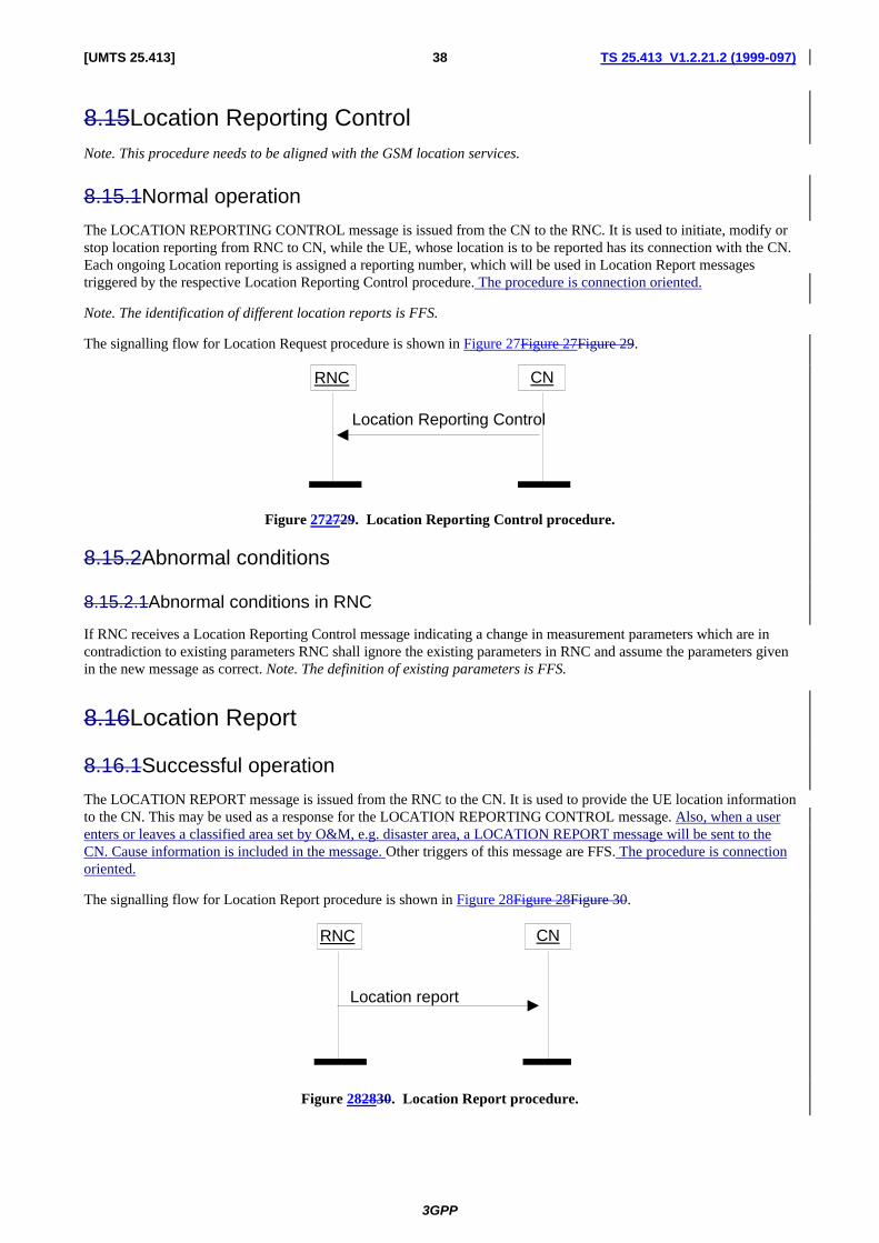
3GPP
TS 25.413 V1.2.21.2 (1999-097)38[UMTS 25.413]
8.15Location Reporting ControlNote. This procedure needs to be aligned with the GSM location services.
8.15.1Normal operation
The LOCATION REPORTING CONTROL message is issued from the CN to the RNC. It is used to initiate, modify orstop location reporting from RNC to CN, while the UE, whose location is to be reported has its connection with the CN.Each ongoing Location reporting is assigned a reporting number, which will be used in Location Report messagestriggered by the respective Location Reporting Control procedure. The procedure is connection oriented.
Note. The identification of different location reports is FFS.
The signalling flow for Location Request procedure is shown in Figure 27Figure 27Figure 29.
CNRNC
Location Reporting Control
Figure 272729. Location Reporting Control procedure.
8.15.2Abnormal conditions
8.15.2.1Abnormal conditions in RNC
If RNC receives a Location Reporting Control message indicating a change in measurement parameters which are incontradiction to existing parameters RNC shall ignore the existing parameters in RNC and assume the parameters givenin the new message as correct. Note. The definition of existing parameters is FFS.
8.16Location Report
8.16.1Successful operation
The LOCATION REPORT message is issued from the RNC to the CN. It is used to provide the UE location informationto the CN. This may be used as a response for the LOCATION REPORTING CONTROL message. Also, when a userenters or leaves a classified area set by O&M, e.g. disaster area, a LOCATION REPORT message will be sent to theCN. Cause information is included in the message. Other triggers of this message are FFS. The procedure is connectionoriented.
The signalling flow for Location Report procedure is shown in Figure 28Figure 28Figure 30.
CNRNC
Location report
Figure 282830. Location Report procedure.

3GPP
TS 25.413 V1.2.21.2 (1999-097)39[UMTS 25.413]
8.16.2Unsuccessful operation
If the RNC can not deliver the location information as requested, RNC shal indicate UE location to be "Undetermined".A cause value shall be added to indicate the reason for the undetermined location.
8.16.3Abnormal conditions
8.16.3.1Abnormal conditions in CN
If CN receives a Location Report message reporting Location that was not requested by CN, CN should stop theindicated location reporting by utilising Location Reporting Control procedure. (FFS).
8.17Error Indication
8.17.1General
The Error Indication procedure is used to carry error messages over the Iu Interface. The procedure uses theconnectionless mode of the signalling connectionbearer.
8.17.2CN originated Error Indication
On the PS side, the SGSN may send an Error Indication to the RNC if it receives a G-PDU with an unknown FlowLabel. The Cause Value to be used is:
- ‘Unknown Flow Label’
For the Cause Value ‘Unknown Flow Label’, both Binding Identity and Network Layer Address is mandatory.
The Binding Identity, i.e. the Flow Label, and the Network Layer Address used in the Error Indication message shall befetched from the G-PDU that triggered the procedure.
The signalling flow for the CN originated Error Indication procedure is shown in Figure 29Figure 29Figure 31.
CNRNC
Error Indication
Figure 292931. Error Indication, CN originated.
8.17.3RNC originated Error Indication
On the PS side, the RNC may send an Error Indication to the SGSN if it receives a G-PDU with an unknown FlowLabel. The Cause Value to be used is:
- ‘Unknown Flow Label’
For the Cause Value ‘Unknown Flow Label’, both Binding Identity and Network Layer Address is mandatory.
The Binding Identity, i.e. the Flow Label, and the Network Layer Address used in the Error Indication message shall befetched from the G-PDU that triggered the procedure.
The signalling flow for the UTRAN originated Error Indication procedure is shown in Figure 30Figure 30Figure 32.

3GPP
TS 25.413 V1.2.21.2 (1999-097)40[UMTS 25.413]
CNRNC
Error Indication
Figure 303032. Error Indication, RNC originated.
9Elements for RANAP communication
9.1Message functional definition and contents [Editor's note: ETSI has not yet discussed the parameters of RANAP messages. The text from the TTC/ARIB documentwill be used as a starting point, but the contents is not agreed and is FFS. In the cases when the messages are the same,TTC/ARIB agree to adopt the ETSI name for the message.]
[Editor's note: It has been agreed that the editor will propose a logical categorisation for messages and informationelements.]
For each message there is, a table listing the signaling elements in their order of� appearance in the transmitted message.
All the RANAP messages are listed in the following table:
Message name ReferenceRADIO ACCESS BEARERAB ASSIGNMENT REQUESTRADIO ACCESS BEARERAB ASSIGNMENT RESPONSERADIO ACCESS BEARER ASSIGNMENT FAILURERADIO ACCESS BEARERAB RELEASE REQUESTQUEUEING INDICATIONCOMMON IDDIRECT TRANSFERINITIAL UE MESSAGELOCATION REPORTING CONTROLLOCATION REPORTCIPHER MODE COMMANDCIPHER MODE COMPLETECIPHER MODE REJECTPAGINGIU RELEASE COMMANDIU RELEASE COMPLETEIU RELEASE REQUESTRELOCATION REQUIREDRELOCATION REQUESTRELOCATION REQUEST ACKNOWLEDGERELOCATION COMMANDRELOCATION DETECTRELOCATION COMPLETERELOCATION PREPARATION FAILURERELOCATION FAILURERELOCATION CANCELRELOCATION CANCEL ACKNOWLEDGERESET

3GPP
TS 25.413 V1.2.21.2 (1999-097)41[UMTS 25.413]
RESET ACKNOWLEDGEOVERLOADCN INVOKE TRACECN INFORMATION BROADCAST REQUESTCN INFORMATION BROADCAST CONFIRMCN INFORMATION BROADCAST REJECTERROR INDICATION
Table 1. List of RANAP messages.
9.1.1Message Contents
9.1.1.1RABRADIO ACCESS BEARER ASSIGNMENT REQUEST
Information element Reference Type
Message type M
BearersRABs x n to be setup or modified C1
RAB ID M
NAS Binding Information M
RABearer parameters M (1)
User Plane mode M
Transport Address M
Iu transport association M
Priority level and pre-emption indication O (2)
BearerRAB linking O
BearersRABs x n to be released C1
RAB ID M
Cause M
C1 At least one group shall be present.
(1) This includes all the necessary parameters for RAB'sbearers (both for MSC and SGSN) includingQoS.
(2) It needs to be clarified how this parameter is in relation to priority parameters already included withthe RABearer parameters.
Note. It needs to be clarified how the re-ordering information as proposed in Tdoc 276 relates to QoSattribute SDU in-sequence delivery.
9.1.1.2RABRADIO ACCESS BEARER ASSIGNMENT RESPONSE
Information element Reference Type
Message type M
Location Identifier O
BearersRABs x n established or modified C1
RAB ID M

3GPP
TS 25.413 V1.2.21.2 (1999-097)42[UMTS 25.413]
RABearer parameters O (1)
Transport address M (2)
Iu transport association M (2)
BearersRABs x n released C1
RAB ID M
Cause M
RABs x n queued C1
RAB ID M
RABs x n failed to establish or modify C1
RAB ID M
Cause M
RABs failed to release C1
RAB ID M
Cause M
C1 At least one group shall be present.
(1) RABearer parameters are needed only if something has changed.
(2) Always present for SGSN.
9.1.1.3RADIO ACCESS BEARER ASSIGNMENT FAILURE
Information element Reference Type
Message type M
Location Identifier O
Bearers x n successfully setup or modified C1
RAB ID M
Bearer parameters O (1)
Transport address M (2)
Iu transport association M (2)
Bearers x n failed to setup C1
RAB ID M
Cause M
Bearers x n released C1
RAB ID M
Cause M
C1 At least one group shall be present.
(1) Bearer parameters are needed only if something has changed.
(2) Always present for SGSN.
9.1.1.4RABRADIO ACCESS BEARER RELEASE REQUEST

3GPP
TS 25.413 V1.2.21.2 (1999-097)43[UMTS 25.413]
Information element Reference Type
Message type M
BearersRABs x n to be released C1
RAB ID M
Cause M
C1 At least one group shall be present.
9.1.1.5QUEUEING INDICATION
Information element Reference Type
Message type M
Bearers x n to be queued C1
RAB ID M
C1 At least one group shall be present.
9.1.1.6COMMON ID
Information element Reference Type
Message type M
Permanent NAS UE IdentityCommon ID (e.g. IMSI) M
9.1.1.7DIRECT TRANSFER
Information element Reference Type
Message type M
NAS PDU M
9.1.1.8INITIAL UE MESSAGE
Information element Reference Type
Message type M
Location Information M
NAS Layer 3 Information M

3GPP
TS 25.413 V1.2.21.2 (1999-097)44[UMTS 25.413]
9.1.1.9LOCATION REPORTING CONTROL
Information element Reference Type
Message type M
Request type M
9.1.1.10LOCATION REPORT
Information element Reference Type
Message type M
Location Information M
Cause O
9.1.1.11CIPHER MODE COMMAND
Information element Reference Type
Message type M
Encryption Information M (1)
(1) Encryption information includes key(s) and permitted algorithms.
Note 1. It is FFS whether the NAS information should be included in this message.
Note 2. The possibility to cipher only some of the RABs is FFS.
9.1.1.12CIPHER MODE COMPLETE
Information element Reference Type
Message type M
Chosen Encryption Algorithm O
Note 1. It is FFS whether the NAS information should be included in this message.
9.1.1.13CIPHER MODE REJECT
Information element Reference Type
Message type M
Cause M

3GPP
TS 25.413 V1.2.21.2 (1999-097)45[UMTS 25.413]
9.1.1.14PAGING
Information element Reference Type
Message type M
CN Domain Indicator M
IMSI M
Temporary UE ID O
Paging area ID OM
Paging Cause O
9.1.1.15IU RELEASE COMMAND
Information element Reference Type
Message type M
Cause M
9.1.1.16IU RELEASE COMPLETE
Information element Reference Type
Message type M
9.1.1.17IU RELEASE REQUEST
Information element Reference Type
Message type M
Cause M
9.1.1.18RELOCATION REQUIRED

3GPP
TS 25.413 V1.2.21.2 (1999-097)46[UMTS 25.413]
Information element Reference Type
Message type M
Cause M
Source ID M
Target IDRNC identification M (1)
Source RNC to target RNC transparent fieldcontainer M
(1) The usage and format of this information element is FFS.
9.1.1.19RELOCATION REQUEST
Information element Reference Type
Message type M
Cause M
Source RNC to target RNC transparent fieldcontainer M
BearersRABs x n to be setup M
RAB ID M
RABearer parameters M
User Plane mode M
Transport address M
Iu transport association M
Priority level and pre-emption indication O
BearerRAB linking O
9.1.1.20RELOCATION REQUEST ACKNOWLEDGE
Information element Reference Type
Message type M
Target RNC to source RNC transparent fieldcontainer O (1)
BearersRABs x n O (2)
RAB ID M
Transport address M (3)
Iu transport association M (3)
(1) Required only via one CN entity.
(2) Always present for SGSN, and present for MSC if parameters have been modified by target RNC.
(3) Always present for SGSN.
9.1.1.21RELOCATION COMMAND

3GPP
TS 25.413 V1.2.21.2 (1999-097)47[UMTS 25.413]
Information element Reference Type
Message type M
Target RNC to source RNC transparent fieldcontainer O (1)
(1) Required only via one CN entity.
9.1.1.22RELOCATION DETECT
Information element Reference Type
Message type M
9.1.1.23RELOCATION COMPLETE
Information element Reference Type
Message type M
9.1.1.24RELOCATION PREPARATION FAILURE
Information element Reference Type
Message type M
Cause M
9.1.1.25RELOCATION FAILURE
Information element Reference Type
Message type M
Cause M
9.1.1.26RELOCATION CANCEL
Information element Reference Type
Message type M
Cause M
9.1.1.27RELOCATION CANCEL ACKNOWLEDGE

3GPP
TS 25.413 V1.2.21.2 (1999-097)48[UMTS 25.413]
Information element Reference Type
Message type M
9.1.1.28RESET
Information element Reference Type
Message type M
Cause M
9.1.1.29RESET ACKNOWLEDGE
Information element Reference Type
Message type M
9.1.1.30OVERLOAD
Information element Reference Type
Message type M
Number of steps O
9.1.1.31CN INVOKE TRACE
Information element Reference Type
Message type M
Trace Type M
Trigger ID O
Trace Reference M
UE Identity O
OMC ID O
9.1.1.32CN INFORMATION BROADCAST REQUEST

3GPP
TS 25.413 V1.2.21.2 (1999-097)49[UMTS 25.413]
Information element Reference Type
Message type M
CN Domain Indicator M
CN System Information piece x n C1
NAS bit string M
Broadcast area M
Categorisation parameters M
C1 At least one group must be present.
Note 1. It is FFS how the broadcasting is turned off.
9.1.1.33CN INFORMATION BROADCAST CONFIRM
Information element Reference Type
Message type M
9.1.1.34CN INFORMATION BROADCAST REJECT
Information element Reference Type
Message type M
Cause M
[Editor's note: The CONFUSION message is removed, since it is not included in procedure descriptions and noparameters are included for this message either.]
9.1.1.35ERROR INDICATION
Information element Reference Type
Message type M
Cause M
Binding ID O
Source Network Layer Address O
9.2Information element functional definitions and contents [Editor's note: RANAP information elements have not yet been discussed in ETSI. If ASN.1 and BER will be used,section 9.2.4 may not be needed at all. The corresponding text from TTC/ARIB document will be included, but it has notbeen agreed and is FFS.
Study item 7: Usage of ASN.1 and encoding rules versus the description of information elements in TTC/ARIBdocument.]
This paragraph contains the CODING of the signaling elements used.

3GPP
TS 25.413 V1.2.21.2 (1999-097)50[UMTS 25.413]
9.2.1RANAP coding standard
Length Indicator
It is desirable to have Length for messages and parameters because future version of protocol may have extension tothe present message or parameter, and also variable size can be present in some parameters as well.
In case of message size exceeding 256 byte it is better to have 2 bytes for message LENGTH.
However it is enough to have 1 byte for parameter LENGTH.
Compatibility Information
Compatibility Information is used in the situation of unrecognized messages or parameter.This parameter should be placed at a certain place then it is easy to pick up this parameterin any circumstances.
Consequently, the format can be as follow:
Message Identifier / Length / Compatibility Info / parameters
Parameter Identifier / Length / Compatibility Info / Fields
Figure 3 shows the coding format of message and Figure 4 shows the coding format of parameter.
Length Indicator
Length Indicator
Fig. 9.2.4.1-1 Length Indicator for Message
Fig. 9.2.4.1-2� Length Indicator for Parameter
Message Identifier
Length
Compatibility Information
Parameter
�
�
Fig. 9.2.4.1-3 Message Coding Format
Parameter Identifier
Length
Compatibility Information
Field
�
�
Fig. 9.2.4.1-4 Parameter Coding Format

3GPP
TS 25.413 V1.2.21.2 (1999-097)51[UMTS 25.413]
Fixed size data and Variable size data in Field
It may have two types of filed i.e. with variable size or fixed size in data of field. It has no any problem to specify thefixed size field. Figure5 shows an example of fixed size data in field.
Regarding the variable size of data
9.2.2Signaling Element Coding
The elements used and their CODING are:
[Editor's note: The table needs to be revised.]
ElementIdentifierCoding
Element name Reference
Call IDBearer IDUser Information RateInformation Transfer CapabilityATM AddressATM Binding IDCauseRR CauseMS Classmark for RANDirect Transfer InformationLayer 3 InformationIMUITMUICipher InformationCell Identifier List
field length
data of field
Fig. 9.2.4.1-6 Length method
Field
Fig. 9.2.4.1-5 Format for fixed size field

3GPP
TS 25.413 V1.2.21.2 (1999-097)52[UMTS 25.413]
Cell IdentifierChosen ChannelCipher Response ModeChosen Cipher AlgorithmGroup Call ReferenceTalker FlagLayer 3 Radio InformationResponse Request

3GPP
TS 25.413 V1.2.21.2 (1999-097)53[UMTS 25.413]
1.
9.2.2.1Message type
Message type uniquely identifies the message being sent. It is mandatory for all elementsmessages.
9.2.2.2RABRadio Access Bearer ID
[Editor's note: This definition needs to be harmonized with UMTS 23.10.]
This ID is to identify a particular radio access bearer in Iu.
9.2.2.3NAS Binding Information
[Editor's note: This definition needs to be harmonized with UMTS 23.10.]
This information is a information transmitted transparently to the RNC.
9.2.2.4RABearer parameters
The purpose of the bearerRAB parameter information element is to indicate all RABbearer parameters for bothdirections, e.g. Quality of service (QoS) classes.
9.2.2.5Transport address
To be used for the user plane transport.
9.2.2.6Iu transport association
This element is used to associate the bearerRAB ID and the corresponding user plane connection.
9.2.2.7Cause
The cause element is used to indicate the reason for a particular event to have occurred according to the cause code list.
9.2.2.8Priority level and pre-emption indication
Indicates the priority of the request.
9.2.2.9RABBearer linking
A group of bearersRABs which must be either all established, or all rejected.
9.2.2.10Location Identifier
Indicates location of the UE.
9.2.2.11Permanent NAS IdentityCommon ID
This ID is common for mobile terminal and is used by the RNC to check if SRB is already existing (from other NE) tothe UE when new radio access bearer is in establishment phase. Initially this is of the type of IMSI. The future usage isFFS.

3GPP
TS 25.413 V1.2.21.2 (1999-097)54[UMTS 25.413]
9.2.2.12CN Domain Indicator
Indicates to which domain (MSC or SGSN) the paging shall be directed.
9.2.2.13IMSI
International Mobile Subscriber Identity, identifies a subscriber.
9.2.2.14Temporary UE IDTMSI
Temporary Mobile Subscriber Identity, used for security reasons to hide the identity of a subscriber.
9.2.2.15Paging Cause
Tells the cause of paging to the UE.
9.2.2.16Trace Type
A fixed length element indicating the type of trace information to be recorded.
9.2.2.17Trigger ID
A variable length element indicating the identity of the entity which initiated the trace.
9.2.2.18Trace Reference
A fixed length element providing a trace reference number allocated by the triggering entity.
9.2.2.19UE Identity
Indicates the identity of the UE.
9.2.2.20OMC ID
A variable length element indicating the destination OMC to which trace information is to be sent.
9.2.2.21Encryption Information
This element contains the user data encryption information (key(s) and permitted algorithms) used to control anyencryption equipment at the RNC.
9.2.2.22Chosen Encryption Algorithm
This element indicates the encryption algorithm being used by the RNC.
9.2.2.23NAS Bit String
The NAS information peace to be broadcast. The internal structure of this bit string is not known or analysed by theRNC, and is specified as part of the CN - UE protocols.
9.2.2.24Broadcast Area
With each bit string, a geographical area where to broadcast it.
3GPP
TS 25.413 V1.2.21.2 (1999-097)55[UMTS 25.413]
9.2.2.25Categorisation parameters
With each bit string, to be used by the RNC to determine how to schedule the repetition cycle.
9.2.2.26NAS PDU
This information element contains the CN – UE or UE – CN message that is transferred without interpretation in theRNC. Typically it contains call control and mobility management messages.
9.2.2.27Request Type
[Editor's note: This definition needs to be harmonized with UMTS 23.10.]
This information request the information type that to be reported from RNC, e.g. to report LAI and RAI of the currentUE location. Other request types are FFS.
9.2.2.28Location Information
[Editor's note: This definition needs to be harmonized with UMTS 23.10.]
This information shows the location information that has been requested by the CN, e.g. LAI and RAI. Other types oflocation information are FFS.
9.2.2.29NAS Layer 3 Information
This is a variable length element used to pass radio interface messages from one network entity to another.
User Plane Mode
[Editor's note: It has been agreed that the editor will propose a definition for this.]
Paging Area ID
[Editor's note: It has been agreed that the editor will propose a definition for this.]
Source ID
[Editor's note: It has been agreed that the editor will propose a definition for this.]
Target ID
[Editor's note: It has been agreed that the editor will propose a definition for this.]
Source RNC to Target RNC Transparent Container
[Editor's note: It has been agreed that the editor will propose a definition for this.]
Target RNC to Source RNC Transparent Container
[Editor's note: It has been agreed that the editor will propose a definition for this.]
Number of steps
Indicates the number of steps to reduce traffic in overload situation.
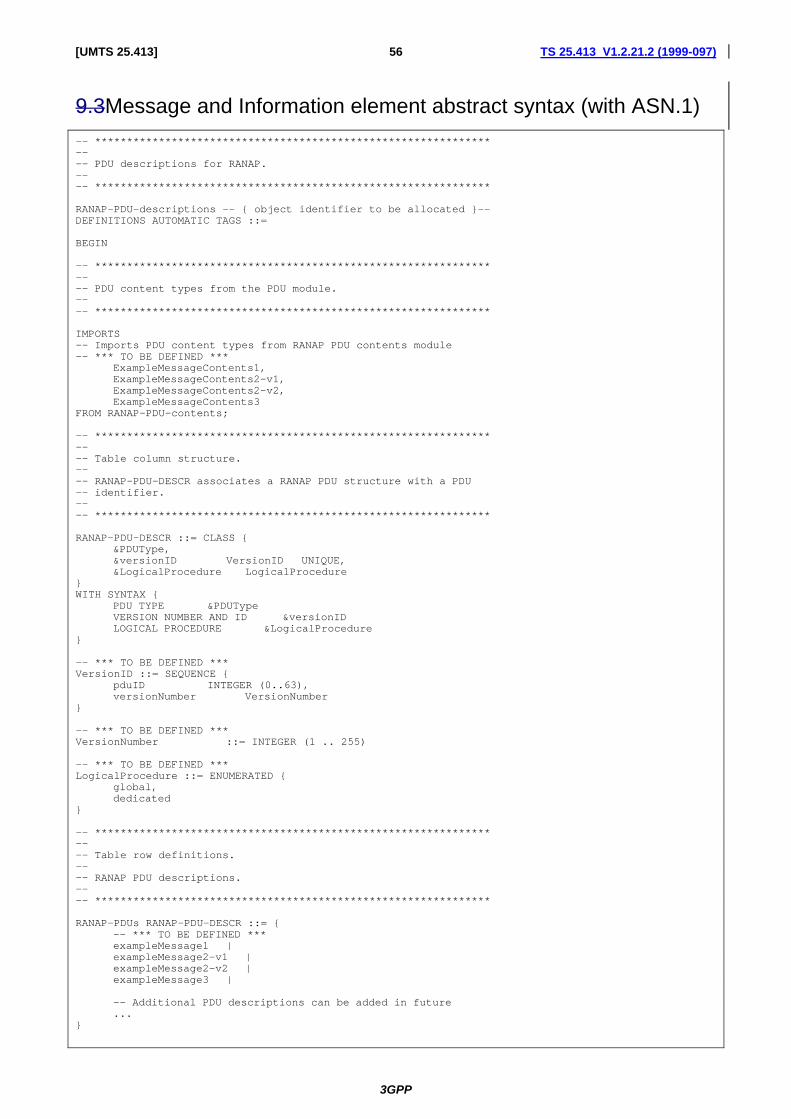
3GPP
TS 25.413 V1.2.21.2 (1999-097)56[UMTS 25.413]
9.3Message and Information element abstract syntax (with ASN.1)
-- **************************************************************---- PDU descriptions for RANAP.---- **************************************************************
RANAP-PDU-descriptions -- { object identifier to be allocated }--DEFINITIONS AUTOMATIC TAGS ::=
BEGIN
-- **************************************************************---- PDU content types from the PDU module.---- **************************************************************
IMPORTS-- Imports PDU content types from RANAP PDU contents module-- *** TO BE DEFINED ***
ExampleMessageContents1,ExampleMessageContents2-v1,ExampleMessageContents2-v2,ExampleMessageContents3
FROM RANAP-PDU-contents;
-- **************************************************************---- Table column structure.---- RANAP-PDU-DESCR associates a RANAP PDU structure with a PDU-- identifier.---- **************************************************************
RANAP-PDU-DESCR ::= CLASS {&PDUType,&versionID VersionID UNIQUE,&LogicalProcedure LogicalProcedure
}WITH SYNTAX {
PDU TYPE &PDUTypeVERSION NUMBER AND ID &versionIDLOGICAL PROCEDURE &LogicalProcedure
}
-- *** TO BE DEFINED ***VersionID ::= SEQUENCE {
pduID INTEGER (0..63),versionNumber VersionNumber
}
-- *** TO BE DEFINED ***VersionNumber ::= INTEGER (1 .. 255)
-- *** TO BE DEFINED ***LogicalProcedure ::= ENUMERATED {
global,dedicated
}
-- **************************************************************---- Table row definitions.---- RANAP PDU descriptions.---- **************************************************************
RANAP-PDUs RANAP-PDU-DESCR ::= {-- *** TO BE DEFINED ***exampleMessage1 |exampleMessage2-v1 |exampleMessage2-v2 |exampleMessage3 |
-- Additional PDU descriptions can be added in future...
}

3GPP
TS 25.413 V1.2.21.2 (1999-097)57[UMTS 25.413]
-- *** TO BE DEFINED ***exampleMessage1 RANAP-PDU-DESCR ::= {PDU TYPE ExampleMessageContents1VERSION NUMBER AND ID { pduID 1, versionNumber 1 }LOGICAL PROCEDURE { global }
}
exampleMessage2-v1 RANAP-PDU-DESCR ::= {PDU TYPE ExampleMessageContents2-v1VERSION NUMBER AND ID { pduID 2, versionNumber 1 }LOGICAL PROCEDURE { dedicated }
}
exampleMessage2-v2 RANAP-PDU-DESCR ::= {PDU TYPE ExampleMessageContents2-v2VERSION NUMBER AND ID { pduID 2, versionNumber 2 }LOGICAL PROCEDURE { dedicated }
}
exampleMessage3 RANAP-PDU-DESCR ::= {PDU TYPE ExampleMessageContents3VERSION NUMBER AND ID { pduID 3, versionNumber 1 }LOGICAL PROCEDURE { global | dedicated }
}
-- **************************************************************---- Generic PDU structure. The RANAP-PDUs table above describes-- valid contents for the vid, indication and value fields.---- **************************************************************
RANAP-PDU ::= SEQUENCE {vid RANAP-PDU-DESCR.&versionID ({RANAP-PDUs}),value RANAP-PDU-DESCR.&PDUType ({RANAP-PDUs}{@vid})
}
END
-- **************************************************************---- RANAP PDU content definitions---- **************************************************************
RANAP-PDU-contents DEFINITIONS AUTOMATIC TAGS ::=
BEGIN
-- IMPORTS
-- *** TO BE DEFINED ***-- FROM RANAP-IEs
-- *** TO BE DEFINED ***-- FROM RANAP-Constants;
-- Definitions of RANAP PDU content types one by one-- *** TO BE DEFINED ***
ExampleMessageContents1 ::= SEQUENCE {-- *** IEs to be defined ***...
}
ExampleMessageContents2-v1 ::= SEQUENCE {-- *** IEs to be defined ***...
}
ExampleMessageContents2-v2 ::= SEQUENCE {-- *** IEs to be defined ***...
}
ExampleMessageContents3 ::= SEQUENCE {-- *** IEs to be defined ***...
}

3GPP
TS 25.413 V1.2.21.2 (1999-097)58[UMTS 25.413]
END
-- **************************************************************---- RANAP Information Elements---- **************************************************************
RANAP-IEs DEFINITIONS AUTOMATIC TAGS ::=
BEGIN
-- IMPORTS
-- *** TO BE DEFINED ***-- FROM RANAP-Constants;
-- Definitions of RANAP IEs one by one-- *** TO BE DEFINED ***
END
-- **************************************************************---- Constant definitions for RANAP---- **************************************************************
RANAP-Constants DEFINITIONS AUTOMATIC TAGS ::=
BEGIN
-- Definitions of RANAP constants one by one-- *** TO BE DEFINED ***
END
9.4Message transfer syntax
9.5Timers[Editor's note: This chapter should list and describe the used timers.]
10Handling of unknown, unforeseen and erroneous protocoldata

3GPP
TS 25.413 V1.2.21.2 (1999-097)59[UMTS 25.413]
11Annex A (normative):
Annex A Document Stability Assessment Table
SectionContentmissing
IncompleteRestructuring
neededChecking
needed
Editorialwork
required
Finalisationneeded
Almoststable
Stable
1 √√
2 √√
3 √√
4 √√
5 √√
6 √√
7 √√
8 √√
9 √√ √√
10 √√
12History
Document history
0.0.1 February 1999 Document skeleton created.
0.0.2 February 1999 Relevant sections from Merged "Description of Iu Interface" have been introduced.
0.0.3 March 1999 The results of the solved study items Iu/2, Iu/3, Iu/4 and Iu/6 have been updated tothe text.
The heading of section 8 has been changed to "RANAP procedures".
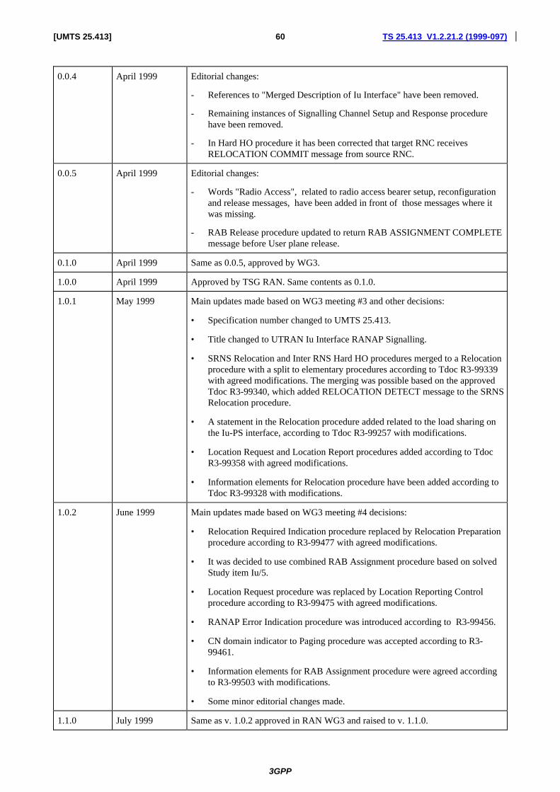
3GPP
TS 25.413 V1.2.21.2 (1999-097)60[UMTS 25.413]
0.0.4 April 1999 Editorial changes:
- References to "Merged Description of Iu Interface" have been removed.
- Remaining instances of Signalling Channel Setup and Response procedurehave been removed.
- In Hard HO procedure it has been corrected that target RNC receivesRELOCATION COMMIT message from source RNC.
0.0.5 April 1999 Editorial changes:
- Words "Radio Access", related to radio access bearer setup, reconfigurationand release messages, have been added in front of those messages where itwas missing.
- RAB Release procedure updated to return RAB ASSIGNMENT COMPLETEmessage before User plane release.
0.1.0 April 1999 Same as 0.0.5, approved by WG3.
1.0.0 April 1999 Approved by TSG RAN. Same contents as 0.1.0.
1.0.1 May 1999 Main updates made based on WG3 meeting #3 and other decisions:
• Specification number changed to UMTS 25.413.
• Title changed to UTRAN Iu Interface RANAP Signalling.
• SRNS Relocation and Inter RNS Hard HO procedures merged to a Relocationprocedure with a split to elementary procedures according to Tdoc R3-99339with agreed modifications. The merging was possible based on the approvedTdoc R3-99340, which added RELOCATION DETECT message to the SRNSRelocation procedure.
• A statement in the Relocation procedure added related to the load sharing onthe Iu-PS interface, according to Tdoc R3-99257 with modifications.
• Location Request and Location Report procedures added according to TdocR3-99358 with agreed modifications.
• Information elements for Relocation procedure have been added according toTdoc R3-99328 with modifications.
1.0.2 June 1999 Main updates made based on WG3 meeting #4 decisions:
• Relocation Required Indication procedure replaced by Relocation Preparationprocedure according to R3-99477 with agreed modifications.
• It was decided to use combined RAB Assignment procedure based on solvedStudy item Iu/5.
• Location Request procedure was replaced by Location Reporting Controlprocedure according to R3-99475 with agreed modifications.
• RANAP Error Indication procedure was introduced according to R3-99456.
• CN domain indicator to Paging procedure was accepted according to R3-99461.
• Information elements for RAB Assignment procedure were agreed accordingto R3-99503 with modifications.
• Some minor editorial changes made.
1.1.0 July 1999 Same as v. 1.0.2 approved in RAN WG3 and raised to v. 1.1.0.

3GPP
TS 25.413 V1.2.21.2 (1999-097)61[UMTS 25.413]
1.1.1. July 1999 Main updates made based on WG3 meeting #5 decisions:
• Description and definition of elementary procedure added according to R3-99727 with modifications. List of elementary procedures included.
• As a result of R3-99727, Iu Release Request changed to an elementaryprocedure. Text proposed by the Editor.
• Failure handling added to Relocation procedure based on R3-99746 withmodifications.
• Relocation cancel elementary procedure added according to R3-99745 withmodifications.
• Bearer ID changed to RAB ID and NAS Binding ID added according to R3-99747.
• User Plane Mode parameter added to RAB Assignment and Relocationprocedures according to R3-99720.
• The Cause parameter added and Transparent field changed to mandatory inRELOCATION REQUIRED and RELOCATION REQUEST messagesaccording to R3-99678.
• The parameters for Location Reporting Control and Location Reportprocedures were agreed according to R3-99748.
• The message contents for the remaining procedures and parameter definitionsadded based on R3-99670 with modofications.
1.1.2 August 1999 'Cause' parameter removed from Overload procedure description. Minor editorialchanges.
1.2.0 August 1999 Version 1.1.2 approved in WG3#6 and raised to v. 1.2.0.
1.2.1 September 1999 Decisions from WG3#6 have been updated as follows:
• RAB Assignment procedure rewritten according to Tdoc R3-99A74 (=updatedTdoc R3-99942) with modifications. Type Class 3 of Elementary Procedureintroduced.
• RAB Release Request procedure added according to Tdoc R3-99A09.
• List of RANAP functions added according to Tdoc R3-99A01 withmodifications.
• 'Transparent field' changed to 'Transparent container' according to Tdoc R3-99952.
• A concept of handling relocation co-ordination in source and target RNCadded according to Tdoc R3-99A10 with modifications.
• Handling of the crossing of RESET messages was included as proposed inTdoc R3-99909.
• Editorial comments proposed in Tdoc R3-99940 included with modifications.
• Definitions in Tdoc R3-99A60 added with modifications.

3GPP
TS 25.413 V1.2.21.2 (1999-097)62[UMTS 25.413]
1.2.2 September 1999 Some additional updates made to fullfil the agreements from WG3#6:
• The definition of Class 3 Elementary Procedure clarified.
• The 'Overload' and 'Location Report' procedures have been updated accordingto the agreements in WG3#6.
• The description of 'Iu Release' and 'Cipher Mode Control' procedures has beenfurther updated to better reflect the decisions in WG3#6.
• The possibility of RAB release to fail added also into the message contents ofRAB ASSIGNMENT RESPONSE.
• Some other minor editorial updates.
Rapporteur for 3GPP UMTS 25.413 is:
Jyrki JussilaNokia Telecommunications
Tel.: +358 9 5113 8436Fax : +358 9 5113 8452Email : [email protected]
This document is written in Microsoft Word version 7.0/96.