TSGR2#4(99)379 - 3GPP
28
TSG-RAN Working Group 2 (Radio layer 2 and Radio layer 3) TSGR2#4(99)379 Berlin 25 th to 28 th May 1999 Agenda Item: 7.2 Source: Editor Title: 3GPP TSG RAN WG2 TR 25.922 V0.1.1: on “Radio Resource Management Strategies“ Document for: Discussion and decision
-
Upload
khangminh22 -
Category
Documents
-
view
0 -
download
0
Transcript of TSGR2#4(99)379 - 3GPP
TSG-RAN Working Group 2 (Radio layer 2 and Radio layer 3) TSGR2#4(99)379Berlin 25th to 28th May 1999
Agenda Item: 7.2Source: Editor
Title: 3GPP TSG RAN WG2 TR 25.922 V0.1.1: on “Radio ResourceManagement Strategies“
Document for: Discussion and decision
TR RAN R2.02 25.922V0.1.1 (1999-04)Technical Report
3rd Generation Partnership Project (3GPP);Technical Specification Group (TSG) RAN;
Working Group 2 (WG2);
Radio Resource Management Strategies

2
TR 25.922 v0.1.1 (1999-04)
Reference<Workitem> (<Shortfilename>.PDF)
Keywords<keyword[, keyword]>
3GPP
Postal address
Office address
Individual copies of this deliverablecan be downloaded fromhttp://www.3gpp.org
Copyright Notification
No part may be reproduced except as authorized by written permission.The copyright and the foregoing restriction extend to reproduction in all media.
©All rights reserved.
3
TR 25.922 v0.1.1 (1999-04)
Contents
1. SCOPE 6
2. REFERENCES 6
3. DEFINITIONS, ABBREVIATIONS AND SYMBOLS 7
3.1 Definitions 7
3.2 Abbreviations 7
3.3 Symbols 8
4. GENERAL DESCRIPTION OF RADIO RESOURCE MANAGEMENT 8
5. IDLE MODE TASKS 8
5.1 Overview 8
5.2 Service type in Idle mode 9
5.3 Criteria for Cell Selection and Reselection 95.3.1 Cell Selection Monitoring Frequency or Cell Set 95.3.2 Cell Re-Selection Monitoring Frequency or Cell Set 9
5.4 Broadcast information receiving 9
6. RRC CONNECTION MOBILITY 9
6.1 General Description of Connected Mode 96.1.1 Handover 9
6.1.1.1 Strategy 96.1.1.2 Causes 96.1.1.3 Cell Set for the Handover Preparation 106.1.1.4 Hard Handover 10
6.1.1.4.1 Hard Handover (FDD and TDD Hard) 106.1.1.5 Soft Handover 106.1.1.6 Inter System Handover 12
6.1.1.6.1 Handover 3G to 2G 126.1.2 Radio Link Management 13
7. ADMISSION CONTROL 13
7.1 Overall strategies 13
4
TR 25.922 v0.1.1 (1999-04)
Other mapping are possible like for instance: 14
7.2 Scenarios 147.2.1 CAC performed in SRNS 14
7.2.2 CAC performed in DRNC 157.2.2.1 Case of DCH 157.2.2.2 Case of Common Transport Channels 15
8. RADIO ACCESS BEARER CONTROL 16
8.1 Radio Access Bearer Control – Overview of Procedures 16
8.2 Usage of RAB control procedures 168.2.1 Example of Radio Access Bearer Setup 168.2.2 Examples of Physical Channel Reconfiguration 17
8.2.2.1 Increased UL data, with switch from RACH/FACH to DCH/DCH 178.2.2.2 Increased DL data, no Transport channel type switching 188.2.2.3 Decrease DL data, no Transport channel type switching 188.2.2.4 Decreased UL data, with switch from DCH/DCH to RACH/FACH 18
8.2.3 Examples of Transport Channel Reconfiguration 198.2.3.1 Increased UL data, with no transport channel type switching 198.2.3.2 Decreased DL data, with switch from DCH/DCH to RACH/FACH 20
8.2.4 Example of RAB and Signalling link Reconfiguration 20
9. DYNAMIC CHANNEL ALLOCATION 21
9.1 DCA (FDD) 21
9.2 DCA (TDD) 219.2.1 Channel Allocation 21
9.2.1.1 Resource allocation to cells (slow DCA) 219.2.1.2 Resource allocation to bearer services (fast DCA) 22
9.2.2 Measurements Reports from UE to the UTRAN 22
10. POWER MANAGEMENT 23
11. RADIO LINK SURVEILLANCE 23
12. APPENDIX A 23
12.1 Simulation environment 23
12.2 Results 2312.2.1 Macro UDD 144 2412.2.2 Micro UDD 384 24
12.2.2.1 Code rate 1 2412.2.2.2 Code rate 2/3 25
5
TR 25.922 v0.1.1 (1999-04)
12.3 Conclusions 26
13. HISTORY 26
6
TR 25.922 v0.1.1 (1999-04)
Intellectual Property Rights
IPRs essential or potentially essential to the present deliverable may have been declared to 3GPP and/or its organizationalpartners. The information pertaining to these essential IPRs, if any, is publicly available for 3GPP members and non-members, free of charge. This can be found in the latest version of the 3GPP Technical Report: [tbd.].Pursuant to the 3GPP Interim IPR Policy, no investigation, including IPR searches, has been carried out by 3GPP . Noguarantee can be given as to the existence of other IPRs not referenced in the [tbd.] , which are, or may be, or may become,essential to the present document.
[Editor’s note: This section needs to be reviewed. It is assumed here than a 3GPP IPR report will be available in the nearfuture.]
ForewordThis Technical Recommendation has been produced by the 3rd Generation Partnership Project, Technical Specification GroupRAN.The contents of this TR may be subject to continuing work within the 3GPP and may change following formal TSG approval.Should the TSG modify the contents of this TR, it will be re-released with an identifying change of release date and an increasein version number as follows:
Version m.t.ewhere:
m indicates [major version number]x the second digit is incremented for all changes of substance, i.e. technical enhancements, corrections, updates, etc.y the third digit is incremented when editorial only changes have been incorporated into the specification.
1. ScopeThe present document shall describe RRM strategies supported by UTRAN specifications and typical algorithms.
2. ReferencesThe following documents contain provisions which, through reference in this text, constitute provisions of the presentdocument.
• References are either specific (identified by date of publication, edition number, version number, etc.) or non-specific.• For a specific reference, subsequent revisions do not apply.• For a non-specific reference, the latest version applies.• A non-specific reference to an TS shall also be taken to refer to later versions published as an EN with the same number.
[1] 3GPP Homepage: www.3GPP.org[2] S2.01, Radio Interface Protocol Architecture[3] S2.02, Layer 1; General requirements[4] S2.03, UE States and Procedures in Connected Mode[5] S2.04, Description of procedures in idle Mode
7
TR 25.922 v0.1.1 (1999-04)
[6] S2.22, Description of RLC protocol[7] S2.31, Description of RRC protocol[8] S2.40, Description of principles for error handling and message description[9] ETSI UMTS 25.XX: ”Vocabulary for the UTRAN”
[10] S1.25, Measurements TDD
3. Definitions, abbreviations and symbols
3.1 Definitions
See [9] for a definition of fundamental concepts and vocabulary.
3.2 Abbreviations
ARQ Automatic Repeat RequestBCCH Broadcast Control ChannelBCH Broadcast ChannelC- Control-CC Call ControlCCCH Common Control ChannelCCH Control ChannelCCTrCH Coded Composite Transport ChannelCN Core NetworkCRC Cyclic Redundancy CheckDC Dedicated Control (SAP)DCA Dynamic Channel AllocationDCCH Dedicated Control ChannelDCH Dedicated ChannelDL DownlinkDRNC Drift Radio Network ControllerDSCH Downlink Shared ChannelDTCH Dedicated Traffic ChannelFACH Forward Link Access ChannelFAUSCH Fast Uplink Signalling ChannelFCS Frame Check SequenceFDD Frequency Division DuplexGC General Control (SAP)HO HandoverITU International Telecommunication Unionkbps kilo-bits per secondL1 Layer 1 (physical layer)L2 Layer 2 (data link layer)L3 Layer 3 (network layer)LAC Link Access ControlLAI Location Area IdentityMAC Medium Access ControlMM Mobility ManagementNt Notification (SAP)OCCCH ODMA Common Control Channel
8
TR 25.922 v0.1.1 (1999-04)
ODCCH ODMA Dedicated Control ChannelODCH ODMA Dedicated Channel
ODMA Opportunity Driven Multiple AccessORACH ODMA Random Access Channel
ODTCH ODMA Dedicated Traffic ChannelPCCH Paging Control ChannelPCH Paging ChannelPDU Protocol Data UnitPHY Physical layerPhyCH Physical ChannelsRACH Random Access ChannelRLC Radio Link ControlRNC Radio Network ControllerRNS Radio Network SubsystemRNTI Radio Network Temporary IdentityRRC Radio Resource ControlSAP Service Access PointSCCH Synchronization Control ChannelSCH Synchronization ChannelSDU Service Data UnitSRNC Serving Radio Network ControllerSRNS Serving Radio Network SubsystemTCH Traffic ChannelTDD Time Division DuplexTFCI Transport Format Combination IndicatorTFI Transport Format IndicatorTMSI Temporary Mobile Subscriber IdentityTPC Transmit Power ControlU- User-UE User EquipmentUER User Equipment with ODMA relay operation enabledUL UplinkUMTS Universal Mobile Telecommunications SystemURA UTRAN Registration AreaUTRA UMTS Terrestrial Radio AccessUTRAN UMTS Terrestrial Radio Access Network
3.3 Symbols
4. General Description of Radio resource Management
5. Idle Mode Tasks
5.1 Overview
9
TR 25.922 v0.1.1 (1999-04)
[A complete overview of idle mode tasks is contained in section 4.1 of S2.04. For the purpose of this recommendation somespecific test will be developed.]
5.2 Service type in Idle mode
[In this section, the impact of service type on RRM strategies will be addressed, also based on section 4.3 of S2.04]
5.3 Criteria for Cell Selection and Reselection5.3.1 Cell Selection Monitoring Frequency or Cell Set
5.3.2 Cell Re-Selection Monitoring Frequency or Cell Set
5.4 Broadcast information receiving[In this section the possible uses of broadcast system information on RRM strategies will be addressed also based on section 6of S2.04]
6. RRC Connection Mobility
6.1 General Description of Connected Mode[The overall description of the connected mode is contained in section 4 of S2.03. For the purpose of this recommendationsome specific test will be developed.]
6.1.1 Handover6.1.1.1 Strategy
The handover strategy employed by the network for radio link control determines the handover decision that will be madebased on the measurement results reported by the UE/RNC and various parameters set for each cell. Network directed handovermight also occur for reasons other than radio link control, e.g. to control traffic distribution between cells. The networkoperator will determine the exact handover strategies.. Possible types of Handover are as follows:
• Handover 3G -3G:• FDD soft/softer handover;• FDD inter-frequency hard handover;• FDD/TDD Handover;• TDD/FDD Handover;• TDD/TDD Handover;• Handover 3G - 2G:• Handover to GSM
6.1.1.2 Causes
The following is a non-exhaustive list for causes for the initiation of a handover process.
• Uplink quality• Uplink signal strength
10
TR 25.922 v0.1.1 (1999-04)
• Downlink quality• Downlink signal strength
• Distance• Change of service
• Better cell• O&M intervention• Directed retry• Traffic• Pre-emption
6.1.1.3 Cell Set for the Handover Preparation
6.1.1.4 Hard Handover
6.1.1.4.1 Hard Handover (FDD and TDD Hard)
[Test to be deployed also based on section 7.3.7 of S2.03]
6.1.1.5 Soft Handover The serving cell (s) (the cells in the active set) are expected to have knowledge of the service used by the UE. The new celldecided to be added to the active set shall be informed that a new connection is desired, and it needs to have the followingminimum information forwarded to it via UTRAN.• Maximum data rate of the connection and other service parameters, such as coding schemes, number of parallel code
channels etc. parameters which form the set of parameters describing the different transport channel configurations in useboth uplink and downlink.
• The UE ID and uplink scrambling code
• The relative timing information of the new cell, in respect to the timing UE is experiencing from the existing connections(as measured by the UE at its location). Based on this the new cellcan determine what should be the timing of thetransmission initiated in respect to the timing of the common channels (BCCH) of the new cell.
As a response the UE needs to know via the existing connections:• From which frame (assuming active set update accepted) does the new cell initiate the transmission to the UE
• What channelisation code(s) are used for that transmission. The channelisation codes from different cells are not required tobe the same as they are under different scrambling code anyway.
• The relative timing information, which needs to be made available at the new cell is indicated in Figure 1 (shows the casewhere the two involved cells are managed by different Node Bs).
11
TR 25.922 v0.1.1 (1999-04)
PCCCHframe
PDCH/PCCHframe
Measure Toffset
Handovercommandand Toffset
UTRANNetwork
Transmision channeland Toffset
BS Bchannelinformation
BS ABS B
Toffset
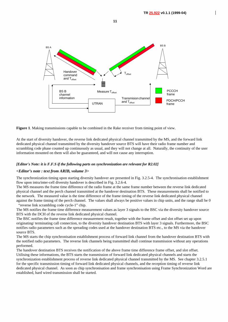
Figure 1. Making transmissions capable to be combined in the Rake receiver from timing point of view.
At the start of diversity handover, the reverse link dedicated physical channel transmitted by the MS, and the forward linkdedicated physical channel transmitted by the diversity handover source BTS will have their radio frame number andscrambling code phase counted up continuously as usual, and they will not change at all. Naturally, the continuity of the userinformation mounted on them will also be guaranteed, and will not cause any interruption.
[Editor's Note: it is F.F.S if the following parts on synchronization are relevant for R2.02]
<Editor’s note : text from ARIB, volume 3>
The synchronization timing upon starting diversity handover are presented in Fig. 3.2.5-4. The synchronisation establishmentflow upon intra/inter-cell diversity handover is described in Fig. 3.2.6-4.The MS measures the frame time difference of the radio frame at the same frame number between the reverse link dedicatedphysical channel and the perch channel transmitted at the handover destination BTS. These measurements shall be notified tothe network. The measured value is the time difference of the frame timing of the reverse link dedicated physical channelagainst the frame timing of the perch channel. The values shall always be positive values in chip units, and the range shall be 0∼“reverse link scrambling code cycle-1” chip.The MS notifies the frame time difference measurement values as layer 3 signals to the BSC via the diversity handover sourceBTS with the DCH of the reverse link dedicated physical channel.The BSC notifies the frame time difference measurement result, together with the frame offset and slot offset set up uponoriginating/ terminating call connection, to the diversity handover destination BTS with layer 3 signals. Furthermore, the BSCnotifies radio parameters such as the spreading codes used at the handover destination BTS etc., to the MS via the handoversource BTS.The MS starts the chip synchronisation establishment process of forward link channel from the handover destination BTS withthe notified radio parameters. The reverse link channels being transmitted shall continue transmission without any operationsperformed.The handover destination BTS receives the notification of the above frame time difference frame offset, and slot offset.Utilising these informations, the BTS starts the transmission of forward link dedicated physical channels and starts thesynchronization establishment process of reverse link dedicated physical channel transmitted by the MS. See chapter 3.2.5.1for the specific transmission timing of forward link dedicated physical channels, and the reception timing of reverse linkdedicated physical channel. As soon as chip synchronisation and frame synchronisation using Frame Synchronization Word areestablished, hard wired transmission shall be started.
12
TR 25.922 v0.1.1 (1999-04)
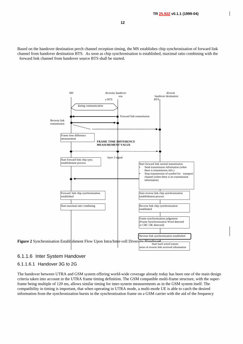
Based on the handover destination perch channel reception timing, the MS establishes chip synchronisation of forward linkchannel from handover destination BTS. As soon as chip synchronisation is established, maximal ratio combining with the
forward link channel from handover source BTS shall be started.
Figure 2 Synchronisation Establishment Flow Upon Intra/Inter-cell Diversity Handover
6.1.1.6 Inter System Handover
6.1.1.6.1 Handover 3G to 2G
The handover between UTRA and GSM system offering world-wide coverage already today has been one of the main designcriteria taken into account in the UTRA frame timing definition. The GSM compatible multi-frame structure, with the super-frame being multiple of 120 ms, allows similar timing for inter-system measurements as in the GSM system itself. Thecompatibility in timing is important, that when operating in UTRA mode, a multi-mode UE is able to catch the desiredinformation from the synchronization bursts in the synchronization frame on a GSM carrier with the aid of the frequency
MS diversity handover sou
e BTS
diversit handover destinationBTS
Frame time differencemeasurement
Start forward link chip sync.establishment process Start forward link normal transmission
• Send transmission information (whenthere is transmission info.)
• Stop transmission of symbol for transportchannel (when there is no transmissioninformation)
Forward link chip synchronizationestablished
Start maximal ratio combining
Start reverse link chip synchronizationestablishment process
Reverse link chip synchronizationestablished
Frame synchronization judgement(Frame Synchronization Word detectedor CRC OK detected)
Reverse link synchronization established
Start hard wired transmssion of reverse link received information
during communication
Forward link transmission
Reverse linktransmission
FRAME TIME DIFFERENCEMEASUREMENT VALUE
layer 3 signal
13
TR 25.922 v0.1.1 (1999-04)
correction burst. This way the relative timing between a GSM and UTRA carriers is maintained similar to the timing betweentwo asynchronous GSM carriers. UTRA/FDD-GSM dual mode UEs can be implemented without simultaneous use of two receiver chains. Although the frame
length is different from GSM frame length, the GSM traffic channel and UTRA FDD channels use similar 120 ms multi-framestructure. Similar timing can be naturally done with UTRA TDD mode as well.
A UE can do the measurements by using idle periods in the downlink transmission, where such idle periods are created by usingthe downlink slotted mode as defined in reference [2]. In addition to downlink slotted frames for measurements, the UTRANwill provide uplink slotted frames to allow the UE to GSM cells on frequencies closed to the FDD uplink band. The slottedmode is under the control of the UTRAN, and the UTRAN should communicate to the UE which frame is slotted. .
Alternatively independent measurements not relying on the slotted mode, but using a dual receiver approach can be performed,where the GSM receiver branch can operate independently of the UTRA FDD receiver branch.
For smooth inter-operation between the systems, information needs to be exchanged between the systems, in order to allow theUTRAN to notify the UE of the existing GSM frequencies in the area ( see section 6.1.1.2.1.4). Further more integratedoperation is needed for the actual handover where the current service is maintained, taking naturally into account the lower datarate capabilities in GSM when compared to UTRA maximum data rates reaching all the way to 2 Mbits/s.
UTRA/TDD-GSM dual mode terminals can be implemented without simultaneous use of two receiver chains. Although theframe length is different from GSM frame length, the GSM traffic channel and UTRA TDD channels rely on similar 120 msmulti-frame structure. A UE can do the measurements either by efficiently using idle slots or by requesting free continuous periods in the downlinkpart obtained by reducing the spreading factor and compressing in time TS occupation in a form similar to the FDD slottedmode. The low-cost constraint excludes the dual receiver approach.
For smooth inter-operation, inter-system information exchanges are needed in order to allow The UTRAN to notify the UE ofthe existing GSM frequencies in the area and vice versa. Further more integrated operation is needed for the actual handoverwhere the current service is maintained, taking naturally into account the lower data rate capabilities in GSM when compared toUMTS maximum data rates reaching all the way to 2 Mbits/s.
Basic requirements to correctly perform a handover in GSM are described in GSM 05.08 “Radio subsystem link control”.
6.1.2 Radio Link Management[Test to be deployed also based on sections 7.3.4, 7.3.5, 7.3.6 of S2.03]
�
7. Admission Control
7.1 Overall strategies
Principle 1: Admission Control is performed according to the type of required QoS.
“Type of service” is to be understood as an implementation specific category derived from standardized QoS parameters.
The following table illustrates the concept :
14
TR 25.922 v0.1.1 (1999-04)
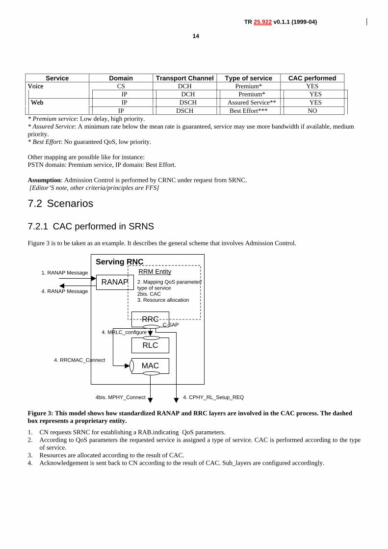
Service Domain Transport Channel Type of service CAC performedVoice CS DCH Premium* YESVoice
IP DCH Premium* YESWeb IP DSCH Assured Service** YESWeb
IP DSCH Best Effort*** NO* Premium service: Low delay, high priority.* Assured Service: A minimum rate below the mean rate is guaranteed, service may use more bandwidth if available, mediumpriority.* Best Effort: No guaranteed QoS, low priority.
Other mapping are possible like for instance:PSTN domain: Premium service, IP domain: Best Effort.
Assumption: Admission Control is performed by CRNC under request from SRNC. [Editor’S note, other criteria/principles are FFS]
7.2 Scenarios
7.2.1 CAC performed in SRNS
Figure 3 is to be taken as an example. It describes the general scheme that involves Admission Control.
Serving RNC
RANAP
RRC
RRM Entity
4. CPHY_RL_Setup_REQ
C-SAP
1. RANAP Message
4. RANAP Message
2. Mapping QoS parameter/type of service2bis. CAC3. Resource allocation
MAC4. RRCMAC_Connect
4bis. MPHY_Connect
RLC
4. MRLC_configure
Figure 3: This model shows how standardized RANAP and RRC layers are involved in the CAC process. The dashedbox represents a proprietary entity.
1. CN requests SRNC for establishing a RAB.indicating QoS parameters.2. According to QoS parameters the requested service is assigned a type of service. CAC is performed according to the type
of service.3. Resources are allocated according to the result of CAC.4. Acknowledgement is sent back to CN according to the result of CAC. Sub_layers are configured accordingly.
15
TR 25.922 v0.1.1 (1999-04)
Steps 2 to 4 may also be triggered by SRNC for reconfiguration purpose within the SRNC (handovers intra-RNC, channelsreconfigurations, location updates).
7.2.2 CAC performed in DRNC
As CAC is always performed in CRNC it occurs in DRNC when Iur is to be used (soft handover, Cell/URA Update).[Editor’snote please clarify the content of this sentence]
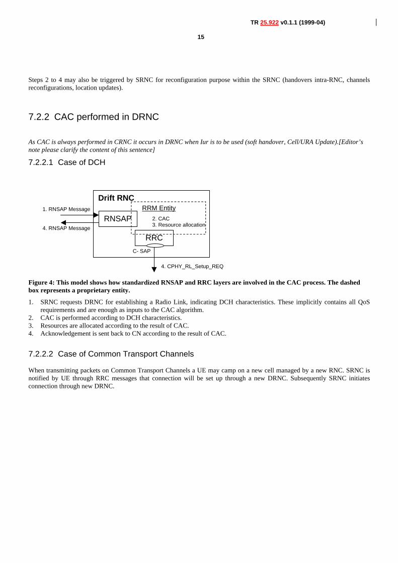
7.2.2.1 Case of DCH
Drift RNC
RNSAP
RRC
RRM Entity
4. CPHY_RL_Setup_REQ
C- SAP
1. RNSAP Message
4. RNSAP Message
2. CAC3. Resource allocation
Figure 4: This model shows how standardized RNSAP and RRC layers are involved in the CAC process. The dashedbox represents a proprietary entity.
1. SRNC requests DRNC for establishing a Radio Link, indicating DCH characteristics. These implicitly contains all QoSrequirements and are enough as inputs to the CAC algorithm.
2. CAC is performed according to DCH characteristics.3. Resources are allocated according to the result of CAC.4. Acknowledgement is sent back to CN according to the result of CAC.
7.2.2.2 Case of Common Transport Channels
When transmitting packets on Common Transport Channels a UE may camp on a new cell managed by a new RNC. SRNC isnotified by UE through RRC messages that connection will be set up through a new DRNC. Subsequently SRNC initiatesconnection through new DRNC.
16
TR 25.922 v0.1.1 (1999-04)
Drift RNC
RNSAP
RRC
RRM Entity
4. CPHY_RL_Setup_REQ
C-SAP
1. RNSAP Message
4. RNSAP Message
2. Mapping QoS parameter/type of service2bis. CAC3. Resource allocation
MAC
4. RRCMAC_Connect
4bis. MPHY_Connect
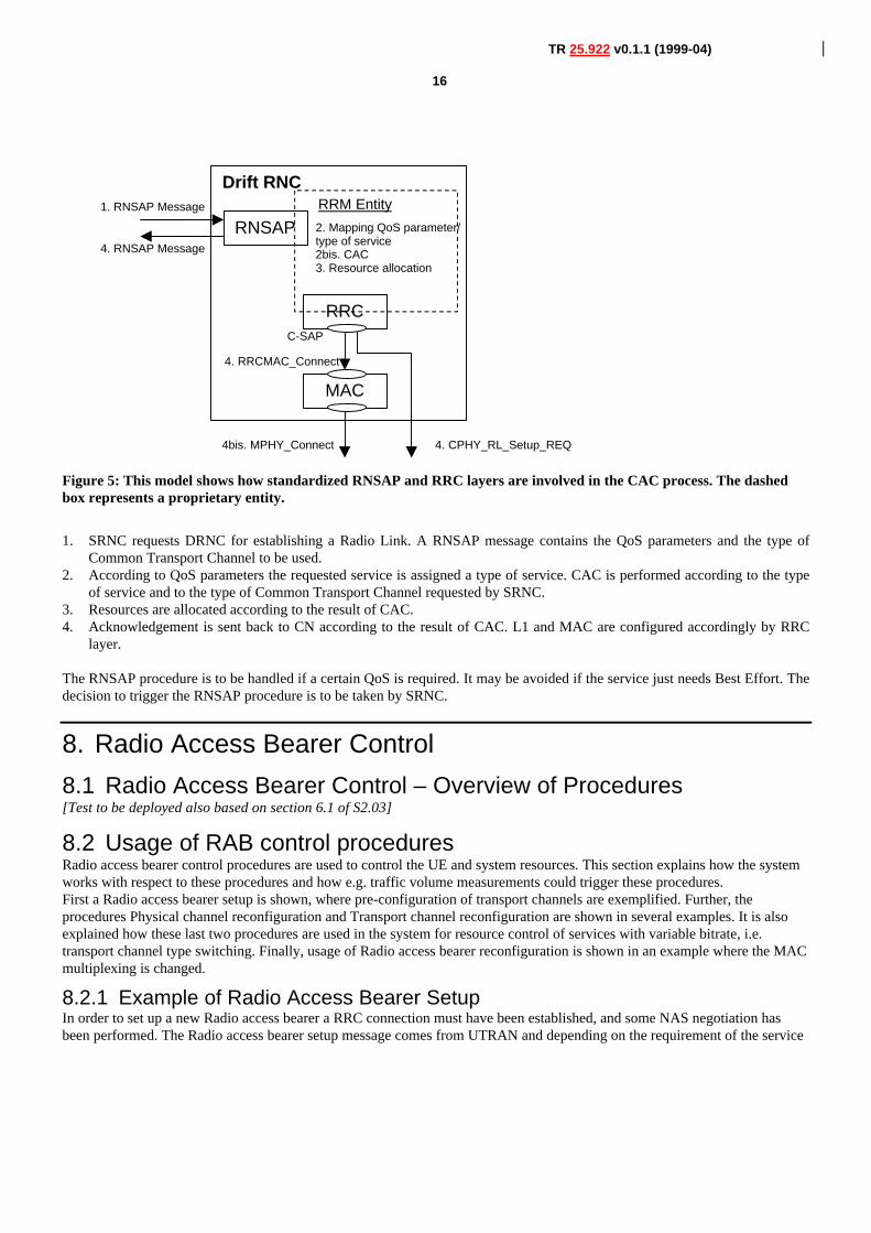
Figure 5: This model shows how standardized RNSAP and RRC layers are involved in the CAC process. The dashedbox represents a proprietary entity.
1. SRNC requests DRNC for establishing a Radio Link. A RNSAP message contains the QoS parameters and the type ofCommon Transport Channel to be used.
2. According to QoS parameters the requested service is assigned a type of service. CAC is performed according to the typeof service and to the type of Common Transport Channel requested by SRNC.
3. Resources are allocated according to the result of CAC.4. Acknowledgement is sent back to CN according to the result of CAC. L1 and MAC are configured accordingly by RRC
layer.
The RNSAP procedure is to be handled if a certain QoS is required. It may be avoided if the service just needs Best Effort. Thedecision to trigger the RNSAP procedure is to be taken by SRNC.
8. Radio Access Bearer Control
8.1 Radio Access Bearer Control – Overview of Procedures[Test to be deployed also based on section 6.1 of S2.03]
8.2 Usage of RAB control proceduresRadio access bearer control procedures are used to control the UE and system resources. This section explains how the systemworks with respect to these procedures and how e.g. traffic volume measurements could trigger these procedures.First a Radio access bearer setup is shown, where pre-configuration of transport channels are exemplified. Further, theprocedures Physical channel reconfiguration and Transport channel reconfiguration are shown in several examples. It is alsoexplained how these last two procedures are used in the system for resource control of services with variable bitrate, i.e.transport channel type switching. Finally, usage of Radio access bearer reconfiguration is shown in an example where the MACmultiplexing is changed.
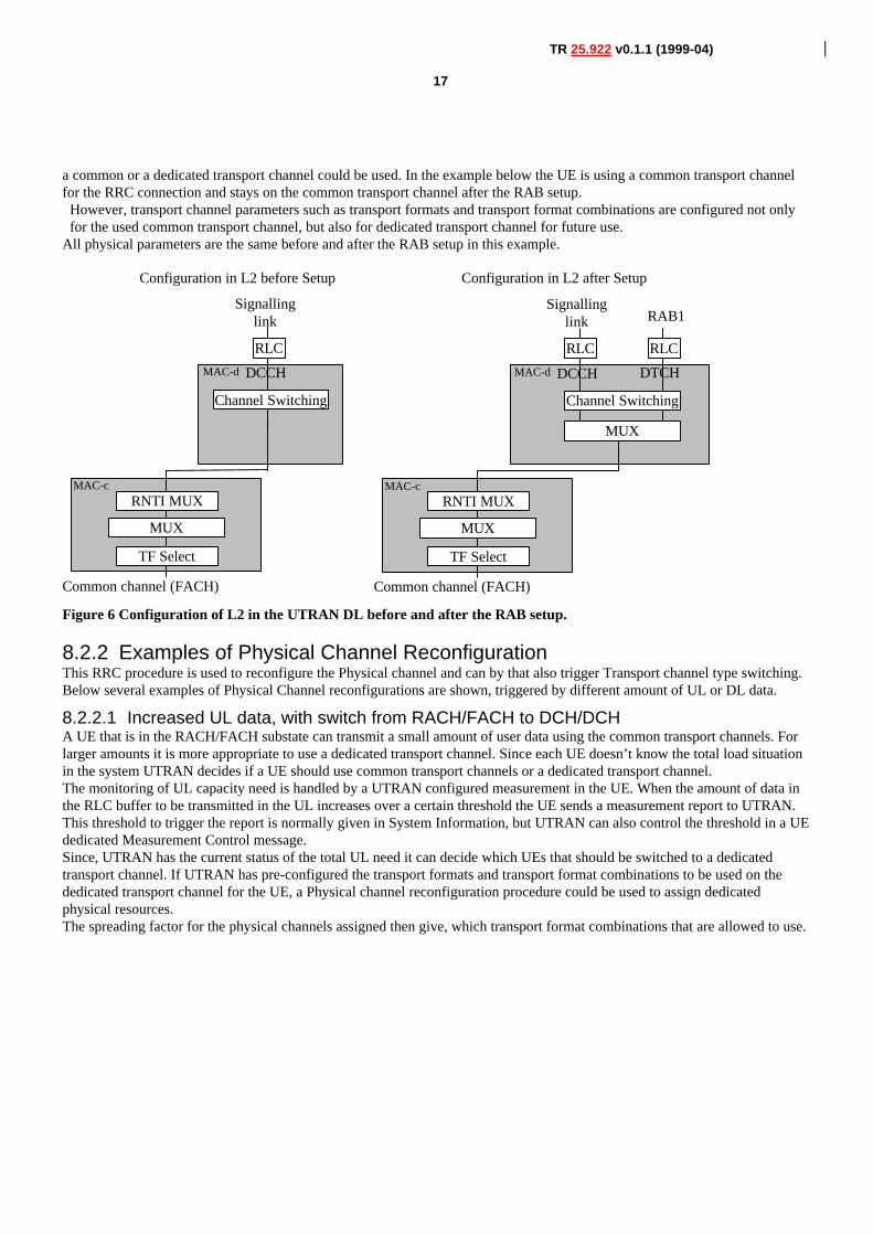
8.2.1 Example of Radio Access Bearer SetupIn order to set up a new Radio access bearer a RRC connection must have been established, and some NAS negotiation hasbeen performed. The Radio access bearer setup message comes from UTRAN and depending on the requirement of the service
17
TR 25.922 v0.1.1 (1999-04)
a common or a dedicated transport channel could be used. In the example below the UE is using a common transport channelfor the RRC connection and stays on the common transport channel after the RAB setup.
However, transport channel parameters such as transport formats and transport format combinations are configured not onlyfor the used common transport channel, but also for dedicated transport channel for future use.
All physical parameters are the same before and after the RAB setup in this example.
MAC-c
MAC-d
Configuration in L2 before Setup
RLC
TF Select
Common channel (FACH)
Channel Switching
Configuration in L2 after Setup
RNTI MUX
Signallinglink
DCCH
MUX
MAC-c
MAC-d
RLC
TF Select
Common channel (FACH)
RLC
Channel Switching
MUX
RNTI MUX
Signallinglink RAB1
DCCH DTCH
MUX
Figure 6 Configuration of L2 in the UTRAN DL before and after the RAB setup.
8.2.2 Examples of Physical Channel ReconfigurationThis RRC procedure is used to reconfigure the Physical channel and can by that also trigger Transport channel type switching.Below several examples of Physical Channel reconfigurations are shown, triggered by different amount of UL or DL data.
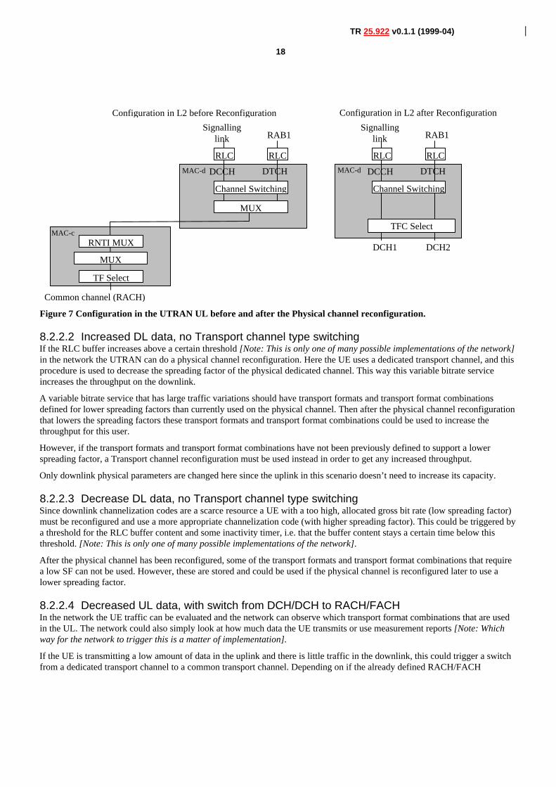
8.2.2.1 Increased UL data, with switch from RACH/FACH to DCH/DCHA UE that is in the RACH/FACH substate can transmit a small amount of user data using the common transport channels. Forlarger amounts it is more appropriate to use a dedicated transport channel. Since each UE doesn’t know the total load situationin the system UTRAN decides if a UE should use common transport channels or a dedicated transport channel.The monitoring of UL capacity need is handled by a UTRAN configured measurement in the UE. When the amount of data inthe RLC buffer to be transmitted in the UL increases over a certain threshold the UE sends a measurement report to UTRAN.This threshold to trigger the report is normally given in System Information, but UTRAN can also control the threshold in a UEdedicated Measurement Control message.Since, UTRAN has the current status of the total UL need it can decide which UEs that should be switched to a dedicatedtransport channel. If UTRAN has pre-configured the transport formats and transport format combinations to be used on thededicated transport channel for the UE, a Physical channel reconfiguration procedure could be used to assign dedicatedphysical resources.The spreading factor for the physical channels assigned then give, which transport format combinations that are allowed to use.
18
TR 25.922 v0.1.1 (1999-04)
MAC-c
MAC-d MAC-d
Configuration in L2 before Reconfiguration
RLC
TF Select
Common channel (RACH)
RLC
Channel Switching
MUX
Configuration in L2 after Reconfiguration
RLC
DCH1
RLC
TFC Select
DCH2
Channel Switching
RNTI MUX
Signallinglink RAB1
DCCH DTCH
Signallinglink RAB1
DCCH DTCH
MUX
Figure 7 Configuration in the UTRAN UL before and after the Physical channel reconfiguration.
8.2.2.2 Increased DL data, no Transport channel type switchingIf the RLC buffer increases above a certain threshold [Note: This is only one of many possible implementations of the network]in the network the UTRAN can do a physical channel reconfiguration. Here the UE uses a dedicated transport channel, and thisprocedure is used to decrease the spreading factor of the physical dedicated channel. This way this variable bitrate serviceincreases the throughput on the downlink.
A variable bitrate service that has large traffic variations should have transport formats and transport format combinationsdefined for lower spreading factors than currently used on the physical channel. Then after the physical channel reconfigurationthat lowers the spreading factors these transport formats and transport format combinations could be used to increase thethroughput for this user.
However, if the transport formats and transport format combinations have not been previously defined to support a lowerspreading factor, a Transport channel reconfiguration must be used instead in order to get any increased throughput.
Only downlink physical parameters are changed here since the uplink in this scenario doesn’t need to increase its capacity.
8.2.2.3 Decrease DL data, no Transport channel type switchingSince downlink channelization codes are a scarce resource a UE with a too high, allocated gross bit rate (low spreading factor)must be reconfigured and use a more appropriate channelization code (with higher spreading factor). This could be triggered bya threshold for the RLC buffer content and some inactivity timer, i.e. that the buffer content stays a certain time below thisthreshold. [Note: This is only one of many possible implementations of the network].
After the physical channel has been reconfigured, some of the transport formats and transport format combinations that requirea low SF can not be used. However, these are stored and could be used if the physical channel is reconfigured later to use alower spreading factor.
8.2.2.4 Decreased UL data, with switch from DCH/DCH to RACH/FACHIn the network the UE traffic can be evaluated and the network can observe which transport format combinations that are usedin the UL. The network could also simply look at how much data the UE transmits or use measurement reports [Note: Whichway for the network to trigger this is a matter of implementation].
If the UE is transmitting a low amount of data in the uplink and there is little traffic in the downlink, this could trigger a switchfrom a dedicated transport channel to a common transport channel. Depending on if the already defined RACH/FACH
19
TR 25.922 v0.1.1 (1999-04)
configuration is possible/preferred in the cell that the UE will be in after the switch, a Transport channel reconfiguration or aPhysical channel reconfiguration procedure is used.
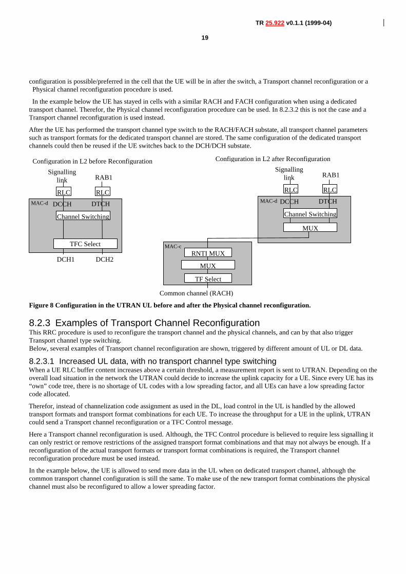
In the example below the UE has stayed in cells with a similar RACH and FACH configuration when using a dedicatedtransport channel. Therefor, the Physical channel reconfiguration procedure can be used. In 8.2.3.2 this is not the case and aTransport channel reconfiguration is used instead.
After the UE has performed the transport channel type switch to the RACH/FACH substate, all transport channel parameterssuch as transport formats for the dedicated transport channel are stored. The same configuration of the dedicated transportchannels could then be reused if the UE switches back to the DCH/DCH substate.
MAC-c
MAC-dMAC-d
Configuration in L2 after Reconfiguration
RLC
TF Select
Common channel (RACH)
RLC
Channel Switching
MUX
Configuration in L2 before Reconfiguration
RLC
DCH1
RLC
TFC Select
DCH2
Channel Switching
RNTI MUX
Signallinglink RAB1
DCCH DTCH
Signallinglink RAB1
DCCH DTCH
MUX
Figure 8 Configuration in the UTRAN UL before and after the Physical channel reconfiguration.
8.2.3 Examples of Transport Channel ReconfigurationThis RRC procedure is used to reconfigure the transport channel and the physical channels, and can by that also triggerTransport channel type switching.Below, several examples of Transport channel reconfiguration are shown, triggered by different amount of UL or DL data.
8.2.3.1 Increased UL data, with no transport channel type switchingWhen a UE RLC buffer content increases above a certain threshold, a measurement report is sent to UTRAN. Depending on theoverall load situation in the network the UTRAN could decide to increase the uplink capacity for a UE. Since every UE has its“own” code tree, there is no shortage of UL codes with a low spreading factor, and all UEs can have a low spreading factorcode allocated.
Therefor, instead of channelization code assignment as used in the DL, load control in the UL is handled by the allowedtransport formats and transport format combinations for each UE. To increase the throughput for a UE in the uplink, UTRANcould send a Transport channel reconfiguration or a TFC Control message.
Here a Transport channel reconfiguration is used. Although, the TFC Control procedure is believed to require less signalling itcan only restrict or remove restrictions of the assigned transport format combinations and that may not always be enough. If areconfiguration of the actual transport formats or transport format combinations is required, the Transport channelreconfiguration procedure must be used instead.
In the example below, the UE is allowed to send more data in the UL when on dedicated transport channel, although thecommon transport channel configuration is still the same. To make use of the new transport format combinations the physicalchannel must also be reconfigured to allow a lower spreading factor.
20
TR 25.922 v0.1.1 (1999-04)
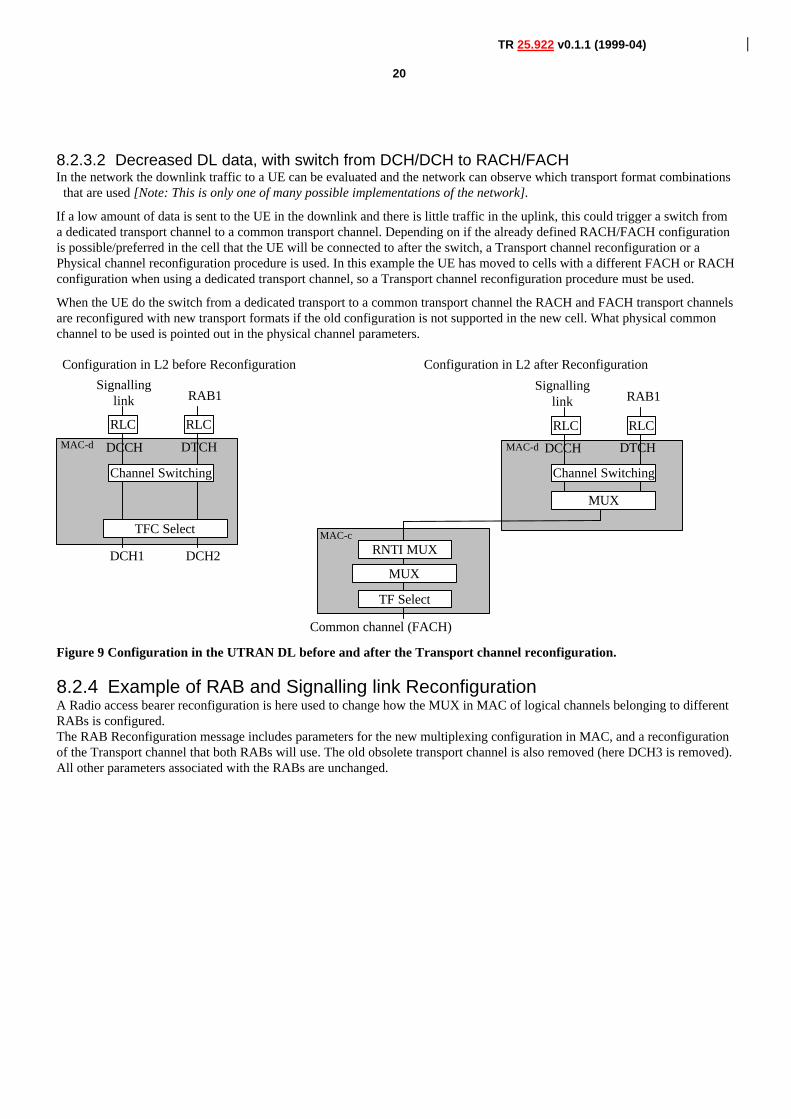
8.2.3.2 Decreased DL data, with switch from DCH/DCH to RACH/FACHIn the network the downlink traffic to a UE can be evaluated and the network can observe which transport format combinations
that are used [Note: This is only one of many possible implementations of the network].
If a low amount of data is sent to the UE in the downlink and there is little traffic in the uplink, this could trigger a switch froma dedicated transport channel to a common transport channel. Depending on if the already defined RACH/FACH configurationis possible/preferred in the cell that the UE will be connected to after the switch, a Transport channel reconfiguration or aPhysical channel reconfiguration procedure is used. In this example the UE has moved to cells with a different FACH or RACHconfiguration when using a dedicated transport channel, so a Transport channel reconfiguration procedure must be used.
When the UE do the switch from a dedicated transport to a common transport channel the RACH and FACH transport channelsare reconfigured with new transport formats if the old configuration is not supported in the new cell. What physical commonchannel to be used is pointed out in the physical channel parameters.
MAC-d
Configuration in L2 before Reconfiguration
RLC
DCH1
RLC
TFC Select
DCH2
Channel Switching
Signallinglink RAB1
DCCH DTCH
MAC-c
MAC-d
Configuration in L2 after Reconfiguration
RLC
TF Select
Common channel (FACH)
RLC
Channel Switching
MUX
RNTI MUX
Signallinglink RAB1
DCCH DTCH
MUX
Figure 9 Configuration in the UTRAN DL before and after the Transport channel reconfiguration.
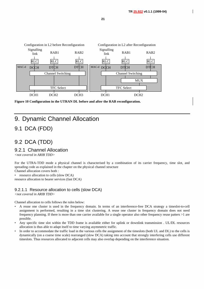
8.2.4 Example of RAB and Signalling link ReconfigurationA Radio access bearer reconfiguration is here used to change how the MUX in MAC of logical channels belonging to differentRABs is configured.The RAB Reconfiguration message includes parameters for the new multiplexing configuration in MAC, and a reconfigurationof the Transport channel that both RABs will use. The old obsolete transport channel is also removed (here DCH3 is removed).All other parameters associated with the RABs are unchanged.
21
TR 25.922 v0.1.1 (1999-04)
MAC-dMAC-d
Configuration in L2 before Reconfiguration
RLC
DCH1
RLC
DCH2
RLC
TFC Select
DCH3
Channel Switching
Configuration in L2 after Reconfiguration
RLC
DCH1
RLC
TFC Select
RLC
Channel Switching
MUX
DCH2
Signallinglink RAB1
DCCH DTCH
RAB2
DTCH
Signallinglink RAB1
DCCH DTCH
RAB2
DTCH
Figure 10 Configuration in the UTRAN DL before and after the RAB reconfiguration.
9. Dynamic Channel Allocation
9.1 DCA (FDD)
9.2 DCA (TDD)9.2.1 Channel Allocation<not covered in ARIB TDD>
For the UTRA-TDD mode a physical channel is characterised by a combination of its carrier frequency, time slot, andspreading code as explained in the chapter on the physical channel structureChannel allocation covers both :• resource allocation to cells (slow DCA)resource allocation to bearer services (fast DCA)
9.2.1.1 Resource allocation to cells (slow DCA) <not covered in ARIB TDD> Channel allocation to cells follows the rules below:• A reuse one cluster is used in the frequency domain. In terms of an interference-free DCA strategy a timeslot-to-cell
assignment is performed, resulting in a time slot clustering. A reuse one cluster in frequency domain does not needfrequency planning. If there is more than one carrier available for a single operator also other frequency reuse patters >1 arepossible.
• Any specific time slot within the TDD frame is available either for uplink or downlink transmission . UL/DL resourcesallocation is thus able to adapt itself to time varying asymmetric traffic.
• In order to accommodate the traffic load in the various cells the assignment of the timeslots (both UL and DL) to the cells isdynamically (on a coarse time scale) rearranged (slow DCA) taking into account that strongly interfering cells use differenttimeslots. Thus resources allocated to adjacent cells may also overlap depending on the interference situation.
22
TR 25.922 v0.1.1 (1999-04)
• Due to idle periods between successive received and transmitted bursts, UEs can provide the network with interferencemeasurements in time slots different from the one currently used. The availability of such information enables the operator
to implement the DCA algorithm suited to the network.• For instance, the prioritized assignment of time slots based on interference measurements results in a clustering in the time
domain and in parallel takes into account the demands on locally different traffic loads within the network.
9.2.1.2 Resource allocation to bearer services (fast DCA)<not covered in ARIB TDD>
Fast channel allocation refers to the allocation of one or multiple physical channels to any bearer service Resource units (RUs)are acquired (and released) according to a cell-related preference list derived from the slow DCA scheme.1. The following principles hold for fast channel allocation:The basic RU used for channel allocation is one code / timeslot /
(frequency).2. Multirate services are achieved by pooling of resource units. This can be made both in the code domain (pooling of
multiple codes within one timeslot = multicode operation) and time domain (pooling of multiple timeslots within oneframe = multislot operation). Additionally, any combination of both is possible. Simulation results reported in AppendixA, recommend that the DCA prefers code pooling , over time slot pooling, for UDD packet data; the use of code pooling infact results in lower number of unsatisfied users.
3. Since the maximal number of codes per time slot in UL/DL depends on several physical circumstances like , channelcharacteristics, environments, etc. (see description of physical layer) and whether additional techniques to further enhancecapacity are applied (for example smart antennas),. the DCA algorithm has to be independent of this number. Additionally,time-hopping can be used to average inter-cell interference in case of low-medium bit rate users.• 4. Channel allocation differentiates between RT and NRT bearer services:RT services: Channels remain allocated for
the whole duration the bearer service is established . The allocated resources may change because of a channelreallocation procedure (e.g. VBR).
• NRT services: Channels are allocated for the period of the transmission of a dedicated data packet only UDD channelallocation is performed using ‘best effort strategy’, i.e. resources available for NRT services are distributed to alladmitted NRT services with pending transmission requests. The number of channels allocated for any NRT service isvariable and depends at least on the number of current available resources and the number of NRT services attemptingfor packet transmission simultaneously. Additionally, prioritisation of admitted NRT services is possible.
5. Channel reallocation procedures (intra-cell handover) can be triggered for many reasons:• To cope with varying interference conditions.• In case of high rate RT services (i.e. services requiring multiple resource units) a ‘channel reshuffling procedure’ is required
to prevent a fragmentation of the allocated codes over to many timeslots. This is achieved by freeing the least loadedtimeslots (timeslots with minimum used codes) by performing a channel reallocation procedure.
• When using smart antennas, channel reallocation is useful to keep spatially separated the different users in the sametimeslot.
9.2.2 Measurements Reports from UE to the UTRAN
While in active mode the DCA needs measurements for the reshuffling procedure (intra-cell handover). The specification of themeasurements to be performed is contained in Section 7.4 in [10]. In this section the relevant measurement reports arepresented:
• Pathloss of a sub-set of cells (pathloss is quantized in NPL [e.g. 128] intervals ; [max. number of cells is 30].• Inter-cell interference measurements of all DL time slots requested by the UTRAN (interference is quantized in NICI [e.g.
32] intervals, due to asymmetry up to 14 time slots are possible)• BER of serving link (quantized in NBER [e.g. 16] intervals)
23
TR 25.922 v0.1.1 (1999-04)
• Transmission power of the UE on serving link (separated in NTX [e.g. 64] intervals)• DTX flag link
• ffsFurther measurements and reports can be requested by the UTRAN.
The RLC informs the DCA about transmission errors. The interaction between DCA and RLC depends on the RLC operationmode. Details are for further study.
10. Power Management
11. Radio Link Surveillance
12. Appendix A
12.1 Simulation environmentThe presented simulations are performed in the following environments and services according to the requirements in thefollowing documents:
• ETSI TR 101 112, Selection procedures for the choice of radio transmission technologies of the Universal MobileTelecommunications System UMTS (UMTS 30.03), version 3.2.0, April 1998.
• Seppo Hämäläinen, Peter Slanina, Magnus Hartman, Antti Lappeteläinen, Harri Holma, Oscar Salonaho, A Novel InterfaceBetween Link and System Level Simulations, Acts Mobile Communications Summit '97, pp. 599-604, Aalborg/Denmark,Oct 7-10, 1997.
Absolute capacities [kbit/s/MHz/cell] were published in:
• ETSI Tdoc SMG2 306/98, UTRA TDD Link Level and System Level Simulation Results for ITU Submission, Source:Siemens, Helsinki, Sep 8-11, 1998.
1. Macro (Vehicular) environment for the UDD 144 kbit/s service.2. Micro (Outdoor-to-Indoor Pedestrian) environment for the UDD 384 kbit/s service.
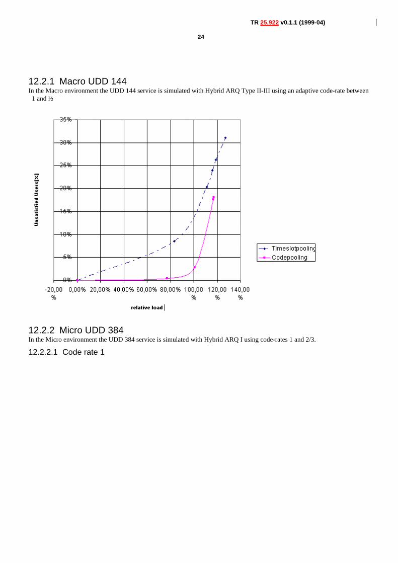
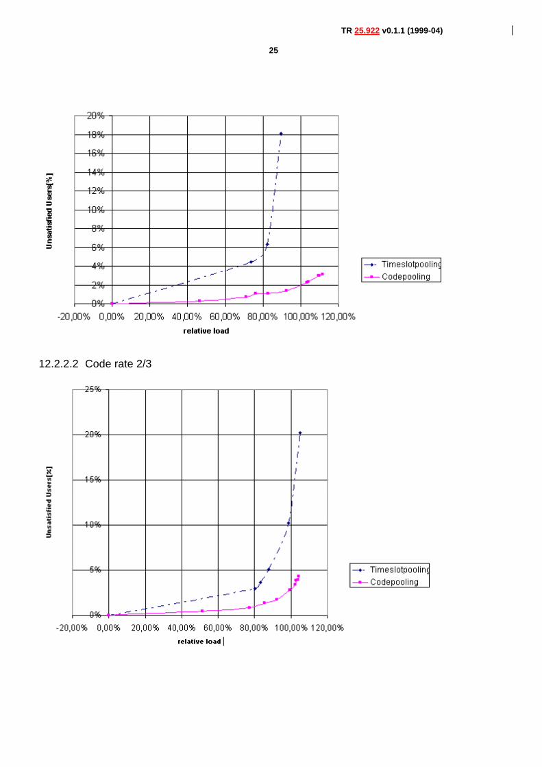
12.2 ResultsThe relative load of the cell is used for the abscissa (horizontal axis) in all of the plots. Here, a relative load of 100% refers tothe maximum cell load obtainable with code-pooling under the ETSI unsatisfied user criterion (in accordance with ETSI TR101 112). Vertically, the percentage of unsatisfied users is shown.
24
TR 25.922 v0.1.1 (1999-04)
12.2.1 Macro UDD 144In the Macro environment the UDD 144 service is simulated with Hybrid ARQ Type II-III using an adaptive code-rate between
1 and ½.
12.2.2 Micro UDD 384In the Micro environment the UDD 384 service is simulated with Hybrid ARQ I using code-rates 1 and 2/3.
12.2.2.1 Code rate 1
25
TR 25.922 v0.1.1 (1999-04)
12.2.2.2 Code rate 2/3
26
TR 25.922 v0.1.1 (1999-04)
12.3 Conclusions
With both Hybrid ARQ I and Hybrid ARQ II code pooling performs better than time slot pooling. This is explained asfollows: Code-pooling performs better in conjunction with the initial transmission of Hybrid ARQ Type II-III. Timeslot poolingsuffers from a high probability of low CIR in at least one of the used timeslots of the PDU. This leads to a high initialtransmission failure probability because the initial transmission is sent almost uncoded. When code-pooling is applied, thewhole PDU depends on the same interference level on all codes: the probabilities of low CIR on each spreading-code within thesame timeslot are strongly coupled.
• The probability of PDU transmission failure for code-pooling is approximately the same as the probability of low CIR in asingle timeslot.
• The probability of PDU transmission failure for timeslot-pooling is approximately the same as the probability of low CIRin at least one of the used timeslots.
This advantage of code-pooling results in lower numbers of unsatisfied users. These results clearly recommend that the DCAprefers code pooling over timeslot pooling for UDD packet data in TDD mode.
13. History
Document history
Date Version Comment
April 1999 0.1.1 Inclusion of the input contributions 99/270, 99/246,99/251. Approved by WG2. This document wassubmitted to TSG RAN and noted as version 0.1.1
April 1999 0.1.0 Document approved at Yokohama meeting
April 1999 0.0.3 Document reviewed after the comments provided duringthe meeting of Yokohama,
April 1999 0.0.2 Different parts from various documents of TSG RANwere included in the first draft version of TR R2.02.
March 1999 0.0.1 Document was created. A Scope and an index wereadded on the basis of td R2-99-182
Rapporteur for 3GPP TSG RAN WG2 R2.02 is:
27
TR 25.922 v0.1.1 (1999-04)
CSELT
Daniele Franceschini Nicola Pio Magnani
Tel.: +39 011 228 5203 Tel.: +39 011 228 7089Fax: .... +39 011 228 7613 Fax: +39 011 2287613
e-mail: [email protected] e-mail: [email protected]
This document is written in Microsoft Word Version 97 SR-1 and saved in Rich Text Format.