3GPP TS 25.420 V6.4.0 (2005-06)
24
3GPP TS 25.420 V6.4.0 (2005-06) Technical Specification 3 rd Generation Partnership Project; Technical Specification Group Radio Access Network; UTRAN I ur interface general aspects and principles (Release 6) The present document has been developed within the 3 rd Generation Partnership Project (3GPP TM ) and may be further elaborated for the purposes of 3GPP. The present document has not been subject to any approval process by the 3GPP Organisational Partners and shall not be implemented. This Specification is provided for future development work within 3GPP only. The Organisational Partners accept no liability for any use of this Specification. Specifications and reports for implementation of the 3GPP TM system should be obtained via the 3GPP Organisational Partners' Publications Offices.
-
Upload
khangminh22 -
Category
Documents
-
view
1 -
download
0
Transcript of 3GPP TS 25.420 V6.4.0 (2005-06)
3GPP TS 25.420 V6.4.0 (2005-06)Technical Specification
3rd Generation Partnership Project;Technical Specification Group Radio Access Network;
UTRAN Iur interface general aspects and principles(Release 6)
The present document has been developed within the 3rd Generation Partnership Project (3GPP TM) and may be further elaborated for the purposes of 3GPP. The present document has not been subject to any approval process by the 3GPP Organisational Partners and shall not be implemented. This Specification is provided for future development work within 3GPP only. The Organisational Partners accept no liability for any use of this Specification.Specifications and reports for implementation of the 3GPP TM system should be obtained via the 3GPP Organisational Partners' Publications Offices.
3GPP
3GPP TS 25.420 V6.4.0 (2005-06)2Release 6
Keywords UMTS, radio
3GPP
Postal address
3GPP support office address 650 Route des Lucioles - Sophia Antipolis
Valbonne - FRANCE Tel.: +33 4 92 94 42 00 Fax: +33 4 93 65 47 16
Internet http://www.3gpp.org
Copyright Notification
No part may be reproduced except as authorized by written permission. The copyright and the foregoing restriction extend to reproduction in all media.
© 2005, 3GPP Organizational Partners (ARIB, ATIS, CCSA, ETSI, TTA, TTC).
All rights reserved.

3GPP
3GPP TS 25.420 V6.4.0 (2005-06)3Release 6
Contents Foreword ............................................................................................................................................................7 1 Scope ........................................................................................................................................................8 2 References ................................................................................................................................................8 3 Definitions and abbreviations...................................................................................................................9 3.1 Definitions ......................................................................................................................................................... 9 3.2 Abbreviations..................................................................................................................................................... 9 3.3 Specification Notations.................................................................................................................................... 10 4 General Aspects .....................................................................................................................................11 4.1 Introduction...................................................................................................................................................... 11 4.2 Iur Interface General Principles ....................................................................................................................... 11 4.3 Iur Interface Specification Objectives.............................................................................................................. 11 4.3.1 General ....................................................................................................................................................... 11 4.3.2 Addressing of RNSs over the Iur Interface ................................................................................................ 11 4.4 Iur Interface Capabilities ................................................................................................................................. 11 4.4.1 Radio application related signalling ........................................................................................................... 11 4.4.2 Iub/Iur DCH data streams .......................................................................................................................... 12 4.4.3 Iur RACH data streams .............................................................................................................................. 12 4.4.4 Iur DSCH data streams [TDD]................................................................................................................... 12 4.4.5 Iur USCH data streams [TDD]................................................................................................................... 12 4.4.6 Iur FACH data streams............................................................................................................................... 12 4.4.7 Iur HS-DSCH data streams ........................................................................................................................ 12 4.4.8 Iub/Iur E-DCH [FDD] data streams ........................................................................................................... 12 4.5 Iur Interface Characteristics............................................................................................................................. 13 4.5.1 Uses of SCCP............................................................................................................................................. 13 4.5.1.1 General ................................................................................................................................................. 13 4.5.1.2 SCCP connection establishment ........................................................................................................... 13 4.5.1.3 Establishment procedure initiated from the SRNC............................................................................... 13 4.5.1.3A Establishment procedure initiated from an RNC requesting common measurements or
information ........................................................................................................................................... 14 4.5.1.4 SCCP connection release...................................................................................................................... 15 4.5.1.5 General SCCP Abnormal Conditions ................................................................................................... 15 4.5.1.5.1 SCCP bearer failure ........................................................................................................................ 15 4.5.1.5.2 SCCP connection failure................................................................................................................. 15 4.5.2 SCCP Addressing Scheme ......................................................................................................................... 16 4.5.2.1 General ................................................................................................................................................. 16 5 Functions of the Iur Interface Protocols ..................................................................................................16 5.1 Functional List ................................................................................................................................................. 16 5.2 Functional Split over Iur .................................................................................................................................. 17 5.2.1 Combining/Splitting................................................................................................................................... 17 5.2.2 Control of Combining/Splitting Topology ................................................................................................. 17 5.2.3 Handling of DRNS Hardware Resources ................................................................................................... 17 5.2.4 Allocation of Physical Channels ................................................................................................................ 17 5.2.5 UpLink Power Control ............................................................................................................................... 17 5.2.6 Down-Link Power Control......................................................................................................................... 17 5.2.7 Admission Control ..................................................................................................................................... 18 5.2.8 Radio Protocol Functional Split ................................................................................................................. 18 5.2.9 MBMS Bearer Type Control...................................................................................................................... 18 6 Iur Interface Protocols .............................................................................................................................18 6.1 General............................................................................................................................................................. 18 6.2 Radio Signalling Protocols .............................................................................................................................. 18 6.2.1 RNSAP Protocol ........................................................................................................................................ 18 6.3 User Plane Frame Protocols............................................................................................................................. 19 6.3.1 Iub/Iur DCH Frame Protocol...................................................................................................................... 19
3GPP
3GPP TS 25.420 V6.4.0 (2005-06)4Release 6
6.3.2 Iur DSCH Frame Protocol [TDD].............................................................................................................. 19 6.3.3 Iur USCH Frame Protocol [TDD].............................................................................................................. 20 6.3.4 Iur RACH Frame Protocol ......................................................................................................................... 20 6.3.5 Iur FACH Frame Protocol.......................................................................................................................... 20 6.3.6 Iur HS-DSCH Frame Protocol ................................................................................................................... 20 6.3.7 Iur E-DCH Frame Protocol ........................................................................................................................ 20 6.4 Mapping of Frame Protocols onto transport bearers........................................................................................ 21 7 DRNS logical Model over Iur .................................................................................................................21 7.1 Overview.......................................................................................................................................................... 21 7.2 Logical Model Elements .................................................................................................................................. 22 7.2.1 Radio Link.................................................................................................................................................. 22 7.2.2 Cell ............................................................................................................................................................. 22 7.2.3 Iur DCH Data Port ..................................................................................................................................... 22 7.2.4 Iur DSCH Data Port [TDD] ....................................................................................................................... 23 7.2.5 Iur USCH Data Port [TDD] ....................................................................................................................... 23 7.2.6 Iur RACH/FACH Data Port ....................................................................................................................... 23 7.2.7 Iur Control Port .......................................................................................................................................... 23 7.2.8 Iur HS-DSCH Data Port............................................................................................................................. 23 7.2.9 Iur E-DCH Data Port [FDD] ...................................................................................................................... 23 8 Iur Interface Protocol Structure ...............................................................................................................23 9 Other Iur Interface Specifications ...........................................................................................................24 9.1 UTRAN Iur Interface: Layer 1 (TS 25.421) .................................................................................................... 24 9.2 UTRAN Iur Interface: Signalling Transport (TS 25.422)................................................................................ 24 9.3 UTRAN Iur Interface: RNSAP Specification (TS 25.423).............................................................................. 24 9.4 UTRAN Iur Interface: Data Transport and Transport Signalling for Common Transport Channel Data
Streams (TS 25.424) ........................................................................................................................................ 24 9.5 UTRAN Iur Interface: User Plane Protocols for Common Transport Channel Data Streams (TS 25.425) ..... 24 9.6 UTRAN Iur & Iub Interface: Data Transport and Transport Signalling for DCH Data Streams (TS
25.426)............................................................................................................................................................. 25 9.7 UTRAN Iur & Iub Interface: User Plane Protocols for DCH Data Streams (TS 25.427)................................ 25 9.8 Summary of UTRAN Iur Interface Technical Specifications .......................................................................... 25
Annex A (informative): Change history ...............................................................................................26

3GPP
3GPP TS 25.420 V6.4.0 (2005-06)5Release 6
Foreword This Technical Specification (TS) has been produced by the 3rd Generation Partnership Project (3GPP).
The contents of the present document are subject to continuing work within the TSG and may change following formal TSG approval. Should the TSG modify the contents of the present document, it will be re-released by the TSG with an identifying change of release date and an increase in version number as follows:
Version x.y.z
where:
x the first digit:
1 presented to TSG for information;
2 presented to TSG for approval;
3 or greater indicates TSG approved document under change control.
y the second digit is incremented for all changes of substance, i.e. technical enhancements, corrections, updates, etc.
z the third digit is incremented when editorial only changes have been incorporated in the document.

3GPP
3GPP TS 25.420 V6.4.0 (2005-06)6Release 6
1 Scope The present document is an introduction to the TSG RAN TS 25.42x series of UMTS Technical Specifications that define the Iur Interface. It is a logical interface for the interconnection of two Radio Network Controller (RNC) components of the UMTS Terrestrial Radio Access Network (UTRAN) for the UMTS system.
2 References The following documents contain provisions which, through reference in this text, constitute provisions of the present document.
• References are either specific (identified by date of publication, edition number, version number, etc.) or non-specific.
• For a specific reference, subsequent revisions do not apply.
• For a non-specific reference, the latest version applies. In the case of a reference to a 3GPP document (including a GSM document), a non-specific reference implicitly refers to the latest version of that document in the same Release as the present document.
[1] 3GPP TS 25.427: "UTRAN Iub/Iur Interface User Plane Protocol for DCH Data Streams".
[2] 3GPP TS 25.425: "UTRAN Iur Interface: User Plane Protocols for Common Transport Channel Data Streams".
[3] 3GPP TS 25.421: "UTRAN Iur Interface: Layer 1".
[4] 3GPP TS 25.422: "UTRAN Iur Interface: Signalling Transport".
[5] 3GPP TS 25.423: "UTRAN Iur Interface: RNSAP Signalling ".
[6] 3GPP TS 25.424: "UTRAN Iur Interface: Data Transport & Transport Signalling ".
[7] 3GPP TS 25.401: "UTRAN Overall Description".
[8] 3GPP TS 25.426: "UTRAN Iur & Iub Interface: Data Transport & Transport Signalling for DCH Data Streams".
[9] ITU-T Recommendation Q.711 (7/96): "Functional description of the signalling connection control part".
[10] ITU-T Recommendation Q.712 (7/96): "Definition and function of signalling connection control part messages".
[11] ITU-T Recommendation Q.713 (7/96): "Signalling connection control part formats and codes".
[12] ITU-T Recommendation Q.714 (7/96): "Signalling connection control part procedures".
[13] 3GPP TS 23.003: "Numbering, Addressing and Identification".
[14] ITU-T Recommendation Q.2630.1 (12/99): "AAL type 2 Signalling Protocol (Capability Set 1)".
[15] Void
[16] Void
[17] 3GPP TR 43.930: "Iur-g interface; Stage 2".
[18] 3GPP TS 25.346: "Introduction of the Multimedia Broadcast Multicast Service".
[19] 3GPP TS 25.309: “FDD Enhanced Uplink; Overall description; Stage 2”.

3GPP
3GPP TS 25.420 V6.4.0 (2005-06)7Release 6
3 Definitions and abbreviations
3.1 Definitions None
3.2 Abbreviations For the purposes of the present document, the following abbreviations apply:
AAL2 ATM Adaptation Layer type 2 AAL5 ATM Adaptation Layer type 5 ALCAP Access Link Control Application Part ATM Asynchronous Transfer Mode BSS Base Station Subsystem CRNC Controlling RNC CTP Common Transport Protocol DCH Dedicated Transport Channel DL Downlink DPCH Dedicated Physical Channel DRNC Drift Radio Network Controller DRNS Drift Radio Network Subsystem DSCH Downlink Shared Channel E-DCH Enhanced Dedicated Channel EDGE Enhanced Data rates for GSM Evolution FACH Forward Access Channel F-DPCH Fractional DPCH FFS For Further Study GERAN GSM/EDGE Radio Access Network GSM Global System for Mobile communications GT Global Title HARQ Hybrid Automatic Repeat Request HS-DSCH High Speed Downlink Shared Channel IP Internet Protocol MAC Medium Access Control MBMS Multimedia Broadcast Multicast Service MTP3-B Message Transfer Part level 3 (for Q.2140) PLMN Public Land Mobile Network PTM Point To Multipoint PTP Point To Point QoS Quality of Service RACH Random Access Channel RF Radio Frequency RNC Radio Network Controller RNS Radio Network Subsystem RNSAP Radio Network Subsystem Application Part RRC Radio Resource Control SCCP Signalling Connection Control Part SPC Signalling Point Code SRNC Serving Radio Network Controller SRNS Serving Radio Network Subsystem SS7 Signalling System No 7 SSCF-NNI Service Specific Co-ordination Function – Network Node Interface SSCOP Service Specific Connection Oriented Protocol SSN Sub-System Number STC Signalling Transport Converter UDP User Datagram Protocol UE User Equipment UL Up-link
3GPP
3GPP TS 25.420 V6.4.0 (2005-06)8Release 6
UMTS Universal Mobile Telecommunication System URA UTRAN Registration Area USCH Uplink Shared Channel UTRAN UMTS Terrestrial Radio Access Network
3.3 Specification Notations For the purposes of the present document, the following notations apply:
[FDD] This tagging of a word indicates that the word preceding the tag "[FDD]" applies only to FDD. This tagging of a heading indicates that the heading preceding the tag "[FDD]" and the section following the heading applies only to FDD.
[TDD] This tagging of a word indicates that the word preceding the tag "[TDD]" applies only to TDD, including 3.84Mcps TDD and 1.28Mcps TDD. This tagging of a heading indicates that the heading preceding the tag "[TDD]" and the section following the heading applies only to TDD, including 3.84Mcps TDD and 1.28Mcps TDD.
[3.84Mcps TDD] This tagging of a word indicates that the word preceding the tag “[3.84Mcps TDD]” applies only to 3.84Mcps TDD. This tagging of a heading indicates that the heading preceding the tag “[3.84Mcps TDD]” and the section following the heading applies only to 3.84Mcps TDD.
[1.28Mcps TDD] This tagging of a word indicates that the word preceding the tag "[1.28Mcps TDD]" applies only to 1.28Mcps TDD. This tagging of a heading indicates that the heading preceding the tag "[1.28Mcps TDD]" and the section following the heading applies only to 1.28Mcps TDD.
[FDD - …] This tagging indicates that the enclosed text following the "[FDD - " applies only to FDD. Multiple sequential paragraphs applying only to FDD are enclosed separately to enable insertion of TDD specific (or common) paragraphs between the FDD specific paragraphs.
[TDD - …] This tagging indicates that the enclosed text following the "[TDD - " applies only to TDD including 3.84Mcps TDD and 1.28Mcps TDD. Multiple sequential paragraphs applying only to TDD are enclosed separately to enable insertion of FDD specific (or common) paragraphs between the TDD specific paragraphs.
[3.84Mcps TDD - …] This tagging indicates that the enclosed text following the "[3.84Mcps TDD - " applies only to 3.84Mcps TDD. Multiple sequential paragraphs applying only to 3.84Mcps TDD are enclosed separately to enable insertion of FDD and TDD specific (or common) paragraphs between the 3.84Mcps TDD specific paragraphs.
[1.28Mcps TDD - …] This tagging indicates that the enclosed text following the "[1.28Mcps TDD – " applies only to 1.28Mcps TDD. Multiple sequential paragraphs applying only to 1.28Mcps TDD are enclosed separately to enable insertion of FDD and TDD specific (or common) paragraphs between the 1.28Mcps TDD specific paragraphs.
Procedure When referring to a procedure in the specification, the Procedure Name is written with the first letters in each word in upper case characters followed by the word "procedure", e.g. RNSAP Basic Mobility Procedures.
Message When referring to a message in the specification, the MESSAGE NAME is written with all letters in upper case characters followed by the word "message", e.g. RADIO LINK SETUP REQUEST message.
Frame When referring to a control or data frame in the specification, the CONTROL/DATA FRAME NAME is written with all letters in upper case characters followed by the words "control/data frame", e.g. DCH data frame.

3GPP
3GPP TS 25.420 V6.4.0 (2005-06)9Release 6
4 General Aspects
4.1 Introduction The logical connection that exists between any two RNCs within the UTRAN is referred to as the Iur interface.
4.2 Iur Interface General Principles The general principles for the specification of the Iur interface are as follows:
- The Iur interface should be open;
- The Iur interface shall support the exchange of signalling information between two RNCs, in addition the interface may need to support one or more Iur data streams;
- From a logical standpoint, the Iur is a point-to-point interface between two RNCs within the UTRAN. A point-to-point logical interface should be feasible even in the absence of a physical direct connection between the two RNCs.
4.3 Iur Interface Specification Objectives
4.3.1 General The Iur interface specifications shall facilitate the following:
- inter-connection of RNCs supplied by different manufacturers;
- support of continuation between RNSs of the UTRAN services offered via the Iu interface;
- separation of Iur interface Radio Network functionality and Transport Network functionality to facilitate introduction of future technology.
4.3.2 Addressing of RNSs over the Iur Interface - For an RRC connection using a dedicated channel or for a UE using F-DPCH in the downlink, the Iur standard
shall allow the addition / deletion of radio links supported by cells belonging to any RNS within the PLMN.
- The specification of the Iur interface shall allow an RNC to address any other RNC within the PLMN for establishing a signalling bearer over Iur.
- The specification of the Iur interface shall allow an RNC to address any other RNC within the PLMN for establishing user data bearers for Iur data streams.
RNSAP shall allow different kinds of addressing schemes to be used for the signalling bearer.
4.4 Iur Interface Capabilities
4.4.1 Radio application related signalling The Iur interface provides capability to support radio interface mobility between RNSs, of UEs having a connection with UTRAN. This capability includes the support of handover, radio resource handling, MBMS handling and synchronisation between RNSs.
3GPP
3GPP TS 25.420 V6.4.0 (2005-06)10Release 6
4.4.2 Iub/Iur DCH data streams The Iur interface provides the means for transport of uplink and downlink Iub/Iur DCH frames carrying user data and control information between SRNC and Node B (DRNS), via the DRNC.
In the UTRAN, one DCH data stream always corresponds to a bi-directional transport channel. Although the TFS is configured separately for each DCH direction and a DCH could be configured with e.g. only a zero-bit transport format in one direction, the DCH is always treated as a bi-directional transport channel in the UTRAN. As a result, two uni-directional Uu DCH transport channels with opposite directions can be mapped to either one or two DCH transport channels in the UTRAN.
4.4.3 Iur RACH data streams The Iur interface provides the means for transport of uplink RACH transport frames between DRNC and SRNC.
4.4.4 Iur DSCH data streams [TDD] An Iur DSCH data stream corresponds to the data carried on one DSCH transport channel for one UE. A UE may have multiple Iur DSCH data streams.
The Iur interface provides a means of transporting down link MAC-c/sh SDUs. In addition, the interface provides a means to the SRNC for queue reporting and a means for the DRNC to allocate capacity to the SRNC.
4.4.5 Iur USCH data streams [TDD] An Iur USCH data stream corresponds to the data carried on one USCH transport channel for one UE. A UE may have multiple Iur USCH data streams.
4.4.6 Iur FACH data streams The Iur interface provides the means for transport of downlink FACH transport frames between SRNC and DRNC.
4.4.7 Iur HS-DSCH data streams An Iur HS-DSCH data stream corresponds to the data carried on one MAC-d flow for one UE. A UE may have multiple Iur HS-DSCH data streams.
The Iur interface provides a means of transporting down link MAC-d PDUs. In addition, the interface provides a means to the SRNC for queue reporting and a means for the DRNC to allocate capacity to the SRNC.
4.4.8 Iub/Iur E-DCH [FDD] data streams The Iur interface provides the means for transport of Iub/Iur E-DCH frames carrying user data between NodeB (DRNS) and SRNC, via the DRNC.
An Iur E-DCH data stream corresponds to the data carried on one MAC-d flow for one UE. A UE may have multiple E-DCH data streams. In addition, the interface provides the following:
- A means for the Node B to indicate the number of HARQ retransmissions to the SRNC [11];
- A means to indicate to the SRNC, for the purposes of re-ordering, the CFN and Subframe Number that have been added by the Node B in the DRNS[1].
3GPP
3GPP TS 25.420 V6.4.0 (2005-06)11Release 6
4.5 Iur Interface Characteristics
4.5.1 Uses of SCCP
4.5.1.1 General
The SCCP is used to support signalling messages between two RNCs. One user function of the SCCP, called Radio Network Subsystem Application Part (RNSAP), is defined. The RNSAP uses one signalling connection per DRNC and UE where a UE is having one or more active radio links for the transfer of layer 3 messages. RNSAP also uses one signalling connection per RNC providing common measurements and information to a particular RNC (i.e. if measurements and information are transferred in both directions between a pair of RNCs, then two SCCP connections are used).
Both connectionless and connection-oriented procedures are used to support the RNSAP. TS 25.423 explain whether connection oriented or connectionless services should be used for a layer 3 procedure.
The following subclauses describe the use of SCCP connections for RNSAP transactions. Subclause 4.5.1.2 describes the connection establishment procedures. Subclause 4.5.1.3 describes the connection establishment procedures initiated from SRNC. Subclause 4.5.1.4 describes the connection release procedures. Subclause 4.5.1.5 describes abnormal conditions.
4.5.1.2 SCCP connection establishment
A new SCCP connection is established when information related to the communication between a UE and the network has to be exchanged between two RNCs, and no SCCP connection exists between the two RNCs involved, for the concerned UE.
In this case, the SCCP connection is established by the SRNC.
A new SCCP connection is established when a request for common measurements or information is made towards a particular RNC and no SCCP connection for common measurements and information transfer has been established from the RNC requesting the measurements or information towards the one providing the measurements or the information.
In this case, the SCCP connection is established by the RNC requesting the measurements or the information.
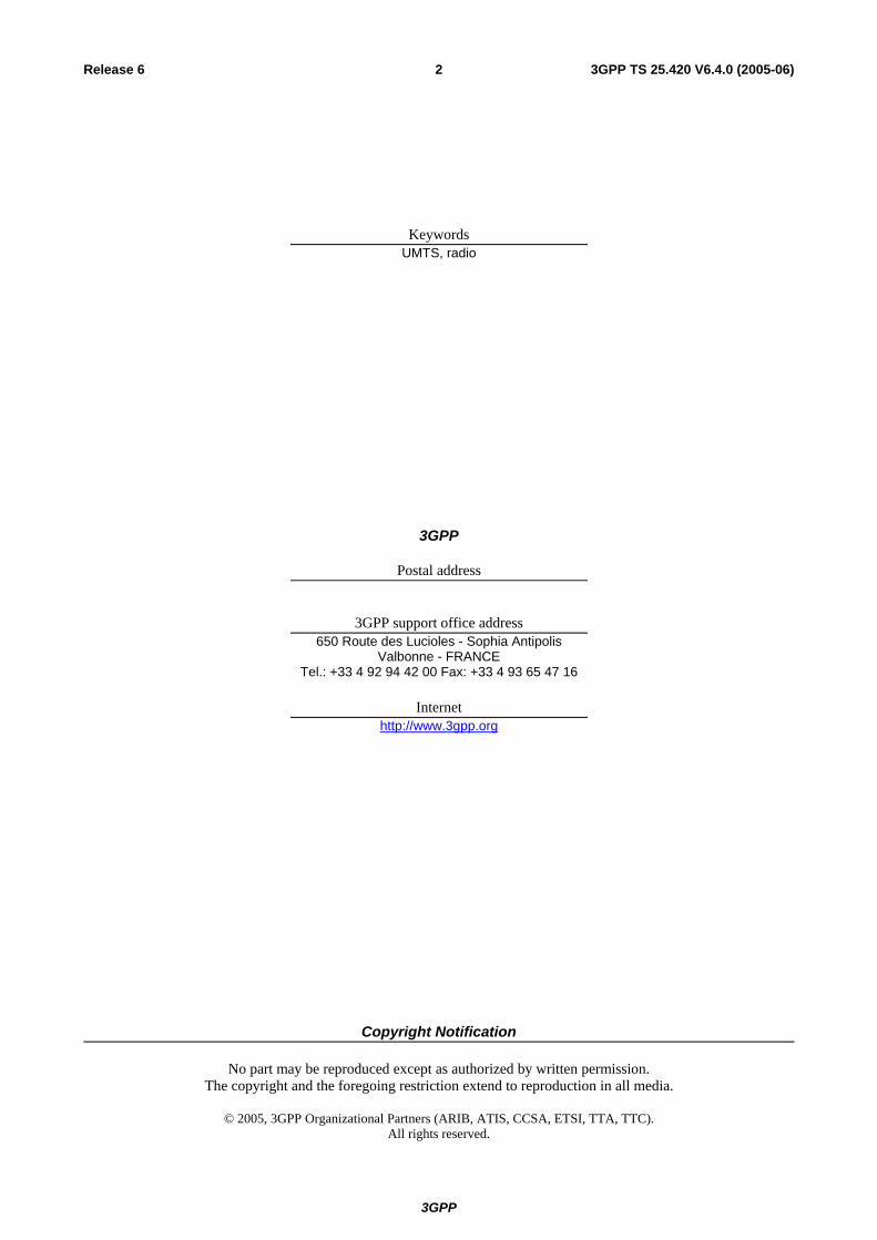
4.5.1.3 Establishment procedure initiated from the SRNC
The SCCP signalling connection establishment is initiated, by the SRNC, when the SRNC needs to request dedicated resources, i.e. a DCH, from a DRNC.
Initiation
- The SRNC sends the SCCP: CR message to the DRNC. The RADIO LINK SETUP REQUEST message may be included in the user data field of an SCCP Connection Request message.
Termination
1. Successful outcome:
- The SCCP Connection Confirm message, which may optionally contain a connection oriented RNSAP message in the user data field, is returned to the SRNC.
2. Unsuccessful outcome:
- If the SCCP signalling connection establishment fails, an SCCP Connection Refusal message will be sent back to the SRNC. This message may optionally contain a connection oriented RNSAP message.
For more information on how the RNSAP procedure Radio Link Setup is handled, please see the procedure Radio Link Setup in TS 25.423 [5].

3GPP
3GPP TS 25.420 V6.4.0 (2005-06)12Release 6
SRNC DRNCCR {SSN=RNSAP, a1=x,
RNSAP message or no user data }
CC {a1=y,a2=x, RNSAP message or no user data}
CREF{a2=x, RNSAP message or no user data}
a1 = source local reference,a2 = destination local referencex = SCCP connection reference at the SRNC,y = SCCP connection reference at the DRNC.
OR
Figure 1: Setting-up of SCCP Signalling Connection
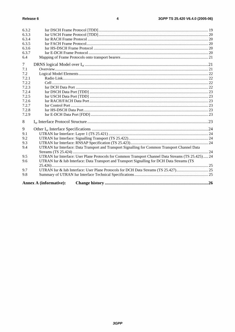
4.5.1.3A Establishment procedure initiated from an RNC requesting common measurements or information
The SCCP signalling connection establishment is initiated, by an RNC, when the RNC needs to request common measurements or provision of information from another RNC and there is no signalling bearer existing for this purpose. For the description below, the RNC requesting the measurements or the information is called RNC1 and the RNC being requested to provide the measurements or the information is called RNC2.
Initiation
- The RNC1 sends the SCCP: CR message to the RNC2. The COMMON MEASUREMENT INITIATION REQUEST or the INFORMATION EXCHANGE INITIATION REQUEST message shall be included in the user data field of the SCCP Connection Request message.
Termination
1. Successful outcome:
- The SCCP Connection Confirm message, which may optionally contain a connection oriented RNSAP message in the user data field, is returned to the RNC1.
2. Unsuccessful outcome:
- If the SCCP signalling connection establishment fails, an SCCP Connection Refusal message will be sent back to the RNC1. This message may optionally contain a connection oriented RNSAP message.
RNSAP Common Measurement Initiation and Information Exchange Initiation procedures are described in [5].

3GPP
3GPP TS 25.420 V6.4.0 (2005-06)13Release 6
RNC1 RNC2CR {SSN=RNSAP, a1=x,
RNSAP message }
CC {a1=y,a2=x, RNSAP message or no user data}
CREF{a2=x, RNSAP message or no user data}
a1 = source local reference,a2 = destination local referencex = SCCP connection reference at the SRNC,y = SCCP connection reference at the DRNC.
OR
Figure 1a: Setting-up of SCCP Signalling Connection
4.5.1.4 SCCP connection release
An SCCP connection related to a specific UE is released in all normal release cases when the RNC which established the SCCP connection realises that a given signalling connection is no longer required.
The RNC which established SCCP connection sends an SCCP Released message.
The procedure may be initiated at the SRNC side and the DRNC side in any abnormal release case.
An SCCP connection used for common measurements and information exchanges is released in all normal release cases when the RNC1 (see 4.5.1.3A) determines that a given signalling connection is no longer required. The RNC1 sends an SCCP Released message.
In case an SCCP Release message is received after the successful completion of an SRNC Relocation procedure while dedicated resources are still allocated the new SRNC shall only release the SCCP connection and the Iur related dedicated resource.
The procedure may be initiated at the RNC 1 side and the RNC 2 side in any abnormal release case.
4.5.1.5 General SCCP Abnormal Conditions
4.5.1.5.1 SCCP bearer failure
If a user-out-of-service information or signalling-point-inaccessible information is received by the RNSAP, no new attempt to establish SCCP connections or to send SCCP Connectionless messages towards the affected signalling point (indicated by the affected signalling point code) will be started until the corresponding user-in-service information or signalling-point-accessible information is received.
When a user-out-of-service information or signalling-point-inaccessible is received by an RNC, an optional timer may be started. When the timer expires, the RNC shall take actions as described in [5] Annex D.1.1. When the user-in-service or signalling-point-accessible is received, the timer is stopped.
4.5.1.5.2 SCCP connection failure
If for any reason an SCCP connection is released, the optional timer expires or a connection refusal is received while any of the RNSAP procedures are being performed or while a dedicated resource is still allocated, this shall be handled by the RNC as described in [5] Annex D.1.2.

3GPP
3GPP TS 25.420 V6.4.0 (2005-06)14Release 6
4.5.2 SCCP Addressing Scheme
4.5.2.1 General
RNSAP may use SSN, SPC and/or GT and any combination of them as addressing schemes for the SCCP. Which of the available addressing schemes to use for the SCCP is an operator matter.
When GT addressing is utilised, the following settings shall be used:
- SSN Indicator = 1 (RNSAP SSN as defined in [13] shall always be included);
- Global Title Indicator = 0100 (GT includes translation type, numbering plan, encoding scheme and nature of address indicator);
- Translation Type = 0000 0000 (not used);
- Numbering Plan = 0001 (E.163/4);
- Nature of Address Indicator = 000 0100 (International Significant Number);
- Encoding Scheme = 0001 or 0010 (BCD, odd or even);
- Routing indicator = 0 or 1 (route on GT or PC/SSN).
When used, the GT shall be the E.164 address of the relevant node.
5 Functions of the Iur Interface Protocols
5.1 Functional List The list of functions on the Iur interface is the following:
1. Transport Network Management.
2. Traffic management of Common Transport Channels:
- Preparation of Common Transport Channel resources;
- Paging.
3. Traffic Management of Dedicated Transport Channels:
- Radio Link Setup/ Addition/ Deletion;
- Measurement Reporting.
4. [TDD - Traffic Management of Downlink Shared Transport Channels and Uplink Shared Transport Channels]:
- Radio Link Setup/ Addition/ Deletion;
- Capacity Allocation.
5. Measurement reporting for common and dedicated measurement objects.
6. Information exchange of UTRAN, GERAN and MBMS bearer service information.
7. Tracing of various events related to a UE.
8. MBMS related functions
- MBMS UE Linking/De-linking
- MBMS URA linking/De-linking

3GPP
3GPP TS 25.420 V6.4.0 (2005-06)15Release 6
- MBMS Channel type Indication
5.2 Functional Split over Iur
5.2.1 Combining/Splitting DRNS may perform combining/splitting of data streams communicated via its cells. SRNS performs combining/splitting of Iur data streams received from/sent to DRNS(s), and data streams communicated via its own cells.
The UL combining of information streams may be performed using any suitable algorithm, for example:
- [FDD - based on maximum ratio algorithm (maximum ratio combining)];
- [FDD - based on quality information associated to each TBS (selection-combining)];
- [TDD - based on the presence/absence of the signal (selection)].
The internal DRNS handling of combining (respectively splitting) of Iub (respectively Iur) DCH frames is controlled by the DRNS.
5.2.2 Control of Combining/Splitting Topology When requesting the addition of a new cell for a UE-UTRAN connection for DCH, the RNC of the SRNS (i.e. the SRNC) can explicitly request to the RNC of the DRNS (i.e. the DRNC) a new Iur data stream, in which case the combining and splitting function within the DRNS is not used for that cell. The SRNC can also explicitly request from the DRNC the use of the combining and splitting function inside the DRNS for that cell. Otherwise, the DRNS takes the decision whether combining and splitting function is used inside the DRNS for that cell i.e. whether a new Iur data stream shall be added or not.
For E-DCH [FDD] combining at the DRNC is not allowed. However, combining in NodeB of the DRNS is mandatory where applicable as described in [19].
5.2.3 Handling of DRNS Hardware Resources Allocation and control of DRNS hardware resources, used for Iur data streams and radio interface transmission/reception in DRNS is performed by DRNS.
5.2.4 Allocation of Physical Channels Allocation of physical channels in cells belonging to DRNS is performed in DRNS.
5.2.5 UpLink Power Control This group of functions controls the level of the uplink transmitted power in order to minimise uplink interference and keep the quality of the connections. If the connection involves both a SRNS and a DRNS the function UL Outer Loop Power Control (located in the SRNC) sets the target quality for the UL Inner Loop Power Control function (located in Node B for DCH [FDD]). For E-DCH [FDD], the DRNS (NodeB) reports the number of HARQ retransmissions to SRNC as an input to the Outer Loop Power Control function.
5.2.6 Down-Link Power Control This group of functions controls the level of the downlink transmitted power. In FDD it is also used to correct the downlink power drifting between several radio links. SRNC regularly (or under some algorithms) sends the target down link power reference based on the measurement report from UE.

3GPP
3GPP TS 25.420 V6.4.0 (2005-06)16Release 6
5.2.7 Admission Control Admission control in a DRNC is implicitly invoked during radio link setup/modify.
Information on UL interference and DL power on cells controlled by the DRNC should be available across Iur.
Additional information exchanges between admission control functions located in different RNCs are for further study.
5.2.8 Radio Protocol Functional Split Iur supports the radio protocol functional split between SRNC and DRNC.
5.2.9 MBMS Bearer Type Control MBMS Bearer type control is split between SRNC and DRNC. The CRNC is in control of an MBMS Bearer of PTM type. The MBMS bearer services activated by the UE are transferred over Iur from SRNC to DRNC. In case the CRNC is a DRNC for one or several UEs, it indicates the selected bearer type to SRNC but it is SRNC decision to set up or release MBMS bearers of PTP type for a given UE as described in [18].
6 Iur Interface Protocols
6.1 General There shall exist a clear separation between the Radio Network Layer and the Transport Layer. Therefore, the radio network signalling and Iur data streams are separated from the data transport resource and traffic handling as shown in Figure 2. Data transport resource and traffic handling is controlled by Transport Signalling. The Transport Signalling is carried by a Signalling Bearer over the Iur interface.
RadioSignallingProtocols
User PlaneFraming
Protocols
TransportSignalling
SignallingBearer
DataTransport
RadioNetworklayer
Transportlayer
Figure 2: Separation of Radio Network Protocols and transport over Iur
6.2 Radio Signalling Protocols
6.2.1 RNSAP Protocol The protocol responsible for providing signalling information across the Iur interface is called the Radio Network Subsystem Application Part (RNSAP). A subset of RNSAP is used over the Iur-g interface.
The RNSAP is terminated by the two RNCs inter-connected via the Iur interface RNSAP Procedure Modules. In addition, the RNSAP is terminated by a RNC and a BSS supporting Iu mode inter-connected via the Iur-g interface.
RNSAP procedures are divided into four modules as follows:

3GPP
3GPP TS 25.420 V6.4.0 (2005-06)17Release 6
1. RNSAP Basic Mobility Procedures;
2. RNSAP Dedicated Procedures;
3. RNSAP Common Transport Channel Procedures;
4. RNSAP Global Procedures;
5. RNSAP MBMS Procedures.
The Basic Mobility Procedures module contains procedures used to handle the mobility within UTRAN as well as to handle mobility in case of UTRAN/GERAN interworking.
The Dedicated Procedures module contains procedures that are used to handle DCHs, [FDD – F-DPCH, E-DCH] [TDD – DSCH, USCHs] and HS-DSCH between two RNSs. If procedures from this module are not used in a specific Iur, then the usage of DCH, [FDD – F-DPCH, E-DCH] [TDD – DSCH, USCH] and HS-DSCH traffic between corresponding RNSs is not possible.
The Common Transport Channel Procedures module contains procedures that are used to control common transport channel data streams (excluding the DSCH, HS-DSCH, E-DCH and USCH) over Iur interface.
The Global Procedures module contains procedures that are not related to a specific UE. The procedures in this module are in contrast to the above modules involving two peer CRNCs. The procedures in this module are also used in cases involving one RNC and one BSS.
The MBMS Procedures module contains procedures that are specific to MBMS and used for cases that cannot be handled by other modules.
6.3 User Plane Frame Protocols
6.3.1 Iub/Iur DCH Frame Protocol There are two types of Iub/Iur DCH FP frames:
- DCH data frame;
- DCH control frame.
The contents of the Iub/Iur DCH data frame include:
- Transport Block Sets;
- Quality estimate.
The contents of the Iur DCH control frame include:
- Measurement reports;
- Power control information;
- Synchronisation information.
For a more detailed description of the Iur/Iub DCH frame protocol refer to 'UTRAN Iur & Iub Interface User Plane Protocol for DCH Data Streams' [1].
6.3.2 Iur DSCH Frame Protocol [TDD] There are two types of Iur DSCH FP frames:
- DSCH data frame;
- DSCH control frames.
The contents of the Iur DSCH data frame include:
3GPP
3GPP TS 25.420 V6.4.0 (2005-06)18Release 6
- MAC-c/sh SDUs;
- User Buffer Status.
The contents of the Iur DSCH control frame include:
- Flow control Information (UL);
- Capacity Request Information (DL).
For a more detailed description of the Iur DSCH frame protocol refer to 'UTRAN Iur Interface User Plane protocols for Common Transport Channel Data Streams' [2].
6.3.3 Iur USCH Frame Protocol [TDD] There is one type of Iur USCH FP frames:
- USCH data frame.
The contents of the Iur USCH data frame include:
- MAC-c/sh SDUs.
For a more detailed description of the Iur USCH frame protocol refer to 'UTRAN Iur Interface User Plane protocols for Common Transport Channel Data Streams' [2].
6.3.4 Iur RACH Frame Protocol For a more detailed description of the Iur RACH framing protocol refer to 'UTRAN Iur Interface User Plane protocols for Common Transport Channel Data Streams' [2].
6.3.5 Iur FACH Frame Protocol For a more detailed description of the Iur FACH framing protocol refer to 'UTRAN Iur Interface User Plane protocols for Common Transport Channel Data Streams' [2].
6.3.6 Iur HS-DSCH Frame Protocol There are two types of Iur HS-DSCH FP frames:
- HS-DSCH data frame;
- HS-DSCH control frames.
The contents of the Iur HS-DSCH data frame include:
- MAC-d PDUs;
- User Buffer Status.
The contents of the Iur HS-DSCH control frame include:
- Flow control Information (UL);
- Capacity Request Information (DL).
For a more detailed description of the Iur HS-DSCH frame protocol refer to 'UTRAN Iur Interface User Plane protocols for Common Transport Channel Data Streams' [2].
6.3.7 Iur E-DCH Frame Protocol There is one type of Iur E-DCH FP frames:

3GPP
3GPP TS 25.420 V6.4.0 (2005-06)19Release 6
- E-DCH data frame;
The contents of the Iur E-DCH data frame include:
- Mac-es PDUs (multiplexed);
- Number of HARQ retransmissions;
- CFN and Sub frame number.
For a more detailed description of the Iur E-DCH frame protocol refer to 'UTRAN Iur Interface User Plane Protocols for DCH Data Streams' [1].
6.4 Mapping of Frame Protocols onto transport bearers DCH One Iur DCH data stream is carried on one transport bearer except in the case of co-
ordinated DCHs in which case a set of co-ordinated DCHs are multiplexed onto the same transport bearer.
[TDD - DSCH One Iur DSCH data stream is carried on one transport bearer.]
HS-DSCH One Iur HS-DSCH data stream is carried on one transport bearer.
[FDD - E-DCH One Iur E-DCH data stream is carried on one transport bearer. For each E-DCH data stream, a transport bearer must be established over the Iur interface.]
[TDD - USCH One Iur USCH data stream is carried on one transport bearer.]
RACH Multiple RACH data streams may be carried on one transport bearer.
FACH Multiple FACH data streams may be carried on one transport bearer.
RACH and FACH data streams for one UE are carried on same transport bearer.
7 DRNS logical Model over Iur
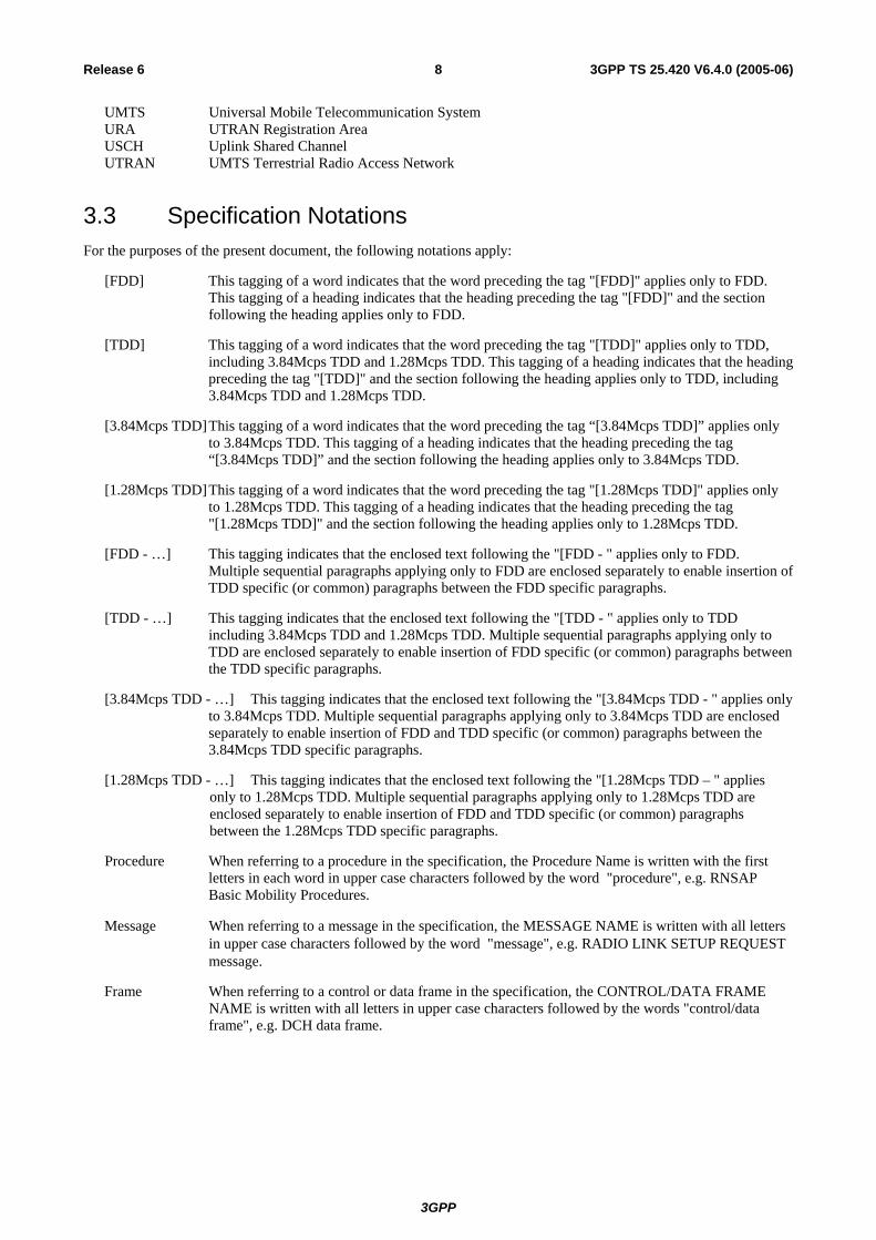
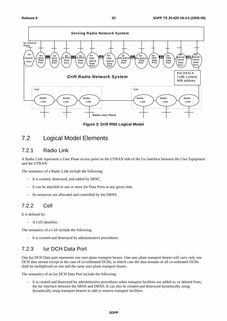
7.1 Overview The model in Figure 3 shows the Drift Radio Network System as seen from the SRNC. It is modelled as a «black box» with a set of Radio Links on the Uu side of the box and another set of User Plane access ports on the Iur side of the box. The Radio Links are connected to the Iur user ports via the internal transport mechanisms of the DRNS. Operations for controlling the connections between ports are sent from the SRNC to the DRNC via an Iur Control Plane port.
3GPP
3GPP TS 25.420 V6.4.0 (2005-06)20Release 6
Radio User Plane
Iur Control Plane
Drift Radio Network System
Radio Link
Radio Link
Radio Link
Iur Control
Port
Radio Link
Radio Link
Radio Link
Serving Radio Network System
Cell Cell
RACH/FACH Traffic Contexts With attributes
DCH Iur
Data Port
Iur DCH Data Port
Iur
Data Port
TDD Iur
DataPort
Iur
DataPort
HS-DSCH HS-DSCHIur
DataPort
TDD E-DCHIur
DataPort
E-DCH Iur
Data Port
Iur
DSCHDataPort
TDDIur
DSCHDataPort
TDD Iur
RACH/ FACH Data Port
Iur
RACH/FACH Data Port
Figure 3: Drift RNS Logical Model
7.2 Logical Model Elements
7.2.1 Radio Link A Radio Link represents a User Plane access point on the UTRAN side of the Uu interface between the User Equipment and the UTRAN.
The semantics of a Radio Link include the following:
- It is created, destroyed, and added by SRNC.
- It can be attached to one or more Iur Data Ports at any given time.
- Its resources are allocated and controlled by the DRNS.
7.2.2 Cell It is defined by:
- A Cell identifier.
The semantics of a Cell include the following:
- It is created and destroyed by administrative procedures.
7.2.3 Iur DCH Data Port One Iur DCH Data port represents one user plane transport bearer. One user plane transport bearer will carry only one DCH data stream except in the case of co-ordinated DCHs, in which case the data streams of all co-ordinated DCHs shall be multiplexed on one and the same user plane transport bearer.
The semantics of an Iur DCH Data Port include the following:
- It is created and destroyed by administrative procedures when transport facilities are added to, or deleted from, the Iur interface between the SRNS and DRNS. It can also be created and destroyed dynamically using dynamically setup transport bearers to add or remove transport facilities.

3GPP
3GPP TS 25.420 V6.4.0 (2005-06)21Release 6
- It is assigned and released by the SRNC in reaction to requests for bearer services from the UE.
- It may be attached to one or more Radio Links. When attached to Radio Links in the downlink direction, it acts as a point-to-multipoint connection for diversity transmission. When attached to multiple Radio Links in the uplink direction, it acts as a multipoint-to-point connection for diversity reception [FDD].
- The transmit and receive combining/splitting resources required to implement the point-to-multipoint and multipoint-to-point connections are controlled by the DRNS [FDD].
- The Iur DCH Data Stream emanating from the Iur DCH Data Port terminates in the SRNS connected to DRNS.
7.2.4 Iur DSCH Data Port [TDD] One Iur DSCH Data port represents one bi-directional Iur user plane transport bearer. One Iur user plane transport bearer will carry only one DSCH data stream.
7.2.5 Iur USCH Data Port [TDD] One Iur USCH Data port represents one Iur user plane transport bearer. One Iur user plane transport bearer will carry only one USCH data stream.
7.2.6 Iur RACH/FACH Data Port The Iur RACH/FACH data port represents a transport bearer and is identified with a transport bearer identity.
7.2.7 Iur Control Port An Iur Control Port represents the Control Plane access point on the Iur interface between the SRNS and the DRNS. It is defined by:
- A transport bearer channel identifier.
The semantics of an Iur Control Port include the following:
- It is created via administrative procedures when the Iur interface is created.
7.2.8 Iur HS-DSCH Data Port One Iur HS-DSCH Data port represents one bi-directional Iur user plane transport bearer. One Iur user plane transport bearer will carry only one HS-DSCH data stream.
7.2.9 Iur E-DCH Data Port [FDD] One Iur E-DCH Data port represents one bi-directional Iur user plane transport bearer. One Iur user plane transport bearer will carry only one E-DCH data stream. It is assigned and released by the SRNC in reaction to requests for bearer services from the UE. It may be attached to one or more Radio Links. When attached to multiple Radio Links in the uplink direction, the receive combining resources required to implement the multipoint-to-point connections is in the NodeB of the DRNS.
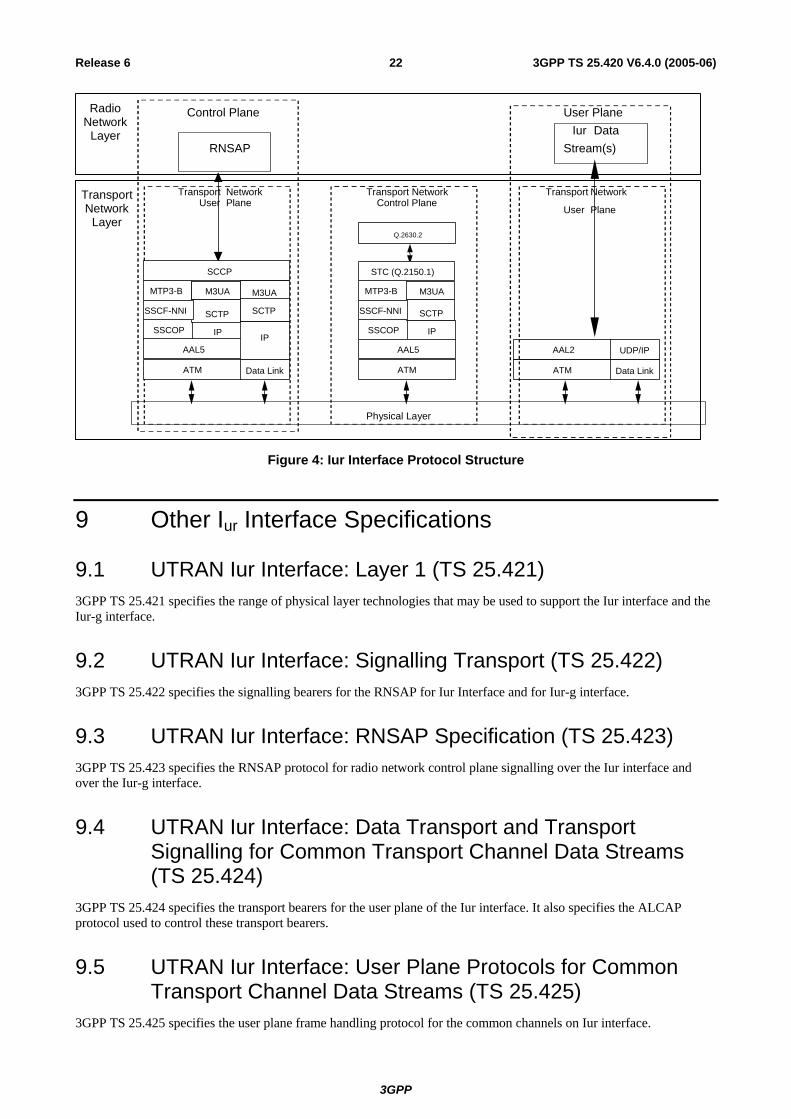
8 Iur Interface Protocol Structure The Iur interface protocol architecture consists of two functional layers:
- Radio Network Layer, defines the procedures related to the interaction of two RNCs within a PLMN. The radio network layer consists of a Radio Network Control Plane and a Radio Network User Plane.
- Transport layer, defines procedures for establishing physical connections between two RNCs within a PLMN.
3GPP
3GPP TS 25.420 V6.4.0 (2005-06)22Release 6
RNSAP
Iur Data
Stream(s)
Transport Network
Layer
Physical Layer
User Transport Network
Plane
Control Plane User Plane
Transport
User
Network
Plane
Transport Network Control Plane
Radio Network
Layer
Q.2630.2
SSCF-NNI
SSCOP
MTP3-B
IP
SSCF-NNI
AAL5
SCTP
SCCP
M3UA M3UA
SCTP
IP
ATM Data Link
SSCF-NNI
AAL2 UDP/IP
ATM Data Link
SSCF-NNI
SSCOP
MTP3-B
IP
SSCF-NNI
AAL5
SCTP
STC (Q.2150.1)
M3UA
ATM
SSCF-NNI
Figure 4: Iur Interface Protocol Structure
9 Other Iur Interface Specifications
9.1 UTRAN Iur Interface: Layer 1 (TS 25.421) 3GPP TS 25.421 specifies the range of physical layer technologies that may be used to support the Iur interface and the Iur-g interface.
9.2 UTRAN Iur Interface: Signalling Transport (TS 25.422) 3GPP TS 25.422 specifies the signalling bearers for the RNSAP for Iur Interface and for Iur-g interface.
9.3 UTRAN Iur Interface: RNSAP Specification (TS 25.423) 3GPP TS 25.423 specifies the RNSAP protocol for radio network control plane signalling over the Iur interface and over the Iur-g interface.
9.4 UTRAN Iur Interface: Data Transport and Transport Signalling for Common Transport Channel Data Streams (TS 25.424)
3GPP TS 25.424 specifies the transport bearers for the user plane of the Iur interface. It also specifies the ALCAP protocol used to control these transport bearers.
9.5 UTRAN Iur Interface: User Plane Protocols for Common Transport Channel Data Streams (TS 25.425)
3GPP TS 25.425 specifies the user plane frame handling protocol for the common channels on Iur interface.
3GPP
3GPP TS 25.420 V6.4.0 (2005-06)23Release 6
9.6 UTRAN Iur & Iub Interface: Data Transport and Transport Signalling for DCH Data Streams (TS 25.426)
3GPP TS 25.426 specifies the transport bearers for the user plane of the Iub/Iur interface. It also specifies the ALCAP protocol used to control these transport bearers.
9.7 UTRAN Iur & Iub Interface: User Plane Protocols for DCH Data Streams (TS 25.427)
3GPP TS 25.427 specifies the user plane frame handling protocol for the dedicated channels on Iub/Iur interface.
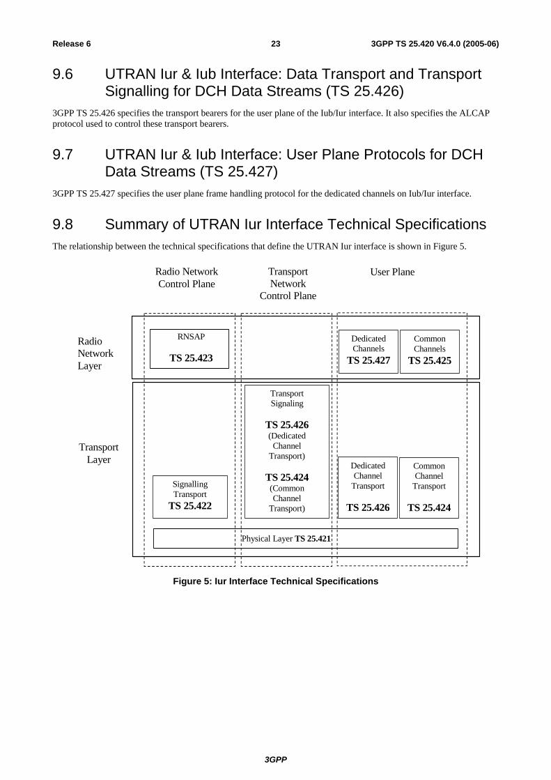
9.8 Summary of UTRAN Iur Interface Technical Specifications The relationship between the technical specifications that define the UTRAN Iur interface is shown in Figure 5.
RNSAP
TS 25.423
TransportLayer
Physical Layer TS 25.421
RadioNetworkLayer
Radio NetworkControl Plane
TransportNetwork
Control Plane
SignallingTransport
TS 25.422
User Plane
DedicatedChannels
TS 25.427
CommonChannels
TS 25.425
DedicatedChannel
Transport
TS 25.426
CommonChannel
Transport
TS 25.424
TransportSignaling
TS 25.426(Dedicated
ChannelTransport)
TS 25.424(CommonChannel
Transport)
Figure 5: Iur Interface Technical Specifications
3GPP
3GPP TS 25.420 V6.4.0 (2005-06)24Release 6
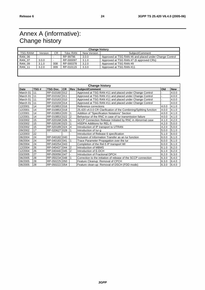
Annex A (informative): Change history
Change history TSG RAN# Version CR Tdoc RAN New Version Subject/Comment RAN_06 - - RP-99796 3.0.0 Approved at TSG RAN #6 and placed under Change Control RAN_07 3.0.0 - RP-000097 3.1.0 Approved at TSG RAN #7 (6 approved CRs) RAN_09 3.1.0 008 RP-000378 3.2.0 Approved at TSG RAN #9 RAN_11 3.2.0 009 RP-010115 3.3.0 Approved at TSG RAN #11
Change history Date TSG # TSG Doc. CR Rev Subject/Comment Old New March 01 11 RP-010160 012 Approved at TSG RAN #11 and placed under Change Control - 4.0.0March 01 11 RP-010162 011 Approved at TSG RAN #11 and placed under Change Control - 4.0.0March 01 11 RP-010163 010 Approved at TSG RAN #11 and placed under Change Control - 4.0.0March 01 11 RP-010159 014 Approved at TSG RAN #11 and placed under Change Control - 4.0.012/2001 14 RP-010853 016 Reference corrections 4.0.0 4.1.012/2001 14 RP-010853 018 25.420 v4.0.0 CR Clarification of the Combining/Splitting function 4.0.0 4.1.012/2001 14 RP-010853 020 1 Addition of “Specification Notations” Section 4.0.0 4.1.012/2001 14 RP-010853 022 2 Behaviour of the RNC in case of Iur transmission failure 4.0.0 4.1.003/2002 15 RP-020168 026 1 SCCP Connection Release Initiated by RNC in Abnormal case 4.1.0 4.2.003/2002 15 RP-020190 023 1 HSDPA Additions for REL-5 4.2.0 5.0.003/2002 15 RP-020189 024 4 Introduction of IP transport to UTRAN 4.2.0 5.0.009/2002 17 RP-020627 028 1 Introduction of Iur-g 5.0.0 5.1.012/2003 22 - - - Introduction of Release 6 specification 5.1.0 6.0.006/2004 24 RP-040182 040 Inclusion of Information Transfer as an Iur function 6.0.0 6.1.006/2004 24 RP-040183 041 1 Trace Parameter Propagation over the Iur 6.0.0 6.1.006/2004 24 RP-040254 043 Completion of the Rel-5 IP transport WI 6.0.0 6.1.012/2004 26 RP-040437 044 2 Introduction of MBMS 6.1.0 6.2.012/2004 26 RP-040440 045 2 Introduction of E-DCH 6.1.0 6.2.003/2005 27 RP-050056 047 - Introduction of Fractional DPCH 6.2.0 6.3.006/2005 28 RP-050234 048 1 Correction to the initiation of release of the SCCP connection 6.3.0 6.4.006/2005 28 RP-050225 050 Feature Cleanup: Removal of CPCH 6.3.0 6.4.006/2005 28 RP-050222 054 Feature clean-up: Removal of DSCH (FDD mode) 6.3.0 6.4.0