
MMI-TS - CAIPE
306
MMI-TS MMI-1500, MMI-850, MMI-750, MMI-730 Installation & Operations Manual, Software Reference, and Connection Guide Version 2.7.0 Kessler Ellis Products 10 Industrial Way East Eatontown, NJ 07724 Phone: 732-935-1320 Fax: 732-935-9344 www.kep.com 99676REV20JAN06 $70.00 PWR CPU COM
-
Upload
khangminh22 -
Category
Documents
-
view
0 -
download
0
Transcript of MMI-TS - CAIPE

1
MMI-TS
MMI-1500, MMI-850, MMI-750, MMI-730Installation & Operations Manual, Software Reference,
and Connection GuideVersion 2.7.0
Kessler Ellis Products10 Industrial Way EastEatontown, NJ 07724Phone: 732-935-1320 Fax: 732-935-9344www.kep.com
99676REV20JAN06 $70.00
PWR
CPU
COM

ii

iii
About this ManualThis document is based on information available at the time of its publication. While efforts have been madeto be accurate, the information in this document may not cover all details or variations in hardware orsoftware, nor does it provide for every possibility concerning installation, operation, or maintenance. Featuresmay be described herein which are not present in all hardware. Kessler Ellis Products assumes no obligationof notice to holders of this document with respect to subsequent changes.
Information in this document is subject to change without notice and does not represent a commitment on thepart of Kessler Ellis Products.
Text ConstructionConstruction CommentBold Characters Keywords that are menu or system items or text that is part of EasyBuilder. Example: BitLamp
Italic Characters Italics are used to draw emphasis to a portion of text. Example: “Note:”[characters] Characters within the [ ] are to be typed in exactly as they are printed. Example: “[c:\eb500\drivers]”
< Characters> Indicates user information is required. A description of the information is between the < > characters.Example: “<project name>”
Key1+Key2 Press and hold Key1 then press Key2 (then release both keys). Example: “Ctrl + N” Hold Controldown while pressing the N. (starts a new project)
Click Tap the primary mouse button once on the indicated object. Example: “Click the OK button.”
Double Click Tap the primary mouse button twice on the indicated object. Example: “Double Click to call up thePart Attributes.”
Right Click Tap the secondary mouse button once. Example: “Right Click on the highlighted object to open theshortcut menu.”
CAPITAL Characters All capitals are used for Directory names, file names, and acronyms. Example: “EB500”
Menu|Menu item This construction is used to specify menu commands. The main menu is on the left with submenusafter it separated by the “|” character. Example: “Edit|Align|Left”
The abbreviations MMI and HMI are used interchangeably in this manual both refer to the touchscreeninterface units.

iv
Safety InstructionsOverviewThis section states the safety instructions which must be followed when installing, operating and servicing theMMI. If neglected, physical injury and death may follow, or damage may occur to controller and relatedequipment. The material in this chapter must be studied before attempting any work on, or with, the unit.
Warnings and NotesThis manual distinguishes safety instructions. Warnings are used to inform of conditions, which can, lead ifproper steps are not taken, to a serious fault condition, physical injury or death. Notes are used when thereader is required to pay special attention or when there is additional information available on the subject.Notes are less crucial than warnings, but should not be disregarded. Readers are notified of the need forspecial attention or additional in formation available on the subject with the following symbols:
Warnings Readers are informed of situations that can result in serious physical injury and/or serious damage toequipment with the symbol shown to the left. A Warning symbol indicates that the reader should payspecial attention to the accompanying text. Take precautionary steps to insure that the installationcomplies with warnings before continuing. Warnings include hazardous conditions that could causepersonal injury or equipment damage if care is not taken. The text next to this symbol describes ways toavoid the danger.
Warnings Dangerous Voltage Warnings: Warns of situations in which high voltage can cause physical injury andor damage equipment.General warning: Warns of situations, which can cause physical injury and or damage equipment bymeans other than electrical.Electrostatic Discharge Warning: Warns of situations in which an electrostatic discharge can damageequipment.
CAUTION! Caution: Aims to draw special attention to the text. Be sure to understand the implications of the textbefore proceeding.
Note: Note: gives additional information or points out more information available on the subject.
APPLICATIONS ASSISTANCEThis manual is designed to provide the necessary information for trouble-free installation and operation ofHMI Touchscreens. Additional help is available when accessing the help functions in the EasyBuildersoftware. If further assistance is needed, please call KEP at 1-800-631-2165 or visit our web site atwww.kep.com.
IMPORTANTNOTE!
Backup project files (*.epj) as needed to insure the ability to modify a project inthe future!

v
PROPRIETARY NOTICEThe information contained in this publication is derived in part from proprietary and patent data. Thisinformation has been prepared for the expressed purpose of assisting operating and maintenance personnelin the efficient use of the instrument described herein. Publication of this information does not convey anyrights to use or reproduce or to use it for any purpose other than in connection with the installation, operationand maintenance of the equipment described herein.
Copyright 2005 byKessler Ellis Products
We hope you will be pleased with our product. If you have any questions concerning our warranty, repair,modification or returned goods process, please contact your local distributor.
WARRANTY This product is warrantied against defects in materials and workmanship for a period of twelve months fromthe date of shipment to Buyer. The Warranty is limited to repair or replacement of the defective unit at the option of the manufacturer. Thiswarranty is void if the product has been altered, misused, dismantled, or otherwise abused. ALL OTHER WARRANTIES, EXPRESSED OR IMPLIED, ARE EXCLUDED, INCLUDING BUT NOTLIMITED TO THE IMPLIED WARRANTIES OF MERCHANTABILITY AND FITNESS FOR A PARTICULARPURPOSE.

vi
About this Manual............................................................iiiText Construction ............................................................iiiSafety Instructions .......................................................... iv
WARRANTY............................................................. v
Section 1: Installation and Startup Guide ........................11.0 Getting Started ..........................................................1
1.1 The MMI-Touchscreen Series................................12.0 Installation Instructions ..............................................2
2.1 Mounting Instructions.............................................22.1.1 Location Considerations ..................................22.1.2 Making a NEMA-4 Mounting............................22.1.3 Environmental Considerations.........................3
2.2 Power Connections................................................42.2.1 Power Requirements .......................................42.2.2 Grounding Requirements ................................52.2.3 CE Requirements ............................................52.2.4 Safety Guidelines ............................................6
2.3 CE Requirements...................................................62.3.1 EU directives that apply to MMI Series............62.3.2 Guide Lines for EU Installations ......................72.3.3 Safety Guide Lines for EU Installations ...........7
2.4 Communications Connections ...............................82.4.1 Connection to an External Device ...................82.4.2 Connection to a Personal Computer................92.4.3 Connection to a Printer..................................102.4.4 Ethernet Connections ....................................10
2.5 Dip Switch Settings ..............................................122.6 HMI Indicator Lights .............................................122.7 Other Hardware Considerations...........................12
3.0 Specifications ..........................................................133.1 General Specifications .........................................133.2 Hardware Specification 1500, 850 Models...........133.3 Hardware Specification 750, 720 Models.............143.3 Functional Specification .......................................14
4.0 Trouble Shooting .....................................................154.1 Power Problems...................................................154.2 Communications Problems ..................................154.3 Commonly Asked Questions................................164.4 Hardware Problems .............................................16
4.4.1 Black Screen after download.........................164.5 Repairs and Returns ............................................17
5.0 Quick Startup Guide ................................................175.1 Connections .........................................................175.2 Installing EasyBuilder...........................................195.3 Initial Start Up ......................................................205.4 Creating a project.................................................21
Section 2: Software Reference Guide ...........................246.0 EasyManager Operations ........................................24
6.1 COM Port Drop-Down Box...................................246.2 Communications Speed Drop-Down Box.............246.3 Project or Recipe Download/Upload ....................246.4 Complete or Partial Download/Upload .................246.5 EasyBuilder..........................................................246.6 Online-Simulator ..................................................256.7 Direct Online-Simulator ........................................25
6.8 Offline-Simulator...................................................256.9 Download .............................................................256.10 Upload................................................................256.11 Mode Change.....................................................26
7.0 Software Fundamentals ...........................................277.1 Screen Editor Overview........................................27
7.1.1 Changing Screen Appearance.......................287.2 System Parameters..............................................29
7.2.1 The PLC Tab Parameters..............................297.2.2 The General Tab............................................337.2.3 The Indicator Tab...........................................377.2.4 The Security Tab ...........................................387.2.5 The Editor Tab...............................................397.2.6 The Hardware Tab.........................................407.2.7 The Auxiliary Tab...........................................42
7.3 Part Placement.....................................................447.3.1 Part Placement Summary..............................447.3.2 Part ID Numbers ............................................447.3.3 Part Dialog Features......................................45
7.4 Window Operations ..............................................507.4.1 Creating New Windows .................................517.4.2 Adding Objects to a Window..........................547.4.3 Copying and Importing Windows from OtherProjects...................................................................547.4.4 Changing and Popping Up Windows .............55
7.5 Task Bar Operations ............................................567.5.1 Task Button Overview....................................567.5.2 Procedure to Setup Task Buttons ..................577.5.3 Creating the Fast Selection Window..............607.5.4 Using the Task Bar ........................................61
7.6 Library Operations................................................627.6.1 Library Overview............................................627.6.2 Shape Library Operations..............................637.6.3 Bitmap Library Operations .............................667.6.4 Group Library Operations ..............................697.6.5 System Libraries ............................................717.6.6 Library Toolbar Functions ..............................717.6.7 Shortcut for changing a Part’s assigned Shapeor Bitmap ................................................................71
7.7 Tag Definition and Use.........................................727.7.1 Adding a Tag to the Tag Library ....................727.7.2 Editing Tags...................................................737.7.3 Deleting Tags.................................................737.7.4 Using Tags.....................................................747.7.5 Exporting and Importing Tags........................74
7.8 Label Definition and Use ......................................757.8.1 Adding a Label to the Label Library ...............757.8.2 Editing Labels ................................................767.8.3 Deleting Labels ..............................................767.8.4 Using Labels ..................................................777.8.5 Exporting and Importing Labels .....................77
7.9 Security ................................................................787.9.1 Security Levels ..............................................787.9.2 Passwords .....................................................787.9.3 Assigning Security .........................................787.9.4 System Reserved Local Word Usage withSecurity...................................................................80

vii
7.9.5 System Reserved Retentive Word Usage withSecurity .................................................................. 807.9.6 How to Implement User Security................... 817.9.7 Additional Security Through the PLC ............ 81
7.10 Print Operations................................................. 827.10.1 Compatible printers ..................................... 827.10.2 Screen Printing with Function Buttons ........ 827.10.3 PLC Controlled Printing............................... 837.10.4 Printing Events............................................ 83
8.0 Drawing................................................................... 84 8.1 Line/Rectangle/Ellipse/Arc/Polygon.................... 84
8.1.1 Note on Pattern Options................................ 848.1.2 Note on Color Options................................... 858.1.3 Drawing Lines, Rectangles, Ellipses, Arcs andPolygons ................................................................ 85
8.2 Text ..................................................................... 868.3 Shape .................................................................. 878.4 Bitmap ................................................................. 878.5 Scale.................................................................... 88
9.0 Editing Placed Objects ............................................ 899.1 Moving and Resizing Objects .............................. 89
9.1.1 The Profile Tab ............................................. 899.1.2 Object Order ................................................. 909.1.3 Nudge ........................................................... 909.1.4 Aligning Objects ............................................ 919.1.5 Resizing Objects ........................................... 919.1.6 Transformation Tools .................................... 91
9.2 Grouping Objects................................................. 929.3 Editing Object Attributes ...................................... 92
9.3.1 Text Editing tools: ......................................... 929.3.2 Editing Stacked Objects ................................ 939.3.3 Editing Grouped Objects Attributes............... 93
9.4 Multi. Copy Command ......................................... 949.5 Finding and Replacing Device Addresses with theFind/Replace Addr… Utility........................................ 959.6 Using the Window No. Treebar............................ 96
9.6.1 Treebar Operations....................................... 9610.0 System Bit and Register Reference ...................... 97
10.1 Local memory .................................................... 9710.2 Remote memory ................................................ 9810.3 Reserved Local Words/Bits ............................... 98
10.3.1 Reserved Local Bits .................................... 9810.3.2 Reserved Local Words.............................. 102
10.4 Retentive memory ........................................... 10410.4.1 Reserved Retentive Word ......................... 10510.4.2 System Information ................................... 105
11.0 EasyBuilder Operations....................................... 10611.1 Project Operations........................................... 106
11.1.1 Compiling a Project ................................... 10611.1.2 Simulating a Project .................................. 10711.1.3 Downloading a Project .............................. 10711.1.4 System Error Messages............................ 108
11.2 Debugging with EasyWindow .......................... 10911.2.1 PLC Monitor .............................................. 11011.2.2 Data Monitor ............................................. 11111.2.3 System Resource...................................... 11211.2.4 Search....................................................... 113
12.0 Project Management and Documenting a Project11412.1 Compressing/Uncompressing a project ........... 11412.2 Decompiling a project ...................................... 11512.3 Documenting a project ..................................... 116
12.3.1 Print Object Summary ............................... 11612.3.2 EasyWindow Documentation..................... 116
12.4 Using Compact Flash to transfer a project....... 11712.4.1 Transferring a project to CompactFlashTM
memory ................................................................ 11712.4.2 Transferring a project from CompactFlashTM
to HMI................................................................... 11712.5 Using Compact Flash to transfer retentive memory................................................................................. 118
12.5.1 Transferring data to CompactFlashTM memory............................................................................. 11812.5.2 Transferring data from CompactFlashTM toretentive memory.................................................. 118
Section 3: Object Reference Guide ............................. 11913.0 Objects Summary................................................ 119
13.1 Bit Lamp........................................................... 12013.2 Word Lamp ...................................................... 12213.3 Set Bit .............................................................. 12413.4 Set Word.......................................................... 12713.5 Toggle Switch .................................................. 13113.6 Multi-State Switch ............................................ 13313.7 Function key..................................................... 134
13.7.1 Character Codes and Creating a Keypad.. 13513.7.2 Hard Copy (Print Function)........................ 13613.7.3 Change Window........................................ 13613.7.4 Return to Previous..................................... 13713.7.5 Change Common Window......................... 13713.7.6 Popup Window .......................................... 13713.7.7 Close Window ........................................... 13713.7.8 JOG FS-Window ....................................... 13813.7.9 Window Bar ............................................... 13813.7.10 Minimize Window .................................... 13913.7.11 Message Board ....................................... 139
13.8 Numeric Input Extend ...................................... 14113.8.1 Numeric Display Format............................ 14213.8.2 Font Alignment .......................................... 143
13.9 Numeric Data................................................... 14613.10 ASCII Input Extend ........................................ 14713.11 ASCII Data..................................................... 14913.12 Moving Shape................................................ 15013.13 Animation....................................................... 15213.14 Indirect Window ............................................. 15413.15 Direct Window................................................ 15613.16 Alarm Display................................................. 15713.17 Trend Display................................................. 15913.18 XY Plot........................................................... 16213.19 Bar Graph ...................................................... 16413.20 Meter Display................................................. 16613.21 Alarm Bar....................................................... 16813.22 Recipe Transfer ............................................. 16913.23 Event Display................................................. 171
System Tools............................................................... 173

viii
13.24 Alarm Scan .................................................... 17313.25 System Message............................................ 17413.26 PLC Control ................................................... 174
13.26.1 Change Window ...................................... 17513.26.2 Back light control ..................................... 17513.26.3 Screen hardcopy ..................................... 17513.26.4 Report printout.........................................17513.26.5 Back light control (write back).................. 17513.26.6 Write data to PLC (base window) ............ 17513.26.6 General PLC Control ............................... 17613.26.6 Execute macro program .......................... 176
13.27 Event Log....................................................... 17613.28 Data Transfer ................................................. 179
Section 4 Macro Reference ......................................... 18014.1 Overview.............................................................. 180
14.1.1 Triggering a Macro ........................................ 18014.2 Editing Macros..................................................... 180
14.2.1 Macro Dialog Features.................................. 18114.2.2 Workspace Macro Editor............................... 181
14.3 Syntax.................................................................. 18214.3.1 Constants and Variables ............................... 18214.3.2 Operators ...................................................... 18414.3.3 Reserved Keywords ...................................... 185
14.4 Statement Construction .......................................18514.4.1 Definition Statement...................................... 18514.4.2 Assignment Statement .................................. 18514.4.3 Logical Statements........................................ 18514.4.4 Reiterative Statements.................................. 18614.4.5 Optional Keywords........................................ 187
14.5 Macro Construction .............................................18714.5.1 Local and Global Variables ........................... 18714.5.1 Function Blocks............................................. 18814.5.2 Built in Function Blocks ................................. 188
14.6 Compile error messages...................................... 190Error_Number descriptions ...................................... 190
14.7 Sample Macro Code............................................ 192Index............................................................................ 195
Section 5 Controller Reference.................................... 199Contents ...................................................................... 19915.0 Communications Overview .................................. 200
15.1 Communications settings ................................. 20015.2 Master-Slave Configuration.............................. 201
16.0 Driver Specifications............................................20316.1 AB DF1 ............................................................ 20416.2 AB DH485 ........................................................20716.3 AB PLC5 .......................................................... 20916.4 A-B Logix DF1 [PDS] ....................................... 21316.5 DELTA DVP ..................................................... 21516.6 EMERSON PLC EC20 [PDS]........................... 21616.7 ENTERTRON MODBUS RTU v1.00................ 21816.8 FACON FB....................................................... 22016.9 FUJI NB Series [PDS] ...................................... 22216.10 GE Fanuc SNP-X........................................... 22316.11 HITACHI.........................................................22616.12 IDEC Micro3 ................................................... 229
16.13 IDEC OpenNET [PDS] ...................................23116.14 IIS ESC (INDUSTRIAL INDEXING SYSTEMS).................................................................................23216.15 Jetter Nano.....................................................23416.16 Keyence KV/Visual KV [PDS].........................23516.17 KOYO Direct...................................................23716.18 Lenze .............................................................24016.19 LG GLOFA Cnet and LG GLOFA Cnet [PDS] 24116.20 LG Master K10S1...........................................24316.21 LG Master K60S.............................................24516.22 LG Master K C-Net.........................................24716.23 LG Master K300S...........................................24816.24 Matsushita FP (Aromat) .................................24916.25 Memory Map Protocol ....................................25216.26 MITSUBISHI A1S, A2A, A2US, A3N/A1SH....25516.27 MITSUBISHI AJ71 - AnA/AnU CPU ...............25616.28 MITSUBISHI FX0n/2/2n COM, FX0n/FX2, FX2n,FX2n D(bit) [PDS].....................................................25816.29 MITSUBISHI J2-S100 ....................................26116.30 MODICON MODBUS RTU / MODBUS RTU(4852W)...........................................................................26316.31 MODBUS RTU Extend [PDS].........................27316.32 MODBUS RTU TCP/IP...................................27416.33 OMRON / OMRON (485 2W) Host Link .........27516.34 OMRON CQM1H-CPU61 [PDS].....................27816.35 OMRON CS/CJ [PDS]....................................28016.36 SAIA PCD Series [PDS] .................................28216.37 Samsung SPC-10...........................................28416.38 Sharp JW Series [PDS] ..................................28516.39 SIEMENS S7-200...........................................28616.40 SIEMENS S7/300 MMI ADAPTOR.................28716.41 Siemens S7/300 PC ADAPTOR.....................28816.42 SIMATIC TI505...............................................28916.43 Telemecanique Unitelway ..............................29116.44 Toshiba T Serial .............................................29216.46 Yokogawa PLC Series [PDS] .........................297
1
Section 1: Installation and Startup Guide1.0 Getting Started1.1 The MMI-Touchscreen Series
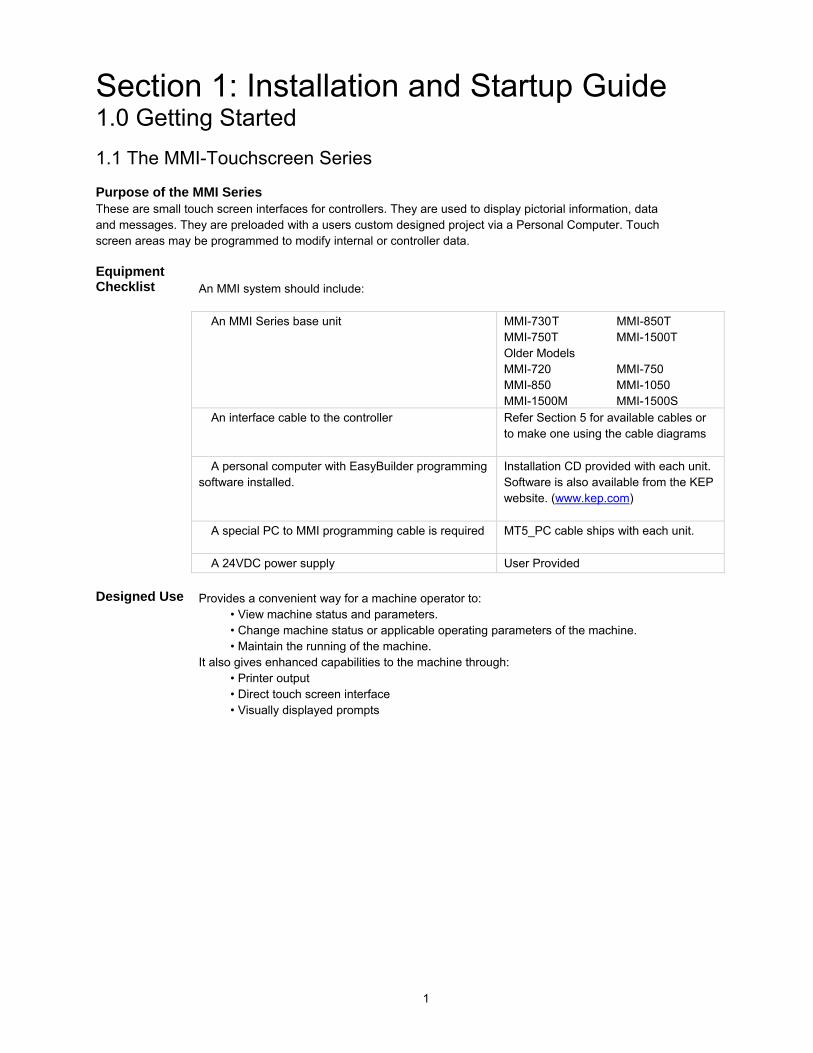
Purpose of the MMI SeriesThese are small touch screen interfaces for controllers. They are used to display pictorial information, dataand messages. They are preloaded with a users custom designed project via a Personal Computer. Touchscreen areas may be programmed to modify internal or controller data.
EquipmentChecklist An MMI system should include:
An MMI Series base unit MMI-730T MMI-850TMMI-750T MMI-1500TOlder ModelsMMI-720 MMI-750MMI-850 MMI-1050MMI-1500M MMI-1500S
An interface cable to the controller Refer Section 5 for available cables orto make one using the cable diagrams
A personal computer with EasyBuilder programmingsoftware installed.
Installation CD provided with each unit.Software is also available from the KEPwebsite. (www.kep.com)
A special PC to MMI programming cable is required MT5_PC cable ships with each unit.
A 24VDC power supply User Provided
Designed Use Provides a convenient way for a machine operator to:• View machine status and parameters.• Change machine status or applicable operating parameters of the machine.• Maintain the running of the machine.
It also gives enhanced capabilities to the machine through:• Printer output• Direct touch screen interface• Visually displayed prompts

2
2.0 Installation Instructions2.1 Mounting Instructions
2.1.1 Location ConsiderationsCare should be taken when locating equipment behind the unit to ensure that AC power wiring, PLC output modules,contactors, starters and relays, and any other source of electrical interference are located away from the back of the unit.
Particular note should be taken to the position of variable speed drives and switching power supplies. Their input and loadcables should be screened to a central star earth point.
2.1.2 Making a NEMA-4 Mounting
PanelDetails
The unit can be mounted into panels with a depth of 4”(105mm). It is recommended that the unitbe mounted on the front panel of a steel enclosure, through an appropriate opening*. Allow aclearance of 1”(25mm) around the sides of the unit for mounting hardware. Allow clearance forcable connections to the back of the unit. Unit depth may vary according to cable type used.Typically, plan a depth to accommodate at least 3”(105mm) behind the panel.Note: Deburr and clean cutout before beginning installation.
*Cutout dimensions:
11.89 [302]
8.86[225]
MMI-1500M / MMI-1500T11.89"(302mm) W x 8.86"(225mm) H
8.74[222]
6.58[167]
MMI-850T8.75"(222mm) W x 6.57"(167mm) H
3
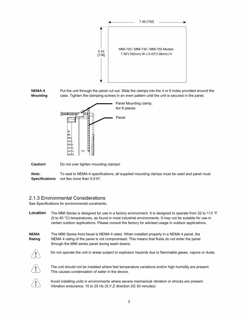
7.56 [192]
5.43[138]
MMI-720 / MMI-730 / MMI-750 Models7.56"(192mm) W x 5.43"(138mm) H
NEMA-4Mounting
Put the unit through the panel cut out. Slide the clamps into the 4 or 6 holes provided around thecase. Tighten the clamping screws in an even pattern until the unit is secured in the panel.
Caution! Do not over tighten mounting clamps!
Note:Specifications
To seal to NEMA-4 specifications, all supplied mounting clamps must be used and panel mustnot flex more than 0.010”.
2.1.3 Environmental ConsiderationsSee Specifications for environmental constraints.
Location The MMI Series is designed for use in a factory environment. It is designed to operate from 32 to 113 °F(0 to 45 °C) temperatures, as found in most industrial environments. It may not be suitable for use incertain outdoor applications. Please consult the factory for advised usage in outdoor applications.
NEMARating
The MMI Series front bezel is NEMA 4 rated. When installed properly in a NEMA 4 panel, theNEMA 4 rating of the panel is not compromised. This means that fluids do not enter the panelthrough the MMI series panel during wash downs.
Do not operate the unit in areas subject to explosion hazards due to flammable gases, vapors or dusts.
The unit should not be installed where fast temperature variations and/or high humidity are present.This causes condensation of water in the device.
Avoid installing units in environments where severe mechanical vibration or shocks are present.Vibration endurance: 10 to 25 Hz (X,Y,Z direction 2G 30 minutes)
Panel Mounting clamp,4or 6 places
Panel

4
2.2 Power ConnectionsMake sure that all local and national electrical standards are met when the installing the unit. Contact your local authorities todetermine which codes apply.2.2.1 Power Requirements
Power The HMI can be powered by DC power only. The specified voltage range is +22 to 25Volts DC. This insures compatibility with most controller DC systems.The power conditioning circuitry inside the unit is accomplished by a switching powersupply. The peak starting current can be as high as 700mA.
FusingRequirements
It is recommended that all input power lines be protected from incorrect wiring orproduct failure by a 2 Amp fuse or a breaker.If the display does not come on within 2 seconds of power up, remove power. Aninternal fuse prevents damage if the polarity of the DC power is incorrect. Check wiringto insure proper connections and try to power up again.
Warning!High Voltage
Connecting high voltages or AC power mains to the DC input makes the unit unusableand may create a hazard to personnel. Such a failure could result in serious personalinjury, loss of life and or equipment damage.DC voltage sources should provide proper isolation from main AC power and similarhazards.
Supply VoltageCondition
Do not power the HMI and inductive DC loads, or input circuitry to the controller, withthe same power supply.Note: The 24 VDC output from some controllers may not have enough current to powerthe HMI.
Wire Routing Wire lengths should be minimized.
Wires should be run in pairs with a neutral or common paired with a hot or signal line.
Always use shielded cable to prevent unwanted electrical interference.
If wiring is to be exposed to lightning or surges, use appropriate surge suppressiondevices.
Keep AC, high energy, and rapidly switching DC wiring separate from signal wires by atleast 8 inches. If signal wires must cross AC power, cross at right angles.
Equip ungrounded DC supplies with a resistor and capacitor in parallel to earth ground.This provides a path for static and high frequency dissipation. Typical values to use are1MOhm and 4700pF.
ElectricalEnvironment
The MMI Series has been tested to conform to European CE requirements. This meansthat the circuitry is designed to resist the effects of electrical noise. This does notguarantee noise immunity in severe cases. Proper wire routing and grounding insuresproper operation. The MMI Series is also UL certified.
Warning!EmergencyStop
A Hard-wired EMERGENCY STOP should be fitted in any system using an HMI tocomply with ICS Safety Recommendations.

5
Connection +24 VDC Wiring DiagramsUse 18 AWG wire to connect positive DC line to the ‘+24V’ (DC+) terminal and the DC groundto the ‘0V‘ (-DC) terminal. See text below about FG ( Chassis Ground).
Terminal Plug: (MMI-720, 730, 750 Models) To make a connection, strip about 3/8” ofinsulation off the end of the wire, and turn the connector screw counterclockwise until the gapis wide open. Insert the wire all the way in, and turn the screw clockwise until it’s tight.
+24V 0V FG
Terminal Block: (MMI-850, 1500 Models) To make a connection, strip about 3/8” ofinsulation off the end of the wire, turn the connector screw counterclockwise until the holddown plate is open wide enough to insert the wire. Insert the stripped portion of the wireunder the plate and turn the screw clockwise until it’s tight.
2.2.2 Grounding Requirements Chassis ground must be used. DC ground is not directly coupled to Earth ground internally. It
is preferable not to ground DC negative return to chassis ground. Poor site earths can introducenoise into a system. If necessary, an earth connection should be made from the power supplyreturn point to the central star earth point.
Ground conductors should be as short and as large in diameter as possible. The conductors mustalways be large enough to carry the maximum short circuit current of the path being considered.Ground conductors should be connected to a tree from a central star earth ground point. Thisensures that no ground conductor carries current from any other branch.
2.2.3 CE RequirementsTo make an HMI comply with EMC directives, and to reduce susceptibility to electrical interference, a separate#14 AWG ground wire should be taken to the chassis ground terminal of the power connector. This groundconnection should be run directly to the central star earth connection point (as recommended in most InstallationInstructions).
Use a ferrite core on the power wiring to reduce radiated emissions from theDC power lines. It is recommended to use a 140Ohm@100MHz ferrite corewith the DC power lines looped through the core once. Position the ferritecore less than 1” away from the DC power connection points on the back ofthe HMI.
140 Ohm @ 100MHz ferrite core

6
2.2.4 Safety GuidelinesThis section presents recommended installation practices, and procedures. Since no two applications are identical, theserecommendations should be considered as guidelines.
HardwareConsiderations
WARNING!The system designer should be aware that devices in Controller systems could fail and therebycreate an unsafe condition. Furthermore, electrical interference in an operator interface, such as anHMI, can lead to equipment start-up, which could result in property damage and/or physical injury tothe equipment operator.
If you, or your company, use any programmable control systems that require an operator orattendant, you should be aware that this potential safety hazard exists and take appropriateprecautions. Although the specific design steps depend on your particular application, the followingprecautions generally apply to installation of solid-state programmable control devices. In addition,these precautions conform to the guidelines for installation of Controllers as recommended in theNEMA ICS 3-304 Control Standards.
ProgrammingConsiderations
To conform with ICS Safety Recommendations, checks should be placed in the controller to ensurethat all writable registers that control critical parts of plant or machinery have limit checks built into theprogram, with an out-of-limit safe shut down procedure to ensure safety of personnel.
ICS 3-304.81 Safety Recommendations: Consideration should be given to the use of an emergency stop function, which is independent of the programmablecontroller. Where the operator is exposed to the machinery, such as in loading or unloading a machine tool, or where themachine cycles automatically, consideration should be given to the use of an electromechanical override or otherredundant means, independent of the programmable controller, for starting and interrupting the cycle. If provision is required for changing programs while the equipment is in operation, consideration should be given to theuse of locks or other means of assuring that such changes can be made only by authorized personnel. These recommendations are intended as safeguards against the failure of critical components and the effects of suchfailures or the inadvertent errors that might be introduced if programs are changed while the equipment is in operation. *
* The ICS 3-304.81 Safety Recommendations are reproduced by permission of the National Electrical ManufacturersAssociation from NEMA ICS 3-304
2.3 CE Requirements2.3.1 EU directives that apply to MMI Series
• EMC Directive (89/336/EEC, 92/31/EEC, 93/68/EEC) electromagnetic emissions and immunity
• Machinery Directive (89/392/EEC, 91/368/EEC, 93/44/EEC, 93/ 68/EEC) machine safety
MMI products are CE-marked to indicate compliance with the EMC Directive. Declarations of Conformity thatspecify the directive(s) and the catalog numbers of the products covered are available from Kessler Ellis Products.

7
The MMI Series has been designed to operate satisfactorily in electromagnetic noise (immunity) and without emitting highlevels of electrical noise into the environment (emission). The units are designed to meet European Community standardswhen installed per the wiring instructions in this manual.
Compatibility StandardsThe MMI has been designed to meet electromagnetic compatibility for industrial environments.
Standard DescriptionCISPR (EN 55011) Group 1, Class A Radiated Emissions levelsEN50081-2 Generic emission standard, industrial environment (Also US FCC Class A)EN50082-2 Generic immunity standard, industrial environment
2.3.2 Guide Lines for EU Installations• Be aware that wiring leaving the cabinet where the unit is installed may be exposed to interference sources.
• The installation practices in the individual product installation manuals of other components in the system must also befollowed.
• Locally applicable grounding safety regulations and machinery directives should be followed for providing a protectiveground to earth. The EMC ground must be a low impedance, low inductance path to the machine chassis ground.
• Power supply to the unit must be through an IEC-rated isolation transformer.
• The Power supply to the controller must be controlled to ensure that it does not exceed over voltage category II perEN60204-1 (IEC 240).
• Other requirements of the Machinery Directive involving displays, languages, instructions, Emergency Stop functions,machine operation, protective guards and interlocks are the responsibility of the machine manufacturer.
• Use a ferrite core on the power wiring to reduce radiated emissions from the DC power lines. It is recommended touse a 140Ohm@100MHz ferrite core with the DC power lines looped through the core once. Position the ferrite coreless than 1” away from the DC power connection points on the back of the UNIT.
2.3.3 Safety Guide Lines for EU Installations
• Only qualified personnel should be allowed to specify, apply, install, operate, maintain or perform any other functionrelated to HMI products. Qualified persons are defined as follows:
System application and design engineers who are familiar with the safety concepts of automation equipment.Installation, start-up, and service personnel who are trained to install and maintain automation equipment.Operating personnel trained to operate automation equipment and trained on the specific safety issues andrequirements of the particular equipment.
• Make sure that the voltage range for the equipment is correct before switching on the equipment.
• Emergency-tripping devices in accordance with EN60204/IEC204 must be effective in all operating modes of theautomation equipment. Resetting the emergency off device must not result in any uncontrolled or undefined restart ofthe equipment.
• Automation equipment and its operating elements must be installed so that unintentional operation is prevented.
• Make sure that operating sequences, interrupted by a voltage dip or power supply failure, resume proper operationwhen the power supply is restored. If necessary, the equipment must be forced into the “emergency off” state.
• Install the power supply and signal cables so that inductive and capacitive interference voltages do not affectautomation functions.

8
2.4 Communications ConnectionsThe ports as you look at the back of the case, are the ports for connecting to a printer, PLC or some external device(Controller Connectors).
2.4.1 Connection to an External Device
CableRequirements
Different cables are required for various devices. See Controller Reference Section for cable details.The KEP part numbers have the SMIC prefix. Refer to a KEP catalog or data sheet for a completelisting of MMI compatible devices.These cables can be obtained from the same distributor where you purchased the MMI.
Warning Communications problems cause the display to show PLC no response... until communicationscan be established. During this time, the controller cannot be affected by the HMI. The COM lighton the front of the HMI turns on with each communication and should appear as if always on orslightly flickering when communications are good.
Restrict cable length to avoid communications problems due to weak signals.Recommended distances:RS232: ............................................................................................ less than 50’ (15m)RS485/422: ..................................................................................... less than 500’ (150m)Ethernet: ......................................................................................... less than 328’ (100m)
Shielded cable must be used for long lengths or cables run in an electrically noisy environment.Use twisted pair cables for all Ethernet connections.
Do not run cables next to AC power lines or near sources of electrical noise.Be sure that the cable ends have been inserted all of the way into mating connectors and are secure.
Pin Designations
PLC [RS-232]
Pin assignment of the 9 Pin, Female, D-SUB, PLC [RS-232] Port. This port is used for connecting theHMI to a controller or Master HMI unit. The Auxiliary (AUX) RS232 port is also accessed through thisconnector. Both PLC and AUX ports share the common ground.
Note: This port is not used for programming the HMI or for printing functions.Do not plug the MT5_PC’s PLC cable end into this port.
Pin # Symbol PLC[RS232] AUX[RS232]1 AUX TxD Transmitted Data2 PLC TxD Transmitted Data3 PLC RxD Received Data4 Not used Received Data5 GND Signal Ground Signal Ground6 AUX RxD7 PLC CTS Clear to send input8 PLC RTS Ready to send output9 Not used
Printer Port(25p D-Female)
(Not Available on MMI-720, 730and 750 models)
PC [RS-232] &PLC [RS-485] Port
(9 pin D-Male)
PLC [RS-232] Port(9 pin D-Female)
Ethernet Port(RJ-45 Male)
(Not Available on allmodels)

9
2.4.2 Connection to a Personal ComputerThe 9 Pin, Female, D-SUB, PC [RS-232] & PLC [RS-485] Port on the back of the unit is the programming port (PCConnector) and RS485/422 communications port for connecting to a controller. The Auxiliary (AUX) RS485 port is alsoaccessed through this connector.
Connection This port can be attached to a Computer via a special DB9 Female to DB9 Female cable providedwith the unit. (KEP P/N: MT5_PC)
Port Activation This port is activated automatically by the PC during: On line simulation, Download and Uploadactivities.The Programmer Port cannot simulate, download or upload to the unit while it is on line with thecontroller at the same time. The unit must be put into “RDS” mode with the EasyManager appletfirst.
Pin Designations
PC [RS-232] &PLC [RS-485]
Pin assignment of the 9 Pin, Male, D-SUB PC [RS-232] & PLC [RS-485] Port
Pin # Symbol PLC[RS485] 2 Wire PLC[RS485] 4 Wire AUX[RS485] 2 Wire PC[RS232]1 PLC RxD- Transmit/Receive - RS485 Receive2 PLC RxD+ Transmit/Receive + RS485 Receive3 PLC TxD- RS485 Transmit4 PLC TxD+ RS485 Transmit5 GND Signal Ground Signal Ground Signal Ground Signal Ground6 AUX Data + Transmit/Receive +7 PC TxD RS232 Transmit8 PC RxD RS232 Receive9 AUX Data - Transmit/Receive -
HMI to PC, MT5_PC Cable Configuration
Connect toPersonal Computer (PC)RS232 Serial PortDB9 Female
Connect toHMI (HMI)RS232/485 [PLC]DB9 Female
Connect toControllerRS485 PortDB9 Male
1 Not used 1 RX- 1 RX-7 Not used 2 RX+ 2 RX+8 Not used 3 TX- 3 TX-4 Not used 4 TX+ 4 TX+5 GND 5 GND 5 GND6 Not used 6 AUX Data + 6 AUX RS485+2 TxD 7 TxD 7 Not used3 RxD 8 RxD 8 Not used9 Not used 9 AUX Data - 9 AUX RS485-
HMI PLCRS485
PC

10
2.4.3 Connection to a PrinterThe printer port on the back of the unit is a Parallel printer port and is compatible with most printers that accept parallelconnectors.
Print Out The MMI-1500 and 850 models have printout capabilities. The printer porttransmits data when a printable object is activated.
Pin Designations Pin assignment of the 25 Pin, D-SUB, Parallel Printer Port.
Pin # Symbol Function1 STB Output2 DATA0 Output3 DATA1 Output4 DATA2 Output5 DATA3 Output6 DATA4 Output7 DATA5 Output8 DATA6 Output9 DATA7 Output11 BUSY Input15 ERROR Input16 INIT Output17-25 GND Signal Ground
2.4.4 Ethernet ConnectionsUnits equipped with the Ethernet port can be connected to Ethernet devices using standard 10T CAT5Ethernet cables. Routing may pass through Hubs and Servers as needed to connect to the PLC.
The Ethernet port can also be used for HMI Master/Slave communications using the same type ofconfigurations.
Connect directly to PLC using 10T Crossover cable
Connect through Hub to PLC
Connecting through Server to PLC or Master
PLC
PLC
Server
Hub

11
2.4.5 HMI to HMI ConnectionsThe HMI supports a master - slave communications. One HMI is connected directly to the PLC and configured as theMaster. All the other HMIs are connected in series to it and are configured as Slaves. In theory there is no limitation to thenumber of HMIs on a chain, however response time gradually decreases when more than three HMIs are linked together.The HMI are configured with the EasyBuilder software to be the Master or a Slave.
Wiring between two HMIsCase 1: Slave to Master, connecting PLC[RS232] directly to PC[RS-232]/PLC[RS485] combination port.Connect to SLAVE HMI PLC[RS-232] portCable has D-SUB Male end
Connect to MASTER HMI PC[RS-232] portCable has D-SUB Female end
2 TxD 8 RxD 3 RxD 7 TxD 5 GND 5 GND
Shield Earth Ground
Case 2: Slave to Master, connecting PLC[RS232] to PC side of split download cable (MT5_PC) with use of Male to Male NullModem cable.Connect to SLAVE HMI PLC[RS-232] portCable has D-SUB Male end
Connect to MT5_PC to MASTER HMI PC[RS-232] portCable has D-SUB Male end
2 TxD 3 RxD 3 RxD 2 TxD 5 GND 5 GND
Shield Earth Ground
Case 3: Ethernet Connections: Units equipped with the Ethernet port can be connected via Ethernet to a Master and Slavesusing standard 10T Ethernet cables. Slave to Master, connect the Ethernet ports with a standard (Category 5) Ethernet 10Tcrossover cable (RJ-45 to RJ45). On the other hand, use standard cables with routing passing through Hubs and Servers asneeded.
Connecting a Master directly to a Slave using 10T Crossover cable
Connecting a Master through a Hub to Slaves
SlaveMaster
Slave
Slave
Hub
Master

12
2.5 Dip Switch SettingsAll dipswitches should normally be in the OFF (down) position. Dipswitches 1 and 2 are used to perform testing andrecovery functions. Dip Switch 3 and 4 are not used and should be left in the off position.
SW1 SW2 ModeOFF OFF Application mode (On line operations, use EasyManager or EasyBuilder to change modes)
ON OFF Force to Touch Adjust mode (Used for touchscreen calibration)
OFF ON Force to RDS mode (Remote Debug and Simulation, used to recover from invalid statesdue to corrupt downloads. Refer to section on troubleshooting.)
ON ON Force to Touch Screen Test mode (Used to check accuracy of Touch Screen)
Note: It is normally not necessary to change dipswitches to put the HMI into programming (RDS) mode.
2.6 HMI Indicator LightsPWR – Indicates if power has been applied to the unit. If this indicator fails to light, check power, check polarity
of wiring and check fusing. If all conditions are correct, contact the factory for help.CPU – Indicates that the CPU is operating properly. If this indicator fails to light, please contact factory.COM – Lights when a serial transmission is sent or received. This indicator appears to flicker when trying to
establish communications.
2.7 Other Hardware Considerations
2.7.1 Touchscreen CalibrationNormally the touchscreen is calibrated at the factory for proper functionality. If the touchscreen cannot becalibrated, please contact the factory for assistance.
Run the EasyManager Utility to get to the Touch screen calibration (Touch Adjust) mode.Click Jump to Touch Adjust to put the unit in this mode. This is used to calibrate the touch screen.On the screen of the HMI unit:
Touch the crosshairs as displayed in sequence on the screen.Touch anywhere outside to the rectangles to move the crosshairs to that location.Touch inside the left rectangle to repeat the calibration process.Touch inside the right rectangle to accept and end the calibration procedure.Touch the screen again to jump to application mode.
2.7.2 CCFL and Battery ReplacementIt is recommended that the factory replacement of these components in case of their failure. Use our toll freenumber to contact KEP.Telephone: 1-800-631-2165.
If the product must be returned, be sure to call KEP and get a Return Goods Authorization(RGA) number first.
Units should be returned in their original packaging container, otherwise, any suitable rigidcontainer can be used as a substitute. Use appropriate packing material. Damage due toshipment is not covered by the warranty. Be sure to include a description of the problem andcontact details for our repair department.All returns are evaluated for proper operation. During evaluation, customer projects are notretained in the units. If you need your project retained, please indicate this in the documentationincluded with the unit.

13
3.0 Specifications3.1 General Specifications
Item SpecificationInput power 21-25 VDC, 500 mA @ 24VDCCE Complies with EN50081-2 and EN50082-2 standardsEMI Complies with FCC Class A (Ferrite core required if using unshielded power supply wires)Isolation resistance Exceeds 50 MΩ at 500VDCVibration endurance 10 to 25 Hz (X,Y,Z direction 2G 30 minutes)Protection structure NEMA 4 / IP65 front panel (when mounted with gasket seal)Operating Temperature 32 to 113 °F (0 to 45 °C)Operation humidity 10 to 90% RH Non CondensingEnclosure Plastic: Polybutylene Terephthalate (PBT) and Polycarbonate(PC)
3.2 Hardware Specification 1500, 850 Models
Item 1500T 1500M 850T 850LCD Display 10.4” TFT, 256 color 10.4” STN, 4 color gray 7.7” TFT, 256 color 7.7” STN, 256 colorDisplay area (mm) 215(W) x 162(H) 162(W) x 123(H)Contrast Ratio 150:1 18:1 250:1 30:1Brightness cd/m2 300 100 400 150Back light CCFLx2(MTBF 25,000 hr) CCFLx1(MTBF15,000 hr) CCFLx1 (MTBF 50,000 hr)Resolution pixels 640(W) x 480(H)Pixel size 0.33(W) x 0.33 (H) mmTouch panel 4 wire resistive typeTouch granularity 2mm gridTouch Feedback Beeper and or Graphic IndicatorSurface hardness 4HProcessor 32 bit RISC CPU 200 MHzFlash ROM Memory 2 MB Standard, 4MB with Ethernet optionSystem Memory 4MB DRAMBattery Held Memory 128kB with Y2K compliant Real Time Clock/CalendarCompact Flash Slot Used for Project
transfers onlyNot Available Used for Project transfers only
Serial ports 1 RS-232 (controller port) and 1 RS-232 / RS-485 (PC & controller port)Parallel port Standard parallel printer portEthernet Port RJ-45 8 wire
(10 BaseT) TCP/IPNot Available RJ-45 8 wire (10 BaseT) TCP/IP
System diagnostic Watch dog timer, power failure detectionDimensionsBezel
H x W x D inches(H x W x D) mm
CutoutH x W inches(H x W) mm
Bezel:9.37 x 12.40 x 2.44(238 x 315 x 62 )
Cutout:8.86 x 11.89(225 x 302 )
Bezel:6.93 x 9.09 x 2.16(176 x 231 x 55)
Cutout:6.57 x 8.75(167 x 222 )
Weight Approx. 2.0 kg Approx. 1.2 kg

14
3.3 Hardware Specification 750, 720 Models
Item 750T / 750T-HB 750 730T 720LCD Display 5.7” TFT 256 color 5.7” STN 256 color 5.7” TFT 256 color 5.7” STN blue modeContrast Ratio 60:1 30:1 150:1 15:1Brightness cd/m2 500 150 500 60Back light CCFLx1 MTBF 30,000 hr MTBF 30,000 hr MTBF 30,000 hr MTBF 50,000 hrResolution pixels 320(W) x 240(H) 320(W) x 234(H) 320(W) x 240(H)Pixel size 0.33(W) x 0.33 (H) mmDisplay area (mm) 120(W) x 90(H)Touch panel 4 wire resistive typeTouch granularity 1.5mm gridTouch Feedback Beeper and or Graphic IndicatorSurface hardness 4HProcessor 32 bit RISC CPU 200 MHzFlash Memory 1 MB Standard, 2MB with Ethernet OptionSystem Memory 4MB DRAMBattery Held Memory 128kB with Y2K compliant Real Time Clock/CalendarCompact Flash Slot Used for Project transfers only Not AvailableSerial ports 1 RS-232 (controller port) and 1 RS-232 / RS-485 (PC & controller port)Parallel Printer port No printer port availableEthernet Port RJ-45 8 wire (10 BaseT) TCP/IP Not AvailableSystem diagnostic Watch dog timer, power failure detectionDimensions
H x W x D inches(H x W x D) mm
Bezel: 5.90 x 8.00 x 2.95 (150 x 204 x 75 )Cutout: 5.43 x 7.56 (138 x 192 )
Weight Approx. 0.84 kg
3.3 Functional Specification
Screen editor EasyBuilder Version 2.6.2 or later(to be run under Windows 98 / NT / 2000 / ME / XP*)
No. of window 1 ~ 1999, limited by memoryNo. of object Up to 500 per window, limited by memoryText strings limited only by memoryBitmap graphics 256 KB per graphic, limited by memorySupport PLC Most popular PLC’sSupport Printer EPSON ESC/P2, HP PCL/(Simple page mode) or compatibleMacro scripts Up to 256 Macro scripts per project, limited by memoryComputer requirements include at least a Pentium 90Mhz PC, 16MB RAM, 10MB available hard disk space,minimum 800x600 resolution VGA, and one available RS-232 serial port.

15
4.0 Trouble Shooting
4.1 Power ProblemsProblems on power up: Unit does not light or unit lights but does not display any windows.
1. Check wiring for proper polarity.2. Check power Supply for proper Voltage and Current capacity.3. Check fuse.
Problems during operation: Faulty unit operation may be due to problems with power quality. The HMI has beendesigned to work in environments where electrical noise is present. However, extreme electrical noise still causesproblems. Make sure that the system is properly earth grounded.
4.2 Communications ProblemsSometimes communications fail. When communications fail, the unit automatically tries to establish thecommunications link again. During the time the unit is establishing communications, the touchscreen of the unit doesnot respond. Function key operations are interrupted. The implication is that the unit should not be used forEmergency Stop applications. A loss of communications can happen at any time. Using the function keys on the unitfor critical operations can lead to a potential disaster. It is good programming practice to allow for safe operation incase of interface failure.
There are various reasons why this happens;
Improper programming: If the MMI window is programmed to access data from an invalid register or bit addressfor the PLC, the unit receives an error message from the PLC. The unit interprets this as a loss in communications.Be sure that all data points being displayed are valid for the PLC that is connected.
Loose or incorrect cables: Make sure that all cables are secured and configured properly for the PLC.
Time outs: Make sure that the PLC is responding to requests from the HMI in a timely manner.
Power loss: Make sure the PLC has power and is running properly.
Electrical noise: Faulty unit operation may be due to problems with power quality. The HMI has been designed towork in environments where electrical noise is present. However, extreme electrical noise still causes problems.Make sure that the system is properly earth grounded.The use of proper grounding techniques insures reliable communications. Make sure the controller and the HMI areconnected to good earth ground sites. This allows EMI (Electro-Magnetic Interference, commonly called electricalnoise) to be channeled to ground where it can no longer disrupt electrical operations. Be sure to routecommunications cables in separate bundles and locations from AC power and control wiring. Do not runcommunications cables near solenoid and relay coils or AC and DC drive controllers. Care should also be taken tolocate the HMI itself away from sources of EMI.

16
4.3 Commonly Asked Questions
Q. Can I have multiple MMIs connected to one Controller?A. The ability to connect more than one HMI to a controller is accomplished through an HMI to HMI link. This is notdone through any PLC protocol. It is done through the master-slave protocol of the MMI.
Q. How do I call up windows with my PLC?A. Use the PLC Control part configured as “Change window” to call up windows by word value. Additionally, Directand Indirect Window parts can be used to bring up windows.
Q. Do I need to change any jumpers to go from one Controller type to another?A. No, the driver that is downloaded into the unit at programming time determines the Controller type. The dipswitches on the back of the unit should all be in the OFF position.
Q. Is there any way to completely erase the HMI user memory?A. No, the HMI memory is initialized automatically before every download cycle.
Q. How Do I change the Battery?A. Battery replacement requires disassembly of the unit in an ESD controlled environment. Battery life expectancyis greater than 5 years.
The MMI-7XX takes one coin type of CR2032 lithium battery to backup the recipe data and keep the RTCrunning. Battery specification: CR2032 3V lithium battery.Steps for battery replacement:
1. Use EasyManager to backup the retentive memory data.2. Turn off the HMI and remove its rear cover.3. Remove the battery from the socket.4. Insert a new battery into the socket.5. Put on the rear cover.6. Reset the RTC time and download the retentive memory data.
The MMI-850 and 1500x products have the battery soldered to the main board. We recommend that theseunits be sent back to the factory for battery replacement.
Q. Can I change the Backlighting bulbs in the field?A. We recommend that the unit be sent back to the factory for bulb replacement. Backlight bulb life expectancy isgreater than 5 years even if running 24 hours a day. Use the Backlight auto shutdown to conserve backlight bulb life.
Q. Why am I getting slow updates on my windows?A. PLC communication speed controls the update speed. Try using a higher baudrate and adjusting the Block packsettings. If an overloaded window is causing a slow update, we suggest changing the window design.NOTE: EasyWindow has a tool called “SystemResource”. It displays object queue item numbers. Use this to helpdetect communication problems. This problem might not show up in Offline Simulation because the PC may havemore CPU speed, more caches, and more VGA speed.
4.4 Hardware Problems4.4.1 Black Screen after downloadSymptom: After project downloaded to a new touchscreen a blank black screen is displayed.Cause: Using the older versions of EasyBuilder to download to newer model touchscreens.
Any version prior to version 2.0.2 downloading to Hardware version 3Any version prior to version 2.5.1 downloading to Hardware version 4Any version prior to version 2.6.0 downloading to Hardware version 4.5
Fix: Install new version of EasyBuilder on your computer.Set DIP Switch 2 ON in the HMI and reset Unit.Load your project using new EasyBuilder.Set DIP Switch 2 OFF and reset Unit.Project should now operate normally.

17
4.5 Repairs and ReturnsAn MMI is designed to provide years of trouble free service. An MMI under goes a full functional test beforeshipment.
The MMI warranty is for one year under normal use.The MMI does not require any “Routine Maintenance” by the user. If a problem should occur, and all troubleshootingprocedures have been exhausted, contact your local representative or distributor.
Use our toll free number to contact KEP if persistent problems are encountered.Telephone: 1-800-631-2165.
If the product must be returned for any reason, be sure to call KEP and get a Return Goods Authorization(RGA) number first.
Units should be returned in their original packaging container, otherwise, any suitable rigid container can beused as a substitute. Use appropriate packing material. Damage due to shipment is not covered by thewarranty. Be sure to include a description of the problem and contact details for our repair department.All returns are evaluated for proper operation. During evaluation, customer projects are not retained in theunits. If you need your project retained, please indicate this in the documentation included with the unit.Products passing normal QC tests are returned to the customer and an evaluation charge is incurred.If the problem is verified and the unit is in warranty, KEP will repair or replace the unit.
5.0 Quick Startup Guide
5.1 ConnectionsSet up the HMI with PC and PLC as described below.
a) Connect PC [RS-232] port of the HMI to the PC. Since the PC [RS-232] and PLC [RS-485] share the same D-SUBconnector, we recommend using the HMI to PC cable provided (MT5_PC). This splits the port into two separate connectorsto ease the program and test process.
b) Connect either the PLC [RS-485] or PLC [RS-232] port of the HMI to the PLC using the proper cable. (Check the PLCsignal type and cable listing in the back of this manual to assure proper port connections.)
c) Connect DC 24V power to the power connector. See Section 2.2.1 for power connection specifications.
Note: Check that all Dip switches are set to the “OFF” position.
d) Apply power and, if necessary, calibrate contrast adjust to the best viewing performance. (Not applicable for MMI-1500T)Set new V4.5 hardware versions in RDS mode where contrast can be adjusted electronically.

18
MMI-7XX Connection points
a. PLC[RS485]/PC[RS232]/AUX [RS485]b. PLC[RS232]/AUX [RS232]c. Ethernet port (RJ-45) (only on some models)d. CF card slot (only on units with Ethernet ports)
MMI-850, MMI-1500 Connection Points
a. PLC[RS485]/PC[RS232]/AUX [RS485]b. PLC[RS232]/AUX [RS232]c. Ethernet port (RJ-45)d. CF card slote. Printer port
Dip Switches
Fuse
PowerConnections
Reset Button
Fuse
PowerConnections
a
d
c be
PowerConnections c a be
d

19
Typical connection
5.2 Installing EasyBuilderInstall EasyBuilder 500 on your PC. Software must be installed on a PC running Windows 98®, Windows 2000® or WindowsXP® software. PC screen resolution must be set to 800x600 or greater. Also, at least a Pentium 90Mhz CPU with 16MBRAM, a CDROM drive, 15MB available hard disk space, VGA video controller, and one available RS-232 serial port isrequired.
Put the EasyBuilder Installation CD into the CD drive. The autorun should bring up a screen showing an area to click tobegin the EasyBuilder Installation.
If the Autorun sequence does not start, browse the CD with Windows® Explorer and start the installation from there. Oncethe Installation process is done, the Start Menu has selections for starting EasyBuilder and EasyManager.There is no need to restart your computer after installation, although this is recommended.
PC
MT5_PC cable
To PLC RS-232Interface
To PLC RS-485Interface
PLC
HMI
To Ethernet Port
PC

20
5.3 Initial Start Up
Use EasyManager to set the following:
1. COM Select Dropdown: Select the number of the RS232 Serial COM portfor communications to the MMI. Ports COM1 through COM10 areavailable.
2. Click on EasyBuilder to start the screen editor for the MMI.
Note: See the Software Reference section for further details about theEasyManager Application.
After clicking the EasyBuilder button, the following popup dialog appears if this is the first time running EasyBuilder.Otherwise, the last open project is automatically opened for editing.
To start a new project, use the keyboard shortcut [Ctrl + N]
or click the tool or select [New] from the File menu and a new project is created from the project template.
3. Select the appropriate Model number you are programming….
MMI1500T (640 x 480) 10.4” TFT 256 ColorMMI1500S (640 x 480) 10.4” STN 256 ColorMMI1500M (640 x480) 10.4” STN 4 Shade Grayscale
MMI850T (640 x 480) 7.7” TFT 256 Color MMI850 (640 x 480) 7.7” STN 256 Color
MMI750T (320 x 240) 5.7” TFT 256 ColorMMI750 (320 x 240) 5.7” STN 256 ColorMMI730T (320 x 234) 5.7” TFT 256 ColorMMI720 (320 x 240) 5.7” STN 4 Shade Grayscale

21
4. Select the Display Mode….
Landscape Portrait
5. Select the Language Mode….This setting determines the character set that is used in project development.
Select Single Byte for European languages. These fonts are in the directory as Ascfont.8, Ascfont.16 and Ascfont.24.These represent the 8, 16 and 24 point sizes. Larger sizes are generated from these base sizes (Example: Font size32 is actually size 16 doubled).
Select Double Bytes for Asiatic languages. Use the Font setting in the System Parameters Editor Tab to select theappropriate character set.
Then click, OK.
5.4 Creating a projectA project file (*.epj FILE) is simply a collection of all the windows and window data used by an application.
Step 1. Select Edit|System Parameters... and the following screen appears. Fill in the system parameters. Use the PLCTab to select the set up the parameters for communicating to the PLC.
a. Select the PLC type from the dropdown list.
b. Confirm that the HMI Model is the one youare programming.
c. Check the communications settings:Serial I/F portBaud rateData bitsParityStop bitsHMI station No.PLC station No.
Set the communications parameters to matchthe PLC. (See the Controller Reference Guidefor details.)
Note:The General, Indicator, Security, Editor,Hardware and Auxiliary Port tabs are used forother settings. See Section 2.0 for full details.For a quick start, these settings can be left attheir defaults.

22
Step 2. Select any additional Group, BMP and/or Shape Libraries to attach to theproject. The default selection provides a good range of library objects. For a quickstart, no additional libraries are needed.
In the Library menu, select [Shape, Bitmap or Group] [Call up Library] or use
the toolbar icons .
EasyBuilder provides three types of libraries.A Shape is a collection of drawing elements, those elements, when put together, defines a graphic symbolrepresenting a button, lamp, function key etc.A Bitmap is a collection of pixel of data; each pixel can be 1, 4 or 8 bits.A Group Library is a collection of shapes and bits that are frequently used and have been saved as a group.
Step 3. Design the windowsUsing the parts and drawing elements, virtually any simple window display can be completed in 10 minutes. “Ease ofUse” is the greatest benefit of our EasyBuilder screen editor software.
a. Use the Draw menu/tools to put static text and shapes on the window. The drawing toolsare used in the similar fashion to most windows drawing packages.
For example: To draw a line: Select the Line tool. Change any attributes for the line. Click onthe screen where the line is to begin, move to where the line is to end and click again to setthe end point.
b. Put active parts on the screen by using the Partsmenu/tools. The parts automatically pop up a dialog forentering information related to the part operation.
For example: Placing a Bit Lamp: Select Bit Lamp fromthe Parts menu. Select the type of bit to access. Enterthe number of the bit. Go to the shape tab. Select Useshape and click on the Shape Library button to select ashape. Click OK to close the dialog. The Bit Lamp isplaced in the upper left corner of the display. Move it tothe desired position.

23
Step 4. Save and Compile the project
In the menu, select File|Save to save the project.
In the menu select Tools|Compile… to compile the project.
Step 5. Simulate the project either On-line or Off-line.
Select Tool|On-line Simulation operation in the menu. After the project is complied, the Simulator retrieves data fromthe PLC through the unit and simulates operation. Before simulation, be sure to connect the unit and the PLC properly
and set the COM port in EasyManager.
Select Tool|Off-line Simulation operation in the menu. After the project is complied, the PC simulates the PLC andemulates operations. The unit does not have to be connected to the PC for this type of simulation. Hint: Use this type
of simulation to demonstrate projects.
Using the Simulators before theproject is completely debugged,saves time by avoiding repeateddownloads.
Step 6. Download the projectIn the menu, select Tool|Download… to load the image file into the MMI. Before downloading, be sure to set theCOM port in the Easy Manager menu. When the download is finished, click OK in response to the Mission complete
message. The HMI automatically switches to Application Mode.
This ends the Quick Start section. From here, it is up to you to design thespectacular window displays that make life easier for your operators.
Sample Simulation Screen

24
Section 2: Software Reference Guide6.0 EasyManager OperationsThe EasyManager is a software shell for launching several utilities. Somefunctions are duplicated in the EasyBuilder screen-editing program. While theEasyBuilder program can be run as a stand-alone program, it is advised to runEasyManager first to set the COM port.
EasyManager has the following components:
6.1 COM Port Drop-Down BoxSelect the number of the RS232 Serial COM port for communications to theMMI. Ports COM1 through COM10 are available for selection.
Note: Make sure that some other program is not already using the selectedCOM port. EasyManager and EasyBuilder will not take control of a COMport that is used by another program. Communications time out errors willbe displayed when attempting EasyManager functions.
6.2 Communications Speed Drop-Down BoxThis selection is used to determine the communications speed between the PCand the unit during downloads and uploads. If you are using the MT5_PC cableto download, the 115200 speed is recommended. When using extensioncables, the 38400 speed is recommended.
6.3 Project or Recipe Download/UploadThere are two types of communications: Downloading - sends data to the unitand Uploading - retrieves data from a unit. The data that is sent or receivedcan be a compiled project’s object file (file with *.eob extension) or retentivememory (recipe) data (file with *.rcp extension).
Select Project Download/Upload to transfer only project data.Select Recipe Download/Upload to transfer only retentive memory (recipe) data.
6.4 Complete or Partial Download/UploadThe Complete or Partial Download/Upload is used to determine how much retentive memory (recipe) data is transferred to orfrom the unit during Download or Upload.
A Complete Download/Upload sends/retrieves the full 65535 bytes of retentive memory (recipe) data from the MMI.A 32K Partial Download/Upload sends/retrieves only the first 32767 bytes of retentive memory (recipe) data.
6.5 EasyBuilderThis button launches the EasyBuilder screen editor. This is used for project creation, editing, compiling, simulation anddownloading.

25
6.6 Online-Simulator The Online simulator retrieves data from the PLC through the unit and uses it to put a realistic image of the unit on the PCscreen. The image shows how a project appears after download. Use the Online-Simulator to view demonstration projectsand show how the windows look in actual operation. A Touchscreen and PLC are needed to simulate a project in this mode.
Note: The project must be compiled by EasyBuilder. This creates a file with extension *.eob. Uncompiled project files withthe *.epj extension cannot be simulated.
Note: When the Direct Online-Simulator option is checked the unit is not needed for Online simulation, the PC can beconnected directly to the PLC with an appropriate communications cable.
6.7 Direct Online-SimulatorWhen this option is checked the HMI is not needed for Online-Simulation. The PC is connected directly to the PLC with anappropriate communications cable.
Note: Direct Online Simulator does not support AB DH485 or UniTelWay drivers.
6.8 Offline-Simulator The Offline simulator emulates the operation of a project on the PC screen. The PC is used to simulate a PLC in a limitedfashion. Use the Offline-Simulator to create demonstration projects or view approximately, how the windows look in actualoperation. A Touchscreen and PLC are not needed to simulate a project in this mode.
Note: The project must be compiled by EasyBuilder. This creates a file with extension *.eob. Uncompiled project files withthe *.epj extension cannot be simulated.
6.9 DownloadDownload a project compiled by EasyBuilder to the MMI. Downloading a Project sends the object *.eob file and or recipe*.rcp file to the MMI. Downloading a Recipe sends only the recipe *.rcp file to the MMI. You are prompted to select the filesas they are downloaded.
Note: The EasyManager download facility is ideal for sending out project updates. Most projects and EasyManager fit on a1.44MB floppy disk. The user just needs to run EasyManager click on download and select the project file. Thedownload begins automatically.
6.10 UploadUpload the project file from HMI to an object file (*.eob). Uploading a Project retrieves the object *.eob file and or retentivememory (recipe) *.rcp file from the MMI. You are prompted to name the files as they are uploaded. Uploading Reciperetrieves the retentive memory (recipe) *.rcp file only from the MMI. You are prompted to name the file as it is uploaded.
Note: The upload file can be transferred to another MMI. This is useful for retrieving data from installed units to make aduplicate setup.

26
6.11 Mode ChangeThe EasyBuilder operates in one of three modes. Click the buttons to switch to the corresponding mode.
Note: It is not necessary to change dipswitches for a mode change.
6.11.1 RDS (Remote Debug & Simulation) modeThe Jump to RDS mode is used for project development. Simulations and Up/Downloads are done in this mode. It puts theunit in a state that displays 9 to 12 lines of unit information.
Line 0: Shows the status of the unit as reported from its internal initialization routine. This should say “Initial OK”.If this line does not display the OK message, please contact the factory for assistance.
Lines 1 and 2: Show the unit’s internal firmware version information. The BootRom Version should be 1.12 with aVersion Id of 0x100a or greater for proper operation with EasyBuilder V2.6.x.
Line 3: The PC communication baudrate setting. This changes automatically to match the EasyManager setting.
Line 4: Shows if the unit has a project in it or not. If no project is present, the unit does not go to Application mode.
Line 5: The download support setting. This changes automatically to match the EasyManager setting.
Line 6: This should always be Fast Mode Simulation.
Line 7: Indicates if Retentive (Recipe) memory is installed in the unit. (Old units may not have memory installed.)
Line 8: Show the unit’s driver status. The unit should indicate that it accepts KEP drivers. If it does not, pleasecontact the factory for assistance.
Line 9: Shows the display resolution.
Line 10: Shows the unit’s MAC ID for Ethernet communications. (Old units do not display this information.)
Lines 11 & 12: Displays the OEM’s copyright notice.
Note: On new hardware platforms, below line 12, are two touch areas for contrast adjust and or a button forinitiating Compact Flash project transfer.
6.11.2 Application (On line operation) modeClicking Jump to Application runs the project in memory. This is the normal operating mode of a unit once it isinstalled, programmed and ready for use.Note: if there is no project in the unit the unit stays or jumps to RDS Mode.
6.11.3 Touch Adjust (Touch screen calibration) modeJump to Touch Adjust is used to calibrate the touch screen. Normally the touchscreen is calibrated at the factory for properfunctionality. If the touchscreen cannot be calibrated, please contact the factory for assistance.
6.12 EXITThis button closes the EasyManager application.

27
7.0 Software Fundamentals
7.1 Screen Editor OverviewClicking on the Easy Manager’s [EasyBuilder] button causes the following window to appear. The functions of each screenarea are explained below.
a. Title Bar: Displays the project’s file name, activewindow number and title.
b. Menu Bar: Displays the menu used to selectEasyBuilder commands.
c. Library Tools: Displays tools for library operations.d. Tool Bar: Displays the icons corresponding to File,
Edit, Option, Library, Tools and Help menu items.e. State Selector: Clicking on this drop-down toggles all
the parts on the window to the specified state.f. Project tools: Used for compiling, simulating and
downloading a project.g. Language: Clicking on this drop-down toggles all the
labels on the window to the specified language.h. Magnification: Used to double screen size for fine
editing and positioning.i. Layer Control: Adjust the Layer of selected part – one
layer up, one layer down, to top layer and to bottomlayer.
j. Position Adjust: Adjust the position of selected parts.k. Alignment: Make all the selected parts line up to the
top, bottom, left or right.
l. Text size & position: Change the font size and alignmentof the selected text.
m. Size Adjust: These tools make the dimension, width orheight, of all the selected parts the same size.
n. Group: The group function makes a collection ofselected parts and drawing elements as one object.
o. Rotate and Flip: Allows shapes to be flippedhorizontally or vertically and rotated in 90-degreeincrements.
p. Drawing Tools: Icons representing each drawing toolare shown.
q. Parts Tools: Icons representing each Part type areshown. Clicking on one of these icons causes thaticon’s dialog box to appear. That Part’s attributes canthen be set and the Part can be placed on the window.
r. Cursor Position: Shows the current cursor position onthe active screen relative to the upper left corner of thescreen.
s. Window Treebar: Provides quick access to Windowproperties, objects and organization.
t. System Tools: Used to set Alarm and Event messages,PLC controls and Data Transfer.
a. Title Bar
b. Menu Bar f. Project Tools
p. Drawing Toolsq. Parts Toolsr. Cursor Position
l. Text size & position
i. Layer Controlj. Position Adjustk. Alignment
m. Size Adjustn. Groupo. Rotate & Flip
e. State Selector g. Label Languagec. Library Tools
d. Tool Bar
s. Window Treebar
t. System Tools
h. Magnification

28
7.1.1 Changing Screen AppearanceThe screen appearance can be changed to make project editing easier. This includes what toolbars are displayed, changinggrid constraint properties and magnification. These changes affect the screen but do not change a window’s properties.
7.1.1.1 View MenuThe View menu is used to Hide or show Toolbars, Status bar and Treebar. The functionality of the Treebar isdiscussed further in the Editing Placed Objects section. Toolbars can be dragged to other sides of the editing windowor dragged away from the edge to be shown as floating. Check a toolbar’s name to open it. Uncheck a toolbar’s nameto close it.
The Size command is used to change the edited window’s magnification to 100 or 200%. Magnification makes iteasier to align objects manually and to make drawing objects intersect at appropriate coordinates.
7.1.1.2 Screen SettingsUse the Option|Grid/Snap menu to make object alignment and drawing easy.
X, Y Select or enter the pixels from one grid pointto the next in the X(Horizontal) or Y(Vertical)direction.Display Checkbox: Enables/Disables gridvisibility.Snap Checkbox: Enables/Disables the snappingof objects to the grid.Fix objects checkbox: Enables/Disables theanchoring of objects once they are placed. Thisprevents inadvertent movement of objects whenselected by mouse click or rearrangement.
Use the Option|Window Property dialog to set the Grid color, turn the object ID display on or off and sets project save andcompile automation features.
Grid color: Select the color of the grid.Note: If the grid color is the same asthe window color, it becomes invisible.
Display Object ID Checkbox:Enables/Disables the object ID numberfrom being displayed in the upper leftcorner of an object.Enable the Object ID for easy referenceto objects listed in the Treebar.Disable the Object ID to view howobjects appear when displayed on theunit’s screen.Note: Object ID’s may obscure thelocations of object labels.
Without Object ID With Object ID

29
Allow Function Key frame when making Shapes Checkbox: Enables/Disables the automatic creation of a shape using afunction key assist. This is discussed further in the Library Operations Section.
Jump to application mode when download done Checkbox: Enables/Disables automatically forcing the HMI to theapplication mode after a download. This avoids the process of going to EasyManager and pressing the Jump to Applicationbutton or cycling power to the unit after download to put it in application mode. This is discussed further in the EasyBuilderOperations Section.
Automatic save and compile at download and simulate checkbox: Enables/Disables automatically saving and compilinga project before simulation or download. This shortens the usual 3-step process to one step. This is discussed further in theEasyBuilder Operations Section.
The Option|Language menu sets the program for 1 or 2 byte font character sets. The particular font set is specified in theEdit|SystemParameters/Editor Tab.Note: The English version of EasyBuilder only supports single byte fonts as defined by EasyAsciiFontMaker.exe.
7.2 System ParametersThe first thing that should be done when starting a new project is to select the System Parameters for that project. TheSystem Parameters determine all of the characteristics of the project as it relates to the Operating System, Windowappearance and PLC.
Select the Edit|System Parameters… menu and the System Parameter Setting dialog appears. Fill in all or some of thesystem parameters as required.
7.2.1 The PLC Tab Parameters
PLC type: Select the type of PLC fromavailable PLC selection menu. The dropdowndisplays all of the built in PLC driversavailable. Additional external “add on” driverslocated in the \Drivers - SubDirectory arealso displayed with the [PDS] suffix. Selectthe driver that matches your PLC’s protocol.
Note: For additional information aboutindividual drivers, see the ControllerReference Guide section.

30
MMI model: Select the unit by model number from the dropdown.
KEP Part# Display Type OEM Part#MMI1500T (640 x 480) 10.4” TFT 256 Color MT510T…MMI1500S (640 x 480) 10.4” STN 256 Color MT510S…MMI1500M (640 x 480) 10.4” STN 4 Shade Grayscale MT510L…MMI1050 (640 x 480) 9.4” STN 4 Shade Grayscale MT509L…MMI850T (640 x 480) 7.7” TFT 256 Color MT508T…MMI850 (640 x 480) 7.7” STN 256 Color MT508S…MMI750T (320 x 240) 5.7” TFT 256 Color MT506T…MMI750 (320 x 240) 5.7” STN 256 Color MT506S…MMI730T (320 x 234) 5.7” TFT 256 Color MT506T46MMI720 (320 x 240) 5.7” STN 4 Shade Grayscale MT506L…
Notes:Changing model type effects how windows are displayed.
EasyBuilder does not scale windows when display size is changed.Example: Changing from a 640x480 to a 320x240 display clips the windows so that only the upper left corner isshown. Changing from a 320x240 to a 640x480 display shows the window’s objects in the upper left corner.
EasyBuilder does not compensate colors so that the display is readable when changing from Color Models to GrayscaleModels.
Use the MMI850 selection to program the discontinued MMI1500S.Use the MMI1500M selection to program the discontinued MMI1050.Use the MMI750T selection to program the MMI750T and MMI750T-HB.
KEP recommends that you develop a project for its target hardware platform.(There is no utility to automatically resize a project for a larger or smaller screen.)
Serial Port I/F: Select the PLC port’s type of hardware communications. The HMI activates thecorresponding port and configuration on the back of the unit.
Serial Port I/F DescriptionRS-232 Communications to the controller are through the PLC[RS-232] port. (Pins
2,3 & 5)RS-485 default Communications to the controller are through the PLC[RS-485] PC[RS-232]
port. This can be 2 wire or 4 wire depending on the PLC type. When unsureselect RS-485 4W or RS-485 2W.
RS-485 4W Communications to the controller are through the PLC[RS-485] PC[RS-232]port. (Pins 1~5)
RS-485 2W Communications to the controller are through the PLC[RS-485] PC[RS-232]port. (Pins 1,2 & 5)
Ethernet (Option) Communications to the controller are through the optional Ethernet port.
Note: RS-485 communications can be forced to 4 wire or 2 wire types. This is practical when communications adapters areused to connect several devices to one PLC. If left at the default, it uses the PLCs default configuration.
Note: For additional information about communication configurations for a selected PLC, see the Controller ReferenceGuide section that refers to that PLC.
Note: The PLC[RS-485] PC[RS-232] port is a dual port and serves as the programming port for the MMI. This port is alsoused for Master/Slave communications (see below).

31
Baud rate, Parity, Data bits and Stop bits: Set the baud rate to match the PLC ports settings. These are disabled ifEthernet communication is selected. (Ethernet communication uses 10 BaseT and TCP/IP parameters.)
Comm. delay and Additional Parameters:The Comm. Delay parameter is used for setting an interval between communications requests to the controller. Enter anumber from 0 to 999. The number specifies the 10-millisecond intervals between communications. For example: a setting of100 puts a 1-second interval between communications requests. This parameter will slow data update rate on a window. Italso gives slow controllers a way to meet processing demands without too many interruptions.
Set the other additional parameters as required by your driver. See the Controller Reference Guide section that referencesthe PLC driver for further details.
HMI station No.: This is used when PLCs require the HMI to have a node or station identifier. Set as needed or leave at 0 ifnot used. Station numbers are 0-255 (Use the range as appropriate for PLC type).
PLC station No.: Used when PLCs have a node or station identifier. The HMI needs the station number to initiatecommunications. Set as needed or leave at 0 if not used. Station numbers are 0-127 (Use the range as appropriate for PLCtype). If the PLC station number does not match the PLC, the “PLC no response” error message is displayed. Stationnumbers above 127 (127~255) are reserved for the Auxiliary Port.
Multiple HMI: Allows more than one HMI to be connected to one PLC. Enable as a Master or a Slave, depending onconnection, or Disable as needed.
Selection DescriptionDisable Disables the chaining of multiple MMIs to one PLC.Slave Select this if this HMI connects to another HMI in the chain.Master Select this when the HMI is the unit connected directly to the PLC.
Connect I/F: Select the unit to unit connection type. Ethernet is available for units with the optional Ethernet port. For allothers, use the Serial interface (I/F) selection.
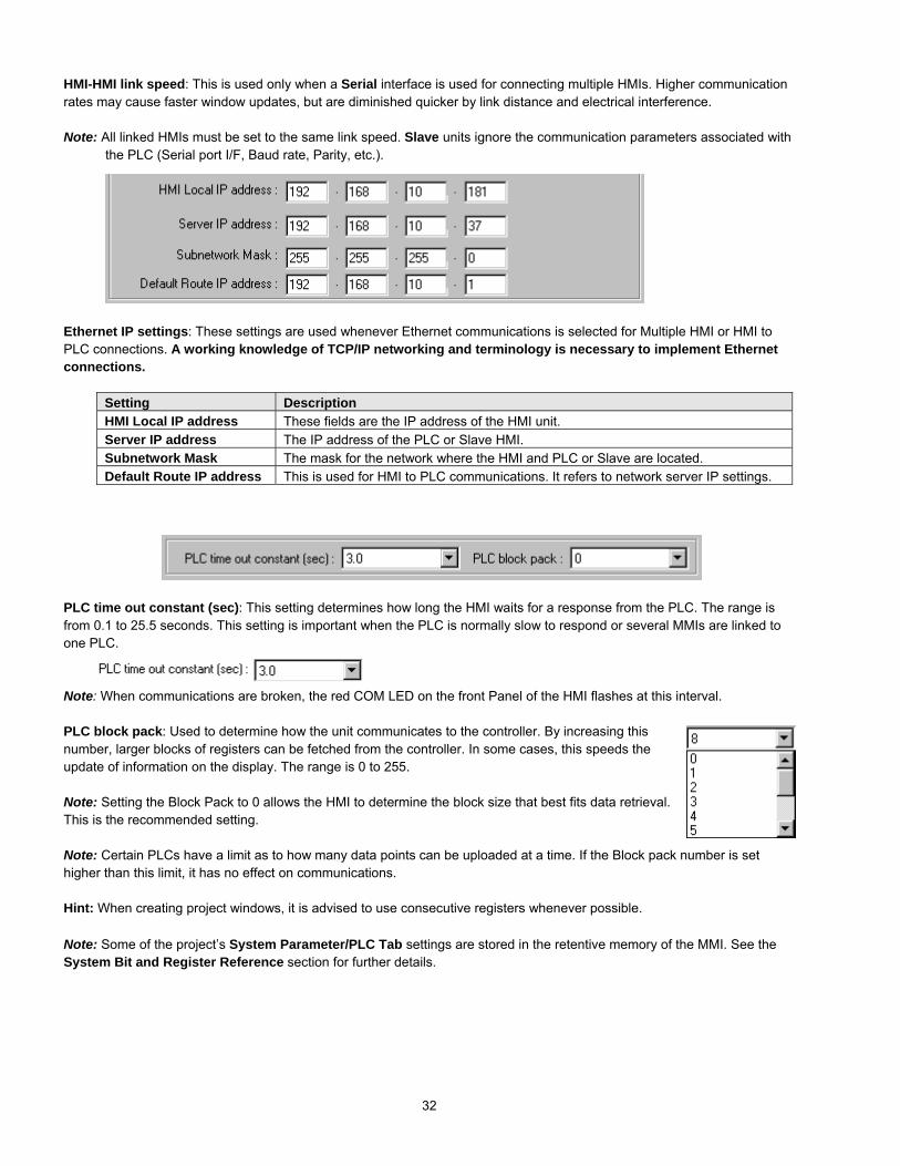
32
HMI-HMI link speed: This is used only when a Serial interface is used for connecting multiple HMIs. Higher communicationrates may cause faster window updates, but are diminished quicker by link distance and electrical interference.
Note: All linked HMIs must be set to the same link speed. Slave units ignore the communication parameters associated withthe PLC (Serial port I/F, Baud rate, Parity, etc.).
Ethernet IP settings: These settings are used whenever Ethernet communications is selected for Multiple HMI or HMI toPLC connections. A working knowledge of TCP/IP networking and terminology is necessary to implement Ethernetconnections.
Setting DescriptionHMI Local IP address These fields are the IP address of the HMI unit.Server IP address The IP address of the PLC or Slave HMI.Subnetwork Mask The mask for the network where the HMI and PLC or Slave are located.Default Route IP address This is used for HMI to PLC communications. It refers to network server IP settings.
PLC time out constant (sec): This setting determines how long the HMI waits for a response from the PLC. The range isfrom 0.1 to 25.5 seconds. This setting is important when the PLC is normally slow to respond or several MMIs are linked toone PLC.
Note: When communications are broken, the red COM LED on the front Panel of the HMI flashes at this interval.
PLC block pack: Used to determine how the unit communicates to the controller. By increasing thisnumber, larger blocks of registers can be fetched from the controller. In some cases, this speeds theupdate of information on the display. The range is 0 to 255.
Note: Setting the Block Pack to 0 allows the HMI to determine the block size that best fits data retrieval.This is the recommended setting.
Note: Certain PLCs have a limit as to how many data points can be uploaded at a time. If the Block pack number is sethigher than this limit, it has no effect on communications.
Hint: When creating project windows, it is advised to use consecutive registers whenever possible.
Note: Some of the project’s System Parameter/PLC Tab settings are stored in the retentive memory of the MMI. See theSystem Bit and Register Reference section for further details.

33
7.2.2 The General Tab
Task buttonThe Task button is used to pop up the FastSelection window or display the Task Bar.Minimized window’s icons are put on the TaskBar. This gives the project a familiar graphicaluser interface.
Note: Refer to the Task Bar Operationssection for a full description of the Task Buttonfeatures.
Attribute: Enables or disables this feature. Ifdisabled, the FastSelection windowand Task Bar are notavailable at run time.
Background color: This dropdown calls thecolor selection dialog. Select 1 of 16 colors forthe Task Bar background.
Position: The Task buttons can be located onthe right or left side ofthe display.
Text: Determines text alignment within the Task Buttons and minimized window icons.
Left adjust: Shifts text to the left side of the Task Buttons and minimized window icons.Center: Centers the text to the center of the Task Buttons and minimized window icons.
Alarm BarThe Alarm bar Part displays alarm text in single line scrolling fashion. These settings affect how the text is scrolled.
Pixels per scroll: Select 8, 16, 24 or 32 from the drop-down menu. This specifies how many pixelsare scrolled in each increment. For example: If the Pixels per scroll were set at 8 and the font size ofthe Alarm Bar was set to 24 (characters are 12 pixels wide), 2/3 of a character would be scrolled inwith each elapse of the Scroll speed time. The larger the number the faster a given message isdisplayed.
Scroll speed: This setting determines how fast each increment of the scroll is displayed (Range: 0.0to 25.5). The setting is the time between characters. The smaller the number, the faster the alarmmessages are displayed. 0.0 is the fastest with no break between characters.
Note: Text blurs at high speeds!Note: Refer to the Object Reference Guide for more details about Alarm Bar operation.

34
No. of windows: This setting is used to specify the maximum number of windows allowed open atany one time (1 - 6). The unit ignores attempts to open more windows than specified until anexisting window is closed.
When more windows are open than recommended, system resources may drop low enough totrigger a "System severe error" message". When the error occurs, the unit must be reset or powermust be cycled to the unit before project execution can resume.
Note: The maximum number allowed is 6. It is recommended to reduce the maximum by one for each of the followingconditions:
• The project has a Common window.• The project has a Message board window.• The project has print screen functions.• The project is using bitmap compression.
If all of the above conditions apply, restrict the maximum number of windows allowed to 2.
Note: The size of the minimized icon on the Task Bar is decreased as the minimum number of windows is increased. Byselecting a lower number, more room is given for a descriptive title in the minimized icon.
Startup window No.: This is the window displayed when the HMI is powered up. Valid window numbers are 10 - 1999.Note: If the specified window does not exist, the unit displays "System severe error (error code 10101)" when started.
Cursor color: Determines the color of the cursor when displayed. The full range of colors is available for this parameter.This is used with Data Input Extend and ASCII Input Extend parts. The cursor (a flashing block) indicates when data entry isenabled for a selected value.
Password: Activate the password option by entering any number greater than 0. This locks the project after it is downloadedso it cannot be uploaded without first entering the password.
Note: Password protection does not prevent the userfrom Downloading. There is no protection to preventa project from being overwritten.
Back light saver: The HMI turns off back light power if there are no touch operations within the settime (Range: 0 to 255, unit in minutes). A zero setting disables the back light “auto shutoff” function.
Buzzer: The buzzer sounds briefly every time the touchscreen is activated by touch. This selectionallows the programmer to turn off the buzzer. The buzzer can be annoying in some applications andduring development phases of a project.
Note: The buzzer cannot be assigned to alarms and is not associated with alarm functions.Note: There are no provisions for the user to control the buzzer.

35
Common Window: Window 6 is the default common window. Objects placed on a common window are always displayedand active. The following settings determine how they appear.
Popup window: Determines where an indirect or direct popup window called from the common window is displayed.Normal: The Popup window is displayed on the layer above the parent-calling window. If anotherwindow is on top of the calling window, it may hide the popup.Above any others: The popup window is displayed on the top layer when activated.
Attribute: Determines the location of the Common window. Below base screen: The common window is always on the bottom layer of the display. All windowscover the common window.Above base screen: The common window is always in the top layer. All windows are below thecommon window. Controls and objects on the Common window are always visible.
Extra No. of Event: Normally, 200 events are stored in the Event Log. If more than 200 events are needed, the additionalamount is entered here. Up to 2800 additional logs can be added. For example, if 1000 events need to be logged, enter 800in this field. See the Event Log part for details on the Event Logger.
RTC Source: The RTC Source determines where the Event Log part and Printer obtains the real time information for theirdisplay and printout.
Local Word: Uses the values in LW 9010 to LW9016. The RTC data from your PLC must betransferred to LW9010 to LW9016 before use. This is done with a Data Transfer part.Note: All values must be BCD coded.
LW Address Description Valid Values9010 Real Time Clock second. 0 - 599011 Real Time Clock minute. 0-599012 Real Time Clock hour. 0-239013 Real Time Clock day. 0-319014 Real Time Clock month. 0-119015 Real Time Clock year. 0-99999016 Real Time Clock day of the week. 0-6
Internal RTC: Uses the RTC in the HMI (RW60000 to RW60006). All values are BCD coded.
RW Address Description Valid Values60000 Real Time Clock second. (read and write allowed) 0 - 5960001 Real Time Clock minute. (read and write allowed) 0-5960002 Real Time Clock hour. (read and write allowed) 0-2360003 Real Time Clock day. (read and write allowed) 0-3160004 Real Time Clock month. (read and write allowed) 0-1160005 Real Time Clock year. (read and write allowed) 0-999960006 Real Time Clock day of the week. (read and write allowed) 0-6

36
Print: Use these settings to set the Printer protocol. This enables Function Key Screen and Event printing as well as thedisplay of printer errors. Time format for Event printing is also set here.
Printer: Select the printer protocol.None: Printing disabled.EPSON ESC/P2: Typically used with dot matrix line printers.SP Printer: Simple printing used with ASCII type printers.HP PCL/Simple Page Mode: Use with PCL compatible laser printers.
Note: Local Bit, LB 9017, is the control bit for printing. If LB9017 is set OFF/ON, printing is disabled/enabled.Note: If None is selected, all print functions and LB9017 are disabled.
Print time tag: Print the time in Hours:Minutes:Seconds format along with the printed information.Print date tag: Print the Date in Month:Day format along with the printed information.Print Sequence number: Select to print the sequence number of the event along with the event occurrence.Extended time format (D:H:/M): Change the time format in the time tag to Days/Hours/Minutes.Extended date format (Y/M/D): Change the time format in the time tag to Year/Month/Day.
Error Detection: Select how printer errors are handled.Local Bit LB 9016 is used for internal error reporting.
Setting DescriptionNo error detection Printer errors are ignored.Error detection (show message) A message box pops up on the HMI display when printer errors occur.Error detection (set local bit) LB 9016 is set to 1 when printer errors occur. LB 9016 remains high until reset by
some user action. It is up to the programmer to handle this error by popping up awindow or providing a way to reset the bit.
Message board window No. (0,10~1999): The message board allows the operator to draw a message within thedesignated window, using the touchscreen. This is especially useful when the operator needs to leave a note about machinestatus or the operator’s whereabouts when not at the machine. The operator can simply write “MACHINE DOWN” or“Lavatory”. Or, some process note or calculation can be entered as a reminder; such as “Backlash +.005”. The messagewindow retains its data until power is lost. This allows the message window to be closed and then opened later without lossof information.
Select the window number to be used as the message board.Note: Selecting 0 disables the Message board feature.Note: Only one Message board window per project is allowed.Note: See the Function Key part section for information about Message board controls.
Note: Some of the project’s System Parameter/General Tab settings are stored in the retentive memory. See the SystemBit and Register Reference section for further details.
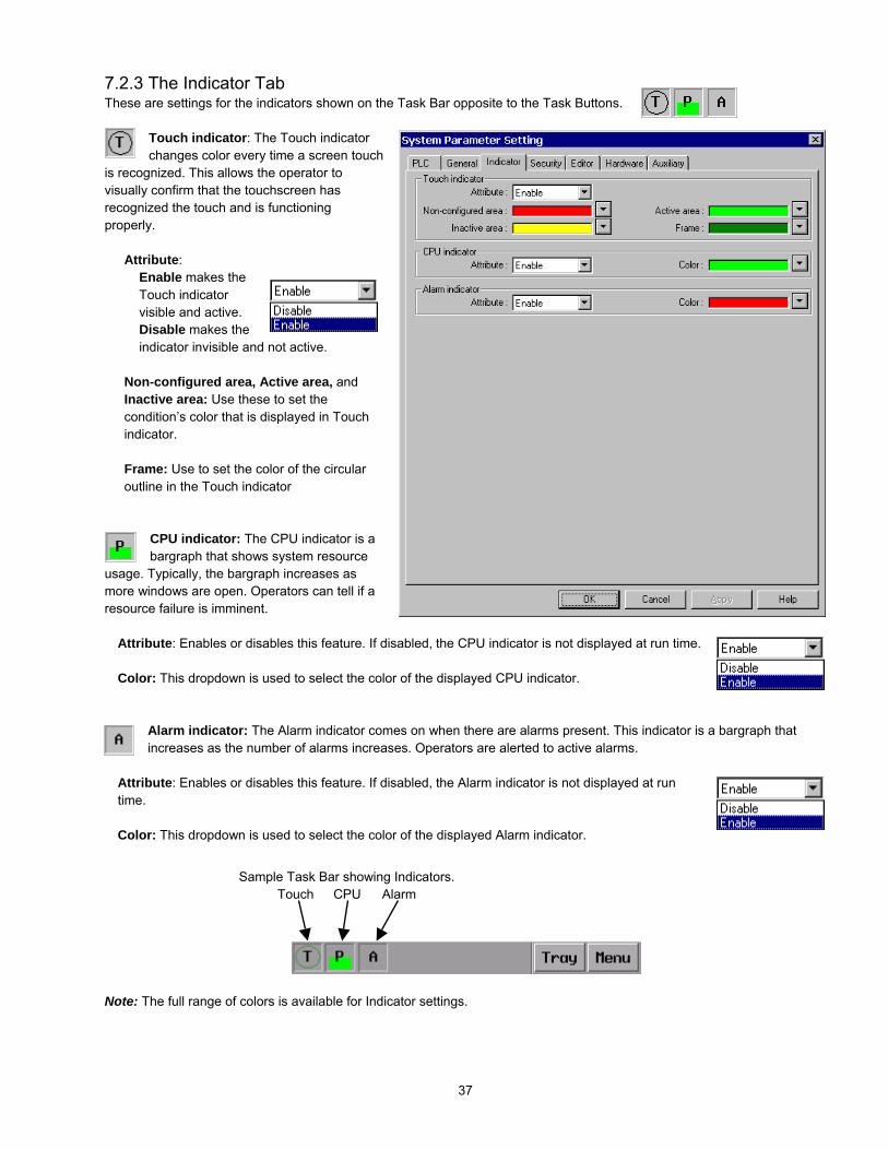
37
7.2.3 The Indicator TabThese are settings for the indicators shown on the Task Bar opposite to the Task Buttons.
Touch indicator: The Touch indicatorchanges color every time a screen touch
is recognized. This allows the operator tovisually confirm that the touchscreen hasrecognized the touch and is functioningproperly.
Attribute:Enable makes theTouch indicatorvisible and active.Disable makes theindicator invisible and not active.
Non-configured area, Active area, andInactive area: Use these to set thecondition’s color that is displayed in Touchindicator.
Frame: Use to set the color of the circularoutline in the Touch indicator
CPU indicator: The CPU indicator is abargraph that shows system resource
usage. Typically, the bargraph increases asmore windows are open. Operators can tell if aresource failure is imminent.
Attribute: Enables or disables this feature. If disabled, the CPU indicator is not displayed at run time.
Color: This dropdown is used to select the color of the displayed CPU indicator.
Alarm indicator: The Alarm indicator comes on when there are alarms present. This indicator is a bargraph thatincreases as the number of alarms increases. Operators are alerted to active alarms.
Attribute: Enables or disables this feature. If disabled, the Alarm indicator is not displayed at runtime.
Color: This dropdown is used to select the color of the displayed Alarm indicator.
Note: The full range of colors is available for Indicator settings.
Sample Task Bar showing Indicators.Touch CPU Alarm

38
7.2.4 The Security TabThe Security tab is used for setting security levels and access codes.
Note: Reference the Security section for further details on Security Control.
Security Control This check box activates thesecurity feature. Security levels are assigned towindows in their Window Settings dialog. Thereare three levels of security.
Lowest - Level 0 is the lowest level of security.
Middle - Level 1 allows access to Level 1 andLevel 0 windows.
Highest - Level 2 is the highest level of securityand can access all levels.
Each level’s password is a double word value (0to 99999999). Passwords are numeric digitsonly and cannot contain any alphabetcharacters.
Note: A password of 0 for a Security leveldisables security for that level (all users canaccess that level).
Note: The project’s Security level settings arestored in the retentive memory of the MMI. Seethe System Bit and Register Referencesection for further details.

39
7.2.5 The Editor TabThe Editor tab allows the programmer to change the project characteristics.
Beginning windowNo.: Changes thewindow numberingso it starts with 1instead of 10.
Internally, EasyBuilder maintains the initialwindow of 10 but displays all window numberswith an offset so they appear to start with aninitial window of 1.
Note: System windows that start with anumber less than 10, such as the FastSelect window, now appear with negativenumbers in the Window Treebar.
Note: Changing this does not affect thewindow numbering for specifying theStartup window setting in the SetSystem Parameters General Tab.
Compiler level: Thisselection is used todetermine the compiletype. Older projects didnot have any checks for PLC address type. UseLevel 0 to recompile older projects and Level 1for all new projects. Old projects work on newunits.
Part Layout: This selection determines what happens when a Part changes state, particularly whenthe Part is in a lower layer, possibly covered by another window or object.Select Control to have the part move to the topmost layer and become visible.Select Nature to have the part stay in its original layer, still changing state, though partially or notvisible.
Address Mode: This selection is used to enable Read and Write Device address fields to acceptExtended notation. Extended notation is used when a touchscreen is connected to more thanone controller. This is used with RS485/422 communications schemes.
Note: The selected PLC in the Set System Parameters PLC Tab must have multiple PLC communications available.For example: PLC type Modbus (485 2 wire) The addressing method is as follows:
Device type Address Description0x: 1#06 PLC 1, Data Bit 000064x: 2#45 PLC 2, Holding Register 400453x: 12#54 PLC 12, Input Register 30054
Number before '#' is theStation number: 0~255

40
Font: The font selection drop-down shows the selection of available fonts. Font selection is only used for Asiatic Languages.Font selection does not affect Western Languages. The fixed font files in EasyBuilder are always used.
Note: The Font selection works in conjunction with the Option|Language menu’s selection.Option|Language: This setting determines the character set that isused in project development.
Select Single Byte for European languages. Single Byte uses extended fonts (ALT key sequences) to typecharacters used in some European countries. Single Byte uses the built in fonts. These fonts are in the directory asAscfont.8, Ascfont.16 and Ascfont.24. These represent the 8, 16 and 24 point sizes. Larger sizes are generatedfrom these base sizes (Example: Font size 32 is actually size 16 doubled).
Select Double Bytes for Asiatic languages. Use the Font setting in the System Parameters Editor Tab to select theappropriate character set.
Note: The fixed western fonts can be edited using the EasyAsciiFontMaker editor included with the software. UseEasyAsciiFontMaker to edit the Font files if a character is not found.
7.2.6 The Hardware TabUse the Hardware tab settings for configuringTFT display characteristics, display orientationand retentive memory use.
LCDDisplay Mode:Determines the orientationof the project on thedisplay.
Landscape is for wide aspectdisplays. The long edges of thedisplay are the top and bottomof the windows. (Default)
Portrait gives a vertical orientationto the project. The long edges ofthe display are the left and rightsides.
TFT PCD Value: This setting applies to theMMI1500T and MMI750T only. It allows theuser to change the PCD of the display. ThePCD is related to the scan frequency of LCD;(the higher scan frequency, the more stable thedisplay).
Suggested use:Set TFT PCD as High if there is no message board in the project.
Set TFT PCD as Low if there is a message board in the project.

41
Retentive MemoryThese settings apply to how the retentive memory is allocated in the unit.
EventLog DataBase: Enables user to keep EventLog information in retentive memory. When the HMI starts up, itchecks the in retentive memory and retrieves EventLog DataBase information.
DataBase Start Address: (0~59999). Information is stored in retentive memory starting with the specified address.Note: LW9058-9059 contains the size in words of the EventLog in retentive memory. Keep in mind that once ablock of retentive memory has been reserved, your project cannot use it for other purposes. We recommend thatyou specify the DataBase Start Address to be after stored recipes so they are not overwritten with Event Log data.
System Parameter: Enables the user to change some System Parameter Settings in the HMI. The parameters arestored in retentive memory beginning with RW60040.For example: RW60041 represents the PLC port baudrate. If you change this value, the next time the HMI ispowered up, the baudrate is set to the value in RW60041.Note: Set LB9044 to ON to activate System Parameter changes from the Retentive Word area immediately.Note: Caution should always be observed when changing System Parameters. There is the possibility of makingthe unit unable to function in the application. When this happens, the project must be downloaded again to restorethe System Parameters.Note: System Bit and Register Reference listing of System Reserved Words.
General Tab System ParameterRW60061 Back light saver: 0(Disable)1~255 second(Enable)RW60064 Buzzer: 0:None 1:YesSecurity TabRW60071 Security Control: 0:None 1:YesRW60072 Password: level 0 (two words)RW60074 Password: level 1 (two words)RW60076 Password: level 2 (two words)

42
7.2.7 The Auxiliary TabThe Auxiliary tab is used for configuring the auxiliary port. This port is configured in the same fashion as the PLCcommunications port. Special drivers are needed for this port. This port does not support AB DH485 or TELEMECANIQUEUniTelWay communications.
Aux. type: Select the type of PLC fromavailable PLC selection menu. The dropdowndisplays all of the PLC drivers available. Thesedrivers are located in the \Drivers -SubDirectory with the *.pds extension. Selectthe driver that matches your PLC’s protocol.
Serial Port I/F: Selectthe Auxiliary port’stype of hardwarecommunications. TheHMI activates the corresponding port pins. OnlyRS232 and 2 wire RS485 configurations areavailable.
Note: For additional information aboutcommunication configurations for a selectedPLC, see the Controller Reference Guidesection that refers to that PLC.
Note: The AUX[RS-485] PC[RS-232] port is adual port.
Baud rate, Parity, Data bits and Stop bits: Setthe baud rate to match the PLC ports settings.
Comm. delay and Additional Parameters:The Comm. delay parameter is used for setting an interval between communications requests to the controller. Enter anumber from 0 to 999. The number specifies the 10-millisecond intervals between communications. Foe example: a settingof 100 puts a 1-second interval between communications requests. This parameter will slow data update rate on a window. Italso gives slow controllers a way to meet processing demands without too many interruptions.
Set the other additional parameters as required by your driver. See the Controller Reference Guide section that referencesthe PLC driver for further details.

43
Aux. Station: Used when PLCs have a node or station identifier. The HMI needs the station number to initiatecommunications. Set as needed or leave at 0 if not used. Station numbers are 0-255 (Use the range as appropriate for PLCtype). If the PLC station number does not match the PLC, the “PLC no response” error message is displayed.
Aux. time out constant (sec): This setting determines how long the HMI waits for a response from the PLC. The range isfrom 0 to 127 seconds. This setting is important when the PLC is normally slow to respond or several MMIs are linked to onePLC.
Note: When communications are broken, the red COM LED on the front Panel of the HMI flashes at this interval.
Aux. block pack: Used to determine how the unit communicates to the controller. By increasing this number, larger blocksof registers can be fetched from the controller. In some cases, this speeds the update of information on the display. Therange is 0 to 255.
Note: Setting the Block Pack to 0 allows the HMI to determine the block size that best fits data retrieval. This is therecommended setting.
Note: Certain PLCs have a limit as to how many data points can be uploaded at a time. If the Block pack number is sethigher than this limit, it may effect communications.
Hint: When creating project windows, it is advised to use consecutive registers whenever possible.

44
WL-001
7.3 Part Placement
7.3.1 Part Placement SummaryA window is composed of a variety of parts such as Switches, Lamps, Numerical data andGraphics. The procedure to add a part to the window is a simple, 3 step, procedure.
1. Select a Part by either clicking on a Parts toolbar icon, or dragging over to one of the Partsmenu’s selections.
2. When the Part’s dialog box appears, set the Part’s attribute data, such as PLC read/writeaddress, Shape or BMP, and Label as described in this section. Some Parts haveadditional tabs that require more information.
3. After all of the Part’s attributes have been set, simplyclick on the OK button to place it on the current window.If desired, use the Part’s sizing handles to adjust itssize, or click on the Part to select it and drag itanywhere on the window.
Typical Part’s Dialog Box
7.3.2 Part ID NumbersAn ID number is a code number that is assigned automatically to a Part or Object.
The number identifies the specific part on the current window.
The Part ID is shown in the upper left corner of the part.
The 2-letter prefix identifies what type of object it is. The suffix identifies the numberof that object. Numbering begins at zero for each type on each window.
Objects are displayed by Part ID in the Window Treebar. Clicking on the part in theTreebar highlights it in the window. See Treebar Operations for more details.
The displaying the Part ID is disabled by unchecking the Display setting in theOption|Window Property menu item.
Note: The programmer cannot change the ID number.
ID Number
A Bit Lamp

45
7.3.3 Part Dialog FeaturesThis section gives a brief overview about part definition. Some Parts have additional tabs that require additional information.For full details about a particular part see Section 3, Object Reference Guide.
7.3.3.1 The General Tab
7.3.3.1.1 Attaching a DescriptionIf desired, a comment can be attached to a Part. This is a good practice for future reference and useful when editing aproject. The maximum description length is 1023 characters.
Note: Descriptions are not downloaded to the MMI. An uploaded project has blank description fields.Note: Descriptions are not included in the Object Summary printout..
7.3.3.1.2 Entering a PLC Read or Write addressValid Device types and Device addresses depend on the individual PLC type. If you haven’t done so, select theappropriate PLC type in the Edit|System Parameters menu item.
Direct Device EntrySelect the Device type from the drop down list. Usually these prefixes are the same as those used in the PLCsdocumentation.
Next, enter the Device address. The Device address does not need the prefix repeated. The device address alsodoes not need leading zeroes.
Example: Selecting R00023 as a read address; Select R as the Device type, enter 23 as the Device address.
Note: Entering bit addresses.Bits are usually entered as the bit word followed by the bit number. When entering bit numbers, delimiterssuch as “space”, “.” and “/” should not be used. For example bit 11 of Input word 3 would be entered as “311”.In some cases, a hexadecimal notation is required (3A). See the Controller Reference Section, for details onbit format for your particular controller.
Attribute: Additional information for part characteristicsis entered here.
Device address: Bit or register number as isapplicable.
Enter your description here. A reference name (notdisplayed) that you assign to the Part.
Device type: Click down arrow icon to show possibleaddress types.
Check box to enable Device selection by Tag name.
Select to receive data as Binary or BCD encoded.
Check box to redirect request to the Auxiliary port.

46
Note: Extended address modeWhen more than one unit is connected tomultiple PLCs of the same kind. (Available forsome RS485 models listed with the 485 2Wsuffix.
The addressing method is as follows:Device type, followed by the PLC ID number, a'#', then the word or bit number.
As shown in diagram: PLC 3, 0x, bit 27 is usedfor Device.
Example: Modbus RTU (485 2W)Device type Address Description0x: 1#06 PLC 1, Data Bit 000064x: 2#45 PLC 2, Holding Register 400453x: 12#54 PLC 12, Input Register 30054
Note: PLC ID number range is limited to: 0~255.
Note: HMI Internal registers and bits. (Reference the System Bit and Register section.)• LB (Local Bit) and LW (Local Word) are the designations for internal bits and words of the MMI. The range for
general use is 0 to 8999. Bits and words from 9000 to 9999 are reserved for system use.• RB bits and RW words are internal retentive memory options. RBI and RWI are the indexes to retentive memory
locations.• Ms_RB, Ms_RW, Ms_LW and Ms_LB are bits and words located in the Master HMI when Master/Slave link ups
are used.
Using a Tag to enter a Read or Write DeviceCheck the Tag box to select a Tag for the Device
Type and Address. Select the Tag that corresponds to thecontrol bit or word for the Part.
Note: Tags must be predefined before use. The Tagdatabase is located in the Library|Tag… menu. See thesection on Tags for more details.
Retrieving Data from the Auxiliary PortCheck the Aux. box to direct the source of the
Read/Write address to the Auxiliary Port.
Note: Be sure the Auxiliary Port is set in the SystemParameters. If no device is present on the Auxiliary port,an error will be returned.

47
7.3.3.1.3 Data format typesBIN (binary format) Decimal numbers are encoded by bit weight
15 0215 214 213 212 211 210 29 28 27 26 25 24 23 22 21 20
BCD (binary coded decimal format) Decimal numbers are encoded by bit weight per 4-bit nibble15 12 11 8 7 4 3 0
103
102
101
100
For example: The Read address raw data is 0000 0100 0010 0101.The BIN format treats the data as 1061The BCD format treats the data as 425
7.3.3.1.4 AttributesSome Parts have Attribute parameters on the General Tab. Select the desired attribute from the dropdown and fill inany information required. The attributes vary from part to part. Reference Section 3, Object Reference Guide, forcomplete details about a Part’s attributes.
7.3.3.2 The Shape TabThe Shape tab is used to assign a graphic background to an object. If no graphic is assigned then the object has atransparent background. A frame is shown on the project window to indicate that a part is present. The frame is not visible insimulations or the MMI.
Selecting a Shape or Bitmap
1. Click on the Shape tab2. Select Use shape or Use bitmap3. Click Shape library or Bitmap library
The shape/bitmap browser pops up. Select the desiredshape/bitmap. Shapes are stored in shape libraries (*.slbfiles). Bitmap graphics are stored in Bitmap libraries (*.blbfiles).
A maximum of 10 libraries can be attached to a project. Bycalling up different shape or bitmap libraries, usefulgraphics for almost any application can be found. Userscan also build up their own shape and bitmap libraries.
Note: If both shape and bitmap are selected for a part, the graphic shown in the preview box is the one displayed on thewindow at run time. (Usually the Shape takes precedence.)
Note: Reference the Library Operations section for full details about the Library features.
Bit numberWeight
The State dropdown can be used to viewadditional states of the selected shape.
The State select buttons can be used to viewthe various states of the selected shape.

48
7.3.3.3 The Label TabLabels are text that is shown on the face of the Switch, Lamp or other object (part). Different text can be assigned to differentstates of a part. Example: State 0 = ”OFF”, State 1 = ”ON”.
Adding a Label to a Part
1. Click on Label tab2. Select each state to label3. Select Attributes for the label4. Type the state’s label in the Content box
ColorSelect a color for the text from the popup Color dialog. Colors can be changed from state to state. The Grayscale units havea color selection of only 4 colors. If you have a color unit, there are 256 colors available. See the section on Drawing fordetails about color selection.
Align (Justification)Select the desired text alignment. Alignment can vary from state to state. When the text input for aLabel becomes 2 lines or more, the alignment can be defined as Left, Center or Right justified.
Note: Center justifies the lines of text only; it does not center the text on the object.
Note: Text alignment can be changed after a part is placed by using the text alignment tools in the tool bar.
FontSelect the desired font size. Font size can vary from state to state.Font sizes 8, 16, 24, 32, 48, 64 and 96 are available.
Note: Font size can be changed after a part is placed by using the font tools in the tool bar.
StateStates are displayed only for those objects with multiple states. The text displayed for each state can be set independently.Simply select a state in order to set its text, font, color and alignment.
Note: The State can be viewedafter a part is placed by usingthe State dropdown or StateSelect buttons in the tool bar.
Select Use Label Library to enable labelselection from a predefined set of Labels.
Select Tracking to place and move labelsof different states all at once and together.
Select Use Label to enable label display.
State 0
State 1

49
Content BoxThere are two options for applying text as the Label. The programmer can:Enter text directly in the Content box (Use label)OrSelect a predefined Label (Use Label Library).
Use label selected…Type in the characters to be displayed onthe button in the Content field. The“ENTER” key can be used to move to thenext line if desired. Text is limited byscreen size. If entered text exceeds thescreen size, it is automatically deletedwhen the part is placed. Be sure to entertext for all of the desired states.
Use Label Library selected…Select the label to use for the state fromthe Label Index dropdown. Text entryinto the Content Box is disabled. Click theLabel Library… button to add or viewpredefined labels.
Note: All states must use the same method for entering the label. You cannot have a predefined label for onestate and a directly entered text for another within the same part.
Duplicate this label to other statesClick this button to copy the displayed Content to all of the other state Contents. This action cannot be reversedusing Undo.
7.3.3.4 Part PlacementOnce all of the Attributes have been set as desired, click the OK button to place a new part on the screen. The part is shownin the upper left corner of the editing window. The part can then be dragged into position and resized as desired.
Note: Label PositionOnce the Part is placed on the window, the Label can be moved anywhere within the boundary of the object. Just clickon the label and drag the mouse to move it to the desired position. Toggle through the state designator to display thepredefined label in each state.
Note: If Tracking is enabled, the labels in all states are located where the current label is displayed.
Click on thelabel
Drag to movelabel
Click on theobject

50
7.4 Window OperationsEvery new project begins with a default window, window number 10. Usually more than one window is needed for a project.There are three types of windows – Base, Fast and Common. Allowable window numbers are from 10 to 1999.
Window typesBase Window:These are the normal windows displayed during HMI runtime operations. They are used as informational or control screensthat allow the operator manage a process. A PLC control or function key may call them up. They are also used with Directand Indirect Window parts to appear on the screen as needed. The possible range of Base window numbers is 10 to 1999(1 to 1989 if starting window is set to 1).
Fast Selection Window:The Fast Selection window is activated when the Screen Task Button is pressed. The size is limited to 10 to 200 pixels wideby 10 to 480 pixels high. It is designated as window number 4 (-5 if starting window is set to 1). See the System Parametersand Task Bar sections for more details about the Fast Selection window.
Note: Base windows can be reassigned to the Fast Select function through a Function Key with the Jog-FS action.The Base window replacing the Fast Select window must be the same height and width as the Fast Select window 4.
Common Window:Common windows are used as foregrounds or backgrounds to Base windows. All controls on the acting Common windoware active. In addition, any objects drawn on the common window and parts with shapes/bitmaps are visible when on top ofthe controlling Base window. This saves memory by allowing the programmer to provide a common header or set of controlsthat are always active no matter what base screen is called.
The default Common window is window 6 (-5 if starting window is set to 1).
Note: Base windows can be reassigned as the Common window through a Function Key with the ChangeCommon Window action. Base window numbers 10 to 1999 can also be assigned as Common windows. When calledas Common windows they behave as Common windows by replacing the default Common window (6).
Note: Base windows may be specified as smaller than full screen to facilitate a pop-up operation. These smallwindows, when popped up, covers the Common window objects.

51
7.4.1 Creating New Windows
7.4.1.1 Procedure for Creating a NewWindow Number
In the Window menu, select the OpenWindow command.
In the Open Window dialog click on NewWindow….
Select the window type; Base Window orFast Selection or Common Window.
Or …
Right click on an undefined window number in the Treebar
Select Create from the popup menu.
Setup the window properties as desired
Name: Give each window a unique name in order toidentify it. The name is shown in the Window Treebar.
Note: Window Names are not downloaded to theMMI. Uploaded projects shows the default windowname.
Window No: This value can be changed if creating theWindow from the Open Window dialog. Valid windownumbers are from 10 to 1999 (1 to 1989 if startingwindow is set to 1).
Note: The window number cannot be changedafter a window is created.
Start Pos.: Set the coordinates of the upper left-handcorner of the window when displayed on the MMI. Thisapplies only if the window is less than a full screen.
Size: Set appropriate width and height if it is going to be a pop-up window, otherwise, set window width as full screen size(320x240 or 640x480 depending on model)
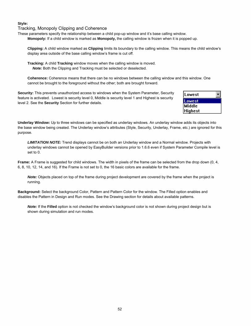
52
Style:Tracking, Monopoly Clipping and CoherenceThese parameters specify the relationship between a child pop-up window and it’s base calling window.
Monopoly: If a child window is marked as Monopoly, the calling window is frozen when it is popped up.
Clipping: A child window marked as Clipping limits its boundary to the calling window. This means the child window’sdisplay area outside of the base calling window’s frame is cut off.
Tracking: A child Tracking window moves when the calling window is moved.Note: Both the Clipping and Tracking must be selected or deselected.
Coherence: Coherence means that there can be no windows between the calling window and this window. Onecannot be brought to the foreground without the other; both are brought forward.
Security: This prevents unauthorized access to windows when the System Parameter, Securityfeature is activated. Lowest is security level 0, Middle is security level 1 and Highest is securitylevel 2. See the Security Section for further details.
Underlay Window: Up to three windows can be specified as underlay windows. An underlay window adds its objects intothe base window being created. The Underlay window’s attributes (Style, Security, Underlay, Frame, etc.) are ignored for thispurpose.
LIMITATION NOTE: Trend displays cannot be on both an Underlay window and a Normal window. Projects withunderlay windows cannot be opened by EasyBuilder versions prior to 1.6.6 even if System Parameter Compile level isset to 0.
Frame: A Frame is suggested for child windows. The width in pixels of the frame can be selected from the drop down (0, 4,6, 8, 10, 12, 14, and 16). If the Frame is not set to 0, the 16 basic colors are available for the frame.
Note: Objects placed on top of the frame during project development are covered by the frame when the project isrunning.
Background: Select the background Color, Pattern and Pattern Color for the window. The Filled option enables anddisables the Pattern in Design and Run modes. See the Drawing section for details about available patterns.
Note: If the Filled option is not checked the window’s background color is not shown during project design but isshown during simulation and run modes.

53
7.4.1.2 Opening Windows for EditingAfter a window is created, with the Open Windowdialog box select it from the list and double click it orpress Open to open the window.
Note: The windows marked with an “*” are alreadyopened.
To edit a window that has already been opened, just select Window menuthen select the window.
Alternatively, Right click thewindow number in the Treebar topopup the shortcut menu. Thenselect Open. If the window isalready open, double-click thewindow number to bring it to thefront.
Note: The windows marked withan “*” are already opened.
7.4.1.3 Modifying Window PropertiesSelect the Window|Open Window menu, Then select the window from the list and press Setting. The window propertiescan now be modified.
Note: The window number cannot be changed after window is created.
7.4.1.4 Deleting a WindowSelect the Window|Open Window menu.Then select the window from the list andpress Delete.
Alternatively, Right click the windownumber in the Treebar. Select Setting toedit the properties or Delete to delete thewindow.
Note: A window Delete cannot berestored with the Undo command!

54
7.4.2 Adding Objects to a WindowOnce a window is opened and displayed, the programmer can draw shapes and add parts to the window. Use the Draw andParts menu or toolbars to create the look and feel desired.Graphics placed with the Drawing Tools do not respond to touch actions. Some Parts do not react to touch actions. It isadvised that each part be reviewed and understood by going through the Parts Reference Section.
7.4.2.1 Drawing GraphicsClick on the drawing tool or select the item from the Draw Menu and drag the shape on the window. Once placed theshape can be resized using its “handles”. Handles are the highlighted squares that appear around the graphic when it isselected. An Attribute Dialog to adjust color and fill characteristics is available through Edit|Change Attribute… menuor by double-clicking the graphic or clicking on the Edit tool.
7.4.2.2 Adding PartsClick on the Part tool or select the item from the Part Menu. Fill in the Part’s Attributes in the popup dialog. Then, placethe Part on the window. Some Parts can be resized after placement. The Attribute Dialog can be recalled throughEdit|Change Atribute… menu or by double-clicking the Part, right clicking and selecting Attributes from the shortcutmenu, or clicking on the Attributes tool.
7.4.3 Copying and Importing Windows from Other ProjectsWindows created in one project can be copied or imported into another project. This is done through the Edit|Windowcopy… menu command. Selecting this menu item pops up the Window Copy dialog box.
Browse to the *epj file that has the window you want to copy or import. Fill in the Source Window No. from the *.epj project.Select a window number in the open project where the window is to be placed (Desti. Window No.). If the Destinationwindow already exists, the program displays a warning dialog that allows you to cancel the operation or continue. If youchose continue, it overwrites the window. Click OK to finish.
Note: Shapes and Bitmaps needed for the imported windows are not automatically brought into the open project. Be sure toattach the appropriate libraries before importing windows.
Note: A window copy cannot be reversed with the Undo command!
The above example shows Window 11 from project EBPrj1 about to be copied to window 14 of the open project.If the open project some project other than EBPrj1, the window is imported. If EBPrj1 is the open project then the window iscopied (duplicated) to the destination window number.

55
7.4.4 Changing and Popping Up WindowsEasyBuilder has 4 ways to change or popup windows during simulation or run operation. See Section 3, Object ReferenceGuide, for complete details about PLC Controls, Functions, Indirect and Direct windows, their attributes, and how toimplement them.
PLC controlled action:Use the Change Window PLC Control to replace all other Base windows being displayed. Common and FastSelection windows are not affected.
Operator controlled action:Use Function parts with the Change Window attribute to replace all other Base windows being displayed. Commonand Fast Selection windows are not affected.
Use Function Key parts with the Popup Window attribute to place another Base over top of the active window. Theonly way to close a popup window is to put a Function button with the Close Window attribute in it.
Note: A popup window of this type cannot use a Function part to pop up another window.
Use Function Key parts with the Change Common Window attribute to replace the currently active common window.Base and Fast Selection windows are not affected.
Use Function Key parts with the Jog FS-Window attribute to replace the currently active Fast Selection window.Common and Base windows are not affected.
Use Function Key parts with the Return to Previous attribute to replace the current Base window with the last activeBase window. Common and Fast Selection windows are not affected.
PLC or Operator controlled action:Use Indirect and Direct window parts to overlay popup windows over active windows in a predefined area. Windowscalled by Indirect and Direct window parts do not replace full screen windows.
Note: Indirect and Direct windows can call up other Indirect and Direct windows.
Note: Indirect and Direct windows do not work properly when they are on the same Base window as a Functionkey Popup Window part. Additionally, do not put Function key Popup Window parts on Indirect and Directwindows.

56
7.5 Task Bar OperationsThe Task Bar allows the programmer to create projects with familiar graphic features. The Task Bar holds the buttons for apop-up menu and system tray. This allows the user to pop-up (maximize) or icon-ize (minimize) child windows and changewindow displays. The “Task bar” must be enabled in the System Parameters for the Task buttons to be displayed.
7.5.1 Task Button Overview
Press the Screen task button to pop-up the Fast Selection window.
The Fast Selection window can have several Function parts (placed on it by the user) to change to different windows. Sincethe Fast Selection window is global to all windows, it can be called up at any time. To change windows, press the functionpart that targets the destination window.
The Window Bar accommodates up to six window icons. Double-click the Minimize function part of a window to shrink thatwindow to the Window Bar. Click it again to return the window to its original location and size.
Typical Task Buttons(As shown above)
Window BarExpands outWindow Bar
Fast SelectionWindow
Expands out FastSelect Window
Alarm, CPUand TouchIndicators
Window Button(Expands out the Window Bar)
Screen Button(Pops up Fast Selection Window)

57
7.5.2 Procedure to Setup Task Buttons
1. Select Edit|System Parameters menu. Click on the General Tab.
2. Select the different drop downs to determine how the task bar appears.
Select Attribute Enable.
Note: The task buttons are visible at run time in the lower rightor left corner of the display. The Task buttons are not visible when editing a window.
Select Background color from pop up dialog. Extendedcolors are not available for the Task Bar background.
Position: This selection determines on which side the Fast Selection window andTask Buttons are displayed.
Select Right or Left.
The Text attribute is used to determine how text is displayed in the task buttons andWindow Bar icons.
Select Left Adjust or Center.

58
3. Once the selections in the System Parameters dialog have been set, select the Window menu, Open Window item.
Click Taskbutton….
Fill in the blanks of the Window Setting dialog.
Name: This is always fixed as Task Bar
Window No. This is always fixed at 2.
Start Pos.: Changes to X and Y have no effect.The task bar is always positioned at the bottomof the screen.
Size: Enter the size of the combined two TaskBar buttons. Each is given half of the Widthspecification.
Width: The range is 10 to 200Height: The range is 10 to 100
Note: The Window Bar is the same height asthe Height specification. The Indicators aredisplayed as square objects with the Heightspecification determining their size.
Change of Style has no effect.
4. Click the Window.... and Screen.... buttons to setup the Task Buttons.

59
The Window Attribute dialog has the settings for thebutton that controls the Window Bar where window iconsare displayed.
The Screen Attribute dialog has the settings for thebutton that controls the popup Fast Selection window.
A Description can be entered if desired.
Attribute: Show speed: Select Fast or Slow. This settingdetermines the pop up animation speed.
Shape: Select a shape for the Screen or Window button.Just like any other button object.
Label: Place a customized label on the Screen or Windowbutton. Just like any other label.
Note: Label text is limited to the button width. Use appropriate text Size and Color.
Once these 4 steps are completed, run the project in Off-line simulation to see how the Task Bar appears. Edit the Task Baras needed to obtain the desired appearance.

60
7.5.3 Creating the Fast Selection WindowEvery new project starts with a default Fast Selection Window. This window can be deleted and a new Fast Selectionwindow created to fit your needs. To create a new Fast Selection window first delete the existing Fast Selection window.
Select Window menu, Open WindowClick the New Window…. button, then click Fast Selection.
Alternatively, Right click window 4 in the WindowTreebar. Then select Create from the pop up menu.
Fill in the blanks of the Window Setting dialog.
Name: This is always fixed as Fast Selection
Window No. This is always fixed at 4.
Start Pos.: Changes to X and Y have no effect.The Fast Selection is always positioned at thebottom of the screen.
Size: Enter the size of the Fast SelectionWindow. The Width and Height size are limited.
For 640 x 480 pixel displays range is:Width: 10 to 200Height: 10 to 480
For 320 x 240 pixel displays range is:Width: 10 to 200Height: 10 to 240
Change of Style has no effect.
Security Level has no effect on Fast Selectionwindows. These windows are alwaysaccessible.
Underlay Windows can be assigned as desired.
Set the Frame and Background attributes as desired.
Follow guidelines in the section on “Creating New Windows” to place buttons and parts on the Fast Selection Window.
Note: Any objects that can be placed on a Base window can be placed on the Fast Selection window.

61
7.5.4 Using the Task BarThe Task Bar is used to hold the window control buttons of pop-up child windows. Window control buttons only appear if aWindow Bar Function part is on the child window. Minimize window parts are not necessary but helps when multiplewindows are displayed to clear the screen.
Function Parts are used to create title bars and minimize icons for child windows. See the Object Reference Guide sectionfor more details about creating and using Function parts.
Base windows can be minimized by putting a Function part with the Minimize window attribute on them.
Base windows that have a Function part with the Window Bar attribute can be moved. The label text in the title bar istruncated and shown in the reduced icon form in the window bar.
Example:1. A Numeric Input Extend part is on a window.2. A pop-up keypad is activated when the Numeric Input Extend part is
touched. The Keypad has a Window Bar and Minimize windowFunction part in it.
3. The operator can minimize the keypad to view the original number ifdesired.
4. Touching the Minimized button on the Task Bar restores the keypadwindow.
Window showing Numeric Input Extend partand Task Bar
Example: Part 1
Window showing pop-up Keypad windowwith Control button on Task Bar
Example: Part 2 and 4
Window showing minimized Keypad windowwith Control button on Task Bar
Example: Part 3
Window Bar Part
Minimize Window Part
Minimized windowControl button

62
7.6 Library Operations
7.6.1 Library OverviewLibraries are a way to create a collection of bitmaps, shapes and groups that apply tothe project being developed. Library objects become available to a project when theLibrary they are in is attached to the project.. To view attached libraries, go to theLibrary menu, select the Shape, Bitmap or Group category and the Call up Librarysubmenu item.
Default libraries are automatically assigned to a new project. Libraries can be added ordeleted from a project at any time. Up to 10 libraries can be assigned to a project.
EasyBuilder provides three types of libraries:1: Shape Library: A Shape is a collection of drawing elements put in by the programmer with the EasyBuilder drawingtools. Those elements, when put together, define a graphic symbol representing a button, lamp, function key etc.
2: Bitmap Library: A Bitmap graphics (BMP) is a collection of pixel of data. This data can come from screen captures,paint or drawing software packages that can generate *.bmp files. Bitmaps smaller than 250 KB and up to 256 colorsare allowed.
3: Group Library: A Group is a collection of objects. (i.e. A keypad would be a group of function buttons.) Commongroups can be saved to this library for use in other windows of the same project or for later use in other projects.
Comparison of Shape and Bitmap AttributesAttribute Bit Mapped Graphics Shapes
Arbitrary Graphic Good Limited to those graphics that can be designed bybasic drawing elements
Memory capacity Very large SmallEffect of enlarge & shrink Fair to Bad GoodDisplay Speed* Good Good
* The MMIs 32 bit processor displays both bit map graphics and shapes extremely fast, even during resize operations.
Click Select Lib. ... To attach an existing library to thecurrent project. Libraries are found in the Library D-Subdirectory where EasyBuilder is installed.
Shape libraries have the *.slb file extension.
Bitmap libraries have the *.blb file extension.
Group libraries have the *.glb file extension.
A sample library dialog
Shape Select Library Dialog
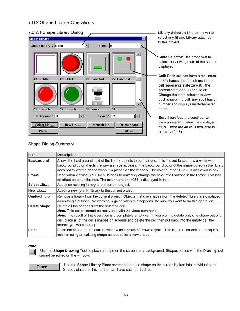
63
7.6.2 Shape Library Operations
7.6.2.1 Shape Library Dialog
Shape Dialog Summary
Item DescriptionBackground Allows the background field of the library objects to be changed. This is used to see how a window’s
background color affects the way a shape appears. The background color of the shape object in the librarydoes not follow the shape when it is placed on the window. The color number 1~256 is displayed in box.
Frame Used when viewing SYS_XXX libraries to uniformly change the color of all buttons in the library. This hasno effect on other libraries. The color number 1~256 is displayed in box.
Select Lib.… Attach an existing library to the current project.New Lib.… Attach a new (blank) library to the current project.Unattach Lib. Remove a library from the current project. Objects that use shapes from the deleted library are displayed
as rectangle outlines. No warning is given when this happens. Be sure you want to do this operation.Delete shape Delete all the shapes from the selected cell.
Note: This action cannot be recovered with the Undo command.Note: The result of this operation is a completely empty cell. If you want to delete only one shape out of acell, place all of the cell’s shapes on screens and delete the cell then put back into the empty cell theshapes you want to keep.
Place Place the shape on the current window as a group of drawn objects. This is useful for editing a shape’scolor or using an existing shape as a base for a new shape.
Note: Use the Shape Drawing Tool to place a shape on the screen as a background. Shapes placed with the Drawing toolcannot be edited on the window.
Use the Shape Library Place command to put a shape on the screen broken into individual parts.Shapes placed in this manner can have each part edited.
Library Selector: Use dropdown toselect any Shape Library attachedto this project.
State Selector: Use dropdown toselect the viewing state of the shapesdisplayed.
Cell: Each cell can have a maximumof 32 shapes, the first shape in thecell represents state zero (0), thesecond state one (1) and so on.Change the state selector to vieweach shape in a cell. Each cell has anumber and displays an 8-charactername
Scroll bar: Use the scroll bar toview above and below the displayedcells. There are 48 cells available ina library (0-47).

64
An empty new library dialog
7.6.2.2 Creating a Shape LibraryClick on the New Lib.… button. A Dialog Boxfor entering a file name appears.
Enter the name of the shape library to becreated.
Note: Be sure the library name is not alreadyused. Creating a new library with the samename as an old library erases the old library.Note: All shape libraries are automaticallyassigned the *.slb file extension.
NOTE: New and modified libraries are not saved to disk until the project is saved. Closing theproject without saving loses changed library data and new libraries!
7.6.2.3 Opening a Shape LibraryClick on the Select Lib.… button. A Standard Dialog Box for selecting a file appears. Select the name of the shape library tobe opened.
7.6.2.4 Adding a Shape to a Library1. Open a window and Draw the graphics by using the drawing tools in the EasyBuilder program. Forexample, the following graphic uses the circle and arc tools.
2. Select the whole graphic by using the arrow tool and dragging a rectangle around it. Whitehandles should appear on all of the selected objects.
3. Select the Library menu Shape submenu Save to library item
or click the tool.

65
4. Fill in the Dialog information.Item DescriptionShape library Used to select the Shape library for adding the shape.Shape No. Used to select the cell no. (Shape no.) for adding the
shape.State No. The State where the shape is to be added. This is
automatically set to the first empty location in the cell.Description Field to enter an 8-character name for the cell.
Note: Individual names cannot be assigned for eachstate.
OK Save the Shape to the specified cell and close thedialog.
Cancel Close the dialog without saving the shape to thespecified cell.
5. Click OK to finish.
7.6.2.5 Editing an Existing ShapeFirst, use the Place button and State dropdown to place all of the shapes for all states of the cell to be edited on windows.The shapes are then edited using the drawing tools. The cell being edited must then be deleted from the shape library. TheDelete shape button deletes all shapes in a cell. (The shapes cannot be restored with the Undo command.) The modifiedshapes are then saved back to the cell in state order sequence.
Note: There is no provision for editing or deleting only one state of a cell that has multiple states.
NOTE: New and modified libraries are not saved to disk until the project is saved. Closing theproject without saving loses changed library data and new libraries!
New library with example shape in cell 0
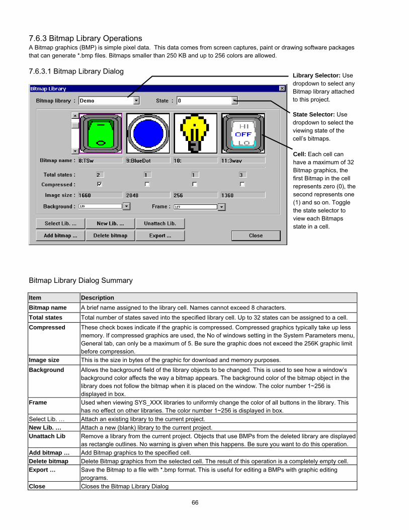
66
7.6.3 Bitmap Library OperationsA Bitmap graphics (BMP) is simple pixel data. This data comes from screen captures, paint or drawing software packagesthat can generate *.bmp files. Bitmaps smaller than 250 KB and up to 256 colors are allowed.
7.6.3.1 Bitmap Library Dialog
Bitmap Library Dialog Summary
Item DescriptionBitmap name A brief name assigned to the library cell. Names cannot exceed 8 characters.Total states Total number of states saved into the specified library cell. Up to 32 states can be assigned to a cell.Compressed These check boxes indicate if the graphic is compressed. Compressed graphics typically take up less
memory. If compressed graphics are used, the No of windows setting in the System Parameters menu,General tab, can only be a maximum of 5. Be sure the graphic does not exceed the 256K graphic limitbefore compression.
Image size This is the size in bytes of the graphic for download and memory purposes.Background Allows the background field of the library objects to be changed. This is used to see how a window’s
background color affects the way a bitmap appears. The background color of the bitmap object in thelibrary does not follow the bitmap when it is placed on the window. The color number 1~256 isdisplayed in box.
Frame Used when viewing SYS_XXX libraries to uniformly change the color of all buttons in the library. Thishas no effect on other libraries. The color number 1~256 is displayed in box.
Select Lib. … Attach an existing library to the current project.New Lib. … Attach a new (blank) library to the current project.Unattach Lib Remove a library from the current project. Objects that use BMPs from the deleted library are displayed
as rectangle outlines. No warning is given when this happens. Be sure you want to do this operation.Add bitmap … Add Bitmap graphics to the specified cell.Delete bitmap Delete Bitmap graphics from the selected cell. The result of this operation is a completely empty cell.Export … Save the Bitmap to a file with *.bmp format. This is useful for editing a BMPs with graphic editing
programs.Close Closes the Bitmap Library Dialog
Cell: Each cell canhave a maximum of 32Bitmap graphics, thefirst Bitmap in the cellrepresents zero (0), thesecond represents one(1) and so on. Togglethe state selector toview each Bitmapsstate in a cell.
Library Selector: Usedropdown to select anyBitmap library attachedto this project.
State Selector: Usedropdown to select theviewing state of thecell’s bitmaps.

67
7.6.3.2 Creating a Bitmap LibraryClick on the New Lib. … button. A Dialog Box for entering a file nameappears.
Enter the name of the bitmap library to be created.
Note: Be sure the library name is not already used. Creating a new librarywith the same name as an old library erases the old library.
Note: All bitmap librariesare automaticallyassigned the *.blbextension.
NOTE: New andmodified librariesare not saved todisk until the projectis saved. Closingthe project withoutsaving loseschanged library dataand new libraries!
7.6.3.3 Opening a Bitmap LibraryClick on the Select Lib… button. A Standard Dialog Box for selecting a file appears. Select the name of the bitmap library tobe opened.
7.6.3.4 Adding a BMP to a library
1. Click on the Add bitmap… button, the following dialog box pops up. Fill in cell no., assign a name to the bitmap, and enterthe number of Total states.
Item DescriptionBitmap No. The cell where the bitmap graphics are to be imported.Bitmap name A brief name for the bitmap that is displayed below the cell.
Up to 8 characters are displayed.Total states The total number of states to be in the cell. All states, up to
the number specified, must be assigned a bitmap.Next Continue on to the Get Bitmap dialog.Cancel Close the dialog without saving the bitmaps to the specified
cell.
Note: Once a cell has bitmaps added, it cannot be updated later with additional bitmaps. To update a cell, the bitmapsmust first be exported, the cell deleted, and the updated graphics added; along with the exported bitmaps.
When done, click on Next button…
The Get Bitmap Graphics Dialog opens.
An empty new library dialog
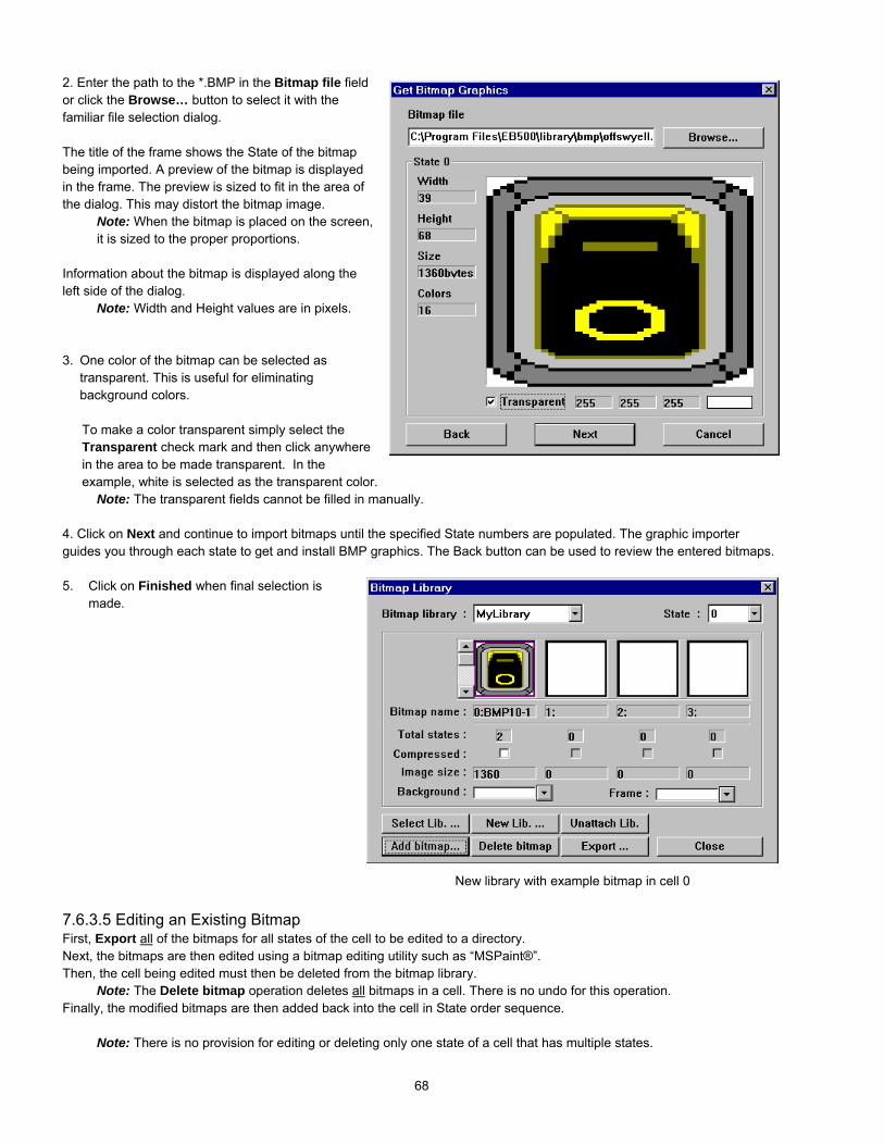
68
2. Enter the path to the *.BMP in the Bitmap file fieldor click the Browse… button to select it with thefamiliar file selection dialog.
The title of the frame shows the State of the bitmapbeing imported. A preview of the bitmap is displayedin the frame. The preview is sized to fit in the area ofthe dialog. This may distort the bitmap image.
Note: When the bitmap is placed on the screen,it is sized to the proper proportions.
Information about the bitmap is displayed along theleft side of the dialog.
Note: Width and Height values are in pixels.
3. One color of the bitmap can be selected astransparent. This is useful for eliminatingbackground colors.
To make a color transparent simply select theTransparent check mark and then click anywherein the area to be made transparent. In theexample, white is selected as the transparent color.
Note: The transparent fields cannot be filled in manually.
4. Click on Next and continue to import bitmaps until the specified State numbers are populated. The graphic importerguides you through each state to get and install BMP graphics. The Back button can be used to review the entered bitmaps.
5. Click on Finished when final selection ismade.
7.6.3.5 Editing an Existing BitmapFirst, Export all of the bitmaps for all states of the cell to be edited to a directory.Next, the bitmaps are then edited using a bitmap editing utility such as “MSPaint®”.Then, the cell being edited must then be deleted from the bitmap library.
Note: The Delete bitmap operation deletes all bitmaps in a cell. There is no undo for this operation.Finally, the modified bitmaps are then added back into the cell in State order sequence.
Note: There is no provision for editing or deleting only one state of a cell that has multiple states.
New library with example bitmap in cell 0

69
7.6.4 Group Library Operations“Group Libraries” enable multiple parts and drawing objects to be combined and saved, and then called up whenevernecessary. The Group objects saved in these libraries can be viewed and selected using the Browser function. Since groupsof objects may include parts that refer to Shape or Bitmap graphics, the related Shape and Bitmap libraries must be attachedto the project before calling up group objects.
7.6.4.1 Group Library Dialog
Group Dialog Summary
Item DescriptionSelect Lib. … Attach an existing library to the current project.New Lib. … Attach a new (blank) library to the current project.Unattach Lib. Remove a library from the current project.Place… Place the group in the selected cell on the window. The group can then be moved into position as
desired. Groups cannot be resized. Placed Groups can be ungrouped and edited if desired.Delete Delete group from the selected cell. The result of this operation is a completely empty cell.Close Closes the Group Library dialog.
7.7.4.2 Creating a Group Library Click on the New Lib. … button. A Dialog Box for entering a file name appears. Enter the name of the group library to becreated.
Note: Be sure the library name is notalready used. Creating a new library withthe same name as an old library erasesthe old library.
Note: All group libraries are automaticallyassigned the *.glb extension.
Library Selector: Use dropdown toselect any Group Library attachedto this project.
Including library: Use dropdownsto view Shape and Bitmap librariesused in creating the displayedGroup library. If the related Shapeand Bitmap libraries are notincluded with the project, the groupobjects are displayed as boundariesof shapes and/or bitmaps. Tocorrect this, go to the Shape andBitmap Library’s dialog and Attachthe required libraries.Shape and Bitmap Libraries mustbe attached to the project before agroup that uses them can beplaced.
Cell: Each cell holds one group.Each cell has a number with an 8character name.
Scroll bar: Use the scroll bar toview above and below the displayedcells. There are 48 cells available ina library (0-47).
An empty new library dialog

70
7.6.4.3 Opening a Group LibraryClick on the Select Lib… button. A Standard Dialog Box for selecting a file appears. Selectthe name of the Group library to be opened.
NOTE: New and modified libraries are not saved to disk until the project issaved. Closing the project without saving loses changed library data andnew libraries!
7.6.4.4 Adding a Group to a Library
1. Open a window and Draw the graphics by using the drawing tools. Also, add any parts such as lamps, function keys, etc.
Example: The group shown below uses Shapes, a Numeric Data part and Rectangles.
2. Use the arrow tool to select all the candidate objects on the window by draggingaround them.
3. Then, in the Library menu, select the Group, Save to library submenu or click on the tool.
4. Select the appropriate Group library. Then, fill in the Description and Group No. fields.
Item DescriptionGroup Library Used to select the Group library to hold the group.Description A brief name for the group that is displayed below the cell.
Up to 8 characters are displayed.Group No. The cell where the bitmap graphics are to be imported.OK Save the group to the specified cell and close the dialog.Cancel Close the dialog without saving the group to the specified
cell.
5. Click OK to save the selected objects to the group library.
New library with example group in cell 0

71
7.6.4.5 Editing an Existing GroupFirst, place the group on a window.Next, edit the group as desired.Then, delete the cell that has the original group. There is no undo for this operation.Finally, Save the edited group to the empty cell.
NOTE: New and modified libraries are not saved to disk until the project is saved. Closing the projectwithout saving loses changed library data and new libraries!
7.6.5 System LibrariesThere are 4 built in System Libraries. 2 Shape libraries and 2 bitmap libraries These Libraries are available for every projectand do not count towards the 10 library limit. The libraries are not stored in the \Library sub-Folder and cannot beUnattached from a project. System shapes cannot be edited or deleted. New shapes cannot be added to these libraries.
Note: Use System Shapes and Bitmaps to reduce the size of a project and to give it a consistent look.
7.6.6 Library Toolbar Functions
To call up an item from a library, either select one of the tool bar’s icons or use the pull downmenu’s [Library] command.
Save selected shape or bitmap to its respective library.
Call up a Shape library.
Call up a bitmap library.
Save group of objects to a Group library.
Call up a Group library.
7.6.7 Shortcut for changing a Part’s assigned Shape or BitmapNormally, a part is assigned a shape or bitmap when it is first edited, before placement on the window. The Shape or Bitmapcan then be changed by going to the Part’s attributes dialog, clicking on the Shape/Bitmap library button and then selectingthe shape/bitmap. All of the dialogs are then closed.
This process can be bypassed as follows.1. Simply click on the Part so its handles are showing.2. Then click on the library tool to call up the appropriate type of library,3. Select the Library and Cell then click OK in the library dialog.4. The dialog closes with the selected shape/bitmap automatically assigned to the part.

72
7.7 Tag Definition and UseA tag is a name that is used to reference a piece of data. Tags are assigned to any register or coil available. All of theregisters and coils used in your application can be defined beforehand.
The Tag Library is an important part of a touchscreen’s project. All Part definitions can be linked to this Tag Library. Thereare many advantages of a centralized library. You can change the tag data reference in the Tag Library, and all theinstances where the tag is used are updated.
The Tag Library dialog box is used todefine new tags and edit the properties ofexisting tags. You can access this dialogbox by selecting Tag… from the Librarymenu.
Item DescriptionAdd … Use to Add tags to the library.Delete Deletes a tag from the library.
Note: Tag cannot be recovered with Undo.Modify … Edit an existing Tag’s properties.Export … Exports defined tags to a file in EasyBuilder format.Import … Imports previously defined and exported tags from a project.Export CSV … Exports defined tags to a file in CSV format.Import CSV … Imports previously defined and CSV exported tags from a project.Exit Save and close the Tag Library
Note: Tags exported in EasyBuilder format can not be edited by other programs. Tags exported as CSV can be edited byprograms that can view standard CSV files.
7.7.1 Adding a Tag to the Tag Library
1. In the Library menu, select the Tag… item or click on the tool.
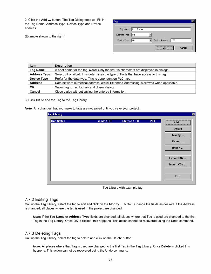
73
2. Click the Add … button. The Tag Dialog pops up. Fill inthe Tag Name, Address Type, Device Type and Deviceaddress.
(Example shown to the right.)
Item DescriptionTag Name A brief name for the tag. Note: Only the first 18 characters are displayed in dialogs.Address Type Select Bit or Word. This determines the type of Parts that have access to this tag.Device Type Prefix for the data type. This is dependent on PLC type.Address Data bit/word numerical address. Note: Extended Addressing is allowed when applicable.OK Saves tag to Tag Library and closes dialog.Cancel Close dialog without saving the entered information.
3. Click OK to add the Tag to the Tag Library.
Note: Any changes that you make to tags are not saved until you save your project.
7.7.2 Editing TagsCall up the Tag Library, select the tag to edit and click on the Modify … button. Change the fields as desired. If the Addressis changed, all places where the tag is used in the project are changed.
Note: If the Tag Name or Address Type fields are changed, all places where that Tag is used are changed to the firstTag in the Tag Library. Once OK is clicked, this happens. This action cannot be recovered using the Undo command.
7.7.3 Deleting TagsCall up the Tag Library, select the tag to delete and click on the Delete button.
Note: All places where that Tag is used are changed to the first Tag in the Tag Library. Once Delete is clicked thishappens. This action cannot be recovered using the Undo command.
Tag Library with example tag

74
Check the Tag box in the address frame to select aTag for the Device Type and Address. (Exampleshown above.)
7.7.4 Using TagsOnce a tag is defined it can be used anywhere a Read or Write Device is needed.
7.7.5 Exporting and Importing TagsDefined tags can be exported and imported to files for archiving, editing or use in other projects. Only tags exported to CSVfiles can be edited by other programs.
Export …: Exports tags in EasyBuilder format. This is the preferred format for archiving tags. Tags in this format can beimported into other projects but not edited with other programs.
Import …: Imports tags from a previous EasyBuilder formatted export operation.Note: This does not import tags from a PLC’s project.Note: If the imported tags were originally exported from a project with a different PLC driver, they will be converted to thecurrent PLC driver. Be sure to check tags for proper conversion.
Export CSV …: Exports defined tags to a file in CSV format. These tags can be viewed and edited with most text editors andspreadsheet programs.
Import CSV …: Imports tags from an exported CSV file or new file in CSV format.Note: If the CSV file has invalid data in one of the fields, One of the following occurs:A “?” is substituted for the invalid field
The project compiles with an error The project simulates/runs with errors Be sure to check tags for proper format.
Note: If the imported tags were originally exported from a project with a different PLC driver, they will be converted to thecurrent PLC driver. Be sure to check tags for proper conversion.
Note: CSV FormatField 1 Field 2 Field 3Tag Name Device Type Device Address
The Device type dropdown becomes the list ofdefined tags. Scroll through the list and select thedesired Tag.

75
7.8 Label Definition and UseA Label is displayed text that is used to identify data or states. Labels are assigned to any Part available. All of the possibletext for several languages or conditions can be pre-defined. The Label Library allows you to change the label texts. Whenthis is done, all instances of label use are updated.
The Label Library dialog box isused to define new labels and editthe properties of existing labels.You can access this dialog box byselecting Label … from the Librarymenu.
Item DescriptionState No. Select the State of the listed labels for display.Add … Use to Add Labels to the library.Modify … Edit an existing Label’s properties.Delete Deletes a Label from the library. Note: Label cannot be recovered with Undo.Export Exports defined Labels to a file in EasyBuilder format.Import Imports previously defined and exported Labels from a project.Export CSV File … Exports defined Labels to a file in CSV format.Import CSV File … Imports previously defined and CSV exported Labels from a project.Exit Save and close the Label Library.
7.8.1 Adding a Label to the Label Library1. Select in the Library|Label … menu or click on the tool.
2. Click the Add … button. The Label Dialog pops up. Fill in the Label Nameand Number of States for the Label. Once this information is entered, theLabel appears in the Label Library with no text assigned. The Modify …button must then be clicked to edit the label texts.
Item DescriptionLabel Name A brief name for the tag. Note: Only the first 18 characters are ever displayed in dialogs.No. of State Enter the number of States this label is to have. Note: The maximum number of States is 32OK Saves Label information to Label Library and closes dialog.Cancel Close dialog without saving the entered information.

76
7.8.2 Editing LabelsCall up the Label Library, select the Label to edit and click on the Modify … button. The Label Content Setting dialog isdisplayed. Change the fields as desired. If the Language text fields are changed, all places where the Label is used in theproject are changed. Use the State No. Dropdown to view the labels in their different states.
Note: Once OK is clicked, the label is savedand the dialog closed. This action cannot berecovered using the Undo command.
Example: Label entry for a label that displays OFFand ON depending on state. The label is assigned 2states. The Languages are English, Spanish, Frenchand German.The text entry for the State 0 (“OFF”) is shown.
Use the Change State No. … button to edit the totalnumber of states for the label being edited.
Label Library showing theexample tag in State 1.
Note: Label text is truncated after 6characters in the Label Librarydisplay. In actual use, the full labelis visible.
7.8.3 Deleting LabelsCall up the Label Library, select the Label to delete and click on the Delete button.
Note: Once Delete is clicked, all places where that Label is used have blank text. This action cannot be recoveredusing the Undo command.

77
7.8.4 Using LabelsOnce a Label is defined, it can be used anywhere text is needed. This includes all Parts that have Label Tabs, Text, andAlarm Scan and Event Log objects.
1. Check the Use Label Library box to enable label use.
2. Select the desired Label from the Label Indexdropdown.
3. Fill in other settings as desired.
Note: The Label Library button can be used to call up theLabel Library for adding labels without exiting the Part orObject dialog.
After a label is assigned to a part, the Language displayedis changed during Simulations or Application mode bychanging the value in System Reserved word LW 9130. (0corresponds to Language State 0, 1 corresponds toLanguage State 1, 2 corresponds to Language State 2,and 3 corresponds to Language State 3.)
A convenient way for an operator to change language is toassign LW 9130 to a Multistate Switch with the JOG+Switch style and No. of states set to 4.Hint: Make a Label in the Label Library for the MultistateSwitch so it is multi-language as well!
7.8.5 Exporting and Importing LabelsDefined Labels can be exported and imported to files for archiving, editing or use in other projects. Only Labels exported toCSV files can be edited by other programs.
Export …: Exports Labels in EasyBuilder format. This is the preferred format for archiving Labels. Labels in this format canbe imported into other projects but not edited with other programs.
Import …: Imports Labels from a previous EasyBuilder formatted export operation.Note: Labels that were originally exported from a project with a different PLC driver are imported with no detrimental effects.
Example of Toggle Switch Object’s Label tab using theexample Label created above.

78
Export CSV …: Exports defined Labels to a file in CSV format. These Labels can be viewed and edited with most texteditors and spreadsheet programs.
Import CSV …: Imports Labels from an exported CSV file or new file in CSV format.
Note: CSV FormatField 1 Fields 2~5 Fields 6~9 Fields 10~13 Fields … etc.Label Name Language 0~3
text for State 0Language 0~3text for State 1
Language 0~3text for State 2
Language 0~3 textfor State … etc.
7.9 SecurityThe HMI provides three user levels and one project level security settings. User security is activated by checking theSecurity Control check box in the System Parameters’ dialog Security tab. Project security is activated in the SystemParameters’ General Tab Password setting.
7.9.1 Security Levels
7.9.1.1 Project Security: Project security has only one level.7.9.1.2 User Security: There are 3 levels of user security. Level 0 is the lowest level of security (all have access to thesewindows regardless of the password), Level 1 is a middle level allowing access to level 1 and level 0 windows. Level 2 isthe highest level of security and can access all levels.
7.9.2 PasswordsPasswords are Digits only (0-9); Characters cannot be part of a password. Passwords cannot be negative or numbers withdecimal points.
7.9.2.1 Project Security: Each levels password is a double word value 0 to 4999999999 (up to 10 digits). A password of 0for a Project disables security for that project.7.9.2.1 User Security: Each Level’s password is a double word value (0 to 99999999). A Security level password of 0 is avalid password for locking out a level.
7.9.3 Assigning Security
7.9.3.1 Project Security: Go to the SystemParameters|General Tab, Password field to activateproject security. Activate the password option byentering any number greater than 0. This locks theproject after it is downloaded so it cannot be uploadedwithout first entering the password.
Note: Password protection does not prevent the userfrom Downloading. There is no protection to prevent aproject from being overwritten.
Example showing a password of12345 being assigned to a project.
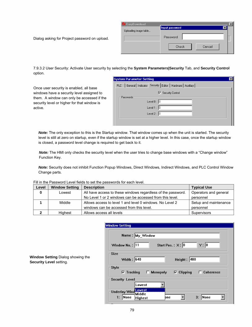
79
Dialog asking for Project password on upload.
7.9.3.2 User Security: Activate User security by selecting the System Parameters|Security Tab, and Security Controloption.
Once user security is enabled, all basewindows have a security level assigned tothem. A window can only be accessed if thesecurity level or higher for that window isactive.
Note: The only exception to this is the Startup window. That window comes up when the unit is started. The securitylevel is still at zero on startup, even if the startup window is set at a higher level. In this case, once the startup windowis closed, a password level change is required to get back to it.
Note: The HMI only checks the security level when the user tries to change base windows with a “Change window”Function Key.
Note: Security does not inhibit Function Popup Windows, Direct Windows, Indirect Windows, and PLC Control WindowChange parts.
Fill in the Password Level fields to set the passwords for each level.Level Window Setting Description Typical Use
0 Lowest All have access to these windows regardless of the password.No Level 1 or 2 windows can be accessed from this level.
Operators and generalpersonnel
1 Middle Allows access to level 1 and level 0 windows. No Level 2windows can be accessed from this level.
Setup and maintenancepersonnel
2 Highest Allows access all levels Supervisors
Window Setting Dialog showing theSecurity Level setting.

80
7.9.4 System Reserved Local Word Usage with Security
This applies to User Security only.Note: The Project Password is not stored in any user accessible memory location.
Internal Local Words LW9040~9043 are the reserved words for implementing security passwords.
Local Word Attribute DescriptionLW9040 -LW9041
Write/Read Double word, Different levels can be activated by changing the value in this register to acorresponding security password. Contains the last password value.
LW9042 Read only Contains the current active security level.LW9043 Write only Allows the project to force the HMI to a lower security level.
Note: A lower level cannot be forced to higher level.
7.9.5 System Reserved Retentive Word Usage with Security
This applies to User Security only.The security passwords are stored in retentivememory locations when the SystemParameter|Hardware, System Parameterdropdown is set to Yes.
Note: This allows the security passwordsto be changed if access to them isprovided in the project.They also are available for review if theproject is uploaded out of the HMI anddecompiled.
Retentive Word DescriptionRW60071 Security Enable: 1: enables the security password feature, 0 disables it.RW60072 Level 0 password (Lowest). 2 Word valueRW60074 Level 1 password (Middle). 2 Word valueRW60076 Level 2 password (Highest). 2 Word valueLocal BitLB9044 Set to ON to activate Security Password System Parameter changes made in the Retentive Word area.
The System automatically resets this bit to 0 when done.

81
7.9.6 How to Implement User SecurityUse a data entry object that accesses LW9040. In the Numeric Tab select it to be displayed as “Mask” and as 9 digits abovethe decimal point with the high limit as 999999999. Use an appropriate shape and for display. Be sure to provide a keypad inthe window for data entry and a way to activate the Trigger bit. See the Numeric Input Extend section for more details aboutdata entry objects.
Provide a way to force the level back to 0 when the secure operation is finished.
This is usually done by a Set Word part acting on LW9043with Set style Set at window close and Set value of 0. NoShape or Label needs to be assigned to the part (this makesthe part invisible). The part can be placed on any middle orhigh security window. An example of such a Set Word Objectdialog is shown on the right.
7.9.7 Additional Security Through the PLCAdditional security can be provided by using PLC data to control Direct and Indirect windows. Program the PLC to preventthese windows from being displayed unless a password compare is positive in the PLC.
These windows are put on the Common window for universal access or put only on special Base windows to further limittheir accessibility.

82
7.10 Print OperationsPrint Operations can be used for obtaining a hardcopy of events, tracking data during a process, documenting a condition fordata collection purposes and other various record keeping activities. Print functions facilitate the printing of data that is sentout as a graphic through the parallel printer port.Note: Actual printer setup is done in the System Parameter|General tab. If no printer is selected these features have noeffect.Note: MMI-720 and MMI-750 models do not have print capabilities.
7.10.1 Compatible printersSupported Printers
Protocol Impact Printers Inkjet Printers Laser PrintersEPSON ESC/P2 protocol LQ-300, LQ-300K+,
LQ-570, LQ-670,LQ-1600
Stylus Color 400, 800,850, 900, 950Stylus Photo 750
EPL-5800, EPLN-N2010,EPL-N2750, EPL-N4000+, EPL-N2010
HP PCL/Simple Page ModeHP PCL protocol
HP DeskJet 450, 640C,656C, 845C, 920C,930C, 1125C, 6122,5550
HP LaserJet 5L, 6LHP LaserJet 2200D
SP PrinterEPSON ESC protocol
EPSON ESC protocolcompatible 9-pin printersPoint of Sale 9-pinprinters
None Printing Disabled Printing Disabled Printing Disabled
7.10.2 Screen Printing with Function ButtonsSelect the Function Key menu item or tool to define a window touch area fortriggering print output. Select the Hardcopy option in the Create FunctionKey Object dialog. Use the Attributes .... button to select the desired printaction.
Selection Print actionPrint Text & Meter & Trend Prints bit and numerical data parts along with drawn objects and text
placed on the display.Print Text & Meter & Trend & AllShape but not including pattern
Prints the outline of bit and numerical data parts along with drawnobjects, text and shapes placed on the display.
Print Text & Meter & Trend & Bitmap Prints bit and numerical data parts along with drawn objects, text andbitmaps placed on the display.
Print Text & Meter & Trend & Bitmap& All Shape but not including pattern
Prints the outline of bit and numerical data parts along with drawnobjects, text, bitmaps and shapes placed on the display.
Print Text & Meter & Trend & Bitmap& All Shape
Prints bit and numerical data parts along with drawn objects, text,bitmaps and shapes placed on the display.
Form Feed Prints a Form Feed command.
Place and size the part in the window as desired. During run operations, when the function object is touched, the printaction is triggered.

83
7.10.3 PLC Controlled PrintingThere are two ways of printing by using a PLC data point. The Screen hardcopy control uses a bit in the PLC totrigger the printout and the Report printout control uses a word. If internal Local or Retentive data points are used,then the operator can trigger printing without the PLC getting involved.
7.10.3.1 Printing the currently active screenThis is used to dump the screen to the printer as a bitmap graphic. The Screen hardcopy PLC control monitors thespecified Read address. When the trigger bit turns ON, the unit prints the active base window. Once the printout isdone, the unit turns the controlling bit OFF. See the Object Reference Guide for more details about PLCControls.
7.10.3.2 Printing a window in the backgroundWindows can be printed in the background while touchscreen operations are being carried out. Use the Reportprintout PLC control. This control prints the window number designated by its Read address. After the window isprinted, the Read address is set to 0. For example, suppose that the Read address is D100. When the value ofD100 is equal to 20, the unit prints out window 20 in the background. When the unit is finished printing, the zero iswritten to address D100.
Note: System Register LW9054 specifies what is printed out in the report. Set this register before triggeringprintouts.Report printout options
0: All Text, Meters & Trends in the window1: All Text, Meters, Trends & Shapes but no pattern fills2: All Text, Meters, Trends & Bitmaps3: All Text, Meters, Trends, Bitmaps, & Shapes but no pattern fills4: All screen objects.
Note: System Register LW9055 acts as an offset for the Report printout control. Set this register beforetriggering printouts.Example: A PLC Control / Report printout uses D100. If (LW9055) = 6, and D100 = 24 then the unit prints outwindow 30. After printing, the unit writes back 0 to D100.
7.10.4 Printing EventsThe Event Logger control allows events to be printed. This is specified whenever an event is being defined. Theprinting can occur when the Event is triggered or when the event returns to its normal state. The SystemParameters|General Tab settings determine what is printed along with the Event message. The information selectedis printed before the message.
Information Item DescriptionPrint sequence number The number of the event. Event numbering starts at 0.Print time tag The time that the print was triggered. (Hours:Minutes:Seconds)Print date tag The date of the printing. (Month:Day)Extended time format (D:H:M) Change the time format in the time tag to Days:Hours:Minutes.Extended date format (Y:M:D) Change the date format in the date tag to Year:Month:Day.
Note: These settings are not the same as the settings in the Event Display Part. Those settings determine what isdisplayed on the screen, not what is sent to the printer.

84
8.0 Drawing
8.1 Line/Rectangle/Ellipse/Arc/Polygon
The following Attributes dialog box is displayed when drawing Line, Rectangle,Ellipse, Arc and Polygon objects:
Interior: The Interior attributes are for objects that can be filled(Rectangle, Ellipse and Polygon). For objects that cannot befilled, this option is disabled. The filled attributes are notdisplayed unless the Filled check box is selected.If the Filled option is selected, the following attributes can beset for Rectangle, Circle and Polygon.
Select Interior colors – Select a color from the 256-color (4colors for grayscale units) selection (4 colors for grayscaleunits).
Select pattern – Choose one of the 27 different patterns available. (See below for pattern selection.)
Select pattern colors – Select a color from the 256-color (4 colors for grayscale units) selection (See below for colorselection).
Frame: The Frame attributes are used to set how the lines for the object are displayed.Select Line types – Choose one of the eight selections for the line or frame width.
Select a Color– Select a color from the 256-color (4 colors for grayscale units) selection (See below for color selection).
8.1.1 Note on Pattern OptionsThe Pattern Style dialog pops up when the PatternStyle button is clicked. Select one of the 27 standardpatterns by clicking on it.
Scale
Bit mapGraphics
Arc
Shape
Polygon
Text
Line
Rectangle
Circle/Ellipse

85
8.1.2 Note on Color OptionsThe color window pops up when a color selection dropdown is activated. One of the standard colors may be chosen or clickon Customize color to access a full spectrum of color options. The color number is shown in small text inside each color’sdisplay. Additionally, the selected color’s RGB numbers are displayed.
256 Color options
16 of the 256 colors are available from the “basic” palette. Additionally, 16 more colors can be put in the Customized palette.Click the Customize color button to customize the secondary palette. The “customized” palette can be changed duringproject development without affecting objects that are already placed. This allows the full range of 256 colors to be used.
4 color options
8.1.3 Drawing Lines, Rectangles, Ellipses, Arcs and PolygonsTo draw a line, rectangle, ellipse or arc simply click and drag the mouse across the window after the appropriate drawing tooland attributes have been selected. Release the mouse and use the editing tools to resize or reposition as desired.
Note: To draw a polygon, click and drag the mouse across the window to the first point. Then click on the additionalpoints of the polygon. Right click the mouse to connect the last point to the first thus closing and ending the polygon.Polygon points cannot be edited, but overall size and position can be, by using the editing tools.
Note: Use the Grid tools to help make straight lines and regular objects.
Note: Holding the Shift Key down while drawing has the following effects:
Line: Restricts to diagonals onlyRectangle: Constricts to a Square shapeEllipse: Constricts to a CircleArc: Restricts to 90-degree segmentPolygon: Restricts to diagonal sides only
The Color Table shows 128colors, Click Next color table toaccess another 128 colors.

86
8.2 Text8.2.1 Placing Text
1. Click on the Text tool to display the Create Text Object dialog. Fill in the fields as indicated.
2. Fill in Text Tab as follows:
Color: 4 or 256 colors are available for selection,depending on model type (See above).
Font: Several font sizes are available: 8, 16, 24, 32,48, 64 and 96.
Align (Justification): When the text input for a displayor Label becomes 2 lines or more, the alignment canbe left, right or center justified.
Note: The Align setting does not determine where thetext is placed on the window.
Content: Type in the characters to be displayed. When typing in the characters, push the “ENTER” key to move to anew line.
Optionally a Label can be used for the text.
To use a Label for the text, select the Use LabelLibrary checkbox. The Contents field is grayed outand the Label Index dropdown appears.
Select the desired Label from the Label Indexdropdown.
If the dropdown does not have a suitable Label, anew Label can be added to the Library by clickingon the Label Library … button. Enter the Labelas desired. Exit the Label Library. The new labelis now available in the Label Index dropdown.
3. Click OK to place the text.
Note: Once text is placed, the Manager toolbar text editing tools can be used to change size and alignment.

87
8.3 ShapeRefer to Library Operations section “Selecting a Shape”
8.3.1 Placing a Shape
1. Click on the Shape tool to display the CreateShape Object dialog. Fill in the fields as indicated.
2. Click on the Shape library …. button and select ashape from a Shape library.
3. Use the State buttons and dropdown to view thestates of the shape before placement.
4. Click OK to place the shape.
8.4 BitmapRefer to Library Operations section “Selecting a Bitmap”
8.4.1 Placing a Bitmap
1. Click on the Bitmap tool to display the CreateBitmap dialog. Fill in the fields as indicated.
2. Click on the Bitmap library…. button and select abitmap from a Bitmap library.
Note: Once a bitmap is selected, the Statistics fieldsshows information about the bitmap. Height andWidth are in pixels. Size is the uncompressed size ofthe bitmap.
Note: The bitmap image in the display box may bedistorted to fit and does not depict actual windowappearance.
3. Use the State dropdown to view the states of the bitmap before placement.
4. Click OK to place the text.

88
8.5 ScaleThe Scale is used to draw lines at regular intervals on a window. This is particularly useful with bar graph, meter or trendparts for measurement indication.
8.5.1 Drawing a Scale
1. Click Scale tool
2. Drag on the window to the desired size. Once the drag isreleased, a Vertical scale is drawn.
3. Click on the Edit tool
4. Fill in Style Tab as follows:Frame: Select the color and line style to be used for theScale.
Scale: Select the Style to be displayed: horizontal,vertical or curved (Up, Down, Full, ¾). Curved scalesare used in conjunction with the Meter part.
Division: Select the number of Divisions on thescale (Range is 1 to 255).
5. Fill in Profile tab to numerically adjust size if
necessary.
6. Click OK and adjust position if necessary.
Up Down Full ¾ Vert Horiz.

89
9.0 Editing Placed ObjectsAll of the toolbar items depicted below are also available from the Edit menu. If tool bars are not visible, use the View Menuto call them up.
Standard Windows editing functions Undo, Redo, Cut, Copy, Paste and Delete are available for allobjects.
9.1 Moving and Resizing ObjectsTo move and resize drawing objects: Use the pointer to select the object by clicking on it. Drag a rectangle arounda group of objects to select them. Optionally, hold the Ctrl key down and click one at a time on the objects to move.The object or group’s handles appear. The object or group can now be dragged around the window. A single object
can be resized by dragging its handle.
9.1.1 The Profile TabOnce an object is placed on the window, its position can be set to a numerical position through the profile tab of theAttributes Dialog for that part (object). Click on the Edit icon and adjust the Profile Tab settings as desired.
Position: X and Y are the location of the upper leftcorner of the object.
Size: Width and Height are the overall size of theobject in pixels.
Note: The following parts do not have Profile tabs:Numeric Input ExtendASCII Input ExtendASCII DataAlarm DisplayAlarm BarRecipe DisplayEvent Display
The Animation Parts have additional fields as describedbelow.
Shape rectangle size:
Width and Height are the overall size of the Shapeor Bitmap assigned to the part in pixels.
Below this are fields for setting the X and Y location eachPoint along the animation path. (See Animation in theObject Reference Guide for more details.)

90
9.1.2 Object OrderObject order allows objects to be “layered” one on top of the other. An object may be brought to the front, back, front onelayer at a time or back one layer at a time. Object order can be selected from the Edit menu Layer submenu or by clickingon the appropriate Toolbar icons.
Command Tool DescriptionTop Layer Brings the object to the top layer
(in front of all other objects).Bottom Layer Sends the object to the bottom
layer (behind all other objects).Previous Layer Brings the object one layer to the
forefront.Next Layer Sends the object one layer
towards the background.
Note: Each object placed on a window resides on it’s own layer. The number of layers on a window is limited by thenumber of objects allowed on a window (500 maximum).
9.1.3 Nudge
Press the cursor keys on the keyboard ( UP, DN, LT, and RT), to move an object or group one pixelat a time. Object position moves can be called from the Edit menu Nudge submenu or by clicking on the appropriate Toolbaricons.
Command Tool DescriptionUp Moves the object one pixel towards the
top edge of the window.Down Moves the object one pixel towards the
bottom edge of the window.Left Moves the object one pixel towards the
left side of the window.Right Moves the object one pixel towards the
right side of the window.
Note: The Grid features do not hinder Nudge operations.
Note: When the Fix objects feature is active, the nudge commands do not move an object.
Handles

91
9.1.4 Aligning ObjectsThe alignment tools are used to line up multiple objects that have been selected by dragging the cursor around them.Objects can be aligned by their left edge, vertical center, right edge, top edge, horizontal center, or bottom edge. Theselected object that is in the top most layer is held in position while the other objects are aligned. Object alignment can becalled from the Edit menu Align submenu or by clicking on the appropriate Toolbar icons.
Command Tool DescriptionLeft Aligns the selected objects to the left side
of the object in the topmost layer.Right Aligns the selected objects to the right
side of the object in the topmost layer.Top Aligns the selected objects to the top edge
of the object in the topmost layer.Bottom Aligns the selected objects to the bottom
edge of the object in the topmost layer.Horiz. Center Aligns the selected objects horizontally to
the center of the object in the topmostlayer.
Vert. Center Aligns the selected objects vertically to thecenter of the object in the topmost layer.
9.1.5 Resizing Objects9.1.5.1 Resizing objects is accomplished by clicking on the object to show its “handles”. Handles are the small rectanglesthat appear around the object to show it is highlighted. The handles can be dragged to change the size of the object.
9.1.5.2 The Profile Tab in the objects Attribute Dialog (as shown above) can also be used to change the size of an object.
9.1.5.3 When multiple objects are selected they can all be constrained to the same size by using the “Make same size” tools.Objects can be made the same width, height, or overall size. Object resizing can be called from the Edit menu MakeSame Size submenu or by clicking on the appropriate Toolbar icons.
Command Tool DescriptionWidth Makes the selected objects to the same width
as the object in the topmost layer.Height Makes the selected objects to the same height
as the object in the topmost layer.Both Makes the selected objects to the same width
and height as the object in the topmost layer.
9.1.6 Transformation ToolsSingle object shapes can be flipped horizontally, vertically and rotated using the transformation tools. Object transformationcan be called from the Edit menu Flip Vertical, Flip Horizontal or Rotate 90 degree items or by clicking on the appropriateToolbar icons.
Command Tool DescriptionFlip Vertical Flips the selected object from top to bottom.
Flip Horizontal Flips the selected object from left to right.
Rotate 90Degrees
Rotates the selected object counterclockwise 90 degrees.
Note: Groups, Bitmaps and Parts cannot use these functions.

92
9.2 Grouping ObjectsWhen multiple objects are selected by dragging the cursor around them, they may be grouped by clicking on the group tool.If an object is not fully encompassed by the drag, it is not selected. When a group is selected, it may be broken up into itsseparate objects by clicking the ungroup tool. Object grouping can be called from the Edit menu Group or Ungroup itemsor by clicking on the appropriate Toolbar icons.
Command Tool DescriptionGroup Groups the selected objects.
Ungroup Breaks apart the selected group into objects.
Group Operations:Once objects are grouped, they are moved as one object.Clicking on any object of the group selects the entire group.A Group selected by dragging around it can be saved to Group Library.If the group only consists of drawn objects, it can be saved to the Shape Library.
9.3 Editing Object AttributesObject attributes can be edited by clicking on the object to show its black “handles”. There are different ways to accessobjects attributes.
1. Click on the Edit icon to call up its Attributes Dialog.2. Double click on the object to call up its Attributes Dialog.3. From the Edit menu, select the Change Attribute… command.4. Alternately, the parts attributes can be edited by right clicking on the part and selecting
Attributes from the pop up shortcut menu.5. Double-click on an object ID number in the Window Treebar Object tab.
Edit the different settings as desired.
9.3.1 Text Editing tools:Once a Text object is placed, the toolbar text editing tools can be used to change some of the characteristics.Note: There are no corresponding menu commands for these tools.Note: These tools can also be used on highlighted Part Labels as well.
Tool DescriptionThis tool is used to change font size. Simply select the size you want from the dropdown.
These tools are used to increment and decrement the font size by one size.Note: You cannot use these tools to reduce the font size to 8.
These tools are used for changing the text alignment for multiple lines of text. Options are Left,Center and Right justify commands.

93
9.3.2 Editing Stacked ObjectsSometimes several objects are placed on top of one another (overlapping or stacked). Selecting one of them for editing canbe a problem. To get to an object in a stack, click to highlight the top object.
If this is not the desired object, do one of the following to get to the object:
1. From the Edit menu, select the Select Next Object command.
2. Click on the Select tool to “tunnel” to the object that needs to be edited.
3. Right click on the object to bring up the Shortcut Menu. The bottom of the Shortcut Menu displaysthe Object ID numbers. Select the number of the object to edit. Then, right click again and selectthe Attribute menu item.
9.3.3 Editing Grouped Objects AttributesTo edit the attributes of objects that have been grouped click on the group or select multiple objects by dragging a rectanglearound them.
Note: The handles for object groups are displayed with the opposite color of regular handles.
Click on the Attribute tool. This action calls up the Addressdialog that allows you to select the object to edit. Highlight theobject and click on Setting ….
Note: Editing in this fashion only allows editing of the object’s“General” tab attributes. Drawing objects are not shown in the listand cannot be edited in this fashion.

94
9.4 Multi. Copy CommandThe Multi. Copy command is used to duplicate a part or object multiple times. As a Partis duplicated, its Device address is incremented. This gives a convenient way to createbanks of indicators and switches.
Using the Multi. Copy Command:
1. Select the Part or object to copy. (It is recommended that you find out theobject’s size first.)
2. Select Multi. Copy from the Edit Menu.
3. Fill in the fields as described below.
Item DescriptionPitch The space from Upper left corners of the copies are X and Y distance apart in pixels
Interval The space between copied objects is the X and Y distance. (Right side to left side, bottomside to top side)
X, Horizontal Distance,Y, Vertical Distance
The distance between or from one copied object to the next.Note: Make these distances greater than the object’s size to leave space between copies.
Quantity X,Quantity Y
The number of copies in the X (across) and Y (up and down) directions.Note: The copy command truncates if copies extend past the edge of the window. PartDevice addressing is also incorrect.
Left to Right The copied objects are duplicated from left to right one row at a time. Object numbering isLeft to right.
Top to Bottom The copied objects are duplicated from left to right one column at a time. Object numberingis top to bottom.
Increment address by This value determines how much the object’s Device Address is incremented for each copy.OK Accepts the settings and performs the Multi. Copy operation
Cancel Cancels the Multi Copy operation and closes the Multi. Copy dialog
For example: If a Bit Lamp part with Device address 23 is beingcopied 4 times and the Increase address by distance is 1, after theMulti. Copy command is executed, there are 4 Bit Lamps on thedisplay with consecutive Device addresses 23, 24, 25 and 26. If theIncrease address by is set to 2 then the addresses would be 23, 25,27 and 29.
Note: The Increase address by setting has no effect when copyinggraphic objects.
4. Click OK to perform the copy.
Note: The Undo command undoes a Multi. Copy action.
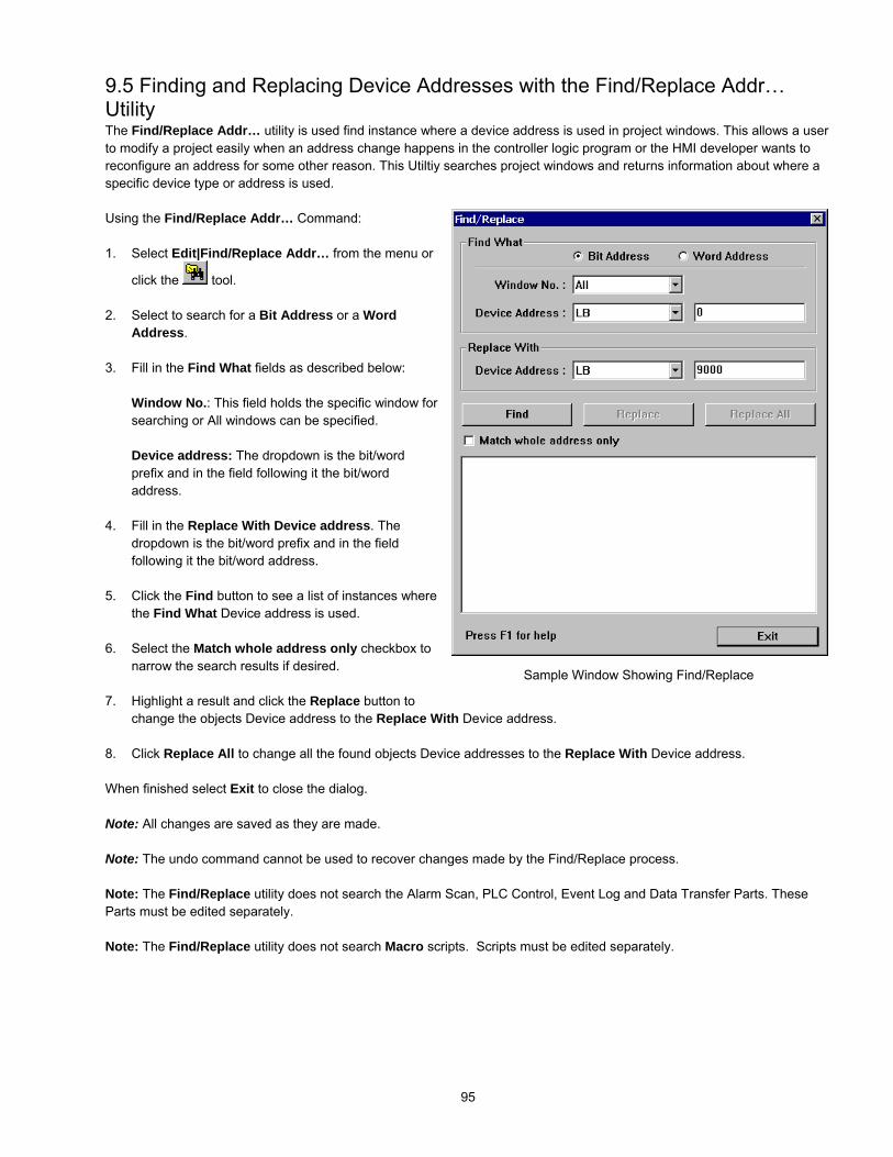
95
9.5 Finding and Replacing Device Addresses with the Find/Replace Addr…UtilityThe Find/Replace Addr… utility is used find instance where a device address is used in project windows. This allows a userto modify a project easily when an address change happens in the controller logic program or the HMI developer wants toreconfigure an address for some other reason. This Utiltiy searches project windows and returns information about where aspecific device type or address is used.
Using the Find/Replace Addr… Command:
1. Select Edit|Find/Replace Addr… from the menu or
click the tool.
2. Select to search for a Bit Address or a WordAddress.
3. Fill in the Find What fields as described below:
Window No.: This field holds the specific window forsearching or All windows can be specified.
Device address: The dropdown is the bit/wordprefix and in the field following it the bit/wordaddress.
4. Fill in the Replace With Device address. Thedropdown is the bit/word prefix and in the fieldfollowing it the bit/word address.
5. Click the Find button to see a list of instances wherethe Find What Device address is used.
6. Select the Match whole address only checkbox tonarrow the search results if desired.
7. Highlight a result and click the Replace button tochange the objects Device address to the Replace With Device address.
8. Click Replace All to change all the found objects Device addresses to the Replace With Device address.
When finished select Exit to close the dialog.
Note: All changes are saved as they are made.
Note: The undo command cannot be used to recover changes made by the Find/Replace process.
Note: The Find/Replace utility does not search the Alarm Scan, PLC Control, Event Log and Data Transfer Parts. TheseParts must be edited separately.
Note: The Find/Replace utility does not search Macro scripts. Scripts must be edited separately.
Sample Window Showing Find/Replace
Sample Window Find/Replace Dialog

96
9.6 Using the Window No. Treebar
The Window Treebar is used during project design to call up and view Windows and Objects.To activate the Treebar select View menu Window No. Treebar item or simply press the Tabkey.
Note: The Tab key is used to toggle the Treebar On and Off.
Initially, the Treebar appears to the left of the design window. Like the other tool bars, it can bedragged to other locations around the window or left to “float”.
9.6.1 Treebar Operations
Click on any Window number to quickly bring it to the forefront in the designwindow.
Double Click on any closed Window number to open the Window for design.
Click and drag the Right Frame to resize the width of the Treebar.
Once a window number is highlighted, right-click in the Treebarwindow to popup a shortcut menu. This menu gives a quick wayto create a new window, open an existing window, close anopen window, delete a window from the project or get to awindow’s settings.
Click on the Windows expansion icon to view all of theobject IDs in the Window.
Click on an object ID number in theTreebar to highlight the object in thedesign window. The object can thenbe positioned or edited as desired.
Double-click on an object ID numberto call up the attributes for that object.

97
10.0 System Bit and Register Reference10.1 Local memoryLocal memory resides in DRAM and every value is initialized to zero at system start up.The HMI is equipped with following local memory ranges:
LB 0000 ~ 9999 (Bit devices) Segmented in groupsof 16 bits as follows:
LB 00 ~ 15LB 16 ~ 31LB 32 ~ 47………LB 9968 ~ 9983LB 9984 ~ 9999
LW 0000 ~ 9999 (Word devices)
LW0000LW0001LW0002………LW9998LW9999

98
Each LBnnnn is a 1-bit device and each LWnnnn is a 16-bit device. These devices use separate memory areas and do notoverlap (i.e. LB0000 is not the first bit of LW0000. Changing LB0000 does not affect LW0000).
Note: The Local Bit and Word addresses above 8999 are reserved for system use.
10.2 Remote memoryWhen using Master - Slave hardware configurations, the Slave MMIs can access the Master’s Local memory.
Master local memory ranges:Ms_LB 0000 ~ 9999 (Bit devices) and Ms_LW 0000 ~ 9999 (Word devices).
10.3 Reserved Local Words/BitsSome Local Words, Local Bits and Recipe Words are reserved for special purposes. Users should not use these areasexcept for their specified purposes.
Local Bits: 9000~9999 are reservedLocal Words: 9000~9999 are reserved
10.3.1 Reserved Local Bits
LB Address Description NOTE Version9000~9009 Initialized as ON Use these bits for objects that need an
initial setting of ON. (read/write)ver 1.2
9010 Recipe download indicator, it is:Set ON when downloadingSet OFF when download done
Use this bit to indicate when a recipedownload is in progress (read/write).
ver 1.2
9011 Recipe upload indicator, it is:Set ON when uploadingSet OFF when upload done
Use this bit to indicate when a recipeupload is in progress. (read/write)
ver 1.2
9012 Recipe download/upload indicator, it is:Set ON when transferring dataSet OFF when transfer done
Use this bit to indicate when any recipetransfer is in progress. (read/write)
ver 1.2
9013 Task bar Touch Indicator pressed bit, it is:Set ON when Touch Indicator is pressed
This bit does not return the state of the”touch indicator”. (read/write)
Ver 1.4

99
LB Address Description NOTE Version9014 Task bar CPU Indicator pressed bit, it is:
Set ON when CPU Indicator is pressedThis bit does not return the state of the”CPU indicator”. (read/write)
Ver 1.4
9015 Task bar Alarm Indicator pressed bit, it is:Set ON when Alarm Indicator is pressed
This bit does not return the state of the”alarm indicator”. (read/write)
Ver 1.4
9016 Print Error indicator:Changes to 1 when printing fails
Use to trigger an alarm or event to letthe user know there is a problem withprinting. (read only)
Ver 1.4
9017 Printer enable bit. The user:Sets ON to disable print functions.Sets OFF to enable print functions.
Setting in System Parameters musthave a printer selected for this Bit tohave an effect. (read/write)
Ver 1.4
9020 Pen enable bit. The user:Sets ON to enable pen functions.
Positive edge trigger. Message boarduse (read/write)
Ver 1.4
9021 Brush (Eraser) enable bit. The user:Sets ON to enable brush functions.
Positive edge trigger. Message boarduse (read/write)
Ver 1.4
9022 Clipping enable bit. The user:Sets ON to enable clip functions.
Positive edge trigger. Message boarduse (read/write)
Ver 1.4
9030 Pen width to 1 pixel enable bit. The user:Sets ON to set pen width to 1 pixel.
Positive edge trigger. Message boarduse (read/write)
Ver 1.4
9031 Pen width to 2 pixels enable bit. The user:Sets ON to set pen width to 2 pixels.
Positive edge trigger. Message boarduse (read/write)
Ver 1.4
9032 Pen width to 3 pixels enable bit. The user:Sets ON to set pen width to 3 pixels.
Positive edge trigger. Message boarduse (read/write)
Ver 1.4
9040 Fast Selection window enable bit. The user:Sets ON to hide Fast Selection window.Sets OFF to show (pop-up) Fast Selectionwindow.
This bit overrides the SystemParameter Task Bar setting.(read/write)
Ver 1.4
9041 Task Bar enable bit. The user:Sets ON to hide the Task Bar.Sets OFF to show (pop-up) the Task Bar.
Task Bar control (read/write) Ver 1.4
9042 Task Buttons enable bit. The user:Sets ON to hide the two Task Buttons.Sets OFF to show (pop-up) the two TaskButtons.
Task Bar control (read/write) Ver 1.4
9043 Hide/Show Task Items (Fast Selection screen, TaskBar and Task Buttons) The user:
Sets ON to hide the Task Items.Sets OFF to show (pop-up) the Task Items.
When enabled, all items appear in theiractivated state. Task Bar and FastSelection window are opened.(read/write)
Ver 1.4
9044 Enable changes made to System Parameters inRetentive memory area. The user:
Sets ON to make the Security Passwords,Backlight and Buzzer System Parametersactive.OFF has no effect.
Forcing this bit ON restores SecurityPasswords, Backlight and Buzzersystem parameters from ReservedRetentive word area.After restoration, the system sets thisbit OFF. (read/write)
Ver 2.1
9045 Reset MMI. The user:Sets ON to reset the HMI.
Forcing this bit ON resets the MMI.(write)
Ver 2.1
9046 Security level change event indicator. Changes to 1 when going from a lowersecurity level to a higher security level.(read only)
Ver 2.1

100
LB Address Description NOTE Version9050 Toshiba T/C write enable bit. The user:
Sets ON to enable writing to T/C bits ON & OFF.Sets OFF to disable T/C writing.
T1/T1S user’s manual NOTE:When writing to Timer/Counter registers, theTimer/Counter’s device data should be added to thewritten data. (2 bytes each, corresponding to theTimer/Counter’s register)
When setting the Timer/Counter‘sdevice to ON, use ‘01’; for OFF use‘00’. (read/write)
Ver 1.5
9051 Enable or Disable the touchscreen when theBacklight is turned OFF. The user:
Sets ON to disable touchscreen when Backlightis turned OFF.Sets OFF to keep touchscreen enabled whenBacklight is turned OFF.
OFF is the default mode.(read/write)
Ver 1.6
9052 Write back enable PLC Control, Change window.The user:
Sets ON to disable write back to PLC.Sets OFF to enable write back to PLC.
This applies to Change Windowcontrol only.(read/write)
Ver 1.6
9055 Disconnect action – PLC communications. The user:Sets ON to continuously retry any write to PLCcommand.Sets OFF to stop any write to PLC commands.
When HMI is disconnected from thePLC, it acts according to the state ofthis local bit 9055.(read/write)
Ver 1.6
9056 Disconnect action –Touchscreen The user:Sets ON to enable touchscreen.Sets OFF to disable touchscreen.
When HMI is disconnected from thePLC, it acts according to the content ofthis local bit 9056. (read/write)
Ver 1.6
Bits LB9060 ~ 9069, 6080 and 6081 are used for detecting Numeric Input Extend and ASCII Input Extend presses. See thefollowing page for Touchscreen map.
9070 MITSUBISHI J2-S10 driver controlEffects local data being added to ‘R’ or subtractedfrom ‘R’.Set bit ON to disable add/subtract operationsSet bit OFF to enable add/subtract operationsValid range: 0x00800000 to 0x7FFFFFFF (8388608to 2147483647 decimal)Invalid range: 0xFF799999 to 0x80000000(-8388608 to –2147483648 decimal).
Due to the protocol limitation of J2-S100 for ‘R’ registers. A valuebetween 0x00800000 and0xFFFFFFFF(inclusive) cannot bewritten to R because it creates anerror.(read/write)
Ver 1.6
9071 MITSUBISHI J2-S10 driver controlWrite options for ‘R’. The user:
Sets bit ON to write to EPROM.Sets bit OFF to write to RAM.(default)
(read/write) Ver 1.6
9090 Event Log Clear The user:Sets bit ON to write to clear entries from theEvent Log. This includes entries stored in RWmemory, if enabled.
After the Event log is cleared, this bitauto resets to OFF.(read/write)
Ver 2.5.2
9091 Adjusts contrast lighter one shade. The user:Sets bit ON to activate.
After the contrast is made lighter, thisbit auto resets to OFF. HardwareVersion 4.5 only.(read/write)
Ver 2.6.0
9092 Adjusts contrast darker one shade. The user:Sets bit ON to activate.
After the contrast is made darker, thisbit auto resets to OFF. HardwareVersion 4.5 only.(read/write)
Ver 2.6.0

101
LB Address Description NOTE Version9100~9227 PLC address/node communication status. These bits correspond to the PLC
Station Numbers 0~127. Thecorresponding bit changes to 0 whencommunication times out. Write 1 toresume communications. (read/write)
Ver 2.6.0
9228~9355 AUX address/node communication status These bits correspond to the AUX.Station Numbers 0~127. Thecorresponding bit changes to 0 whencommunication times out. Write 1 toresume communications. (read/write)
Ver 2.6.0
9360 CF statusOFF: CF not installedON: CF installed
(read only) Ver 2.7.0
9361 Controls CF card Recipe downloadOFF: no action,ON: starts recipe download from CF
Ver 2.7.0
..............................................................9060 Keypad control bit, left side (of window)
Bit forced ON whenever a user actives an input dataobject (NI or AI).Bit forced OFF when entering valid data or ESC keyis pressed.
User can use this bit to control a Directwindow Keypad popup. Keypadwindow is closed if input succeeds.(read only)
Ver 1.6
9061 Keypad control bit, left side See note for 9060. (read only) Ver 1.69062 Keypad control bit, left and top side See note for 9060. (read only) Ver 1.69063 Keypad control bit, left and bottom side See note for 9060. (read only) Ver 1.69064 Keypad control bit, right side See note for 9060. (read only) Ver 1.69065 Keypad control bit, right side See note for 9060. (read only) Ver 1.69066 Keypad control bit, right and top side See note for 9060. (read only) Ver 1.69067 Keypad control bit, right and bottom side See note for 9060. (read only) Ver 1.69068 Keypad control bit, all side See note for 9060. (read only) Ver 1.69069 Keypad control bit, all side See note for 9060. (read only) Ver 1.69080 Keypad control bit, top side See note for 9060. (read only) Ver 2.09081 Keypad control bit, bottom side See note for 9060. (read only) Ver 2.0

102
10.3.2 Reserved Local Words
LW Address Description NOTE Version9000 Retentive memory Index base RBI and RWI use this as an index offset when
accessing retentive data. (read/write)Ver 1.2
9002-9003 Set to Numeric Input Maximum valuewhen numeric input gets the focus.
Numeric Input loads its maximum value whenactivated. When Numeric Input loses thefocus, it is set to zero.(read only)
Ver 1.4
9004-9005 Set to Numeric Input Minimum value whennumeric input gets the focus.
Numeric Input loads its minimum value whenactivated. When Numeric Input loses thefocus, it is set to zero.(read only)
Ver 1.4
9006 Message board mode0: pen1: brush
2: clipping
Message board use(read)
Ver 1.4
9007 Pen width0:1 pixel1:2 pixel2:3 pixel
Message board use(read)
Ver 1.4
9008 Pen color0-255
Message board use(read/write)
Ver 1.4
9010 Local second BCD code, valid values: 0 ~ 59(read/write allow)
Ver 1.2
9011 Local minute BCD code, valid values: 0 ~ 59(read/write allow)
Ver 1.2
9012 Local hour BCD code, valid values: 0 ~ 23(read/write allow)
Ver 1.2
9013 Local day BCD code, valid values: 0 ~ 31(read/write allow)
Ver 1.2
9014 Local month BCD code, valid values: 0 ~ 11(read/write allow)
Ver 1.2
9015 Local year BCD code, valid values: 0 ~ 9999(read/write allow)
Ver 1.2
9016 Local day of the week BCD code, valid values: 0 ~ 6(read/write allow)
Ver 1.2
9020 Object queue statusThis holds the total number of objects of allthe windows on the display.(Each window can hold up to 500 objects.)
If a screens object queue exceeds 1000, thenthe HMI screen is too complex. The HMI is indanger of reporting a Severe System Errordue to low system resources.
Ver 1.4
9034-9035 System time (unit as 0.1 second) Starts at 0 when project started. (read/write) Ver 1.49040-9041 Window Security password
This word must contain the password foraccess to secure windows.
Double word(write only)
Ver 1.6
9042 Security levelThe current active security level
(read only) Ver 1.6
9043 Force security levelSet to 0 (Lowest) or 1 (Middle).
A security level can only be forced to a lowerlevel than is active. (write only)
Ver 1.6

103
LW Address Description NOTE Version9044 Touch process mode
There are three operational modes to handlemomentary switches. They are based on thecurrent value of LW9044. Use a SET WORDof "Set on window open" in the Commonwindow to configure the desired operationmode. 0: Window popup operation is enabledduring touch down and up, at touch up the BITpreviously set ON is set OFF, even if a popupwindow hides the momentary switch. (defaultinitial value) 1: Window popup operation is disabledduring touch down and up. 2: Window popup operation is enabled duringtouch down and up. Therefore, if themomentary switch is hidden by a popupwindow, on touch up, the BIT is not reset.
This modification is to resolve a softwareconstraint in older versions.
When a momentary switch is pressed, (touchdown) the related bit is set ON.
If there is any popup window that hides themomentary switch before it is released, the bitremains ON even if released (touch up).(read/write)
Ver 1.6
9050 Base Window Id Slave HMI can use this word to show thesame screen as the Master.
Ver 1.2
9051 Reserved for Base Window ID write backoperations by a slave MMI. (See LW9050)
PLC control/Change screen writes back to9051, so it is reserved for that purpose.
Ver 1.2
9054 Report printout option, print out:0: Text, Meters and Trends1: Text, Meters, Trends and Shapes but notpatterns2: Text, Meters, Trends and Bitmaps3: Text, Meters, Trends, Bitmaps andShapes but not patterns4: All
Use this to change the attributes of a PLCControl/ Report printout assignment.(read/write)
Ver 1.5
9055 PLC Control word OffsetThere are two options in the PLC Controlobject that use this local word:Change window, and Report printout.The value in this word is added to thecontrolling data as an offset.Before writing back, the HMI subtracts thisvalue from the data.
Use this to offset window numbers comingfrom the PLC.Example:A PLC Control / Change window uses D10.If (LW9055) = 10, and D10 = 4 then the HMIchanges to window 14. After changing, theHMI writes back 4 to D11.(read/write)
Ver 1.6
9057 EventLog DataBase Item size Managementinformation, the size of every item
Use when storing the Event Log in retentivememory. (read only)
Ver 2.1
9058-9059 EventLog DataBase sizeManagement information, the size of theDataBase, the size includes managementinformation. (total_item * item_size) +(management_info_size)
Use when storing the Event Log in retentivememory.(read only)
Ver 2.1
9060-9075 Holds Numeric and ASCII Input, input data.9075 holds the least significant digits.
(read/write) Ver 1.4

104
LW Address Description NOTE Version9080-9085 Project name Use ASCII Data to show project name
It occupies 12 bytes.(read only)
Ver 1.5
9086-9087 Project size in bytes Use Numeric Data to show (In Decimal)(read only)
Ver 1.5
9088-9089 Project size in K bytes Use Numeric Data to show (In Decimal)(read only)
Ver 1.5
9090-9091 Compiler version ID Use Numeric Data to show (In Decimal)(read only)
Ver 1.5
9092 Project Compile Date/Year Use Numeric Data to show (In Decimal)(read only)
Ver 1.5
9093 Project Compile Date/Month Use Numeric Data to show (In Decimal)(read only)
Ver 1.5
9094 Project Compile Date/Day Use Numeric Data to show (In Decimal)(read only)
Ver 1.5
9100 Indirect Addressing, For external PLC only 9100 indirect window number Ver 1.69101 Indirect Addressing, For external PLC only 9101 indirect offset Ver 1.69130 Language control word Use this to change the displayed language
state for all labels. The range is 0~3.(read/write)
Ver 2.5
9135 Li-Battery Voltage in millivolts
Note: This is not the PLC’s battery. It is thetouchscreen’s internal battery.
Only displayed after download. Not availablein Simulation modes. Hardware Version 4.5only. The range is 0~1228 which is scaledfrom 0~3V. If the LW9135 < 1126 (2.75V),change the Li-battery. (read only)
Ver 2.6.0
9136 CF card download status0: inactive1: download in progress2: download complete3: download failed
(read only) Ver 2.7.0
10.4 Retentive memoryThe HMI units have 64K of battery backed RAM. This memory is accessed by using the following data types:
RB - accesses the first 2047 registers as 16 bit groups. The bit is designated as a hexadecimal number. (i.e. accessing bit10 of word 63 would be Device type RB, Device address 63A)
RBI - accesses the first 2047 register’s bits and sets the index pointer to that bit. LW9000 is used in conjunction with the RBIvalue to give an offset value for Recipe Transfer parts. (i.e. If RBI is set to device address 20 and LW9000 has a value of 5 init, then bit downloads and saves would begin at RB25 = RBI20 + 5.)
RW - accesses the retentive registers as words. The full range (0 to 65535) is available but registers above 60000 arereserved for system use (See below).
RWI - Reads the register and sets the index pointer to the value in that register. LW9000 is used in conjunction with the RWIvalue to give an offset value for Recipe Transfer parts. See Recipe Transfer Part for an example of the RWI register is used.The valid range of RWI types is 0~ 32767.
Ms_RB and Ms_RW are used by Slave configured units for accessing retentive memory locations in a remote Master unit.
NOTE: All retentive data types overlap in retentive memory. (i.e. changing RB0002 to ON changes the value of RW00001.This also affects RWI00001 and RBI0002.)Some Retentive Words are reserved for special purposes. Users should not use these areas except for their specifiedpurposes. Retentive Words: 60000~65535 are reserved

105
10.4.1 Reserved Retentive Word
RW Address Description NOTE Version60000 Real Time Clock second BCD code, valid values: 0 - 59
(read/write allow)Ver 1.2
60001 Real Time Clock minute BCD code, valid values: 0-59(read/write allow)
Ver 1.2
60002 Real Time Clock hour BCD code, valid values: 0-23(read/write allow)
Ver 1.2
60003 Real Time Clock day BCD code, valid values: 0-31(read/write allow)
Ver 1.2
60004 Real Time Clock month BCD code, valid values: 0-11(read/write allow)
Ver 1.2
60005 Real Time Clock year BCD code, valid values: 0-9999(read/write allow)
Ver 1.2
60006 Real Time Clock day of the week BCD code, valid values: 0-6(read/write allow)
Ver 1.2
NOTE about RTC:When using "Objects" to display and change system time, the user must take care to enter only valid values.For example: Seconds cannot be changed to 78(BCD), if 78 (BCD) is entered, the RTC continues counting 78 79 80 ...etc. This causes unpredictable conditions to happen.
10.4.2 System InformationSystem Parameter mapping to recipe card information. When a project is downloaded to a unit and run for the first time,System Parameters are stored in the System Reserved Memory area. The following is a list of the mapping relationship.
Parameters from the General TabRW System Parameter NOTE Version60061 Back light saver 0 (Disable)
1~255 second (Enable)Ver 2.1
60064 Buzzer 0:None1:Yes
Ver 2.1
Parameters from the Security TabRW System Parameter NOTE Version60071 Security Control: 0:None 1:Yes Ver 2.160072 Password: level 0 two words Ver 2.160074 Password: level 1 two words Ver 2.`60076 Password: level 2 two words Ver 2.`

106
11.0 EasyBuilder Operations11.1 Project Operations
11.1.1 Compiling a ProjectBefore a project can be Simulated or downloaded it must be compiled. Compiling is the process used to convert the graphicscreen information and object information into a data the units processor can understand. During this process the code isoptimized and reduced. This is why large *.epj project files can fit into the HMI memory. The result is the small *.eob objectfile. It is this file that is downloaded to the unit or accessed for simulation.
Note: If the Automatic save and compile at download and simulate checkbox in the Option|Window Property …menu settings is checked, a project is automatically saved and compiled before simulation or download.
A project must be saved before compiling.
To compile a project:
1. Select the Compile tool or select Compile … from the Tools menu.
The Project *.epj name and resultant compiled *.eob file names are shown in the Compiling dialog. Make sure this is thecorrect project to compile.
2. Click on the Compile button.
Note: As the project is compiled, data or error messages are displayed in the text field. Once the compile is finished,the project file sizes are listed. If the Total size value is greater than the available HMI memory, the project cannot bedownloaded properly. This is true even if it can be simulated without problems.
3. Click on the Close button to exit the Compiling dialog.
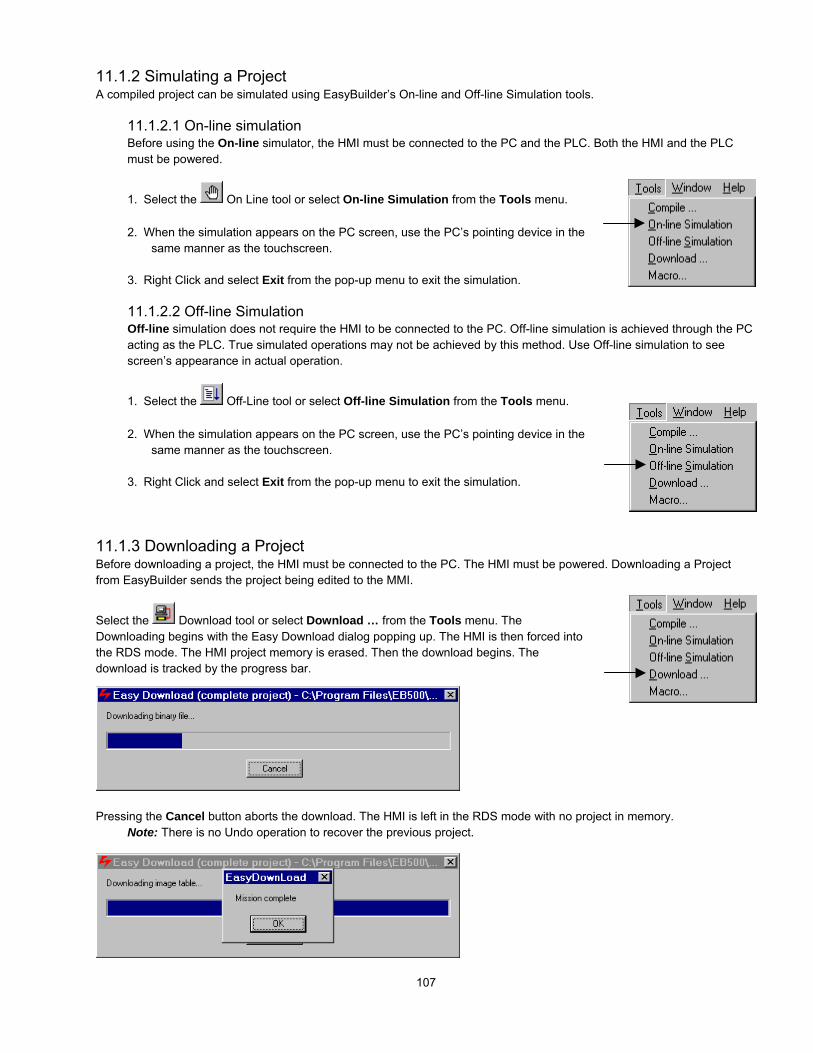
107
11.1.2 Simulating a ProjectA compiled project can be simulated using EasyBuilder’s On-line and Off-line Simulation tools.
11.1.2.1 On-line simulationBefore using the On-line simulator, the HMI must be connected to the PC and the PLC. Both the HMI and the PLCmust be powered.
1. Select the On Line tool or select On-line Simulation from the Tools menu.
2. When the simulation appears on the PC screen, use the PC’s pointing device in thesame manner as the touchscreen.
3. Right Click and select Exit from the pop-up menu to exit the simulation.
11.1.2.2 Off-line SimulationOff-line simulation does not require the HMI to be connected to the PC. Off-line simulation is achieved through the PCacting as the PLC. True simulated operations may not be achieved by this method. Use Off-line simulation to seescreen’s appearance in actual operation.
1. Select the Off-Line tool or select Off-line Simulation from the Tools menu.
2. When the simulation appears on the PC screen, use the PC’s pointing device in thesame manner as the touchscreen.
3. Right Click and select Exit from the pop-up menu to exit the simulation.
11.1.3 Downloading a ProjectBefore downloading a project, the HMI must be connected to the PC. The HMI must be powered. Downloading a Projectfrom EasyBuilder sends the project being edited to the MMI.
Select the Download tool or select Download … from the Tools menu. TheDownloading begins with the Easy Download dialog popping up. The HMI is then forced intothe RDS mode. The HMI project memory is erased. Then the download begins. Thedownload is tracked by the progress bar.
Pressing the Cancel button aborts the download. The HMI is left in the RDS mode with no project in memory.Note: There is no Undo operation to recover the previous project.

108
When the download is complete, the Mission complete message is displayed.
Click OK to close the Easy Download dialogs.
Note: If the Jump to application mode when download done checkbox in the Option|Window Property … menusettings is checked, the HMI Jumps to Application automatically after download. Otherwise, force the HMI to theapplication mode after a download by going to EasyManager and pressing Jump to Application or Cycling power tothe HMI.
11.1.4 System Error MessagesA running project (simulation or after download) displays error messages when various fault conditions occur. Below is a list
of these messages.
Message DescriptionAttach Fail Suggest Reset PLC Cannot setup communication with PLC, cycle power to the PLC to clear its buffer
and retry.Attach PLC Cannot detect the PLC. Check the cable connections and PLC port settings.
Initiate communications with the PLC.Base Window<##> Must FullScreen Size
Attempting to open a Base window number <##> that is less than full size.
BCD Transfer Overflow Occurs when attempting to enter an illegal data value into a BCD type register(such as entering 10000 to a 16-bit BCD register).
Invalid Window Number <##> A change screen command issued by either Function Key or PLC Control isattempting to switch to undefined screen: <##> (screen number).
MilliSecond Timer Full Out of system resources – check factoryNot Support Operation Attempting to do something that is not allowed for the driver. Object Queue Full Out of system resources – check factoryPLC Data Block Queue Full The PLC data points on a screen cannot be divided into less than 100 read blocks.
(100 is the limit of read blocks) PLC no response * HMI lost communication with PLC, incorrect cable configuration to PLC or incorrect
System Parameter settings for PLC.PLC responsed always delayed. PLC reply timing was off. Try to adjust response time in the PLC if this is possible;
if not, report problem to KEP. PLC response error* PLC replied with an unexpected response message, caused by a read command
or write command. Check if the configured PLC device address is available.Printer fail! The printer is not ready or the printer buffer is full.Printer pool overflow The printer buffer is full. Check that the printer is on line and responding.Project image error, compileragain
There is an error in the compiled project file (*.eob). Check the project compilelevel and recompile the project.
Second Timer Full Out of system resources – check factory System Severe Error* System has run out of memory – check factory System severe error(error code 10002)
System cannot uncompress a graphic because it is larger than 250KB. Do notcompress bitmaps larger than 250KB. Change System Parameter/EditorTab/Object In Compress to “No”.
System severe error(error code 10013)
Attempt to use an external driver with Hardware that is not enabled to accept it.Contact the factory for assistance.
System severe error(error code 10101)
System Parameter/General Tab/Startup window is an undefined window. Changethe Startup window number to a valid window.
Text Index Out of Range: Font Style <##>
The text string contains illegal values that access characters out of the font tablerange. <##> denotes the illegal character code.
This PLC Only Support Read<##> Words of Word of BIT Data
A part is attempting to read more bit data from the PLC than the driver can handle.Reduce the number of bits on the screen or adjust the Block Pack.
This PLC Only Support Read<##> Words of Word Data
A part is attempting to read more data from the PLC than the driver can handle.Reduce the number of words assigned to the part or adjust the Block Pack.

109
This PLC Only Support Write<##> Words of Word Data
A part is attempting to write more data to the PLC than the driver can handle.Reduce the number of words assigned to that part or adjust the Block Pack.
Touch Queue Full System has run out of memory – check factoryWidth and Height Must Be samewith Window 4
Attempting to change the Fast Select Window, via Function Key, with a windowthat is not the same size as Window 4.
White Board Support Popup StyleOnly
The Message Board window can only be called up as a Direct, Indirect or Popupwindow.
Window <##> was opened As acommon Popup Window
Attempting to open a full screen Base window number <##> as a Popup window.
*Message can be customized by “System Message Part”.
11.2 Debugging with EasyWindowEasyBuilder projects can be debugged with the EasyWindow utility. EasyWindow is the utility that is used to run projects inSimulation mode. There are two simulation screen formats; a graphic simulation that looks like the bezel of an HMI unit withthe simulation window, or a Window frame with menu and the simulation window.
For the Graphic Simulation, right click to bring up the EasyWindow menu.For the Windows Frame Simulation, selections can be made right from the menu bar.
Use the Emulator setting menu item to change the simulation appearance.
Note: Menu items below the Emulator setting are used for project documentation. (Seesection on Project Management and Documentation.)
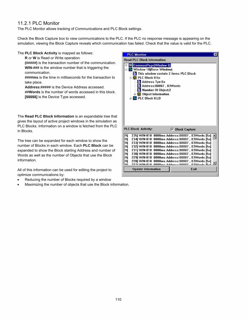
110
11.2.1 PLC MonitorThe PLC Monitor allows tracking of Communications and PLC Block settings.
Check the Block Capture box to view communications to the PLC. If the PLC no response message is appearing on thesimulation, viewing the Block Capture reveals which communication has failed. Check that the value is valid for the PLC.
The PLC Block Activity is mapped as follows:R or W is Read or Write operation.(#####) is the transaction number of the communication.WIN-### is the window number that is triggering thecommunication.####ms is the time in milliseconds for the transaction totake place.Address:##### is the Device Address accessed.##Words is the number of words accessed in this block.[$$$$$] is the Device Type accessed.
The Read PLC Block Information is an expandable tree thatgives the layout of active project windows in the simulation asPLC Blocks. Information on a window is fetched from the PLCin Blocks.
The tree can be expanded for each window to show thenumber of Blocks in each window. Each PLC Block can beexpanded to show the Block starting Address and number ofWords as well as the number of Objects that use the Blockinformation.
All of this information can be used for editing the project tooptimize communications by:• Reducing the number of Blocks required by a window• Maximizing the number of objects that use the Block information.

111
11.2.2 Data MonitorThe Data Monitor tool is used to monitor data transactions for specified parts. The transactionlist is updated whenever data changes are triggered. Several data Monitors can open tomonitor specific part types.
The Title bar of the Data Monitor dialog displays the monitor number. This is useful whenmore than one Data Monitor is open.
Option:Pause Checkbox: Enables/Disables transaction updates. Use this when transactions are scrolling too fast to stop themfor a snapshot of transaction history.All Object Checkbox: Enables/Disables activating the transaction history for all objects on the active windows.
Monitor Object: Select the parts to monitor. If there are no parts of the type selected, the transaction list does not updatethat part type; other types on active windows are updated.
Transaction list fieldsColumn DescriptionCount The transaction number. The most recent transactions are on the top of the Transaction list.WI/OI Window number and Object ID number. Use this to tell what window the transaction is from and what
Part is triggering the transaction.Object The Part Type that triggered the transaction.Access Type Indicates if the transaction was a Read or Write transaction.Addr Type Device type from the Part attribute.Address Device address from the part attribute.Data The state data from the device. Bits are shown as OFF or ON, words are shown as hexadecimal values.
In the above example, the most current (top) transaction shows Bit Lamp 5, on window 10 (Address 0x00001), going to theOFF State.
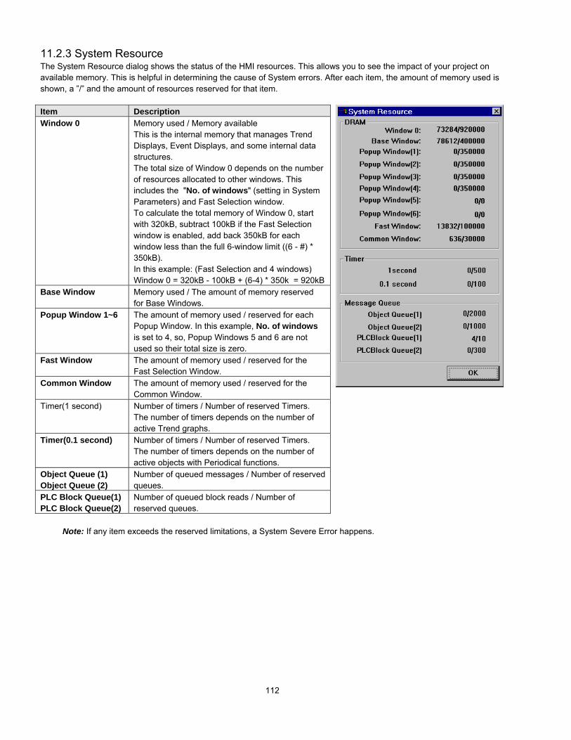
112
11.2.3 System ResourceThe System Resource dialog shows the status of the HMI resources. This allows you to see the impact of your project onavailable memory. This is helpful in determining the cause of System errors. After each item, the amount of memory used isshown, a ”/” and the amount of resources reserved for that item.
Item DescriptionWindow 0 Memory used / Memory available
This is the internal memory that manages TrendDisplays, Event Displays, and some internal datastructures.The total size of Window 0 depends on the numberof resources allocated to other windows. Thisincludes the "No. of windows" (setting in SystemParameters) and Fast Selection window.To calculate the total memory of Window 0, startwith 320kB, subtract 100kB if the Fast Selectionwindow is enabled, add back 350kB for eachwindow less than the full 6-window limit ((6 - #) *350kB).In this example: (Fast Selection and 4 windows)Window 0 = 320kB - 100kB + (6-4) * 350k = 920kB
Base Window Memory used / The amount of memory reservedfor Base Windows.
Popup Window 1~6 The amount of memory used / reserved for eachPopup Window. In this example, No. of windowsis set to 4, so, Popup Windows 5 and 6 are notused so their total size is zero.
Fast Window The amount of memory used / reserved for theFast Selection Window.
Common Window The amount of memory used / reserved for theCommon Window.
Timer(1 second) Number of timers / Number of reserved Timers.The number of timers depends on the number ofactive Trend graphs.
Timer(0.1 second) Number of timers / Number of reserved Timers.The number of timers depends on the number ofactive objects with Periodical functions.
Object Queue (1)Object Queue (2)
Number of queued messages / Number of reservedqueues.
PLC Block Queue(1)PLC Block Queue(2)
Number of queued block reads / Number ofreserved queues.
Note: If any item exceeds the reserved limitations, a System Severe Error happens.

113
11.2.4 SearchSearch is used to find all instances where a PLC reference or Part type is used. This is used for documentation purposes orto eliminate repetitious Parts. The Search dialog provides two search methods.
11.2.4.1 PLCThis searches for a PLC address or Part type.Two search formats are provided.
A: Search from one address to anotherinclusive (fill in both fields, the left one lessthan the right).
B: Search one address only (fill in the leftfield only).
11.2.4.1 PartThis searches for a Part type in the openedproject. The search result shows a list of all Part’slocations of the selected type. Select Part typefrom the dropdown list.
Click the Search button to activate the search.
After the results of the search are displayed, click on a search result to jump to the window where the result is located. Theselected results are highlighted with a flashing border.
Use the Copy to clipboard to paste the information into a text document for printing, records or other documentationfunction.

114
12.0 Project Management and Documenting a ProjectThe standard Windows file functions are available for EasyBuilder projects. EasyBuilder projects are saved with the *.EPJextension. Projects that are compiled or Uploaded are saved as files with *.EOB extensions.
A Quick Summary of File Menu Operations:New – Starts a new projectOpen… – Opens an existing projectClose – Closes a project. (A reduced menu is displayed. See note below.)Save – Saves a project to disk.Save As… – Saves a project with the option of specifying a new storage location or project name.
Note: Reduced Menu when no Projects are OpenFile Menu: Shows limited file functions. (New, Open, Recent files, Exit)View Menu: Shows limited toolbar viewing. (Standard toolbar, Status bar)Tools Menu: Compress… and DecompileHelp Menu: Access to the Help Topics… and About EasyBuilder… commands.
Note: About EasyBuilder should show version 2.6.2 for compatibility with this manual.
12.1 Compressing/Uncompressing a projectProject compression is an easy way to archive a project with its libraries. Select the Tool|Compress … menu item tocompress a project along with all of the libraries used in that project into a single file. The extension used forcompressed files is *.CMP. Uncompressing can be used to extract the project and its libraries later. If the originallibraries or project data is lost, they can be recovered by uncompressing the archived project.
Enter the project’s name in the Source Name field or click Browse … to search for the project to compress. The Destinationname is automatically assigned. If you would like a different name for the compressed project, enter it in the Desti. Namefield.
Click on the Compressing …. button to begin the compression process.
Note: The same procedure is used in the Uncompressing …. section for uncompressing a file.

115
12.2 Decompiling a projectThe Decompile … tool is used to create a project *.epj file from an *.eob file. The *.eob file may be from a compiled projector from an upload. Use this tool to Decompile an *.eob file. All the windows and their objects are converted back into aproject file. Because window and object names are not retained during the compile process, they are assigned defaultnames in the derived project. Window Shapes and Bitmaps are saved to Library folders with the project file name as a prefixalong with their associated library extension (slb, blb). Groups from the group libraries are saved as individual components(drawing elements, shapes, bitmaps and objects) and are not recreated.
Note: Projects created with any version of EasyBuilder before version 1.6.2 cannot be decompiled. Projects uploadedfrom units with BootROM versions prior to V1.6, cannot be decompiled. Upgrading the BootROM in an older unit doesnot make an upload compatible.
It is recommended that you retain all project information in an archive for future changes. See the section on compressingprojects above.
Enter the EOB file name or click the Browse… button to select the *.eob file for decompile. The *.eob file can be from anexisting project or upload. Browse for the project to decompile. Once an *.eob file is selected, a default name is inserted intothe EPJ file name field. If this is not acceptable, press the Browse… button and select an appropriate file name for thedecompiled project.
Press the Decompile button to begin the decompile process. As the project is decompiled, the text box displays progressand statistics about the project.
Notes: New libraries containing all of the Shapes and Bitmaps used in the project are created with the project name asthe prefix and a number as the suffix. Groups are decompiled as ungrouped objects.Windows do not retain their Names. Parts do not retain their descriptions.
Press the Stop button to stop the Decompile at any time.
Use the Close button to exit the Decompiling dialog.
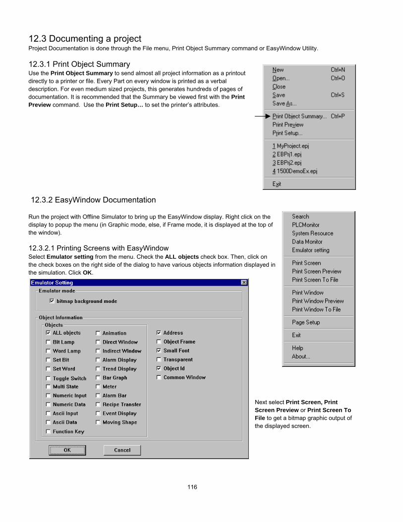
116
12.3 Documenting a projectProject Documentation is done through the File menu, Print Object Summary command or EasyWindow Utility.
12.3.1 Print Object SummaryUse the Print Object Summary to send almost all project information as a printoutdirectly to a printer or file. Every Part on every window is printed as a verbaldescription. For even medium sized projects, this generates hundreds of pages ofdocumentation. It is recommended that the Summary be viewed first with the PrintPreview command. Use the Print Setup… to set the printer’s attributes.
12.3.2 EasyWindow Documentation
Run the project with Offline Simulator to bring up the EasyWindow display. Right click on thedisplay to popup the menu (in Graphic mode, else, if Frame mode, it is displayed at the top ofthe window).
12.3.2.1 Printing Screens with EasyWindowSelect Emulator setting from the menu. Check the ALL objects check box. Then, click onthe check boxes on the right side of the dialog to have various objects information displayed inthe simulation. Click OK.
Next select Print Screen, PrintScreen Preview or Print Screen ToFile to get a bitmap graphic output ofthe displayed screen.

117
12.3.2.2 Printing Object Assignments with EasyWindowSelect Print Window, Print Window Preview or Print Window to File from the menu. Select the Image radio button toprint the screen. Select the Table radio button to print a table of objects on the screen. Check the Alarm text box if youwould like active alarms printed with the Table. Click OK.
12.4 Using Compact Flash to transfer a projectProjects can be transferred to HMI units with Ethernet ports. These units have a compact flash slot that acceptsCompactFlashTM memory cards. Projects are stored to the CompactFlashTM memory cards, transported to the unit andinserted, then transferred to the units flash memory. This is convenient for sending project updates to remote locations andcustomer sites. It also allows the project to be transferred to the unit without the need of a portable PC or other externalequipment.
12.4.1 Transferring a project to CompactFlashTM memory1. Compile the project as usual. This generates a project file with the EOB extension.
2. Run the ImageCF.exe utility.
3. Use the ImageCF.exe utility to select the EOB file to convert toCompactFlashTM compatible format. This is done by clicking onthe magnifying glass button in the ImageCF dialog. By default,a file named ImageCF.bin is created in the folder where theImageCF.exe utility is located.
4. Copy the ImageCF.bin to the CompactFlashTM memory card. A CompactFlashTM interface attached to your PC isneeded to do this. CompactFlashTM interfaces are available in most stores that sell computer hardware.Note: The CompactFlashTM memory card may be formatted as FAT16 or FAT32, do not give the CompactFlashTM
memory card a volume label.
12.4.2 Transferring a project from CompactFlashTM to HMI1. Remove the CompactFlashTM card from the CompactFlashTM interface and transport it to the site where the HMI is
located.
2. Power down the HMI unit. Put dipswitch 2 of the unit in the up (on) position. Insert the CompactFlashTM card intothe units CompactFlashTM slot.
3. Apply power to the MMI. The unit comes up in RDS mode. If the CompactFlashTM card is detected the screendisplays a button with the letters “CF” on it in the lower right corner. Press this button to transfer the project from theCompactFlashTM memory card to the unit’s internal flash memory.
4. Once the screen stops scrolling text and indicates that the transfer is complete, remove power from the MMI. Putdipswitch 2 back to the down (off) position, remove the CompactFlashTM memory card and apply power to the unit.The transferred project is now the running application.

118
12.5 Using Compact Flash to transfer retentive memoryUploaded retentive memory can be transferred to HMI units with Compact Flash ports. These units accept CompactFlashTM
memory cards. Data is stored to the CompactFlashTM memory cards, transported to the unit and inserted, then transferred tothe units retentive memory. This is convenient for sending recipe updates to remote locations and customer sites. It alsoallows the data to be transferred to the unit without the need of a portable PC or other external equipment.
A project must be in the HMI that shows the status of LB9360, displays the value in LW9136 and has a SetBit part toactivate LB9361.
12.5.1 Transferring data to CompactFlashTM memoryCopy the previously uploaded *.rcp file to the CompactFlashTM memory card. A CompactFlashTM interface attached to yourPC is needed to do this. CompactFlashTM interfaces are available in most stores that sell computer hardware.Note: The CompactFlashTM memory card may be formatted as FAT16 or FAT32, do not give the CompactFlashTM memorycard a volume label.
12.5.2 Transferring data from CompactFlashTM to retentive memory1. Remove the CompactFlashTM card from the CompactFlashTM interface and transport it to the site where the HMI is
located.
2. Insert the CompactFlashTM card into the units CompactFlashTM slot.Check that LB9360 changes status from OFF to ON.
3. Force LB9361 to ON. Check that LW9136 changes from 0 to 1. Once the download is complete, LW9136 changesto 2. This indicates a successful transfer.Note: If a 3 is displayed in LW9136 then the download has failed. You may need to repeat the process making sureall steps are followed.

119
Section 3: Object Reference Guide13.0 Objects Summary
Icon Name Function ID numberBit Lamp Displays ON or OFF shape to reflect current bit status in
the PLC.BL-nnn
Word Lamp Displays a different shape to reflect current register datain the PLC.
WL-nnn
Set Bit Forces a set or reset of a PLC bit address data (coil). SB-nnn
Set Word Write specified data to a PLC word address (register). SW-nnn
Toggle Switch Combination of bit lamp and set bit parts. TS-nnn
Multi-State Switch Combination of word lamp and set word parts. MS-nnn
Function Key Create a touch area to change window, input data, popup or minimize a window.
FK-nnn
Numeric Input Display PLC registers data in numeric form and allowkeypad input for changes.
NI-nnn
Numeric Data Display the PLC register data in numeric form only. ND-nnn
ASCII Input Display the PLC register data in ASCII and acceptkeypad input.
AI-nnn
ASCII Data Display the PLC register data as ASCII characters. AD-nnn
Moving Shape Moves a changeable object around the screen. MV-nnn
Animation Moves a changeable object along predefined points onthe screen.
AN-nnn
Indirect Window Designate to call a specific pop up window by a PLCword address.
WP-nnn
Direct Window Control a preset pop up window by a PLC bit address WC-nnn
Alarm Display Display alarm messages as triggered by word value in adefined location.
AL-nnn
Trend Display Periodically retrieve a group of PLC register data anddisplay as values verses time.
TD-nnn
XY Plot Periodically retrieve groups of PLC register data anddisplay as X values verses Y values.
XY-nnn
Bar Graph Display the PLC register data as a bar graph (horizontalor vertical).
BG-nnn
Meter Display Display the PLC register data as an analog meter (semi-circle or full circle).
MD-nnn
Alarm Bar Display alarm messages as triggered by bit status,scrolling on a single line.
AB-nnn
Recipe Action Download a block of registers to the controller or uploadand save a block of registers to the MMI.
RP-nnn
Event Display Display prioritized and formatted alarm messages astriggered by bit status in a defined location.
ED-nnn

120
13.1 Bit Lamp A Bit Lamp displays the ON or OFF status of a designated bit address. If the bit status is OFF, the state 0 shape isdisplayed. If the bit status is ON, the state 1 shape is displayed, and so on. The corresponding label is alsodisplayed if Use Label or Use Label Library are enabled. Bit Lamps cannot be used to change the state of a bit.
Use the Set Bit or Toggle Switch parts to change Bit State.
Procedure to place a Bit LampNote: Refer to Software Reference Guide, Part Placement for further details about completing each tab item.
Step 1. Click tool or select Parts|Bit Lamp from themenu.
Step 2. Fill in General Tab Items:Description: A reference name (not displayed) thatyou assign to the Bit Lamp.
Read Address: Bit that controls the Bit Lamp state,shape and label. See section on Part Placement formore details about entering a Read address.
Device type is the bit type prefix.Device address is the bit number.Tag is used to select the Read address from a listof predefined Tags.Aux. directs the Read address to be retrievedfrom the Auxiliary Port.
Attribute: This area is used to set the displayproperties.Function. There are two Function types for BitLamps: Normal and Blinking. If a blinking function isselected, the Break time needs to be set.
Function Summary:Attribute Description Display at State 0 Display at State 1Normal Bit Lamp is displayed as the State (0 or 1) of its
Shape/Bitmap and /or Label.State 0 Shape andLabel
State 1 Shape andLabel
ON Blinks State 0 The State 0 Shape/Bitmap and /or Label blinkswhen the Read address is ON.
State 0 Shape andLabel
State 0 Shape andLabel blinking
ON Blinks State 1 The Shape/Bitmap and /or Label changes to State 1and blinks when the Read address is ON.
State 0 Shape andLabel
State 1 Shape andLabel blinking
Break time is used to set the blink duty cycle. The Integer entered in the Break time field represents half of the 50-50duty cycle in 1/10ths of a second. Range is 0 to 2147483647.
Read bitstatus = ON
Read bitstatus = OFF

121
Step 3. Click the Shape Tab: Select Use shape and/or Usebitmap. Click Shape library or Bitmap library to bring up a libraryfor selecting the Shape or Bitmap to display the 0(OFF) and 1(ON)states.
Note: If the Shape or Bitmap only has one state, the lampseems to disappear when the Bit Lamp changes from thatstate.Note: When both Shape and Bitmap are selected, the Shapealways over writes the Bitmap graphic.
Step 4. Go to the Label Tab and fill in Attribute fields. Seesection on Part Placement for more details about entering Labels.
Color is the color of the text for the indicated State. Selectone of 256 colors or 4 shades of bluescale.
Font is the size of the text. Text size can be different for eachstate.
Align is only used if multiple lines are in the label.Note: Align justifies the text. It does not justify the textrelative to the shape/bitmap. Center does not center the textin the area of the shape/bitmap.
Use the State dropdown to toggle between the State 0 andState 1 texts.
Content contains the text to denote State 0 and State 1.Select Use label to enter a label in the Content field andmake it active for the part.Select Use Label Library to choose a predefined label fromthe Label Index dropdown and make it active for the part.
Select Tracking (if appropriate).
Tracking: Tracking is used to align all of the labels from thedifferent states after placement. This means that if the labelin State 0 is moved the labels in all other states are movedalso in the same direction and position.
Note: This might be desirable for an annunciator but inappropriate for a toggle switch.
Click Duplicate this label to other states to copy the Content to all other states of the label. This action cannot bereversed by the Undo command.
Step 5. Click OK to place the Bit Lamp on the window. Position the Bit Lamp and resize it if necessary. Adjust the labelposition as desired. Click once to select the Bit Lamp. Click the BitLamp again to adjust the Label Text. Double-click to editthe Bit Lamp.
Bit Lamp Design Tips:1. Use the Bit Lamp to Show/Hide static shapes and backgrounds. For example: Putting a red frame around some
parameters that have become out of range.2. Assign Help text to State 1 and no text to State 0. Use the Bit Lamp to display that help when it is appropriate by forcing
the Read address ON. (Alarm condition, during setup, on user request, etc.) A Shape or Bitmap is not needed in thisinstance.
3. Use the Multi. Copy… command to make a bank of indicators from a single Bit Lamp.

122
13.2 Word Lamp A Word Lamp changes state according to the value in the designated word address. If the value equals 0, the firstshape is displayed. If the value equals 1, the second shape is displayed, and so on. The corresponding label for thestate is also displayed if “Use Label” check box is enabled.
Procedure to place a Word LampNote: Refer to Section 2: Software Reference Guide, Part Placement for details about completing each tab item.
1. Click Word Lamp icon or select Word Lamp from theParts menu.
2. Fill in General Tab Items:Description: A reference name (not displayed) thatyou assign to the Word Lamp.
Read Address: PLC Word that controls the WordLamp state, shape and label.
Device type is the word prefix.
Device address is the word number.
No. of words is fixed at 1 for this part.
Tag is used to select the Read address from a listof predefined Tags.
Aux. directs the Read address to be retrieved from the Auxiliary Port.
Data format: Defines data from the controller as binary (BIN) or binary coded decimal (BCD)
Data format typesBIN (binary format) Decimal numbers are encoded by bit weight
15 0215 214 213 212 211 210 29 28 27 26 25 24 23 22 21 20
BCD (binary coded decimal format) Decimal numbers are encoded by bit weight per 4-bit nibble15 12 11 8 7 4 3 0
103
102
101
100
For example: The Read address raw data is 0000 0100 0010 0101.The BIN format treats the data as 1061The BCD format treats the data as 425
No. of states: The value of the PLC register data minus 1. (Range: 1 to 32)For example: A 3-position switch would have the No. of States set to 3.
Example
Bit numberWeight
Registervalue = 0
Registervalue = 1
Registervalue = 2

123
3. Go to Shape Tab: Select Use shape and/or Usebitmap. Click Shape library or Bitmap library to displaythe library for choosing the Shape or Bitmap to display theword states.
Note: If the Shape or Bitmap only has one state, thelamp seems to disappear when the Word Lampchanges from that state.
Note: When both Shape and Bitmap are selected,the Shape always over writes the Bitmap graphic.
Use the State select buttons or State dropdown to view theshape/bitmap in various states.
4. Go to Label Tab: Fill in text to denote each state.Note: Refer to Bit Lamp procedure for more details onfilling out the Label tab.
5. Click OK to place the Word Lamp on the window.Position the Word Lamp and resize it if necessary. Adjustthe label positions as desired.
Note: Refer to Section 2: Software Reference Guide, PartPlacement for details about completing each tab item.
Word Lamp Design Tips:
1. Use the Word Lamp as a Mini-Message Center. The Read address becomes the message triggering word. The numberof messages is the number of states (1-32). Select an appropriate shape for the background. In the Label tab, enter amessage for each state. To call up a message, just put its state number in the Read address word.
2. The word lamp can also be used to create traffic lights, stack pole lights and other multi-colored indicators.
3. Create animation by saving sequential bitmaps of a process to a bitmap library. Put a Periodical JOG++ Set Word parton the same window to animate the Word Lamp part.

124
13.3 Set BitThe Set Bit Part defines a touch area, that when activated, changes the state of a specified bit.
Procedure to place a Set Bit
1. Click Set Bit icon or select Set Bit from the Parts menu.
2. Fill in General Tab Items:Description: A reference name (not displayed) that youassign to the Set Bit Part.
Write Address: Bit that is acted on by the Set Bit action.Device type is the bit prefix.Device address is the bit number.Tag is used to select the Write address from a listof predefined Tags.Aux. directs the Read address to be retrievedfrom the Auxiliary Port.
Attribute: Style: Defines the action performed by theSet Bit part. See Note below.
3. Go to Shape Tab: Select Shape or Bitmap to displaygraphics that represent the touch area.
Note: Refer to Bit Lamp procedure for more details on filling out the Shape tab.
Note: Shapes and bitmaps assigned to Set Bit parts change state only when the part is touched. They do not changestate according to the Write address' state.
4. Go to Label Tab: Fill in fields to denote states.Note: Refer to Bit Lamp procedure for more details on filling out the Label tab.
5. Click OK to place the Set Bit part on the window. Position the Set Bit part and resize it if necessary. Adjust the labelposition as desired.
Note: Refer to Section 2: Software Reference Guide, Part Placement for details about completing each tab item.
Style: Defines the actionperformed by the Set Bit part.See Note below.
Y0Y0

125
Note: Set Style Functions
Set Style Description of actionON When the Set Bit Part is pressed, the designated Device address is turned ON. The state
continues (i.e. remains ON) even after release.OFF When the Set Bit Part is pressed, the designated Device address is turned OFF. The state
continues (i.e. remains OFF) even after release.Toggle Every time the Set Bit Part is pressed, the designated PLC bit is complemented (ON
OFF, OFF ON)(Toggles).Momentary Only while the Set Bit Part is held down (pressed), is the specified Device address turned
ON. Likewise, when the switch is released, the specified bit address is turned OFF.Note: This software has three operation modes to handle momentary switch operations,based on the current value of LW9044. Use an " Set ON at window open" Set Word part inthe start up window to configure the desired operating mode. Operating Modes are asfollows:
0: Window popup is enabled during touch operations (down and up), when the touch isreleased (up) the BIT that was previously set ON is set OFF even if the popupwindow hides the momentary switch. (Default Mode of operation)
1: Window popup is disabled during touch operations (down and up). This preventspopup windows from hiding momentary switches.
2: Window popup is enabled during touch operations (down and up). If the momentaryswitch is hidden by a popup window at the time touch release (up), the BIT is notreset.
Note: DO NOT USE HMI MOMENTARY OPERATIONS FOR CRITICAL FUNCTIONS.Communications failures between the HMI and the controller during a momentaryoperation may cause the HMI to ignore touch release thus causing damage tomachinery and operator.
The following styles do not require touch to be activated.They are activated by the specified event or condition.
Periodical toggle Changes the state of the designated bit at a regular interval as selected in the Intervaldropdown. Interval time in actual operation may vary from specified. Do not use HMIintervals for critical timing.
Design Tip: Use a Set Bit, Periodical toggle part on the common window to reset a timerin the controller. The timer can then be used as a watchdog to tell if the HMIcommunications link has been broken.

126
Set Style Description of action
Design Tip: Use the following on window open/close Set Bit parts to initiate actions in the HMI and Controller. Forexample you might want to turn a bit on/off in the controller when the operator enters/exits the setup window. TheController would then suspend operations pending the change in setup.
Set ON at windowopen
When the window containing this Set Bit Part is opened, the designated Device address isturned ON.
Set OFF at windowopen
When the window containing this Set Bit Part is opened, the designated Device address isturned OFF.
Set ON at windowclose
When the window containing this Set Bit Part is closed, the designated Device address isturned ON.
Set OFF at windowclose
When the window containing this Set Bit Part is closed, the designated Device address isturned OFF.
Design Tip: Use the following on window maximize/minimize Set Bit Parts to initiate actions depending a windowstate.
Set ON at windowmaximized
When the window containing this Set Bit Part is maximized, the designated Deviceaddress is turned ON.
Set OFF at windowmaximized
When the window containing this Set Bit Part is maximized, the designated Deviceaddress is turned OFF.
Set ON at windowminimized
When the window containing this Set Bit Part is minimized, the designated Device addressis turned ON.
Set OFF at windowminimized
When the window containing this Set Bit Part is minimized, the designated Device addressis turned OFF.
Design Tip: Use the following on backlight Set Bit Parts to initiate actions that depend on the screen being active.For example: A Set Bit part of this type might signal a process to go to “sleep mode” because no one is monitoringit.
Set ON at backlightoff
When the backlight is turned off, the designated Device address is turned ON.
Set OFF at backlightoff
When the backlight is turned off, the designated Device address is turned OFF.
Design Tip: Use the following on data entry Set Bit Parts to initiate actions that depend on valid data. For example:Use a Set ON at enter success to trigger the controller to advance the HMI to the next window.
Set ON at entersuccess
When a function key with the ENT attribute is pressed in response to a Numeric Input orASCII Input part and the attempt to write the data succeeds, the designated Deviceaddress is turned ON.
Set OFF at entersuccess
When a function key with the ENT attribute is pressed in response to a Numeric Input orASCII Input part and the attempt to write the data fails, the designated Device address isturned OFF.

127
13.4 Set WordThe Set Word Part defines a touch area that when activated,writes a predefined value (constant) to the designated PLCaddress.
Procedure to place a Set Word
1. Click Set Word icon or select Set Word from the Partsmenu.
2. Fill in General Tab Items:Description: A reference name (not displayed) that youassign to the Set Word
Write Address: Word in the MMI/PLC that is affectedby the Set Word control. Data in the register may beinterpreted as Binary or BCD information (See note onWord Lamp Part).
Device type is the word prefix.Device address is the word number.Tag is used to select the Write address from a listof predefined Tags.Aux. directs the Read address to be retrievedfrom the Auxiliary Port.
Data format: Defines data from the controller asbinary (BIN) or binary coded decimal (BCD).See Word Lamp 13.2 for format description.
Attribute: The action that is performed on the Writeaddress. See Note below for an explanation of each Set style and its accompanying fields.
3. Go to Shape Tab: Select Shape or Bitmap to display graphics that represent the touch area.
Note: Refer to Bit Lamp procedure for more details on filling out the Shape tab.
Note: Shapes and bitmaps assigned to Set Word parts change state only when the part is touched. They do not changestate according to the Write address' state.
4. Go to Label Tab: Fill in fields to denote states.Note: Refer to Bit Lamp procedure for more details on filling out the Label tab.
5. Click OK to place the Set Word part on the window. Position the Set Word part and resize it if necessary. Adjust the labelposition as desired.
Note: Refer to Section 2: Software Reference Guide, Part Placement for details about completing each tab item.
Set Style: Defines the actionperformed by the Set Wordpart. See Note below.
D100=9999

128
Note: Set Style Attributes
Set Style Parameters DescriptionSetconstant
Set value When pressed, preset Set valuedata is written to the designatedword.Design Tip: Use to put fixed datainto words. Examples: force defaultvalues; return to home positions;
Design Tip: Use the JOG attributes to create Thumbwheels,Adjust +/-, and Spin controls.Add value(JOG+)
Inc. valueUpper limitMaximum:32767
Every time pressed, the Inc. valueis added to the designated word, ifthe result is not larger than Upperlimit.
Sub value(JOG-)
Dec. valueBottom limitMinimum:-32768
Every time pressed, the Dec.Value is subtracted from the valueof the designated word, if the resultis not less than Bottom Limit.
JOG++ Inc. valueUpper limitJOG delayJOG speedMaximum:32767
When pressed, the Inc. value isadded to the designated word atregular intervals as specified byJOG delay* and JOG speed*, ifthe result is not larger than Upperlimit.
JOG- - Dec. valueBottom limitJOG delayJOG speedMinimum:-32768
When pressed, the Dec. value issubtracted from the value of thedesignated word at regularintervals as specified by JOGdelay* and JOG speed*, if theresult is not less than Bottomlimit.
*JOG Delay: The interval that the part must be touched before repeat action occurs.*JOG Speed: The interval between repeat actions once repeating begins.Note: Interval times in actual operation may vary from specified. Do not use HMI intervals for critical timing.
Set Style Parameters DescriptionSet atwindowopen
Set value When the window containing thispart is opened, the Set value datais written to the designated word.Design Tip: Use this attribute tosend the window number to thePLC so it knows what window isopen.
Set atwindowclose
Set value Set value data is written to thedesignated word automaticallywhen the window containing it isclosed.Design Tip: Use this attribute toforce the password state to 0 whena secure window is closed.

129
Set Style Parameters DescriptionDesign Tip: Use the Periodical styles along with the Animationand Move parts to make window animations.Set Style Parameters DescriptionPeriodicalJOG++
Inc. valueUpper limitBreak timeMaximum:32767
This Attribute becomes activeautomatically when the window isactive. The Inc. value is added tothe designated word, if the resultis not larger than Upper limit.Once the upper limit is reached orexceeded, the value returns tozero and incrementing beginsagain. The Break time is the timebetween increments.
PeriodicalJOG--
Dec. valueBottom limitBreak timeMinimum:-32768
This Attribute becomes activeautomatically when the window isactive. The Dec. value issubtracted from the designatedword, if the result is not less thanBottom limit. Once the bottomlimit is reached or exceeded,decrementing stops. The Breaktime is the time betweendecrements.
Periodicalbounce
Inc. valueUpper limitBreak time
This Attribute becomes activeautomatically when the window isactive. The Inc. value is added tothe value of the designated wordat regular intervals as specified bythe Break time until the Upperlimit is reached. Then the Incvalue is subtracted from thedesignated word until zero isreached. This cycle is repeateduntil the window becomesinactive.
Note: Interval times in actual operation may vary from specified. Do not use HMI intervals for critical timing.
Step up Low limitHigh limitBreak time
This Attribute becomes activeautomatically when the window isactive. The value is incrementedby 1 at regular intervals asspecified by the Break time untilthe High limit is reached. Thenthe value is reset to the Lowlimit. This cycle is repeated untilthe window becomes inactive.Design Tip: Use the Step stylesalong with the Move part toanimate graphics within a fixedpixel boundary.

130
Set Style Parameters DescriptionStep down Low limit
High limitBreak time
This Attribute becomes activeautomatically when the window isactive. The Value is decrementedat regular intervals as specified bythe Break time until the Low limitis reached. Then the Value isreset to the High limit. This cycleis repeated until the windowbecomes inactive.
Set atwindowmaximized
Set value Set value data is written to thedesignated word automaticallywhen the window containing it ismaximized.
Set atwindowminimized
Set value Set value data is written to thedesignated word automaticallywhen the window containing it isminimized.
Set atbacklightoff
Set value Set value data is written to thedesignated word automaticallywhen the backlight is turned off.
Design Tip: Use the following to provide error codes to thePLC after data entry.Set atentersuccess
Set value When a function key with theENT attribute is pressed inresponse to a Numeric Input orASCII Input part and the attemptto write the data succeeds, thedesignated Device Address isloaded with the Set value.
Set atenter fail
Set value When a function key with theENT attribute is pressed inresponse to a Numeric Input orASCII Input part and the attemptto write the data fails, thedesignated Device Address isloaded with the Set value.

131
13.5 Toggle SwitchThe toggle switch is a combination of Bit Lamp and Set Bit. It representsthe ON/OFF status of a PLC bit address, and defines a touch area,when activated, it may turn the same or different bit ON or OFF.
Procedure to place a Toggle Switch.
1. Click Toggle Switch icon or select Toggle Switch fromthe Parts menu.
2. Fill in General Tab Items:Description: A reference name (not displayed) thatyou assign to the Toggle Switch.
Read address: Bit that controls the Toggle Switchstate, shape and label.
Device type is the bit prefix.Device address is the bit number.Tag is used to select the Read address from a listof predefined Tags.Aux. directs the Read address to be retrievedfrom the Auxiliary Port.
Write address: Bit that is affected by the ToggleSwitch Set Style.
Device type is the bit prefix.Device address is the bit number.Tag is used to select the Write address from a listof predefined Tags.Aux. directs the Write address to be retrieved from the Auxiliary Port.
Switch style: See Note Switch Style Functions below for an explanation of each Switch style.
3. Go to Shape Tab: Select Shape or Bitmap to display graphics that represent the touch area.
Note: Refer to Bit Lamp procedure for more details on filling out the Shape tab.
Note: Shapes and Bitmaps assigned to Toggle Switch parts change state according to the Read address' state.
4. Go to Label Tab: Fill in fields to denote states.Note: Refer to Section 2: Software Reference Guide, Part Placement for more details on filling out the Label tab.
5. Click OK to place the Toggle Switch part on the window. Position the Toggle Switch part and resize it if necessary. Adjustthe label position as desired.
Note: Refer to Section 2: Software Reference Guide, Part Placement for details about completing each tab item.
Switch style: Defines the actionperformed by the Toggle Switch part.See Note Switch Style Functions below.

132
Note: Switch Style Functions
Switch Style DescriptionON When the Set Bit Part is pressed, the Write address is turned ON. The state continues (i.e.
remains ON) even after release.OFF When the Set Bit Part is pressed, the Write address is turned OFF. The state continues (i.e.
remains OFF) even after release.Toggle Every time the Set Bit Part is pressed, the Write address is complemented (ON OFF, OFF
ON)(Toggles).Momentary* Only while the Set Bit Part is held down (pressed), is the Write address turned ON. Likewise,
when the switch is released, the Write address is turned OFF.
Note: DO NOT USE HMI MOMENTARY OPERATIONS FOR CRITICAL FUNCTIONS.Communications failures between the HMI and the controller during a momentary operationmay cause the HMI to ignore touch release thus causing damage to machinery and operator.
Note: The state of the toggle switch shape/bitmap corresponds directly to the state of the read bit.This is different from the Set Bit part, which only changes shape/bitmap when touched.
*Note: This software has three operation modes to handle momentary switch operations, based on the current value ofLW9044. Use an "initial set" SET WORD in the start up window to configure the desired operating mode. Operating Modesare as follows:
0: Window popup is enabled during touch operations (down and up), when the touch is released (up) the BIT that waspreviously set ON is set OFF even if the popup window hides the momentary switch. (Default Mode of operation)
1: Window popup is disabled during touch operations (down and up). This prevents popup windows from hidingmomentary switches.
2: Window popup is enabled during touch operations (down and up). If the momentary switch is hidden by a popupwindow at the time touch release (up), the BIT is not reset.
Design Tips:1. Use the same device address for read and write to have the Toggle Switch show the state of the device it is switching.
2. Use different Read and Write addresses for processes that need confirmation of state. Example: A motor start up mightneed to be up to speed before operations can be performed. Use the Write address to start the motor and the Readaddress as an indicator of when the motor is up to speed.
3. Disable Label tab, Tracking to place Labels at different locations on the switch.

133
13.6 Multi-State SwitchThe Multi-State Switch is a combination of WordLamp and Set Word. It displays a different statedepending on the value of the PLC monitor word
address. It also defines a touch area that when activated,writes a specified data to the PLC word address, whichmay be the same as the Read address or a differentaddress.
Procedure to place a Multi-State Switch
1. Click Multi-State Switch icon or select MultiStateSwitch from the Parts menu.
2. Fill in General Tab Items:Description: Reference text (not displayed) assigned tothe Multi-State Switch.
Read Address: Word in the PLC that controls the Multi-State Switch state, shape and label.
Device type is the word prefix.Device address is the word number.Data in the register may be interpreted as Binary orBCD information.No. of words is restricted to 1 for this part.Tag is used to select the Read address from a list ofpredefined Tags.Aux. directs the Read address to be retrieved fromthe Auxiliary Port.
Write Address: Word in the PLC that is controlled by the Multi-State Switch Style.Device type is the word prefix.Device address is the word numberData in the register may be interpreted as BIN (Binary) or BCD information.No. of words is restricted to 1 for this part.Tag is used to select the Write address from a list of predefined Tags.Aux. directs the Write address to be retrieved from the Auxiliary Port.
Attribute:Switch Style: See table below
No. of states: The maximum value of the register data minus 1 (The first state is when the register is at 0). Thenumber of states is restricted to a maximum of 32 states.
3. Go to Shape Tab: Select Shape or Bitmap to display word states.
Note: Refer to Bit Lamp procedure for more details on filling out the Shape tab.Note: If the Shape or Bitmap only has one state, the lamp seems to disappear when the Bit Lamp changes from thatstate.Note: When both Shape and Bitmap are selected, the Shape always over writes the Bitmap graphic.Note: Shapes and bitmaps assigned to Multi-State Switch parts do not change state when the part is touched. They onlychange state according to the Read address' state.

134
4. Go to Label Tab: Fill in fields to denote states.
5. Click OK to place the Multi-State Switch part on the window. Position the Multi-State Switch part and resize it if necessary.Adjust the label position as desired.
Note: Refer to Section 2: Software Reference Guide, Part Placement for details about completing each tab item.
Note: Switch Style Functions
Set Style DescriptionJOG+ The value in the designated write address is increased by one when the Multi-State
Switch is pressed.JOG- The value in the designated write address is decreased by one when the Multi-State
Switch is pressed.
Note: Range is -32768 to 32767. Above 32767 the value cycles to -32768, below -32768 the value cycles to 32767.
Design Tips:1. Use the same device address for read and write to have the Multi-State Switch show the state of the device it is
changing.
2. Use the Multi-State switch to jog through text selections. For example, states 0-6 correspond to days of the week(Sunday through Saturday). Assign the labels of states 0-6 to correspond to the days of the week. You may or may notuse a shape for this object. This Multi-State Switch allows the operator to select the day of the week. This is useful whensetting the internal real time clock.
13.7 Function keyThe Function Key is used to create an active screen area for a data entry key, inputting a digit or ASCII character,changing screen displays and minimizing or moving windows.
Procedure to place a Function Key
1. Click Function Key icon or select Function Key fromthe Parts menu.
2. Fill in General Tab Items:Description: A reference name (not displayed) that youassign to the Function Key.
Determine what function occurs when pressed, Seeoptions below.
3. Go to Shape Tab: Select Shape or Bitmap to displaystates that represent the touch area.
4. Go to Label Tab: Fill in fields to denote states.
5. Click OK, position the Function Key and resize it if necessary.Click OK to place the Function Key part on the window. Position the Function Key part and resize it if necessary. Adjust thelabel position as desired.
Note: Refer to Section 2: Software Reference Guide for details about completing each tab item

135
Function Key Topics13.7.1 Character Codes and Creating a Keypad13.7.2 Hard Copy (Print Function)13.7.3 Change Window13.7.4 Return to Previous13.7.5 Change Common Window13.7.6 Popup Window13.7.7 Close Window13.7.8 JOG FS-Window13.7.9 Window Bar13.7.10 Minimize Window13.7.11 Message Board
13.7.1 Character Codes and Creating a Keypad A keypad is composed of a variety of functionkeys with different ASCII codes and special keys“ENT” (Enter), “BS” (Backspace), “CLR” (Clear)and ”ESC” (Escape).
By creating one function key then duplicating it, changing its character code and arranging the keys in a regular pattern, akeypad can be created. Since any character can be assigned to a function key, specialized keypads can be made for anyapplication. Keypads can be saved in the Group Library for use wherever needed.
Keypads are used with the Numeric and ASCII Input Parts to change their values. As the first key is pressed the displayedvalue is cleared and new data entry begins.
Special Key Functions:CLR key Sets the displayed value to 0 or blank.BS key Erases previously entered characters from latest to earliest.ESC key Ends data entry without changing word values.ENT key Ends data entry and saves the displayed value to the word.
Note: Both the ENT and the ESC keys reset the System Reserved bits LB9060 - LB9069 to zero.
A typical Numeric keypadconsisting of 0~9,‘.’,’-‘, CLR, ESC and ENT
An ASCII keypad emulating a keyboard.

136
13.7.2 Hard Copy (Print Function) Print functions facilitate the printing of screen data. Data is sent out as a graphicthrough the parallel printer port.Note: MMI-720 and MMI-750 models donot have print capabilities.
Use the Attributes.... button to select thedesired print action.
Selection Print actionPrint Text & Meter & Trend Prints bit and numerical data parts along with drawn objects and text placed on
the display.Print Text & Meter & Trend & AllShape but not including pattern
Prints the outline of bit and numerical data parts along with drawn objects, textand shapes placed on the display.
Print Text & Meter & Trend & Bitmap Prints bit and numerical data parts along with drawn objects, text and bitmapsplaced on the display.
Print Text & Meter & Trend & Bitmap& All Shape but not including pattern
Prints the outline of bit and numerical data parts along with drawn objects, text,bitmaps and shapes placed on the display.
Print Text & Meter & Trend & Bitmap& All Shape
Prints bit and numerical data parts along with drawn objects, text, bitmaps andshapes placed on the display.
Form Feed Prints a Form Feed command.
Note: Actual printer setup is done in the System Parameter, General tab. If no printer is selected the key has no effect.
13.7.3 Change Window If the function key is set as “Change Window”,when the touch area is pressed (activated), thecurrent window display terminates and changes tothe window designated by “Window No.”.
Note: Be sure to select a valid window number. Project does not compile if Window No. is not defined.
Window 10
Press Change Window Function key Button (inthis example labeled MENU)
‘Jump to’ Window 100
Window 100

137
13.7.4 Return to PreviousThis function terminates the existing window andrecalls the last active window.
For example: If window 21 was replaced by window 32, and window 32 has a Function defined as Return to Previous, then,when it is pressed, window 32 is terminated and window 21 is displayed.
Note: Indirect, Direct and Popup windows cannot be recalled.
13.7.5 Change Common Window If the function key is set as “Change CommonWindow”, when the touch area is pressed(activated), the current common window displayterminates. The new common window designatedby Window No. is displayed. Any full screen base window can be used as a replacement for the default Common window(Window 6).
Note: Be sure to select a valid window number. Project cannot compile if Window No. is not defined.
13.7.6 Popup Window If the function key is set as “Popup Window”,when the touch area is pressed (activated), thewindow designated by Window No is displayedover top of the base window. The existingwindow(s) are not terminated.
Note: A window assigned to a function key as a Popup window and also assigned to a Direct or Indirect Window parton the same screen is not displayed when the Popup key is pressed. The Direct/Indirect Window control disables thefunction key. In addition, Indirect/Direct Windows disable Function key Popup keys placed in them.
13.7.7 Close WindowA Close Window function key terminates thewindow it is placed in when pressed. This is themethod for operators to close Popup Windows.
Caution: This type of function key can also be placed on Base windows. Closing all windowsmay leave the operator with no way to proceed! Be sure to have a way for the operator orPLC to call up a window when this happens.
Window 10
‘Popup’ Window 100
Window 10
Window 100

138
13.7.8 JOG FS-WindowThis function changes the popup window thatappears when the Fast Selection, Task Barbutton is pressed.
Note: The window specified must be the exact same size as the original Fast Selection window (Window 4).
Note: The Fast Selection window does not have to be showing when this button is touched in order for it to change.
Design Tips:Use this key to change menus when going from operation to setup or help. These function keys can be placed directly on theFast Selection window.
13.7.9 Window BarA function key defined with “Window Bar”attribute is used to move the position of a windowon the screen. A Popup, Direct or Indirect window that is smaller than a full screen can make use of this function. Thewindow with the “window bar” attributes, can be moved by touching the window bar area then touching a second position,the window is moved to that place. Typically, the Window Bar is placed across the top of the window with a label describingthat window’s purpose. The window bar label is displayed on the task bar icon when the window is minimized.
Note: The window bar can be used to move windows so they are partially off screen. This might appear to hide thewindow. However, a window can never be moved entirely off screen. If the Task Bar is showing, then the window’sicon indicates that it is still open. Toggling off the Base window that called a Popup window closes the Popup window.Direct and Indirect windows can be recovered by toggling data in their control devices.
First touch activates thewindow move function
Second touch moves the windowto the desired place

139
13.7.10 Minimize WindowWhen the function key is pressed, the window isminimized to an icon in the task bar. A touch onthe window’s icon maximizes the window again.
Note: The Minimize Window function works only if there is also a Window Bar on the same window.Note: The Minimize Window function works only on Direct, Indirect and Popup windows.
13.7.11 Message BoardIf the project has a message board, function buttons can be placed on the window that calls the Message Board screen tochange the characteristics of the pen or erase the board.
Note: Do not put these functions directly on the Message Board. This does not cause harm but buttons may bedisplayed as stuck in the ON State when they are not in the OFF State.
Click on the Message Board radio button then select a type of action from the drop down list. Click on the Attributes....button to set the particular action for the function button. See below for an explanation of the actions.
13.7.11.1 Set Operation ModeSet Operation is used to define how the touch actson the message board.
Pen is used for drawing graphics/text on the Message Boardwindow.
Brush is used as an eraser to erase lines drawn by the pen.
Clip allows the operator to drag a rectangle around an area. Whenthe operator stops touching the screen the area in the rectangle iserased.
Window MinimizedtoWindow icon
Touchminimizesfunction key

140
13.7.11.2 Set pen styleSet pen style is used to select the pen thickness.Click on the desired Line width and click OK.
13.7.11.3 Set pen colorSet pen color is used to select the color of linesdrawn on the Message window. Click on theColor dropdown, select the desired Color fromthe color chart, and click OK.
13.7.11.4 Clear boardThere are no attributes for this selection. Afunction button with this action simply erases theentire Message window.

141
13.8 Numeric Input ExtendA Numeric Input displays the current value of a PLC register data. If the Trigger address bit is active, when thearea of the shape is touched, a flashing cursor indicating input via keypad is activated. Use an already displayedkeypad made of function keys to enter numeric data to the PLC register designated by the Read address.
Procedure to place a Numeric Input Extend
1. Click Numeric Input Extend icon or select NumericInput Extend from the Parts menu.
2. Fill in General Tab Items:
Description: A reference name (not displayed) thatyou assign to the Numeric Input Extend.
Read Address: Word in the PLC that is displayed andmodified.
Device type is the word prefix.Device address is the word number.Data format: Defines data from the controller asbinary (BIN) or binary coded decimal (BCD).See Word Lamp 13.2 for format description.No. of words:
For PLC types that handle data in words:Select 1 Word (16 Bits) or 2 consecutive Words (32 Bits) for this part.
For PLC types that handle data in bytes:Select 1 Word (8 Bits), 2 Words (16 Bits) or 4 Words (32 Bits) for this part.
Tag is used to select the Read address from a list of predefined Tags.Aux. directs the Read address to be retrieved from the Auxiliary Port.
Trigger Address: Bit in the PLC that controls the ability to enter data into the Read Address. If bit is OFF, data entry isdisabled. Note: The trigger address does not pop up the keypad. It simply enables data to be entered.
Device type is the word prefix.Device address is the word number.Tag is used to select the Trigger address from a list of predefined Tags.Aux. directs the Trigger address to be retrieved from the Auxiliary Port.
Trigger Address Design Tips:1. LB 9000 to LB 9009 are internal bits that are set to 1 at power up. These bits can be used for Trigger
addresses so that the Numeric Input parts are always active.
Display currentreading value
Enter data whenkeypad appears.
Touch the shape area toactivate the data entryoperation

142
2. Have the PLC check a register for a password value and use a PLC bit to activate the Numeric Input for added security.
3. Fill in Numeric Tab items:Display: Manipulates data so it is displayed in a useful format. See 13.8.1 Numeric Display Format section below.
4. Go to Shape Tab: Select Shape or Bitmap to be used as a background button. The button is used to identify the part asan input part as opposed to just a regular data display. The button changes state when pressed.
Note: Refer to Bit Lamp procedure for more details on filling out the Shape tab.
5. Go to Font Tab: Fill in attributes for the displayed digits. See 13.8.2 Font Alignment below for details.
6. Click OK to place the Numeric Input part on the window. Position the Numeric Input part and resize it if necessary. Adjustthe number position just as you would any other label.
Note: Refer to Section 2: Software Reference Guide for details about completing each tab item
Note: Reserved Local Bit for Keypad.When the user activates a Numeric or ASCII Input object, the HMI turns internal bits LB9060~LB9069 ON. After user inputand entry, the HMI checks the input data, if the data is valid then LB9060~LB9069 are turned OFF otherwise the inputremains active waiting for valid entry. This is used for controlling popup keypads, see below.
13.8.1 Numeric Display Format
Decimal: For Raw data Display, the reading value is displayed in itsoriginal value as a decimal number in the range –32768 to32767.
For Do conversion, the reading value is converted toengineering units before display.
Fill in the Numeric portion of the tab.Specify number above decimal point and number belowdecimal point.
Scaling is performed as follows:
Display value = (reading value – Input Low) * (Engineering High – Engineering Low) (Input High – Input Low)
Note: PLCs can only accept integer values. This affects how the HMI enters and displays scaled values. It is especiallyevident when scaling from a smaller value to a larger value. For example: Scaling a 0-10 value to a 0-100 value only yieldsmultiples of 10. A value of 25 can never be displayed. Entering a value of 29 returns a value of 20. The HMI does not“round”. It can only truncate to the next lower value.
Note: The decimal point for Do Conversion shows the actual decimal portion from the scaling formula. Data entered in theDecimal portion is used for converting data back to the PLC. Make sure keypads used for data entry contain a Decimal pointfor these cases.The Decimal point for Raw data display is for appearance only and does not indicate that scaling has been done. Forexample: The No. below Dec. is set to 2. The value from the PLC is 104. The value is displayed as 1.04. Entering a value of1.55 sends 155 to the PLC.
Note: Be sure to set Input limits to the values that is sent to the PLC not displayed values. For example: Using the examplein the note above, Input limits might be Input low = 0; Input high = 200; (not Input low = 0 Input high = 2).

143
Hex: The number is displayed in hex (0~9, A~F) format.Scaling is disabled.
Binary: The number is displayed in binary (0 & 1) format.Scaling is disabled.
Mask: Displays only “****” and ignores the reading value.This is used for security code input. Scaling is disabled butdecimal point is allowed.
Single float: Data in the controller is translated from a 32bit IEEE Floating-Point format to a decimal number anddisplayed. Device address is changed to 2 words whenthis option is selected.
Double float: Data in the controller is translated from a 64bit IEEE Floating-Point format to a decimal number anddisplayed. Device address is changed to 4 words whenthis option is selected.
Caution! Divide by 0 results in the PLC causes Floating-Point values that are invalid. These values cause the HMI tohave a severe system error. Insure that floating point data is valid.
During data entry the Input Low and Input High are used to limit the range of valid input data.
Note: Input low and high are always decimal values. This true even if the displayed value isHex or Binary.
13.8.2 Font AlignmentThe Font Attributes specify the size and color of displaynumeric digits. Available font sizes include 8, 16, 24, 32,48, 64, 72 and 96.
Align selection is applicable for Decimal format only.Below is an example of how the alignment functions.If a display format is set as:“No. above decimal = 5”,“No. below decimal = 0” ,With reading value 123, it is displayed in various formatsas follows:
Right adjust 1 2 3Left adjust 1 2 3Leading zero 0 0 1 2 3
Note: No label can be added to Numeric Input parts. Addtext to the screen to provide labels for these parts.
Note: Refer to Section 2: Software Reference Guide for details about completing each tab item

144
Keypads and Pop-up Keypad EmulationA default keypad is installed in Window 50 and called up in the common window of new projects. They may be deleted andyour own keypads implemented. This is a brief example of how to create a pop-up keypad for use in your applications.
How it works when finished:You touch the displayed numeric value.A keypad pops up.You edit the value.Press the enter key.The keypad disappears.The new value is displayed.
How to create it:Step 1: Create the keypad with an Enter key and save it to a group library. Alternately youcan use one of the keypads already provided in the keypads.glb library. (Located in the\library D-Subdirectory) The key is to group the keypad and find it’s over all dimensions.This can be done easily by drawing a rectangle around the keypad then looking at itsAttributes’ Profile tab. For our example, we are using keypad 0 from the keypads.glb library.The dimensions are 160W x 160H pixels.
Step 2: Create a window with overall dimensions thatmatch the dimensions of the keypad you are using. Youmay have to factor in a border if you select one for thewindow.For Example, Use window 20. The dimensions are 160Wx 160H pixels. If using a Frame, add extra pixels asneeded. For this example, the Frame width is set to 0.
Step 3: Place keypad in this window.
Step 4: Create Numeric Input Extend objects on the windowyou are developing for your project. Set the Trigger addressattribute to LB9000. Be sure to set the Input low and highranges on the numeric tab.For our example, we are using Window 10 The input rangesare set as 0 to 1000. The objects are shown as NI_0, NI_1 andNI_2.

145
Step 5: Create a Direct Window object that is triggered by anappropriate bit that calls up the keypad into it. Once placed, adjustthe Profile to be the same size as the dimensions of the keypadwindow. Do not place the Direct Window over top of the NumericInput objects.
For our example, theDirect Windowobject is triggered byLB9068 (System’sInput Active bit) andcalls up Window 20.The Profile is set to160W x 160H.
Step 6: Save, Compile and Simulate to verify proper operation.When the Data Input object is touched the keypad should pop up and data entry should be activated. Enter a valid number,the keypad should disappear.

146
13.9 Numeric DataA Numeric Data Part displays the current reading of a designated PLC register data. Data isdisplayed as text; no shape or bitmap can be associated with this part.
Procedure to place a Numeric Data
1. Click Numeric Data icon or select Numeric Data fromthe Parts menu.
2. Fill in General Tab Items:Description: A reference name (not displayed) that youassign to the Numeric Data.
Read Address: Word in the PLC that is displayed andmodified by the Numeric Data Tab.
Device type is the word prefix.Device address is the word number.Data format: Defines data from the controller asbinary (BIN) or binary coded decimal (BCD).See Word Lamp 13.2 for format description.No. of words:For PLC types that handle data in words:
Select 1 Word (16 Bits) or 2 consecutiveWords (32 Bits).
For PLC types that handle data in consecutive bytes:Select 1 (8 Bits), 2 (16 Bits) or 4 (32 Bits) Words.
Tag is used to select the Read address from a list of predefined Tags.Aux. directs the Read address to be retrieved from the Auxiliary Port.
3. Fill in Numeric Tab items: See previous section on Numeric Input Extend- 13.8.1 Numeric Display Format for details.
4. Go to Font Tab: Fill in attributes of the displayed digits. See Numeric Input Extend - 13.8.2 Font Alignment for details.
5. Click OK to place the Numeric Data part on the window. Position the Numeric Data part as desired.
Note: Refer to Section 2: Software Reference Guide for details about completing each tab item

147
13.10 ASCII Input ExtendASCII Input Extend displays current value of the PLC register(s) data as decoded by the standard ASCII charactertable. When the shape area is touched and the trigger bit is active, ASCII Input is available through any displayedalphanumeric keypad. Entered data is put into consecutive PLC registers starting with the “Read address”.
1 st B Y T E 2 nd B Y T E 3 th B Y T E 4 th B Y T E4 5 4 1 5 3 5 9
E A S Y
Procedure to place an ASCII Input
Click ASCII Input Extend icon or select ASCII InputExtend from the Parts menu.
1. Fill in General Tab Items:Description: A reference name (not displayed) thatyou assign to the ASCII Input.
Read Address: Word or words (up to 16 words maybe addressed in this manner, each word contains 2ASCII characters) in the PLC that is displayed andmodified by the ASCII Input.
Device type is the word prefix.Device address is the word number.No. of words: Up to 16 consecutive words (32characters) can be displayed.Tag is used to select the Read address from a listof predefined Tags.Aux. directs the Read address to be retrievedfrom the Auxiliary Port.
Trigger Address: Bit in the Controller that controls the ability to enter data into the Read Address. If bit is OFF, dataentry is disabled.
Reading value isdecoded in ASCIIcode and displayed
Touch the shapearea to activateinput operation
Enter data fromalphanumerickeypad

148
Trigger Address Design Tips:LB 9000 to LB 9009 are internal bits that are set to 1 at power up. These bits can be used for Trigger addressesso that the ASCII Input Extend parts are always active.
Have the PLC check a register for a password value and use a PLC bit to activate the ASCII Input Extend foradded security.
Attribute: Select to Left or Right justify the ASCII characters as they are displayed.
2. Go to Shape Tab: Select Shape or Bitmap to be used as a background button. The button is used to identify the part asan input part as opposed to just a regular data display. The button changes state when pressed.
3. Go to Font Tab: Fill in the Color and Font attributes of the displayed data.
4. Click OK to place the ASCII Input Extend part on the window. Position the ASCII Input Extend part and resize it ifnecessary. Adjust the number position as a label.
Note: Refer to Section 2: Software Reference Guide for details about completing each tab item
ASCII Input Extend Design Tips:1. Use the ASCII Input Extend part to enter Names for recipes.2. Create a message area on the screen that the operator can use to leave brief text messages about machine operation.

149
13.11 ASCII DataASCII Data displays the current value of the PLC register data. The data is decoded by standard ASCII characterstable. Data changes by the operator are disabled. Reference the ASCII Input Extend section.
Procedure to place an ASCII Data Part
1. Click ASCII Data icon or select ASCII Data from theParts menu.
2. Fill in General Tab Items:Description: A reference name (not displayed) thatyou assign to the ASCII Input.Read Address: Word or words (up to 16 words maybe addressed in this manner, each word contains 2ASCII characters).
Device type is the word prefix.Device address is the word number.No. of words: Up to 16 consecutive words (32characters) can be displayed.Tag is used to select the Read address from a list ofpredefined Tags.Aux. directs the Read address to be retrieved fromthe Auxiliary Port.
3. Go to Font Tab: Fill in the Color and Font attributes of the displayed data.
4. Click OK to place the Numeric Data Part on the window. Position the Numeric Data Part as desired.
ASCII Data Design Tip:Use the ASCII Data Part to display messages, units of measure, etc. that are stored in the PLC.
Reading value is decoded in ASCII codecharacters and displayed

150
13.12 Moving ShapeThe Moving Shape tool is used to place an object in a window at a location specified by the PLC. The state and theabsolute location of the shape in the window depend on the current values of three continuous PLC registers.Typically, the first register controls the state of the object the second the horizontal position (X), and the third the
vertical position (Y).
Procedure to place a Moving Shape
1. Click Moving Shape icon or select Moving Shape fromthe Parts menu.
2. Fill in General Tab Items:Description: A reference name (not displayed) that youassign to the Moving Shape.
Read Address: Word in the PLC that controls theMoving Shape state, position and label.
Device type is the word prefix.Device address is the word number.Data format: Defines data from the controller asbinary (BIN) or binary coded decimal (BCD).See Word Lamp 13.2 for format description.Tag is used to select the Read address from a list ofpredefined Tags.Aux. directs the Read address to be retrieved from the Auxiliary Port.
Attribute: Style: See Note: Attribute Functions below.
3. Go to Shape Tab: Select Shape or Bitmap to move and display states.
4. Go to Label Tab: Fill in fields to denote states, if desired.
5. Click OK to place the Moving Shape on the window. Position the Moving Shape (during operation, initial position dependson register values) and resize it if necessary. Adjust the label position as desired.
Note: Refer to Section 2: Software Reference Guide for details about completing each tab item
Moving Shape Design Tips:1. Use a moving shape as a pen for a trend chart. Set it so that the pen shape corresponds to the trend chart input.
Change the state of the pen shape to change from green to red when a high or low limit is exceeded.
2. Use a moving shape object as a pointer to a setpoint on a bargraph. Set it so that it corresponds to the one of thevariable set points. As the operator changes the setpoint, the pointer moves to a new position.
X & Y position iscontrolled by PLC

151
Note: Attribute FunctionsNo. of states: Up to 32 different states can be assigned to the Moving Shape Part. For example: If the moving shape was aneedle pointer, you could have it change to different states that display it as different colors.
Style: Position is controlled by the Read Address Device as shown in the table below.
Control by PLC X axis (all types) Y axis (all types) X & Y axisRead Address Shape or Bitmap State Shape or Bitmap State Shape or Bitmap StateRead Address+1 X position Y position X positionRead Address+2 Not Used Not Used Y position
When scaling is used, scaling is performed as follows:
Display value = (reading value – Input low) * (Scaling high – Scaling low) (Input high – Input low)
When reverse scaling is used, scaling is performed as follows:
Display value = (Input high – reading value) * (Scaling high – Scaling low) (Input high – Input low)
Possible selections:
Selection DescriptionX axis only Shape moves Left (0) to Right (Max. screen resolution 320 or 640)Y axis only Shape moves Top (0) to Bottom (Max. screen resolution 240 or 480)X & Y axis Shape moves Top Left (0) to Bottom Right (Max. screen resolution 240, 320 or 480, 640)X axis w/ scaling Shape moves Left (0) to Right (Max. scaled screen resolution 320 or 640)Y axis w/ scaling Shape moves Top (0) to Bottom (Max. scaled screen resolution 240 or 480)X axis w/ reverse scaling Shape moves Right (0) to Left (Max. scaled screen resolution 320 or 640)Y axis w/ reverse scaling Shape moves Bottom (0) to Top (Max. scaled screen resolution 240 or 480)

152
13.13 AnimationThe Animation Part is used to place an object on the screen at a specified location determinedby a predefined path and data in the PLC. The state and the absolute location of the shape onthe screen depend on current reading value of two continuous PLC registers. Typically, the
first register controls the state of the object the second controls the position along the predefined path.As the PLC position register changes value the shape or bitmap jumps to the next position along thepath.
Procedure to place an animation
1. Click Animation icon or select Moving Shape from the Parts menu.
2. Click on screen to define the path (stopping points) for the object to travel. Right-click the mouse to end the path.
3. Click the Edit Attributes Tool and fill in General TabItems:
Description: A reference name (not displayed) that youassign to the Animation.
Read Address: Word in the PLC that controls theAnimation state, position and label.
Device type is the word prefix.Device address is the word number.Data format: Defines data from the controller asbinary (BIN) or binary coded decimal (BCD).See Word Lamp 13.2 for format description.No. of words is restricted to 2 Words for this part.Tag is used to select the Read address from a list ofpredefined Tags.Aux. directs the Read address to be retrieved fromthe Auxiliary Port.
No. of states: Select the total number of states for theobject. This determines what state of the shape orbitmap is displayable at stops along the path. (Range: 1 to 32)
4. Go to Shape Tab: Select Shape or Bitmap to move and display states.
5. Go to Label Tab: Fill in text to denote states, if desired.
6. Click Ok to position the Animation part on the window. Resize the overall path area if necessary. During operation, initialposition depends on the register value.
Note: Refer to Section 2: Software Reference Guide for details about completing each tab item
Position and state arecontrolled by PLC
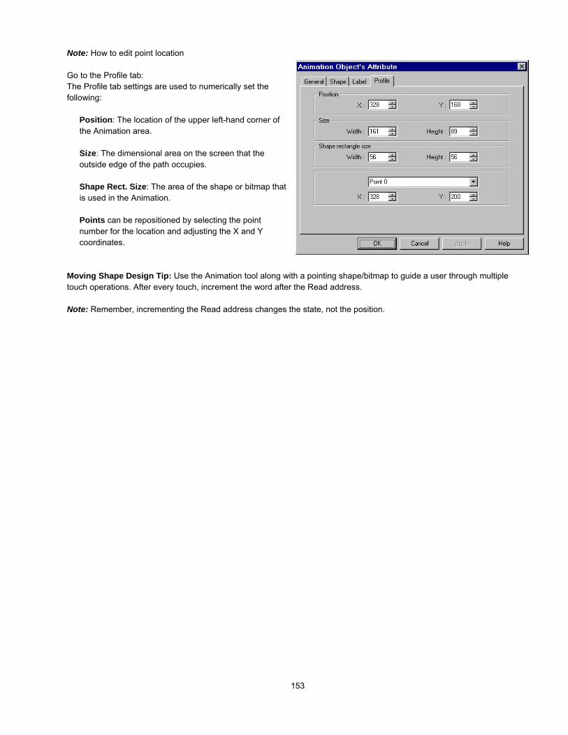
153
Note: How to edit point location
Go to the Profile tab:The Profile tab settings are used to numerically set thefollowing:
Position: The location of the upper left-hand corner ofthe Animation area.
Size: The dimensional area on the screen that theoutside edge of the path occupies.
Shape Rect. Size: The area of the shape or bitmap thatis used in the Animation.
Points can be repositioned by selecting the pointnumber for the location and adjusting the X and Ycoordinates.
Moving Shape Design Tip: Use the Animation tool along with a pointing shape/bitmap to guide a user through multipletouch operations. After every touch, increment the word after the Read address.
Note: Remember, incrementing the Read address changes the state, not the position.

154
13.14 Indirect WindowThe Indirect Window places a defined child window area over the current window. The Indirect Window’s screensare created the same as regular base windows. Usually their size is smaller than a full window. The Windows arethen displayed in the Indirect Window frame as called by a PLC data register. The limitation to the maximum
registered Indirect Windows on each screen is 500. However, at run time, only 5 windows at the most can be displayedsimultaneously on each screen.
Note: Only valid window numbers are displayed. If the window number is not defined then the Indirect Window area is lefttransparent.
Note: Indirect Windows disable Popup function keys placed on the same screen. A popup window can only be triggeredby one method on any given window.
Screen 10Register an Indirect Window with“Read Address = D100”
Screen 10
Screen 21 is displayed
Word ValueD100 21
Screen 10 Word ValueD100 20
Screen 20 is displayed.
While active, D100 designates thepop up window

155
Procedure to place an Indirect Window
1. Click the Indirect Window Tool or select IndirectWindow from the Parts menu.
2. Fill in General Tab Items:
Description: A reference name (not displayed) that youassign to the Indirect Window.
Read Address: Word in the PLC that determines whichwindow is displayed in the Indirect Window area.
Device type is the word prefix.Device address is the word number.Data format: Defines data from the controller asbinary (BIN) or binary coded decimal (BCD).See Word Lamp 13.2 for format description.No. of words is restricted to 2 Words for this part.Tag is used to select the Read address from a list ofpredefined Tags.Aux. directs the Read address to be retrieved from the Auxiliary Port.
3. Click OK to position the Indirect Window and resize it if necessary. Resize to fit the dimensions exactly by using theProfile tab settings.
Note: The size of the window limits the area of display. The window area outside of the Indirect window’s is clipped.
Indirect Window Design Tip:Function Button parts “Window Bar” and “Minimize Window” can be assigned to the windows that are popped up to enablerepositioning and minimizing features. Refer to “Window Bar” and “Minimize Window” in the Function Key Part section.
Use an Indirect Window to display consecutive Help screens.

156
13.15 Direct WindowThe Direct Window places a defined child window area over the current window. The displayed window number ispreset in the Direct Window. The window for display is a regular base window.
Note: The maximum number of Direct Windows for a screen is 500 (Object limit). However, at run time, a maximum of sixwindows can be displayed simultaneously. This number may be reduced further depending on System Parameter settings.
Procedure to place a Direct Window
1. Click the Direct Window Tool or select Direct Windowfrom the Parts menu.
2. Fill in General Tab Items:Description: A reference name (not displayed) that youassign to the Direct Window.
Read Address: Bit in the PLC that calls the DirectWindow.
Device type is the word prefix.Device address is the word number.Tag is used to select the Read address from a list ofpredefined Tags.Aux. directs the Read address to be retrieved fromthe Auxiliary Port.
Window No.: The base window the Direct Windowdisplays. Only valid window numbers are shown in thedrop down list.
3. Click OK to position the Direct Window where you want it to pop-up and resize it if necessary.
The size of the window limits the area of display. The window area outside of the window boundary is clipped. FunctionButton parts “Window Bar” and “Minimize Window” can be assigned to the window to enable repositioning and minimizing.
Note: Direct Windows disable Popup function keys for the same window number placed on the same screen. A window canonly be triggered by one method.
Screen 10
Define a Direct windowarea with“Read Address = M10”and“Window Number = 100”
At run time whenM10 = 100 the popup window appears.
The pop up keypadis window 100.
Screen 10

157
13.16 Alarm Display The Alarm Display opens a window to display messages registered in the Alarm Scan list via alarm triggerconditions. All active alarm messages are sorted by time. As new alarms are displayed on the top line, older onesare scrolled down.
Note: Refer to the Alarm Scan section for more details about alarm messages.
Procedure to add Alarm Display
1. Click Alarm Display icon or select Alarm Display fromthe Parts menu.
2. Fill in General Tab Items:Description: A reference name (not displayed) that youassign to the Alarm Display.
Read Address: The Read Address controls thescrolling, up and down, of the alarm display window. Ithas nothing to do with triggering alarms.
Device type is the word prefix.Device address is the word number.Data format: Defines data from the controller asbinary (BIN) or binary coded decimal (BCD).See Word Lamp 13.2 for format description.No. of words is restricted to 2 Words for this part.Tag is used to select the Read address from a list ofpredefined Tags.Aux. directs the Read address to be retrieved from the Auxiliary Port.
Attribute:Display line: Specifies the height of the window in Font 16 high lines. (Font size 24 takes up two lines)Char. length: Specifies the width of the window in Font 16 characters, extra characters past this length are truncated.
Note: Font 16 characters are 8 pixels wide by 16 pixels high.
3. Click OK to place and position the Alarm Display where desired.
Note: Resize an Alarm Display part by adjusting the Display Line and Char. Length attributes.
Note: Refer to Section 2: Software Reference Guide for details about completing each tab item
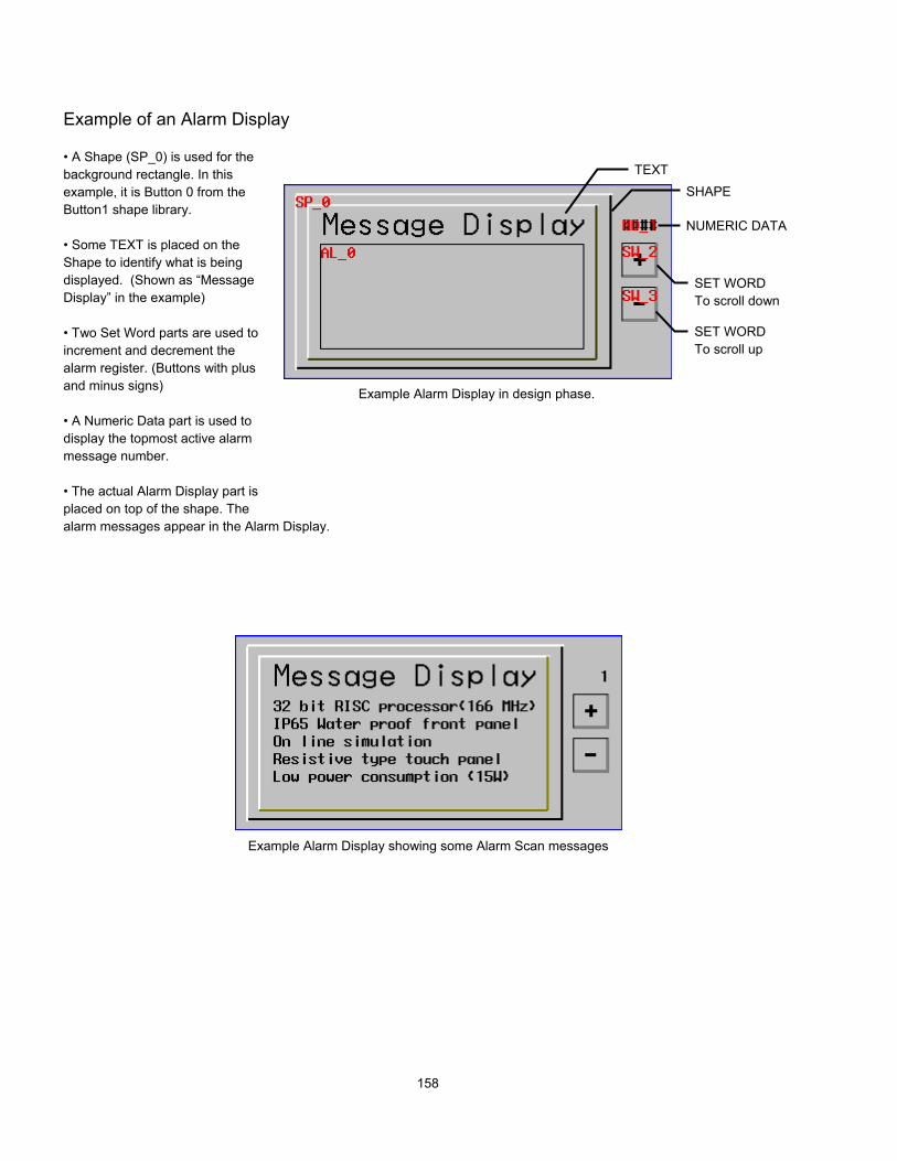
158
Example of an Alarm Display
• A Shape (SP_0) is used for thebackground rectangle. In thisexample, it is Button 0 from theButton1 shape library.
• Some TEXT is placed on theShape to identify what is beingdisplayed. (Shown as “MessageDisplay” in the example)
• Two Set Word parts are used toincrement and decrement thealarm register. (Buttons with plusand minus signs)
• A Numeric Data part is used todisplay the topmost active alarmmessage number.
• The actual Alarm Display part isplaced on top of the shape. Thealarm messages appear in the Alarm Display.
TEXTSHAPE
SET WORDTo scroll down
NUMERIC DATA
Example Alarm Display in design phase.
SET WORDTo scroll up
Example Alarm Display showing some Alarm Scan messages

159
13.17 Trend DisplayThe Trend Display periodically retrieves a block of PLC data and displays the trend data over time. As eachsampling period elapses, the new data is read from the PLC and inserted towards the right side of the trend graph,the trend graph, when full is shifted to the left direction. The Trend Display data is retrieved on a real time basis.
An example of a typical trend display is shown to the right. AShape is used for the background and Scales are added toshow relative information about the trend. The trend displayis then placed on the Shape.
Procedure to add a Single page Trend Display
1. Click Trend Display icon or select Trend Display fromthe Parts menu.
2. Fill in General Tab Items:Page type: Select Single page.Single page is a simple trenddisplay. Data is plotted asdescribed in the above example.
Sampling time: Time between point plots in seconds.
Plot point: the number of sample points displayedacross the length of the chart.
Read address: Specify the PLC word address of thefirst Trend data pen, the second Trend data pen startsat read address + 1, and the third starts at readaddress + 2, etc.
Device type is the word prefix.Device address is the word number.Data format: Defines data from the controller as binary (BIN) or binary coded decimal (BCD).See Word Lamp 13.2 for format description.No. of Channel: The number of PLC data words retrieved is the same as No. of Channel, one word per channel. Up to16 channels can be specified for a trend.Tag is used to select the Read address from a list of predefined Tags.Aux. directs the Read address to be retrieved from the Auxiliary Port.
Trend Display Design Tip: Too many pens can make a trend cluttered and unreadable.
Shapes
Trend Display
Scales
The newest data is inserted into the left side andthe trend graph is shifted right.

160
3. Fill in the Trend Tab: Select the “Channel” to vieweach channel’s settings.
4. Description: A reference name (not displayed) thatyou assign to the Trend Display.
Pen attribute: Specify the Trend Color and penthickness for the channel.
Value: Set the zero and span for each channel.
4. Click OK to position and resize the Trend Display
Procedure to add a Multiple pages Trend Display
1. Click Trend Display icon or select Trend Display from the Parts menu.
2. Fill in General Tab Items:Page type: Select Multiple pages.Multiple pages allows a trenddisplay to be extended. Data isplotted as before but it is not lostafter it is scrolled off the trend.
Hold style: Determineshow the trend reactswhen the hold bit isactivated. Hold trenddisplay simply prevents further updates until the Hold bitis turned off. Hold trend display & clear stops the trendupdate and clears out all pages of the trend.
No. of page: The data is held in memory for review up tothe number of pages (31 maximum) specified by thedropdown. Each page is the number of sample points specified in the Plot point field. The Scroll control is used to recallplots.
Attribute: Start from left selects to have the trend pens start from the left and traverse the display before scrolling begins.Start from the right begins the pens scrolling from right to left from the first sample onwards.
Sampling time: Time between point plots in seconds.
Plot point: The number of sample points displayed across the length of the Trend Display part.

161
Read address: Specify the PLC word address of the first trend data pen, the second trend data pen starts at read address+ 1, and the third starts at read address + 2, etc.
Device type is the word prefix.Device address is the word number.Data format: Defines data from the controller as binary (BIN) or binary coded decimal (BCD).See Word Lamp 13.2 for format description.No. of Channel: The number of PLC data words retrieved is the same as No. of Channel, one word per channel. Up to16 channels can be specified for a trend.Tag is used to select the Read address from a list of predefined Tags.Aux. directs the Read address to be retrieved from the Auxiliary Port.
Scroll control: The address of the register that determines which portion of the multiple page display is being shown on thescreen. Each increment of the value in the scroll register moves the Trend display one sample plot to the left. For example:If the plot was 10 Plot points wide, the Scroll control needs to be incremented by 10 to scroll back and forth in full pages.
Device type is the word prefix.Device address is the word number.Data format: Defines data from the controller as binary (BIN) or binary coded decimal (BCD).See Word Lamp 13.2 for format description.Tag is used to select the Read address from a list of predefined Tags.Aux. directs the Read address to be retrieved from the Auxiliary Port.
Hold control: The bit that controls the trend update. See Hold style above.Device type is the word prefix.Device address is the word number.Tag is used to select the Read address from a list of predefined Tags.Aux. directs the Read address to be retrieved from the Auxiliary Port.
3. Fill in the Trend Tab: Select the “Channel” to view eachchannel’s settings.
Description: A reference name (not displayed) thatyou assign to the Trend Display.
Pen attribute: Specify the Trend Color and penthickness for the channel.
Value: Set the zero and span for each channel.
4. Click OK to position and resize the Trend Display.
5. Add Scales, Drawing objects, and Text to give theTrend a finished look. (See example above).
Note: Refer to Section 2: Software Reference Guide fordetails about completing each tab item

162
13.18 XY PlotThe XY Plot displays word data as a line plotted out on x and y coordinates The XY Plotperiodically retrieves a block of PLC data and plots the data out on x and y coordinatesover time. As each sampling period elapses, the new data is read from the PLC and
plotted. When number of plotted points equals plot points, the first points start deleting. The XY Plotis refreshed on a real time basis.
Procedure to add a Single page XY Plot
1. Click the XY Plot tool or select XY Plot from the Parts menu.
2. Fill in General Tab Items:Page type: Select Single page. Single page is a simpleXY Plot display. Data is plotted asdescribed in above.
Sampling time: Time betweenpoint plots in seconds.
Plot point: The maximum number of sample pointsdisplayed on the plot (10 to 255).
Read address: Specify the PLC word address of the Xplot data pen. The Y plot pen is Read address +1.
Device type is the word prefix.Device address is the word number.Data format: Defines data from the controller asbinary (BIN) or binary coded decimal (BCD).See Word Lamp 13.2 for format description.Tag is used to select the Read address from a list of predefined Tags.Aux. directs the Read address to be retrieved from the Auxiliary Port.
3. Fill in the Plot Tab: Only Channel 0 is available.
Description: A reference name (not displayed) that youassign to the XY Plot.
Pen attribute: Specify the pen Color and thickness for thechannel.
Value: Set the Zero and Span for the Horizontal (H) andVertical (V) axis.
4. Click OK to position and resize the XY Plot.

163
Procedure to add a Multiple pages XY Plot
1. Click the XY Plot tool or select XY Plot from the Partsmenu.
2. Fill in General Tab Items:Page type: Select Multiple pages.Multiple pages allows a plot displayto be extended. Data is plotted asbefore but it is not lost as points are erased off the plot.
Hold style: Determineshow the plot reacts whenthe hold bit is activated.Hold plot display simplyprevents further updates until the Hold bit is turned off.Hold plot display & clear stops the plot update andclears out all plots in memory.
Sampling time: Time between point plots in seconds.
No. of page: The data is held in memory for review up to the number of pages (31 maximum) specified by the dropdown.Each page is the number of sample points specified in the Plot point field. The Scroll control is used to recall plots.
Plot point: The maximum number of sample points displayed on the plot (10 to 255).
Read address: Specify the PLC word address of the X plot data pen. The Y plot pen is Read address +1.Device type is the word prefix.Device address is the word number.Data format: Defines data from the controller as binary (BIN) or binary coded decimal (BCD).See Word Lamp 13.2 for format description.Tag is used to select the Read address from a list of predefined Tags.Aux. directs the Read address to be retrieved from the Auxiliary Port.
Scroll control: The address of the register that determines which portion of the multiple page display is being shown on thescreen. Each increment of the value in the scroll register moves the plot display one sample plot previous.
Device type is the word prefix.Device address is the word number.Data format: Defines data from the controller as binary (BIN) or binary coded decimal (BCD).See Word Lamp 13.2 for format description.Tag is used to select the Read address from a list of predefined Tags.Aux. directs the Read address to be retrieved from the Auxiliary Port.
Hold control: The bit that controls the plot update. See Hold style above.Device type is the bit prefix.Device address is the bit number.Tag is used to select the Read address from a list of predefined Tags.Aux. directs the Read address to be retrieved from the Auxiliary Port.
3. Fill in the Plot Tab the same way as for Single Page plots. Refer to previous page.
4. Click OK to position and resize the XY Plot.
5. Add Scales, Drawing objects, and Text to give the Plot a finished look.Note: Refer to Section 2: Software Reference Guide for details about completing each tab item

164
13.19 Bar GraphThe Bar Graph displays PLC register data as a bar graph inproportion to its value as defined by the SPAN and ZERO settings.
Procedure to place a Bar Graph
1. Click the Bar Graph Tool or select Bar Graph from the Parts menu.
2. Fill in General Tab Items:Description: A reference name (not displayed) that you
assign to the Bar Graph.
Read Address: First Word of 3 possible that are used tocontrol the Bar Graph display.
Device type is the word prefix.Device address is the word number.Data format: Defines data from the controller asbinary (BIN) or binary coded decimal (BCD).See Word Lamp 13.2 for format description.No. of words: Restricted to 1 or 3. Three words are
needed when variable alarm is selected. The BarGraph continuously retrieves 3 data words, onefor data and one each for high and low alarmlimits. One word is needed when fixed alarms areselected.
Tag is used to select the Read address from a list ofpredefined Tags.Aux. directs the Read address to be retrieved from the Auxiliary Port.
3. Fill in Shape Tab Items. Bitmaps with transparent portions can be used to make irregular bargraphs such as tanks with cutaway views.
4. Go to Bar Graph Tab and make settings.
Attribute:
Direction: Up, Down, Left and Right. Select the directionfor the bargraph to travel.
Variable alarm:Yes: The high and low alarm limits are retrieved fromPLC data registers as described below.
No: The high and low alarm limits are set in the “Value”fields.
Variable Alarm YES NORead Address Bar graph data Bar graph dataRead Address+1 Low alarm --Read Address+2 High alarm --

165
Color: Set Bar, Background, Frame and Alarm bar colors.
Value:Low/High alarm limit: if “Variable alarm is No”, the high and low alarm limits are entered here.
Enter Zero and Span. The filled bar percentage is calculated as follows:
% of filled bar = (Register value – Zero) * 100%(Span – Zero)
5. Click OK to position the Bar Graph and resize it if necessary.
Note: Refer to Section 2: Software Reference Guide for details about completing each tab item

166
13.20 Meter DisplayThe Meter displays PLC register data as an angular indicatorin proportion to its value as defined by the SPAN and ZEROsetting.
Procedure to place a Meter
1. Click the Meter Tool or select Meter Display from the Parts menu.
2. Fill in General Tab Items:Description: A reference name (not displayed) that you
assign to the Meter
Read Address: PLC word that used to control thedisplayed value.
Device type is the word prefix.Device address is the word number.Data format: Defines data from the controller asbinary (BIN) or binary coded decimal (BCD).See Word Lamp 13.2 for format description.No. of words: Restricted to 1 for this part.Tag is used to select the Read address from a list ofpredefined Tags.Aux. directs the Read address to be retrieved fromthe Auxiliary Port.
3. Go to Meter Display make selections and fill in fields as desired.
Indicator:There are two Indicator Styles available; straight arm andvane pointer.
Style 1 Style 2
Scale
Shape
Indicator
A traditional meter may becomposed of three types of parts

167
Attribute:
Up half Full up Full Bottom..........¾ full
Attribute DescriptionUp half Topmost 180 degrees of semicircle, meter moves left to right clockwiseFull up Full circle, meter moves clockwise starting from 12 o’clock positionFull bottom Full circle, meter moves clockwise starting from 6 o’clock position¾ full Topmost 270 degrees of semicircle, meter moves left to right clockwise
Percentage of angle ∠ (relative to 180° for Half circle and 360° for Full circle) = (Register value – Zero) * 100%(Span – Zero)
Color: set indicator color.
4. Click OK to position the Meter and resize it if necessary.
Note: Refer to Section 2: Software Reference Guide for details about completing each tab item

168
13.21 Alarm BarThe Alarm Bar sets aside a window to display messages registered in the Alarm Scan list via alarm conditions. Themessages are scrolled in from right to left in order of triggering. Alarms continue to scroll until they switch to theinactive state.
Example of an Alarm Bar:• A Shape (SP_0) is used for the background rectangle.• Some TEXT is placed on the Shape to identify what isbeing displayed.• The actual Alarm Bar part is placed on top of the shape.
The alarm messages appear in the Alarm Bar.
Procedure to add Alarm Bar
1. Click the Alarm Bar Tool or select Alarm Bar from theParts menu.
2. Fill in General Tab Items:Description: A reference name (not displayed) that youassign to the Alarm Bar.
Display line: Specifies the height of the window, inlines, at one message per line. All messages aredisplayed as size 16 or 24 font. Two lines are requiredfor size 24 font.
Char. length: Specifies the width of the window in 16point characters. Due to scrolling, messages are nevertruncated as in the Alarm Display.
3. Click OK to place and position the Alarm Bar where desired.Note: Resize an Alarm Bar part by adjusting the Display Line and Char. Length attributes.
Design Tips:Put an Alarm Bar object where the Task Bar is located. When the task bar is extended, it hides the bar. When it iscontracted, the bar can be seen. This way, the operator can check for messages as desired and hide annoying messages.Put the alarm bar in the common window so it is always available.
TEXT
SHAPE
ALARMDISPLAY
Display at run time scrolling an alarm.

169
13.22 Recipe TransferThe Recipe Transfer part activates the transfer of a block of contiguous registers from the HMI to the controller orfrom the controller to the MMI. HMI storage address is determined by an internal word (See special note below).
Procedure to create a Recipe Transfer Part.
1. Click the Recipe Transfer Tool or select RecipeTransfer from the Parts menu.
2. Fill in General Tab Items:Description: A reference name (not displayed) that youassign to the Recipe Transfer.
Write Address: Word that begins the block of registersto write or receive upload from the PLC.
Device type is the word prefix.Device address is the word number.No. of words is how many registers are transferred.Tag is used to select the Read address from a list ofpredefined Tags.Aux. directs the Read address to be retrieved fromthe Auxiliary Port.
Note: When using RW words for recipe transfer functions, the range is RW00000 to RW59999. The transfer starts atthe RW address specified by RWIxxxx with offset LW9000 and continues up to the number of words specified.
Attribute:Download moves values from the HMI retentive memory to the controller.Save transfers values from the controller to the HMI retentive memory area.
3. Go to Shape Tab: Select Shape or Bitmap of the button to activate the transfer.
4. Go to Label Tab: Fill in fields to denote states, if desired.
5. Click OK to position the part and resize it if necessary.
Note: Refer to Section 2: Software Reference Guide for details about completing each tab item
Note: Reserved System Bits Used for Recipe TransferLB9010 Indicates when a download is in progress: Downloading Active (ON) or Not Downloading (OFF).LB9011 Indicates when an upload is in progress: Uploading Active (ON) or Not Uploading (OFF).LB9012 Indicates if the HMI is: Downloading (ON) or Uploading (OFF)
Note: System Words Used for Recipe TransferRWxxxx Retentive memory location: Downloads and uploads begin at the address specified by LW9000.RWIxxxx Pointer to Retentive memory: Downloads and uploads start at the xxxx address of RWIxxxx.LW9000 Offset Pointer to Retentive memory: Downloads and uploads begin at the xxxx address of RWIxxxx plus theoffset number that is in LW9000
PLC Target Register

170
Note: HMI Recipe FunctionThe retentive memory resides in battery backed SRAM. The memory contents are preserved for at least half year afterpower off. The battery is recharged whenever the system is powered. The total size of retentive memory is 64K words.
The retentive memory is accessed by an index address. The number of words you specify in LW9000 offsets an indexaddress from its indicated address. For example if (LW9000)= 50, an RWI Device address of 100 physically accesses dataat address RW 150 (100+50). This dual pointer system allows high flexibility in handing complex recipe tasks. By varyingthese addresses many recipes can be stored in retentive memory and downloaded or saved as needed.
For Example:In this example, the controller has 5 registers that are parameters for machine operation (a recipe). The need to changethese five registers depends on the part or process the machine is running. There are four different setups needed. These 4setups are stored in the MMI-TS at internal register values RW200, RW210, RW220, and RW230. Download Setup 1 bywriting the value 200 to internal register RWI0000. If you press a Recipe Transfer button that has the Download attribute, theRecipe at 200 is downloaded. Download Setup 2 by writing the value 210 to internal register RWI0000 and press the RecipeTransfer button that has the Download attribute (and so on).
Transfer one parameter by putting its position in LW9000. For example, as in the above example with 210 in registerRWI0000, if you set the value in LW9000 to 3 and then press a 1 word Recipe Transfer button, it transfers only one register.Only parameter 3 is downloaded from Recipe 210.

171
13.23 Event DisplayThe Event Display part opens a window to display messages in prioritized order. Various formatting features allowthe display of event trigger, acknowledge and return to normal times. The use of the Real Time Clock is required forproper display of the time.
13.22.1 Procedure to create an Event Display Part.
1. Click Event Display icon or select Event Display fromthe Parts menu.
2. Fill in General Tab Items:Description: A reference name (not displayed) that youassign to the Event Display.
Read Address: Used to control the scrolling, up anddown, of the Event display window. The value in the readaddress is the relative distance from the event in thetopmost line of the display. All active messages aresorted by time, the new events are displayed on thetopmost line and previous ones are below it. By varyingthe value in the Read address, previous Events can beviewed.
Device type is the word prefix.Device address is the word number.Data format: Defines data from the controller asbinary (BIN) or binary coded decimal (BCD).See Word Lamp 13.2 for format description.No. of words is fixed at 1 for this part.Tag is used to select the Read address from a list of predefined Tags.Aux. directs the Read address to be retrieved from the Auxiliary Port.
Write Address: A word that receives the write value specified in the Event Log’s trigger event. The value is set whenacknowledging event messages in the Event Display.
Device type is the word prefix.Device address is the word number.Data format: Defines data from the controller as binary (BIN) or binary coded decimal (BCD).See Word Lamp 13.2 for format description.No. of words is fixed at 1 for this part.Tag is used to select the Read address from a list of predefined Tags.Aux. directs the Read address to be retrieved from the Auxiliary Port.
Example of an Event Display showing Event #1Selected and Acknowledged
Read Address Value
Event Display Part
Write Address Value

172
3. Fill in Event Display Tab Items:Display line: Specifies the window height in lines ofFont 16 text per line.Character length: Specifies the width of the windowin Font 16 characters. Extra characters past thislength are truncated.Text space: The number of pixels above and belowmessages.Acknowledge style: An event is acknowledged bytouching the event. Click is touch once. Double clickis touch twice quickly. This puts a select box aroundthe message and acknowledges the display.
Color: Colors of message text for different states(Acknowledge, Return to normal) of event messages.The Select Box is a dashed line that highlights aselected message.
Format: The information displayed before the message. Times are displayed in HH:MM:SS (Hours:Minutes:Seconds)format by default. Select the items to include in display. Some items add columns to the Event Display object. Be sure tocompensate the display size to accommodate all the information.
Format Item Description Adds ColumnSequence No. The number of the event. Event numbering starts at 0. YesEvent Trig. date(M/D) The date when the event occurred. (Month/Day) NoEvent Trig. time The time that the event was triggered. YesAcknowledge time The time that the event was acknowledged. YesReturn to normal time The time when the event returned to a non-triggered state. YesShort time format (H:M) Change the time format in the time tag to Hours: Minutes. NoExtended time format (D/H/M) Change the time format in the time tag to Days/Hours: Minutes. NoExtended date format (Y/M/D) Change the date format in the date tag to Year/Month/Day. No
Note: Be sure to allow sufficient character length to accommodate all information. If the Format information andmessage text exceeds the Character length, the message is truncated.
4. Click OK to position the part.
Note: Resize an Event Display part by adjusting the Display line and Character length attributes.
13.23.2 Storing Eventlog Information in Retentive Memory
Event Log data can be stored in retentive memory. Stored events are recalled at startup and displayed in Event Displayparts. Use the following steps to implement this feature.
1. Go to the System Parameters, Hardware Tab and select Set Eventlog DataBase: No or Yes.
2. Set the DataBase Start Address:(RW)0~59999.
3. Set the System word LW9058 to the size the Eventlog data is allowed to occupy in retentive memory. Keep in mind thatonce a block of retentive memory is reserved by the Eventlog Database, the project cannot use it for other purposes.Note: We recommended using the upper portions of retentive memory to avoid over writing recipe data.

173
System Tools
13.24 Alarm ScanAlarm Messages are displayed on Alarm Display and Alarm Bar parts. The message to be displayed must first beregistered in the Alarm Scan list. A bit controls each message. If the bit activates the alarm (either ON or OFF), thecorresponding message is displayed.
Procedure to add/modify alarm messages
1. Click Alarm Scan icon or select Alarm Scanfrom the Parts menu. The Alarm Scan Object message summaryscreen is displayed.
2. Click on the Add button to add a newmessage or click on the Setting …. button toedit an existing message. If you click on theDelete button, the current highlighted functionis deleted
3. When adding or editing messages fill in theAttributes Dialog:
Read Address: specifies the PLC bit address thattriggers the message.
Device type is the bit prefix.Device address is the bit numberTag is used to select the Read address from alist of predefined Tags.Aux. directs the Read address to be retrievedfrom the Auxiliary Port.
Attribute:AlarmON: displays this message when the bit is ON.OFF: displays this message when the bit is OFF.Category – alarm category (reserved for futureuse)
Text: Enter the message Content text, text Color and Font size.Note: Size 24 font requires Alarm Display and Alarm Bar parts to have a minimum of two lines to be displayedproperly.
4. Click OK, the message appears in Alarm Scan message summary box.
Note: Normally up to 200 alarm and event messages can be programmed into the Alarm Scan and Event Log objects. Ifmore than 200 messages are needed, go to the System Parameters, General Tab, Extra No. of Event: and enter theadditional amount. For example, if 1200 messages are needed, enter 1000. Up to 2800 extra events can be added. SeeSoftware Reference section, System Parameters for more information about this topic.
Alarm Scan Design Tip: In order to take full use of communication bandwidth, it is recommended that a block of continuousPLC bit devices be used for the Alarm Scan list. For example: Use Bits 100 to 199 to control the display of all alarmmessages. In this case, one read command retrieves Bits 100 to 199 all at once instead of one bit at a time.

174
13.25 System MessageIt is possible to customize system messages for different languages. There are three possible system messagesthat can be displayed.
1. “PLC no response” - Displayed when the display cannot access the PLC.2. “PLC response error” - Displayed when the reply message from PLC is different than expected.3. “System severe error” – Displayed when the system runs out of memory or some other fatal error occurs.
Procedure to modify system messages
Click System Message icon or select System Message fromthe Parts menu to pop up the system message dialog box.
Fill in appropriate text for the content of each message tocustomize it.
Press OK to finish the modification.
13.26 PLC ControlThe PLC control provides a way for the PLC to control HMI system functions.
Procedure to create a PLC control function.
1. Click PLC control icon or select PLC Control from theParts menu to pop up the PLC control summary screen.
2. Click on the Add button to create a new PLC controlfunction. Click on the Setting …. button to edit anexisting PLC control function. If you click on the Deletebutton, the current highlighted function is deleted.
3. Select options in the PLC Control dialog box.Read Address: Designates the address of thePLC control register.
Device type is the bit or word prefix.Device address is the bit or word number.Data format: Defines data from thecontroller as binary (BIN) or binary codeddecimal (BCD).See Word Lamp 13.2 for formatdescription.Tag is used to select the Read addressfrom a list of predefined Tags.Aux. directs the Read address to beretrieved from the Auxiliary Port.
Attribute: Assign the operation activated bythis function. See below.Type of control:See Note: Types of Controls below.
4. Click on the OK button to create the object and exit the dialog. The object appears in the PLC Control summary box

175
5. Click on the Close button to exit the PLC Control summary.
Note: Types of Controls
13.26.1 Change WindowThis operation uses two addresses. The Read address holds the active window number. If the value stored in the Readaddress changes to a valid window number, that window number then replaces the currently displayed window. The newwindow number is moved into the Read Address + 1 register.
Read Address Controls screen changes by numberRead Address + 1 Destination screen number is written
Note: System Register LW9055 acts as an offset for this type of control.Example: A PLC Control / Change window uses D10. If (LW9055) = 10, and D10 = 14 then the HMI changes towindow 24. After changing, the HMI writes back 14 to D11.
13.26.2 Back light controlTurns the display’s backlight OFF when the Read address turns ON (positive edge triggered). When the backlight is OFF, atouch reactivates the backlight.
13.26.3 Screen hardcopyMonitors the Read address. When the bit turns ON, the HMI prints the active base window. Once the printout is done, theHMI turns the controlling bit OFF. You must enable the printer in the System Parameter settings to use this feature.
13.26.4 Report printoutPrints the screen number designated by the Read address. After the screen is printed, the Read address is set to 0. Forexample, suppose that the Read address is D100. When the value of D100 is equal to 20, the HMI prints out window 20 inthe background. When the HMI is finished printing, the HMI writes zero to address D100. You must enable the printer in theSystem Parameter settings to use this feature.
Note: System Register LW9054 specifies what is printed out in the report.Report printout options
0: Text & Meter & Trend1: Text & Meter & Trend & Shape but no pattern2: Text & Meter & Trend & Bitmap3: Text & Meter & Trend & Bitmap & Shape but not pattern4: All
Note: System Register LW9055 acts as an offset for the Report printout control.Example: A PLC Control / Report printout uses D100. If (LW9055) = 6, and D100 = 24 then the HMI prints out window30. After printing, the HMI writes back 0 to D100.
13.26.5 Back light control (write back)Turns the display’s backlight OFF when the Read address turns ON (positive edge triggered). Whenever the backlight isturned OFF (through PLC control or time-out) the HMI turns the Read address bit OFF in the PLC. When the backlight isOFF, a touch reactivates the backlight.
13.26.6 Write data to PLC (base window)The active, base window number is written to the Read address. Pop-up windows do not have their number written to theRead address.

176
13.26.6 General PLC ControlThis control is used to trigger data transfer to and from the PLC. A Read address word is specified for the control. This objectrequires five or more words. The action performed is based on the value in the Read address as follows:
Read address value Action1 Data is transferred from the PLC to HMI RW memory locations.2 Data is transferred from the PLC to HMI LW memory locations.3 Data is transferred from HMI RW locations to the PLC.4 Data is transferred from HMI LW locations to the PLC.
Note: Once the operation is finished, the Read Address is set to 0.
Control Word AssignmentsRead address value Action
Read address + 1 The number of words (N) to transfer (Maximum 32).Read address + 2 The offset in the PLC of the starting address for transfers.Read address + 3 The offset of the starting addresses for LW and RW transfers.
Read address + 4 +N The beginning of the data for transfer and N words following
13.26.6 Execute macro programExecutes the Macro specified in the Macro ID field when the Read address turns ON (positive edge triggered). This is theonly way to execute macros. Refer to the Macro Reference Section for more details about Macro creation and editing.
13.27 Event LogEvent Log Messages are displayed on the Event Display Part. The message to be displayed on the Event Displaymust first be registered in the Event Log list. A bit or word device controls each message. If the bit or word deviceactivates (either ON/OFF or value limit), the corresponding message is displayed in the Event Display. By default,
events are stored in non-retentive memory and are lost when power is cycled to the unit. To retain events, activate theSystem Parameters, Hardware tab setting that stores events in retentive memory. Events stored there remain even whenpower is cycled.
Procedure to add/modify Event Log messages.
1. Click Event Log Tool or select PLCControl from the Parts menu to displaythe Event Log message summary screen.
2. Select the Add button to add a newmessage. Click on Setting …. button toedit an existing message. Use Delete toremove a highlighted message.
Note: There is no Undo operationfor the Delete command.

177
3. Fill in Attributes Dialog:Address type: Select Bit or Word address type.Read Address: Specifies the PLC bit or word address thattriggers the message.
Device type is the bit or word prefix.Device address is the bit or word number.For Word types select how the device data is encoded.Data format: Defines data from the controller as binary(BIN) or binary coded decimal (BCD).See Word Lamp 13.2 for format description.Aux. directs the Read address to be retrieved from theAuxiliary Port.Tag is used to select the Read address from a list ofpredefined Tags.
Attribute:Event Trig.
Bits: ON: displays message when bit is ON. OFF:displays message when bit is OFF.
Words: Use “<” to trigger when value in word is lessthan entered value. Use “>” to trigger when value inword is greater than entered value. Use “==” to triggerwhen value in word is the same as the entered value.
Category – Event category (reserved for future use)
Print:On Trig.: Prints out message when event is triggered.Return to normal: Prints out message when the eventreturns to normal state.
Text:Fill in the fields as described below.
Item DescriptionContent Directly entered text message or Label from Label Library. See note on embedding values.Color Color of the text when displayed in the Event Display part.Font Font size, 16 or 24 point. Default is 16.Use Label Library Select to use a predefined Label form the Label Library instead of directly entered text.Label Library … Click to call up the Label Library for editing or adding Labels.Write Value A value to be written to the Write address of the Event Display when the event is acknowledged.
Note: Data from Local Words can be embedded in an Event message for printing only. To embed values use the %nndformat. For display, the message is blank where the word data is displayed.
To print out current value of PLC register data, first assign a Recipe transfer object or PLC Control/General Control tomove data from the PLC to internal (LW) memory.
Where:% The starting delimiternn An internal register (LW) number 00-99d The ending delimiter
For example: The Content field is set as "Current temperature value %25dF: HIGH ALARM"If LW25 = 120 then the message are printed out as "Current temperature value 120F: HIGH ALARM".

178
4. Click OK, the message appears in the Event Log message summary box.
Note: Normally 200 events are stored in the Event Log. Once the Event Log is full, Events are deleted from thebeginning of the list as new Events occur (First-In-First-Out). If more than 200 events are needed, go to the SystemParameters, General Tab, Extra No. of Event: and enter the additional amount is entered here. Up to 2800 additionallogs can be added. For example, if 1000 events need to be logged, enter 800 in this field.
Note: In order to take full use of communication bandwidth, it is recommended that a block of continuous PLC bitdevices be used for the Event Log list. For example: Use Bits 100 to 199 to control the display of all event messages.In this case, one read command retrieves Bits 100 to 199 all at once instead of one bit at a time.
Storing Event Log Data to Retentive MemoryNormally, Event Log data is stored in temporary memory. Event Log data is lost when power to the unit is lost. Event Logdata can be saved to retentive memory by enabling the System Parameters - The Hardware Tab, EventLog Databasecheck box. This sets aside a 20 word header area for the database. Events are then stored after that area in retentivememory as they occur.
System reserved words used in conjunction with this feature:
LW9057 contains the size that is allocated for a single event. This is the size of the largest possible EventLog DataBaseItem.
LW9058-9059 contains the size in words of the EventLog in retentive memory. Keep in mind that once a block of retentivememory has been reserved, your project cannot use it for other purposes. We recommend that you specify the DataBaseStart Address to be after stored recipes so they are not overwritten with Event Log data.
LB9090 is a bit that clears the event log data in memory. This is used to reset the log once its information has been uploadedor is no longer useful.

179
13.28 Data TransferThis part is used to transfer data from one location in the Controller or HMI to another in the controller or MMI. Datamay be single or multiple bit or word data. Data Transfer functions are always active no matter what screen is beingdisplayed.
Procedure to create a Data Transfer function.
1. Click Data Transfer Tool or select DataTransfer from the Parts menu to pop up theData Transfer summary screen.
2. Click on the Add …. button to create a newData Transfer function or click on the Setting…. icon to modify an existing Data Transferfunction. If you click on the Delete button, thecurrent highlighted function is deleted.
3. Assign options in the Data TransferObject dialog box.
Description: A reference name (notdisplayed) that you assign to the DataTransfer.Source address: The starting address ofthe bit or word to transfer.
Device type is the word prefix.Device address is the word number.No. of Words is the number ofconsecutive words to transfer.(Applies to Word Transfers only)Tag is used to select the Readaddress from a list of predefinedTags.Aux. directs the Read address to beretrieved from the Auxiliary Port.
Destination Address: The startingaddress of the bit or word that receivesthe data.
Device type is the word prefix.Device address is the word number.Tag is used to select the Destination address from a list of predefined Tags.
Attribute:Set Address mode to transfer Bit or Word data.Number of Bits is the number of consecutive bits to transfer. (Applies to Bit Transfers only)The Interval selection is the frequency rate (0.0 to 25.5 seconds) at which the block transfer is repeated. An Interval of 0.0transfers the data once at power up.
Note: Be sure to allow for communications time lags. Specifying a time that is shorter thanthe time it takes to actually transfer the data locks up the unit.
4. Click OK when done entering values.
5. Click Close in the Data Transfer Object dialog when all desired Data Transfer functions have been programmed.

180
Section 4 Macro Reference14.1 OverviewMacros provide the additional functionality your application may need. Macros are automated sequences of commands thatare executed at run-time. Macros allow you to perform tasks such as complex scaling operations, string handling, and userinteractions with your project.
Note: Up to 256 Macros can be placed in a project.
14.1.1 Triggering a MacroA Macro is triggered by turning ON a bit that isassigned to an Execute macro program PLCControl.
Note: The Macro is triggered every time the Bit’sRead address is turned ON. Leaving the bit ONdoes not continually execute the Macro. The bitmust be turned OFF then back ON to trigger theMacro another time.
The triggering bit can be programmed to turn onwith any PLC or HMI Project action.
14.2 Editing MacrosThe Macro Dialog is opened from the Tools|Macro… Menu command.
Use the tool shortcut for the Macro… command.

181
14.2.1 Macro Dialog FeaturesThe Macro Dialog is used for creating and managing defined Macros.
DownLoad Macro: The list of Macros that are added to the project *.eob file at compile time.
Not-DownLoad Macro: The list of Macros not added to the project’s compiled *.eob file. The Macros in this list are notcompiled and may be used for reference. They may be in the development process or reserved for future use in the project.
Add: Starts the process for adding and editing a new Macro.
Delete: This command is used to delete the highlighted Macro fromone of the lists. This command cannot be recovered with Undo.
Edit: Brings up the Macro editor displaying the highlighted Macro.
Copy: Copies the Highlighted Macro.
Paste: Pastes a copied Macro into the list with a digit after the name.Use this to duplicate Macros.
OK: Exits the Macro Dialog and saves changes.
Cancel: Exits the Macro Dialog without saving changes.
Help: Calls up the help topic for the Macro Dialog.
14.2.2 Workspace Macro EditorThe Workspace Dialog is where the Macro editing is done. Macro commands are entered into the upper text field. Reviewthe Macro command functions and format section before attempting to enter Macro text.
Macro ID: This number identifies the Macro foruse with PLC Control, Execute macro programcommands. The valid range is 1 to 65535.
Macro Name: A brief but descriptive title for theMacro. This title is displayed in the list boxes ofthe Macro Dialog. Only 27 characters aredisplayed.
The upper text box is used for editing the Macro.The lower text box is for displaying compilemessages and errors.
GET/SET FN: Calls up the PLC Dialog wizardfor creating commands for internal registeroperations. See the Macro Syntax section.

182
Compile: Checks the Macro for errors and displays them in the lower text box of the Workspace Dialog.If no errors are found, the Macro is compiled and the Workspace Dialog is closed. The macro name is displayed in theDownLoad Macro Dialog list.
Cancel: Closes the Workspace Dialog. If the Macro has not been compiled successfully, the macro name is displayed in theNot DownLoad Macro Dialog list.
Help: Calls up the help topic for Macro editing.
14.3 SyntaxA Macro is made up of statements. The statements contain constants, variables and operators. The statements are put in aspecific order to create the desired output.
14.3.1 Constants and Variables
14.3.1.1 ConstantsConstants are fixed values and can be entered directly into statements as:
Constant Type Note ExampleDecimal Integer 1234, -345, 0, 1138463220Hexadecimal Must begin with 0x 0x2A, 0xFFFF, 0x20B54AASCII Strings must be enclosed in single quotes ‘a’, ‘test3’, ‘47’Boolean True, False
Example statement using a constant:C = 397Where: C is a variable and 397 a constant.
Note: PLC and System registers and bits cannot be directly put into a Macro. Use theGetData and SetData Statements to assign their values to Macro Variables for later use inmathematical manipulation.
Workspace Dialog showing a compile error.

183
14.3.1.2 VariablesVariables are names that represent information. The information can change as the variable is modified by statements.
Naming rules for Variables:1. All variable names must start with an alphabet
character. Other characters in the variable canbe characters or numbers.
2. Punctuation, the “_” character, spaces and non-alphanumeric characters cannot be used invariable names.
3. Variable names longer than 32 characters arenot allowed.
4. Reserved words cannot be used as Variablenames.
Examples of good variable names:Temperature LimitSwitch41PresetCounter xwin errorcode
Examples of bad variable names: Error3wayswitchRun_LampmodOverCurrentSensingRelayTrippingPoint
begins with a numberillegal character “_”reserved wordlonger than 32 characters
There are 5 different variable types:Type Description Rangebool 1 bit (discrete) variable 0,1char 8 bit (byte) variable ±128short 16 bit (word) variable ±32767int 32 bit (double word) variable ±4294836225float 32 bit (floating point) variable ±4294836225
Declaring VariablesVariables must be declared before being used. All variable declarations must be made before any other statements in themacro. To declare a variable, specify the type then the variable name.
Example of a simple declaration int n
If there more than a single variable of a particular type is needed, they can be declared in the same statement by separatingthem with commas.
Example of multiple variable declaration short a, InputBlock1, color
Declaring ArraysMacros support one-dimensional arrays. To declare an array of variables, specify the type, the variable name then thenumber of variables in the array enclosed in brackets “[ ]”. Arrays are 1 to 4096 variables in length. (Macros only support upto 4096 variables per macro)
Example of Array declaration int g[10]
Variable and Array InitializationThere are two ways variables can be initialized:
1. By statement using the assignment operator (=).Example of statement initialization int n, V[4]
n = 399 V[0] = 24
2. During declarationExample of initialization during declaration char i='z', a, b=3
The declaration of arrays is a special case. An entire array can be initialized during declaration by enclosing commaseparated values inside curly brackets “ ”
Example of Array initialization at declaration int V[4]=24, 15, 5, 0
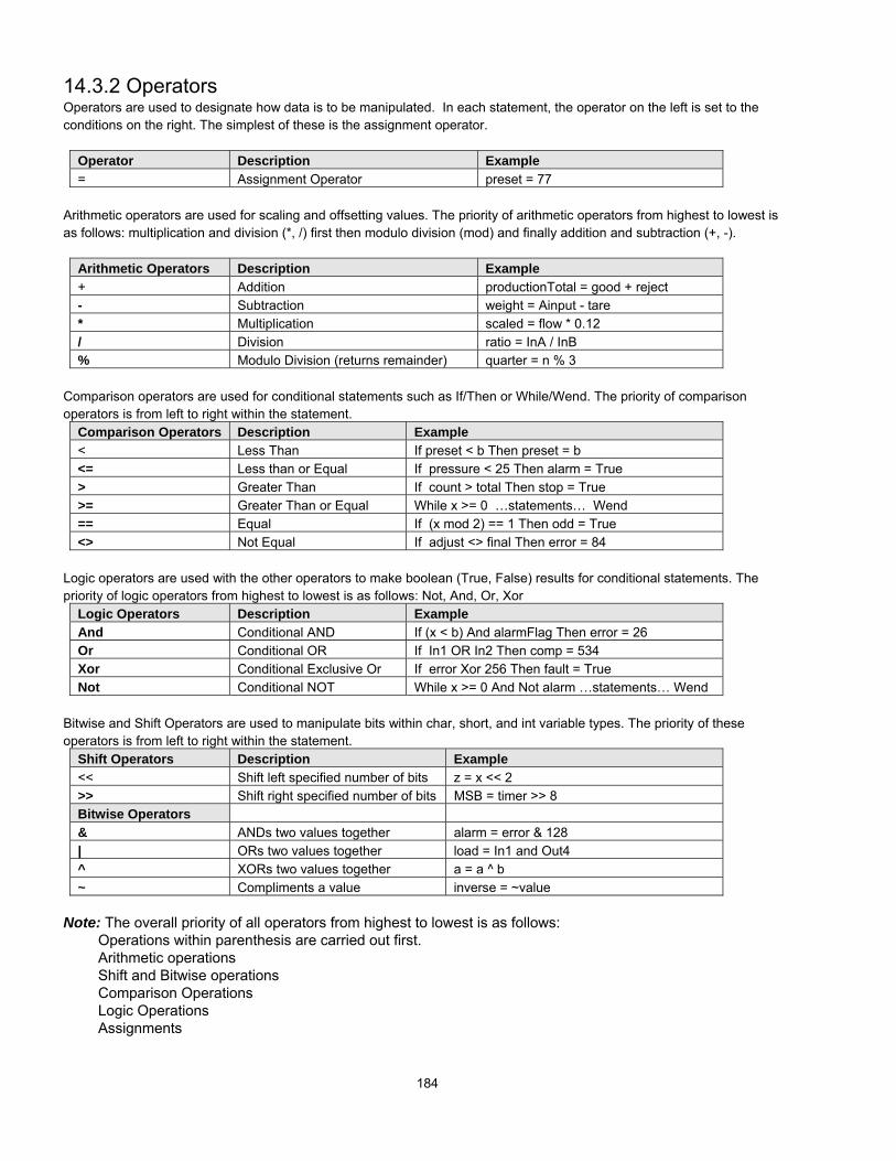
184
14.3.2 OperatorsOperators are used to designate how data is to be manipulated. In each statement, the operator on the left is set to theconditions on the right. The simplest of these is the assignment operator.
Operator Description Example= Assignment Operator preset = 77
Arithmetic operators are used for scaling and offsetting values. The priority of arithmetic operators from highest to lowest isas follows: multiplication and division (*, /) first then modulo division (mod) and finally addition and subtraction (+, -).
Arithmetic Operators Description Example+ Addition productionTotal = good + reject- Subtraction weight = Ainput - tare* Multiplication scaled = flow * 0.12/ Division ratio = InA / InB% Modulo Division (returns remainder) quarter = n % 3
Comparison operators are used for conditional statements such as If/Then or While/Wend. The priority of comparisonoperators is from left to right within the statement.
Comparison Operators Description Example< Less Than If preset < b Then preset = b<= Less than or Equal If pressure < 25 Then alarm = True> Greater Than If count > total Then stop = True>= Greater Than or Equal While x >= 0 …statements… Wend== Equal If (x mod 2) == 1 Then odd = True<> Not Equal If adjust <> final Then error = 84
Logic operators are used with the other operators to make boolean (True, False) results for conditional statements. Thepriority of logic operators from highest to lowest is as follows: Not, And, Or, Xor
Logic Operators Description ExampleAnd Conditional AND If (x < b) And alarmFlag Then error = 26Or Conditional OR If In1 OR In2 Then comp = 534Xor Conditional Exclusive Or If error Xor 256 Then fault = TrueNot Conditional NOT While x >= 0 And Not alarm …statements… Wend
Bitwise and Shift Operators are used to manipulate bits within char, short, and int variable types. The priority of theseoperators is from left to right within the statement.
Shift Operators Description Example<< Shift left specified number of bits z = x << 2>> Shift right specified number of bits MSB = timer >> 8Bitwise Operators& ANDs two values together alarm = error & 128| ORs two values together load = In1 and Out4^ XORs two values together a = a ^ b~ Compliments a value inverse = ~value
Note: The overall priority of all operators from highest to lowest is as follows:Operations within parenthesis are carried out first.Arithmetic operationsShift and Bitwise operationsComparison OperationsLogic OperationsAssignments

185
14.3.3 Reserved KeywordsThe following keywords are reserved for Macro use. They cannot be used for variable, array, or function names.+, -, *, /, %, >=, >, <, <=, <>, ==, And, Or, Xor, Not, <<, >>, =, &, |, ^, ~If, Then, Else, End, Select, Case, For, To, Down, Step, Next, While, Wend, Break , Continue, Return, Sub, bool, char,short, int, float
14.4 Statement ConstructionStatement construction depends on the statement’s purpose. All statements begin on a new line.
14.4.1 Definition StatementThis covers the declaration of variables and arrays. The formal construction is as follows:
type nametype name[constant]
14.4.2 Assignment StatementAssignment statements use the assignment operator to move data from the expression on the right side of the operator tothe variable on the left side. An expression is the combination of variables, constants and operators to yield a value.
Variable = Expression
14.4.3 Logical StatementsLogical statements perform actions depending on conditions. There are two types of conditional statements.
14.4.3.1 If-Then-Else StatementsThese statements perform actions depending on the condition of a Boolean expression.The Syntax is as follows:
Single Line format:If <Condition> Then [statements] Else [statements]
Block format:If <Condition> Then
[Statements]Else
[Statements]End If
Syntax description:If Must be used to begin the statement<Condition> Required. This is the controlling statement. It is FALSE when the condition evaluates to
0 and TRUE when it evaluates to 1.Then Must precede the statements to execute if the Condition evaluates to TRUE.[Statements] Statements to execute. These can include other If-Then-Else statements.Else Must precede the statements to execute if the Condition evaluates to FALSE.End If Must be used to end an If-Then-Else statement when it is entered in Block format.

186
14.4.3.2 Select-Case StatementsThe Select Case is a specialized form of the If-Then-Else statement. It allows multiple comparisons to values. The Syntax is as follows:
Select Case <Expression>[Case <evaluation>][Statements]
[Case Else][Statements]
End Select
Syntax description:Select Case Must be used to begin the statement< Expression > Required. This is the controlling expression. The result of evaluating the expression is
used as a test in the Case expressions.Case Must precede the statements that evaluate the results of the Select Case <Expression>< evaluation > This is the controlling statement for each Case. It is compared to the results of the Select
Case <Expression>. If it evaluates to TRUE then the statements below it are executed. Iffit evaluates to FALSE then the macro jumps to the next Case or Case Else.
[Statements] Statements to execute when the evaluation is TRUE.Case Else Must precede the statements to execute if none of the Cases evaluates to TRUE.End Select Must be used to end a Select Case.
14.4.4 Reiterative StatementsReiterative statements control loops and repetitive tasks depending on conditions. There are two types of reiterativestatements.
14.4.4.1 For-Next StatementsThe For-Next construction is for stepping through a fixed number of iterations. A variable is used as a counter to trackprogress and test for ending conditions. Use this for fixed execution counts.The Syntax is as follows:
For <Counter> = <StartValue> To <EndValue> [Step <Stepvalue> ]orFor <Counter> = <StartValue> Down <EndValue> [Step <Stepvalue> ]
[Statements]Next [counter]
Syntax description:For Must be used to begin the statement< Counter > Required. This is the controlling variable. The result of evaluating the variable is used as
a test for completion.<StartValue> Required. The < Counter >s initialized value.To or Down This determines if the Step control increments or decrements the <Counter>. “To”
increments <Counter> by <Stepvalue>. “Down” decrements <Counter> by <Stepvalue>.<EndValue> Required. The test point. If the < Counter >is greater than this value, the macro exits the
loop.Step Optional keyword. Specifies that a <StepValue> other than one is to be used.<StepValue> The value that < Counter > is changed every loop. If [Step <Stepvalue> ] keywords are
omitted the step value defaults to 1.[Statements] Statements to execute when the evaluation is TRUE. For-Next loops may be nested.Next Must precede the statements to execute if none of the Cases evaluates to TRUE.[counter] Optional < Counter > name. This is used when nesting For-Next loops.
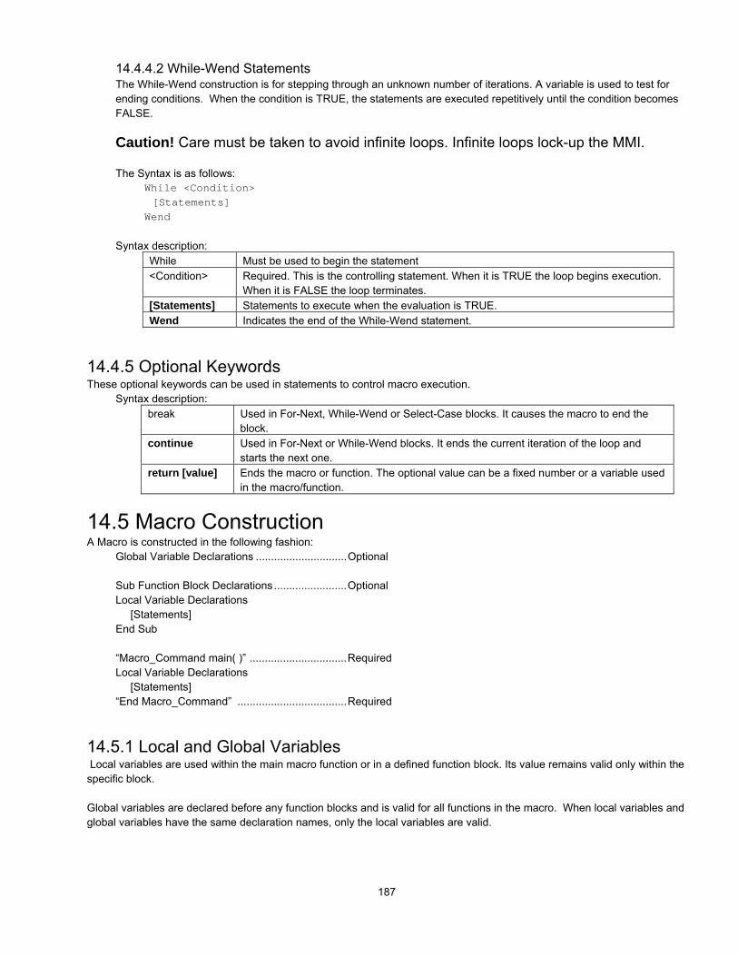
187
14.4.4.2 While-Wend StatementsThe While-Wend construction is for stepping through an unknown number of iterations. A variable is used to test forending conditions. When the condition is TRUE, the statements are executed repetitively until the condition becomesFALSE.
Caution! Care must be taken to avoid infinite loops. Infinite loops lock-up the MMI.
The Syntax is as follows:While <Condition>[Statements]
Wend
Syntax description:While Must be used to begin the statement<Condition> Required. This is the controlling statement. When it is TRUE the loop begins execution.
When it is FALSE the loop terminates.[Statements] Statements to execute when the evaluation is TRUE.Wend Indicates the end of the While-Wend statement.
14.4.5 Optional KeywordsThese optional keywords can be used in statements to control macro execution.
Syntax description:break Used in For-Next, While-Wend or Select-Case blocks. It causes the macro to end the
block.continue Used in For-Next or While-Wend blocks. It ends the current iteration of the loop and
starts the next one.return [value] Ends the macro or function. The optional value can be a fixed number or a variable used
in the macro/function.
14.5 Macro ConstructionA Macro is constructed in the following fashion:
Global Variable Declarations ..............................Optional
Sub Function Block Declarations........................OptionalLocal Variable Declarations
[Statements]End Sub
“Macro_Command main( )” ................................RequiredLocal Variable Declarations
[Statements]“End Macro_Command” ....................................Required
14.5.1 Local and Global Variables Local variables are used within the main macro function or in a defined function block. Its value remains valid only within thespecific block.
Global variables are declared before any function blocks and is valid for all functions in the macro. When local variables andglobal variables have the same declaration names, only the local variables are valid.

188
14.5.1 Function BlocksFunction Blocks are useful for reducing repetitive code, must be defined before use and can use any variable and statementtype. A function block is called by putting its name followed by parameters, in parenthesis, in the Main Macro Function. Afterthe function block is executed, it returns the value to the Main Function where it is used as an assignment or condition.Note: Macro Functions cannot be nested or interleaved.
The Syntax is as follows:Sub type <name> [(parameters)]
Variable Declarations[Statements][Return [value]]
End Sub
Syntax description:Sub Must be used to begin the Function Blocktype Required. This is the data type of value that the function returns.<name> The name of the Function. It is used in the Main Macro to call the function.(parameters) Optional. The parameters hold values that are passed to the function by the Main Macro.
The passed parameters must have their type declared in the parameter field andassigned a variable name. For example: Sub int MyFunction (int x, int y). x and y wouldbe integers passed to the function by the Main Macro. This function is called by astatement that looks similar to this: “z = MyFunction(123, preset)” Notice that the callingstatement can pass hard coded values or variables to the function. After the function isexecuted, an integer value is returned to “z”.
VariableDeclarations
Variables that are used in the Function Block must be declared first. This is in addition topassed parameters. In the above example x and y are variables that the function canuse. Global variables are also available for use in Function Blocks.
[Statements] Statements to execute.[Return [value]] Used to return a value to the calling statement. The value can be a constant or a
variable. Return also ends Function Block execution.End Sub Must be used to end a Function Block.
14.5.2 Built in Function BlocksEasyBuilder has two built in Function Blocks for retrieving and transferring data to the PLC. Theyare accessed by pressing the GET/SET FN button in the Macro Editor.
14.5.2.1 GetData FunctionThe GetData Function retrieves data from the PLC and puts itinto a variable for the Macro to use. To access the GetDataFunction, Click on a blank line in a Statement area of the macrothen click on the GET/SET FN button. The Macro Functionsdialog pops up.
Select GetData as the Function Name.
Macro AddressDevice Type: The variable type that receives the data. Thisautomatically changes to match the variable selected in theDevice Address.
Device Address: This dropdown list displays the declared variables of the Macro. Select the variable to hold the PLC data.
Array Item: If an array is selected for the Device Address, the particular item of the array must be designated.

189
PLC AddressDevice Type: Select the Device type from the dropdown list. The Device type depends on the PLC driver. Once this isselected, you can chose to get the data in Binary (Bin) or BCD (Bcd) format.
Device Address: this is the address number of the Device Type. The format is same as any other EasyBuilder part.Note: Extended Addressing mode is not allowed in this field. If Extended addressing is active, PLC data can be put intoLocal words/bits using the Data Transfer Part or General PLC Control, and then manipulated from there.
Aux. directs the Device Data to be retrieved from the Auxiliary Port.
No. of Words: This is the number of words to get.
Click OK to place the GetData Function into the code. Click Cancel to exit the function without saving any changes.Using the above graphic as an example, the code looks like this:
GetData(DwellTimer ,4x_Bin ,68,1)
14.5.2.2 SetData FunctionThe SetData Function sends data to the PLC and from avariable. To access the SetData Function, Click on a blank linein a Statement area of the macro then click on the GET/SET FNbutton. The Macro Functions dialog pops up.
Select SetData from the dropdown as the Function Name.
Macro AddressData Type: This is the variable type for transfer into the PLC.This automatically changes to match the variable selected inthe Device Address.
Device Address: This dropdown list displays the declaredvariables of the Macro. Select the variable to send to the PLC.
Array Item: If an array is selected for the Device Address, the particular item of the array must be designated.
PLC AddressDevice Type: Select the Device type from the dropdown list. The Device type depends on the PLC driver. Once this isselected, you can chose to send the data in Binary (Bin) or BCD (Bcd) format.
Device Address: The address number of the Device Type. The format is same as any other EasyBuilder part.Note: Extended Addressing mode is not allowed in this field. If Extended addressing is active, Variable data can be put intoLocal words/bits then transferred to the PLC by using the Data Transfer Part or General PLC Control.
Aux. directs the Device Data to be sent to the Auxiliary Port.
No. of Words: This is the number of words to send.
Click OK to place the SetData Function into the code. Click Cancel to exit the function without saving any changes. Usingthe above graphic as an example, the code looks like this:
SetData(preset ,4x_Bin ,174,1)
Note: Once you are familiar with the format, the GetData and SetData functions can be entered by hand. The compilerreturns error notices when the format is incorrect.

190
14.6 Compile error messagesThere are many causes for compiler errors. As the compiler detects errors it displays a warning message in the lower textbox of the Workspace Editor. Macros with errors cannot be downloaded and are listed in the Not Download Macro box of theMacro Dialog.
Error message format: Macro_name(: Error_Number ) Error_MessageThe Error_ Number corresponds to one of the conditions listed below.
Error_Number descriptionsNumber Message Format Sample Code Reason for error1 "Syntax error:" 'identifier' Macro_Command main( )
Char i , 3xyzint g[4]g[3] = 4
End Macro_Command
An unsupported variable name ,”Errormessage: “Syntax error: 3x”Variable names must begin withalphabet characters.
2 'identifier' used withouthaving been initialized
Macro_Command main( )Char iint g[i]g[3] = 4
End Macro_Command
Undefined size of an array. Arrays mustbe defined with fixed values.
3 "Re-declaration error: "'identifier'
Macro_Command main( )int g[10] , gFor g = 0 To 2g[3] = 4Next g
End Macro_Command
“g” is defined twice in the samefunction. The name of variable orfunction cannot be used more thanonce in a function.
4 "Function name error:"'identifier'
Macro_Command If( ). . .End Macro_Command
“If” is being used as the Function name.Reserved keywords or constants cannotbe the name of a function
5 "Statement missing" Macro_Command main ) Function definition missing “(“6 "Missing expression in If statement"7 "Missing “Then” in If statement"8 "Missing “EndIf” "9 "Unfinished “If’ statement before “End If” "10 "Illegal Else statement"
The format for “If-Then” statement is:If [logic expression]Then [ Else [If [logic expression] Then ] ]EndIf
Formats other than this cause compile errors.11 "There should be constant behind “Case” "12 "Missing “Case” behind “Select” "13 "Missing “expression” behind “Select Case” "14 "Missing “End Select” statement"15 "Illegal “Case” statement"16 "Unfinished “Select” statement before “End Select” "
The format for “Select-Case” statement is:Select Case [expression] Case [constant] Case [constant] Case [constant] Case ElseEnd Select
Formats other than this cause compile errors.17 " “For” statement error: missing “For” before “Next” "18 "Should be integer of char variable"19 "Missing assign statement"20 "Missing keyword “To” "21 "Missing “Next” statement"
The format for “For-Next” statement is:For [variable] = [initial value] To [end value] [Step]Next [variable]
Formats other than this cause compile errors.22 " “While” statement error: missing “While” before
“Wend” "23 "Missing “Wend” statement"
The format of “While” statement is:While [logic expression]Wend
Formats other than this cause compile errors.

191
24 "Illegal “Break” statement “Break” statement can only be used in “For-Next”,“While-Wend”, or “Select-Case” statements.“Break” statement takes one line of Macro.
25 "Illegal “Continue” statement" “Continue” statement can only be used in “For-Next”or “While-Wend” statements.“Continue” statement takes one line of Macro.
26 "Expression error"27 "Illegal operation object" Macro_Command main( )
int g[10] , gg[3] = 4 + xyzEnd Macro_Command
“xyz” represents an incompatible object.The mismatch of operational objects in anexpression causes compile errors.
28 "Missing “Sub” " The format of function declaration is:Sub(Macro_Command) [data type] function_name( )End Sub(Macro_Command)
Formats other than this cause compile errors.29 "Missing “Macro_Command” "30 "Mismatch of the number of parameters "31 "Mismatch of data type of parameter"32 "Parameter error"
The number of parameters in a function’s declarationmust be equivalent to the number of argumentspassed to the function.
33 "Undefined function" Any variable or function should be declared beforeuse.
34 "Illegal member of array35 "Illegal definition of array";36 "Illegal index of array"37 "Undefined symbol"38 "Un-supported PLC data address" ; The parameter of GetData( … ) , SetData( … ) should
be legal PLC address.
39 "Should be integer, character or constant" The format of array is:Declaration: array_name[constant] (constant is the size of the array)
Usage: array_name[integer, character or constant]
Formats other than this cause compile errors.40 "Illegal Macro statement
before declarationstatement "
Macro_Command main( )int g[10]For g[2] = 0 To 2g[3] = 4 + g[9]int h , kNext g[2]
End Macro_Command
Statement position of “int h , k”declaration caused the error. Alldeclarations must be made beforeoperational statements.
41 "Floating point can not bitwise shift"42 "Missing function return value "43 "Function can not return a value"44 "Illegal Float data type in expression"45 "Error PLC address"46 "Stack can not exceed 4k bytes"47 "Only one main entrance in the Macro is allowed"48 "Too many main entrance: " 'identifier'
The only one main entrance of Macro is:Macro_Command function_name( )End Macro_Command
You cannot nest or interleave Macro Functions.

192
14.7 Sample Macro Code1: Various expressions(Arithmetic, Bitwise shift, Logic and Comparison)
Macro_Command main( )int b[10]
b[0]= (400 + 400 << 2) / 401b[1]= 22 *2 - 30 % 7b[2]= 111 >> 2b[3]= 403 > 9 + 3 >= 9 + 3 < 4 + 3 <= 8b[4]= Not 8 + 1 And 2 + 1 Or 0 + 1 Xor 2b[5]= 405 And 3 And Not 0b[6]= 8 & 4 + 4 & 4 + 8 | 4 + 8 ^ 4b[7]= 6 - ~ 4b[8]= 0x11b[9]= 409
End Macro_Command
2: For-NextMacro_Command main( )int a[10]int b[10]
int i For i = 0 To 4 Step 1If( a[0] == 400 ) ThenGetData(a[0] ,4x_Bin ,1,9)SetData(b[0] ,4x_Bin ,11,10)
End IfNextEnd Macro_Command
3: While-Wend, if, break, continueMacro_Command main( )int b[10]int I
b[0]= (400 + 400 << 2) - 401 + 99b[1]= 100i = 5While i == 5SetData(b[1] ,4x_Bin ,11,1)
If b[1] == 100 ThenBreakSetData(b[0] ,4x_Bin ,12,1)i = 4ContinueSetData(b[0] ,4x_Bin ,13,1)
End IfWendEnd Macro_Command
4: Global variables and function callchar g
Sub int sin(int j ,int k)int ySetData(j ,4x_Bin ,14,1)GetData(y ,4x_Bin ,15,1)g = yReturn yEnd Sub
Macro_Command main( )int b[5]int i
b[0]= (400 + 400 << 2) - 401 + 99b[1]= 100b[2]= 111b[3]= 403i = 5While i == 5 - 20 % 3
SetData(b[1] ,4x_Bin ,11,1)If b[1] == 100 Then
SetData(b[0] ,4x_Bin ,12,1)i = sin(b[2],b[3] )SetData(g ,4x_Bin ,17,1)SetData(i ,4x_Bin ,16,1)
End IfWendEnd Macro_Command
5: Initializing and working with arrays and PLC data Macro_Command main( )

193
int w, i[10]char x
For w = 0 To 9i[w] = 0
NextGetData(i[0] ,4x_Bin ,1,4)w = i[0] + i[1] + i[2] + i[3]If w > 150 Then
For w = 0 To 3i[w] = 0
NextSetData(i[0] ,4x_Bin ,1,4)x = 0SetData(x ,1x_Bin ,3,1)GetData(i[0] ,4x_Bin ,212,2)x = 0SetData(x ,0x_Bin ,4,1)
ElseFor w = 0 To 3
i[w] = i[w] + 2*wNextSetData(i[0] ,4x_Bin ,1,4)
End IfEnd Macro_Command
6: If-Then-ElseMacro_Command main( )int j, k[10]
For j = 0 To 10k[j] = jNextIf k[0] == 0 ThenSetData(k[4],4x_Bin ,1,1)End IfIf k[0] == 0 ThenSetData(k[4],4x_Bin ,1,1)ElseSetData(k[5],4x_Bin ,1,1)End IfIf k[1] == 0 ThenSetData(k[3],4x_Bin ,2,1)Else If k[1] == 1 ThenSetData(k[1],4x_Bin ,3,1)End IfIf k[1] == 0 ThenSetData(20,4x_Bin ,4,1)Else If k[1] == 2 ThenSetData(k[1],4x_Bin ,5,1)ElseSetData(k[2],4x_Bin ,6,1)End IfEnd Macro_Command
7: Select-CaseMacro_Command main( )int j, k[10]
For j = 0 To 10k[j] = jNextSelect Case k[1]
Case 1j = 1
Break
Case 2j = 2
BreakEnd SelectSetData(j,4x_Bin ,1,1)End Macro_Command
Macro_Command main( )int k[10]int jj = 90 * 1k[4] = 8Select Case k[4]
Case 1j = 1
Break
Case 3j = 2End SelectSetData(j,4x_Bin ,1,1)End Macro_Command
8: ArrayMacro_Command main( )int a[25]int b[1]int i
b[0] = 13For i = 0 To b[0] Step 1a[i] = 20 + i * 10NextSetData(a[0] ,4x_Bin ,1,13)End Macro_Command
9: While-Wend Macro_Command main( )

194
char Toggleflagint a[13]int b[14]int c = 4848char i = 0b[0] = 13
While b[0]a[i] = 20 + i * 10
If a[i] == 120 Thenc =200Break
End Ifi = i + 1
WendSetData(c ,4x_Bin ,2,1)End Macro_Command
Nested While LoopsMacro_Command main( )int a[250]int b[250]int i = 1
a[0] = 1b[0] = 2While a[0]
While b[0]b[i ] = 10 + i * 10If b[i] == 210 Then
SetData(i ,4x_Bin ,1,2)b[i] = 200Break
End Ifi = i + 1
WendIf b[i] == 200 Then
SetData(b[0] ,4x_Bin ,1,4)Break
End IfSetData(b[0] ,4x_Bin ,1,3)
WendEnd Macro_Command
10: Break and Continue(1)Macro_Command main( )int j, K[10]
For j = 0 To 10If j % 2 == 0 Then
k[j] = 5Else
BreakEnd If
NextSetData(k[0],4x_Bin ,1,10)End Macro_Command
(2)Macro_Command main( )int a[13]int b[14]int c = 4848char i = 0
b[0] = 13While b[0]
a[i] = 20 + i * 10If a[i] == 120 Then
c =200i = i + 1Continue
End Ifi = i + 1If c == 200 Then
SetData(c ,4x_Bin ,2,1)Break
End IfWendEnd Macro_Command
11: Infinite loopThe loop is created because b[0] is never set to zero.Caution! Infinite loops slow down screen updates or lockup the MMI. Do not attempt to run this code in simulationmode.
Macro_Command main( )int b[14]char i = 0
b[0] = 13While b[0]i = i + 1WendEnd Macro_Command

195
IndexA
Address Mode............................................................... 39Alarm Bar .............................................................. 33, 168Alarm Display.............................................................. 157Alarm indicator .............................................................. 37Alarm Scan.................................................................. 173Aligning Objects ............................................................ 91Allow Function Key frame when making Shapes .......... 29Animation .................................................................... 152ASCII Data .................................................................. 149ASCII Input Extend...................................................... 147Automatic save and compile ......................................... 29Aux. block pack ............................................................. 43Aux. Station................................................................... 43Aux. time out constant................................................... 43Aux. type ....................................................................... 42Auxiliary (AUX) RS232 port............................................. 8Auxiliary (AUX) RS485 port............................................. 9Auxiliary Port ................................................................. 46Auxiliary Tab ................................................................. 42
B
Back light .................................................13, 14, 105, 175Back light saver............................................................. 34Bar Graph ................................................................... 164Base Window ................................................................ 50Battery........................................................................... 13Battery replacement ................................................ 12, 16Baud rate ................................................................ 31, 42BCD .............................................................................. 47Beginning window No.................................................... 39BIN ................................................................................ 47Bit Lamp...................................................................... 120Bitmap Library ............................................................... 47
Adding a bitmap......................................................... 67Creating a Bitmap Library.......................................... 67Dialog ........................................................................ 66Editing a Bitmap ........................................................ 68
Bitmap Tool ................................................................... 87Black Screen after download......................................... 16Buzzer........................................................................... 34
C
CE Requirements........................................................ 5, 6Clipping ......................................................................... 52Coherence .................................................................... 52Color Options ................................................................ 85COM port ................................................................ 20, 24Comm. delay........................................................... 31, 42Common Window.................................................... 35, 50Communications settings ............................................ 200Communications Speed ................................................ 24
Compact Flash .................................................... 117, 118Compile ......................................................................... 23Compiler level................................................................ 39Compiling a Project ..................................................... 106Complete Download/Upload.......................................... 24Compressing/Uncompressing a project....................... 114Connect I/F.................................................................... 31Connection Points
MMI-7XX.................................................................... 18MMI-850, 1500........................................................... 18
Connections ................................................................ 4, 8CPU indicator ................................................................ 37Creating a Keypad....................................................... 135Creating a project .......................................................... 21Cursor color................................................................... 34Cutout dimensions........................................................... 2
D
Data bits .................................................................. 31, 42Data format.................................................................... 47Data Transfer .............................................................. 179Debugging ................................................................... 109
Data Monitor ............................................................ 111PLC Monitor............................................................. 110Searching................................................................. 113System Resources................................................... 112
Decompiling a project .................................................. 115Default Route IP address .............................................. 32Description .................................................................... 45Device address.............................................................. 45Device type.................................................................... 45Dimensions.................................................................... 13Dip Switch Settings ....................................................... 12Direct Online-Simulator ................................................. 25Direct Window ............................................................. 156Display Mode........................................................... 21, 40Do conversion ............................................................. 142Documenting a Project ........................................ 114, 116Double float ................................................................. 143Downloading.......................................................... 23, 107Drawing ......................................................................... 84
Attributes.................................................................... 84Color Options............................................................. 85Lines, Rectangles, Ellipses, Arcs and Polygons ........ 85Pattern Styles ............................................................ 84Scales ........................................................................ 88
DriverActivation ................................................................. 203
Drivers ................................................................... 29, 203External.................................................................... 203Standard .................................................................. 203
Duplicate this label to other states................................. 49

196
E
EasyManager .................................. 12, 19, 20, 24, 25, 26EasyWindow................................................................ 109Editing Grouped Objects ...............................................93Editing Object Attributes ................................................92Editing Placed Objects ..................................................89Editor ............................................................... 39, 40, 241Error Messages ........................................................... 108Ethernet ............................................................... 8, 13, 31
IP Settings..................................................................32Ethernet Connections ....................................................11Ethernet port............................................................ 10, 30Event Display............................................................... 171Event Log ....................................................................176Event Logger .................................................................35EventLog .......................................................................35
Data Base ..................................................................41Eventlog in Retentive Memory..................................... 172Exporting and Importing Labels .....................................77Exporting and Importing Tags........................................74Extended address mode................................................46Extended notation..........................................................39Extra No. of Event ................................................. 35, 173
F
Fast Selection Window ...................................... 33, 50, 60Find/Replace Addr… utility ............................................95Fix objects ............................................................... 28, 90Flip Horizontal................................................................91Flip Vertical....................................................................91Font ...............................................................................48Font Alignment ............................................................ 143font selection .................................................................40Function Key................................................................ 134
Change Common Window ....................................... 137Change Window....................................................... 136Close a Window ....................................................... 137Jog Fast Select Window........................................... 138Message Board Functions ....................................... 139Minimize Window ..................................................... 139Pop up a Window..................................................... 137Return to Previous ...................................................137Window Bar.............................................................. 138
Fusing Requirements ......................................................4
G
General Tab............................. 33, 39, 41, 57, 78, 83, 105GET/SET FN ............................................................... 188Grid color .......................................................................28Grid/Snap ......................................................................28Grounding Requirements ................................................5Group Library.................................................................69
Adding a Group..........................................................70Creating a Group Library............................................69Dialog.........................................................................69Editing a Group ..........................................................71
Grouping Objects...........................................................92
H
Hard Copy....................................................................136hardcopy ..........................................................82, 83, 175Hardcopy .......................................................................82Hardware Tab ................................................................40HMI Indicator Lights .......................................................12HMI Local IP address.....................................................32HMI station No. ..............................................................31HMI-HMI link speed .......................................................32
I
Indicator Tab..................................................................37Indirect Window ...........................................................154Installation........................................................................5Installing EasyBuilder.....................................................19
J
Jump to Application..................................................26, 29
L
Label LibraryAdding a Label ...........................................................75Editing a label.............................................................76Exporting And Importing.............................................77Using Labels ..............................................................77
Label Position ................................................................49Label Tab.......................................................................48
Tracking .....................................................................48Use Label ...................................................................48Use Label Library .......................................................48
Language.......................................................................29Double Bytes..............................................................40Single byte .................................................................40
Layers ............................................................................90Library
Bitmap ..................................................................62, 66Group ...................................................................62, 69Operations..................................................................62Shape.........................................................................62Shape Operations ......................................................63System .......................................................................71Toolbar Functions.......................................................71
Local memory ................................................................97
M
Macro.....................................................95, 176, 180, 188Compile error messages ..........................................190Construction .....................................................185, 187Editing ......................................................................180GetData Function .....................................................188Operators .................................................................184Sample code ............................................................192SetData Function......................................................189Syntax ......................................................................182

197
Triggering ................................................................ 180Mask ........................................................................... 143Master - Slave communications ............................ 11, 201Message Board ........................................................... 139
Clear Board ............................................................. 140Set Operation Mode ................................................ 139Set pen color ........................................................... 140Set pen style............................................................ 140
Message board window ................................................ 36Meter Display .............................................................. 166Minimize window........................................................... 61Minimize Window ........................................................ 139Model number ......................................................... 20, 30Monopoly....................................................................... 52Mounting Instructions ...................................................... 2Moving Objects ............................................................. 89Moving Shape ............................................................. 150MT5_PC Cable................................................................ 9Multi. Copy .................................................................... 94Multiple HMI .................................................................. 31Multi-State Switch ....................................................... 133
N
NEMA-4 Mounting........................................................... 2new project........................................................ 29, 50, 62New project ................................................................... 20No. of windows.............................................................. 34Nudge Tools.................................................................. 90Numeric Data .............................................................. 146Numeric Display Format.............................................. 142
Binary ...................................................................... 143Do Conversion......................................................... 142Double Float ............................................................ 143Font Alignment ........................................................ 143Hex .......................................................................... 143Mask........................................................................ 143Raw data display ..................................................... 142Single Float.............................................................. 143
Numeric Input Extend.................................................. 141
O
Object ID ....................................................................... 28Object Order.................................................................. 90Off-line Simulation....................................................... 107Offline-Simulator ........................................................... 25On-line simulation ....................................................... 107Online-Simulator ........................................................... 25
P
Parity....................................................................... 31, 42Part
Attributes ................................................................... 47General Tab............................................................... 45ID Numbers ............................................................... 44Placement.................................................................. 49Placement Summary ................................................. 44
Part Layout .................................................................... 39Partial Download/Upload............................................... 24Password....................................................................... 34Passwords..................................................................... 78PC [RS-232] & PLC [RS-485] Port .................................. 9PLC [RS-232] Port........................................................... 8PLC block pack ............................................................. 32PLC Control................................................................. 174
Back light Control..................................................... 175Back light control (write back) .................................. 175Change Window....................................................... 175Execute macro program........................................... 176General PLC Control................................................ 176Report printout ......................................................... 175Screen hardcopy........................................................ 83Screen Hardcopy ..................................................... 175Write data to PLC (base window)............................. 175
PLC station No. ............................................................. 31PLC Tab ............................................................ 21, 29, 39PLC time out constant ................................................... 32PLC type........................................................................ 29PLC[RS-232] port .......................................................... 30PLC[RS-485] PC[RS-232] port. ..................................... 30Pop-up Keypad............................................................ 144Print Operations ............................................................ 82Printer
Error Detection........................................................... 36Selection .................................................................... 36
Printer Port .................................................................... 10Printing
Active Screen............................................................. 83Events........................................................................ 83Using PLC Controls ................................................... 83Window in background............................................... 83
Printing Screens with EasyWindow ............................. 116Profile Tab ..................................................................... 89Project Download/Upload.............................................. 24Project Operations....................................................... 106
R
Raw data Display ........................................................ 142RDS mode..................................................................... 26Read address ................................................................ 45Real Time Clock .......................................................... 105Recipe Download/Upload.............................................. 24Recipe Transfer........................................................... 169Remote memory............................................................ 98Repairs and Returns ..................................................... 17Reserved Local Bits ...................................................... 98Reserved Local Words/Bi .............................................. 98Reserved Retentive Word ........................................... 105Resizing Objects ..................................................... 89, 91Retentive memory ....................................................... 104Retentive Memory ......................................................... 41Rotate 90 Degrees ........................................................ 91RTC

198
Source........................................................................35
S
Safety Guidelines ............................................................6Scale Tool......................................................................88Screen Editor Overview.................................................27Security..........................................................................78
Assigning ...................................................................78Control .......................................................................38How to use .................................................................81Level .............................................................. 38, 78, 79Reserved Local Words...............................................80Reserved Retentive Words ........................................80
Security Tab .............................................. 38, 41, 79, 105Serial Port I/F........................................................... 30, 42Server IP address..........................................................32Set Bit .......................................................................... 124Set Word .....................................................................127Shape Library ................................................................47
Adding a Shape .........................................................64Creating .....................................................................64Dialog.........................................................................63Editing a Shape..........................................................65
Shape Tab.....................................................................47Shape Tool ....................................................................87Shortcut
Changing assigned Shape or Bitmap.........................71Simulation......................................................................23Single float................................................................... 143Size command...............................................................28Specifications ................................................................13Stacked Objects ............................................................93Startup window No. .......................................................34State ..............................................................................48Stop bits .................................................................. 31, 42Subnetwork Mask ..........................................................32System Bits and Registers.............................................97System Libraries............................................................71System Message ......................................................... 174System Parameters .......................................................29
Storing in retentive memory .......................................41
T
Tag Library ....................................................................72Adding a Tag..............................................................72Deleting Tags.............................................................73Editing a Tag..............................................................73Exporting and Importing Tags ....................................74Using Tags.................................................................74
Tags ..............................................................................46Task Bar .................................................................. 37, 56
Using..........................................................................61Task button....................................................................33Task Button ...................................................................56
Task ButtonsSetup..........................................................................57
Text................................................................................86Alignment ...................................................................86Font ............................................................................86Label Use ...................................................................86Placing .......................................................................86
TFT PCD Value .............................................................40Toggle Switch ..............................................................131Touch indicator ..............................................................37Touchscreen calibration...........................................12, 26Tracking .........................................................................49Treebar ..........................................................................96Trend Display...............................................................159
Multiple Pages..........................................................160Single Page..............................................................159
Trouble Shooting ...........................................................15
U
Underlay Window...........................................................52
V
View Menu .....................................................................28
W
WARRANTY ....................................................................vWindow
Background ................................................................52Changing....................................................................55Copying ......................................................................54Creating......................................................................51Delete.........................................................................53Frame.........................................................................52Importing ....................................................................54Number ......................................................................51Opening......................................................................53Operations..................................................................50Popping Up ................................................................55Security ......................................................................52Size ............................................................................51Start Position..............................................................51Style ...........................................................................52Tracking .....................................................................52Types .........................................................................50
Window Bar ...........................................................61, 138Window Property......................................................28, 44Word Lamp ..................................................................122Write address.................................................................45
X
XY Plot.........................................................................162Multiple Pages..........................................................163Single Page..............................................................162

199
Section 5 Controller ReferenceContents
15.0 Communications Overview ......................................................................................................................20015.1 Communications settings .........................................................................................................................20015.2 Master-Slave Configuration......................................................................................................................20116.0 Driver Specifications ................................................................................................................................20316.1 AB DF1 ....................................................................................................................................................20416.2 AB DH485 ................................................................................................................................................20716.3 AB PLC5 ..................................................................................................................................................20916.4 A-B Logix DF1..........................................................................................................................................21316.5 DELTA DVP .............................................................................................................................................21516.6 ENTERTRON MODBUS RTU v1.00........................................................................................................21616.7 FACON FB...............................................................................................................................................22016.8 [pds]Fuji NB Series Ver1.0.......................................................................................................................22216.9 GE FANUC SNP-X...................................................................................................................................22316.10 HITACHI EH-150 (CPU port) .................................................................................................................22616.11 IDEC Micro3 ...........................................................................................................................................22916.12 IDEC OpenNET .....................................................................................................................................23116.13 INDUSTRIAL INDEXING SYSTEMS, INC. ............................................................................................23216.14 Jetter Nano ............................................................................................................................................23416.15 Keyence KV-16DT .................................................................................................................................23516.16 KOYO Direct ..........................................................................................................................................23716.17 Lenze .....................................................................................................................................................24016.18 [PDS] LG GLOFA Cnet Ver2.00.............................................................................................................24116.19 LG Master K10S1...................................................................................................................................24316.20 LG Master K60S ....................................................................................................................................24516.21 LG Master K C-Net.................................................................................................................................24716.22 LG Master K300S...................................................................................................................................24816.23 Matsushita FP (Aromat) .........................................................................................................................24916.24 Memory Map Protocol ............................................................................................................................25216.25 MITSUBISHI A1S, A2A, A2US, A3N/A1SH ...........................................................................................25516.26 MITSUBISHI AJ71C24 - AnA/AnU CPU ................................................................................................25616.27 MITSUBISHI FX0n/2/2n COM, FX0n/FX2, FX2n, FX2n D(bit)...............................................................25816.28 MITSUBISHI J2-S100 ............................................................................................................................26116.29 MODICON MODBUS RTU / MODBUS RTU(485 2W) ...........................................................................26316.30 MODBUS RTU Extend V3 .....................................................................................................................27316.31 MODBUS RTU TCP/IP ..........................................................................................................................27416.32 OMRON / OMRON (485 2W) Host Link .................................................................................................27516.33 [pds]OMRON CQM1H-CPU61 Ver1.00 .................................................................................................27816.34 OMRON CS/CJ Ver 1.00a .....................................................................................................................28016.35 SAIA PCD PGU mode............................................................................................................................28216.36 Samsung SPC-10 ..................................................................................................................................28416.37 [pds] Sharp JW Series Ver1.0................................................................................................................28516.38 SIEMENS S7-200 ..................................................................................................................................28616.39 SIEMENS S7/300 MMI ADAPTOR ........................................................................................................28716.40 Siemens S7/300 PC ADAPTOR ............................................................................................................28816.41 SIMATIC TI505 ......................................................................................................................................28916.42 Telemecanique Unitelway ......................................................................................................................29116.43 Toshiba T Serial .....................................................................................................................................29216.44 VIGOR M Series ....................................................................................................................................29516.45 Yokogawa PLC Series V1.0...................................................................................................................297

200
15.0 Communications OverviewA programming cable is provided with each unit. In addition to this cable, a cable is needed to connect the HMI to yourController (PLC). This section provides pin out diagrams so that you can make your own cable. In some cases, a readymade 6’ (2m) cable is available. The available cables have their part number listed with the wiring diagrams.
15.1 Communications settingsOnce the cable is made and the HMI is connected to the PLC communications can begin. It is up to the programmer to makesure the settings in the PLC are correct and that they match the settings in the MMI. The HMI settings are made through theEasyBuilder Software. Run EasyBuilder, open or start a new project and go to the Edit|System Parameters… Menuselection.
Select the PLC type from the drop down menu.If the PLC type is not shown, consult thefactory for availability. Make the appropriateselections for your particular situation.
Serial I/F port: Selects the type ofcommunications and thus the HMI port to whichthe PLC is connected.Baud rate: Communication speed, this mustmatch the PLC setting.Data bits, Stop bits, Parity: Communicationsattributes that also must match the PLCsettings.Parameter 1 ~ 6: Set additional parametersaccording to PLC type specification sheets.
HMI station No.: The ID number of the HMIwhen used with PLCs that allow multipledevices connected to its port.PLC station No.: The ID number of the PLC.Used when multiple PLCs have the capability tobe on line with other devices.
Multiple HMI: Allows more than one HMI to beconnected to one PLC. Enable as a Master or aSlave, depending on connection, or Disable asneeded.HMI-HMI link speed: This is used only whenmultiple HMIs are connected to a single PLC.Faster link speeds may increase screen updates but it is affected by distance of link and electrical interference.
Note: All linked MMI’s must be set to the same speed. When an HMI is set as “slave”, it ignores the communicationparameters connected with the PLC (Serial port I/F, Baud rate, etc.).
Connect I/F: Select the unit to unit connection type. Ethernet is available for units with the optional Ethernet port. For allothers, use the Serial interface (I/F) selection.

201
Ethernet IP settings: These settings are used whenever Ethernet communications is selected for HMI to MMI or MMI toPLC connections. A working knowledge of TCP/IP networking and terminology is necessary to implement Ethernetconnections.
HMI Local IP address: These fields are the IP address of the HMI unit.Server IP address: The IP address of the PLC or Slave MMI.Subnetwork Mask: The mask for the network where the HMI and PLC or Slave are located.Default Route IP address: This is used for HMI to PLC communications and refers to network server IP settings.
PLC time out constant (sec): This setting determines how long the HMI waits for a response from the PLC before retry.The range is from 3.0 to 25.5 seconds. This setting is important when the PLC is normally slow to respond or if severalMMI’s are linked to one PLC.
PLC block pack: Used to determine how the unit communicates to the controller. By increasing this number, larger blocks ofregisters can be fetched from the controller. In some cases, this speeds the update of information on the display. Hint: Whencreating a display, it is advised that consecutive registers be used whenever possible.
Note: Communication disconnection handling processTwo conditions cause PLC-HMI communications problems.The PLC does not respondThe PLC gives an error code response
If the HMI detects communication problems, it responds according to the state of local bit LB9055.Bit is OFF, 0: Abort: Any command to write data to the PLC is deleted.Bit is ON, 1: Retry: Keeps on writing command to the PLC.
15.2 Master-Slave ConfigurationThe HMI supports a master - slave communications. One HMI is connected directly to the PLC and configured as theMaster. All the other MMIs are connected in series to it and are configured as Slaves. In theory there is no limitation to thenumber of MMIs on a chain, however response time gradually decreases when more than three MMIs are linked together.The HMI are configured with the EasyBuilder software to be the Master or a Slave.
Serial Linking is accomplished by connecting the PLC [RS232] port of the slave to the RS232 side of the PLC/PC 232/485connector of the master or successive unit. Ethernet linking is via crossover cable or through a hub with standard Ethernet10BaseT cabling.
Serial wiring between two MMIs

202
Case 1: Slave to Master, connecting PLC[RS232] directly to PC[RS-232]/PLC[RS485] combination port.Connect to SLAVE HMI PLC[RS-232] portCable has D-SUB Male end
Connect to MASTER HMI PC[RS-232] portCable has D-SUB Female end
2 TxD 8 RxD 3 RxD 7 TxD 5 GND 5 GND
Shield Earth Ground
Case 2: Slave to Master, connecting PLC[RS232] to PC side of split download cable (MT5_PC) with use of Male to Male NullModem cable.Connect to SLAVE HMI PLC[RS-232] portCable has D-SUB Male end
Connect to MT5_PC to MASTER HMI PC[RS-232] portCable has D-SUB Male end
2 TxD 3 RxD 3 RxD 2 TxD 5 GND 5 GND
Shield Earth Ground
Case 3 Optional Ethernet Connections: Units equipped with the optional Ethernet port can be connected via Ethernet to aMaster and Slaves using standard 10T Ethernet cables. Slave to Master, connect the Ethernet ports with a standard(Category 5) Ethernet 10T crossover cable (RJ-45 to RJ45). On the other hand, use standard cables with routing passingthrough Hubs and Servers as needed.
Connecting a Master directly to a Slave using 10T Crossover cable
Connecting a Master through a Hub to Slaves
SlaveMaster
Slave
Slave
Hub
Master

203
15.3 DriversThere are two types of drivers used with EasyBuilder.
15.3.1 Standard DriversStandard Drivers are those that are built into the EasyBuilder software package. To access the register ranges for thesedrivers, use the PLCAddressView.exe utility. The following are brief reference sheets for these drivers. It is understood thatthe programmer is familiar with the Programmable Controller and its operation. In most cases, the communicationsparameters listed in the reference are the default settings. Not all drivers listed in the System Parameters have referencesheets.
15.3.2 External DriversEasyBuilder version 2.0.2 and later now supports enhanced external drivers. These are drivers developed for specialapplications or extended support over and above the list of Standard PLC drivers.
If an external driver is not installed on your computer, it can be downloaded from the KEP website (www.kep.com)downloads area.
Steps to Activate a DriverCreate a Subdirectory under the EasyBuilder main directory named drivers. If the directory already exists then there is noneed to create a second directory.
Copy the driver file into the drivers directory. Driver files end with the *.pds extension.
Start EasyBuilder and go to the System Parameters, PLC tab. The new driver should be listed along with all of the standarddrivers. Drivers are listed in alphabetical order.
16.0 Driver SpecificationsThe following are brief reference sheets for the drivers. It is understood that the programmer is familiar with theProgrammable Controller and its operation. In most cases, the communications parameters listed in the reference are thedefault settings.

204
16.1 AB DF1
16.1.1 HMI SettingsCommunication parameters must be set the same as those of the PLC. The following settings are recommended.Parameter Recommended Setting NotesSerial I/F port RS-232 Options: RS232, RS485 – Dependant on PLC hardwareBaud rate 19200 Options: 9600, 19200, 38400, 57600, 115200 - Must match PLC channel
settingParity None Options: Odd, Even, None - Must match PLC channel settingData bits 8 Options: 7, 8 - Must match PLC channel settingStop bits 1 Options: 1, 2 - Must match PLC channel settingHMI station No. 0 HMI station No. must be 0PLC station No. 1 The Station number must match the PLC Node Number (0-31)Comm. delay (10msec) 0 Request delay: 0~999 @10 milliseconds. Use when the PLC requires a
delay between requests. Not implemented in simulation mode.
16.1.2 PLC SettingSupports all SLC Series PLC’s that have DF1 ports.
Communication parameters must be the same as those of the MMI.Full Duplex Operation must be set.No Hardware Handshaking must be set.
16.1.3 Wiring16.1.3.1 Wiring for cable connections using AB Micrologix CPU’s with RS232 Round 8 pin MiniDIN ports.
KEP Part#: SMICABMICRO-05 (D-Sub 9 Male Socket to 8 pin MiniDIN Male Plug Cable)HMI PLC[RS-232] Connect to AB Micrologix 1000, 1200, 1500 CPU’s RS-232 Port 2 TD 4 RX 3 RD 7 TX 5 GND 9 2 GND
Shield Earth Ground
16.1.3.2 Wiring for cable connections using AB CompactLogix or ControlLogix CPU’s with RS232 D-Sub9 Male Socket ports.KEP Part#: SMICABDF1-05 (D-Sub 9 Male Socket to D-Sub 9 Female Plug Cable)
HMI PLC[RS-232] Connect to AB Micrologix 1500, SLC5/03 or SLC5/04 CPU RS-232 port 2 TD 2 RD 3 RD 3 TD 5 GND 9 5 GND
7 RTS 8 CTSShield Earth Ground

205
16.1.3.3 Wiring for cable connections using AB PLC5 CPU’s with RS232 D-Sub 25 Male Socket ports.KEP Part#: (Not Available) (D-Sub 9 Male Socket to D-Sub 25 Female Plug Cable)
HMI PLC[RS-232] Connect to AB PLC5 CPU’s with RS232 Port 2 TD 3 RX 3 RD 2 TX 5 GND 9 7 GND
4 RTS 5 CTS 6 DSR 8 DCD 20 DTRShield Earth Ground
16.1.3.4 Wiring for cable connections using AB PLC5 CPU’s with RS422 D-Sub 25 Male Socket ports.KEP Part#: (Not Available) (D-Sub 9 Female Plug to D-Sub 25 Female Plug Cable)
HMI PLC[RS-485] Connect to AB PLC5 CPU’s with RS422 Port 2 RxD+ 14 TxD+ 1 RxD- 2 TxD- 4 TxD+ 16 RxD+ 3 TxD- 3 RxD- 5 GND 7 GND
4 RTS+ 5 CTS+6 DSR+ 8 DCD+ 20 DTR+22 DSR- 10 DCD- 23 DTR-19 RTS- 13 CTS-Shield Earth Ground
16.1.3.5 Wiring for cable connections using SLC5/01, SLC5/02 CPU’s with KE Module RS422 D-Sub 9Female Plug ports.KEP Part#: (Not Available) (D-Sub 9 Female Plug to D-Sub 9 Male Socket Cable)
HMI PLC[RS-485] Connect to AB SLC5/01, SLC5/02 CPU’s with KE Module RS422 Port 2 RxD+ 9 TxD+ 1 RxD- 1 TxD- 4 TxD+ 6 RxD+ 3 TxD- 2 RxD- 5 GND 5 GND
Shield Earth Ground
Note: Graphic representation may not reflect the actual appearance of the finished cable.

206
16.1.4 Device addressBit/Word Type Address
FormatRange Notes
B I1 dddbb ddd: 000~254 bb: 00~15 See Note on AB I/O addressing after section 14.2.B O0 dddbb ddd: 000~254 bb: 00~15 See Note on ABI/O addressing after section 14.2.B B3, 10~13 dddbb ddd: 000~254 bb: 00~15 File number is fixed, specify both Element and BitB Bfn* fffdddbb fff: 7, 10~254 ddd: 000~254
bb:00~15File, Element and bit must be specified
B NfnBit* fffdddbb fff: 7, 10~254 ddd: 000~254bb:00~15
Both File and Element must be specified
W N7, 10~15 ddd ddd: 000~254 File number is fixed, specify ElementW Nfn* fffddd fff: 7, 10~254 ddd: 000~254 Both File and Element must be specifiedW F8 (N8) ddd ddd: 000~255 Floating Point wordsW Ffn* fffddd fff: 7, 10~254 ddd: 000~254 Both File and Element must be specifiedW T4 SV,PV ddd ddd: 000~254 PV is timer accumulator, SV is presetW C5 SV,PV ddd ddd: 000~254 PV is counter accumulator, SV is preset
Note: Attempting to access a device that is not defined in PLC memory causes theHMI to display the “PLC no response” error message.Note: The PLC’s memory range may vary within the range supported by the driver. Use appropriate addresses.Note: *The NfnBit, Bfn, Nfn and Ffn device types allow access to any data file (fff) and element (nnn) in memory. fff specifiesthe data file 000-254, and nnn specifies the element number 000-254. For example, to specify Integer data file 15, element 7(N15:7), select Nfn as the device type and enter 015007 as the Device address.See Note 16.3.5 for more information on formatting Device Addresses.

207
16.2 AB DH485
16.2.1 HMI SettingsCommunication parameters must be set the same as those of the PLC. The following settings are recommended.Parameter Recommended Setting NotesSerial I/F port RS-485 Options: RS232, RS485 – Dependant on PLC hardwareBaud rate 19200 Options: 9600, 19200, 38400, 57600, 115200 - Must match PLC
channel settingParity Even Options: Odd, Even, None - Must match PLC channel settingData bits 8 Options: 7, 8 - Must match PLC channel settingStop bits 1 Options: 1, 2 - Must match PLC channel settingHMI station No. 0 HMI station No. must be unique to network (0-31)PLC station No. 1 The Station number must match the PLC Node Number (0-31)Comm. delay (10msec) 0 Request delay: 0~999 @10 milliseconds. Use when the PLC requires a
delay between requests. Not implemented in simulation mode.
16.2.2 PLC SettingSupports all SLC Series PLC’s that have DH485 ports.Communication parameters must be the same as those of the MMI.
The PLC DH485 Address must be different from the HMI station No..
16.2.3 Wiring
16.2.3.1 Wiring for cable connections using SLC Series CPU’s with DH485 RJ45 clip style ports.KEP Part#: SMIC15AB500-05 (D-Sub 9 Female Plug to RJ45 Male Plug Cable)
HMI PLC[RS-485] Connect to AB SLC500 CPU’s with DH485 Port 2 RX+ 1 SDA 1 RX- 2 SDB 5 GND 7 GND
Shield Earth Ground
16.2.3.2 Wiring for cable connections using SLC Series CPU’s with RS232 D-Sub 9 Male Socket ports.KEP Part#: SMICABDF1-05 (D-Sub 9 Male Socket to D-Sub 9 Female Plug Cable)
HMI PLC[RS-232] AB Micrologix 1500, SLC5/03 or SLC5/04 CPU RS-232 port 2 TD 2 RD 3 RD 3 TD 5 GND 9 5 GND
7 RTS 8 CTSShield Earth Ground
Note: Graphic representation may not reflect the actual appearance of the finished cable.

208
16.2.4 Device address
Bit/Word Type AddressFormat
Range Notes
B I1 dddbb ddd: 000~254 bb: 00~15 See Note 16.2.5 after this sectionB O0 dddbb ddd: 000~254 bb: 00~15 See Note 16.2.5 after this sectionB B3, 10~13 dddbb ddd: 000~254 bb: 00~15 File number is fixed, specify both Element and BitB Bfn* fffdddbb fff: 7, 10~254 ddd: 000~254
bb:00~15File, Element and bit must be specified
B NfnBit* fffdddbb fff: 7, 10~254 ddd: 000~254bb:00~15
Both File and Element must be specified
W N7, 10~15 ddd ddd: 000~254 File number is fixed, specify ElementW F8 (N8) ddd ddd: 000~254 Floating Point wordsW T4 SV,PV ddd ddd: 000~254 PV is timer accumulator, SV is presetW C5 SV,PV ddd ddd: 000~254 PV is counter accumulator, SV is presetW Nfn* fffddd fff: 7, 10~254 ddd: 000~254 Both File and Element must be specified
Note: Attempting to access a device that is not defined in PLC memory causes theHMI to display the “No response” error message.Note: The PLC’s memory range may vary within the range supported by the driver. Use appropriate addresses.Note: *The NfnBit, Bfn, and Nfn device types allow access to any data file (fff) and element (nnn) in memory. fff specifies thedata file 000-254, and nnn specifies the element number 000-254. For example, to specify Integer data file 15, element 7(N15:7), select Nfn as the device type and enter 015007 as the Device address.Note: See Note 16.3.5 for more information on formatting Device Addresses.

209
16.3 AB PLC5
16.3.1 HMI SettingsCommunication parameters must be set the same as those of the PLC. The following settings are recommended.Parameter Recommended Setting NotesSerial I/F port RS-232 Options: RS232, RS485 – Dependant on PLC hardwareBaud rate 19200 Options: 9600, 19200, 38400, 57600, 115200 - Must match PLC
channel settingParity None Options: Odd, Even, None - Must match PLC channel settingData bits 8 Options: 7, 8 - Must match PLC channel settingStop bits 1 Options: 1, 2 - Must match PLC channel settingHMI station No. 0 HMI station No. must be unique to network (0-31)PLC station No. 1 The Station number must match the PLC Node Number (0-31)Comm. delay (10msec) 0 Request delay: 0~999 @10 milliseconds. Use when the PLC requires a
delay between requests. Not implemented in simulation mode.
16.3.2 PLC SettingCommunication parameters must be the same as those of the MMI. Additionally, set the PLC for Full Duplex Operation,no hardware handshaking and the Checksum set to CRC.
Compatible with:PLC-5 Series with DF1 ports: PLC-5/11, PLC-5/20, PLC-5/30, PLC-5/40
16.3.3 Wiring16.3.3.1 Wiring for cable connections using PLC5 CPU’s with RS232 D-Sub 25 Male Socket ports.
KEP Part#: (Not Available) (D-Sub 9 Male Socket to D-Sub 25 Female Plug Cable)HMI PLC[RS-232] Connect to AB PLC5 CPU’s with DF1 RS232 Port 2 TD 3 RX 3 RD 2 TX 5 GND 9 7 GND
4 RTS 5 CTS 6 DSR 8 DCD 20 DTRShield Earth Ground

210
16.3.3.2 Wiring for cable connections using PLC5 CPU’s with RS422 D-Sub 25 Male Socket ports.KEP Part#: (Not Available) (D-Sub 9 Female Plug to D-Sub 25 Female Plug Cable)
HMI PLC[RS-485] Connect to AB PLC5 CPU’s with RS422 Port 2 RxD+ 14 TxD+ 1 RxD- 2 TxD- 4 TxD+ 16 RxD+ 3 TxD- 3 RxD- 5 GND 7 GND
4 RTS+ 5 CTS+6 DSR+ 8 DCD+ 20 DTR+22 DSR- 10 DCD- 23 DTR-19 RTS- 13 CTS-Shield Earth Ground
Note: Graphic representation may not reflect the actual appearance of the finished cable.
16.3.4 Device address
Bit/Word Type AddressFormat
Range Notes
B I1 dddbb ddd: 000~254 bb: 00~15 See Note 16.2.5 after this sectionB O0 dddbb ddd: 000~254 bb: 00~15 See Note 16.2.5 after this sectionB B3, 10~13 dddbb ddd: 000~254 bb: 00~15 File number is fixed, specify both Element and BitW N7, 10~15 ddd ddd: 000~254 File number is fixed, specify ElementW Nfn* fffddd fff: 7, 10~254 ddd: 000~254 Both File and Element must be specifiedW F8 (N8) ddd ddd: 000~255 Floating Point wordsW Ffn* fffddd fff: 7, 10~254 ddd: 000~254 Both File and Element must be specifiedW F8 (N8) ddd ddd: 000~254 Floating Point wordsW T4 SV,PV ddd ddd: 000~254 PV is timer accumulator, SV is presetW C5 SV,PV ddd ddd: 000~254 PV is counter accumulator, SV is preset
Note: Attempting to access a device that is not defined in PLC memory causes theHMI to display the “No response” error message.Note: The PLC’s memory range may vary within the range supported by the driver. Use appropriate addresses.Note: See Note 16.3.5 for more information on formatting Device Addresses.Note: * Nfn and Ffn device types allow access to any data file (fff) and element (nnn) in memory. fff specifies the data file000-254, and nnn specifies the element number 000-254. For example, to specify Integer data file 15, element 7 (N15:7),select Nfn as the device type and enter 015007 as the Device address.See Note 16.3.5 for more information on formatting Device Addresses.

211
16.3.5 Entering A-B Device addresses
General Format: EasyBuilder uses Allen Bradley’sextended address notation for specifying Deviceaddresses. Only put the raw address in the DeviceAddress field. Extra “.”, “/”, and spaces are not allowed.For example: To access Bit 8 of B003 array element 14,select B3 for the Device Type, and put 301408 in theDevice Address field.
Bit TypesB3, B10, B11, B12, B13: File number is fixed, specify bothElement and Bit. The Bit must be a two-digit number.Note: Leading zeroes of the element do not have to beentered.
Example showing file B003, element 001, bit 13, beingassigned to a Bit Lamp part.
The device address could also be entered as shownbelow.
Extended Bit TypesBfn and NfnBit: File, Element and bit must be specified.
Example showing file N010, element 021, bit 07, beingassigned to a Set Bit part.
Notice that there are no separators in the Device Addressfield. This is the proper format.
Word TypesN7, N10~N15; F8 (N8); T4SV, T4PV; C5SV, C5PV: Onlythe Element needs to be specified.Nfn: File number and Element need to be specified.
Example of a Multi-State part showing word type formats.Read address is N11 element 14 and Write address is N11element 2.
Notice that leading zeroes in the Device address field arenot necessary if only an element number is required.
The Bfn, Nfn and Ffn device types allow access to anydata file (fff) and element (nnn) in memory. fff specifies thedata file 000-254, and nnn specifies the element number000-254. For example, to specify Integer data file 15,element 7 (N15:7), select Nfn as the Device type andenter 015007 as the Device address.

212
16.3.6 Note on Allen Bradley Input/Output address mapping
Input I1 dddbb: Where ddd designates the element no. and bb designates the bit number15 14 13 12 11 10 9 8 7 6 5 4 3 2 1 0
I :0I :1I :2I: 3
Output O0 dddbb: Where ddd designates the element no. and bb designates the bit number15 14 13 12 11 10 9 8 7 6 5 4 3 2 1 0
O :0O :1O :2O: 3
For example, the address “O 102” designates output memory word 1, bit 2.
Allen Bradley IO address formatO: eee.sss/bb and I: eee.sss/bbWhere eee = slot number, sss = word number and bb = bit number
Example: A controller is configured with 8 point output modules in slots 1 and 2, a 16 point input module in slot 3, and a 16point output module in slot 4. The mapping for Allen Bradley IO addresses to internal memory address is as follows:Slot – Type AB Program Addressing AB Internal Addressing to be used in MMI1 - 8 point output O: 1.0/0 ~ 1.0/7 O: 00 ~ 072 - 8 point output O: 2.0/0 ~ 2.0/7 O: 100 ~ 1073 - 16 point input I: 3.0/0 ~ 3.0/15 I: 00 ~ 154 - 16 point output O: 4.0/0 ~ 4.0/15 O: 200 ~ 215

213
16.4 A-B Logix DF1 [PDS]
16.4.1 HMI SettingCommunication parameters must be set the same as those of the PLC. The following settings are recommended.Parameter Recommended Setting NotesPLC type AB Logix DF1 [PDS V2.00] ablogix.pds driver must be present in \drivers folderSerial I/F port RS-232Baud rate 19200* Options: 9600, 19200- Must match PLC channel settingParity None* Options: Odd, Even, None - Must match PLC channel settingData bits 8* Options: 7, 8 - Must match PLC channel settingStop bits 1* Options: 1, 2 - Must match PLC channel settingHMI station No. 0 HMI station No. must be 0PLC station No. 1 The Station number must match the PLC Node Number (1-31)Comm. delay (10msec) 0 Request delay: 0~999 @10 milliseconds. Use when the PLC requires
a delay between requests. Not implemented in simulation mode.*Settings given are the default.
16.4.2 PLC SettingsCommunication parameters must be the same as those of the MMI.
Full Duplex Operation must be set.No Hardware Handshaking must be set.Error checking must be set to CRC.Tag structure must be set as specified below (16.4.5).
Compatible PLCsCompactLogixTM, ControlLogixTM, FlexLogix 1794-L33A
16.4.3 Wiring
16.4.3.1 Wiring for cable connections using AB CompactLogix or ControlLogix CPU’s with RS232 D-Sub9 Male Socket ports.KEP Part#: SMICABDF1-05 (D-Sub 9 Male Socket to D-Sub 9 Female Plug Cable)
HMI PLC[RS-232] Connect to AB CompactLogix or ControlLogix CPU RS-232 port Channel 0 or 1 2 TD 2 RD 3 RD 3 TD 5 GND 9 5 GND
7 RTS 8 CTSShield Earth Ground
Note: Graphic representation may not reflect the actual appearance of the finished cable.

214
16.4.4 Device addressBit/Word Type Address
FormatRange Notes
B B_BOOL FF EEE bb FF: 0~99, EEE: 0~255, bb: 0~15
B File bits, in file#, element#, bit# format
B N_BOOL FF EEE bb FF: 0~99, EEE: 0~255, bb: 0~15
N File bits, in file#, element#, bit# format
W Bx_INT FFF EEE FFF: 3, 10~255, EEE: 0~255 Integer Bit WordsW Tx.ACC FFF EEE FFF: 4, 10~255, EEE: 0~255 Timer AccumulatorsW Tx.PRE FFF EEE FFF: 4, 10~255, EEE: 0~255 Timer Presets if not redirected to a Data WordW Cx.ACC FFF EEE FFF: 5, 10~255, EEE: 0~255 Counter AccumulatorsW Cx.PRE FFF EEE FFF: 5, 10~255, EEE: 0~255 Counter Presets if not redirected to a Data WordW F8_REAL EEE ddd: 0~255 Single Floating Point WordsW Nx_INT FFF EEE FFF: 7, 10~255, EEE: 0~255 Integer Words
16.4.5 CONFIGURING THE Flex/Compact/ControlLogixTM CONTROLLER
When creating a project with the RSLogix 5000 software, create Controller Tag single dimension arrays of: integer, doubleinteger, timer, counter and bit.For example: Create an array called N007 selecting INT as the data type. Set the “Dim 0” field to the number of integers youneeded to access with the HMI (Dim 0 = xxx, Dim 1and 2 fields are set to zero). Set the scope to the entire project.For Bits the V_BOOL type is not needed. Map bits as INT type arrays (i.e. B003 INT[100])
The HMI handles Device Addresses as numerical inputs. Controller Tags need to be mapped to a PLC/SLC data file. This putsthem in a format so that the HMI can access them as though it is communicating to an SLC processor.• Select “Logic | Map PLC/SLC Messages…” from the Menu Bar.• Specify the file number and the Controller Tag array to be assigned to it.
For example: For file number 7, specify the N007 array.• Continue this process until all desired tag arrays are mapped.Note: File types below 9 must be mapped as per SLC designations (i.e. T004 must be mapped to file 4). File types above 9 canbe any array type (i.e. B011 can be mapped to File 15, but remember, the HMI device address must then be 15, not 11, for thisarray!).
After finishing the RSLogix project, configure the serial port to which the HMI is connected. Note the communications settingsand make sure they match the settings in the MMI. Make sure that the port is set for point-to-point communications and CRCerror checking is selected.
Notes for addressing data with the MMI1. INT types can only be read as 1 word even though the setup software allows 2 words for this data type.2. Leading zeroes do not need to be provided for the FFF portion of an address.3. The file “Type” does not need to be repeated in the Device Address field.4. Only put the raw address in the Device Address field. Extra “.”, “/”, and spaces are not allowed. For example: To access Bit
8 of B003 array element 14, select B_BOOL for the Device Type, and put 301408 in the Device Address field.5. See section “16.3.5 Entering A-B Device addresses” for examples of Device Address entry.6. Input and Output types are not implemented. You need to map these to B or N files so that the HMI can access their data.

215
16.5 DELTA DVP
16.5.1 HMI SettingCommunication parameters must be set the same as those of the PLC. The following settings are recommended.Parameter Recommended Setting NotesSerial I/F port RS-232 Options: RS232, RS485 – Dependant on PLC hardwareBaud rate 9600 Options: 9600, 19200- Must match PLC settingParity Even Options: Odd, Even, None - Must match PLC settingData bits 7 Options: 7, 8 - Must match PLC settingStop bits 1 Must match PLC settingHMI station No. 0 Not usedPLC station No. 1 The Station number must match the PLC Station Number (0-255)Comm. delay (10msec) 0 Request delay: 0~999 @10 milliseconds. Use when the PLC requires a
delay between requests. Not implemented in simulation mode.
This driver supports Extended Address mode.
16.5.2 PLC SettingCommunication parameters must be set the same as those of the HMI (RS-232 port, 9600, Even parity, 7 data bits and 1stop bit).Compatible with:
Delta DVP-14ES, DVP-24ES, DVP-32ES, DVP-60ES
16.5.3 Wiring16.5.3.1 Wiring for cable connections using DELTA DVP CPU’s with RS232 Round 8 pin MiniDIN ports.
KEP Part#: (Not Available) (D-Sub 9 Male Socket to 8 pin MiniDIN Male Plug Cable)HMI PLC[RS-232] DVP-14ES, DVP-24ES, DVP-32ES, DVP-60ES CPU’s RS-232 Port 2 TD 4 RX 3 RD 5 TX 5 GND 9 8 GND
Shield Earth Ground
Note: Graphic representation may not reflect the actual appearance of the finished cable.
16.5.4 Device addressBit/Word Type Address Format Range Notes
B X ooooo ooooo: 0 ~ 23417 Octal values only - InputsB Y ooooo ooooo: 0 ~ 23417 Octal values only - OutputsB M dddd dddd: 0 ~ 9999 Internal BitsB S dddd dddd: 0 ~ 9999 Step BitsB T dddd dddd: 0 ~ 9999 Timer Control BitB C dddd dddd: 0 ~ 9999 Counter Control bitW TV dddd dddd: 0 ~ 9999 TimerW CV ddd ddd: 0 ~ 127 Single word counterW CV2 ddd ddd: 232 ~ 255 High Speed Double Word counterW D dddd dddd: 0 ~ 9999 Data Register
Note: The PLC’s memory range may vary within the range supported by the driver. Use appropriate addresses.

216
16.6 EMERSON PLC EC20 [PDS]
16.6.1 HMI SettingCommunication parameters must be set the same as those of the PLC. The following settings are recommended.Parameter Recommended Setting NotesPLC type EMERSON PLC EC20[PDS
V2.5.0] Emerson.pds driver must be present in \drivers folder
Serial I/F port RS-232 Options: RS232, RS485 4W, RS485 2W – Dependant on PLChardware
Baud rate 9600 Options: 9600, 19200- Must match PLC settingParity None Options: Odd, Even, None - Must match PLC settingData bits 8 Options: 7, 8 - Must match PLC settingStop bits 1 Must match PLC settingHMI station No. 0 Not usedPLC station No. 1 The Station number must match the PLC Station Number (0-255)Comm. delay (10msec) 0 Request delay: 0~999 @10 milliseconds. Use when the PLC requires a
delay between requests. Not implemented in simulation mode.
This driver supports Extended Address mode.
16.6.2 PLC SettingPLC ID number must match setting in MMICompatible with:
Emerson EC20 PLCs with MODBUS communications option.
16.6.3 Wiring
16.6.3.1 Wiring for cable connections using Emerson EC20 CPUs with COM1 RS232 Screw Terminal ports.KEP Part#: (Not Available) (D-Sub 9 Male Socket to Flying Leads Cable)
HMI PLC[RS-232] Connect to Entertron CPU with RS232 Port 2 TXD 1 RXD 3 RXD 2 TXD 5 GND 9 3 GND
Shield Earth Ground

217
16.6.4 Device address
Bit/Word Type Address Format Range NotesB X ooo ooo: 0~377 (octal) Input Relays
B Y ooo ooo: 0~377 (octal) Output Relays
B M dddd dddd: 0~1999 Internal Relays
B SM ddd ddd: 0~255 Special Relays
B S ddd ddd: 0~992 Special Relays
B T ddd ddd: 0~255 Timer Relays
B C ddd ddd: 0~255 Counter Relays
W D dddd dddd: 0~7999 Data Words
W SD ddd dddd: 0~255 Special Data Words
W Z dd dd: 0~15 Data Words
W T ddd ddd: 0~255 Timer Accumulators
W C ddd ddd: 0~199 Counter Accumulators
W C_Double ddd ddd: 200~255 Double word Counter Accumulators
W D_Double dddd dddd: 0~7998 Double words
Note: The Controller’s memory range may vary within the range supported by the driver. Use appropriate addresses.

218
16.7 ENTERTRON MODBUS RTU v1.00
16.7.1 HMI SettingCommunication parameters must be set the same as those of the PLC. The following settings are recommended.Parameter Recommended Setting NotesPLC type Entertron Modbus RTU v1.00 entertron.pds driver must be present in \drivers folderSerial I/F port RS-232, RS485 2W Options: RS232, RS485 2W – Dependant on PLC hardwareBaud rate 9600 Options: 9600, 19200- Must match PLC settingParity None Options: Odd, Even, None - Must match PLC settingData bits 8 Options: 7, 8 - Must match PLC settingStop bits 2 Must match PLC settingHMI station No. 0 Not usedPLC station No. 1 The Station number must match the PLC Station Number (0-255)Comm. delay (10msec) 0 Request delay: 0~999 @10 milliseconds. Use when the PLC requires a
delay between requests. Not implemented in simulation mode.
This driver supports Extended Address mode.
16.7.2 PLC SettingPLC ID number must match setting in MMICompatible with:
All Entertron PLCs with MODBUS communications option.
16.7.3 Wiring
16.7.3.1 Wiring for cable connections using Entertron CPUs with RS232 Screw Terminal ports.KEP Part#: (Not Available) (D-Sub 9 Male Socket to Flying Leads Cable)
HMI PLC[RS-232] Connect to Entertron CPU with RS232 Port 2 TD 1 RD 3 RD 2 TD 5 GND 9 3 GND
Shield Earth Ground
16.7.3.2 Wiring for cable connections using Entertron CPUs with RS485 Screw Terminal ports.KEP Part#: (Not Available) (D-Sub 9 Female Plug to Flying Leads Cable)
HMI PLC[RS-485] Connect to Entertron CPU with RS485 Port 1 RXD- 3 TXD- 1 RXD- 2 RXD+ 4 TXD+ 2 RXD+ 5 GND 3 GND
Shield Earth Ground
Note: Graphic representation may not reflect the actual appearance of the finished cable.

219
16.7.4 Device address
Bit/Word Type Address Format Range NotesB 1x ddddd ddddd: 1~65535 Input bits (Read only)B 0x ddddd ddddd: 1~65535 Internal CoilsB 4x_bit ddddbb dddd: 1~9999 bb: 0~15 Internal Register CoilsW 3x ddddd ddddd: 1~65535 Input Registers (Read only)W 4x ddddd ddddd: 1~65535 Internal RegistersW 5x ddddd ddddd: 1~65535 4x type with Double Words swapped
NOTE: Address type "5x" is mapped to 4x Internal Registers. 5x register types are the same as "4x" except "5x" double worddata is swapped.
For example,If 4x has the following informationAddress 1 2 3 4 5 6Data in word 0x123 0x267 0x3 0x4 0x5 0x04x Data 0x2670123 0x40003 0x5
For 5x, it becomesAddress 1 2 3 4 5 6Data in word 0x123 0x267 0x3 0x4 0x5 0x05x Data 0x1230267 0x30004 0x50000

220
16.8 FACON FB
16.8.1 HMI SettingCommunication parameters must be set the same as those of the PLC. The following settings are recommended.Parameter Recommended Setting NotesSerial I/F port RS-232 Options: RS232, RS485 – Dependant on PLC hardwareBaud rate 9600 Must match PLC settingParity Even Must match PLC settingData bits 7 Must match PLC settingStop bits 1 Options: 1, 2 - Must match PLC settingHMI station No. 0 Not usedPLC station No. 1 The Station number must match the PLC Station Number (0-255)Comm. delay (10msec) 0 Request delay: 0~999 @10 milliseconds. Use when the PLC requires a
delay between requests. Not implemented in simulation mode.
This driver supports Extended Address mode.
16.8.2 PLC SettingCommunication parameters must be set the same as those of the HMI (RS-232 port, 9600, Even parity, 7 data bits and1 stop bit).
Compatible with:FACON FB MC Series and FB MA Series with FB-DTBR converter.
16.8.3 Wiring
16.8.3.1 Wiring for cable connections using FACON CPU’s or FB-DTBR/DTBR-E with RS232 D-Sub 15 MaleSocket ports.KEP Part#: (Not Available) (D-Sub 9 Male Socket to D-Sub 15 Female Plug Cable)
HMI PLC[RS-232] Connect to FACON CPU’s RS-232 Port 2 TD 1 RX 3 RD 2 TX 5 GND 9 6 GND
3 RTS 4 CTS Shield Earth Ground
16.8.3.2 Wiring for cable connections using FACON CPU’s with RS485 D-Sub 15 Male Socket ports.KEP Part#: (Not Available) (D-Sub 9 Female Socket to D-Sub 15 Female Plug Cable)
HMI PLC[RS-485] Connect to FACON CPU with RS485 Port 1 RXD- 7 D- 2 RXD+ 5 D+ 5 GND 6 GND
Shield Earth Ground

221
16.8.3.3 Wiring for cable connections using FACON FB-DTBR/DTBR-E with 3 pin Screw Terminal ports.KEP Part#: (Not Available) (D-Sub 9 Female Socket to Flying Leads Cable)
HMI PLC[RS-485] Connect to FACON FB-DTBR/DTBR-E with RS485 Port 1 RXD- 1 D- 2 RXD+ 2 D+ 5 GND 3 GND
Shield Earth Ground
Note: Graphic representation may not reflect the actual appearance of the finished cable.
16.8.4 Device address
Bit/Word Type Address Format Range NotesB X dddd dddd = 0 ~ 9999 Input coilsB Y dddd dddd = 0 ~ 9999 Output coilsB M dddd dddd = 0 ~ 9999 Internal coilsB S dddd dddd = 0 ~ 9999 Step coilsB T dddd dddd = 0 ~ 9999 Timer control bitB C dddd dddd = 0 ~ 9999 Counter control bitW R dddd dddd = 0 ~ 9999 Data wordsW D dddd dddd = 0 ~ 9999 Data wordsW RT dddd dddd = 0 ~ 9999 Single word timerW RC dddd dddd = 0 ~ 9999 Single word counterW DRT dddd dddd = 0 ~ 9999 Double word timer, use double word addresses, i.e.
skip every other addressW DRC dddd dddd = 0 ~ 9999 Double word counter, use double word addresses, i.e.
skip every other addressNote: The PLC’s memory range may vary within the range supported by the driver. Use appropriate addresses.

222
16.9 FUJI NB Series [PDS]16.9.1 HMI SettingCommunication parameters must be set the same as those of the PLC. The following settings are recommended.Parameter Recommended Setting NotesPLC type FUJI NB Series [PDS V1.00] FujiNB.pds driver must be present in \drivers folderSerial I/F port RS-485Baud rate 19200 Must match PLC settingParity Odd Must match PLC settingData bits 8 Must match PLC settingStop bits 1 Must match PLC settingHMI station No. 0 Not usedPLC station No. 0 The Station number must match the PLC Station Number (0-255)Parameter 1 0 PLC Password (default is 0)Comm. delay (10msec) 0 Request delay: 0~999 @10 milliseconds. Use when the PLC
requires a delay between requests. Not implemented in simulationmode.
16.9.2 Fuji SettingsCommunication parameters must be the same as those of HMI (See recommendation above).
Compatible with: FUJI NB0 and NB1 Series
16.9.3 Wiring16.9.3.1 Wiring for cable connections using Fuji NB CPU’s with RS422 RJ-45 Socket ports.
KEP Part#: (Not Available) (D-Sub 9 Female Socket to RJ-45 Female Plug Cable)HMI PLC[RS-485] Connect to Fuji NB CPU with RS422 Port 1 RXD- 4 TXD- 2 RXD+ 3 TXD+ 3 TXD- 6 RXD- 4 TXD+ 5 RXD+ 5 GND 2 or 8 GND
Shield Earth Ground
Note: Graphic representation may not reflect the actual appearance of the finished cable.
16.9.4 Device addressBit/Word Type Addressing format Range (NB0) Note
B Y hh (Hexadecimal) hh: 0~1F Output RelayB X hh hh: 0~1F Output RelayB M hhh hh: 0~FF Internal RelayB L hhh hh: 0~0FF Latch RelayB C hhh hh: 0~01F CounterB M_Spe* hhh hhh: 0~1FF Special RelayB T hh hh: 0~1F TimerW CV hh hh: 0~1F Counter valueW TV hh hh: 0~1F Timer valueW D hh hh: 0~1F Data RegisterW D_Spe* hh hh: 0~3F Special Register
Note: *M_Spe and D_Spe ranges begin at 8000. However, the Device Address is only the last three digits of the fulladdress. (Example: A numeric display is to show D8015. The Device type selection is D_Spe, the Device Address is 15.)Note: The PLC’s memory range may vary within the range supported by the driver. Use appropriate addresses.
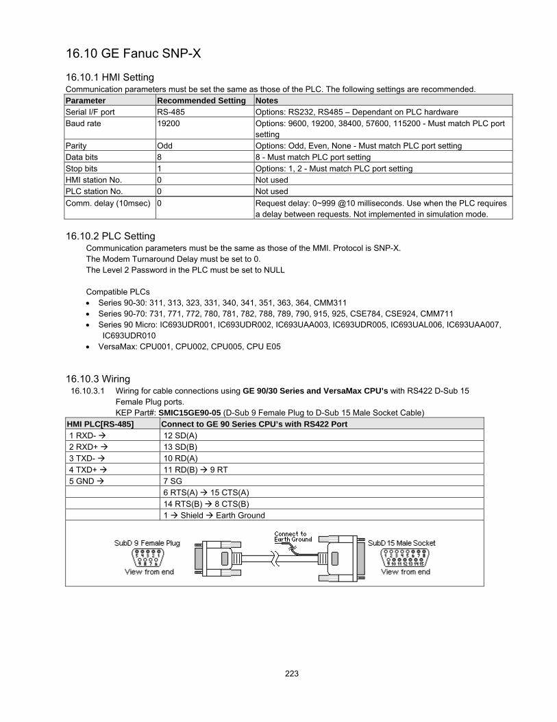
223
16.10 GE Fanuc SNP-X
16.10.1 HMI SettingCommunication parameters must be set the same as those of the PLC. The following settings are recommended.Parameter Recommended Setting NotesSerial I/F port RS-485 Options: RS232, RS485 – Dependant on PLC hardwareBaud rate 19200 Options: 9600, 19200, 38400, 57600, 115200 - Must match PLC port
settingParity Odd Options: Odd, Even, None - Must match PLC port settingData bits 8 8 - Must match PLC port settingStop bits 1 Options: 1, 2 - Must match PLC port settingHMI station No. 0 Not usedPLC station No. 0 Not usedComm. delay (10msec) 0 Request delay: 0~999 @10 milliseconds. Use when the PLC requires
a delay between requests. Not implemented in simulation mode.
16.10.2 PLC SettingCommunication parameters must be the same as those of the MMI. Protocol is SNP-X.The Modem Turnaround Delay must be set to 0.The Level 2 Password in the PLC must be set to NULL
Compatible PLCs• Series 90-30: 311, 313, 323, 331, 340, 341, 351, 363, 364, CMM311• Series 90-70: 731, 771, 772, 780, 781, 782, 788, 789, 790, 915, 925, CSE784, CSE924, CMM711• Series 90 Micro: IC693UDR001, IC693UDR002, IC693UAA003, IC693UDR005, IC693UAL006, IC693UAA007,
IC693UDR010• VersaMax: CPU001, CPU002, CPU005, CPU E05
NFORMATION
16.10.3 Wiring16.10.3.1 Wiring for cable connections using GE 90/30 Series and VersaMax CPU’s with RS422 D-Sub 15
Female Plug ports.KEP Part#: SMIC15GE90-05 (D-Sub 9 Female Plug to D-Sub 15 Male Socket Cable)
HMI PLC[RS-485] Connect to GE 90 Series CPU’s with RS422 Port 1 RXD- 12 SD(A) 2 RXD+ 13 SD(B) 3 TXD- 10 RD(A) 4 TXD+ 11 RD(B) 9 RT 5 GND 7 SG
6 RTS(A) 15 CTS(A) 14 RTS(B) 8 CTS(B) 1 Shield Earth Ground

224
16.10.3.2 Wiring for cable connections using GE 90 Series CMM Modules with RS422 D-Sub 25 Female Plugports.KEP Part#: (Not Available) (D-Sub 9 Female Plug to D-Sub 25 Male Socket Cable)
HMI PLC[RS-485] Connect to GE 90 Series CMM Modules with RS422 Port 1 RXD- 9 SD(A) 2 RXD+ 21 SD(B) 3 TXD- 13 RD(A) 4 TXD+ 25 RD(B) 5 GND 7 SG
10 RTS(A) 11 CTS(A) 22 RTS(B) 23 CTS(B) Shield Earth Ground
16.10.3.3 Wiring for cable connections using GE 90 Series CMM Modules with RS232 D-Sub 25 Female Plugports.KEP Part#: (Not Available) (D-Sub 9 Male Socket to D-Sub 25 Male Socket Cable)
HMI PLC[RS-232] Connect to GE 90 Series CMM Modules with RS232 Port 2 TXD 3 RXD 3 RXD 2 TXD 5 GND 7 GND
4 RTS 5 CTS 8 DCD 20 DTR 1 Shield Earth Ground
16.10.3.4 Wiring for cable connections using GE 90/70 Series and 351, 352, 363 and 364 CPU’s with RS232RJ-12 socket ports.KEP Part#: (Not Available) (D-Sub 9 Male Socket to RJ-12 Male Plug Cable)
HMI PLC[RS-232] Connect to GE 90/70 Series 351 & 352 CPU’s with RS232 Port 2 TXD 5 RXD 3 RXD 2 TXD 5 GND 3 GND
Shield Earth Ground
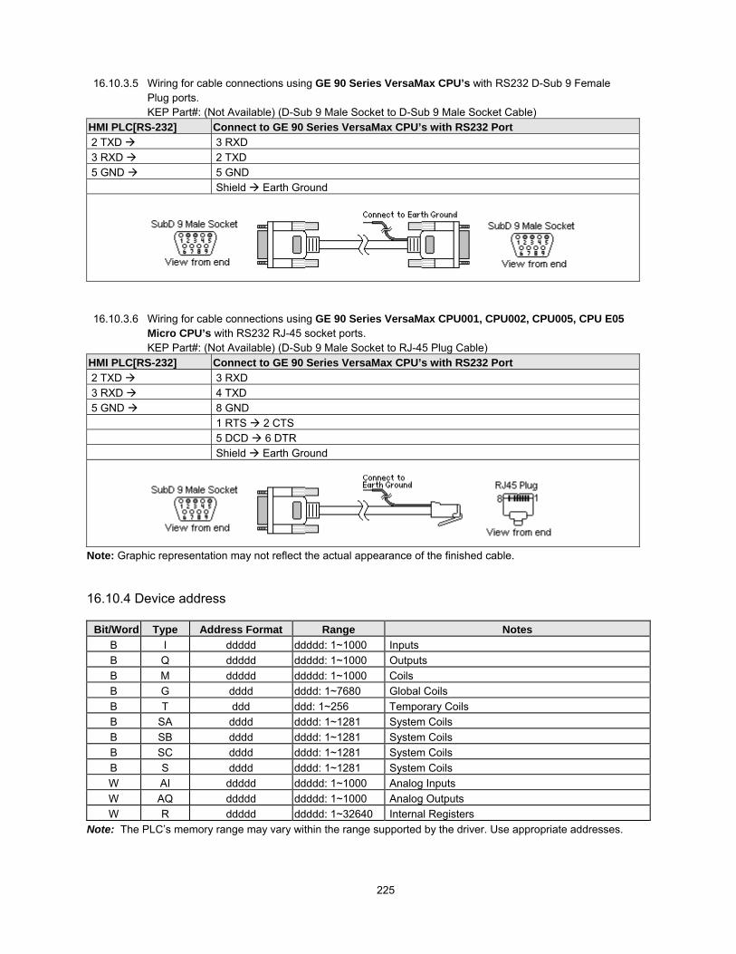
225
16.10.3.5 Wiring for cable connections using GE 90 Series VersaMax CPU’s with RS232 D-Sub 9 FemalePlug ports.KEP Part#: (Not Available) (D-Sub 9 Male Socket to D-Sub 9 Male Socket Cable)
HMI PLC[RS-232] Connect to GE 90 Series VersaMax CPU’s with RS232 Port 2 TXD 3 RXD 3 RXD 2 TXD 5 GND 5 GND
Shield Earth Ground
16.10.3.6 Wiring for cable connections using GE 90 Series VersaMax CPU001, CPU002, CPU005, CPU E05Micro CPU’s with RS232 RJ-45 socket ports.KEP Part#: (Not Available) (D-Sub 9 Male Socket to RJ-45 Plug Cable)
HMI PLC[RS-232] Connect to GE 90 Series VersaMax CPU’s with RS232 Port 2 TXD 3 RXD 3 RXD 4 TXD 5 GND 8 GND
1 RTS 2 CTS 5 DCD 6 DTR Shield Earth Ground
Note: Graphic representation may not reflect the actual appearance of the finished cable.
16.10.4 Device address
Bit/Word Type Address Format Range NotesB I ddddd ddddd: 1~1000 InputsB Q ddddd ddddd: 1~1000 OutputsB M ddddd ddddd: 1~1000 CoilsB G dddd dddd: 1~7680 Global CoilsB T ddd ddd: 1~256 Temporary CoilsB SA dddd dddd: 1~1281 System CoilsB SB dddd dddd: 1~1281 System CoilsB SC dddd dddd: 1~1281 System CoilsB S dddd dddd: 1~1281 System CoilsW AI ddddd ddddd: 1~1000 Analog InputsW AQ ddddd ddddd: 1~1000 Analog OutputsW R ddddd ddddd: 1~32640 Internal Registers
Note: The PLC’s memory range may vary within the range supported by the driver. Use appropriate addresses.

226
16.11 HITACHI
16.11.1 HMI SettingCommunication parameters must be set the same as those of the PLC. The following settings are recommended.Parameter Recommended Setting NotesSerial I/F port RS232 Options: RS232, RS485 – Dependant on PLC hardwareBaud rate 19200 Options: 9600, 19200, 38400 - Must match PLC port settingParity Even Options: Odd, Even, None - Must match PLC port settingData bits 7 Options: 7, 8 - Must match PLC port settingStop bits 1 Options: 1, 2 - Must match PLC port settingHMI station No. 0 Not usedPLC station No. 0 Not usedComm. delay (10msec) 0 Request delay: 0~999 @10 milliseconds. Use when the PLC requires a
delay between requests. Not implemented in simulation mode.
16.11.2 PLC SettingCommunication parameters must be the same as those of the MMI.Set communication baud rate as 19200.
Compatible with: (CPU Ports)H Series PLCs: EH150, Micro-EH, H20, H40, H64, H200, H250, H252, H300, H302, H700, H702, H1000, H1002,H2000, H4010.
CPU TYPE Port 1 Port 2EH-150/CPU 104A RS-232 RS-232EH-150/CPU 208A RS-232 RS-232EH-150/CPU 308A RS-232/RS-485 RS-232EH-150/CPU 316A RS-232/RS-485 RS-232EH-150/CPU 448A RS-232/RS-485 RS-232
16.11.3 Wiring
16.11.3.1 Wiring for cable connections using Hitachi H Series CPU’s with RS232 D-Sub 15 Female Plugports. RS-232 port (mode 2; RS-232 switches: 1,7=OFF 2,3,4,5,6,8=ON)KEP Part#: (Not Available) (D-Sub 9 Male Socket to D-Sub 15 Male Socket Cable)
HMI PLC[RS-232] Connect to Hitachi H Series CPU’s with RS232 Port 2 TXD 3 RXD 3 RXD 2 TXD 5 GND 9 GND 10 GND 7 CTS 4 RTS
5 CTS 7 DSR 8 PHL 14 PV12 Shield Earth Ground

227
16.11.3.2 Wiring for cable connections using Hitachi EH Series CPU’s with RS232 RJ45 Female Socket ports.RS-232 port 1 (RS-232 switches: 1,4,7,8=OFF 2,3,5=ON)KEP Part#: (Not Available) (D-Sub 9 Male Socket to RJ45 Male Plug Cable)
HMI PLC[RS-232] Connect to Hitachi EH Series CPU’s with RS232 Port 1 2 TXD 6 RXD 3 RXD 5 TXD 5 GND 1 GND 7 CTS 8 RTS
Shield Earth Ground
16.11.3.3 Wiring for cable connections using Hitachi EH Series CPU’s with RS485-4 Wire RJ45 FemaleSocket ports. RS-232 port 1 (RS-485 switches: 1,4,7,8=OFF 2,3,5 =ON)KEP Part#: (Not Available) (D-Sub 9 Female Plug to RJ45 Male Plug Cable)
HMI PLC[RS-232] Connect to Hitachi EH Series CPU’s with RS485 Port 1 1 RXD- 5 TXD- 2 RXD+ 4 TXD+ 3 TXD- 6 RXD- 4 TXD+ 7 RXD+ 5 GND 1 GND
Shield Earth Ground 7 CTS 8 RTS Must be jumpered on HMI RS232 port
16.11.3.4 Wiring for cable connections using Hitachi EH Series CPU’s with RS485-2 Wire RJ45 FemaleSocket ports. RS-232 port 1 (RS-485 switches: 1,4,7,8=OFF 2,3,5 =ON)KEP Part#: (Not Available) (D-Sub 9 Female Plug to RJ45 Male Plug Cable)
HMI PLC[RS-232] Connect to Hitachi EH Series CPU’s with RS485 Port 1 1 RXD-/TXD- 5 TXD- 6 RXD- 2 RXD+/TXD+ 4 TXD+ 7 RXD+ 5 GND 1 GND
Shield Earth Ground 7 CTS 8 RTS Must be jumpered on HMI RS232 port
Note: Graphic representation may not reflect the actual appearance of the finished cable.

228
16.11.4 Device address
Bit/Word Type Address Format Range NotesB X hhhh(h) hhhh: 0~FFFF (h):0~F Input BitsB Y hhhh(h) hhhh: 0~FFFF (h):0~F Output bitsB M hhhh(h) hhhh: 0~FFFF (h):0~F Data bitsB T hhhh(h) hhhh: 0~FFFF (h):0~F Timer Counter BitsB R hhhh(h) hhhh: 0~FFFF (h):0~F Internal BitsB L hhhh(h) hhhh: 0~FFFF (h):0~F Link bitsW TC ddd ddd: 0~FF Timer CounterW WM hhh hhh: 0~270F Data WordsW WX hhh hhh: 0~270F Input wordsW WY hhh hhh: 0~270F Output wordsW WR hhh hhh: 0~270F Internal WordsW WL hhh hhh: 0~270F Link Words
Note: The PLC’s memory range may vary within the range supported by the driver. Use appropriate addresses.All addresses are in hexadecimal.

229
16.12 IDEC Micro3
16.12.1 HMI SettingCommunication parameters must be set the same as those of the PLC. The following settings are recommended.Parameter Recommended Setting NotesSerial I/F port RS232 Options: RS232, RS485 – Dependant on PLC hardwareBaud rate 9600 Options: 9600, 19200 - Must match PLC port settingParity Even Options: Odd, Even, None - Must match PLC port settingData bits 7 Options: 7, 8 - Must match PLC port settingStop bits 1 Options: 1, 2 - Must match PLC port settingHMI station No. 0 Not usedPLC station No. 255 Must match PLC port setting (0~255)Comm. delay (10msec) 0 Request delay: 0~999 @10 milliseconds. Use when the PLC requires
a delay between requests. Not implemented in simulation mode.
This driver supports Extended Address mode.
16.12.2 PLC SettingCommunication parameters must be the same as those of the MMI.Micro3C PLC’s must use Loader Protocol
Compatible with:Micro3 Series: Micro3 (10-48 I/O), Micro3C (16-48 I/O)OpenNet Series: FC3A-CP2K, FC3A-CP2KM, FC3A-CP2S, FC3A-CP2SMMicroSmart: All-in-one (FC4A-C10R2/C16R2/C24R2), Slim (FC4A-D20K3/D20S3/D20RKI1/D20RS1/D40K3/D4053)
16.12.3 Wiring16.12.3.1 Wiring for cable connections using IDEC Micro3 CPU’s with RS485 Round 8 pin MiniDIN ports.
KEP Part#: SMIC15IDECM3-05 (D-Sub 9 Female Plug to 8 pin MiniDIN Male Plug Cable)HMI PLC[RS-485] Connect to IDEC Micro3 CPU’s RS-485 Port 1 RXD/TXD- 2 RXD/TXD- 2 RXD/TXD+ 1 RXD/TXD+ 5 GND 7 GND
Shield Earth Ground
16.12.3.2 Wiring for cable connections using IDEC Micro3C and OpenNET CPU’s with RS232 Round 8 pinMiniDIN ports.KEP Part#: SMICIDECM3C-05 (D-Sub 9 Male Socket to 8 pin MiniDIN Male Plug Cable)
HMI PLC[RS-232] Connect to IDEC Micro3C and OpenNET CPU’s RS-232 Port 2 TXD 4 RXD 3 RXD 3 TXD 5 GND 9 6 7 GND
Note: Graphic representation may not reflect the actual appearance of the finished cable.

230
16.12.3.2 Wiring for cable connections using IDEC Micro3C with RS485 DataLink Terminal connections.KEP Part#: (Not Available) (D-Sub 9 Female Plug to Flying Leads Cable)
HMI PLC[RS-485] Connect to IDEC Micro3C RS-485 DataLink Terminals 2 TXD A 3 RXD B 5 GND SG
Notes on DataLink Terminals: Set the protocol selector switch to 2, 3 or 4 to select loader protocol for the DataLinkTerminal.Communication Protocols for Loader Port and Data Link Terminals
Protocol SelectorSwitch Position
Loader Port Protocol Data Link TerminalProtocol
Remarks
0 Loader protocol Data link protocol1 User protocol Data link protocol2 Loader protocol Loader protocol3 User protocol Loader protocol4 Loader protocol Loader protocol Fixed 9600, E, 7, 15~7 Reserved Reserved
16.12.4 Device addressBit/Word Type Address Format Range Notes
B X ddddo dddd: 0~2047, o: 0~7 Inputs(I), Word portion is decimal, bit portion is octalB Y ddddo dddd: 0~2047, o: 0~7 Outputs(Q), Word portion is decimal, bit portion is octalB M ddddo dddd: 0~2047, o: 0~7 Word portion is decimal, bit portion is octalW RT dddd dddd: 0~9999 Timer AccumulatorW RC dddd dddd: 0~9999 Counter AccumulatorW D dddd dddd: 0~9999 Data Words
Note: The PLC’s memory range may vary within the range supported by the driver. Use appropriate addresses.Note: SR, O and M8 bit types, Timer and Counter Presets, Bit types as words, RTC Calendar and Link words are notsupported by this driver. See IDEC OpenNET driver below for extended support.

231
16.13 IDEC OpenNET [PDS]
16.13.1 HMI SettingThis driver uses the same HMI and PLC settings and Wiring as the IDEC Micro3 driver listed above.Parameter Recommended Setting NotesPLC type Idec OpenNet idecONC.pds driver must be present in \drivers folderThe following additional Device addresses are supported.
16.13.2 Device addressBit/Word Type Address Format Range Notes
B I ddo dd: 0~59, o: 0~7 Input Bits(X), word portion is decimal, bit portion is octalB Q ddo dd: 0~59, o: 0~7 Output Bits(Y), word portion is decimal, bit portion is octalB M dddo ddd: 0~255, o: 0~7 Internal Bits, word portion is decimal, bit portion is octalB M8 dddo ddd: 0~23, o: 0~7 Special Internal Bits, word portion is decimal, bit portion is
octalB SR ddd ddd: 0~255 Shift Register BitsB O dddo ddd: 0~847, o: 0~7 Link Relay Bits, Only available in processors that support
OpenNetdddd: 0~1299 Data Wordsdddd: 2000~7999 Only available if expanded memory in processor
W D dddd
dddd: 8000~8199 Special Data WordsW TV dd dd: 0~99 Timer Values (read only)W TP dd dd: 0~99 Timer Presets if not redirected to a Data WordW CV dd dd: 0~99 Counter Values (read only)W CP dd dd: 0~99 Counter Presets if not redirected to a Data WordW SRW dd d: 0~15 Shift Register WordsW MW ddd ddd: 0~127 Internal Bit WordsW MW8 dd dd: 0~11 Special Internal Bit WordsW IW dd dd: 0~29 Input WordsW QW dd dd: 0~29 Output WordsW RTC d d: 0~6 Real Time Clock / Calendar Values (read as BCD only)W OW ddd ddd: 0~423 Link Relay Words, Only available in processors that
support OpenNetW LINK dddd dddd: 100~1317 Link Registers, Only processors that support OpenNet

232
16.14 IIS ESC (INDUSTRIAL INDEXING SYSTEMS)
16.14.1 HMI SettingCommunication parameters must be set the same as those of the PLC. The following settings are recommended.Parameter Recommended Setting NotesSerial I/F port RS232 Options: RS232, RS485 – Dependant on PLC hardwareBaud rate 19200 Options: 9600, 19200, 38400, 57600, 115200 - Must match PLC port
settingParity None Options: Odd, Even, None - Must match PLC port settingData bits 8 Options: 7, 8 - Must match PLC port settingStop bits 1 Options: 1, 2 - Must match PLC port settingHMI station No. 0 Not usedPLC station No. 255 Not usedComm. delay (10msec) 0 Request delay: 0~999 @10 milliseconds. Use when the PLC requires a
delay between requests. Not implemented in simulation mode.
16.14.2 Controller SettingCommunication parameters must be the same as those of the MMI.App Port set Mode: ESC Packet Protocol 19200, None, 8, 1
Compatible PLCEmerald EMC-2000 controller
16.14.3 Wiring16.14.3.1 Wiring for cable connections using Emerald EMC-2000 Controllers with RS232 RJ-12 socket ports.
KEP Part#: (Not Available) (D-Sub 9 Male Socket to RJ-12 Male Cable)HMI PLC[RS-232] Connect to Emerald EMC-2000 Controller with RS232 Port 2 TXD 3 RXD 3 RXD 5 TXD 5 GND 4 GND
Shield Earth Ground
Note: Graphic representation may not reflect the actual appearance of the finished cable.

233
16.14.4 Device address
Bit/Word Type Address Format Range NotesB CNTRLLR Status ddd 0~9999 Controller status
BDevice Status ddd(ddd) 01000~4095255
dddd: device number(ddd): flag number
Device status
BDevice Input dddd(ddd) 01000~4095255
dddd: device number(ddd): flag number
Inputs
BDevice Output ddd 01000~4095255
dddd: device number(ddd): flag number
Outputs
B Timer dd 0~15 Timers
B User Flag dd 0~63 User flags
B GLBL SW Pls dd 0~15 Global S/W
B GLBL HW Pls dd 0~15 Global H/W
W Short Data hhhh 0~FFFF Short Data- (1 word)
D Long Data hhhh 0~FFFF Long Data- (2 words)
F Float Data hhhh 0~FFFF Float Data- (4 words)
W Text hhh 0~FFF ASCII Data

234
16.15 Jetter Nano
16.15.1 HMI SettingCommunication parameters must be set the same as those of the PLC. The following settings are recommended.Parameter Recommended Setting NotesSerial I/F port RS232Baud rate 9600 Must match PLC port settingParity Even Options: Odd, Even, None - Must match PLC port settingData bits 8 Must match PLC port settingStop bits 1 Must match PLC port settingHMI station No. 0 Not usedPLC station No. 0 Not usedComm. delay (10msec) 0 Request delay: 0~999 @10 milliseconds. Use when the PLC requires a
delay between requests. Not implemented in simulation mode.
16.15.2 PLC SettingCommunication mode: 9600, Even, 8, 1
Compatible PLC’s:NANO-A: NANO-B: NANO-C: NANO-D:
16.15.3 Wiring16.15.3.1 Wiring for cable connections using Jetter NANO CPU’s with RS232 D-Sub 9 Female Plug ports.
KEP Part#: (Not Available) (D-Sub 9 Male Socket to D-Sub 9 Male Socket Cable)HMI PLC[RS-232] Connect to Jetter NANO CPU with RS232 Port 2 TXD 3 RXD 3 RXD 2 TXD 5 GND 7 GND
Shield Earth Ground
Note: Graphic representation may not reflect the actual appearance of the finished cable.
16.15.4 Device addressBit/Word Type Address Format Range Memo
BI dddd(oo) dddd: 1~9999
oo: 01~08 (octal)
BO dddd(oo) 00 dddd: 1~9999
oo: 01~08 (octal)B F ddd 0~999
D DR ddddd 0~32767
Double WordDoes not support the use of ‘R’ types for just oneWORD. “R” must be a signed double word in the PLC(4W<->3W) Conversion with signed.
W WR ddddd 0~65535
Word(2W<->3W)Conversion with signed. For example:0x234590(PLC)->0x4590(MMI)0x67FF00(PLC)->0xFF00(MMI)0x4590(MMI)->0x004590(PLC)0xFF00(MMI)->0xFFFF00(PLC)
Note: The PLC’s memory range may vary within the range supported by the driver. Use appropriate addresses.

235
16.16 Keyence KV/Visual KV [PDS]
16.16.1 HMI SettingCommunication parameters must be set the same as those of the PLC. The following settings are recommended.Parameter Recommended Setting NotesPLC type KEYENCE KV/Visual KV
[PDS V2.00] Keyv_16DT.pds driver must be present in \drivers folder
Serial I/F port RS232Baud rate 9600 Must match PLC port settingParity Even Options: Odd, Even, None - Must match PLC port settingData bits 8 Must match PLC port settingStop bits 1 Must match PLC port settingHMI station No. 0 Not usedPLC station No. 0 Not usedComm. delay (10msec) 0 Request delay: 0~999 @10 milliseconds. Use when the PLC requires a
delay between requests. Not implemented in simulation mode.
16.16.2 PLC SettingCommunication parameters must be the same as those of the MMI.
Compatible PLCsKV series PLC: KV-10, KV-16, KV-24 and KV-40
16.16.3 Wiring
16.16.3.1 Wiring for cable connections using Keyence KV Series with RS232 RJ-12 Socket ports.KEP Part#: SMICKEY-05 (D-Sub 9 Male Socket to RJ-12 Male Cable)
HMI PLC[RS-232] Connect to Keyence KV Series CPU with RS232 Port 2 TXD 4 RXD 3 RXD 3 TXD 5 GND 9 2 GND
Shield Earth Ground

236
16.16.4 Device address
Bit/Word Type Address Format Range NotesB End_Command d d: 0 The End_Command is used to suspend or enable
communications to the PLC. Communications areautomatically started when the HMI is powered up.
B Relay(bit) dddbb0 dddbb:0~19999bb: 00~15
Must add “0” after the address
W DM dddd dddd: 0~1999 Data MemoryW TM dd dd: 0~99 Temporary MemoryW Relay ddddd ddd: 0~19999 Relays
W Timer_Contact ddd ddd: 0~999 Timer BitsW Timer_Current ddd ddd: 0~999 Timer AccumulatorW Timer_Preset ddd ddd: 0~999 Timer PresetW Counter_Contact ddd ddd: 0~999 Counter BitsW Counter_Current ddd ddd: 0~999 Counter AccumulatorW Counter_Preset ddd ddd: 0~999 Counter Preset
The PLC’s memory range may vary within the range supported by the driver. Use appropriate addresses.

237
16.17 KOYO Direct
16.17.1 HMI SettingCommunication parameters must be set the same as those of the PLC. The following settings are recommended.Parameter Recommended Setting NotesSerial I/F port RS232 Options: RS232, RS485 – Dependant on PLC hardwareBaud rate 9600 Options: 9600, 19200, 38400, 57600, 115200 - Must match PLC port
settingParity Odd Options: Odd, Even, None - Must match PLC port settingData bits 8 Options: 7, 8 - Must match PLC port settingStop bits 1 Options: 1, 2 - Must match PLC port settingHMI station No. 0 Not usedPLC station No. 0 1 – D2-240, 1 – D4-440 or must match PLC port setting (0-255)Comm. delay (10msec) 0 Request delay: 0~999 @10 milliseconds. Use when the PLC requires a
delay between requests. Not implemented in simulation mode.
16.17.2 PLC SettingThe PLC must not have the password protection enabled.Communication is K-Sequence, Full Duplex, No Hardware Handshaking, Station Number 1.D4-440 Station No. must be set to 1.CPU’s with RUN/TERM switches must be set in the TERM mode.
Compatible PLCsDL05 Series: D0-05 MicroDL105 Series: F1-130 MicroDL205 Series: D2-230, D2-240, D2-250DL305 Series: D3-350DL405 Series: D4-430, D4-440, D4-450
NFORMATIN16.17.3 Wiring
16.17.3.1 Wiring for cable connections using Koyo DL05, DL105, DL205 Series, DL305 (D3-350 CPU, Port1), or DL405 (D4-450, Port 2) with RS232 RJ-12 Socket ports.KEP Part#: SMICK205-05 (D-Sub 9 Male Socket to RJ-12 Male Cable) Koyo Part# D3-DSCBL-1
HMI PLC[RS-232] Connect to Koyo CPU with RS232 Port 2 TXD 3 RXD 3 RXD 4 TXD 5 GND 9 1 GND
Shield Earth Ground

238
16.17.3.2 Wiring for cable connections using Koyo DL405 (D4-430, D4-440 or D4-450, Port 0) with RS232 D-Sub 15 Female Plug ports.KEP Part#: SMICK405-05 (D-Sub 9 Male Socket to D-Sub 15 Male Socket Cable)
HMI PLC[RS-232] Connect to Koyo D4-430, D4-440 or D4-450 CPU with RS232 Port 0 2 TXD 3 RXD 3 RXD 2 TXD 5 GND 9 13 GND
1 YOP 7 CTS 8 YOM4 ONLINE 14 GNDShield Earth Ground
16.17.3.3 Wiring for cable connections using Koyo DL205 (D2-250, Port 2) CPU with RS232 SVGA 15Female Plug ports.KEP Part#: (Not Available) (D-Sub 9 Male Socket to SVGA 15 Male Socket Cable)
HMI PLC[RS-232] Connect to Koyo D2-250 CPU with RS232 Port 2 2 TXD 3 RXD 3 RXD 2 TXD 5 GND 7 GND
4 RTS 5 CTSShield Earth Ground
16.17.3.4 Wiring for cable connections using Koyo DL405 (D4-430, D4-440, or D4-450, Port 1) CPU withRS232 D-Sub 25 Female Plug ports.KEP Part#: (Not Available) (D-Sub 9 Male Socket to D-Sub 25 Male Socket Cable)
HMI PLC[RS-232] Connect to Koyo D4-430, D4-440, or D4-450 CPU with RS232 Port 1 2 TXD 3 RXD 3 RXD 2 TXD 5 GND 7 GND
4 RTS 5 CTSShield Earth Ground

239
16.17.3.5 Wiring for cable connections using Koyo DL405 (D4-430, D4-440 or D4-450, Port 1) CPU withRS485 D-Sub 25 Female Plug ports.KEP Part#: (Not Available) (D-Sub 9 Female Plug to D-Sub 25 Male Socket Cable)Koyo Part# D3-DSCBL-2
HMI PLC[RS-485 Connect to Koyo D4-430, D4-440, or D4-450 CPU with RS485 Port 1 1 RXD- 16 TXD- 2 RXD+ 14 TXD+ 3 TXD- 10 RXD- 4 TXD+ 9 RXD+ 5 GND 7 GND
11 RTS+ 19CTS+ 25 RTS- 18CTS-Shield Earth Ground
16.17.3.6 Wiring for cable connections using Koyo DL405 (D4-450, Port 3) CPU with RS485 D-Sub 25Female Plug ports.KEP Part#: (Not Available) (D-Sub 9 Female Plug to D-Sub 25 Male Socket Cable)
HMI PLC[RS-485] Connect to Koyo D4-450 CPU with RS485 Port 3 1 RXD- 13 TXD- 2 RXD+ 12 TXD+ 3 TXD- 25 RXD- 4 TXD+ 24 RXD+ 5 GND 7 GND
Shield Earth Ground
Note: Graphic representation may not reflect the actual appearance of the finished cable.
16.17.4 Device address
Bit/Word Type Address Format Range NotesB X ooooo ooooo: 0~77777 Inputs (I)B Y ooooo ooooo: 0~77777 Outputs (Q)B C ooooo ooooo: 0~77777 Internal Bits (M)B GX ooooo ooooo: 0~77777 Global BitsB T ooooo ooooo: 0~77777 Timer BitsB CT ooooo ooooo: 0~77777 Counter BitsW V ooooo ooooo: 0~77777 Data Registers ( R )
Note: All addresses are numbered in octal.The PLC’s memory range may vary within the range supported by the driver. Use appropriate addresses.

240
16.18 Lenze
16.18.1 HMI SettingCommunication parameters must be set the same as those of the Controller. The following settings are recommended.Parameter Recommended Setting NotesSerial I/F port RS485Baud rate 9600 Options: 9600, 19200- Must match Controller port settingParity Even Options: Odd, Even, None - Must match Controller port settingData bits 8 Options: 7, 8 - Must match Controller port settingStop bits 1 Options: 1, 2 - Must match Controller port settingHMI station No. 0 Or must not match Controller port setting (0-255)PLC station No. 1 Or must match Controller port setting (0-255)Comm. delay (10msec) 0 Request delay: 0~999 @10 milliseconds. Use when the PLC requires a
delay between requests. Not implemented in simulation mode.
16.18.2 PLC SettingCommunication parameters must be the same as those of the MMI.Compatible Models:
8200 Vector with LECOM A/B module 2102IB9300 Vector with LECOM A/B module 2102IB
16.18.3 WiringWiring for cable connections to 9300/8200 series controllers with pass-through 2102IBV001:RS232/485 interface.
16.18.3.1 Wiring for cable connections using Lenze Controller with LECOM-B RS485 Plug in terminal ports.KEP Part#: (Not Available) (D-Sub 9 Male Socket to 4 pole Plug Cable)
HMI PLC[RS-485] Connect to Lenze Controller with RS485 Port 1 RXD- 71 T/R(B)- 2 RXD+ 72 T/R(A)
Shield Earth Ground
16.18.4 Device address
Bit/Word Type Address Format Range NotesB CNB ddddbb dddd: 0~9999, bb: 0~15 Always use 2 digits for bit designationW CI dddd(dd) dddd: 0~8192 dd:00~99 16 Bit values
DW CD dddd(dd) dddd: 0~8192 dd:00~99 32 Bit ValuesDW CF dddd(dd) dddd: 0~8192 dd:00~99 32 Bit Floating Point ValuesW CNI dddd dddd: 0~9999 16 Bit values
DW CND dddd dddd: 0~9999 32 Bit ValuesDW CNF dddd dddd: 0~9999 32 Bit Floating Point Values
Note: The PLC’s memory range may vary within the range supported by the driver. Use appropriate addresses.
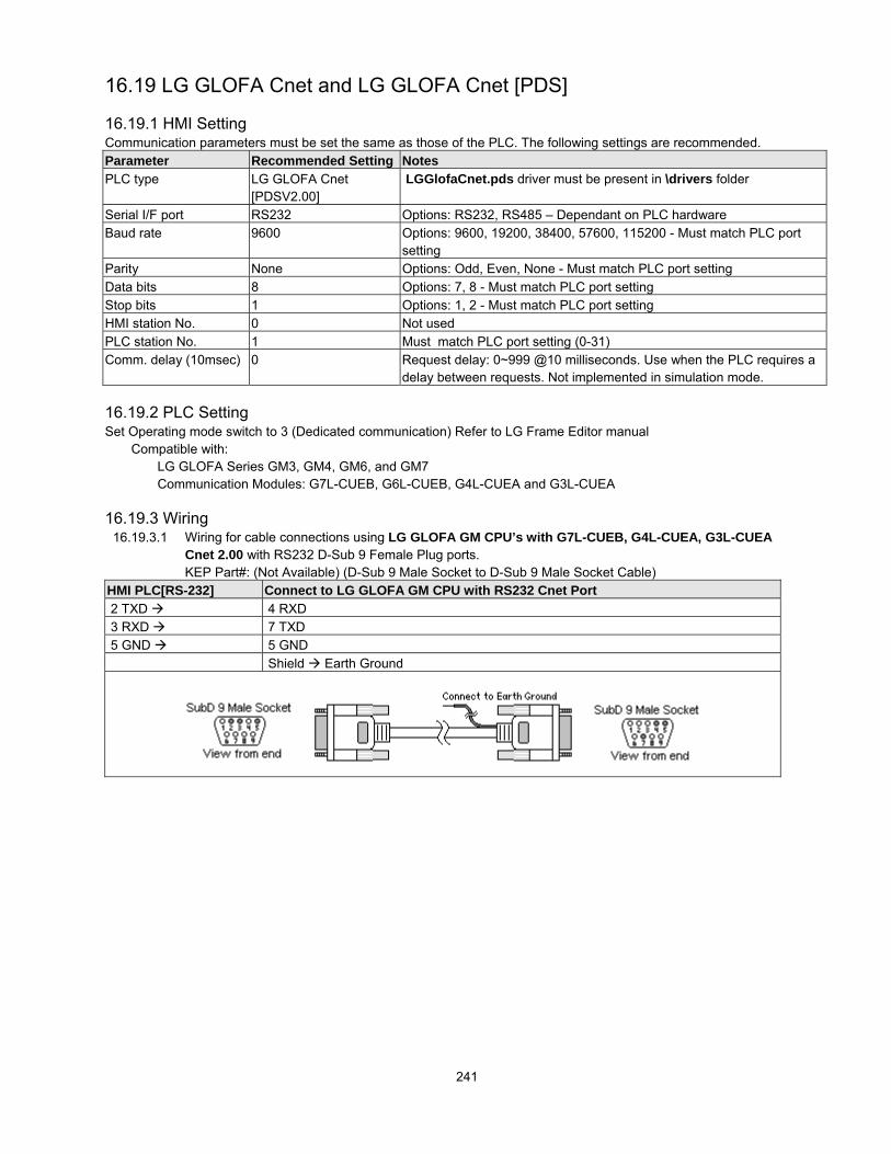
241
16.19 LG GLOFA Cnet and LG GLOFA Cnet [PDS]
16.19.1 HMI SettingCommunication parameters must be set the same as those of the PLC. The following settings are recommended.Parameter Recommended Setting NotesPLC type LG GLOFA Cnet
[PDSV2.00] LGGlofaCnet.pds driver must be present in \drivers folder
Serial I/F port RS232 Options: RS232, RS485 – Dependant on PLC hardwareBaud rate 9600 Options: 9600, 19200, 38400, 57600, 115200 - Must match PLC port
settingParity None Options: Odd, Even, None - Must match PLC port settingData bits 8 Options: 7, 8 - Must match PLC port settingStop bits 1 Options: 1, 2 - Must match PLC port settingHMI station No. 0 Not usedPLC station No. 1 Must match PLC port setting (0-31)Comm. delay (10msec) 0 Request delay: 0~999 @10 milliseconds. Use when the PLC requires a
delay between requests. Not implemented in simulation mode.
16.19.2 PLC SettingSet Operating mode switch to 3 (Dedicated communication) Refer to LG Frame Editor manual
Compatible with:LG GLOFA Series GM3, GM4, GM6, and GM7Communication Modules: G7L-CUEB, G6L-CUEB, G4L-CUEA and G3L-CUEA
16.19.3 Wiring16.19.3.1 Wiring for cable connections using LG GLOFA GM CPU’s with G7L-CUEB, G4L-CUEA, G3L-CUEA
Cnet 2.00 with RS232 D-Sub 9 Female Plug ports.KEP Part#: (Not Available) (D-Sub 9 Male Socket to D-Sub 9 Male Socket Cable)
HMI PLC[RS-232] Connect to LG GLOFA GM CPU with RS232 Cnet Port 2 TXD 4 RXD 3 RXD 7 TXD 5 GND 5 GND
Shield Earth Ground

242
16.19.3.2 Wiring for cable connections using LG GLOFA GM CPU’s with G7L-CUEB/G6L-CUEB/G4L-CUEA/G3L-CUEA Cnet Communications module with RS232 D-Sub 9 Female Plug ports.KEP Part#: (Not Available) (D-Sub 9 Male Socket to D-Sub 9 Male Socket Cable)
HMI PLC[RS-232] Connect to LG GLOFA GM with RS232 Cnet Communications Module Port 2 TXD 2 RXD 3 RXD 3 TXD 5 GND 5 GND
1 CD 7 RTS 8 CTS 4 DTR 6 DSR Shield Earth Ground
16.19.3.3 Wiring for cable connections using LG GLOFA GM CPU’s with G7L-CUEB/G6L-CUEB/G4L-CUEA/G3L-CUEA Cnet Communications Module with RS422 Screw Terminal ports.KEP Part#: (Not Available) (D-Sub 9 Female Plug to Flying Leads Cable)
HMI PLC[RS-485] Connect to LG GLOFA GM with RS422 Cnet Communications Module Port 1 RXD- SDA 2 RXD+ SDB 3 TXD- RDA 4 TXD+ RDB 5 GND SG
Shield Earth Ground
Note: Graphic representation may not reflect the actual appearance of the finished cable.
16.19.4 Device address
Bit/Word Type Address Format Range NotesB MX ddddd ddddd: 0~32767W MW ddddd ddddd: 0~9999 LG GLOFA Cnet [PDS] driver range is 0~32767
Note: The PLC’s memory range may vary within the range supported by the driver. Use appropriate addresses.

243
16.20 LG Master K10S1
16.20.1 HMI SettingCommunication parameters must be set the same as those of the PLC. The following settings are recommended.Parameter Recommended Setting NotesSerial I/F port RS232 Options: RS232Baud rate 9600 Options: 9600, 19200, 38400, 57600, 115200 - Must match PLC port
settingParity None Options: Odd, Even, None - Must match PLC port settingData bits 8 Options: 7, 8 - Must match PLC port settingStop bits 1 Options: 1, 2 - Must match PLC port settingHMI station No. 0 Not usedPLC station No. 1 Not usedComm. delay (10msec) 0 Request delay: 0~999 @10 milliseconds. Use when the PLC requires a
delay between requests. Not implemented in simulation mode.
16.20.2 PLC Setting
Communication parameters must be the same as those of the MMI.Compatible PLCs:
LG MASTER-K Series K10S1
16.20.3 Wiring
16.20.3.1 Wiring for cable connections using LG MASTER-K Series K10S1 CPU’s with RS232 D-Sub 9 MaleSocket ports.KEP Part#: ZA9M9F (D-Sub 9 Male Socket to D-Sub 9 Female Plug Cable)
HMI PLC[RS-232] Connect to LG MASTER-K K10S1 CPU RS-232 port 2 TXD 2 RXD 3 RXD 3 TXD 5 GND 5 GND
Shield Earth Ground
Note: Graphic representation may not reflect the actual appearance of the finished cable.

244
16.20.4 Device address
Bit/Word Type Address Format Range NotesB P dddh ddd: 0~255 h: 0~F I/O Relay, Word portion is decimal, bit portion is
hexadecimalB K dddh ddd: 0~255 h: 0~F Keep Relay, Word portion is decimal, bit portion is
hexadecimalB M dddh ddd: 0~255 h: 0~F Auxiliary Relay, Word portion is decimal, bit portion is
hexadecimalB L dddh ddd: 0~255 h: 0~F Link Relay, Word portion is decimal, bit portion is
hexadecimalB F dddh ddd: 0~255 h: 0~F Special Relay, Word portion is decimal, bit portion is
hexadecimalB T ddd ddd: 0~255 Timer RelayB C ddd ddd: 0~255 Counter RelayW TV ddd ddd: 0~255 Timer AccumulatorW CV ddd ddd: 0~255 Counter AccumulatorW D dddd dddd: 9999 Data Registers
Note: The PLC’s memory range may vary within the range supported by the driver. Use appropriate addresses.
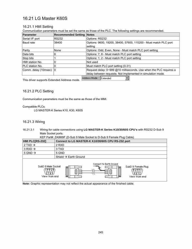
245
16.21 LG Master K60S
16.21.1 HMI SettingCommunication parameters must be set the same as those of the PLC. The following settings are recommended.Parameter Recommended Setting NotesSerial I/F port RS232 Options: RS232Baud rate 38400 Options: 9600, 19200, 38400, 57600, 115200 - Must match PLC port
settingParity None Options: Odd, Even, None - Must match PLC port settingData bits 8 Options: 7, 8 - Must match PLC port settingStop bits 1 Options: 1, 2 - Must match PLC port settingHMI station No. 0 Not usedPLC station No. 0 Must match PLC port setting (0-31)Comm. delay (10msec) 0 Request delay: 0~999 @10 milliseconds. Use when the PLC requires a
delay between requests. Not implemented in simulation mode.
This driver supports Extended Address mode.
16.21.2 PLC Setting
Communication parameters must be the same as those of the MMI.
Compatible PLCs:LG MASTER-K Series K10, K30, K60S
16.21.3 Wiring
16.21.3.1 Wiring for cable connections using LG MASTER-K Series K10/30/60S CPU’s with RS232 D-Sub 9Male Socket ports.KEP Part#: ZA9M9F (D-Sub 9 Male Socket to D-Sub 9 Female Plug Cable)
HMI PLC[RS-232] Connect to LG MASTER-K K10/30/60S CPU RS-232 port 2 TXD 2 RXD 3 RXD 3 TXD 5 GND 5 GND
Shield Earth Ground
Note: Graphic representation may not reflect the actual appearance of the finished cable.

246
16.21.4 Device address
Bit/Word Type Address Format Range NotesB P dddh ddd: 0~255 h: 0~F I/O Relay, Word portion is decimal, bit portion is
hexadecimalB K dddh ddd: 0~255 h: 0~F Keep Relay, Word portion is decimal, bit portion is
hexadecimalB M dddh ddd: 0~255 h: 0~F Auxiliary Relay, Word portion is decimal, bit portion is
hexadecimalB L dddh ddd: 0~255 h: 0~F Link Relay, Word portion is decimal, bit portion is
hexadecimalB F dddh ddd: 0~255 h: 0~F Special Relay, Word portion is decimal, bit portion is
hexadecimalW TV ddd ddd: 0~255 Timer AccumulatorW CV ddd ddd: 0~255 Counter AccumulatorW D dddd dddd: 9999 Data Registers
Note: The PLC’s memory range may vary within the range supported by the driver. Use appropriate addresses.

247
16.22 LG Master K C-Net
16.22.1 HMI SettingCommunication parameters must be set the same as those of the PLC. The following settings are recommended.Parameter Recommended Setting NotesSerial I/F port RS232 Options: RS232, RS485 – Dependant on PLC hardwareBaud rate 38400 Options: 9600, 19200, 38400 - Must match PLC port settingParity None Options: Odd, Even, None - Must match PLC port settingData bits 8 Options: 7, 8 - Must match PLC port settingStop bits 1 Options: 1, 2 - Must match PLC port settingHMI station No. 0 Not usedPLC station No. 0 Must match PLC port setting (0-31)Comm. delay (10msec) 0 Request delay: 0~999 @10 milliseconds. Use when the PLC requires a
delay between requests. Not implemented in simulation mode.
This driver supports Extended Address mode.
16.22.2 PLC SettingCommunication parameters must be the same as those of the MMI.Compatible with:
LG MASTER-K series K80S, K200S, K300S, K1000S
16.22.3 Wiring16.22.3.1 Wiring for cable connections using LG MASTER-K Series K80S, K200S, K300S, K1000S CPU’s
with CNET RS232 D-Sub 9 Male Socket ports.KEP Part#: (Not Available) (D-Sub 9 Male Socket to D-Sub 9 Female Plug Cable)
HMI PLC[RS-232] Connect to LG MASTER-K K10/30/60S CPU RS-232 port 2 TXD 4 RXD 3 RXD 7 TXD 5 GND 5 GND
Shield Earth Ground
Note: Graphic representation may not reflect the actual appearance of the finished cable.
16.22.4 Device addressBit/Word Type Address Format Range Notes
B P dddh ddd: 0~255 h: 0~F I/O Relay, Word portion is decimal, bit portion ishexadecimal
B K dddh ddd: 0~255 h: 0~F Keep Relay, Word portion is decimal, bit portion ishexadecimal
B M dddh ddd: 0~255 h: 0~F Auxiliary Relay, Word portion is decimal, bit portion ishexadecimal
B L dddh ddd: 0~255 h: 0~F Link Relay, Word portion is decimal, bit portion ishexadecimal
B F dddh ddd: 0~255 h: 0~F Special Relay, Word portion is decimal, bit portion ishexadecimal
W TV ddd ddd: 0~255 Timer AccumulatorW CV ddd ddd: 0~255 Counter AccumulatorW D dddd dddd: 9999 Data Registers
Note: The PLC’s memory range may vary within the range supported by the driver. Use appropriate addresses.

248
16.23 LG Master K300S
16.23.1 HMI SettingCommunication parameters must be set the same as those of the PLC. The following settings are recommended.Parameter Recommended Setting NotesSerial I/F port RS232Baud rate 38400 Options: 9600, 19200, 38400 - Must match PLC port settingParity None Options: Odd, Even, None - Must match PLC port settingData bits 8 Options: 7, 8 - Must match PLC port settingStop bits 1 Options: 1, 2 - Must match PLC port settingHMI station No. 0 Not usedPLC station No. 0 Must match PLC port setting (0-31)Comm. delay (10msec) 0 Request delay: 0~999 @10 milliseconds. Use when the PLC requires a
delay between requests. Not implemented in simulation mode.
16.23.2 PLC SettingCommunication parameters must be the same as those of the MMI.Compatible with:
LG MASTER-K series: K80S, K200S, K300S, K1000S
16.23.3 Wiring16.23.3.1 Wiring for cable connections using LG MASTER-K Series K80S, K200S, K300S, K1000S CPU’s
with RS232 D-Sub 9 Male Socket ports.KEP Part#: ZA9M9F (D-Sub 9 Male Socket to D-Sub 9 Female Plug Cable)
HMI PLC[RS-232] Connect to LG MASTER-K K80S, K200S, K300S, K1000S CPU RS-232 port 2 TXD 2 RXD 3 RXD 3 TXD 5 GND 5 GND
Shield Earth Ground
Note: Graphic representation may not reflect the actual appearance of the finished cable.
16.23.4 Device addressBit/Word Type Address Format Range Notes
B P dddh ddd: 0~255 h: 0~F I/O Relay, Word portion is decimal, bit portion ishexadecimal
B K dddh ddd: 0~255 h: 0~F Keep Relay, Word portion is decimal, bit portion ishexadecimal
B M dddh ddd: 0~255 h: 0~F Auxiliary Relay, Word portion is decimal, bit portion ishexadecimal
B L dddh ddd: 0~255 h: 0~F Link Relay, Word portion is decimal, bit portion ishexadecimal
B F dddh ddd: 0~255 h: 0~F Special Relay, Word portion is decimal, bit portion ishexadecimal
W TV ddd ddd: 0~255 Timer AccumulatorW CV ddd ddd: 0~255 Counter AccumulatorW D dddd dddd: 9999 Data Registers
Note: The PLC’s memory range may vary within the range supported by the driver. Use appropriate addresses.

249
16.24 Matsushita FP (Aromat)
16.24.1 HMI SettingCommunication parameters must be set the same as those of the PLC. The following settings are recommended.Parameter Recommended Setting NotesSerial I/F port RS232 Options: RS232, RS485 – Dependant on PLC hardwareBaud rate 9600 Options: 9600, 19200, 38400, 57600, 115200 - Must match PLC port
settingParity Odd Options: Odd, Even, None - Must match PLC port settingData bits 8 Options: 7, 8 - Must match PLC port settingStop bits 1 Options: 1, 2 - Must match PLC port settingHMI station No. 0 Not usedPLC station No. 1 Must match PLC port setting (0-255) Note: FP3 must set 0Comm. delay (10msec) 0 Request delay: 0~999 @10 milliseconds. Use when the PLC requires a
delay between requests. Not implemented in simulation mode.
16.24.2 PLC SettingCommunication parameters must be the same as those of the MMI.Compatible with:
FP Sigma, FP0, FP1, FP2, FP2SH, FP10SH and FP3
16.24.3 Wiring16.24.3.1 Wiring for cable connections using Matsushita FP1 CPU’s with Hirose MiniDIN RS422 ports.
KEP Part#: (Not Available) (D-Sub 9 Female Plug to Hirose MiniDIN 8 Male Cable)HMI PLC[RS-485] Connect to Matsushita FP1 CPU Port 1 RXD- 5 TXA- 2 RXD+ 2 TXB+ 3 TXD- 3 RXA- 4 TXD+ 6 RXB+ 5 GND 1 GND
Shield Earth Ground
16.24.3.2 Wiring for cable connections using Matsushita FP Sigma, FP0, FP2, FP2SH,FPM CPU’s with RS232 MiniDIN 5 ports.KEP Part#: (Not Available) (D-Sub 9 Male Socket to MiniDIN 5 Male Cable)
HMI PLC[RS-232] Connect to Matsushita FP Sigma, FP0, FP2, FP2SH or FPM CPU Port 2 RXD 5 TXD 3 TXD 3 RXD 5 GND 1 GND
Shield Earth Ground

250
16.24.3.3 Wiring for cable connections using Matsushita FP1, FP2, FP2SH, FPM CPU’s with RS232 D-Sub 9Female Plug ports.KEP Part#: (Not Available) (D-Sub 9 Male Socket to D-Sub 9 Male Socket Cable)
HMI PLC[RS-232] Connect to Matsushita FP1, FP2, FP2SH or FPM CPU Port 2 TXD 3 RXD 3 RXD 2 TXD 5 GND 7 GND
4 RTS 5 CTS 8 CD 9 ER Shield Earth Ground
16.24.3.4 Wiring for cable connections using MATSUSHITA FP0 CPU’s with RS232 Screw Terminal ports.KEP Part#: (Not Available) (D-Sub 9 Male Socket to Flying leads Cable)
HMI PLC[RS-232] Connect to Matsushita FP0 Screw Terminal Port 2 TXD 1 R 3 RXD 2 S 5 GND 3 G
Shield Earth Ground
16.24.3.1 Wiring for cable connections using Matsushita FP3 CPU’s with RS422 D-Sub 15 Male Socket ports.KEP Part#: (Not Available) (D-Sub 9 Female Plug to D-Sub 15 Female Plug Cable)
HMI PLC[RS-485] Connect to Matsushita FP3 CPU Port 1 RXD- 9 TXA- 2 RXD+ 2 TXB+ 3 TXD- 10 RXA- 4 TXD+ 3 RXB+ 5 GND 7 GND
4 RTS+ 5 CTS+ 11 RTS- 12 CTS- Shield Earth Ground
Note: Graphic representation may not reflect the actual appearance of the finished cable.

251
16.24.4 Device addressBit/Word Type Address Format Range Notes
B X dddh ddd: 0~9999 h: 0~F Inputs Relays, Word portion is decimal, bit portion ishexadecimal
B Y dddh ddd: 0~9999 h: 0~F Output Relays, Word portion is decimal, bit portion ishexadecimal
B R dddh ddd: 0~9999 h: 0~F Internal Relays, Word portion is decimal, bit portion ishexadecimal
B L ddd ddd: 0~9999 Link RelaysB T ddd ddd: 0~9999 Timer RelaysB C ddd ddd: 0~9999 Counter RelaysW SV ddd ddd: 0~9999 Timer/Counter PresetsW EV ddd ddd: 0~9999 Timer/Counter AccumulatorsW DT dddd dddd: 0~9999 Data RegistersNote: The PLC’s memory range may vary within the range supported by the driver. Use appropriate addresses.

252
16.25 Memory Map Protocol
Memory Map protocol is similar to IBM 3764R communication protocol. The HMI reserves 512 words of Data memory for usewith this protocol. The Host must update the values in these words. The HMI uses the words to display data and controlparts status on its screen. When touch actions are taken, data is sent to the Host and the Host must then update the memoryin the MMI. The Host is always responsible for updating the HMI memory.
Select one of the following from the Driver list in the System Parameters settings:MemoryMap_Master: The HMI commands take precedence whenever there is a “collision” on the communications lines.The Host must wait for all clear and then send commands.
MemoryMap_Slave: The Host commands take precedence whenever there is a “collision” on the communications lines. TheHMI must wait for all clear and then send commands.
16.25.1 HMI SettingCommunication parameters must be set the same as those of the PLC. The following settings are recommended.Parameter Recommended Setting NotesSerial I/F port RS232 Options: RS232, RS485/2W/4W. Note: RS485 Default is RS485 4WBaud rate 9600 Options: 9600, 19200, 38400, 57600, 115200 - Must match PLC port
setting. As per Host setting Note: RS485 2W is limited to 9600, 19200Parity Even Options: Odd, Even, None - As per Host settingData bits 8 Options: 7, 8 - As per Host settingStop bits 1 Options: 1, 2 - As per Host settingHMI station No. 0 Not usedPLC station No. 0 Not usedComm. delay (10msec) 0 Request delay: 0~999 @10 milliseconds. Use when the PLC requires a
delay between requests. Not implemented in simulation mode.
16.25.2 Wiring16.25.2.1 Wiring for HMI between RS232 D-Sub 9 Female Plug ports.
KEP Part#: (Not Available) (D-Sub 9 Male Socket to D-Sub 9 Male Socket Cable)HMI PLC[RS-232] Connect to HMI PLC[RS-232] 2 TXD 3 RXD 3 RXD 2 TXD 5 GND 5 GND
Shield Earth Ground

253
16.25.2.2 Wiring for HMI between RS485 2W D-Sub 9 Male Socket ports.KEP Part#: (Not Available) (D-Sub 9 Female Plug to D-Sub 9 Female Plug Cable)
HMI PLC[RS-485] Connect to HMI PLC[RS-485] 1 RXD-/TXA- 1 RXD-/TXA- 2 RXD+/TXB+ 2 RXD+/TXB+ 5 GND 5 GND
Shield Earth Ground
16.25.2.3 Wiring for HMI between RS485 4W D-Sub 9 Male Socket ports.KEP Part#: (Not Available) (D-Sub 9 Female Plug to D-Sub 9 Female Plug Cable)
HMI PLC[RS-485] Connect to HMI PLC[RS-485] 1 RXD- 3 TXA- 2 RXD+ 4 TXB+ 3 TXD- 1 RXA- 4 TXD+ 2 RXB+ 5 GND 5 GND
Shield Earth Ground
Note: Graphic representation may not reflect the actual appearance of the finished cable.
16.25.3 HMI Memory Map Designations.
Device Name Address RangeMB (bits) nnnh nnn: 0 ~ 255 b: 0 ~ F(hex)MW (words) dddd dddd: 0000 ~ 0511
Only 512 words are allocated for use. The first 255 words are also used as bit addresses. Word 0 contains bits 0000 through000F, word 1 contains bits 0010 through 001F etc. Beware of using words that already have some of their bits designated foruse in the lower area. The same applies for long (double) words. Long words use up two words of memory and must bedesignated with even numbered addresses.

254
16.25.4 Method of OperationCommunications is controlled by software flow control methods. All communications begin with an STX command beingsent. The receiving device then responds with ACK if ready to accept information or NAK if busy. When communications areended, an ACK or NAK confirms if the data was received properly.
For Example:Good CommunicationSequence
Delayed CommunicationSequence
Bad Communicationsequence
Host: ---> STXMMI(Slave) ---> ACKHost: ---> String of dataHMI ---> ACK
Host: ---> STXMMI(Master) ---> NAKHost: ---> waits a while thensends STXMMI(Master) ---> ACKHost: ---> String of dataHMI ---> ACK
Host: ---> STXMMI(Slave) ---> ACKHost: ---> String of dataHMI ---> NAKHost: repeats sequencehoping for better results
16.25.4.1 Word Write Operation---> STX<--- ACK
01 (Hexadecimal)Word Address (Low byte)Word Address (High byte)
Number of bytesData bytes
:::
DLEETX
Basic Checksum (BCC)<--- ACK
Note: There is no Read command. It is the responsibilityof the controlling computer to update all of the HMI unitsby writing data to them. The HMI units can write data backto the controlling computer. The controlling computercannot read data out of the HMI units nor can the HMIunits read data out of the controlling computer.
16.24.4.2 Bit Write Operation---> STX<--- ACK
02 (Hexadecimal)Bit Address (Low byte)Bit Address (High byte)
Number of bytesData 00 or 01
DLEETX
Basic Checksum (BCC)<--- ACK
Note: If DLE (10 hex) is in the data being sent, it mustbe sent twice to avoid premature end of transmission.
Note: BCC is the XOR of all transmitted data in a frameincluding the DLE and ETX commands.
Hexadecimal CodesCode HexSTX 02ETX 03ACK 06DLE 10NAK 15

255
16.26 MITSUBISHI A1S, A2A, A2US, A3N/A1SH
16.26.1 HMI SettingCommunication parameters must be set the same as those of the PLC. The following settings are recommended.Parameter Recommended Setting NotesPLC Type MITSUBISHI A1S
MITSUBISHI A2AMITSUBISHI A2USMITSUBISHI A3n/A1SH
Serial I/F port RS232Baud rate 9600 Must match PLC port settingParity Odd Options: Odd, Even, None - Must match PLC port settingData bits 8 Options: 7, 8 - Must match PLC port settingStop bits 1 Options: 1, 2 - Must match PLC port settingHMI station No. 0 Not usedPLC station No. 0 Not usedComm. delay (10msec) 0 Request delay: 0~999 @10 milliseconds. Use when the PLC requires a
delay between requests. Not implemented in simulation mode.
16.26.2 PLC SettingsCommunication parameters must be the same as those of the MMI.
Compatible with:Mitsubishi A Series: A1S, A2A, A2US and A3N/A1SH
16.26.3 WiringUse KEP Part#: 500_AnS cable to connect HMI RS-232 port with Mitsubishi A Series CPU port.Cable wiring not available.
16.26.4 Device addressBit/Word Type Address Format Range Notes
B X hhhh hhh: 0~FFFF Input Relays, Addresses are in hexadecimalB Y hhhh hhh: 0~FFFF Output Relays, Addresses are in hexadecimalB M ddddd ddddd: 0~65535 Auxiliary RelaysB B hhhh hhhh: 0~ FFFF Addresses are in hexadecimal
Note: Not Available for A2USB F ddddd ddddd: 0~65535 Note: Not Available for A2USW TV ddddd ddd: 0~65535 Timer AccumulatorW CV ddddd ddd: 0~65535 Counter AccumulatorW D ddddd dddd: 0~65535 Data RegistersW W hhhh hhhh: FFFF Addresses are in hexadecimal.
Note: Not Available for A2USW R ddddd ddd: 0~65535 Note: Not Available for A2US
Note: The PLC’s memory range may vary within the range supported by the driver. Use appropriate addresses.

256
16.27 MITSUBISHI AJ71 - AnA/AnU CPU
16.27.1 HMI SettingCommunication parameters must be set the same as those of the PLC. The following settings are recommended.Parameter Recommended Setting NotesPLC Type MITSUBISHI AJ71
MITSUBISHI AJ71 -AnA/AnU CPU
Mode Setting Switch: Protocol 1Mode Setting Switch: Protocol 4 (Format 4)
Serial I/F port RS485 4W Options: RS232, RS485 4W – Dependant on PLC hardwareBaud rate 9600 Options: 9600, 19200 - Must match PLC port settingParity Odd Options: Odd, Even, None - Must match PLC port settingData bits 8 Options: 7, 8 - Must match PLC port settingStop bits 1 Options: 1, 2 - Must match PLC port settingHMI station No. 0 Not usedPLC station No. 0 Not usedComm. delay (10msec) 0 Request delay: 0~999 @10 milliseconds. Use when the PLC requires a
delay between requests. Not implemented in simulation mode.
16.27.2 AJ71 SettingCommunication parameters must be the same as those of HMI (See recommendation above).
Station Number = Switches 00Mode Setting Switch Protocol 1/Protocol 4 (see note above)Computer Link / multi-drop link Computer LinkParity setting Set EnableSum checking Set Enable
Compatible with:Mitsubishi A Series: AJ71C24 communication module with Generic AnA/AnU CPU Series
16.27.3 Wiring16.27.2.3 Wiring for HMI to Mitsubishi AJ71C24 communication module with Generic AnA/AnU Series CPU
RS422 Screw Terminal ports.KEP Part#: (Not Available) (D-Sub 9 Female Plug to Flying Leads Cable)
HMI PLC[RS-485] Connect to HMI PLC[RS-485] 1 RXD- 1 SDB- 2 RXD+ 2 SDA+ 3 TXD- 3 RDB- 4 TXD+ 4 RDA+ 5 GND 5 GND
Shield Earth Ground
Note: Graphic representation may not reflect the actual appearance of the finished cable.

257
16.27.4 Device address
Bit/Word Type Address Format Range NotesB X hhhh hhhh: 0~270F Input Relays, Addresses are in hexadecimalB Y hhhh hhhh: 0~270F Output Relays, Addresses are in hexadecimalB M ddddd dddd: 0~9999 Auxiliary RelaysB T ddddd ddddd: 0~255 Note: Not Available for Generic AnA/AnU CPU SeriesB C ddddd ddddd: 0~255 Note: Not Available for Generic AnA/AnU CPU SeriesB B hhhh hhhh: 0~ 270F Addresses are in hexadecimal.
Note: Not Available for Generic AnA/AnU CPU SeriesB F ddddd ddddd: 0~65535 Note: Not Available for Generic AnA/AnU CPU SeriesW TV ddddd ddd: 0~255 Timer AccumulatorW CV ddddd ddd: 0~255 Counter AccumulatorW D ddddd dddd: 0~9999 Data RegistersW W hhhh hhhh: 0~270F Addresses are in hexadecimal.
Note: Not Available for Generic AnA/AnU CPU SeriesW R ddddd ddd: 0~65535 Note: Not Available for Generic AnA/AnU CPU Series
Note: The PLC’s memory range may vary within the range supported by the driver. Use appropriate addresses.

258
16.28 MITSUBISHI FX0n/2/2n COM, FX0n/FX2, FX2n, FX2n D(bit) [PDS]
16.28.1 HMI SettingCommunication parameters must be set the same as those of the PLC. The following settings are recommended.Parameter Recommended Setting NotesPLC Type MITSUBISHI FX0n/2/2n COM
MITSUBISHI FX0n/FX2MITSUBISHI FX2nMITSUBISHI FX2n D9bit0[PDS V1.00]
Use with BD Communication Modules
mitsubishi(D_bit).pds driver must be present in \drivers folder
Serial I/F port RS485 4W Options: RS232, RS485 2W, RS485 4W – Dependant on PLChardware
Baud rate 9600 Options: 9600, 19200, 38400, 57600, 115200 - Must match PLCport setting
Parity Even Options: Odd, Even, None - Must match PLC port settingData bits 7 Options: 7, 8 - Must match PLC port settingStop bits 1 Options: 1, 2 - Must match PLC port settingHMI station No. 0 Not usedPLC station No. 0 Options: 0-255 Note: Must set PLC station when using a BD
ModuleComm. delay (10msec) 0 Request delay: 0~999 @10 milliseconds. Use when the PLC
requires a delay between requests. Not implemented in simulationmode.
This driver supports Extended Address mode.
16.28.2 PLC SettingCommunication parameters must be the same as those of HMI (See recommendation above).
Compatible with:Mitsubishi Models Touchscreen Driver
FX0S FX0S-10 ~ FX0S-24 FXon/FX2FX0N Series FX0N-24 ~ FX0N-60 FXon/FX2FX0 Series FX0-14 ~ FX0-30Fxon FXon/FX2FX1S Supermicro FX1S-10 ~ FX1S-30 FXon/FX2FX1N Supermicro FX1N-14 ~ FX1N-60 FXon/FX2FX, FX2 & FX2C Series FX-16 ~ FX-128 FXon/FX2FX2N Series FX2N-16 ~ FX2N-128 FX2n / FX2n D(bit)FX2NC Supermicro FX2NC-16 ~ FX2NC-96 FX2n / FX2n D(bit)BD Communication Module: FX2N-485-BD, FX2N-232-BD, FX1N-485-BD and FX1N-232-BDNote: PLC station number (0~15) must be set when using the BDModule.Register D8120 setting: Set bit 9 and bit 8 of BFM#0 as 0
FX0n/2/2n COM
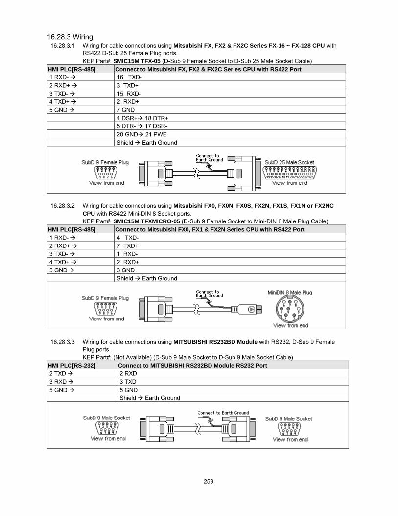
259
16.28.3 Wiring16.28.3.1 Wiring for cable connections using Mitsubishi FX, FX2 & FX2C Series FX-16 ~ FX-128 CPU with
RS422 D-Sub 25 Female Plug ports.KEP Part#: SMIC15MITFX-05 (D-Sub 9 Female Socket to D-Sub 25 Male Socket Cable)
HMI PLC[RS-485] Connect to Mitsubishi FX, FX2 & FX2C Series CPU with RS422 Port 1 RXD- 16 TXD- 2 RXD+ 3 TXD+ 3 TXD- 15 RXD- 4 TXD+ 2 RXD+ 5 GND 7 GND
4 DSR+ 18 DTR+ 5 DTR- 17 DSR- 20 GND 21 PWE Shield Earth Ground
16.28.3.2 Wiring for cable connections using Mitsubishi FX0, FX0N, FX0S, FX2N, FX1S, FX1N or FX2NCCPU with RS422 Mini-DIN 8 Socket ports.KEP Part#: SMIC15MITFXMICRO-05 (D-Sub 9 Female Socket to Mini-DIN 8 Male Plug Cable)
HMI PLC[RS-485] Connect to Mitsubishi FX0, FX1 & FX2N Series CPU with RS422 Port 1 RXD- 4 TXD- 2 RXD+ 7 TXD+ 3 TXD- 1 RXD- 4 TXD+ 2 RXD+ 5 GND 3 GND
Shield Earth Ground
16.28.3.3 Wiring for cable connections using MITSUBISHI RS232BD Module with RS232, D-Sub 9 FemalePlug ports.KEP Part#: (Not Available) (D-Sub 9 Male Socket to D-Sub 9 Male Socket Cable)
HMI PLC[RS-232] Connect to MITSUBISHI RS232BD Module RS232 Port 2 TXD 2 RXD 3 RXD 3 TXD 5 GND 5 GND
Shield Earth Ground

260
16.28.3.4 Wiring for cable connections using MITSUBISHI RS485BD Module with RS485 Screw Terminalports.KEP Part#: (Not Available) (D-Sub 9 Female Plug to Flying Leads Cable)
HMI PLC[RS-485] Connect to MITSUBISHI RS485BD Module RS422 Port 2 RxD+ 1 SDB- 1 RxD- 2 SDA+ 4 TxD+ 3 RDB- 3 TxD- 4 RDA+ 5 GND 5 GND
Shield Earth Ground
Note: Graphic representation may not reflect the actual appearance of the finished cable.
16.28.4 Device address
Bit/Word Type Address Format Range NotesB X ooo ooo: 0 ~ 377 Input Relays (I). Addresses are in OctalB Y ooo ooo: 0 ~ 377 Output Relays (O). Addresses are in OctalB M dddd dddd: 0 ~ 7999 Internal RelaysB T ddd ddd: 0 ~ 255 Timer Control RelaysB C ddd ddd: 0 ~ 255 Counter Control RelaysB SM dddd dddd: 8000 ~ 9999 Special Relays
Note: MITSUBISHI FX2n D9bit [PDS] driver onlyB D(bit) ddddbb dddd: 0 ~ 7999
bb: 00~15Data Word RelaysNote: MITSUBISHI FX2n D9bit [PDS] driver only
W TV ddd ddd: 0 ~ 255 Single Word TimerW CV ddd ddd: 0 ~ 199 Single Word CounterW CV2 ddd ddd: 200 ~ 255 Double Word CounterW D dddd dddd: 0 ~ 7999 Data WordsW SD dddd dddd: 8000 ~ 9999 Special Data Words
Note: MITSUBISHI FX2n D9bit [PDS] driver onlyNote: The PLC’s memory range may vary within the range supported by the driver. Use appropriate addresses.

261
16.29 MITSUBISHI J2-S100
16.29.1 HMI SettingCommunication parameters must be set the same as those of the PLC. The following settings are recommended.Parameter Recommended Setting NotesSerial I/F port RS485 4W Options: RS232, RS485 4W – Dependant on PLC hardwareBaud rate 9600 Options: 9600, 19200 - Must match PLC port settingParity Even Options: Odd, Even, None - Must match PLC port settingData bits 8 Must match PLC port settingStop bits 1 Must match PLC port settingHMI station No. 0 Not usedPLC station No. 0 Options: 0~15 - Must match PLC port settingComm. delay (10msec) 0 Request delay: 0~999 @10 milliseconds. Use when the PLC requires a
delay between requests. Not implemented in simulation mode.
16.29.2 J2-S100 SettingCommunication parameters must be the same as those of HMI (See recommendation above).
Compatible with:MITSUBISHI J2-S100(MR-J2-10C) Servo
16.29.3 Wiring16.29.3.1 Wiring for cable connections using MITSUBISHI J2-S100 with RS422 MicroD 20 Socket ports.
KEP Part#: (Not Available) (D-Sub 9 Female Plug to MicroD Plug Cable)HMI PLC[RS-485] Connect to MITSUBISHI J2-S100 CN3 RS422 Port 2 RxD+ 19 SDN- 1 RxD- 9 SDP+ 4 TxD+ 15 RDN- 3 TxD- 5 RDP+ 5 GND 11 LG
Shield Earth Ground
16.29.3.2 Wiring for cable connections using MITSUBISHI J2-S100 with RS232 MicroD 20 Socket ports.KEP Part#: (Not Available) (D-Sub 9 Male Socket to MicroD Plug Cable)
HMI PLC[RS-232] Connect to MITSUBISHI J2-S100 CN3 RS232 Port 2 TxD 2 RxD 3 RxD 12 TxD 5 GND 11 LG
Shield Earth Ground
Note: Graphic representation may not reflect the actual appearance of the finished cable.

262
16.29.4 Device addressBit/Word Type Address Format Range Notes
B I dd dd: 0~31B EI dd dd: 0~31B C dd dd: 0~31B O dd dd: 0~31B EO dd dd: 0~31W D h h: 1~2 Addresses are in hexadecimalW R h h: 1~2 Addresses are in hexadecimal
Note: The PLC’s memory range may vary within the range supported by the driver. Use appropriate addresses.
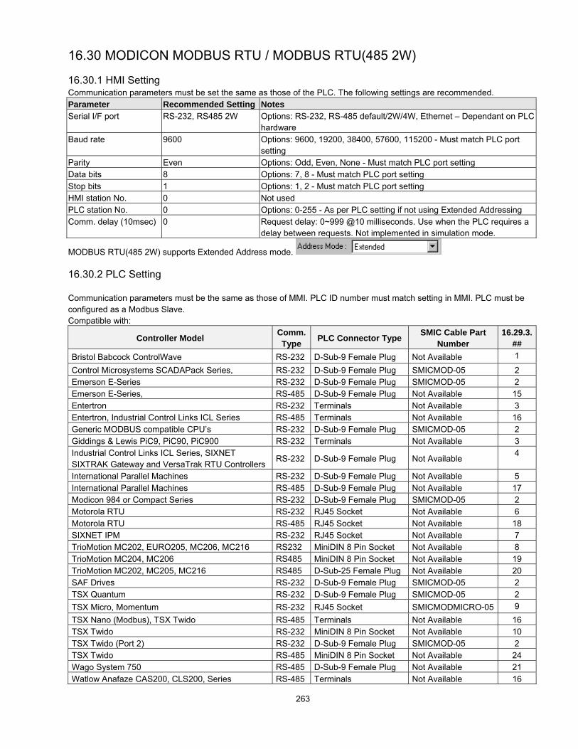
263
16.30 MODICON MODBUS RTU / MODBUS RTU(485 2W)
16.30.1 HMI SettingCommunication parameters must be set the same as those of the PLC. The following settings are recommended.Parameter Recommended Setting NotesSerial I/F port RS-232, RS485 2W Options: RS-232, RS-485 default/2W/4W, Ethernet – Dependant on PLC
hardwareBaud rate 9600 Options: 9600, 19200, 38400, 57600, 115200 - Must match PLC port
settingParity Even Options: Odd, Even, None - Must match PLC port settingData bits 8 Options: 7, 8 - Must match PLC port settingStop bits 1 Options: 1, 2 - Must match PLC port settingHMI station No. 0 Not usedPLC station No. 0 Options: 0-255 - As per PLC setting if not using Extended AddressingComm. delay (10msec) 0 Request delay: 0~999 @10 milliseconds. Use when the PLC requires a
delay between requests. Not implemented in simulation mode.
MODBUS RTU(485 2W) supports Extended Address mode.
16.30.2 PLC Setting
Communication parameters must be the same as those of MMI. PLC ID number must match setting in MMI. PLC must beconfigured as a Modbus Slave.Compatible with:
Controller Model Comm.Type PLC Connector Type SMIC Cable Part
Number16.29.3.
##Bristol Babcock ControlWave RS-232 D-Sub-9 Female Plug Not Available 1
Control Microsystems SCADAPack Series, RS-232 D-Sub-9 Female Plug SMICMOD-05 2Emerson E-Series RS-232 D-Sub-9 Female Plug SMICMOD-05 2Emerson E-Series, RS-485 D-Sub-9 Female Plug Not Available 15Entertron RS-232 Terminals Not Available 3Entertron, Industrial Control Links ICL Series RS-485 Terminals Not Available 16Generic MODBUS compatible CPU’s RS-232 D-Sub-9 Female Plug SMICMOD-05 2Giddings & Lewis PiC9, PiC90, PiC900 RS-232 Terminals Not Available 3Industrial Control Links ICL Series, SIXNETSIXTRAK Gateway and VersaTrak RTU Controllers
RS-232 D-Sub-9 Female Plug Not Available4
International Parallel Machines RS-232 D-Sub-9 Female Plug Not Available 5International Parallel Machines RS-485 D-Sub-9 Female Plug Not Available 17Modicon 984 or Compact Series RS-232 D-Sub-9 Female Plug SMICMOD-05 2Motorola RTU RS-232 RJ45 Socket Not Available 6Motorola RTU RS-485 RJ45 Socket Not Available 18SIXNET IPM RS-232 RJ45 Socket Not Available 7TrioMotion MC202, EURO205, MC206, MC216 RS232 MiniDIN 8 Pin Socket Not Available 8TrioMotion MC204, MC206 RS485 MiniDIN 8 Pin Socket Not Available 19TrioMotion MC202, MC205, MC216 RS485 D-Sub-25 Female Plug Not Available 20SAF Drives RS-232 D-Sub-9 Female Plug SMICMOD-05 2TSX Quantum RS-232 D-Sub-9 Female Plug SMICMOD-05 2TSX Micro, Momentum RS-232 RJ45 Socket SMICMODMICRO-05 9TSX Nano (Modbus), TSX Twido RS-485 Terminals Not Available 16TSX Twido RS-232 MiniDIN 8 Pin Socket Not Available 10TSX Twido (Port 2) RS-232 D-Sub-9 Female Plug SMICMOD-05 2TSX Twido RS-485 MiniDIN 8 Pin Socket Not Available 24Wago System 750 RS-485 D-Sub-9 Female Plug Not Available 21Watlow Anafaze CAS200, CLS200, Series RS-485 Terminals Not Available 16

264
Controller Model Comm.Type PLC Connector Type SMIC Cable Part
Number16.29.3.
##Watlow MLS300 Series RS-232 RJ-12 Socket Not Available 11Watlow MLS300 Series RS-485 RJ-12 Socket Not Available 22Watlow Anafaze PPC2000 Series RS-232 RJ-11 Socket Not Available 12Watlow Anafaze PPC2000 Series RS-485 RJ-12 Socket Not Available 23Yaskawa MP920 or MP930 controller RS-232 D-Sub-9 Female Plug Not Available 13Yaskawa SMC 20X0, 3010 Series RS-232 D-Sub-9 Male Socket Not Available 14
16.30.3 Wiring
16.30.3.1 Wiring for cable connections using Bristol Babcock ControlWave Compatible CPU’s withRS-232 D-Sub 9 Female Plug ports.KEP Part#: (Not Available) (D-Sub 9 Male Socket to D-Sub 9 Male Socket Cable)
HMI PLC[RS-232] MODBUS COMPATIBLE CPU RS-232 port 2 TD 3 RD 3 RD 2 TD 5 GND 5 GND
1 DCD 4 DTR 6 DSR 7 RTS 8 CTS Shield Earth Ground
16.30.3.2 Wiring for cable connections using 984 Series, Compact, Control Microsystems SCADAPackSeries, Emerson E-Series, SAF Drives, TSX Quantum and other MODBUS Compatible CPU’swith RS-232 D-Sub 9 Female Plug ports.KEP Part#: SMICMOD-05 (D-Sub 9 Male Socket to D-Sub 9 Male Socket Cable)
HMI PLC[RS-232] MODBUS COMPATIBLE CPU RS-232 port 2 TD 2 RD 3 RD 3 TD 5 GND 9 5 GND 7 RTS 8 CTS 7 RTS 8 CTS
Shield Earth Ground

265
16.30.3.3 Wiring for cable connections using Entertron or Giddings & Lewis PiC9, PiC90, PiC900 CPU’swith screw terminal ports.KEP Part#: (Not Available) (D-Sub 9 Male Socket to Flying Leads Cable)
HMI PLC[RS-232] Connect to Entertron or Giddings & Lewis CPU with RS232 Port 2 TD 1 RD 3 RD 2 TD 5 GND 3 GND
Shield Earth Ground
16.30.3.4 Wiring for cable connections using Industrial Control Links ICL Series, SIXNET SIXTRAKGateway and VersaTrak RTU Controllers Compatible CPU’s with RS-232 D-Sub 9 pin ports.KEP Part#: (Not Available) (D-Sub 9 Male Socket to D-Sub 9 Male Socket Cable)
HMI PLC[RS-232] MODBUS COMPATIBLE CPU RS-232 port 2 TD 3 RD 3 RD 2 TD 5 GND 5 GND
4 DTR 6 DSR 7 RTS 8 CTS Shield Earth Ground
16.30.3.5 Wiring for cable connections using International Parallel Machines CPU’s with RS-232 D-Sub 9Male Socket ports.KEP Part#: (Not Available) (D-Sub 9 Male Socket to D-Sub 9 Female Plug Cable)
HMI PLC[RS-232] Connect to International Parallel Machines CPU with RS232 Port 2 TD 1 RD 3 RD 2 TD 5 GND 3 GND
7 RTS 8 CTS Shield Earth Ground

266
16.30.3.6 Wiring for cable connections using Motorola MOSCAD CPU’s with RS232 RJ45 clip style ports.KEP Part#: (Not Available) (D-Sub 9 Male Socket to RJ45 Male Plug Cable)
HMI PLC[RS-232] Connect to Motorola MOSCAD CPU’s with RS-232 Port 2 TD 7 RD 3 RD 8 TD 5 GND 5 GND
Shield Earth Ground
16.30.3.7 Wiring for cable connections using SIXNET IPM CPU’s with RS232 RJ45 clip style ports.KEP Part#: (Not Available) (D-Sub 9 Male Socket to RJ45 Male Plug Cable)
HMI PLC[RS-232] Connect to SIXNET IPM CPU’s with RS-232 Port Conventional Connection
2 TD 5 RD 3 RD 6 TD 5 GND 4 GND
7 RTS 8 CTS Shield Earth Ground
16.30.3.8 Wiring for cable connections using TrioMotion MC202, EURO205, MC206, MC216 Controller’swith RS232 Round 8 pin MiniDIN ports.KEP Part#: (Not Available) (D-Sub 9 Male Socket to 8 pin MiniDIN Male Plug Cable)
HMI PLC[RS-232] TrioMotion MC202, EURO205, MC206, MC216 Controller’s RS-232 Port 2 TD 5 RX 3 RD 3 TX 5 GND 4 GND
Shield Earth Ground

267
16.30.3.9 Wiring for cable connections using TSX Micro and Momentum CPU’s with RS232 RJ45 clip styleports.KEP Part#: SMICMODMICRO-05 (D-Sub 9 Female Plug to RJ45 Male Plug Cable)
HMI PLC[RS-232] Connect to TSX Micro and Momentum CPU’s with RS-232 Port 2 TD 4 SDA 3 RD 3 SDB 5 GND 9 5 GND 7 RTS 8 CTS 6 RTS 7 CTS
Shield Earth Ground
16.30.3.10 Wiring for cable connections using TSX Twido CPU’s with RS232 Round 8 pin MiniDIN ports.KEP Part#: (Not Available) (D-Sub 9 Male Socket to 8 pin MiniDIN Male Plug Cable)
HMI PLC[RS-232] Connect to TSX Twido CPU’s RS-232 Port 2 TD 4 RX 3 RD 3 TX 5 GND 7 GND
Shield Earth Ground
16.30.3.11 Wiring for cable connections using Watlow MLS300 Series Controllers with RS232 RJ12 FemalePlug ports.KEP Part#: (Not Available) (D-Sub 9 Male Socket to RJ12 Male Plug Cable)
HMI PLC[RS-232] Connect to Watlow Electric MLS300 Series Controllers with RS-232 Port 2 TD 2 RX 3 RD 6 TX 5 GND 3 GND
1 Shield Earth Ground

268
16.30.3.12 Wiring for cable connections using Watlow Anafaze PPC2000 Series Controllers with RS232RJ11, Female Plug ports.KEP Part#: (Not Available) (D-Sub 9 Male Socket to RJ11 Male Plug Cable)
HMI PLC[RS-232] Connect to Watlow Electric PPC2000 Series Controllers with RS-232 Port 2 TD 2 RX 3 RD 3 TX 5 GND 1 GND
4 Shield Earth Ground
16.30.3.13 Wiring for cable connections using Yaskowa MP920 or MP930 Controllers withRS-232 D-Sub 9 pin ports.KEP Part#: (Not Available) (D-Sub 9 Male Socket to D-Sub 9 Male Socket Cable)
HMI PLC[RS-232] Connect to Yaskowa MP920 or MP930 Controller’s RS-232 port 2 TD 3 RD 3 RD 2 TD 5 GND 7 GND
4 RTS 5 CTS Shield Earth Ground
16.30.3.14 Wiring for cable connections using Yaskawa SMC 20X0, 3010 Series Controllers withRS-232 D-Sub 9 pin ports.KEP Part#: (Not Available) (D-Sub 9 Male Socket to D-Sub 9 Female Plug Cable)
HMI PLC[RS-232] Connect to Yaskawa SMC 20X0, 3010 Series Controller’s RS-232 port 2 TD 3 RD 3 RD 2 TD 5 GND 5 GND
4 RTS 1 CTS Shield Earth Ground

269
16.30.3.15 Wiring for cable connections using 984 Series, Compact, Control Microsystems SCADAPackSeries, Emerson E-Series, SAF Drives, TSX Quantum and other MODBUS Compatible CPU’swith RS-485 D-Sub 9 Male Socket ports.KEP Part#: (Not Available) (D-Sub 9 Female Plug to D-Sub 9 Female Plug Cable)
HMI PLC[RS-485] MODBUS COMPATIBLE CPU RS-485 port 1 RXD 9 RD 2 RXD 4 TD 5 GND 5 GND
1 Shield Shield Earth Ground
16.30.3.16 Wiring for cable connections using Entertron, TSX Nano, TSX Twido, Industrial Control LinksICL Series, Watlow Anafaze CAS200, CLS200, Series Controllers with RS485 screw terminalports.KEP Part#: (Not Available) (D-Sub 9 Female Plug to Flying Leads Cable)
HMI PLC[RS-485] Entertron, TSX Nano or Industrial Control Links ICL Series or Watlow AnafazeCAS200, CLS200, Series CPU’s with RS485 Port
1 RXD- 3 TXD- 1 RXD- 2 RXD+ 4 TXD+ 2 RXD+ 5 GND 3 GND
Shield Earth Ground
16.30.3.17 Wiring for cable connections using International Parallel Machines Controllers with D-Sub 9Female Plug ports.KEP Part#: (Not Available) (D-Sub 9 Female Plug to D-Sub 9 Male Socket Cable)
HMI PLC[RS-485] International Parallel Machines Controllers with RS485 Port 1 RXD- 9 DO- 2 RXD+ 8 DO+ 3 TXD- 5 DI- 4 TXD+ 4 DI+ 5 GND 1 GND
Shield Earth Ground

270
16.30.3.18 Wiring for cable connections using Motorola MOSCAD CPU’s with RS485 RJ45 clip style ports.KEP Part#: (Not Available) (D-Sub 9 Female Plug to RJ45 Male Plug Cable)
HMI PLC[RS-485] Connect to Motorola MOSCAD CPU’s with RS-485 Port1 RXD- 3 TXD- 3 DO+/RI+2 RXD+ 4 TXD+ 2 DO-/RI- 5 GND 1 GND
Shield Earth Ground
16.30.3.19 Wiring for cable connections using TrioMotion MC204 and MC206 Controller’s with RS485Round 8 pin MiniDIN port 2.KEP Part#: (Not Available) (D-Sub 9 Female Plug to 8 pin MiniDIN Male Plug Cable)
HMI PLC[RS-485] TrioMotion MC204 and MC206 Controller’s RS-485 Port 1 RXD- 7 TXD- 2 RXD+ 8 TXD+ 3 TXD- 2 RXD- 4 TXD+ 1 RXD+ 5 GND 4 GND
Shield Earth Ground
16.30.3.20 Wiring for cable connections using TrioMotion MC204, MC205 and MC216 Controller’s withRS485 D-Sub 25 Female Plug port.KEP Part#: (Not Available) (D-Sub 9 Female Plug to D-Sub 25 Male Socket Cable)
HMI PLC[RS-485] Connect to TrioMotion MC204 (Port 1), MC205 (Port 2) and MC216 (Port2) withRS485.
1 RXD- 8 TXD- 2 RXD+ 9 TXD+ 3 TXD- 7 RXD- 4 TXD+ 6 RXD+ 5 GND 5 GND
Shield Earth Ground

271
16.30.3.21 Wiring for cable connections using Wago System 750 Series Controllers with D-Sub 9 FemalePlug ports.KEP Part#: (Not Available) (D-Sub 9 Female Plug to D-Sub 9 Male Socket Cable)
HMI PLC[RS-485] Connect to Wago System 750 Series Controllers with RS485 Port 1 RXD- 8 TXD- 2 RXD+ 3 TXD+ 3 TXD- 7 RXD- 4 TXD+ 2 RXD+ 5 GND 5 GND
Shield Earth Ground
16.30.3.22 Wiring for cable connections using Watlow MLS300 Series CPU’s with RS485 RJ-12 Socket ports.KEP Part#: (Not Available) (D-Sub 9 Female Socket to RJ-12 Female Plug Cable)
HMI PLC[RS-485] Connect to Watlow MLS300 Series CPU with RS422 Port 1 RXD- 5 TXD- 2 RXD+ 2 TXD+ 3 TXD- 4 RXD- 4 TXD+ 6 RXD+ 5 GND 3 GND
1 Shield Earth Ground
16.30.3.23 Wiring for cable connections using Watlow Anafaze PPC2000 Series Controllers with RS485 RJ-12 Socket ports.KEP Part#: (Not Available) (D-Sub 9 Female Socket to RJ-12 Female Plug Cable)
HMI PLC[RS-485] Connect to Watlow MLS300 Series CPU with RS422 Port 1 RXD- 4 TXD- 2 RXD+ 3 TXD+ 3 TXD- 5 RXD- 4 TXD+ 2 RXD+ 5 GND 1 GND
6 Shield Earth Ground
16.30.3.24 Wiring for cable connections using TSX Twido CPU’s with RS485 Round 8 pin MiniDIN ports.KEP Part#: (Not Available) (D-Sub 9 Female Socket to 8 pin MiniDIN Male Plug Cable)

272
HMI PLC[RS-485] Connect to TSX Twido CPU’s RS-485 Port1 RXD- / TXD- 2 DO+/RI+2 RXD+ / TXD+ 1 DO-/RI- 5 GND 5 DPT 7GND
Shield Earth Ground
Note: Graphic representation may not reflect the actual appearance of the finished cable.
16.30.4 Device address
Bit/Word Type Address Format Range NotesB 1x ddddd ddddd: 1~9999 Input bits (Read only)B 0x ddddd ddddd: 1~9999 Internal CoilsB 3x_bit ddddbb dddd: 1~9999 bb: 0~15 Internal Input Coils (Read only)B 4x_bit ddddbb dddd: 1~9999 bb: 0~15 Internal Register CoilsW 3x ddddd ddddd: 1~9999 Input Registers (Read only)W 4x ddddd ddddd: 1~9999 Internal Registers
Note: The Controller’s memory range may vary within the range supported by the driver. Use appropriate addresses.

273
16.31 MODBUS RTU Extend [PDS]16.31.1 HMI SettingCommunication parameters must be set the same as those of the PLC. The following settings are recommended.Parameter Recommended Setting NotesPLC Type Modbus RTU Extend
[PDS V3.01] ModbusExtend.pds driver must be present in \drivers folder
Serial I/F port RS-232, RS485 2W Options: RS-232, RS-485 default/2W/4W – Dependant on PLC hardwareBaud rate 9600 Options: 9600, 19200, 38400, 57600, 115200 - Must match PLC port
settingParity Even Options: Odd, Even, None - Must match PLC port settingData bits 8 Options: 7, 8 - Must match PLC port settingStop bits 1 Options: 1, 2 - Must match PLC port settingHMI station No. 0 Not usedPLC station No. 1 Options: 0-255 - As per PLC setting if not using Extended AddressingComm. delay (10msec) 0 Turn around delay 0~1000 milliseconds. Note: Not implemented in
simulation mode. This is used for controllers requiring a delay betweendata requests.
Supports Extended Address mode.
16.31.2 PLC SettingPLC ID number must match setting in MMI
16.31.3 WiringUse the same wiring as the MODBUS RTU driver.
16.31.4 Device addressBit/Word Type Address Format Range Notes
B 1x ddddd ddddd: 1~65535 Input bits Note: Read OnlyB 0x ddddd ddddd: 1~65535 Internal CoilsB 3x_bit ddddbb dddd: 1~65535 bb: 0~15 Input Register Coils Note: Read OnlyB 4x_bit ddddbb dddd: 1~65535 bb: 0~15 Internal Register CoilsW 3x ddddd ddddd: 1~65535 Input Registers Note: Read OnlyW 4x ddddd ddddd: 1~65535 Internal RegistersW 5x ddddd ddddd: 1~65535 4x type with Double Words swapped*W 6x ddddd ddddd: 1~65535 4x type that uses single word write commands
instead of multiple word write commands like 4xand 5x types. Limit 6x types to single word objectsonly.
Note: The Controller’s memory range may vary within the range supported by the driver. Use appropriate addresses.*NOTE: Address type "5x" is mapped to 4x Internal Registers. 5x register types are the same as "4x" except "5x" doubleword data is swapped.
For example,If 4x has the following informationAddress 1 2 3 4 5 6Data in word 0x123 0x267 0x3 0x4 0x5 0x04x Data 0x2670123 0x40003 0x5
For 5x, it becomesAddress 1 2 3 4 5 6Data in word 0x123 0x267 0x3 0x4 0x5 0x05x Data 0x1230267 0x30004 0x50000

274
16.32 MODBUS RTU TCP/IP16.32.1 HMI Setting – Ethernet port hardware option must be presentCommunication parameters must be set the same as those of the PLC. The following settings are recommended.Parameter Recommended Setting NotesSerial I/F port EthernetHMI station No. 0 Not usedPLC station No. 1 Options: 0-255 - As per PLC settingComm. delay (10msec) 0 Request delay: 0~999 @10 milliseconds. Use when the PLC requires a
delay between requests. Not implemented in simulation mode.Multiple HMI MasterConnect I/F EthernetLocal IP address The IP address of the HMI unitServer IP address The IP address of the PLCSubnetwork Mask IP MaskDefault Route IP address The IP address of the main server
16.32.2 PLC SettingPLC ID number must match setting in MMI
16.32.3 WiringUse the same wiring as the MODBUS RTU driver. CAT-5 class through cable to Hub or crossover cable to Controller.
16.32.4 Device address
Bit/Word Type Address Format Range NotesB 1x ddddd ddddd: 1~9999 Input bits (Read only)B 0x ddddd ddddd: 1~9999 Internal CoilsB 3x_bit ddddbb dddd: 1~9999 bb: 0~15 Internal Input Coils (Read only)B 4x_bit ddddbb dddd: 1~9999 bb: 0~15 Internal Register CoilsW 3x ddddd ddddd: 1~9999 Input Registers (Read only)W 4x ddddd ddddd: 1~9999 Internal RegistersW 5x ddddd ddddd: 1~9999 4x type with Double Words swapped
Note: The Controller’s memory range may vary within the range supported by the driver. Use appropriate addresses.NOTE:Address type "5x" is mapped to 4x Internal Registers. 5x register types are the same as "4x" except "5x" double word datais swapped.
For example,If 4x has the following informationAddress 1 2 3 4 5 6Data in word 0x123 0x267 0x3 0x4 0x5 0x04x Data 0x2670123 0x40003 0x5
For 5x, it becomesAddress 1 2 3 4 5 6Data in word 0x123 0x267 0x3 0x4 0x5 0x05x Data 0x1230267 0x30004 0x50000

275
16.33 OMRON / OMRON (485 2W) Host Link
16.33.1 HMI SettingCommunication parameters must be set the same as those of the PLC. The following settings are recommended.Parameter Recommended Setting NotesPLC Type OMRON
OMRON(485 2W)Does not support Extended Address modeSupports Extended Address mode
Serial I/F port RS-232, RS485 2W Options: RS-232, RS-485 default/2W/4W – Dependant on PLChardware
Baud rate 9600 Options: 9600, 19200, 38400, 57600, 115200 - Must match PLC portsetting
Parity Even Options: Odd, Even, None - Must match PLC port settingData bits 7 Options: 7, 8 - Must match PLC port settingStop bits 1 Options: 1, 2 - Must match PLC port settingHMI station No. 0 Not usedPLC station No. 0 Options: 0-255 - As per PLC setting if not using Extended AddressingComm. delay (10msec) 0 Request delay: 0~999 @10 milliseconds. Use when the PLC requires a
delay between requests. Not implemented in simulation mode.
OMRON(485 2W) supports Extended Address mode.
16.33.2 PLC SettingHost Link Protocol Communication parameters must be the same as those of the HMI
Set Station Number as “00” if not using Extended Address mode or RS232 connections.Compatible with:
SYSMAC C-Series: C200H, C60K, C40K/H, C28K/H, C20K/H, and C200H/HS/ALPHACQM1 Series: CQM1, CPM1/1H, CPM2A, and SRM1Communication Module: CPM1-CIF01 adapter (for CPM1/CPM1A/CPM2A series, CQM1/CQM1H series)Communication Module: CPM1H-SCB41 communication module (for CQM1H-CPU51/61)
Communication Module: C200h-LK201, 3G2A6-LK201Communication Module: C200HW-COM02/03/04/05/06
16.33.3 Wiring
16.33.3.1 Wiring for cable connections using OMRON C20H, C28H, and C40H CPU’s and C200HW-COM02/03/04/05/06 Modules with RS-232 Host Link D-Sub 9 Female Plug ports.KEP Part#: (Not Available) (D-Sub 9 Male Socket to D-Sub 9 Male Socket Cable)
HMI PLC[RS-232] Connect to OMRON C20H, C28H, and C40H CPU RS-232 Host Link port 2 TD 3 RD 3 RD 2 TD 5 GND 7 GND
4 RS 5 CS 1 Shield Earth Ground

276
16.33.3.2 Wiring for cable connections using OMRON C20K, C28K, C40K, C60K, and C200H/HS/ALPHACPU’s and C200h-LK201, 3G2A6-LK201 Modules with RS-232 Host Link D-Sub 25 Female Plugports.KEP Part#: (Not Available) (D-Sub 9 Male Socket to D-Sub 25 Male Socket Cable)
HMI PLC[RS-232] Connect to OMRON C20K, C28K, C40K, C60K, and C200H/HS/ALPHA CPU orC200h-LK201, 3G2A6-LK201 Module RS-232 Host Link port
2 TD 3 RD 3 RD 2 TD 5 GND 7 GND
4 RS 5 CS 1 Shield Earth Ground
16.33.3.3 Wiring for cable connections using OMRON CPM2A, CQM1/1H,C200H/HS/ALPHA, CPM1 orSRM1 Series CPU’s with RS-232 Host Link D-Sub 9 Female Plug ports.KEP Part#: SMICOMCQM-05 (D-Sub 9 Male Socket to D-Sub 9 Male Socket Cable)
HMI PLC[RS-232] Connect to OMRON CPM2A, CQM1/1H,C200H/HS/ALPHA, CPM1 or SRM1 CPURS-232 Host Link port
2 TD 3 RD 3 RD 2 TD 5 GND 9 9 GND 7 RTS 8 CTS 4 RS 5 CS
1 Shield Earth Ground
16.33.3.4 Wiring for cable connections using OMRON LK202, C20K, C28K, C40K, C60K, andC200H/HS/ALPHA CPU’s with RS-422 Host Link D-Sub 9 Female Plug ports.KEP Part#: (Not Available) (D-Sub 9 Female Plug to D-Sub 9 Male Socket Cable)
HMI PLC[RS-485] Connect to OMRON LK202, C20K, C28K, C40K, C60K, and C200H/HS/ALPHA CPURS-422 Host Link port
1 RXD- 9 SDA 2 RXD+ 5 SDB 3 TXD- 1 RDB 4 TXD+ 6 RDA 5 GND 3 SG
7 Shield Earth Ground

277
16.33.3.4 Wiring for cable connections using OMRON CQM1 CPU’s with RS-422 Host Link D-Sub 9 FemalePlug ports.KEP Part#: (Not Available) (D-Sub 9 Female Plug to D-Sub 9 Male Socket Cable)
HMI PLC[RS-485] Connect to OMRON CQM1 CPU RS-422 Host Link port 1 RXD- 1 RDB 2 RXD+ 2 RDA 3 TXD- 6 SDB 4 TXD+ 8 SDA
7 Shield Earth Ground
Note: Graphic representation may not reflect the actual appearance of the finished cable.
16.33.4 Device addressBit/Word Type Address Format Range Notes
B IR dddbb ddd: 0~4095 bb: 00~15 I/O and internal RelayB HR dddbb ddd: 0~4095 bb: 00~15 Hold RelayB AR dddbb ddd: 0~4095 bb: 00~15 Auxiliary RelayB LR dddbb ddd: 0~4095 bb: 00~15 Latch RelayW TC ddd ddd: 0~255 Timer/Counter
Note: Present value onlyW DM dddd dddd: 0~9999 Data registerNote: The Controller’s memory range may vary within the range supported by the driver. Use appropriate addresses.

278
16.34 OMRON CQM1H-CPU61 [PDS]
16.34.1 HMI SettingCommunication parameters must be set the same as those of the PLC. The following settings are recommended.Parameter Recommended Setting NotesPLC Type [pds]OMRON CQM1H-
CPU61Omron.pds driver must be present in \drivers folder
Serial I/F port RS-232, RS485 2W Options: RS-232, RS-485 default/2W/4W – Dependant on PLChardware
Baud rate 9600 Options: 9600, 19200 - Must match PLC port settingParity Even Options: Odd, Even, None - Must match PLC port settingData bits 7 Options: 7, 8 - Must match PLC port settingStop bits 2 Options: 1, 2 - Must match PLC port settingHMI station No. 0 Not usedPLC station No. 0 Options: 0-255 - As per PLC setting if not using Extended AddressingComm. delay (10msec) 0 Request delay: 0~999 @10 milliseconds. Use when the PLC requires a
delay between requests. Not implemented in simulation mode.
[pds]OMRON CQM1H-CPU61 Ver1.00 supports Extended Address mode.
16.34.2 PLC SettingHost Link Protocol Communication parameters must be the same as those of the HMI
Set Station Number as “00” if not using Extended Address mode or RS232 connections.Compatible with:
CQM1 Series: CQM1H-CPU61, CQM1H-SCB41CPM1H Series: SCB41
16.34.3 Wiring16.34.3.1 Wiring for cable connections using OMRON CQM1H-CPU61 CPU with RS-232 Host Link D-Sub 9
Female Plug ports.KEP Part#: SMICOMCQM-05 (D-Sub 9 Male Socket to D-Sub 9 Male Socket Cable)
HMI PLC[RS-232] Connect to OMRON CQM1H-CPU61 CPU RS-232 Host Link port 2 TD 3 RD 3 RD 2 TD 5 GND 9 9 GND 7 RTS 8 CTS 4 RS 5 CS
1 Shield Earth Ground

279
16.34.3.2 Wiring for cable connections using OMRON CQM1H-SCB41 Serial Communications Boardconfigured for two wire RS-485 Host Link D-Sub 9 Female Plug ports.KEP Part#: (Not Available) (D-Sub 9 Male Socket to D-Sub 9 Male Socket Cable)
HMI PLC[RS-485] Connect to OMRON CQM1H-SCB41 Serial Communications Board RS-485 HostLink port Unit 1 Unit 2, etc.
1 RXD- 3 TXD- 1 RDA 1 RDA 2 RXD+ 4 TXD+ 2 RDB 2 RDB 5 GND Shield Earth Ground Shield Earth Ground
Note: Graphic representation may not reflect the actual appearance of the finished cable.
16.34.4 Device addressBit/Word Type Address Format Range Notes
B IR dddbb ddd: 0~4095 bb: 00~15 I/O and internal RelayB HR dddbb ddd: 0~4095 bb: 00~15 Hold RelayB AR dddbb ddd: 0~4095 bb: 00~15 Auxiliary RelayB LR dddbb ddd: 0~4095 bb: 00~15 Latch RelayW TC(PV) ddd ddd: 0~519 Timer/Counter Preset value onlyW DM dddd dddd: 0~6659 Data registerW EM0 dddd dddd: 0~6149 Extended Data registerNote: The Controller’s memory range may vary within the range supported by the driver. Use appropriate addresses.

280
16.35 OMRON CS/CJ [PDS]
16.35.1 HMI SettingCommunication parameters must be set the same as those of the PLC. The following settings are recommended.Parameter Recommended Setting NotesPLC Type OMRON CS/CJ Ver 1.01b OmronCS_CJ.pds driver must be present in \drivers folderSerial I/F port RS-232, RS485 2W Options: RS-232, RS-485 default/2W/4W – Dependant on PLC
hardwareBaud rate 9600 Options: 9600, 19200 - Must match PLC port settingParity Even Options: Odd, Even, None - Must match PLC port settingData bits 7 Options: 7, 8 - Must match PLC port settingStop bits 2 Options: 1, 2 - Must match PLC port settingHMI station No. 0 Not usedPLC station No. 0 Not usedComm. delay (10msec) 0 Request delay: 0~999 @10 milliseconds. Use when the PLC requires a
delay between requests. Not implemented in simulation mode.Parameter 6 0 Error Report Register
This Parameter is the LW register number to hold any returned errorsfrom the OMRON CS/CJ controller. (For example: Setting thisparameter to 100, activates LW0100 as the error code register.)Note: Setting this parameter to 0 disables error reporting.
16.35.2 PLC SettingHost Link Protocol Communication parameters must be the same as those of the HMICompatible with:
CS1Series: CS1G-CPU42EV1, 43EV1, 44EV1, 45EV1; CS1H-CPU63EV1, 64EV1, 65EV1, 66EV1, and 67EV1CS1H Series: CS1G-CPU42H, 43H, 44H, 45H; CS1H-CPU63H, 64H, 65H, 66H, and 67HCJ1 Series: CJ1G-CPU42, 43, 44, 45; CJ1H-CPU65, 66; CJ1W-SCU41
16.35.3 Wiring16.35.3.1 Wiring for cable connections using OMRON CS1 and CJ1 Series CPUs with RS-232 Host Link D-
Sub 9 Female Plug ports.KEP Part#: SMICOMCQM-05 (D-Sub 9 Male Socket to D-Sub 9 Male Socket Cable)
HMI PLC[RS-232] Connect to OMRON CS1 or CJ1 CPU RS-232 Host Link port 2 TD 3 RD 3 RD 2 TD 5 GND 9 9 GND 7 RTS 8 CTS 4 RS 5 CS
1 Shield Earth Ground

281
16.35.3.2 Wiring for cable connections using OMRON CJ1W-SCU41 communication module with RS-422Host Link D-Sub 9 Female Plug ports.KEP Part#: (Not Available) (D-Sub 9 Female Plug to D-Sub 9 Male Socket Cable)
HMI PLC[RS-485] Connect to OMRON CJ1W-SCU41 RS-422 Host Link port 1 RXD- 1 SDA 2 RXD+ 2 SDB 3 TXD- 6 RDA 4 TXD+ 8 RDB
7 Shield Earth Ground
16.35.3.3 Wiring for cable connections using OMRON CJ1W-CJ1W-C1F11 communication module with RS-422 Host Link screw terminal ports.KEP Part#: (Not Available) (D-Sub 9 Female Plug to flying leads)
HMI PLC[RS-485] Connect to OMRON CJ1W-CJ1W-C1F11 RS-422 Host Link port 1 RXD- 3 SDA- 2 RXD+ 4 SDB+ 3 TXD- 1 RDA- 4 TXD+ 2 RDB+ 5 GND 7 Shield Earth Ground
Note: Graphic representation may not reflect the actual appearance of the finished cable.
16.35.4 Device addressBit/Word Type Address Format Range Notes
B CIO ddddbb dddd: 0~6143 bb: 00~15 Always use 2 digits for bit designationB HR dddbb ddd: 0~511 bb: 00~15 Always use 2 digits for bit designationB AR dddbb ddd: 0~959 bb: 00~15 Always use 2 digits for bit designationB LR dddbb ddd: 0~199 bb: 00~15 Always use 2 digits for bit designationB T(Status) dddd dddd: 0~2047 Timer Completion coil statusB C(Status) dddd dddd: 0~2047 Counter Completion coil statusW T(Value) dddd dddd: 0~2047 Timer actual time valueW C(Value) ddd ddd: 0~2047 Counter actual countW DM dddd dddd: 0~6143 Data MemoryW EM dddd dddd: 0~9999 Extended MemoryW CIOW dddd dddd: 0~9999 Channel I/O as wordsW HRW dddd ddd: 0~511 Holding Relay as wordsW ARW dddd ddd: 0~959 Auxiliary Relay as wordsW LRW dddd ddd: 0~199 LR as wordsNote: The Controller’s memory range may vary within the range supported by the driver. Use appropriate addresses.

282
16.36 SAIA PCD Series [PDS]
16.36.1 HMI SettingCommunication parameters must be set the same as those of the PLC. The following settings are recommended.Parameter Recommended Setting NotesPLC Type SAIA PCD PGU Mode
[PDS V1.00]SAIA PCD S-BUS Mode[PDS V1.00]
P800.pds driver must be present in \drivers folder
SSbus.pds driver must be present in \drivers folder
Serial I/F port RS-232, RS485 2W Options: RS-232, RS-485 default/2W/4W – Dependant on PLChardware
Baud rate 9600 Options: 9600, 19200 - Must match PLC port settingParity Even (None – S-Bus) Options: Odd, Even, None - Must match PLC port settingData bits 7 (8 – S-Bus) Options: 7, 8 - Must match PLC port settingStop bits 1 Options: 1, 2 - Must match PLC port settingHMI station No. 0 Not usedPLC station No. 0 Options: 0-255 - As per PLC settingComm. delay (10msec) 0 Request delay: 0~999 @10 milliseconds. Use when the PLC requires a
delay between requests. Not implemented in simulation mode.
16.36.2 PLC SettingCommunication parameters must be the same as those of the HMICompatible with:
SAIA PCD Series, PGU modeSAIA PCD Series, S-Bus mode: Data (S2)
16.36.3 Wiring16.36.3.1 Wiring for cable connections using SAIA PCD CPU with RS-232 Host Link D-Sub 9 Female Plug
ports.KEP Part#: (Not Available) (D-Sub 9 Male Socket to D-Sub 9 Male Socket Cable)
HMI PLC[RS-232] Connect to SAIA PCD CPU RS-232 Host Link port 2 TD 2 RXD 3 RD 3 TXD 5 GND 5 GND 8 RTS 6 DSR
7 RTS 8 CTS Shield Earth Ground

283
16.36.3.2 Wiring for cable connections using SAIA PCD CPU with PGU Port Type RS-232 S-Bus D-Sub 9Female Plug ports.KEP Part#: (Not Available) (D-Sub 9 Male Socket to D-Sub 9 Male Socket Cable)
HMI PLC[RS-232] Connect to SAIA PCD CPU RS-232 Port 0 2 TD 2 RXD 3 RD 3 TXD 5 GND 5 GND
7 RTS 8 CTS Shield Earth Ground
Note: Graphic representation may not reflect the actual appearance of the finished cable.
16.36.3.3 Wiring for cable connections using SAIA PCD 1 CPU with Port 1-Type RS-485 S-Bus ports.KEP Part#: (Not Available) (D-Sub 9 Male Socket to PCD Cable)
HMI PLC[RS-232] Connect to SAIA PCD 1 port 1 RX- 11 RX- 2 RX+ 12 RX+
Shield Earth GroundGraphic not available
16.36.3.4 Wiring for cable connections using SAIA PCD 2 CPU with Port 0-Type RS-485 S-Bus ports.KEP Part#: (Not Available) (D-Sub 9 Male Socket to PCD Cable)
HMI PLC[RS-232] Connect to SAIA PCD 0 port 1 RX- 29 RX- 2 RX+ 28 RX+
Shield Earth GroundGraphic not available
16.36.4 Device address
Bit/Word Type AddressFormat
Range Notes
B Flag dddd ddd: 0~ 8191 Internal RelayB Input ddd ddd: 0~ 511 Input RelayB Output ddd ddd: 0~ 511 Output RelayW Register dddd dddd: 0~4095 Internal 32 bit Register
Note: Double WordW Counter dddd dddd: 0~1599 Counter Accumulator
Note: Double WordW Timer dddd dddd: 0~450 Timer Accumulator
Note: Double WordW Reg_Word dddd dddd: 0~4095 Internal 16 bit Register reads 16 LSB data. 16 MSB’s
must be zeroed. Data range is –32768 to +32767W Reg_Float dddd dddd: 0~4095 Internal 32 bit Floating Point Register
Note: Double WordNote: Reg_Float: SAIA PCD uses non-standard floating-point format. Before sending and after received data from PCD, thedriver converts the format. This causes an over flow error when the exponent is too large.

284
16.37 Samsung SPC-10
16.37.1 HMI SettingCommunication parameters must be set the same as those of the PLC. The following settings are recommended.Parameter Recommended Setting NotesSerial I/F port RS485 2WBaud rate 9600 Must match PLC port settingParity None Must match PLC port settingData bits 8 Must match PLC port settingStop bits 1 Must match PLC port settingHMI station No. 192PLC station No. 255Comm. delay (10msec) 0 Request delay: 0~999 @10 milliseconds. Use when the PLC requires a
delay between requests. Not implemented in simulation mode.
16.37.2 PLC SettingCommunication parameters must be the same as those of the MMICompatible with:
Samsung SPC-10
16.37.3 Wiring16.37.3.1 Wiring for cable connections using Samsung SPC-10 CPU with RS485 Round 8 pin MiniDIN ports.
KEP Part#: (Not Available) (D-Sub 9 Female Plug to 8 pin MiniDIN Male Plug Cable)HMI PLC[RS-485] Connect to Samsung SPC-10 CPU’s RS-485 Port 1 RXD/TXD- 6 RXD/TXD- 2 RXD/TXD+ 7 RXD/TXD+ 5 GND 5 GND
Shield Earth Ground
Note: Graphic representation may not reflect the actual appearance of the finished cable.
16.37.4 Device address
Bit/Word Type Address Format Range NotesB R dddd(dd) dddd: 0~9999 (dd): 0~15 Input / OutputB K dddd(dd) dddd: 0~9999 (dd): 0~15 Keep relayB M dddd(dd) dddd: 0~9999 (dd): 0~15 Internal relayB F dddd(dd) dddd: 0~9999 (dd): 0~15 Special relayW W dddd dddd: 0~9999 Data register

285
16.38 Sharp JW Series [PDS]
16.38.1 HMI Setting -- SharpJW.pds driver must be presentCommunication parameters must be set the same as those of the PLC. The following settings are recommended.Parameter Recommended Setting NotesPLC Type SHARP JW Series [PDS
V1.00]SharpJW.pds driver must be present in \drivers folder
Serial I/F port RS485 2WBaud rate 19200 Must match PLC port settingParity None Options: Odd, Even, None - Must match PLC port settingData bits 7 Must match PLC port settingStop bits 1 Options: 1, 2 - Must match PLC port settingHMI station No. 0 Not usedPLC station No. 1 Options: 0-255 - As per PLC setting, PLC default is 1Comm. delay (10msec) 0 Request delay: 0~999 @10 milliseconds. Use when the PLC requires a
delay between requests. Not implemented in simulation mode.
16.38.2 PLC SettingCommunication parameters must be the same as those of the MMI. PLC ID number must match setting in MMI.
Compatible with:Sharp JW Series: JW10, JW-32CV1, JW-32CV2, JW-32CV3
16.38.3 Wiring
16.38.3.1 Wiring for cable connections using Sharp JW Series CPUs with RS485 Screw Terminal ports.KEP Part#: (Not Available) (D-Sub 9 Female Plug to Flying Leads Cable)
HMI PLC[RS-485] Connect to Sharp JW Series CPU General Purpose Communication Port 1 RXD- / TXD- L2 RXD- 2 RXD+ / TXD+ L1 RXD+
Shield Earth Ground
Note: Graphic representation may not reflect the actual appearance of the finished cable.
16.38.4 Device address
Bit/Word Type Address Format Range PLC Mapping and ExampleB R oooo(o) octal oooo: 0~1577
o: 0~7(A0000-A1577) R15777 is mapped to (A1577) bit 7
W TC ooo ooo: 0~776 (B000-B0777) TC2 is mapped to (b0002~b0003)W DM ooo oooo: 0~776 (09000-09777) D10 is mapped to (09010~09011)
oooo oooo: 1000~1776 (19000-19777) D1006 is mapped to (19006~19007)oooo oooo: 2000~2776 (29000-29777) D2552 is mapped to (29552~29553)oooo oooo: 3000~3776 (39000-39777) D3776 is mapped to (39776~39777)
TC and DM addresses must be even numbers.

286
16.39 SIEMENS S7-200
16.39.1 HMI SettingCommunication parameters must be set the same as those of the PLC. The following settings are recommended.Parameter Recommended Setting NotesSerial I/F port RS485 2W Options: RS-232, RS-485 default/2W/4W – Dependant on PLC
hardwareBaud rate 9600 Options: 9600, 19200, 38400, 57600, 115200 - Must match PLC port
settingParity Even Options: Odd, Even, None - Must match PLC port settingData bits 8 Options: 7, 8 - Must match PLC port settingStop bits 1 Options: 1, 2 - Must match PLC port settingHMI station No. 0 Not usedPLC station No. 2 Options: 0-255 - As per PLC settingComm. delay (10msec) 0 Request delay: 0~999 @10 milliseconds. Use when the PLC requires a
delay between requests. Not implemented in simulation mode.
16. 39.2 PLC SettingCommunication parameters must be the same as those of the MMI.Compatible with:
Siemens S7-200 Series: S7-212, S7-214, S7-215, S7-216, S7-221, S7-222, S7-224, S7-226N
16. 39.3 Wiring16.39.3.1 Wiring for cable connections using Siemens S7-200 Series CPUs with RS485 D-Sub 9 Female
Plug ports.KEP Part#: SMIC15SIS7-05 (D-Sub 9 Female Plug to D-Sub 9 Male Socket Cable)
HMI PLC[RS-485] Connect to Siemens S7-200 CPU RS485 Port 1 RXD- / TXD- 8 D- 2 RXD+ / TXD+ 3 D+ 5 GND 5 GND
Shield Earth Ground
Note: Graphic representation may not reflect the actual appearance of the finished cable.
16.39.4 Device address
Bit/Word Type Address Format Range NotesB I ddddo dddd: 0~4095 o: 0~7 Input Bits, Word portion is decimal, bit portion is octalB Q ddddo dddd: 0~4095 o: 0~7 Output Bits, Word portion is decimal, bit portion is octalB M ddddo dddd: 0~4095 o: 0~7 Internal Bits, Word portion is decimal, bit portion is octalB VW.B ddddo dddd: 0~4095 o: 0~7 Data Word Bits, Word portion is decimal, bit portion is
octalW VW dddd dddd: 0~5120 Data Words, Addresses must be even numbers 0,2,4,…
etc.Note: The Controller’s memory range may vary within the range supported by the driver. Use appropriate addresses.Note: Do not write to Data words that do not exist as this may cause PLC malfunction.

287
16.40 SIEMENS S7/300 MMI ADAPTORSiemens MMI adapter (Siemens Part# 6ES7-972-0CA10-0XA0) required.
16.40.1 HMI SettingCommunication parameters must be set the same as those of the PLC. The following settings are recommended.Parameter Recommended Setting NotesSerial I/F port RS-232 Options: RS-232, RS-485 default/2W/4W – Dependant on PLC
hardwareBaud rate 9600 Options: 9600, 19200, 38400, 57600, 115200 - Must match PLC port
settingParity Odd Options: Odd, Even, None - Must match PLC port settingData bits 8 Options: 7, 8 - Must match PLC port settingStop bits 1 Options: 1, 2 - Must match PLC port settingHMI station No. 0 Not usedPLC station No. 2 Options: 0-255 - As per PLC settingComm. delay (10msec) 0 Request delay: 0~999 @10 milliseconds. Use when the PLC requires a
delay between requests. Not implemented in simulation mode.
16.40.2 PLC SettingS300 Station number (Station Number) must be 02 and DB10 must be created.
Communication parameters must be the same as those of the MMI.Compatible with:
Siemens S7-300 Series: CPU 312, 313, 314, 315, 316, 318 (using an MMI adapter from Siemens)
16.40.3 WiringAdapter cable to go from HMI to MMI Adapter cable.
DO NOT PLUG THIS CABLE DIRECTLY INTO THE PLC!16.40.3.1 Wiring for cable connections using Siemens S7-300 CPU’s with MMI adapter RS232 D-Sub 9 Male
Socket ports.KEP Part#: SMICABDF1-05 (D-Sub 9 Male Socket to D-Sub 9 Female Plug Cable)
HMI PLC[RS-232] Connect to Siemens MMI adapter RS-232 port 2 TD 2 RD 3 RD 3 TD 5 GND 9 5 GND
7 RTS 8 CTSShield Earth Ground
Note: Graphic representation may not reflect the actual appearance of the finished cable.
16.40.4 Device addressBit/Word Type Address Format Range Notes
B I ddddo dddd: 0~4095 o: 0~7 Input Bits, Word portion is decimal, bit portion is octalB Q ddddo dddd: 0~4095 o: 0~7 Output Bits, Word portion is decimal, bit portion is octalB M ddddo dddd: 0~4095 o: 0~7 Internal Bits, Word portion is decimal, bit portion is octalW DB10 dddd dddd: 0~8192 Data Words, Addresses must be even numbers 0,2,4,…
etc.Note: Do not write to Data words that do not exist as this may cause PLC malfunction.

288
16.41 Siemens S7/300 PC ADAPTORSiemens PC adapter (Siemens Part# 6ES7-972-0CA22-0XA0) is required.
16.41.1 HMI SettingCommunication parameters must be set the same as those of the PLC. The following settings are recommended.Parameter Recommended Setting NotesSerial I/F port RS-232 Options: RS-232, RS-485 default/2W/4W – Dependant on PLC
hardwareBaud rate 19200 Options: 9600, 19200, 38400, 57600, 115200 - Must match PLC port
settingParity Odd Options: Odd, Even, None - Must match PLC port settingData bits 8 Options: 7, 8 - Must match PLC port settingStop bits 1 Options: 1, 2 - Must match PLC port settingHMI station No. 0 Not usedPLC station No. 2 Options: 0-255 - As per PLC settingComm. delay (10msec) 0 Request delay: 0~999 @10 milliseconds. Use when the PLC requires a
delay between requests. Not implemented in simulation mode.
16.41.2 PLC SettingS300 Station number (Station Number) must be 02 and DB10 must be created.
Communication parameters must be the same as those of the MMI.Compatible with:
Siemens S7-300 Series: CPU 312, 313, 314, 315, 316, 318 (using an MMI adapter from Siemens)
16.41.3 WiringAdapter cable to go from HMI to PC Adapter cable.
DO NOT PLUG THIS CABLE DIRECTLY INTO THE PLC!16.41.3.1 Wiring for cable connections using Siemens S7-300 CPU’s with PC adapter RS232 D-Sub 9 Male
Socket ports.KEP Part#: (Not Available) (D-Sub 9 Male Socket to D-Sub 9 Female Plug Cable)
HMI PLC[RS-232] Connect to Siemens PC adapter RS-232 port 2 TD 3 RD 3 RD 2 TD 5 GND 5 GND
7 RTS 8 CTSShield Earth Ground
Note: Graphic representation may not reflect the actual appearance of the finished cable.
16.41.4 Device addressBit/Word Type Address Format Range Notes
B I ddddo dddd: 0~4095 o: 0~7 Input Bits, Word portion is decimal, bit portion is octalB Q ddddo dddd: 0~4095 o: 0~7 Output Bits, Word portion is decimal, bit portion is octalB M ddddo dddd: 0~4095 o: 0~7 Internal Bits, Word portion is decimal, bit portion is octalB DB10~29Bit ddddo dddd: 0~8192 o: 0~7 Data Word Bits, Word portion is decimal, bit portion is
octalW DB10~60 dddd dddd: 0~8192 Data Words, Addresses must be even numbers 0,2,4,…
etc.Note: Do not write to Data words that do not exist as this may cause PLC malfunction.

289
16.42 SIMATIC TI505
16.42.1 HMI SettingCommunication parameters must be set the same as those of the PLC. The following settings are recommended.Parameter Recommended Setting NotesSerial I/F port RS-232, RS485(4W) Options: RS-232, RS-485 default/2W/4W – Dependant on PLC
hardwareBaud rate 19200 Options: 9600, 19200, 38400, 57600, 115200 - Must match PLC port
settingParity Odd Options: Odd, Even, None - Must match PLC port settingData bits 7 Options: 7, 8 - Must match PLC port settingStop bits 1 Options: 1, 2 - Must match PLC port settingHMI station No. 0 Not usedPLC station No. 0 Not usedComm. delay (10msec) 0 Request delay: 0~999 @10 milliseconds. Use when the PLC requires a
delay between requests. Not implemented in simulation mode.
16.42.2 PLC Setting
Communication parameters must be the same as those of the MMI.Compatible with:
Siemens SIMATIC TI505 Series: TI520, TI525, TI530, TI535, TI545, TI555, TI560, TI565, and TI575 using NITPprotocol in point-to-point, single master, single slave connection.
16.42.3 Wiring
16.42.3.1 Wiring for cable connections using Siemens SIMATIC TI505 Series CPU with RS232 D-Sub 25Female Plug ports.KEP Part#: (Not Available) (D-Sub 9 Male Socket to D-Sub 25 Male Socket Cable)
HMI PLC[RS-232] Connect to Siemens SIMATIC TI505 Series CPU with RS232 Port 2 TXD 3 RXD 3 RXD 2 TXD 5 GND 7 GND
4 RTS 5 CTS 6 DSR 8 DCD 20 DTRShield Earth Ground

290
16.42.3.2 Wiring for cable connections using SIMATIC TI505 Series CPU’s with RS232 D-Sub Male Socketports.KEP Part#: (Not Available) (D-Sub 9 Male Socket to D-Sub 9 Female Plug Cable)
HMI PLC[RS-232] Connect to SIMATIC TI505 Series with RS232 Port 2 TXD 2 RXD 3 RXD 3 TXD 5 GND 5 GND
7 RTS 8 CTS 1 DCD 4 DTR 6 DSR Shield Earth Ground
16.42.3.3 Wiring for cable connections using SIMATIC TI555 CPU/545-1102 CPU’s with RS232 D-Sub MaleSocket ports.KEP Part#: (Not Available) (D-Sub 9 Female Plug to D-Sub 9 Female Plug Cable)
HMI PLC[RS-485] Connect to SIMATIC TI555 CPU/545-1102 with RS-422 port 1 RXD- 8 DO- 2 RXD+ 3 DO+ 3 TXD- 2 DI- 4 TXD+ 9 DI+ 5 GND 5 GND
Shield Earth Ground
Note: Graphic representation may not reflect the actual appearance of the finished cable.
16.42.4 Device address
Bit/Word Type Address Format Range NotesB CR ddddd ddddd: 1~65535 Internal RelayB X ddddd ddddd: 1~65535 Input CoilsB Y ddddd ddddd: 1~65535 Output CoilsW V ddddd ddddd: 1~65535 Data wordsW STW ddddd ddddd: 1~65535 Status WordsW TCP ddddd ddddd: 1~65535 Timer/Counter PresetsW TCC ddddd ddddd: 1~65535 Timer/Counter AccumulatorsW WX ddddd ddddd: 1~65535 Input Coils as WordsW WY ddddd ddddd: 1~65535 Output Coils as Words

291
16.43 Telemecanique Unitelway
16.43.1 HMI SettingCommunication parameters must be set the same as those of the PLC. The following settings are recommended.Parameter Recommended Setting NotesSerial I/F port RS485(2W) Options: RS-232, RS-485 default/2W/4W – Dependant on PLC
hardwareBaud rate 9600 Options: 9600, 19200, 38400, 57600, 115200 - Must match PLC port
settingParity Odd Options: Odd, Even, None - Must match PLC port settingData bits 8 Must match PLC port settingStop bits 1 Options: 1, 2 - Must match PLC port settingHMI station No. 4 Options: 4~7PLC station No. 1 Options: 0~3Comm. delay (10msec) 0 Request delay: 0~999 @10 milliseconds. Use when the PLC requires a
delay between requests. Not implemented in simulation mode.
16.43.2 PLC SettingCommunication parameters must be the same as those of the MMI. Set Protocol to UniTelWay and set PLC as master.
Compatible with:Modicon TSX Series: TSX NEZA, TSX07, TSX37, TSX P-ACC01 adapter
16.43.3 Wiring
16.43.3.1 Wiring for cable connections using TSX Series CPU’s with RS485 Round 8 pin MiniDIN ports.KEP Part#: SMIC15TSX07-05 (D-Sub 9 Female Plug to 8 pin MiniDIN Male Plug Cable)
HMI PLC[RS-485] Connect to TSX Series CPU’s RS-485 Port 1 RXD/TXD- 2 RXD/TXD- 2 RXD/TXD+ 1 RXD/TXD+ 5 GND 7 GND
Shield Earth Ground
Note: Graphic representation may not reflect the actual appearance of the finished cable.
16.43.4 Device address
Bit/Word Type Address Format Range NotesB S ddddd ddddd: 0~32767 Special register bitsB M ddddd ddddd: 0~32767 Data bitsB MW.B ddddbb dddd: 0~9999, bb: 00~15 Data Register Bits
Always use 2 digits for bit designationW MW ddddd ddddd: 0~32767 Data Registers

292
16.44 Toshiba T Serial16.44.1 HMI SettingCommunication parameters must be set the same as those of the PLC. The following settings are recommended.Parameter Recommended Setting NotesSerial I/F port RS-232, RS-485(4W) Options: RS-232, RS-485 default/2W/4W – Dependant on PLC hardwareBaud rate 9600 Options: 9600, 19200, 38400, 57600, 115200 - Must match PLC port
settingParity Odd Options: Odd, Even, None - Must match PLC port settingData bits 8 Must match PLC port settingStop bits 1 Options: 1, 2 - Must match PLC port settingHMI station No. 0 Not UsedPLC station No. 1 Must match PLC port setting (0~255)Comm. delay (10msec) 0 Request delay: 0~999 @10 milliseconds. Use when the PLC requires a
delay between requests. Not implemented in simulation mode.
This driver supports Extended Address mode.
16.44.2 PLC SettingCommunication parameters must be the same as those of the MMI. Set PLC node ID.Compatible with:
Toshiba T Series: T1, T2, T2E, T2N, T3, T3H, S2T
16.44.3 Wiring16.44.3.1 Wiring for cable connections using Toshiba T1 Series CPU’s with RS232 Round 8 pin MiniDIN
ports.KEP Part#: SMICTSBT1-05 (D-Sub 9 Male Socket to 8 pin MiniDIN Male Plug Cable)
HMI PLC[RS-232] Connect to Toshiba T1 Series CPU’s with RS232 Port 2 TXD 8 RXD 3 RXD 6 TXD 5 GND 9 3 GND
4 RTS 7 CTS Shield Earth Ground
16.44.3.2 Wiring for connections using Toshiba T2/T3 Series CPU’s with RS232 D-Sub 9 Female Plug ports.KEP Part#: (Not Available) (D-Sub 9 Male Socket to D-Sub 9 Male Cable)
HMI PLC[RS-232] Connect to Toshiba T2/T3 Series CPU’s with RS232 Port 2 TD 2 RD 3 RD 3 TD 5 GND 5 GND
7 RTS 8 CTSShield Earth Ground

293
16.44.3.3 Wiring for cable connections using Toshiba T Series CPU’s with RS422 D-Sub 15 Female Plug Linkports.KEP Part#: (Not Available) (D-Sub 9 Female Plug to D-Sub 15 Male Socket Cable)
HMI PLC[RS-485] Connect to Toshiba T Series CPU’s with RS422 Port 1 RXD- 11 TXA 2 RXD+ 3 TXB 3 TXD- 10 RXA 4 TXD+ 2 RXB 5 GND 7 SG
5 RTSA 4 CTSA 13 RTSB 12 CTSB Shield Earth Ground
16.44.3.3 Wiring for cable connections using Toshiba S2T Series CPU’s with RS485 Screw Terminal Linkports.KEP Part#: (Not Available) (D-Sub 9 Female Plug to flying leads Cable)
HMI PLC[RS-485] Connect to Toshiba S2T Series CPU’s with RS422 Port 1 RXD- 2 TXB 2 RXD+ 1 TXA 3 TXD- 5 RXB 4 TXD+ 3 RXA 5 GND 6 SG
Shield Earth Ground
Note: Graphic representation may not reflect the actual appearance of the finished cable.
16.44.4 Device address
Bit/Word Type Address Format Range NotesB X ddddh ddd: 0~9999 h: 0~F Input Relays, Word portion is decimal, bit portion is
hexadecimalB Y ddddh ddd: 0~9999 h: 0~F Output Relays, Word portion is decimal, bit portion is
hexadecimalB R ddddh ddd: 0~9999 h: 0~F Internal Relays, Word portion is decimal, bit portion is
hexadecimalB S ddddh ddd: 0~9999 h: 0~F Special Relays, Word portion is decimal, bit portion is
hexadecimalW T dddd ddd: 0~9999 Timer RegistersW C dddd ddd: 0~9999 Counter RegistersW D ddddd dddd: 0~9999 Data RegistersW SW dddd ddd: 0~9999 Special Bits as Words

294
W XW dddd dd: 0~9999 Input Bits as WordsW YW dddd dd: 0~9999 Output Bits as WordsW RW dddd ddd: 0~9999
Note: The Controller’s memory range may vary within the range supported by the driver. Use appropriate addresses.Note:1. According to Toshiba documentation TS02_E003.pdf page 45(NOTE 1): When a Timer/Counter is a time-up/counter, adata flag bit of 1 is appended to write data; if it is a time-down/counter then 0 is appended. Local bit (LB9050) is defined toaccommodate this option. If LB9050 is ON, Timer/Counters are “Up” types. If LB9050 is OFF, they are treated as “Down”types.2. According to Toshiba documentation TS02_E003.pdf page 49(NOTE 1), for the standard T1 version 1.00 and 1.10, thedevice bit positions A to F cannot be specified or accessed. For example: R00A cannot be specified as a valid DeviceAddress. We have verified this bug. It reports a “PLC response” error message to the screen when access is attempted

295
16.45 VIGOR M Series
16.45.1 HMI SettingCommunication parameters must be set the same as those of the PLC. The following settings are recommended.Parameter Recommended Setting NotesSerial I/F port RS-232, RS-485(4W) Options: RS-232, RS-485 default/2W/4W – Dependant on PLC
hardwareBaud rate 19200 Options: 9600, 19200, 38400, 57600, 115200 - Must match PLC port
settingParity Even Options: Odd, Even, None - Must match PLC port settingData bits 7 Options: 7, 8 - Must match PLC port settingStop bits 1 Options: 1, 2 - Must match PLC port settingHMI station No. 0 Not UsedPLC station No. 1 Options: 0~255 - Must match PLC settingComm. delay (10msec) 0 Request delay: 0~999 @10 milliseconds. Use when the PLC requires a
delay between requests. Not implemented in simulation mode.
16.45.2 PLC Setting
Communication parameters must be the same as those of the MMICompatible with:
VIGOR: M Series, V Series, VB Series
16.45.3 Wiring
16.45.3.1 Wiring for cable connections using M Series, V Series, VB Series CPU with RS422 Screw Terminalports.KEP Part#: (Not Available) (D-Sub 9 Female Plug to Flying Leads Cable)
HMI PLC[RS-485] Connect to M Series, V Series, VB Series CPU RS422 Port 2 RXD+ 1 TXD- 1 RXD- 2 TXD+ 4 TXD+ 3 RXD- 3 TXD- 4 RXD+ 5 GND 5 GND
Shield Earth Ground

296
16.45.3.2 Wiring for cable connections using M Series, V Series, VB Series CPUs with RS232 D-Sub 9 MaleSocket ports.KEP Part#: ZA9M9F (D-Sub 9 Male Socket to D-Sub 9 Female Plug Cable)
HMI PLC[RS-232] Connect to M Series, V Series, VB Series CPU RS-232 port 2 TD 2 RD 3 RD 3 TD 5 GND 5 GND
Shield Earth Ground
Note: Graphic representation may not reflect the actual appearance of the finished cable.
16.45.4 Device address
Bit/Word Type Address Format Range NotesB X ooo ooo: 0~377 (octal) Input Relays
B Y ooo ooo: 0~377 (octal) Output Relays
B M dddd dddd: 0~7999 Internal Relays
B T ddd ddd: 0~255 Timer Relays
B C ddd ddd: 0~255 Counter Relays
B SM dddd dddd: 9000~9255 Special Relays
W TV ddd ddd: 0~255 Timer Accumulators
W CV ddd ddd: 0~199 Counter Accumulators
W D dddd dddd: 0~7999 Data Words
W CV2 ddd ddd: 0~255 Double word Counter Accumulators
W SD dddd dddd: 9000~9255 Special Data Words
Note: The Controller’s memory range may vary within the range supported by the driver. Use appropriate addresses.

297
16.46 Yokogawa PLC Series [PDS]
16.46.1 HMI SettingCommunication parameters must be set the same as those of the PLC. The following settings are recommended.Parameter Recommended Setting NotesPLC Type YOKOKAWA Series
[PDS V1.04]Yokogawa.pds driver must be present in \drivers folder
Serial I/F port RS-232 Options: RS-232, RS-485 default/2W/4W – Dependant on PLChardware
Baud rate 19200 Options: 9600, 19200, 38400, 57600, 115200 - Must match PLC portsetting
Parity Even Options: Odd, Even, None - Must match PLC port settingData bits 8 Options: 7, 8 - Must match PLC port settingStop bits 1 Options: 1, 2 - Must match PLC port settingHMI station No. 0 Not UsedPLC station No. 1 Options: 0~255 - Must match PLC settingComm. delay (10msec) 0 Request delay: 0~999 @10 milliseconds. Use when the PLC requires a
delay between requests. Not implemented in simulation mode.
16.46.2 PLC Setting
Communication parameters must be the same as those of the MMI. Additionally, Select Use Personal CommunicationLink, Use checksum, and Use End Character. Compatible with:
Yokogawa: FA-M3 series
16.46.3 Wiring
16.46.3.1 Wiring for cable connections using FA-M3 series CPUs with RS232 D-Sub 9 Male Socket ports.KEP Part#: ZA9M9F (D-Sub 9 Male Socket to D-Sub 9 Female Plug Cable)
HMI PLC[RS-232] Connect to VIGOR: M Series, V Series, VB Series CPU RS-232 port 2 TD 2 RD 3 RD 3 TD 5 GND 5 GND
Shield Earth Ground
Note: Graphic representation may not reflect the actual appearance of the finished cable.

298
16.46.4 Device address
Bit/Word Type Address Format Range NotesB X ddddd ddddd: 201~71664 Input Relays, Range is discontinuous
B Y ddddd ddddd: 201~71664 Output Relays, Range is discontinuous
B I ddddd dddd: 1~16384 Internal Relays
B L ddddd dddd: 1~71024 Internal Relays, Range is discontinuous
B M dddd dddd: 1~9984 Internal Relays
W D dddd dddd: 1~8192 Data Words
W B ddddd ddddd: 0~32768
W V dd ddd: 1~64
W W ddddd ddd: 1~71024 Range is discontinuous
W Z ddd ddd: 1~512
Note: The Controller’s memory range may vary within the range supported by the driver. Use appropriate addresses.