TSGS#22(03)0653 - 3GPP
261
Technical Specification Group Services and System Aspects TSGS#22(03)0653 Meeting #22, Maui, Hawaii, USA, 15-18 December 2003 Source: TSG SA WG2 Title: CRs on 23.060 (PS domain Stage 2) Agenda Item: 7.2.3 The following Change Requests (CRs) have been approved by TSG SA WG2 and are requested to be approved by TSG SA plenary #22. Note: the source of all these CRs is now S2, even if the name of the originating company(ies) is still reflected on the cover page of all the attached CRs. Tdoc # Title Spec CR # cat Versio n in REL WI S2 meeting Clauses affected S2-033697 Paging with RNTI followed by CN identity to solve issues of UTRAN-UE RRC mis- synchronisation causing lost CS domain calls 23.060 444r4 F 3.15.0 99 TEI S2-35 6.1.2.4.1, 8.2.4, 8.2.5 S2-033698 Paging with RNTI followed by CN identity to solve issues of UTRAN-UE RRC mis- synchronisation causing lost CS domain calls 23.060 459r1 A 4.8.0 4 TEI S2-35 6.1.2.4.1, 8.2.4, 8.2.5 S2-033699 Paging with RNTI followed by CN identity to solve issues of UTRAN-UE RRC mis- synchronisation causing lost CS domain calls 23.060 460r1 A 5.6.0 5 TEI S2-35 6.1.2.4.1, 8.2.4, 8.2.5 S2-033700 Paging with RNTI followed by CN identity to solve issues of UTRAN-UE RRC mis- synchronisation causing lost CS domain calls 23.060 461r2 A 6.2.0 6 TEI S2-35 6.1.2.4.1, 8.2.4, 8.2.5 S2-034250 PFI correction 23.060 465r4 F 3.15.0 99 TEI S2-36 9.2.2.1; 9.2.2.1.1; 9.2.3; 12.6.3.5; 12.6.3.5.1 S2-034251 PFI correction 23.060 466r2 A 4.8.0 4 TEI S2-36 2; 9.2.2.1; 9.2.2.1.1; 9.2.3; 12.6.3.5; 12.6.3.5.1 S2-034252 PFI correction 23.060 467r2 A 5.6.0 5 TEI S2-36 2; 9.2.2.1; 9.2.2.1.1; 9.2.3; 12.6.3.5; 12.6.3.5.1 S2-034377 PFI correction 23.060 468 F 6.2.0 6 TEI S2-36 2; 9.2.2.1; 9.2.2.1.1; 9.2.3; 12.6.3.5;
-
Upload
khangminh22 -
Category
Documents
-
view
0 -
download
0
Transcript of TSGS#22(03)0653 - 3GPP
Technical Specification Group Services and System Aspects TSGS#22(03)0653
Meeting #22, Maui, Hawaii, USA, 15-18 December 2003
Source: TSG SA WG2 Title: CRs on 23.060 (PS domain Stage 2) Agenda Item: 7.2.3 The following Change Requests (CRs) have been approved by TSG SA WG2 and are requested to be approved by TSG SA plenary #22. Note: the source of all these CRs is now S2, even if the name of the originating company(ies) is still reflected on the cover page of all the attached CRs.
Tdoc # Title Spec CR # cat Version in
REL WI S2 meeting
Clauses affected
S2-033697 Paging with RNTI followed by CN identity to solve issues of UTRAN-UE RRC mis-synchronisation causing lost CS domain calls
23.060 444r4 F 3.15.0 99 TEI S2-35 6.1.2.4.1, 8.2.4, 8.2.5
S2-033698 Paging with RNTI followed by CN identity to solve issues of UTRAN-UE RRC mis-synchronisation causing lost CS domain calls
23.060 459r1 A 4.8.0 4 TEI S2-35 6.1.2.4.1, 8.2.4, 8.2.5
S2-033699 Paging with RNTI followed by CN identity to solve issues of UTRAN-UE RRC mis-synchronisation causing lost CS domain calls
23.060 460r1 A 5.6.0 5 TEI S2-35 6.1.2.4.1, 8.2.4, 8.2.5
S2-033700 Paging with RNTI followed by CN identity to solve issues of UTRAN-UE RRC mis-synchronisation causing lost CS domain calls
23.060 461r2 A 6.2.0 6 TEI S2-35 6.1.2.4.1, 8.2.4, 8.2.5
S2-034250 PFI correction 23.060 465r4 F 3.15.0 99 TEI S2-36 9.2.2.1; 9.2.2.1.1; 9.2.3; 12.6.3.5; 12.6.3.5.1
S2-034251 PFI correction 23.060 466r2 A 4.8.0 4 TEI S2-36 2; 9.2.2.1; 9.2.2.1.1; 9.2.3; 12.6.3.5; 12.6.3.5.1
S2-034252 PFI correction 23.060 467r2 A 5.6.0 5 TEI S2-36 2; 9.2.2.1; 9.2.2.1.1; 9.2.3; 12.6.3.5; 12.6.3.5.1
S2-034377 PFI correction 23.060 468 F 6.2.0 6 TEI S2-36 2; 9.2.2.1; 9.2.2.1.1; 9.2.3; 12.6.3.5;
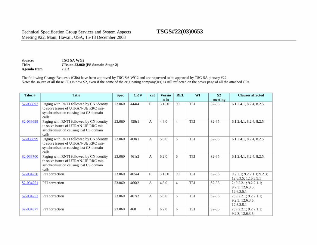
12.6.3.5.1 S2-034247 Serving network identity from SGSN to
GGSN 23.060 473r3 F 5.6.0 5 TEI S2-36 6.9.1.2.2, 6.9.1.3.2,
6.9.2.1, 6.9.2.2.1, 6.9.2.2.2, 6.13.2.1, 6.13.2.2, 9.2.2.1, 9.2.2.1.1, 9.2.3.1, 9.2.3.3
S2-034248 Serving network identity from SGSN to GGSN
23.060 474r3 F 6.2.0 6 TEI S2-36 6.9.1.2.2, 6.9.1.3.2, 6.9.2.1, 6.9.2.2.1, 6.9.2.2.2, 6.13.2.1, 6.13.2.2, 9.2.2.1, 9.2.2.1.1, 9.2.3.1, 9.2.3.3
S2-033571 Teardown indicator in DEACTIVATE PDP CONTEXT ACCEPT message
23.060 469 F 6.2.0 6 TEI6 S2-35 9.2.4.2; 9.2.4.3
S2-033724 SGSN behaviour on BSS downgraded ABQP
23.060 475r1 F 6.2.0 6 TEI S2-35 9.2.2.1, 9.2.2.1.1, 9.2.3.1, 9.2.3.2, 9.2.3.3, 12.6.3.5.1
S2-033726 BSS paging co-ordination for A/Gb mode 23.060 480 F 6.2.0 6 TEI6 S2-35 6.3.3.1, 8.1.6 (new) S2-034327 Security Issue with Multiple PDP Contexts 23.060 434r8 B 6.2.0 6 TEI6 S2-36 6.9.1.2.2, 6.9.1.3.2,
6.9.2.1, 6.9.2.2, 6.13.2, 9.2. 2.1, 9.2.2.1.1, 9.2.3.1, 9.2.3.2, 9.2.3.3, 9.2.4, 13.2, Additional clause 15.4
S2-034328 BSS PFC procedures at PDP context modification
23.060 478r3 F 6.2.0 6 TEI S2-36 9.2.3.1, 9.2.3.2, 9.2.3.3
CR page 1
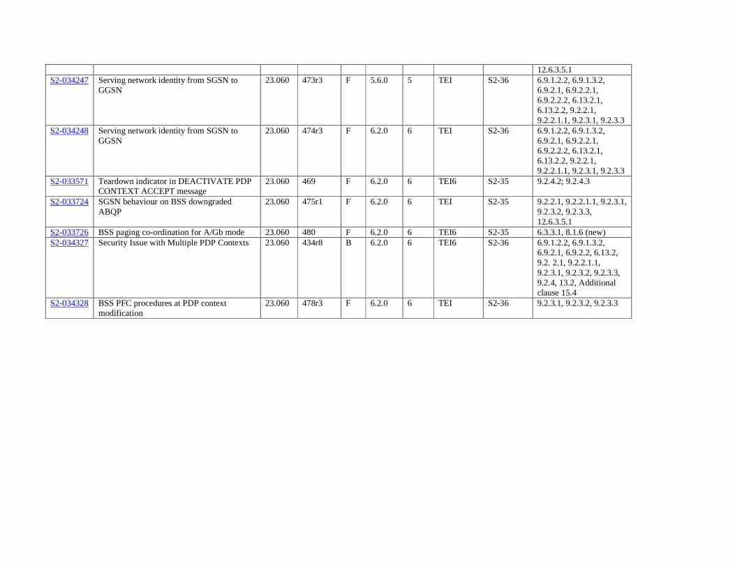
3GPP TSG-SA2 #35 Tdoc S2-033697
Bangkok, Thailand, 27-31/10/03 rev of S2-033624 CR-Form-v7
CHANGE REQUEST
! 23.060 CR 444 ! rev 4 ! Current version: 3.15.0 !
For HELP on using this form, see bottom of this page or look at the pop-up text over the ! symbols.
Proposed change affects: UICC apps! ME Radio Access Network X Core Network X
Title: ! Paging with RNTI followed by CN identity to solve issues of UTRAN-UE RRC mis-
synchronisation causing lost CS domain calls Source: ! Vodafone Ltd Work item code: ! TEI Date: ! 30/10/03 Category: ! F Release: ! R99 Use one of the following categories:
F (correction) A (corresponds to a correction in an earlier release) B (addition of feature), C (functional modification of feature) D (editorial modification)
Detailed explanations of the above categories can be found in 3GPP TR 21.900.
Use one of the following releases: 2 (GSM Phase 2) R96 (Release 1996) R97 (Release 1997) R98 (Release 1998) R99 (Release 1999) Rel-4 (Release 4) Rel-5 (Release 5) Rel-6 (Release 6)
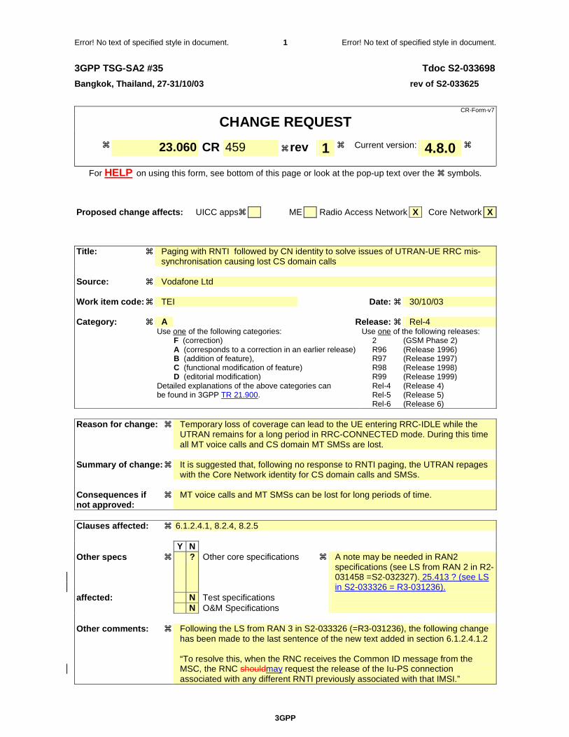
Reason for change: ! Temporary loss of coverage can lead to the UE entering RRC-IDLE while the
UTRAN remains for a long period in RRC-CONNECTED mode. During this time all MT voice calls and CS domain MT SMSs are lost.
Summary of change: ! It is suggested that, following no response to RNTI paging, the UTRAN repages
with the Core Network identity for CS domain calls and SMSs. Consequences if ! not approved:
MT voice calls and MT SMSs can be lost for long periods of time.
Clauses affected: ! 6.1.2.4.1, 8.2.4, 8.2.5 Y N Other specs ! ? Other core specifications ! A note may be needed in RAN2
specifications (see LS from RAN 2 in R2-031458 =S2-032327). 25.413 ? (see LS in S2-033326 = R3-031236)..
affected: N Test specifications N O&M Specifications Other comments: ! Following the LS from RAN 3 in S2-033326 (=R3-031236), the following change
has been made to the last sentence of the new text added in section 6.1.2.4.1.2 “To resolve this, when the RNC receives the Common ID message from the MSC, the RNC mayshould request the release of the Iu-PS connection associated with any different RNTI previously associated with that IMSI.”
How to create CRs using this form:
CR page 2
Comprehensive information and tips about how to create CRs can be found at http://www.3gpp.org/specs/CR.htm. Below is a brief summary:
1) Fill out the above form. The symbols above marked ! contain pop-up help information about the field that they are closest to.
2) Obtain the latest version for the release of the specification to which the change is proposed. Use the MS Word "revision marks" feature (also known as "track changes") when making the changes. All 3GPP specifications can be downloaded from the 3GPP server under ftp://ftp.3gpp.org/specs/ For the latest version, look for the directory name with the latest date e.g. 2001-03 contains the specifications resulting from the March 2001 TSG meetings.
3) With "track changes" disabled, paste the entire CR form (use CTRL-A to select it) into the specification just in front of the clause containing the first piece of changed text. Delete those parts of the specification which are not relevant to the change request.

Error! No text of specified style in document.
3GPP
Error! No text of specified style in document. 3 Error! No text of specified style in document.
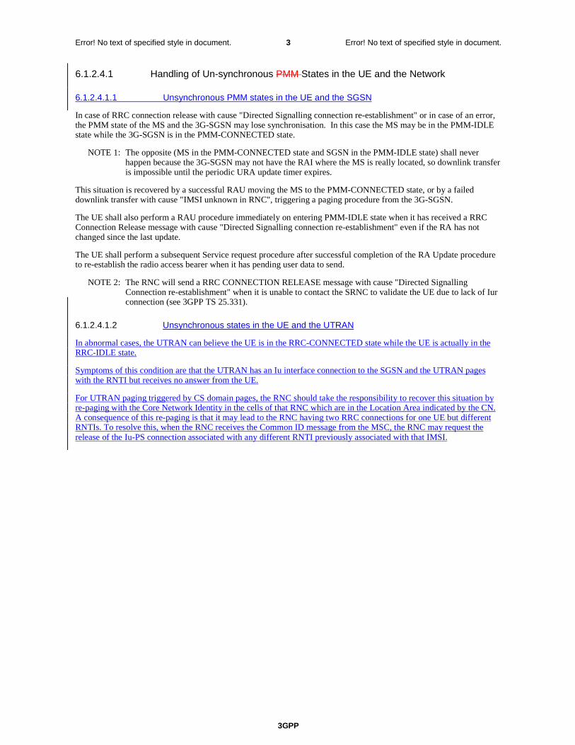
6.1.2.4.1 Handling of Un-synchronous PMM States in the UE and the Network
6.1.2.4.1.1 Unsynchronous PMM states in the UE and the SGSN
In case of RRC connection release with cause "Directed Signalling connection re-establishment" or in case of an error, the PMM state of the MS and the 3G-SGSN may lose synchronisation. In this case the MS may be in the PMM-IDLE state while the 3G-SGSN is in the PMM-CONNECTED state.
NOTE: The opposite (MS in the PMM-CONNECTED state and SGSN in the PMM-IDLE state) shall never happen because the 3G-SGSN may not have the RAI where the MS is really located, so downlink transfer is impossible until the periodic URA update timer expires.
This situation is recovered by a successful RAU moving the MS to the PMM-CONNECTED state, or by a failed downlink transfer with cause "IMSI unknown in RNC", triggering a paging procedure from the 3G-SGSN.
The UE shall also perform a RAU procedure immediately on entering PMM-IDLE state when it has received a RRC Connection Release message with cause "Directed Signalling connection re-establishment" even if the RA has not changed since the last update.
The UE shall perform a subsequent Service request procedure after successful completion of the RA Update procedure to re-establish the radio access bearer when it has pending user data to send.
NOTE: The RNC will send a RRC CONNECTION RELEASE message with cause "Directed Signalling Connection re-establishment" when it is unable to contact the SRNC to validate the UE due to lack of Iur connection (see TS 25.331).
6.1.2.4.1.2 Unsynchronous states in the UE and the UTRAN
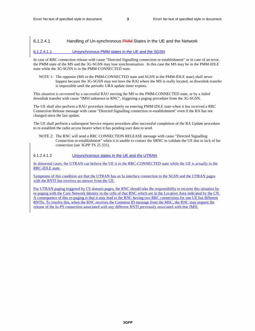
In abnormal cases, the UTRAN can believe the UE is in the RRC-CONNECTED state while the UE is actually in the RRC-IDLE state.
Symptoms of this condition are that the UTRAN has an Iu interface connection to the SGSN and the UTRAN pages with the RNTI but receives no answer from the UE.
For UTRAN paging triggered by CS domain pages, the RNC should take the responsibility to recover this situation by re-paging with the Core Network Identity in the cells of that RNC which are in the Location Area indicated by the CN. A consequence of this re-paging is that it may lead to the RNC having two RRC connections for one UE but different RNTIs. To resolve this, when the RNC receives the Common ID message from the MSC, the RNC may request the release of the Iu-PS connection associated with any different RNTI previously associated with that IMSI.
Error! No text of specified style in document.
3GPP
Error! No text of specified style in document. 4 Error! No text of specified style in document.
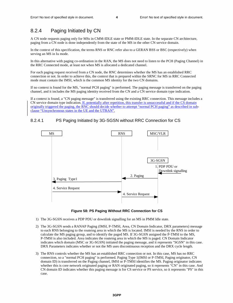
8.2.4 Paging Initiated by CN
A CN node requests paging only for MSs in CMM-IDLE state or PMM-IDLE state. In the separate CN architecture, paging from a CN node is done independently from the state of the MS in the other CN service domain.
In this alternative with paging co-ordination in the UTRAN, the MS does not need to listen to the PCH (Paging Channel) in the RRC Connected mode, at least not when MS is allocated a dedicated channel.
For each paging request received from a CN node, the RNC determines whether the MS has an established RRC connection or not. In order to achieve this, the context that is prepared within the SRNC for MS in RRC Connected mode must contain the IMSI, which is the common MS identity for the two CN domains.
If no context is found for the MS, "normal PCH paging" is performed. The paging message is transferred on the paging channel, and it includes the MS paging identity received from the CN and a CN service domain type indication.
If a context is found, a "CN paging message" is transferred using the existing RRC connection. This message includes a CN service domain type indication. If, potentially after repetition, this transfer is unsuccessful and if the CS domain originally triggered the paging, the RNC should decide whether to attempt “normal PCH paging” as described in sub-clause “Unsynchronous states in the UE and the UTRAN”.
.
8.2.4.1 PS Paging Initiated by 3G-SGSN without RRC Connection for CS
4. Service Request
4. Service Request
3. Paging Type12. Paging
MS RNS MSC/VLR
3G-SGSN
1. PDP PDU orDownlink signalling
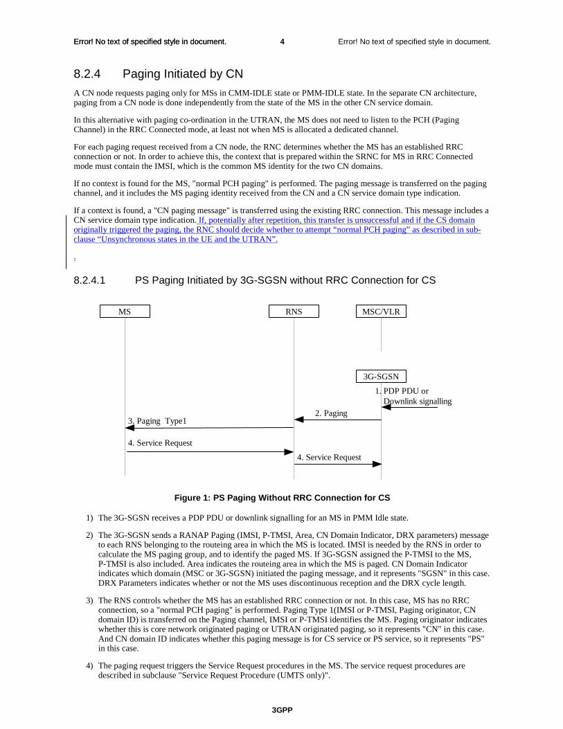
Figure 1: PS Paging Without RRC Connection for CS
1) The 3G-SGSN receives a PDP PDU or downlink signalling for an MS in PMM Idle state.
2) The 3G-SGSN sends a RANAP Paging (IMSI, P-TMSI, Area, CN Domain Indicator, DRX parameters) message to each RNS belonging to the routeing area in which the MS is located. IMSI is needed by the RNS in order to calculate the MS paging group, and to identify the paged MS. If 3G-SGSN assigned the P-TMSI to the MS, P-TMSI is also included. Area indicates the routeing area in which the MS is paged. CN Domain Indicator indicates which domain (MSC or 3G-SGSN) initiated the paging message, and it represents "SGSN" in this case. DRX Parameters indicates whether or not the MS uses discontinuous reception and the DRX cycle length.
3) The RNS controls whether the MS has an established RRC connection or not. In this case, MS has no RRC connection, so a "normal PCH paging" is performed. Paging Type 1(IMSI or P-TMSI, Paging originator, CN domain ID) is transferred on the Paging channel, IMSI or P-TMSI identifies the MS. Paging originator indicates whether this is core network originated paging or UTRAN originated paging, so it represents "CN" in this case. And CN domain ID indicates whether this paging message is for CS service or PS service, so it represents "PS" in this case.
4) The paging request triggers the Service Request procedures in the MS. The service request procedures are described in subclause "Service Request Procedure (UMTS only)".

Error! No text of specified style in document.
3GPP
Error! No text of specified style in document. 5 Error! No text of specified style in document.
Optionally, 3G-SGSN may include "Non Searching Indication" in RANAP Paging message in this case. If a "Non Searching Indication" parameter is present, the RNC will not search the established RRC connection, and just initiate "normal PCH paging".
Error! No text of specified style in document.
3GPP
Error! No text of specified style in document. 6 Error! No text of specified style in document.
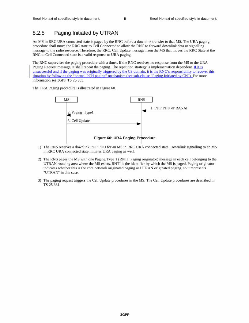
8.2.5 Paging Initiated by UTRAN
An MS in RRC URA connected state is paged by the RNC before a downlink transfer to that MS. The URA paging procedure shall move the RRC state to Cell Connected to allow the RNC to forward downlink data or signalling message to the radio resource. Therefore, the RRC: Cell Update message from the MS that moves the RRC State at the RNC to Cell Connected state is a valid response to URA paging.
The RNC supervises the paging procedure with a timer. If the RNC receives no response from the MS to the URA Paging Request message, it shall repeat the paging. The repetition strategy is implementation dependent. If it is unsuccessful and if the paging was originally triggered by the CS domain, it is the RNC’s responsibility to recover this situation by following the “normal PCH paging” mechanism (see sub-clause “Paging Initiated by CN”). For more information see TS 25.303.
The URA Paging procedure is illustrated in Figure 2.
MS RNS
1. PDP PDU or RANAP
3. Cell Update
2. Paging Type1
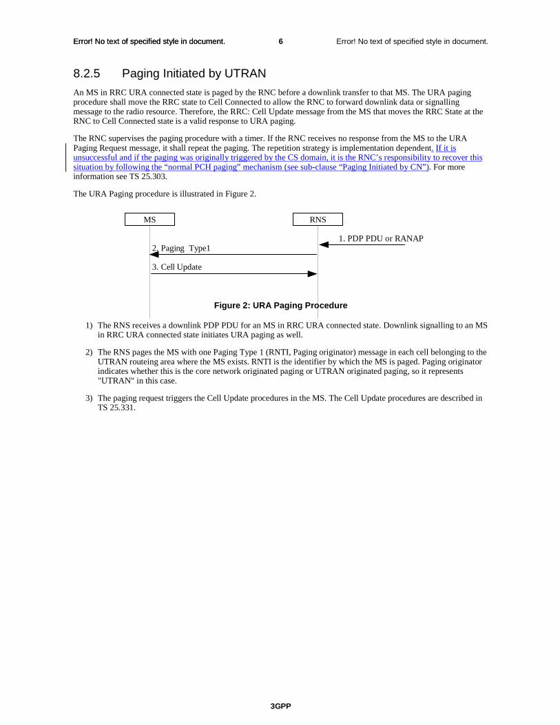
Figure 2: URA Paging Procedure
1) The RNS receives a downlink PDP PDU for an MS in RRC URA connected state. Downlink signalling to an MS in RRC URA connected state initiates URA paging as well.
2) The RNS pages the MS with one Paging Type 1 (RNTI, Paging originator) message in each cell belonging to the UTRAN routeing area where the MS exists. RNTI is the identifier by which the MS is paged. Paging originator indicates whether this is the core network originated paging or UTRAN originated paging, so it represents "UTRAN" in this case.
3) The paging request triggers the Cell Update procedures in the MS. The Cell Update procedures are described in TS 25.331.
3GPP
Error! No text of specified style in document. 1 Error! No text of specified style in document.
3GPP TSG-SA2 #35 Tdoc S2-033698
Bangkok, Thailand, 27-31/10/03 rev of S2-033625
CR-Form-v7
CHANGE REQUEST
! 23.060 CR 459 ! rev 1 ! Current version: 4.8.0 !
For HELP on using this form, see bottom of this page or look at the pop-up text over the ! symbols.
Proposed change affects: UICC apps! ME Radio Access Network X Core Network X
Title: ! Paging with RNTI followed by CN identity to solve issues of UTRAN-UE RRC mis-
synchronisation causing lost CS domain calls Source: ! Vodafone Ltd Work item code: ! TEI Date: ! 30/10/03 Category: ! A Release: ! Rel-4 Use one of the following categories:
F (correction) A (corresponds to a correction in an earlier release) B (addition of feature), C (functional modification of feature) D (editorial modification)
Detailed explanations of the above categories can be found in 3GPP TR 21.900.
Use one of the following releases: 2 (GSM Phase 2) R96 (Release 1996) R97 (Release 1997) R98 (Release 1998) R99 (Release 1999) Rel-4 (Release 4) Rel-5 (Release 5) Rel-6 (Release 6)
Reason for change: ! Temporary loss of coverage can lead to the UE entering RRC-IDLE while the
UTRAN remains for a long period in RRC-CONNECTED mode. During this time all MT voice calls and CS domain MT SMSs are lost.
Summary of change: ! It is suggested that, following no response to RNTI paging, the UTRAN repages
with the Core Network identity for CS domain calls and SMSs. Consequences if ! not approved:
MT voice calls and MT SMSs can be lost for long periods of time.
Clauses affected: ! 6.1.2.4.1, 8.2.4, 8.2.5 Y N Other specs ! ? Other core specifications ! A note may be needed in RAN2
specifications (see LS from RAN 2 in R2-031458 =S2-032327). 25.413 ? (see LS in S2-033326 = R3-031236).
affected: N Test specifications N O&M Specifications Other comments: ! Following the LS from RAN 3 in S2-033326 (=R3-031236), the following change
has been made to the last sentence of the new text added in section 6.1.2.4.1.2 “To resolve this, when the RNC receives the Common ID message from the MSC, the RNC shouldmay request the release of the Iu-PS connection associated with any different RNTI previously associated with that IMSI.”
3GPP
Error! No text of specified style in document. 2 Error! No text of specified style in document.
How to create CRs using this form: Comprehensive information and tips about how to create CRs can be found at http://www.3gpp.org/specs/CR.htm. Below is a brief summary:
1) Fill out the above form. The symbols above marked ! contain pop-up help information about the field that they are closest to.
2) Obtain the latest version for the release of the specification to which the change is proposed. Use the MS Word "revision marks" feature (also known as "track changes") when making the changes. All 3GPP specifications can be downloaded from the 3GPP server under ftp://ftp.3gpp.org/specs/ For the latest version, look for the directory name with the latest date e.g. 2001-03 contains the specifications resulting from the March 2001 TSG meetings.
3) With "track changes" disabled, paste the entire CR form (use CTRL-A to select it) into the specification just in front of the clause containing the first piece of changed text. Delete those parts of the specification which are not relevant to the change request.
3GPP
Error! No text of specified style in document. 3 Error! No text of specified style in document.
6.1.2.4.1 Handling of Un-synchronous PMM States in the UE and the Network
6.1.2.4.1.1 Unsynchronous PMM states in the UE and the SGSN
In case of RRC connection release with cause "Directed Signalling connection re-establishment" or in case of an error, the PMM state of the MS and the 3G-SGSN may lose synchronisation. In this case the MS may be in the PMM-IDLE state while the 3G-SGSN is in the PMM-CONNECTED state.
NOTE 1: The opposite (MS in the PMM-CONNECTED state and SGSN in the PMM-IDLE state) shall never happen because the 3G-SGSN may not have the RAI where the MS is really located, so downlink transfer is impossible until the periodic URA update timer expires.
This situation is recovered by a successful RAU moving the MS to the PMM-CONNECTED state, or by a failed downlink transfer with cause "IMSI unknown in RNC", triggering a paging procedure from the 3G-SGSN.
The UE shall also perform a RAU procedure immediately on entering PMM-IDLE state when it has received a RRC Connection Release message with cause "Directed Signalling connection re-establishment" even if the RA has not changed since the last update.
The UE shall perform a subsequent Service request procedure after successful completion of the RA Update procedure to re-establish the radio access bearer when it has pending user data to send.
NOTE 2: The RNC will send a RRC CONNECTION RELEASE message with cause "Directed Signalling Connection re-establishment" when it is unable to contact the SRNC to validate the UE due to lack of Iur connection (see 3GPP TS 25.331).
6.1.2.4.1.2 Unsynchronous states in the UE and the UTRAN
In abnormal cases, the UTRAN can believe the UE is in the RRC-CONNECTED state while the UE is actually in the RRC-IDLE state.
Symptoms of this condition are that the UTRAN has an Iu interface connection to the SGSN and the UTRAN pages with the RNTI but receives no answer from the UE.
For UTRAN paging triggered by CS domain pages, the RNC should take the responsibility to recover this situation by re-paging with the Core Network Identity in the cells of that RNC which are in the Location Area indicated by the CN. A consequence of this re-paging is that it may lead to the RNC having two RRC connections for one UE but different RNTIs. To resolve this, when the RNC receives the Common ID message from the MSC, the RNC may request the release of the Iu-PS connection associated with any different RNTI previously associated with that IMSI.

3GPP
Error! No text of specified style in document. 4 Error! No text of specified style in document.
8.2.4 Paging Initiated by CN
A CN node requests paging only for MSs in CMM-IDLE state or PMM-IDLE state. In the separate CN architecture, paging from a CN node is done independently from the state of the MS in the other CN service domain.
In this alternative with paging co-ordination in the UTRAN, the MS does not need to listen to the PCH (Paging Channel) in the RRC Connected mode, at least not when MS is allocated a dedicated channel.
For each paging request received from a CN node, the RNC determines whether the MS has an established RRC connection or not. In order to achieve this, the context that is prepared within the SRNC for MS in RRC Connected mode must contain the IMSI, which is the common MS identity for the two CN domains.
If no context is found for the MS, "normal PCH paging" is performed. The paging message is transferred on the paging channel, and it includes the MS paging identity received from the CN and a CN service domain type indication.
If a context is found, a "CN paging message" is transferred using the existing RRC connection. This message includes a CN service domain type indication. If, potentially after repetition, this transfer is unsuccessful and if the CS domain originally triggered the paging, the RNC should decide whether to attempt “normal PCH paging” as described in sub-clause “Unsynchronous states in the UE and the UTRAN”.
8.2.4.1 PS Paging Initiated by 3G-SGSN without RRC Connection for CS
4. Service Request
4. Service Request
3. Paging Type12. Paging
MS RNS MSC/VLR
3G-SGSN
1. PDP PDU orDownlink signalling
Figure 58: PS Paging Without RRC Connection for CS
1) The 3G-SGSN receives a PDP PDU or downlink signalling for an MS in PMM Idle state.
2) The 3G-SGSN sends a RANAP Paging (IMSI, P-TMSI, Area, CN Domain Indicator, DRX parameters) message to each RNS belonging to the routeing area in which the MS is located. IMSI is needed by the RNS in order to calculate the MS paging group, and to identify the paged MS. If 3G-SGSN assigned the P-TMSI to the MS, P-TMSI is also included. Area indicates the routeing area in which the MS is paged. CN Domain Indicator indicates which domain (MSC or 3G-SGSN) initiated the paging message, and it represents "SGSN" in this case. DRX Parameters indicates whether or not the MS uses discontinuous reception and the DRX cycle length.
3) The RNS controls whether the MS has an established RRC connection or not. In this case, MS has no RRC connection, so a "normal PCH paging" is performed. Paging Type 1(IMSI or P-TMSI, Paging originator, CN domain ID) is transferred on the Paging channel, IMSI or P-TMSI identifies the MS. Paging originator indicates whether this is core network originated paging or UTRAN originated paging, so it represents "CN" in this case. And CN domain ID indicates whether this paging message is for CS service or PS service, so it represents "PS" in this case.
4) The paging request triggers the Service Request procedures in the MS. The service request procedures are described in clause "Service Request Procedure (UMTS only)".
3GPP
Error! No text of specified style in document. 5 Error! No text of specified style in document.
Optionally, 3G-SGSN may include "Non Searching Indication" in RANAP Paging message in this case. If a "Non Searching Indication" parameter is present, the RNC will not search the established RRC connection, and just initiate "normal PCH paging".
3GPP
Error! No text of specified style in document. 6 Error! No text of specified style in document.
8.2.5 Paging Initiated by UTRAN
An MS in RRC URA connected state is paged by the RNC before a downlink transfer to that MS. The URA paging procedure shall move the RRC state to Cell Connected to allow the RNC to forward downlink data or signalling message to the radio resource. Therefore, the RRC: Cell Update message from the MS that moves the RRC State at the RNC to Cell Connected state is a valid response to URA paging.
The RNC supervises the paging procedure with a timer. If the RNC receives no response from the MS to the URA Paging Request message, it shall repeat the paging. The repetition strategy is implementation dependent. If it is unsuccessful and if the paging was originally triggered by the CS domain, it is the RNC’s responsibility to recover this situation by following the “normal PCH paging” mechanism (see sub-clause “Paging Initiated by CN”). For more information see 3GPP TS 25.303.
The URA Paging procedure is illustrated in Figure 60.
MS RNS
1. PDP PDU or RANAP
3. Cell Update
2. Paging Type1
Figure 60: URA Paging Procedure
1) The RNS receives a downlink PDP PDU for an MS in RRC URA connected state. Downlink signalling to an MS in RRC URA connected state initiates URA paging as well.
2) The RNS pages the MS with one Paging Type 1 (RNTI, Paging originator) message in each cell belonging to the UTRAN routeing area where the MS exists. RNTI is the identifier by which the MS is paged. Paging originator indicates whether this is the core network originated paging or UTRAN originated paging, so it represents "UTRAN" in this case.
3) The paging request triggers the Cell Update procedures in the MS. The Cell Update procedures are described in TS 25.331.
3GPP
Error! No text of specified style in document. 1 Error! No text of specified style in document.
3GPP TSG-SA2 #35 Tdoc S2-033699
Bangkok, Thailand, 27-31/10/03 rev of S2-033626
CR-Form-v7
CHANGE REQUEST
! 23.060 CR 460 ! rev 1 ! Current version: 5.6.0 !
For HELP on using this form, see bottom of this page or look at the pop-up text over the ! symbols.
Proposed change affects: UICC apps! ME Radio Access Network X Core Network X
Title: ! Paging with RNTI followed by CN identity to solve issues of UTRAN-UE RRC mis-
synchronisation causing lost CS domain calls Source: ! Vodafone Ltd Work item code: ! TEI Date: ! 30/10/03 Category: ! A Release: ! Rel-5 Use one of the following categories:
F (correction) A (corresponds to a correction in an earlier release) B (addition of feature), C (functional modification of feature) D (editorial modification)
Detailed explanations of the above categories can be found in 3GPP TR 21.900.
Use one of the following releases: 2 (GSM Phase 2) R96 (Release 1996) R97 (Release 1997) R98 (Release 1998) R99 (Release 1999) Rel-4 (Release 4) Rel-5 (Release 5) Rel-6 (Release 6)
Reason for change: ! Temporary loss of coverage can lead to the UE entering RRC-IDLE while the
UTRAN remains for a long period in RRC-CONNECTED mode. During this time all MT voice calls and CS domain MT SMSs are lost.
Summary of change: ! It is suggested that, following no response to RNTI paging, the UTRAN repages
with the Core Network identity for CS domain calls and SMSs. Consequences if ! not approved:
MT voice calls and MT SMSs can be lost for long periods of time.
Clauses affected: ! 6.1.2.4.1, 8.2.4, 8.2.5 Y N Other specs ! ? Other core specifications ! A note may be needed in RAN2
specifications (see LS from RAN 2 in R2-031458 =S2-032327). 25.413 ? (see LS in S2-033326 = R3-031236).
affected: N Test specifications N O&M Specifications Other comments: ! Following the LS from RAN 3 in S2-033326 (=R3-031236), the following change
has been made to the last sentence of the new text added in section 6.1.2.4.1.2 “To resolve this, when the RNC receives the Common ID message from the MSC, the RNC shouldmay request the release of the Iu-PS connection associated with any different RNTI previously associated with that IMSI.”
How to create CRs using this form:
3GPP
Error! No text of specified style in document. 2 Error! No text of specified style in document.
Comprehensive information and tips about how to create CRs can be found at http://www.3gpp.org/specs/CR.htm. Below is a brief summary:
1) Fill out the above form. The symbols above marked ! contain pop-up help information about the field that they are closest to.
2) Obtain the latest version for the release of the specification to which the change is proposed. Use the MS Word "revision marks" feature (also known as "track changes") when making the changes. All 3GPP specifications can be downloaded from the 3GPP server under ftp://ftp.3gpp.org/specs/ For the latest version, look for the directory name with the latest date e.g. 2001-03 contains the specifications resulting from the March 2001 TSG meetings.
3) With "track changes" disabled, paste the entire CR form (use CTRL-A to select it) into the specification just in front of the clause containing the first piece of changed text. Delete those parts of the specification which are not relevant to the change request.
3GPP
Error! No text of specified style in document. 3 Error! No text of specified style in document.
6.1.2.4.1 Handling of Un-synchronous PMM States in the UE and the Network
6.1.2.4.1.1 Unsynchronous PMM states in the UE and the SGSN
In case of RRC connection release with cause "Directed Signalling connection re-establishment" or in case of an error, the PMM state of the MS and the 3G-SGSN may lose synchronisation. In this case the MS may be in the PMM-IDLE state while the 3G-SGSN is in the PMM-CONNECTED state.
NOTE 1: The opposite (MS in the PMM-CONNECTED state and SGSN in the PMM-IDLE state) shall never happen because the 3G-SGSN may not have the RAI where the MS is really located, so downlink transfer is impossible until the periodic URA update timer expires.
This situation is recovered by a successful RAU moving the MS to the PMM-CONNECTED state, or by a failed downlink transfer with cause "IMSI unknown in RNC", triggering a paging procedure from the 3G-SGSN.
The UE shall also perform a RAU procedure immediately on entering PMM-IDLE state when it has received a RRC Connection Release message with cause "Directed Signalling connection re-establishment" even if the RA has not changed since the last update.
The UE shall perform a subsequent Service request procedure after successful completion of the RA Update procedure to re-establish the radio access bearer when it has pending user data to send.
NOTE 2: The RNC will send a RRC CONNECTION RELEASE message with cause "Directed Signalling Connection re-establishment" when it is unable to contact the SRNC to validate the UE due to lack of Iur connection (see 3GPP TS 25.331).
6.1.2.4.1.2 Unsynchronous states in the UE and the UTRAN
In abnormal cases, the UTRAN can believe the UE is in the RRC-CONNECTED state while the UE is actually in the RRC-IDLE state.
Symptoms of this condition are that the UTRAN has an Iu interface connection to the SGSN and the UTRAN pages with the RNTI but receives no answer from the UE.
For UTRAN paging triggered by CS domain pages, the RNC should take the responsibility to recover this situation by re-paging with the Core Network Identity in the cells of that RNC which are in the Location Area indicated by the CN. A consequence of this re-paging is that it may lead to the RNC having two RRC connections for one UE but different RNTIs. To resolve this, when the RNC receives the Common ID message from the MSC, the RNC may request the release of the Iu-PS connection associated with any different RNTI previously associated with that IMSI.

3GPP
Error! No text of specified style in document. 4 Error! No text of specified style in document.
8.2.4 Paging Initiated by CN
A CN node requests paging only for MSs in CMM-IDLE state or PMM-IDLE state. In the separate CN architecture, paging from a CN node is done independently from the state of the MS in the other CN service domain.
In the context of this specification, the terms RNS or RNC refer also to a GERAN BSS or BSC (respectively) when serving an MS in Iu mode.
In this alternative with paging co-ordination in the RAN, the MS does not need to listen to the PCH (Paging Channel) in the RRC Connected mode, at least not when MS is allocated a dedicated channel.
For each paging request received from a CN node, the RNC determines whether the MS has an established RRC connection or not. In order to achieve this, the context that is prepared within the SRNC for MS in RRC Connected mode must contain the IMSI, which is the common MS identity for the two CN domains.
If no context is found for the MS, "normal PCH paging" is performed. The paging message is transferred on the paging channel, and it includes the MS paging identity received from the CN and a CN service domain type indication.
If a context is found, a "CN paging message" is transferred using the existing RRC connection. This message includes a CN service domain type indication. If, potentially after repetition, this transfer is unsuccessful and if the CS domain originally triggered the paging, the RNC should decide whether to attempt “normal PCH paging” as described in sub-clause “Unsynchronous states in the UE and the UTRAN”.
8.2.4.1 PS Paging Initiated by 3G-SGSN without RRC Connection for CS
4. Service Request
4. Service Request
3. Paging Type12. Paging
MS RNS MSC/VLR
3G-SGSN
1. PDP PDU orDownlink signalling
Figure 58: PS Paging Without RRC Connection for CS
1) The 3G-SGSN receives a PDP PDU or downlink signalling for an MS in PMM Idle state.
2) The 3G-SGSN sends a RANAP Paging (IMSI, P-TMSI, Area, CN Domain Indicator, DRX parameters) message to each RNS belonging to the routeing area in which the MS is located. IMSI is needed by the RNS in order to calculate the MS paging group, and to identify the paged MS. If 3G-SGSN assigned the P-TMSI to the MS, P-TMSI is also included. Area indicates the routeing area in which the MS is paged. CN Domain Indicator indicates which domain (MSC or 3G-SGSN) initiated the paging message, and it represents "SGSN" in this case. DRX Parameters indicates whether or not the MS uses discontinuous reception and the DRX cycle length.
3) The RNS controls whether the MS has an established RRC connection or not. In this case, MS has no RRC connection, so a "normal PCH paging" is performed. Paging Type 1(IMSI or P-TMSI, Paging originator, CN domain ID) is transferred on the Paging channel, IMSI or P-TMSI identifies the MS. Paging originator indicates whether this is core network originated paging or RAN originated paging, so it represents "CN" in this case. And CN domain ID indicates whether this paging message is for CS service or PS service, so it represents "PS" in this case.
3GPP
Error! No text of specified style in document. 5 Error! No text of specified style in document.
4) The paging request triggers the Service Request procedures in the MS. The service request procedures are described in clause "Service Request Procedure (Iu mode)".
Optionally, 3G-SGSN may include "Non Searching Indication" in RANAP Paging message in this case. If a "Non Searching Indication" parameter is present, the RNC will not search the established RRC connection, and just initiate "normal PCH paging".
3GPP
Error! No text of specified style in document. 6 Error! No text of specified style in document.
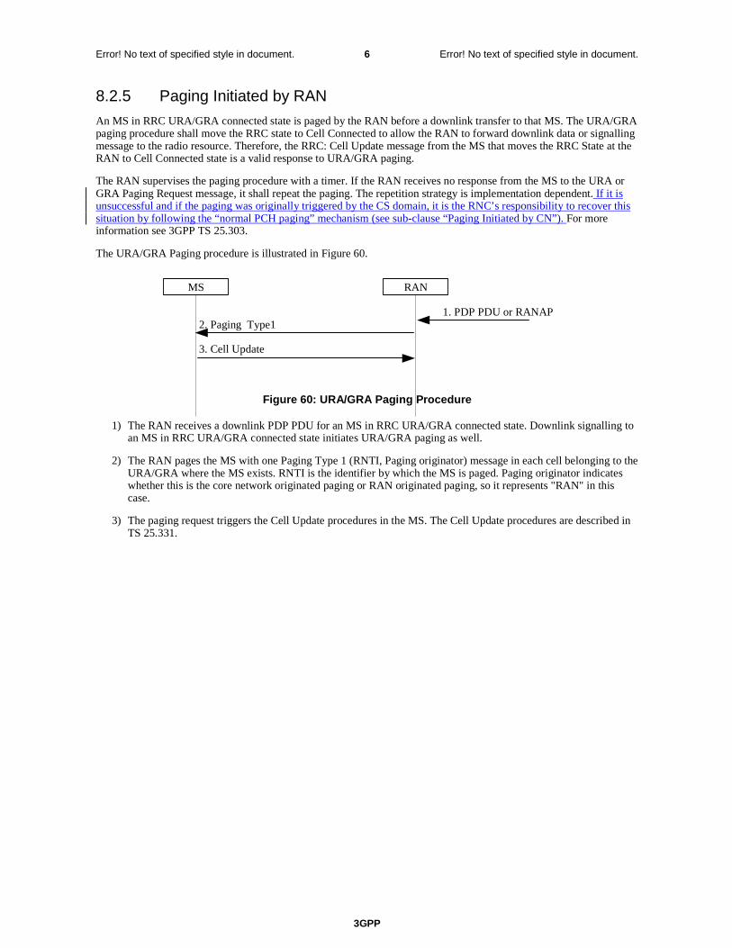
8.2.5 Paging Initiated by RAN
An MS in RRC URA/GRA connected state is paged by the RAN before a downlink transfer to that MS. The URA/GRA paging procedure shall move the RRC state to Cell Connected to allow the RAN to forward downlink data or signalling message to the radio resource. Therefore, the RRC: Cell Update message from the MS that moves the RRC State at the RAN to Cell Connected state is a valid response to URA/GRA paging.
The RAN supervises the paging procedure with a timer. If the RAN receives no response from the MS to the URA or GRA Paging Request message, it shall repeat the paging. The repetition strategy is implementation dependent. If it is unsuccessful and if the paging was originally triggered by the CS domain, it is the RNC’s responsibility to recover this situation by following the “normal PCH paging” mechanism (see sub-clause “Paging Initiated by CN”). For more information see 3GPP TS 25.303.
The URA/GRA Paging procedure is illustrated in Figure 60.
MS RAN
1. PDP PDU or RANAP
3. Cell Update
2. Paging Type1
Figure 60: URA/GRA Paging Procedure
1) The RAN receives a downlink PDP PDU for an MS in RRC URA/GRA connected state. Downlink signalling to an MS in RRC URA/GRA connected state initiates URA/GRA paging as well.
2) The RAN pages the MS with one Paging Type 1 (RNTI, Paging originator) message in each cell belonging to the URA/GRA where the MS exists. RNTI is the identifier by which the MS is paged. Paging originator indicates whether this is the core network originated paging or RAN originated paging, so it represents "RAN" in this case.
3) The paging request triggers the Cell Update procedures in the MS. The Cell Update procedures are described in TS 25.331.
3GPP
Error! No text of specified style in document. 1 Error! No text of specified style in document.
3GPP TSG-SA2 #35 Tdoc S2-033700
Bangkok, Thailand, 27-31/10/03 rev of S2-032627 CR-Form-v7
CHANGE REQUEST
! 23.060 CR 461 ! rev 2 ! Current version: 6.2.0 !
For HELP on using this form, see bottom of this page or look at the pop-up text over the ! symbols.
Proposed change affects: UICC apps! ME Radio Access Network X Core Network X
Title: ! Paging with RNTI followed by CN identity to solve issues of UTRAN-UE RRC mis-
synchronisation causing lost CS domain calls Source: ! Vodafone Ltd Work item code: ! TEI Date: ! 30/10/03 Category: ! A Release: ! Rel-6 Use one of the following categories:
F (correction) A (corresponds to a correction in an earlier release) B (addition of feature), C (functional modification of feature) D (editorial modification)
Detailed explanations of the above categories can be found in 3GPP TR 21.900.
Use one of the following releases: 2 (GSM Phase 2) R96 (Release 1996) R97 (Release 1997) R98 (Release 1998) R99 (Release 1999) Rel-4 (Release 4) Rel-5 (Release 5) Rel-6 (Release 6)
Reason for change: ! Temporary loss of coverage can lead to the UE entering RRC-IDLE while the
UTRAN remains for a long period in RRC-CONNECTED mode. During this time all MT voice calls and CS domain MT SMSs are lost.
Summary of change: ! It is suggested that, following no response to RNTI paging, the UTRAN repages
with the Core Network identity for CS domain calls and SMSs. Consequences if ! not approved:
MT voice calls and MT SMSs can be lost for long periods of time.
Clauses affected: ! 6.1.2.4.1, 8.2.4, 8.2.5 Y N Other specs ! ? Other core specifications ! A note may be needed in RAN2
specifications (see LS from RAN 2 in R2-031458 =S2-032327). 25.413 ? (see LS in S2-033326 = R3-031236).
affected: N Test specifications N O&M Specifications Other comments: ! Following the LS from RAN 3 in S2-033326 (=R3-031236), the following change
has been made to the last sentence of the new text added in section 6.1.2.4.1.2 “To resolve this, when the RNC receives the Common ID message from the MSC, the RNC mayshould request the release of the Iu-PS connection associated with any different RNTI previously associated with that IMSI.”
How to create CRs using this form:

3GPP
Error! No text of specified style in document. 2 Error! No text of specified style in document.
Comprehensive information and tips about how to create CRs can be found at http://www.3gpp.org/specs/CR.htm. Below is a brief summary:
1) Fill out the above form. The symbols above marked ! contain pop-up help information about the field that they are closest to.
2) Obtain the latest version for the release of the specification to which the change is proposed. Use the MS Word "revision marks" feature (also known as "track changes") when making the changes. All 3GPP specifications can be downloaded from the 3GPP server under ftp://ftp.3gpp.org/specs/ For the latest version, look for the directory name with the latest date e.g. 2001-03 contains the specifications resulting from the March 2001 TSG meetings.
3) With "track changes" disabled, paste the entire CR form (use CTRL-A to select it) into the specification just in front of the clause containing the first piece of changed text. Delete those parts of the specification which are not relevant to the change request.

3GPP
Error! No text of specified style in document. 3 Error! No text of specified style in document.
6.1.2.4.1 Handling of Un-synchronous PMM States in the UE and the Network
6.1.2.4.1.1 Unsynchronous PMM states in the UE and the SGSN
In case of RRC connection release with cause "Directed Signalling connection re-establishment" or in case of an error, the PMM state of the MS and the 3G-SGSN may lose synchronisation. In this case the MS may be in the PMM-IDLE state while the 3G-SGSN is in the PMM-CONNECTED state.
NOTE 1: The opposite (MS in the PMM-CONNECTED state and SGSN in the PMM-IDLE state) shall never happen because the 3G-SGSN may not have the RAI where the MS is really located, so downlink transfer is impossible until the periodic URA update timer expires.
This situation is recovered by a successful RAU moving the MS to the PMM-CONNECTED state, or by a failed downlink transfer with cause "IMSI unknown in RNC", triggering a paging procedure from the 3G-SGSN.
The UE shall also perform a RAU procedure immediately on entering PMM-IDLE state when it has received a RRC Connection Release message with cause "Directed Signalling connection re-establishment" even if the RA has not changed since the last update.
The UE shall perform a subsequent Service request procedure after successful completion of the RA Update procedure to re-establish the radio access bearer when it has pending user data to send.
NOTE 2: The RNC will send a RRC CONNECTION RELEASE message with cause "Directed Signalling Connection re-establishment" when it is unable to contact the SRNC to validate the UE due to lack of Iur connection (see 3GPP TS 25.331).
6.1.2.4.1.2 Unsynchronous states in the UE and the UTRAN
In abnormal cases, the UTRAN can believe the UE is in the RRC-CONNECTED state while the UE is actually in the RRC-IDLE state.
Symptoms of this condition are that the UTRAN has an Iu interface connection to the SGSN and the UTRAN pages with the RNTI but receives no answer from the UE.
For UTRAN paging triggered by CS domain pages, the RNC should take the responsibility to recover this situation by re-paging with the Core Network Identity in the cells of that RNC which are in the Location Area indicated by the CN. A consequence of this re-paging is that it may lead to the RNC having two RRC connections for one UE but different RNTIs. To resolve this, when the RNC receives the Common ID message from the MSC, the RNC may request the release of the Iu-PS connection associated with any different RNTI previously associated with that IMSI.
3GPP
Error! No text of specified style in document. 4 Error! No text of specified style in document.
8.2.4 Paging Initiated by CN
A CN node requests paging only for MSs in CMM-IDLE state or PMM-IDLE state. In the separate CN architecture, paging from a CN node is done independently from the state of the MS in the other CN service domain.
In the context of this specification, the terms RNS or RNC refer also to a GERAN BSS or BSC (respectively) when serving an MS in Iu mode.
In this alternative with paging co-ordination in the RAN, the MS does not need to listen to the PCH (Paging Channel) in the RRC Connected mode, at least not when MS is allocated a dedicated channel.
For each paging request received from a CN node, the RNC determines whether the MS has an established RRC connection or not. In order to achieve this, the context that is prepared within the SRNC for MS in RRC Connected mode must contain the IMSI, which is the common MS identity for the two CN domains.
If no context is found for the MS, "normal PCH paging" is performed. The paging message is transferred on the paging channel, and it includes the MS paging identity received from the CN and a CN service domain type indication.
If a context is found, a "CN paging message" is transferred using the existing RRC connection. This message includes a CN service domain type indication. If, potentially after repetition, this transfer is unsuccessful and if the CS domain originally triggered the paging, the RNC should decide whether to attempt “normal PCH paging” as described in sub-clause “Unsynchronous states in the UE and the UTRAN”.
8.2.4.1 PS Paging Initiated by 3G-SGSN without RRC Connection for CS
4. Service Request
4. Service Request
3. Paging Type12. Paging
MS RNS MSC/VLR
3G-SGSN
1. PDP PDU orDownlink signalling
Figure 58: PS Paging Without RRC Connection for CS
1) The 3G-SGSN receives a PDP PDU or downlink signalling for an MS in PMM Idle state.
2) The 3G-SGSN sends a RANAP Paging (IMSI, P-TMSI, Area, CN Domain Indicator, DRX parameters) message to each RNS belonging to the routeing area in which the MS is located. IMSI is needed by the RNS in order to calculate the MS paging group, and to identify the paged MS. If 3G-SGSN assigned the P-TMSI to the MS, P-TMSI is also included. Area indicates the routeing area in which the MS is paged. CN Domain Indicator indicates which domain (MSC or 3G-SGSN) initiated the paging message, and it represents "SGSN" in this case. DRX Parameters indicates whether or not the MS uses discontinuous reception and the DRX cycle length.
3) The RNS controls whether the MS has an established RRC connection or not. In this case, MS has no RRC connection, so a "normal PCH paging" is performed. Paging Type 1(IMSI or P-TMSI, Paging originator, CN domain ID) is transferred on the Paging channel, IMSI or P-TMSI identifies the MS. Paging originator indicates whether this is core network originated paging or RAN originated paging, so it represents "CN" in this case. And CN domain ID indicates whether this paging message is for CS service or PS service, so it represents "PS" in this case.
3GPP
Error! No text of specified style in document. 5 Error! No text of specified style in document.
4) The paging request triggers the Service Request procedures in the MS. The service request procedures are described in clause "Service Request Procedure (Iu mode)".
Optionally, 3G-SGSN may include "Non Searching Indication" in RANAP Paging message in this case. If a "Non Searching Indication" parameter is present, the RNC will not search the established RRC connection, and just initiate "normal PCH paging".

3GPP
Error! No text of specified style in document. 6 Error! No text of specified style in document.
8.2.5 Paging Initiated by RAN
An MS in RRC URA/GRA connected state is paged by the RAN before a downlink transfer to that MS. The URA/GRA paging procedure shall move the RRC state to Cell Connected to allow the RAN to forward downlink data or signalling message to the radio resource. Therefore, the RRC: Cell Update message from the MS that moves the RRC State at the RAN to Cell Connected state is a valid response to URA/GRA paging.
The RAN supervises the paging procedure with a timer. If the RAN receives no response from the MS to the URA or GRA Paging Request message, it shall repeat the paging. The repetition strategy is implementation dependent. If it is unsuccessful and if the paging was originally triggered by the CS domain, it is the RNC’s responsibility to recover this situation by following the “normal PCH paging” mechanism (see sub-clause “Paging Initiated by CN”). For more information see 3GPP TS 25.303.
The URA/GRA Paging procedure is illustrated in Figure 60.
MS RAN
1. PDP PDU or RANAP
3. Cell Update
2. Paging Type1
Figure 60: URA/GRA Paging Procedure
1) The RAN receives a downlink PDP PDU for an MS in RRC URA/GRA connected state. Downlink signalling to an MS in RRC URA/GRA connected state initiates URA/GRA paging as well.
2) The RAN pages the MS with one Paging Type 1 (RNTI, Paging originator) message in each cell belonging to the URA/GRA where the MS exists. RNTI is the identifier by which the MS is paged. Paging originator indicates whether this is the core network originated paging or RAN originated paging, so it represents "RAN" in this case.
3) The paging request triggers the Cell Update procedures in the MS. The Cell Update procedures are described in TS 25.331.

3GPP TSG-SA2 Meeting #36 Tdoc S2-034250 New York, USA, 24-28 November 2003 Rev of S2-034158
CR-Form-v7
CHANGE REQUEST
! 23.060 CR 465 ! rev 4 ! Current version: 3.15.0 !
For HELP on using this form, see bottom of this page or look at the pop-up text over the ! symbols.
Proposed change affects: UICC apps! ME X Radio Access Network X Core Network X
Title: ! PFI correction Source: ! Nokia Work item code: ! TEI Date: ! 26/11/2003 Category: ! F Release: ! R99 Use one of the following categories:
F (correction) A (corresponds to a correction in an earlier release) B (addition of feature), C (functional modification of feature) D (editorial modification)
Detailed explanations of the above categories can be found in 3GPP TR 21.900.
Use one of the following releases: 2 (GSM Phase 2) R96 (Release 1996) R97 (Release 1997) R98 (Release 1998) R99 (Release 1999) Rel-4 (Release 4) Rel-5 (Release 5) Rel-6 (Release 6)
Reason for change: ! In the specification is not told clearly whether SGSN can send Packet Flow
Indentifier (PFI), during PDP context activation or modification, to an MS not supporting BSS packet flow procedures.
Summary of change: ! It is clarified that the SGSN should not send Packet Flow Indentifier (PFI) to an
MS that indicated in the MS Network Capability IE it does not support BSS packet flow procedures.
Consequences if ! not approved:
There can be problems with MS which don’t support BSS packet flow procedures but network anyway sends them PFI. Also the MS’s information sent to network, which tells whether MS supports or not BSS packet flow procedures would be totally useless if network could still try to use them.
Clauses affected: ! 9.2.2.1; 9.2.2.1.1; 9.2.3; 12.6.3.5; 12.6.3.5.1 Y N Other specs ! X Other core specifications ! Possible 3GPP TS 24.008 affected: X Test specifications X O&M Specifications Other comments: ! It is assumed that the 23.060 CR is approved first and no formal linkage between
the 24.008 CRs is needed.
3GPP TS 23.060 v3.15.0 (2003-06) CR page 2
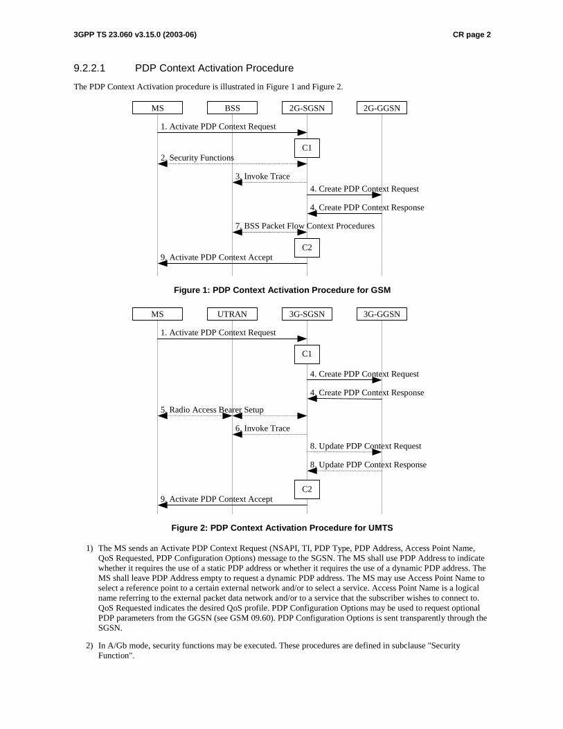
9.2.2.1 PDP Context Activation Procedure
The PDP Context Activation procedure is illustrated in Figure 1 and Figure 2.
2G-GGSN
9. Activate PDP Context Accept
4. Create PDP Context Response
4. Create PDP Context Request
1. Activate PDP Context Request
2G-SGSNBSS
2. Security Functions
MS
7. BSS Packet Flow Context Procedures
C1
C2
3. Invoke Trace
Figure 1: PDP Context Activation Procedure for GSM
3G-GGSN
9. Activate PDP Context Accept
4. Create PDP Context Response
4. Create PDP Context Request
1. Activate PDP Context Request
3G-SGSNUTRANMS
5. Radio Access Bearer Setup
C1
C2
6. Invoke Trace
8. Update PDP Context Response
8. Update PDP Context Request
Figure 2: PDP Context Activation Procedure for UMTS
1) The MS sends an Activate PDP Context Request (NSAPI, TI, PDP Type, PDP Address, Access Point Name, QoS Requested, PDP Configuration Options) message to the SGSN. The MS shall use PDP Address to indicate whether it requires the use of a static PDP address or whether it requires the use of a dynamic PDP address. The MS shall leave PDP Address empty to request a dynamic PDP address. The MS may use Access Point Name to select a reference point to a certain external network and/or to select a service. Access Point Name is a logical name referring to the external packet data network and/or to a service that the subscriber wishes to connect to. QoS Requested indicates the desired QoS profile. PDP Configuration Options may be used to request optional PDP parameters from the GGSN (see GSM 09.60). PDP Configuration Options is sent transparently through the SGSN.
2) In A/Gb mode, security functions may be executed. These procedures are defined in subclause "Security Function".
3GPP TS 23.060 v3.15.0 (2003-06) CR page 3
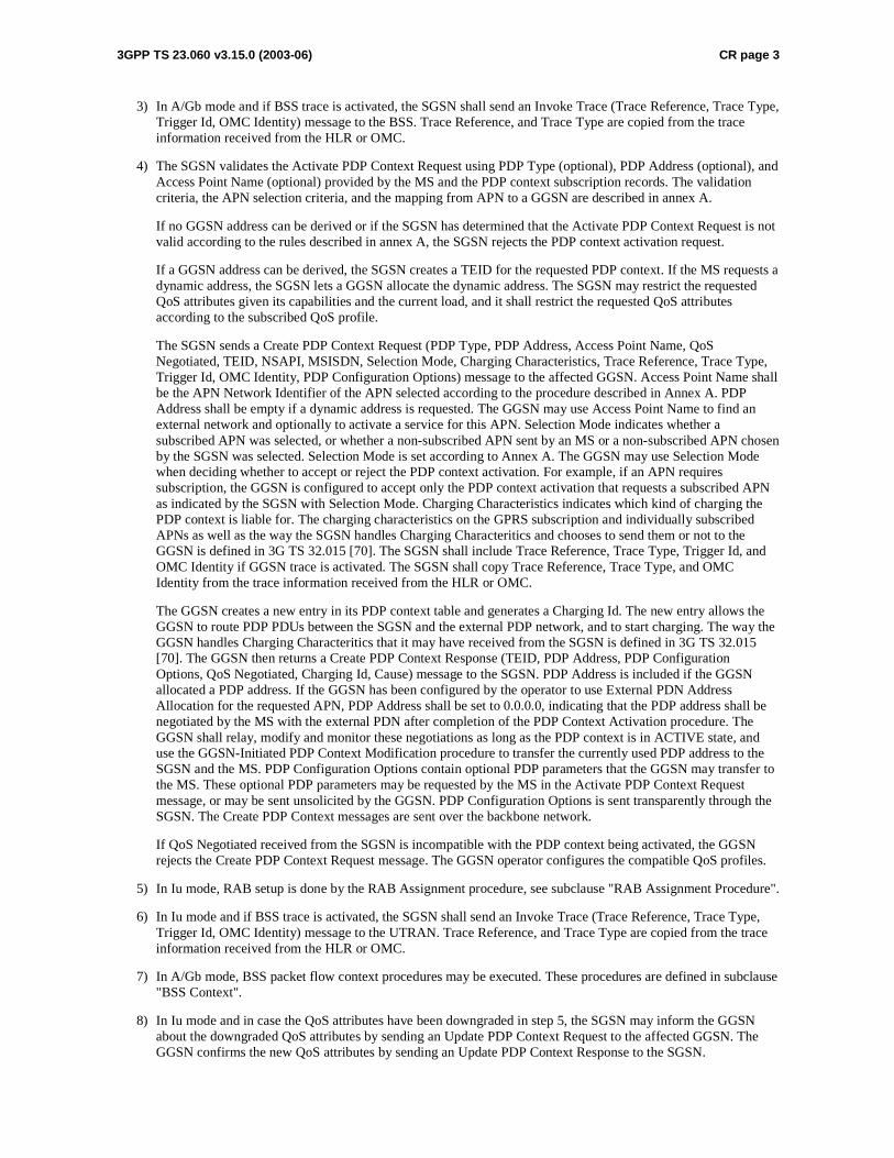
3) In A/Gb mode and if BSS trace is activated, the SGSN shall send an Invoke Trace (Trace Reference, Trace Type, Trigger Id, OMC Identity) message to the BSS. Trace Reference, and Trace Type are copied from the trace information received from the HLR or OMC.
4) The SGSN validates the Activate PDP Context Request using PDP Type (optional), PDP Address (optional), and Access Point Name (optional) provided by the MS and the PDP context subscription records. The validation criteria, the APN selection criteria, and the mapping from APN to a GGSN are described in annex A.
If no GGSN address can be derived or if the SGSN has determined that the Activate PDP Context Request is not valid according to the rules described in annex A, the SGSN rejects the PDP context activation request.
If a GGSN address can be derived, the SGSN creates a TEID for the requested PDP context. If the MS requests a dynamic address, the SGSN lets a GGSN allocate the dynamic address. The SGSN may restrict the requested QoS attributes given its capabilities and the current load, and it shall restrict the requested QoS attributes according to the subscribed QoS profile.
The SGSN sends a Create PDP Context Request (PDP Type, PDP Address, Access Point Name, QoS Negotiated, TEID, NSAPI, MSISDN, Selection Mode, Charging Characteristics, Trace Reference, Trace Type, Trigger Id, OMC Identity, PDP Configuration Options) message to the affected GGSN. Access Point Name shall be the APN Network Identifier of the APN selected according to the procedure described in Annex A. PDP Address shall be empty if a dynamic address is requested. The GGSN may use Access Point Name to find an external network and optionally to activate a service for this APN. Selection Mode indicates whether a subscribed APN was selected, or whether a non-subscribed APN sent by an MS or a non-subscribed APN chosen by the SGSN was selected. Selection Mode is set according to Annex A. The GGSN may use Selection Mode when deciding whether to accept or reject the PDP context activation. For example, if an APN requires subscription, the GGSN is configured to accept only the PDP context activation that requests a subscribed APN as indicated by the SGSN with Selection Mode. Charging Characteristics indicates which kind of charging the PDP context is liable for. The charging characteristics on the GPRS subscription and individually subscribed APNs as well as the way the SGSN handles Charging Characteritics and chooses to send them or not to the GGSN is defined in 3G TS 32.015 [70]. The SGSN shall include Trace Reference, Trace Type, Trigger Id, and OMC Identity if GGSN trace is activated. The SGSN shall copy Trace Reference, Trace Type, and OMC Identity from the trace information received from the HLR or OMC.
The GGSN creates a new entry in its PDP context table and generates a Charging Id. The new entry allows the GGSN to route PDP PDUs between the SGSN and the external PDP network, and to start charging. The way the GGSN handles Charging Characteritics that it may have received from the SGSN is defined in 3G TS 32.015 [70]. The GGSN then returns a Create PDP Context Response (TEID, PDP Address, PDP Configuration Options, QoS Negotiated, Charging Id, Cause) message to the SGSN. PDP Address is included if the GGSN allocated a PDP address. If the GGSN has been configured by the operator to use External PDN Address Allocation for the requested APN, PDP Address shall be set to 0.0.0.0, indicating that the PDP address shall be negotiated by the MS with the external PDN after completion of the PDP Context Activation procedure. The GGSN shall relay, modify and monitor these negotiations as long as the PDP context is in ACTIVE state, and use the GGSN-Initiated PDP Context Modification procedure to transfer the currently used PDP address to the SGSN and the MS. PDP Configuration Options contain optional PDP parameters that the GGSN may transfer to the MS. These optional PDP parameters may be requested by the MS in the Activate PDP Context Request message, or may be sent unsolicited by the GGSN. PDP Configuration Options is sent transparently through the SGSN. The Create PDP Context messages are sent over the backbone network.
If QoS Negotiated received from the SGSN is incompatible with the PDP context being activated, the GGSN rejects the Create PDP Context Request message. The GGSN operator configures the compatible QoS profiles.
5) In Iu mode, RAB setup is done by the RAB Assignment procedure, see subclause "RAB Assignment Procedure".
6) In Iu mode and if BSS trace is activated, the SGSN shall send an Invoke Trace (Trace Reference, Trace Type, Trigger Id, OMC Identity) message to the UTRAN. Trace Reference, and Trace Type are copied from the trace information received from the HLR or OMC.
7) In A/Gb mode, BSS packet flow context procedures may be executed. These procedures are defined in subclause "BSS Context".
8) In Iu mode and in case the QoS attributes have been downgraded in step 5, the SGSN may inform the GGSN about the downgraded QoS attributes by sending an Update PDP Context Request to the affected GGSN. The GGSN confirms the new QoS attributes by sending an Update PDP Context Response to the SGSN.

3GPP TS 23.060 v3.15.0 (2003-06) CR page 4
9) The SGSN inserts the NSAPI along with the GGSN address in its PDP context. If the MS has requested a dynamic address, the PDP address received from the GGSN is inserted in the PDP context. The SGSN selects Radio Priority and Packet Flow Id based on QoS Negotiated, and returns an Activate PDP Context Accept (PDP Type, PDP Address, TI, QoS Negotiated, Radio Priority, Packet Flow Id, PDP Configuration Options) message to the MS. If the MS indicated in the MS Network Capability it does not support BSS packet flow procedures or if the BSS does not support BSS packet flow procedures, then the SGSN should not include the Packet Flow Id. The SGSN is now able to route PDP PDUs between the GGSN and the MS, and to start charging.
For each PDP Address a different quality of service (QoS) profile may be requested. For example, some PDP addresses may be associated with E-mail that can tolerate lengthy response times. Other applications cannot tolerate delay and demand a very high level of throughput, interactive applications being one example. These different requirements are reflected in the QoS profile. The QoS profile is defined in subclause "Quality of Service Profile". If a QoS requirement is beyond the capabilities of a PLMN, the PLMN negotiates the QoS profile as close as possible to the requested QoS profile. The MS either accepts the negotiated QoS profile, or deactivates the PDP context.
After an SGSN has successfully updated the GGSN, the PDP contexts associated with an MS is distributed as shown in clause "Information Storage".
If the PDP Context Activation Procedure fails or if the SGSN returns an Activate PDP Context Reject (Cause, PDP Configuration Options) message, the MS may attempt another activation to the same APN up to a maximum number of attempts.
CAMEL procedure calls shall be performed, see referenced procedures in 3G TS 23.078:
C1) CAMEL_GPRS_PDP_Context_Establishment.
In Figure 1 and Figure 2, procedures return as result "Continue".
C2) CAMEL_GPRS_PDP_Context_Establishment_Acknowledgement.
In Figure 1 and Figure 2, procedures return as result "Continue".
9.2.2.1.1 Secondary PDP Context Activation Procedure
The Secondary PDP Context Activation procedure may be used to activate a PDP context while reusing the PDP address and other PDP context information from an already active PDP context, but with a different QoS profile. Procedures for APN selection and PDP address negotiation are not executed. A unique TI and a unique NSAPI shall identify each PDP context sharing the same PDP address and APN.
The Secondary PDP Context Activation procedure may be executed without providing a Traffic Flow Template (TFT) to the newly activated PDP context if all other active PDP contexts for this PDP address and APN already have an associated TFT.Otherwise a TFT shall be provided. The TFT contains attributes that specify an IP header filter that is used to direct data packets received from the interconnected external packet data network to the newly activated PDP context.
3GPP TS 23.060 v3.15.0 (2003-06) CR page 5
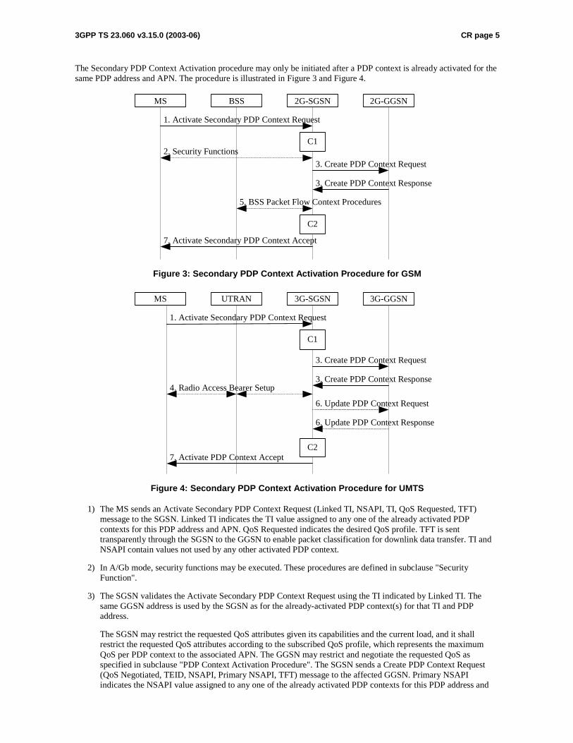
The Secondary PDP Context Activation procedure may only be initiated after a PDP context is already activated for the same PDP address and APN. The procedure is illustrated in Figure 3 and Figure 4.
2G-GGSN
7. Activate Secondary PDP Context Accept
3. Create PDP Context Response
3. Create PDP Context Request
1. Activate Secondary PDP Context Request
2G-SGSNBSS
2. Security Functions
MS
5. BSS Packet Flow Context Procedures
C1
C2
Figure 3: Secondary PDP Context Activation Procedure for GSM
3G-GGSN
7. Activate PDP Context Accept
3. Create PDP Context Response
3. Create PDP Context Request
1. Activate Secondary PDP Context Request
3G-SGSNUTRANMS
4. Radio Access Bearer Setup
C1
C2
6. Update PDP Context Response
6. Update PDP Context Request
Figure 4: Secondary PDP Context Activation Procedure for UMTS
1) The MS sends an Activate Secondary PDP Context Request (Linked TI, NSAPI, TI, QoS Requested, TFT) message to the SGSN. Linked TI indicates the TI value assigned to any one of the already activated PDP contexts for this PDP address and APN. QoS Requested indicates the desired QoS profile. TFT is sent transparently through the SGSN to the GGSN to enable packet classification for downlink data transfer. TI and NSAPI contain values not used by any other activated PDP context.
2) In A/Gb mode, security functions may be executed. These procedures are defined in subclause "Security Function".
3) The SGSN validates the Activate Secondary PDP Context Request using the TI indicated by Linked TI. The same GGSN address is used by the SGSN as for the already-activated PDP context(s) for that TI and PDP address.
The SGSN may restrict the requested QoS attributes given its capabilities and the current load, and it shall restrict the requested QoS attributes according to the subscribed QoS profile, which represents the maximum QoS per PDP context to the associated APN. The GGSN may restrict and negotiate the requested QoS as specified in subclause "PDP Context Activation Procedure". The SGSN sends a Create PDP Context Request (QoS Negotiated, TEID, NSAPI, Primary NSAPI, TFT) message to the affected GGSN. Primary NSAPI indicates the NSAPI value assigned to any one of the already activated PDP contexts for this PDP address and

3GPP TS 23.060 v3.15.0 (2003-06) CR page 6
APN. TFT is included only if received in the Activate Secondary PDP Context Request message. The GGSN uses the same external network as used by the already-activated PDP context(s) for that PDP address, generates a new entry in its PDP context table, and stores the TFT. The new entry allows the GGSN to route PDP PDUs via different GTP tunnels between the SGSN and the external PDP network. The GGSN returns a Create PDP Context Response (TEID, QoS Negotiated, Cause) message to the SGSN.
4) In Iu mode, RAB setup is done by the RAB Assignment procedure.
5) In A/Gb mode, BSS packet flow context procedures may be executed. These procedures are defined in subclause "BSS Context".
6) In Iu mode and in case when the QoS attributes have been downgraded in step 4, the SGSN may inform the GGSN about the downgraded QoS attributes by sending to it an Update PDP Context Request. The GGSN confirms the new QoS attributes by sending an Update PDP Context Response to the SGSN.
7) The SGSN selects Radio Priority and Packet Flow Id based on QoS Negotiated, and returns an Activate Secondary PDP Context Accept (TI, QoS Negotiated, Radio Priority, Packet Flow Id) message to the MS. If the MS indicated in the MS Network Capability it does not support BSS packet flow procedures or if the BSS does not support BSS packet flow procedures, then the SGSN should not include the Packet Flow Id. The SGSN is now able to route PDP PDUs between the GGSN and the MS via different GTP tunnels and possibly different LLC links.
For each additionally activated PDP context a QoS profile and TFT may be requested.
If the secondary PDP context activation procedure fails or if the SGSN returns an Activate Secondary PDP Context Reject (Cause) message, the MS may attempt another activation with a different TFT, depending on the cause.
CAMEL procedure calls shall be performed, see referenced procedures in 3G TS 23.078:
C1) CAMEL_GPRS_PDP_Context_Establishment.
In Figure 3 and in Figure 4, procedures return as result "Continue".
C2) CAMEL_GPRS_PDP_Context_Establishment_Acknowledgement.
In Figure 3 and in Figure 4, procedures return as result "Continue".
************************NEXT CHANGE*************************
9.2.3 Modification Procedures
Modification procedures modify parameters that were negotiated during an activation procedure for one or several PDP contexts. An MS or GGSN, or an SGSN can decide can request the modification procedures. The Modification procedures can possibly be triggered by the HLR as explained in subclause "Insert Subscriber Data Procedure" or by a RAB Release procedure initiated by an RNC. An MS and SGSN can also decide about modofication procedures after an RNC-initiated Iu release.
The following parameters can be modified:
- QoS Negotiated;
- Radio Priority;
- Packet Flow Id;
- PDP Address (in case of the GGSN-initiated modification procedure); and
- TFT (in case of MS-initiated modification procedure).
3GPP TS 23.060 v3.15.0 (2003-06) CR page 7
The SGSN can request the modification of parameters by sending a Modify PDP Context Request message to the MS.
A GGSN can request the modification of parameters by sending an Update PDP Context Request message to the SGSN.
An MS can request the modification of parameters by sending a Modify PDP Context Request message to the SGSN.
An RNC can request an Iu release by sending an Iu Release Request message to the SGSN. After Iu release the MS and SGSN shall modify the PDP contexts according to the rules defined in subclause "RNC-Initiated PDP Context Modification Procedure".
An RNC can request the release of a radio access bearer. After RAB release the MS and the SGSN shall locally modify the corresponding PDP context according to rules defined in the subclause "RAB Release-Initiated Local PDP Context Modification Procedure".
A trace may be activated while a PDP context is active. To enable trace activation in a GGSN, the SGSN shall send an Update PDP Context Request message to the GGSN. If PDP context modification is performed only to activate a trace, the SGSN shall not send a Modify PDP Context Request message to the MS.
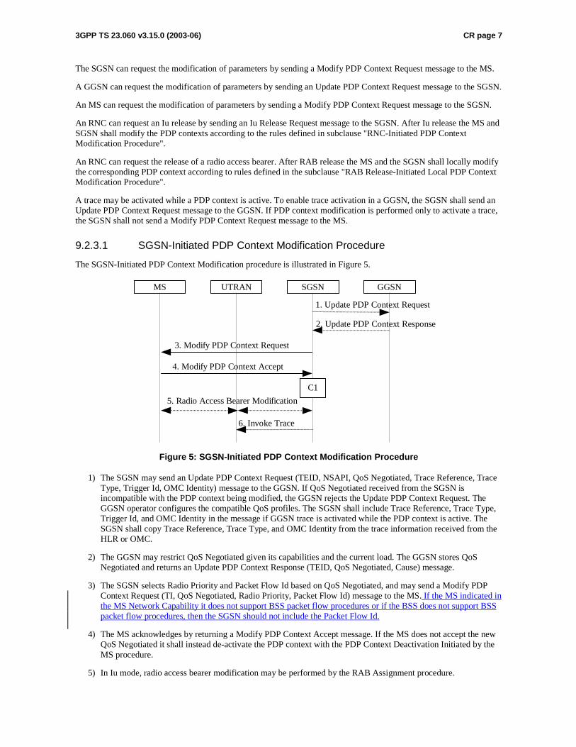
9.2.3.1 SGSN-Initiated PDP Context Modification Procedure
The SGSN-Initiated PDP Context Modification procedure is illustrated in Figure 5.
GGSN
2. Update PDP Context Response
1. Update PDP Context Request
SGSNUTRANMS
3. Modify PDP Context Request
4. Modify PDP Context Accept
5. Radio Access Bearer Modification
C1
6. Invoke Trace
Figure 5: SGSN-Initiated PDP Context Modification Procedure
1) The SGSN may send an Update PDP Context Request (TEID, NSAPI, QoS Negotiated, Trace Reference, Trace Type, Trigger Id, OMC Identity) message to the GGSN. If QoS Negotiated received from the SGSN is incompatible with the PDP context being modified, the GGSN rejects the Update PDP Context Request. The GGSN operator configures the compatible QoS profiles. The SGSN shall include Trace Reference, Trace Type, Trigger Id, and OMC Identity in the message if GGSN trace is activated while the PDP context is active. The SGSN shall copy Trace Reference, Trace Type, and OMC Identity from the trace information received from the HLR or OMC.
2) The GGSN may restrict QoS Negotiated given its capabilities and the current load. The GGSN stores QoS Negotiated and returns an Update PDP Context Response (TEID, QoS Negotiated, Cause) message.
3) The SGSN selects Radio Priority and Packet Flow Id based on QoS Negotiated, and may send a Modify PDP Context Request (TI, QoS Negotiated, Radio Priority, Packet Flow Id) message to the MS. If the MS indicated in the MS Network Capability it does not support BSS packet flow procedures or if the BSS does not support BSS packet flow procedures, then the SGSN should not include the Packet Flow Id.
4) The MS acknowledges by returning a Modify PDP Context Accept message. If the MS does not accept the new QoS Negotiated it shall instead de-activate the PDP context with the PDP Context Deactivation Initiated by the MS procedure.
5) In Iu mode, radio access bearer modification may be performed by the RAB Assignment procedure.
3GPP TS 23.060 v3.15.0 (2003-06) CR page 8
6) If BSS trace is activated while the PDP context is active, the SGSN shall send an Invoke Trace (Trace Reference, Trace Type, Trigger Id, OMC Identity) message to the BSS or UTRAN. Trace Reference, and Trace Type are copied from the trace information received from the HLR or OMC.
CAMEL procedure calls shall be performed, see referenced procedure in 3G TS 23.078:
C1) CAMEL_GPRS_Change_Of_QoS.
The procedure returns as result "Continue".
9.2.3.2 GGSN-Initiated PDP Context Modification Procedure
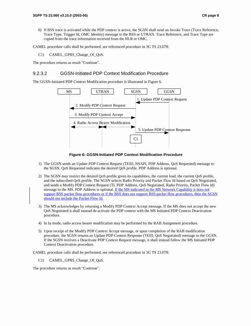
The GGSN-Initiated PDP Context Modification procedure is illustrated in Figure 6.
GGSN
5. Update PDP Context Response
1. Update PDP Context Request
SGSNUTRANMS
2. Modify PDP Context Request
3. Modify PDP Context Accept
4. Radio Access Bearer Modification
C1
Figure 6: GGSN-Initiated PDP Context Modification Procedure
1) The GGSN sends an Update PDP Context Request (TEID, NSAPI, PDP Address, QoS Requested) message to the SGSN. QoS Requested indicates the desired QoS profile. PDP Address is optional.
2) The SGSN may restrict the desired QoS profile given its capabilities, the current load, the current QoS profile, and the subscribed QoS profile. The SGSN selects Radio Priority and Packet Flow Id based on QoS Negotiated, and sends a Modify PDP Context Request (TI, PDP Address, QoS Negotiated, Radio Priority, Packet Flow Id) message to the MS. PDP Address is optional. If the MS indicated in the MS Network Capability it does not support BSS packet flow procedures or if the BSS does not support BSS packet flow procedures, then the SGSN should not include the Packet Flow Id.
3) The MS acknowledges by returning a Modify PDP Context Accept message. If the MS does not accept the new QoS Negotiated it shall instead de-activate the PDP context with the MS Initiated PDP Context Deactivation procedure.
4) In Iu mode, radio access bearer modification may be performed by the RAB Assignment procedure.
5) Upon receipt of the Modify PDP Context Accept message, or upon completion of the RAB modification procedure, the SGSN returns an Update PDP Context Response (TEID, QoS Negotiated) message to the GGSN. If the SGSN receives a Deactivate PDP Context Request message, it shall instead follow the MS Initiated PDP Context Deactivation procedure.
CAMEL procedure calls shall be performed, see referenced procedure in 3G TS 23.078:
C1) CAMEL_GPRS_Change_Of_QoS.
The procedure returns as result "Continue".
3GPP TS 23.060 v3.15.0 (2003-06) CR page 9
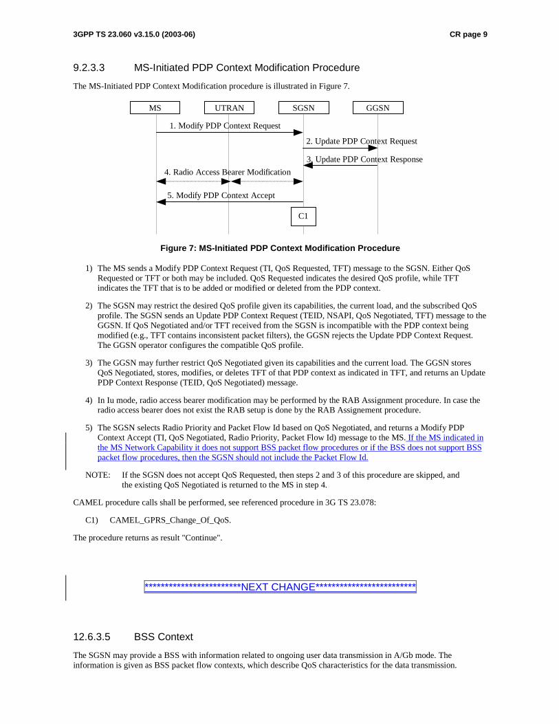
9.2.3.3 MS-Initiated PDP Context Modification Procedure
The MS-Initiated PDP Context Modification procedure is illustrated in Figure 7.
GGSN
3. Update PDP Context Response
2. Update PDP Context Request
SGSNUTRANMS
1. Modify PDP Context Request
5. Modify PDP Context Accept
4. Radio Access Bearer Modification
C1
Figure 7: MS-Initiated PDP Context Modification Procedure
1) The MS sends a Modify PDP Context Request (TI, QoS Requested, TFT) message to the SGSN. Either QoS Requested or TFT or both may be included. QoS Requested indicates the desired QoS profile, while TFT indicates the TFT that is to be added or modified or deleted from the PDP context.
2) The SGSN may restrict the desired QoS profile given its capabilities, the current load, and the subscribed QoS profile. The SGSN sends an Update PDP Context Request (TEID, NSAPI, QoS Negotiated, TFT) message to the GGSN. If QoS Negotiated and/or TFT received from the SGSN is incompatible with the PDP context being modified (e.g., TFT contains inconsistent packet filters), the GGSN rejects the Update PDP Context Request. The GGSN operator configures the compatible QoS profile.
3) The GGSN may further restrict QoS Negotiated given its capabilities and the current load. The GGSN stores QoS Negotiated, stores, modifies, or deletes TFT of that PDP context as indicated in TFT, and returns an Update PDP Context Response (TEID, QoS Negotiated) message.
4) In Iu mode, radio access bearer modification may be performed by the RAB Assignment procedure. In case the radio access bearer does not exist the RAB setup is done by the RAB Assignement procedure.
5) The SGSN selects Radio Priority and Packet Flow Id based on QoS Negotiated, and returns a Modify PDP Context Accept (TI, QoS Negotiated, Radio Priority, Packet Flow Id) message to the MS. If the MS indicated in the MS Network Capability it does not support BSS packet flow procedures or if the BSS does not support BSS packet flow procedures, then the SGSN should not include the Packet Flow Id.
NOTE: If the SGSN does not accept QoS Requested, then steps 2 and 3 of this procedure are skipped, and the existing QoS Negotiated is returned to the MS in step 4.
CAMEL procedure calls shall be performed, see referenced procedure in 3G TS 23.078:
C1) CAMEL_GPRS_Change_Of_QoS.
The procedure returns as result "Continue".
************************NEXT CHANGE*************************
12.6.3.5 BSS Context
The SGSN may provide a BSS with information related to ongoing user data transmission in A/Gb mode. The information is given as BSS packet flow contexts, which describe QoS characteristics for the data transmission.
3GPP TS 23.060 v3.15.0 (2003-06) CR page 10
Network support of BSS packet flow procedures is indicated in the system information as specified in GSM 04.60 [14], the MS support is indicated in MS network capability as specified in 3GPP TS 24.008 [13].
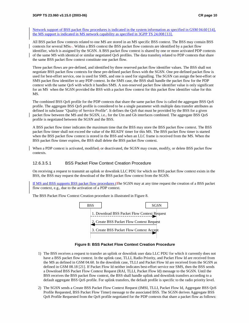
All BSS packet flow contexts related to one MS are stored in an MS specific BSS context. The BSS may contain BSS contexts for several MSs. . Within a BSS context the BSS packet flow contexts are identified by a packet flow identifier, which is assigned by the SGSN. A BSS packet flow context is shared by one or more activated PDP contexts of the same MS with identical or similar negotiated QoS profiles. The data transfers related to PDP contexts that share the same BSS packet flow context constitute one packet flow.
Three packet flows are pre-defined, and identified by three reserved packet flow identifier values. The BSS shall not negotiate BSS packet flow contexts for these pre-defined packet flows with the SGSN. One pre-defined packet flow is used for best-effort service, one is used for SMS, and one is used for signalling. The SGSN can assign the best-effort or SMS packet flow identifier to any PDP context. In the SMS case, the BSS shall handle the packet flow for the PDP context with the same QoS with which it handles SMS. A non-reserved packet flow identifier value is only significant for an MS when the SGSN provided the BSS with a packet flow context for this packet flow identifier value for this MS.
The combined BSS QoS profile for the PDP contexts that share the same packet flow is called the aggregate BSS QoS profile. The aggregate BSS QoS profile is considered to be a single parameter with multiple data transfer attributes as defined in subclause "Quality of Service Profile". It defines the QoS that must be provided by the BSS for a given packet flow between the MS and the SGSN, i.e., for the Um and Gb interfaces combined. The aggregate BSS QoS profile is negotiated between the SGSN and the BSS.
A BSS packet flow timer indicates the maximum time that the BSS may store the BSS packet flow context. The BSS packet flow timer shall not exceed the value of the READY timer for this MS. The BSS packet flow timer is started when the BSS packet flow context is stored in the BSS and when an LLC frame is received from the MS. When the BSS packet flow timer expires, the BSS shall delete the BSS packet flow context.
When a PDP context is activated, modified, or deactivated, the SGSN may create, modify, or delete BSS packet flow contexts.
12.6.3.5.1 BSS Packet Flow Context Creation Procedure
On receiving a request to transmit an uplink or downlink LLC PDU for which no BSS packet flow context exists in the BSS, the BSS may request the download of the BSS packet flow context from the SGSN.
If MS and BSS supports BSS packet flow procedures tThe SGSN may at any time request the creation of a BSS packet flow context, e.g., due to the activation of a PDP context.
The BSS Packet Flow Context Creation procedure is illustrated in Figure 8.
2. Create BSS Packet Flow Context Request
3. Create BSS Packet Flow Context Accept
BSS SGSN
1. Download BSS Packet Flow Context Request
Figure 8: BSS Packet Flow Context Creation Procedure
1) The BSS receives a request to transfer an uplink or downlink user data LLC PDU for which it currently does not have a BSS packet flow context. In the uplink case, TLLI, Radio Priority, and Packet Flow Id are received from the MS as defined in GSM 04.60. In the downlink case, TLLI and Packet Flow Id are received from the SGSN as defined in GSM 08.18 [21]. If Packet Flow Id neither indicates best-effort service nor SMS, then the BSS sends a Download BSS Packet Flow Context Request (RAI, TLLI, Packet Flow Id) message to the SGSN. Until the BSS receives the BSS packet flow context, the BSS shall handle uplink and downlink transfers according to a default aggregate BSS QoS profile. For uplink transfers, the default profile is specific to the radio priority level.
2) The SGSN sends a Create BSS Packet Flow Context Request (IMSI, TLLI, Packet Flow Id, Aggregate BSS QoS Profile Requested, BSS Packet Flow Timer) message to the associated BSS. The SGSN derives Aggregate BSS QoS Profile Requested from the QoS profile negotiated for the PDP contexts that share a packet flow as follows:
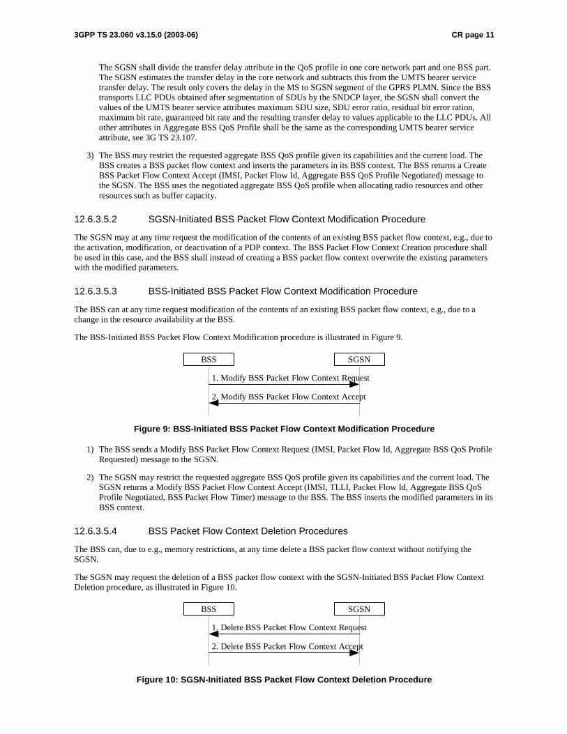
3GPP TS 23.060 v3.15.0 (2003-06) CR page 11
The SGSN shall divide the transfer delay attribute in the QoS profile in one core network part and one BSS part. The SGSN estimates the transfer delay in the core network and subtracts this from the UMTS bearer service transfer delay. The result only covers the delay in the MS to SGSN segment of the GPRS PLMN. Since the BSS transports LLC PDUs obtained after segmentation of SDUs by the SNDCP layer, the SGSN shall convert the values of the UMTS bearer service attributes maximum SDU size, SDU error ratio, residual bit error ration, maximum bit rate, guaranteed bit rate and the resulting transfer delay to values applicable to the LLC PDUs. All other attributes in Aggregate BSS QoS Profile shall be the same as the corresponding UMTS bearer service attribute, see 3G TS 23.107.
3) The BSS may restrict the requested aggregate BSS QoS profile given its capabilities and the current load. The BSS creates a BSS packet flow context and inserts the parameters in its BSS context. The BSS returns a Create BSS Packet Flow Context Accept (IMSI, Packet Flow Id, Aggregate BSS QoS Profile Negotiated) message to the SGSN. The BSS uses the negotiated aggregate BSS QoS profile when allocating radio resources and other resources such as buffer capacity.
12.6.3.5.2 SGSN-Initiated BSS Packet Flow Context Modification Procedure
The SGSN may at any time request the modification of the contents of an existing BSS packet flow context, e.g., due to the activation, modification, or deactivation of a PDP context. The BSS Packet Flow Context Creation procedure shall be used in this case, and the BSS shall instead of creating a BSS packet flow context overwrite the existing parameters with the modified parameters.
12.6.3.5.3 BSS-Initiated BSS Packet Flow Context Modification Procedure
The BSS can at any time request modification of the contents of an existing BSS packet flow context, e.g., due to a change in the resource availability at the BSS.
The BSS-Initiated BSS Packet Flow Context Modification procedure is illustrated in Figure 9.
1. Modify BSS Packet Flow Context Request
2. Modify BSS Packet Flow Context Accept
BSS SGSN
Figure 9: BSS-Initiated BSS Packet Flow Context Modification Procedure
1) The BSS sends a Modify BSS Packet Flow Context Request (IMSI, Packet Flow Id, Aggregate BSS QoS Profile Requested) message to the SGSN.
2) The SGSN may restrict the requested aggregate BSS QoS profile given its capabilities and the current load. The SGSN returns a Modify BSS Packet Flow Context Accept (IMSI, TLLI, Packet Flow Id, Aggregate BSS QoS Profile Negotiated, BSS Packet Flow Timer) message to the BSS. The BSS inserts the modified parameters in its BSS context.
12.6.3.5.4 BSS Packet Flow Context Deletion Procedures
The BSS can, due to e.g., memory restrictions, at any time delete a BSS packet flow context without notifying the SGSN.
The SGSN may request the deletion of a BSS packet flow context with the SGSN-Initiated BSS Packet Flow Context Deletion procedure, as illustrated in Figure 10.
1. Delete BSS Packet Flow Context Request
2. Delete BSS Packet Flow Context Accept
BSS SGSN
Figure 10: SGSN-Initiated BSS Packet Flow Context Deletion Procedure

3GPP TS 23.060 v3.15.0 (2003-06) CR page 12
1) The SGSN sends a Delete BSS Packet Flow Context Request (IMSI, Packet Flow Id) message to the BSS. The BSS deletes the corresponding BSS packet flow context from its BSS context.
2) The BSS returns a Delete BSS Packet Flow Context Accept (TLLI, Packet Flow Id) message to the SGSN.
3GPP TSG-SA2 Meeting #36 Tdoc S2-034251 New York, USA, 24-28 November 2003 revision of S2-034159
CR-Form-v7
CHANGE REQUEST
! 23.060 CR 466 ! rev 2 ! Current version: 4.8.0 !
For HELP on using this form, see bottom of this page or look at the pop-up text over the ! symbols.
Proposed change affects: UICC apps! ME X Radio Access Network X Core Network X
Title: ! PFI correction Source: ! Nokia Work item code: ! TEI Date: ! 26/11/2003 Category: ! A Release: ! Rel-4 Use one of the following categories:
F (correction) A (corresponds to a correction in an earlier release) B (addition of feature), C (functional modification of feature) D (editorial modification)
Detailed explanations of the above categories can be found in 3GPP TR 21.900.
Use one of the following releases: 2 (GSM Phase 2) R96 (Release 1996) R97 (Release 1997) R98 (Release 1998) R99 (Release 1999) Rel-4 (Release 4) Rel-5 (Release 5) Rel-6 (Release 6)
Reason for change: ! In the specification is not told clearly whether SGSN can send Packet Flow
Indentifier (PFI), during PDP context activation or modification, to an MS not supporting BSS packet flow procedures.
Summary of change: ! It is clarified that the SGSN should not send Packet Flow Indentifier (PFI) to an
MS that indicated in the MS Network Capability IE it does not support BSS packet flow procedures.
Consequences if ! not approved:
There can be problems with MS which don’t support BSS packet flow procedures but network anyway sends them PFI. Also the MS’s information sent to network, which tells whether MS supports or not BSS packet flow procedures would be totally useless if network could still try to use them.
Clauses affected: ! 2; 9.2.2.1; 9.2.2.1.1; 9.2.3; 12.6.3.5; 12.6.3.5.1 Y N Other specs ! X Other core specifications ! Possible 3GPP TS 24.008 affected: X Test specifications X O&M Specifications Other comments: ! It is assumed that the 23.060 CR is approved first and no formal linkage between
the 24.008 CRs is needed.
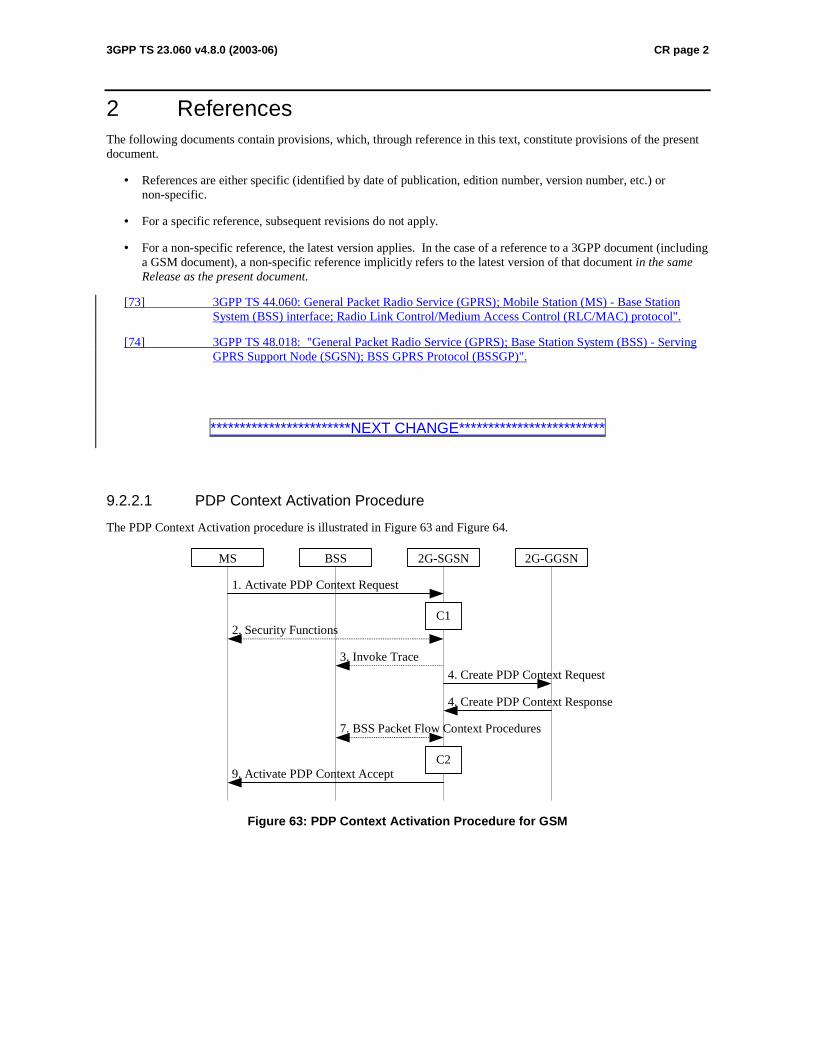
3GPP TS 23.060 v4.8.0 (2003-06) CR page 2
2 References The following documents contain provisions, which, through reference in this text, constitute provisions of the present document.
• References are either specific (identified by date of publication, edition number, version number, etc.) or non-specific.
• For a specific reference, subsequent revisions do not apply.
• For a non-specific reference, the latest version applies. In the case of a reference to a 3GPP document (including a GSM document), a non-specific reference implicitly refers to the latest version of that document in the same Release as the present document.
[73] 3GPP TS 44.060: General Packet Radio Service (GPRS); Mobile Station (MS) - Base Station System (BSS) interface; Radio Link Control/Medium Access Control (RLC/MAC) protocol".
[74] 3GPP TS 48.018: "General Packet Radio Service (GPRS); Base Station System (BSS) - Serving GPRS Support Node (SGSN); BSS GPRS Protocol (BSSGP)".
************************NEXT CHANGE*************************
9.2.2.1 PDP Context Activation Procedure
The PDP Context Activation procedure is illustrated in Figure 63 and Figure 64.
2G-GGSN
9. Activate PDP Context Accept
4. Create PDP Context Response
4. Create PDP Context Request
1. Activate PDP Context Request
2G-SGSNBSS
2. Security Functions
MS
7. BSS Packet Flow Context Procedures
C1
C2
3. Invoke Trace
Figure 63: PDP Context Activation Procedure for GSM

3GPP TS 23.060 v4.8.0 (2003-06) CR page 3
3G-GGSN
9. Activate PDP Context Accept
4. Create PDP Context Response
4. Create PDP Context Request
1. Activate PDP Context Request
3G-SGSNUTRANMS
5. Radio Access Bearer Setup
C1
C2
6. Invoke Trace
8. Update PDP Context Response
8. Update PDP Context Request
Figure 64: PDP Context Activation Procedure for UMTS
1) The MS sends an Activate PDP Context Request (NSAPI, TI, PDP Type, PDP Address, Access Point Name, QoS Requested, PDP Configuration Options) message to the SGSN. The MS shall use PDP Address to indicate whether it requires the use of a static PDP address or whether it requires the use of a dynamic PDP address. The MS shall leave PDP Address empty to request a dynamic PDP address. The MS may use Access Point Name to select a reference point to a certain external network and/or to select a service. Access Point Name is a logical name referring to the external packet data network and/or to a service that the subscriber wishes to connect to. QoS Requested indicates the desired QoS profile. PDP Configuration Options may be used to request optional PDP parameters from the GGSN (see GSM 09.60). PDP Configuration Options is sent transparently through the SGSN.
2) In A/Gb mode, security functions may be executed. These procedures are defined in clause "Security Function".
3) In A/Gb mode and if BSS trace is activated, the SGSN shall send an Invoke Trace (Trace Reference, Trace Type, Trigger Id, OMC Identity) message to the BSS. Trace Reference, and Trace Type are copied from the trace information received from the HLR or OMC.
4) The SGSN validates the Activate PDP Context Request using PDP Type (optional), PDP Address (optional), and Access Point Name (optional) provided by the MS and the PDP context subscription records. The validation criteria, the APN selection criteria, and the mapping from APN to a GGSN are described in annex A.
If no GGSN address can be derived or if the SGSN has determined that the Activate PDP Context Request is not valid according to the rules described in annex A, the SGSN rejects the PDP context activation request.
If a GGSN address can be derived, the SGSN creates a TEID for the requested PDP context. If the MS requests a dynamic address, the SGSN lets a GGSN allocate the dynamic address. The SGSN may restrict the requested QoS attributes given its capabilities and the current load, and it shall restrict the requested QoS attributes according to the subscribed QoS profile.
The SGSN sends a Create PDP Context Request (PDP Type, PDP Address, Access Point Name, QoS Negotiated, TEID, NSAPI, MSISDN, Selection Mode, Charging Characteristics, Trace Reference, Trace Type, Trigger Id, OMC Identity, PDP Configuration Options) message to the affected GGSN. Access Point Name shall be the APN Network Identifier of the APN selected according to the procedure described in Annex A. PDP Address shall be empty if a dynamic address is requested. The GGSN may use Access Point Name to find an external network and optionally to activate a service for this APN. Selection Mode indicates whether a subscribed APN was selected, or whether a non-subscribed APN sent by an MS or a non-subscribed APN chosen by the SGSN was selected. Selection Mode is set according to Annex A. The GGSN may use Selection Mode when deciding whether to accept or reject the PDP context activation. For example, if an APN requires subscription, the GGSN is configured to accept only the PDP context activation that requests a subscribed APN as indicated by the SGSN with Selection Mode. Charging Characteristics indicates which kind of charging the

3GPP TS 23.060 v4.8.0 (2003-06) CR page 4
PDP context is liable for. The charging characteristics on the GPRS subscription and individually subscribed APNs as well as the way the SGSN handles Charging Characteritics and chooses to send them or not to the GGSN is defined in 3GPP TS 32.215 [70]. The SGSN shall include Trace Reference, Trace Type, Trigger Id, and OMC Identity if GGSN trace is activated. The SGSN shall copy Trace Reference, Trace Type, and OMC Identity from the trace information received from the HLR or OMC.
The GGSN creates a new entry in its PDP context table and generates a Charging Id. The new entry allows the GGSN to route PDP PDUs between the SGSN and the external PDP network, and to start charging. The way the GGSN handles Charging Characteritics that it may have received from the SGSN is defined in 3GPP TS 32.215 [70]. The GGSN then returns a Create PDP Context Response (TEID, PDP Address, PDP Configuration Options, QoS Negotiated, Charging Id, Cause) message to the SGSN. PDP Address is included if the GGSN allocated a PDP address. If the GGSN has been configured by the operator to use External PDN Address Allocation for the requested APN, PDP Address shall be set to 0.0.0.0, indicating that the PDP address shall be negotiated by the MS with the external PDN after completion of the PDP Context Activation procedure. The GGSN shall relay, modify and monitor these negotiations as long as the PDP context is in ACTIVE state, and use the GGSN-Initiated PDP Context Modification procedure to transfer the currently used PDP address to the SGSN and the MS. PDP Configuration Options contain optional PDP parameters that the GGSN may transfer to the MS. These optional PDP parameters may be requested by the MS in the Activate PDP Context Request message, or may be sent unsolicited by the GGSN. PDP Configuration Options is sent transparently through the SGSN. The Create PDP Context messages are sent over the backbone network.
If QoS Negotiated received from the SGSN is incompatible with the PDP context being activated, the GGSN rejects the Create PDP Context Request message. The GGSN operator configures the compatible QoS profiles.
5) In Iu mode, RAB setup is done by the RAB Assignment procedure, see subclause "RAB Assignment Procedure".
6) In Iu mode and if BSS trace is activated, the SGSN shall send an Invoke Trace (Trace Reference, Trace Type, Trigger Id, OMC Identity) message to the UTRAN. Trace Reference, and Trace Type are copied from the trace information received from the HLR or OMC.
7) In A/Gb mode, BSS packet flow context procedures may be executed. These procedures are defined in clause "BSS Context".
8) In Iu mode and in case the QoS attributes have been downgraded in step 5, the SGSN may inform the GGSN about the downgraded QoS attributes by sending an Update PDP Context Request to the affected GGSN. The GGSN confirms the new QoS attributes by sending an Update PDP Context Response to the SGSN.
9) The SGSN inserts the NSAPI along with the GGSN address in its PDP context. If the MS has requested a dynamic address, the PDP address received from the GGSN is inserted in the PDP context. The SGSN selects Radio Priority and Packet Flow Id based on QoS Negotiated, and returns an Activate PDP Context Accept (PDP Type, PDP Address, TI, QoS Negotiated, Radio Priority, Packet Flow Id, PDP Configuration Options) message to the MS. If the MS indicated in the MS Network Capability it does not support BSS packet flow procedures or if the BSS does not support BSS packet flow procedures, then the SGSN should not include the Packet Flow Id. The SGSN is now able to route PDP PDUs between the GGSN and the MS, and to start charging.
For each PDP Address a different quality of service (QoS) profile may be requested. For example, some PDP addresses may be associated with E-mail that can tolerate lengthy response times. Other applications cannot tolerate delay and demand a very high level of throughput, interactive applications being one example. These different requirements are reflected in the QoS profile. The QoS profile is defined in clause "Quality of Service Profile". If a QoS requirement is beyond the capabilities of a PLMN, the PLMN negotiates the QoS profile as close as possible to the requested QoS profile. The MS either accepts the negotiated QoS profile, or deactivates the PDP context.
After an SGSN has successfully updated the GGSN, the PDP contexts associated with an MS is distributed as shown in clause "Information Storage".
If the PDP Context Activation Procedure fails or if the SGSN returns an Activate PDP Context Reject (Cause, PDP Configuration Options) message, the MS may attempt another activation to the same APN up to a maximum number of attempts.
The CAMEL procedure calls shall be performed, see referenced procedures in 3GPP TS 23.078:
C1) CAMEL_GPRS_PDP_Context_Establishment.
In Figure 63 and Figure 64, procedures return as result "Continue".
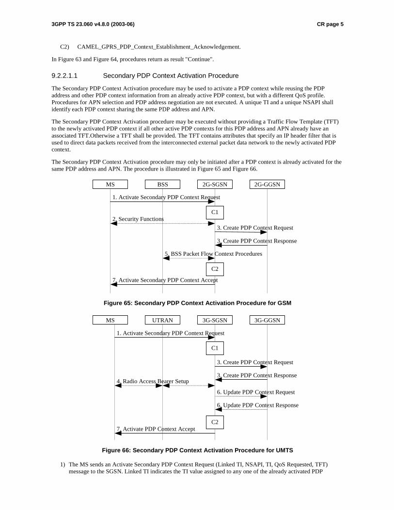
3GPP TS 23.060 v4.8.0 (2003-06) CR page 5
C2) CAMEL_GPRS_PDP_Context_Establishment_Acknowledgement.
In Figure 63 and Figure 64, procedures return as result "Continue".
9.2.2.1.1 Secondary PDP Context Activation Procedure
The Secondary PDP Context Activation procedure may be used to activate a PDP context while reusing the PDP address and other PDP context information from an already active PDP context, but with a different QoS profile. Procedures for APN selection and PDP address negotiation are not executed. A unique TI and a unique NSAPI shall identify each PDP context sharing the same PDP address and APN.
The Secondary PDP Context Activation procedure may be executed without providing a Traffic Flow Template (TFT) to the newly activated PDP context if all other active PDP contexts for this PDP address and APN already have an associated TFT.Otherwise a TFT shall be provided. The TFT contains attributes that specify an IP header filter that is used to direct data packets received from the interconnected external packet data network to the newly activated PDP context.
The Secondary PDP Context Activation procedure may only be initiated after a PDP context is already activated for the same PDP address and APN. The procedure is illustrated in Figure 65 and Figure 66.
2G-GGSN
7. Activate Secondary PDP Context Accept
3. Create PDP Context Response
3. Create PDP Context Request
1. Activate Secondary PDP Context Request
2G-SGSNBSS
2. Security Functions
MS
5. BSS Packet Flow Context Procedures
C1
C2
Figure 65: Secondary PDP Context Activation Procedure for GSM
3G-GGSN
7. Activate PDP Context Accept
3. Create PDP Context Response
3. Create PDP Context Request
1. Activate Secondary PDP Context Request
3G-SGSNUTRANMS
4. Radio Access Bearer Setup
C1
C2
6. Update PDP Context Response
6. Update PDP Context Request
Figure 66: Secondary PDP Context Activation Procedure for UMTS
1) The MS sends an Activate Secondary PDP Context Request (Linked TI, NSAPI, TI, QoS Requested, TFT) message to the SGSN. Linked TI indicates the TI value assigned to any one of the already activated PDP
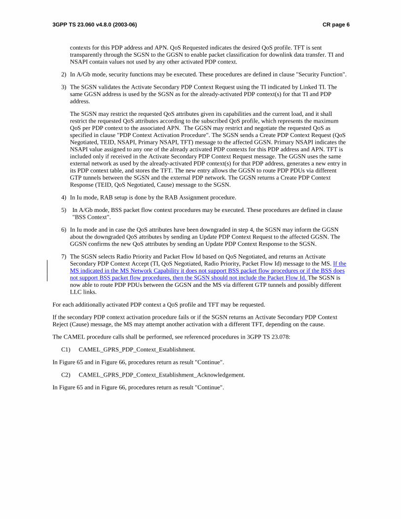
3GPP TS 23.060 v4.8.0 (2003-06) CR page 6
contexts for this PDP address and APN. QoS Requested indicates the desired QoS profile. TFT is sent transparently through the SGSN to the GGSN to enable packet classification for downlink data transfer. TI and NSAPI contain values not used by any other activated PDP context.
2) In A/Gb mode, security functions may be executed. These procedures are defined in clause "Security Function".
3) The SGSN validates the Activate Secondary PDP Context Request using the TI indicated by Linked TI. The same GGSN address is used by the SGSN as for the already-activated PDP context(s) for that TI and PDP address.
The SGSN may restrict the requested QoS attributes given its capabilities and the current load, and it shall restrict the requested QoS attributes according to the subscribed QoS profile, which represents the maximum QoS per PDP context to the associated APN. The GGSN may restrict and negotiate the requested QoS as specified in clause "PDP Context Activation Procedure". The SGSN sends a Create PDP Context Request (QoS Negotiated, TEID, NSAPI, Primary NSAPI, TFT) message to the affected GGSN. Primary NSAPI indicates the NSAPI value assigned to any one of the already activated PDP contexts for this PDP address and APN. TFT is included only if received in the Activate Secondary PDP Context Request message. The GGSN uses the same external network as used by the already-activated PDP context(s) for that PDP address, generates a new entry in its PDP context table, and stores the TFT. The new entry allows the GGSN to route PDP PDUs via different GTP tunnels between the SGSN and the external PDP network. The GGSN returns a Create PDP Context Response (TEID, QoS Negotiated, Cause) message to the SGSN.
4) In Iu mode, RAB setup is done by the RAB Assignment procedure.
5) In A/Gb mode, BSS packet flow context procedures may be executed. These procedures are defined in clause "BSS Context".
6) In Iu mode and in case the QoS attributes have been downgraded in step 4, the SGSN may inform the GGSN about the downgraded QoS attributes by sending an Update PDP Context Request to the affected GGSN. The GGSN confirms the new QoS attributes by sending an Update PDP Context Response to the SGSN.
7) The SGSN selects Radio Priority and Packet Flow Id based on QoS Negotiated, and returns an Activate Secondary PDP Context Accept (TI, QoS Negotiated, Radio Priority, Packet Flow Id) message to the MS. If the MS indicated in the MS Network Capability it does not support BSS packet flow procedures or if the BSS does not support BSS packet flow procedures, then the SGSN should not include the Packet Flow Id. The SGSN is now able to route PDP PDUs between the GGSN and the MS via different GTP tunnels and possibly different LLC links.
For each additionally activated PDP context a QoS profile and TFT may be requested.
If the secondary PDP context activation procedure fails or if the SGSN returns an Activate Secondary PDP Context Reject (Cause) message, the MS may attempt another activation with a different TFT, depending on the cause.
The CAMEL procedure calls shall be performed, see referenced procedures in 3GPP TS 23.078:
C1) CAMEL_GPRS_PDP_Context_Establishment.
In Figure 65 and in Figure 66, procedures return as result "Continue".
C2) CAMEL_GPRS_PDP_Context_Establishment_Acknowledgement.
In Figure 65 and in Figure 66, procedures return as result "Continue".

3GPP TS 23.060 v4.8.0 (2003-06) CR page 7
************************NEXT CHANGE*************************
9.2.3 Modification Procedures
Modification procedures modify parameters that were negotiated during an activation procedure for one or several PDP contexts. An MS, a GGSN, an SGSN, or an RNC can request a modification procedure. The Modification procedures may possibly be triggered by the HLR as explained in subclause "Insert Subscriber Data Procedure" or by an RNC in a RAB Release or an RNC-initiated RAB Modification procedure. An MS and SGSN can also decide about modification procedures after an RNC-initiated Iu release.
The following parameters can be modified:
- QoS Negotiated;
- Radio Priority;
- Packet Flow Id;
- PDP Address (in case of the GGSN-initiated modification procedure); and
- TFT (in case of MS-initiated modification procedure).
The SGSN can request the modification of parameters by sending a Modify PDP Context Request message to the MS.
A GGSN can request the modification of parameters by sending an Update PDP Context Request message to the SGSN.
An MS can request the modification of parameters by sending a Modify PDP Context Request message to the SGSN.
An RNC can request an Iu release by sending an Iu Release Request message to the SGSN. After Iu release the MS and SGSN shall modify the PDP contexts according to the rules defined in clause "RNC-Initiated PDP Context Modification Procedure".
An RNC can request the release of a radio access bearer. After RAB release the MS and the SGSN shall locally modify the corresponding PDP context according to rules defined in the clause "RAB Release-Initiated Local PDP Context Modification Procedure".
A trace may be activated while a PDP context is active. To enable trace activation in a GGSN, the SGSN shall send an Update PDP Context Request message to the GGSN. If PDP context modification is performed only to activate a trace, the SGSN shall not send a Modify PDP Context Request message to the MS.
An RNC may request the modification of some negotiated RAB related QoS parameters by sending a RAB Modify Request.

3GPP TS 23.060 v4.8.0 (2003-06) CR page 8
9.2.3.1 SGSN-Initiated PDP Context Modification Procedure
The SGSN-Initiated PDP Context Modification procedure is illustrated in Figure 70.
GGSN
2. Update PDP Context Response
1. Update PDP Context Request
SGSNUTRANMS
3. Modify PDP Context Request
4. Modify PDP Context Accept
5. Radio Access Bearer Modification
C1
6. Invoke Trace
Figure 70: SGSN-Initiated PDP Context Modification Procedure
1) The SGSN may send an Update PDP Context Request (TEID, NSAPI, QoS Negotiated, Trace Reference, Trace Type, Trigger Id, OMC Identity) message to the GGSN. If QoS Negotiated received from the SGSN is incompatible with the PDP context being modified, the GGSN rejects the Update PDP Context Request. The GGSN operator configures the compatible QoS profiles. The SGSN shall include Trace Reference, Trace Type, Trigger Id, and OMC Identity in the message if GGSN trace is activated while the PDP context is active. The SGSN shall copy Trace Reference, Trace Type, and OMC Identity from the trace information received from the HLR or OMC.
2) The GGSN may restrict QoS Negotiated given its capabilities and the current load. The GGSN stores QoS Negotiated and returns an Update PDP Context Response (TEID, QoS Negotiated, Cause) message.
3) The SGSN selects Radio Priority and Packet Flow Id based on QoS Negotiated, and may send a Modify PDP Context Request (TI, QoS Negotiated, Radio Priority, Packet Flow Id) message to the MS. If the MS indicated in the MS Network Capability it does not support BSS packet flow procedures or if the BSS does not support BSS packet flow procedures, then the SGSN should not include the Packet Flow Id.
4) The MS acknowledges by returning a Modify PDP Context Accept message. If the MS does not accept the new QoS Negotiated it shall instead de-activate the PDP context with the PDP Context Deactivation Initiated by the MS procedure.
5) In Iu mode, radio access bearer modification may be performed by the RAB Assignment procedure.
6) If BSS trace is activated while the PDP context is active, the SGSN shall send an Invoke Trace (Trace Reference, Trace Type, Trigger Id, OMC Identity) message to the BSS or UTRAN. Trace Reference, and Trace Type are copied from the trace information received from the HLR or OMC.
The CAMEL procedure calls shall be performed, see referenced procedure in 3GPP TS 23.078:
C1) CAMEL_GPRS_Change_Of_QoS.
The procedure returns as result "Continue".
9.2.3.2 GGSN-Initiated PDP Context Modification Procedure
The GGSN-Initiated PDP Context Modification procedure is illustrated in Figure 71.
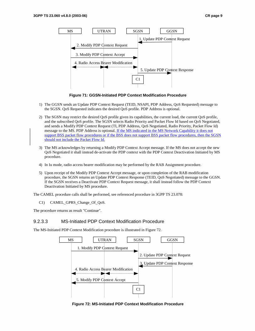
3GPP TS 23.060 v4.8.0 (2003-06) CR page 9
GGSN
5. Update PDP Context Response
1. Update PDP Context Request
SGSNUTRANMS
2. Modify PDP Context Request
3. Modify PDP Context Accept
4. Radio Access Bearer Modification
C1
Figure 71: GGSN-Initiated PDP Context Modification Procedure
1) The GGSN sends an Update PDP Context Request (TEID, NSAPI, PDP Address, QoS Requested) message to the SGSN. QoS Requested indicates the desired QoS profile. PDP Address is optional.
2) The SGSN may restrict the desired QoS profile given its capabilities, the current load, the current QoS profile, and the subscribed QoS profile. The SGSN selects Radio Priority and Packet Flow Id based on QoS Negotiated, and sends a Modify PDP Context Request (TI, PDP Address, QoS Negotiated, Radio Priority, Packet Flow Id) message to the MS. PDP Address is optional. If the MS indicated in the MS Network Capability it does not support BSS packet flow procedures or if the BSS does not support BSS packet flow procedures, then the SGSN should not include the Packet Flow Id.
3) The MS acknowledges by returning a Modify PDP Context Accept message. If the MS does not accept the new QoS Negotiated it shall instead de-activate the PDP context with the PDP Context Deactivation Initiated by MS procedure.
4) In Iu mode, radio access bearer modification may be performed by the RAB Assignment procedure.
5) Upon receipt of the Modify PDP Context Accept message, or upon completion of the RAB modification procedure, the SGSN returns an Update PDP Context Response (TEID, QoS Negotiated) message to the GGSN. If the SGSN receives a Deactivate PDP Context Request message, it shall instead follow the PDP Context Deactivation Initiated by MS procedure.
The CAMEL procedure calls shall be performed, see referenced procedure in 3GPP TS 23.078:
C1) CAMEL_GPRS_Change_Of_QoS.
The procedure returns as result "Continue".
9.2.3.3 MS-Initiated PDP Context Modification Procedure
The MS-Initiated PDP Context Modification procedure is illustrated in Figure 72.
GGSN
3. Update PDP Context Response
2. Update PDP Context Request
SGSNUTRANMS
1. Modify PDP Context Request
5. Modify PDP Context Accept
4. Radio Access Bearer Modification
C1
Figure 72: MS-Initiated PDP Context Modification Procedure
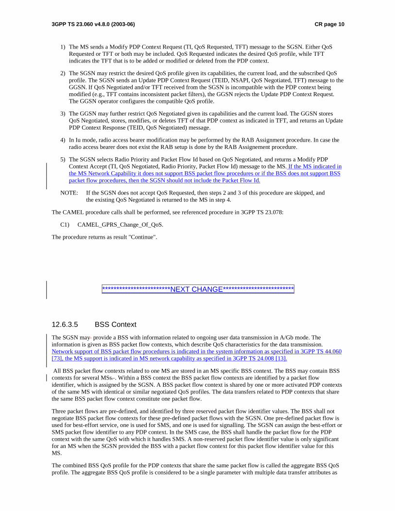
3GPP TS 23.060 v4.8.0 (2003-06) CR page 10
1) The MS sends a Modify PDP Context Request (TI, QoS Requested, TFT) message to the SGSN. Either QoS Requested or TFT or both may be included. QoS Requested indicates the desired QoS profile, while TFT indicates the TFT that is to be added or modified or deleted from the PDP context.
2) The SGSN may restrict the desired QoS profile given its capabilities, the current load, and the subscribed QoS profile. The SGSN sends an Update PDP Context Request (TEID, NSAPI, QoS Negotiated, TFT) message to the GGSN. If QoS Negotiated and/or TFT received from the SGSN is incompatible with the PDP context being modified (e.g., TFT contains inconsistent packet filters), the GGSN rejects the Update PDP Context Request. The GGSN operator configures the compatible QoS profile.
3) The GGSN may further restrict QoS Negotiated given its capabilities and the current load. The GGSN stores QoS Negotiated, stores, modifies, or deletes TFT of that PDP context as indicated in TFT, and returns an Update PDP Context Response (TEID, QoS Negotiated) message.
4) In Iu mode, radio access bearer modification may be performed by the RAB Assignment procedure. In case the radio access bearer does not exist the RAB setup is done by the RAB Assignement procedure.
5) The SGSN selects Radio Priority and Packet Flow Id based on QoS Negotiated, and returns a Modify PDP Context Accept (TI, QoS Negotiated, Radio Priority, Packet Flow Id) message to the MS. If the MS indicated in the MS Network Capability it does not support BSS packet flow procedures or if the BSS does not support BSS packet flow procedures, then the SGSN should not include the Packet Flow Id.
NOTE: If the SGSN does not accept QoS Requested, then steps 2 and 3 of this procedure are skipped, and the existing QoS Negotiated is returned to the MS in step 4.
The CAMEL procedure calls shall be performed, see referenced procedure in 3GPP TS 23.078:
C1) CAMEL_GPRS_Change_Of_QoS.
The procedure returns as result "Continue".
************************NEXT CHANGE*************************
12.6.3.5 BSS Context
The SGSN may provide a BSS with information related to ongoing user data transmission in A/Gb mode. The information is given as BSS packet flow contexts, which describe QoS characteristics for the data transmission. Network support of BSS packet flow procedures is indicated in the system information as specified in 3GPP TS 44.060 [73], the MS support is indicated in MS network capability as specified in 3GPP TS 24.008 [13].
All BSS packet flow contexts related to one MS are stored in an MS specific BSS context. The BSS may contain BSS contexts for several MSs. . Within a BSS context the BSS packet flow contexts are identified by a packet flow identifier, which is assigned by the SGSN. A BSS packet flow context is shared by one or more activated PDP contexts of the same MS with identical or similar negotiated QoS profiles. The data transfers related to PDP contexts that share the same BSS packet flow context constitute one packet flow.
Three packet flows are pre-defined, and identified by three reserved packet flow identifier values. The BSS shall not negotiate BSS packet flow contexts for these pre-defined packet flows with the SGSN. One pre-defined packet flow is used for best-effort service, one is used for SMS, and one is used for signalling. The SGSN can assign the best-effort or SMS packet flow identifier to any PDP context. In the SMS case, the BSS shall handle the packet flow for the PDP context with the same QoS with which it handles SMS. A non-reserved packet flow identifier value is only significant for an MS when the SGSN provided the BSS with a packet flow context for this packet flow identifier value for this MS.
The combined BSS QoS profile for the PDP contexts that share the same packet flow is called the aggregate BSS QoS profile. The aggregate BSS QoS profile is considered to be a single parameter with multiple data transfer attributes as
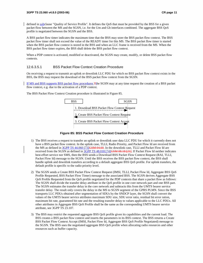
3GPP TS 23.060 v4.8.0 (2003-06) CR page 11
defined in subclause "Quality of Service Profile". It defines the QoS that must be provided by the BSS for a given packet flow between the MS and the SGSN, i.e. for the Um and Gb interfaces combined. The aggregate BSS QoS profile is negotiated between the SGSN and the BSS.
A BSS packet flow timer indicates the maximum time that the BSS may store the BSS packet flow context. The BSS packet flow timer shall not exceed the value of the READY timer for this MS. The BSS packet flow timer is started when the BSS packet flow context is stored in the BSS and when an LLC frame is received from the MS. When the BSS packet flow timer expires, the BSS shall delete the BSS packet flow context.
When a PDP context is activated, modified or deactivated, the SGSN may create, modify, or delete BSS packet flow contexts.
12.6.3.5.1 BSS Packet Flow Context Creation Procedure
On receiving a request to transmit an uplink or downlink LLC PDU for which no BSS packet flow context exists in the BSS, the BSS may request the download of the BSS packet flow context from the SGSN.
If MS and BSS supports BSS packet flow procedures Tthe SGSN may at any time request the creation of a BSS packet flow context, e.g. due to the activation of a PDP context.
The BSS Packet Flow Context Creation procedure is illustrated in Figure 85.
2. Create BSS Packet Flow Context Request
3. Create BSS Packet Flow Context Accept
BSS SGSN
1. Download BSS Packet Flow Context Request
Figure 85: BSS Packet Flow Context Creation Procedure
1) The BSS receives a request to transfer an uplink or downlink user data LLC PDU for which it currently does not have a BSS packet flow context. In the uplink case, TLLI, Radio Priority, and Packet Flow Id are received from the MS as defined in 3GPP TS 44.060 [73]GSM 04.60. In the downlink case, TLLI and Packet Flow Id are received from the SGSN as defined in 3GPP TS 48.018 [74]GSM 08.18 [21]. If Packet Flow Id neither indicates best-effort service nor SMS, then the BSS sends a Download BSS Packet Flow Context Request (RAI, TLLI, Packet Flow Id) message to the SGSN. Until the BSS receives the BSS packet flow context, the BSS shall handle uplink and downlink transfers according to a default aggregate BSS QoS profile. For uplink transfers, the default profile is specific to the radio priority level.
2) The SGSN sends a Create BSS Packet Flow Context Request (IMSI, TLLI, Packet Flow Id, Aggregate BSS QoS Profile Requested, BSS Packet Flow Timer) message to the associated BSS. The SGSN derives Aggregate BSS QoS Profile Requested from the QoS profile negotiated for the PDP contexts that share a packet flow as follows: The SGSN shall divide the transfer delay attribute in the QoS profile in one core network part and one BSS part. The SGSN estimates the transfer delay in the core network and subtracts this from the UMTS bearer service transfer delay. The result only covers the delay in the MS to SGSN segment of the GPRS PLMN. Since the BSS transports LLC PDUs obtained after segmentation of SDUs by the SNDCP layer, the SGSN shall convert the values of the UMTS bearer service attributes maximum SDU size, SDU error ratio, residual bit error ration, maximum bit rate, guaranteed bit rate and the resulting transfer delay to values applicable to the LLC PDUs. All other attributes in Aggregate BSS QoS Profile shall be the same as the corresponding UMTS bearer service attribute, see 3GPP TS 23.107.
3) The BSS may restrict the requested aggregate BSS QoS profile given its capabilities and the current load. The BSS creates a BSS packet flow context and inserts the parameters in its BSS context. The BSS returns a Create BSS Packet Flow Context Accept (IMSI, Packet Flow Id, Aggregate BSS QoS Profile Negotiated) message to the SGSN. The BSS uses the negotiated aggregate BSS QoS profile when allocating radio resources and other resources such as buffer capacity.
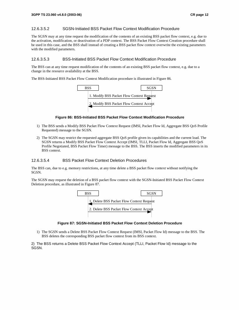
3GPP TS 23.060 v4.8.0 (2003-06) CR page 12
12.6.3.5.2 SGSN-Initiated BSS Packet Flow Context Modification Procedure
The SGSN may at any time request the modification of the contents of an existing BSS packet flow context, e.g. due to the activation, modification, or deactivation of a PDP context. The BSS Packet Flow Context Creation procedure shall be used in this case, and the BSS shall instead of creating a BSS packet flow context overwrite the existing parameters with the modified parameters.
12.6.3.5.3 BSS-Initiated BSS Packet Flow Context Modification Procedure
The BSS can at any time request modification of the contents of an existing BSS packet flow context, e.g. due to a change in the resource availability at the BSS.
The BSS-Initiated BSS Packet Flow Context Modification procedure is illustrated in Figure 86.
1. Modify BSS Packet Flow Context Request
2. Modify BSS Packet Flow Context Accept
BSS SGSN
Figure 86: BSS-Initiated BSS Packet Flow Context Modification Procedure
1) The BSS sends a Modify BSS Packet Flow Context Request (IMSI, Packet Flow Id, Aggregate BSS QoS Profile Requested) message to the SGSN.
2) The SGSN may restrict the requested aggregate BSS QoS profile given its capabilities and the current load. The SGSN returns a Modify BSS Packet Flow Context Accept (IMSI, TLLI, Packet Flow Id, Aggregate BSS QoS Profile Negotiated, BSS Packet Flow Timer) message to the BSS. The BSS inserts the modified parameters in its BSS context.
12.6.3.5.4 BSS Packet Flow Context Deletion Procedures
The BSS can, due to e.g. memory restrictions, at any time delete a BSS packet flow context without notifying the SGSN.
The SGSN may request the deletion of a BSS packet flow context with the SGSN-Initiated BSS Packet Flow Context Deletion procedure, as illustrated in Figure 87.
1. Delete BSS Packet Flow Context Request
2. Delete BSS Packet Flow Context Accept
BSS SGSN
Figure 87: SGSN-Initiated BSS Packet Flow Context Deletion Procedure
1) The SGSN sends a Delete BSS Packet Flow Context Request (IMSI, Packet Flow Id) message to the BSS. The BSS deletes the corresponding BSS packet flow context from its BSS context.
2) The BSS returns a Delete BSS Packet Flow Context Accept (TLLI, Packet Flow Id) message to the SGSN.

3GPP TSG-SA2 Meeting #36 Tdoc S2-034252 New York, USA, 24-28 November 2003 revision of Tdoc S2-034160
CR-Form-v7
CHANGE REQUEST
! 23.060 CR 467 ! rev 2 ! Current version: 5.6.0 !
For HELP on using this form, see bottom of this page or look at the pop-up text over the ! symbols.
Proposed change affects: UICC apps! ME X Radio Access Network X Core Network X
Title: ! PFI correction Source: ! Nokia Work item code: ! TEI Date: ! 26/11/2003 Category: ! A Release: ! Rel-5 Use one of the following categories:
F (correction) A (corresponds to a correction in an earlier release) B (addition of feature), C (functional modification of feature) D (editorial modification)
Detailed explanations of the above categories can be found in 3GPP TR 21.900.
Use one of the following releases: 2 (GSM Phase 2) R96 (Release 1996) R97 (Release 1997) R98 (Release 1998) R99 (Release 1999) Rel-4 (Release 4) Rel-5 (Release 5) Rel-6 (Release 6)
Reason for change: ! In the specification is not told clearly whether SGSN can send Packet Flow
Indentifier (PFI), during PDP context activation or modification, to an MS not supporting BSS packet flow procedures.
Summary of change: ! It is clarified that the SGSN should not send Packet Flow Indentifier (PFI) to an
MS that indicated in the MS Network Capability IE it does not support BSS packet flow procedures.
Consequences if ! not approved:
There can be problems with MS which don’t support BSS packet flow procedures but network anyway sends them PFI. Also the MS’s information sent to network, which tells whether MS supports or not BSS packet flow procedures would be totally useless if network could still try to use them.
Clauses affected: ! 2; 9.2.2.1; 9.2.2.1.1; 9.2.3; 12.6.3.5; 12.6.3.5.1 Y N Other specs ! X Other core specifications ! Possible 3GPP TS 24.008 affected: X Test specifications X O&M Specifications Other comments: ! It is assumed that the 23.060 CR is approved first and no formal linkage between
the 24.008 CRs is needed.
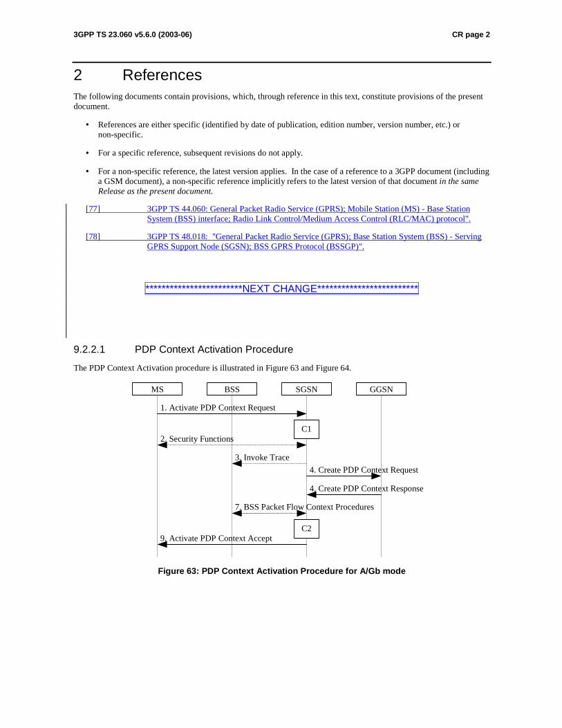
3GPP TS 23.060 v5.6.0 (2003-06) CR page 2
2 References The following documents contain provisions, which, through reference in this text, constitute provisions of the present document.
• References are either specific (identified by date of publication, edition number, version number, etc.) or non-specific.
• For a specific reference, subsequent revisions do not apply.
• For a non-specific reference, the latest version applies. In the case of a reference to a 3GPP document (including a GSM document), a non-specific reference implicitly refers to the latest version of that document in the same Release as the present document.
[77] 3GPP TS 44.060: General Packet Radio Service (GPRS); Mobile Station (MS) - Base Station System (BSS) interface; Radio Link Control/Medium Access Control (RLC/MAC) protocol".
[78] 3GPP TS 48.018: "General Packet Radio Service (GPRS); Base Station System (BSS) - Serving GPRS Support Node (SGSN); BSS GPRS Protocol (BSSGP)".
************************NEXT CHANGE*************************
9.2.2.1 PDP Context Activation Procedure
The PDP Context Activation procedure is illustrated in Figure 63 and Figure 64.
GGSN
9. Activate PDP Context Accept
4. Create PDP Context Response
4. Create PDP Context Request
1. Activate PDP Context Request
SGSNBSS
2. Security Functions
MS
7. BSS Packet Flow Context Procedures
C1
C2
3. Invoke Trace
Figure 63: PDP Context Activation Procedure for A/Gb mode
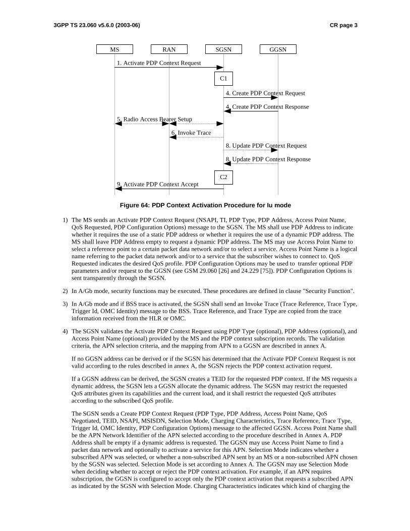
3GPP TS 23.060 v5.6.0 (2003-06) CR page 3
GGSN
9. Activate PDP Context Accept
4. Create PDP Context Response
4. Create PDP Context Request
1. Activate PDP Context Request
SGSNRANMS
5. Radio Access Bearer Setup
C1
C2
6. Invoke Trace
8. Update PDP Context Response
8. Update PDP Context Request
Figure 64: PDP Context Activation Procedure for Iu mode
1) The MS sends an Activate PDP Context Request (NSAPI, TI, PDP Type, PDP Address, Access Point Name, QoS Requested, PDP Configuration Options) message to the SGSN. The MS shall use PDP Address to indicate whether it requires the use of a static PDP address or whether it requires the use of a dynamic PDP address. The MS shall leave PDP Address empty to request a dynamic PDP address. The MS may use Access Point Name to select a reference point to a certain packet data network and/or to select a service. Access Point Name is a logical name referring to the packet data network and/or to a service that the subscriber wishes to connect to. QoS Requested indicates the desired QoS profile. PDP Configuration Options may be used to transfer optional PDP parameters and/or request to the GGSN (see GSM 29.060 [26] and 24.229 [75]). PDP Configuration Options is sent transparently through the SGSN.
2) In A/Gb mode, security functions may be executed. These procedures are defined in clause "Security Function".
3) In A/Gb mode and if BSS trace is activated, the SGSN shall send an Invoke Trace (Trace Reference, Trace Type, Trigger Id, OMC Identity) message to the BSS. Trace Reference, and Trace Type are copied from the trace information received from the HLR or OMC.
4) The SGSN validates the Activate PDP Context Request using PDP Type (optional), PDP Address (optional), and Access Point Name (optional) provided by the MS and the PDP context subscription records. The validation criteria, the APN selection criteria, and the mapping from APN to a GGSN are described in annex A.
If no GGSN address can be derived or if the SGSN has determined that the Activate PDP Context Request is not valid according to the rules described in annex A, the SGSN rejects the PDP context activation request.
If a GGSN address can be derived, the SGSN creates a TEID for the requested PDP context. If the MS requests a dynamic address, the SGSN lets a GGSN allocate the dynamic address. The SGSN may restrict the requested QoS attributes given its capabilities and the current load, and it shall restrict the requested QoS attributes according to the subscribed QoS profile.
The SGSN sends a Create PDP Context Request (PDP Type, PDP Address, Access Point Name, QoS Negotiated, TEID, NSAPI, MSISDN, Selection Mode, Charging Characteristics, Trace Reference, Trace Type, Trigger Id, OMC Identity, PDP Configuration Options) message to the affected GGSN. Access Point Name shall be the APN Network Identifier of the APN selected according to the procedure described in Annex A. PDP Address shall be empty if a dynamic address is requested. The GGSN may use Access Point Name to find a packet data network and optionally to activate a service for this APN. Selection Mode indicates whether a subscribed APN was selected, or whether a non-subscribed APN sent by an MS or a non-subscribed APN chosen by the SGSN was selected. Selection Mode is set according to Annex A. The GGSN may use Selection Mode when deciding whether to accept or reject the PDP context activation. For example, if an APN requires subscription, the GGSN is configured to accept only the PDP context activation that requests a subscribed APN as indicated by the SGSN with Selection Mode. Charging Characteristics indicates which kind of charging the
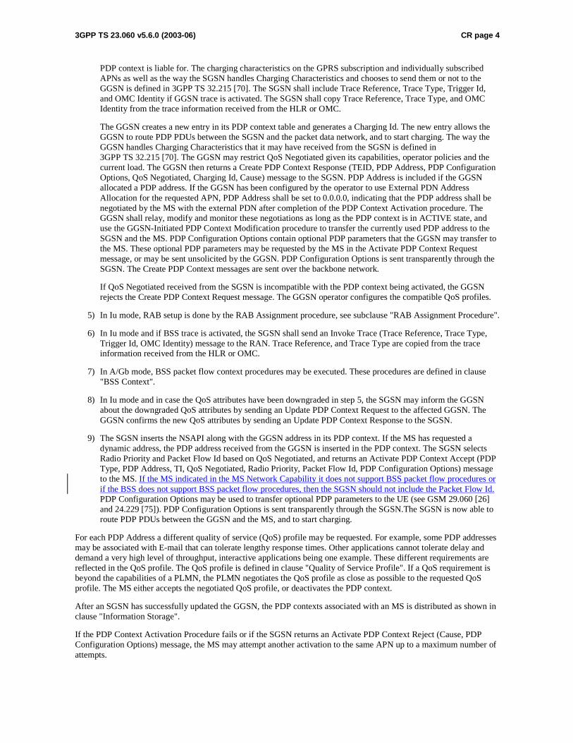
3GPP TS 23.060 v5.6.0 (2003-06) CR page 4
PDP context is liable for. The charging characteristics on the GPRS subscription and individually subscribed APNs as well as the way the SGSN handles Charging Characteristics and chooses to send them or not to the GGSN is defined in 3GPP TS 32.215 [70]. The SGSN shall include Trace Reference, Trace Type, Trigger Id, and OMC Identity if GGSN trace is activated. The SGSN shall copy Trace Reference, Trace Type, and OMC Identity from the trace information received from the HLR or OMC.
The GGSN creates a new entry in its PDP context table and generates a Charging Id. The new entry allows the GGSN to route PDP PDUs between the SGSN and the packet data network, and to start charging. The way the GGSN handles Charging Characteristics that it may have received from the SGSN is defined in 3GPP TS 32.215 [70]. The GGSN may restrict QoS Negotiated given its capabilities, operator policies and the current load. The GGSN then returns a Create PDP Context Response (TEID, PDP Address, PDP Configuration Options, QoS Negotiated, Charging Id, Cause) message to the SGSN. PDP Address is included if the GGSN allocated a PDP address. If the GGSN has been configured by the operator to use External PDN Address Allocation for the requested APN, PDP Address shall be set to 0.0.0.0, indicating that the PDP address shall be negotiated by the MS with the external PDN after completion of the PDP Context Activation procedure. The GGSN shall relay, modify and monitor these negotiations as long as the PDP context is in ACTIVE state, and use the GGSN-Initiated PDP Context Modification procedure to transfer the currently used PDP address to the SGSN and the MS. PDP Configuration Options contain optional PDP parameters that the GGSN may transfer to the MS. These optional PDP parameters may be requested by the MS in the Activate PDP Context Request message, or may be sent unsolicited by the GGSN. PDP Configuration Options is sent transparently through the SGSN. The Create PDP Context messages are sent over the backbone network.
If QoS Negotiated received from the SGSN is incompatible with the PDP context being activated, the GGSN rejects the Create PDP Context Request message. The GGSN operator configures the compatible QoS profiles.
5) In Iu mode, RAB setup is done by the RAB Assignment procedure, see subclause "RAB Assignment Procedure".
6) In Iu mode and if BSS trace is activated, the SGSN shall send an Invoke Trace (Trace Reference, Trace Type, Trigger Id, OMC Identity) message to the RAN. Trace Reference, and Trace Type are copied from the trace information received from the HLR or OMC.
7) In A/Gb mode, BSS packet flow context procedures may be executed. These procedures are defined in clause "BSS Context".
8) In Iu mode and in case the QoS attributes have been downgraded in step 5, the SGSN may inform the GGSN about the downgraded QoS attributes by sending an Update PDP Context Request to the affected GGSN. The GGSN confirms the new QoS attributes by sending an Update PDP Context Response to the SGSN.
9) The SGSN inserts the NSAPI along with the GGSN address in its PDP context. If the MS has requested a dynamic address, the PDP address received from the GGSN is inserted in the PDP context. The SGSN selects Radio Priority and Packet Flow Id based on QoS Negotiated, and returns an Activate PDP Context Accept (PDP Type, PDP Address, TI, QoS Negotiated, Radio Priority, Packet Flow Id, PDP Configuration Options) message to the MS. If the MS indicated in the MS Network Capability it does not support BSS packet flow procedures or if the BSS does not support BSS packet flow procedures, then the SGSN should not include the Packet Flow Id. PDP Configuration Options may be used to transfer optional PDP parameters to the UE (see GSM 29.060 [26] and 24.229 [75]). PDP Configuration Options is sent transparently through the SGSN.The SGSN is now able to route PDP PDUs between the GGSN and the MS, and to start charging.
For each PDP Address a different quality of service (QoS) profile may be requested. For example, some PDP addresses may be associated with E-mail that can tolerate lengthy response times. Other applications cannot tolerate delay and demand a very high level of throughput, interactive applications being one example. These different requirements are reflected in the QoS profile. The QoS profile is defined in clause "Quality of Service Profile". If a QoS requirement is beyond the capabilities of a PLMN, the PLMN negotiates the QoS profile as close as possible to the requested QoS profile. The MS either accepts the negotiated QoS profile, or deactivates the PDP context.
After an SGSN has successfully updated the GGSN, the PDP contexts associated with an MS is distributed as shown in clause "Information Storage".
If the PDP Context Activation Procedure fails or if the SGSN returns an Activate PDP Context Reject (Cause, PDP Configuration Options) message, the MS may attempt another activation to the same APN up to a maximum number of attempts.
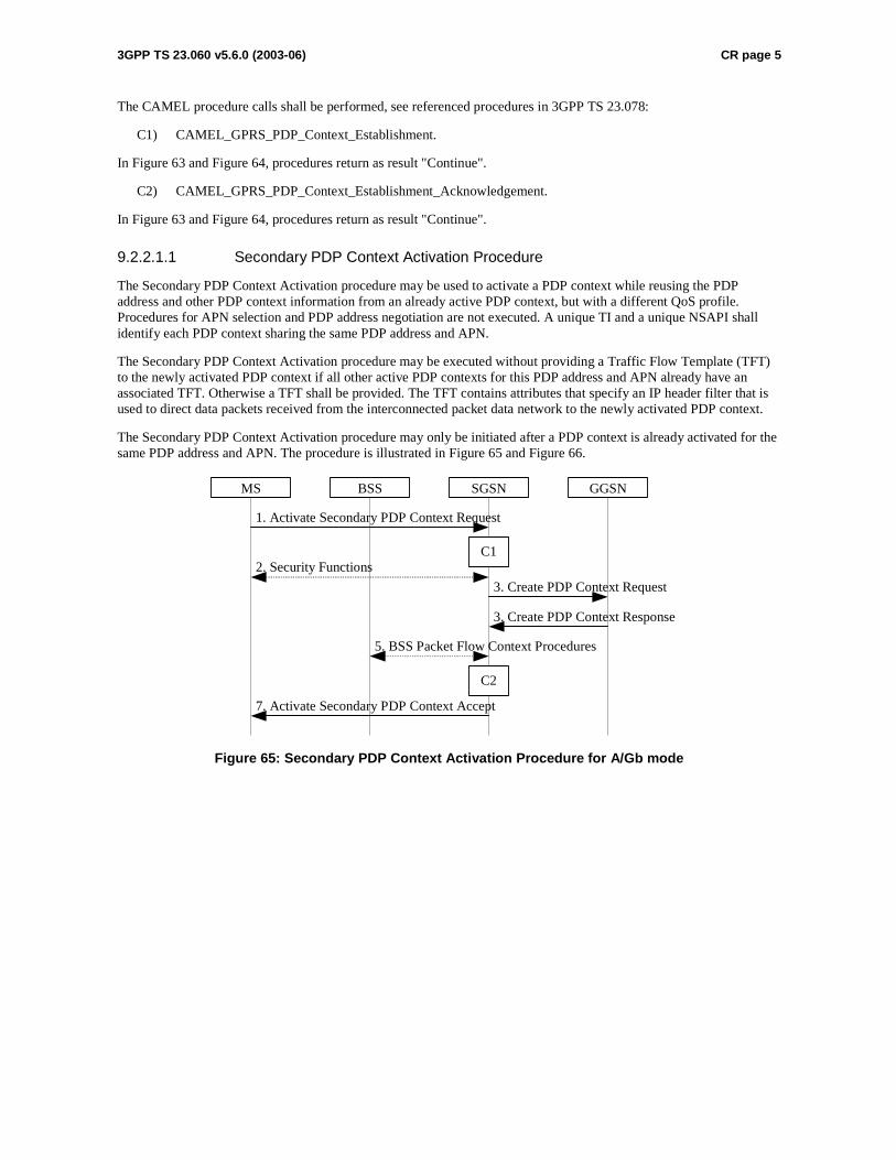
3GPP TS 23.060 v5.6.0 (2003-06) CR page 5
The CAMEL procedure calls shall be performed, see referenced procedures in 3GPP TS 23.078:
C1) CAMEL_GPRS_PDP_Context_Establishment.
In Figure 63 and Figure 64, procedures return as result "Continue".
C2) CAMEL_GPRS_PDP_Context_Establishment_Acknowledgement.
In Figure 63 and Figure 64, procedures return as result "Continue".
9.2.2.1.1 Secondary PDP Context Activation Procedure
The Secondary PDP Context Activation procedure may be used to activate a PDP context while reusing the PDP address and other PDP context information from an already active PDP context, but with a different QoS profile. Procedures for APN selection and PDP address negotiation are not executed. A unique TI and a unique NSAPI shall identify each PDP context sharing the same PDP address and APN.
The Secondary PDP Context Activation procedure may be executed without providing a Traffic Flow Template (TFT) to the newly activated PDP context if all other active PDP contexts for this PDP address and APN already have an associated TFT. Otherwise a TFT shall be provided. The TFT contains attributes that specify an IP header filter that is used to direct data packets received from the interconnected packet data network to the newly activated PDP context.
The Secondary PDP Context Activation procedure may only be initiated after a PDP context is already activated for the same PDP address and APN. The procedure is illustrated in Figure 65 and Figure 66.
GGSN
7. Activate Secondary PDP Context Accept
3. Create PDP Context Response
3. Create PDP Context Request
1. Activate Secondary PDP Context Request
SGSNBSS
2. Security Functions
MS
5. BSS Packet Flow Context Procedures
C1
C2
Figure 65: Secondary PDP Context Activation Procedure for A/Gb mode
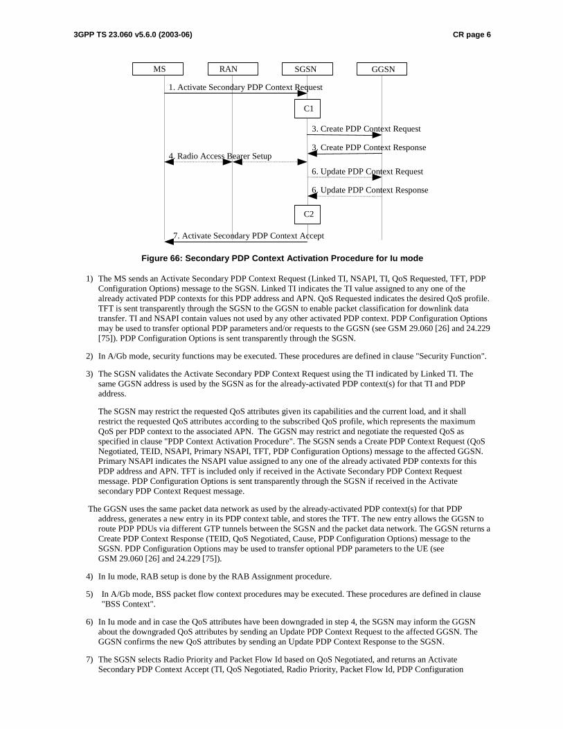
3GPP TS 23.060 v5.6.0 (2003-06) CR page 6
GGSN
7. Activate Secondary PDP Context Accept
3 . Create PDP Context Response
3 . Create PDP Context Request
1. Activate Secondary PDP Context Request
SGSN RAN MS
4 . Radio Access Bearer Setup
C1
C2
6. Update PDP Context Response
6. Update PDP Context Request
Figure 66: Secondary PDP Context Activation Procedure for Iu mode
1) The MS sends an Activate Secondary PDP Context Request (Linked TI, NSAPI, TI, QoS Requested, TFT, PDP Configuration Options) message to the SGSN. Linked TI indicates the TI value assigned to any one of the already activated PDP contexts for this PDP address and APN. QoS Requested indicates the desired QoS profile. TFT is sent transparently through the SGSN to the GGSN to enable packet classification for downlink data transfer. TI and NSAPI contain values not used by any other activated PDP context. PDP Configuration Options may be used to transfer optional PDP parameters and/or requests to the GGSN (see GSM 29.060 [26] and 24.229 [75]). PDP Configuration Options is sent transparently through the SGSN.
2) In A/Gb mode, security functions may be executed. These procedures are defined in clause "Security Function".
3) The SGSN validates the Activate Secondary PDP Context Request using the TI indicated by Linked TI. The same GGSN address is used by the SGSN as for the already-activated PDP context(s) for that TI and PDP address.
The SGSN may restrict the requested QoS attributes given its capabilities and the current load, and it shall restrict the requested QoS attributes according to the subscribed QoS profile, which represents the maximum QoS per PDP context to the associated APN. The GGSN may restrict and negotiate the requested QoS as specified in clause "PDP Context Activation Procedure". The SGSN sends a Create PDP Context Request (QoS Negotiated, TEID, NSAPI, Primary NSAPI, TFT, PDP Configuration Options) message to the affected GGSN. Primary NSAPI indicates the NSAPI value assigned to any one of the already activated PDP contexts for this PDP address and APN. TFT is included only if received in the Activate Secondary PDP Context Request message. PDP Configuration Options is sent transparently through the SGSN if received in the Activate secondary PDP Context Request message.
The GGSN uses the same packet data network as used by the already-activated PDP context(s) for that PDP address, generates a new entry in its PDP context table, and stores the TFT. The new entry allows the GGSN to route PDP PDUs via different GTP tunnels between the SGSN and the packet data network. The GGSN returns a Create PDP Context Response (TEID, QoS Negotiated, Cause, PDP Configuration Options) message to the SGSN. PDP Configuration Options may be used to transfer optional PDP parameters to the UE (see GSM 29.060 [26] and 24.229 [75]).
4) In Iu mode, RAB setup is done by the RAB Assignment procedure.
5) In A/Gb mode, BSS packet flow context procedures may be executed. These procedures are defined in clause "BSS Context".
6) In Iu mode and in case the QoS attributes have been downgraded in step 4, the SGSN may inform the GGSN about the downgraded QoS attributes by sending an Update PDP Context Request to the affected GGSN. The GGSN confirms the new QoS attributes by sending an Update PDP Context Response to the SGSN.
7) The SGSN selects Radio Priority and Packet Flow Id based on QoS Negotiated, and returns an Activate Secondary PDP Context Accept (TI, QoS Negotiated, Radio Priority, Packet Flow Id, PDP Configuration
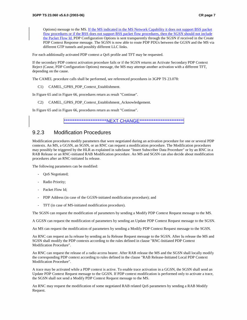
3GPP TS 23.060 v5.6.0 (2003-06) CR page 7
Options) message to the MS. If the MS indicated in the MS Network Capability it does not support BSS packet flow procedures or if the BSS does not support BSS packet flow procedures, then the SGSN should not include the Packet Flow Id. PDP Configuration Options is sent transparently through the SGSN if received in the Create PDP Context Response message. The SGSN is now able to route PDP PDUs between the GGSN and the MS via different GTP tunnels and possibly different LLC links.
For each additionally activated PDP context a QoS profile and TFT may be requested.
If the secondary PDP context activation procedure fails or if the SGSN returns an Activate Secondary PDP Context Reject (Cause, PDP Configuration Options) message, the MS may attempt another activation with a different TFT, depending on the cause.
The CAMEL procedure calls shall be performed, see referenced procedures in 3GPP TS 23.078:
C1) CAMEL_GPRS_PDP_Context_Establishment.
In Figure 65 and in Figure 66, procedures return as result "Continue".
C2) CAMEL_GPRS_PDP_Context_Establishment_Acknowledgement.
In Figure 65 and in Figure 66, procedures return as result "Continue".
************************NEXT CHANGE*************************
9.2.3 Modification Procedures
Modification procedures modify parameters that were negotiated during an activation procedure for one or several PDP contexts. An MS, a GGSN, an SGSN, or an RNC can request a modification procedure. The Modification procedures may possibly be triggered by the HLR as explained in subclause "Insert Subscriber Data Procedure" or by an RNC in a RAB Release or an RNC-initiated RAB Modification procedure. An MS and SGSN can also decide about modification procedures after an RNC-initiated Iu release.
The following parameters can be modified:
- QoS Negotiated;
- Radio Priority;
- Packet Flow Id;
- PDP Address (in case of the GGSN-initiated modification procedure); and
- TFT (in case of MS-initiated modification procedure).
The SGSN can request the modification of parameters by sending a Modify PDP Context Request message to the MS.
A GGSN can request the modification of parameters by sending an Update PDP Context Request message to the SGSN.
An MS can request the modification of parameters by sending a Modify PDP Context Request message to the SGSN.
An RNC can request an Iu release by sending an Iu Release Request message to the SGSN. After Iu release the MS and SGSN shall modify the PDP contexts according to the rules defined in clause "RNC-Initiated PDP Context Modification Procedure".
An RNC can request the release of a radio access bearer. After RAB release the MS and the SGSN shall locally modify the corresponding PDP context according to rules defined in the clause "RAB Release-Initiated Local PDP Context Modification Procedure".
A trace may be activated while a PDP context is active. To enable trace activation in a GGSN, the SGSN shall send an Update PDP Context Request message to the GGSN. If PDP context modification is performed only to activate a trace, the SGSN shall not send a Modify PDP Context Request message to the MS.
An RNC may request the modification of some negotiated RAB related QoS parameters by sending a RAB Modify Request.
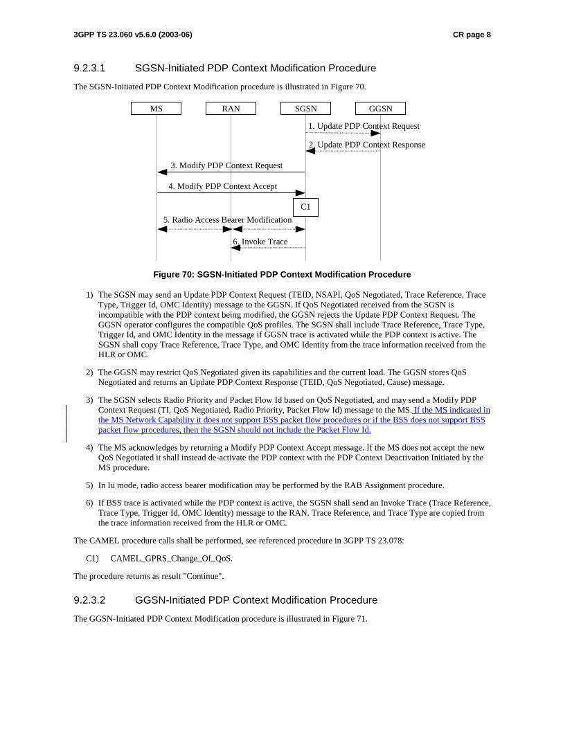
3GPP TS 23.060 v5.6.0 (2003-06) CR page 8
9.2.3.1 SGSN-Initiated PDP Context Modification Procedure
The SGSN-Initiated PDP Context Modification procedure is illustrated in Figure 70.
GGSN
2. Update PDP Context Response
1. Update PDP Context Request
SGSNRANMS
3. Modify PDP Context Request
4. Modify PDP Context Accept
5. Radio Access Bearer Modification
C1
6. Invoke Trace
Figure 70: SGSN-Initiated PDP Context Modification Procedure
1) The SGSN may send an Update PDP Context Request (TEID, NSAPI, QoS Negotiated, Trace Reference, Trace Type, Trigger Id, OMC Identity) message to the GGSN. If QoS Negotiated received from the SGSN is incompatible with the PDP context being modified, the GGSN rejects the Update PDP Context Request. The GGSN operator configures the compatible QoS profiles. The SGSN shall include Trace Reference, Trace Type, Trigger Id, and OMC Identity in the message if GGSN trace is activated while the PDP context is active. The SGSN shall copy Trace Reference, Trace Type, and OMC Identity from the trace information received from the HLR or OMC.
2) The GGSN may restrict QoS Negotiated given its capabilities and the current load. The GGSN stores QoS Negotiated and returns an Update PDP Context Response (TEID, QoS Negotiated, Cause) message.
3) The SGSN selects Radio Priority and Packet Flow Id based on QoS Negotiated, and may send a Modify PDP Context Request (TI, QoS Negotiated, Radio Priority, Packet Flow Id) message to the MS. If the MS indicated in the MS Network Capability it does not support BSS packet flow procedures or if the BSS does not support BSS packet flow procedures, then the SGSN should not include the Packet Flow Id.
4) The MS acknowledges by returning a Modify PDP Context Accept message. If the MS does not accept the new QoS Negotiated it shall instead de-activate the PDP context with the PDP Context Deactivation Initiated by the MS procedure.
5) In Iu mode, radio access bearer modification may be performed by the RAB Assignment procedure.
6) If BSS trace is activated while the PDP context is active, the SGSN shall send an Invoke Trace (Trace Reference, Trace Type, Trigger Id, OMC Identity) message to the RAN. Trace Reference, and Trace Type are copied from the trace information received from the HLR or OMC.
The CAMEL procedure calls shall be performed, see referenced procedure in 3GPP TS 23.078:
C1) CAMEL_GPRS_Change_Of_QoS.
The procedure returns as result "Continue".
9.2.3.2 GGSN-Initiated PDP Context Modification Procedure
The GGSN-Initiated PDP Context Modification procedure is illustrated in Figure 71.

3GPP TS 23.060 v5.6.0 (2003-06) CR page 9
GGSN
5. Update PDP Context Response
1. Update PDP Context Request
SGSNRANMS
2. Modify PDP Context Request
3. Modify PDP Context Accept
4. Radio Access Bearer Modification
C1
Figure 71: GGSN-Initiated PDP Context Modification Procedure
1) The GGSN sends an Update PDP Context Request (TEID, NSAPI, PDP Address, QoS Requested) message to the SGSN. QoS Requested indicates the desired QoS profile. PDP Address is optional.
2) The SGSN may restrict the desired QoS profile given its capabilities, the current load, the current QoS profile, and the subscribed QoS profile. The SGSN selects Radio Priority and Packet Flow Id based on QoS Negotiated, and sends a Modify PDP Context Request (TI, PDP Address, QoS Negotiated, Radio Priority, Packet Flow Id) message to the MS. PDP Address is optional. If the MS indicated in the MS Network Capability it does not support BSS packet flow procedures or if the BSS does not support BSS packet flow procedures, then the SGSN should not include the Packet Flow Id.
3) The MS acknowledges by returning a Modify PDP Context Accept message. If the MS does not accept the new QoS Negotiated it shall instead de-activate the PDP context with the PDP Context Deactivation Initiated by MS procedure.
4) In Iu mode, radio access bearer modification may be performed by the RAB Assignment procedure.
5) Upon receipt of the Modify PDP Context Accept message, or upon completion of the RAB modification procedure, the SGSN returns an Update PDP Context Response (TEID, QoS Negotiated) message to the GGSN. If the SGSN receives a Deactivate PDP Context Request message, it shall instead follow the PDP Context Deactivation Initiated by MS procedure.
The CAMEL procedure calls shall be performed, see referenced procedure in 3GPP TS 23.078:
C1) CAMEL_GPRS_Change_Of_QoS.
The procedure returns as result "Continue".
9.2.3.3 MS-Initiated PDP Context Modification Procedure
The MS-Initiated PDP Context Modification procedure is illustrated in Figure 72.
GGSN
3. Update PDP Context Response
2. Update PDP Context Request
SGSNRANMS
1. Modify PDP Context Request
5. Modify PDP Context Accept
4. Radio Access Bearer Modification
C1
Figure 72: MS-Initiated PDP Context Modification Procedure
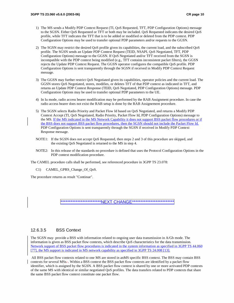
3GPP TS 23.060 v5.6.0 (2003-06) CR page 10
1) The MS sends a Modify PDP Context Request (TI, QoS Requested, TFT, PDP Configuration Options) message to the SGSN. Either QoS Requested or TFT or both may be included. QoS Requested indicates the desired QoS profile, while TFT indicates the TFT that is to be added or modified or deleted from the PDP context. PDP Configuration Options may be used to transfer optional PDP parameters and/or requests to the GGSN.
2) The SGSN may restrict the desired QoS profile given its capabilities, the current load, and the subscribed QoS profile. The SGSN sends an Update PDP Context Request (TEID, NSAPI, QoS Negotiated, TFT, PDP Configuration Options) message to the GGSN. If QoS Negotiated and/or TFT received from the SGSN is incompatible with the PDP context being modified (e.g., TFT contains inconsistent packet filters), the GGSN rejects the Update PDP Context Request. The GGSN operator configures the compatible QoS profile. PDP Configuration Options is sent transparently through the SGSN if received in Modify PDP Context Request message.
3) The GGSN may further restrict QoS Negotiated given its capabilities, operator policies and the current load. The GGSN stores QoS Negotiated, stores, modifies, or deletes TFT of that PDP context as indicated in TFT, and returns an Update PDP Context Response (TEID, QoS Negotiated, PDP Configuration Options) message. PDP Configuration Options may be used to transfer optional PDP parameters to the UE.
4) In Iu mode, radio access bearer modification may be performed by the RAB Assignment procedure. In case the radio access bearer does not exist the RAB setup is done by the RAB Assignement procedure.
5) The SGSN selects Radio Priority and Packet Flow Id based on QoS Negotiated, and returns a Modify PDP Context Accept (TI, QoS Negotiated, Radio Priority, Packet Flow Id, PDP Configuration Options) message to the MS. If the MS indicated in the MS Network Capability it does not support BSS packet flow procedures or if the BSS does not support BSS packet flow procedures, then the SGSN should not include the Packet Flow Id. PDP Configuration Options is sent transparently through the SGSN if received in Modify PDP Context Response message.
NOTE1: If the SGSN does not accept QoS Requested, then steps 2 and 3 of this procedure are skipped, and the existing QoS Negotiated is returned to the MS in step 4.
NOTE2: In this release of the standards no procedure is defined that uses the Protocol Configuration Options in the PDP context modification procedure.
The CAMEL procedure calls shall be performed, see referenced procedure in 3GPP TS 23.078:
C1) CAMEL_GPRS_Change_Of_QoS.
The procedure returns as result "Continue".
************************NEXT CHANGE*************************
12.6.3.5 BSS Context
The SGSN may provide a BSS with information related to ongoing user data transmission in A/Gb mode. The information is given as BSS packet flow contexts, which describe QoS characteristics for the data transmission. Network support of BSS packet flow procedures is indicated in the system information as specified in 3GPP TS 44.060 [77], the MS support is indicated in MS network capability as specified in 3GPP TS 24.008 [13].
All BSS packet flow contexts related to one MS are stored in anMS specific BSS context. The BSS may contain BSS contexts for several MSs. . Within a BSS context the BSS packet flow contexts are identified by a packet flow identifier, which is assigned by the SGSN. A BSS packet flow context is shared by one or more activated PDP contexts of the same MS with identical or similar negotiated QoS profiles. The data transfers related to PDP contexts that share the same BSS packet flow context constitute one packet flow.

3GPP TS 23.060 v5.6.0 (2003-06) CR page 11
Three packet flows are pre-defined, and identified by three reserved packet flow identifier values. The BSS shall not negotiate BSS packet flow contexts for these pre-defined packet flows with the SGSN. One pre-defined packet flow is used for best-effort service, one is used for SMS, and one is used for signalling. The SGSN can assign the best-effort or SMS packet flow identifier to any PDP context. In the SMS case, the BSS shall handle the packet flow for the PDP context with the same QoS with which it handles SMS. A non-reserved packet flow identifier value is only significant for an MS when the SGSN provided the BSS with a packet flow context for this packet flow identifier value for this MS.
The combined BSS QoS profile for the PDP contexts that share the same packet flow is called the aggregate BSS QoS profile. The aggregate BSS QoS profile is considered to be a single parameter with multiple data transfer attributes as defined in subclause "Quality of Service Profile". It defines the QoS that must be provided by the BSS for a given packet flow between the MS and the SGSN, i.e. for the Um and Gb interfaces combined. The aggregate BSS QoS profile is negotiated between the SGSN and the BSS.
A BSS packet flow timer indicates the maximum time that the BSS may store the BSS packet flow context. The BSS packet flow timer shall not exceed the value of the READY timer for this MS. The BSS packet flow timer is started when the BSS packet flow context is stored in the BSS and when an LLC frame is received from the MS. When the BSS packet flow timer expires, the BSS shall delete the BSS packet flow context.
When a PDP context is activated, modified or deactivated, the SGSN may create, modify, or delete BSS packet flow contexts.
12.6.3.5.1 BSS Packet Flow Context Creation Procedure
On receiving a request to transmit an uplink or downlink LLC PDU for which no BSS packet flow context exists in the BSS, the BSS may request the download of the BSS packet flow context from the SGSN.
If MS and BSS supports BSS packet flow procedures Tthe SGSN may at any time request the creation of a BSS packet flow context, e.g. due to the activation of a PDP context.
The BSS Packet Flow Context Creation procedure is illustrated in Figure 85.
2. Create BSS Packet Flow Context Request
3. Create BSS Packet Flow Context Accept
BSS SGSN
1. Download BSS Packet Flow Context Request
Figure 85: BSS Packet Flow Context Creation Procedure
1) The BSS receives a request to transfer an uplink or downlink user data LLC PDU for which it currently does not have a BSS packet flow context. In the uplink case, TLLI, Radio Priority, and Packet Flow Id are received from the MS as defined in 3GPP TS 44.060 [77]GSM 04.60. In the downlink case, TLLI and Packet Flow Id are received from the SGSN as defined in 3GPP TS 48.018 [78]GSM 08.18 [21]. If Packet Flow Id neither indicates best-effort service nor SMS, then the BSS sends a Download BSS Packet Flow Context Request (RAI, TLLI, Packet Flow Id) message to the SGSN. Until the BSS receives the BSS packet flow context, the BSS shall handle uplink and downlink transfers according to a default aggregate BSS QoS profile. For uplink transfers, the default profile is specific to the radio priority level.
2) The SGSN sends a Create BSS Packet Flow Context Request (IMSI, TLLI, Packet Flow Id, Aggregate BSS QoS Profile Requested, BSS Packet Flow Timer) message to the associated BSS. The SGSN derives Aggregate BSS QoS Profile Requested from the QoS profile negotiated for the PDP contexts that share a packet flow as follows: The SGSN shall divide the transfer delay attribute in the QoS profile in one core network part and one BSS part. The SGSN estimates the transfer delay in the core network and subtracts this from the GPRS bearer service transfer delay. The result only covers the delay in the MS to SGSN segment of the GPRS PLMN. Since the BSS transports LLC PDUs obtained after segmentation of SDUs by the SNDCP layer, the SGSN shall convert the values of the GPRS bearer service attributes maximum SDU size, SDU error ratio, residual bit error ration, maximum bit rate, guaranteed bit rate and the resulting transfer delay to values applicable to the LLC PDUs. All other attributes in Aggregate BSS QoS Profile shall be the same as the corresponding GPRS bearer service attribute, see 3GPP TS 23.107.
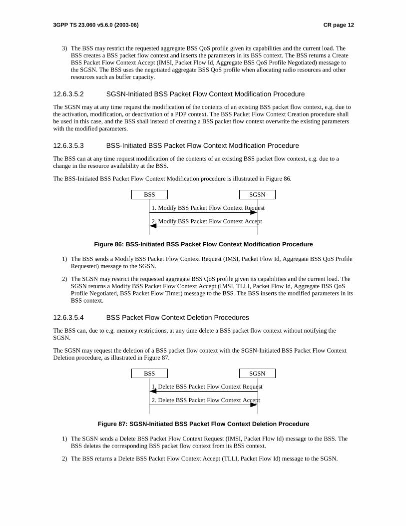
3GPP TS 23.060 v5.6.0 (2003-06) CR page 12
3) The BSS may restrict the requested aggregate BSS QoS profile given its capabilities and the current load. The BSS creates a BSS packet flow context and inserts the parameters in its BSS context. The BSS returns a Create BSS Packet Flow Context Accept (IMSI, Packet Flow Id, Aggregate BSS QoS Profile Negotiated) message to the SGSN. The BSS uses the negotiated aggregate BSS QoS profile when allocating radio resources and other resources such as buffer capacity.
12.6.3.5.2 SGSN-Initiated BSS Packet Flow Context Modification Procedure
The SGSN may at any time request the modification of the contents of an existing BSS packet flow context, e.g. due to the activation, modification, or deactivation of a PDP context. The BSS Packet Flow Context Creation procedure shall be used in this case, and the BSS shall instead of creating a BSS packet flow context overwrite the existing parameters with the modified parameters.
12.6.3.5.3 BSS-Initiated BSS Packet Flow Context Modification Procedure
The BSS can at any time request modification of the contents of an existing BSS packet flow context, e.g. due to a change in the resource availability at the BSS.
The BSS-Initiated BSS Packet Flow Context Modification procedure is illustrated in Figure 86.
1. Modify BSS Packet Flow Context Request
2. Modify BSS Packet Flow Context Accept
BSS SGSN
Figure 86: BSS-Initiated BSS Packet Flow Context Modification Procedure
1) The BSS sends a Modify BSS Packet Flow Context Request (IMSI, Packet Flow Id, Aggregate BSS QoS Profile Requested) message to the SGSN.
2) The SGSN may restrict the requested aggregate BSS QoS profile given its capabilities and the current load. The SGSN returns a Modify BSS Packet Flow Context Accept (IMSI, TLLI, Packet Flow Id, Aggregate BSS QoS Profile Negotiated, BSS Packet Flow Timer) message to the BSS. The BSS inserts the modified parameters in its BSS context.
12.6.3.5.4 BSS Packet Flow Context Deletion Procedures
The BSS can, due to e.g. memory restrictions, at any time delete a BSS packet flow context without notifying the SGSN.
The SGSN may request the deletion of a BSS packet flow context with the SGSN-Initiated BSS Packet Flow Context Deletion procedure, as illustrated in Figure 87.
1. Delete BSS Packet Flow Context Request
2. Delete BSS Packet Flow Context Accept
BSS SGSN
Figure 87: SGSN-Initiated BSS Packet Flow Context Deletion Procedure
1) The SGSN sends a Delete BSS Packet Flow Context Request (IMSI, Packet Flow Id) message to the BSS. The BSS deletes the corresponding BSS packet flow context from its BSS context.
2) The BSS returns a Delete BSS Packet Flow Context Accept (TLLI, Packet Flow Id) message to the SGSN.
3GPP TSG-SA2 Meeting #35 Tdoc S2-034377 New York, USA, 24-28 November 2003 revision of Tdoc S2-034161
CR-Form-v7
CHANGE REQUEST
! 23.060 CR 468 ! rev ! Current version: 6.2.0 !
For HELP on using this form, see bottom of this page or look at the pop-up text over the ! symbols.
Proposed change affects: UICC apps! ME X Radio Access Network X Core Network X
Title: ! PFI correction Source: ! Nokia Work item code: ! TEI Date: ! 26/11/2003 Category: ! F Release: ! Rel-6 Use one of the following categories:
F (correction) A (corresponds to a correction in an earlier release) B (addition of feature), C (functional modification of feature) D (editorial modification)
Detailed explanations of the above categories can be found in 3GPP TR 21.900.
Use one of the following releases: 2 (GSM Phase 2) R96 (Release 1996) R97 (Release 1997) R98 (Release 1998) R99 (Release 1999) Rel-4 (Release 4) Rel-5 (Release 5) Rel-6 (Release 6)
Reason for change: ! In the specification is not told clearly whether SGSN can send Packet Flow
Indentifier (PFI), during PDP context activation or modification, to an MS not supporting BSS packet flow procedures.
Summary of change: ! It is clarified that the SGSN shall not send Packet Flow Indentifier (PFI) to an MS
that indicated in the MS Network Capability IE it does not support BSS packet flow procedures.
Consequences if ! not approved:
There can be problems with MS which don’t support BSS packet flow procedures but network anyway sends them PFI. Also the MS’s information sent to network, which tells whether MS supports or not BSS packet flow procedures would be totally useless if network could still try to use them.
Clauses affected: ! 2; 9.2.2.1; 9.2.2.1.1; 9.2.3; 12.6.3.5; 12.6.3.5.1 Y N Other specs ! X Other core specifications ! Possible 3GPP TS 24.008 affected: X Test specifications X O&M Specifications Other comments: ! It is assumed that the 23.060 CR is approved first and no formal linkage between
the 24.008 CRs is needed.
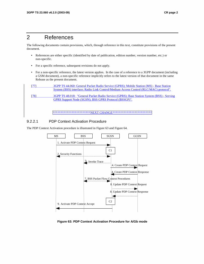
3GPP TS 23.060 v6.2.0 (2003-09) CR page 2
2 References The following documents contain provisions, which, through reference in this text, constitute provisions of the present document.
• References are either specific (identified by date of publication, edition number, version number, etc.) or non-specific.
• For a specific reference, subsequent revisions do not apply.
• For a non-specific reference, the latest version applies. In the case of a reference to a 3GPP document (including a GSM document), a non-specific reference implicitly refers to the latest version of that document in the same Release as the present document.
[77] 3GPP TS 44.060: General Packet Radio Service (GPRS); Mobile Station (MS) - Base Station System (BSS) interface; Radio Link Control/Medium Access Control (RLC/MAC) protocol".
[78] 3GPP TS 48.018: "General Packet Radio Service (GPRS); Base Station System (BSS) - Serving GPRS Support Node (SGSN); BSS GPRS Protocol (BSSGP)".
************************NEXT CHANGE*************************
9.2.2.1 PDP Context Activation Procedure
The PDP Context Activation procedure is illustrated in Figure 63 and Figure 64.
GGSN
9. Activate PDP Context Accept
4. Create PDP Context Response
4. Create PDP Context Request
1. Activate PDP Context Request
SGSN BSS
2. Security Functions
MS
7. BSS Packet Flow Context Procedures
C1
C2
3. Invoke Trace
8. Update PDP Context Request
8. Update PDP Context Response
Figure 63: PDP Context Activation Procedure for A/Gb mode

3GPP TS 23.060 v6.2.0 (2003-09) CR page 3
GGSN
9. Activate PDP Context Accept
4. Create PDP Context Response
4. Create PDP Context Request
1. Activate PDP Context Request
SGSNRANMS
5. Radio Access Bearer Setup
C1
C2
6. Invoke Trace
8. Update PDP Context Response
8. Update PDP Context Request
Figure 64: PDP Context Activation Procedure for Iu mode
1) The MS sends an Activate PDP Context Request (NSAPI, TI, PDP Type, PDP Address, Access Point Name, QoS Requested, PDP Configuration Options) message to the SGSN. The MS shall use PDP Address to indicate whether it requires the use of a static PDP address or whether it requires the use of a dynamic PDP address. The MS shall leave PDP Address empty to request a dynamic PDP address. The MS may use Access Point Name to select a reference point to a certain packet data network and/or to select a service. Access Point Name is a logical name referring to the packet data network and/or to a service that the subscriber wishes to connect to. QoS Requested indicates the desired QoS profile. PDP Configuration Options may be used to transfer optional PDP parameters and/or request to the GGSN (see GSM 29.060 [26] and 24.229 [75]). PDP Configuration Options is sent transparently through the SGSN.
2) In A/Gb mode, security functions may be executed. These procedures are defined in clause "Security Function".
3) In A/Gb mode and if BSS trace is activated, the SGSN shall send an Invoke Trace (Trace Reference, Trace Type, Trigger Id, OMC Identity) message to the BSS. Trace Reference, and Trace Type are copied from the trace information received from the HLR or OMC.
4) The SGSN validates the Activate PDP Context Request using PDP Type (optional), PDP Address (optional), and Access Point Name (optional) provided by the MS and the PDP context subscription records. The validation criteria, the APN selection criteria, and the mapping from APN to a GGSN are described in annex A.
If no GGSN address can be derived or if the SGSN has determined that the Activate PDP Context Request is not valid according to the rules described in annex A, the SGSN rejects the PDP context activation request.
If a GGSN address can be derived, the SGSN creates a TEID for the requested PDP context. If the MS requests a dynamic address, the SGSN lets a GGSN allocate the dynamic address. The SGSN may restrict the requested QoS attributes given its capabilities and the current load, and it shall restrict the requested QoS attributes according to the subscribed QoS profile.
The SGSN sends a Create PDP Context Request (PDP Type, PDP Address, Access Point Name, QoS Negotiated, TEID, NSAPI, MSISDN, Selection Mode, Charging Characteristics, Trace Reference, Trace Type, Trigger Id, OMC Identity, PDP Configuration Options) message to the affected GGSN. Access Point Name shall be the APN Network Identifier of the APN selected according to the procedure described in Annex A. PDP Address shall be empty if a dynamic address is requested. The GGSN may use Access Point Name to find a packet data network and optionally to activate a service for this APN. Selection Mode indicates whether a subscribed APN was selected, or whether a non-subscribed APN sent by an MS or a non-subscribed APN chosen by the SGSN was selected. Selection Mode is set according to Annex A. The GGSN may use Selection Mode when deciding whether to accept or reject the PDP context activation. For example, if an APN requires subscription, the GGSN is configured to accept only the PDP context activation that requests a subscribed APN as indicated by the SGSN with Selection Mode. Charging Characteristics indicates which kind of charging the
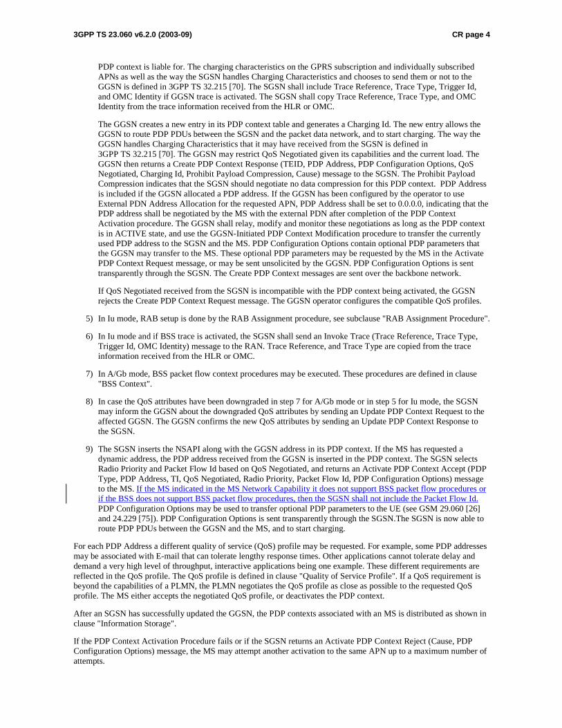
3GPP TS 23.060 v6.2.0 (2003-09) CR page 4
PDP context is liable for. The charging characteristics on the GPRS subscription and individually subscribed APNs as well as the way the SGSN handles Charging Characteristics and chooses to send them or not to the GGSN is defined in 3GPP TS 32.215 [70]. The SGSN shall include Trace Reference, Trace Type, Trigger Id, and OMC Identity if GGSN trace is activated. The SGSN shall copy Trace Reference, Trace Type, and OMC Identity from the trace information received from the HLR or OMC.
The GGSN creates a new entry in its PDP context table and generates a Charging Id. The new entry allows the GGSN to route PDP PDUs between the SGSN and the packet data network, and to start charging. The way the GGSN handles Charging Characteristics that it may have received from the SGSN is defined in 3GPP TS 32.215 [70]. The GGSN may restrict QoS Negotiated given its capabilities and the current load. The GGSN then returns a Create PDP Context Response (TEID, PDP Address, PDP Configuration Options, QoS Negotiated, Charging Id, Prohibit Payload Compression, Cause) message to the SGSN. The Prohibit Payload Compression indicates that the SGSN should negotiate no data compression for this PDP context. PDP Address is included if the GGSN allocated a PDP address. If the GGSN has been configured by the operator to use External PDN Address Allocation for the requested APN, PDP Address shall be set to 0.0.0.0, indicating that the PDP address shall be negotiated by the MS with the external PDN after completion of the PDP Context Activation procedure. The GGSN shall relay, modify and monitor these negotiations as long as the PDP context is in ACTIVE state, and use the GGSN-Initiated PDP Context Modification procedure to transfer the currently used PDP address to the SGSN and the MS. PDP Configuration Options contain optional PDP parameters that the GGSN may transfer to the MS. These optional PDP parameters may be requested by the MS in the Activate PDP Context Request message, or may be sent unsolicited by the GGSN. PDP Configuration Options is sent transparently through the SGSN. The Create PDP Context messages are sent over the backbone network.
If QoS Negotiated received from the SGSN is incompatible with the PDP context being activated, the GGSN rejects the Create PDP Context Request message. The GGSN operator configures the compatible QoS profiles.
5) In Iu mode, RAB setup is done by the RAB Assignment procedure, see subclause "RAB Assignment Procedure".
6) In Iu mode and if BSS trace is activated, the SGSN shall send an Invoke Trace (Trace Reference, Trace Type, Trigger Id, OMC Identity) message to the RAN. Trace Reference, and Trace Type are copied from the trace information received from the HLR or OMC.
7) In A/Gb mode, BSS packet flow context procedures may be executed. These procedures are defined in clause "BSS Context".
8) In case the QoS attributes have been downgraded in step 7 for A/Gb mode or in step 5 for Iu mode, the SGSN may inform the GGSN about the downgraded QoS attributes by sending an Update PDP Context Request to the affected GGSN. The GGSN confirms the new QoS attributes by sending an Update PDP Context Response to the SGSN.
9) The SGSN inserts the NSAPI along with the GGSN address in its PDP context. If the MS has requested a dynamic address, the PDP address received from the GGSN is inserted in the PDP context. The SGSN selects Radio Priority and Packet Flow Id based on QoS Negotiated, and returns an Activate PDP Context Accept (PDP Type, PDP Address, TI, QoS Negotiated, Radio Priority, Packet Flow Id, PDP Configuration Options) message to the MS. If the MS indicated in the MS Network Capability it does not support BSS packet flow procedures or if the BSS does not support BSS packet flow procedures, then the SGSN shall not include the Packet Flow Id. PDP Configuration Options may be used to transfer optional PDP parameters to the UE (see GSM 29.060 [26] and 24.229 [75]). PDP Configuration Options is sent transparently through the SGSN.The SGSN is now able to route PDP PDUs between the GGSN and the MS, and to start charging.
For each PDP Address a different quality of service (QoS) profile may be requested. For example, some PDP addresses may be associated with E-mail that can tolerate lengthy response times. Other applications cannot tolerate delay and demand a very high level of throughput, interactive applications being one example. These different requirements are reflected in the QoS profile. The QoS profile is defined in clause "Quality of Service Profile". If a QoS requirement is beyond the capabilities of a PLMN, the PLMN negotiates the QoS profile as close as possible to the requested QoS profile. The MS either accepts the negotiated QoS profile, or deactivates the PDP context.
After an SGSN has successfully updated the GGSN, the PDP contexts associated with an MS is distributed as shown in clause "Information Storage".
If the PDP Context Activation Procedure fails or if the SGSN returns an Activate PDP Context Reject (Cause, PDP Configuration Options) message, the MS may attempt another activation to the same APN up to a maximum number of attempts.
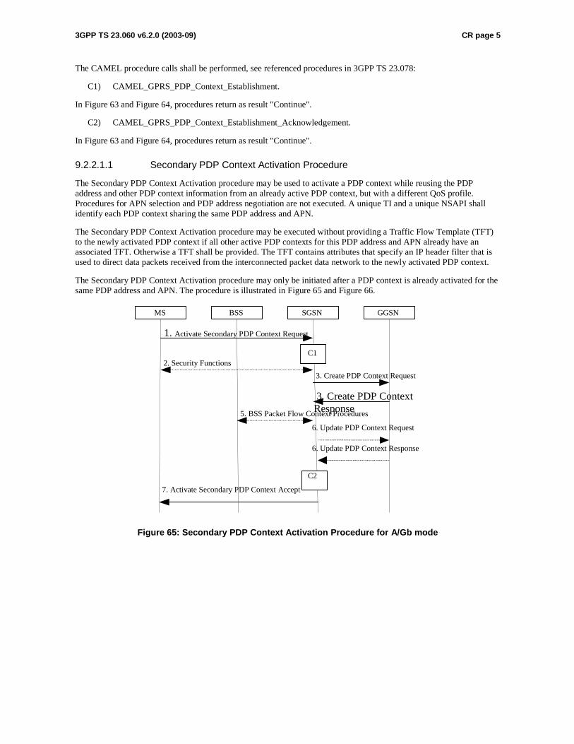
3GPP TS 23.060 v6.2.0 (2003-09) CR page 5
The CAMEL procedure calls shall be performed, see referenced procedures in 3GPP TS 23.078:
C1) CAMEL_GPRS_PDP_Context_Establishment.
In Figure 63 and Figure 64, procedures return as result "Continue".
C2) CAMEL_GPRS_PDP_Context_Establishment_Acknowledgement.
In Figure 63 and Figure 64, procedures return as result "Continue".
9.2.2.1.1 Secondary PDP Context Activation Procedure
The Secondary PDP Context Activation procedure may be used to activate a PDP context while reusing the PDP address and other PDP context information from an already active PDP context, but with a different QoS profile. Procedures for APN selection and PDP address negotiation are not executed. A unique TI and a unique NSAPI shall identify each PDP context sharing the same PDP address and APN.
The Secondary PDP Context Activation procedure may be executed without providing a Traffic Flow Template (TFT) to the newly activated PDP context if all other active PDP contexts for this PDP address and APN already have an associated TFT. Otherwise a TFT shall be provided. The TFT contains attributes that specify an IP header filter that is used to direct data packets received from the interconnected packet data network to the newly activated PDP context.
The Secondary PDP Context Activation procedure may only be initiated after a PDP context is already activated for the same PDP address and APN. The procedure is illustrated in Figure 65 and Figure 66.
GGSN
7. Activate Secondary PDP Context Accept
3. Create PDP Context Response
3. Create PDP Context Request
1. Activate Secondary PDP Context Request
SGSN BSS
2. Security Functions
MS
5. BSS Packet Flow Context Procedures
C1
C2
6. Update PDP Context Request
6. Update PDP Context Response
Figure 65: Secondary PDP Context Activation Procedure for A/Gb mode
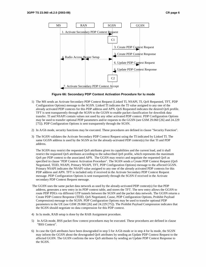
3GPP TS 23.060 v6.2.0 (2003-09) CR page 6
GGSN
7. Activate Secondary PDP Context Accept
3 . Create PDP Context Response
3 . Create PDP Context Request
1. Activate Secondary PDP Context Request
SGSN RAN MS
4 . Radio Access Bea rer Setup
C1
C2
6. Update PDP Context Response
6. Update PDP Context Request
Figure 66: Secondary PDP Context Activation Procedure for Iu mode
1) The MS sends an Activate Secondary PDP Context Request (Linked TI, NSAPI, TI, QoS Requested, TFT, PDP Configuration Options) message to the SGSN. Linked TI indicates the TI value assigned to any one of the already activated PDP contexts for this PDP address and APN. QoS Requested indicates the desired QoS profile. TFT is sent transparently through the SGSN to the GGSN to enable packet classification for downlink data transfer. TI and NSAPI contain values not used by any other activated PDP context. PDP Configuration Options may be used to transfer optional PDP parameters and/or requests to the GGSN (see GSM 29.060 [26] and 24.229 [75]). PDP Configuration Options is sent transparently through the SGSN.
2) In A/Gb mode, security functions may be executed. These procedures are defined in clause "Security Function".
3) The SGSN validates the Activate Secondary PDP Context Request using the TI indicated by Linked TI. The same GGSN address is used by the SGSN as for the already-activated PDP context(s) for that TI and PDP address.
The SGSN may restrict the requested QoS attributes given its capabilities and the current load, and it shall restrict the requested QoS attributes according to the subscribed QoS profile, which represents the maximum QoS per PDP context to the associated APN. The GGSN may restrict and negotiate the requested QoS as specified in clause "PDP Context Activation Procedure". The SGSN sends a Create PDP Context Request (QoS Negotiated, TEID, NSAPI, Primary NSAPI, TFT, PDP Configuration Options) message to the affected GGSN. Primary NSAPI indicates the NSAPI value assigned to any one of the already activated PDP contexts for this PDP address and APN. TFT is included only if received in the Activate Secondary PDP Context Request message. PDP Configuration Options is sent transparently through the SGSN if received in the Activate secondary PDP Context Request message.
The GGSN uses the same packet data network as used by the already-activated PDP context(s) for that PDP address, generates a new entry in its PDP context table, and stores the TFT. The new entry allows the GGSN to route PDP PDUs via different GTP tunnels between the SGSN and the packet data network. The GGSN returns a Create PDP Context Response (TEID, QoS Negotiated, Cause, PDP Configuration Options, Prohibit Payload Compression) message to the SGSN. PDP Configuration Options may be used to transfer optional PDP parameters to the UE (see GSM 29.060 [26] and 24.229 [75]). The Prohibit Payload Compression indicates that the SGSN should negotiate no data compression for this PDP context.
4) In Iu mode, RAB setup is done by the RAB Assignment procedure.
5) In A/Gb mode, BSS packet flow context procedures may be executed. These procedures are defined in clause "BSS Context".
6) In case the QoS attributes have been downgraded in step 5 for A/Gb mode or in step 4 for Iu mode, the SGSN may inform the GGSN about the downgraded QoS attributes by sending an Update PDP Context Request to the affected GGSN. The GGSN confirms the new QoS attributes by sending an Update PDP Context Response to the SGSN.
3GPP TS 23.060 v6.2.0 (2003-09) CR page 7
7) The SGSN selects Radio Priority and Packet Flow Id based on QoS Negotiated, and returns an Activate Secondary PDP Context Accept (TI, QoS Negotiated, Radio Priority, Packet Flow Id, PDP Configuration Options) message to the MS. If the MS indicated in the MS Network Capability it does not support BSS packet flow procedures or if the BSS does not support BSS packet flow procedures, then the SGSN shall not include the Packet Flow Id. PDP Configuration Options is sent transparently through the SGSN if received in the Create PDP Context Response message. The SGSN is now able to route PDP PDUs between the GGSN and the MS via different GTP tunnels and possibly different LLC links.
For each additionally activated PDP context a QoS profile and TFT may be requested.
If the secondary PDP context activation procedure fails or if the SGSN returns an Activate Secondary PDP Context Reject (Cause, PDP Configuration Options) message, the MS may attempt another activation with a different TFT, depending on the cause.
The CAMEL procedure calls shall be performed, see referenced procedures in 3GPP TS 23.078:
C1) CAMEL_GPRS_PDP_Context_Establishment.
In Figure 65 and in Figure 66, procedures return as result "Continue".
C2) CAMEL_GPRS_PDP_Context_Establishment_Acknowledgement.
In Figure 65 and in Figure 66, procedures return as result "Continue".
************************NEXT CHANGE*************************
9.2.3 Modification Procedures
Modification procedures modify parameters that were negotiated during an activation procedure for one or several PDP contexts. An MS, a GGSN, an SGSN, or an RNC can request a modification procedure. The Modification procedures may possibly be triggered by the HLR as explained in subclause "Insert Subscriber Data Procedure" or by an RNC in a RAB Release or an RNC-initiated RAB Modification procedure. An MS and SGSN can also decide about modification procedures after an RNC-initiated Iu release.
The following parameters can be modified:
- QoS Negotiated;
- Radio Priority;
- Packet Flow Id;
- PDP Address (in case of the GGSN-initiated modification procedure); and
- TFT (in case of MS-initiated modification procedure).
The SGSN can request the modification of parameters by sending a Modify PDP Context Request message to the MS.
A GGSN can request the modification of parameters by sending an Update PDP Context Request message to the SGSN.
An MS can request the modification of parameters by sending a Modify PDP Context Request message to the SGSN.
An RNC can request an Iu release by sending an Iu Release Request message to the SGSN. After Iu release the MS and SGSN shall modify the PDP contexts according to the rules defined in clause "RNC-Initiated PDP Context Modification Procedure".
An RNC can request the release of a radio access bearer. After RAB release the MS and the SGSN shall locally modify the corresponding PDP context according to rules defined in the clause "RAB Release-Initiated Local PDP Context Modification Procedure".
A trace may be activated while a PDP context is active. To enable trace activation in a GGSN, the SGSN shall send an Update PDP Context Request message to the GGSN. If PDP context modification is performed only to activate a trace, the SGSN shall not send a Modify PDP Context Request message to the MS.
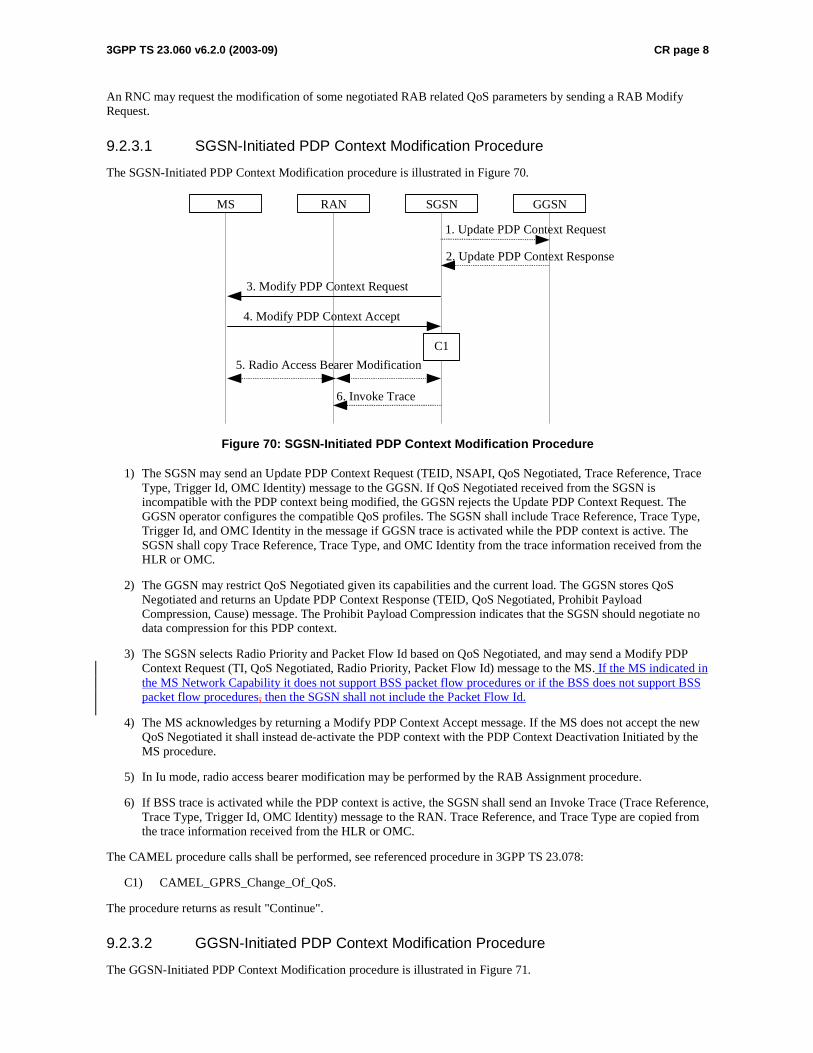
3GPP TS 23.060 v6.2.0 (2003-09) CR page 8
An RNC may request the modification of some negotiated RAB related QoS parameters by sending a RAB Modify Request.
9.2.3.1 SGSN-Initiated PDP Context Modification Procedure
The SGSN-Initiated PDP Context Modification procedure is illustrated in Figure 70.
GGSN
2. Update PDP Context Response
1. Update PDP Context Request
SGSNRANMS
3. Modify PDP Context Request
4. Modify PDP Context Accept
5. Radio Access Bearer Modification
C1
6. Invoke Trace
Figure 70: SGSN-Initiated PDP Context Modification Procedure
1) The SGSN may send an Update PDP Context Request (TEID, NSAPI, QoS Negotiated, Trace Reference, Trace Type, Trigger Id, OMC Identity) message to the GGSN. If QoS Negotiated received from the SGSN is incompatible with the PDP context being modified, the GGSN rejects the Update PDP Context Request. The GGSN operator configures the compatible QoS profiles. The SGSN shall include Trace Reference, Trace Type, Trigger Id, and OMC Identity in the message if GGSN trace is activated while the PDP context is active. The SGSN shall copy Trace Reference, Trace Type, and OMC Identity from the trace information received from the HLR or OMC.
2) The GGSN may restrict QoS Negotiated given its capabilities and the current load. The GGSN stores QoS Negotiated and returns an Update PDP Context Response (TEID, QoS Negotiated, Prohibit Payload Compression, Cause) message. The Prohibit Payload Compression indicates that the SGSN should negotiate no data compression for this PDP context.
3) The SGSN selects Radio Priority and Packet Flow Id based on QoS Negotiated, and may send a Modify PDP Context Request (TI, QoS Negotiated, Radio Priority, Packet Flow Id) message to the MS. If the MS indicated in the MS Network Capability it does not support BSS packet flow procedures or if the BSS does not support BSS packet flow procedures, then the SGSN shall not include the Packet Flow Id.
4) The MS acknowledges by returning a Modify PDP Context Accept message. If the MS does not accept the new QoS Negotiated it shall instead de-activate the PDP context with the PDP Context Deactivation Initiated by the MS procedure.
5) In Iu mode, radio access bearer modification may be performed by the RAB Assignment procedure.
6) If BSS trace is activated while the PDP context is active, the SGSN shall send an Invoke Trace (Trace Reference, Trace Type, Trigger Id, OMC Identity) message to the RAN. Trace Reference, and Trace Type are copied from the trace information received from the HLR or OMC.
The CAMEL procedure calls shall be performed, see referenced procedure in 3GPP TS 23.078:
C1) CAMEL_GPRS_Change_Of_QoS.
The procedure returns as result "Continue".
9.2.3.2 GGSN-Initiated PDP Context Modification Procedure
The GGSN-Initiated PDP Context Modification procedure is illustrated in Figure 71.
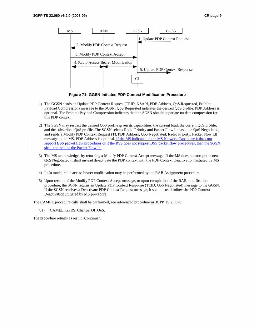
3GPP TS 23.060 v6.2.0 (2003-09) CR page 9
GGSN
5. Update PDP Context Response
1. Update PDP Context Request
SGSNRANMS
2. Modify PDP Context Request
3. Modify PDP Context Accept
4. Radio Access Bearer Modification
C1
Figure 71: GGSN-Initiated PDP Context Modification Procedure
1) The GGSN sends an Update PDP Context Request (TEID, NSAPI, PDP Address, QoS Requested, Prohibit Payload Compression) message to the SGSN. QoS Requested indicates the desired QoS profile. PDP Address is optional. The Prohibit Payload Compression indicates that the SGSN should negotiate no data compression for this PDP context.
2) The SGSN may restrict the desired QoS profile given its capabilities, the current load, the current QoS profile, and the subscribed QoS profile. The SGSN selects Radio Priority and Packet Flow Id based on QoS Negotiated, and sends a Modify PDP Context Request (TI, PDP Address, QoS Negotiated, Radio Priority, Packet Flow Id) message to the MS. PDP Address is optional. If the MS indicated in the MS Network Capability it does not support BSS packet flow procedures or if the BSS does not support BSS packet flow procedures, then the SGSN shall not include the Packet Flow Id.
3) The MS acknowledges by returning a Modify PDP Context Accept message. If the MS does not accept the new QoS Negotiated it shall instead de-activate the PDP context with the PDP Context Deactivation Initiated by MS procedure.
4) In Iu mode, radio access bearer modification may be performed by the RAB Assignment procedure.
5) Upon receipt of the Modify PDP Context Accept message, or upon completion of the RAB modification procedure, the SGSN returns an Update PDP Context Response (TEID, QoS Negotiated) message to the GGSN. If the SGSN receives a Deactivate PDP Context Request message, it shall instead follow the PDP Context Deactivation Initiated by MS procedure.
The CAMEL procedure calls shall be performed, see referenced procedure in 3GPP TS 23.078:
C1) CAMEL_GPRS_Change_Of_QoS.
The procedure returns as result "Continue".
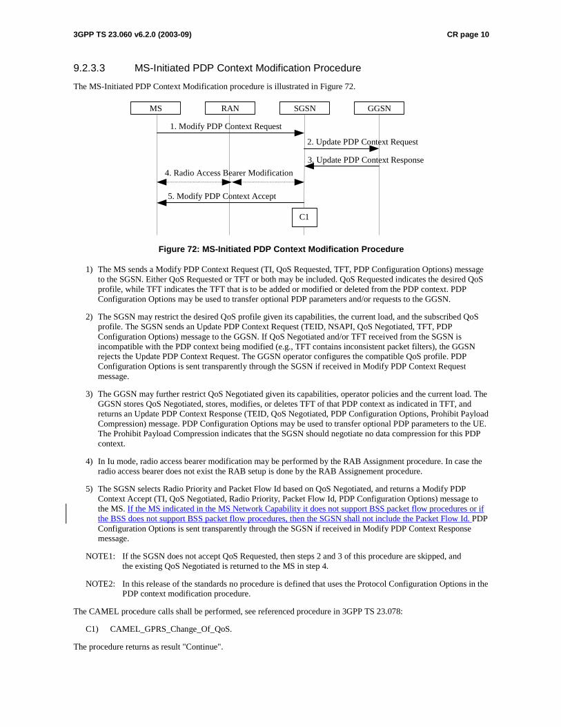
3GPP TS 23.060 v6.2.0 (2003-09) CR page 10
9.2.3.3 MS-Initiated PDP Context Modification Procedure
The MS-Initiated PDP Context Modification procedure is illustrated in Figure 72.
GGSN
3. Update PDP Context Response
2. Update PDP Context Request
SGSNRANMS
1. Modify PDP Context Request
5. Modify PDP Context Accept
4. Radio Access Bearer Modification
C1
Figure 72: MS-Initiated PDP Context Modification Procedure
1) The MS sends a Modify PDP Context Request (TI, QoS Requested, TFT, PDP Configuration Options) message to the SGSN. Either QoS Requested or TFT or both may be included. QoS Requested indicates the desired QoS profile, while TFT indicates the TFT that is to be added or modified or deleted from the PDP context. PDP Configuration Options may be used to transfer optional PDP parameters and/or requests to the GGSN.
2) The SGSN may restrict the desired QoS profile given its capabilities, the current load, and the subscribed QoS profile. The SGSN sends an Update PDP Context Request (TEID, NSAPI, QoS Negotiated, TFT, PDP Configuration Options) message to the GGSN. If QoS Negotiated and/or TFT received from the SGSN is incompatible with the PDP context being modified (e.g., TFT contains inconsistent packet filters), the GGSN rejects the Update PDP Context Request. The GGSN operator configures the compatible QoS profile. PDP Configuration Options is sent transparently through the SGSN if received in Modify PDP Context Request message.
3) The GGSN may further restrict QoS Negotiated given its capabilities, operator policies and the current load. The GGSN stores QoS Negotiated, stores, modifies, or deletes TFT of that PDP context as indicated in TFT, and returns an Update PDP Context Response (TEID, QoS Negotiated, PDP Configuration Options, Prohibit Payload Compression) message. PDP Configuration Options may be used to transfer optional PDP parameters to the UE. The Prohibit Payload Compression indicates that the SGSN should negotiate no data compression for this PDP context.
4) In Iu mode, radio access bearer modification may be performed by the RAB Assignment procedure. In case the radio access bearer does not exist the RAB setup is done by the RAB Assignement procedure.
5) The SGSN selects Radio Priority and Packet Flow Id based on QoS Negotiated, and returns a Modify PDP Context Accept (TI, QoS Negotiated, Radio Priority, Packet Flow Id, PDP Configuration Options) message to the MS. If the MS indicated in the MS Network Capability it does not support BSS packet flow procedures or if the BSS does not support BSS packet flow procedures, then the SGSN shall not include the Packet Flow Id. PDP Configuration Options is sent transparently through the SGSN if received in Modify PDP Context Response message.
NOTE1: If the SGSN does not accept QoS Requested, then steps 2 and 3 of this procedure are skipped, and the existing QoS Negotiated is returned to the MS in step 4.
NOTE2: In this release of the standards no procedure is defined that uses the Protocol Configuration Options in the PDP context modification procedure.
The CAMEL procedure calls shall be performed, see referenced procedure in 3GPP TS 23.078:
C1) CAMEL_GPRS_Change_Of_QoS.
The procedure returns as result "Continue".

3GPP TS 23.060 v6.2.0 (2003-09) CR page 11
************************NEXT CHANGE*************************
12.6.3.5 BSS Context
The SGSN may provide a BSS with information related to ongoing user data transmission in A/Gb mode. The information is given as BSS packet flow contexts, which describe QoS characteristics for the data transmission. Network support of BSS packet flow procedures is indicated in the system information as specified in 3GPP TS 44.060 [77], the MS support is indicated in MS network capability as specified in 3GPP TS 24.008 [13].
All BSS packet flow contexts related to one MS are stored in an MS specific BSS context. The BSS may contain BSS contexts for several MSs. Within a BSS context the BSS packet flow contexts are identified by a packet flow identifier, which is assigned by the SGSN. A BSS packet flow context is shared by one or more LLC SAPIs of the same MS with identical or similar negotiated QoS profiles. The data transfers related to LLC SAPIs that share the same BSS packet flow context constitute one packet flow.
Three packet flows are pre-defined, and identified by three reserved packet flow identifier values. The BSS shall not negotiate BSS packet flow contexts for these pre-defined packet flows with the SGSN. One pre-defined packet flow is used for best-effort service, one is used for SMS, and one is used for signalling. The SGSN can assign the best-effort or SMS packet flow identifier to any PDP context. In the SMS case, the BSS shall handle the packet flow for the PDP context with the same QoS with which it handles SMS. A non-reserved packet flow identifier value is only significant for an MS when the SGSN provided the BSS with a packet flow context for this packet flow identifier value for this MS.
The combined BSS QoS profile for the PDP contexts that share the same packet flow is called the aggregate BSS QoS profile. The aggregate BSS QoS profile is considered to be a single parameter with multiple data transfer attributes as defined in subclause "Quality of Service Profile". It defines the QoS that must be provided by the BSS for a given packet flow between the MS and the SGSN, i.e. for the Um and Gb interfaces combined. The aggregate BSS QoS profile is negotiated between the SGSN and the BSS.
A BSS packet flow timer indicates the maximum time that the BSS may store the BSS packet flow context. The BSS packet flow timer shall not exceed the value of the READY timer for this MS. The BSS packet flow timer is started when the BSS packet flow context is stored in the BSS and when an LLC frame is received from the MS. When the BSS packet flow timer expires, the BSS shall delete the BSS packet flow context.
When a PDP context is activated, modified or deactivated, the SGSN may create, modify, or delete BSS packet flow contexts.
12.6.3.5.1 BSS Packet Flow Context Creation Procedure
On receiving a request to transmit an uplink or downlink LLC PDU for which no BSS packet flow context exists in the BSS, the BSS may request the download of the BSS packet flow context from the SGSN.
If MS and BSS supports BSS packet flow procedures Tthe SGSN may at any time request the creation of a BSS packet flow context, e.g. due to the activation of a PDP context.
The BSS Packet Flow Context Creation procedure is illustrated in Figure 85.
2. Create BSS Packet Flow Context Request
3. Create BSS Packet Flow Context Accept
BSS SGSN
1. Download BSS Packet Flow Context Request
Figure 85: BSS Packet Flow Context Creation Procedure
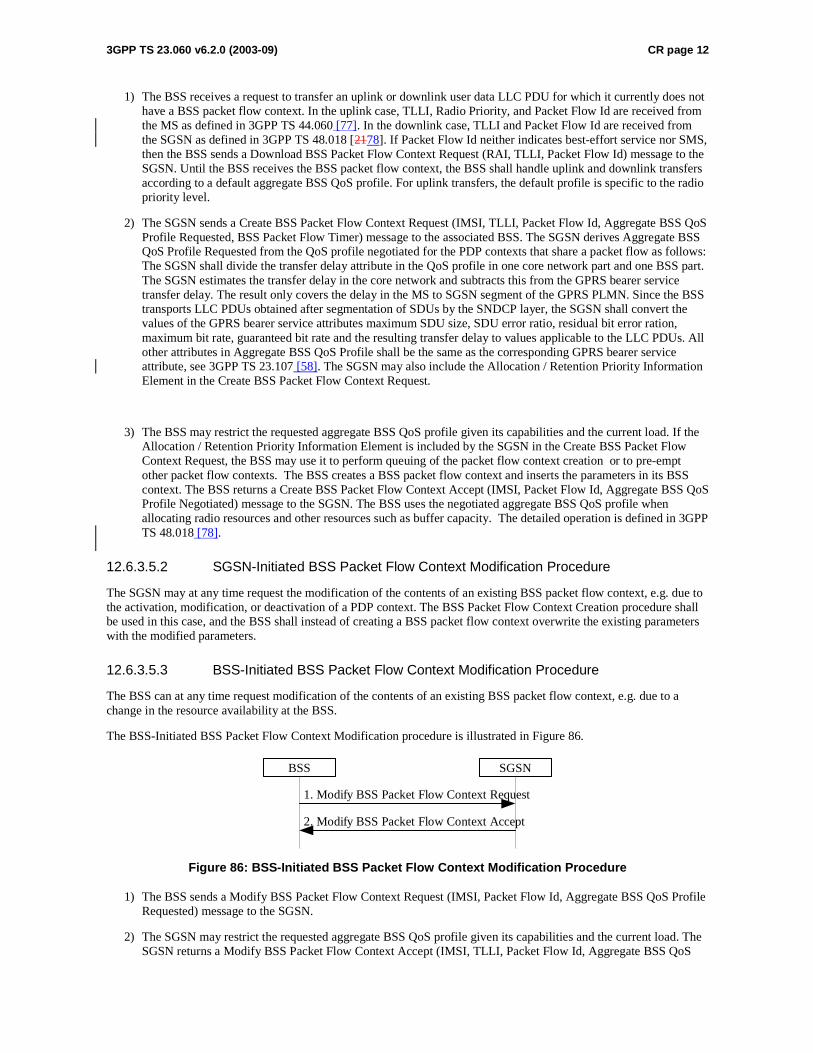
3GPP TS 23.060 v6.2.0 (2003-09) CR page 12
1) The BSS receives a request to transfer an uplink or downlink user data LLC PDU for which it currently does not have a BSS packet flow context. In the uplink case, TLLI, Radio Priority, and Packet Flow Id are received from the MS as defined in 3GPP TS 44.060 [77]. In the downlink case, TLLI and Packet Flow Id are received from the SGSN as defined in 3GPP TS 48.018 [2178]. If Packet Flow Id neither indicates best-effort service nor SMS, then the BSS sends a Download BSS Packet Flow Context Request (RAI, TLLI, Packet Flow Id) message to the SGSN. Until the BSS receives the BSS packet flow context, the BSS shall handle uplink and downlink transfers according to a default aggregate BSS QoS profile. For uplink transfers, the default profile is specific to the radio priority level.
2) The SGSN sends a Create BSS Packet Flow Context Request (IMSI, TLLI, Packet Flow Id, Aggregate BSS QoS Profile Requested, BSS Packet Flow Timer) message to the associated BSS. The SGSN derives Aggregate BSS QoS Profile Requested from the QoS profile negotiated for the PDP contexts that share a packet flow as follows: The SGSN shall divide the transfer delay attribute in the QoS profile in one core network part and one BSS part. The SGSN estimates the transfer delay in the core network and subtracts this from the GPRS bearer service transfer delay. The result only covers the delay in the MS to SGSN segment of the GPRS PLMN. Since the BSS transports LLC PDUs obtained after segmentation of SDUs by the SNDCP layer, the SGSN shall convert the values of the GPRS bearer service attributes maximum SDU size, SDU error ratio, residual bit error ration, maximum bit rate, guaranteed bit rate and the resulting transfer delay to values applicable to the LLC PDUs. All other attributes in Aggregate BSS QoS Profile shall be the same as the corresponding GPRS bearer service attribute, see 3GPP TS 23.107 [58]. The SGSN may also include the Allocation / Retention Priority Information Element in the Create BSS Packet Flow Context Request.
3) The BSS may restrict the requested aggregate BSS QoS profile given its capabilities and the current load. If the Allocation / Retention Priority Information Element is included by the SGSN in the Create BSS Packet Flow Context Request, the BSS may use it to perform queuing of the packet flow context creation or to pre-empt other packet flow contexts. The BSS creates a BSS packet flow context and inserts the parameters in its BSS context. The BSS returns a Create BSS Packet Flow Context Accept (IMSI, Packet Flow Id, Aggregate BSS QoS Profile Negotiated) message to the SGSN. The BSS uses the negotiated aggregate BSS QoS profile when allocating radio resources and other resources such as buffer capacity. The detailed operation is defined in 3GPP TS 48.018 [78].
12.6.3.5.2 SGSN-Initiated BSS Packet Flow Context Modification Procedure
The SGSN may at any time request the modification of the contents of an existing BSS packet flow context, e.g. due to the activation, modification, or deactivation of a PDP context. The BSS Packet Flow Context Creation procedure shall be used in this case, and the BSS shall instead of creating a BSS packet flow context overwrite the existing parameters with the modified parameters.
12.6.3.5.3 BSS-Initiated BSS Packet Flow Context Modification Procedure
The BSS can at any time request modification of the contents of an existing BSS packet flow context, e.g. due to a change in the resource availability at the BSS.
The BSS-Initiated BSS Packet Flow Context Modification procedure is illustrated in Figure 86.
1. Modify BSS Packet Flow Context Request
2. Modify BSS Packet Flow Context Accept
BSS SGSN
Figure 86: BSS-Initiated BSS Packet Flow Context Modification Procedure
1) The BSS sends a Modify BSS Packet Flow Context Request (IMSI, Packet Flow Id, Aggregate BSS QoS Profile Requested) message to the SGSN.
2) The SGSN may restrict the requested aggregate BSS QoS profile given its capabilities and the current load. The SGSN returns a Modify BSS Packet Flow Context Accept (IMSI, TLLI, Packet Flow Id, Aggregate BSS QoS

3GPP TS 23.060 v6.2.0 (2003-09) CR page 13
Profile Negotiated, BSS Packet Flow Timer) message to the BSS. The BSS inserts the modified parameters in its BSS context.
12.6.3.5.4 BSS Packet Flow Context Deletion Procedures
The BSS may, due to e.g. memory restrictions or user inactivity, at any time delete a BSS packet flow context without notifying the SGSN.
If the BSS is no longer able to support the aggregate BSS QoS profile of a BSS packet flow context, it may, especially for conversational or streaming traffic class, request the SGSN to delete or modify the BSS packet flow context. The SGSN should either modify or delete the BSS packet flow context. In addition the SGSN may need to initiate the PDP Context Modification or PDP Context Deletion procedure.
1. Delete BSS Packet Flow Context Request
BSS SGSN
2. SGSN initiated BSS Packet Flow Context deletion or modification
Figure 86a: BSS-Initiated BSS Packet Flow Context Deletion Procedure
1) The BSS sends a Delete BSS Packet Flow Context Request (TLLI, Packet Flow Id, Cause) to the SGSN.
2) The SGSN should start either the SGSN-initiated BSS packet flow context modification procedure or the deletion of the BSS packet flow context. In addition the SGSN may need to initiate the PDP Context Modification or PDP Context Deletion procedure.
The SGSN may request the deletion of a BSS packet flow context with the SGSN-Initiated BSS Packet Flow Context Deletion procedure, as illustrated in Figure 87.
1. Delete BSS Packet Flow Context Request
2. Delete BSS Packet Flow Context Accept
BSS SGSN
Figure 87: SGSN-Initiated BSS Packet Flow Context Deletion Procedure
1) The SGSN sends a Delete BSS Packet Flow Context Request (TLLI , Packet Flow Id) message to the BSS. The BSS deletes the corresponding BSS packet flow context from its BSS context.
2) The BSS returns a Delete BSS Packet Flow Context Accept (TLLI, Packet Flow Id) message to the SGSN.
CR page 1
3GPP TSG SA WG2 Meeting #35 S2-033724 Bangkok, Thailand, 27th – 31st October 2003
CR-Form-v7
CHANGE REQUEST
! 23.060 CR 475 ! rev 1 ! Current version: 6.2.0 !
For HELP on using this form, see bottom of this page or look at the pop-up text over the ! symbols.
Proposed change affects: UICC apps! ME X Radio Access Network Core Network X Title: ! SGSN handling of BSS downgraded ABQP at PFC creation Source: ! Nortel Networks Work item code: ! TEI Date: ! 27/11/03 Category: ! F Release: ! Rel-6 Use one of the following categories:
F (correction) A (corresponds to a correction in an earlier release) B (addition of feature), C (functional modification of feature) D (editorial modification)
Detailed explanations of the above categories can be found in 3GPP TR 21.900.
Use one of the following releases: 2 (GSM Phase 2) R96 (Release 1996) R97 (Release 1997) R98 (Release 1998) R99 (Release 1999) Rel-4 (Release 4) Rel-5 (Release 5) Rel-6 (Release 6)
Reason for change: ! When the SGSN requests the creation of a PFC, the BSS may decide to restrict
the requested aggregate BSS QoS profile (ABQP) given its capabilities and the current load. In this case the BSS returns a negotiated ABQP to the SGSN through a create BSS PFC Accept. The negotiated QoS that is returned to the MS in the Activate PDP Context Accept should take into account the downgraded ABQP. The SGSN behaviour is not clear in 23.060.
Summary of change: ! Clarify that the SGSN should take into account the negotiated ABQP in the PDP
context activation and PDP context modification procedures to the MS if the BSS downgrades the ABQP at BSS Packet Flow Creation.
Consequences if ! not approved:
Unclear behaviour of SGSN. If the SGSN does not return the downgraded ABQP, there is inconsinstency between the QoS in the MS and the QoS in the BSS.
Clauses affected: ! 9.2.2.1, 9.2.2.1.1, 9.2.3.1, 9.2.3.2, 9.2.3.3, 12.6.3.5.1 Y N Other specs ! X Other core specifications ! affected: X Test specifications X O&M Specifications Other comments: !
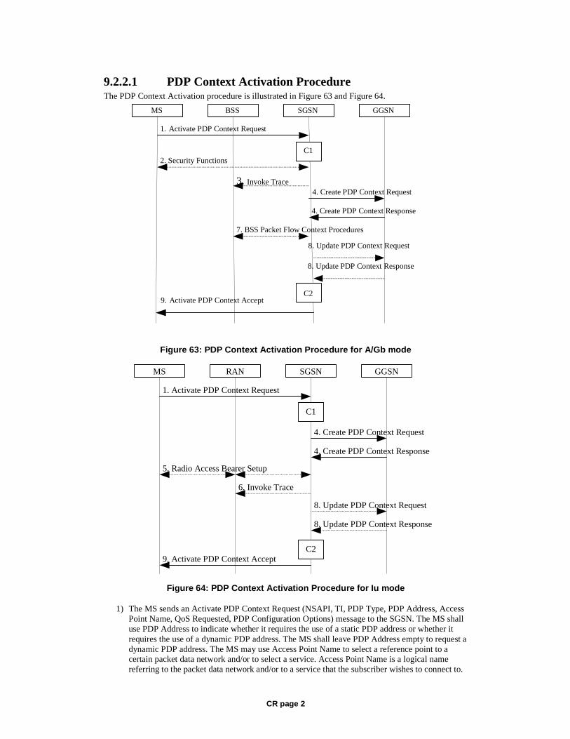
CR page 2
9.2.2.1 PDP Context Activation Procedure The PDP Context Activation procedure is illustrated in Figure 63 and Figure 64.
GGSN
9. Activate PDP Context Accept
4. Create PDP Context Response
4. Create PDP Context Request
1. Activate PDP Context Request
SGSN BSS
2. Security Functions
MS
7. BSS Packet Flow Context Procedures
C1
C2
3. Invoke Trace
8. Update PDP Context Request
8. Update PDP Context Response
Figure 63: PDP Context Activation Procedure for A/Gb mode
GGSN
9. Activate PDP Context Accept
4. Create PDP Context Response
4. Create PDP Context Request
1. Activate PDP Context Request
SGSNRANMS
5. Radio Access Bearer Setup
C1
C2
6. Invoke Trace
8. Update PDP Context Response
8. Update PDP Context Request
Figure 64: PDP Context Activation Procedure for Iu mode
1) The MS sends an Activate PDP Context Request (NSAPI, TI, PDP Type, PDP Address, Access Point Name, QoS Requested, PDP Configuration Options) message to the SGSN. The MS shall use PDP Address to indicate whether it requires the use of a static PDP address or whether it requires the use of a dynamic PDP address. The MS shall leave PDP Address empty to request a dynamic PDP address. The MS may use Access Point Name to select a reference point to a certain packet data network and/or to select a service. Access Point Name is a logical name referring to the packet data network and/or to a service that the subscriber wishes to connect to.
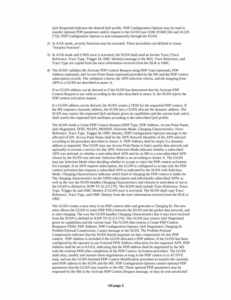
CR page 3
QoS Requested indicates the desired QoS profile. PDP Configuration Options may be used to transfer optional PDP parameters and/or request to the GGSN (see GSM 29.060 [26] and 24.229 [75]). PDP Configuration Options is sent transparently through the SGSN.
2) In A/Gb mode, security functions may be executed. These procedures are defined in clause "Security Function".
3) In A/Gb mode and if BSS trace is activated, the SGSN shall send an Invoke Trace (Trace Reference, Trace Type, Trigger Id, OMC Identity) message to the BSS. Trace Reference, and Trace Type are copied from the trace information received from the HLR or OMC.
4) The SGSN validates the Activate PDP Context Request using PDP Type (optional), PDP Address (optional), and Access Point Name (optional) provided by the MS and the PDP context subscription records. The validation criteria, the APN selection criteria, and the mapping from APN to a GGSN are described in annex A.
If no GGSN address can be derived or if the SGSN has determined that the Activate PDP Context Request is not valid according to the rules described in annex A, the SGSN rejects the PDP context activation request.
If a GGSN address can be derived, the SGSN creates a TEID for the requested PDP context. If the MS requests a dynamic address, the SGSN lets a GGSN allocate the dynamic address. The SGSN may restrict the requested QoS attributes given its capabilities and the current load, and it shall restrict the requested QoS attributes according to the subscribed QoS profile.
The SGSN sends a Create PDP Context Request (PDP Type, PDP Address, Access Point Name, QoS Negotiated, TEID, NSAPI, MSISDN, Selection Mode, Charging Characteristics, Trace Reference, Trace Type, Trigger Id, OMC Identity, PDP Configuration Options) message to the affected GGSN. Access Point Name shall be the APN Network Identifier of the APN selected according to the procedure described in Annex A. PDP Address shall be empty if a dynamic address is requested. The GGSN may use Access Point Name to find a packet data network and optionally to activate a service for this APN. Selection Mode indicates whether a subscribed APN was selected, or whether a non-subscribed APN sent by an MS or a non-subscribed APN chosen by the SGSN was selected. Selection Mode is set according to Annex A. The GGSN may use Selection Mode when deciding whether to accept or reject the PDP context activation. For example, if an APN requires subscription, the GGSN is configured to accept only the PDP context activation that requests a subscribed APN as indicated by the SGSN with Selection Mode. Charging Characteristics indicates which kind of charging the PDP context is liable for. The charging characteristics on the GPRS subscription and individually subscribed APNs as well as the way the SGSN handles Charging Characteristics and chooses to send them or not to the GGSN is defined in 3GPP TS 32.215 [70]. The SGSN shall include Trace Reference, Trace Type, Trigger Id, and OMC Identity if GGSN trace is activated. The SGSN shall copy Trace Reference, Trace Type, and OMC Identity from the trace information received from the HLR or OMC.
The GGSN creates a new entry in its PDP context table and generates a Charging Id. The new entry allows the GGSN to route PDP PDUs between the SGSN and the packet data network, and to start charging. The way the GGSN handles Charging Characteristics that it may have received from the SGSN is defined in 3GPP TS 32.215 [70]. The GGSN may restrict QoS Negotiated given its capabilities and the current load. The GGSN then returns a Create PDP Context Response (TEID, PDP Address, PDP Configuration Options, QoS Negotiated, Charging Id, Prohibit Payload Compression, Cause) message to the SGSN. The Prohibit Payload Compression indicates that the SGSN should negotiate no data compression for this PDP context. PDP Address is included if the GGSN allocated a PDP address. If the GGSN has been configured by the operator to use External PDN Address Allocation for the requested APN, PDP Address shall be set to 0.0.0.0, indicating that the PDP address shall be negotiated by the MS with the external PDN after completion of the PDP Context Activation procedure. The GGSN shall relay, modify and monitor these negotiations as long as the PDP context is in ACTIVE state, and use the GGSN-Initiated PDP Context Modification procedure to transfer the currently used PDP address to the SGSN and the MS. PDP Configuration Options contain optional PDP parameters that the GGSN may transfer to the MS. These optional PDP parameters may be requested by the MS in the Activate PDP Context Request message, or may be sent unsolicited
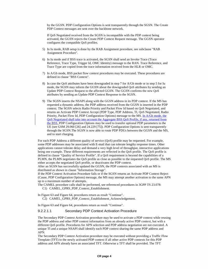
CR page 4
by the GGSN. PDP Configuration Options is sent transparently through the SGSN. The Create PDP Context messages are sent over the backbone network.
If QoS Negotiated received from the SGSN is incompatible with the PDP context being activated, the GGSN rejects the Create PDP Context Request message. The GGSN operator configures the compatible QoS profiles.
5) In Iu mode, RAB setup is done by the RAB Assignment procedure, see subclause "RAB Assignment Procedure".
6) In Iu mode and if BSS trace is activated, the SGSN shall send an Invoke Trace (Trace Reference, Trace Type, Trigger Id, OMC Identity) message to the RAN. Trace Reference, and Trace Type are copied from the trace information received from the HLR or OMC.
7) In A/Gb mode, BSS packet flow context procedures may be executed. These procedures are defined in clause "BSS Context".
8) In case the QoS attributes have been downgraded in step 7 for A/Gb mode or in step 5 for Iu mode, the SGSN may inform the GGSN about the downgraded QoS attributes by sending an Update PDP Context Request to the affected GGSN. The GGSN confirms the new QoS attributes by sending an Update PDP Context Response to the SGSN.
9) The SGSN inserts the NSAPI along with the GGSN address in its PDP context. If the MS has requested a dynamic address, the PDP address received from the GGSN is inserted in the PDP context. The SGSN selects Radio Priority and Packet Flow Id based on QoS Negotiated, and returns an Activate PDP Context Accept (PDP Type, PDP Address, TI, QoS Negotiated, Radio Priority, Packet Flow Id, PDP Configuration Options) message to the MS. In A/Gb mode, the QoS Negotiated shall take into account the Aggregate BSS QoS Profile, if any, returned from the BSS. PDP Configuration Options may be used to transfer optional PDP parameters to the UE (see GSM 29.060 [26] and 24.229 [75]). PDP Configuration Options is sent transparently through the SGSN.The SGSN is now able to route PDP PDUs between the GGSN and the MS, and to start charging.
For each PDP Address a different quality of service (QoS) profile may be requested. For example, some PDP addresses may be associated with E-mail that can tolerate lengthy response times. Other applications cannot tolerate delay and demand a very high level of throughput, interactive applications being one example. These different requirements are reflected in the QoS profile. The QoS profile is defined in clause "Quality of Service Profile". If a QoS requirement is beyond the capabilities of a PLMN, the PLMN negotiates the QoS profile as close as possible to the requested QoS profile. The MS either accepts the negotiated QoS profile, or deactivates the PDP context. After an SGSN has successfully updated the GGSN, the PDP contexts associated with an MS is distributed as shown in clause "Information Storage". If the PDP Context Activation Procedure fails or if the SGSN returns an Activate PDP Context Reject (Cause, PDP Configuration Options) message, the MS may attempt another activation to the same APN up to a maximum number of attempts. The CAMEL procedure calls shall be performed, see referenced procedures in 3GPP TS 23.078:
C1) CAMEL_GPRS_PDP_Context_Establishment.
In Figure 63 and Figure 64, procedures return as result "Continue". C2) CAMEL_GPRS_PDP_Context_Establishment_Acknowledgement.
In Figure 63 and Figure 64, procedures return as result "Continue".
9.2.2.1.1 Secondary PDP Context Activation Procedure
The Secondary PDP Context Activation procedure may be used to activate a PDP context while reusing the PDP address and other PDP context information from an already active PDP context, but with a different QoS profile. Procedures for APN selection and PDP address negotiation are not executed. A unique TI and a unique NSAPI shall identify each PDP context sharing the same PDP address and APN. The Secondary PDP Context Activation procedure may be executed without providing a Traffic Flow Template (TFT) to the newly activated PDP context if all other active PDP contexts for this PDP address and APN already have an associated TFT. Otherwise a TFT shall be provided. The TFT

CR page 5
contains attributes that specify an IP header filter that is used to direct data packets received from the interconnected packet data network to the newly activated PDP context. The Secondary PDP Context Activation procedure may only be initiated after a PDP context is already activated for the same PDP address and APN. The procedure is illustrated in Figure 65 and Figure 66.
GGSN
7. Activate Secondary PDP Context Accept
3. Create PDP Context Response
3. Create PDP Context Request
1. Activate Secondary PDP Context Request
SGSN BSS
2. Security Functions
MS
5. BSS Packet Flow Context Procedures
C1
C2
6. Update PDP Context Request
6. Update PDP Context Response
Figure 65: Secondary PDP Context Activation Procedure for A/Gb mode
GGSN
7. Activate Secondary PDP Context Accept
3 . Create PDP Context Response
3 . Create PDP Context Request
1. Activate Secondary PDP Context Request
SGSN RAN MS
4 . Radio Access Bea rer Setup
C1
C2
6. Update PDP Context Response
6. Update PDP Context Request
Figure 66: Secondary PDP Context Activation Procedure for Iu mode
1) The MS sends an Activate Secondary PDP Context Request (Linked TI, NSAPI, TI, QoS Requested, TFT, PDP Configuration Options) message to the SGSN. Linked TI indicates the TI value assigned to any one of the already activated PDP contexts for this PDP address and APN. QoS Requested indicates the desired QoS profile. TFT is sent transparently through the SGSN to the GGSN to enable packet classification for downlink data transfer. TI and NSAPI contain values not used by any other activated PDP context. PDP Configuration Options may be used to transfer optional PDP parameters and/or requests to the GGSN (see GSM 29.060 [26] and 24.229 [75]). PDP Configuration Options is sent transparently through the SGSN.
2) In A/Gb mode, security functions may be executed. These procedures are defined in clause "Security Function".
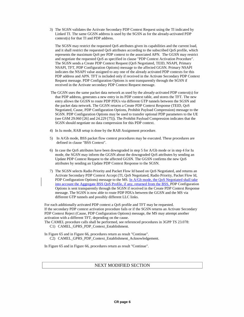
CR page 6
3) The SGSN validates the Activate Secondary PDP Context Request using the TI indicated by Linked TI. The same GGSN address is used by the SGSN as for the already-activated PDP context(s) for that TI and PDP address.
The SGSN may restrict the requested QoS attributes given its capabilities and the current load, and it shall restrict the requested QoS attributes according to the subscribed QoS profile, which represents the maximum QoS per PDP context to the associated APN. The GGSN may restrict and negotiate the requested QoS as specified in clause "PDP Context Activation Procedure". The SGSN sends a Create PDP Context Request (QoS Negotiated, TEID, NSAPI, Primary NSAPI, TFT, PDP Configuration Options) message to the affected GGSN. Primary NSAPI indicates the NSAPI value assigned to any one of the already activated PDP contexts for this PDP address and APN. TFT is included only if received in the Activate Secondary PDP Context Request message. PDP Configuration Options is sent transparently through the SGSN if received in the Activate secondary PDP Context Request message.
The GGSN uses the same packet data network as used by the already-activated PDP context(s) for that PDP address, generates a new entry in its PDP context table, and stores the TFT. The new entry allows the GGSN to route PDP PDUs via different GTP tunnels between the SGSN and the packet data network. The GGSN returns a Create PDP Context Response (TEID, QoS Negotiated, Cause, PDP Configuration Options, Prohibit Payload Compression) message to the SGSN. PDP Configuration Options may be used to transfer optional PDP parameters to the UE (see GSM 29.060 [26] and 24.229 [75]). The Prohibit Payload Compression indicates that the SGSN should negotiate no data compression for this PDP context.
4) In Iu mode, RAB setup is done by the RAB Assignment procedure.
5) In A/Gb mode, BSS packet flow context procedures may be executed. These procedures are defined in clause "BSS Context".
6) In case the QoS attributes have been downgraded in step 5 for A/Gb mode or in step 4 for Iu mode, the SGSN may inform the GGSN about the downgraded QoS attributes by sending an Update PDP Context Request to the affected GGSN. The GGSN confirms the new QoS attributes by sending an Update PDP Context Response to the SGSN.
7) The SGSN selects Radio Priority and Packet Flow Id based on QoS Negotiated, and returns an Activate Secondary PDP Context Accept (TI, QoS Negotiated, Radio Priority, Packet Flow Id, PDP Configuration Options) message to the MS. In A/Gb mode, the QoS Negotiated shall take into account the Aggregate BSS QoS Profile, if any, returned from the BSS. PDP Configuration Options is sent transparently through the SGSN if received in the Create PDP Context Response message. The SGSN is now able to route PDP PDUs between the GGSN and the MS via different GTP tunnels and possibly different LLC links.
For each additionally activated PDP context a QoS profile and TFT may be requested. If the secondary PDP context activation procedure fails or if the SGSN returns an Activate Secondary PDP Context Reject (Cause, PDP Configuration Options) message, the MS may attempt another activation with a different TFT, depending on the cause. The CAMEL procedure calls shall be performed, see referenced procedures in 3GPP TS 23.078:
C1) CAMEL_GPRS_PDP_Context_Establishment.
In Figure 65 and in Figure 66, procedures return as result "Continue". C2) CAMEL_GPRS_PDP_Context_Establishment_Acknowledgement.
In Figure 65 and in Figure 66, procedures return as result "Continue".
NEXT MODIFIED SECTION
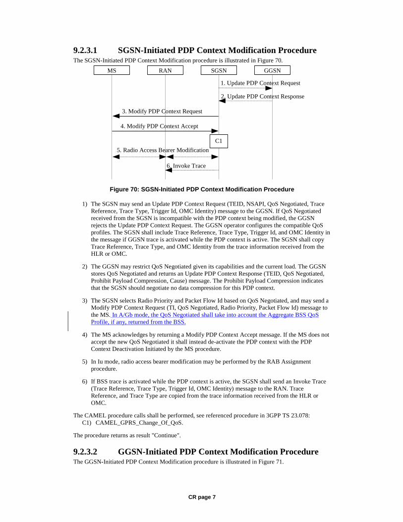
CR page 7
9.2.3.1 SGSN-Initiated PDP Context Modification Procedure The SGSN-Initiated PDP Context Modification procedure is illustrated in Figure 70.
GGSN
2. Update PDP Context Response
1. Update PDP Context Request
SGSNRANMS
3. Modify PDP Context Request
4. Modify PDP Context Accept
5. Radio Access Bearer Modification
C1
6. Invoke Trace
Figure 70: SGSN-Initiated PDP Context Modification Procedure
1) The SGSN may send an Update PDP Context Request (TEID, NSAPI, QoS Negotiated, Trace Reference, Trace Type, Trigger Id, OMC Identity) message to the GGSN. If QoS Negotiated received from the SGSN is incompatible with the PDP context being modified, the GGSN rejects the Update PDP Context Request. The GGSN operator configures the compatible QoS profiles. The SGSN shall include Trace Reference, Trace Type, Trigger Id, and OMC Identity in the message if GGSN trace is activated while the PDP context is active. The SGSN shall copy Trace Reference, Trace Type, and OMC Identity from the trace information received from the HLR or OMC.
2) The GGSN may restrict QoS Negotiated given its capabilities and the current load. The GGSN stores QoS Negotiated and returns an Update PDP Context Response (TEID, QoS Negotiated, Prohibit Payload Compression, Cause) message. The Prohibit Payload Compression indicates that the SGSN should negotiate no data compression for this PDP context.
3) The SGSN selects Radio Priority and Packet Flow Id based on QoS Negotiated, and may send a Modify PDP Context Request (TI, QoS Negotiated, Radio Priority, Packet Flow Id) message to the MS. In A/Gb mode, the QoS Negotiated shall take into account the Aggregate BSS QoS Profile, if any, returned from the BSS.
4) The MS acknowledges by returning a Modify PDP Context Accept message. If the MS does not accept the new QoS Negotiated it shall instead de-activate the PDP context with the PDP Context Deactivation Initiated by the MS procedure.
5) In Iu mode, radio access bearer modification may be performed by the RAB Assignment procedure.
6) If BSS trace is activated while the PDP context is active, the SGSN shall send an Invoke Trace (Trace Reference, Trace Type, Trigger Id, OMC Identity) message to the RAN. Trace Reference, and Trace Type are copied from the trace information received from the HLR or OMC.
The CAMEL procedure calls shall be performed, see referenced procedure in 3GPP TS 23.078: C1) CAMEL_GPRS_Change_Of_QoS.
The procedure returns as result "Continue".
9.2.3.2 GGSN-Initiated PDP Context Modification Procedure The GGSN-Initiated PDP Context Modification procedure is illustrated in Figure 71.
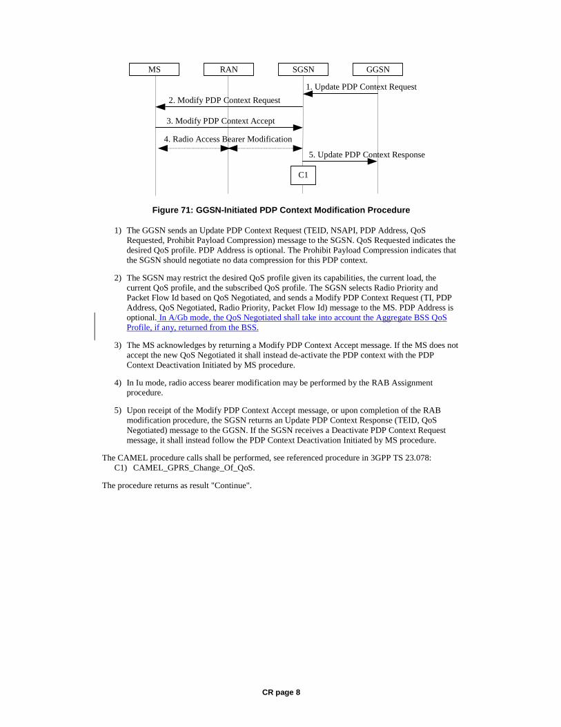
CR page 8
GGSN
5. Update PDP Context Response
1. Update PDP Context Request
SGSNRANMS
2. Modify PDP Context Request
3. Modify PDP Context Accept
4. Radio Access Bearer Modification
C1
Figure 71: GGSN-Initiated PDP Context Modification Procedure
1) The GGSN sends an Update PDP Context Request (TEID, NSAPI, PDP Address, QoS Requested, Prohibit Payload Compression) message to the SGSN. QoS Requested indicates the desired QoS profile. PDP Address is optional. The Prohibit Payload Compression indicates that the SGSN should negotiate no data compression for this PDP context.
2) The SGSN may restrict the desired QoS profile given its capabilities, the current load, the current QoS profile, and the subscribed QoS profile. The SGSN selects Radio Priority and Packet Flow Id based on QoS Negotiated, and sends a Modify PDP Context Request (TI, PDP Address, QoS Negotiated, Radio Priority, Packet Flow Id) message to the MS. PDP Address is optional. In A/Gb mode, the QoS Negotiated shall take into account the Aggregate BSS QoS Profile, if any, returned from the BSS.
3) The MS acknowledges by returning a Modify PDP Context Accept message. If the MS does not accept the new QoS Negotiated it shall instead de-activate the PDP context with the PDP Context Deactivation Initiated by MS procedure.
4) In Iu mode, radio access bearer modification may be performed by the RAB Assignment procedure.
5) Upon receipt of the Modify PDP Context Accept message, or upon completion of the RAB modification procedure, the SGSN returns an Update PDP Context Response (TEID, QoS Negotiated) message to the GGSN. If the SGSN receives a Deactivate PDP Context Request message, it shall instead follow the PDP Context Deactivation Initiated by MS procedure.
The CAMEL procedure calls shall be performed, see referenced procedure in 3GPP TS 23.078: C1) CAMEL_GPRS_Change_Of_QoS.
The procedure returns as result "Continue".
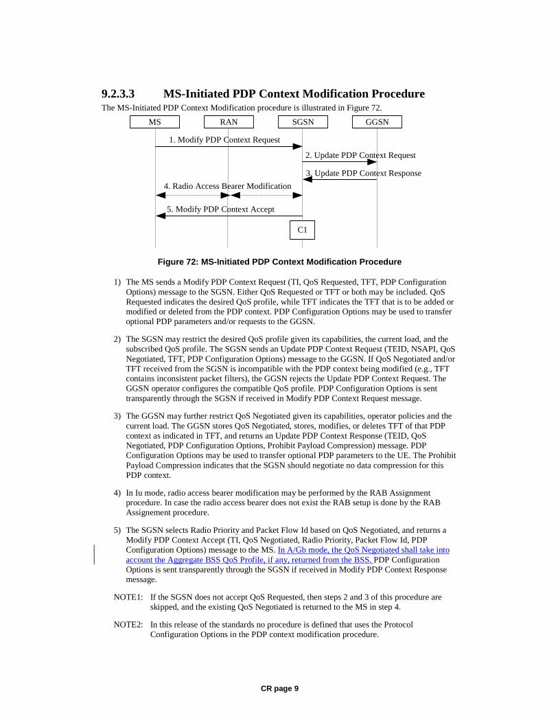
CR page 9
9.2.3.3 MS-Initiated PDP Context Modification Procedure The MS-Initiated PDP Context Modification procedure is illustrated in Figure 72.
GGSN
3. Update PDP Context Response
2. Update PDP Context Request
SGSNRANMS
1. Modify PDP Context Request
5. Modify PDP Context Accept
4. Radio Access Bearer Modification
C1
Figure 72: MS-Initiated PDP Context Modification Procedure
1) The MS sends a Modify PDP Context Request (TI, QoS Requested, TFT, PDP Configuration Options) message to the SGSN. Either QoS Requested or TFT or both may be included. QoS Requested indicates the desired QoS profile, while TFT indicates the TFT that is to be added or modified or deleted from the PDP context. PDP Configuration Options may be used to transfer optional PDP parameters and/or requests to the GGSN.
2) The SGSN may restrict the desired QoS profile given its capabilities, the current load, and the subscribed QoS profile. The SGSN sends an Update PDP Context Request (TEID, NSAPI, QoS Negotiated, TFT, PDP Configuration Options) message to the GGSN. If QoS Negotiated and/or TFT received from the SGSN is incompatible with the PDP context being modified (e.g., TFT contains inconsistent packet filters), the GGSN rejects the Update PDP Context Request. The GGSN operator configures the compatible QoS profile. PDP Configuration Options is sent transparently through the SGSN if received in Modify PDP Context Request message.
3) The GGSN may further restrict QoS Negotiated given its capabilities, operator policies and the current load. The GGSN stores QoS Negotiated, stores, modifies, or deletes TFT of that PDP context as indicated in TFT, and returns an Update PDP Context Response (TEID, QoS Negotiated, PDP Configuration Options, Prohibit Payload Compression) message. PDP Configuration Options may be used to transfer optional PDP parameters to the UE. The Prohibit Payload Compression indicates that the SGSN should negotiate no data compression for this PDP context.
4) In Iu mode, radio access bearer modification may be performed by the RAB Assignment procedure. In case the radio access bearer does not exist the RAB setup is done by the RAB Assignement procedure.
5) The SGSN selects Radio Priority and Packet Flow Id based on QoS Negotiated, and returns a Modify PDP Context Accept (TI, QoS Negotiated, Radio Priority, Packet Flow Id, PDP Configuration Options) message to the MS. In A/Gb mode, the QoS Negotiated shall take into account the Aggregate BSS QoS Profile, if any, returned from the BSS. PDP Configuration Options is sent transparently through the SGSN if received in Modify PDP Context Response message.
NOTE1: If the SGSN does not accept QoS Requested, then steps 2 and 3 of this procedure are skipped, and the existing QoS Negotiated is returned to the MS in step 4.
NOTE2: In this release of the standards no procedure is defined that uses the Protocol Configuration Options in the PDP context modification procedure.
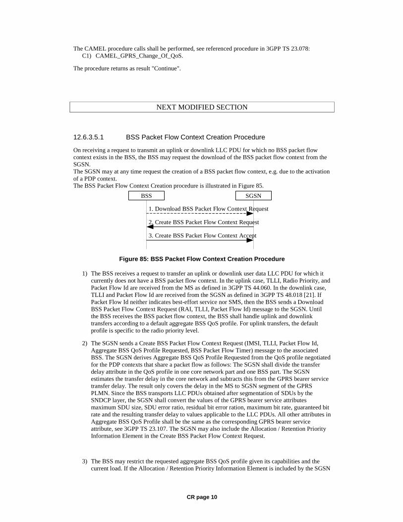
CR page 10
The CAMEL procedure calls shall be performed, see referenced procedure in 3GPP TS 23.078: C1) CAMEL_GPRS_Change_Of_QoS.
The procedure returns as result "Continue".
NEXT MODIFIED SECTION
12.6.3.5.1 BSS Packet Flow Context Creation Procedure
On receiving a request to transmit an uplink or downlink LLC PDU for which no BSS packet flow context exists in the BSS, the BSS may request the download of the BSS packet flow context from the SGSN. The SGSN may at any time request the creation of a BSS packet flow context, e.g. due to the activation of a PDP context. The BSS Packet Flow Context Creation procedure is illustrated in Figure 85.
2. Create BSS Packet Flow Context Request
3. Create BSS Packet Flow Context Accept
BSS SGSN
1. Download BSS Packet Flow Context Request
Figure 85: BSS Packet Flow Context Creation Procedure
1) The BSS receives a request to transfer an uplink or downlink user data LLC PDU for which it currently does not have a BSS packet flow context. In the uplink case, TLLI, Radio Priority, and Packet Flow Id are received from the MS as defined in 3GPP TS 44.060. In the downlink case, TLLI and Packet Flow Id are received from the SGSN as defined in 3GPP TS 48.018 [21]. If Packet Flow Id neither indicates best-effort service nor SMS, then the BSS sends a Download BSS Packet Flow Context Request (RAI, TLLI, Packet Flow Id) message to the SGSN. Until the BSS receives the BSS packet flow context, the BSS shall handle uplink and downlink transfers according to a default aggregate BSS QoS profile. For uplink transfers, the default profile is specific to the radio priority level.
2) The SGSN sends a Create BSS Packet Flow Context Request (IMSI, TLLI, Packet Flow Id, Aggregate BSS QoS Profile Requested, BSS Packet Flow Timer) message to the associated BSS. The SGSN derives Aggregate BSS QoS Profile Requested from the QoS profile negotiated for the PDP contexts that share a packet flow as follows: The SGSN shall divide the transfer delay attribute in the QoS profile in one core network part and one BSS part. The SGSN estimates the transfer delay in the core network and subtracts this from the GPRS bearer service transfer delay. The result only covers the delay in the MS to SGSN segment of the GPRS PLMN. Since the BSS transports LLC PDUs obtained after segmentation of SDUs by the SNDCP layer, the SGSN shall convert the values of the GPRS bearer service attributes maximum SDU size, SDU error ratio, residual bit error ration, maximum bit rate, guaranteed bit rate and the resulting transfer delay to values applicable to the LLC PDUs. All other attributes in Aggregate BSS QoS Profile shall be the same as the corresponding GPRS bearer service attribute, see 3GPP TS 23.107. The SGSN may also include the Allocation / Retention Priority Information Element in the Create BSS Packet Flow Context Request.
3) The BSS may restrict the requested aggregate BSS QoS profile given its capabilities and the current load. If the Allocation / Retention Priority Information Element is included by the SGSN

CR page 11
in the Create BSS Packet Flow Context Request, the BSS may use it to perform queuing of the packet flow context creation or to pre-empt other packet flow contexts. The BSS creates a BSS packet flow context and inserts the parameters in its BSS context. The BSS returns a Create BSS Packet Flow Context Accept (IMSI, Packet Flow Id, Aggregate BSS QoS Profile Negotiated) message to the SGSN. The BSS uses the negotiated aggregate BSS QoS profile when allocating radio resources and other resources such as buffer capacity. The detailed operation is defined in 3GPP TS 48.018. If the SGSN Aggregate BSS QoS Profile requested by the SGSN was restricted by the BSS, the SGSN takes the BSS restriction into account when indicating to the MS the negotiated QoS of the associated PDP context(s).

CR page 1
3GPP TSG SA WG2 Meeting #36 S2-034247 New York, USA, 27th – 28th November 2003
CR-Form-v7
CHANGE REQUEST
! 23.060 CR 473 ! rev 3 ! Current version: 5.6.0 !
For HELP on using this form, see bottom of this page or look at the pop-up text over the ! symbols.
Proposed change affects: UICC apps! ME Radio Access Network Core Network X Title: ! Serving network identity from SGSN to GGSN Source: ! Nortel Networks Work item code: ! TEI Date: ! 24/11/03 Category: ! F Release: ! Rel-5 Use one of the following categories:
F (correction) A (corresponds to a correction in an earlier release) B (addition of feature), C (functional modification of feature) D (editorial modification)
Detailed explanations of the above categories can be found in 3GPP TR 21.900.
Use one of the following releases: 2 (GSM Phase 2) R96 (Release 1996) R97 (Release 1997) R98 (Release 1998) R99 (Release 1999) Rel-4 (Release 4) Rel-5 (Release 5) Rel-6 (Release 6)
Reason for change: ! In an LS from SA5 (S2-033339), SA2 are asked to add the requirement of
including the MCC and MNC of the location of where the MS is registered in messaging between SGSN and GGSN (inside the RAI). This is necessary for accurate content filtering.
Previous liaisons from T2, CPWP and BARG indicated problems with the implementation of integrated pricing structures without such additions.
Summary of change: ! Information is added to the Create PDP Context Req and Update PDP Context
Req, to provide to the GGSN with the network identity on which the MS is registered.
Consequences if ! not approved:
Stage 2 requirement missing.
Clauses affected: ! 6.9.1.2.2, 6.9.1.3.2, 6.9.2.1, 6.9.2.2.1, 6.9.2.2.2, 6.13.2.1, 6.13.2.2, 9.2.2.1,
9.2.2.1.1, 9.2.3.1, 9.2.3.3 Y N Other specs ! X Other core specifications ! affected: X Test specifications X O&M Specifications Other comments: !
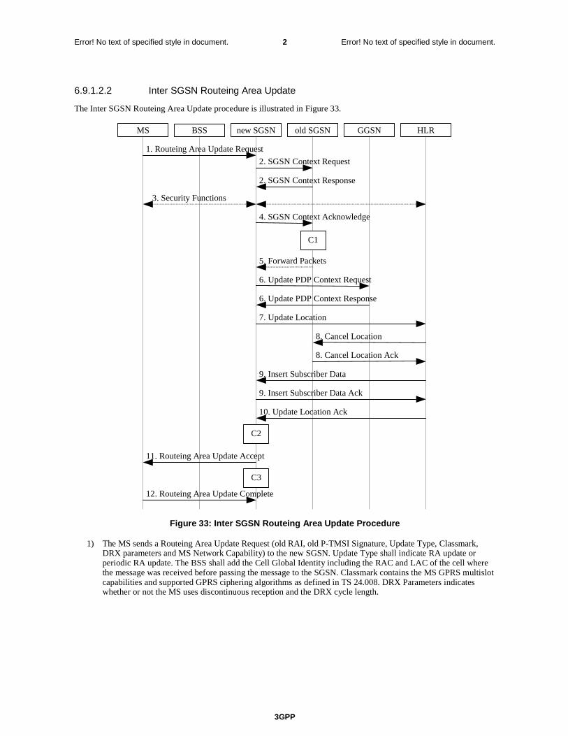
3GPP
Error! No text of specified style in document. 2 Error! No text of specified style in document.
6.9.1.2.2 Inter SGSN Routeing Area Update
The Inter SGSN Routeing Area Update procedure is illustrated in Figure 33.
MS BSS new SGSN HLR GGSN old SGSN
2. SGSN Context Response
3. Security Functions
1. Routeing Area Update Request
2. SGSN Context Request
6. Update PDP Context Request
6. Update PDP Context Response
7. Update Location
10. Update Location Ack
11. Routeing Area Update Accept
8. Cancel Location
8. Cancel Location Ack
9. Insert Subscriber Data Ack
9. Insert Subscriber Data
12. Routeing Area Update Complete
5. Forward Packets
4. SGSN Context Acknowledge
C3
C2
C1
Figure 33: Inter SGSN Routeing Area Update Procedure
1) The MS sends a Routeing Area Update Request (old RAI, old P-TMSI Signature, Update Type, Classmark, DRX parameters and MS Network Capability) to the new SGSN. Update Type shall indicate RA update or periodic RA update. The BSS shall add the Cell Global Identity including the RAC and LAC of the cell where the message was received before passing the message to the SGSN. Classmark contains the MS GPRS multislot capabilities and supported GPRS ciphering algorithms as defined in TS 24.008. DRX Parameters indicates whether or not the MS uses discontinuous reception and the DRX cycle length.
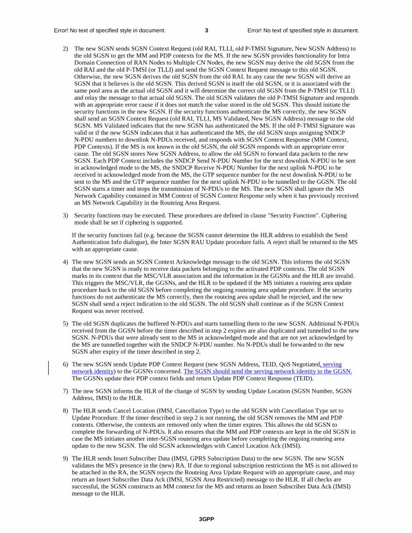
3GPP
Error! No text of specified style in document. 3 Error! No text of specified style in document.
2) The new SGSN sends SGSN Context Request (old RAI, TLLI, old P-TMSI Signature, New SGSN Address) to the old SGSN to get the MM and PDP contexts for the MS. If the new SGSN provides functionality for Intra Domain Connection of RAN Nodes to Multiple CN Nodes, the new SGSN may derive the old SGSN from the old RAI and the old P-TMSI (or TLLI) and send the SGSN Context Request message to this old SGSN. Otherwise, the new SGSN derives the old SGSN from the old RAI. In any case the new SGSN will derive an SGSN that it believes is the old SGSN. This derived SGSN is itself the old SGSN, or it is associated with the same pool area as the actual old SGSN and it will determine the correct old SGSN from the P-TMSI (or TLLI) and relay the message to that actual old SGSN. The old SGSN validates the old P-TMSI Signature and responds with an appropriate error cause if it does not match the value stored in the old SGSN. This should initiate the security functions in the new SGSN. If the security functions authenticate the MS correctly, the new SGSN shall send an SGSN Context Request (old RAI, TLLI, MS Validated, New SGSN Address) message to the old SGSN. MS Validated indicates that the new SGSN has authenticated the MS. If the old P-TMSI Signature was valid or if the new SGSN indicates that it has authenticated the MS, the old SGSN stops assigning SNDCP N-PDU numbers to downlink N-PDUs received, and responds with SGSN Context Response (MM Context, PDP Contexts). If the MS is not known in the old SGSN, the old SGSN responds with an appropriate error cause. The old SGSN stores New SGSN Address, to allow the old SGSN to forward data packets to the new SGSN. Each PDP Context includes the SNDCP Send N-PDU Number for the next downlink N-PDU to be sent in acknowledged mode to the MS, the SNDCP Receive N-PDU Number for the next uplink N-PDU to be received in acknowledged mode from the MS, the GTP sequence number for the next downlink N-PDU to be sent to the MS and the GTP sequence number for the next uplink N-PDU to be tunnelled to the GGSN. The old SGSN starts a timer and stops the transmission of N-PDUs to the MS. The new SGSN shall ignore the MS Network Capability contained in MM Context of SGSN Context Response only when it has previously received an MS Network Capability in the Routeing Area Request.
3) Security functions may be executed. These procedures are defined in clause "Security Function". Ciphering mode shall be set if ciphering is supported.
If the security functions fail (e.g. because the SGSN cannot determine the HLR address to establish the Send Authentication Info dialogue), the Inter SGSN RAU Update procedure fails. A reject shall be returned to the MS with an appropriate cause.
4) The new SGSN sends an SGSN Context Acknowledge message to the old SGSN. This informs the old SGSN that the new SGSN is ready to receive data packets belonging to the activated PDP contexts. The old SGSN marks in its context that the MSC/VLR association and the information in the GGSNs and the HLR are invalid. This triggers the MSC/VLR, the GGSNs, and the HLR to be updated if the MS initiates a routeing area update procedure back to the old SGSN before completing the ongoing routeing area update procedure. If the security functions do not authenticate the MS correctly, then the routeing area update shall be rejected, and the new SGSN shall send a reject indication to the old SGSN. The old SGSN shall continue as if the SGSN Context Request was never received.
5) The old SGSN duplicates the buffered N-PDUs and starts tunnelling them to the new SGSN. Additional N-PDUs received from the GGSN before the timer described in step 2 expires are also duplicated and tunnelled to the new SGSN. N-PDUs that were already sent to the MS in acknowledged mode and that are not yet acknowledged by the MS are tunnelled together with the SNDCP N-PDU number. No N-PDUs shall be forwarded to the new SGSN after expiry of the timer described in step 2.
6) The new SGSN sends Update PDP Context Request (new SGSN Address, TEID, QoS Negotiated, serving network identity) to the GGSNs concerned. The SGSN should send the serving network identity to the GGSN. The GGSNs update their PDP context fields and return Update PDP Context Response (TEID).
7) The new SGSN informs the HLR of the change of SGSN by sending Update Location (SGSN Number, SGSN Address, IMSI) to the HLR.
8) The HLR sends Cancel Location (IMSI, Cancellation Type) to the old SGSN with Cancellation Type set to Update Procedure. If the timer described in step 2 is not running, the old SGSN removes the MM and PDP contexts. Otherwise, the contexts are removed only when the timer expires. This allows the old SGSN to complete the forwarding of N-PDUs. It also ensures that the MM and PDP contexts are kept in the old SGSN in case the MS initiates another inter-SGSN routeing area update before completing the ongoing routeing area update to the new SGSN. The old SGSN acknowledges with Cancel Location Ack (IMSI).
9) The HLR sends Insert Subscriber Data (IMSI, GPRS Subscription Data) to the new SGSN. The new SGSN validates the MS's presence in the (new) RA. If due to regional subscription restrictions the MS is not allowed to be attached in the RA, the SGSN rejects the Routeing Area Update Request with an appropriate cause, and may return an Insert Subscriber Data Ack (IMSI, SGSN Area Restricted) message to the HLR. If all checks are successful, the SGSN constructs an MM context for the MS and returns an Insert Subscriber Data Ack (IMSI) message to the HLR.
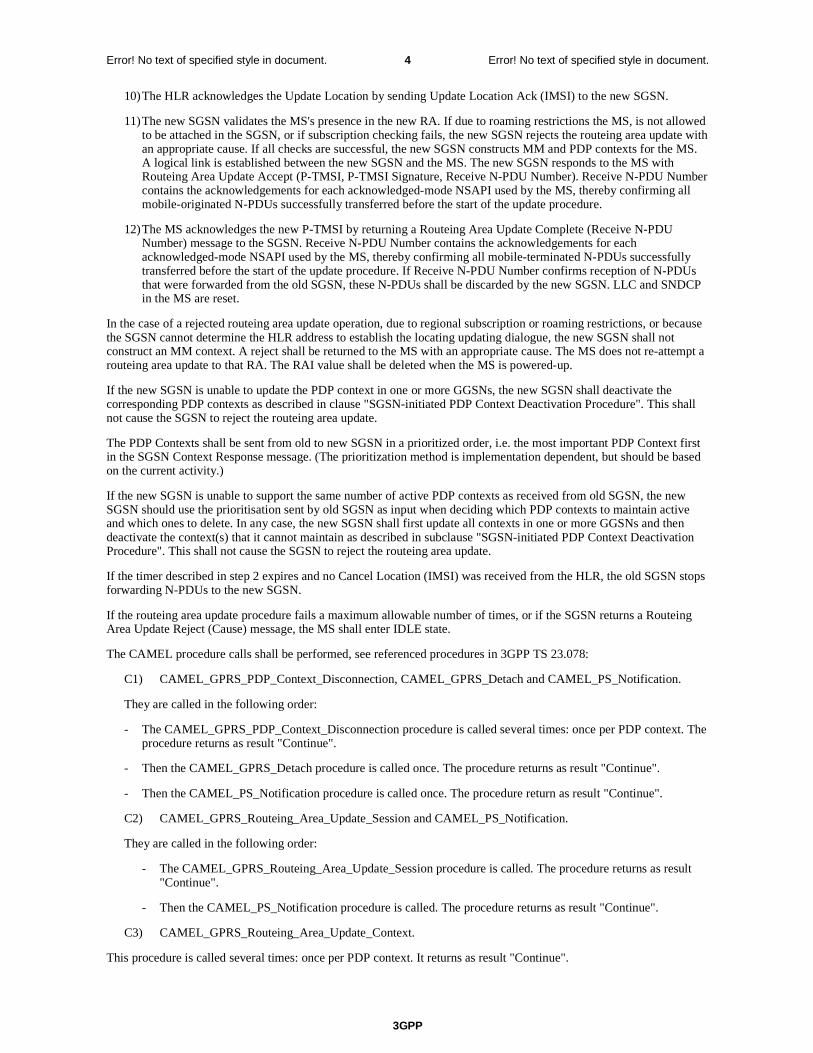
3GPP
Error! No text of specified style in document. 4 Error! No text of specified style in document.
10) The HLR acknowledges the Update Location by sending Update Location Ack (IMSI) to the new SGSN.
11) The new SGSN validates the MS's presence in the new RA. If due to roaming restrictions the MS, is not allowed to be attached in the SGSN, or if subscription checking fails, the new SGSN rejects the routeing area update with an appropriate cause. If all checks are successful, the new SGSN constructs MM and PDP contexts for the MS. A logical link is established between the new SGSN and the MS. The new SGSN responds to the MS with Routeing Area Update Accept (P-TMSI, P-TMSI Signature, Receive N-PDU Number). Receive N-PDU Number contains the acknowledgements for each acknowledged-mode NSAPI used by the MS, thereby confirming all mobile-originated N-PDUs successfully transferred before the start of the update procedure.
12) The MS acknowledges the new P-TMSI by returning a Routeing Area Update Complete (Receive N-PDU Number) message to the SGSN. Receive N-PDU Number contains the acknowledgements for each acknowledged-mode NSAPI used by the MS, thereby confirming all mobile-terminated N-PDUs successfully transferred before the start of the update procedure. If Receive N-PDU Number confirms reception of N-PDUs that were forwarded from the old SGSN, these N-PDUs shall be discarded by the new SGSN. LLC and SNDCP in the MS are reset.
In the case of a rejected routeing area update operation, due to regional subscription or roaming restrictions, or because the SGSN cannot determine the HLR address to establish the locating updating dialogue, the new SGSN shall not construct an MM context. A reject shall be returned to the MS with an appropriate cause. The MS does not re-attempt a routeing area update to that RA. The RAI value shall be deleted when the MS is powered-up.
If the new SGSN is unable to update the PDP context in one or more GGSNs, the new SGSN shall deactivate the corresponding PDP contexts as described in clause "SGSN-initiated PDP Context Deactivation Procedure". This shall not cause the SGSN to reject the routeing area update.
The PDP Contexts shall be sent from old to new SGSN in a prioritized order, i.e. the most important PDP Context first in the SGSN Context Response message. (The prioritization method is implementation dependent, but should be based on the current activity.)
If the new SGSN is unable to support the same number of active PDP contexts as received from old SGSN, the new SGSN should use the prioritisation sent by old SGSN as input when deciding which PDP contexts to maintain active and which ones to delete. In any case, the new SGSN shall first update all contexts in one or more GGSNs and then deactivate the context(s) that it cannot maintain as described in subclause "SGSN-initiated PDP Context Deactivation Procedure". This shall not cause the SGSN to reject the routeing area update.
If the timer described in step 2 expires and no Cancel Location (IMSI) was received from the HLR, the old SGSN stops forwarding N-PDUs to the new SGSN.
If the routeing area update procedure fails a maximum allowable number of times, or if the SGSN returns a Routeing Area Update Reject (Cause) message, the MS shall enter IDLE state.
The CAMEL procedure calls shall be performed, see referenced procedures in 3GPP TS 23.078:
C1) CAMEL_GPRS_PDP_Context_Disconnection, CAMEL_GPRS_Detach and CAMEL_PS_Notification.
They are called in the following order:
- The CAMEL_GPRS_PDP_Context_Disconnection procedure is called several times: once per PDP context. The procedure returns as result "Continue".
- Then the CAMEL_GPRS_Detach procedure is called once. The procedure returns as result "Continue".
- Then the CAMEL_PS_Notification procedure is called once. The procedure return as result "Continue".
C2) CAMEL_GPRS_Routeing_Area_Update_Session and CAMEL_PS_Notification.
They are called in the following order:
- The CAMEL_GPRS_Routeing_Area_Update_Session procedure is called. The procedure returns as result "Continue".
- Then the CAMEL_PS_Notification procedure is called. The procedure returns as result "Continue".
C3) CAMEL_GPRS_Routeing_Area_Update_Context.
This procedure is called several times: once per PDP context. It returns as result "Continue".

3GPP
Error! No text of specified style in document. 5 Error! No text of specified style in document.
Next change
6.9.1.3.2 Combined Inter SGSN RA / LA Update
The Combined RA / LA Update (inter-SGSN) procedure is illustrated in Figure 35.
12b. Cancel Location
12c. Cancel Location Ack
12d. Insert Subscriber Data
16. TMSI Reallocation Complete
12f. Update Location Ack
13. Location Update Accept
15. Routeing Area Update Complete
14. Routeing Area Update Accept
8. Cancel Location
8. Cancel Location Ack
6. Update PDP Context Response
6. Update PDP Context Request
7. Update Location
10. Update Location Ack
12a. Update Location
11. Location Update Request
2. SGSN Context Response
3. Security Functions
2. SGSN Context Request
1. Routeing Area Update Request
9. Insert Subscriber Data
9. Insert Subscriber Data Ack
12e. Insert Subscriber Data Ack
MS BSS GGSN old SGSN new SGSN HLR
new MSC/VLR
old MSC/VLR
5. Forward Packets
4. SGSN Context Acknowledge
C3
C2
C1
Figure 35: Combined RA / LA Update in the Case of Inter SGSN RA Update Procedure

3GPP
Error! No text of specified style in document. 6 Error! No text of specified style in document.
1) The MS sends a Routeing Area Update Request (old RAI, old P-TMSI Signature, Update Type, Classmark, DRX parameters and MS Network Capability) to the new SGSN. Update Type shall indicate combined RA / LA update, or, if the MS wants to perform an IMSI attach, combined RA / LA update with IMSI attach requested. The BSS shall add the Cell Global Identity including the RAC and LAC of the cell where the message was received before passing the message to the SGSN. Classmark contains the MS GPRS multislot capabilities and supported GPRS ciphering algorithms as defined in 3GPP TS 24.008. DRX Parameters indicates whether or not the MS uses discontinuous and the DRX cycle length.
2) The new SGSN sends SGSN Context Request (old RAI, TLLI, old P-TMSI Signature, New SGSN Address) to the old SGSN to get the MM and PDP contexts for the MS. If the new SGSN provides functionality for Intra Domain Connection of RAN Nodes to Multiple CN Nodes, the new SGSN may derive the old SGSN from the old RAI and the old P-TMSI (or TLLI) and send the SGSN Context Request message to this old SGSN. Otherwise, the new SGSN derives the old SGSN from the old RAI. In any case the new SGSN will derive an SGSN that it believes is the old SGSN. This derived SGSN is itself the old SGSN, or it is associated with the same pool area as the actual old SGSN and it will determine the correct old SGSN from the P-TMSI (or TLLI) and relay the message to that actual old SGSN. The old SGSN validates the old P-TMSI Signature and responds with an appropriate error cause if it does not match the value stored in the old SGSN. This should initiate the security functions in the new SGSN. If the security functions authenticate the MS correctly, the new SGSN shall send an SGSN Context Request (old RAI, TLLI, MS Validated, New SGSN Address) message to the old SGSN. MS Validated indicates that the new SGSN has authenticated the MS. If the old P-TMSI Signature was valid or if the new SGSN indicates that it has authenticated the MS, the old SGSN stops assigning SNDCP N-PDU numbers to downlink N-PDUs received, and responds with SGSN Context Response (MM Context, PDP Contexts). If the MS is not known in the old SGSN, the old SGSN responds with an appropriate error cause. The old SGSN stores New SGSN Address until the old MM context is cancelled, to allow the old SGSN to forward data packets to the new SGSN. Each PDP Context includes the SNDCP Send N-PDU Number for the next downlink N-PDU to be sent in acknowledged mode to the MS, the SNDCP Receive N-PDU Number for the next uplink N-PDU to be received in acknowledged mode from the MS, the GTP sequence number for the next downlink N-PDU to be sent to the MS and the GTP sequence number for the next uplink N-PDU to be tunnelled to the GGSN. The old SGSN starts a timer and stops the downlink transfer. The new SGSN shall ignore the MS Network Capability contained in MM Context of SGSN Context Response only when it has previously received an MS Network Capability in the Routeing Area Request.
3) Security functions may be executed. These procedures are defined in clause "Security Function". Ciphering mode shall be set if ciphering is supported. If the security functions fail (e.g. because the SGSN cannot determine the HLR address to establish the Send Authentication Info dialogue), the Inter SGSN RAU Update procedure fails. A reject shall be returned to the MS with an appropriate cause.
4) The new SGSN sends an SGSN Context Acknowledge message to the old SGSN. This informs the old SGSN that the new SGSN is ready to receive data packets belonging to the activated PDP contexts. The old SGSN marks in its context that the MSC/VLR association and the information in the GGSNs and the HLR are invalid. This triggers the MSC/VLR, the GGSNs, and the HLR to be updated if the MS initiates a routeing area update procedure back to the old SGSN before completing the ongoing routeing area update procedure. If the security functions do not authenticate the MS correctly, the routeing area update shall be rejected, and the new SGSN shall send a reject indication to the old SGSN. The old SGSN shall continue as if the SGSN Context Request was never received.
5) The old SGSN duplicates the buffered N-PDUs and starts tunnelling them to the new SGSN. Additional N-PDUs received from the GGSN before the timer described in step 2 expires are also duplicated and tunnelled to the new SGSN. N-PDUs that were already sent to the MS in acknowledged mode and that are not yet acknowledged by the MS are tunnelled together with the SNDCP N-PDU number. No N-PDUs shall be forwarded to the new SGSN after expiry of the timer described in step 2.
6) The new SGSN sends Update PDP Context Request (new SGSN Address, TEID, QoS Negotiated, serving network identity) to the GGSNs concerned. The SGSN should send the serving network identity to the GGSN. The GGSNs update their PDP context fields and return an Update PDP Context Response (TEID).
7) The new SGSN informs the HLR of the change of SGSN by sending Update Location (SGSN Number, SGSN Address, IMSI) to the HLR.
8) The HLR sends Cancel Location (IMSI, Cancellation Type) to the old SGSN with Cancellation Type set to Update Procedure. If the timer described in step 2 is not running, the old SGSN removes the MM and PDP contexts. Otherwise, the contexts are removed only when the timer expires. This allows the old SGSN to complete the forwarding of N-PDUs. It also ensures that the MM and PDP contexts are kept in the old SGSN in case the MS initiates another inter SGSN routeing area update before completing the ongoing routeing area update to the new SGSN. The old SGSN acknowledges with Cancel Location Ack (IMSI).

3GPP
Error! No text of specified style in document. 7 Error! No text of specified style in document.
9) The HLR sends Insert Subscriber Data (IMSI, GPRS Subscription Data) to the new SGSN. The new SGSN validates the MS's presence in the (new) RA. If due to regional subscription restrictions the MS is not allowed to be attached in the RA, the SGSN rejects the Routeing Area Update Request with an appropriate cause, and may return an Insert Subscriber Data Ack (IMSI, SGSN Area Restricted) message to the HLR. If all checks are successful, the SGSN constructs an MM context for the MS and returns an Insert Subscriber Data Ack (IMSI) message to the HLR.
10) The HLR acknowledges the Update Location by sending Update Location Ack (IMSI) to the new SGSN.
11) If the association has to be established, if Update Type indicates combined RA / LA update with IMSI attach requested, or if the LA changed with the routeing area update, the new SGSN sends a Location Update Request (new LAI, IMSI, SGSN Number, Location Update Type) to the VLR. Location Update Type shall indicate IMSI attach if Update Type in step 1 indicated combined RA / LA update with IMSI attach requested. Otherwise, Location Update Type shall indicate normal location update. When the SGSN does not provide functionality for the Intra Domain Connection of RAN Nodes to Multiple CN Nodes, the VLR number is derived from the RAI. When the SGSN provides functionality for Intra Domain Connection of RAN Nodes to Multiple CN Nodes, the SGSN uses the RAI and a hash value from the IMSI to determine the VLR number. The SGSN starts the location update procedure towards the new MSC/VLR upon receipt of the first Insert Subscriber Data message from the HLR in step 9). The VLR creates or updates the association with the SGSN by storing SGSN Number.
12) If the subscriber data in the VLR is marked as not confirmed by the HLR, the new VLR informs the HLR. The HLR cancels the old VLR and inserts subscriber data in the new VLR:
a) The new VLR sends an Update Location (new VLR) to the HLR.
b) The HLR cancels the data in the old VLR by sending Cancel Location (IMSI) to the old VLR.
c) The old VLR acknowledges with Cancel Location Ack (IMSI).
d) The HLR sends Insert Subscriber Data (IMSI, subscriber data) to the new VLR.
e) The new VLR acknowledges with Insert Subscriber Data Ack (IMSI).
f) The HLR responds with Update Location Ack (IMSI) to the new VLR.
13) The new VLR allocates a new TMSI and responds with Location Update Accept (VLR TMSI) to the SGSN. VLR TMSI is optional if the VLR has not changed.
14) The new SGSN validates the MS's presence in the new RA. If due to roaming restrictions the MS is not allowed to be attached in the RA, or if subscription checking fails, the SGSN rejects the routeing area update with an appropriate cause. If all checks are successful, the new SGSN establishes MM and PDP contexts for the MS. A logical link is established between the new SGSN and the MS. The new SGSN responds to the MS with Routeing Area Update Accept (P-TMSI, VLR TMSI, P-TMSI Signature, Receive N-PDU Number). Receive N-PDU Number contains the acknowledgements for each acknowledged-mode NSAPI used by the MS, thereby confirming all mobile-originated N-PDUs successfully transferred before the start of the update procedure.
15) The MS confirms the reallocation of the TMSIs by returning a Routeing Area Update Complete (Receive N-PDU Number) message to the SGSN. Receive N-PDU Number contains the acknowledgements for each acknowledged-mode NSAPI used by the MS, thereby confirming all mobile-terminated N-PDUs successfully transferred before the start of the update procedure. If Receive N-PDU Number confirms reception of N-PDUs that were forwarded from the old SGSN, these N-PDUs shall be discarded by the new SGSN. LLC and SNDCP in the MS are reset.
16) The new SGSN sends a TMSI Reallocation Complete message to the new VLR if the MS confirms the VLR TMSI.
In the case of a rejected routeing area update operation, due to regional subscription or roaming restrictions, or because the SGSN cannot determine the HLR address to establish the locating updating dialogue, the new SGSN shall not construct an MM context. A reject shall be returned to the MS with an appropriate cause. The MS shall not re-attempt a routeing area update to that RA. The RAI value shall be deleted when the MS is powered-up.
If the new SGSN is unable to update the PDP context in one or more GGSNs, the new SGSN shall deactivate the corresponding PDP contexts as described in clause "SGSN-initiated PDP Context Deactivation Procedure". This shall not cause the SGSN to reject the routeing area update.
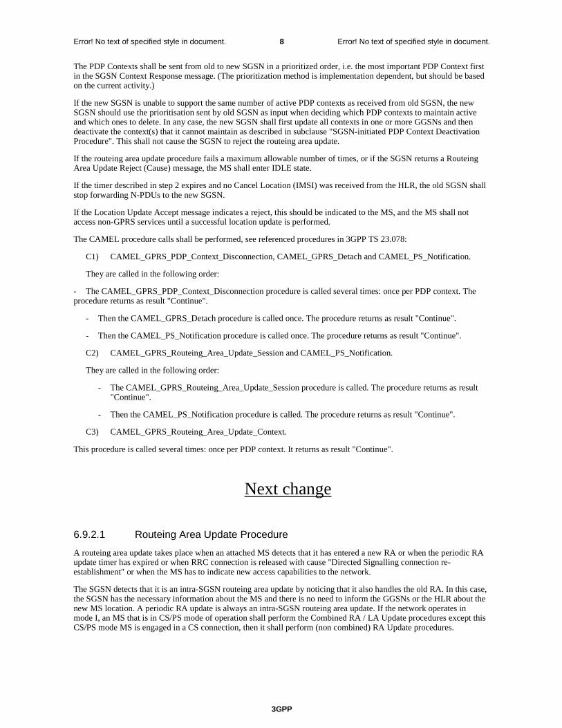
3GPP
Error! No text of specified style in document. 8 Error! No text of specified style in document.
The PDP Contexts shall be sent from old to new SGSN in a prioritized order, i.e. the most important PDP Context first in the SGSN Context Response message. (The prioritization method is implementation dependent, but should be based on the current activity.)
If the new SGSN is unable to support the same number of active PDP contexts as received from old SGSN, the new SGSN should use the prioritisation sent by old SGSN as input when deciding which PDP contexts to maintain active and which ones to delete. In any case, the new SGSN shall first update all contexts in one or more GGSNs and then deactivate the context(s) that it cannot maintain as described in subclause "SGSN-initiated PDP Context Deactivation Procedure". This shall not cause the SGSN to reject the routeing area update.
If the routeing area update procedure fails a maximum allowable number of times, or if the SGSN returns a Routeing Area Update Reject (Cause) message, the MS shall enter IDLE state.
If the timer described in step 2 expires and no Cancel Location (IMSI) was received from the HLR, the old SGSN shall stop forwarding N-PDUs to the new SGSN.
If the Location Update Accept message indicates a reject, this should be indicated to the MS, and the MS shall not access non-GPRS services until a successful location update is performed.
The CAMEL procedure calls shall be performed, see referenced procedures in 3GPP TS 23.078:
C1) CAMEL_GPRS_PDP_Context_Disconnection, CAMEL_GPRS_Detach and CAMEL_PS_Notification.
They are called in the following order:
- The CAMEL_GPRS_PDP_Context_Disconnection procedure is called several times: once per PDP context. The procedure returns as result "Continue".
- Then the CAMEL_GPRS_Detach procedure is called once. The procedure returns as result "Continue".
- Then the CAMEL_PS_Notification procedure is called once. The procedure returns as result "Continue".
C2) CAMEL_GPRS_Routeing_Area_Update_Session and CAMEL_PS_Notification.
They are called in the following order:
- The CAMEL_GPRS_Routeing_Area_Update_Session procedure is called. The procedure returns as result "Continue".
- Then the CAMEL_PS_Notification procedure is called. The procedure returns as result "Continue".
C3) CAMEL_GPRS_Routeing_Area_Update_Context.
This procedure is called several times: once per PDP context. It returns as result "Continue".
Next change
6.9.2.1 Routeing Area Update Procedure
A routeing area update takes place when an attached MS detects that it has entered a new RA or when the periodic RA update timer has expired or when RRC connection is released with cause "Directed Signalling connection re-establishment" or when the MS has to indicate new access capabilities to the network.
The SGSN detects that it is an intra-SGSN routeing area update by noticing that it also handles the old RA. In this case, the SGSN has the necessary information about the MS and there is no need to inform the GGSNs or the HLR about the new MS location. A periodic RA update is always an intra-SGSN routeing area update. If the network operates in mode I, an MS that is in CS/PS mode of operation shall perform the Combined RA / LA Update procedures except this CS/PS mode MS is engaged in a CS connection, then it shall perform (non combined) RA Update procedures.
3GPP
Error! No text of specified style in document. 9 Error! No text of specified style in document.
In Iu mode, an RA update is either an intra-SGSN or inter-SGSN RA update, either combined RA / LA update or only RA update, either initiated by an MS in PMM-CONNECTED (only valid after a Serving RNS Relocation Procedure, see clause 6.9.2.2) or in PMM-IDLE state. All the RA update cases are contained in the procedure illustrated in Figure 36.
NOTE 1: The network may receive an RA update from a UE in PMM-CONNECTED state over a new Iu signalling connection. This could happen when the UE enters PMM-IDLE state on receipt of RRC Connection Release with cause "Directed Signalling connection re-establishment" and initiates an RA or Combined RA update procedure (see clause 6.1.2.4.1).
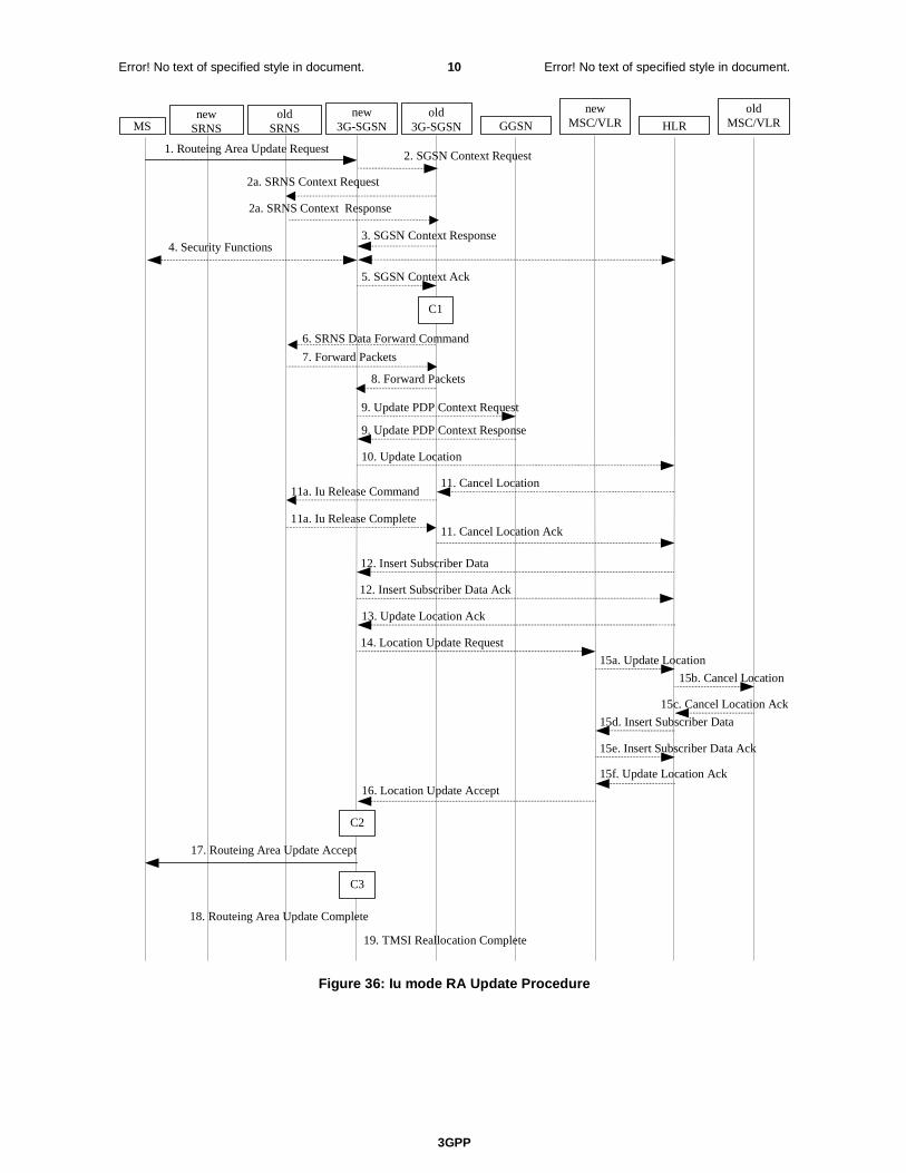
3GPP
Error! No text of specified style in document. 10 Error! No text of specified style in document.
3. SGSN Context Response 4. Security Functions
2. SGSN Context Request 1. Routeing Area Update Request
MS old
SRNS GGSN old
3G-SGSN new
3G-SGSN HLR
new MSC/VLR
old MSC/VLR
5. SGSN Context Ack
11. Cancel Location
11. Cancel Location Ack
9. Update PDP Context Response
9. Update PDP Context Request
10. Update Location
15b. Cancel Location
15c. Cancel Location Ack
15d. Insert Subscriber Data
19. TMSI Reallocation Complete
15f. Update Location Ack 16. Location Update Accept
18. Routeing Area Update Complete
17. Routeing Area Update Accept
13. Update Location Ack
15a. Update Location
14. Location Update Request
12. Insert Subscriber Data
12. Insert Subscriber Data Ack
15e. Insert Subscriber Data Ack
C3
C2
2a. SRNS Context Request
2a. SRNS Context Response
11a. Iu Release Command
11a. Iu Release Complete
6. SRNS Data Forward Command
7. Forward Packets
8. Forward Packets
new SRNS
C1
Figure 36: Iu mode RA Update Procedure
3GPP
Error! No text of specified style in document. 11 Error! No text of specified style in document.
1) The RRC connection is established, if not already done. The MS sends a Routeing Area Update Request message (P-TMSI, old RAI, old P-TMSI Signature, Update Type, follow on request, Classmark, DRX Parameters, MS Network Capability) to the new SGSN. The MS shall set a follow-on request if there is pending uplink traffic (signalling or user data). The SGSN may use, as an implementation option, the follow-on request indication to release or keep the Iu connection after the completion of the RA update procedure. Update Type shall indicate:
- RA Update if the RA Update is triggered by a change of RA;
- Periodic RA Update if the RA update is triggered by the expiry of the Periodic RA Update timer;
- Combined RA / LA Update if the MS is also IMSI-attached and the LA update shall be performed in network operation mode I (see clause "Interactions Between SGSN and MSC/VLR"); or
- Combined RA / LA Update with IMSI attach requested if the MS wants to perform an IMSI attach in network operation mode I.
The SRNC shall add the Routeing Area Identity including the RAC and LAC of the area where the MS is located before forwarding the message to the 3G-SGSN. This RA identity corresponds to the RAI in the MM system information sent by the SRNC to the MS. Classmark is described in clause "MS Network Capability". DRX Parameters indicates whether or not the MS uses discontinuous reception and the DRX cycle length.
NOTE 2: Sending the Routeing Area Update Request message to the SGSN triggers the establishment of a signalling connection between RAN and SGSN for the concerned MS.
2) If the RA update is an Inter-SGSN Routeing area update and if the MS was in PMM-IDLE state, the new SGSN sends an SGSN Context Request message (old P-TMSI, old RAI, old P-TMSI Signature) to the old SGSN to get the MM and PDP contexts for the MS. If the new SGSN provides functionality for Intra Domain Connection of RAN Nodes to Multiple CN Nodes, the new SGSN may derive the old SGSN from the old RAI and the old P-TMSI and send the SGSN Context Request message to this old SGSN. Otherwise, the new SGSN derives the old SGSN from the old RAI. In any case the new SGSN will derive an SGSN that it believes is the old SGSN. This derived SGSN is itself the old SGSN, or it is associated with the same pool area as the actual old SGSN and it will determine the correct old SGSN from the P-TMSI and relay the message to that actual old SGSN. The old SGSN validates the old P-TMSI Signature and responds with an appropriate error cause if it does not match the value stored in the old SGSN. This should initiate the security functions in the new SGSN. If the security functions authenticate the MS correctly, the new SGSN shall send an SGSN Context Request (IMSI, old RAI, MS Validated) message to the old SGSN. MS Validated indicates that the new SGSN has authenticated the MS. If the old P-TMSI Signature was valid or if the new SGSN indicates that it has authenticated the MS, the old SGSN starts a timer.. If the MS is not known in the old SGSN, the old SGSN responds with an appropriate error cause.
2a) If the MS is PMM-CONNECTED state in the old 3G-SGSN or, in case of an intra-SGSN RA update, if the MS is in the PMM-CONNECTED state and the RAU was received over another Iu connection than the established one, the old SGSN sends an SRNS Context Request (IMSI) message to the old SRNS to retrieve the sequence numbers for the PDP context for inclusion in the SGSN Context Response message. Upon reception of this message, the SRNS buffers and stops sending downlink PDUs to the MS and returns an SRNS Context Response (IMSI, GTP-SNDs, GTP-SNUs, PDCP-SNUs) message. The SRNS shall include for each PDP context the next in-sequence GTP sequence number to be sent to the MS and the GTP sequence number of the next uplink PDU to be tunnelled to the GGSN. For each active PDP context which uses lossless PDCP, the SRNS also includes the uplink PDCP sequence number (PDCP-SNU). PDCP-SNU shall be the next in-sequence PDCP sequence number expected from the MS (per each active radio bearer). No conversion of PDCP sequence numbers to SNDCP sequence numbers shall be done in the 3G-SGSN.
3) The old 3G-SGSN responds with an SGSN Context Response (MM Context, PDP Contexts) message. For each PDP context the old 3G-SGSN shall include the GTP sequence number for the next uplink GTP PDU to be tunnelled to the GGSN and the next downlink GTP sequence number for the next PDU to be sent to the MS. Each PDP Context also includes the PDCP sequence numbers if PDCP sequence numbers are received from the old SRNS. The new 3G-SGSN shall ignore the MS Network Capability contained in MM Context of SGSN Context Response only when it has previously received an MS Network Capability in the Routeing Area Request. The GTP sequence numbers received from the old 3G-SGSN are only relevant if delivery order is required for the PDP context (QoS profile).
4) Security functions may be executed. These procedures are defined in clause "Security Function". If the security functions do not authenticate the MS correctly, the routeing area update shall be rejected, and the new SGSN shall send a reject indication to the old SGSN. The old SGSN shall continue as if the SGSN Context Request was never received.
3GPP
Error! No text of specified style in document. 12 Error! No text of specified style in document.
5) If the RA update is an Inter-SGSN Routeing area update, the new SGSN sends an SGSN Context Acknowledge message to the old SGSN. The old SGSN marks in its context that the MSC/VLR association and the information in the GGSNs and the HLR are invalid. This triggers the MSC/VLR, the GGSNs, and the HLR to be updated if the MS initiates a routeing area update procedure back to the old SGSN before completing the ongoing routeing area update procedure.
6) If the MS is in PMM-CONNECTED state in the old 3G-SGSN or, in case of an intra-SGSN RA update, if the MS is PMM connected and the RAU was received over another Iu connection than the established one, the old 3G-SGSN sends an SRNS Data Forward Command (RAB ID, Transport Layer Address, Iu Transport Association) message to the SRNS. Upon receipt of the SRNS Data Forward Command message from the 3G-SGSN, the SRNS shall start the data-forwarding timer.
7) For each indicated RAB the SRNS starts duplicating and tunnelling the buffered GTP PDUs to the old 3G-SGSN. For each radio bearer which uses lossless PDCP the SRNS shall start tunnelling the partly transmitted and the transmitted but not acknowledged PDCP-PDUs together with their related PDCP sequence numbers and start duplicating and tunnelling the buffered GTP PDUs to the old 3G-SGSN. Upon receipt of the SRNS Data Forward Command message from the 3G-SGSN, the SRNS shall start the data-forwarding timer.
8) If the RA update is an Inter-SGSN RA Update, the old 3G-SGSN tunnels the GTP PDUs to the new 3G-SGSN. No conversion of PDCP sequence numbers to SNDCP sequence numbers shall be done in the 3G-SGSN.
9) If the RA update is an Inter-SGSN RA Update and if the MS was not in PMM-CONNECTED state in the new 3G-SGSN, the new SGSN sends Update PDP Context Request (new SGSN Address, QoS Negotiated, Tunnel Endpoint Identifier, serving network identity) to the GGSNs concerned. The SGSN should send the serving network identity to the GGSN. The GGSNs update their PDP context fields and return an Update PDP Context Response (Tunnel Endpoint Identifier). Note: If the RA update is an Inter-SGSN routeing area update initiated by an MS in PMM-CONNECTED state in the new 3G-SGSN, the Update PDP Context Request message is sent as described in subclause "Serving RNS Relocation Procedures".
10) If the RA update is an Inter-SGSN RA Update, the new SGSN informs the HLR of the change of SGSN by sending Update Location (SGSN Number, SGSN Address, IMSI) to the HLR.
11) If the RA update is an Inter-SGSN RA Update, the HLR sends Cancel Location (IMSI, Cancellation Type) to the old SGSN with Cancellation Type set to Update Procedure. If the timer described in step 2 is not running, the old SGSN removes the MM context. Otherwise, the contexts are removed only when the timer expires. It also ensures that the MM context is kept in the old SGSN in case the MS initiates another inter SGSN routeing area update before completing the ongoing routeing area update to the new SGSN. The old SGSN acknowledges with Cancel Location Ack (IMSI).
11a) On receipt of Cancel Location, if the MS is PMM-CONNECTED in the old 3G-SGSN, the old 3G-SGSN sends an Iu Release Command message to the old SRNC. When the data-forwarding timer has expired, the SRNS responds with an Iu Release Complete message.
12) If the RA update is an inter-SGSN RA Update, the HLR sends Insert Subscriber Data (IMSI, subscription data) to the new SGSN. The new SGSN validates the MS's presence in the (new) RA. If due to regional subscription restrictions the MS is not allowed to be attached in the RA, the SGSN rejects the Routeing Area Update Request with an appropriate cause, and may return an Insert Subscriber Data Ack (IMSI, SGSN Area Restricted) message to the HLR. If all checks are successful, the SGSN constructs an MM context for the MS and returns an Insert Subscriber Data Ack (IMSI) message to the HLR.
13) If the RA update is an Inter-SGSN RA Update, the HLR acknowledges the Update Location by sending Update Location Ack (IMSI) to the new SGSN.
14) If Update Type indicates combined RA / LA update with IMSI attach requested, or if the LA changed with the routeing area update, the association has to be established, and the new SGSN sends a Location Update Request (new LAI, IMSI, SGSN Number, Location Update Type) to the VLR. Location Update Type shall indicate IMSI attach if Update Type in step 1 indicated combined RA / LA update with ISI attach requested. Otherwise, Location Update Type shall indicate normal location update. When the SGSN does not provide functionality for the Intra Domain Connection of RAN Nodes to Multiple CN Nodes, the VLR number is derived from the RAI. When the SGSN provides functionality for Intra Domain Connection of RAN Nodes to Multiple CN Nodes, the SGSN uses the RAI and a hash value from the IMSI to determine the VLR number. The SGSN starts the location update procedure towards the new MSC/VLR upon receipt of the first Insert Subscriber Data message from the HLR in step 8). The VLR creates or updates the association with the SGSN by storing SGSN Number.
15) If the subscriber data in the VLR is marked as not confirmed by the HLR, the new VLR informs the HLR. The HLR cancels the old VLR and inserts subscriber data in the new VLR:
3GPP
Error! No text of specified style in document. 13 Error! No text of specified style in document.
a) The new VLR sends an Update Location (new VLR) to the HLR.
b) The HLR cancels the data in the old VLR by sending Cancel Location (IMSI) to the old VLR.
c) The old VLR acknowledges with Cancel Location Ack (IMSI).
d) The HLR sends Insert Subscriber Data (IMSI, subscriber data) to the new VLR.
e) The new VLR acknowledges with Insert Subscriber Data Ack (IMSI).
f) The HLR responds with Update Location Ack (IMSI) to the new VLR.
16) The new VLR allocates a new TMSI and responds with Location Update Accept (VLR TMSI) to the SGSN. VLR TMSI is optional if the VLR has not changed.
17) The new SGSN validates the MS's presence in the new RA. If due to roaming restrictions the MS is not allowed to be attached in the RA, or if subscription checking fails, the SGSN rejects the routeing area update with an appropriate cause. If all checks are successful, the new SGSN establishes MM context for the MS. The new SGSN responds to the MS with Routeing Area Update Accept (P-TMSI, VLR TMSI, P-TMSI Signature).
18) The MS confirms the reallocation of the TMSIs by returning a Routeing Area Update Complete message to the SGSN.
19) The new SGSN sends a TMSI Reallocation Complete message to the new VLR if the MS confirms the VLR TMSI.
NOTE 3: Steps 15, 16, and 19 are performed only if step 14 is performed.
NOTE: The new SGSN may initiate RAB establishment after execution of the security functions (step 4), or wait until completion of the RA update procedure. For the MS, RAB establishment may occur anytime after the RA update request is sent (step 1).
In the case of a rejected routeing area update operation, due to regional subscription or roaming restrictions, the new SGSN shall not construct an MM context. A reject shall be returned to the MS with an appropriate cause. The MS shall not re-attempt a routeing area update to that RA. The RAI value shall be deleted when the MS is powered up.
If the new SGSN is unable to update the PDP context in one or more GGSNs, the new SGSN shall deactivate the corresponding PDP contexts as described in subclause "SGSN-initiated PDP Context Deactivation Procedure". This shall not cause the SGSN to reject the routeing area update.
The PDP Contexts shall be sent from old to new SGSN in a prioritized order, i.e. the most important PDP Context first in the SGSN Context Response message. (The prioritization method is implementation dependent, but should be based on the current activity.)
If the new SGSN is unable to support the same number of active PDP contexts as received from old SGSN, the new SGSN should use the prioritisation sent by old SGSN as input when deciding which PDP contexts to maintain active and which ones to delete. In any case, the new SGSN shall first update all contexts in one or more GGSNs and then deactivate the context(s) that it cannot maintain as described in subclause "SGSN-initiated PDP Context Deactivation Procedure". This shall not cause the SGSN to reject the routeing area update.
NOTE: In case MS was in PMM-CONNECTED state the PDP Contexts are sent already in the Forward Relocation Request message as described in subclause “Serving RNS relocation procedures”.
If the routeing area update procedure fails a maximum allowable number of times, or if the SGSN returns a Routeing Area Update Reject (Cause) message, the MS shall enter PMM-DETACHED state.
If the Location Update Accept message indicates a reject, this should be indicated to the MS, and the MS shall not access non-PS services until a successful location update is performed.
The CAMEL procedure calls shall be performed, see referenced procedures in 3GPP TS 23.078:
C1) CAMEL_GPRS_PDP_Context_Disconnection, CAMEL_GPRS_Detach and CAMEL_PS_Notification.
They are called in the following order:
- The CAMEL_GPRS_PDP_Context_Disconnection procedure is called several times: once per PDP context. The procedure returns as result "Continue".
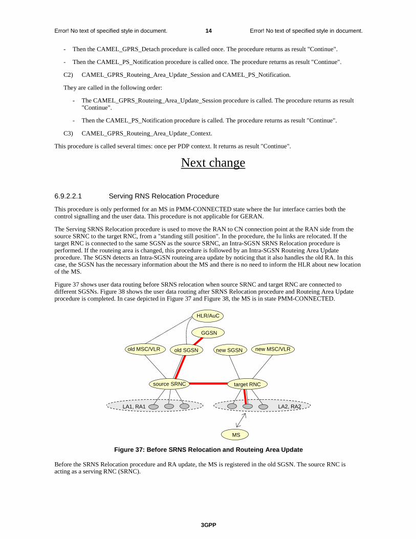
3GPP
Error! No text of specified style in document. 14 Error! No text of specified style in document.
- Then the CAMEL_GPRS_Detach procedure is called once. The procedure returns as result "Continue".
- Then the CAMEL_PS_Notification procedure is called once. The procedure returns as result "Continue".
C2) CAMEL_GPRS_Routeing_Area_Update_Session and CAMEL_PS_Notification.
They are called in the following order:
- The CAMEL_GPRS_Routeing_Area_Update_Session procedure is called. The procedure returns as result "Continue".
- Then the CAMEL_PS_Notification procedure is called. The procedure returns as result "Continue".
C3) CAMEL_GPRS_Routeing_Area_Update_Context.
This procedure is called several times: once per PDP context. It returns as result "Continue".
Next change
6.9.2.2.1 Serving RNS Relocation Procedure
This procedure is only performed for an MS in PMM-CONNECTED state where the Iur interface carries both the control signalling and the user data. This procedure is not applicable for GERAN.
The Serving SRNS Relocation procedure is used to move the RAN to CN connection point at the RAN side from the source SRNC to the target RNC, from a "standing still position". In the procedure, the Iu links are relocated. If the target RNC is connected to the same SGSN as the source SRNC, an Intra-SGSN SRNS Relocation procedure is performed. If the routeing area is changed, this procedure is followed by an Intra-SGSN Routeing Area Update procedure. The SGSN detects an Intra-SGSN routeing area update by noticing that it also handles the old RA. In this case, the SGSN has the necessary information about the MS and there is no need to inform the HLR about new location of the MS.
Figure 37 shows user data routing before SRNS relocation when source SRNC and target RNC are connected to different SGSNs. Figure 38 shows the user data routing after SRNS Relocation procedure and Routeing Area Update procedure is completed. In case depicted in Figure 37 and Figure 38, the MS is in state PMM-CONNECTED.
LA1, RA1
HLR/AuC
old SGSN
GGSN
LA2, RA2
new SGSN
source SRNC
new MSC/VLRold MSC/VLR
MS
target RNC
Figure 37: Before SRNS Relocation and Routeing Area Update
Before the SRNS Relocation procedure and RA update, the MS is registered in the old SGSN. The source RNC is acting as a serving RNC (SRNC).

3GPP
Error! No text of specified style in document. 15 Error! No text of specified style in document.
LA1, RA1
MS
HLR/AuC
old SGSN
source RNC
GGSN
LA2, RA2
new SGSNold MSC/VLR new MSC/VLR
target SRNC
Figure 38: After SRNS Relocation and Routeing Area Update
After the SRNS Relocation procedure and RA update, the MS is registered in the new SGSN. The MS is in the state PMM-CONNECTED towards the new SGSN, and the target RNC is acting as the serving RNC.
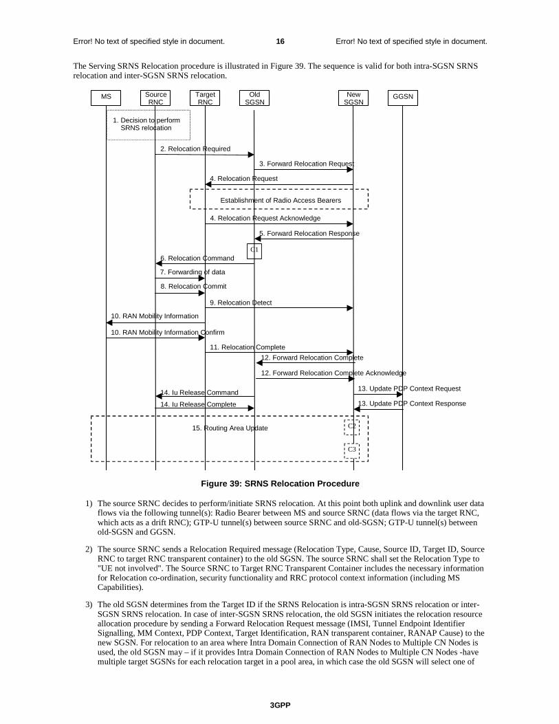
3GPP
Error! No text of specified style in document. 16 Error! No text of specified style in document.
The Serving SRNS Relocation procedure is illustrated in Figure 39. The sequence is valid for both intra-SGSN SRNS relocation and inter-SGSN SRNS relocation.
MS Target RNC
Source RNC
Old SGSN
New SGSN GGSN
3. Forward Relocation Request
4. Relocation Request
2. Relocation Required
6. Relocation Command
5. Forward Relocation Response
4. Relocation Request Acknowledge
9. Relocation Detect
11. Relocation Complete 12. Forward Relocation Complete
10. RAN Mobility Information
10. RAN Mobility Information Confirm
Establishment of Radio Access Bearers
15. Routing Area Update
13. Update PDP Context Request 14. Iu Release Command 14. Iu Release Complete
C1
C2
1. Decision to perform SRNS relocation
8. Relocation Commit 7. Forwarding of data
13. Update PDP Context Response
12. Forward Relocation Complete Acknowledge
C3
Figure 39: SRNS Relocation Procedure
1) The source SRNC decides to perform/initiate SRNS relocation. At this point both uplink and downlink user data flows via the following tunnel(s): Radio Bearer between MS and source SRNC (data flows via the target RNC, which acts as a drift RNC); GTP-U tunnel(s) between source SRNC and old-SGSN; GTP-U tunnel(s) between old-SGSN and GGSN.
2) The source SRNC sends a Relocation Required message (Relocation Type, Cause, Source ID, Target ID, Source RNC to target RNC transparent container) to the old SGSN. The source SRNC shall set the Relocation Type to "UE not involved". The Source SRNC to Target RNC Transparent Container includes the necessary information for Relocation co-ordination, security functionality and RRC protocol context information (including MS Capabilities).
3) The old SGSN determines from the Target ID if the SRNS Relocation is intra-SGSN SRNS relocation or inter-SGSN SRNS relocation. In case of inter-SGSN SRNS relocation, the old SGSN initiates the relocation resource allocation procedure by sending a Forward Relocation Request message (IMSI, Tunnel Endpoint Identifier Signalling, MM Context, PDP Context, Target Identification, RAN transparent container, RANAP Cause) to the new SGSN. For relocation to an area where Intra Domain Connection of RAN Nodes to Multiple CN Nodes is used, the old SGSN may – if it provides Intra Domain Connection of RAN Nodes to Multiple CN Nodes -have multiple target SGSNs for each relocation target in a pool area, in which case the old SGSN will select one of

3GPP
Error! No text of specified style in document. 17 Error! No text of specified style in document.
them to become the new SGSN, as specified in 3GPP TS 23.236 [73]. The PDP context contains GGSN Address for User Plane and Uplink TEID for Data (to this GGSN Address and Uplink TEID for Data the old SGSN and the new SGSN send uplink packets). At the same time a timer is started on the MM and PDP contexts in the old SGSN (see the Routeing Area Update procedure in subclause "Location Management Procedures (Iu mode)"). The Forward Relocation Request message is applicable only in the case of inter-SGSN SRNS relocation.
4) The new SGSN sends a Relocation Request message (Permanent NAS UE Identity, Cause, CN Domain Indicator, Source-RNC to target RNC transparent container, RABs to be setup) to the target RNC. Only the Iu Bearers of the RABs are setup between the target RNC and the new-SGSN as the existing Radio Bearers will be reallocated between the MS and the target RNC when the target RNC takes the role of the serving RNC. For each requested RAB, the RABs to be setup information elements shall contain information such as RAB ID, RAB parameters, Transport Layer Address, and Iu Transport Association. SGSN shall not establish RABs for PDP contexts with maximum bitrate for uplink and downlink of 0 kbit/s. The RAB ID information element contains the NSAPI value, and the RAB parameters information element gives the QoS profile. The Transport Layer Address is the SGSN Address for user data, and the Iu Transport Association corresponds to the uplink Tunnel Endpoint Identifier Data. After all necessary resources for accepted RABs including the Iu user plane are successfully allocated; the target RNC shall send the Relocation Request Acknowledge message (RABs setup, RABs failed to setup) to the new SGSN. Each RAB to be setup is defined by a Transport Layer Address, which is the target RNC Address for user data, and an Iu Transport Association, which corresponds to the downlink Tunnel Endpoint Identifier for user data. For each RAB to be set up, the target RNC may receive simultaneously downlink user packets both from the source SRNC and from the new SGSN.
5) When resources for the transmission of user data between the target RNC and the new SGSN have been allocated and the new SGSN is ready for relocation of SRNS, the Forward Relocation Response message (Cause, RANAP Cause, and RAB Setup Information) is sent from the new SGSN to old SGSN. This message indicates that the target RNC is ready to receive from source SRNC the forwarded downlink PDUs, i.e. the relocation resource allocation procedure is terminated successfully. RANAP Cause is information from the target RNC to be forwarded to the source SRNC. The RAB Setup Information, one information element for each RAB, contains the RNC Tunnel Endpoint Identifier and the RNC IP address for data forwarding from the source SRNC to the target RNC. If the target RNC or the new SGSN failed to allocate resources, the RAB Setup Information element contains only NSAPI indicating that the source SRNC shall release the resources associated with the NSAPI. The Forward Relocation Response message is applicable only in case of inter-SGSN SRNS relocation.
6) The old SGSN continues the relocation of SRNS by sending a Relocation Command message (RABs to be released, and RABs subject to data forwarding) to the source SRNC. The old SGSN decides the RABs to be subject for data forwarding based on QoS, and those RABs shall be contained in RABs subject to data forwarding. For each RAB subject to data forwarding, the information element shall contain RAB ID, Transport Layer Address, and Iu Transport Association. These are the same Transport Layer Address and Iu Transport Association that the target RNC had sent to new SGSN in Relocation Request Acknowledge message, and these are used for forwarding of downlink N-PDU from source SRNC to target RNC. The source SRNC is now ready to forward downlink user data directly to the target RNC over the Iu interface. This forwarding is performed for downlink user data only.
7) The source SRNC may, according to the QoS profile, begin the forwarding of data for the RABs to be subject for data forwarding. The data forwarding at SRNS relocation shall be carried out through the Iu interface, meaning that the data exchanged between the source SRNC and the target RNC are duplicated in the source SRNC and routed at IP layer towards the target RNC. For each radio bearer which uses lossless PDCP the GTP-PDUs related to transmitted but not yet acknowledged PDCP-PDUs are duplicated and routed at IP layer towards the target RNC together with their related downlink PDCP sequence numbers. The source RNC continues transmitting duplicates of downlink data and receiving uplink data. Before the serving RNC role is not yet taken over by target RNC and when downlink user plane data starts to arrive to target RNC, the target RNC may buffer or discard arriving downlink GTP-PDUs according to the related QoS profile.
Note: The order of steps, starting from step 7 onwards, does not necessarily reflect the order of events. For instance, source RNC may start data forwarding (step 7) and send Relocation Commit message (step 8) almost simultaneously except in the delivery order required case where step 7 triggers step 8. Target RNC may send Relocation Detect message (step 9) and RAN Mobility Information message (step 10) at the same time. Hence, target RNC may receive RAN Mobility Information Confirm message (step 10) while data forwarding (step 7) is still underway, and before the new SGSN receives Update PDP Context Response message (step 11).
8) Before sending the Relocation Commit the uplink and downlink data transfer in the source, SRNC shall be suspended for RABs, which require delivery order. The source RNC shall start the data-forwarding timer. When the source SRNC is ready, the source SRNC shall trigger the execution of relocation of SRNS by sending a Relocation Commit message (SRNS Contexts) to the target RNC over the Iur interface. The purpose of this procedure is to transfer SRNS contexts from the source RNC to the target RNC, and to move the SRNS role
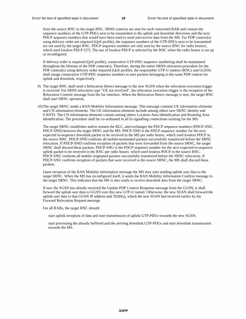
3GPP
Error! No text of specified style in document. 18 Error! No text of specified style in document.
from the source RNC to the target RNC. SRNS contexts are sent for each concerned RAB and contain the sequence numbers of the GTP-PDUs next to be transmitted in the uplink and downlink directions and the next PDCP sequence numbers that would have been used to send and receive data from the MS. For PDP context(s) using delivery order not required (QoS profile), the sequence numbers of the GTP-PDUs next to be transmitted are not used by the target RNC. PDCP sequence numbers are only sent by the source RNC for radio bearers, which used lossless PDCP [57]. The use of lossless PDCP is selected by the RNC when the radio bearer is set up or reconfigured.
If delivery order is required (QoS profile), consecutive GTP-PDU sequence numbering shall be maintained throughout the lifetime of the PDP context(s). Therefore, during the entire SRNS relocation procedure for the PDP context(s) using delivery order required (QoS profile), the responsible GTP-U entities (RNCs and GGSN) shall assign consecutive GTP-PDU sequence numbers to user packets belonging to the same PDP context for uplink and downlink, respectively.
9) The target RNC shall send a Relocation Detect message to the new SGSN when the relocation execution trigger is received. For SRNS relocation type "UE not involved", the relocation execution trigger is the reception of the Relocation Commit message from the Iur interface. When the Relocation Detect message is sent, the target RNC shall start SRNC operation.
10) The target SRNC sends a RAN Mobility Information message. This message contains UE information elements and CN information elements. The UE information elements include among others new SRNC identity and S-RNTI. The CN information elements contain among others Location Area Identification and Routeing Area Identification. The procedure shall be co-ordinated in all Iu signalling connections existing for the MS.
The target SRNC establishes and/or restarts the RLC, and exchanges the PDCP sequence numbers (PDCP-SNU, PDCP-SND) between the target SRNC and the MS. PDCP-SND is the PDCP sequence number for the next expected in-sequence downlink packet to be received in the MS per radio bearer, which used lossless PDCP in the source RNC. PDCP-SND confirms all mobile-terminated packets successfully transferred before the SRNC relocation. If PDCP-SND confirms reception of packets that were forwarded from the source SRNC, the target SRNC shall discard these packets. PDCP-SNU is the PDCP sequence number for the next expected in-sequence uplink packet to be received in the RNC per radio bearer, which used lossless PDCP in the source RNC. PDCP-SNU confirms all mobile originated packets successfully transferred before the SRNC relocation. If PDCP-SNU confirms reception of packets that were received in the source SRNC, the MS shall discard these packets.
Upon reception of the RAN Mobility Information message the MS may start sending uplink user data to the target SRNC. When the MS has reconfigured itself, it sends the RAN Mobility Information Confirm message to the target SRNC. This indicates that the MS is also ready to receive downlink data from the target SRNC.
If new the SGSN has already received the Update PDP Context Response message from the GGSN, it shall forward the uplink user data to GGSN over this new GTP-U tunnel. Otherwise, the new SGSN shall forward the uplink user data to that GGSN IP address and TEID(s), which the new SGSN had received earlier by the Forward Relocation Request message.
For all RABs, the target RNC should:
start uplink reception of data and start transmission of uplink GTP-PDUs towards the new SGSN;
start processing the already buffered and the arriving downlink GTP-PDUs and start downlink transmission towards the MS.
3GPP
Error! No text of specified style in document. 19 Error! No text of specified style in document.
11) When the target SRNC receives the RAN Mobility Information Confirm message, i.e. the new SRNC—ID + S-RNTI are successfully exchanged with the MS by the radio protocols, the target SRNC shall initiate the Relocation Complete procedure by sending the Relocation Complete message to the new SGSN. The purpose of the Relocation Complete procedure is to indicate by the target SRNC the completion of the relocation of the SRNS to the CN.
12) Upon receipt of the Relocation complete message, if the SRNS Relocation is an inter-SGSN SRNS relocation, the new SGSN shall signal to the old SGSN the completion of the SRNS relocation procedure by sending a Forward Relocation Complete message.
13) Upon receiving the Relocation Complete message, the CN shall switch the user plane from source RNC to target SRNC. If the SRNS Relocation is an inter SGSN SRNS relocation, the new SGSN sends Update PDP Context Request messages (new SGSN Address, SGSN Tunnel Endpoint Identifier, QoS Negotiated, serving network identity) to the GGSNs concerned. The SGSN should send the serving network identity to the GGSN. The GGSNs update their PDP context fields and return an Update PDP Context Response (GGSN Tunnel Endpoint Identifier).
14) Upon receiving the Relocation Complete message or if it is an inter-SGSN SRNS relocation; the Forward Relocation Complete message, the old SGSN sends an Iu Release Command message to the source RNC. When the RNC data-forwarding timer has expired the source RNC responds with an Iu Release Complete.
15) After the MS has finished the RNTI reallocation procedure and if the new Routeing Area Identification is different from the old one, the MS initiates the Routeing Area Update procedure. See subclause "Location Management Procedures (Iu mode)". Note that it is only a subset of the RA update procedure that is performed, since the MS is in PMM-CONNECTED mode.
If the SRNS Relocation is inter-SGSN, then the following CAMEL procedure calls shall be performed (see referenced procedures in 3GPP TS 23.078)
C1) CAMEL_GPRS_PDP_Context_Disconnection, CAMEL_GPRS_Detach and CAMEL_PS_Notification.
They are called in the following order:
- The CAMEL_GPRS_PDP_Context_Disconnection procedure is called several times: once per PDP context. The procedure returns as result "Continue".
- Then the CAMEL_GPRS_Detach procedure is called once. The procedure returns as result "Continue".
- Then the CAMEL_PS_Notification procedure is called once. The procedure returns as result "Continue".
If the SRNS Relocation is intra-SGSN, then the above mentioned CAMEL procedures calls shall not be performed.
If Routeing Area Update occurs, then the following CAMEL procedure calls shall be performed (see referenced procedures in 3GPP TS 23.078):
C2) CAMEL_GPRS_Routeing_Area_Update_Session and CAMEL_PS_Notification.
They are called in the following order:
- The CAMEL_GPRS_Routeing_Area_Update_Session procedure is called. The procedure returns as result "Continue".
- Then, the CAMEL_PS_Notification procedure is called. The procedure returns as result "Continue".
C3) CAMEL_GPRS_Routeing_Area_Update_Context.
This procedure is called several times: once per PDP context. It returns as result ""Continue"".
For C2 and C3: refer to Routing Area Update procedure description for detailed message flow.
6.9.2.2.2 Combined Hard Handover and SRNS Relocation Procedure
This procedure is only performed for an MS in PMM-CONNECTED state in case the Iur interface is not available. In the context of this specification, the terms RNS or RNC refer also to a GERAN BSS or BSC (respectively) when serving a mobile in Iu mode.
The Combined Hard Handover and SRNS Relocation procedure is used to move the RAN to CN connection point at the RAN side from the source SRNC to the target RNC, while performing a hard handover decided by the RAN. In the

3GPP
Error! No text of specified style in document. 20 Error! No text of specified style in document.
procedure, the Iu links are relocated. If the target RNC is connected to the same SGSN as the source SRNC, an Intra-SGSN SRNS Relocation procedure is performed. If the routeing area is changed, this procedure is followed by an Intra-SGSN Routeing Area Update procedure. The SGSN detects that it is an intra-SGSN routeing area update by noticing that it also handles the old RA. In this case, the SGSN has the necessary information about the MS and there is no need to inform the HLR about the new MS location.
If the target RNC is connected to a different SGSN than the source SRNC, an Inter-SGSN SRNS Relocation procedure is performed. This procedure is followed by an Inter-SGSN Routeing Area Update procedure.
Figure 40 shows the situation before a Combined Hard Handover and SRNS Relocation procedure when source and target RNC are connected to different SGSNs. Figure 41 shows the situation after the Combined Hard Handover and SRNS Relocation procedure and RA update procedure have been completed. In the case described in Figure 40 and Figure 41 the MS is in PMM-CONNECTED state. Both figures are also applicable to BSS to RNS relocation and vice-versa, as well as for BSS to BSS relocation.
LA1, RA1
MS
HLR/AuC
old SGSN
GGSN
LA2, RA2
new SGSN
target RNCsource SRNC
new MSC/VLRold MSC/VLR
Figure 40: Before Combined Hard Handover and SRNS Relocation and Routeing Area Update
Before the SRNS Relocation and Routeing Area Update the MS is registered in the old SGSN and in the old MSC/VLR. The source RNC is acting as serving RNC.
LA1, RA1
MS
HLR/AuC
old SGSN
source RNC
GGSN
LA2, RA2
new SGSN
target SRNC
old MSC/VLR new MSC/VLR
Figure 41: After Combined Hard Handover and SRNS Relocation and Routeing Area Update
After the SRNS relocation and RA update, the MS is registered in the new SGSN and in the new MSC/VLR. The MS is in state PMM-CONNECTED towards the new SGSN and in MM IDLE state towards the new MSC/VLR. The target RNC is acting as serving RNC.

3GPP
Error! No text of specified style in document. 21 Error! No text of specified style in document.
The Combined Hard Handover and SRNS Relocation procedure for the PS domain is illustrated in Figure 42. The sequence is valid for both intra-SGSN SRNS relocation and inter-SGSN SRNS relocation. Furthermore, this signalling flow is also applicable for BSS to RNS relocation and vice-versa, as well as BSS to BSS relocation.
MS Target RNC
Source RNC
Old SGSN
New SGSN GGSN
3. Forward Relocation Request
4. Relocation Request
2. Relocation Required
6. Relocation Command
5. Forward Relocation Response
4. Relocation Request Acknowledge
10. Relocation Detect
11. Relocation Complete
12. Forward Relocation Complete
9. Forward SRNS Context 9. Forward SRNS Context
9. Forward SRNS Context
8. RRC message
8. RRC message
1. Decision to perform SRNS Relocation MS Involved
MS detected by target RNC
Establishment of Radio Access Bearers
15. Routing Area Update
13. Update PDP Context Request 14. Iu Release Command
14. Iu Release Complete
C1
7. Forwarding of data
13. Update PDP Context Response
9. Forward SRNS Context Acknowledge
12. Forward Relocation Complete Acknowledge
C3
C2
Figure 42: Combined Hard Handover and SRNS Relocation Procedure
1) Based on measurement results and knowledge of the RAN topology, the source SRNC decides to initiate a combined hard handover and SRNS relocation. At this point both uplink and downlink user data flows via the following tunnel(s): Radio Bearer between the MS and the source SRNC (no drift RNC available); GTP-U tunnel(s) between the source SRNC and the old SGSN; GTP-U tunnel(s) between the old SGSN and the GGSN.
2) The source SRNC sends a Relocation Required message (Relocation Type, Cause, Source ID, Target ID, Source RNC To Target RNC Transparent Container) to the old SGSN. The source SRNC shall set Relocation Type to "UE Involved". Source RNC To Target RNC Transparent Container includes the necessary information for
3GPP
Error! No text of specified style in document. 22 Error! No text of specified style in document.
relocation co-ordination, security functionality and RRC protocol context information (including MS Capabilities).
3) The old SGSN determines from the Target ID if the SRNS relocation is intra-SGSN SRNS relocation or inter-SGSN SRNS relocation. In case of inter-SGSN SRNS relocation the old SGSN initiates the relocation resource allocation procedure by sending a Forward Relocation Request message (IMSI, Tunnel Endpoint Identifier Signalling, MM Context, PDP Context, Target Identification, RAN Transparent Container, RANAP Cause) to the new SGSN. For relocation to an area where Intra Domain Connection of RAN Nodes to Multiple CN Nodes is used, the old SGSN may – if it provides Intra Domain Connection of RAN Nodes to Multiple CN Nodes -have multiple target SGSNs for each relocation target in a pool area, in which case the old SGSN will select one of them to become the new SGSN, as specified in 3GPP TS 23.236 [73]. PDP context contains GGSN Address for User Plane and Uplink TEID for Data (to this GGSN Address and Uplink TEID for Data, the old SGSN and the new SGSN send uplink packets). At the same time a timer is started on the MM and PDP contexts in the old SGSN (see Routeing Area Update procedure in subclause "Location Management Procedures (Iu mode)"). The Forward Relocation Request message is applicable only in case of inter-SGSN SRNS relocation.
4) The new SGSN sends a Relocation Request message (Permanent NAS UE Identity, Cause, CN Domain Indicator, Source RNC To Target RNC Transparent Container, RAB To Be Setup) to the target RNC. For each RAB requested to be established, RABs To Be Setup shall contain information such as RAB ID, RAB parameters, Transport Layer Address, and Iu Transport Association. SGSN shall not establish RABs for PDP contexts with maximum bitrate for uplink and downlink of 0 kbit/s. The RAB ID information element contains the NSAPI value, and the RAB parameters information element gives the QoS profile. The Transport Layer Address is the SGSN Address for user data, and the Iu Transport Association corresponds to the uplink Tunnel Endpoint Identifier Data.
After all the necessary resources for accepted RABs including the Iu user plane are successfully allocated, the target RNC shall send the Relocation Request Acknowledge message (Target RNC To Source RNC Transparent Container, RABs Setup, RABs Failed To Setup) to the new SGSN. Each RAB to be setup is defined by a Transport Layer Address, which is the target RNC Address for user data, and the Iu Transport Association, which corresponds to the downlink Tunnel Endpoint Identifier for user data. The transparent container contains all radio-related information that the MS needs for the handover, i.e., a complete RRC message (e.g., Physical Channel Reconfiguration in UTRAN case, or Handover From UTRAN, or Handover Command in GERAN Iu mode case) to be sent transparently via CN and source SRNC to the MS. For each RAB to be set up, the target RNC may receive simultaneously downlink user packets both from the source SRNC and from the new SGSN.
5) When resources for the transmission of user data between target RNC and new SGSN have been allocated and the new SGSN is ready for relocation of SRNS, the Forward Relocation Response (Cause, RAN Transparent Container, RANAP Cause, Target-RNC Information) message is sent from the new SGSN to the old SGSN. This message indicates that the target RNC is ready to receive from source SRNC the forwarded downlink PDUs, i.e., the relocation resource allocation procedure is terminated successfully. RAN transparent container and RANAP Cause are information from the target RNC to be forwarded to the source SRNC. The Target RNC Information, one information element for each RAB to be set up, contains the RNC Tunnel Endpoint Identifier and RNC IP address for data forwarding from the source SRNC to the target RNC. The Forward Relocation Response message is applicable only in case of inter-SGSN SRNS relocation.
6) The old SGSN continues the relocation of SRNS by sending a Relocation Command message (Target RNC To Source RNC Transparent Container, RABs To Be Released, RABs Subject To Data Forwarding) to the source SRNC. The old SGSN decides the RABs to be subject for data forwarding based on QoS, and those RABs shall be contained in RABs subject to data forwarding. For each RAB subject to data forwarding, the information element shall contain RAB ID, Transport Layer Address, and Iu Transport Association. These are the same Transport Layer Address and Iu Transport Association that the target RNC had sent to new SGSN in Relocation Request Acknowledge message, and these are used for forwarding of downlink N-PDU from the source SRNC to the target RNC. The source SRNC is now ready to forward downlink user data directly to the target RNC over the Iu interface. This forwarding is performed for downlink user data only.
7) The source SRNC may, according to the QoS profile, begins the forwarding of data for the RABs to be subject for data forwarding.
NOTE: The order of steps, starting from step 7 onwards, does not necessarily reflect the order of events. For instance, source RNC may start data forwarding (step 7), send the RRC message to MS (step 8) and forward SRNS Context message to the old SGSN (step 9) almost simultaneously.
The data forwarding at SRNS relocation shall be carried out through the Iu interface, meaning that the GTP-PDUs exchanged between the source SRNC and the target RNC are duplicated in the source SRNC and routed at the IP layer towards the target RNC. For each radio bearer which uses lossless PDCP the GTP-PDUs related to transmitted but not yet acknowledged PDCP-PDUs are duplicated and routed at IP layer towards the target RNC
3GPP
Error! No text of specified style in document. 23 Error! No text of specified style in document.
together with their related downlink PDCP sequence numbers. The source RNC continues transmitting duplicates of downlink data and receiving uplink data.
Before the serving RNC role is not yet taken over by target RNC and when downlink user plane data starts to arrive to target RNC, the target RNC may buffer or discard arriving downlink GTP-PDUs according to the related QoS profile.
8) Before sending the RRC message the uplink and downlink data transfer shall be suspended in the source SRNC for RABs, which require delivery order. The RRC message is for example Physical Channel Reconfiguration for RNS to RNS relocation, or Intersystem to UTRAN Handover for BSS to RNS relocation, or Handover from UTRAN Command for BSS relocation, or Handover Command for BSS to BSS relocation. When the source SRNC is ready, the source RNC shall trigger the execution of relocation of SRNS by sending to the MS the RRC message provided in the Target RNC to source RNC transparent container, e.g., a Physical Channel Reconfiguration (UE Information Elements, CN Information Elements) message. UE Information Elements include among others new SRNC identity and S-RNTI. CN Information Elements contain among others Location Area Identification and Routeing Area Identification.
When the MS has reconfigured itself, it sends an RRC message e.g., a Physical Channel Reconfiguration Complete message to the target SRNC. If the Forward SRNS Context message with the sequence numbers is received, the exchange of packets with the MS may start. If this message is not yet received, the target RNC may start the packet transfer for all RABs, which do not require maintaining the delivery order.
9) The source SRNC continues the execution of relocation of SRNS by sending a Forward SRNS Context (RAB Contexts) message to the target RNC via the old and the new SGSN. The Forward SRNS Context message is acknowledged by a Forward SRNS Context Acknowledge message, from new to old SGSN. The purpose of this procedure is to transfer SRNS contexts from the source RNC to the target RNC, and to move the SRNS role from the source RNC to the target RNC. SRNS contexts are sent for each concerned RAB and contain the sequence numbers of the GTP PDUs next to be transmitted in the uplink and downlink directions and the next PDCP sequence numbers that would have been used to send and receive data from the MS. PDCP sequence numbers are only sent by the source RNC for the radio bearers which used lossless PDCP [57]. The use of lossless PDCP is selected by the RNC when the radio bearer is set up or reconfigured. For PDP context(s) using delivery order not required (QoS profile), the sequence numbers of the GTP-PDUs next to be transmitted are not used by the target RNC.
If delivery order is required (QoS profile), consecutive GTP-PDU sequence numbering shall be maintained throughout the lifetime of the PDP context(s). Therefore, during the entire SRNS relocation procedure for the PDP context(s) using delivery order required (QoS profile), the responsible GTP-U entities (RNCs and GGSN) shall assign consecutive GTP-PDU sequence numbers to user packets belonging to the same PDP context uplink and downlink, respectively.
The target RNC establishes and/or restarts the RLC and exchanges the PDCP sequence numbers (PDCP-SNU, PDCP-SND) between the target RNC and the MS. PDCP-SND is the PDCP sequence number for the next expected in-sequence downlink packet to be received by the MS per radio bearer, which used lossless PDCP in the source RNC. PDCP-SND confirms all mobile terminated packets successfully transferred before the SRNC relocation. If PDCP-SND confirms reception of packets that were forwarded from the source SRNC, then the target SRNC shall discard these packets. PDCP-SNU is the PDCP sequence number for the next expected in-sequence uplink packet to be received in the RNC per radio bearer, which used lossless PDCP in the source RNC. PDCP-SNU confirms all mobile originated packets successfully transferred before the SRNC relocation. If PDCP-SNU confirms reception of packets that were received in the source SRNC, the MS shall discard these packets.
10) The target RNC shall send a Relocation Detect message to the new SGSN when the relocation execution trigger is received. For SRNS relocation type "UE Involved", the relocation execution trigger may be received from the Uu interface; i.e., when target RNC detects the MS on the lower layers. When the Relocation Detect message is sent, the target RNC shall start SRNC operation.
11) When the target SRNC receives the appropriate RRC message, e.g. Physical Channel Reconfiguration Complete message or the Radio Bearer Release Complete message in UTRAN case, or the Handover To UTRAN Complete message or Handover Complete message in GERAN case, i.e. the new SRNC-ID + S-RNTI are successfully exchanged with the MS by the radio protocols, the target SRNC shall initiate a Relocation Complete procedure by sending the Relocation Complete message to the new SGSN. The purpose of the Relocation Complete procedure is to indicate by the target SRNC the completion of the relocation of the SRNS to the CN.
3GPP
Error! No text of specified style in document. 24 Error! No text of specified style in document.
12) Upon reception of Relocation Complete message, if the SRNS Relocation is an inter-SGSN SRNS relocation, the new SGSN signals to the old SGSN the completion of the SRNS relocation procedure by sending a Forward Relocation Complete message.
13) Upon reception of Relocation Complete message, the CN shall switch the user plane from the source RNC to the target SRNC. If the SRNS relocation is an inter-SGSN SRNS relocation, the new SGSN sends an Update PDP Context Request (New SGSN Address, SGSN Tunnel Endpoint Identifier, QoS Negotiated, serving network identity) message to the GGSNs concerned. The SGSN should send the serving network identity to the GGSN. The GGSNs update their PDP context fields and return an Update PDP Context Response (GGSN Tunnel Endpoint Identifier) message.
14) Upon receiving the Relocation Complete message or, if it is an inter-SGSN SRNS relocation, the Forward Relocation Complete message, the old SGSN sends an Iu Release Command message to the source RNC. When the RNC data-forwarding timer has expired, the source RNC responds with an Iu Release Complete message.
15) After the MS has finished the reconfiguration procedure and if the new Routeing Area Identification is different from the old one, the MS initiates the Routeing Area Update procedure. See subclause "Location Management Procedures (Iu mode)". Note that it is only a subset of the RA update procedure that is performed, since the MS is in PMM-CONNECTED state.
If the SRNS Relocation is inter-SGSN, then the following CAMEL procedure calls shall be performed (see referenced procedures in 3GPP TS 23.078)
C1) CAMEL_GPRS_PDP_Context_Disconnection, CAMEL_GPRS_Detach and CAMEL_PS_Notification.
They are called in the following order:
- The CAMEL_GPRS_PDP_Context_Disconnection procedure is called several times: once per PDP context. The procedure returns as result "Continue".
- Then the CAMEL_GPRS_Detach procedure is called once. The procedure returns as result "Continue".
- Then the CAMEL_PS_Notification procedure is called once. The procedure returns as result "Continue".
If the SRNS Relocation is intra-SGSN, then the above mentioned CAMEL procedures calls shall not be performed.
If Routeing Area Update occurs, then the following CAMEL procedure calls shall be performed (see referenced procedures in 3GPP TS 23.078):
C2) CAMEL_GPRS_Routeing_Area_Update_Session and CAMEL_PS_Notification.
They are called in the following order:
- The CAMEL_GPRS_Routeing_Area_Update_Session procedure is called. In Figure 42, the procedure returns as result "Continue".
- Then the CAMEL_PS_Notification procedure is called. The procedure returns as result "Continue".
C3) CAMEL_GPRS_Routeing_Area_Update_Context.
This procedure is called several times: once per PDP context. It returns as result "Continue".
For C2 and C3: refer to Routing Area Update procedure description for detailed message flow.
6.9.2.2.3 Combined Cell / URA Update and SRNS Relocation Procedure
This procedure is only performed for an MS in PMM-CONNECTED state, where the Iur/Iur-g interface carries control signalling but no user data In the context of this specification, the terms RNS or RNC refer also to a GERAN BSS or BSC (respectively) when serving an MS in Iu mode.
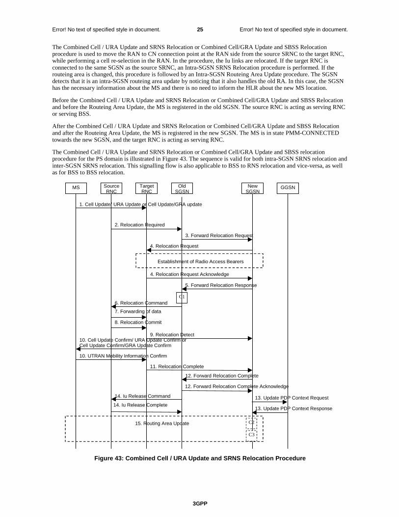
3GPP
Error! No text of specified style in document. 25 Error! No text of specified style in document.
The Combined Cell / URA Update and SRNS Relocation or Combined Cell/GRA Update and SBSS Relocation procedure is used to move the RAN to CN connection point at the RAN side from the source SRNC to the target RNC, while performing a cell re-selection in the RAN. In the procedure, the Iu links are relocated. If the target RNC is connected to the same SGSN as the source SRNC, an Intra-SGSN SRNS Relocation procedure is performed. If the routeing area is changed, this procedure is followed by an Intra-SGSN Routeing Area Update procedure. The SGSN detects that it is an intra-SGSN routeing area update by noticing that it also handles the old RA. In this case, the SGSN has the necessary information about the MS and there is no need to inform the HLR about the new MS location.
Before the Combined Cell / URA Update and SRNS Relocation or Combined Cell/GRA Update and SBSS Relocation and before the Routeing Area Update, the MS is registered in the old SGSN. The source RNC is acting as serving RNC or serving BSS.
After the Combined Cell / URA Update and SRNS Relocation or Combined Cell/GRA Update and SBSS Relocation and after the Routeing Area Update, the MS is registered in the new SGSN. The MS is in state PMM-CONNECTED towards the new SGSN, and the target RNC is acting as serving RNC.
The Combined Cell / URA Update and SRNS Relocation or Combined Cell/GRA Update and SBSS relocation procedure for the PS domain is illustrated in Figure 43. The sequence is valid for both intra-SGSN SRNS relocation and inter-SGSN SRNS relocation. This signalling flow is also applicable to BSS to RNS relocation and vice-versa, as well as for BSS to BSS relocation.
MS Target RNC
Source RNC
Old SGSN
New SGSN GGSN
3. Forward Relocation Request
4. Relocation Request
2. Relocation Required
6. Relocation Command
5. Forward Relocation Response
4. Relocation Request Acknowledge
9. Relocation Detect
11. Relocation Complete 12. Forward Relocation Complete
10. Cell Update Confirm/ URA Update Confirm or Cell Update Confirm/GRA Update Confirm
10. UTRAN Mobility Information Confirm
Establishment of Radio Access Bearers
15. Routing Area Update
13. Update PDP Context Request 14. Iu Release Command 14. Iu Release Complete
C1
C2
1. Cell Update/ URA Update or Cell Update/GRA update
8. Relocation Commit
7. Forwarding of data
13. Update PDP Context Response
12. Forward Relocation Complete Acknowledge
C3
Figure 43: Combined Cell / URA Update and SRNS Relocation Procedure
3GPP
Error! No text of specified style in document. 26 Error! No text of specified style in document.
1) The MS sends a Cell Update / URA Update or a Cell Update / GRA Update message to the source SRNC (if the cell is located under another RNC the message is routed via the DRNC to SRNC over the Iur). The source SRNC decides whether or not to perform a combined cell / URA update and SRNS relocation towards the target RNC. The rest of this subclause describes the case where a combined cell / URA update and SRNS relocation applies. In this case no radio bearer is established between the source SRNC and the UE. Nonetheless the following tunnel(s) are established: GTP-U tunnel(s) between source SRNC and old-SGSN; GTP-U tunnel(s) between old-SGSN and GGSN.
2) The source SRNC sends a Relocation Required message (Relocation Type, Cause, Source ID, Target ID, Source RNC to Target RNC Transparent Container) to the old SGSN. The source SRNC shall set Relocation Type to "UE not involved". Source RNC to Target RNC Transparent Container includes the necessary information for Relocation co-ordination, security functionality, and RRC protocol context information (including MS Capabilities).
3) The old SGSN determines from the Target ID if the SRNS Relocation is intra-SGSN SRNS relocation or inter-SGSN SRNS relocation. In the case of inter-SGSN SRNS relocation the old SGSN initiates the relocation resource allocation procedure by sending a Forward Relocation Request (IMSI, Tunnel Endpoint Identifier Signalling, MM Context, PDP Context, Target Identification, RAN Transparent Container, RANAP Cause) message to the new SGSN. For relocation to an area where Intra Domain Connection of RAN Nodes to Multiple CN Nodes is used, the old SGSN may – if it provides Intra Domain Connection of RAN Nodes to Multiple CN Nodes -have multiple target SGSNs for each relocation target in a pool area, in which case the old SGSN will select one of them to become the new SGSN, as specified in 3GPP TS 23.236 [73]. PDP context contains GGSN Address for User Plane and Uplink TEID for Data (to this GGSN Address and Uplink TEID for Data, the old SGSN and the new SGSN send uplink packets). At the same time a timer is started on the MM and PDP contexts in the old SGSN, see Routeing Area Update procedure in subclause "Location Management Procedures (Iu mode)". The Forward Relocation Request message is applicable only in case of inter-SGSN SRNS relocation.
4) The new SGSN sends a Relocation Request message (Permanent NAS UE Identity, Cause, CN Domain Indicator, Source RNC to Target RNC Transparent Container, RABs To Be Setup) to the target RNC. For each requested RAB, RABs To Be Setup shall contain information such as RAB ID, RAB parameters, Transport Layer Address, and Iu Transport Association. SGSN shall not establish RABs for PDP contexts with maximum bitrate for uplink and downlink of 0 kbit/s. The RAB ID information element contains the NSAPI value, and the RAB parameters information element gives the QoS profile. The Transport Layer Address is the SGSN Address for user data, and the Iu Transport Association corresponds to the uplink Tunnel Endpoint Identifier Data.
After all necessary resources for accepted RABs including the Iu user plane are successfully allocated, the target RNC shall send the Relocation Request Acknowledge message (RABs setup, RABs failed to setup) to the new SGSN. Each RAB to be setup is defined by a Transport Layer Address, which is the target RNC Address for user data, and a Iu Transport Association which corresponds to the downlink Tunnel Endpoint Identifier for user data.
After the new SGSN receives the Relocation Request Acknowledge message, the GTP-U tunnels are established between the target RNC and the new-SGSN.
The target-RNC may simultaneously receive for each RAB to be set up downlink user packets both from the source SRNC and from the new SGSN.
5) When resources for the transmission of user data between the target RNC and the new SGSN have been allocated and the new SGSN is ready for relocation of SRNS, the Forward Relocation Response message (Cause, RANAP Cause, and Target RNC Information) is sent from the new SGSN to the old SGSN. This message indicates that the target RNC is ready to receive from the source SRNC the forwarded downlink packets, i.e., the relocation resource allocation procedure is terminated successfully. RANAP Cause is information from the target RNC to be forwarded to the source SRNC. The RAB Setup Information, one information element for each RAB, contains the RNC Tunnel Endpoint Identifier and RNC IP address for data forwarding from the source SRNC to the target RNC. If the target RNC or the new SGSN failed to allocate resources, the RAB Setup Information element contains only NSAPI indicating that the source SRNC shall release the resources associated with the NSAPI. The Forward Relocation Response message is applicable only in case of inter-SGSN SRNS relocation.
6) The old SGSN continues the relocation of SRNS by sending a Relocation Command (RABs to be released, and RABs subject to data forwarding) message to the source SRNC. The old SGSN decides the RABs subject to data forwarding based on QoS, and those RABs shall be contained in RABs subject to data forwarding. For each RAB subject to data forwarding, the information element shall contain RAB ID, Transport Layer Address, and Iu Transport Association. These are the same Transport Layer Address and Iu Transport Association that the target RNC had sent to new SGSN in Relocation Request Acknowledge message, and these are used for forwarding of downlink N-PDU from the source SRNC to the target RNC. The source SRNC is now ready to forward downlink data directly to the target RNC over the Iu interface. This forwarding is performed for downlink user data only.

3GPP
Error! No text of specified style in document. 27 Error! No text of specified style in document.
7) The source SRNC may, according to the QoS profile, begin the forwarding of data for the RABs subject to data forwarding and starts the data-forwarding timer. The data forwarding at SRNS relocation shall be carried out through the Iu interface, meaning that the data exchanged between the source SRNC and the target RNC are duplicated in the source SRNC and routed at the IP layer towards the target RNC. For each radio bearer which uses lossless PDCP the GTP-PDUs related to transmitted but not yet acknowledged PDCP-PDUs are duplicated and routed at IP layer towards the target RNC together with their related downlink PDCP sequence numbers. The source RNC continues transmitting duplicates of downlink data and receiving uplink data.
Note: The order of steps, starting from step 7 onwards, does not necessarily reflect the order of events. For instance, source RNC may send data forwarding (step 7) and start Relocation Commit message (step 8) almost simultaneously. Target RNC may send Relocation Detect message (step 9) and Cell Update Confirm/URA Update Confirm (or Cell Update Confirm/GRA Update Confirm) message (step 10) at the same time. Hence, target RNC may receive the UTRAN or GERAN Mobility Information Confirm message from MS (step 10) while data forwarding (step 8) is still underway, and before the new SGSN receives Update PDP Context Response message (step 11).
Before the serving RNC role is not yet taken over by target RNC and when downlink user plane data starts to arrive to target RNC, the target RNC may buffer or discard arriving downlink GTP-PDUs according to the related QoS profile.
8) Before sending the Relocation Commit the uplink and downlink data transfer in the source, SRNC shall be suspended for RABs, which require delivery order.
When the source SRNC is ready, the source SRNC shall trigger the execution of relocation of SRNS by sending a Relocation Commit message (SRNS Contexts) to the target RNC over the UTRAN Iur interface or over the GERAN Iur-g interface, respectively. The purpose of this procedure is to transfer SRNS contexts from the source RNC to the target RNC, and to move the SRNS role from the source RNC to the target RNC. SRNS contexts are sent for each concerned RAB and contain the sequence numbers of the GTP-PDUs next to be transmitted in the uplink and downlink directions and the next PDCP sequence numbers that would have been used to send and receive data from the MS. . PDCP sequence numbers are only sent by the source RNC for radio bearers, which used lossless PDCP [57]. The use of lossless PDCP is selected by the RNC when the radio bearer is set up or reconfigured. For PDP context(s) using delivery order not required (QoS profile), the sequence numbers of the GTP-PDUs next to be transmitted are not used by the target RNC.
If delivery order is required (QoS profile), consecutive GTP-PDU sequence numbering shall be maintained throughout the lifetime of the PDP context(s). Therefore, during the entire SRNS relocation procedure for the PDP context(s) using delivery order required (QoS profile), the responsible GTP-U entities (RNCs and GGSN) shall assign consecutive GTP-PDU sequence numbers to user packets belonging to the same PDP context for uplink and downlink respectively.
9) The target RNC shall send a Relocation Detect message to the new SGSN when the relocation execution trigger is received. For SRNS relocation type "UE not involved", the relocation execution trigger is the reception of the Relocation Commit message from the Iur interface. When the Relocation Detect message is sent, the target RNC shall start SRNC operation.
10) The target SRNC sends a Cell Update Confirm / URA Update Confirm or Cell Update Confirm / GRA Update Confirm message. This message contains UE information elements and CN information elements. The UE information elements include among others new SRNC identity and S-RNTI. The CN information elements contain among others Location Area Identification and Routeing Area Identification. The procedure shall be co-ordinated in all Iu signalling connections existing for the MS.
Upon reception of the Cell Update Confirm / URA Update Confirm or Cell Update Confirm / GRA Update Confirm message the MS may start sending uplink user data to the target SRNC. When the MS has reconfigured itself, it sends the RAN Mobility Information Confirm message to the target SRNC. This indicates that the MS is also ready to receive downlink data from the target SRNC.
If the new SGSN has already received the Update PDP Context Response message from the GGSN, it shall forward the uplink user data to the GGSN over this new GTP-U tunnel. Otherwise, the new SGSN shall forward the uplink user data to that GGSN IP address and TEID(s), which the new SGSN had received earlier by the Forward Relocation Request message.
The target SRNC and the MS exchange the PDCP sequence numbers; PDCP-SNU and PDCP-SND. PDCP-SND is the PDCP sequence number for the next expected in-sequence downlink packet to be received in the MS per radio bearer, which used lossless PDCP in the source RNC. PDCP-SND confirms all mobile terminated packets successfully transferred before the SRNC relocation procedure. . If PDCP-SND confirms the reception of packets that were forwarded from the source SRNC, the target SRNC shall discard these packets. PDCP-SNU is

3GPP
Error! No text of specified style in document. 28 Error! No text of specified style in document.
the PDCP sequence number for the next expected in-sequence uplink packet to be received in the RNC per radio bearer, which used lossless PDCP in the source RNC. PDCP-SNU confirms all mobile originated packets successfully transferred before the SRNC relocation. If PDCP-SNU confirms reception of packets that were received in the source SRNC, the target SRNC shall discard these packets.
11) When the target SRNC receives the RAN Mobility Information Confirm message, i.e. the new SRNC-ID + S-RNTI are successfully exchanged with the MS by the radio protocols, the target SRNC shall initiate the Relocation Complete procedure by sending the Relocation Complete message to the new SGSN. The purpose of the Relocation Complete procedure is to indicate by the target SRNC the completion of the relocation of the SRNS to the CN.
12) Upon receipt of Relocation Complete message, if the SRNS Relocation is an inter SGSN SRNS relocation, the new SGSN signals to the old SGSN the completion of the SRNS relocation procedure by sending a Forward Relocation Complete message.
13) Upon receipt of the Relocation Complete message, the CN shall switch the user plane from the source RNC to the target SRNC. If the SRNS Relocation is an inter-SGSN SRNS relocation, the new SGSN sends Update PDP Context Request messages (new SGSN Address, SGSN Tunnel Endpoint Identifier, QoS Negotiated, serving network identity) to the GGSNs concerned. The SGSN should send the serving network identity to the GGSN. The GGSNs update their PDP context fields and return an Update PDP Context Response (GGSN Tunnel Endpoint Identifier) message.
14) Upon receiving the Relocation Complete message or if it is an inter-SGSN SRNS relocation, the Forward Relocation Complete message, the old SGSN sends an Iu Release Command message to the source RNC. When the RNC data-forwarding timer has expired the source RNC responds with an Iu Release Complete.
15) After the MS has finished the Cell / URA update or the Cell / GRA update and RNTI reallocation procedure and if the new Routeing Area Identification is different from the old one, the MS initiates the Routeing Area Update procedure. See subclause "Location Management Procedures (Iu mode)". Note that it is only a subset of the RA update procedure that is performed, since the MS is in PMM-CONNECTED state.
If the SRNS Relocation is inter-SGSN, then the following CAMEL procedure calls shall be performed (see referenced procedures in 3GPP TS 23.078)
C1) CAMEL_GPRS_PDP_Context_Disconnection, CAMEL_GPRS_Detach and CAMEL_PS_Notification.
They are called in the following order:
- The CAMEL_GPRS_PDP_Context_Disconnection procedure is called several times: once per PDP context. The procedure returns as result "Continue".
- Then the CAMEL_GPRS_Detach procedure is called once. The procedure returns as result "Continue".
- Then the CAMEL_PS_Notification procedure is called once. The procedure returns as result "Continue".
If the SRNS Relocation is intra-SGSN, then the above mentioned CAMEL procedures calls shall not be performed.
If Routeing Area Update occurs, then the following CAMEL procedure calls shall be performed (see referenced procedures in 3GPP TS 23.078):
C2) CAMEL_GPRS_Routeing_Area_Update_Session and CAMEL_PS_Notification.
They are called in the following order:
- The CAMEL_GPRS_Routeing_Area_Update_Session procedure is called. The procedure returns as result "Continue".
- Then, the CAMEL_PS_Notification procedure is called. The procedure returns as result "Continue".
C3) CAMEL_GPRS_Routeing_Area_Update_Context.
This procedure is called several times: once per PDP context. It returns as result "Continue". For C2 and C3: refer to Routing Area Update procedure description for detailed message flow.
Next change
3GPP
Error! No text of specified style in document. 29 Error! No text of specified style in document.
6.13.2.1 Iu mode to A/Gb mode Inter-SGSN Change
An inter-SGSN inter-system change from Iu mode to A/Gb mode takes place when an MS in PMM-IDLE or PMM-CONNECTED state changes from UTRAN or GERAN Iu mode to A/Gb mode and the A/Gb mode radio access node serving the MS is served by a different SGSN. In this case, the RA changes. Therefore, the MS shall initiate a A/Gb mode RA update procedure. The RA update procedure is either combined RA / LA update or only RA update. These RA update cases are illustrated in Figure 54. In the context of this specification, the terms RNS or RNC refer also to a GERAN BSS or BSC (respectively) when serving an MS in Iu mode.
A combined RA / LA update takes place in network operation mode I when the MS enters a new RA or when a GPRS-attached MS performs IMSI attach. The MS sends a Routeing Area Update Request indicating that an LA update may also need to be performed, in which case the SGSN forwards the LA update to the VLR. This concerns only idle mode (see 3GPP TS 23.122), as no combined RA / LA updates are performed during a CS connection.

3GPP
Error! No text of specified style in document. 30 Error! No text of specified style in document.
MS new2G-SGSN
HLRGGSNold3G-SGSN
2. Routing Area Update Request
10. Update PDP Context Request
10. Update PDP Context Response
11. Update GPRS Location
15. Update GPRS Location Ack
5. SGSN Context Response
6. Security Functions
19. Routing Area Update Accept
12. Cancel Location
12. Cancel Location Ack
14. Insert Subscriber Data Ack
14. Insert Subscriber Data
7. SGSN Context Acknowledge
BSS SRNS
3. SGSN Context Request
13. Iu Release Command
13. Iu Release Complete
8a. Forward Packets
9. Forward Packets
4. SRNS Context Request
4. SRNS Context Response
8. SRNS Data Forward Command
22. BSS Packet Flow Context Procedure
1. Intersystem changedecision
C3
C1
20. Routing Area Update Complete
newMSC/VLR
oldMSC/VLR
16. Location Update Request
17a. Update Location
17b. Cancel Location
17c. Cancel Location Ack
17d. Insert Subscriber Data
17e. Insert Subscriber Data Ack
17f. Update Location Ack 18. Location Update Accept
21. TMSI Reallocation Complete
C2
Figure 54: Iu mode to A/Gb mode Inter-SGSN Change
1) The MS or RAN decides to perform an inter-system change, which makes the MS switch to a new cell where A/Gb mode has to be used, and stops transmission to the network.
3GPP
Error! No text of specified style in document. 31 Error! No text of specified style in document.
2) The MS sends a Routeing Area Update Request (old RAI, old P-TMSI Signature, Update Type, MS Network Capability) message to the new 2G-SGSN. Update Type shall indicate RA update or combined RA / LA update, or, if the MS wants to perform an IMSI attach, combined RA / LA update with IMSI attach requested. The BSS shall add the Cell Global Identity including the RAC and LAC of the cell where the message was received before passing the message to the new 2G-SGSN.
3) The new 2G-SGSN sends an SGSN Context Request (old RAI, TLLI, old P-TMSI Signature, New SGSN Address) message to the old 3G-SGSN to get the MM and PDP contexts for the MS. If the new SGSN provides functionality for Intra Domain Connection of RAN Nodes to Multiple CN Nodes, the new SGSN may derive the old SGSN from the old RAI and the old P-TMSI (or TLLI) and send the SGSN Context Request message to this old SGSN. Otherwise, the new SGSN derives the old SGSN from the old RAI. In any case the new SGSN will derive an SGSN that it believes is the old SGSN. This derived SGSN is itself the old SGSN, or it is associated with the same pool area as the actual old SGSN and it will determine the correct old SGSN from the P-TMSI (or TLLI) and relay the message to that actual old SGSN. The old 3G-SGSN validates the old P-TMSI Signature and responds with an appropriate error cause if it does not match the value stored in the old 3G-SGSN. If the received old P-TMSI Signature does not match the stored value, the security functions in the new 2G-SGSN should be initiated. If the security functions authenticate the MS correctly, the new 2G-SGSN shall send an SGSN Context Request (old RAI, TLLI, MS Validated, New SGSN Address) message to the old 3G-SGSN. MS Validated indicates that the new 2G-SGSN has authenticated the MS. If the old P-TMSI Signature was valid or if the new 2G-SGSN indicates that it has authenticated the MS correctly, the old 3G-SGSN starts a timer. If the MS is not known in the old 3G-SGSN, the old 3G-SGSN responds with an appropriate error cause.
4) If the MS is PMM-CONNECTED the old 3G-SGSN sends an SRNS Context Request (IMSI) message to the SRNS. Upon receipt of this message the SRNS buffers and stops sending downlink PDUs to the MS and returns an SRNS Context Response (GTP-SNDs, GTP-SNUs, PDCP-SNDs, PDCP-SNUs) message. The SRNS shall include for each PDP context the next in-sequence GTP sequence number to be sent to the MS and the GTP sequence number of the next uplink PDU to be tunnelled to the GGSN. For each active PDP context, which uses lossless PDCP, the SRNS also includes the uplink PDCP sequence number (PDCP-SNU) downlink PDCP sequence number (PDCP-SND). PDCP-SNU shall be the next in-sequence PDCP sequence number expected from the MS. PDCP-SND is the PDCP sequence number for the first downlink packet for which successful transmission has not been confirmed. The 3G-SGSN shall strip off the eight most significant bits of the passed PDCP sequence numbers, thus converting them to SNDCP N-PDU numbers and stores the N-PDU numbers in its PDP contexts..
5) The old 3G-SGSN responds with an SGSN Context Response (MM Context, PDP Contexts) message. For each PDP context the old 3G-SGSN shall include the GTP sequence number for the next uplink GTP PDU to be tunnelled to the GGSN and the next downlink GTP sequence number for the next in-sequence N-PDU to be sent to the MS. Each PDP Context also includes the SNDCP Send N-PDU Number (the value is 0) for the next in-sequence downlink N-PDU to be sent in SNDCP acknowledged mode to the MS and the SNDCP Receive N-PDU Number (= converted PDCP-SNU) for the next in-sequence uplink N-PDU to be received in SNDCP acknowledged mode from the MS. The new 3G-SGSN shall ignore the MS Network Capability contained in MM Context of SGSN Context Response only when it has previously received an MS Network Capability in the Routeing Area Request.
6) Security functions may be executed.
7) The new 2G-SGSN sends an SGSN Context Acknowledge message to the old 3G-SGSN. This informs the old 3G-SGSN that the new 2G-SGSN is ready to receive data packets belonging to the activated PDP contexts. The old SGSN marks in its context that the MSC/VLR association and the information in the GGSNs and the HLR are invalid. This triggers the MSC/VLR, the GGSNs, and the HLR to be updated if the MS initiates a RA update procedure back to the old SGSN before completing the ongoing RA update procedure.
8) If the MS is in the PMM-CONNECTED state, the old 3G-SGSN sends an SRNS Data Forward Command (RAB ID, Transport Layer Address, Iu Transport Association) message to the SRNS. For each indicated RAB the SRNS starts duplicating and tunnelling the buffered GTP PDUs to the old 3G-SGSN. For each radio bearer which uses lossless PDCP the SRNS shall start tunnelling the GTP-PDUs related to transmitted but not yet acknowledged PDCP-PDUs to the old 3G-SGSN together with their related downlink PDCP sequence numbers. Upon receipt of the SRNS Data Forward Command message from the 3G-SGSN, the SRNS shall start the data-forwarding timer.
9) The old 3G-SGSN tunnels the GTP PDUs to the new 2G-SGSN. In the case of GTPv1, the conversion of PDCP sequence numbers to SNDCP sequence numbers (the eight most significant bits shall be stripped off) shall be done in the new SGSN. No N-PDU sequence numbers shall be indicated for these N-PDUs. If GTPv0 is used between the SGSNs, the conversion of PDCP sequence numbers to SNDCP numbers shall be done in the old 3G-SGSN (by stripping off the eight most significant bits).
3GPP
Error! No text of specified style in document. 32 Error! No text of specified style in document.
10) The new 2G-SGSN sends an Update PDP Context Request (new SGSN Address, TEID, QoS Negotiated, serving network identity) message to each GGSN concerned. The SGSN should send the serving network identity to the GGSN. Each GGSN updates its PDP context fields and returns an Update PDP Context Response (TEID) message.
11) The new 2G-SGSN informs the HLR of the change of SGSN by sending an Update GPRS Location (SGSN Number, SGSN Address, IMSI) message to the HLR.
12) The HLR sends a Cancel Location (IMSI) message to the old 3G-SGSN. The old 3G-SGSN acknowledges with a Cancel Location Ack (IMSI) message. The old 3G-SGSN removes the MM and PDP contexts if the timer described in step 3 is not running. If the timer is running, the MM and PDP contexts shall be removed when the timer expires.
13) When the MS is PMM-CONNECTED, the old 3G-SGSN sends an Iu Release Command message to the SRNS. When the RNC data-forwarding timer has expired, the SRNS responds with an Iu Release Complete message.
14) The HLR sends an Insert Subscriber Data (IMSI, GPRS Subscription Data) message to the new 2G-SGSN. The 2G-SGSN constructs an MM context and PDP contexts for the MS and returns an Insert Subscriber Data Ack (IMSI) message to the HLR.
15) The HLR acknowledges the Update GPRS Location by returning an Update GPRS Location Ack (IMSI) message to the new 2G-SGSN.
16) If the association has to be established i.e. if Update Type indicates combined RA / LA update with IMSI attach requested, or if the LA changed with the routeing area update, the new 2G-SGSN sends a Location Update Request (new LAI, IMSI, SGSN Number, Location Update Type) to the VLR. Location Update Type shall indicate IMSI attach if Update Type in step 1 indicated combined RA / LA update with IMSI attach requested. Otherwise, Location Update Type shall indicate normal location update. When the SGSN does not provide functionality for the Intra Domain Connection of RAN Nodes to Multiple CN Nodes, the VLR number is derived from the RAI. When the SGSN provides functionality for Intra Domain Connection of RAN Nodes to Multiple CN Nodes, the SGSN uses the RAI and a hash value from the IMSI to determine the VLR number. The 2G-SGSN starts the location update procedure towards the new MSC/VLR upon receipt of the first Insert Subscriber Data message from the HLR in step 14). The VLR creates or updates the association with the 2G-SGSN by storing SGSN Number.
17) If the subscriber data in the VLR is marked as not confirmed by the HLR, the new VLR informs the HLR. The HLR cancels the old VLR and inserts subscriber data in the new VLR:
a) The new VLR sends an Update Location (new VLR) to the HLR.
b) The HLR cancels the data in the old VLR by sending Cancel Location (IMSI) to the old VLR.
c) The old VLR acknowledges with Cancel Location Ack (IMSI).
d) The HLR sends Insert Subscriber Data (IMSI, subscriber data) to the new VLR.
e) The new VLR acknowledges with Insert Subscriber Data Ack (IMSI).
f) The HLR responds with Update Location Ack (IMSI) to the new VLR.
18) The new VLR allocates a new TMSI and responds with Location Update Accept (VLR TMSI) to the 2G-SGSN. VLR TMSI is optional if the VLR has not changed.
19) The new 2G-SGSN validates the MS's presence in the new RA. If due to roaming restrictions the MS is not allowed to be attached in the RA, or if subscription checking fails, the new 2G-SGSN rejects the routeing area update with an appropriate cause. If all checks are successful, the new 2G-SGSN constructs MM and PDP contexts for the MS. A logical link is established between the new 2G-SGSN and the MS. 2G-SGSN initiates the establishment procedure. The new 2G-SGSN responds to the MS with a Routeing Area Update Accept (P-TMSI, P-TMSI Signature, Receive N-PDU Number (= converted PDCP-SNU) message. Receive N-PDU Number contains the acknowledgements for each NSAPI which used lossless PDCP before the start of the update procedure, thereby confirming all mobile-originated N-PDUs successfully transferred before the start of the update procedure. If Receive N-PDU Number confirms the reception of N-PDUs, the MS shall discard these N-PDUs.
20) The MS acknowledges the new P-TMSI by returning a Routeing Area Update Complete (Receive N-PDU Number (= converted PDCP-SND)) message to the SGSN. Receive N-PDU Number contains the acknowledgements for each lossless PDCP used by the MS before the start of the update procedure, thereby

3GPP
Error! No text of specified style in document. 33 Error! No text of specified style in document.
confirming all mobile-terminated N-PDUs successfully transferred before the start of the update procedure. If Receive N-PDU Number confirms the reception of N-PDUs that were forwarded from the old 3G-SGSN, the new 2G-SGSN shall discard these N-PDUs. The MS deducts Receive N-PDU number from PDCP-SND by stripping off the eight most significant bits. PDCP-SND is the PDCP sequence number for the next expected in-sequence downlink packet to be received in the MS per radio bearer, which used lossless PDCP. The new 2G-SGSN negotiates with the MS for each NSAPI the use of acknowledged or unacknowledged SNDCP regardless whether the SRNS used lossless PDCP or not.
21) The new 2G-SGSN sends TMSI Reallocation Complete message to the new VLR if the MS confirms the VLR TMSI.
22) The 2G-SGSN and the BSS may execute the BSS Packet Flow Context procedure.
If the new SGSN is unable to update the PDP context in one or more GGSNs, the new SGSN shall deactivate the corresponding PDP contexts as described in subclause "SGSN-initiated PDP Context Deactivation Procedure". This shall not cause the SGSN to reject the routeing area update.
The PDP Contexts shall be sent from old to new SGSN in a prioritized order, i.e. the most important PDP Context first in the SGSN Context Response message. (The prioritization method is implementation dependent, but should be based on the current activity.)
If the new SGSN is unable to support the same number of active PDP contexts as received from old SGSN, the new SGSN should use the prioritisation sent by old SGSN as input when deciding which PDP contexts to maintain active and which ones to delete. In any case, the new SGSN shall first update all contexts in one or more GGSNs and then deactivate the context(s) that it cannot maintain as described in subclause "SGSN-initiated PDP Context Deactivation Procedure". This shall not cause the SGSN to reject the routeing area update.
The CAMEL procedure calls shall be performed, see referenced procedures in 3GPP TS 23.078:
C1) CAMEL_GPRS_PDP_Context_Disconnection, CAMEL_GPRS_Detach and CAMEL_PS_Notification.
They are called in the following order:
- The CAMEL_GPRS_PDP_Context_Disconnection procedure is called several times: once per PDP context. The procedure returns as result "Continue".
- Then the CAMEL_GPRS_Detach procedure is called once. The procedure returns as result "Continue".
- Then the CAMEL_PS_Notification procedure is called once. The procedure returns as result "Continue".
C2) CAMEL_GPRS_Routeing_Area_Update_Session and CAMEL_PS_Notification.
They are called in the following order:
- The CAMEL_GPRS_Routeing_Area_Update_Session procedure is called. The procedure returns as result "Continue".
- Then the CAMEL_PS_Notification procedure is called. The procedure returns as result "Continue".
C3) CAMEL_GPRS_Routeing_Area_Update_Context.
This procedure is called several times once per PDP context. It returns as result "Continue".
6.13.2.2 A/Gb mode to Iu mode Inter-SGSN Change
The inter-system change from A/Gb mode to Iu mode takes place when a GPRS-attached MS changes from A/Gb mode to UTRAN or GERAN Iu mode and the new RAN node serving the MS is served by a different SGSN. In this case the RA changes. Therefore, the MS shall initiate a Iu mode RA update procedure by establishing an RRC connection and initiating the RA update procedure. The RA update procedure is either combined RA / LA update or only RA update, these RA update cases are illustrated in Figure 55. In the context of this specification, the terms RNS or RNC refer also to a GERAN BSS or BSC (respectively) when serving an MS in Iu mode.
If the network operates in mode I, then an MS, that is both PS-attached and CS-attached, shall perform the Combined RA / LA Update procedures. This concerns only idle mode (see 3GPP TS 23.122), as no combined RA / LA updates are performed during a CS connection.
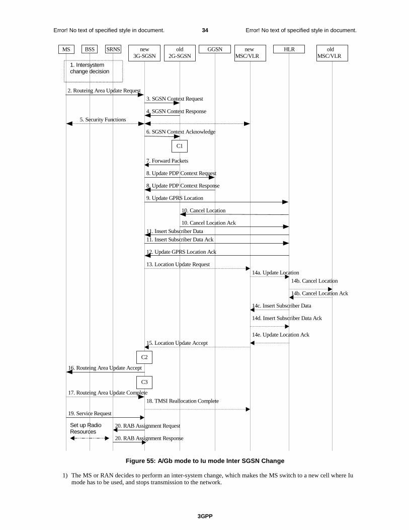
3GPP
Error! No text of specified style in document. 34 Error! No text of specified style in document.
MS new3G-SGSN
HLRGGSNold2G-SGSN
8. Update PDP Context Request
8. Update PDP Context Response
9. Update GPRS Location
12. Update GPRS Location Ack
2. Routeing Area Update Request
4. SGSN Context Response
5. Security Functions
16. Routeing Area Update Accept
10. Cancel Location
10. Cancel Location Ack
11. Insert Subscriber Data Ack
11. Insert Subscriber Data
17. Routeing Area Update Complete
6. SGSN Context Acknowledge
BSS SRNS
3. SGSN Context Request
20. RAB Assignment Request
20. RAB Assignment Response
7. Forward Packets
1. Intersystemchange decision
C3
C1
newMSC/VLR
oldMSC/VLR
13. Location Update Request
14a. Update Location
14b. Cancel Location
14b. Cancel Location Ack
14c. Insert Subscriber Data
14d. Insert Subscriber Data Ack
14e. Update Location Ack
15. Location Update Accept
18. TMSI Reallocation Complete
Set up RadioResources
19. Service Request
C2
Figure 55: A/Gb mode to Iu mode Inter SGSN Change
1) The MS or RAN decides to perform an inter-system change, which makes the MS switch to a new cell where Iu mode has to be used, and stops transmission to the network.
3GPP
Error! No text of specified style in document. 35 Error! No text of specified style in document.
2) The MS sends a Routeing Area Update Request (P-TMSI, old RAI, old P-TMSI Signature, Update Type, CM, MS Network Capability) message to the new 3G-SGSN. Update Type shall indicate RA update or combined RA / LA update, or, if the MS wants to perform an IMSI attach, combined RA / LA update with IMSI attach requested, and also if the MS has a follow-on request, i.e. if there is pending uplink traffic (signalling or data). The SGSN may use, as an implementation option, the follow-on request indication to release or keep the Iu connection after the completion of the RA update procedure. The SRNC shall add the Routeing Area Identity including the RAC and LAC of the area where the MS is located before forwarding the message to the 3G-SGSN. This RA identity corresponds to the RAI in the MM system information sent by the SRNC to the MS.
3) The new 3G-SGSN uses the old RAI received from the MS to derive the old 2G-SGSN address, and sends an SGSN Context Request (old RAI, old P-TMSI, New SGSN Address) message to the old 2G-SGSN to get the MM and PDP contexts for the MS. If the new SGSN provides functionality for Intra Domain Connection of RAN Nodes to Multiple CN Nodes, the new SGSN may derive the old SGSN from the old RAI and the old P-TMSI and send the SGSN Context Request message to this old SGSN. Otherwise, the new SGSN derives the old SGSN from the old RAI. In any case the new SGSN will derive an SGSN that it believes is the old SGSN. This derived SGSN is itself the old SGSN, or it is associated with the same pool area as the actual old SGSN and it will determine the correct old SGSN from the P-TMSI and relay the message to that actual old SGSN. The old 2G-SGSN validates the old P-TMSI Signature and responds with an appropriate error cause if it does not match the value stored in the old 2G-SGSN. If the received old P-TMSI Signature does not match the stored value, the old 2G-SGSN should initiate the security functions in the new 3G-SGSN. If the security functions authenticate the MS correctly, the new 3G-SGSN shall send an SGSN Context Request (old RAI, IMSI, MS Validated, New SGSN Address) message to the old 2G-SGSN. MS Validated indicates that the new 3G-SGSN has authenticated the MS. If the old P-TMSI Signature was valid or if the new 3G-SGSN indicates that it has authenticated the MS correctly, the old 2G-SGSN starts a timer and stops the transmission of N-PDUs to the MS.
4) The old 2G-SGSN responds with an SGSN Context Response (MM Context, PDP Contexts) message. Each PDP Context includes the GTP sequence number for the next downlink N-PDU to be sent to the MS and the GTP sequence number for the next uplink N-PDU to be tunnelled to the GGSN. Each PDP Context also includes the SNDCP Send N-PDU Number for the next downlink N-PDU to be sent in acknowledged mode SNDCP to the MS and the SNDCP Receive N-PDU Number for the next uplink N-PDU to be received in acknowledged mode SNDCP from the MS. The new 3G-SGSN derives the corresponding PDCP sequence numbers from these N-PDU sequence numbers by adding eight most significant bits "1". These PDCP sequence numbers are stored in the 3G-SGSN PDP contexts. The new 3G-SGSN shall ignore the MS Network Capability contained in MM Context of SGSN Context Response only when it has previously received an MS Network Capability in the Routeing Area Request.
5) Security functions may be executed.
6) The new 3G-SGSN sends an SGSN Context Acknowledge message to the old 2G-SGSN. This informs the old 2G-SGSN that the new 3G-SGSN is ready to receive data packets belonging to the activated PDP contexts. The old SGSN marks in its context that the MSC/VLR association and the information in the GGSNs and the HLR are invalid. This triggers the MSC/VLR, the GGSNs, and the HLR to be updated if the MS initiates a routeing area update procedure back to the old SGSN before completing the ongoing routeing area update procedure.
7) The old 2G-SGSN duplicates the buffered N-PDUs and starts tunnelling them to the new 3G-SGSN. Additional N-PDUs received from the GGSN before the timer described in step 3 expires are also duplicated and tunnelled to the new 3G-SGSN. N-PDUs that were already sent to the MS in acknowledged mode SNDCP and that are not yet acknowledged by the MS are tunnelled together with their related SNDCP N-PDU sequence number. No PDCP sequence numbers shall be indicated for these N-PDUs. No N-PDUs shall be forwarded to the new 3G-SGSN after expiry of the timer described in step 3.
8) The new 3G-SGSN sends an Update PDP Context Request (new SGSN Address, TEID, QoS Negotiated, serving network identity) message to each GGSN concerned. The SGSN should send the serving network identity to the GGSN. Each GGSN updates its PDP context fields and returns an Update PDP Context Response (TEID) message.
9) The new 3G-SGSN informs the HLR of the change of SGSN by sending an Update GPRS Location (SGSN Number, SGSN Address, IMSI) message to the HLR.
10) The HLR sends a Cancel Location (IMSI, Cancellation Type) message to the old 2G-SGSN. The old 2G-SGSN removes the MM and PDP contexts if the timer described in step 3 is not running. If the timer is running, the MM and PDP contexts are removed when the timer expires. The old 2G-SGSN acknowledges with a Cancel Location Ack (IMSI) message.

3GPP
Error! No text of specified style in document. 36 Error! No text of specified style in document.
11) The HLR sends an Insert Subscriber Data (IMSI, GPRS Subscription Data) message to the new 3G-SGSN. The 3G-SGSN constructs an MM context for the MS and returns an Insert Subscriber Data Ack (IMSI) message to the HLR.
12) The HLR acknowledges the Update GPRS Location by returning an Update GPRS Location Ack (IMSI) message to the new 3G-SGSN.
13) If the association has to be established, if Update Type indicates combined RA / LA update with IMSI attach requested, or if the LA changed with the routeing area update, the new SGSN sends a Location Update Request (new LAI, IMSI, SGSN Number, Location Update Type) to the VLR. Location Update Type shall indicate IMSI attach if Update Type in step 1 indicated combined RA / LA update with IMSI attach requested. Otherwise, Location Update Type shall indicate normal location update. When the SGSN does not provide functionality for the Intra Domain Connection of RAN Nodes to Multiple CN Nodes, the VLR number is derived from the RAI. When the SGSN provides functionality for Intra Domain Connection of RAN Nodes to Multiple CN Nodes, the SGSN uses the RAI and a hash value from the IMSI to determine the VLR number. The 3G-SGSN starts the location update procedure towards the new MSC/VLR upon receipt of the first Insert Subscriber Data message from the HLR in step 12). The VLR creates or updates the association with the 3G-SGSN by storing SGSN Number.
14) If the subscriber data in the VLR is marked as not confirmed by the HLR, the new VLR informs the HLR. The HLR cancels the old VLR and inserts subscriber data in the new VLR:
a) The new VLR sends an Update Location (new VLR) to the HLR.
b) The HLR cancels the data in the old VLR by sending Cancel Location (IMSI) to the old VLR.
c) The old VLR acknowledges with Cancel Location Ack (IMSI).
d) The HLR sends Insert Subscriber Data (IMSI, subscriber data) to the new VLR.
e) The new VLR acknowledges with Insert Subscriber Data Ack (IMSI).
f) The HLR responds with Update Location Ack (IMSI) to the new VLR.
15) The new VLR allocates a new TMSI and responds with Location Update Accept (VLR TMSI) to the 3G-SGSN. VLR TMSI is optional if the VLR has not changed.
16) The new 3G-SGSN validate the MS's presence in the new RA. If due to roaming restrictions the MS is not allowed to be attached in the RA, or if subscription checking fails, the new 3G-SGSN rejects the routeing area update with an appropriate cause. If all checks are successful, the new 3G-SGSN constructs MM and PDP contexts for the MS. The new 3G-SGSN responds to the MS with a Routeing Area Update Accept (P-TMSI, P-TMSI signature) message.
17) The MS acknowledges the new P-TMSI by returning a Routeing Area Update Complete message to the SGSN.
18) The new 3G-SGSN sends TMSI Reallocation Complete message to the new VLR, if the MS confirms the VLR TMSI.
19) If the MS has uplink data or signalling pending it shall send a Service Request (P-TMSI, RAI, CKSN, Service Type) message to the SGSN. Service Type specifies the requested service. Service Type shall indicate one of the following: Data or Signalling.
20) If the MS has sent the Service Request, the new 3G-SGSN requests the SRNS to establish a radio access bearer by sending a RAB Assignment Request (RAB ID(s), QoS Profile(s), GTP-SNDs, GTP-SNUs, PDCP-SNUs) message to the SRNS. The PDCP sequence numbers are derived from the N-PDU sequence numbers in step 4) and stored in the SGSN PDP contexts. The SRNS sends a Radio Bearer Setup Request (PDCP-SNUs) message to the MS. The MS responds with a Radio Bearer Setup Complete (PDCP-SNDs) message. The MS deducts PDCP-SND from its Receive N-PDU Number by adding eight most significant bits "1". The SRNS responds with a RAB Assignment Response message. The SRNS shall discard all N-PDUs tunnelled from the SGSN with N-PDU sequence numbers older than the eight least significant bits of the PDCP-SNDs received from the MS. Other N-PDUs shall be transmitted to the MS. The MS shall discard all N-PDUs with SNDCP sequence numbers older than the eight least significant bits of the PDCP-SNUs received from the SRNS. Other N-PDUs shall be transmitted to the SRNS. The SRNS negotiates with the MS for each radio bearer the use of lossless PDCP or not regardless whether the old 2G-SGSN used acknowledged or unacknowledged SNDCP for the related NSAPI or not.
NOTE: The NSAPI value is carried in the RAB ID IE.
3GPP
Error! No text of specified style in document. 37 Error! No text of specified style in document.
NOTE: The new SGSN may initiate RAB establishment after execution of the security functions (step 5), or wait until completion of the RA update procedure. For the MS, RAB establishment may occur anytime after the RA update request is sent (step 2).
If the new SGSN is unable to update the PDP context in one or more GGSNs, the new SGSN shall deactivate the corresponding PDP contexts as described in subclause "SGSN-initiated PDP Context Deactivation Procedure". This shall not cause the SGSN to reject the routeing area update.
The PDP Contexts shall be sent from old to new SGSN in a prioritized order, i.e. the most important PDP Context first in the SGSN Context Response message. (The prioritization method is implementation dependent, but should be based on the current activity.)
If the new SGSN is unable to support the same number of active PDP contexts as received from old SGSN, the new SGSN should use the prioritisation sent by old SGSN as input when deciding which PDP contexts to maintain active and which ones to delete. In any case, the new SGSN shall first update all contexts in one or more GGSNs and then deactivate the context(s) that it cannot maintain as described in subclause "SGSN-initiated PDP Context Deactivation Procedure". This shall not cause the SGSN to reject the routeing area update.
The CAMEL procedure calls shall be performed, see referenced procedures in 3GPP TS 23.078:
C1) CAMEL_GPRS_PDP_Context_Disconnection, CAMEL_GPRS_Detach and CAMEL_PS_Notification.
They are called in the following order:
- The CAMEL_GPRS_PDP_Context_Disconnection procedure is called several times: once per PDP context. The procedure returns as result "Continue".
- Then the CAMEL_GPRS_Detach procedure is called once. It returns as result "Continue".
- Then the CAMEL_PS_Notification procedure is called once. It returns as result "Continue".
C2) CAMEL_GPRS_Routeing_Area_Update_Session and CAMEL_PS_Notification.
They are called in the following order:
- The CAMEL_GPRS_Routeing_Area_Update_Session procedure is called. The procedure returns as result "Continue".
- Then the CAMEL_PS_Notification procedure is called. The procedure returns as result "Continue".
C3) CAMEL_GPRS_Routeing_Area_Update_Context
This procedure is called several times: once per PDP context. It returns as result "Continue".
Next change
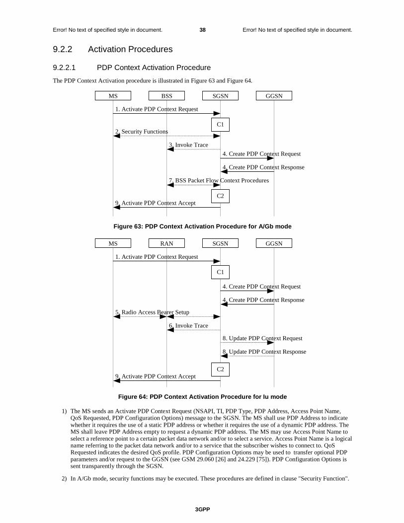
3GPP
Error! No text of specified style in document. 38 Error! No text of specified style in document.
9.2.2 Activation Procedures
9.2.2.1 PDP Context Activation Procedure
The PDP Context Activation procedure is illustrated in Figure 63 and Figure 64.
GGSN
9. Activate PDP Context Accept
4. Create PDP Context Response
4. Create PDP Context Request
1. Activate PDP Context Request
SGSNBSS
2. Security Functions
MS
7. BSS Packet Flow Context Procedures
C1
C2
3. Invoke Trace
Figure 63: PDP Context Activation Procedure for A/Gb mode
GGSN
9. Activate PDP Context Accept
4. Create PDP Context Response
4. Create PDP Context Request
1. Activate PDP Context Request
SGSNRANMS
5. Radio Access Bearer Setup
C1
C2
6. Invoke Trace
8. Update PDP Context Response
8. Update PDP Context Request
Figure 64: PDP Context Activation Procedure for Iu mode
1) The MS sends an Activate PDP Context Request (NSAPI, TI, PDP Type, PDP Address, Access Point Name, QoS Requested, PDP Configuration Options) message to the SGSN. The MS shall use PDP Address to indicate whether it requires the use of a static PDP address or whether it requires the use of a dynamic PDP address. The MS shall leave PDP Address empty to request a dynamic PDP address. The MS may use Access Point Name to select a reference point to a certain packet data network and/or to select a service. Access Point Name is a logical name referring to the packet data network and/or to a service that the subscriber wishes to connect to. QoS Requested indicates the desired QoS profile. PDP Configuration Options may be used to transfer optional PDP parameters and/or request to the GGSN (see GSM 29.060 [26] and 24.229 [75]). PDP Configuration Options is sent transparently through the SGSN.
2) In A/Gb mode, security functions may be executed. These procedures are defined in clause "Security Function".

3GPP
Error! No text of specified style in document. 39 Error! No text of specified style in document.
3) In A/Gb mode and if BSS trace is activated, the SGSN shall send an Invoke Trace (Trace Reference, Trace Type, Trigger Id, OMC Identity) message to the BSS. Trace Reference, and Trace Type are copied from the trace information received from the HLR or OMC.
4) The SGSN validates the Activate PDP Context Request using PDP Type (optional), PDP Address (optional), and Access Point Name (optional) provided by the MS and the PDP context subscription records. The validation criteria, the APN selection criteria, and the mapping from APN to a GGSN are described in annex A.
If no GGSN address can be derived or if the SGSN has determined that the Activate PDP Context Request is not valid according to the rules described in annex A, the SGSN rejects the PDP context activation request.
If a GGSN address can be derived, the SGSN creates a TEID for the requested PDP context. If the MS requests a dynamic address, the SGSN lets a GGSN allocate the dynamic address. The SGSN may restrict the requested QoS attributes given its capabilities and the current load, and it shall restrict the requested QoS attributes according to the subscribed QoS profile.
The SGSN sends a Create PDP Context Request (PDP Type, PDP Address, Access Point Name, QoS Negotiated, TEID, NSAPI, MSISDN, Selection Mode, Charging Characteristics, Trace Reference, Trace Type, Trigger Id, OMC Identity, PDP Configuration Options, serving network identity) message to the affected GGSN. The SGSN should send the serving network identity to the GGSN. Access Point Name shall be the APN Network Identifier of the APN selected according to the procedure described in Annex A. PDP Address shall be empty if a dynamic address is requested. The GGSN may use Access Point Name to find a packet data network and optionally to activate a service for this APN. Selection Mode indicates whether a subscribed APN was selected, or whether a non-subscribed APN sent by an MS or a non-subscribed APN chosen by the SGSN was selected. Selection Mode is set according to Annex A. The GGSN may use Selection Mode when deciding whether to accept or reject the PDP context activation. For example, if an APN requires subscription, the GGSN is configured to accept only the PDP context activation that requests a subscribed APN as indicated by the SGSN with Selection Mode. Charging Characteristics indicates which kind of charging the PDP context is liable for. The charging characteristics on the GPRS subscription and individually subscribed APNs as well as the way the SGSN handles Charging Characteristics and chooses to send them or not to the GGSN is defined in 3GPP TS 32.215 [70]. The SGSN shall include Trace Reference, Trace Type, Trigger Id, and OMC Identity if GGSN trace is activated. The SGSN shall copy Trace Reference, Trace Type, and OMC Identity from the trace information received from the HLR or OMC.
The GGSN creates a new entry in its PDP context table and generates a Charging Id. The new entry allows the GGSN to route PDP PDUs between the SGSN and the packet data network, and to start charging. The way the GGSN handles Charging Characteristics that it may have received from the SGSN is defined in 3GPP TS 32.215 [70]. The GGSN may restrict QoS Negotiated given its capabilities, operator policies and the current load. The GGSN then returns a Create PDP Context Response (TEID, PDP Address, PDP Configuration Options, QoS Negotiated, Charging Id, Cause) message to the SGSN. PDP Address is included if the GGSN allocated a PDP address. If the GGSN has been configured by the operator to use External PDN Address Allocation for the requested APN, PDP Address shall be set to 0.0.0.0, indicating that the PDP address shall be negotiated by the MS with the external PDN after completion of the PDP Context Activation procedure. The GGSN shall relay, modify and monitor these negotiations as long as the PDP context is in ACTIVE state, and use the GGSN-Initiated PDP Context Modification procedure to transfer the currently used PDP address to the SGSN and the MS. PDP Configuration Options contain optional PDP parameters that the GGSN may transfer to the MS. These optional PDP parameters may be requested by the MS in the Activate PDP Context Request message, or may be sent unsolicited by the GGSN. PDP Configuration Options is sent transparently through the SGSN. The Create PDP Context messages are sent over the backbone network.
If QoS Negotiated received from the SGSN is incompatible with the PDP context being activated, the GGSN rejects the Create PDP Context Request message. The GGSN operator configures the compatible QoS profiles.
5) In Iu mode, RAB setup is done by the RAB Assignment procedure, see subclause "RAB Assignment Procedure".
6) In Iu mode and if BSS trace is activated, the SGSN shall send an Invoke Trace (Trace Reference, Trace Type, Trigger Id, OMC Identity) message to the RAN. Trace Reference, and Trace Type are copied from the trace information received from the HLR or OMC.
7) In A/Gb mode, BSS packet flow context procedures may be executed. These procedures are defined in clause "BSS Context".
8) In Iu mode and in case the QoS attributes have been downgraded in step 5, the SGSN may inform the GGSN about the downgraded QoS attributes by sending an Update PDP Context Request to the affected GGSN. The GGSN confirms the new QoS attributes by sending an Update PDP Context Response to the SGSN.
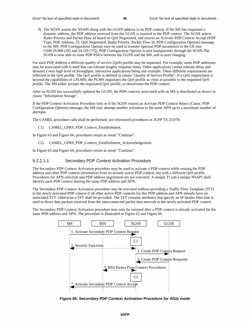
3GPP
Error! No text of specified style in document. 40 Error! No text of specified style in document.
9) The SGSN inserts the NSAPI along with the GGSN address in its PDP context. If the MS has requested a dynamic address, the PDP address received from the GGSN is inserted in the PDP context. The SGSN selects Radio Priority and Packet Flow Id based on QoS Negotiated, and returns an Activate PDP Context Accept (PDP Type, PDP Address, TI, QoS Negotiated, Radio Priority, Packet Flow Id, PDP Configuration Options) message to the MS. PDP Configuration Options may be used to transfer optional PDP parameters to the UE (see GSM 29.060 [26] and 24.229 [75]). PDP Configuration Options is sent transparently through the SGSN.The SGSN is now able to route PDP PDUs between the GGSN and the MS, and to start charging.
For each PDP Address a different quality of service (QoS) profile may be requested. For example, some PDP addresses may be associated with E-mail that can tolerate lengthy response times. Other applications cannot tolerate delay and demand a very high level of throughput, interactive applications being one example. These different requirements are reflected in the QoS profile. The QoS profile is defined in clause "Quality of Service Profile". If a QoS requirement is beyond the capabilities of a PLMN, the PLMN negotiates the QoS profile as close as possible to the requested QoS profile. The MS either accepts the negotiated QoS profile, or deactivates the PDP context.
After an SGSN has successfully updated the GGSN, the PDP contexts associated with an MS is distributed as shown in clause "Information Storage".
If the PDP Context Activation Procedure fails or if the SGSN returns an Activate PDP Context Reject (Cause, PDP Configuration Options) message, the MS may attempt another activation to the same APN up to a maximum number of attempts.
The CAMEL procedure calls shall be performed, see referenced procedures in 3GPP TS 23.078:
C1) CAMEL_GPRS_PDP_Context_Establishment.
In Figure 63 and Figure 64, procedures return as result "Continue".
C2) CAMEL_GPRS_PDP_Context_Establishment_Acknowledgement.
In Figure 63 and Figure 64, procedures return as result "Continue".
9.2.2.1.1 Secondary PDP Context Activation Procedure
The Secondary PDP Context Activation procedure may be used to activate a PDP context while reusing the PDP address and other PDP context information from an already active PDP context, but with a different QoS profile. Procedures for APN selection and PDP address negotiation are not executed. A unique TI and a unique NSAPI shall identify each PDP context sharing the same PDP address and APN.
The Secondary PDP Context Activation procedure may be executed without providing a Traffic Flow Template (TFT) to the newly activated PDP context if all other active PDP contexts for this PDP address and APN already have an associated TFT. Otherwise a TFT shall be provided. The TFT contains attributes that specify an IP header filter that is used to direct data packets received from the interconnected packet data network to the newly activated PDP context.
The Secondary PDP Context Activation procedure may only be initiated after a PDP context is already activated for the same PDP address and APN. The procedure is illustrated in Figure 65 and Figure 66.
GGSN
7. Activate Secondary PDP Context Accept
3. Create PDP Context Response
3. Create PDP Context Request
1. Activate Secondary PDP Context Request
SGSNBSS
2. Security Functions
MS
5. BSS Packet Flow Context Procedures
C1
C2
Figure 65: Secondary PDP Context Activation Procedure for A/Gb mode

3GPP
Error! No text of specified style in document. 41 Error! No text of specified style in document.
GGSN
7. Activate Secondary PDP Context Accept
3 . Create PDP Context Response
3 . Create PDP Context Request
1. Activate Secondary PDP Context Request
SGSN RAN MS
4 . Radio Access Bearer Setup
C1
C2
6. Update PDP Context Response
6. Update PDP Context Request
Figure 66: Secondary PDP Context Activation Procedure for Iu mode
1) The MS sends an Activate Secondary PDP Context Request (Linked TI, NSAPI, TI, QoS Requested, TFT, PDP Configuration Options) message to the SGSN. Linked TI indicates the TI value assigned to any one of the already activated PDP contexts for this PDP address and APN. QoS Requested indicates the desired QoS profile. TFT is sent transparently through the SGSN to the GGSN to enable packet classification for downlink data transfer. TI and NSAPI contain values not used by any other activated PDP context. PDP Configuration Options may be used to transfer optional PDP parameters and/or requests to the GGSN (see GSM 29.060 [26] and 24.229 [75]). PDP Configuration Options is sent transparently through the SGSN.
2) In A/Gb mode, security functions may be executed. These procedures are defined in clause "Security Function".
3) The SGSN validates the Activate Secondary PDP Context Request using the TI indicated by Linked TI. The same GGSN address is used by the SGSN as for the already-activated PDP context(s) for that TI and PDP address.
The SGSN may restrict the requested QoS attributes given its capabilities and the current load, and it shall restrict the requested QoS attributes according to the subscribed QoS profile, which represents the maximum QoS per PDP context to the associated APN. The GGSN may restrict and negotiate the requested QoS as specified in clause "PDP Context Activation Procedure". The SGSN sends a Create PDP Context Request (QoS Negotiated, TEID, NSAPI, Primary NSAPI, TFT, PDP Configuration Options, serving network identity) message to the affected GGSN. The SGSN should send the serving network identity to the GGSN. Primary NSAPI indicates the NSAPI value assigned to any one of the already activated PDP contexts for this PDP address and APN. TFT is included only if received in the Activate Secondary PDP Context Request message. PDP Configuration Options is sent transparently through the SGSN if received in the Activate secondary PDP Context Request message.
The GGSN uses the same packet data network as used by the already-activated PDP context(s) for that PDP address, generates a new entry in its PDP context table, and stores the TFT. The new entry allows the GGSN to route PDP PDUs via different GTP tunnels between the SGSN and the packet data network. The GGSN returns a Create PDP Context Response (TEID, QoS Negotiated, Cause, PDP Configuration Options) message to the SGSN. PDP Configuration Options may be used to transfer optional PDP parameters to the UE (see GSM 29.060 [26] and 24.229 [75]).
4) In Iu mode, RAB setup is done by the RAB Assignment procedure.
5) In A/Gb mode, BSS packet flow context procedures may be executed. These procedures are defined in clause "BSS Context".
6) In Iu mode and in case the QoS attributes have been downgraded in step 4, the SGSN may inform the GGSN about the downgraded QoS attributes by sending an Update PDP Context Request to the affected GGSN. The GGSN confirms the new QoS attributes by sending an Update PDP Context Response to the SGSN.
7) The SGSN selects Radio Priority and Packet Flow Id based on QoS Negotiated, and returns an Activate Secondary PDP Context Accept (TI, QoS Negotiated, Radio Priority, Packet Flow Id, PDP Configuration
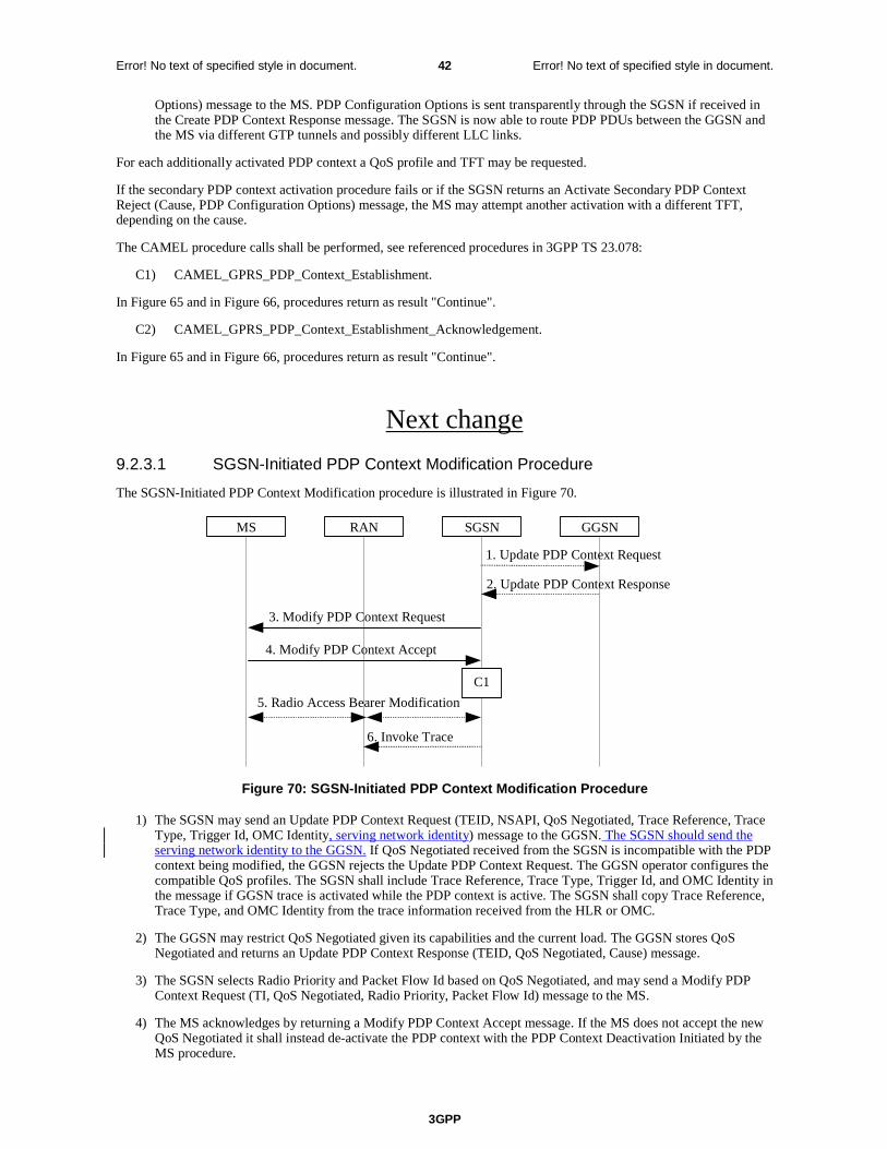
3GPP
Error! No text of specified style in document. 42 Error! No text of specified style in document.
Options) message to the MS. PDP Configuration Options is sent transparently through the SGSN if received in the Create PDP Context Response message. The SGSN is now able to route PDP PDUs between the GGSN and the MS via different GTP tunnels and possibly different LLC links.
For each additionally activated PDP context a QoS profile and TFT may be requested.
If the secondary PDP context activation procedure fails or if the SGSN returns an Activate Secondary PDP Context Reject (Cause, PDP Configuration Options) message, the MS may attempt another activation with a different TFT, depending on the cause.
The CAMEL procedure calls shall be performed, see referenced procedures in 3GPP TS 23.078:
C1) CAMEL_GPRS_PDP_Context_Establishment.
In Figure 65 and in Figure 66, procedures return as result "Continue".
C2) CAMEL_GPRS_PDP_Context_Establishment_Acknowledgement.
In Figure 65 and in Figure 66, procedures return as result "Continue".
Next change
9.2.3.1 SGSN-Initiated PDP Context Modification Procedure
The SGSN-Initiated PDP Context Modification procedure is illustrated in Figure 70.
GGSN
2. Update PDP Context Response
1. Update PDP Context Request
SGSNRANMS
3. Modify PDP Context Request
4. Modify PDP Context Accept
5. Radio Access Bearer Modification
C1
6. Invoke Trace
Figure 70: SGSN-Initiated PDP Context Modification Procedure
1) The SGSN may send an Update PDP Context Request (TEID, NSAPI, QoS Negotiated, Trace Reference, Trace Type, Trigger Id, OMC Identity, serving network identity) message to the GGSN. The SGSN should send the serving network identity to the GGSN. If QoS Negotiated received from the SGSN is incompatible with the PDP context being modified, the GGSN rejects the Update PDP Context Request. The GGSN operator configures the compatible QoS profiles. The SGSN shall include Trace Reference, Trace Type, Trigger Id, and OMC Identity in the message if GGSN trace is activated while the PDP context is active. The SGSN shall copy Trace Reference, Trace Type, and OMC Identity from the trace information received from the HLR or OMC.
2) The GGSN may restrict QoS Negotiated given its capabilities and the current load. The GGSN stores QoS Negotiated and returns an Update PDP Context Response (TEID, QoS Negotiated, Cause) message.
3) The SGSN selects Radio Priority and Packet Flow Id based on QoS Negotiated, and may send a Modify PDP Context Request (TI, QoS Negotiated, Radio Priority, Packet Flow Id) message to the MS.
4) The MS acknowledges by returning a Modify PDP Context Accept message. If the MS does not accept the new QoS Negotiated it shall instead de-activate the PDP context with the PDP Context Deactivation Initiated by the MS procedure.
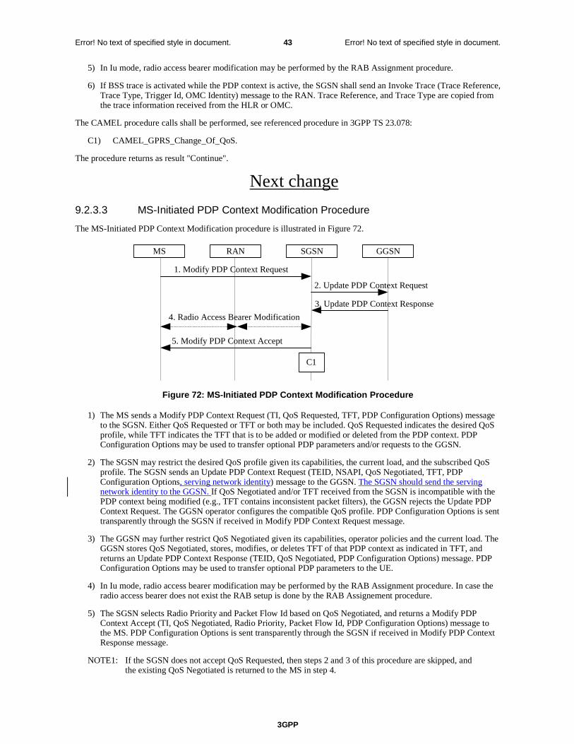
3GPP
Error! No text of specified style in document. 43 Error! No text of specified style in document.
5) In Iu mode, radio access bearer modification may be performed by the RAB Assignment procedure.
6) If BSS trace is activated while the PDP context is active, the SGSN shall send an Invoke Trace (Trace Reference, Trace Type, Trigger Id, OMC Identity) message to the RAN. Trace Reference, and Trace Type are copied from the trace information received from the HLR or OMC.
The CAMEL procedure calls shall be performed, see referenced procedure in 3GPP TS 23.078:
C1) CAMEL_GPRS_Change_Of_QoS.
The procedure returns as result "Continue".
Next change
9.2.3.3 MS-Initiated PDP Context Modification Procedure
The MS-Initiated PDP Context Modification procedure is illustrated in Figure 72.
GGSN
3. Update PDP Context Response
2. Update PDP Context Request
SGSNRANMS
1. Modify PDP Context Request
5. Modify PDP Context Accept
4. Radio Access Bearer Modification
C1
Figure 72: MS-Initiated PDP Context Modification Procedure
1) The MS sends a Modify PDP Context Request (TI, QoS Requested, TFT, PDP Configuration Options) message to the SGSN. Either QoS Requested or TFT or both may be included. QoS Requested indicates the desired QoS profile, while TFT indicates the TFT that is to be added or modified or deleted from the PDP context. PDP Configuration Options may be used to transfer optional PDP parameters and/or requests to the GGSN.
2) The SGSN may restrict the desired QoS profile given its capabilities, the current load, and the subscribed QoS profile. The SGSN sends an Update PDP Context Request (TEID, NSAPI, QoS Negotiated, TFT, PDP Configuration Options, serving network identity) message to the GGSN. The SGSN should send the serving network identity to the GGSN. If QoS Negotiated and/or TFT received from the SGSN is incompatible with the PDP context being modified (e.g., TFT contains inconsistent packet filters), the GGSN rejects the Update PDP Context Request. The GGSN operator configures the compatible QoS profile. PDP Configuration Options is sent transparently through the SGSN if received in Modify PDP Context Request message.
3) The GGSN may further restrict QoS Negotiated given its capabilities, operator policies and the current load. The GGSN stores QoS Negotiated, stores, modifies, or deletes TFT of that PDP context as indicated in TFT, and returns an Update PDP Context Response (TEID, QoS Negotiated, PDP Configuration Options) message. PDP Configuration Options may be used to transfer optional PDP parameters to the UE.
4) In Iu mode, radio access bearer modification may be performed by the RAB Assignment procedure. In case the radio access bearer does not exist the RAB setup is done by the RAB Assignement procedure.
5) The SGSN selects Radio Priority and Packet Flow Id based on QoS Negotiated, and returns a Modify PDP Context Accept (TI, QoS Negotiated, Radio Priority, Packet Flow Id, PDP Configuration Options) message to the MS. PDP Configuration Options is sent transparently through the SGSN if received in Modify PDP Context Response message.
NOTE1: If the SGSN does not accept QoS Requested, then steps 2 and 3 of this procedure are skipped, and the existing QoS Negotiated is returned to the MS in step 4.
3GPP
Error! No text of specified style in document. 44 Error! No text of specified style in document.
NOTE2: In this release of the standards no procedure is defined that uses the Protocol Configuration Options in the PDP context modification procedure.
The CAMEL procedure calls shall be performed, see referenced procedure in 3GPP TS 23.078:
C1) CAMEL_GPRS_Change_Of_QoS.
The procedure returns as result "Continue".
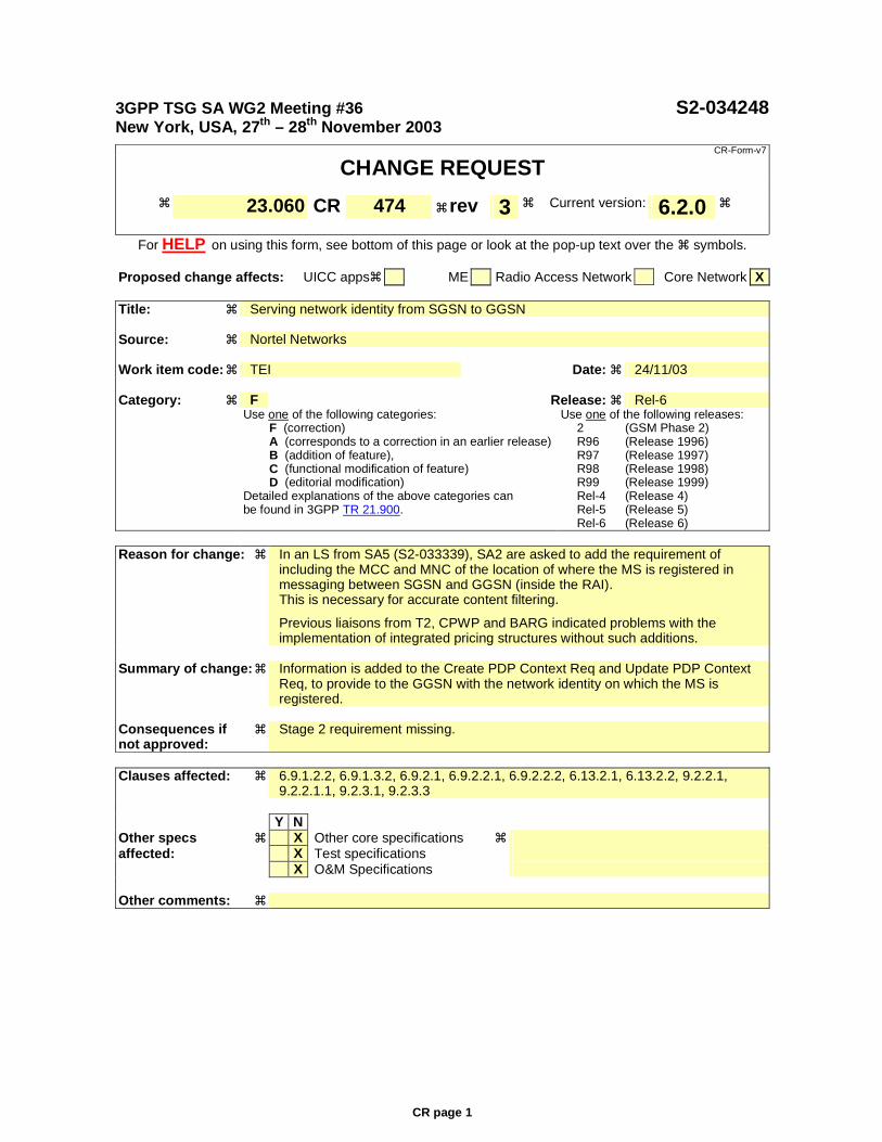
CR page 1
3GPP TSG SA WG2 Meeting #36 S2-034248 New York, USA, 27th – 28th November 2003
CR-Form-v7
CHANGE REQUEST
! 23.060 CR 474 ! rev 3 ! Current version: 6.2.0 !
For HELP on using this form, see bottom of this page or look at the pop-up text over the ! symbols.
Proposed change affects: UICC apps! ME Radio Access Network Core Network X Title: ! Serving network identity from SGSN to GGSN Source: ! Nortel Networks Work item code: ! TEI Date: ! 24/11/03 Category: ! F Release: ! Rel-6 Use one of the following categories:
F (correction) A (corresponds to a correction in an earlier release) B (addition of feature), C (functional modification of feature) D (editorial modification)
Detailed explanations of the above categories can be found in 3GPP TR 21.900.
Use one of the following releases: 2 (GSM Phase 2) R96 (Release 1996) R97 (Release 1997) R98 (Release 1998) R99 (Release 1999) Rel-4 (Release 4) Rel-5 (Release 5) Rel-6 (Release 6)
Reason for change: ! In an LS from SA5 (S2-033339), SA2 are asked to add the requirement of
including the MCC and MNC of the location of where the MS is registered in messaging between SGSN and GGSN (inside the RAI). This is necessary for accurate content filtering.
Previous liaisons from T2, CPWP and BARG indicated problems with the implementation of integrated pricing structures without such additions.
Summary of change: ! Information is added to the Create PDP Context Req and Update PDP Context
Req, to provide to the GGSN with the network identity on which the MS is registered.
Consequences if ! not approved:
Stage 2 requirement missing.
Clauses affected: ! 6.9.1.2.2, 6.9.1.3.2, 6.9.2.1, 6.9.2.2.1, 6.9.2.2.2, 6.13.2.1, 6.13.2.2, 9.2.2.1,
9.2.2.1.1, 9.2.3.1, 9.2.3.3 Y N Other specs ! X Other core specifications ! affected: X Test specifications X O&M Specifications Other comments: !

3GPP
Error! No text of specified style in document. 2 Error! No text of specified style in document.
6.9.1.2.2 Inter SGSN Routeing Area Update
The Inter SGSN Routeing Area Update procedure is illustrated in Figure 33.
MS BSS new SGSN HLR GGSN old SGSN
2. SGSN Context Response
3. Security Functions
1. Routeing Area Update Request
2. SGSN Context Request
6. Update PDP Context Request
6. Update PDP Context Response
7. Update Location
10. Update Location Ack
11. Routeing Area Update Accept
8. Cancel Location
8. Cancel Location Ack
9. Insert Subscriber Data Ack
9. Insert Subscriber Data
12. Routeing Area Update Complete
5. Forward Packets
4. SGSN Context Acknowledge
C3
C2
C1
Figure 33: Inter SGSN Routeing Area Update Procedure
1) The MS sends a Routeing Area Update Request (old RAI, old P-TMSI Signature, Update Type, Classmark, DRX parameters and MS Network Capability) to the new SGSN. Update Type shall indicate RA update or periodic RA update. The BSS shall add the Cell Global Identity including the RAC and LAC of the cell where the message was received before passing the message to the SGSN. Classmark contains the MS GPRS multislot capabilities and supported GPRS ciphering algorithms as defined in TS 24.008. DRX Parameters indicates whether or not the MS uses discontinuous reception and the DRX cycle length.
3GPP
Error! No text of specified style in document. 3 Error! No text of specified style in document.
2) The new SGSN sends SGSN Context Request (old RAI, TLLI, old P-TMSI Signature, New SGSN Address) to the old SGSN to get the MM and PDP contexts for the MS. If the new SGSN provides functionality for Intra Domain Connection of RAN Nodes to Multiple CN Nodes, the new SGSN may derive the old SGSN from the old RAI and the old P-TMSI (or TLLI) and send the SGSN Context Request message to this old SGSN. Otherwise, the new SGSN derives the old SGSN from the old RAI. In any case the new SGSN will derive an SGSN that it believes is the old SGSN. This derived SGSN is itself the old SGSN, or it is associated with the same pool area as the actual old SGSN and it will determine the correct old SGSN from the P-TMSI (or TLLI) and relay the message to that actual old SGSN. The old SGSN validates the old P-TMSI Signature and responds with an appropriate error cause if it does not match the value stored in the old SGSN. This should initiate the security functions in the new SGSN. If the security functions authenticate the MS correctly, the new SGSN shall send an SGSN Context Request (old RAI, TLLI, MS Validated, New SGSN Address) message to the old SGSN. MS Validated indicates that the new SGSN has authenticated the MS. If the old P-TMSI Signature was valid or if the new SGSN indicates that it has authenticated the MS, the old SGSN stops assigning SNDCP N-PDU numbers to downlink N-PDUs received, and responds with SGSN Context Response (MM Context, PDP Contexts). If the MS is not known in the old SGSN, the old SGSN responds with an appropriate error cause. The old SGSN stores New SGSN Address, to allow the old SGSN to forward data packets to the new SGSN. Each PDP Context includes the SNDCP Send N-PDU Number for the next downlink N-PDU to be sent in acknowledged mode to the MS, the SNDCP Receive N-PDU Number for the next uplink N-PDU to be received in acknowledged mode from the MS, the GTP sequence number for the next downlink N-PDU to be sent to the MS and the GTP sequence number for the next uplink N-PDU to be tunnelled to the GGSN. The old SGSN starts a timer and stops the transmission of N-PDUs to the MS. The new SGSN shall ignore the MS Network Capability contained in MM Context of SGSN Context Response only when it has previously received an MS Network Capability in the Routeing Area Request.
3) Security functions may be executed. These procedures are defined in clause "Security Function". Ciphering mode shall be set if ciphering is supported.
If the security functions fail (e.g. because the SGSN cannot determine the HLR address to establish the Send Authentication Info dialogue), the Inter SGSN RAU Update procedure fails. A reject shall be returned to the MS with an appropriate cause.
4) The new SGSN sends an SGSN Context Acknowledge message to the old SGSN. This informs the old SGSN that the new SGSN is ready to receive data packets belonging to the activated PDP contexts. The old SGSN marks in its context that the MSC/VLR association and the information in the GGSNs and the HLR are invalid. This triggers the MSC/VLR, the GGSNs, and the HLR to be updated if the MS initiates a routeing area update procedure back to the old SGSN before completing the ongoing routeing area update procedure. If the security functions do not authenticate the MS correctly, then the routeing area update shall be rejected, and the new SGSN shall send a reject indication to the old SGSN. The old SGSN shall continue as if the SGSN Context Request was never received.
5) The old SGSN duplicates the buffered N-PDUs and starts tunnelling them to the new SGSN. Additional N-PDUs received from the GGSN before the timer described in step 2 expires are also duplicated and tunnelled to the new SGSN. N-PDUs that were already sent to the MS in acknowledged mode and that are not yet acknowledged by the MS are tunnelled together with the SNDCP N-PDU number. No N-PDUs shall be forwarded to the new SGSN after expiry of the timer described in step 2.
6) The new SGSN sends Update PDP Context Request (new SGSN Address, TEID, QoS Negotiated, serving network identity) to the GGSNs concerned. The SGSN shall send the serving network identity to the GGSN. The GGSNs update their PDP context fields and return Update PDP Context Response (TEID, Prohibit Payload Compression). The Prohibit Payload Compression indicates that the SGSN should negotiate no data compression for this PDP context.
7) The new SGSN informs the HLR of the change of SGSN by sending Update Location (SGSN Number, SGSN Address, IMSI) to the HLR.
8) The HLR sends Cancel Location (IMSI, Cancellation Type) to the old SGSN with Cancellation Type set to Update Procedure. If the timer described in step 2 is not running, the old SGSN removes the MM and PDP contexts. Otherwise, the contexts are removed only when the timer expires. This allows the old SGSN to complete the forwarding of N-PDUs. It also ensures that the MM and PDP contexts are kept in the old SGSN in case the MS initiates another inter-SGSN routeing area update before completing the ongoing routeing area update to the new SGSN. The old SGSN acknowledges with Cancel Location Ack (IMSI).
9) The HLR sends Insert Subscriber Data (IMSI, GPRS Subscription Data) to the new SGSN. The new SGSN validates the MS's presence in the (new) RA. If due to regional subscription restrictions the MS is not allowed to be attached in the RA, the SGSN rejects the Routeing Area Update Request with an appropriate cause, and may return an Insert Subscriber Data Ack (IMSI, SGSN Area Restricted) message to the HLR. If all checks are
3GPP
Error! No text of specified style in document. 4 Error! No text of specified style in document.
successful, the SGSN constructs an MM context for the MS and returns an Insert Subscriber Data Ack (IMSI) message to the HLR.
10) The HLR acknowledges the Update Location by sending Update Location Ack (IMSI) to the new SGSN.
11) The new SGSN validates the MS's presence in the new RA. If due to roaming restrictions the MS, is not allowed to be attached in the SGSN, or if subscription checking fails, the new SGSN rejects the routeing area update with an appropriate cause. If all checks are successful, the new SGSN constructs MM and PDP contexts for the MS. A logical link is established between the new SGSN and the MS. The new SGSN responds to the MS with Routeing Area Update Accept (P-TMSI, P-TMSI Signature, Receive N-PDU Number). Receive N-PDU Number contains the acknowledgements for each acknowledged-mode NSAPI used by the MS, thereby confirming all mobile-originated N-PDUs successfully transferred before the start of the update procedure.
12) The MS acknowledges the new P-TMSI by returning a Routeing Area Update Complete (Receive N-PDU Number) message to the SGSN. Receive N-PDU Number contains the acknowledgements for each acknowledged-mode NSAPI used by the MS, thereby confirming all mobile-terminated N-PDUs successfully transferred before the start of the update procedure. If Receive N-PDU Number confirms reception of N-PDUs that were forwarded from the old SGSN, these N-PDUs shall be discarded by the new SGSN. LLC and SNDCP in the MS are reset.
In the case of a rejected routeing area update operation, due to regional subscription or roaming restrictions, or because the SGSN cannot determine the HLR address to establish the locating updating dialogue, the new SGSN shall not construct an MM context. A reject shall be returned to the MS with an appropriate cause. The MS does not re-attempt a routeing area update to that RA. The RAI value shall be deleted when the MS is powered-up.
If the new SGSN is unable to update the PDP context in one or more GGSNs, the new SGSN shall deactivate the corresponding PDP contexts as described in clause "SGSN-initiated PDP Context Deactivation Procedure". This shall not cause the SGSN to reject the routeing area update.
The PDP Contexts shall be sent from old to new SGSN in a prioritized order, i.e. the most important PDP Context first in the SGSN Context Response message. (The prioritization method is implementation dependent, but should be based on the current activity.)
If the new SGSN is unable to support the same number of active PDP contexts as received from old SGSN, the new SGSN should use the prioritisation sent by old SGSN as input when deciding which PDP contexts to maintain active and which ones to delete. In any case, the new SGSN shall first update all contexts in one or more GGSNs and then deactivate the context(s) that it cannot maintain as described in subclause "SGSN-initiated PDP Context Deactivation Procedure". This shall not cause the SGSN to reject the routeing area update.
If the timer described in step 2 expires and no Cancel Location (IMSI) was received from the HLR, the old SGSN stops forwarding N-PDUs to the new SGSN.
If the routeing area update procedure fails a maximum allowable number of times, or if the SGSN returns a Routeing Area Update Reject (Cause) message, the MS shall enter IDLE state.
The CAMEL procedure calls shall be performed, see referenced procedures in 3GPP TS 23.078:
C1) CAMEL_GPRS_PDP_Context_Disconnection, CAMEL_GPRS_Detach and CAMEL_PS_Notification.
They are called in the following order:
- The CAMEL_GPRS_PDP_Context_Disconnection procedure is called several times: once per PDP context. The procedure returns as result "Continue".
- Then the CAMEL_GPRS_Detach procedure is called once. The procedure returns as result "Continue".
- Then the CAMEL_PS_Notification procedure is called once. The procedure return as result "Continue".
C2) CAMEL_GPRS_Routeing_Area_Update_Session and CAMEL_PS_Notification.
They are called in the following order:
- The CAMEL_GPRS_Routeing_Area_Update_Session procedure is called. The procedure returns as result "Continue".
- Then the CAMEL_PS_Notification procedure is called. The procedure returns as result "Continue".
C3) CAMEL_GPRS_Routeing_Area_Update_Context.
3GPP
Error! No text of specified style in document. 5 Error! No text of specified style in document.
This procedure is called several times: once per PDP context. It returns as result "Continue".
Next change
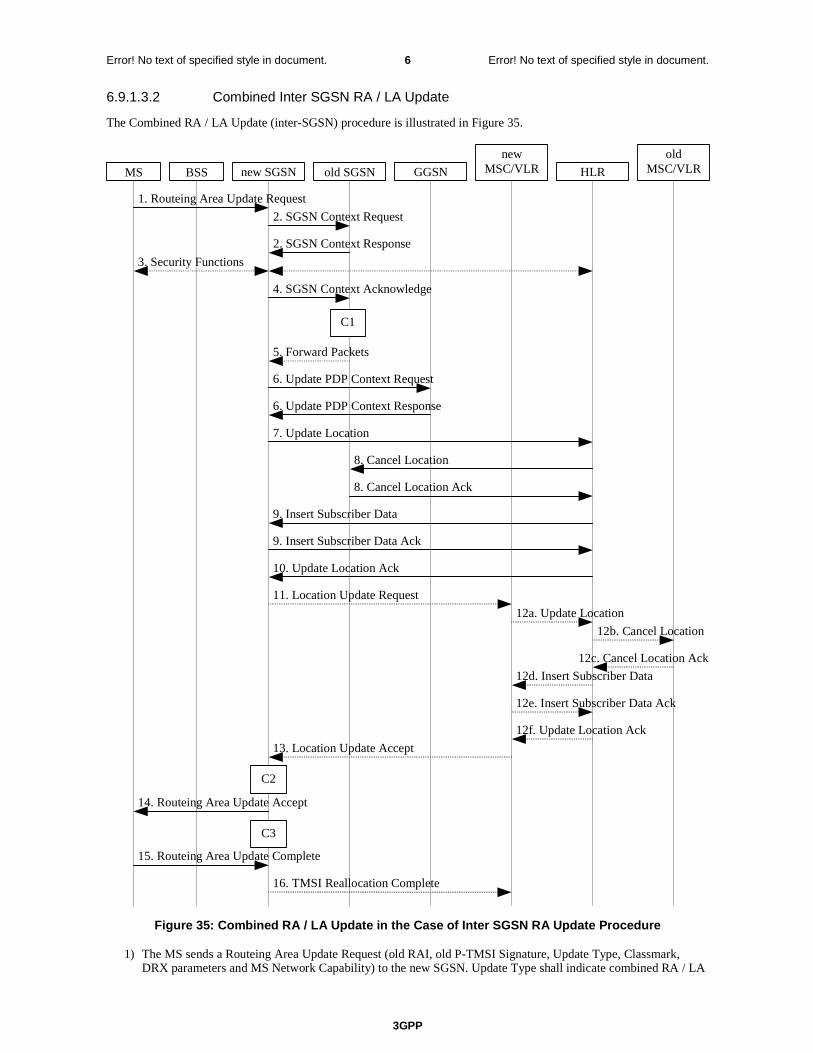
3GPP
Error! No text of specified style in document. 6 Error! No text of specified style in document.
6.9.1.3.2 Combined Inter SGSN RA / LA Update
The Combined RA / LA Update (inter-SGSN) procedure is illustrated in Figure 35.
12b. Cancel Location
12c. Cancel Location Ack
12d. Insert Subscriber Data
16. TMSI Reallocation Complete
12f. Update Location Ack
13. Location Update Accept
15. Routeing Area Update Complete
14. Routeing Area Update Accept
8. Cancel Location
8. Cancel Location Ack
6. Update PDP Context Response
6. Update PDP Context Request
7. Update Location
10. Update Location Ack
12a. Update Location
11. Location Update Request
2. SGSN Context Response
3. Security Functions
2. SGSN Context Request
1. Routeing Area Update Request
9. Insert Subscriber Data
9. Insert Subscriber Data Ack
12e. Insert Subscriber Data Ack
MS BSS GGSN old SGSN new SGSN HLR
new MSC/VLR
old MSC/VLR
5. Forward Packets
4. SGSN Context Acknowledge
C3
C2
C1
Figure 35: Combined RA / LA Update in the Case of Inter SGSN RA Update Procedure
1) The MS sends a Routeing Area Update Request (old RAI, old P-TMSI Signature, Update Type, Classmark, DRX parameters and MS Network Capability) to the new SGSN. Update Type shall indicate combined RA / LA
3GPP
Error! No text of specified style in document. 7 Error! No text of specified style in document.
update, or, if the MS wants to perform an IMSI attach, combined RA / LA update with IMSI attach requested. The BSS shall add the Cell Global Identity including the RAC and LAC of the cell where the message was received before passing the message to the SGSN. Classmark contains the MS GPRS multislot capabilities and supported GPRS ciphering algorithms as defined in 3GPP TS 24.008. DRX Parameters indicates whether or not the MS uses discontinuous and the DRX cycle length.
2) The new SGSN sends SGSN Context Request (old RAI, TLLI, old P-TMSI Signature, New SGSN Address) to the old SGSN to get the MM and PDP contexts for the MS. If the new SGSN provides functionality for Intra Domain Connection of RAN Nodes to Multiple CN Nodes, the new SGSN may derive the old SGSN from the old RAI and the old P-TMSI (or TLLI) and send the SGSN Context Request message to this old SGSN. Otherwise, the new SGSN derives the old SGSN from the old RAI. In any case the new SGSN will derive an SGSN that it believes is the old SGSN. This derived SGSN is itself the old SGSN, or it is associated with the same pool area as the actual old SGSN and it will determine the correct old SGSN from the P-TMSI (or TLLI) and relay the message to that actual old SGSN. The old SGSN validates the old P-TMSI Signature and responds with an appropriate error cause if it does not match the value stored in the old SGSN. This should initiate the security functions in the new SGSN. If the security functions authenticate the MS correctly, the new SGSN shall send an SGSN Context Request (old RAI, TLLI, MS Validated, New SGSN Address) message to the old SGSN. MS Validated indicates that the new SGSN has authenticated the MS. If the old P-TMSI Signature was valid or if the new SGSN indicates that it has authenticated the MS, the old SGSN stops assigning SNDCP N-PDU numbers to downlink N-PDUs received, and responds with SGSN Context Response (MM Context, PDP Contexts). If the MS is not known in the old SGSN, the old SGSN responds with an appropriate error cause. The old SGSN stores New SGSN Address until the old MM context is cancelled, to allow the old SGSN to forward data packets to the new SGSN. Each PDP Context includes the SNDCP Send N-PDU Number for the next downlink N-PDU to be sent in acknowledged mode to the MS, the SNDCP Receive N-PDU Number for the next uplink N-PDU to be received in acknowledged mode from the MS, the GTP sequence number for the next downlink N-PDU to be sent to the MS and the GTP sequence number for the next uplink N-PDU to be tunnelled to the GGSN. The old SGSN starts a timer and stops the downlink transfer. The new SGSN shall ignore the MS Network Capability contained in MM Context of SGSN Context Response only when it has previously received an MS Network Capability in the Routeing Area Request.
3) Security functions may be executed. These procedures are defined in clause "Security Function". Ciphering mode shall be set if ciphering is supported. If the security functions fail (e.g. because the SGSN cannot determine the HLR address to establish the Send Authentication Info dialogue), the Inter SGSN RAU Update procedure fails. A reject shall be returned to the MS with an appropriate cause.
4) The new SGSN sends an SGSN Context Acknowledge message to the old SGSN. This informs the old SGSN that the new SGSN is ready to receive data packets belonging to the activated PDP contexts. The old SGSN marks in its context that the MSC/VLR association and the information in the GGSNs and the HLR are invalid. This triggers the MSC/VLR, the GGSNs, and the HLR to be updated if the MS initiates a routeing area update procedure back to the old SGSN before completing the ongoing routeing area update procedure. If the security functions do not authenticate the MS correctly, the routeing area update shall be rejected, and the new SGSN shall send a reject indication to the old SGSN. The old SGSN shall continue as if the SGSN Context Request was never received.
5) The old SGSN duplicates the buffered N-PDUs and starts tunnelling them to the new SGSN. Additional N-PDUs received from the GGSN before the timer described in step 2 expires are also duplicated and tunnelled to the new SGSN. N-PDUs that were already sent to the MS in acknowledged mode and that are not yet acknowledged by the MS are tunnelled together with the SNDCP N-PDU number. No N-PDUs shall be forwarded to the new SGSN after expiry of the timer described in step 2.
6) The new SGSN sends Update PDP Context Request (new SGSN Address, TEID, QoS Negotiated, serving network identity) to the GGSNs concerned. The SGSN shall send the serving network identity to the GGSN. The GGSNs update their PDP context fields and return an Update PDP Context Response (TEID, Prohibit Payload Compression). The Prohibit Payload Compression indicates that the SGSN should negotiate no data compression for this PDP context.
7) The new SGSN informs the HLR of the change of SGSN by sending Update Location (SGSN Number, SGSN Address, IMSI) to the HLR.
8) The HLR sends Cancel Location (IMSI, Cancellation Type) to the old SGSN with Cancellation Type set to Update Procedure. If the timer described in step 2 is not running, the old SGSN removes the MM and PDP contexts. Otherwise, the contexts are removed only when the timer expires. This allows the old SGSN to complete the forwarding of N-PDUs. It also ensures that the MM and PDP contexts are kept in the old SGSN in case the MS initiates another inter SGSN routeing area update before completing the ongoing routeing area update to the new SGSN. The old SGSN acknowledges with Cancel Location Ack (IMSI).
3GPP
Error! No text of specified style in document. 8 Error! No text of specified style in document.
9) The HLR sends Insert Subscriber Data (IMSI, GPRS Subscription Data) to the new SGSN. The new SGSN validates the MS's presence in the (new) RA. If due to regional subscription restrictions the MS is not allowed to be attached in the RA, the SGSN rejects the Routeing Area Update Request with an appropriate cause, and may return an Insert Subscriber Data Ack (IMSI, SGSN Area Restricted) message to the HLR. If all checks are successful, the SGSN constructs an MM context for the MS and returns an Insert Subscriber Data Ack (IMSI) message to the HLR.
10) The HLR acknowledges the Update Location by sending Update Location Ack (IMSI) to the new SGSN.
11) If the association has to be established, if Update Type indicates combined RA / LA update with IMSI attach requested, or if the LA changed with the routeing area update, the new SGSN sends a Location Update Request (new LAI, IMSI, SGSN Number, Location Update Type) to the VLR. Location Update Type shall indicate IMSI attach if Update Type in step 1 indicated combined RA / LA update with IMSI attach requested. Otherwise, Location Update Type shall indicate normal location update. When the SGSN does not provide functionality for the Intra Domain Connection of RAN Nodes to Multiple CN Nodes, the VLR number is derived from the RAI. When the SGSN provides functionality for Intra Domain Connection of RAN Nodes to Multiple CN Nodes, the SGSN uses the RAI and a hash value from the IMSI to determine the VLR number. The SGSN starts the location update procedure towards the new MSC/VLR upon receipt of the first Insert Subscriber Data message from the HLR in step 9). The VLR creates or updates the association with the SGSN by storing SGSN Number.
12) If the subscriber data in the VLR is marked as not confirmed by the HLR, the new VLR informs the HLR. The HLR cancels the old VLR and inserts subscriber data in the new VLR:
a) The new VLR sends an Update Location (new VLR) to the HLR.
b) The HLR cancels the data in the old VLR by sending Cancel Location (IMSI) to the old VLR.
c) The old VLR acknowledges with Cancel Location Ack (IMSI).
d) The HLR sends Insert Subscriber Data (IMSI, subscriber data) to the new VLR.
e) The new VLR acknowledges with Insert Subscriber Data Ack (IMSI).
f) The HLR responds with Update Location Ack (IMSI) to the new VLR.
13) The new VLR allocates a new TMSI and responds with Location Update Accept (VLR TMSI) to the SGSN. VLR TMSI is optional if the VLR has not changed.
14) The new SGSN validates the MS's presence in the new RA. If due to roaming restrictions the MS is not allowed to be attached in the RA, or if subscription checking fails, the SGSN rejects the routeing area update with an appropriate cause. If all checks are successful, the new SGSN establishes MM and PDP contexts for the MS. A logical link is established between the new SGSN and the MS. The new SGSN responds to the MS with Routeing Area Update Accept (P-TMSI, VLR TMSI, P-TMSI Signature, Receive N-PDU Number). Receive N-PDU Number contains the acknowledgements for each acknowledged-mode NSAPI used by the MS, thereby confirming all mobile-originated N-PDUs successfully transferred before the start of the update procedure.
15) The MS confirms the reallocation of the TMSIs by returning a Routeing Area Update Complete (Receive N-PDU Number) message to the SGSN. Receive N-PDU Number contains the acknowledgements for each acknowledged-mode NSAPI used by the MS, thereby confirming all mobile-terminated N-PDUs successfully transferred before the start of the update procedure. If Receive N-PDU Number confirms reception of N-PDUs that were forwarded from the old SGSN, these N-PDUs shall be discarded by the new SGSN. LLC and SNDCP in the MS are reset.
16) The new SGSN sends a TMSI Reallocation Complete message to the new VLR if the MS confirms the VLR TMSI.
In the case of a rejected routeing area update operation, due to regional subscription or roaming restrictions, or because the SGSN cannot determine the HLR address to establish the locating updating dialogue, the new SGSN shall not construct an MM context. A reject shall be returned to the MS with an appropriate cause. The MS shall not re-attempt a routeing area update to that RA. The RAI value shall be deleted when the MS is powered-up.
If the new SGSN is unable to update the PDP context in one or more GGSNs, the new SGSN shall deactivate the corresponding PDP contexts as described in clause "SGSN-initiated PDP Context Deactivation Procedure". This shall not cause the SGSN to reject the routeing area update.
3GPP
Error! No text of specified style in document. 9 Error! No text of specified style in document.
The PDP Contexts shall be sent from old to new SGSN in a prioritized order, i.e. the most important PDP Context first in the SGSN Context Response message. (The prioritization method is implementation dependent, but should be based on the current activity.)
If the new SGSN is unable to support the same number of active PDP contexts as received from old SGSN, the new SGSN should use the prioritisation sent by old SGSN as input when deciding which PDP contexts to maintain active and which ones to delete. In any case, the new SGSN shall first update all contexts in one or more GGSNs and then deactivate the context(s) that it cannot maintain as described in subclause "SGSN-initiated PDP Context Deactivation Procedure". This shall not cause the SGSN to reject the routeing area update.
If the routeing area update procedure fails a maximum allowable number of times, or if the SGSN returns a Routeing Area Update Reject (Cause) message, the MS shall enter IDLE state.
If the timer described in step 2 expires and no Cancel Location (IMSI) was received from the HLR, the old SGSN shall stop forwarding N-PDUs to the new SGSN.
If the Location Update Accept message indicates a reject, this should be indicated to the MS, and the MS shall not access non-GPRS services until a successful location update is performed.
The CAMEL procedure calls shall be performed, see referenced procedures in 3GPP TS 23.078:
C1) CAMEL_GPRS_PDP_Context_Disconnection, CAMEL_GPRS_Detach and CAMEL_PS_Notification.
They are called in the following order:
- The CAMEL_GPRS_PDP_Context_Disconnection procedure is called several times: once per PDP context. The procedure returns as result "Continue".
- Then the CAMEL_GPRS_Detach procedure is called once. The procedure returns as result "Continue".
- Then the CAMEL_PS_Notification procedure is called once. The procedure returns as result "Continue".
C2) CAMEL_GPRS_Routeing_Area_Update_Session and CAMEL_PS_Notification.
They are called in the following order:
- The CAMEL_GPRS_Routeing_Area_Update_Session procedure is called. The procedure returns as result "Continue".
- Then the CAMEL_PS_Notification procedure is called. The procedure returns as result "Continue".
C3) CAMEL_GPRS_Routeing_Area_Update_Context.
This procedure is called several times: once per PDP context. It returns as result "Continue".
Next change
6.9.2.1 Routeing Area Update Procedure
A routeing area update takes place when an attached MS detects that it has entered a new RA or when the periodic RA update timer has expired or when RRC connection is released with cause "Directed Signalling connection re-establishment" or when the MS has to indicate new access capabilities to the network.
The SGSN detects that it is an intra-SGSN routeing area update by noticing that it also handles the old RA. In this case, the SGSN has the necessary information about the MS and there is no need to inform the GGSNs or the HLR about the new MS location. A periodic RA update is always an intra-SGSN routeing area update. If the network operates in mode I, an MS that is in CS/PS mode of operation shall perform the Combined RA / LA Update procedures except this CS/PS mode MS is engaged in a CS connection, then it shall perform (non combined) RA Update procedures.
In Iu mode, an RA update is either an intra-SGSN or inter-SGSN RA update, either combined RA / LA update or only RA update, either initiated by an MS in PMM-CONNECTED or in PMM-IDLE state. The SRNC may provide a PMM-CONNECTED state MS with MM information like RAI by dedicated signalling. Typically, the SRNC should
3GPP
Error! No text of specified style in document. 10 Error! No text of specified style in document.
not provide a RAI to an MS in PMM-CONNECTED state. An exception is after an SRNS relocation, in which case the new SRNC shall indicate the RAI to the MS.
All the RA update cases are contained in the procedure illustrated in Figure 36.
NOTE 1: The network may receive an RA update from a UE in PMM-CONNECTED state over a new Iu signalling connection. This could happen when the UE enters PMM-IDLE state on receipt of RRC Connection Release with cause "Directed Signalling connection re-establishment" and initiates an RA or Combined RA update procedure (see clause 6.1.2.4.1).
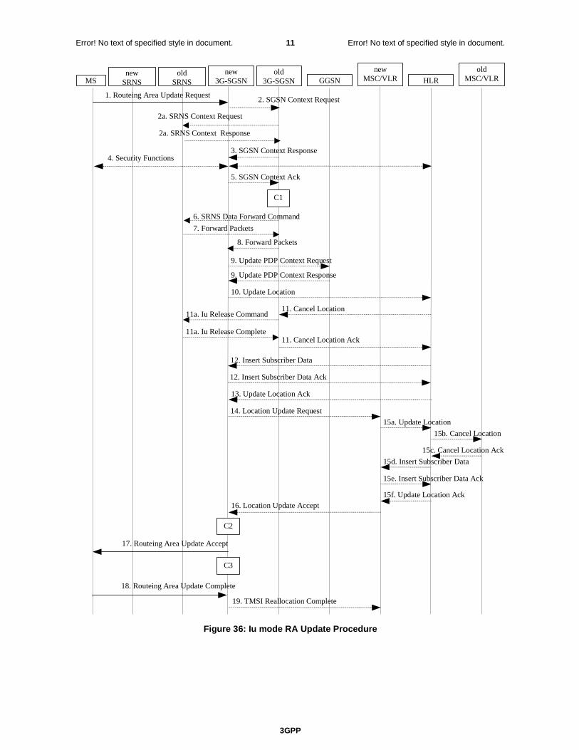
3GPP
Error! No text of specified style in document. 11 Error! No text of specified style in document.
3. SGSN Context Response 4. Security Functions
2. SGSN Context Request 1. Routeing Area Update Request
MS old
SRNS GGSN old
3G-SGSN new
3G-SGSN HLR
new MSC/VLR
old MSC/VLR
5. SGSN Context Ack
11. Cancel Location
11. Cancel Location Ack
9. Update PDP Context Response
9. Update PDP Context Request
10. Update Location
15b. Cancel Location
15c. Cancel Location Ack
15d. Insert Subscriber Data
19. TMSI Reallocation Complete
15f. Update Location Ack 16. Location Update Accept
18. Routeing Area Update Complete
17. Routeing Area Update Accept
13. Update Location Ack
15a. Update Location
14. Location Update Request
12. Insert Subscriber Data
12. Insert Subscriber Data Ack
15e. Insert Subscriber Data Ack
C3
C2
2a. SRNS Context Request
2a. SRNS Context Response
11a. Iu Release Command
11a. Iu Release Complete
6. SRNS Data Forward Command
7. Forward Packets
8. Forward Packets
new SRNS
C1
Figure 36: Iu mode RA Update Procedure

3GPP
Error! No text of specified style in document. 12 Error! No text of specified style in document.
1) The RRC connection is established, if not already done. The MS sends a Routeing Area Update Request message (P-TMSI, old RAI, old P-TMSI Signature, Update Type, follow on request, Classmark, DRX Parameters, MS Network Capability) to the new SGSN. The MS shall set a follow-on request if there is pending uplink traffic (signalling or user data). The SGSN may use, as an implementation option, the follow-on request indication to release or keep the Iu connection after the completion of the RA update procedure. Update Type shall indicate:
- RA Update if the RA Update is triggered by a change of RA;
- Periodic RA Update if the RA update is triggered by the expiry of the Periodic RA Update timer;
- Combined RA / LA Update if the MS is also IMSI-attached and the LA update shall be performed in network operation mode I (see clause "Interactions Between SGSN and MSC/VLR"); or
- Combined RA / LA Update with IMSI attach requested if the MS wants to perform an IMSI attach in network operation mode I.
The SRNC shall add the Routeing Area Identity including the RAC and LAC of the area where the MS is located before forwarding the message to the 3G-SGSN. This RA identity corresponds to the RAI in the MM system information sent by the SRNC to the MS. Classmark is described in clause "MS Network Capability". DRX Parameters indicates whether or not the MS uses discontinuous reception and the DRX cycle length.
NOTE 2: Sending the Routeing Area Update Request message to the SGSN triggers the establishment of a signalling connection between RAN and SGSN for the concerned MS.
2) If the RA update is an Inter-SGSN Routeing area update and if the MS was in PMM-IDLE state, the new SGSN sends an SGSN Context Request message (old P-TMSI, old RAI, old P-TMSI Signature) to the old SGSN to get the MM and PDP contexts for the MS. If the new SGSN provides functionality for Intra Domain Connection of RAN Nodes to Multiple CN Nodes, the new SGSN may derive the old SGSN from the old RAI and the old P-TMSI and send the SGSN Context Request message to this old SGSN. Otherwise, the new SGSN derives the old SGSN from the old RAI. In any case the new SGSN will derive an SGSN that it believes is the old SGSN. This derived SGSN is itself the old SGSN, or it is associated with the same pool area as the actual old SGSN and it will determine the correct old SGSN from the P-TMSI and relay the message to that actual old SGSN. The old SGSN validates the old P-TMSI Signature and responds with an appropriate error cause if it does not match the value stored in the old SGSN. This should initiate the security functions in the new SGSN. If the security functions authenticate the MS correctly, the new SGSN shall send an SGSN Context Request (IMSI, old RAI, MS Validated) message to the old SGSN. MS Validated indicates that the new SGSN has authenticated the MS. If the old P-TMSI Signature was valid or if the new SGSN indicates that it has authenticated the MS, the old SGSN starts a timer.. If the MS is not known in the old SGSN, the old SGSN responds with an appropriate error cause.
2a) If the MS is PMM-CONNECTED state in the old 3G-SGSN or, in case of an intra-SGSN RA update, if the MS is in the PMM-CONNECTED state and the RAU was received over another Iu connection than the established one, the old SGSN sends an SRNS Context Request (IMSI) message to the old SRNS to retrieve the sequence numbers for the PDP context for inclusion in the SGSN Context Response message. Upon reception of this message, the SRNS buffers and stops sending downlink PDUs to the MS and returns an SRNS Context Response (IMSI, GTP-SNDs, GTP-SNUs, PDCP-SNUs) message. The SRNS shall include for each PDP context the next in-sequence GTP sequence number to be sent to the MS and the GTP sequence number of the next uplink PDU to be tunnelled to the GGSN. For each active PDP context which uses lossless PDCP, the SRNS also includes the uplink PDCP sequence number (PDCP-SNU). PDCP-SNU shall be the next in-sequence PDCP sequence number expected from the MS (per each active radio bearer). No conversion of PDCP sequence numbers to SNDCP sequence numbers shall be done in the 3G-SGSN.
3) The old 3G-SGSN responds with an SGSN Context Response (MM Context, PDP Contexts) message. For each PDP context the old 3G-SGSN shall include the GTP sequence number for the next uplink GTP PDU to be tunnelled to the GGSN and the next downlink GTP sequence number for the next PDU to be sent to the MS. Each PDP Context also includes the PDCP sequence numbers if PDCP sequence numbers are received from the old SRNS. The new 3G-SGSN shall ignore the MS Network Capability contained in MM Context of SGSN Context Response only when it has previously received an MS Network Capability in the Routeing Area Request. The GTP sequence numbers received from the old 3G-SGSN are only relevant if delivery order is required for the PDP context (QoS profile).
4) Security functions may be executed. These procedures are defined in clause "Security Function". If the security functions do not authenticate the MS correctly, the routeing area update shall be rejected, and the new SGSN shall send a reject indication to the old SGSN. The old SGSN shall continue as if the SGSN Context Request was never received.
3GPP
Error! No text of specified style in document. 13 Error! No text of specified style in document.
5) If the RA update is an Inter-SGSN Routeing area update, the new SGSN sends an SGSN Context Acknowledge message to the old SGSN. The old SGSN marks in its context that the MSC/VLR association and the information in the GGSNs and the HLR are invalid. This triggers the MSC/VLR, the GGSNs, and the HLR to be updated if the MS initiates a routeing area update procedure back to the old SGSN before completing the ongoing routeing area update procedure.
6) If the MS is in PMM-CONNECTED state in the old 3G-SGSN or, in case of an intra-SGSN RA update, if the MS is PMM connected and the RAU was received over another Iu connection than the established one, the old 3G-SGSN sends an SRNS Data Forward Command (RAB ID, Transport Layer Address, Iu Transport Association) message to the SRNS. Upon receipt of the SRNS Data Forward Command message from the 3G-SGSN, the SRNS shall start the data-forwarding timer.
7) For each indicated RAB the SRNS starts duplicating and tunnelling the buffered GTP PDUs to the old 3G-SGSN. For each radio bearer which uses lossless PDCP the SRNS shall start tunnelling the partly transmitted and the transmitted but not acknowledged PDCP-PDUs together with their related PDCP sequence numbers and start duplicating and tunnelling the buffered GTP PDUs to the old 3G-SGSN. Upon receipt of the SRNS Data Forward Command message from the 3G-SGSN, the SRNS shall start the data-forwarding timer.
8) If the RA update is an Inter-SGSN RA Update, the old 3G-SGSN tunnels the GTP PDUs to the new 3G-SGSN. No conversion of PDCP sequence numbers to SNDCP sequence numbers shall be done in the 3G-SGSN.
9) If the RA update is an Inter-SGSN RA Update and if the MS was not in PMM-CONNECTED state in the new 3G-SGSN, the new SGSN sends Update PDP Context Request (new SGSN Address, QoS Negotiated, Tunnel Endpoint Identifier, serving network identity) to the GGSNs concerned. The SGSN shall send the serving network identity to the GGSN. The GGSNs update their PDP context fields and return an Update PDP Context Response (Tunnel Endpoint Identifier, Prohibit Payload Compression). The Prohibit Payload Compression indicates that the SGSN should negotiate no data compression for this PDP context. Note: If the RA update is an Inter-SGSN routeing area update initiated by an MS in PMM-CONNECTED state in the new 3G-SGSN, the Update PDP Context Request message is sent as described in subclause "Serving RNS Relocation Procedures".
10) If the RA update is an Inter-SGSN RA Update, the new SGSN informs the HLR of the change of SGSN by sending Update Location (SGSN Number, SGSN Address, IMSI) to the HLR.
11) If the RA update is an Inter-SGSN RA Update, the HLR sends Cancel Location (IMSI, Cancellation Type) to the old SGSN with Cancellation Type set to Update Procedure. If the timer described in step 2 is not running, the old SGSN removes the MM context. Otherwise, the contexts are removed only when the timer expires. It also ensures that the MM context is kept in the old SGSN in case the MS initiates another inter SGSN routeing area update before completing the ongoing routeing area update to the new SGSN. The old SGSN acknowledges with Cancel Location Ack (IMSI).
11a) On receipt of Cancel Location, if the MS is PMM-CONNECTED in the old 3G-SGSN, the old 3G-SGSN sends an Iu Release Command message to the old SRNC. When the data-forwarding timer has expired, the SRNS responds with an Iu Release Complete message.
12) If the RA update is an inter-SGSN RA Update, the HLR sends Insert Subscriber Data (IMSI, subscription data) to the new SGSN. The new SGSN validates the MS's presence in the (new) RA. If due to regional subscription restrictions the MS is not allowed to be attached in the RA, the SGSN rejects the Routeing Area Update Request with an appropriate cause, and may return an Insert Subscriber Data Ack (IMSI, SGSN Area Restricted) message to the HLR. If all checks are successful, the SGSN constructs an MM context for the MS and returns an Insert Subscriber Data Ack (IMSI) message to the HLR.
13) If the RA update is an Inter-SGSN RA Update, the HLR acknowledges the Update Location by sending Update Location Ack (IMSI) to the new SGSN.
14) If Update Type indicates combined RA / LA update with IMSI attach requested, or if the LA changed with the routeing area update, the association has to be established, and the new SGSN sends a Location Update Request (new LAI, IMSI, SGSN Number, Location Update Type) to the VLR. Location Update Type shall indicate IMSI attach if Update Type in step 1 indicated combined RA / LA update with ISI attach requested. Otherwise, Location Update Type shall indicate normal location update. When the SGSN does not provide functionality for the Intra Domain Connection of RAN Nodes to Multiple CN Nodes, the VLR number is derived from the RAI. When the SGSN provides functionality for Intra Domain Connection of RAN Nodes to Multiple CN Nodes, the SGSN uses the RAI and a hash value from the IMSI to determine the VLR number. The SGSN starts the location update procedure towards the new MSC/VLR upon receipt of the first Insert Subscriber Data message from the HLR in step 8). The VLR creates or updates the association with the SGSN by storing SGSN Number.
3GPP
Error! No text of specified style in document. 14 Error! No text of specified style in document.
15) If the subscriber data in the VLR is marked as not confirmed by the HLR, the new VLR informs the HLR. The HLR cancels the old VLR and inserts subscriber data in the new VLR:
a) The new VLR sends an Update Location (new VLR) to the HLR.
b) The HLR cancels the data in the old VLR by sending Cancel Location (IMSI) to the old VLR.
c) The old VLR acknowledges with Cancel Location Ack (IMSI).
d) The HLR sends Insert Subscriber Data (IMSI, subscriber data) to the new VLR.
e) The new VLR acknowledges with Insert Subscriber Data Ack (IMSI).
f) The HLR responds with Update Location Ack (IMSI) to the new VLR.
16) The new VLR allocates a new TMSI and responds with Location Update Accept (VLR TMSI) to the SGSN. VLR TMSI is optional if the VLR has not changed.
17) The new SGSN validates the MS's presence in the new RA. If due to roaming restrictions the MS is not allowed to be attached in the RA, or if subscription checking fails, the SGSN rejects the routeing area update with an appropriate cause. If all checks are successful, the new SGSN establishes MM context for the MS. The new SGSN responds to the MS with Routeing Area Update Accept (P-TMSI, VLR TMSI, P-TMSI Signature).
18) The MS confirms the reallocation of the TMSIs by returning a Routeing Area Update Complete message to the SGSN.
19) The new SGSN sends a TMSI Reallocation Complete message to the new VLR if the MS confirms the VLR TMSI.
NOTE 3: Steps 15, 16, and 19 are performed only if step 14 is performed.
NOTE: The new SGSN may initiate RAB establishment after execution of the security functions (step 4), or wait until completion of the RA update procedure. For the MS, RAB establishment may occur anytime after the RA update request is sent (step 1).
In the case of a rejected routeing area update operation, due to regional subscription or roaming restrictions, the new SGSN shall not construct an MM context. A reject shall be returned to the MS with an appropriate cause. The MS shall not re-attempt a routeing area update to that RA. The RAI value shall be deleted when the MS is powered up.
If the new SGSN is unable to update the PDP context in one or more GGSNs, the new SGSN shall deactivate the corresponding PDP contexts as described in subclause "SGSN-initiated PDP Context Deactivation Procedure". This shall not cause the SGSN to reject the routeing area update.
The PDP Contexts shall be sent from old to new SGSN in a prioritized order, i.e. the most important PDP Context first in the SGSN Context Response message. (The prioritization method is implementation dependent, but should be based on the current activity.)
If the new SGSN is unable to support the same number of active PDP contexts as received from old SGSN, the new SGSN should use the prioritisation sent by old SGSN as input when deciding which PDP contexts to maintain active and which ones to delete. In any case, the new SGSN shall first update all contexts in one or more GGSNs and then deactivate the context(s) that it cannot maintain as described in subclause "SGSN-initiated PDP Context Deactivation Procedure". This shall not cause the SGSN to reject the routeing area update.
NOTE: In case MS was in PMM-CONNECTED state the PDP Contexts are sent already in the Forward Relocation Request message as described in subclause “Serving RNS relocation procedures”.
If the routeing area update procedure fails a maximum allowable number of times, or if the SGSN returns a Routeing Area Update Reject (Cause) message, the MS shall enter PMM-DETACHED state.
If the Location Update Accept message indicates a reject, this should be indicated to the MS, and the MS shall not access non-PS services until a successful location update is performed.
The CAMEL procedure calls shall be performed, see referenced procedures in 3GPP TS 23.078:
C1) CAMEL_GPRS_PDP_Context_Disconnection, CAMEL_GPRS_Detach and CAMEL_PS_Notification.
They are called in the following order:
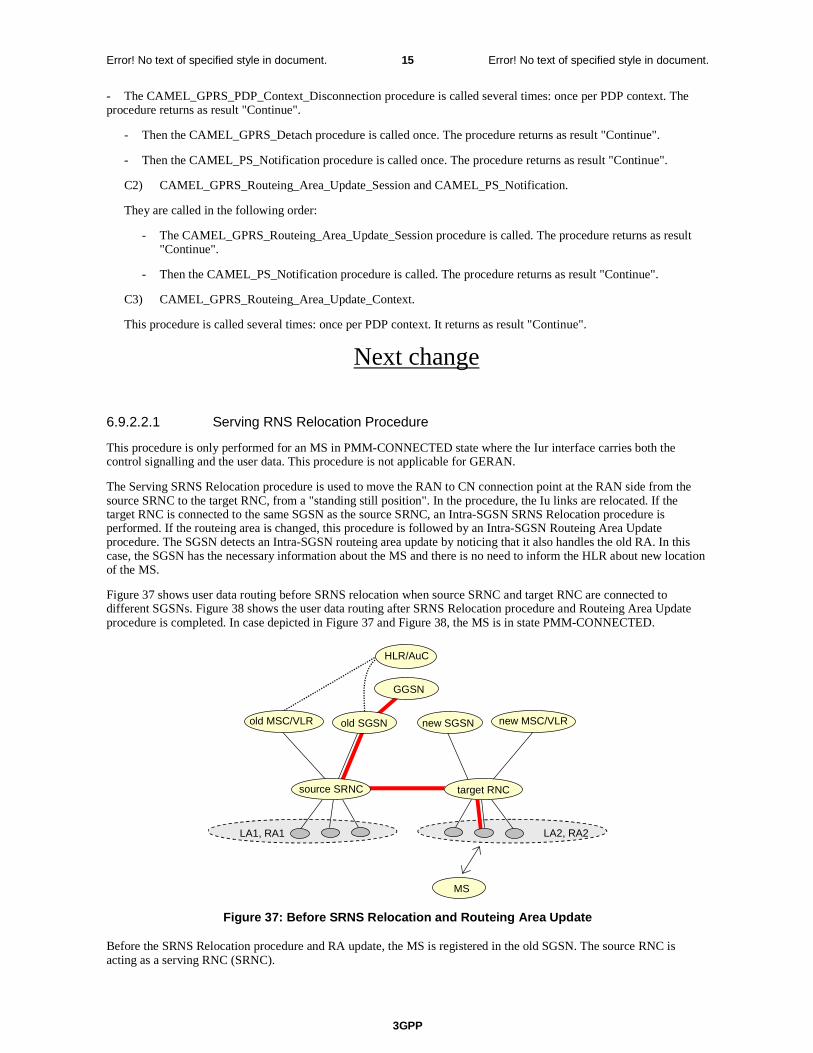
3GPP
Error! No text of specified style in document. 15 Error! No text of specified style in document.
- The CAMEL_GPRS_PDP_Context_Disconnection procedure is called several times: once per PDP context. The procedure returns as result "Continue".
- Then the CAMEL_GPRS_Detach procedure is called once. The procedure returns as result "Continue".
- Then the CAMEL_PS_Notification procedure is called once. The procedure returns as result "Continue".
C2) CAMEL_GPRS_Routeing_Area_Update_Session and CAMEL_PS_Notification.
They are called in the following order:
- The CAMEL_GPRS_Routeing_Area_Update_Session procedure is called. The procedure returns as result "Continue".
- Then the CAMEL_PS_Notification procedure is called. The procedure returns as result "Continue".
C3) CAMEL_GPRS_Routeing_Area_Update_Context.
This procedure is called several times: once per PDP context. It returns as result "Continue".
Next change
6.9.2.2.1 Serving RNS Relocation Procedure
This procedure is only performed for an MS in PMM-CONNECTED state where the Iur interface carries both the control signalling and the user data. This procedure is not applicable for GERAN.
The Serving SRNS Relocation procedure is used to move the RAN to CN connection point at the RAN side from the source SRNC to the target RNC, from a "standing still position". In the procedure, the Iu links are relocated. If the target RNC is connected to the same SGSN as the source SRNC, an Intra-SGSN SRNS Relocation procedure is performed. If the routeing area is changed, this procedure is followed by an Intra-SGSN Routeing Area Update procedure. The SGSN detects an Intra-SGSN routeing area update by noticing that it also handles the old RA. In this case, the SGSN has the necessary information about the MS and there is no need to inform the HLR about new location of the MS.
Figure 37 shows user data routing before SRNS relocation when source SRNC and target RNC are connected to different SGSNs. Figure 38 shows the user data routing after SRNS Relocation procedure and Routeing Area Update procedure is completed. In case depicted in Figure 37 and Figure 38, the MS is in state PMM-CONNECTED.
LA1, RA1
HLR/AuC
old SGSN
GGSN
LA2, RA2
new SGSN
source SRNC
new MSC/VLRold MSC/VLR
MS
target RNC
Figure 37: Before SRNS Relocation and Routeing Area Update
Before the SRNS Relocation procedure and RA update, the MS is registered in the old SGSN. The source RNC is acting as a serving RNC (SRNC).
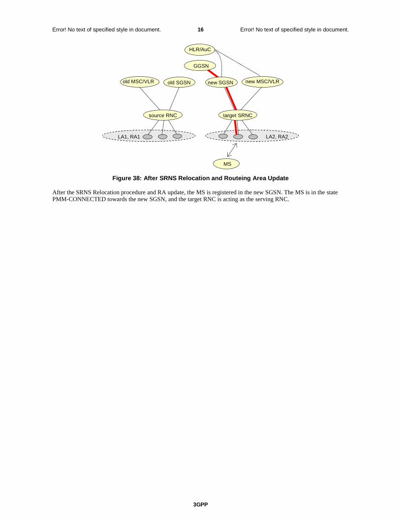
3GPP
Error! No text of specified style in document. 16 Error! No text of specified style in document.
LA1, RA1
MS
HLR/AuC
old SGSN
source RNC
GGSN
LA2, RA2
new SGSNold MSC/VLR new MSC/VLR
target SRNC
Figure 38: After SRNS Relocation and Routeing Area Update
After the SRNS Relocation procedure and RA update, the MS is registered in the new SGSN. The MS is in the state PMM-CONNECTED towards the new SGSN, and the target RNC is acting as the serving RNC.

3GPP
Error! No text of specified style in document. 17 Error! No text of specified style in document.
The Serving SRNS Relocation procedure is illustrated in Figure 39. The sequence is valid for both intra-SGSN SRNS relocation and inter-SGSN SRNS relocation.
MS Target RNC
Source RNC
Old SGSN
New SGSN GGSN
3. Forward Relocation Request
4. Relocation Request
2. Relocation Required
6. Relocation Command
5. Forward Relocation Response
4. Relocation Request Acknowledge
9. Relocation Detect 10. RAN Mobility Information
10. RAN Mobility Information Confirm
Establishment of Radio Access Bearers
C1
1. Decision to perform SRNS relocation
8. Relocation Commit 7. Forwarding of data
11. Relocation Complete 12. Forward Relocation Complete
15. Routing Area Update
13. Update PDP Context Request 14. Iu Release Command 14. Iu Release Complete
C2
13. Update PDP Context Response
12. Forward Relocation Complete Acknowledge
C3
Figure 39: SRNS Relocation Procedure
1) The source SRNC decides to perform/initiate SRNS relocation. At this point both uplink and downlink user data flows via the following tunnel(s): Radio Bearer between MS and source SRNC (data flows via the target RNC, which acts as a drift RNC); GTP-U tunnel(s) between source SRNC and old-SGSN; GTP-U tunnel(s) between old-SGSN and GGSN.
2) The source SRNC sends a Relocation Required message (Relocation Type, Cause, Source ID, Target ID, Source RNC to target RNC transparent container) to the old SGSN. The source SRNC shall set the Relocation Type to "UE not involved". The Source SRNC to Target RNC Transparent Container includes the necessary information for Relocation co-ordination, security functionality and RRC protocol context information (including MS Capabilities).
3) The old SGSN determines from the Target ID if the SRNS Relocation is intra-SGSN SRNS relocation or inter-SGSN SRNS relocation. In case of inter-SGSN SRNS relocation, the old SGSN initiates the relocation resource allocation procedure by sending a Forward Relocation Request message (IMSI, Tunnel Endpoint Identifier Signalling, MM Context, PDP Context, Target Identification, RAN transparent container, RANAP Cause) to the new SGSN. For relocation to an area where Intra Domain Connection of RAN Nodes to Multiple CN Nodes is used, the old SGSN may – if it provides Intra Domain Connection of RAN Nodes to Multiple CN Nodes -have multiple target SGSNs for each relocation target in a pool area, in which case the old SGSN will select one of
3GPP
Error! No text of specified style in document. 18 Error! No text of specified style in document.
them to become the new SGSN, as specified in 3GPP TS 23.236 [73]. The PDP context contains GGSN Address for User Plane and Uplink TEID for Data (to this GGSN Address and Uplink TEID for Data the old SGSN and the new SGSN send uplink packets). At the same time a timer is started on the MM and PDP contexts in the old SGSN (see the Routeing Area Update procedure in subclause "Location Management Procedures (Iu mode)"). The Forward Relocation Request message is applicable only in the case of inter-SGSN SRNS relocation.
4) The new SGSN sends a Relocation Request message (Permanent NAS UE Identity, Cause, CN Domain Indicator, Source-RNC to target RNC transparent container, RABs to be setup) to the target RNC. Only the Iu Bearers of the RABs are setup between the target RNC and the new-SGSN as the existing Radio Bearers will be reallocated between the MS and the target RNC when the target RNC takes the role of the serving RNC. For each requested RAB, the RABs to be setup information elements shall contain information such as RAB ID, RAB parameters, Transport Layer Address, and Iu Transport Association. SGSN shall not establish RABs for PDP contexts with maximum bitrate for uplink and downlink of 0 kbit/s. The RAB ID information element contains the NSAPI value, and the RAB parameters information element gives the QoS profile. The Transport Layer Address is the SGSN Address for user data, and the Iu Transport Association corresponds to the uplink Tunnel Endpoint Identifier Data. After all necessary resources for accepted RABs including the Iu user plane are successfully allocated; the target RNC shall send the Relocation Request Acknowledge message (RABs setup, RABs failed to setup) to the new SGSN. Each RAB to be setup is defined by a Transport Layer Address, which is the target RNC Address for user data, and an Iu Transport Association, which corresponds to the downlink Tunnel Endpoint Identifier for user data. For each RAB to be set up, the target RNC may receive simultaneously downlink user packets both from the source SRNC and from the new SGSN.
5) When resources for the transmission of user data between the target RNC and the new SGSN have been allocated and the new SGSN is ready for relocation of SRNS, the Forward Relocation Response message (Cause, RANAP Cause, and RAB Setup Information) is sent from the new SGSN to old SGSN. This message indicates that the target RNC is ready to receive from source SRNC the forwarded downlink PDUs, i.e. the relocation resource allocation procedure is terminated successfully. RANAP Cause is information from the target RNC to be forwarded to the source SRNC. The RAB Setup Information, one information element for each RAB, contains the RNC Tunnel Endpoint Identifier and the RNC IP address for data forwarding from the source SRNC to the target RNC. If the target RNC or the new SGSN failed to allocate resources, the RAB Setup Information element contains only NSAPI indicating that the source SRNC shall release the resources associated with the NSAPI. The Forward Relocation Response message is applicable only in case of inter-SGSN SRNS relocation.
6) The old SGSN continues the relocation of SRNS by sending a Relocation Command message (RABs to be released, and RABs subject to data forwarding) to the source SRNC. The old SGSN decides the RABs to be subject for data forwarding based on QoS, and those RABs shall be contained in RABs subject to data forwarding. For each RAB subject to data forwarding, the information element shall contain RAB ID, Transport Layer Address, and Iu Transport Association. These are the same Transport Layer Address and Iu Transport Association that the target RNC had sent to new SGSN in Relocation Request Acknowledge message, and these are used for forwarding of downlink N-PDU from source SRNC to target RNC. The source SRNC is now ready to forward downlink user data directly to the target RNC over the Iu interface. This forwarding is performed for downlink user data only.
7) The source SRNC may, according to the QoS profile, begin the forwarding of data for the RABs to be subject for data forwarding. The data forwarding at SRNS relocation shall be carried out through the Iu interface, meaning that the data exchanged between the source SRNC and the target RNC are duplicated in the source SRNC and routed at IP layer towards the target RNC. For each radio bearer which uses lossless PDCP the GTP-PDUs related to transmitted but not yet acknowledged PDCP-PDUs are duplicated and routed at IP layer towards the target RNC together with their related downlink PDCP sequence numbers. The source RNC continues transmitting duplicates of downlink data and receiving uplink data. Before the serving RNC role is not yet taken over by target RNC and when downlink user plane data starts to arrive to target RNC, the target RNC may buffer or discard arriving downlink GTP-PDUs according to the related QoS profile.
Note: The order of steps, starting from step 7 onwards, does not necessarily reflect the order of events. For instance, source RNC may start data forwarding (step 7) and send Relocation Commit message (step 8) almost simultaneously except in the delivery order required case where step 7 triggers step 8. Target RNC may send Relocation Detect message (step 9) and RAN Mobility Information message (step 10) at the same time. Hence, target RNC may receive RAN Mobility Information Confirm message (step 10) while data forwarding (step 7) is still underway, and before the new SGSN receives Update PDP Context Response message (step 11).
8) Before sending the Relocation Commit the uplink and downlink data transfer in the source, SRNC shall be suspended for RABs, which require delivery order. The source RNC shall start the data-forwarding timer. When the source SRNC is ready, the source SRNC shall trigger the execution of relocation of SRNS by sending a Relocation Commit message (SRNS Contexts) to the target RNC over the Iur interface. The purpose of this procedure is to transfer SRNS contexts from the source RNC to the target RNC, and to move the SRNS role

3GPP
Error! No text of specified style in document. 19 Error! No text of specified style in document.
from the source RNC to the target RNC. SRNS contexts are sent for each concerned RAB and contain the sequence numbers of the GTP-PDUs next to be transmitted in the uplink and downlink directions and the next PDCP sequence numbers that would have been used to send and receive data from the MS. For PDP context(s) using delivery order not required (QoS profile), the sequence numbers of the GTP-PDUs next to be transmitted are not used by the target RNC. PDCP sequence numbers are only sent by the source RNC for radio bearers, which used lossless PDCP [57]. The use of lossless PDCP is selected by the RNC when the radio bearer is set up or reconfigured.
If delivery order is required (QoS profile), consecutive GTP-PDU sequence numbering shall be maintained throughout the lifetime of the PDP context(s). Therefore, during the entire SRNS relocation procedure for the PDP context(s) using delivery order required (QoS profile), the responsible GTP-U entities (RNCs and GGSN) shall assign consecutive GTP-PDU sequence numbers to user packets belonging to the same PDP context for uplink and downlink, respectively.
9) The target RNC shall send a Relocation Detect message to the new SGSN when the relocation execution trigger is received. For SRNS relocation type "UE not involved", the relocation execution trigger is the reception of the Relocation Commit message from the Iur interface. When the Relocation Detect message is sent, the target RNC shall start SRNC operation.
10) The target SRNC sends a RAN Mobility Information message. This message contains UE information elements and CN information elements. The UE information elements include among others new SRNC identity and S-RNTI. The CN information elements contain among others Location Area Identification and Routeing Area Identification. The procedure shall be co-ordinated in all Iu signalling connections existing for the MS.
The target SRNC establishes and/or restarts the RLC, and exchanges the PDCP sequence numbers (PDCP-SNU, PDCP-SND) between the target SRNC and the MS. PDCP-SND is the PDCP sequence number for the next expected in-sequence downlink packet to be received in the MS per radio bearer, which used lossless PDCP in the source RNC. PDCP-SND confirms all mobile-terminated packets successfully transferred before the SRNC relocation. If PDCP-SND confirms reception of packets that were forwarded from the source SRNC, the target SRNC shall discard these packets. PDCP-SNU is the PDCP sequence number for the next expected in-sequence uplink packet to be received in the RNC per radio bearer, which used lossless PDCP in the source RNC. PDCP-SNU confirms all mobile originated packets successfully transferred before the SRNC relocation. If PDCP-SNU confirms reception of packets that were received in the source SRNC, the MS shall discard these packets.
Upon reception of the RAN Mobility Information message the MS may start sending uplink user data to the target SRNC. When the MS has reconfigured itself, it sends the RAN Mobility Information Confirm message to the target SRNC. This indicates that the MS is also ready to receive downlink data from the target SRNC.
If new the SGSN has already received the Update PDP Context Response message from the GGSN, it shall forward the uplink user data to GGSN over this new GTP-U tunnel. Otherwise, the new SGSN shall forward the uplink user data to that GGSN IP address and TEID(s), which the new SGSN had received earlier by the Forward Relocation Request message.
For all RABs, the target RNC should:
start uplink reception of data and start transmission of uplink GTP-PDUs towards the new SGSN;
start processing the already buffered and the arriving downlink GTP-PDUs and start downlink transmission towards the MS.
11) When the target SRNC receives the RAN Mobility Information Confirm message, i.e. the new SRNC—ID + S-RNTI are successfully exchanged with the MS by the radio protocols, the target SRNC shall initiate the Relocation Complete procedure by sending the Relocation Complete message to the new SGSN. The purpose of the Relocation Complete procedure is to indicate by the target SRNC the completion of the relocation of the SRNS to the CN.
12) Upon receipt of Relocation Complete message, if the SRNS Relocation is an inter SGSN SRNS relocation, the new SGSN signals to the old SGSN the completion of the SRNS relocation procedure by sending a Forward Relocation Complete message.
13) Upon receipt of the Relocation Complete message, the CN shall switch the user plane from the source RNC to the target SRNC. If the SRNS Relocation is an inter-SGSN SRNS relocation, the new SGSN sends Update PDP Context Request messages (new SGSN Address, SGSN Tunnel Endpoint Identifier, QoS Negotiated, serving network identity) to the GGSNs concerned. The SGSN shall send the serving network identity to the GGSN. The GGSNs update their PDP context fields and return an Update PDP Context Response (GGSN Tunnel

3GPP
Error! No text of specified style in document. 20 Error! No text of specified style in document.
Endpoint Identifier, Prohibit Payload Compression) message. The Prohibit Payload Compression indicates that the SGSN should negotiate no data compression for this PDP context.
14) Upon receiving the Relocation Complete message or if it is an inter-SGSN SRNS relocation; the Forward Relocation Complete message, the old SGSN sends an Iu Release Command message to the source RNC. When the RNC data-forwarding timer has expired the source RNC responds with an Iu Release Complete.
15) After the MS has finished the RNTI reallocation procedure and if the new Routeing Area Identification is different from the old one, the MS initiates the Routeing Area Update procedure. See subclause "Location Management Procedures (Iu mode)". Note that it is only a subset of the RA update procedure that is performed, since the MS is in PMM-CONNECTED mode.
If the SRNS Relocation is inter-SGSN, then the following CAMEL procedure calls shall be performed (see referenced procedures in 3GPP TS 23.078)
C1) CAMEL_GPRS_PDP_Context_Disconnection, CAMEL_GPRS_Detach and CAMEL_PS_Notification.
They are called in the following order:
- The CAMEL_GPRS_PDP_Context_Disconnection procedure is called several times: once per PDP context. The procedure returns as result "Continue".
- Then the CAMEL_GPRS_Detach procedure is called once. The procedure returns as result "Continue".
- Then the CAMEL_PS_Notification procedure is called once. The procedure returns as result "Continue".
If the SRNS Relocation is intra-SGSN, then the above mentioned CAMEL procedures calls shall not be performed.
If Routeing Area Update occurs, then the following CAMEL procedure calls shall be performed (see referenced procedures in 3GPP TS 23.078):
C2) CAMEL_GPRS_Routeing_Area_Update_Session and CAMEL_PS_Notification.
They are called in the following order:
- The CAMEL_GPRS_Routeing_Area_Update_Session procedure is called. The procedure returns as result "Continue".
- Then, the CAMEL_PS_Notification procedure is called. The procedure returns as result "Continue".
C3) CAMEL_GPRS_Routeing_Area_Update_Context.
This procedure is called several times: once per PDP context. It returns as result ""Continue"".
For C2 and C3: refer to Routing Area Update procedure description for detailed message flow.
6.9.2.2.2 Combined Hard Handover and SRNS Relocation Procedure
This procedure is only performed for an MS in PMM-CONNECTED state in case the Iur interface is not available. In the context of this specification, the terms RNS or RNC refer also to a GERAN BSS or BSC (respectively) when serving a mobile in Iu mode.
The Combined Hard Handover and SRNS Relocation procedure is used to move the RAN to CN connection point at the RAN side from the source SRNC to the target RNC, while performing a hard handover decided by the RAN. In the procedure, the Iu links are relocated. If the target RNC is connected to the same SGSN as the source SRNC, an Intra-SGSN SRNS Relocation procedure is performed. If the routeing area is changed, this procedure is followed by an Intra-SGSN Routeing Area Update procedure. The SGSN detects that it is an intra-SGSN routeing area update by noticing that it also handles the old RA. In this case, the SGSN has the necessary information about the MS and there is no need to inform the HLR about the new MS location.
If the target RNC is connected to a different SGSN than the source SRNC, an Inter-SGSN SRNS Relocation procedure is performed. This procedure is followed by an Inter-SGSN Routeing Area Update procedure.
Figure 40 shows the situation before a Combined Hard Handover and SRNS Relocation procedure when source and target RNC are connected to different SGSNs. Figure 41 shows the situation after the Combined Hard Handover and SRNS Relocation procedure and RA update procedure have been completed. In the case described in Figure 40 and Figure 41 the MS is in PMM-CONNECTED state. Both figures are also applicable to BSS to RNS relocation and vice-versa, as well as for BSS to BSS relocation.
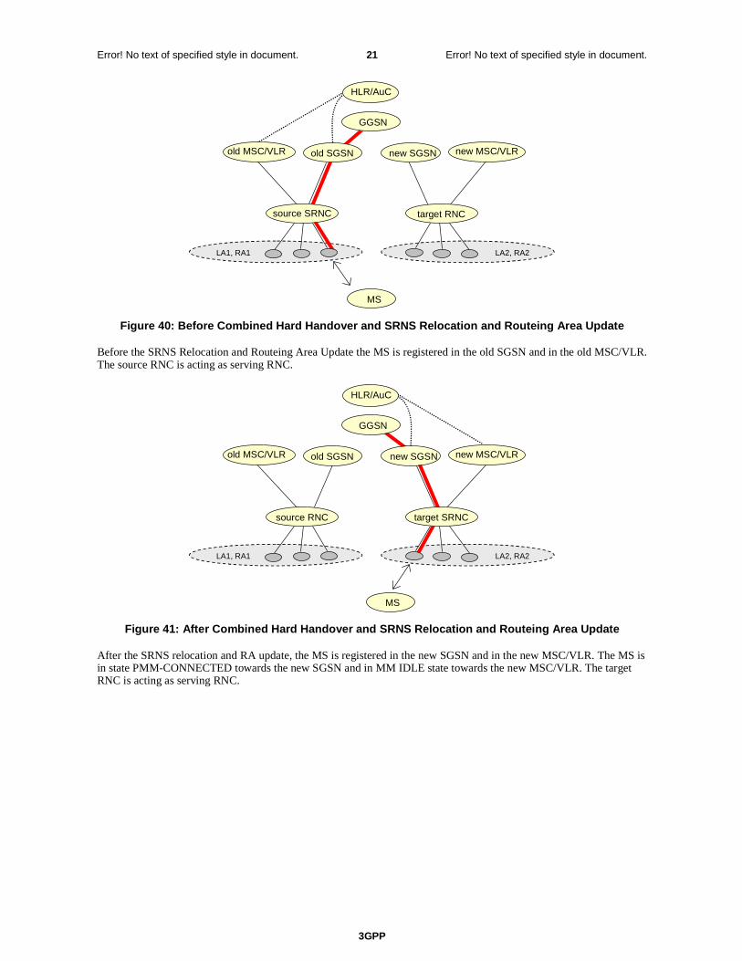
3GPP
Error! No text of specified style in document. 21 Error! No text of specified style in document.
LA1, RA1
MS
HLR/AuC
old SGSN
GGSN
LA2, RA2
new SGSN
target RNCsource SRNC
new MSC/VLRold MSC/VLR
Figure 40: Before Combined Hard Handover and SRNS Relocation and Routeing Area Update
Before the SRNS Relocation and Routeing Area Update the MS is registered in the old SGSN and in the old MSC/VLR. The source RNC is acting as serving RNC.
LA1, RA1
MS
HLR/AuC
old SGSN
source RNC
GGSN
LA2, RA2
new SGSN
target SRNC
old MSC/VLR new MSC/VLR
Figure 41: After Combined Hard Handover and SRNS Relocation and Routeing Area Update
After the SRNS relocation and RA update, the MS is registered in the new SGSN and in the new MSC/VLR. The MS is in state PMM-CONNECTED towards the new SGSN and in MM IDLE state towards the new MSC/VLR. The target RNC is acting as serving RNC.

3GPP
Error! No text of specified style in document. 22 Error! No text of specified style in document.
The Combined Hard Handover and SRNS Relocation procedure for the PS domain is illustrated in Figure 42. The sequence is valid for both intra-SGSN SRNS relocation and inter-SGSN SRNS relocation. Furthermore, this signalling flow is also applicable for BSS to RNS relocation and vice-versa, as well as BSS to BSS relocation.
MS Target RNC
Source RNC
Old SGSN
New SGSN GGSN
3. Forward Relocation Request
4. Relocation Request
2. Relocation Required
6. Relocation Command
5. Forward Relocation Response
4. Relocation Request Acknowledge
10. Relocation Detect
9. Forward SRNS Context 9. Forward SRNS Context
9. Forward SRNS Context
8. RRC message
8. RRC message
1. Decision to perform SRNS Relocation MS Involved
MS detected by target RNC
Establishment of Radio Access Bearers
C1
7. Forwarding of data
9. Forward SRNS Context Acknowledge
11. Relocation Complete
12. Forward Relocation Complete
15. Routing Area Update
13. Update PDP Context Request 14. Iu Release Command
14. Iu Release Complete 13. Update PDP Context Response
12. Forward Relocation Complete Acknowledge
C3
C2
Figure 42: Combined Hard Handover and SRNS Relocation Procedure
1) Based on measurement results and knowledge of the RAN topology, the source SRNC decides to initiate a combined hard handover and SRNS relocation. At this point both uplink and downlink user data flows via the following tunnel(s): Radio Bearer between the MS and the source SRNC (no drift RNC available); GTP-U tunnel(s) between the source SRNC and the old SGSN; GTP-U tunnel(s) between the old SGSN and the GGSN.
2) The source SRNC sends a Relocation Required message (Relocation Type, Cause, Source ID, Target ID, Source RNC To Target RNC Transparent Container) to the old SGSN. The source SRNC shall set Relocation Type to "UE Involved". Source RNC To Target RNC Transparent Container includes the necessary information for relocation co-ordination, security functionality and RRC protocol context information (including MS Capabilities).
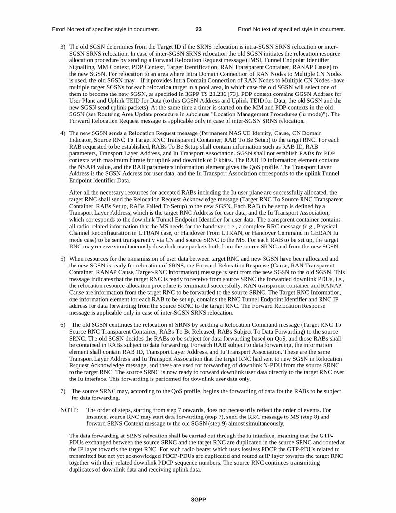
3GPP
Error! No text of specified style in document. 23 Error! No text of specified style in document.
3) The old SGSN determines from the Target ID if the SRNS relocation is intra-SGSN SRNS relocation or inter-SGSN SRNS relocation. In case of inter-SGSN SRNS relocation the old SGSN initiates the relocation resource allocation procedure by sending a Forward Relocation Request message (IMSI, Tunnel Endpoint Identifier Signalling, MM Context, PDP Context, Target Identification, RAN Transparent Container, RANAP Cause) to the new SGSN. For relocation to an area where Intra Domain Connection of RAN Nodes to Multiple CN Nodes is used, the old SGSN may – if it provides Intra Domain Connection of RAN Nodes to Multiple CN Nodes -have multiple target SGSNs for each relocation target in a pool area, in which case the old SGSN will select one of them to become the new SGSN, as specified in 3GPP TS 23.236 [73]. PDP context contains GGSN Address for User Plane and Uplink TEID for Data (to this GGSN Address and Uplink TEID for Data, the old SGSN and the new SGSN send uplink packets). At the same time a timer is started on the MM and PDP contexts in the old SGSN (see Routeing Area Update procedure in subclause "Location Management Procedures (Iu mode)"). The Forward Relocation Request message is applicable only in case of inter-SGSN SRNS relocation.
4) The new SGSN sends a Relocation Request message (Permanent NAS UE Identity, Cause, CN Domain Indicator, Source RNC To Target RNC Transparent Container, RAB To Be Setup) to the target RNC. For each RAB requested to be established, RABs To Be Setup shall contain information such as RAB ID, RAB parameters, Transport Layer Address, and Iu Transport Association. SGSN shall not establish RABs for PDP contexts with maximum bitrate for uplink and downlink of 0 kbit/s. The RAB ID information element contains the NSAPI value, and the RAB parameters information element gives the QoS profile. The Transport Layer Address is the SGSN Address for user data, and the Iu Transport Association corresponds to the uplink Tunnel Endpoint Identifier Data.
After all the necessary resources for accepted RABs including the Iu user plane are successfully allocated, the target RNC shall send the Relocation Request Acknowledge message (Target RNC To Source RNC Transparent Container, RABs Setup, RABs Failed To Setup) to the new SGSN. Each RAB to be setup is defined by a Transport Layer Address, which is the target RNC Address for user data, and the Iu Transport Association, which corresponds to the downlink Tunnel Endpoint Identifier for user data. The transparent container contains all radio-related information that the MS needs for the handover, i.e., a complete RRC message (e.g., Physical Channel Reconfiguration in UTRAN case, or Handover From UTRAN, or Handover Command in GERAN Iu mode case) to be sent transparently via CN and source SRNC to the MS. For each RAB to be set up, the target RNC may receive simultaneously downlink user packets both from the source SRNC and from the new SGSN.
5) When resources for the transmission of user data between target RNC and new SGSN have been allocated and the new SGSN is ready for relocation of SRNS, the Forward Relocation Response (Cause, RAN Transparent Container, RANAP Cause, Target-RNC Information) message is sent from the new SGSN to the old SGSN. This message indicates that the target RNC is ready to receive from source SRNC the forwarded downlink PDUs, i.e., the relocation resource allocation procedure is terminated successfully. RAN transparent container and RANAP Cause are information from the target RNC to be forwarded to the source SRNC. The Target RNC Information, one information element for each RAB to be set up, contains the RNC Tunnel Endpoint Identifier and RNC IP address for data forwarding from the source SRNC to the target RNC. The Forward Relocation Response message is applicable only in case of inter-SGSN SRNS relocation.
6) The old SGSN continues the relocation of SRNS by sending a Relocation Command message (Target RNC To Source RNC Transparent Container, RABs To Be Released, RABs Subject To Data Forwarding) to the source SRNC. The old SGSN decides the RABs to be subject for data forwarding based on QoS, and those RABs shall be contained in RABs subject to data forwarding. For each RAB subject to data forwarding, the information element shall contain RAB ID, Transport Layer Address, and Iu Transport Association. These are the same Transport Layer Address and Iu Transport Association that the target RNC had sent to new SGSN in Relocation Request Acknowledge message, and these are used for forwarding of downlink N-PDU from the source SRNC to the target RNC. The source SRNC is now ready to forward downlink user data directly to the target RNC over the Iu interface. This forwarding is performed for downlink user data only.
7) The source SRNC may, according to the QoS profile, begins the forwarding of data for the RABs to be subject for data forwarding.
NOTE: The order of steps, starting from step 7 onwards, does not necessarily reflect the order of events. For instance, source RNC may start data forwarding (step 7), send the RRC message to MS (step 8) and forward SRNS Context message to the old SGSN (step 9) almost simultaneously.
The data forwarding at SRNS relocation shall be carried out through the Iu interface, meaning that the GTP-PDUs exchanged between the source SRNC and the target RNC are duplicated in the source SRNC and routed at the IP layer towards the target RNC. For each radio bearer which uses lossless PDCP the GTP-PDUs related to transmitted but not yet acknowledged PDCP-PDUs are duplicated and routed at IP layer towards the target RNC together with their related downlink PDCP sequence numbers. The source RNC continues transmitting duplicates of downlink data and receiving uplink data.
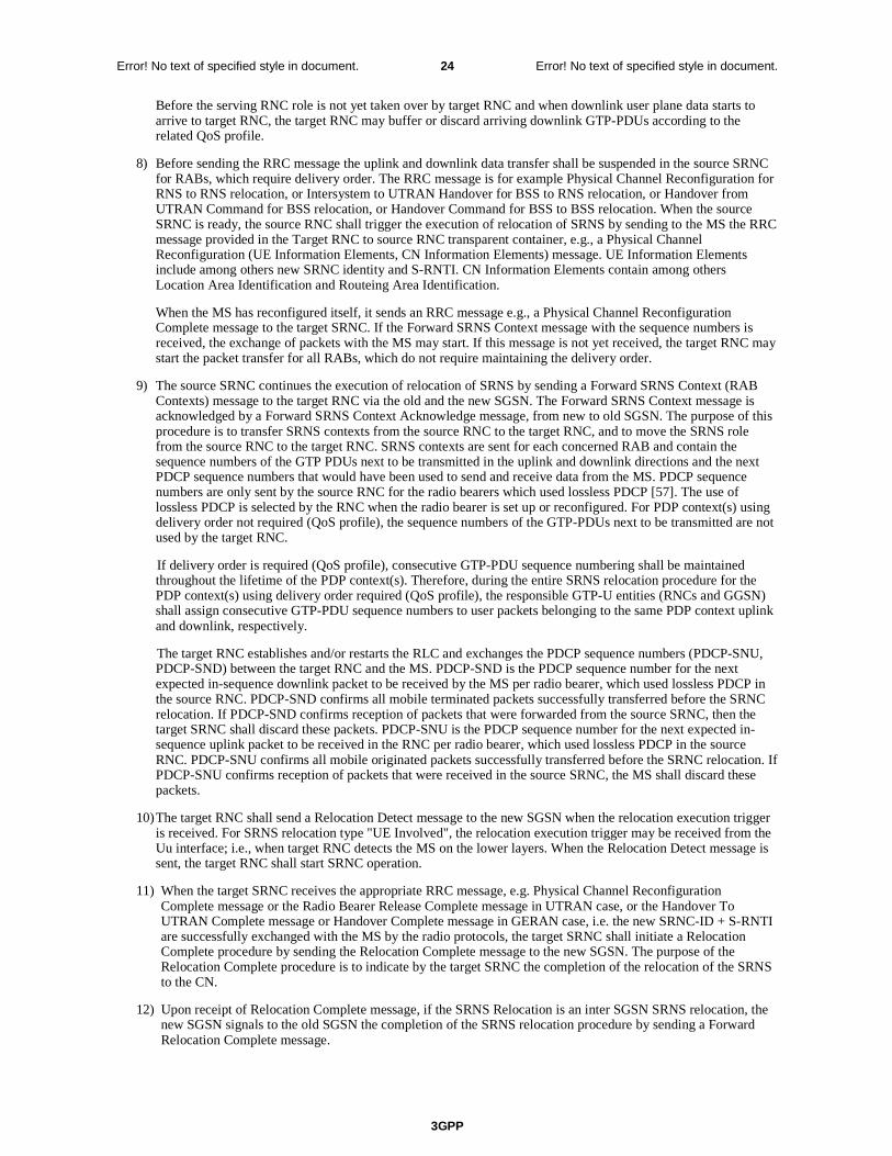
3GPP
Error! No text of specified style in document. 24 Error! No text of specified style in document.
Before the serving RNC role is not yet taken over by target RNC and when downlink user plane data starts to arrive to target RNC, the target RNC may buffer or discard arriving downlink GTP-PDUs according to the related QoS profile.
8) Before sending the RRC message the uplink and downlink data transfer shall be suspended in the source SRNC for RABs, which require delivery order. The RRC message is for example Physical Channel Reconfiguration for RNS to RNS relocation, or Intersystem to UTRAN Handover for BSS to RNS relocation, or Handover from UTRAN Command for BSS relocation, or Handover Command for BSS to BSS relocation. When the source SRNC is ready, the source RNC shall trigger the execution of relocation of SRNS by sending to the MS the RRC message provided in the Target RNC to source RNC transparent container, e.g., a Physical Channel Reconfiguration (UE Information Elements, CN Information Elements) message. UE Information Elements include among others new SRNC identity and S-RNTI. CN Information Elements contain among others Location Area Identification and Routeing Area Identification.
When the MS has reconfigured itself, it sends an RRC message e.g., a Physical Channel Reconfiguration Complete message to the target SRNC. If the Forward SRNS Context message with the sequence numbers is received, the exchange of packets with the MS may start. If this message is not yet received, the target RNC may start the packet transfer for all RABs, which do not require maintaining the delivery order.
9) The source SRNC continues the execution of relocation of SRNS by sending a Forward SRNS Context (RAB Contexts) message to the target RNC via the old and the new SGSN. The Forward SRNS Context message is acknowledged by a Forward SRNS Context Acknowledge message, from new to old SGSN. The purpose of this procedure is to transfer SRNS contexts from the source RNC to the target RNC, and to move the SRNS role from the source RNC to the target RNC. SRNS contexts are sent for each concerned RAB and contain the sequence numbers of the GTP PDUs next to be transmitted in the uplink and downlink directions and the next PDCP sequence numbers that would have been used to send and receive data from the MS. PDCP sequence numbers are only sent by the source RNC for the radio bearers which used lossless PDCP [57]. The use of lossless PDCP is selected by the RNC when the radio bearer is set up or reconfigured. For PDP context(s) using delivery order not required (QoS profile), the sequence numbers of the GTP-PDUs next to be transmitted are not used by the target RNC.
If delivery order is required (QoS profile), consecutive GTP-PDU sequence numbering shall be maintained throughout the lifetime of the PDP context(s). Therefore, during the entire SRNS relocation procedure for the PDP context(s) using delivery order required (QoS profile), the responsible GTP-U entities (RNCs and GGSN) shall assign consecutive GTP-PDU sequence numbers to user packets belonging to the same PDP context uplink and downlink, respectively.
The target RNC establishes and/or restarts the RLC and exchanges the PDCP sequence numbers (PDCP-SNU, PDCP-SND) between the target RNC and the MS. PDCP-SND is the PDCP sequence number for the next expected in-sequence downlink packet to be received by the MS per radio bearer, which used lossless PDCP in the source RNC. PDCP-SND confirms all mobile terminated packets successfully transferred before the SRNC relocation. If PDCP-SND confirms reception of packets that were forwarded from the source SRNC, then the target SRNC shall discard these packets. PDCP-SNU is the PDCP sequence number for the next expected in-sequence uplink packet to be received in the RNC per radio bearer, which used lossless PDCP in the source RNC. PDCP-SNU confirms all mobile originated packets successfully transferred before the SRNC relocation. If PDCP-SNU confirms reception of packets that were received in the source SRNC, the MS shall discard these packets.
10) The target RNC shall send a Relocation Detect message to the new SGSN when the relocation execution trigger is received. For SRNS relocation type "UE Involved", the relocation execution trigger may be received from the Uu interface; i.e., when target RNC detects the MS on the lower layers. When the Relocation Detect message is sent, the target RNC shall start SRNC operation.
11) When the target SRNC receives the appropriate RRC message, e.g. Physical Channel Reconfiguration Complete message or the Radio Bearer Release Complete message in UTRAN case, or the Handover To UTRAN Complete message or Handover Complete message in GERAN case, i.e. the new SRNC-ID + S-RNTI are successfully exchanged with the MS by the radio protocols, the target SRNC shall initiate a Relocation Complete procedure by sending the Relocation Complete message to the new SGSN. The purpose of the Relocation Complete procedure is to indicate by the target SRNC the completion of the relocation of the SRNS to the CN.
12) Upon receipt of Relocation Complete message, if the SRNS Relocation is an inter SGSN SRNS relocation, the new SGSN signals to the old SGSN the completion of the SRNS relocation procedure by sending a Forward Relocation Complete message.
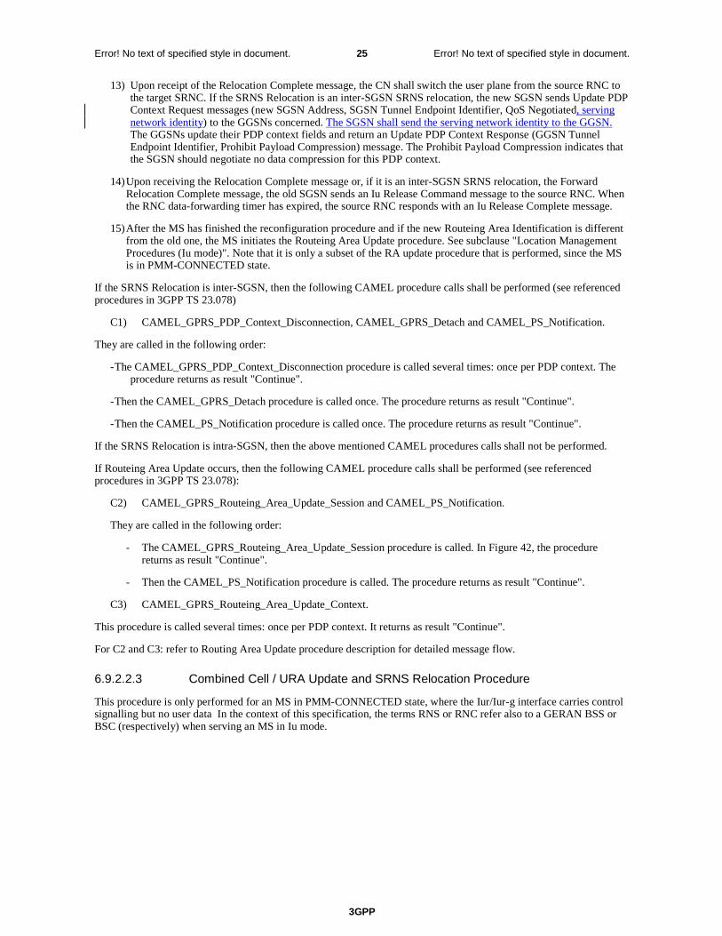
3GPP
Error! No text of specified style in document. 25 Error! No text of specified style in document.
13) Upon receipt of the Relocation Complete message, the CN shall switch the user plane from the source RNC to the target SRNC. If the SRNS Relocation is an inter-SGSN SRNS relocation, the new SGSN sends Update PDP Context Request messages (new SGSN Address, SGSN Tunnel Endpoint Identifier, QoS Negotiated, serving network identity) to the GGSNs concerned. The SGSN shall send the serving network identity to the GGSN. The GGSNs update their PDP context fields and return an Update PDP Context Response (GGSN Tunnel Endpoint Identifier, Prohibit Payload Compression) message. The Prohibit Payload Compression indicates that the SGSN should negotiate no data compression for this PDP context.
14) Upon receiving the Relocation Complete message or, if it is an inter-SGSN SRNS relocation, the Forward Relocation Complete message, the old SGSN sends an Iu Release Command message to the source RNC. When the RNC data-forwarding timer has expired, the source RNC responds with an Iu Release Complete message.
15) After the MS has finished the reconfiguration procedure and if the new Routeing Area Identification is different from the old one, the MS initiates the Routeing Area Update procedure. See subclause "Location Management Procedures (Iu mode)". Note that it is only a subset of the RA update procedure that is performed, since the MS is in PMM-CONNECTED state.
If the SRNS Relocation is inter-SGSN, then the following CAMEL procedure calls shall be performed (see referenced procedures in 3GPP TS 23.078)
C1) CAMEL_GPRS_PDP_Context_Disconnection, CAMEL_GPRS_Detach and CAMEL_PS_Notification.
They are called in the following order:
- The CAMEL_GPRS_PDP_Context_Disconnection procedure is called several times: once per PDP context. The procedure returns as result "Continue".
- Then the CAMEL_GPRS_Detach procedure is called once. The procedure returns as result "Continue".
- Then the CAMEL_PS_Notification procedure is called once. The procedure returns as result "Continue".
If the SRNS Relocation is intra-SGSN, then the above mentioned CAMEL procedures calls shall not be performed.
If Routeing Area Update occurs, then the following CAMEL procedure calls shall be performed (see referenced procedures in 3GPP TS 23.078):
C2) CAMEL_GPRS_Routeing_Area_Update_Session and CAMEL_PS_Notification.
They are called in the following order:
- The CAMEL_GPRS_Routeing_Area_Update_Session procedure is called. In Figure 42, the procedure returns as result "Continue".
- Then the CAMEL_PS_Notification procedure is called. The procedure returns as result "Continue".
C3) CAMEL_GPRS_Routeing_Area_Update_Context.
This procedure is called several times: once per PDP context. It returns as result "Continue".
For C2 and C3: refer to Routing Area Update procedure description for detailed message flow.
6.9.2.2.3 Combined Cell / URA Update and SRNS Relocation Procedure
This procedure is only performed for an MS in PMM-CONNECTED state, where the Iur/Iur-g interface carries control signalling but no user data In the context of this specification, the terms RNS or RNC refer also to a GERAN BSS or BSC (respectively) when serving an MS in Iu mode.
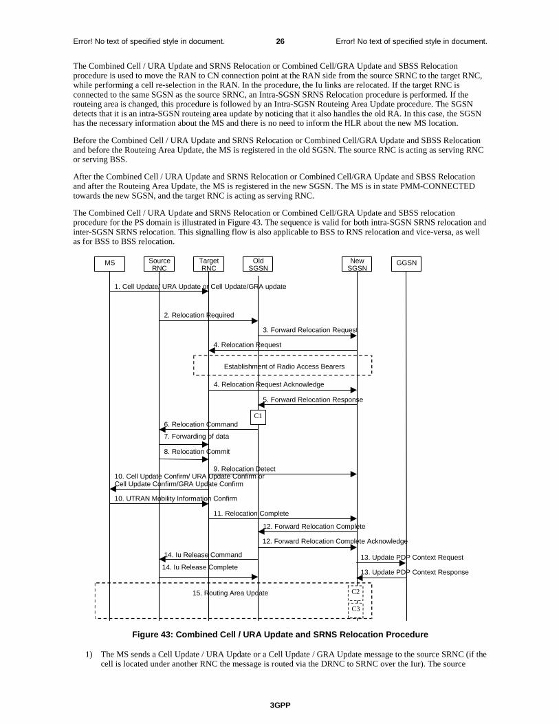
3GPP
Error! No text of specified style in document. 26 Error! No text of specified style in document.
The Combined Cell / URA Update and SRNS Relocation or Combined Cell/GRA Update and SBSS Relocation procedure is used to move the RAN to CN connection point at the RAN side from the source SRNC to the target RNC, while performing a cell re-selection in the RAN. In the procedure, the Iu links are relocated. If the target RNC is connected to the same SGSN as the source SRNC, an Intra-SGSN SRNS Relocation procedure is performed. If the routeing area is changed, this procedure is followed by an Intra-SGSN Routeing Area Update procedure. The SGSN detects that it is an intra-SGSN routeing area update by noticing that it also handles the old RA. In this case, the SGSN has the necessary information about the MS and there is no need to inform the HLR about the new MS location.
Before the Combined Cell / URA Update and SRNS Relocation or Combined Cell/GRA Update and SBSS Relocation and before the Routeing Area Update, the MS is registered in the old SGSN. The source RNC is acting as serving RNC or serving BSS.
After the Combined Cell / URA Update and SRNS Relocation or Combined Cell/GRA Update and SBSS Relocation and after the Routeing Area Update, the MS is registered in the new SGSN. The MS is in state PMM-CONNECTED towards the new SGSN, and the target RNC is acting as serving RNC.
The Combined Cell / URA Update and SRNS Relocation or Combined Cell/GRA Update and SBSS relocation procedure for the PS domain is illustrated in Figure 43. The sequence is valid for both intra-SGSN SRNS relocation and inter-SGSN SRNS relocation. This signalling flow is also applicable to BSS to RNS relocation and vice-versa, as well as for BSS to BSS relocation.
MS Target RNC
Source RNC
Old SGSN
New SGSN GGSN
3. Forward Relocation Request
4. Relocation Request
2. Relocation Required
6. Relocation Command
5. Forward Relocation Response
4. Relocation Request Acknowledge
9. Relocation Detect 10. Cell Update Confirm/ URA Update Confirm or Cell Update Confirm/GRA Update Confirm
10. UTRAN Mobility Information Confirm
Establishment of Radio Access Bearers
C1
1. Cell Update/ URA Update or Cell Update/GRA update
8. Relocation Commit
7. Forwarding of data
11. Relocation Complete 12. Forward Relocation Complete
15. Routing Area Update
13. Update PDP Context Request 14. Iu Release Command 14. Iu Release Complete
C2
13. Update PDP Context Response
12. Forward Relocation Complete Acknowledge
C3
Figure 43: Combined Cell / URA Update and SRNS Relocation Procedure
1) The MS sends a Cell Update / URA Update or a Cell Update / GRA Update message to the source SRNC (if the cell is located under another RNC the message is routed via the DRNC to SRNC over the Iur). The source
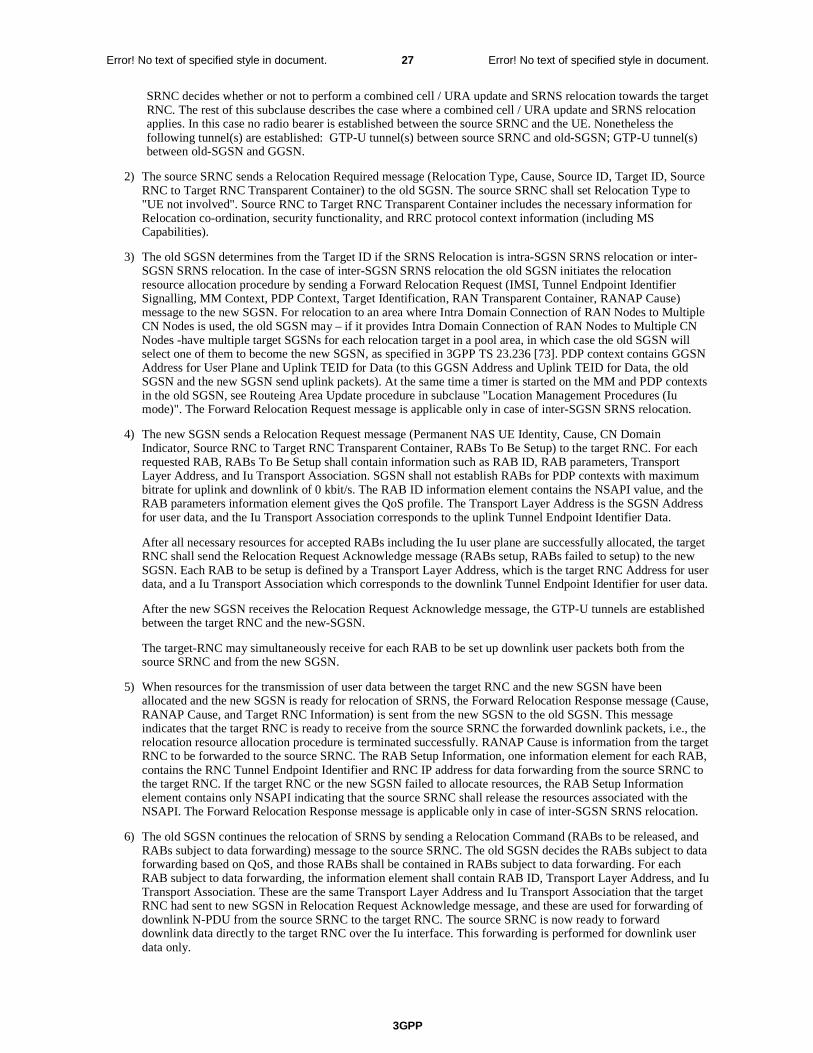
3GPP
Error! No text of specified style in document. 27 Error! No text of specified style in document.
SRNC decides whether or not to perform a combined cell / URA update and SRNS relocation towards the target RNC. The rest of this subclause describes the case where a combined cell / URA update and SRNS relocation applies. In this case no radio bearer is established between the source SRNC and the UE. Nonetheless the following tunnel(s) are established: GTP-U tunnel(s) between source SRNC and old-SGSN; GTP-U tunnel(s) between old-SGSN and GGSN.
2) The source SRNC sends a Relocation Required message (Relocation Type, Cause, Source ID, Target ID, Source RNC to Target RNC Transparent Container) to the old SGSN. The source SRNC shall set Relocation Type to "UE not involved". Source RNC to Target RNC Transparent Container includes the necessary information for Relocation co-ordination, security functionality, and RRC protocol context information (including MS Capabilities).
3) The old SGSN determines from the Target ID if the SRNS Relocation is intra-SGSN SRNS relocation or inter-SGSN SRNS relocation. In the case of inter-SGSN SRNS relocation the old SGSN initiates the relocation resource allocation procedure by sending a Forward Relocation Request (IMSI, Tunnel Endpoint Identifier Signalling, MM Context, PDP Context, Target Identification, RAN Transparent Container, RANAP Cause) message to the new SGSN. For relocation to an area where Intra Domain Connection of RAN Nodes to Multiple CN Nodes is used, the old SGSN may – if it provides Intra Domain Connection of RAN Nodes to Multiple CN Nodes -have multiple target SGSNs for each relocation target in a pool area, in which case the old SGSN will select one of them to become the new SGSN, as specified in 3GPP TS 23.236 [73]. PDP context contains GGSN Address for User Plane and Uplink TEID for Data (to this GGSN Address and Uplink TEID for Data, the old SGSN and the new SGSN send uplink packets). At the same time a timer is started on the MM and PDP contexts in the old SGSN, see Routeing Area Update procedure in subclause "Location Management Procedures (Iu mode)". The Forward Relocation Request message is applicable only in case of inter-SGSN SRNS relocation.
4) The new SGSN sends a Relocation Request message (Permanent NAS UE Identity, Cause, CN Domain Indicator, Source RNC to Target RNC Transparent Container, RABs To Be Setup) to the target RNC. For each requested RAB, RABs To Be Setup shall contain information such as RAB ID, RAB parameters, Transport Layer Address, and Iu Transport Association. SGSN shall not establish RABs for PDP contexts with maximum bitrate for uplink and downlink of 0 kbit/s. The RAB ID information element contains the NSAPI value, and the RAB parameters information element gives the QoS profile. The Transport Layer Address is the SGSN Address for user data, and the Iu Transport Association corresponds to the uplink Tunnel Endpoint Identifier Data.
After all necessary resources for accepted RABs including the Iu user plane are successfully allocated, the target RNC shall send the Relocation Request Acknowledge message (RABs setup, RABs failed to setup) to the new SGSN. Each RAB to be setup is defined by a Transport Layer Address, which is the target RNC Address for user data, and a Iu Transport Association which corresponds to the downlink Tunnel Endpoint Identifier for user data.
After the new SGSN receives the Relocation Request Acknowledge message, the GTP-U tunnels are established between the target RNC and the new-SGSN.
The target-RNC may simultaneously receive for each RAB to be set up downlink user packets both from the source SRNC and from the new SGSN.
5) When resources for the transmission of user data between the target RNC and the new SGSN have been allocated and the new SGSN is ready for relocation of SRNS, the Forward Relocation Response message (Cause, RANAP Cause, and Target RNC Information) is sent from the new SGSN to the old SGSN. This message indicates that the target RNC is ready to receive from the source SRNC the forwarded downlink packets, i.e., the relocation resource allocation procedure is terminated successfully. RANAP Cause is information from the target RNC to be forwarded to the source SRNC. The RAB Setup Information, one information element for each RAB, contains the RNC Tunnel Endpoint Identifier and RNC IP address for data forwarding from the source SRNC to the target RNC. If the target RNC or the new SGSN failed to allocate resources, the RAB Setup Information element contains only NSAPI indicating that the source SRNC shall release the resources associated with the NSAPI. The Forward Relocation Response message is applicable only in case of inter-SGSN SRNS relocation.
6) The old SGSN continues the relocation of SRNS by sending a Relocation Command (RABs to be released, and RABs subject to data forwarding) message to the source SRNC. The old SGSN decides the RABs subject to data forwarding based on QoS, and those RABs shall be contained in RABs subject to data forwarding. For each RAB subject to data forwarding, the information element shall contain RAB ID, Transport Layer Address, and Iu Transport Association. These are the same Transport Layer Address and Iu Transport Association that the target RNC had sent to new SGSN in Relocation Request Acknowledge message, and these are used for forwarding of downlink N-PDU from the source SRNC to the target RNC. The source SRNC is now ready to forward downlink data directly to the target RNC over the Iu interface. This forwarding is performed for downlink user data only.
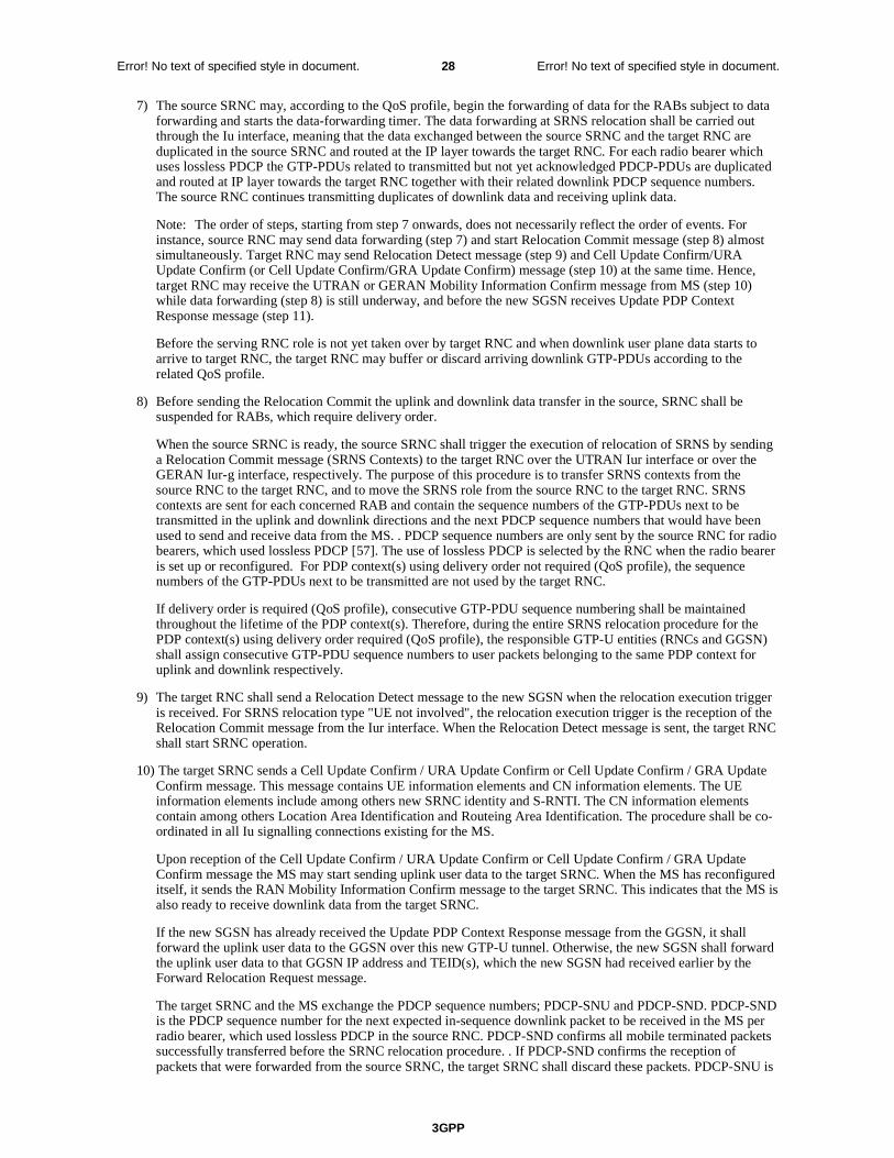
3GPP
Error! No text of specified style in document. 28 Error! No text of specified style in document.
7) The source SRNC may, according to the QoS profile, begin the forwarding of data for the RABs subject to data forwarding and starts the data-forwarding timer. The data forwarding at SRNS relocation shall be carried out through the Iu interface, meaning that the data exchanged between the source SRNC and the target RNC are duplicated in the source SRNC and routed at the IP layer towards the target RNC. For each radio bearer which uses lossless PDCP the GTP-PDUs related to transmitted but not yet acknowledged PDCP-PDUs are duplicated and routed at IP layer towards the target RNC together with their related downlink PDCP sequence numbers. The source RNC continues transmitting duplicates of downlink data and receiving uplink data.
Note: The order of steps, starting from step 7 onwards, does not necessarily reflect the order of events. For instance, source RNC may send data forwarding (step 7) and start Relocation Commit message (step 8) almost simultaneously. Target RNC may send Relocation Detect message (step 9) and Cell Update Confirm/URA Update Confirm (or Cell Update Confirm/GRA Update Confirm) message (step 10) at the same time. Hence, target RNC may receive the UTRAN or GERAN Mobility Information Confirm message from MS (step 10) while data forwarding (step 8) is still underway, and before the new SGSN receives Update PDP Context Response message (step 11).
Before the serving RNC role is not yet taken over by target RNC and when downlink user plane data starts to arrive to target RNC, the target RNC may buffer or discard arriving downlink GTP-PDUs according to the related QoS profile.
8) Before sending the Relocation Commit the uplink and downlink data transfer in the source, SRNC shall be suspended for RABs, which require delivery order.
When the source SRNC is ready, the source SRNC shall trigger the execution of relocation of SRNS by sending a Relocation Commit message (SRNS Contexts) to the target RNC over the UTRAN Iur interface or over the GERAN Iur-g interface, respectively. The purpose of this procedure is to transfer SRNS contexts from the source RNC to the target RNC, and to move the SRNS role from the source RNC to the target RNC. SRNS contexts are sent for each concerned RAB and contain the sequence numbers of the GTP-PDUs next to be transmitted in the uplink and downlink directions and the next PDCP sequence numbers that would have been used to send and receive data from the MS. . PDCP sequence numbers are only sent by the source RNC for radio bearers, which used lossless PDCP [57]. The use of lossless PDCP is selected by the RNC when the radio bearer is set up or reconfigured. For PDP context(s) using delivery order not required (QoS profile), the sequence numbers of the GTP-PDUs next to be transmitted are not used by the target RNC.
If delivery order is required (QoS profile), consecutive GTP-PDU sequence numbering shall be maintained throughout the lifetime of the PDP context(s). Therefore, during the entire SRNS relocation procedure for the PDP context(s) using delivery order required (QoS profile), the responsible GTP-U entities (RNCs and GGSN) shall assign consecutive GTP-PDU sequence numbers to user packets belonging to the same PDP context for uplink and downlink respectively.
9) The target RNC shall send a Relocation Detect message to the new SGSN when the relocation execution trigger is received. For SRNS relocation type "UE not involved", the relocation execution trigger is the reception of the Relocation Commit message from the Iur interface. When the Relocation Detect message is sent, the target RNC shall start SRNC operation.
10) The target SRNC sends a Cell Update Confirm / URA Update Confirm or Cell Update Confirm / GRA Update Confirm message. This message contains UE information elements and CN information elements. The UE information elements include among others new SRNC identity and S-RNTI. The CN information elements contain among others Location Area Identification and Routeing Area Identification. The procedure shall be co-ordinated in all Iu signalling connections existing for the MS.
Upon reception of the Cell Update Confirm / URA Update Confirm or Cell Update Confirm / GRA Update Confirm message the MS may start sending uplink user data to the target SRNC. When the MS has reconfigured itself, it sends the RAN Mobility Information Confirm message to the target SRNC. This indicates that the MS is also ready to receive downlink data from the target SRNC.
If the new SGSN has already received the Update PDP Context Response message from the GGSN, it shall forward the uplink user data to the GGSN over this new GTP-U tunnel. Otherwise, the new SGSN shall forward the uplink user data to that GGSN IP address and TEID(s), which the new SGSN had received earlier by the Forward Relocation Request message.
The target SRNC and the MS exchange the PDCP sequence numbers; PDCP-SNU and PDCP-SND. PDCP-SND is the PDCP sequence number for the next expected in-sequence downlink packet to be received in the MS per radio bearer, which used lossless PDCP in the source RNC. PDCP-SND confirms all mobile terminated packets successfully transferred before the SRNC relocation procedure. . If PDCP-SND confirms the reception of packets that were forwarded from the source SRNC, the target SRNC shall discard these packets. PDCP-SNU is
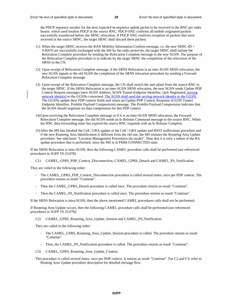
3GPP
Error! No text of specified style in document. 29 Error! No text of specified style in document.
the PDCP sequence number for the next expected in-sequence uplink packet to be received in the RNC per radio bearer, which used lossless PDCP in the source RNC. PDCP-SNU confirms all mobile originated packets successfully transferred before the SRNC relocation. If PDCP-SNU confirms reception of packets that were received in the source SRNC, the target SRNC shall discard these packets.
11) When the target SRNC receives the RAN Mobility Information Confirm message, i.e. the new SRNC-ID + S-RNTI are successfully exchanged with the MS by the radio protocols, the target SRNC shall initiate the Relocation Complete procedure by sending the Relocation Complete message to the new SGSN. The purpose of the Relocation Complete procedure is to indicate by the target SRNC the completion of the relocation of the SRNS to the CN.
12) Upon receipt of Relocation Complete message, if the SRNS Relocation is an inter SGSN SRNS relocation, the new SGSN signals to the old SGSN the completion of the SRNS relocation procedure by sending a Forward Relocation Complete message.
13) Upon receipt of the Relocation Complete message, the CN shall switch the user plane from the source RNC to the target SRNC. If the SRNS Relocation is an inter-SGSN SRNS relocation, the new SGSN sends Update PDP Context Request messages (new SGSN Address, SGSN Tunnel Endpoint Identifier, QoS Negotiated, serving network identity) to the GGSNs concerned. The SGSN shall send the serving network identity to the GGSN. The GGSNs update their PDP context fields and return an Update PDP Context Response (GGSN Tunnel Endpoint Identifier, Prohibit Payload Compression) message. The Prohibit Payload Compression indicates that the SGSN should negotiate no data compression for this PDP context.
14) Upon receiving the Relocation Complete message or if it is an inter-SGSN SRNS relocation, the Forward Relocation Complete message, the old SGSN sends an Iu Release Command message to the source RNC. When the RNC data-forwarding timer has expired the source RNC responds with an Iu Release Complete.
15) After the MS has finished the Cell / URA update or the Cell / GRA update and RNTI reallocation procedure and if the new Routeing Area Identification is different from the old one, the MS initiates the Routeing Area Update procedure. See subclause "Location Management Procedures (Iu mode)". Note that it is only a subset of the RA update procedure that is performed, since the MS is in PMM-CONNECTED state.
If the SRNS Relocation is inter-SGSN, then the following CAMEL procedure calls shall be performed (see referenced procedures in 3GPP TS 23.078)
C1) CAMEL_GPRS_PDP_Context_Disconnection, CAMEL_GPRS_Detach and CAMEL_PS_Notification.
They are called in the following order:
- The CAMEL_GPRS_PDP_Context_Disconnection procedure is called several times: once per PDP context. The procedure returns as result "Continue".
- Then the CAMEL_GPRS_Detach procedure is called once. The procedure returns as result "Continue".
- Then the CAMEL_PS_Notification procedure is called once. The procedure returns as result "Continue".
If the SRNS Relocation is intra-SGSN, then the above mentioned CAMEL procedures calls shall not be performed.
If Routeing Area Update occurs, then the following CAMEL procedure calls shall be performed (see referenced procedures in 3GPP TS 23.078):
C2) CAMEL_GPRS_Routeing_Area_Update_Session and CAMEL_PS_Notification.
They are called in the following order:
- The CAMEL_GPRS_Routeing_Area_Update_Session procedure is called. The procedure returns as result "Continue".
- Then, the CAMEL_PS_Notification procedure is called. The procedure returns as result "Continue".
C3) CAMEL_GPRS_Routeing_Area_Update_Context.
This procedure is called several times: once per PDP context. It returns as result "Continue". For C2 and C3: refer to Routing Area Update procedure description for detailed message flow.
3GPP
Error! No text of specified style in document. 30 Error! No text of specified style in document.
Next change
6.13.2.1 Iu mode to A/Gb mode Inter-SGSN Change
An inter-SGSN inter-system change from Iu mode to A/Gb mode takes place when an MS in PMM-IDLE or PMM-CONNECTED state changes from UTRAN or GERAN Iu mode to A/Gb mode and the A/Gb mode radio access node serving the MS is served by a different SGSN. In this case, the RA changes. Therefore, the MS shall initiate a A/Gb mode RA update procedure. The RA update procedure is either combined RA / LA update or only RA update. These RA update cases are illustrated in Figure 54. In the context of this specification, the terms RNS or RNC refer also to a GERAN BSS or BSC (respectively) when serving an MS in Iu mode.
A combined RA / LA update takes place in network operation mode I when the MS enters a new RA or when a GPRS-attached MS performs IMSI attach. The MS sends a Routeing Area Update Request indicating that an LA update may also need to be performed, in which case the SGSN forwards the LA update to the VLR. This concerns only idle mode (see 3GPP TS 23.122), as no combined RA / LA updates are performed during a CS connection.
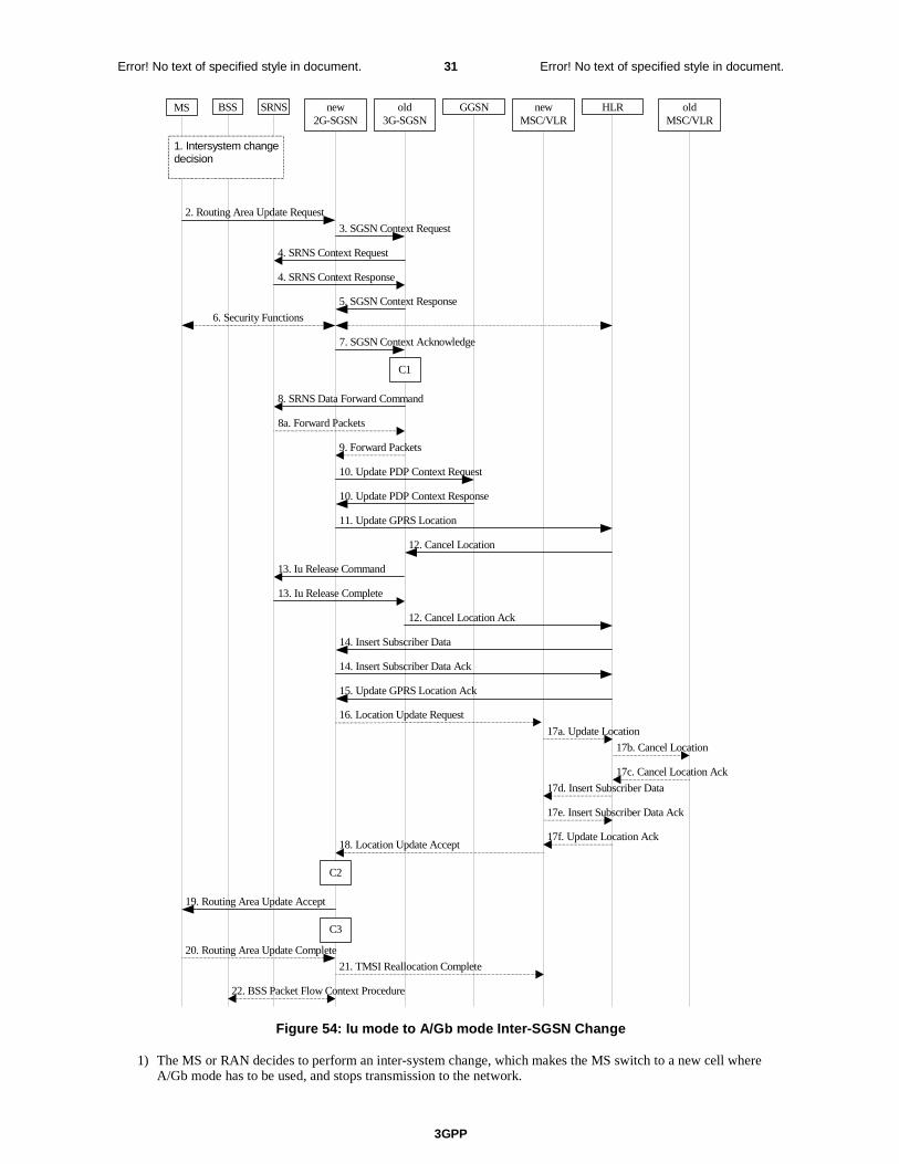
3GPP
Error! No text of specified style in document. 31 Error! No text of specified style in document.
MS new2G-SGSN
HLRGGSNold3G-SGSN
2. Routing Area Update Request
10. Update PDP Context Request
10. Update PDP Context Response
11. Update GPRS Location
15. Update GPRS Location Ack
5. SGSN Context Response
6. Security Functions
19. Routing Area Update Accept
12. Cancel Location
12. Cancel Location Ack
14. Insert Subscriber Data Ack
14. Insert Subscriber Data
7. SGSN Context Acknowledge
BSS SRNS
3. SGSN Context Request
13. Iu Release Command
13. Iu Release Complete
8a. Forward Packets
9. Forward Packets
4. SRNS Context Request
4. SRNS Context Response
8. SRNS Data Forward Command
22. BSS Packet Flow Context Procedure
1. Intersystem changedecision
C3
C1
20. Routing Area Update Complete
newMSC/VLR
oldMSC/VLR
16. Location Update Request
17a. Update Location
17b. Cancel Location
17c. Cancel Location Ack
17d. Insert Subscriber Data
17e. Insert Subscriber Data Ack
17f. Update Location Ack 18. Location Update Accept
21. TMSI Reallocation Complete
C2
Figure 54: Iu mode to A/Gb mode Inter-SGSN Change
1) The MS or RAN decides to perform an inter-system change, which makes the MS switch to a new cell where A/Gb mode has to be used, and stops transmission to the network.

3GPP
Error! No text of specified style in document. 32 Error! No text of specified style in document.
2) The MS sends a Routeing Area Update Request (old RAI, old P-TMSI Signature, Update Type, MS Network Capability) message to the new 2G-SGSN. Update Type shall indicate RA update or combined RA / LA update, or, if the MS wants to perform an IMSI attach, combined RA / LA update with IMSI attach requested. The BSS shall add the Cell Global Identity including the RAC and LAC of the cell where the message was received before passing the message to the new 2G-SGSN.
3) The new 2G-SGSN sends an SGSN Context Request (old RAI, TLLI, old P-TMSI Signature, New SGSN Address) message to the old 3G-SGSN to get the MM and PDP contexts for the MS. If the new SGSN provides functionality for Intra Domain Connection of RAN Nodes to Multiple CN Nodes, the new SGSN may derive the old SGSN from the old RAI and the old P-TMSI (or TLLI) and send the SGSN Context Request message to this old SGSN. Otherwise, the new SGSN derives the old SGSN from the old RAI. In any case the new SGSN will derive an SGSN that it believes is the old SGSN. This derived SGSN is itself the old SGSN, or it is associated with the same pool area as the actual old SGSN and it will determine the correct old SGSN from the P-TMSI (or TLLI) and relay the message to that actual old SGSN. The old 3G-SGSN validates the old P-TMSI Signature and responds with an appropriate error cause if it does not match the value stored in the old 3G-SGSN. If the received old P-TMSI Signature does not match the stored value, the security functions in the new 2G-SGSN should be initiated. If the security functions authenticate the MS correctly, the new 2G-SGSN shall send an SGSN Context Request (old RAI, TLLI, MS Validated, New SGSN Address) message to the old 3G-SGSN. MS Validated indicates that the new 2G-SGSN has authenticated the MS. If the old P-TMSI Signature was valid or if the new 2G-SGSN indicates that it has authenticated the MS correctly, the old 3G-SGSN starts a timer. If the MS is not known in the old 3G-SGSN, the old 3G-SGSN responds with an appropriate error cause.
4) If the MS is PMM-CONNECTED the old 3G-SGSN sends an SRNS Context Request (IMSI) message to the SRNS. Upon receipt of this message the SRNS buffers and stops sending downlink PDUs to the MS and returns an SRNS Context Response (GTP-SNDs, GTP-SNUs, PDCP-SNDs, PDCP-SNUs) message. The SRNS shall include for each PDP context the next in-sequence GTP sequence number to be sent to the MS and the GTP sequence number of the next uplink PDU to be tunnelled to the GGSN. For each active PDP context, which uses lossless PDCP, the SRNS also includes the uplink PDCP sequence number (PDCP-SNU) downlink PDCP sequence number (PDCP-SND). PDCP-SNU shall be the next in-sequence PDCP sequence number expected from the MS. PDCP-SND is the PDCP sequence number for the first downlink packet for which successful transmission has not been confirmed. The 3G-SGSN shall strip off the eight most significant bits of the passed PDCP sequence numbers, thus converting them to SNDCP N-PDU numbers and stores the N-PDU numbers in its PDP contexts..
5) The old 3G-SGSN responds with an SGSN Context Response (MM Context, PDP Contexts) message. For each PDP context the old 3G-SGSN shall include the GTP sequence number for the next uplink GTP PDU to be tunnelled to the GGSN and the next downlink GTP sequence number for the next in-sequence N-PDU to be sent to the MS. Each PDP Context also includes the SNDCP Send N-PDU Number (the value is 0) for the next in-sequence downlink N-PDU to be sent in SNDCP acknowledged mode to the MS and the SNDCP Receive N-PDU Number (= converted PDCP-SNU) for the next in-sequence uplink N-PDU to be received in SNDCP acknowledged mode from the MS. The new 3G-SGSN shall ignore the MS Network Capability contained in MM Context of SGSN Context Response only when it has previously received an MS Network Capability in the Routeing Area Request.
6) Security functions may be executed.
7) The new 2G-SGSN sends an SGSN Context Acknowledge message to the old 3G-SGSN. This informs the old 3G-SGSN that the new 2G-SGSN is ready to receive data packets belonging to the activated PDP contexts. The old SGSN marks in its context that the MSC/VLR association and the information in the GGSNs and the HLR are invalid. This triggers the MSC/VLR, the GGSNs, and the HLR to be updated if the MS initiates a RA update procedure back to the old SGSN before completing the ongoing RA update procedure.
8) If the MS is in the PMM-CONNECTED state, the old 3G-SGSN sends an SRNS Data Forward Command (RAB ID, Transport Layer Address, Iu Transport Association) message to the SRNS. For each indicated RAB the SRNS starts duplicating and tunnelling the buffered GTP PDUs to the old 3G-SGSN. For each radio bearer which uses lossless PDCP the SRNS shall start tunnelling the GTP-PDUs related to transmitted but not yet acknowledged PDCP-PDUs to the old 3G-SGSN together with their related downlink PDCP sequence numbers. Upon receipt of the SRNS Data Forward Command message from the 3G-SGSN, the SRNS shall start the data-forwarding timer.
9) The old 3G-SGSN tunnels the GTP PDUs to the new 2G-SGSN. In the case of GTPv1, the conversion of PDCP sequence numbers to SNDCP sequence numbers (the eight most significant bits shall be stripped off) shall be done in the new SGSN. No N-PDU sequence numbers shall be indicated for these N-PDUs. If GTPv0 is used between the SGSNs, the conversion of PDCP sequence numbers to SNDCP numbers shall be done in the old 3G-SGSN (by stripping off the eight most significant bits).
3GPP
Error! No text of specified style in document. 33 Error! No text of specified style in document.
10) The new 2G-SGSN sends an Update PDP Context Request (new SGSN Address, TEID, QoS Negotiated, serving network identity) message to each GGSN concerned. The SGSN shall send the serving network identity to the GGSN. Each GGSN updates its PDP context fields and returns an Update PDP Context Response (TEID, Prohibit Payload Compression) message. The Prohibit Payload Compression indicates that the SGSN should negotiate no data compression for this PDP context.
11) The new 2G-SGSN informs the HLR of the change of SGSN by sending an Update GPRS Location (SGSN Number, SGSN Address, IMSI) message to the HLR.
12) The HLR sends a Cancel Location (IMSI) message to the old 3G-SGSN. The old 3G-SGSN acknowledges with a Cancel Location Ack (IMSI) message. The old 3G-SGSN removes the MM and PDP contexts if the timer described in step 3 is not running. If the timer is running, the MM and PDP contexts shall be removed when the timer expires.
13) When the MS is PMM-CONNECTED, the old 3G-SGSN sends an Iu Release Command message to the SRNS. When the RNC data-forwarding timer has expired, the SRNS responds with an Iu Release Complete message.
14) The HLR sends an Insert Subscriber Data (IMSI, GPRS Subscription Data) message to the new 2G-SGSN. The 2G-SGSN constructs an MM context and PDP contexts for the MS and returns an Insert Subscriber Data Ack (IMSI) message to the HLR.
15) The HLR acknowledges the Update GPRS Location by returning an Update GPRS Location Ack (IMSI) message to the new 2G-SGSN.
16) If the association has to be established i.e. if Update Type indicates combined RA / LA update with IMSI attach requested, or if the LA changed with the routeing area update, the new 2G-SGSN sends a Location Update Request (new LAI, IMSI, SGSN Number, Location Update Type) to the VLR. Location Update Type shall indicate IMSI attach if Update Type in step 1 indicated combined RA / LA update with IMSI attach requested. Otherwise, Location Update Type shall indicate normal location update. When the SGSN does not provide functionality for the Intra Domain Connection of RAN Nodes to Multiple CN Nodes, the VLR number is derived from the RAI. When the SGSN provides functionality for Intra Domain Connection of RAN Nodes to Multiple CN Nodes, the SGSN uses the RAI and a hash value from the IMSI to determine the VLR number. The 2G-SGSN starts the location update procedure towards the new MSC/VLR upon receipt of the first Insert Subscriber Data message from the HLR in step 14). The VLR creates or updates the association with the 2G-SGSN by storing SGSN Number.
17) If the subscriber data in the VLR is marked as not confirmed by the HLR, the new VLR informs the HLR. The HLR cancels the old VLR and inserts subscriber data in the new VLR:
a) The new VLR sends an Update Location (new VLR) to the HLR.
b) The HLR cancels the data in the old VLR by sending Cancel Location (IMSI) to the old VLR.
c) The old VLR acknowledges with Cancel Location Ack (IMSI).
d) The HLR sends Insert Subscriber Data (IMSI, subscriber data) to the new VLR.
e) The new VLR acknowledges with Insert Subscriber Data Ack (IMSI).
f) The HLR responds with Update Location Ack (IMSI) to the new VLR.
18) The new VLR allocates a new TMSI and responds with Location Update Accept (VLR TMSI) to the 2G-SGSN. VLR TMSI is optional if the VLR has not changed.
19) The new 2G-SGSN validates the MS's presence in the new RA. If due to roaming restrictions the MS is not allowed to be attached in the RA, or if subscription checking fails, the new 2G-SGSN rejects the routeing area update with an appropriate cause. If all checks are successful, the new 2G-SGSN constructs MM and PDP contexts for the MS. A logical link is established between the new 2G-SGSN and the MS. 2G-SGSN initiates the establishment procedure. The new 2G-SGSN responds to the MS with a Routeing Area Update Accept (P-TMSI, P-TMSI Signature, Receive N-PDU Number (= converted PDCP-SNU) message. Receive N-PDU Number contains the acknowledgements for each NSAPI which used lossless PDCP before the start of the update procedure, thereby confirming all mobile-originated N-PDUs successfully transferred before the start of the update procedure. If Receive N-PDU Number confirms the reception of N-PDUs, the MS shall discard these N-PDUs.
20) The MS acknowledges the new P-TMSI by returning a Routeing Area Update Complete (Receive N-PDU Number (= converted PDCP-SND)) message to the SGSN. Receive N-PDU Number contains the
3GPP
Error! No text of specified style in document. 34 Error! No text of specified style in document.
acknowledgements for each lossless PDCP used by the MS before the start of the update procedure, thereby confirming all mobile-terminated N-PDUs successfully transferred before the start of the update procedure. If Receive N-PDU Number confirms the reception of N-PDUs that were forwarded from the old 3G-SGSN, the new 2G-SGSN shall discard these N-PDUs. The MS deducts Receive N-PDU number from PDCP-SND by stripping off the eight most significant bits. PDCP-SND is the PDCP sequence number for the next expected in-sequence downlink packet to be received in the MS per radio bearer, which used lossless PDCP. The new 2G-SGSN negotiates with the MS for each NSAPI the use of acknowledged or unacknowledged SNDCP regardless whether the SRNS used lossless PDCP or not.
21) The new 2G-SGSN sends TMSI Reallocation Complete message to the new VLR if the MS confirms the VLR TMSI.
22) The 2G-SGSN and the BSS may execute the BSS Packet Flow Context procedure.
If the new SGSN is unable to update the PDP context in one or more GGSNs, the new SGSN shall deactivate the corresponding PDP contexts as described in subclause "SGSN-initiated PDP Context Deactivation Procedure". This shall not cause the SGSN to reject the routeing area update.
The PDP Contexts shall be sent from old to new SGSN in a prioritized order, i.e. the most important PDP Context first in the SGSN Context Response message. (The prioritization method is implementation dependent, but should be based on the current activity.)
If the new SGSN is unable to support the same number of active PDP contexts as received from old SGSN, the new SGSN should use the prioritisation sent by old SGSN as input when deciding which PDP contexts to maintain active and which ones to delete. In any case, the new SGSN shall first update all contexts in one or more GGSNs and then deactivate the context(s) that it cannot maintain as described in subclause "SGSN-initiated PDP Context Deactivation Procedure". This shall not cause the SGSN to reject the routeing area update.
The CAMEL procedure calls shall be performed, see referenced procedures in 3GPP TS 23.078:
C1) CAMEL_GPRS_PDP_Context_Disconnection, CAMEL_GPRS_Detach and CAMEL_PS_Notification.
They are called in the following order:
- The CAMEL_GPRS_PDP_Context_Disconnection procedure is called several times: once per PDP context. The procedure returns as result "Continue".
- Then the CAMEL_GPRS_Detach procedure is called once. The procedure returns as result "Continue".
- Then the CAMEL_PS_Notification procedure is called once. The procedure returns as result "Continue".
C2) CAMEL_GPRS_Routeing_Area_Update_Session and CAMEL_PS_Notification.
They are called in the following order:
- The CAMEL_GPRS_Routeing_Area_Update_Session procedure is called. The procedure returns as result "Continue".
- Then the CAMEL_PS_Notification procedure is called. The procedure returns as result "Continue".
C3) CAMEL_GPRS_Routeing_Area_Update_Context.
This procedure is called several times once per PDP context. It returns as result "Continue".
6.13.2.2 A/Gb mode to Iu mode Inter-SGSN Change
The inter-system change from A/Gb mode to Iu mode takes place when a GPRS-attached MS changes from A/Gb mode to UTRAN or GERAN Iu mode and the new RAN node serving the MS is served by a different SGSN. In this case the RA changes. Therefore, the MS shall initiate a Iu mode RA update procedure by establishing an RRC connection and initiating the RA update procedure. The RA update procedure is either combined RA / LA update or only RA update, these RA update cases are illustrated in Figure 55. In the context of this specification, the terms RNS or RNC refer also to a GERAN BSS or BSC (respectively) when serving an MS in Iu mode.
If the network operates in mode I, then an MS, that is both PS-attached and CS-attached, shall perform the Combined RA / LA Update procedures. This concerns only idle mode (see 3GPP TS 23.122), as no combined RA / LA updates are performed during a CS connection.
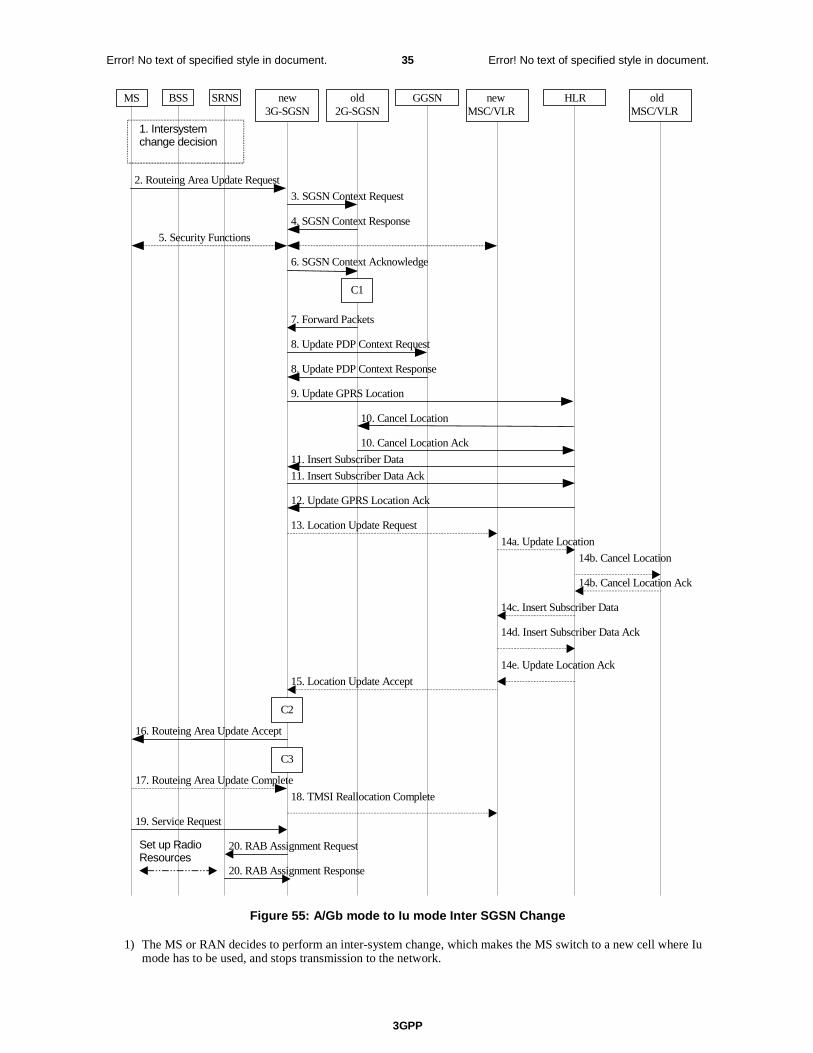
3GPP
Error! No text of specified style in document. 35 Error! No text of specified style in document.
MS new3G-SGSN
HLRGGSNold2G-SGSN
8. Update PDP Context Request
8. Update PDP Context Response
9. Update GPRS Location
12. Update GPRS Location Ack
2. Routeing Area Update Request
4. SGSN Context Response
5. Security Functions
16. Routeing Area Update Accept
10. Cancel Location
10. Cancel Location Ack
11. Insert Subscriber Data Ack
11. Insert Subscriber Data
17. Routeing Area Update Complete
6. SGSN Context Acknowledge
BSS SRNS
3. SGSN Context Request
20. RAB Assignment Request
20. RAB Assignment Response
7. Forward Packets
1. Intersystemchange decision
C3
C1
newMSC/VLR
oldMSC/VLR
13. Location Update Request
14a. Update Location
14b. Cancel Location
14b. Cancel Location Ack
14c. Insert Subscriber Data
14d. Insert Subscriber Data Ack
14e. Update Location Ack
15. Location Update Accept
18. TMSI Reallocation Complete
Set up RadioResources
19. Service Request
C2
Figure 55: A/Gb mode to Iu mode Inter SGSN Change
1) The MS or RAN decides to perform an inter-system change, which makes the MS switch to a new cell where Iu mode has to be used, and stops transmission to the network.
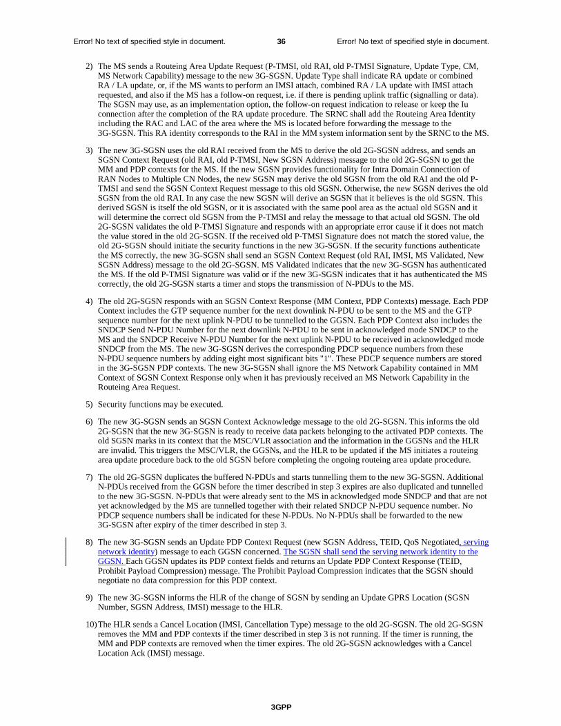
3GPP
Error! No text of specified style in document. 36 Error! No text of specified style in document.
2) The MS sends a Routeing Area Update Request (P-TMSI, old RAI, old P-TMSI Signature, Update Type, CM, MS Network Capability) message to the new 3G-SGSN. Update Type shall indicate RA update or combined RA / LA update, or, if the MS wants to perform an IMSI attach, combined RA / LA update with IMSI attach requested, and also if the MS has a follow-on request, i.e. if there is pending uplink traffic (signalling or data). The SGSN may use, as an implementation option, the follow-on request indication to release or keep the Iu connection after the completion of the RA update procedure. The SRNC shall add the Routeing Area Identity including the RAC and LAC of the area where the MS is located before forwarding the message to the 3G-SGSN. This RA identity corresponds to the RAI in the MM system information sent by the SRNC to the MS.
3) The new 3G-SGSN uses the old RAI received from the MS to derive the old 2G-SGSN address, and sends an SGSN Context Request (old RAI, old P-TMSI, New SGSN Address) message to the old 2G-SGSN to get the MM and PDP contexts for the MS. If the new SGSN provides functionality for Intra Domain Connection of RAN Nodes to Multiple CN Nodes, the new SGSN may derive the old SGSN from the old RAI and the old P-TMSI and send the SGSN Context Request message to this old SGSN. Otherwise, the new SGSN derives the old SGSN from the old RAI. In any case the new SGSN will derive an SGSN that it believes is the old SGSN. This derived SGSN is itself the old SGSN, or it is associated with the same pool area as the actual old SGSN and it will determine the correct old SGSN from the P-TMSI and relay the message to that actual old SGSN. The old 2G-SGSN validates the old P-TMSI Signature and responds with an appropriate error cause if it does not match the value stored in the old 2G-SGSN. If the received old P-TMSI Signature does not match the stored value, the old 2G-SGSN should initiate the security functions in the new 3G-SGSN. If the security functions authenticate the MS correctly, the new 3G-SGSN shall send an SGSN Context Request (old RAI, IMSI, MS Validated, New SGSN Address) message to the old 2G-SGSN. MS Validated indicates that the new 3G-SGSN has authenticated the MS. If the old P-TMSI Signature was valid or if the new 3G-SGSN indicates that it has authenticated the MS correctly, the old 2G-SGSN starts a timer and stops the transmission of N-PDUs to the MS.
4) The old 2G-SGSN responds with an SGSN Context Response (MM Context, PDP Contexts) message. Each PDP Context includes the GTP sequence number for the next downlink N-PDU to be sent to the MS and the GTP sequence number for the next uplink N-PDU to be tunnelled to the GGSN. Each PDP Context also includes the SNDCP Send N-PDU Number for the next downlink N-PDU to be sent in acknowledged mode SNDCP to the MS and the SNDCP Receive N-PDU Number for the next uplink N-PDU to be received in acknowledged mode SNDCP from the MS. The new 3G-SGSN derives the corresponding PDCP sequence numbers from these N-PDU sequence numbers by adding eight most significant bits "1". These PDCP sequence numbers are stored in the 3G-SGSN PDP contexts. The new 3G-SGSN shall ignore the MS Network Capability contained in MM Context of SGSN Context Response only when it has previously received an MS Network Capability in the Routeing Area Request.
5) Security functions may be executed.
6) The new 3G-SGSN sends an SGSN Context Acknowledge message to the old 2G-SGSN. This informs the old 2G-SGSN that the new 3G-SGSN is ready to receive data packets belonging to the activated PDP contexts. The old SGSN marks in its context that the MSC/VLR association and the information in the GGSNs and the HLR are invalid. This triggers the MSC/VLR, the GGSNs, and the HLR to be updated if the MS initiates a routeing area update procedure back to the old SGSN before completing the ongoing routeing area update procedure.
7) The old 2G-SGSN duplicates the buffered N-PDUs and starts tunnelling them to the new 3G-SGSN. Additional N-PDUs received from the GGSN before the timer described in step 3 expires are also duplicated and tunnelled to the new 3G-SGSN. N-PDUs that were already sent to the MS in acknowledged mode SNDCP and that are not yet acknowledged by the MS are tunnelled together with their related SNDCP N-PDU sequence number. No PDCP sequence numbers shall be indicated for these N-PDUs. No N-PDUs shall be forwarded to the new 3G-SGSN after expiry of the timer described in step 3.
8) The new 3G-SGSN sends an Update PDP Context Request (new SGSN Address, TEID, QoS Negotiated, serving network identity) message to each GGSN concerned. The SGSN shall send the serving network identity to the GGSN. Each GGSN updates its PDP context fields and returns an Update PDP Context Response (TEID, Prohibit Payload Compression) message. The Prohibit Payload Compression indicates that the SGSN should negotiate no data compression for this PDP context.
9) The new 3G-SGSN informs the HLR of the change of SGSN by sending an Update GPRS Location (SGSN Number, SGSN Address, IMSI) message to the HLR.
10) The HLR sends a Cancel Location (IMSI, Cancellation Type) message to the old 2G-SGSN. The old 2G-SGSN removes the MM and PDP contexts if the timer described in step 3 is not running. If the timer is running, the MM and PDP contexts are removed when the timer expires. The old 2G-SGSN acknowledges with a Cancel Location Ack (IMSI) message.
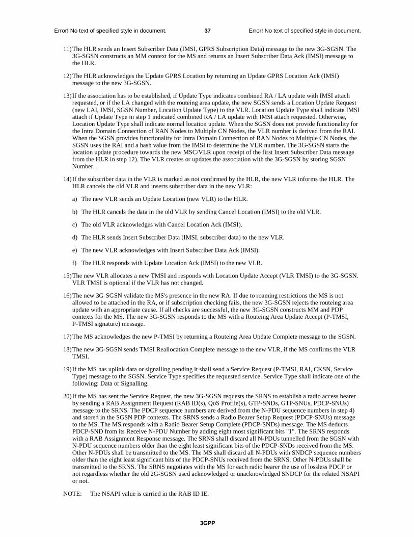
3GPP
Error! No text of specified style in document. 37 Error! No text of specified style in document.
11) The HLR sends an Insert Subscriber Data (IMSI, GPRS Subscription Data) message to the new 3G-SGSN. The 3G-SGSN constructs an MM context for the MS and returns an Insert Subscriber Data Ack (IMSI) message to the HLR.
12) The HLR acknowledges the Update GPRS Location by returning an Update GPRS Location Ack (IMSI) message to the new 3G-SGSN.
13) If the association has to be established, if Update Type indicates combined RA / LA update with IMSI attach requested, or if the LA changed with the routeing area update, the new SGSN sends a Location Update Request (new LAI, IMSI, SGSN Number, Location Update Type) to the VLR. Location Update Type shall indicate IMSI attach if Update Type in step 1 indicated combined RA / LA update with IMSI attach requested. Otherwise, Location Update Type shall indicate normal location update. When the SGSN does not provide functionality for the Intra Domain Connection of RAN Nodes to Multiple CN Nodes, the VLR number is derived from the RAI. When the SGSN provides functionality for Intra Domain Connection of RAN Nodes to Multiple CN Nodes, the SGSN uses the RAI and a hash value from the IMSI to determine the VLR number. The 3G-SGSN starts the location update procedure towards the new MSC/VLR upon receipt of the first Insert Subscriber Data message from the HLR in step 12). The VLR creates or updates the association with the 3G-SGSN by storing SGSN Number.
14) If the subscriber data in the VLR is marked as not confirmed by the HLR, the new VLR informs the HLR. The HLR cancels the old VLR and inserts subscriber data in the new VLR:
a) The new VLR sends an Update Location (new VLR) to the HLR.
b) The HLR cancels the data in the old VLR by sending Cancel Location (IMSI) to the old VLR.
c) The old VLR acknowledges with Cancel Location Ack (IMSI).
d) The HLR sends Insert Subscriber Data (IMSI, subscriber data) to the new VLR.
e) The new VLR acknowledges with Insert Subscriber Data Ack (IMSI).
f) The HLR responds with Update Location Ack (IMSI) to the new VLR.
15) The new VLR allocates a new TMSI and responds with Location Update Accept (VLR TMSI) to the 3G-SGSN. VLR TMSI is optional if the VLR has not changed.
16) The new 3G-SGSN validate the MS's presence in the new RA. If due to roaming restrictions the MS is not allowed to be attached in the RA, or if subscription checking fails, the new 3G-SGSN rejects the routeing area update with an appropriate cause. If all checks are successful, the new 3G-SGSN constructs MM and PDP contexts for the MS. The new 3G-SGSN responds to the MS with a Routeing Area Update Accept (P-TMSI, P-TMSI signature) message.
17) The MS acknowledges the new P-TMSI by returning a Routeing Area Update Complete message to the SGSN.
18) The new 3G-SGSN sends TMSI Reallocation Complete message to the new VLR, if the MS confirms the VLR TMSI.
19) If the MS has uplink data or signalling pending it shall send a Service Request (P-TMSI, RAI, CKSN, Service Type) message to the SGSN. Service Type specifies the requested service. Service Type shall indicate one of the following: Data or Signalling.
20) If the MS has sent the Service Request, the new 3G-SGSN requests the SRNS to establish a radio access bearer by sending a RAB Assignment Request (RAB ID(s), QoS Profile(s), GTP-SNDs, GTP-SNUs, PDCP-SNUs) message to the SRNS. The PDCP sequence numbers are derived from the N-PDU sequence numbers in step 4) and stored in the SGSN PDP contexts. The SRNS sends a Radio Bearer Setup Request (PDCP-SNUs) message to the MS. The MS responds with a Radio Bearer Setup Complete (PDCP-SNDs) message. The MS deducts PDCP-SND from its Receive N-PDU Number by adding eight most significant bits "1". The SRNS responds with a RAB Assignment Response message. The SRNS shall discard all N-PDUs tunnelled from the SGSN with N-PDU sequence numbers older than the eight least significant bits of the PDCP-SNDs received from the MS. Other N-PDUs shall be transmitted to the MS. The MS shall discard all N-PDUs with SNDCP sequence numbers older than the eight least significant bits of the PDCP-SNUs received from the SRNS. Other N-PDUs shall be transmitted to the SRNS. The SRNS negotiates with the MS for each radio bearer the use of lossless PDCP or not regardless whether the old 2G-SGSN used acknowledged or unacknowledged SNDCP for the related NSAPI or not.
NOTE: The NSAPI value is carried in the RAB ID IE.
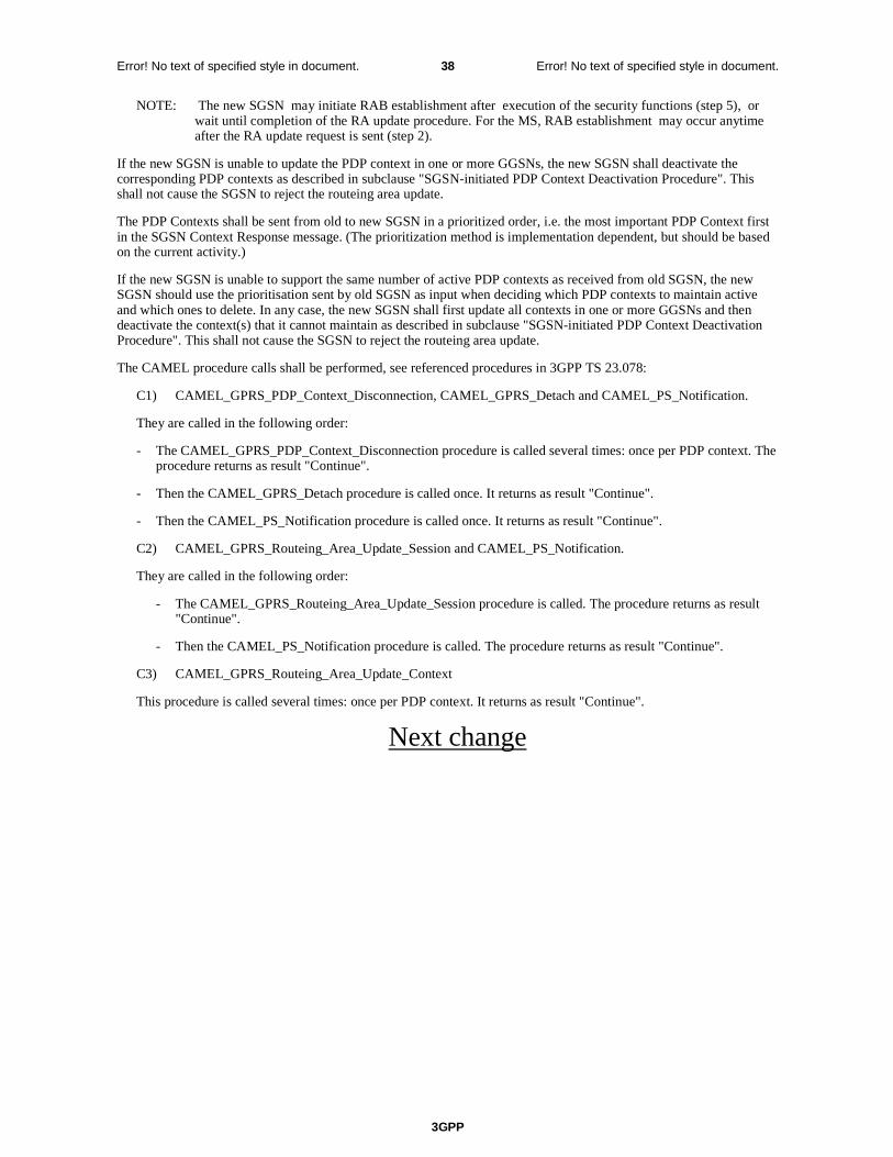
3GPP
Error! No text of specified style in document. 38 Error! No text of specified style in document.
NOTE: The new SGSN may initiate RAB establishment after execution of the security functions (step 5), or wait until completion of the RA update procedure. For the MS, RAB establishment may occur anytime after the RA update request is sent (step 2).
If the new SGSN is unable to update the PDP context in one or more GGSNs, the new SGSN shall deactivate the corresponding PDP contexts as described in subclause "SGSN-initiated PDP Context Deactivation Procedure". This shall not cause the SGSN to reject the routeing area update.
The PDP Contexts shall be sent from old to new SGSN in a prioritized order, i.e. the most important PDP Context first in the SGSN Context Response message. (The prioritization method is implementation dependent, but should be based on the current activity.)
If the new SGSN is unable to support the same number of active PDP contexts as received from old SGSN, the new SGSN should use the prioritisation sent by old SGSN as input when deciding which PDP contexts to maintain active and which ones to delete. In any case, the new SGSN shall first update all contexts in one or more GGSNs and then deactivate the context(s) that it cannot maintain as described in subclause "SGSN-initiated PDP Context Deactivation Procedure". This shall not cause the SGSN to reject the routeing area update.
The CAMEL procedure calls shall be performed, see referenced procedures in 3GPP TS 23.078:
C1) CAMEL_GPRS_PDP_Context_Disconnection, CAMEL_GPRS_Detach and CAMEL_PS_Notification.
They are called in the following order:
- The CAMEL_GPRS_PDP_Context_Disconnection procedure is called several times: once per PDP context. The procedure returns as result "Continue".
- Then the CAMEL_GPRS_Detach procedure is called once. It returns as result "Continue".
- Then the CAMEL_PS_Notification procedure is called once. It returns as result "Continue".
C2) CAMEL_GPRS_Routeing_Area_Update_Session and CAMEL_PS_Notification.
They are called in the following order:
- The CAMEL_GPRS_Routeing_Area_Update_Session procedure is called. The procedure returns as result "Continue".
- Then the CAMEL_PS_Notification procedure is called. The procedure returns as result "Continue".
C3) CAMEL_GPRS_Routeing_Area_Update_Context
This procedure is called several times: once per PDP context. It returns as result "Continue".
Next change
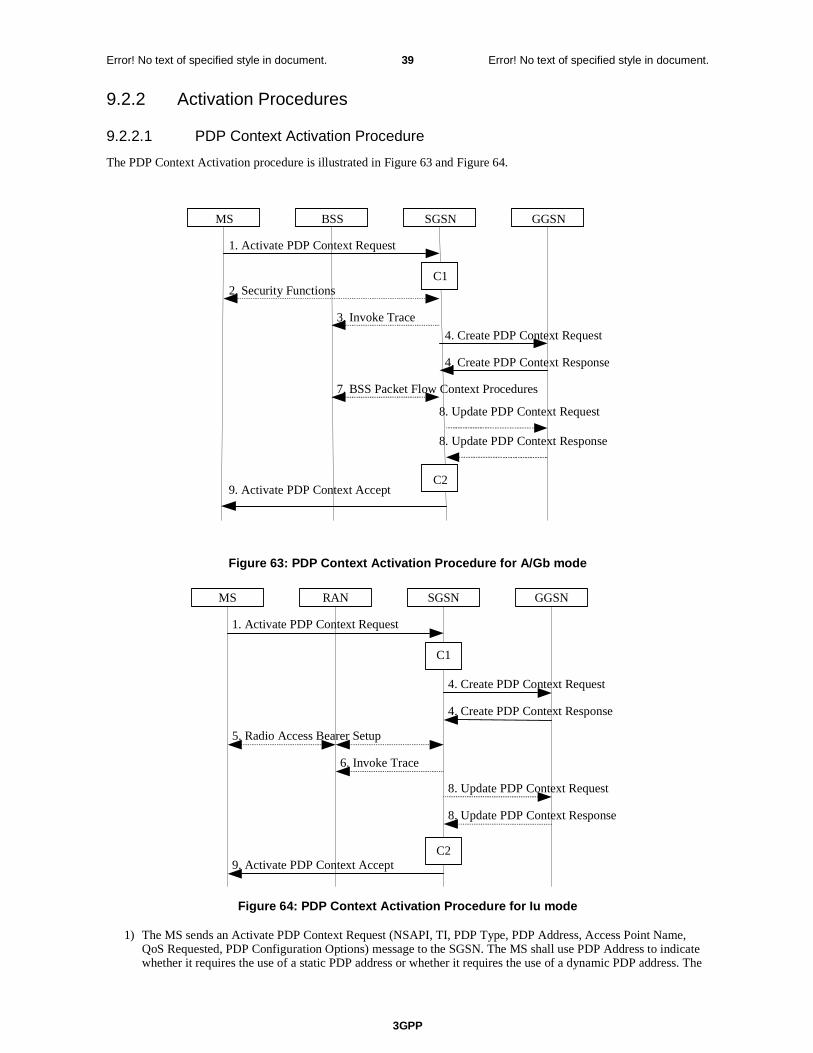
3GPP
Error! No text of specified style in document. 39 Error! No text of specified style in document.
9.2.2 Activation Procedures
9.2.2.1 PDP Context Activation Procedure
The PDP Context Activation procedure is illustrated in Figure 63 and Figure 64.
Figure 63: PDP Context Activation Procedure for A/Gb mode
GGSN
9. Activate PDP Context Accept
4. Create PDP Context Response
4. Create PDP Context Request
1. Activate PDP Context Request
SGSNRANMS
5. Radio Access Bearer Setup
C1
C2
6. Invoke Trace
8. Update PDP Context Response
8. Update PDP Context Request
Figure 64: PDP Context Activation Procedure for Iu mode
1) The MS sends an Activate PDP Context Request (NSAPI, TI, PDP Type, PDP Address, Access Point Name, QoS Requested, PDP Configuration Options) message to the SGSN. The MS shall use PDP Address to indicate whether it requires the use of a static PDP address or whether it requires the use of a dynamic PDP address. The
GGSN
9. Activate PDP Context Accept
4. Create PDP Context Response
4. Create PDP Context Request
1. Activate PDP Context Request
SGSN BSS
2. Security Functions
MS
7. BSS Packet Flow Context Procedures
C1
C2
3. Invoke Trace
8. Update PDP Context Request
8. Update PDP Context Response
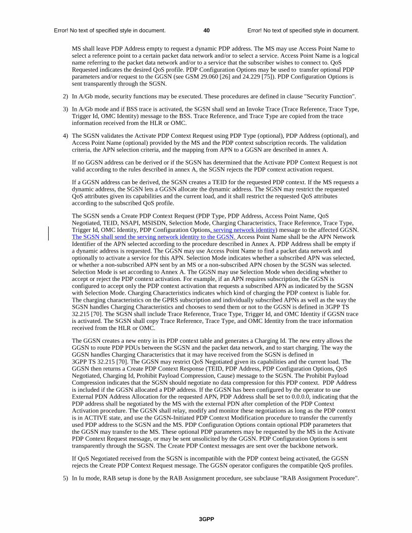
3GPP
Error! No text of specified style in document. 40 Error! No text of specified style in document.
MS shall leave PDP Address empty to request a dynamic PDP address. The MS may use Access Point Name to select a reference point to a certain packet data network and/or to select a service. Access Point Name is a logical name referring to the packet data network and/or to a service that the subscriber wishes to connect to. QoS Requested indicates the desired QoS profile. PDP Configuration Options may be used to transfer optional PDP parameters and/or request to the GGSN (see GSM 29.060 [26] and 24.229 [75]). PDP Configuration Options is sent transparently through the SGSN.
2) In A/Gb mode, security functions may be executed. These procedures are defined in clause "Security Function".
3) In A/Gb mode and if BSS trace is activated, the SGSN shall send an Invoke Trace (Trace Reference, Trace Type, Trigger Id, OMC Identity) message to the BSS. Trace Reference, and Trace Type are copied from the trace information received from the HLR or OMC.
4) The SGSN validates the Activate PDP Context Request using PDP Type (optional), PDP Address (optional), and Access Point Name (optional) provided by the MS and the PDP context subscription records. The validation criteria, the APN selection criteria, and the mapping from APN to a GGSN are described in annex A.
If no GGSN address can be derived or if the SGSN has determined that the Activate PDP Context Request is not valid according to the rules described in annex A, the SGSN rejects the PDP context activation request.
If a GGSN address can be derived, the SGSN creates a TEID for the requested PDP context. If the MS requests a dynamic address, the SGSN lets a GGSN allocate the dynamic address. The SGSN may restrict the requested QoS attributes given its capabilities and the current load, and it shall restrict the requested QoS attributes according to the subscribed QoS profile.
The SGSN sends a Create PDP Context Request (PDP Type, PDP Address, Access Point Name, QoS Negotiated, TEID, NSAPI, MSISDN, Selection Mode, Charging Characteristics, Trace Reference, Trace Type, Trigger Id, OMC Identity, PDP Configuration Options, serving network identity) message to the affected GGSN. The SGSN shall send the serving network identity to the GGSN. Access Point Name shall be the APN Network Identifier of the APN selected according to the procedure described in Annex A. PDP Address shall be empty if a dynamic address is requested. The GGSN may use Access Point Name to find a packet data network and optionally to activate a service for this APN. Selection Mode indicates whether a subscribed APN was selected, or whether a non-subscribed APN sent by an MS or a non-subscribed APN chosen by the SGSN was selected. Selection Mode is set according to Annex A. The GGSN may use Selection Mode when deciding whether to accept or reject the PDP context activation. For example, if an APN requires subscription, the GGSN is configured to accept only the PDP context activation that requests a subscribed APN as indicated by the SGSN with Selection Mode. Charging Characteristics indicates which kind of charging the PDP context is liable for. The charging characteristics on the GPRS subscription and individually subscribed APNs as well as the way the SGSN handles Charging Characteristics and chooses to send them or not to the GGSN is defined in 3GPP TS 32.215 [70]. The SGSN shall include Trace Reference, Trace Type, Trigger Id, and OMC Identity if GGSN trace is activated. The SGSN shall copy Trace Reference, Trace Type, and OMC Identity from the trace information received from the HLR or OMC.
The GGSN creates a new entry in its PDP context table and generates a Charging Id. The new entry allows the GGSN to route PDP PDUs between the SGSN and the packet data network, and to start charging. The way the GGSN handles Charging Characteristics that it may have received from the SGSN is defined in 3GPP TS 32.215 [70]. The GGSN may restrict QoS Negotiated given its capabilities and the current load. The GGSN then returns a Create PDP Context Response (TEID, PDP Address, PDP Configuration Options, QoS Negotiated, Charging Id, Prohibit Payload Compression, Cause) message to the SGSN. The Prohibit Payload Compression indicates that the SGSN should negotiate no data compression for this PDP context. PDP Address is included if the GGSN allocated a PDP address. If the GGSN has been configured by the operator to use External PDN Address Allocation for the requested APN, PDP Address shall be set to 0.0.0.0, indicating that the PDP address shall be negotiated by the MS with the external PDN after completion of the PDP Context Activation procedure. The GGSN shall relay, modify and monitor these negotiations as long as the PDP context is in ACTIVE state, and use the GGSN-Initiated PDP Context Modification procedure to transfer the currently used PDP address to the SGSN and the MS. PDP Configuration Options contain optional PDP parameters that the GGSN may transfer to the MS. These optional PDP parameters may be requested by the MS in the Activate PDP Context Request message, or may be sent unsolicited by the GGSN. PDP Configuration Options is sent transparently through the SGSN. The Create PDP Context messages are sent over the backbone network.
If QoS Negotiated received from the SGSN is incompatible with the PDP context being activated, the GGSN rejects the Create PDP Context Request message. The GGSN operator configures the compatible QoS profiles.
5) In Iu mode, RAB setup is done by the RAB Assignment procedure, see subclause "RAB Assignment Procedure".
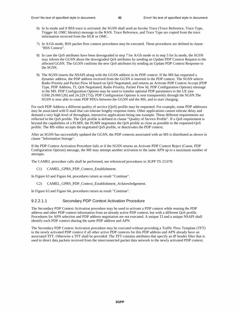
3GPP
Error! No text of specified style in document. 41 Error! No text of specified style in document.
6) In Iu mode and if BSS trace is activated, the SGSN shall send an Invoke Trace (Trace Reference, Trace Type, Trigger Id, OMC Identity) message to the RAN. Trace Reference, and Trace Type are copied from the trace information received from the HLR or OMC.
7) In A/Gb mode, BSS packet flow context procedures may be executed. These procedures are defined in clause "BSS Context".
8) In case the QoS attributes have been downgraded in step 7 for A/Gb mode or in step 5 for Iu mode, the SGSN may inform the GGSN about the downgraded QoS attributes by sending an Update PDP Context Request to the affected GGSN. The GGSN confirms the new QoS attributes by sending an Update PDP Context Response to the SGSN.
9) The SGSN inserts the NSAPI along with the GGSN address in its PDP context. If the MS has requested a dynamic address, the PDP address received from the GGSN is inserted in the PDP context. The SGSN selects Radio Priority and Packet Flow Id based on QoS Negotiated, and returns an Activate PDP Context Accept (PDP Type, PDP Address, TI, QoS Negotiated, Radio Priority, Packet Flow Id, PDP Configuration Options) message to the MS. PDP Configuration Options may be used to transfer optional PDP parameters to the UE (see GSM 29.060 [26] and 24.229 [75]). PDP Configuration Options is sent transparently through the SGSN.The SGSN is now able to route PDP PDUs between the GGSN and the MS, and to start charging.
For each PDP Address a different quality of service (QoS) profile may be requested. For example, some PDP addresses may be associated with E-mail that can tolerate lengthy response times. Other applications cannot tolerate delay and demand a very high level of throughput, interactive applications being one example. These different requirements are reflected in the QoS profile. The QoS profile is defined in clause "Quality of Service Profile". If a QoS requirement is beyond the capabilities of a PLMN, the PLMN negotiates the QoS profile as close as possible to the requested QoS profile. The MS either accepts the negotiated QoS profile, or deactivates the PDP context.
After an SGSN has successfully updated the GGSN, the PDP contexts associated with an MS is distributed as shown in clause "Information Storage".
If the PDP Context Activation Procedure fails or if the SGSN returns an Activate PDP Context Reject (Cause, PDP Configuration Options) message, the MS may attempt another activation to the same APN up to a maximum number of attempts.
The CAMEL procedure calls shall be performed, see referenced procedures in 3GPP TS 23.078:
C1) CAMEL_GPRS_PDP_Context_Establishment.
In Figure 63 and Figure 64, procedures return as result "Continue".
C2) CAMEL_GPRS_PDP_Context_Establishment_Acknowledgement.
In Figure 63 and Figure 64, procedures return as result "Continue".
9.2.2.1.1 Secondary PDP Context Activation Procedure
The Secondary PDP Context Activation procedure may be used to activate a PDP context while reusing the PDP address and other PDP context information from an already active PDP context, but with a different QoS profile. Procedures for APN selection and PDP address negotiation are not executed. A unique TI and a unique NSAPI shall identify each PDP context sharing the same PDP address and APN.
The Secondary PDP Context Activation procedure may be executed without providing a Traffic Flow Template (TFT) to the newly activated PDP context if all other active PDP contexts for this PDP address and APN already have an associated TFT. Otherwise a TFT shall be provided. The TFT contains attributes that specify an IP header filter that is used to direct data packets received from the interconnected packet data network to the newly activated PDP context.

3GPP
Error! No text of specified style in document. 42 Error! No text of specified style in document.
The Secondary PDP Context Activation procedure may only be initiated after a PDP context is already activated for the same PDP address and APN. The procedure is illustrated in Figure 65 and Figure 66.
Figure 65: Secondary PDP Context Activation Procedure for A/Gb mode
GGSN
7. Activate Secondary PDP Context Accept
3 . Create PDP Context Response
3 . Create PDP Context Request
1. Activate Secondary PDP Context Request
SGSN RAN MS
4 . Radio Access Bea rer Setup
C1
C2
6. Update PDP Context Response
6. Update PDP Context Request
Figure 66: Secondary PDP Context Activation Procedure for Iu mode
1) The MS sends an Activate Secondary PDP Context Request (Linked TI, NSAPI, TI, QoS Requested, TFT, PDP Configuration Options) message to the SGSN. Linked TI indicates the TI value assigned to any one of the already activated PDP contexts for this PDP address and APN. QoS Requested indicates the desired QoS profile. TFT is sent transparently through the SGSN to the GGSN to enable packet classification for downlink data transfer. TI and NSAPI contain values not used by any other activated PDP context. PDP Configuration Options may be used to transfer optional PDP parameters and/or requests to the GGSN (see GSM 29.060 [26] and 24.229 [75]). PDP Configuration Options is sent transparently through the SGSN.
2) In A/Gb mode, security functions may be executed. These procedures are defined in clause "Security Function".
GGSN
7. Activate Secondary PDP Context Accept
3. Create PDP Context Response
3. Create PDP Context Request
1. Activate Secondary PDP Context Request
SGSNBSS
2. Security Functions
MS
5. BSS Packet Flow Context Procedures
C1
C2
6. Update PDP Context Request
6. Update PDP Context Response

3GPP
Error! No text of specified style in document. 43 Error! No text of specified style in document.
3) The SGSN validates the Activate Secondary PDP Context Request using the TI indicated by Linked TI. The same GGSN address is used by the SGSN as for the already-activated PDP context(s) for that TI and PDP address.
The SGSN may restrict the requested QoS attributes given its capabilities and the current load, and it shall restrict the requested QoS attributes according to the subscribed QoS profile, which represents the maximum QoS per PDP context to the associated APN. The GGSN may restrict and negotiate the requested QoS as specified in clause "PDP Context Activation Procedure". The SGSN sends a Create PDP Context Request (QoS Negotiated, TEID, NSAPI, Primary NSAPI, TFT, PDP Configuration Options, serving network identity) message to the affected GGSN. The SGSN shall send the serving network identity to the GGSN. Primary NSAPI indicates the NSAPI value assigned to any one of the already activated PDP contexts for this PDP address and APN. TFT is included only if received in the Activate Secondary PDP Context Request message. PDP Configuration Options is sent transparently through the SGSN if received in the Activate secondary PDP Context Request message.
The GGSN uses the same packet data network as used by the already-activated PDP context(s) for that PDP address, generates a new entry in its PDP context table, and stores the TFT. The new entry allows the GGSN to route PDP PDUs via different GTP tunnels between the SGSN and the packet data network. The GGSN returns a Create PDP Context Response (TEID, QoS Negotiated, Cause, PDP Configuration Options, Prohibit Payload Compression) message to the SGSN. PDP Configuration Options may be used to transfer optional PDP parameters to the UE (see GSM 29.060 [26] and 24.229 [75]). The Prohibit Payload Compression indicates that the SGSN should negotiate no data compression for this PDP context.
4) In Iu mode, RAB setup is done by the RAB Assignment procedure.
5) In A/Gb mode, BSS packet flow context procedures may be executed. These procedures are defined in clause "BSS Context".
6) In case the QoS attributes have been downgraded in step 5 for A/Gb mode or in step 4 for Iu mode, the SGSN may inform the GGSN about the downgraded QoS attributes by sending an Update PDP Context Request to the affected GGSN. The GGSN confirms the new QoS attributes by sending an Update PDP Context Response to the SGSN.
7) The SGSN selects Radio Priority and Packet Flow Id based on QoS Negotiated, and returns an Activate Secondary PDP Context Accept (TI, QoS Negotiated, Radio Priority, Packet Flow Id, PDP Configuration Options) message to the MS. PDP Configuration Options is sent transparently through the SGSN if received in the Create PDP Context Response message. The SGSN is now able to route PDP PDUs between the GGSN and the MS via different GTP tunnels and possibly different LLC links.
For each additionally activated PDP context a QoS profile and TFT may be requested.
If the secondary PDP context activation procedure fails or if the SGSN returns an Activate Secondary PDP Context Reject (Cause, PDP Configuration Options) message, the MS may attempt another activation with a different TFT, depending on the cause.
The CAMEL procedure calls shall be performed, see referenced procedures in 3GPP TS 23.078:
C1) CAMEL_GPRS_PDP_Context_Establishment.
In Figure 65 and in Figure 66, procedures return as result "Continue".
C2) CAMEL_GPRS_PDP_Context_Establishment_Acknowledgement.
In Figure 65 and in Figure 66, procedures return as result "Continue".
Next change
9.2.3 Modification Procedures
Modification procedures modify parameters that were negotiated during an activation procedure for one or several PDP contexts. An MS, a GGSN, an SGSN, or an RNC can request a modification procedure. The Modification procedures
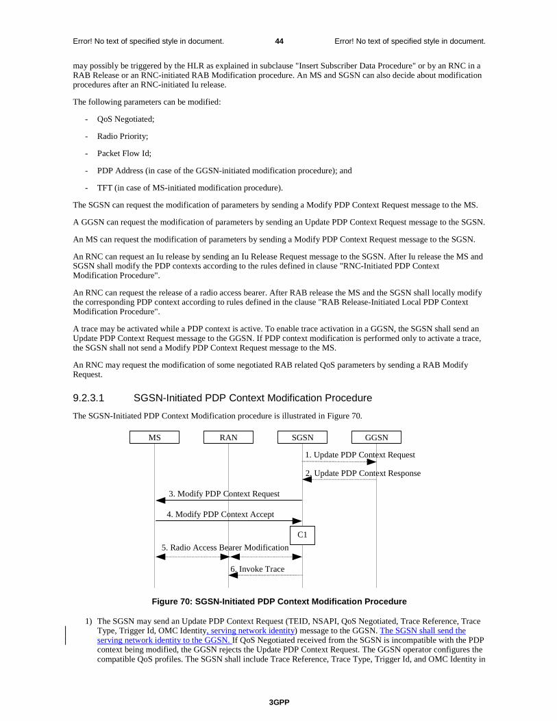
3GPP
Error! No text of specified style in document. 44 Error! No text of specified style in document.
may possibly be triggered by the HLR as explained in subclause "Insert Subscriber Data Procedure" or by an RNC in a RAB Release or an RNC-initiated RAB Modification procedure. An MS and SGSN can also decide about modification procedures after an RNC-initiated Iu release.
The following parameters can be modified:
- QoS Negotiated;
- Radio Priority;
- Packet Flow Id;
- PDP Address (in case of the GGSN-initiated modification procedure); and
- TFT (in case of MS-initiated modification procedure).
The SGSN can request the modification of parameters by sending a Modify PDP Context Request message to the MS.
A GGSN can request the modification of parameters by sending an Update PDP Context Request message to the SGSN.
An MS can request the modification of parameters by sending a Modify PDP Context Request message to the SGSN.
An RNC can request an Iu release by sending an Iu Release Request message to the SGSN. After Iu release the MS and SGSN shall modify the PDP contexts according to the rules defined in clause "RNC-Initiated PDP Context Modification Procedure".
An RNC can request the release of a radio access bearer. After RAB release the MS and the SGSN shall locally modify the corresponding PDP context according to rules defined in the clause "RAB Release-Initiated Local PDP Context Modification Procedure".
A trace may be activated while a PDP context is active. To enable trace activation in a GGSN, the SGSN shall send an Update PDP Context Request message to the GGSN. If PDP context modification is performed only to activate a trace, the SGSN shall not send a Modify PDP Context Request message to the MS.
An RNC may request the modification of some negotiated RAB related QoS parameters by sending a RAB Modify Request.
9.2.3.1 SGSN-Initiated PDP Context Modification Procedure
The SGSN-Initiated PDP Context Modification procedure is illustrated in Figure 70.
GGSN
2. Update PDP Context Response
1. Update PDP Context Request
SGSNRANMS
3. Modify PDP Context Request
4. Modify PDP Context Accept
5. Radio Access Bearer Modification
C1
6. Invoke Trace
Figure 70: SGSN-Initiated PDP Context Modification Procedure
1) The SGSN may send an Update PDP Context Request (TEID, NSAPI, QoS Negotiated, Trace Reference, Trace Type, Trigger Id, OMC Identity, serving network identity) message to the GGSN. The SGSN shall send the serving network identity to the GGSN. If QoS Negotiated received from the SGSN is incompatible with the PDP context being modified, the GGSN rejects the Update PDP Context Request. The GGSN operator configures the compatible QoS profiles. The SGSN shall include Trace Reference, Trace Type, Trigger Id, and OMC Identity in

3GPP
Error! No text of specified style in document. 45 Error! No text of specified style in document.
the message if GGSN trace is activated while the PDP context is active. The SGSN shall copy Trace Reference, Trace Type, and OMC Identity from the trace information received from the HLR or OMC.
2) The GGSN may restrict QoS Negotiated given its capabilities and the current load. The GGSN stores QoS Negotiated and returns an Update PDP Context Response (TEID, QoS Negotiated, Prohibit Payload Compression, Cause) message. The Prohibit Payload Compression indicates that the SGSN should negotiate no data compression for this PDP context.
3) The SGSN selects Radio Priority and Packet Flow Id based on QoS Negotiated, and may send a Modify PDP Context Request (TI, QoS Negotiated, Radio Priority, Packet Flow Id) message to the MS.
4) The MS acknowledges by returning a Modify PDP Context Accept message. If the MS does not accept the new QoS Negotiated it shall instead de-activate the PDP context with the PDP Context Deactivation Initiated by the MS procedure.
5) In Iu mode, radio access bearer modification may be performed by the RAB Assignment procedure.
6) If BSS trace is activated while the PDP context is active, the SGSN shall send an Invoke Trace (Trace Reference, Trace Type, Trigger Id, OMC Identity) message to the RAN. Trace Reference, and Trace Type are copied from the trace information received from the HLR or OMC.
The CAMEL procedure calls shall be performed, see referenced procedure in 3GPP TS 23.078:
C1) CAMEL_GPRS_Change_Of_QoS.
The procedure returns as result "Continue".
Next change
9.2.3.3 MS-Initiated PDP Context Modification Procedure
The MS-Initiated PDP Context Modification procedure is illustrated in Figure 72.
GGSN
3. Update PDP Context Response
2. Update PDP Context Request
SGSNRANMS
1. Modify PDP Context Request
5. Modify PDP Context Accept
4. Radio Access Bearer Modification
C1
Figure 72: MS-Initiated PDP Context Modification Procedure
1) The MS sends a Modify PDP Context Request (TI, QoS Requested, TFT, PDP Configuration Options) message to the SGSN. Either QoS Requested or TFT or both may be included. QoS Requested indicates the desired QoS profile, while TFT indicates the TFT that is to be added or modified or deleted from the PDP context. PDP Configuration Options may be used to transfer optional PDP parameters and/or requests to the GGSN.
2) The SGSN may restrict the desired QoS profile given its capabilities, the current load, and the subscribed QoS profile. The SGSN sends an Update PDP Context Request (TEID, NSAPI, QoS Negotiated, TFT, PDP Configuration Options, serving network identity) message to the GGSN. The SGSN shall send the serving network identity to the GGSN. If QoS Negotiated and/or TFT received from the SGSN is incompatible with the PDP context being modified (e.g., TFT contains inconsistent packet filters), the GGSN rejects the Update PDP Context Request. The GGSN operator configures the compatible QoS profile. PDP Configuration Options is sent transparently through the SGSN if received in Modify PDP Context Request message.
3GPP
Error! No text of specified style in document. 46 Error! No text of specified style in document.
3) The GGSN may further restrict QoS Negotiated given its capabilities, operator policies and the current load. The GGSN stores QoS Negotiated, stores, modifies, or deletes TFT of that PDP context as indicated in TFT, and returns an Update PDP Context Response (TEID, QoS Negotiated, PDP Configuration Options, Prohibit Payload Compression) message. PDP Configuration Options may be used to transfer optional PDP parameters to the UE. The Prohibit Payload Compression indicates that the SGSN should negotiate no data compression for this PDP context.
4) In Iu mode, radio access bearer modification may be performed by the RAB Assignment procedure. In case the radio access bearer does not exist the RAB setup is done by the RAB Assignement procedure.
5) The SGSN selects Radio Priority and Packet Flow Id based on QoS Negotiated, and returns a Modify PDP Context Accept (TI, QoS Negotiated, Radio Priority, Packet Flow Id, PDP Configuration Options) message to the MS. PDP Configuration Options is sent transparently through the SGSN if received in Modify PDP Context Response message.
NOTE1: If the SGSN does not accept QoS Requested, then steps 2 and 3 of this procedure are skipped, and the existing QoS Negotiated is returned to the MS in step 4.
NOTE2: In this release of the standards no procedure is defined that uses the Protocol Configuration Options in the PDP context modification procedure.
The CAMEL procedure calls shall be performed, see referenced procedure in 3GPP TS 23.078:
C1) CAMEL_GPRS_Change_Of_QoS.
The procedure returns as result "Continue".
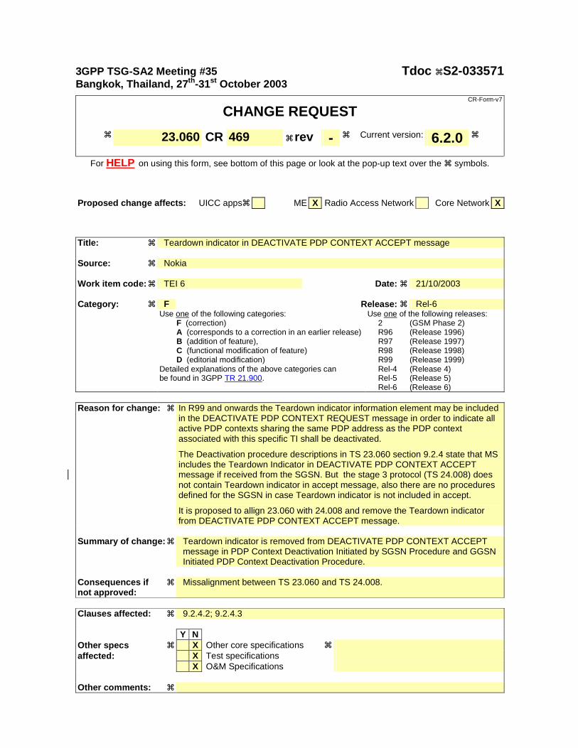
3GPP TSG-SA2 Meeting #35 Tdoc !S2-033571 Bangkok, Thailand, 27th-31st October 2003
CR-Form-v7
CHANGE REQUEST
! 23.060 CR 469 ! rev - ! Current version: 6.2.0 !
For HELP on using this form, see bottom of this page or look at the pop-up text over the ! symbols.
Proposed change affects: UICC apps! ME X Radio Access Network Core Network X
Title: ! Teardown indicator in DEACTIVATE PDP CONTEXT ACCEPT message Source: ! Nokia Work item code: ! TEI 6 Date: ! 21/10/2003 Category: ! F Release: ! Rel-6 Use one of the following categories:
F (correction) A (corresponds to a correction in an earlier release) B (addition of feature), C (functional modification of feature) D (editorial modification)
Detailed explanations of the above categories can be found in 3GPP TR 21.900.
Use one of the following releases: 2 (GSM Phase 2) R96 (Release 1996) R97 (Release 1997) R98 (Release 1998) R99 (Release 1999) Rel-4 (Release 4) Rel-5 (Release 5) Rel-6 (Release 6)
Reason for change: ! In R99 and onwards the Teardown indicator information element may be included
in the DEACTIVATE PDP CONTEXT REQUEST message in order to indicate all active PDP contexts sharing the same PDP address as the PDP context associated with this specific TI shall be deactivated.
The Deactivation procedure descriptions in TS 23.060 section 9.2.4 state that MS includes the Teardown Indicator in DEACTIVATE PDP CONTEXT ACCEPT message if received from the SGSN. But the stage 3 protocol (TS 24.008) does not contain Teardown indicator in accept message, also there are no procedures defined for the SGSN in case Teardown indicator is not included in accept.
It is proposed to allign 23.060 with 24.008 and remove the Teardown indicator from DEACTIVATE PDP CONTEXT ACCEPT message.
Summary of change: ! Teardown indicator is removed from DEACTIVATE PDP CONTEXT ACCEPT
message in PDP Context Deactivation Initiated by SGSN Procedure and GGSN Initiated PDP Context Deactivation Procedure.
Consequences if ! not approved:
Missalignment between TS 23.060 and TS 24.008.
Clauses affected: ! 9.2.4.2; 9.2.4.3 Y N Other specs ! X Other core specifications ! affected: X Test specifications X O&M Specifications Other comments: !
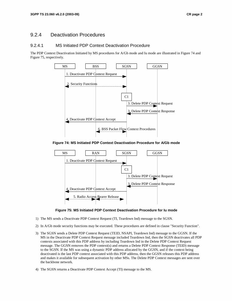
3GPP TS 23.060 v6.2.0 (2003-09) CR page 2
9.2.4 Deactivation Procedures
9.2.4.1 MS Initiated PDP Context Deactivation Procedure
The PDP Context Deactivation Initiated by MS procedures for A/Gb mode and Iu mode are illustrated in Figure 74 and Figure 75, respectively.
GGSN
3. Delete PDP Context Response
3. Delete PDP Context Request
SGSN BSS MS
1. Deactivate PDP Context Request
4. Deactivate PDP Context Accept
C1
6. BSS Packet Flow Context Procedures
2. Security Functions
Figure 74: MS Initiated PDP Context Deactivation Procedure for A/Gb mode
GGSN
3. Delete PDP Context Response
3. Delete PDP Context Request
SGSNRANMS
1. Deactivate PDP Context Request
4. Deactivate PDP Context Accept
5. Radio Access Bearer Release
C1
Figure 75: MS Initiated PDP Context Deactivation Procedure for Iu mode
1) The MS sends a Deactivate PDP Context Request (TI, Teardown Ind) message to the SGSN.
2) In A/Gb mode security functions may be executed. These procedures are defined in clause "Security Function".
3) The SGSN sends a Delete PDP Context Request (TEID, NSAPI, Teardown Ind) message to the GGSN. If the MS in the Deactivate PDP Context Request message included Teardown Ind, then the SGSN deactivates all PDP contexts associated with this PDP address by including Teardown Ind in the Delete PDP Context Request message. The GGSN removes the PDP context(s) and returns a Delete PDP Context Response (TEID) message to the SGSN. If the MS was using a dynamic PDP address allocated by the GGSN, and if the context being deactivated is the last PDP context associated with this PDP address, then the GGSN releases this PDP address and makes it available for subsequent activation by other MSs. The Delete PDP Context messages are sent over the backbone network.
4) The SGSN returns a Deactivate PDP Context Accept (TI) message to the MS.
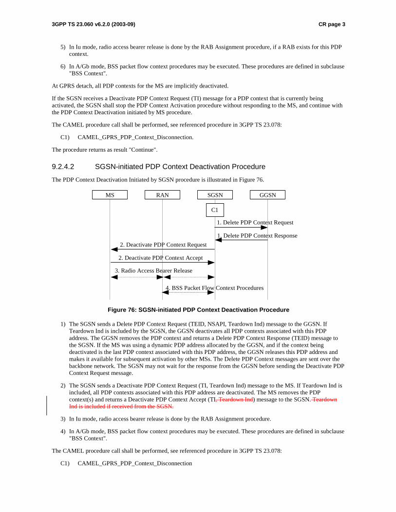
3GPP TS 23.060 v6.2.0 (2003-09) CR page 3
5) In Iu mode, radio access bearer release is done by the RAB Assignment procedure, if a RAB exists for this PDP context.
6) In A/Gb mode, BSS packet flow context procedures may be executed. These procedures are defined in subclause "BSS Context".
At GPRS detach, all PDP contexts for the MS are implicitly deactivated.
If the SGSN receives a Deactivate PDP Context Request (TI) message for a PDP context that is currently being activated, the SGSN shall stop the PDP Context Activation procedure without responding to the MS, and continue with the PDP Context Deactivation initiated by MS procedure.
The CAMEL procedure call shall be performed, see referenced procedure in 3GPP TS 23.078:
C1) CAMEL_GPRS_PDP_Context_Disconnection.
The procedure returns as result "Continue".
9.2.4.2 SGSN-initiated PDP Context Deactivation Procedure
The PDP Context Deactivation Initiated by SGSN procedure is illustrated in Figure 76.
GGSN
1. Delete PDP Context Response
1. Delete PDP Context Request
SGSN RAN MS
2. Deactivate PDP Context Request
2. Deactivate PDP Context Accept
3. Radio Access Bearer Release
C1
4. BSS Packet Flow Context Procedures
Figure 76: SGSN-initiated PDP Context Deactivation Procedure
1) The SGSN sends a Delete PDP Context Request (TEID, NSAPI, Teardown Ind) message to the GGSN. If Teardown Ind is included by the SGSN, the GGSN deactivates all PDP contexts associated with this PDP address. The GGSN removes the PDP context and returns a Delete PDP Context Response (TEID) message to the SGSN. If the MS was using a dynamic PDP address allocated by the GGSN, and if the context being deactivated is the last PDP context associated with this PDP address, the GGSN releases this PDP address and makes it available for subsequent activation by other MSs. The Delete PDP Context messages are sent over the backbone network. The SGSN may not wait for the response from the GGSN before sending the Deactivate PDP Context Request message.
2) The SGSN sends a Deactivate PDP Context Request (TI, Teardown Ind) message to the MS. If Teardown Ind is included, all PDP contexts associated with this PDP address are deactivated. The MS removes the PDP context(s) and returns a Deactivate PDP Context Accept (TI, Teardown Ind) message to the SGSN. Teardown Ind is included if received from the SGSN.
3) In Iu mode, radio access bearer release is done by the RAB Assignment procedure.
4) In A/Gb mode, BSS packet flow context procedures may be executed. These procedures are defined in subclause "BSS Context".
The CAMEL procedure call shall be performed, see referenced procedure in 3GPP TS 23.078:
C1) CAMEL_GPRS_PDP_Context_Disconnection

3GPP TS 23.060 v6.2.0 (2003-09) CR page 4
The procedure returns as result "Continue".
9.2.4.3 GGSN-initiated PDP Context Deactivation Procedure
The PDP Context Deactivation Initiated by GGSN procedure is illustrated in Figure 77.
GGSN
3. Delete PDP Context Response
1. Delete PDP Context Request
SGSN RAN MS
2. Deactivate PDP Context Request
2. Deactivate PDP Context Accept
4. Radio Access Bearer Release
C1
5. BSS Packet Flow Context Procedures
Figure 77: GGSN-initiated PDP Context Deactivation Procedure
1) The GGSN sends a Delete PDP Context Request (TEID, NSAPI, Teardown Ind) message to the SGSN. Teardown Ind indicates whether or not all PDP contexts associated with this PDP address shall be deactivated.
2) The SGSN sends a Deactivate PDP Context Request (TI, Teardown Ind) message to the MS. If Teardown Ind was included by the SGSN, then all PDP contexts associated with this PDP address are deactivated. The MS removes the PDP context(s) and returns a Deactivate PDP Context Accept (TI, Teardown Ind) message to the SGSN. Teardown Ind is included if received from the SGSN.
3) The SGSN returns a Delete PDP Context Response (TEID) message to the GGSN. If the MS was using a dynamic PDP address allocated by the GGSN, and if the context being deactivated is the last PDP context associated with this PDP address, the GGSN releases this PDP address and makes it available for subsequent activation by other MSs. The Delete PDP Context messages are sent over the backbone network. The SGSN may not wait for the response from the MS before sending the Delete PDP Context Response message.
4) In Iu mode, radio access bearer release is done by the RAB Assignment procedure.
5) In A/Gb mode, BSS packet flow context procedures may be executed. These procedures are defined in subclause "BSS Context".
The CAMEL procedure call shall be performed, see referenced procedure in 3GPP TS 23.078:
C1) CAMEL_GPRS_PDP_Context_Disconnection.
The procedure returns as result "Continue".
CR page 1
3GPP TSG- SA WG2#35 Tdoc !S2-033726 Bangkok, Thailand. October 27-31, 2003
CR-Form-v7
CHANGE REQUEST
! 23.060 CR 480 ! rev - ! Current version: 6.2.0 !
For HELP on using this form, see bottom of this page or look at the pop-up text over the ! symbols.
Proposed change affects: UICC apps! ME X Radio Access Network X Core Network
Title: ! BSS paging co-ordination for A/Gb mode Source: ! Motorola Work item code: ! TEI6 Date: ! 28/08/2003 Category: ! F Release: ! Rel-6 Use one of the following categories:
F (correction) A (corresponds to a correction in an earlier release) B (addition of feature), C (functional modification of feature) D (editorial modification)
Detailed explanations of the above categories can be found in 3GPP TR 21.900.
Use one of the following releases: 2 (GSM Phase 2) R96 (Release 1996) R97 (Release 1997) R98 (Release 1998) R99 (Release 1999) Rel-4 (Release 4) Rel-5 (Release 5) Rel-6 (Release 6)
Reason for change: ! The possibility to do paging co-ordination on BSS level exists in TS 44.060 and
in TS 44.018 since R99, but this possibility is not mentioned in TS 23.060. Summary of change: ! Description of BSS paging co-ordination is added. Consequences if ! not approved:
The possibility with paging co-ordination on BSS level might be overlooked, resulting in non-optimal MS implementations regarding the possibilty to monitor pagings from both CS and PS domains simultaneously.
Clauses affected: ! 6.3.3.1, 8.1.6 (new) Y N Other specs ! X Other core specifications ! Affected: X Test specifications X O&M Specifications Other comments: ! How to create CRs using this form: Comprehensive information and tips about how to create CRs can be found at http://www.3gpp.org/specs/CR.htm. Below is a brief summary:
1) Fill out the above form. The symbols above marked ! contain pop-up help information about the field that they are closest to.
2) Obtain the latest version for the release of the specification to which the change is proposed. Use the MS Word "revision marks" feature (also known as "track changes") when making the changes. All 3GPP specifications can be downloaded from the 3GPP server under ftp://ftp.3gpp.org/specs/ For the latest version, look for the directory name with the latest date e.g. 2001-03 contains the specifications resulting from the March 2001 TSG meetings.

CR page 2
3) With "track changes" disabled, paste the entire CR form (use CTRL-A to select it) into the specification just in front of the clause containing the first piece of changed text. Delete those parts of the specification which are not relevant to the change request.
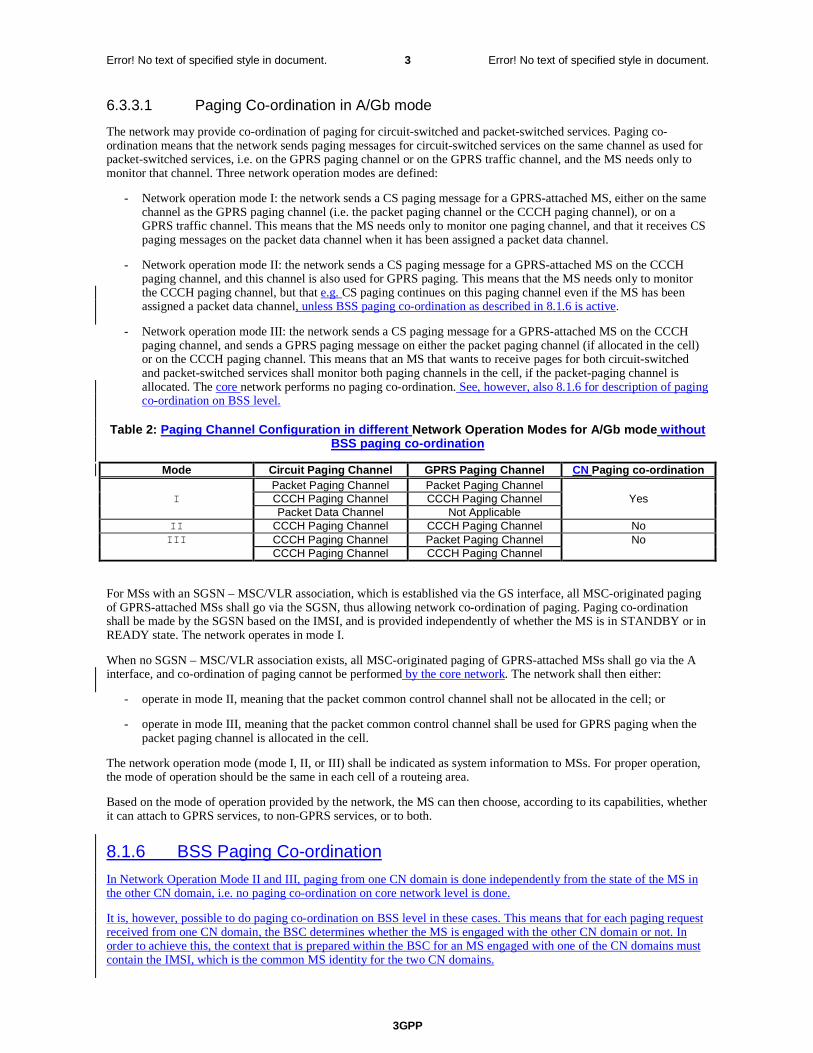
3GPP
Error! No text of specified style in document. 3 Error! No text of specified style in document.
6.3.3.1 Paging Co-ordination in A/Gb mode
The network may provide co-ordination of paging for circuit-switched and packet-switched services. Paging co-ordination means that the network sends paging messages for circuit-switched services on the same channel as used for packet-switched services, i.e. on the GPRS paging channel or on the GPRS traffic channel, and the MS needs only to monitor that channel. Three network operation modes are defined:
- Network operation mode I: the network sends a CS paging message for a GPRS-attached MS, either on the same channel as the GPRS paging channel (i.e. the packet paging channel or the CCCH paging channel), or on a GPRS traffic channel. This means that the MS needs only to monitor one paging channel, and that it receives CS paging messages on the packet data channel when it has been assigned a packet data channel.
- Network operation mode II: the network sends a CS paging message for a GPRS-attached MS on the CCCH paging channel, and this channel is also used for GPRS paging. This means that the MS needs only to monitor the CCCH paging channel, but that e.g. CS paging continues on this paging channel even if the MS has been assigned a packet data channel, unless BSS paging co-ordination as described in 8.1.6 is active.
- Network operation mode III: the network sends a CS paging message for a GPRS-attached MS on the CCCH paging channel, and sends a GPRS paging message on either the packet paging channel (if allocated in the cell) or on the CCCH paging channel. This means that an MS that wants to receive pages for both circuit-switched and packet-switched services shall monitor both paging channels in the cell, if the packet-paging channel is allocated. The core network performs no paging co-ordination. See, however, also 8.1.6 for description of paging co-ordination on BSS level.
Table 2: Paging Channel Configuration in different Network Operation Modes for A/Gb mode without BSS paging co-ordination
Mode Circuit Paging Channel GPRS Paging Channel CN Paging co-ordination Packet Paging Channel Packet Paging Channel I CCCH Paging Channel CCCH Paging Channel Yes Packet Data Channel Not Applicable
II CCCH Paging Channel CCCH Paging Channel No III CCCH Paging Channel Packet Paging Channel No
CCCH Paging Channel CCCH Paging Channel
For MSs with an SGSN – MSC/VLR association, which is established via the GS interface, all MSC-originated paging of GPRS-attached MSs shall go via the SGSN, thus allowing network co-ordination of paging. Paging co-ordination shall be made by the SGSN based on the IMSI, and is provided independently of whether the MS is in STANDBY or in READY state. The network operates in mode I.
When no SGSN – MSC/VLR association exists, all MSC-originated paging of GPRS-attached MSs shall go via the A interface, and co-ordination of paging cannot be performed by the core network. The network shall then either:
- operate in mode II, meaning that the packet common control channel shall not be allocated in the cell; or
- operate in mode III, meaning that the packet common control channel shall be used for GPRS paging when the packet paging channel is allocated in the cell.
The network operation mode (mode I, II, or III) shall be indicated as system information to MSs. For proper operation, the mode of operation should be the same in each cell of a routeing area.
Based on the mode of operation provided by the network, the MS can then choose, according to its capabilities, whether it can attach to GPRS services, to non-GPRS services, or to both.
8.1.6 BSS Paging Co-ordination
In Network Operation Mode II and III, paging from one CN domain is done independently from the state of the MS in the other CN domain, i.e. no paging co-ordination on core network level is done.
It is, however, possible to do paging co-ordination on BSS level in these cases. This means that for each paging request received from one CN domain, the BSC determines whether the MS is engaged with the other CN domain or not. In order to achieve this, the context that is prepared within the BSC for an MS engaged with one of the CN domains must contain the IMSI, which is the common MS identity for the two CN domains.
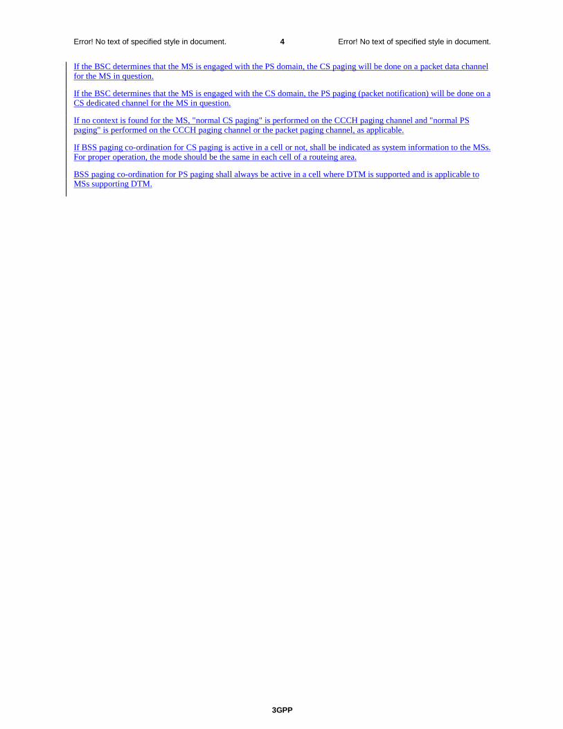
3GPP
Error! No text of specified style in document. 4 Error! No text of specified style in document.
If the BSC determines that the MS is engaged with the PS domain, the CS paging will be done on a packet data channel for the MS in question.
If the BSC determines that the MS is engaged with the CS domain, the PS paging (packet notification) will be done on a CS dedicated channel for the MS in question.
If no context is found for the MS, "normal CS paging" is performed on the CCCH paging channel and "normal PS paging" is performed on the CCCH paging channel or the packet paging channel, as applicable.
If BSS paging co-ordination for CS paging is active in a cell or not, shall be indicated as system information to the MSs. For proper operation, the mode should be the same in each cell of a routeing area.
BSS paging co-ordination for PS paging shall always be active in a cell where DTM is supported and is applicable to MSs supporting DTM.

CR page 1
3GPP TSG-SA2 Meeting #36 Tdoc !S2-034327 New York, USA, 24–28 November 2003 Revised S2-034320 S2-034255 S2-034156
CR-Form-v7
CHANGE REQUEST
! 23.060 CR 434 ! rev 8 ! Current version: 6.2.0 !
For HELP on using this form, see bottom of this page or look at the pop-up text over the ! symbols.
Proposed change affects: UICC apps! ME Radio Access Network Core Network X
Title: ! Security Issue with Multiple PDP Contexts Source: ! Vodafone Work item code: ! TEI6 Date: ! 27/11/2003 Category: ! B Release: ! Rel-6 Use one of the following categories:
F (correction) A (corresponds to a correction in an earlier release) B (addition of feature), C (functional modification of feature) D (editorial modification)
Detailed explanations of the above categories can be found in 3GPP TR 21.900.
Use one of the following releases: 2 (GSM Phase 2) R96 (Release 1996) R97 (Release 1997) R98 (Release 1998) R99 (Release 1999) Rel-4 (Release 4) Rel-5 (Release 5) Rel-6 (Release 6)
Reason for change: ! A security loophole has been identified when multiple Primary PDP Contexts are
active. In effect, the loophole may cause the UE to become a router for packets between the connections created by the PDP contexts. This CR aims to reduce the impact of this loophole by removing the ability to have connections to public access and certain private APNs as required by the APN configuration.
Summary of change: ! The addition of the parameters APN Restriction and Maximum APN Restriction
to be transferred in Create PDP Context requests and Update PDP Context requests. Addition of feature to perform calculation/decision of whether certain APN combinations are permissible in the PDP Context Activation and Inter-SGSN Routeing Area Update procedures.
Consequences if ! not approved:
Hackers in the public domain may be able to access connections to private APNs via a UE’s PDP context to a public APN.
Clauses affected: ! 6.9.1.2.2, 6.9.1.3.2, 6.9.2.1, 6.9.2.2, 6.13.2, 9.2.2.1, 9.2.2.1.1, 9.2.3.1, 9.2.3.2,
9.2.3.3, 9.2.4, 13.2, Additional clause 15.4 Y N Other specs ! X Other core specifications ! 29.060, 24.008 affected: X Test specifications X O&M Specifications
CR page 2
Other comments: ! How to create CRs using this form: Comprehensive information and tips about how to create CRs can be found at http://www.3gpp.org/specs/CR.htm. Below is a brief summary:
1) Fill out the above form. The symbols above marked ! contain pop-up help information about the field that they are closest to.
2) Obtain the latest version for the release of the specification to which the change is proposed. Use the MS Word "revision marks" feature (also known as "track changes") when making the changes. All 3GPP specifications can be downloaded from the 3GPP server under ftp://ftp.3gpp.org/specs/ For the latest version, look for the directory name with the latest date e.g. 2001-03 contains the specifications resulting from the March 2001 TSG meetings.
3) With "track changes" disabled, paste the entire CR form (use CTRL-A to select it) into the specification just in front of the clause containing the first piece of changed text. Delete those parts of the specification which are not relevant to the c

CR page 3
****** FIRST MODIFIED SECTION ******
6.9.1.2.2 Inter SGSN Routeing Area Update
The Inter SGSN Routeing Area Update procedure is illustrated in Figure 33.
MS BSS new SGSN HLR GGSN old SGSN
2. SGSN Context Response
3. Security Functions
1. Routeing Area Update Request
2. SGSN Context Request
6. Update PDP Context Request
6. Update PDP Context Response
7. Update Location
10. Update Location Ack
11. Routeing Area Update Accept
8. Cancel Location
8. Cancel Location Ack
9. Insert Subscriber Data Ack
9. Insert Subscriber Data
12. Routeing Area Update Complete
5. Forward Packets
4. SGSN Context Acknowledge
C3
C2
C1
Figure 33: Inter SGSN Routeing Area Update Procedure
1) The MS sends a Routeing Area Update Request (old RAI, old P-TMSI Signature, Update Type, Classmark, DRX parameters and MS Network Capability) to the new SGSN. Update Type shall indicate RA update or periodic RA update. The BSS shall add the Cell Global Identity including the RAC and LAC of the cell where the message was received before passing the message to the SGSN. Classmark contains the MS GPRS multislot capabilities and supported GPRS ciphering algorithms as defined in TS 24.008. DRX Parameters indicates whether or not the MS uses discontinuous reception and the DRX cycle length.
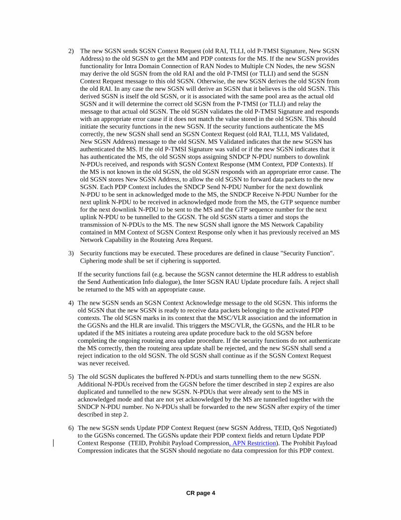
CR page 4
2) The new SGSN sends SGSN Context Request (old RAI, TLLI, old P-TMSI Signature, New SGSN Address) to the old SGSN to get the MM and PDP contexts for the MS. If the new SGSN provides functionality for Intra Domain Connection of RAN Nodes to Multiple CN Nodes, the new SGSN may derive the old SGSN from the old RAI and the old P-TMSI (or TLLI) and send the SGSN Context Request message to this old SGSN. Otherwise, the new SGSN derives the old SGSN from the old RAI. In any case the new SGSN will derive an SGSN that it believes is the old SGSN. This derived SGSN is itself the old SGSN, or it is associated with the same pool area as the actual old SGSN and it will determine the correct old SGSN from the P-TMSI (or TLLI) and relay the message to that actual old SGSN. The old SGSN validates the old P-TMSI Signature and responds with an appropriate error cause if it does not match the value stored in the old SGSN. This should initiate the security functions in the new SGSN. If the security functions authenticate the MS correctly, the new SGSN shall send an SGSN Context Request (old RAI, TLLI, MS Validated, New SGSN Address) message to the old SGSN. MS Validated indicates that the new SGSN has authenticated the MS. If the old P-TMSI Signature was valid or if the new SGSN indicates that it has authenticated the MS, the old SGSN stops assigning SNDCP N-PDU numbers to downlink N-PDUs received, and responds with SGSN Context Response (MM Context, PDP Contexts). If the MS is not known in the old SGSN, the old SGSN responds with an appropriate error cause. The old SGSN stores New SGSN Address, to allow the old SGSN to forward data packets to the new SGSN. Each PDP Context includes the SNDCP Send N-PDU Number for the next downlink N-PDU to be sent in acknowledged mode to the MS, the SNDCP Receive N-PDU Number for the next uplink N-PDU to be received in acknowledged mode from the MS, the GTP sequence number for the next downlink N-PDU to be sent to the MS and the GTP sequence number for the next uplink N-PDU to be tunnelled to the GGSN. The old SGSN starts a timer and stops the transmission of N-PDUs to the MS. The new SGSN shall ignore the MS Network Capability contained in MM Context of SGSN Context Response only when it has previously received an MS Network Capability in the Routeing Area Request.
3) Security functions may be executed. These procedures are defined in clause "Security Function". Ciphering mode shall be set if ciphering is supported.
If the security functions fail (e.g. because the SGSN cannot determine the HLR address to establish the Send Authentication Info dialogue), the Inter SGSN RAU Update procedure fails. A reject shall be returned to the MS with an appropriate cause.
4) The new SGSN sends an SGSN Context Acknowledge message to the old SGSN. This informs the old SGSN that the new SGSN is ready to receive data packets belonging to the activated PDP contexts. The old SGSN marks in its context that the MSC/VLR association and the information in the GGSNs and the HLR are invalid. This triggers the MSC/VLR, the GGSNs, and the HLR to be updated if the MS initiates a routeing area update procedure back to the old SGSN before completing the ongoing routeing area update procedure. If the security functions do not authenticate the MS correctly, then the routeing area update shall be rejected, and the new SGSN shall send a reject indication to the old SGSN. The old SGSN shall continue as if the SGSN Context Request was never received.
5) The old SGSN duplicates the buffered N-PDUs and starts tunnelling them to the new SGSN. Additional N-PDUs received from the GGSN before the timer described in step 2 expires are also duplicated and tunnelled to the new SGSN. N-PDUs that were already sent to the MS in acknowledged mode and that are not yet acknowledged by the MS are tunnelled together with the SNDCP N-PDU number. No N-PDUs shall be forwarded to the new SGSN after expiry of the timer described in step 2.
6) The new SGSN sends Update PDP Context Request (new SGSN Address, TEID, QoS Negotiated) to the GGSNs concerned. The GGSNs update their PDP context fields and return Update PDP Context Response (TEID, Prohibit Payload Compression, APN Restriction). The Prohibit Payload Compression indicates that the SGSN should negotiate no data compression for this PDP context.

CR page 5
7) The new SGSN informs the HLR of the change of SGSN by sending Update Location (SGSN Number, SGSN Address, IMSI) to the HLR.
8) The HLR sends Cancel Location (IMSI, Cancellation Type) to the old SGSN with Cancellation Type set to Update Procedure. If the timer described in step 2 is not running, the old SGSN removes the MM and PDP contexts. Otherwise, the contexts are removed only when the timer expires. This allows the old SGSN to complete the forwarding of N-PDUs. It also ensures that the MM and PDP contexts are kept in the old SGSN in case the MS initiates another inter-SGSN routeing area update before completing the ongoing routeing area update to the new SGSN. The old SGSN acknowledges with Cancel Location Ack (IMSI).
9) The HLR sends Insert Subscriber Data (IMSI, GPRS Subscription Data) to the new SGSN. The new SGSN validates the MS's presence in the (new) RA. If due to regional subscription restrictions the MS is not allowed to be attached in the RA, the SGSN rejects the Routeing Area Update Request with an appropriate cause, and may return an Insert Subscriber Data Ack (IMSI, SGSN Area Restricted) message to the HLR. If all checks are successful, the SGSN constructs an MM context for the MS and returns an Insert Subscriber Data Ack (IMSI) message to the HLR.
10) The HLR acknowledges the Update Location by sending Update Location Ack (IMSI) to the new SGSN.
11) The new SGSN validates the MS's presence in the new RA. If due to roaming restrictions the MS, is not allowed to be attached in the SGSN, or if subscription checking fails, the new SGSN rejects the routeing area update with an appropriate cause. If all checks are successful, the new SGSN constructs MM and PDP contexts for the MS. A logical link is established between the new SGSN and the MS. The new SGSN responds to the MS with Routeing Area Update Accept (P-TMSI, P-TMSI Signature, Receive N-PDU Number). Receive N-PDU Number contains the acknowledgements for each acknowledged-mode NSAPI used by the MS, thereby confirming all mobile-originated N-PDUs successfully transferred before the start of the update procedure.
12) The MS acknowledges the new P-TMSI by returning a Routeing Area Update Complete (Receive N-PDU Number) message to the SGSN. Receive N-PDU Number contains the acknowledgements for each acknowledged-mode NSAPI used by the MS, thereby confirming all mobile-terminated N-PDUs successfully transferred before the start of the update procedure. If Receive N-PDU Number confirms reception of N-PDUs that were forwarded from the old SGSN, these N-PDUs shall be discarded by the new SGSN. LLC and SNDCP in the MS are reset.
In the case of a rejected routeing area update operation, due to regional subscription or roaming restrictions, or because the SGSN cannot determine the HLR address to establish the locating updating dialogue, the new SGSN shall not construct an MM context. A reject shall be returned to the MS with an appropriate cause. The MS does not re-attempt a routeing area update to that RA. The RAI value shall be deleted when the MS is powered-up.
If the new SGSN is unable to update the PDP context in one or more GGSNs, the new SGSN shall deactivate the corresponding PDP contexts as described in clause "SGSN-initiated PDP Context Deactivation Procedure". This shall not cause the SGSN to reject the routeing area update.
The PDP Contexts shall be sent from old to new SGSN in a prioritized order, i.e. the most important PDP Context first in the SGSN Context Response message. (The prioritization method is implementation dependent, but should be based on the current activity.)
The new SGSN shall determine the Maximum APN restriction based on the received APN Restriction of each PDP context from the GGSN and then store the new Maximum APN restriction value.
If the new SGSN is unable to support the same number of active PDP contexts as received from old SGSN, the new SGSN should use the prioritisation sent by old SGSN as input when deciding which PDP contexts to maintain active and which ones to delete. In any case, the new SGSN shall first update all contexts in one or more GGSNs and then deactivate the context(s) that it cannot maintain as described in subclause
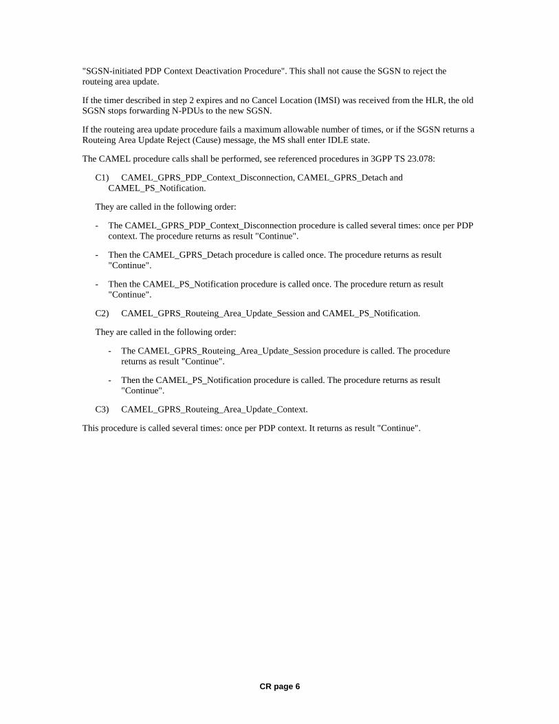
CR page 6
"SGSN-initiated PDP Context Deactivation Procedure". This shall not cause the SGSN to reject the routeing area update.
If the timer described in step 2 expires and no Cancel Location (IMSI) was received from the HLR, the old SGSN stops forwarding N-PDUs to the new SGSN.
If the routeing area update procedure fails a maximum allowable number of times, or if the SGSN returns a Routeing Area Update Reject (Cause) message, the MS shall enter IDLE state.
The CAMEL procedure calls shall be performed, see referenced procedures in 3GPP TS 23.078:
C1) CAMEL_GPRS_PDP_Context_Disconnection, CAMEL_GPRS_Detach and CAMEL_PS_Notification.
They are called in the following order:
- The CAMEL_GPRS_PDP_Context_Disconnection procedure is called several times: once per PDP context. The procedure returns as result "Continue".
- Then the CAMEL_GPRS_Detach procedure is called once. The procedure returns as result "Continue".
- Then the CAMEL_PS_Notification procedure is called once. The procedure return as result "Continue".
C2) CAMEL_GPRS_Routeing_Area_Update_Session and CAMEL_PS_Notification.
They are called in the following order:
- The CAMEL_GPRS_Routeing_Area_Update_Session procedure is called. The procedure returns as result "Continue".
- Then the CAMEL_PS_Notification procedure is called. The procedure returns as result "Continue".
C3) CAMEL_GPRS_Routeing_Area_Update_Context.
This procedure is called several times: once per PDP context. It returns as result "Continue".

CR page 7
6.9.1.3.2 Combined Inter SGSN RA / LA Update
The Combined RA / LA Update (inter-SGSN) procedure is illustrated in Figure 35.
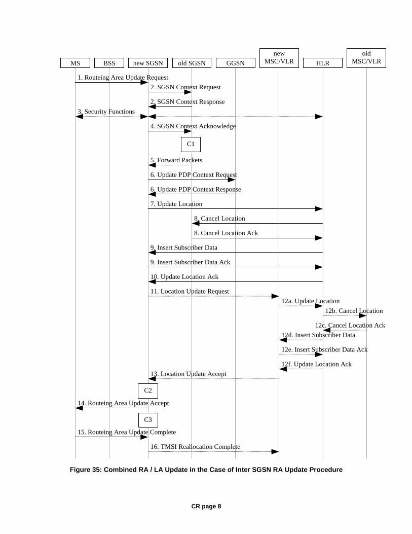
CR page 8
12b. Cancel Location
12c. Cancel Location Ack
12d. Insert Subscriber Data
16. TMSI Reallocation Complete
12f. Update Location Ack
13. Location Update Accept
15. Routeing Area Update Complete
14. Routeing Area Update Accept
8. Cancel Location
8. Cancel Location Ack
6. Update PDP Context Response
6. Update PDP Context Request
7. Update Location
10. Update Location Ack
12a. Update Location
11. Location Update Request
2. SGSN Context Response
3. Security Functions
2. SGSN Context Request
1. Routeing Area Update Request
9. Insert Subscriber Data
9. Insert Subscriber Data Ack
12e. Insert Subscriber Data Ack
MS BSS GGSN old SGSN new SGSN HLR
new MSC/VLR
old MSC/VLR
5. Forward Packets
4. SGSN Context Acknowledge
C3
C2
C1
Figure 35: Combined RA / LA Update in the Case of Inter SGSN RA Update Procedure
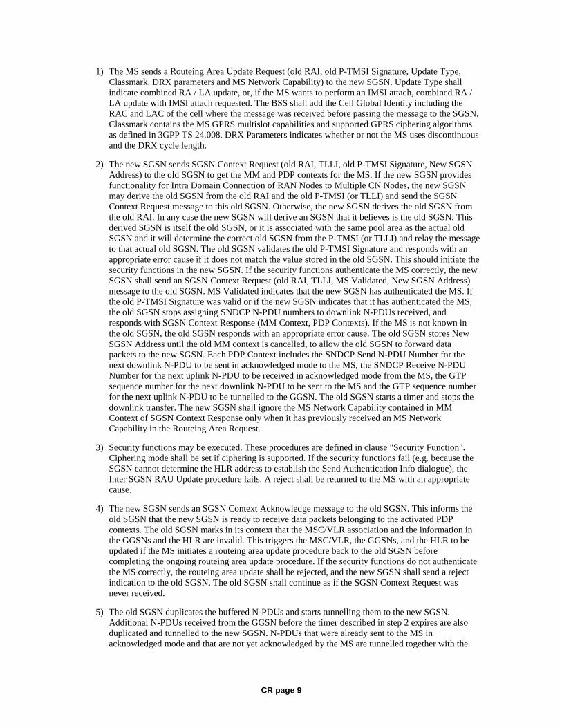
CR page 9
1) The MS sends a Routeing Area Update Request (old RAI, old P-TMSI Signature, Update Type, Classmark, DRX parameters and MS Network Capability) to the new SGSN. Update Type shall indicate combined RA / LA update, or, if the MS wants to perform an IMSI attach, combined RA / LA update with IMSI attach requested. The BSS shall add the Cell Global Identity including the RAC and LAC of the cell where the message was received before passing the message to the SGSN. Classmark contains the MS GPRS multislot capabilities and supported GPRS ciphering algorithms as defined in 3GPP TS 24.008. DRX Parameters indicates whether or not the MS uses discontinuous and the DRX cycle length.
2) The new SGSN sends SGSN Context Request (old RAI, TLLI, old P-TMSI Signature, New SGSN Address) to the old SGSN to get the MM and PDP contexts for the MS. If the new SGSN provides functionality for Intra Domain Connection of RAN Nodes to Multiple CN Nodes, the new SGSN may derive the old SGSN from the old RAI and the old P-TMSI (or TLLI) and send the SGSN Context Request message to this old SGSN. Otherwise, the new SGSN derives the old SGSN from the old RAI. In any case the new SGSN will derive an SGSN that it believes is the old SGSN. This derived SGSN is itself the old SGSN, or it is associated with the same pool area as the actual old SGSN and it will determine the correct old SGSN from the P-TMSI (or TLLI) and relay the message to that actual old SGSN. The old SGSN validates the old P-TMSI Signature and responds with an appropriate error cause if it does not match the value stored in the old SGSN. This should initiate the security functions in the new SGSN. If the security functions authenticate the MS correctly, the new SGSN shall send an SGSN Context Request (old RAI, TLLI, MS Validated, New SGSN Address) message to the old SGSN. MS Validated indicates that the new SGSN has authenticated the MS. If the old P-TMSI Signature was valid or if the new SGSN indicates that it has authenticated the MS, the old SGSN stops assigning SNDCP N-PDU numbers to downlink N-PDUs received, and responds with SGSN Context Response (MM Context, PDP Contexts). If the MS is not known in the old SGSN, the old SGSN responds with an appropriate error cause. The old SGSN stores New SGSN Address until the old MM context is cancelled, to allow the old SGSN to forward data packets to the new SGSN. Each PDP Context includes the SNDCP Send N-PDU Number for the next downlink N-PDU to be sent in acknowledged mode to the MS, the SNDCP Receive N-PDU Number for the next uplink N-PDU to be received in acknowledged mode from the MS, the GTP sequence number for the next downlink N-PDU to be sent to the MS and the GTP sequence number for the next uplink N-PDU to be tunnelled to the GGSN. The old SGSN starts a timer and stops the downlink transfer. The new SGSN shall ignore the MS Network Capability contained in MM Context of SGSN Context Response only when it has previously received an MS Network Capability in the Routeing Area Request.
3) Security functions may be executed. These procedures are defined in clause "Security Function". Ciphering mode shall be set if ciphering is supported. If the security functions fail (e.g. because the SGSN cannot determine the HLR address to establish the Send Authentication Info dialogue), the Inter SGSN RAU Update procedure fails. A reject shall be returned to the MS with an appropriate cause.
4) The new SGSN sends an SGSN Context Acknowledge message to the old SGSN. This informs the old SGSN that the new SGSN is ready to receive data packets belonging to the activated PDP contexts. The old SGSN marks in its context that the MSC/VLR association and the information in the GGSNs and the HLR are invalid. This triggers the MSC/VLR, the GGSNs, and the HLR to be updated if the MS initiates a routeing area update procedure back to the old SGSN before completing the ongoing routeing area update procedure. If the security functions do not authenticate the MS correctly, the routeing area update shall be rejected, and the new SGSN shall send a reject indication to the old SGSN. The old SGSN shall continue as if the SGSN Context Request was never received.
5) The old SGSN duplicates the buffered N-PDUs and starts tunnelling them to the new SGSN. Additional N-PDUs received from the GGSN before the timer described in step 2 expires are also duplicated and tunnelled to the new SGSN. N-PDUs that were already sent to the MS in acknowledged mode and that are not yet acknowledged by the MS are tunnelled together with the
CR page 10
SNDCP N-PDU number. No N-PDUs shall be forwarded to the new SGSN after expiry of the timer described in step 2.
6) The new SGSN sends Update PDP Context Request (new SGSN Address, TEID, QoS Negotiated) to the GGSNs concerned. The GGSNs update their PDP context fields and return an Update PDP Context Response (TEID, Prohibit Payload Compression, APN Restriction). The Prohibit Payload Compression indicates that the SGSN should negotiate no data compression for this PDP context.
7) The new SGSN informs the HLR of the change of SGSN by sending Update Location (SGSN Number, SGSN Address, IMSI) to the HLR.
8) The HLR sends Cancel Location (IMSI, Cancellation Type) to the old SGSN with Cancellation Type set to Update Procedure. If the timer described in step 2 is not running, the old SGSN removes the MM and PDP contexts. Otherwise, the contexts are removed only when the timer expires. This allows the old SGSN to complete the forwarding of N-PDUs. It also ensures that the MM and PDP contexts are kept in the old SGSN in case the MS initiates another inter SGSN routeing area update before completing the ongoing routeing area update to the new SGSN. The old SGSN acknowledges with Cancel Location Ack (IMSI).
9) The HLR sends Insert Subscriber Data (IMSI, GPRS Subscription Data) to the new SGSN. The new SGSN validates the MS's presence in the (new) RA. If due to regional subscription restrictions the MS is not allowed to be attached in the RA, the SGSN rejects the Routeing Area Update Request with an appropriate cause, and may return an Insert Subscriber Data Ack (IMSI, SGSN Area Restricted) message to the HLR. If all checks are successful, the SGSN constructs an MM context for the MS and returns an Insert Subscriber Data Ack (IMSI) message to the HLR.
10) The HLR acknowledges the Update Location by sending Update Location Ack (IMSI) to the new SGSN.
11) If the association has to be established, if Update Type indicates combined RA / LA update with IMSI attach requested, or if the LA changed with the routeing area update, the new SGSN sends a Location Update Request (new LAI, IMSI, SGSN Number, Location Update Type) to the VLR. Location Update Type shall indicate IMSI attach if Update Type in step 1 indicated combined RA / LA update with IMSI attach requested. Otherwise, Location Update Type shall indicate normal location update. When the SGSN does not provide functionality for the Intra Domain Connection of RAN Nodes to Multiple CN Nodes, the VLR number is derived from the RAI. When the SGSN provides functionality for Intra Domain Connection of RAN Nodes to Multiple CN Nodes, the SGSN uses the RAI and a hash value from the IMSI to determine the VLR number. The SGSN starts the location update procedure towards the new MSC/VLR upon receipt of the first Insert Subscriber Data message from the HLR in step 9). The VLR creates or updates the association with the SGSN by storing SGSN Number.
12) If the subscriber data in the VLR is marked as not confirmed by the HLR, the new VLR informs the HLR. The HLR cancels the old VLR and inserts subscriber data in the new VLR:
a) The new VLR sends an Update Location (new VLR) to the HLR.
b) The HLR cancels the data in the old VLR by sending Cancel Location (IMSI) to the old VLR.
c) The old VLR acknowledges with Cancel Location Ack (IMSI).
d) The HLR sends Insert Subscriber Data (IMSI, subscriber data) to the new VLR.
e) The new VLR acknowledges with Insert Subscriber Data Ack (IMSI).
f) The HLR responds with Update Location Ack (IMSI) to the new VLR.
13) The new VLR allocates a new TMSI and responds with Location Update Accept (VLR TMSI) to the SGSN. VLR TMSI is optional if the VLR has not changed.
CR page 11
14) The new SGSN validates the MS's presence in the new RA. If due to roaming restrictions the MS is not allowed to be attached in the RA, or if subscription checking fails, the SGSN rejects the routeing area update with an appropriate cause. If all checks are successful, the new SGSN establishes MM and PDP contexts for the MS. A logical link is established between the new SGSN and the MS. The new SGSN responds to the MS with Routeing Area Update Accept (P-TMSI, VLR TMSI, P-TMSI Signature, Receive N-PDU Number). Receive N-PDU Number contains the acknowledgements for each acknowledged-mode NSAPI used by the MS, thereby confirming all mobile-originated N-PDUs successfully transferred before the start of the update procedure.
15) The MS confirms the reallocation of the TMSIs by returning a Routeing Area Update Complete (Receive N-PDU Number) message to the SGSN. Receive N-PDU Number contains the acknowledgements for each acknowledged-mode NSAPI used by the MS, thereby confirming all mobile-terminated N-PDUs successfully transferred before the start of the update procedure. If Receive N-PDU Number confirms reception of N-PDUs that were forwarded from the old SGSN, these N-PDUs shall be discarded by the new SGSN. LLC and SNDCP in the MS are reset.
16) The new SGSN sends a TMSI Reallocation Complete message to the new VLR if the MS confirms the VLR TMSI.
In the case of a rejected routeing area update operation, due to regional subscription or roaming restrictions, or because the SGSN cannot determine the HLR address to establish the locating updating dialogue, the new SGSN shall not construct an MM context. A reject shall be returned to the MS with an appropriate cause. The MS shall not re-attempt a routeing area update to that RA. The RAI value shall be deleted when the MS is powered-up.
If the new SGSN is unable to update the PDP context in one or more GGSNs, the new SGSN shall deactivate the corresponding PDP contexts as described in clause "SGSN-initiated PDP Context Deactivation Procedure". This shall not cause the SGSN to reject the routeing area update.
The PDP Contexts shall be sent from old to new SGSN in a prioritized order, i.e. the most important PDP Context first in the SGSN Context Response message. (The prioritization method is implementation dependent, but should be based on the current activity.)
The new SGSN shall determine the Maximum APN restriction based on the received APN Restriction of each PDP context from the GGSN and then store the new Maximum APN restriction value.
If the new SGSN is unable to support the same number of active PDP contexts as received from old SGSN, the new SGSN should use the prioritisation sent by old SGSN as input when deciding which PDP contexts to maintain active and which ones to delete. In any case, the new SGSN shall first update all contexts in one or more GGSNs and then deactivate the context(s) that it cannot maintain as described in subclause "SGSN-initiated PDP Context Deactivation Procedure". This shall not cause the SGSN to reject the routeing area update.
If the routeing area update procedure fails a maximum allowable number of times, or if the SGSN returns a Routeing Area Update Reject (Cause) message, the MS shall enter IDLE state.
If the timer described in step 2 expires and no Cancel Location (IMSI) was received from the HLR, the old SGSN shall stop forwarding N-PDUs to the new SGSN.
If the Location Update Accept message indicates a reject, this should be indicated to the MS, and the MS shall not access non-GPRS services until a successful location update is performed.
The CAMEL procedure calls shall be performed, see referenced procedures in 3GPP TS 23.078:
C1) CAMEL_GPRS_PDP_Context_Disconnection, CAMEL_GPRS_Detach and CAMEL_PS_Notification.
They are called in the following order:
CR page 12
- The CAMEL_GPRS_PDP_Context_Disconnection procedure is called several times: once per PDP context. The procedure returns as result "Continue".
- Then the CAMEL_GPRS_Detach procedure is called once. The procedure returns as result "Continue".
- Then the CAMEL_PS_Notification procedure is called once. The procedure returns as result "Continue".
C2) CAMEL_GPRS_Routeing_Area_Update_Session and CAMEL_PS_Notification.
They are called in the following order:
- The CAMEL_GPRS_Routeing_Area_Update_Session procedure is called. The procedure returns as result "Continue".
- Then the CAMEL_PS_Notification procedure is called. The procedure returns as result "Continue".
C3) CAMEL_GPRS_Routeing_Area_Update_Context.
This procedure is called several times: once per PDP context. It returns as result "Continue".
CR page 13
***** NEXT MODIFIED SECTION ******
6.9.2.1 Routeing Area Update Procedure
A routeing area update takes place when an attached MS detects that it has entered a new RA or when the periodic RA update timer has expired or when RRC connection is released with cause "Directed Signalling connection re-establishment" or when the MS has to indicate new access capabilities to the network.
The SGSN detects that it is an intra-SGSN routeing area update by noticing that it also handles the old RA. In this case, the SGSN has the necessary information about the MS and there is no need to inform the GGSNs or the HLR about the new MS location. A periodic RA update is always an intra-SGSN routeing area update. If the network operates in mode I, an MS that is in CS/PS mode of operation shall perform the Combined RA / LA Update procedures except this CS/PS mode MS is engaged in a CS connection, then it shall perform (non combined) RA Update procedures.
In Iu mode, an RA update is either an intra-SGSN or inter-SGSN RA update, either combined RA / LA update or only RA update, either initiated by an MS in PMM-CONNECTED or in PMM-IDLE state. The SRNC may provide a PMM-CONNECTED state MS with MM information like RAI by dedicated signalling. Typically, the SRNC should not provide a RAI to an MS in PMM-CONNECTED state. An exception is after an SRNS relocation, in which case the new SRNC shall indicate the RAI to the MS.
All the RA update cases are contained in the procedure illustrated in Figure 36.
NOTE 1: The network may receive an RA update from a UE in PMM-CONNECTED state over a new Iu signalling connection. This could happen when the UE enters PMM-IDLE state on receipt of RRC Connection Release with cause "Directed Signalling connection re-establishment" and initiates an RA or Combined RA update procedure (see clause 6.1.2.4.1).

CR page 14
3. SGSN Context Response 4. Security Functions
2. SGSN Context Request 1. Routeing Area Update Request
MS old
SRNS GGSN old
3G-SGSN new
3G-SGSN HLR
new MSC/VLR
old MSC/VLR
5. SGSN Context Ack
11. Cancel Location
11. Cancel Location Ack
9. Update PDP Context Response
9. Update PDP Context Request
10. Update Location
15b. Cancel Location
15c. Cancel Location Ack
15d. Insert Subscriber Data
19. TMSI Reallocation Complete
15f. Update Location Ack 16. Location Update Accept
18. Routeing Area Update Complete
17. Routeing Area Update Accept
13. Update Location Ack
15a. Update Location
14. Location Update Request
12. Insert Subscriber Data
12. Insert Subscriber Data Ack
15e. Insert Subscriber Data Ack
C3
C2
2a. SRNS Context Request
2a. SRNS Context Response
11a. Iu Release Command
11a. Iu Release Complete
6. SRNS Data Forward Command
7. Forward Packets
8. Forward Packets
new SRNS
C1
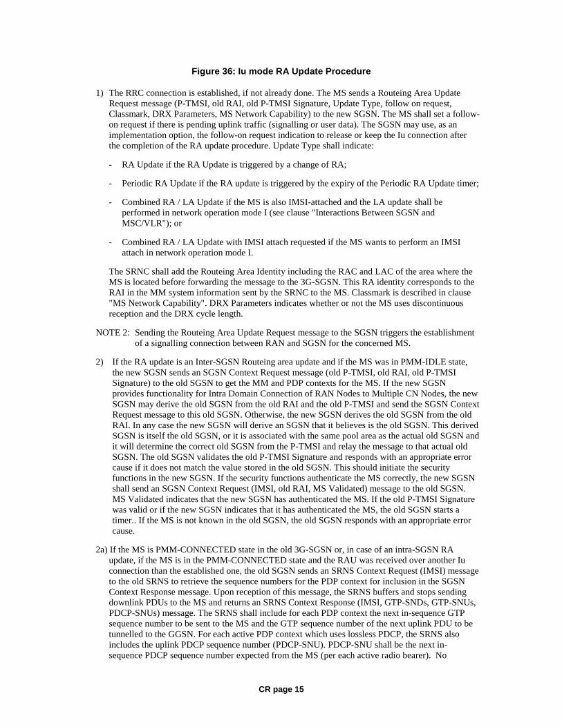
CR page 15
Figure 36: Iu mode RA Update Procedure
1) The RRC connection is established, if not already done. The MS sends a Routeing Area Update Request message (P-TMSI, old RAI, old P-TMSI Signature, Update Type, follow on request, Classmark, DRX Parameters, MS Network Capability) to the new SGSN. The MS shall set a follow-on request if there is pending uplink traffic (signalling or user data). The SGSN may use, as an implementation option, the follow-on request indication to release or keep the Iu connection after the completion of the RA update procedure. Update Type shall indicate:
- RA Update if the RA Update is triggered by a change of RA;
- Periodic RA Update if the RA update is triggered by the expiry of the Periodic RA Update timer;
- Combined RA / LA Update if the MS is also IMSI-attached and the LA update shall be performed in network operation mode I (see clause "Interactions Between SGSN and MSC/VLR"); or
- Combined RA / LA Update with IMSI attach requested if the MS wants to perform an IMSI attach in network operation mode I.
The SRNC shall add the Routeing Area Identity including the RAC and LAC of the area where the MS is located before forwarding the message to the 3G-SGSN. This RA identity corresponds to the RAI in the MM system information sent by the SRNC to the MS. Classmark is described in clause "MS Network Capability". DRX Parameters indicates whether or not the MS uses discontinuous reception and the DRX cycle length.
NOTE 2: Sending the Routeing Area Update Request message to the SGSN triggers the establishment of a signalling connection between RAN and SGSN for the concerned MS.
2) If the RA update is an Inter-SGSN Routeing area update and if the MS was in PMM-IDLE state, the new SGSN sends an SGSN Context Request message (old P-TMSI, old RAI, old P-TMSI Signature) to the old SGSN to get the MM and PDP contexts for the MS. If the new SGSN provides functionality for Intra Domain Connection of RAN Nodes to Multiple CN Nodes, the new SGSN may derive the old SGSN from the old RAI and the old P-TMSI and send the SGSN Context Request message to this old SGSN. Otherwise, the new SGSN derives the old SGSN from the old RAI. In any case the new SGSN will derive an SGSN that it believes is the old SGSN. This derived SGSN is itself the old SGSN, or it is associated with the same pool area as the actual old SGSN and it will determine the correct old SGSN from the P-TMSI and relay the message to that actual old SGSN. The old SGSN validates the old P-TMSI Signature and responds with an appropriate error cause if it does not match the value stored in the old SGSN. This should initiate the security functions in the new SGSN. If the security functions authenticate the MS correctly, the new SGSN shall send an SGSN Context Request (IMSI, old RAI, MS Validated) message to the old SGSN. MS Validated indicates that the new SGSN has authenticated the MS. If the old P-TMSI Signature was valid or if the new SGSN indicates that it has authenticated the MS, the old SGSN starts a timer.. If the MS is not known in the old SGSN, the old SGSN responds with an appropriate error cause.
2a) If the MS is PMM-CONNECTED state in the old 3G-SGSN or, in case of an intra-SGSN RA update, if the MS is in the PMM-CONNECTED state and the RAU was received over another Iu connection than the established one, the old SGSN sends an SRNS Context Request (IMSI) message to the old SRNS to retrieve the sequence numbers for the PDP context for inclusion in the SGSN Context Response message. Upon reception of this message, the SRNS buffers and stops sending downlink PDUs to the MS and returns an SRNS Context Response (IMSI, GTP-SNDs, GTP-SNUs, PDCP-SNUs) message. The SRNS shall include for each PDP context the next in-sequence GTP sequence number to be sent to the MS and the GTP sequence number of the next uplink PDU to be tunnelled to the GGSN. For each active PDP context which uses lossless PDCP, the SRNS also includes the uplink PDCP sequence number (PDCP-SNU). PDCP-SNU shall be the next in-sequence PDCP sequence number expected from the MS (per each active radio bearer). No
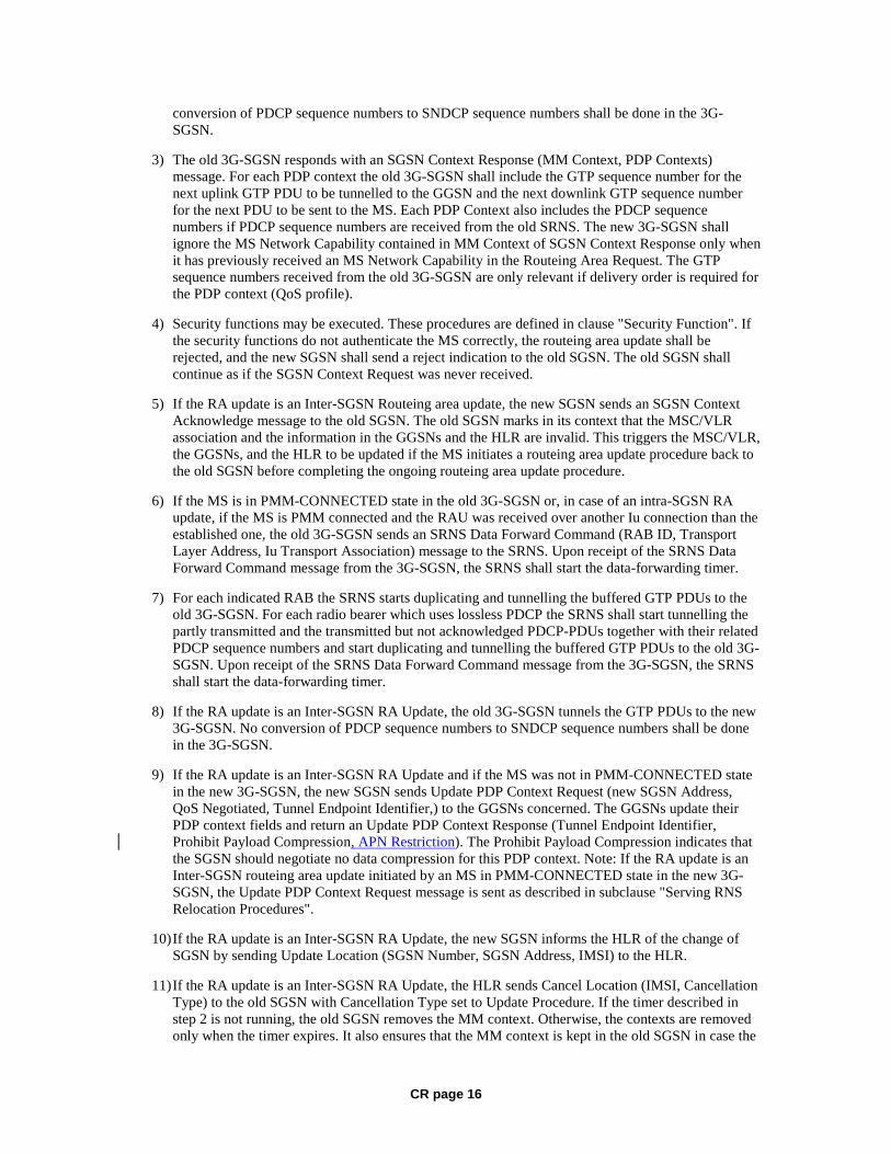
CR page 16
conversion of PDCP sequence numbers to SNDCP sequence numbers shall be done in the 3G-SGSN.
3) The old 3G-SGSN responds with an SGSN Context Response (MM Context, PDP Contexts) message. For each PDP context the old 3G-SGSN shall include the GTP sequence number for the next uplink GTP PDU to be tunnelled to the GGSN and the next downlink GTP sequence number for the next PDU to be sent to the MS. Each PDP Context also includes the PDCP sequence numbers if PDCP sequence numbers are received from the old SRNS. The new 3G-SGSN shall ignore the MS Network Capability contained in MM Context of SGSN Context Response only when it has previously received an MS Network Capability in the Routeing Area Request. The GTP sequence numbers received from the old 3G-SGSN are only relevant if delivery order is required for the PDP context (QoS profile).
4) Security functions may be executed. These procedures are defined in clause "Security Function". If the security functions do not authenticate the MS correctly, the routeing area update shall be rejected, and the new SGSN shall send a reject indication to the old SGSN. The old SGSN shall continue as if the SGSN Context Request was never received.
5) If the RA update is an Inter-SGSN Routeing area update, the new SGSN sends an SGSN Context Acknowledge message to the old SGSN. The old SGSN marks in its context that the MSC/VLR association and the information in the GGSNs and the HLR are invalid. This triggers the MSC/VLR, the GGSNs, and the HLR to be updated if the MS initiates a routeing area update procedure back to the old SGSN before completing the ongoing routeing area update procedure.
6) If the MS is in PMM-CONNECTED state in the old 3G-SGSN or, in case of an intra-SGSN RA update, if the MS is PMM connected and the RAU was received over another Iu connection than the established one, the old 3G-SGSN sends an SRNS Data Forward Command (RAB ID, Transport Layer Address, Iu Transport Association) message to the SRNS. Upon receipt of the SRNS Data Forward Command message from the 3G-SGSN, the SRNS shall start the data-forwarding timer.
7) For each indicated RAB the SRNS starts duplicating and tunnelling the buffered GTP PDUs to the old 3G-SGSN. For each radio bearer which uses lossless PDCP the SRNS shall start tunnelling the partly transmitted and the transmitted but not acknowledged PDCP-PDUs together with their related PDCP sequence numbers and start duplicating and tunnelling the buffered GTP PDUs to the old 3G-SGSN. Upon receipt of the SRNS Data Forward Command message from the 3G-SGSN, the SRNS shall start the data-forwarding timer.
8) If the RA update is an Inter-SGSN RA Update, the old 3G-SGSN tunnels the GTP PDUs to the new 3G-SGSN. No conversion of PDCP sequence numbers to SNDCP sequence numbers shall be done in the 3G-SGSN.
9) If the RA update is an Inter-SGSN RA Update and if the MS was not in PMM-CONNECTED state in the new 3G-SGSN, the new SGSN sends Update PDP Context Request (new SGSN Address, QoS Negotiated, Tunnel Endpoint Identifier,) to the GGSNs concerned. The GGSNs update their PDP context fields and return an Update PDP Context Response (Tunnel Endpoint Identifier, Prohibit Payload Compression, APN Restriction). The Prohibit Payload Compression indicates that the SGSN should negotiate no data compression for this PDP context. Note: If the RA update is an Inter-SGSN routeing area update initiated by an MS in PMM-CONNECTED state in the new 3G-SGSN, the Update PDP Context Request message is sent as described in subclause "Serving RNS Relocation Procedures".
10) If the RA update is an Inter-SGSN RA Update, the new SGSN informs the HLR of the change of SGSN by sending Update Location (SGSN Number, SGSN Address, IMSI) to the HLR.
11) If the RA update is an Inter-SGSN RA Update, the HLR sends Cancel Location (IMSI, Cancellation Type) to the old SGSN with Cancellation Type set to Update Procedure. If the timer described in step 2 is not running, the old SGSN removes the MM context. Otherwise, the contexts are removed only when the timer expires. It also ensures that the MM context is kept in the old SGSN in case the
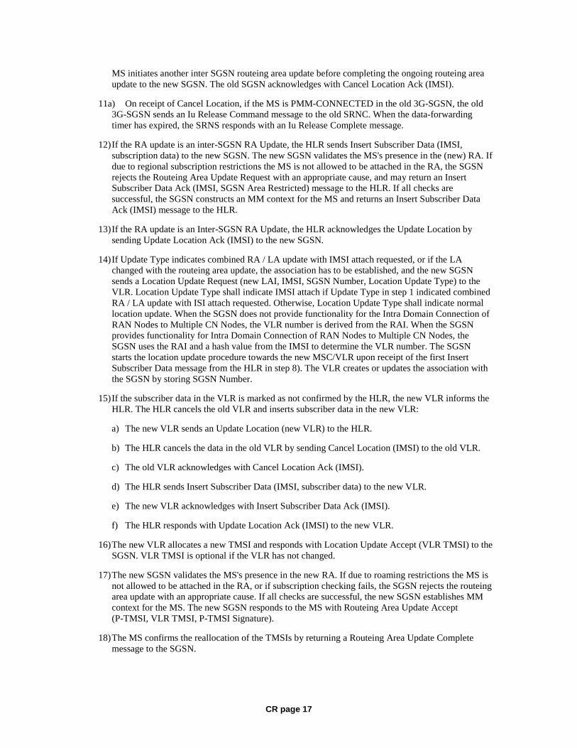
CR page 17
MS initiates another inter SGSN routeing area update before completing the ongoing routeing area update to the new SGSN. The old SGSN acknowledges with Cancel Location Ack (IMSI).
11a) On receipt of Cancel Location, if the MS is PMM-CONNECTED in the old 3G-SGSN, the old 3G-SGSN sends an Iu Release Command message to the old SRNC. When the data-forwarding timer has expired, the SRNS responds with an Iu Release Complete message.
12) If the RA update is an inter-SGSN RA Update, the HLR sends Insert Subscriber Data (IMSI, subscription data) to the new SGSN. The new SGSN validates the MS's presence in the (new) RA. If due to regional subscription restrictions the MS is not allowed to be attached in the RA, the SGSN rejects the Routeing Area Update Request with an appropriate cause, and may return an Insert Subscriber Data Ack (IMSI, SGSN Area Restricted) message to the HLR. If all checks are successful, the SGSN constructs an MM context for the MS and returns an Insert Subscriber Data Ack (IMSI) message to the HLR.
13) If the RA update is an Inter-SGSN RA Update, the HLR acknowledges the Update Location by sending Update Location Ack (IMSI) to the new SGSN.
14) If Update Type indicates combined RA / LA update with IMSI attach requested, or if the LA changed with the routeing area update, the association has to be established, and the new SGSN sends a Location Update Request (new LAI, IMSI, SGSN Number, Location Update Type) to the VLR. Location Update Type shall indicate IMSI attach if Update Type in step 1 indicated combined RA / LA update with ISI attach requested. Otherwise, Location Update Type shall indicate normal location update. When the SGSN does not provide functionality for the Intra Domain Connection of RAN Nodes to Multiple CN Nodes, the VLR number is derived from the RAI. When the SGSN provides functionality for Intra Domain Connection of RAN Nodes to Multiple CN Nodes, the SGSN uses the RAI and a hash value from the IMSI to determine the VLR number. The SGSN starts the location update procedure towards the new MSC/VLR upon receipt of the first Insert Subscriber Data message from the HLR in step 8). The VLR creates or updates the association with the SGSN by storing SGSN Number.
15) If the subscriber data in the VLR is marked as not confirmed by the HLR, the new VLR informs the HLR. The HLR cancels the old VLR and inserts subscriber data in the new VLR:
a) The new VLR sends an Update Location (new VLR) to the HLR.
b) The HLR cancels the data in the old VLR by sending Cancel Location (IMSI) to the old VLR.
c) The old VLR acknowledges with Cancel Location Ack (IMSI).
d) The HLR sends Insert Subscriber Data (IMSI, subscriber data) to the new VLR.
e) The new VLR acknowledges with Insert Subscriber Data Ack (IMSI).
f) The HLR responds with Update Location Ack (IMSI) to the new VLR.
16) The new VLR allocates a new TMSI and responds with Location Update Accept (VLR TMSI) to the SGSN. VLR TMSI is optional if the VLR has not changed.
17) The new SGSN validates the MS's presence in the new RA. If due to roaming restrictions the MS is not allowed to be attached in the RA, or if subscription checking fails, the SGSN rejects the routeing area update with an appropriate cause. If all checks are successful, the new SGSN establishes MM context for the MS. The new SGSN responds to the MS with Routeing Area Update Accept (P-TMSI, VLR TMSI, P-TMSI Signature).
18) The MS confirms the reallocation of the TMSIs by returning a Routeing Area Update Complete message to the SGSN.

CR page 18
19) The new SGSN sends a TMSI Reallocation Complete message to the new VLR if the MS confirms the VLR TMSI.
NOTE 3: Steps 15, 16, and 19 are performed only if step 14 is performed.
NOTE: The new SGSN may initiate RAB establishment after execution of the security functions (step 4), or wait until completion of the RA update procedure. For the MS, RAB establishment may occur anytime after the RA update request is sent (step 1).
In the case of a rejected routeing area update operation, due to regional subscription or roaming restrictions, the new SGSN shall not construct an MM context. A reject shall be returned to the MS with an appropriate cause. The MS shall not re-attempt a routeing area update to that RA. The RAI value shall be deleted when the MS is powered up.
If the new SGSN is unable to update the PDP context in one or more GGSNs, the new SGSN shall deactivate the corresponding PDP contexts as described in subclause "SGSN-initiated PDP Context Deactivation Procedure". This shall not cause the SGSN to reject the routeing area update.
The PDP Contexts shall be sent from old to new SGSN in a prioritized order, i.e. the most important PDP Context first in the SGSN Context Response message. (The prioritization method is implementation dependent, but should be based on the current activity.)
The new SGSN shall determine the Maximum APN restriction based on the received APN Restriction of each PDP context from the GGSN and then store the new Maximum APN restriction value.
If the new SGSN is unable to support the same number of active PDP contexts as received from old SGSN, the new SGSN should use the prioritisation sent by old SGSN as input when deciding which PDP contexts to maintain active and which ones to delete. In any case, the new SGSN shall first update all contexts in one or more GGSNs and then deactivate the context(s) that it cannot maintain as described in subclause "SGSN-initiated PDP Context Deactivation Procedure". This shall not cause the SGSN to reject the routeing area update.
NOTE: In case MS was in PMM-CONNECTED state the PDP Contexts are sent already in the Forward Relocation Request message as described in subclause “Serving RNS relocation procedures”.
If the routeing area update procedure fails a maximum allowable number of times, or if the SGSN returns a Routeing Area Update Reject (Cause) message, the MS shall enter PMM-DETACHED state.
If the Location Update Accept message indicates a reject, this should be indicated to the MS, and the MS shall not access non-PS services until a successful location update is performed.
The CAMEL procedure calls shall be performed, see referenced procedures in 3GPP TS 23.078:
C1) CAMEL_GPRS_PDP_Context_Disconnection, CAMEL_GPRS_Detach and CAMEL_PS_Notification.
They are called in the following order:
- The CAMEL_GPRS_PDP_Context_Disconnection procedure is called several times: once per PDP context. The procedure returns as result "Continue".
- Then the CAMEL_GPRS_Detach procedure is called once. The procedure returns as result "Continue".
- Then the CAMEL_PS_Notification procedure is called once. The procedure returns as result "Continue".

CR page 19
C2) CAMEL_GPRS_Routeing_Area_Update_Session and CAMEL_PS_Notification.
They are called in the following order:
- The CAMEL_GPRS_Routeing_Area_Update_Session procedure is called. The procedure returns as result "Continue".
- Then the CAMEL_PS_Notification procedure is called. The procedure returns as result "Continue".
C3) CAMEL_GPRS_Routeing_Area_Update_Context.
This procedure is called several times: once per PDP context. It returns as result "Continue".
6.9.2.2 Serving RNS Relocation Procedures
In the context of this specification, the terms RNS or RNC refer also to a GERAN BSS or BSC (respectively) when serving an MS in Iu mode.
Serving RNS relocation procedures move the RAN to CN connection point at the RAN side of the source RNC to the target RNC. The Serving RNS Relocation Procedures, described in the following sub-clauses, may be performed as “Lossless SRNS Relocation”, which means packet loss during the SRNS change is eliminated. For this purpose, the RNS and the MS have to provide PDCP layer functionality, which in the subsequent description is referred as the lossless PDCP. The source RNC decides to perform the Serving RNS Relocation Procedure as “Lossless SRNS Relocation” based on capabilities of the UE and the RNS and based on QoS parameters (e.g. SDU error ratio).
For “Lossless SRNS Relocation”, both the MS and the source RNS have to support and to use the lossless PDCP. When the SRNS changes, the old RNS forwards all received and not yet transferred downlink GTP-PDUs to the target RNS. GTP-PDUs forwarded to the target RNS indicate a PDCP sequence number if the contained N-PDUs were sent to the MS as a PDCP-SDUs, but are not yet acknowledged by lossless PDCP. The target RNS and the MS exchange respective sequence numbers of next expected PDCP-PDUs. This process indicates PDCP-PDUs that were already successfully transferred between the MS and the source RNS for downlink and uplink directions, respectively. This also confirms all N-PDUs (PDCP-SDUs) successfully transferred before the change of the SRNS. These N-PDUs are discarded by the MS and the target RNS, respectively. The target RNS identifies the forwarded GTP-PDUs containing confirmed N-PDUs by the PDCP sequence number in the GTP-PDU. All other N-PDUs have to be transmitted via the new MS – RNS link.
6.9.2.2.1 Serving RNS Relocation Procedure
This procedure is only performed for an MS in PMM-CONNECTED state where the Iur interface carries both the control signalling and the user data. This procedure is not applicable for GERAN.
The Serving SRNS Relocation procedure is used to move the RAN to CN connection point at the RAN side from the source SRNC to the target RNC, from a "standing still position". In the procedure, the Iu links are relocated. If the target RNC is connected to the same SGSN as the source SRNC, an Intra-SGSN SRNS Relocation procedure is performed. If the routeing area is changed, this procedure is followed by an Intra-SGSN Routeing Area Update procedure. The SGSN detects an Intra-SGSN routeing area update by noticing that it also handles the old RA. In this case, the SGSN has the necessary information about the MS and there is no need to inform the HLR about new location of the MS.
Figure 37 shows user data routing before SRNS relocation when source SRNC and target RNC are connected to different SGSNs. Figure 38 shows the user data routing after SRNS Relocation procedure and Routeing Area Update procedure is completed. In case depicted in Figure 37 and Figure 38, the MS is in state PMM-CONNECTED.

CR page 20
LA1, RA1
HLR/AuC
old SGSN
GGSN
LA2, RA2
new SGSN
source SRNC
new MSC/VLRold MSC/VLR
MS
target RNC
Figure 37: Before SRNS Relocation and Routeing Area Update
Before the SRNS Relocation procedure and RA update, the MS is registered in the old SGSN. The source RNC is acting as a serving RNC (SRNC).
LA1, RA1
MS
HLR/AuC
old SGSN
source RNC
GGSN
LA2, RA2
new SGSNold MSC/VLR new MSC/VLR
target SRNC
Figure 38: After SRNS Relocation and Routeing Area Update
After the SRNS Relocation procedure and RA update, the MS is registered in the new SGSN. The MS is in the state PMM-CONNECTED towards the new SGSN, and the target RNC is acting as the serving RNC.
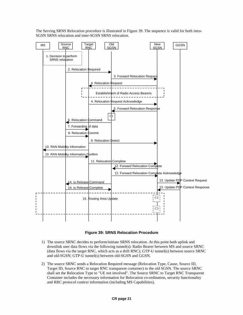
CR page 21
The Serving SRNS Relocation procedure is illustrated in Figure 39. The sequence is valid for both intra-SGSN SRNS relocation and inter-SGSN SRNS relocation.
MS Target RNC
Source RNC
Old SGSN
New SGSN GGSN
3. Forward Relocation Request
4. Relocation Request
2. Relocation Required
6. Relocation Command
5. Forward Relocation Response
4. Relocation Request Acknowledge
9. Relocation Detect 10. RAN Mobility Information
10. RAN Mobility Information Confirm
Establishment of Radio Access Bearers
C1
1. Decision to perform SRNS relocation
8. Relocation Commit 7. Forwarding of data
11. Relocation Complete 12. Forward Relocation Complete
15. Routing Area Update
13. Update PDP Context Request 14. Iu Release Command 14. Iu Release Complete
C2
13. Update PDP Context Response
12. Forward Relocation Complete Acknowledge
C3
Figure 39: SRNS Relocation Procedure
1) The source SRNC decides to perform/initiate SRNS relocation. At this point both uplink and downlink user data flows via the following tunnel(s): Radio Bearer between MS and source SRNC (data flows via the target RNC, which acts as a drift RNC); GTP-U tunnel(s) between source SRNC and old-SGSN; GTP-U tunnel(s) between old-SGSN and GGSN.
2) The source SRNC sends a Relocation Required message (Relocation Type, Cause, Source ID, Target ID, Source RNC to target RNC transparent container) to the old SGSN. The source SRNC shall set the Relocation Type to "UE not involved". The Source SRNC to Target RNC Transparent Container includes the necessary information for Relocation co-ordination, security functionality and RRC protocol context information (including MS Capabilities).
CR page 22
3) The old SGSN determines from the Target ID if the SRNS Relocation is intra-SGSN SRNS relocation or inter-SGSN SRNS relocation. In case of inter-SGSN SRNS relocation, the old SGSN initiates the relocation resource allocation procedure by sending a Forward Relocation Request message (IMSI, Tunnel Endpoint Identifier Signalling, MM Context, PDP Context, Target Identification, RAN transparent container, RANAP Cause) to the new SGSN. For relocation to an area where Intra Domain Connection of RAN Nodes to Multiple CN Nodes is used, the old SGSN may – if it provides Intra Domain Connection of RAN Nodes to Multiple CN Nodes -have multiple target SGSNs for each relocation target in a pool area, in which case the old SGSN will select one of them to become the new SGSN, as specified in 3GPP TS 23.236 [73]. The PDP context contains GGSN Address for User Plane and Uplink TEID for Data (to this GGSN Address and Uplink TEID for Data the old SGSN and the new SGSN send uplink packets). At the same time a timer is started on the MM and PDP contexts in the old SGSN (see the Routeing Area Update procedure in subclause "Location Management Procedures (Iu mode)"). The Forward Relocation Request message is applicable only in the case of inter-SGSN SRNS relocation.
4) The new SGSN sends a Relocation Request message (Permanent NAS UE Identity, Cause, CN Domain Indicator, Source-RNC to target RNC transparent container, RABs to be setup) to the target RNC. Only the Iu Bearers of the RABs are setup between the target RNC and the new-SGSN as the existing Radio Bearers will be reallocated between the MS and the target RNC when the target RNC takes the role of the serving RNC. For each requested RAB, the RABs to be setup information elements shall contain information such as RAB ID, RAB parameters, Transport Layer Address, and Iu Transport Association. SGSN shall not establish RABs for PDP contexts with maximum bitrate for uplink and downlink of 0 kbit/s. The RAB ID information element contains the NSAPI value, and the RAB parameters information element gives the QoS profile. The Transport Layer Address is the SGSN Address for user data, and the Iu Transport Association corresponds to the uplink Tunnel Endpoint Identifier Data. After all necessary resources for accepted RABs including the Iu user plane are successfully allocated; the target RNC shall send the Relocation Request Acknowledge message (RABs setup, RABs failed to setup) to the new SGSN. Each RAB to be setup is defined by a Transport Layer Address, which is the target RNC Address for user data, and an Iu Transport Association, which corresponds to the downlink Tunnel Endpoint Identifier for user data. For each RAB to be set up, the target RNC may receive simultaneously downlink user packets both from the source SRNC and from the new SGSN.
5) When resources for the transmission of user data between the target RNC and the new SGSN have been allocated and the new SGSN is ready for relocation of SRNS, the Forward Relocation Response message (Cause, RANAP Cause, and RAB Setup Information) is sent from the new SGSN to old SGSN. This message indicates that the target RNC is ready to receive from source SRNC the forwarded downlink PDUs, i.e. the relocation resource allocation procedure is terminated successfully. RANAP Cause is information from the target RNC to be forwarded to the source SRNC. The RAB Setup Information, one information element for each RAB, contains the RNC Tunnel Endpoint Identifier and the RNC IP address for data forwarding from the source SRNC to the target RNC. If the target RNC or the new SGSN failed to allocate resources, the RAB Setup Information element contains only NSAPI indicating that the source SRNC shall release the resources associated with the NSAPI. The Forward Relocation Response message is applicable only in case of inter-SGSN SRNS relocation.
6) The old SGSN continues the relocation of SRNS by sending a Relocation Command message (RABs to be released, and RABs subject to data forwarding) to the source SRNC. The old SGSN decides the RABs to be subject for data forwarding based on QoS, and those RABs shall be contained in RABs subject to data forwarding. For each RAB subject to data forwarding, the information element shall contain RAB ID, Transport Layer Address, and Iu Transport Association. These are the same Transport Layer Address and Iu Transport Association that the target RNC had sent to new SGSN in Relocation Request Acknowledge message, and these are used for forwarding of downlink N-PDU from source SRNC to target RNC. The source SRNC is now ready to forward downlink user data directly to the target RNC over the Iu interface. This forwarding is performed for downlink user data only.
CR page 23
7) The source SRNC may, according to the QoS profile, begin the forwarding of data for the RABs to be subject for data forwarding. The data forwarding at SRNS relocation shall be carried out through the Iu interface, meaning that the data exchanged between the source SRNC and the target RNC are duplicated in the source SRNC and routed at IP layer towards the target RNC. For each radio bearer which uses lossless PDCP the GTP-PDUs related to transmitted but not yet acknowledged PDCP-PDUs are duplicated and routed at IP layer towards the target RNC together with their related downlink PDCP sequence numbers. The source RNC continues transmitting duplicates of downlink data and receiving uplink data. Before the serving RNC role is not yet taken over by target RNC and when downlink user plane data starts to arrive to target RNC, the target RNC may buffer or discard arriving downlink GTP-PDUs according to the related QoS profile.
Note: The order of steps, starting from step 7 onwards, does not necessarily reflect the order of events. For instance, source RNC may start data forwarding (step 7) and send Relocation Commit message (step 8) almost simultaneously except in the delivery order required case where step 7 triggers step 8. Target RNC may send Relocation Detect message (step 9) and RAN Mobility Information message (step 10) at the same time. Hence, target RNC may receive RAN Mobility Information Confirm message (step 10) while data forwarding (step 7) is still underway, and before the new SGSN receives Update PDP Context Response message (step 11).
8) Before sending the Relocation Commit the uplink and downlink data transfer in the source, SRNC shall be suspended for RABs, which require delivery order. The source RNC shall start the data-forwarding timer. When the source SRNC is ready, the source SRNC shall trigger the execution of relocation of SRNS by sending a Relocation Commit message (SRNS Contexts) to the target RNC over the Iur interface. The purpose of this procedure is to transfer SRNS contexts from the source RNC to the target RNC, and to move the SRNS role from the source RNC to the target RNC. SRNS contexts are sent for each concerned RAB and contain the sequence numbers of the GTP-PDUs next to be transmitted in the uplink and downlink directions and the next PDCP sequence numbers that would have been used to send and receive data from the MS. For PDP context(s) using delivery order not required (QoS profile), the sequence numbers of the GTP-PDUs next to be transmitted are not used by the target RNC. PDCP sequence numbers are only sent by the source RNC for radio bearers, which used lossless PDCP [57]. The use of lossless PDCP is selected by the RNC when the radio bearer is set up or reconfigured.
If delivery order is required (QoS profile), consecutive GTP-PDU sequence numbering shall be maintained throughout the lifetime of the PDP context(s). Therefore, during the entire SRNS relocation procedure for the PDP context(s) using delivery order required (QoS profile), the responsible GTP-U entities (RNCs and GGSN) shall assign consecutive GTP-PDU sequence numbers to user packets belonging to the same PDP context for uplink and downlink, respectively.
9) The target RNC shall send a Relocation Detect message to the new SGSN when the relocation execution trigger is received. For SRNS relocation type "UE not involved", the relocation execution trigger is the reception of the Relocation Commit message from the Iur interface. When the Relocation Detect message is sent, the target RNC shall start SRNC operation.
10) The target SRNC sends a RAN Mobility Information message. This message contains UE information elements and CN information elements. The UE information elements include among others new SRNC identity and S-RNTI. The CN information elements contain among others Location Area Identification and Routeing Area Identification. The procedure shall be co-ordinated in all Iu signalling connections existing for the MS.

CR page 24
The target SRNC establishes and/or restarts the RLC, and exchanges the PDCP sequence numbers (PDCP-SNU, PDCP-SND) between the target SRNC and the MS. PDCP-SND is the PDCP sequence number for the next expected in-sequence downlink packet to be received in the MS per radio bearer, which used lossless PDCP in the source RNC. PDCP-SND confirms all mobile-terminated packets successfully transferred before the SRNC relocation. If PDCP-SND confirms reception of packets that were forwarded from the source SRNC, the target SRNC shall discard these packets. PDCP-SNU is the PDCP sequence number for the next expected in-sequence uplink packet to be received in the RNC per radio bearer, which used lossless PDCP in the source RNC. PDCP-SNU confirms all mobile originated packets successfully transferred before the SRNC relocation. If PDCP-SNU confirms reception of packets that were received in the source SRNC, the MS shall discard these packets.
Upon reception of the RAN Mobility Information message the MS may start sending uplink user data to the target SRNC. When the MS has reconfigured itself, it sends the RAN Mobility Information Confirm message to the target SRNC. This indicates that the MS is also ready to receive downlink data from the target SRNC.
If new the SGSN has already received the Update PDP Context Response message from the GGSN, it shall forward the uplink user data to GGSN over this new GTP-U tunnel. Otherwise, the new SGSN shall forward the uplink user data to that GGSN IP address and TEID(s), which the new SGSN had received earlier by the Forward Relocation Request message.
For all RABs, the target RNC should:
start uplink reception of data and start transmission of uplink GTP-PDUs towards the new SGSN;
start processing the already buffered and the arriving downlink GTP-PDUs and start downlink transmission towards the MS.
11) When the target SRNC receives the RAN Mobility Information Confirm message, i.e. the new SRNC—ID + S-RNTI are successfully exchanged with the MS by the radio protocols, the target SRNC shall initiate the Relocation Complete procedure by sending the Relocation Complete message to the new SGSN. The purpose of the Relocation Complete procedure is to indicate by the target SRNC the completion of the relocation of the SRNS to the CN.
12) Upon receipt of Relocation Complete message, if the SRNS Relocation is an inter SGSN SRNS relocation, the new SGSN signals to the old SGSN the completion of the SRNS relocation procedure by sending a Forward Relocation Complete message.
13) Upon receipt of the Relocation Complete message, the CN shall switch the user plane from the source RNC to the target SRNC. If the SRNS Relocation is an inter-SGSN SRNS relocation, the new SGSN sends Update PDP Context Request messages (new SGSN Address, SGSN Tunnel Endpoint Identifier, QoS Negotiated) to the GGSNs concerned. The GGSNs update their PDP context fields and return an Update PDP Context Response (GGSN Tunnel Endpoint Identifier, Prohibit Payload Compression, APN Restriction) message. The Prohibit Payload Compression indicates that the SGSN should negotiate no data compression for this PDP context.
14) Upon receiving the Relocation Complete message or if it is an inter-SGSN SRNS relocation; the Forward Relocation Complete message, the old SGSN sends an Iu Release Command message to the source RNC. When the RNC data-forwarding timer has expired the source RNC responds with an Iu Release Complete.
15) After the MS has finished the RNTI reallocation procedure and if the new Routeing Area Identification is different from the old one, the MS initiates the Routeing Area Update procedure. See subclause "Location Management Procedures (Iu mode)". Note that it is only a subset of the RA update procedure that is performed, since the MS is in PMM-CONNECTED mode.
CR page 25
The new SGSN shall determine the Maximum APN restriction based on the received APN Restriction of each PDP context from the GGSN and then store the new Maximum APN restriction value.
If the SRNS Relocation is inter-SGSN, then the following CAMEL procedure calls shall be performed (see referenced procedures in 3GPP TS 23.078)
C1) CAMEL_GPRS_PDP_Context_Disconnection, CAMEL_GPRS_Detach and CAMEL_PS_Notification.
They are called in the following order:
- The CAMEL_GPRS_PDP_Context_Disconnection procedure is called several times: once per PDP context. The procedure returns as result "Continue".
- Then the CAMEL_GPRS_Detach procedure is called once. The procedure returns as result "Continue".
- Then the CAMEL_PS_Notification procedure is called once. The procedure returns as result "Continue".
If the SRNS Relocation is intra-SGSN, then the above mentioned CAMEL procedures calls shall not be performed.
If Routeing Area Update occurs, then the following CAMEL procedure calls shall be performed (see referenced procedures in 3GPP TS 23.078):
C2) CAMEL_GPRS_Routeing_Area_Update_Session and CAMEL_PS_Notification.
They are called in the following order:
- The CAMEL_GPRS_Routeing_Area_Update_Session procedure is called. The procedure returns as result "Continue".
- Then, the CAMEL_PS_Notification procedure is called. The procedure returns as result "Continue".
C3) CAMEL_GPRS_Routeing_Area_Update_Context.
This procedure is called several times: once per PDP context. It returns as result ""Continue"".
For C2 and C3: refer to Routing Area Update procedure description for detailed message flow.
6.9.2.2.2 Combined Hard Handover and SRNS Relocation Procedure
This procedure is only performed for an MS in PMM-CONNECTED state in case the Iur interface is not available. In the context of this specification, the terms RNS or RNC refer also to a GERAN BSS or BSC (respectively) when serving a mobile in Iu mode.
The Combined Hard Handover and SRNS Relocation procedure is used to move the RAN to CN connection point at the RAN side from the source SRNC to the target RNC, while performing a hard handover decided by the RAN. In the procedure, the Iu links are relocated. If the target RNC is connected to the same SGSN as the source SRNC, an Intra-SGSN SRNS Relocation procedure is performed. If the routeing area is changed, this procedure is followed by an Intra-SGSN Routeing Area Update procedure. The SGSN detects that it is an intra-SGSN routeing area update by noticing that it also handles the old RA. In this case, the SGSN has the necessary information about the MS and there is no need to inform the HLR about the new MS location.
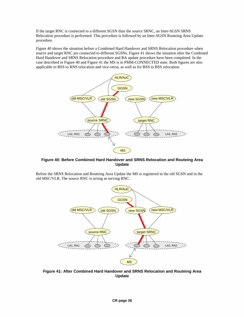
CR page 26
If the target RNC is connected to a different SGSN than the source SRNC, an Inter-SGSN SRNS Relocation procedure is performed. This procedure is followed by an Inter-SGSN Routeing Area Update procedure.
Figure 40 shows the situation before a Combined Hard Handover and SRNS Relocation procedure when source and target RNC are connected to different SGSNs. Figure 41 shows the situation after the Combined Hard Handover and SRNS Relocation procedure and RA update procedure have been completed. In the case described in Figure 40 and Figure 41 the MS is in PMM-CONNECTED state. Both figures are also applicable to BSS to RNS relocation and vice-versa, as well as for BSS to BSS relocation.
LA1, RA1
MS
HLR/AuC
old SGSN
GGSN
LA2, RA2
new SGSN
target RNCsource SRNC
new MSC/VLRold MSC/VLR
Figure 40: Before Combined Hard Handover and SRNS Relocation and Routeing Area Update
Before the SRNS Relocation and Routeing Area Update the MS is registered in the old SGSN and in the old MSC/VLR. The source RNC is acting as serving RNC.
LA1, RA1
MS
HLR/AuC
old SGSN
source RNC
GGSN
LA2, RA2
new SGSN
target SRNC
old MSC/VLR new MSC/VLR
Figure 41: After Combined Hard Handover and SRNS Relocation and Routeing Area Update
CR page 27
After the SRNS relocation and RA update, the MS is registered in the new SGSN and in the new MSC/VLR. The MS is in state PMM-CONNECTED towards the new SGSN and in MM IDLE state towards the new MSC/VLR. The target RNC is acting as serving RNC.
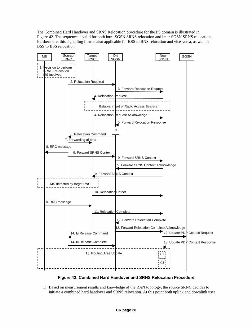
CR page 28
The Combined Hard Handover and SRNS Relocation procedure for the PS domain is illustrated in Figure 42. The sequence is valid for both intra-SGSN SRNS relocation and inter-SGSN SRNS relocation. Furthermore, this signalling flow is also applicable for BSS to RNS relocation and vice-versa, as well as BSS to BSS relocation.
MS Target RNC
Source RNC
Old SGSN
New SGSN GGSN
3. Forward Relocation Request
4. Relocation Request
2. Relocation Required
6. Relocation Command
5. Forward Relocation Response
4. Relocation Request Acknowledge
10. Relocation Detect
9. Forward SRNS Context 9. Forward SRNS Context
9. Forward SRNS Context
8. RRC message
8. RRC message
1. Decision to perform SRNS Relocation MS Involved
MS detected by target RNC
Establishment of Radio Access Bearers
C1
7. Forwarding of data
9. Forward SRNS Context Acknowledge
11. Relocation Complete
12. Forward Relocation Complete
15. Routing Area Update
13. Update PDP Context Request 14. Iu Release Command
14. Iu Release Complete 13. Update PDP Context Response
12. Forward Relocation Complete Acknowledge
C3
C2
Figure 42: Combined Hard Handover and SRNS Relocation Procedure
1) Based on measurement results and knowledge of the RAN topology, the source SRNC decides to initiate a combined hard handover and SRNS relocation. At this point both uplink and downlink user
CR page 29
data flows via the following tunnel(s): Radio Bearer between the MS and the source SRNC (no drift RNC available); GTP-U tunnel(s) between the source SRNC and the old SGSN; GTP-U tunnel(s) between the old SGSN and the GGSN.
2) The source SRNC sends a Relocation Required message (Relocation Type, Cause, Source ID, Target ID, Source RNC To Target RNC Transparent Container) to the old SGSN. The source SRNC shall set Relocation Type to "UE Involved". Source RNC To Target RNC Transparent Container includes the necessary information for relocation co-ordination, security functionality and RRC protocol context information (including MS Capabilities).
3) The old SGSN determines from the Target ID if the SRNS relocation is intra-SGSN SRNS relocation or inter-SGSN SRNS relocation. In case of inter-SGSN SRNS relocation the old SGSN initiates the relocation resource allocation procedure by sending a Forward Relocation Request message (IMSI, Tunnel Endpoint Identifier Signalling, MM Context, PDP Context, Target Identification, RAN Transparent Container, RANAP Cause) to the new SGSN. For relocation to an area where Intra Domain Connection of RAN Nodes to Multiple CN Nodes is used, the old SGSN may – if it provides Intra Domain Connection of RAN Nodes to Multiple CN Nodes -have multiple target SGSNs for each relocation target in a pool area, in which case the old SGSN will select one of them to become the new SGSN, as specified in 3GPP TS 23.236 [73]. PDP context contains GGSN Address for User Plane and Uplink TEID for Data (to this GGSN Address and Uplink TEID for Data, the old SGSN and the new SGSN send uplink packets). At the same time a timer is started on the MM and PDP contexts in the old SGSN (see Routeing Area Update procedure in subclause "Location Management Procedures (Iu mode)"). The Forward Relocation Request message is applicable only in case of inter-SGSN SRNS relocation.
4) The new SGSN sends a Relocation Request message (Permanent NAS UE Identity, Cause, CN Domain Indicator, Source RNC To Target RNC Transparent Container, RAB To Be Setup) to the target RNC. For each RAB requested to be established, RABs To Be Setup shall contain information such as RAB ID, RAB parameters, Transport Layer Address, and Iu Transport Association. SGSN shall not establish RABs for PDP contexts with maximum bitrate for uplink and downlink of 0 kbit/s. The RAB ID information element contains the NSAPI value, and the RAB parameters information element gives the QoS profile. The Transport Layer Address is the SGSN Address for user data, and the Iu Transport Association corresponds to the uplink Tunnel Endpoint Identifier Data.
After all the necessary resources for accepted RABs including the Iu user plane are successfully allocated, the target RNC shall send the Relocation Request Acknowledge message (Target RNC To Source RNC Transparent Container, RABs Setup, RABs Failed To Setup) to the new SGSN. Each RAB to be setup is defined by a Transport Layer Address, which is the target RNC Address for user data, and the Iu Transport Association, which corresponds to the downlink Tunnel Endpoint Identifier for user data. The transparent container contains all radio-related information that the MS needs for the handover, i.e., a complete RRC message (e.g., Physical Channel Reconfiguration in UTRAN case, or Handover From UTRAN, or Handover Command in GERAN Iu mode case) to be sent transparently via CN and source SRNC to the MS. For each RAB to be set up, the target RNC may receive simultaneously downlink user packets both from the source SRNC and from the new SGSN.
5) When resources for the transmission of user data between target RNC and new SGSN have been allocated and the new SGSN is ready for relocation of SRNS, the Forward Relocation Response (Cause, RAN Transparent Container, RANAP Cause, Target-RNC Information) message is sent from the new SGSN to the old SGSN. This message indicates that the target RNC is ready to receive from source SRNC the forwarded downlink PDUs, i.e., the relocation resource allocation procedure is terminated successfully. RAN transparent container and RANAP Cause are information from the target RNC to be forwarded to the source SRNC. The Target RNC Information, one information element for each RAB to be set up, contains the RNC Tunnel Endpoint Identifier and RNC IP address for data forwarding from the source SRNC to the target RNC. The Forward Relocation Response message is applicable only in case of inter-SGSN SRNS relocation.
CR page 30
6) The old SGSN continues the relocation of SRNS by sending a Relocation Command message (Target RNC To Source RNC Transparent Container, RABs To Be Released, RABs Subject To Data Forwarding) to the source SRNC. The old SGSN decides the RABs to be subject for data forwarding based on QoS, and those RABs shall be contained in RABs subject to data forwarding. For each RAB subject to data forwarding, the information element shall contain RAB ID, Transport Layer Address, and Iu Transport Association. These are the same Transport Layer Address and Iu Transport Association that the target RNC had sent to new SGSN in Relocation Request Acknowledge message, and these are used for forwarding of downlink N-PDU from the source SRNC to the target RNC. The source SRNC is now ready to forward downlink user data directly to the target RNC over the Iu interface. This forwarding is performed for downlink user data only.
7) The source SRNC may, according to the QoS profile, begins the forwarding of data for the RABs to be subject for data forwarding.
NOTE: The order of steps, starting from step 7 onwards, does not necessarily reflect the order of events. For instance, source RNC may start data forwarding (step 7), send the RRC message to MS (step 8) and forward SRNS Context message to the old SGSN (step 9) almost simultaneously.
The data forwarding at SRNS relocation shall be carried out through the Iu interface, meaning that the GTP-PDUs exchanged between the source SRNC and the target RNC are duplicated in the source SRNC and routed at the IP layer towards the target RNC. For each radio bearer which uses lossless PDCP the GTP-PDUs related to transmitted but not yet acknowledged PDCP-PDUs are duplicated and routed at IP layer towards the target RNC together with their related downlink PDCP sequence numbers. The source RNC continues transmitting duplicates of downlink data and receiving uplink data.
Before the serving RNC role is not yet taken over by target RNC and when downlink user plane data starts to arrive to target RNC, the target RNC may buffer or discard arriving downlink GTP-PDUs according to the related QoS profile.
8) Before sending the RRC message the uplink and downlink data transfer shall be suspended in the source SRNC for RABs, which require delivery order. The RRC message is for example Physical Channel Reconfiguration for RNS to RNS relocation, or Intersystem to UTRAN Handover for BSS to RNS relocation, or Handover from UTRAN Command for BSS relocation, or Handover Command for BSS to BSS relocation. When the source SRNC is ready, the source RNC shall trigger the execution of relocation of SRNS by sending to the MS the RRC message provided in the Target RNC to source RNC transparent container, e.g., a Physical Channel Reconfiguration (UE Information Elements, CN Information Elements) message. UE Information Elements include among others new SRNC identity and S-RNTI. CN Information Elements contain among others Location Area Identification and Routeing Area Identification.
When the MS has reconfigured itself, it sends an RRC message e.g., a Physical Channel Reconfiguration Complete message to the target SRNC. If the Forward SRNS Context message with the sequence numbers is received, the exchange of packets with the MS may start. If this message is not yet received, the target RNC may start the packet transfer for all RABs, which do not require maintaining the delivery order.
9) The source SRNC continues the execution of relocation of SRNS by sending a Forward SRNS Context (RAB Contexts) message to the target RNC via the old and the new SGSN. The Forward SRNS Context message is acknowledged by a Forward SRNS Context Acknowledge message, from new to old SGSN. The purpose of this procedure is to transfer SRNS contexts from the source RNC to the target RNC, and to move the SRNS role from the source RNC to the target RNC. SRNS contexts are sent for each concerned RAB and contain the sequence numbers of the GTP PDUs next to be transmitted in the uplink and downlink directions and the next PDCP sequence numbers that would have been used to send and receive data from the MS. PDCP sequence numbers are only sent by the source RNC for the radio bearers which used lossless PDCP [57]. The use of lossless PDCP

CR page 31
is selected by the RNC when the radio bearer is set up or reconfigured. For PDP context(s) using delivery order not required (QoS profile), the sequence numbers of the GTP-PDUs next to be transmitted are not used by the target RNC.
If delivery order is required (QoS profile), consecutive GTP-PDU sequence numbering shall be maintained throughout the lifetime of the PDP context(s). Therefore, during the entire SRNS relocation procedure for the PDP context(s) using delivery order required (QoS profile), the responsible GTP-U entities (RNCs and GGSN) shall assign consecutive GTP-PDU sequence numbers to user packets belonging to the same PDP context uplink and downlink, respectively.
The target RNC establishes and/or restarts the RLC and exchanges the PDCP sequence numbers (PDCP-SNU, PDCP-SND) between the target RNC and the MS. PDCP-SND is the PDCP sequence number for the next expected in-sequence downlink packet to be received by the MS per radio bearer, which used lossless PDCP in the source RNC. PDCP-SND confirms all mobile terminated packets successfully transferred before the SRNC relocation. If PDCP-SND confirms reception of packets that were forwarded from the source SRNC, then the target SRNC shall discard these packets. PDCP-SNU is the PDCP sequence number for the next expected in-sequence uplink packet to be received in the RNC per radio bearer, which used lossless PDCP in the source RNC. PDCP-SNU confirms all mobile originated packets successfully transferred before the SRNC relocation. If PDCP-SNU confirms reception of packets that were received in the source SRNC, the MS shall discard these packets.
10) The target RNC shall send a Relocation Detect message to the new SGSN when the relocation execution trigger is received. For SRNS relocation type "UE Involved", the relocation execution trigger may be received from the Uu interface; i.e., when target RNC detects the MS on the lower layers. When the Relocation Detect message is sent, the target RNC shall start SRNC operation.
11) When the target SRNC receives the appropriate RRC message, e.g. Physical Channel Reconfiguration Complete message or the Radio Bearer Release Complete message in UTRAN case, or the Handover To UTRAN Complete message or Handover Complete message in GERAN case, i.e. the new SRNC-ID + S-RNTI are successfully exchanged with the MS by the radio protocols, the target SRNC shall initiate a Relocation Complete procedure by sending the Relocation Complete message to the new SGSN. The purpose of the Relocation Complete procedure is to indicate by the target SRNC the completion of the relocation of the SRNS to the CN.
12) Upon receipt of Relocation Complete message, if the SRNS Relocation is an inter SGSN SRNS relocation, the new SGSN signals to the old SGSN the completion of the SRNS relocation procedure by sending a Forward Relocation Complete message.
13) Upon receipt of the Relocation Complete message, the CN shall switch the user plane from the source RNC to the target SRNC. If the SRNS Relocation is an inter-SGSN SRNS relocation, the new SGSN sends Update PDP Context Request messages (new SGSN Address, SGSN Tunnel Endpoint Identifier, QoS Negotiated) to the GGSNs concerned. The GGSNs update their PDP context fields and return an Update PDP Context Response (GGSN Tunnel Endpoint Identifier, Prohibit Payload Compression, APN Restriction) message. The Prohibit Payload Compression indicates that the SGSN should negotiate no data compression for this PDP context.
14) Upon receiving the Relocation Complete message or, if it is an inter-SGSN SRNS relocation, the Forward Relocation Complete message, the old SGSN sends an Iu Release Command message to the source RNC. When the RNC data-forwarding timer has expired, the source RNC responds with an Iu Release Complete message.
15) After the MS has finished the reconfiguration procedure and if the new Routeing Area Identification is different from the old one, the MS initiates the Routeing Area Update procedure. See subclause "Location Management Procedures (Iu mode)". Note that it is only a subset of the RA update procedure that is performed, since the MS is in PMM-CONNECTED state.
CR page 32
If the SRNS Relocation is inter-SGSN, then the following CAMEL procedure calls shall be performed (see referenced procedures in 3GPP TS 23.078)
C1) CAMEL_GPRS_PDP_Context_Disconnection, CAMEL_GPRS_Detach and CAMEL_PS_Notification.
They are called in the following order:
- The CAMEL_GPRS_PDP_Context_Disconnection procedure is called several times: once per PDP context. The procedure returns as result "Continue".
- Then the CAMEL_GPRS_Detach procedure is called once. The procedure returns as result "Continue".
- Then the CAMEL_PS_Notification procedure is called once. The procedure returns as result "Continue".
The new SGSN shall determine the Maximum APN restriction based on the received APN Restriction of each PDP context from the GGSN and then store the new Maximum APN restriction value.
If the SRNS Relocation is intra-SGSN, then the above mentioned CAMEL procedures calls shall not be performed.
If Routeing Area Update occurs, then the following CAMEL procedure calls shall be performed (see referenced procedures in 3GPP TS 23.078):
C2) CAMEL_GPRS_Routeing_Area_Update_Session and CAMEL_PS_Notification.
They are called in the following order:
- The CAMEL_GPRS_Routeing_Area_Update_Session procedure is called. In Figure 42, the procedure returns as result "Continue".
- Then the CAMEL_PS_Notification procedure is called. The procedure returns as result "Continue".
C3) CAMEL_GPRS_Routeing_Area_Update_Context.
This procedure is called several times: once per PDP context. It returns as result "Continue".
For C2 and C3: refer to Routing Area Update procedure description for detailed message flow.
6.9.2.2.3 Combined Cell / URA Update and SRNS Relocation Procedure
This procedure is only performed for an MS in PMM-CONNECTED state, where the Iur/Iur-g interface carries control signalling but no user data In the context of this specification, the terms RNS or RNC refer also to a GERAN BSS or BSC (respectively) when serving an MS in Iu mode.

CR page 33
The Combined Cell / URA Update and SRNS Relocation or Combined Cell/GRA Update and SBSS Relocation procedure is used to move the RAN to CN connection point at the RAN side from the source SRNC to the target RNC, while performing a cell re-selection in the RAN. In the procedure, the Iu links are relocated. If the target RNC is connected to the same SGSN as the source SRNC, an Intra-SGSN SRNS Relocation procedure is performed. If the routeing area is changed, this procedure is followed by an Intra-SGSN Routeing Area Update procedure. The SGSN detects that it is an intra-SGSN routeing area update by noticing that it also handles the old RA. In this case, the SGSN has the necessary information about the MS and there is no need to inform the HLR about the new MS location.
Before the Combined Cell / URA Update and SRNS Relocation or Combined Cell/GRA Update and SBSS Relocation and before the Routeing Area Update, the MS is registered in the old SGSN. The source RNC is acting as serving RNC or serving BSS.
After the Combined Cell / URA Update and SRNS Relocation or Combined Cell/GRA Update and SBSS Relocation and after the Routeing Area Update, the MS is registered in the new SGSN. The MS is in state PMM-CONNECTED towards the new SGSN, and the target RNC is acting as serving RNC.
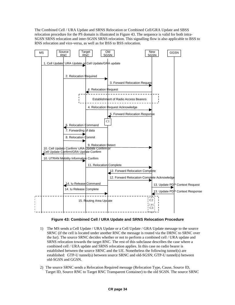
CR page 34
The Combined Cell / URA Update and SRNS Relocation or Combined Cell/GRA Update and SBSS relocation procedure for the PS domain is illustrated in Figure 43. The sequence is valid for both intra-SGSN SRNS relocation and inter-SGSN SRNS relocation. This signalling flow is also applicable to BSS to RNS relocation and vice-versa, as well as for BSS to BSS relocation.
MS Target RNC
Source RNC
Old SGSN
New SGSN GGSN
3. Forward Relocation Request
4. Relocation Request
2. Relocation Required
6. Relocation Command
5. Forward Relocation Response
4. Relocation Request Acknowledge
9. Relocation Detect 10. Cell Update Confirm/ URA Update Confirm or Cell Update Confirm/GRA Update Confirm
10. UTRAN Mobility Information Confirm
Establishment of Radio Access Bearers
C1
1. Cell Update/ URA Update or Cell Update/GRA update
8. Relocation Commit
7. Forwarding of data
11. Relocation Complete 12. Forward Relocation Complete
15. Routing Area Update
13. Update PDP Context Request 14. Iu Release Command 14. Iu Release Complete
C2
13. Update PDP Context Response
12. Forward Relocation Complete Acknowledge
C3
Figure 43: Combined Cell / URA Update and SRNS Relocation Procedure
1) The MS sends a Cell Update / URA Update or a Cell Update / GRA Update message to the source SRNC (if the cell is located under another RNC the message is routed via the DRNC to SRNC over the Iur). The source SRNC decides whether or not to perform a combined cell / URA update and SRNS relocation towards the target RNC. The rest of this subclause describes the case where a combined cell / URA update and SRNS relocation applies. In this case no radio bearer is established between the source SRNC and the UE. Nonetheless the following tunnel(s) are established: GTP-U tunnel(s) between source SRNC and old-SGSN; GTP-U tunnel(s) between old-SGSN and GGSN.
2) The source SRNC sends a Relocation Required message (Relocation Type, Cause, Source ID, Target ID, Source RNC to Target RNC Transparent Container) to the old SGSN. The source SRNC
CR page 35
shall set Relocation Type to "UE not involved". Source RNC to Target RNC Transparent Container includes the necessary information for Relocation co-ordination, security functionality, and RRC protocol context information (including MS Capabilities).
3) The old SGSN determines from the Target ID if the SRNS Relocation is intra-SGSN SRNS relocation or inter-SGSN SRNS relocation. In the case of inter-SGSN SRNS relocation the old SGSN initiates the relocation resource allocation procedure by sending a Forward Relocation Request (IMSI, Tunnel Endpoint Identifier Signalling, MM Context, PDP Context, Target Identification, RAN Transparent Container, RANAP Cause) message to the new SGSN. For relocation to an area where Intra Domain Connection of RAN Nodes to Multiple CN Nodes is used, the old SGSN may – if it provides Intra Domain Connection of RAN Nodes to Multiple CN Nodes -have multiple target SGSNs for each relocation target in a pool area, in which case the old SGSN will select one of them to become the new SGSN, as specified in 3GPP TS 23.236 [73]. PDP context contains GGSN Address for User Plane and Uplink TEID for Data (to this GGSN Address and Uplink TEID for Data, the old SGSN and the new SGSN send uplink packets). At the same time a timer is started on the MM and PDP contexts in the old SGSN, see Routeing Area Update procedure in subclause "Location Management Procedures (Iu mode)". The Forward Relocation Request message is applicable only in case of inter-SGSN SRNS relocation.
4) The new SGSN sends a Relocation Request message (Permanent NAS UE Identity, Cause, CN Domain Indicator, Source RNC to Target RNC Transparent Container, RABs To Be Setup) to the target RNC. For each requested RAB, RABs To Be Setup shall contain information such as RAB ID, RAB parameters, Transport Layer Address, and Iu Transport Association. SGSN shall not establish RABs for PDP contexts with maximum bitrate for uplink and downlink of 0 kbit/s. The RAB ID information element contains the NSAPI value, and the RAB parameters information element gives the QoS profile. The Transport Layer Address is the SGSN Address for user data, and the Iu Transport Association corresponds to the uplink Tunnel Endpoint Identifier Data.
After all necessary resources for accepted RABs including the Iu user plane are successfully allocated, the target RNC shall send the Relocation Request Acknowledge message (RABs setup, RABs failed to setup) to the new SGSN. Each RAB to be setup is defined by a Transport Layer Address, which is the target RNC Address for user data, and a Iu Transport Association which corresponds to the downlink Tunnel Endpoint Identifier for user data.
After the new SGSN receives the Relocation Request Acknowledge message, the GTP-U tunnels are established between the target RNC and the new-SGSN.
The target-RNC may simultaneously receive for each RAB to be set up downlink user packets both from the source SRNC and from the new SGSN.
5) When resources for the transmission of user data between the target RNC and the new SGSN have been allocated and the new SGSN is ready for relocation of SRNS, the Forward Relocation Response message (Cause, RANAP Cause, and Target RNC Information) is sent from the new SGSN to the old SGSN. This message indicates that the target RNC is ready to receive from the source SRNC the forwarded downlink packets, i.e., the relocation resource allocation procedure is terminated successfully. RANAP Cause is information from the target RNC to be forwarded to the source SRNC. The RAB Setup Information, one information element for each RAB, contains the RNC Tunnel Endpoint Identifier and RNC IP address for data forwarding from the source SRNC to the target RNC. If the target RNC or the new SGSN failed to allocate resources, the RAB Setup Information element contains only NSAPI indicating that the source SRNC shall release the resources associated with the NSAPI. The Forward Relocation Response message is applicable only in case of inter-SGSN SRNS relocation.
6) The old SGSN continues the relocation of SRNS by sending a Relocation Command (RABs to be released, and RABs subject to data forwarding) message to the source SRNC. The old SGSN decides the RABs subject to data forwarding based on QoS, and those RABs shall be contained in RABs subject to data forwarding. For each RAB subject to data forwarding, the information element

CR page 36
shall contain RAB ID, Transport Layer Address, and Iu Transport Association. These are the same Transport Layer Address and Iu Transport Association that the target RNC had sent to new SGSN in Relocation Request Acknowledge message, and these are used for forwarding of downlink N-PDU from the source SRNC to the target RNC. The source SRNC is now ready to forward downlink data directly to the target RNC over the Iu interface. This forwarding is performed for downlink user data only.
7) The source SRNC may, according to the QoS profile, begin the forwarding of data for the RABs subject to data forwarding and starts the data-forwarding timer. The data forwarding at SRNS relocation shall be carried out through the Iu interface, meaning that the data exchanged between the source SRNC and the target RNC are duplicated in the source SRNC and routed at the IP layer towards the target RNC. For each radio bearer which uses lossless PDCP the GTP-PDUs related to transmitted but not yet acknowledged PDCP-PDUs are duplicated and routed at IP layer towards the target RNC together with their related downlink PDCP sequence numbers. The source RNC continues transmitting duplicates of downlink data and receiving uplink data.
Note: The order of steps, starting from step 7 onwards, does not necessarily reflect the order of events. For instance, source RNC may send data forwarding (step 7) and start Relocation Commit message (step 8) almost simultaneously. Target RNC may send Relocation Detect message (step 9) and Cell Update Confirm/URA Update Confirm (or Cell Update Confirm/GRA Update Confirm) message (step 10) at the same time. Hence, target RNC may receive the UTRAN or GERAN Mobility Information Confirm message from MS (step 10) while data forwarding (step 8) is still underway, and before the new SGSN receives Update PDP Context Response message (step 11).
Before the serving RNC role is not yet taken over by target RNC and when downlink user plane data starts to arrive to target RNC, the target RNC may buffer or discard arriving downlink GTP-PDUs according to the related QoS profile.
8) Before sending the Relocation Commit the uplink and downlink data transfer in the source, SRNC shall be suspended for RABs, which require delivery order.
When the source SRNC is ready, the source SRNC shall trigger the execution of relocation of SRNS by sending a Relocation Commit message (SRNS Contexts) to the target RNC over the UTRAN Iur interface or over the GERAN Iur-g interface, respectively. The purpose of this procedure is to transfer SRNS contexts from the source RNC to the target RNC, and to move the SRNS role from the source RNC to the target RNC. SRNS contexts are sent for each concerned RAB and contain the sequence numbers of the GTP-PDUs next to be transmitted in the uplink and downlink directions and the next PDCP sequence numbers that would have been used to send and receive data from the MS. . PDCP sequence numbers are only sent by the source RNC for radio bearers, which used lossless PDCP [57]. The use of lossless PDCP is selected by the RNC when the radio bearer is set up or reconfigured. For PDP context(s) using delivery order not required (QoS profile), the sequence numbers of the GTP-PDUs next to be transmitted are not used by the target RNC.
If delivery order is required (QoS profile), consecutive GTP-PDU sequence numbering shall be maintained throughout the lifetime of the PDP context(s). Therefore, during the entire SRNS relocation procedure for the PDP context(s) using delivery order required (QoS profile), the responsible GTP-U entities (RNCs and GGSN) shall assign consecutive GTP-PDU sequence numbers to user packets belonging to the same PDP context for uplink and downlink respectively.
9) The target RNC shall send a Relocation Detect message to the new SGSN when the relocation execution trigger is received. For SRNS relocation type "UE not involved", the relocation execution trigger is the reception of the Relocation Commit message from the Iur interface. When the Relocation Detect message is sent, the target RNC shall start SRNC operation.
10) The target SRNC sends a Cell Update Confirm / URA Update Confirm or Cell Update Confirm / GRA Update Confirm message. This message contains UE information elements and CN information elements. The UE information elements include among others new SRNC identity and S-RNTI. The CN information elements contain among others Location Area Identification and
CR page 37
Routeing Area Identification. The procedure shall be co-ordinated in all Iu signalling connections existing for the MS.
Upon reception of the Cell Update Confirm / URA Update Confirm or Cell Update Confirm / GRA Update Confirm message the MS may start sending uplink user data to the target SRNC. When the MS has reconfigured itself, it sends the RAN Mobility Information Confirm message to the target SRNC. This indicates that the MS is also ready to receive downlink data from the target SRNC.
If the new SGSN has already received the Update PDP Context Response message from the GGSN, it shall forward the uplink user data to the GGSN over this new GTP-U tunnel. Otherwise, the new SGSN shall forward the uplink user data to that GGSN IP address and TEID(s), which the new SGSN had received earlier by the Forward Relocation Request message.
The target SRNC and the MS exchange the PDCP sequence numbers; PDCP-SNU and PDCP-SND. PDCP-SND is the PDCP sequence number for the next expected in-sequence downlink packet to be received in the MS per radio bearer, which used lossless PDCP in the source RNC. PDCP-SND confirms all mobile terminated packets successfully transferred before the SRNC relocation procedure. . If PDCP-SND confirms the reception of packets that were forwarded from the source SRNC, the target SRNC shall discard these packets. PDCP-SNU is the PDCP sequence number for the next expected in-sequence uplink packet to be received in the RNC per radio bearer, which used lossless PDCP in the source RNC. PDCP-SNU confirms all mobile originated packets successfully transferred before the SRNC relocation. If PDCP-SNU confirms reception of packets that were received in the source SRNC, the target SRNC shall discard these packets.
11) When the target SRNC receives the RAN Mobility Information Confirm message, i.e. the new SRNC-ID + S-RNTI are successfully exchanged with the MS by the radio protocols, the target SRNC shall initiate the Relocation Complete procedure by sending the Relocation Complete message to the new SGSN. The purpose of the Relocation Complete procedure is to indicate by the target SRNC the completion of the relocation of the SRNS to the CN.
12) Upon receipt of Relocation Complete message, if the SRNS Relocation is an inter SGSN SRNS relocation, the new SGSN signals to the old SGSN the completion of the SRNS relocation procedure by sending a Forward Relocation Complete message.
13) Upon receipt of the Relocation Complete message, the CN shall switch the user plane from the source RNC to the target SRNC. If the SRNS Relocation is an inter-SGSN SRNS relocation, the new SGSN sends Update PDP Context Request messages (new SGSN Address, SGSN Tunnel Endpoint Identifier, QoS Negotiated) to the GGSNs concerned. The GGSNs update their PDP context fields and return an Update PDP Context Response (GGSN Tunnel Endpoint Identifier, Prohibit Payload Compression, APN Restriction) message. The Prohibit Payload Compression indicates that the SGSN should negotiate no data compression for this PDP context.
14) Upon receiving the Relocation Complete message or if it is an inter-SGSN SRNS relocation, the Forward Relocation Complete message, the old SGSN sends an Iu Release Command message to the source RNC. When the RNC data-forwarding timer has expired the source RNC responds with an Iu Release Complete.
15) After the MS has finished the Cell / URA update or the Cell / GRA update and RNTI reallocation procedure and if the new Routeing Area Identification is different from the old one, the MS initiates the Routeing Area Update procedure. See subclause "Location Management Procedures (Iu mode)". Note that it is only a subset of the RA update procedure that is performed, since the MS is in PMM-CONNECTED state.
If the SRNS Relocation is inter-SGSN, then the following CAMEL procedure calls shall be performed (see referenced procedures in 3GPP TS 23.078)
C1) CAMEL_GPRS_PDP_Context_Disconnection, CAMEL_GPRS_Detach and CAMEL_PS_Notification.
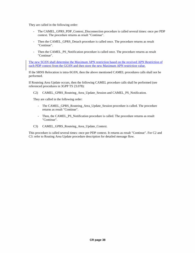
CR page 38
They are called in the following order:
- The CAMEL_GPRS_PDP_Context_Disconnection procedure is called several times: once per PDP context. The procedure returns as result "Continue".
- Then the CAMEL_GPRS_Detach procedure is called once. The procedure returns as result "Continue".
- Then the CAMEL_PS_Notification procedure is called once. The procedure returns as result "Continue".
The new SGSN shall determine the Maximum APN restriction based on the received APN Restriction of each PDP context from the GGSN and then store the new Maximum APN restriction value.
If the SRNS Relocation is intra-SGSN, then the above mentioned CAMEL procedures calls shall not be performed.
If Routeing Area Update occurs, then the following CAMEL procedure calls shall be performed (see referenced procedures in 3GPP TS 23.078):
C2) CAMEL_GPRS_Routeing_Area_Update_Session and CAMEL_PS_Notification.
They are called in the following order:
- The CAMEL_GPRS_Routeing_Area_Update_Session procedure is called. The procedure returns as result "Continue".
- Then, the CAMEL_PS_Notification procedure is called. The procedure returns as result "Continue".
C3) CAMEL_GPRS_Routeing_Area_Update_Context.
This procedure is called several times: once per PDP context. It returns as result "Continue". For C2 and C3: refer to Routing Area Update procedure description for detailed message flow.
CR page 39
***** NEXT MODIFIED SECTION ******
6.13.2 Inter-SGSN Inter-system Change
6.13.2.1 Iu mode to A/Gb mode Inter-SGSN Change
An inter-SGSN inter-system change from Iu mode to A/Gb mode takes place when an MS in PMM-IDLE or PMM-CONNECTED state changes from UTRAN or GERAN Iu mode to A/Gb mode and the A/Gb mode radio access node serving the MS is served by a different SGSN. In this case, the RA changes. Therefore, the MS shall initiate a A/Gb mode RA update procedure. The RA update procedure is either combined RA / LA update or only RA update. These RA update cases are illustrated in Figure 54. In the context of this specification, the terms RNS or RNC refer also to a GERAN BSS or BSC (respectively) when serving an MS in Iu mode.
A combined RA / LA update takes place in network operation mode I when the MS enters a new RA or when a GPRS-attached MS performs IMSI attach. The MS sends a Routeing Area Update Request indicating that an LA update may also need to be performed, in which case the SGSN forwards the LA update to the VLR. This concerns only idle mode (see 3GPP TS 23.122), as no combined RA / LA updates are performed during a CS connection.
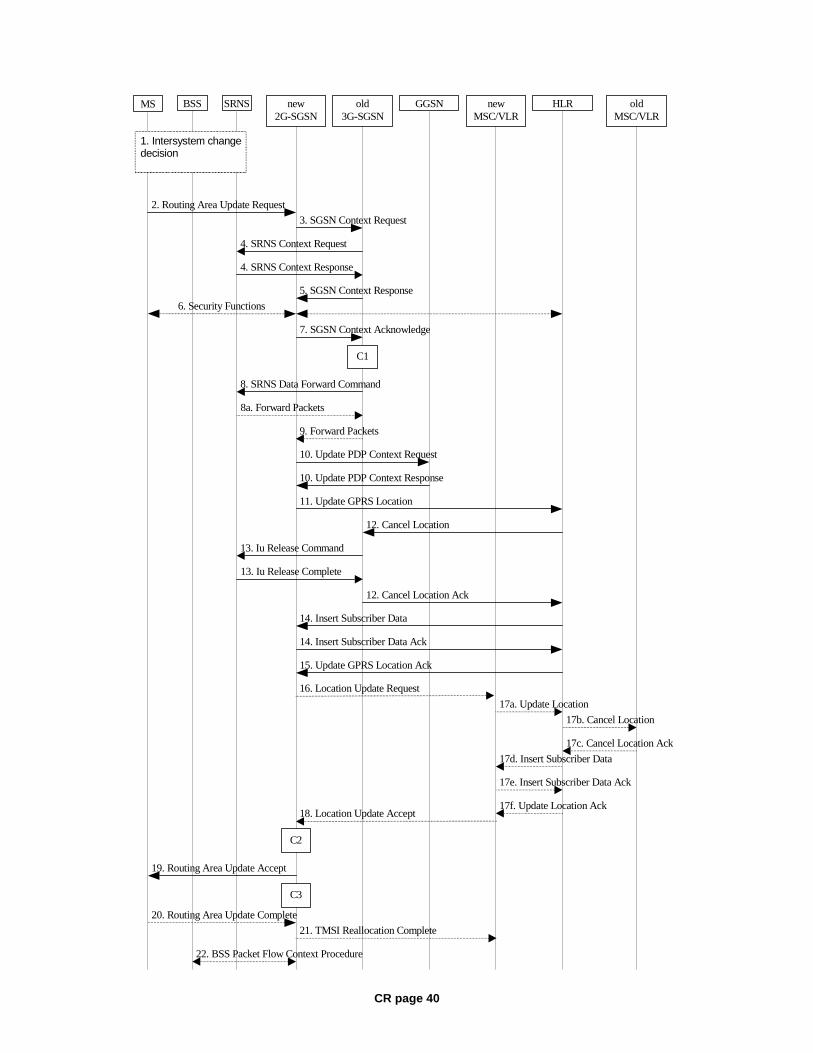
CR page 40
MS new2G-SGSN
HLRGGSNold3G-SGSN
2. Routing Area Update Request
10. Update PDP Context Request
10. Update PDP Context Response
11. Update GPRS Location
15. Update GPRS Location Ack
5. SGSN Context Response
6. Security Functions
19. Routing Area Update Accept
12. Cancel Location
12. Cancel Location Ack
14. Insert Subscriber Data Ack
14. Insert Subscriber Data
7. SGSN Context Acknowledge
BSS SRNS
3. SGSN Context Request
13. Iu Release Command
13. Iu Release Complete
8a. Forward Packets
9. Forward Packets
4. SRNS Context Request
4. SRNS Context Response
8. SRNS Data Forward Command
22. BSS Packet Flow Context Procedure
1. Intersystem changedecision
C3
C1
20. Routing Area Update Complete
newMSC/VLR
oldMSC/VLR
16. Location Update Request
17a. Update Location
17b. Cancel Location
17c. Cancel Location Ack
17d. Insert Subscriber Data
17e. Insert Subscriber Data Ack
17f. Update Location Ack 18. Location Update Accept
21. TMSI Reallocation Complete
C2
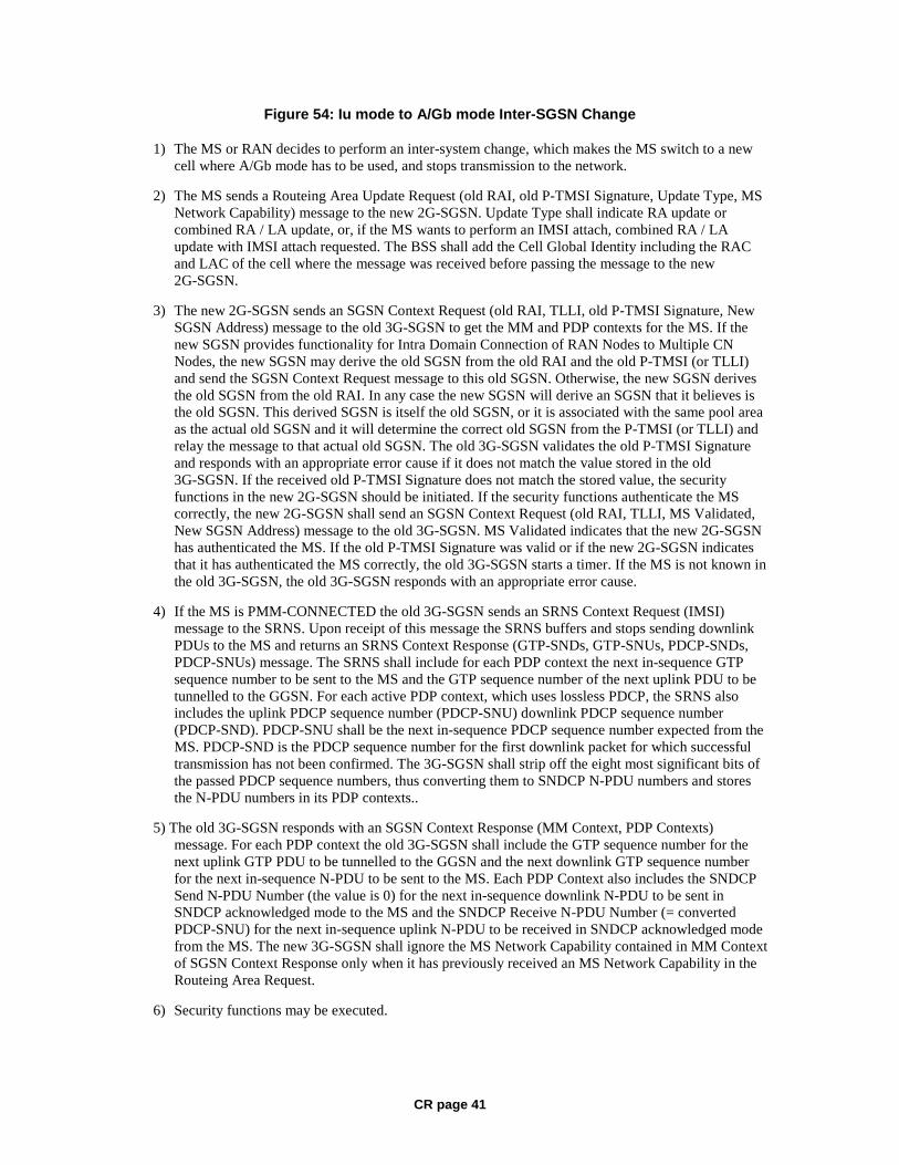
CR page 41
Figure 54: Iu mode to A/Gb mode Inter-SGSN Change
1) The MS or RAN decides to perform an inter-system change, which makes the MS switch to a new cell where A/Gb mode has to be used, and stops transmission to the network.
2) The MS sends a Routeing Area Update Request (old RAI, old P-TMSI Signature, Update Type, MS Network Capability) message to the new 2G-SGSN. Update Type shall indicate RA update or combined RA / LA update, or, if the MS wants to perform an IMSI attach, combined RA / LA update with IMSI attach requested. The BSS shall add the Cell Global Identity including the RAC and LAC of the cell where the message was received before passing the message to the new 2G-SGSN.
3) The new 2G-SGSN sends an SGSN Context Request (old RAI, TLLI, old P-TMSI Signature, New SGSN Address) message to the old 3G-SGSN to get the MM and PDP contexts for the MS. If the new SGSN provides functionality for Intra Domain Connection of RAN Nodes to Multiple CN Nodes, the new SGSN may derive the old SGSN from the old RAI and the old P-TMSI (or TLLI) and send the SGSN Context Request message to this old SGSN. Otherwise, the new SGSN derives the old SGSN from the old RAI. In any case the new SGSN will derive an SGSN that it believes is the old SGSN. This derived SGSN is itself the old SGSN, or it is associated with the same pool area as the actual old SGSN and it will determine the correct old SGSN from the P-TMSI (or TLLI) and relay the message to that actual old SGSN. The old 3G-SGSN validates the old P-TMSI Signature and responds with an appropriate error cause if it does not match the value stored in the old 3G-SGSN. If the received old P-TMSI Signature does not match the stored value, the security functions in the new 2G-SGSN should be initiated. If the security functions authenticate the MS correctly, the new 2G-SGSN shall send an SGSN Context Request (old RAI, TLLI, MS Validated, New SGSN Address) message to the old 3G-SGSN. MS Validated indicates that the new 2G-SGSN has authenticated the MS. If the old P-TMSI Signature was valid or if the new 2G-SGSN indicates that it has authenticated the MS correctly, the old 3G-SGSN starts a timer. If the MS is not known in the old 3G-SGSN, the old 3G-SGSN responds with an appropriate error cause.
4) If the MS is PMM-CONNECTED the old 3G-SGSN sends an SRNS Context Request (IMSI) message to the SRNS. Upon receipt of this message the SRNS buffers and stops sending downlink PDUs to the MS and returns an SRNS Context Response (GTP-SNDs, GTP-SNUs, PDCP-SNDs, PDCP-SNUs) message. The SRNS shall include for each PDP context the next in-sequence GTP sequence number to be sent to the MS and the GTP sequence number of the next uplink PDU to be tunnelled to the GGSN. For each active PDP context, which uses lossless PDCP, the SRNS also includes the uplink PDCP sequence number (PDCP-SNU) downlink PDCP sequence number (PDCP-SND). PDCP-SNU shall be the next in-sequence PDCP sequence number expected from the MS. PDCP-SND is the PDCP sequence number for the first downlink packet for which successful transmission has not been confirmed. The 3G-SGSN shall strip off the eight most significant bits of the passed PDCP sequence numbers, thus converting them to SNDCP N-PDU numbers and stores the N-PDU numbers in its PDP contexts..
5) The old 3G-SGSN responds with an SGSN Context Response (MM Context, PDP Contexts) message. For each PDP context the old 3G-SGSN shall include the GTP sequence number for the next uplink GTP PDU to be tunnelled to the GGSN and the next downlink GTP sequence number for the next in-sequence N-PDU to be sent to the MS. Each PDP Context also includes the SNDCP Send N-PDU Number (the value is 0) for the next in-sequence downlink N-PDU to be sent in SNDCP acknowledged mode to the MS and the SNDCP Receive N-PDU Number (= converted PDCP-SNU) for the next in-sequence uplink N-PDU to be received in SNDCP acknowledged mode from the MS. The new 3G-SGSN shall ignore the MS Network Capability contained in MM Context of SGSN Context Response only when it has previously received an MS Network Capability in the Routeing Area Request.
6) Security functions may be executed.
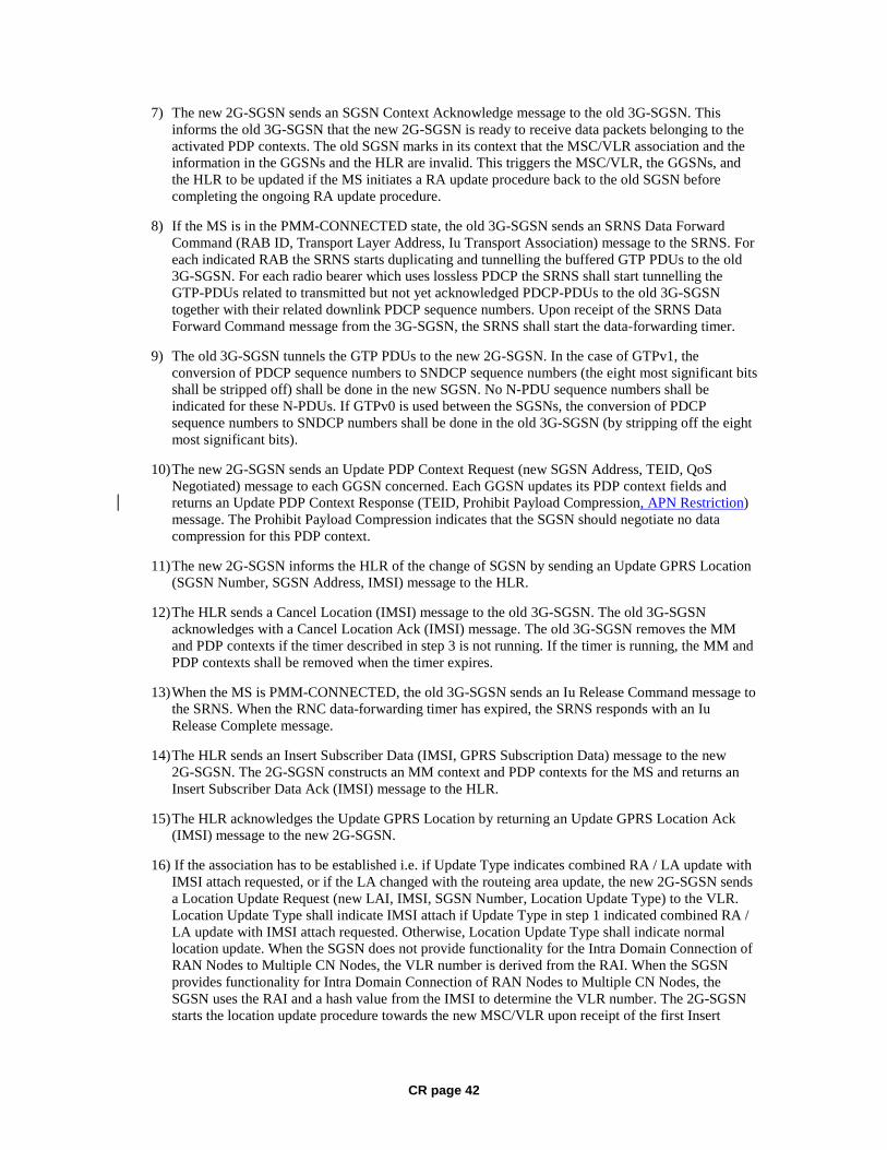
CR page 42
7) The new 2G-SGSN sends an SGSN Context Acknowledge message to the old 3G-SGSN. This informs the old 3G-SGSN that the new 2G-SGSN is ready to receive data packets belonging to the activated PDP contexts. The old SGSN marks in its context that the MSC/VLR association and the information in the GGSNs and the HLR are invalid. This triggers the MSC/VLR, the GGSNs, and the HLR to be updated if the MS initiates a RA update procedure back to the old SGSN before completing the ongoing RA update procedure.
8) If the MS is in the PMM-CONNECTED state, the old 3G-SGSN sends an SRNS Data Forward Command (RAB ID, Transport Layer Address, Iu Transport Association) message to the SRNS. For each indicated RAB the SRNS starts duplicating and tunnelling the buffered GTP PDUs to the old 3G-SGSN. For each radio bearer which uses lossless PDCP the SRNS shall start tunnelling the GTP-PDUs related to transmitted but not yet acknowledged PDCP-PDUs to the old 3G-SGSN together with their related downlink PDCP sequence numbers. Upon receipt of the SRNS Data Forward Command message from the 3G-SGSN, the SRNS shall start the data-forwarding timer.
9) The old 3G-SGSN tunnels the GTP PDUs to the new 2G-SGSN. In the case of GTPv1, the conversion of PDCP sequence numbers to SNDCP sequence numbers (the eight most significant bits shall be stripped off) shall be done in the new SGSN. No N-PDU sequence numbers shall be indicated for these N-PDUs. If GTPv0 is used between the SGSNs, the conversion of PDCP sequence numbers to SNDCP numbers shall be done in the old 3G-SGSN (by stripping off the eight most significant bits).
10) The new 2G-SGSN sends an Update PDP Context Request (new SGSN Address, TEID, QoS Negotiated) message to each GGSN concerned. Each GGSN updates its PDP context fields and returns an Update PDP Context Response (TEID, Prohibit Payload Compression, APN Restriction) message. The Prohibit Payload Compression indicates that the SGSN should negotiate no data compression for this PDP context.
11) The new 2G-SGSN informs the HLR of the change of SGSN by sending an Update GPRS Location (SGSN Number, SGSN Address, IMSI) message to the HLR.
12) The HLR sends a Cancel Location (IMSI) message to the old 3G-SGSN. The old 3G-SGSN acknowledges with a Cancel Location Ack (IMSI) message. The old 3G-SGSN removes the MM and PDP contexts if the timer described in step 3 is not running. If the timer is running, the MM and PDP contexts shall be removed when the timer expires.
13) When the MS is PMM-CONNECTED, the old 3G-SGSN sends an Iu Release Command message to the SRNS. When the RNC data-forwarding timer has expired, the SRNS responds with an Iu Release Complete message.
14) The HLR sends an Insert Subscriber Data (IMSI, GPRS Subscription Data) message to the new 2G-SGSN. The 2G-SGSN constructs an MM context and PDP contexts for the MS and returns an Insert Subscriber Data Ack (IMSI) message to the HLR.
15) The HLR acknowledges the Update GPRS Location by returning an Update GPRS Location Ack (IMSI) message to the new 2G-SGSN.
16) If the association has to be established i.e. if Update Type indicates combined RA / LA update with IMSI attach requested, or if the LA changed with the routeing area update, the new 2G-SGSN sends a Location Update Request (new LAI, IMSI, SGSN Number, Location Update Type) to the VLR. Location Update Type shall indicate IMSI attach if Update Type in step 1 indicated combined RA / LA update with IMSI attach requested. Otherwise, Location Update Type shall indicate normal location update. When the SGSN does not provide functionality for the Intra Domain Connection of RAN Nodes to Multiple CN Nodes, the VLR number is derived from the RAI. When the SGSN provides functionality for Intra Domain Connection of RAN Nodes to Multiple CN Nodes, the SGSN uses the RAI and a hash value from the IMSI to determine the VLR number. The 2G-SGSN starts the location update procedure towards the new MSC/VLR upon receipt of the first Insert
CR page 43
Subscriber Data message from the HLR in step 14). The VLR creates or updates the association with the 2G-SGSN by storing SGSN Number.
17) If the subscriber data in the VLR is marked as not confirmed by the HLR, the new VLR informs the HLR. The HLR cancels the old VLR and inserts subscriber data in the new VLR:
a) The new VLR sends an Update Location (new VLR) to the HLR.
b) The HLR cancels the data in the old VLR by sending Cancel Location (IMSI) to the old VLR.
c) The old VLR acknowledges with Cancel Location Ack (IMSI).
d) The HLR sends Insert Subscriber Data (IMSI, subscriber data) to the new VLR.
e) The new VLR acknowledges with Insert Subscriber Data Ack (IMSI).
f) The HLR responds with Update Location Ack (IMSI) to the new VLR.
18) The new VLR allocates a new TMSI and responds with Location Update Accept (VLR TMSI) to the 2G-SGSN. VLR TMSI is optional if the VLR has not changed.
19) The new 2G-SGSN validates the MS's presence in the new RA. If due to roaming restrictions the MS is not allowed to be attached in the RA, or if subscription checking fails, the new 2G-SGSN rejects the routeing area update with an appropriate cause. If all checks are successful, the new 2G-SGSN constructs MM and PDP contexts for the MS. A logical link is established between the new 2G-SGSN and the MS. 2G-SGSN initiates the establishment procedure. The new 2G-SGSN responds to the MS with a Routeing Area Update Accept (P-TMSI, P-TMSI Signature, Receive N-PDU Number (= converted PDCP-SNU) message. Receive N-PDU Number contains the acknowledgements for each NSAPI which used lossless PDCP before the start of the update procedure, thereby confirming all mobile-originated N-PDUs successfully transferred before the start of the update procedure. If Receive N-PDU Number confirms the reception of N-PDUs, the MS shall discard these N-PDUs.
20) The MS acknowledges the new P-TMSI by returning a Routeing Area Update Complete (Receive N-PDU Number (= converted PDCP-SND)) message to the SGSN. Receive N-PDU Number contains the acknowledgements for each lossless PDCP used by the MS before the start of the update procedure, thereby confirming all mobile-terminated N-PDUs successfully transferred before the start of the update procedure. If Receive N-PDU Number confirms the reception of N-PDUs that were forwarded from the old 3G-SGSN, the new 2G-SGSN shall discard these N-PDUs. The MS deducts Receive N-PDU number from PDCP-SND by stripping off the eight most significant bits. PDCP-SND is the PDCP sequence number for the next expected in-sequence downlink packet to be received in the MS per radio bearer, which used lossless PDCP. The new 2G-SGSN negotiates with the MS for each NSAPI the use of acknowledged or unacknowledged SNDCP regardless whether the SRNS used lossless PDCP or not.
21) The new 2G-SGSN sends TMSI Reallocation Complete message to the new VLR if the MS confirms the VLR TMSI.
22) The 2G-SGSN and the BSS may execute the BSS Packet Flow Context procedure.
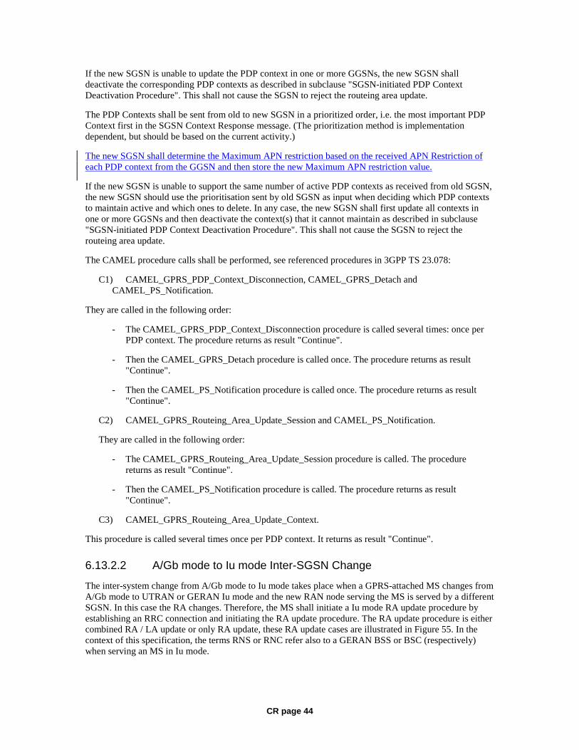
CR page 44
If the new SGSN is unable to update the PDP context in one or more GGSNs, the new SGSN shall deactivate the corresponding PDP contexts as described in subclause "SGSN-initiated PDP Context Deactivation Procedure". This shall not cause the SGSN to reject the routeing area update.
The PDP Contexts shall be sent from old to new SGSN in a prioritized order, i.e. the most important PDP Context first in the SGSN Context Response message. (The prioritization method is implementation dependent, but should be based on the current activity.)
The new SGSN shall determine the Maximum APN restriction based on the received APN Restriction of each PDP context from the GGSN and then store the new Maximum APN restriction value.
If the new SGSN is unable to support the same number of active PDP contexts as received from old SGSN, the new SGSN should use the prioritisation sent by old SGSN as input when deciding which PDP contexts to maintain active and which ones to delete. In any case, the new SGSN shall first update all contexts in one or more GGSNs and then deactivate the context(s) that it cannot maintain as described in subclause "SGSN-initiated PDP Context Deactivation Procedure". This shall not cause the SGSN to reject the routeing area update.
The CAMEL procedure calls shall be performed, see referenced procedures in 3GPP TS 23.078:
C1) CAMEL_GPRS_PDP_Context_Disconnection, CAMEL_GPRS_Detach and CAMEL_PS_Notification.
They are called in the following order:
- The CAMEL_GPRS_PDP_Context_Disconnection procedure is called several times: once per PDP context. The procedure returns as result "Continue".
- Then the CAMEL_GPRS_Detach procedure is called once. The procedure returns as result "Continue".
- Then the CAMEL_PS_Notification procedure is called once. The procedure returns as result "Continue".
C2) CAMEL_GPRS_Routeing_Area_Update_Session and CAMEL_PS_Notification.
They are called in the following order:
- The CAMEL_GPRS_Routeing_Area_Update_Session procedure is called. The procedure returns as result "Continue".
- Then the CAMEL_PS_Notification procedure is called. The procedure returns as result "Continue".
C3) CAMEL_GPRS_Routeing_Area_Update_Context.
This procedure is called several times once per PDP context. It returns as result "Continue".
6.13.2.2 A/Gb mode to Iu mode Inter-SGSN Change
The inter-system change from A/Gb mode to Iu mode takes place when a GPRS-attached MS changes from A/Gb mode to UTRAN or GERAN Iu mode and the new RAN node serving the MS is served by a different SGSN. In this case the RA changes. Therefore, the MS shall initiate a Iu mode RA update procedure by establishing an RRC connection and initiating the RA update procedure. The RA update procedure is either combined RA / LA update or only RA update, these RA update cases are illustrated in Figure 55. In the context of this specification, the terms RNS or RNC refer also to a GERAN BSS or BSC (respectively) when serving an MS in Iu mode.

CR page 45
If the network operates in mode I, then an MS, that is both PS-attached and CS-attached, shall perform the Combined RA / LA Update procedures. This concerns only idle mode (see 3GPP TS 23.122), as no combined RA / LA updates are performed during a CS connection.
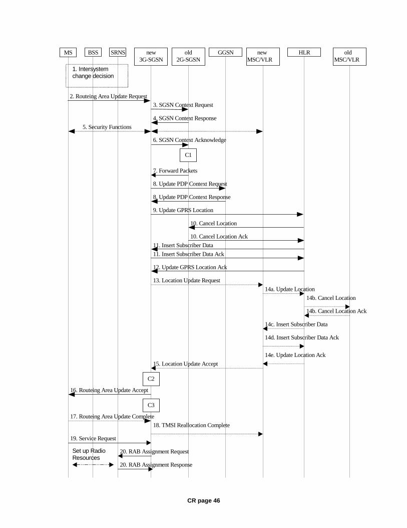
CR page 46
MS new3G-SGSN
HLRGGSNold2G-SGSN
8. Update PDP Context Request
8. Update PDP Context Response
9. Update GPRS Location
12. Update GPRS Location Ack
2. Routeing Area Update Request
4. SGSN Context Response
5. Security Functions
16. Routeing Area Update Accept
10. Cancel Location
10. Cancel Location Ack
11. Insert Subscriber Data Ack
11. Insert Subscriber Data
17. Routeing Area Update Complete
6. SGSN Context Acknowledge
BSS SRNS
3. SGSN Context Request
20. RAB Assignment Request
20. RAB Assignment Response
7. Forward Packets
1. Intersystemchange decision
C3
C1
newMSC/VLR
oldMSC/VLR
13. Location Update Request
14a. Update Location
14b. Cancel Location
14b. Cancel Location Ack
14c. Insert Subscriber Data
14d. Insert Subscriber Data Ack
14e. Update Location Ack
15. Location Update Accept
18. TMSI Reallocation Complete
Set up RadioResources
19. Service Request
C2

CR page 47
Figure 55: A/Gb mode to Iu mode Inter SGSN Change
1) The MS or RAN decides to perform an inter-system change, which makes the MS switch to a new cell where Iu mode has to be used, and stops transmission to the network.
2) The MS sends a Routeing Area Update Request (P-TMSI, old RAI, old P-TMSI Signature, Update Type, CM, MS Network Capability) message to the new 3G-SGSN. Update Type shall indicate RA update or combined RA / LA update, or, if the MS wants to perform an IMSI attach, combined RA / LA update with IMSI attach requested, and also if the MS has a follow-on request, i.e. if there is pending uplink traffic (signalling or data). The SGSN may use, as an implementation option, the follow-on request indication to release or keep the Iu connection after the completion of the RA update procedure. The SRNC shall add the Routeing Area Identity including the RAC and LAC of the area where the MS is located before forwarding the message to the 3G-SGSN. This RA identity corresponds to the RAI in the MM system information sent by the SRNC to the MS.
3) The new 3G-SGSN uses the old RAI received from the MS to derive the old 2G-SGSN address, and sends an SGSN Context Request (old RAI, old P-TMSI, New SGSN Address) message to the old 2G-SGSN to get the MM and PDP contexts for the MS. If the new SGSN provides functionality for Intra Domain Connection of RAN Nodes to Multiple CN Nodes, the new SGSN may derive the old SGSN from the old RAI and the old P-TMSI and send the SGSN Context Request message to this old SGSN. Otherwise, the new SGSN derives the old SGSN from the old RAI. In any case the new SGSN will derive an SGSN that it believes is the old SGSN. This derived SGSN is itself the old SGSN, or it is associated with the same pool area as the actual old SGSN and it will determine the correct old SGSN from the P-TMSI and relay the message to that actual old SGSN. The old 2G-SGSN validates the old P-TMSI Signature and responds with an appropriate error cause if it does not match the value stored in the old 2G-SGSN. If the received old P-TMSI Signature does not match the stored value, the old 2G-SGSN should initiate the security functions in the new 3G-SGSN. If the security functions authenticate the MS correctly, the new 3G-SGSN shall send an SGSN Context Request (old RAI, IMSI, MS Validated, New SGSN Address) message to the old 2G-SGSN. MS Validated indicates that the new 3G-SGSN has authenticated the MS. If the old P-TMSI Signature was valid or if the new 3G-SGSN indicates that it has authenticated the MS correctly, the old 2G-SGSN starts a timer and stops the transmission of N-PDUs to the MS.
4) The old 2G-SGSN responds with an SGSN Context Response (MM Context, PDP Contexts) message. Each PDP Context includes the GTP sequence number for the next downlink N-PDU to be sent to the MS and the GTP sequence number for the next uplink N-PDU to be tunnelled to the GGSN. Each PDP Context also includes the SNDCP Send N-PDU Number for the next downlink N-PDU to be sent in acknowledged mode SNDCP to the MS and the SNDCP Receive N-PDU Number for the next uplink N-PDU to be received in acknowledged mode SNDCP from the MS. The new 3G-SGSN derives the corresponding PDCP sequence numbers from these N-PDU sequence numbers by adding eight most significant bits "1". These PDCP sequence numbers are stored in the 3G-SGSN PDP contexts. The new 3G-SGSN shall ignore the MS Network Capability contained in MM Context of SGSN Context Response only when it has previously received an MS Network Capability in the Routeing Area Request.
5) Security functions may be executed.
6) The new 3G-SGSN sends an SGSN Context Acknowledge message to the old 2G-SGSN. This informs the old 2G-SGSN that the new 3G-SGSN is ready to receive data packets belonging to the activated PDP contexts. The old SGSN marks in its context that the MSC/VLR association and the information in the GGSNs and the HLR are invalid. This triggers the MSC/VLR, the GGSNs, and the HLR to be updated if the MS initiates a routeing area update procedure back to the old SGSN before completing the ongoing routeing area update procedure.
7) The old 2G-SGSN duplicates the buffered N-PDUs and starts tunnelling them to the new 3G-SGSN. Additional N-PDUs received from the GGSN before the timer described in step 3 expires are also duplicated and tunnelled to the new 3G-SGSN. N-PDUs that were already sent to the MS in

CR page 48
acknowledged mode SNDCP and that are not yet acknowledged by the MS are tunnelled together with their related SNDCP N-PDU sequence number. No PDCP sequence numbers shall be indicated for these N-PDUs. No N-PDUs shall be forwarded to the new 3G-SGSN after expiry of the timer described in step 3.
8) The new 3G-SGSN sends an Update PDP Context Request (new SGSN Address, TEID, QoS Negotiated) message to each GGSN concerned. Each GGSN updates its PDP context fields and returns an Update PDP Context Response (TEID, Prohibit Payload Compression, APN Restriction) message. The Prohibit Payload Compression indicates that the SGSN should negotiate no data compression for this PDP context.
9) The new 3G-SGSN informs the HLR of the change of SGSN by sending an Update GPRS Location (SGSN Number, SGSN Address, IMSI) message to the HLR.
10) The HLR sends a Cancel Location (IMSI, Cancellation Type) message to the old 2G-SGSN. The old 2G-SGSN removes the MM and PDP contexts if the timer described in step 3 is not running. If the timer is running, the MM and PDP contexts are removed when the timer expires. The old 2G-SGSN acknowledges with a Cancel Location Ack (IMSI) message.
11) The HLR sends an Insert Subscriber Data (IMSI, GPRS Subscription Data) message to the new 3G-SGSN. The 3G-SGSN constructs an MM context for the MS and returns an Insert Subscriber Data Ack (IMSI) message to the HLR.
12) The HLR acknowledges the Update GPRS Location by returning an Update GPRS Location Ack (IMSI) message to the new 3G-SGSN.
13) If the association has to be established, if Update Type indicates combined RA / LA update with IMSI attach requested, or if the LA changed with the routeing area update, the new SGSN sends a Location Update Request (new LAI, IMSI, SGSN Number, Location Update Type) to the VLR. Location Update Type shall indicate IMSI attach if Update Type in step 1 indicated combined RA / LA update with IMSI attach requested. Otherwise, Location Update Type shall indicate normal location update. When the SGSN does not provide functionality for the Intra Domain Connection of RAN Nodes to Multiple CN Nodes, the VLR number is derived from the RAI. When the SGSN provides functionality for Intra Domain Connection of RAN Nodes to Multiple CN Nodes, the SGSN uses the RAI and a hash value from the IMSI to determine the VLR number. The 3G-SGSN starts the location update procedure towards the new MSC/VLR upon receipt of the first Insert Subscriber Data message from the HLR in step 12). The VLR creates or updates the association with the 3G-SGSN by storing SGSN Number.
14) If the subscriber data in the VLR is marked as not confirmed by the HLR, the new VLR informs the HLR. The HLR cancels the old VLR and inserts subscriber data in the new VLR:
a) The new VLR sends an Update Location (new VLR) to the HLR.
b) The HLR cancels the data in the old VLR by sending Cancel Location (IMSI) to the old VLR.
c) The old VLR acknowledges with Cancel Location Ack (IMSI).
d) The HLR sends Insert Subscriber Data (IMSI, subscriber data) to the new VLR.
e) The new VLR acknowledges with Insert Subscriber Data Ack (IMSI).
f) The HLR responds with Update Location Ack (IMSI) to the new VLR.
15) The new VLR allocates a new TMSI and responds with Location Update Accept (VLR TMSI) to the 3G-SGSN. VLR TMSI is optional if the VLR has not changed.
16) The new 3G-SGSN validate the MS's presence in the new RA. If due to roaming restrictions the MS is not allowed to be attached in the RA, or if subscription checking fails, the new 3G-SGSN rejects
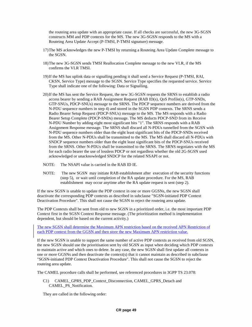
CR page 49
the routeing area update with an appropriate cause. If all checks are successful, the new 3G-SGSN constructs MM and PDP contexts for the MS. The new 3G-SGSN responds to the MS with a Routeing Area Update Accept (P-TMSI, P-TMSI signature) message.
17) The MS acknowledges the new P-TMSI by returning a Routeing Area Update Complete message to the SGSN.
18) The new 3G-SGSN sends TMSI Reallocation Complete message to the new VLR, if the MS confirms the VLR TMSI.
19) If the MS has uplink data or signalling pending it shall send a Service Request (P-TMSI, RAI, CKSN, Service Type) message to the SGSN. Service Type specifies the requested service. Service Type shall indicate one of the following: Data or Signalling.
20) If the MS has sent the Service Request, the new 3G-SGSN requests the SRNS to establish a radio access bearer by sending a RAB Assignment Request (RAB ID(s), QoS Profile(s), GTP-SNDs, GTP-SNUs, PDCP-SNUs) message to the SRNS. The PDCP sequence numbers are derived from the N-PDU sequence numbers in step 4) and stored in the SGSN PDP contexts. The SRNS sends a Radio Bearer Setup Request (PDCP-SNUs) message to the MS. The MS responds with a Radio Bearer Setup Complete (PDCP-SNDs) message. The MS deducts PDCP-SND from its Receive N-PDU Number by adding eight most significant bits "1". The SRNS responds with a RAB Assignment Response message. The SRNS shall discard all N-PDUs tunnelled from the SGSN with N-PDU sequence numbers older than the eight least significant bits of the PDCP-SNDs received from the MS. Other N-PDUs shall be transmitted to the MS. The MS shall discard all N-PDUs with SNDCP sequence numbers older than the eight least significant bits of the PDCP-SNUs received from the SRNS. Other N-PDUs shall be transmitted to the SRNS. The SRNS negotiates with the MS for each radio bearer the use of lossless PDCP or not regardless whether the old 2G-SGSN used acknowledged or unacknowledged SNDCP for the related NSAPI or not.
NOTE: The NSAPI value is carried in the RAB ID IE.
NOTE: The new SGSN may initiate RAB establishment after execution of the security functions (step 5), or wait until completion of the RA update procedure. For the MS, RAB establishment may occur anytime after the RA update request is sent (step 2).
If the new SGSN is unable to update the PDP context in one or more GGSNs, the new SGSN shall deactivate the corresponding PDP contexts as described in subclause "SGSN-initiated PDP Context Deactivation Procedure". This shall not cause the SGSN to reject the routeing area update.
The PDP Contexts shall be sent from old to new SGSN in a prioritized order, i.e. the most important PDP Context first in the SGSN Context Response message. (The prioritization method is implementation dependent, but should be based on the current activity.)
The new SGSN shall determine the Maximum APN restriction based on the received APN Restriction of each PDP context from the GGSN and then store the new Maximum APN restriction value.
If the new SGSN is unable to support the same number of active PDP contexts as received from old SGSN, the new SGSN should use the prioritisation sent by old SGSN as input when deciding which PDP contexts to maintain active and which ones to delete. In any case, the new SGSN shall first update all contexts in one or more GGSNs and then deactivate the context(s) that it cannot maintain as described in subclause "SGSN-initiated PDP Context Deactivation Procedure". This shall not cause the SGSN to reject the routeing area update.
The CAMEL procedure calls shall be performed, see referenced procedures in 3GPP TS 23.078:
C1) CAMEL_GPRS_PDP_Context_Disconnection, CAMEL_GPRS_Detach and CAMEL_PS_Notification.
They are called in the following order:
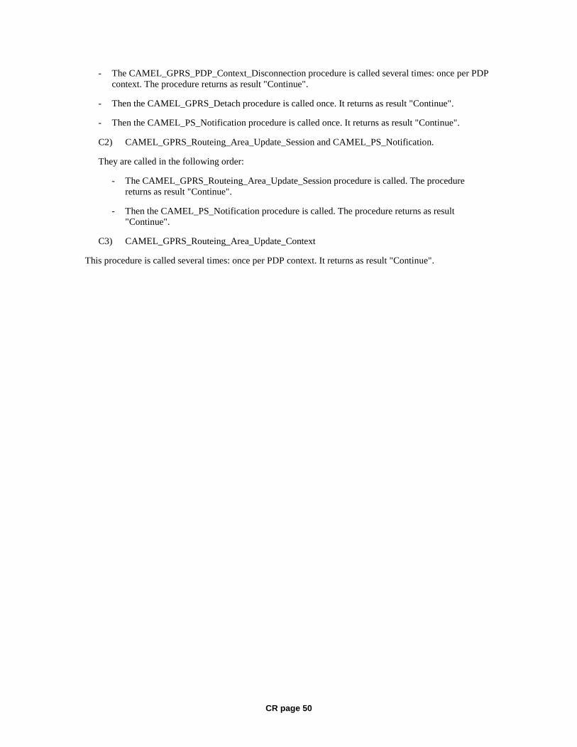
CR page 50
- The CAMEL_GPRS_PDP_Context_Disconnection procedure is called several times: once per PDP context. The procedure returns as result "Continue".
- Then the CAMEL_GPRS_Detach procedure is called once. It returns as result "Continue".
- Then the CAMEL_PS_Notification procedure is called once. It returns as result "Continue".
C2) CAMEL_GPRS_Routeing_Area_Update_Session and CAMEL_PS_Notification.
They are called in the following order:
- The CAMEL_GPRS_Routeing_Area_Update_Session procedure is called. The procedure returns as result "Continue".
- Then the CAMEL_PS_Notification procedure is called. The procedure returns as result "Continue".
C3) CAMEL_GPRS_Routeing_Area_Update_Context
This procedure is called several times: once per PDP context. It returns as result "Continue".
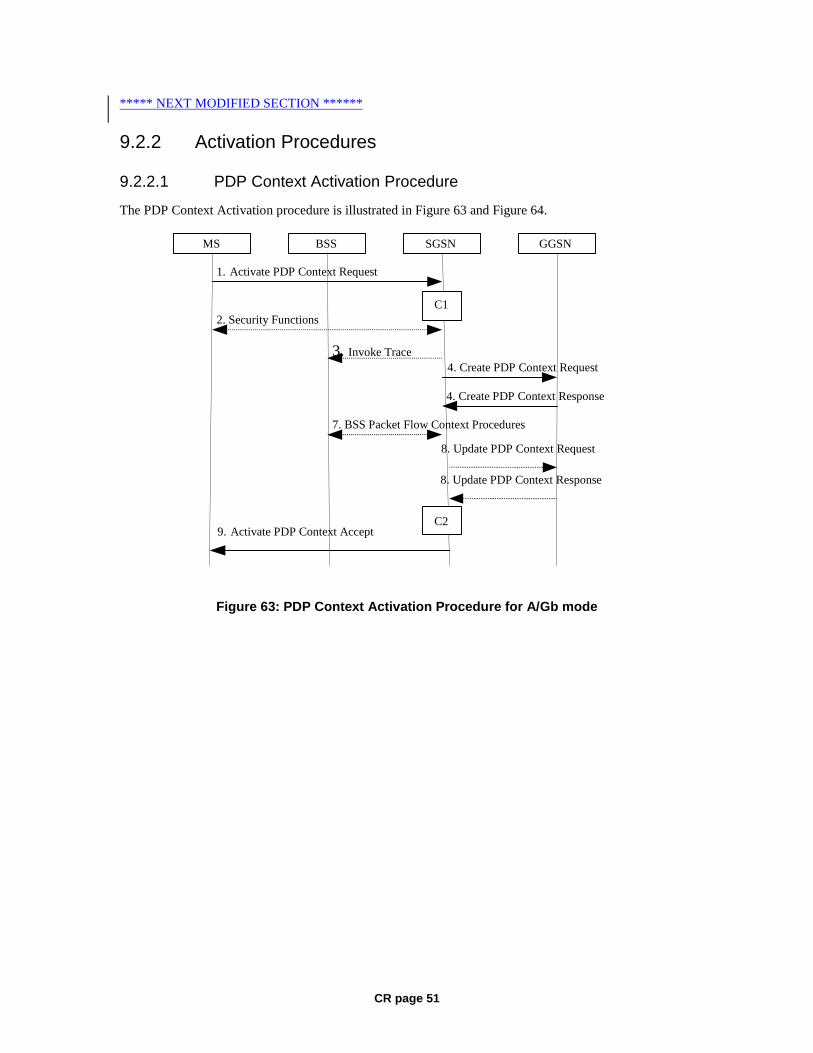
CR page 51
***** NEXT MODIFIED SECTION ******
9.2.2 Activation Procedures
9.2.2.1 PDP Context Activation Procedure
The PDP Context Activation procedure is illustrated in Figure 63 and Figure 64.
GGSN
9. Activate PDP Context Accept
4. Create PDP Context Response
4. Create PDP Context Request
1. Activate PDP Context Request
SGSN BSS
2. Security Functions
MS
7. BSS Packet Flow Context Procedures
C1
C2
3. Invoke Trace
8. Update PDP Context Request
8. Update PDP Context Response
Figure 63: PDP Context Activation Procedure for A/Gb mode
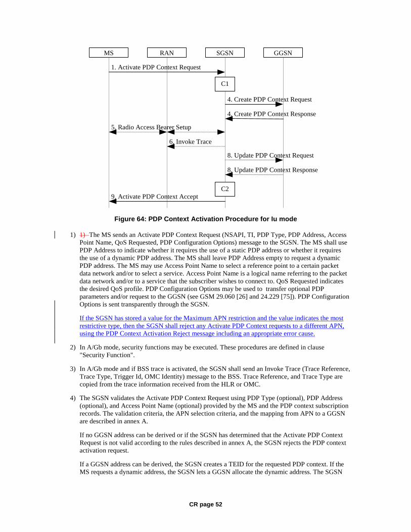
CR page 52
GGSN
9. Activate PDP Context Accept
4. Create PDP Context Response
4. Create PDP Context Request
1. Activate PDP Context Request
SGSNRANMS
5. Radio Access Bearer Setup
C1
C2
6. Invoke Trace
8. Update PDP Context Response
8. Update PDP Context Request
Figure 64: PDP Context Activation Procedure for Iu mode
1) 1) The MS sends an Activate PDP Context Request (NSAPI, TI, PDP Type, PDP Address, Access Point Name, QoS Requested, PDP Configuration Options) message to the SGSN. The MS shall use PDP Address to indicate whether it requires the use of a static PDP address or whether it requires the use of a dynamic PDP address. The MS shall leave PDP Address empty to request a dynamic PDP address. The MS may use Access Point Name to select a reference point to a certain packet data network and/or to select a service. Access Point Name is a logical name referring to the packet data network and/or to a service that the subscriber wishes to connect to. QoS Requested indicates the desired QoS profile. PDP Configuration Options may be used to transfer optional PDP parameters and/or request to the GGSN (see GSM 29.060 [26] and 24.229 [75]). PDP Configuration Options is sent transparently through the SGSN.
If the SGSN has stored a value for the Maximum APN restriction and the value indicates the most restrictive type, then the SGSN shall reject any Activate PDP Context requests to a different APN, using the PDP Context Activation Reject message including an appropriate error cause.
2) In A/Gb mode, security functions may be executed. These procedures are defined in clause "Security Function".
3) In A/Gb mode and if BSS trace is activated, the SGSN shall send an Invoke Trace (Trace Reference, Trace Type, Trigger Id, OMC Identity) message to the BSS. Trace Reference, and Trace Type are copied from the trace information received from the HLR or OMC.
4) The SGSN validates the Activate PDP Context Request using PDP Type (optional), PDP Address (optional), and Access Point Name (optional) provided by the MS and the PDP context subscription records. The validation criteria, the APN selection criteria, and the mapping from APN to a GGSN are described in annex A.
If no GGSN address can be derived or if the SGSN has determined that the Activate PDP Context Request is not valid according to the rules described in annex A, the SGSN rejects the PDP context activation request.
If a GGSN address can be derived, the SGSN creates a TEID for the requested PDP context. If the MS requests a dynamic address, the SGSN lets a GGSN allocate the dynamic address. The SGSN

CR page 53
may restrict the requested QoS attributes given its capabilities and the current load, and it shall restrict the requested QoS attributes according to the subscribed QoS profile.
The SGSN sends a Create PDP Context Request (PDP Type, PDP Address, Access Point Name, QoS Negotiated, TEID, NSAPI, MSISDN, Selection Mode, Charging Characteristics, Trace Reference, Trace Type, Trigger Id, OMC Identity, PDP Configuration Options, Maximum APN Restriction) message to the affected GGSN. Access Point Name shall be the APN Network Identifier of the APN selected according to the procedure described in Annex A. PDP Address shall be empty if a dynamic address is requested. The GGSN may use Access Point Name to find a packet data network and optionally to activate a service for this APN. Selection Mode indicates whether a subscribed APN was selected, or whether a non-subscribed APN sent by an MS or a non-subscribed APN chosen by the SGSN was selected. Selection Mode is set according to Annex A. The GGSN may use Selection Mode when deciding whether to accept or reject the PDP context activation. For example, if an APN requires subscription, the GGSN is configured to accept only the PDP context activation that requests a subscribed APN as indicated by the SGSN with Selection Mode. Charging Characteristics indicates which kind of charging the PDP context is liable for. The charging characteristics on the GPRS subscription and individually subscribed APNs as well as the way the SGSN handles Charging Characteristics and chooses to send them or not to the GGSN is defined in 3GPP TS 32.215 [70]. The SGSN shall include Trace Reference, Trace Type, Trigger Id, and OMC Identity if GGSN trace is activated. The SGSN shall copy Trace Reference, Trace Type, and OMC Identity from the trace information received from the HLR or OMC. The Maximum APN Restriction denotes the most stringent restriction as required by any already active PDP contexts. If there are no already active PDP contexts, this value is set to the least restrictive type (see subcluase 15.4). If the GGSN receives the Maximum APN Restriction, then the GGSN shall check if the Maximum APN Restiction value does not conflict with the APN Restriction value associated with this PDP context request. If there is no conflict the request shall be allowed, otherwise the request shall be rejected with the SGSN sending a PDP Context Activation Reject Message to the MS including an appropriate error cause.
The GGSN creates a new entry in its PDP context table and generates a Charging Id. The new entry allows the GGSN to route PDP PDUs between the SGSN and the packet data network, and to start charging. The way the GGSN handles Charging Characteristics that it may have received from the SGSN is defined in 3GPP TS 32.215 [70]. The GGSN may restrict QoS Negotiated given its capabilities and the current load. The GGSN then returns a Create PDP Context Response (TEID, PDP Address, PDP Configuration Options, QoS Negotiated, Charging Id, Prohibit Payload Compression, APN Restriction, Cause) message to the SGSN. The Prohibit Payload Compression indicates that the SGSN should negotiate no data compression for this PDP context. PDP Address is included if the GGSN allocated a PDP address. If the GGSN has been configured by the operator to use External PDN Address Allocation for the requested APN, PDP Address shall be set to 0.0.0.0, indicating that the PDP address shall be negotiated by the MS with the external PDN after completion of the PDP Context Activation procedure. The GGSN shall relay, modify and monitor these negotiations as long as the PDP context is in ACTIVE state, and use the GGSN-Initiated PDP Context Modification procedure to transfer the currently used PDP address to the SGSN and the MS. PDP Configuration Options contain optional PDP parameters that the GGSN may transfer to the MS. These optional PDP parameters may be requested by the MS in the Activate PDP Context Request message, or may be sent unsolicited by the GGSN. PDP Configuration Options is sent transparently through the SGSN. The Create PDP Context messages are sent over the backbone network.
If QoS Negotiated received from the SGSN is incompatible with the PDP context being activated, the GGSN rejects the Create PDP Context Request message. The GGSN operator configures the compatible QoS profiles.
If an APN Restriction is received from the GGSN for this PDP Context, then the SGSN shall store this value for the PDP Context and the SGSN shall check this received value with the stored value for the Maximum APN Restriction to ensure there are no conflicts between values. If the consquence of this check results in the PDP context being rejected, the SGSN shall initiate a PDP
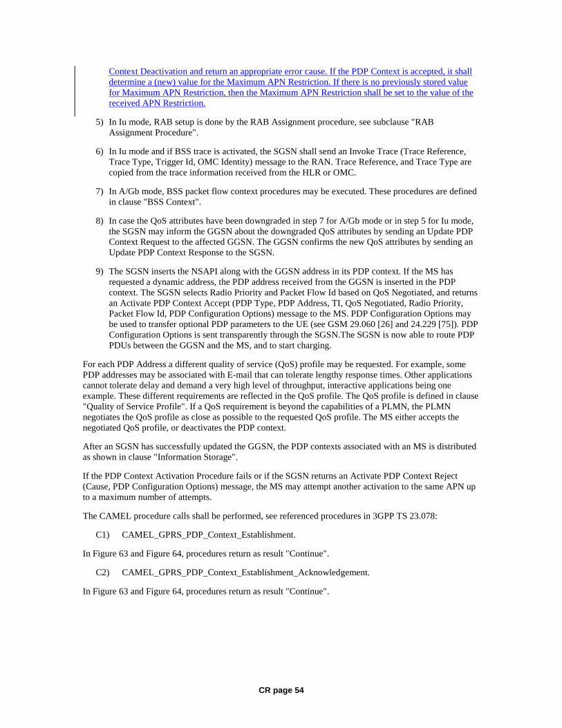
CR page 54
Context Deactivation and return an appropriate error cause. If the PDP Context is accepted, it shall determine a (new) value for the Maximum APN Restriction. If there is no previously stored value for Maximum APN Restriction, then the Maximum APN Restriction shall be set to the value of the received APN Restriction.
5) In Iu mode, RAB setup is done by the RAB Assignment procedure, see subclause "RAB Assignment Procedure".
6) In Iu mode and if BSS trace is activated, the SGSN shall send an Invoke Trace (Trace Reference, Trace Type, Trigger Id, OMC Identity) message to the RAN. Trace Reference, and Trace Type are copied from the trace information received from the HLR or OMC.
7) In A/Gb mode, BSS packet flow context procedures may be executed. These procedures are defined in clause "BSS Context".
8) In case the QoS attributes have been downgraded in step 7 for A/Gb mode or in step 5 for Iu mode, the SGSN may inform the GGSN about the downgraded QoS attributes by sending an Update PDP Context Request to the affected GGSN. The GGSN confirms the new QoS attributes by sending an Update PDP Context Response to the SGSN.
9) The SGSN inserts the NSAPI along with the GGSN address in its PDP context. If the MS has requested a dynamic address, the PDP address received from the GGSN is inserted in the PDP context. The SGSN selects Radio Priority and Packet Flow Id based on QoS Negotiated, and returns an Activate PDP Context Accept (PDP Type, PDP Address, TI, QoS Negotiated, Radio Priority, Packet Flow Id, PDP Configuration Options) message to the MS. PDP Configuration Options may be used to transfer optional PDP parameters to the UE (see GSM 29.060 [26] and 24.229 [75]). PDP Configuration Options is sent transparently through the SGSN.The SGSN is now able to route PDP PDUs between the GGSN and the MS, and to start charging.
For each PDP Address a different quality of service (QoS) profile may be requested. For example, some PDP addresses may be associated with E-mail that can tolerate lengthy response times. Other applications cannot tolerate delay and demand a very high level of throughput, interactive applications being one example. These different requirements are reflected in the QoS profile. The QoS profile is defined in clause "Quality of Service Profile". If a QoS requirement is beyond the capabilities of a PLMN, the PLMN negotiates the QoS profile as close as possible to the requested QoS profile. The MS either accepts the negotiated QoS profile, or deactivates the PDP context.
After an SGSN has successfully updated the GGSN, the PDP contexts associated with an MS is distributed as shown in clause "Information Storage".
If the PDP Context Activation Procedure fails or if the SGSN returns an Activate PDP Context Reject (Cause, PDP Configuration Options) message, the MS may attempt another activation to the same APN up to a maximum number of attempts.
The CAMEL procedure calls shall be performed, see referenced procedures in 3GPP TS 23.078:
C1) CAMEL_GPRS_PDP_Context_Establishment.
In Figure 63 and Figure 64, procedures return as result "Continue".
C2) CAMEL_GPRS_PDP_Context_Establishment_Acknowledgement.
In Figure 63 and Figure 64, procedures return as result "Continue".
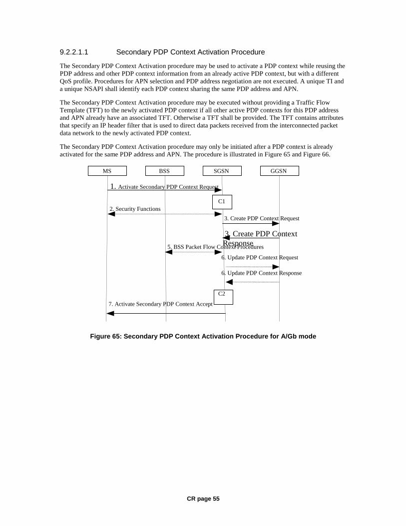
CR page 55
9.2.2.1.1 Secondary PDP Context Activation Procedure
The Secondary PDP Context Activation procedure may be used to activate a PDP context while reusing the PDP address and other PDP context information from an already active PDP context, but with a different QoS profile. Procedures for APN selection and PDP address negotiation are not executed. A unique TI and a unique NSAPI shall identify each PDP context sharing the same PDP address and APN.
The Secondary PDP Context Activation procedure may be executed without providing a Traffic Flow Template (TFT) to the newly activated PDP context if all other active PDP contexts for this PDP address and APN already have an associated TFT. Otherwise a TFT shall be provided. The TFT contains attributes that specify an IP header filter that is used to direct data packets received from the interconnected packet data network to the newly activated PDP context.
The Secondary PDP Context Activation procedure may only be initiated after a PDP context is already activated for the same PDP address and APN. The procedure is illustrated in Figure 65 and Figure 66.
GGSN
7. Activate Secondary PDP Context Accept
3. Create PDP Context Response
3. Create PDP Context Request
1. Activate Secondary PDP Context Request
SGSN BSS
2. Security Functions
MS
5. BSS Packet Flow Context Procedures
C1
C2
6. Update PDP Context Request
6. Update PDP Context Response
Figure 65: Secondary PDP Context Activation Procedure for A/Gb mode
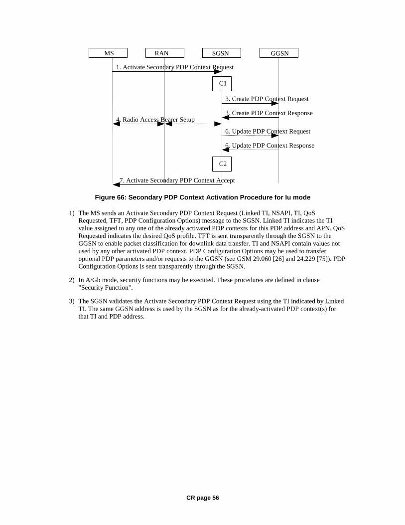
CR page 56
GGSN
7. Activate Secondary PDP Context Accept
3 . Create PDP Context Response
3 . Create PDP Context Request
1. Activate Secondary PDP Context Request
SGSN RAN MS
4 . Radio Access Bea rer Setup
C1
C2
6. Update PDP Context Response
6. Update PDP Context Request
Figure 66: Secondary PDP Context Activation Procedure for Iu mode
1) The MS sends an Activate Secondary PDP Context Request (Linked TI, NSAPI, TI, QoS Requested, TFT, PDP Configuration Options) message to the SGSN. Linked TI indicates the TI value assigned to any one of the already activated PDP contexts for this PDP address and APN. QoS Requested indicates the desired QoS profile. TFT is sent transparently through the SGSN to the GGSN to enable packet classification for downlink data transfer. TI and NSAPI contain values not used by any other activated PDP context. PDP Configuration Options may be used to transfer optional PDP parameters and/or requests to the GGSN (see GSM 29.060 [26] and 24.229 [75]). PDP Configuration Options is sent transparently through the SGSN.
2) In A/Gb mode, security functions may be executed. These procedures are defined in clause "Security Function".
3) The SGSN validates the Activate Secondary PDP Context Request using the TI indicated by Linked TI. The same GGSN address is used by the SGSN as for the already-activated PDP context(s) for that TI and PDP address.

CR page 57
The SGSN may restrict the requested QoS attributes given its capabilities and the current load, and it shall restrict the requested QoS attributes according to the subscribed QoS profile, which represents the maximum QoS per PDP context to the associated APN. The GGSN may restrict and negotiate the requested QoS as specified in clause "PDP Context Activation Procedure". The SGSN sends a Create PDP Context Request (QoS Negotiated, TEID, NSAPI, Primary NSAPI, TFT, PDP Configuration Options) message to the affected GGSN. Primary NSAPI indicates the NSAPI value assigned to any one of the already activated PDP contexts for this PDP address and APN. TFT is included only if received in the Activate Secondary PDP Context Request message. PDP Configuration Options is sent transparently through the SGSN if received in the Activate secondary PDP Context Request message.
The GGSN uses the same packet data network as used by the already-activated PDP context(s) for that PDP address, generates a new entry in its PDP context table, and stores the TFT. The new entry allows the GGSN to route PDP PDUs via different GTP tunnels between the SGSN and the packet data network. The GGSN returns a Create PDP Context Response (TEID, QoS Negotiated, Cause, PDP Configuration Options, Prohibit Payload Compression, APN Restriction) message to the SGSN. PDP Configuration Options may be used to transfer optional PDP parameters to the UE (see GSM 29.060 [26] and 24.229 [75]). The Prohibit Payload Compression indicates that the SGSN should negotiate no data compression for this PDP context. If an APN Restriction is received from the GGSN for this PDP Context, then the SGSN shall store this value for the PDP Context.
4) In Iu mode, RAB setup is done by the RAB Assignment procedure.
5) In A/Gb mode, BSS packet flow context procedures may be executed. These procedures are defined in clause "BSS Context".
6) In case the QoS attributes have been downgraded in step 5 for A/Gb mode or in step 4 for Iu mode, the SGSN may inform the GGSN about the downgraded QoS attributes by sending an Update PDP Context Request to the affected GGSN. The GGSN confirms the new QoS attributes by sending an Update PDP Context Response to the SGSN.
7) The SGSN selects Radio Priority and Packet Flow Id based on QoS Negotiated, and returns an Activate Secondary PDP Context Accept (TI, QoS Negotiated, Radio Priority, Packet Flow Id, PDP Configuration Options) message to the MS. PDP Configuration Options is sent transparently through the SGSN if received in the Create PDP Context Response message. The SGSN is now able to route PDP PDUs between the GGSN and the MS via different GTP tunnels and possibly different LLC links.
For each additionally activated PDP context a QoS profile and TFT may be requested.
If the secondary PDP context activation procedure fails or if the SGSN returns an Activate Secondary PDP Context Reject (Cause, PDP Configuration Options) message, the MS may attempt another activation with a different TFT, depending on the cause.
The CAMEL procedure calls shall be performed, see referenced procedures in 3GPP TS 23.078:
C1) CAMEL_GPRS_PDP_Context_Establishment.
In Figure 65 and in Figure 66, procedures return as result "Continue".
C2) CAMEL_GPRS_PDP_Context_Establishment_Acknowledgement.
In Figure 65 and in Figure 66, procedures return as result "Continue".
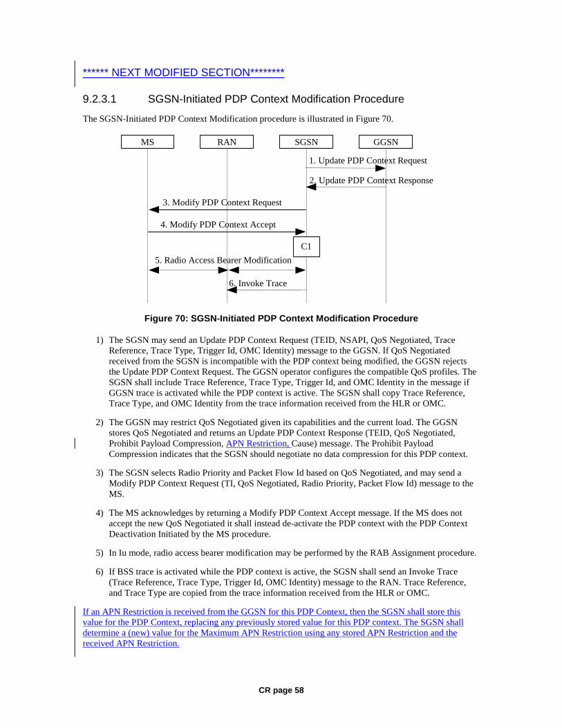
CR page 58
****** NEXT MODIFIED SECTION********
9.2.3.1 SGSN-Initiated PDP Context Modification Procedure
The SGSN-Initiated PDP Context Modification procedure is illustrated in Figure 70.
GGSN
2. Update PDP Context Response
1. Update PDP Context Request
SGSNRANMS
3. Modify PDP Context Request
4. Modify PDP Context Accept
5. Radio Access Bearer Modification
C1
6. Invoke Trace
Figure 70: SGSN-Initiated PDP Context Modification Procedure
1) The SGSN may send an Update PDP Context Request (TEID, NSAPI, QoS Negotiated, Trace Reference, Trace Type, Trigger Id, OMC Identity) message to the GGSN. If QoS Negotiated received from the SGSN is incompatible with the PDP context being modified, the GGSN rejects the Update PDP Context Request. The GGSN operator configures the compatible QoS profiles. The SGSN shall include Trace Reference, Trace Type, Trigger Id, and OMC Identity in the message if GGSN trace is activated while the PDP context is active. The SGSN shall copy Trace Reference, Trace Type, and OMC Identity from the trace information received from the HLR or OMC.
2) The GGSN may restrict QoS Negotiated given its capabilities and the current load. The GGSN stores QoS Negotiated and returns an Update PDP Context Response (TEID, QoS Negotiated, Prohibit Payload Compression, APN Restriction, Cause) message. The Prohibit Payload Compression indicates that the SGSN should negotiate no data compression for this PDP context.
3) The SGSN selects Radio Priority and Packet Flow Id based on QoS Negotiated, and may send a Modify PDP Context Request (TI, QoS Negotiated, Radio Priority, Packet Flow Id) message to the MS.
4) The MS acknowledges by returning a Modify PDP Context Accept message. If the MS does not accept the new QoS Negotiated it shall instead de-activate the PDP context with the PDP Context Deactivation Initiated by the MS procedure.
5) In Iu mode, radio access bearer modification may be performed by the RAB Assignment procedure.
6) If BSS trace is activated while the PDP context is active, the SGSN shall send an Invoke Trace (Trace Reference, Trace Type, Trigger Id, OMC Identity) message to the RAN. Trace Reference, and Trace Type are copied from the trace information received from the HLR or OMC.
If an APN Restriction is received from the GGSN for this PDP Context, then the SGSN shall store this value for the PDP Context, replacing any previously stored value for this PDP context. The SGSN shall determine a (new) value for the Maximum APN Restriction using any stored APN Restriction and the received APN Restriction.
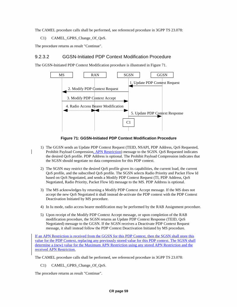
CR page 59
The CAMEL procedure calls shall be performed, see referenced procedure in 3GPP TS 23.078:
C1) CAMEL_GPRS_Change_Of_QoS.
The procedure returns as result "Continue".
9.2.3.2 GGSN-Initiated PDP Context Modification Procedure
The GGSN-Initiated PDP Context Modification procedure is illustrated in Figure 71.
GGSN
5. Update PDP Context Response
1. Update PDP Context Request
SGSNRANMS
2. Modify PDP Context Request
3. Modify PDP Context Accept
4. Radio Access Bearer Modification
C1
Figure 71: GGSN-Initiated PDP Context Modification Procedure
1) The GGSN sends an Update PDP Context Request (TEID, NSAPI, PDP Address, QoS Requested, Prohibit Payload Compression, APN Restriction) message to the SGSN. QoS Requested indicates the desired QoS profile. PDP Address is optional. The Prohibit Payload Compression indicates that the SGSN should negotiate no data compression for this PDP context.
2) The SGSN may restrict the desired QoS profile given its capabilities, the current load, the current QoS profile, and the subscribed QoS profile. The SGSN selects Radio Priority and Packet Flow Id based on QoS Negotiated, and sends a Modify PDP Context Request (TI, PDP Address, QoS Negotiated, Radio Priority, Packet Flow Id) message to the MS. PDP Address is optional.
3) The MS acknowledges by returning a Modify PDP Context Accept message. If the MS does not accept the new QoS Negotiated it shall instead de-activate the PDP context with the PDP Context Deactivation Initiated by MS procedure.
4) In Iu mode, radio access bearer modification may be performed by the RAB Assignment procedure.
5) Upon receipt of the Modify PDP Context Accept message, or upon completion of the RAB modification procedure, the SGSN returns an Update PDP Context Response (TEID, QoS Negotiated) message to the GGSN. If the SGSN receives a Deactivate PDP Context Request message, it shall instead follow the PDP Context Deactivation Initiated by MS procedure.
If an APN Restriction is received from the GGSN for this PDP Context, then the SGSN shall store this value for the PDP Context, replacing any previously stored value for this PDP context. The SGSN shall determine a (new) value for the Maximum APN Restriction using any stored APN Restriction and the received APN Restriction.
The CAMEL procedure calls shall be performed, see referenced procedure in 3GPP TS 23.078:
C1) CAMEL_GPRS_Change_Of_QoS.
The procedure returns as result "Continue".
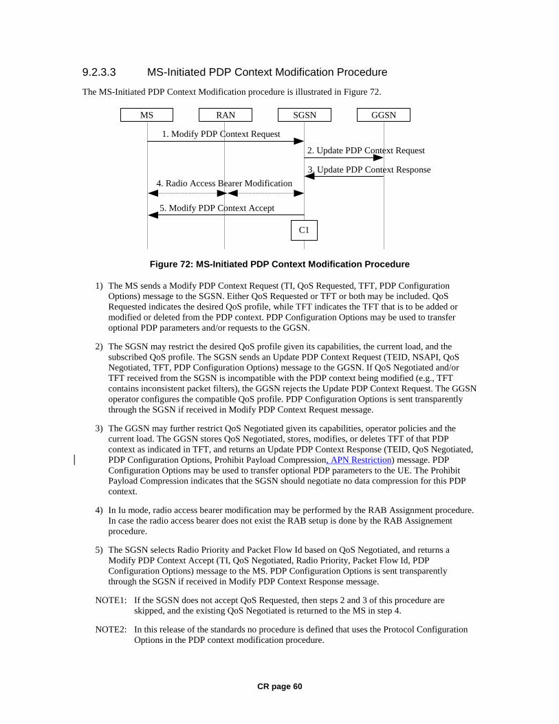
CR page 60
9.2.3.3 MS-Initiated PDP Context Modification Procedure
The MS-Initiated PDP Context Modification procedure is illustrated in Figure 72.
GGSN
3. Update PDP Context Response
2. Update PDP Context Request
SGSNRANMS
1. Modify PDP Context Request
5. Modify PDP Context Accept
4. Radio Access Bearer Modification
C1
Figure 72: MS-Initiated PDP Context Modification Procedure
1) The MS sends a Modify PDP Context Request (TI, QoS Requested, TFT, PDP Configuration Options) message to the SGSN. Either QoS Requested or TFT or both may be included. QoS Requested indicates the desired QoS profile, while TFT indicates the TFT that is to be added or modified or deleted from the PDP context. PDP Configuration Options may be used to transfer optional PDP parameters and/or requests to the GGSN.
2) The SGSN may restrict the desired QoS profile given its capabilities, the current load, and the subscribed QoS profile. The SGSN sends an Update PDP Context Request (TEID, NSAPI, QoS Negotiated, TFT, PDP Configuration Options) message to the GGSN. If QoS Negotiated and/or TFT received from the SGSN is incompatible with the PDP context being modified (e.g., TFT contains inconsistent packet filters), the GGSN rejects the Update PDP Context Request. The GGSN operator configures the compatible QoS profile. PDP Configuration Options is sent transparently through the SGSN if received in Modify PDP Context Request message.
3) The GGSN may further restrict QoS Negotiated given its capabilities, operator policies and the current load. The GGSN stores QoS Negotiated, stores, modifies, or deletes TFT of that PDP context as indicated in TFT, and returns an Update PDP Context Response (TEID, QoS Negotiated, PDP Configuration Options, Prohibit Payload Compression, APN Restriction) message. PDP Configuration Options may be used to transfer optional PDP parameters to the UE. The Prohibit Payload Compression indicates that the SGSN should negotiate no data compression for this PDP context.
4) In Iu mode, radio access bearer modification may be performed by the RAB Assignment procedure. In case the radio access bearer does not exist the RAB setup is done by the RAB Assignement procedure.
5) The SGSN selects Radio Priority and Packet Flow Id based on QoS Negotiated, and returns a Modify PDP Context Accept (TI, QoS Negotiated, Radio Priority, Packet Flow Id, PDP Configuration Options) message to the MS. PDP Configuration Options is sent transparently through the SGSN if received in Modify PDP Context Response message.
NOTE1: If the SGSN does not accept QoS Requested, then steps 2 and 3 of this procedure are skipped, and the existing QoS Negotiated is returned to the MS in step 4.
NOTE2: In this release of the standards no procedure is defined that uses the Protocol Configuration Options in the PDP context modification procedure.

CR page 61
If an APN Restriction is received from the GGSN for this PDP Context, then the SGSN shall store this value for the PDP Context, replacing any previously stored value for this PDP context. The SGSN shall determine a (new) value for the Maximum APN Restriction using any stored APN Restriction and the received APN Restriction.
The CAMEL procedure calls shall be performed, see referenced procedure in 3GPP TS 23.078:
C1) CAMEL_GPRS_Change_Of_QoS.
The procedure returns as result "Continue".
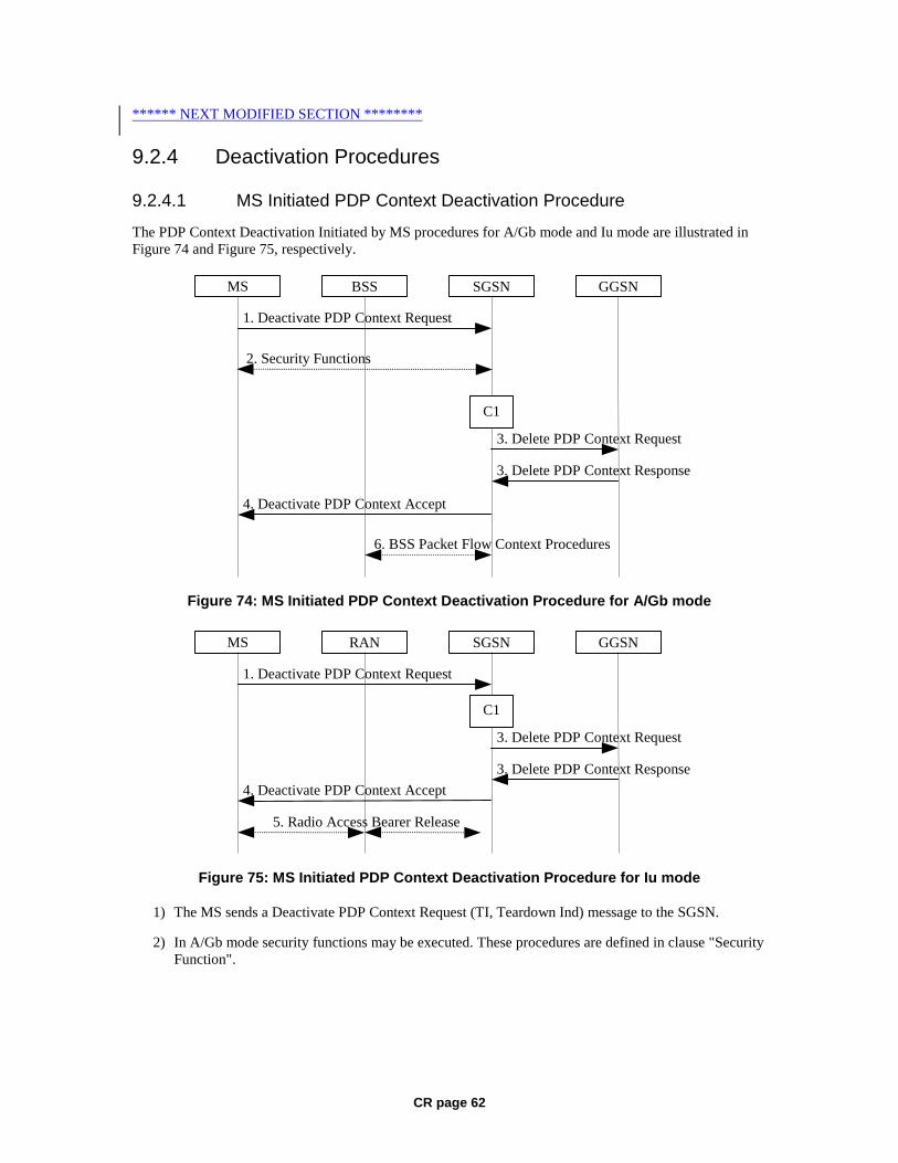
CR page 62
****** NEXT MODIFIED SECTION ********
9.2.4 Deactivation Procedures
9.2.4.1 MS Initiated PDP Context Deactivation Procedure
The PDP Context Deactivation Initiated by MS procedures for A/Gb mode and Iu mode are illustrated in Figure 74 and Figure 75, respectively.
GGSN
3. Delete PDP Context Response
3. Delete PDP Context Request
SGSN BSS MS
1. Deactivate PDP Context Request
4. Deactivate PDP Context Accept
C1
6. BSS Packet Flow Context Procedures
2. Security Functions
Figure 74: MS Initiated PDP Context Deactivation Procedure for A/Gb mode
GGSN
3. Delete PDP Context Response
3. Delete PDP Context Request
SGSNRANMS
1. Deactivate PDP Context Request
4. Deactivate PDP Context Accept
5. Radio Access Bearer Release
C1
Figure 75: MS Initiated PDP Context Deactivation Procedure for Iu mode
1) The MS sends a Deactivate PDP Context Request (TI, Teardown Ind) message to the SGSN.
2) In A/Gb mode security functions may be executed. These procedures are defined in clause "Security Function".

CR page 63
3) The SGSN sends a Delete PDP Context Request (TEID, NSAPI, Teardown Ind) message to the GGSN. If the MS in the Deactivate PDP Context Request message included Teardown Ind, then the SGSN deactivates all PDP contexts associated with this PDP address by including Teardown Ind in the Delete PDP Context Request message. The GGSN removes the PDP context(s) and returns a Delete PDP Context Response (TEID) message to the SGSN. If the MS was using a dynamic PDP address allocated by the GGSN, and if the context being deactivated is the last PDP context associated with this PDP address, then the GGSN releases this PDP address and makes it available for subsequent activation by other MSs. The Delete PDP Context messages are sent over the backbone network.
4) The SGSN returns a Deactivate PDP Context Accept (TI) message to the MS.
5) In Iu mode, radio access bearer release is done by the RAB Assignment procedure, if a RAB exists for this PDP context.
6) In A/Gb mode, BSS packet flow context procedures may be executed. These procedures are defined in subclause "BSS Context".
At GPRS detach, all PDP contexts for the MS are implicitly deactivated.
If the SGSN receives a Deactivate PDP Context Request (TI) message for a PDP context that is currently being activated, the SGSN shall stop the PDP Context Activation procedure without responding to the MS, and continue with the PDP Context Deactivation initiated by MS procedure.
The SGSN determines the Maximum APN Restriction for the remaining PDP contexts and stores this new value for the Maximum APN Restriction.
The CAMEL procedure call shall be performed, see referenced procedure in 3GPP TS 23.078:
C1) CAMEL_GPRS_PDP_Context_Disconnection.
The procedure returns as result "Continue".
9.2.4.2 SGSN-initiated PDP Context Deactivation Procedure
The PDP Context Deactivation Initiated by SGSN procedure is illustrated in Figure 76.
GGSN
1. Delete PDP Context Response
1. Delete PDP Context Request
SGSN RAN MS
2. Deactivate PDP Context Request
2. Deactivate PDP Context Accept
3. Radio Access Bearer Release
C1
4. BSS Packet Flow Context Procedures
Figure 76: SGSN-initiated PDP Context Deactivation Procedure
1) The SGSN sends a Delete PDP Context Request (TEID, NSAPI, Teardown Ind) message to the GGSN. If Teardown Ind is included by the SGSN, the GGSN deactivates all PDP contexts
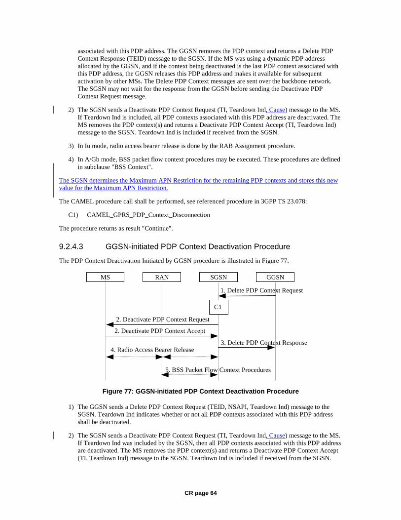
CR page 64
associated with this PDP address. The GGSN removes the PDP context and returns a Delete PDP Context Response (TEID) message to the SGSN. If the MS was using a dynamic PDP address allocated by the GGSN, and if the context being deactivated is the last PDP context associated with this PDP address, the GGSN releases this PDP address and makes it available for subsequent activation by other MSs. The Delete PDP Context messages are sent over the backbone network. The SGSN may not wait for the response from the GGSN before sending the Deactivate PDP Context Request message.
2) The SGSN sends a Deactivate PDP Context Request (TI, Teardown Ind, Cause) message to the MS. If Teardown Ind is included, all PDP contexts associated with this PDP address are deactivated. The MS removes the PDP context(s) and returns a Deactivate PDP Context Accept (TI, Teardown Ind) message to the SGSN. Teardown Ind is included if received from the SGSN.
3) In Iu mode, radio access bearer release is done by the RAB Assignment procedure.
4) In A/Gb mode, BSS packet flow context procedures may be executed. These procedures are defined in subclause "BSS Context".
The SGSN determines the Maximum APN Restriction for the remaining PDP contexts and stores this new value for the Maximum APN Restriction.
The CAMEL procedure call shall be performed, see referenced procedure in 3GPP TS 23.078:
C1) CAMEL_GPRS_PDP_Context_Disconnection
The procedure returns as result "Continue".
9.2.4.3 GGSN-initiated PDP Context Deactivation Procedure
The PDP Context Deactivation Initiated by GGSN procedure is illustrated in Figure 77.
GGSN
3. Delete PDP Context Response
1. Delete PDP Context Request
SGSN RAN MS
2. Deactivate PDP Context Request
2. Deactivate PDP Context Accept
4. Radio Access Bearer Release
C1
5. BSS Packet Flow Context Procedures
Figure 77: GGSN-initiated PDP Context Deactivation Procedure
1) The GGSN sends a Delete PDP Context Request (TEID, NSAPI, Teardown Ind) message to the SGSN. Teardown Ind indicates whether or not all PDP contexts associated with this PDP address shall be deactivated.
2) The SGSN sends a Deactivate PDP Context Request (TI, Teardown Ind, Cause) message to the MS. If Teardown Ind was included by the SGSN, then all PDP contexts associated with this PDP address are deactivated. The MS removes the PDP context(s) and returns a Deactivate PDP Context Accept (TI, Teardown Ind) message to the SGSN. Teardown Ind is included if received from the SGSN.
CR page 65
3) The SGSN returns a Delete PDP Context Response (TEID) message to the GGSN. If the MS was using a dynamic PDP address allocated by the GGSN, and if the context being deactivated is the last PDP context associated with this PDP address, the GGSN releases this PDP address and makes it available for subsequent activation by other MSs. The Delete PDP Context messages are sent over the backbone network. The SGSN may not wait for the response from the MS before sending the Delete PDP Context Response message.
4) In Iu mode, radio access bearer release is done by the RAB Assignment procedure.
5) In A/Gb mode, BSS packet flow context procedures may be executed. These procedures are defined in subclause "BSS Context".
The SGSN determines the Maximum APN Restriction for the remaining PDP contexts and stores this new value for the Maximum APN Restriction.
The CAMEL procedure call shall be performed, see referenced procedure in 3GPP TS 23.078:
C1) CAMEL_GPRS_PDP_Context_Disconnection.
The procedure returns as result "Continue".
CR page 66
***** NEXT MODIFIED SECTION *****
13.2 SGSN SGSN maintains MM context and PDP context information for MSs in the STANDBY, READY, PMM-IDLE, and PMM-CONNECTED states. Table 6 shows the context fields for one MS.
During the Intersystem Change, when new Authentication and Key Agreement is not performed, the KSI in the new 3G-SGSN shall be assigned the value of the CKSN, which has been sent by the MS. Similarly, in the new 2G-SGSN, when AKA does not take place, the CKSN shall be assigned the value of the KSI, which has been sent by the MS.
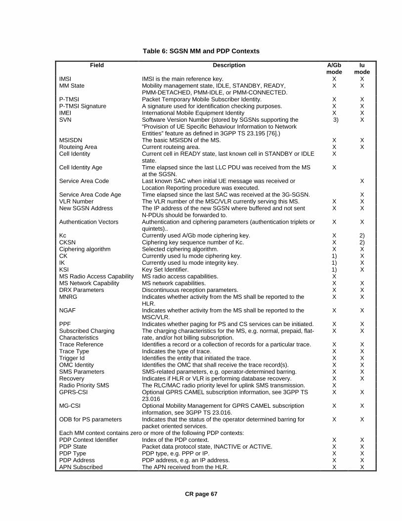
CR page 67
Table 6: SGSN MM and PDP Contexts
Field Description A/Gb mode
Iu mode
IMSI IMSI is the main reference key. X X MM State Mobility management state, IDLE, STANDBY, READY,
PMM-DETACHED, PMM-IDLE, or PMM-CONNECTED. X X
P-TMSI Packet Temporary Mobile Subscriber Identity. X X P-TMSI Signature A signature used for identification checking purposes. X X IMEI International Mobile Equipment Identity X X SVN Software Version Number (stored by SGSNs supporting the
“Provision of UE Specific Behaviour Information to Network Entities” feature as defined in 3GPP TS 23.195 [76].)
3) X
MSISDN The basic MSISDN of the MS. X X Routeing Area Current routeing area. X X Cell Identity Current cell in READY state, last known cell in STANDBY or IDLE
state. X
Cell Identity Age Time elapsed since the last LLC PDU was received from the MS at the SGSN.
X
Service Area Code Last known SAC when initial UE message was received or Location Reporting procedure was executed.
X
Service Area Code Age Time elapsed since the last SAC was received at the 3G-SGSN. X VLR Number The VLR number of the MSC/VLR currently serving this MS. X X New SGSN Address The IP address of the new SGSN where buffered and not sent
N-PDUs should be forwarded to. X X
Authentication Vectors Authentication and ciphering parameters (authentication triplets or quintets)..
X X
Kc Currently used A/Gb mode ciphering key. X 2) CKSN Ciphering key sequence number of Kc. X 2) Ciphering algorithm Selected ciphering algorithm. X X CK Currently used Iu mode ciphering key. 1) X IK Currently used Iu mode integrity key. 1) X KSI Key Set Identifier. 1) X MS Radio Access Capability MS radio access capabilities. X MS Network Capability MS network capabilities. X X DRX Parameters Discontinuous reception parameters. X X MNRG Indicates whether activity from the MS shall be reported to the
HLR. X X
NGAF Indicates whether activity from the MS shall be reported to the MSC/VLR.
X X
PPF Indicates whether paging for PS and CS services can be initiated. X X Subscribed Charging Characteristics
The charging characteristics for the MS, e.g. normal, prepaid, flat-rate, and/or hot billing subscription.
X X
Trace Reference Identifies a record or a collection of records for a particular trace. X X Trace Type Indicates the type of trace. X X Trigger Id Identifies the entity that initiated the trace. X X OMC Identity Identifies the OMC that shall receive the trace record(s). X X SMS Parameters SMS-related parameters, e.g. operator-determined barring. X X Recovery Indicates if HLR or VLR is performing database recovery. X X Radio Priority SMS The RLC/MAC radio priority level for uplink SMS transmission. X GPRS-CSI Optional GPRS CAMEL subscription information, see 3GPP TS
23.016 X X
MG-CSI Optional Mobility Management for GPRS CAMEL subscription information, see 3GPP TS 23.016.
X X
ODB for PS parameters Indicates that the status of the operator determined barring for packet oriented services.
X X
Each MM context contains zero or more of the following PDP contexts: PDP Context Identifier Index of the PDP context. X X PDP State Packet data protocol state, INACTIVE or ACTIVE. X X PDP Type PDP type, e.g. PPP or IP. X X PDP Address PDP address, e.g. an IP address. X X APN Subscribed The APN received from the HLR. X X
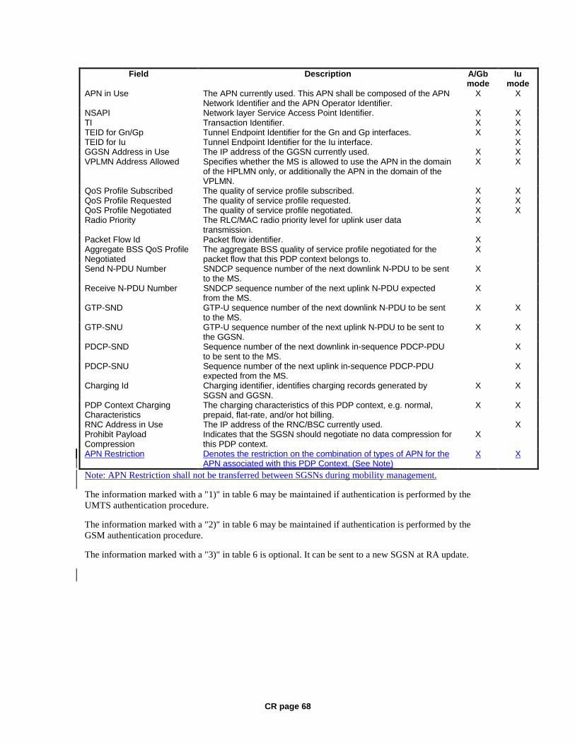
CR page 68
Field Description A/Gb mode
Iu mode
APN in Use The APN currently used. This APN shall be composed of the APN Network Identifier and the APN Operator Identifier.
X X
NSAPI Network layer Service Access Point Identifier. X X TI Transaction Identifier. X X TEID for Gn/Gp Tunnel Endpoint Identifier for the Gn and Gp interfaces. X X TEID for Iu Tunnel Endpoint Identifier for the Iu interface. X GGSN Address in Use The IP address of the GGSN currently used. X X VPLMN Address Allowed Specifies whether the MS is allowed to use the APN in the domain
of the HPLMN only, or additionally the APN in the domain of the VPLMN.
X X
QoS Profile Subscribed The quality of service profile subscribed. X X QoS Profile Requested The quality of service profile requested. X X QoS Profile Negotiated The quality of service profile negotiated. X X Radio Priority The RLC/MAC radio priority level for uplink user data
transmission. X
Packet Flow Id Packet flow identifier. X Aggregate BSS QoS Profile Negotiated
The aggregate BSS quality of service profile negotiated for the packet flow that this PDP context belongs to.
X
Send N-PDU Number SNDCP sequence number of the next downlink N-PDU to be sent to the MS.
X
Receive N-PDU Number SNDCP sequence number of the next uplink N-PDU expected from the MS.
X
GTP-SND GTP-U sequence number of the next downlink N-PDU to be sent to the MS.
X X
GTP-SNU GTP-U sequence number of the next uplink N-PDU to be sent to the GGSN.
X X
PDCP-SND Sequence number of the next downlink in-sequence PDCP-PDU to be sent to the MS.
X
PDCP-SNU Sequence number of the next uplink in-sequence PDCP-PDU expected from the MS.
X
Charging Id Charging identifier, identifies charging records generated by SGSN and GGSN.
X X
PDP Context Charging Characteristics
The charging characteristics of this PDP context, e.g. normal, prepaid, flat-rate, and/or hot billing.
X X
RNC Address in Use The IP address of the RNC/BSC currently used. X Prohibit Payload Compression
Indicates that the SGSN should negotiate no data compression for this PDP context.
X
APN Restriction Denotes the restriction on the combination of types of APN for the APN associated with this PDP Context. (See Note)
X X
Note: APN Restriction shall not be transferred between SGSNs during mobility management.
The information marked with a "1)" in table 6 may be maintained if authentication is performed by the UMTS authentication procedure.
The information marked with a "2)" in table 6 may be maintained if authentication is performed by the GSM authentication procedure.
The information marked with a "3)" in table 6 is optional. It can be sent to a new SGSN at RA update.
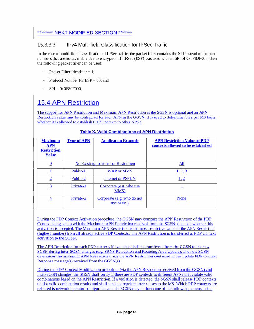
CR page 69
******** NEXT MODIFIED SECTION *******
15.3.3.3 IPv4 Multi-field Classification for IPSec Traffic
In the case of multi-field classification of IPSec traffic, the packet filter contains the SPI instead of the port numbers that are not available due to encryption. If IPSec (ESP) was used with an SPI of 0x0F80F000, then the following packet filter can be used:
- Packet Filter Identifier = 4;
- Protocol Number for ESP = 50; and
- SPI = 0x0F80F000.
15.4 APN Restriction The support for APN Restriction and Maximum APN Restriction at the SGSN is optional and an APN Restriction value may be configured for each APN in the GGSN. It is used to determine, on a per MS basis, whether it is allowed to establish PDP Contexts to other APNs.
Table X. Valid Combinations of APN Restriction
Maximum APN
Restriction Value
Type of APN Application Example APN Restriction Value of PDP contexts allowed to be established
0 No Existing Contexts or Restriction All
1 Public-1 WAP or MMS 1, 2, 3
2 Public-2 Internet or PSPDN 1, 2
3 Private-1 Corporate (e.g. who use MMS)
1
4 Private-2 Corporate (e.g. who do not use MMS)
None
During the PDP Context Activation procedure, the GGSN may compare the APN Restriction of the PDP Context being set up with the Maximum APN Restriction received from the SGSN to decide whether this activation is accepted. The Maximum APN Restriction is the most restrictive value of the APN Restriction (highest number) from all already active PDP Contexts. The APN Restriction is transferred at PDP Context activation to the SGSN.
The APN Restriction for each PDP context, if available, shall be transferred from the GGSN to the new SGSN during inter-SGSN changes (e.g. SRNS Relocation and Routeing Area Update). The new SGSN determines the maximum APN Restriction using the APN Restriction contained in the Update PDP Context Response message(s) received from the GGSN(s).
During the PDP Context Modification procedure (via the APN Restriction received from the GGSN) and inter-SGSN changes, the SGSN shall verify if there are PDP contexts to different APNs that violate valid combinations based on the APN Restriction. If a violation is detected, the SGSN shall release PDP contexts until a valid combination results and shall send appropriate error causes to the MS. Which PDP contexts are released is network operator configurable and the SGSN may perform one of the following actions, using
CR page 70
the SGSN-Initiated PDP Context Deactivation procedures in section 9.2.4.2, until a valid combination remains or no further actions are possible:
1. Deactivate the most restrictive, as dictated by the APN Restriction value, PDP Context sending an approriate error cause to the MS,
2. Deactivate the least restrictive, as dictated by the APN Restriction value, PDP Context sending an appropriate error cause to the MS,
3. Deactivate PDP Contexts in no particular order sending an appropriate error cause to the MS.

3GPP TSG SA WG2 Meeting #36 S2-034328 New York, USA 24-28 November 2003 revision of S2-033725
CR-Form-v7
CHANGE REQUEST
! 23.060 CR 478 ! rev 3 ! Current version: 6.2.0 !
For HELP on using this form, see bottom of this page or look at the pop-up text over the ! symbols.
Proposed change affects: UICC apps! ME Radio Access Network X Core Network X Title: ! BSS PFC procedures at PDP context modification Source: ! Nortel Networks, Nokia Work item code: ! TEI Date: ! 26/11/03 Category: ! F Release: ! Rel-6 Use one of the following categories:
F (correction) A (corresponds to a correction in an earlier release) B (addition of feature), C (functional modification of feature) D (editorial modification)
Detailed explanations of the above categories can be found in 3GPP TR 21.900.
Use one of the following releases: 2 (GSM Phase 2) R96 (Release 1996) R97 (Release 1997) R98 (Release 1998) R99 (Release 1999) Rel-4 (Release 4) Rel-5 (Release 5) Rel-6 (Release 6)
Reason for change: ! In the PDP context modification flows, the usageof PFC in the A/Gb case is
missing. In addition for Iu mode, the RAB modification procedures are also moved to be executed before Modify PDP Context Request is send to MS. This is more optimised order for Iu bearer as it allows SGSN to take into account the QoS granted bu the RAN before indicating the neqotiated QoS to UE. RAN may influence to the provided QoS from Rel-4 onwards.
Summary of change: ! Add BSS Packet Flow Creation in PDP context modification flows.
RAB modification procedures are moved to be executed before Modify PDP Context Request is send to MS.
Consequences if ! not approved:
Incomplete stage 2 specification for PFC usage. For Iu bearer the optimised order of procedures is not shown.
Clauses affected: ! 9.2.3.1, 9.2.3.2, 9.2.3.3 Y N Other specs ! X Other core specifications ! affected: X Test specifications X O&M Specifications Other comments: !
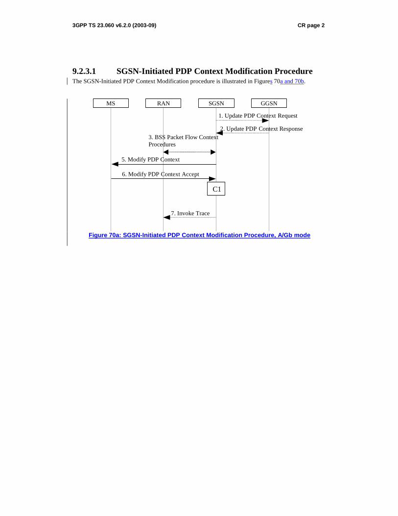
3GPP TS 23.060 v6.2.0 (2003-09) CR page 2
9.2.3.1 SGSN-Initiated PDP Context Modification Procedure The SGSN-Initiated PDP Context Modification procedure is illustrated in Figures 70a and 70b.
GGSN
2. Update PDP Context Response
1. Update PDP Context Request
SGSN RAN MS
5. Modify PDP Context
6. Modify PDP Context Accept
C1
7. Invoke Trace
3. BSS Packet Flow Context Procedures
Figure 70a: SGSN-Initiated PDP Context Modification Procedure, A/Gb mode
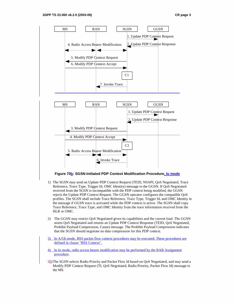
3GPP TS 23.060 v6.2.0 (2003-09) CR page 3
GGSN
2. Update PDP Context Response
1. Update PDP Context Request
SGSN RAN MS
5. Modify PDP Context Request
6. Modify PDP Context Accept
4. Radio Access Bearer Modification
C1
7. Invoke Trace
GGSN
2. Update PDP Context Response
1. Update PDP Context Request
SGSNRANMS
3. Modify PDP Context Request
4. Modify PDP Context Accept
5. Radio Access Bearer Modification
C1
6. Invoke Trace
Figure 70b: SGSN-Initiated PDP Context Modification Procedure, Iu mode
1) The SGSN may send an Update PDP Context Request (TEID, NSAPI, QoS Negotiated, Trace Reference, Trace Type, Trigger Id, OMC Identity) message to the GGSN. If QoS Negotiated received from the SGSN is incompatible with the PDP context being modified, the GGSN rejects the Update PDP Context Request. The GGSN operator configures the compatible QoS profiles. The SGSN shall include Trace Reference, Trace Type, Trigger Id, and OMC Identity in the message if GGSN trace is activated while the PDP context is active. The SGSN shall copy Trace Reference, Trace Type, and OMC Identity from the trace information received from the HLR or OMC.
2) The GGSN may restrict QoS Negotiated given its capabilities and the current load. The GGSN stores QoS Negotiated and returns an Update PDP Context Response (TEID, QoS Negotiated, Prohibit Payload Compression, Cause) message. The Prohibit Payload Compression indicates that the SGSN should negotiate no data compression for this PDP context.
3) In A/Gb mode, BSS packet flow context procedures may be executed. These procedures are defined in clause "BSS Context".
4) In Iu mode, radio access bearer modification may be performed by the RAB Assignment procedure.
35) The SGSN selects Radio Priority and Packet Flow Id based on QoS Negotiated, and may send a Modify PDP Context Request (TI, QoS Negotiated, Radio Priority, Packet Flow Id) message to the MS.
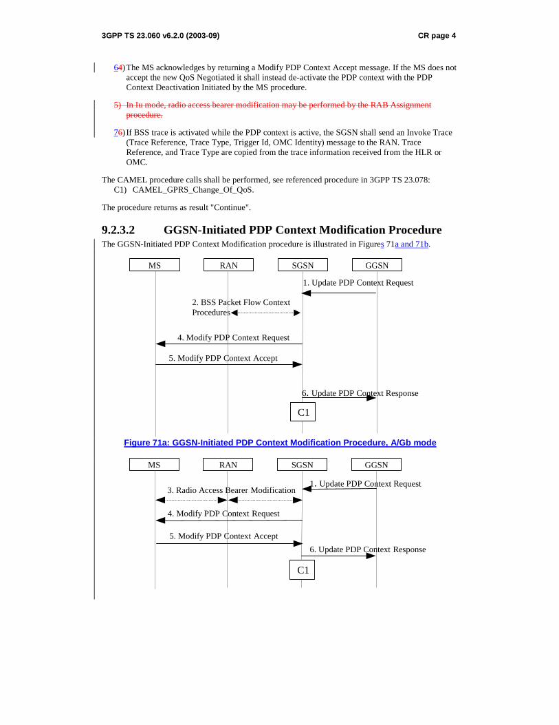
3GPP TS 23.060 v6.2.0 (2003-09) CR page 4
64) The MS acknowledges by returning a Modify PDP Context Accept message. If the MS does not accept the new QoS Negotiated it shall instead de-activate the PDP context with the PDP Context Deactivation Initiated by the MS procedure.
5) In Iu mode, radio access bearer modification may be performed by the RAB Assignment procedure.
76) If BSS trace is activated while the PDP context is active, the SGSN shall send an Invoke Trace (Trace Reference, Trace Type, Trigger Id, OMC Identity) message to the RAN. Trace Reference, and Trace Type are copied from the trace information received from the HLR or OMC.
The CAMEL procedure calls shall be performed, see referenced procedure in 3GPP TS 23.078: C1) CAMEL_GPRS_Change_Of_QoS.
The procedure returns as result "Continue".
9.2.3.2 GGSN-Initiated PDP Context Modification Procedure The GGSN-Initiated PDP Context Modification procedure is illustrated in Figures 71a and 71b.
GGSN
6. Update PDP Context Response
1. Update PDP Context Request
SGSN RAN MS
4. Modify PDP Context Request
5. Modify PDP Context Accept
C1
2. BSS Packet Flow Context Procedures
Figure 71a: GGSN-Initiated PDP Context Modification Procedure, A/Gb mode
GGSN
6. Update PDP Context Response
1. Update PDP Context Request
SGSN RAN MS
4. Modify PDP Context Request
5. Modify PDP Context Accept
3. Radio Access Bearer Modification
C1

3GPP TS 23.060 v6.2.0 (2003-09) CR page 5
GGSN
5. Update PDP Context Response
1. Update PDP Context Request
SGSNRANMS
2. Modify PDP Context Request
3. Modify PDP Context Accept
4. Radio Access Bearer Modification
C1
Figure 71b: GGSN-Initiated PDP Context Modification Procedure, Iu mode
1) The GGSN sends an Update PDP Context Request (TEID, NSAPI, PDP Address, QoS Requested, Prohibit Payload Compression) message to the SGSN. QoS Requested indicates the desired QoS profile. PDP Address is optional. The Prohibit Payload Compression indicates that the SGSN should negotiate no data compression for this PDP context.
2) In A/Gb mode, BSS packet flow context procedures may be executed. These procedures are defined in clause "BSS Context".
3) In Iu mode, radio access bearer modification may be performed by the RAB Assignment procedure.
42) The SGSN may restrict the desired QoS profile given its capabilities, the current load, the current QoS profile, and the subscribed QoS profile. The SGSN selects Radio Priority and Packet Flow Id based on QoS Negotiated, and sends a Modify PDP Context Request (TI, PDP Address, QoS Negotiated, Radio Priority, Packet Flow Id) message to the MS. PDP Address is optional.
53) The MS acknowledges by returning a Modify PDP Context Accept message. If the MS does not accept the new QoS Negotiated it shall instead de-activate the PDP context with the PDP Context Deactivation Initiated by MS procedure.
4) In Iu mode, radio access bearer modification may be performed by the RAB Assignment procedure.
65) Upon receipt of the Modify PDP Context Accept message, or upon completion of the RAB modification procedure, the SGSN returns an Update PDP Context Response (TEID, QoS Negotiated) message to the GGSN. If the SGSN receives a Deactivate PDP Context Request message, it shall instead follow the PDP Context Deactivation Initiated by MS procedure.
The CAMEL procedure calls shall be performed, see referenced procedure in 3GPP TS 23.078: C1) CAMEL_GPRS_Change_Of_QoS.
The procedure returns as result "Continue".
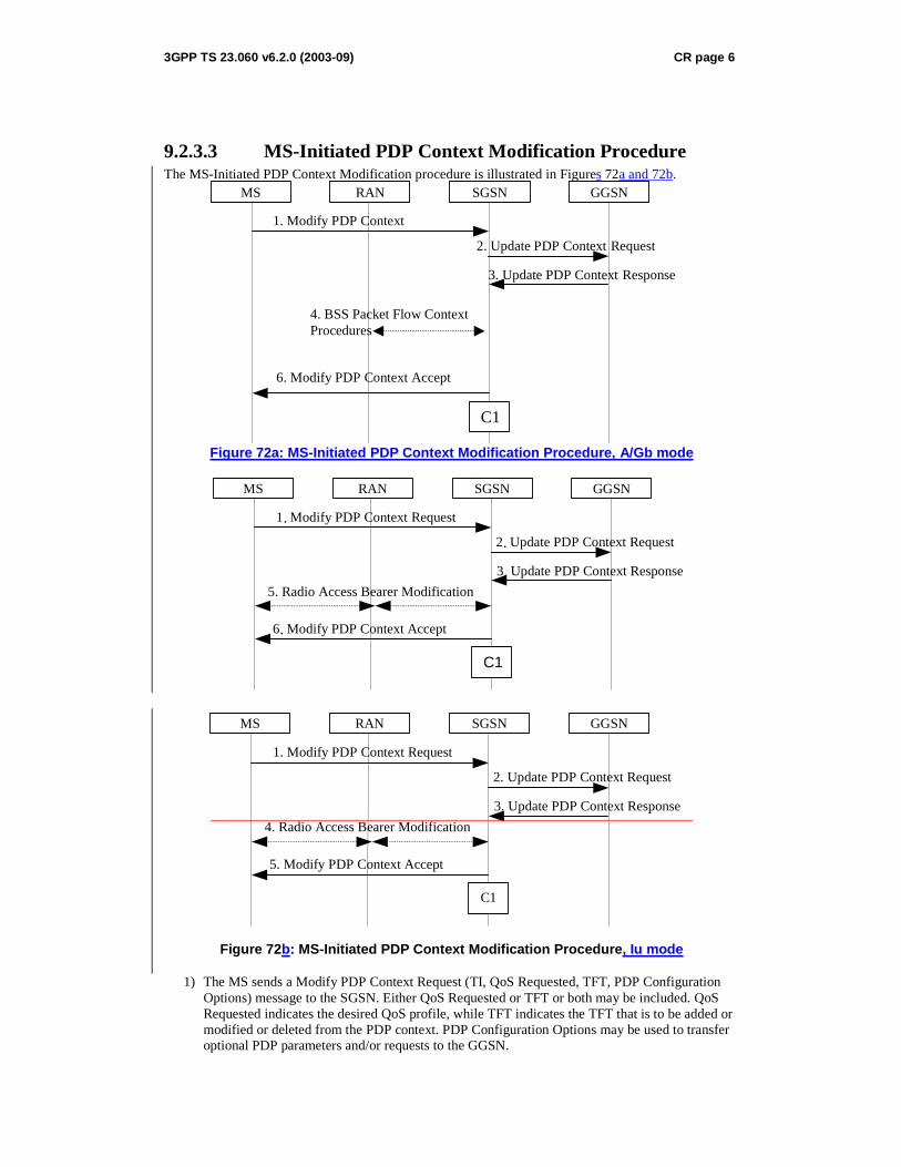
3GPP TS 23.060 v6.2.0 (2003-09) CR page 6
9.2.3.3 MS-Initiated PDP Context Modification Procedure The MS-Initiated PDP Context Modification procedure is illustrated in Figures 72a and 72b.
GGSN
3. Update PDP Context Response
2. Update PDP Context Request
SGSN RAN MS
1. Modify PDP Context
6. Modify PDP Context Accept
C1
4. BSS Packet Flow Context Procedures
Figure 72a: MS-Initiated PDP Context Modification Procedure, A/Gb mode
GGSN
3 . Update PDP Context Response
2 . Update PDP Context Request
SGSN RAN MS
1 . Modify PDP Context Request
6 . Modify PDP Context Accept
5. Radio Access Bearer Modification
C1
GGSN
3. Update PDP Context Response
2. Update PDP Context Request
SGSNRANMS
1. Modify PDP Context Request
5. Modify PDP Context Accept
4. Radio Access Bearer Modification
C1
Figure 72b: MS-Initiated PDP Context Modification Procedure, Iu mode
1) The MS sends a Modify PDP Context Request (TI, QoS Requested, TFT, PDP Configuration Options) message to the SGSN. Either QoS Requested or TFT or both may be included. QoS Requested indicates the desired QoS profile, while TFT indicates the TFT that is to be added or modified or deleted from the PDP context. PDP Configuration Options may be used to transfer optional PDP parameters and/or requests to the GGSN.

3GPP TS 23.060 v6.2.0 (2003-09) CR page 7
2) The SGSN may restrict the desired QoS profile given its capabilities, the current load, and the subscribed QoS profile. The SGSN sends an Update PDP Context Request (TEID, NSAPI, QoS Negotiated, TFT, PDP Configuration Options) message to the GGSN. If QoS Negotiated and/or TFT received from the SGSN is incompatible with the PDP context being modified (e.g., TFT contains inconsistent packet filters), the GGSN rejects the Update PDP Context Request. The GGSN operator configures the compatible QoS profile. PDP Configuration Options is sent transparently through the SGSN if received in Modify PDP Context Request message.
3) The GGSN may further restrict QoS Negotiated given its capabilities, operator policies and the current load. The GGSN stores QoS Negotiated, stores, modifies, or deletes TFT of that PDP context as indicated in TFT, and returns an Update PDP Context Response (TEID, QoS Negotiated, PDP Configuration Options, Prohibit Payload Compression) message. PDP Configuration Options may be used to transfer optional PDP parameters to the UE. The Prohibit Payload Compression indicates that the SGSN should negotiate no data compression for this PDP context.
4) In A/Gb mode, BSS packet flow context procedures may be executed. These procedures are defined in clause "BSS Context".
5) In Iu mode, radio access bearer modification may be performed by the RAB Assignment procedure. In case the radio access bearer does not exist the RAB setup is done by the RAB Assignement procedure.
56) The SGSN selects Radio Priority and Packet Flow Id based on QoS Negotiated, and returns a Modify PDP Context Accept (TI, QoS Negotiated, Radio Priority, Packet Flow Id, PDP Configuration Options) message to the MS. PDP Configuration Options is sent transparently through the SGSN if received in Modify PDP Context Response message.
NOTE1: If the SGSN does not accept QoS Requested, then steps 2 and 3 of this procedure are skipped, and the existing QoS Negotiated is returned to the MS in step 4.
NOTE2: In this release of the standards no procedure is defined that uses the Protocol Configuration Options in the PDP context modification procedure.
The CAMEL procedure calls shall be performed, see referenced procedure in 3GPP TS 23.078: C1) CAMEL_GPRS_Change_Of_QoS.
The procedure returns as result "Continue".