TS3, TS4 and TS5 High-Speed Cameras Operator's Manual
202
TS3, TS4 and TS5 High-Speed Cameras Operator’s Manual Firmware / Soſtware Version 2.4.2 2017-9 110S-3000AC HIGH-SPEED IMAGING IN THE PALM OF YOUR HAND
-
Upload
khangminh22 -
Category
Documents
-
view
4 -
download
0
Transcript of TS3, TS4 and TS5 High-Speed Cameras Operator's Manual

TS3, TS4 and TS5 High-Speed Cameras Operator’s Manual
Firmware / Software Version 2.4.2
2017-9
110S-3000AC
HIGH-SPEED IMAGING IN THE PALM OF YOUR HAND

TS3 /TS4 / TS5 User’s Guide
11S-3000AC page i
Copyrights and Disclaimer
This documentation is copyrighted material. Making unauthorized copies is prohibited by law. No part of this documentation may be reproduced, transmitted, transcribed, stored in a retrieval system or translated into any human or computer language without the prior written permission of Fastec Imaging Corporation.Information in this document is provided in connection with Fastec Imaging products. Fastec Imaging believes the printed matter contained herein to be accurate from date of publication and reserves the right to make changes as necessary without notice. Fastec Imaging makes no commitment to update the information and shall have no responsibility whatsoever for conflicts or incompatibilities arising from future changes to the software or documentation.No license, express or implied, or otherwise, to any intellectual property rights is granted by this document. Except as provided in Fastec Imaging’s Terms and Conditions of Sale for such products, Fastec Imaging assumes no liability whatsoever.
THIS MANUAL IS PROVIDED “AS IS” WITHOUT WARRANTY OF ANY KIND, EITHER EXPRESSED OR IMPLIED, RELATING TO SALE AND/OR USE OF FASTEC IMAGING PRODUCTS INCLUDING LIABILITY OR WARRANTIES RELATING TO FITNESS FOR A PARTICULAR PURPOSE, CONSEQUENTIAL OR INCIDENTAL DAMAGES, MERCHANTABILITY, OR INFRINGEMENT OF ANY PATENT COPYRIGHT OR OTHER INTELLECTUAL PROPERTY RIGHT. FASTEC IMAGING FURTHER DOES NOT WARRANT THE ACCURACY OR COMPLETENESS OF THE INFORMATION, TEXT, GRAPHICS OR OTHER ITEMS CONTAINED WITHIN THIS MANUAL. FASTEC IMAGING SHALL NOT BE LIABLE FOR ANY SPECIAL, INDIRECT, INCIDENTAL, OR CONSEQUENTIAL DAMAGES, INCLUDING WITHOUT LIMITATION, LOST REVENUES OR LOST PROFITS, WHICH MAY RESULT FROM THE USE OF THIS DOCUMENT. Fastec Imaging products are not intended for use in medical, lifesaving or life sustaining applications. Fastec Imaging customers using or selling Fastec Imaging products for use in such applications do so at their own risk and agree to fully indemnify Fastec Imaging for any damages resulting from such improper use or sale.
Trademarks
Windows™ is a registered trademark of Microsoft Corporation. Other brand or product names are trademarks of their respective holders. Product names or services listed in this publication are for identification purposes only, and may be trademarks of third parties. Third-party brands and names are the property of their respective owners.
Reader Response We at Fastec Imaging strive to produce quality documentation and welcome your feedback. Please contact us with technical questions, comments and suggestions.
Fastec Imaging Corporation17150 Via Del CampoSte. 301San Diego, CA [email protected]
TS3 / TS4 / TS5 User’s Guide
page ii 11S-3000AC
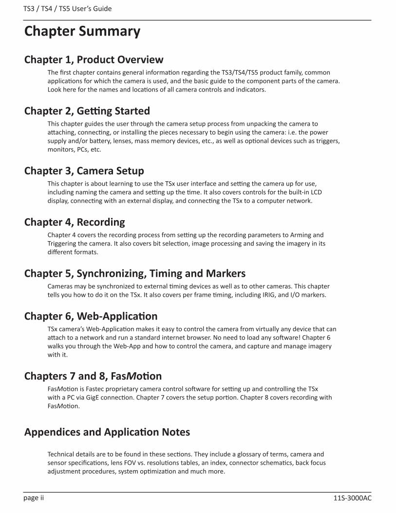
Chapter Summary
Chapter 1, Product OverviewThe first chapter contains general information regarding the TS3/TS4/TS5 product family, common applications for which the camera is used, and the basic guide to the component parts of the camera. Look here for the names and locations of all camera controls and indicators.
Chapter 2, Getting StartedThis chapter guides the user through the camera setup process from unpacking the camera to attaching, connecting, or installing the pieces necessary to begin using the camera: i.e. the power supply and/or battery, lenses, mass memory devices, etc., as well as optional devices such as triggers, monitors, PCs, etc.
Chapter 3, Camera SetupThis chapter is about learning to use the TSx user interface and setting the camera up for use, including naming the camera and setting up the time. It also covers controls for the built-in LCD display, connecting with an external display, and connecting the TSx to a computer network.
Chapter 4, Recording Chapter 4 covers the recording process from setting up the recording parameters to Arming and Triggering the camera. It also covers bit selection, image processing and saving the imagery in its different formats.
Chapter 5, Synchronizing, Timing and MarkersCameras may be synchronized to external timing devices as well as to other cameras. This chapter tells you how to do it on the TSx. It also covers per frame timing, including IRIG, and I/O markers.
Chapter 6, Web-ApplicationTSx camera’s Web-Application makes it easy to control the camera from virtually any device that can attach to a network and run a standard internet browser. No need to load any software! Chapter 6 walks you through the Web-App and how to control the camera, and capture and manage imagery with it.
Chapters 7 and 8, FasMotionFasMotion is Fastec proprietary camera control software for setting up and controlling the TSx with a PC via GigE connection. Chapter 7 covers the setup portion. Chapter 8 covers recording with FasMotion.
Appendices and Application Notes
Technical details are to be found in these sections. They include a glossary of terms, camera and sensor specifications, lens FOV vs. resolutions tables, an index, connector schematics, back focus adjustment procedures, system optimization and much more.

TS3 /TS4 / TS5 User’s Guide
11S-3000AC page iii
ContentsCopyrights and Disclaimer .................................................................................................... i
Trademarks ............................................................................................................................................... iReader Response ...................................................................................................................................... i
Chapter Summary ................................................................................................................ iiChapter 1, Product Overview .................................................................................................................... iiChapter 2, Getting Started ........................................................................................................................ iiChapter 3, Camera Setup .......................................................................................................................... iiChapter 4, Recording ............................................................................................................................... iiChapter 5, Synchronizing, Timing and Markers ......................................................................................... iiChapter 6, Web-Application ...................................................................................................................... iiChapters 7 and 8, FasMotion .................................................................................................................... iiAppendices and Application Notes ........................................................................................................... ii
1 Product Overview .............................................................................................................. 11-1 Product Description ............................................................................................................................ 11-2 Models ............................................................................................................................................... 21-3 Controls, Indicators, and Connectors................................................................................................... 31-4 Care and Maintenance of the TSx ....................................................................................................... 61-5 Getting Help ....................................................................................................................................... 7
2 Getting Started ................................................................................................................. 72-1 Unpacking the Camera ....................................................................................................................... 72-2 Installing the Lens ............................................................................................................................... 72-3 Powering Up, Charging, and Power Down ........................................................................................... 82-4 TSx Memory and Mass Storage Options ............................................................................................ 112-5 FasMotion Camera Control Software ................................................................................................ 14
3 Camera Setup .................................................................................................................. 153-1 Display and Menu Navigation and Status Bar .................................................................................... 153-2 Using the Touchscreen ...................................................................................................................... 163-3 Language Selection ........................................................................................................................... 173-4 Controlling the Displays .................................................................................................................... 183-5 Connecting to a PC via Ethernet ........................................................................................................ 193-6 Setting up WiFi ................................................................................................................................. 203-7 Using the TSx with a PC .................................................................................................................... 213-8 TSx Name the Camera ...................................................................................................................... 223-9 Setting the Time .............................................................................................................................. 233-10 Storage ........................................................................................................................................... 243-11 Formatting Camera Media .............................................................................................................. 253-12 Configuration and Camera Information ........................................................................................... 263-13 Reset .............................................................................................................................................. 26
4 Recording ........................................................................................................................ 274-1 Selecting the Recording Mode .......................................................................................................... 274-2 Setting Frame Rate and Resolution ................................................................................................... 294-3 Binning and Subsampling on the TS5 ................................................................................................ 324-4 Setting Shutter Speed ....................................................................................................................... 33

TS3 / TS4 / TS5 User’s Guide
page iv 11S-3000AC
4-5 Low Light Mode ................................................................................................................................ 344-6 Setting Bit Depth .............................................................................................................................. 344-7 Setting Session Length ...................................................................................................................... 364-8 Configuring the Trigger and External I/O ........................................................................................... 364-9 Black Level Calibration ...................................................................................................................... 394-10 Record in Standard Basic Mode ....................................................................................................... 394-11 Autosave ........................................................................................................................................ 414-12 FasFire .......................................................................................................................................... 424-13 Long Recording Modes .................................................................................................................... 444-14 Reviewing Captured Imagery: Playback ........................................................................................... 454-15 Playback: Jump to Markers ............................................................................................................. 474-16 Image Processing ............................................................................................................................ 484-17 Custom Color Correction ................................................................................................................. 504-18 Saving Images to Mass Storage ....................................................................................................... 524-19 Loading CAP Files Back to Memory ................................................................................................. 54
5 TSx Synchronization, Timing and Markers ........................................................................ 555-1 Sync In .............................................................................................................................................. 555-2 Sync Out ........................................................................................................................................... 585-3 Master/Slave Setup .......................................................................................................................... 595-4 External Source Sync ........................................................................................................................ 615-5 TSx Timestamps and Markers ........................................................................................................... 625-6 IRIG Timestamps and Sync ................................................................................................................ 64
6 Using the Web Application (Web-GUI) ............................................................................. 666-1 Web-GUI Overview ........................................................................................................................... 666-2 Camera Tab ....................................................................................................................................... 676-3 Storage Settings Tab .......................................................................................................................... 686-4 Record Settings ................................................................................................................................. 706-5 Record Controls ................................................................................................................................ 716-6 Display Settings Tab .......................................................................................................................... 726-7 Arm, Trigger, Live, and Review Buttons ............................................................................................. 726-8 Review Tab ....................................................................................................................................... 73
7 FasMotion Setup .............................................................................................................. 757-1 Install FasMotion Camera Control Software ...................................................................................... 757-2 Language Selection in FasMotion ...................................................................................................... 777-3 Connect the Camera to a Wired Network .......................................................................................... 777-4 Managing TSx Network Settings in FasMotion................................................................................... 797-5 WiFi Setup in FasMotion ................................................................................................................... 807-6 FasMotion Application Window ........................................................................................................ 817-7 Connecting to Multiple Cameras in FasMotion .................................................................................. 827-8 Controlling the Image Displays .......................................................................................................... 837-9 Name the Camera ............................................................................................................................. 857-10 Camera Time and Date.................................................................................................................... 857-11 Connect to a TSx Outside FasMotion ............................................................................................... 867-12 Storage Setup ................................................................................................................................. 887-13 Configurations ................................................................................................................................ 897-14 Reboot and Power Down ................................................................................................................ 907-15 Camera Information ........................................................................................................................ 90
Table of Contents Continued
TS3 /TS4 / TS5 User’s Guide
11S-3000AC page v
7-16 Solving Setup Issues ........................................................................................................................ 91
8 Recording with FasMotion ............................................................................................... 928-1 Long Record and Standard Modes in FasMotion ............................................................................... 928-2 Setting Frame Rate and Resolution in FasMotion .............................................................................. 938-3 Setting Shutter Speed in FasMotion .................................................................................................. 948-4 Enabling Auto-Exposure Tracking ...................................................................................................... 958-5 Setting Bit Depth in FasMotion ......................................................................................................... 968-6 Configuring the Trigger in FasMotion ................................................................................................ 968-7 Configuring Sync and Arm I/O in FasMotion ...................................................................................... 978-8 Black Level Calibration in FasMotion ................................................................................................. 998-9 Record: Arm and Trigger in FasMotion .............................................................................................. 998-10 Image Trigger ................................................................................................................................ 1018-11 Time Trigger .................................................................................................................................. 1038-12 Autosave in FasMotion ................................................................................................................. 1038-13 FasFire in FasMotion ..................................................................................................................... 1048-14 Long Recording Modes .................................................................................................................. 1068-15 Reviewing Captured Imagery: Playback in FasMotion .................................................................... 1078-16 Image Processing in FasMotion ..................................................................................................... 1128-17 Custom Color Correction in FasMotion .......................................................................................... 1148-18 Saving Images to Mass Storage in FasMotion ................................................................................ 1168-19 Adding Overlay Metadata ............................................................................................................. 1188-20: Playback from File and Transcoding ............................................................................................. 1218-21: Transfers, Batch Transfers and Conversions .................................................................................. 122
Application Notes ............................................................................................................. 124Application Note 1: Histograms ............................................................................................................ 124Application Note 2: Understanding Bit Depth ....................................................................................... 126Application Note 3: Trigger Position and the Circular Buffer .................................................................. 128Application Note 4: Frame Rate, Resolution, and Exposure ................................................................... 132Application Note 5: Optimizing System for Image Transfers .................................................................. 133
Table of Contents Continued

TS3 / TS4 / TS5 User’s Guide
page vi 11S-3000AC
Table of FiguresFigure 1-1: TSx Back View ........................................................................................................................ 3Figure 1-2: TSx Front View ...................................................................................................................... 4Figure 1-3: TSx Top View .......................................................................................................................... 4Figure 1-4: TSx Side View (Door open) .................................................................................................... 5Figure 1-5: TSx Bottom View .................................................................................................................... 5Figure 2-1: Battery Access Door ............................................................................................................... 8Figure 2-2: Power Up / Charging Menu (TS3 / TS5) ................................................................................... 9Figure 2-3: Power Up / Charging Menu (TS4-LR3 / TSx-D) ......................................................................... 9Figure 2-4: Battery Charge Indicator on Status Bar ................................................................................. 10Figure 2-5: Charging Menu ..................................................................................................................... 10Figure 2-6: Restarting Menu ................................................................................................................... 10Figure 2-7: Power Off Warning ............................................................................................................... 11Figure 2-8: Power Off Menu ................................................................................................................... 11Figure 2-9: Mass Storage ........................................................................................................................ 12Figure 2-10: USB-OTG on the TSx ........................................................................................................... 13Figure 2-11: FasMotion on Windows ...................................................................................................... 14Figure 2-12: FasMotion on Mac .............................................................................................................. 14Figure 3-1: System Menu ....................................................................................................................... 15Figure 3-2: Touchscreen Menu ............................................................................................................... 16Figure 3-3: Touchscreen Calibration ....................................................................................................... 16Figure 3-4: Language Selection in User Preferences ................................................................................ 17Figure 3-5: Language Selection Spinner ................................................................................................. 17Figure 3-6: Russian Menu ...................................................................................................................... 17Figure 3-7: Select Language.................................................................................................................... 17Figure 3-8: LCD Display Controls ............................................................................................................. 18
Application Note 6: Choosing an Image File Format .............................................................................. 139Application Note 7: Advanced Calibration ............................................................................................. 141Application Note 8: Running the TSx on Batteries ................................................................................. 143
Appendices ...................................................................................................................... 145Appendix A: Definition of terms ........................................................................................................... 145Appendix B: TS3 / 4 Specifications ........................................................................................................ 148Appendix C: TS5 Specifications ............................................................................................................. 149Appendix D: TS3 / TS4 Record / Resolution Tables ................................................................................ 150Appendix E: TS5 Record / Resolution Tables ......................................................................................... 155Appendix F: Power and I/O Connections ............................................................................................... 163Appendix G: Adjusting Back Focus ........................................................................................................ 166Appendix H: Switching Lens Mounts ..................................................................................................... 168Appendix I: Camera Status LEDs ........................................................................................................... 169Appendix J: Contents of <Capture>.txt file ............................................................................................ 170Appendix K: Contents of <Capture>.xml file .......................................................................................... 171Appendix L: TSx Updates ...................................................................................................................... 173Appendix M: Physical Measurements ................................................................................................... 175Appendix N: Crop Factor ....................................................................................................................... 177Appendix O: Partition Capture (CAP) File Format .................................................................................. 178Appendix P: Day Number Calendar Conversion .................................................................................... 180Appendix Q: Battery ............................................................................................................................ 182Appendix R: TS5 with External SSD ....................................................................................................... 185

TS3 /TS4 / TS5 User’s Guide
11S-3000AC page vii
Figure 3-9: HDMI Controls ...................................................................................................................... 18Figure 3-10: TSx to PC Connections ....................................................................................................... 19Figure 3-11: Network Menu ................................................................................................................... 19Figure 3-12: Static IP Dialog Box ............................................................................................................. 20Figure 3-13: WiFi Access Point Settings .................................................................................................. 20Figure 3-14: WiFi ad hoc SSID ................................................................................................................. 20Figure 3-15: WiFi IP Address in System Menu ......................................................................................... 21Figure 3-16: Web Browser Screen .......................................................................................................... 21Figure 3-17: TSx in Windows Explorer .................................................................................................... 22Figure 3-18: Camera Name Menu .......................................................................................................... 22Figure 3-19: Keypad Dialog Boxes .......................................................................................................... 23Figure 3-20: Time Format Menu ............................................................................................................. 23Figure 3-21: Storage Menu ..................................................................................................................... 24Figure 3-22: System Explore Dialog: File Stacks ...................................................................................... 24Figure 3-23: File Action Dialog ............................................................................................................... 24Figure 3-24: Storage Formatting Menu ................................................................................................... 25Figure 3-25: Save and Load Configurations ............................................................................................. 26Figure 3-26: Camera Information Box ..................................................................................................... 26Figure 3-27: Reset Dialog Box ................................................................................................................. 26Figure 4-1: Selecting Recording Mode .................................................................................................... 27Figure 4-2: Basic Mode Options ............................................................................................................. 27Figure 4-3: FasFire Mode Options .......................................................................................................... 27Figure 4-4: Trigger Position Dialog .......................................................................................................... 28Figure 4-5: FasCorder Options Dialog ..................................................................................................... 28Figure 4-6: Settings Menu ...................................................................................................................... 30Figure 4-7: Recording Settings Dialog ..................................................................................................... 30Figure 4-8: Aspect Ratio Choices ............................................................................................................ 30Figure 4-9: ROI Offset Dialog .................................................................................................................. 30Figure 4-10: Settings Info-Box ................................................................................................................ 31Figure 4-11: Recent Settings Dialog ........................................................................................................ 31Figure 4-12: TS5_H Record Settings Dialog ............................................................................................. 32Figure 4-13: Selecting 2X Binning ........................................................................................................... 32Figure 4-14: 4X Subsampling Selected .................................................................................................... 32Figure 4-15: Shutter Speed Menu .......................................................................................................... 33Figure 4-16: Advanced Shutter Speed .................................................................................................... 33Figure 4-17: Low Light Slider .................................................................................................................. 34Figure 4-18: Bit Depth Menu TS3 / TS4 ................................................................................................... 34Figure 4-19: Bit Depth Menu TS5 ........................................................................................................... 35Figure 4-20: TS5 Advanced Bit Selection Dialog ...................................................................................... 35Figure 4-21: Session Length Adjustment ................................................................................................ 36Figure 4-22: Trigger Position .................................................................................................................. 36Figure 4-23: External Trigger .................................................................................................................. 36Figure 4-24: Trigger Out Settings ............................................................................................................ 37Figure 4-25: Sync In Settings .................................................................................................................. 37Figure 4-26: Sync Out Settings ................................................................................................................ 37Figure 4-27: Arm In Settings ................................................................................................................... 38Figure 4-28: Arm Out Settings ................................................................................................................ 38Figure 4-29: Black FPN Settings .............................................................................................................. 39Figure 4-30: Black Level Calibration Dialog ............................................................................................. 39
Table of Figures Continued
TS3 / TS4 / TS5 User’s Guide
page viii 11S-3000AC
Figure 4-31: Camera LED ........................................................................................................................ 40Figure 4-32: Progress: Armed TSx ........................................................................................................... 40Figure 4-33: Recording Progress: Triggered TSx ...................................................................................... 41Figure 4-34: Autosave Dialog ................................................................................................................. 42Figure 4-35: FasFire Gas Gauge .............................................................................................................. 43Figure 4-36: Autosave Progress Bar ........................................................................................................ 44Figure 4-37: Review Menu with Unsaved Partitions ............................................................................... 44Figure 4-38: Cancel Record Warning ....................................................................................................... 44Figure 4-39: Exit FasCorder Capture ....................................................................................................... 45Figure 4-40: Playback Buttons--Markers Present .................................................................................... 45Figure 4-41: Event Marker Control Dialog ............................................................................................... 47Figure 4-42: Event Marker Signal Selection ............................................................................................ 47Figure 4-43: TS3 / TS4 Image Pipeline .................................................................................................... 48Figure 4-44: TS5 Image Pipeline ............................................................................................................. 49Figure 4-45: Image Processing Options ................................................................................................... 50Figure 4-46: White Balance Dialog ......................................................................................................... 50Figure 4-47: Custom White Balance ....................................................................................................... 51Figure 4-48: RGB Control Dialog ............................................................................................................. 51Figure 4-49: Save Dialog Boxes ............................................................................................................... 53Figure 4-50: Loading a CAP file from the System Menu .......................................................................... 54Figure 4-51: Loading a CAP from Review ................................................................................................ 54Figure 5-1: Sync In Settings Dialog .......................................................................................................... 55Figure 5-2: Sync In Master Rate (Set too low) ......................................................................................... 56Figure 5-3: Sync In Master Rate (Set Correctly) ....................................................................................... 56Figure 5-4: Sync: Per Frame Timing ........................................................................................................ 57Figure 5-5: Sync In Per Second ............................................................................................................... 57Figure 5-6: Sync: Per Second Timing ....................................................................................................... 58Figure 5-7: Sync Out Per Frame .............................................................................................................. 58Figure 5-8: Sync Pass Thru ...................................................................................................................... 59Figure 5-9: Master and Slave Cameras ................................................................................................... 59Figure 5-10: External Sync: Local Grouping ............................................................................................. 60Figure 5-11: External Sync: Distributed Grouping ................................................................................... 61Figure 5-12: Image with Timestamp ....................................................................................................... 62Figure 5-13: Per-frame Metadata from XML file ..................................................................................... 63Figure 5-14: IRIG BNC ............................................................................................................................. 64Figure 5-15: Enabling IRIG ...................................................................................................................... 64Figure 5-16: IRIG Waiting for Lock .......................................................................................................... 64Figure 5-17: IRIG Timestamp in IRIG Menu ............................................................................................. 64Figure 5-18: Sync-In Dialog with IRIG Enabled ........................................................................................ 65Figure 5-19: IRIG Timestamp in Review .................................................................................................. 65Figure 6-1: Address bar (Chrome) .......................................................................................................... 66Figure 6-2: Application Window Camera Tab .......................................................................................... 66Figure 6-3: Camera Tab .......................................................................................................................... 67Figure 6-4: Network and WiFi Dialogs .................................................................................................... 67Figure 6-5: Web App User Preferences ................................................................................................... 68Figure 6-6: Storage Settings Tab ............................................................................................................. 68Figure 6-7: Explore Window ................................................................................................................... 68Figure 6-8: Formatting Media ................................................................................................................. 69Figure 6-9: Setting Session Length in Web App ....................................................................................... 69
Table of Figures Continued
TS3 /TS4 / TS5 User’s Guide
11S-3000AC page ix
Figure 6-10: Record Settings Tab ............................................................................................................ 70Figure 6-11: Record Settings--Advanced Settings .................................................................................... 71Figure 6-12: Record Controls Tab ............................................................................................................ 71Figure 6-13: Display Settings Tab ............................................................................................................ 72Figure 6-14: Arm, Trigger, Live and Review Buttons ................................................................................ 72Figure 6-15: Web-App Review and Save ................................................................................................. 73Figure 6-16: Video Review Tab ............................................................................................................... 74Figure 6-17: Download Information Box ................................................................................................. 74Figure 7-1: FasMotion Installation .......................................................................................................... 75Figure 7-2: FasMotion Install Location .................................................................................................... 75Figure 7-3: FasMotion Start Folder ......................................................................................................... 76Figure 7-4: FasMotion Install Progress .................................................................................................... 76Figure 7-5: FasMotion Installation Complete .......................................................................................... 76Figure 7-6: Install FasMotion for Mac ..................................................................................................... 77Figure 7-7: Update FasMotion for Mac ................................................................................................... 77Figure 7-8: Language Selection ............................................................................................................... 77Figure 7-9: FasMotion “Found Cameras” Pane ....................................................................................... 78Figure 7-10: Network Configuration Dialog ............................................................................................ 79Figure 7-11: Empty Network Configuration ............................................................................................ 79Figure 7-12: New Network Configuration ............................................................................................... 79Figure 7-13: FasMotion Configuration Menu with WiFi .......................................................................... 80Figure 7-14: WiFi Configuration Dialog ................................................................................................... 80Figure 7-15: WiFi Access Point Scan Dialog ............................................................................................. 80Figure 7-16: FasMotion Window Menu .................................................................................................. 81Figure 7-17: FasMotion Application Window ......................................................................................... 81Figure 7-18: FasMotion with Multiple Camera Views ............................................................................. 82Figure 7-19: Video Control ..................................................................................................................... 82Figure 7-20: View Menu ......................................................................................................................... 83Figure 7-21: User Preferences ................................................................................................................ 83Figure 7-22: Gamma Comparison ........................................................................................................... 84Figure 7-23: HDMI Settings .................................................................................................................... 85Figure 7-24: Camera Configuration Menu ............................................................................................... 85Figure 7-25: Time and Date Configuration .............................................................................................. 85Figure 7-26: Web-Application ................................................................................................................ 86Figure 7-27: Open TSx Media in Windows Explorer ................................................................................ 87Figure 7-28: FasMotion Storage Settings Tab .......................................................................................... 88Figure 7-29: FasMotion Camera Explorer ................................................................................................ 88Figure 7-30: FasMotion Camera Context Menu ...................................................................................... 89Figure 7-31: Push Configurations............................................................................................................ 89Figure 7-32: Found Cameras Context Menu ............................................................................................ 90Figure 7-33: Add Column Dialog ............................................................................................................. 90Figure 7-34: Allow Programs Through Windows Firewall ........................................................................ 91Figure 8-1: Record Settings: LR Enabled .................................................................................................. 92Figure 8-2: Records Settings: LR Disabled ............................................................................................... 92Figure 8-3: Mode Change Messages ....................................................................................................... 92Figure 8-4: Record Settings Tab .............................................................................................................. 93Figure 8-5: Shutter Settings .................................................................................................................... 94Figure 8-6: Exposure Tracking Window .................................................................................................. 95Figure 8-7: Trigger Configuration ............................................................................................................ 96
Table of Figures Continued
TS3 / TS4 / TS5 User’s Guide
page x 11S-3000AC
Figure 8-8: FasMotion I/O Dialog in Record Controls ............................................................................. 97Figure 8-9: Sync In Tab Dialog ................................................................................................................ 97Figure 8-10: Sync Out Tab Dialog ............................................................................................................ 98Figure 8-11: Arm In Tab Dialog ............................................................................................................... 98Figure 8-12: Arm Out Tab Dialog ............................................................................................................ 98Figure 8-13: Black Level Calibration Dialog ............................................................................................. 99Figure 8-14: Cancel Recording Dialog ................................................................................................... 100Figure 8-15: Record Progress Bar: Armed ............................................................................................. 100Figure 8-16: Record Progress Bar: Triggered ......................................................................................... 100Figure 8-17: Camera Window with Playback Controls .......................................................................... 101Figure 8-18: Image Trigger Dialog ......................................................................................................... 101Figure 8-19: Image Trigger Setup .......................................................................................................... 102Figure 8-20: Image Trigger-Triggered .................................................................................................... 102Figure 8-21: Time Trigger Dialog ........................................................................................................... 103Figure 8-22: Autosave Settings Dialog .................................................................................................. 104Figure 8-23: FasFire Gas Gauges in FasMotion ...................................................................................... 105Figure 8-24: FasFire in FasMotion, one Partition Left ............................................................................ 105Figure 8-25: Video Review, FasMotion with Multiple Partitions ............................................................ 105Figure 8-26: FasCorder in FasMotion .................................................................................................... 106Figure 8-27: FasMotion Playback Window............................................................................................ 107Figure 8-28: Playback Bug Selected ...................................................................................................... 108Figure 8-29: Video Controls (Playback) ................................................................................................. 108Figure 8-30: Jump to Time Relative ...................................................................................................... 109Figure 8-31: Jump to Time Absolute ..................................................................................................... 109Figure 8-32: Event Marker Control Dialog ............................................................................................. 109Figure 8-33: Video Controls with I/O Charts ......................................................................................... 110Figure 8-34: Video Controls with 2x Zoom ............................................................................................ 110Figure 8-35: Video Controls with 4x Zoom ............................................................................................ 110Figure 8-36: Select Per Frame Metadata in View Menu ........................................................................ 111Figure 8-37: Per Frame Metadata in FasMotion .................................................................................... 111Figure 8-38: TS3 / TS4 Image Pipeline .................................................................................................. 112Figure 8-39: TS5 Image Pipeline ........................................................................................................... 113Figure 8-40: Display Settings ................................................................................................................ 114Figure 8-41: Custom White Balance ..................................................................................................... 115Figure 8-42: FasMotion Save Dialog ..................................................................................................... 117Figure 8-43: AVI Selected ..................................................................................................................... 117Figure 8-44: Metadata Overlay Example 1 ............................................................................................ 118Figure 8-45: Metadata Overlay Example 2 ............................................................................................ 118Figure 8-46: Metadata Overlay Example 3 ............................................................................................ 118Figure 8-47: Playback Context Menu .................................................................................................... 119Figure 8-48: Overlay Item Selection Dialog ........................................................................................... 119Figure 8-49: Overlay Context Menu ...................................................................................................... 119Figure 8-50: Overlay Font Dialog .......................................................................................................... 119Figure 8-51: Overlay Background Color ................................................................................................ 120Figure 8-52: Image Overlay Example .................................................................................................... 120Figure 8-53: Open Video File ................................................................................................................ 121Figure 8-54: FasMotion Explore Menu ................................................................................................. 122Figure 8-55: Copy: Choose Destination ................................................................................................. 122Figure 8-56: Batch Copy Convert: JPEG or BMP to AVI .......................................................................... 122
Table of Figures Continued
TS3 /TS4 / TS5 User’s Guide
11S-3000AC page xi
Figure 8-57: Batch Copy Convert: CAP files ........................................................................................... 123Figure 9-1: Histogram: Linear Gradient ................................................................................................. 124Figure 9-2: Histogram: Mono-tonal ...................................................................................................... 124Figure 9-3: Histogram: Monotonal Color Image .................................................................................... 125Figure 9-4: Results of Bit Shifting in Images .......................................................................................... 127Figure 9-5: Circular Buffer Fills and Images Shift Position ..................................................................... 128Figure 9-6: Circular Buffer Fills and Images Shift Position ..................................................................... 129Figure 9-7: Circular Buffer End Trigger .................................................................................................. 129Figure 9-8: Circular Buffer 50% Trigger ................................................................................................. 130Figure 9-9: FasMotion User Preferences: Packet Delay ......................................................................... 134Figure 9-10: FasMotion User Preferences: Enable Statistics .................................................................. 135Figure 9-11: Memory Usage in Task Manager ....................................................................................... 137Figure 9-12: Black Level Calibration Dialog ........................................................................................... 141Figure 9-13: TS3 / TS4 Advanced Calibration Dialog ............................................................................. 141Figure 9-14: TS5 Advanced Calibration Dialog ...................................................................................... 141Figure 9-15: Example of Analog Gain .................................................................................................... 141Figure 9-16: Example of Manual Black Level Adjustment...................................................................... 142Figure 9-17: Battery Gas Gauge ............................................................................................................ 143Figure 9-18: External 98Wh battery Pack .............................................................................................. 144Figure 10-1: Sync I/O Cable Drawing .................................................................................................... 164Figure 10-2: Sync I/O Camera Interface Schematic ............................................................................... 164Figure 10-3: PLC to 3.3V Adapter Schematic ......................................................................................... 165Figure 10-4: PLC 24V as Camera Trigger ................................................................................................ 165Figure 10-5: PLC Low as Camera Trigger ............................................................................................... 165Figure 10-6: Focus Chart ...................................................................................................................... 166Figure 10-7: C-mount ........................................................................................................................... 166Figure 10-8: Focal Plane Mark on TSx ................................................................................................... 166Figure 10-9: F-mount Barrel and Shims ................................................................................................ 167Figure 10-10: Navitar 50mm f/95 Lens ................................................................................................. 167Figure 10-11: Removing an F- or PL-mount ........................................................................................... 168Figure 10-12: TSx Lens Alignment Piece ............................................................................................... 168Figure 10-13: TSx With C-mount .......................................................................................................... 168Figure 10-14: Camera Status LEDs ........................................................................................................ 169Figure 10-15: Camera Update Screens .................................................................................................. 173Figure 10-16: Contents of Update SD Card ........................................................................................... 174Figure 10-17: SD Card Restorer Messages............................................................................................. 174Figure 10-18: Physical Measurements .................................................................................................. 175Figure 10-19: Physical Measurements Continued ................................................................................. 176Figure 10-20: Crop Factor 1280 x 1024 ................................................................................................. 177Figure 10-21: Crop Factor 1280 x 720 ................................................................................................... 177Figure 10-22: Crop Factor 800 x 600 ..................................................................................................... 177Figure 10-23: CAP File Diagram ............................................................................................................ 178Figure 10-24: Battery Connections ....................................................................................................... 182Figure 10-25: Battery Charging Curve ................................................................................................... 183Figure 10-26: Discharge Rate by Mode ................................................................................................. 184Figure 10-27: StarTech SSD Dock .......................................................................................................... 185Figure 10-28: TS5 eSATA Connection .................................................................................................... 186Figure 10-29: FasMotion Image File Selection ...................................................................................... 188
Table of Figures Continued

TS3 / TS4 / TS5 User’s Guide
page xii 11S-3000AC
Table of TablesTable 1-1: TSx Models .............................................................................................................................. 2Table 1-2: Camera Part Locations ............................................................................................................. 3Table 2-1: Package Contents: ................................................................................................................... 7Table 2-2: Lens Selection .......................................................................................................................... 8Table 2-3: Battery LED States ................................................................................................................. 11Table 2-4: TSx Mass Storage Functionality .............................................................................................. 13Table 3-1: Menu Terminology ................................................................................................................ 15Table 3-2: Network LEDs ........................................................................................................................ 19Table 4-1: Maximum Frame Rates and Resolutions ................................................................................ 29Table 4-2: Maximum Streaming (LR) Mode Frame Rates and Resolutions ............................................... 29Table 4-3: Sample Binning and Subsampling Resolutions ....................................................................... 32Table 4-4: Sample Frame Rates and Shutter Speeds ............................................................................... 33Table 4-5: Bit Depth and High-Order Bit ................................................................................................. 35Table 4-6: FasFire Partitions ................................................................................................................... 42Table 4-7: Playback Control .................................................................................................................... 46Table 4-8: Playback Rates ....................................................................................................................... 46Table 4-9: Image File Save Options ......................................................................................................... 52Table 5-1: I/O Pin to Markers ................................................................................................................. 63Table 5-2: Sync LED Behavior ................................................................................................................. 65Table 7-1: TSx Network LEDs .................................................................................................................. 78Table 8-1: Maximum Exposure by Model ............................................................................................... 94Table 8-2: TS5 Bit Selection .................................................................................................................... 96Table 8-3: Camera Control Buttons ......................................................................................................... 99Table 8-4: Playback Buttons ................................................................................................................. 107Table 8-5: File Save Options ................................................................................................................. 116Table 9-1: Image Transfer Performance ............................................................................................... 136Table 9-2: Table Stats.txt Moderate Performance System ..................................................................... 136Table 9-3: Missing Frames on a Busy System ........................................................................................ 137Table 9-4: Benefit from Jumbo Packets ................................................................................................ 137Table 9-5: Finding the Correct Packet Delay Value ................................................................................ 138Table 9-6: Sample Mac Stat.csv Entries ................................................................................................ 138Table 9-7: File Format Features ............................................................................................................ 140Table 9-8: Save to SSD Benchmarks ...................................................................................................... 140Table 10-1: Definitions ......................................................................................................................... 145Table 10-2: Specifications ..................................................................................................................... 148Table 10-3: TS3 / TS4 Sample Resolutions, Rates, and Times ................................................................ 150Table 10-4: TS5 Sample Resolutions, Rates, and Times ......................................................................... 155Table 10-5: Power Pin Out ................................................................................................................... 163Table 10-6: I/O Connector Pin Out ....................................................................................................... 163Table 10-7: Camera LED Behavior ......................................................................................................... 169Table 10-8: Information Status ............................................................................................................. 173Table 10-9: Crop Factor ........................................................................................................................ 177Table 10-10: CAP File Format ............................................................................................................... 179Table 10-11: Dates and Day Numbers (non leap years) ......................................................................... 180Table 10-12: Dates and Day Numbers (leap years) ................................................................................ 181Table 10-13: External SSD Selection Logic ............................................................................................. 186
TS3 /TS4 / TS5 User’s Guide
11S-3000AC page 1
1 Product Overview1-1 Product Description
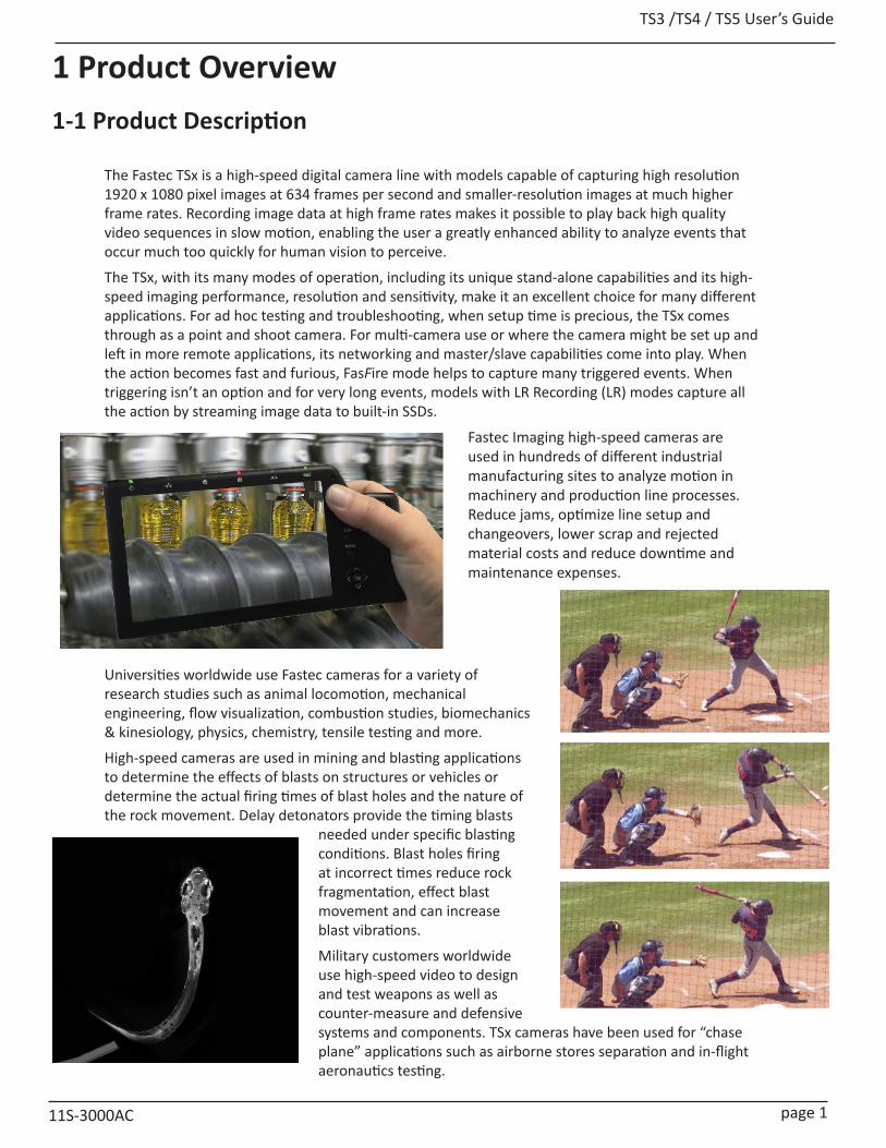
The Fastec TSx is a high-speed digital camera line with models capable of capturing high resolution 1920 x 1080 pixel images at 634 frames per second and smaller-resolution images at much higher frame rates. Recording image data at high frame rates makes it possible to play back high quality video sequences in slow motion, enabling the user a greatly enhanced ability to analyze events that occur much too quickly for human vision to perceive.
The TSx, with its many modes of operation, including its unique stand-alone capabilities and its high-speed imaging performance, resolution and sensitivity, make it an excellent choice for many different applications. For ad hoc testing and troubleshooting, when setup time is precious, the TSx comes through as a point and shoot camera. For multi-camera use or where the camera might be set up and left in more remote applications, its networking and master/slave capabilities come into play. When the action becomes fast and furious, FasFire mode helps to capture many triggered events. When triggering isn’t an option and for very long events, models with LR Recording (LR) modes capture all the action by streaming image data to built-in SSDs.
Fastec Imaging high-speed cameras are used in hundreds of different industrial manufacturing sites to analyze motion in machinery and production line processes. Reduce jams, optimize line setup and changeovers, lower scrap and rejected material costs and reduce downtime and maintenance expenses.
Universities worldwide use Fastec cameras for a variety of research studies such as animal locomotion, mechanical engineering, flow visualization, combustion studies, biomechanics & kinesiology, physics, chemistry, tensile testing and more.
High-speed cameras are used in mining and blasting applications to determine the effects of blasts on structures or vehicles or determine the actual firing times of blast holes and the nature of the rock movement. Delay detonators provide the timing blasts
needed under specific blasting conditions. Blast holes firing at incorrect times reduce rock fragmentation, effect blast movement and can increase blast vibrations.
Military customers worldwide use high-speed video to design and test weapons as well as counter-measure and defensive systems and components. TSx cameras have been used for “chase plane” applications such as airborne stores separation and in-flight aeronautics testing.

TS3 / TS4 / TS5 User’s Guide
page 2 11S-3000AC
Camera Max Resolution @ fps Standard Memory
Max Memory
Sensor Size (No Binning /
Subsampling)
Optional Solid-State Drive
TS3L 800 x 600 @1250fps 4GB 8GB 14mm 256GB* / 512GB/ 1TB / 2TBTS3S 1280 x 1024 @ 510fps 4GB 8GB 22.9mm 256GB* / 512GB/ 1TB / 2TBTS4 1280 x 1024 @ 510fps 8GB 8GB 22.9mm 512GB / 1TB/2TBTS5L 800 x 600 @1677fps 4GB 8GB 5mm 256GB* / 512GB/ 1TB / 2TBTS5S 1280 x 1024 @ 991fps 4GB 8GB 8.2mm 256GB* / 512GB/ 1TB / 2TBTS5H 1920 x 1080 @ 634fps 4GB 8GB 11mm 256GB* / 512GB/ 1TB / 2TBTS5Q 2560 x 2048 @ 253fps 4GB 8GB 16.4mm 256GB* / 512GB/ 1TB / 2TB
Table 1-1: TSx Models
1-2 Models
Fastec Imaging sells a number of different TSx high-speed digital camera models. These cameras are offered in either monochrome or color with various high-speed digital-image recording capabilities using a wide range of recording rates, sensor resolutions, and on-board memory options. All cameras are equipped with a standard C-mount lens mount, and 1/4-20 tripod mount. Additional lens mount options are available.
All TSx cameras support the following modes of operation:
• Stand-alone operation: A built-in 7” LCD touch display, SSD, SD Card, USB port, and battery power allow it to be fully functional without the connection to a host control device such as a computer.
• Remote operation using FasMotion software installed on a computer or using the Fastec Web Application. With the Web Application, any host device with a common Web browser may be used to control the camera.
TS3L models have a maximum frame rate of 1250 fps, which they can do at their maximum resolution of 800 x 600.
TS3S and TS4 models have a maximum frame rate of over 60,000 fps at a very small resolution (48 x 32) and a maximum resolution of 1280 x 1024, at which it can record at 510 fps. See “Appendix D: TS3 / TS4 Record / Resolution Tables” on page 150.
TS5 cameras are based on a 12-bit 5 Megapixel sensor. All models make use of the advanced feature set of this sensor, which include features not available on the TS3 or TS4, specifically binning and sub-sampling.
All TS4 cameras as well as TS3 and TS5 cameras with the “D” (Dual mode) can be operated in “Long Record” mode in which they record directly to an onboard SSD instead of to volatile memory. While the very highest record rates are only possible in “Standard” mode (recording to memory), high-speed recordings of much longer durations are possible in Long Record mode.
The TSx camera housing is made of 100% machined aluminum with a black anodized finish. It is both attractive and extremely durable. LEMO connectors are used for critical power and Sync/Trigger connections. An aluminum side panel door protects USB-OTG, HDMI, Gig-E, Sync/Trigger, and Power connectors as well as the SD card slot when the camera is operating in stand-alone mode. Power is supplied by an AC power adapter or a high-capacity Li-Ion battery.
More example frame rates including rates for LR modes are listed in “Appendix D: TS3 / TS4 Record / Resolution Tables” on page 150 and “Appendix E: TS5 Record / Resolution Tables” on page 155.
*256GB SSDs are not available on Dual Mode cameras

TS3 /TS4 / TS5 User’s Guide
11S-3000AC page 3
1-3 Controls, Indicators, and Connectors
Figure 1-1: TSx Back View
Camera Part Link to ViewLED Indicators “Figure 1-1: TSx Back View” / “Figure 1-2: TSx Front View”
Arm Button “Figure 1-1: TSx Back View”Display Button “Figure 1-1: TSx Back View”
Menu Button “Figure 1-1: TSx Back View”D-Pad (Directional Pad) “Figure 1-1: TSx Back View”
Trigger Button “Figure 1-3: TSx Top View” ON/OFF Button “Figure 1-3: TSx Top View”
Strap Attachments “Figure 1-3: TSx Top View” / “Figure 1-5: TSx Bottom View”C-Mount “Figure 1-2: TSx Front View”
C-Mount Lock Screws “Figure 1-3: TSx Top View” / “Figure 1-5: TSx Bottom View”Lens Mount Holes “Figure 1-3: TSx Top View”
1/4-20 Tripod Mounts “Figure 1-3: TSx Top View” / “Figure 1-5: TSx Bottom View”USB Port “Figure 1-3: TSx Top View”
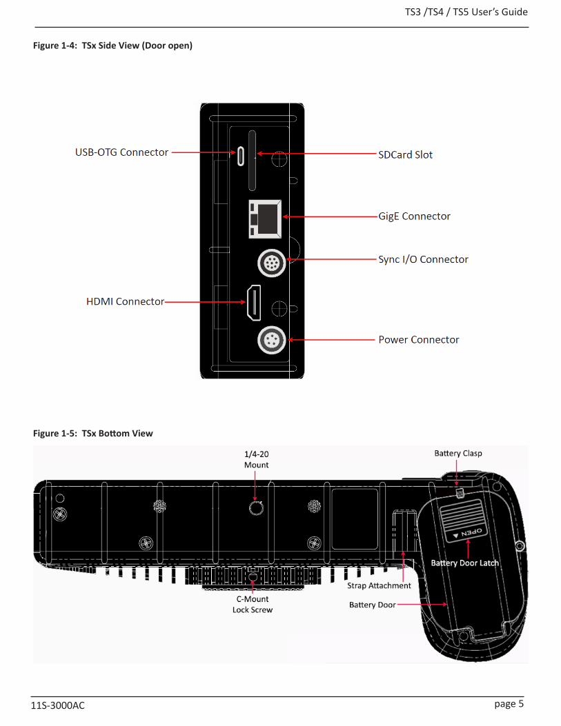
USB OTG Port “Figure 1-4: TSx Side View (Door open)” SD Card Slot “Figure 1-4: TSx Side View (Door open)”
Gig-E Connector “Figure 1-4: TSx Side View (Door open)”Sync I/O Connector “Figure 1-4: TSx Side View (Door open)”
HDMI Connector “Figure 1-4: TSx Side View (Door open)”Power Connector “Figure 1-4: TSx Side View (Door open)”
Battery Door “Figure 1-5: TSx Bottom View”Battery Door Latch “Figure 1-5: TSx Bottom View”
Battery Clasp “Figure 1-5: TSx Bottom View”
Table 1-2: Camera Part Locations
Note: See “Appendix M: Physical Measurements” on page 175 for dimensions.

TS3 / TS4 / TS5 User’s Guide
page 4 11S-3000AC
FASTECTrigger Button
C-Mount
Lens Mount Holes
Network LED
Storage LED
Camera LED
Sync LED
Battery LED
Power LED
Figure 1-2: TSx Front View
Figure 1-3: TSx Top View
TS3
TS3 /TS4 / TS5 User’s Guide
11S-3000AC page 5
Figure 1-4: TSx Side View (Door open)
Figure 1-5: TSx Bottom View
TS3 / TS4 / TS5 User’s Guide
page 6 11S-3000AC
1-4 Care and Maintenance of the TSxCamera ExteriorThe TSx exterior is made of durable anodized aluminum.
• Do not allow moisture to penetrate the camera case
• Clean exterior with a lint-free cloth.
• Do not use reagents, solvents, or adhesives.
TSx Touch Display• Take care with the glass on the display as it may break if it is struck or if the camera is dropped.
• Avoid contacting the display with sharp objects as the thin polarizing membrane may be scratched.
• Wipe off any water droplets that may come in contact with the display as it may cause spots.
• Clean the display with a soft cotton or microfiber cloth.
• Do not leave the display in direct sunlight for extended periods of time as it is sensitive to ultra violet light.
• Do not leave a fixed image on the display for extended periods of time as image retention may occur.
OpticsWhen changing lenses or lens mounts, be sure to keep the optical opening covered and clean. Any contamination on the camera optics may result in blemishes on the images.
• Remove dust or dirt from the filter glass with air whenever possible. Use air from a squeeze bulb or compressed air can.
• Use a lens pen or brush, if necessary to remove dust.
• Never use household glass cleaners or solvents on optical surfaces.
Camera Storage• Store the camera in a dust-free protective bag or box, preferably in a cool dry space.
• Never store the camera in the presence of oxidizing agents, solvents, or any other types of reactive chemicals.
• Remove the battery if the camera will not be in use for more than a few days.
• Always charge batteries to about 40% before storing. If the cell voltage is allowed to drop too low, the battery will not perform optimally and my completely lose its ability to keep a charge.
Battery Contact CleaningTSx batteries and internal battery connectors both have gold-plated contacts that are not subject to corrosion. These contacts may build up a film of contaminants over time that might affect battery performance.
• Clean battery connector pins with DeoxIT® or similar product every two to three months. (See “Appendix Q: Battery” on page 182.)
TS3 /TS4 / TS5 User’s Guide
11S-3000AC page 7
1-5 Getting HelpContact Your Distributor:Your Fastec distributor is eager to help and is always interested to get updates regarding your application, successes, and challenges. They may direct you back to the factory for support, but will want to follow up with you to ensure that your issues are addressed.
If you are unsure how to contact your distributor, please visit http://www.fastecimaging.com
Fastec Contact Information:
You may contact Fastec directly by email or phone with any questions regarding camera setup and imaging workflow for your application or with any problems you may have using the camera.
TSx cameras were designed for remote access. It is possible for the support staff at Fastec to logon to your camera via the internet using a remote desktop application such as TeamViewer to help diagnose and resolve any issue you may have.
If your camera ever requires shipment back to the Fastec factory for upgrades or repairs, make sure to get the proper RMA number and shipping instructions from Fastec before shipping.
Email: [email protected]
Phone: (858) 592-2342
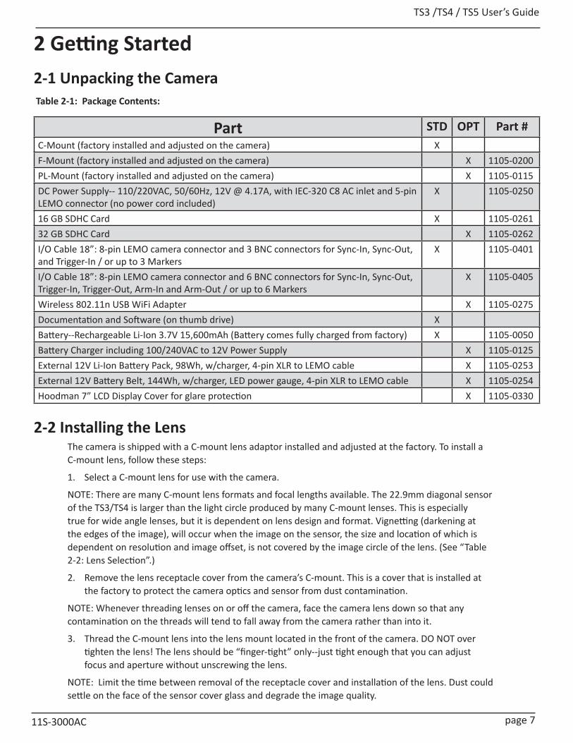
TS3 /TS4 / TS5 User’s Guide
11S-3000AC page 7
2 Getting Started 2-1 Unpacking the Camera
Part STD OPT Part #C-Mount (factory installed and adjusted on the camera) XF-Mount (factory installed and adjusted on the camera) X 1105-0200PL-Mount (factory installed and adjusted on the camera) X 1105-0115DC Power Supply-- 110/220VAC, 50/60Hz, 12V @ 4.17A, with IEC-320 C8 AC inlet and 5-pin LEMO connector (no power cord included)
X 1105-0250
16 GB SDHC Card X 1105-026132 GB SDHC Card X 1105-0262I/O Cable 18”: 8-pin LEMO camera connector and 3 BNC connectors for Sync-In, Sync-Out, and Trigger-In / or up to 3 Markers
X 1105-0401
I/O Cable 18”: 8-pin LEMO camera connector and 6 BNC connectors for Sync-In, Sync-Out, Trigger-In, Trigger-Out, Arm-In and Arm-Out / or up to 6 Markers
X 1105-0405
Wireless 802.11n USB WiFi Adapter X 1105-0275Documentation and Software (on thumb drive) XBattery--Rechargeable Li-Ion 3.7V 15,600mAh (Battery comes fully charged from factory) X 1105-0050Battery Charger including 100/240VAC to 12V Power Supply X 1105-0125External 12V Li-Ion Battery Pack, 98Wh, w/charger, 4-pin XLR to LEMO cable X 1105-0253External 12V Battery Belt, 144Wh, w/charger, LED power gauge, 4-pin XLR to LEMO cable X 1105-0254Hoodman 7” LCD Display Cover for glare protection X 1105-0330
2-2 Installing the LensThe camera is shipped with a C-mount lens adaptor installed and adjusted at the factory. To install a C-mount lens, follow these steps:
1. Select a C-mount lens for use with the camera.
NOTE: There are many C-mount lens formats and focal lengths available. The 22.9mm diagonal sensor of the TS3/TS4 is larger than the light circle produced by many C-mount lenses. This is especially true for wide angle lenses, but it is dependent on lens design and format. Vignetting (darkening at the edges of the image), will occur when the image on the sensor, the size and location of which is dependent on resolution and image offset, is not covered by the image circle of the lens. (See “Table 2-2: Lens Selection”.)
2. Remove the lens receptacle cover from the camera’s C-mount. This is a cover that is installed at the factory to protect the camera optics and sensor from dust contamination.
NOTE: Whenever threading lenses on or off the camera, face the camera lens down so that any contamination on the threads will tend to fall away from the camera rather than into it.
3. Thread the C-mount lens into the lens mount located in the front of the camera. DO NOT over tighten the lens! The lens should be “finger-tight” only--just tight enough that you can adjust focus and aperture without unscrewing the lens.
NOTE: Limit the time between removal of the receptacle cover and installation of the lens. Dust could settle on the face of the sensor cover glass and degrade the image quality.
Table 2-1: Package Contents:
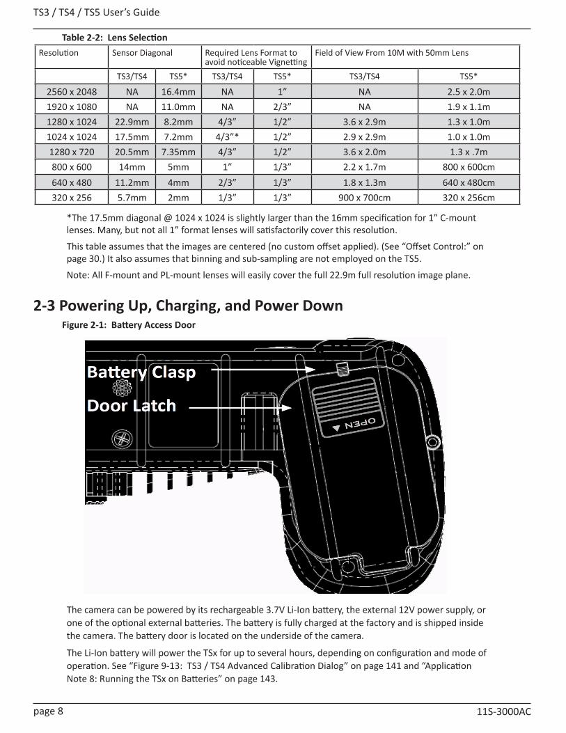
TS3 / TS4 / TS5 User’s Guide
page 8 11S-3000AC
*The 17.5mm diagonal @ 1024 x 1024 is slightly larger than the 16mm specification for 1” C-mount lenses. Many, but not all 1” format lenses will satisfactorily cover this resolution.
This table assumes that the images are centered (no custom offset applied). (See “Offset Control:” on page 30.) It also assumes that binning and sub-sampling are not employed on the TS5.
Note: All F-mount and PL-mount lenses will easily cover the full 22.9m full resolution image plane.
2-3 Powering Up, Charging, and Power Down
The camera can be powered by its rechargeable 3.7V Li-Ion battery, the external 12V power supply, or one of the optional external batteries. The battery is fully charged at the factory and is shipped inside the camera. The battery door is located on the underside of the camera.
The Li-Ion battery will power the TSx for up to several hours, depending on configuration and mode of operation. See “Figure 9-13: TS3 / TS4 Advanced Calibration Dialog” on page 141 and “Application Note 8: Running the TSx on Batteries” on page 143.
Resolution Sensor Diagonal Required Lens Format to avoid noticeable Vignetting
Field of View From 10M with 50mm Lens
TS3/TS4 TS5* TS3/TS4 TS5* TS3/TS4 TS5*
2560 x 2048 NA 16.4mm NA 1” NA 2.5 x 2.0m1920 x 1080 NA 11.0mm NA 2/3” NA 1.9 x 1.1m1280 x 1024 22.9mm 8.2mm 4/3” 1/2” 3.6 x 2.9m 1.3 x 1.0m1024 x 1024 17.5mm 7.2mm 4/3”* 1/2” 2.9 x 2.9m 1.0 x 1.0m1280 x 720 20.5mm 7.35mm 4/3” 1/2” 3.6 x 2.0m 1.3 x .7m800 x 600 14mm 5mm 1” 1/3” 2.2 x 1.7m 800 x 600cm640 x 480 11.2mm 4mm 2/3” 1/3” 1.8 x 1.3m 640 x 480cm320 x 256 5.7mm 2mm 1/3” 1/3” 900 x 700cm 320 x 256cm
Figure 2-1: Battery Access Door
Table 2-2: Lens Selection

TS3 /TS4 / TS5 User’s Guide
11S-3000AC page 9
Removing the Battery
1. Turn the TSx upside down to access the battery compartment.
2. Slide the battery door latch to the “open” position. The spring loaded door will open.
3. Move the battery clasp away from the edge of the battery and pull on the battery strap.
Installing the Battery
1. Open the battery door (follow steps 1-2, above).
2. Look into the battery compartment and notice the connector at the bottom and the battery strap.
3. Position the battery strap within the compartment so that it has enough slack to accommodate the battery but will not bunch up when the battery is installed.
4. Orient the battery appropriately and slide it into the compartment.
5. With the battery seated properly in the compartment, the battery clasp will close, securing it in place.
6. Fold the loose end of the battery strap over the top of the battery and close the battery access door.
7. Slide the battery door latch closed.
8. The TSx should now power up. If it does not, please follow the instructions below for connecting the DC power supply and charging the battery.
9. Press the Menu button once to get the menus and status bar to appear on the LCD display.
Attaching the External DC Power Supply
The 12V DC Power Supply operates on 100-240VAC, 50-60Hz. The socket is a standard IEC-320 C8 AC inlet, used worldwide for all types of electronic equipment. The power supply is shipped without power cord so that the user may use one appropriate for local power outlets.
1. Attach a power cord to the power supply and connect it to an AC power outlet.
2. Attach the power supply output cord to the camera via LEMO connectors. Note that the LEMO connector is keyed: the red dot on the connector will face the LCD side (back) of the camera.
Powering Up
The TSx will power up when:
• Power (12v to 26v DC) is applied at the Power In connector (see “Figure 1-4: TSx Side View (Door open)” on page 5).
Or:
• A charged battery is inserted into the camera.
Or:
• The camera is connected to a power source and/or has a battery installed and the Power On/Off button is pressed (see “Figure 1-3: TSx Top View” on page 4).
Figure 2-2: Power Up / Charging Menu (TS3 / TS5)
Figure 2-3: Power Up / Charging Menu (TS4-LR3 / TSx-D)
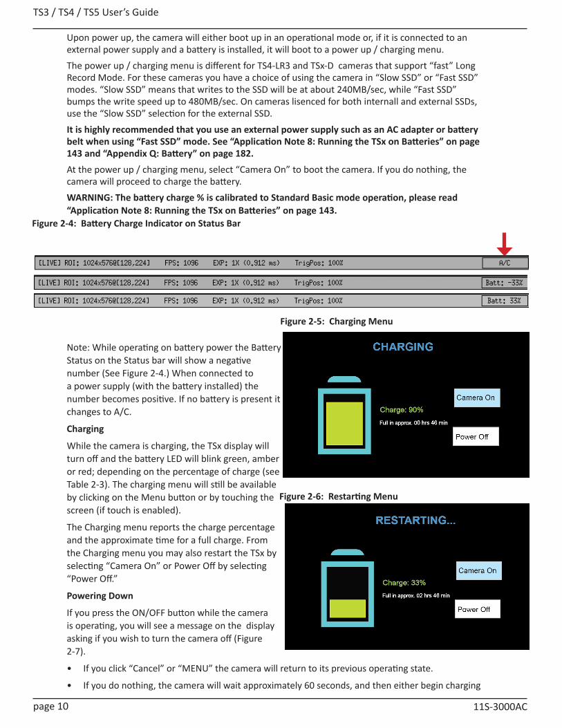
TS3 / TS4 / TS5 User’s Guide
page 10 11S-3000AC
Figure 2-6: Restarting Menu
Upon power up, the camera will either boot up in an operational mode or, if it is connected to an external power supply and a battery is installed, it will boot to a power up / charging menu.The power up / charging menu is different for TS4-LR3 and TSx-D cameras that support “fast” Long Record Mode. For these cameras you have a choice of using the camera in “Slow SSD” or “Fast SSD” modes. “Slow SSD” means that writes to the SSD will be at about 240MB/sec, while “Fast SSD” bumps the write speed up to 480MB/sec. On cameras lisenced for both internall and external SSDs, use the “Slow SSD” selection for the external SSD.It is highly recommended that you use an external power supply such as an AC adapter or battery belt when using “Fast SSD” mode. See “Application Note 8: Running the TSx on Batteries” on page 143 and “Appendix Q: Battery” on page 182.At the power up / charging menu, select “Camera On” to boot the camera. If you do nothing, the camera will proceed to charge the battery.WARNING: The battery charge % is calibrated to Standard Basic mode operation, please read “Application Note 8: Running the TSx on Batteries” on page 143.
Note: While operating on battery power the Battery Status on the Status bar will show a negative number (See Figure 2-4.) When connected to a power supply (with the battery installed) the number becomes positive. If no battery is present it changes to A/C.
Charging
While the camera is charging, the TSx display will turn off and the battery LED will blink green, amber or red; depending on the percentage of charge (see Table 2-3). The charging menu will still be available by clicking on the Menu button or by touching the screen (if touch is enabled).
The Charging menu reports the charge percentage and the approximate time for a full charge. From the Charging menu you may also restart the TSx by selecting “Camera On” or Power Off by selecting “Power Off.”
Powering Down
If you press the ON/OFF button while the camera is operating, you will see a message on the display asking if you wish to turn the camera off (Figure 2-7).
• If you click “Cancel” or “MENU” the camera will return to its previous operating state.
• If you do nothing, the camera will wait approximately 60 seconds, and then either begin charging
Figure 2-4: Battery Charge Indicator on Status Bar
Figure 2-5: Charging Menu
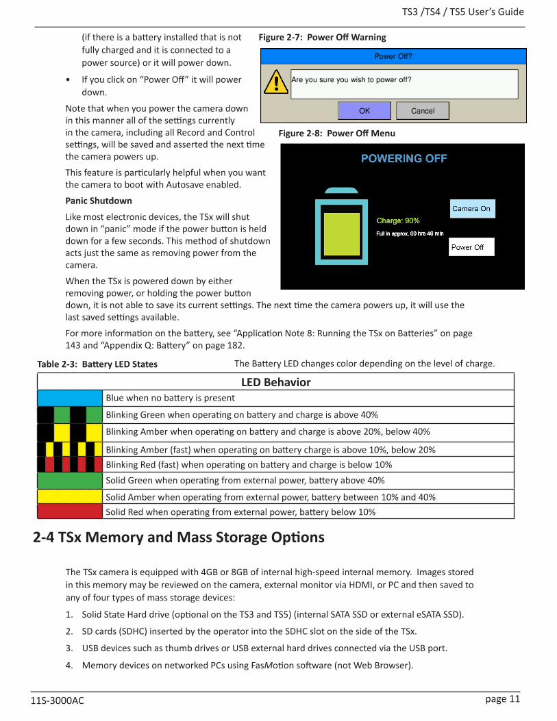
TS3 /TS4 / TS5 User’s Guide
11S-3000AC page 11
(if there is a battery installed that is not fully charged and it is connected to a power source) or it will power down.
• If you click on “Power Off” it will power down.
Note that when you power the camera down in this manner all of the settings currently in the camera, including all Record and Control settings, will be saved and asserted the next time the camera powers up.
This feature is particularly helpful when you want the camera to boot with Autosave enabled.
Panic Shutdown
Like most electronic devices, the TSx will shut down in “panic” mode if the power button is held down for a few seconds. This method of shutdown acts just the same as removing power from the camera.
When the TSx is powered down by either removing power, or holding the power button down, it is not able to save its current settings. The next time the camera powers up, it will use the last saved settings available.
For more information on the battery, see “Application Note 8: Running the TSx on Batteries” on page 143 and “Appendix Q: Battery” on page 182.
LED BehaviorBlue when no battery is present
Blinking Green when operating on battery and charge is above 40%
Blinking Amber when operating on battery and charge is above 20%, below 40%
Blinking Amber (fast) when operating on battery charge is above 10%, below 20%Blinking Red (fast) when operating on battery and charge is below 10%Solid Green when operating from external power, battery above 40%
Solid Amber when operating from external power, battery between 10% and 40% Solid Red when operating from external power, battery below 10%
The Battery LED changes color depending on the level of charge.
2-4 TSx Memory and Mass Storage Options
The TSx camera is equipped with 4GB or 8GB of internal high-speed internal memory. Images stored in this memory may be reviewed on the camera, external monitor via HDMI, or PC and then saved to any of four types of mass storage devices:
1. Solid State Hard drive (optional on the TS3 and TS5) (internal SATA SSD or external eSATA SSD).
2. SD cards (SDHC) inserted by the operator into the SDHC slot on the side of the TSx.
3. USB devices such as thumb drives or USB external hard drives connected via the USB port.
4. Memory devices on networked PCs using FasMotion software (not Web Browser).
Table 2-3: Battery LED States
Figure 2-7: Power Off Warning
Figure 2-8: Power Off Menu

TS3 / TS4 / TS5 User’s Guide
page 12 11S-3000AC
Solid State Hard Drives (SSDs)
Solid state drives (SSDs) in sizes up to 2TB are available on the TS3, TS4 and TS5. (See “Table 1-1: TSx Models” on page 2.) These drives serve as mass storage devices for the camera. Image data from the TSx’s high-speed internal memory may be downloaded to the SSD, thus making room for the next high-speed image capture. While the SSD does not add to the recording time of the camera operating in Standard mode, it does allow the user to download large quantities of image data without ever connecting the TSx to a PC or other external device.
SSDs on the TS4, TS3-D, and TS5-D
SSDs are standard equipment on all “Dual Mode” cameras, which include the TS3 and TS5 with the “D” option and the TS4 . They may be used as described above, or in Long Record mode whereby the image data is streamed directly to the SSD, thereby greatly adding to the record time.
SD Card (SDHC only)
The TSx is shipped with a 16GB SDHC SD card. (32GB cards are an available option). This card has two functions:
• It can be used as a mass storage device for downloading and distributing images. SD cards and card readers are very commonly used storage devices among PC users and photographers.
• Any field software updates for the TSx from Fastec will be installed via the SD card.
Note: An SD card when used for a software update must be reformatted before it can be reused as a mass storage device. See “Appendix L: TSx Updates” on page 173.
USB Port (USB 2.0)
The TSx will act as a Host to any USB 2.0 mass storage device connected at the USB port. (See “Figure 1-3: TSx Top View”.)
Figure 2-9: Mass Storage

TS3 /TS4 / TS5 User’s Guide
11S-3000AC page 13
USB-On the Go!
The USB-OTG port allows the camera to be connected as a slave to any PC, using a USB-A to USB-Micro-B cable. Once connected via the TSx’s OTG port, any FAT-32 formatted mass storage device on the camera can be accessed by the PC. This includes an SD card, Solid State Drive, or thumb drive in the USB port.
Note: This is not supported for the SSD when in Long Record mode because the drive cannot be formatted FAT-32 for streaming.
1. Install thumb drive and/or SD card in the camera. (Any device that is connected to the camera after the camera and PC are connected will not be seen by the PC.)
2. Attach the camera to the PC via the camera’s USB-OTG port, which is next to the SD card slot on the side of the camera. (See ““Figure 1-4: TSx Side View (Door open)” on page 5.) As each device is located by the PC an Autoplay window on the PC will open.
3. Copy files from camera media to PC (not back to camera), and then eject the media from the PC.Note: Use this method for relatively small image transfers. Much faster and more efficient workflows are available using FasMotion. Please refer to “8-21: Transfers, Batch Transfers and Conversions” on page 122.
Camera Utilities: Target Drive(s) Functions
System/Storage/Explore SSD/USB/SDHC/eSATA Move, Copy, Delete, Load CAP file, review metadata of Image files*
System/Storage/Format SSD/USB/SDHC/eSATA Format drive
System/Storage/Eject USB/SDHC Safely Eject Media Review/Save SSD/USB/SDHC/eSATA Save image Data from Internal High-Speed MemoryRecord Still SSD/USB/SDHC/eSATA Save a single still ImageAutosave SSD/USB/SDHC/eSATA Autosave image Data from Internal High-Speed MemoryStream (Long Record) SSD/eSATA (proprietary format) Long Record Basic, Long Record BROC, Long Record ROCFasMotion Utilities:Storage/Explore PC Drives+SSD/USB/SDHC/eSATA Move, Copy, Delete, Batch, Convert to AVI, Load CAP, review meta-
data*Storage/Format SSD/USB/SDHC/eSATA Format drive, Sanitize SSDReview/Save PC Drives+SSD/USB/SDHC/eSATA Save image Data from Internal High-Speed Memory, Load CAP fileRecord Still PC Drives+SSD/USB/SDHC/eSATA Save a single still ImageAutosave PC Drives+SSD/USB/SDHC/ eSATA Autosave image Data to any camera media or to PCStream (Long Record) SSD/ eSATA (proprietary format) Long Record Basic, Long Record BROC, Long Record ROCPC via Gig-E Connection:Explore SSD/USB/SDHC/eSATA Open, Copy files, multiple files, directories From TSx to PC onlyWeb Application SSD/USB/SDHC/eSATA Open, Copy files (one at a time) from TSx to PC onlyStorage/Browse SSD/USB/SDHC/eSATA Move, Copy, Delete (1 file at a time), review metadata of Image files*Storage/Format SSD/USB/SDHC/eSATA Format driveReview/Save SSD/USB/SDHC/eSATA Save image Data from Internal High-Speed MemoryRecord Still PC Drives+SSD/USB/SDHC/eSATA Save a single still ImageAutosave PC Drives+SSD/USB/SDHC/eSATA Autosave image Data from Internal High-Speed MemoryStream (Long Record) SSD/eSATA (proprietary format) Long Record Basic, Long Record BROC, Long Record ROCPC via USB-OTG: SSD/USB/SDHC/eSATA (FAT-32) Copy files and directories from TSx
*NOTE: Move and Delete functions only apply to USB and SDHC; Load CAP file only applies to SSD.
Figure 2-10: USB-OTG on the TSx
Table 2-4: TSx Mass Storage Functionality

TS3 / TS4 / TS5 User’s Guide
page 14 11S-3000AC
2-5 FasMotion Camera Control Software
The FasMotion software installation programs for Windows and Mac are copied onto the USB thumb drive that shipped with your TSx camera. The latest released versions are always available via the Fastec website, http://www.fastecimaging.com.
See “7-1 Install FasMotion Camera Control Software” on page 75 for installation instructions.
This software may be used to set up and control ILx and TSx cameras. With it you may configure all recording parameters including Session Length, Resolution, Frame Rate, Exposure, Color Balance, Autosave, Trigger point, and Sync options.
Benefits of using FasMotion software:
• High-quality, full-resolution display is helpful when viewing videos and when setting image display properties.
• Transfer image data from camera memory to PC much faster than other methods. See “Application Note 5: Optimizing System for Image Transfers” on page 133.
• Use I/O markers to find moments of interest during playback.
• Use I/O charts to visualize and associate I/O states with image data.
• Save multiple configurations to speed up setup.
Figure 2-11: FasMotion on Windows
Figure 2-12: FasMotion on Mac

TS3 /TS4 / TS5 User’s Guide
11S-3000AC page 15
3 Camera Setup3-1 Display and Menu Navigation and Status Bar
The Display Button, Menu Button, and Directional Pad (D-Pad) are found on the back of the camera to the right of the LCD. (See “TSx Back View” on page 3.)
When the camera powers on for the first time, a live image with no menu is displayed.
Pressing the DISP button repeatedly toggles through several display modes: Live image, then the image plus an information bar (with record settings and status), another click adds a Histogram, then off. When reviewing video, a set of playback controls is added with the information bar, then the histogram, and then a second information bar appears with timestamps, event markers, and synchronization data. (See “5-5 TSx Timestamps and Markers” on page 62.)
The MENU button toggles the on-screen menus on and off. While navigating menus, the Menu button is used to go backward through levels of the menu. For example, if you are navigating a Menu, pressing the Menu button will return you to the Menu Bar. (See Menu Terminology, below.)
The D-Pad is used to move within menus and dialogs. It has an “OK” button in its center for selecting menu items and options.
While navigating through menus, the current location is indicated by a change of color from white or green to gray. When navigating a Menu, the drop down selections will always appear in the left-most column. The selected menu will appear in white letters in the Menu Bar. Selected or Enabled items turn green once the cursor is moved away from them.
Menu Bar Across the top of the display: Touch Menu Icon, Record, Control, Display, Review, SystemMenu Having made a selection from the menu bar, a drop down menu appears, such as the System
menu shown below. Present status for items in the selected menu is listed.Element The menu options, i.e., Name, Network, etc. are called Menu ElementsDialog Box Having chosen an item from a menu, a dialog box may open, such as the Frame Rate and
Resolution. (See “Figure 4-5: FasCorder Options Dialog” on page 28.) This is often a place where the user may make choices and/or input data.
Status Bar The Status Bar is located at the bottom of the display. Information includes (from left to right) Camera State: LIVE= live view, CAP= recording, REVIEW= playback; Operating Mode: (blank) = Std. Basic, FasFire=Std. FasFire, Autosave=Std. Autosave , LR=Long Record Basic, LR BROC= Long Record FasCorder BROC, LR ROC= Long Recording FasCorder ROC; ROI= Resolution; FPS= Frame rate; EXP= Exposure; Trigger Position (shown if not BROC or ROC); [E] appears if connected to FasMotion; and Power /Batter Status (A/C= no battery, xx% = battery charge)
Table 3-1: Menu Terminology
Figure 3-1: System Menu
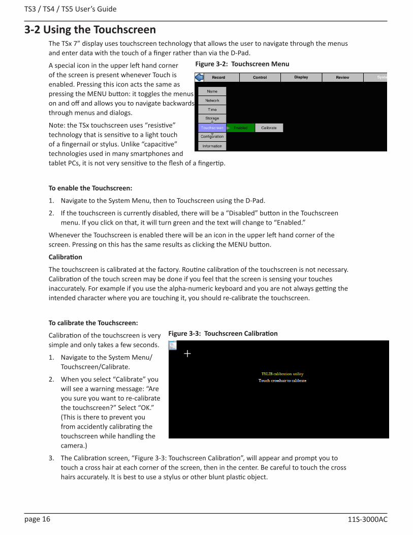
TS3 / TS4 / TS5 User’s Guide
page 16 11S-3000AC
3-2 Using the TouchscreenThe TSx 7” display uses touchscreen technology that allows the user to navigate through the menus and enter data with the touch of a finger rather than via the D-Pad.
A special icon in the upper left hand corner of the screen is present whenever Touch is enabled. Pressing this icon acts the same as pressing the MENU button: it toggles the menus on and off and allows you to navigate backwards through menus and dialogs.
Note: the TSx touchscreen uses “resistive” technology that is sensitive to a light touch of a fingernail or stylus. Unlike “capacitive” technologies used in many smartphones and tablet PCs, it is not very sensitive to the flesh of a fingertip.
To enable the Touchscreen:
1. Navigate to the System Menu, then to Touchscreen using the D-Pad.
2. If the touchscreen is currently disabled, there will be a “Disabled” button in the Touchscreen menu. If you click on that, it will turn green and the text will change to “Enabled.”
Whenever the Touchscreen is enabled there will be an icon in the upper left hand corner of the screen. Pressing on this has the same results as clicking the MENU button.
Calibration
The touchscreen is calibrated at the factory. Routine calibration of the touchscreen is not necessary. Calibration of the touch screen may be done if you feel that the screen is sensing your touches inaccurately. For example if you use the alpha-numeric keyboard and you are not always getting the intended character where you are touching it, you should re-calibrate the touchscreen.
To calibrate the Touchscreen:
Calibration of the touchscreen is very simple and only takes a few seconds.
1. Navigate to the System Menu/Touchscreen/Calibrate.
2. When you select “Calibrate” you will see a warning message: “Are you sure you want to re-calibrate the touchscreen?” Select “OK.” (This is there to prevent you from accidently calibrating the touchscreen while handling the camera.)
3. The Calibration screen, “Figure 3-3: Touchscreen Calibration”, will appear and prompt you to touch a cross hair at each corner of the screen, then in the center. Be careful to touch the cross hairs accurately. It is best to use a stylus or other blunt plastic object.
Figure 3-2: Touchscreen Menu
Figure 3-3: Touchscreen Calibration
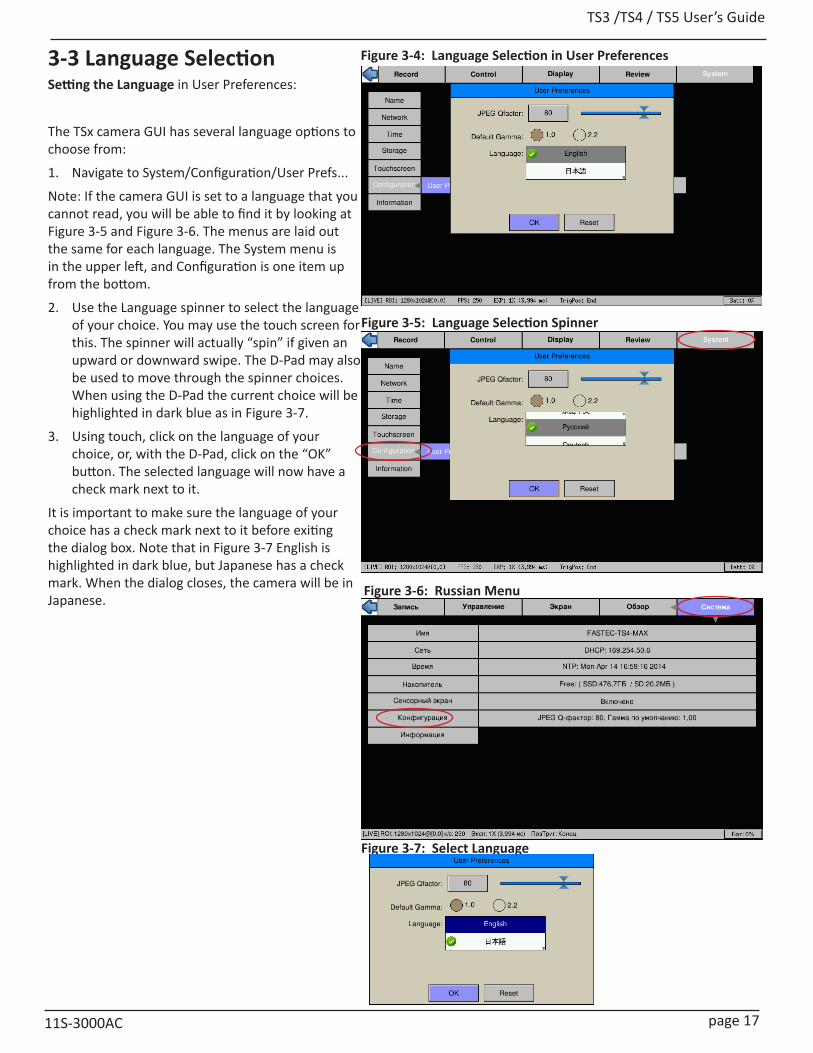
TS3 /TS4 / TS5 User’s Guide
11S-3000AC page 17
3-3 Language SelectionSetting the Language in User Preferences:
The TSx camera GUI has several language options to choose from:
1. Navigate to System/Configuration/User Prefs...
Note: If the camera GUI is set to a language that you cannot read, you will be able to find it by looking at Figure 3-5 and Figure 3-6. The menus are laid out the same for each language. The System menu is in the upper left, and Configuration is one item up from the bottom.
2. Use the Language spinner to select the language of your choice. You may use the touch screen for this. The spinner will actually “spin” if given an upward or downward swipe. The D-Pad may also be used to move through the spinner choices. When using the D-Pad the current choice will be highlighted in dark blue as in Figure 3-7.
3. Using touch, click on the language of your choice, or, with the D-Pad, click on the “OK” button. The selected language will now have a check mark next to it.
It is important to make sure the language of your choice has a check mark next to it before exiting the dialog box. Note that in Figure 3-7 English is highlighted in dark blue, but Japanese has a check mark. When the dialog closes, the camera will be in Japanese.
Figure 3-4: Language Selection in User Preferences
Figure 3-5: Language Selection Spinner
Figure 3-6: Russian Menu
Figure 3-7: Select Language
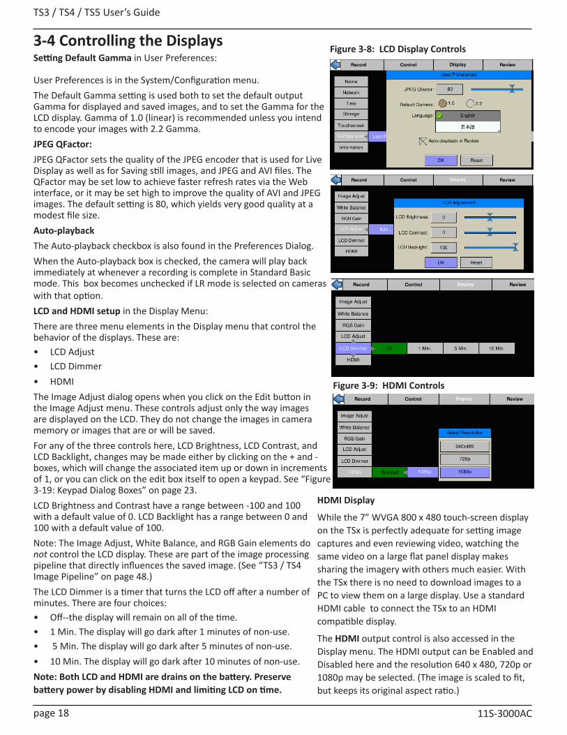
TS3 / TS4 / TS5 User’s Guide
page 18 11S-3000AC
3-4 Controlling the DisplaysSetting Default Gamma in User Preferences:
User Preferences is in the System/Configuration menu. The Default Gamma setting is used both to set the default output Gamma for displayed and saved images, and to set the Gamma for the LCD display. Gamma of 1.0 (linear) is recommended unless you intend to encode your images with 2.2 Gamma.JPEG QFactor:JPEG QFactor sets the quality of the JPEG encoder that is used for Live Display as well as for Saving still images, and JPEG and AVI files. The QFactor may be set low to achieve faster refresh rates via the Web interface, or it may be set high to improve the quality of AVI and JPEG images. The default setting is 80, which yields very good quality at a modest file size.Auto-playbackThe Auto-playback checkbox is also found in the Preferences Dialog.When the Auto-playback box is checked, the camera will play back immediately at whenever a recording is complete in Standard Basic mode. This box becomes unchecked if LR mode is selected on cameras with that option.LCD and HDMI setup in the Display Menu:There are three menu elements in the Display menu that control the behavior of the displays. These are:• LCD Adjust • LCD Dimmer • HDMIThe Image Adjust dialog opens when you click on the Edit button in the Image Adjust menu. These controls adjust only the way images are displayed on the LCD. They do not change the images in camera memory or images that are or will be saved. For any of the three controls here, LCD Brightness, LCD Contrast, and LCD Backlight, changes may be made either by clicking on the + and - boxes, which will change the associated item up or down in increments of 1, or you can click on the edit box itself to open a keypad. See “Figure 3-19: Keypad Dialog Boxes” on page 23. LCD Brightness and Contrast have a range between -100 and 100 with a default value of 0. LCD Backlight has a range between 0 and 100 with a default value of 100.Note: The Image Adjust, White Balance, and RGB Gain elements do not control the LCD display. These are part of the image processing pipeline that directly influences the saved image. (See “TS3 / TS4 Image Pipeline” on page 48.)The LCD Dimmer is a timer that turns the LCD off after a number of minutes. There are four choices: • Off--the display will remain on all of the time.• 1 Min. The display will go dark after 1 minutes of non-use.• 5 Min. The display will go dark after 5 minutes of non-use.• 10 Min. The display will go dark after 10 minutes of non-use.Note: Both LCD and HDMI are drains on the battery. Preserve battery power by disabling HDMI and limiting LCD on time.
Figure 3-8: LCD Display Controls
Figure 3-9: HDMI Controls
HDMI Display
While the 7” WVGA 800 x 480 touch-screen display on the TSx is perfectly adequate for setting image captures and even reviewing video, watching the same video on a large flat panel display makes sharing the imagery with others much easier. With the TSx there is no need to download images to a PC to view them on a large display. Use a standard HDMI cable to connect the TSx to an HDMI compatible display.
The HDMI output control is also accessed in the Display menu. The HDMI output can be Enabled and Disabled here and the resolution 640 x 480, 720p or 1080p may be selected. (The image is scaled to fit, but keeps its original aspect ratio.)
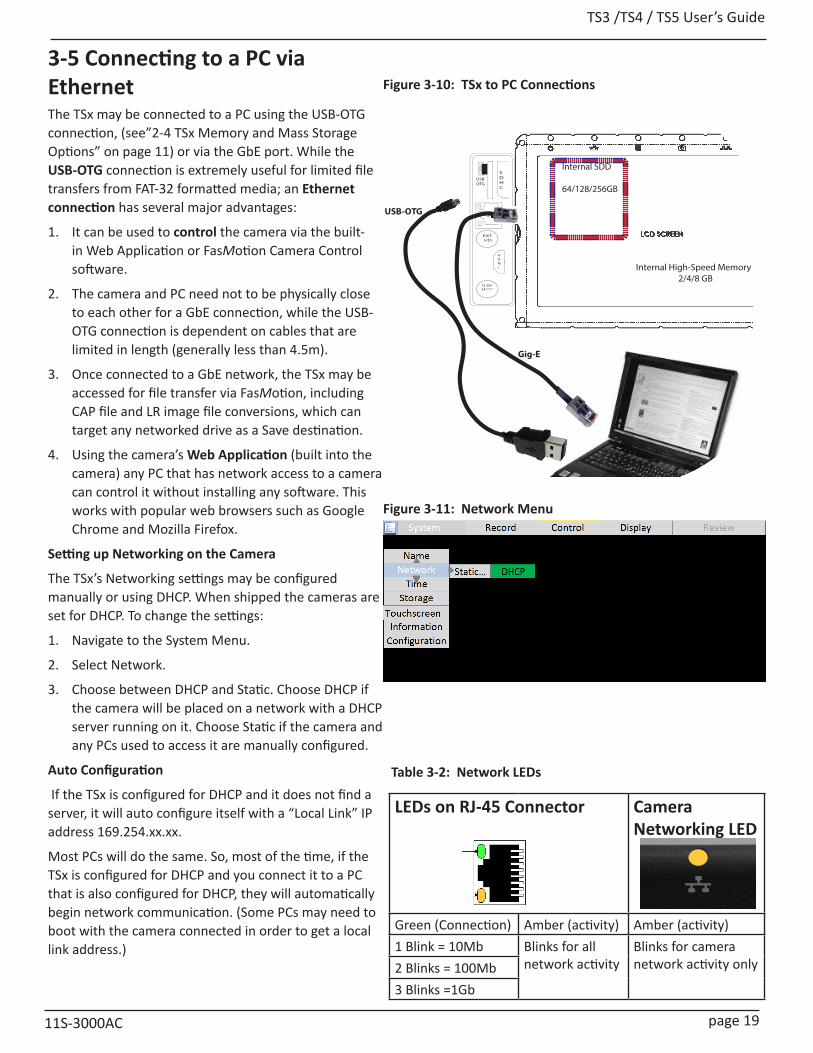
TS3 /TS4 / TS5 User’s Guide
11S-3000AC page 19
3-5 Connecting to a PC via EthernetThe TSx may be connected to a PC using the USB-OTG connection, (see”2-4 TSx Memory and Mass Storage Options” on page 11) or via the GbE port. While the USB-OTG connection is extremely useful for limited file transfers from FAT-32 formatted media; an Ethernet connection has several major advantages:
1. It can be used to control the camera via the built-in Web Application or FasMotion Camera Control software.
2. The camera and PC need not to be physically close to each other for a GbE connection, while the USB-OTG connection is dependent on cables that are limited in length (generally less than 4.5m).
3. Once connected to a GbE network, the TSx may be accessed for file transfer via FasMotion, including CAP file and LR image file conversions, which can target any networked drive as a Save destination.
4. Using the camera’s Web Application (built into the camera) any PC that has network access to a camera can control it without installing any software. This works with popular web browsers such as Google Chrome and Mozilla Firefox.
Setting up Networking on the Camera
The TSx’s Networking settings may be configured manually or using DHCP. When shipped the cameras are set for DHCP. To change the settings:
1. Navigate to the System Menu.
2. Select Network.
3. Choose between DHCP and Static. Choose DHCP if the camera will be placed on a network with a DHCP server running on it. Choose Static if the camera and any PCs used to access it are manually configured.
Auto Configuration
If the TSx is configured for DHCP and it does not find a server, it will auto configure itself with a “Local Link” IP address 169.254.xx.xx.
Most PCs will do the same. So, most of the time, if the TSx is configured for DHCP and you connect it to a PC that is also configured for DHCP, they will automatically begin network communication. (Some PCs may need to boot with the camera connected in order to get a local link address.)
USBOTG
SDHC
GigE
EXT I/O
12-26v3A
HDM I Internal High-Speed Memory
2/4/8 GB
Internal SDD
64/128/256GB
Gig-E
USB-OTG
Figure 3-11: Network Menu
Figure 3-10: TSx to PC Connections
LEDs on RJ-45 Connector Camera Networking LED
Green (Connection) Amber (activity) Amber (activity)1 Blink = 10Mb Blinks for all
network activityBlinks for camera network activity only2 Blinks = 100Mb
3 Blinks =1Gb
Table 3-2: Network LEDs
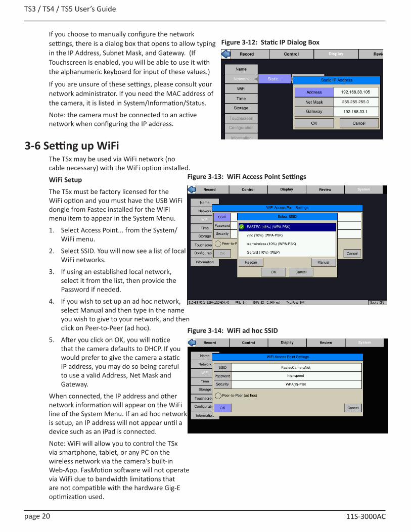
TS3 / TS4 / TS5 User’s Guide
page 20 11S-3000AC
If you choose to manually configure the network settings, there is a dialog box that opens to allow typing in the IP Address, Subnet Mask, and Gateway. (If Touchscreen is enabled, you will be able to use it with the alphanumeric keyboard for input of these values.)
If you are unsure of these settings, please consult your network administrator. If you need the MAC address of the camera, it is listed in System/Information/Status.
Note: the camera must be connected to an active network when configuring the IP address.
Figure 3-12: Static IP Dialog Box
3-6 Setting up WiFiThe TSx may be used via WiFi network (no cable necessary) with the WiFi option installed.
WiFi Setup
The TSx must be factory licensed for the WiFi option and you must have the USB WiFi dongle from Fastec installed for the WiFi menu item to appear in the System Menu.
1. Select Access Point... from the System/WiFi menu.
2. Select SSID. You will now see a list of local WiFi networks.
3. If using an established local network, select it from the list, then provide the Password if needed.
4. If you wish to set up an ad hoc network, select Manual and then type in the name you wish to give to your network, and then click on Peer-to-Peer (ad hoc).
5. After you click on OK, you will notice that the camera defaults to DHCP. If you would prefer to give the camera a static IP address, you may do so being careful to use a valid Address, Net Mask and Gateway.
When connected, the IP address and other network information will appear on the WiFi line of the System Menu. If an ad hoc network is setup, an IP address will not appear until a device such as an iPad is connected.
Note: WiFi will allow you to control the TSx via smartphone, tablet, or any PC on the wireless network via the camera’s built-in Web-App. FasMotion software will not operate via WiFi due to bandwidth limitations that are not compatible with the hardware Gig-E optimization used.
Figure 3-13: WiFi Access Point Settings
Figure 3-14: WiFi ad hoc SSID
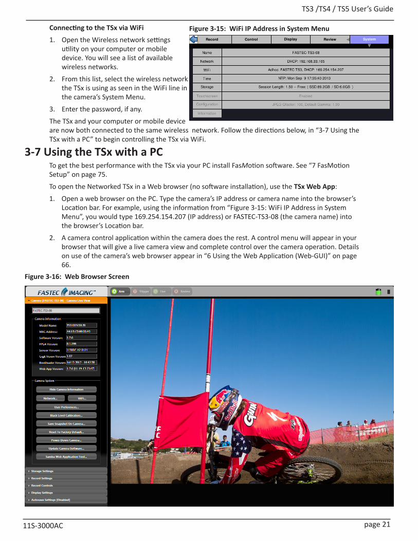
TS3 /TS4 / TS5 User’s Guide
11S-3000AC page 21
3-7 Using the TSx with a PCTo get the best performance with the TSx via your PC install FasMotion software. See “7 FasMotion Setup” on page 75.
To open the Networked TSx in a Web browser (no software installation), use the TSx Web App:
1. Open a web browser on the PC. Type the camera’s IP address or camera name into the browser’s Location bar. For example, using the information from “Figure 3-15: WiFi IP Address in System Menu”, you would type 169.254.154.207 (IP address) or FASTEC-TS3-08 (the camera name) into the browser’s Location bar.
2. A camera control application within the camera does the rest. A control menu will appear in your browser that will give a live camera view and complete control over the camera operation. Details on use of the camera’s web browser appear in “6 Using the Web Application (Web-GUI)” on page 66.
Figure 3-16: Web Browser Screen
Connecting to the TSx via WiFi
1. Open the Wireless network settings utility on your computer or mobile device. You will see a list of available wireless networks.
2. From this list, select the wireless network the TSx is using as seen in the WiFi line in the camera’s System Menu.
3. Enter the password, if any.
The TSx and your computer or mobile device are now both connected to the same wireless network. Follow the directions below, in “3-7 Using the TSx with a PC” to begin controlling the TSx via WiFi.
Figure 3-15: WiFi IP Address in System Menu
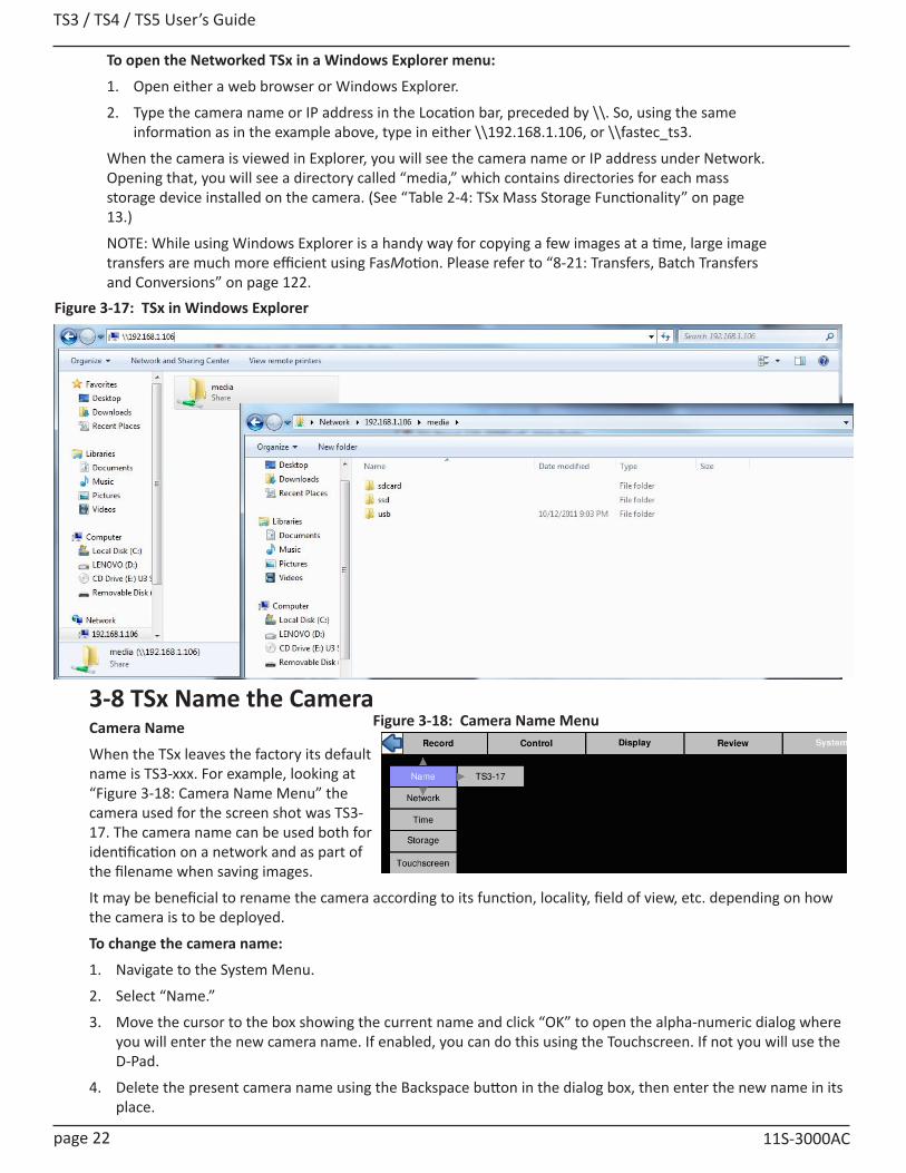
TS3 / TS4 / TS5 User’s Guide
page 22 11S-3000AC
To open the Networked TSx in a Windows Explorer menu:
1. Open either a web browser or Windows Explorer.
2. Type the camera name or IP address in the Location bar, preceded by \\. So, using the same information as in the example above, type in either \\192.168.1.106, or \\fastec_ts3.
When the camera is viewed in Explorer, you will see the camera name or IP address under Network. Opening that, you will see a directory called “media,” which contains directories for each mass storage device installed on the camera. (See “Table 2-4: TSx Mass Storage Functionality” on page 13.)
NOTE: While using Windows Explorer is a handy way for copying a few images at a time, large image transfers are much more efficient using FasMotion. Please refer to “8-21: Transfers, Batch Transfers and Conversions” on page 122.
3-8 TSx Name the Camera Camera Name
When the TSx leaves the factory its default name is TS3-xxx. For example, looking at “Figure 3-18: Camera Name Menu” the camera used for the screen shot was TS3-17. The camera name can be used both for identification on a network and as part of the filename when saving images.
It may be beneficial to rename the camera according to its function, locality, field of view, etc. depending on how the camera is to be deployed.
To change the camera name:
1. Navigate to the System Menu.
2. Select “Name.”
3. Move the cursor to the box showing the current name and click “OK” to open the alpha-numeric dialog where you will enter the new camera name. If enabled, you can do this using the Touchscreen. If not you will use the D-Pad.
4. Delete the present camera name using the Backspace button in the dialog box, then enter the new name in its place.
Figure 3-17: TSx in Windows Explorer
Figure 3-18: Camera Name Menu
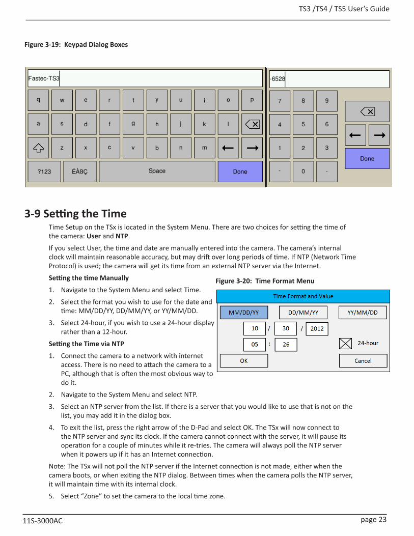
TS3 /TS4 / TS5 User’s Guide
11S-3000AC page 23
3-9 Setting the Time Time Setup on the TSx is located in the System Menu. There are two choices for setting the time of the camera: User and NTP.
If you select User, the time and date are manually entered into the camera. The camera’s internal clock will maintain reasonable accuracy, but may drift over long periods of time. If NTP (Network Time Protocol) is used; the camera will get its time from an external NTP server via the Internet.
Setting the time Manually
1. Navigate to the System Menu and select Time.
2. Select the format you wish to use for the date and time: MM/DD/YY, DD/MM/YY, or YY/MM/DD.
3. Select 24-hour, if you wish to use a 24-hour display rather than a 12-hour.
Setting the Time via NTP
1. Connect the camera to a network with internet access. There is no need to attach the camera to a PC, although that is often the most obvious way to do it.
2. Navigate to the System Menu and select NTP.
3. Select an NTP server from the list. If there is a server that you would like to use that is not on the list, you may add it in the dialog box.
4. To exit the list, press the right arrow of the D-Pad and select OK. The TSx will now connect to the NTP server and sync its clock. If the camera cannot connect with the server, it will pause its operation for a couple of minutes while it re-tries. The camera will always poll the NTP server when it powers up if it has an Internet connection.
Note: The TSx will not poll the NTP server if the Internet connection is not made, either when the camera boots, or when exiting the NTP dialog. Between times when the camera polls the NTP server, it will maintain time with its internal clock.
5. Select “Zone” to set the camera to the local time zone.
Figure 3-20: Time Format Menu
Figure 3-19: Keypad Dialog Boxes
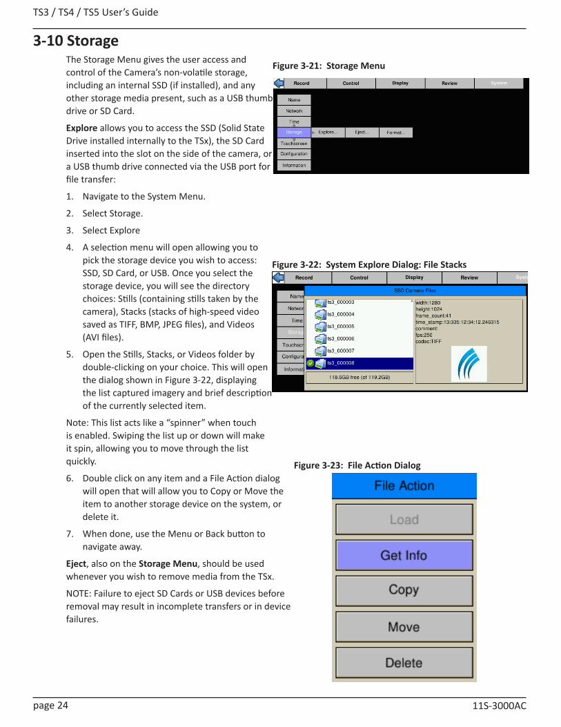
TS3 / TS4 / TS5 User’s Guide
page 24 11S-3000AC
3-10 StorageThe Storage Menu gives the user access and control of the Camera’s non-volatile storage, including an internal SSD (if installed), and any other storage media present, such as a USB thumb drive or SD Card.
Explore allows you to access the SSD (Solid State Drive installed internally to the TSx), the SD Card inserted into the slot on the side of the camera, or a USB thumb drive connected via the USB port for file transfer:
1. Navigate to the System Menu.
2. Select Storage.
3. Select Explore
4. A selection menu will open allowing you to pick the storage device you wish to access: SSD, SD Card, or USB. Once you select the storage device, you will see the directory choices: Stills (containing stills taken by the camera), Stacks (stacks of high-speed video saved as TIFF, BMP, JPEG files), and Videos (AVI files).
5. Open the Stills, Stacks, or Videos folder by double-clicking on your choice. This will open the dialog shown in Figure 3-22, displaying the list captured imagery and brief description of the currently selected item.
Note: This list acts like a “spinner” when touch is enabled. Swiping the list up or down will make it spin, allowing you to move through the list quickly.
6. Double click on any item and a File Action dialog will open that will allow you to Copy or Move the item to another storage device on the system, or delete it.
7. When done, use the Menu or Back button to navigate away.
Eject, also on the Storage Menu, should be used whenever you wish to remove media from the TSx.
NOTE: Failure to eject SD Cards or USB devices before removal may result in incomplete transfers or in device failures.
Figure 3-21: Storage Menu
Figure 3-22: System Explore Dialog: File Stacks
Figure 3-23: File Action Dialog
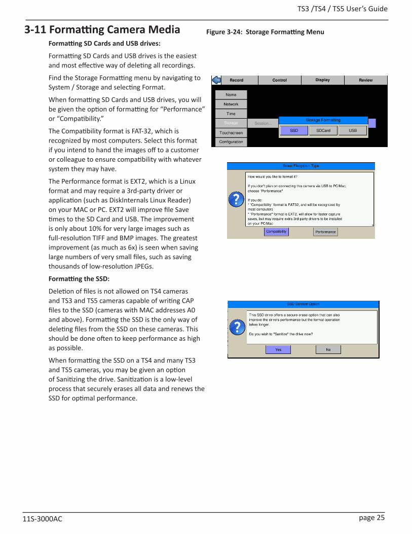
TS3 /TS4 / TS5 User’s Guide
11S-3000AC page 25
3-11 Formatting Camera MediaFormatting SD Cards and USB drives:
Formatting SD Cards and USB drives is the easiest and most effective way of deleting all recordings.
Find the Storage Formatting menu by navigating to System / Storage and selecting Format.
When formatting SD Cards and USB drives, you will be given the option of formatting for “Performance” or “Compatibility.”
The Compatibility format is FAT-32, which is recognized by most computers. Select this format if you intend to hand the images off to a customer or colleague to ensure compatibility with whatever system they may have.
The Performance format is EXT2, which is a Linux format and may require a 3rd-party driver or application (such as DiskInternals Linux Reader) on your MAC or PC. EXT2 will improve file Save times to the SD Card and USB. The improvement is only about 10% for very large images such as full-resolution TIFF and BMP images. The greatest improvement (as much as 6x) is seen when saving large numbers of very small files, such as saving thousands of low-resolution JPEGs.
Formatting the SSD:
Deletion of files is not allowed on TS4 cameras and TS3 and TS5 cameras capable of writing CAP files to the SSD (cameras with MAC addresses A0 and above). Formatting the SSD is the only way of deleting files from the SSD on these cameras. This should be done often to keep performance as high as possible.
When formatting the SSD on a TS4 and many TS3 and TS5 cameras, you may be given an option of Sanitizing the drive. Sanitization is a low-level process that securely erases all data and renews the SSD for optimal performance.
Figure 3-24: Storage Formatting Menu

TS3 / TS4 / TS5 User’s Guide
page 26 11S-3000AC
3-12 Configuration and Camera InformationTSx Configurations, which include all camera settings (resolution, frame rate, Preferences, color settings, etc.), may be Saved, Reloaded, or Reset to factory defaults. From the TSx Camera GUI two configurations may be Saved and/or Loaded.
Configurations may also be saved using FasMotion. FasMotion saves configuration files onto PC media and can store any number of configurations.
Note: Camera configurations are version-specific. When a camera firmware update is performed, you should always perform a Hard Reset, which will delete all saved configurations.
1. From the System Menu, navigate to Configuration.
2. Select Save to save the current configuration. The configuration may be saved as Configuration #1 or Configuration #2.
3. Select Load to load a saved Configuration (Configuration #1, or #2).
General information about the camera, including MAC address and versions of software, FPGA, Sensor and Gig-E are available in Information in the System Menu.
3-13 ResetThere are two levels of Reset available on the TSx, ‘Soft Reset,’ and ‘Hard Reset.’
The ‘Soft Reset’ is similar to a PC reset or warm boot. It does not change any settings or power the system down, it simply restarts the user interface and clears out any error conditions. All user configurations and all image data are preserved.
The ‘Hard Reset’ resets the camera configuration back to its factory settings. This eliminates the current user settings as well as any saved configurations (Config 1 and Config 2) and erases any image data in the camera as well as the black calibration frame. For these reasons, the Hard Reset is very seldom done other than after a firmware update.
Always remember to perform a black frame calibration after a hard reset!
Figure 3-25: Save and Load Configurations
Figure 3-26: Camera Information Box
Figure 3-27: Reset Dialog Box
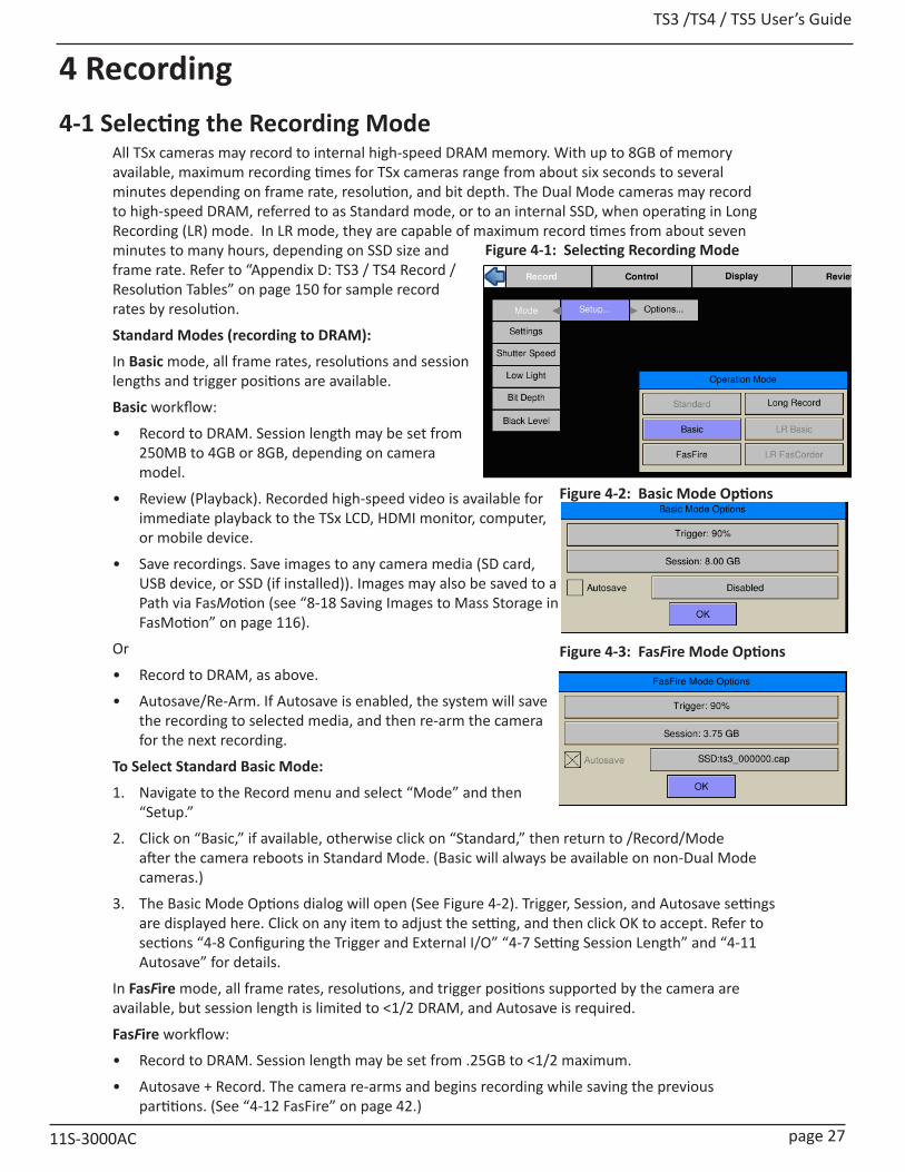
TS3 /TS4 / TS5 User’s Guide
11S-3000AC page 27
4 Recording4-1 Selecting the Recording Mode
All TSx cameras may record to internal high-speed DRAM memory. With up to 8GB of memory available, maximum recording times for TSx cameras range from about six seconds to several minutes depending on frame rate, resolution, and bit depth. The Dual Mode cameras may record to high-speed DRAM, referred to as Standard mode, or to an internal SSD, when operating in Long Recording (LR) mode. In LR mode, they are capable of maximum record times from about seven minutes to many hours, depending on SSD size and frame rate. Refer to “Appendix D: TS3 / TS4 Record / Resolution Tables” on page 150 for sample record rates by resolution.
Standard Modes (recording to DRAM):
In Basic mode, all frame rates, resolutions and session lengths and trigger positions are available.
Basic workflow:
• Record to DRAM. Session length may be set from 250MB to 4GB or 8GB, depending on camera model.
• Review (Playback). Recorded high-speed video is available for immediate playback to the TSx LCD, HDMI monitor, computer, or mobile device.
• Save recordings. Save images to any camera media (SD card, USB device, or SSD (if installed)). Images may also be saved to a Path via FasMotion (see “8-18 Saving Images to Mass Storage in FasMotion” on page 116).
Or
• Record to DRAM, as above.
• Autosave/Re-Arm. If Autosave is enabled, the system will save the recording to selected media, and then re-arm the camera for the next recording.
To Select Standard Basic Mode:
1. Navigate to the Record menu and select “Mode” and then “Setup.”
2. Click on “Basic,” if available, otherwise click on “Standard,” then return to /Record/Mode after the camera reboots in Standard Mode. (Basic will always be available on non-Dual Mode cameras.)
3. The Basic Mode Options dialog will open (See Figure 4-2). Trigger, Session, and Autosave settings are displayed here. Click on any item to adjust the setting, and then click OK to accept. Refer to sections “4-8 Configuring the Trigger and External I/O” “4-7 Setting Session Length” and “4-11 Autosave” for details.
In FasFire mode, all frame rates, resolutions, and trigger positions supported by the camera are available, but session length is limited to <1/2 DRAM, and Autosave is required.
FasFire workflow:
• Record to DRAM. Session length may be set from .25GB to <1/2 maximum.
• Autosave + Record. The camera re-arms and begins recording while saving the previous partitions. (See “4-12 FasFire” on page 42.)
Figure 4-1: Selecting Recording Mode
Figure 4-2: Basic Mode Options
Figure 4-3: FasFire Mode Options
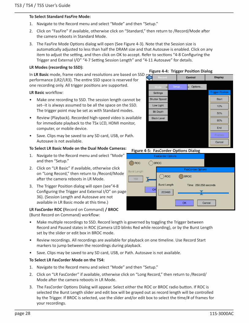
TS3 / TS4 / TS5 User’s Guide
page 28 11S-3000AC
To Select Standard FasFire Mode:
1. Navigate to the Record menu and select “Mode” and then “Setup.”
2. Click on “FasFire” if available, otherwise click on “Standard,” then return to /Record/Mode after the camera reboots in Standard Mode.
3. The FasFire Mode Options dialog will open (See Figure 4-3). Note that the Session size is automatically adjusted to less than half the DRAM size and that Autosave is enabled. Click on any item to adjust the setting, and then click on OK to accept. Refer to sections “4-8 Configuring the Trigger and External I/O” “4-7 Setting Session Length” and “4-11 Autosave” for details.
LR Modes (recording to SSD):
In LR Basic mode, frame rates and resolutions are based on SSD performance (LR2/LR3). The entire SSD space is reserved for one recording only. All trigger positions are supported.
LR Basic workflow:
• Make one recording to SSD. The session length cannot be set--it is always assumed to be all the space on the SSD. The trigger point may be set as with Standard modes.
• Review (Playback). Recorded high-speed video is available for immediate playback to the TSx LCD, HDMI monitor, computer, or mobile device.
• Save. Clips may be saved to any SD card, USB, or Path. Autosave is not available.
To Select LR Basic Mode on the Dual Mode Cameras:
1. Navigate to the Record menu and select “Mode” and then “Setup.”
2. Click on “LR Basic” if available, otherwise click on “Long Record,” then return to /Record/Mode after the camera reboots in LR Mode.
3. The Trigger Position dialog will open (see”4-8 Configuring the Trigger and External I/O” on page 36). (Session Length and Autosave are not available in LR Basic mode at this time.)
LR FasCorder ROC (Record on Command) / BROC (Burst Record on Command) workflow:
• Make multiple recordings to SSD. Record length is governed by toggling the Trigger between Record and Paused states in ROC (Camera LED blinks Red while recording), or by the Burst Length set by the slider or edit box in BROC mode.
• Review recordings. All recordings are available for playback on one timeline. Use Record Start markers to jump between the recordings during playback.
• Save. Clips may be saved to any SD card, USB, or Path. Autosave is not available.
To Select LR FasCorder Mode on the TS4:
1. Navigate to the Record menu and select “Mode” and then “Setup.”
2. Click on “LR FasCorder” if available, otherwise click on “Long Record,” then return to /Record/Mode after the camera reboots in LR Mode.
3. The FasCorder Options Dialog will appear. Select either the ROC or BROC radio button. If ROC is selected the Burst Length slider and edit box will be grayed out as record length will be controlled by the Trigger. If BROC is selected, use the slider and/or edit box to select the time/# of frames for your recordings.
Figure 4-4: Trigger Position Dialog
Figure 4-5: FasCorder Options Dialog
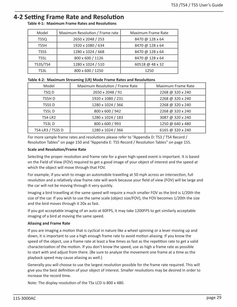
TS3 /TS4 / TS5 User’s Guide
11S-3000AC page 29
4-2 Setting Frame Rate and Resolution
Model Maximum Resolution / Frame rate Maximum Frame Rate TS5Q 2650 x 2048 / 253 8470 @ 128 x 64TS5H 1920 x 1080 / 634 8470 @ 128 x 64TS5S 1280 x 1024 / 668 8470 @ 128 x 64TS5L 800 x 600 / 1126 8470 @ 128 x 64
TS3S/TS4 1280 x 1024 / 510 60518 @ 48 x 32TS3L 800 x 600 / 1250 1250
Model Maximum Resolution / Frame Rate Maximum Frame RateTSQ D 2650 x 2048 / 91 2268 @ 320 x 240
TS5H D 1920 x 1080 / 231 2268 @ 320 x 240TS5S D 1280 x 1024 / 366 2268 @ 320 x 240TS5L D 800 x 600 / 942 2268 @ 320 x 240
TS4-LR2 1280 x 1024 / 183 3087 @ 320 x 240TS3L D 800 x 600 / 993 1250 @ 640 x 480
TS4-LR3 / TS3S D 1280 x 1024 / 366 6165 @ 320 x 240
For more sample frame rates and resolutions please refer to “Appendix D: TS3 / TS4 Record / Resolution Tables” on page 150 and “Appendix E: TS5 Record / Resolution Tables” on page 155.
Scale and Resolution/Frame Rate
Selecting the proper resolution and frame rate for a given high-speed event is important. It is based on the Field of View (FOV) required to get a good image of your object of interest and the speed at which the object will move through that FOV.
For example, if you wish to image an automobile travelling at 50 mph across an intersection, full resolution and a relatively slow frame rate will work because your field of view (FOV) will be large and the car will not be moving through it very quickly.
Imaging a bird travelling at the same speed will require a much smaller FOV as the bird is 1/20th the size of the car. If you wish to use the same scale (object size/FOV), the FOV becomes 1/20th the size and the bird moves through it 20x as fast.
If you got acceptable imaging of an auto at 60FPS, it may take 1200FPS to get similarly acceptable imaging of a bird at moving the same speed.
Aliasing and Frame Rate
If you are imaging a motion that is cyclical in nature like a wheel spinning or a lever moving up and down, it is important to use a high enough frame rate to avoid motion aliasing. If you know the speed of the object, use a frame rate at least a few times as fast as the repetition rate to get a valid characterization of the motion. If you don’t know the speed, use as high a frame rate as possible to start with and adjust from there. (Be sure to analyze the movement one frame at a time as the playback speed may cause aliasing as well.)
Generally you will choose to use the largest resolution possible for the frame rate required. This will give you the best definition of your object of interest. Smaller resolutions may be desired in order to increase the record time.
Note: The display resolution of the TSx LCD is 800 x 480.
Table 4-1: Maximum Frame Rates and Resolutions
Table 4-2: Maximum Streaming (LR) Mode Frame Rates and Resolutions
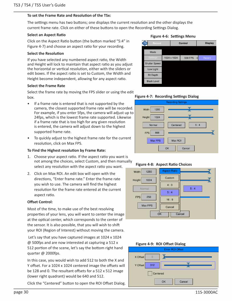
TS3 / TS4 / TS5 User’s Guide
page 30 11S-3000AC
To set the Frame Rate and Resolution of the TSx:
The settings menu has two buttons; one displays the current resolution and the other displays the current frame rate. Click on either of these buttons to open the Recording Settings Dialog.
Select an Aspect RatioClick on the Aspect Ratio button (the button marked “5:4” in Figure 4-7) and choose an aspect ratio for your recording.
Select the ResolutionIf you have selected any numbered aspect ratio, the Width and Height will lock to maintain that aspect ratio as you adjust the horizontal or vertical resolution, either with the sliders or edit boxes. If the aspect ratio is set to Custom, the Width and Height become independent, allowing for any aspect ratio.
Select the Frame RateSelect the frame rate by moving the FPS slider or using the edit box. • If a frame rate is entered that is not supported by the
camera, the closest supported frame rate will be recorded. For example, if you enter 5fps, the camera will adjust up to 24fps, which is the lowest frame rate supported. Likewise if a frame rate that is too high for any given resolution is entered, the camera will adjust down to the highest supported frame rate.
• To quickly adjust to the highest frame rate for the current resolution, click on Max FPS.
To Find the Highest resolution by Frame Rate:1. Choose your aspect ratio. If the aspect ratio you want is
not among the choices, select Custom, and then manually select any resolution with the aspect ratio you want.
2. Click on Max ROI. An edit box will open with the directions, “Enter frame rate.” Enter the frame rate you wish to use. The camera will find the highest resolution for the frame rate entered at the current aspect ratio.
Offset Control:
Most of the time, to make use of the best resolving properties of your lens, you will want to center the image at the optical center, which corresponds to the center of the sensor. It is also possible, that you will wish to shift your ROI (Region of Interest) without moving the camera.
Let’s say that you have captured images at 1024 x 1024 @ 500fps and are now interested at capturing a 512 x 512 portion of the scene, let’s say the bottom right hand quarter @ 2000fps.
In this case, you would wish to add 512 to both the X and Y offset. For a 1024 x 1024 centered image the offsets will be 128 and 0. The resultant offsets for a 512 x 512 image (lower right quadrant) would be 640 and 512.
Click the “Centered” button to open the ROI Offset Dialog.
Figure 4-8: Aspect Ratio Choices
Figure 4-7: Recording Settings Dialog
Figure 4-6: Settings Menu
Figure 4-9: ROI Offset Dialog
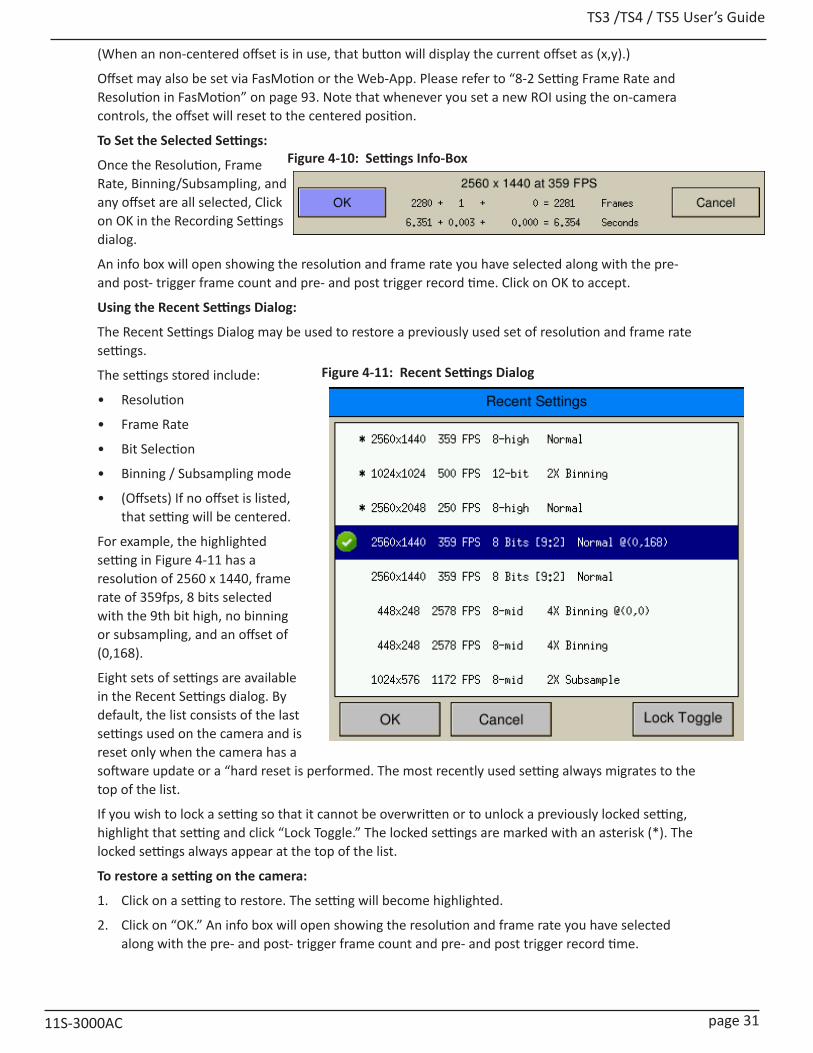
TS3 /TS4 / TS5 User’s Guide
11S-3000AC page 31
(When an non-centered offset is in use, that button will display the current offset as (x,y).)
Offset may also be set via FasMotion or the Web-App. Please refer to “8-2 Setting Frame Rate and Resolution in FasMotion” on page 93. Note that whenever you set a new ROI using the on-camera controls, the offset will reset to the centered position.
To Set the Selected Settings:
Once the Resolution, Frame Rate, Binning/Subsampling, and any offset are all selected, Click on OK in the Recording Settings dialog.
An info box will open showing the resolution and frame rate you have selected along with the pre- and post- trigger frame count and pre- and post trigger record time. Click on OK to accept.
Using the Recent Settings Dialog:
The Recent Settings Dialog may be used to restore a previously used set of resolution and frame rate settings.
The settings stored include:
• Resolution
• Frame Rate
• Bit Selection
• Binning / Subsampling mode
• (Offsets) If no offset is listed, that setting will be centered.
For example, the highlighted setting in Figure 4-11 has a resolution of 2560 x 1440, frame rate of 359fps, 8 bits selected with the 9th bit high, no binning or subsampling, and an offset of (0,168).
Eight sets of settings are available in the Recent Settings dialog. By default, the list consists of the last settings used on the camera and is reset only when the camera has a software update or a “hard reset is performed. The most recently used setting always migrates to the top of the list.
If you wish to lock a setting so that it cannot be overwritten or to unlock a previously locked setting, highlight that setting and click “Lock Toggle.” The locked settings are marked with an asterisk (*). The locked settings always appear at the top of the list.
To restore a setting on the camera:
1. Click on a setting to restore. The setting will become highlighted.
2. Click on “OK.” An info box will open showing the resolution and frame rate you have selected along with the pre- and post- trigger frame count and pre- and post trigger record time.
Figure 4-11: Recent Settings Dialog
Figure 4-10: Settings Info-Box
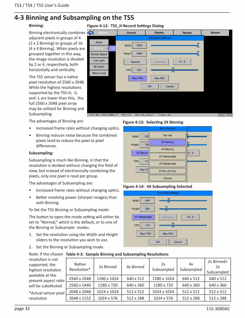
TS3 / TS4 / TS5 User’s Guide
page 32 11S-3000AC
4-3 Binning and Subsampling on the TS5Binning:
Binning electronically combines adjacent pixels in groups of 4 (2 x 2 Binning) or groups of 16 (4 x 4 Binning). When pixels are grouped together in this way, the image resolution is divided by 2 or 4, respectively, both horizontally and vertically.
The TS5 sensor has a native pixel resolution of 2560 x 2048. While the highest resolutions supported by the TS5-H, -S, and -L are lower than this, the full 2560 x 2048 pixel array may be utilized for Binning and Subsampling.
The advantages of Binning are:
• Increased frame rates without changing optics.
• Binning reduces noise because the combined pixels tend to reduce the pixel to pixel differences.
Subsampling:
Subsampling is much like Binning, in that the resolution is divided without changing the field of view, but instead of electronically combining the pixels, only one pixel is read per group.
The advantages of Subsampling are:
• Increased frame rates without changing optics.
• Better resolving power (sharper images) than with Binning.
To Set the TS5 Binning or Subsampling mode:
The button to open the mode setting will either be set to “Normal,” which is the default, or to one of the Binning or Subsample modes.
1. Set the resolution using the Width and Height sliders to the resolution you wish to use.
2. Set the Binning or Subsampling mode.
Note: If the chosen resolution is not supported, the highest resolution available at the present aspect ratio will be substituted.
*Actual sensor pixel resolution
Figure 4-12: TS5_H Record Settings Dialog
Figure 4-13: Selecting 2X Binning
Figure 4-14: 4X Subsampling Selected
Native Resolution* 2x Binned 4x Binned 2x
Subsampled4x
Subsampled
2x Binned+ 2x
Subsampled2560 x 2048 1280 x 1024 640 x 512 1280 x 1024 640 x 512 640 x 5122560 x 1440 1280 x 720 640 x 360 1280 x 720 640 x 360 640 x 3602048 x 2048 1024 x 1024 512 x 512 1024 x 1024 512 x 512 512 x 5122048 x 1152 1024 x 576 512 x 288 1024 x 576 512 x 288 512 x 288
Table 4-3: Sample Binning and Subsampling Resolutions
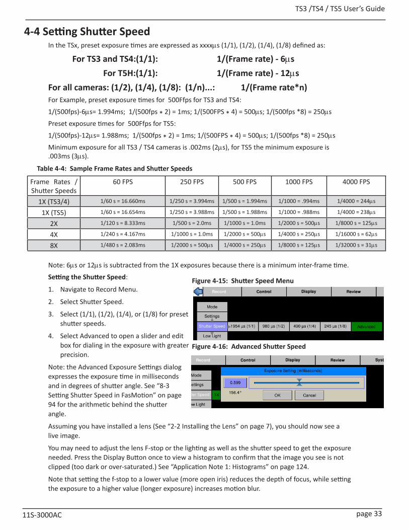
TS3 /TS4 / TS5 User’s Guide
11S-3000AC page 33
Frame Rates / Shutter Speeds
60 FPS 250 FPS 500 FPS 1000 FPS 4000 FPS
1X (TS3/4) 1/60 s = 16.660ms 1/250 s = 3.994ms 1/500 s = 1.994ms 1/1000 = .994ms 1/4000 = 244ms
1X (TS5) 1/60 s = 16.654ms 1/250 s = 3.988ms 1/500 s = 1.988ms 1/1000 = .988ms 1/4000 = 238ms
2X 1/120 s = 8.333ms 1/500 s = 2.0ms 1/1000 s = 1.0ms 1/2000 s = 500ms 1/8000 s = 125ms
4X 1/240 s = 4.167ms 1/1000 s = 1.0ms 1/2000 s = 500ms 1/4000 s = 250ms 1/16000 s = 62ms
8X 1/480 s = 2.083ms 1/2000 s = 500ms 1/4000 s = 250ms 1/8000 s = 125ms 1/32000 s = 31ms
Figure 4-15: Shutter Speed Menu
4-4 Setting Shutter SpeedIn the TSx, preset exposure times are expressed as xxxxms (1/1), (1/2), (1/4), (1/8) defined as:
For TS3 and TS4:(1/1): 1/(Frame rate) - 6ms For T5H:(1/1): 1/(Frame rate) - 12msFor all cameras: (1/2), (1/4), (1/8): (1/n)...: 1/(Frame rate*n)For Example, preset exposure times for 500Ffps for TS3 and TS4:
1/(500fps)-6ms= 1.994ms; 1/(500fps * 2) = 1ms; 1/(500FPS * 4) = 500ms; 1/(500fps *8) = 250ms
Preset exposure times for 500Ffps for TS5:
1/(500fps)-12ms= 1.988ms; 1/(500fps * 2) = 1ms; 1/(500FPS * 4) = 500ms; 1/(500fps *8) = 250ms
Minimum exposure for all TS3 / TS4 cameras is .002ms (2ms), for TS5 the minimum exposure is .003ms (3ms).
Note: 6ms or 12ms is subtracted from the 1X exposures because there is a minimum inter-frame time.
Setting the Shutter Speed:
1. Navigate to Record Menu.
2. Select Shutter Speed.
3. Select (1/1), (1/2), (1/4), or (1/8) for preset shutter speeds.
4. Select Advanced to open a slider and edit box for dialing in the exposure with greater precision.
Note: the Advanced Exposure Settings dialog expresses the exposure time in milliseconds and in degrees of shutter angle. See “8-3 Setting Shutter Speed in FasMotion” on page 94 for the arithmetic behind the shutter angle.
Assuming you have installed a lens (See “2-2 Installing the Lens” on page 7), you should now see a live image.
You may need to adjust the lens F-stop or the lighting as well as the shutter speed to get the exposure needed. Press the Display Button once to view a histogram to confirm that the image you see is not clipped (too dark or over-saturated.) See “Application Note 1: Histograms” on page 124.
Note that setting the f-stop to a lower value (more open iris) reduces the depth of focus, while setting the exposure to a higher value (longer exposure) increases motion blur.
Figure 4-16: Advanced Shutter Speed
Table 4-4: Sample Frame Rates and Shutter Speeds

TS3 / TS4 / TS5 User’s Guide
page 34 11S-3000AC
4-5 Low Light ModeThere is an option labeled “Low Light.” THIS IS NOT A SHUTTER SPEED USED FOR RECORDING! This is a special exposure setting that works in “Live Mode” only--for Live view and not while recording.
In some special circumstances, the light available for setting up the TSx for a high-speed event is not the same as what will be used for event itself. For example, you may be using an extremely bright light or light of a spectrum that would be harmful or uncomfortable for people to work under. In Low Light Mode the camera framing and focusing can be done in available light.
The exposure for Low Light Mode is much longer than would be possible for a high frame rate. The default shutter speed for Low Light mode is 41.666ms, which is the “1X” shutter speed for 24 FPS. The shutter speed for Low Light may be adjusted via the Web-App or custom camera software, but not via the on-camera interface.
To enter Low Light Mode:
Note: Be careful when using the Low Light feature! It is very easy to forget that it is on! Remember to set your exposure for the light that will be present during the image capture.
1. Set the Shutter Speed just as you need it for the high speed event, as described in “4-4 Setting Shutter Speed”
2. Navigate to the Record/Low Light Menu.
3. If Low Light is not enabled, there will be two items in the menu: “Disabled,” and an exposure setting (41.660ms by default). When you click on the “Disabled” button, it will change to “Enabled.” You will notice immediately that the Live image is much brighter.
4. If you wish to adjust the low-light setting, click on the exposure setting button to open the Low-light Adjustment slider. The edit box may also be used to enter the exposure.
Note: When you Arm the camera to begin recording, Low-light mode will automatically be canceled and the exposure will revert back to its normal setting (which is usually much darker).
4-6 Setting Bit DepthFor a description of what bit depth is and the results of changing bit depth, please refer to “Application Note 2: Understanding Bit Depth” on page 126.
Setting the recording bit depth for TS3 and TS4 cameras:
1. Navigate to the Record Menu.
2. Select Bit Depth.
3. Select 8-low, 8-mid, 8-high, or 10-bit. If any of the 8-bit mappings are chosen, the live image will immediately reflect that change. If 10-bit is chosen, the displayed live image will default to 8-high.
Note: The image processor of the TSx does all of its calculations in 16-bit space in order to avoid quantization errors that would result in image contouring and reduction of the color palette. When 10 bits are recorded, the extra bits are used in image processing even though only 8 bits (24 bits in color)will ultimately be displayed.
Figure 4-17: Low Light Slider
Figure 4-18: Bit Depth Menu TS3 / TS4
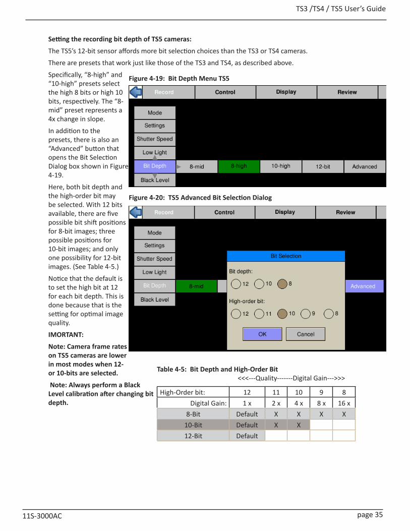
TS3 /TS4 / TS5 User’s Guide
11S-3000AC page 35
Setting the recording bit depth of TS5 cameras:
The TS5’s 12-bit sensor affords more bit selection choices than the TS3 or TS4 cameras.
There are presets that work just like those of the TS3 and TS4, as described above.
Specifically, “8-high” and “10-high” presets select the high 8 bits or high 10 bits, respectively. The “8-mid” preset represents a 4x change in slope.
In addition to the presets, there is also an “Advanced” button that opens the Bit Selection Dialog box shown in Figure 4-19.
Here, both bit depth and the high-order bit may be selected. With 12 bits available, there are five possible bit shift positions for 8-bit images; three possible positions for 10-bit images; and only one possibility for 12-bit images. (See Table 4-5.)
Notice that the default is to set the high bit at 12 for each bit depth. This is done because that is the setting for optimal image quality.
IMORTANT:
Note: Camera frame rates on TS5 cameras are lower in most modes when 12- or 10-bits are selected.
Note: Always perform a Black Level calibration after changing bit depth.
<<<---Quality-------Digital Gain--->>>
High-Order bit: 12 11 10 9 8Digital Gain: 1 x 2 x 4 x 8 x 16 x
8-Bit Default X X X X10-Bit Default X X12-Bit Default
Figure 4-19: Bit Depth Menu TS5
Figure 4-20: TS5 Advanced Bit Selection Dialog
Table 4-5: Bit Depth and High-Order Bit

TS3 / TS4 / TS5 User’s Guide
page 36 11S-3000AC
4-7 Setting Session LengthThe TSx has 4GB, or 8GB (depending on model and option) of internal high-speed memory used for capturing high-speed imagery. When operating in Standard Basic or FasFire modes, (not Long-Recording modes), all or part of this memory may be used to capture high-speed events. Total recording time will depend on resolution, frame rate, and bit depth.
Configure Session:
Session selects the amount of memory to be used for capturing imagery, which dictates the number of frames captured as well as the capture time:
1. Navigate to the Record Menu.
2. Select Mode.
3. Select either Basic Options or FasFire Options, depending on which mode you are in. (See “4-1 Selecting the Recording Mode” on page 27.
4. Click on the “Session” button to open the Session Length Adjustment dialog. See “Figure 4-2: Basic Mode Options” and “Figure 4-2: Basic Mode Options” on page 27.
5. Use the touch-enabled slider to select the amount of memory for the session (in increments of 256MB). Note that the number of frames and session time will change.
6. When the slider is selected, the D-Pad may be used for fine adjustment.
Note: When in FasFire mode, less than 50% of camera DRAM (memory) will be available. When in Basic mode with less than 50% of the DRAM selected and Autosave is enabled, the camera will operate in FasFire mode. (See “4-12 FasFire” on page 42.)
4-8 Configuring the Trigger and External I/OThe trigger Position menu will appear in the camera GUI when setting up Standard Basic, LR Basic, or Standard FasFire mode operation. See section “4-1 Selecting the Recording Mode” on page 27.
Select Start, 10%, 50%, 90% or End.
Note: When controlling the camera via Web-Application or FasMotion software, it is possible to position the trigger in 1% or even 1-frame increments. Figure 4-22 shows how the trigger position set to 1383 frames via the Web-Application or FasMotion is displayed in the Camera GUI.
Enabling the External Trigger
There are times when manually pressing the trigger button is not practical. The camera may be mounted in a location that is difficult or dangerous to reach, or it may be that the precision required to activate the trigger is much easier to maintain through electrical means.
1. Navigate to the Control Menu.
2. Select Ext. Trigger.
3. If Disabled, click on the “Disabled” button. It will turn green and the text will change to “Enabled.”
4. The next button to the right will either say Rising or Falling Edge. If you need to change the setting, click on this button to open the dialog box pictured in “Figure 4-23: External Trigger”
Please refer to “Appendix F: Power and I/O Connections” on page 163 for connection information and warnings.
Figure 4-22: Trigger Position
Figure 4-23: External Trigger
Figure 4-21: Session Length Adjustment
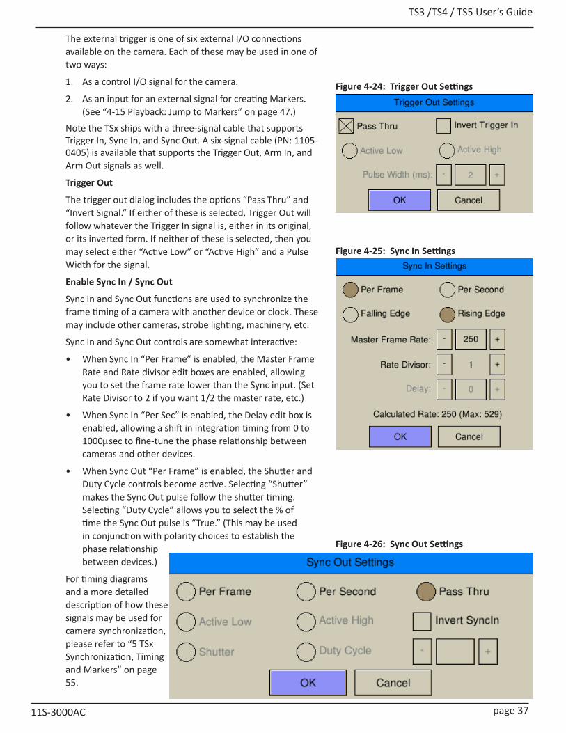
TS3 /TS4 / TS5 User’s Guide
11S-3000AC page 37
The external trigger is one of six external I/O connections available on the camera. Each of these may be used in one of two ways:
1. As a control I/O signal for the camera.
2. As an input for an external signal for creating Markers. (See “4-15 Playback: Jump to Markers” on page 47.)
Note the TSx ships with a three-signal cable that supports Trigger In, Sync In, and Sync Out. A six-signal cable (PN: 1105-0405) is available that supports the Trigger Out, Arm In, and Arm Out signals as well.
Trigger Out
The trigger out dialog includes the options “Pass Thru” and “Invert Signal.” If either of these is selected, Trigger Out will follow whatever the Trigger In signal is, either in its original, or its inverted form. If neither of these is selected, then you may select either “Active Low” or “Active High” and a Pulse Width for the signal.
Enable Sync In / Sync Out
Sync In and Sync Out functions are used to synchronize the frame timing of a camera with another device or clock. These may include other cameras, strobe lighting, machinery, etc.
Sync In and Sync Out controls are somewhat interactive:
• When Sync In “Per Frame” is enabled, the Master Frame Rate and Rate divisor edit boxes are enabled, allowing you to set the frame rate lower than the Sync input. (Set Rate Divisor to 2 if you want 1/2 the master rate, etc.)
• When Sync In “Per Sec” is enabled, the Delay edit box is enabled, allowing a shift in integration timing from 0 to 1000msec to fine-tune the phase relationship between cameras and other devices.
• When Sync Out “Per Frame” is enabled, the Shutter and Duty Cycle controls become active. Selecting “Shutter” makes the Sync Out pulse follow the shutter timing. Selecting “Duty Cycle” allows you to select the % of time the Sync Out pulse is “True.” (This may be used in conjunction with polarity choices to establish the phase relationship between devices.)
For timing diagrams and a more detailed description of how these signals may be used for camera synchronization, please refer to “5 TSx Synchronization, Timing and Markers” on page 55.
Figure 4-24: Trigger Out Settings
Figure 4-25: Sync In Settings
Figure 4-26: Sync Out Settings
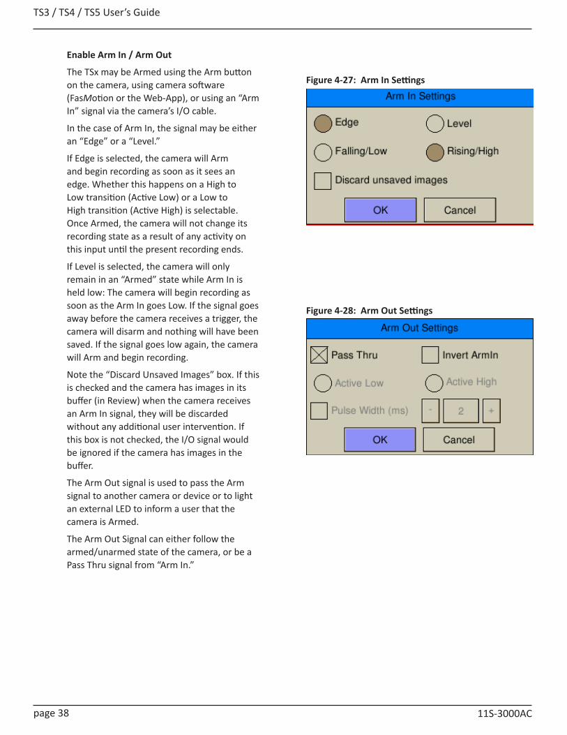
TS3 / TS4 / TS5 User’s Guide
page 38 11S-3000AC
Enable Arm In / Arm Out
The TSx may be Armed using the Arm button on the camera, using camera software (FasMotion or the Web-App), or using an “Arm In” signal via the camera’s I/O cable.
In the case of Arm In, the signal may be either an “Edge” or a “Level.”
If Edge is selected, the camera will Arm and begin recording as soon as it sees an edge. Whether this happens on a High to Low transition (Active Low) or a Low to High transition (Active High) is selectable. Once Armed, the camera will not change its recording state as a result of any activity on this input until the present recording ends.
If Level is selected, the camera will only remain in an “Armed” state while Arm In is held low: The camera will begin recording as soon as the Arm In goes Low. If the signal goes away before the camera receives a trigger, the camera will disarm and nothing will have been saved. If the signal goes low again, the camera will Arm and begin recording.
Note the “Discard Unsaved Images” box. If this is checked and the camera has images in its buffer (in Review) when the camera receives an Arm In signal, they will be discarded without any additional user intervention. If this box is not checked, the I/O signal would be ignored if the camera has images in the buffer.
The Arm Out signal is used to pass the Arm signal to another camera or device or to light an external LED to inform a user that the camera is Armed.
The Arm Out Signal can either follow the armed/unarmed state of the camera, or be a Pass Thru signal from “Arm In.”
Figure 4-27: Arm In Settings
Figure 4-28: Arm Out Settings
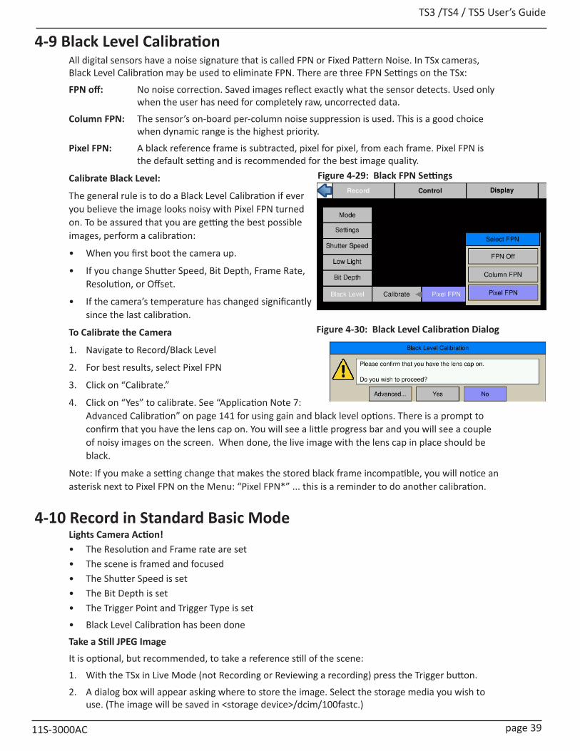
TS3 /TS4 / TS5 User’s Guide
11S-3000AC page 39
Figure 4-30: Black Level Calibration Dialog
4-9 Black Level CalibrationAll digital sensors have a noise signature that is called FPN or Fixed Pattern Noise. In TSx cameras, Black Level Calibration may be used to eliminate FPN. There are three FPN Settings on the TSx:
FPN off: No noise correction. Saved images reflect exactly what the sensor detects. Used only when the user has need for completely raw, uncorrected data.
Column FPN: The sensor’s on-board per-column noise suppression is used. This is a good choice when dynamic range is the highest priority.
Pixel FPN: A black reference frame is subtracted, pixel for pixel, from each frame. Pixel FPN is the default setting and is recommended for the best image quality.
Calibrate Black Level:
The general rule is to do a Black Level Calibration if ever you believe the image looks noisy with Pixel FPN turned on. To be assured that you are getting the best possible images, perform a calibration:
• When you first boot the camera up.
• If you change Shutter Speed, Bit Depth, Frame Rate, Resolution, or Offset.
• If the camera’s temperature has changed significantly since the last calibration.
To Calibrate the Camera
1. Navigate to Record/Black Level
2. For best results, select Pixel FPN
3. Click on “Calibrate.”
4. Click on “Yes” to calibrate. See “Application Note 7: Advanced Calibration” on page 141 for using gain and black level options. There is a prompt to confirm that you have the lens cap on. You will see a little progress bar and you will see a couple of noisy images on the screen. When done, the live image with the lens cap in place should be black.
Note: If you make a setting change that makes the stored black frame incompatible, you will notice an asterisk next to Pixel FPN on the Menu: “Pixel FPN*” ... this is a reminder to do another calibration.
4-10 Record in Standard Basic ModeLights Camera Action!• The Resolution and Frame rate are set • The scene is framed and focused• The Shutter Speed is set• The Bit Depth is set• The Trigger Point and Trigger Type is set
• Black Level Calibration has been done
Take a Still JPEG Image
It is optional, but recommended, to take a reference still of the scene:
1. With the TSx in Live Mode (not Recording or Reviewing a recording) press the Trigger button.
2. A dialog box will appear asking where to store the image. Select the storage media you wish to use. (The image will be saved in <storage device>/dcim/100fastc.)
Figure 4-29: Black FPN Settings
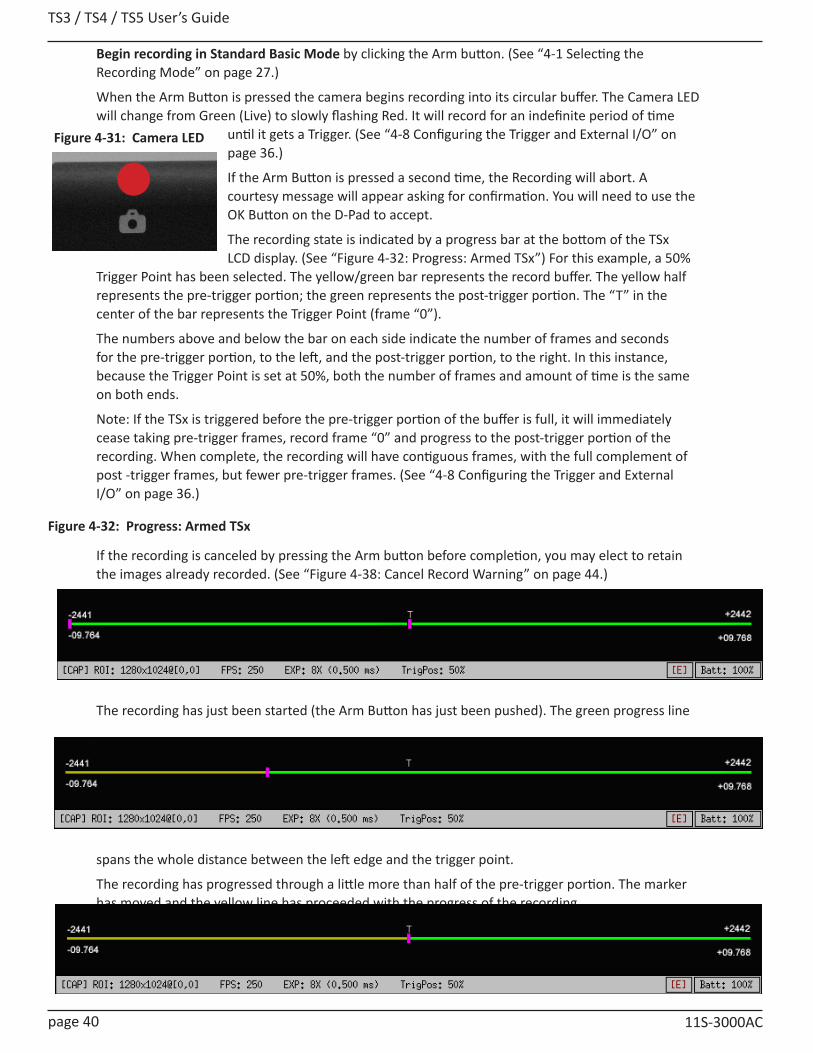
TS3 / TS4 / TS5 User’s Guide
page 40 11S-3000AC
Begin recording in Standard Basic Mode by clicking the Arm button. (See “4-1 Selecting the Recording Mode” on page 27.)
When the Arm Button is pressed the camera begins recording into its circular buffer. The Camera LED will change from Green (Live) to slowly flashing Red. It will record for an indefinite period of time
until it gets a Trigger. (See “4-8 Configuring the Trigger and External I/O” on page 36.)
If the Arm Button is pressed a second time, the Recording will abort. A courtesy message will appear asking for confirmation. You will need to use the OK Button on the D-Pad to accept.
The recording state is indicated by a progress bar at the bottom of the TSx LCD display. (See “Figure 4-32: Progress: Armed TSx”) For this example, a 50%
Trigger Point has been selected. The yellow/green bar represents the record buffer. The yellow half represents the pre-trigger portion; the green represents the post-trigger portion. The “T” in the center of the bar represents the Trigger Point (frame “0”).
The numbers above and below the bar on each side indicate the number of frames and seconds for the pre-trigger portion, to the left, and the post-trigger portion, to the right. In this instance, because the Trigger Point is set at 50%, both the number of frames and amount of time is the same on both ends.
Note: If the TSx is triggered before the pre-trigger portion of the buffer is full, it will immediately cease taking pre-trigger frames, record frame “0” and progress to the post-trigger portion of the recording. When complete, the recording will have contiguous frames, with the full complement of post -trigger frames, but fewer pre-trigger frames. (See “4-8 Configuring the Trigger and External I/O” on page 36.)
If the recording is canceled by pressing the Arm button before completion, you may elect to retain the images already recorded. (See “Figure 4-38: Cancel Record Warning” on page 44.)
The recording has just been started (the Arm Button has just been pushed). The green progress line
spans the whole distance between the left edge and the trigger point.
The recording has progressed through a little more than half of the pre-trigger portion. The marker has moved and the yellow line has proceeded with the progress of the recording.
All of the pre-trigger frames have been recorded. The TSx is continuing to record new frames as it discards the oldest. It can remain in this state indefinitely waiting for a Trigger.
Figure 4-32: Progress: Armed TSx
Figure 4-31: Camera LED
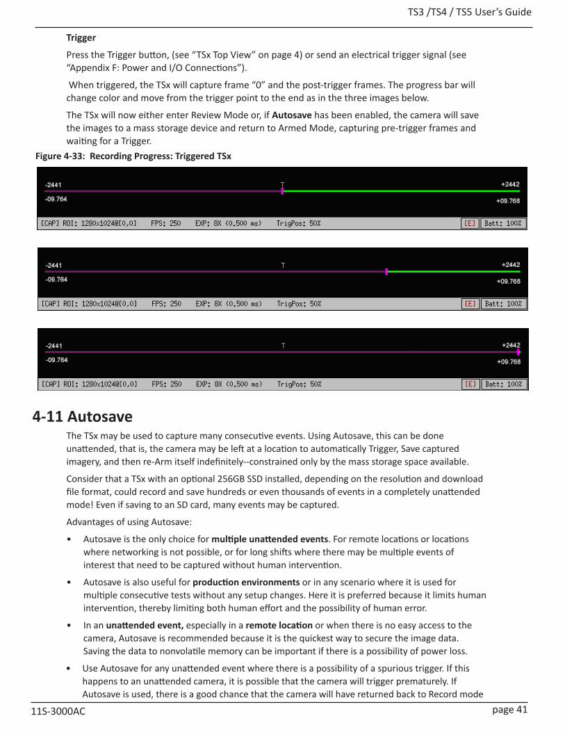
TS3 /TS4 / TS5 User’s Guide
11S-3000AC page 41
Trigger
Press the Trigger button, (see “TSx Top View” on page 4) or send an electrical trigger signal (see “Appendix F: Power and I/O Connections”).
When triggered, the TSx will capture frame “0” and the post-trigger frames. The progress bar will change color and move from the trigger point to the end as in the three images below.
The TSx will now either enter Review Mode or, if Autosave has been enabled, the camera will save the images to a mass storage device and return to Armed Mode, capturing pre-trigger frames and waiting for a Trigger.
4-11 AutosaveThe TSx may be used to capture many consecutive events. Using Autosave, this can be done unattended, that is, the camera may be left at a location to automatically Trigger, Save captured imagery, and then re-Arm itself indefinitely--constrained only by the mass storage space available.
Consider that a TSx with an optional 256GB SSD installed, depending on the resolution and download file format, could record and save hundreds or even thousands of events in a completely unattended mode! Even if saving to an SD card, many events may be captured.
Advantages of using Autosave:
• Autosave is the only choice for multiple unattended events. For remote locations or locations where networking is not possible, or for long shifts where there may be multiple events of interest that need to be captured without human intervention.
• Autosave is also useful for production environments or in any scenario where it is used for multiple consecutive tests without any setup changes. Here it is preferred because it limits human intervention, thereby limiting both human effort and the possibility of human error.
• In an unattended event, especially in a remote location or when there is no easy access to the camera, Autosave is recommended because it is the quickest way to secure the image data. Saving the data to nonvolatile memory can be important if there is a possibility of power loss.
• Use Autosave for any unattended event where there is a possibility of a spurious trigger. If this happens to an unattended camera, it is possible that the camera will trigger prematurely. If Autosave is used, there is a good chance that the camera will have returned back to Record mode
-2449
-09.796
T +2449
+09.796
-2449
-09.796
T +2449
+09.796
Figure 4-33: Recording Progress: Triggered TSx

TS3 / TS4 / TS5 User’s Guide
page 42 11S-3000AC
in time to capture the planned event.
Autosave is available in Standard Basic and FasFire modes.
1. Navigate to the Record menu and select Standard Basic or FasFire.
2. In the settings dialog, make sure that the Autosave check box is checked. (It will be checked automatically if FasFire is selected).
3. A dialog box will open to allow you to set up Start/Stop frames for downloading (the Start/Stop times for the recording are the defaults), the destination drive (mass storage target for downloads), file type options, and options for naming the downloaded files. (See “4-18 Saving Images to Mass Storage” on page 52.)
4. When finished setting up the Autosave settings, click on the OK button.
Note: Autosave will continue re-arming itself, capturing images when triggered, and downloading them until the target drive runs out of space or Autosave is manually cancelled using the Arm button.
Note: A camera that is powered-down with Autosave enabled will power up with Autosave enabled. See “2-3 Powering Up, Charging, and Power Down” on page 8.
4-12 FasFire Note: FasFire mode takes more power than other recording modes. Please refer to “Application Note 8: Running the TSx on Batteries” on page 143.
The TSx is capable of recording images to one memory partition while saving images from another partition to non-volatile media such as an SSD, SD card, or USB device. Depending on the amount of high-speed DRAM memory (4GB or 8GB) on your camera and the Session Length (partition size) you set (see “3-10 Storage” on page 24), the FasFire feature lets you capture many clips in quick succession without ever waiting for the camera to finish saving the last.
You will usually find that the camera has saved one or more partition before you get to the last one. Depending on the session size, the speed of the media, and the interval between events, you will often find that you will be able to keep recording clips at will until the space in the save media is exhausted.
For example, if you have 4GB of DRAM in your camera, and you set the Session Length to 0.50GB. You have divided the memory into 8 partitions. The camera will reserve one of these for buffering and open up the remaining 7 for FasFire. (See Table 4-5.)
Figure 4-34: Autosave Dialog
FasFire PartitionsSession Length 4GB DRAM 8GB DRAM
256MB 15 16512MB 7 150.75GB 5 10
1GB 3 71.25GB 3 6
1.5GB 2 51.75GB 2 4
2GB 1* 32.25GB 1* 32.5GB 1* 3
2.75GB 1* 23GB 1* 2
3.25GB 1* 23.5GB 1* 2
3.75GB 1* 2
4 or >4GB 1* 1*
Table 4-6: FasFire Partitions
* With only one partition, the camera does not operate in FasFire mode

TS3 /TS4 / TS5 User’s Guide
11S-3000AC page 43
Figure 4-35: FasFire Gas GaugeEntering FasFire
The camera will operate in FasFire mode whenever there are at least two FasFire partitions and the camera is set to AutoSave. (Refer to “4-1 Selecting the Recording Mode” on page 27.) In FasFire, as soon as the camera receives an Arm signal, FasFire will commence.
Using the Gas Gauge
Using the DISP button on the TSx to toggle through the displays in FasFire, you will find that there is a “gas gauge” available at the upper left corner of the image.
When the gas gauge is solid green, as in the upper image in Figure 4-35, all memory partitions are empty. This means that either you have not triggered the camera yet, or that all of the partitions you have recorded have been saved.
When you trigger the camera, the gas gauge retracts proportionately to the number of available partitions. The gas gauge in the center image shows that half the available partitions are available, and half are being saved.
If you continue to trigger the camera quickly, you may get down to the last partition. At this point the gas gauge turns red, as in the bottom image.
The gas gauge will recover as soon as partitions are saved to media, so if you wait for a while you will see the gas gauge recovering, a partition at a time, until it is solid green again.
If you do use the last partition, the camera will display the Autosave Progress bar and indicate the number of partitions waiting to be saved. (See “Figure 4-36: Autosave Progress Bar”.) As soon as one partition is free, you will see the gas gauge again and may proceed to record images.
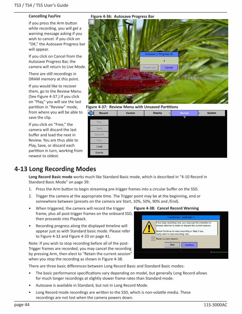
TS3 / TS4 / TS5 User’s Guide
page 44 11S-3000AC
Figure 4-36: Autosave Progress Bar
Figure 4-37: Review Menu with Unsaved Partitions
Cancelling FasFire
If you press the Arm button while recording, you will get a warning message asking if you wish to cancel. If you click on “OK,” the Autosave Progress bar will appear.
If you click on Cancel from the Autosave Progress Bar, the camera will return to Live Mode.
There are still recordings in DRAM memory at this point.
If you would like to recover them, go to the Review Menu. (See Figure 4-37.) If you click on “Play,” you will see the last partition in “Review” mode, from where you will be able to save the clip.
If you click on “Free,” the camera will discard the last buffer and load the next in Review. You are thus able to Play, Save, or discard each partition in turn, working from newest to oldest.
4-13 Long Recording ModesLong Record Basic mode works much like Standard Basic mode, which is described in “4-10 Record in Standard Basic Mode” on page 39:
1. Press the Arm button to begin streaming pre-trigger frames into a circular buffer on the SSD.
2. Trigger the camera at the appropriate time. The Trigger point may be at the beginning, end or somewhere between (presets on the camera are Start, 10%, 50%, 90% and /End).
• When triggered, the camera will record the trigger frame, plus all post-trigger frames on the onboard SSD, then proceeds into Playback.
• Recording progress along the displayed timeline will appear just as with Standard basic mode. Please refer to Figure 4-32 and Figure 4-33 on page 41.
Note: If you wish to stop recording before all of the post-Trigger frames are recorded, you may cancel the recording by pressing Arm, then elect to “Retain the current session” when you stop the recording as shown in Figure 4-38.
There are three basic differences between Long Record Basic and Standard Basic modes:
• The basic performance specifications vary depending on model, but generally Long Record allows for much longer recordings at slightly slower frame rates than Standard mode.
• Autosave is available in Standard, but not in Long Record Mode.
• Long Record mode recordings are written to the SSD, which is non-volatile media. These recordings are not lost when the camera powers down.
Figure 4-38: Cancel Record Warning

TS3 /TS4 / TS5 User’s Guide
11S-3000AC page 45
4-14 Reviewing Captured Imagery: PlaybackFour things to do in Review:1. Configure Event Markers--This makes it easy to find events such as the beginnings of ROC and
BROC recordings, or activity on the I/O lines.2. Play the video--play it forward, backward, frame by frame, adjust the cut-in and cut-out points
(find the interesting portion of the clip), etc. 3. Adjust the image brightness, contrast, gamma, bit depth, color, etc. (See “4-16 Image Processing”
on page 48.)
4. Save video to a mass storage device. (See “4-18 Saving Images to Mass Storage” on page 52.)To Review the video:In Review Mode there is a series of buttons on the bottom of the display, and a progress bar, very much like the one used for Record Mode to mark the place in the video currently being viewed.To enter Review / Play:1. Either complete a recording, which will automatically open Review / Play, or navigate to the
Review Menu and select Play. This will only be available when there is a recording in the TSx image buffer and the camera is not Recording or Saving to storage. When the image buffer is empty the Review Menu text will be grayed and the menu items are not accessible.
2. Use the Playback Buttons or touch-enabled slider to move through the imagery. The Status Bar
Figure 4-40: Playback Buttons--Markers Present
FasCorder ROC mode is convenient when multiple recordings of various durations will be made or when there are pauses in the action that need not be recorded. FasCorder BROC mode records a specified number of frames with each trigger. See ”4-1 Selecting the Recording Mode” on page 27.
1. Once the camera is set to ROC or BROC mode, press the Arm button. You will now see the recording timeline and a live image on the display. The position bug will be all the way to the left.
2. Press the Trigger button. The TS4 is now recording and streaming the images directly to the onboard SSD. The camera LED will flash red.
3. ROC mode: Press the Trigger button again. The recording will now pause. The camera LED will flash amber. Repeated triggering will cause the camera to alternate between recording and paused states. When recording, the camera LED will flash red. When paused, the LED will flash amber and the position bug will stop. This can be repeated until space on the SSD is exhausted.
4. Press the Arm button. A message will appear giving you the option to continue recording or stop and go into Playback.
Note: Appending to ROC and BROC recordings upon returning from Playback or a Power cycle will cause a number of black frames (up to 128) to be inserted in the recording timeline.
It is possible to alternate FasCorder ROC and BROC recordings in any combination as they are compatible formats. Long Record basic recordings, however, are not compatible with FasCorder and cannot coexist on the SSD.
Figure 4-39: Exit FasCorder CaptureBROC mode: The camera LED will flash red while recording a specified number of frames, then the camera will pause with the LED flashing amber. If the trigger is pressed before the specified number of frames have finished recording, the additional frames are appended to the recording.
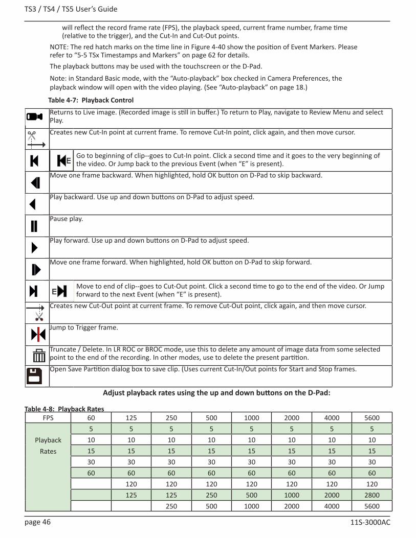
TS3 / TS4 / TS5 User’s Guide
page 46 11S-3000AC
Returns to Live image. (Recorded image is still in buffer.) To return to Play, navigate to Review Menu and select Play.
Creates new Cut-In point at current frame. To remove Cut-In point, click again, and then move cursor.
Go to beginning of clip--goes to Cut-In point. Click a second time and it goes to the very beginning of the video. Or Jump back to the previous Event (when “E” is present).
Move one frame backward. When highlighted, hold OK button on D-Pad to skip backward.
Play backward. Use up and down buttons on D-Pad to adjust speed.
Pause play.
Play forward. Use up and down buttons on D-Pad to adjust speed.
Move one frame forward. When highlighted, hold OK button on D-Pad to skip forward.
Move to end of clip--goes to Cut-Out point. Click a second time to go to the end of the video. Or Jump forward to the next Event (when “E” is present).
Creates new Cut-Out point at current frame. To remove Cut-Out point, click again, and then move cursor.
Jump to Trigger frame.
Truncate / Delete. In LR ROC or BROC mode, use this to delete any amount of image data from some selected point to the end of the recording. In other modes, use to delete the present partition.Open Save Partition dialog box to save clip. (Uses current Cut-In/Out points for Start and Stop frames.
Adjust playback rates using the up and down buttons on the D-Pad:
FPS 60 125 250 500 1000 2000 4000 5600
Playback Rates
5 5 5 5 5 5 5 510 10 10 10 10 10 10 1015 15 15 15 15 15 15 1530 30 30 30 30 30 30 3060 60 60 60 60 60 60 60
120 120 120 120 120 120 120125 125 250 500 1000 2000 2800
250 500 1000 2000 4000 5600
Table 4-7: Playback Control
Table 4-8: Playback Rates
will reflect the record frame rate (FPS), the playback speed, current frame number, frame time (relative to the trigger), and the Cut-In and Cut-Out points.
NOTE: The red hatch marks on the time line in Figure 4-40 show the position of Event Markers. Please refer to “5-5 TSx Timestamps and Markers” on page 62 for details. The playback buttons may be used with the touchscreen or the D-Pad.
Note: in Standard Basic mode, with the “Auto-playback” box checked in Camera Preferences, the playback window will open with the video playing. (See “Auto-playback” on page 18.)
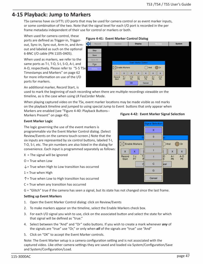
TS3 /TS4 / TS5 User’s Guide
11S-3000AC page 47
4-15 Playback: Jump to MarkersTSx cameras have six LVTTL I/O ports that may be used for camera control or as event marker inputs, or some combination of the two. Note that the signal level for each I/O port is recorded in the per frame metadata independent of their use for control or markers or both.
When used for camera control, these ports are defined as Trigger-in, Trigger-out, Sync-in, Sync-out, Arm-in, and Arm-out and labeled as such on the optional 6-BNC I/O cable (PN 1105-0405).
When used as markers, we refer to the same ports as T-I, T-O, S-I, S-O, A-I, and A-O, respectively. Please refer to “5-5 TSx Timestamps and Markers” on page 62 for more information on use of the I/O ports for markers.
An additional marker, Record Start, is used to mark the beginning of each recording when there are multiple recordings viewable on the timeline, as is the case when using LR FasCorder Mode.
When playing captured video on the TSx, event marker locations may be made visible as red marks on the playback timeline and jumped to using special Jump to Event buttons that only appear when Markers are enabled (see “Figure 4-40: Playback Buttons--Markers Present” on page 45).
Event Marker Logic
The logic governing the use of the event markers is programmable via the Event Marker Control dialog. (Select Review/Events on the camera touch-screen.) Note that the six inputs are represented by six control buttons, labeled T-I, T-O, S-I, etc. The pin numbers are also listed in the dialog for convenience. Each input is programmed separately as follows:
X = The signal will be ignored
O = True when Low
↓= True when High to Low transition has occurred
1 = True when High
↑= True when Low to High transition has occurred
C = True when any transition has occurred
G = “Glitch” true if the camera has seen a signal, but its state has not changed since the last frame.
Setting up Event Markers
1. Open the Event Marker Control dialog: click on Review/Events
2. To make markers appear on the timeline, select the Enable Markers check box.
3. For each I/O signal you wish to use, click on the associated button and select the state for which that signal will be defined as “true.”
4. Select between the “And” and “Or” radio buttons. If you wish to create a mark whenever any of the signals are “true” use “Or,” or only when all of the signals are “true” use “And”
5. Click on “OK” to accept the Event Marker controls.
Note: The Event Marker setup is a camera configuration setting and is not associated with the captured video. Like other camera settings they are saved and loaded via System/Configuration/Save and System/Configuration/Load.
Figure 4-41: Event Marker Control Dialog
Figure 4-42: Event Marker Signal Selection
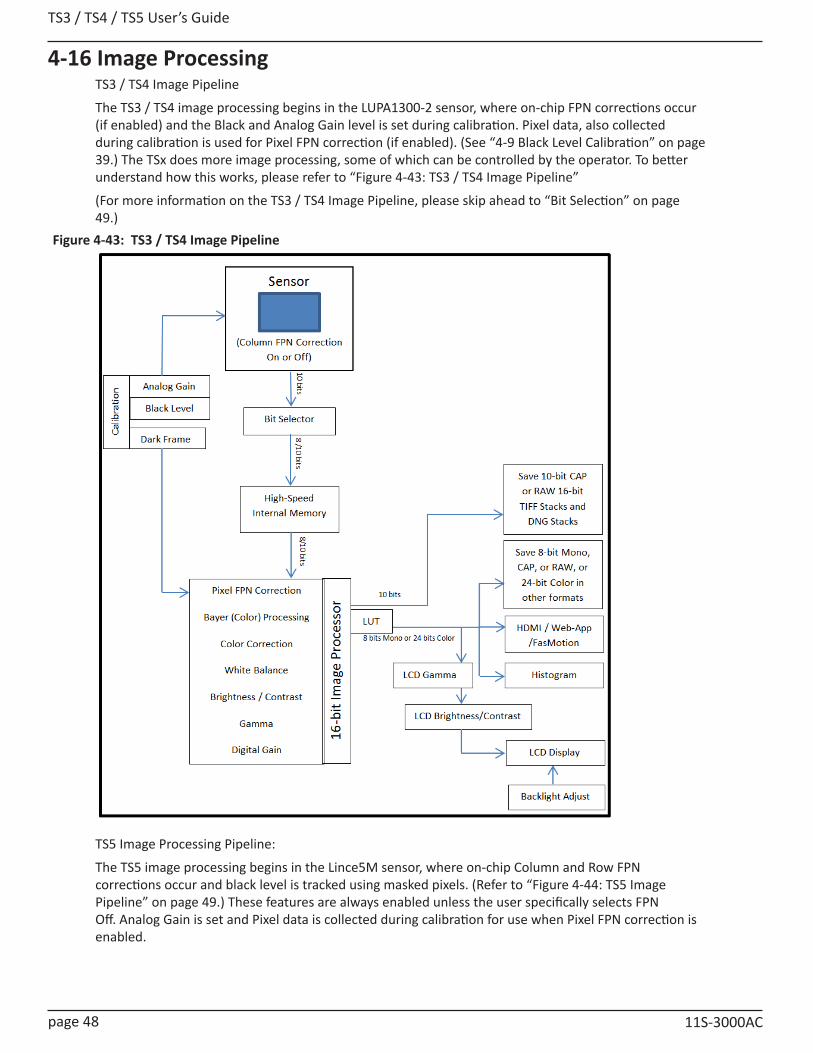
TS3 / TS4 / TS5 User’s Guide
page 48 11S-3000AC
4-16 Image ProcessingTS3 / TS4 Image Pipeline
The TS3 / TS4 image processing begins in the LUPA1300-2 sensor, where on-chip FPN corrections occur (if enabled) and the Black and Analog Gain level is set during calibration. Pixel data, also collected during calibration is used for Pixel FPN correction (if enabled). (See “4-9 Black Level Calibration” on page 39.) The TSx does more image processing, some of which can be controlled by the operator. To better understand how this works, please refer to “Figure 4-43: TS3 / TS4 Image Pipeline”
(For more information on the TS3 / TS4 Image Pipeline, please skip ahead to “Bit Selection” on page 49.)
TS5 Image Processing Pipeline:
The TS5 image processing begins in the Lince5M sensor, where on-chip Column and Row FPN corrections occur and black level is tracked using masked pixels. (Refer to “Figure 4-44: TS5 Image Pipeline” on page 49.) These features are always enabled unless the user specifically selects FPN Off. Analog Gain is set and Pixel data is collected during calibration for use when Pixel FPN correction is enabled.
Figure 4-43: TS3 / TS4 Image Pipeline
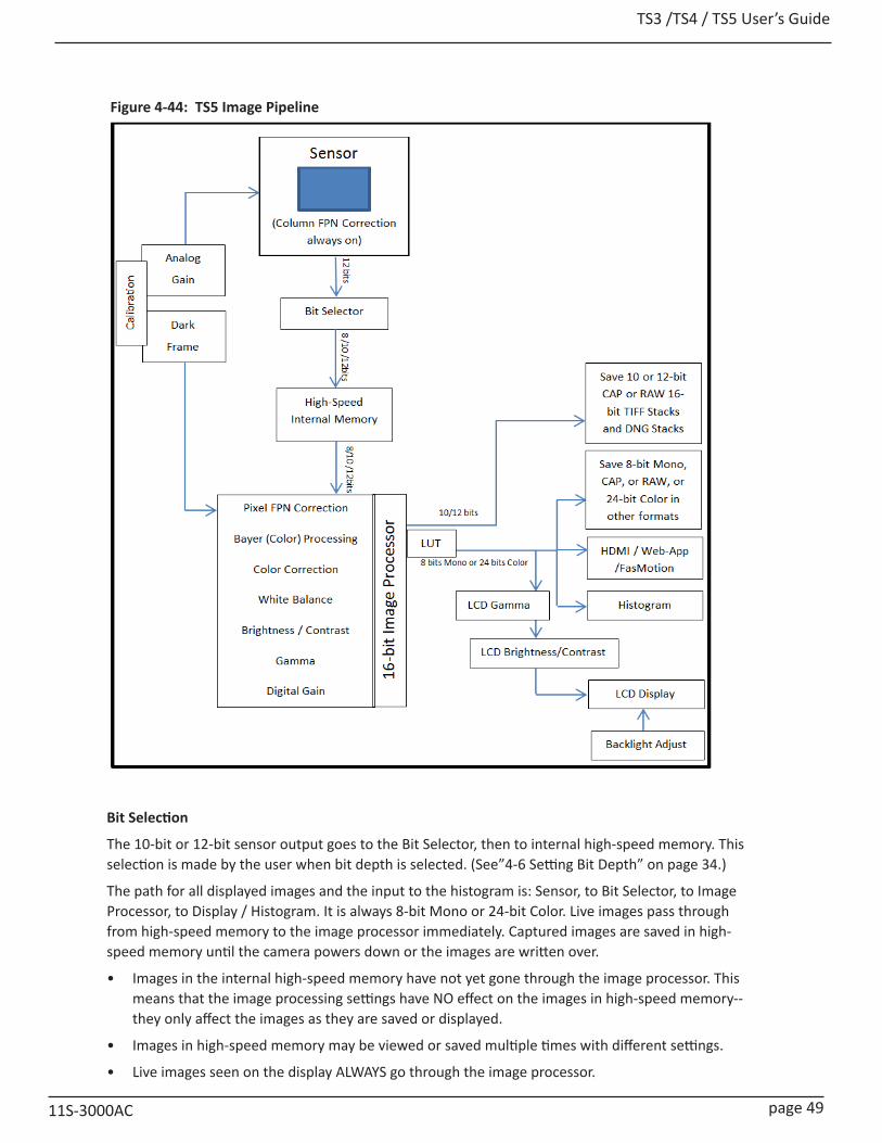
TS3 /TS4 / TS5 User’s Guide
11S-3000AC page 49
Bit Selection
The 10-bit or 12-bit sensor output goes to the Bit Selector, then to internal high-speed memory. This selection is made by the user when bit depth is selected. (See”4-6 Setting Bit Depth” on page 34.)
The path for all displayed images and the input to the histogram is: Sensor, to Bit Selector, to Image Processor, to Display / Histogram. It is always 8-bit Mono or 24-bit Color. Live images pass through from high-speed memory to the image processor immediately. Captured images are saved in high-speed memory until the camera powers down or the images are written over.
• Images in the internal high-speed memory have not yet gone through the image processor. This means that the image processing settings have NO effect on the images in high-speed memory--they only affect the images as they are saved or displayed.
• Images in high-speed memory may be viewed or saved multiple times with different settings.
• Live images seen on the display ALWAYS go through the image processor.
Figure 4-44: TS5 Image Pipeline
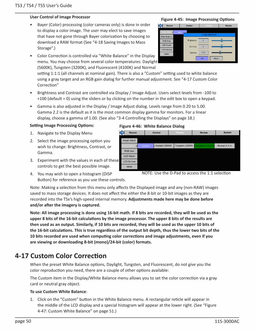
TS3 / TS4 / TS5 User’s Guide
page 50 11S-3000AC
Figure 4-45: Image Processing OptionsUser Control of Image Processor
• Bayer (Color) processing (color cameras only) is done in order to display a color image. The user may elect to save images that have not gone through Bayer colorization by choosing to download a RAW format (See “4-18 Saving Images to Mass Storage”.)
• Color Correction is controlled via “White Balance” in the Display menu. You may choose from several color temperatures: Daylight (5600K), Tungsten (3200K), and Fluorescent (4100K) and Normal setting 1:1:1 (all channels at nominal gain). There is also a “Custom” setting used to white balance using a gray target and an RGB gain dialog for further manual adjustment. See “4-17 Custom Color Correction”
• Brightness and Contrast are controlled via Display / Image Adjust. Users select levels from -100 to +100 (default = 0) using the sliders or by clicking on the number in the edit box to open a keypad.
• Gamma is also adjusted in the Display / Image Adjust dialog. Levels range from 0.20 to 5.00. Gamma 2.2 is the default as it is the most common display gamma for monitors. For a linear display, choose a gamma of 1.00. (See also “3-4 Controlling the Displays” on page 18.)
Setting Image Processing Options:
1. Navigate to the Display Menu
2. Select the image processing option you wish to change: Brightness, Contrast, or Gamma.
3. Experiment with the values in each of these controls to get the best possible image.
4. You may wish to open a histogram (DISP Button) for reference as you use these controls.
Note: Making a selection from this menu only affects the Displayed image and any (non-RAW) images saved to mass storage devices. It does not affect the either the 8-bit or 10-bit images as they are recorded into the TSx’s high-speed internal memory. Adjustments made here may be done before and/or after the imagery is captured.
Note: All image processing is done using 16-bit math. If 8 bits are recorded, they will be used as the upper 8 bits of the 16-bit calculations by the image processor. The upper 8 bits of the results are then used as an output. Similarly, if 10 bits are recorded, they will be used as the upper 10 bits of the 16-bit calculations. This is true regardless of the output bit depth, thus the lower two bits of the 10 bits recorded are used when computing color corrections and image adjustments, even if you are viewing or downloading 8-bit (mono)/24-bit (color) formats.
4-17 Custom Color CorrectionWhen the preset White Balance options, Daylight, Tungsten, and Fluorescent, do not give you the color reproduction you need, there are a couple of other options available:
The Custom item in the Display/White Balance menu allows you to set the color correction via a gray card or neutral gray object.
To use Custom White Balance:
1. Click on the “Custom” button in the White Balance menu. A rectangular reticle will appear in the middle of the LCD display and a special histogram will appear at the lower right. (See “Figure 4-47: Custom White Balance” on page 51.)
Figure 4-46: White Balance Dialog
NOTE: Use the D-Pad to access the 1:1 selection

TS3 /TS4 / TS5 User’s Guide
11S-3000AC page 51
2. Center the reticle (the white box in the center of the image) on a neutral gray object in the field of view. In this instance we are using an 18% gray card, which is the recommended target. Most often the card will only fill a portion of the field of view--it only needs to fill the reticle. It is important that the card or other neutral gray object is located close to the objects of interest and is exposed to the same light as the objects you are going to image.
3. Adjust the lens aperture so that the histogram shows the pixel values grouped high (to the right side of the box), but not saturated. It is important that the high pixel value is less than 255. Notice on the example here, that the RGB peaks are not well aligned and that the Blue peak is farthest to the left. This means that the color is skewed slightly towards the yellow, the complement to blue.
Note: The histogram used with Custom White Balance represents only the area of the reticle, not the whole image.
Note: For more information regarding TSx Histograms please refer to “Application Note 1: Histograms” on page 124.
4. Press the Trigger button. You will immediately notice a difference in the color.
Using RGB Gain Controls
Another option for addressing color correction is via RGB Gains. It is recommended that you use the RGB gains sparingly and as a final “tweak” to make subtle changes to the color. The best use of this is to get the color as close as possible using the White Balance presets or Custom options before adjusting the RGB gains.
To use RGB Gain:
1. Navigate to the Display/RGB Gain menu and open the dialog box.
2. For any color gain you wish to increase, move the slider to the desired position. Remember to use the D-Pad for fine adjustment.
3. If you wish to simply add color-neutral gain to the image, move all three sliders proportionately.
Note: Remember that in the Bayer pattern, 1/2 of the pixels are green, 1/4 are blue and 1/4 are red. Whenever you change gain values you will be adding some noise to the image. It is best to avoid using any more gain than you need to, and to take special care with the green channel as it represents half of the pixels in the image.
Figure 4-48: RGB Control Dialog
Figure 4-47: Custom White Balance

TS3 / TS4 / TS5 User’s Guide
page 52 11S-3000AC
4-18 Saving Images to Mass StorageImage sequences are saved either as Partition Captures (CAP files), or AVI videos, in which one file contains all the frames of the sequence, or as TIFF, DNG, JPEG, or BMP stacks, which are collections of files, one file per frame of imagery. Partition Capture files (CAP) include all the raw image data in a proprietary uncompressed format. The file save options change depending on whether 8-bit, 10-bit, or 12-bit image data has been written to internal high-speed memory:
10 or 12-bits recorded 8-bits recordedTIFF (8-bit M /24-bit C) or RAW TIFF (16-bit) TIFF (8-bit M / 24-bit C) or RAW TIFF (8-bit)DNG (16-bit Raw format) DNG (8-bit Raw format)BMP (8-bit M /24-bit C) BMP (8-bit M/ 24-bit C)
AVI (8-bit M /24-bit C) AVI (8-bit M / 24-bit C) JPEG (8-bit M /24-bit C) JPEG (8-bit M / 24-bit C)CAP (10 or 12-bit Raw format) CAP (8-bit Raw format)
Note: CAP files are only available on cameras with SSDs, SN A0 and up, or after a main board upgrade.
Calculating file sizes for TIFF and BMP images is very simple:
Resolution x Bit depth/8 = approximate BMP or TIFF file size in Bytes (to convert Bytes to KB divide by 1024)For example a 1280 x 1024 Mono BMP or TIFF is:
1280 x 1024 x 8 / 8 = 1,310,720 bytes = 1,280K
A 1280 x 1024 16-bit RAW TIFF/DNG is:
1280 x 1024 x 16 / 8 = 2,621,440 bytes = 2,560K
CAP files are always the size of the current buffer (session size).
The actual file size of a 1280 x 1024 mono BMP or TIFF is about 1281K (the additional 1K for the file header). The actual size of 16-bit RAW TIFF is 2561K (again add an additional 1K for the header).
Note: The RAW 16-bit TIFF saved from the camera actually has 10 bits of image data. The 16-bit format is used for compatibility reasons.
Calculating file sizes for AVI and JPEG images is much more difficult. The compression is often approximately 10x to 20x, but it can be much greater for images with little content, and it can be much less for very complex images.
RAW images are not colorized, so Mono and Color images are the same size. Colorization increases file size 3x because 8 bits are saved for each of red, green, and blue channels.
To Save a recording to a connected mass storage device on the TSx:
1. Navigate to the Review Menu
2. Select Save. The Save dialog box will appear as in “Figure 4-49: Save Dialog Boxes”. The Start and Stop frames for the Save may be edited for all file formats except for Partition Capture (CAP) files.
Note that the frame numbers initially shown in the dialog box will be the actual start and stop frames for the entire capture unless the Cut In and Cut Out buttons were used during Review. If you are not sure what the actual beginning and end frame numbers for the video are, you can find them on the far left / far right sides of the record bar. (See “Figure 4-33: Recording Progress: Triggered TSx”)
Table 4-9: Image File Save Options

TS3 /TS4 / TS5 User’s Guide
11S-3000AC page 53
1. Selecting “Destination” will open a dialog box for selecting the mass storage device to save to.
2. Select “Format” to select the file type. Once you select a file type from the list, the OK button will turn blue. (See “Table 4-9: Image File Save Options” on page 52.)
3. The default name format for image stacks folders is ts3_000000. If you would like the name to include the camera name, Select Use Name in the dialog. The resulting folder name format
for the example would become FASTEC-TS3-08_000000.
4. If you would like to add a tag to the name, select Tag. The Tag may be edited. Using the Tag in the example, the folder name becomes 2013-12-02_000000.
5. Both the Name and the Tag may be used.
6. If AVI files are saved, the default file name is ts3_000000.AVI. The Use Name and Use Tag options are also valid for AVI files, in which case the resulting file names are FASTEC-TS3-08_000000.AVI, or 2013-12-02_000000.AVI, etc. If the file size exceeds the 4GB limit for 32-bit file systems, the TSx will make a second file for the remainder of the imagery. (MiDAS and other players will play the video as one.)
7. A Comment may be added to the file. Comments become part of the information used in Explore (see Figure 3-22 on page 24)and also are written to the metadata (see “Appendix J: Contents of <Capture>.txt file”)
When the TSx saves imagery to mass storage it creates the following:
• DCIM. This is an industry standard directory name for Digital Camera Images.
• 100fastc. This is a sub-directory under DCIM.
• ts3_000000. This is the first sub-directory under DCIM/100fastc, used for storing image stacks.
• hs-video. This is the directory that all AVI files are written to.
• <filename>.txt. For each download, the camera creates this text file. In it are the camera setup values, including resolution, frame rate, camera name, time stamp for the capture, image processing values, color processing values, etc. (See “Appendix J: Contents of <Capture>.txt file”)
• <filename>.cfg files. This is a binary file used for MiDAS player.
• An XML file may be saved along with the image data. This XML file has per-frame information for the capture including acquisition timing for each frame with microsecond resolution.
Note: Image files may be saved multiple times using different formats, different start and stop points, and different image processing options (brightness, contrast, gamma, color, etc.).
Figure 4-49: Save Dialog Boxes
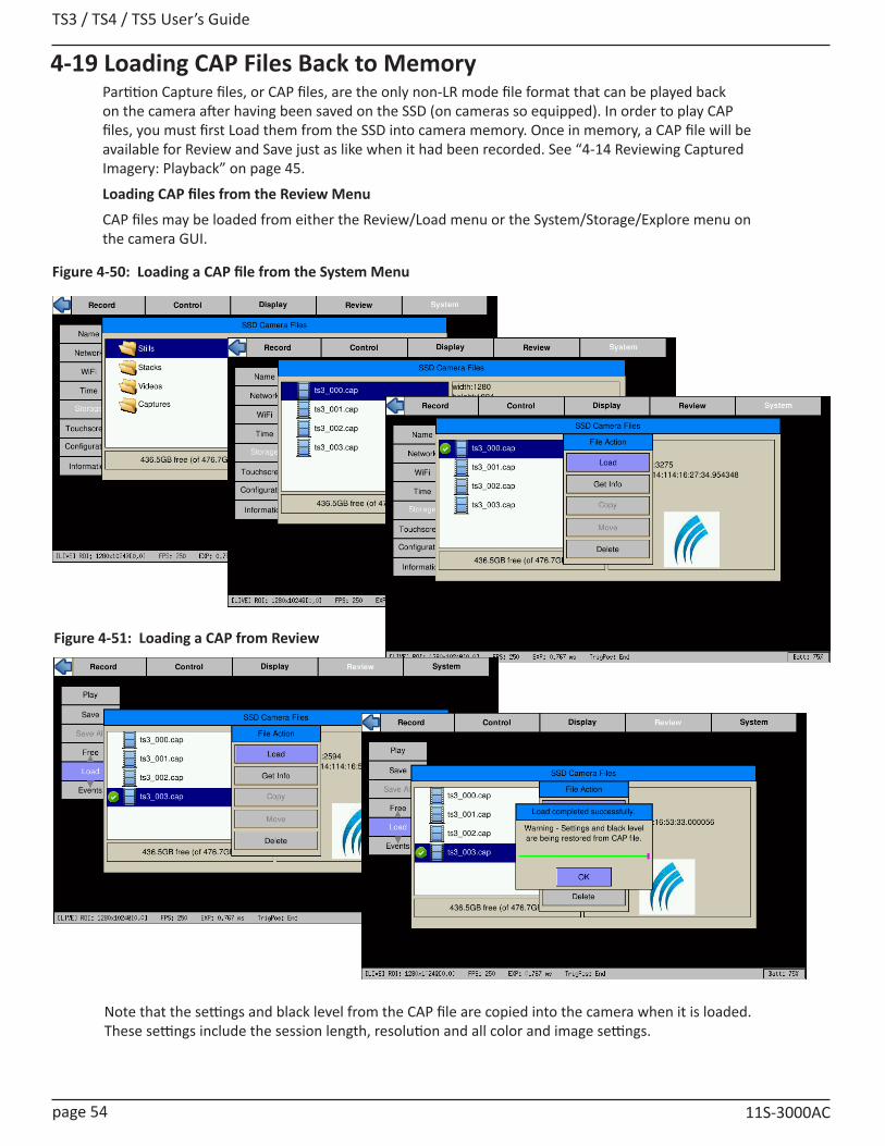
TS3 / TS4 / TS5 User’s Guide
page 54 11S-3000AC
4-19 Loading CAP Files Back to MemoryPartition Capture files, or CAP files, are the only non-LR mode file format that can be played back on the camera after having been saved on the SSD (on cameras so equipped). In order to play CAP files, you must first Load them from the SSD into camera memory. Once in memory, a CAP file will be available for Review and Save just as like when it had been recorded. See “4-14 Reviewing Captured Imagery: Playback” on page 45.
Loading CAP files from the Review Menu
CAP files may be loaded from either the Review/Load menu or the System/Storage/Explore menu on the camera GUI.
Figure 4-50: Loading a CAP file from the System Menu
Figure 4-51: Loading a CAP from Review
Note that the settings and black level from the CAP file are copied into the camera when it is loaded. These settings include the session length, resolution and all color and image settings.
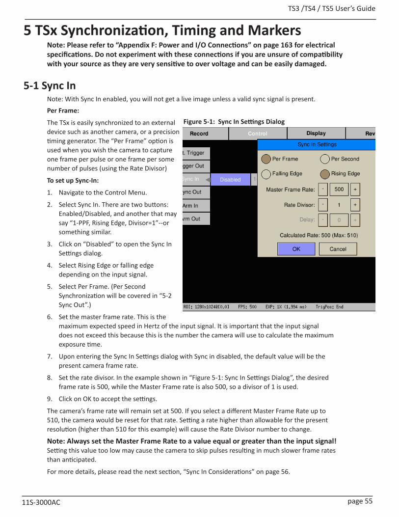
TS3 /TS4 / TS5 User’s Guide
11S-3000AC page 55
5 TSx Synchronization, Timing and MarkersNote: Please refer to “Appendix F: Power and I/O Connections” on page 163 for electrical specifications. Do not experiment with these connections if you are unsure of compatibility with your source as they are very sensitive to over voltage and can be easily damaged.
5-1 Sync InNote: With Sync In enabled, you will not get a live image unless a valid sync signal is present.
Per Frame:
The TSx is easily synchronized to an external device such as another camera, or a precision timing generator. The “Per Frame” option is used when you wish the camera to capture one frame per pulse or one frame per some number of pulses (using the Rate Divisor)
To set up Sync-In:
1. Navigate to the Control Menu.
2. Select Sync In. There are two buttons: Enabled/Disabled, and another that may say “1-PPF, Rising Edge, Divisor=1”--or something similar.
3. Click on “Disabled” to open the Sync In Settings dialog.
4. Select Rising Edge or falling edge depending on the input signal.
5. Select Per Frame. (Per Second Synchronization will be covered in “5-2 Sync Out”.)
6. Set the master frame rate. This is the maximum expected speed in Hertz of the input signal. It is important that the input signal does not exceed this because this is the number the camera will use to calculate the maximum exposure time.
7. Upon entering the Sync In Settings dialog with Sync in disabled, the default value will be the present camera frame rate.
8. Set the rate divisor. In the example shown in “Figure 5-1: Sync In Settings Dialog”, the desired frame rate is 500, while the Master Frame rate is also 500, so a divisor of 1 is used.
9. Click on OK to accept the settings.
The camera’s frame rate will remain set at 500. If you select a different Master Frame Rate up to 510, the camera would be reset for that rate. Setting a rate higher than allowable for the present resolution (higher than 510 for this example) will cause the Rate Divisor number to change.
Note: Always set the Master Frame Rate to a value equal or greater than the input signal! Setting this value too low may cause the camera to skip pulses resulting in much slower frame rates than anticipated.
For more details, please read the next section, “Sync In Considerations” on page 56.
Figure 5-1: Sync In Settings Dialog
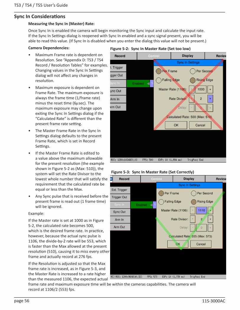
TS3 / TS4 / TS5 User’s Guide
page 56 11S-3000AC
Sync In ConsiderationsMeasuring the Sync In (Master) Rate:
Once Sync In is enabled the camera will begin monitoring the Sync input and calculate the input rate. If the Sync In Settings dialog is reopened with Sync In enabled and a sync signal present, you will be able to read this value. (If Sync In is disabled when you enter the dialog this value will not be present.)
Camera Dependencies:
• Maximum Frame rate is dependent on Resolution. See “Appendix D: TS3 / TS4 Record / Resolution Tables” for examples. Changing values in the Sync In Settings dialog will not affect any changes in resolution.
• Maximum exposure is dependent on Frame Rate. The maximum exposure is always the frame time (1/frame rate) minus the reset time (6msec). The maximum exposure may change upon exiting the Sync In Settings dialog if the “Calculated Rate” is different than the present frame rate setting.
• The Master Frame Rate in the Sync In Settings dialog defaults to the present Frame Rate, which is set in Record Settings.
• If the Master Frame Rate is edited to a value above the maximum allowable for the present resolution (the example shown in Figure 5-2 as (Max: 510)), the system will set the Rate Divisor to the lowest whole number that will satisfy the requirement that the calculated rate be equal or less than the Max.
• Any Sync pulse that is received before the present frame is read out (1 frame time) will be ignored.
Example:
If the Master rate is set at 1000 as in Figure 5-2, the calculated rate becomes 500, which is the desired frame rate. In practice, however, because the actual sync pulse is 1106, the divide-by-2 rate will be 553, which is faster than the Max allowed at the present resolution (510), causing it to miss every other frame and actually record at 276 fps.
If the Resolution is adjusted so that the Max frame rate is increased, as in Figure 5-3, and the Master Rate is increased to a rate higher than the measured 1106, the expected actual frame rate and maximum exposure time will be within the cameras capabilities. The camera will record at 1106/2 (553) fps.
Figure 5-2: Sync In Master Rate (Set too low)
Figure 5-3: Sync In Master Rate (Set Correctly)

TS3 /TS4 / TS5 User’s Guide
11S-3000AC page 57
Figure 5-5: Sync In Per Second
Per Frame Clock
Camera 1
Camera 2
6∝sec
Camera 3
Figure 5-4: Sync: Per Frame Timing
The Frame Clock may be from another Camera (See “5-3 Master/Slave Setup” on page 59) or some other external clock.
Note: for each camera, the signal shown represents the exposure (high = shutter “open”)
Camera 1 is set for Falling Edge, at a 1x shutter. Note that there is a 6msec inter-frame time.
Camera 2 is set for Falling Edge, at a 2x shutter. Note that exposures for Camera 1 and Camera 2 begin at the same time.
Camera 3 is set for Rising Edge, a 4x shutter and has a rate divisor of 3.
Per Second:
Many commonly available sync sources have a precision 1 Hz output. IRIG and GPS are two that are very often used with high-speed data capture.
The TSx is able to utilize these signals for synchronization of cameras at any frame rate.
To use Per Second Synchronization:
1. Navigate to the Control Menu and open the Sync In Settings dialog (as in the previous section).
2. Select “Per Second” in the dialog box. The Master Frame rate and Rate Divisor fields will gray-out.
3. A delay of from 0 to 1000msec may be used to fine-tune integration timing. This may be done to adjust the phase relationship between multiple cameras, or to align exposure start times of cameras with different exposure settings.
4. The Calculated Rate will reflect the frame rate set in Record/Settings. If you wish to change those settings you will do those as for any normal recording. (See “4-1 Selecting the Recording Mode” on page 27.)

TS3 / TS4 / TS5 User’s Guide
page 58 11S-3000AC
5-2 Sync OutPer Frame
External devices such as additional cameras, strobe lights, and test instruments may be synchronized via Sync Out pulses from the TSx. The “Per Frame” option output is one pulse per frame--the sync pulse rate is equal to the recording frame rate.
To set up Sync Out:
1. Navigate to the Control Menu.
2. Select Sync Out. There are two buttons: Enabled/Disabled, and another that may say 1-PPF, Shutter, Active High--or something similar.
3. Change the state of the first button to “Enabled” (green), and then click on the second button to open the Sync Out Settings Dialog.
4. The signal can either be Active High, meaning the signal goes high when the shutter opens, or Active Low, meaning the signal goes low with when the shutter opens. Select Active High or Low from the dialog box.
5. The signal can either follow the Shutter (integration time) or you can select Duty Cycle and control the % of frame time (1/frame rate) for the active portion of the signal using the number box provided.
Per Second
If you choose the “Per Second,” the camera will output a 1Hz signal. The only active options in this mode are Active High and Active Low.
Figure 5-7: Sync Out Per Frame
Figure 5-6: Sync: Per Second Timing
Each Camera derives an internal clock from the 1Hz “Per Second” input signal, (from either the Sync-In or IRIG inputs), which it can use to run at any desired rate, as in normal operation. A small correction may be done at the inter-frame time of the last frame in any given second (see the “alignment correction” on the diagram).Camera 1 is set with a 1x shutter. The exposure time is 1/fps - 6msec. Camera 2 is set at the same frame rate as Camera 1, but with a shorter exposure. Note that the frame alignment is at the end of each exposure, not the beginning as with per-frame sync.
Camera 3 is set at a slightly faster frame rate than cameras 1 and 2. Note that the end of the exposure of the last frame of the second will be aligned with cameras (slightly skewed) 1 and 2. Sync timing between camera 3 and the other two cameras will phase in and out depending on the frame rates.
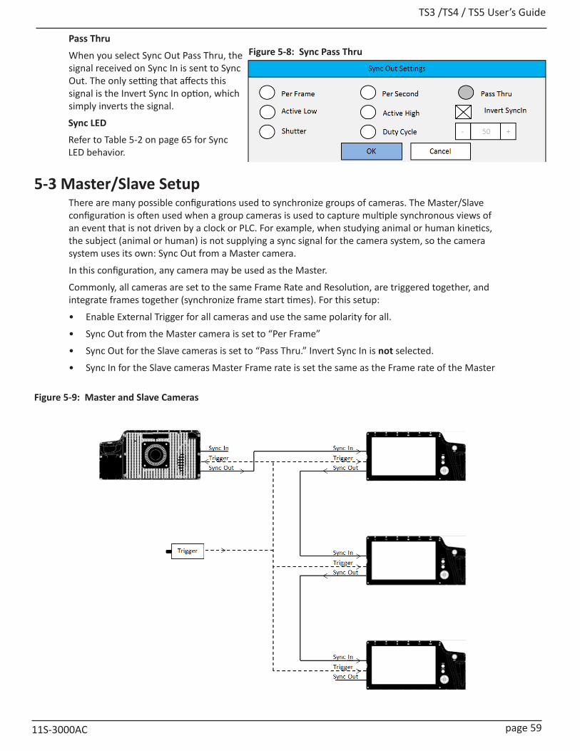
TS3 /TS4 / TS5 User’s Guide
11S-3000AC page 59
Pass Thru
When you select Sync Out Pass Thru, the signal received on Sync In is sent to Sync Out. The only setting that affects this signal is the Invert Sync In option, which simply inverts the signal.
Sync LED
Refer to Table 5-2 on page 65 for Sync LED behavior.
5-3 Master/Slave SetupThere are many possible configurations used to synchronize groups of cameras. The Master/Slave configuration is often used when a group cameras is used to capture multiple synchronous views of an event that is not driven by a clock or PLC. For example, when studying animal or human kinetics, the subject (animal or human) is not supplying a sync signal for the camera system, so the camera system uses its own: Sync Out from a Master camera.
In this configuration, any camera may be used as the Master.
Commonly, all cameras are set to the same Frame Rate and Resolution, are triggered together, and integrate frames together (synchronize frame start times). For this setup:
• Enable External Trigger for all cameras and use the same polarity for all.
• Sync Out from the Master camera is set to “Per Frame”
• Sync Out for the Slave cameras is set to “Pass Thru.” Invert Sync In is not selected.
• Sync In for the Slave cameras Master Frame rate is set the same as the Frame rate of the Master
Figure 5-8: Sync Pass Thru
Figure 5-9: Master and Slave Cameras
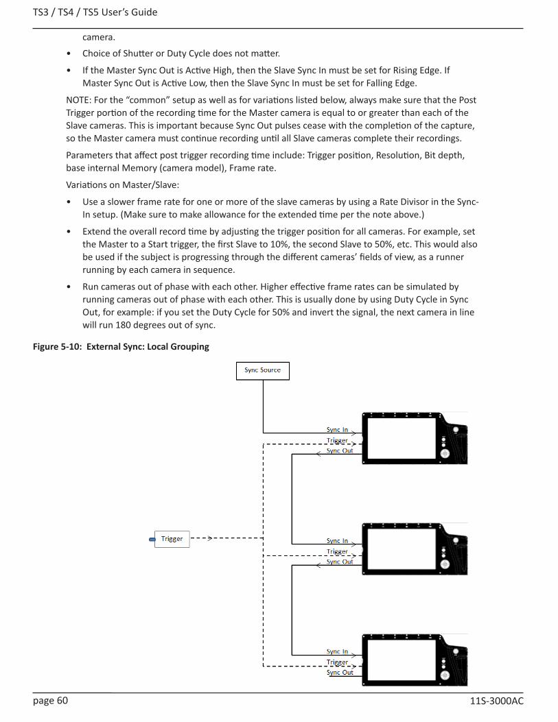
TS3 / TS4 / TS5 User’s Guide
page 60 11S-3000AC
camera.
• Choice of Shutter or Duty Cycle does not matter.
• If the Master Sync Out is Active High, then the Slave Sync In must be set for Rising Edge. If Master Sync Out is Active Low, then the Slave Sync In must be set for Falling Edge.
NOTE: For the “common” setup as well as for variations listed below, always make sure that the Post Trigger portion of the recording time for the Master camera is equal to or greater than each of the Slave cameras. This is important because Sync Out pulses cease with the completion of the capture, so the Master camera must continue recording until all Slave cameras complete their recordings.
Parameters that affect post trigger recording time include: Trigger position, Resolution, Bit depth, base internal Memory (camera model), Frame rate.
Variations on Master/Slave:
• Use a slower frame rate for one or more of the slave cameras by using a Rate Divisor in the Sync-In setup. (Make sure to make allowance for the extended time per the note above.)
• Extend the overall record time by adjusting the trigger position for all cameras. For example, set the Master to a Start trigger, the first Slave to 10%, the second Slave to 50%, etc. This would also be used if the subject is progressing through the different cameras’ fields of view, as a runner running by each camera in sequence.
• Run cameras out of phase with each other. Higher effective frame rates can be simulated by running cameras out of phase with each other. This is usually done by using Duty Cycle in Sync Out, for example: if you set the Duty Cycle for 50% and invert the signal, the next camera in line will run 180 degrees out of sync.
Figure 5-10: External Sync: Local Grouping

TS3 /TS4 / TS5 User’s Guide
11S-3000AC page 61
5-4 External Source Sync Synchronizing to an external source is most common in applications where a preferred sync pulse is available such as one from a PLC, IRIG, or GPS.
NOTE: Please refer to “Appendix F: Power and I/O Connections” on page 163, for electrical specifications.
This sync pulse may be used for a localized group of cameras, in which the cameras are connected as in “Figure 5-10: External Sync: Local Grouping” on page 60 is commonly used. The cameras may also be placed far apart, in which case they are connected to a distributed sync signal as in “Figure 5-11: External Sync: Distributed Grouping”.
In the case of using a PLC or other local clock, you will need to know the polarity and frequency of the signal in order to set the cameras up. Optimum frame rates can often be derived using the Rate Divisor function.
When using IRIG or GPS as an input, you will first need to derive a 1Hz signal from the source, and then use the Per Second option. This gives you complete flexibility with respect to frame rate: you can select any frame rate you wish to use.
Note: full IRIG and GPS implementation is planned for a future release.
Triggering in a distributed grouping may either be implemented locally via switch, camera button, or software or it may be available along with the sync as a distributed signal.
Figure 5-11: External Sync: Distributed Grouping

TS3 / TS4 / TS5 User’s Guide
page 62 11S-3000AC
5-5 TSx Timestamps and MarkersWhenever the TSx records imagery, it also records a timestamp for each frame. This timestamp may be displayed during playback and may also be saved to an XML file (see “Appendix K: Contents of <Capture>.xml file” on page 171 and “4-8 Configuring the Trigger and External I/O” on page 36).
Using the DISP button while in playback mode, you can toggle through the available displays. In the figure above, you see that the Info line at the bottom of the image is present as is the Timestamp line at the top of the image. For information on setting up Markers in Playback see “4-15 Playback: Jump to Markers” on page 47.
Time: YY:DDD:HH:MM:SS.xxxxxx
For the example shown in Figure 5-12 this is:
YY = Year: 14 = 2014
DDD = Day: 336 = Dec 2 (See “Appendix P: Day Number Calendar Conversion” on page 180.)
HH:MM= Hour: Minute: 14:10 = 1:10 pm
SS.xxxxxx = Seconds: = 43.942265 (granularity to msec)
Note: the Timestamp line is always available during playback from camera memory or from CAP files loaded into camera memory from an SSD. It is also seen in saved files played back via FasMotion, but only if they are accompanied by an XML file.
If you are interested in archiving Marker Data and Timestamps, remember to save the XML file along with the video!
Markers: 00111111 (See “Table 5-1: I/O Pin to Markers” on page 63.)
The Timestamp line includes event markers. In the example shown in Figure 5-12 all of the I/O pins were “high” for the duration of the displayed image frame. For each I/O pin there is a default signal, such as Trigger-In, Sync-In, Arm-Out, etc. that can be enabled via the Control menu. These same I/O pins may be utilized for marking events in the captured video clip. The electrical interface is the same for all pins.
NOTE: These pins are very sensitive to over voltage and can easily be damaged. Please refer to “Appendix F: Power and I/O Connections” on page 163.
Figure 5-12: Image with Timestamp
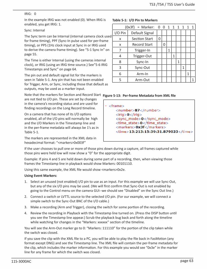
TS3 /TS4 / TS5 User’s Guide
11S-3000AC page 63
(0x3f) = Marker: 0 0 1 1 1 1 1 1I/O Pin Default Signal
x Section Start 0x Record Start 07 Trigger-In 14 Trigger-Out 18 Sync-In 13 Sync-Out 16 Arm-In 15 Arm-Out 1
Table 5-1: I/O Pin to Markers
Figure 5-13: Per-frame Metadata from XML file
IRIG: 0
In the example IRIG was not enabled (0). When IRIG is enabled, you get IRIG: 1.
Sync: Internal
The Sync term can be Internal (internal camera clock used for frame timing), PPF (Sync-In pulse used for per-frame timing), or PPS (1Hz clock input at Sync in or IRIG used to derive the camera frame timing). See “5-1 Sync In” on page 55.
The Time is either Internal (using the cameras internal clock), or IRIG (using an IRIG time source.) See”5-6 IRIG Timestamps and Sync” on page 64.
The pin out and default signal list for the markers is seen in Table 5-1. Any pin that has not been enabled for Trigger, Arm, or Sync, including those that default as outputs, may be used as a marker input.
Note that the markers for Section and Record Start are not tied to I/O pin. These are set by changes in the camera’s recording status and are used for finding recordings on the Long Record timeline.
On a camera that has none of its I/O options enabled, all of the I/O pins will normally be high and the I/O Markers in the Timestamp line and in the per-frame metadata will always be 1’s as in Table 5-1.
The markers are represented in the XML data in hexadecimal format: “<markers>0x003f”
If the user chooses to pull one or more of those pins down during a capture, all frames captured while those pins were held low will now show a “0” for the appropriate digit.
Example: If pins 4 and 5 are held down during some part of a recording, then, when viewing those frames the Timestamp line in playback would show Markers: 00101110.
Using this same example, the XML file would show <markers>0x2e.
Using Event Markers:
1. Select an unused (not enabled) I/O pin to use as an input. For this example we will use Sync-Out, but any of the six I/O pins may be used. (We will first confirm that Sync-Out is not enabled by going to the Control menu on the camera GUI--we should see “Disabled” on the Sync Out line.)
2. Connect a switch or LVTTL source to the selected I/O pin. (For our example, we will connect a simple switch to the Sync-Out BNC of the I/O cable.)
3. Make a recording (Arm and Trigger), closing the switch for some portion of the recording.
4. Review the recording in Playback with the Timestamp line turned on. (Press the DISP button until you see the Timestamp line appear.) Scrub the playback bug back and forth along the timeline while watching for changes in the “Markers: xxxxxx” section of the timeline.
You will see the Arm-Out marker go to 0: “Markers: 111110” for the portion of the clip taken while the switch was closed.
If you save the clip with the XML file to a PC, you will be able to play the file back in FasMotion (any format except DNG) and see the Timestamp line. The XML file will contain the per-frame metadata for the clip, which includes the marker information. For this example you would see “0x3e” in the marker line for any frame for which the switch was closed.
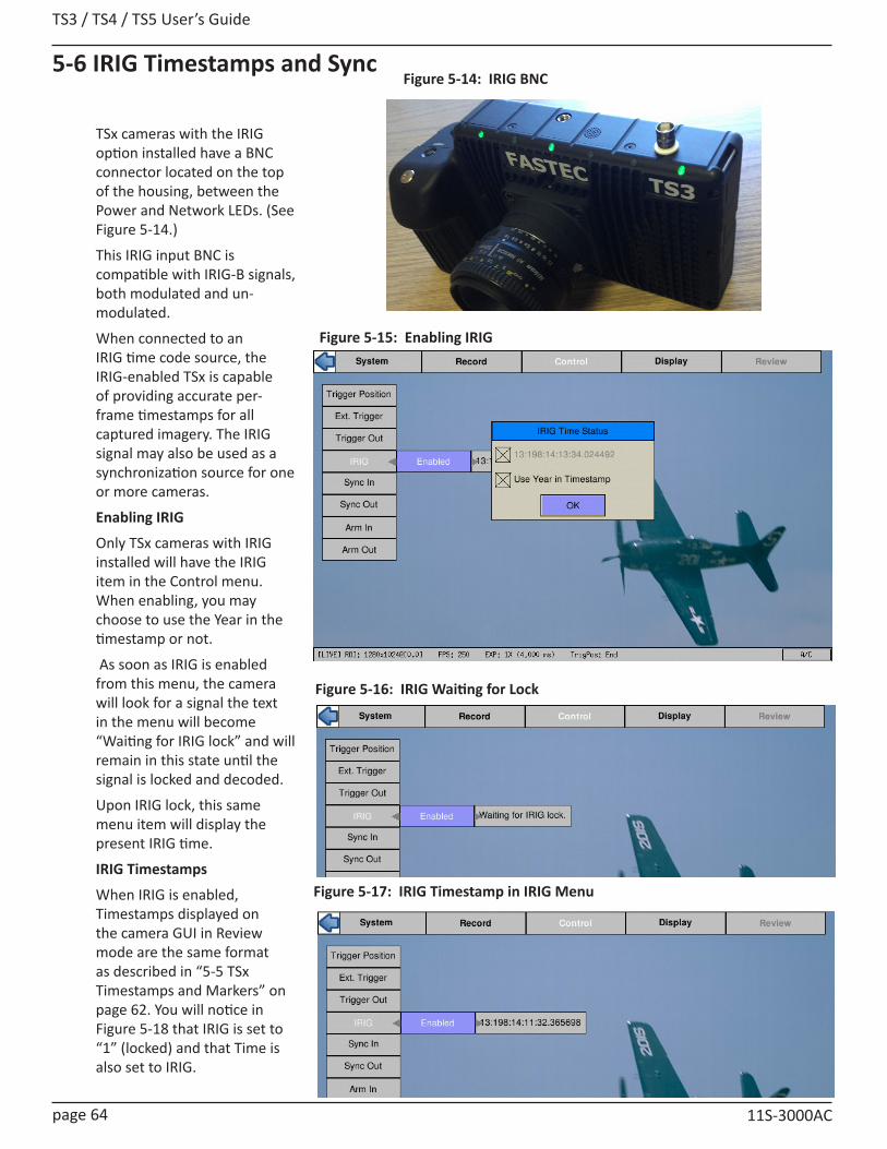
TS3 / TS4 / TS5 User’s Guide
page 64 11S-3000AC
TSx cameras with the IRIG option installed have a BNC connector located on the top of the housing, between the Power and Network LEDs. (See Figure 5-14.)
This IRIG input BNC is compatible with IRIG-B signals, both modulated and un-modulated.
When connected to an IRIG time code source, the IRIG-enabled TSx is capable of providing accurate per-frame timestamps for all captured imagery. The IRIG signal may also be used as a synchronization source for one or more cameras.
Enabling IRIG
Only TSx cameras with IRIG installed will have the IRIG item in the Control menu. When enabling, you may choose to use the Year in the timestamp or not.
As soon as IRIG is enabled from this menu, the camera will look for a signal the text in the menu will become “Waiting for IRIG lock” and will remain in this state until the signal is locked and decoded.
Upon IRIG lock, this same menu item will display the present IRIG time.
IRIG Timestamps
When IRIG is enabled, Timestamps displayed on the camera GUI in Review mode are the same format as described in “5-5 TSx Timestamps and Markers” on page 62. You will notice in Figure 5-18 that IRIG is set to “1” (locked) and that Time is also set to IRIG.
Figure 5-17: IRIG Timestamp in IRIG Menu
Figure 5-14: IRIG BNC
Figure 5-15: Enabling IRIG
Figure 5-16: IRIG Waiting for Lock
5-6 IRIG Timestamps and Sync

TS3 /TS4 / TS5 User’s Guide
11S-3000AC page 65
Sync LED Behavior Sync In IRIG Enable IRIG-InSolid Black Disabled No X
Slow Blink Amber PPF/PPS + No Signal No XSolid Amber PPF/PPS + Signal No X
Slow Blink Magenta Disabled Yes No SignalFast Blink Magenta Disabled Yes Locking
Solid Magenta Disabled Yes LockedSlow Blink Red PPF + No Signal Yes No SignalFast Blink Red PPF + No Signal Yes Locking
Solid Red PPF + No Signal Yes LockedSlow Blink Green PPF + Signal Yes No SignalFast Blink Green PPF + Signal Yes Locking
Solid Green PPF + Signal Yes LockedSlow Blink Blue IRIG Yes No Signal
Fast Blink Blue IRIG Yes LockingSolid Blue IRIG Yes Locked
Figure 5-18: Sync-In Dialog with IRIG EnabledIRIG Sync
Cameras may be synchronized using the IRIG 1Hz signal. When IRIG is Enabled, the “Per Second” selection in the Sync-In Dialog is changed to IRIG. The functionality is the same as with a Per Second synchronization, but the IRIG signal is used in place of a 1Hz signal at the Sync-In pin. See “Sync In Per Second” on page 57.
IRIG enabled Cameras may also be synchronized using the same Per Frame modes and Master/Slave configurations as cameras without IRIG. Please refer to the first two sections of this chapter for setup and timing considerations.
Sync LED
The Sync LED is there to let you know at a glance whether or not all necessary signals are present. The basic rule is that if the LED is blinking, one or more signals are missing or not yet locked.
Figure 5-19: IRIG Timestamp in Review
Table 5-2: Sync LED Behavior
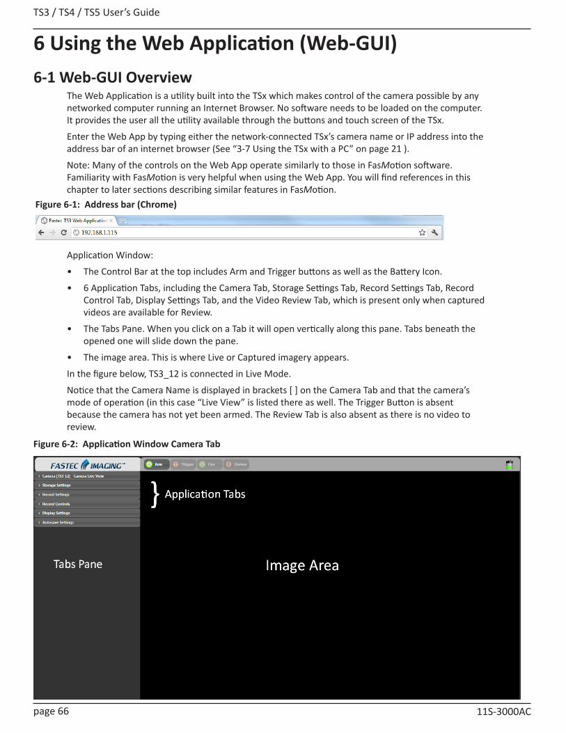
TS3 / TS4 / TS5 User’s Guide
page 66 11S-3000AC
6 Using the Web Application (Web-GUI)6-1 Web-GUI Overview
The Web Application is a utility built into the TSx which makes control of the camera possible by any networked computer running an Internet Browser. No software needs to be loaded on the computer. It provides the user all the utility available through the buttons and touch screen of the TSx.
Enter the Web App by typing either the network-connected TSx’s camera name or IP address into the address bar of an internet browser (See “3-7 Using the TSx with a PC” on page 21 ).
Note: Many of the controls on the Web App operate similarly to those in FasMotion software. Familiarity with FasMotion is very helpful when using the Web App. You will find references in this chapter to later sections describing similar features in FasMotion.
Application Window:
• The Control Bar at the top includes Arm and Trigger buttons as well as the Battery Icon.
• 6 Application Tabs, including the Camera Tab, Storage Settings Tab, Record Settings Tab, Record Control Tab, Display Settings Tab, and the Video Review Tab, which is present only when captured videos are available for Review.
• The Tabs Pane. When you click on a Tab it will open vertically along this pane. Tabs beneath the opened one will slide down the pane.
• The image area. This is where Live or Captured imagery appears.
In the figure below, TS3_12 is connected in Live Mode.
Notice that the Camera Name is displayed in brackets [ ] on the Camera Tab and that the camera’s mode of operation (in this case “Live View” is listed there as well. The Trigger Button is absent because the camera has not yet been armed. The Review Tab is also absent as there is no video to review.
Figure 6-1: Address bar (Chrome)
Figure 6-2: Application Window Camera Tab
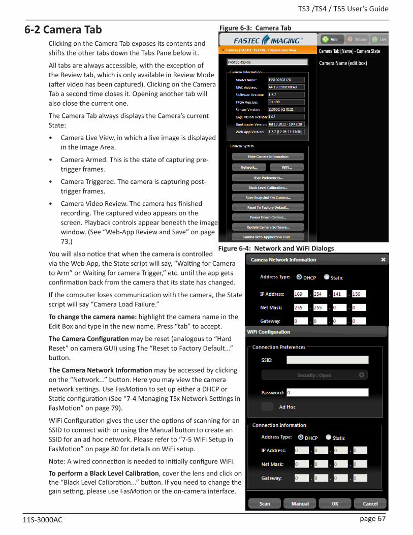
TS3 /TS4 / TS5 User’s Guide
11S-3000AC page 67
6-2 Camera TabClicking on the Camera Tab exposes its contents and shifts the other tabs down the Tabs Pane below it.
All tabs are always accessible, with the exception of the Review tab, which is only available in Review Mode (after video has been captured). Clicking on the Camera Tab a second time closes it. Opening another tab will also close the current one.
The Camera Tab always displays the Camera’s current State:
• Camera Live View, in which a live image is displayed in the Image Area.
• Camera Armed. This is the state of capturing pre-trigger frames.
• Camera Triggered. The camera is capturing post-trigger frames.
• Camera Video Review. The camera has finished recording. The captured video appears on the screen. Playback controls appear beneath the image window. (See “Web-App Review and Save” on page 73.)
You will also notice that when the camera is controlled via the Web App, the State script will say, “Waiting for Camera to Arm” or Waiting for camera Trigger,” etc. until the app gets confirmation back from the camera that its state has changed.
If the computer loses communication with the camera, the State script will say “Camera Load Failure.”
To change the camera name: highlight the camera name in the Edit Box and type in the new name. Press “tab” to accept.
The Camera Configuration may be reset (analogous to “Hard Reset” on camera GUI) using The “Reset to Factory Default...” button.
The Camera Network Information may be accessed by clicking on the “Network...” button. Here you may view the camera network settings. Use FasMotion to set up either a DHCP or Static configuration (See “7-4 Managing TSx Network Settings in FasMotion” on page 79).
WiFi Configuration gives the user the options of scanning for an SSID to connect with or using the Manual button to create an SSID for an ad hoc network. Please refer to “7-5 WiFi Setup in FasMotion” on page 80 for details on WiFi setup.
Note: A wired connection is needed to initially configure WiFi.
To perform a Black Level Calibration, cover the lens and click on the “Black Level Calibration...” button. If you need to change the gain setting, please use FasMotion or the on-camera interface.
Figure 6-3: Camera Tab
Figure 6-4: Network and WiFi Dialogs
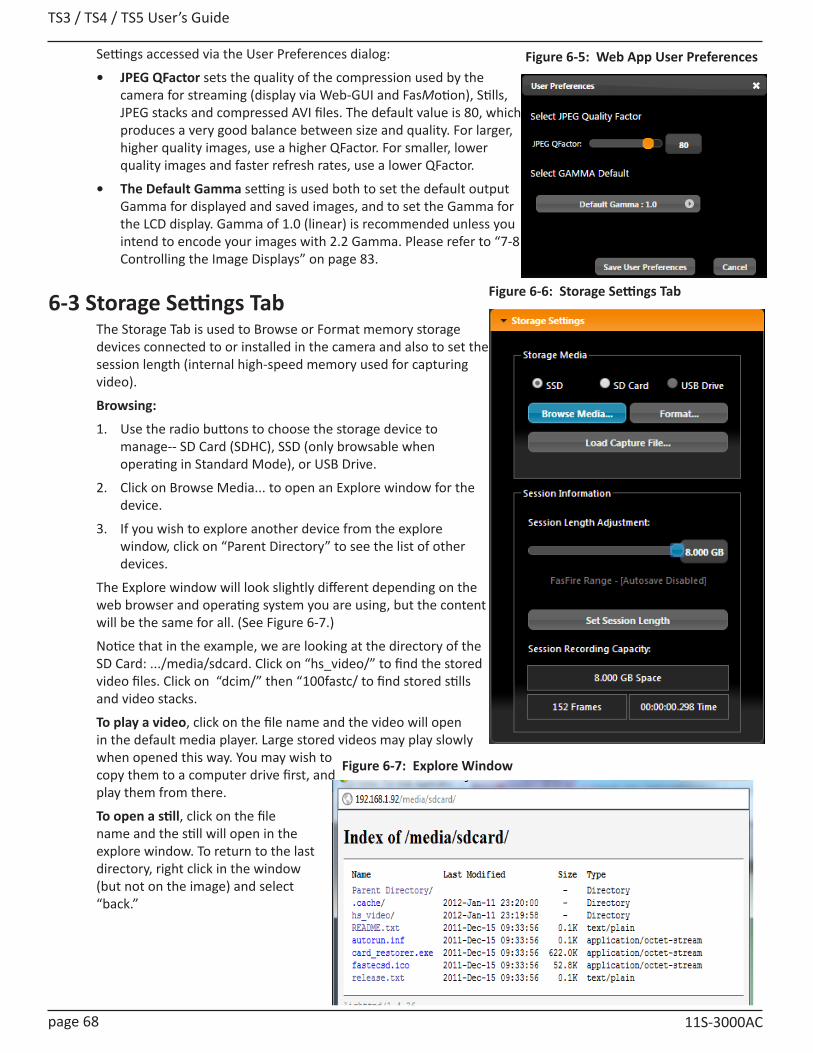
TS3 / TS4 / TS5 User’s Guide
page 68 11S-3000AC
Settings accessed via the User Preferences dialog:
• JPEG QFactor sets the quality of the compression used by the camera for streaming (display via Web-GUI and FasMotion), Stills, JPEG stacks and compressed AVI files. The default value is 80, which produces a very good balance between size and quality. For larger, higher quality images, use a higher QFactor. For smaller, lower quality images and faster refresh rates, use a lower QFactor.
• The Default Gamma setting is used both to set the default output Gamma for displayed and saved images, and to set the Gamma for the LCD display. Gamma of 1.0 (linear) is recommended unless you intend to encode your images with 2.2 Gamma. Please refer to “7-8 Controlling the Image Displays” on page 83.
6-3 Storage Settings TabThe Storage Tab is used to Browse or Format memory storage devices connected to or installed in the camera and also to set the session length (internal high-speed memory used for capturing video).
Browsing:
1. Use the radio buttons to choose the storage device to manage-- SD Card (SDHC), SSD (only browsable when operating in Standard Mode), or USB Drive.
2. Click on Browse Media... to open an Explore window for the device.
3. If you wish to explore another device from the explore window, click on “Parent Directory” to see the list of other devices.
The Explore window will look slightly different depending on the web browser and operating system you are using, but the content will be the same for all. (See Figure 6-7.)
Notice that in the example, we are looking at the directory of the SD Card: .../media/sdcard. Click on “hs_video/” to find the stored video files. Click on “dcim/” then “100fastc/ to find stored stills and video stacks.
To play a video, click on the file name and the video will open in the default media player. Large stored videos may play slowly when opened this way. You may wish to copy them to a computer drive first, and play them from there.
To open a still, click on the file name and the still will open in the explore window. To return to the last directory, right click in the window (but not on the image) and select “back.”
Figure 6-5: Web App User Preferences
Figure 6-6: Storage Settings Tab
Figure 6-7: Explore Window

TS3 /TS4 / TS5 User’s Guide
11S-3000AC page 69
To copy a video or still to a computer drive:
1. Right click on the file you wish to open. A context menu will open with a list of actions. The list varies depending on the browser you are using.
2. If using Chrome, Firefox, or Safari, select “save link as...” or, if using Windows Internet Explorer, select “save target as...”This will open a dialog box allowing you to navigate to the drive and directory you wish to save the file to.
Note: This is recommended for stills and AVI files only. Only one file may be copied at a time. No files may be either deleted or moved via the Web App. In order to copy groups of files and directories (file stacks, etc.) open the camera in a separate Explore window. (See “3-7 Using the TSx with a PC” on page 21.)
Formatting:
1. Use the radio buttons to choose the storage device to format-- SD Card (SDHC), SSD (internal drive), or USB Drive.
2. Click on Format...
3. Select the format type you wish to use (refer to Figure 6-8).
Note: Format choices vary depending on media type and camera version.
Setting the Session Length
Session selects the amount of memory to be used for capturing imagery, which dictates the number of frames captured as well as the capture time.
1. Move the Session Length Adjustment slider to the desired position. You will see the Time and # of Frames change as well as the Space in GB.
2. Click on the blue “Set Session Length” button to send the change to the camera.
3. To set the camera in FasFire mode the session length will need to be set at less than half the memory size. When the slider is moved to where the camera may be operated in FasFire mode, the text below the Session Length Adjustment slider will become red.
Note that Autosave must be enabled in order to operate in FasFire Mode. Please refer to “4-12 FasFire” on page 42.
Long Recording Mode
When a Dual Mode camera is operated in Long Recording mode, the Session Length Adjustment slider becomes disabled and the Session Recording Capacity changes to “LR Mode.”
Figure 6-8: Formatting Media
Figure 6-9: Setting Session Length in Web App

TS3 / TS4 / TS5 User’s Guide
page 70 11S-3000AC
6-4 Record SettingsThe Record Settings Tab is analogous to the Record Menu on the TS3 camera GUI. It contains the controls for setting ROI (Region of Interest), record Rate and Time (Frame Rate and Record Time), Shutter Speed, and Bit Depth, and FPN.
For the TSx operating in Long Record (LR) mode, the Basic and FasCorder options are selectable via this tab. Please refer to “LR Modes (recording to SSD):” on page 28.
Note: The LR Mode section of the tab is only visible when the camera is operating in LR mode. The Burst (frames) slider is only visible when BROC is selected.
Setting ROI:
1. If you wish to use one of the standard aspect ratios: 4:3, 5:4, or 16:9, click on the Frame Aspect Ratio bar and make your selection from those choices. If wish to select a custom aspect ratio, select that choice from the same pull down menu.
2. If you are using anything but a “Custom” for aspect ratio, you can adjust either width or height and the other will adjust automatically. You can either use the sliders or the edit boxes to make your selection. If you use the edit box, hit the “Tab” key on your computer keyboard or click outside the box to complete your entry.
3. Select the “Autoset” box if you wish the camera ROI set automatically for the largest resolution possible at the selected frame rate.
4. Select the “Center” box to center the ROI to the optical center. If this is unchecked, you may set the ROI offset using the Offset X and Y edit boxes (See “Offset Control:” on page 30).
Setting the Frame Rate:
Either move the Frame Rate slider or edit the associated text box to change the frame rate.
The frame rate is limited by the resolution. There is a Max frame rate number next to the edit box letting you know what the maximum frame rate is for the current resolution. Clicking on the “Autoset” button will set the frame rate to that maximum number possible with the current resolution setting.
Setting the Shutter Speed:
Set the shutter speed by moving the slider.
The minimum shutter speed (maximum sensor integration time) is limited by the frame rate. It is .006ms less than 1 frame time or 1/(frame rate -.006ms) for TS3 / TS4; 1/(frame rate -.012ms) for TS5. The maximum shutter speed (minimum sensor integration time) is .002ms for the TS3 / TS4, .003ms for TS5.
Low Light: (See “Offset Control:” on page 30.)
The Low light feature lets you use shutter speeds up to 33.326ms for framing and focusing the camera prior to image capture. (During image capture the shutter speed will revert to its normal setting.)
Figure 6-10: Record Settings Tab
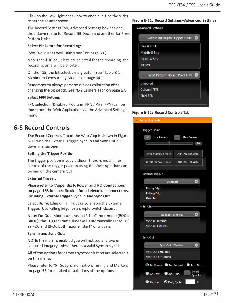
TS3 /TS4 / TS5 User’s Guide
11S-3000AC page 71
Figure 6-11: Record Settings--Advanced SettingsClick on the Low Light check box to enable it. Use the slider to set the shutter speed.
The Record Settings Tab, Advanced Settings box has one drop down menu for Record Bit Depth and another for Fixed Pattern Noise.
Select Bit Depth for Recording:
(See “4-9 Black Level Calibration” on page 39.)
Note that if 10 or 12 bits are selected for the recording, the recording time will be shorter.
On the TS5, the bit selection is greater. (See “Table 8-1: Maximum Exposure by Model” on page 94.)
Remember to always perform a black calibration after changing the bit depth. See “6-2 Camera Tab” on page 67.
Select FPN Setting:
FPN selection (Disabled / Column FPN / Pixel FPN) can be done from the Web-Application via the Advanced Settings menu.
6-5 Record ControlsThe Record Controls Tab of the Web-App is shown in Figure 6-12 with the External Trigger, Sync In and Sync Out pull down menus open.
Setting the Trigger Position:
The trigger position is set via slider. There is much finer control of the trigger position using the Web-App than can be had on the camera GUI.
External Trigger:
Please refer to “Appendix F: Power and I/O Connections” on page 163 for specification for all electrical connections, including External Trigger, Sync In and Sync Out.
Select Rising Edge or Falling Edge to enable the External Trigger. Use Falling Edge for a simple switch closure.
Note: For Dual Mode cameras in LR FasCorder mode (ROC or BROC), the Trigger Frame slider will automatically set to “0” as ROC and BROC both require “start” or triggers.
Sync In and Sync Out:
NOTE: If Sync in is enabled you will not see any Live or captured imagery unless there is a valid Sync In signal.
All of the options for camera synchronization are selectable on this menu.
Please refer to “5 TSx Synchronization, Timing and Markers” on page 55 for detailed descriptions of the options.
Figure 6-12: Record Controls Tab
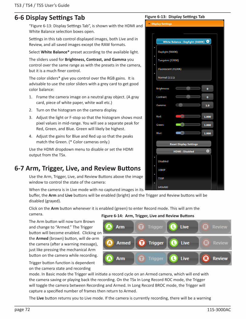
TS3 / TS4 / TS5 User’s Guide
page 72 11S-3000AC
6-6 Display Settings Tab“Figure 6-13: Display Settings Tab”, is shown with the HDMI and White Balance selection boxes open.
Settings in this tab control displayed images, both Live and in Review, and all saved images except the RAW formats.
Select White Balance* preset according to the available light.
The sliders used for Brightness, Contrast, and Gamma you control over the same range as with the presets in the camera, but it is a much finer control.
The color sliders* give you control over the RGB gains. It is advisable to use the color sliders with a grey card to get good color balance:
1. Frame the camera image on a neutral gray object. (A gray card, piece of white paper, white wall etc.)
2. Turn on the histogram on the camera display.
3. Adjust the light or F-stop so that the histogram shows most pixel values in mid-range. You will see a separate peak for Red, Green, and Blue. Green will likely be highest.
4. Adjust the gains for Blue and Red up so that the peaks match the Green. (* Color cameras only.)
Use the HDMI dropdown menu to disable or set the HDMI output from the TSx.
6-7 Arm, Trigger, Live, and Review ButtonsUse the Arm, Trigger, Live, and Review Buttons above the image window to control the state of the camera:
When the camera is in Live mode with no captured images in its buffer, the Arm and Live buttons will be enabled (bright) and the Trigger and Review buttons will be disabled (grayed).
Click on the Arm button whenever it is enabled (green) to enter Record mode. This will arm the camera.
The Arm button will now turn Brown and change to “Armed.” The Trigger button will become enabled. Clicking on the Armed (brown) button, will de-arm the camera (after a warning message), just like pressing the mechanical Arm button on the camera while recording.
Trigger button function is dependent on the camera state and recording mode. In Basic mode the Trigger will initiate a record cycle on an Armed camera, which will end with the camera saving or playing back the recording. On the TSx In Long Record ROC mode, the Trigger will toggle the camera between Recording and Armed. In Long Record BROC mode, the Trigger will capture a specified number of frames then return to Armed.
The Live button returns you to Live mode. If the camera is currently recording, there will be a warning
Figure 6-13: Display Settings Tab
Figure 6-14: Arm, Trigger, Live and Review Buttons

TS3 /TS4 / TS5 User’s Guide
11S-3000AC page 73
message that proceeding will result in loss of unsaved video. If the camera is in Review mode, pressing the Live button will bring up an information box telling you that you are leaving Review and entering Live mode, but that captured video will remain in the camera until it is re-armed.
When in Review Mode, the Live and Review buttons act as a toggle between Live and Review. The current recording is not deleted until the camera is Armed or powered down.
6-8 Review TabWhen in Review Mode, the Review Tab will open and the Playback controls will appear beneath the Image window.
Note: While in Review, the image may be adjusted using the controls in the Display Settings Tab. See “6-6 Display Settings Tab” on page 72.
The Play buttons, which only appear when the mouse cursor is brought over them, have the same functions as on the camera GUI (see “Table 4-7: Playback Control” on page 46), except that the Cut-In and Cut-Out points are entered by editing the Clipping Range boxes or by adjusting the slider between them. The clipping range is then used, as it is on the camera GUI for both playback and while saving to mass storage.
You may jump to the beginning of the clip (|<); to the end (>|) or to the Trigger frame (T). You may also move to any frame by editing the Current Frame box, or by moving the slider beneath it.
The Playback Frame Rate may box may be edited directly or controlled via slider. The Playback Rate
Figure 6-15: Web-App Review and Save
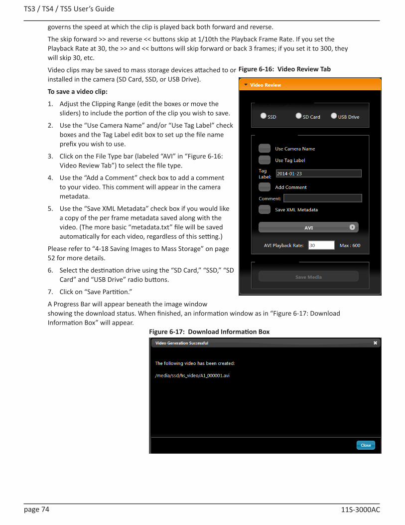
TS3 / TS4 / TS5 User’s Guide
page 74 11S-3000AC
governs the speed at which the clip is played back both forward and reverse.
The skip forward >> and reverse << buttons skip at 1/10th the Playback Frame Rate. If you set the Playback Rate at 30, the >> and << buttons will skip forward or back 3 frames; if you set it to 300, they will skip 30, etc.
Video clips may be saved to mass storage devices attached to or installed in the camera (SD Card, SSD, or USB Drive).
To save a video clip:
1. Adjust the Clipping Range (edit the boxes or move the sliders) to include the portion of the clip you wish to save.
2. Use the “Use Camera Name” and/or “Use Tag Label” check boxes and the Tag Label edit box to set up the file name prefix you wish to use.
3. Click on the File Type bar (labeled “AVI” in “Figure 6-16: Video Review Tab”) to select the file type.
4. Use the “Add a Comment” check box to add a comment to your video. This comment will appear in the camera metadata.
5. Use the “Save XML Metadata” check box if you would like a copy of the per frame metadata saved along with the video. (The more basic “metadata.txt” file will be saved automatically for each video, regardless of this setting.)
Please refer to “4-18 Saving Images to Mass Storage” on page 52 for more details.
6. Select the destination drive using the “SD Card,” “SSD,” “SD Card” and “USB Drive” radio buttons.
7. Click on “Save Partition.”
A Progress Bar will appear beneath the image window showing the download status. When finished, an information window as in “Figure 6-17: Download Information Box” will appear.
Figure 6-16: Video Review Tab
Figure 6-17: Download Information Box

TS3 /TS4 / TS5 User’s Guide
11S-3000AC page 75
7 FasMotion Setup7-1 Install FasMotion Camera Control Software
The FasMotion install program is available on the Fastec website, www.fastecimaging.com/Software/Release and is also copied onto the USB thumb drive that shipped with your camera.
This software may be used to set up and control TSx cameras. With it you may configure all parameters including Recording Mode, Session Length, Resolution, Frame Rate, Exposure, Color Balance, Autosave, Trigger point, and I/O Sync options.
To install FasMotion on a Windows PC:
(Please refer to “To install FasMotion on a Mac:” on page 77 for instructions on installing FasMotion on a Mac.)
1. Run the FasMotion install file on your PC. The file will have the format: FasMotion<version>.exe. For example, FasMotion64_2.0.22.exe would be the install file for version 2.0.22. It is recommended that you copy the install file to the hard drive of your PC for safekeeping.
2. The Windows Account Control will display a message asking if you want to allow the installer to make changes to your computer. Answer “Yes.”
3. The Installer Setup window will appear as shown informing you that the install process has begun. Click on “Next.”
4. The next window allows you to choose a location for the program. Select a location and click on “Next.”
Note: If you install the 64-bit version, it should be installed in \Program Files.
If you currently have a previous version installed in \Program Files (x86), use the Browse function to install FasMotion into \Program Files. (The install will create the “FasMotion” folders and necessary sub-folders.)
Figure 7-1: FasMotion Installation
Figure 7-2: FasMotion Install Location
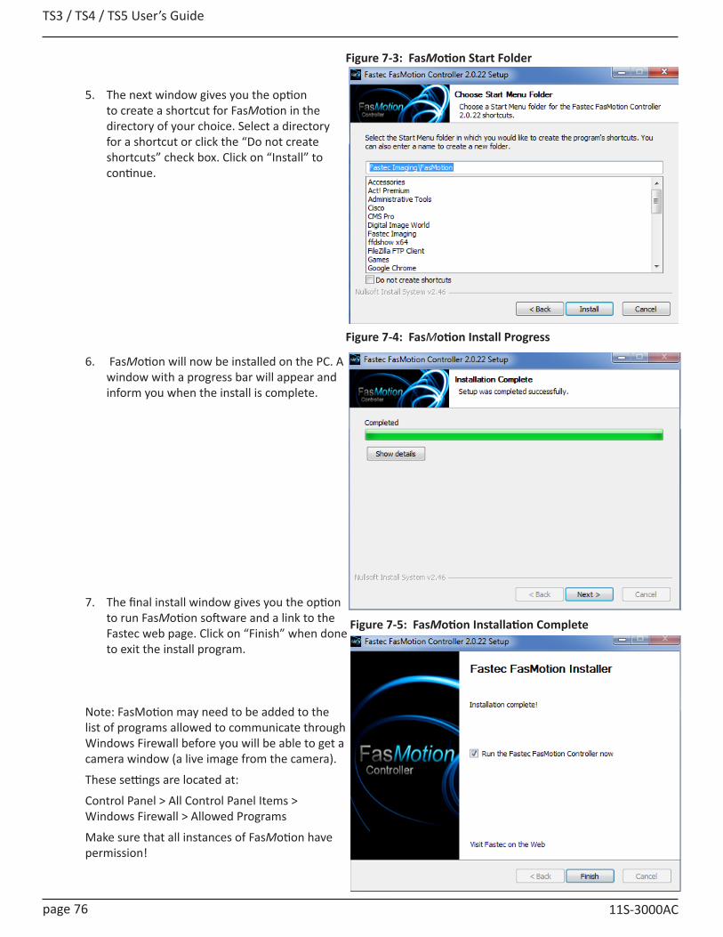
TS3 / TS4 / TS5 User’s Guide
page 76 11S-3000AC
5. The next window gives you the option to create a shortcut for FasMotion in the directory of your choice. Select a directory for a shortcut or click the “Do not create shortcuts” check box. Click on “Install” to continue.
6. FasMotion will now be installed on the PC. A window with a progress bar will appear and inform you when the install is complete.
7. The final install window gives you the option to run FasMotion software and a link to the Fastec web page. Click on “Finish” when done to exit the install program.
Note: FasMotion may need to be added to the list of programs allowed to communicate through Windows Firewall before you will be able to get a camera window (a live image from the camera).
These settings are located at:
Control Panel > All Control Panel Items > Windows Firewall > Allowed Programs
Make sure that all instances of FasMotion have permission!
Figure 7-3: FasMotion Start Folder
Figure 7-4: FasMotion Install Progress
Figure 7-5: FasMotion Installation Complete
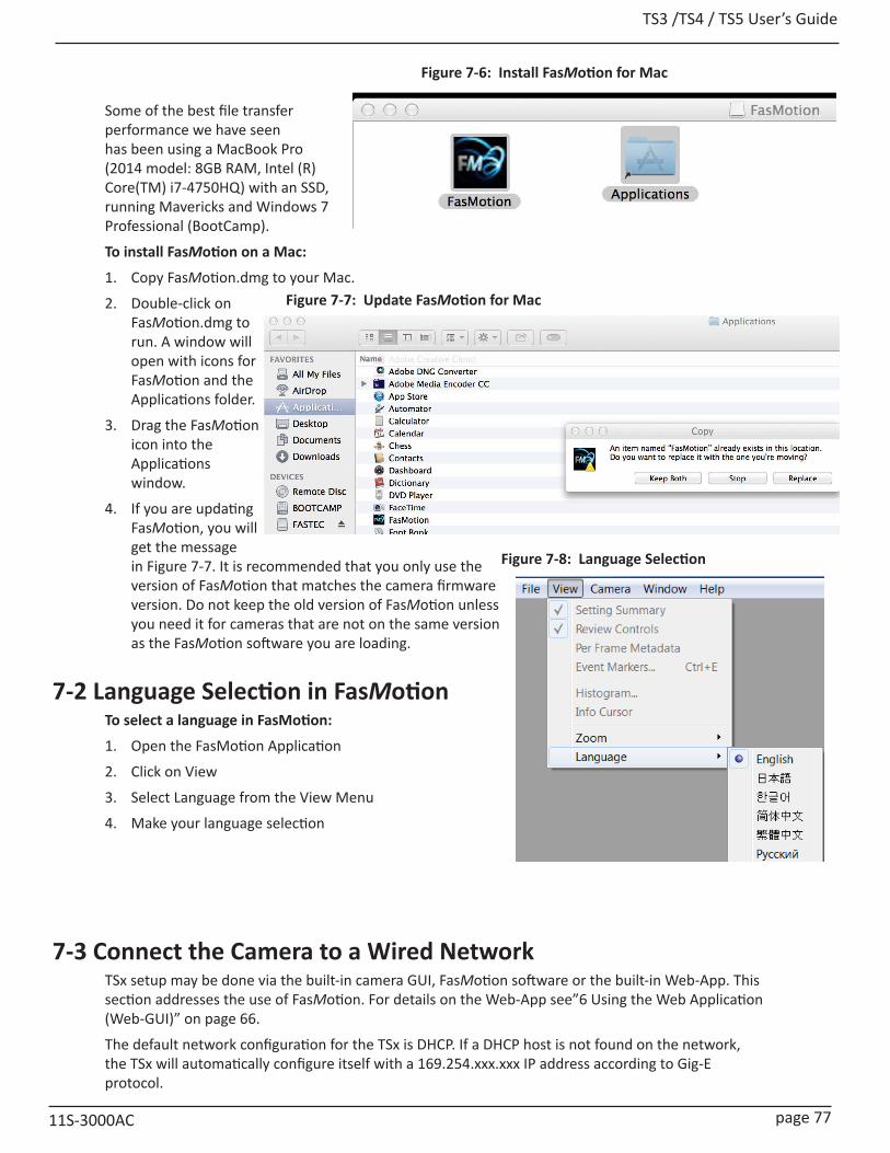
TS3 /TS4 / TS5 User’s Guide
11S-3000AC page 77
Some of the best file transfer performance we have seen has been using a MacBook Pro (2014 model: 8GB RAM, Intel (R) Core(TM) i7-4750HQ) with an SSD, running Mavericks and Windows 7 Professional (BootCamp).
To install FasMotion on a Mac:
1. Copy FasMotion.dmg to your Mac.
2. Double-click on FasMotion.dmg to run. A window will open with icons for FasMotion and the Applications folder.
3. Drag the FasMotion icon into the Applications window.
4. If you are updating FasMotion, you will get the message in Figure 7-7. It is recommended that you only use the version of FasMotion that matches the camera firmware version. Do not keep the old version of FasMotion unless you need it for cameras that are not on the same version as the FasMotion software you are loading.
7-2 Language Selection in FasMotionTo select a language in FasMotion:
1. Open the FasMotion Application
2. Click on View
3. Select Language from the View Menu
4. Make your language selection
Figure 7-6: Install FasMotion for Mac
Figure 7-7: Update FasMotion for Mac
7-3 Connect the Camera to a Wired NetworkTSx setup may be done via the built-in camera GUI, FasMotion software or the built-in Web-App. This section addresses the use of FasMotion. For details on the Web-App see”6 Using the Web Application (Web-GUI)” on page 66.
The default network configuration for the TSx is DHCP. If a DHCP host is not found on the network, the TSx will automatically configure itself with a 169.254.xxx.xxx IP address according to Gig-E protocol.
Figure 7-8: Language Selection

TS3 / TS4 / TS5 User’s Guide
page 78 11S-3000AC
LEDs on RJ-45 Connector Camera Networking LED
Green (Connection) Amber (activity) Amber (activity)1 Blink = 10Mb Blinks for all
network activityBlinks for camera network activity only2 Blinks = 100Mb
3 Blinks =1Gb
To attach the TSx to a network:
1. Before connecting to power, connect the TSx to your network via a switch or router, or directly to your PC using CAT 5E or CAT 6 Ethernet cable.
2. Power up the TSx. See “2-3 Powering Up, Charging, and Power Down” on page 8.
3. Watch the LEDs on the camera’s RJ-45 connector. When the camera connects to the PC or local network the green LED will begin to blink in a pattern depending on connection speed. (See “Table 3-2: Network LEDs” on page 19.)
4. Start the FasMotion software application.
5. Select a camera from the “Found Cameras” list in FasMotion. Double-click to open.
Note: Figure 7-9 shows the context menu for the “Found Cameras” dialog, which opens with a right-click on the list. This menu may be used to arrange or configure the dialog as well as carry out other functions described elsewhere. “Arrange By” sorts the list according to whatever parameter you choose. Also shown here is the “Show Columns” dialog, which opens when you select “Add Column.” This is used to add or remove camera parameters from the “Found Cameras” list.
Note: It is best to disable adapters that will not be used with FasMotion, especially any adapters sharing the same subnet. Please refer to “Application Note 5: Optimizing System for Image Transfers” on page 133 for more details.
Table 7-1: TSx Network LEDs
Figure 7-9: FasMotion “Found Cameras” Pane
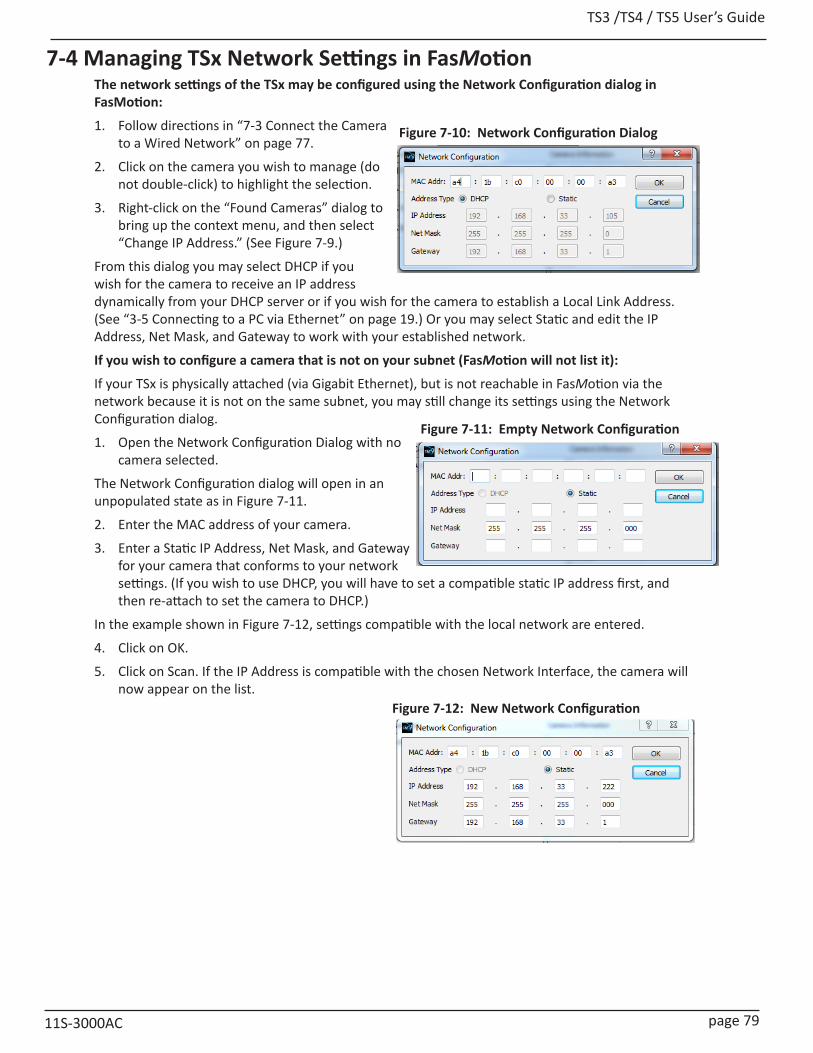
TS3 /TS4 / TS5 User’s Guide
11S-3000AC page 79
7-4 Managing TSx Network Settings in FasMotionThe network settings of the TSx may be configured using the Network Configuration dialog in FasMotion:
1. Follow directions in “7-3 Connect the Camera to a Wired Network” on page 77.
2. Click on the camera you wish to manage (do not double-click) to highlight the selection.
3. Right-click on the “Found Cameras” dialog to bring up the context menu, and then select “Change IP Address.” (See Figure 7-9.)
From this dialog you may select DHCP if you wish for the camera to receive an IP address dynamically from your DHCP server or if you wish for the camera to establish a Local Link Address. (See “3-5 Connecting to a PC via Ethernet” on page 19.) Or you may select Static and edit the IP Address, Net Mask, and Gateway to work with your established network.
If you wish to configure a camera that is not on your subnet (FasMotion will not list it):
If your TSx is physically attached (via Gigabit Ethernet), but is not reachable in FasMotion via the network because it is not on the same subnet, you may still change its settings using the Network Configuration dialog.
1. Open the Network Configuration Dialog with no camera selected.
The Network Configuration dialog will open in an unpopulated state as in Figure 7-11.
2. Enter the MAC address of your camera.
3. Enter a Static IP Address, Net Mask, and Gateway for your camera that conforms to your network settings. (If you wish to use DHCP, you will have to set a compatible static IP address first, and then re-attach to set the camera to DHCP.)
In the example shown in Figure 7-12, settings compatible with the local network are entered.
4. Click on OK.
5. Click on Scan. If the IP Address is compatible with the chosen Network Interface, the camera will now appear on the list.
Figure 7-10: Network Configuration Dialog
Figure 7-11: Empty Network Configuration
Figure 7-12: New Network Configuration
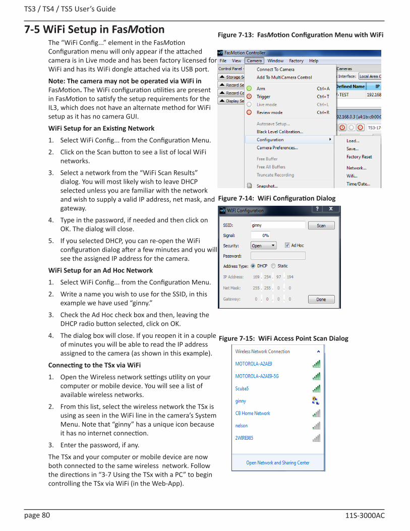
TS3 / TS4 / TS5 User’s Guide
page 80 11S-3000AC
Figure 7-13: FasMotion Configuration Menu with WiFi
Figure 7-14: WiFi Configuration Dialog
Figure 7-15: WiFi Access Point Scan Dialog
7-5 WiFi Setup in FasMotionThe “WiFi Config...” element in the FasMotion Configuration menu will only appear if the attached camera is in Live mode and has been factory licensed for WiFi and has its WiFi dongle attached via its USB port.
Note: The camera may not be operated via WiFi in FasMotion. The WiFi configuration utilities are present in FasMotion to satisfy the setup requirements for the IL3, which does not have an alternate method for WiFi setup as it has no camera GUI.
WiFi Setup for an Existing Network
1. Select WiFi Config... from the Configuration Menu.
2. Click on the Scan button to see a list of local WiFi networks.
3. Select a network from the “WiFi Scan Results” dialog. You will most likely wish to leave DHCP selected unless you are familiar with the network and wish to supply a valid IP address, net mask, and gateway.
4. Type in the password, if needed and then click on OK. The dialog will close.
5. If you selected DHCP, you can re-open the WiFi configuration dialog after a few minutes and you will see the assigned IP address for the camera.
WiFi Setup for an Ad Hoc Network
1. Select WiFi Config... from the Configuration Menu.
2. Write a name you wish to use for the SSID, in this example we have used “ginny.”
3. Check the Ad Hoc check box and then, leaving the DHCP radio button selected, click on OK.
4. The dialog box will close. If you reopen it in a couple of minutes you will be able to read the IP address assigned to the camera (as shown in this example).
Connecting to the TSx via WiFi
1. Open the Wireless network settings utility on your computer or mobile device. You will see a list of available wireless networks.
2. From this list, select the wireless network the TSx is using as seen in the WiFi line in the camera’s System Menu. Note that “ginny” has a unique icon because it has no internet connection.
3. Enter the password, if any.
The TSx and your computer or mobile device are now both connected to the same wireless network. Follow the directions in “3-7 Using the TSx with a PC” to begin controlling the TSx via WiFi (in the Web-App).
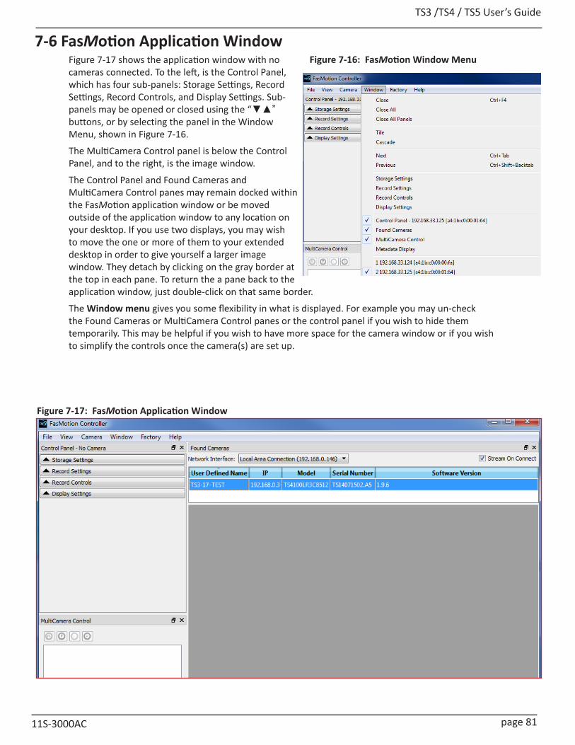
TS3 /TS4 / TS5 User’s Guide
11S-3000AC page 81
7-6 FasMotion Application WindowFigure 7-17 shows the application window with no cameras connected. To the left, is the Control Panel, which has four sub-panels: Storage Settings, Record Settings, Record Controls, and Display Settings. Sub-panels may be opened or closed using the “▼▲” buttons, or by selecting the panel in the Window Menu, shown in Figure 7-16.
The MultiCamera Control panel is below the Control Panel, and to the right, is the image window.
The Control Panel and Found Cameras and MultiCamera Control panes may remain docked within the FasMotion application window or be moved outside of the application window to any location on your desktop. If you use two displays, you may wish to move the one or more of them to your extended desktop in order to give yourself a larger image window. They detach by clicking on the gray border at the top in each pane. To return the a pane back to the application window, just double-click on that same border.
The Window menu gives you some flexibility in what is displayed. For example you may un-check the Found Cameras or MultiCamera Control panes or the control panel if you wish to hide them temporarily. This may be helpful if you wish to have more space for the camera window or if you wish to simplify the controls once the camera(s) are set up.
Figure 7-16: FasMotion Window Menu
Figure 7-17: FasMotion Application Window
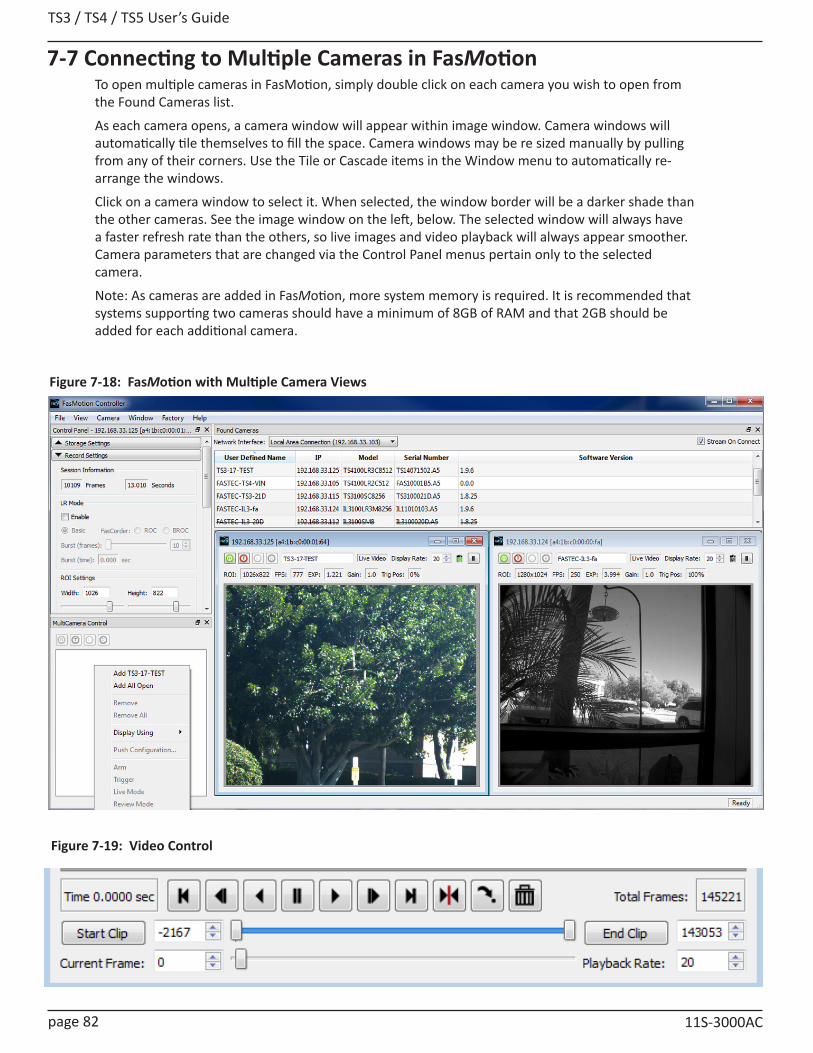
TS3 / TS4 / TS5 User’s Guide
page 82 11S-3000AC
7-7 Connecting to Multiple Cameras in FasMotionTo open multiple cameras in FasMotion, simply double click on each camera you wish to open from the Found Cameras list.
As each camera opens, a camera window will appear within image window. Camera windows will automatically tile themselves to fill the space. Camera windows may be re sized manually by pulling from any of their corners. Use the Tile or Cascade items in the Window menu to automatically re-arrange the windows.
Click on a camera window to select it. When selected, the window border will be a darker shade than the other cameras. See the image window on the left, below. The selected window will always have a faster refresh rate than the others, so live images and video playback will always appear smoother. Camera parameters that are changed via the Control Panel menus pertain only to the selected camera.
Note: As cameras are added in FasMotion, more system memory is required. It is recommended that systems supporting two cameras should have a minimum of 8GB of RAM and that 2GB should be added for each additional camera.
Figure 7-19: Video Control
Figure 7-18: FasMotion with Multiple Camera Views

TS3 /TS4 / TS5 User’s Guide
11S-3000AC page 83
Figure 7-21: User Preferences
Figure 7-20: View Menu7-8 Controlling the Image Displays
Zoom to Window The full image is sized to completely fill the image window. The image may be distorted as the aspect ratio is lost.
Zoom to Fit The image expands proportionally and fills the image window without losing its aspect ratio.
Zoom 1 to 1 The image is represented pixel for pixel on the display. Depending on the display resolution, the image may only fill part of the image window, or the image may be cut off, in which case sliders will appear so that you may access the entire image.
Zoom In The image is enlarged greater than 1:1 with the first click, then progressively larger with each additional click. When the image exceeds the size of the window, sliders will appear for access.
Zoom Out If you have Zoomed-In on an image, Zoom-Out allows you to back through the zoom settings down to 1:1.
Setting Default Gamma and JPEG Quality Camera Preferences is in the Camera menu.
The Default Gamma setting is used to set the default output Gamma for displayed and saved images.
The default Gamma is 1.0 (linear). Many laptop computer displays have a Gamma of 1.0, while larger flat panel LCD monitors often have a Gamma of 2.2.
Note that changing the Default Gamma setting does not change the current Gamma of the camera, it sets it reset value. To set the Gamma of the camera to a new default, navigate to the Display Settings tab and select “Reset Light and Color Settings.”
Figure 7-22 on page 84 uses two screen shots of a high-contrast image to demonstrate the difference in appearance between Gamma 1.0 and 2.2. These images were displayed on a monitor with a 2.2 Gamma.
JPEG Quality is set to 80 by default as a good compromise between quality and image size. For higher-quality Stills, JPEGs and AVI files set to 100. For faster live refresh rates (streaming to the display) set this lower.Auto-playbackThe Auto-playback checkbox is also found in the Preferences Dialog.When the Auto-playback box is checked, the camera will playback immediately at whenever a recording is complete in Standard Basic mode. This box becomes unchecked if LR mode is selected on cameras with that option.
Display Rate for live images:
The display rate for live images in FasMotion may be adjusted using the spinner at the top of the Image Window. (See Figure 7-22 on page 84.) This number will automatically change according to the performance of the network and the PC. The JPEG Quality setting will also affect the display rate as it controls the size of the JPEGs sent via Ethernet to FasMotion.
There is also a pause/play button on the top of the Image Window. This may be used to temporarily start and stop the video stream.
Ctrl + Mouse Wheel Zoom Control:
Place the cursor on a point of interest on the image, hold down the Ctrl but-ton, and then turn the mouse wheel. If the image zoom becomes larger than the window, the mouse cursor becomes a “hand” and can be used to reposition the image within the window.
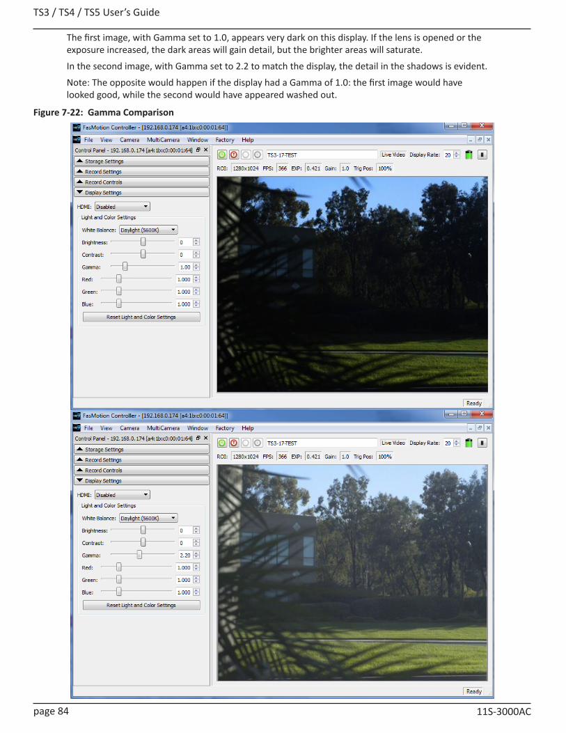
TS3 / TS4 / TS5 User’s Guide
page 84 11S-3000AC
Figure 7-22: Gamma Comparison
The first image, with Gamma set to 1.0, appears very dark on this display. If the lens is opened or the exposure increased, the dark areas will gain detail, but the brighter areas will saturate.
In the second image, with Gamma set to 2.2 to match the display, the detail in the shadows is evident.
Note: The opposite would happen if the display had a Gamma of 1.0: the first image would have looked good, while the second would have appeared washed out.
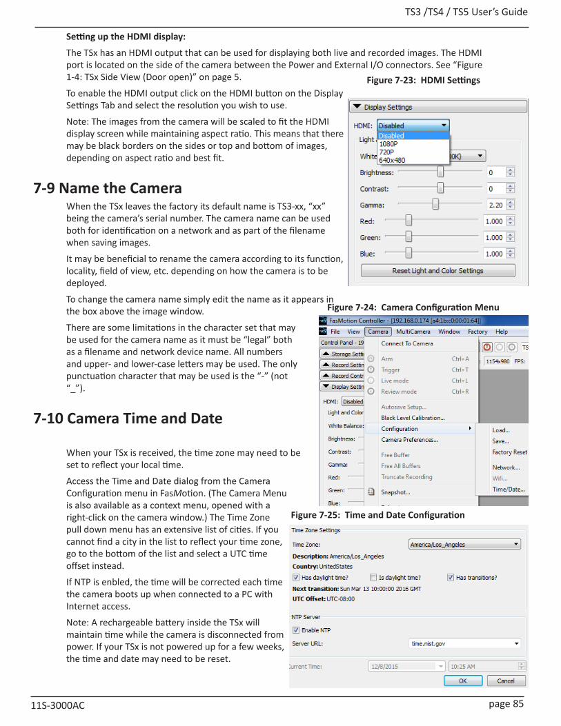
TS3 /TS4 / TS5 User’s Guide
11S-3000AC page 85
Figure 7-25: Time and Date Configuration
Figure 7-23: HDMI Settings
Setting up the HDMI display:
The TSx has an HDMI output that can be used for displaying both live and recorded images. The HDMI port is located on the side of the camera between the Power and External I/O connectors. See “Figure 1-4: TSx Side View (Door open)” on page 5.
To enable the HDMI output click on the HDMI button on the Display Settings Tab and select the resolution you wish to use.
Note: The images from the camera will be scaled to fit the HDMI display screen while maintaining aspect ratio. This means that there may be black borders on the sides or top and bottom of images, depending on aspect ratio and best fit.
7-9 Name the CameraWhen the TSx leaves the factory its default name is TS3-xx, “xx” being the camera’s serial number. The camera name can be used both for identification on a network and as part of the filename when saving images.
It may be beneficial to rename the camera according to its function, locality, field of view, etc. depending on how the camera is to be deployed.
To change the camera name simply edit the name as it appears in the box above the image window.
There are some limitations in the character set that may be used for the camera name as it must be “legal” both as a filename and network device name. All numbers and upper- and lower-case letters may be used. The only punctuation character that may be used is the “-” (not “_”).
7-10 Camera Time and Date
When your TSx is received, the time zone may need to be set to reflect your local time.
Access the Time and Date dialog from the Camera Configuration menu in FasMotion. (The Camera Menu is also available as a context menu, opened with a right-click on the camera window.) The Time Zone pull down menu has an extensive list of cities. If you cannot find a city in the list to reflect your time zone, go to the bottom of the list and select a UTC time offset instead.
If NTP is enbled, the time will be corrected each time the camera boots up when connected to a PC with Internet access.
Note: A rechargeable battery inside the TSx will maintain time while the camera is disconnected from power. If your TSx is not powered up for a few weeks, the time and date may need to be reset.
Figure 7-24: Camera Configuration Menu

TS3 / TS4 / TS5 User’s Guide
page 86 11S-3000AC
7-11 Connect to a TSx Outside FasMotionFasMotion software is the primary user interface for the TSx. It is the most flexible and efficient way to use the camera. There may be times, however when you may wish to access the TSx using the built-in Web-Application or through its USB OTG port.
To open the Networked TSx in a Web browser in the Web-Application:
The Web-application works with many web browsers, including Google Chrome, Mozilla Firefox, Safari and Microsoft Internet Explorer. Unlike FasMotion, it does not require a wired Gig-E connection on the host device. It works on most PCs, Smartphones, and tablets:
1. Type the camera’s IP address or camera name into the browser’s Location bar. For example, using the information from “Figure 7-25: Time and Date Configuration” you would type 192.168.33.114 (IP address) or L3-A3 (the camera name) into the browser’s Location bar.
2. A camera control application within the camera does the rest. A control menu will appear in your browser that will give a live camera view and complete control over the camera operation. Details on use of the camera’s web browser appear in Chapter 6 of this manual.
Note: The Web-Application is useful for setting up and controlling the camera, but it does not have the display performance (refresh rate) of FasMotion and has no utility for saving video or image files
on the host device (PC, Tablet, etc.).
Figure 7-26: Web-Application
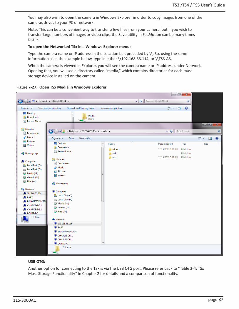
TS3 /TS4 / TS5 User’s Guide
11S-3000AC page 87
You may also wish to open the camera in Windows Explorer in order to copy images from one of the cameras drives to your PC or network.
Note: This can be a convenient way to transfer a few files from your camera, but if you wish to transfer large numbers of images or video clips, the Save utility in FasMotion can be many times faster.
To open the Networked TSx in a Windows Explorer menu:
Type the camera name or IP address in the Location bar, preceded by \\. So, using the same information as in the example below, type in either \\192.168.33.114, or \\TS3-A3.
When the camera is viewed in Explorer, you will see the camera name or IP address under Network. Opening that, you will see a directory called “media,” which contains directories for each mass storage device installed on the camera.
USB OTG:
Another option for connecting to the TSx is via the USB OTG port. Please refer back to “Table 2-4: TSx Mass Storage Functionality” in Chapter 2 for details and a comparison of functionality.
Figure 7-27: Open TSx Media in Windows Explorer

TS3 / TS4 / TS5 User’s Guide
page 88 11S-3000AC
7-12 Storage SetupThe FasMotion Storage Settings Tab gives the user access and control of the Camera memory and any installed media, including a Solid State Drive (SSD), SD Card, or USB drive.
The TSx has 4GB, or 8GB of internal high-speed memory used for capturing high-speed imagery (depending on model and option). You can elect to use all of this memory when recording, or a smaller amount. Total record time will depend on resolution, frame rate, and bit depth. For cameras in LR mode, the dialog box changes. The Session Recording Capacity slider becomes disabled as it is no longer needed. If SSD is selected, the Explore button is grayed.
Configure Session (Standard Mode):
Use the Session Recording Capacity slider to select the amount of memory you wish to use to capture video. This slider has a granularity of 250MB.
Use the Format utility in the Storage Settings Tab to format any of the camera media. The SSD, SD Card, and USB drives are all accessible for formatting.
Formatting the SSD:
It is recommended that you format the SSD to delete all recordings and completely clean it off. This should be done often to keep performance as high as possible.
To format the SSD simply select the SSD radio button in the Storage Settings dialog and click on “Format.”
When formatting the SSD on most cameras, you will be given an option of Sanitizing the drive. Sanitization is a low-level process that securely erases all data and renews the SSD for optimal performance.
Formatting SD Cards and USB drives:
Formatting SD Cards and USB drives is the easiest and most effective way of deleting all recordings. When formatting SD Cards and USB drives, FasMotion will give the option of “Performance” or “Compatibility.”
The Compatibility format is FAT-32, which is recognized by most computers. The Performance format is EXT2, which is a Linux format and may require a 3rd-party driver or application (such as DiskInternals Linux Reader) on your MAC or PC. EXT2 will improve file Save times to the SD Card and USB. The improvement is only about 10% for very large images such as full-resolution TIFF and BMP images. The greatest improvement (as much as 6x) is seen when saving large numbers of very small files, such as saving thousands of low-resolution JPEGs.
Exploring Camera Media:
Open the FasMotion Camera Explore dialog by selecting the
Figure 7-28: FasMotion Storage Settings Tab
Figure 7-29: FasMotion Camera Explorer
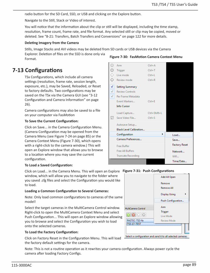
TS3 /TS4 / TS5 User’s Guide
11S-3000AC page 89
radio button for the SD Card, SSD, or USB and clicking on the Explore button.
Navigate to the Still, Stack or Video of interest.
You will notice that the information about the clip or still will be displayed, including the time stamp, resolution, frame count, frame rate, and file format. Any selected still or clip may be copied, moved or deleted. See “8-21: Transfers, Batch Transfers and Conversions” on page 122 for more details.
Deleting Imagery from the Camera
Stills, Image Stacks and AVI videos may be deleted from SD cards or USB devices via the Camera Explorer. Deletion of files on the SSD is done only via Format.
7-13 ConfigurationsTSx Configurations, which include all camera settings (resolution, frame rate, session length, exposure, etc.), may be Saved, Reloaded, or Reset to factory defaults. Two configurations may be saved on the TSx via the Camera GUI (see “3-12 Configuration and Camera Information” on page 26).
Camera configurations may also be saved to a file on your computer via FasMotion
To Save the Current Configuration:
Click on Save... in the Camera Configuration Menu. (Camera Configuration may be opened from the Camera Menu (see Figure 7-24 on page 85) or the Camera Context Menu (Figure 7-30), which opens with a right-click to the camera window.) This will open an Explore window that allows you to browse to a location where you may save the current configuration.
To Load a Saved Configuration:
Click on Load... in the Camera Menu. This will open an Explore window, which will allow you to navigate to the folder where you saved .cfg files and select the Configuration you would like to load.
Loading a Common Configuration to Several Cameras:
Note: Only load common configurations to cameras of the same model!
Select the target cameras in the MultiCamera Control window. Right-click to open the MultiCamera Context Menu and select Push Configuration... This will open an Explore window allowing you to browse and select the Configuration you wish to load onto the selected cameras.
To Load the Factory Configuration:
Click on Factory Reset in the Configuration Menu. This will load the factory default settings for the camera.
Note: This is not a routine operation as it rewrites your camera configuration. Always power cycle the camera after loading Factory Configs.
Figure 7-30: FasMotion Camera Context Menu
Figure 7-31: Push Configurations
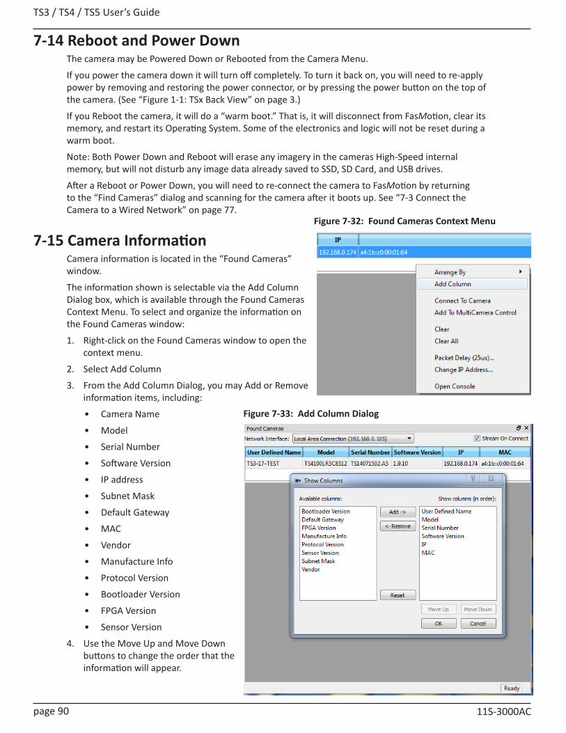
TS3 / TS4 / TS5 User’s Guide
page 90 11S-3000AC
7-14 Reboot and Power DownThe camera may be Powered Down or Rebooted from the Camera Menu.
If you power the camera down it will turn off completely. To turn it back on, you will need to re-apply power by removing and restoring the power connector, or by pressing the power button on the top of the camera. (See “Figure 1-1: TSx Back View” on page 3.)
If you Reboot the camera, it will do a “warm boot.” That is, it will disconnect from FasMotion, clear its memory, and restart its Operating System. Some of the electronics and logic will not be reset during a warm boot.
Note: Both Power Down and Reboot will erase any imagery in the cameras High-Speed internal memory, but will not disturb any image data already saved to SSD, SD Card, and USB drives.
After a Reboot or Power Down, you will need to re-connect the camera to FasMotion by returning to the “Find Cameras” dialog and scanning for the camera after it boots up. See “7-3 Connect the Camera to a Wired Network” on page 77.
7-15 Camera InformationCamera information is located in the “Found Cameras” window.
The information shown is selectable via the Add Column Dialog box, which is available through the Found Cameras Context Menu. To select and organize the information on the Found Cameras window:
1. Right-click on the Found Cameras window to open the context menu.
2. Select Add Column
3. From the Add Column Dialog, you may Add or Remove information items, including:
• Camera Name
• Model
• Serial Number
• Software Version
• IP address
• Subnet Mask
• Default Gateway
• MAC
• Vendor
• Manufacture Info
• Protocol Version
• Bootloader Version
• FPGA Version
• Sensor Version
4. Use the Move Up and Move Down buttons to change the order that the information will appear.
Figure 7-32: Found Cameras Context Menu
Figure 7-33: Add Column Dialog

TS3 /TS4 / TS5 User’s Guide
11S-3000AC page 91
7-16 Solving Setup IssuesIf the camera is not present in the Found Cameras window:AnyITSx camera connected via Gigabit Ethernet should appear on the FasMotion Found Cameras window as long as:
1. The physical connection is sound (good CAT 5e or CAT 6 cable, etc.).
2. The camera’s IP address is on the same subnet as the computer.
It is best to check #1, the physical connection, first.
• Make sure that the cable is marked CAT 5e or CAT 6.
• Connect the computer to another network device with the same cable and confirm that it can connect.
• Connect the camera to the computer via the GigE cable and confirm that the green LED on the camera’s Ethernet connector lights in a three-blink pattern. (Three blinks indicate a GigE connection; two indicate 100BaseT.)
The simplest way to ensure #2, above, is to use a direct connection between the camera and computer (no switches or routers between camera and computer).
• If the camera’s network configuration is set for DHCP, which is the default setting, Make sure the computer is set to DHCP: the TCP/IPv4 properties of the network adapter are set to obtain an IP address automatically.
• If the camera’s network configuration is set to a Static IP address, make sure that the computer is set to a Static IP address on the same subnet.
• If the camera is set to an unknown Static IP address and you cannot view the camera display to retrieve it, refer to “7-4 Managing TSx Network Settings in FasMotion” on page 79.
• If you can connect to the camera in FasMotion, but do not get a Live image:In most cases, all of the control and setup features work in FasMotion, but you cannot get a live image or transfer images to the computer. There are two common causes:
1. WiFi is enabled on the computer.
2. The firewall is not allowing FasMotion to use UDP, which is the protocol for both live view and file transfers.
The first thing to do is always to make sure that the GigE interface that the camera is connected to is the only network interfaced active--disable the WiFi adapter and any other NICs present.
Check to see that all instances of FasMotion are allowed through the Windows firewall.
Note that the example shown here is from a Fastec test computer that has had many versions of FasMotion on it. Your computer is not likely to have this many, but there may be more than one.
If image transfers from camera to computer are slow or fail, please refer to “Application Note 5: Optimizing System for Image Transfers” on page 133 and make sure your system meets the requirements and is set up properly.
Figure 7-34: Allow Programs Through Windows Firewall
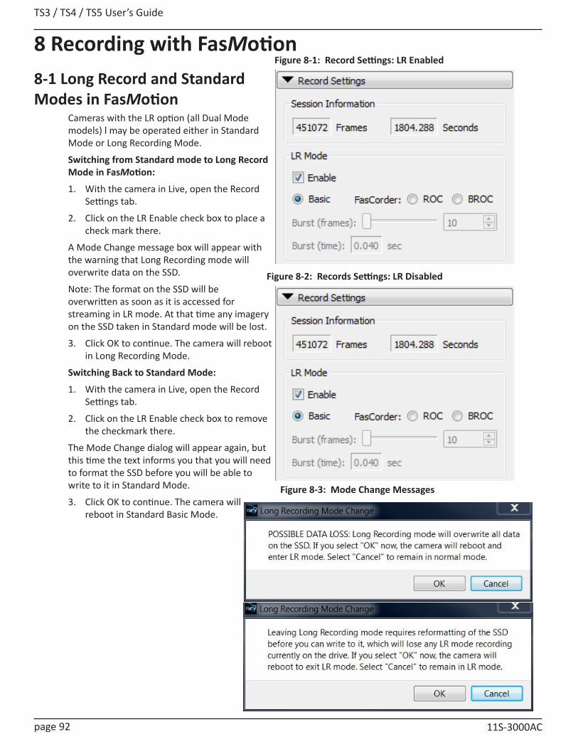
TS3 / TS4 / TS5 User’s Guide
page 92 11S-3000AC
8 Recording with FasMotion8-1 Long Record and Standard Modes in FasMotion
Cameras with the LR option (all Dual Mode models) l may be operated either in Standard Mode or Long Recording Mode.
Switching from Standard mode to Long Record Mode in FasMotion:
1. With the camera in Live, open the Record Settings tab.
2. Click on the LR Enable check box to place a check mark there.
A Mode Change message box will appear with the warning that Long Recording mode will overwrite data on the SSD.
Note: The format on the SSD will be overwritten as soon as it is accessed for streaming in LR mode. At that time any imagery on the SSD taken in Standard mode will be lost.
3. Click OK to continue. The camera will reboot in Long Recording Mode.
Switching Back to Standard Mode:
1. With the camera in Live, open the Record Settings tab.
2. Click on the LR Enable check box to remove the checkmark there.
The Mode Change dialog will appear again, but this time the text informs you that you will need to format the SSD before you will be able to write to it in Standard Mode.
3. Click OK to continue. The camera will reboot in Standard Basic Mode.
Figure 8-1: Record Settings: LR Enabled
Figure 8-2: Records Settings: LR Disabled
Figure 8-3: Mode Change Messages

TS3 /TS4 / TS5 User’s Guide
11S-3000AC page 93
8-2 Setting Frame Rate and Resolution in FasMotionRecord Settings are interactive:
• The Resolution you choose will define the maximum Frame Rate and number of frames that can be captured.
• The Frame Rate will define maximum Shutter Speed (exposure time in msec).
• The Frame Rate and number of Frames captured define the duration of the recording (time in seconds).
• If you select Autoset in either Frame Rate or Resolution, that parameter will be selected automatically to its maximum allowable value, dependent on the other current settings
To set the Resolution of the TSx:
1. Select the Aspect Ratio you wish to use: choices are Custom, 5:4, 4:3, and 16:9.
2. Adjust the image Width (in pixels) you wish to use. This can be done either by editing the number in the Width edit box, or by moving the slider.
Resolutions can be refined to any even-numbered pair from minimum to maximum resolution, depending on camera model. Please refer to “Appendix E: TS5 Record / Resolution Tables” on page 155 and “Appendix D: TS3 / TS4 Record / Resolution Tables” on page 150 for details.
Whenever any slider has focus, it turns blue. It may be then controlled by dragging it with the mouse or using the keyboard arrow keys. Often the best way to do this is by dragging it with the mouse until it is close to the value you want, then using the arrow keys to “zero in” on the exact value.
To set the Frame Rate of the TSx:
Either edit the number in the Frame Rate edit box, or move the Frame Rate slider to the desired position using the mouse and arrow keys.
Offset Control:
Most of the time, to make use of the best resolving properties of your lens, you will want to center the image at the optical center, which corresponds to the center of the sensor. In this case you would make sure that the “Center” check box is checked.
It is also possible, that you will wish to shift your ROI (Region of Interest) without moving the camera.
Let’s say, for example, that you have captured images at 1024 x 1024 @ 500fps on a TS3, and are now interested at capturing a 512 x 512 portion of the scene, let’s say the bottom right hand quarter @ 2000fps.
In this case, you would wish to add 512 to both the X and Y offset. For a 1024 x 1024 centered image the offsets will be 128 and 0. The resultant offsets for a 512 x 512 image (lower right quadrant) would be 640 and 512.
Figure 8-4: Record Settings Tab

TS3 / TS4 / TS5 User’s Guide
page 94 11S-3000AC
8-3 Setting Shutter Speed in FasMotion
The Shutter Speed is expressed in microseconds of exposure time and in shutter angle (degrees).
Minimum Exposure:
Minimum exposure is 2msec for all TS3 / TS4 models, 3msec for all TS5 models (regardless of frame rate).
Maximum Exposure:
TS3 and TS4 TS51/(Frame rate) - 6ms
Example: At 500 fps the max exposure is:(1/500sec) -6ms = 2000msec -6msec = 1994msec
1/(Frame rate) - 12msExample: At 500 fps the max exposure is:(1/500sec) -12ms = 2000msec -12msec = 1988msec
For those accustomed to using shutter angle, to convert that to degrees:
(Exposure (in msec) / Frame Time) X 360o
For example, at 500fps, an exposure time of 250msec is:
(250msec / 1/500 sec) X 360o = (250 / 2000) X 360o = 45o
Setting the Shutter Speed:
Shutter Speed is set using the slider or edit box in the “Shutter Settings” section of the Record Settings Tab. (See “Figure 8-5: Shutter Settings”.)
Low Light Mode:
In some special circumstances, the light available for setting up the TSx for a high-speed event is not as bright as what will be used for event itself. You may, for example be using some lights that can only be switched on for a short time and are not available for camera set up.
The exposure for Low Light Mode is much longer than would be possible for a high frame rate. The default shutter speed for Low Light mode is 41.666ms, which is the “1X” shutter speed for 24 FPS. The shutter speed for Low Light may be adjusted via FasMotion by checking the Low Light box and moving the slider or editing the Low Light edit box.
To enter Low Light Mode:
Note: Be careful when using the Low Light feature! It is very easy to forget that it is on! Remember to set your exposure for the light that will be present during the image capture.
1. Set the Shutter Speed just as you need it for the high speed event.
2. Click on the Low Light check box. A check mark will appear in the box. The edit box and the slider will become active.
3. Adjust the slider or edit the box for the desired exposure.
4. Press the Arm Button.
The camera will begin recording. You will notice that the image is darker now than in Live Mode (unless you are recording at 24fps).
5. Press Arm again to quit recording. (Click “OK” on the Warning message to Cancel.)
Figure 8-5: Shutter Settings
Table 8-1: Maximum Exposure by Model

TS3 /TS4 / TS5 User’s Guide
11S-3000AC page 95
8-4 Enabling Auto-Exposure TrackingThe auto-exposure feature is designed to adjust the shutter setting of a camera to accommodate changes in available light such as changes in sunlight due to moving clouds.
It is not meant to track immediate changes such as flickering light sources, or explosive events.
1. Set your shutter speed to get the best exposure for the present lighting conditions. It is best if the shutter speed is not too close to either the maximum or minimum for the current frame.
2. Click the Track Window check box to begin using the auto-exposure function. A green track window will appear on the image.
3. Move and/or re size the track window to so that it covers an appropriate area of the image. Choose this area carefully:
• It should be illuminated similarly to the area of interest
• It should not become obscured by other moving objects
4. Click the Enable check box to begin tracking. The tracking window will now become a thin white border.
Click the Reset button to begin over. This will re-locate and re-size the tracking window and turn it green again, making it easier to locate.
Figure 8-6: Exposure Tracking Window
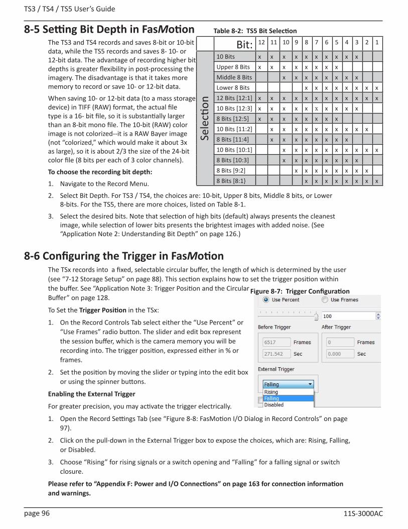
TS3 / TS4 / TS5 User’s Guide
page 96 11S-3000AC
8-5 Setting Bit Depth in FasMotionThe TS3 and TS4 records and saves 8-bit or 10-bit data, while the TS5 records and saves 8- 10- or 12-bit data. The advantage of recording higher bit depths is greater flexibility in post-processing the imagery. The disadvantage is that it takes more memory to record or save 10- or 12-bit data.
When saving 10- or 12-bit data (to a mass storage device) in TIFF (RAW) format, the actual file type is a 16- bit file, so it is substantially larger than an 8-bit mono file. The 10-bit (RAW) color image is not colorized--it is a RAW Bayer image (not “colorized,” which would make it about 3x as large), so it is about 2/3 the size of the 24-bit color file (8 bits per each of 3 color channels).
To choose the recording bit depth:
1. Navigate to the Record Menu.
2. Select Bit Depth. For TS3 / TS4, the choices are: 10-bit, Upper 8 bits, Middle 8 bits, or Lower 8-bits. For the TS5, there are more choices, listed on Table 8-1.
3. Select the desired bits. Note that selection of high bits (default) always presents the cleanest image, while selection of lower bits presents the brightest images with added noise. (See “Application Note 2: Understanding Bit Depth” on page 126.)
8-6 Configuring the Trigger in FasMotionThe TSx records into a fixed, selectable circular buffer, the length of which is determined by the user (see “7-12 Storage Setup” on page 88). This section explains how to set the trigger position within the buffer. See “Application Note 3: Trigger Position and the Circular Buffer” on page 128.
To Set the Trigger Position in the TSx:
1. On the Record Controls Tab select either the “Use Percent” or “Use Frames” radio button. The slider and edit box represent the session buffer, which is the camera memory you will be recording into. The trigger position, expressed either in % or frames.
2. Set the position by moving the slider or typing into the edit box or using the spinner buttons.
Enabling the External Trigger
For greater precision, you may activate the trigger electrically.
1. Open the Record Settings Tab (see “Figure 8-8: FasMotion I/O Dialog in Record Controls” on page 97).
2. Click on the pull-down in the External Trigger box to expose the choices, which are: Rising, Falling, or Disabled.
3. Choose “Rising” for rising signals or a switch opening and “Falling” for a falling signal or switch closure.
Please refer to “Appendix F: Power and I/O Connections” on page 163 for connection information and warnings.
Figure 8-7: Trigger Configuration
Bit: 12 11 10 9 8 7 6 5 4 3 2 1
Sele
ction
10 Bits x x x x x x x x x xUpper 8 Bits x x x x x x x xMiddle 8 Bits x x x x x x x xLower 8 Bits x x x x x x x x12 Bits [12:1] x x x x x x x x x x x x10 Bits [12:3] x x x x x x x x x x8 Bits [12:5] x x x x x x x x10 Bits [11:2] x x x x x x x x x x8 Bits [11:4] x x x x x x x x10 Bits [10:1] x x x x x x x x x x8 Bits [10:3] x x x x x x x x8 Bits [9:2] x x x x x x x x8 Bits [8:1} x x x x x x x x
Table 8-2: TS5 Bit Selection

TS3 /TS4 / TS5 User’s Guide
11S-3000AC page 97
8-7 Configuring Sync and Arm I/O in FasMotionIRIG Enable
For TSx cameras that have the IRIG option, the IRIG input may be enabled and the option to use the year in the timestamp via the Record Controls tab. (See “5-6 IRIG Timestamps and Sync” on page 64.)
I/O Controls
The I/O portion of the Record Controls tab includes dialogs for each of the I/O signals supported by the TSx. Each of these may be used in either of two ways:
1. As a control I/O signal for the camera.
2. As an input for an external signal for creating Markers. (See “Jumping to Markers” on page 109.)
Note that the TSx ships with a three-signal cable that supports Trigger In, Sync In, and Sync Out. A six-signal cable (PN:1105-0405) is available that supports the Trigger Out, Arm In, and Arm Out as well.
Trigger In was covered in the previous section. The remaining five I/O dialogs are controlled by a series of tabs. (See Figure 8-8.) Clicking on each tab opens the associated dialog. When enabled, a green circle will appear on the tab. In the Figure, External Trigger, Trigger Out, and Sync Out are all enabled.
Trigger Out
The trigger out dialog includes the options “Pass Thru” and “Invert Signal.” If either of these is selected, Trigger Out will follow whatever the Trigger In signal is, either in its original, or its inverted form. If neither of these is selected, then you may select either “Active Low” or “Active High” and a Pulse Width for the signal.
Enable Sync In / Sync Out
Sync In and Sync Out functions are used to synchronize the frame timing of a camera with another device or clock. These may include other cameras, strobe lighting, machinery, etc.
Sync In and Sync Out controls are somewhat interactive:
• When Sync In “Per Frame” is enabled, the Master Frame Rate and Rate divisor edit boxes are enabled. (See “5-1 Sync In” on page 55 for details.)
• When Sync In “Per Sec” is enabled, the Delay edit box is enabled, allowing a shift in integration timing from 0 to 1000msec to fine-tune the phase relationship between cameras and other devices.
• When IRIG is enabled the “Per Sec” selection in the Sync In box becomes “IRIG” and the TSx will use the IRIG signal as the 1Hz input for the “Per Sec” clock.
• When Sync Out “Per Frame” is enabled, the Shutter and Duty Cycle controls become active. Selecting
Figure 8-8: FasMotion I/O Dialog in Record Controls
Figure 8-9: Sync In Tab Dialog
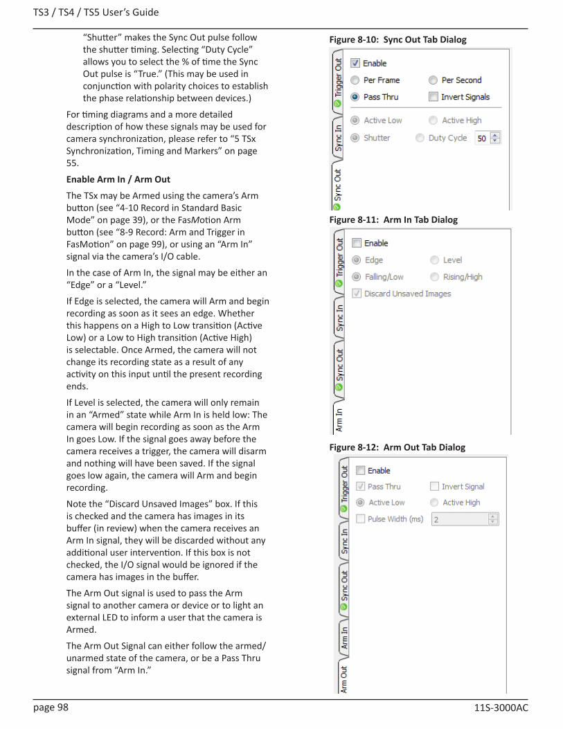
TS3 / TS4 / TS5 User’s Guide
page 98 11S-3000AC
Figure 8-10: Sync Out Tab Dialog
Figure 8-11: Arm In Tab Dialog
Figure 8-12: Arm Out Tab Dialog
“Shutter” makes the Sync Out pulse follow the shutter timing. Selecting “Duty Cycle” allows you to select the % of time the Sync Out pulse is “True.” (This may be used in conjunction with polarity choices to establish the phase relationship between devices.)
For timing diagrams and a more detailed description of how these signals may be used for camera synchronization, please refer to “5 TSx Synchronization, Timing and Markers” on page 55.
Enable Arm In / Arm Out
The TSx may be Armed using the camera’s Arm button (see “4-10 Record in Standard Basic Mode” on page 39), or the FasMotion Arm button (see “8-9 Record: Arm and Trigger in FasMotion” on page 99), or using an “Arm In” signal via the camera’s I/O cable.
In the case of Arm In, the signal may be either an “Edge” or a “Level.”
If Edge is selected, the camera will Arm and begin recording as soon as it sees an edge. Whether this happens on a High to Low transition (Active Low) or a Low to High transition (Active High) is selectable. Once Armed, the camera will not change its recording state as a result of any activity on this input until the present recording ends.
If Level is selected, the camera will only remain in an “Armed” state while Arm In is held low: The camera will begin recording as soon as the Arm In goes Low. If the signal goes away before the camera receives a trigger, the camera will disarm and nothing will have been saved. If the signal goes low again, the camera will Arm and begin recording.
Note the “Discard Unsaved Images” box. If this is checked and the camera has images in its buffer (in review) when the camera receives an Arm In signal, they will be discarded without any additional user intervention. If this box is not checked, the I/O signal would be ignored if the camera has images in the buffer.
The Arm Out signal is used to pass the Arm signal to another camera or device or to light an external LED to inform a user that the camera is Armed.
The Arm Out Signal can either follow the armed/unarmed state of the camera, or be a Pass Thru signal from “Arm In.”

TS3 /TS4 / TS5 User’s Guide
11S-3000AC page 99
8-8 Black Level Calibration in FasMotionBlack level calibration does two things: 1. It sets the black level of the camera to ensure that, in the absence of all light, there is no offset or
clipping (the “blackest” pixel will have a value of 0).2. Dark frame data is saved for correcting Fixed Pattern Noise (FPN).NOTE: Fixed Pattern Noise exists on every image sensor. Calibrate Black Level:To be assured that you are getting the best possible images, perform a calibration:• When you first boot the camera up.• If you change Shutter Speed, Bit Depth, Frame
Rate, Resolution, or Offset.In the Advanced Settings section of the Record Settings Tab (see Figure 8-4 on page 93) you will see an FPN selection dropdown menu. The items include Disabled Column, or Pixel. Click on that button and select the FPN setting you wish to use, based on the following:• Pixel FPN is a per-pixel image correction that is done in the TSx’s image processor engine. It
provides the cleanest images available. This is the setting that is most highly recommended.
• Column FPN is an image correction done on the TSx’s sensor. It does not do as good a job cleaning up the images as Pixel FPN.
• FPN Off means that there is no noise correction being used. (Calibration is not relevant for FPN off)
To Calibrate the Camera:
1. Set the camera to Live.
2. Shut out all light to the sensor: close the f-stop down all the way and put a lens cap on it or cover it securely.
3. Select Black Level Calibration from the Camera Menu. For information on Advanced Calibration, refer to “Application Note 7: Advanced Calibration” on page 141.
Note: If you make a setting change that makes the stored black frame incompatible, you will notice an asterisk next to Pixel on the FPN Selection button: “Pixel*” ... this is a reminder to do another calibration.
8-9 Record: Arm and Trigger in FasMotion
Live Mode A (Arm) and T (Trigger) buttons active:Camera in Live mode, waiting to Arm
Recording:Armed
A (Arm) and T (Trigger) buttons active: Camera is Armed, waiting for the trigger
Recording:Triggered
No buttons active:Camera has been triggered and is continuing to record
Review Mode L (Go to Live) button active:Camera has been armed and triggered, in Review
LiveImages in Buffer
A (Arm), T (Trigger) and R (Review) buttons active:Camera in Live mode, has a recording in the buffer
Figure 8-13: Black Level Calibration Dialog
Table 8-3: Camera Control Buttons

TS3 / TS4 / TS5 User’s Guide
page 100 11S-3000AC
Lights Camera Action!• The Resolution and Frame rate are set• The scene is framed and focused• The Shutter Speed is set• The Bit Depth is set• The Trigger Point and Trigger Type is set
• Black Level Calibration has been done
Take a Still JPEG Image
It is optional, but recommended, to take a reference still of the scene:
With the TSx in Live Mode (not Recording or Reviewing a recording) either click on the Trigger Button or click on “Snapshot...” in the Camera menu.
A dialog box will appear asking where to store the image. Select the storage media you wish to use. (The image will be saved in <storage device>/dcim/100fastc.)
Standard Basic Mode Recording
To begin recording, click the Arm button. The Arm Button will turn from green to brown (see “Table 8-3: Camera Control Buttons”) and the camera begins recording into its circular buffer (see “Application Note 3: Trigger Position and the Circular Buffer” on page 128 for an explanation of the circular buffer). The Camera LED will change from Green (Live) to slowly flashing Amber. It will record for an indefinite period of time until it gets a Trigger. (See “8-6 Configuring the Trigger in FasMotion” on page 96.)
If the Arm Button is pressed a second time, the Recording will abort. The button and the LED will return to green. The Cancel Recording dialog gives the option to retain the images already recorded, discard them, or to continue recording.
The recording state is indicated by a progress bar at the bottom of the image window. Numbers to the right of the
progress bar represent: number of recorded frames / total frames.
When all of the pre-trigger frames have been recorded, the progress bar stops and turns Yellow.
Note: If the TSx is triggered before the pre-trigger portion of the buffer is full, it will immediately cease taking pre-trigger frames, record frame “0” and progress to the post-trigger portion of the recording. When complete, the recording will have contiguous frames, with the full complement of post -trigger frames, but fewer pre-trigger frames. (See “8-6 Configuring the Trigger in FasMotion” on page 96.)
Figure 8-15: Record Progress Bar: Armed
Figure 8-16: Record Progress Bar: Triggered
Figure 8-14: Cancel Recording Dialog
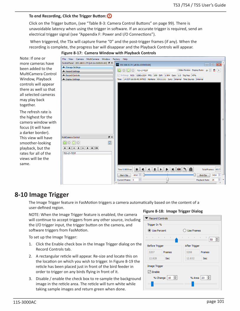
TS3 /TS4 / TS5 User’s Guide
11S-3000AC page 101
To end Recording, Click the Trigger Button:
Click on the Trigger button, (see “Table 8-3: Camera Control Buttons” on page 99). There is unavoidable latency when using the trigger in software. If an accurate trigger is required, send an electrical trigger signal (see “Appendix F: Power and I/O Connections”).
When triggered, the TSx will capture frame “0” and the post-trigger frames (if any). When the recording is complete, the progress bar will disappear and the Playback Controls will appear.
8-10 Image TriggerThe Image Trigger feature in FasMotion triggers a camera automatically based on the content of a user-defined region.
NOTE: When the Image Trigger feature is enabled, the camera will continue to accept triggers from any other source, including the I/O trigger input, the trigger button on the camera, and software triggers from FasMotion.
To set up the Image Trigger:
1. Click the Enable check box in the Image Trigger dialog on the Record Controls tab.
2. A rectangular reticle will appear. Re-size and locate this on the location on which you wish to trigger. In Figure 8-19 the reticle has been placed just in front of the bird feeder in order to trigger on any birds flying in front of it.
3. Disable / enable the check box to re-sample the background image in the reticle area. The reticle will turn white while taking sample images and return green when done.
-2449
-09.796
T +2449
-09.796 +09.796
Figure 8-17: Camera Window with Playback ControlsNote: If one or more cameras have been added to the MultiCamera Control Window, Playback controls will appear there as well so that all selected cameras may play back together.
The refresh rate is the highest for the camera window with focus (it will have a darker border). This view will have smoother-looking playback, but the rates for all of the views will be the same.
Figure 8-18: Image Trigger Dialog
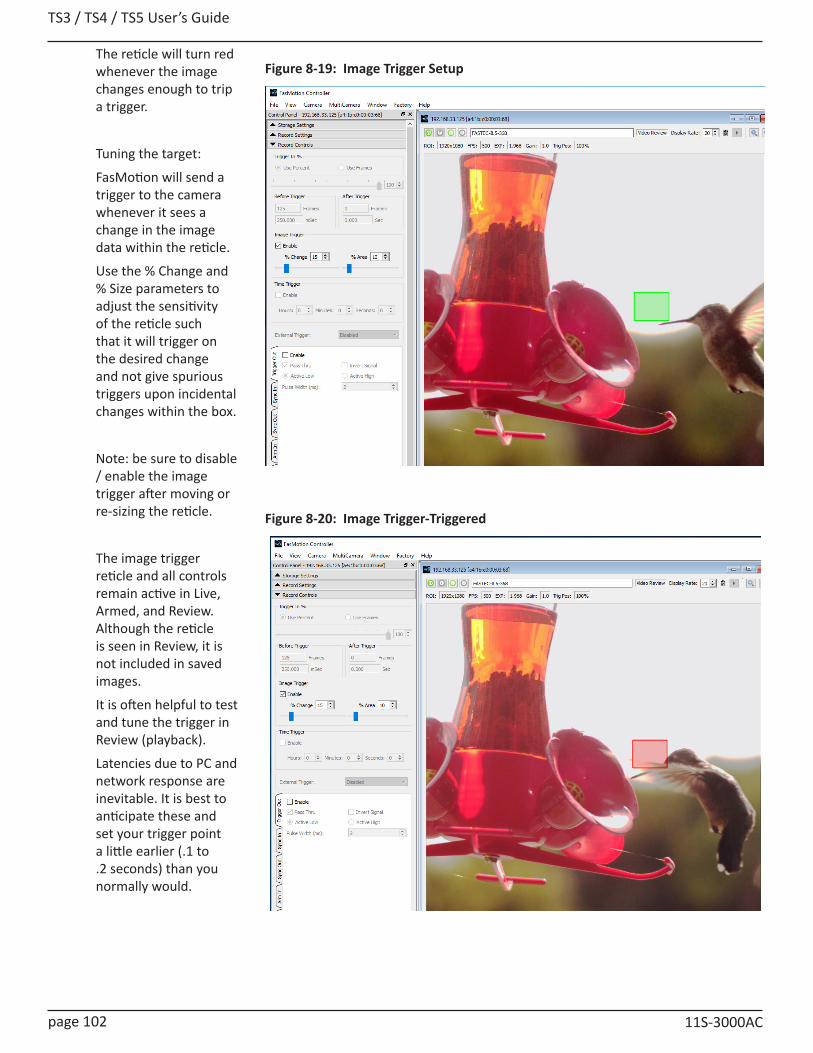
TS3 / TS4 / TS5 User’s Guide
page 102 11S-3000AC
Figure 8-19: Image Trigger Setup
Figure 8-20: Image Trigger-Triggered
The reticle will turn red whenever the image changes enough to trip a trigger.
Tuning the target:
FasMotion will send a trigger to the camera whenever it sees a change in the image data within the reticle.
Use the % Change and % Size parameters to adjust the sensitivity of the reticle such that it will trigger on the desired change and not give spurious triggers upon incidental changes within the box.
Note: be sure to disable / enable the image trigger after moving or re-sizing the reticle.
The image trigger reticle and all controls remain active in Live, Armed, and Review. Although the reticle is seen in Review, it is not included in saved images.
It is often helpful to test and tune the trigger in Review (playback).
Latencies due to PC and network response are inevitable. It is best to anticipate these and set your trigger point a little earlier (.1 to .2 seconds) than you normally would.
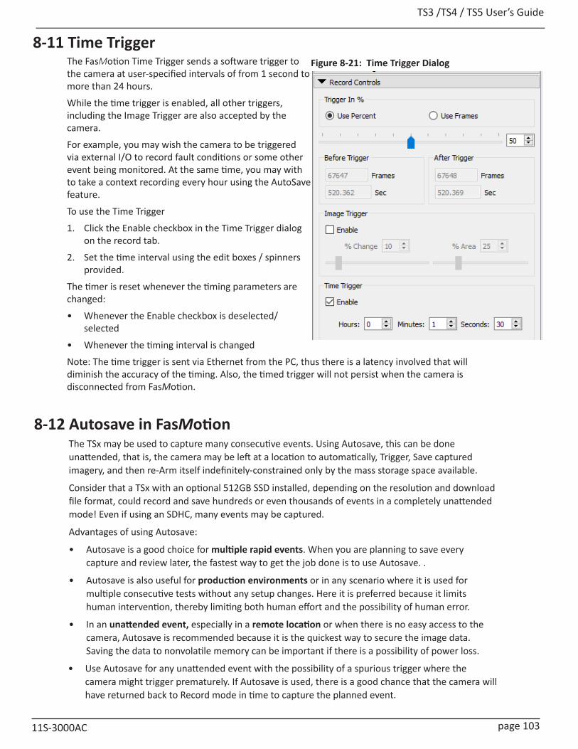
TS3 /TS4 / TS5 User’s Guide
11S-3000AC page 103
8-12 Autosave in FasMotionThe TSx may be used to capture many consecutive events. Using Autosave, this can be done unattended, that is, the camera may be left at a location to automatically, Trigger, Save captured imagery, and then re-Arm itself indefinitely-constrained only by the mass storage space available.
Consider that a TSx with an optional 512GB SSD installed, depending on the resolution and download file format, could record and save hundreds or even thousands of events in a completely unattended mode! Even if using an SDHC, many events may be captured.
Advantages of using Autosave:
• Autosave is a good choice for multiple rapid events. When you are planning to save every capture and review later, the fastest way to get the job done is to use Autosave. .
• Autosave is also useful for production environments or in any scenario where it is used for multiple consecutive tests without any setup changes. Here it is preferred because it limits human intervention, thereby limiting both human effort and the possibility of human error.
• In an unattended event, especially in a remote location or when there is no easy access to the camera, Autosave is recommended because it is the quickest way to secure the image data. Saving the data to nonvolatile memory can be important if there is a possibility of power loss.
• Use Autosave for any unattended event with the possibility of a spurious trigger where the camera might trigger prematurely. If Autosave is used, there is a good chance that the camera will have returned back to Record mode in time to capture the planned event.
8-11 Time TriggerThe FasMotion Time Trigger sends a software trigger to the camera at user-specified intervals of from 1 second to more than 24 hours.
While the time trigger is enabled, all other triggers, including the Image Trigger are also accepted by the camera.
For example, you may wish the camera to be triggered via external I/O to record fault conditions or some other event being monitored. At the same time, you may with to take a context recording every hour using the AutoSave feature.
To use the Time Trigger
1. Click the Enable checkbox in the Time Trigger dialog on the record tab.
2. Set the time interval using the edit boxes / spinners provided.
The timer is reset whenever the timing parameters are changed:
• Whenever the Enable checkbox is deselected/selected
• Whenever the timing interval is changed
Note: The time trigger is sent via Ethernet from the PC, thus there is a latency involved that will diminish the accuracy of the timing. Also, the timed trigger will not persist when the camera is disconnected from FasMotion.
Figure 8-21: Time Trigger Dialog
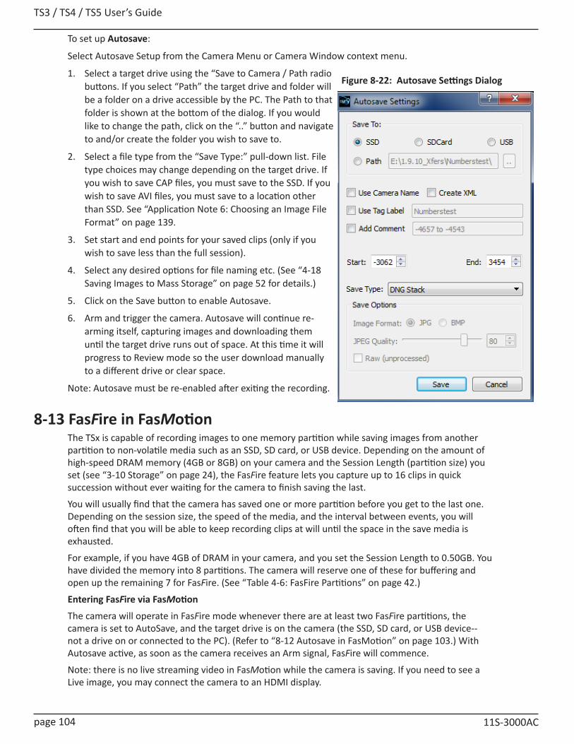
TS3 / TS4 / TS5 User’s Guide
page 104 11S-3000AC
To set up Autosave:
Select Autosave Setup from the Camera Menu or Camera Window context menu.
1. Select a target drive using the “Save to Camera / Path radio buttons. If you select “Path” the target drive and folder will be a folder on a drive accessible by the PC. The Path to that folder is shown at the bottom of the dialog. If you would like to change the path, click on the “..” button and navigate to and/or create the folder you wish to save to.
2. Select a file type from the “Save Type:” pull-down list. File type choices may change depending on the target drive. If you wish to save CAP files, you must save to the SSD. If you wish to save AVI files, you must save to a location other than SSD. See “Application Note 6: Choosing an Image File Format” on page 139.
3. Set start and end points for your saved clips (only if you wish to save less than the full session).
4. Select any desired options for file naming etc. (See “4-18 Saving Images to Mass Storage” on page 52 for details.)
5. Click on the Save button to enable Autosave.
6. Arm and trigger the camera. Autosave will continue re-arming itself, capturing images and downloading them until the target drive runs out of space. At this time it will progress to Review mode so the user download manually to a different drive or clear space.
Note: Autosave must be re-enabled after exiting the recording.
8-13 FasFire in FasMotionThe TSx is capable of recording images to one memory partition while saving images from another partition to non-volatile media such as an SSD, SD card, or USB device. Depending on the amount of high-speed DRAM memory (4GB or 8GB) on your camera and the Session Length (partition size) you set (see “3-10 Storage” on page 24), the FasFire feature lets you capture up to 16 clips in quick succession without ever waiting for the camera to finish saving the last.
You will usually find that the camera has saved one or more partition before you get to the last one. Depending on the session size, the speed of the media, and the interval between events, you will often find that you will be able to keep recording clips at will until the space in the save media is exhausted.
For example, if you have 4GB of DRAM in your camera, and you set the Session Length to 0.50GB. You have divided the memory into 8 partitions. The camera will reserve one of these for buffering and open up the remaining 7 for FasFire. (See “Table 4-6: FasFire Partitions” on page 42.)
Entering FasFire via FasMotion
The camera will operate in FasFire mode whenever there are at least two FasFire partitions, the camera is set to AutoSave, and the target drive is on the camera (the SSD, SD card, or USB device--not a drive on or connected to the PC). (Refer to “8-12 Autosave in FasMotion” on page 103.) With Autosave active, as soon as the camera receives an Arm signal, FasFire will commence.
Note: there is no live streaming video in FasMotion while the camera is saving. If you need to see a Live image, you may connect the camera to an HDMI display.
Figure 8-22: Autosave Settings Dialog

TS3 /TS4 / TS5 User’s Guide
11S-3000AC page 105
Using the Gas Gauges in FasMotion
Two gas gauges appear in the upper right corner of the image window during FasFire operation. The gas gauge on the left in Figure 8-23 indicates the number of available partitions for recording into. The gas gauge on the right shows the progress of the current save.
As DRAM memory is filled the gauge on the left decrements its counter, indicating the number of partitions available. As partitions become available again, after video clips are saved to the target drive, the number will increment and the green level will grow upwards. If all but one of the partitions become full, the last segment of the gas gauge will turn red. And when the very last segment is used, you will see the normal Autosave progress bar until one partition is saved and the gauge begins to be restored again.
Cancelling FasFire
If you press the Arm button while recording, you will get a warning message asking if you wish to cancel. If you click on “OK,” the camera will continue to save images.
If you click on Arm and Trigger, the camera will make one more capture and go into Review/Playback.
The last recording will be available for Review/Playback and Save, as will any other recordings still in DRAM.
Reminder: once the camera has exited the recording state, Autosave must be re-enabled if you wish to commence recording again in FasFire mode.
Video Review with Multiple Partitions
If AutoSave is canceled with multiple unsaved clips in DRAM, the FasMotion gas gauge will show the number of available clips. See Figure 8-23.
In this example there are 8 clips available for review. They are always presented with the newest first. You may review the present clip and save it, and then to see the next, you click on “Free,” which will delete the present partition allowing you to review and save the next.
Figure 8-23: FasFire Gas Gauges in FasMotion
Figure 8-24: FasFire in FasMotion, one Partition Left
Figure 8-25: Video Review, FasMotion with Multiple Partitions
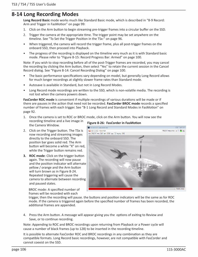
TS3 / TS4 / TS5 User’s Guide
page 106 11S-3000AC
8-14 Long Recording ModesLong Record Basic mode works much like Standard Basic mode, which is described in “8-9 Record: Arm and Trigger in FasMotion” on page 99:1. Click on the Arm button to begin streaming pre-trigger frames into a circular buffer on the SSD.2. Trigger the camera at the appropriate time. The trigger point may be set anywhere on the
timeline. See ”To Set the Trigger Position in the TSx:” on page 96.• When triggered, the camera will record the trigger frame, plus all post-trigger frames on the
onboard SSD, then proceed into Playback.• The progress of the recording is displayed on the timeline very much as it is with Standard basic
mode. Please refer to “Figure 8-15: Record Progress Bar: Armed” on page 100.Note: If you wish to stop recording before all of the post-Trigger frames are recorded, you may cancel the recording by clicking the Arm button, then select “Yes” to retain the current session in the Cancel Record dialog. See “Figure 8-14: Cancel Recording Dialog” on page 100.• The basic performance specifications vary depending on model, but generally Long Record allows
for much longer recordings at slightly slower frame rates than Standard mode. • Autosave is available in Standard, but not in Long Record Modes. • Long Record mode recordings are written to the SSD, which is non-volatile media. The recording is
not lost when the camera powers down.FasCorder ROC mode is convenient if multiple recordings of various durations will be made or if there are pauses in the action that need not be recorded. FasCorder BROC mode records a specified number of frames with each trigger. See “8-1 Long Record and Standard Modes in FasMotion” on page 92.1. Once the camera is set to ROC or BROC mode, click on the Arm button. You will now see the
recording timeline and a live image in the Camera Window.
2. Click on the Trigger button. The TSx is now recording and streaming images directly to the onboard SSD. The position bar goes solid red. The Arm button will become a white “X” on red, while the Trigger button remains red.
3. ROC mode: Click on the trigger button again. The recording will now pause and the position indicator will alternate yellow / orange and the Arm button will turn brown as in Figure 8-24. Repeated triggering will cause the camera to alternate between recording and paused states.
4. Press the Arm button. A message will appear giving you the options of exiting to Review and Save, or to continue recording.
Note: Appending to ROC and BROC recordings upon returning from Playback or a Power cycle will cause a number of black frames (up to 128) to be inserted in the recording timeline. It is possible to alternate FasCorder ROC and BROC recordings in any combination as they are compatible formats. Long Record basic recordings, however, are not compatible with FasCorder and cannot coexist on the SSD.
BROC mode: A specified number of frames will be recorded with each trigger, then the recording will pause. the buttons and position indicators will be the same as for ROC mode. If the camera is triggered again before the specified number of frames has been recorded, the additional frames are appended.
Figure 8-26: FasCorder in FasMotion
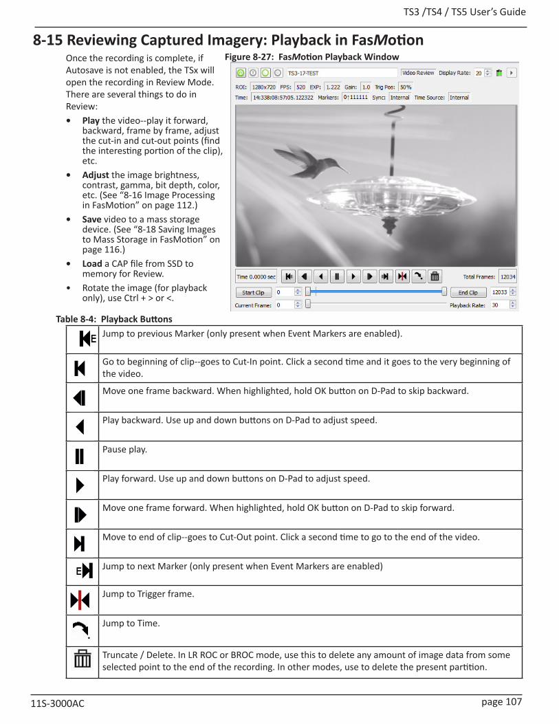
TS3 /TS4 / TS5 User’s Guide
11S-3000AC page 107
8-15 Reviewing Captured Imagery: Playback in FasMotionOnce the recording is complete, if Autosave is not enabled, the TSx will open the recording in Review Mode. There are several things to do in Review:• Play the video--play it forward,
backward, frame by frame, adjust the cut-in and cut-out points (find the interesting portion of the clip), etc.
• Adjust the image brightness, contrast, gamma, bit depth, color, etc. (See “8-16 Image Processing in FasMotion” on page 112.)
• Save video to a mass storage device. (See “8-18 Saving Images to Mass Storage in FasMotion” on page 116.)
• Load a CAP file from SSD to memory for Review.
• Rotate the image (for playback only), use Ctrl + > or <.
Jump to previous Marker (only present when Event Markers are enabled).
Go to beginning of clip--goes to Cut-In point. Click a second time and it goes to the very beginning of the video.
Move one frame backward. When highlighted, hold OK button on D-Pad to skip backward.
Play backward. Use up and down buttons on D-Pad to adjust speed.
Pause play.
Play forward. Use up and down buttons on D-Pad to adjust speed.
Move one frame forward. When highlighted, hold OK button on D-Pad to skip forward.
Move to end of clip--goes to Cut-Out point. Click a second time to go to the end of the video.
Jump to next Marker (only present when Event Markers are enabled)
Jump to Trigger frame.
Jump to Time.
Truncate / Delete. In LR ROC or BROC mode, use this to delete any amount of image data from some selected point to the end of the recording. In other modes, use to delete the present partition.
Figure 8-27: FasMotion Playback Window
Table 8-4: Playback Buttons
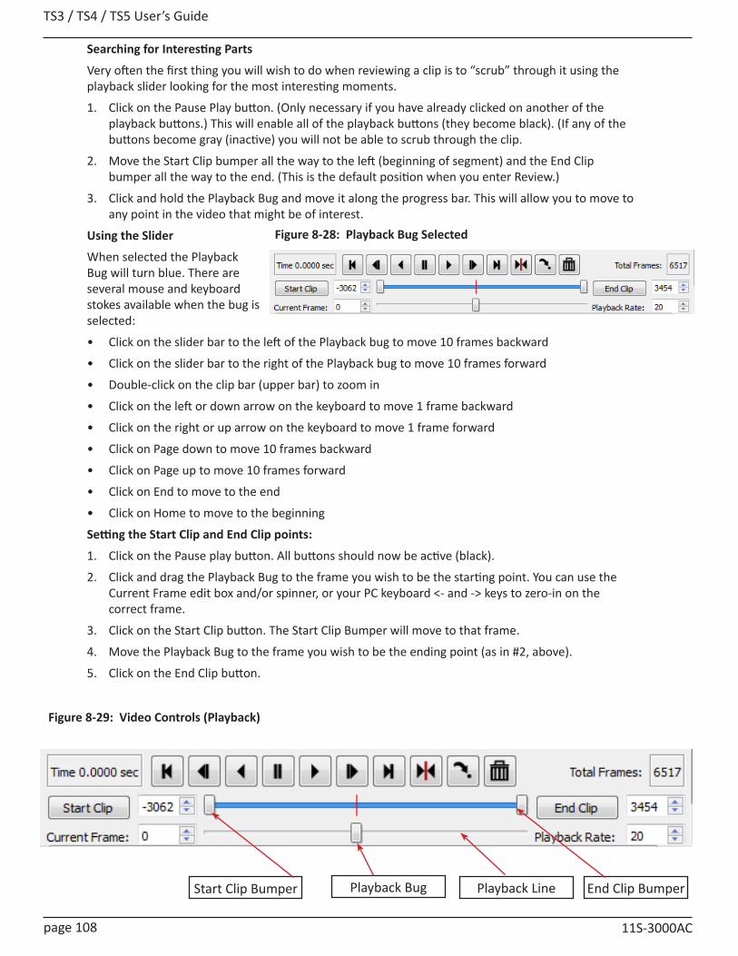
TS3 / TS4 / TS5 User’s Guide
page 108 11S-3000AC
Figure 8-28: Playback Bug Selected
Searching for Interesting Parts
Very often the first thing you will wish to do when reviewing a clip is to “scrub” through it using the playback slider looking for the most interesting moments.
1. Click on the Pause Play button. (Only necessary if you have already clicked on another of the playback buttons.) This will enable all of the playback buttons (they become black). (If any of the buttons become gray (inactive) you will not be able to scrub through the clip.
2. Move the Start Clip bumper all the way to the left (beginning of segment) and the End Clip bumper all the way to the end. (This is the default position when you enter Review.)
3. Click and hold the Playback Bug and move it along the progress bar. This will allow you to move to any point in the video that might be of interest.
Using the Slider
When selected the Playback Bug will turn blue. There are several mouse and keyboard stokes available when the bug is selected:
• Click on the slider bar to the left of the Playback bug to move 10 frames backward
• Click on the slider bar to the right of the Playback bug to move 10 frames forward
• Double-click on the clip bar (upper bar) to zoom in
• Click on the left or down arrow on the keyboard to move 1 frame backward
• Click on the right or up arrow on the keyboard to move 1 frame forward
• Click on Page down to move 10 frames backward
• Click on Page up to move 10 frames forward
• Click on End to move to the end
• Click on Home to move to the beginning
Setting the Start Clip and End Clip points:
1. Click on the Pause play button. All buttons should now be active (black).
2. Click and drag the Playback Bug to the frame you wish to be the starting point. You can use the Current Frame edit box and/or spinner, or your PC keyboard <- and -> keys to zero-in on the correct frame.
3. Click on the Start Clip button. The Start Clip Bumper will move to that frame.
4. Move the Playback Bug to the frame you wish to be the ending point (as in #2, above).
5. Click on the End Clip button.
Figure 8-29: Video Controls (Playback)
Start Clip Bumper Playback Bug End Clip BumperPlayback Line
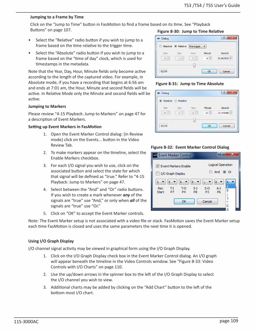
TS3 /TS4 / TS5 User’s Guide
11S-3000AC page 109
Jumping to a Frame by Time
Click on the “Jump to Time” button in FasMotion to find a frame based on its time. See “Playback Buttons” on page 107.
• Select the “Relative” radio button if you wish to jump to a frame based on the time relative to the trigger time.
• Select the “Absolute” radio button if you wish to jump to a frame based on the “time of day” clock, which is used for timestamps in the metadata.
Note that the Year, Day, Hour, Minute fields only become active according to the length of the captured video. For example, in Absolute mode, if you have a recording that begins at 6:56 am and ends at 7:01 am, the Hour, Minute and second fields will be active. In Relative Mode only the Minute and second fields will be active.
Jumping to Markers
Please review “4-15 Playback: Jump to Markers” on page 47 for a description of Event Markers.
Setting up Event Markers in FasMotion
1. Open the Event Marker Control dialog: (in Review mode) click on the Events... button in the Video Review Tab.
2. To make markers appear on the timeline, select the Enable Markers checkbox.
3. For each I/O signal you wish to use, click on the associated button and select the state for which that signal will be defined as “true.” Refer to “4-15 Playback: Jump to Markers” on page 47.
4. Select between the “And” and “Or” radio buttons. If you wish to create a mark whenever any of the signals are “true” use “And,” or only when all of the signals are “true” use “Or.”
5. Click on “OK” to accept the Event Marker controls.
Note: The Event Marker setup is not associated with a video file or stack. FasMotion saves the Event Marker setup each time FasMotion is closed and uses the same parameters the next time it is opened.
Using I/O Graph Display
I/O channel signal activity may be viewed in graphical form using the I/O Graph Display.
1. Click on the I/O Graph Display check box in the Event Marker Control dialog. An I/O graph will appear beneath the timeline in the Video Controls window. See “Figure 8-33: Video Controls with I/O Charts” on page 110.
2. Use the up/down arrows in the spinner box to the left of the I/O Graph Display to select the I/O channel you wish to view.
3. Additional charts may be added by clicking on the “Add Chart” button to the left of the bottom most I/O chart.
Figure 8-30: Jump to Time Relative
Figure 8-31: Jump to Time Absolute
Figure 8-32: Event Marker Control Dialog

TS3 / TS4 / TS5 User’s Guide
page 110 11S-3000AC
Zooming in on the Timeline
The timeline in the Video Controls window may span many thousands of images in a “Normal Mode” recording, and hundreds of thousands of images in “Long Recording Mode.” The timeline Zoom feature allows you to reduce the number of frames viewable across the timeline, making the task of finding specific events in the video much easier.
To Zoom In:
Double click on the timeline to zoom to 2x.
A highlight mark will appear over the zoomed area of the Timeline and a “Zoomed Playback Line” that spans the highlighted area will appear below the Playback Line.
The highlighted portion of the Timeline may be moved by clicking and dragging it, so that any portion of the captured video may be accessed.
Zoom In and Zoom Out buttons appear at either end of the Zoomed Playback Line. Clicking on the Zoom-In button increases the Zoom 2x: to 4x, 8x, 16x, etc. to the maximum zoom of 4 frames.
Note that the I/O signal charts also expand when zoomed in. If there is a lot of activity on these channels, as in the examples shown here, zooming in is advantageous for seeing the signals clearly.
Figure 8-33: Video Controls with I/O Charts
Figure 8-34: Video Controls with 2x Zoom
Figure 8-35: Video Controls with 4x Zoom

TS3 /TS4 / TS5 User’s Guide
11S-3000AC page 111
Viewing Per Frame Metadata in FasMotion
Whenever the TSx records imagery, it also records a timestamp for each frame. This timestamp may be displayed during playback and may also be saved to an XML file (see “Appendix K: Contents of <Capture>.xml file” on page 171 and “4-18 Saving Images to Mass Storage” on page 52).
Per Frame Metadata may always be viewed while playing unsaved images in camera memory and also may be viewed when playing back saved image files if they were saved with the XML file. (See “Figure 8-42: FasMotion Save Dialog” on page 117.)
To View Per Frame Metadata:
Right-click on the Camera window when in Playback and click on Per Frame Metadata.
The Per Frame Metadata includes a Timestamp, Marker information, IRIG status, Sync status, and Time source.
Timestamp Format
Time: YY:DDD:HH:MM:SS.xxxxxx
For the example shown in Figure 8-37 this is:
YY = Year: 14 = 2014
DDD = Day: 338 = Dec 3 (See “Appendix P: Day Number Calendar Conversion” on page 180.)
HH:MM= Hour: Minute: 08:57 = 8:57 am
SS.xxxxxx = Seconds: = 31.281870 (granularity to msec)
Note: the Timestamp line is always available during playback from camera memory or from CAP files loaded into camera memory from an SSD. It is also seen in saved files played back via FasMotion, but only if they are accompanied by an XML file.
Markers: 00111111
The Timestamp line includes event markers. In the example shown in Figure 8-37, all of the I/O pins were “high” for the duration of the displayed image frame. (See “5-5 TSx Timestamps and Markers” on page 62 for more information.)
Sync: Internal
The Sync term can be Internal (internal camera clock used for frame timing), PPF (Sync-In pulse used for per-frame timing), or PPS (1Hz clock input at Sync in or IRIG used to derive the camera frame timing). See “5-1 Sync In”.
Time: Internal
The Time is either Internal (using the cameras internal clock), or IRIG (using an IRIG time source.) See”5-6 IRIG Timestamps and Sync” on page 64.
Figure 8-36: Select Per Frame Metadata in View Menu
Figure 8-37: Per Frame Metadata in FasMotion

TS3 / TS4 / TS5 User’s Guide
page 112 11S-3000AC
8-16 Image Processing in FasMotionTS3 / TS4 Image Processing PipelineThe TS3 / TS4 image processing begins in the LUPA1300-2 sensor, where on-chip FPN corrections occur (if enabled) and the Black and Analog Gain level is set during calibration. Pixel data, also collected during calibration is used for Pixel FPN correction (if enabled). (See “8-8 Black Level Calibration in FasMotion” on page 99.) The TSx does more image processing, some of which can be controlled by the operator. To better understand how this works, please refer to “Figure 8-38: TS3 / TS4 Image Pipeline”.
TS5 Image Processing Pipeline:
The TS5 image processing begins in the Lince5M sensor, where on-chip Column and Row FPN corrections occur and black level is tracked using masked pixels. (Refer to “Figure 8-39: TS5 Image Pipeline” on page 113.) These features are always enabled unless the user specifically selects FPN Off. Analog Gain is set and Pixel data is collected during calibration for use when Pixel FPN correction is enabled.
Figure 8-38: TS3 / TS4 Image Pipeline

TS3 /TS4 / TS5 User’s Guide
11S-3000AC page 113
Bit Selection
The 10-bit or 12-bit sensor output goes to the Bit Selector, then to internal high-speed memory. This selection is made by the user when bit depth is selected. (See”8-5 Setting Bit Depth in FasMotion” on page 96.)
The path for all images and the input to the histogram is: Sensor, to Bit Selector, to Image Processor, to Display / Histogram. It is always 8-bit Mono or 24-bit Color. Live images pass through from high-speed memory to the image processor immediately. Captured images are saved in high-speed memory until the camera powers down or the images are written over.
• Images in the internal high-speed memory have not yet gone through the image processor. This means that the image processing settings have NO effect on the images in high-speed memory--they only affect the images as they are saved or displayed.
• Images in high-speed memory may be viewed or saved multiple times with different settings.
• Live images seen on the display ALWAYS go through the image processor.
Figure 8-39: TS5 Image Pipeline
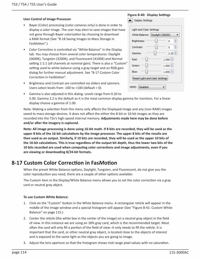
TS3 / TS4 / TS5 User’s Guide
page 114 11S-3000AC
User Control of Image Processor
• Bayer (Color) processing (color cameras only) is done in order to display a color image. The user may elect to save images that have not gone through Bayer colorization by choosing to download a RAW format (See “8-18 Saving Images to Mass Storage in FasMotion”.)
• Color Correction is controlled via “White Balance” in the Display tab. You may choose from several color temperatures: Daylight (5600K), Tungsten (3200K), and Fluorescent (4100K) and Normal setting 1:1:1 (all channels at nominal gain). There is also a “Custom” setting used to white balance using a gray target and an RGB gain dialog for further manual adjustment. See “8-17 Custom Color Correction in FasMotion”.
• Brightness and Contrast are controlled via sliders and spinners. Users select levels from -100 to +100 (default = 0).
• Gamma is also adjusted in this dialog. Levels range from 0.20 to 5.00. Gamma 2.2 is the default as it is the most common display gamma for monitors. For a linear display choose a gamma of 1.00.
Note: Making a selection from this menu only affects the Displayed image and any (non-RAW) images saved to mass storage devices. It does not affect the either the 8-bit or 10-bit images as they are recorded into the TSx’s high-speed internal memory. Adjustments made here may be done before and/or after the imagery is captured.
Note: All image processing is done using 16-bit math. If 8 bits are recorded, they will be used as the upper 8 bits of the 16-bit calculations by the image processor. The upper 8 bits of the results are then used as an output. Similarly, if 10 bits are recorded, they will be used as the upper 10 bits of the 16-bit calculations. This is true regardless of the output bit depth, thus the lower two bits of the 10 bits recorded are used when computing color corrections and image adjustments, even if you are viewing or downloading 8/24-bit formats.
8-17 Custom Color Correction in FasMotionWhen the preset White Balance options, Daylight, Tungsten, and Fluorescent, do not give you the color reproduction you need, there are a couple of other options available:
The Custom item in the Display/White Balance menu allows you to set the color correction via a gray card or neutral gray object.
To use Custom White Balance:
1. Click on the “Custom” button in the White Balance menu. A rectangular reticle will appear in the middle of the image window and a special histogram will appear (See “Figure 8-41: Custom White Balance” on page 115.)
2. Center the reticle (the white box in the center of the image) on a neutral gray object in the field of view. In this instance we are using an 18% gray card, which is the recommended target. Most often the card will only fill a portion of the field of view--it only needs to fill the reticle. It is important that the card, or other neutral gray object, is located close to the objects of interest and is exposed to the same light as the objects you are going to image.
3. Adjust the lens aperture so that the histogram shows mid-range pixel values with no saturation.
Figure 8-40: Display Settings
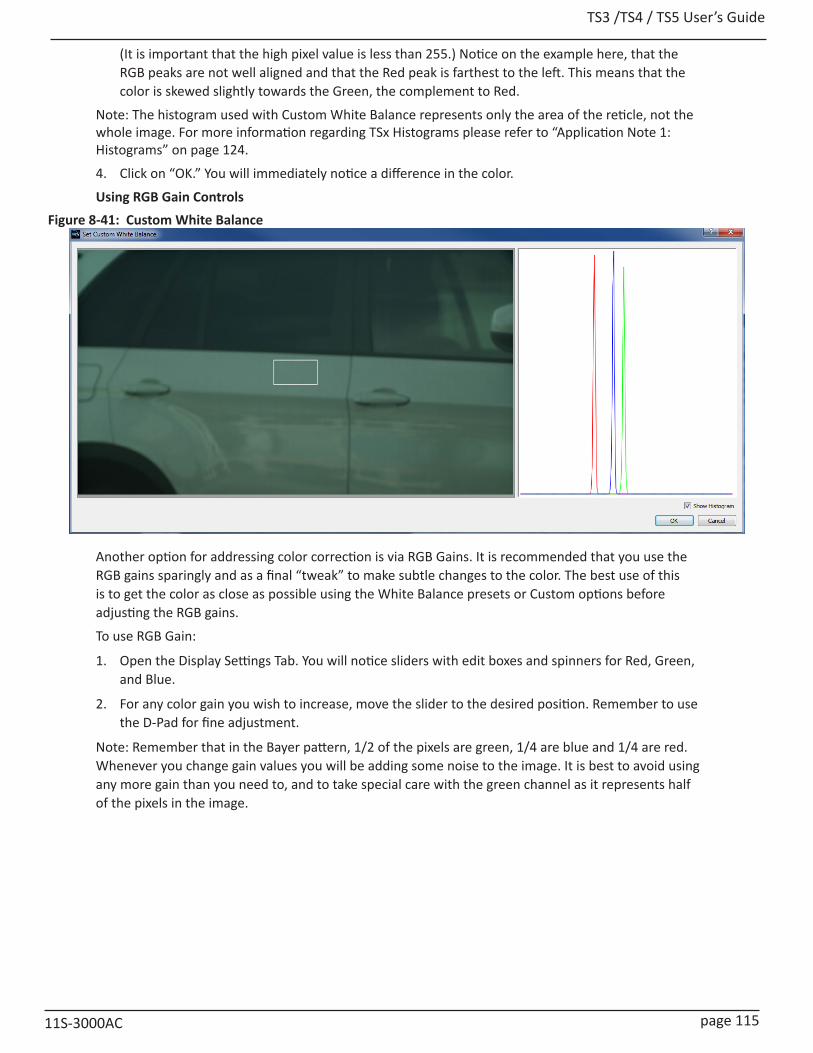
TS3 /TS4 / TS5 User’s Guide
11S-3000AC page 115
(It is important that the high pixel value is less than 255.) Notice on the example here, that the RGB peaks are not well aligned and that the Red peak is farthest to the left. This means that the color is skewed slightly towards the Green, the complement to Red.
Note: The histogram used with Custom White Balance represents only the area of the reticle, not the whole image. For more information regarding TSx Histograms please refer to “Application Note 1: Histograms” on page 124.
4. Click on “OK.” You will immediately notice a difference in the color.
Using RGB Gain Controls
Another option for addressing color correction is via RGB Gains. It is recommended that you use the RGB gains sparingly and as a final “tweak” to make subtle changes to the color. The best use of this is to get the color as close as possible using the White Balance presets or Custom options before adjusting the RGB gains.
To use RGB Gain:
1. Open the Display Settings Tab. You will notice sliders with edit boxes and spinners for Red, Green, and Blue.
2. For any color gain you wish to increase, move the slider to the desired position. Remember to use the D-Pad for fine adjustment.
Note: Remember that in the Bayer pattern, 1/2 of the pixels are green, 1/4 are blue and 1/4 are red. Whenever you change gain values you will be adding some noise to the image. It is best to avoid using any more gain than you need to, and to take special care with the green channel as it represents half of the pixels in the image.
Figure 8-41: Custom White Balance

TS3 / TS4 / TS5 User’s Guide
page 116 11S-3000AC
8-18 Saving Images to Mass Storage in FasMotionImage sequences may be saved as CAP files (proprietary raw format, see “Appendix O: Partition Capture (CAP) File Format” on page 178), as AVI videos, in which one file contains all the frames of the sequence, or TIFF, JPEG, or BMP stacks, which are collections of files, one file per frame of imagery. The file save options change depending on whether or 8-bit or 10- or 12-bit image data has been written to internal high-speed memory:
10- or 12-bits recorded 8-bits recordedTIFF (8-bit M /24-bit C) or RAW TIFF (16-bit) TIFF (8-bit M / 24-bit C) or RAW TIFF (8-bit)DNG (16-bit raw format) DNG (8-bit Raw format)BMP (8-bit M /24-bit C) BMP (8-bit M/ 24-bit C)
AVI (8-bit M /24-bit C) AVI (8-bit M / 24-bit C) JPEG (8-bit M /24-bit C) JPEG (8-bit M / 24-bit C)
CAP (10- or 12-bit raw format) CAP (8-bit Raw format)
Calculating file sizes for TIFF and BMP images is very simple:
Resolution x Bit depth/8 = approximate BMP or TIFF file size in Bytes (to convert Bytes to KB divide by 1024)For example a 1280 x 1024 Mono BMP or TIFF is:
1280 x 1024 x 8 / 8 = 1,310,720 bytes = 1,280K
A 1280 x 1024 16-bit RAW TIFF/DNG is:
1280 x 1024 x 16 / 8 = 2,621,440 bytes = 2,560K
CAP files are always the size of the current buffer (session size).
The actual file size of a 1280 x 1024 mono BMP or TIFF is about 1281K (the additional 1K for the file header). The actual size of 16-bit RAW TIFF is 2561K (again add an additional 1K for the header).
Note: The RAW 16-bit TIFF saved from the camera actually has 10 bits of image data. The 16-bit format is used for compatibility reasons.
Calculating file sizes for AVI and JPEG images is much more difficult. The compression is often approximately 10x to 20x, but it can be much greater for images with little content, and it can be much less for very complex images.
RAW images are not colorized, so Mono and Color images are the same size. Colorization increases file size 3x because 8 bits are saved for each of red, green, and blue channels.
To Save a recording to a connected mass storage device on the TSx or to a drive Path on a computer:
1. Make a recording and establish the Start Clip and End Clip points you wish to use (see “8-15 Reviewing Captured Imagery: Playback in FasMotion” on page 107).
Note that the frame numbers initially shown in the dialog box will be the actual start and stop frames for the entire capture unless the Start Clip and End Clip bumpers have been moved. If you are not sure what the actual beginning and end frame numbers for the clip are, you can find them on the far left / far right sides of the Clip bar.
Table 8-5: File Save Options
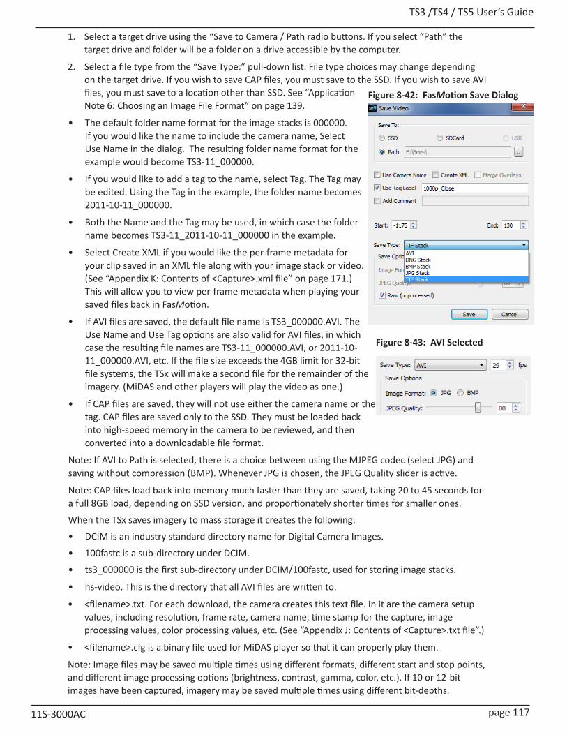
TS3 /TS4 / TS5 User’s Guide
11S-3000AC page 117
1. Select a target drive using the “Save to Camera / Path radio buttons. If you select “Path” the target drive and folder will be a folder on a drive accessible by the computer.
2. Select a file type from the “Save Type:” pull-down list. File type choices may change depending on the target drive. If you wish to save CAP files, you must save to the SSD. If you wish to save AVI files, you must save to a location other than SSD. See “Application Note 6: Choosing an Image File Format” on page 139.
• The default folder name format for the image stacks is 000000. If you would like the name to include the camera name, Select Use Name in the dialog. The resulting folder name format for the example would become TS3-11_000000.
• If you would like to add a tag to the name, select Tag. The Tag may be edited. Using the Tag in the example, the folder name becomes 2011-10-11_000000.
• Both the Name and the Tag may be used, in which case the folder name becomes TS3-11_2011-10-11_000000 in the example.
• Select Create XML if you would like the per-frame metadata for your clip saved in an XML file along with your image stack or video. (See “Appendix K: Contents of <Capture>.xml file” on page 171.) This will allow you to view per-frame metadata when playing your saved files back in FasMotion.
• If AVI files are saved, the default file name is TS3_000000.AVI. The Use Name and Use Tag options are also valid for AVI files, in which case the resulting file names are TS3-11_000000.AVI, or 2011-10-11_000000.AVI, etc. If the file size exceeds the 4GB limit for 32-bit file systems, the TSx will make a second file for the remainder of the imagery. (MiDAS and other players will play the video as one.)
• If CAP files are saved, they will not use either the camera name or the tag. CAP files are saved only to the SSD. They must be loaded back into high-speed memory in the camera to be reviewed, and then converted into a downloadable file format.
Note: If AVI to Path is selected, there is a choice between using the MJPEG codec (select JPG) and saving without compression (BMP). Whenever JPG is chosen, the JPEG Quality slider is active.
Note: CAP files load back into memory much faster than they are saved, taking 20 to 45 seconds for a full 8GB load, depending on SSD version, and proportionately shorter times for smaller ones.
When the TSx saves imagery to mass storage it creates the following:
• DCIM is an industry standard directory name for Digital Camera Images.
• 100fastc is a sub-directory under DCIM.
• ts3_000000 is the first sub-directory under DCIM/100fastc, used for storing image stacks.
• hs-video. This is the directory that all AVI files are written to.
• <filename>.txt. For each download, the camera creates this text file. In it are the camera setup values, including resolution, frame rate, camera name, time stamp for the capture, image processing values, color processing values, etc. (See “Appendix J: Contents of <Capture>.txt file”.)
• <filename>.cfg is a binary file used for MiDAS player so that it can properly play them.
Note: Image files may be saved multiple times using different formats, different start and stop points, and different image processing options (brightness, contrast, gamma, color, etc.). If 10 or 12-bit images have been captured, imagery may be saved multiple times using different bit-depths.
Figure 8-42: FasMotion Save Dialog
Figure 8-43: AVI Selected
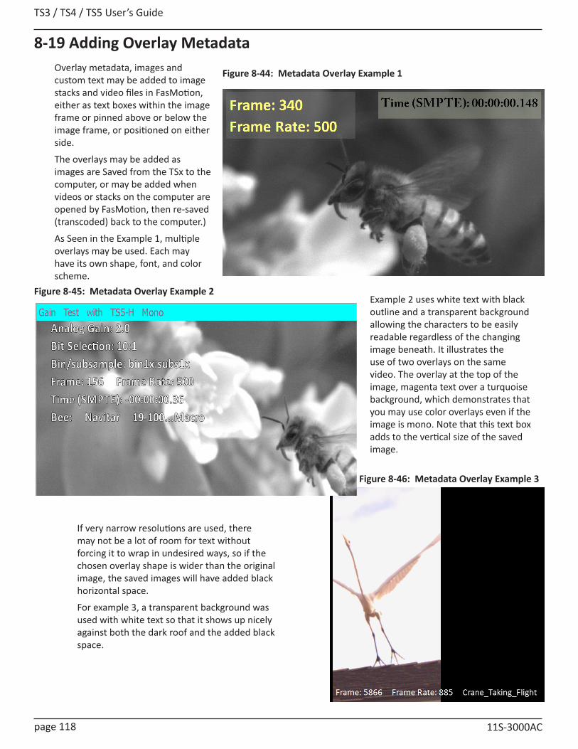
TS3 / TS4 / TS5 User’s Guide
page 118 11S-3000AC
8-19 Adding Overlay Metadata
Figure 8-44: Metadata Overlay Example 1
Example 2 uses white text with black outline and a transparent background allowing the characters to be easily readable regardless of the changing image beneath. It illustrates the use of two overlays on the same video. The overlay at the top of the image, magenta text over a turquoise background, which demonstrates that you may use color overlays even if the image is mono. Note that this text box adds to the vertical size of the saved image.
Overlay metadata, images and custom text may be added to image stacks and video files in FasMotion, either as text boxes within the image frame or pinned above or below the image frame, or positioned on either side.
The overlays may be added as images are Saved from the TSx to the computer, or may be added when videos or stacks on the computer are opened by FasMotion, then re-saved (transcoded) back to the computer.)
As Seen in the Example 1, multiple overlays may be used. Each may have its own shape, font, and color scheme.
If very narrow resolutions are used, there may not be a lot of room for text without forcing it to wrap in undesired ways, so if the chosen overlay shape is wider than the original image, the saved images will have added black horizontal space.
For example 3, a transparent background was used with white text so that it shows up nicely against both the dark roof and the added black space.
Figure 8-45: Metadata Overlay Example 2
Figure 8-46: Metadata Overlay Example 3
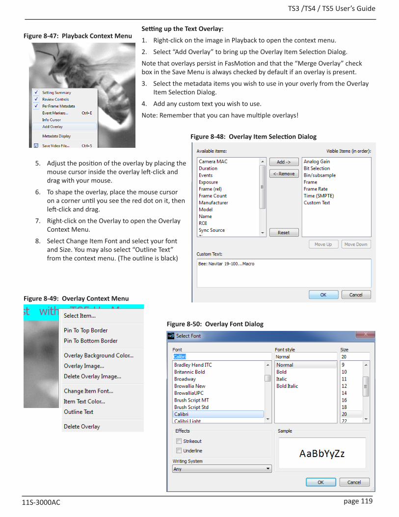
TS3 /TS4 / TS5 User’s Guide
11S-3000AC page 119
Figure 8-47: Playback Context Menu
Figure 8-48: Overlay Item Selection Dialog
Setting up the Text Overlay:
1. Right-click on the image in Playback to open the context menu.
2. Select “Add Overlay” to bring up the Overlay Item Selection Dialog.
Note that overlays persist in FasMotion and that the “Merge Overlay” check box in the Save Menu is always checked by default if an overlay is present.
3. Select the metadata items you wish to use in your overly from the Overlay Item Selection Dialog.
4. Add any custom text you wish to use.
Note: Remember that you can have multiple overlays!
5. Adjust the position of the overlay by placing the mouse cursor inside the overlay left-click and drag with your mouse.
6. To shape the overlay, place the mouse cursor on a corner until you see the red dot on it, then left-click and drag.
7. Right-click on the Overlay to open the Overlay Context Menu.
8. Select Change Item Font and select your font and Size. You may also select “Outline Text” from the context menu. (The outline is black)
Figure 8-50: Overlay Font Dialog
Figure 8-49: Overlay Context Menu

TS3 / TS4 / TS5 User’s Guide
page 120 11S-3000AC
9. Select “Item Text Color...” from the context menu to select the color for the text. (This dialog is iden-tical to the Background Color Dialog.)
10. Select “Overlay Background Color...” to change the color of the overlay background. The Alpha chan-nel is used for transparency: 0 = totally transpar-ent, 255=totally opaque.
11. Save the image data with the overlay as an AVI or Stack (any type except DNG) to a Path. Remember that the Merge Overlay check box must be checked.
Figure 8-51: Overlay Background Color
Setting up an Image Overlay:
Image overlays may be added to any recording in much the same way as text overlays:
1. Right-click on the image window in Playback to bring up the context menu (see Figure 8-47).
2. Select “Add Overlay.”
3. The Overlay Item Selection Dialog will open. Click on “Cancel.”
4. You will now have an overlay at the top of the image with the text “<add items>”
5. Right-click on the overlay box to bring up the Overlay Context Menu and select “Overlay Image...”
6. A browser will open which will allow you to select a .jpg, .png, .bmp, or .tif image.
7. Size the overlay by grabbing it by a corner and stretching or shrinking it to fit.
Note: If you wish to use an image with a transparency (alpha) channel, use a png image.
Figure 8-52: Image Overlay Example

TS3 /TS4 / TS5 User’s Guide
11S-3000AC page 121
8-20: Playback from File and TranscodingFasMotion is capable of playing back and transcoding AVI videos and image stacks recorded by TSx cameras and stored on a computer drive.
To open a video or stack, select “Open Video File...” from the File Menu in FasMotion.
This will open a Windows Explore window that will allow you to browse the media connected to your computer. In the lower right corner of the window you will see the list of Image file types FasMotion can open: jpg, jpeg, bmp, tif, tiff, dng and avi.
You may also click on the down arrow to select cap files.
You may open multiple files for playback, although only one file may be either played or saved at a time.
To Transcode a video, that is, to re-save it, right-click on the image window (or Ctrl+S) and select “Save Video File...”
This will open the familiar Save Video dialog box. This is a slightly different version of the dialog than you would see if saving video from the camera. It allows only saves to a Path (not to any camera media).
This dialog supports:
• Transcoding from any saved stack or CAP file (not AVI).
• Adjusting Start and End points.
• Adjust JPEG Quality. (When transcoding from JPEG to JPEG or JPEG to AVI, there will always some loss of fidelity even if JPEG Quality is set to 100. If the original JPEG was saved with JPEG Quality set to 80, setting it to 100 for the second generation will not make the second generation better than the first. )
• Adding overlays (cannot remove original overlays).
• Save to AVI, BMP, JPG, or TIF. Save to DNG only from CAP file.
Figure 8-53: Open Video File

TS3 / TS4 / TS5 User’s Guide
page 122 11S-3000AC
Figure 8-54: FasMotion Explore Menu
Stills, stacks, videos, and capture files (CAP), saved on camera media may be managed via Explore on the FasMotion Storage Settings tab.
Copy / Batch Copy
Stills, videos, and stacks may be copied from any camera media (SD card, SSD, or USB device) to any other camera media or to a Path accessible via your computer (any media attached to your computer or networked drive, etc.).
1. Select the camera media you wish to copy from using the radio buttons in External Storage box on the Storage Settings tab.
2. Click on the Explore button. The media on the camera will be accessed and read at this point, which may take a minute or two, depending on the number of files and folders present.
3. Select the type of image data you wish to copy, (Stills, Stacks, Video or Capture).
4. You will be presented with a list of avail-able files or folders to pick from. Pick one or more from this list. You may click on one, or Ctrl/click on multiple files, or Shift/click on the first and last of a sequence for a Batch Copy.
5. Once you have made your selection, click on Copy. A little dialog box will open that allows you to choose a destination.
6. Select from the list of available camera media to copy to another drive on the camera, or Path to copy to media attached to your computer.
Move
Move works exactly like Copy, except that the source files are deleted after they are copied.
Note: Move is not enabled for the SSD on most TSx cameras.
Figure 8-55: Copy: Choose Destination
Figure 8-56: Batch Copy Convert: JPEG or BMP to AVI
8-21: Transfers, Batch Transfers and Conversions
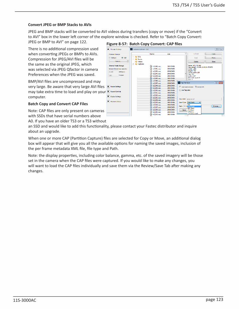
TS3 /TS4 / TS5 User’s Guide
11S-3000AC page 123
Convert JPEG or BMP Stacks to AVIs
JPEG and BMP stacks will be converted to AVI videos during transfers (copy or move) if the “Convert to AVI” box in the lower left corner of the explore window is checked. Refer to “Batch Copy Convert: JPEG or BMP to AVI” on page 122.
There is no additional compression used when converting JPEGs or BMPs to AVIs. Compression for JPEG/AVI files will be the same as the original JPEG, which was selected via JPEG Qfactor in camera Preferences when the JPEG was saved.
BMP/AVI files are uncompressed and may very large. Be aware that very large AVI files may take extra time to load and play on your computer.
Batch Copy and Convert CAP Files
Note: CAP files are only present on cameras with SSDs that have serial numbers above A0. If you have an older TS3 or a TS3 without an SSD and would like to add this functionality, please contact your Fastec distributor and inquire about an upgrade.
When one or more CAP (Partition Capture) files are selected for Copy or Move, an additional dialog box will appear that will give you all the available options for naming the saved images, inclusion of the per frame metadata XML file, file type and Path.
Note: the display properties, including color balance, gamma, etc. of the saved imagery will be those set in the camera when the CAP files were captured. If you would like to make any changes, you will want to load the CAP files individually and save them via the Review/Save Tab after making any changes.
Figure 8-57: Batch Copy Convert: CAP files
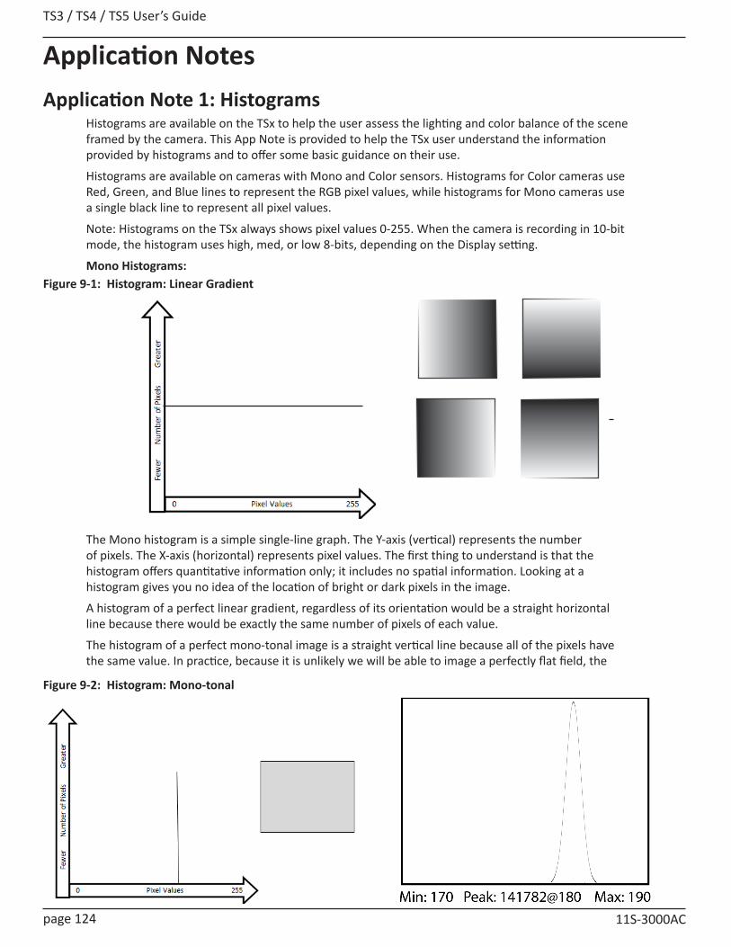
TS3 / TS4 / TS5 User’s Guide
page 124 11S-3000AC
Application NotesApplication Note 1: Histograms
Histograms are available on the TSx to help the user assess the lighting and color balance of the scene framed by the camera. This App Note is provided to help the TSx user understand the information provided by histograms and to offer some basic guidance on their use.
Histograms are available on cameras with Mono and Color sensors. Histograms for Color cameras use Red, Green, and Blue lines to represent the RGB pixel values, while histograms for Mono cameras use a single black line to represent all pixel values.
Note: Histograms on the TSx always shows pixel values 0-255. When the camera is recording in 10-bit mode, the histogram uses high, med, or low 8-bits, depending on the Display setting.
Mono Histograms:
The Mono histogram is a simple single-line graph. The Y-axis (vertical) represents the number of pixels. The X-axis (horizontal) represents pixel values. The first thing to understand is that the histogram offers quantitative information only; it includes no spatial information. Looking at a histogram gives you no idea of the location of bright or dark pixels in the image.
A histogram of a perfect linear gradient, regardless of its orientation would be a straight horizontal line because there would be exactly the same number of pixels of each value.
The histogram of a perfect mono-tonal image is a straight vertical line because all of the pixels have the same value. In practice, because it is unlikely we will be able to image a perfectly flat field, the
Figure 9-1: Histogram: Linear Gradient
Figure 9-2: Histogram: Mono-tonal

TS3 /TS4 / TS5 User’s Guide
11S-3000AC page 125
Figure 9-3: Histogram: Monotonal Color Image
If we view the same mono-tonal content used in Figure 9-2 on a color camera, we get the more complex histograms seen in Figure 9-3.
Assuming that the mono-tonal image is a neutral gray target, the histogram on the left shows what you would expect if the camera’s color balance is shifted a bit toward the red, as it might be under tungsten illumination. In this case the color channels are easily visible as they are separated. The histogram on the right shows what you would expect if the camera’s color balance is a good match.
Histograms and Exposure Settings
Professional Digital photographers are very sophisticated in their use of histograms. While the use of histograms as a tool for fine-tuning light and color content for artistic purposes is beyond the scope of this App Note, there are a couple of simple rules to follow that will be helpful.
1. The best images contain a balance of highlights and lowlights. To this end it is good to strive for a distributed grouping of peaks across the histogram.
2. Try to identify the peaks for any objects of interest in the scene. Make sure that those objects are not in danger of exceeding the camera’s dynamic range--that they are not close in value to either 0 or 255.
3. Avoid Min: 0. If the minimum pixel level is 0, you know that some pixels are registering no light at all. If there are some very dark areas in the scene, you might expect this and accept it. But if the scene is more uniform and you need to be able to bring out details in the dark areas, avoid Min: 0, as no amount of gamma or brightness adjustment will help. If you are recording in 10-bit mode and viewing the upper 8-bits, you may wish to view mid- and low-8 bit settings just to see if you are truly at Min: 0
4. Avoid Max: 255. Once an area reaches saturation (255), it is game-over in terms of image processing. In color images this may even result in some color shifting as one color may easily saturate before the others.
histogram of a mono-tonal image will be a bell curve. The histogram shown to the right in Figure 9-2 is in the format used on the TSx. It shows minimum, maximum and peak values for the image. The peak value also includes the number of pixels exactly at the peak value: Peak: <# of pixels>@<pixel value>.

TS3 / TS4 / TS5 User’s Guide
page 126 11S-3000AC
Application Note 2: Understanding Bit DepthEach pixel in a digital image has a numeric value. Low numbers represent dark pixels; higher numbers represent brighter ones.
Mono images that we see displayed on computer screens use 256 shades of gray. The pixel values range from 0 to 255. Color images use 256 shades each of red green and blue. With 256 (red) x 256 (green) x 256 (blue), color images may use more than 16 million colors!
TS3 and TS4 sensors output 10-bit image data. This represents 1024 shades of gray for mono and 1024 shades each for Red, Green, and Blue for color-- that would be 10243... more than a billion colors! TS5 sensors output 12-bit image data, which represents 4096 shades of gray for mono and 40963 colors.
Consider 10-bit images:
Decimal numbers 0 to 1023 are expressed 0000000000 to 1111111111 in binary. Each binary digit is a “bit.” So a 3 bit number, 000 to 111, is the equivalent to decimal 0 to 7. An 8-bit number, 00000000 to 11111111, is the equivalent to decimal 0 to 255. A 10-bit number is equivalent to decimal 0 to 1023.
Because we will be accessing the imagery on devices such as computers and LCD screens like the one on the TSx, that can only display 256 shades of gray (or 2563 colors) one valid option is to save only 8 of the 10 bits produced for each pixel of the sensor. If we choose this option, we will need to decide which 8 of the 10 bits to save. There are three choices:
1. High 8-bit (dropping the two least significant bits and saving the high-order bits): 1111111111
In this case we have a mapping that looks like this:
10-bit (1024) values (in decimal): 0 1 2 3 4 5 6 7 8 9 10 11 .................511.............................1023
8-bit (256) values (in decimal): 0 0 0 0 1 1 1 1 2 2 2 2 ...................127...............................255
Note that for the 10-bit image 0 is black 511 is midway to saturation (white) and 1023 is at saturation. For the 8-bit image 0 is black, 127 is midrange and 255 is white--the two images would appear the same to us.
2. Bit Shifting for Mid 8-bit images (dropping the least significant bit and the most significant bit): 1111111111
In this case the mapping looks like this:
10-bit (1024) values: 0 1 2 3 4 5 6 7 8 9 10 11.........255..................511...........................................1023
8-bit (255) values: 0 0 1 1 2 2 3 3 4 4 5 5...........127..................255
Note that while we have the same starting point (black = 0), saturation now comes at the midrange of the original 10-bit data. Compared with the High 8-bit mapping, this image has twice as steep a response slope--it is much brighter. This brightness will come at the cost of seeing more noise, however.
3. Bit Shifting for Low 8-bit order bits (dropping the two most significant bits):
4. 111111111110-bit (1024) values: 0 1 2 3 4 5 6 7 8 9 10 11...........255............512................................................1023
8-bit (255) values: 0 1 2 3 4 5 6 7 8 9 10 11...... ....255
As with the other mappings, black is black = 0, but with the Low 8-bit mapping, saturation comes twice as fast as with the Mid 8-bit and 4x as fast as with the High 8-bit.
Note: On the TS5, 8-bit images may be bit shifted to any of five positions so instead of having just high-8, mid-8, and low-8, there are two more intermediate choices, each shift changing the slope by a factor of two.
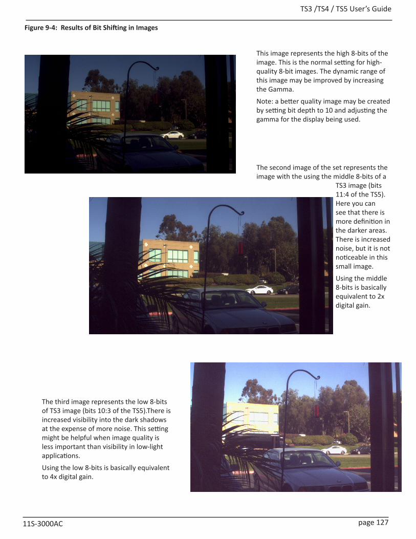
TS3 /TS4 / TS5 User’s Guide
11S-3000AC page 127
This image represents the high 8-bits of the image. This is the normal setting for high-quality 8-bit images. The dynamic range of this image may be improved by increasing the Gamma.
Note: a better quality image may be created by setting bit depth to 10 and adjusting the gamma for the display being used.
The second image of the set represents the image with the using the middle 8-bits of a
TS3 image (bits 11:4 of the TS5). Here you can see that there is more definition in the darker areas. There is increased noise, but it is not noticeable in this small image.
Using the middle 8-bits is basically equivalent to 2x digital gain.
The third image represents the low 8-bits of TS3 image (bits 10:3 of the TS5).There is increased visibility into the dark shadows at the expense of more noise. This setting might be helpful when image quality is less important than visibility in low-light applications.
Using the low 8-bits is basically equivalent to 4x digital gain.
Figure 9-4: Results of Bit Shifting in Images
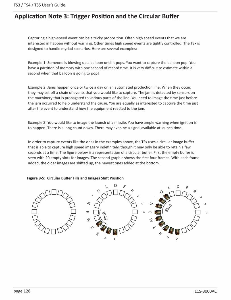
TS3 / TS4 / TS5 User’s Guide
page 128 11S-3000AC
Application Note 3: Trigger Position and the Circular Buffer
Capturing a high-speed event can be a tricky proposition. Often high speed events that we are interested in happen without warning. Other times high speed events are tightly controlled. The TSx is designed to handle myriad scenarios. Here are several examples:
Example 1: Someone is blowing up a balloon until it pops. You want to capture the balloon pop. You have a partition of memory with one second of record time. It is very difficult to estimate within a second when that balloon is going to pop!
Example 2: Jams happen once or twice a day on an automated production line. When they occur, they may set off a chain of events that you would like to capture. The jam is detected by sensors on the machinery that is propagated to various parts of the line. You need to image the time just before the jam occurred to help understand the cause. You are equally as interested to capture the time just after the event to understand how the equipment reacted to the jam.
Example 3: You would like to image the launch of a missile. You have ample warning when ignition is to happen. There is a long count down. There may even be a signal available at launch time.
In order to capture events like the ones in the examples above, the TSx uses a circular image buffer that is able to capture high speed imagery indefinitely, though it may only be able to retain a few seconds at a time. The figure below is a representation of a circular buffer. First the empty buffer is seen with 20 empty slots for images. The second graphic shows the first four frames. With each frame added, the older images are shifted up, the newest ones added at the bottom.
R
EN
E.
W
OL D
>
ER
<<
<
>
Shift
R
EN
E.
W
OL D
>
ER
<<
<
>
Shift
Figure 9-5: Circular Buffer Fills and Images Shift Position
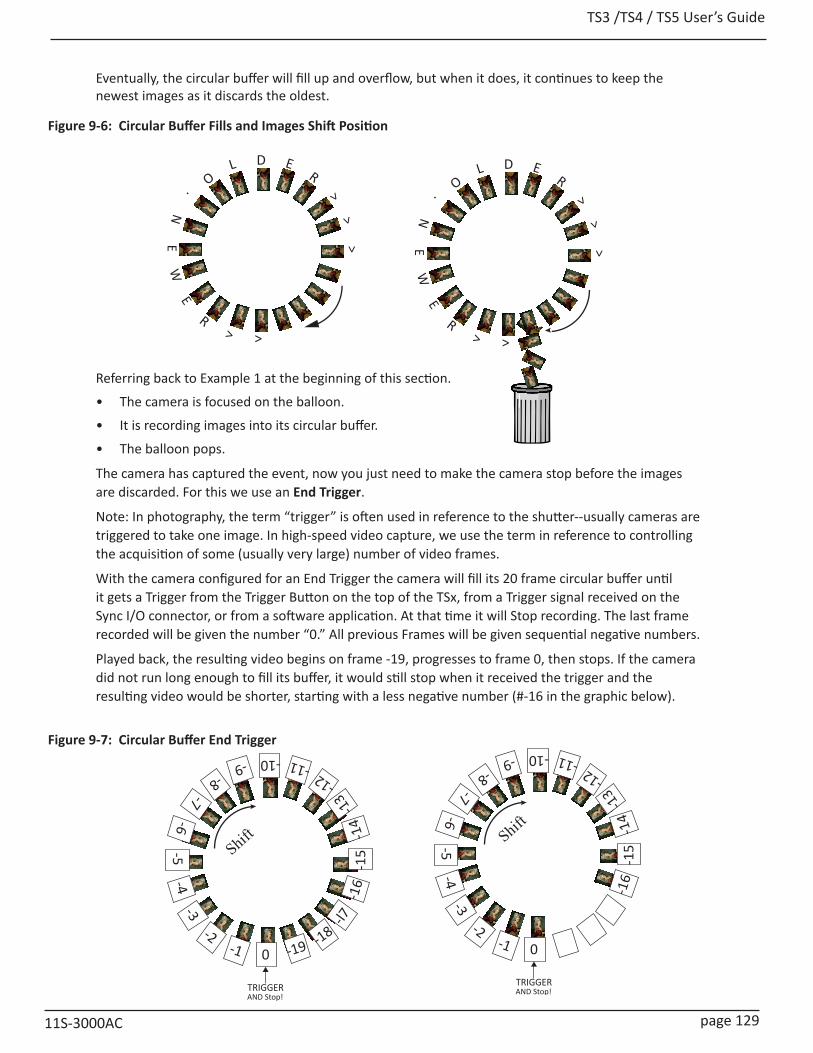
TS3 /TS4 / TS5 User’s Guide
11S-3000AC page 129
Eventually, the circular buffer will fill up and overflow, but when it does, it continues to keep the newest images as it discards the oldest.
Referring back to Example 1 at the beginning of this section.
• The camera is focused on the balloon.
• It is recording images into its circular buffer.
• The balloon pops.
The camera has captured the event, now you just need to make the camera stop before the images are discarded. For this we use an End Trigger.
Note: In photography, the term “trigger” is often used in reference to the shutter--usually cameras are triggered to take one image. In high-speed video capture, we use the term in reference to controlling the acquisition of some (usually very large) number of video frames.
With the camera configured for an End Trigger the camera will fill its 20 frame circular buffer until it gets a Trigger from the Trigger Button on the top of the TSx, from a Trigger signal received on the Sync I/O connector, or from a software application. At that time it will Stop recording. The last frame recorded will be given the number “0.” All previous Frames will be given sequential negative numbers.
Played back, the resulting video begins on frame -19, progresses to frame 0, then stops. If the camera did not run long enough to fill its buffer, it would still stop when it received the trigger and the resulting video would be shorter, starting with a less negative number (#-16 in the graphic below).
Shift
-2
-3-6
-5-7
-4
-8-9 -10
-1
-11-12
-13
-14
-15
-16
-l7
-18-190
TRIGGERAND Stop!
-2
-3-6
-5-7
-4
-8-9 -10
-1
-11-12
-13
-14
-15
-16
0
TRIGGERAND Stop!
Shift
R
EN
E.
W
OL D
>
ER
<<
<
>
R
EN
E.
W
OL D
>
ER
<<
<>
Figure 9-6: Circular Buffer Fills and Images Shift Position
Figure 9-7: Circular Buffer End Trigger
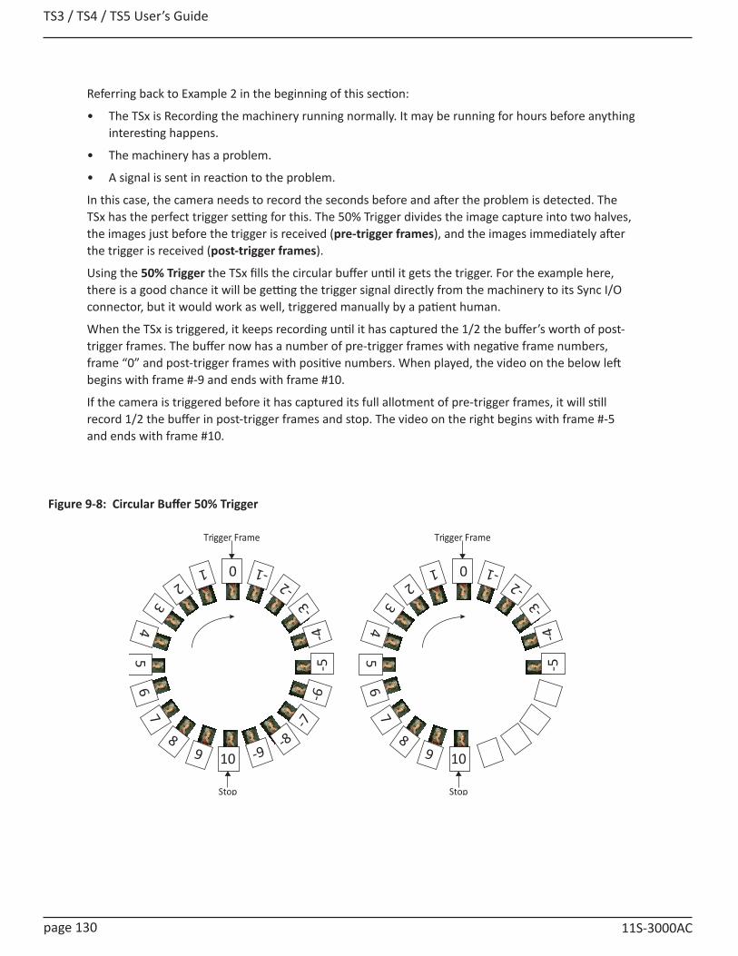
TS3 / TS4 / TS5 User’s Guide
page 130 11S-3000AC
Referring back to Example 2 in the beginning of this section:
• The TSx is Recording the machinery running normally. It may be running for hours before anything interesting happens.
• The machinery has a problem.
• A signal is sent in reaction to the problem.
In this case, the camera needs to record the seconds before and after the problem is detected. The TSx has the perfect trigger setting for this. The 50% Trigger divides the image capture into two halves, the images just before the trigger is received (pre-trigger frames), and the images immediately after the trigger is received (post-trigger frames).
Using the 50% Trigger the TSx fills the circular buffer until it gets the trigger. For the example here, there is a good chance it will be getting the trigger signal directly from the machinery to its Sync I/O connector, but it would work as well, triggered manually by a patient human.
When the TSx is triggered, it keeps recording until it has captured the 1/2 the buffer’s worth of post-trigger frames. The buffer now has a number of pre-trigger frames with negative frame numbers, frame “0” and post-trigger frames with positive numbers. When played, the video on the below left begins with frame #-9 and ends with frame #10.
If the camera is triggered before it has captured its full allotment of pre-trigger frames, it will still record 1/2 the buffer in post-trigger frames and stop. The video on the right begins with frame #-5 and ends with frame #10.
8
74
53
6
21 0
9
-1-2
-3-4
-5-6
-7
-8-910
Stop
Trigger Frame
8
74
53
62
1 0
9
-1-2
-3-4
-5
10
Stop
Trigger Frame
Figure 9-8: Circular Buffer 50% Trigger
TS3 /TS4 / TS5 User’s Guide
11S-3000AC page 131
Referring back to the 3rd example at the beginning of the section:
• The TSx is framed and focused on a missile about to launch.
• It begins recording well before launch time. But it is only required to capture the launch.
• There is a countdown. The TSx receives its trigger electronically from launch control or manually.
In this case no video is required before time 0 of the launch. The Trigger acts like a “start button” for the camera to begin saving captured video.
For this type of recording, the TSx has a Start Trigger. Using the Start Trigger, when the TSx gets a trigger it will record Frame 0, and then fill the buffer with post-trigger frames. The video played back will begin with Frame 0, then proceed with all positive frame numbers.
Selecting Other Trigger Values
More likely than using the Start Trigger for example 3, however, is to use a 5% or 10% Trigger. This affords you a cushion of safety in case there is a problem with the launch signal--giving you time to trigger manually. Also in the case that there is a problem in the launch sequence just before ignition, that would be captured as well.
The 10% trigger works just like the 50% trigger explained above, except that only 10% of the imagery is captured pre-trigger, and 90% is captured post-trigger.
Using FasMotion or the Web-App, the trigger position can be placed anywhere by percentage or frame number. The TSx on-display interface has Start, 10%, 50%, 90% and End options.
TS3 / TS4 / TS5 User’s Guide
page 132 11S-3000AC
Application Note 4: Frame Rate, Resolution, and ExposureScale and Resolution/Frame Rate
Selecting the proper resolution and frame rate for a given high-speed event is important. It is based on the Field of View (FOV) required to get a good image of your object of interest and the speed at which the object will move through that FOV.
For example, if you wish to image an automobile traveling at 50 mph across an intersection, full resolution and a relatively slow frame rate will work because your field of view (FOV) will be large and the car will not be moving through it very quickly.
Imaging a bird traveling at the same speed will require a much smaller FOV as the bird is 1/20th the size of the car. If you wish to use the same scale (object size/FOV), the FOV becomes 1/20th the size, and the bird moves through it 20 times as fast.
If you got acceptable imaging of an auto at 60FPS, it may take 1250FPS to get similarly acceptable imaging of a bird at moving the same speed.
Aliasing and Frame Rate
If you are imaging a motion that is cyclical in nature like a wheel spinning or a lever moving up and down, it is important to use a high enough frame rate to avoid motion aliasing. If you know the speed of the object, use a frame rate at least a few times as fast as the repetition rate to get a valid characterization of the motion. If you don’t know the speed, use as high a frame rate as possible to start with and adjust from there. (Be sure to analyze the movement one frame at a time as the playback speed may cause aliasing as well.)
Generally you will choose to use the largest resolution possible for the frame rate required. This will give you the best definition of your object of interest. Smaller resolutions may be desired in order to increase the record time. Choosing the right shutter speed is dependent not only on the speed at which an object is traveling through the FOV, it is also dependent on how the imagery is going to be used.
For motion analysis it is best to get as short an exposure as possible in order to limit motion blur. (Motion blur can be defined as the number of pixels traversed by an edge of an object during an exposure.)
For smooth video, on the other hand, long exposures are best. These make for more attractive movies, but blurry stills.

TS3 /TS4 / TS5 User’s Guide
11S-3000AC page 133
Application Note 5: Optimizing System for Image TransfersTransferring large volumes of image data from the camera to a computer over the Gigabit Ethernet connection can be very fast on an optimized system. For example, a full 8GB camera buffer will produce about 25GB of color TIFF files. An optimized high-performance system may transfer 25GB of full-resolution images from camera in less than five minutes, while on a non-optimized system, the transfer could easily take more than an hour.
Several parameters contribute to file transfer performance:
• Network and PC hardware
• Computer activity
• FasMotion setup
• Image file format and resolution
Network and PC Hardware
• Processor/Chipset type and speed: use fast multi-core processors, 64-bit system
• Memory capacity and speed: 4GB minimum. 8GB recommended
• Graphics card type speed and on-board memory: Graphics performance can throttle live and playback views, graphics cards without on-board memory will take system memory and may slow things down.
• NIC type and speed: NIC performance varies widely. Pick a Gigabit NIC that supports Jumbo Frames. We have found that some systems only perform well with Jumbo frames set to 9K, while others work well at 1500. This is a parameter that you may need to experiment with to get optimum results.
• Multiple Network interfaces may be available. For optimum transfers, disable or disconnect all interfaces other than the one to be used with the camera during transfers. Two or more interfaces are on the same subnet should never be allowed. (Having both wired and wireless interfaces active is a common problem.)
• Hard Disk type: sustained transfer speed is most important drive attribute. Having a second drive on the system for image transfers is helpful--avoid using the drive that the OS and any program files are on. SATA II or III SSD or high-speed spinning media drives may be added internally or externally to your PC. If the PC has an eSATA port, consider connecting an SSD to it for image transfers.
• Disk state: fragmented disks and disks that are running out of space will slow transfers.
PC OS/Software
• Close all other applications, services, updaters, etc., including performance monitors such as Task Manager, Wireshark, HD Tune Pro, etc. while running FasMotion.
• File System format: On a Windows PC, use NTFS for the data drive, for Mac us HFS+
• Do not index the target drive.
• Set UDP receive buffers to 3MB on Mac computers: edit or create /etc/sysctl.conf to contain the line: net.inet.udp.recvspace=3145728
Note: this requires some low-level changes to your Mac that you may not be accustomed to making. There is a lot of online help available, but if you need assistance please contact Fastec.
• PC Power Management: disable all, including sleep modes
• Disable all Firewalls and Anti-virus software! (You will not want the PC attached to the any outside network including the Internet while connected to the camera.)
• 3rd party filter drivers: (disable using NIC’s properties page)
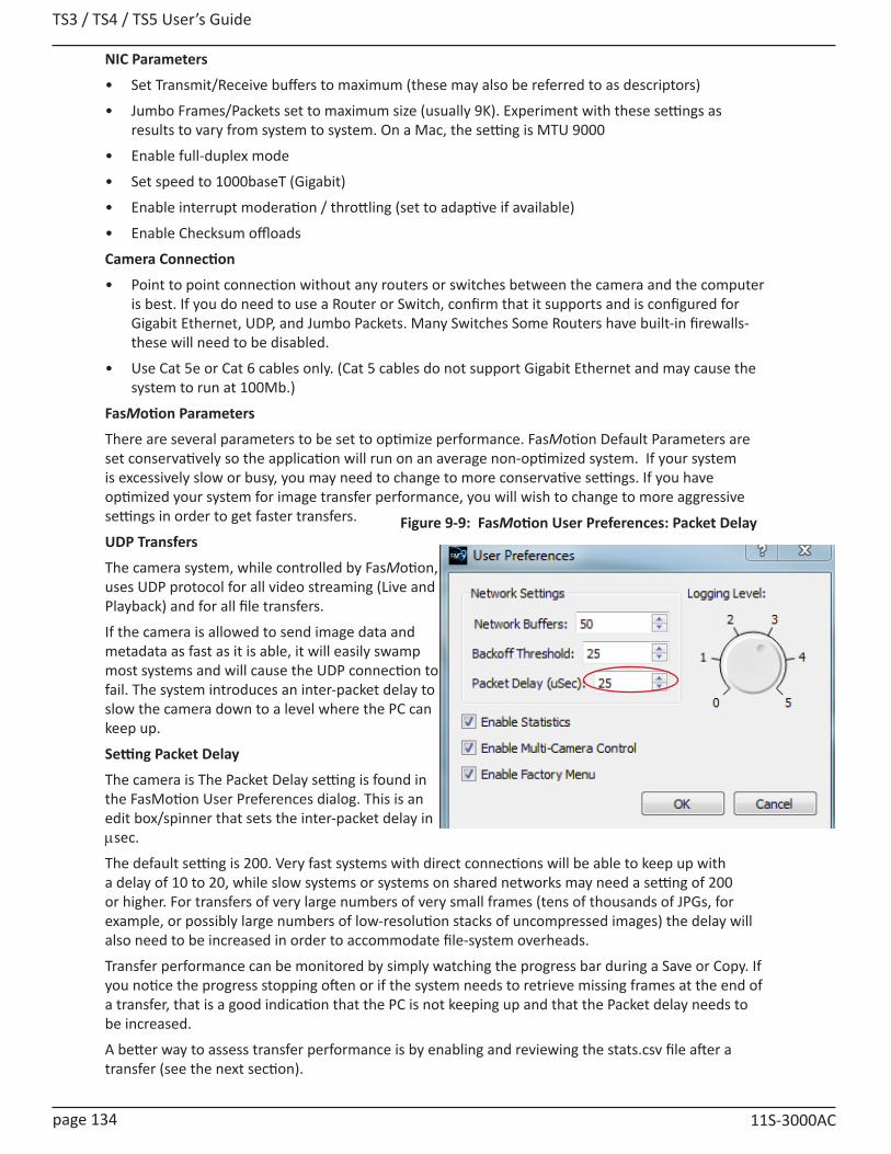
TS3 / TS4 / TS5 User’s Guide
page 134 11S-3000AC
NIC Parameters
• Set Transmit/Receive buffers to maximum (these may also be referred to as descriptors)
• Jumbo Frames/Packets set to maximum size (usually 9K). Experiment with these settings as results to vary from system to system. On a Mac, the setting is MTU 9000
• Enable full-duplex mode
• Set speed to 1000baseT (Gigabit)
• Enable interrupt moderation / throttling (set to adaptive if available)
• Enable Checksum offloads
Camera Connection
• Point to point connection without any routers or switches between the camera and the computer is best. If you do need to use a Router or Switch, confirm that it supports and is configured for Gigabit Ethernet, UDP, and Jumbo Packets. Many Switches Some Routers have built-in firewalls-these will need to be disabled.
• Use Cat 5e or Cat 6 cables only. (Cat 5 cables do not support Gigabit Ethernet and may cause the system to run at 100Mb.)
FasMotion Parameters
There are several parameters to be set to optimize performance. FasMotion Default Parameters are set conservatively so the application will run on an average non-optimized system. If your system is excessively slow or busy, you may need to change to more conservative settings. If you have optimized your system for image transfer performance, you will wish to change to more aggressive settings in order to get faster transfers.
UDP Transfers
The camera system, while controlled by FasMotion, uses UDP protocol for all video streaming (Live and Playback) and for all file transfers.
If the camera is allowed to send image data and metadata as fast as it is able, it will easily swamp most systems and will cause the UDP connection to fail. The system introduces an inter-packet delay to slow the camera down to a level where the PC can keep up.
Setting Packet Delay
The camera is The Packet Delay setting is found in the FasMotion User Preferences dialog. This is an edit box/spinner that sets the inter-packet delay in msec.
The default setting is 200. Very fast systems with direct connections will be able to keep up with a delay of 10 to 20, while slow systems or systems on shared networks may need a setting of 200 or higher. For transfers of very large numbers of very small frames (tens of thousands of JPGs, for example, or possibly large numbers of low-resolution stacks of uncompressed images) the delay will also need to be increased in order to accommodate file-system overheads.
Transfer performance can be monitored by simply watching the progress bar during a Save or Copy. If you notice the progress stopping often or if the system needs to retrieve missing frames at the end of a transfer, that is a good indication that the PC is not keeping up and that the Packet delay needs to be increased.
A better way to assess transfer performance is by enabling and reviewing the stats.csv file after a transfer (see the next section).
Figure 9-9: FasMotion User Preferences: Packet Delay
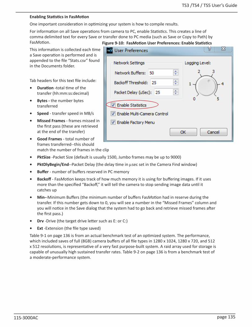
TS3 /TS4 / TS5 User’s Guide
11S-3000AC page 135
Enabling Statistics in FasMotion
One important consideration in optimizing your system is how to compile results.
For information on all Save operations from camera to PC, enable Statistics. This creates a line of comma delimited text for every Save or transfer done to PC media (such as Save or Copy to Path) by FasMotion.
This information is collected each time a Save operation is performed and is appended to the file “Stats.csv” found in the Documents folder.
Tab headers for this text file include:
• Duration -total time of the transfer (hh:mm:ss:decimal)
• Bytes - the number bytes transferred
• Speed - transfer speed in MB/s
• Missed Frames - frames missed in the first pass (these are retrieved at the end of the transfer)
• Good Frames - total number of frames transferred--this should match the number of frames in the clip
• PktSize -Packet Size (default is usually 1500, Jumbo frames may be up to 9000)
• PktDlyBegin/End--Packet Delay (the delay time in msec set in the Camera Find window)
• Buffer - number of buffers reserved in PC memory
• Backoff - FasMotion keeps track of how much memory it is using for buffering images. If it uses more than the specified “Backoff,” it will tell the camera to stop sending image data until it catches up
• Min--Minimum Buffers (the minimum number of buffers FasMotion had in reserve during the transfer. If this number gets down to 0, you will see a number in the “Missed Frames” column and you will notice in the Save dialog that the system had to go back and retrieve missed frames after the first pass.)
• Drv -Drive (the target drive letter such as E: or C:)
• Ext -Extension (the file type saved)
Table 9-1 on page 136 is from an actual benchmark test of an optimized system. The performance, which included saves of full (8GB) camera buffers of all file types in 1280 x 1024, 1280 x 720, and 512 x 512 resolutions, is representative of a very fast purpose-built system. A raid array used for storage is capable of unusually high sustained transfer rates. Table 9-2 on page 136 is from a benchmark test of a moderate-performance system.
Figure 9-10: FasMotion User Preferences: Enable Statistics
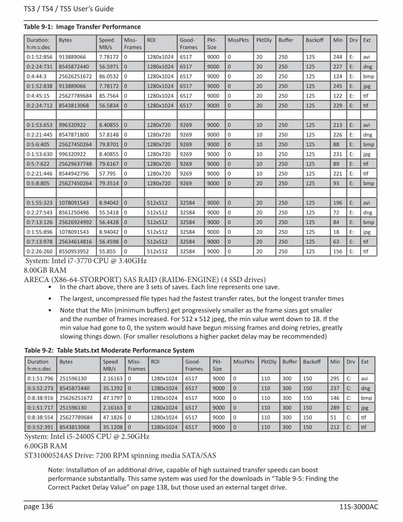
TS3 / TS4 / TS5 User’s Guide
page 136 11S-3000AC
Table 9-1: Image Transfer Performance
Duration: h:m:s:dec
Bytes Speed MB/s
Miss-Frames
ROI Good-Frames
Pkt-Size
MissPkts PktDly Buffer Backoff Min Drv Ext
0:1:52:856 913889066 7.78172 0 1280x1024 6517 9000 0 20 250 125 244 E: avi
0:2:24:731 8545872440 56.5971 0 1280x1024 6517 9000 0 20 250 125 227 E: dng
0:4:44:3 25626251672 86.0532 0 1280x1024 6517 9000 0 20 250 125 124 E: bmp
0:1:52:838 913889066 7.78172 0 1280x1024 6517 9000 0 20 250 125 245 E: jpg
0:4:45:15 25627789684 85.7564 0 1280x1024 6517 9000 0 20 250 125 122 E: tif
0:2:24:712 8543813068 56.5834 0 1280x1024 6517 9000 0 20 250 125 229 E: tif
0:1:53:653 996320922 8.40855 0 1280x720 9269 9000 0 10 250 125 213 E: avi
0:2:21:445 8547871800 57.8148 0 1280x720 9269 9000 0 10 250 125 226 E: dng
0:5:6:405 25627450264 79.8701 0 1280x720 9269 9000 0 10 250 125 88 E: bmp
0:1:53:630 996320922 8.40855 0 1280x720 9269 9000 0 10 250 125 231 E: jpg
0:5:7:622 25629637748 79.6167 0 1280x720 9269 9000 0 10 250 125 89 E: tif
0:2:21:446 8544942796 57.795 0 1280x720 9269 9000 0 10 250 125 221 E: tif
0:5:8:805 25627450264 79.3514 0 1280x720 9269 9000 0 20 250 125 93 E: bmp
0:1:55:323 1078091543 8.94042 0 512x512 32584 9000 0 20 250 125 196 E: avi
0:2:27:543 8561250496 55.5418 0 512x512 32584 9000 0 20 250 125 72 E: dng
0:7:13:126 25626924992 56.4428 0 512x512 32584 9000 0 20 250 125 84 E: bmp
0:1:55:896 1078091543 8.94042 0 512x512 32584 9000 0 20 250 125 18 E: jpg
0:7:13:978 25634614816 56.4598 0 512x512 32584 9000 0 20 250 125 63 E: tif
0:2:26:260 8550953952 55.855 0 512x512 32584 9000 0 20 250 125 156 E: tif
System: Intel i7-3770 CPU @ 3.40GHz8.00GB RAMARECA (X86-64-STORPORT) SAS RAID (RAID6-ENGINE) (4 SSD drives)
• In the chart above, there are 3 sets of saves. Each line represents one save.
• The largest, uncompressed file types had the fastest transfer rates, but the longest transfer times
• Note that the Min (minimum buffers) get progressively smaller as the frame sizes got smaller and the number of frames increased. For 512 x 512 jpeg, the min value went down to 18. If the min value had gone to 0, the system would have begun missing frames and doing retries, greatly slowing things down. (For smaller resolutions a higher packet delay may be recommended)
Note: Installation of an additional drive, capable of high sustained transfer speeds can boost performance substantially. This same system was used for the downloads in “Table 9-5: Finding the Correct Packet Delay Value” on page 138, but those used an external target drive.
Duration h:m:s:dec
Bytes Speed MB/s
Miss-Frames
ROI Good-Frames
Pkt-Size
MissPkts PktDly Buffer Backoff Min Drv Ext
0:1:51:796 251596130 2.16163 0 1280x1024 6517 9000 0 110 300 150 295 C: avi
0:3:52:273 8545872440 35.1292 0 1280x1024 6517 9000 0 110 300 150 237 C: dng
0:8:38:916 25626251672 47.1797 0 1280x1024 6517 9000 0 110 300 150 146 C: bmp
0:1:51:717 251596130 2.16163 0 1280x1024 6517 9000 0 110 300 150 289 C: jpg
0:8:38:554 25627789684 47.1826 0 1280x1024 6517 9000 0 110 300 150 51 C: tif
0:3:52:391 8543813068 35.1208 0 1280x1024 6517 9000 0 110 300 150 212 C: tif
System: Intel i5-2400S CPU @ 2.50GHz6.00GB RAMST31000524AS Drive: 7200 RPM spinning media SATA/SAS
Table 9-2: Table Stats.txt Moderate Performance System
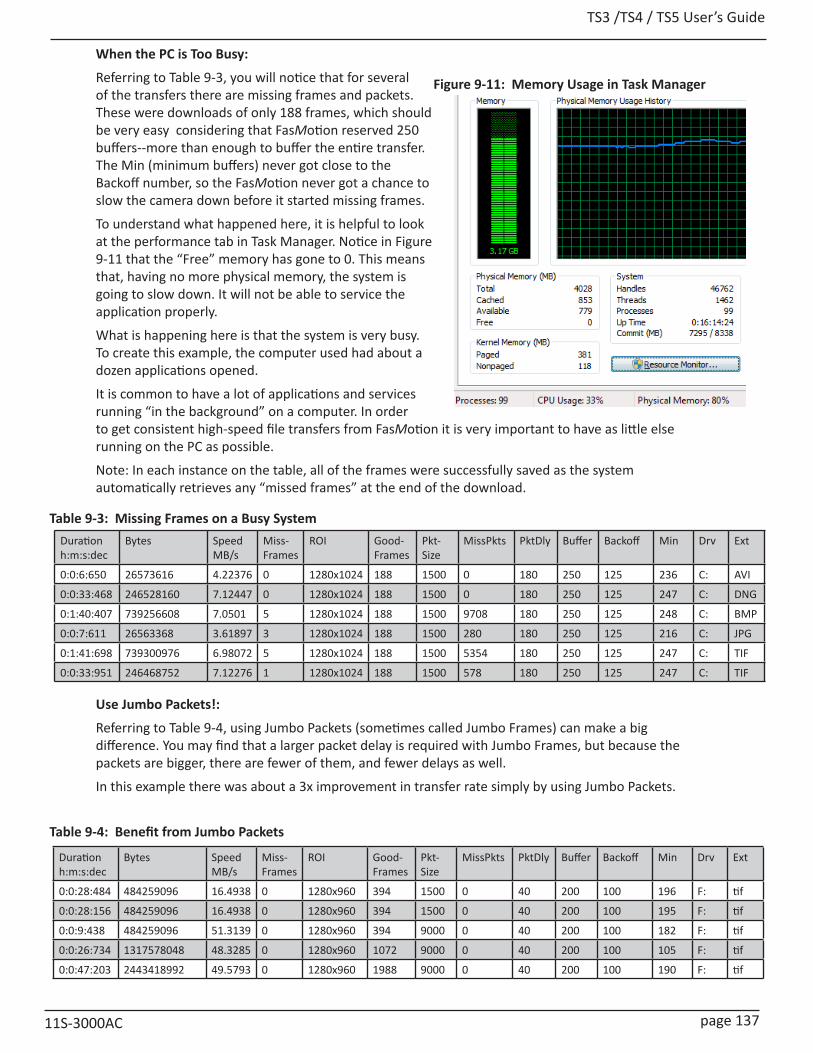
TS3 /TS4 / TS5 User’s Guide
11S-3000AC page 137
When the PC is Too Busy:
Referring to Table 9-3, you will notice that for several of the transfers there are missing frames and packets. These were downloads of only 188 frames, which should be very easy considering that FasMotion reserved 250 buffers--more than enough to buffer the entire transfer. The Min (minimum buffers) never got close to the Backoff number, so the FasMotion never got a chance to slow the camera down before it started missing frames.
To understand what happened here, it is helpful to look at the performance tab in Task Manager. Notice in Figure 9-11 that the “Free” memory has gone to 0. This means that, having no more physical memory, the system is going to slow down. It will not be able to service the application properly.
What is happening here is that the system is very busy. To create this example, the computer used had about a dozen applications opened.
It is common to have a lot of applications and services running “in the background” on a computer. In order to get consistent high-speed file transfers from FasMotion it is very important to have as little else running on the PC as possible.
Note: In each instance on the table, all of the frames were successfully saved as the system automatically retrieves any “missed frames” at the end of the download.
Use Jumbo Packets!:
Referring to Table 9-4, using Jumbo Packets (sometimes called Jumbo Frames) can make a big difference. You may find that a larger packet delay is required with Jumbo Frames, but because the packets are bigger, there are fewer of them, and fewer delays as well.
In this example there was about a 3x improvement in transfer rate simply by using Jumbo Packets.
Figure 9-11: Memory Usage in Task Manager
Duration h:m:s:dec
Bytes Speed MB/s
Miss-Frames
ROI Good-Frames
Pkt-Size
MissPkts PktDly Buffer Backoff Min Drv Ext
0:0:6:650 26573616 4.22376 0 1280x1024 188 1500 0 180 250 125 236 C: AVI
0:0:33:468 246528160 7.12447 0 1280x1024 188 1500 0 180 250 125 247 C: DNG
0:1:40:407 739256608 7.0501 5 1280x1024 188 1500 9708 180 250 125 248 C: BMP
0:0:7:611 26563368 3.61897 3 1280x1024 188 1500 280 180 250 125 216 C: JPG
0:1:41:698 739300976 6.98072 5 1280x1024 188 1500 5354 180 250 125 247 C: TIF
0:0:33:951 246468752 7.12276 1 1280x1024 188 1500 578 180 250 125 247 C: TIF
Table 9-3: Missing Frames on a Busy System
Duration h:m:s:dec
Bytes Speed MB/s
Miss-Frames
ROI Good-Frames
Pkt-Size
MissPkts PktDly Buffer Backoff Min Drv Ext
0:0:28:484 484259096 16.4938 0 1280x960 394 1500 0 40 200 100 196 F: tif
0:0:28:156 484259096 16.4938 0 1280x960 394 1500 0 40 200 100 195 F: tif
0:0:9:438 484259096 51.3139 0 1280x960 394 9000 0 40 200 100 182 F: tif
0:0:26:734 1317578048 48.3285 0 1280x960 1072 9000 0 40 200 100 105 F: tif
0:0:47:203 2443418992 49.5793 0 1280x960 1988 9000 0 40 200 100 190 F: tif
Table 9-4: Benefit from Jumbo Packets

TS3 / TS4 / TS5 User’s Guide
page 138 11S-3000AC
Finding the Correct Packet Delay Value:
The correct packet delay value is one where the PC can keep up with the flow of incoming packets. The use of the buffer will sometimes mask the fact that the drive is not quite keeping up.
Referring to Table 9-5, compare the Min column (that is the minimum number of buffers available during the save) with the “Good Frames” column (the number of frames saved). You can see that as the number of frames increases, the Min number decreases, which means that the hard drive is not quite keeping up with the flow.
Note: In each instance on the table, all of the frames were successfully saved as the system automatically retrieves any “missed frames” at the end of the download.
The last three downloads shown on the table demonstrate that a higher Packet Delay is a little better for this system. In these last three saves, delays of 50, 35, and 25 were used. You can see that the speed of the transfer was not really affected by the increased delay times, but that the Min buffer value was very high. For this system a Packet Delay of 40 will probably be OK, but 50 is a better number because the system can maintain the same transfer rate without exhausting its buffers.
The examples on this table were test results using a MacBook Pro with a built-in SSD. The first three entries were from a mono camera, the rest are color. The TIFF files were 10-bit raw TIFFs. Note that the fastest speeds were from the largest files (color BMP). The MacBook Pro in this configuration is the fastest computer we have tested.
Duration h:m:s:dec
Bytes Speed MB/s
Miss-Frames
ROI Good-Frames
Pkt-Size
MissPkts PktDly Buffer Backoff Min Drv Ext
0:0:14:663 1179664800 80.3583 0 1280x1024 300 9000 0 40 200 100 178 K: bmp
0:0:19:266 1572886400 78.9485 0 1280x1024 400 9000 0 40 200 100 174 K: bmp
0:0:23:562 1966108000 81.5229 0 1280x1024 500 9000 0 40 200 100 168 K: bmp
0:0:28:242 2359329600 80.3583 0 1280x1024 600 9000 0 40 200 100 161 K: bmp
0:0:41:923 3538994400 82.3182 0 1280x1024 900 9000 0 40 200 100 152 K: bmp
0:0:56:45 4718659200 80.3583 0 1280x1024 1200 9000 0 40 200 100 130 K: bmp
0:1:10:535 5898324000 80.3583 0 1280x1024 1500 9000 0 40 200 100 105 K: bmp
0:1:33:768 7864432000 80.6463 0 1280x1024 2000 9000 0 40 200 100 99 K: bmp
0:2:19:27 11796648000 80.9364 0 1280x1024 3000 9000 0 40 200 100 99 K: bmp
0:5:13:731 25626251672 78.0802 1 1280x1024 6517 9000 40 40 200 100 99 K: bmp
0:5:15:858 25626251672 77.5844 0 1280x1024 6517 9000 0 50 200 100 188 K: bmp
0:5:16:5 25626251672 77.3389 0 1280x1024 6517 9000 0 35 200 100 99 K: bmp
0:5:16:338 25626251672 77.3389 0 1280x1024 6517 9000 0 25 200 100 96 K: bmp
Table 9-5: Finding the Correct Packet Delay Value
Duration Bytes Speed (MB/sec)
Miss-Frames
Good-Frames
PktSize MissPkts PktDly- Begin
PktDly-End
Buffer Back-off
Min Drv Ext
0:1:53:53 855392409 7.21917 0 9269 9000 0 20 20 200 100 174 /U avi
0:1:52:853 855392409 7.28362 0 9269 9000 0 20 20 200 100 194 /U jpg
0:2:24:884 8552320920 56.6398 0 9269 9000 0 20 20 200 100 197 /U bmp
0:4:34:914 25626251672 89.1938 0 6517 9000 0 15 15 200 100 198 /U bmp
0:4:36:409 25626251672 88.5475 0 6517 4500 0 10 10 200 100 198 /U bmp
0:2:34:456 12804839864 79.2964 0 6946 9000 0 20 20 200 100 196 /U tif
0:2:34:982 12804839864 79.2964 0 6946 4500 0 10 10 200 100 196 /U tif
0:3:12:49 12804839864 63.6023 0 6946 1500 0 10 10 200 100 195 /U tif
0:1:24:165 600384525 6.81632 0 6946 9000 0 20 20 200 100 176 /U avi
0:1:27:766 600384525 6.58128 0 6946 4500 0 20 20 200 100 176 /U avi
Table 9-6: Sample Mac Stat.csv Entries
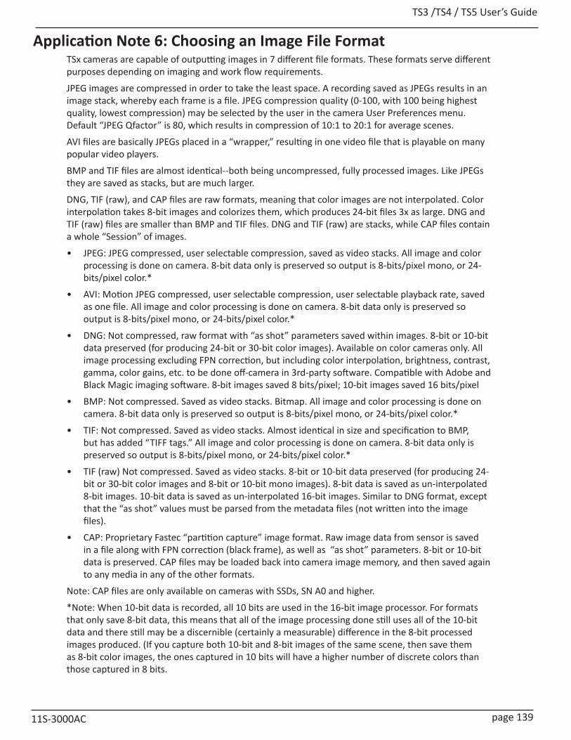
TS3 /TS4 / TS5 User’s Guide
11S-3000AC page 139
Application Note 6: Choosing an Image File FormatTSx cameras are capable of outputting images in 7 different file formats. These formats serve different purposes depending on imaging and work flow requirements.
JPEG images are compressed in order to take the least space. A recording saved as JPEGs results in an image stack, whereby each frame is a file. JPEG compression quality (0-100, with 100 being highest quality, lowest compression) may be selected by the user in the camera User Preferences menu. Default “JPEG Qfactor” is 80, which results in compression of 10:1 to 20:1 for average scenes.
AVI files are basically JPEGs placed in a “wrapper,” resulting in one video file that is playable on many popular video players.
BMP and TIF files are almost identical--both being uncompressed, fully processed images. Like JPEGs they are saved as stacks, but are much larger.
DNG, TIF (raw), and CAP files are raw formats, meaning that color images are not interpolated. Color interpolation takes 8-bit images and colorizes them, which produces 24-bit files 3x as large. DNG and TIF (raw) files are smaller than BMP and TIF files. DNG and TIF (raw) are stacks, while CAP files contain a whole “Session” of images.
• JPEG: JPEG compressed, user selectable compression, saved as video stacks. All image and color processing is done on camera. 8-bit data only is preserved so output is 8-bits/pixel mono, or 24-bits/pixel color.*
• AVI: Motion JPEG compressed, user selectable compression, user selectable playback rate, saved as one file. All image and color processing is done on camera. 8-bit data only is preserved so output is 8-bits/pixel mono, or 24-bits/pixel color.*
• DNG: Not compressed, raw format with “as shot” parameters saved within images. 8-bit or 10-bit data preserved (for producing 24-bit or 30-bit color images). Available on color cameras only. All image processing excluding FPN correction, but including color interpolation, brightness, contrast, gamma, color gains, etc. to be done off-camera in 3rd-party software. Compatible with Adobe and Black Magic imaging software. 8-bit images saved 8 bits/pixel; 10-bit images saved 16 bits/pixel
• BMP: Not compressed. Saved as video stacks. Bitmap. All image and color processing is done on camera. 8-bit data only is preserved so output is 8-bits/pixel mono, or 24-bits/pixel color.*
• TIF: Not compressed. Saved as video stacks. Almost identical in size and specification to BMP, but has added “TIFF tags.” All image and color processing is done on camera. 8-bit data only is preserved so output is 8-bits/pixel mono, or 24-bits/pixel color.*
• TIF (raw) Not compressed. Saved as video stacks. 8-bit or 10-bit data preserved (for producing 24-bit or 30-bit color images and 8-bit or 10-bit mono images). 8-bit data is saved as un-interpolated 8-bit images. 10-bit data is saved as un-interpolated 16-bit images. Similar to DNG format, except that the “as shot” values must be parsed from the metadata files (not written into the image files).
• CAP: Proprietary Fastec “partition capture” image format. Raw image data from sensor is saved in a file along with FPN correction (black frame), as well as “as shot” parameters. 8-bit or 10-bit data is preserved. CAP files may be loaded back into camera image memory, and then saved again to any media in any of the other formats.
Note: CAP files are only available on cameras with SSDs, SN A0 and higher.
*Note: When 10-bit data is recorded, all 10 bits are used in the 16-bit image processor. For formats that only save 8-bit data, this means that all of the image processing done still uses all of the 10-bit data and there still may be a discernible (certainly a measurable) difference in the 8-bit processed images produced. (If you capture both 10-bit and 8-bit images of the same scene, then save them as 8-bit color images, the ones captured in 10 bits will have a higher number of discrete colors than those captured in 8 bits.

TS3 / TS4 / TS5 User’s Guide
page 140 11S-3000AC
*FPN: FPN correction is user-selectable. If FPN is set to Column, the correction is at the sensor-level and is asserted for all file types. If it is set to Off/Disabled, there will be no correction in any format. If it is set to Pixel, the black frame will be subtracted in all formats except for CAP. For CAP files, the black frame is copied into the CAP file and the correction is asserted when creating image data display and conversion.
** “As-shot” parameters: all image processing parameters, including color corrections, gains, brightness, contrast, and gamma are saved, but not asserted (pixel values are not manipulated). This allows for post-processing of the original pixel data.
Format Processing Size @1280 x 1024 Pro Con
8-bit 10-bit
JPG JPEG CompressionColor InterpolationBrightness, Contrast, Gamma, Gains, FPN*
241K(color)
• Small• Popular still format• Easy analysis
• Degrades with re-processing• Huge folders full of files
AVI JPEG CompressionColor InterpolationBrightness, Contrast, Gamma, Gain, FPN*
241K(color)
• Small• Popular video format• Nice 1-file archive format
• Degrades with re-processing
DNG FPN*, (“As-shot” parameters** saved-not processed)
1281K(raw)
2561K(raw)
• Maintains highest image fidelity
• All bits saved in 10-bit mode• Compatible with high-quality
image and video production tools
• Compact vs BMP/TIF
• Huge folders full of files
BMP Color InterpolationBrightness, Contrast, Gamma, Gains, FPN*
3841K(color)
• Good image fidelity• Compatible with popular
imaging tools
• Huge folders full of files
TIF Color InterpolationBrightness, Contrast, Gamma, Gains, FPN*
3841K(color)
• Good image fidelity• Compatible with popular
imaging tools
• Huge folders full of files
TIF(r) FPN* only 1281K(raw)
2561K(raw)
• Maintains highest image fidelity
• All bits saved in 10-bit mode • Compact vs BMP/TIF
• Huge folders full of files
CAP None (black frame and “As-shot” parameters** saved)
1291K(raw)
1725K(raw)
• Maintains highest image fidelity
• Only format that can be played back by the camera
• 1-file format• Fastest Saves to SSD• Convert to any other format
via the camera
• Proprietary format
Table 9-7: File Format Features
1280x1024 10-bit 1280 x 1024 8-bit 1280x720 10-bit 1280x720 8-bit 512x512 256x256
Save to SSD
Rate MB/s
Images /s Rate MB/s
Images /s Rate MB/s
Images /s Rate MB/s
Images /s Rate MB/s
Images /s Rate MB/s
Images /s
CAP 104.46 84.64 104.37 62.56 125.34 142.58 118.01 100.60 115.65 458.86 103.35 1652.59
DNG 52.47 41.96 100.14 40.05 44.22 50.28 83.53 47.50 15.16 60.05 3.21 50.92
BMP 127.32 33.95 127.57 34.02 109.17 41.40 109.35 41.47 45.80 60.58 9.77 52.09
JPG 4.34 27.64 2.40 27.25 1.65 27.90 1.06 28.05 1.42 37.96 0.45 35.58
TIFF 127.25 33.93 126.91 33.84 109.22 41.42 108.48 41.14 45.27 59.87 9.77 52.01
TiFF(r) 52.37 41.89 100.43 40.17 43.90 49.93 83.29 47.37 15.13 59.97 3.24 51.63
Table 9-8: Save to SSD Benchmarks
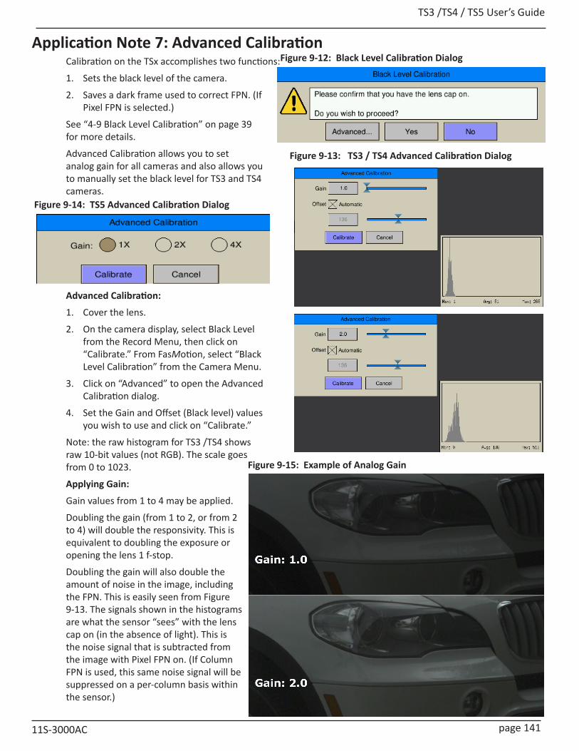
TS3 /TS4 / TS5 User’s Guide
11S-3000AC page 141
Application Note 7: Advanced CalibrationCalibration on the TSx accomplishes two functions:
1. Sets the black level of the camera.
2. Saves a dark frame used to correct FPN. (If Pixel FPN is selected.)
See “4-9 Black Level Calibration” on page 39 for more details.
Advanced Calibration allows you to set analog gain for all cameras and also allows you to manually set the black level for TS3 and TS4 cameras.
Advanced Calibration:
1. Cover the lens.
2. On the camera display, select Black Level from the Record Menu, then click on “Calibrate.” From FasMotion, select “Black Level Calibration” from the Camera Menu.
3. Click on “Advanced” to open the Advanced Calibration dialog.
4. Set the Gain and Offset (Black level) values you wish to use and click on “Calibrate.”
Note: the raw histogram for TS3 /TS4 shows raw 10-bit values (not RGB). The scale goes from 0 to 1023.
Applying Gain:
Gain values from 1 to 4 may be applied.
Doubling the gain (from 1 to 2, or from 2 to 4) will double the responsivity. This is equivalent to doubling the exposure or opening the lens 1 f-stop.
Doubling the gain will also double the amount of noise in the image, including the FPN. This is easily seen from Figure 9-13. The signals shown in the histograms are what the sensor “sees” with the lens cap on (in the absence of light). This is the noise signal that is subtracted from the image with Pixel FPN on. (If Column FPN is used, this same noise signal will be suppressed on a per-column basis within the sensor.)
Figure 9-12: Black Level Calibration Dialog
Figure 9-13: TS3 / TS4 Advanced Calibration Dialog
Figure 9-15: Example of Analog Gain
Figure 9-14: TS5 Advanced Calibration Dialog
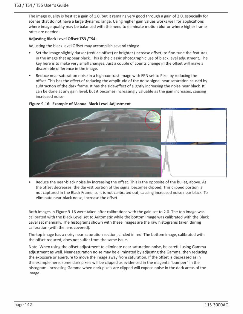
TS3 / TS4 / TS5 User’s Guide
page 142 11S-3000AC
The image quality is best at a gain of 1.0, but it remains very good through a gain of 2.0, especially for scenes that do not have a large dynamic range. Using higher gain values works well for applications where image quality may be balanced with the need to eliminate motion blur or where higher frame rates are needed.
Adjusting Black Level Offset TS3 /TS4:
Adjusting the black level Offset may accomplish several things:
• Set the image slightly darker (reduce offset) or brighter (increase offset) to fine-tune the features in the image that appear black. This is the classic photographic use of black level adjustment. The key here is to make very small changes. Just a couple of counts change in the offset will make a discernible difference in the image.
• Reduce near-saturation noise in a high-contrast image with FPN set to Pixel by reducing the offset. This has the effect of reducing the amplitude of the noise signal near saturation caused by subtraction of the dark frame. It has the side-effect of slightly increasing the noise near black. It can be done at any gain level, but it becomes increasingly valuable as the gain increases, causing increased noise
• Reduce the near-black noise by increasing the offset. This is the opposite of the bullet, above. As the offset decreases, the darkest portion of the signal becomes clipped. This clipped portion is not captured in the Black Frame, so it is not calibrated out, causing increased noise near black. To eliminate near-black noise, increase the offset.
Both images in Figure 9-16 were taken after calibrations with the gain set to 2.0. The top image was calibrated with the Black Level set to Automatic while the bottom image was calibrated with the Black Level set manually. The histograms shown with these images are the raw histograms taken during calibration (with the lens covered).
The top image has a noisy near-saturation section, circled in red. The bottom image, calibrated with the offset reduced, does not suffer from the same issue.
Note: When using the offset adjustment to eliminate near-saturation noise, be careful using Gamma adjustment as well. Near-saturation noise may be eliminated by adjusting the Gamma, then reducing the exposure or aperture to move the image away from saturation. If the offset is decreased as in the example here, some dark pixels will be clipped as evidenced in the magenta “bumper” in the histogram. Increasing Gamma when dark pixels are clipped will expose noise in the dark areas of the image.
Figure 9-16: Example of Manual Black Level Adjustment

TS3 /TS4 / TS5 User’s Guide
11S-3000AC page 143
Application Note 8: Running the TSx on BatteriesThis section addresses the issue of running the TSx for long periods of time and in various modes without AC power available.
The TSx is capable of operating for about four hours in Standard Basic Mode, depending on use of the Display, SSD, HDMI, etc. For some models, running in FasFire or Long Record Mode with a fast SSD, the record time is much less. Please refer to “Appendix Q: Battery” on page 182 and pay special attention to “Figure 10-26: Discharge Rate by Mode” on page 184.
Test battery performance for your application for your camera:There are many models of TSx cameras with many options and many modes of operation for each. The very best way to predict how long your camera may operate on battery in a given setting is to test it before any critical session.
Things that affect battery performance:
• Recording modes that require the camera to write to an internal SSD take the most power.
• TSx display. The display may be set to automatically turn off after one minute, five minutes, or ten minutes. It can also be turned on and off using the DISP button. Allowing the battery to switch off, or manually turning it off when it is not needed will preserve some power.
• HDMI output. The HDMI output should be disabled when not in use. When enabled, this feature will consume power even when there is no HDMI display connected.
• USB devices. USB devices such as flash drives and WiFi dongles are powered by the camera and may consume a considerable amount of power.
• Gigabit Ethernet. The Ethernet connection will draw some power as well. The
• Battery contact wear or contamination. Over time, the battery contacts may develop some resistance, which may affect performance profoundly, lengthening charging times and diminishing record times. Using a contact cleaner/conditioner such as DeoxIT will help to preserve battery performance and enhance battery life.
Using the Gas Gauge:
The Battery Gas Gauge seen in the lower right-hand corner of the camera display as part of the information bar.
The gas gauge is a built-in feature of the battery itself. It is calibrated by cycling the battery from fully charged to fully discharged. This calibration is based on Standard Basic recording modes of the camera system such that the battery percentage is an indication of the level of charge.
When the camera is operating in Standard Basic modes, you can expect that the camera will operate until the gas gauge goes to 0%.
WARNING: If the camera is operating in FasFire or Long Record mode, especially if it is a TS4100LR3 model, recording and saving imagery to an SSD at SATA III speeds or a TS5, the battery will not supply enough power to the camera to operate to 0%. Depending on the camera, mode, features enabled, battery connections, etc. the camera may power down when the gas gauge gets to 50%, 60%, or even 70%. See “Figure 10-26: Discharge Rate by Mode” on page 184.
Note: With version 2.1.x camera firmware, all TS5-D cameras and TS4 LR3 cameras will power up in LR2 mode if external power is not applied. If external power is present at the time the camera powers up, the Charging menu will appear and allow you to choose to operate the camera in “Fast SSD” (LR3) mode, or “Slow SSD” (LR2) mode. It is not recommended to operate these cameras in LR3 mode without external power. See “Figure 2-3: Power Up / Charging Menu (TS4-LR3 / TSx-D)” on page 9.
Using Supplemental Power:
External batteries are available through Fastec that can be used in conjunction with the internal
Figure 9-17: Battery Gas Gauge

TS3 / TS4 / TS5 User’s Guide
page 144 11S-3000AC
Figure 9-18: External 98Wh battery Pack
battery or as stand-alone power for the TSx.
There are two external batteries currently available for the TSx:
• 12V Battery Pack, 98Wh, which will support camera operations more than 2x as long as the internal battery.
• 12V Battery Belt, 144Wh, which will support camera operation about 3x as long as the internal battery. External batteries may be used in conjunction with internal batteries:
• If you have several charged Fastec (internal) batteries available, use the external battery to power the camera when changing internal batteries without having to power the camera down.
• For more power-intensive recording modes such as FasFire and Long Record modes using the TS4, you may wish to use external batteries as the primary power source. In this case, have a fully-charged internal battery present as well. When the external battery power runs low, you will notice the battery LED begin to blink intermittently and you will see a minus sign on the battery gas gauge %. These are indications that the camera is beginning to run on the internal battery. When this happens, replace the external battery for extended operation.

TS3 /TS4 / TS5 User’s Guide
11S-3000AC page 145
AppendicesAppendix A: Definition of termsArm When armed, the camera will capture and write images into a partition of camera
memory, and then overwrite it continually until it receives a trigger.
Arm/Record Bug The Arm/Record Bug is the small vertical line used in conjunction with the Record Bar to indicate the progress of the camera while acquiring pre- and post-trigger images.
AVI Audio Video Interleave (AVI) is a popular file type for electronic video. AVI files may include certain types of image/video data (compressed or non-compressed), audio data, and metadata.
Backlight The Backlight is the illumination used to light the LCD display on the camera.Battery Status LED Battery Status LED States:Bit Depth Images captured by the TSx sensor are read in binary form. Each pixel is given a binary
10-bit value from 0000000000 to 1111111111, or, in decimal form, from 0 to 1023. 0 is black, 1023 is white—all numbers in between are shades of gray from very dark to very bright. The camera operator has the option of recording all ten bits (1024 shades) or 8 bits (256 shades). If the operator chooses to record 8-bit data, they must choose which 8 bits of the ten to record. They may wish to record the Lower 8 bits, which will greatly enhance the dark areas of the image, tend to saturate the bright areas, and will expose more noise; or the Middle 8 bits, which will somewhat enhance the dark areas wash out the brighter areas, and expose some noise; or the High 8 bits, which will be the cleanest image, but with the least definition in the darker areas.
BMP Stack BitMaP (BMP) files contain non-compressed image data. Each file contains one image. A BMP Stack is a collection of images. The BMP Stack produced by the TSx is a collection of frames, written as BMP files representing a captured video sequence.
Brightness Linear image control that boosts all pixel values without disturbing the slope of the curve.
CinemaDNG CinemaDNG is an open digital cinema format that uses the Adobe Digital Negative Specification (DNG), widely used as an archival format for Raw images. The specification is an attempt to standardize digital commercial video format thereby simplifying collaboration and workflow across the entertainment industry and all other industries dependent on digital video recording, i.e. automobile crash testing, military testing, etc.
Color Temperature The Color Temperature of an ideal black body is defined as its surface temperature in kelvins (K). The Color Temperature of a light source is an assigned value that closely approximates what a human would perceive as a match between that light source and an ideal black body at that Temperature (K). High color temperatures are seen bluish, while lower color temperatures are seen reddish.
Config. Camera Configuration that can be saved and reloaded. Includes settings for Frame Rate, Resolution, Shutter Speed, Trigger, bit depth, and Auto Save.
Contrast Linear image control that enhances the difference between pixel values by changing the slope of the curve, while maintaining the mean value.
Cursor The cursor may be any graphic indication of where the current focus is within the user interface. This may be anything from a blinking vertical line as used within a dialog box when the user is entering text, or it may be a change in the color of a button as when navigating through menus.
Custom Camera Control Application
Camera control software compatible with the TSx.
Table 10-1: Definitions

TS3 / TS4 / TS5 User’s Guide
page 146 11S-3000AC
DHCP DHCP is a utility by which a server dynamically assigns IP addresses to clients on a network. When DHCP is selected in the Network Menu, the camera will allow a server on a connected network to assign it an IP address.
Dialog A Dialog is a box that requires user input such as the selection of an option, or the entering of a number or text.
Download Electronically moving image data from a camera to a “remote” device, i.e. a PC or other mass storage.
Enable Raw A raw image is one where image processing including colorization, white balance, brightness, contrast, and gamma, are all bypassed.
File Type Digital files are commonly identified by their extensions. Familiar types include PDF, TXT, JPEG,TIFF, DOC, MP3, etc. Each of these files has a specified format that usually includes information in the file header and specially formatted data that applications on PCs, Cameras, Printers, Smartphones, and other electronic devices can read, write, and decipher for human viewing, editing, listening, etc.
Gain In imaging the term Gain is most often used as a multiplier applied to a pixel value. Gamma Power curve often used to encode image data so that a picture displayed on a given
monitor appears true to the human perception of the original scene. Nominally, a particular display may have decode Gamma of 1.0, common among laptops, or 2.2, common among larger LCD and LED displays.
HDMI HDMI, High-Definition Multimedia Interface, is used to transmit digitized video (and audio) data from the camera to a remote display. This is a popular method for connecting consumer products such as televisions, cable TV boxes, DVD players, etc.
Image Memory Image memory is the internal memory in the camera reserved for raw image data. This is volatile memory that is erased when the camera is shut down.
JPEG Stack Joint Photographic Expert Group (JPEG) file format is a highly compressed file format, capable of reducing image files to a fraction of the size of a BMP or lossless TIFF. The image quality of JPEGs is excellent, although there may be some discernible noise in the displayed image, often referred to as JPEG artifacts.
Menu Once an item in the Menu Bar is selected, the corresponding Menu appears below.Menu Bar The Menu Bar is the bar across the top of the camera display that lists the Menu Items.Network The camera may be connected to one or more computers via its RJ45 GigE (Gigabit
Ethernet) connection.NTP Time Network Time Protocol: Network Protocol for synchronizing time clocks of devices
attached to a given network or internet, within a few hundredths of a second.Play/Review Bug In Review there is a progress bar that graphically indicates the position of the currently
viewed frame within the image sequence. The small vertical line that is used as the indicator is referred to as the Review Bug.
Record The camera is acquiring images and storing them in internal memory. This begins when the camera is armed, and ends after a trigger is received.
Record Bar When the camera is Armed and it commences capturing images, the Record Bar presents a graphic indication of the progress of filling the buffer.
Refresh Rate Rate at which image data is re-painted on the display. For CRTs this is analogous to the vertical frequency.
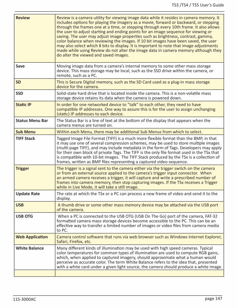
TS3 /TS4 / TS5 User’s Guide
11S-3000AC page 147
Review Review is a camera utility for viewing image data while it resides in camera memory. It includes options for playing the imagery as a movie, forward or backward, or stepping through the frames one at a time, or stepping through every 10th frame. It also allows the user to adjust starting and ending points for an image sequence for viewing or saving. The user may adjust image properties such as brightness, contrast, gamma, color balance when reviewing the images. If 10 bit images have been saved, the user may also select which 8 bits to display. It is important to note that image adjustments made while using Review do not alter the image data in camera memory although they do alter the viewed and saved images.
Save Moving image data from a camera’s internal memory to some other mass storage device. This mass storage may be local, such as the SSD drive within the camera, or remote, such as a PC.
SD This is Secure Digital memory, such as the SD Card used as a plug-in mass storage device for the camera.
SSD Solid-state hard drive that is located inside the camera. This is a non-volatile mass storage device retains its data when the camera is powered down.
Static IP In order for one networked device to “talk” to each other, they need to have compatible IP addresses. One way to assure this is for the user to assign unchanging (static) IP addresses to each device.
Status Menu Bar The Status Bar is a line of text at the bottom of the display that appears when the camera menus are turned on.
Sub Menu Within each Menu, there may be additional Sub Menus from which to select.TIFF Stack Tagged Image File Format (TIFF) is a much more flexible format than the BMP, in that
it may use one of several compression schemes, may be used to store multiple images (multi-page TIFF), and may include metadata in the form of Tags. Developers may apply for their own block of private Tags. The TIFF is the only file format used in the TSx that is compatible with 10-bit images. The TIFF Stack produced by the TSx is a collection of frames, written as BMP files representing a captured video sequence.
Trigger The trigger is a signal sent to the camera either via the trigger switch on the camera or from an external source applied to the camera’s trigger input connector. When an armed camera receives a trigger, it will capture and write a prescribed number of frames into camera memory, then stop capturing images. If the TSx receives a Trigger while in Live Mode, it will take a still image.
Update Rate The rate at which the TSx or a PC can process a new frame of video and send it to the display.
USB A thumb drive or some other mass memory device may be attached via the USB port of the camera.
USB OTG When a PC is connected to the USB OTG (USB On The Go) port of the camera, FAT-32 formatted camera mass storage devices become accessible to the PC. This can be an effective way to transfer a limited number of images or video files from camera media to PC.
Web Application Camera control software that runs via web browser such as Windows Internet Explorer, Safari, Firefox, etc.
White Balance Many different kinds of illumination may be used with high speed cameras. Typical color temperatures for common types of illumination are used to compute RGB gains, which, when applied to captured imagery, should approximate what a human would perceive as accurate color. The term White Balance refers to the idea that, presented with a white card under a given light source, the camera should produce a white image.
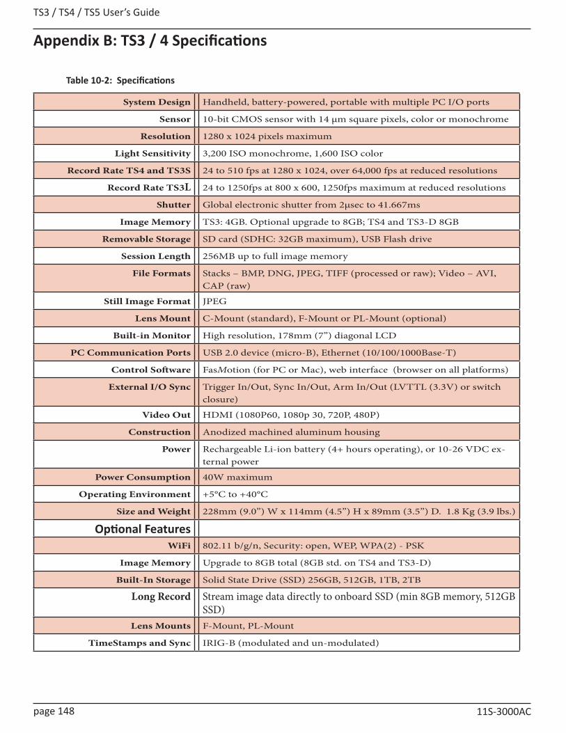
TS3 / TS4 / TS5 User’s Guide
page 148 11S-3000AC
Appendix B: TS3 / 4 Specifications
System Design Handheld, battery-powered, portable with multiple PC I/O ports
Sensor 10-bit CMOS sensor with 14 µm square pixels, color or monochrome
Resolution 1280 x 1024 pixels maximum
Light Sensitivity 3,200 ISO monochrome, 1,600 ISO color
Record Rate TS4 and TS3S 24 to 510 fps at 1280 x 1024, over 64,000 fps at reduced resolutions
Record Rate TS3L 24 to 1250fps at 800 x 600, 1250fps maximum at reduced resolutions
Shutter Global electronic shutter from 2μsec to 41.667ms
Image Memory TS3: 4GB. Optional upgrade to 8GB; TS4 and TS3-D 8GB
Removable Storage SD card (SDHC: 32GB maximum), USB Flash drive
Session Length 256MB up to full image memory
File Formats Stacks – BMP, DNG, JPEG, TIFF (processed or raw); Video – AVI, CAP (raw)
Still Image Format JPEG
Lens Mount C-Mount (standard), F-Mount or PL-Mount (optional)
Built-in Monitor High resolution, 178mm (7”) diagonal LCD
PC Communication Ports USB 2.0 device (micro-B), Ethernet (10/100/1000Base-T)
Control Software FasMotion (for PC or Mac), web interface (browser on all platforms)
External I/O Sync Trigger In/Out, Sync In/Out, Arm In/Out (LVTTL (3.3V) or switch closure)
Video Out HDMI (1080P60, 1080p 30, 720P, 480P)
Construction Anodized machined aluminum housing
Power Rechargeable Li-ion battery (4+ hours operating), or 10-26 VDC ex-ternal power
Power Consumption 40W maximum
Operating Environment +5°C to +40°C
Size and Weight 228mm (9.0”) W x 114mm (4.5”) H x 89mm (3.5”) D. 1.8 Kg (3.9 lbs.)
Optional FeaturesWiFi 802.11 b/g/n, Security: open, WEP, WPA(2) - PSK
Image Memory Upgrade to 8GB total (8GB std. on TS4 and TS3-D)
Built-In Storage Solid State Drive (SSD) 256GB, 512GB, 1TB, 2TB
Long Record Stream image data directly to onboard SSD (min 8GB memory, 512GB SSD)
Lens Mounts F-Mount, PL-Mount
TimeStamps and Sync IRIG-B (modulated and un-modulated)
Table 10-2: Specifications
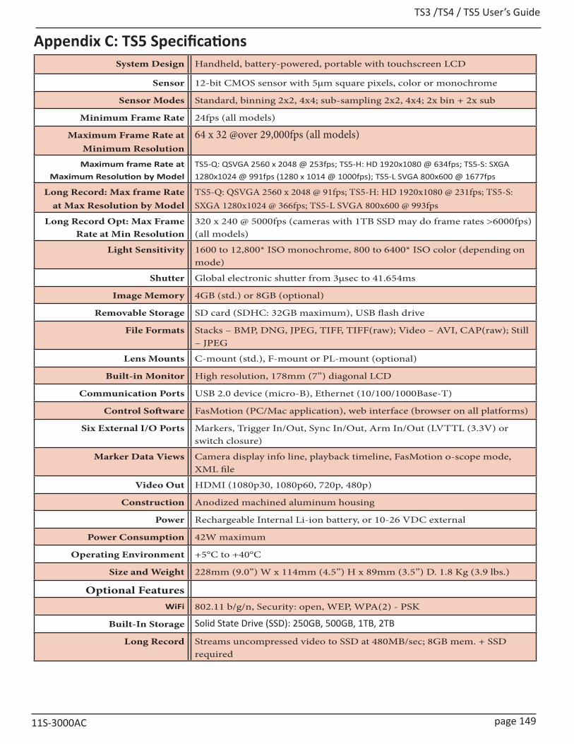
TS3 /TS4 / TS5 User’s Guide
11S-3000AC page 149
Appendix C: TS5 SpecificationsSystem Design Handheld, battery-powered, portable with touchscreen LCD
Sensor 12-bit CMOS sensor with 5μm square pixels, color or monochrome
Sensor Modes Standard, binning 2x2, 4x4; sub-sampling 2x2, 4x4; 2x bin + 2x sub
Minimum Frame Rate 24fps (all models)
Maximum Frame Rate atMinimum Resolution
64 x 32 @over 29,000fps (all models)
Maximum frame Rate at Maximum Resolution by Model
TS5-Q: QSVGA 2560 x 2048 @ 253fps; TS5-H: HD 1920x1080 @ 634fps; TS5-S: SXGA 1280x1024 @ 991fps (1280 x 1014 @ 1000fps); TS5-L SVGA 800x600 @ 1677fps
Long Record: Max frame Rateat Max Resolution by Model
TS5-Q: QSVGA 2560 x 2048 @ 91fps; TS5-H: HD 1920x1080 @ 231fps; TS5-S: SXGA 1280x1024 @ 366fps; TS5-L SVGA 800x600 @ 993fps
Long Record Opt: Max Frame Rate at Min Resolution
320 x 240 @ 5000fps (cameras with 1TB SSD may do frame rates >6000fps) (all models)
Light Sensitivity 1600 to 12,800* ISO monochrome, 800 to 6400* ISO color (depending on mode)
Shutter Global electronic shutter from 3μsec to 41.654ms
Image Memory 4GB (std.) or 8GB (optional)
Removable Storage SD card (SDHC: 32GB maximum), USB flash drive
File Formats Stacks – BMP, DNG, JPEG, TIFF, TIFF(raw); Video – AVI, CAP(raw); Still – JPEG
Lens Mounts C-mount (std.), F-mount or PL-mount (optional)
Built-in Monitor High resolution, 178mm (7”) diagonal LCD
Communication Ports USB 2.0 device (micro-B), Ethernet (10/100/1000Base-T)
Control Software FasMotion (PC/Mac application), web interface (browser on all platforms)
Six External I/O Ports Markers, Trigger In/Out, Sync In/Out, Arm In/Out (LVTTL (3.3V) or switch closure)
Marker Data Views Camera display info line, playback timeline, FasMotion o-scope mode, XML file
Video Out HDMI (1080p30, 1080p60, 720p, 480p)
Construction Anodized machined aluminum housing
Power Rechargeable Internal Li-ion battery, or 10-26 VDC external
Power Consumption 42W maximum
Operating Environment +5°C to +40°C
Size and Weight 228mm (9.0”) W x 114mm (4.5”) H x 89mm (3.5”) D. 1.8 Kg (3.9 lbs.)
Optional FeaturesWiFi 802.11 b/g/n, Security: open, WEP, WPA(2) - PSK
Built-In Storage Solid State Drive (SSD): 250GB, 500GB, 1TB, 2TB
Long Record Streams uncompressed video to SSD at 480MB/sec; 8GB mem. + SSD required

TS3 / TS4 / TS5 User’s Guide
page 150 11S-3000AC
Appendix D: TS3 / TS4 Record / Resolution TablesNOTE: These tables include only a sampling of resolution and frame rate values. Resolutions are available in increments of 2 x 2 pixels from 48 x 32 to 1280 x 1024 (to 800 x 600 in TS3L models). Minimum resolution in Long Record mode is 320 x 240. All are available via Advanced Settings on the camera GUI, the Web-App or FasMotion software. Frame rates are available in 1fps increments from 24 fps to the maximum rate for any resolution and mode.
NOTE: Maximum Frame rates are limited to 1250fps on TS3L models
4:3 Resolutions (Standard Modes)
Resolution Frame Rate 4GB Capacity 8GB CapacityH. V. FPS 8-bit 10-bit 8-bit 10-bit
Time (s) Frames Time (s) Frames Time (s) Frames Time (s) Frames
320 240 60 921.4 55286 687.3 41240 1853.1 111187 1385.6 83139320 240 125 442.3 55286 329.9 41240 889.5 111187 665.1 83139320 240 250 221.1 55286 165.0 41240 444.7 111187 332.5 83139320 240 500 110.6 55286 82.5 41240 222.3 111187 166.3 83139320 240 1000 55.3 55286 41.2 41240 111.2 111187 83.1 83139320 240 1250 44.2 55286 33.0 41240 88.9 111187 66.5 83139320 240 1500 36.9 55286 27.5 41240 74.1 111187 55.4 83139320 240 2000 27.6 55286 20.6 41240 55.6 111187 41.6 83139320 240 4000 13.8 55286 10.3 41240 27.8 111187 20.8 83139320 240 5600 9.9 55286 7.4 41240 19.8 111187 14.8 83139320 240 6259 (Max) 8.8 55286 6.6 41240 17.8 111187 13.3 83139
640 480 60 230.4 13825 172.3 10337 463.4 27805 346.5 20789640 480 125 110.6 13825 82.7 10337 222.4 27805 166.3 20789640 480 250 55.3 13825 41.3 10337 111.2 27805 83.1 20789640 480 500 27.7 13825 20.7 10337 55.6 27805 41.6 20789640 480 1000 13.8 13825 10.3 10337 27.8 27805 20.8 20789640 480 1250 11.1 13825 8.3 10337 22.2 27805 16.6 20789640 480 1959 (Max) 7.1 13825 5.3 10337 14.2 27805 10.6 20789
800 600 60 147.5 8848 110.5 6628 296.6 17796 222.2 13330800 600 125 70.8 8848 53.0 6628 142.4 17796 111.1 13330800 600 250 35.4 8848 26.5 6628 71.2 17796 53.3 13330800 600 500 17.7 8848 13.3 6628 35.6 17796 26.7 13330800 600 1000 8.8 8848 6.6 6628 17.8 17796 13.3 13330800 600 1299 (Max) 6.4 8848 5.1 6628 13.7 17796 10.3 13330
(5:4):1280 1024 60 54.0 3240 40.5 2428 108.6 6517 81.4 48841280 1024 125 25.9 3240 19.4 2428 52.1 6517 39.1 48841280 1024 250 13.0 3240 9.7 2428 26.1 6517 19.5 48841280 1024 500 6.5 3240 4.9 2428 13.0 6517 9.8 48841280 1024 510 (Max) 6.4 3240 4.8 2428 12.9 6517 9.6 4884
Table 10-3: TS3 / TS4 Sample Resolutions, Rates, and Times
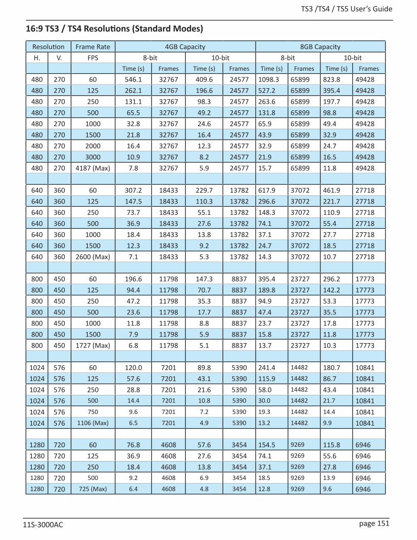
TS3 /TS4 / TS5 User’s Guide
11S-3000AC page 151
16:9 TS3 / TS4 Resolutions (Standard Modes)
Resolution Frame Rate 4GB Capacity 8GB CapacityH. V. FPS 8-bit 10-bit 8-bit 10-bit
Time (s) Frames Time (s) Frames Time (s) Frames Time (s) Frames
480 270 60 546.1 32767 409.6 24577 1098.3 65899 823.8 49428480 270 125 262.1 32767 196.6 24577 527.2 65899 395.4 49428480 270 250 131.1 32767 98.3 24577 263.6 65899 197.7 49428480 270 500 65.5 32767 49.2 24577 131.8 65899 98.8 49428480 270 1000 32.8 32767 24.6 24577 65.9 65899 49.4 49428480 270 1500 21.8 32767 16.4 24577 43.9 65899 32.9 49428480 270 2000 16.4 32767 12.3 24577 32.9 65899 24.7 49428480 270 3000 10.9 32767 8.2 24577 21.9 65899 16.5 49428480 270 4187 (Max) 7.8 32767 5.9 24577 15.7 65899 11.8 49428
640 360 60 307.2 18433 229.7 13782 617.9 37072 461.9 27718640 360 125 147.5 18433 110.3 13782 296.6 37072 221.7 27718640 360 250 73.7 18433 55.1 13782 148.3 37072 110.9 27718640 360 500 36.9 18433 27.6 13782 74.1 37072 55.4 27718640 360 1000 18.4 18433 13.8 13782 37.1 37072 27.7 27718640 360 1500 12.3 18433 9.2 13782 24.7 37072 18.5 27718640 360 2600 (Max) 7.1 18433 5.3 13782 14.3 37072 10.7 27718
800 450 60 196.6 11798 147.3 8837 395.4 23727 296.2 17773800 450 125 94.4 11798 70.7 8837 189.8 23727 142.2 17773800 450 250 47.2 11798 35.3 8837 94.9 23727 53.3 17773800 450 500 23.6 11798 17.7 8837 47.4 23727 35.5 17773800 450 1000 11.8 11798 8.8 8837 23.7 23727 17.8 17773800 450 1500 7.9 11798 5.9 8837 15.8 23727 11.8 17773800 450 1727 (Max) 6.8 11798 5.1 8837 13.7 23727 10.3 17773
1024 576 60 120.0 7201 89.8 5390 241.4 14482 180.7 108411024 576 125 57.6 7201 43.1 5390 115.9 14482 86.7 108411024 576 250 28.8 7201 21.6 5390 58.0 14482 43.4 108411024 576 500 14.4 7201 10.8 5390 30.0 14482 21.7 108411024 576 750 9.6 7201 7.2 5390 19.3 14482 14.4 108411024 576 1106 (Max) 6.5 7201 4.9 5390 13.2 14482 9.9 10841
1280 720 60 76.8 4608 57.6 3454 154.5 9269 115.8 69461280 720 125 36.9 4608 27.6 3454 74.1 9269 55.6 69461280 720 250 18.4 4608 13.8 3454 37.1 9269 27.8 69461280 720 500 9.2 4608 6.9 3454 18.5 9269 13.9 69461280 720 725 (Max) 6.4 4608 4.8 3454 12.8 9269 9.6 6946

TS3 / TS4 / TS5 User’s Guide
page 152 11S-3000AC
1:1 TS3 / TS4 Resolutions (Standard Modes)Resolution Frame Rate 4GB Capacity 8GB CapacityH. V. FPS 8-bit 10-bit 8-bit 10-bit
Time (s) Frames Time (s) Frames Time (s) Frames Time (s) Frames
256 256 60 1079.7 64784 803.6 48217 2171.47 130288 1616.2 96970256 256 125 518.3 64784 385.7 48217 1042.3 130288 775.8 96970256 256 250 259.1 64784 192.9 48217 521.2 130288 387.9 96970256 256 500 129.6 64784 96.4 48217 260.6 130288 193.9 96970256 256 1000 64.8 64784 48.2 48217 130.3 130288 97.0 96970256 256 1500 43.2 64784 32.1 48217 86.9 130288 64.6 96970256 256 2000 32.4 64784 24.1 48217 65.1 130288 48.5 96970256 256 4000 16.2 64784 12.1 48217 32.6 130288 24.2 96970256 256 6870 (Max) 9.4 64784 7.0 48217 19.0 130288 14.1 96970
400 400 60 442.4 26543 330.2 19809 889.7 53381 664.0 39838400 400 125 212.3 26543 158.5 19809 427.0 53381 318.7 39838400 400 250 106.2 26543 79.2 19809 213.5 53381 159.3 39838400 400 500 53.1 26543 39.6 19809 106.8 53381 79.7 39838400 400 1000 26.5 26543 19.8 19809 53.4 53381 39.8 39838400 400 2000 13.3 26543 9.9 19809 26.7 53381 19.9 39838400 400 3339 (Max) 7.9 26543 5.9 19809 16.0 53381 11.9 39838
512 512 60 270.0 16201 202.1 12128 543.0 32583 406.5 24391512 512 125 129.6 16201 97.0 12128 260.7 32583 195.1 24391512 512 250 64.8 16201 48.5 12128 130.3 32583 97.6 24391512 512 500 32.4 16201 24.3 12128 65.2 32583 48.8 24391512 512 1000 16.2 16201 12.1 12128 32.6 32583 24.4 24391512 512 1500 10.8 16201 8.1 12128 21.7 32583 16.3 24391512 512 2162 (Max) 7.5 16201 5.6 12128 15.1 32583 11.3 24391
800 800 60 110.6 6636 82.9 4971 222.4 13347 166.6 9998800 800 125 53.1 6636 39.8 4971 106.8 13347 80.0 9998800 800 250 26.5 6636 19.9 4971 53.4 13347 40.0 9998800 800 500 13.3 6636 9.9 4971 26.7 13347 20.0 9998800 800 977 (Max) 6.8 6636 5.1 4971 13.7 13347 10.2 9998
1024 1024 60 67.7 4059 50.5 3032 135.8 8146 101.6 60981024 1024 125 32.5 4059 24.3 3032 65.2 8146 48.8 60981024 1024 250 16.2 4059 12.1 3032 32.6 8146 24.4 60981024 1024 500 8.1 4059 6.1 3032 16.3 8146 12.2 60981024 1024 624 (Max) 6.5 4059 4.9 3032 13.1 8146 9.8 6098

TS3 /TS4 / TS5 User’s Guide
11S-3000AC page 153
TS4 LR2 in Long Record modeResolution LR2 8-bit Frame Rates and Times hh:mm:ss LR2 10-bit Frame Rates and Times hh:mm:ssH. V. FPS 256GB SSD 512GB SSD FPS 256GB SSD 512GB SSD320 240 60 15:13:34 30:27:08 60 11:07:35 22:15:11320 240 125 7:18:31 14:37:01 125 5:20:27 10:40:53320 240 250 3:39:15 7:18:31 250 2:40:13 5:20:27320 240 500 1:49:38 3:39:15 500 1:20:07 2:40:13320 240 1000 0:54:49 1:49:38 1000 0:40:03 1:20:07320 240 2000 0:27:24 0:54:49 2000 0:20:02 0:40:03320 240 3083 (Max) 0:17:47 0:35:34 2253 (Max) 0:13:00 0:25:59
400 400 60 7:13:55 14:27:50 60 5:27:30 10:55:00400 400 125 3:28:17 6:56:34 125 2:37:12 5:14:24400 400 250 1:44:08 3:28:17 250 1:18:36 2:37:12
400 400 500 0:52:04 1:44:08 500 0:39:18 1:18:36400 400 1000 0:26:02 0:52:04 1000 0:19:39 0:39:18400 400 1464 (Max) 0:17:47 0:35:34 1105 (Max) 0:13:25 0:26:51
512 512 60 4:31:13 9:02:26 60 3:21:49 6:43:38512 512 125 2:10:11 4:20:22 125 1:36:52 3:13:44512 512 250 1:05:06 2:10:11 250 0:48:26 1:36:52
512 512 500 0:32:33 1:05:06 500 0:24:13 0:48:26512 512 901 (Max) 0:18:04 0:36:07 681 (Max) 0:13:26 0:26:53
640 480 60 3:51:26 7:42:52 60 2:51:50 5:43:41640 480 125 1:51:05 3:42:10 125 1:22:29 2:44:58640 480 250 0:55:33 1:51:05 250 0:41:14 1:22:29640 480 500 0:27:46 0:55:33 500 0:20:37 0:41:14640 480 770 (Max) 0:18:02 0:36:04 580 (Max) 0:13:23 0:26:47
800 600 60 2:27:06 4:54:11 60 1:50:33 3:41:05800 600 125 1:10:36 2:21:13 125 0:53:04 1:46:07800 600 250 0:35:18 1:10:36 250 0:26:32 0:53:04800 600 496 (Max) 0:17:48 0:35:35 373 (Max) 0:13:22 0:26:45
1280 720 60 1:17:07 2:34:14 60 1:29:55 2:59:501280 720 125 0:37:01 1:14:02 125 0:43:10 1:26:191280 720 259 (Max) 0:17:52 0:35:44 194 (Max) 0:20:50 0:41:40
1024 1024 60 1:07:48 2:15:37 60 0:50:44 1:41:291024 1024 125 0:32:33 1:05:06 125 0:24:21 0:48:421024 1024 227 (Max) 0:17:55 0:35:51 170 (Max) 0:13:25 0:26:49
1280 1024 60 0:54:13 1:48:27 60 0:40:38 1:21:171280 1024 125 0:26:02 0:52:03 125 0:19:30 0:39:011280 1024 183 (Max) 0:17:47 0:35:33 136 (Max) 0:13:19 0:26:39
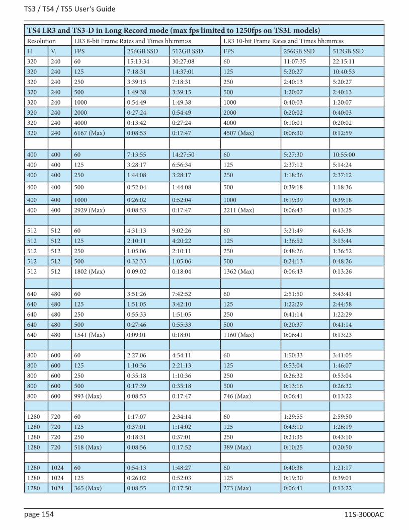
TS3 / TS4 / TS5 User’s Guide
page 154 11S-3000AC
TS4 LR3 and TS3-D in Long Record mode (max fps limited to 1250fps on TS3L models)Resolution LR3 8-bit Frame Rates and Times hh:mm:ss LR3 10-bit Frame Rates and Times hh:mm:ssH. V. FPS 256GB SSD 512GB SSD FPS 256GB SSD 512GB SSD320 240 60 15:13:34 30:27:08 60 11:07:35 22:15:11320 240 125 7:18:31 14:37:01 125 5:20:27 10:40:53320 240 250 3:39:15 7:18:31 250 2:40:13 5:20:27320 240 500 1:49:38 3:39:15 500 1:20:07 2:40:13320 240 1000 0:54:49 1:49:38 1000 0:40:03 1:20:07320 240 2000 0:27:24 0:54:49 2000 0:20:02 0:40:03320 240 4000 0:13:42 0:27:24 4000 0:10:01 0:20:02320 240 6167 (Max) 0:08:53 0:17:47 4507 (Max) 0:06:30 0:12:59
400 400 60 7:13:55 14:27:50 60 5:27:30 10:55:00400 400 125 3:28:17 6:56:34 125 2:37:12 5:14:24400 400 250 1:44:08 3:28:17 250 1:18:36 2:37:12
400 400 500 0:52:04 1:44:08 500 0:39:18 1:18:36
400 400 1000 0:26:02 0:52:04 1000 0:19:39 0:39:18400 400 2929 (Max) 0:08:53 0:17:47 2211 (Max) 0:06:43 0:13:25
512 512 60 4:31:13 9:02:26 60 3:21:49 6:43:38512 512 125 2:10:11 4:20:22 125 1:36:52 3:13:44512 512 250 1:05:06 2:10:11 250 0:48:26 1:36:52512 512 500 0:32:33 1:05:06 500 0:24:13 0:48:26512 512 1802 (Max) 0:09:02 0:18:04 1362 (Max) 0:06:43 0:13:26
640 480 60 3:51:26 7:42:52 60 2:51:50 5:43:41640 480 125 1:51:05 3:42:10 125 1:22:29 2:44:58640 480 250 0:55:33 1:51:05 250 0:41:14 1:22:29640 480 500 0:27:46 0:55:33 500 0:20:37 0:41:14640 480 1541 (Max) 0:09:01 0:18:01 1160 (Max) 0:06:41 0:13:23
800 600 60 2:27:06 4:54:11 60 1:50:33 3:41:05800 600 125 1:10:36 2:21:13 125 0:53:04 1:46:07800 600 250 0:35:18 1:10:36 250 0:26:32 0:53:04800 600 500 0:17:39 0:35:18 500 0:13:16 0:26:32800 600 993 (Max) 0:08:53 0:17:47 746 (Max) 0:06:41 0:13:22
1280 720 60 1:17:07 2:34:14 60 1:29:55 2:59:501280 720 125 0:37:01 1:14:02 125 0:43:10 1:26:191280 720 250 0:18:31 0:37:01 250 0:21:35 0:43:101280 720 518 (Max) 0:08:56 0:17:52 389 (Max) 0:10:25 0:20:50
1280 1024 60 0:54:13 1:48:27 60 0:40:38 1:21:171280 1024 125 0:26:02 0:52:03 125 0:19:30 0:39:011280 1024 365 (Max) 0:08:55 0:17:50 273 (Max) 0:06:41 0:13:22
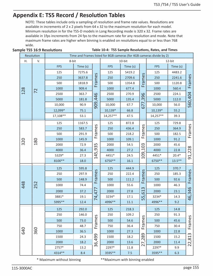
TS3 /TS4 / TS5 User’s Guide
11S-3000AC page 155
Appendix E: TS5 Record / Resolution TablesNOTE: These tables include only a sampling of resolution and frame rate values. Resolutions are available in increments of 2 x 2 pixels from 64 x 32 to the maximum resolution for each model. Minimum resolution in for the TS5-D models in Long Recording mode is 320 x 32. Frame rates are available in 1fps increments from 24 fps to the maximum rate for any resolution and mode. Note that maximum frame rates are higher when binning is enabled on resolutions equal to or less than 768 wide.
Table 10-4: TS5 Sample Resolutions, Rates, and TimesSample TS5 16:9 ResolutionsResolution Time and Frames listed for 8GB cameras (for 4GB cameras divide by 2)H. V. 8-bit 10-bit 12-bit
128
72
FPS Time (s)
909,
446
F
ram
es
FPS Time (s)
677,
396
F
ram
es
FPS Time (s)
560,
404
Fra
mes
125 7275.6 125 5419.2 125 4483.2250 3637.8 250 2709.6 250 2241.6500 1818.9 500 1354.8 500 1120.8
1000 909.4 1000 677.4 1000 560.42500 363.7 2500 270.9 2500 224.15000 181.8 5000 135.4 5000 112.0
10,000 90.9 10,000 67.7 10,000 56.0
12,099* 75.1 10,139* 66.8 10,139* 55.217,108** 53.1 14,257** 47.5 14,257** 39.3
320
180
125 1167.5
145,
935
Fr
ames
125 872.8
109,
103
Fr
ames
125 729.8
91,2
28
F
ram
es250 583.7 250 436.4 250 364.9500 291.9 500 218.2 500 182.5
1000 145.9 1000 109.1 1000 91.22000 72.9 2000 54.5 2000 45.64000 36.4 4000 27.2 4000 22.8
5329* 27.3 4451* 24.5 4451* 20.4*8100** 18.0 6750** 16.1 6750** 13.5**
448
252
125 595.8
74,4
77
Fram
es
125 444.9
55,6
13
Fram
es
125 370.7
46,3
46
Fram
es250 297.9 250 222.4 250 185.3
500 148.9 500 111.2 500 92.6
1000 74.4 1000 55.6 1000 46.3
2000 37.2 2000 27.8 2000 23.13881* 19.1 3234* 17.1 3234* 14.3
5995** 12.4 4996** 11.1 4996** 9.2
640
360
125 292.0
36,4
99
Fra
mes
125 218.3
27,2
89
Fram
es
125 14.8
22,8
13
Fram
es
250 146.0 250 109.2 250 91.3
500 73.0 500 54.6 500 45.6750 48.7 750 36.4 750 30.4
1000 36.5 1000 27.3 1000 22.81500 24.3 1500 18.2 1500 15.22000 18.2 2000 13.6 2000 11.4
2757* 13.2 2297* 11.8 2297* 9.94314** 8.4 3595** 7.5 3595** 6.3
* Maximum without binning **Maximum with binning enabled
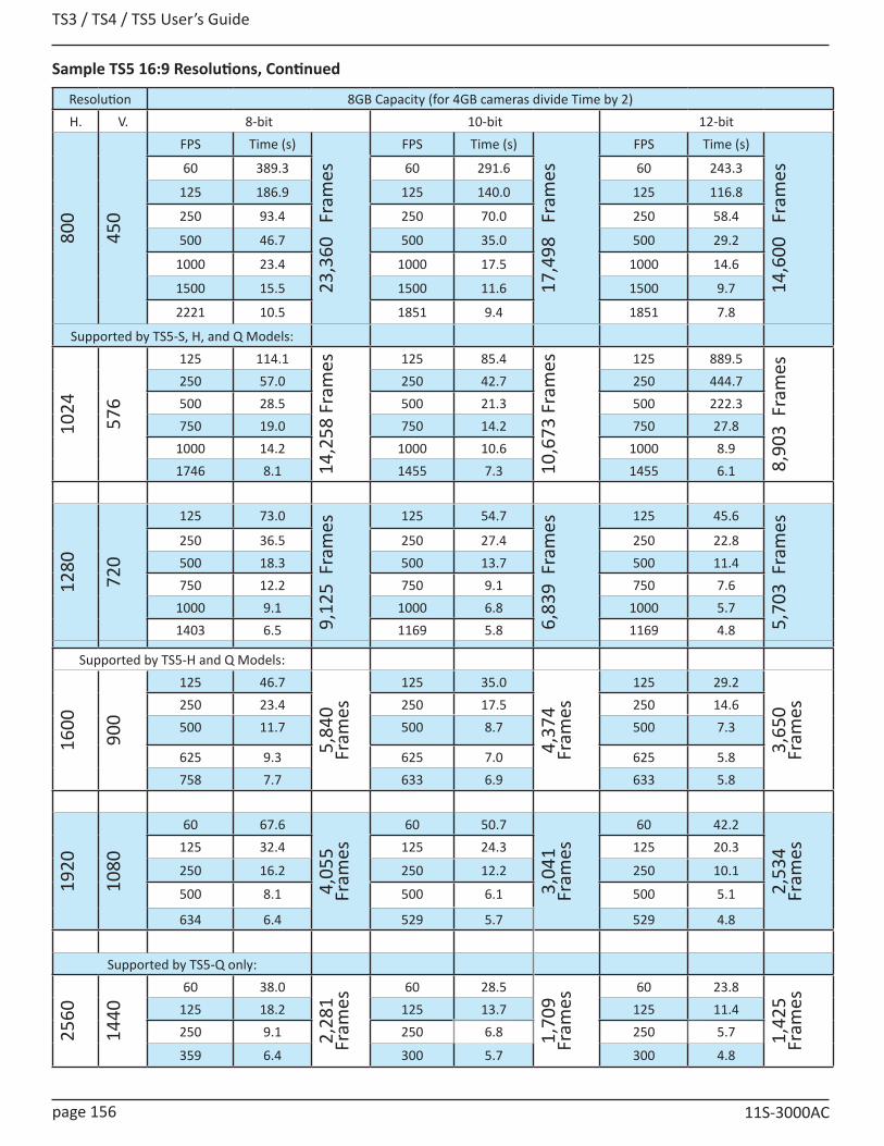
TS3 / TS4 / TS5 User’s Guide
page 156 11S-3000AC
Sample TS5 16:9 Resolutions, Continued
Resolution 8GB Capacity (for 4GB cameras divide Time by 2)H. V. 8-bit 10-bit 12-bit
800
450
FPS Time (s)
23,3
60
Fram
es
FPS Time (s)
17,4
98
Fram
es
FPS Time (s)
14,6
00
Fram
es60 389.3 60 291.6 60 243.3
125 186.9 125 140.0 125 116.8
250 93.4 250 70.0 250 58.4
500 46.7 500 35.0 500 29.2
1000 23.4 1000 17.5 1000 14.6
1500 15.5 1500 11.6 1500 9.7
2221 10.5 1851 9.4 1851 7.8
Supported by TS5-S, H, and Q Models:
1024
576
125 114.1
14,2
58 F
ram
es 125 85.4
10,6
73 F
ram
es 125 889.5
8,90
3 F
ram
es
250 57.0 250 42.7 250 444.7500 28.5 500 21.3 500 222.3750 19.0 750 14.2 750 27.8
1000 14.2 1000 10.6 1000 8.91746 8.1 1455 7.3 1455 6.1
1280
720
125 73.0
9,12
5 F
ram
es 125 54.7
6,83
9 F
ram
es 125 45.6
5,70
3 F
ram
es
250 36.5 250 27.4 250 22.8500 18.3 500 13.7 500 11.4750 12.2 750 9.1 750 7.6
1000 9.1 1000 6.8 1000 5.71403 6.5 1169 5.8 1169 4.8
Supported by TS5-H and Q Models:
1600
900
125 46.7
5,84
0 Fr
ames
125 35.0
4,37
4 Fr
ames
125 29.2
3,65
0 Fr
ames250 23.4 250 17.5 250 14.6
500 11.7 500 8.7 500 7.3
625 9.3 625 7.0 625 5.8758 7.7 633 6.9 633 5.8
1920
1080
60 67.6
4,05
5 Fr
ames
60 50.7
3,04
1 Fr
ames
60 42.2
2,53
4 Fr
ames125 32.4 125 24.3 125 20.3
250 16.2 250 12.2 250 10.1
500 8.1 500 6.1 500 5.1
634 6.4 529 5.7 529 4.8
Supported by TS5-Q only:
2560
1440
60 38.0
2,28
1 Fr
ames
60 28.5
1,70
9 Fr
ames
60 23.8
1,42
5 Fr
ames125 18.2 125 13.7 125 11.4
250 9.1 250 6.8 250 5.7
359 6.4 300 5.7 300 4.8
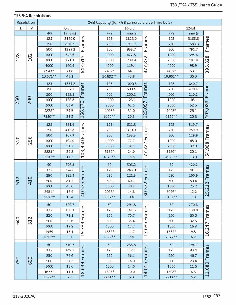
TS3 /TS4 / TS5 User’s Guide
11S-3000AC page 157
TS5 5:4 ResolutionsResolution 8GB Capacity (for 4GB cameras divide Time by 2)
H. V. 8-bit 10-bit 12-bitFPS Time (s)
642,
615
Fra
mes
FPS Time (s)
477,
872
Fra
mes
FPS Time (s)
395,
828
Fra
mes
128
102
125 5140.9 125 3823.0 125 3166.6250 2570.5 250 1911.5 250 1583.3500 1285.2 500 955.7 500 791.7
1000 642.6 1000 477.8 1000 395.82000 321.3 2000 238.9 2000 197.94000 160.6 4000 119.4 4000 98.9
8943* 71.8 7452* 64.1 7452* 53.113,071** 49.1 10,892** 43.8 10,892** 36.3
250
200
125 1334.216
6,77
0 F
ram
es 125 1000.8
125,
097
Fra
mes 125 840.7
105,
089
Fra
mes
250 667.1 250 500.4 250 420.4500 333.5 500 250.2 500 210.2
1000 166.8 1000 125.1 1000 105.12000 83.4 2000 62.5 2000 52.5
4828* 34.5 4023* 31.0 4023* 26.17380** 22.5 6150** 20.3 6150** 20.3
320
256
125 831.6
103,
950
Fram
es 125 621.8
77,7
27 F
ram
es
125 519.7
64,9
68 F
ram
es250 415.8 250 310.9 250 259.9500 207.9 500 155.5 500 129.9
1000 104.0 1000 77.7 1000 65.02000 51.3 2000 38.3 2000 32.0
3823* 26.8 3186* 24.0 3186* 20.15910** 17.3 4925** 15.5 4925** 13.0
512
410
60 676.3
40,5
75 F
ram
es
60 506.2
30,3
72 F
ram
es
60 420.2
25,2
12 F
ram
es125 324.6 125 243.0 125 201.7250 162.3 250 121.5 250 100.9500 81.2 500 60.7 500 50.4
1000 40.6 1000 30.4 1000 25.22431* 16.4 2026* 14.8 2026* 12.2
3818** 10.4 3182** 9.4 3182** 7.8
640
512
60 329.7
19,7
83 F
ram
es
60 294.8
17,6
85 F
ram
es
60 270.816
,247
Fra
mes125 158.3 125 141.5 125 130.0
250 79.1 250 70.7 250 65.0500 39.6 500 35.4 500 32.5
1000 19.8 1000 17.7 1000 16.31959 13.1 1632* 11.7 1632* 9.8
3093** 8.2 2577** 7.4 2577** 6.2
750
600
60 310.7
18,6
39 F
ram
es
60 233.6
14,0
16 F
ram
es
60 194.7
11,6
80 F
ram
es125 149.1 125 112.1 125 93.4250 74.6 250 56.1 250 46.7500 37.3 500 28.0 500 23.4
1000 18.6 1000 14.0 1000 11.61677* 11.1 1398* 10.0 1398* 8.3
2657** 7.0 2214** 6.3 2214** 5.2
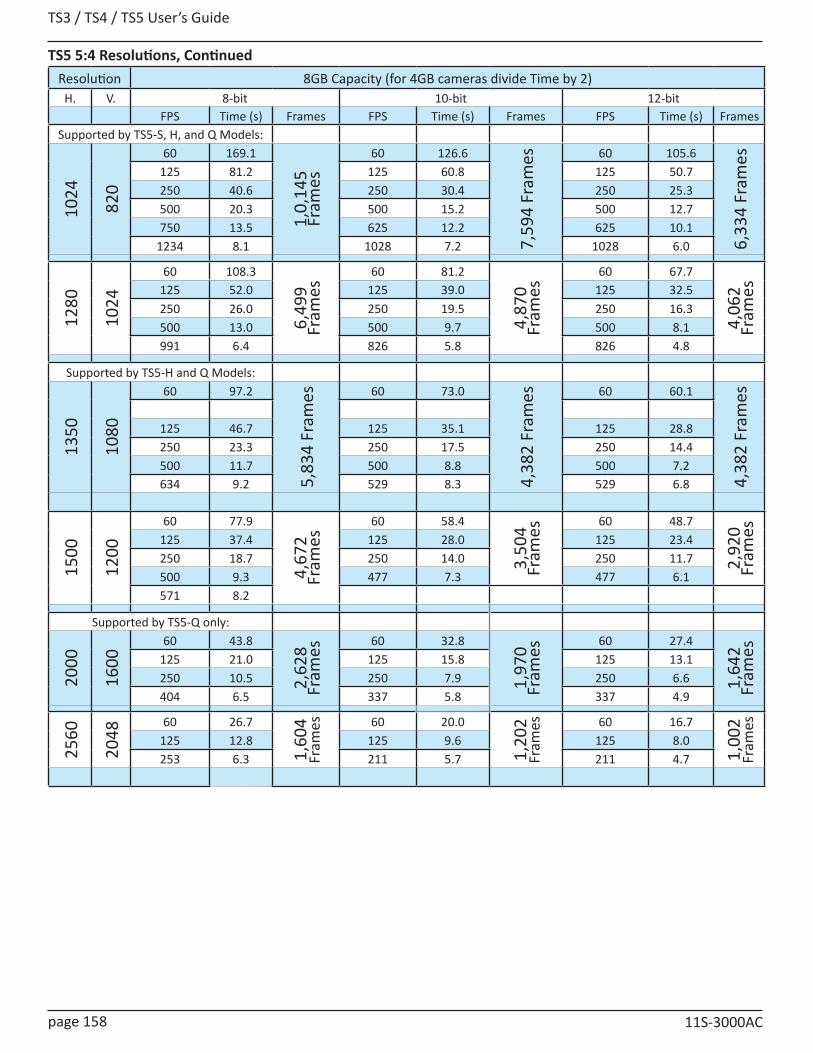
TS3 / TS4 / TS5 User’s Guide
page 158 11S-3000AC
TS5 5:4 Resolutions, ContinuedResolution 8GB Capacity (for 4GB cameras divide Time by 2)
H. V. 8-bit 10-bit 12-bitFPS Time (s) Frames FPS Time (s) Frames FPS Time (s) Frames
Supported by TS5-S, H, and Q Models:
1024
820
60 169.1
1,0,
145
Fram
es
60 126.6
7,59
4 Fr
ames 60 105.6
6,33
4 Fr
ames
125 81.2 125 60.8 125 50.7250 40.6 250 30.4 250 25.3500 20.3 500 15.2 500 12.7750 13.5 625 12.2 625 10.1
1234 8.1 1028 7.2 1028 6.0
1280
1024
60 108.3
6,49
9 Fr
ames
60 81.2
4,87
0 Fr
ames
60 67.7
4,06
2 Fr
ames125 52.0 125 39.0 125 32.5
250 26.0 250 19.5 250 16.3500 13.0 500 9.7 500 8.1991 6.4 826 5.8 826 4.8
Supported by TS5-H and Q Models:
1350
1080
60 97.2
5,83
4 Fr
ames 60 73.0
4,38
2 Fr
ames 60 60.1
4,38
2 Fr
ames
125 46.7 125 35.1 125 28.8250 23.3 250 17.5 250 14.4500 11.7 500 8.8 500 7.2634 9.2 529 8.3 529 6.8
1500
1200
60 77.9
4,67
2 Fr
ames
60 58.43,
504
Fram
es60 48.7
2,92
0 Fr
ames125 37.4 125 28.0 125 23.4
250 18.7 250 14.0 250 11.7500 9.3 477 7.3 477 6.1571 8.2
Supported by TS5-Q only:
2000
1600
60 43.8
2,62
8 Fr
ames
60 32.8
1,97
0 Fr
ames
60 27.4
1,64
2 Fr
ames125 21.0 125 15.8 125 13.1
250 10.5 250 7.9 250 6.6404 6.5 337 5.8 337 4.9
2560
2048
60 26.7
1,60
4 Fr
ames 60 20.0
1,20
2 Fr
ames 60 16.7
1,00
2 Fr
ames
125 12.8 125 9.6 125 8.0253 6.3 211 5.7 211 4.7

TS3 /TS4 / TS5 User’s Guide
11S-3000AC page 159
TS5 4:3 ResolutionsResolution 8GB Capacity (for 4GB cameras divide Time by 2)H. V. 8-bit 10-bit 12-bit
FPS Time (s) Frames FPS Time (s) Frames FPS Time (s) Frames
128
96
125 5461.4
682,
675
Fra
mes
125 4067.0
508,
375
Fra
mes
125 3364.2
420,
527
Fra
mes250 2730.7 250 2033.5 250 1682.1
500 1365.4 500 1016.8 500 841.11000 682.7 1000 508.4 1000 420.52000 341.3 2000 254.2 2000 210.34000 170.7 4000 127.1 4000 105.1
9485* 72.3 7862* 64.6 7862* 53.413,718** 49.765 11,432** 44.4 11,432** 36.7
256
192
125 1368.017
1,00
1 F
ram
es125 1018.2
127,
278
Fra
mes
125 842.1
105,
258
Fra
mes250 684.0 250 509.1 250 421.0
500 342.0 500 254.6 500 210.5750 228.0 750 169.7 750 140.3
1000 171.0 1000 127.3 1000 105.32000 85.5 2000 63.6 2000 52.6
5017* 34.0 4180* 30.4 4180* 25.17652** 22.3 6377** 19.9 6377** 16.5
320
240
125 875.7
109,
466
Fra
mes 125 654.8
81,8
52 F
ram
es125 547.4
68,4
27 F
ram
es250 437.9 250 327.4 250 273.7500 218.9 500 163.7 500 136.9
1000 109.5 1000 81.9 1000 68.42000 54.7 2000 40.9 2000 34.2
4065* 26.9 3387* 24.1 3387* 20.26267** 17.4 5222** 15.6 5222* 13.1
512
384
60 712.9
42,7
71 F
ram
es
60 533.6
32,0
17 F
ram
es
60 443.0
26,5
78 F
ram
es125 342.2 125 256.1 125 212.6250 171.1 250 128.1 250 106.3500 85.5 500 64.0 500 53.2
1000 42.8 1000 32.0 1000 26.62590* 16.5 2158* 14.8 2158* 12.3
4061** 10.4 3384** 9.4 3384** 7.8
640
480
60 456.3
27,3
75 F
ram
es
60 341.1
20,4
68 F
ram
es
60 285.2
17,1
10 F
ram
es125 219.0 125 163.7 125 136.9250 109.5 250 81.9 250 68.4500 54.8 500 40.9 500 34.2
1000 27.4 1000 20.5 1000 17.12086* 13.1 1738* 11.7 1738* 9.8
3289** 8.3 2741** 7.4 2741** 6.2

TS3 / TS4 / TS5 User’s Guide
page 160 11S-3000AC
TS5 4:3 Resolutions, Continued
Resolution 8GB Capacity (for 4GB cameras divide Time by 2)H. V. 8-bit 10-bit 12-bit
800
600
FPS Time (s)
17,5
20 F
ram
es
FPS Time (s)
13,1
24 F
ram
es
FPS Time (s)
10,9
50 F
ram
es60 292.0 60 218.7 60 182.5125 140.2 125 105.0 125 87.6250 70.1 250 52.5 250 43.8500 35.0 500 26.2 500 21.9750 23.4 750 17.5 750 14.6
1677 10.4 1398 9.3 1398 7.8Supported by TS5-S, -H and -Q models:
1024
768
60 178.210
,694
Fra
mes 60 133.4
8,00
5 Fr
ames
60 111.3
6,67
7 Fr
ames125 85.6 125 64.0 125 53.4
250 42.8 250 32.0 250 26.7500 21.4 500 16.0 500 13.4750 14.3 750 10.6 750 8.9
1316 8.1 1097 7.2 1097 6.0
1280
960
60 114.1
6,84
4 Fr
ames
60 85.5
5,12
9 Fr
ames
60 71.3
4,27
7 Fr
ames125 54.8 125 41.0 125 34.2
250 27.4 250 20.5 250 17.1500 13.7 500 10.3 500 8.6
1057 6.4 880 5.8 880 4.8Supported by TS5-H and -Q models:
1440
1080
60 90.1
5,40
7 Fr
ames
60 67.6
4,05
5 Fr
ames
60 56.3
3,37
9 Fr
ames125 43.3 125 32.4 125 27.0
250 21.6 250 16.2 250 13.5500 10.8 500 8.1 500 6.8
634(Max) 8.5 529(Max) 7.7 529(Max) 6.4Supported by TS5 Q only:
2000
1500
60 46.7
2,80
3 Fr
ames
60 35.0
2,10
1 Fr
ames
60 29.2
1,75
2 Fr
ames125 22.4 125 16.8 125 14.0
250 11.2 250 8.4 250 7.0431(Max) 6.5 359(Max) 5.9 359(Max) 4.9
2560
1920
60 28.5
1,71
1 Fr
ames 60 21.4
1,28
2 Fr
ames 60 17.8
1,06
9 Fr
ames
125 13.7 125 10.3 125 8.6270f(Max) 6.3 225(Max) 5.7 225(Max) 4.8

TS3 /TS4 / TS5 User’s Guide
11S-3000AC page 161
Resolution 1TB Capacity SSD (for TS5 with 512GB divide by 2, TS5 with 2TB multiply by 2 for approximate times)H V 8 Bits 10 Bits 12 Bits
FPS Hr Min Sec FPS Hr Min Sec FPS Hr Min Sec
320
180
60 75 10 15 60 59 20 44 60 49 1 28125 36 4 55 125 28 29 9 125 23 31 54250 18 2 27 250 14 14 34 250 11 45 57500 9 1 13 500 7 7 17 500 5 52 58
1000 4 30 36 1000 3 33 38 1000 2 56 291500 3 0 24 1500 2 22 25 1500 1 57 393000 1 30 12 3000 1 11 12 3000 0 58 493904* 1 9 19 3082* 1 9 19 2546* 1 10 584451** 1 0 47 4451** 0 47 59 4451** 0 39 395000*** 0 54 7 5000*** 0 42 43 5000*** 0 35 17
320
240
60 59 28 32 60 43 27 47 60 37 40 3125 28 32 53 125 20 51 44 125 18 4 49250 14 16 26 250 10 25 52 250 9 2 24500 7 8 13 500 5 12 56 500 4 31 12
1000 3 34 6 1000 2 36 28 1000 2 15 362000 1 47 3 2000 1 18 14 2000 1 7 483082* 1 9 28 2252* 1 9 28 1952* 1 9 283394** 1 3 5 3394** 0 46 6 3394** 0 39 575000*** 0 41 0 4505*** 0 34 43 3905*** 0 34 43
512
512
60 17 39 24 60 13 8 22 60 10 58 16125 8 28 31 125 6 18 25 125 5 15 58250 4 14 15 250 3 9 12 250 2 37 59500 2 7 7 500 1 34 36 500 1 18 59915* 1 9 28 681* 1 9 27 568* 1 9 321634 0 38 54 1362 0 34 43 1137 0 34 44
640
480
60 15 4 0 60 11 11 17 60 9 25 0125 7 13 55 125 5 22 13 125 4 31 12250 3 36 57 250 2 41 6 250 2 15 36500 1 48 28 500 1 20 33 500 1 7 48781* 1 9 26 580* 1 9 26 488* 1 9 281562 0 34 43 1160 0 34 43 976 0 34 44
800
600
60 9 34 34 60 7 11 51 60 6 0 38125 4 35 47 125 3 27 17 125 2 53 6250 2 17 53 250 1 43 38 250 1 26 33496* 1 9 30 373* 1 9 28 311* 1 9 34500 1 8 56 500 0 51 49 500 0 43 16993 0 34 43 746 0 34 44 623 0 34 43
TS5-D Long Record

TS3 / TS4 / TS5 User’s Guide
page 162 11S-3000AC
*Maximum frame rate in LR2 (Slow SSD or External SSD) mode. See “Figure 2-3: Power Up / Charging Menu (TS4-LR3 / TSx-D)” on page 9.
**Maximum frame rate in LR3 (Fast SSD) without binning.
***Maximum frame rate in LR3 (Fast SSD) binning enabled (up to 7500fps for some SSDs).
Resolution 1TB Capacity SSD (for TS5 with 512GB divide by 2, TS5 with 2TB multiply by 2 for approximate times)H V 8 Bits 10 Bits 12 Bits
FPS Hr Min Sec FPS Hr Min Sec FPS Hr Min Sec
1280
720
60 5 1 20 60 3 45 14 60 3 8 20125 2 24 38 125 1 48 7 125 1 30 24250 1 12 19 250 0 54 3 250 0 45 12260* 1 9 32 194* 1 9 39 162* 1 9 45520 0 34 46 389 0 34 44 325 0 34 46
1280
1024
60 3 31 52 60 2 38 45 60 2 12 24125 1 41 42 125 1 16 12 125 1 3 33183* 1 9 28 137* 1 9 31 114* 1 9 41250 0 50 51 274 0 34 45 228 0 34 50366 0 34 44
Supported by TS5-H and -Q models:
1350
1080
60 3 9 54 60 2 22 43 60 1 58 56125 1 31 9 125 1 8 30 125 0 57 5164* 1 9 28 123* 1 9 37 102* 1 9 57250 0 45 34 246 0 34 48 205 0 34 48328 0 34 44
1920
1080
60 2 13 43 60 1 40 26 60 1 23 41115* 1 9 46 86* 1 10 4 72* 1 9 44125 1 4 11 125 0 48 12 125 0 40 10231 0 34 44 173 0 34 50 144 0 34 52
Supported by TS5 Q only:
2560
1440
60 1 15 18 60 0 56 25 60 0 47 465* 1 9 30 48* 1 10 32 40* 1 10 36130 0 34 45 97 0 34 54 81 0 34 52
2560
2048
45* 1 10 35 34* 1 10 1 28* 1 10 5660 0 52 56 68 0 35 0 57 0 34 5091 0 34 54
TS5-D Long Record, Continued
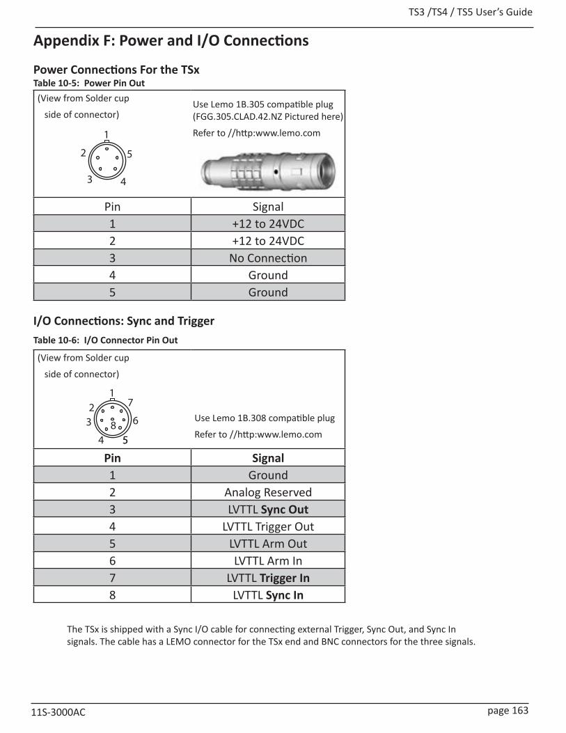
TS3 /TS4 / TS5 User’s Guide
11S-3000AC page 163
Appendix F: Power and I/O Connections
Power Connections For the TSx (View from Solder cup
side of connector)
Pin Signal1 +12 to 24VDC2 +12 to 24VDC3 No Connection4 Ground5 Ground
I/O Connections: Sync and Trigger
(View from Solder cup
side of connector)
Pin Signal1 Ground2 Analog Reserved3 LVTTL Sync Out4 LVTTL Trigger Out5 LVTTL Arm Out6 LVTTL Arm In7 LVTTL Trigger In8 LVTTL Sync In
The TSx is shipped with a Sync I/O cable for connecting external Trigger, Sync Out, and Sync In signals. The cable has a LEMO connector for the TSx end and BNC connectors for the three signals.
1
3
2
4
5
Use Lemo 1B.305 compatible plug (FGG.305.CLAD.42.NZ Pictured here)
Refer to //http:www.lemo.com
1
32
5
6
7
58
4
Use Lemo 1B.308 compatible plug
Refer to //http:www.lemo.com
Table 10-5: Power Pin Out
Table 10-6: I/O Connector Pin Out

TS3 / TS4 / TS5 User’s Guide
page 164 11S-3000AC
Figure 10-1: Sync I/O Cable Drawing
Figure 10-2: Sync I/O Camera Interface Schematic
(This drawing depicts a 6-signal cable that exposes all available I/O channels. Cameras are shipped with the standard 3-signal cable that exposes Sync Out, Trigger In, and Sync In.)
The TSx I/O circuits are designed to operate at LVTTL levels (3.3v). The inputs will respond to simple switch closures.
NOTE: THESE I/O PORTS ARE FOR LVTTL LEVELS ONLY. VOLTAGES ABOVE 3.3V WILL HARM THE TSx.
3.3v
1.8v
DI
OE
LVTTLTr /Tr r
uClamp3306p
to Control Logic
R
anscieveranslato
GND
3.3v
1 7 TRIG IN
8 SYNC INLEMO_1B_8P_REC
(1/2)- 74AVC2T245
3
SYN
C O
UT
Transceiver/Translator
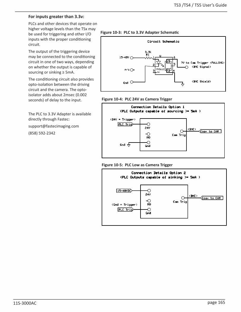
TS3 /TS4 / TS5 User’s Guide
11S-3000AC page 165
For inputs greater than 3.3v:PLCs and other devices that operate on higher voltage levels than the TSx may be used for triggering and other I/O inputs with the proper conditioning circuit.
The output of the triggering device may be connected to the conditioning circuit in one of two ways, depending on whether the output is capable of sourcing or sinking ≥ 5mA.
The conditioning circuit also provides opto-isolation between the driving circuit and the camera. The opto-isolator adds about 2msec (0.002 seconds) of delay to the input.
The PLC to 3.3V Adapter is available directly through Fastec:
(858) 592-2342
Figure 10-3: PLC to 3.3V Adapter Schematic
Figure 10-4: PLC 24V as Camera Trigger
Figure 10-5: PLC Low as Camera Trigger
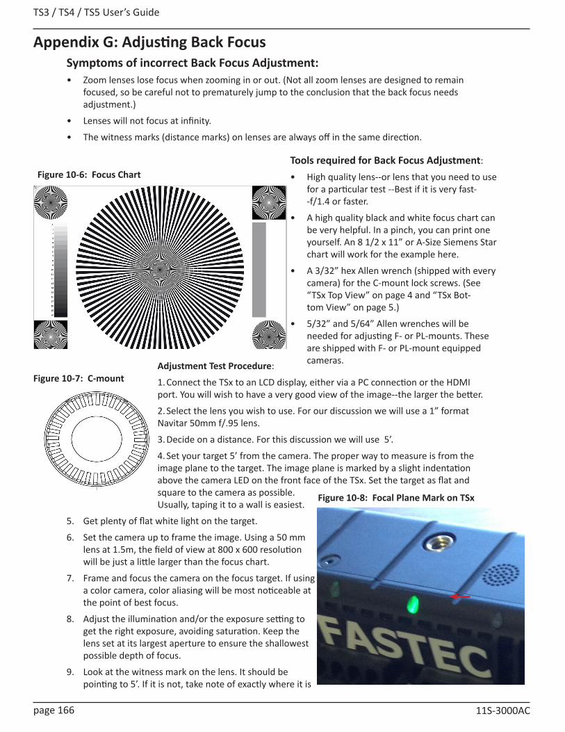
TS3 / TS4 / TS5 User’s Guide
page 166 11S-3000AC
Figure 10-6: Focus ChartTools required for Back Focus Adjustment:
• High quality lens--or lens that you need to use for a particular test --Best if it is very fast--f/1.4 or faster.
• A high quality black and white focus chart can be very helpful. In a pinch, you can print one yourself. An 8 1/2 x 11” or A-Size Siemens Star chart will work for the example here.
• A 3/32” hex Allen wrench (shipped with every camera) for the C-mount lock screws. (See “TSx Top View” on page 4 and “TSx Bot-tom View” on page 5.)
• 5/32” and 5/64” Allen wrenches will be needed for adjusting F- or PL-mounts. These are shipped with F- or PL-mount equipped cameras.
Appendix G: Adjusting Back FocusSymptoms of incorrect Back Focus Adjustment:• Zoom lenses lose focus when zooming in or out. (Not all zoom lenses are designed to remain
focused, so be careful not to prematurely jump to the conclusion that the back focus needs adjustment.)
• Lenses will not focus at infinity.
• The witness marks (distance marks) on lenses are always off in the same direction.
Adjustment Test Procedure:
1. Connect the TSx to an LCD display, either via a PC connection or the HDMI port. You will wish to have a very good view of the image--the larger the better.
2. Select the lens you wish to use. For our discussion we will use a 1” format Navitar 50mm f/.95 lens.
3. Decide on a distance. For this discussion we will use 5’.
4. Set your target 5’ from the camera. The proper way to measure is from the image plane to the target. The image plane is marked by a slight indentation above the camera LED on the front face of the TSx. Set the target as flat and square to the camera as possible. Usually, taping it to a wall is easiest.
5. Get plenty of flat white light on the target.
6. Set the camera up to frame the image. Using a 50 mm lens at 1.5m, the field of view at 800 x 600 resolution will be just a little larger than the focus chart.
7. Frame and focus the camera on the focus target. If using a color camera, color aliasing will be most noticeable at the point of best focus.
8. Adjust the illumination and/or the exposure setting to get the right exposure, avoiding saturation. Keep the lens set at its largest aperture to ensure the shallowest possible depth of focus.
9. Look at the witness mark on the lens. It should be pointing to 5’. If it is not, take note of exactly where it is
Figure 10-7: C-mount
Figure 10-8: Focal Plane Mark on TSx
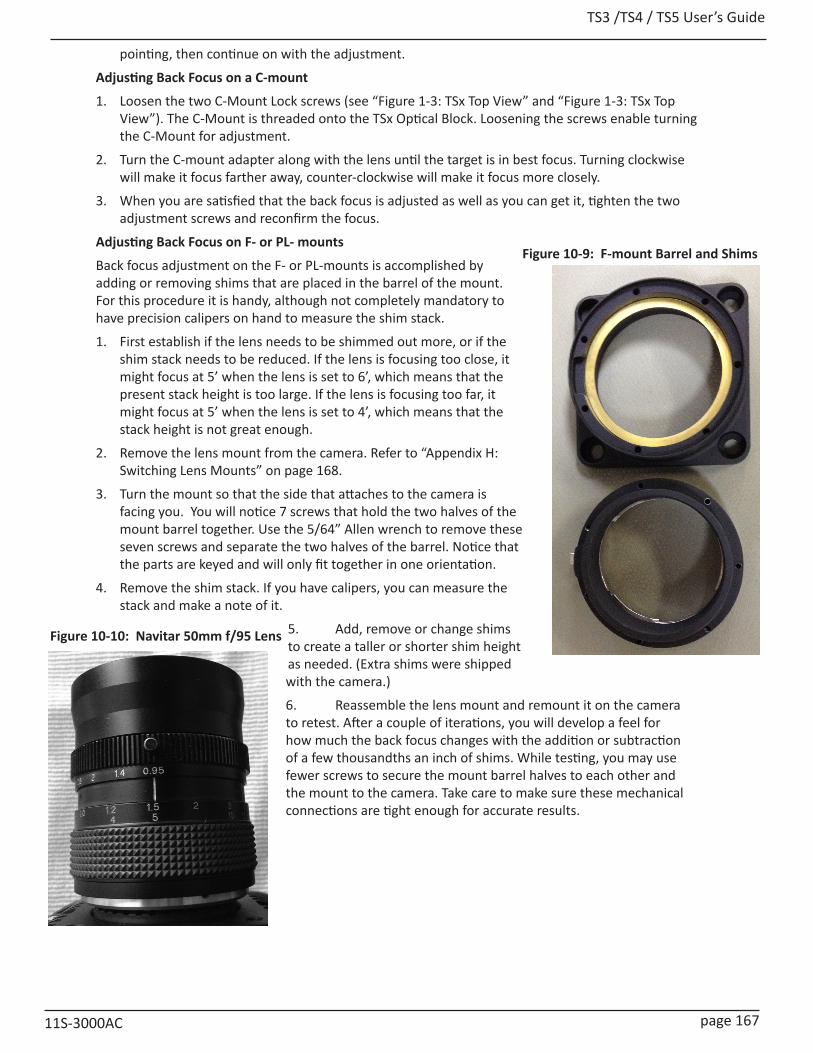
TS3 /TS4 / TS5 User’s Guide
11S-3000AC page 167
Figure 10-10: Navitar 50mm f/95 Lens
pointing, then continue on with the adjustment.
Adjusting Back Focus on a C-mount
1. Loosen the two C-Mount Lock screws (see “Figure 1-3: TSx Top View” and “Figure 1-3: TSx Top View”). The C-Mount is threaded onto the TSx Optical Block. Loosening the screws enable turning the C-Mount for adjustment.
2. Turn the C-mount adapter along with the lens until the target is in best focus. Turning clockwise will make it focus farther away, counter-clockwise will make it focus more closely.
3. When you are satisfied that the back focus is adjusted as well as you can get it, tighten the two adjustment screws and reconfirm the focus.
Adjusting Back Focus on F- or PL- mounts
Back focus adjustment on the F- or PL-mounts is accomplished by adding or removing shims that are placed in the barrel of the mount. For this procedure it is handy, although not completely mandatory to have precision calipers on hand to measure the shim stack.
1. First establish if the lens needs to be shimmed out more, or if the shim stack needs to be reduced. If the lens is focusing too close, it might focus at 5’ when the lens is set to 6’, which means that the present stack height is too large. If the lens is focusing too far, it might focus at 5’ when the lens is set to 4’, which means that the stack height is not great enough.
2. Remove the lens mount from the camera. Refer to “Appendix H: Switching Lens Mounts” on page 168.
3. Turn the mount so that the side that attaches to the camera is facing you. You will notice 7 screws that hold the two halves of the mount barrel together. Use the 5/64” Allen wrench to remove these seven screws and separate the two halves of the barrel. Notice that the parts are keyed and will only fit together in one orientation.
4. Remove the shim stack. If you have calipers, you can measure the stack and make a note of it.
5. Add, remove or change shims to create a taller or shorter shim height as needed. (Extra shims were shipped with the camera.)
6. Reassemble the lens mount and remount it on the camera to retest. After a couple of iterations, you will develop a feel for how much the back focus changes with the addition or subtraction of a few thousandths an inch of shims. While testing, you may use fewer screws to secure the mount barrel halves to each other and the mount to the camera. Take care to make sure these mechanical connections are tight enough for accurate results.
Figure 10-9: F-mount Barrel and Shims
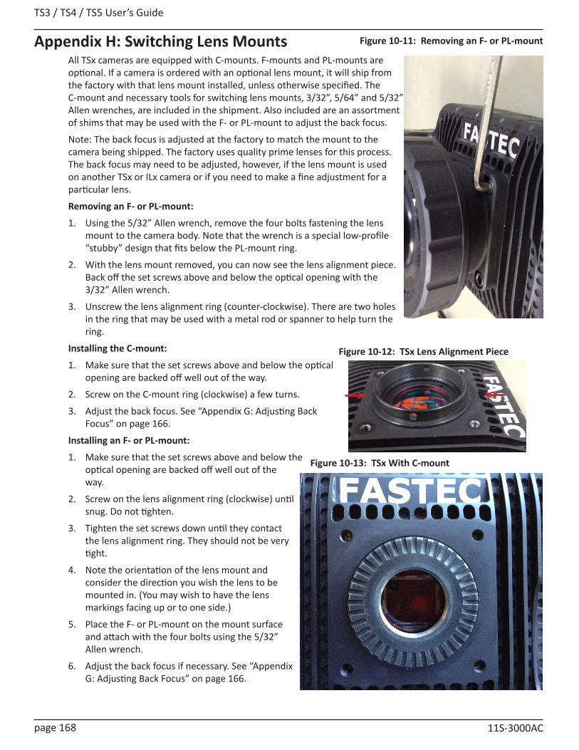
TS3 / TS4 / TS5 User’s Guide
page 168 11S-3000AC
Appendix H: Switching Lens MountsAll TSx cameras are equipped with C-mounts. F-mounts and PL-mounts are optional. If a camera is ordered with an optional lens mount, it will ship from the factory with that lens mount installed, unless otherwise specified. The C-mount and necessary tools for switching lens mounts, 3/32”, 5/64” and 5/32” Allen wrenches, are included in the shipment. Also included are an assortment of shims that may be used with the F- or PL-mount to adjust the back focus.
Note: The back focus is adjusted at the factory to match the mount to the camera being shipped. The factory uses quality prime lenses for this process. The back focus may need to be adjusted, however, if the lens mount is used on another TSx or ILx camera or if you need to make a fine adjustment for a particular lens.
Removing an F- or PL-mount:
1. Using the 5/32” Allen wrench, remove the four bolts fastening the lens mount to the camera body. Note that the wrench is a special low-profile “stubby” design that fits below the PL-mount ring.
2. With the lens mount removed, you can now see the lens alignment piece. Back off the set screws above and below the optical opening with the 3/32” Allen wrench.
3. Unscrew the lens alignment ring (counter-clockwise). There are two holes in the ring that may be used with a metal rod or spanner to help turn the ring.
Installing the C-mount:
1. Make sure that the set screws above and below the optical opening are backed off well out of the way.
2. Screw on the C-mount ring (clockwise) a few turns.
3. Adjust the back focus. See “Appendix G: Adjusting Back Focus” on page 166.
Installing an F- or PL-mount:
1. Make sure that the set screws above and below the optical opening are backed off well out of the way.
2. Screw on the lens alignment ring (clockwise) until snug. Do not tighten.
3. Tighten the set screws down until they contact the lens alignment ring. They should not be very tight.
4. Note the orientation of the lens mount and consider the direction you wish the lens to be mounted in. (You may wish to have the lens markings facing up or to one side.)
5. Place the F- or PL-mount on the mount surface and attach with the four bolts using the 5/32” Allen wrench.
6. Adjust the back focus if necessary. See “Appendix G: Adjusting Back Focus” on page 166.
Figure 10-11: Removing an F- or PL-mount
Figure 10-12: TSx Lens Alignment Piece
Figure 10-13: TSx With C-mount
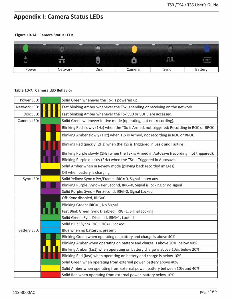
TS3 /TS4 / TS5 User’s Guide
11S-3000AC page 169
Appendix I: Camera Status LEDs
Power Network Disk Camera Sync Battery
Figure 10-14: Camera Status LEDs
Power LED: Solid Green whenever the TSx is powered up.
Network LED: Fast blinking Amber whenever the TSx is sending or receiving on the network.
Disk LED: Fast blinking Amber whenever the TSx SSD or SDHC are accessed.Camera LED: Solid Green whenever in LIve mode (operating, but not recording).
Blinking Red slowly (1Hz) when the TSx is Armed, not triggered; Recording in ROC or BROC
Blinking Amber slowly (1Hz) when TSx is Armed, not recording in ROC or BROC
Blinking Red quickly (2Hz) when the TSx is Triggered in Basic and FasFire
Blinking Purple slowly (1Hz) when the TSx is Armed in Autosave (recording, not triggered).Blinking Purple quickly (2Hz) when the TSx is Triggered in Autosave.Solid Amber when in Review mode (playing back recorded images).Off when battery is charging
Sync LED: Solid Yellow: Sync = Per/Frame, IRIG= 0, Signal state= any Blinking Purple: Sync = Per Second, IRIG=0, Signal is locking or no signalSolid Purple: Sync = Per Second, IRIG=0, Signal LockedOff: Sync disabled, IRIG=0
Blinking Green: IRIG=1, No SignalFast Blink Green: Sync Disabled, IRIG=1, Signal LockingSolid Green: Sync Disabled, IRIG=1, LockedSolid Blue: Sync=IRIG, IRIG=1, Locked
Battery LED: Blue when no battery is presentBlinking Green when operating on battery and charge is above 40%Blinking Amber when operating on battery and charge is above 20%, below 40%Blinking Amber (fast) when operating on battery charge is above 10%, below 20%Blinking Red (fast) when operating on battery and charge is below 10%Solid Green when operating from external power, battery above 40%Solid Amber when operating from external power, battery between 10% and 40% Solid Red when operating from external power, battery below 10%
Table 10-7: Camera LED Behavior
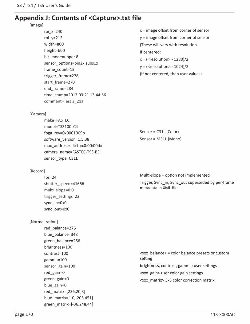
TS3 / TS4 / TS5 User’s Guide
page 170 11S-3000AC
Appendix J: Contents of <Capture>.txt file[Image] roi_x=240 roi_y=212 width=800 height=600 bit_mode=upper 8 sensor_options=bin2x:subs1x frame_count=15 trigger_frame=278 start_frame=270 end_frame=284 time_stamp=2013:03:21 13:44:56 comment=Test 3_21a
[Camera] make=FASTEC model=TS3100LC4 fpga_rev=0x0001009b software_version=1.5.38 mac_address=a4:1b:c0:00:00:be camera_name=FASTEC-TS3-BE sensor_type=C31L
[Record] fps=24 shutter_speed=41666 multi_slope=0:0 trigger_settings=22 sync_in=0x0 sync_out=0x0
[Normalization] red_balance=276 blue_balance=348 green_balance=256 brightness=100 contrast=100 gamma=100 sensor_gain=100 red_gain=0 green_gain=0 blue_gain=0 red_matrix=[236,20,3] blue_matrix=[10,-205,451] green_matrix=[-36,248,44]
x = image offset from corner of sensor
y = image offset from corner of sensor
(These will vary with resolution.
If centered:
x = (<resolution> - 1280)/2
y = (<resolution> - 1024)/2
(If not centered, then user values)
Sensor = C31L (Color)
Sensor = M31L (Mono)
Multi-slope = option not implemented
Trigger, Sync_in, Sync_out superseded by per-frame metadata in XML file.
<xxx_balance> = color balance presets or custom setting
brightness, contrast, gamma: user settings
<xxx_gain> user color gain settings
<xxx_matrix> 3x3 color correction matrix
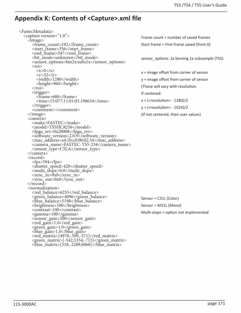
TS3 /TS4 / TS5 User’s Guide
11S-3000AC page 171
Appendix K: Contents of <Capture>.xml file
Frame count = number of saved frames
Start frame = First frame saved (from 0)
sensor_options: 2x binning 1x subsample (TS5)
x = image offset from corner of sensor
y = image offset from corner of sensor
(These will vary with resolution.
If centered:
x = (<resolution> - 1280)/2
y = (<resolution> - 1024)/2
(If not centered, then user values)
Sensor = C31L (Color)
Sensor = M31L (Mono)
Multi-slope = option not implemented
<FastecMetadata> <capture version=”1.0”> <image> <frame_count>192</frame_count> <start_frame>356</start_frame> <end_frame>547</end_frame> <bit_mode>unknown</bit_mode> <sensor_options>bin2x:subs1x</sensor_options> <roi> <x>0</x> <y>32</y> <width>1280</width> <height>960</height> </roi> <trigger> <frame>680</frame> <time>15:077:11:01:03.198634</time> </trigger> <comment></comment> </image> <camera> <make>FASTEC</make> <model>TS5HC8256</model> <fpga_rev>0x20008</fpga_rev> <software_version>2.0.9</software_version> <mac_address>a4:1b:c0:00:02:34</mac_address> <camera_name>FASTEC-TS5-234</camera_name> <sensor_type>C5LA</sensor_type> </camera> <record> <fps>594</fps> <shutter_speed>420</shutter_speed> <multi_slope>0:0</multi_slope> <sync_in>0x0</sync_in> <sync_out>0x0</sync_out> </record> <normalization> <red_balance>6255</red_balance> <green_balance>4096</green_balance> <blue_balance>5198</blue_balance> <brightness>100</brightness> <contrast>100</contrast> <gamma>100</gamma> <sensor_gain>200</sensor_gain> <red_gain>1.0</red_gain> <green_gain>1.0</green_gain> <blue_gain>1.0</blue_gain> <red_matrix>[4978,-509,-371]</red_matrix> <green_matrix>[-542,5354,-715]</green_matrix> <blue_matrix>[318,-2289,6068]</blue_matrix>

TS3 / TS4 / TS5 User’s Guide
page 172 11S-3000AC
</normalization> </capture> <frames> <frame> <number>356</number> <hw_number>14048</hw_number> <irig>0</irig> <sync_mode>0</sync_mode> <time_state>0</time_state> <markers>0x003f</markers> <time>15:077:11:01:02.653150</time> <frame>
<xxx_balance> = color balance presets or custom setting
brightness, contrast, gamma: user settings
<xxx_gain> user color gain settings
<xxx_matrix> 3x3 color correction matrix
IRIG = 0 (disabled)
IRIG = 1 (enabled)
Time State = 0 (Master)
Time State = 1-3 (Sync In: Per Sec Slave)
Time State = 4-6 (Sync In: Per Sec IRIG)
sync_mode = 0 (disabled)
sync_mode = 1 (Per Frame)
sync_mode = 2 (Per Second)
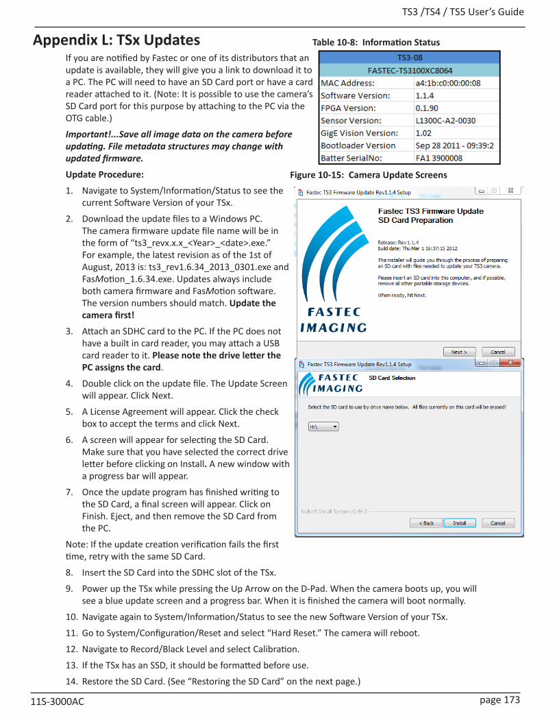
TS3 /TS4 / TS5 User’s Guide
11S-3000AC page 173
Appendix L: TSx UpdatesIf you are notified by Fastec or one of its distributors that an update is available, they will give you a link to download it to a PC. The PC will need to have an SD Card port or have a card reader attached to it. (Note: It is possible to use the camera’s SD Card port for this purpose by attaching to the PC via the OTG cable.)
Important!...Save all image data on the camera before updating. File metadata structures may change with updated firmware.
Update Procedure:
1. Navigate to System/Information/Status to see the current Software Version of your TSx.
2. Download the update files to a Windows PC. The camera firmware update file name will be in the form of “ts3_revx.x.x_<Year>_<date>.exe.” For example, the latest revision as of the 1st of August, 2013 is: ts3_rev1.6.34_2013_0301.exe and FasMotion_1.6.34.exe. Updates always include both camera firmware and FasMotion software. The version numbers should match. Update the camera first!
3. Attach an SDHC card to the PC. If the PC does not have a built in card reader, you may attach a USB card reader to it. Please note the drive letter the PC assigns the card.
4. Double click on the update file. The Update Screen will appear. Click Next.
5. A License Agreement will appear. Click the check box to accept the terms and click Next.
6. A screen will appear for selecting the SD Card. Make sure that you have selected the correct drive letter before clicking on Install. A new window with a progress bar will appear.
7. Once the update program has finished writing to the SD Card, a final screen will appear. Click on Finish. Eject, and then remove the SD Card from the PC.
Note: If the update creation verification fails the first time, retry with the same SD Card.
8. Insert the SD Card into the SDHC slot of the TSx.
9. Power up the TSx while pressing the Up Arrow on the D-Pad. When the camera boots up, you will see a blue update screen and a progress bar. When it is finished the camera will boot normally.
10. Navigate again to System/Information/Status to see the new Software Version of your TSx.
11. Go to System/Configuration/Reset and select “Hard Reset.” The camera will reboot.
12. Navigate to Record/Black Level and select Calibration.
13. If the TSx has an SSD, it should be formatted before use.
14. Restore the SD Card. (See “Restoring the SD Card” on the next page.)
Figure 10-15: Camera Update Screens
Table 10-8: Information Status
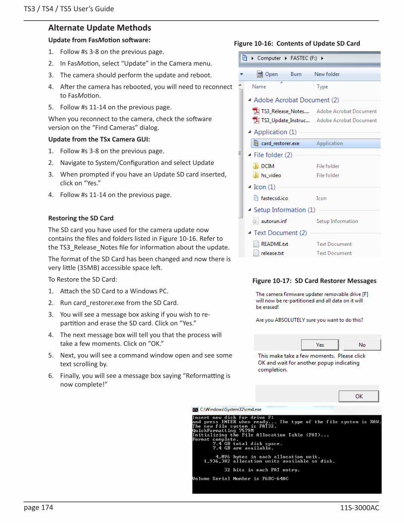
TS3 / TS4 / TS5 User’s Guide
page 174 11S-3000AC
Alternate Update MethodsUpdate from FasMotion software:
1. Follow #s 3-8 on the previous page.
2. In FasMotion, select “Update” in the Camera menu.
3. The camera should perform the update and reboot.
4. After the camera has rebooted, you will need to reconnect to FasMotion.
5. Follow #s 11-14 on the previous page.
When you reconnect to the camera, check the software version on the “Find Cameras” dialog.
Update from the TSx Camera GUI:
1. Follow #s 3-8 on the previous page.
2. Navigate to System/Configuration and select Update
3. When prompted if you have an Update SD card inserted, click on “Yes.”
4. Follow #s 11-14 on the previous page.
Restoring the SD Card
The SD card you have used for the camera update now contains the files and folders listed in Figure 10-16. Refer to the TS3_Release_Notes file for information about the update.
The format of the SD Card has been changed and now there is very little (35MB) accessible space left.
To Restore the SD Card:
1. Attach the SD Card to a Windows PC.
2. Run card_restorer.exe from the SD Card.
3. You will see a message box asking if you wish to re-partition and erase the SD card. Click on “Yes.”
4. The next message box will tell you that the process will take a few moments. Click on “OK.”
5. Next, you will see a command window open and see some text scrolling by.
6. Finally, you will see a message box saying “Reformatting is now complete!”
Figure 10-16: Contents of Update SD Card
Figure 10-17: SD Card Restorer Messages
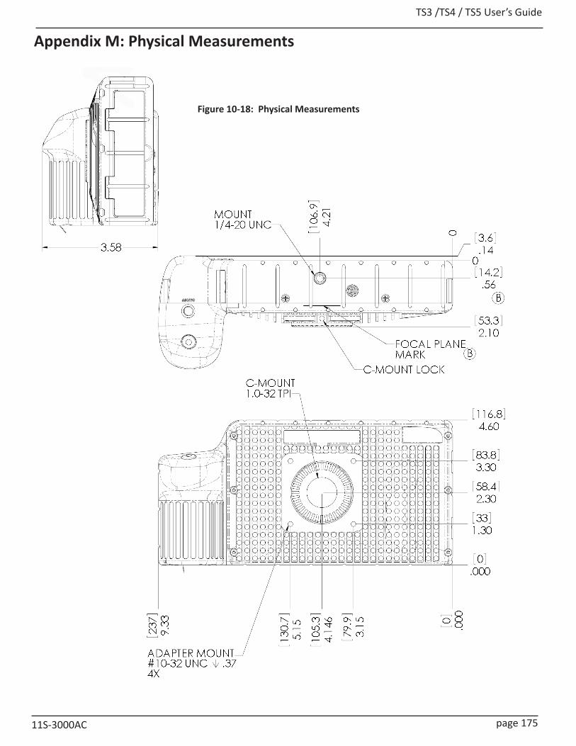
TS3 /TS4 / TS5 User’s Guide
11S-3000AC page 175
Appendix M: Physical Measurements
Figure 10-18: Physical Measurements

TS3 / TS4 / TS5 User’s Guide
page 176 11S-3000AC
Figure 10-19: Physical Measurements Continued
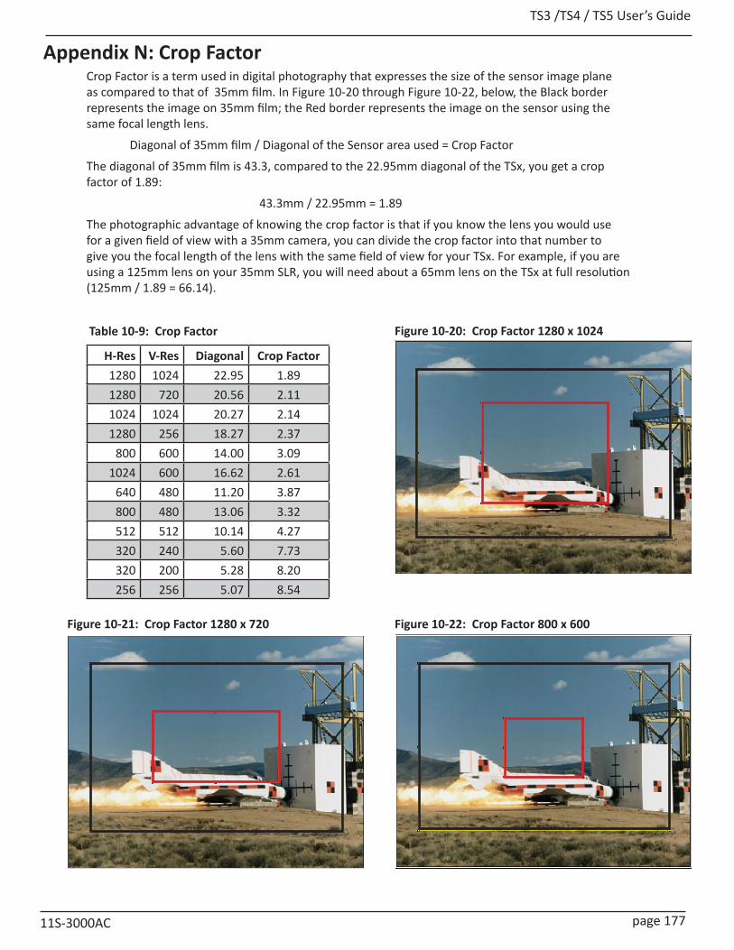
TS3 /TS4 / TS5 User’s Guide
11S-3000AC page 177
Appendix N: Crop FactorCrop Factor is a term used in digital photography that expresses the size of the sensor image plane as compared to that of 35mm film. In Figure 10-20 through Figure 10-22, below, the Black border represents the image on 35mm film; the Red border represents the image on the sensor using the same focal length lens.
Diagonal of 35mm film / Diagonal of the Sensor area used = Crop Factor
The diagonal of 35mm film is 43.3, compared to the 22.95mm diagonal of the TSx, you get a crop factor of 1.89:
43.3mm / 22.95mm = 1.89
The photographic advantage of knowing the crop factor is that if you know the lens you would use for a given field of view with a 35mm camera, you can divide the crop factor into that number to give you the focal length of the lens with the same field of view for your TSx. For example, if you are using a 125mm lens on your 35mm SLR, you will need about a 65mm lens on the TSx at full resolution (125mm / 1.89 = 66.14).
H-Res V-Res Diagonal Crop Factor1280 1024 22.95 1.891280 720 20.56 2.111024 1024 20.27 2.141280 256 18.27 2.37
800 600 14.00 3.091024 600 16.62 2.61
640 480 11.20 3.87800 480 13.06 3.32512 512 10.14 4.27320 240 5.60 7.73320 200 5.28 8.20256 256 5.07 8.54
Figure 10-20: Crop Factor 1280 x 1024
Figure 10-21: Crop Factor 1280 x 720
Table 10-9: Crop Factor
Figure 10-22: Crop Factor 800 x 600

TS3 / TS4 / TS5 User’s Guide
page 178 11S-3000AC
Appendix O: Partition Capture (CAP) File Format
Partition Capture file format is a Fastec Imaging proprietary raw data format used to store image data gathered by the TSx in one “Session” into the camera’s built-in SSD drive. The session length is set by the user (see “3-10 Storage” on page 24) to any multiple of 256MB up to the memory capacity of the camera, either 4GB or 8GB. The actual length of a recorded session may vary, however, depending on whether the full allotment of pre-trigger frames were captured before the trigger was asserted (see “Application Note 3: Trigger Position and the Circular Buffer” on page 128).
There are three major distinguishing benefits of CAP files:
1. CAP file transfer time from DRAM to SSD is the shortest of all of the non-compressed file types.
2. CAP files are the only files that may be copied back into DRAM from the SSD and played back from the camera or on a PC via the camera.
3. CAP files are the only non-compressed single file format available from the camera.
Note: CAP files are only available on cameras with SSDs, SN A0 and higher.
Figure 10-23: CAP File Diagram

TS3 /TS4 / TS5 User’s Guide
11S-3000AC page 179
Field Size DescriptionManufacturer’s name 32 “FASTEC”.Model name 32 “TS3100SC8064” for example.Serial number 16 “0.0.122.A3” for example.Application version 32 “1.5.8” for example.Camera name 16 “FastecA4-7A” for example.Ethernet MAC address 6 The MAC address of the camera.Bit selection 1 0:Low8, 1:Mid8, 2:High8, 3:10BitsOld Sensor gain 1 (Obsolete)FPGA version 4 FPGA version information.ROI x-offset 2 Left side of the ROI window.ROI y-offset 2 Top side of the ROI window.ROI width 2 Width of the ROI window.ROI height 2 Height of the ROI window.Frames per second 4 Number of frames per second.Shutter speed 4 Exposure time in microseconds.Sensor type 4 Type of sensor used, “L13C” for example.GPS location 64 GPS location information.Frame count 4 Total number of frames captured.Frame size 4 Size of the frames in quadwords.First frame 4 Frame number of the first frame in the capture buffer.Trigger frame 4 Frame number of the trigger frame in the capture buffer.Trigger time seconds 4 Linux time of the trigger event.Trigger time nanoseconds 4 Nanoseconds of trigger event from last second.Start of video 4 Start of capture buffer, in quadwords.As-shot neutral 12 The AsShotNeutral value.Matrix coefficients 36 IPM matrix coefficients.
White balance gains 12 IPM white balance gain settings.Multislope settings 2 LUPA 1300-2 multislope settings.Trigger settings 1 Trigger position setting in percent, or 127 if position was specified by frame
count instead of percentSyncIn settings 1SyncOut settings 1Brightness 1 0-255 centered around 128.Contrast 1 0-255 centered around 128.Gamma 1 0-250 centered around 100.RGB gain settings 3 Red, green, blue gain settings.FPN settings 1 Off, sensor or pixel correction.Correction table offset 4 Offset to the correction table.Correction table length 4 Size of the correction table, in quadwords.Reserved 16 Reserved for future useTrigger frame setting 4 Post-trigger frame count setting, if setting is not by percentComment 64 User commentsensor_opts 4 sensor binning, subsampling, and HDR optionsblack_offset 2 black level offset for saved CT in CAP or LR capture
sensor_dac 1 sensor DAC VREF for saved CT in CAP or LR capturesensor_vrefcol 1 sensor VREFCOL for saved CT in CAP or LR capturesensor_gain 2 sensor gain in canonical form ( x 100 )placeholder 2 reserved, maintain alignment
Table 10-10: CAP File Format

TS3 / TS4 / TS5 User’s Guide
page 180 11S-3000AC
JAN FEB MAR APR MAY JUNE JUL AUG SEPT OCT NOV DEC
1/1 1 2/1 32 3/1 60 4/1 91 5/1 121 6/1 152 7/1 182 8/1 213 9/1 244 10/1 274 11/1 305 12/1 335
1/2 2 2/2 33 3/2 61 4/2 92 5/2 122 6/2 153 7/2 183 8/2 214 9/2 245 10/2 275 11/2 306 12/2 336
1/3 3 2/3 34 3/3 62 4/3 93 5/3 123 6/3 154 7/3 184 8/3 215 9/3 246 10/3 276 11/3 307 12/3 337
1/4 4 2/4 35 3/4 63 4/4 94 5/4 124 6/4 155 7/4 185 8/4 216 9/4 247 10/4 277 11/4 308 12/4 338
1/5 5 2/5 36 3/5 64 4/5 95 5/5 125 6/5 156 7/5 186 8/5 217 9/5 248 10/5 278 11/5 309 12/5 339
1/6 6 2/6 37 3/6 65 4/6 96 5/6 126 6/6 157 7/6 187 8/6 218 9/6 249 10/6 279 11/6 310 12/6 340
1/7 7 2/7 38 3/7 66 4/7 97 5/7 127 6/7 158 7/7 188 8/7 219 9/7 250 10/7 280 11/7 311 12/7 341
1/8 8 2/8 39 3/8 67 4/8 98 5/8 128 6/8 159 7/8 189 8/8 220 9/8 251 10/8 281 11/8 312 12/8 342
1/9 9 2/9 40 3/9 68 4/9 99 5/9 129 6/9 160 7/9 190 8/9 221 9/9 252 10/9 282 11/9 313 12/9 343
1/10 10 2/10 41 3/10 69 4/10 100 5/10 130 6/10 161 7/10 191 8/10 222 9/10 253 10/10 283 11/10 314 12/10 344
1/11 11 2/11 42 3/11 70 4/11 101 5/11 131 6/11 162 7/11 192 8/11 223 9/11 254 10/11 284 11/11 315 12/11 345
1/12 12 2/12 43 3/12 71 4/12 102 5/12 132 6/12 163 7/12 193 8/12 224 9/12 255 10/12 285 11/12 316 12/12 346
1/13 13 2/13 44 3/13 72 4/13 103 5/13 133 6/13 164 7/13 194 8/13 225 9/13 256 10/13 286 11/13 317 12/13 347
1/14 14 2/14 45 3/14 73 4/14 104 5/14 134 6/14 165 7/14 195 8/14 226 9/14 257 10/14 287 11/14 318 12/14 348
1/15 15 2/15 46 3/15 74 4/15 105 5/15 135 6/15 166 7/15 196 8/15 227 9/15 258 10/15 288 11/15 319 12/15 349
1/16 16 2/16 47 3/16 75 4/16 106 5/16 136 6/16 167 7/16 197 8/16 228 9/16 259 10/16 289 11/16 320 12/16 350
1/17 17 2/17 48 3/17 76 4/17 107 5/17 137 6/17 168 7/17 198 8/17 229 9/17 260 10/17 290 11/17 321 12/17 351
1/18 18 2/18 49 3/18 77 4/18 108 5/18 138 6/18 169 7/18 199 8/18 230 9/18 261 10/18 291 11/18 322 12/18 352
1/19 19 2/19 50 3/19 78 4/19 109 5/19 139 6/19 170 7/19 200 8/19 231 9/19 262 10/19 292 11/19 323 12/19 353
1/20 20 2/20 51 3/20 79 4/20 110 5/20 140 6/20 171 7/20 201 8/20 232 9/20 263 10/20 293 11/20 324 12/20 354
1/21 21 2/21 52 3/21 80 4/21 111 5/21 141 6/21 172 7/21 202 8/21 233 9/21 264 10/21 294 11/21 325 12/21 355
1/22 22 2/22 53 3/22 81 4/22 112 5/22 142 6/22 173 7/22 203 8/22 234 9/22 265 10/22 295 11/22 326 12/22 356
1/23 23 2/23 54 3/23 82 4/23 113 5/23 143 6/23 174 7/23 204 8/23 235 9/23 266 10/23 296 11/23 327 12/23 357
1/24 24 2/24 55 3/24 83 4/24 114 5/24 144 6/24 175 7/24 205 8/24 236 9/24 267 10/24 297 11/24 328 12/24 358
1/25 25 2/25 56 3/25 84 4/25 115 5/25 145 6/25 176 7/25 206 8/25 237 9/25 268 10/25 298 11/25 329 12/25 359
1/26 26 2/26 57 3/26 85 4/26 116 5/26 146 6/26 177 7/26 207 8/26 238 9/26 269 10/26 299 11/26 330 12/26 360
1/27 27 2/27 58 3/27 86 4/27 117 5/27 147 6/27 178 7/27 208 8/27 239 9/27 270 10/27 300 11/27 331 12/27 361
1/28 28 2/28 59 3/28 87 4/28 118 5/28 148 6/28 179 7/28 209 8/28 240 9/28 271 10/28 301 11/28 332 12/28 362
1/29 29 3/29 88 4/29 119 5/29 149 6/29 180 7/29 210 8/29 241 9/29 272 10/29 302 11/29 333 12/29 363
1/30 30 3/30 89 4/30 120 5/30 150 6/30 181 7/30 211 8/30 242 9/30 273 10/30 303 11/30 334 12/30 364
1/31 31 3/31 90 5/31 151 7/31 212 8/31 243 10/31 304 12/31 365
Appendix P: Day Number Calendar Conversion
Time stamps on the TSx and ILx are written in the following format:
YY:DDD:HH:MM:SS.xxxxxx
For example, 13:206:15:36:13.987304 = 2013, 206th day, 15th hour, 36th minute, 13.987304 seconds, which is July 25, 2013 at 3:36 in the afternoon + 13.987304 seconds
Table 10-11 and Table 10-12 convert calendar dates to day numbers.
Table 10-11: Dates and Day Numbers (non leap years)

TS3 /TS4 / TS5 User’s Guide
11S-3000AC page 181
Table 10-12: Dates and Day Numbers (leap years)JAN FEB MAR APR MAY JUNE JUL AUG SEPT OCT NOV DEC
1/1 1 2/1 32 3/1 61 4/1 92 5/1 122 6/1 153 7/1 183 8/1 214 9/1 245 10/1 275 11/1 306 12/1 336
1/2 2 2/2 33 3/2 62 4/2 93 5/2 123 6/2 154 7/2 184 8/2 215 9/2 246 10/2 276 11/2 307 12/2 337
1/3 3 2/3 34 3/3 63 4/3 94 5/3 124 6/3 155 7/3 185 8/3 216 9/3 247 10/3 277 11/3 308 12/3 338
1/4 4 2/4 35 3/4 64 4/4 95 5/4 125 6/4 156 7/4 186 8/4 217 9/4 248 10/4 278 11/4 309 12/4 339
1/5 5 2/5 36 3/5 65 4/5 96 5/5 126 6/5 157 7/5 187 8/5 218 9/5 249 10/5 279 11/5 310 12/5 340
1/6 6 2/6 37 3/6 66 4/6 97 5/6 127 6/6 158 7/6 188 8/6 219 9/6 250 10/6 280 11/6 311 12/6 341
1/7 7 2/7 38 3/7 67 4/7 98 5/7 128 6/7 159 7/7 189 8/7 220 9/7 251 10/7 281 11/7 312 12/7 342
1/8 8 2/8 39 3/8 68 4/8 99 5/8 129 6/8 160 7/8 190 8/8 221 9/8 252 10/8 282 11/8 313 12/8 343
1/9 9 2/9 40 3/9 69 4/9 100 5/9 130 6/9 161 7/9 191 8/9 222 9/9 253 10/9 283 11/9 314 12/9 344
1/10 10 2/10 41 3/10 70 4/10 101 5/10 131 6/10 162 7/10 192 8/10 223 9/10 254 10/10 284 11/10 315 12/10 345
1/11 11 2/11 42 3/11 71 4/11 102 5/11 132 6/11 163 7/11 193 8/11 224 9/11 255 10/11 285 11/11 316 12/11 346
1/12 12 2/12 43 3/12 72 4/12 103 5/12 133 6/12 164 7/12 194 8/12 225 9/12 256 10/12 286 11/12 317 12/12 347
1/13 13 2/13 44 3/13 73 4/13 104 5/13 134 6/13 165 7/13 195 8/13 226 9/13 257 10/13 287 11/13 318 12/13 348
1/14 14 2/14 45 3/14 74 4/14 105 5/14 135 6/14 166 7/14 196 8/14 227 9/14 258 10/14 288 11/14 319 12/14 349
1/15 15 2/15 46 3/15 75 4/15 106 5/15 136 6/15 167 7/15 197 8/15 228 9/15 259 10/15 289 11/15 320 12/15 350
1/16 16 2/16 47 3/16 76 4/16 107 5/16 137 6/16 168 7/16 198 8/16 229 9/16 260 10/16 290 11/16 321 12/16 351
1/17 17 2/17 48 3/17 77 4/17 108 5/17 138 6/17 169 7/17 199 8/17 230 9/17 261 10/17 291 11/17 322 12/17 352
1/18 18 2/18 49 3/18 78 4/18 109 5/18 139 6/18 170 7/18 200 8/18 231 9/18 262 10/18 292 11/18 323 12/18 353
1/19 19 2/19 50 3/19 79 4/19 110 5/19 140 6/19 171 7/19 201 8/19 232 9/19 263 10/19 293 11/19 324 12/19 354
1/20 20 2/20 51 3/20 80 4/20 111 5/20 141 6/20 172 7/20 202 8/20 233 9/20 264 10/20 294 11/20 325 12/20 355
1/21 21 2/21 52 3/21 81 4/21 112 5/21 142 6/21 173 7/21 203 8/21 234 9/21 265 10/21 295 11/21 326 12/21 356
1/22 22 2/22 53 3/22 82 4/22 113 5/22 143 6/22 174 7/22 204 8/22 235 9/22 266 10/22 296 11/22 327 12/22 357
1/23 23 2/23 54 3/23 83 4/23 114 5/23 144 6/23 175 7/23 205 8/23 236 9/23 267 10/23 297 11/23 328 12/23 358
1/24 24 2/24 55 3/24 84 4/24 115 5/24 145 6/24 176 7/24 206 8/24 237 9/24 268 10/24 298 11/24 329 12/24 359
1/25 25 2/25 56 3/25 85 4/25 116 5/25 146 6/25 177 7/25 207 8/25 238 9/25 269 10/25 299 11/25 330 12/25 360
1/26 26 2/26 57 3/26 86 4/26 117 5/26 147 6/26 178 7/26 208 8/26 239 9/26 270 10/26 300 11/26 331 12/26 361
1/27 27 2/27 58 3/27 87 4/27 118 5/27 148 6/27 179 7/27 209 8/27 240 9/27 271 10/27 301 11/27 332 12/27 362
1/28 28 2/28 59 3/28 88 4/28 119 5/28 149 6/28 180 7/28 210 8/28 241 9/28 272 10/28 302 11/28 333 12/28 363
1/29 29 2/29 60 3/29 89 4/29 120 5/29 150 6/29 181 7/29 211 8/29 242 9/29 273 10/29 303 11/29 334 12/29 364
1/30 30 3/30 90 4/30 121 5/30 151 6/30 182 7/30 212 8/30 243 9/30 274 10/30 304 11/30 335 12/30 365
1/31 31 3/31 91 5/31 152 7/31 213 8/31 244 10/31 305 12/31 366
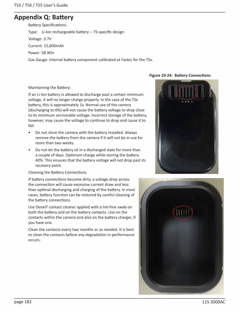
TS3 / TS4 / TS5 User’s Guide
page 182 11S-3000AC
Appendix Q: Battery Battery Specifications:
Type: Li-Ion rechargeable battery -- TS-specific design
Voltage: 3.7V
Current: 15,600mAh
Power: 58 Whr
Gas Gauge: Internal battery component calibrated at Fastec for the TSx.
Maintaining the Battery:
If an Li-Ion battery is allowed to discharge past a certain minimum voltage, it will no longer charge properly. In the case of the TSx battery, this is approximately 1v. Normal use of the camera (discharging to 0%) will not cause the battery voltage to drop close to its minimum serviceable voltage. Incorrect storage of the battery, however, may cause the voltage to continue to drop and cause it to fail.
• Do not store the camera with the battery installed. Always remove the battery from the camera if it will not be in use for more than two weeks.
• Do not let the battery sit in a discharged state for more than a couple of days. Optimum charge while storing the battery 40%. This ensures that the battery voltage will not drop past its recovery point.
Cleaning the Battery Connections
If battery connections become dirty, a voltage drop across the connection will cause excessive current draw and less than optimal discharging and charging of the battery. In most cases, battery function can be restored by careful cleaning of the battery connections.
Use DeoxIT contact cleaner applied with a lint-free swab on both the battery and on the battery contacts. Use on the contacts within the camera and also on the battery charger, if you have one.
Clean the contacts every two months or as needed. It is best to clean the contacts before any degradation in performance occurs.
Figure 10-24: Battery Connections

TS3 /TS4 / TS5 User’s Guide
11S-3000AC page 183
Battery Charging
The TSx battery may be charged with the optional battery charger or in the camera. Charging the battery in the camera takes a little over four hours, while the battery charger takes about six and a half hours.
The graph in Figure 10-25 shows “Empty” at a point somewhat below 0%. Empty in this case refers to the battery level at which the camera will no longer boot up.
If the battery connections become contaminated, the charging times will rise.
Note: The battery gas gauge is based on Standard Basic mode in “Live.”
Figure 10-25: Battery Charging Curve

TS3 / TS4 / TS5 User’s Guide
page 184 11S-3000AC
Operation of the TSx on BatteryThe TSx will run on battery power for a few hours, depending on operating mode and enabled features and associated hardware used.
For example if the camera is Live with the display off, it will run almost five hours (see the red line on the chart, below). Running in this mode with intermittent use of the display and the touch screen and recording, the camera will run for about four hours. TS5 cameras use slightly more power and will generally run for about 80-90% as long as the TS3.
Recording in LR2 Basic mode (TS4100LR2 cameras), the camera will record, with HDMI output and the display off for more than three hours. (See blue line on the chart, below.)
Recording in LR3 Basic mode (TS4100LR3 and TS3-D cameras), the camera may record, with HDMI output and the display off for a little over one hour. With the display on and HDMI on it may only record for as little as 25 minutes. TS5-D cameras in LR3 mode will often record for only a few minutes using battery power. For this reason, it is best to switch to LR2 mode (“Slow SSD”) when operating TS4-LR3, TS3-D or TS5-D cameras on internal battery power. See “Figure 2-3: Power Up / Charging Menu (TS4-LR3 / TSx-D)” on page 9.
WARNING: Do not rely on the gas gauge for LR mode recordings and when using FasFire!
Drain on the battery:
The following features will tend to drain the battery: Writing to the SSD (especially in SATA III mode as with the TS4100LR3), leaving the display on, enabling HDMI, USB devices and Ethernet connectivity.
Figure 10-26: Discharge Rate by Mode

TS3 /TS4 / TS5 User’s Guide
11S-3000AC page 185
Appendix R: TS5 with External SSDThe External SSD option is available for any TS5 camera with or without an internal SSD. It may be purchased with the camera or purchased as an add-on.
External SSD Basics:
• On cameras with both internal and external SSDs, only one SSD will be available during a session. The user will select which SSD is to be used when the camera boots. (See “Table 10-13: External SSD Selection Logic” on page 186.)
• External SSDs operate as eSATA devices at SATA II speeds (write at up to 275MB/s), while the internal TS5 SSDs operate at SATA III speeds (write at up to 520MB/s).
• External SSDs must be powered on and connected to the TS5 when the camera boots up in order for the drive to be recognized.
• When using a TS5 with an external SSD, the camera operation is exactly the same as with the internal SSD with respect to Format, Explore, Record Modes, etc. with the exception that maximum frame rates are slower in Long Record Modes at most of the higher resolutions. (See “Table 10-4: TS5 Sample Resolutions, Rates, and Times” on page 155.)
• The External SSD must be connected to the TS5 via an eSATA cable (not a USB cable).
• The External SSD may be connected to a PC via eSATA or USB3 cable, but cannot be connected to both a PC and TS5 at the same time. Figure 10-27: StarTech SSD Dock
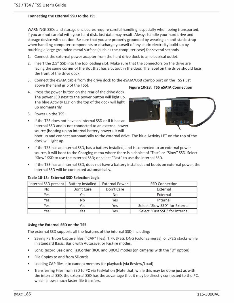
TS3 / TS4 / TS5 User’s Guide
page 186 11S-3000AC
Connecting the External SSD to the TS5
WARNING! SSDs and storage enclosures require careful handling, especially when being transported. If you are not careful with your hard disk, lost data may result. Always handle your hard drive and storage device with caution. Be sure that you are properly grounded by wearing an anti-static strap when handling computer components or discharge yourself of any static electricity build-up by touching a large grounded metal surface (such as the computer case) for several seconds.
1. Connect the external power adapter from the hard drive dock to an electrical outlet.
2. Insert the 2.5” SSD into the top loading slot. Make sure that the connectors on the drive are facing the same corner of the slot that has a cutout in the door. The label on the drive should face the front of the drive dock.
3. Connect the eSATA cable from the drive dock to the eSATA/USB combo port on the TS5 (just above the hand grip of the TS5).
4. Press the power button on the rear of the drive dock. The power LED next to the power button will light up. The blue Activity LED on the top of the dock will light up momentarily.
5. Power up the TS5.
• If the TS5 does not have an internal SSD or if it has an internal SSD and is not connected to an external power source (booting up on internal battery power), it will boot up and connect automatically to the external drive. The blue Activity LET on the top of the dock will light up.
• If the TS5 has an internal SSD, has a battery installed, and is connected to an external power source, it will boot to the Charging menu where there is a choice of “Fast” or “Slow” SSD. Select “Slow” SSD to use the external SSD; or select “Fast” to use the internal SSD.
• If the TS5 has an internal SSD, does not have a battery installed, and boots on external power, the internal SSD will be connected automatically.
Internal SSD present Battery Installed External Power SSD ConnectionNo Don’t Care Don’t Care ExternalYes Yes No ExternalYes No Yes InternalYes Yes Yes Select “Slow SSD” for ExternalYes Yes Yes Select “Fast SSD” for Internal
Using the External SSD on the TS5
The external SSD supports all the features of the internal SSD, including:
• Saving Partition Capture files (“CAP” files), TIFF, JPEG, DNG (color cameras), or JPEG stacks while in Standard Basic, Basic with Autosave, or FasFire modes.
• Long Record Basic and FasCorder (ROC and BROC) modes (on cameras with the “D” option)
• File Copies to and from SDcards
• Loading CAP files into camera memory for playback (via Review/Load)
• Transferring Files from SSD to PC via FasMotion (Note that, while this may be done just as with the internal SSD, the external SSD has the advantage that it may be directly connected to the PC, which allows much faster file transfers.
Figure 10-28: TS5 eSATA Connection
Table 10-13: External SSD Selection Logic
TS3 /TS4 / TS5 User’s Guide
11S-3000AC page 187
Drive Dock Fan
The drive dock fan is designed to keep the SSD cool, which will help to optimize the drive life span and performance. It is especially important to run the fan when the TS5 is operating in Long Record mode as it will be writing to the drive incessantly while recording.
Formatting the External SSD
There are two file system formats used with the SSD:
• Long Record format, which is used to store only raw image data, calibration data and metadata
• Standard Record format, which is a modified FAT32 file system format that is used to store image stacks Partition Capture (CAP) files
NOTE: The external SSD should only be formatted by the TS5. Formatting the external SSD on a PC will not be helpful as it will need to be reformatted by the camera in order to be used again.
Selecting System/Storage/Format/SSD from the camera’s touch display, or formatting the SSD through FasMotion or the Web-Application, will format the SSD appropriately for whichever mode the camera was booted in. If the camera was booted in Standard mode, the SSD will be formatted in the Fastec modified FAT32 system; and if the camera was booted in Long Record mode, the SSD will be formatted in the Long Record format.
NOTE: For Standard Mode recordings, formatting the drive is the only recommended method of removing files from the SSD. While this may be inconvenient, it is the only way to ensure that the drive will not become fragmented and begin to lose data.
Removing the External Drive from the TS5
1. IMPORTANT!: Always power down the camera “politely” before removing the external SSD. This may be done by pressing the On/Off button, then following the prompts in the dialog box (which may also include going through the Charging dialog).
2. Once the camera is powered down, turn off the SSD using the Power button on the back of the drive dock.
3. Remove the eSATA connector from the TS5.
Connecting the External SSD to a PC using the eSATA connection:
1. Begin with the PC powered down.
2. Connect the power adapter to the drive dock.
3. Insert the SSD into the drive dock.
4. Connect the eSATA cable from the drive dock to the PC eSATA connector.
5. Press the Power button on the back of the drive dock to power up the SSD.
6. Boot up the PC. (When using the eSATA connection, the SSD must be powered up and connected BEFORE the PC boots.)
Connecting the External SSD to a PC using the USB-3 connection (preferred):
1. Begin with the PC running.
2. Connect the power adapter to the drive dock.
3. Insert the SSD into the drive dock.
4. Connect the USB-3 cable between the drive dock and a USB-3 connector on the PC
5. Press the Power button on the back of the drive dock to power up the SSD.
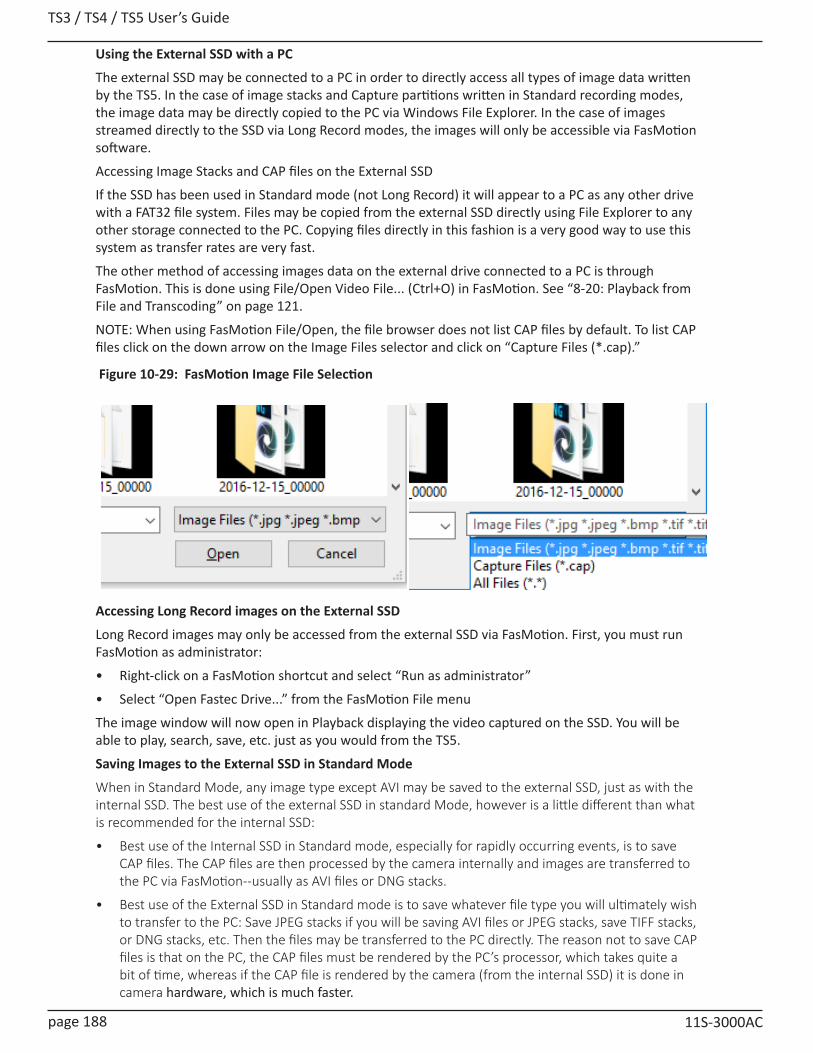
TS3 / TS4 / TS5 User’s Guide
page 188 11S-3000AC
Using the External SSD with a PC
The external SSD may be connected to a PC in order to directly access all types of image data written by the TS5. In the case of image stacks and Capture partitions written in Standard recording modes, the image data may be directly copied to the PC via Windows File Explorer. In the case of images streamed directly to the SSD via Long Record modes, the images will only be accessible via FasMotion software.
Accessing Image Stacks and CAP files on the External SSD
If the SSD has been used in Standard mode (not Long Record) it will appear to a PC as any other drive with a FAT32 file system. Files may be copied from the external SSD directly using File Explorer to any other storage connected to the PC. Copying files directly in this fashion is a very good way to use this system as transfer rates are very fast.
The other method of accessing images data on the external drive connected to a PC is through FasMotion. This is done using File/Open Video File... (Ctrl+O) in FasMotion. See “8-20: Playback from File and Transcoding” on page 121.
NOTE: When using FasMotion File/Open, the file browser does not list CAP files by default. To list CAP files click on the down arrow on the Image Files selector and click on “Capture Files (*.cap).”
Accessing Long Record images on the External SSD
Long Record images may only be accessed from the external SSD via FasMotion. First, you must run FasMotion as administrator:
• Right-click on a FasMotion shortcut and select “Run as administrator”
• Select “Open Fastec Drive...” from the FasMotion File menu
The image window will now open in Playback displaying the video captured on the SSD. You will be able to play, search, save, etc. just as you would from the TS5.
Saving Images to the External SSD in Standard Mode
When in Standard Mode, any image type except AVI may be saved to the external SSD, just as with the internal SSD. The best use of the external SSD in standard Mode, however is a little different than what is recommended for the internal SSD:
• Best use of the Internal SSD in Standard mode, especially for rapidly occurring events, is to save CAP files. The CAP files are then processed by the camera internally and images are transferred to the PC via FasMotion--usually as AVI files or DNG stacks.
• Best use of the External SSD in Standard mode is to save whatever file type you will ultimately wish to transfer to the PC: Save JPEG stacks if you will be saving AVI files or JPEG stacks, save TIFF stacks, or DNG stacks, etc. Then the files may be transferred to the PC directly. The reason not to save CAP files is that on the PC, the CAP files must be rendered by the PC’s processor, which takes quite a bit of time, whereas if the CAP file is rendered by the camera (from the internal SSD) it is done in camera hardware, which is much faster.
Figure 10-29: FasMotion Image File Selection