Treball Fi de Ma18 aster - Gerard Castillo Lasheras - UPCommons
136
MASTER THESIS TITLE: Study and proposal of a distributed and scalable real-time media production platform DEGREE: MSc Telecomunication Engineering and Master’s degree in Applied Telecommunications and Engineering Management (MASTEAM) AUTHOR: Gerard Castillo Lasheras ADVISOR: David Cassany Viladomat SUPERVISOR: David Rinc ´ on Rivera DATE: October 7, 2015
-
Upload
khangminh22 -
Category
Documents
-
view
7 -
download
0
Transcript of Treball Fi de Ma18 aster - Gerard Castillo Lasheras - UPCommons

MASTER THESIS
TITLE: Study and proposal of a distributed and scalable real-time media productionplatform
DEGREE: MSc Telecomunication Engineering and Master’s degree in AppliedTelecommunications and Engineering Management (MASTEAM)
AUTHOR: Gerard Castillo Lasheras
ADVISOR: David Cassany Viladomat
SUPERVISOR: David Rincon Rivera
DATE: October 7, 2015


Tıtol: Estudi i proposta d’una plataforma de produccio de media a temps real, distribuıdai escalable
Autor: Gerard Castillo Lasheras
Director: David Cassany Viladomat
Supervisor: David Rincon Rivera
Data: 7 d’Octubre de 2015
Resum
La industria de produccio de continguts audiovisuals (e.g.: cadenes de radiodifusio, pro-ductores de baix pressupost) ha estat, i encara esta, emprant tecnologies rıgides i difıcilsd’escalar per al transport i gestio dels seus fluxos a traves de les seves cadenes de pro-duccio. Tot i que des de principis de l’any 2000 s’esta portant a terme una migracio atecnologies basades en xarxes IP, l’adopcio esta essent tımida i lenta.
A mes, la majoria d’aquestes tecnologies encara vigents impliquen grans costos de des-plegament i manteniment (e.g.: maquinari especıfic, cablejat especıfic i costos). Peraquest motiu, es proposa l’estudi de tecnologies IP i, especıficament, tecnologies rela-cionades amb el concepte de la computacio distribuıda, i al nuvol, per tal de proposarsolucions per a abaratir els costos i millorar les possibilitats de produccio de contingutsaudiovisuals.
Concretament, aquesta tesi s’enfoca en analitzar, proposar, desenvolupar i demostrar tec-nologies especıfiques de virtualitzacio, monitoratge i aplicacio, que ofereixen solucions alsreptes esmentats.
Pel que fa a la virtualitzacio s’utilitzen tecnologies basades en Linux Containers, concre-tament contenidors Docker. Gracies a la capa de gestio que ofereix aquesta tecnologıas’assoleix l’empaquetament, distribucio i execucio d’aplicacions de forma distribuıda a laxarxa. A mes a mes, s’assegura una plataforma escalable ja que aquest tipus de tecnolo-gia permet el manteniment, gestio i replicacio d’aplicacions de forma rapida i robusta.
L’aplicacio d’eines de monitoritzacio es una peca clau per a oferir a les aplicacions ia la propia plataforma el control de l’estat d’aquestes i aixı permetre aplicar polıtiquesd’actuacio a temps real de forma eficient. En concret, s’utilitzen les tecnologies Collectdi Graphite. Aquestes eines tambe permeten ser gestionades dins de contenidors per talde poder ser distribuıdes per la xarxa en paral·lel a les aplicacions que conformen laplataforma.
Finalment, es demostra que el nucli de la plataforma, el LiveMediaStreamer framework,assoleix els requisits per a ser utilitzada com a servei al nuvol per a la produccio de con-tinguts audiovisuals a temps real gracies a les tecnologies esmentades anteriorment, laimplementacio d’una capa d’estadıstiques (de xarxa i de rendiment intern) i el desenvolu-pament d’un software intermig que ofereix una API REST.

Title : Study and proposal of a distributed and scalable real-time media production platform
Author: Gerard Castillo Lasheras
Advisor: David Cassany Viladomat
Supervisor: David Rincon Rivera
Date: October 7, 2015
Overview
The audio-visual media content production industry (e.g.: broadcasters, small productioncompanies) has been, and already is, employing rigid and difficult to scale technologies totransport and manage their streams through their processing chain. Although since early2000s a gradually adoption of IP technologies has been happening, the process is stillslow.
Furthermore, most of the existing technologies involve large deployment and maintenancecosts (e.g.: specific hardware, specific and costly wiring). For this reason, the study of IPtechnology is proposed, specifically technology related to the distributed cloud computingconcept, in order to propose solutions to reduce costs and increase the audiovisual contentproduction’s possibilities.
Particularly, this thesis focuses on analysing, proposing, developing and demonstratingspecific virtualization, monitoring and application technologies in order to provide solutionsto these mentioned issues.
Regarding virtualization, technologies based on Linux Containers are used, specificallyDocker containers. Thanks to the managing layer offered by Docker containers the ship-ment, distribution and execution of applications over the network is achieved. Moreover,platform scalability is assured because the maintenance, management and replication ofapplications containerized within this technology are fast and reliable.
The use of monitoring tools is a key point to offer application status management to ap-plications and to the platform itself and to allow the application of actuation policies inreal-time in an efficient manner. Specifically, Collectd and Graphite are the selected tools.Moreover, these tools are able to be managed inside containers in order to be simultane-ously deployed over the network together with the applications’ platform.
Finally, as it is demonstrated, the core of the platform, the LiveMediaStreamer framework,achieves the requirements in order to be used as a real-time cloud service for audiovisualmedia content production. This is thanks to the technologies above-mentioned, the statis-tics layer implemented for monitoring (network and performance) and the development ofa REST API middleware.

Dedicat a tothom que m’ha permes i ajudat a arribar fins aquı.


CONTENTS
Introduction . . . . . . . . . . . . . . . . . . . . . . . . . . . . . . . . . . . . 1
CHAPTER 1. State of the art . . . . . . . . . . . . . . . . . . . . . . . . . 5
1.1. Media content production . . . . . . . . . . . . . . . . . . . . . . . . . . . 51.1.1. Standard formats . . . . . . . . . . . . . . . . . . . . . . . . . . . 5
1.1.2. Convergence to IP . . . . . . . . . . . . . . . . . . . . . . . . . . . 7
1.2. Migration to cloud . . . . . . . . . . . . . . . . . . . . . . . . . . . . . . . 91.2.1. Cloud computing . . . . . . . . . . . . . . . . . . . . . . . . . . . . 9
1.2.2. Virtualization . . . . . . . . . . . . . . . . . . . . . . . . . . . . . . 11
1.2.3. Monitoring . . . . . . . . . . . . . . . . . . . . . . . . . . . . . . . 14
1.3. LiveMediaStreamer framework . . . . . . . . . . . . . . . . . . . . . . . . 16
CHAPTER 2. Problem statement and proposal . . . . . . . . . . . . . 19
2.1. Architecture analysis . . . . . . . . . . . . . . . . . . . . . . . . . . . . . . 192.1.1. Virtualization . . . . . . . . . . . . . . . . . . . . . . . . . . . . . . 20
2.1.2. Monitoring layer . . . . . . . . . . . . . . . . . . . . . . . . . . . . 22
2.1.3. Application layer . . . . . . . . . . . . . . . . . . . . . . . . . . . . 24
2.2. Architecture proposal . . . . . . . . . . . . . . . . . . . . . . . . . . . . . 26
2.3. Task planning . . . . . . . . . . . . . . . . . . . . . . . . . . . . . . . . . . 28
CHAPTER 3. Application . . . . . . . . . . . . . . . . . . . . . . . . . . . 29
3.1. REST API . . . . . . . . . . . . . . . . . . . . . . . . . . . . . . . . . . . . 29
3.2. Network metrics . . . . . . . . . . . . . . . . . . . . . . . . . . . . . . . . . 303.2.1. Input network metrics . . . . . . . . . . . . . . . . . . . . . . . . . 30
3.2.2. Output network metrics . . . . . . . . . . . . . . . . . . . . . . . . 32
3.3. Pipeline metrics . . . . . . . . . . . . . . . . . . . . . . . . . . . . . . . . . 333.3.1. Delay . . . . . . . . . . . . . . . . . . . . . . . . . . . . . . . . . 34
3.3.2. Losses . . . . . . . . . . . . . . . . . . . . . . . . . . . . . . . . . 35
CHAPTER 4. Virtualization . . . . . . . . . . . . . . . . . . . . . . . . . . 37

4.1. Creating and managing generic containers . . . . . . . . . . . . . . . . . . 374.1.1. Basic LMS container . . . . . . . . . . . . . . . . . . . . . . . . . . 39
4.1.2. HTTP REST API container . . . . . . . . . . . . . . . . . . . . . . 40
4.2. Linking containers . . . . . . . . . . . . . . . . . . . . . . . . . . . . . . . 414.2.1. Same OS . . . . . . . . . . . . . . . . . . . . . . . . . . . . . . . 41
4.2.2. Separate OS . . . . . . . . . . . . . . . . . . . . . . . . . . . . . . 42
4.3. Running multiple processes within a container . . . . . . . . . . . . . . . 42
4.4. Best practices . . . . . . . . . . . . . . . . . . . . . . . . . . . . . . . . . . 43
CHAPTER 5. Monitoring layer . . . . . . . . . . . . . . . . . . . . . . . . 45
5.1. Monitoring containers . . . . . . . . . . . . . . . . . . . . . . . . . . . . . 455.1.1. From the container point of view . . . . . . . . . . . . . . . . . . . . 46
5.1.2. From the OS point of view . . . . . . . . . . . . . . . . . . . . . . . 47
5.2. Showcasing monitoring . . . . . . . . . . . . . . . . . . . . . . . . . . . . 48
CHAPTER 6. Platform deployment tests, and results . . . . . . . . . 51
6.1. Platform deployment . . . . . . . . . . . . . . . . . . . . . . . . . . . . . . 516.1.1. Isolated deployments . . . . . . . . . . . . . . . . . . . . . . . . . 52
6.1.2. Generic scenario deployment . . . . . . . . . . . . . . . . . . . . . 54
CHAPTER 7. Conclusions . . . . . . . . . . . . . . . . . . . . . . . . . . . 59
7.1. LiveMediaStreamer . . . . . . . . . . . . . . . . . . . . . . . . . . . . . . . 59
7.2. Collectd and Graphite . . . . . . . . . . . . . . . . . . . . . . . . . . . . . 60
7.3. Docker . . . . . . . . . . . . . . . . . . . . . . . . . . . . . . . . . . . . . . 61
7.4. Platform . . . . . . . . . . . . . . . . . . . . . . . . . . . . . . . . . . . . . 62
7.5. Next steps . . . . . . . . . . . . . . . . . . . . . . . . . . . . . . . . . . . . 62
Acronyms . . . . . . . . . . . . . . . . . . . . . . . . . . . . . . . . . . . . . . 65
Bibliography . . . . . . . . . . . . . . . . . . . . . . . . . . . . . . . . . . . . 67
APPENDIX A. LiveMediaStreamer architecture . . . . . . . . . . . . . 73
APPENDIX B. LMS HTTP RESTful API . . . . . . . . . . . . . . . . . . . 85
APPENDIX C. Specific application metric methods . . . . . . . . . . 87
C.1. Input network metric method . . . . . . . . . . . . . . . . . . . . . . . . . 87
C.2. Output network metric method . . . . . . . . . . . . . . . . . . . . . . . . 88
C.3. Pipiline delay metric method . . . . . . . . . . . . . . . . . . . . . . . . . . 89
APPENDIX D. Docker cheat sheet . . . . . . . . . . . . . . . . . . . . . . 91
APPENDIX E. Docker, Nginx and Collectd configuration files . . . 105
E.1. Basic LMS container . . . . . . . . . . . . . . . . . . . . . . . . . . . . . . 105
E.2. HTTP REST API container . . . . . . . . . . . . . . . . . . . . . . . . . . . 106
E.3. Running multiple processes within a container . . . . . . . . . . . . . . . 107
E.4. Nginx server file configuration example . . . . . . . . . . . . . . . . . . . 108
E.5. Sharing volumes within containers . . . . . . . . . . . . . . . . . . . . . . 110
E.6. Collectd client container . . . . . . . . . . . . . . . . . . . . . . . . . . . . 110
E.7. Collectd client configuration . . . . . . . . . . . . . . . . . . . . . . . . . . 111
E.8. Collectd server and Graphite container . . . . . . . . . . . . . . . . . . . . 111
E.9. Collectd server configuration . . . . . . . . . . . . . . . . . . . . . . . . . 113
E.10.Collectd tail plugin example configuration . . . . . . . . . . . . . . . . . . 113
APPENDIX F. Source codes . . . . . . . . . . . . . . . . . . . . . . . . . 117
APPENDIX G. Exchanged e-mails with Live555 developer mailinglist . . . . . . . . . . . . . . . . . . . . . . . . . . . . . . . . . 119


LIST OF FIGURES
1 Broadcasting example based on open-source softwares [2] . . . . . . . . . . . 2
1.1 Cloud computing layers . . . . . . . . . . . . . . . . . . . . . . . . . . . . . . 10
2.1 Generic platform architecture . . . . . . . . . . . . . . . . . . . . . . . . . . . 192.2 QEMU with KVM or hypervisor type2 to type1 . . . . . . . . . . . . . . . . . . 212.3 Docker with LXC . . . . . . . . . . . . . . . . . . . . . . . . . . . . . . . . . 222.4 Monitoring layer architecture proposal . . . . . . . . . . . . . . . . . . . . . . 242.5 LiveMediaStreamer framework statistics gathering and logging proposal . . . . 262.6 Proposal of the platform architecture . . . . . . . . . . . . . . . . . . . . . . . 272.7 Example of specific platform deployment . . . . . . . . . . . . . . . . . . . . . 272.8 Task planning - Gantt proposal . . . . . . . . . . . . . . . . . . . . . . . . . . 28
3.1 RESTfull API middleware architecture . . . . . . . . . . . . . . . . . . . . . . 293.2 Input network metrics structure . . . . . . . . . . . . . . . . . . . . . . . . . . 313.3 Output network metrics structure . . . . . . . . . . . . . . . . . . . . . . . . . 333.4 LMS framwork’s internal pipeline structure example . . . . . . . . . . . . . . . 34
5.1 Detailed monitoring architecture . . . . . . . . . . . . . . . . . . . . . . . . . 45
6.1 Configuration of the scenario for the isolated deployments . . . . . . . . . . . 526.2 Isolated scenarios - CPU usage . . . . . . . . . . . . . . . . . . . . . . . . . 536.3 Isolated scenarios - average pipeline processing time . . . . . . . . . . . . . . 536.4 Isolated scenarios - pipeline accumulated lost blocks . . . . . . . . . . . . . . 546.5 Configuration of the scenario for the generic deployment . . . . . . . . . . . . 556.6 Generic scenario - video mixing configuration result . . . . . . . . . . . . . . . 556.7 Generic scenario - average CPU usage . . . . . . . . . . . . . . . . . . . . . 566.8 Generic scenario - paths average processing time . . . . . . . . . . . . . . . . 566.9 Generic scenario - paths accumulated lost blocks . . . . . . . . . . . . . . . . 57
7.1 Generic scenario - derivative function of the video path accumulated lost blocks 607.2 Transcoder scenario - Collectd bandwidth usage (bits per second) . . . . . . . 607.3 Audio and video mixer scenario - Collectd bandwidth usage (bits per second) . 61

LIST OF TABLES
6.1 Deployment environment characteristics . . . . . . . . . . . . . . . . . . . . . 51


INTRODUCTION
The audio-visual media content production industry (e.g.: broadcasters, small productioncompanies) has been, and already is, employing rigid and difficult to scale technologiesto transport and manage their streams through their processing chain. But, since early2000s, a gradually adoption of IP technologies has been happening. Key examples of thisadoption are that TV content media production is already digital based (i.e.: broadcastingchannels) and its media transport layer is circuit oriented. Moreover, IP networks offerenhancements over operational and cost issues and it is the next step to the audiovisualmedia production.
Since few years ago, the broadcasting industry is pushing on to adopt IP as the transporttechnology because of several benefits such as:
• Enhanced agility and flexibility of the broadcast workflows
• Convergence of services (i.e.: audio, video, metadata and generic data)
• Format agnosticism to support the adoption of coming new UHDTV formats such as4K and 8K
• Economy of scale by integrating broadcasting industry into the far more massive ITindustry
But there is still a lot of work to be done to achieve complete IP convergence, and lots ofnew possibilities thanks to different architectures and configurations that can be appliedon OTT (Over-The-Top [1]) content management systems.
Since almost all post-production environments have become file-based, they can now becompletely migrated to IP infrastructures. Main examples are some control and manage-ment services, and media content distribution over Internet (i.e.: live or on demmand mediastreaming to end-users) or over proprietary networks (i.e.: IPTV [1]).
Nevertheless, the live production environment has yet to be migrated to IP. The main chal-lenges are some stringent constraints such as levels of synchronization, extremely lowpacket loss levels, high-bandwidth demand or jitter variation, because these are not all in-trinsically assured by current IP-based technologies, which offer a best-effort service withno guarantee.
Figure 1 helps understanding where this thesis is focusing and what is its goal: to offerspecific solutions and tools for real-time media content production over cloud infrastruc-tures. Therefore, this thesis is mainly focused on the ”Live production” step of Figure 1,where related participants (i.e.: people, cams, mixers, ...) are aimed to be networked ormoved to an IP and virtualized environment.
The following topics are going to be studied together with the aim to propose and developa platform prototype. Moreover, this platform prototype will be deployed in an experimentalenvironment in order to demonstrate and validate the proposal.
• Virtualization layer
The virtualization paradigm offers specific solutions to improve scalability, robust-ness and reliability of any platform and services to be deployed over a cloud en-
1

2 Study and proposal of a distributed and scalable real-time media production platform
Figure 1: Broadcasting example based on open-source softwares [2]
vironment (n-tier applications development [3]). Therefore, the virtualization of alltools implemented within this thesis is considered.
• Monitoring layer
The monitoring layer is a crucial system tool to be deployed which offers the ca-pability of getting non-stop feedback from deployed services in order to actuate inreal-time over any defined alarm. This layer gives also the chance to find and solveinfrastructure/platform bottle-necks. So, in this thesis environment, the performanceof the services deployed will be monitored (e.g.: LiveMediaStreamer framework pro-cessing latency and losses, and external network performance parameters such asbandwidth usage, packet losses and delay variation).
• Application layer
The application layer is the core service itself (the audio and video production coreservice) that must be adapted in order to offer full compatibility with previous men-tioned layers and to become a cloud service. Therefore, a HTTP REST API andapplication statistics gathering will be developed.
All the items above-mentioned are related to this thesis execution period that is alignedwith specific goals of the i2CAT Foundation Audiovisual Unit [4], which has specific re-search challenges such as to study and propose enhancements for networked media andinteractive and immersive media related topics. Specifically, this thesis is one of the nextsteps related to i2CAT’s LiveMediaStreamer framework project [5], an open-source soft-ware developed in the Audiovisual Unit’s technical team. One of this main functionalities

3
is the capability of working as a software-based audio and video mixer, and this is thescenario that this thesis is going to focus on as the main service to be analysed.
Finally, this thesis is organized as follows: Chapter 1 describes the state of the art of re-lated technologies of the audiovisual content production, where the steps already done forreaching IP convergence are briefly explained. Furthermore, an introduction of the cloudconcept and the topics related of this thesis are also shown. In Chapter 2, the problemstatement is presented with a proposal solution, based on the topics already explained.Chapter 3 (application), 4 (virtualization) and 5 (monitoring) are each one focused on howeach part of the solution are developed. Chapter 6 describes the deployment, tests anddemonstrations of the software. Chapter 7 concludes the thesis and describes the futurelines of development.


CHAPTER 1. STATE OF THE ART
This chapter aims to provide a vision of how the audio-visual media production sector hasbeen, and still is, converging to IP.
Moreover, this chapter will be focused on the topics related to media production over an IPenvironment and, specifically, the ones related on this thesis study and proposal. Theseare virtualization, monitoring and application core service.
Within the broadcast workflow two main scenarios can be distinguished: production anddiffusion (i.e.: broadcasting). It is important to remark that this thesis is going to be focusedonly on the production scenario (i.e.: live production, see Figure 1).
1.1. Media content production
This section summarises the standard formats currently used in audio-visual media con-tent production and how they are adapted to reach IP convergence.
1.1.1. Standard formats
In production environment, broadcasters manage their audio and video content in an un-compressed or slightly compressed state. The main reason is to ensure they deliver thebest quality possible (i.e.: lossless quality) of their digitized data. Besides, the goal to de-liver best quality possible is also intended for diffusion environments but taking into accountbandwidth usage constraints.
1.1.1.1. Media formats in production environment
In 1989, SMPTE (The Society of Motion Picture and Television Engineers [6]) standardizeda family of digital video and audio interfaces based on coaxial cable, called SDI (SerialDigital Interface [7]), which is used for transport of uncompressed digital video and audioin a television studio environment.
Around SDI there are other related standards which are focused in specific solutions (i.e.:to support higher video resolution, media qualities, media formats, frame rates, audiochannels, synchronization,. . . ). An example is the HD-SDI [7] standard (High-DefinitionSerial Digital Interface, defined in SMPTE 292M) which provides enough bandwidth totransport HD video fromats (i.e.: up to 1,485 Gbps). Other SDI related standards are the3G-SDI [8] and 12G UHD-SDI [9], which give support to FHD (i.e.: Full HD, 1080p resolu-tion up to 2,970 Gbps bitrates) and 4K (i.e.: UHD cinema resolution up to 12 Gbps bitrates)video formats, respectively.
The main parameters related to uncompressed audio and video signals are:
- For video:
• Color depth: this is also referred to as bits-per-pixel (BPP), and defines how manycolors can be represented by each pixel in the video frames (i.e.: still images). Anumber n of bits per pixel provides 2n colours per pixel.
5

6 Study and proposal of a distributed and scalable real-time media production platform
• Video resolution: this is measured by the number of pixels wide by the number ofpixels high of a video stream.
• Frame rate: this is the number of still images (i.e.: video frames) per second (i.e.:fps) sent as part of the video stream.
Then, the bitrate generated by an uncompressed video stream can be calculated as:
bitrate(bits/s)= color depth(bits/pixel)· f rame size(pixels/ f rame)· f rame rate( f rames/s)(1.1)
- For audio:
• Sample rate: This is the average number of audio samples obtained in one secondand its measurement unit is hertz (Hz).
• Bit depth: this is the number of bits an audio sample is recorded at.
• Number of channels: this is the number of separate streams of the audio information.
Then, the bitrate generated by an uncompressed audio stream can be calculated as:
bitrate(bits/s) = sample rate(samples/s) ·bit depth(bits/sample) · channels (1.2)
A typical HD-SDI stream with 10 bits per sample and YUV1 4:2:2 color encoding schemeis applied with Y sampled at 74.25 Msamples per seconds and CB (i.e.: U) and CR (i.e.:V) sampled at 37.125 Msamples per seconds. So, the amount of bandwidth accepted is:
10bits/sample · (74.25Msamples/s+2 ·37.125Msamples/s) = 1.485Gbps (1.3)
This number includes both the active part of the image and the inactive part (synchroniza-tion).
If the visible part is calculated, a video sampled at 50 frames per second at interleavedframe rate, with frame size of 1920 x 1080 pixels and bit depth of YUV 4:2:2 fits insideHD-SDI:
25 ·1920 ·1080 ·10 · [1+0.5+0.5] = 1.036Gbps (1.4)
1.1.1.2. Media formats in diffusion environment
The wide adoption of low-delay encoding (e.g.: JPEG2K, AVC, AVCi, VC-2) for high qualityvideo streams could represent a new opportunity to reduce the bandwidth consumption inseveral scenarios (e.g.: diffusion). Likewise, high-compression mechanism as MPEG4H264 or HEVC could be useful to transport media content through very limited networkresources scenarios (as Internet or cloud-based systems).
1In YUV, ‘Y’ represents the brightness, or luma value, and ‘UV’ represents the color, or chroma values(U is the blue-difference and V is the red-difference). In contrast, the values of the RGB encoding schemerepresent the intensities of red, green and blue channels in each pixel. YUV is used because the humaneye perceives chroma worse than luma, and therefore a chroma subsampling factor of 2 or 4 can be applied(i.e.: only half or a fourth of color samples are taken, compared with the luma or black-and-white signal.)

CHAPTER 1. STATE OF THE ART 7
To remark that visually lossless compression formats (e.g.: the lossless encoding profileof JPEG2K) are also considered for production environments.
Related to the above statements, the recent advances in chip designs by industry lead-ers (such as Intel, Broadcom, Xilinx and Altera) have eased a strong movement towardsconsolidation of complex functions (e.g.: encoding, transcoding, conversion) into a singledevice, instead several disparate platforms. Additionally, these hardware advances implythe chance of using software-centric frameworks, which provide for greater flexibility andcustomization from a business standpoint. Both advances are enabling a broader adop-tion of upcoming media technologies at a reduced cost, without compromise on quality,flexibility nor capability.
1.1.2. Convergence to IP
This section focuses on IP convergence, from the transport and media types points of view,and describes how media content is transported in an IP environment over tools that aregoing to be developed during this thesis, to reach the goal of convergence of the mediacontent production to IP.
Since SDI standard was released, new encapsulation audio (i.e.: AES67-2013 [10]) andvideo (i.e.: SMPTE 2022-6 [11]) standards have appeared for the transport of high-qualitymedia signals over IP Networks. Also, further specific solutions, such as managing packetloss recovery using FEC (SMPTE 2022-5 [12]), provide higher robustness.
In the middle of 2014, the Video Services Forum (VSF [13]) has formed a new workinggroup (SVIP [14], which focuses on defining and researching requirements for video overIP without SDI encapsulation) looking at new encapsulation mechanisms for audio, videoand ancillary data into IP without using SDI framing (raw data) to develop or recommenda standard for video over IP without SDI encapsulation.
Moreover, in 2013 SMPTE, VSF and EBU (European Broadcasting Union) created theJT-NM task force (JT-NM) to drive the broadcasting industry towards a full IP adoption byproviding guidelines to enable a successful migration. Currently, the JT-NM is workingto develop a reference architecture to help all involved layers to agree on all cross issueswhile defining specific requirements over concrete use cases to uncover missing definitionsto address the general scenario [15].
Both gropus aim to study and define the requirements for video over IP/Ethernet withinplant (e.g.: video, audio, ancillary data, bundles, timing, sequencing and latency) in orderto research over current and proposed solutions so that to report on gaps between require-ments and existing solutions (especially regarding existing SMPTE 2022 Standards) andfinally to propose scope for follow on activity, if required.
1.1.2.1. Layer 2 - Data Link
Besides, it is important to remark the role of the Ethernet [16] protocol, which was stan-dardised in 1983 and since then it has been increasing its speed rate from the initial 10Mbps to 100 Gbps (foreseen 400 Gbps by IEEE P802.3bs [17] Task Force), with currentlyeasily affordable 10 Gbps and 40 Gbps interfaces. These rates are enough to accom-modate current broadcast formats (e.g.: HD-SDI at 1.5 Gbps, 3G-SDI at 3 Gbps and

8 Study and proposal of a distributed and scalable real-time media production platform
UHD at 12 Gbps) and future formats, thanks to the nature of the packet technologies thatmake them completely agnostic to the upper formats and indeed transparent for future for-mats in contrast with current media transport technologies which are completely boundedwith the transported formats (i.e.: standard cable video formats used over broadcast en-vironments). On the other hand, Ethernet does not have any timing awareness or QoSassurance, and therefore it is difficult to accommodate current broadcast requirementsover this technology. Since Ethernet is widely used in the IT industry as COTS2 (Commer-cial Off-The-Shelf) switches, the next logical step is to use this technology in the broadcastindustry deployments and assess specific necessary features as the latency deviation orpacket loss.
To address some of the inherent Ethernet limitations, Audio Video Bridging (AVB, IEEE802.1BA-2011 standard [18]) appeared in 2011. AVB is a set of standard extensionsto the Ethernet IEEE 802.1 [19] focusing on timing and QoS guarantees within local areanetworks. Its approach is a plug-and-play platform to ease transition from current transporttechnologies to the newer ones using the same workflows, but the current version is stilllimited to local premises and limited topologies. Since November 2012, because morevaried industry sectors joined the task group, a more general name, the Time SensitiveNetworking (TSN task group [20]), was created to carry on with the new developments.
A new paradigm, SDN (Software-Defined Networking) is emerging [21]. SDN separatesthe control and forwarding plane besides, creating northbound interfaces to interact withexternal applications, enables new flexible and customised network operations and de-ployments. There are a lot of foreseen benefits from this approach but to be fully capableof supporting all type of streams some extensions should appear, such as the specific ex-tension which has been released by the ONF (Open Networking Forum) to address timingrestrictions [21].
1.1.2.2. Layer 3 - Network
IP is the de facto standard and within its protocol suite there are some solutions which helpto transport media content efficiently. For instance, IP supports the multicast [22] paradigmoperation using widely supported routing protocols (e.g.: IGMP), but the computational andscalable complexity of these protocols tends to difficult and limit deployments.
In terms of QoS, IP has a field known as ToS/DSCP [23] which marks the header packetsalong their way to help mappings with lower-layer protocols (e.g.: Ethernet or MPLS) toimplement QoS at the buffer level.
1.1.2.3. Layer 4 - Transport
UDP has been preferred over TCP for real-time transport because of its connectionless na-ture and avoidance of unnecessary retransmission and congestion avoidance techniquesfor live streams. RTP (Real Time Protocol), whose most deployed version is RFC 3550,was initially introduced to audio and video services, to add supplementary data fiels inorder to enhance the UDP protocol (i.e.: timestamp field, sequence number, payload iden-
2COTS refers to products that are commercially available and can be bought ready to use. The use ofCOTS products/services may imply a reduction of overall development, deployment and maintenance timeand cost.

CHAPTER 1. STATE OF THE ART 9
tification), together with the protocol for control purposes (i.e.: RTCP, which stands forReal Time Control Protocol). RTCP takes care of monitoring the QoS of the audiovisualtransmission. Recently, new extensions have appeared introducing new header options tosupport the adoption of services related to media production workflows. Specifically, RTPand RTCP extension have been proposed to accommodate media specific info over IP.
1.1.2.4. Signaling and metadata
In the signaling layer, protocols such as RTSP (Real Time Streaming Protocol) for end-to-end session control or SDP for service description provide capabilities for the streammanagement. Furthermore, media wrappers aim to gather different types of programmemedia and associated information, as well as generically identify this information. Differentmedia wrapper formats are in use at this time, but, for the media industry, it is importantthat the wrappers have characteristics like openness, extensibility and performance. TheMXF (Material Exchange Format) is a container format [24], which supports a number ofdifferent streams of coded based by enabling interoperability between different platforms.This is done by encoding in any type of video and audio compression formats, togetherwith a metadata wrapper which describes the material contained within the MXF file.
1.2. Migration to cloud
This section is related to the previous one but focusing on how OTT3 [1] content tech-nologies (i.e.: video delivery techniques) are giving new chances to enhance audio-visualmedia production to IP convergence, concretely within the cloud computing concept.
1.2.1. Cloud computing
Cloud computing describes the delivery of shared computing resources (software and/ordata) on demand through the Internet. Cloud computing is defined by the NIST recom-mendations [25]. So, for many reasons like flexibility, scalability, security, data protection,agility and cost many organisations are migrating to cloud computing environments.
Nowadays, cloud computing defines three fundamental models named SaaS, PaaS andIaaS, as seen in Figure 1.1, that are organized through application/service, platform andinfrastructure layers.
Moreover, there are different deployment models depending on the product to be delivered(e.g.: specific service or application), which are related to the resources from the entitythat is offering or using such product. The main deployment models are:
• Public: when applications/services run over resources that are open for public use,which may be free. The fact of being public/opened implies much more complexityin terms of security issues.
3OTT refers to the service you use over the network services of your service provider. An example ofOTT service is Youtube, which lets you playback video content on top of the infrastructure of several ISPs(Internet Service Providers).

10 Study and proposal of a distributed and scalable real-time media production platform
Figure 1.1: Cloud computing layers
• Private: when infrastructure is operated solely for a single organization, whethermanaged internally or by a third-party, and hosted either internally or externally.This cloud type might be similar in terms of architecture design from the public one.
• Hybrid: when a composition of two or more clouds (private or public ones) aretreated as distinct entities but are bound together, offering the benefits of multipledeployment models. Hybrid cloud allows to extend the capabilities of a cloud ser-vice by aggregation, integration or customization with another cloud service.
High-performance computing (e.g.: GPU based clouds [26]) and software-defined net-working (SDN) can improve solutions to current cloud issues such as security, processingperformance and full processing chain control through specific SLAs (Service Level Agree-ments), among others.
So, in many terms, the cloud concept is a key solution to help media producers createbetter content more quickly. There are lots of examples to focus on, but let us introducethe ones that will provide flexible and scalable ways to access the benefits that cloudcomputing brings to media production:
• Low-cost initial expenditures
Media production tends to require an enormous initial investment in technology in-frastructure and the technical staff to manage it. In that sense, cloud computingtechnology offers to the creative industries to ease the need to invest heavily intechnology that would rapidly become obsolete. Cloud computing allows the mediaproduction industry to provision only the technology they need, when they need it,avoiding excessive CAPEX.
• Cost forecasting
Infrastructure as a Service (Iaas) prices are predictable and granularly treated. Itallows prediction on a per project basis with detailed cost analysis precision. Asdone by many IaaS providers (e.g.: Amazon and Wowza), each resource used in amedia production workflow is metered, and companies pay only for what they use.
CHAPTER 1. STATE OF THE ART 11
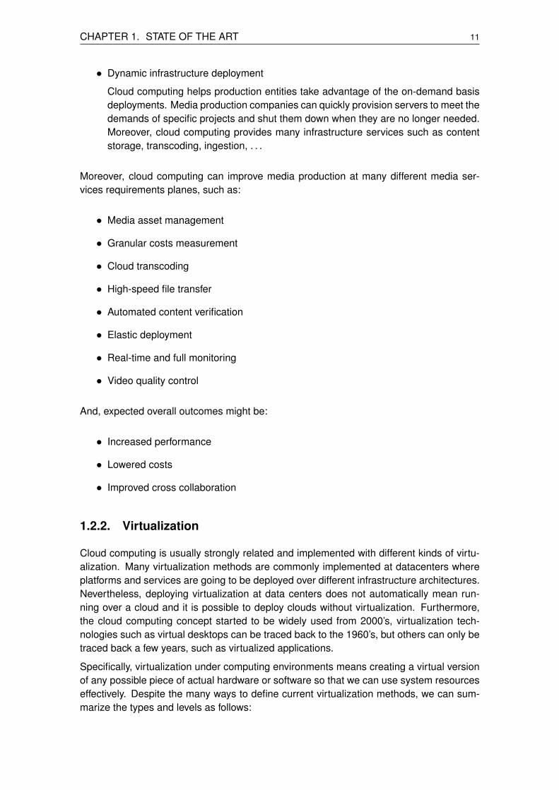
• Dynamic infrastructure deployment
Cloud computing helps production entities take advantage of the on-demand basisdeployments. Media production companies can quickly provision servers to meet thedemands of specific projects and shut them down when they are no longer needed.Moreover, cloud computing provides many infrastructure services such as contentstorage, transcoding, ingestion, . . .
Moreover, cloud computing can improve media production at many different media ser-vices requirements planes, such as:
• Media asset management
• Granular costs measurement
• Cloud transcoding
• High-speed file transfer
• Automated content verification
• Elastic deployment
• Real-time and full monitoring
• Video quality control
And, expected overall outcomes might be:
• Increased performance
• Lowered costs
• Improved cross collaboration
1.2.2. Virtualization
Cloud computing is usually strongly related and implemented with different kinds of virtu-alization. Many virtualization methods are commonly implemented at datacenters whereplatforms and services are going to be deployed over different infrastructure architectures.Nevertheless, deploying virtualization at data centers does not automatically mean run-ning over a cloud and it is possible to deploy clouds without virtualization. Furthermore,the cloud computing concept started to be widely used from 2000’s, virtualization tech-nologies such as virtual desktops can be traced back to the 1960’s, but others can only betraced back a few years, such as virtualized applications.
Specifically, virtualization under computing environments means creating a virtual versionof any possible piece of actual hardware or software so that we can use system resourceseffectively. Despite the many ways to define current virtualization methods, we can sum-marize the types and levels as follows:

12 Study and proposal of a distributed and scalable real-time media production platform
• Types: based on specific computer/server resources virtualization. We can distin-guish:
– Data virtualization: when an application is able to retrieve and manipulate datawithout requiring technical details of such data.
– Memory virtualization: when, in a cluster, volatile random access memory (i.e.:RAM) resources are decoupled from physical machines in order to be aggre-gated with other RAM resources and to become a virtualized memory pool.
– Network virtualization: when combining hardware and software network re-sources and network functionalities into a single and software-based manage-ment entity.
– Storage virtualization: when pooling data from multiple and different storagedevices into a virtual device that is managed from a central console.
• Levels: based on abstract and generic virtualization concepts. The following casescan be distinguished:
– Application virtualization: when encapsulating an application software from theunderlying operating system on which it is executed. It involves separating thephysical client device from the management of the application itself.
– Environment virtualization: when virtualizing at operating system level. It is avirtualization method where the kernel of an operating system allows for multi-ple isolated user-space instances, instead of just one.
– Hardware virtualization: when hiding the physical characteristics of a comput-ing platform from a user point of view and showing another abstract computingplatform. It means computer or operating system virtualization by creating vir-tual machines. Nowadays, the software that manages virtualization is calledhypervisor or virtual machine monitor.
Therefore, in terms of cloud computing benefits, virtualization can increase agility, flexi-bility, and scalability while creating significant cost savings. Workloads might be deployedfaster, performance and availability increases and operations can become fully automated,resulting in a cloud with ease to be managed.
This section focuses on the previous defined virtualization layers, which are of interest forthis thesis development.
So, starting from the upper layer, the current technologies for application virtualization are:
• Desktop virtualization: when separating part or all of the desktop environment andassociated applications from the physical client device that is used to access re-motelly or locally it. This improves portability, manageability and compatibility of apersonal computer’s desktop environment. A common implementation of this ap-proach is to host multiple desktop operating system instances on a server hardwareplatform running a hypervisor. This is generally referred to as Virtual Desktop Infras-tructure (i.e.: VDI). Some commercial examples are Microsoft RemoteApp and theCitrix Seamless Windows.

CHAPTER 1. STATE OF THE ART 13
• Application streaming: when delivering pieces of the application’s code, data, andsettings when they’re first needed, instead of the entire application being deliveredbefore startup. Running the packaged application may require the installation of alightweight client application. Packages are usually delivered over a protocol suchas HTTP, CIFS or RTSP. Some examples are Microsoft App-V and Citrix XenAppStreaming.
The next lower layer is the intermediate layer of environment virtulization. The pioneerimplementation of this layer was FreeBSD’s jails mechanism, allowing system administra-tors to partition a FreeBSD-based computer system into several independent mini-systemscalled jails. There are many other examples of environment virtualization, but all of themare OS-based virtualization with differences such as its kernel operating system (i.e.:FreeBSD, Solaris, Unix-like, and Windows) and the level of isolation in terms of resourcesutilization (i.e.: types of virtualization, explained above), security and ease of delegation.
Currently, the environment virtualization method of Linux containers (LXCs) are widely en-hancing application/services development, testing, packaging, deployment and managingmethodologies. Specifically, containers represent one of the leading trends in computingtoday. With this technology it is possible to run multiple isolated Linux systems (i.e.: con-tainers) on a single Linux control host. LXC combines kernel’s cgroups4 and support forisolated namespaces5 to provide an isolated environment for applications without the needfor starting any virtual machine.
Finally, the lower environment virtualization layer is the hardware-centric one. Differentmethods can be distinguished as follows:
• Full virtualization: when simulating enough hardware to allow using an isolated guestoperating system in a virtual machine. There are many examples of implementationlike Parallels, VirtualBox, OracleVM, VMware and QEMU among other platforms.
• Hardware-assisted virtualization: is a full virtualization enhancement that uses spe-cific hardware capabilities by improving hardware simulation efficiency. There manyimplementations’ examples like Linux KVM and Xen among others platforms.
• Partial virtualization: was the previous virtualization technology of the full virtual-ization. The main differences resides on the address space virtualization, in whicheach virtual machine consists of an independent address space. This fact impliesthat a full operating system is not able to run in a virtual machine but many of itsapplications.
• Paravirtualization: when a virtual machine does not implement full hardware virtual-ization, but offers a special API for a guest with a modified version of the operatingsystem. This type of virtualization is also implemented in most of the widely usedvirtualization platforms like VMware, Parallels and Xen.
4The control groups (cgroups) is a Linux kernel feature that limits, accounts for, and isolates the resourceusage (CPU, memory, disk I/O, network, etc.) of a collection of processes.
5Namespace isolation refers to a Linux kernel feature where specific groups of processes are separatedsuch that they cannot interact with resources in other groups (i.e.: namespaces).

14 Study and proposal of a distributed and scalable real-time media production platform
1.2.3. Monitoring
Strongly related to cloud reliability is the monitoring concept. In order to reach maximumcloud reliability it is important to observe and check the progress and/or quality of keyparameters over certain periods of time and to keep them under systematic review in orderto create proper reactions, if required.
Therefore, this implies monitoring the cloud infrastructure (e.g.: servers, virtual or physical)and related services (e.g.: applications). Here appear the QoS (Quality of Service) andQoE (Quality of Experience) terms, respectively.
QoS is the network-centric monitoring of underlying infrastructure components such asservers, routers and its network traffic. QoS metrics are generally device-related (e.g.:CPU and memory load, CPU temperature, disk space or HDD health) or transport-oriented(e.g.: packet loss, delay, bandwidth usage or jitter).
Although QoS can be fully affordable due to the robustness and redundancy of currentinfrastructures (e.g.: back-up services, network rerouting and error correction), this doesnot mean that any end user might be feeling comfortable by using deployed services (e.g.:searching on a e-commerce webpage) over a QoS-assured infrastructure. Then, QoEmonitoring term evaluates the quality delivered to a user and it is done by analysing pa-rameters when connecting to such services like a user. Therefore, QoE performance in-dicators are user-centric (e.g.: webpages response time or measuring video and audioquality (e.g.: Mean Opinion Score test, MOS).
Common network monitoring protocols for distributed infrastructures management are:
• SNMP: Simple Network Management Protocol is a widely known and used Internetstandard protocol for managing IP-capable devices. SNMP is based on monitoringstations (i.e.: traps) which implement registry (i.e.: Management information base,MIB) polling to specific equipments (IP-capable devices supporing SNMP), whichoffer data of interest such as disk usage, link status, CPU usage,. . . Moreover, it canbe configured in an asynchronous mode.
• WMI: Windows Management Instrumentations is a Microsoft’s implementation ofthe Web-Based Enterprise Management (WBEM) and Common Information Model(CIM) standards from the Distributed Management Task Force (DMTF). It offers a de-tailed set of properties and methods (offering data metrics similar as done by SNMP)for access by an authenticated user but it is all done through Windows proprietarydefinitions.
• NetFlow: a Cisco protocol for network switches and routers. It is meant to be usedas a network flow analyser (by identifying and analysing each configured flow, whichis an unidirectional statistical packet sequence)
Usually, these protocols are used to measure QoS, but there are complex algorithms thatprocesses those QoS measurements parameters of interest in order to measure the QoEtoo. Nevertheless, there are specific applications to define and perform specific QoE mea-surements.
Focusing our attention in the topics of this thesis, the QoE measurements are relevantfor audiovisual content services because bad network performance may highly affect the

CHAPTER 1. STATE OF THE ART 15
user’s experience. This is mainly because these contents are compressed and coded, andhave low redundancy. Moreover, when designing systems, for referenced analysis, severalelements in the video production and delivery chain may introduce distortion by degradingthe content (i.e.: from the transcoding system, transport network, access network, homenetwork to end device).
An important concept is the referenceless6 analysis, which is based on the idea that endusers do not know about the original content. In this case, instead of measuring the QoEby comparing the original data to the delivered one, this is done by trying to detect artefacts(i.e.: blockiness, blur or jerkiness for video frames).
Obviously, the automation of critical cloud performance monitoring tasks is crucial for en-suring availability, providing efficient services and reducing common errors, costs and com-plexity. So, the use of OTT applications are crucial in order to process such quantities ofdata flows and display outcome parameters of interest.
There are many tools that offer monitoring capabilities to be integrated and of-the-shelf.Such monitoring capabilities can be organized as:
• System monitoring
Single server/computer/instance resources monitoring (e.g.: CPU and memory loadsor processes utilization). Typical examples are the system monitoring tools that eachoperating system includes by default.
• Network monitoring
Related to the previous item, but specific to network resources monitoring (e.g.:monitoring input and output accumulated bytes of a single computer network inter-face or monitoring specific network hardware like accumulated incoming UDP pack-ets of a router in a LAN). There are many examples of tools and services for networkmonitoring which go from desktop applications (e.g.: netstat [30]) to specific routerand switch daemons (e.g.: MRTG [31]).
• Infrastructure monitoring
When system and network monitoring are coupled together by adding specific toolsand interfaces to monitor distributed resources within the infrastructure. There aremany examples of tools (e.g.: cacti [32] or monitis [33]) and services (e.g.: new relic[34] or pingdom [35]) at this monitoring level.
The associated database model for collecting such amount of data is the widely knownRound Robin Database [36], which stores data in a circular buffer based database wherethe system storage remains fixed by handling time-series data, and data is stored at dif-ferent levels of time granularity by consolidating the more granular data into coarse timescales (e.g.: 5 minutes - 1 hour - 1 day - 1 week).
Finally, it is important to remark that network managers have the capability to minimize thestorage and network resources by allocating only the resources that are required thanksto monitoring evaluation services and tools (i.e.: infrastructure optimization).
6Referenceless analysis is a technique studied and implemented by the AGH Multimedia Team [27] andit has been applyed within European projects [28] where i2CAT Foundation’s Media Internet area and AGHMultimedia Team has been collaborating [29].

16 Study and proposal of a distributed and scalable real-time media production platform
1.3. LiveMediaStreamer framework
This section is devoted to the framework which the core service (i.e.: audio and video mixersoftware) to be analysed is implemented with, the LiveMediaStreamer (LMS) framework.
The aim of the LiveMediaStreamer framework is to offer multiple audio and video streamsmanipulation in real-time in many ways. It is designed following a pipeline pattern so thatit consists in a number of filters (i.e.: encoders, decoders, receivers, transmitters, dashers,mixers and resamplers) that can be concatenated or connected with each other in orderto process a data flow. The framework is developed under a Linux environment, currentlybeing the only supported platform, using C++ standard libraries and it makes use of severalmature media-related libraries, which are:
• Live555 [37] – Network streaming media library which implements the RTP standardprotocol.
• ffmpeg [38] – A complete, cross-platform solution to record, convert and streamaudio and video.
• OpenCV [39] – Open source computer vision and machine learning software library.
• x264 [40] – Free software library and application for encoding video streams into theH.264/MPEG-4 AVC compression format.
• x265 HEVC Encoder [41] – Open source HEVC encoder.
• LAME [42] – High quality MPEG Audio Layer III (MP3) encoder, under LGPL license.
• Opus [43] – Totally open, royalty-free, highly versatile audio codec.
• WebM VPX [44] – VP8/VP9 Codec SDK. A open, royalty-free, media file formatdesigned for the web.
The framework is designed to be managed remotely through a simple network interfacebased on JSON-formatted TCP socket messages.
The LMS framework project stated to be developed since two years ago. A first imple-mentation was based on the network core of the open-source software UltraGrid [45]. Oneyear after, a new core has been developed based on the network streaming library Live555.This change has improved system performance and eased further developments. Live555library enables implementing any RTP and RTSP module, standard or not, among offeringout of the box specific audio and video RTP payload formats support like H264, HEVC orVP9 for video codecs and G711, OPUS or AAC for audio codecs.
Currently, the framework does not have a RESTful API, but has a web API based mid-dleware, that loads and manages an audio and video mixer scenario, written in Rubyprogramming language. It implements Sinatra framework for the web service interfaceside.
The main reason to provide a REST API is due to its decoupled architecture and low band-width usage, which makes the REST architecture style suitable for developing applicationsover cloud environments.

CHAPTER 1. STATE OF THE ART 17
Appendix A includes more information about specifics of the LMS architecture in order tounderstand the following chapters (mostly, in problem statement and proposal’s section2.1.3. and Chapter 3, the solution’s implementation).
Finally, note that there are many existing similar solutions but most of them are proprietaryor closed solutions (i.e.: Wowza Streaming Engine or Adobe Flash Media Server). More-over, these solutions does not provide video and audio mixing features which means thatthe use of other external tools is required if they are aimed to be used as real-time mediaproduction tools.


CHAPTER 2. PROBLEM STATEMENT ANDPROPOSAL
The goal of this chapter is to provide a structured vision of the specific problems of eachone of the points to be developed within this thesis.
The main challenges are to prepare and/or adapt current technologies to be ready for acloud deployment. This fact implies studying the existing technologies and tools in orderto create specific services that will be interconnected between them. Finally, the requireddevelopments will be carried out in order to assure the goals behind and ease demonstratethe results.
The main goals of this thesis are:
• To implement a high-level HTTP REST API in order to manage and monitor theLiveMediaStreamer framework.
• To demonstrate that LMS is able to be deployed in a virtualized environment.
• To enhance LMS with specific metrics measurements in order to demonstrate itscapabilities as a real-time media streaming framework.
• To offer a set of tools which gather the aforementioned metrics and present them inorder to demonstrate the previous statements.
• To include all previous statements within an architecture proposal.
• To demonstrate previous statements in specific testing deployments.
2.1. Architecture analysis
The main requirement is to define the platform’s architecture to be prototyped in order tohave a global and generic insight. So, taking into account the pieces required for this the-sis (i.e.: service layer, monitoring layer, virtualization/deployment layer), such architectureshould contain the different high level layers as shown in Figure 2.1.
Figure 2.1: Generic platform architecture
The ”LiveMediaStreamer REST API” layer will contain the service that will be offered todifferent and external applications (communicating over HTTP) in order to manage the
19

20 Study and proposal of a distributed and scalable real-time media production platform
”LiveMediaStreamer instance” layer by creating different audio and video production sce-narios. Both layers are the core layers of the platform.
Moreover, in order to offer a centralized monitoring system, the ”Statistics collector anddisplay” layer becomes as the generic box for this requirement.
It is also required to provide an orchestrator that manages the deployment and distributionof the possible configurations for the previous introduced layers. This will be done thanksto the ”Virtualization manager” layer.
Finally, an important point is to define how the communication between each layer is goingto be carried out. This is described in the following sections.
2.1.1. Virtualization
This subsection aims to introduce the possibilities that different virtualization technologiescan offer in our project requirements, and to decide between one of them.
First of all, the following points show which are the expected outcomes for using virtualiza-tion and what requirements should the selected technology fulfill:
• To manage and maintain a system of small pieces of services
• To have flexibility in order to quickly instantiate (e.g.: start, restart, stop) the requiredinstances (e.g.: to assure real-time scalability) and to deploy any possible requiredscenario/configuration
• To offer ease of continuous development and deployment of the different parts of thearchitecture
• To have a virtualizatied application version control system for having different versiontags for the architecture modules (e.g.: a development and a production containerof the same REST API service)
• To assure full compatibility for the core layers’ operating system (right now only Linuxenvironments are supported)
• To assure full compatibility for the hardware to work with (mainly x86 processors arein the scope)
Moreover, it is also required to use a technology that is as much lightweight as possible.Since we want to virtualize each piece of the platform architecture.
Under Linux environments there are many virtualization options to analyse (most of themproprietary), but let us focus on the ones that are open-source and have wider and activecommunities behind. These are:
• KVM (Kernel-based Virtual Machines) [46]
It is a FreeBSD and Linux kernel module that offers a full virtualization solution forLinux on x86 hardware containing virtualization extensions (Intel VT or AMD-V). It

CHAPTER 2. PROBLEM STATEMENT AND PROPOSAL 21
consists of a loadable kernel module that provides the core virtualization infrastruc-ture and a processor specific module. Usually, KVM runs with the QEMU (QuickEmulator) [47] which is a complete and standalone emulation suite that performshardware virtualization.
KVM with QEMU are able to offer virtualization for x86, PowerPC, and S/390 guests.For instance, when the target architecture is the same as the host architecture,QEMU can make use of KVM particular features in order to not emulate CPU normemory by using the offered by the host kernel.
Figure 2.2: QEMU with KVM or hypervisor type2 to type1
Figure 2.2 showcases how KVM can convert a type2 hypervisor (i.e.: QEMU) into atype1 hypervisor (known as a bare metal hypervisor) which increases overall appli-cation performances.
• LXC (Linux Containers) [48]
It is an operating-system-level virtualization environment able to run multiple isolatedLinux systems (known as containers) on a single Linux central host.
Linux kernel itself provides the cgroups functionality that allows limitation and pri-oritization of resources (CPU, memory, block I/O, network, etc.) without the needfor starting any virtual machines, and namespace isolation functionality that allowscomplete isolation of an applications’ view of the operating environment, includingprocess trees, networking, user IDs and mounted file systems.
Nowadays virtualization tendencies are focusing on the Docker project [49], whichis a platform that provides an additional layer of abstraction and automation ofoperating-system-level virtualization on Linux, Mac OS and Windows.
Using LXC with Docker mean resource isolation to allow independent containers torun within a single Linux instance, avoiding the overhead of starting and maintaining

22 Study and proposal of a distributed and scalable real-time media production platform
Figure 2.3: Docker with LXC
virtual machines. Moreover, the Docker project automates the deployment of appli-cations inside software containers and offers different tools to manage them (i.e.:CLI, API and file configurations), as shown in Figure 2.3.
Thus, it seems that the technology that best suits this thesis requirements is the Dockerproject. The main reasons are the capabilities of ease maintenance, test and quicklydeploy each container.
Finally, it is important to point out that another key feature of the Docker solution is that itallows containers to intercommunicate containers that are in the same physical server byisolating its network layer. This means much more security and performance over othervirtualization solutions (at least of the simplicity point of view when intercommunicatinginstances).
2.1.2. Monitoring layer
We now provide an insight on the minimum requirements for the monitoring module, to-gether with an analysis of available tools. Following the same criteria used previously, wefocus on open-source tools.
The main requirements for the monitoring layer implementation are:
• To ease distributed deployments.
• To offer full control for specific configuration requirements and to not depend onexternal/enterprise services.
• To be fully deployable.

CHAPTER 2. PROBLEM STATEMENT AND PROPOSAL 23
• To be as lightweight as possible in terms of:
– Processing capacity
– Memory utilization
– Network throughput
• To be supported under a Linux environment.
• To be flexible and scalable enough to be used in future extensions of the project.
• To support RRD (Round Robin Database) as a DBMS (Database Management Sys-tem) in order to control data storage size.
The data to be gathered includes:
• CPU and memory usage per process.
• Network usage (per process involved and per media flow)
• Internal core service performance parameters (i.e.: LiveMediaStreamer core perfor-mance):
– Processing time
– Data block losses ratio
We propose to split the monitoring layer in order to ensure stated requirements. Theproposal, as usually done in many monitoring tools such as system monitoring, followsthis model:
• Gathering layer
It will only be responsible of the gathering, distribution and storing of the metrics.
• Display layer
It will only be responsible of displaying data in answer of user-specific queries.
An alert layer could be considered as a future development. This thesis is focused onmeasuring and demonstrating that such platform is feasible but it could be enhanced witha set of alarms and actuators system in order to become as automated as possible.
The following list describes some of the tools available that might fit this thesis’s require-ments as previously exposed:
• Munin [51]
A cross-platform web-based network monitoring and graphing tool designed as afront-end application. Written in Perl.
• RRDTool [52]
A de-facto industry standard, it is a high performance data logging and graphingsystem for time series data. Written in C and runs under GNU/Linux and Windowsplatforms.

24 Study and proposal of a distributed and scalable real-time media production platform
• Collectd [53]
Small daemon which collects system information periodically and provides mecha-nisms to store and monitor the values in a variety of ways. Written in C and supportany Unix-like OS.
• Graphite [54]
Tool for monitoring and graphing the performance of computer systems, which col-lects, stores, and displays time series data in real time.
Many other solutions have been discarded due to its dependence on specific enterprises’roadmap or because they do not fit under the aforementioned requirements.
Finally, Collectd and Graphite are the selected tools. The main reasons are due to be-ing fully configurable and its core design and philosophy. Collectd has a data distributionsystem based on a push model and it can be single deployed (i.e.: gathering and dis-play layer), but it is going to be used with Graphite as the storage and display tool. Thisfact assures high performance for the containers where the Collectd will be gathering andtransmitting metrics through UDP. Moreover, Graphite software will be deployed as a cen-tralized storing and displaying tool which will be fed from many Collectds. Another reasonto select Collectd is its fully compatibility with Docker (Collectd can be deployed inside acontainer and there is also an official plugin to monitor Docker containers in an OS). Fi-nally, Graphite has also been selected because it offers a HTTP API which enhances itsscalability.
Therefore, the monitoring layer is proposed to be designed as shown in Figure 2.4.
Figure 2.4: Monitoring layer architecture proposal
2.1.3. Application layer
This subsection aims to compile the minimum requirements that the core service (i.e.: theLiveMediaStreamer framework) should implement to fit within the platform. This meansassuring that it can be demonstrated as an efficient real-time cloud production platform, asa prototype.
CHAPTER 2. PROBLEM STATEMENT AND PROPOSAL 25
First of all, let us identify the main goals that LiveMediaStreamer framework should provide:
• To assure minimal performance cost in computational terms when measuring inter-nal metrics in order to not interfere on the overall performance of the framework,whatever the scenario setup.
• To calculate specific metrics of interest. Common metrics should be:
– For network usage statistics
∗ Bandwidth usage per incoming and outgoing streams
∗ Packet loss ratio per incoming and outgoing streams
∗ Delay variation per incoming and outgoing streams
∗ Delay from far-end clients to LMS per incoming and outgoing streams
– For media statistics
∗ Pipeline losses
∗ Pipeline delay
• To compile the metrics in an efficient manner in order to let them be gathered byCollectd or any other application.
Currently, as of revision 0.2, the LiveMediaStreamer framework does not implement anymetrics gathering neither logging.
Regarding network usage statistics, LiveMediaStreamer does not support any internalmetrics gathering at network modules (i.e.: receiver and transmitter) where the Live555library is implemented. However, the Live555 library allows a quick implementation ofnetwork statistics measurements (i.e.: bandwidth, losses, jitter, delay).
Thanks to Live555 examples (i.e.: the testProgs folder inside the source code library path)it becomes easy to understand how to gather network statistics at the input side. But,regarding output network statistics, it is not so obvious which is the optimal solution. Thisfact is mainly due to having two options which imply to implement the metrics gatheringby doing some methods’ re-implementation of the RTP (i.e.: first option) or the RTCP (i.e.:second option) main classes, but this specific problem statement will be treated in Chapter3.
Regarding media statistics, current LiveMediaStreamers’ version of the framework doesnot implement any metrics gathering. So, in order to minimize computational cost of suchmeasurements we propose to implement:
• A specific method to measure processing delays (i.e.: the time a frame takes to beprocessed within a path).
• A specific method to measure processing losses.
Then, in order to implement the metrics presentation to be logged for external applications,a middleware API is required to be developed. Current API is not at all an API but a webGUI API for an specific scenario (i.e.: AVMixer scenario, as mentioned in Chapter 1 Section1.3.), which means that it is required to implement a more generic middleware API to let

26 Study and proposal of a distributed and scalable real-time media production platform
external applications to log the LMS internal metrics as API definition reclaims. Therefore,the proposal for solving this issue is to develop a RESTfull API in order to present themetrics from the LMS instance. This implementation is an opportunity to develop a full APIfor managing the LiveMediaStreamer framework over HTTP. Moreover, such middlewarewill ease to develop new applications over the LMS framework by evolving it as a SaaS,which means a proper enhancement to fit in a cloud environment.
Figure 2.5: LiveMediaStreamer framework statistics gathering and logging proposal
Figure 2.5 illustrates how previous statements are proposed to be implemented. As it canbe seen in Appendix A, each filter can have one or more readers and writers (both areinheritors of the IOInterface class). This issue will be described in Chapter 3.
Finally, the Pipelinemanager class instance is the class responsible for compiling the met-rics, filter by filter, when they are requested by the Controller class instance.
2.2. Architecture proposal
Once the problem statement has been described for each defined layer (i.e.: virtualization,monitoring and application) of the platform, a global architecture can be proposed. This isshown in Figure 2.6 which tries to be as generic as possible in order to illustrate the possi-bilities of the platform. There are different physical servers shown in order to demonstratethe aim to also support flexibility and scalability. In the following chapters (specifically theconclusions Chapter 6) we will demonstrate the feasibility of the approach.
Moreover, each physical server has different types of containers where different and possi-ble combinations and configurations of the technologies are shown that might be deployedand used for specific use cases (scenarios).

CHAPTER 2. PROBLEM STATEMENT AND PROPOSAL 27
Figure 2.6: Proposal of the platform architecture
Figure 2.7: Example of specific platform deployment
For example, a possible and specific architecture configuration could be a transcoder sce-nario. Figure 2.7 shows a simple example of a transcoding service behind a web appli-cation. This use case includes an user, which configures and manages the LiveMediaS-treamer’s scenario configured for a transcoding service (e.g.: starting with a HTML inputform for incoming inputs, transcoding parameters and RTSP server configuration). Specif-ically, at the architecture level, there is a container with an LMS daemon running, anotherone with the REST API that receives queries from the HTTP server from another container,

28 Study and proposal of a distributed and scalable real-time media production platform
which is serving the web application to the end user (e.g.: web browser). Then, each con-tainer has a collectd client that parses the logs of interest and sends the metrics to theGraphite service. Therefore, through the web interface the user can see specific graphics(e.g.: CPU usage, data losses, bandwidth usage, . . . ) from the graphite server (in anothercontainer) in order to monitor the overall performance and actuate if required.
Finally, it is important to point out that what will be deployed in order to demonstrate theplatform feasibility is an specific scenario, but it is as generic as possible. This will bedetailed in Chapter 6.
2.3. Task planning
This section describes the tasks to be done and its precedence.
Figure 2.8: Task planning - Gantt proposal
Figure 2.8 is the Gantt proposal for the task planning organization. It takes into account aperiod of six months for the execution of this thesis and it shows specific periods per task.For example, some tasks might seem overloaded, but this is taking into account that thewhole time will not be spent on working in the thesis but other tasks related to tasks carriedout at the i2CAT Foundation.
Note that the fact of working with a team inside an organization means extra tasks such asinternal demonstrations periods in order to carry out specific validations.
The following chapters describes the work done in each one of the topics: Application(Chapter 3), virtualization (Chapter 4), monitoring (Chapter 5) and testing and deployment(Chapter 6).

CHAPTER 3. APPLICATION
The main goal of this chapter is to develop the tasks related to the application, includingto prepare LMS to be deployed as a cloud service and to give support for internal andexternal monitoring.
3.1. REST API
As mentioned previous chapters, it is required to develop an API ready to be used overcloud environments in order to ease creating specific and new applications over the LMSframework, and thus to demonstrate the viability of this thesis prototype.
Nowadays, the common and widely used format for cloud services intercommunication isJSON, as it is also used for the TCP socket API of the LMS framework. Therefore, this APImiddleware is going to follow such requirement.
A suitable technology to work with JSON formatted messages is Node.js [55] which iswidely known for its good performance. Node.js is an open source, cross-platform runtimeenvironment for server-side and networking applications. It provides an event-driven archi-tecture and a non-blocking I/O API that optimizes application’s throughput and scalability.This technology is commonly used for real-time web applications.
Working with Node.js means avoiding serialization of the JSON messages by increasingservices intercommunication performance (i.e.: less computational cost and less process-ing time).
A common Noje.js framework for developing web applications and REST APIs is Express.js[56]. It is the de-facto standard server framework for Node.js. So, our middleware devel-opment is going to use Express.js routing system (URIs with HTTP request methods likeGET, POST, PUT and DELETE).
Figure 3.1 illustrates the software structure proposal for developing the HTTP RESTfull APImiddleware, which is responsible for translating the TCP socket API of the LMS framework.
Figure 3.1: RESTfull API middleware architecture
29

30 Study and proposal of a distributed and scalable real-time media production platform
• HTTP REST API layer
This layer handles HTTP queries from external applications. It implements specificroutes to handle specific HTTP queries. The first implementation will not implementmultiple LMS management but single, as shown in Figure 3.1.
• Interface layer
This layer handles the body messages from the previous layer’s HTTP queries andmanipulates them in order to create an as much generic as possible API by adaptingthe messages to be sent through following TCP socket layer.
• TCP socket layer
This layer is the responsible for sending and receiving JSON-formatted TCP socketmessages to and from the targeted LMS instance.
As presented in Section 1.3. and detailed in Appendix A, there are two different manage-ment layers: the generic one and the filter specific one. So, by following this organization,the proposed API’s structure is as described in Appendix B.
Note that this API is not implementing persistence1 because the state (managed through’State’ method) is given by the LMS instance itself. The unique sign of persistence isregarding the LMS host and port which the middleware is connected to (managed through’Connect’ and ’Disconnect’ methods). Higher levels of persistence should be implementedby external applications, which implies specific scenarios and requirements (i.e.: specificpersistence).
For more details about how this is structured and the overall middleware is implementedcheck Appendix F with the code.
3.2. Network metrics
Network metrics could be treated as external metrics. This is because these metrics arespecially dependent from sources which transmit to LMS, the receivers from LMS and thestate of the network itself. Obviously, the performance of the LMS affects to the metricsgathered too, but this effect is intended to be minimized, at least in a gathering and pre-sentation of the metrics’ point of view.
3.2.1. Input network metrics
As mentioned in Section 2.1.3., input network metrics are going to be implemented by car-rying out methods re-implementations of methods provided by the Live555 library, whichis the library that will manage network streams.
By following the LiveMediaStreamer architecture structure, input network implementa-tions are going to be developed inside the ’liveMediaInput’ structure. Specifically, a new
1Persistence, in computer science, refers to the characteristic of state that outlives the process that cre-ated it. This is usually solved by storing the state’s application as data structures in databases.

CHAPTER 3. APPLICATION 31
Figure 3.2: Input network metrics structure
class is developed, called ’SCSSubsessionStats’. This class is managed by the ’Stream-CleanState’ class, which is a class related to each stream ’Session’ class managed bythe ’SourceManager’ class. This last class is a ’HeadFilter’ class. Figure 3.2 shows theinter-class structure.
By initializing new RTP or RTSPClient sessions (i.e.: network inputs), a group of subes-sions is associated per each stream (i.e.: an RTP session has one subsession associatedand the RTSPClient session has as many subsessions as accepted from the SDP thatdefines different RTP sessions).
When a new subsession is set, a new RTPReceiverStats class is automatically initialized.This Live555 object implements RTCP stats measurement which are only required to betreated outside. This is done at SCSSubsessionState, which creates a new schedule toperiodically measure and save current state (a default granularity of 1 second is set). Theimplemented method is called periodically as shown in Appendix C Section C.1. Thisimplementation prepares the metrics that are going to be presented when a new statequery is received. The code in Appendix C Section C.1. shows how metrics from theLive555 library are obtained. For a more detailed insight of the overall implementation seeAppendix F. The metrics that are presented per each new state query are shown next (adefault granularity of 1 second is set):
• Bitrate: maximum, minimum and average in kbps.
• Packet loss percentage: maximum, minimum and average.
• Inter-packet gap: maximum, minimum and average in milliseconds.
• Jitter: maximum, minimum and current inter-packet gap variation in microseconds.

32 Study and proposal of a distributed and scalable real-time media production platform
All these metrics are measured through previous algorithm shown which is executed eachsecond (it is the default value set for all metrics gathered indeed). Specifically, bitrate ismeasured by dividing the total number bytes, received during each scheduled period, bythe elapsed time given by the Live555 library implementation:
average bitrate(kbps) =kbits received
elapsed seconds(3.1)
The maximum and the minimum bitrates are the last maximum and minimum averagebitrates obtained, and this is done for all other metrics.
Jitter is measured as the estimate of the statistical variance of the RTP data interarrivaltime inserted in the interarrival jitter field of reception reports (in microseconds), and thisis already internally done by the Live555 library. So, what is presented is the current jittervalue at the beginning of each new schedule.
Another metric that might be of interest is the delay from the stream source to the LMSinstance but it is discarded due to not being offered from Live555 library. Moreover, ithas been discarded to be implemented at SCSSubsessionStats class level due to is com-putational cost and complexity to develop such requirement. Note that this metric is notrelevant because network performance problems can be detected through other metricsalready gathered (i.e.: jitter and packet loss ratio).
3.2.2. Output network metrics
As done in the previous section, output network metrics are going to be implemented bycarrying out re-implementations of methods given by the Live555 library.
This implementation has been much more difficult due to not having control of the creationor deletion of the RTPSink class of the Live555 library. Previous developments beforethe final version were based over the RTPSink re-implementation already done per eachOnDemandServerMediaSubsession (Live555 library class), which is also re-implementedby QueueServerMediaSubsession (LMS framework class). But the implementation wasstill losing the specific RTPSink instance of specific subsession.
In order to continue with the development, an e-mail was sent to the Live555 developersmailing list and a solution was provided by Ross Finlayson as shown in Appendix G.
The best option, as suggested by Ross, was to re-implement the RTCPInstance classper each inheriting class of the OnDemandServerMediaSubsession class, specifically theinheriting classes of the QueueServerMediaSubsession class.
Figure 3.3 shows the relationship between the SinkManager class with both possible typesof connections (RTP or RTSP). Each Connetion object has a map of objects of the re-implemented RTCPInstance class, called ConnRTCPInstance (i.e.: RTCP instances pereach connection). Then, each time a new specific RTP connection or any QueueServer-MediaSubsession (RTSP connection, from RTSP server) is created, a ConnRTCPInstanceis associated in order to start gathering the statistics offered from Live555 library. This isshown in Appendix C Section C.2., with the code of the method that is periodically called(default periodicity value is set to 1 second). In this case, the delay metric is gathered fromthe Live555 library.

CHAPTER 3. APPLICATION 33
Figure 3.3: Output network metrics structure
The metrics are:
• Bitrate: maximum, minimum and average in kbps.
• Packet loss percentage (ratio): maximum, minimum and current.
• Round trip delay: maximum, minimum and current in milliseconds.
• Jitter: maximum, minimum and current inter-packet gap variation in microseconds.
All these metrics are measured by following the same expressions used for the input net-work metrics.
3.3. Pipeline metrics
The following metrics are presented as the internal metrics. Please, note that the measure-ment of these metrics interfere the overall performance of the LMS framework. Therefore,to achieve the minimum possible computational cost is a must. But, first of all, let us pick upthe example figure of a pipeline from Appendix A in order to showcase the internal pipelinestructure of the LMS framework. As described in Appendix A, this will help understandingthe following two implementations.
Note that in Figure 3.4 the arrows are the queues which interconnect each filter’s writerwith another filter’s reader. Writers and readers are subclasses of the IOInterface class.

34 Study and proposal of a distributed and scalable real-time media production platform
Figure 3.4: LMS framwork’s internal pipeline structure example
3.3.1. Delay
This metric is related to the time that data (i.e.: a video frame, an audio sample,. . . ) takesto be processed from an origin point to an end point by an unique given path, and this ismeasured from a given and required time: the data’s timestamps. Data inside the LMSsource code is known as a ”frame”, which can be an audio frame (i.e.: sample), a H264video NAL unit, a raw frame, . . .
The delay time is not measured per each filter in order to not affect the overall performance,but each measured time involves an origin filter which resets the timestamps. These ori-gins are the Head (i.e.: receiver) and OneToMany (i.e.: audio and video mixer) filters.These filters reset the frames’ timestamps in order to reach and control an internal syn-chronization, and this is due to the fact that these filters have many outputs (i.e.: writers) ormany inputs (i.e.: readers) and they require synchronizing their outputs in order to assureone point of time control inside the LMS framework, whatever the scenario configured.
So, in order to measure the delay it is important to note that a pipeline is not composedby an unique path (see Appendix A for clarifications) but multiple paths. This fact impliesthat it is not possible to measure an unique overall delay time per frame which goes overthe pipeline2, or at least it is not suitable for performance issues, but it can be done forexternal applications which know the scenario configuration and gathers such metrics.Therefore, this is solved by splitting the measurements by paths. And this is an optimalmeasurement: the delay is given by the differential time measured by the last reader of the
2There is a special case when there is only a path that defines the pipeline itself (e.g.: a path for onlytranscoding video with one quality: a receiver, a decoder, a re-sampler, an encoder and a transmitter, allconnected within a path that defines the pipeline of this specific scenario)

CHAPTER 3. APPLICATION 35
path (i.e.: the reader of the destination filter). Appendix C Section C.3. shows the methodwhich implements the measurement inside the Reader class.
In summary, the code measure the average delay of a frame by a given window time(default is configured to 1 second) with a resolution of microseconds. And this meansmeasuring from the origin time, which, as said, is set by the origin filters (i.e.: the beginningof a path, starting from a writer), to each reader of the path (i.e.: each filter). But, the delaytime presented is from the beginning (i.e.: initial writer of the path) until the last reader.Figure 3.4 illustrates different path examples.
3.3.2. Losses
This metric follows a similar criteria as the previous one. This is solved by measuring atthe same point, but it is done when flushing frames at the reader side (as presented inSection 2.1.3.). In order to reach minimal computational cost, the measurement is just acounter of the overall data losses when calling the flush methods. What is done is a methodencapsulation by defining a parent method that is just incrementing its reader counter andthen it calls the specific flush implementation per each data/frame type.
In order to properly present it to external applications it is required to be presented at apath level as done for the delay metrics. So, in this case it is only required to sum up theoverall losses of the path’s readers.
It is important to note that this metric is not referenced to a total data processed or atany time point, but measuring its continuity over time permits detect losses with differentthresholds. This means that if this value is incrementing gradually then the system is notworking properly. Such detections might imply fast increments on its continuity (differentialincrease).
Note that Pipeline metrics are measured when flushing frames (discarding) or when areader is able to remove a frame from its belonging queue.
Finally, once previous developments are carried out a first step to offer a cloud real-timemedia production service is achieved. This means, offering a RESTful API and a statuslayer for monitoring external and internal performance of the platform.


CHAPTER 4. VIRTUALIZATION
This chapter focuses on the preparation of generic containers for a media production plat-form prototype with the technologies and tools introduced in Chapter 1. We study and testthe Docker technology in order to assure that LMS is ready to properly fit in a container-ized environment and to evaluate different possibilities to reach maximum flexibility whenconfiguring and deploying different scenarios.
4.1. Creating and managing generic containers
The minimal containerized entities are the following ones:
• The core container with a LiveMediaStreamer instance already deployed inside andready to use.
• The HTTP REST API container with the middleware interface inside and ready touse
First of all, let us describe how and where Docker is installed. The host operating systemwhere tests are going to be carried out is an Ubuntu 14.04 LTS [57], which is the Linuxdistribution version where the LMS is being developed. Note that previous list does nothandle monitoring requirements, but this topic will be treated in Chapter 5. this is becauseour initial interest is related to testing how LiveMediaStreamer can be deployed inside acontainerised environment.
Note that main Docker requirements for Ubuntu 14.04 are to be under a 64-bit installationand kernel must be at version 3.10 or higher (lower versions are buggy and unstable).
Some procedures must be taken into account in order to properly install and assure abest fit possible of the Docker technology inside the OS (and also to be ready for a cloudenvironment). These procedures include:
• To create a docker group: in order to avoid user permission issues.
• To adjust memory and swap accounting: in order to not suffer memory overheadand performance degradation.
• To enable UFW forwarding: if UFW is enabled it is required to properly configure itsforwarding policy (if UFW’s enabled it will drop all forwarding and incoming traffic).
• To configure a DNS server: since Docker defaults to using an external DNS name-server, it cannot use the local one.
It is strongly recommended to check documentation’s web page of the official Dockerproject site [49] in order to know how these configurations can be done.
Once Docker is properly installed as a daemon in the OS let us focus on interesting possi-bilities that this technology offers in order to create and manage containers:
37

38 Study and proposal of a distributed and scalable real-time media production platform
• Creating containers
– Using a Docker file
This is the main configuration file for a Docker container set up. It can be seenas an initial script to build a specific docker container. Also, it is like setting upa local git1 repository to later distribute it, but at a container level instead ofsoftware level. There you can define many configuration parameters in orderto install and properly configure required dependencies and tools to run inside.
– Using Docker pull, commit and push for images
This is not recommended for creating an original container, but it is appropriatewhen starting with Docker technology. However, it is recommended to be usedonce an initial container has been build (from a Docker file) in order to maintainand to distribute different versions and deployments of this (as said, as a higherlevel git repository). It is important to note that a Docker image consists of aseries of layers. Docker makes use of union file systems to combine these lay-ers into a single image (the container itself). Union file systems allow files anddirectories of separate file systems, known as branches, to be transparentlyoverlaid, forming a single coherent file system. This last fact is a key point dueto its capacity of also offering deployment layers inside a container (i.e.: morethan one tool/technology inside a container).
• Managing containers
– Using Docker Hub service
It is a public registry of Docker images’ repositories (there are also private oneswith specific paying plans) from Docker official site. There is a list of basic (e.g.:CentOS, Ubuntu, Debian, ...) and complex (e.g.: CentOs with Nginx, Ubuntuwith Nginx and Wordpress, Debian with Node.js and MongoDB, ...) containerscontaining clean and/or OS environments.
– Using Docker Registry and Repository service
This item is a key point when looking for local management of images’ repos-itories. This tool let us deploy an external (e.g.: private) registry if some en-hancements over Docker Hub are desired (e.g.: specific user credentials, highlevel security layer,...).
– Using Docker Compose
This tool let us create a localhost orchestrator of docker containers. Thismeans managing/running more than one container and linking them (if re-quired) at same time from the same point.
For a more specific detailed list of options and possibilities from Docker containers, pleasecheck Appendix D.

CHAPTER 4. VIRTUALIZATION 39
4.1.1. Basic LMS container
Once previous brief of Docker possibilities to work with has been introduced let us startcontainerizing a single LiveMediaStreamer.
As shown in the wiki page at GitHub’s LiveMediaStreamer (see Appendix A), the frame-work has some requirements and dependences that should be previously solved (i.e.:installed). Appendix E Section E.1. lists the first and basic Docker file which installs andconfigures the image in order to run a LMS instance.
Now, let us focus on what is done in order to explain it better:
• FROM: this command indicates which is the image base to be used, in this case, aspreviously mentioned, Ubuntu 14.04 is the selected environment.
• MAINTAINER: this command tags the maintainer/creator of such container image.
• RUN: specific command which runs specific bash scripts (e.g.: apt-get, mkdir, ad-duser and any other available system command from the base image)
• USER: this command is used in order to specify the system user that is going tobe loaded in such container. This is mainly for security reasons (e.g.: avoiding rootuser).
• EXPOSE: this command handles the ports to be exposed from the container itself.This does not imply that later ports couldn’t be exposed through the command lineinterface, but it is used in order to list suitable ports to be required. In this case, theexposed ports are a range of UDP ports where streams will be input or outputted(i.e.: RTP), a TCP range for the RTSP and the TCP port for managing the LMSframework through TCP socket messages.
• CMD: this configures the command that will be executed when running the imageitself. It is important to point out that any user can later enter inside the containeravoiding the execution of the default CMD defined (e.g.: executing bash for develop-ment purposes inside the container and creating a new container’s version).
There are many other commands that could be used inside a Docker file (see Appendix D)but they are not required in this case.
Once the Docker file is defined it is time to build the image as follows:
$ docker build \-t <origin repository registry>/<image name>:<version tag> \<Docker file folder path>
Note that in order to start working with different images and managing them in differentenvironments (i.e.: different servers/computers) a Docker Hub account has been created.So, let us define each parameter in order to name and tag each image to built during thisthesis. In this case:
• Origin repository registry is ”gerardcl” (see https://hub.docker.com/r/gerardcl)

40 Study and proposal of a distributed and scalable real-time media production platform
• Image name is ”lms”
• Image version tag is ”single”
The last command builds the image by following the defined script inside the Docker filealready defined. Finally, the command to execute the image is:
$ docker run --rm -p <host port>:<container port> \--name single-lms gerardcl/lms:single
This last command runs the previous defined and built image by exposing internal TCPport (i.e.: <container port>, which has been configured in CMD method with 7777) toanother defined TPC port at host side (i.e.: <host port>). Flag --rm is used in order tobe able to run again the same command by defining (i.e.: identifying) the running imagewith ”single-lms” name (i.e.: --name flag). Note that for testing purposes flags -i -t(or -it, it is just the same) might be also added in the command in order to run as aninteractive process (this means allocating a TTY for the container process, so exposingthe STDIN, STDOUT and STDERR standard streams). Therefore, the effect is similar toexecuting the process over the same OS too.
Finally, in order to expose other ports it is just required to add the -p flag as many times asports required. If an UDP port is also required to be exposed it is required to add the udptag as shown:
$ docker run --rm -p <host port>:<container port> \-p <stream1 host port>:<stream1 container port>:udp \--name single-lms gerardcl/lms:single
4.1.2. HTTP REST API container
The following container to be built is the HTTP REST API middleware developed in Chap-ter 3. Since it is a Node.js application, it requires to be built with Node.js and the NPMwhich is the official Node.js package manager. NPM is used to to install middleware’sdependencies. This is shown in Appendix E Section E.2..
In this case, in order to build and manage such image, these are the image parameterswhich define this image:
• Origin repository registry is ”gerardcl” (see https://hub.docker.com/r/gerardcl)
• Image name is ”lms-rest-api”
• Image version tag is ”single”
The building command is:
$ docker build \-t gerardcl/lms-rest-api:single \<Docker file folder path>

CHAPTER 4. VIRTUALIZATION 41
Note that the middleware implementation support changing the listening port of the appli-cation (default is 8080) by just adding the ”-e” flag and defining the ”PORT” environmentvariable of the container. An example is shown:
$ docker run -it -e "PORT=9000" -p 8080:9000 \--name lms-rest-api --rm gerardcl/lms-rest-api:single
This last command sets the internal ”PORT” environment variable to 9000 and binds it tothe 8080 port of the host.
4.2. Linking containers
In order to play with the previously built containers, it is required to know how they mightbe interconnected (i.e.: linked).
4.2.1. Same OS
If containers are running on the same OS it is important to keep in mind that each en-vironment is isolated and its network environment is isolated too. Then, in order to letthe HTTP REST API container connect to and manage the LMS instance container it isrequired to share the its network environment with LMS instance container. Here is howeach container might be executed:
$ docker run -it -p 8080:8080 --name lms-rest-api \--rm gerardcl/lms-rest-api:single
$ docker run -it --rm --net container:lms-rest-api \--name lms gerardcl/lms:single
Flag --net container:<container id> helps solving this issue. This configures the”lms” container to use the network environment of the ”lms-rest-api” container. So, bothcontainers are on the same localhost, but isolated. The only exposed port is the 8080,which is required to get access to REST API.
To point out that in this case it is not required to expose the TCP socket API port becauseit is internally linked through the REST API container. This is a key point of the Dockertechnology, which lets isolate a container from external world.
In order to demonstrate it let us show what a $ netstat -putaneo command executionreturns:
• Looking for port 8080:
Proto LocalAddress ForeignAddress State User PID/Program nametcp6 :::8080 :::* LISTEN 0 21735/docker-proxy
• Looking for port 7777:
No result obtained so isolation is reached on port 7777

42 Study and proposal of a distributed and scalable real-time media production platform
4.2.2. Separate OS
In order to deploy each container in separate OS it is required to expose required ports forachieve intercommunication. The Docker ”run” command might be:
• For LMS container (only exposing TCP socket API control ports):
$ docker run -it --rm -p 7777:7777 --name lms gerardcl/lms:single
• For REST API container:
$ docker run -it -p 8080:8080 --name lms-rest-api --rm \gerardcl/lms-rest-api:single
Then, in order to reach connection from REST API to LMS the host to set in the connectJSON parameter is the host IP of the OS which is running the LMS instance containerized.And, obviously, in order to play with the REST API and control the remote LMS instance,the host URI must be the OS IP of the running REST API container.
4.3. Running multiple processes within a container
Finally, it is important to note that a Docker image is only able to run a single processthrough the CMD method. But there is a solution to reach executing more than one process(i.e.: multiple services). This fact will help developing Chapter 5.
The solution for running multiple services inside the same container remains on a com-mon and widely used tool, called supervisord. Supervisord is a client/server system thatallows monitoring and controlling any number of processes on UNIX-like operating sys-tems, which is meant to be used to control processes related to a project or a customer(i.e.: a Docker container), and is meant to start like any other program at boot time.
An example for supervisor to be required is due to the fact that LMS framework is ableto encapsulate audio and/or video streams to MPEG-DASH2 [58] segments, which a keypoint feature of the LMS framework in order to offer live or on demand streaming to browserapplications. Therefore, in order to let a browser play obtained segments an HTTP serveris required, which serves the required files to be sent to the browser. Appendix E SectionE.3. describes the Docker file for building such container, which will have a LMS instanceand a HTTP server (i.e.: Nginx).
This is quite similar to the first Docker file introduced in this chapter but:
• Nginx and Supervisord are also installed
• Specific /var/run and /var/log folders are created per each Supervidord process in-side the supervisord.conf file
2Dynamic Adaptive Streaming over HTTP (DASH), also known as MPEG-DASH, is an adaptive bitratestreaming technique that enables high quality streaming of media content over the Internet delivered fromconventional HTTP web servers.

CHAPTER 4. VIRTUALIZATION 43
• This Docker file uses the command ADD in order to add specific configuration filesfor the Nginx and Supervisord container’s servers (they are later showcased)
• What is executed now is the Supervisord daemon
• The port for the Nginx server is exposed
• The user that is going to be used for this container is its root user due to requirebeing used by supervisord service itself
The Nginx configuration file is as shown in Appendix E Section E.4. In this configurationfile, apart from typical Nginx configurations (which are out of scope of this thesis), some ac-cess control methods are added in order to treat common HTTP server issues like CORS(Cross-Origin Resource Sharing). Note that the root file system specified is the one whichthe LMS instance should use for saving the MPEG-DASH output files too (i.e.: the dasherfilter should be configured with this folder).
Finally, the last file to show is the supervisord.conf configuration file:
[supervisord]nodaemon=true
[program:livemediastreamer]command=/usr/local/bin/livemediastreamer 7777
[program:nginx]command=/usr/sbin/nginx
This supervisord configuration file defines both services to be executed, LiveMediaS-treamer and Nginx. Then, as done with previous Docker files, let us show how it should bebuilt:
$ docker build \-t gerardcl/lms:dash \<Docker file folder path>
An example command to run this container’s image is shown next:
$ docker run -p 8090:8090 -p 7777:7777 -p 5004:5004/udp -it \--rm --name lms-dash gerardcl/lms:dash
So, this container will serve the MPEG-DASH files on http://host:8090/ and it will also belistening on port 7777 in order to get TCP socket configuration messages and it will belistening on port 5004 in order to receive an audio or a video on that port.
4.4. Best practices
As illustrated in the official Docker documentation web site [50], one of the best practicesthat should be taken into account is to avoid creating complex images and try to split asmuch as possible them.

44 Study and proposal of a distributed and scalable real-time media production platform
For example, the previous section is just an example of a scenario where running multipleservices inside a container is a must (i.e.: when there are no other options or the solutionbecomes much complex or the customer demands it), which should be avoided.
So, let us try to showcase a best practice for solving previous use case. By using the”volumes” feature that Docker offers, this last container with multiple services inside couldbe splitted into two: one specific container for a Nginx server (with same configuration fileas shown before) and the other the single LMS container introduced at the beginning ofthis chapter.
First of all, let us describe which is the Docker file generated for the Nginx container inAppendix E Section E.5.
Then, the build command might be as follows:
$ docker build \-t gerardcl/lms-nginx:single \<Docker file folder path>
Finally, let us show in order which should be the commands to execute:
$ docker run -v <host volume folder>:/home/lms/dashSegments \-p 7777:7777 -p 5004:5004/udp -it --rm \--name lmsdash gerardcl/lms:single
$ docker run -it -p 8090:8090 --rm --name nginx \--volumes-from lmsdash:ro gerardcl/lms-nginx:single
With -v flag is specified the ”host volume folder”, which is the host folder shared withthe internal folder which LMS container will write the MPEG-DASH files. If not spec-ified, default permissions are read and write. Then, the Nginx container will use the--volumes-from <container id>:<permissions mode> flag by specifying the con-tainers from which will share its volume and its file permissions. In this case file permis-sions are specified to be in read-only mode in order to not avoid file modifications from theserver/container side.
So, scalability, performance and control of the set of containers are assured by applyingbest practices like the last one.
Finally, note that thanks to these illustrations of Docker file configurations there is a stepforward to demonstrate this thesis’s goals.

CHAPTER 5. MONITORING LAYER
As already discussed, in order to properly manage a cloud computing environment it isstrongly required to use monitoring tools in order to gather information of interest by im-proving the environment itself or by finding out issues and solving them as fast as possible.
This chapter describes how the selected monitoring tools can fit in the architecture thathas been proposed and how they can be used. This includes preparing the environment tosupport Collectd (i.e.: monitoring and gathering) and Graphite (i.e.: storing and presenting)tools.
Such tools are helpful to demonstrate that LiveMediaStreamer framework could be de-ployed as the core of a real-time media production platform, as shown in Chapter 6).
Note that the fact of creating small and reusable containers is the main goal of this chapterand, of course, the goal of this platform architecture to prototype. And, thanks to theselected monitoring tools, which are lightweight and ease configuration flexibility, this issuemight be properly solved.
Figure 5.1 illustrates the proposal of the monitoring architecture, which describes the rela-tionship between different containers and the whole Collectd and Graphite deployment.
Figure 5.1: Detailed monitoring architecture
5.1. Monitoring containers
This section is based on how Collectd can be configured and deployed in order to monitorand properly gather the metrics of interest.
45
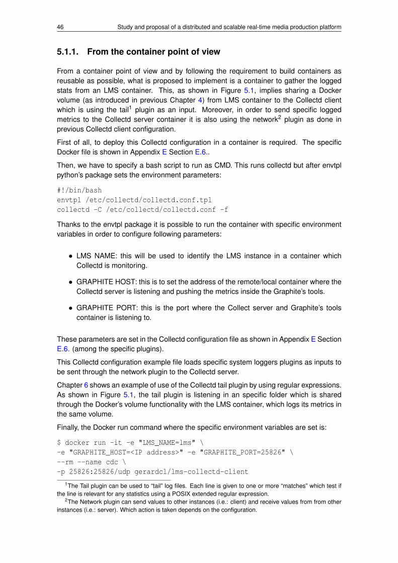
46 Study and proposal of a distributed and scalable real-time media production platform
5.1.1. From the container point of view
From a container point of view and by following the requirement to build containers asreusable as possible, what is proposed to implement is a container to gather the loggedstats from an LMS container. This, as shown in Figure 5.1, implies sharing a Dockervolume (as introduced in previous Chapter 4) from LMS container to the Collectd clientwhich is using the tail1 plugin as an input. Moreover, in order to send specific loggedmetrics to the Collectd server container it is also using the network2 plugin as done inprevious Collectd client configuration.
First of all, to deploy this Collectd configuration in a container is required. The specificDocker file is shown in Appendix E Section E.6..
Then, we have to specify a bash script to run as CMD. This runs collectd but after envtplpython’s package sets the environment parameters:
#!/bin/bashenvtpl /etc/collectd/collectd.conf.tplcollectd -C /etc/collectd/collectd.conf -f
Thanks to the envtpl package it is possible to run the container with specific environmentvariables in order to configure following parameters:
• LMS NAME: this will be used to identify the LMS instance in a container whichCollectd is monitoring.
• GRAPHITE HOST: this is to set the address of the remote/local container where theCollectd server is listening and pushing the metrics inside the Graphite’s tools.
• GRAPHITE PORT: this is the port where the Collect server and Graphite’s toolscontainer is listening to.
These parameters are set in the Collectd configuration file as shown in Appendix E SectionE.6. (among the specific plugins).
This Collectd configuration example file loads specific system loggers plugins as inputs tobe sent through the network plugin to the Collectd server.
Chapter 6 shows an example of use of the Collectd tail plugin by using regular expressions.As shown in Figure 5.1, the tail plugin is listening in an specific folder which is sharedthrough the Docker’s volume functionality with the LMS container, which logs its metrics inthe same volume.
Finally, the Docker run command where the specific environment variables are set is:
$ docker run -it -e "LMS_NAME=lms" \-e "GRAPHITE_HOST=<IP address>" -e "GRAPHITE_PORT=25826" \--rm --name cdc \-p 25826:25826/udp gerardcl/lms-collectd-client
1The Tail plugin can be used to “tail” log files. Each line is given to one or more “matches” which test ifthe line is relevant for any statistics using a POSIX extended regular expression.
2The Network plugin can send values to other instances (i.e.: client) and receive values from from otherinstances (i.e.: server). Which action is taken depends on the configuration.
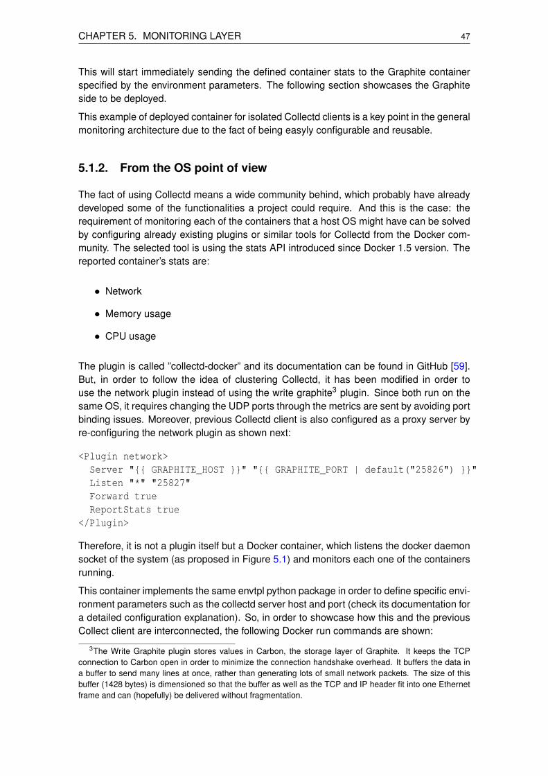
CHAPTER 5. MONITORING LAYER 47
This will start immediately sending the defined container stats to the Graphite containerspecified by the environment parameters. The following section showcases the Graphiteside to be deployed.
This example of deployed container for isolated Collectd clients is a key point in the generalmonitoring architecture due to the fact of being easyly configurable and reusable.
5.1.2. From the OS point of view
The fact of using Collectd means a wide community behind, which probably have alreadydeveloped some of the functionalities a project could require. And this is the case: therequirement of monitoring each of the containers that a host OS might have can be solvedby configuring already existing plugins or similar tools for Collectd from the Docker com-munity. The selected tool is using the stats API introduced since Docker 1.5 version. Thereported container’s stats are:
• Network
• Memory usage
• CPU usage
The plugin is called ”collectd-docker” and its documentation can be found in GitHub [59].But, in order to follow the idea of clustering Collectd, it has been modified in order touse the network plugin instead of using the write graphite3 plugin. Since both run on thesame OS, it requires changing the UDP ports through the metrics are sent by avoiding portbinding issues. Moreover, previous Collectd client is also configured as a proxy server byre-configuring the network plugin as shown next:
<Plugin network>Server "{{ GRAPHITE_HOST }}" "{{ GRAPHITE_PORT | default("25826") }}"Listen "*" "25827"Forward trueReportStats true
</Plugin>
Therefore, it is not a plugin itself but a Docker container, which listens the docker daemonsocket of the system (as proposed in Figure 5.1) and monitors each one of the containersrunning.
This container implements the same envtpl python package in order to define specific envi-ronment parameters such as the collectd server host and port (check its documentation fora detailed configuration explanation). So, in order to showcase how this and the previousCollect client are interconnected, the following Docker run commands are shown:
3The Write Graphite plugin stores values in Carbon, the storage layer of Graphite. It keeps the TCPconnection to Carbon open in order to minimize the connection handshake overhead. It buffers the data ina buffer to send many lines at once, rather than generating lots of small network packets. The size of thisbuffer (1428 bytes) is dimensioned so that the buffer as well as the TCP and IP header fit into one Ethernetframe and can (hopefully) be delivered without fragmentation.

48 Study and proposal of a distributed and scalable real-time media production platform
• Collectd tail client (from the container point of view):
docker run -it --rm --name cc -v /home/gerardcl/logs/:/home/lms/logs \-p 25826:25826/udp -e "LMS_NAME=lmsAVMixingStats" \-e "GRAPHITE_HOST=192.168.1.140" \gerardcl/lms-collectd-client
• Collectd docker socket API reader (from the OS point of view):
docker run -v /var/run/docker.sock:/var/run/docker.sock \-e GRAPHITE_HOST=127.0.0.1 -e COLLECTD_HOST=lmsOS \-e COLLECTD_DOCKER_APP=lmsAVMixStats -e GRAPHITE_PORT=25827 \-it --rm --name collector --net="container:cc" \gerardcl/lms-collectd-collector
In order to avoid port binding issues, the previous code sets up the Docker collectd collectorcontainer to use the same network environment of the Collectd tail client.
5.2. Showcasing monitoring
This section focuses on the storage and presentation side of the metrics already loggedand gathered. This is proposed to be done within a container built with a Collectd server(network data inputs served to Graphite) and a Graphite system (storing and presentingstats).
Installing and configuring Graphite is not trivial and not as easy as installing and configur-ing Collectd. This can be seen in the Docker file of the Appendix E Section E.8. in orderto build such container, as shown in Figure 5.1.
In this case, specific ”collectd” and ”graphite” users are created (among other environmentconfigurations as shown). Then, a bunch of different and specific configuration files forgraphite are added (i.e.: ADD command) to their specific configuration folders. And, fi-nally, specific command executions for database synchronization (i.e.: sqlite3 [60], whichis required for specific features for the Graphite web application) and other final configu-rations required for Graphite are also done. Regarding Collectd, it is installed in a similarway as previously done but it is now configured as shown in Appendix E Section E.9..
So, here, Collectd is configured as a server by listening from anywhere at the default portfor Collectd clustering. Moreover, the write graphite plugin is loaded in order to work as anoutput to the Graphite’s Carbon tool, which receives the data to be stored in the WhisperRRD of the Graphite installation.
It is required to configure this container to be able to run multiple processes (i.e.: Graphiteand Collectd). Therefore, by following the instructions of the previous section regardinghow to run multiple processes inside a container in Chapter 4, the Supervisord system isused. This time it is configured by splitting the processes configurations into two parts, Col-lectd and Graphite. The later configures the Graphite web application and the Graphite’sCarbon cache.

CHAPTER 5. MONITORING LAYER 49
• Collectd:
[program:collectd]user=collectddirectory=/command=collectd -C /etc/collectd/collectd.conf -fstdout_logfile=/var/log/supervisor/%(program_name)s.logstderr_logfile=/var/log/supervisor/%(program_name)s_error.log
• Graphite web:
[program:graphite-web]user=graphitedirectory=/opt/graphite/webapp/command=/opt/graphite/env/bin/gunicorn -w 1 -b 0.0.0.0:8080 \--pythonpath /opt/graphite/webapp/graphite graphite_wsgistdout_logfile=/var/log/supervisor/%(program_name)s.logstderr_logfile=/var/log/supervisor/%(program_name)s_error.log
• Carbon cache:
[program:carbon-cache]user=graphitedirectory=/env=PYTHONPATH=/opt/graphite/lib/command=/opt/graphite/bin/carbon-cache.py --debug startstdout_logfile=/var/log/supervisor/%(program_name)s.logstderr_logfile=/var/log/supervisor/%(program_name)s_error.log
An important configuration, that must be previously decided and configured by knowing therequirements for why monitoring is required, implies defining the storage schemas, whichdetail retention rates for storing metrics by using the Round-Robin Database storage type,as mentioned in Chapter 2. So, in order to work over a real-time media production platformit is important to achieve as much time accuracy as possible regarding the specific metricsof interest (e.g.: bandwidth usage, losses, pipeline delays, . . . ). There are more filesregarding the Graphite’s tools configuration, but most of them are set to default valueswhich are the recommended ones.
Before presenting the results, it is important to describe example commands for both Col-lectd client, and Collectd server and Graphite’s containers:
$ docker run -it -e "LMS_NAME=lms" -e "GRAPHITE_HOST=<IP of >" \--rm --name collectd -p 25826:25826/udp gerardcl/lms-collectd-client
$ docker run -it --rm --name graphite -p 25826:25826/udp -p 8080:8080 \gerardcl/lms-collectd-graphite

50 Study and proposal of a distributed and scalable real-time media production platform
As shown, the collectd (i.e.: Collectd client) container sends to the default port (i.e.: UDPprotocol) of the graphite host’s container (with Collectd server and Graphite tools). More-over, the graphite container opens the HTTP port 8080 in order to enable browsers to getaccess to its web application anywhere.
As conclusion, thanks to previous monitoring technology treated a generic and scalablemonitoring layer is achieved.

CHAPTER 6. PLATFORM DEPLOYMENT TESTS,AND RESULTS
In order to demonstrate that the LiveMediaStreamer is a suitable tool to be used as thecore framework of a cloud real-time media production platform it is required to test how itperforms over the cloud.
6.1. Platform deployment
In order to demonstrate how LMS fits the project requirements two scenarios, with differentcomplexity, are deployed.
• Isolated deployments
The main goal of this deployment is to demonstrate how LMS performs inside aDocker container by comparing its performance in the same OS but without runninginside a container (i.e.: system installation).
In this scenario LMS is configured to act as a transcoder service. This means ap-plying one pipeline per stream type (i.e.: one video and one audio paths).
• Generic deployment scenario
This scenario aims to showcase a suitable and as much generic as possible cloudreal-time media production scenario. LMS is configured to receive eight streams(i.e.: four audio and four video streams), mix them and transmit them through RTP/RTSP.
The environment where the deployments are done is composed of two laptops. The LMScontainer and the Collectd client container are deployed in laptop described in Table 6.1.The second laptop is a Dual-Core PC with the Graphite container running. Note that thefirst laptop described has the highest computational cost because all the audio and videoprocessing is done in. The second laptop only stores the statistics, displays the Graphitegraphs in a browser, plays the LMS’s output streams and transmits a video source (2 MbpsH.264 encoded video stream at 25 fps and at 1280x720 pixels resolution) as input for theLMS.
Table 6.1: Deployment environment characteristics
Parameter Value
Hardware type Sony VAIO laptopCPU Intel core i7-3632QM at 2.20 GHzRAM 6 GB (4 + 2) DDR3
Operating system XUbuntu 14.04 - 64 bits (x86 64)Kernel version 3.13.0-55-genericDocker version 1.6.8
As seen, the deployment has not been carried out in any type of specific server or highperformance cluster environment. The main goal is to demonstrate flexibility on the de-ployment (i.e.: in a laptop) and portability of the platform (not only the cloud itself). All of
51

52 Study and proposal of a distributed and scalable real-time media production platform
these characteristics are achieved thanks to the performance of the platform itself and theLMS (the core).
Note that all tests have been carried out in a 1 Gbps local area network with a router withboth laptops connected (see Figure 6.1 and Figure 6.5). The measurements have beencarried out during 10 minutes and a second of granularity.
6.1.1. Isolated deployments
This section compares the performance of the LMS installed on system (i.e.: in the hostOS) and the same LMS inside a container. A C/C++ script has been developed, whichconfigures the LMS framework as shown in Figure 6.1. Moreover, in order to test theperformance, the pipeline metrics are logged once per second (i.e.: pipeline losses anddelay) and gathered by a Collectd client container properly configured. Then the Collectdclient sends the data to the Graphite container. Check Appendix E Section E.10. to seean example of how the logging and collecting is implemented for these demonstrations.
Figure 6.1: Configuration of the scenario for the isolated deployments
The Collectd client container, which reads from the folder where the LMS is logging itsmetrics, uses the tail plugin (previously explained in Chapter 5) with specific regularexpressions in order to parse the metrics from the LMS logs.
Both isolated scenarios are the same but one is running the LMS on the system and theother is running the same configured LMS but containerized. The second OS is the onewhich runs the Docker container with the Collectd and Graphite tools. Moreover, this OSacts as the receiver of the transcoded streams through the RTSP protocol and also actsas the transmitter of the source stream.
Figure 6.2 shows the results. These are mainly focused on the pipeline performance met-rics (i.e.: internal LMS performance). The figure describes the CPU usage gathered at theCollectd client side and presented for the Graphite web GUI for both isolated scenarios.Regarding system installation the CPU average usage of the averages given by Graphite

CHAPTER 6. PLATFORM DEPLOYMENT TESTS, AND RESULTS 53
is around 4,015% and around 4,111% for the containerized one. So, there is not so differ-ence about running system installation or the same application containerized.
(a) System installation (b) Containerized
Figure 6.2: Isolated scenarios - CPU usage
Figure 6.3 illustrates the average pipeline delay introduced by the LMS system, whichin both video and audio cases is almost the same. Regarding video, system installationreaches an average of 216,8 milliseconds and the containerized case reaches an averageof 215,9 milliseconds. Regarding audio, system installation reaches an average of 25,6milliseconds and the containerized reaches an average of 25,2 milliseconds.
(a) System installation - Video path (b) Containerized - Video path
(c) System installation - Audio path (d) Containerized - Audio path
Figure 6.3: Isolated scenarios - average pipeline processing time

54 Study and proposal of a distributed and scalable real-time media production platform
(a) System installation - Video path (b) Containerized - Video path
(c) System installation - Audio path (d) Containerized - Audio path
Figure 6.4: Isolated scenarios - pipeline accumulated lost blocks
Regarding pipeline losses, as shown in Figure 6.4, both pipelines within both system in-stallation and containerized scenarios do not introduce any data loss. Therefore, LMSis a good option to work with, not only on system installation but also in a containerizedenvironment in order to be a portable service over a cloud infrastructure.
6.1.2. Generic scenario deployment
This last scenario is a generic and basic example demonstration of audio and video pro-duction in a cloud environment. Figure 6.5 illustrates how the scenario is configured.
This demonstration is quite similar to the previous but this time LMS is only configured andrunning inside a container. This LMS configuration is also a C/C++ script which configuresthe framework, as shown in Figure 6.5, inside the LMS container, specifically.
In this case what is deployed is an audio and video mixer which receives four audio streamsand four video streams encoded with OPUS and H264 codecs, respectively, which arestreamed through its standard RTP encapsulation (i.e.: specific payload headers).
Regarding the audio mixing, all input streams are mixed using the logarithmic mixing algo-rithm in order to not saturate the signal of the resulting audio stream. Regarding the videomixing, the HD inputs (at 1280x720 pixels resolution) are mixed as shown in Figure 6.6.All video inputs are resized (through the pre-resampler filter to the video mixer, see Figure6.5) to half of its size in order to fit into a resulting HD video stream as shown in Figure 6.5.

CHAPTER 6. PLATFORM DEPLOYMENT TESTS, AND RESULTS 55
Figure 6.5: Configuration of the scenario for the generic deployment
Figure 6.6: Generic scenario - video mixing configuration result
Let us focus now on the results regarding the pipeline performance parameters. The CPUusage of the containerized audio and video mixer obtained by averaging the averages,shown in Figure 6.7, is 23,02%.

56 Study and proposal of a distributed and scalable real-time media production platform
Figure 6.7: Generic scenario - average CPU usage
The audio and video average pipeline delay introduced in this scenario is shown in Figure6.8. There are two path groups, the ”recevier to mixer” paths and the ”mixer to transmitter”path (see Figure 6.5).
(a) Audio paths (b) Video paths
Figure 6.8: Generic scenario - paths average processing time
The average delay introduced for the audio ”receiver to mixer” paths averages is 8,6 mil-liseconds and the audio ”mixer to transmitter” path average delay is 23,1 milliseconds.Then, by adding the maximum average path (16,2 ms), a total average value of 39,3milliseconds of processing time involving the audio pipeline is achieved. Regarding thepipeline’s video path, an average of 9,89 milliseconds is obtained by averaging the ”re-ceiver to mixer” video paths average processing times. By adding the average of the ”mixerto transmitter” path processing time of 67 milliseconds to the maximum average obtainedin the ”receiver to mixer” path (12,8 ms) a total average of 79,8 milliseconds of delay in-troduced for the video pipeline is obtained. Therefore, the generic scenario demonstratesthat LMS achieves real-time1 processing time values.
1Real-time parameters [61] mean a maximum delay of 150 milliseconds between origin and destination.

CHAPTER 6. PLATFORM DEPLOYMENT TESTS, AND RESULTS 57
(a) Audio paths (b) Video paths
Figure 6.9: Generic scenario - paths accumulated lost blocks
Figure 6.9(a) illustrates that the audio paths of the accumulated lost blocks remains tozero, meaning that the audio pipeline is not discarding any data at any filter, which is animportant fact because losing any byte of audio would mean noticing some effects (i.e.:audio clips).
Then regarding the video ”receiver to mixer” paths there aren’t accumulated data losses.But, ”mixer to transmitter” path reaches around 52.308 lost data blocks. The fact of havinglost data blocks is due to the transitory period of the mixer filter. However, this accumulatedlosses remains constant, meaning that there are no more data blocks lost.
So, although this scenario is being deployed in an Intel i7 processor laptop, it is able toreal-time mix four couples of audio and video streams without issues.
Finally, we want to emphasize that the signal discontinuities that appear in some figuresare due to the fact of transmitting origin streams in a pseudo-live mode, which means audioand video loops. Therefore, this noise appears when the origin streams restart.


CHAPTER 7. CONCLUSIONS
This chapter aims to be a corollary of the whole thesis, summarizing the results and conclu-sions obtained in each one of the topics previously treated, which are related to prototypea cloud real-time media production platform.
The main goals of the thesis have been achieved:
• To develop an HTTP REST API middleware.
• To implement statistics measurement for the LMS framework.
• To create a virtualized environment which is suitable for cloud infrastructures.
• To create a logging, gathering, storing and displaying system for the platform me-trics.
Therefore, the obtained results demonstrate that this thesis offers a set of tools that havebeen tested and prepared for real-time media content production over cloud infrastruc-tures.
7.1. LiveMediaStreamer
As seen in Chapter 6, LiveMediaStreamer is performing properly and seems to be able tofit as the core part for real-time video and audio streams manipulation.
Figures 6.2 and 6.7 illustrates the scalability of the core in terms of stream processingcapabilities. This means that if for an audio and video stream treatment (Figure 6.1) theaverage CPU usage is around the 4%, and for four pairs of audio and video streams treat-ment (Figure 6.5) the CPU usage is around the 23% of an eight core CPU, then LMS canbe considered as a reliable and a scalable core framework. This is also confirmed by thefact of not suffering data losses inside the pipeline (Figures 6.4 and 6.9). However, it isimportant to note that in the video mixing pipeline there are accumulated losses, whichappear due to the fact of synchronizing different streams with different frame rates. Fig-ure 7.1 illustrates a constant index of losses which means that this data losses are notincrementing in time, so the system is stable.
It is important to note that in Figure 7.1 (also in previous Chapter 6 figures) there is somenoisy data which are caused by the use of working static files to simulate live audio-videostreaming. This means that when a file ends some seconds of discontinuity are noticed.
Related to the LMS framework development plan, it is demonstrated that the selected thirdparty libraries are suitable to continue being used (i.e.: Live555, LibAV/ffmpeg, x264 andOpenCV, among others) because they achieve an acceptable performance (i.e: the resultsshow that the filters where they are implemented do not add critical processing time). And,regarding behaviour debugging tools for the LMS, it is possible to know which filters arecritical or which should be improved thanks to the implemented metrics gathering system(i.e.: developers are now able to know how many time a filter takes to process a frame).
It is also important to remark that thanks to the developments done related to metricsgathering and the tools deployed around the LMS, it is easier to detect issues in the future.
59

60 Study and proposal of a distributed and scalable real-time media production platform
Figure 7.1: Generic scenario - derivative function of the video path accumulated lost blocks
For example, Figure 6.8(a) showed that the processing time for the audio ”receiver tomixer” path was not working properly due to not cleaning up the queues when the source issending in a pseudo-live mode (i.e.: a loop, a periodic reinitialization of the audio stream).
Finally, note that the generic scenario, which performs audio and video mixing from mul-tiple inputs, demonstrates that the video pipeline introduces around 80 milliseconds ofprocessing time. However, most of this delay is due to the encoder (i.e.: x264 library) andthe mixer (i.e.: OpenCV library) filters (the ”mixer to trasmitter” path).
7.2. Collectd and Graphite
The selection of these tools for the monitoring layer is a good choice when the goal is tohave a lightweight and highly configurable system.
A critical issue about clustering such tools (i.e.: Collectd clustering) is how its bandwidthusage may affect the whole system performance. Figures 7.2 and 7.3, which are a filteredwhireshark capture of the UDP stream bandwidth usage from the Collectd client to theCollectd and Graphite server, demonstrates that despite the huge amount of parametersto be sent, the communication protocol is lightweight and is not an issue that the systemmight suffer from. In the worst case (i.e.: generic scenario) the bandwidth usage averageis below 70 kbps.
Figure 7.2: Transcoder scenario - Collectd bandwidth usage (bits per second)

CHAPTER 7. CONCLUSIONS 61
Figure 7.3: Audio and video mixer scenario - Collectd bandwidth usage (bits per second)
Regarding the Graphite tool it is important to remark its huge amount of features to presentand treat the metrics, which help to carry out proper graphical data mining. It is alsoremarkable its compatibility with external tools in order to implement alarm systems ornear real-time actuators over the system which is being monitored. This fact is a key pointin order to implement a cloud real-time media production platform service.
Regarding the amount of data to be stored, thanks to the RRD, once the periodicity andgranularity of time points are defined the required storage capacity is known and remainsconstant in time. This is a key point that ensure the system performance will not be affectedbecause of the HDD usage.
There is a last point to highlight about Graphite, which is its capability to offer graphicsand specific data through its HTTP API. This means that specific applications are able todisplay data performance, in many ways, in near real-time.
7.3. Docker
Regarding this virtualization system implemented. Docker has demonstrated to be aproper tool to encapsulate each one of the required pieces of the platform in order todevelop, test, distribute and play with them.
Moreover, Docker offers to this platform prototype to become a multiplatform tool, whichmeans that any piece of this prototype can be executed in any OS which Docker givessupport (i.e.: currently supported OS are Linux/Unix, MacOSX and Windows).
Thanks to this tool, the global platform becomes fast to scale due to its fast start-up, restartand shut-down times. And this is also due to its ease to quickly replicate any containerizedapplication or service, if required.
Despite its strengths, it is not still a mature technology (the company behind, called dot-Cloud, and Docker project itself were born in 2013) but it is evolving really fast. This isdemonstrated by the high growth that its community is taking place year by year.
An area to be improved, which should be solved by Docker itself or through external solu-tions, are security issues. This is mainly due to the fact that when running a containerizedLMS this container does not completely isolate LMS from the security considerations ofrunning it directly on the host; in fact it adds more security vulnerabilities. The most impor-tant of these is that the Docker daemon’s API does not require any kind of authentication.It is important to make sure that there is a good firewall configured to isolate the hostmachine from outside the host, or it might be prone to external attacks. Docker’s bridgednetworking as well as mounted file system support allows for possible security holes into
62 Study and proposal of a distributed and scalable real-time media production platform
and out of the container itself, but this might happen also with traditional virtualization.Of course, the topic of container security is an extensive subject, but it is an issue to bestrongly considered when creating a container in order to guarantee the security of Docker(and LXC).
Despite the aforementioned issues, Docker offers other interesting solutions like directhardware access (i.e.: non specific GPU drivers nor emulator are required) and security atinfrastructure management level (i.e.: fast replication and relocation of the containers whenspecific containers are running with troubles like external network attacks to the service).
7.4. Platform
The platform developed and tested in this project can be considered the tip of the icebergof a cloud real-time and live media production platform. Therefore, the outcomes of thisthesis are specific tools/solutions which are suitable to be used together or separated,which might lead to future implementations of new specific and higher level tools (e.g.:dynamic platform configuration through browser application).
We can conclude the main goals of this project has been achieved and are ready to beused.
In order to comply the premise to be as open as possible, a web site of the LMS frame-work has been published at http://livemediastreamer.i2cat.net in order to start building acommunity of users and developers.
7.5. Next steps
New user requirements should be gathered, guiding new developments, but assuring therequirement to offer a set of tools as much configurable as possible.
In order to improve some filter steps a possibility is to work over GPGPUs (General Pur-pose Graphic Processing Units). In this case, OpenCV is already offering specific APIs towork over CUDA. Such implementations could lead to develop UHD video pipelines.
Regarding the network side, and thanks to the APIs implemented, it seems feasible toanalyse possibilities to deploy these thesis tools within SDN environments, which shouldimprove management and resource optimization.
Other possible future lines could be related to implement new codec and new media for-mats in order to keep up with the codec market.
In order to improve streaming robustness, a FEC implementation is also a point to explorebut keeping in mind to optimize the bandwidth and delay (i.e.: processing time) overheads.There are specific and proprietary solutions but we propose to implement the standarddescribed in RFC 5109 (RTP Payload Format for Generic Forward Error Correction). It isalso important to support specific synchronization mechanisms (in order to assure accu-rate streams synchronizations), such as PTP (Precision Time Protocol - IEEE 1588-2008standard), which is a protocol used to synchronize clocks throughout a computer network.
CHAPTER 7. CONCLUSIONS 63
Finally, in order to offer a complete set of tools for private media production use cases andto maintain specific license agreements (i.e.: IPR - Intellectual Property Rights) it is alsoproposed to implement DRM (Digital Rights Management) technology.

64 Study and proposal of a distributed and scalable real-time media production platform

ACRONYMS
AAC Advanced Audio CodingAES Audio Engineering SocietyAPI Application Programme InterfaceAVB Audio Video BridgingAVC Advanced Video CodingAVCi Advanced Video Coding - IntraBPP Bits Per PixelCAPEX Capital ExpendituresCIFS Common Internet File SystemCIM Common Information ModelCLI Command Line InterfaceCORS Cross-Origin Resource SharingCOTS Commercial Off-The-ShelfCPU Central Processing UnitDASH Dynamic Adaptive Streaming over HTTPDBMS Database Management SystemDMTF Distributed Management Task ForceDNS Domain Name ServiceDVMRP Distance Vector Multicast Routing ProtocolEBU European Broadcasting UnionFHD Full High DefinitionGPL GNU General Public LicenseGPU Graphics Processing UnitHD High DefinitionHDD Hard Disk DriveHEVC High Efficiency Video CodingHTML HyperText Markup LanguageHTTP Hypertext Transfer ProtocolIaaS Infrastructure as a ServiceIEEE Institute of Electrical and Electronics EngineersIGMP Internet Group Management ProtocolIO Input and OutputIP Internet ProtocolIPTV Internet Protocol TelevisionIT Information TechnologyJPEG Joint Photographic Experts GroupJSON Javascript Object NotationJT-NM Joint Task Force on Networked MediaKVM Kernel-based Virtual MachineLAN Local Area NetworkLGPL GNU Lesser General Public LicenseLMS LiveMediaStreamer frameworkLTS Long Term ServiceLXC Linux Containers
65
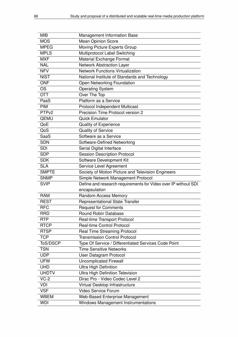
66 Study and proposal of a distributed and scalable real-time media production platform
MIB Management Information BaseMOS Mean Opinion ScoreMPEG Moving Picture Experts GroupMPLS Multiprotocol Label SwitchingMXF Material Exchange FormatNAL Network Abstraction LayerNFV Network Functions VirtualizationNIST National Institute of Standards and TechnologyONF Open Networking FoundationOS Operating SystemOTT Over The TopPaaS Platform as a ServicePIM Protocol Independent MulticastPTPv2 Precision Time Protocol version 2QEMU Quick EmulatorQoE Quality of ExperienceQoS Quality of ServiceSaaS Software as a ServiceSDN Software-Defined NetworkingSDI Serial Digital InterfaceSDP Session Description ProtocolSDK Software Development KitSLA Service Level AgreementSMPTE Society of Motion Picture and Television EngineersSNMP Simple Network Management ProtocolSVIP Define and research requirements for Video over IP without SDI
encapsulationRAM Random-Access MemoryREST Representational State TransferRFC Request for CommentsRRD Round Robin DatabaseRTP Real-time Transport ProtocolRTCP Real-time Control ProtocolRTSP Real Time Streaming ProtocolTCP Transmission Control ProtocolToS/DSCP Type Of Service / Differentiated Services Code PointTSN Time Sensitive NetworksUDP User Datagram ProtocolUFW Uncomplicated FirewallUHD Ultra High DefinitionUHDTV Ultra High Definition TelevisionVC-2 Dirac Pro - Video Codec Level 2VDI Virtual Desktop InfrastructureVSF Video Service ForumWBEM Web-Based Enterprise ManagementWDI Windows Management Instrumentations

BIBLIOGRAPHY
[1] Narang, N. “Concept Series : What is the Difference between OTT and IPTV”. M&EIndustry Trends, Technology and Research. 1–1. (2013) 1, 9
[2] Weil, N. “How to vuild your own TV Channel with Open-Source& other goodies”. Homesite: http://blog.eltrovemo.com/364/diy-broadcast-how-to-build-your-own-tv-channel-with-open-source-other-goodiesxiii, 2
[3] Ortiz Ramirez, A. “Three-Tier Architecture”. Linux Journal. volum(75), 1–1. (2000) 2
[4] i2CAT Foundation - Audiovisual Unit. Homesite: http://i2cat.net/en/area/audiovisual 2
[5] LiveMediaStreamer framework project. Homesite: https://github.com/ua-i2cat/liveMediaStreamer 2
[6] Society of Motion Picture & Television Engineers. Homesite: https://www.smpte.org/standards 5
[7] Poynton, Charles A. “Digital Video Interfaces”. Digital Video and HDTV: Algorithms andInterfaces. (Morgan Kaufmann. San Francisco. 2003): 130–131. 5
[8] SMPTE 424:2012 - 3 Gb/s Signal/Data Serial Interface. Homesite: http://standards.smpte.org/content/978-1-61482-714-6/st-424-2012/SEC1 5
[9] 32NF-70 WG Ultra HD SDI Interfaces. Homesite: https://kws.smpte.org/kws/public/projects/project/details?project_id=180 5
[10] AES standard for audio applications of networks - High-performance stream-ing audio-over-IP interoperability. Homesite: http://www.aes.org/publications/standards/search.cfm?docID=96 7
[11] Transport of High Bit Rate Media Signals over IP Networks(HBRMT). Homesite: http://standards.smpte.org/content/978-1-61482-716-0/st-2022-6-2012/SEC1.abstract?sid=5e7e93aa-6b4c-483d-b185-7bd46b9c3287 7
[12] ST 2022-5:2012 - Forward Error Correction for High Bit Rate Media Trans-port Over IP Networks. Homesite: http://standards.smpte.org/content/978-1-61482-715-3/st-2022-5-2012/SEC1.abstract 7
[13] Video Services Forum, Inc. (VSF). Homesite: http://www.videoservicesforum.org/about_vsf.shtml 7
[14] Define and research requirements for Video over IP without SDI encapsulation.Homesite: http://www.videoservicesforum.org/SVIP.shtml 7
[15] Joint Task Force on Professional Networked Streamed Media (JT-NM). Homesite:https://www.smpte.org/jt-nm 7
67

68 Study and proposal of a distributed and scalable real-time media production platform
[16] IEEE 802.3 Ethernet Working Group. Homesite: http://www.ieee802.org/3/ 7
[17] IEEE P802.3bs 400 Gb/s Ethernet Task Force. Homesite: http://www.ieee802.org/3/bs/index.html 7
[18] 802.1BA - Audio Video Bridging (AVB) Systems. Homesite: http://www.ieee802.org/1/pages/802.1ba.html 8
[19] The IEEE 802.1 Working Group. Homesite: http://www.ieee802.org/1/ 8
[20] The Time-Sensitive Networking Task Group. Homesite: http://www.ieee802.org/1/pages/tsn.html 8
[21] Open Networking Foundation “ONF White Paper”. Software-Defined Networking: TheNew Norm for Networks. (Open Networking Foundation. Palo Alto. 2012): 7–10. 8
[22] Deering , S. “Host Extensions for IP Multicasting”. IETF Network Working Group RFC1112. 1–2. (1989) 8
[23] Babiarz , J., Chan, K., Nortel Networks, Baker, F., Cysco Systems “Media Type Reg-istration for the Society of Motion Picture and Television Engineers (SMPTE) MaterialExchange Format (MXF)”. IETF Network Working Group RFC 4539. 1. (2006) 8
[24] Edwards , T. “Configuration Guidelines for DiffServ Service Classes”. IETF NetworkWorking Group RFC 4594. 7–8. (2006) 9
[25] Mell , P., Grance, T., National Institute of Standards and Technology “NIST SpecialPublication 800-145”. The NIST Definition of Cloud Computing. 2–3. (2011) 9
[26] Latimer , D., Open Group Foundation “Petepath and NVIDIA presentation”.GPU based cloud computing. https://www.ogf.org/OGF28/materials/1914/OpenGridForum28.pdf 10
[27] AGH Multimedia Team. Homesite: http://qoe.kt.agh.edu.pl/ 15
[28] MITSU - European project. Homesite: http://mitsu-project.eu/ 15
[29] AGH Video Quality assessment module. Homesite: http://vq.kt.agh.edu.pl/15
[30] FAQS.ORG “Network Administrators Guide” . Chapter 5. Configuring TCP/IPNetworking. http://www.faqs.org/docs/linux_network/x-087-2-iface.netstat.html 15
[31] OETIKER+PARTNER AG. “Multi Router Traffic Grapher”. What is MRTG ?. https://oss.oetiker.ch/mrtg/doc/mrtg.en.html 15
[32] The Cacti Group, Inc. “Complete network graphing solution”. http://www.cacti.net/ 15
[33] Monitis, part of TeamViewer Family “All-in-one application monitoring platform”.http://www.monitis.com/ 15

BIBLIOGRAPHY 69
[34] New Relic, Inc. “Software analytics done with SaaS”. http://newrelic.com/about15
[35] Pingdom AB. “Website mointoring”. https://www.pingdom.com/ 15
[36] Yu, J. “Round Robin Databases ”. https://jawnsy.wordpress.com/2010/01/08/round-robin-databases/ 15
[37] Live555 library. Homesite: http://www.live555.com/ 16
[38] FFmpeg library. Homesite: http://ffmpeg.org/ 16
[39] OpenCV library. Homesite: http://opencv.org/ 16
[40] x264 library. Homesite: http://www.videolan.org/developers/x264.html 16
[41] x265 library. Homesite: https://bitbucket.org/multicoreware/x265 16
[42] LAME library. Homesite: http://lame.sourceforge.net/ 16
[43] OPUS library. Homesite: http://www.opus-codec.org/ 16
[44] WebM library. Homesite: http://www.webmproject.org/code/ 16
[45] UltraGrid project. Homesite: http://www.ultragrid.cz/en 16
[46] Kernel Virtual Machine project. Homesite: http://www.linux-kvm.org/page/Main_Page 20
[47] Quick EMUlator project. Homesite: http://wiki.qemu.org/Main_Page 21
[48] Linux containers project. Homesite: https://linuxcontainers.org/ 21
[49] Docker project. Homesite: https://www.docker.com/ 21, 37
[50] Docker file - Best practices. Homesite: https://docs.docker.com/articles/dockerfile_best-practices 43
[51] Munin project. Homesite: http://munin-monitoring.org/ 23
[52] RRDTool project. Homesite: http://oss.oetiker.ch/rrdtool/ 23
[53] Collectd project. Homesite: https://collectd.org/ 24
[54] Graphite project. Homesite: http://graphite.wikidot.com/ 24
[55] Nodejs project. Homesite: https://nodejs.org/en/ 29
[56] Expressjs project. Homesite: http://expressjs.com/ 29
[57] Ubuntu project. Homesite: http://www.ubuntu.com/ 37
[58] MPEG-DASH project. Homesite: http://dashif.org/about/ 42
[59] Collectd Docker container GitHub project. Homesite: https://github.com/bobrik/collectd-docker/ 47

[60] SQLite project. Homesite: https://www.sqlite.org/ 48
[61] Percy, A. “Understanding Latency in IP Telephony” 3. [Online]. Available: http://www.aitel.hist.no/fag/ipt/lek02/iptel_latency_brooktrout.pdf 56

APPENDICES


APPENDIX A. LIVEMEDIASTREAMERARCHITECTURE
This appendix points to main links to learn LMS framework basics, which go to the LMSframework official web site developed during August 2015 (http://livemediastreamer.i2cat.net/)
• LMS architecture: http://livemediastreamer.i2cat.net/architecture/
• LMS core API: http://livemediastreamer.i2cat.net/tcpsocketapi/
• LMS REST API: http://livemediastreamer.i2cat.net/apirest/
Finally, next pages contain the LMS architecture site content attached.
73

Architecture
Table of contents
Introduction
Platform and libraries
Framework layers
Data �ow layer
Execution layer
Control layer
Main classes
FrameQueue
Frame
BaseFilter
Reader & Writer
Path
PipelineManager
WorkersPool
Controller
Structures
Filters
Receiver
Transmitter
Video decoder
Video resampler
Video encoder
Video mixer
Audio decoder
Audio encoder
Contact News Documentation Get LMS!

Audio mixer
Demuxer
Dasher
Pipelines
Connecting �lters
Paths
Management
TCP API
HTTP REST API
Introduction
LiveMediaStreamer framework has been designed based on two main concepts: modularity and simplicity. Therefore, using it, a wide range of streaming applications can
be designed due to its architecture. The main idea is constructing pipelines (paths and/or multipaths) of interconnected modules that process frames. Moreover, its
architecture ease addition to support new audio, video, container formats and transmission protocols.
The framework has been designed for Linux platforms using C/C++ language. It’s the environment supported by all the underlying libraries:
Live555 – Internet Streaming Media, Wireless, and Multicast technology, services, & standardsffmpeg – A complete, cross-platform solution to record, convert and stream audio and videoOpenCV – Open source computer vision and machine learning software libraryx264 – Free software library and application for encoding video streams into the H.264/MPEG-4 AVC compression formatx265 HEVC Encoder – Open source HEVC encoder.LAME – High quality MPEG Audio Layer III (MP3) encoder licensed under the LGPLOpus – Totally open, royalty-free, highly versatile audio codecWebM VPX – VP8/VP9 Codec SDK. A open, royalty-free, media �le format designed for the web
LMS enables to use and manage platform resources with full control, which is a critical aspect for time sensitive applications.
Framework layers
In order to keep the software modular and con�gurable, with a simple TCP socket access API, it has been organized into three layers:
Data �ow layerExecution layerControl layer
Data �ow layer
The software data �ow has been designed to follow the pipes and �lters design pattern. In computer science a pipeline is known to be a sequence or a chain of several
processors (routines, threads, etc.) placed in a manner that the output of each processor is the entrance of the next. Called pipeline thanks to the analogy to a physical
pipeline. The information that �ows inside a pipeline usually is a stream of records, bytes or bits that is read from a buffer or queue (pipe) by the �lter (processor) that after
processing it is written to another buffer to keep data �owing. Pipelines are usually implemented in multithreaded environments so it take advantage of parallel
programming, so the processors may run in parallel and not in strict sequence. This is a very suitable pattern for multimedia live streaming as in such scenarios the data to
process are continuous audio and video �ows.
Execution Layer
The execution layer of the software is where the parallelization takes part. Each �lter of the pipeline implements a Runnable pure abstract class which represents the
interface between the �lters and the WorkerPool class (an automated pool of workers, which has autiomatic management of threads execution). Each �lter is
automatically assigned inside the worker pool within a list of workers to be executed. Workers are totally independent of the pipeline composition and the �lter nature,
they only know about Runnables which is a simple interface that runs the processing routine of a single frame of a �lter. This way independence between the
parallelization and the pipeline con�guration is kept. Therefore, this is an implementation of a regular thread-pool pattern where each thread consumes tasks from a task
queue.
Keeping the software as a lock free implementation is important as the procedure to signal conditions between threads and awake and sleep threads might be time
consuming. It may help to keep optimal usage of the CPU, but it might be waste of time, which is critical for time sensitive applications.
Moreover this approach gives freedom on how the parallelization is done and let to the management layers de�ne the criteria to follow. Again this is important in order to
determine bottlenecks and to test different criteria (i.e. audio prioritization).

Control Layer
The control and management of the pipeline prepared to be done using a self-de�ned TCP socket protocol so it can be managed remotely and easily presented as a cloud
service as it can be operated remotely and it is pretty simple to develop web services or applications on top of it without having to actually get into the C++ code. See TCP
socket API section for all the details of this protocol. The Controller class is the responsible of dispatching received events to the PipelineManager class, which is the class
that has full overview of the system, it has the �lters pool and their interconnections (the paths). PipelineManager class, in fact, is where execution and data �ow layers
meet and the Controller class owns an instance of PipelineManager.
Main classes
In the following �gure there is a conceptual diagram of the logical structure of the control and data�ow layers.
In this diagram we can see a video transcoding scenario. In this case, a video is received from the network and decoded. After that, it is encoded in two different ways with
different parameters (size, bitrate, framerate). Finally, each encoded video is transmitted independently.
As it can be seen in the diagram there is a receiver and a transmitter as head and tail �lters of the pipeline, respectively. Moreover there is a video decoder, which is
connected to the receiver. Two video resamplers, each one connected to a video encoder, share the output of the video decoder. Finally, each video encoder is connected
to the transmitter.
Three different paths form this pipeline:
The �rst is de�ned by the receiver as origin �lter and the video decoder as destination �lter. In this case, the origin writer must be speci�ed because the receiver could
have more than one writer. Regarding destination reader, video decoder only has one reader so it is not necessary to specify it (default id for any writer/reader is 1).
The second is de�ned by the video decoder as origin �lter and the transmitter as destination �lter. Moreover, there are two mid �lters: video resampler and video
encoder. It is not necessary to specify the origin writer because video decoder has only one writer. However, transmitter has multiple readers so it is important to
specify a destination reader.
The third is similar to the second path. It has the same origin �lter and the same origin writer. Although the destination �lter is the same, the destination reader must
be different (note that the writers can be shared by different paths, unlike readers).
Finally it also can be seen the PipelineManager, which contains all the �lters and paths, and the Controller which manages control messages and dispatches the resulting
events to the corresponding �lters or to the PipelineManager.
The main structure of this approach is designed around the following 10 major classes or structures described in the following subsections:
FrameQueue
This is the pure abstract class that represents buffering structure of the pipeline. It is a circular queue prepared that owns a certain number of pre-allocated frames. It is
relevant that frames are pre-allocated and reused all the time during the execution of the program, allocating memory is an expensive operation for the OS, as it implies a
complete lock of the whole process memory, so keeping memory allocation and deallocation to the minimum expression is a must in order to optimize time sensitive
applications.
Another important aspect in terms of optimization is that the queue must be thread safe. To avoid complex or time consuming mutex operations it have been designed in a
simple lock free structure, assuming and forcing in the code single consumer and single producer scenarios.
This class is implemented by: AVFramedQueue (discret audio or video frames), AudioCircularBuffer (continuous raw audio byte array), X264VideoCircularBuffer (speci�c

for x264 in order to tread NAL units as discrete independent frames).
Frame
This is a very simple abstract class that handles byte array of a video or audio frame and some other frame related information, such as timestamp, is planar, sequence
number, etc. This class is implemented by: AudioFrame (it adds audio related data, such as sample rate, bits per sample, etc.), VideoFrame (it adds video related data, such
as codec, colour space, etc.), X264VideoFrame (it adds NAL units management to VideoFrame).
BaseFilter
This is one of the most important classes, is where all the data processing is done. The most relevant elements that contains this class might be list of Readers and the list
of Writers (see IOInterface description). Each �lter may have from none to many inputs and from none to many outputs. Each input is determined by a single Reader and
each output by single Writer. Readers and Writers job is to put in and to take out frames to and from the �lter respectively. Each �lter implementation must de�ne the
routine doProcessFrame, which is the responsible of processing frames given by the readers and to �ll the resulting frames given by the writer with the processed data.
Another important element of �lters is that they have a priority events queue. This queue stores events requested by the user in order to modify the �lter con�guration
(frame rate, bitrate, etc.). Priority criteria is time based, events may be targeted to take place after certain amount of time (this way it is possible to program events).
Finally, the �lters are responsible for connecting themselves, so it implements the connect, which connect a certain Writer from the �lter to a Reader from another �lter,
here is where and when the FrameQueue is created and its frames allocated. Is in this connection process when the Frames and FrameQueues are initiated according to
the speci�c data they will handle (i.e. AudioCircularBuffer for raw audio bytes or an AVFramedQueue with VideoFrames for raw video frames). The same way using
disconnect routine destroy the FrameQueue that uni�es two �lters and destroys allocated frames. It cannot exist a FramedQueue if two �lters are not connected.
This class is implemented by each processing �lter of the system (audio or video encoders and decoders, receivers, transmitters, mixer, resamplers, etc.). However
between each speci�c �lter implementation and the BaseFilter class there are:
OneToOneFilter: a �lter limited to a single input stream and single output stream
OneToManyFilter: a �lter with a single input stream and several output streams
HeadFilter: this is a �lter that represents the origin of one or several streams, none inputs, i.e. the receiver �lter is a HeadFilter
TailFilter: this �lter is the ending �lter of a pipeline, none outputs, i.e. the transmitter �lter is a TailFilter
ManyToOneFilter: a �lter that has several input streams and a single output stream, i.e. the video mixer �lter is a ManyToOneFilter
Finally, it’s important to point out that there are two different types of the Filter class: Regular (main type of �lter) and Server (it is an special case for network �lters
adapted to live555 library needs, for transmitting and receiving RTP streams).
Reader & Writer
These are two independent classes, but conceptually tightly related, because they share the FramedQueue object when connected. These are Reader and Writer objects.
They are pretty simple and they only encapsulate a FrameQueue object. Each of them contain a reference of a FramedQueue, being a reference to the same object if they
are connected with each other. A Writer has the routines to add frames to the queue and the Reader has the routines to read (and mark them as obsolete) frames of the
queue.
Path
This class is an important object in order to determine the pipeline con�guration, �lters interconnections and different data paths. As the �lters may have from zero to
many inputs and outputs the pipeline is likely to present different branches, conjunctions and bifurcations. A Path is just a list for all the �lters connected to a same branch,
in fact, a Path is de�ned by an origin �lter (HeadFilter or OneToManyFilter), a destination �lter (TailFilter or ManyToOneFilter) and a sorted list of all the �lters (only
OneToOneFilter) sequentially connected between origin and destination �lters (see Figure 1). Note that the Path doesn’t own or contain the �lters; it just records their ID.
The container of all the �lters of the whole pipeline is the PipelineManager class. Path only stores the interconnections of a particular branch of the pipeline. The Path
becomes handy when having to identify and distinguish different instances of a �lter of a kind.
PipelineManager
This class as the name suggests is the class that de�nes the pipeline as a whole, it’s the only object that has all related information to existing �lters, paths and their
interconnections. Moreover it represents the contact between the data �ow, control and execution layers.
In PipelineManager there are three relevant attributes: a list of Paths and a list of Filters. This class implements all the routines needed to create, destroy, assign and
connect all these elements.
WorkersPool
This is a pure abstract class that is mostly in charge of executing the process method of one or several �lters in a dedicated thread. Note that, in general, it’s isolated and
unaware of �lter type. The workers pool basically contains a list of Runnables and related C++ thread objects. A Runnable is an interface implemented by BaseFilter, which
has some basic methods such as processFrame and processEvent in order to process a single frame of the �lter. First processEvent is executed (the �lter gets recon�gured

it there was some pending event) and then processFrame (the �lter process current inputs and places the result in the Writer’s queue).
When a Worker starts it runs their speci�c thread in an in�nite loop that keeps running Runnable methods that performs speci�c �lter actions. In order to control data
consuming cadence the worker might be de�ned to process at a certain frame-rate, this way each iteration of its Runnable is determined by the frame-rate. If there is no
frame-rate de�ned the WorkerPool has a best-effort behaviour, trying to consume data as fast as possible.
Controller
The controller is the class that handles the interface to outside world, it is the class that de�nes the control protocol. The protocol is simple, each received packet by the
controller is a JSON or an array of JSONs, each JSON represents and event. There are two types of events, internal event (–ANCHOR–) or �lter events (–ANCHOR–).
Filter events are dispatched to the speci�c �lter’s events queue and internal events are handled by the PipelineManager. So the controller handles the TCP listening socket
and parses incoming events format and consistency.
Structures
Filters
In this section a simple description of the �lters that are going to be included in the software is presented. Relevant information such as inputs/outputs, relevant
parameters or tips are described using a common structured table to enable information access at a glance.
Receiver
It manages the reception of streams into the system. Supported transport protocols are RTP and RTSP.
For each input stream it creates a new writer, identi�ed by the reception port.
Filter name Receiver
Process frame description It manages RTP/RTSP input sessions
Input Network
Output Number of outputs: N
Data type: codec audio/video frames
Parameters None
Tips For each RTP session, it creates a writer identi�ed with the session (see Connecting �lters and Path chapters)
Transmitter
It manages the muxing and the transmission of output streams. Supported muxing formats are DASH and MPEG-TS. Supported protocols are RTP/RTSP and HTTP (only
for DASH format).
Streams can be transmitted without muxing them into a container using RTP/RTSP.
It is also possible to transmit streams directly over RTP, without using RTSP to manage the session, de�ning the destination IP and port.
This module can have multiple readers, each one representing a stream. Each stream can be simultaneously muxed in different formats and/or transmitted using different
RTP/RTSP sessions.
Filter name Transmitter
Process frame description It manages RTP/RTSP output sessions
Input Number of inputs: N
Data type: coded audio/video frames
Output Network
Parameters None
Tips Each reader can be used in many output sessions at the same time
Video decoder
It decodes video coded frames, outputting raw video frames. It has only one reader and one writer.

Supported codecs are the ones supported by libavcodec (which includes H264, HEVC, VP8 and VP9 decoding support)
Decoded frames size and pixel format are determined by the coded frames.
Filter name Video decoder
Process framedescription
It decodes the input video frame, outputting a raw video frame
Input Number of inputs: 1
Data type: coded video frames
Output Number of outputs: 1
Data type: raw video frames
Parameters None
Tips Supported input codecs: H264, H265 and VP8
Output frames pixel format and size is de�ned by the input frame (this module does not resize nor change pixel format, use video resamplerfor this).
Video resampler
It resizes and/or changes the pixel format of raw frames, outputting resampled raw frames.
Supported pixel formats are the same supported by libavcodec (e.g YUV420, RGB24).
Con�gurable parameters are video output size and pixel format.
Filter name Video resampler
Process frame description It resizes and/or changes the pixel format of the input frame
Input Number of inputs: 1
Data type: raw video frames
Output Number of outputs: 1
Data type: raw video frames
Parameters Output size, output pixel format, discard period
Tips Supported pixel formats:
RGB24, RGB32, YUV420P, YUV422P, YUV444P, YUYV422, YUVJ420P
Video encoder
It encodes raw video frames, outputting coded video frames.
Supported codecs are the ones supported by libavcodec (which includes H264, HEVC, VP8 and VP9 encoding support using libx264, libx265 and libvpx).
Con�gurable parameters are codec, frame rate, GoP length and bitrate.
Filter name Video encoder
Process frame description It encodes the raw input video frame, outputting coded frame NALUs
Input Number of inputs: 1
Data type: raw video frames
Output Number of outputs: 1
Data type: H264 coded NALUs
Parameters Framerate, bitrate, GoP

Tips Supported output codecs: H264 and H265
Supported input pixel format: YUV420P, YUV422P
Video mixer
It has multiple readers, each one associated to a channel. Its main task is composing a layout using frames of its different channels, outputting mixed frames.
It only supports RGB24 raw frames as input; output frames are also in this pixel format.
Con�gurable parameters are channel number and layout size. Channel con�gurable parameters are size, upper left corner position, opacity, layer and enabled/disabled.
It is important to consider that video mixer does not resize its input frames. This means that channel input frames and its size con�guration must coincide.
Filter name Video mixer
Process frame description It composes a layout using frames of its different channels
Input Number of inputs: N
Data type: raw video frames
Output Number of outputs: 1
Data type: raw video frames
Parameters Channel number, layout size
Channel: size, upper left corner position, opacity, layer, enabled/disabled
Tips Video mixer does not resize channel frames, so input frames size must be equal to channel size con�guration (using video resample module)
Supported input pixel format: RGB24
Output pixel format: RGB24
Audio decoder
It decodes audio coded frames, outputting raw audio frames. It has only one reader and one writer.
Supported codecs are the ones supported by libavcodec (e.g. OPUS, AAC, MP3). Supported sample formats are the ones supported by libavresample (e.g S16, FLT).
Con�gurable parameters are output sample rate, sample format and channel number.
Filter name Audio decoder
Process frame description It decodes the input coded audio, outputting a raw audio frame
Input Number of inputs: 1
Data type: coded audio frames
Output Number of outputs: 1
Data type: raw audio frames
Parameters Output sample rate, channels and sample format
Tips Supported input codecs: PCM, PCMU, OPUS
Default output con�guration: 48k, stereo, signed 16bit Planar
Audio encoder
It encodes raw audio samples, grouping them into frames and coding these ones. It has only one reader and one writer.
Supported codecs are the ones supported by libavcodec (e.g. OPUS, AAC, MP3).
Con�gurable parameters are output codec, sample rate, sample format and channel number. Some of these parameters may be de�ned by the codec, as long as the
number of samples per frame (which is not externally con�gurable).
Filter name Audio encoder
Process frame description It encodes the input frame, outputting the coded frame

Input Number of inputs: 1
Data type: raw audio frames
Output Number of outputs: 1
Data type: coded audio frames
Parameters Codec, sample rate, channels
Tips Default output con�guration: AAC, 48k, stereo
Supported codecs: AAC, PCMU
Audio mixer
It mixes raw audio samples (grouped in frames), outputting the resulting mixed samples (grouped frames) . It has only one reader and one writer.
It has multiple readers, each one associated to a channel.
It only supports signed 16bit planar (s16p) PCM samples as input; output samples are also in this format.
Con�gurable parameters are output codec, sample rate, sample format and channel number. Some of these parameters may be de�ned by the codec, as long as the
number of samples per frame (which is not externally con�gurable).
Filter name Audio mixer
Process frame description It mixes input channels frames, outputting a mixed audio frame
Input Number of inputs: N
Data type: raw audio frames
Output Number of outputs: 1
Data type: raw audio frames
Parameters Channel number, master volume, channel volume
Output sample rate, channels and sample format
Tips Default output con�guration: 48k, stereo, S16P
Default mixing channels: 8
Demuxer
It is a wrapper of the ffmpeg framework which enables LMS to receive all supported input network protocols by ffmpeg. It is designed as the receiver �lter, it is a Head
�lter.
It receives streams from the con�gured input URI (i.e.: RTMP, …) and outputs its media streams to the following �lters (usually an audio or a video decoder). So, it has
multiple writers each one associated to each output stream.
Con�gurable parameters are the input URI.
Filter name Demuxer
Process frame description It manages input network sessions
Input Network
Output Number of outputs: N
Data type: codec audio/video frames
Parameters Input URI
Tips For each stream associated to input URI, it creates a writer
Dasher
It is a Tail �lter as it is the transmitter �lter also. It is con�gured with different input streams (audio and video) which are encapsulated to MPEG-DASH.
It has multiple readers, each one associated to a dasher segmenter. Resulting outputs (MPD, init and segments) are stored in previous de�ned system folder path.
It supports H.264 and H.265 as video input codecs and AAC as audio input codecs.

Con�gurable parameters are input codecs associated to each input stream which are also associated to a dasher segmenter. The duration of the segments, the maximum
number of segments and minimum buffer time are also input con�guration parameters. Output parameters are the destination folder and the �les base name.
Filter name Dasher
Process frame description It manages MPEG-DASH stream encapsulation and �le creation
Input Number of inputs: N
Data type: coded audio/video frames
Output MPEG-DASH �les (MPD, init and segments) to be served through an HTTP server
Parameters Segment duration, maximum number of segments, minimum buffer time, destination folder and �les base name
Tips Each reader is associated to a segmenter
Pipelines
A pipeline is de�ned by a group of paths and its associated �lters which process media frames. Its head �lter is always a receiver or a demuxer, which is capable of
capturing network streams and feed different �lters with the received data. Its tail �lter is always a transmitter or a dasher, which is fed by different �lters and is
responsible for muxing this data and sending it to the network. Between them, each �lter process its input frames and feeds the �lter/s connected to it.
Different pipelines correspond to different use cases. For example, a transcoding scenario is described in –ANCHOR–. Another example could be a video production
scenario, using video mixer and audio mixer �lters along with encoders, decoders and resamplers.
Connecting �lters
Filters need to be connected between them in order to create a useful scenario.
Filters are connected using frame queues. Each �lter consumes frames from its input queue/s, processes them and feeds its output queue/s with these processed frames.
Regarding this, there are four types of connection:
One to one: �lter A output is connected to �lter B input
Shared output: �lter A output is connected to various �lters, which share output frames. This means that the same frame is read by many �lters at once concurrently.
Many to one: many �lters are connected to different inputs of the same �lter, which must support multiple inputs (e.g audio mixer, video mixer)
One to many: many �lters are connected to different outputs of the same �lter, which must support multiple outputs. The difference between this and “Sharedoutput” connection is that in this case the different outputs represent frames with different information (e.g. a video splitter, where each output represents a part of avideo frame).
Paths
A path represents a series of one to one connections between �lters. It is de�ned by:
Origin �lter: path head �lter ID
Destination �lter: path tail �lter ID
Origin �lter output: head �lter writer ID (if origin �lter supports multiple outputs)
Destination �lter input: tail �lter reader ID (if destination �lter supports multiple inputs)
Middle �lters: �lter IDs between head and tail (head-to-tail ordered). These �lters must only have one input and one output.
Management
There are two management levels in order to control the whole system at real-time
TCP API
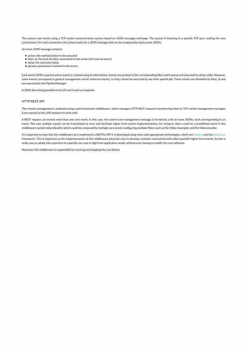
The system core works using a TCP socket communication system based on JSON messages exchange. The system is listening to a speci�c TCP port, waiting for new
connections. For each connection, the system waits for a JSON message that can be composed by many event JSONs.
An event JSON message contains:
action: the method/action to be executed�lter_id: the id of the �lter associated to the action (0 if internal event)delay: the execution delayparams: parameters involved in the action
Each event JSON is parsed and an event is created using its information. Events are pushed to the corresponding �lter event queue and executed by delay order. However,
some events correspond to general management events (internal events), so they cannot be executed by any �lter speci�cally. These events are identi�ed by �lter_id and
are executed by the PipelineManager.
A JSON describing possible errors (if any) is sent as response.
HTTP REST API
The remote management is achieved using a web framework middleware, which manages HTTP REST requests transforming them to TCP socket management messages
(core events) to the LMS instance to work with.
A REST request can involve more than one core event. In this case, the system core management message is formed by a list of event JSONs, each corresponding to an
event. This way multiple events can be transmitted at once and facilitate higher level events implementations, for instance, there could be a prede�ned event in the
middleware named reduceQuality which could be composed by multiple core events con�guring multiple �lters such as the Video resampler and the Video encoder.
It’s important to note that the middleware as it implements a RESTful API it is developed using more web appropriate technologies, which are Node.js and the Express.js
framework. This is important as the implementation of this middleware becomes easy to develop, maintain and extend with other possible higher level events. So this is
really easy to adapt and customize to a speci�c use case or high level application needs, without even having to modify the core software.
Moreover this middleware is responsible for starting and stopping the core binary.
About
LiveMediaStreamer framework is a projectof i2CAT Foundation's Media Internet Area.
The Internet Research Center.
LiveMediaStreamer Team
The LiveMediaStreamer framework maincontributors
Latest News
Ultraorbism: experimentation on distributed
performances
LiveMediaStreamer and UltraGrid
integrations
First LiveMediaStreamer pilot test within
the SPECIFI project
Copyright © 2015 LiveMediaStreamer framework. Graphic Design Pau Adelantado & Web Design Gerard
Castillo
Contact News Documentation Get LMS!


APPENDIX B. LMS HTTP RESTFUL API
Proposed HTTP RESTful API’s structure for managing an instance of the LiveMediaS-treamer:
• Generic management queries
– ConnectChecks if an existing instance of LMS is running and sets the LMS port andLMS host to work with.
POST http://<host>:<port>/api/connectJSON {
"port":<lms-port>,"host":"<lms-host>"
}
– DisconnectResets the running LMS instance and sets lms-port and lms-host to null inorder to connect again to the same or any another LMS instance running.
GET http://<host>:<port>/api/disconnect
– StateGets the state object of the current LMS instance connected to (JSON objectwith the configured filters and paths).
GET http://<host>:<port>/api/state
– Create a filterCreates a filter (current types are: receiver, transmitter, demuxer, dasher, au-dioDecoder, audioEncoder, videoDecoder, videoResampler, videoEncoder, au-dioMixer, videoMixer) with an unique identifier.
POST http://<host>:<port>/api/createFilterJSON {
"id": filterID,"type": "type"
}
– Create a path of filtersCreate a path of filters. It interconnects each filter as specified.
POST http://<host>:<port>/api/createPathJSON {
’id’ : pathId,’orgFilterId’ : orgFilterId,’dstFilterId’ : dstFilterId,’orgWriterId’ : orgWriterId,’dstReaderId’ : dstReaderId,’midFiltersIds’ : [filterID1, filterID2,...]
}
– Remove a path of filtersDeletes a path of filters. It disconnects each path’s filters.
85

DELETE http://<host>:<port>/api/path/:path_id
• Specific filter management queries
– Configure an existing filter
Configures an existing filter (each filter has its own actions defined, check AP-PENDIX A)
PUT http://<host>:<port>/api/filter/:filterIDJSON [
{"action":"the action",
"params":{"param1":param1,"param2":"param2","param3":"param3","param4":true
}}
]
So, with previous API proposal, the whole LMS’s TCP socket API becomes simplified.
Moreover, specific responses format to client has been proposed as shown:
• Success messages
It may be a string, bool, array or another object, depending on the request method
JSON {"message": { the incoming message }
}
• Error messages
JSON {"error": "the error message"
}

APPENDIX C. SPECIFIC APPLICATION METRICMETHODS
This appendix is showing concrete algorithm of interest in order to help understanding howapplication methods work.
C.1. Input network metric method
void SCSSubsessionStats::periodicStatMeasurement(struct timeval const& timeNow){
unsigned secsDiff = timeNow.tv_sec - measurementEndTime.tv_sec;int usecsDiff = timeNow.tv_usec - measurementEndTime.tv_usec;double timeDiff = secsDiff + usecsDiff/1000000.0;measurementEndTime = timeNow;
RTPReceptionStatsDB::Iterator statsIter(fSource->receptionStatsDB());
RTPReceptionStats* stats = statsIter.next(True);if (stats != NULL) {
double kBytesTotalNow = stats->totNumKBytesReceived();double kBytesDeltaNow = kBytesTotalNow - kBytesTotal;kBytesTotal = kBytesTotalNow;
double kbpsNow = timeDiff == 0.0 ? 0.0 : 8*kBytesDeltaNow/timeDiff;if (kbpsNow < 0.0) kbpsNow = 0.0; // in case of roundoff errorif (kbpsNow < kbitsPerSecondMin) kbitsPerSecondMin = kbpsNow;if (kbpsNow > kbitsPerSecondMax) kbitsPerSecondMax = kbpsNow;
unsigned totReceivedNow = stats->totNumPacketsReceived();unsigned totExpectedNow = stats->totNumPacketsExpected();unsigned deltaReceivedNow = totReceivedNow - totNumPacketsReceived;unsigned deltaExpectedNow = totExpectedNow - totNumPacketsExpected;totNumPacketsReceived = totReceivedNow;totNumPacketsExpected = totExpectedNow;
double lossFractionNow = deltaExpectedNow == 0 ? 0.0 : 1.0 -deltaReceivedNow/(double)deltaExpectedNow;
if (lossFractionNow < packetLossFractionMin) {packetLossFractionMin = lossFractionNow;
}if (lossFractionNow > packetLossFractionMax) {
packetLossFractionMax = lossFractionNow;}
87

minInterPacketGapUS = stats->minInterPacketGapUS();maxInterPacketGapUS = stats->maxInterPacketGapUS();totalGaps = stats->totalInterPacketGaps();jitter = stats->jitter();
}}
C.2. Output network metric method
void ConnRTCPInstance::periodicStatMeasurement(struct timeval const& timeNow){
unsigned currentNumBytes;double currentElapsedTime;
RTPTransmissionStatsDB::IteratorstatsIter(fSink->transmissionStatsDB());
fSink->getTotalBitrate(currentNumBytes, currentElapsedTime);
avgBitrate = currentElapsedTime == 0 ? 0.0 :((8*currentNumBytes/currentElapsedTime)/1000.0);if(minBitrate > avgBitrate) minBitrate = avgBitrate;if(maxBitrate < avgBitrate) maxBitrate = avgBitrate;
RTPTransmissionStats* stats;while((stats = statsIter.next()) != NULL){
SSRC = stats->SSRC();packetLossRatio = stats->packetLossRatio();if(minPacketLossRatio > packetLossRatio)minPacketLossRatio = packetLossRatio;
if(maxPacketLossRatio < packetLossRatio)maxPacketLossRatio = packetLossRatio;
roundTripDelay = stats->roundTripDelay();if(minRoundTripDelay > roundTripDelay)minRoundTripDelay = roundTripDelay;
if(maxRoundTripDelay < roundTripDelay)maxRoundTripDelay = roundTripDelay;
jitter = stats->jitter();if(minJitter > jitter) minJitter = jitter;if(maxJitter < jitter) maxJitter = jitter;
}}

C.3. Pipiline delay metric method
void Reader::measureDelay(){
if(lastTs.count() < 0){lastTs = frame->getPresentationTime();
}
if (lastTs == frame->getPresentationTime()) {return;
}
timeCounter += frame->getPresentationTime() - lastTs;lastTs = frame->getPresentationTime();
if(timeCounter >= windowDelay){avgDelay = delay / frameCounter;timeCounter = std::chrono::microseconds(0);delay = std::chrono::microseconds(0);frameCounter = 0;
}
delay += std::chrono::duration_cast<std::chrono::microseconds>(std::chrono::system_clock::now()- frame->getOriginTime());frameCounter++;
}


APPENDIX D. DOCKER CHEAT SHEET
This is a continually expanded GitHub repository where Docker users contribute with spe-cific usages of the Docker technology:
Docker cheat sheet
Current version of previous Docker cheat sheet is attached within next pages:
91

1of12
DockerCheatSheet
NOTE: This used to be a gist that continually expanded. It's now a github project because it'sconsiderably easier for other people to edit, fix and expand on Docker using Github. Just clickREADME.md(https://github.com/wsargent/docker-cheat-sheet/blob/master/README.md), and then on the"writing pen" icon on the right to edit.
Why
Prerequisites
Installation
Containers
Images
Registry and Repository
Dockerfile
Layers
Links
Volumes
Exposing Ports
Best Practices
Tips
Why"With Docker, developers can build any app in any language using any toolchain.“Dockerized” apps are completely portable and can run anywhere - colleagues’ OS X andWindows laptops, QA servers running Ubuntu in the cloud, and production data center VMsrunning Red Hat.
Developers can get going quickly by starting with one of the 13,000+ apps available on DockerHub. Docker manages and tracks changes and dependencies, making it easier for sysadminsto understand how the apps that developers build work. And with Docker Hub, developers canautomate their build pipeline and share artifacts with collaborators through public or privaterepositories.
Docker helps developers build and ship higher-quality applications, faster." -- What isDocker(https://www.docker.com/whatisdocker/#copy1)
Prerequisites

2of12
I use Oh My Zsh(https://github.com/robbyrussell/oh-my-zsh)with the Docker plugin(https://github.com/robbyrussell/oh-my-zsh/wiki/Plugins#docker)for autocompletion of dockercommands. YMMV.
Linux
The 3.10.x kernel is the minimum requirement(http://docs.docker.com/installation/binaries/#check-kernel-dependencies)for Docker.
MacOS
10.8 “Mountain Lion” or newer is required.
Installation
Linux
Quick and easy install script provided by Docker:
If you're not willing to run a random shell script, please see the installation(https://docs.docker.com/installation/)instructions for your distribution.
If you are a complete Docker newbie, you should follow the series of tutorials(http://docs.docker.com/linux/started/)now.
MacOSX
Download and install Docker Toolbox(https://www.docker.com/toolbox). If that doesn't work, seethe installation instructions(http://docs.docker.com/installation/mac/).
Docker used to use boot2docker, but you should be using docker machine now. The Dockerwebsite has instructions on how to upgrade(https://docs.docker.com/installation/mac/#migrate-from-boot2docker). If you have an existing docker instance, you can also install the Docker Machine(https://docs.docker.com/machine/install-machine/)binaries directly.
Once you've installed Docker Toolbox, install a VM with Docker Machine using the VirtualBoxprovider:
Then start up a container:
curl-- sSLhttps:: //get.docker.com/|sh
docker-- machinecreate---- driver== virtualboxdefaultdefault
docker-- machinels
eval"$(docker-machineenvdefault)"
dockerrunhello-- world

3of12
That's it, you have a running Docker container.
If you are a complete Docker newbie, you should probably follow the series of tutorials(http://docs.docker.com/mac/started/)now.
ContainersYour basic isolated Docker process(http://etherealmind.com/basics-docker-containers-hypervisors-coreos/). Containers are to Virtual Machines as threads are to processes. Or you can think of them aschroots on steroids.
Lifecycle
dockercreate(https://docs.docker.com/reference/commandline/create)creates a container butdoes not start it.
dockerrun(https://docs.docker.com/reference/commandline/run)creates and starts a containerin one operation.
dockerstop(https://docs.docker.com/reference/commandline/stop)stops it.
dockerstart(https://docs.docker.com/reference/commandline/start)will start it again.
dockerrestart(https://docs.docker.com/reference/commandline/restart)restarts a container.
dockerrm(https://docs.docker.com/reference/commandline/rm)deletes a container.
dockerkill(https://docs.docker.com/reference/commandline/kill)sends a SIGKILL to a container.
dockerattach(https://docs.docker.com/reference/commandline/attach)will connect to a runningcontainer.
dockerwait(https://docs.docker.com/reference/commandline/wait)blocks until container stops.
If you want to run and then interact with a container, dockerstart, then spawn a shell asdescribed in Executing Commands(https://github.com/wsargent/docker-cheat-sheet/#executing-commands).
If you want a transient container, dockerrun--rm will remove the container after it stops.
If you want to remove also the volumes associated with the container, the deletion of thecontainer must include the -v switch like in docker--rm-v.
If you want to poke around in an image, dockerrun-t-i<myimage><myshell> to open a tty.
If you want to poke around in a running container, dockerexec-t-i<mycontainer><myshell> to open a tty.
If you want to map a directory on the host to a docker container, dockerrun-v$HOSTDIR:$DOCKERDIR. Also see Volumes(https://github.com/wsargent/docker-cheat-sheet/#volumes).
If you want to integrate a container with a host process manager(https://docs.docker.com/articles/host_integration/), start the daemon with -r=false then use dockerstart-a.
If you want to expose container ports through the host, see the exposing ports section.
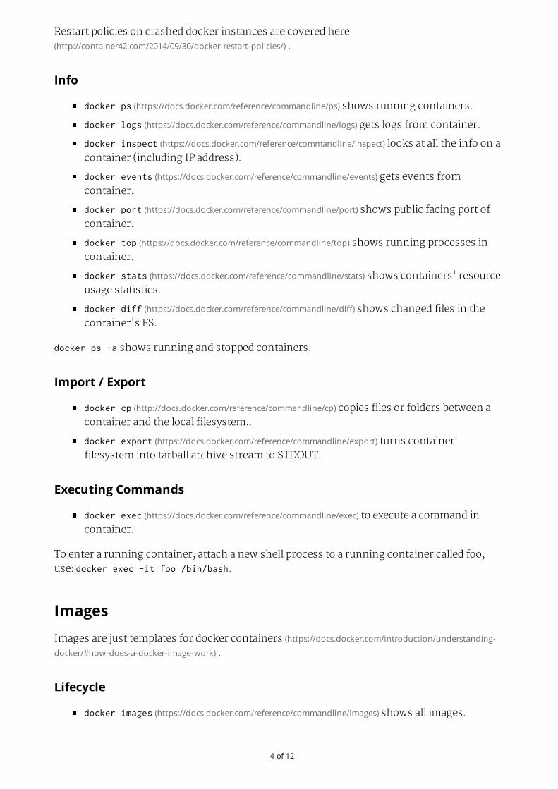
4of12
Restart policies on crashed docker instances are covered here(http://container42.com/2014/09/30/docker-restart-policies/).
Info
dockerps(https://docs.docker.com/reference/commandline/ps)shows running containers.
dockerlogs(https://docs.docker.com/reference/commandline/logs)gets logs from container.
dockerinspect(https://docs.docker.com/reference/commandline/inspect)looks at all the info on acontainer (including IP address).
dockerevents(https://docs.docker.com/reference/commandline/events)gets events fromcontainer.
dockerport(https://docs.docker.com/reference/commandline/port)shows public facing port ofcontainer.
dockertop(https://docs.docker.com/reference/commandline/top)shows running processes incontainer.
dockerstats(https://docs.docker.com/reference/commandline/stats)shows containers' resourceusage statistics.
dockerdiff(https://docs.docker.com/reference/commandline/diff)shows changed files in thecontainer's FS.
dockerps-a shows running and stopped containers.
Import/Export
dockercp(http://docs.docker.com/reference/commandline/cp)copies files or folders between acontainer and the local filesystem..
dockerexport(https://docs.docker.com/reference/commandline/export)turns containerfilesystem into tarball archive stream to STDOUT.
ExecutingCommands
dockerexec(https://docs.docker.com/reference/commandline/exec)to execute a command incontainer.
To enter a running container, attach a new shell process to a running container called foo,use: dockerexec-itfoo/bin/bash.
ImagesImages are just templates for docker containers(https://docs.docker.com/introduction/understanding-docker/#how-does-a-docker-image-work).
Lifecycle
dockerimages(https://docs.docker.com/reference/commandline/images)shows all images.

5of12
dockerimport(https://docs.docker.com/reference/commandline/import)creates an image from atarball.
dockerbuild(https://docs.docker.com/reference/commandline/build)creates image fromDockerfile.
dockercommit(https://docs.docker.com/reference/commandline/commit)creates image from acontainer.
dockerrmi(https://docs.docker.com/reference/commandline/rmi)removes an image.
dockerload(https://docs.docker.com/reference/commandline/load)loads an image from a tararchive as STDIN, including images and tags (as of 0.7).
dockersave(https://docs.docker.com/reference/commandline/save)saves an image to a tararchive stream to STDOUT with all parent layers, tags & versions (as of 0.7).
Info
dockerhistory(https://docs.docker.com/reference/commandline/history)shows history of image.
dockertag(https://docs.docker.com/reference/commandline/tag)tags an image to a name (localor registry).
Docker image ids are sensitive information(https://medium.com/@quayio/your-docker-image-ids-are-secrets-and-its-time-you-treated-them-that-way-f55e9f14c1a4)and should not be exposed to the outsideworld. Treat them like passwords.
Registry&Repository
A repository is a hosted collection of tagged images that together create the file system for acontainer.
A registry is a host -- a server that stores repositories and provides an HTTP API for managingthe uploading and downloading of repositories(https://docs.docker.com/userguide/dockerrepos/).
Docker.com hosts its own index(https://registry.hub.docker.com/)to a central registry whichcontains a large number of repositories. Having said that, the central docker registry does notdo a good job of verifying images(https://titanous.com/posts/docker-insecurity)and should be avoidedif you're worried about security.
dockerlogin(https://docs.docker.com/reference/commandline/login)to login to a registry.
dockersearch(https://docs.docker.com/reference/commandline/search)searches registry forimage.
dockerpull(https://docs.docker.com/reference/commandline/pull)pulls an image from registryto local machine.
dockerpush(https://docs.docker.com/reference/commandline/push)pushes an image to theregistry from local machine.
Runlocalregistry
Registry implementation(http://github.com/docker/docker-registry)has an official image for basic

6of12
setup that can be launched with dockerrun-p5000:5000registry(https://github.com/docker/docker-registry#quick-start)Note that this installation does not have anyauthorization controls. You may use option -P-p127.0.0.1:5000:5000 to limit connectionsto localhost only. In order to push to this repository tag image withrepositoryHostName:5000/imageName then push this tag.
DockerfileThe configuration file(https://docs.docker.com/reference/builder/). Sets up a Docker container whenyou run dockerbuild on it. Vastly preferable to dockercommit. If you use jEdit(http://jedit.org),I've put up a syntax highlighting module for Dockerfile(https://github.com/wsargent/jedit-docker-mode)you can use. You may also like to try the tools section.
Instructions
.dockerignore(https://docs.docker.com/reference/builder/#the-dockerignore-file)
FROM(https://docs.docker.com/reference/builder/#from)
MAINTAINER(https://docs.docker.com/reference/builder/#maintainer)
RUN(https://docs.docker.com/reference/builder/#run)
CMD(https://docs.docker.com/reference/builder/#cmd)
EXPOSE(https://docs.docker.com/reference/builder/#expose)
ENV(https://docs.docker.com/reference/builder/#env)
ADD(https://docs.docker.com/reference/builder/#add)
COPY(https://docs.docker.com/reference/builder/#copy)
ENTRYPOINT(https://docs.docker.com/reference/builder/#entrypoint)
VOLUME(https://docs.docker.com/reference/builder/#volume)
USER(https://docs.docker.com/reference/builder/#user)
WORKDIR(https://docs.docker.com/reference/builder/#workdir)
ONBUILD(https://docs.docker.com/reference/builder/#onbuild)
Tutorial
Flux7's Dockerfile Tutorial(http://flux7.com/blogs/docker/docker-tutorial-series-part-3-automation-is-the-word-using-dockerfile/)
Examples
Examples(https://docs.docker.com/reference/builder/#dockerfile-examples)
Best practices for writing Dockerfiles(https://docs.docker.com/articles/dockerfile_best-practices/)
Michael Crosby(http://crosbymichael.com/)has some more Dockerfiles best practices(http://crosbymichael.com/dockerfile-best-practices.html)/ take 2(http://crosbymichael.com/dockerfile-best-practices-take-2.html).

7of12
BestPracticesThis is where general Docker best practices and war stories go:
The Rabbit Hole of Using Docker in Automated Tests(http://gregoryszorc.com/blog/2014/10/16/the-rabbit-hole-of-using-docker-in-automated-tests/)
Bridget Kromhout(https://twitter.com/bridgetkromhout)has a useful blog post on runningDocker in production(http://sysadvent.blogspot.co.uk/2014/12/day-1-docker-in-production-reality-not.html)at Dramafever.
There's also a best practices blog post(http://developers.lyst.com/devops/2014/12/08/docker/)from Lyst.
A Docker Dev Environment in 24 Hours!(http://blog.relateiq.com/a-docker-dev-environment-in-24-hours-part-2-of-2/)
Building a Development Environment With Docker(http://tersesystems.com/2013/11/20/building-a-development-environment-with-docker/)
Discourse in a Docker Container(http://samsaffron.com/archive/2013/11/07/discourse-in-a-docker-container)
LayersThe versioned filesystem in Docker is based on layers. They're like git commits or changesetsfor filesystems(https://docs.docker.com/terms/layer/).
Note that if you're using aufs(http://en.wikipedia.org/wiki/Aufs)as your filesystem, Docker does notalways remove data volumes containers layers when you delete a container! See PR 8484(https://github.com/docker/docker/pull/8484)for more details.
LinksLinks are how Docker containers talk to each other through TCP/IP ports(https://docs.docker.com/userguide/dockerlinks/). Linking into Redis(https://docs.docker.com/examples/running_redis_service/)and Atlassian(http://blogs.atlassian.com/2013/11/docker-all-the-things-at-atlassian-automation-and-wiring/)show workedexamples. You can also (in 0.11) resolve links by hostname(https://docs.docker.com/userguide/dockerlinks/#updating-the-etchosts-file).
NOTE: If you want containers to ONLY communicate with each other through links, start thedocker daemon with -icc=false to disable inter process communication.
If you have a container with the name CONTAINER (specified by dockerrun--nameCONTAINER) and in the Dockerfile, it has an exposed port:
Then if we create another container called LINKED like so:
EXPOSE1337
8of12
Then the exposed ports and aliases of CONTAINER will show up in LINKED with the followingenvironment variables:
And you can connect to it that way.
To delete links, use dockerrm--link.
If you want to link across docker hosts then you should look at Swarm(http://docs.docker.com/swarm/). This link on stackoverflow(http://stackoverflow.com/questions/21283517/how-to-link-docker-services-across-hosts)provides some goodinformation on different patterns for linking containers across docker hosts.
VolumesDocker volumes are free-floating filesystems(http://docs.docker.com/userguide/dockervolumes/).They don't have to be connected to a particular container. You should use volumes mountedfrom data-only containers(https://medium.com/@ramangupta/why-docker-data-containers-are-good-589b3c6c749e)for portability.
Volumes are useful in situations where you can't use links (which are TCP/IP only). Forinstance, if you need to have two docker instances communicate by leaving stuff on thefilesystem.
You can mount them in several docker containers at once, using dockerrun--volumes-from.
Because volumes are isolated filesystems, they are often used to store state fromcomputations between transient containers. That is, you can have a stateless and transientcontainer run from a recipe, blow it away, and then have a second instance of the transientcontainer pick up from where the last one left off.
See advanced volumes(http://crosbymichael.com/advanced-docker-volumes.html)for more details.Container42 is also helpful(http://container42.com/2014/11/03/docker-indepth-volumes/).
For an easy way to clean abandoned volumes, see docker-cleanup-volumes(https://github.com/chadoe/docker-cleanup-volumes)
As of 1.3, you can map MacOS host directories as docker volumes(http://docs.docker.com/userguide/dockervolumes/#mount-a-host-directory-as-a-data-volume)throughboot2docker:
You can also use remote NFS volumes if you're feeling brave(http://www.tech-d.net/2014/03/29/docker-quicktip-4-remote-volumes/).
dockerrun-- d---- linkCONTAINER:: ALIAS---- nameLINKEDuser// wordpress
$ALIAS_PORT_1337_TCP_PORT
$ALIAS_PORT_1337_TCP_ADDR
dockerrun-- v// Users// wsargent// myapp// src:: /src

9of12
You may also consider running data-only containers as described here(http://container42.com/2013/12/16/persistent-volumes-with-docker-container-as-volume-pattern/)to providesome data portability.
ExposingportsExposing incoming ports through the host container is fiddly but doable(https://docs.docker.com/reference/run/#expose-incoming-ports).
The fastest way is to map the container port to the host port (only using localhost interface)using -p:
If you don't want to use the -p option on the command line, you can persist port forwardingby using EXPOSE(https://docs.docker.com/reference/builder/#expose):
If you're running Docker in Virtualbox, you then need to forward the port there as well, usingforwarded_port(https://docs.vagrantup.com/v2/networking/forwarded_ports.html). It can be useful todefine something in Vagrantfile to expose a range of ports so that you can dynamically mapthem:
If you forget what you mapped the port to on the host container, use dockerport to show it:
TipsSources:
15 Docker Tips in 5 minutes(http://sssslide.com/speakerdeck.com/bmorearty/15-docker-tips-in-5-minutes)
LastIds
dockerrun-- p127.0.0.1:: $HOSTPORT:: $CONTAINERPORT---- nameCONTAINER-- tsomeimage
EXPOSE<< CONTAINERPORT>>
Vagrant.configure(VAGRANTFILE_API_VERSION)dodo || config||
...
(49000..49900).eachdodo || port||
config.vm.network:: forwarded_port,:: host=>=> port,:: guest=>=> port
end
...
end
dockerportCONTAINER$CONTAINERPORT
10of12
Commitwithcommand(needsDockerfile)
GetIPaddress
or
or using a go template(https://docs.docker.com/reference/commandline/inspect)
Getportmapping
Findcontainersbyregularexpression
GetEnvironmentSettings
Killrunningcontainers
Deleteoldcontainers
aliasdl== 'dockerps-l-q'
dockerrunubuntuechohelloworld
dockercommit`dl`helloworld
dockercommit-- run== '{"Cmd":["postgres","-too-many-opts"]}'`dl`postgres
dockerinspect`dl`|| grepIPAddress|| cut-- d'"'-- f4
wgethttp:: //stedolan.github.io/jq/download/source/jq-1.3.tar.gz
tarxzvfjq-- 1.3.tar.gz
cdjq-- 1.3
.// configure&&&& make&&&& sudomakeinstall
dockerinspect`dl`|| jq-- r'.[0].NetworkSettings.IPAddress'
dockerinspect-- f'{{.NetworkSettings.IPAddress}}'<< container_name>>
dockerinspect-- f'{{range$p,$conf:=.NetworkSettings.Ports}}{{$p}}->{{(index
$conf0).HostPort}}{{end}}'<< containername>>
forfor iinin $(dockerps-- a|| grep"REGEXP_PATTERN"|| cut-- f1-- d"");dodo echo$i;don
e`
dockerrun---- rmubuntuenv
dockerkill$(dockerps-- q)
dockerps-- a|| grep'weeksago'|| awk'{print$1}'|| xargsdockerrm

11of12
Deletestoppedcontainers
Deletedanglingimages
Deleteallimages
Showimagedependencies
SlimmingdownDockercontainersIntercityBlog
Cleaning APT
Flatten an image
For backup
Monitorsystemresourceutilizationforrunningcontainers
To check the CPU, memory and network i/o usage, you can use:
for a single container or
dockerrm-- v`dockerps-- a-- q-- fstatus== exited`
dockerrmi$(dockerimages-- q-- fdangling== truetrue )
dockerrmi$(dockerimages-- q)
dockerimages-- viz|| dot-- Tpng-- odocker.png
RUNapt-- getclean
RUNrm-- rf// varvar /lib/apt/lists/*/tmp/*/var/tmp/*
ID== $(dockerrun-- dimage-- name// bin// bash)
dockerexportexport $ID|| dockerimportimport –flat-- image-- name
ID== $(dockerrun-- dimage-- name// bin// bash)
(dockerexportexport $ID|| gzip-- c>> image.tgz)
gzip-- dcimage.tgz|| dockerimportimport -- flat-- image-- name
dockerstats<< container>>
dockerstats$(dockerps-- q)

12of12
to monitor all containers on the docker host.


APPENDIX E. DOCKER, NGINX AND COLLECTDCONFIGURATION FILES
This appendix is listing specific Docker, Nginx and Collectd configuration files.
E.1. Basic LMS container
Next Docker file installs latest development commit into the container to be built and pre-pares the image to run LMS as a service.
# LiveMediaStreamer ContainerFROM ubuntu:14.04MAINTAINER Gerard CL <[email protected]>
RUN apt-get update && apt-get -y upgrade
RUN apt-get -y install git cmake autoconf automake build-essential \libass-dev libtheora-dev libtool libvorbis-dev pkg-config zlib1g-dev \libcppunit-dev yasm libx264-dev libmp3lame-dev libopus-dev \libvpx-dev liblog4cplus-dev libtinyxml2-dev opencv-data \libopencv-dev mercurial cmake-curses-gui vim libcurl3 wget curl
RUN adduser --disabled-password --gecos ’’ lms && adduser lms sudo \&& echo ’%sudo ALL=(ALL) NOPASSWD:ALL’ >> /etc/sudoers
USER lms
RUN hg clone https://bitbucket.org/multicoreware/x265 /home/lms/x265 \&& cd /home/lms/x265 && cmake -G "Unix Makefiles" ./source \&& make -j && sudo make install && sudo ldconfig
RUN git clone https://github.com/mstorsjo/fdk-aac.git/ /home/lms/fdk-aac \&& cd /home/lms/fdk-aac && libtoolize && ./autogen.sh \&& ./configure && make -j && sudo make install && sudo ldconfig
RUN cd /home/lms && wget http://ffmpeg.org/releases/ffmpeg-2.7.tar.bz2 \&& tar xjvf ffmpeg-2.7.tar.bz2 && cd ffmpeg-2.7 \&& ./configure --enable-gpl --enable-libass --enable-libtheora \--enable-libvorbis --enable-libx264 --enable-nonfree --enable-shared \--enable-libopus --enable-libmp3lame --enable-libvpx \--enable-libfdk_aac --enable-libx265 && make -j \&& sudo make install && sudo ldconfig
RUN cd /home/lms && wget \http://www.live555.com/liveMedia/public/live555-latest.tar.gz \&& tar xaf live555-latest.tar.gz && cd live \
105

&& ./genMakefiles linux-with-shared-libraries && make -j \&& sudo make install && sudo ldconfig
RUN git clone https://github.com/ua-i2cat/livemediastreamer.git \/home/lms/livemediastreamer && cd /home/lms/livemediastreamer \&& git checkout development && ./autogen.sh \&& make -j && sudo make install && sudo ldconfig
EXPOSE 5000-5017/udpEXPOSE 8554-8564EXPOSE 7777
CMD ["/usr/local/bin/livemediastreamer","7777"]
E.2. HTTP REST API container
Next Docker file installs Node.js and clones latest HTTP REST API for LMS from theGitHub repository. It also prepares the image in order to run the HTTP REST API mid-dleware for the LMS framework.
# LiveMediaStreamer ContainerFROM ubuntu:14.04
MAINTAINER Gerard CL <[email protected]>
RUN apt-get update && apt-get -y upgrade
RUN apt-get -y install git npm
RUN adduser --disabled-password --gecos ’’ lms \&& adduser lms sudo \&& echo ’%sudo ALL=(ALL) NOPASSWD:ALL’ >> /etc/sudoers
USER lms
RUN cd /home/lms \&& git clone https://github.com/ua-i2cat/LMStoREST.git \/home/lms/LMStoREST && cd /home/lms/LMStoREST && npm install
EXPOSE 8080CMD ["nodejs", "/home/lms/LMStoREST/lms-middleware.js"]

E.3. Running multiple processes within a container
This Docker file installs Nginx and LMS inside the same container in order to be ready toserve through HTTP Nginx server the MPEG-DASH files generated for the LMS framework(it externally requires to be configured as a transcoder to MPEG-DASH). Then, superviord,which is also installed, runs as the default image process. Supervisord is managing eachdefined process to be executed.
# LiveMediaStreamer Container# and Nginx server for MPEG-DASH streamingFROM ubuntu:14.04MAINTAINER Gerard CL <[email protected]>
RUN apt-get update && apt-get -y upgrade
RUN apt-get -y install git cmake autoconf automake build-essential \libass-dev libtheora-dev libtool libvorbis-dev pkg-config zlib1g-dev \libcppunit-dev yasm libx264-dev libmp3lame-dev libopus-dev \libvpx-dev liblog4cplus-dev libtinyxml2-dev opencv-data \libopencv-dev mercurial cmake-curses-gui vim libcurl3 wget curl
RUN apt-get -y install nginx supervisorRUN mkdir -p /var/lock/nginx /var/run/nginx \/var/lock/livemediastreamer /var/run/livemediastreamer \/var/log/supervisor
ADD ./nginx.conf /etc/nginx/nginx.confADD ./supervisord.conf /etc/supervisor/conf.d/supervisord.conf
RUN adduser --disabled-password --gecos ’’ lms \&& adduser lms sudo \&& echo ’%sudo ALL=(ALL) NOPASSWD:ALL’ >> /etc/sudoers
RUN mkdir -p /home/lms/dashSegments
USER lms
RUN hg clone https://bitbucket.org/multicoreware/x265 /home/lms/x265 \&& cd /home/lms/x265 && cmake -G "Unix Makefiles" ./source \&& make -j && sudo make install && sudo ldconfig
RUN git clone https://github.com/mstorsjo/fdk-aac.git/ /home/lms/fdk-aac \&& cd /home/lms/fdk-aac && libtoolize && ./autogen.sh \&& ./configure && make -j && sudo make install && sudo ldconfig
RUN cd /home/lms && wget http://ffmpeg.org/releases/ffmpeg-2.7.tar.bz2 \&& tar xjvf ffmpeg-2.7.tar.bz2 && cd ffmpeg-2.7 \
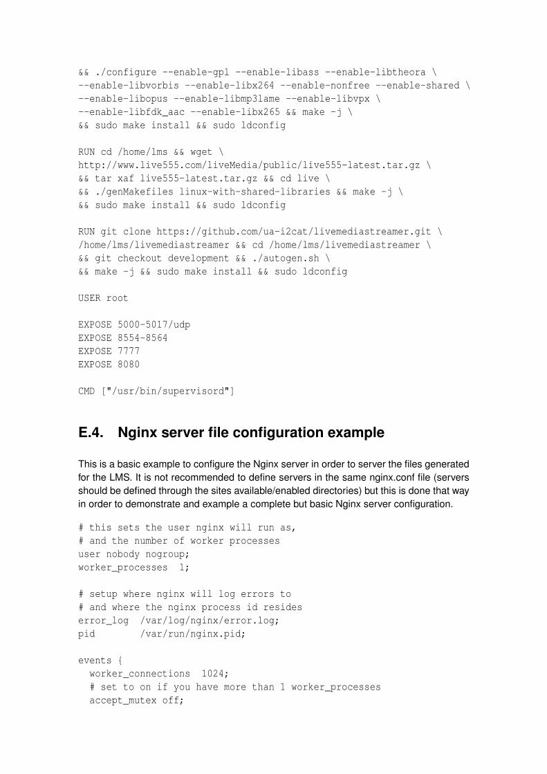
&& ./configure --enable-gpl --enable-libass --enable-libtheora \--enable-libvorbis --enable-libx264 --enable-nonfree --enable-shared \--enable-libopus --enable-libmp3lame --enable-libvpx \--enable-libfdk_aac --enable-libx265 && make -j \&& sudo make install && sudo ldconfig
RUN cd /home/lms && wget \http://www.live555.com/liveMedia/public/live555-latest.tar.gz \&& tar xaf live555-latest.tar.gz && cd live \&& ./genMakefiles linux-with-shared-libraries && make -j \&& sudo make install && sudo ldconfig
RUN git clone https://github.com/ua-i2cat/livemediastreamer.git \/home/lms/livemediastreamer && cd /home/lms/livemediastreamer \&& git checkout development && ./autogen.sh \&& make -j && sudo make install && sudo ldconfig
USER root
EXPOSE 5000-5017/udpEXPOSE 8554-8564EXPOSE 7777EXPOSE 8080
CMD ["/usr/bin/supervisord"]
E.4. Nginx server file configuration example
This is a basic example to configure the Nginx server in order to server the files generatedfor the LMS. It is not recommended to define servers in the same nginx.conf file (serversshould be defined through the sites available/enabled directories) but this is done that wayin order to demonstrate and example a complete but basic Nginx server configuration.
# this sets the user nginx will run as,# and the number of worker processesuser nobody nogroup;worker_processes 1;
# setup where nginx will log errors to# and where the nginx process id resideserror_log /var/log/nginx/error.log;pid /var/run/nginx.pid;
events {worker_connections 1024;# set to on if you have more than 1 worker_processesaccept_mutex off;

}
http {include /etc/nginx/mime.types;
default_type application/octet-stream;access_log /tmp/nginx.access.log combined;
# use the kernel sendfilesendfile on;# prepend http headers before sendfile()tcp_nopush on;
keepalive_timeout 5;tcp_nodelay on;
gzip on;gzip_vary on;gzip_min_length 500;
gzip_disable "MSIE [1-6]\.(?!.*SV1)";gzip_types text/plain text/xml text/css
text/comma-separated-valuestext/javascript application/x-javascriptapplication/atom+xml image/x-icon;
# configure the virtual hostserver {# replace with your domain nameserver_name localhost;root /home/lms/dashSegments;# port to listen for requests onlisten 8090;# maximum accepted body size of client requestclient_max_body_size 4G;# the server will close connections after this timekeepalive_timeout 5;
add_header Access-Control-Allow-Origin "*";add_header Access-Control-Allow-Methods "GET, OPTIONS";add_header Access-Control-Allow-Headers "origin, authorization, accept";add_header Cache-Control no-cache;
location / {add_header Access-Control-Allow-Origin "*";add_header Access-Control-Allow-Methods "GET, OPTIONS";add_header Access-Control-Allow-Headers "origin, authorization, accept";add_header Cache-Control no-cache;

}}
}
daemon off;
E.5. Sharing volumes within containers
This containers installs Nginx and runs it as default image command. This is an isolatedNginx server container which is serving the LMS files through the shared volumes betweenthe basic LMS container and this one.
# Nginx Container - LMS special oneFROM ubuntu:14.04MAINTAINER Gerard CL <[email protected]>
RUN apt-get update && apt-get install --fix-missing \&& apt-get -y upgrade
RUN apt-get -y install nginx
ADD ./nginx.conf /etc/nginx/nginx.conf
RUN adduser --disabled-password --gecos ’’ lms \&& adduser lms sudo \&& echo ’%sudo ALL=(ALL) NOPASSWD:ALL’ >> /etc/sudoers
RUN mkdir -p /home/lms/dashSegments
EXPOSE 8090
CMD ["/usr/sbin/nginx"]
E.6. Collectd client container
This is a basic Collectd client container build.
FROM ubuntu:14.04MAINTAINER Gerard CL <[email protected]>
ENV DEBIAN_FRONTEND noninteractive
RUN apt-get updateRUN apt-get -y install collectd curl python-dev python-pip

ADD collectd.conf.tpl /etc/collectd/collectd.conf.tpl
RUN pip install envtplADD start_container /usr/bin/start_containerRUN chmod +x /usr/bin/start_containerCMD start_container
E.7. Collectd client configuration
This is a basic Collectd client configuration template file.
Hostname "{{ LMS_NAME }}"FQDNLookup true
Interval 1Timeout 4ReadThreads 5
LoadPlugin syslogLoadPlugin cpuLoadPlugin loadLoadPlugin memoryLoadPlugin network
<Plugin "syslog">LogLevel "info"NotifyLevel "OKAY"
</Plugin>
<Plugin network>Server "{{ GRAPHITE_HOST }}" "{{ GRAPHITE_PORT | default("25826") }}"ReportStats true
</Plugin>
E.8. Collectd server and Graphite container
This Docker file installs and configures all the dependences required to run a basic Graphitesystem which is served by a Collectd server which listens from external Collectd container-ized clients.
# LiveMediaStreamer ContainerFROM ubuntu:14.04MAINTAINER Gerard CL <[email protected]>
RUN apt-get update

RUN apt-get install -y python-cairo collectd-core libgcrypt11 \python-virtualenv build-essential python-dev supervisor sudo
RUN adduser --system --group --no-create-home collectd \&& adduser --system --home /opt/graphite graphite
RUN sudo -u graphite virtualenv --system-site-packages ˜graphite/env
RUN echo "django \n \python-memcached \n \django-tagging \n \twisted \n \gunicorn \n \whisper \n \carbon \n \graphite-web" > /tmp/graphite_reqs.txt
RUN sudo -u graphite HOME=/opt/graphite /bin/sh -c ". \˜/env/bin/activate && pip install -r /tmp/graphite_reqs.txt"
ADD collectd/collectd.conf /etc/collectd/ADD supervisor/ /etc/supervisor/conf.d/ADD graphite/settings.py /opt/graphite/webapp/graphite/ADD graphite/local_settings.py /opt/graphite/webapp/graphite/ADD graphite/mkadmin.py /opt/graphite/webapp/graphite/ADD graphite/storage-schemas.conf /opt/graphite/conf/
RUN cp /opt/graphite/conf/carbon.conf.example \/opt/graphite/conf/carbon.confRUN cp /opt/graphite/conf/graphite.wsgi.example \/opt/graphite/webapp/graphite/graphite_wsgi.pyRUN cp /opt/graphite/conf/graphite.wsgi.example \/opt/graphite/conf/graphite.wsgiRUN cp /opt/graphite/conf/storage-aggregation.conf.example \/opt/graphite/conf/storage-aggregation.conf
RUN sed -i "s#ˆ\(SECRET_KEY = \).*#\1\"‘python -c ’import os; import base64; \print(base64.b64encode(os.urandom(40)))’‘\"#" \/opt/graphite/webapp/graphite/app_settings.pyRUN sudo -u graphite HOME=/opt/graphite PYTHONPATH=/opt/graphite/lib/ \/bin/sh -c "cd ˜/webapp/graphite && ˜/env/bin/python manage.py syncdb --noinput"RUN sudo -u graphite HOME=/opt/graphite PYTHONPATH=/opt/graphite/lib/ \/bin/sh -c "cd ˜/webapp/graphite && ˜/env/bin/python mkadmin.py"
EXPOSE 8080 25826/udp
CMD exec supervisord -n

E.9. Collectd server configuration
This is a Collectd server configuration example.
Hostname "localhost"FQDNLookup trueInterval 1
LoadPlugin syslogLoadPlugin networkLoadPlugin write_graphite
<Plugin syslog>LogLevel "info"NotifyLevel "OKAY"</Plugin>
<Plugin network>Listen "*" "25826"ReportStats true</Plugin>
<Plugin write_graphite><Node "graphing">Host "localhost"Port "2003"Protocol "tcp"LogSendErrors truePrefix "collectd."StoreRates trueAlwaysAppendDS falseEscapeCharacter "_"</Node></Plugin>
E.10. Collectd tail plugin example configuration
Next tail plugin configuration is performing specific regular expression matching to bindlogged metrics from the LMS demo script. Each logged line to stdout is formatted asshown next:
|PATHID|value|avgDelay-5004|value|lostBlocks-5004|value|PATHID|value|avgDelay-5006|value|lostBlocks-5006|value|RXmediaType|video|videoRXavgBitRateInKbps|value|videoRXavgPacketLossPercentage|value|videoRXavgInterPacketGapInMiliseconds|value|videoRXcurJitterInMicroseconds|value|RXmediaType|audio|audioRXavgBitRateInKbps|value|audioRXavgPacketLossPercentage

|value|audioRXavgInterPacketGapInMiliseconds|value|audioRXcurJitterInMicroseconds|value|TX_URI|value|TX_SSRC-1|value|TXavgBitrateInKbps-1|value|TXpacketLossRatio-1|value|TXjitterInMicroseconds-1|value|TXroundTripDelayMilliseconds-1|value|TX_SSRC-2|value|TXavgBitrateInKbps-2|value|TXpacketLossRatio-2|value|TXjitterInMicroseconds-2|value|TXroundTripDelayMilliseconds-2|value|
Then, each new line is parsed through the tail plugin of the Collectd configuration. Anexample is shown next:
<Plugin tail><File "/home/lms/logs/lms.log">Instance "lmsTest"<Match>Regex ".*avgDelay-5004\\|([0-9]*).*"DSType "CounterAdd"Type counterInstance "VideoAVGdelay-us"</Match><Match>Regex ".*lostBlocks-5004\\|([0-9]*).*"DSType "CounterAdd"Type counterInstance "VideoLostBlocks"</Match><Match>Regex ".*avgDelay-5006\\|([0-9]*).*"DSType "CounterAdd"Type counterInstance "AudioAVGdelay-us"</Match><Match>Regex ".*lostBlocks-5006\\|([0-9]*).*"DSType "CounterAdd"Type counterInstance "AudioLostBlocks"</Match><Match>Regex ".*RXmediaType\\|video.*videoRXavgBitRateInKbps\\|([0-9]*).*"DSType "CounterAdd"Type counterInstance "videoRXavgBitRateInKbps"</Match><Match>Regex ".*RXmediaType\\|video.*videoRXavgPacketLossPercentage\\|([0-9]*).*"DSType "CounterAdd"Type counterInstance "videoRXavgPacketLossPercentage"

</Match><Match>Regex ".*RXmediaType\\|video.*videoRXavgInterPacketGapInMiliseconds\\|([0-9]*).*"DSType "CounterAdd"Type counterInstance "videoRXavgInterPacketGapInMiliseconds"</Match><Match>Regex ".*RXmediaType\\|video.*videoRXcurJitterInMicroseconds\\|([0-9]*).*"DSType "CounterAdd"Type counterInstance "videoRXcurJitterInMicroseconds"</Match><Match>Regex ".*RXmediaType\\|audio.*audioRXavgBitRateInKbps\\|([0-9]*).*"DSType "CounterAdd"Type counterInstance "audioRXavgBitRateInKbps"</Match><Match>Regex ".*RXmediaType\\|audio.*audioRXavgPacketLossPercentage\\|([0-9]*).*"DSType "CounterAdd"Type counterInstance "audioRXavgPacketLossPercentage"</Match><Match>Regex ".*RXmediaType\\|audio.*audioRXavgInterPacketGapInMiliseconds\\|([0-9]*).*"DSType "CounterAdd"Type counterInstance "audioRXavgInterPacketGapInMiliseconds"</Match><Match>Regex ".*RXmediaType\\|audio.*audioRXcurJitterInMicroseconds\\|([0-9]*).*"DSType "CounterAdd"Type counterInstance "audioRXcurJitterInMicroseconds"</Match><Match>Regex ".*TXavgBitrateInKbps-1\\|([0-9]*).*"DSType "CounterAdd"Type counterInstance "VideoTXavgBitrateInKbps"</Match><Match>Regex ".*TXpacketLossRatio-1\\|([0-9]*).*"DSType "CounterAdd"Type counterInstance "VideoTXpacketLossRatio"

</Match><Match>Regex ".*TXjitterInMicroseconds-1\\|([0-9]*).*"DSType "CounterAdd"Type counterInstance "VideoTXjitterInMicroseconds"</Match><Match>Regex ".*TXroundTripDelayMilliseconds-1\\|([0-9]*).*"DSType "CounterAdd"Type counterInstance "VideoTXroundTripDelayMilliseconds"</Match><Match>Regex ".*TXavgBitrateInKbps-2\\|([0-9]*).*"DSType "CounterAdd"Type counterInstance "AudioTXavgBitrateInKbps"</Match><Match>Regex ".*TXpacketLossRatio-2\\|([0-9]*).*"DSType "CounterAdd"Type counterInstance "AudioTXpacketLossRatio"</Match><Match>Regex ".*TXjitterInMicroseconds-2\\|([0-9]*).*"DSType "CounterAdd"Type counterInstance "AudioTXjitterInMicroseconds"</Match><Match>Regex ".*TXroundTripDelayMilliseconds-2\\|([0-9]*).*"DSType "CounterAdd"Type counterInstance "AudioTXroundTripDelayMilliseconds"</Match></File></Plugin>

APPENDIX F. SOURCE CODES
Full source codes can be found in the GitHub’s web page of the Media Internet Area’sdevelopers team of the i2CAT Foundation:
• HTTP REST API
This is the source code repository for the RESTfull API middleware.
https://github.com/ua-i2cat/LMStoREST
• LiveMediaStreame framework
This is the source code repository for the LiveMediaStreamer framework.
https://github.com/ua-i2cat/liveMediaStreamer
Concretely:
– Statistics for network inputs
https://github.com/ua-i2cat/liveMediaStreamer/tree/development/src/modules/liveMediaInput
– Statistics for network outputs
https://github.com/ua-i2cat/liveMediaStreamer/tree/development/src/modules/liveMediaOutput
– Statistics for pipeline metrics
https://github.com/ua-i2cat/liveMediaStreamer/blob/development/src/IOInterface.cpp
117


APPENDIX G. EXCHANGED E-MAILS WITHLIVE555 DEVELOPER MAILING LIST
This appendix is showing the e-mail conversation I had with the CEO and CTO of theLive555 library, which helped a lot for developing a proper solution to gather the Live555statistics (i.e.: network statistics).
E-mail sent:
Sender: Gerard Castillo Lasheras <[email protected]>Receiver: LIVE555 Streaming Media - development &use <[email protected]>Hi Ross,
I’m implementing statistics on our software (liveMediaStreamer framework)and I’d like to have access to the RTPTransmissionStatsDB. But, I do notsee how to get the RTPSink object (which has the RTPTransmissionStatsDBand its stats).
Which should be the proper way to get the RTPSink object related to myOnDemandServerMediaSubsession childs? I’ve seen thatOnDemandServerMediaSubsession has a friend classe StreamStatewhich has the RTPSink associated but, anyway,I’m not able to have access to it.
Thanks in advance,
Kind regards,
The reply:
Sender: Ross Finlayson <[email protected]>Receiver: LIVE555 Streaming Media - development &use <[email protected]>
First of all, note that while a "OnDemandServerMediaSubsession"object refers to a track of streamable media, a "RTPSink" objectrefers to a receiving client (or possibly multiple clients if"reuseFirstSource" is True). So there’s (in general) aone-to-many relationship between "OnDemandServerMediaSubsession"and "RTPSink". Thus, it doesn’t make sense to talk about*the* RTPSink object for your "OnDemandServerMediaSubsession".
However...There are at least two possible ways to get access to the"RTPSink" objects:
1/ Note the pure virtual function "createNewRTPSink()" that you
119

have implemented in your "OnDemandServerMediaSubsession" subclass.You can use your implementation of this function to get accessto the "RTPTransmissionStatsDB" for the new "RTPSink", afteryou’ve created it.The drawback of this approach, though, is that you don’t know whenthe "RTPSink" object later gets deleted, so - if you’re notcareful - you may end up holding a reference or pointer to a"RTPTransmissionStatsDB" that has been deleted.
2/ Define a subclass "myRTCPInstance" of the "RTCPInstance"class. Then, in your "OnDemandServerMediaSubsession" subclass,reimplement the "createRTCP()" virtual function to create a"myRTCPInstance" object, rather than a "RTCPInstance"object. Note that "createRTCP()" contains a "sink"parameter, pointing to a "RTPSink", from which you canget the "RTPTransmissionStatsDB".The advantage of this approach over approach 1/ is that- by defining a subclass of "RTCPInstance", you can learn whenthe "RTPInstance" object gets deleted, and thus when the"RTPSink" object gets deleted. (The "RTCPInstance" objectalways gets deleted immediately before the "RTPSink"object.) Thus, you can use your "myRTCPInstance" destructorto figure out when the "RTPTransmissionStatsDB" should nolonger be used.