Transient Modelling of a Rotary-Kiln Pyrolyser
13
The Open Mechanical Engineering Journal, 2007, 1, 1-13 1 1874-155X/07 2007 Bentham Science Publishers Ltd. Transient Modelling of a Rotary-Kiln Pyrolyser A. Traverso * , R. Bertone and A.F. Massardo Thermochemical Power Group, University of Genova, DiMSET, Italy Abstract: The increasing interest in small-scale renewable-energy plants for distributed power generation has led to a demand for suitable software tools to study and develop control systems able to manage advanced integrated systems. Biomass, as a renewable energy resource, needs to be processed if it is to be exploited in small CHP units and pyrolysis is one of the options available for transforming solid biomass into useful liquid and gaseous fuels. This work is concerned with the development of a time-dependent model of a rotary-kiln pyrolyser for biomass: the model is intended for the de- velopment of control systems and the simulation of integrated energy systems, where the pyrolyser is connected to a power-generation package. The model was developed within the TRANSEO environment and based on a quasi 2-D nu- merical discretisation of the rotary kiln. Results are shown for a real case that is currently under construction: the model is able to predict the impact of different operating conditions on fuel yields, as well as capturing the main transient phenom- ena occurring during changes in the pyrolyser operating conditions. Kewords: Biomass, pyrolysis, distributed generation, transient modelling. INTRODUCTION Due to the increasing price of oil, the Kyoto commitment of European countries and favourable political and social conditions, there is currently a large demand for biomass energy conversion systems of relatively small size (below 20MW of thermal input) in Europe. Northern European countries have been successfully operating thermal or cogen- erative biomass-fuelled plants for several years, while Southern European countries, such as Italy, where the aver- age annual demand for heat is low, are struggling to promote this type of system because of its poor economic sustainabil- ity [1], despite economic incentives. However, there are already opportunities for niche appli- cations for full-electric or cogenerative energy plants below 1MW electric power thanks to the availability of unexploited residual biomasses (wood industry residues, furniture indus- try residues, meat and bone meal, etc.) or biomass waste (waste water treatment residuals, organic urban waste frac- tion, etc.): in such cases, the zero or negative cost of biomass fuel is often counterbalanced by the relatively small quanti- ties available over the course of an entire year without facing the costs of long-distance transportation. The use of biomass in microturbines or internal combustion engines necessarily requires thermochemical pre-treatment (such as gasification and pyrolysis) to produce a low LHV gaseous fraction that can be used as primary fuel and there is renewed interest, especially in Italy, in the slow pyrolysis of waste and bio- mass by means of semi-conventional rotary kilns (Fig. (2) – main dimensions in Table 4), as an effective and robust way to process solid biomass [2-4]. The advantages envisaged for this type of technology are: • simple design and proven technology, *Address correspondence to this author at the Thermochemical Power Group, University of Genova, DiMSET, Italy; E-mail: [email protected] • capability of processing almost untreated biomass with characteristic dimensions up to 50mm (larger particles may be processed at lower throughputs), • fuel flexibility, i.e. capability of switching from one type of biomass to another during normal operation in a quite straightforward way. From the perspective of energy use, the main disadvan- tage is the presence of tars in the gaseous products, which need to be abated to acceptable levels for the prime-movers considered: nevertheless, gas cleaning is a problem of all biomass thermochemical processes. The development of pyrolyser and prime-mover inte- grated systems requires simulation tools for developing and testing suitable control strategies. Existing detailed models of particle pyrolytic decomposition, such as in [5], focus on capturing biomass particle behaviour and pyrolysis product distribution, rather than describing a particular pyrolysis process. Other models, such as [4], show the off-design be- haviour of the system without describing the time-dependent characteristics. This work aims to develop a transient model of the entire biomass rotary kiln pyrolyser process for control system analysis. The model was developed within the TRANSEO environment, which exploits the MATLAB-Simulink visual interface: since TRANSEO already has the capability of simulating microturbines and microturbine-based advanced cycles [6-8], the next step in this work is the transient study of the integrated system to gain information on the overall plant dynamics. Nevertheless, this paper is focused on the first part of this programme, which is the transient analysis of the pyrolyser itself. THE TRANSEO TOOL TRANSEO is an original tool for the transient and dy- namic simulations of energy systems. The tool is specifically designed for managing microturbine-based cycles, but, in principle, any cycle layout and size could be modelled.
-
Upload
independent -
Category
Documents
-
view
0 -
download
0
Transcript of Transient Modelling of a Rotary-Kiln Pyrolyser

The Open Mechanical Engineering Journal, 2007, 1, 1-13 1
1874-155X/07 2007 Bentham Science Publishers Ltd.
Transient Modelling of a Rotary-Kiln Pyrolyser
A. Traverso*, R. Bertone and A.F. Massardo
Thermochemical Power Group, University of Genova, DiMSET, Italy
Abstract: The increasing interest in small-scale renewable-energy plants for distributed power generation has led to a
demand for suitable software tools to study and develop control systems able to manage advanced integrated systems.
Biomass, as a renewable energy resource, needs to be processed if it is to be exploited in small CHP units and pyrolysis is
one of the options available for transforming solid biomass into useful liquid and gaseous fuels. This work is concerned
with the development of a time-dependent model of a rotary-kiln pyrolyser for biomass: the model is intended for the de-
velopment of control systems and the simulation of integrated energy systems, where the pyrolyser is connected to a
power-generation package. The model was developed within the TRANSEO environment and based on a quasi 2-D nu-
merical discretisation of the rotary kiln. Results are shown for a real case that is currently under construction: the model is
able to predict the impact of different operating conditions on fuel yields, as well as capturing the main transient phenom-
ena occurring during changes in the pyrolyser operating conditions.
Kewords: Biomass, pyrolysis, distributed generation, transient modelling.
INTRODUCTION
Due to the increasing price of oil, the Kyoto commitment of European countries and favourable political and social conditions, there is currently a large demand for biomass energy conversion systems of relatively small size (below 20MW of thermal input) in Europe. Northern European countries have been successfully operating thermal or cogen-erative biomass-fuelled plants for several years, while Southern European countries, such as Italy, where the aver-age annual demand for heat is low, are struggling to promote this type of system because of its poor economic sustainabil-ity [1], despite economic incentives.
However, there are already opportunities for niche appli-cations for full-electric or cogenerative energy plants below 1MW electric power thanks to the availability of unexploited residual biomasses (wood industry residues, furniture indus-try residues, meat and bone meal, etc.) or biomass waste (waste water treatment residuals, organic urban waste frac-tion, etc.): in such cases, the zero or negative cost of biomass fuel is often counterbalanced by the relatively small quanti-ties available over the course of an entire year without facing the costs of long-distance transportation. The use of biomass in microturbines or internal combustion engines necessarily requires thermochemical pre-treatment (such as gasification and pyrolysis) to produce a low LHV gaseous fraction that can be used as primary fuel and there is renewed interest, especially in Italy, in the slow pyrolysis of waste and bio-mass by means of semi-conventional rotary kilns (Fig. (2) – main dimensions in Table 4), as an effective and robust way to process solid biomass [2-4].
The advantages envisaged for this type of technology are:
• simple design and proven technology,
*Address correspondence to this author at the Thermochemical Power
Group, University of Genova, DiMSET, Italy;
E-mail: [email protected]
• capability of processing almost untreated biomass with characteristic dimensions up to 50mm (larger particles may be processed at lower throughputs),
• fuel flexibility, i.e. capability of switching from one type of biomass to another during normal operation in a quite straightforward way.
From the perspective of energy use, the main disadvan-tage is the presence of tars in the gaseous products, which need to be abated to acceptable levels for the prime-movers considered: nevertheless, gas cleaning is a problem of all biomass thermochemical processes.
The development of pyrolyser and prime-mover inte-grated systems requires simulation tools for developing and testing suitable control strategies. Existing detailed models of particle pyrolytic decomposition, such as in [5], focus on capturing biomass particle behaviour and pyrolysis product distribution, rather than describing a particular pyrolysis process. Other models, such as [4], show the off-design be-haviour of the system without describing the time-dependent characteristics.
This work aims to develop a transient model of the entire biomass rotary kiln pyrolyser process for control system analysis. The model was developed within the TRANSEO environment, which exploits the MATLAB-Simulink visual interface: since TRANSEO already has the capability of simulating microturbines and microturbine-based advanced cycles [6-8], the next step in this work is the transient study of the integrated system to gain information on the overall plant dynamics. Nevertheless, this paper is focused on the first part of this programme, which is the transient analysis of the pyrolyser itself.
THE TRANSEO TOOL
TRANSEO is an original tool for the transient and dy-namic simulations of energy systems. The tool is specifically designed for managing microturbine-based cycles, but, in principle, any cycle layout and size could be modelled.
2 The Open Mechanical Engineering Journal, 2007, Volume 1 Traverso et al.
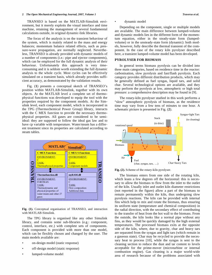
TRANSEO is based on the MATLAB-Simulink envi-ronment, but it merely exploits the visual interface and time machine, retaining the management of several fundamental calculations outside, in original dynamic-link libraries.
The focus of the analysis is on the transient behaviour of the system, which is mainly related to the mass and energy balances; momentum balance related effects, such as pres-sure-wave propagation, are normally neglected. Neverthe-less, TRANSEO is already provided with dynamic models of a number of components (i.e.: pipe and ejector components), which can be employed for the full dynamic analysis of their behaviour. Unfortunately this approach is very time-consuming and it is seldom worth extending the full dynamic analysis to the whole cycle. Most cycles can be effectively simulated on a transient basis, which already provides suffi-cient accuracy, as demonstrated by the validation results.
Fig. (1) presents a conceptual sketch of TRANSEO’s position within MATLAB-Simulink, together with its own objects. At the MATLAB level a complete set of thermo-physical functions was developed to equip the tool with the properties required by the component models. At the Sim-ulink level, each component model, which is incorporated in the TPG (Thermochemical Power Group) library, interacts with the C MEX function to provide the necessary thermo-physical properties. All gases are considered to be semi-ideal: they are supposed to follow the ideal gas law and to have cp variable with temperature. Water/steam has a differ-ent treatment since its properties are calculated according to steam tables.
Fig. (1). Conceptual organisation of TRANSEO, and interaction
with MATLAB-Simulink.
The TPG library is organised like any other Simulink library, and contains some sub-libraries (e.g.: component, control, interface, etc.) with complete sets of components. Each component is provided with more than one model, which can be flexibly chosen and changed by the user. The main models available are:
• on-design model (static response)
• off-design model (static response)
• lumped-volume model
• dynamic model
Depending on the component, single or multiple models are available. The main difference between lumped-volume and dynamic models lies in the different form of the momen-tum equation, either in the steady-state form (lumped-volume) or in the unsteady-state form (dynamic): both mod-els, however, fully describe the thermal transient of the com-ponent. In the case of the rotary kiln pyrolyser described here, a transient lumped-volume model has been developed.
PYROLYSER FOR BIOMASS
In general terms biomass pyrolysis can be divided into three main categories, based on residence time in the reactor: carbonisation, slow pyrolysis and fast/flash pyrolysis. Each category provides different distribution products, which may be generally defined as fuel syngas, liquid tars, and solid char. Several technological options are available, and they may perform the pyrolysis at low, atmospheric or high total pressure: a comprehensive description may be found in [9].
The rotary-kiln pyrolyser studied in this work performs a “slow” atmospheric pyrolysis of biomass, as the residence time may vary from a few tens of minutes to one hour. A schematic picture is presented in Fig. (2).
Biomass
Fuel
(char, syngas, tars, …)
Air
Syngas+light Tars
(to cleaning)
Char+heavy Tars
rotational speed
Stack
(to drier)
Fig. (2). Scheme of the rotary-kiln pyrolyser.
The biomass enters from one side of the rotating kiln, which leans a few degrees off the horizontal: this is neces-sary to allow the biomass to flow from the inlet to the outlet of the kiln. Usually inlet and outlet kiln diameter restrictions (not reported in the figure) allow a part of the biomass to remain permanently within the kiln, thus undergoing slow pyrolysis reactions. The kiln can be provided with internal fins which help to mix and rotate the biomass, thus ensuring its uniform state (temperature and chemical composition) in the radial direction, with the secondary effect of contributing to the transfer of heat from the hot wall to the biomass. From the outside, the kiln looks like a normal pipe without any fins, as they would be quickly damaged by the high external temperatures. The processed biomass exits at the opposite side of the kiln, where, due to gravity, char and heavy tars are separated from the syngas and light tars (which remain in a gaseous state). Char may be recycled to provide the neces-sary heat to process [10], while the syngas is sent to the cleaning section to reduce the dust and tar content to levels acceptable for the prime-mover (microturbine or internal combustion engine). Gas cleaning is a major world-wide area of research because of the problems associated with
-physical properties
MATLAB© Simulink©Simulink©
.
TR
AN
SE
O
TR
AN
SE
O
ENVIRONMENT:CTASK:Thermophysical properties
C MEX Functions
ENVIRONMENT:CTASK:Component models
C MEX S-Functions
ENVIRONMENT:FORTRANTASK:Thermodynamic and physical properties of water/steam and other 27 gases
Thermofunction.dll
ENVIRONMENT:CTASK:Flow compositionAdditional data
myRAM.dll
-physical properties
MATLAB© Simulink©Simulink©
.
TR
AN
SE
O
TR
AN
SE
O
ENVIRONMENT:CTASK:Thermophysical properties
C MEX Functions
ENVIRONMENT:CTASK:Thermophysical properties
C MEX Functions
ENVIRONMENT:CTASK:Component models
C MEX S-Functions
ENVIRONMENT:CTASK:Component models
C MEX S-Functions
ENVIRONMENT:FORTRANTASK:Thermodynamic and physical properties of water/steam and other 27 gases
Thermofunction.dll
ENVIRONMENT:FORTRANTASK:Thermodynamic and physical properties of water/steam and other 27 gases
Thermofunction.dll
ENVIRONMENT:CTASK:Flow compositionAdditional data
myRAM.dll
ENVIRONMENT:CTASK:Flow compositionAdditional data
myRAM.dll

Transient Modelling of a Rotary-Kiln Pyrolyser The Open Mechanical Engineering Journal, 2007, Volume 1 3
output-gas purity levels and associated costs. However, gas cleaning is outside the scope of this work: for the real appli-cations under consideration wet scrubbing is the preferred technical solution.
Heat for the process is indirectly supplied by an external combustor: hot exhausts circle around the external wall of the kiln in a helicoidal manner to the stack exit. The overall hot exhaust heat exchange with the biomass can be either co-flow or counter-flow. The former ensures a larger thermal gradient at the biomass inlet, which reaches the reaction temperature (>350°C) more rapidly, but at the same time the overall heat exchange is less efficient and the exhausts exit the stack at a higher temperature. The situation is reversed in the second case, which provides a more efficient heat ex-change between the hot exhausts and rotary kiln but takes more pipe length to bring the biomass to the reaction tem-perature. In this work the co-flow configuration was consid-ered, as shown in Fig. (2).
A sealing must be placed between the rotating kiln and the exhaust chamber: in fact, this does not represent a par-ticular technical challenge as the kiln rotates at slow speeds (order of magnitude of 10-100 rpm). The rotational speed and angle of inclination of the kiln must be adjusted accord-ing to the feeding biomass flow [3].
The main factor which limits the throughput of rotary kilns is the heat transfer from the hot external exhaust cham-ber to the internal biomass. In fact, at least three thermal resistances in series are present: convection/radiation be-tween the hot exhausts and the outer kiln wall, conduction between the outer and inner walls, conduction/radiation be-tween the inner wall and the biomass particles. The first and the last heat exchange mechanisms mostly limit the overall heat transfer to the reacting biomass, and they affect the overall dimensions required for the rotary kiln: in practice, the more effective the heat exchange, the smaller the surface required to perform the overall process. Another important parameter which affects the reactor throughput is the bio-mass inlet humidity: in the case of untreated biomass, it may exceed 50% of the overall input weight, hence requiring a large quantity of heat just to dry it. Therefore, it would be advantageous to pre-treat the biomass in an upstream drier that exploits the hot exhausts from the pyrolyser to bring the biomass to standard humidity conditions (e.g. 10% of the weight): this would allow better operation and constant throughput for the pyrolysing reactor.
Finally, although outside the scope of this work, it is worthwhile mentioning the performance achievable by an integrated pyrolyser energy system. The work presented in [11] shows that different levels of integration may lead to very different net performances in terms of electrical effi-ciency: the results are reported in Table 1. The differences in electrical efficiency are, of course, counter-balanced by dif-ferent capital costs (not reported), which may drive the final decision away from the best thermodynamic option. Never-theless Table 1 shows that rotary-kiln pyrolysers have re-markable potential for energy applications, which justifies the interest in this type of technology.
In this work, char has been assumed to be recirculated to the external combustor, providing the heat for the rotary kiln.
Table 1. Electrical Efficiency for Rotary-Kiln Pyrolysis Gas
Turbine Integrated Plants as Reported in [11] (Bio-
mass Thermal Input = 1000 kg/h, LHV = 14600
kJ/kg)
External Fuel
to Pyrolyser Gas Turbine
Char Steam
Boiler HRSG
Electrical
Efficiency
Char X 8%
Char X X 12.50%
Gas X X X 28%
Gas X 15%
TRANSIENT MODEL
In this work a quasi-2D time-dependent model of the rotary-kiln biomass pyrolyser, including pyrolysis kinetics, has been developed and described. The computational mesh is presented in Fig. (3).
Biomass
Hot exhausts
Char+heavy Tars
Kiln wall
External
insulated wallN cells
0
2
3
1
4
i-1 i i+1
i-1 i i+1
i-1 i i+1
i-1 i i+1
Fig. (3). Computational discretisation of the quasi 2-D rotary-kiln
pyrolyser model.
The model may be divided into three main parts:
1. Geometrical parameters
2. Pyrolysis reactions
3. Energy balance
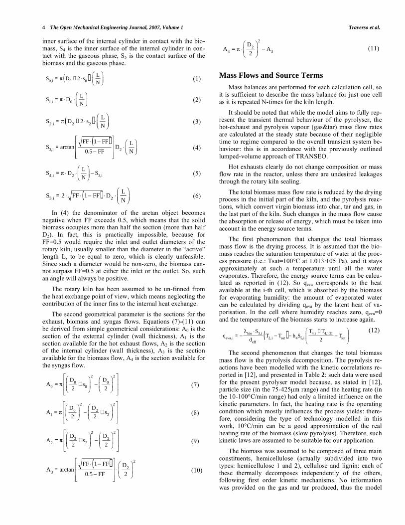
Geometrical Parameters
The first geometrical parameter is the available surfaces for heat exchange.
With reference to Fig. (3), hot exhausts and biomass are considered to pass through two concentrical cylinders, where the external section is occupied by the hot exhausts and the internal section by biomass and gas&tars. There are six main geometrical parameters that influence the reactor dimen-sions, from the model perspective: the inner diameters of the two cylinders (D0, D2), their thicknesses (s0, s2), their total length (L) and the filling factor of the inner cylinder section (FF): the last is defined as the fraction of D2 occupied by the biomass (the rest is occupied by the gaseous phase). FF can be considered practically constant for the entire kiln length, due to the restrictions of the inlet and outlet diameters which keep an almost constant volume of biomass within the rotary kiln.
It should be noted that the calculation mesh divides the total length into N cells and N+1 sections (just for fluids), so the available heat transfer surface must refer to the single cell. Thus, the heat exchange surfaces in equations (1)-(6) can be obtained: S0 is the outer surface of the external cylin-der, S1 is the inner surface of the external cylinder, S2 is the outer surface of the internal cylinder (rotary kiln), S3 is the
4 The Open Mechanical Engineering Journal, 2007, Volume 1 Traverso et al.
inner surface of the internal cylinder in contact with the bio-mass, S4 is the inner surface of the internal cylinder in con-tact with the gaseous phase, S5 is the contact surface of the biomass and the gaseous phase.
S0,i
= D0
+ 2 s0( )
L
N (1)
S1,i
= D0
L
N (2)
S2,i
= D2
+ 2 s2( )
L
N (3)
S3,i
= arctanFF 1 FF( )0.5 FF
D2
L
N (4)
S4,i
= D2
L
NS
3,i (5)
S5,i
= 2 FF 1 FF( ) D2
L
N (6)
In (4) the denominator of the arctan object becomes negative when FF exceeds 0.5, which means that the solid biomass occupies more than half the section (more than half D2). In fact, this is practically impossible, because for FF=0.5 would require the inlet and outlet diameters of the rotary kiln, usually smaller than the diameter in the “active” length L, to be equal to zero, which is clearly unfeasible. Since such a diameter would be non-zero, the biomass can-not surpass FF=0.5 at either the inlet or the outlet. So, such an angle will always be positive.
The rotary kiln has been assumed to be un-finned from the heat exchange point of view, which means neglecting the contribution of the inner fins to the internal heat exchange.
The second geometrical parameter is the sections for the exhaust, biomass and syngas flows. Equations (7)-(11) can be derived from simple geometrical considerations: A0 is the section of the external cylinder (wall thickness), A1 is the section available for the hot exhaust flows, A2 is the section of the internal cylinder (wall thickness), A3 is the section available for the biomass flow, A4 is the section available for the syngas flow.
A0
=D
0
2+ s
0
2D
0
2
2
(7)
A1
=D
0
2
2D
2
2+ s
2
2
(8)
A2
=D
2
2+ s
2
2D
2
2
2
(9)
A3
= arctanFF 1 FF( )0.5 FF
D2
2
2
(10)
A4
=D
2
2
2
A3 (11)
Mass Flows and Source Terms
Mass balances are performed for each calculation cell, so it is sufficient to describe the mass balance for just one cell as it is repeated N-times for the kiln length.
It should be noted that while the model aims to fully rep-resent the transient thermal behaviour of the pyrolyser, the hot-exhaust and pyrolysis vapour (gas&tar) mass flow rates are calculated at the steady state because of their negligible time to regime compared to the overall transient system be-haviour: this is in accordance with the previously outlined lumped-volume approach of TRANSEO.
Hot exhausts clearly do not change composition or mass flow rate in the reactor, unless there are undesired leakages through the rotary kiln sealing.
The total biomass mass flow rate is reduced by the drying process in the initial part of the kiln, and the pyrolysis reac-tions, which convert virgin biomass into char, tar and gas, in the last part of the kiln. Such changes in the mass flow cause the absorption or release of energy, which must be taken into account in the energy source terms.
The first phenomenon that changes the total biomass mass flow is the drying process. It is assumed that the bio-mass reaches the saturation temperature of water at the proc-ess pressure (i.e.: Tsat=100°C at 1.013 105 Pa), and it stays approximately at such a temperature until all the water evaporates. Therefore, the energy source terms can be calcu-lated as reported in (12). So qeva corresponds to the heat available at the i-th cell, which is absorbed by the biomass for evaporating humidity: the amount of evaporated water can be calculated by dividing qeva by the latent heat of va-porisation. In the cell where humidity reaches zero, qeva=0 and the temperature of the biomass starts to increase again.
qeva,i
=bio
S3,i
deff
T2,i
Tsat( ) h
4S
5,i
T4,i
+ T4,i+1
2T
sat (12)
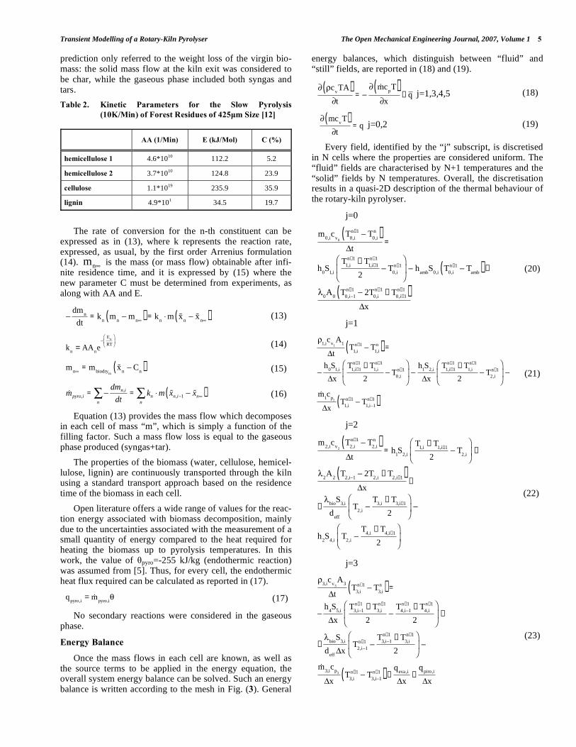
The second phenomenon that changes the total biomass mass flow is the pyrolysis decomposition. The pyrolysis re-actions have been modelled with the kinetic correlations re-ported in [12], and presented in Table 2: such data were used for the present pyrolyser model because, as stated in [12], particle size (in the 75-425μm range) and the heating rate (in the 10-100°C/min range) had only a limited influence on the kinetic parameters. In fact, the heating rate is the operating condition which mostly influences the process yields: there-fore, considering the type of technology modelled in this work, 10°C/min can be a good approximation of the real heating rate of the biomass (slow pyrolysis). Therefore, such kinetic laws are assumed to be suitable for our application.
The biomass was assumed to be composed of three main constituents, hemicellulose (actually subdivided into two types: hemicellulose 1 and 2), cellulose and lignin: each of these thermally decomposes independently of the others, following first order kinetic mechanisms. No information was provided on the gas and tar produced, thus the model
Transient Modelling of a Rotary-Kiln Pyrolyser The Open Mechanical Engineering Journal, 2007, Volume 1 5
prediction only referred to the weight loss of the virgin bio-mass: the solid mass flow at the kiln exit was considered to be char, while the gaseous phase included both syngas and tars.
Table 2. Kinetic Parameters for the Slow Pyrolysis
(10K/Min) of Forest Residues of 425μm Size [12]
AA (1/Min) E (kJ/Mol) C (%)
hemicellulose 1 4.6*1010 112.2 5.2
hemicellulose 2 3.7*1010 124.8 23.9
cellulose 1.1*1019 235.9 35.9
lignin 4.9*101 34.5 19.7
The rate of conversion for the n-th constituent can be expressed as in (13), where k represents the reaction rate, expressed, as usual, by the first order Arrenius formulation (14). nm is the mass (or mass flow) obtainable after infi-nite residence time, and it is expressed by (15) where the new parameter C must be determined from experiments, as along with AA and E.
dmn
dt= k
nm
nm
n( ) = kn
m xn
xn( ) (13)
k
n= AA
ne
En
RT (14)
m
n= m
biodryin
xn
Cn( ) (15)
mpyro,i =dmn,i
dt= kn m xn,i 1 xn( )
nn
(16)
Equation (13) provides the mass flow which decomposes in each cell of mass “m”, which is simply a function of the filling factor. Such a mass flow loss is equal to the gaseous phase produced (syngas+tar).
The properties of the biomass (water, cellulose, hemicel-lulose, lignin) are continuously transported through the kiln using a standard transport approach based on the residence time of the biomass in each cell.
Open literature offers a wide range of values for the reac-tion energy associated with biomass decomposition, mainly due to the uncertainties associated with the measurement of a small quantity of energy compared to the heat required for heating the biomass up to pyrolysis temperatures. In this work, the value of pyro=-255 kJ/kg (endothermic reaction) was assumed from [5]. Thus, for every cell, the endothermic heat flux required can be calculated as reported in (17).
q
pyro,i= m
pyro,i (17)
No secondary reactions were considered in the gaseous phase.
Energy Balance
Once the mass flows in each cell are known, as well as the source terms to be applied in the energy equation, the overall system energy balance can be solved. Such an energy balance is written according to the mesh in Fig. (3). General
energy balances, which distinguish between “fluid” and “still” fields, are reported in (18) and (19).
cvTA( )
t=
mcpT( )
x+ q j=1,3,4,5 (18)
mcvT( )
t= q j=0,2 (19)
Every field, identified by the “j” subscript, is discretised in N cells where the properties are considered uniform. The “fluid” fields are characterised by N+1 temperatures and the “solid” fields by N temperatures. Overall, the discretisation results in a quasi-2D description of the thermal behaviour of the rotary-kiln pyrolyser.
• j=0
m0,i
cv
0
T0,i
n+1 T0,i
n( )t
=
h0S
1,i
T1,i
n+1+ T
1,i+1
n+1
2T
0,i
n+1 hamb
S0,i
T0,i
n+1 Tamb( ) +
0A
0T
0,i 1
n+1 2T0,i
n+1+ T
0,i+1
n+1( )x
(20)
• j=1
1,ic
v1
A1
tT
1,i
n+1 T1,i
n( ) =
h0S
1,i
x
T1,i+1
n+1+ T
1,i
n+1
2T
0,i
n+1h
1S
2,i
x
T1,i+1
n+1+ T
1,i
n+1
2T
2,i
n+1
m1c
p1
xT
1,i
n+1 T1,i 1
n+1( )
(21)
• j=2
m2,i
cv
2
T2,i
n+1 T2,i
n( )t
= h1S
2,i
T1,i
+ T1,i+1
2T
2,i+
2A
2T
2,i 12T
2,i+ T
2,i+1( )x
+
+bio
S3,i
deff
T2,i
T3,i
+ T3,i+1
2
h2S
4,iT
2,i
T4,i
+ T4,i+1
2
(22)
• j=3
3,ic
v3
A3
tT
3,i
n+1 T3,i
n( ) =
h4S
5,i
x
T3,i 1
n+1+ T
3,i
n+1
2
T4,i 1
n+1+ T
4,i
n+1
2+
+bio
S3,i
deff
xT
2,i 1
n+1T
3,i 1
n+1+ T
3,i
n+1
2
m3,i
cp
3
xT
3,i
n+1 T3,i 1
n+1( ) +q
eva,i
x+
qpiro,i
x
(23)

6 The Open Mechanical Engineering Journal, 2007, Volume 1 Traverso et al.
• j=4
4,ic
v4
A4
tT
4,i
n+1 T4,i
n( ) =
h4S
5,i
x
T3,i 1
n+1+ T
3,i
n+1
2
T4,i 1
n+1+ T
4,i
n+1
2+
h2S
4,i
xT
2,i 1
n+1T
4,i 1
n+1+ T
4,i
n+1
2
m4,i
cp
4
xT
4,i
n+1 T4,i 1
n+1( )
(24)
They are specified in the equations (20-24), which report, for each domain field, the discretised general forms of the aforementioned energy balances.
Equations (20)-(24) can be reduced to a linear system with unknown temperatures, which can be solved straight-away, obtaining the temperatures of the entire domain in the next time step.
Equations (20)-(24) contain several assumed constant parameters, presented in Table 3. The parameters related to the exhausts were calculated using their composition and assuming semi-ideal behaviour.
The convective heat exchange parameters need to be es-timated and vary according to the operating conditions. All equivalent convective coefficients (h0, h1, h2, h4) included both parallel convective and radiative heat transfers (the equivalent convective coefficient is the sum of the two). With regard to hamb, an average value representative of a well insulated furnace was been assumed.
Table 3. Constant Parameters of Energy Balance and Heat
Transfer
cv0 753 [J/kgK] 0 19 [W/mK]
cv2 753 [J/kgK] 2 19 [W/mK]
cv3= cp3 2.0 [J/kgK] bio 0.13 [W/mK]
cv4 1100 [J/kgK] of walls 0.9
cp4 1300 [J/kgK] of biomass 0.75
hamb 1 [W/m2K] of exhausts (with particles) 0.2
The linearised form of the equivalent convective heat transfer coefficient in (25) was used for the radiation. The F factor was always approximated with one: this is acceptable for both the heat exchanges between the hot exhausts and the rotating pipe, considering the distribution of the exhausts around the rotating pipe to be uniform, and the heat ex-changes between the rotating pipe and biomass, which actu-ally have F=1 at the contact surface S3. The emissivities are reported in Table 3. Radiation was neglected for the heat exchanges with the inner gaseous phase (j=4).
hrad =1
1
+1
2
11
F1 2 T1 + T2( ) T12
+ T22( )
(25)
The convection heat regime varied: the hot exhausts ex-changed heat with the walls in a turbulent regime, while the inner pyrolysis gases were considered to be in laminar mo-
tion. This was due to the considerable difference in their mass flows (about 10 to 1). The correlations (26) and (27) were taken from [13] and used for the hot exhausts (flow over immersed body) and the inner gaseous phase (circular horizontal tubes with constant wall temperature and laminar flow), respectively.
The heat exchange between the biomass and rotating pipe was considered to occur at the contact surface S3, where it was composed of radiation and contact conductance, and between S4 and S5, where it only consisted of radiation. The pyrolysis vapours were considered transparent to radiation.
The equivalent convective coefficient for the contact conductance and the effective biomass particle diameter are defined in (28).
h = 0.0266 *D
eq
* Re0.8* Pr0.33 (26)
h = 3.66 +0.19Gz0.8
1+ 0.117Gz0.467 with
Gz = Re PrD
eq
L
(27)
bio
deff
= hbio
= bio
d(1 ) + h
rad (28)
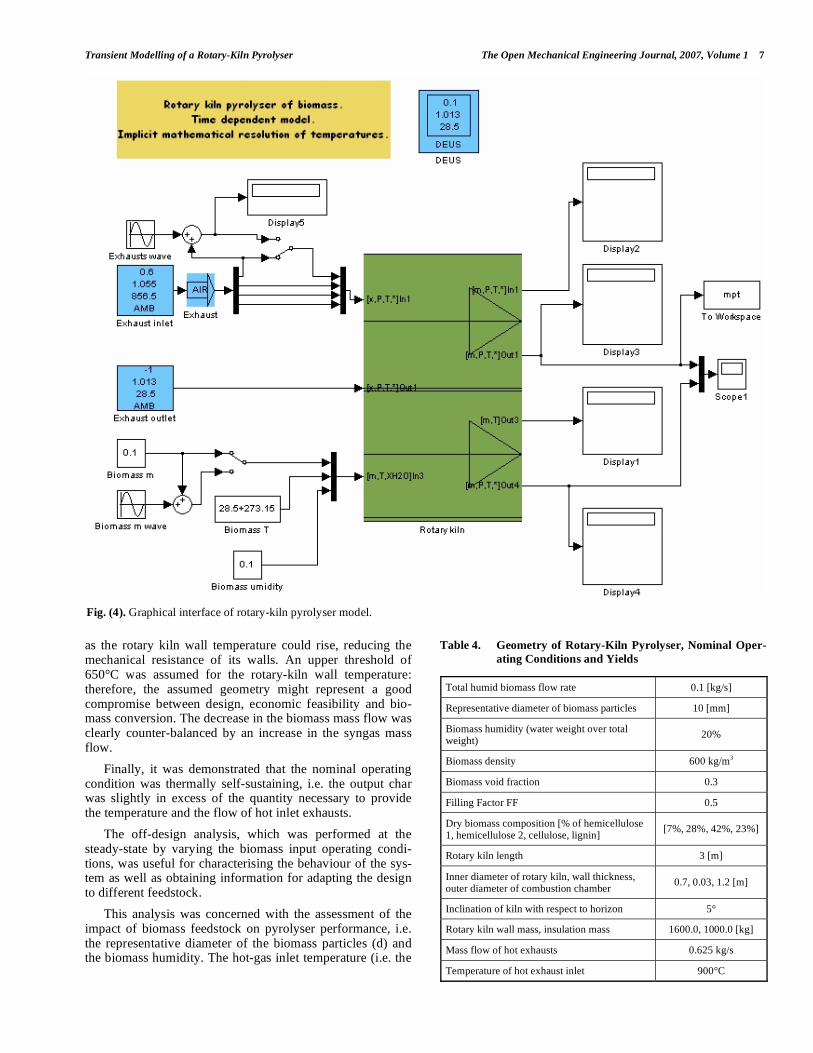
Fig. (4) illustrates the final appearance of the pyrolyser model: thanks to the Simulink visual interface, its integration with energy generation modules will be straightforward at the simulation level.
The results were obtained with 20 longitudinal cells and 0.1s time step. Mesh does not affect the results down to 6-8 nodes. Time independence was checked.
STEADY-STATE ANALYSIS
The geometry of the rotary-kiln pyrolyser and its nominal operating conditions were fixed according to Table 4. The data were similar to those of a rotary-kiln which is currently under construction at a biomass residue collection site.
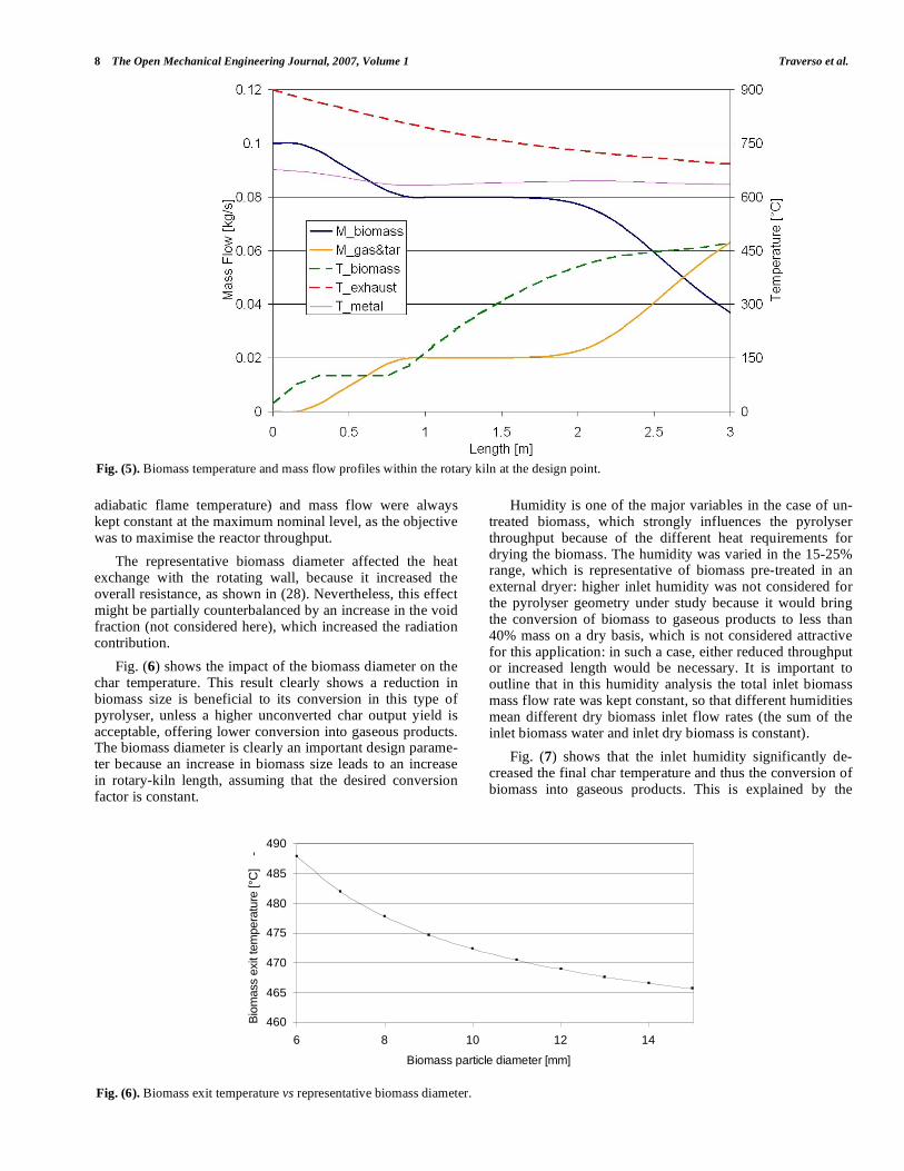
Under such operating conditions, as shown in Fig. (5), the biomass exits the kiln in the form of char at about 470°C, with a total mass loss of about 62% with respect to the inlet. Since 20% of the mass flow of gaseous products consisted of original biomass humidity, the dry inlet biomass was con-verted to syngas and tars with a (0.62-0.2)/0.8 = 0.52 conver-sion factor.
Fig. (5) shows the behaviour of the main properties along the length of the rotary-kiln. It was interesting to observe a relatively small temperature floor during the drying process that shifted forward the following increase in the biomass temperature: after drying, the biomass temperature curve shows a decreasing slope, which is due to the co-current heat exchange configuration, as the difference in temperature between the biomass and hot exhausts is reduced between the kiln entry and exit. The biomass mass flow initially de-creased because of the drying process, and then, after achiev-ing temperatures of the order of 350-400°C, rapidly de-creased while being transformed into char: the high negative slope at the end of the pyrolyser suggests that additional length may help to increase the overall conversion of solid biomass. Of course, the increase in length cannot be massive,
Transient Modelling of a Rotary-Kiln Pyrolyser The Open Mechanical Engineering Journal, 2007, Volume 1 7
as the rotary kiln wall temperature could rise, reducing the mechanical resistance of its walls. An upper threshold of 650°C was assumed for the rotary-kiln wall temperature: therefore, the assumed geometry might represent a good compromise between design, economic feasibility and bio-mass conversion. The decrease in the biomass mass flow was clearly counter-balanced by an increase in the syngas mass flow.
Finally, it was demonstrated that the nominal operating condition was thermally self-sustaining, i.e. the output char was slightly in excess of the quantity necessary to provide the temperature and the flow of hot inlet exhausts.
The off-design analysis, which was performed at the steady-state by varying the biomass input operating condi-tions, was useful for characterising the behaviour of the sys-tem as well as obtaining information for adapting the design to different feedstock.
This analysis was concerned with the assessment of the impact of biomass feedstock on pyrolyser performance, i.e. the representative diameter of the biomass particles (d) and the biomass humidity. The hot-gas inlet temperature (i.e. the
Table 4. Geometry of Rotary-Kiln Pyrolyser, Nominal Oper-
ating Conditions and Yields
Total humid biomass flow rate 0.1 [kg/s]
Representative diameter of biomass particles 10 [mm]
Biomass humidity (water weight over total weight)
20%
Biomass density 600 kg/m3
Biomass void fraction 0.3
Filling Factor FF 0.5
Dry biomass composition [% of hemicellulose 1, hemicellulose 2, cellulose, lignin]
[7%, 28%, 42%, 23%]
Rotary kiln length 3 [m]
Inner diameter of rotary kiln, wall thickness, outer diameter of combustion chamber
0.7, 0.03, 1.2 [m]
Inclination of kiln with respect to horizon 5°
Rotary kiln wall mass, insulation mass 1600.0, 1000.0 [kg]
Mass flow of hot exhausts 0.625 kg/s
Temperature of hot exhaust inlet 900°C
Fig. (4). Graphical interface of rotary-kiln pyrolyser model.
8 The Open Mechanical Engineering Journal, 2007, Volume 1 Traverso et al.
adiabatic flame temperature) and mass flow were always kept constant at the maximum nominal level, as the objective was to maximise the reactor throughput.
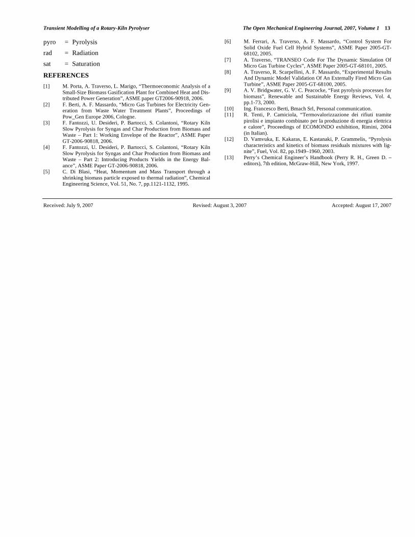
The representative biomass diameter affected the heat exchange with the rotating wall, because it increased the overall resistance, as shown in (28). Nevertheless, this effect might be partially counterbalanced by an increase in the void fraction (not considered here), which increased the radiation contribution.
Fig. (6) shows the impact of the biomass diameter on the char temperature. This result clearly shows a reduction in biomass size is beneficial to its conversion in this type of pyrolyser, unless a higher unconverted char output yield is acceptable, offering lower conversion into gaseous products. The biomass diameter is clearly an important design parame-ter because an increase in biomass size leads to an increase in rotary-kiln length, assuming that the desired conversion factor is constant.
Humidity is one of the major variables in the case of un-treated biomass, which strongly influences the pyrolyser throughput because of the different heat requirements for drying the biomass. The humidity was varied in the 15-25% range, which is representative of biomass pre-treated in an external dryer: higher inlet humidity was not considered for the pyrolyser geometry under study because it would bring the conversion of biomass to gaseous products to less than 40% mass on a dry basis, which is not considered attractive for this application: in such a case, either reduced throughput or increased length would be necessary. It is important to outline that in this humidity analysis the total inlet biomass mass flow rate was kept constant, so that different humidities mean different dry biomass inlet flow rates (the sum of the inlet biomass water and inlet dry biomass is constant).
Fig. (7) shows that the inlet humidity significantly de-creased the final char temperature and thus the conversion of biomass into gaseous products. This is explained by the
Fig. (5). Biomass temperature and mass flow profiles within the rotary kiln at the design point.
460
465
470
475
480
485
490
6 8 10 12 14
Biomass particle diameter [mm]
Bio
mass e
xit tem
peratu
re [°C
] -
Fig. (6). Biomass exit temperature vs representative biomass diameter.

Transient Modelling of a Rotary-Kiln Pyrolyser The Open Mechanical Engineering Journal, 2007, Volume 1 9
higher heat absorbed during the internal drying process, which occupied an increasing portion of the kiln length.
TRANSIENT ANALYSIS
The model was tested to assess the behaviour of the ro-tary-kiln pyrolyser during transient operating conditions, an essential step for developing suitable control strategies. This study is expected to be reviewed as soon as field data meas-urements are available, but it will be used in the design phase of the control system. Three type of transients were studied: the system start-up, the step change in the inlet biomass hu-midity, the step change in the biomass mass flow.
System Start-Up
The start-up of high-temperature chemical reactors is usually a very delicate procedure because thermal time-gradients must be controlled to avoid damage to refractory or moving parts, and because external energy resources may be required for non-negligible periods of time: the latter is one of the reasons why the start-up time should usually be mini-mised. Therefore, instead of focusing on the limitations and constraints which might push system operators to opt for
small temperature ramps (i.e.: extended start-up time), the aim of this work was the simulation of the fastest possible start-up: this was done by feeding the pyrolyser, starting at ambient conditions, with nominal hot exhaust flows and a nominal biomass flow. The pyrolyser was initially consid-ered to be filled with biomass at the nominal filling factor FF. The results obtained gave the time threshold below which it would be impossible to start up the system because of its thermal capacitances.
Fig. (8) shows the pyrolyser yields during the start-up. Apart from the steam of the drying process, pyrolysis de-composition substances were produced after about 1800s, when the final section reached about 300°C. From then on there was a rapid increase in the gaseous products due to an increase in the temperature in all the previous sections. The positive slope started to decrease significantly after about 1400s, when the final section passed 450°C, causing the al-most total pyrolysis of the biomass. In this respect, the time to regime of the pyrolysis was a bit lower than the time to regime of the heating process.
Fig. (9) shows that the biomass thermal capacitance had a strong influence on the time to regime of the reactor: in fact,
455
460
465
470
475
480
485
490
495
15 17 19 21 23 25
Humidity [H2O_w / Total_w *100]
Bio
mass e
xit tem
peratu
re [°C
] -
Fig. (7). Biomass exit temperature vs biomass humidity.
0
0.02
0.04
0.06
0.08
0.1
0.12
0 1800 3600 5400 7200 9000 10800 12600
Time [s]
Ma
ss flo
w [k
g/s
]
M_biomass
M_gas&tar
Fig. (8). Pyrolyser biomass (char) and vapour (gas&tar) yields during the start-up.

10 The Open Mechanical Engineering Journal, 2007, Volume 1 Traverso et al.
the last section reached the steady-state only after about 3600s, which was of the same order of magnitude as the es-timated residence time of about 3000s. Actually, earlier sec-tions reached the steady-state before the latter sections, which is a direct consequence of the biomass flow direction. It is interesting to observe that the temperature curve for each section presented a horizontal phase during the first 500-700s. When the temperature reached about 100°C it stayed constant for some time, waiting for the full vaporisa-tion of the biomass humidity.
Fig. (9). Top: evolution of the biomass temperature in the kiln dur-
ing the start-up. Bottom: biomass, gas&tar and exhaust exit tem-
peratures during the start-up.
This was why the gas mass flow peaked about 800s after the start-up. The drying of the biomass started at the pyro-lyser inlet and then propagated to the latter sections until they also reached the steady-state conditions.
Step Change in the Inlet Biomass Humidity
Changes may be expected in the inlet biomass humidity during normal operation because of the variability of feed-stock. So, the analysis of this transient behaviour was par-ticularly interesting for understanding the capability of this type of technology to handle a rapidly varying inlet biomass.
Initially, the pyrolyser was at steady-state conditions. Then a step was applied to the inlet biomass humidity: in the first case, the inlet humidity was changed from 10% to 20% (+10% step), in the second case the inlet humidity was changed from 20% to 10% (-10% step).
Fig. (10) shows the process yields during the entire tran-sient. Firstly, an overall time to regime of about 2500s was observed, which means that the system is characterised by
significant thermal capacitance that limited its fast response capability to new operating conditions: at the same time, this feature should help to smooth out rapid oscillations in the biomass humidity at the inlet, which should not affect the overall behaviour of the reactor output. In both cases, it is interesting to observe a fast decrease or increase in the gas output, followed by an opposite trend with over-elongation beyond the new regime. This can be explained by the sys-tem’s thermal capacitance, which initially evaporated a part of the water in the biomass, releasing or absorbing heat, and then needed to counterbalance such a heat exchange before reaching the regime.
0
0.01
0.02
0.03
0.04
0.05
0.06
0.07
0.08
0 1800 3600 5400 7200 9000 10800
Time [s]
Mass flo
w [kg/s
]
M_biomass
M_gas&tar
0
0.01
0.02
0.03
0.04
0.05
0.06
0.07
0.08
0 1800 3600 5400 7200 9000 10800
Time [s]
Mass flo
w [kg/s
]
M_biomass
M_gas&tar
Fig. (10). Pyrolyser biomass (char) and vapour (gas&tar) yields
after the humidity step change (Top: + 10%; Bottom: -10%).
The sudden increase or decrease in the inlet humidity reduced or increased the mass flow of dry biomass (the inlet total mass flow was constant), which changed the outlet char flow rate only after a period approximately equal to the resi-dence time: this happened with almost unchanged tempera-ture profiles. The output temperature curves in Fig. (11) show that they move much slower than the gaseous output did, mainly following the behaviour of the char yield. This was expected, but it represents a detrimental feature for the controllability of this system, which mainly exploits the gaseous output as a useful product for power generation.
Step Change in the Biomass Mass Flow
Changes in the biomass inlet mass flow could be necessi-tated by a scarcity of feedstock or a reduced production re-quirement. Thus, it is interesting to characterise the response of the pyrolyser to this type of disturbance.
Initially, the pyrolyser was at steady-state conditions. Then a step was applied to the inlet biomass flow rate: in the

Transient Modelling of a Rotary-Kiln Pyrolyser The Open Mechanical Engineering Journal, 2007, Volume 1 11
first case, the mass flow was changed from 80% to 100% of the nominal flow rate (+20% step), in the second case the mass flow was changed from 100% to 80% (-20%step).
0
100
200
300
400
500
600
700
800
0 1800 3600 5400 7200 9000 10800
Time [s]
Tem
peratu
re [°C
]
T_biomass
T_gas&tar
T_exhaust
0
100
200
300
400
500
600
700
800
0 1800 3600 5400 7200 9000 10800
Time [s]
Tem
peratu
re [°C
]
T_biomass
T_gas&tar
T_exhausts
Fig. (11). Biomass, gas&tar and exhaust exit temperatures after the
humidity step change (Top: + 10%; Bottom: -10%).
Fig. (12) shows the outlet mass flow behaviour during the transient, while Fig. (13) reports the corresponding exit temperatures. It showed a quicker response than the gaseous phase, which was mainly due to the change in the biomass humidity evaporation rates. In terms of its impact on the char mass flow rate, the inlet biomass flow rate step became ap-parent at the kiln exit only after more than 3000s had elapsed, which was the approximate residence time of the biomass. Thus, the char mass flow behaved as a lag-dominated parameter, while the gaseous mass flow had a more disturbed behaviour. In fact, the char behaviour can be well understood by monitoring the char exit temperature, while gaseous yields may show variations which can hardly be correlated with the input disturbances (when they are not known).
CONCLUSIONS
A quasi 2-D time-dependent model of a rotary-kiln bio-mass pyrolyser incorporating first-order slow pyrolysis bio-mass kinetics from literature was developed. The model was meant to provide information on the transient response of the system for control purposes and integration with other en-ergy devices (e.g. microturbine, internal combustion engine).
A steady-state analysis revealed that, in terms of biomass conversion into syngas/tar, the performance of the pyrolyser
was strongly affected by such inlet biomass conditions as diameter and humidity.
0
0.01
0.02
0.03
0.04
0.05
0.06
0.07
0 1800 3600 5400 7200 9000 10800
Time [s]
Mass F
low
[kg/s
]
M_biomass
M_gas&tar
0
0.01
0.02
0.03
0.04
0.05
0.06
0.07
0.08
0.09
0 1800 3600 5400 7200 9000 10800
Time [s]
Mass F
low
[kg/s
]M_biomass
M_gas&tar
Fig. (12). Pyrolyser biomass (char) and vapour (gas&tar) yields
after the inlet biomass mass flow rate change (Top: + 20%; Bottom:
-20%).
Transient analyses were performed for three operating cases: the start-up, the step change in the inlet biomass hu-midity and the step change in the inlet biomass mass flow rate. The fastest possible start-up without imposing con-straints on the temperature ramp was simulated to assess the lowest threshold for bringing the pyrolyser to nominal condi-tions: a minimum time to regime of about 3600s was ob-served. In terms of the humidity change, the pyrolyser needed about 2500s to reach the new regime, with character-istic sovra-elongation behaviour in the gaseous yield, which may cause control issues. The step change analysis of the biomass flow rate confirmed the relationship between the exit char temperature and the char yield, while the gaseous flow rate might be subject to significantly faster changes with oscillation behaviour: for this reason the control of such yields may be difficult in real applications.
Overall, it was demonstrated that the rotary-kiln biomass pyrolyser is a relatively slow-response system which is mainly driven by its large thermal capacitance. Output gase-ous yields may be subject to sudden changes in response to inlet changes in the biomass humidity and flow. However, these can be controlled by the proper management of the biomass feedstock: such a practice is expected to facilitate integration with a prime-mover, because it would avoid the

12 The Open Mechanical Engineering Journal, 2007, Volume 1 Traverso et al.
disturbed trends in the syngas yield that were observed in the case-studies considered in this work.
0
100
200
300
400
500
600
700
800
0 1800 3600 5400 7200 9000 10800
Time [s]
Tem
peratu
re [°C
]
T_biomass
T_gas&tar
T_exhaust
0
100
200
300
400
500
600
700
800
0 1800 3600 5400 7200 9000 10800
Time [s]
Tem
peratu
re [°C
]
T_biomass
T_gas%tar
T_exhaust
Fig. (13). Biomass, gas&tar and exhaust exit temperatures after the
inlet biomass mass flow rate change (Top: + 20%; Bottom: -20%).
ACKNOWLEDGEMENTS
This research was partially supported by the European Commission (project Dev-BIOSOFC, FP6-042436, MTKD-CT-2006-042436).
NOMENCLATURE
A = Section [m2]
AA = Frequency factor [s-1
]
cp = Constant pressure specific heat [J/kg K]
cv = Constant volume specific heat [J/kg K]
C = Fractional contribution to overall mass loss
CHP = Combined Heat and Power
d = Representative diameter of biomass particles [m]
D = Diameter [m]. Equivalent diameter of a section A is (4A/perimeter)
E = Activation energy [kJ/mol]
F = View factor for radiation [kJ/mol]
FF = Filling factor
Gz = Graetz number (defined in eq.27)
h = Convective coefficient [W/m2K]
HRSG = Heat Recovery Steam Generator
L = Active length of rotary kiln [m]
LHV = Low Heating Value [J/kg]
k = Reaction rate [s-1
]
N = Number of horizontal cells
m = Mass [kg]
m = Mass flow rate [kg/s]
n = n-th Type of biomass constituent (hemicellulose, cellulose, lignin)
Pr = Prandtl number (= cpμ )
q = Heat flux [W]
q = Heat flux per unit length [W/m]
R = Gas constant [kJ/mol K]
Re = Reynolds number (= vD μ )
s = Thickness [m]
S = Surface [m2]
t = Time [s]
T = Temperature [K]
x = Mass fraction of biomass constituent
x = Single cell length [m] (= L/N)
v = Velocity [m/s]
Greek Letters
= Emissivity
= Thermal conductivity [W/mK]
μ = Dynamic viscosity [Pa s]
= Void fraction
= Heat of pyrolysis [J/kg]
= Density [kg/m3]
= 5.670·10-8
Stephan-Boltzmann constant [W/m2K
4]
Subscripts
0 = Insulated external wall
1 = Hot exhausts
2 = Kiln wall
3 = Outer wall of kiln
4 = Insulated external wall
amb = Ambient
bio = Biomass
char = Char
dry = Dry
eff = Effective
eq = Equivalent
eva = Evaporation
i = i-th Cell in the 1-N range
in = Inlet
n = Temporal instant
Transient Modelling of a Rotary-Kiln Pyrolyser The Open Mechanical Engineering Journal, 2007, Volume 1 13
pyro = Pyrolysis
rad = Radiation
sat = Saturation
REFERENCES
[1] M. Porta, A. Traverso, L. Marigo, “Thermoeconomic Analysis of a
Small-Size Biomass Gasification Plant for Combined Heat and Dis-tributed Power Generation”, ASME paper GT2006-90918, 2006.
[2] F. Berti, A. F. Massardo, “Micro Gas Turbines for Electricity Gen-eration from Waste Water Treatment Plants”, Proceedings of
Pow_Gen Europe 2006, Cologne. [3] F. Fantozzi, U. Desideri, P. Bartocci, S. Colantoni, “Rotary Kiln
Slow Pyrolysis for Syngas and Char Production from Biomass and Waste – Part 1: Working Envelope of the Reactor”, ASME Paper
GT-2006-90818, 2006. [4] F. Fantozzi, U. Desideri, P. Bartocci, S. Colantoni, “Rotary Kiln
Slow Pyrolysis for Syngas and Char Production from Biomass and Waste – Part 2: Introducing Products Yields in the Energy Bal-
ance”, ASME Paper GT-2006-90818, 2006. [5] C. Di Blasi, “Heat, Momentum and Mass Transport through a
shrinking biomass particle exposed to thermal radiation”, Chemical Engineering Science, Vol. 51, No. 7, pp.1121-1132, 1995.
[6] M. Ferrari, A. Traverso, A. F. Massardo, “Control System For
Solid Oxide Fuel Cell Hybrid Systems”, ASME Paper 2005-GT-68102, 2005.
[7] A. Traverso, “TRANSEO Code For The Dynamic Simulation Of Micro Gas Turbine Cycles”, ASME Paper 2005-GT-68101, 2005.
[8] A. Traverso, R. Scarpellini, A. F. Massardo, “Experimental Results And Dynamic Model Validation Of An Externally Fired Micro Gas
Turbine”, ASME Paper 2005-GT-68100, 2005. [9] A. V. Bridgwater, G. V. C. Peacocke, “Fast pyrolysis processes for
biomass”, Renewable and Sustainable Energy Reviews, Vol. 4, pp.1-73, 2000.
[10] Ing. Francesco Berti, Bmach Srl, Personal communication. [11] R. Tenti, P. Camiciola, “Termovalorizzazione dei rifiuti tramite
pirolisi e impianto combinato per la produzione di energia elettrica e calore”, Proceedings of ECOMONDO exhibition, Rimini, 2004
(in Italian). [12] D. Vamvuka, E. Kakaras, E. Kastanaki, P. Grammelis, “Pyrolysis
characteristics and kinetics of biomass residuals mixtures with lig-nite”, Fuel, Vol. 82, pp.1949–1960, 2003.
[13] Perry’s Chemical Engineer’s Handbook (Perry R. H., Green D. – editors), 7th edition, McGraw-Hill, New York, 1997.
Received: July 9, 2007 Revised: August 3, 2007 Accepted: August 17, 2007