Traffic Steering in Radio Level Integration of LTE and Wi-Fi ...
190
Traffic Steering in Radio Level Integration of LTE and Wi-Fi Networks Thomas Valerrian Pasca Santhappan A Dissertation Submitted to Indian Institute of Technology Hyderabad In Partial Fulfillment of the Requirements for The Degree of Doctor of Philosophy Department of Computer Science and Engineering Indian Institute of Technology Hyderabad January 2019
-
Upload
khangminh22 -
Category
Documents
-
view
1 -
download
0
Transcript of Traffic Steering in Radio Level Integration of LTE and Wi-Fi ...
Traffic Steering in Radio Level Integration of LTE
and Wi-Fi Networks
Thomas Valerrian Pasca Santhappan
A Dissertation Submitted to
Indian Institute of Technology Hyderabad
In Partial Fulfillment of the Requirements for
The Degree of Doctor of Philosophy
Department of Computer Science and Engineering
Indian Institute of Technology Hyderabad
January 2019

Declaration
I declare that this written submission represents my ideas in my own words, and where
ideas or words of others have been included, I have adequately cited and referenced the
original sources. I also declare that I have adhered to all principles of academic honesty and
integrity and have not misrepresented or fabricated or falsified any idea/data/fact/source in
my submission. I understand that any violation of the above will be a cause for disciplinary
action by the Institute and can also evoke penal action from the sources that have thus not
been properly cited, or from whom proper permission has not been taken when needed.
—————————
(Signature)
(Thomas Valerrian Pasca Santhappan)
CS13P1002
(Roll No.)

iii
Acknowledgements
I thank everyone who supported my research career at IIT Hyderabad. I heartily thank
people who extended me both moral and technical support.
I thank my advisor Dr. Bheemarjuna Reddy Tamma who trusted in me that I am
capable of pursuing research career. I thank him for all the support which he has extended
to me from the day I joined this campus till today. He is one of the most hardworking
persons I have encountered in my life. I did learn many things from him in terms of
technical writing, understanding problem in-sights, and developing interesting solutions. I
thank him for all the things which he taught me. I am very blessed to work with him.
I thank Dr. Antony franklin for his support and guidance in my thesis works. I thank
him for his special guidance in writing patents and presenting the works in standards forum.
I also thank him for extending moral support during tough times of my research career.
I would like to thank my lab seniors Vanlin Sathya, Mukesh Giluka, Anil Kumar
Rangisetti, and Mallikarjuna for the environment that they have set for me to work-in. Also,
my supportive juniors Anand Baswade, Himank Gupta, Shashwat Kumar, Venkatarami
Reddy, Nabhasmita Sen, Veerendra Kumar, Debashisha Mishra, Amogh PC, and Sumanta
Patro. I thank all the students of NeWS Lab for being supportive to me in all the works.
I thank my colleagues Anand Baswade, Mukesh Giluka, and Himank Gupta for the best
memories which they gave me. I thank Vanlin Sathya for his wonderful guidance throughout
my research career. He supported me during ups and downs of my career. I thank Mukesh
Giluka for providing me moral support throughout my stay at IIT Hyderabad.
I thank Chaganti Ramaraju who initiated the ambitious project of deploying an open
source LTE using OpenAirInterface (OAI), which eventually become core of my Ph.D. work.
I thank Dr. Raymon Knoop, Dr. Florain kaltenberger, Dr. Navid Nikaein, Lionel Gauthier,
and Cedric Roux for mentoring during internship work at EURECOM, France.
I specially thank Himank Gupta, Siva sairam prasad Kodali, Mukesh Giluka, Sumanta
Patro, Sreekanth Dama, Debashisha Mishra, Amogh PC, Nagamani Dheeravath, Vanlin
Sathya, Anil Kumar Rangisetti, Adharsh Srivats, Dr. Kotaro Kataoka, Dr. Kiran kumar
kuchi, Badrinaaraayanan Akilesh, Arjun V Anand, Prasanth Sharma, Ajay Brahmaksha-
triya, Naveen Kamath, Nabhasmita Sen, Venkatarami Reddy, and Tathagat Priyadarshi
for their generous research contributions and supportive work in due course of solving my
research problems.
I thank all my Doctoral Committee members, Dr. Kiran Kumar Kuchi, Dr. Kotaro
Kataoka, Dr. Rajalakshmi P, and Dr. Sathya Peri. Special thanks to Dr. Antony Franklin
for his guidance on every doctoral committee meeting.
I would heartily thank Goutham, Ramanjaneyulu Narayana, and Dileep Reddy towards
their service as project staff in setting up and maintaining the precious NeWS LAB.
I extend my thanks to Yoghita, Aravind anna, Murugan, Karthick anna and all my
friends at IIT Hyderabad for they have encouraged me throughout my Ph.D tenure. The
iv

memories of the time which I spent on tamil new year is ever green, I thank all my friends
for making it memorable. I would like to thank all the Ph.D. and M.Tech students of CSE
department, for the unforgettable memories which they gave me each year on my birthdays,
and moral support which they extended to me during different phases of my Ph.D program.
I thank Rakesh Lingam, Swarnalatha Mailaram, Veerla Swarnalatha, Angel Nivia,
Dhanalakshmi, Suresh Reddy, Yanthan, Pravin J, Deep Khandavalli, Manjela Toppo, Mu-
rali, Nisha James, Pradeep Parchuri, Sathya Vanlin, Rajesh Nimmagadda, Sunil Reddy
Mallireddy, Vidya Sagar, Anand Kakarla, Jedidiah, Joel Prakash, Keerthi Katam, Kimi,
Koteshwar Rao, Koteswara Rao Kandukuri, Krupa Teja, Kukkamudi Sreenivas, Mhatsomo
W Yanthan, Jessy, Shekar, and Anu George for being part of the fellowship. I also thank
them for the wonderful extended support and prayers.
I thank Roji Mol, Edin Michael, Jayashree, Martin, and Joseph for being part of the
choir and extending their support. I specially thank Roji Mol and Edin Michael for their
parental care. I also thank Saranya M S for supporting me both in my research works and
in my personal life.
I would like to thank staff members in the Administrative block, Cyber Physical Systems
lab (CPS) and Network Operations Center (ISAC-NOC), Jaya (CPS), Mr. Baswaraj (CPS),
Mr. Raguram (ISAC), Lalitha, Pushapa, Madhu, and Mr. Vijay Chakri (ISAC) for their
cheerful assistance.
I want to thank all my family members, and in particular, my parents A. Santhappan
and M. Elizabeth, my brother S. Xavier ArockiaRaj, and my sister-in-law Ronica BIS. This
entire journey, from research interests to my extra curricular activities, would not have been
meaningful without their constant support and companionship.
I would like to thank staff members at the Hostel office and Mess, Mr. Vel Murugan
(Hostel office), Mr. Prabhu (SGR Mess), and Mr. Logu (Shakthi Mess) for their true service
and their compassion.
I like to conclude with the saying, “Unless the grain of wheat falls into the ground and
dies, it remains what it was–a single grain; but that if it dies, it yields a rich harvest”. It
says that unless someone is prepared and committed to take up a challenge inspite of how
much bigger the challenge is, one cannot see a victory.
Thomas Valerrian Pasca Santhappan
v

Dedication
To
Almighty God,
My Parents & Friends.
vi
Abstract
A smartphone generates approximately 1, 614 MB of data per month which is 48 times
of the data generated by a typical basic-feature cell phone. Cisco forecasts that the mo-
bile data traffic growth will remain to increase and reach 49 Exabytes per month by 2021.
However, the telecommunication service providers/operators face many challenges in order
to improve cellular network capacity to match these ever-increasing data demands due to
low, almost flat Average Revenue Per User (ARPU) and low Return on Investment (RoI).
Spectrum resource crunch and licensing requirement for operation in cellular bands further
complicate the procedure to support and manage the network.
In order to deal with the aforementioned challenges, one of the most vital solutions is
to leverage the integration benefits of cellular networks with unlicensed operation of Wi-Fi
networks. A closer level of cellular and Wi-Fi coupling/interworking improves Quality of
Service (QoS) by unified connection management to user devices (UEs). It also offloads
a significant portion of user traffic from cellular Base Station (BS) to Wi-Fi Access Point
(AP). In this thesis, we have considered the cellular network to be Long Term Evolution
(LTE) popularly known as 4G-LTE for interworking with Wi-Fi.
Third Generation Partnership Project (3GPP) defined various LTE and Wi-Fi inter-
working architectures from Rel-8 to Rel-11. Because of the limitations in these legacy LTE
Wi-Fi interworking solutions, 3GPP proposed Radio Level Integration (RLI) architectures
to enhance flow mobility and to react fast to channel dynamics. RLI node encompasses link
level connection between Small cell evolved Node B (SeNB) and Wi-Fi AP. LTE WLAN
Aggregation (LWA) and LTE Wi-Fi Integration with IPSec tunnel (LWIP) are the RLI
architectures which are introduced in 3GPP Rel-12 and Rel-13.
The fundamental challenges for RLI architectures include: (1) Dynamic traffic steering
across time-varying channel conditions on LTE and Wi-Fi links, (2) Out-of-order packet
delivery problem when traffic steering is done at fine granularity (packet level steering), (3)
Co-tier interference management in dense deployment scenarios, (4) Efficient placement of
the RLI nodes and effective radio resource management in indoor deployments, and (5) High
energy consumption at UEs and RLI nodes due to use of multiple radios simultaneously.
This thesis addresses some of the fundamental challenges which prevent RLI architectures
from achieving interworking benefits.
To address the problem of co-tier interference in dense deployment scenario and to en-
able efficient downlink traffic steering, this thesis proposes a novel Power awaRE dynamiC
traffIc StEering (PRECISE) algorithm. The proposed algorithm targets to meet the fol-
lowing objectives in LWIP system: (i) Mitigation of co-tier interference in dense LWIP
vii

deployments, (ii) Meeting Guaranteed Bit Rate (GBR) requirements of the users including
those experiencing poor Signal to Interference plus Noise Ratio (SINR), and (iii) Dynamic
steering of the flows across LTE and Wi-Fi links to maximize the system throughput.
The second important problem addressed is the uplink traffic steering. To enable effi-
cient uplink traffic steering in LWIP system, in this thesis, Network Coordination Function
(NCF) is proposed. NCF is realized at the LWIP node by implementing various uplink traf-
fic steering algorithms. NCF encompasses four different uplink traffic steering algorithms
for efficient utilization of Wi-Fi resources in LWIP system. NCF facilitates the network to
take intelligent decisions rather than individual UEs deciding to steer the uplink traffic onto
LTE link or Wi-Fi link. The NCF algorithms work by leveraging the availability of LTE as
the anchor to improvise the channel utilization of Wi-Fi.
The third most important problem is to enable packet level steering in LWIP. When
data rates of LTE and Wi-Fi links are incomparable, steering packets across the links create
problems for TCP traffic. When the packets are received Out-of-Order (OOO) at the TCP
receiver due to variation in delay experienced on each link, it leads to the generation of
DUPlicate ACKnowledgements (DUP-ACK). These unnecessary DUP-ACKs adversely af-
fect the TCP congestion window growth and thereby lead to poor TCP performance. This
thesis addresses this problem by proposing a virtual congestion control mechanism (VIrtual
congeStion control wIth Boost acknowLedgEment -VISIBLE). The proposed mechanism
not only improves the throughput of a flow by reducing the number of unnecessary DUP-
ACKs delivered to the TCP sender but also sends Boost ACKs in order to rapidly grow the
congestion window to reap in aggregation benefits of heterogeneous links.
The fourth problem considered is the placement of LWIP nodes. In this thesis, we have
addressed problems pertaining to the dense deployment of LWIP nodes. LWIP deployment
can be realized in colocated and non-colocated fashion. The placement of LWIP nodes is
done with the following objectives: (i) Minimizing the number of LWIP nodes deployed
without any coverage holes, (ii) Maximizing SINR in every sub-region of a building, and
(iii) Minimizing the energy spent by UEs and LWIP nodes.
Finally, prototypes of RLI architectures are presented (i.e., LWIP and LWA testbeds).
The prototypes are developed using open source LTE platform OpenAirInterface (OAI) and
commercial-off-the-shelf hardware components. The developed LWIP prototype is made to
work with commercial UE (Nexus 5). The LWA prototype requires modification at the UE
protocol stack, hence it is realized using OAI-UE. The developed prototypes are coupled
with the legacy multipath protocol such as MPTCP to investigate the coupling benefits.
viii
Contents
Declaration . . . . . . . . . . . . . . . . . . . . . . . . . . . . . . . . . . . . . . . ii
Acknowledgements . . . . . . . . . . . . . . . . . . . . . . . . . . . . . . . . . . . iv
Abstract . . . . . . . . . . . . . . . . . . . . . . . . . . . . . . . . . . . . . . . . . vii
Nomenclature xii
Abbreviations 7
1 Introduction 13
1.1 Components of Cellular Wi-Fi interworking . . . . . . . . . . . . . . . . . . 15
1.1.1 Overview of LTE networks . . . . . . . . . . . . . . . . . . . . . . . 15
1.1.2 Overview of Wi-Fi networks . . . . . . . . . . . . . . . . . . . . . . . 23
1.2 Interworking of different wireless access technologies . . . . . . . . . . . . . 25
1.3 Evolution of Cellular Wi-Fi Interworking . . . . . . . . . . . . . . . . . . . . 27
1.4 Objectives and scope of the thesis . . . . . . . . . . . . . . . . . . . . . . . 29
1.5 Organization of the thesis . . . . . . . . . . . . . . . . . . . . . . . . . . . . 30
2 Radio level integration architectures 32
2.1 Introduction to RLI architectures . . . . . . . . . . . . . . . . . . . . . . . . 32
2.1.1 Advantages of RLI architectures . . . . . . . . . . . . . . . . . . . . 33
2.2 Existing and proposed RLI architectures . . . . . . . . . . . . . . . . . . . . 35
2.2.1 3GPP architectures on radio level integration . . . . . . . . . . . . . 35
2.2.2 Proposed RLI architectures . . . . . . . . . . . . . . . . . . . . . . . 39
2.3 Link aggregation strategies for RLI architectures . . . . . . . . . . . . . . . 43
2.4 Simulation setup . . . . . . . . . . . . . . . . . . . . . . . . . . . . . . . . . 45
2.5 Performance results . . . . . . . . . . . . . . . . . . . . . . . . . . . . . . . 48
2.5.1 Analysis of Expt #1 results . . . . . . . . . . . . . . . . . . . . . . . 48
2.5.2 Analysis of Expt #2 results . . . . . . . . . . . . . . . . . . . . . . . 48
2.5.3 Analysis of Expts #3 and #4 results . . . . . . . . . . . . . . . . . . 49
2.5.4 Analysis of Expt #5 results . . . . . . . . . . . . . . . . . . . . . . . 51
2.6 Challenges associated with LWIP architecture . . . . . . . . . . . . . . . . . 52
2.6.1 Does packet split (split bearer) has merits? . . . . . . . . . . . . . . 52
ix
2.6.2 Is TCP a stumbling block for packet split? . . . . . . . . . . . . . . 52
2.7 Summary . . . . . . . . . . . . . . . . . . . . . . . . . . . . . . . . . . . . . 53
3 Downlink traffic steering in LWIP architecture 54
3.1 Motivation . . . . . . . . . . . . . . . . . . . . . . . . . . . . . . . . . . . . 54
3.2 Related work . . . . . . . . . . . . . . . . . . . . . . . . . . . . . . . . . . . 55
3.3 Proposed work: PRECISE . . . . . . . . . . . . . . . . . . . . . . . . . . . . 57
3.3.1 System model . . . . . . . . . . . . . . . . . . . . . . . . . . . . . . . 58
3.3.2 IM Phase of PRECISE: Interference mitigation using orthogonal RATs 61
3.3.3 GI Phase of PRECISE: GBR improvement using dynamic power control 62
3.3.4 Flow steering across LTE and Wi-Fi links . . . . . . . . . . . . . . . 63
3.3.5 Obtaining decision making parameters for TOPSIS . . . . . . . . . . 63
3.4 Simulation setup . . . . . . . . . . . . . . . . . . . . . . . . . . . . . . . . . 65
3.5 Performance results . . . . . . . . . . . . . . . . . . . . . . . . . . . . . . . 66
3.5.1 SINR distribution in the indoor scenario . . . . . . . . . . . . . . . . 66
3.5.2 Ensure GBR in the network . . . . . . . . . . . . . . . . . . . . . . . 68
3.5.3 Different phases of PRECISE algorithm . . . . . . . . . . . . . . . . 68
3.5.4 Throughput analysis . . . . . . . . . . . . . . . . . . . . . . . . . . . 68
3.6 Summary . . . . . . . . . . . . . . . . . . . . . . . . . . . . . . . . . . . . . 70
4 Uplink traffic steering in LWIP architecture 71
4.1 Motivation . . . . . . . . . . . . . . . . . . . . . . . . . . . . . . . . . . . . 71
4.1.1 Design requirements for Uplink traffic steering . . . . . . . . . . . . 72
4.2 Related work . . . . . . . . . . . . . . . . . . . . . . . . . . . . . . . . . . . 73
4.3 Proposed NCF algorithms for uplink traffic steering . . . . . . . . . . . . . 74
4.3.1 Dynamic Optimal Uplink Traffic steering Algorithm (DOUTA) . . . 77
4.3.2 Fast UpliNk through Direct medium access (FUND) . . . . . . . . . 82
4.3.3 FUND with fair channel access (FUND++) . . . . . . . . . . . . . . 84
4.3.4 Enhanced UpliNk With viRtuAl Polling (E-UNWRAP) . . . . . . . 86
4.3.5 Realization of NCF algorithms in LWIP System . . . . . . . . . . . 89
4.3.6 Benefits of NCF algorithms . . . . . . . . . . . . . . . . . . . . . . . 90
4.4 Simulation setup . . . . . . . . . . . . . . . . . . . . . . . . . . . . . . . . . 91
4.5 Performance results . . . . . . . . . . . . . . . . . . . . . . . . . . . . . . . 92
4.5.1 Performance results of DOUTA algorithm . . . . . . . . . . . . . . . 93
4.5.2 Performance results of FUND algorithm . . . . . . . . . . . . . . . . 94
4.5.3 Performance results of FUND++ algorithm . . . . . . . . . . . . . . 96
4.5.4 Performance results of E-UNWRAP algorithm . . . . . . . . . . . . 96
4.6 Summary . . . . . . . . . . . . . . . . . . . . . . . . . . . . . . . . . . . . . 100
x

5 Optimizing LWIP to efficiently support transport layer protocols 101
5.1 Motivation . . . . . . . . . . . . . . . . . . . . . . . . . . . . . . . . . . . . 101
5.2 Related work . . . . . . . . . . . . . . . . . . . . . . . . . . . . . . . . . . . 102
5.3 Proposed VISIBLE mechanism for downlink traffic steering . . . . . . . . . 104
5.3.1 LWIP packet steering . . . . . . . . . . . . . . . . . . . . . . . . . . 104
5.3.2 Analysis of packet steering techniques . . . . . . . . . . . . . . . . . 105
5.3.3 VIrtual congeStion control wIth Boost acknowLdgEment: VISIBLE
mechanism . . . . . . . . . . . . . . . . . . . . . . . . . . . . . . . . 107
5.4 Simulation setup . . . . . . . . . . . . . . . . . . . . . . . . . . . . . . . . . 112
5.5 Performance results . . . . . . . . . . . . . . . . . . . . . . . . . . . . . . . 112
5.5.1 Performance of different phases of VISIBLE mechanism . . . . . . . 113
5.5.2 Performance of LWIP vs LWIP+VISIBLE . . . . . . . . . . . . . . . 115
5.5.3 Performance of LWIP+VISIBLE vs MPTCP . . . . . . . . . . . . . 115
5.5.4 Performance of different link aggregation architectures . . . . . . . . 116
5.6 Summary . . . . . . . . . . . . . . . . . . . . . . . . . . . . . . . . . . . . . 117
6 Efficient placement of LWIP nodes 118
6.1 Related work . . . . . . . . . . . . . . . . . . . . . . . . . . . . . . . . . . . 118
6.2 System model . . . . . . . . . . . . . . . . . . . . . . . . . . . . . . . . . . . 119
6.2.1 Building model . . . . . . . . . . . . . . . . . . . . . . . . . . . . . . 119
6.2.2 Path Loss model for LTE network . . . . . . . . . . . . . . . . . . . 120
6.2.3 Path Loss model for Wi-Fi network . . . . . . . . . . . . . . . . . . 120
6.3 Optimization models for placement of LWIP nodes . . . . . . . . . . . . . . 121
6.3.1 Models for determining minimal number of LWIP nodes required for
deployment of LWIP system . . . . . . . . . . . . . . . . . . . . . . . 122
6.3.2 Model for optimal placement of LWIP nodes . . . . . . . . . . . . . 124
6.3.3 Models to obtain optimal power setting for operation of LWIP nodes
and LWIP-UEs . . . . . . . . . . . . . . . . . . . . . . . . . . . . . . 125
6.4 Performance results . . . . . . . . . . . . . . . . . . . . . . . . . . . . . . . 127
6.4.1 Result of Min-NC-LWIP and Min-C-LWIP models . . . . . . . . . . 127
6.4.2 Result of optimal LWIP placement model . . . . . . . . . . . . . . . 128
6.4.3 Result for energy saving at LWIP nodes and LWIP-UEs . . . . . . . 130
6.5 Summary . . . . . . . . . . . . . . . . . . . . . . . . . . . . . . . . . . . . . 133
7 Prototyping of RLI architectures 135
7.1 Introduction to prototyping of RLI architectures . . . . . . . . . . . . . . . 135
7.2 LWIP prototyping . . . . . . . . . . . . . . . . . . . . . . . . . . . . . . . . 135
7.2.1 LTE testbed using OAI platform . . . . . . . . . . . . . . . . . . . . 137
7.2.2 Realization of LWIP testbed using OAI platform . . . . . . . . . . . 137
7.2.3 LWIP testbed: UDP results . . . . . . . . . . . . . . . . . . . . . . . 141
xi

7.2.4 LWIP testbed: TCP results . . . . . . . . . . . . . . . . . . . . . . . 143
7.3 LWA prototyping . . . . . . . . . . . . . . . . . . . . . . . . . . . . . . . . . 145
7.3.1 Traffic steering in LWA testbed . . . . . . . . . . . . . . . . . . . . . 146
7.3.2 Realization of LWA testbed using OAI platform . . . . . . . . . . . . 147
7.4 Performance comparison of LWA and LWIP prototypes . . . . . . . . . . . 147
7.5 Coupling LWA architecture with MPTCP . . . . . . . . . . . . . . . . . . . 148
7.5.1 Multipath TCP . . . . . . . . . . . . . . . . . . . . . . . . . . . . . . 148
7.5.2 MPTCP over LWA . . . . . . . . . . . . . . . . . . . . . . . . . . . . 149
7.6 Performance results of MPTCP over LWA . . . . . . . . . . . . . . . . . . . 149
7.6.1 Network congestion scenario . . . . . . . . . . . . . . . . . . . . . . . 151
7.6.2 Channel contention scenario . . . . . . . . . . . . . . . . . . . . . . . 153
7.6.3 Mixed: Network congestion and channel contention scenario . . . . . 156
7.7 Summary . . . . . . . . . . . . . . . . . . . . . . . . . . . . . . . . . . . . . 157
8 Conclusions and Future work 159
8.1 Conclusions . . . . . . . . . . . . . . . . . . . . . . . . . . . . . . . . . . . . 159
8.2 Future work . . . . . . . . . . . . . . . . . . . . . . . . . . . . . . . . . . . . 161
List of Publications 163
References 168
xii
List of Figures
1.1 Enhancement of key capabilities from IMT-Advanced to IMT-2020 [1]. . . . 14
1.2 LTE architecture. . . . . . . . . . . . . . . . . . . . . . . . . . . . . . . . . . 16
1.3 LTE protocol stack - Control plane. . . . . . . . . . . . . . . . . . . . . . . 19
1.4 LTE protocol stack - Data plane. . . . . . . . . . . . . . . . . . . . . . . . . 19
1.5 LTE frame structure. . . . . . . . . . . . . . . . . . . . . . . . . . . . . . . . 21
1.6 Wi-Fi architecture. . . . . . . . . . . . . . . . . . . . . . . . . . . . . . . . . 24
1.7 Wi-Fi protocol stack. . . . . . . . . . . . . . . . . . . . . . . . . . . . . . . . 25
1.8 Optimizations at different layers of protocol stack for interworking. . . . . . 27
1.9 Evolution of cellular Wi-Fi interworking. . . . . . . . . . . . . . . . . . . . 28
1.10 Organization of the thesis. . . . . . . . . . . . . . . . . . . . . . . . . . . . . 30
2.1 Colocated RLI Architecture. . . . . . . . . . . . . . . . . . . . . . . . . . . . 33
2.2 Non-colocated RLI Architecture. . . . . . . . . . . . . . . . . . . . . . . . . 33
2.3 Diversification in the region of association with different RATs using RLI
architectures. . . . . . . . . . . . . . . . . . . . . . . . . . . . . . . . . . . . 34
2.4 3GPP colocated LTE Wi-Fi aggregation architecture [2]. . . . . . . . . . . . 36
2.5 3GPP non-colocated LTE Wi-Fi aggregation architecture [2]. . . . . . . . . 36
2.6 3GPP LTE Wi-Fi Integration with IPSec tunnel (LWIP) architecture. . . . 38
2.7 Proposed LWIP, LWA, and LWIR architectures. . . . . . . . . . . . . . . . . 40
2.8 Link Aggregation Strategies for RLI architectures. . . . . . . . . . . . . . . 44
2.9 NS-3 class diagram for LWIP implementation. . . . . . . . . . . . . . . . . . 45
2.10 Expt #1: Variation in UDP throughput vs ADR of UDP flows; One UE case. 49
2.11 Expt #2: Variation in UDP throughput vs ADR of UDP flows; Four UEs case. 49
2.12 Expt #3: Home Scenario with one LWIP node; variation in system through-
put vs number of UEs; Mixed Traffic, UDP-Heavy. . . . . . . . . . . . . . . 50
2.13 Expt #4: Home Scenario with one LWIP node; variation in system through-
put vs number of UEs; Mixed Traffic, TCP-Heavy. . . . . . . . . . . . . . . 50
2.14 Expt #5: REM Plot for Indoor Stadium layout with 10 LWIP Nodes. . . . 50
2.15 Expt #5; Indoor Stadium with 10 LWIP nodes; variation in system through-
put vs number of UEs; Mixed Traffic. . . . . . . . . . . . . . . . . . . . . . 50
2.16 Expt #5: Delay of Voice Traffic in Indoor Stadium with 10 LWIP nodes. . 51
1

2.17 Expt #5: Jitter of Voice Traffic in Indoor Stadium with 10 LWIP nodes. . . 51
3.1 System Model. . . . . . . . . . . . . . . . . . . . . . . . . . . . . . . . . . . 59
3.2 Variation in coverage regions of LTE and Wi-Fi cells observed in different
phases of PRECISE algorithm. . . . . . . . . . . . . . . . . . . . . . . . . . 60
3.3 SINR distribution 3D-map of the building chosen for conducting experiment
with four C-LWIP nodes. The x, y, and z values of C-LWIP nodes are also
given in the map. . . . . . . . . . . . . . . . . . . . . . . . . . . . . . . . . . 65
3.4 CDF of SINR of UEs. . . . . . . . . . . . . . . . . . . . . . . . . . . . . . . 67
3.5 Different events triggered over time in case of load = 100, 300, and 600 flows
in the network. . . . . . . . . . . . . . . . . . . . . . . . . . . . . . . . . . . 67
3.6 Triggers for different network loads. . . . . . . . . . . . . . . . . . . . . . . 69
3.7 CDF of throughput of UEs. . . . . . . . . . . . . . . . . . . . . . . . . . . . 69
3.8 Throughput observed with different loads. . . . . . . . . . . . . . . . . . . . 70
3.9 Number of unmet GBR flows. . . . . . . . . . . . . . . . . . . . . . . . . . . 70
4.1 The optimization which is feasible in Wi-Fi domain. . . . . . . . . . . . . . 73
4.2 Enhanced LWIP architecture which supports both downlink and uplink traf-
fic steering. . . . . . . . . . . . . . . . . . . . . . . . . . . . . . . . . . . . . 74
4.3 Objectives of Network Coordination Function Algorithms. . . . . . . . . . . 75
4.4 Proposed NCF Algorithms. . . . . . . . . . . . . . . . . . . . . . . . . . . . 76
4.5 Aggregate Wi-Fi throughput observed with five UEs in the network. . . . . 78
4.6 Aggregate Wi-Fi throughput observed with 10 UEs in the network. . . . . . 78
4.7 Aggregate Wi-Fi throughput observed with 20 UEs in the network. . . . . . 78
4.8 Traffic Steering at LWIP Node. . . . . . . . . . . . . . . . . . . . . . . . . . 79
4.9 Traffic Steering at UE associated to LWIP Node. . . . . . . . . . . . . . . . 79
4.10 Instantaneous network throughputs observed for different decision-making
intervals (T). . . . . . . . . . . . . . . . . . . . . . . . . . . . . . . . . . . . 83
4.11 Operation of FUND algorithm. . . . . . . . . . . . . . . . . . . . . . . . . . 85
4.12 Operation of UNWRAP algorithm (Variable Operation Time). . . . . . . . 88
4.13 Experimental scenario for evaluation of NCF algorithms. . . . . . . . . . . . 92
4.14 Variation in Wi-Fi throughput with offered load - DCF:Wi-Fi Offloading vs
DOUTA. . . . . . . . . . . . . . . . . . . . . . . . . . . . . . . . . . . . . . . 94
4.15 Variation in time elapsed in collisions with offered load - DCF:Wi-Fi Offload-
ing vs DOUTA. . . . . . . . . . . . . . . . . . . . . . . . . . . . . . . . . . . 94
4.16 Variation in time elapsed in collisions with offered load - DCF vs NCF:FUND. 95
4.17 Variation in Wi-Fi throughput with offered load - DCF vs NCF:FUND. . . 95
4.18 Variation in system fairness with offered load - DCF vs NCF:FUND. . . . . 96
4.19 Variation in system fairness with offered load - NCF:FUND vs NCF:FUND++. 97
4.20 Variation in Wi-Fi throughput with offered load - NCF:FUND vs NCF:FUND++. 97
2

4.21 Variation in time elapsed in collisions with offered load - NCF:FUND vs
NCF:FUND++. . . . . . . . . . . . . . . . . . . . . . . . . . . . . . . . . . 97
4.22 Variation in Wi-Fi throughput with offered load - DCF vs NCF:UNWRAP -
Variable operation. . . . . . . . . . . . . . . . . . . . . . . . . . . . . . . . . 98
4.23 Variation in time elapsed in collisions with offered load - DCF vs NCF:UNWRAP -
Variable operation. . . . . . . . . . . . . . . . . . . . . . . . . . . . . . . . . 98
4.24 Variation in system fairness with offered load - DCF vs NCF:UNWRAP -
Variable operation. . . . . . . . . . . . . . . . . . . . . . . . . . . . . . . . . 98
4.25 Variation in Wi-Fi Throughput with offered load - DCF vs NCF:E-UNWRAP -
Full operation. . . . . . . . . . . . . . . . . . . . . . . . . . . . . . . . . . . 98
4.26 Variation in time elapsed in collisions with offered load - DCF vs NCF:E-
UNWRAP - Full operation. . . . . . . . . . . . . . . . . . . . . . . . . . . . 99
4.27 Variation in system fairness with offered load - DCF vs NCF:E-UNWRAP -
Full operation. . . . . . . . . . . . . . . . . . . . . . . . . . . . . . . . . . . 99
5.1 Packet steering model at LWIP node. . . . . . . . . . . . . . . . . . . . . . 105
5.2 Queue length of the system for L-RTT & Q-Depl steering techniques. . . . 106
5.3 An example of virtual congestion control procedure in VISIBLE mechanism. 109
5.4 Experimental setup used for evaluation of VISIBLE mechanism. . . . . . . 113
5.5 Different phases of VISIBLE in VISIBLE+LWIP system. . . . . . . . . . . 114
5.6 Holding time of ACK packets in VISIBLE+LWIP system. . . . . . . . . . . 114
5.7 Number of DUP-ACKs held at VISIBLE+LWIP node. . . . . . . . . . . . . 114
5.8 Lengths of LTE and Wi-Fi queues. . . . . . . . . . . . . . . . . . . . . . . . 114
5.9 Congestion window growth of LWIP and LWIP+VISIBLE architectures. . . 115
5.10 RTT of TCP flow in case of LWIP and LWIP+VISIBLE architectures. . . . 115
5.11 Throughputs of MPTCP and LWIP+VISIBLE. . . . . . . . . . . . . . . . . 116
5.12 Throughputs of basic LWA, basic LWIP, and LWIP+VISIBLE. . . . . . . . 116
6.1 Building model considered. . . . . . . . . . . . . . . . . . . . . . . . . . . . 120
6.2 Non-colocated LWIP deployment with MIR placement. . . . . . . . . . . . . 128
6.3 Colocated LWIP deployment with MIR placement. . . . . . . . . . . . . . . 128
6.4 LTE SINR heatmap and subregion association in case of non-colocated LWIP
deployment with optimal placement model. . . . . . . . . . . . . . . . . . . 129
6.5 Wi-Fi SINR heatmap and subregion association in case of non-colocated
LWIP deployment with optimal placement model. . . . . . . . . . . . . . . 129
6.6 LTE SINR heatmap and subregion association in case of colocated LWIP
deployment with optimal placement model. . . . . . . . . . . . . . . . . . . 130
6.7 Wi-Fi SINR heatmap and subregion association in case of colocated LWIP
deployment with optimal placement model. . . . . . . . . . . . . . . . . . . 130
3

6.8 SINR CDF observed in all the sub-regions for a non-colocated deployment
with optimal placement model. . . . . . . . . . . . . . . . . . . . . . . . . . 131
6.9 SINR CDF observed in all the sub-regions for a colocated deployment with
optimal placement model. . . . . . . . . . . . . . . . . . . . . . . . . . . . . 131
6.10 Sub-regions associativity : non-colocated placement. . . . . . . . . . . . . . 131
6.11 Sub-regions associativity : colocated placement. . . . . . . . . . . . . . . . . 131
6.12 Energy consumed at LWIP node : non-colocated deployment. . . . . . . . . 132
6.13 Energy consumed at LWIP node : colocated deployment. . . . . . . . . . . 132
6.14 Average energy spent by a UE : non-colocated deployment. . . . . . . . . . 132
6.15 Average energy spent by a UE : colocated deployment. . . . . . . . . . . . . 132
7.1 RLI architectures and their layer of integration. . . . . . . . . . . . . . . . . 136
7.2 OpenAirInterface LTE software stack [3]. . . . . . . . . . . . . . . . . . . . 137
7.3 Protocol implementation structure of LWIP prototype system. . . . . . . . 138
7.4 LWIP testbed setup. . . . . . . . . . . . . . . . . . . . . . . . . . . . . . . . 140
7.5 Instantaneous throughput in iPerf UDP test (in downlink → 802.11b). . . . 142
7.6 Instantaneous throughput in iPerf UDP test (in downlink→ 802.11g). . . . 142
7.7 CDF of jitter for iPerf test (in downlink→ 802.11g). . . . . . . . . . . . . . 143
7.8 Overall throughput observed for 16 MB and 32 MB file sizes in low contention
scenario. . . . . . . . . . . . . . . . . . . . . . . . . . . . . . . . . . . . . . . 144
7.9 Throughput of Wi-Fi observed for 16 MB and 32 MB file sizes in low con-
tention scenario. . . . . . . . . . . . . . . . . . . . . . . . . . . . . . . . . . 144
7.10 Time to download a 32 MB file using different LASs in low contention scenario.144
7.11 Overall throughput observed for 16 MB and 32 MB file sizes using different
LASs in high contention scenario. . . . . . . . . . . . . . . . . . . . . . . . . 144
7.12 Throughput of Wi-Fi observed for 16 MB and 32 MB file sizes with high
contention. . . . . . . . . . . . . . . . . . . . . . . . . . . . . . . . . . . . . 145
7.13 Time to download a 32 MB file with high contention for different LASs. . . 145
7.14 LWA testbed setup. . . . . . . . . . . . . . . . . . . . . . . . . . . . . . . . 147
7.15 Download time observed with different RLI prototypes. . . . . . . . . . . . 148
7.16 Architecture of MPTCP over LWA (MLWA). . . . . . . . . . . . . . . . . . 150
7.17 Experimental setup for evaluation of MPTCP, LWA and MLWA. . . . . . . 151
7.18 Throughput observed while downloading a file of 16 MB by varying conges-
tion losses in the network. . . . . . . . . . . . . . . . . . . . . . . . . . . . . 152
7.19 Throughput observed while downloading a file of 32 MB by varying conges-
tion losses in the network. . . . . . . . . . . . . . . . . . . . . . . . . . . . . 152
7.20 Throughput observed while downloading a file of 64 MB by varying conges-
tion losses in the network. . . . . . . . . . . . . . . . . . . . . . . . . . . . . 153
7.21 Congestion window observed for LWA operation while downloading a file of
64 MB with 10−4 loss rate. . . . . . . . . . . . . . . . . . . . . . . . . . . . 153
4

7.22 Congestion window observed for MPTCP operation while downloading a file
of 64 MB with 10−4 loss rate. . . . . . . . . . . . . . . . . . . . . . . . . . . 153
7.23 Congestion window observed for MLWA operation while downloading a file
of 64 MB with 10−4 loss rate. . . . . . . . . . . . . . . . . . . . . . . . . . . 154
7.24 Download time in case of LWA, MPTCP, and MLWA by varying file sizes
under low Wi-Fi channel contention scenario. . . . . . . . . . . . . . . . . . 155
7.25 Download time in case of LWA, MPTCP, and MLWA by varying file sizes
under moderate Wi-Fi channel contention scenario. . . . . . . . . . . . . . . 155
7.26 Channel busy time observed in Wi-Fi channel when a 32 MB file was down-
loaded under low Wi-Fi channel contention scenario. . . . . . . . . . . . . . 155
7.27 Channel busy time observed in Wi-Fi channel when a 32 MB file was down-
loaded under moderate Wi-Fi channel contention scenario. . . . . . . . . . . 155
7.28 Download time for a 32 MB file with network congestion and moderate chan-
nel contention scenario. . . . . . . . . . . . . . . . . . . . . . . . . . . . . . 156
7.29 Download time for a 32 MB file with network congestion and moderate chan-
nel contention scenario. . . . . . . . . . . . . . . . . . . . . . . . . . . . . . 156
7.30 Congestion window for LWA operation while a 32 MB file downloaded with
10−3 loss rate under moderate channel contention. . . . . . . . . . . . . . . 157
7.31 Congestion window for MPTCP operation while a 32 MB file is downloaded
with 10−3 loss rate under moderate channel contention. . . . . . . . . . . . 157
7.32 Congestion window for MLWA operation while a 32 MB file is downloaded
with 10−3 loss rate under moderate channel contention. . . . . . . . . . . . 157
5

List of Tables
1.1 Interfaces in LTE architecture and their purpose . . . . . . . . . . . . . . . 16
1.2 Downlink OFDM modulation parameters of LTE . . . . . . . . . . . . . . . 23
1.3 Comparison of various IEEE 802.11 standards . . . . . . . . . . . . . . . . . 26
2.1 Comparison of proposed RLI architectures . . . . . . . . . . . . . . . . . . . 43
2.2 Simulation parameters for evaluation of different LASs in LWIP architecture 46
2.3 Percentage distribution of user traffic . . . . . . . . . . . . . . . . . . . . . . 47
3.1 Notations used in PRECISE algorithm . . . . . . . . . . . . . . . . . . . . . 58
3.2 Simulation parameters for evaluating PRECISE algorithm . . . . . . . . . . 66
4.1 Characteristics of proposed NCF algorithms . . . . . . . . . . . . . . . . . . 77
4.2 Simulation parameters for evaluation of NCF algorithms . . . . . . . . . . . 93
4.3 Comparison of NCF algorithms . . . . . . . . . . . . . . . . . . . . . . . . . 99
5.1 Notations used in VISIBLE mechanism . . . . . . . . . . . . . . . . . . . . 111
5.2 NS-3 parameters to evaluate VISIBLE mechanism . . . . . . . . . . . . . . 113
6.1 Notations used in optimization models for placement of LWIP nodes . . . . 121
7.1 Parameters to evaluate real-time performance of LWIP testbed . . . . . . . 140
7.2 Hardware parameters of LWIP testbed . . . . . . . . . . . . . . . . . . . . . 141
6

Abbreviation Expanded
ABS - Almost Blank Sub-frame
ACK - Acknowledgement
ADSN - ACK Duplication Sequence Number
AM - Acknowledged Mode
ANDSF - Access Network Discovery and Selection Function
AP - Access Points
ARPU - Average Revenue Per User
ARQ - Automatic Repeat Request
AS - Access Stratum
BI - Bearer ID
BS - Base Station
BSR - Buffer Status Report
BSSID - Basic Service Set Identifier
BWA - Bandwidth Allocation
C/DPlane - Control/Data Plane
CA - Collision Avoidance
CAPEX - Capital Expenditure
CCA - Clear Channel Assessment
CDF - Cumulative Distribution Function
CSMA - Carrier Sense Multiple Access
CWRP - Contention Window Regulation Procedure
DCF - Distributed Coordination Function
DC - Dual Connectivity
DOUTA - Dynamic Optimal Uplink Traffic Steering Algorithm
DRB - Data Radio Bearer
DRX - Discontinuous Reception
DSMIPv6 - Dual Stack Mobile IPv6
DUP −ACKs - DUPlicate ACKnowledgements
eMBB - Enhanced Mobile Broadband
eNB - Evolved Node B
eICIC - Enhanced Inter-Cell Interference Co-ordination
7
E − UTRA - Evolved Universal Terrestrial Radio Access
E − UNWRAP - Enhanced UpliNk With viRtuAl Polling
EAP - Extensible Authentication Protocol
EPC - Evolved Packet Core
ePDG - Evolved Packet Gateway
EPS - Evolved Packet System
FDD - Frequency Division Duplex
FFR - Fractional Frequency Reuse
FI - Fairness Index
FS −N − LAS - Flow Split Naive Link Aggregation Strategy
FUND - Fast UpliNk through Direct medium access
FUND + + - FUND with fair Channel Access
GBR - Guaranteed Bit Rate
GRE - Generic Routing Encapsulation
GTP - GPRS Tunnelling Protocol
HAF - Hybrid Access Femto
HARQ - Hybrid Automatic Repeat Request
HCF - Hybrid Coordination Function
HetNet - Heterogeneous Network
HeNB - Home evolved Node B
HESSID - Homogeneous Extended Service Set Identifier
HRW - Highest Received SN on WLAN
HSS - Home Subscriber Server
HTTP - Hyper Text Transfer Protocol
IAT - Instantaneous Average Throughput
ICIC - Inter-Cell Interference Coordination
IFOM - IP flow mobility
IKE - Internet Key Exchange
IMS - IP Multimedia Subsystem
ITU - International Telecommunications Union
IP - Integer Programming
8

ISI - Inter-Symbol Interference
LAA - Licensed Assisted Access
LAL - Link Aggregation Layer
LIA - Link Increase Algorithm
LP - Linear Programming
LTE - Long Term Evolution
LTE − U - LTE in Unlicensed
LWA - LTE WLAN Aggregation
LWAAP - LWA Adaptation Protocol
LWIP - LTE WLAN Radio Level Integration with IPSec Tunnel
LWIR - LTE WLAN Integration at RLC Layer
MAC - Medium Access Control
MADM - Multi Attribute Decision Making
MAPCON - Multiple-Access PDN Connectivity
MBR - Maximum Bit Rate
MBS - Macro Base Station
MCS - Modulation and Coding Scheme
MIB - Master Information Block
MINLP - Mixed Integer Non-Linear Programming
MILP - Mixed Integer Linear Programming
MIMO - Multiple Input Multiple Output
MIR - Minimum Interference Region
MME - Mobility Management Entity
MPTCP - Multipath TCP
MTC - Machine Type Communication
NAT - Network Address Translation
NAS - Non Access Stratum
NIS - Negative Ideal Solution
NMP - Number of Missing PDUs
NCF - Network Coordination Function
NSWO - Non-Seamless WLAN Offload
OFDMA - Orthogonal Frequency Division Multiple Access
9
OAI - OpenAirInterface
OFDM - Orthogonal Frequency Division Multiplexing
OOO - Out-of-Order
OPEX - Operational Expenditure
OPF - Optimal Placement of Femtocells
P −GW - Packet Gateway
PCF - Point Coordination Function
PBR - Prioritised Bit Rate
PC - Power Control
PCEF - Policy and Charging Enforcement Function
PCRF - Policy and Charging Rules Function
PDCP - Packet Data Convergence Protocol
PDF - Policy Decision Function
PDN - Packet Data Network
PDU - Protocol Data Unit
PER - Packet Error Rate
PF - Proportional Fair
PIFS - PCF Inter Frame Spacing
PIS - Positive Ideal Solution
PL - Path Loss
PMD - Physical Medium Dependent
PMIP - Proxy Mobile IPv6
PLCP - Physical Layer Convergence Procedure
PRACH - Physical Random Access Channel
PRB - Physical Resource Blocks
PRECISE -Power awaRE dynamiC traffIc StEering
PMD - Physical Medium Dependent
PSS - Primary synchronization Signals
PS −N − LAS - Packet Split Naive Link Aggregation Strategy
Q−Depl - Queue Depletion Rate
QCI - QoS Class Indicator
QoS - Quality of Service
RAN - Radio Access Network10
RAT - Radio Access Technology
RB - Resource Block
RC - Relative Closeness
REG−ORD - Regulated order
REM - Radio Environmental Map
RLC - Radio Link Control
RLI - Radio Level Integration
RNTI - Radio Network Temporary Identifier
ROHC - Robust Header Compression
RoI - Return on Investment
RR Scheduler - Round Robin Scheduler
RRC - Radio Resource Control
RS - Remote Server
RSSI - Received Signal Strength Indication
RTT - Round Trip Time
S −GW - Serving Gateway
SAE - System Architecture Evolution
SDF - Service Data Flow
SDLC - Synchronous Data Link Control
SDR - Software Defined Radio
SDU - Service Data Unit
SeNB - Small cell evolved NodeB
SGSN - Serving GPRS Support Node
SIBs - System Information Blocks
SINR - Signal-to-Interference plus Noise Ratio
SINRTh - Threshold SINR
S − LRTT - Smoothed Link Round Trip Time
SON - Self Organizing Network
SOPC - Sub-optimal Power Control
SRB - Signalling Radio Bearer
SPS - Semi-Persistent Scheduling
STD −ORD - Standard order
SSID - Service Set Identifier11
SSS - Secondary Synchronization Signals
TB - Transport Block
TCP - Transmission Control Protocol
TDD - Time Division Duplex
TEP - Tunnel End Point
TM - Transparent Mode
TOPSIS - Technique for Order Performance by Similarity to Ideal Solution
TSM - Traffic Steering Master
TSS - Traffic Steering Slave
TTI - Transmission Time Interval
UE - User Equipment
UM - Unacknowledged Mode
URLLC - Ultra-Reliable and Low-Latency Communications
URI - User Location Information
V CP - Virtual Contention Period
V ISIBLE - VIrtual congeStion control wIth Boost acknowLedgEment
VWS - Virtual Wi-Fi Scheduler
Wi− Fi - Wireless Fidelity
WLAN - Wireless Local Area Network
WT - Wireless Termination
12
Chapter 1
Introduction
The huge growth in the number of smartphones used and the traffic generated by them have
become a major challenge to the telecommunication industry. International Telecommuni-
cations Union (ITU) envisions that by 2020 the requirements that a mobile network should
cater will be humongous [1]. The penetration of multi-featured electronic gadgets such as
smartphones, tablets, and laptops in the market and the popularity of mobile applications
(native and web) developed for these devices are main reasons for this humongous data
demand. It is observed that smartphones generate approximately 1, 614 MB of data per
month which is 48 times of the data generated by a typical basic-feature cell phone (which
generates only 33 MB per month of mobile data traffic) [4]. Also, mobile data traffic growth
will continue to increase and reach 49 Exabytes by per month by 2021, and annual traffic
will exceed half a zettabyte.
Fig. 1.1 shows the key enhancements to International Mobile Telecommunication Ad-
vanced (IMT-Advanced) system with a target date set for 2020 (IMT-2020). ITU envisions
the requirements for IMT-2020 a.k.a. 5G as follows, (1) Peak data rate of 20 Gbps, which
is 20x higher, (2) Area traffic capacity of 10 Mbps/m2, which is 100x higher, (3) Network
energy efficiency of 100x, (4) Connection density of 106, which is 10x higher, (5) latency
of 1 ms, which is 10x lower, (6) Spectrum efficiency of 3x, (7) Support for mobility up to
500 Kmph, and (8) Per user experienced data rate of 100 Mbps, which is 10x high. Among
these requirements, area traffic capacity, network energy efficiency, and peak data rate top
the list. As densification of small cell deployment targets to serve the growth in area traf-
fic capacity, the densification introduces challenges such as co-tier interference, improper
13

v
10 3x
100x
500
10
Peak data rate
(Gbps)User experienced
data rate (Mbps)
Spectrum
efficiency
Mobility (Kmph)
Latency (ms)Connection density
(devices/km)2
Network energy
efficiency
Area traffic capacity
(Mbit/s/m2)
Figure 1.1: Enhancement of key capabilities from IMT-Advanced to IMT-2020 [1].
channel utilization, and inefficient placement of these small cells in indoor environments
due to structural limitations of the buildings. The second highest requirement is on the
energy efficiency of the networks, as the wireless services are contributing to larger volume
of carbon foot-print [5]. Study from [6] reveals that the major energy component of the
cellular network operation is from the Radio Access Network (RAN), of which cell site
consumes 72% of the total energy spent. Redesigning cellular system architecture is the
key to resolve the power consumption challenge at RAN of the next generation of cellular
networks. The third major requirement which arises is the Quality of Service (QoS) pro-
visioning. 5G is designed to be a service-oriented architecture with support for enhanced
mobile broadband (eMBB), massive Machine-Type Communication (mMTC), and Ultra-
Reliable and Low-Latency Communication (URLLC) [7]. The targeted QoS is viable when
multiple RATs coexist and serve flexibly across in order to meet the demand. However,
the telecommunication service providers/operators face many challenges in improving cel-
lular network capacities to match these ever-increasing data demands due to low, almost
flat Average Revenue Per User (ARPU) and low Return on Investment (RoI). Spectrum
resource crunch and licensing requirement for operation in cellular bands further complicate
14

the procedure to support and manage the network.
In order to deal with the aforementioned challenges and to meet ITU’s targeted 5G re-
quirements, one of the most vital solutions is to leverage the integration benefits of multiple
radio access technologies (Multi-RAT). For instance, cellular base stations (BSs) operating
with a limited bandwidth on licensed band can be integrated with Wi-Fi Access Points
(APs) which operate on unlicensed band with more bandwidth. A closer level of cellular
and Wi-Fi coupling/interworking not only addresses the data demand but also improves
QoS by unified connection management to user devices. In this thesis, we address some of
the challenges associated with interworking of cellular and Wi-Fi networks.
1.1 Components of Cellular Wi-Fi interworking
In this section the overview of cellular networks, specifically LTE will be described, followed
by the description of Wireless Local Area Network (WLAN).
1.1.1 Overview of LTE networks
LTE (Long Term Evolution) or E-UTRA (Evolved Universal Terrestrial Radio Access) is
also referred to as ”the gold standard of wireless technology” because of its speed and en-
hanced coverage compared to its predecessor technologies. Also, compared to 3G, LTE
provides a higher data rate, low latency, improved network responsiveness, high spec-
trum efficiency, improved cost efficiency, enhanced security, and better QoS. The standards
specifications for LTE system were developed by Third Generation Partnership Project
(3GPP) [8].
The LTE architecture includes two major components: the radio access network and
the core network. Evolved NodeB (eNB) or eNodeB is the radio access network component.
Multiple eNBs are interconnected via X2-interface. The core network (called as Evolved
Packet Core - EPC) components include Serving Gateway (S-GW), Packet Data Network
Gateway (P-GW), Mobility Management Entity (MME), Policy and Charging Rules Func-
tion (PCRF) Server, and Home Subscriber Server (HSS). The access network is connected
to the core network via S1-interface. A User Equipment (UE) refers to the device used by
an end-user to communicate with eNodeB. Evolved Packet System (EPS) includes Evolved
Universal Terrestrial Radio Access (E-UTRA) and EPC. Fig. 1.2 shows all the components
15
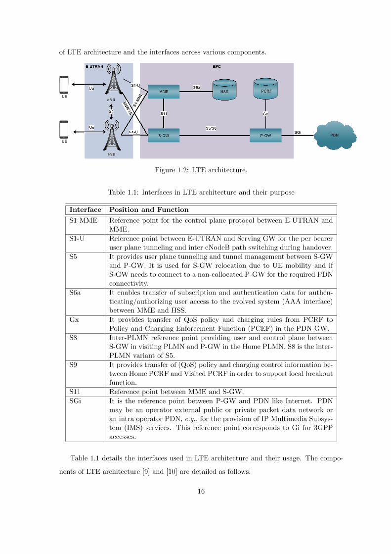
of LTE architecture and the interfaces across various components.
S1-U SGi
UE
PDN
S1-U
UE
S1-MME
Figure 1.2: LTE architecture.
Table 1.1: Interfaces in LTE architecture and their purpose
Interface Position and Function
S1-MME Reference point for the control plane protocol between E-UTRAN andMME.
S1-U Reference point between E-UTRAN and Serving GW for the per beareruser plane tunneling and inter eNodeB path switching during handover.
S5 It provides user plane tunneling and tunnel management between S-GWand P-GW. It is used for S-GW relocation due to UE mobility and ifS-GW needs to connect to a non-collocated P-GW for the required PDNconnectivity.
S6a It enables transfer of subscription and authentication data for authen-ticating/authorizing user access to the evolved system (AAA interface)between MME and HSS.
Gx It provides transfer of QoS policy and charging rules from PCRF toPolicy and Charging Enforcement Function (PCEF) in the PDN GW.
S8 Inter-PLMN reference point providing user and control plane betweenS-GW in visiting PLMN and P-GW in the Home PLMN. S8 is the inter-PLMN variant of S5.
S9 It provides transfer of (QoS) policy and charging control information be-tween Home PCRF and Visited PCRF in order to support local breakoutfunction.
S11 Reference point between MME and S-GW.
SGi It is the reference point between P-GW and PDN like Internet. PDNmay be an operator external public or private packet data network oran intra operator PDN, e.g., for the provision of IP Multimedia Subsys-tem (IMS) services. This reference point corresponds to Gi for 3GPPaccesses.
Table 1.1 details the interfaces used in LTE architecture and their usage. The compo-
nents of LTE architecture [9] and [10] are detailed as follows:
16

1. Evolved Node-B: The eNB sends and receives radio transmissions to all the mobiles
(UEs) using the analog and digital signal processing functions of the LTE air interface.
It controls the low-level operation of UEs, by sending them signaling messages such
as broadcast messages (MIB - Master Information Block), control messages (SIBs
- System Information Blocks), synchronization signals (PSS, SSS i.e., Primary and
secondary synchronization signals), and handover commands. Each eNB connects
with the EPC by means of S1 interface and it can also be connected to nearby base
stations by X2 interface, which is mainly used for signaling and packet forwarding
during handover. The eNB supports the following functions: (1) Inter-cell radio
resource management, (2) Resource block control, (3) Radio admission control, (4)
eNB measurement and configuration, and (5) Dynamic resource allocation.
2. Serving Gateway: S-GW routes and forwards data packets to and from the UE.
A UE can get associated utmost with one S-GW. It acts as a mobility anchor point.
It plays a significant role during inter-eNodeB handovers. It acts as a local mobility
anchor (LMA) point for inter-eNodeB handover and assists the eNodeB reordering
function by sending one or more ”end marker” packets to the source eNodeB imme-
diately after switching the path. It also acts as a mobility anchor for inter-3GPP
mobility (terminating the S4 interface from a Serving GPRS Support Node (SGSN)
and relaying the traffic between 2G/3G system and a P-GW). It supports transport
level packet marking and allows accounting and QoS class indicator (QCI) granularity
for charging. Replicating of user traffic in the event of Lawful Interception is done at
S-GW. It allows reporting of user location information (ULI).
3. Packet Data Network Gateway: P-GW is the gateway which terminates SGi
interface towards PDN. P-GW does the following functions: (1) Per-user based packet
filtering (for e.g., deep packet inspection), (2) Lawful Interception, (3) UE IP address
allocation, (4) Transport level packet marking in the uplink and downlink, e.g., setting
the DiffServ Code Point, based on the QCI of the associated EPS bearer, (5) Uplink
and downlink service level charging, gating control, and rate enforcement, and (6)
Downlink rate enforcement based on the accumulated Maximum Bit Rate (MBRs)
of the aggregate of Service Data Flows (SDFs) with the same Guaranteed Bit Rate
(GBR) QCI (e.g., by rate policing/shaping).
17

4. Home Subscriber Server: HSS is the master database for all UEs. It is the entity
containing subscription-related information to support the network entities actually
handling calls/sessions. The HSS is responsible for holding the following user related
information: (1) User identification, numbering and addressing information, (2) User
security information, network access control information for authentication and autho-
rization, (3) User location information at the inter-system level, and (4) User profile
information. The HSS generates user security information for mutual authentication,
communication integrity check and ciphering.
5. Mobility Management Entity: MME is a control plane entity within EPC. It
supports the following functions: (1) Mobility Management, (2) Non-Access Stratum
(NAS) signalling and security, (3) Inter core network signalling for mobility between
3GPP access networks, (4) Tracking area list management, (5) P-GW and S-GW
selection, (6) SGSN selection for handovers to 2G or 3G access networks, (7) Roaming,
(8) Authentication, and (9) Bearer management functions including dedicated bearer
establishment.
6. Policy and Charging Rules Function: PCRF also known as policy server or
Policy Decision Function (PDF), is a component of EPC. It is responsible for enforcing
charging decisions at P-GW. The policy charging can be based on, (1) Volume-based
charging, (2) Time based charging, (3) Volume and time-based charging, or (4) Event-
based charging.
7. User Equipment: UE refers to the mobile terminal. UE attaches to eNB of LTE net-
work through a radio interface. UE sends Physical Random Access Channel (PRACH)
preamble to eNB to latch onto eNB and gets completely attached on successful com-
pletion of Radio Resource Control (RRC) procedures. On successful attachment, UE
gets an IP address, and a bearer is created from UE till P-GW. A bearer refers to a
path that user traffic (IP flows) uses when passing through an LTE network (between
UE and P-GW).
Protocol stack of LTE The protocol stacks of LTE networks are discussed here. LTE
eNB includes the following layers: (1) Radio Resource Control (RRC), (2) Packet Data
Convergence Protocol (PDCP), (3) Radio Link Control (RLC), (4) Medium Access Control
18

(MAC), and (5) Physical Layer (PHY). Figs. 1.3 and 1.4 show the control and data plane
operations at LTE eNB, UE, MME and layers involved in each operation. The detailed
functionalities of each layer are as follows:
RRC
PDCP
RLC
MAC
PHY
UE
RRC
PDCP
RLC
MAC
PHY
eNodeB
S1AP
SCTP
IP
MAC
Ethernet
S1AP
SCTP
IP
MAC
Ethernet
MME
Uu S1-MME
Ethernet
Figure 1.3: LTE protocol stack - Control plane.
PDCP
RLC
MAC
PHY
UE
PDCP
RLC
MAC
PHY
eNodeB
GTP-U
UDP
IP
MAC
Ethernet
GTP-U
UDP
IP
MAC
Ethernet
MME
Uu S1-U
Figure 1.4: LTE protocol stack - Data plane.
1. Radio Resource Control: RRC [11] is the key component in LTE protocol stack
which is responsible for allocating radio resources. The RRC protocol includes the
following main functions: (1) Broadcast of system information, (2) Transmission of in-
formation applicable for UEs in RRC IDLE, e.g., cell (re-)selection parameters, neigh-
bouring cell information and information applicable for UEs in RRC CONNECTED
e.g., common channel configuration information, (3) Paging, (4) Establishment, mod-
ification, suspension, resumption, release of RRC connection, including e.g., assign-
ment, modification of UE identity (C-RNTI), establishment, modification, release of
Signalling Radio Bearer (SRB) - SRB1, SRB2, and access class barring, (5) Initial
security activation i.e., initial configuration of AS integrity protection (SRBs) and AS
19
ciphering (SRBs, Data Radio Bearer - DRBs), (6) For RNs, configuration of Access
Stratum (AS) integrity protection for DRBs, (7) RRC connection mobility includ-
ing e.g., intra-frequency and inter-frequency handovers, associated security handling
i.e., key, algorithm change, specification of RRC context information transferred be-
tween UE and eNB, (8) Establishment, modification, release of Radio Bearers (RBs)
carrying user data (DRBs), (9) Radio configuration control including e.g., assign-
ment, modification of Automatic Repeat Request (ARQ) configuration, Hybrid ARQ
(HARQ) configuration, Discontinuous Reception (DRX) [12] configuration, and (10)
QoS control including assignment, modification of semi-persistent scheduling (SPS)
configuration information for DL and UL, assignment, modification of parameters for
UL rate control in the UE i.e., allocation of a priority and a prioritised bit rate (PBR)
for each RB.
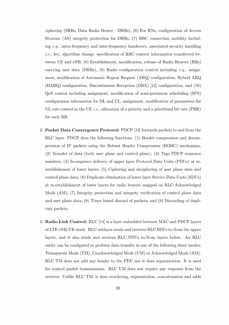
2. Packet Data Convergence Protocol: PDCP [13] forwards packets to and from the
RLC layer. PDCP does the following functions: (1) Header compression and decom-
pression of IP packets using the Robust Header Compression (ROHC) mechanism,
(2) Transfer of data (both user plane and control plane), (3) Tags PDCP sequence
numbers, (4) In-sequence delivery of upper layer Protocol Data Units (PDUs) at re-
establishment of lower layers, (5) Ciphering and deciphering of user plane data and
control plane data, (6) Duplicate elimination of lower layer Service Data Units (SDUs)
at re-establishment of lower layers for radio bearers mapped on RLC Acknowledged
Mode (AM), (7) Integrity protection and integrity verification of control plane data
and user plane data, (8) Timer based discard of packets, and (9) Discarding of dupli-
cate packets.
3. Radio Link Control: RLC [14] is a layer embedded between MAC and PDCP layers
of LTE eNB/UE stack. RLC sublayer sends and receives RLC SDUs to/from the upper
layers, and it also sends and receives RLC PDUs to/from layers below. An RLC
entity can be configured to perform data transfer in one of the following three modes:
Transparent Mode (TM), Unacknowledged Mode (UM) or Acknowledged Mode (AM).
RLC TM does not add any header to the PDU nor it does segmentation. It is used
for control packet transmissions. RLC UM does not require any response from the
receiver. Unlike RLC TM, it does reordering, segmentation, concatenation and adds
20
RLC header. RLC AM has all the features of RLC UM and it also does retransmission
of unacknowledged packets.
The RLC supports the following functions: (1) Transfer of upper layer PDUs, (2) Error
correction through ARQ (only for AM data transfer), (3) Concatenation, segmentation
and reassembly of RLC SDUs (only for UM and AM modes of data transfer), (4) Re-
segmentation of RLC data PDUs (only for AM mode data transfer), (5) Reordering
of RLC data PDUs (only for UM and AM modes of data transfer), (6) Duplicate
detection (only for UM and AM modes of data transfer), (7) RLC SDU discard (only
for UM and AM modes of data transfer), and (8) Protocol error detection (only for
AM mode data transfer).
4. Medium Access Control: MAC [15] layer lies in between RLC layer and physical
layer of LTE stack. MAC in LTE is scheduling based and does the following function-
alities: (1) Mapping between logical channels and transport channels, (2) Multiplexing
of MAC SDUs from one or different logical channels onto transport blocks (TB) to
be delivered to the physical layer on transport channels, (3) Demultiplexing of MAC
SDUs from one or different logical channels from transport blocks (TB) delivered
from the physical layer on transport channels, (4) Scheduling information reporting,
(5) Error correction through HARQ, (6) Priority handling between UEs by means
of dynamic scheduling, (7) Priority handling between logical channels of each MAC
entity, and (8) Logical channel prioritisation.
0 1 2 3 10 11 19
1 Frame = 10 Subframes = 10ms
1 Subframe
1 Slot = 0.5ms
0 1 2 3 4 5 6
7 OFDM Symbols
0 1 2 3 4 5 6
Cyclic Prefixes
Figure 1.5: LTE frame structure.
5. Physical Layer: PHY [16] of LTE supports Time division duplex (TDD) and Fre-
21

quency division duplex (FDD) modes of operation. FDD is the widely used mode
of operation. In FDD, LTE uplink and downlink are separated by a frequency off-
set specified by [17]. In this section, we discuss LTE multiplexing, frame structure,
modulation, and channels. LTE delivers higher data rate compared to 3G due to
the following features: (1) Orthogonal Frequency Division Multiplexing (OFDM), (2)
Support for wider bandwidth (carrier aggregation), and (3) Multiple Input Multiple
Output (MIMO).
Downlink Multiplexing: LTE uses Orthogonal Frequency Division Multiplexing
(OFDM), which employs multiple subcarriers spaced orthogonal to each other in the
frequency domain. Here, orthogonality means the cross-talks of the adjacent sub-
carrier is nil, and no guard band is required between subcarriers. The advantage of
subcarrier transmission over single carrier transmission is that the symbol duration
of each subcarrier is elongated which in turn reduces inter-symbol interference (ISI).
Whereas, in case of single carrier transmission the symbol duration is very small hence
ISI could be higher.
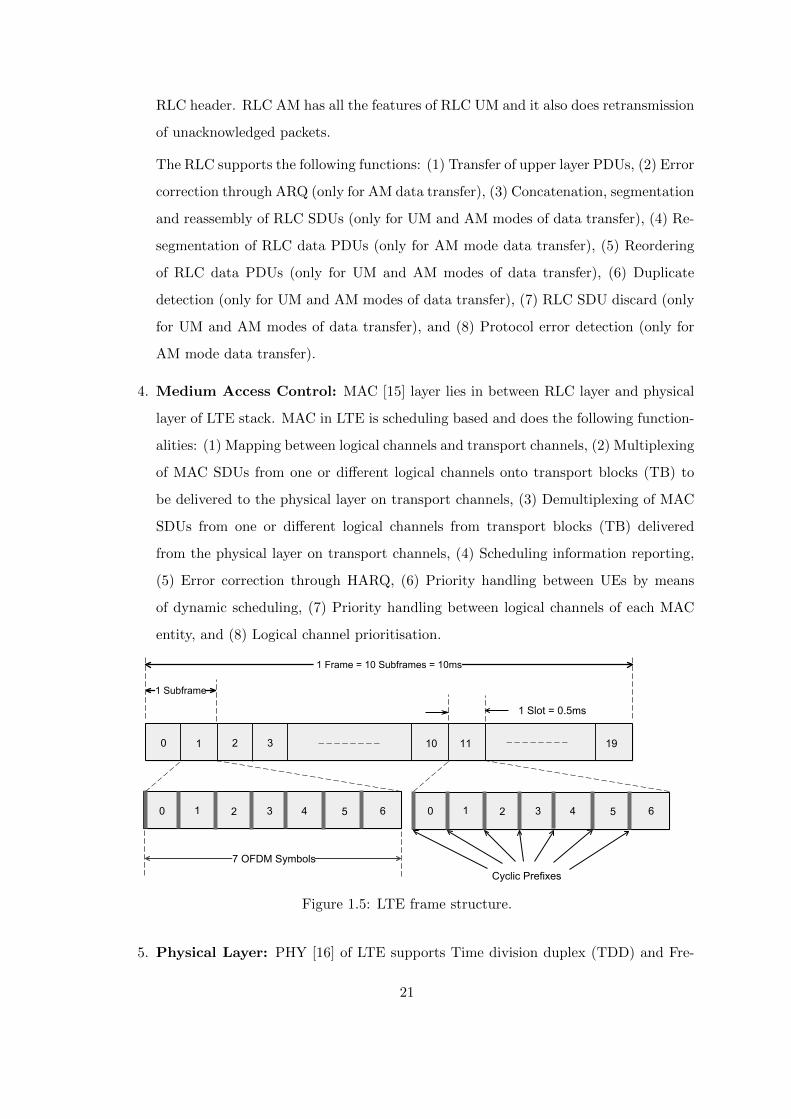
Frame Structure: Fig. 1.5 shows the LTE frame structure [18]. LTE transmission
is segmented into frames, and each frame is of duration 10 ms. Each frame is further
divided into 10 subframes. Each subframe prolongs for one millisecond duration. Each
subframe comprises of a pair of resource blocks (RB) in frequency domain, and the
number of such resource block pairs is determined by bandwidth. A resource block is
the smallest unit in the LTE structure. RB has 12 subcarriers in the frequency domain
and 7 symbols in the time domain, which corresponds to 0.5 ms. Each subcarrier is
separated by 15 KHz, therefore in a RB there are 12 (subcarriers) x 7 (symbols) = 84
(symbols) in normal cyclic prefix. The purpose of the cyclic prefix is to ensure that
two symbols transmitted in the same subcarrier should not overlap in time domain
due to multipath reception. Table 1.2 provides the OFDM modulation parameters in
downlink for different bandwidths.
LTE supports higher order modulation (up to 64 QAM), large bandwidths (up to 20
MHz), and spatial multiplexing in the downlink (up to 4x4 MIMO). The theoretical
peak data rate on the transport channel in uplink can reach up to 75 Mbps, and in
the downlink, using spatial multiplexing, the rate can reach up to 300 Mbps.
22

Table 1.2: Downlink OFDM modulation parameters of LTE
Supportedbandwidth
1.25 MHz 2.5 MHz 5 MHz 10 MHz 15 MHz 20 MHz
Sub-frameduration
0.5 ms 0.5 ms 0.5 ms 0.5 ms 0.5 ms 0.5 ms
Subcarrierspacing
15 KHz 15 KHz 15 KHz 15 KHz 15 KHz 15 KHz
Samplingfrequency
192 MHz 3.84 MHz 7.68 MHz 15.36 MHz 23.04 MHz 30.72 MHz
FFT size 128 256 512 1024 1536 2048
OFDM sym-bol per slot(short/ longCP)
7/6 7/6 7/6 7/6 7/6 7/6
CP Long(usec/ sam-ples)
(16.67/32) (16.67/64) (16.67/128) (16.67/256) (16.67/384) (16.67/512)
1.1.2 Overview of Wi-Fi networks
IEEE 802.11 also known as Wireless Fidelity (Wi-Fi) is the most popular Wireless Local
Area Network (WLAN) [19] technology for short-range communications. It appears to
higher layers as a wired Ethernet (IEEE 802.3). The fundamental building block of 802.11
architecture is known as a Basic Service Set (BSS). A BSS typically contains one or more
wireless stations and a base station also known as Access Point (AP). Multiple APs may
be connected together to form a distributed system. Fig. 1.6 shows the BSS and Extended
Service Set (ESS). IEEE 802.11 stations can also group themselves together to form an
ad-hoc network. Fig. 1.7 shows different layers of Wi-Fi radio protocol stack, namely
(1) Logical Link Control (LLC), (2) Medium Access Control (MAC), and (3) Physical
Layer (PHY). A brief description of these layers is given below.
1. Logical Link Control: LLC layer is the upper sub-layer of the Data Link layer.
It provides multiplexing mechanisms that make it possible for several network pro-
tocols (IP, IPX) to coexist within a multipoint network and to be transported over
the same network media, and can also provide flow control mechanisms. The LLC
sub-layer acts as an interface between the MAC sublayer and the network layer. The
LLC multiplexing interface includes the following network protocol features: (1) Mul-
tipoint network operation, (2) Unified network media exchange, (3) Flow control, (4)
Line protocol identification, like Synchronous Data Link Control (SDLC), (5) Frame
23

Extended Service Set (ESS)
Figure 1.6: Wi-Fi architecture.
sequence number assignment, and (6) Acknowledgement tracking.
2. Medium Access Control: MAC in Wi-Fi follows carrier sense multiple access with
collision avoidance (CSMA/CA) protocol. CSMA/CA enforces that AP or wireless
station transmit after sensing the channel as idle i.e., listen-before-talk. Unlike IEEE
802.3 standard where collisions can be detected by employing CSMA/CD, Wi-Fi can-
not detect collisions on the channel. Hence, it tries to avoid collisions by employing
one of the following methodologies for channel access: (1) Distributed Coordination
Function (DCF) [20], (2) Point Coordination Function (PCF) [20], and (3) Hybrid
Coordination Function (HCF) [21].
Distributed Coordination Function: In DCF, collisions are predominantly avoided
by obeying to a backoff based transmission. Every station backs off for a random num-
ber of slots. A slot here refers to a fixed time unit. Each station observes the channel
for the chosen backoff time. If the channel gets busy before the backoff time of the
station expires, then the station freezes its backoff time and waits for the channel
to become idle. A station/AP, on observing the channel to be idle for the chosen
backoff time, goes for transmitting a frame. If the frame is delivered successfully to
the intended receiver then the station/AP gets an acknowledgement. If the frame
transmitted is lost (due to collision or channel error), then the station/AP doubles
the contention window from which a random backoff is chosen.
Point Coordination Function: In PCF, the AP coordinates transmissions for all
stations in the network. Thereby PCF mode ensures a contention free delivery of
24
frames and hence significantly reduces collisions. According to PCF, a station can
transmit only when it receives CF-Poll frame from AP and the station is PCF capable.
If AP polls a station and it does not have any frames to send, then it must transmit
a null frame. Due to the priority of PCF over DCF, stations that only use DCF
might not gain access to the medium. To prevent this, a repetition interval has been
designed which includes both PCF (Contention free) & DCF (Contention Based)
modes of operation.
Logical Link Control
Point Coordination Function (PCF)
Distributed Coordination Function (DCF)
2.4 GHz
5 GHz
OFDM
20, 40 MHz
15, 30, 45,
...480, 540,
600 Mbps
Contention-free
serviceContention
service
MA
C L
ayer
PH
Y L
ayer
IEEE 802.11 IEEE 802.11 a IEEE 802.11 b IEEE 802.11 g IEEE 802.11 n IEEE 802.11 ac
Figure 1.7: Wi-Fi protocol stack.
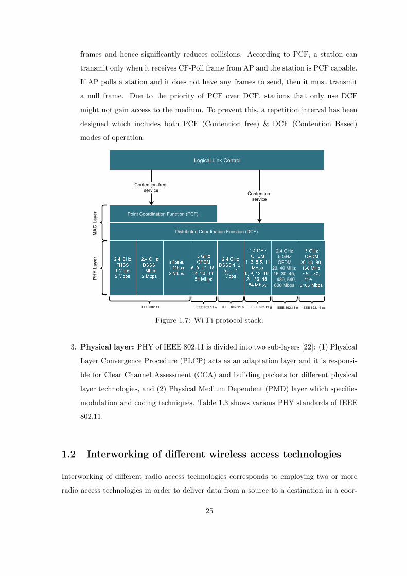
3. Physical layer: PHY of IEEE 802.11 is divided into two sub-layers [22]: (1) Physical
Layer Convergence Procedure (PLCP) acts as an adaptation layer and it is responsi-
ble for Clear Channel Assessment (CCA) and building packets for different physical
layer technologies, and (2) Physical Medium Dependent (PMD) layer which specifies
modulation and coding techniques. Table 1.3 shows various PHY standards of IEEE
802.11.
1.2 Interworking of different wireless access technologies
Interworking of different radio access technologies corresponds to employing two or more
radio access technologies in order to deliver data from a source to a destination in a coor-
25
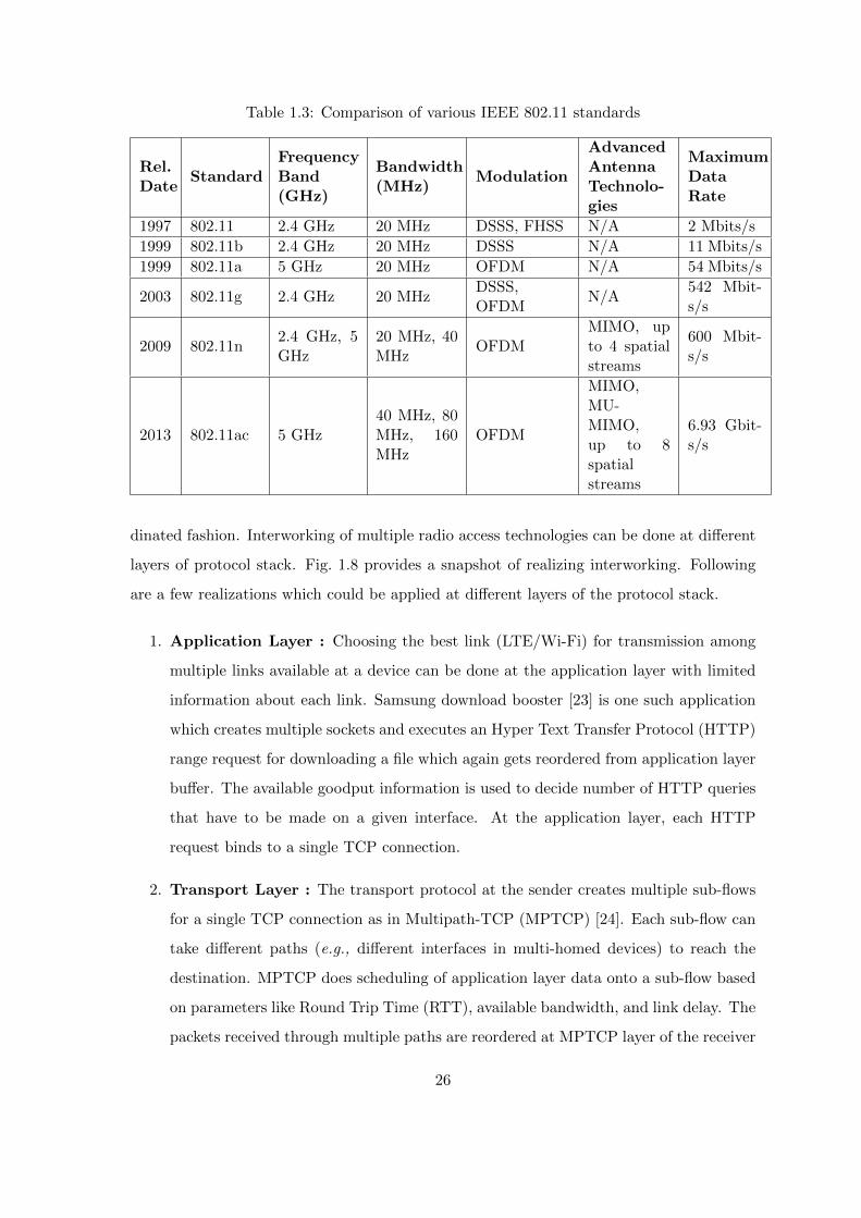
Table 1.3: Comparison of various IEEE 802.11 standards
Rel.Date
StandardFrequencyBand(GHz)
Bandwidth(MHz)
Modulation
AdvancedAntennaTechnolo-gies
MaximumDataRate
1997 802.11 2.4 GHz 20 MHz DSSS, FHSS N/A 2 Mbits/s
1999 802.11b 2.4 GHz 20 MHz DSSS N/A 11 Mbits/s
1999 802.11a 5 GHz 20 MHz OFDM N/A 54 Mbits/s
2003 802.11g 2.4 GHz 20 MHzDSSS,OFDM
N/A542 Mbit-s/s
2009 802.11n2.4 GHz, 5GHz
20 MHz, 40MHz
OFDMMIMO, upto 4 spatialstreams
600 Mbit-s/s
2013 802.11ac 5 GHz40 MHz, 80MHz, 160MHz
OFDM
MIMO,MU-MIMO,up to 8spatialstreams
6.93 Gbit-s/s
dinated fashion. Interworking of multiple radio access technologies can be done at different
layers of protocol stack. Fig. 1.8 provides a snapshot of realizing interworking. Following
are a few realizations which could be applied at different layers of the protocol stack.
1. Application Layer : Choosing the best link (LTE/Wi-Fi) for transmission among
multiple links available at a device can be done at the application layer with limited
information about each link. Samsung download booster [23] is one such application
which creates multiple sockets and executes an Hyper Text Transfer Protocol (HTTP)
range request for downloading a file which again gets reordered from application layer
buffer. The available goodput information is used to decide number of HTTP queries
that have to be made on a given interface. At the application layer, each HTTP
request binds to a single TCP connection.
2. Transport Layer : The transport protocol at the sender creates multiple sub-flows
for a single TCP connection as in Multipath-TCP (MPTCP) [24]. Each sub-flow can
take different paths (e.g., different interfaces in multi-homed devices) to reach the
destination. MPTCP does scheduling of application layer data onto a sub-flow based
on parameters like Round Trip Time (RTT), available bandwidth, and link delay. The
packets received through multiple paths are reordered at MPTCP layer of the receiver
26

and delivered to the receiver’s application layer.
Application Layer
Protocol Stack Optimization
Intelligence is required to send the traffic
over multiple interfaces based on metrics
such as RTT and bandwidth
Medium access techniques can be enhanced,
when one link regulates and coordinates
medium access of the other link
Application should be intelligent to open
multiple sockets on different IP addresses
and reorder the data at application layer
Traffic offload algorithms based on
network state can be implemented for
effective utilization of multiple links
Replace your text here! Replace your text here! Replace your
text here!
Replace your text here! Replace your text here! Replace your
text here!
Your Text
Figure 1.8: Optimizations at different layers of protocol stack for interworking.
3. Network Layer : Interworking of multiple radio access technologies at IP layer can
be realized by introducing a fine granularity of traffic offloading across different RATs.
The decision is taken based on the collective information obtained from all the RATs.
A quick decision is taken and the offloading is done, and the decision contrived is
independent of the above layers. To yield a compelling performance, an intelligent
traffic offloading algorithm is vital at this layer. IP Flow Mobility and Seamless
Offload is an example which employs Dual Stack Mobile IPv6 (DSMIPv6) [25] to use
two networks simultaneously.
4. MAC Layer : MAC layer aggregates multiple RATs by employing fine co-ordination
and enhanced regulation of traffic offloading across different RATs. Integration at
MAC level has more control in taking a decision compared to realizing integration at
higher layers.
1.3 Evolution of Cellular Wi-Fi Interworking
3GPP defined various LTE and Wi-Fi interworking architectures from Rel-8. The user
mobility with IP address preservation for all the traffic from 3GPP access to non-3GPP
27
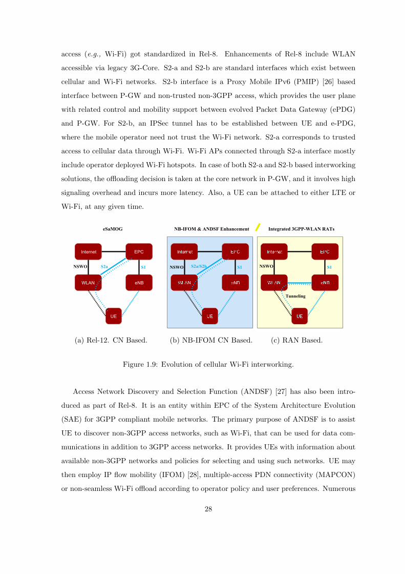
access (e.g., Wi-Fi) got standardized in Rel-8. Enhancements of Rel-8 include WLAN
accessible via legacy 3G-Core. S2-a and S2-b are standard interfaces which exist between
cellular and Wi-Fi networks. S2-b interface is a Proxy Mobile IPv6 (PMIP) [26] based
interface between P-GW and non-trusted non-3GPP access, which provides the user plane
with related control and mobility support between evolved Packet Data Gateway (ePDG)
and P-GW. For S2-b, an IPSec tunnel has to be established between UE and e-PDG,
where the mobile operator need not trust the Wi-Fi network. S2-a corresponds to trusted
access to cellular data through Wi-Fi. Wi-Fi APs connected through S2-a interface mostly
include operator deployed Wi-Fi hotspots. In case of both S2-a and S2-b based interworking
solutions, the offloading decision is taken at the core network in P-GW, and it involves high
signaling overhead and incurs more latency. Also, a UE can be attached to either LTE or
Wi-Fi, at any given time.
Internet EPC
WLAN eNB
UE
NSWO S2a S1 S2a/S2b S1 S1NSWO NSWO
Tunneling
eSaMOG NB-IFOM & ANDSF Enhancement Integrated 3GPP-WLAN RATs
(a) Rel-12. CN Based. (b) NB-IFOM CN Based. (c) RAN Based.
Figure 1.9: Evolution of cellular Wi-Fi interworking.
Access Network Discovery and Selection Function (ANDSF) [27] has also been intro-
duced as part of Rel-8. It is an entity within EPC of the System Architecture Evolution
(SAE) for 3GPP compliant mobile networks. The primary purpose of ANDSF is to assist
UE to discover non-3GPP access networks, such as Wi-Fi, that can be used for data com-
munications in addition to 3GPP access networks. It provides UEs with information about
available non-3GPP networks and policies for selecting and using such networks. UE may
then employ IP flow mobility (IFOM) [28], multiple-access PDN connectivity (MAPCON)
or non-seamless Wi-Fi offload according to operator policy and user preferences. Numerous
28

works have been done on offloading LTE traffic to Wi-Fi and vice-versa [29], [30].
Access Network Discovery and Selection Function enhancements (eANDSF) has been
proposed in Rel-9 which includes cellular network information, device mobility state, and
further deals for intelligent network selection and traffic steering. The 3GPP Rel-10 specifies
a variety of deployment scenarios and it allows a universal network connection irrespective
of whether it is based on GPRS Tunnelling Protocol (GTP) [31] or PMIP with the help of
UE support. In Rel-11, SaMOG-I [32] i.e., S2-a mobility over GTP has been introduced
which has an S2-a interface using GTP via trusted WLAN. Fig. 1.9(a) shows core network
based enhanced SaMOG architecture. Location-based selection of gateways for WLAN
has also been discussed in this release. In Rel-12, multiple IP connectivities via trusted
WLAN using GTP, and IP flow mobility have been introduced. Fig. 1.9(b) shows the Rel-
12 architecture with involves Network Based IP Flow Mobility (NB-IFOM) [33]. In Rel-12
and Rel-13, Radio Level Integration (RLI) of LTE and Wi-Fi is introduced, which enhances
the interworking capability between LTE and Wi-Fi. Fig. 1.9(c) shows the evolved radio
level integration architecture. All the architectures shown in Fig. 1.9 support Non-Seamless
WLAN Offload (NSWO). 3GPP has defined NSWO as the ability for a device to send traffic
directly to the Wi-Fi access network. In Rel-14, the RLI architectures are further enhanced
to support uplink aggregation, mobility and enable Wi-Fi interworking for high frequency
bands (60 GHz). RLI architectures introduced by 3GPP include:
1. LTE Wi-Fi Radio Level Integration with IPSec tunnel (LWIP)
2. LTE Wi-Fi Aggregation (LWA)
In RLI architecture, a node which logically comprises of LTE small cell and Wi-Fi AP is
called as RLI node. Details of these architectures will be discussed in Chapter 2.
1.4 Objectives and scope of the thesis
In this thesis, LTE Wi-Fi Integration architectures are investigated in which LTE small cell
eNodeB (SeNB) and Wi-Fi AP are tightly coupled at RAN level, as shown in Fig. 1.9(c).
The scope of this thesis includes:
1. Addressing challenges which persist with radio level interworking architectures.
29

Chapters 3, 5
Chapter 2
LTE Wi-Fi Radio Level Integration
Downlink
Steering
DOUTA
PRECISE
VISIBLE
Architectures
LWIR
LWIP
Chapter 4
Uplink
Steering
FUND++
DOUTA
FUND
E-UNWRAP
Chapter 6
Placement
OPT-LWIP
Min-NC-LWIP
Min-C-LWIP
OPT-LWIP-
Energy
OPT-LWIP-UE
Energy
Chapter 7
Prototypes
LWA
LTE
LWIP
MLWA
Figure 1.10: Organization of the thesis.
2. Efficient downlink steering solutions to enable faster steering of packets/flows across
LTE and Wi-Fi networks in LWIP architecture.
3. Novel uplink steering solutions to enhance the performance of uplink traffic and also
to improve the throughput of legacy users in the system.
4. Develop solution to address out-of-order packet delivery problem introduced by LWIP
architecture in case of packet level steering. The solution targets to improve the perfor-
mance of Transmission Control Protocol (TCP) by introducing intelligent operations
at the link layer of RLI node.
5. Optimal placement of LWIP nodes in order to enhance capacity and coverage, and
also to improve the energy savings at RLI nodes and UEs.
6. Design and develop prototype testbed for RLI architectures and study the aggregation
benefits.
1.5 Organization of the thesis
In this chapter, introduction and background required to understand the work done in
thesis were given and the contributions of the thesis were highlighted. Rest of the thesis
is organized as follows, refer Fig. 1.10. In Chapter 2, various RLI architectures and their
30

features are presented. And the challenges associated with different RLI architectures are be
enumerated. This chapter also introduces link aggregation strategies in RLI architectures.
The proposed link aggregation strategies are evaluated through simulation experiments.
Chapter 3 explains the necessity for efficient downlink traffic steering in LWIP architec-
ture. A downlink traffic steering solution has been proposed, Power-Aware Dynamic Traffic
Steering (PRECISE). The performance of the proposed steering solution is examined from
the perspective of Quality of Service (QoS) improvement and energy efficiency.
Chapter 4 presents the stringent requirements for uplink traffic steering solution in LWIP
architecture. Network Coordination Function (NCF) is proposed to address the challenges
in uplink traffic steering. NCF comprises of different uplink steering algorithm targeted to
improve the network throughput by optimizing the uplink traffic steering ratio across LTE
and Wi-Fi links. It also minimizes the number of collisions on the Wi-Fi channel. NCF is
evaluated under different scenarios to observe its benefits.
Chapter 5 describes one of the problems with LWIP architecture, which is out-of-order
(OOO) delivery of packets at the destination due to link diversity. The OOO delivery
hinders Transmission Control Protocol (TCP) growth significantly. A solution is proposed
to overcome this challenge, ”Virtual Congestion Control with Boost ACKs for Packet Level
Steering in LWIP Networks” (VISIBLE). Performance of the proposed solution is measured
and compared with state-of-the-art solutions.
In Chapter 6, placement of LWIP nodes is discussed and problems such as (1) Minimum
number of RLI nodes required in a region to ensure QoS guarantees, (2) Optimal transmit
power settings at RLI nodes to enhance capacity and coverage, and (3) Energy efficient
placement of these RLI nodes are addressed.
In Chapter 7, prototypes for RLI architectures were developed. The performance of
different RLI architectures has been profiled. Also the co-operation between RLI architec-
tures and multipath transport layer architecture is studied. Finally, Chapter 8 concludes
the various works done on RLI architectures in this thesis and discusses some possible future
extensions.
31

Chapter 2
Radio level integration
architectures
In this chapter, Radio Level Integration (RLI) architectures and their advantages over tradi-
tional LTE Wi-Fi interworking architectures are discussed. Also, the challenges associated
with RLI architectures and potential solutions to improvise their benefits are also detailed.
2.1 Introduction to RLI architectures
Integrating different radio access technologies such as LTE and Wi-Fi at their radio protocol
stacks is referred to as radio level integration. Such radio level integration [34], [35] can be
realized at IP, PDCP, RLC, or MAC layers. 3GPP developed specifications for realizing the
integration at IP layer and PDCP layer. 3GPP has coined the terms LTE Wi-Fi Aggregation
(LWA) and LTE Wi-Fi interworking with IPSec tunnel (LWIP) for realizing integration at
PDCP and IP, respectively. These architectures have enhanced capabilities compared to
realizing interworking at the higher layers (Transport layer or Application layer). The radio
level interworking architectures enables decision making functionality at layer 2 [36]. RLI
architectures could be realized in two ways: (1) Colocated RLI and (2) Non-colocated RLI.
In colocated RLI, SeNB and Wi-Fi AP are located in the same device and tightly integrated
at RAN level in an RLI node, whereas in the latter case, Wi-Fi AP and SeNB are connected
via a standardized interface referred as Xw. Figs. 2.1 and 2.2 show the generic colocated
and non-colocated RLI architectures, respectively.
RLI architectures have the following merits over traditional LTE Wi-Fi interworking
32
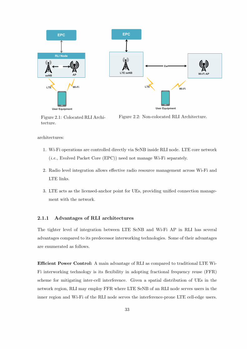
EPC
seNB AP
RLI Node
User Equipment
LTE Wi-Fi
Figure 2.1: Colocated RLI Archi-tecture.
EPC
LTE seNB Wi-Fi AP
Xw
User Equipment
LTE Wi-Fi
Figure 2.2: Non-colocated RLI Architecture.
architectures:
1. Wi-Fi operations are controlled directly via SeNB inside RLI node. LTE core network
(i.e., Evolved Packet Core (EPC)) need not manage Wi-Fi separately.
2. Radio level integration allows effective radio resource management across Wi-Fi and
LTE links.
3. LTE acts as the licensed-anchor point for UEs, providing unified connection manage-
ment with the network.
2.1.1 Advantages of RLI architectures
The tighter level of integration between LTE SeNB and Wi-Fi AP in RLI has several
advantages compared to its predecessor interworking technologies. Some of their advantages
are enumerated as follows.
Efficient Power Control: A main advantage of RLI as compared to traditional LTE Wi-
Fi interworking technology is its flexibility in adopting fractional frequency reuse (FFR)
scheme for mitigating inter-cell interference. Given a spatial distribution of UEs in the
network region, RLI may employ FFR where LTE SeNB of an RLI node serves users in the
inner region and Wi-Fi of the RLI node serves the interference-prone LTE cell-edge users.
33

Figure 2.3: Diversification in the region of association with different RATsusing RLI architectures.
In case of dense urban scenarios, RLI nodes are vital for mitigating the interference among
neighbour RLI nodes by assigning non-overlapping LTE and Wi-Fi bands appropriately
as shown in Fig. 2.3. The coverage regions of RLI nodes shown in Fig. 2.3 are spatially
marked distinctly as regions R1 and R2. The users residing in R1 will be served using LTE
interface of RLI node. Similarly, the users residing in region R2 could be served potentially
using Wi-Fi interface in order to mitigate the inter-cell interference. This is possible due to
unified control plane signaling between LTE SeNB and Wi-Fi AP in RLI node. If the region
R2 suffers interference from the adjacent Wi-Fi APs, then the APs with common channel
will be set dynamically to operate on orthogonal channels. The mechanism prevents two
R1 regions to fall adjacent, because LTE which is captured in R1 works with reuse factor
one. In simple words, LTE has limited bandwidth, whereas Wi-Fi operating in unlicensed
band has many orthogonal channel to choose from.
In case of traditional LTE Wi-Fi interworking techniques, the interference mitigation
could not be achieved effectively because LTE and Wi-Fi radios are uncoordinated and also
placed at geographically different locations (spatially separated). Hence, traditional LTE
Wi-Fi interworking techniques do not employ FFR effectively. They are limited to support
offloading of data plane traffic from LTE to Wi-Fi.
Enhanced Security: Traditional LTE Wi-Fi interworking techniques (s2a/s2b) employ
tunnels from LTE network to Wi-Fi network. It involves encryption of packets at IP layer
34
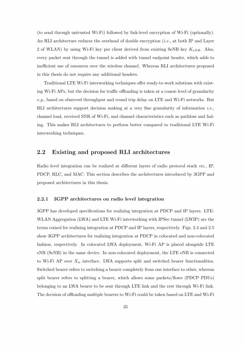
(to send through untrusted Wi-Fi) followed by link-level encryption of Wi-Fi (optionally).
An RLI architecture reduces the overhead of double encryption (i.e., at both IP and Layer
2 of WLAN) by using Wi-Fi key per client derived from existing SeNB key KeNB. Also,
every packet sent through the tunnel is added with tunnel endpoint header, which adds to
inefficient use of resources over the wireless channel. Whereas RLI architectures proposed
in this thesis do not require any additional headers.
Traditional LTE Wi-Fi interworking techniques offer ready-to-work solutions with exist-
ing Wi-Fi APs, but the decision for traffic offloading is taken at a coarse level of granularity
e.g., based on observed throughput and round trip delay on LTE and Wi-Fi networks. But
RLI architectures support decision making at a very fine granularity of information i.e.,
channel load, received SNR of Wi-Fi, and channel characteristics such as pathloss and fad-
ing. This makes RLI architectures to perform better compared to traditional LTE Wi-Fi
interworking techniques.
2.2 Existing and proposed RLI architectures
Radio level integration can be realized at different layers of radio protocol stack viz., IP,
PDCP, RLC, and MAC. This section describes the architectures introduced by 3GPP and
proposed architectures in this thesis.
2.2.1 3GPP architectures on radio level integration
3GPP has developed specifications for realizing integration at PDCP and IP layers. LTE-
WLAN Aggregation (LWA) and LTE Wi-Fi interworking with IPSec tunnel (LWIP) are the
terms coined for realizing integration at PDCP and IP layers, respectively. Figs. 2.4 and 2.5
show 3GPP architectures for realizing integration at PDCP in colocated and non-colocated
fashion, respectively. In colocated LWA deployment, Wi-Fi AP is placed alongside LTE
eNB (SeNB) in the same device. In non-colocated deployment, the LTE eNB is connected
to Wi-Fi AP over Xw interface. LWA supports split and switched bearer functionalities.
Switched bearer refers to switching a bearer completely from one interface to other, whereas
split bearer refers to splitting a bearer, which allows some packets/flows (PDCP PDUs)
belonging to an LWA bearer to be sent through LTE link and the rest through Wi-Fi link.
The decision of offloading multiple bearers to Wi-Fi could be taken based on LTE and Wi-Fi
35
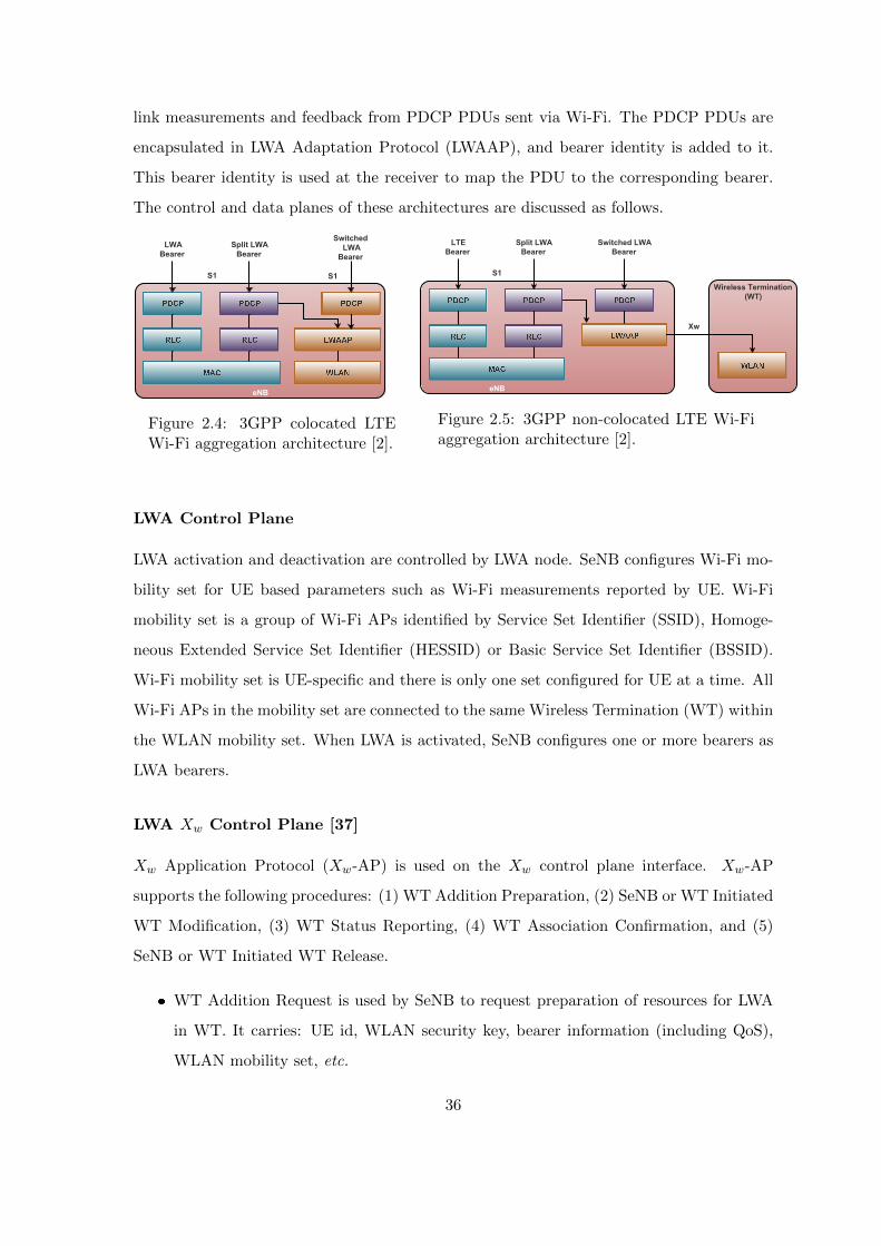
link measurements and feedback from PDCP PDUs sent via Wi-Fi. The PDCP PDUs are
encapsulated in LWA Adaptation Protocol (LWAAP), and bearer identity is added to it.
This bearer identity is used at the receiver to map the PDU to the corresponding bearer.
The control and data planes of these architectures are discussed as follows.
eNB
S1 S1
LWA
Bearer
Split LWA
Bearer
Switched
LWA
Bearer
Figure 2.4: 3GPP colocated LTEWi-Fi aggregation architecture [2].
Wireless Termination
(WT)
eNB
S1
Xw
LTE
Bearer
Split LWA
Bearer
Switched LWA
Bearer
Figure 2.5: 3GPP non-colocated LTE Wi-Fiaggregation architecture [2].
LWA Control Plane
LWA activation and deactivation are controlled by LWA node. SeNB configures Wi-Fi mo-
bility set for UE based parameters such as Wi-Fi measurements reported by UE. Wi-Fi
mobility set is a group of Wi-Fi APs identified by Service Set Identifier (SSID), Homoge-
neous Extended Service Set Identifier (HESSID) or Basic Service Set Identifier (BSSID).
Wi-Fi mobility set is UE-specific and there is only one set configured for UE at a time. All
Wi-Fi APs in the mobility set are connected to the same Wireless Termination (WT) within
the WLAN mobility set. When LWA is activated, SeNB configures one or more bearers as
LWA bearers.
LWA Xw Control Plane [37]
Xw Application Protocol (Xw-AP) is used on the Xw control plane interface. Xw-AP
supports the following procedures: (1) WT Addition Preparation, (2) SeNB or WT Initiated
WT Modification, (3) WT Status Reporting, (4) WT Association Confirmation, and (5)
SeNB or WT Initiated WT Release.
WT Addition Request is used by SeNB to request preparation of resources for LWA
in WT. It carries: UE id, WLAN security key, bearer information (including QoS),
WLAN mobility set, etc.
36

WT Modification Request is used by SeNB to modify mobility set, security key or
bearers configured for LWA for a UE.
WT Status Report is used by WT to report WLAN measurements per BSS. It carries
BSSID, BSS load, WAN metrics, and channel utilization.
WT Association Confirmation is used by WT to indicate that a UE successfully con-
nected to WLAN.
LWA Wi-Fi Measurements
UE compatible with LWA operation shall support Wi-Fi measurement reporting. Mea-
surement configurations include SSIDs, Wi-Fi band, and frequency/channel. Measurement
reporting is triggered based on Received Signal Strength Indication (RSSI) threshold. Mea-
surement report contains: SSIDs, RSSI, STA count, backhaul rate, admission capacity,
channel utilization, etc. Wi-Fi measurement can trigger one of the following cases:
1. Event W1: A Wi-Fi AP becomes better than a threshold RSSI (T1).
2. Event W2: All Wi-Fi APs inside the Wi-Fi mobility set become worse than a threshold
RSSI (T1) and a Wi-Fi AP outside the Wi-Fi mobility set becomes better than a
threshold RSSI (T2).
3. Event W3: All Wi-Fi APs inside the Wi-Fi mobility set become worse than a threshold
RSSI (T1).
Wi-Fi measurement framework is common to LWA and LWIP. There are separate UE
capability indications for LWA, LWIP, and Wi-Fi measurements.
LWA Xw Dataplane [38]
Xw data plane uses GPRS Tunnelling Protocol for User Plane (GTP-U) on top of UDP
for data transfer between SeNB to WT. Downlink stream is used for data forwarding. The
uplink stream is used for feedback/flow control. Optional downlink data delivery status
procedure is used by WT to indicate its buffer status and lost PDUs to SeNB. Every PDU
is assigned an Xw-U sequence number.
37

WLAN
S1-MME
IPsec
TunneleNB
UE
RRC NASUser
Plane
User Plane
IP Packets
from DRB
S1-UE
Figure 2.6: 3GPP LTE Wi-Fi Integration with IPSec tunnel (LWIP) architecture.
LWA UE Feedback
LWA supports deployment with limited WLAN infrastructure impact. If WT does not
support feedback/flow control, SeNB may trigger status reporting from UE on air interface
(at PDCP layer) using either: (1) PDCP status report: First Missing PDCP Sequence
Number (SN), and bitmap of received PDCP SDUs or (2) LWA status report: First Missing
SN (FMS), Number of Missing PDUs (NMP), and Highest Received SN on WLAN (HRW).
Note that SeNB can also derive information about packets lost on LTE from RLC layer
since only RLC Acknowledged Mode (AM) is allowed for LWA. If configured by SeNB, UE
reports association confirmation on air interface (at RRC layer).
LWIP Data Plane
Fig. 2.6 shows the LWIP architecture introduced by 3GPP. LWIP supports both uplink and
downlink data transfer over Wi-Fi link. One or more bearers can be offloaded to WLAN via
IPSec. In the uplink, PDCP SDUs are encapsulated using Generic Routing Encapsulation
(GRE) protocol [39]. GRE key carries bearer identifier, hence bearer differentiation is not
needed in the downlink. LWIP does not support re-ordering, hence split bearer is not
38

recommended by 3GPP. Each DRB may be configured so that traffic for that bearer can
be routed over the IPSec tunnel in either only downlink or both uplink and downlink over
Wi-Fi.
LWIP Control Plane
Activation and deactivation of LWIP operation are controlled by SeNB. When LWIP is
activated, the following activities take place:
SeNB sends Wi-Fi mobility set, bearer information, and LWIP-SeGW IP address to
whom.
After WLAN association and Extensible Authentication Protocol (EAP/AKA) au-
thentication, UE establishes IPSec connection with LWIP-SeGW using Internet Key
Exchange (IKE).
IPSec keys are derived (by SeNB and UE) based on SeNB Key (KeNB).
LWIP re-uses same WLAN measurement reporting framework and WLAN mobility concept
of LWA.
2.2.2 Proposed RLI architectures
We have proposed various RLI architectures which are contemporary with 3GPP architec-
tures. The proposed integration architectures are slightly different from 3GPP architectures
in which the integration across LTE and Wi-Fi links has been realized by introducing a Link
Aggregation Layer (LAL). LAL is responsible for steering packets/flows/bytes across LTE
and Wi-Fi links in both downlink and uplink. Our proposed integration architectures in-
clude (i) LWIP, (ii) LWA, and (iii) LWIR. Fig. 2.7 captures all the proposed integration
architectures with LAL. In the following, we present each of the proposed RLI architectures
in detail.
LWIP-Proposed
As shown in Fig. 2.7(a), LWIP is realized by introducing a LAL in the protocol stack of
the LWIP node and LWIP-UE. LAL does not add any new header to the IP data packets
received from EPC via S1-U interface. Packets going through LTE and Wi-Fi interfaces
39
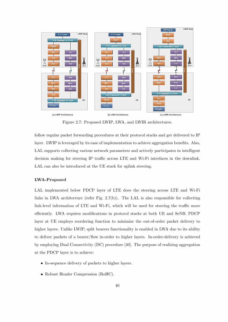
LWIP Node
Tu
nn
el
UE
SeNB Wi-Fi
LWA Node
Tu
nn
el
UE
SeNB Wi-Fi
LWIR Node
Tu
nn
el
UE
SeNB Wi-Fi
(a) LWIP Architecture (b) LWA Architecture (c) LWIR Architecture
Figure 2.7: Proposed LWIP, LWA, and LWIR architectures.
follow regular packet forwarding procedures at their protocol stacks and get delivered to IP
layer. LWIP is leveraged by its ease of implementation to achieve aggregation benefits. Also,
LAL supports collecting various network parameters and actively participates in intelligent
decision making for steering IP traffic across LTE and Wi-Fi interfaces in the downlink.
LAL can also be introduced at the UE stack for uplink steering.
LWA-Proposed
LAL implemented below PDCP layer of LTE does the steering across LTE and Wi-Fi
links in LWA architecture (refer Fig. 2.7(b)). The LAL is also responsible for collecting
link-level information of LTE and Wi-Fi, which will be used for steering the traffic more
efficiently. LWA requires modifications in protocol stacks at both UE and SeNB. PDCP
layer at UE employs reordering function to minimize the out-of-order packet delivery to
higher layers. Unlike LWIP, split bearers functionality is enabled in LWA due to its ability
to deliver packets of a bearer/flow in-order to higher layers. In-order-delivery is achieved
by employing Dual Connectivity (DC) procedure [40]. The purpose of realizing aggregation
at the PDCP layer is to achieve:
In-sequence delivery of packets to higher layers.
Robust Header Compression (RoHC).
40

Encryption of the packets sent through the Wi-Fi interface.
In-sequence delivery is required for aggregation because in case of split bearer at packet level
the out-of-order packets have to be reassembled and delivered to the higher layer in-order.
RoHC further enhances the aggregation capacity by compressing the IP header of packets
sent through the Wi-Fi interface. Encryption for data through Wi-Fi interface is provided
by legacy LTE encryption function at PDCP layer and this removes the need for additional
encryption at Wi-Fi interface.
LWIR-Proposed
LWIR architecture is shown in Fig. 2.7 (c). The traffic is steered from the RLC layer of
LTE SeNB protocol stack to Wi-Fi stack. In LTE radio protocol stack, based on resources
allocated by LTE MAC scheduler, the RLC layer does segmentation and reassembling of
PDCP payloads and creates RLC frames. These RLC frames are then forwarded to the
MAC layer of LTE. In order to perform traffic steering at LWIR node, a Virtual Wi-Fi
Scheduler (VWS) is introduced inside LAL. This VWS is above the Logical Link Control
(LLC) layer of Wi-Fi AP device at LWIR node and it takes data at the granularity of bytes
from RLC queue for sending over Wi-Fi link. VWS picks bytes from different RLC queues
based on their QoS requirements and the observed CQI of all the associated users.
Steering traffic from SeNB to Wi-Fi AP is realized by establishing a layer-2 tunnel
between the RLC layer of LTE protocol stack and the LLC layer of Wi-Fi protocol stack.
The Virtual Wi-Fi Scheduler (VWS) retrieves data from the RLC layer of the LTE stack
only when the Wi-Fi backoff is about to expire. This notification of Wi-Fi queue status and
monitoring the backoff counter value are done by VWS. The VWS periodically queries the
Wi-Fi driver to get these parameters and chooses one of the RLC queues from which data
has to be steered through Wi-Fi in the downlink. The VWS chooses an RLC queue based
on one of the following criteria:
1. Longest RLC buffer first : Bytes are taken out from the longest RLC buffer of a UE
for steering through Wi-Fi.
2. Highest CQI first : Bytes are taken out from the RLC buffer of the UE which is having
highest CQI among all UEs.
41
3. Longest RLC buffer with highest CQI : UE with longest RLC buffer is chosen. If
there is a tie among UEs with the longest RLC buffer, the tie is broken by choosing
the UE that is having highest CQI.
4. Longest RLC buffer with lowest CQI : UE with longest RLC buffer is chosen. If there
is a tie among UEs with the longest RLC buffer, the tie is broken by choosing the UE
that is having lowest CQI.
The LAL creates IP packets with destination IP corresponding to UE’s IP address. The
packet includes as its payload, the bytes taken from the RLC queue. The packet is tagged
with RLC header corresponding to the destination RLC queue. At the UE side, when the
packet is received at LLC layer, it forwards the packet to the IP layer. A listening socket on
the corresponding port which is denoted as Tunnel End Point (TEP) captures the packet.
The TEP deserializes the packet and reads the tagged value of RLC and forwards to the
corresponding RLC queue.
LWIR architecture supports high reliability for the packets sent through LTE and Wi-Fi
links. When a packet is lost in transmission over LTE or Wi-Fi link, RLC retransmission
procedure is invoked to retransmit the lost packet. One of the major problems in steering
traffic across multiple interfaces is the out-of-order delivery of packets, which arises due
to the long waiting time of packets on one interface compared to the other. The VWS
brings down the waiting time of packets in the Wi-Fi queue and thereby avoids out-of-order
delivery and improves the performance of TCP flows significantly.
In summary, the LWIR system has the following advantages:
Like in LWA and LWIP systems, LTE acts as the licensed anchor in LWIR system.
High flexibility is achieved by employing steering at the granularity of bytes i.e., a
fraction of PDCP payload could be sent through LTE link and the remaining through
Wi-Fi link based on their channel conditions.
High reliability in traffic steering, which is achieved by retransmission functionality of
RLC layer.
Reduced contention delay on Wi-Fi link, which is achieved by retrieving data from
RLC buffer only when the Wi-Fi queue is empty.
42
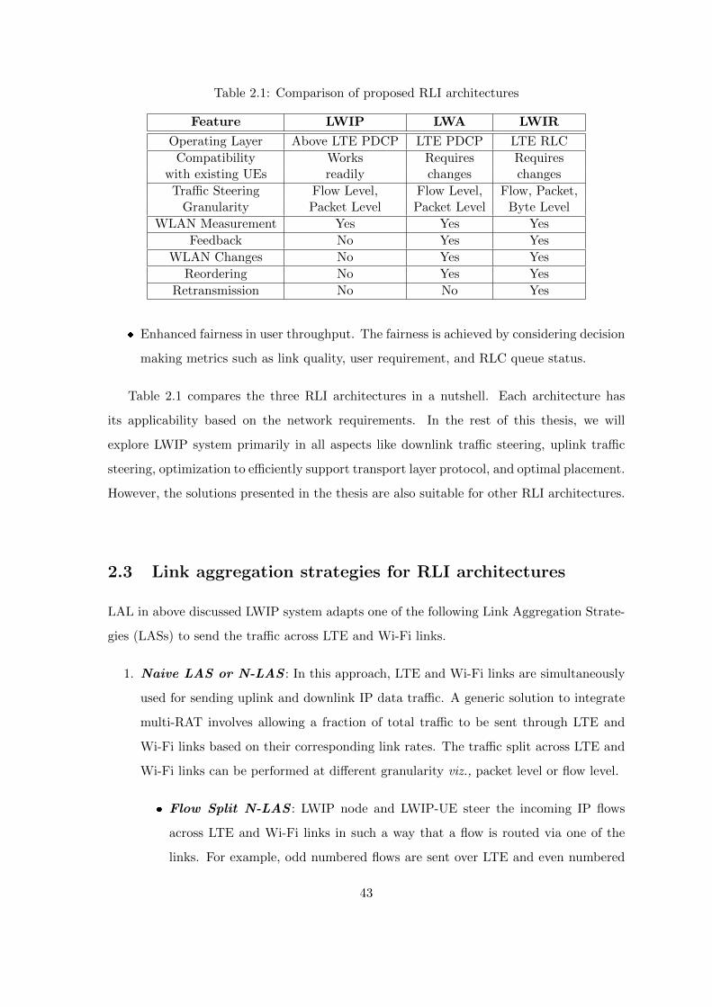
Table 2.1: Comparison of proposed RLI architectures
Feature LWIP LWA LWIR
Operating Layer Above LTE PDCP LTE PDCP LTE RLC
Compatibility Works Requires Requireswith existing UEs readily changes changes
Traffic Steering Flow Level, Flow Level, Flow, Packet,Granularity Packet Level Packet Level Byte Level
WLAN Measurement Yes Yes Yes
Feedback No Yes Yes
WLAN Changes No Yes Yes
Reordering No Yes Yes
Retransmission No No Yes
Enhanced fairness in user throughput. The fairness is achieved by considering decision
making metrics such as link quality, user requirement, and RLC queue status.
Table 2.1 compares the three RLI architectures in a nutshell. Each architecture has
its applicability based on the network requirements. In the rest of this thesis, we will
explore LWIP system primarily in all aspects like downlink traffic steering, uplink traffic
steering, optimization to efficiently support transport layer protocol, and optimal placement.
However, the solutions presented in the thesis are also suitable for other RLI architectures.
2.3 Link aggregation strategies for RLI architectures
LAL in above discussed LWIP system adapts one of the following Link Aggregation Strate-
gies (LASs) to send the traffic across LTE and Wi-Fi links.
1. Naive LAS or N-LAS : In this approach, LTE and Wi-Fi links are simultaneously
used for sending uplink and downlink IP data traffic. A generic solution to integrate
multi-RAT involves allowing a fraction of total traffic to be sent through LTE and
Wi-Fi links based on their corresponding link rates. The traffic split across LTE and
Wi-Fi links can be performed at different granularity viz., packet level or flow level.
Flow Split N-LAS : LWIP node and LWIP-UE steer the incoming IP flows
across LTE and Wi-Fi links in such a way that a flow is routed via one of the
links. For example, odd numbered flows are sent over LTE and even numbered
43
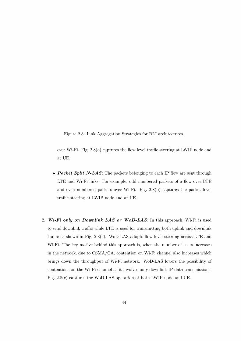
Remote Host
S-GW/P-GW
SeNB AP
Flo
w 1
Flo
w 2
Remote Host
S-GW/P-GW
SeNB AP
UE
P
1
P
3
P
2
P
4
P
6
P
5
(a) FS-N-LAS (b) PS-N-LAS
Remote Host
S-GW/P-GW
SeNB AP
UE
Flo
w 1
(c) WoD-LAS
Flo
w 2
Flow 2
Link Aggregation Layer
UE
Link Aggregation Layer
Figure 2.8: Link Aggregation Strategies for RLI architectures.
over Wi-Fi. Fig. 2.8(a) captures the flow level traffic steering at LWIP node and
at UE.
Packet Split N-LAS : The packets belonging to each IP flow are sent through
LTE and Wi-Fi links. For example, odd numbered packets of a flow over LTE
and even numbered packets over Wi-Fi. Fig. 2.8(b) captures the packet level
traffic steering at LWIP node and at UE.
2. Wi-Fi only on Downlink LAS or WoD-LAS : In this approach, Wi-Fi is used
to send downlink traffic while LTE is used for transmitting both uplink and downlink
traffic as shown in Fig. 2.8(c). WoD-LAS adopts flow level steering across LTE and
Wi-Fi. The key motive behind this approach is, when the number of users increases
in the network, due to CSMA/CA, contention on Wi-Fi channel also increases which
brings down the throughput of Wi-Fi network. WoD-LAS lowers the possibility of
contentions on the Wi-Fi channel as it involves only downlink IP data transmissions.
Fig. 2.8(c) captures the WoD-LAS operation at both LWIP node and UE.
44
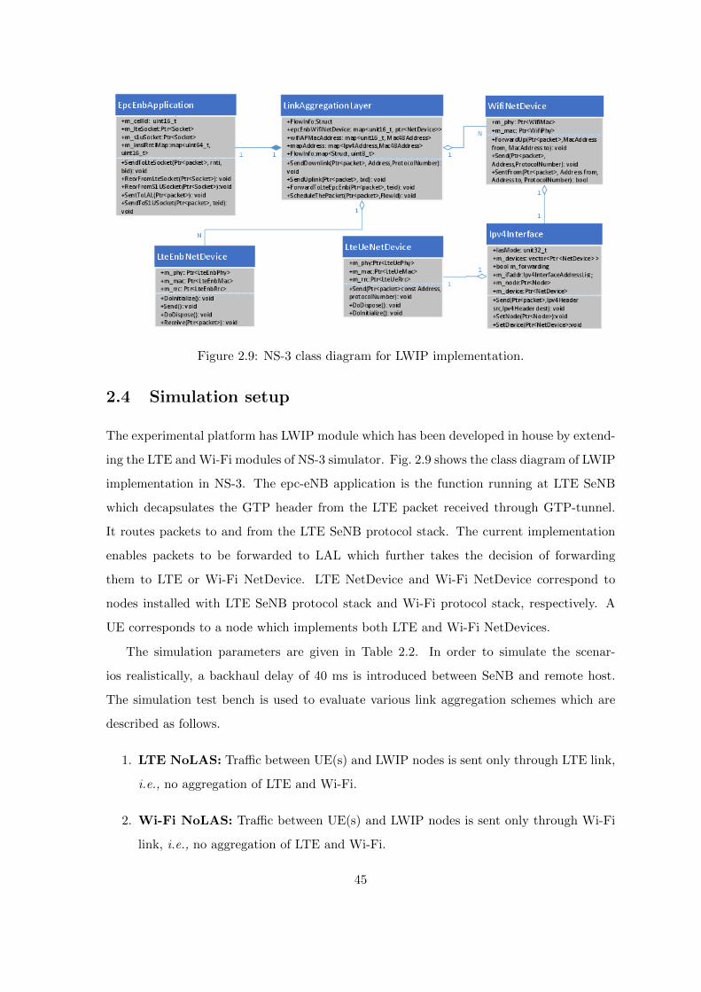
Figure 2.9: NS-3 class diagram for LWIP implementation.
2.4 Simulation setup
The experimental platform has LWIP module which has been developed in house by extend-
ing the LTE and Wi-Fi modules of NS-3 simulator. Fig. 2.9 shows the class diagram of LWIP
implementation in NS-3. The epc-eNB application is the function running at LTE SeNB
which decapsulates the GTP header from the LTE packet received through GTP-tunnel.
It routes packets to and from the LTE SeNB protocol stack. The current implementation
enables packets to be forwarded to LAL which further takes the decision of forwarding
them to LTE or Wi-Fi NetDevice. LTE NetDevice and Wi-Fi NetDevice correspond to
nodes installed with LTE SeNB protocol stack and Wi-Fi protocol stack, respectively. A
UE corresponds to a node which implements both LTE and Wi-Fi NetDevices.
The simulation parameters are given in Table 2.2. In order to simulate the scenar-
ios realistically, a backhaul delay of 40 ms is introduced between SeNB and remote host.
The simulation test bench is used to evaluate various link aggregation schemes which are
described as follows.
1. LTE NoLAS: Traffic between UE(s) and LWIP nodes is sent only through LTE link,
i.e., no aggregation of LTE and Wi-Fi.
2. Wi-Fi NoLAS: Traffic between UE(s) and LWIP nodes is sent only through Wi-Fi
link, i.e., no aggregation of LTE and Wi-Fi.
45
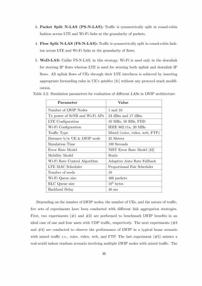
3. Packet Split N-LAS (PS-N-LAS): Traffic is symmetrically split in round-robin
fashion across LTE and Wi-Fi links at the granularity of packets.
4. Flow Split N-LAS (FS-N-LAS): Traffic is symmetrically split in round-robin fash-
ion across LTE and Wi-Fi links at the granularity of flows.
5. WoD-LAS: Unlike FS-N-LAS, in this strategy, Wi-Fi is used only in the downlink
for steering IP flows whereas LTE is used for steering both uplink and downlink IP
flows. All uplink flows of UEs through their LTE interfaces is achieved by inserting
appropriate forwarding rules in UE’s iptables [41] without any protocol stack modifi-
cation.
Table 2.2: Simulation parameters for evaluation of different LASs in LWIP architecture
Parameter Value
Number of LWIP Nodes 1 and 10
Tx power of SeNB and Wi-Fi APs 23 dBm and 17 dBm
LTE Configuration 10 MHz, 50 RBs, FDD
Wi-Fi Configuration IEEE 802.11a, 20 MHz
Traffic Type Mixed (voice, video, web, FTP)
Distance b/w UE & LWIP node 25 Meters
Simulation Time 100 Seconds
Error Rate Model NIST Error Rate Model [42]
Mobility Model Static
Wi-Fi Rate Control Algorithm Adaptive Auto Rate Fallback
LTE MAC Scheduler Proportional Fair Scheduler
Number of seeds 10
Wi-Fi Queue size 400 packets
RLC Queue size 105 bytes
Backhaul Delay 40 ms
Depending on the number of LWIP nodes, the number of UEs, and the nature of traffic,
five sets of experiments have been conducted with different link aggregation strategies.
First, two experiments (#1 and #2) are performed to benchmark LWIP benefits in an
ideal case of one and four users with UDP traffic, respectively. The next experiments (#3
and #4) are conducted to observe the performance of LWIP in a typical home scenario
with mixed traffic i.e., voice, video, web, and FTP. The last experiment (#5) mimics a
real-world indoor stadium scenario involving multiple LWIP nodes with mixed traffic. The
46
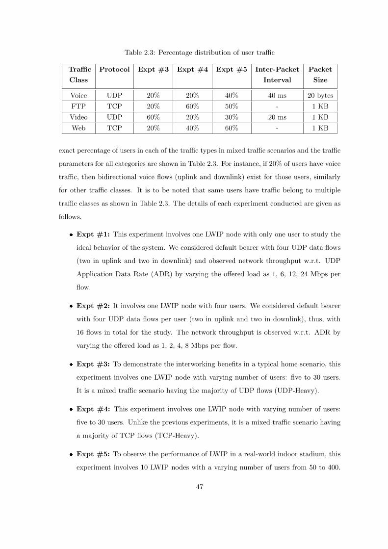
Table 2.3: Percentage distribution of user traffic
Traffic Protocol Expt #3 Expt #4 Expt #5 Inter-Packet Packet
Class Interval Size
Voice UDP 20% 20% 40% 40 ms 20 bytes
FTP TCP 20% 60% 50% - 1 KB
Video UDP 60% 20% 30% 20 ms 1 KB
Web TCP 20% 40% 60% - 1 KB
exact percentage of users in each of the traffic types in mixed traffic scenarios and the traffic
parameters for all categories are shown in Table 2.3. For instance, if 20% of users have voice
traffic, then bidirectional voice flows (uplink and downlink) exist for those users, similarly
for other traffic classes. It is to be noted that same users have traffic belong to multiple
traffic classes as shown in Table 2.3. The details of each experiment conducted are given as
follows.
Expt #1: This experiment involves one LWIP node with only one user to study the
ideal behavior of the system. We considered default bearer with four UDP data flows
(two in uplink and two in downlink) and observed network throughput w.r.t. UDP
Application Data Rate (ADR) by varying the offered load as 1, 6, 12, 24 Mbps per
flow.
Expt #2: It involves one LWIP node with four users. We considered default bearer
with four UDP data flows per user (two in uplink and two in downlink), thus, with
16 flows in total for the study. The network throughput is observed w.r.t. ADR by
varying the offered load as 1, 2, 4, 8 Mbps per flow.
Expt #3: To demonstrate the interworking benefits in a typical home scenario, this
experiment involves one LWIP node with varying number of users: five to 30 users.
It is a mixed traffic scenario having the majority of UDP flows (UDP-Heavy).
Expt #4: This experiment involves one LWIP node with varying number of users:
five to 30 users. Unlike the previous experiments, it is a mixed traffic scenario having
a majority of TCP flows (TCP-Heavy).
Expt #5: To observe the performance of LWIP in a real-world indoor stadium, this
experiment involves 10 LWIP nodes with a varying number of users from 50 to 400.
47
LTE of LWIP nodes are operating with reuse factor one, and every Wi-Fi AP of LWIP
node operates in the same channel for creating high interference scenario.
2.5 Performance results
The variations of UDP throughput w.r.t. UDP ADR of uplink and downlink flows for one
UE (Exp #1) and four UEs (Exp #2) are shown in Figs. 2.10 and 2.11, respectively. UDP
traffic types tend to harvest maximum capacity of the links, hence this experimental result
sets a classical benchmark for aggregation advantages over individual LTE and Wi-Fi radio
links.
2.5.1 Analysis of Expt #1 results
In one UE case with 4 Mbps and 24 Mbps ADR, the network is able to deliver the offered
load in all the LASs as shown in Fig. 2.10. The observed throughput variation in Wi-
Fi NoLAS does not vary much after 48 Mbps ADR and thereafter saturates, because, it
reaches its maximum achievable rate of 24 Mbps for 802.11a with maximum PHY rate of
54 Mbps. Similarly, LTE NoLAS attains saturation after 48 Mbps. However, by leveraging
the radio level integration benefits of LWIP node, PS-N-LAS and FS-N-LAS are able to
deliver higher network throughputs than that of individual LTE and Wi-Fi only networks.
The two variants of N-LAS are indistinguishable in performance due to its naive approach
of symmetrically dividing flows and type of user traffic. WoD-LAS is no better than both
FS-N-LAS and PS-N-LAS due to the presence of only one user and no contention in Wi-Fi.
The next experiment encompasses a contention based scenario.
2.5.2 Analysis of Expt #2 results
The inclusion of four users in the network leads to contentions and therefore, Wi-Fi No-
LAS performance is observed to be poor as compared to other LASs. Wi-Fi NoLAS yields
poor throughput of 8 Mbps though it achieved 24 Mbps in previous experiment. Such
phenomenon is not only due to collisions on the Wi-Fi channel but also the rate control
algorithm which is sensitive to packet loss and its conservative action. The rate control algo-
rithm used in this experiment is adaptive-auto-rate-fallback, which reduces the transmission
rate on observing collisions and it could resort to the lowest transmission rate very quickly.
48
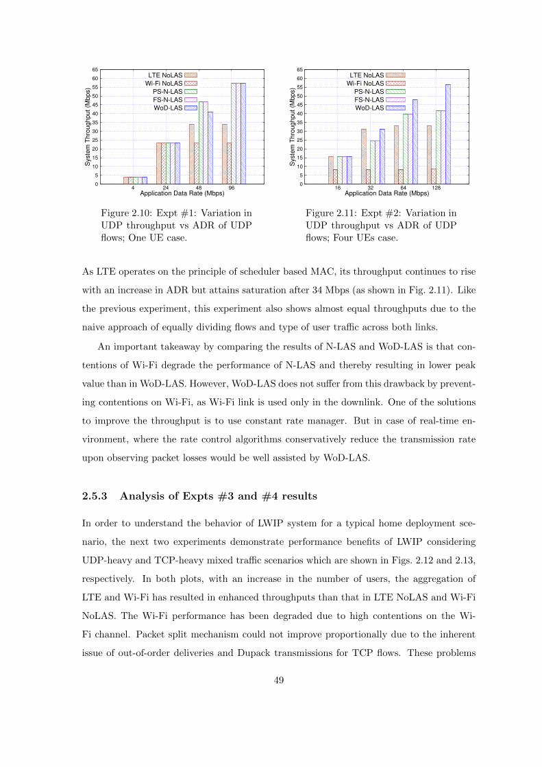
0
5
10
15
20
25
30
35
40
45
50
55
60
65
4 24 48 96
Syste
m T
hro
ug
hp
ut
(Mb
ps)
Application Data Rate (Mbps)
LTE NoLAS
Wi-Fi NoLAS
PS-N-LAS
FS-N-LAS
WoD-LAS
Figure 2.10: Expt #1: Variation inUDP throughput vs ADR of UDPflows; One UE case.
0
5
10
15
20
25
30
35
40
45
50
55
60
65
16 32 64 128
Syste
m T
hro
ug
hp
ut
(Mb
ps)
Application Data Rate (Mbps)
LTE NoLAS
Wi-Fi NoLAS
PS-N-LAS
FS-N-LAS
WoD-LAS
Figure 2.11: Expt #2: Variation inUDP throughput vs ADR of UDPflows; Four UEs case.
As LTE operates on the principle of scheduler based MAC, its throughput continues to rise
with an increase in ADR but attains saturation after 34 Mbps (as shown in Fig. 2.11). Like
the previous experiment, this experiment also shows almost equal throughputs due to the
naive approach of equally dividing flows and type of user traffic across both links.
An important takeaway by comparing the results of N-LAS and WoD-LAS is that con-
tentions of Wi-Fi degrade the performance of N-LAS and thereby resulting in lower peak
value than in WoD-LAS. However, WoD-LAS does not suffer from this drawback by prevent-
ing contentions on Wi-Fi, as Wi-Fi link is used only in the downlink. One of the solutions
to improve the throughput is to use constant rate manager. But in case of real-time en-
vironment, where the rate control algorithms conservatively reduce the transmission rate
upon observing packet losses would be well assisted by WoD-LAS.
2.5.3 Analysis of Expts #3 and #4 results
In order to understand the behavior of LWIP system for a typical home deployment sce-
nario, the next two experiments demonstrate performance benefits of LWIP considering
UDP-heavy and TCP-heavy mixed traffic scenarios which are shown in Figs. 2.12 and 2.13,
respectively. In both plots, with an increase in the number of users, the aggregation of
LTE and Wi-Fi has resulted in enhanced throughputs than that in LTE NoLAS and Wi-Fi
NoLAS. The Wi-Fi performance has been degraded due to high contentions on the Wi-
Fi channel. Packet split mechanism could not improve proportionally due to the inherent
issue of out-of-order deliveries and Dupack transmissions for TCP flows. These problems
49

0
5
10
15
20
25
5 10 15 20 25 30
Syste
m T
hro
ug
hp
ut
(Mb
ps)
Number of Users
LTE NoLASWi-Fi NoLAS
Packet Split N-LASFlow Split N-LAS
WoD-LAS
Figure 2.12: Expt #3: Home Sce-nario with one LWIP node; varia-tion in system throughput vs num-ber of UEs; Mixed Traffic, UDP-Heavy.
0
5
10
15
20
25
30
35
5 10 15 20 25 30
Syste
m T
hro
ug
hp
ut
(Mb
ps)
Number of Users
LTE NoLASWi-Fi NoLAS
Packet Split N-LASFlow Split N-LAS
WoD-LAS
Figure 2.13: Expt #4: Home Sce-nario with one LWIP node; varia-tion in system throughput vs num-ber of UEs; Mixed Traffic, TCP-Heavy.
are avoided in FS-N-LAS, because a flow is pushed as a single unit to the destined radio
interface. Comparison of WoD-LAS and FS-N-LAS shows that WoD-LAS suppresses the
demerits of FS-N-LAS by restricting uplink flows only to LTE. In WoD-LAS, Wi-Fi uti-
lizes its spectrum resources to carry user data and provides best-effort services by smartly
utilizing the flow constraints in one direction. This facilitates a significant reduction in the
number of collisions, thereby improving the system throughput over N-LAS schemes.
-100
-50
0
50
100
150
200
-100 -50 0 50 100 150 200 250
Y in
Me
ter
X in Meter
-10
-5
0
5
10
15
SIN
R (
dB
)
1 2 3 4
5
6 7 8 9
10
Figure 2.14: Expt #5: REM Plotfor Indoor Stadium layout with 10LWIP Nodes.
0
50
100
150
200
50 100 150 200 250 300 350 400
Syste
m T
hro
ug
hp
ut
(Mb
ps)
Number of Users
LTE NoLASWi-Fi NoLAS
PS-N-LASFS-N-LASWoD-LAS
Figure 2.15: Expt #5; Indoor Sta-dium with 10 LWIP nodes; varia-tion in system throughput vs num-ber of UEs; Mixed Traffic.
50
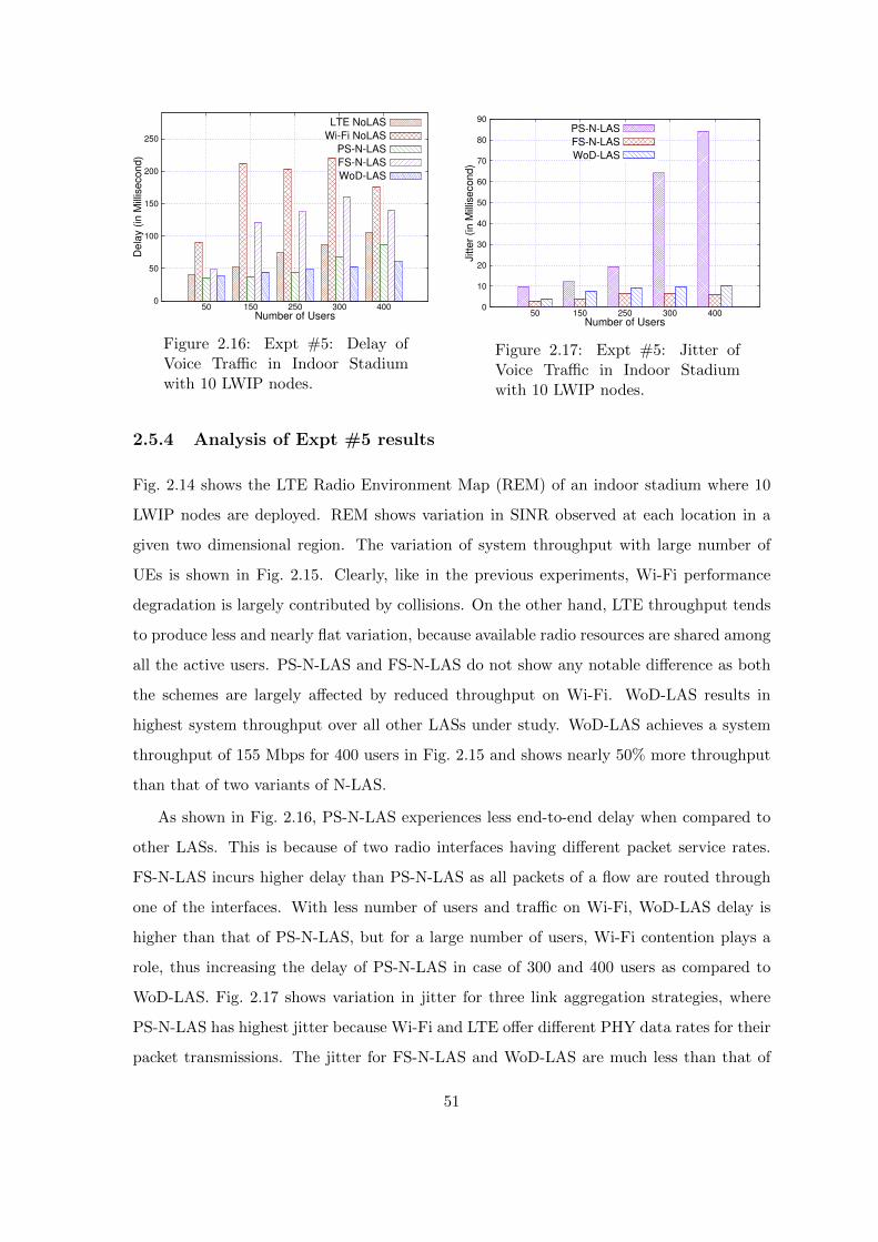
0
50
100
150
200
250
50 150 250 300 400
De
lay (
in M
illis
eco
nd
)
Number of Users
LTE NoLAS
Wi-Fi NoLAS
PS-N-LAS
FS-N-LAS
WoD-LAS
Figure 2.16: Expt #5: Delay ofVoice Traffic in Indoor Stadiumwith 10 LWIP nodes.
0
10
20
30
40
50
60
70
80
90
50 150 250 300 400
Jitte
r (in
Mill
ise
co
nd
)
Number of Users
PS-N-LAS
FS-N-LAS
WoD-LAS
Figure 2.17: Expt #5: Jitter ofVoice Traffic in Indoor Stadiumwith 10 LWIP nodes.
2.5.4 Analysis of Expt #5 results
Fig. 2.14 shows the LTE Radio Environment Map (REM) of an indoor stadium where 10
LWIP nodes are deployed. REM shows variation in SINR observed at each location in a
given two dimensional region. The variation of system throughput with large number of
UEs is shown in Fig. 2.15. Clearly, like in the previous experiments, Wi-Fi performance
degradation is largely contributed by collisions. On the other hand, LTE throughput tends
to produce less and nearly flat variation, because available radio resources are shared among
all the active users. PS-N-LAS and FS-N-LAS do not show any notable difference as both
the schemes are largely affected by reduced throughput on Wi-Fi. WoD-LAS results in
highest system throughput over all other LASs under study. WoD-LAS achieves a system
throughput of 155 Mbps for 400 users in Fig. 2.15 and shows nearly 50% more throughput
than that of two variants of N-LAS.
As shown in Fig. 2.16, PS-N-LAS experiences less end-to-end delay when compared to
other LASs. This is because of two radio interfaces having different packet service rates.
FS-N-LAS incurs higher delay than PS-N-LAS as all packets of a flow are routed through
one of the interfaces. With less number of users and traffic on Wi-Fi, WoD-LAS delay is
higher than that of PS-N-LAS, but for a large number of users, Wi-Fi contention plays a
role, thus increasing the delay of PS-N-LAS in case of 300 and 400 users as compared to
WoD-LAS. Fig. 2.17 shows variation in jitter for three link aggregation strategies, where
PS-N-LAS has highest jitter because Wi-Fi and LTE offer different PHY data rates for their
packet transmissions. The jitter for FS-N-LAS and WoD-LAS are much less than that of
51

PS-N-LAS and it does not significantly impact voice traffic. Depending on network require-
ments, network operators could dynamically switch among various LASs for enhancing user
experience and responsiveness of the system.
2.6 Challenges associated with LWIP architecture
This section describes various shortcoming of RLI architectures, especially LWIP, and po-
tential challenges that have to be addressed. LWIP architecture has the potential to compete
with other contemporary solutions [43] such as LTE-U (LTE in Unlicensed) [44] and LAA
(Licensed Assisted Access) [45]. But LWIP can be successful only if we address the problem
of steering across LTE and Wi-Fi effectively. This section describes various challenges and
the way forward to address those challenges.
2.6.1 Does packet split (split bearer) has merits?
Packet split has a finer offloading granularity and finds its goodness in the case of UDP
transmissions. It is an ideal offloading solution, where offloading decisions are instanta-
neous based on interface availability, delay, jitter, and losses due to fading, collision, and
interference on that particular link. A finer level of offloading is beneficial only if the link
information is available.
2.6.2 Is TCP a stumbling block for packet split?
Even after supporting dynamic offloading mechanism and finest offloading granularity,
packet split is not able to offer better throughput because of difference in time of deliv-
ery of the packets over LTE and Wi-Fi link to the destination. TCP, being a highly reliable
protocol, on observing a missing packet (which is due to arrival delay on another link -
but no loss due to congestion) starts retransmission procedure by sending DUPlicate AC-
Knowledgements (DUPACKs). TCP sender understands these DUPACKs as actual packet
loss due to congestion in the network and reduces the congestion window on receiving three
consecutive DUPACKs, which is the most undesirable reaction for packet split. This prob-
lem arises because the IP layer of the receiver fails to reorder the packets which are received
out-of-order. A reordering mechanism to ensure in-order delivery of packets in case of split
bearer mechanism is needed for reaping in full benefits of packet split in LWIP.
52

2.7 Summary
RLI architectures aggregate LTE and Wi-Fi radio links better as compared to traditional
interworking architectures. RLI exhibits enhanced control over the radio links and it has
the ability to steer the traffic at the granularity of flows/packets/bytes. LWIP of RLI
architecture adapts various link aggregation strategies which facilitate a way forward to
better utilizing multiple radio links. The developed simulation workbench supports different
link aggregation strategies. It can be clearly observed that WoD-LAS has improved the
system throughput by 50% as compared to N-LAS in an indoor stadium environment. The
following chapters discuss on effective steering across LTE and Wi-Fi in order to harvest
the aggregated benefits of RLI.
53

Chapter 3
Downlink traffic steering in LWIP
architecture
The previous chapter enumerated various challenges with RLI architectures. One of the im-
portant challenges which prevents RLI architectures from achieving aggregated link band-
width is the co-tier interference between adjacent RLI nodes deployed. This chapter details
the root cause of the problem and proposes a solution to address it.
3.1 Motivation
Challenges with small cell deployments include co-tier interference due to densification of
small cells and QoS provisioning. The choice of intensifying the deployment of LTE small
cells in order to improve the network capacity leads to high co-tier interference. The usage of
orthogonal RATs (LTE and Wi-Fi) emerges as a prominent solution to address this problem.
The users located at the high interference zone of LTE can connect to Wi-Fi, thereby
reducing the effect of co-tier interference in LTE. Currently, LTE small cells and Wi-Fi
APs are independently deployed, which make an LTE user who is facing high interference
difficult to find a suitable Wi-Fi AP to associate with for obtaining better service. The
co-located LWIP architecture that integrates stacks of LTE small cell and Wi-Fi AP in a
single hardware unit has been proposed in order to address this problem, which ensures
Wi-Fi link available for users even in the interference region. Co-located LWIP (C-LWIP)
facilitates a unified control over LTE and Wi-Fi links. But C-LWIP deployment also has
some issues. For example, consider a non co-located deployment of LWIP by an operator
54
for a shopping mall with ’N’ number of LTE SeNBs and ’N’ number of Wi-Fi APs that
are connected to each other using Xw interface for interworking. A typical setup can cover
a shopping mall of size say ’A’ sq. meters without any coverage holes i.e., each location
is ensured good SINR from at least one network: LTE or Wi-Fi. But it is impractical to
cover the same area with ’N’ number of co-located LWIP nodes. Suppose the number of
co-located LWIP nodes deployed is increased in order to solve the coverage hole problem,
then this densification of LWIP nodes would lead to high co-tier interference.
The second most important challenge is to ensure QoS for LWIP users, which corre-
sponds to allocating sufficient radio resources for their guaranteed bit rate (GBR) flows.
In a typical indoor scenario, the SINR received by a user a.k.a. User Equipment (UE) is
constrained by the number of walls and number of interfering LWIP nodes that exist in its
vicinity. Many a time UEs with poor SINR fail to meet their GBR flow requirements. LTE
MAC scheduler such as Priority Set Scheduler (allocates radio resources primarily to GBR
bearers, after serving GBR bearers it schedules other bearers), allocates more resources to
the UEs with poor SINR in order to meet their GBR requirements. Such a QoS centric
allocation adversely affects the overall system throughput. This problem of efficient QoS
provisioning pertains with C-LWIP nodes as well.
An important advantage of LWIP architecture is its ability in steering the flows dynami-
cally across LTE and Wi-Fi links without requiring time-consuming core network signaling.
Hence, a solution to maximize network throughput of LWIP by efficiently steering the flows
dynamically across LTE and Wi-Fi links is needed. In order to address the above-mentioned
challenges, in this chapter, a novel Power awaRE dynamiC traffIc StEering (PRECISE) al-
gorithm is proposed for C-LWIP system which performs dynamic transmit power control
and traffic steering in both LTE and Wi-Fi networks.
3.2 Related work
This section details the work in literature pertaining to interference management, QoS fulfil-
ment, and flow steering. The existing solutions for interference mitigation include Inter-Cell
Interference Coordination (ICIC) and eICIC [46]. These solutions employ frequency reuse
and subframe muting to reduce interference in LTE networks. The offloading algorithm
presented in [47] prioritizes the traffic with specific QoS requirement. The voice and video
55
flows are sent through the cellular network while the elastic flows are sent through Wi-Fi
network. This approach ensures the QoS of GBR flows, but it does not intend to maximize
the utilization of network resources. In [48], to overcome poor availability and performance
of the cellular network, the authors have used two key ideas viz., leverage delay tolerance
and fast switching from cellular to Wi-Fi to reduce the load on the cellular network. Ini-
tially, all flows are sent through Wi-Fi. If Wi-Fi is unable to transmit packets of a flow
in a small time window (delay tolerance limit), then that flow is quickly switched onto the
cellular network. This solution focuses on maximizing the utilization of Wi-Fi, but it fails
to maximize the overall network throughput.
Here are a few offloading solutions in the literature on traditional LTE Wi-Fi interwork-
ing. Significant work has been done for LTE Wi-Fi interworking which involves offloading
decisions made at the cellular gateway of LTE network [49], [50], [47], [51], and [52]. Also, a
lot of work has been carried out on modelling the downlink steering performance of cellular
gateway-based solutions [53], [54], and [55]. In [56], the authors have shown that delaying
the application data transmission until a user gets in Wi-Fi coverage has reduced the load
on the cellular network. The authors project that offloading through Wi-Fi is the most
preferable solution as it reduces the load on the cellular network, but the solution leads
to inefficient utilization of Wi-Fi resources due to contention. In [36], the authors have
proposed different LTE Wi-Fi interworking techniques, where flow offloading is realized by
steering traffic at the transport layer, network layer, and link layer. All these works intent
to perform flow offloading, and not much work has been done in tight coupling of LTE
Wi-Fi networks as in the case of RLI architectures, which give LTE a finer control over
Wi-Fi interface for efficient traffic steering.
Here are some works in the literature on RLI architectures. In [30], the authors pro-
posed an α-optimal scheduler in which scheduling across multiple Radio Access Technologies
(RATs) is formulated as an optimization problem. Steering the incoming traffic across dif-
ferent RATs viz., LTE and Wi-Fi is done based on the value of α. For different values of
α, the scheduler morphs its purpose as a proportional fair scheduler, maximum throughput
scheduler, or maximize minimum rate scheduler. In [57], the authors proposed a “water-
filling” based interpretation for resource allocation across multiple RATs. The fraction of
traffic sent over a RAT is proportional to the ratio of users peak capacity on two RATs. The
above mentioned schedulers enable efficient scheduling across both LTE and Wi-Fi RATs
56
simultaneously, but they do not aim to reduce interference in dense deployment scenarios.
To address the problems which exist with the aforementioned works in the literature,
and to efficiently utilize the C-LWIP architecture for downlink traffic steering, Power-Aware
Dynamic Traffic Steering (PRECISE) algorithm has been proposed in this chapter. The
proposed PRECISE algorithm does efficient flow steering with intelligent power control for
minimizing interference and thereby ensuring GBR QoS requirements with improved overall
network throughput.
3.3 Proposed work: PRECISE
The PRECISE algorithm has been designed with the following objectives:
1. Mitigation of co-tier interference in dense deployment of LWIP system.
2. Meeting GBR requirements of the users including those experiencing poor SINR.
3. Dynamic steering of the flows across LTE and Wi-Fi links to maximize the overall
system throughput.
Algorithm 1 details the components and working of the PRECISE algorithm. Table 3.1
lists the notations used in PRECISE algorithm. PRECISE has the following two phases:
1. Interference Mitigation (IM) Phase: regulates the transmit power of LTE and Wi-Fi
interfaces to minimize the co-tier interference.
2. GBR Improvement (GI) Phase: targets to satisfy the GBR requirements of the user-
s/flows.
Initially, the flow state information of all downlink flows is collected by a centralized decision
making entity (e.g., LWIP gateway). Note that this LWIP gateway assists only in regulating
the transmit power across LWIP nodes. If requirements of GBR flows are met, then the
algorithm aims to improve the system throughput by mitigating the co-tier interference
by triggering IM Phase. In this phase, optimal transmit power values are computed and
set for LTE and Wi-Fi interfaces in order to reduce co-tier interference across interfering
C-LWIP nodes. The IM Phase is continued as long as QoS requirements of GBR flows
are met. If GBR requirements of some of the flows are not met, then GBR Improvement
Phase (GI Phase) is triggered in which the transmit powers of LTE and Wi-Fi interfaces
57

of C-LWIP nodes are adjusted in order to meet the GBR requirements. Gs corresponds to
percentage of GBR flows satisfied, it is given by Gs =∑
j∈GBR Fj∑i∈GBR,NGBR Fi
× 100. Here, Fi
corresponds to information of the ith flow in the network i.e., information about ith flow
such as, (i) Type of flow: GBR or NGBR, (ii) Bandwidth requirement, (iii) Delay budget,
(iv) Status of GBR [met or unmet], and (v) Throughput observed by that flow). Both IM
and GI phases are followed by flow steering across LTE and Wi-Fi links in order to achieve
their corresponding objectives. Flow steering involves ordering different flows based on their
affinity to an interface. An ith flow’s affinity to an interface is given by its affinity index
(AIi). If there exists GBR flows not meeting the GBR requirements, then a set of unmet
GBR flows (ΦG) are moved first to lightly loaded interface of the C-LWIP node. If GBR
requirements are met, then a set of NGBR flows (ΦNG) with high affinity are moved to
the corresponding interface to maximize the throughput of the system. ΦG is obtained by
iteratively picking a set of unmet GBR flows that are currently being served in a heavily
loaded link but can be accommodatable on the other link. Accommodating a flow on a new
link is discussed later in Section 3.3.4.
Table 3.1: Notations used in PRECISE algorithm
Symbols Definition
Fi Flow information of ith flow
G∫ Percentage of GBR flows met their QoS requirement
αLi,j Association of ith UE with jth LWIP node over LTE link
αWi,j Association of ith UE with jth LWIP node over Wi-Fi link
PL Transmit power of LTE link in LWIP node
PW Transmit power of Wi-Fi link in LWIP node
LL,LW Load on LTE and Wi-Fi links
AI Flow affinity index
BT Wi-Fi channel busy time
IT Wi-Fi channel idle time
ΦG Set of unsatisfied GBR flows
ΦNG Set of unsatisfied NGBR flows
3.3.1 System model
Our system model (shown in Fig. 3.1) comprises of LWIP nodes, deployed in a given region
of interest, which run proposed PRECISE algorithm to achieve the targeted objectives.
Fig. 3.2 depicts an example of coverage pattern exhibited by the considered system during
58

LWIP Node
Figure 3.1: System Model.
IM and GI phases. It includes LTE operating on one licensed frequency band across all the
cells and Wi-Fi using one unlicensed channel across all the cells. During IM phase, LTE and
Wi-Fi coverages appear to cover the alternate cell edge regions in order to reduce co-tier
interference (note that this figure is a closer approximation and it may vary based on user
density and their positions in the network). In Fig. 3.2, points ’A’ and ’D’ denote locations
of two C-LWIP nodes whereas ’B’ and ’C’ denote the regions of interest. When C-LWIP
nodes at ’A’ and ’D’ transmit with the same power, then the regions ’B’ and ’C’ suffer from
high co-tier interference. IM Phase is then triggered which reduces LTE co-tier interference
in the regions ’B’ and ’C’ by reducing the transmit power of LTE eNodeB in C-LWIP node
’A’. Similarly, Wi-Fi interference at regions ’B’ and ’C’ is reduced by reducing the transmit
power of Wi-Fi AP in C-LWIP node ’D’. During GI phase, the edge of coverage region is
expanded or shrank based on the number of UEs with unmet GBR flows. Expansion or
increase in transmit power on a link corresponds to improving bit rate for a UE with unmet
GBR requirements. Reduction in coverage region corresponds to reducing interference for
UEs associated with other C-LWIP nodes without degrading GBR guarantees of the current
C-LWIP node. The power control function of PRECISE algorithm runs at LWIP gateway
whereas the flow steering runs at the C-LWIP node so that it can take independent and
fast steering of flows across LTE and Wi-Fi links. The flow steering algorithm is executed
once in every N TTIs.
59

IM Phase GI Phase
LTE Coverage in IM Phase
Wi-Fi Coverage in IM Phase
Coverage expanded by GI Phase
Coverage reduced by GI Phase
A
CB
D
Figure 3.2: Variation in coverage regions of LTE and Wi-Fi cells observed in different phasesof PRECISE algorithm.
Algorithm 1 Power awaRE dynamiC traffIc StEering (PRECISE)
Input: Set of all flows information in the system (Fi), i ∈ flows 1,. . . ,k, SINR of UEsassociated with C-LWIP nodes
1: for Every N ms do2: if Gs ≥ 90% then . Trigger IM Phase3: ΘIM (PLj , P
Wj )
4: Set Tx powers obtained through ΘIM optimization5: else . Trigger GI Phase6: ΘGI(PLj , P
Wj )
7: Set Tx powers obtained through ΘGI optimization8: end if
. Flow Steering9: AI ←TOPSIS(F i)
10: if LL > LW then11: if GBR flows unsatisfied then12: Steer a set of unmet GBR flows (ΦG) to Wi-Fi13: else14: Steer a set of NGBR flows (ΦNG) with high affinity index to Wi-Fi15: end if16: else17: if GBR flows unsatisfied then18: Steer a set of unmet GBR flows (ΦG) to LTE19: else20: Steer a set of NGBR flows (ΦNG) with high affinity index to LTE21: end if22: end if23: end for
60

3.3.2 IM Phase of PRECISE: Interference mitigation using orthogonal
RATs
In this work, the interference mitigation sub-problem is formulated as a mixed integer non-
linear programming (MINLP) problem with an objective of minimizing co-tier interference
within a RAT. IM phase sets the optimal transmit powers to LTE and Wi-Fi interfaces of
C-LWIP node. The SINR maximization of C-LWIP is formulated as follows:
Maximize ΘIM =
U,B∑i=1,j=1
(αLi,j × SINRLi + αWi,j × SINRWi ) (3.1)
s.t.
B∑j=1
αLi,j ≤ 1 ∀i andB∑j=1
αWi,j ≤ 1 ∀i
αLi,j =
1, if SINRLi ≥ ThLTE
0, otherwise
αWi,j =
1, if SINRWi ≥ ThWi-Fi
0, otherwise
αLi,j =
0 or 1, if αWi,j = 1
0, otherwise
αWi,j =
0 or 1, if αLi,j = 1
0, otherwise
PLmin ≤ PLj ≤ PLmax
PWmin ≤ PWj ≤ PWmax
ΘIM is the sum over LTE and Wi-Fi SINRs of users associated with LTE and Wi-Fi
links of C-LWIP nodes. Here, PLj and PWj are the transmit powers of LTE and Wi-Fi
interfaces of jth LWIP node, respectively. The power is a regulatory parameter which can
61
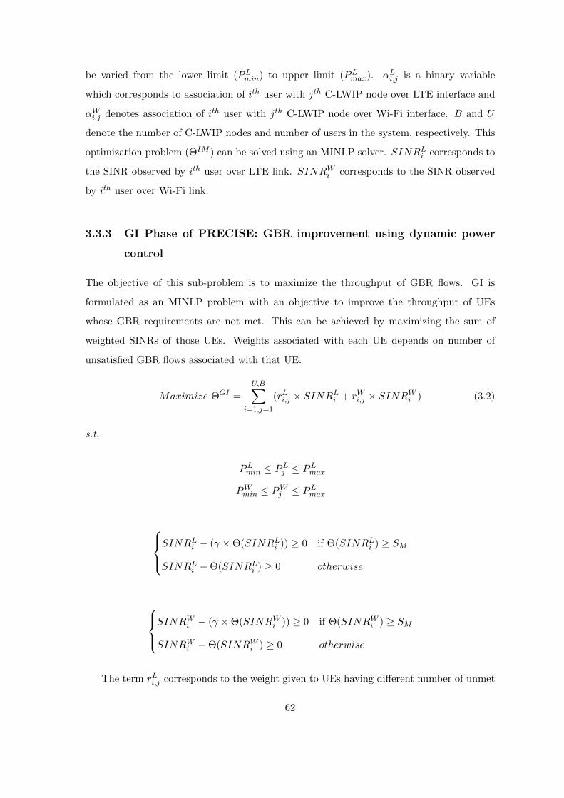
be varied from the lower limit (PLmin) to upper limit (PLmax). αLi,j is a binary variable
which corresponds to association of ith user with jth C-LWIP node over LTE interface and
αWi,j denotes association of ith user with jth C-LWIP node over Wi-Fi interface. B and U
denote the number of C-LWIP nodes and number of users in the system, respectively. This
optimization problem (ΘIM ) can be solved using an MINLP solver. SINRLi corresponds to
the SINR observed by ith user over LTE link. SINRWi corresponds to the SINR observed
by ith user over Wi-Fi link.
3.3.3 GI Phase of PRECISE: GBR improvement using dynamic power
control
The objective of this sub-problem is to maximize the throughput of GBR flows. GI is
formulated as an MINLP problem with an objective to improve the throughput of UEs
whose GBR requirements are not met. This can be achieved by maximizing the sum of
weighted SINRs of those UEs. Weights associated with each UE depends on number of
unsatisfied GBR flows associated with that UE.
Maximize ΘGI =
U,B∑i=1,j=1
(rLi,j × SINRLi + rWi,j × SINRWi ) (3.2)
s.t.
PLmin ≤ PLj ≤ PLmax
PWmin ≤ PWj ≤ PLmax
SINRLi − (γ ×Θ(SINRLi )) ≥ 0 if Θ(SINRLi ) ≥ SM
SINRLi −Θ(SINRLi ) ≥ 0 otherwise
SINRWi − (γ ×Θ(SINRWi )) ≥ 0 if Θ(SINRWi ) ≥ SM
SINRWi −Θ(SINRWi ) ≥ 0 otherwise
The term rLi,j corresponds to the weight given to UEs having different number of unmet
62
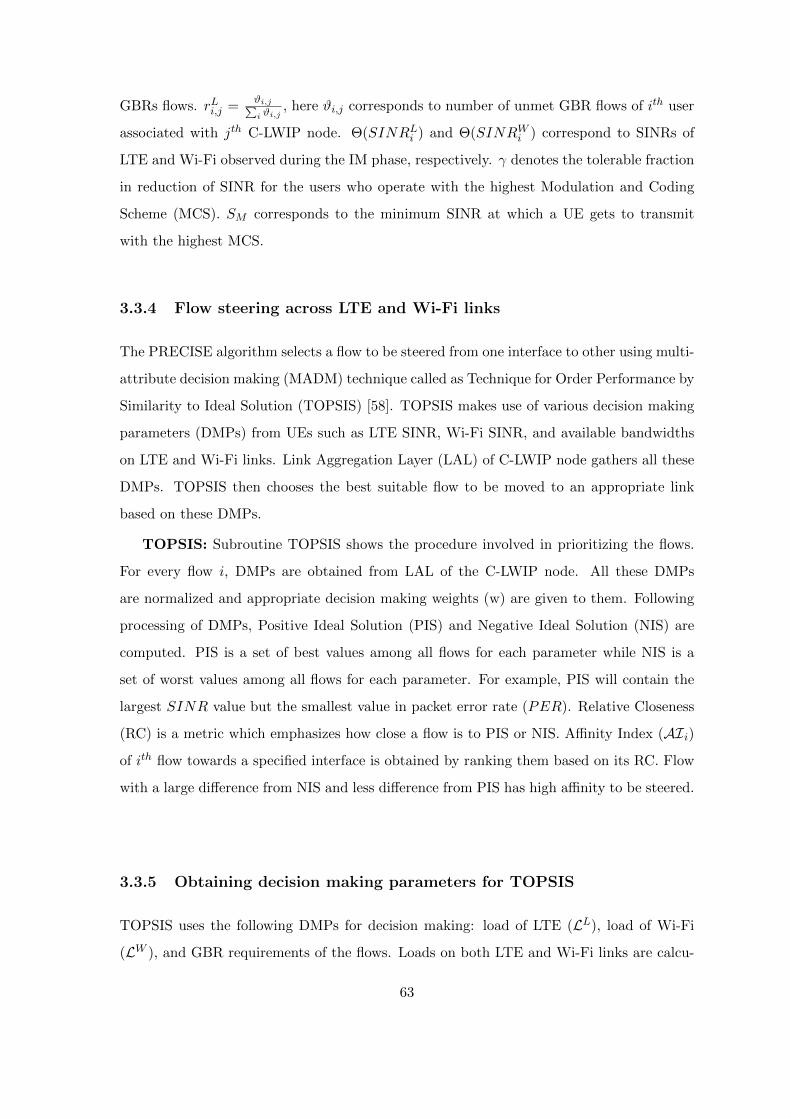
GBRs flows. rLi,j =ϑi,j∑i ϑi,j
, here ϑi,j corresponds to number of unmet GBR flows of ith user
associated with jth C-LWIP node. Θ(SINRLi ) and Θ(SINRWi ) correspond to SINRs of
LTE and Wi-Fi observed during the IM phase, respectively. γ denotes the tolerable fraction
in reduction of SINR for the users who operate with the highest Modulation and Coding
Scheme (MCS). SM corresponds to the minimum SINR at which a UE gets to transmit
with the highest MCS.
3.3.4 Flow steering across LTE and Wi-Fi links
The PRECISE algorithm selects a flow to be steered from one interface to other using multi-
attribute decision making (MADM) technique called as Technique for Order Performance by
Similarity to Ideal Solution (TOPSIS) [58]. TOPSIS makes use of various decision making
parameters (DMPs) from UEs such as LTE SINR, Wi-Fi SINR, and available bandwidths
on LTE and Wi-Fi links. Link Aggregation Layer (LAL) of C-LWIP node gathers all these
DMPs. TOPSIS then chooses the best suitable flow to be moved to an appropriate link
based on these DMPs.
TOPSIS: Subroutine TOPSIS shows the procedure involved in prioritizing the flows.
For every flow i, DMPs are obtained from LAL of the C-LWIP node. All these DMPs
are normalized and appropriate decision making weights (w) are given to them. Following
processing of DMPs, Positive Ideal Solution (PIS) and Negative Ideal Solution (NIS) are
computed. PIS is a set of best values among all flows for each parameter while NIS is a
set of worst values among all flows for each parameter. For example, PIS will contain the
largest SINR value but the smallest value in packet error rate (PER). Relative Closeness
(RC) is a metric which emphasizes how close a flow is to PIS or NIS. Affinity Index (AIi)
of ith flow towards a specified interface is obtained by ranking them based on its RC. Flow
with a large difference from NIS and less difference from PIS has high affinity to be steered.
3.3.5 Obtaining decision making parameters for TOPSIS
TOPSIS uses the following DMPs for decision making: load of LTE (LL), load of Wi-Fi
(LW ), and GBR requirements of the flows. Loads on both LTE and Wi-Fi links are calcu-
63
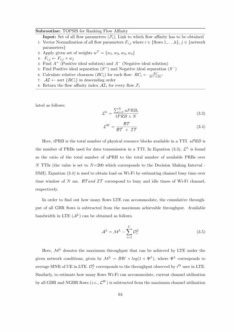
Subroutine: TOPSIS for Ranking Flow Affinity
Input: Set of all flow parameters (Fi), Link to which flow affinity has to be obtained1: Vector Normalization of all flow parameters Fi,j where i ∈ flows 1,. . . ,k, j ∈ network
parameters2: Apply given set of weights wT = w1, w2, w3, w43: Fi,j ← Fi,j × wj4: Find A+ (Positive ideal solution) and A− (Negative ideal solution)5: Find Positive ideal separation (S+) and Negative ideal separation (S−)
6: Calculate relative closeness (RCi) for each flow: RCi ← Si−
Si++Si−
7: AI ← sort RCi in descending order8: Return the flow affinity index AIi for every flow Fi
lated as follows:
LL =
∑Ni=1 uPRBitPRB ×N
(3.3)
LW =BT
BT + IT(3.4)
Here, tPRB is the total number of physical resource blocks available in a TTI. uPRB is
the number of PRBs used for data transmission in a TTI. In Equation (3.3), LL is found
as the ratio of the total number of uPRB to the total number of available PRBs over
N TTIs (the value is set to N=200 which corresponds to the Decision Making Interval -
DMI). Equation (3.4) is used to obtain load on Wi-Fi by estimating channel busy time over
time window of N ms. BT and IT correspond to busy and idle times of Wi-Fi channel,
respectively.
In order to find out how many flows LTE can accommodate, the cumulative through-
put of all GBR flows is subtracted from the maximum achievable throughput. Available
bandwidth in LTE (AL) can be obtained as follows.
AL =ML −U∑i=1
OLi (3.5)
Here, ML denotes the maximum throughput that can be achieved by LTE under the
given network conditions, given by ML = BW × log(1 + ΨL), where ΨL corresponds to
average SINR of UE in LTE. OLi corresponds to the throughput observed by ith user in LTE.
Similarly, to estimate how many flows Wi-Fi can accommodate, current channel utilization
by all GBR and NGBR flows (i.e., LW ) is subtracted from the maximum channel utilization
64
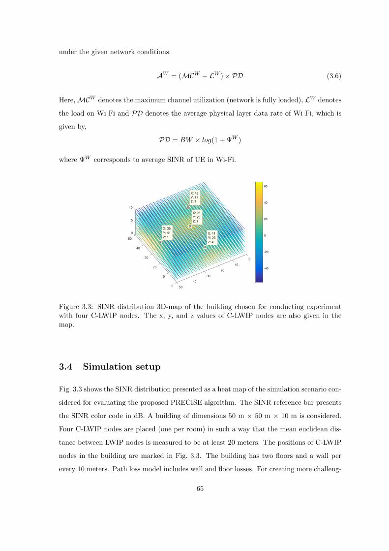
under the given network conditions.
AW = (MCW − LW )× PD (3.6)
Here,MCW denotes the maximum channel utilization (network is fully loaded), LW denotes
the load on Wi-Fi and PD denotes the average physical layer data rate of Wi-Fi, which is
given by,
PD = BW × log(1 + ΨW )
where ΨW corresponds to average SINR of UE in Wi-Fi.
0
50
40
300
1020
20
3010
40
0 50
5
10
-40
-20
0
20
40
60
X: 26
Y: 25
Z: 7
X: 35
Y: 41
Z: 1
X: 42
Y: 17
Z: 7
X: 11
Y: 23
Z: 4
Figure 3.3: SINR distribution 3D-map of the building chosen for conducting experimentwith four C-LWIP nodes. The x, y, and z values of C-LWIP nodes are also given in themap.
3.4 Simulation setup
Fig. 3.3 shows the SINR distribution presented as a heat map of the simulation scenario con-
sidered for evaluating the proposed PRECISE algorithm. The SINR reference bar presents
the SINR color code in dB. A building of dimensions 50 m × 50 m × 10 m is considered.
Four C-LWIP nodes are placed (one per room) in such a way that the mean euclidean dis-
tance between LWIP nodes is measured to be at least 20 meters. The positions of C-LWIP
nodes in the building are marked in Fig. 3.3. The building has two floors and a wall per
every 10 meters. Path loss model includes wall and floor losses. For creating more challeng-
65

ing environment, LTE is considered to operate with reuse factor one, and all Wi-Fi APs are
configured to operate on the same channel. The other important simulation parameters are
shown in Table 3.2. MATLAB based solver (fmincon) is employed in this work to solve
the optimization problem. The time taken to obtain the optimal solution is in the order of
ms, which makes the proposed solution to work in real-time.
Table 3.2: Simulation parameters for evaluating PRECISE algorithm
Parameter Value
# of UEs, LWIP Nodes 100, 4
Max Tx power of LTE & Wi-Fi 23, 20 dBm
LTE path loss model 3GPP indoor path loss model [59]
Wi-Fi path loss model ITU path loss model [60]
LTE MAC Scheduler Priority Set Scheduler (PSS)
UE position Random
Wi-Fi Standard IEEE 802.11n
Wi-Fi frequency and bandwidth 2.4 GHz, 20 MHz
LTE frequency and bandwidth 2.6 GHz, 10 MHz
Simulation duration 104 Seconds
Number of seeds 10
3.5 Performance results
The performance of the PRECISE algorithm has been evaluated in a dense deployment sce-
nario. The PRECISE algorithm is compared with existing Wi-Fi offload algorithms [61], [48],
3GPP Rel. 12 [62], and a state-of-the-art α-optimal scheduler [30] to observe its perfor-
mance benefits. Wi-Fi offload algorithm prefers to use only Wi-Fi link whenever Wi-Fi is
available and switches to LTE link on observing poor SINR in Wi-Fi. In 3GPP Rel. 12
solution, a UE gets associated with either LTE or Wi-Fi link of C-LWIP node. The UE
prefers to associate with the link having higher SINR. The α-optimal scheduler associates
a set of flows through LTE and Wi-Fi links based on achievable throughputs by that UE in
different RATs. When α=1, the scheduler does a proportionally fair split among the flows
sent through LTE and Wi-Fi links.
3.5.1 SINR distribution in the indoor scenario
The SINR distributions of UEs are observed in two cases: (i) LWIP with fixed power (set to
the maximum power) and (ii) LWIP power obtained from the PRECISE algorithm. Fig. 3.4
66
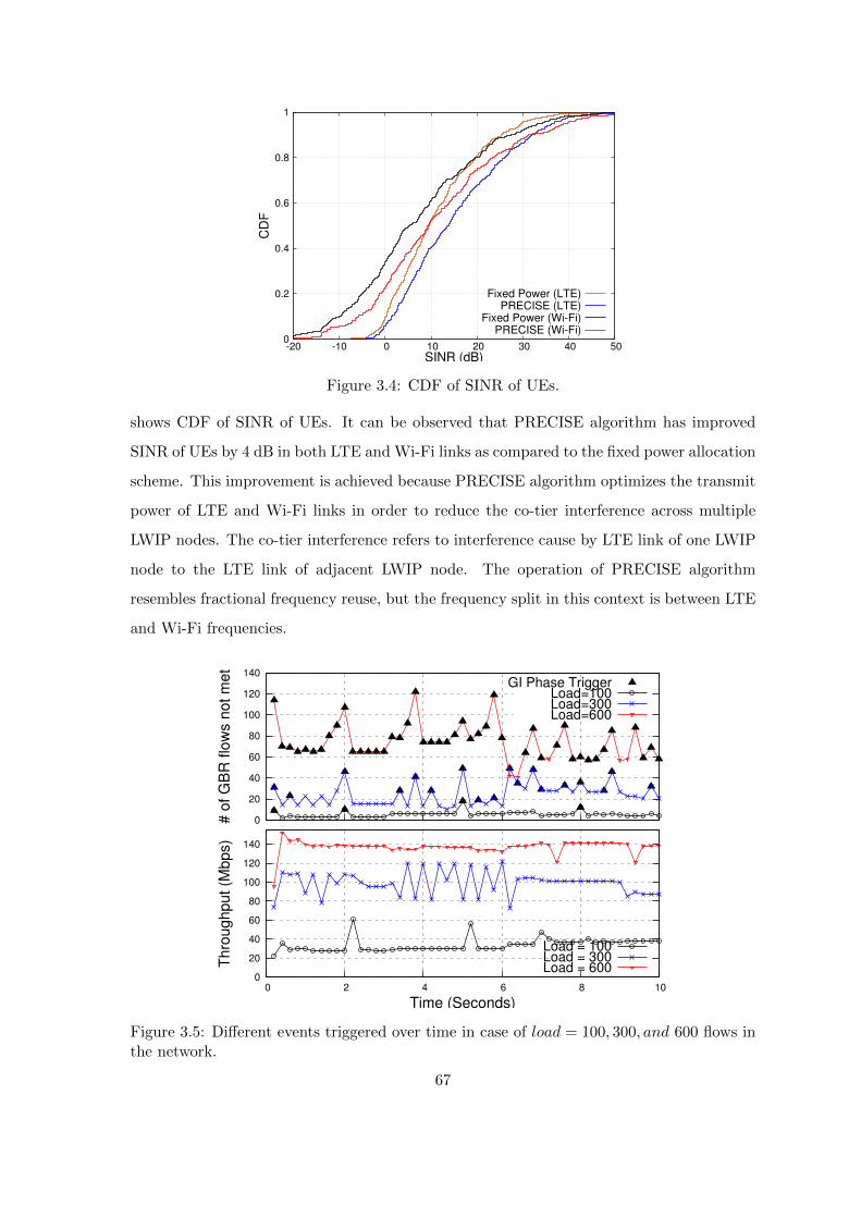
0
0.2
0.4
0.6
0.8
1
-20 -10 0 10 20 30 40 50
CD
F
SINR (dB)
Fixed Power (LTE)PRECISE (LTE)
Fixed Power (Wi-Fi)PRECISE (Wi-Fi)
Figure 3.4: CDF of SINR of UEs.
shows CDF of SINR of UEs. It can be observed that PRECISE algorithm has improved
SINR of UEs by 4 dB in both LTE and Wi-Fi links as compared to the fixed power allocation
scheme. This improvement is achieved because PRECISE algorithm optimizes the transmit
power of LTE and Wi-Fi links in order to reduce the co-tier interference across multiple
LWIP nodes. The co-tier interference refers to interference cause by LTE link of one LWIP
node to the LTE link of adjacent LWIP node. The operation of PRECISE algorithm
resembles fractional frequency reuse, but the frequency split in this context is between LTE
and Wi-Fi frequencies.
0
20
40
60
80
100
120
140
# o
f G
BR
flo
ws n
ot m
et
GI Phase TriggerLoad=100Load=300Load=600
0
20
40
60
80
100
120
140
0 2 4 6 8 10
Thro
ughput (M
bps)
Time (Seconds)
Load = 100Load = 300Load = 600
Figure 3.5: Different events triggered over time in case of load = 100, 300, and 600 flows inthe network.
67

3.5.2 Ensure GBR in the network
The PRECISE algorithm ensures data rate requirements of GBR flows and maximizes the
throughput for NGBR flows thereby maximizing the entire network throughput. In this
experiment, UE traffic includes GBR and NGBR flows. GBR flows comprise of conver-
sational voice (G.711) at 87.2 Kbps GBR, Video call (HD) at 1.2 Mbps, and Streaming
Video at 1.2 Mbps [63]. NGBR flows include Sync Apps and file downloads. The total
number of downlink flows in the network at any instance follows Poisson distribution with
mean following load in the network. Fig. 3.5 is an instantaneous capture of throughput and
number of unmet GBR flows. Data points are plotted for every 200 ms which corresponds
to a DMI of the PRECISE algorithm. The experiment is conducted for low, medium, and
high load conditions (load= 100, 300, and 600 flows), and number of triggers observed in all
the cases are examined. In case of load=100 flows, the number of GBR flows are low and
they are satisfied. As the load increases, the number of unmet GBR flows increases. This
triggers GI phase, which regulates the transmit power of LWIP nodes in order to reduce
the number of unmet GBR flows. During GI phase, the transmit power of LTE and Wi-Fi
links are obtained by solving the optimization problem shown in Equation (3.2). In case of
high load (load=600 flows), GI phase is triggered more than IM phase as the unmet GBR
flows are very high.
3.5.3 Different phases of PRECISE algorithm
To study different phase of the PRECISE algorithm, four different experiments have been
conducted. In each experiment, the mean number of flows in LWIP network is varied from
100 to 600. The number of IM triggers and GI triggers observed for different loads are
counted. Fig. 3.6 shows the number of times IM and GI phases are triggered. As the load
in the network by increasing the number of flows from 100 to 600, the number of unmet
GBR flows increases. In order to reduce the number of unmet GBR flows, GI phase is
triggers accordingly.
3.5.4 Throughput analysis
Performance of different algorithms are compared with the PRECISE algorithm. Fig. 3.7
shows CDF of throughput of UEs observed for a fixed load (load = 600 flows) when different
68

algorithms are employed. In case of Wi-Fi preferred algorithm, UE throughput is low
because UE associated with LWIP node strictly confines to use Wi-Fi resources even when
both LTE and Wi-Fi SINRs are high. The UE prefers to use LTE only when Wi-Fi SINR is
lesser than a threshold which leads to inefficient resource utilization. Rel-12 allows the UE
to choose and associate the flow to the link with better SINR. Hence, the UE throughput
has improved significantly compared to Wi-Fi preferred algorithm. α-optimal scheduler
distributes the flows of a UE proportionally across LTE and Wi-Fi links based on the
throughput of a UE on each RAT (observed over each DMI). In case of the PRECISE
algorithm, not only the flow steering that has been done across LTE and Wi-Fi links,
but also the efficient power regulation for improving UE throughput. The experiment is
repeated by varying the load (number of flows), and throughputs achieved by different
algorithms are captured in Fig. 3.8. As the load increases, the throughput of the network
increases significantly in case of PRECISE compared to other algorithms because of efficient
flow routing and power regulation. The PRECISE algorithm has improved the network
throughput by 48% as compared to the state-of-the-art α-optimal scheduler. The PRECISE
algorithm has outperformed 3GPP Rel-12 based LTE Wi-Fi interworking solution by 84%.
The α-optimal thrives to maximize the throughput of all the UEs in the network, hence
it indulges in steering the flows with high data requirement onto the best interface. The
PRECISE algorithm also considers the type of traffic (GBR, NGBR) involved in order to
maximize the GBR satisfaction at high load. Fig. 3.9 captures the fraction of unmet GBR
flows in the network when different algorithms are employed. The PRECISE algorithm
minimizes the unmet GBR flows compared to other algorithms because of its ability to pick
0
10
20
30
40
50
100 200 300 400 500 600
# o
f T
riggers
Load (# of flows in the network)
IM-Phase TriggersGI-Phase Triggers
Figure 3.6: Triggers for different net-work loads.
0
0.2
0.4
0.6
0.8
1
0 0.5 1 1.5 2 2.5 3 3.5
CD
F
User Throughput (Mbps)
Wi-Fi PreferredRel-12
α-OptimalPRECISE
Figure 3.7: CDF of throughput ofUEs.
69
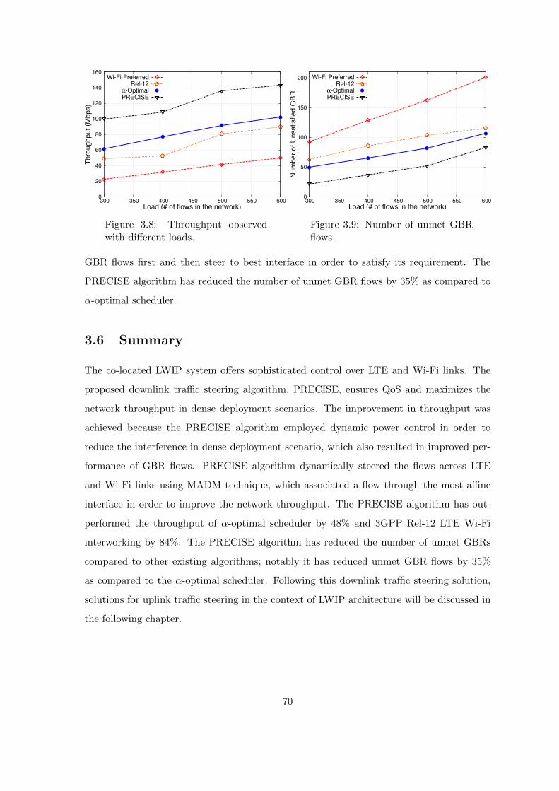
0
20
40
60
80
100
120
140
160
300 350 400 450 500 550 600
Thro
ug
hput
(Mbps)
Load (# of flows in the network)
Wi-Fi PreferredRel-12
α-OptimalPRECISE
Figure 3.8: Throughput observedwith different loads.
0
50
100
150
200
300 350 400 450 500 550 600
Nu
mber
of U
nsatisfied
GB
R
Load (# of flows in the network)
Wi-Fi PreferredRel-12
α-OptimalPRECISE
Figure 3.9: Number of unmet GBRflows.
GBR flows first and then steer to best interface in order to satisfy its requirement. The
PRECISE algorithm has reduced the number of unmet GBR flows by 35% as compared to
α-optimal scheduler.
3.6 Summary
The co-located LWIP system offers sophisticated control over LTE and Wi-Fi links. The
proposed downlink traffic steering algorithm, PRECISE, ensures QoS and maximizes the
network throughput in dense deployment scenarios. The improvement in throughput was
achieved because the PRECISE algorithm employed dynamic power control in order to
reduce the interference in dense deployment scenario, which also resulted in improved per-
formance of GBR flows. PRECISE algorithm dynamically steered the flows across LTE
and Wi-Fi links using MADM technique, which associated a flow through the most affine
interface in order to improve the network throughput. The PRECISE algorithm has out-
performed the throughput of α-optimal scheduler by 48% and 3GPP Rel-12 LTE Wi-Fi
interworking by 84%. The PRECISE algorithm has reduced the number of unmet GBRs
compared to other existing algorithms; notably it has reduced unmet GBR flows by 35%
as compared to the α-optimal scheduler. Following this downlink traffic steering solution,
solutions for uplink traffic steering in the context of LWIP architecture will be discussed in
the following chapter.
70
Chapter 4
Uplink traffic steering in LWIP
architecture
In the previous chapter, it was discussed about effectively utilizing the radio resources
of LWIP nodes in downlink. It was concluded in Chapter 2 that employing Wi-Fi to
carry only downlink IP traffic improves the overall performance of the LWIP system (since
uplink in Wi-Fi involves contentions). However, completely preventing uplink transmissions
in Wi-Fi of LWIP system could incur longer uplink queuing delay. Also, when LTE link
quality becomes poor then Wi-Fi only in downlink fails to meet the QoS requirements. This
chapter addresses the fundamental problems which prevent Wi-Fi performing efficient uplink
transmissions in LWIP system by proposing various uplink traffic steering mechanisms.
4.1 Motivation
The major challenge to enable uplink transmissions through Wi-Fi in LWIP system is its
contention based MAC operation. It allows a Wi-Fi node to transmit on the expiry of
chosen backoff value, which could lead to collision if backoffs of two or more nodes expire
at the same time. This collision probability increases with the number of contending nodes
on the channel in Wi-Fi. LWIP involves tight coupling of LTE and Wi-Fi, and it enables
LTE to have finer control over Wi-Fi. This property of LWIP will be exploited in this
chapter in order to reduce the number of collisions in the Wi-Fi domain by regulating
uplink transmissions.
Towards this, an uplink traffic steering framework in the context of LTE Wi-Fi integra-
71

tion is proposed in this chapter with the following objectives:
1. Obtaining the optimal fraction of uplink traffic to be steered through Wi-Fi to maxi-
mize uplink throughput.
2. Reducing number of collisions with distributed access control.
3. Achieving fair operation with other background Wi-Fi nodes operating on the channel.
4.1.1 Design requirements for Uplink traffic steering
Fig. 4.1 shows the possible optimization in saturated and unsaturated regions in Wi-Fi
domain. In the unsaturated region, the activity on Wi-Fi channel is low. Hence, the UEs
associated with LWIP node can offload traffic from the LTE interface to the Wi-Fi interface
and thereby enhancing the utilization of the Wi-Fi channel. In the saturated region, the
activity on Wi-Fi channel is high. The channel efficiency can be achieved by avoiding
collisions among users contending in the uplink. Hence, the primary challenge which has
to be addressed is a large number of collisions occurring in Wi-Fi domain. Reduction in
collisions can be achieved by coordinating uplink transmissions on Wi-Fi channel with the
help of a primary carrier like LTE. An efficient uplink traffic steering algorithm should have
the following properties:
1. The uplink traffic steering algorithm should operate fairly with other users operating
on Wi-Fi channel i.e., native Wi-Fi users on the channel should not be affected.
2. The uplink traffic steering algorithm should facilitate at least the transmission oppor-
tunity that DCF (Distributed Co-ordination Function) would have provided.
3. The uplink traffic steering algorithm should reduce the number of collisions due to
simultaneous transmissions by multiple nodes on the Wi-Fi channel as compared to
DCF.
4. The decision taken by uplink traffic steering solution should be prominent and hold till
subsequent control channel broadcast (Master Information Block - MIB and System
Information Block - SIBs) in LTE in order to maintain consistency in traffic steering.
In other words, between two consecutive LTE broadcast messages, any decision taken
such as uplink flow offloading or uplink packet scheduling should not change.
72

Packet Arrival Rate (pkts/sec)
Th
rou
gh
pu
t (M
bp
s)
Saturated Region
Rate of Uplink through
Wi-Fi interface of LWIP
user can be increased
Regulate rate of
uplink Wi-Fi transmission
of UE with the help
of LTE interface
UnSaturated Region
Figure 4.1: The optimization which is feasible in Wi-Fi domain.
4.2 Related work
In this section, the evolution of LTE Wi-Fi integration will be elaborated and the state-of-
the-art integration architectures will be presented.
It is reported in [64] that not much work has been done on uplink traffic steering; instead
some works have been done in the context of power saving. The existing uplink traffic of-
floading techniques aim to save the battery power of the UEs. Here are a few existing uplink
traffic offloading works in the literature with the objective to improve power efficiency and
enable proportional routing. In [65], the authors have proposed two uplink traffic offload-
ing algorithms to improve the energy efficiency of the UEs and to increase the offloaded
data volume under concurrent use of two access technologies using IP Flow Mobility and
Seamless Offload (IFOM). In the first algorithm, UEs with high volume data are promoted
and given priority in accessing Wi-Fi Access Point (AP) to offload their data. The second
algorithm does a proportionally fair bandwidth allocation based on data needs of the UEs.
In [66], a weighted Proportionally Fair Bandwidth (PFB) allocation algorithm for the Wi-
Fi access in conjunction with a pricing-based rate allocation for the LTE uplink access is
developed. In [67], the authors have proposed an energy efficient offloading algorithm which
chooses the users to be offloaded at a lower computational complexity, with an objective
of minimizing the energy spent by the users associated with LTE and Wi-Fi networks. To
the best of our knowledge, none of the existing works have focused on improving the Wi-Fi
channel utilization by using LTE for regulating uplink Wi-Fi transmissions. Even though
there exist numerous solutions for steering traffic across LTE and Wi-Fi links in downlink
steering, interestingly, not much work has been done in uplink traffic steering.
73

4.3 Proposed NCF algorithms for uplink traffic steering
In order to realize efficient uplink traffic steering in LWIP, in this chapter we propose a
Network Coordination Function (NCF) which has various uplink traffic steering algorithms
aggregated. Fig. 4.2 shows the enhanced LWIP architecture which supports uplink traffic
steering as well. Link Aggregation Layer (LAL) is responsible for steering the traffic across
LTE and Wi-Fi links which exists at both LWIP node and LWIP-UE. NCF includes novel
medium access control algorithms and flow regulation algorithms employed at SeNB and
UE. The list of proposed algorithms are as follows:
1. Dynamic Optimal Uplink Traffic steering Algorithm (DOUTA)
2. Fast UpliNk through Direct medium access (FUND)
3. FUND with fair Channel Access (FUND++)
4. Enhanced UpliNk With viRtuAl Polling (E-UNWRAP)
Tunnel
UE
SeNB Wi-Fi
Figure 4.2: Enhanced LWIP architecture which supports both downlink and uplink trafficsteering.
Fig. 4.3 shows design objectives for developing various NCF algorithms. These algo-
rithms operate at different layers with multiple objectives, but all the algorithms have one
common objective, which is to maximize the Wi-Fi channel utilization by reducing channel
74

time wasted due to collisions. NCF facilitates the network to make intelligent decisions
rather than individual UEs deciding to steer the uplink traffic onto LTE or Wi-Fi link. The
NCF algorithms work by leveraging the availability of LTE as the anchor to improvise the
channel utilization of Wi-Fi. Also, these algorithms do uplink traffic steering by taking
inputs from both LTE and Wi-Fi links. NCF coordinates both the LTE and Wi-Fi trans-
missions by regulating the uplink flow rate and improvising the existing medium access
techniques.
Figure 4.3: Objectives of Network Coordination Function Algorithms.
The proposed NCF, implemented at LWIP node and LWIP-UEs, maximizes the channel
utilization of Wi-Fi link as compared to DCF mechanism, and ensures fairness in the channel
access. NCF targets to maximize the network level throughput along with fairness by
employing a centralized coordination among LWIP users, but in case of DCF, user level
fairness is ensured in a long run even though it may not lead to efficient channel utilization.
Fig. 4.4 shows proposed NCF algorithms and their features.
Table 4.1, in a nutshell, presents the layer of operation for different NCF algorithms
and the kind of operations performed by them. A network operator can employ these
algorithms: either one of them at a time or couple the algorithm operating at the IP
layer with the algorithm operating at the MAC layer. Among NCF algorithms, DOUTA
does not require any modification at UE side and hence it can be readily deployed with
75

modifications restricted only to LWIP node. If the finer level of coordination at the MAC
layer is required, then FUND, FUND++, and E-UNWRAP can be employed. It is to
be noted that the proposed NCF algorithms focus on improving the network throughput
without changing the semantics of Wi-Fi QoS. Each of these algorithms has its own merits
which are enumerated below, they are as follows:
Network Coordination
Function
FUND
DOUTA
Coordination through flow control
Regulating the contention rate
FUND++
UNWRAP
Fair transmission opportunity for each user
Coordination through Medium Access Control
Enhanced medium access through virtual polling
Enables coordinated uplink transmission alongside
of DCF
Fairness in medium access across multiple
networks operating in the channel
Coordination through Medium Access Control
Figure 4.4: Proposed NCF Algorithms.
FUND is preferred in situations where the time duration that is given to an LWIP
user is proportional to that of legacy Wi-Fi user in accessing the Wi-Fi channel.
FUND++ is most appropriate in situations where the transmission opportunities
given to LWIP user and legacy Wi-Fi user on the channel are equal.
DOUTA is chosen in situations where user’s Wi-Fi MAC has to be kept unaltered and
better throughput has to be obtained only by optimizing the flow rate.
E-UNWRAP is recommended when LWIP users and legacy Wi-Fi users contend for
the channel at the same time. Internally, the LWIP users collisions are resolved by
LWIP node, so LWIP users do not physically collide and thereby preventing collisions
on the Wi-Fi channel.
It is notable that NCF algorithms focus on optimizing Wi-Fi uplink transmissions con-
sidering that LTE is available to send out the outstanding packets which Wi-Fi could not
76

Table 4.1: Characteristics of proposed NCF algorithms
Algorithm Operating Layer Operation performed
DOUTA IP Layer Controlling the packet steering rate
FUND MAC Layer Facilitates fair medium access opportunity
FUND++ MAC Layer Regulates medium access duty cycles
E-UNWRAP MAC Layer Coordinates through virtual polling
transmit. For all the NCF algorithms, we study only the performance of Wi-Fi uplink trans-
missions with an assumption that LTE performance is unaltered due to scheduled MAC
employed in LTE.
4.3.1 Dynamic Optimal Uplink Traffic steering Algorithm (DOUTA)
DOUTA has been designed with the objective of controlling collisions on the Wi-Fi chan-
nel by regulating the packet steering rate onto LTE and Wi-Fi interfaces of LWIP node
(downlink) and LWIP-UE (uplink). Here is a small network scenario which explains the
importance of uplink steering. A Wi-Fi network of one BSS is considered. The number of
Wi-Fi stations (users) in the network connected to the AP is varied and the performance is
observed. The users transmit packets of size 1500 bytes with varying inter-packet interval
defined by the experiment. The packet inter-packet interval for a packet transmitted is
varied from 10 packets/sec to 50 packets/sec for each Wi-Fi station. Figs. 4.5, 4.6, and
4.7 show that by varying the number of users in the network (5, 10, and 20) and varying
the packet arrival rate (10, 20, 30, 40, and 50 pkts/sec/station) the normalized network
throughput reaches to the maximum value at a particular packet arrival rate. This value
is specific for a given number of users in the network. The peak is observed at certain
packet arrival rates, because at that given packet arrival rate the DCF mechanism is able
to deliver more packets successfully as compared to the saturated case (where the number
of collisions becomes constant). DOUTA explores this phenomenon and finds the optimal
point at which the network could attain maximum throughput. Packet steering rate (PSR)
onto LTE and Wi-Fi links correspond to the fraction of packets sent to LTE and Wi-Fi
queues out of the total incoming packets from the higher layer.
Fig. 4.8 and 4.9 show the traffic steering structure at LWIP node and LWIP-UE, re-
spectively. The Traffic Steering Master (TSM) runs the DOUTA algorithm and obtains the
PSR onto LTE and Wi-Fi interfaces for both the LWIP node and LWIP-UEs. The Traffic
77

PAR at AP (pkts/sec)
2
4
60
6
8
×105
Thro
ughput (b
ps)
10
40
2050
PAR at UE (pkts/sec)
4030200 100
Figure 4.5: Aggregate Wi-Fithroughput observed with five UEsin the network.
PA
R a
t AP
(pkts/se
c)
Thro
ughput (b
ps)
4
5
60
6
7
8
×105
9
40
10
20
PAR at UE (pkts/sec)
5040300 20100
Figure 4.6: Aggregate Wi-Fithroughput observed with 10 UEs inthe network.
PAR at U
E (pkts
/sec)
PAR at AP (pkts/sec)
60
404
5
200
6
10
×105
Thro
ughput (b
ps)
7
20
8
30
9
40 050
Figure 4.7: Aggregate Wi-Fi throughput observed with 20 UEs in the network.
Steering Slave (TSS) obtains the uplink PSR from TSM and regulates the LWIP-UE uplink
traffic through Wi-Fi and LTE interfaces. We have considered a scenario with an LWIP
node and a set of ‘N ′ LWIP-UEs associated to it. The objective function of the optimiza-
tion problem is to maximize network throughput, subjected to medium access constraints
(abiding DCF rules). As users run different applications, and the volume of traffic gener-
ated by each user is non-identical, which makes the constraints of the optimization problem
multi-dimensional.
Optimal uplink packet steering rate
An optimization problem is formulated for maximizing the Wi-Fi network throughput given
’N ’ LWIP-UEs and one LWIP node in the LWIP system. The optimal fraction of incoming
packets that has to be sent through Wi-Fi interface of LWIP node and LWIP-UE can be
78
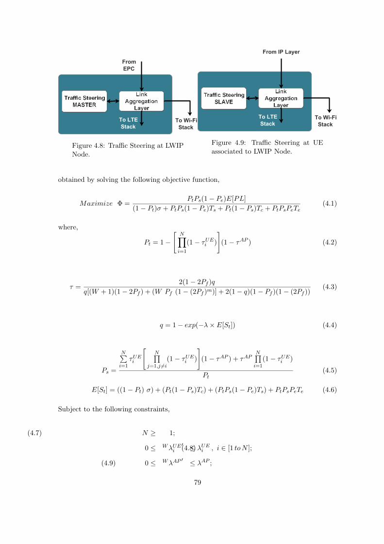
To LTE
Stack
From
EPC
To Wi-Fi
Stack
Figure 4.8: Traffic Steering at LWIPNode.
To LTE
Stack
From IP Layer
To Wi-Fi
Stack
Figure 4.9: Traffic Steering at UEassociated to LWIP Node.
obtained by solving the following objective function,
Maximize Φ =PtPs(1− Pe)E[PL]
(1− Pt)σ + PtPs(1− Pe)Ts + Pt(1− Ps)Tc + PtPsPeTe(4.1)
where,
Pt = 1−
[N∏i=1
(1− τUEi )
](1− τAP ) (4.2)
τ =2(1− 2Pf )q
q[(W + 1)(1− 2Pf ) + (W Pf (1− (2Pf )m)] + 2(1− q)(1− Pf )(1− (2Pf ))(4.3)
q = 1− exp(−λ× E[St]) (4.4)
Ps =
N∑i=1
τUEi
[N∏
j=1,j 6=i(1− τUEi )
](1− τAP ) + τAP
N∏i=1
(1− τUEi )
Pt(4.5)
E[St] = ((1− Pt) σ) + (Pt(1− Ps)Tc) + (PtPs(1− Pe)Ts) + PtPsPeTe (4.6)
Subject to the following constraints,
N ≥ 1; (4.7)
0 ≤ WλUEi′ ≤ λUEi , i ∈ [1 toN ]; (4.8)
0 ≤ WλAP′ ≤ λAP ; (4.9)
79
Here, Φ is the objective function to be maximized, which is a closed form expression for
the throughput of a Wi-Fi network, derived from [68] by considering the Wi-Fi channel
to be ideal with non-saturated traffic. In Equation (4.1), Pe corresponds to the packet
error probability and E[PL] corresponds to the expected payload length. Pt corresponds
to probability that at least one transmission happens in the network which is expressed by
Equation (4.2) and Ps corresponds to the probability that a given transmission is successful.
λUEi represents ith UE’s packet generation rate (to be sent over uplink) and λAP represents
the packet arrival rate to LWIP node (to be sent over downlink). WλUEi and WλAP denote
the packet steering rates (fraction of the total packets to be sent to the Wi-Fi interface
queue) of LWIP-UE and LWIP node, respectively. WλUEi′
and WλAP′
denote the optimal
packet steering rates which can obtained by varying WλUEi and WλAP for which Φ is the
maximum. The remaining packets of the stream are sent to LTE queue (LλUEi ) so that
they could be delivered over LTE interface. This optimization problem can be extended by
considering other background Wi-Fi devices on the channel. After inclusion of other devices,
the objective function Φ remains unaltered where as Pt and Ps have minor modifications to
factor in transmissions of all the other devices. τ corresponds to the transmission probability
of a given node which is expressed in Equation (4.3). It also shows the relation between
τ and probability of having at least one packet in the buffer q. Equation (4.4) shows the
relation between λ and q. E[St] corresponds to expected duration of a time slot. Here,
σ, Tc, Ts, and Te correspond to duration of time slot in case of idle, collision, successful
transmission, and channel error, respectively. Values for σ, Tc, Ts, and Te correspond to the
duration of SIFS, DIFS, packet transmission time, and ACK transmission time, respectively.
The relation between τ , Pt, and Ps is given in Equation (4.5). The throughput of the system
(Equation (4.1)) increases with the increase in the success probability, which is controlled by
λ and N . For a network with known user count, throughput is solely controlled by λ. Hence,
altering λ value varies the network throughput. The control parameter WλUEi′
varies from
zero to λUEi ; one of the best operating solutions would be to set all WλUEi′
to zero so that
WλAP′will take the value of λAP , which will reflect Wi-Fi operating only in downlink mode,
and all the uplink data has to be sent through LTE. But it contradicts with our objective of
enabling efficient uplink transmissions through Wi-Fi. A network operator can decide the
lower bound on the fraction of uplink to be supported through Wi-Fi. Enforcing it in the
lower bound of the above mentioned constraints, the optimization solution will fetch the
80

best packet steering rate for LTE and Wi-Fi links with minimum uplink transmission rate.
Algorithm 2 Dynamic Optimal Uplink Traffic Steering Algorithm (DOUTA).
Input:λUEi , λAP ← Packet arrival rates of ith UE and LWIP node’s APN ← Number of active users in the channelLλUEi ← Fraction of packets steered to LTE interface of ith UEWλUEi ← Fraction of packets steered to Wi-Fi interface of ith UE
Output: WλAP′ ← Optimal packet steering rate to Wi-Fi interface at AP
WλUEi′ ← Optimal packet steering rate to Wi-Fi interface of ith UE
1: for Every T ms do . Trigger interval is ’T’ ms . Compute the optimal offload fraction2: Φ(WλAP
′, λAP ,WλUE
′, λUE)
3: if WλAP > WλAP′OR WλUEi > WλUE
′i ∈ [1 to N ] then
. Current packet steering rate of LWIP-AP or LWIP-UE is higher than the obtainedoptimal traffic steering rate - regulate the packet steering at UE or AP
4: Steer a traffic fraction λδ to interface Ik =LTE5: Ω(λδ, Ik)6: else if WλAP == WλAP
′and WλUE == WλUE
′then
. Current packet steering rate is optimal, do not let the packet steering rate toincrease or decrease
7: ω(WλAP′, WλUE
′)
8: else. Interfaces are not loaded, packet steering rate can be increased to achieve maximumthroughput
9: Steer a traffic fraction λδ to interface Ik =Wi-Fi10: Ω(λδ, Ik)11: end if12: end for
Algorithm 2 shows the working procedure of DOUTA. The incoming packets are steered
to LTE and Wi-Fi queues in order to achieve maximum system throughput. In Algorithm 2,
LWIP node obtains all the input parameters for the proposed algorithm such as uplink traffic
arrival rate of each LWIP-UE (obtained from the buffer status report (BSR)) and observed
throughput of each LWIP-UE (on both the LTE and Wi-Fi links) through LTE uplink
control channel. The output of the DOUTA algorithm i.e., allowable uplink traffic rate is
conveyed to LWIP-UEs through the downlink control channel of LTE. The optimization
algorithm is triggered at every T ms interval to find the optimal fraction of packets to be
sent through Wi-Fi interface. We have conducted experiments and monitored the network
throughput at different granularity of time intervals ‘T’ viz., 10, 100, and 300 ms. Fig. 4.10
shows the instantaneous network throughputs reported at LWIP node. If Algorithm 2 runs
at an interval of 10 or 100 ms, it can mislead decisions as fluctuations in the network
81

Algorithm 3 Ω(λδ, Ik) Steering the traffic
Input: λδ ← Fraction of traffic to be steeredIk ← Interface to which traffic has to be steeredFi ← Information of ith flowfor i=0; i < Fmax; i++ do
if λdelta >0 thenλdelta ← λdelta − flowsize(Fi) . Flow size in packets per unit timeInterface(Fi)← Ik
elsebreak;
end ifend for
throughput are very high. However, the decision taken at an interval of 300 ms is stable
and captures the actual network state as depicted in Fig. 4.10.
If the current packet steering rate through Wi-Fi interface is higher than the optimal
packet steering rate, then the packet steering rate to Wi-Fi interface is reduced by, steering
a fraction of the total packets (λδ) to LTE interface, which is given by Ω. The function
Ω controls the fraction of traffic that has to move from LTE to Wi-Fi interface and vice-
versa, whereas ω sustains the traffic offload rate when the global optimal solution is reached.
Algorithm 3 details the operations of Ω.
DOUTA algorithm is scalable as it does not involve any additional signaling overhead.
Also, the DOUTA algorithm of NCF can be adopted by LWIP systems without any protocol
stack level modifications at the UE side, which is an added advantage. The optimization
problem shown in Equation (4.1) is solved using a MATLAB-based solver (fmincon) which
solves it in the order of milliseconds. In case of real deployment, for different incoming
packet arrival rates and different number of UEs, the optimal allowable uplink traffic rates
can be precomputed and then stored in a look-up table. Such a look-up table based solution
eliminates the need for running a solver on-the-fly at LWIP node and LWIP-UEs.
4.3.2 Fast UpliNk through Direct medium access (FUND)
The DOUTA algorithm, explained in the previous section, aims to improve the network
throughput by regulating the traffic at the IP layer. DOUTA maximizes the network
throughput by regulating the flows (load), but it may not completely eliminate collisions on
the channel (which is the primary reason for poor throughput in dense deployment scenar-
ios), which can only be done by coordinating the uplink transmissions at the MAC layer.
82

0
5
10
15
20
25
30
35
40
45
50
0 2 4 6 8 10
Thro
ughput (M
bps)
Time (Sec)
T = 10 msT = 100 msT = 300 ms
Figure 4.10: Instantaneous network throughputs observedfor different decision-making intervals (T).
Hence, we propose FUND algorithm which coordinates the uplink transmissions at the
MAC layer in order to improve the Wi-Fi channel utilization by reducing collisions among
LWIP-UEs.
Algorithm 4 Fast UpliNk through Direct medium access (FUND)
Input: Ui ← Uplink requirement of ith LWIP-UEN ← Number of active devices operating on Wi-Fi channelm← Number of LWIP-UEs having uplink demandTFON , T
FOFF ← Duration of FUND ON PERIOD and FUND OFF PERIOD
TFCY C ← TFON + TFOFFOutput: Scheduling order for LWIP-UEs (So)
1: for Every FUND CYCLE (TFCY C) do2: if FUND ON PERIOD then3: So ← F(Ui, n, L) . Proportional allocation based on flow requirement4: Notify LWIP-UEs about So through LTE control message5: Employ FUND medium access procedure6: else . FUND OFF PERIOD7: Set So for all the LWIP-UEs to NULL . LWIP-UEs do not transmit in FUND
OFF PERIOD.8: Every other node does data transmission by following DCF procedure9: end if
10: FON ← Number of active LWIP−UEsTotal number of active nodes on the channel =⇒ m
N
11: TFON ← TFCY C × FON . is duration of the FUND ON PERIOD12: TFOFF ← TFCY C × (1− FON ) . is duration of the FUND OFF PERIOD13: end for
FUND Operation Procedure: The entire duration of the transmission is divided
into two access periods as depicted in Fig. 4.11. A FUND CYCLE comprises of FUND
ON PERIOD and FUND OFF PERIOD. During FUND ON PERIOD, the UEs associated
with LWIP will operate based on Algorithm 4. In Fig. 4.11, during FUND ON PERIOD,
83
the fast uplink is achieved by enabling LWIP-UEs to transmit after the PCF Inter Frame
Spacing (PIFS) time interval, which ensures that LWIP-UEs will occupy the channel earlier
than any standalone Wi-Fi stations using DCF mechanism for channel access. LWIP-UEs
transmission/scheduling order is pre-computed by LWIP node and sent through LTE control
messages. The scheduling order is obtained by choosing those LWIP-UEs which have uplink
data to transmit; this information is obtained from buffer status report (BSR) which is a
periodic report sent to LTE SeNB by each UE through LTE uplink control channel. LWIP-
UEs which have uplink data to transmit are sorted based on their buffer occupancy to obtain
the scheduling order. Every LWIP-UE after receiving the scheduling order (So) through LTE
control messages waits for its opportunity. So remains unmodified till next scheduling order
which is given via LTE control messages. Every LWIP-UE waits for its opportunity and
transmits. During FUND OFF PERIOD none of the LWIP-UE contends for the channel.
If an LWIP-UE needs to transmit uplink data in the next FUND CYCLE, then it should
notify the uplink requirement Ui (of ith LWIP-UE) in advance. LWIP node uses Ui to do a
proportional allocation in uplink transmission F(Ui,m). Here m corresponds to the number
of LWIP-UEs with the uplink requirement. FUND algorithm finds the number of nodes
actively contending on the channel (N), by observing the transmissions on the channel with
unique Wi-Fi MAC addresses.
4.3.3 FUND with fair channel access (FUND++)
FUND++ is designed in order to enhance FUND operation fairly with Non-LWIP-UEs
on the Wi-Fi channel. Algorithm 5 details the medium access procedure of FUND++.
Similar to FUND, FUND++ has FUND++ ON PERIOD and FUND++ OFF PERIOD.
Duration of FUND++ ON PERIOD and FUND++ OFF PERIOD are regulated in order
to achieve fair transmission opportunity with Non-LWIP-UEs. FUND++ ON PERIOD and
FUND++ OFF PERIOD are controlled based on successful packet transmission of LWIP
and Non-LWIP nodes on the channel. If more collisions are observed during FUND++ OFF
PERIOD (DCF), then the duration of FUND++ OFF PERIOD is extended in order to
allow the Non-LWIP-UEs to get fair amount of successful transmissions with those of LWIP-
UEs. Number of packets successfully transmitted by ith LWIP-UE and ith Non-LWIP-
UE through Wi-Fi interface is denoted as SiL and SiNL, respectively. In this algorithm,
TF+ON and TF+
OFF correspond to FUND++ ON PERIOD and FUND++ OFF PERIOD,
84

Figure 4.11: Operation of FUND algorithm.
respectively. FUND++ CYCLE (TF+CY C) is the sum of FUND++ ON and OFF PERIOD
(TF+CY C = TF+
ON + TF+OFF ). The FUND++ algorithm starts with TF+
ON = mN × T
F+CY C , then
based on the successful packet transmissions observed by LWIP-UEs and Non-LWIP-UEs,
the value gets changed to TF+ON =
∑i S
iNL∑
i SiNL+
∑i S
iL× TF+
CY C . If more packets collide, then
FUND++ OFF PERIOD extends. This ensures fairness in successful packet transmissions
across LWIP-UEs and Non-LWIP-UEs.
The comparison between FUND and FUND++ is detailed as follows.
In case of FUND, the time interval for LWIP transmissions is kept constant (only based
on active users). In a FUND cycle, users are given uplink transmission opportunities
based on their BSR and QoS requirements.
In case of FUND++, the FUND++ ON and FUND++ OFF PERIODs are varied
according to the fraction of successfully transmitted packets by LWIP-UEs and Non-
LWIP-UEs on the channel.
FUND++ operates in more fairer manner with other Wi-Fi nodes on the channel
compared to FUND, and it also approaches the throughput achieved by FUND on
the channel.
85

Algorithm 5 FUND++
Input: SiL ← Number of packets successfully transmitted by ith LWIP-UESiNL ← Number of packets successfully transmitted by ith Non-LWIP-UETF+ON , T
F+OFF ← Duration of FUND++ ON PERIOD and FUND++ OFF PERIOD
TF+CY C ← TF+
ON + TF+OFF . A FUND++ cycle duration
Ui ← Uplink requirement of ith LWIP-UEOutput: Scheduling order (So) for LWIP-UEs and TF+
ON , TF+OFF
Initial Value: TF+ON ←
mN ∗ T
F+CY C and TF+
OFF ← TF+CY C − T
F+ON
1: for Every FUND++ CYCLE (TF+CY C) do
2: if FUND++ ON PERIOD then3: So ← F(Ui, n, L) . Proportional allocation based on flow requirement4: Notify LWIP-UEs about So through LTE control message5: Employ FUND medium access procedure6: else . FUND++ OFF PERIOD7: Set So for all the LWIP-UEs to NULL . LWIP-UEs do not transmit in
FUND++ OFF PERIOD.8: Every other node does data transmission following DCF procedure9: end if
10: TF+ON ←
∑i S
iNL∑
i SiNL+
∑i S
iL× TF+
CY C
11: TF+OFF ←
∑i S
iL∑
i SiNL+
∑i S
iL× TF+
CY C
12: end for
4.3.4 Enhanced UpliNk With viRtuAl Polling (E-UNWRAP)
The problem that exists with FUND and FUND++ algorithms is that they divide the
channel access for LWIP-UEs and Non-LWIP-UEs separately (FUND ON PERIOD and
FUND OFF PERIOD). A Non-LWIP-UE following DCF is prevented from transmitting
in uplink during FUND ON PERIOD because LWIP-UEs occupy the channel immediately
after the PCF time interval. In order to relax this bifurcation of channel access time and to
allow any Non-LWIP-UE to contend for the channel at any given time, we propose Enhanced
UpliNk With viRtuAl Polling (E-UNWRAP) algorithm. This algorithm coordinates the
medium access for LWIP-UEs and ensures no collisions among LWIP-UEs even if they follow
the DCF mechanism like any other Non-LWIP-UE. The term virtual polling corresponds
to LWIP node polling each LWIP-UE for uplink packet availability in its Wi-Fi queue.
PCF mode of Wi-Fi also supports similar scheduling of Wi-Fi transmissions using polling
mechanism. However, polling is inefficient due to periodic query on each UE’s Wi-Fi inter-
face even when the packets are not available with UE [69]. The null frame is sent as the
reply by UE to Wi-Fi AP when there is no packet to transmit in the uplink. Note that,
the underutilization of resources observed in Wi-Fi domain can be resolved by leveraging
86

the availability of LTE interface in LWIP, where polling is carried out using LTE link. LTE
control messages can be used to make a query to the LWIP-UE about its Wi-Fi queue
status, which can further be used in creating a scheduling order for the uplink transmis-
sions. Such a co-ordinated operation can ensure that no two LWIP-UEs connected to LWIP
node can transmit at the same time. The actual collisions which could be happening on
the Wi-Fi channel among LWIP-UEs are nullified. This way of resolving the collisions is
possible only with LWIP architecture. E-UNWRAP also has an objective to regulate the
virtual contention period (VCP), which is achieved by observing the collisions among other
nodes on the channel, hence it operates by taking the number of observed collisions on the
channel as an input.
The virtual contention period can be operated in three possible modes.
1. Constant Cycle Operation: In constant cycle operation, VCP has a fixed cycle
duration which is unaltered. Given the fixed cycle duration, based on the effective
throughput that can be achieved by an LWIP node, the uplink steering can be regu-
lated.
2. Varying Cycle Operation: In varying cycle operation, VCP employs a time-varying
cycle which is controlled by taking collisions observed on the channel as an input.
Based on the collisions observed during the DCF period (non-VCP), the VCP is
made to shrink or expand dynamically. During the non-VCP period, LWIP-UEs con-
tend along with standalone Wi-Fi users in the network. The only difference between
VCP and non-VCP period is that the contention window regulation (explained in
Section 4.3.4) is made only in VCP.
3. Full Cycle Operation: In full cycle operation, the LWIP-UEs are made to work
as if the VCP period is available all the time. LWIP node schedules each uplink
transmission of the user based on the number of packets in the user’s queue. Also, full
cycle operation allows changing the contention window of LWIP-UE. In the following,
we have detailed the working procedure of full cycle operation.
E-UNWRAP with FULL cycle operation for Virtual Polling
E-UNWRAP works with two basic approaches: (1) Scheduling Wi-Fi transmissions with
an auxiliary LTE interface and (2) Regulating the Wi-Fi contention window. Scheduling
87
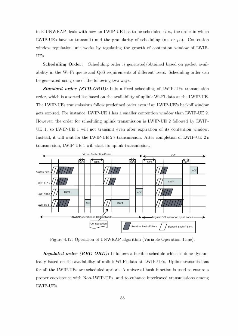
in E-UNWRAP deals with how an LWIP-UE has to be scheduled (i.e., the order in which
LWIP-UEs have to transmit) and the granularity of scheduling (ms or µs). Contention
window regulation unit works by regulating the growth of contention window of LWIP-
UEs.
Scheduling Order: Scheduling order is generated/obtained based on packet avail-
ability in the Wi-Fi queue and QoS requirements of different users. Scheduling order can
be generated using one of the following two ways.
Standard order (STD-ORD): It is a fixed scheduling of LWIP-UEs transmission
order, which is a sorted list based on the availability of uplink Wi-Fi data at the LWIP-UE.
The LWIP-UEs transmissions follow predefined order even if an LWIP-UE’s backoff window
gets expired. For instance, LWIP-UE 1 has a smaller contention window than LWIP-UE 2.
However, the order for scheduling uplink transmission is LWIP-UE 2 followed by LWIP-
UE 1, so LWIP-UE 1 will not transmit even after expiration of its contention window.
Instead, it will wait for the LWIP-UE 2’s transmission. After completion of LWIP-UE 2’s
transmission, LWIP-UE 1 will start its uplink transmission.
Figure 4.12: Operation of UNWRAP algorithm (Variable Operation Time).
Regulated order (REG-ORD): It follows a flexible schedule which is done dynam-
ically based on the availability of uplink Wi-Fi data at LWIP-UEs. Uplink transmissions
for all the LWIP-UEs are scheduled apriori. A universal hash function is used to ensure a
proper coexistence with Non-LWIP-UEs, and to enhance interleaved transmissions among
LWIP-UEs.
88

Contention Window Regulation: Contention window regulation procedure (CWRP)
has two main purposes: (1) To support developing the REG-ORD and (2) To coexist
fairly with Non-LWIP-UEs. CWRP supports REG-ORD by controlling the backoff value of
LWIP-UE which in turn makes the transmission to be ordered. A universal hash function
is employed to set individual LWIP-UE’s backoff value. The hash function ensures that
there will be no collision among the users connected to the LWIP node while maintaining
the fair channel sharing with background Wi-Fi users on the same channel. A universal
hash function, ha,b(x) = ((ax+ b)mod p), where p is a prime number greater than or equal
to the average contention window (operational contention window: CWopr). The value
of the average contention window is varied based on the number of collisions observed on
the channel in the last observation period. Algorithm 6 shows that CWopr increases when∑θicol
T spkt
is greater than the collision threshold (CTcol), where θicol corresponds to the num-
ber of transmissions that got collided for ith user on the channel and T spkt counts the total
number of successful packets transmitted. CWopr doubles when the number of collisions
observed on the channel is greater than CTcol. The value of CWopr decreases exponentially
when the number of collisions observed is lesser than CTcol. Hence, harmony in channel
sharing is achieved with Non-LWIP-UEs operating on the channel, and at the same time
collisions among LWIP-UEs are resolved internally.
4.3.5 Realization of NCF algorithms in LWIP System
This subsection describes the implementation details of proposed NCF algorithms. NCF
works across (layers 2 and 3) MAC and IP layers of LWIP node. Some of the proposed
NCF algorithms need LWIP-UEs to perform certain operations based on the input received
from the LWIP node.
In the case of DOUTA, LWIP node instructs its associated LWIP-UEs about the al-
lowable number of uplink packets that can be transmitted by each LWIP-UE. To obtain
the number of uplink packets to be transmitted in the uplink, the optimization problem
(Equation (4.1)) has to be solved. Solving the optimization problem is done at LWIP node,
whereas throttling the number of uplink packet transmissions through Wi-Fi interface is
done at LWIP-UE.
In case of FUND, during FUND ON PERIOD, LWIP-UEs will transmit one after the
other, according to the transmission order given by LWIP node. During FUND OFF PE-
89

Algorithm 6 E-UNWRAP - Full Cycle operation of VCP
Input: θicol ← Collision observed by ith LWIP-UE on the channel during the observationperiodN ← Number of users (LWIP and non LWIP users) in the channelp← First prime number greater than CWopr
Tpkts ← Total number of transmissions in observation periodNUL ← Number of LWIP-UEs having uplink data to transmitCTcol ← Collision thresholdOutput: a, b← Coefficients for universal hash function
1: for NUL uplink users do2: h(a, b)← (ak + b)mod p . k is an unique user ID (can be MAC ID)3: end for . a and b ensure no collision by assigning different contention slots amongNUL uplink users
4: if∑θicol∑Tpkts
≥ CTcol then
5: CWopr ← CWopr × 26: else7: CWopr ← CWopr/2 . Reduce the contention window and find new hash function8: end if9: if CW ≥ CWmax then
10: CW ← CWmax
11: end if12: Broadcast a, b, p to all LWIP-UEs a prior, through control messages of LTE
RIOD, LWIP-UEs will not contend with Non-LWIP-UEs (standalone Wi-Fi UEs) for trans-
missions. Determining the transmission order for LWIP-UEs and notifying FUND ON and
OFF PERIODs to LWIP-UEs are done by LWIP node, whereas performing uplink trans-
missions in the obtained transmission order is done by respective LWIP-UEs. In case of
FUND++, the procedure involved is similar to that of FUND except for the duration of
ON and OFF PERIODs which are regulated to achieve better fairness across LWIP-UEs
and Non-LWIP-UEs.
In case of UNWRAP, LWIP-UEs set their backoff values based on a function determined
by LWIP node. This backoff window function ensures no collisions among LWIP-UEs in
the virtual polling period. During the DCF period, LWIP-UEs backoff window function
follows the legacy DCF mechanism. LWIP node gives the function for choosing backoff to
its associated LWIP-UEs.
4.3.6 Benefits of NCF algorithms
The benefits of different NCF algorithms are detailed as follows. DOUTA: It can be observed
that DOUTA has focused on steering the traffic at LTE and Wi-Fi links of LWIP and LWIP-
90
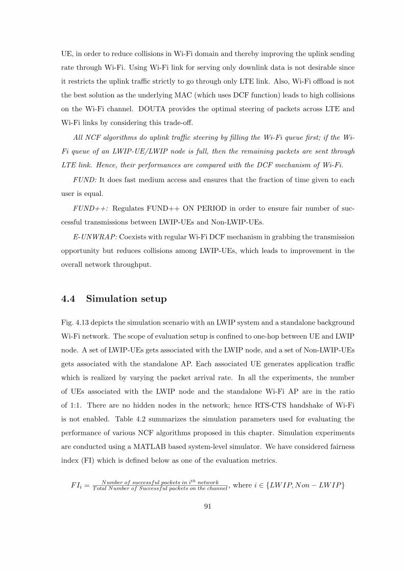
UE, in order to reduce collisions in Wi-Fi domain and thereby improving the uplink sending
rate through Wi-Fi. Using Wi-Fi link for serving only downlink data is not desirable since
it restricts the uplink traffic strictly to go through only LTE link. Also, Wi-Fi offload is not
the best solution as the underlying MAC (which uses DCF function) leads to high collisions
on the Wi-Fi channel. DOUTA provides the optimal steering of packets across LTE and
Wi-Fi links by considering this trade-off.
All NCF algorithms do uplink traffic steering by filling the Wi-Fi queue first; if the Wi-
Fi queue of an LWIP-UE/LWIP node is full, then the remaining packets are sent through
LTE link. Hence, their performances are compared with the DCF mechanism of Wi-Fi.
FUND: It does fast medium access and ensures that the fraction of time given to each
user is equal.
FUND++: Regulates FUND++ ON PERIOD in order to ensure fair number of suc-
cessful transmissions between LWIP-UEs and Non-LWIP-UEs.
E-UNWRAP: Coexists with regular Wi-Fi DCF mechanism in grabbing the transmission
opportunity but reduces collisions among LWIP-UEs, which leads to improvement in the
overall network throughput.
4.4 Simulation setup
Fig. 4.13 depicts the simulation scenario with an LWIP system and a standalone background
Wi-Fi network. The scope of evaluation setup is confined to one-hop between UE and LWIP
node. A set of LWIP-UEs gets associated with the LWIP node, and a set of Non-LWIP-UEs
gets associated with the standalone AP. Each associated UE generates application traffic
which is realized by varying the packet arrival rate. In all the experiments, the number
of UEs associated with the LWIP node and the standalone Wi-Fi AP are in the ratio
of 1:1. There are no hidden nodes in the network; hence RTS-CTS handshake of Wi-Fi
is not enabled. Table 4.2 summarizes the simulation parameters used for evaluating the
performance of various NCF algorithms proposed in this chapter. Simulation experiments
are conducted using a MATLAB based system-level simulator. We have considered fairness
index (FI) which is defined below as one of the evaluation metrics.
FIi = Number of successful packets in ith networkTotal Number of Successful packets on the channel , where i ∈ LWIP,Non− LWIP
91
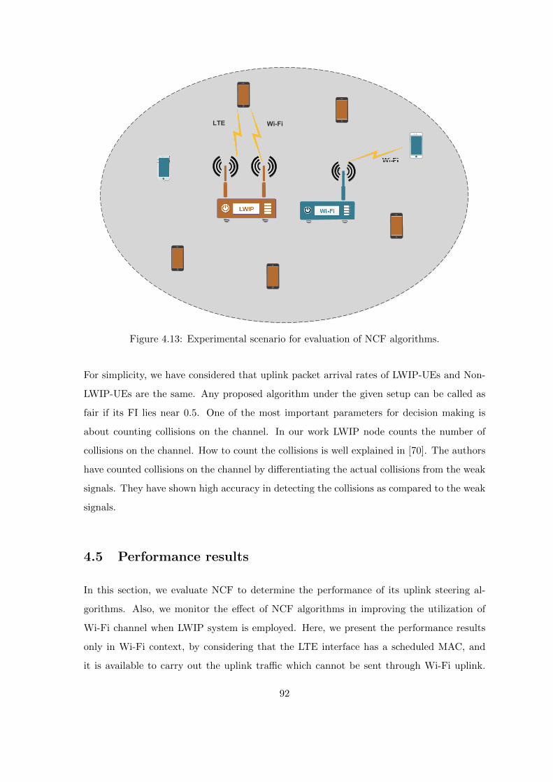
LTE Wi-Fi
Figure 4.13: Experimental scenario for evaluation of NCF algorithms.
For simplicity, we have considered that uplink packet arrival rates of LWIP-UEs and Non-
LWIP-UEs are the same. Any proposed algorithm under the given setup can be called as
fair if its FI lies near 0.5. One of the most important parameters for decision making is
about counting collisions on the channel. In our work LWIP node counts the number of
collisions on the channel. How to count the collisions is well explained in [70]. The authors
have counted collisions on the channel by differentiating the actual collisions from the weak
signals. They have shown high accuracy in detecting the collisions as compared to the weak
signals.
4.5 Performance results
In this section, we evaluate NCF to determine the performance of its uplink steering al-
gorithms. Also, we monitor the effect of NCF algorithms in improving the utilization of
Wi-Fi channel when LWIP system is employed. Here, we present the performance results
only in Wi-Fi context, by considering that the LTE interface has a scheduled MAC, and
it is available to carry out the uplink traffic which cannot be sent through Wi-Fi uplink.
92

Table 4.2: Simulation parameters for evaluation of NCF algorithms
Parameter Value
Number of users N ⇒[10 to 30]
The fraction of users connected to LWIP Node N/2
Non-LWIP Wi-Fi users N/2
Simulation Time 100 Seconds
Mobility Model Static
Packet arrival rate per device [102 to 103] packets per sec
Number of seeds 10
DIFS 28 µsec
PIFS 20 µsec
SIFS 10 µsec
ACK size 16 bytes
Wi-Fi PHY data rate 65 Mbps
Payload size (IP Packet) 1470 bytes
MAC of LWIP-Users NCF
MAC of Non-LWIP-Users DCF
MAC+PHY header size 24+16 bytes
The performance of the NCF algorithms is compared with most widely used DCF based
medium access mechanism of Wi-Fi. The evaluation aims at obtaining the following three
crucial metrics of analysis for all the experiments.
1. How efficiently collisions are reduced on Wi-Fi channel: Observed Collisions
2. By how much throughput of Wi-Fi network has improved because of NCF - Observed
Throughput
3. How NCF works fairly with DCF in accessing the channel - Observed Fairness
4.5.1 Performance results of DOUTA algorithm
Fig. 4.14 shows variation in the Wi-Fi network throughput of both LWIP and background
Wi-Fi users when DOUTA and Wi-Fi offload algorithms are employed. The load offered
by each UE/STA is varied from 100 to 700 packets/sec. The variation in throughput is
closely observed by increasing the number of UEs in the network from 10 to 30. In the case
of Wi-Fi offload algorithm, each LWIP-UE prefers to send data through Wi-Fi interface
whenever the Wi-Fi link is available (Wi-Fi Preferred Algorithm [61]) and follows DCF
mechanism for medium access. DOUTA also follows the DCF procedure, but it tends to
control the uplink traffic sent through Wi-Fi channel when the offered load increases. In
93

other words, DOUTA instructs each LWIP-UE the optimal fraction of traffic that has to be
sent through Wi-Fi uplink, which is obtained by solving the optimization function discussed
in Section 4.3.1 and allowing rest of the traffic to be sent through LTE interface. Such a
regulated transmission in Wi-Fi uplink has reduced the contention on the network, thereby
reducing the time elapsed in collisions which can be observed in Fig. 4.15. In Fig. 4.15,
the X-axis captures the offered load and Y-axis represents time elapsed in collisions, over
the simulation time which has been normalized to 10 seconds. It can be observed that
the time elapsed in collisions varies from 2 to 3 seconds out of 10 seconds in the saturated
region. Also, Wi-Fi has 7% improvement in the network throughput in case of DOUTA as
compared to that of Wi-Fi offload algorithm (DCF+Wi-Fi offload). The time elapsed in
collisions has also been reduced by 13%. This throughput improvement is achieved without
incurring any additional signaling overhead in the core network.
5
10
15
20
25
30
100 200 300 400 500 600 700
Thro
ughp
ut (M
bp
s)
Offered Load Per UE (Packets/Second)
DCF:Wi-Fi Offloading N=10DOUTA N=10
DCF:Wi-Fi Offloading N=20DOUTA N=20
DCF:Wi-Fi Offloading N=30DOUTA N=30
Figure 4.14: Variation in Wi-Fi throughput with offered load -DCF:Wi-Fi Offloading vs DOUTA.
0
500000
1e+06
1.5e+06
2e+06
2.5e+06
3e+06
100 200 300 400 500 600 700
Tim
e e
lapse
d in
co
llisio
ns (
µ s
ec)
Offered Load Per UE (Packets/Second)
DCF:Wi-Fi Offloading N=10DOUTA N=10
DCF:Wi-Fi Offloading N=20DOUTA N=20
DCF:Wi-Fi Offloading N=30DOUTA N=30
Figure 4.15: Variation in timeelapsed in collisions with offered load- DCF:Wi-Fi Offloading vs DOUTA.
4.5.2 Performance results of FUND algorithm
Fig. 4.16 shows time elapsed in collisions by varying offered load for DCF and NCF:FUND
mechanisms. The term NCF:FUND and FUND are used interchangeably. As the packet
arrival rate (offered load) increases the number of collisions observed also increases in DCF
mechanism. As the number of users vary from 10 to 30, FUND exhibits a significant
performance improvement compared to DCF. FUND has reduced the number of collisions
by 50% as compared to legacy DCF mechanism by coordinating the uplink transmission
and by using fast channel access technique. Reduction in collisions has eventually led to
94

high throughput as shown in Fig. 4.17. FUND ensures collisionless transmissions among
LWIP-UEs by sending the uplink schedule vector through LTE interface, which contains the
transmission order for each LWIP-UE. But the greedy access to channel reduces fairness
among the users on the Wi-Fi channel. Fig. 4.18 shows fairness among UEs concerning
successful packet transmissions while using DCF and FUND algorithms. When LWIP-UEs
and Non-LWIP-UEs employ DCF mechanism, then 0.5 is their expected FI, which is clear
from the plot. Shifting FI above 0.5 conveys that the algorithm is greedy and facilitates
more opportunities for LWIP-UEs as compared to Non-LWIP-UEs. This is because FUND
enables the LWIP-UEs to get served immediately after the PIFS interval, whereas Non-
LWIP-UEs are served after DIFS interval followed by a random backoff. Even though
FUND algorithm allows a biased utilization of resources benefiting LWIP-UEs, it ensures
proportional FUND ON PERIOD and FUND OFF PERIOD based on the number of LWIP-
UEs and Non-LWIP-UEs present on the channel. Eventually, the fraction of time given for
each user to perform uplink transmission is equal in FUND algorithm. Hence, it provides
fairness at the granularity of number of users operating on the channel. FUND++ is a
dynamic approach to further improve the fairness of users in terms of successful packet
transmissions. Nevertheless, FUND is the most efficient of all NCF algorithms in terms of
channel utilization.
0
500000
1e+06
1.5e+06
2e+06
2.5e+06
3e+06
100 200 300 400 500 600 700
Tim
e e
lapse
d in
co
llisio
ns (
µ s
ec)
Offered Load Per UE (Packets/Second)
DCF N=10FUND N=10
DCF N=20FUND N=20
DCF N=30FUND N=30
Figure 4.16: Variation in timeelapsed in collisions with offered load- DCF vs NCF:FUND.
5
10
15
20
25
30
35
40
45
50
100 200 300 400 500 600 700
Thro
ughp
ut (M
bp
s)
Offered Load Per UE (Packets/Second)
DCF N=10FUND N=10
DCF N=20FUND N=20
DCF N=30FUND N=30
Figure 4.17: Variation in Wi-Fithroughput with offered load - DCFvs NCF:FUND.
95
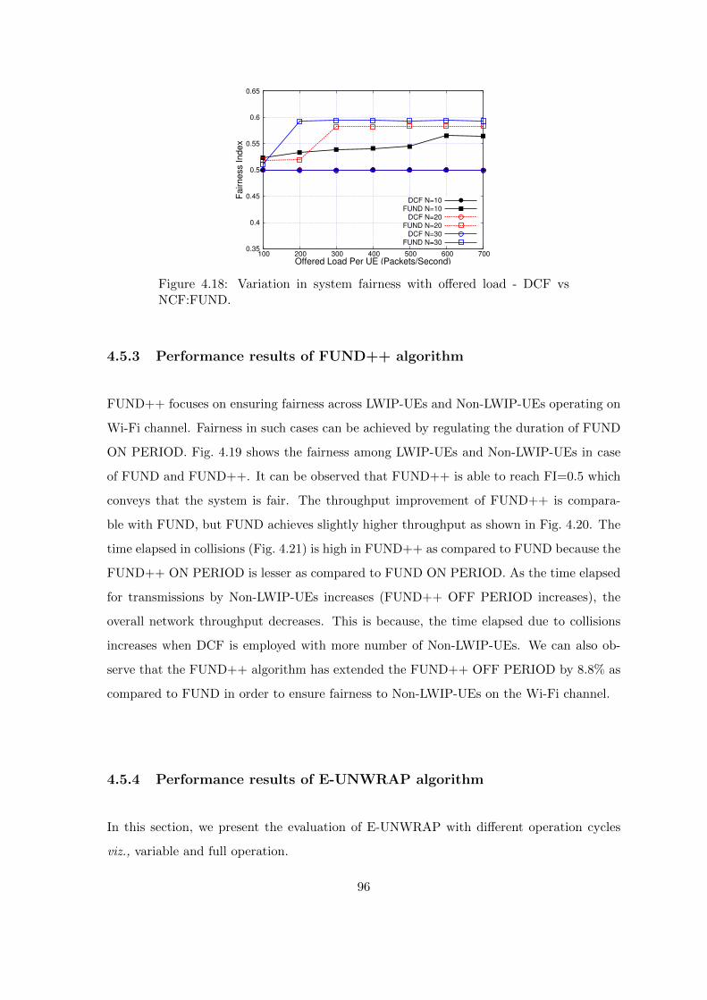
0.35
0.4
0.45
0.5
0.55
0.6
0.65
100 200 300 400 500 600 700
Fairness In
dex
Offered Load Per UE (Packets/Second)
DCF N=10FUND N=10
DCF N=20FUND N=20
DCF N=30FUND N=30
Figure 4.18: Variation in system fairness with offered load - DCF vsNCF:FUND.
4.5.3 Performance results of FUND++ algorithm
FUND++ focuses on ensuring fairness across LWIP-UEs and Non-LWIP-UEs operating on
Wi-Fi channel. Fairness in such cases can be achieved by regulating the duration of FUND
ON PERIOD. Fig. 4.19 shows the fairness among LWIP-UEs and Non-LWIP-UEs in case
of FUND and FUND++. It can be observed that FUND++ is able to reach FI=0.5 which
conveys that the system is fair. The throughput improvement of FUND++ is compara-
ble with FUND, but FUND achieves slightly higher throughput as shown in Fig. 4.20. The
time elapsed in collisions (Fig. 4.21) is high in FUND++ as compared to FUND because the
FUND++ ON PERIOD is lesser as compared to FUND ON PERIOD. As the time elapsed
for transmissions by Non-LWIP-UEs increases (FUND++ OFF PERIOD increases), the
overall network throughput decreases. This is because, the time elapsed due to collisions
increases when DCF is employed with more number of Non-LWIP-UEs. We can also ob-
serve that the FUND++ algorithm has extended the FUND++ OFF PERIOD by 8.8% as
compared to FUND in order to ensure fairness to Non-LWIP-UEs on the Wi-Fi channel.
4.5.4 Performance results of E-UNWRAP algorithm
In this section, we present the evaluation of E-UNWRAP with different operation cycles
viz., variable and full operation.
96
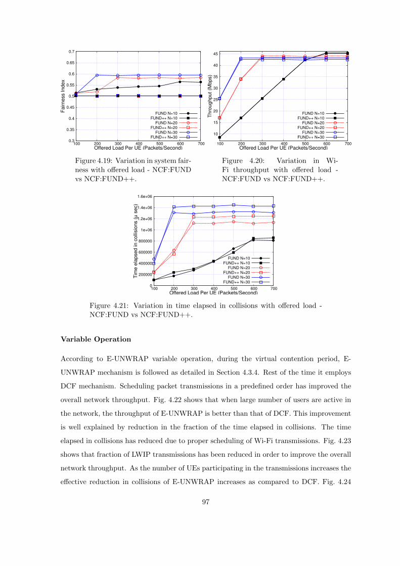
0.3
0.35
0.4
0.45
0.5
0.55
0.6
0.65
0.7
100 200 300 400 500 600 700
Fairness In
dex
Offered Load Per UE (Packets/Second)
FUND N=10FUND++ N=10
FUND N=20FUND++ N=20
FUND N=30FUND++ N=30
Figure 4.19: Variation in system fair-ness with offered load - NCF:FUNDvs NCF:FUND++.
10
15
20
25
30
35
40
45
100 200 300 400 500 600 700
Thro
ug
hput
(Mbps)
Offered Load Per UE (Packets/Second)
FUND N=10FUND++ N=10
FUND N=20FUND++ N=20
FUND N=30FUND++ N=30
Figure 4.20: Variation in Wi-Fi throughput with offered load -NCF:FUND vs NCF:FUND++.
0
200000
400000
600000
800000
1e+06
1.2e+06
1.4e+06
1.6e+06
100 200 300 400 500 600 700
Tim
e e
lapse
d in
co
llisio
ns (
µ s
ec)
Offered Load Per UE (Packets/Second)
FUND N=10FUND++ N=10
FUND N=20FUND++ N=20
FUND N=30FUND++ N=30
Figure 4.21: Variation in time elapsed in collisions with offered load -NCF:FUND vs NCF:FUND++.
Variable Operation
According to E-UNWRAP variable operation, during the virtual contention period, E-
UNWRAP mechanism is followed as detailed in Section 4.3.4. Rest of the time it employs
DCF mechanism. Scheduling packet transmissions in a predefined order has improved the
overall network throughput. Fig. 4.22 shows that when large number of users are active in
the network, the throughput of E-UNWRAP is better than that of DCF. This improvement
is well explained by reduction in the fraction of the time elapsed in collisions. The time
elapsed in collisions has reduced due to proper scheduling of Wi-Fi transmissions. Fig. 4.23
shows that fraction of LWIP transmissions has been reduced in order to improve the overall
network throughput. As the number of UEs participating in the transmissions increases the
effective reduction in collisions of E-UNWRAP increases as compared to DCF. Fig. 4.24
97

shows that LWIP-UEs have subdued their transmission opportunities in order to improve
the overall network performance.
5
10
15
20
25
30
35
100 200 300 400 500 600 700
Thro
ug
hput
(Mbps)
Offered Load Per UE (Packets/Second)
DCF N=10UNWRAP-VAR N=10
DCF N=20UNWRAP-VAR N=20
DCF N=30UNWRAP-VAR N=30
Figure 4.22: Variation in Wi-Fithroughput with offered load - DCFvs NCF:UNWRAP - Variable oper-ation.
0
500000
1e+06
1.5e+06
2e+06
2.5e+06
3e+06
100 200 300 400 500 600 700
Tim
e e
lap
sed in c
olli
sio
ns (
µ s
ec)
Offered Load Per UE (Packets/Second)
DCF N=10UNWRAP-VAR N=10
DCF N=20UNWRAP-VAR N=20
DCF N=30UNWRAP-VAR N=30
Figure 4.23: Variation in timeelapsed in collisions with offered load- DCF vs NCF:UNWRAP - Variableoperation.
0
0.2
0.4
0.6
0.8
1
100 200 300 400 500 600 700
Fairne
ss I
nd
ex
Offered Load Per UE (Packets/Second)
DCF N=10UNWRAP-VAR N=10
DCF N=20UNWRAP-VAR N=20
DCF N=30UNWRAP-VAR N=30
Figure 4.24: Variation in system fair-ness with offered load - DCF vsNCF:UNWRAP - Variable opera-tion.
5
10
15
20
25
30
35
40
100 200 300 400 500 600 700
Thro
ughp
ut (M
bp
s)
Offered Load Per UE (Packets/Second)
DCF N=10UNWRAP N=10
DCF N=20UNWRAP N=20
DCF N=30UNWRAP N=30
Figure 4.25: Variation in Wi-FiThroughput with offered load - DCFvs NCF:E-UNWRAP - Full opera-tion.
Full operation
In full operation mode, the VCP is spread over the entire duration, and contention windows
of LWIP-UEs are regulated by the contention window regulation module. Fig. 4.25 shows
a significant improvement (21%) in the network throughput for E-UNWRAP with full op-
eration in comparison to DCF. This unleashes the power of LWIP in regulating the usage
of Wi-Fi spectrum effectively. This phenomenon can be well explained using Fig. 4.26; it
98

shows the collisions among LWIP-UEs have been significantly reduced, thus resulting in the
overall improvement in throughput. The number of collisions has reduced because of co-
ordinated Wi-Fi transmission among LWIP-UEs. The coordination in Wi-Fi transmissions
is achieved by sending a scheduled order through LTE link. E-UNWRAP has not grabbed
more channel access opportunities as compared to DCF. It is fair and Fig. 4.27 shows that
it even subdues its transmission opportunities in order to increase opportunities for legacy
Wi-Fi nodes operating on the same channel.
0
500000
1e+06
1.5e+06
2e+06
2.5e+06
3e+06
100 200 300 400 500 600 700
Tim
e e
lap
sed in c
olli
sio
ns (
µ s
ec)
Offered Load Per UE (Packets/Second)
DCF N=10UNWRAP N=10
DCF N=20UNWRAP N=20
DCF N=30UNWRAP N=30
Figure 4.26: Variation in timeelapsed in collisions with offered load- DCF vs NCF:E-UNWRAP - Fulloperation.
0
0.2
0.4
0.6
0.8
1
100 200 300 400 500 600 700
Fa
irne
ss Inde
x
Offered Load Per UE (Packets/Second)
DCF N=10UNWRAP N=10
DCF N=20UNWRAP N=20
DCF N=30UNWRAP N=30
Figure 4.27: Variation in system fair-ness with offered load - DCF vsNCF:E-UNWRAP - Full operation.
Table 4.3: Comparison of NCF algorithms
Parameters DOUTA FUND FUND++ E-UNWRAP
MAC changes Not Required Required Required Required
Improves Improves Operates ImprovesFairness Non-LWIP LWIP with Non-LWIP
opportunities opportunities Fairness opportunities
Better than Better than Better than Better thanThroughput Wi-Fi offload DCF DCF DCF
by 7% by 36% by 23% by 21%
Compatibility Works Modifications are Modifications are Modifications arewith UEs Readily Required Required Required
Operation Continuous Interleaved Interleaved Continuous
Type with TFON with TF+ON
Time Reduced by Reduced by Reduced by Reduced byelapsed 13% w.r.t. 56% w.r.t. 52% w.r.t. 33% w.r.t.
in collisions to Wi-Fi offload to DCF to DCF to DCF
99

4.6 Summary
In this chapter, we have presented various NCF algorithms with an objective of improving
the Wi-Fi channel utilization by enabling efficient uplink transmissions in LWIP system.
The developed algorithms are diverse in their objectives, layer of operation, and type of op-
eration. We compared the proposed NCF algorithms with highly successful DCF mechanism
of IEEE 802.11 standard. The existence of a primary interface (LTE) facilitates efficient co-
ordination in uplink transmissions by LWIP-UEs and Non-LWIP-UEs on contention based
Wi-Fi channel, which resulted in efficient Wi-Fi channel utilization. The developed NCF
algorithms are shown to operate fairly with legacy Wi-Fi networks operating on the same
Wi-Fi channel; some algorithms subdue their benefits in order to improve overall network
performance.
Table 4.3 presents quantitative and qualitative comparison of various NCF algorithms
with DCF of 802.11 standard. Using extensive simulation experiments, we observe that the
proposed NCF algorithms have reduced collisions in Wi-Fi uplink by 13-56% and thereby
improved overall network throughput by 7-36% as compared to Wi-Fi offload with DCF
mechanism of Wi-Fi. A network operator can deploy the NCF algorithm, DOUTA, with-
out requiring any modifications at UE. If a finer level of coordination at the MAC layer is
required, then FUND, FUND++, and E-UNWRAP can be employed with minor modifica-
tions at UE protocol stack. The proposed algorithms could also work in case of other RLI
architectures with minor modifications.
100

Chapter 5
Optimizing LWIP to efficiently
support transport layer protocols
In Chapter 3 and 4 various traffic steering solutions are presented for LWIP architectures
to effectively use the radio resources of LTE and Wi-Fi networks i.e., with the perspective
of optimizing link layer performance. But, this chapter introduces a technique which can be
incorporated into traffic steering to improve performance of transport layer protocols such
as TCP.
5.1 Motivation
Tighter interworking architectures like LWIP can harvest full benefits of link aggregation
only when they do traffic steering at the packet level. Downlink packet steering in LWIP
context refers to dynamically forwarding some packets of a downlink flow that arrive at
LWIP node (i.e., SeNB) through LTE link and the rest through Wi-Fi link. But a naive link
aggregation strategy like packet split naive link aggregation strategy (PS-N-LAS) which does
steering at packet level across multiple links introduces problem for TCP traffic, especially
when data rates of the links are quite different. The packets steered across the links get
delivered at the receiver at different times. As and when the packets are received Out-of-
Order (OOO) at the TCP receiver, it leads to generation of DUPlicate ACKnowledgements
(DUP-ACKs). These unnecessary DUP-ACKs adversely affect the growth of congestion
window and thereby lead to poor TCP performance [71]. DUP-ACKs are predominant
when links are heterogeneous i.e., when one link rate is much faster/slower than the other
101

link. This problem is addressed to some extent in LWA architecture, where PDCP reordering
procedure ensures packets are delivered in-sequence to the TCP layer at the receiver using
Dual Connectivity (DC) [72] reordering procedure. But, during the reordering procedure,
if the packets are buffered for longer duration, it has adverse effect on growth of TCP
congestion window (for instance, congestion control algorithms such as TCP-New Reno [73],
HTCP [74], STCP [75], BIC [76] and HSTCP [77] are dependent on RTT) and hence, results
in poor throughput as shown later in Section 5.5. In case of LWIP, this becomes even
more challenging as packet steering is done at IP layer which lacks any packet reordering
mechanism. Hence, in this chapter, the problem with packet level steering of TCP flows
over the LWIP architecture is addressed by proposing a novel virtual congestion control
mechanism (VIrtual congeStion control wIth Boost acknowLedgEment -VISIBLE). The
proposed mechanism not only improves the throughput of TCP flows by reducing number
of unnecessary DUP-ACKs delivered to the TCP sender but also sends Boost ACKs in
order to keep growing the congestion window and thereby reaps in the aggregate benefits
of heterogeneous links. These Boost ACKs are pseudo ACKs for the actual TCP packets
which are already in the downlink queue of LWIP node. VISIBLE mechanism has been
implemented at LWIP node in such a way that it does not disturb the semantics of TCP.
This chapter is organized as follows, Section 5.2 presents the existing work on addressing
the OOO delivery problem and spurious retransmission triggers. Section 5.3 details the
proposed VISIBLE mechanism and the packet steering technique employed along with it.
In Section 5.4, the simulation setup considered for evaluating the proposed algorithm and
other comparative algorithms are described. Section 5.5 presents the performance results
evaluated. Finally, Section 5.6 summarizes the findings and presents a concluding remarks.
5.2 Related work
This section details the existing works related to two major problems that are being ad-
dressed in this chapter: (1) Reducing triggers that lead to spurious retransmissions and
(2) Reducing OOO packet delivery. Here are some existing works which capture spurious
retransmission problem in multi-hop wireless ad hoc network (inline with the problem of
LWIP). Reducing spurious retransmissions involves the TCP sender to precisely differenti-
ate congestion loss from OOO packet delivery. DOOR [78] detects OOO delivered packet
102
by an additional ordering information in the TCP ACK to avoid redundancy. It adds one
byte TCP option field known as ACK Duplication Sequence Number (ADSN) to TCP ACK
header. When the receiver sends the first ACK for TCP data segment, the ADSN option is
initially marked as zero. It increments ADSN number when it sends a DUP-ACK for the
same sequence number. Extension of DOOR is TCP-DOOR-TS [79] which uses TCP times-
tamp mechanism. The sender keeps track of sending times of the packets with respect to
receiving times and relatively calculates the time stamp of every packet with the previously
received one for detection of OOO packet. TCP receiver sets a field known as ooo option bit
and informs the same to the sender. This method needs an option field to be explicitly set
for its working. Eifel algorithm [80] explains about TCP robustness against spurious re-
transmissions. It has the facility of backward compatibility. It eliminates retransmission
ambiguity and restores the transmission with the next unsent packet.
The forthcoming works include reordering at the receiver side. Delayed ACK [81] in-
troduces a waiting time before the receiver generates a DUP-ACK. This delay in ACK
generation provides an opportunity for the receiver to check the necessity of generating a
DUP-ACK. The drawback of this method is that when an ACK is delayed in slow start
phase, it may negatively affect the growth of TCP congestion window. Other re-ordering
techniques such as Reordering Robust-TCP [82] and TCP-Packet Reordering [83] target
to prevent persistent packet re-ordering from contrivedly activating congestion response by
deferring packet retransmission and congestion response till the occurrence of packet loss.
Here are works specific to multi-RAT aggregation. Khadraoui et al. [84] studied the
performance of TCP in LWA testbed and observed that LWA performs poorly even after
packet reordering. Also it was found that PDCP reordering timer has negative impact on
TCP growth and hence proposed a network coding technique to enhance the performance
of LWA. A well known solution for aggregating multiple links/paths is Multipath TCP
(MPTCP) [85]. The power of multiple sub-flows can be used to harvest the aggregated
bandwidth of links in a multi-homed host. MPTCP receiver aggregates data from multiple
sub-flows, reorders and then delivers it to higher layers. The problem with MPTCP is that
it is not efficient in utilizing multiple links when they have heterogeneous data rates. Also,
decision taken by MPTCP is based on the entire path into consideration even if the problem
resides only with the last hop, which is true more often for wireless networks. Hence, in
this work we propose a solution to enhance the TCP performance in LWIP architecture.
103
5.3 Proposed VISIBLE mechanism for downlink traffic steer-
ing
Proposed VISIBLE mechanism addresses the problems faced by downlink TCP flows in
LWIP networks. It is implemented at LWIP node, and it includes two major components:
(1) Packet steering and (2) Virtual congestion control. Packet steering takes care of forward-
ing the incoming packets of LWIP node into queues of LTE and Wi-Fi (i.e., RLC queue of
LTE stack and MAC queue of Wi-Fi stack) at appropriate rates. Virtual congestion control
helps the TCP sender to grow its congestion window by resolving DUP-ACK problem with
the help of LWIP node, thereby improving throughputs of TCP flows.
5.3.1 LWIP packet steering
The major cause for OOO packet delivery in LWIP networks is due to “speed of slowest
link”. This problem arises when packets of a TCP flow are split across two interfaces and
a packet that is first sent through one interface arrives later than the ones that are sent
through the other interface. This limits TCP throughput to the speed of slowest link. On
one hand, steering all the packets onto one link avoids OOO delivery but it is inefficient in
aggregating multiple links. On the other hand, steering packets in inappropriate fraction
could cause more OOO deliveries. A better packet steering technique is required to split
packets of the incoming TCP flow across LTE and Wi-Fi links. Here, two packet steering
techniques for LWIP networks are presented.
1. Lowest RTT First (L-RTT): This technique resembles MPTCP’s default scheduler
which first fills the congestion window of the link with the lowest RTT and then the
link with higher RTT. In LWIP context, the transmit queue of an interface with the
lowest RTT is filled first before the other interface. Note that RTT here factors in
delay of only the last (wireless) hop, not end-to-end path.
2. Queue Depletion Rate (Q-Depl): The rate of decrease in the length of each
queue is used as a factor for steering the traffic across LTE and Wi-Fi links. The
interface with faster depletion rate receives more packets. The queue depletion rate
is comparable to available data rate of an interface.
104
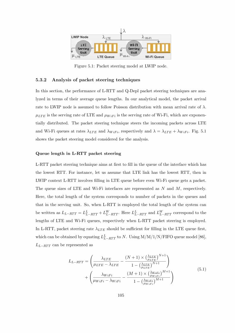
LWIP Node
LTE Queue Wi-Fi Queue
l
m mLTE Wi-Fi
l lLTE Wi-Fi
Figure 5.1: Packet steering model at LWIP node.
5.3.2 Analysis of packet steering techniques
In this section, the performance of L-RTT and Q-Depl packet steering techniques are ana-
lyzed in terms of their average queue lengths. In our analytical model, the packet arrival
rate to LWIP node is assumed to follow Poisson distribution with mean arrival rate of λ.
µLTE is the serving rate of LTE and µWiFi is the serving rate of Wi-Fi, which are exponen-
tially distributed. The packet steering technique steers the incoming packets across LTE
and Wi-Fi queues at rates λLTE and λWiFi, respectively and λ = λLTE + λWiFi. Fig. 5.1
shows the packet steering model considered for the analysis.
Queue length in L-RTT packet steering
L-RTT packet steering technique aims at first to fill in the queue of the interface which has
the lowest RTT. For instance, let us assume that LTE link has the lowest RTT, then in
LWIP context L-RTT involves filling in LTE queue before even Wi-Fi queue gets a packet.
The queue sizes of LTE and Wi-Fi interfaces are represented as N and M , respectively.
Here, the total length of the system corresponds to number of packets in the queues and
that in the serving unit. So, when L-RTT is employed the total length of the system can
be written as LL−RTT = LLL−RTT +LWL−RTT . Here LLL−RTT and LWL−RTT correspond to the
lengths of LTE and Wi-Fi queues, respectively when L-RTT packet steering is employed.
In L-RTT, packet steering rate λLTE should be sufficient for filling in the LTE queue first,
which can be obtained by equating LLL−RTT to N . Using M/M/1/N/FIFO queue model [86],
LL−RTT can be represented as
LL−RTT =
(λLTE
µLTE − λLTE−
(N + 1)×(λLTEµLTE
)N+1
1−(λLTEµLTE
)N+1
)
+
(λWiFi
µWiFi − λWiFi−
(M + 1)×(λWiFiµWiFi
)M+1
1−(λWiFiµWiFi
)M+1
) (5.1)
105
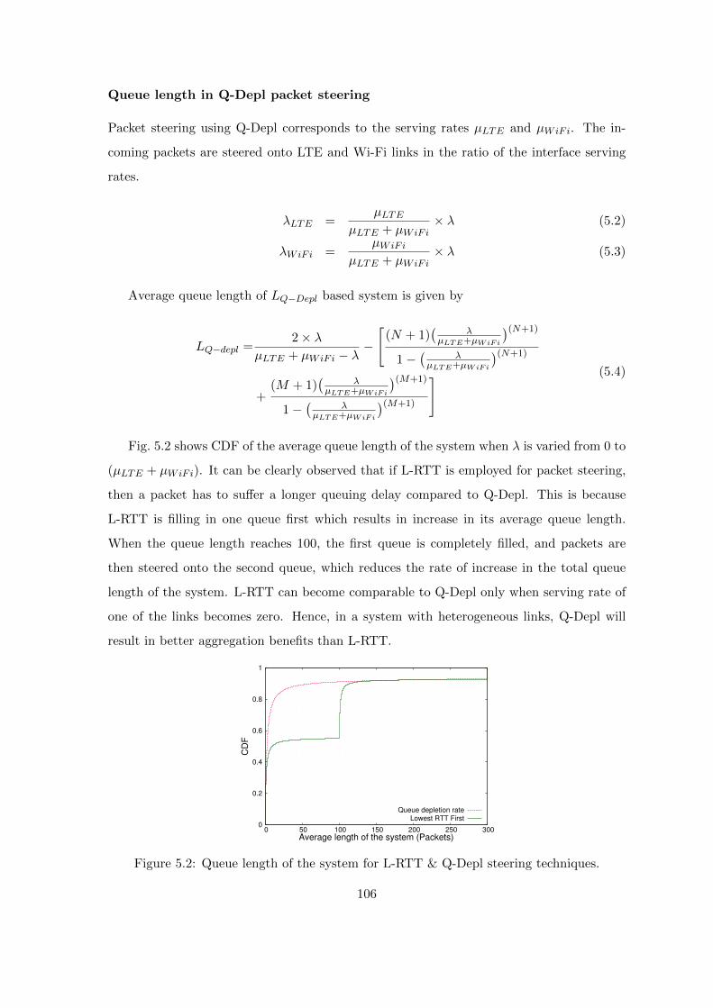
Queue length in Q-Depl packet steering
Packet steering using Q-Depl corresponds to the serving rates µLTE and µWiFi. The in-
coming packets are steered onto LTE and Wi-Fi links in the ratio of the interface serving
rates.
λLTE =µLTE
µLTE + µWiFi× λ (5.2)
λWiFi =µWiFi
µLTE + µWiFi× λ (5.3)
Average queue length of LQ−Depl based system is given by
LQ−depl =2× λ
µLTE + µWiFi − λ−
[(N + 1)
(λ
µLTE+µWiFi
)(N+1)
1−(
λµLTE+µWiFi
)(N+1)
+(M + 1)
(λ
µLTE+µWiFi
)(M+1)
1−(
λµLTE+µWiFi
)(M+1)
] (5.4)
Fig. 5.2 shows CDF of the average queue length of the system when λ is varied from 0 to
(µLTE + µWiFi). It can be clearly observed that if L-RTT is employed for packet steering,
then a packet has to suffer a longer queuing delay compared to Q-Depl. This is because
L-RTT is filling in one queue first which results in increase in its average queue length.
When the queue length reaches 100, the first queue is completely filled, and packets are
then steered onto the second queue, which reduces the rate of increase in the total queue
length of the system. L-RTT can become comparable to Q-Depl only when serving rate of
one of the links becomes zero. Hence, in a system with heterogeneous links, Q-Depl will
result in better aggregation benefits than L-RTT.
0
0.2
0.4
0.6
0.8
1
0 50 100 150 200 250 300
CD
F
Average length of the system (Packets)
Queue depletion rateLowest RTT First
Figure 5.2: Queue length of the system for L-RTT & Q-Depl steering techniques.
106
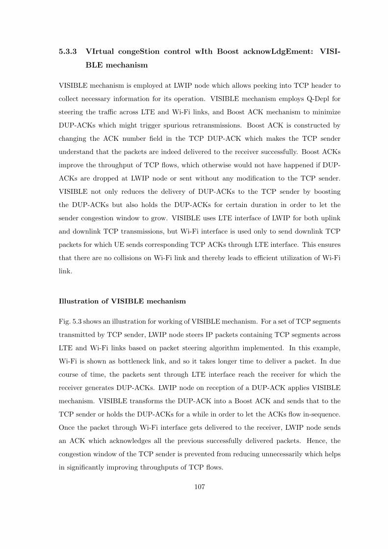
5.3.3 VIrtual congeStion control wIth Boost acknowLdgEment: VISI-
BLE mechanism
VISIBLE mechanism is employed at LWIP node which allows peeking into TCP header to
collect necessary information for its operation. VISIBLE mechanism employs Q-Depl for
steering the traffic across LTE and Wi-Fi links, and Boost ACK mechanism to minimize
DUP-ACKs which might trigger spurious retransmissions. Boost ACK is constructed by
changing the ACK number field in the TCP DUP-ACK which makes the TCP sender
understand that the packets are indeed delivered to the receiver successfully. Boost ACKs
improve the throughput of TCP flows, which otherwise would not have happened if DUP-
ACKs are dropped at LWIP node or sent without any modification to the TCP sender.
VISIBLE not only reduces the delivery of DUP-ACKs to the TCP sender by boosting
the DUP-ACKs but also holds the DUP-ACKs for certain duration in order to let the
sender congestion window to grow. VISIBLE uses LTE interface of LWIP for both uplink
and downlink TCP transmissions, but Wi-Fi interface is used only to send downlink TCP
packets for which UE sends corresponding TCP ACKs through LTE interface. This ensures
that there are no collisions on Wi-Fi link and thereby leads to efficient utilization of Wi-Fi
link.
Illustration of VISIBLE mechanism
Fig. 5.3 shows an illustration for working of VISIBLE mechanism. For a set of TCP segments
transmitted by TCP sender, LWIP node steers IP packets containing TCP segments across
LTE and Wi-Fi links based on packet steering algorithm implemented. In this example,
Wi-Fi is shown as bottleneck link, and so it takes longer time to deliver a packet. In due
course of time, the packets sent through LTE interface reach the receiver for which the
receiver generates DUP-ACKs. LWIP node on reception of a DUP-ACK applies VISIBLE
mechanism. VISIBLE transforms the DUP-ACK into a Boost ACK and sends that to the
TCP sender or holds the DUP-ACKs for a while in order to let the ACKs flow in-sequence.
Once the packet through Wi-Fi interface gets delivered to the receiver, LWIP node sends
an ACK which acknowledges all the previous successfully delivered packets. Hence, the
congestion window of the TCP sender is prevented from reducing unnecessarily which helps
in significantly improving throughputs of TCP flows.
107

In the second part of Fig. 5.3, a TCP segment with sequence number 150 is lost on LTE
link. LWIP node again performs boosting and holding on reception of DUP-ACKs. As the
DUP-ACKs arrival to LWIP node continues even after boost and holding phases, LWIP
node concludes that the packet is actually lost and does a retransmission from its local
buffer. Hence, TCP segment loss that occurred at the link level (LTE/Wi-Fi) is salvaged
locally by the LWIP node.
The proposed VISIBLE is presented in Algorithm 7. Table 5.1 lists out the notations
used in presenting VISIBLE mechanism. Following are the main features that VISIBLE
mechanism encompasses, (1) Rate of boosting DUP-ACKs, (2) Holding DUP-ACKs, and
(3) Reducing packet losses. These main features are presented below in detail.
(1) Boosting DUP-ACKs
During Boost ACK phase, a received DUP-ACK is transformed into a regular ACK by
changing ACK number field of TCP header to a new ACK number. Note that this action is
done only when the packet with sequence number corresponding to the new ACK number
is received by LWIP node from the TCP sender before-hand. The ACK with new ACK
number conveys the sender that the packet got delivered to the receiver successfully, which
makes the sender to grow its congestion window. Boost ACK phase is followed by a skipped
ACK (also called as ACK holding) period in order to align the boosted ACK (new ACK) to
become in-sequence with actual received ACK from the receiver. The rate of boosting ACKs
is a function of available buffer space in queues of LTE and Wi-Fi interfaces. Boosting of
ACKs should be stopped much before the buffer space gets filled up. This ensures that
the actual packets sent by the sender for the boosted ACKs will not get lost in the LWIP
node due to buffer overflow phenomenon. The rate of boosting the ACKs is also reduced
as the queue starts filling up. This is done in order to reduce the rate of growth of sender’s
congestion window so that it can sustain longer time without reduction due to packet losses
induced by the full buffer.
(2) Holding DUP-ACKs
During holding DUP-ACK phase, the actual DUP-ACKs when received at LWIP node are
not sent to the TCP sender instead they are dropped by LWIP node. Dropping too many
DUP-ACKs leads to timeout [87] at the TCP sender and also increases RTT, hence rate of
108

(ACK=110)
(Seq=100)
(ACK=120)
(Seq=110)(Seq=120)
(Seq=130)
(ACK=140)
(ACK=110)
(ACK=110)
(ACK=140)
(ACK=150)
(Seq=140)
(ACK=160)
(Seq=150)(Seq=160)(Seq=170)
(ACK=190)
(ACK=150)
(ACK=150)
(ACK=150)
X
(Seq=180)
(ACK=190)
(Seq=150)
(ACK=110
)
Figure 5.3: An example of virtual congestion control procedure in VISIBLE mechanism.
109
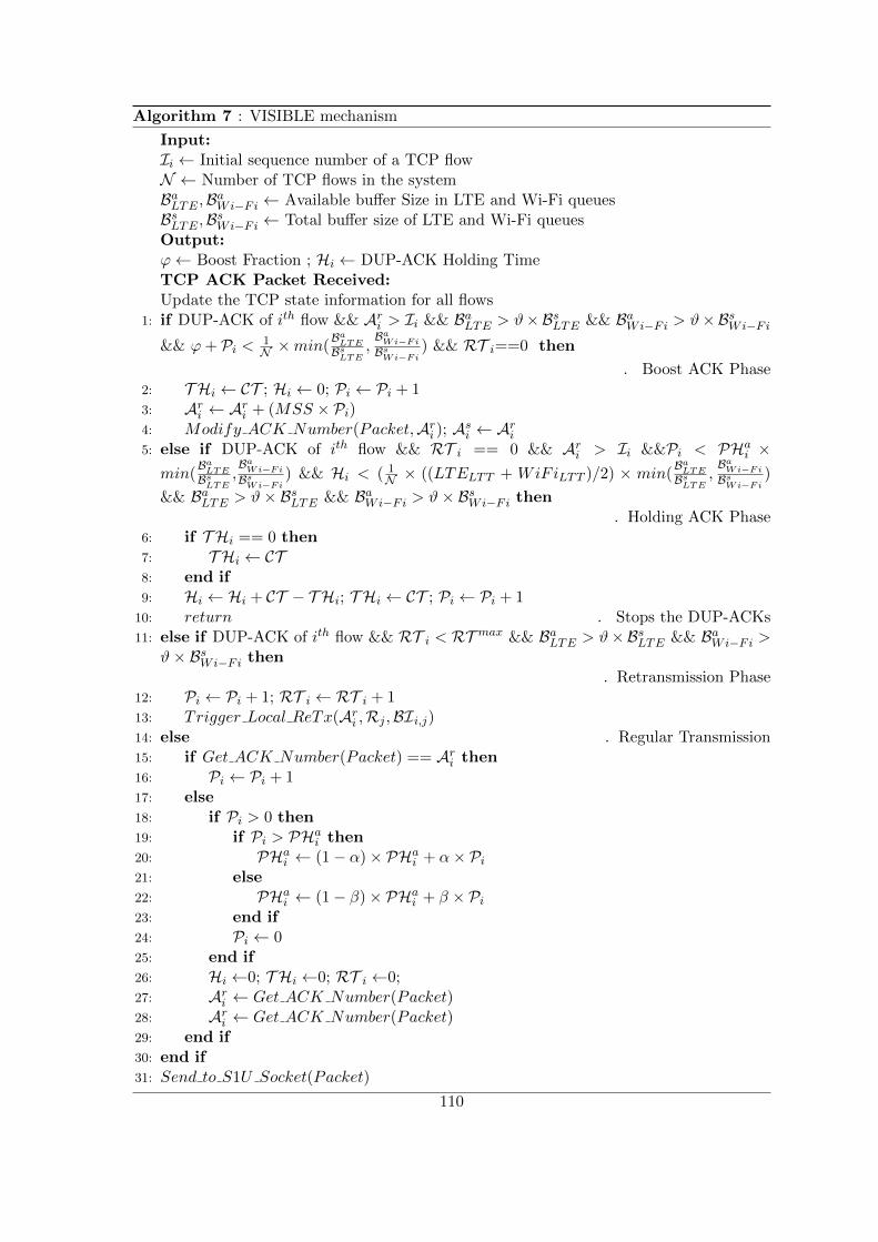
Algorithm 7 : VISIBLE mechanism
Input:Ii ← Initial sequence number of a TCP flowN ← Number of TCP flows in the systemBaLTE ,BaWi−Fi ← Available buffer Size in LTE and Wi-Fi queuesBsLTE ,BsWi−Fi ← Total buffer size of LTE and Wi-Fi queuesOutput:ϕ← Boost Fraction ; Hi ← DUP-ACK Holding TimeTCP ACK Packet Received:Update the TCP state information for all flows
1: if DUP-ACK of ith flow && Ari > Ii && BaLTE > ϑ×BsLTE && BaWi−Fi > ϑ×BsWi−Fi
&& ϕ+ Pi < 1N ×min(
BaLTEBsLTE
,BaWi−Fi
BsWi−Fi) && RT i==0 then
. Boost ACK Phase2: T Hi ← CT ; Hi ← 0; Pi ← Pi + 13: Ari ← Ari + (MSS × Pi)4: Modify ACK Number(Packet,Ari ); Asi ← Ari5: else if DUP-ACK of ith flow && RT i == 0 && Ari > Ii &&Pi < PHai ×min(
BaLTEBsLTE
,BaWi−Fi
BsWi−Fi) && Hi < ( 1
N × ((LTELTT + WiFiLTT )/2) × min(BaLTEBsLTE
,BaWi−Fi
BsWi−Fi)
&& BaLTE > ϑ× BsLTE && BaWi−Fi > ϑ× BsWi−Fi then. Holding ACK Phase
6: if T Hi == 0 then7: T Hi ← CT8: end if9: Hi ← Hi + CT − T Hi; T Hi ← CT ; Pi ← Pi + 1
10: return . Stops the DUP-ACKs11: else if DUP-ACK of ith flow && RT i < RT max && BaLTE > ϑ×BsLTE && BaWi−Fi >
ϑ× BsWi−Fi then. Retransmission Phase
12: Pi ← Pi + 1; RT i ← RT i + 113: Trigger Local ReTx(Ari ,Rj ,BIi,j)14: else . Regular Transmission15: if Get ACK Number(Packet) == Ari then16: Pi ← Pi + 117: else18: if Pi > 0 then19: if Pi > PHai then20: PHai ← (1− α)× PHai + α× Pi21: else22: PHai ← (1− β)× PHai + β × Pi23: end if24: Pi ← 025: end if26: Hi ←0; T Hi ←0; RT i ←0;27: Ari ← Get ACK Number(Packet)28: Ari ← Get ACK Number(Packet)29: end if30: end if31: Send to S1U Socket(Packet)
110
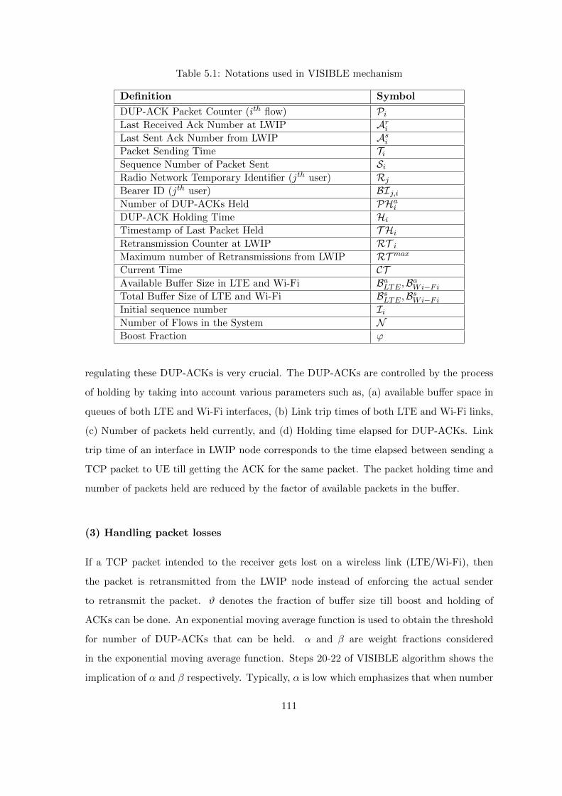
Table 5.1: Notations used in VISIBLE mechanism
Definition Symbol
DUP-ACK Packet Counter (ith flow) PiLast Received Ack Number at LWIP AriLast Sent Ack Number from LWIP AsiPacket Sending Time TiSequence Number of Packet Sent SiRadio Network Temporary Identifier (jth user) RjBearer ID (jth user) BIj,iNumber of DUP-ACKs Held PHaiDUP-ACK Holding Time HiTimestamp of Last Packet Held T HiRetransmission Counter at LWIP RT iMaximum number of Retransmissions from LWIP RT maxCurrent Time CTAvailable Buffer Size in LTE and Wi-Fi BaLTE ,BaWi−FiTotal Buffer Size of LTE and Wi-Fi BsLTE ,BsWi−FiInitial sequence number IiNumber of Flows in the System NBoost Fraction ϕ
regulating these DUP-ACKs is very crucial. The DUP-ACKs are controlled by the process
of holding by taking into account various parameters such as, (a) available buffer space in
queues of both LTE and Wi-Fi interfaces, (b) Link trip times of both LTE and Wi-Fi links,
(c) Number of packets held currently, and (d) Holding time elapsed for DUP-ACKs. Link
trip time of an interface in LWIP node corresponds to the time elapsed between sending a
TCP packet to UE till getting the ACK for the same packet. The packet holding time and
number of packets held are reduced by the factor of available packets in the buffer.
(3) Handling packet losses
If a TCP packet intended to the receiver gets lost on a wireless link (LTE/Wi-Fi), then
the packet is retransmitted from the LWIP node instead of enforcing the actual sender
to retransmit the packet. ϑ denotes the fraction of buffer size till boost and holding of
ACKs can be done. An exponential moving average function is used to obtain the threshold
for number of DUP-ACKs that can be held. α and β are weight fractions considered
in the exponential moving average function. Steps 20-22 of VISIBLE algorithm shows the
implication of α and β respectively. Typically, α is low which emphasizes that when number
111

of DUP-ACKs are increased, the holding threshold should be increased slowly. β takes a
high value signifying that when the number of DUP-ACKs decreases the number of packets
held should also be decreased rapidly, so that it reduces TCP timeouts happening because
of longer holding. Trigger Local ReTx function retransmits the TCP packet locally from
LWIP node with radio network temporary identifier (RNTI) (R) and bearer id (BI).
5.4 Simulation setup
The performance of the proposed VISIBLE mechanism is evaluated in NS-3 with exper-
imental parameters shown in Table 5.2. The LWIP module and LWA module were de-
veloped in NS-3. Our simulation setup consists of an LWIP node and a set of associated
UEs. Our proposed mechanism VISIBLE is implemented on LWIP, hence it is denoted as
LWIP+VISIBLE. Fig. 5.4 shows the simulation setup. Each LWIP-UE receives two down-
link TCP flows from a Remote Server (RS). Bulk-send application is used to send TCP
traffic. On receiving TCP segments from RS, VISIBLE+LWIP steers them across LTE and
Wi-Fi links. On reception of each TCP packet, LWIP-UE generates a TCP ACK, which is
sent in uplink to RS through LWIP node. On reception of a TCP ACK, LWIP node runs
Algorithm 7. In our setup, TCP New Reno [73] is chosen as the underlying congestion con-
trol mechanism. This is because unlike TCP Cubic [88], the growth of congestion window
of TCP New Reno is dependant on RTTs. Hence, holding ACK packet for longer dura-
tion will adversely affect the sending rate by the TCP sender. The problem becomes more
challenging if a packet is held for a longer time which could lead to TCP timeouts. In the
experiments, for simplicity, it has been considered that only one LWIP-UE gets associated
with the LWIP node. LWIP-UE in the system establishes a downlink TCP flow with RS.
5.5 Performance results
This section captures the performance of different phases of VISIBLE algorithms. It also
shows the improvement of the proposed VISIBLE mechanism as compared to the state-of-
the-art algorithms.
112

Table 5.2: NS-3 parameters to evaluate VISIBLE mechanism
Parameter Value
Number of LWIP Node and UEs 1, 1
LTE SeNB bandwidth 10 MHz, FDD
LTE and Wi-Fi Tx power 20, 16 dBm
LTE antenna model Isotropic antenna model
LTE path loss model Friis propagation loss model [89]
LTE SeNB scheduler Proportional fair
Wi-Fi frequency, bandwidth 2.4 GHz and 5 GHz, 20 MHz
Wi-Fi standard IEEE 802.11 a, b, g
Wi-Fi rate control algorithm Adaptive auto rate fallback
Application TCP Bulk Send Application
TCP congestion control algorithm TCP New Reno
Buffer size of LWIP Node 40 packets (per interface)
Simulation duration 100 sec
Number of seeds 10
Mobility Model Constant position mobility model
Advertised receiver window size 65535 bytes
Remote ServerPacket Gateway
S-GW
UE
Figure 5.4: Experimental setup used for evaluation of VISIBLE mechanism.
5.5.1 Performance of different phases of VISIBLE mechanism
Various phases of VISIBLE mechanism are evaluated in this section. Fig. 5.5 shows the
ACK number received at LWIP node and various operations performed on those TCP ACK
packets. When LWIP node receives DUP-ACKs, then Boost ACK phase gets triggered and
VISIBLE boosts the ACK numbers. Further on receiving DUP-ACKs, holding phase is
113

triggered. The DUP-ACKs are held by LWIP node either till the threshold time to hold
these DUP-ACKs is met or till the number of DUP-ACKs threshold is met. DUP-ACKs
threshold varies dynamically as regulated by the VISIBLE algorithm. Fig. 5.6 shows the
duration for which the DUP-ACKs are held and threshold time to held DUP-ACKs. Fig. 5.7
shows the number of DUP-ACKs that are held and threshold for number of DUP-ACKs that
can be held. The threshold in both cases (viz., time to hold the DUP-ACKs and number of
DUP-ACKs to be held) resembles a saw tooth pattern. Fig. 5.8 shows the queue lengths of
LTE and Wi-Fi interfaces. Retransmission of packets is triggered when DUP-ACKs count
exceeds threshold packets to be held or the threshold holding time. Fig. 5.7 also shows the
DUP-ACKs exceeding the threshold.
0
5000
10000
15000
20000
25000
30000
35000
5 5.0025 5.005 5.0075 5.01
Ackno
wle
dg
em
ent
Num
be
r (B
yte
s)
Time (seconds)
Boost ACKHolded ACK
RetransmissionRegular ACK
Figure 5.5: Different phases of VIS-IBLE in VISIBLE+LWIP system.
0
2
4
6
8
10
12
14
16
1 2 3 4 5 6 7 8 9 10
Ho
ldin
g T
ime (
Mill
iseco
nds)
Time (seconds)
Holding time thresholdDUPACKs recived duration
Figure 5.6: Holding time of ACKpackets in VISIBLE+LWIP system.
0.5
1
1.5
2
2.5
3
3.5
4
4.5
5
1 2 3 4 5 6 7 8 9 10
Num
ber
of
pa
cke
ts
Time (seconds)
Packet hold thresholdDUPACKs Received
Figure 5.7: Number of DUP-ACKsheld at VISIBLE+LWIP node.
0
5
10
15
20
25
30
35
1 2 3 4 5 6 7 8 9 10
Packets
in Q
ue
ue
Time (seconds)
LTE (LWIP+VISIBLE)WiFi (LWIP+VISIBLE)
LTE (LWIP)WiFi (LWIP)
Figure 5.8: Lengths of LTE and Wi-Fi queues.
114
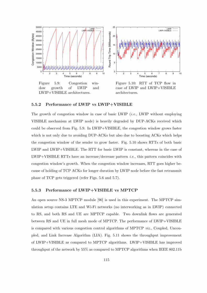
0
5000
10000
15000
20000
25000
30000
35000
40000
45000
50000
1 2 3 4 5 6 7 8 9 10
Con
gestion
Win
dow
(B
yte
s)
Time (seconds)
LWIPLWIP+VISIBLE
Figure 5.9: Congestion win-dow growth of LWIP andLWIP+VISIBLE architectures.
0
5
10
15
20
25
1 2 3 4 5 6 7 8 9 10
Roun
d T
rip T
ime (
Mill
iseco
nds)
Time (seconds)
LWIPLWIP+VISIBLE
Figure 5.10: RTT of TCP flow incase of LWIP and LWIP+VISIBLEarchitectures.
5.5.2 Performance of LWIP vs LWIP+VISIBLE
The growth of congestion window in case of basic LWIP (i.e., LWIP without employing
VISIBLE mechanism at LWIP node) is heavily degraded by DUP-ACKs received which
could be observed from Fig. 5.9. In LWIP+VISIBLE, the congestion window grows faster
which is not only due to avoiding DUP-ACKs but also due to boosting ACKs which helps
the congestion window of the sender to grow faster. Fig. 5.10 shows RTTs of both basic
LWIP and LWIP+VISIBLE. The RTT for basic LWIP is constant, whereas in the case of
LWIP+VISIBLE RTTs have an increase/decrease pattern i.e., this pattern coincides with
congestion window’s growth. When the congestion window increases, RTT goes higher be-
cause of holding of TCP ACKs for longer duration by LWIP node before the fast retransmit
phase of TCP gets triggered (refer Figs. 5.6 and 5.7).
5.5.3 Performance of LWIP+VISIBLE vs MPTCP
An open source NS-3 MPTCP module [90] is used in this experiment. The MPTCP sim-
ulation setup contains LTE and Wi-Fi networks (no interworking as in LWIP) connected
to RS, and both RS and UE are MPTCP capable. Two downlink flows are generated
between RS and UE in full mesh mode of MPTCP. The performance of LWIP+VISIBLE
is compared with various congestion control algorithms of MPTCP viz., Coupled, Uncou-
pled, and Link Increase Algorithm (LIA). Fig. 5.11 shows the throughput improvement
of LWIP+VISIBLE as compared to MPTCP algorithms. LWIP+VISIBLE has improved
throughput of the network by 55% as compared to MPTCP algorithms when IEEE 802.11b
115
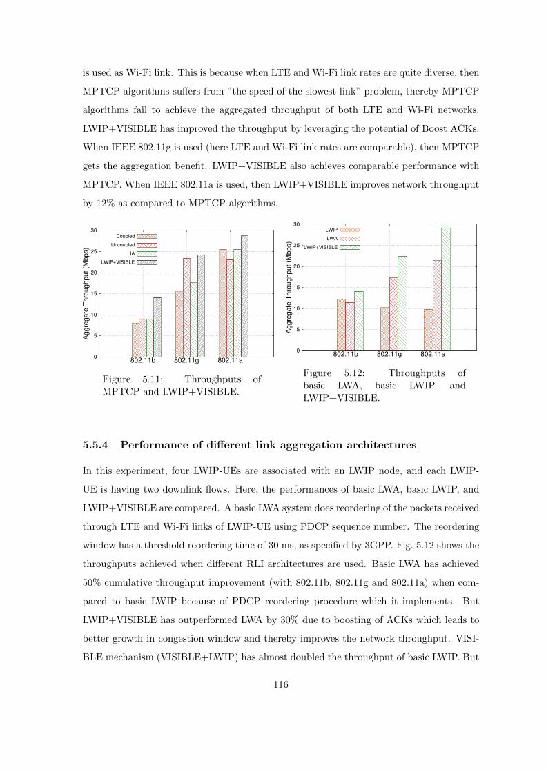
is used as Wi-Fi link. This is because when LTE and Wi-Fi link rates are quite diverse, then
MPTCP algorithms suffers from ”the speed of the slowest link” problem, thereby MPTCP
algorithms fail to achieve the aggregated throughput of both LTE and Wi-Fi networks.
LWIP+VISIBLE has improved the throughput by leveraging the potential of Boost ACKs.
When IEEE 802.11g is used (here LTE and Wi-Fi link rates are comparable), then MPTCP
gets the aggregation benefit. LWIP+VISIBLE also achieves comparable performance with
MPTCP. When IEEE 802.11a is used, then LWIP+VISIBLE improves network throughput
by 12% as compared to MPTCP algorithms.
0
5
10
15
20
25
30
802.11b 802.11g 802.11a
Ag
gre
ga
te T
hro
ug
hpu
t (M
bp
s)
Coupled
Uncoupled
LIA
LWIP+VISIBLE
Figure 5.11: Throughputs ofMPTCP and LWIP+VISIBLE.
0
5
10
15
20
25
30
802.11b 802.11g 802.11a
Ag
gre
ga
te T
hro
ughput
(Mbp
s)
LWIP
LWA
LWIP+VISIBLE
Figure 5.12: Throughputs ofbasic LWA, basic LWIP, andLWIP+VISIBLE.
5.5.4 Performance of different link aggregation architectures
In this experiment, four LWIP-UEs are associated with an LWIP node, and each LWIP-
UE is having two downlink flows. Here, the performances of basic LWA, basic LWIP, and
LWIP+VISIBLE are compared. A basic LWA system does reordering of the packets received
through LTE and Wi-Fi links of LWIP-UE using PDCP sequence number. The reordering
window has a threshold reordering time of 30 ms, as specified by 3GPP. Fig. 5.12 shows the
throughputs achieved when different RLI architectures are used. Basic LWA has achieved
50% cumulative throughput improvement (with 802.11b, 802.11g and 802.11a) when com-
pared to basic LWIP because of PDCP reordering procedure which it implements. But
LWIP+VISIBLE has outperformed LWA by 30% due to boosting of ACKs which leads to
better growth in congestion window and thereby improves the network throughput. VISI-
BLE mechanism (VISIBLE+LWIP) has almost doubled the throughput of basic LWIP. But
116

VISIBLE mechanism can be employed only when the TCP packet header is unencrypted.
5.6 Summary
In this chapter, VISIBLE mechanism was proposed for improving TCP performance in
LWIP networks. The most crucial challenge was to let the congestion window of the sender
to grow, which was achieved by sending Boost ACKs to TCP sender in a controlled fashion
from LWIP node. The proposed VISIBLE mechanism has successfully aggregated multiple
links even if they are offering quite different rates. LWIP node incorporated packet steering
technique based on queue depletion rate and Boost ACKs. The proposed VISIBLE mech-
anism outperformed MPTCP based LTE-Wi-Fi integration by 37% and LWA architecture
by 30%. The proposed mechanism can be employed in the context of 5G multi-connectivity,
where different RATs can be employed to deliver the same flow.
117

Chapter 6
Efficient placement of LWIP nodes
In this chapter, we address issues in deployment of colocated and non-colocated LWIP
nodes by mobile operators. The problem of placing LWIP nodes in dense environments is
studied with the following objectives: (i) Minimize the number of LWIP nodes required
to serve users in a given building with a certain threshold Signal-to-Interference-plus-Noise
Ratio (SINR), (ii) Maximize SINR inside the building by placing LWIP nodes at optimal
locations, and (iii) Minimize the energy spent at LWIP nodes and users without degrading
SINR of users.
The above mentioned objective functions are formulated as Mixed Integer Non-Linear
Programming (MINLP) problems. This chapter is organized as follows, at first the works
closely related to placement of small cells in indoor environments are discussed. And the
problem which is unaddressed in the literature under heterogeneous networks is elaborated.
The system model considered to address the problem in LWIP context is presented, and
the objective functions are presented in detail. Finally, the proposed models are evaluated
and their performance is compared with other existing models.
6.1 Related work
In this section, we discuss the literature pertaining to the optimal placement of small cells in
dense mobile environments. In [91] and [92], optimal placement of a single small cell inside a
building is done by considering interference from Macro BS. This placement is not scalable
for enterprise scenarios with multiple floors. In [93], the authors have considered enterprise
scenarios and studied how to minimize number of LTE small cells required for placement
118

to ensure a certain threshold SINR to all regions inside a building with multiple floors. A
limitation of this work is that the authors have considered the placement problem by only
concerning homogeneous radio access technologies (RATs) i.e., Macro BS and small cells
of LTE. In [94], the authors have proposed a joint femto placement and power optimization
model with an objective to minimize uplink power spent by UEs inside a building. In
this context, the authors have not considered many real-world challenges such as multiple
walls present inside the building and cross-tier interference from Macro BS. In [71], the
authors have detailed various challenges pertaining to tighter coupling of LTE and Wi-Fi
links at physical and network layers. The authors have pointed that, at the physical layer,
heterogeneous reuse of spectrum (i.e., users in interference region of LTE could be served by
Wi-Fi and vice-versa) would be an effective solution in case of dense deployment scenarios,
but the authors have not explored this property of the system. In this chapter, we focus on
both colocated and non-colocated LWIP deployment in dense enterprise environments by
considering factors like distance between small cells and UEs, cross-tier interference from
Macro BS (in case of LTE), co-tier interference from other LWIP nodes deployed, and path
loss due to obstacles such as walls across rooms inside the building.
6.2 System model
In this section, we describe the system model considered for our study.
6.2.1 Building model
Fig. 6.1 shows the building model considered in our study. Dimensions of the building
considered are 48 m × 48 m × 3 m, where L × W × H correspond to length, width,
and height of the building, respectively. The building has 16 rooms, each of dimensions
12 m × 12 m × 3 m. Walls separate the rooms, and each room encloses nine sub-regions.
A sub-region is of length 4 m × 4 m × 3 m, and the building is having only one floor. Thus,
the building is divided into 144 sub-regions (I1, I2, . . . , I144). A Macro BS is placed at a
distance of 1.4 km from the building. As the size of a sub-region is much smaller when
compared to the size of the building, we can safely assume that within every sub-region,
SINR is constant.
119

Macro
1.4 Km
1
2
3
4
5
6
7
8
9
10
11
12
13
14
15
16
17
18
19
20
21
22
23
24
25
26
27
28
29
30
31
32
33
34
35
36
37
38
39
40
41
42
43
44
45
46
47
48
49
50
51
52
53
54
55
56
57
58
59
60
61
62
63
64
65
66
67
68
69
70
71
72
73
74
75
76
77
78
79
80
81
82
83
84
85
86
87
88
89
90
91
92
93
94
95
96
97
98
99
100
101
102
103
104
105
106
107
108
109
110
111
112
113
114
115
116
117
118
119
120
121
122
123
124
125
126
127
128
129
130
131
132
133
134
135
136
137
138
139
140
141
142
143
144
4 m
Subregion
Wall
48 m
12 m
Figure 6.1: Building model considered.
6.2.2 Path Loss model for LTE network
We have used 3GPP Indoor Path Loss Model (Urban Deployment) [59] for LTE (PLMLTE).
It is given by
PLMLTE = 37 + 30 log10(d) + 18.3kk+2k+1−0.46 + nσ − 1 (6.1)
Where d is the distance of a sub-region from an LTE small cell in meters, k represents
the number of floors between a sub-region and cell, and σ represents penetration loss in dB.
6.2.3 Path Loss model for Wi-Fi network
We have used International Telecommunication Union (ITU) indoor path loss model [60] for
Wi-Fi. It estimates the path loss inside a room or a closed area inside a building delimited
by walls of any form. This model is most suitable for the frequency range between 900 MHz
and 5.2 GHz. The ITU model for Wi-Fi PLMWi−Fi is given by
PLMWi−Fi = 20 log10(f) +N log10(d) + (Pf × n)− 28 (6.2)
Where d is the distance of a sub-region from Wi-Fi AP in meters, f represents the frequency
of transmission in MHz, N accounts for the distance power loss coefficient, n is the number
120

of walls, and Pf denotes the penetration loss in dB.
The notations which are used in the optimization problem for placement of LWIP nodes
inside a building are detailed in Table 6.1.
Table 6.1: Notations used in optimization models for placement of LWIP nodes
Symbol Definition
Ri Set of all sub-regions inside the building
αlb 1 if a LTE small cell is placed at sub-region b, 0 otherwise
αwb 1 if Wi-Fi AP is placed at sub-region b, 0 otherwise
αc 1 if a interfering LTE small cell or Wi-Fi AP is placed at sub-regionc, 0 otherwise
βls,b 1 if sub-region 4 is connected to LTE small cell at b, 0 otherwise
βws,b 1 if sub-region s is connected to Wi-Fi AP at b, 0 otherwise
δls,b LTE channel gain between s and b sub-regions
δws,b Wi-Fi channel gain between s and b sub-regions
γlb LTE SINR observed at sub-region b
γwb Wi-Fi SINR observed at sub-region b
P lb LTE transmit power of LWIP node or UE located at sub-region b
Pwb Wi-Fi transmit power of LWIP node or UE located at sub-region b
Pmmax Maximum transmit power of Macro Base Station
P lmax Maximum transmit power of LTE small cell
Pwmax Maximum transmit power of Wi-Fi AP
λl LTE SINR threshold
λw Wi-Fi SINR threshold
No System Noise
M Macro Base Station
6.3 Optimization models for placement of LWIP nodes
In this section, we formulate different optimization problems for colocated (C) and non-
colocated (NC) LWIP deployments with the following three objectives:
Minimal number of LWIP nodes required to ensure good coverage in the building.
Optimal placement of LWIP nodes to maximize SINR inside the building.
Optimal placement and power control of LWIP nodes to minimize the energy spent
at LWIP nodes and UEs.
121
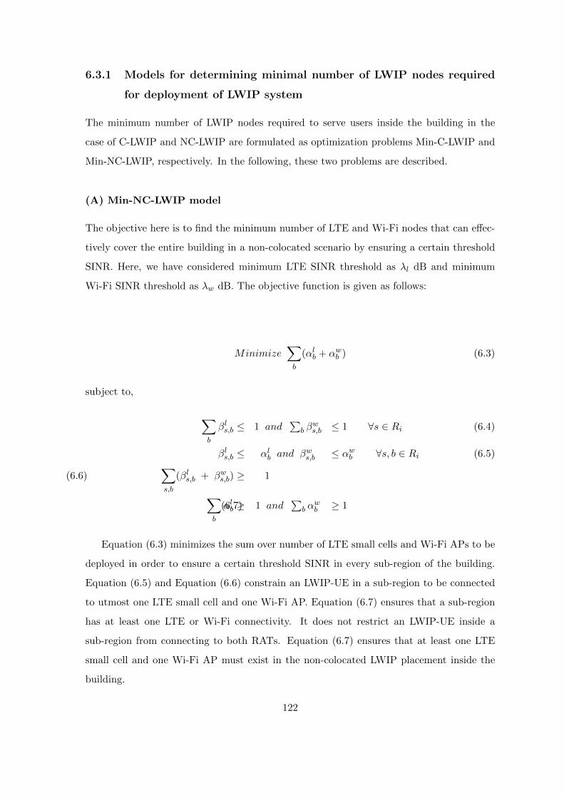
6.3.1 Models for determining minimal number of LWIP nodes required
for deployment of LWIP system
The minimum number of LWIP nodes required to serve users inside the building in the
case of C-LWIP and NC-LWIP are formulated as optimization problems Min-C-LWIP and
Min-NC-LWIP, respectively. In the following, these two problems are described.
(A) Min-NC-LWIP model
The objective here is to find the minimum number of LTE and Wi-Fi nodes that can effec-
tively cover the entire building in a non-colocated scenario by ensuring a certain threshold
SINR. Here, we have considered minimum LTE SINR threshold as λl dB and minimum
Wi-Fi SINR threshold as λw dB. The objective function is given as follows:
Minimize∑b
(αlb + αwb ) (6.3)
subject to,
∑b
βls,b ≤ 1 and∑
b βws,b ≤ 1 ∀s ∈ Ri (6.4)
βls,b ≤ αlb and βws,b ≤ αwb ∀s, b ∈ Ri (6.5)∑s,b
(βls,b + βws,b) ≥ 1 (6.6)
∑b
αlb ≥ 1 and∑
b αwb ≥ 1 (6.7)
Equation (6.3) minimizes the sum over number of LTE small cells and Wi-Fi APs to be
deployed in order to ensure a certain threshold SINR in every sub-region of the building.
Equation (6.5) and Equation (6.6) constrain an LWIP-UE in a sub-region to be connected
to utmost one LTE small cell and one Wi-Fi AP. Equation (6.7) ensures that a sub-region
has at least one LTE or Wi-Fi connectivity. It does not restrict an LWIP-UE inside a
sub-region from connecting to both RATs. Equation (6.7) ensures that at least one LTE
small cell and one Wi-Fi AP must exist in the non-colocated LWIP placement inside the
building.
122

Inf × (1− βls,b) + (δls,b · P lmax · αlb)No +
∑c∈Ri\b
δls,c · P lmax · αc +∑e∈M
δls,e · Pmmax≥ λl ∀s, b ∈ Ri (6.8)
Inf × (1− βws,b) + (δws,b · Pwmax · αwb )
No +∑
c∈Ri\bδws,c · Pwmax · αc
≥ λw ∀s, b ∈ Ri (6.9)
For LWIP-UE at sub-region s to be connected to an LTE small cell or a Wi-Fi AP located
at sub-region b, the sub-region has to receive a certain minimum SINR from that LTE small
cell or Wi-Fi AP. Equation (6.8) captures this constraint on LTE SINR threshold (λl) and
Equation (6.9) on Wi-Fi SINR threshold (λw). In the case of LTE, Macro BS interference
is also considered. Inf in Equation (6.8) is an infinitely large value which is introduced
because solver ignores the case where the values are very high and thus the computation
time is reduced. Inf signifies that, if a sub-region s is not associated with LTE small cell or
Wi-Fi AP at sub-region b, then the SINR becomes infinite. Hence the solver ignores such
cases during its execution.
(B) Min-C-LWIP Model
The minimum number of C-LWIP nodes that can effectively cover the building with a
certain minimum SINR threshold at every sub-region is given by:
Minimize∑b
(αlb + αwb ) (6.10)
The objective function given in Equation (6.10) for C-LWIP deployment is same as that
given in Equation (6.3) for NC-LWIP deployment along with the constraints given in Equa-
tion (6.5) to Equation (6.9). The only additional constraint that the colocated deployment
requires over non-colocated deployment is given in Equation (6.11). It states that the loca-
tion of the LTE small cell and Wi-Fi AP must be in the same sub-region, as the colocated
deployment involves placing them together in the same integrated box.
123
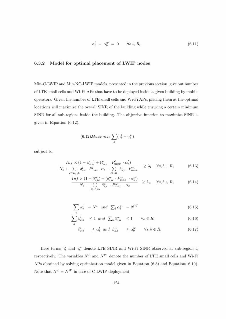
αlb − αwb = 0 ∀b ∈ Ri (6.11)
6.3.2 Model for optimal placement of LWIP nodes
Min-C-LWIP and Min-NC-LWIP models, presented in the previous section, give out number
of LTE small cells and Wi-Fi APs that have to be deployed inside a given building by mobile
operators. Given the number of LTE small cells and Wi-Fi APs, placing them at the optimal
locations will maximize the overall SINR of the building while ensuring a certain minimum
SINR for all sub-regions inside the building. The objective function to maximize SINR is
given in Equation (6.12).
Maximize∑b
(γlb + γwb ) (6.12)
subject to,
Inf × (1− βls,b) + (δls,b · P lmax · αlb)No +
∑c∈Ri\b
δls,c · P lmax · αc +∑e∈M
δls,e · Pmmax≥ λl ∀s, b ∈ Ri (6.13)
Inf × (1− βws,b) + (δws,b · Pwmax · αwb )
No +∑
c∈Ri\bδws,c · Pwmax · αc
≥ λw ∀s, b ∈ Ri (6.14)
∑b
αlb = NL and∑
b αwb = NW (6.15)∑
b
βls,b ≤ 1 and∑
b βws,b ≤ 1 ∀s ∈ Ri (6.16)
βls,b ≤ αlb and βws,b ≤ αwb ∀s, b ∈ Ri (6.17)
Here terms γlb and γwb denote LTE SINR and Wi-Fi SINR observed at sub-region b,
respectively. The variables NL and NW denote the number of LTE small cells and Wi-Fi
APs obtained by solving optimization model given in Equation (6.3) and Equation( 6.10).
Note that NL = NW in case of C-LWIP deployment.
124

6.3.3 Models to obtain optimal power setting for operation of LWIP
nodes and LWIP-UEs
Power control in LWIP architecture reaps the highest improvement in LWIP performance
in dense deployment scenario [95]. The placement of LWIP nodes plays a vital role in opti-
mizing the energy spent at LWIP nodes and LWIP-UEs. In this section, we have formulated
optimization problems to minimize the energy spent at LWIP nodes and LWIP-UEs by first
placing the LWIP nodes at optimal locations (obtained by solving Equation (6.12)) and
then by setting transmit power levels at LWIP nodes and LWIP-UEs to optimal values.
(A) Model to optimize transmit power of LWIP nodes to save energy
Min-Power-LWIP-node Model: This model saves energy spent by LWIP nodes. Energy
spent at LWIP nodes can be reduced by reducing transmit power levels of LWIP nodes
while still ensuring a certain SINR threshold to every sub-region inside the building. Equa-
tion (6.18) shows the objective function to minimize the energy spent at LWIP nodes.
Minimize∑b∈Ri
(αlb × P lb) + (αwb × Pwb ) (6.18)
subject to,
Inf × (1− βls,b) + (δls,b · P lb · αlb)No +
∑c∈Ri\b
δls,c · P lb · αc +∑e∈M
δls,e · Pmmax≥ λl ∀s, b ∈ Ri (6.19)
Inf × (1− βws,b) + (δws,b · Pwb · αwb )
No +∑
c∈Ri\bδws,c · Pwb · αc
≥ λw ∀s, b ∈ Ri (6.20)
P lmin ≤ P lb ≤ P lmax ∀b ∈ Ri (6.21)
Pwmin ≤ Pwb ≤ Pwmax ∀b ∈ Ri (6.22)
βls,b ≤ αlb and βws,b ≤ αwb ∀s, b ∈ Ri (6.23)∑b
αlb = NL and∑b
αwb = NW (6.24)
Constraints shown in Equations (6.19)-(6.24) ensure that SINR received above the SINR
threshold in all the sub-regions, with transmit power values bounded within the limits, and
125

associativity condition ensuring that a LWIP-UE associates with utmost one LWIP node.
Finally, the sum of LTE nodes deployed and sum of Wi-Fi nodes deployed must be NL and
NW , respectively.
(B) Model to optimize transmit power of LWIP-UEs to save energy
Min-Power-LWIP-UE Model: This model is to save the energy spent by LWIP-UEs.
The energy spent at LWIP-UE can be reduced by first placing the LWIP nodes at optimal
positions. We formulate an optimization problem to find the optimal locations for LWIP
nodes which minimizes the energy spent at LWIP-UEs as follows. Equation (6.18) presented
in last subsection varies the transmit power of LWIP node in order to save energy at LWIP
node, whereas in Equation (6.25), the energy spent by LWIP-UE is reduced by varying the
transmit power and the position of LWIP node. The implicit vision is, closer the LWIP
nodes to LWIP-UEs it prevents UEs from transmitting with higher transmit power, thereby
saving energy spent by LWIP-UEs.
Minimize∑b∈Ri
(βls,b × P lb) + (βws,b × Pwb ) (6.25)
subject to,
Inf × (1− βls,b) + (δls,b · P lb · αlb)No
≥ λl ∀s, b ∈ Ri (6.26)
Inf × (1− βws,b) + (δws,b · Pwb · αwb )
No≥ λw ∀s, b ∈ Ri (6.27)
P lmin ≤ P lb ≤ P lmax ∀b ∈ Ri (6.28)
Pwmin ≤ Pwb ≤ Pwmax ∀b ∈ Ri (6.29)
βls,b ≤ αlb and βws,b ≤ αwb ∀s, b ∈ Ri (6.30)∑b
αlb = NL and∑b
αwb = NW (6.31)
The objective function shown in Equation (6.25) minimizes the overall energy spent by
LWIP-UEs. We have assumed that the number of LWIP-UEs in all sub-regions is the same.
Equations (6.26)–(6.31) show the constraints on minimum SINR threshold to be met in
126
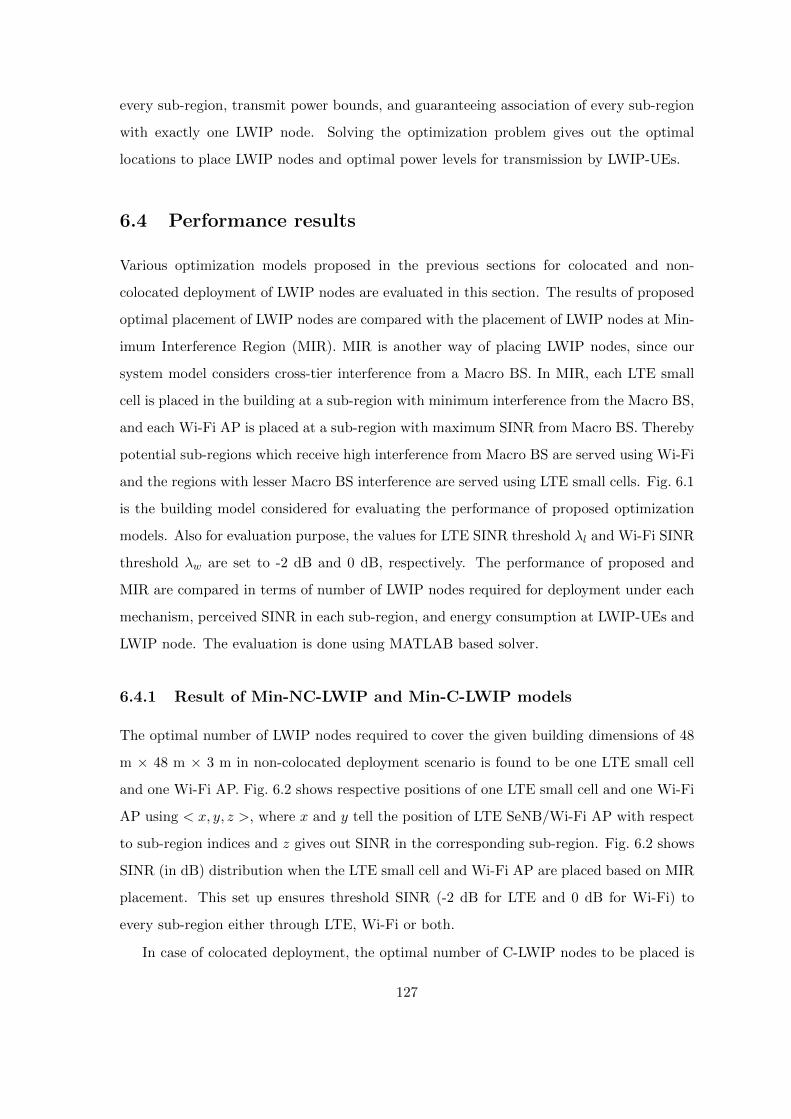
every sub-region, transmit power bounds, and guaranteeing association of every sub-region
with exactly one LWIP node. Solving the optimization problem gives out the optimal
locations to place LWIP nodes and optimal power levels for transmission by LWIP-UEs.
6.4 Performance results
Various optimization models proposed in the previous sections for colocated and non-
colocated deployment of LWIP nodes are evaluated in this section. The results of proposed
optimal placement of LWIP nodes are compared with the placement of LWIP nodes at Min-
imum Interference Region (MIR). MIR is another way of placing LWIP nodes, since our
system model considers cross-tier interference from a Macro BS. In MIR, each LTE small
cell is placed in the building at a sub-region with minimum interference from the Macro BS,
and each Wi-Fi AP is placed at a sub-region with maximum SINR from Macro BS. Thereby
potential sub-regions which receive high interference from Macro BS are served using Wi-Fi
and the regions with lesser Macro BS interference are served using LTE small cells. Fig. 6.1
is the building model considered for evaluating the performance of proposed optimization
models. Also for evaluation purpose, the values for LTE SINR threshold λl and Wi-Fi SINR
threshold λw are set to -2 dB and 0 dB, respectively. The performance of proposed and
MIR are compared in terms of number of LWIP nodes required for deployment under each
mechanism, perceived SINR in each sub-region, and energy consumption at LWIP-UEs and
LWIP node. The evaluation is done using MATLAB based solver.
6.4.1 Result of Min-NC-LWIP and Min-C-LWIP models
The optimal number of LWIP nodes required to cover the given building dimensions of 48
m × 48 m × 3 m in non-colocated deployment scenario is found to be one LTE small cell
and one Wi-Fi AP. Fig. 6.2 shows respective positions of one LTE small cell and one Wi-Fi
AP using < x, y, z >, where x and y tell the position of LTE SeNB/Wi-Fi AP with respect
to sub-region indices and z gives out SINR in the corresponding sub-region. Fig. 6.2 shows
SINR (in dB) distribution when the LTE small cell and Wi-Fi AP are placed based on MIR
placement. This set up ensures threshold SINR (-2 dB for LTE and 0 dB for Wi-Fi) to
every sub-region either through LTE, Wi-Fi or both.
In case of colocated deployment, the optimal number of C-LWIP nodes to be placed is
127
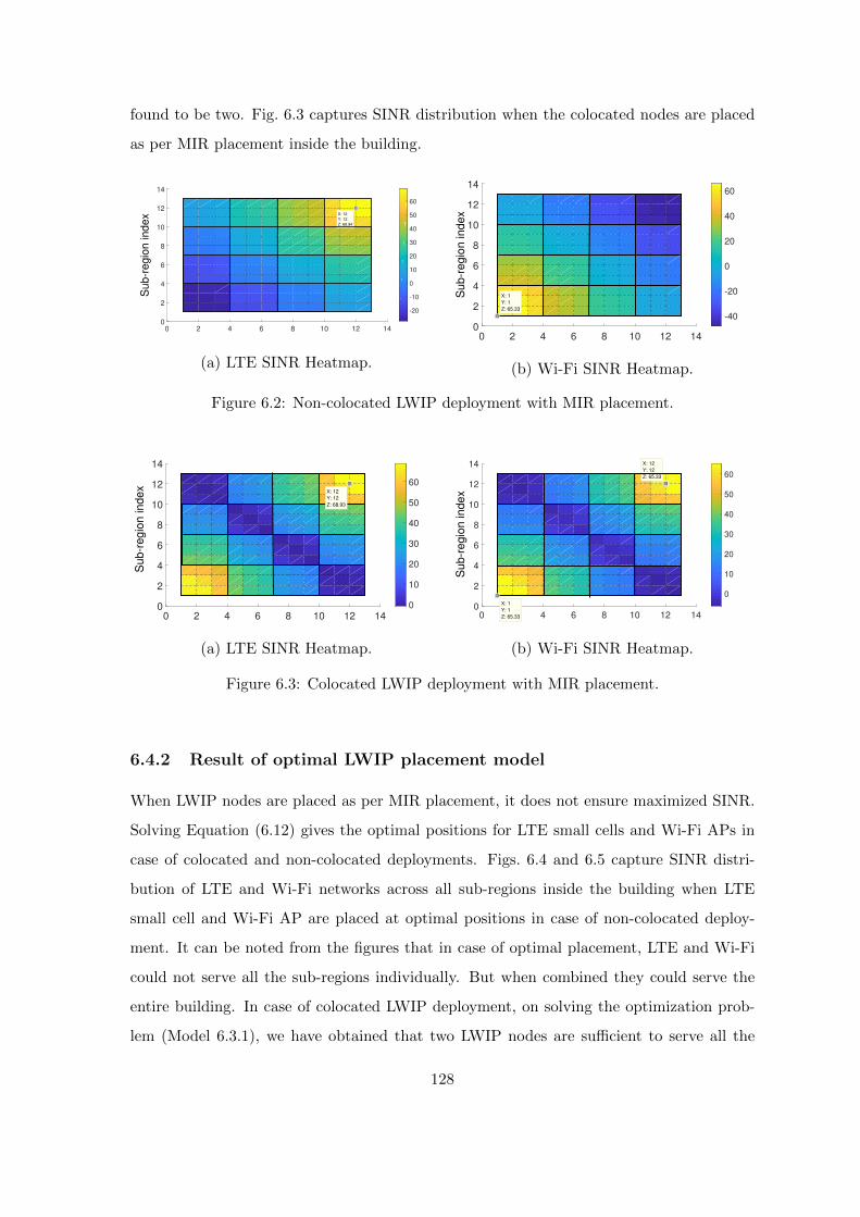
found to be two. Fig. 6.3 captures SINR distribution when the colocated nodes are placed
as per MIR placement inside the building.
0 2 4 6 8 10 12 140
2
4
6
8
10
12
14
-20
-10
0
10
20
30
40
50
60
X: 12
Y: 12
Su
b-r
eg
ion
in
de
x
Z: 68.94
(a) LTE SINR Heatmap.
0 2 4 6 8 10 12 140
2
4
6
8
10
12
14
-40
-20
0
20
40
60
X: 1
Y: 1
Su
b-r
eg
ion
in
de
x
Z: 65.33
(b) Wi-Fi SINR Heatmap.
Figure 6.2: Non-colocated LWIP deployment with MIR placement.
0 2 4 6 8 10 12 140
2
4
6
8
10
12
14
0
10
20
30
40
50
60X: 12
Y: 12
Su
b-r
eg
ion
in
de
x
Z: 68.93
(a) LTE SINR Heatmap.
0
2
4
6
8
10
12
14
0 2 4 6 8 10 12 14
0
10
20
30
40
50
60
X: 1
Y: 1
Su
b-r
eg
ion
in
de
x
Z: 65.33
X: 12
Y: 12
Z: 65.33
(b) Wi-Fi SINR Heatmap.
Figure 6.3: Colocated LWIP deployment with MIR placement.
6.4.2 Result of optimal LWIP placement model
When LWIP nodes are placed as per MIR placement, it does not ensure maximized SINR.
Solving Equation (6.12) gives the optimal positions for LTE small cells and Wi-Fi APs in
case of colocated and non-colocated deployments. Figs. 6.4 and 6.5 capture SINR distri-
bution of LTE and Wi-Fi networks across all sub-regions inside the building when LTE
small cell and Wi-Fi AP are placed at optimal positions in case of non-colocated deploy-
ment. It can be noted from the figures that in case of optimal placement, LTE and Wi-Fi
could not serve all the sub-regions individually. But when combined they could serve the
entire building. In case of colocated LWIP deployment, on solving the optimization prob-
lem (Model 6.3.1), we have obtained that two LWIP nodes are sufficient to serve all the
128
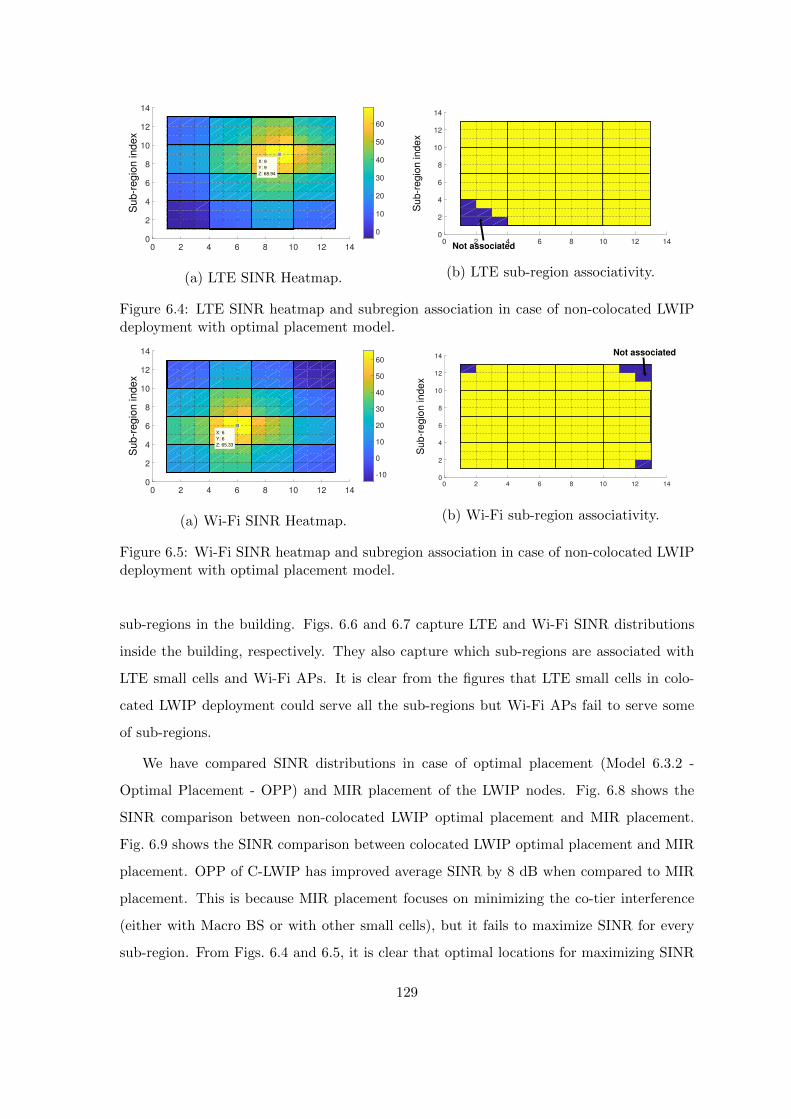
0 2 4 6 8 10 12 140
2
4
6
8
10
12
14
0
10
20
30
40
50
60
X: 9
Y: 9
Su
b-r
eg
ion
in
de
x
Z: 68.94
(a) LTE SINR Heatmap.
0 2 4 6 8 10 12 140
2
4
6
8
10
12
14
Not associated
Su
b-r
eg
ion
in
de
x
(b) LTE sub-region associativity.
Figure 6.4: LTE SINR heatmap and subregion association in case of non-colocated LWIPdeployment with optimal placement model.
0 2 4 6 8 10 12 140
2
4
6
8
10
12
14
-10
0
10
20
30
40
50
60
X: 6
Y: 6
Su
b-r
eg
ion
in
de
x
Z: 65.33
(a) Wi-Fi SINR Heatmap.
0 2 4 6 8 10 12 140
2
4
6
8
10
12
14 Not associated
Su
b-r
eg
ion
in
de
x
(b) Wi-Fi sub-region associativity.
Figure 6.5: Wi-Fi SINR heatmap and subregion association in case of non-colocated LWIPdeployment with optimal placement model.
sub-regions in the building. Figs. 6.6 and 6.7 capture LTE and Wi-Fi SINR distributions
inside the building, respectively. They also capture which sub-regions are associated with
LTE small cells and Wi-Fi APs. It is clear from the figures that LTE small cells in colo-
cated LWIP deployment could serve all the sub-regions but Wi-Fi APs fail to serve some
of sub-regions.
We have compared SINR distributions in case of optimal placement (Model 6.3.2 -
Optimal Placement - OPP) and MIR placement of the LWIP nodes. Fig. 6.8 shows the
SINR comparison between non-colocated LWIP optimal placement and MIR placement.
Fig. 6.9 shows the SINR comparison between colocated LWIP optimal placement and MIR
placement. OPP of C-LWIP has improved average SINR by 8 dB when compared to MIR
placement. This is because MIR placement focuses on minimizing the co-tier interference
(either with Macro BS or with other small cells), but it fails to maximize SINR for every
sub-region. From Figs. 6.4 and 6.5, it is clear that optimal locations for maximizing SINR
129

0
2
4
6
8
10
12
14
0 2 4 6 8 10 12 140
10
20
30
40
50
60
X: 2
Y: 10
Z: 68.91
Su
b-r
eg
ion
in
de
x
X: 10
Y: 3
Z: 68.91
(a) LTE SINR Heatmap.
0
2
Su
b-r
eg
ion
in
de
x
4
6
8
10
12
14
0 2 4 6 8 10 12 14
(b) LTE sub-region associativity.
Figure 6.6: LTE SINR heatmap and subregion association in case of colocated LWIP de-ployment with optimal placement model.
0
2
4
6
8
10
12
14
0 2 4 6 8 10 12 14
0
10
20
30
40
50
60
X: 2
Y: 10
Su
b-r
eg
ion
in
de
x
Z: 65.33
(a) Wi-Fi SINR Heatmap.
0
2
4
6
8
10
12
14
0 2 4 6 8 10 12 14
Not associated
Su
b-r
eg
ion
in
de
x
(b) Wi-Fi sub-region associativity.
Figure 6.7: Wi-Fi SINR heatmap and subregion association in case of colocated LWIPdeployment with optimal placement model.
lie towards the center of the building but MIR placement is confined towards the corners.
Figs. 6.10 and 6.11 show the number of sub-regions associated only with LTE, only with
Wi-Fi and with both LTE and Wi-Fi in case of colocated and non-colocated deployments.
It can be observed that the number of sub-regions associated with both LTE and Wi-Fi in
case of OPP has improved by 43% on average when compared to MIR placement.
6.4.3 Result for energy saving at LWIP nodes and LWIP-UEs
To minimize the energy spent at LWIP nodes and UEs, the LWIP nodes have to be placed in
optimal locations by optimizing the transmit power levels of LWIP nodes in order to ensure a
certain threshold SINR in all the sub-regions inside the building. The optimization problem
described in Section 6.3.3 with the above objectives is evaluated here. The optimization
problem thrives to obtain the optimal locations for placement of LWIP nodes and minimal
130

-60 -40 -20 0 20 40 60 80
SINR in dB
0
0.2
0.4
0.6
0.8
1
CD
F
LTE : OPP
Wi-Fi : OPP
LTE : MIR
Wi-Fi : MIR
Figure 6.8: SINR CDF observed in all the sub-regions for a non-colocated deployment withoptimal placement model.
-10 0 10 20 30 40 50 60 70
SINR in dB
0
0.2
0.4
0.6
0.8
1
CD
F
LTE : OPP
Wi-Fi : OPP
LTE : MIR
Wi-Fi : MIR
Figure 6.9: SINR CDF observed in all the sub-regions for a colocated deployment withoptimal placement model.
0
50
100
150
200
LTE Wi-Fi Both
Nu
mbe
r o
f sub
-regio
ns
NC-FPS MIRNC-FPS with OPP
NC-OPS at MIRNC-OPS at OPP
Figure 6.10: Sub-regions associativ-ity : non-colocated placement.
0
50
100
150
200
LTE Wi-Fi Both
Nu
mbe
r o
f sub
-regio
ns
C-FPS MIRNC-FPS with OPP
NC-OPS at MIRNC-OPS at OPP
Figure 6.11: Sub-regions associativ-ity : colocated placement.
transmit power levels that can cover all the sub-regions inside the building.
131
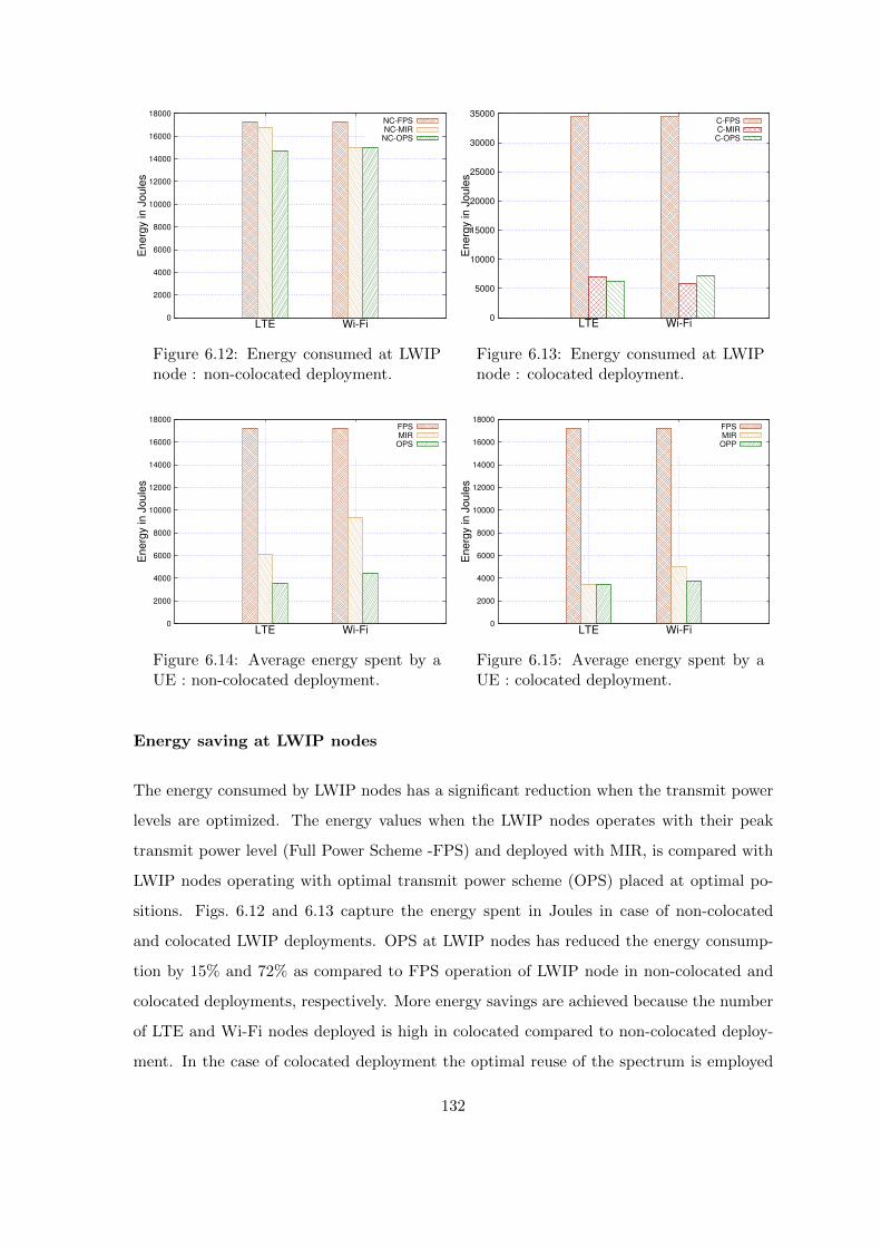
0
2000
4000
6000
8000
10000
12000
14000
16000
18000
LTE Wi-Fi
Energ
y in
Jou
les
NC-FPSNC-MIR
NC-OPS
Figure 6.12: Energy consumed at LWIPnode : non-colocated deployment.
0
5000
10000
15000
20000
25000
30000
35000
LTE Wi-Fi
Energ
y in
Jou
les
C-FPSC-MIR
C-OPS
Figure 6.13: Energy consumed at LWIPnode : colocated deployment.
0
2000
4000
6000
8000
10000
12000
14000
16000
18000
LTE Wi-Fi
En
erg
y in J
oule
s
FPSMIR
OPS
Figure 6.14: Average energy spent by aUE : non-colocated deployment.
0
2000
4000
6000
8000
10000
12000
14000
16000
18000
LTE Wi-Fi
En
erg
y in J
oule
s
FPSMIR
OPP
Figure 6.15: Average energy spent by aUE : colocated deployment.
Energy saving at LWIP nodes
The energy consumed by LWIP nodes has a significant reduction when the transmit power
levels are optimized. The energy values when the LWIP nodes operates with their peak
transmit power level (Full Power Scheme -FPS) and deployed with MIR, is compared with
LWIP nodes operating with optimal transmit power scheme (OPS) placed at optimal po-
sitions. Figs. 6.12 and 6.13 capture the energy spent in Joules in case of non-colocated
and colocated LWIP deployments. OPS at LWIP nodes has reduced the energy consump-
tion by 15% and 72% as compared to FPS operation of LWIP node in non-colocated and
colocated deployments, respectively. More energy savings are achieved because the number
of LTE and Wi-Fi nodes deployed is high in colocated compared to non-colocated deploy-
ment. In the case of colocated deployment the optimal reuse of the spectrum is employed
132

as presented in Section 2.1.1 of Chapter 2. The optimal reuse of the spectrum involves
regulation of transmit power in LTE and Wi-Fi links of LWIP nodes. In a given LWIP
node, LWIP-UEs in the inner coverage region are served using LTE, and those UEs which
lie in the outer coverage region are served using Wi-Fi. This pattern happens alternatively
in adjacent colocated LWIP nodes (where the outer coverage region is served by LTE, while
Wi-Fi serves the inner coverage region). This alternate pattern avoids the outer coverage
regions of two adjacent colocated LWIP nodes served using the same RAT viz., LTE or
Wi-Fi, thereby using the available spectrum efficiently.
Energy savings at LWIP-UE
The energy spent by LWIP-UEs can be reduced by placing the LWIP nodes at the sub-
regions obtained by solving the Model 6.3.3. Figs. 6.14 and 6.15 capture the average energy
spent by an LWIP-UE for different deployment cum power control scenarios. In case of non-
colocated deployment, OPS with OPP has reduced the energy spent at LWIP-UE by 47%
as compared to placement at MIR with optimal power. In case of colocated deployment,
the energy spent at LWIP-UE has reduced by 25% compared to operating LWIP nodes at
MIR with optimal power. In both the figures, full power is given for reference which shows
the energy spent by an LWIP-UE if it operate at the full transmit power.
6.5 Summary
The placement of LWIP nodes has a significant impact on SINR observed and rates achiev-
able in different sub-regions of buildings. We have addressed the placement problem with
three major objectives, which include (i) Minimizing the number of LWIP nodes to be
placed, (ii) Maximizing the SINR for all sub-regions, and (iii) Minimizing the energy spent
by LWIP-UEs and LWIP nodes. Solutions obtained for these optimization problems have
improved the performance of the LWIP system significantly. The OPP have achieved 8
dB improvement in SINR and 43% improvement in number of sub-regions connected to
both LTE and Wi-Fi as compared to MIR placement. Also, the OPS with OPP lead to
10% energy saving at LWIP node and 36% energy saving at LWIP-UE side compared to
MIR placement. Either NS-3 or MATLAB based simulations were carried out to evalu-
ate the performance of RLI architectures in all previous chapters. It is of high interest
133
to study the performance of these architectures and traffic steering solutions proposed in
real-time. The next chapter will describe the testbed implementation of RLI architectures
using open-source tools.
134
Chapter 7
Prototyping of RLI architectures
This chapter details prototype implementation of different RLI architectures. Also, the
performance of these architectures has been studied in various realistic network scenarios.
7.1 Introduction to prototyping of RLI architectures
In Chapter 2, the following RLI architectures and their layer of interworking were studied.
1. LTE Wi-Fi Integration with IPSec tunnel (LWIP)
2. LTE Wi-Fi Aggregation (LWA)
3. LTE Wi-Fi Integration at RLC layer (LWIR)
Fig. 7.1 shows the difference in the layer of integration of LTE and Wi-Fi radio protocol
stacks for LWA, LWIP, and LWIR architectures. RLI architectures target to steer incoming
traffic across LTE and Wi-Fi links. Steering at IP is flexible and easily adaptable. Steering
at PDCP and RLC require modifications at the radio protocol stacks of LTE and Wi-
Fi, but they ensure in-sequence and reliable delivery, respectively. In subsequent sections,
prototype implementation of each architecture is described in detail.
7.2 LWIP prototyping
This section provides an overview of LWIP architecture and its prototype implementation.
LWIP enables a tighter level integration between LTE and Wi-Fi radio protocol stacks at
IP layer to perform traffic steering at the granularity of bearer level, flow level, and packet
135

LWIP Node
Tu
nn
el
UE
SeNB Wi-Fi
LWA Node
Tu
nn
el
UE
SeNB Wi-Fi
LWIR Node
Tu
nn
el
UE
SeNB Wi-Fi
LWIP Architecture b LWA Architecture LWIR Architecture
Figure 7.1: RLI architectures and their layer of integration.
level. LWIP is realized by introducing a Link Aggregation Layer (LAL) in the protocol stack
of the LWIP node. The traffic steering is done above the PDCP layer of LTE and the LLC
layer of Wi-Fi in their respective protocol stacks. Based on the traffic steering mechanism,
the LAL decides which packets/flows/bearers to be transmitted over LTE and Wi-Fi and
sends them over the corresponding radio interface. The LAL does not add any new header
to the IP data packets received from EPC via S1-U interface. Packets going through LTE
and Wi-Fi interfaces follow regular packet forwarding procedures at their protocol stacks
and get delivered directly to IP layer.
LWIP is leveraged by its ease of implementation to achieve the aggregation benefits.
Also, LAL supports collecting various network parameters and actively participates in in-
telligent decision making for steering IP traffic across LTE and Wi-Fi interfaces in the
downlink. It is notable that LWIP architecture does not require any modification to the
protocol of UE. In our implementation, LWIP supports downlink traffic steering across LTE
and Wi-Fi.
LWIP testbed is setup using OpenAirInterface (OAI) platform as LTE network and a
Cisco access point as Wi-Fi AP. The following subsections present more details on LTE
testbed and LWIP testbed.
136

Management (OSS)IP PacketsAT Commands
Control Plane Data Plane 3GPP Layers Linux Stack
Figure 7.2: OpenAirInterface LTE software stack [3].
7.2.1 LTE testbed using OAI platform
OpenAirInterface [3] is a complete implementation of 4G-LTE (Rel-10). It includes Ope-
nAirInterface User Equipment (OAI-UE), OpenAirInterface eNodeB (OAI-eNB), and Ope-
nAirInterface Core Network (OAI-CN). OAI-eNB works with many commercial UEs such
as Nexus 5, Samsung Galaxy S5, iPhone 5s, etc.
OAI-eNB implements MAC, RLC, PDCP, and RRC layers according to the LTE stan-
dard. It also supports eMBMS services (MCH, MCCH, MTCH). OAI-CN has EPC com-
ponents which comply with 3GPP releases up to Rel-10. It includes Serving Gateway
(S-GW), Packet Data Network Gateway (P-GW), Mobility Management Entity (MME),
Home Subscriber Server (HSS), and Non-Access Stratum (NAS).
ExpressMIMO2 (ExMIMO2) board, which is PCI express based, is used as RF frontend
in the testbed setup. ExMIMO2 boards belong to the class of Software Defined Radio
(SDR) that can work up to 80 MHz of carrier aggregation [96]. Fig. 7.2 shows the software
stack of LTE in OAI.
7.2.2 Realization of LWIP testbed using OAI platform
Fig. 7.3 illustrates the protocol implementation structure of LWIP prototype. The LWIP
implementation follows the architecture proposed in [97], which includes a minor modifica-
tion to 3GPP LWIP architecture. The main difference between 3GPP LWIP architecture
and implemented architecture is that there is no IPSec tunnel to deliver the packets to des-
tined UE in our implementation. This is because the security aspect of LWIP system is not
a primary focus in our work. However, the security procedures of our proposed architecture
are detailed in Chapter 2. The UE obtains an IP address for each interface viz., LTE and
137

LWIP Node
UE
Figure 7.3: Protocol implementation structure of LWIP prototype system.
Wi-Fi. The information about the interface availability and IP addresses of interfaces are
made available at LWIP node. When a packet arrives at LWIP node through LTE network,
it is forwarded to UE through LTE protocol stack without any changes. If the packet has
to be sent through Wi-Fi interface, then the actual destination IP address of each incoming
packet is changed from LTE UE IP address to Wi-Fi UE IP address by LWIP node. At
UE, the destination IP address of packet received from Wi-Fi interface is changed back to
LTE UE IP address.
Our LWIP testbed setup is shown in Fig. 7.4. The following issues and challenges are
addressed for realizing a fully functional LWIP testbed system.
A socket connection should be established with LTE interface of LWIP-UE:
In Android Operating System (OS), when Wi-Fi radio is enabled, it gets the highest
priority over all available radio interfaces for data communication. This priority issue
has to be solved because the connection is LTE anchored in LWIP system. With
a stringent motive of making the existing UE to work, an Android application is
developed in-house which changes the priority for a set of flows to use LTE interface
even when Wi-Fi interface is available for communication. During socket creation,
the Android application binds new flow to LTE interface using socket bind function.
138

The Wi-Fi interface details of UE have to be informed to LTE SeNB: The
SeNB of LWIP node should be aware of the destination interface information for
enabling traffic steering. In our LWIP testbed, the information of LWIP-UE’s Wi-Fi
IP address is made known to LWIP node. This information can be communicated
using control channel of LTE.
Some packets from LTE core network have to be steered to Wi-Fi network:
This action mangles the packet headers to achieve successful routing between LTE and
Wi-Fi networks. This also involves recomputing the header checksum of appropriate
layers in order to avoid the packet drop at the destination. In our LWIP testbed, the
actual packet destination IP address is changed by LWIP node in order to deliver the
packet over the Wi-Fi link. When the destination IP gets changed, the higher layer
checksum has to be recomputed for the mangled packet. For instance, to compute the
transport layer checksum, the pseudo header and transport header information are
required. Pseudo header includes (Destination IP, Source IP, TCP segment length,
Protocol type, and Reserved bit). Thus change in the destination IP requires the
checksum of TCP to be recomputed, without which the packet is dropped due to
incorrect checksum.
An unmodified connection between LTE-SeNB and UE through Wi-Fi in-
terface has to be maintained: Packets received at the destination (UE) should
get delivered to the socket to which it is bounded to. If a packet is not transformed,
the packet gets lost. In our LWIP testbed, each packet upon reaching the LWIP-UE
with Wi-Fi UE IP address is changed back to LTE UE IP address with the help of
iptables rule, thereby managing the connection alive even through Wi-Fi interface.
Thus, the state of a flow is unalterably maintained by inserting flow rule in iptables of
LWIP-UE. Here is a sample iptables rule which is inserted. The rule is inserted at the
prerouting chain of Network Address Translation (NAT) table. It changes the current
destination IP address (Wi-Fi IP address of UE) of the packet to new destination IP
address (LTE IP address of UE).
i p t a b l e s −t nat −A PREROUTING −d c u r r e n t i p −j DNAT
−−to−d e s t i n a t i o n new ip
139

This iptables rule make the packet look as if it is unaltered to the destination socket.
Hence, it enables the aggregation of LTE and Wi-Fi links.
Figure 7.4: LWIP testbed setup.
LWIP testbed configurations are shown in Tables 7.1 and 7.2. In our testbed, the LWIP-
UE (Google Nexus 5 phone), is downloading a file from the remote server using LWIP. Both
interfaces are enabled through an Android application. We have enhanced the functionality
of open-source Android application, HIPRIKeeper [98] which can enable both LTE and Wi-
Fi interfaces of LWIP-UE at the same time to support LWIP operation. Incoming traffic is
steered across LTE and Wi-Fi proportionally based on the physical layer data rates of the
individual links, which was later enhanced to support dynamic traffic steering.
Table 7.1: Parameters to evaluate real-time performance of LWIP testbed
Parameter Value
LTE SeNB Bandwidth 5 MHz
LTE operation band Band 7
Number of Resource Blocks 25
Tx Power of Wi-Fi AP 20 dBm
Tx Power of LTE SeNB 15 dBm
LTE Scheduler Round Robin
Traffic Steering Proportional to link rates
Wi-Fi Frequency, Bandwidth 2.4 GHz, 20 MHz
Wi-Fi Standard IEEE 802.11b and 802.11g
140

7.2.3 LWIP testbed: UDP results
The performance of LWIP system is studied using following experiments:
1. iPerf [99] UDP test over LTE network i.e., LTE-NoLAS
2. iPerf UDP test over Wi-Fi network i.e., Wi-Fi-NoLAS
3. iPerf UDP test over LWIP system
Table 7.2: Hardware parameters of LWIP testbed
Parameter Value
OAI LTE eNB Hardware Con-figuration
ExMIMO2, Intel Xeon 8 core, 12GB DDR, Giga-bit Ethernet 1 Gb/s
OAI LTE eNB Software Con-figuration
Ubuntu 14.04, Low Latency Kernel 3.19
OAI EPC Hardware Configu-ration
Intel Xeon Server 24 core, 64GB DDR, Gigabit Eth-ernet 10 Gb/s
OAI EPC host OS Configura-tion
Ubuntu 14.04, Kernel 3.19 generic
Remote Server HardwareConfiguration
Intel Xeon 8 core, 32GB DDR, Gigabit Ether-net 1 Gb/s
Remote Server OS Configura-tion
Ubuntu 14.04, Kernel 3.2 Apache 2 Web server, TCP- High Speed
User Equipment (LWIP-UE) Nexus 5 - hammerhead, Android 4.4.4 (KitKat)
Wi-Fi Access Point Cisco AP (WRT54GH)
UDP iPerf test is conducted from a remote server in the LAN to the LWIP-UE. In
this experiment, LWIP setup is created using IEEE 802.11b and 802.11g in different tests.
The experiment also includes evaluating the UDP performance over legacy LTE without
any link aggregation (LTE-NoLAS), legacy Wi-Fi (Wi-Fi - NoLAS), and LWIP with link
aggregation (proportional steering based on link rates). Here are a set of commands which
give an idea of testcase taken.
# For LTE t e s t
i p e r f −u −c s e r v e r i p −t 100 −b 100M −B LTE IP address − i 1
#For Wi−Fi t e s t
i p e r f −u −c s e r v e r i p −t 100 −b 100M −B Wi−Fi IP addre s s − i 1
#For LWIP t e s t
#Enable both r a d i o s and LWIP operat ion
i p e r f −u −c s e r v e r i p −t 100 −b 100M −B LTE IP address − i 1
141
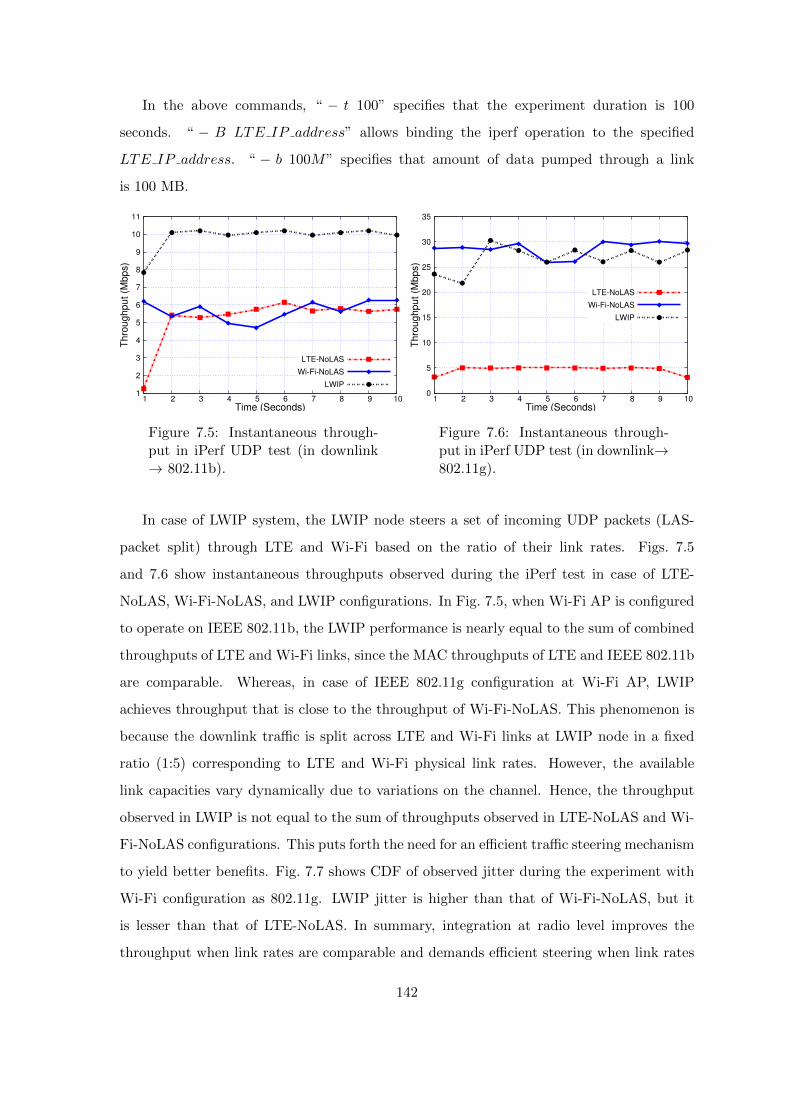
In the above commands, “ − t 100” specifies that the experiment duration is 100
seconds. “ − B LTE IP address” allows binding the iperf operation to the specified
LTE IP address. “ − b 100M” specifies that amount of data pumped through a link
is 100 MB.
1
2
3
4
5
6
7
8
9
10
11
1 2 3 4 5 6 7 8 9 10
Thro
ug
hput
(Mbps)
Time (Seconds)
LTE-NoLAS
Wi-Fi-NoLAS
LWIP
Figure 7.5: Instantaneous through-put in iPerf UDP test (in downlink→ 802.11b).
0
5
10
15
20
25
30
35
1 2 3 4 5 6 7 8 9 10
Thro
ug
hput
(Mbps)
Time (Seconds)
LTE-NoLAS
Wi-Fi-NoLAS
LWIP
Figure 7.6: Instantaneous through-put in iPerf UDP test (in downlink→802.11g).
In case of LWIP system, the LWIP node steers a set of incoming UDP packets (LAS-
packet split) through LTE and Wi-Fi based on the ratio of their link rates. Figs. 7.5
and 7.6 show instantaneous throughputs observed during the iPerf test in case of LTE-
NoLAS, Wi-Fi-NoLAS, and LWIP configurations. In Fig. 7.5, when Wi-Fi AP is configured
to operate on IEEE 802.11b, the LWIP performance is nearly equal to the sum of combined
throughputs of LTE and Wi-Fi links, since the MAC throughputs of LTE and IEEE 802.11b
are comparable. Whereas, in case of IEEE 802.11g configuration at Wi-Fi AP, LWIP
achieves throughput that is close to the throughput of Wi-Fi-NoLAS. This phenomenon is
because the downlink traffic is split across LTE and Wi-Fi links at LWIP node in a fixed
ratio (1:5) corresponding to LTE and Wi-Fi physical link rates. However, the available
link capacities vary dynamically due to variations on the channel. Hence, the throughput
observed in LWIP is not equal to the sum of throughputs observed in LTE-NoLAS and Wi-
Fi-NoLAS configurations. This puts forth the need for an efficient traffic steering mechanism
to yield better benefits. Fig. 7.7 shows CDF of observed jitter during the experiment with
Wi-Fi configuration as 802.11g. LWIP jitter is higher than that of Wi-Fi-NoLAS, but it
is lesser than that of LTE-NoLAS. In summary, integration at radio level improves the
throughput when link rates are comparable and demands efficient steering when link rates
142

are heterogeneous.
0
0.2
0.4
0.6
0.8
1
0 1 2 3 4 5 6 7
CD
F
Jitter( Milli Seconds)
LTE-NoLAS
Wi-Fi-NoLAS
LWIP
Figure 7.7: CDF of jitter for iPerf test (in downlink→ 802.11g).
7.2.4 LWIP testbed: TCP results
To observe the performance of TCP under different Link Aggregation Strategies (LASs),
a set of experiments have been conducted. To better investigate the LASs, scenarios are
created for different loads viz., low and high load. Wi-Fi AP uses IEEE 802.11g standard
for following experiments. An Android application is developed in-house which downloads
two files simultaneously from a remote server and measures their throughputs. Apart from
LTE-NoLAS and Wi-Fi-NoLAS, the UE performance is evaluated using the following LASs:
PS-N-LAS: Packet split enables set of packets of incoming traffic to be sent through
LTE and other packets through Wi-Fi.
FS-N-LAS: Flow split enables one flow to be downloaded through LTE and other
through Wi-Fi.
WoD-LAS: Wi-Fi-only-in-Downlink enables both the flows to use Wi-Fi for down-
link, and the corresponding TCP ACKs are sent through LTE in the uplink.
We have not included the performance evaluation of PS-N-LAS in this section. This is
because PS-N-LAS exhibits poor performance in LWIP due to ”speed of the slowest link”
problem as discussed earlier in Chapter 2.
TCP Experiment 1 - Lightly Loaded Scenario: The setup consists of a UE and an
LWIP node with background transmissions on Wi-Fi channel (observed channel load is 8%).
Now, UE downloads two files from the remote server using different LASs. Files of different
143

sizes are downloaded viz., 16 and 32 MB. Fig. 7.8 shows the throughput observed in case of
different file downloads. It can be observed that FS-LAS has achieved higher throughput
since it effectively aggregates LTE and Wi-Fi links. Fig. 7.9 shows that all the LASs
employed utilize Wi-Fi link at its maximum link rate and therefore achieve throughput
of 25 Mbps (approx.) for IEEE 802.11g mode of operation. Time to download a file
using different LASs is shown in Fig. 7.10. Even though the throughput of FS-LAS and
WoD-LAS are comparable, the time to download a file through FS-LAS incurs longer time
than WoD-LAS because file download through LTE interface incurs longer download time.
0
5
10
15
20
25
30
35
16 MB 32 MB
Thro
ughpu
t (M
bps)
File Size
LTE NoLASWi-Fi NoLAS
FS-LASWoD-LAS
Figure 7.8: Overall throughput ob-served for 16 MB and 32 MB file sizesin low contention scenario.
0
5
10
15
20
25
30
35
16 MB 32 MB
Thro
ughpu
t (M
bps)
File Size
Wi-Fi NoLASFS-LAS
WoD-LAS
Figure 7.9: Throughput of Wi-Fi ob-served for 16 MB and 32 MB file sizesin low contention scenario.
0
20
40
60
80
100
LTE NoLAS Wi-Fi NoLAS FS-LAS WoD-LAS
Dow
nlo
ad T
ime
(S
ec)
Flow-1
Flow-2
Figure 7.10: Time to download a 32MB file using different LASs in lowcontention scenario.
0
5
10
15
20
25
30
35
16 MB 32 MB
Thro
ugh
put
(Mb
ps)
File Size
LTE NoLAS
Wi-Fi NoLAS
FS-LAS
WoD-LAS
Figure 7.11: Overall throughput ob-served for 16 MB and 32 MB filesizes using different LASs in highcontention scenario.
144
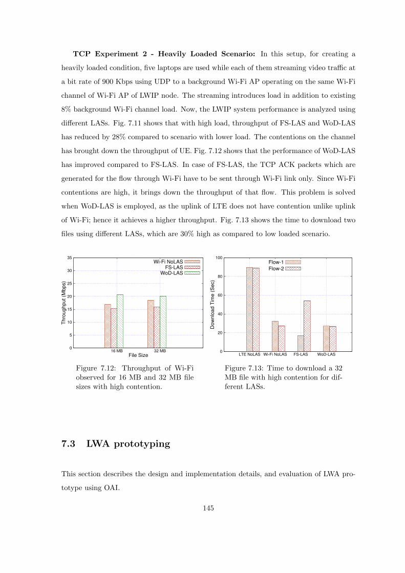
TCP Experiment 2 - Heavily Loaded Scenario: In this setup, for creating a
heavily loaded condition, five laptops are used while each of them streaming video traffic at
a bit rate of 900 Kbps using UDP to a background Wi-Fi AP operating on the same Wi-Fi
channel of Wi-Fi AP of LWIP node. The streaming introduces load in addition to existing
8% background Wi-Fi channel load. Now, the LWIP system performance is analyzed using
different LASs. Fig. 7.11 shows that with high load, throughput of FS-LAS and WoD-LAS
has reduced by 28% compared to scenario with lower load. The contentions on the channel
has brought down the throughput of UE. Fig. 7.12 shows that the performance of WoD-LAS
has improved compared to FS-LAS. In case of FS-LAS, the TCP ACK packets which are
generated for the flow through Wi-Fi have to be sent through Wi-Fi link only. Since Wi-Fi
contentions are high, it brings down the throughput of that flow. This problem is solved
when WoD-LAS is employed, as the uplink of LTE does not have contention unlike uplink
of Wi-Fi; hence it achieves a higher throughput. Fig. 7.13 shows the time to download two
files using different LASs, which are 30% high as compared to low loaded scenario.
0
5
10
15
20
25
30
35
16 MB 32 MB
Th
roug
hput
(Mbp
s)
File Size
Wi-Fi NoLASFS-LAS
WoD-LAS
Figure 7.12: Throughput of Wi-Fiobserved for 16 MB and 32 MB filesizes with high contention.
0
20
40
60
80
100
LTE NoLAS Wi-Fi NoLAS FS-LAS WoD-LAS
Do
wnlo
ad T
ime (
Sec)
Flow-1
Flow-2
Figure 7.13: Time to download a 32MB file with high contention for dif-ferent LASs.
7.3 LWA prototyping
This section describes the design and implementation details, and evaluation of LWA pro-
totype using OAI.
145

7.3.1 Traffic steering in LWA testbed
A dynamic packet steering solution is introduced in this section. It minimizes the number
of packets delivered out-of-order by aggregating the two link rates effectively. It is different
from the solutions discussed in the previous chapters. Chapter 3 detailed the traffic steering
solution combined with an approach for power control. Whereas the dynamic steering
solution discussed below does not involve power control solution instead it considers the
link statistics such as link delay, instantaneous packet loss on a link, etc. to take steering
decisions.
Dynamic packet steering solution that runs at LAL takes inputs such as link round trip
time (LRTT) of LTE and Wi-Fi link, and the packet loss rates of LTE and Wi-Fi links.
LRTT of each link is obtained by sending probe packets on corresponding links. Probing
packets which are originated at PDCP layer of LWA node (ICMP packets are used) are
sent over LTE and Wi-Fi links. The LWA UE on receiving the probe packets sends the
probe responses back to LWA node. The size of probe packets are in order of few bytes
(approx. 30 bytes), which are generated at an interval of 3 ms to get the link information
more accurately. A smoothed LRTT (SLRTT) estimator is used to calculate the steering
ratio. SLRTT of a link l is given by,
SLRTTl = (1− α)× LRTTl + α× SLRTTl ; l ∈ Wi− Fi, LTE (7.1)
where α is the smoothing factor. The value of α is determined by probe packet interval
Pi, where α = 1/Pi. The probe response for the probe packet received through Wi-Fi
interface of LWA-UE is rerouted through LTE interface in uplink to reduce contentions on
Wi-Fi channel.
The steering window can be of fixed size or variable. Steering window size is the sum of
packets sent through LTE and Wi-Fi links in one cycle. For instance, if x : y is the steering
ratio across LTE and Wi-Fi, x + y corresponds to steering window size and time elapsed
to send x + y packets is referred to as a cycle. A fixed steering window does not change
the sum of x and y, whereas the steering window with variable size allows variations in it.
This work employs variable steering window at LWA node as adapts quite well to channel
variations on both links.
146
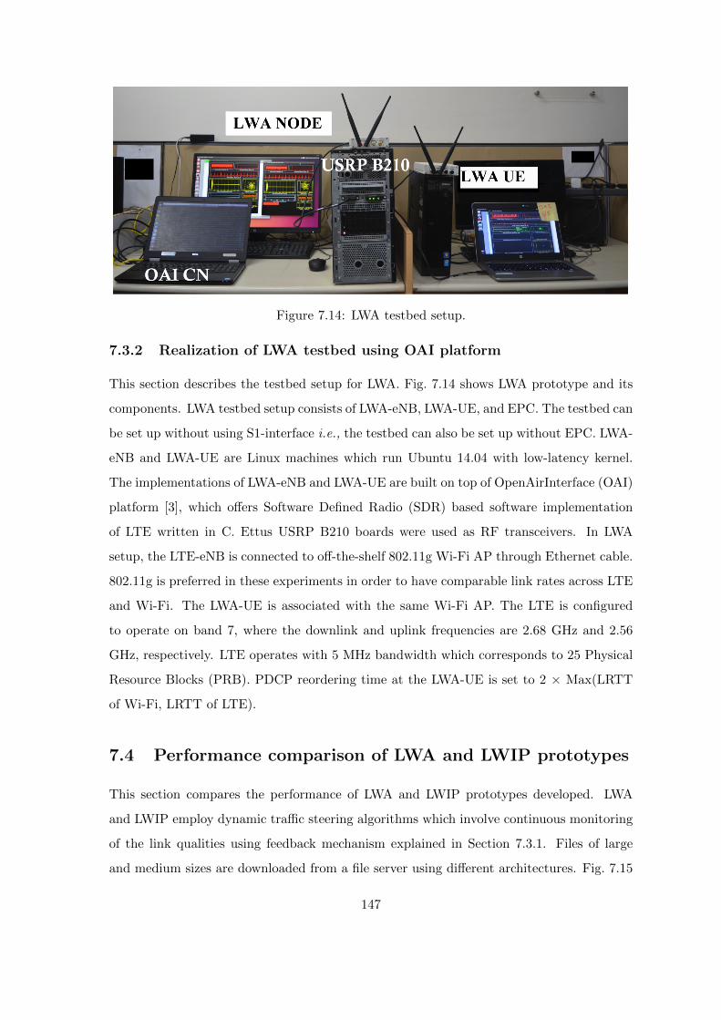
Figure 7.14: LWA testbed setup.
7.3.2 Realization of LWA testbed using OAI platform
This section describes the testbed setup for LWA. Fig. 7.14 shows LWA prototype and its
components. LWA testbed setup consists of LWA-eNB, LWA-UE, and EPC. The testbed can
be set up without using S1-interface i.e., the testbed can also be set up without EPC. LWA-
eNB and LWA-UE are Linux machines which run Ubuntu 14.04 with low-latency kernel.
The implementations of LWA-eNB and LWA-UE are built on top of OpenAirInterface (OAI)
platform [3], which offers Software Defined Radio (SDR) based software implementation
of LTE written in C. Ettus USRP B210 boards were used as RF transceivers. In LWA
setup, the LTE-eNB is connected to off-the-shelf 802.11g Wi-Fi AP through Ethernet cable.
802.11g is preferred in these experiments in order to have comparable link rates across LTE
and Wi-Fi. The LWA-UE is associated with the same Wi-Fi AP. The LTE is configured
to operate on band 7, where the downlink and uplink frequencies are 2.68 GHz and 2.56
GHz, respectively. LTE operates with 5 MHz bandwidth which corresponds to 25 Physical
Resource Blocks (PRB). PDCP reordering time at the LWA-UE is set to 2 × Max(LRTT
of Wi-Fi, LRTT of LTE).
7.4 Performance comparison of LWA and LWIP prototypes
This section compares the performance of LWA and LWIP prototypes developed. LWA
and LWIP employ dynamic traffic steering algorithms which involve continuous monitoring
of the link qualities using feedback mechanism explained in Section 7.3.1. Files of large
and medium sizes are downloaded from a file server using different architectures. Fig. 7.15
147

shows the variation in download time when packet level steering was employed to perform
file download operation in LWA and LWIP architectures. LWA effectively aggregates the
link capacities of LTE and Wi-Fi links compared to LWIP, because LWIP suffers from
out-of-order packet delivery problem at the receiver due to varying link rates of different
interfaces. Downloading a file using LWIP many a times leads to failure. Though LWA is
better than LWIP but is inefficient in aggregating link capacities in certain use cases such as
mobility [84]. The results obtained in our experiment are in line with our NS-3 simulation
results discussed in Section 5.5.3. Even with an efficient traffic steering algorithm LWIP
fails to aggregate link capacities. In the forthcoming sections, we therefore make use of
LWA prototype for experimentation.
0
50
100
150
200
250
16 MB 32 MB 64 MB
Tim
e to D
ow
nlo
ad (
Sec)
LTE
Wi-Fi
LWIP
LWA
Figure 7.15: Download time observed with different RLI prototypes.
7.5 Coupling LWA architecture with MPTCP
This section describes the integrated MPTCP and LWA solution in order to efficiently
aggregate LTE and Wi-Fi links under challenging link and network conditions.
7.5.1 Multipath TCP
Multipath TCP is a transport layer solution which enables simultaneous use of multiple
interfaces e.g., Wi-Fi and LTE. MPTCP uses multiple paths to deliver the segments corre-
sponding to one end-to-end connection. MPTCP implements congestion control algorithms
148
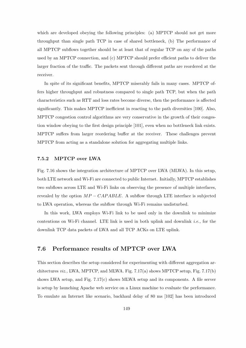
which are developed obeying the following principles: (a) MPTCP should not get more
throughput than single path TCP in case of shared bottleneck, (b) The performance of
all MPTCP subflows together should be at least that of regular TCP on any of the paths
used by an MPTCP connection, and (c) MPTCP should prefer efficient paths to deliver the
larger fraction of the traffic. The packets sent through different paths are reordered at the
receiver.
In spite of its significant benefits, MPTCP miserably fails in many cases. MPTCP of-
fers higher throughput and robustness compared to single path TCP, but when the path
characteristics such as RTT and loss rates become diverse, then the performance is affected
significantly. This makes MPTCP inefficient in reacting to the path diversities [100]. Also,
MPTCP congestion control algorithms are very conservative in the growth of their conges-
tion window obeying to the first design principle [101], even when no bottleneck link exists.
MPTCP suffers from larger reordering buffer at the receiver. These challenges prevent
MPTCP from acting as a standalone solution for aggregating multiple links.
7.5.2 MPTCP over LWA
Fig. 7.16 shows the integration architecture of MPTCP over LWA (MLWA). In this setup,
both LTE network and Wi-Fi are connected to public Internet. Initially, MPTCP establishes
two subflows across LTE and Wi-Fi links on observing the presence of multiple interfaces,
revealed by the option MP − CAPABLE. A subflow through LTE interface is subjected
to LWA operation, whereas the subflow through Wi-Fi remains undisturbed.
In this work, LWA employs Wi-Fi link to be used only in the downlink to minimize
contentions on Wi-Fi channel. LTE link is used in both uplink and downlink i.e., for the
downlink TCP data packets of LWA and all TCP ACKs on LTE uplink.
7.6 Performance results of MPTCP over LWA
This section describes the setup considered for experimenting with different aggregation ar-
chitectures viz., LWA, MPTCP, and MLWA. Fig. 7.17(a) shows MPTCP setup, Fig. 7.17(b)
shows LWA setup, and Fig. 7.17(c) shows MLWA setup and its components. A file server
is setup by launching Apache web service on a Linux machine to evaluate the performance.
To emulate an Internet like scenario, backhaul delay of 80 ms [102] has been introduced
149
Figure 7.16: Architecture of MPTCP over LWA (MLWA).
at the Ethernet interface of the file server with the help of netem network emulator [103].
The performance of aggregation architectures is evaluated by conducting file download op-
erations of various file sizes viz., 16, 32, and 64 MB. Table 7.1 captures various parameters
used in these experiments. The aggregation architectures are evaluated under the following
three challenging scenarios:
1. Network congestion in the backhaul.
2. Contention on the Wi-Fi channel.
3. Mixed: network congestion in the backhaul and contention on Wi-Fi channel.
The experiments are conducted by varying packet loss rates (which mimics network
congestion), file sizes, and channel contentions under different scenarios. Each experiment
150
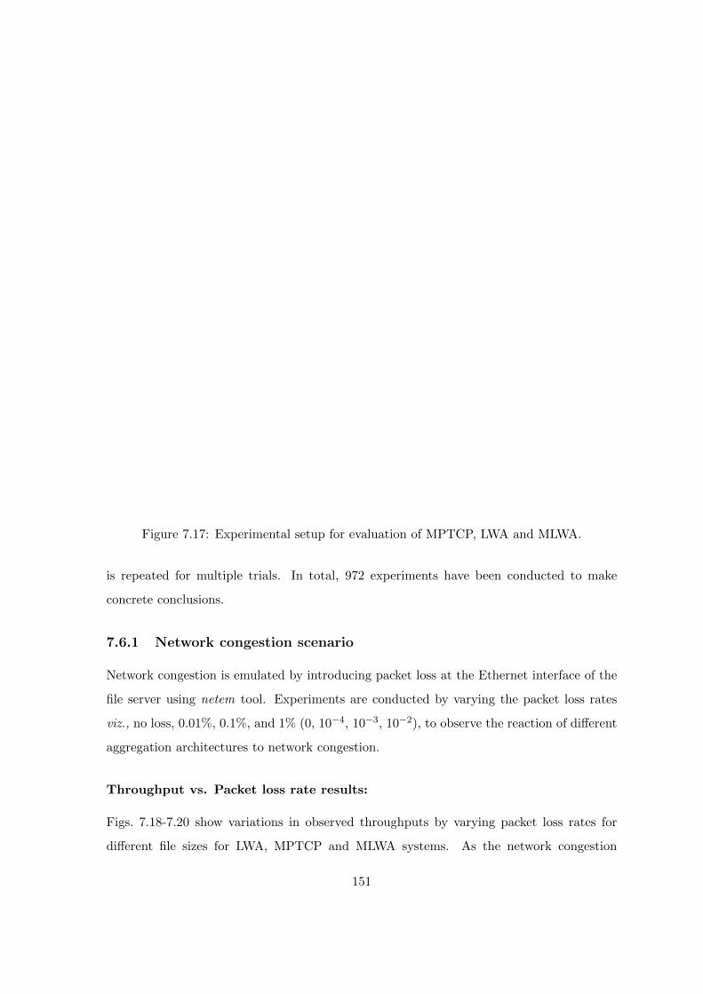
MPTCP Server MPTCP Server
SeNB Wi-Fi AP
Route 1Route 2
(a) MPTCP Setup. (b) LWA Setup. (c) MLWA Setup.
TCP Server
Figure 7.17: Experimental setup for evaluation of MPTCP, LWA and MLWA.
is repeated for multiple trials. In total, 972 experiments have been conducted to make
concrete conclusions.
7.6.1 Network congestion scenario
Network congestion is emulated by introducing packet loss at the Ethernet interface of the
file server using netem tool. Experiments are conducted by varying the packet loss rates
viz., no loss, 0.01%, 0.1%, and 1% (0, 10−4, 10−3, 10−2), to observe the reaction of different
aggregation architectures to network congestion.
Throughput vs. Packet loss rate results:
Figs. 7.18-7.20 show variations in observed throughputs by varying packet loss rates for
different file sizes for LWA, MPTCP and MLWA systems. As the network congestion
151
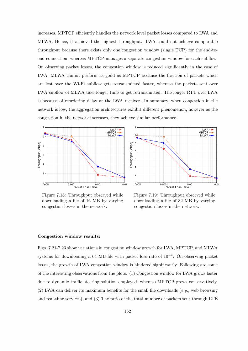
increases, MPTCP efficiently handles the network level packet losses compared to LWA and
MLWA. Hence, it achieved the highest throughput. LWA could not achieve comparable
throughput because there exists only one congestion window (single TCP) for the end-to-
end connection, whereas MPTCP manages a separate congestion window for each subflow.
On observing packet losses, the congestion window is reduced significantly in the case of
LWA. MLWA cannot perform as good as MPTCP because the fraction of packets which
are lost over the Wi-Fi subflow gets retransmitted faster, whereas the packets sent over
LWA subflow of MLWA take longer time to get retransmitted. The longer RTT over LWA
is because of reordering delay at the LWA receiver. In summary, when congestion in the
network is low, the aggregation architectures exhibit different phenomenon, however as the
congestion in the network increases, they achieve similar performance.
0
2
4
6
8
10
12
1e-05 0.0001 0.001 0.01
Th
roug
hput
(Mbp
s)
Packet Loss Rate
LWAMPTCPMLWA
Figure 7.18: Throughput observed whiledownloading a file of 16 MB by varyingcongestion losses in the network.
0
2
4
6
8
10
12
14
1e-05 0.0001 0.001 0.01
Th
roug
hput
(Mbp
s)
Packet Loss Rate
LWAMPTCPMLWA
Figure 7.19: Throughput observed whiledownloading a file of 32 MB by varyingcongestion losses in the network.
Congestion window results:
Figs. 7.21-7.23 show variations in congestion window growth for LWA, MPTCP, and MLWA
systems for downloading a 64 MB file with packet loss rate of 10−4. On observing packet
losses, the growth of LWA congestion window is hindered significantly. Following are some
of the interesting observations from the plots: (1) Congestion window for LWA grows faster
due to dynamic traffic steering solution employed, whereas MPTCP grows conservatively,
(2) LWA can deliver its maximum benefits for the small file downloads (e.g., web browsing
and real-time services), and (3) The ratio of the total number of packets sent through LTE
152
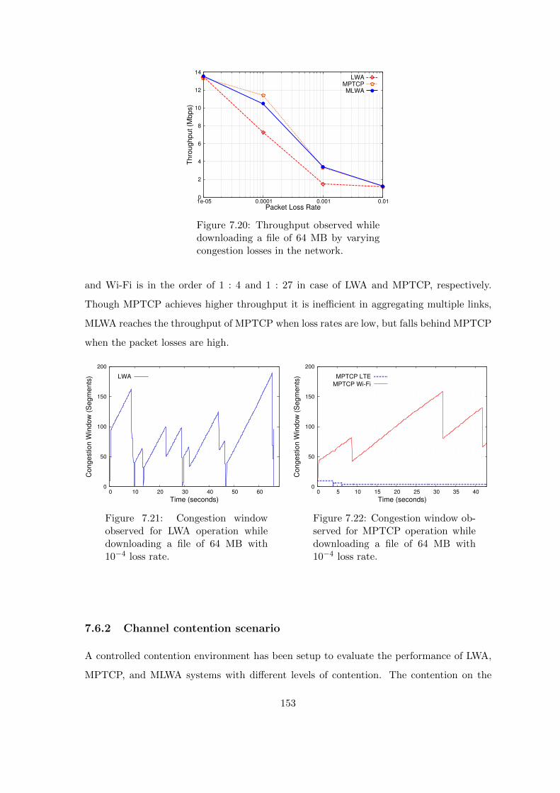
0
2
4
6
8
10
12
14
1e-05 0.0001 0.001 0.01
Thro
ug
hput
(Mbps)
Packet Loss Rate
LWAMPTCPMLWA
Figure 7.20: Throughput observed whiledownloading a file of 64 MB by varyingcongestion losses in the network.
and Wi-Fi is in the order of 1 : 4 and 1 : 27 in case of LWA and MPTCP, respectively.
Though MPTCP achieves higher throughput it is inefficient in aggregating multiple links,
MLWA reaches the throughput of MPTCP when loss rates are low, but falls behind MPTCP
when the packet losses are high.
0
50
100
150
200
0 10 20 30 40 50 60
Co
ngestio
n W
indo
w (
Seg
men
ts)
Time (seconds)
LWA
Figure 7.21: Congestion windowobserved for LWA operation whiledownloading a file of 64 MB with10−4 loss rate.
0
50
100
150
200
0 5 10 15 20 25 30 35 40
Co
ngestio
n W
indo
w (
Seg
men
ts)
Time (seconds)
MPTCP LTE
MPTCP Wi-Fi
Figure 7.22: Congestion window ob-served for MPTCP operation whiledownloading a file of 64 MB with10−4 loss rate.
7.6.2 Channel contention scenario
A controlled contention environment has been setup to evaluate the performance of LWA,
MPTCP, and MLWA systems with different levels of contention. The contention on the
153
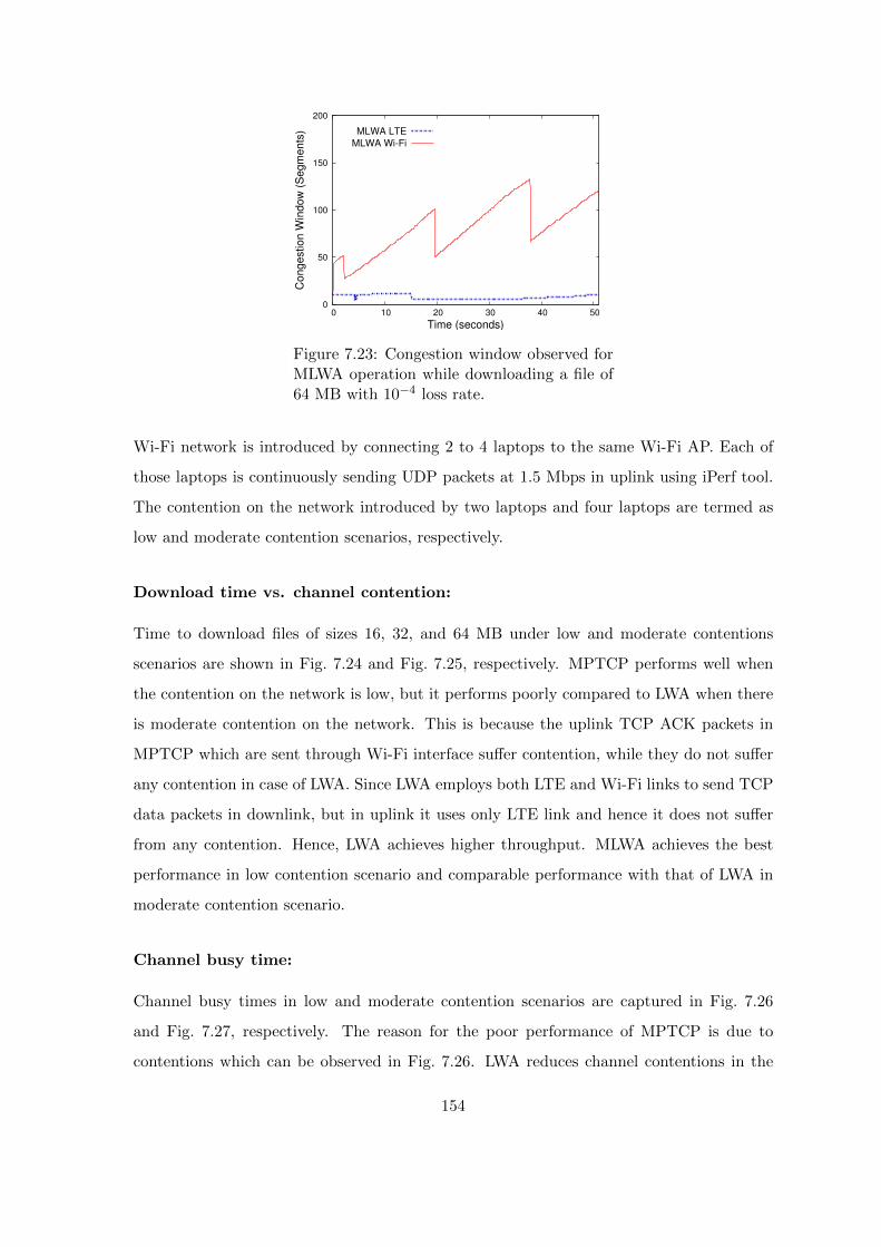
0
50
100
150
200
0 10 20 30 40 50
Con
gestio
n W
indow
(S
egm
en
ts)
Time (seconds)
MLWA LTE
MLWA Wi-Fi
Figure 7.23: Congestion window observed forMLWA operation while downloading a file of64 MB with 10−4 loss rate.
Wi-Fi network is introduced by connecting 2 to 4 laptops to the same Wi-Fi AP. Each of
those laptops is continuously sending UDP packets at 1.5 Mbps in uplink using iPerf tool.
The contention on the network introduced by two laptops and four laptops are termed as
low and moderate contention scenarios, respectively.
Download time vs. channel contention:
Time to download files of sizes 16, 32, and 64 MB under low and moderate contentions
scenarios are shown in Fig. 7.24 and Fig. 7.25, respectively. MPTCP performs well when
the contention on the network is low, but it performs poorly compared to LWA when there
is moderate contention on the network. This is because the uplink TCP ACK packets in
MPTCP which are sent through Wi-Fi interface suffer contention, while they do not suffer
any contention in case of LWA. Since LWA employs both LTE and Wi-Fi links to send TCP
data packets in downlink, but in uplink it uses only LTE link and hence it does not suffer
from any contention. Hence, LWA achieves higher throughput. MLWA achieves the best
performance in low contention scenario and comparable performance with that of LWA in
moderate contention scenario.
Channel busy time:
Channel busy times in low and moderate contention scenarios are captured in Fig. 7.26
and Fig. 7.27, respectively. The reason for the poor performance of MPTCP is due to
contentions which can be observed in Fig. 7.26. LWA reduces channel contentions in the
154

0
10
20
30
40
50
60
Dow
nlo
ad T
ime (
sec)
File Size (MB)
16 MB 32 MB 64 MB
LW
A
MP
TC
P
ML
WA
LW
A
MP
TC
P
ML
WA
LW
A
MP
TC
P
ML
WA
Figure 7.24: Download time in case ofLWA, MPTCP, and MLWA by varyingfile sizes under low Wi-Fi channel con-tention scenario.
0
20
40
60
80
100
Dow
nlo
ad T
ime (
sec)
File Size (MB)
16 MB 32 MB 64 MB
LW
A
MP
TC
P
MLW
A
LW
A
MP
TC
P
MLW
A
LW
A
MP
TC
P
MLW
A
Figure 7.25: Download time in case ofLWA, MPTCP, and MLWA by varyingfile sizes under moderate Wi-Fi channelcontention scenario.
network by allowing the LWA-UE to send uplink packets through LTE and thereby it
facilitates improved transmission opportunities to other Wi-Fi stations in the network.
MLWA achieves high throughputs in both moderate and low contention scenarios because it
employs the merit of MPTCP in low contention scenario (which employs different congestion
regulation mechanism per subflow), and it employs LWA feature (no uplink contention) in
case of moderate or high contention scenario.
0
0.2
0.4
0.6
0.8
1
Norm
aliz
ed
Cha
nnel B
usy T
ime
File Size
16 MB 32 MB 64 MB
LW
A
MP
TC
P
MLW
A
LW
A
MP
TC
P
MLW
A
LW
A
MP
TC
P
MLW
A
Figure 7.26: Channel busy time observedin Wi-Fi channel when a 32 MB filewas downloaded under low Wi-Fi chan-nel contention scenario.
0
0.2
0.4
0.6
0.8
1
Norm
aliz
ed
Cha
nnel B
usy T
ime
File Size
16 MB 32 MB 64 MB
LW
A
MP
TC
P
MLW
A
LW
A
MP
TC
P
MLW
A
LW
A
MP
TC
P
MLW
A
Figure 7.27: Channel busy time observedin Wi-Fi channel when a 32 MB file wasdownloaded under moderate Wi-Fi chan-nel contention scenario.
155
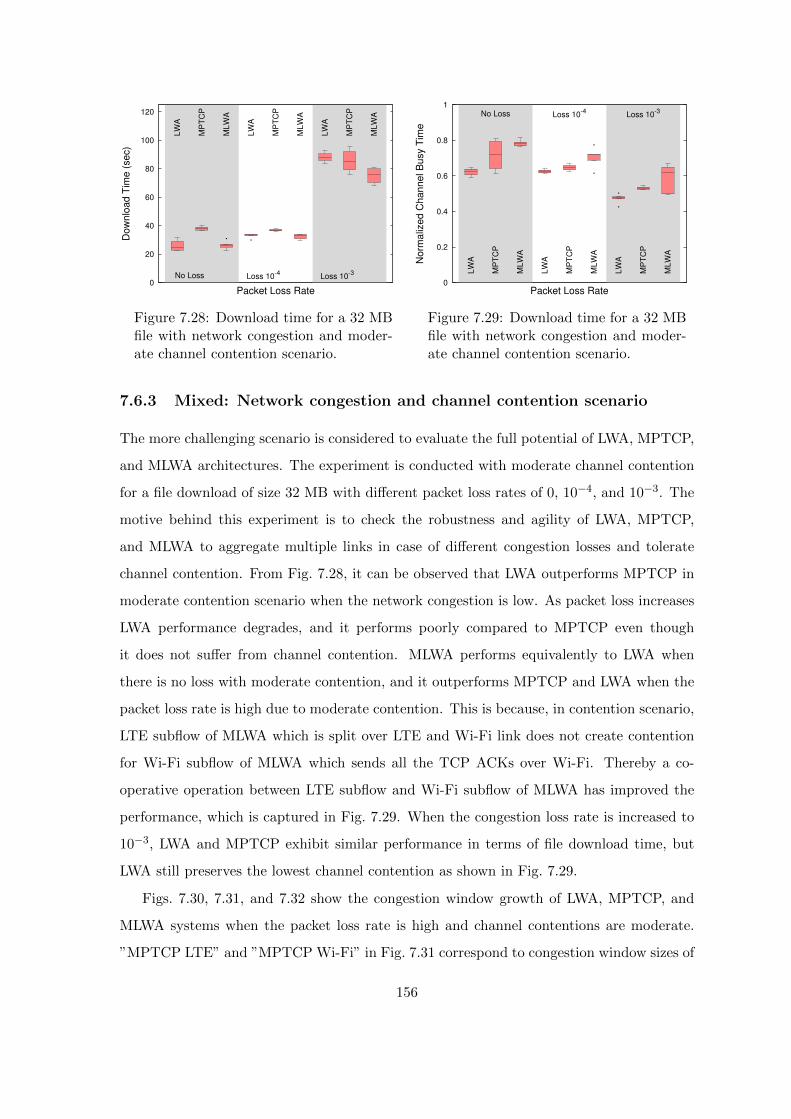
0
20
40
60
80
100
120
Dow
nlo
ad T
ime (
sec)
Packet Loss Rate
No Loss Loss 10-4
Loss 10-3
LW
A
MP
TC
P
MLW
A
LW
A
MP
TC
P
MLW
A
LW
A
MP
TC
P
MLW
A
Figure 7.28: Download time for a 32 MBfile with network congestion and moder-ate channel contention scenario.
0
0.2
0.4
0.6
0.8
1
Norm
aliz
ed
Chan
nel B
usy T
ime
Packet Loss Rate
No Loss Loss 10-4
Loss 10-3
LW
A
MP
TC
P
MLW
A
LW
A
MP
TC
P
MLW
A
LW
A
MP
TC
P
MLW
A
Figure 7.29: Download time for a 32 MBfile with network congestion and moder-ate channel contention scenario.
7.6.3 Mixed: Network congestion and channel contention scenario
The more challenging scenario is considered to evaluate the full potential of LWA, MPTCP,
and MLWA architectures. The experiment is conducted with moderate channel contention
for a file download of size 32 MB with different packet loss rates of 0, 10−4, and 10−3. The
motive behind this experiment is to check the robustness and agility of LWA, MPTCP,
and MLWA to aggregate multiple links in case of different congestion losses and tolerate
channel contention. From Fig. 7.28, it can be observed that LWA outperforms MPTCP in
moderate contention scenario when the network congestion is low. As packet loss increases
LWA performance degrades, and it performs poorly compared to MPTCP even though
it does not suffer from channel contention. MLWA performs equivalently to LWA when
there is no loss with moderate contention, and it outperforms MPTCP and LWA when the
packet loss rate is high due to moderate contention. This is because, in contention scenario,
LTE subflow of MLWA which is split over LTE and Wi-Fi link does not create contention
for Wi-Fi subflow of MLWA which sends all the TCP ACKs over Wi-Fi. Thereby a co-
operative operation between LTE subflow and Wi-Fi subflow of MLWA has improved the
performance, which is captured in Fig. 7.29. When the congestion loss rate is increased to
10−3, LWA and MPTCP exhibit similar performance in terms of file download time, but
LWA still preserves the lowest channel contention as shown in Fig. 7.29.
Figs. 7.30, 7.31, and 7.32 show the congestion window growth of LWA, MPTCP, and
MLWA systems when the packet loss rate is high and channel contentions are moderate.
”MPTCP LTE” and ”MPTCP Wi-Fi” in Fig. 7.31 correspond to congestion window sizes of
156
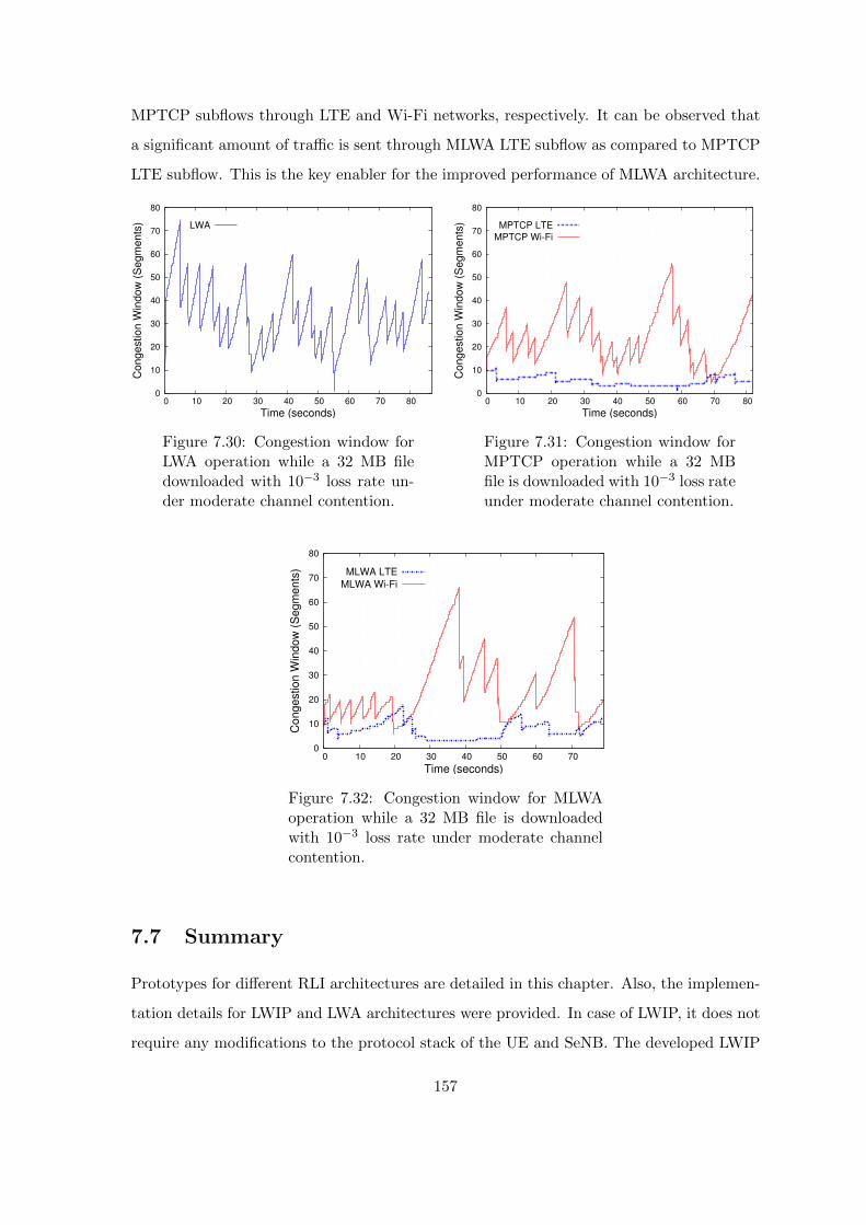
MPTCP subflows through LTE and Wi-Fi networks, respectively. It can be observed that
a significant amount of traffic is sent through MLWA LTE subflow as compared to MPTCP
LTE subflow. This is the key enabler for the improved performance of MLWA architecture.
0
10
20
30
40
50
60
70
80
0 10 20 30 40 50 60 70 80
Con
gestio
n W
indow
(S
egm
en
ts)
Time (seconds)
LWA
Figure 7.30: Congestion window forLWA operation while a 32 MB filedownloaded with 10−3 loss rate un-der moderate channel contention.
0
10
20
30
40
50
60
70
80
0 10 20 30 40 50 60 70 80
Con
gestio
n W
indow
(S
egm
en
ts)
Time (seconds)
MPTCP LTE
MPTCP Wi-Fi
Figure 7.31: Congestion window forMPTCP operation while a 32 MBfile is downloaded with 10−3 loss rateunder moderate channel contention.
0
10
20
30
40
50
60
70
80
0 10 20 30 40 50 60 70
Co
nge
stio
n W
indo
w (
Seg
me
nts
)
Time (seconds)
MLWA LTE
MLWA Wi-Fi
Figure 7.32: Congestion window for MLWAoperation while a 32 MB file is downloadedwith 10−3 loss rate under moderate channelcontention.
7.7 Summary
Prototypes for different RLI architectures are detailed in this chapter. Also, the implemen-
tation details for LWIP and LWA architectures were provided. In case of LWIP, it does not
require any modifications to the protocol stack of the UE and SeNB. The developed LWIP
157

prototype was evaluated using different link aggregation strategies. The experiment results
conclude that WoD-LAS has improved sum of flow throughputs by 28% as compared to
FS-LAS when the contention on Wi-Fi channel is high. Thus, enabling WoD-LAS will be
the most preferred link aggregation solution.
In case of LWA, the changes to the radio protocol stack are done both at the LWA node
and LWA-UE. Also, the integrated performance of LWA with MPTCP is studied under
challenging environments. From the conducted experiments, the following inferences were
drawn, (i) In case of network congestion, MPTCP is an ideal solution which can adequately
handle the network level losses, (ii) LWA fails to aggregate link capacities when there is a
congestion in the network, (iii) LWA is well suitable when the download files are of smaller
size (less than 1 MB like Web traffic), (iv) When the channel contentions are moderate or
high, LWA not only improves the performance of its users, but also improves overall perfor-
mance of all users on the Wi-Fi channel, and (v) MLWA is robust and exhibits significant
performance when the congestion losses are high and channel contentions are high. The
experiments revealed that the transport layer solution and radio level interworking solutions
are complementing each other and co-operation between these two solutions in any scenario
is better than at least one of their performances.
158

Chapter 8
Conclusions and Future work
8.1 Conclusions
Radio Level Integration architectures are developed to address the challenges which pre-
vailed in traditional LTE Wi-Fi interworking architectures. In this thesis, various radio level
integration architectures were studied, and the fundamental challenges which prevent them
from achieving integrated benefits are addressed. The main contributions of this thesis are:
1. Proposed radio level integration architectures with an objective to enhance the level
of interworking (in terms of steering the traffic, balancing the load, and regulating the
transmit power) between LTE and Wi-Fi networks.
2. Proposed a solution to address co-tier interference across LTE small cells in dense
deployment scenarios of RLI systems.
3. Proposed a dynamic traffic steering solution which efficiently handles the time-varying
channel conditions on LTE and Wi-Fi links.
4. The problem of out-of-order packet delivery which arises for packet level steering in
LWIP architecture was addressed by proposing an efficient algorithm.
5. Efficient placement of the devices and effective radio resource management are studied
for indoor deployments of RLI systems.
6. Designed and developed prototypes of radio level integration architectures using open
source tools. The developed prototypes were profiled. The problems of link level
159

contention and network level congestion were studied, and solutions were developed
and evaluated using these prototypes.
In Chapter 2 of the thesis, novel link aggregation strategies were proposed to address various
challenges in realizing full benefits of RLI architectures. Primarily, traffic steering solutions
were proposed in Chapters 3 and 4 to enable efficient uplink and downlink steering, respec-
tively. In Chapter 3, a downlink traffic steering solution was proposed targeting to reduce
the co-tier interference across the deployed LWIP nodes and to maximizes QoS of the net-
work. The proposed downlink traffic steering algorithm, PRECISE has outperformed the
state-of-the-art α-optimal scheduler by 48% and 3GPP Rel-12 LTE Wi-Fi interworking by
84% on system throughput. We have observed from our experiments that, Wi-Fi when
employed to carry only downlink traffic uses the Wi-Fi channel more efficiently. Hence, any
downlink traffic steering solution employing Wi-Fi-only-in-downlink achieved significant im-
provement in system throughput and reduced number of collisions on Wi-Fi channel.
Restricting Wi-Fi to operate only-in-downlink by preventing any sort of uplink through
Wi-Fi does not utilize the radio resources efficiently. Also the high demand for LTE uplink
radio resources introduces longer waiting time. Hence, to overcome the problem of chan-
nel contention on Wi-Fi and to utilize the uplink radio resources more effectively, uplink
traffic steering solution, Network Coordination Function (NCF) was proposed in Chapter 4
of this thesis. The proposed steering solution NCF works by coordinating Wi-Fi uplink
transmissions using LTE as the anchor. The proposed solution operates fairly and improves
the throughput of LWIP node by 21% as compared to LWIP system operating with default
DCF mechanism.
Chapter 5 addressed another important challenge, the out-of-order packet delivery at
the receiver due to packet level steering employed at LWIP node. The packets of a flow are
steered across LTE and Wi-Fi links by downlink traffic steering mechanism employed; due
to difference in the link rates of LTE and Wi-Fi the packets might arrive out-of-order at the
receiver. Such out-of-order reception negatively affects the growth of TCP congestion win-
dow. In order to address this challenge, VISIBLE algorithm was proposed which minimizes
the out-of-order packet delivery by employing a virtual boosting and virtual reordering
mechanism. The proposed solution (VISIBLE) has out performed LWA and MPTCP by
30% and 37%, respectively in terms of system throughput.
160
In Chapter 6, the placement problem of RLI nodes was investigated with the objectives
of minimizing the number of LWIP nodes to be placed, to maximize the SINR of all the
sub-regions in a given building, and to reduce the energy consumed at LWIP node and
LWIP-UE. It is observed that placing the RLI nodes optimally has significant performance
improvement as compared to placing them with MIR placement.
Finally, in Chapter 7 of the thesis, prototypes of RLI architectures (LWA and LWIP)
were built and their performance were compared with existing multi-RAT aggregation solu-
tions. The traffic steering solution was primarily targeted to address the link layer problems.
But, it is also equally important to co-operate with higher layer solutions in order improve
the end-to-end network performance. Hence, co-operation between LWA and MPTCP is
investigated. It was observed that the proposed co-operative solution out performed stan-
dalone LWA and MPTCP solutions when there existed network losses and high contentions
on the Wi-Fi channel.
8.2 Future work
Radio level integration can be explored to address the problem of poor video delivery
and optimizations can be done to enhance the quality of video delivery by understanding
the semantics of video transmission and coupling appropriately with diverse properties of
multiple radio access technologies.
The insights drawn from this thesis can be employed in designing and supporting 5G
multi-connectivity in various contexts such as deployment, efficient steering, and efficient
utilization of resources in the unlicensed band.
5G is being designed to cater to the requirements of different verticals. 5G New Radio
(NR) is versatile and targets to provide numerous services which span from Mobile Broad-
band, Machine to Machine communication, massive Internet of Things, and Tactile Internet.
The key enabling technologies of 5G include Cloud-Radio Access Network (C-RAN) and
multi-RAT connectivity. As a notable point in 5G Multi-RAT design, to aggregate multiple
links effectively where the link rates are diverse, the radio level interworking solution is
mandatory.
The solutions proposed in this thesis to address the problems related to multi-RAT
integration can be adopted to address similar problems in the context of Multi-connectivity
161

in 5G where LTE, Wi-Fi and 5G NR need to be integrated.
The developed solution can be used to address the problem with mmWave communica-
tion which suffers from very high fluctuations in the data rates. When mmWave transmitter
and receiver are in line-of-sight (LOS) high data rate is observed. When the transmitter
and receiver are not in line-of-sight (NLOS) then their data rates dwindle drastically. The
existing reliable transport layer protocols are not designed to support these high fluctua-
tions. The solution proposed in this thesis in the context of enhancement to transport layer
protocols using LWIP can be reused by introducing more insights on the high fluctuation
of data rates.
5G also targets to achieve bounded waiting time with very high reliability, Ultra Reli-
able Low-Latency Communication (URLLC) is the term coined for this requirement. Only
a ubiquitous network with the high available resource can satisfy these low latency require-
ments. But in reality, none of the deployed networks are ubiquitous and resource-rich. A
feasible solution to this target is to pool resources from multiple networks to achieve high
reliability. Connected cars, autonomous driving, remote health care, industrial automation,
and all mission-critical services seek URLLC. The solution proposed in this thesis can be
extended to meet the targets of URLLC by optimizing proposed traffic steering algorithms.
The developed prototypes can be further extended to support cloud-based multi-RAT
aggregation. Also, in case of radio aggregation cloud units, the developed prototypes can
be modified to realize RAN split at different layers of LTE and Wi-Fi protocol stacks. The
RAN split can be dynamically adjusted based on the objectives and capabilities of the radio
aggregation unit.
162

List of Publications
Published Research Papers
1. Thomas Valerrian Pasca S, Sumanta Patro, Bheemarjuna Reddy Tamma, and
Antony Franklin A, “Network Coordination Function for Uplink Traffic Steering in
Tightly Coupled LTE Wi-Fi Networks,” Elsevier Computer Networks, vol. 127, pp.
296-316, November 2017.
2. Thomas Valerrian Pasca S, Nabhasmita Sen, Venkatarami Reddy, Bheemarjuna
Reddy Tamma, and Antony Franklin A, “A Framework for Integrating MPTCP over
LWA - A Testbed Evaluation,” in Proc. of Wireless Network Testbeds, Experimental
evaluation & CHaracterization (WiNTECH) - ACM MobiCom Workshop, November
2018, New Delhi, India.
3. Thomas Valerrian Pasca S, Bheemarjuna Reddy Tamma, and Antony Franklin A,
“VISIBLE: Virtual Congestion Control with Boost ACKs for Packet Level Steering
in LWIP Networks,” in Proc. of IEEE GLOBECOM, December 2017, Singapore.
4. Thomas Valerrian Pasca S, Himank Gupta, Bheemarjuna Reddy Tamma, and
Antony Franklin A, “PRECISE: Power Aware Dynamic Traffic Steering in Tightly
Coupled LTE Wi-Fi Networks,” in Proc. of IEEE PIMRC, October 2017, Montreal,
Canada.
5. Thomas Valerrian Pasca S, Sumanta Patro, Bheemarjuna Reddy Tamma, and
Antony Franklin A, “A Real-Time Performance Evaluation of Tightly Coupled LTE
Wi-Fi Radio Access Networks,” in Proc. of IEEE ANTS, December 2017, Bhubanesh-
war, India. (Won Best Paper Award - 2nd position)
6. Thomas Valerrian Pasca S, Adharsh Srivats Rangarajan, Bheemarjuna Reddy
Tamma, and Antony Franklin A, “Optimal Placement of Colocated and Non-Colocated
LWA Nodes in Dense Deployments,” in Proc. of IEEE ANTS, December 2017,
Bhubaneshwar, India.
7. Thomas Valerrian Pasca S, Amogh PC, Debashisha Mishra, Nagamani Dheera-
vath, Anil kumar Rangisetti, Bheemarjuna Reddy Tamma, and Antony Franklin A,
163
“Architectural Challenges and Solutions for Collocated LWIP - A Network Layer Per-
spective,” in Proc. of NCC, March 2017, Chennai, India.
Research Demos
1. Thomas Valerrian Pasca S, Himank Gupta, Sumanta Patro, Bheemarjuna Reddy
Tamma, and Antony Franklin A, “LTE-Wi-Fi Radio Level Integration at RLC Layer:
A Demo of LWIR,” in Proc. of COMSNETS, January 2018, Bangalore, India. (Won
Best Academic Demo Award)
2. Thomas Valerrian Pasca S, Sumanta Patro, Bheemarjuna Reddy Tamma, and
Antony Franklin A, “Tightly Coupled LTE Wi-Fi Radio Access Networks: A Demo
of LWIP,” in Proc. of COMSNETS, January 2017, Bangalore, India.
Patents
1. Thomas Valerrian Pasca S, Bheemarjuna Reddy Tamma, and Antony Franklin A,
“Traffic steering in aggregated LTE-Wi-Fi Networks,” Indian Patent, Application No:
4705/CHE/2015, Patent Pending.
2. Antony Franklin A, Bheemarjuna Reddy Tamma, Prashant Sharma, and Thomas
Valerrian Pasca S, “Method and System for LTE WLAN Integration at RLC
Layer (LWIR) with Integrated LTE Wi-Fi Scheduler,” Indian Patent, Application
No: 201641025740, Patent Pending.
3. Antony Franklin A, Bheemarjuna Reddy Tamma, Prashant Sharma, Thomas Valer-
rian Pasca S, “Method for Scheduling Data by Network Node Aggregated With LTE
and Wi-Fi Protocol Stacks,” US Patent, Application No: 20180035445, Patent Pend-
ing.
164

Research Papers (Under review)
1. Thomas Valerrian Pasca S, Himank Gupta, Bheemarjuna Reddy Tamma, and
Antony Franklin A, “Energy Aware Traffic Steering Solution for Aggregated LTE
Wi-Fi Networks,” submitted to Elsevier Computer Communications, January 2019.
2. Thomas Valerrian Pasca S, Sumanta Patro, Bheemarjuna Reddy Tamma, and
Antony Franklin A, “DIDA: A Packet Level Steering Solution for LWIP Networks,”
submitted to IEEE ICC, 2019.
Research Papers (In preparation)
1. Thomas Valerrian Pasca S, Bheemarjuna Reddy Tamma, and Antony Franklin
A, “Is Packet Level Steering Feasible in Tightly Coupled LTE Wi-Fi Interworking
Architecture? - A Realtime Solution” to be submitted to IEEE Transactions on
Mobile Computing.
2. Thomas Valerrian Pasca S, Venkatarami Reddy, and Nabhasmita Sen, Bheemar-
juna Reddy Tamma, and Antony Franklin A, “Radio Level Aggregation of LTE and
Wi-Fi for Edge Cloud - A Testbed Approach” to be submitted to IEEE Communica-
tion Magazine.
165

Publications (Other supporting work)
1. Thomas Valerrian Pasca S, Akilesh B, Arjun V Anand, and Bheemarjuna Reddy
Tamma, “A NS-3 Module for LTE UE Energy Consumption,” in Proc. of IEEE
ANTS, November 2016, Bangalore, India.
2. Thomas Valerrian Pasca S, Siva sairam prasad Kodali, and Kotaro Kataoka,
“AMPS: Application Aware Multipath Flow Routing Using Machine Learning in
SDN,” in Proc. of NCC, March 2017, Chennai, India.
3. Prasanth Sharma, Ajay Brahmakshatriya, Thomas Valerrian Pasca S, Bheemar-
juna Reddy Tamma, and Antony Franklin A, “LWIR: LTE-WLAN Integration at
RLC Layer with Virtual WLAN Scheduler for Efficient Aggregation,” in Proc. of
IEEE GLOBECOM, December 2016, Washington DC, USA.
4. Sreekanth Dama, Thomas Valerrian Pasca S, Vanlin Sathya, and Kiran Kumar
Kuchi, “A Feasible Cellular Internet of Things: Enabling Edge Computing and the
IoT in Dense Futuristic Cellular Networks,” IEEE Consumer Electronics Magazine,
vol. 6, no. 1, pp. 66-72, January 2017.
5. Anil Kumar Rangisetti, Thomas Valerrian Pasca S, and Bheemarjuna Reddy
Tamma, “QoS Aware load balance in software defined LTE networks,” Elsevier Com-
puter Communications, vol. 97, pp. 52-71, January 2017.
6. Sumanta Patro, Thomas Valerrian Pasca S, Bheemarjuna Reddy Tamma, and
Antony Franklin A, “INCARNATE: An Interference Aware Spatial Scheme for Tightly
Coupled LTE-Wi-Fi Networks,” in Proc. of COMSNETS, January 2018, Bangalore,
India.
7. Sumanta Patro, Thomas Valerrian Pasca S, Bheemarjuna Reddy Tamma, and
Antony Franklin A, “mINCARNATE: An Interference and Mobility Aware Spatial
Scheme for Tightly Coupled LTE-Wi-Fi Networks,” in Proc. of Lecture Notes in
Computer Science (LNCS) - Communication Systems and Networks, pp. 126-149,
January 2019.
166

Patents (Other supporting works)
1. Sreekanth Dama, Thomas Valerrian Pasca S, Abhinav Kumar, Bheemarjuna Reddy
Tamma, and Kiran kumar Kuchi, “Method for accessing a channel in wireless com-
munication network”, US Patent No: 20160242175, Patent Granted.
2. Sreekanth Dama, Thomas Valerrian Pasca S, Sathya Vanlin, Kiran Kumar Kuchi,
and Bheemarjuna Reddy Tamma, “A Novel RACH Mechanism for Dense Cellular-IoT
Deployments”, Provisional Filling: 06.11.2015, Patent Pending.
167
Bibliography
[1] I. T. Union, “IMT Vision Framework and overall objectives of the future development
of IMT for 2020 and beyond.” [Online]. Available: https://www.itu.int/
[2] 3GPP, “Evolved Universal Terrestrial Radio Access (E-UTRA) and Evolved Univer-
sal Terrestrial Radio Access Network (E-UTRAN); Overall description,” Tech. Rep.
36.300, 2016.
[3] N. Nikaein, M. Mahesh K, M. Saravana, D. Alex, K. Raymond, and B. Christian,
“OpenAirInterface: A flexible platform for 5G research,” ACM SIGCOMM Computer
Communication Review (CCR), vol. 44, no. 5, pp. 33–38, 2014.
[4] Cisco, “Global Mobile Data Traffic Forecast Update, 2016 - 2021.” [Online].
Available: http://www.cisco.com/c/en/us/solutions/collateral/service-provider/
visual-networking-index-vni/mobile-white-paper-c11-520862.html
[5] T. E. Klein and P. Richard, “ICT energy challenges, impact and solutions,” in Proc. of
International ICIN Conference-Innovations in Clouds, Internet and Networks. IFIP,
2016.
[6] Y. Chen, S. Zhang, S. Xu, and G. Y. Li, “Fundamental trade-offs on green wireless
networks,” IEEE Communications Magazine, vol. 49, no. 6, pp. 30–37, 2011.
[7] 3GPP, “Study on enhancement of Ultra-Reliable Low-Latency Communication
(URLLC) support in the 5G Core network (5GC),” Tech. Rep. 23.725, 2018.
[8] “Third Generation Partnership Project.” [Online]. Available: http://www.3gpp.org/
[9] 3GPP, “Network architecture,” Tech. Rep. 23.002, 2018.
[10] ——, “Policy and charging control architecture,” Tech. Rep. 23.203, 2018.
168

[11] ——, “Evolved Universal Terrestrial Radio Access (E-UTRA); Radio Resource Con-
trol (RRC);,” Tech. Rep. 36.331, 2017.
[12] C. S. Bontu and E. Illidge, “Drx mechanism for power saving in lte,” IEEE Commu-
nications Magazine, vol. 47, no. 6, pp. 48–55, June 2009.
[13] 3GPP, “Evolved Universal Terrestrial Radio Access (E-UTRA); Packet Data Conver-
gence Protocol (PDCP) specification,” Tech. Rep. 36.323, 2018.
[14] ——, “Evolved Universal Terrestrial Radio Access (E-UTRA); Radio Link Control
(RLC) protocol specification,” Tech. Rep. 36.322, 2018.
[15] ——, “Evolved Universal Terrestrial Radio Access (E-UTRA); Medium Access Con-
trol (MAC) protocol specification,” Tech. Rep. 36.321, 2018.
[16] ——, “ Evolved Universal Terrestrial Radio Access (E-UTRA); LTE physical layer;
General description,” Tech. Rep. 36.201, 2018.
[17] ——, “Technical Specification Group Radio Access Network; Evolved Universal Ter-
restrial Radio Access (E-UTRA); Base Station (BS) radio transmission and recep-
tion,” Tech. Rep. 36.104, 2018.
[18] ——, “Evolved Universal Terrestrial Radio Access (E-UTRA); Physical channels and
modulation,” Tech. Rep. 36.211, 2018.
[19] I. S. Association, “Wireless Local Area Network (WLAN).” [Online]. Available:
https://standards.ieee.org/standard/802 11ac-2013.html
[20] “IEEE Standard for Wireless LAN Medium Access Control (MAC) and Physical Layer
(PHY) specifications,” IEEE Std 802.11-1997, pp. 1–445, Nov 1997.
[21] M. Benveniste, “Hybrid coordination function (HCF) access through tiered contention
and overlapped wireless cell mitigation,” Nov. 14 2006, US Patent 7,136,361.
[22] Tektronics, “Wi-Fi: Overview of the 802.11 Physical Layer and Transmitter
Measurements.” [Online]. Available: www.cnrood.com/en/media/solutions/Wi-Fi
Overview of the 802.11 Physical Layer.pdf
169
[23] C. Samsung, “Samsung Download Booster.” [Online]. Available: www.samsung.com/
au/galaxys5-mobile/features.html
[24] A. Ford, C. Raiciu, M. Handley, and O. Bonaventure, “TCP Extensions for Multipath
Operation with Multiple Addresses,” Tech. Rep. RFC 6824, 2013.
[25] H. Soliman, “Mobile ipv6 support for dual stack hosts and routers,” Tech. Rep. 5555,
2009. [Online]. Available: https://www.rfc-editor.org/rfc/rfc5555
[26] 3GPP, “Proxy Mobile IPv6 (PMIPv6) based Mobility and Tunnelling protocols,”
Tech. Rep. 29.275, 2015.
[27] ——, “Access Network Discovery and Selection Function (ANDSF),” Tech. Rep.
24.312, 2015.
[28] ——, “IP flow mobility and seamless Wireless Local Area Network (WLAN) offload,”
Tech. Rep. 23.261, 2015.
[29] K. Lee, J. Lee, Y. Yi, I. Rhee, and S. Chong, “Mobile data offloading: How much can
WiFi deliver?” IEEE/ACM Transactions on Networking (ToN), vol. 21, no. 2, pp.
536–550, 2013.
[30] S. Singh, S. p. Yeh, N. Himayat, and S. Talwar, “Optimal traffic aggregation in
multi-RAT heterogeneous wireless networks,” in Proc. of International Conference on
Communications Workshops (ICC). IEEE, May 2016, pp. 626–631.
[31] 3GPP, “Evolved Universal Terrestrial Radio Access (E-UTRA); LTE-WLAN Radio
Level Integration Using Ipsec Tunnel (LWIP) encapsulation; Protocol specification,”
Tech. Rep. 29.060, 1999.
[32] ——, “Study on S2a Mobility based on GPRS Tunnelling Protocol (GTP) and Wire-
less Local Area Network (WLAN) access to the Enhanced Packet Core (EPC) network
(SaMOG,” Tech. Rep. 23.852, 2013.
[33] ——, “Network-Based IP Flow Mobility (NBIFOM),” Tech. Rep. 23.161, 2015.
[34] ——, “Evolved Universal Terrestrial Radio Access (E-UTRA); LTE-WLAN Aggrega-
tion Adaptation Protocol (LWAAP) specification,” Tech. Rep. 36.360, 2016.
170
[35] ——, “General Packet Radio Service (GPRS); GPRS Tunnelling Protocol (GTP),”
Tech. Rep. 36.361, 2016.
[36] J. Ling, S. Kanugovi, S. Vasudevan, and A. Pramod, “Enhanced capacity and coverage
by Wi-Fi LTE integration,” IEEE Communications Magazine, vol. 53, no. 3, pp. 165–
171, March 2015.
[37] 3GPP, “Evolved Universal Terrestrial Radio Access Network (E-UTRAN) and Wire-
less Local Area Network (WLAN); Xw application protocol (XwAP),” Tech. Rep.
36.463, 2015.
[38] ——, “Evolved Universal Terrestrial Radio Access Network (E-UTRAN) and Wireless
Local Area Network (WLAN); Xw interface user plane protocol,” Tech. Rep. 36.465,
2016.
[39] S. Hanks, T. Li, D. Farinacci, and P. Traina, “Generic Routing Encapsulation (GRE),”
Tech. Rep. RFC 1701, 1994.
[40] 3GPP, “Study on Small Cell enhancements for E-UTRA and E-UTRAN; Higher layer
aspects,” Tech. Rep. 36.842, 2013.
[41] “iptables.” [Online]. Available: https://linux.die.net/man/8/iptables
[42] “Nist Error Model.” [Online]. Available: https://www.nsnam.org/doxygen/
nist-error-rate-model 8cc source.html
[43] B. Chen, J. Chen, Y. Gao, and J. Zhang, “Coexistence of LTE-LAA and Wi-Fi on 5
GHz With Corresponding Deployment Scenarios: A Survey,” IEEE Communications
Surveys Tutorials, vol. 19, no. 1, pp. 7–32, Firstquarter 2017.
[44] “LTE over unlicensed.” [Online]. Available: http://www.3gpp.org/news-events/
3gpp-news/1603-lte in unlicensed
[45] “License Assisted Access.” [Online]. Available: ftp://ftp.3gpp.org/tsg ran/WG1
RL1/TSGR1 79/Docs/R1-145483.zip
[46] S. Deb et al., “Algorithms for eICIC in LTE HetNets,” IEEE/ACM Transactions on
Networking (ToN), vol. 22, no. 1, pp. 137–150, 2014.
171
[47] J.-H. Lee, J. Bonnin, and X. Lagrange, “Host-based distributed mobility management:
Example of traffic offloading,” in Proc. of Consumer Communications and Networking
Conference (CCNC). IEEE, 2013, pp. 637–640.
[48] K. Lee, J. Lee, Y. Yi, I. Rhee, and S. Chong, “Mobile Data Offloading: How Much
Can Wi-Fi Deliver?” IEEE/ACM Transactions on Networking (ToN), vol. 21, no. 2,
pp. 536–550, April 2013.
[49] S. Ranjan, N. Akhtar, M. Mehta, and A. Karandikar, “User-based integrated offload-
ing approach for 3GPP LTE-WLAN network,” in Proc. of National Conference on
Communications (NCC). IEEE, 2014, pp. 1–6.
[50] M. Gerasimenko, N. Himayat, S.-p. Yeh, S. Talwar, S. Andreev, and Y. Kouch-
eryavy, “Characterizing performance of load-aware network selection in multi-radio
(WiFi/LTE) heterogeneous networks,” in Proc. of Global Communications Conference
Workshops (GC Wkshps). IEEE, 2013, pp. 397–402.
[51] S.-p. Yeh, A. Y. Panah, N. Himayat, and S. Talwar, “QoS Aware Scheduling and
Cross-Radio Coordination in Multi-Radio Heterogeneous Networks,” in Proc. of Ve-
hicular Technology Conference (VTC). IEEE, 2013, pp. 1–6.
[52] Sou and Sok-Ian, “Mobile data offloading with policy and charging control in 3GPP
core network,” IEEE Transactions on Vehicular Technology, vol. 62, no. 7, pp. 3481–
3486, 2013.
[53] N. Sapountzis, T. Spyropoulos, N. Nikaein, and U. Salim, “An Analytical Framework
for Optimal Downlink-Uplink User Association in HetNets with Traffic Differentia-
tion,” in Proc. of Global Communications Conference (GLOBECOM). IEEE, Dec
2015, pp. 1–7.
[54] P. Sermpezis and T. Spyropoulos, “Modelling and Analysis of Communication Traffic
Heterogeneity in Opportunistic Networks,” IEEE Transactions on Mobile Computing
(TMC), vol. 14, no. 11, pp. 2316–2331, 2015.
[55] F. Mehmeti and T. Spyropoulos, “Is it worth to be patient? Analysis and optimization
of delayed mobile data offloading,” in Proc. of INFOCOM. IEEE, April 2014, pp.
2364–2372.
172

[56] A. Balasubramanian, R. Mahajan, and A. Venkataramani, “Augmenting Mobile 3G
Using WiFi,” in Proc. of International Conference on Mobile Systems, Applications,
and Services (MobiSys). ACM, 2010, pp. 209–222.
[57] S. Singh, M. Geraseminko, S. ping Yeh, N. Himayat, and S. Talwar, “Proportional
Fair Traffic Splitting and Aggregation in Heterogeneous Wireless Networks,” IEEE
Communications Letters, vol. 20, no. 5, pp. 1010–1013, May 2016.
[58] Y.-J. Lai, T.-Y. Liu, and C.-L. Hwang, “Topsis for MODM,” European Journal of
Operational Research, vol. 76, no. 3, pp. 486–500, 1994.
[59] 3GPP, “Evolved Universal Terrestrial Radio Access (E-UTRA); Radio Frequency
(RF) requirements for LTE Pico Node B,” Tech. Rep. 36.931, 2018.
[60] T. Chrysikos, G. Georgopoulos, and S. Kotsopoulos, “Site-specific validation of ITU
indoor path loss model at 2.4 GHz,” in Proc. of International Symposium on a World
of Wireless, Mobile and Multimedia Networks Workshops (WoWMoM). IEEE, June
2009, pp. 1–6.
[61] G. Americas, “Whitepaper on LTE Aggregation and Unlicensed spectrum.”
[Online]. Available: http://www.5gamericas.org/files/1214/4648/2397/4G Americas
LTE Aggregation Unlicensed Spectrum White Paper - November 2015.pdf
[62] 3GPP, “LTE/WLAN Radio Interworking,” Tech. Rep. 37.834, 2013.
[63] Skype, “How much bandwidth does Skype need?” [Online]. Available:
https://support.skype.com/en/faq/FA1417/how-much-bandwidth-does-skype-need
[64] Y. He, M. Chen, B. Ge, and M. Guizani, “On wifi offloading in heterogeneous net-
works: Various incentives and trade-off strategies,” IEEE Communications Surveys
Tutorials, vol. 18, no. 4, pp. 2345–2385, Fourthquarter 2016.
[65] V. Miliotis, L. Alonso, and C. Verikoukis, “Offloading with IFOM: The uplink case,”
in Proc. of Global Communications Conference (GLOBECOM). IEEE, Dec 2014,
pp. 2661–2666.
173
[66] ——, “Energy efficient proportionally fair uplink offloading for IP Flow Mobility,” in
Proc. of International Workshop on Computer Aided Modeling and Design of Com-
munication Links and Networks (CAMAD). IEEE, Dec 2014, pp. 6–10.
[67] U. Sethakaset, Y. K. Chia, and S. Sun, “Energy Efficient WiFi Offloading for Cellular
Uplink Transmissions,” in Proc. of Vehicular Technology Conference (VTC). IEEE,
May 2014, pp. 1–5.
[68] F. Daneshgaran, M. Laddomada, F. Mesiti, and M. Mondin, “Unsaturated throughput
analysis of IEEE 802.11 in presence of non ideal transmission channel and capture
effects,” IEEE Transactions on Wireless Communications (TWC), vol. 7, no. 4, pp.
1276–1286, 2008.
[69] S. Rasheed, K. Masnoon, N. Thanthry, and R. Pendse, “PCF vs DCF: a performance
comparison,” in Proc. of the Southeastern Symposium on System Theory. IEEE,
2004, pp. 215–219.
[70] S. Rayanchu, A. Mishra, D. Agrawal, S. Saha, and S. Banerjee, “Diagnosing Wire-
less Packet Losses in 802.11: Separating Collision from Weak Signal,” in Proc. of
INFOCOM. IEEE, April 2008, pp. 735–743.
[71] S. Thomas Valerrian Pasca, P. C. Amogh, M. Debashisha, D. Nagamani, R. Anil Ku-
mar, T. Bheemarjuna Reddy, and A. Antony Franklin, “Architectural Challenges and
Solutions for Collocated LWIP: Network Layer Perspective,” in Proc. of National
Conference on Communication (NCC). IEEE, March 2017, pp. 1–6.
[72] 3GPP, “Study on Small Cell enhancements for E-UTRA.” [Online]. Available:
http://www.3gpp.org/ftp/Specs/archive/36 series/36.842/36842-c00.zip
[73] T. Henderson, Boeing, S. Floyd, A. Gurtov, and Y. Nishida, “The NewReno Modifi-
cation to TCP’s Fast Recovery Algorithm,” Tech. Rep. RFC 6582, 2012.
[74] D. Leith and R. Shorten, “H-TCP: TCP for high-speed and long-distance networks,”
in Proc. of PFLDnet, 2004.
[75] T. Kelly, “Scalable TCP: Improving Performance in Highspeed Wide Area Networks,”
ACM SIGCOMM CCR, vol. 33, no. 2, pp. 83–91, 2003.
174

[76] L. Xu, K. Harfoush, and I. Rhee, “Binary Increase Congestion Control (BIC) for Fast
Long-Distance Networks,” in Proc. of INFOCOM, vol. 4. IEEE, 2004, pp. 2514–2524.
[77] S. Floyd, “Highspeed tcp for large congestion windows,” Tech. Rep., 2003.
[78] F. Wang and Y. Zhang, “Improving TCP performance over mobile ad-hoc networks
with out-of-order detection and response,” in Proc. of Mobile Ad Hoc Networking and
Computing (MobiHoc). ACM, 2002, pp. 217–225.
[79] H. Mulugeta and K. Raimond, “Performance improvement of TCP using TCP-DOOR-
TS algorithm in mobile ad hoc networks,” in Proc. of International Conference on
Communication Technology. IEEE, 2011, pp. 642–646.
[80] R. Ludwig and R. H. Katz, “The Eifel algorithm: making TCP robust against spuri-
ous retransmissions,” SIGCOMM Computer Communication Review (CCR), vol. 30,
no. 1, pp. 30–36, 2000.
[81] V. Paxson, “End-to-end Internet packet dynamics,” IEEE/ACM Transactions on Net-
working (ToN), vol. 7, no. 3, pp. 277–292, 1999.
[82] M. Zhang, B. Karp, S. Floyd, and L. Peterson, “RR-TCP: a reordering-robust TCP
with DSACK,” in Proc. of International Conference on Network Protocols (ICNP).
IEEE, 2003, pp. 95–106.
[83] S. Bohacek, J. P. Hespanha, J. Lee, C. Lim, and K. Obraczka, “A new TCP for per-
sistent packet reordering,” IEEE/ACM Transactions on Networking (ToN), vol. 14,
no. 2, April 2006.
[84] Y. Khadraoui, X. Lagrange, and A. Gravey, “TCP Performance for Practical Imple-
mentation of Very Tight Coupling between LTE and WiFi,” in Proc. of Vehicular
Technology Conference (VTC). IEEE, Sept 2016, pp. 1–6.
[85] C. Paasch and O. Bonaventure, “Multipath tcp,” Communications of the ACM,
vol. 57, no. 4, pp. 51–57, 2014.
[86] L. Kleinrock, Queueing systems, volume 2: Computer applications. wiley New York,
1976, vol. 66.
175
[87] V. Paxson and M. Allman, “Computing TCP’s Retransmission Timer,” Tech. Rep.
RFC 6298, 2000.
[88] S. Ha, I. Rhee, and L. Xu, “Cubic: a new tcp-friendly high-speed tcp variant,” ACM
SIGOPS operating systems review, vol. 42, no. 5, pp. 64–74, 2008.
[89] H. T. Friis, “A Note on a Simple Transmission Formula,” Proceedings of the IRE,
vol. 34, no. 5, pp. 254–256, May 1946.
[90] M. Kheirkhah, I. Wakeman, and G. Parisis, “Multipath-TCP in ns-3,” CoRR, 2015.
[Online]. Available: http://arxiv.org/abs/1510.07721
[91] W. Guo and S. Wang, “Interference-aware self-deploying femto-cell,” IEEE Wireless
Communications Letters, vol. 1, no. 6, pp. 609–612, 2012.
[92] W. Guo, S. Wang, X. Chu, J. Zhang, J. Chen, and H. Song, “Automated small-cell
deployment for heterogeneous cellular networks,” IEEE Communications Magazine,
vol. 51, no. 5, pp. 46–53, 2013.
[93] S. Vanlin, R. Arun, and T. Bheemarjuna Reddy, “On placement and dynamic power
control of femtocells in lte hetnets,” in Proc. of Global Communications Conference
(GLOBECOM). IEEE, 2014, pp. 4394–4399.
[94] J. Liu, Q. Chen, and H. D. Sherali, “Algorithm design for femtocell base station
placement in commercial building environments,” in Proc. of INFOCOM. IEEE,
2012, pp. 2951–2955.
[95] S. Thomas Valerrian Pasca, G. Himank, T. Bheemarjuna Reddy, and
A. Antony Franklin, “PRECISE: Power Aware Dynamic Traffic Steering in Tightly
Coupled LTE Wi-Fi Networks,” in Proc. of International Symposium on Personal,
Indoor, and Mobile Radio Communications (PIMRC). IEEE, 2017, pp. 1–7.
[96] N. Nikaein, R. Knopp, F. Kaltenberger, L. Gauthier, C. Bonnet, D. Nussbaum, and
R. Ghaddab, “Demo: OpenAirInterface: an open LTE network in a PC,” in Proc. of
International Conference on Mobile Computing and Networking (MobiCom). ACM,
2014, pp. 305–308.
176
[97] T. Bheemarjuna Reddy, A. Antony Franklin, and S. Thomas Valerrian Pasca, “Traffic
steering strategies for LWA.” [Online]. Available: www.tsdsi.org/standards/swip/30/
[98] M. Baerts, “HIPRIKeeper.” [Online]. Available: https://github.com/
MPTCP-smartphone-thesis/MultipathControl
[99] D. Jon, S. Elliott, B. A. Mah, J. Poskanzer, K. Prabhu, M. Ashley, A. Brown,
A. Jaible, S. Sahani, B. Simpson, and B. Tierney, “iPerf3.” [Online]. Available:
https://iperf.fr/
[100] S. K. Saha, A. Kannan, G. Lee, N. Ravichandran, P. K. Medhe, N. Merchant, and
D. Koutsonikolas, “Multipath TCP in Smartphones: Impact on Performance, Energy,
and CPU Utilization,” in Proc. of Mobility Management and Wireless Access. ACM,
2017, pp. 23–31.
[101] S. Ferlin, O. Alay, T. Dreibholz, D. A. Hayes, and M. Welzl, “Revisiting congestion
control for multipath TCP with shared bottleneck detection,” in Proc. of INFOCOM.
IEEE, 2016, pp. 1–9.
[102] Y.-C. Chen, Y.-s. Lim, R. J. Gibbens, E. M. Nahum, R. Khalili, and D. Towsley, “A
Measurement-based Study of MultiPath TCP Performance over Wireless Networks,”
in Proc. of Internet Measurement Conference (IMC). ACM, 2013, pp. 455–468.
[103] L. network developers, “Network emulation.” [Online]. Available: https://wiki.
linuxfoundation.org/networking/netem
177

DOCTORAL COMMITTEE
Chairperson and Dr. Bheemarjuna Reddy TammaResearch Advisor Associate Professor
Department of Computer Science and EngineeringIndian Institute of Technology Hyderabad
Members: Dr. Kotaro KataokaAssociate ProfessorDepartment of Computer Science and EngineeringIndian Institute of Technology Hyderabad
Dr. Sathya PeriAssociate ProfessorDepartment of Computer Science and EngineeringIndian Institute of Technology Hyderabad
Dr. Kiran Kumar KuchiProfessorDepartment of Electrical and EngineeringIndian Institute of Technology Hyderabad
Dr. P. RajalakshmiAssociate ProfessorDepartment of Electrical EngineeringIndian Institute of Technology Hyderabad
178