
Crowdsourced traffic information in traffic management - DIVA
Upload
khangminh22Category
view
0download
0
"{Double click to insert image}"
Traffic Signal Design Appendix D Location and Dimensions of Components
Issue No: 1.8 23 December 2016

Traffic Signal Design | Issue No 1.8 | 23 December 2016 Appendix D Location and Dimensions of Components
Preface The traffic signal design guidelines have been developed to assist in designing traffic control signals. The information contained in the various parts is intended to be used as a guide to good practice. Discretion and judgement should be exercised, taking into account all the factors that may influence the design of traffic signals at any particular site.
The guidelines make reference, where relevant, to current Australian Standards or the Austroads Guides, and are intended to supplement and otherwise assist in their interpretation and application. If any conflict arises, the Australian Standards, the Austroads Guides and the RMS Supplements are to prevail.
The complete set of traffic signal design guidelines is as follows.
Section Title Appendix Title 1 Investigation A Design Plan Checklist 2 Warrants B Traffic Signal Symbols 3 Design Process C Location and Function of Lanterns 4 Plan Requirements D Location and Dimensions of Components 5 Geometry E Left Turn on Red 6 Pavement Marking F Level Crossing Interface – Concept of
Operations 7 Phasing and Signal Group Display Sequence 8 Lanterns G Level Crossing Interface – Traffic Signal Design
Guidance 9 Posts 10 Signs 11 Detectors 12 Controller 13 Provision for Future Facilities 14 Signalised Mid-block Marked Footcrossings 15 Special Situations 16 References
Primary references and complementary material Roads and Maritime has adopted the Australian Standards and the Austroads Guides as its primary technical references. Roads and Maritime has developed the following complementary material which must be used in conjunction with the Standards and Guides.
• Australian Standards Traffic Supplements. • Supplements to the Austroads Guides. • Traffic Signal Design Guide. • Delineation Manual. • NSW Bicycle Guidelines. • Standard Drawings. • Technical Directions. • Technical Specifications.
These documents are published on the Roads and Maritime website at www.rms.nsw.gov.au. 2008 Roads and Maritime Services Extracts from these guidelines may be reproduced providing the subject is kept in context and the source is acknowledged. Every effort has been made to supply complete and accurate information. However Roads and Maritime assumes no responsibility for its use. All trade name references herein are either trademarks or registered trademarks of their respective companies.
Traffic Signal Design | Issue No1.8 | 23 December 2016 Appendix D Location and Dimensions of Components
About this release
Title: Traffic Signal Design Guide: Appendix D Location and Dimensions of Components
Document Number: RMS/Pub. 08.092 ISBN 978-1-921242-95-3 (Electronic only)
Version: 1.8
Prepared by: Michael Bajenov, Intelligent Transport Systems Lyndall Johnson, Network Operations
Contributors: Fraser Johnson, Brian Taylor (Intelligent Transport Systems); Alan Dixon, Harry Campara (Network Operations); Jorge Sales-Luis (Road Design Engineering)
Endorsed by: Alan Dixon, Principal Manager Network Operations Andrew Mehaffey, Principal Manager Intelligent Transport Systems
Authorised by: Craig Moran, General Manager Road Network Operations
Date of approval and effect:
23-12-2016
Email for enquiries or feedback:
Issue Date Section Description Approver
1.0 Feb 2008 Initial release P Collins A/Dir Network Management
1.1 May 2009 1.1 Clearance of 0.6m shown as minimum. R O’Keefe Mgr Policies & Guidelines 1.2 Text of 2nd layout amended.
1.4 Text & diagrams for fencing at mid-block marked foot crossings amended.
1.7 The location of a post where the nose of a median is behind a marked foot crossing amended.
1.2 Aug 2009 1.7 Added minimum offset of 3.0m from the kerb for non-frangible posts located at rear of footway.
R O’Keefe Mgr Policies & Guidelines
1.3 Dec 2010 1.3 Diagram amended. R O’Keefe Mgr Traffic Policies, Guidelines & Legislation
1.4 Jan 2011 1.7 Note added to clarify the position of the post for a mid-block marked foot crossing.
R O’Keefe Mgr Traffic Policies, Guidelines & Legislation
D.3 | 15 Note: Printed copies of this document are uncontrolled
Traffic Signal Design | Issue No 1.8 | 23 December 2016 Appendix D Location and Dimensions of Components
Issue Date Section Description Approver
1.5 Jun 2012 1.7 Amendments related to Type 14 posts and Type 15 mast arms.
R O’Keefe Mgr Traffic Policies, Guidelines & Legislation
1.6 Aug 2012 1.7 Amendment related to mid-block post locations. R O’Keefe Mgr Traffic Policies, Guidelines & Legislation
1.7 Mar 2013 1.7 Location of primary post for mid-block marked foot crossing amended.
R O’Keefe Mgr Traffic Policies, Guidelines & Legislation
1.8 Dec 2016 All Reformatted to reflect latest structure and corporate identity. Layouts numbered for ease of referencing. Hyperlinks to other sections or documents removed.
Craig Moran GM Road Network Operations
1.1 Notes added to diagram.
1.2(g), 1.3(a), 1.6(e), 1.7(h)&(i)
All diagrams updated with high entry angle traffic islands. Reference to specifications included where required.
1.4(c)&(d) Minimum width of median amended to 3.0m.
1.5(a) Diagram updated and reference to model drawing included.
1.6(a) Distance between kerb and line marking clarified.
1.7(a) Post types and positioning updated.
1.7(f) Post positioning updated.
1.8(f) Diagram updated to indicate departure detector starts from the approach edge of the stop line.
1.8(i) Addition of detector locations for motorway entry ramp with ramp metering traffic signals.
Contents 1.1. Typical layout with combined components at a marked foot crossing ..........................5
1.2. Marked foot crossings at intersections .............................................................................5
1.3. Pedestrian crossings ..........................................................................................................7
1.4. Mid-block marked foot crossings ......................................................................................7
1.5. Kerb ramps ..........................................................................................................................8
1.6. Stop lines ............................................................................................................................8
1.7. Posts (including Mast Arms and Poles) ............................................................................9
1.8. Vehicle detectors .............................................................................................................. 12
1.9. Pedestrian push-button detectors ................................................................................... 14
1.10. Controllers ..................................................................................................................... 14
D.4 | 15 Note: Printed copies of this document are uncontrolled

Traffic Signal Design | Issue No1.8 | 23 December 2016 Appendix D Location and Dimensions of Components
1.1. Typical layout with combined components at a marked foot crossing
1.2. Marked foot crossings at intersections (a) The standard width of a signalised marked foot crossing is 3.6 m. If the standard width is used, the dimension does not need to be shown on the design layout. If any other width is used, the dimension must be shown. All dashed paint lines are 0.15 m wide and commence at the lip line of any kerb which has a concrete gutter (eg SA or SF), or 0.3 m clear of any kerb which does not have concrete gutter (eg SF or SM), including raised medians and islands. These dimensions do not need to be shown on the design layout.
D.5 | 15 Note: Printed copies of this document are uncontrolled
Traffic Signal Design | Issue No 1.8 | 23 December 2016 Appendix D Location and Dimensions of Components
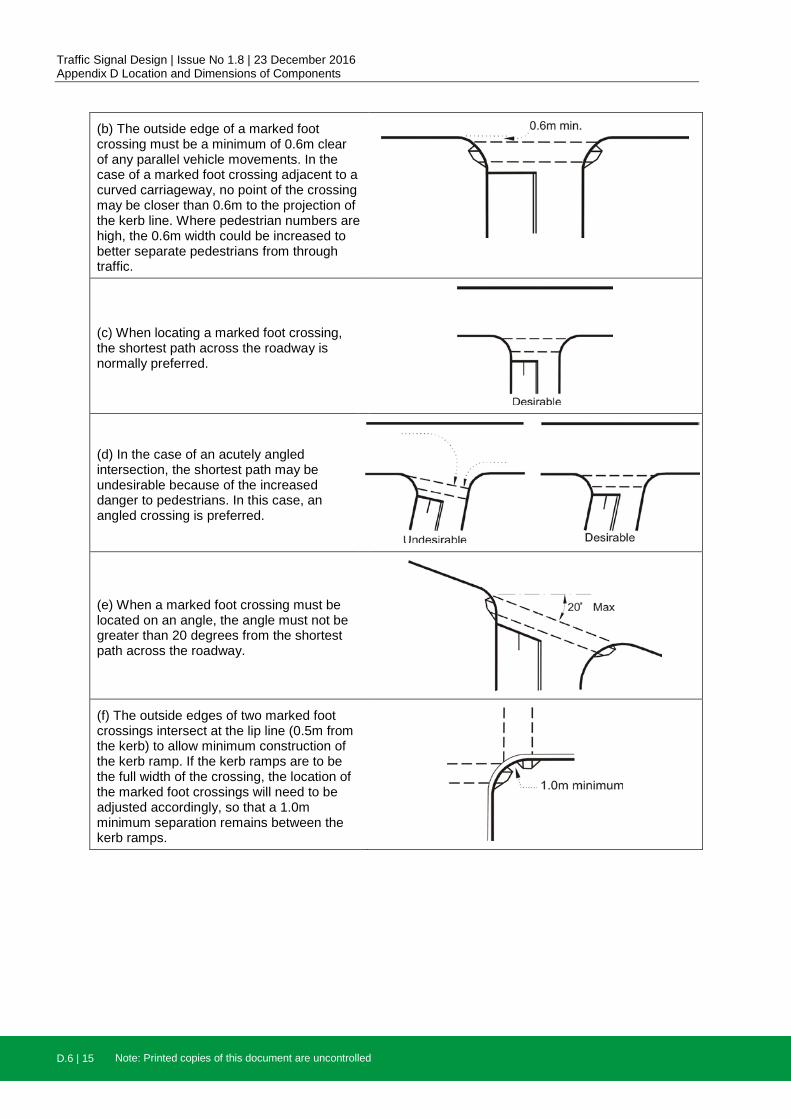
(b) The outside edge of a marked foot crossing must be a minimum of 0.6m clear of any parallel vehicle movements. In the case of a marked foot crossing adjacent to a curved carriageway, no point of the crossing may be closer than 0.6m to the projection of the kerb line. Where pedestrian numbers are high, the 0.6m width could be increased to better separate pedestrians from through traffic.
(c) When locating a marked foot crossing, the shortest path across the roadway is normally preferred.
(d) In the case of an acutely angled intersection, the shortest path may be undesirable because of the increased danger to pedestrians. In this case, an angled crossing is preferred.
(e) When a marked foot crossing must be located on an angle, the angle must not be greater than 20 degrees from the shortest path across the roadway.
(f) The outside edges of two marked foot crossings intersect at the lip line (0.5m from the kerb) to allow minimum construction of the kerb ramp. If the kerb ramps are to be the full width of the crossing, the location of the marked foot crossings will need to be adjusted accordingly, so that a 1.0m minimum separation remains between the kerb ramps.
D.6 | 15 Note: Printed copies of this document are uncontrolled

Traffic Signal Design | Issue No1.8 | 23 December 2016 Appendix D Location and Dimensions of Components
(g) Where a marked foot crossing is provided to a corner island, the crossing ends 0.3m from the kerb, not at the paint. This is to discourage pedestrians from standing on the road pavement
1.3. Pedestrian crossings
(a) The dimensions of a pedestrian crossing at an uncontrolled left-turn slip lane are as shown. Refer to QA specification R145.
1.4. Mid-block marked foot crossings
(a) The dimensions of a one-stage mid-block marked foot crossing at a one-way street are as shown. A barrier fence may be installed between the stop line and the crossing if considered necessary.
(b) The dimensions of a one-stage mid-block marked foot crossing at a two-way street are as shown. A barrier fence may be installed between the stop line and the crossing if considered necessary.
(c) The dimensions of a two-stage mid-block marked foot crossing with a left-hand offset are as shown. A barrier fence must be provided on the median, and may also be installed on the kerb between the stop line and the crossing if considered necessary.
D.7 | 15 Note: Printed copies of this document are uncontrolled

Traffic Signal Design | Issue No 1.8 | 23 December 2016 Appendix D Location and Dimensions of Components
(d) The dimensions of a two-stage mid-block marked foot crossing with a right-hand offset are as shown. A barrier fence must be provided on the median, and may also be installed on the kerb between the stop line and the crossing if considered necessary.
1.5. Kerb ramps
(a) The basic dimensions of a kerb ramp are as shown. For full details, refer to model drawing MD.R173.B01.A.1. All kerb ramps should be shown on the design layout to ensure there are no conflicts with posts or utilities. To aid the passage of wheelchairs, trolleys and strollers, a vertical rise should not be provided at the gutter ie no lip.
1.6. Stop lines (a) Stop lines are 0.3 m wide and commence 0.3m clear of any kerb that does not have a concrete gutter eg SF type kerb, or from the edge of the gutter for kerbs that do have a concrete gutter, eg SA, SE type kerbs, (including raised medians and islands).
These dimensions do not need to be shown on the design layout.
(b) Stop lines should be located no less than 5.4m from the prolongation of the kerb line of the cross street. This distance is measured to the front edge of the stop line and will allow the immediate installation of a marked foot crossing, or an installation in the future. If it is known that there is little likelihood of a marked foot crossing ever being installed, this distance may be reduced to 3m following approval by the Principal Manager, Network Operations.
D.8 | 15 Note: Printed copies of this document are uncontrolled
Traffic Signal Design | Issue No1.8 | 23 December 2016 Appendix D Location and Dimensions of Components
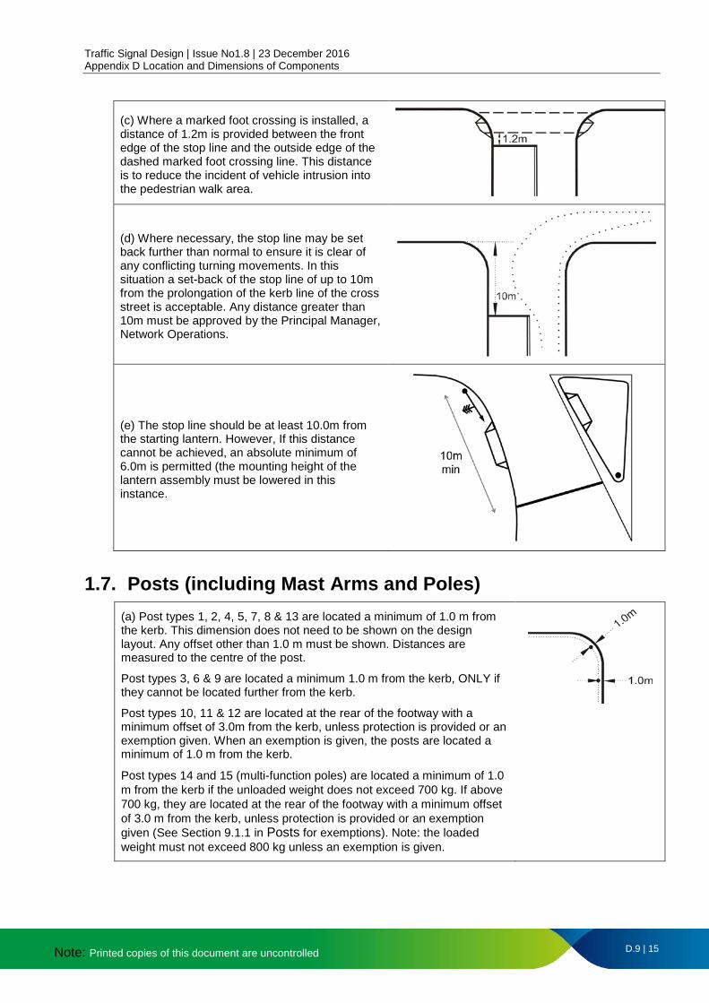
(c) Where a marked foot crossing is installed, a distance of 1.2m is provided between the front edge of the stop line and the outside edge of the dashed marked foot crossing line. This distance is to reduce the incident of vehicle intrusion into the pedestrian walk area.
(d) Where necessary, the stop line may be set back further than normal to ensure it is clear of any conflicting turning movements. In this situation a set-back of the stop line of up to 10m from the prolongation of the kerb line of the cross street is acceptable. Any distance greater than 10m must be approved by the Principal Manager, Network Operations.
(e) The stop line should be at least 10.0m from the starting lantern. However, If this distance cannot be achieved, an absolute minimum of 6.0m is permitted (the mounting height of the lantern assembly must be lowered in this instance.
1.7. Posts (including Mast Arms and Poles) (a) Post types 1, 2, 4, 5, 7, 8 & 13 are located a minimum of 1.0 m from the kerb. This dimension does not need to be shown on the design layout. Any offset other than 1.0 m must be shown. Distances are measured to the centre of the post.
Post types 3, 6 & 9 are located a minimum 1.0 m from the kerb, ONLY if they cannot be located further from the kerb.
Post types 10, 11 & 12 are located at the rear of the footway with a minimum offset of 3.0m from the kerb, unless protection is provided or an exemption given. When an exemption is given, the posts are located a minimum of 1.0 m from the kerb.
Post types 14 and 15 (multi-function poles) are located a minimum of 1.0 m from the kerb if the unloaded weight does not exceed 700 kg. If above 700 kg, they are located at the rear of the footway with a minimum offset of 3.0 m from the kerb, unless protection is provided or an exemption given (See Section 9.1.1 in Posts for exemptions). Note: the loaded weight must not exceed 800 kg unless an exemption is given.
D.9 | 15 Note: Printed copies of this document are uncontrolled

Traffic Signal Design | Issue No 1.8 | 23 December 2016 Appendix D Location and Dimensions of Components
(b) The primary post is located 0.5 m beyond the front edge of the stop line, irrespective of whether a marked foot crossing is provided or not.
NB: For mid-block marked foot crossings, the primary post is located on the front line of the stop line.
(c) Posts must be located a minimum of 1.0 m from any services.
(d) When a post cannot be located as outlined above, it may be located before the stop line, rather than beyond the stop line. In this case, the pedestrian lantern may need to be transferred to a more suitably located post. The post carrying the pedestrian push button should, ideally, be located as near as practical to the kerb ramp for ease of access by the disabled.
(e) Where the nose of a median is not behind a marked foot crossing, a post on the median must be located a minimum of 2.0 m from the nose. If a distance of 2.0 m is used, it does not need to be shown on the design layout. Any other distance must be shown.
(f) Where the nose of a median is behind a marked foot crossing and the median is ≥3.0 m wide, the median post is to be located 0.6 m from the nose to accommodate the mandatory pedestrian push button. Where the median is <3.0 m wide, the post must be 2.8 m from the nose (to suit ladder access) and a Type 13 post located 0.6 m from the nose. Only the dimension for the re-located post needs to be shown.
D.10 | 15 Note: Printed copies of this document are uncontrolled

Traffic Signal Design | Issue No1.8 | 23 December 2016 Appendix D Location and Dimensions of Components
(g) Where a median extends beyond the marked foot crossing and there is a break in the median, the median nose must be a minimum of 2.0 m long and the post located a minimum of 0.6 m from the break in the median.
A clearance of 0.3m should be allowed between the outside edge of the marked foot crossing lines and the ends of the median. If turning path templates won't permit this arrangement, the median nose should be deleted and a treatment similar to the one previous should be used. These dimensions do not need to be shown on the design layout.
(h) Post types 1, 2 & 13 on an island must be located a minimum of 1.0 m* from every edge of the island.
* Measurements are to the centre of the post, mast arm or pole.
(i) Mast arms types 4, 5 & 9 and post type 6 on an island, must be located a minimum of 2.0 m* from every edge and a barrier type kerb must be used.
Mast arms types 3, 10, 11 & 12 are required to be located out of the clear zone unless protection is provided or an exemption given. When an exemption is given, the posts are located a minimum of 2.0 m from every edge of the island and a barrier type kerb must be used.
Post types 14 & 15 (Multi-function Poles) are located a minimum of 2.0 m* from every edge and a barrier type kerb must be used if the fully loaded weight does not exceed 700kg. If above 700kg, they are located at the rear of the footway with a minimum offset of 3.0m from the kerb, unless protection is provided or an exemption given. (See Section 9.1.1 Posts for exemptions)
* Measurements are to the centre of the post, mast arm or pole.
(j) For mid-block marked foot crossings:
• The primary post is to be located on the front edge of the stop line.
• The tertiary post with pedestrian lantern is to be located 0.7m beyond edge of the marked foot crossing to accommodate the kerb ramp.
Note: For marked foot crossings, posts with the pedestrian lanterns are located 0.7m beyond edge of marked foot crossing to accommodate the kerb ramp.
D.11 | 15 Note: Printed copies of this document are uncontrolled

Traffic Signal Design | Issue No 1.8 | 23 December 2016 Appendix D Location and Dimensions of Components
1.8. Vehicle detectors (a) The dimensions of a 4.5 m long stop line detector are as shown:
• A is 0.7 m if adjacent to a barrier line or 0.5 m if adjacent to a raised median, painted median or edge line.
• B is 0.8 m if adjacent to integral kerb and gutter or 0.5 m if adjacent to a raised island, painted island or edge line.
• C is the width of the detector. All dimensions except C are standard and do not need to be shown on the design layout unless they vary from the standard for some reason. Dimension C must always be shown.
Note: Dimensions A, B & C shown apply to all the vehicle detector diagrams which follow except where another dimension is shown.
(b) If the stop line is on an angle, the detectors are staggered as shown. This is due to the fact that the stop line detectors should be rectangular.
(c) If the detectors are on a curved approach, then dimensions A and B must be the minimum offset from the kerbs and paint lines.
(d) The saw cuts for vehicle detector loops must be located a minimum of 0.3 m from expansion joints, services and service covers. If this results in detectors being located in a non-standard position, setting-out dimensions must be shown.
(e) Stop line detectors should always be rectangular. When the edges of the lane are not parallel, the orientation of the detector may be varied to suit the predominant flow.
D.12 | 15 Note: Printed copies of this document are uncontrolled

Traffic Signal Design | Issue No1.8 | 23 December 2016 Appendix D Location and Dimensions of Components
(f) Where intersection geometry allows, the location of an 11.0 m stop line detector should be as shown.
(g) Where this is not possible, dimension D or E needs to be shown to enable the detector to be located.
(h) The location of advance (passage) detectors must be shown as a distance from the stop line to the centre of the detector.
Dimensions X and Y must always be shown. All other dimensions are standard and do not need to be shown unless they vary from the standard for some reason.
• A is 0.3 m if the detector is adjacent to a raised median without integral kerb and gutter, painted median or edge line or 0.6 m if adjacent to a barrier line or raised median with integral kerb and gutter.
• B is 0.3 m if the detector is adjacent to a raised island without integral kerb and gutter, painted island or edge line or 0.8 m if adjacent to integral kerb and gutter.
D.13 | 15 Note: Printed copies of this document are uncontrolled

Traffic Signal Design | Issue No 1.8 | 23 December 2016 Appendix D Location and Dimensions of Components
1.9. Pedestrian push-button detectors
(a) Pedestrian push-button detectors located on median posts should be fitted with a dual (two-way) arrow disc and mounted so that the face of the push button is parallel to the pedestrian crossing. All other pedestrian push-button detectors should be fitted with a single vertical arrow disc and mounted so that the face of the push button is at a right angle to the axis of the pedestrian crossing.
1.10. Controllers
(a) Ground mounted controllers should be located adjacent to the property line whenever possible.
(b) If this is not feasible, they may be positioned adjacent to the kerb line.
(c) Post-mounted controllers are located adjacent to a Type 2 post near the kerb line.
(d) The location of the controller must be shown on the design plan by providing the distance from the centre of the controller to a permanent and easily identifiable feature.
D.14 | 15 Note: Printed copies of this document are uncontrolled

rms.nsw.gov.au/
13 22 13
Customer feedback Roads and Maritime Locked Bag 928, North Sydney NSW 2059
December 2016 RMS 08.092
ISBN: 978-1-921242-95-3
Copyright © 2022 FDOKUMEN