Vibration suppression of steel truss railway bridge using tuned mass dampers
Upload
khangminh22Category
view
1download
0
Hari P Pokharel, Arcadis Australia Pacific, Sydney
2nd April 2019
TRACING LOAD PATH IN A CONCRETE TRUSS BRIDGE AND
DEVELOPING DESIGN DETAILS FOR A TYPICAL NODE
REFERENCE TO THE FIU PEDESTRIAN BRIDGE THAT COLLAPSED IN MARCH 2018
Disclaimer: The views, thoughts, and opinions expressed in this paper are solely those of the author in his private capacity and are in no way
connected to, belong or represent the views, thoughts or opinions of the author’s employer, Arcadis Australia Pacific Pty Limited or any other entity
connected to the author’s employer.
© Arcadis 2018
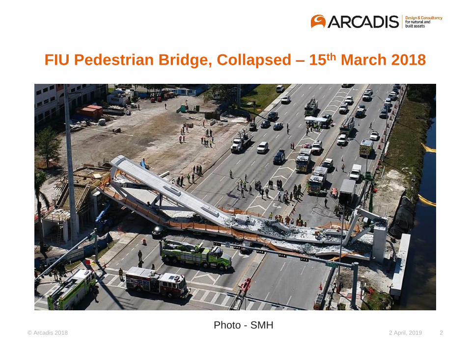
FIU Pedestrian Bridge, Collapsed – 15th March 2018
2 April, 2019 2Photo - SMH
© Arcadis 2018
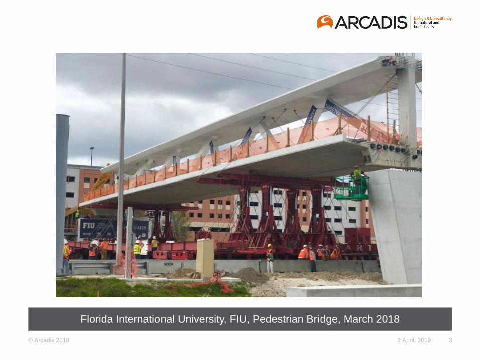
Florida International University, FIU, Pedestrian Bridge, March 2018
2 April, 2019 3
© Arcadis 2018
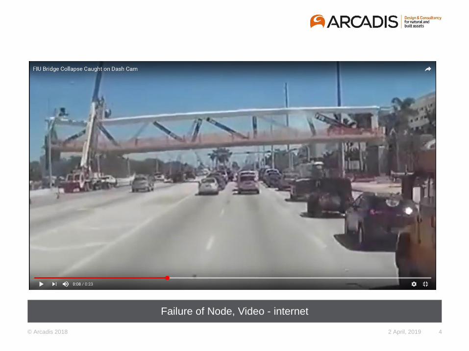
Failure of Node, Video - internet
2 April, 2019 4
© Arcadis 2018
Background and Purpose of This Presentation
1. Loss of Life, Injuries, Pain – Our Professional Obligation, Trust and Responsibility.
2. US National Transport Safety Board, NTSB, Investigating the causes of failure.
Initial investigation report, November 2018 – Confirmed strength of material as
required in design documents.
3. Selection of Bridge Type –
- Merits of concrete truss bridge
- Multi criteria analysis
4. Discussion - Design of Nodes in reinforced concrete truss bridges
5
© Arcadis 2018
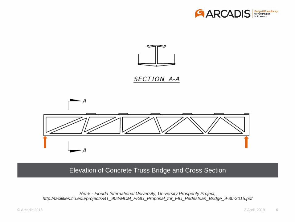
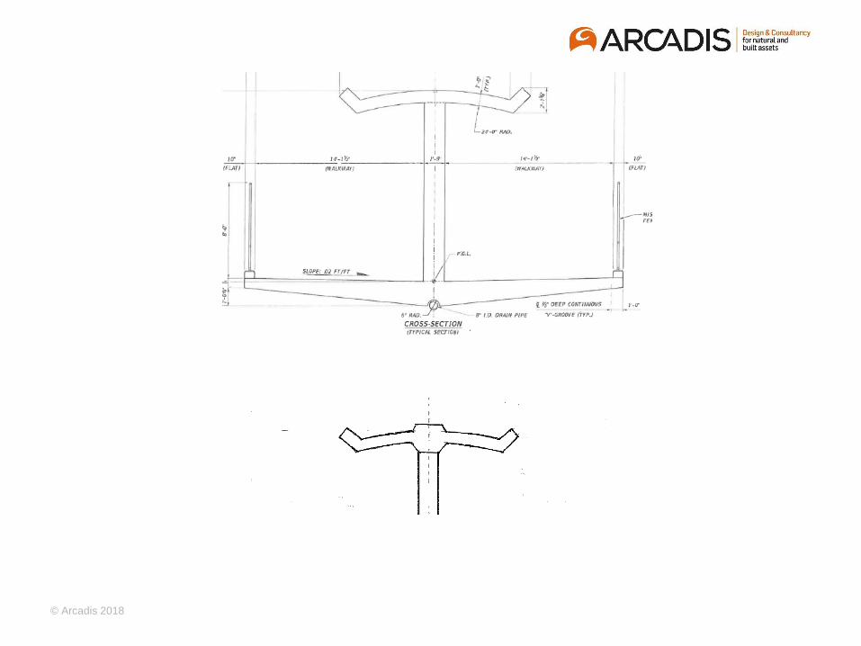
Elevation of Concrete Truss Bridge and Cross Section
2 April, 2019 6
Ref-5 - Florida International University, University Prosperity Project, http://facilities.fiu.edu/projects/BT_904/MCM_FIGG_Proposal_for_FIU_Pedestrian_Bridge_9-30-2015.pdf
© Arcadis 2018
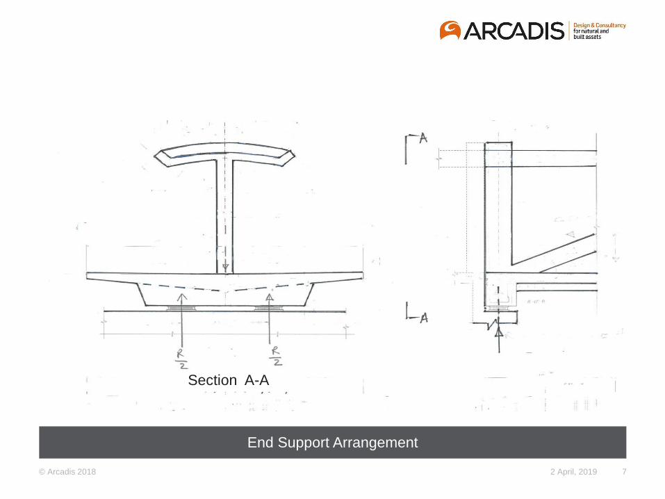
End Support Arrangement
2 April, 2019 7
Section A-A
© Arcadis 2018
Design Philosophy - Bridge Codes
Limit sate conditions
- Equilibrium and stability
- Deflection
- Crack width
- Vibration,
- etc.
- Ductility
Mode of failure to be ductile
Alternate load path, excessive deflection, warning - Robustness
- Load factors, and
- Strength reduction factors
No Collapse – Safety First
© Arcadis 2018
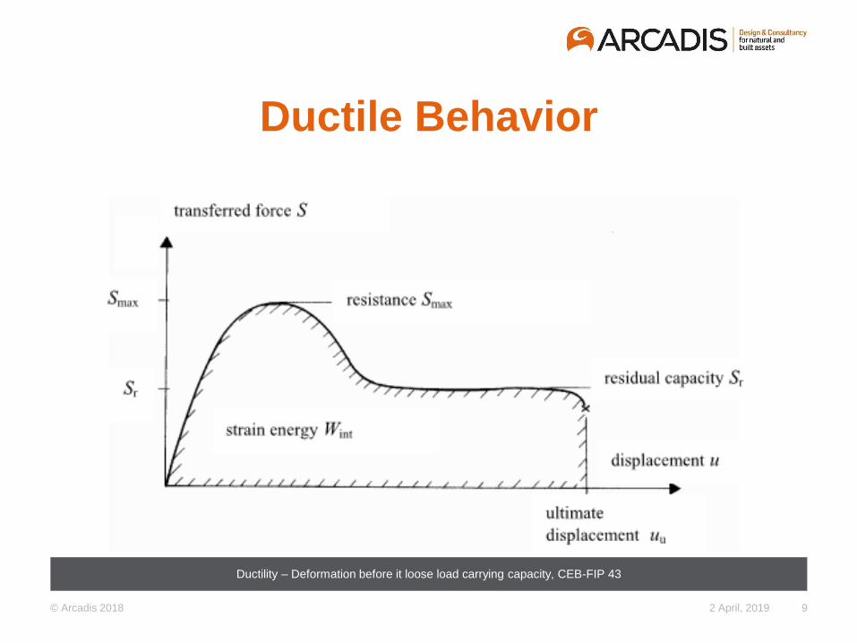
Ductile Behavior
Ductility – Deformation before it loose load carrying capacity, CEB-FIP 43
2 April, 2019 9
© Arcadis 2018
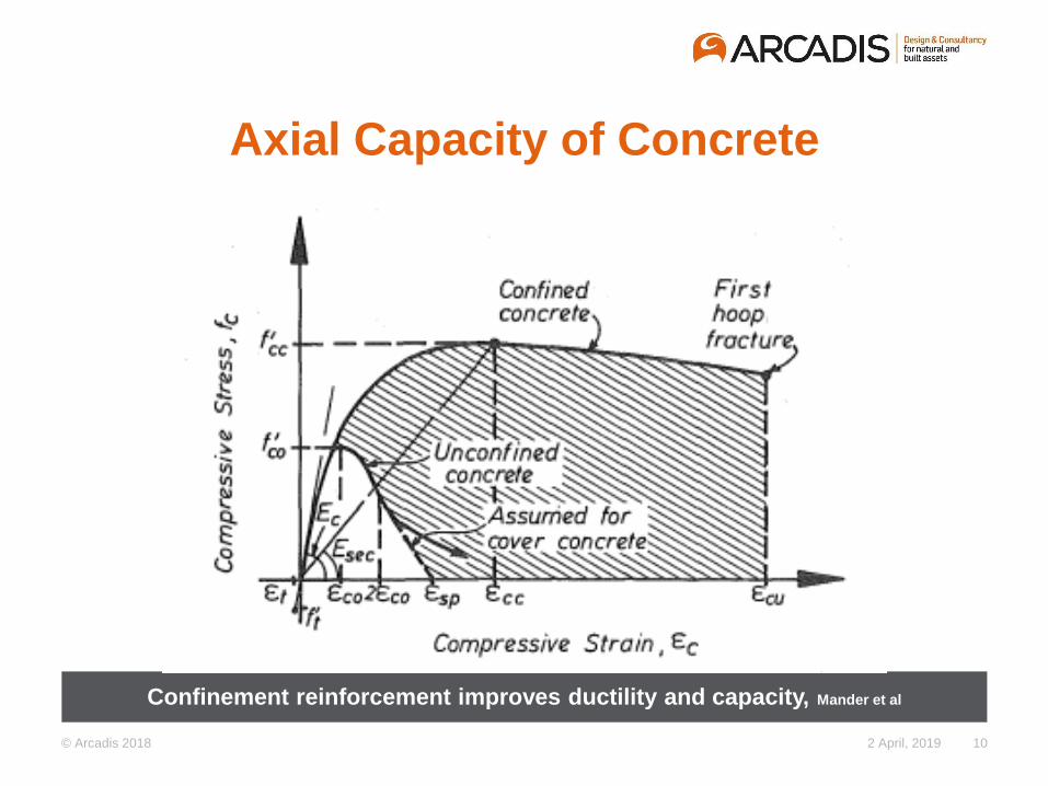
Axial Capacity of Concrete
Confinement reinforcement improves ductility and capacity, Mander et al
2 April, 2019 10
© Arcadis 2018
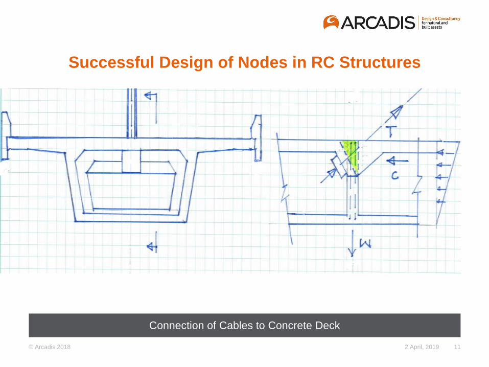
Successful Design of Nodes in RC Structures
Connection of Cables to Concrete Deck
2 April, 2019 11
© Arcadis 2018
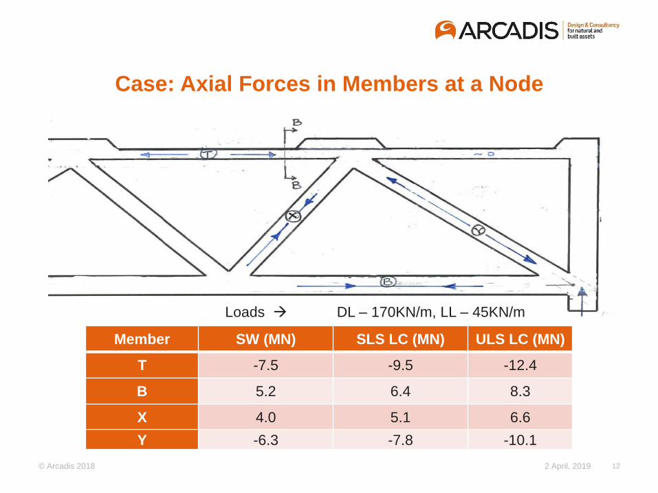
Case: Axial Forces in Members at a Node
Member SW (MN) SLS LC (MN) ULS LC (MN)
T -7.5 -9.5 -12.4
B 5.2 6.4 8.3
X 4.0 5.1 6.6
Y -6.3 -7.8 -10.1
2 April, 2019 12
Loads → DL – 170KN/m, LL – 45KN/m
© Arcadis 2018
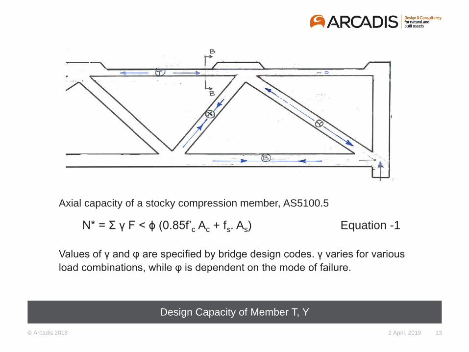
Design Capacity of Member T, Y
2 April, 2019 13
Axial capacity of a stocky compression member, AS5100.5
N* = Σ γ F < ϕ (0.85f’c Ac + fs. As) Equation -1
Values of γ and φ are specified by bridge design codes. γ varies for various
load combinations, while φ is dependent on the mode of failure.
© Arcadis 2018
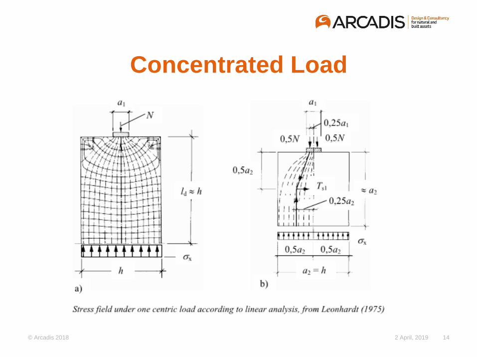
Concentrated Load
2 April, 2019 14
© Arcadis 2018
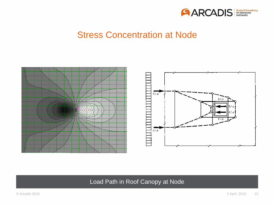
Stress Concentration at Node
Load Path in Roof Canopy at Node
2 April, 2019 15
© Arcadis 2018
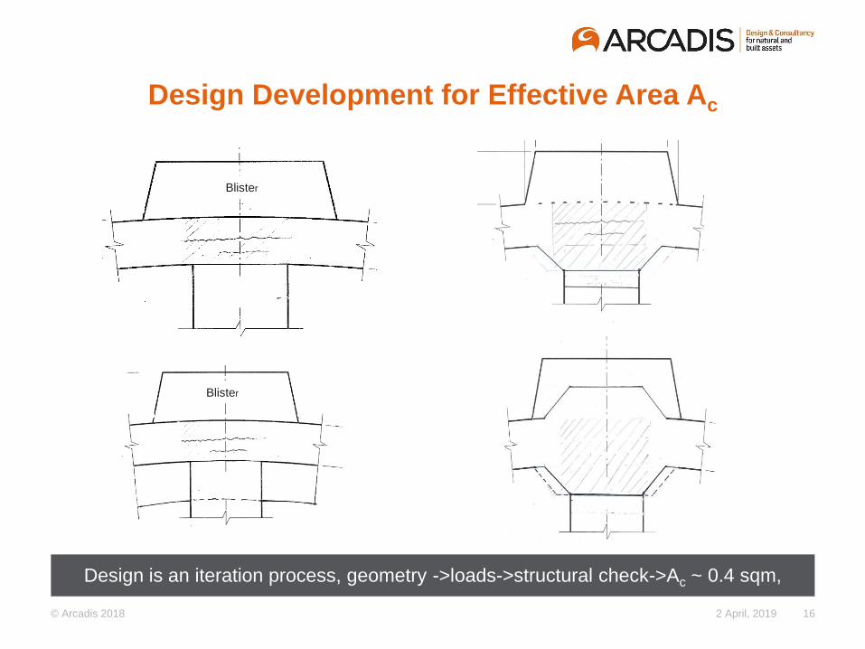
Design Development for Effective Area Ac
Design is an iteration process, geometry ->loads->structural check->Ac ~ 0.4 sqm,
2 April, 2019 16
Blister
Blister
© Arcadis 2018
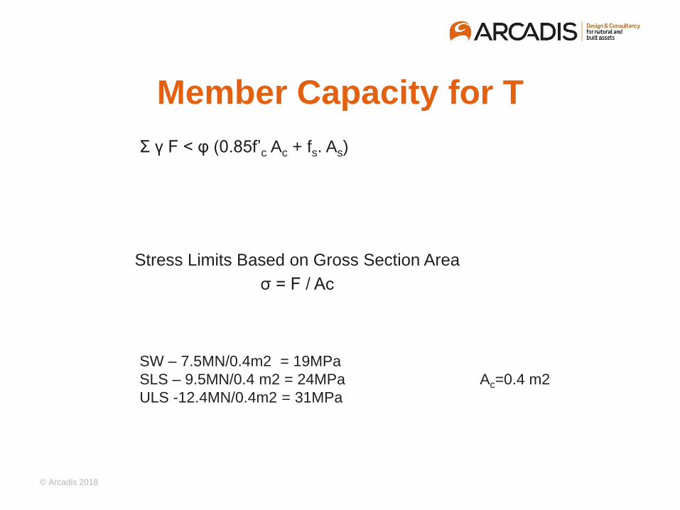
Member Capacity for T
Σ γ F < φ (0.85f’c Ac + fs. As)
SW – 7.5MN/0.4m2 = 19MPa
SLS – 9.5MN/0.4 m2 = 24MPa Ac=0.4 m2
ULS -12.4MN/0.4m2 = 31MPa
Stress Limits Based on Gross Section Area
σ = F / Ac
© Arcadis 2018
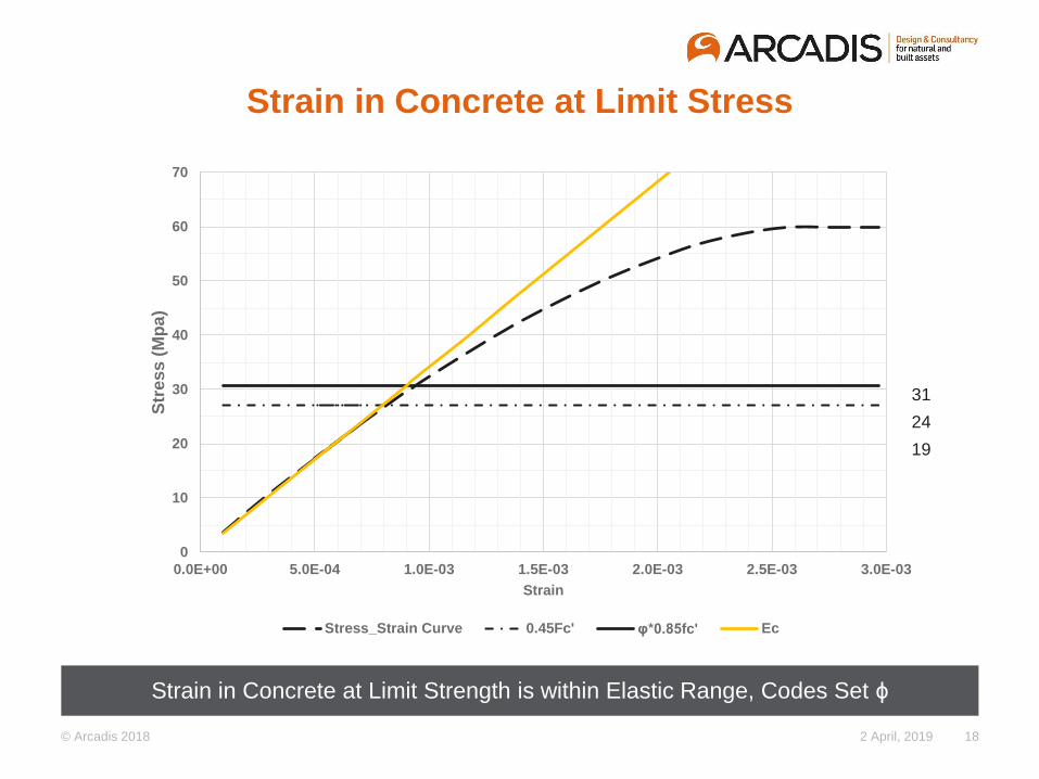
Strain in Concrete at Limit Stress
2 April, 2019 18
0
10
20
30
40
50
60
70
0.0E+00 5.0E-04 1.0E-03 1.5E-03 2.0E-03 2.5E-03 3.0E-03
Str
es
s (
Mp
a)
Strain
Stress_Strain Curve 0.45Fc' φ*0.85fc' Ec
Strain in Concrete at Limit Strength is within Elastic Range, Codes Set ϕ
31
24
19
© Arcadis 2018
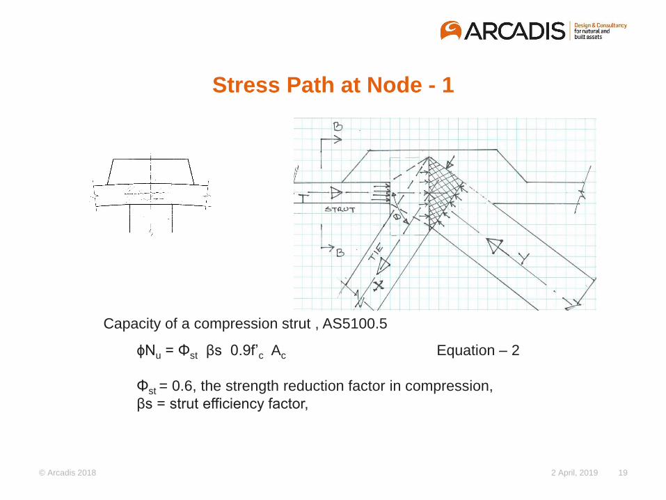
Stress Path at Node - 1
2 April, 2019 19
Capacity of a compression strut , AS5100.5
ϕNu = Φst βs 0.9f’c Ac Equation – 2
Φst = 0.6, the strength reduction factor in compression,
βs = strut efficiency factor,
© Arcadis 2018
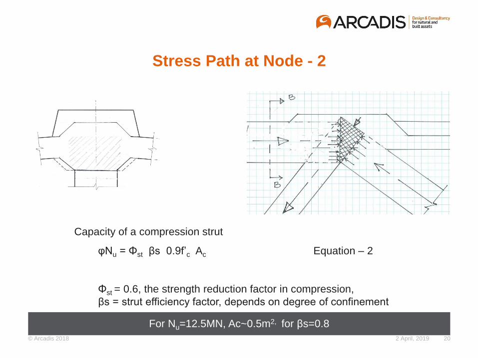
Stress Path at Node - 2
2 April, 2019 20
Capacity of a compression strut
φNu = Φst βs 0.9f’c Ac Equation – 2
Φst = 0.6, the strength reduction factor in compression,
βs = strut efficiency factor, depends on degree of confinement
For Nu=12.5MN, Ac~0.5m2, for βs=0.8
© Arcadis 2018
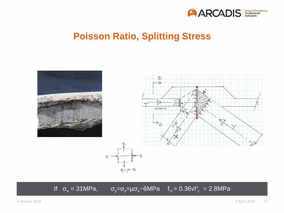
Poisson Ratio, Splitting Stress
If σx = 31MPa, σy=σz=µσx~6MPa f,t = 0.36√f’c = 2.8MPa
2 April, 2019 21
© Arcadis 2018
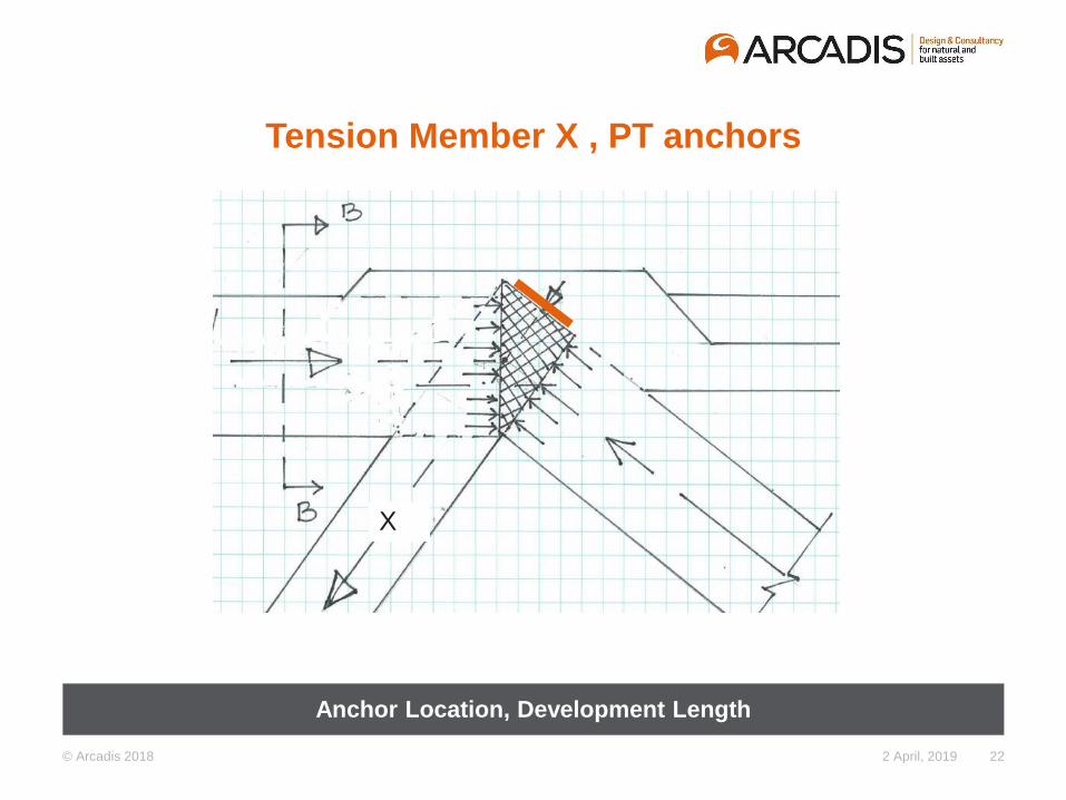
Tension Member X , PT anchors
Anchor Location, Development Length
2 April, 2019 22
X
© Arcadis 2018
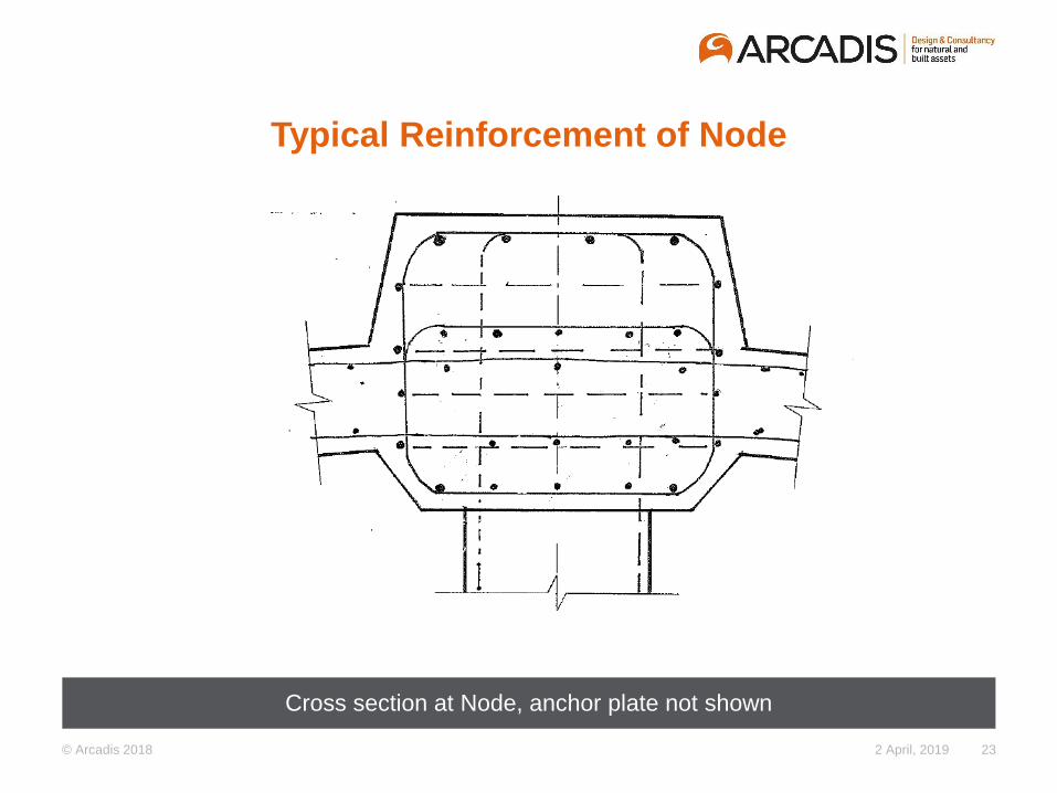
Typical Reinforcement of Node
Cross section at Node, anchor plate not shown
2 April, 2019 23
© Arcadis 2018
© Arcadis 2018
Design Development – Input from Construction Operation
Strength depends on making of concrete – batching, placing curing
Often strength in structure is lower than the strength in test cylinder
Changing nature of support conditions during transportation alters
load path, affecting integrity of concrete member
Whole construction process requires – documentation, review and
input for design
Design development process – construction operation, design
verification, peer review - > minimize risk
© Arcadis 2018
Summary - Conclusions
• Several factors could contribute for the collapse of bridge
• Complexities of geometry in balancing need of Architectural and
Structural requirements in Landmark bridges.
• Load path at a Node is complex
• Assessment of capacity following code requirements can create
robust design
• Concrete Truss Bridge for future bridge projects - feasible
• Replying in computer without understanding behaviour can be
design risk
© Arcadis 2018
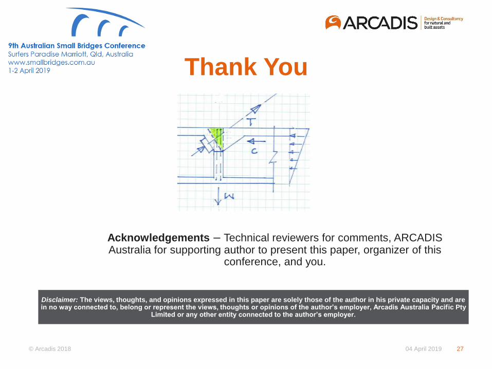
Thank You
Disclaimer: The views, thoughts, and opinions expressed in this paper are solely those of the author in his private capacity and are in no way connected to, belong or represent the views, thoughts or opinions of the author’s employer, Arcadis Australia Pacific Pty
Limited or any other entity connected to the author’s employer.
Acknowledgements – Technical reviewers for comments, ARCADIS Australia for supporting author to present this paper, organizer of this
conference, and you.
04 April 2019 27
Copyright © 2022 FDOKUMEN