A Macroeconomic Balance Measure of New Zealand's Equilibrium Exchange Rate

Kurow-Hakataramea Bridges New Zealand’s Last Long Howe Truss Bridge
Archaeological Site I40/86
Archaeological Authority No. 2013/389
Final Report on the Dismantling of the Bridges
for New Zealand Transport Agency
& McConnell Dowell
P.G. Petchey Southern Archæology Ltd.
2014
Kurow-Hakataramea Bridges 1
Table of Contents Introduction ................................................................................................................................ 2!Background History .................................................................................................................... 4!
The Waitaki River .................................................................................................................. 4!Prehistoric (Maori) Occupation .............................................................................................. 4!Historic (European) Occupation ............................................................................................. 4!The Kurow Branch Railway ................................................................................................... 6!The Kurow-Hakataramea (Upper Waitaki) Bridges ............................................................... 7!
Description of the Kurow-Hakataramea Bridges Prior to Demolition ..................................... 18!Bridge No. 1 (North Bridge): General Description .............................................................. 20!Bridge No. 1 Construction Details: Piers ............................................................................. 22!Bridge No. 1 Construction Details: Superstructure .............................................................. 25!
Span by Span Record of Bridge No.1 in 2014 ......................................................................... 30!Kurow Island ............................................................................................................................ 37!Bridge No. 2 ............................................................................................................................. 38!
Bridge No. 2 Construction Details: Piers ............................................................................. 39!Bridge No. 2 Construction Details: Superstructure .............................................................. 39!
Timber Railway Bridges ........................................................................................................... 41!Surviving and Preserved Timber Truss Bridges in New Zealand ............................................ 43!Combined Road/Rail Bridges in New Zealand ........................................................................ 47!Significance of the Kurow-Kakataramea Bridges .................................................................... 48!Conclusion ................................................................................................................................ 51!References ................................................................................................................................ 52!Appendix A .............................................................................................................................. 54!
Measured Drawings: Original Plans (supplied by NZ Transport Agency). ......................... 54!Appendix B ............................................................................................................................... 56!
Measured Drawings: 2014 Plans of Construction Details (Southern Archaeology) ............ 56!Appendix C ............................................................................................................................... 61!
Measured Drawings: Display Trusses (McConnell Dowell) ................................................ 61!Appendix D .............................................................................................................................. 64!
Bridge Opening Invitations 2014 ......................................................................................... 64!
Kurow-Hakataramea Bridges 2
Kurow-Hakataramea (Upper Waitaki) Road Bridges, SH82 Final Report for Archaeological Authority No. 2013/389
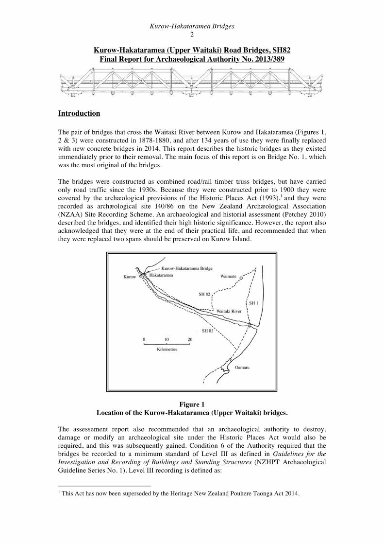
Introduction The pair of bridges that cross the Waitaki River between Kurow and Hakataramea (Figures 1, 2 & 3) were constructed in 1878-1880, and after 134 years of use they were finally replaced with new concrete bridges in 2014. This report describes the historic bridges as they existed immendiately prior to their removal. The main focus of this report is on Bridge No. 1, which was the most original of the bridges. The bridges were constructed as combined road/rail timber truss bridges, but have carried only road traffic since the 1930s. Because they were constructed prior to 1900 they were covered by the archæological provisions of the Historic Places Act (1993),1 and they were recorded as archæological site I40/86 on the New Zealand Archæological Association (NZAA) Site Recording Scheme. An archaeological and historial assessment (Petchey 2010) described the bridges, and identified their high historic significance. However, the report also acknowledged that they were at the end of their practical life, and recommended that when they were replaced two spans should be preserved on Kurow Island.
Figure 1 Location of the Kurow-Hakataramea (Upper Waitaki) bridges.
The assessement report also recommended that an archaeological authority to destroy, damage or modify an archaeological site under the Historic Places Act would also be required, and this was subsequently gained. Condition 6 of the Authority required that the bridges be recorded to a minimum standard of Level III as defined in Guidelines for the Investigation and Recording of Buildings and Standing Structures (NZHPT Archaeological Guideline Series No. 1). Level III recording is defined as:
1 This Act has now been superseded by the Heritage New Zealand Pouhere Taonga Act 2014.

Kurow-Hakataramea Bridges 3
• Measured drawings of selective elevations – internal and external – cross-sections, floor plans, roof plans and ceiling plans.
• Written records, including annotation of measured drawings. • Photography of selective contextual views, elevations, spaces, fixtures and other
features. • Selective sampling of relevant materials.
Condition 5 of the Authority required that two 40 ft. trusses be preserved and erected on Kurow Island.
Figure 2 Location of the two Kurow-Hakataramea bridges.
From NZMS 260 I40 Kurow.
Figure 3 Aerial photograph of the two Kurow-Hakataramea Bridges in 2012 (Google Earth).

Kurow-Hakataramea Bridges 4
Background History
The Waitaki River The Waitaki River (Figure 1) forms the boundary between the provinces of Otago and Canterbury. It is only some 109 kilometres long, but with its major tributary rivers (Tekapo, Pukaki, Ohau, Ahuriri, Hakataramea and Otemetata) it has the second largest catchment in New Zealand, second only to the Clutha River (Encylopaedia of New Zealand 1966: 524). The river has been heavily developed for hydro-electric power generation, and the lowest (and oldest) power station on the river is the Waitaki Dam, 5.5 kilometres upstream from the Kurow-Hakataramea bridges.
Prehistoric (Maori) Occupation In the prehistoric and historic periods the Waitaki Valley was one of the major routes into the interior. For prehistoric Maori the main river valleys in the south (including the Waitaki, Clutha and Mataura rivers) provided routes for resource-gathering trips. These resources included moa (in the early or archaic period), eels, and lithic sources (greenstone [pounamu], silcrete). Numerous ovens recorded in the Waitaki Valley are evidence of the consumption of cooked cabbage tree (Ti, cordyline australis), the root of which yielded fructose and glucose after long cooking. Starting from winter camps on the coast (often at estuarine locations), groups would walk inland, either up the river valleys or along leading ridges in the hills. The return journey would often be made down the river on flax rafts (mokihi), considerably speeding up the return time and allowing gathered material to be carried. A highly significant element of the North Otago and Waitaki prehistoric landscape are the numerous rock art sites, where drawings have been made in rock shelters. These sites are enigmatic, although representation of European ships in some sites indicates that the practice continued into the contact period. The early European explorers in the area (from the 1840s onwards) noted the location of a number of small Maori settlements up the Waitaki Valley, the best documented of which was Te Puna-a-maru, near the Awamoko Stream, which was declared Native Reserve No. 10 in 1848. Edward Shortland listed 40 inhabitants of the Lower Waitaki settlements, based on information from Huruhuru at Te Puna-a-maru (Shortland 1844). Various first hand accounts of some of these settlements survive, including Shortland (1844), Mantell (1848) and Thomson (1857). The closest recorded settlement site to the Kurow-Hakataramea bridge was Te Riha-turiha, an old kaika near Kurow Creek (two kilometres south-east of the bridge) referred to by Stevenson (1947), but to date no archæological evidence of this has been recorded. The proximity of recorded archæological evidence to the bridge is discussed further below.
Historic (European) Occupation European settlement of the Waitaki Valley effectively started from 1848, after Kemp’s Purchase for the Government of much of the South Island. An area of some 20,000,000 acres was purchased from Kai Tahu chiefs for the sum of £2,000 (McDonald 1940:21). Excluded from the purchase were to be the places of residence and cultivation of the Maori inhabitants (it being Mantell’s task to survey these reserves, see comments above), but the resultant Native Reserves tended to be small. Initially land was opened to freehold purchase at a cost of £1 per acre, reduced to 10/- per acre in March 1853. But to encourage the occupation of large tracts of land by pastoralists, a new form of tenure was created by the Lands Amendment and Extension Ordinance of 1851.

Kurow-Hakataramea Bridges 5
This allowed Licences to be issued for the occupation of large runs on 14 year terms, the fees being based on the carrying capacity of the land (McDonald 1940:22). The actual size of a run was not limited, but the Otago Land regulations of 1856 allowed for no more than 25,000 sheep on any run (Scotter 1948:2). Each holder of a pastoral lease had the right to reserve eighty acres at his home station and ten acres at each out-station. When these areas had been surveyed and acknowledged, the runholder was given the first right of freehold purchase of these areas of land (a pre-emptive right). The following is taken directly from McDonald (1940:24-26):
“By 1856 all the land in the triangle bounded by the Waitaki, the Kakanui Mountains and the sea had been taken up, and the seekers after “country” now penetrated the rougher regions beyond Kurow. Soon a long line of stations stretched up the Waitaki Valley, along the Ahuriri, and over the Lindis Pass into Central Otago. The runs throughout Otago were numbered consecutively according to the date of application… Papakaio was No. 16. It ran from Boundary Creek to the Waitaki and contained 26,000 acres. Throughout its history as a run it was held by the brothers W.G. and R.A. Filleul. The adjacent Waikoura run (from Filleul’s boundary to the Awamoko) was first taken up by D. R. Williams and John Lemon, who sold out in 1859 to the Filleuls. It comprised 23,000 acres. Between the Awamoko and the Marewhenua was Run 27, named after the latter river; it was first applied for by A.C. Strode and then passed in rapid succession through the hands of S.H. Pike and M. Holmes until it was acquired by J. Borton. At the same time Borton and J.S. Jeffreys took up No. 92, which adjoined Marewhenua on the south; presently A. McMaster succeeded Jeffreys in the partnership. The two runs between them covered 22,000 acres. Across the Marewhenua was No. 17, an area of 28,000 acres, acquired first by W.H. Valpy and sold by him to H. Lawson. The latter was drowned in January, 1857, while vainly trying to save the life of one of his shepherds who had fallen into a sheep-dipping pool; the run was then taken over by J. McEvoy. The Otekaike run, No. 28, lay beyond, and was held in succession by S.H. Pike, J.P. Taylor, who afterwards became Superintendent of Southland, and W.H. Dansey, whose name survives in Dansey’s Pass. No. 23 was the Gorge, Kurow, and was held by John McLean, known as “Little Jock” to distinguish him from the more celebrated holder of Morven Hills.”
The name “Kurow” is a corruption of the Maori “Kohurau,” meaning a hill of many mists (Neave 1980:6). The township probably grew informally at first in the area close to the Kurow Station buildings2 (where most local residents would have worked), and the Upper Ferry over the Waitaki. The ferry was initially operated by John Merry, but subsequently taken over (and then moved upstream) by Christian Hille, who also had the Western House hotel. The town was formally surveyed in 1880, in anticipation of the railway arriving (Cyclopedia 1999). Small scale subdivisions occurred in the Kurow area in 1895 (the Tahawai Settlement, known locally as “Paddy’s Flat,” comprising eight smallholdings of seven to nine acres each on the outskirts of Kurow), and in 1907 (the Kurow Settlement, comprising thirteen holdings of eleven to 35 acres) (Hall 1987:321). The Kurow school was established in 1882 (McDonald 1940:131), while the notable Anglican St. Alban’s Vicarage and Chapel at Kurow was built in 1892, from a bequest from Robert Campbells’ widow (McEwan 1994:35). The 2 The sheep station, not to be confused with the later Kurow railway station.
Kurow-Hakataramea Bridges 6
town received a considerable boost in 1928, when work commenced on the Waitaki hydro-electric dam a short distance upstream (see discussion below). One effect of this was the substantial enlargement of the local school, which was constituted a district high school in 1931 (McDonald 1940:234-235).
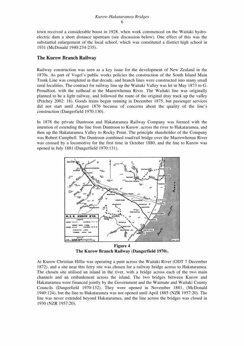
The Kurow Branch Railway Railway construction was seen as a key issue for the development of New Zealand in the 1870s. As part of Vogel’s public works policies the construction of the South Island Main Trunk Line was completed in that decade, and branch lines were constructed into many small rural localities. The contract for railway line up the Waitaki Valley was let in May 1873 to G. Proudfoot, with the railhead at the Maerewhenua River. The Waitaki line was originally planned to be a light railway, and followed the route of the original dray track up the valley (Petchey 2002: 18). Goods trains began running in December 1875, but passenger services did not start until August 1876 because of concerns about the quality of the line’s construction (Dangerfield 1970:130). In 1878 the private Duntroon and Hakataramea Railway Company was formed with the intention of extending the line from Duntroon to Kurow, across the river to Hakataramea, and then up the Hakataramea Valley to Rocky Point. The principle shareholder of the Company was Robert Campbell. The Duntroon combined road/rail bridge over the Maerewhenua River was crossed by a locomotive for the first time in October 1880, and the line to Kurow was opened in July 1881 (Dangerfield 1970:131).
Figure 4
The Kurow Branch Railway (Dangerfield 1970). At Kurow Christian Hillie was operating a punt across the Waitaki River (ODT 7 December 1872), and a site near this ferry site was chosen for a railway bridge across to Hakataramea. The chosen site utilised an island in the river, with a bridge across each of the two main channels and an embankment across the island. The two bridges between Kurow and Hakataramea were financed jointly by the Government and the Waimate and Waitaki County Councils (Dangerfield 1970:132). They were opened in November 1881, (McDonald 1940:124), but the line to Hakataramea was not opened until April 1885 (NZR 1957:20). The line was never extended beyond Hakataramea, and the line across the bridges was closed in 1930 (NZR 1957:20).

Kurow-Hakataramea Bridges 7
The Duntroon to Hakataramea line was always worked by New Zealand Railways, and was taken over by the NZR from the Duntroon and Hakataramea Railway Company in 1885 (NZR 1957:20). In 1928 a temporary branch line was built from Kurow four miles up river to the Waitaki Dam site in order to transport materials to the construction site (McDonald 1940:234). It was lifted in 1937, after the dam was completed and the construction site tidied up (NZ Rly. Atlas). The Kurow Branch line was finally closed in June 1983 (NZ Rly. Atlas), after the traffic generated by the Upper Waitaki hydo schemes had ceased, and road largely replaced rail for freight and passenger transport. The lines were lifted and most structures removed, although the Kurow and Duntroon stations still survive.
The Kurow-Hakataramea (Upper Waitaki) Bridges As outlined above, the bridge between Kurow and Hakataramea was opened in November 1881, and the railway line across it was closed in 1930. The bridge was actually two separate bridges connected by a causeway on the island in the middle of the river. The railway line was built by the Duntroon and Hakataramea Railway Company, but the bridges over the Waitaki were financed jointly by the Government and the Waimate and Waitaki County Councils. The company had intended continuing the line up the Hakataramea Valley to Rocky Point, but the track never continued past the station at Hakataramea, just over the bridges. The contract to build the bridges was let in 1878 to J. Reid. 3 Initially the bridge superstructures were constructed from kauri beams, but these were not durable enough and had to be later replaced by hardwood timbers. Flooding was a hazard even before the bridge was finished, and in October 1878 a massive flood swept away 3 piers and damaged the approaches (Dangerfield 1970:131-132). The bridge was subsequently damaged on numerous other occasions by floods, for example in early 1892 when several spans were damaged (Otago Daily Times 12 February 1892) and 1930 when a pile subsided under the weight of a coal train during a flood (Otago Daily Times 29 September 1984).
Figure 5 Workers manhandling a pile driver on the bridge after several piers had been washed
away by floods. This image is variously dated to the 1878 flood during construction or to 1893 (original from T. Cogger, Jim Dangerfield Colln.).
3 However, the surviving plans of the bridge (see Figure 5) are signed by a John Blair as the contractor.
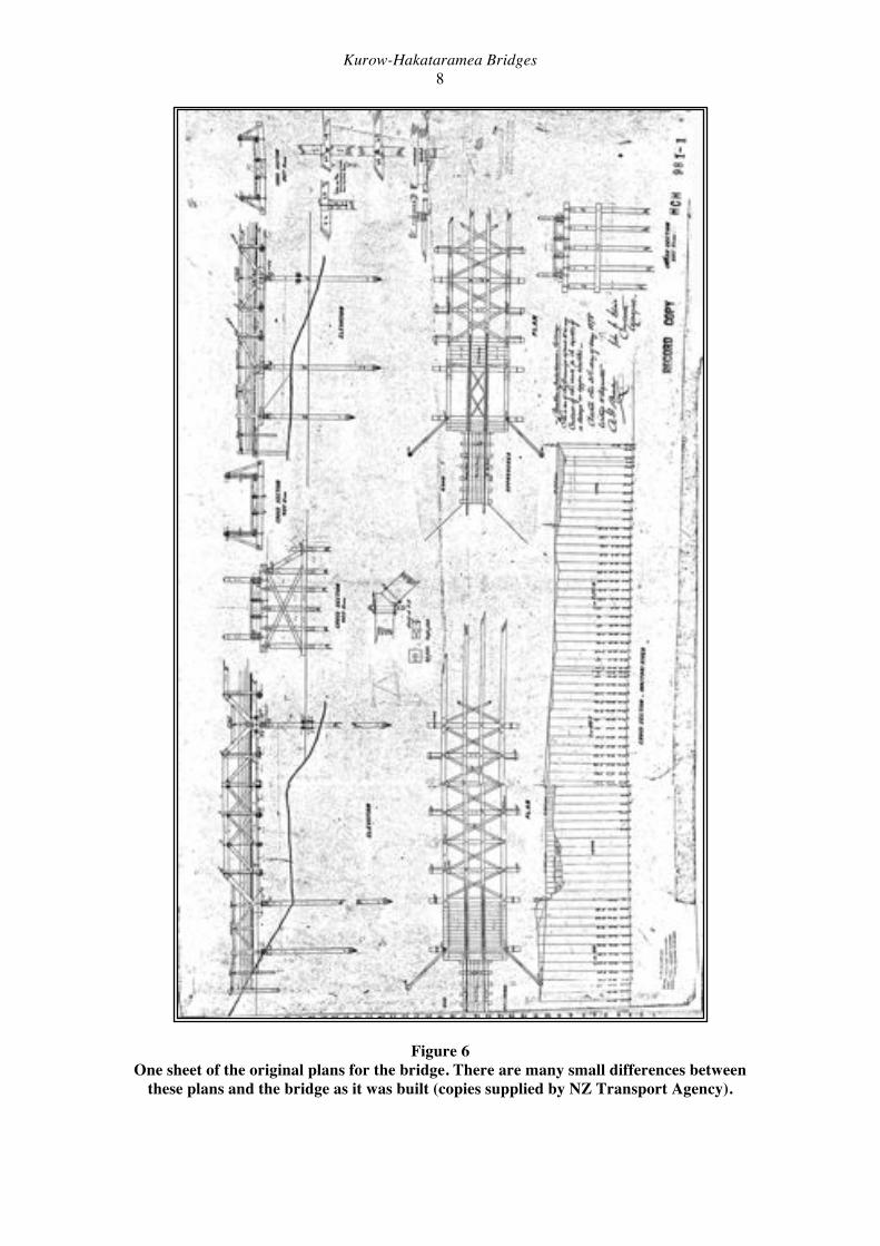
Kurow-Hakataramea Bridges 8
Figure 6 One sheet of the original plans for the bridge. There are many small differences between
these plans and the bridge as it was built (copies supplied by NZ Transport Agency).
Kurow-Hakataramea Bridges 9
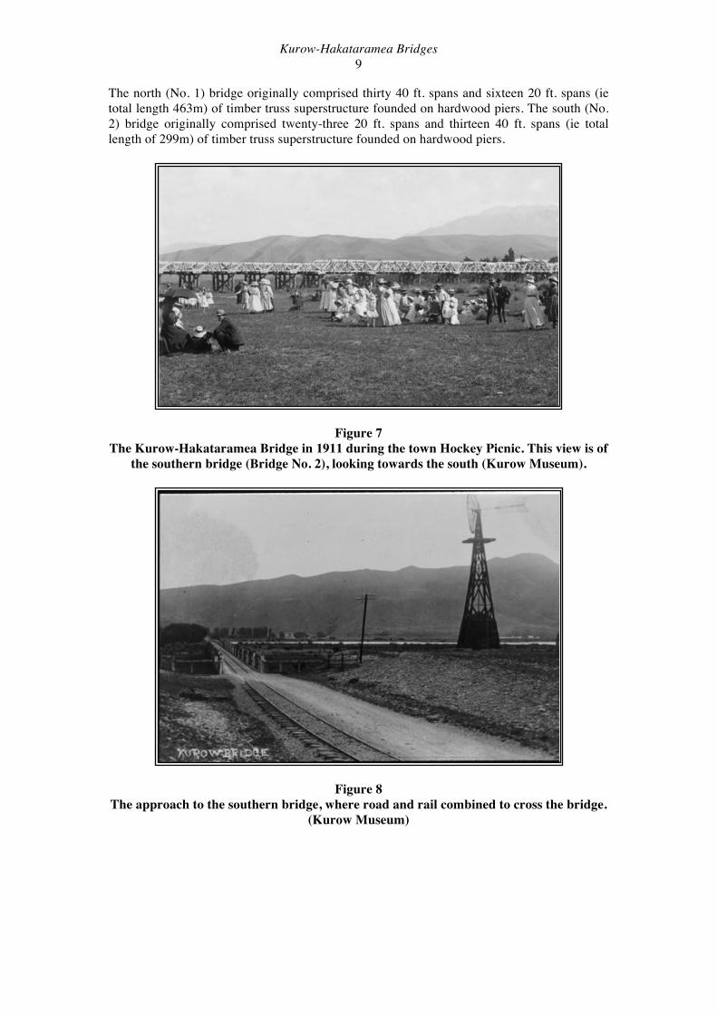
The north (No. 1) bridge originally comprised thirty 40 ft. spans and sixteen 20 ft. spans (ie total length 463m) of timber truss superstructure founded on hardwood piers. The south (No. 2) bridge originally comprised twenty-three 20 ft. spans and thirteen 40 ft. spans (ie total length of 299m) of timber truss superstructure founded on hardwood piers.
Figure 7 The Kurow-Hakataramea Bridge in 1911 during the town Hockey Picnic. This view is of
the southern bridge (Bridge No. 2), looking towards the south (Kurow Museum).
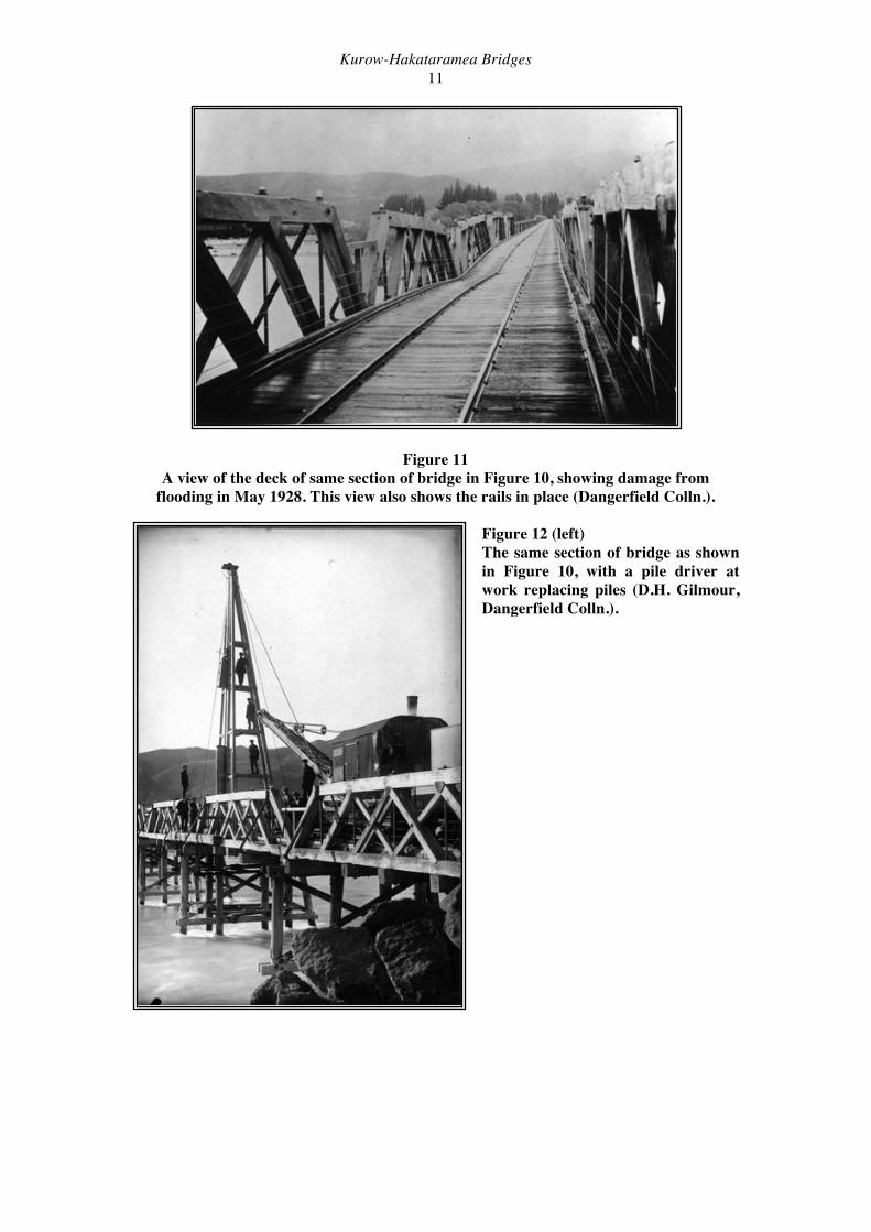
Figure 8 The approach to the southern bridge, where road and rail combined to cross the bridge.
(Kurow Museum)

Kurow-Hakataramea Bridges 10
Figure 9 The Kurow-Hakataramea bridges from the hill above Kurow, after 1902. This shows
how long the bridge originally was, prior to the major shortening of the southern bridge in the 1970s. The meander closest to Kurow was cut off when the bridge was shortened
(Kurow Museum).
Figure 10 The southern end of the northern bridge (Bridge No. 1), showing the 40 ft trusses suffering damage during flooding in May 1928 (L.D. Cairns, Dangerfield Colln.)
Kurow-Hakataramea Bridges 11
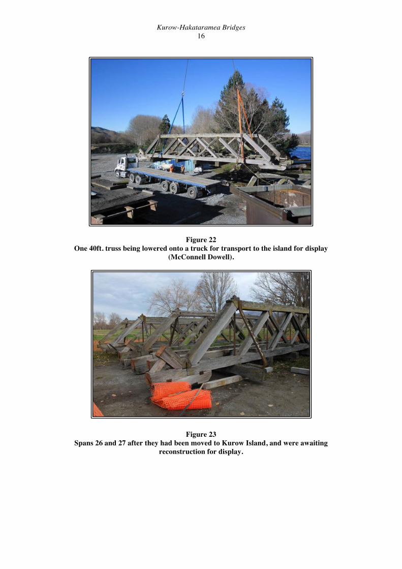
Figure 11 A view of the deck of same section of bridge in Figure 10, showing damage from
flooding in May 1928. This view also shows the rails in place (Dangerfield Colln.). Figure 12 (left) The same section of bridge as shown in Figure 10, with a pile driver at work replacing piles (D.H. Gilmour, Dangerfield Colln.).

Kurow-Hakataramea Bridges 12
Figure 13 The same section of bridge shown in Figures 10 to 12, taken in 2010. The poor state of
the trusses by this date can be seen. The line between Kurow and Hakataramea was closed in July 1930 after flooding damaged one bridge and part subsided while a coal train was being shunted across. The rails were lifted in 1940, and for the rest of their life the bridges were used for road transport only, with the terminus of the Kurow Branch Railway being at Kurow. The entire line was closed completely in 1983 (Otago Daily Times 11 June 1983). At some time prior to 1974 both bridges were reduced in length to 378m and 140m respectively (total length reduced from 762m to 518m). In the early 1970s the timber truss superstructures (up to 90 years old at that stage) had deteriorated to the stage where a Heavy Motor Vehicle Posting Weight Limit of 50% Class I was necessary. In view of the urgency to upgrade the load capacity, and because at that stage the Lower Waitaki Power Development was considered imminent (and thought to affect any new bridging proposal in this area), it was decided to upgrade the superstructures to Class I capacity using a semi-permanent solution. As a result, in 1976 the entire timber truss superstructures for both bridges were replaced with steel beams (RSJs) and timber baulk decking, having an assessed life on the order of 20 years. At the same time, the No. 1 bridge was shortened by the construction of an embankment to give the current bridge lengths of 256m (No. 1) and 140m (No. 2), a total length of 396m. For the No. 1 bridge the timber trusses were retained to provide side protection, while at the No. 2 bridge reject Bailey bridge panels were used to provide side protection (McNally 2007). In 1974 the timber substructure of both bridges was thoroughly inspected and while some deterioration was evident, it was assessed that the substructure would be adequate for the intended life of the replacement superstructures (about 1996). However, in the main channel of the north bridge some piles had only 2.5m embedment below bed level. Subsequently eight piers were underpinned using steel H piles. Several decayed pier caps were also upgraded using steel channels (McNally 2007). In December 1995/January 1996 the bridges again suffered extensive flood damage, resulting in emergency closures (Figure 14). For the next 18 years Pier 19 remained at an angle, and the bridge was periodically closed during flood events. Up to the time of their demolition in

Kurow-Hakataramea Bridges 13
2014 the bridges remained in service with the 1970s steel girders (both bridges) and Bailey bridge sides (Bridge No. 2) still in place, together with numerous more recent repairs and strengthening additions.
Figure 14 Damage to Bridge No. 1 caused by the failure of Pier 19 during flooding in 1995 (McNally 2007).
In 2013/2014 the bridges were replaced by a pair of concrete and steel two-lane road bridges built by McConnell Dowell Constructors Ltd. Each new bridge was built immediately downstream of the respective old bridge. For the purposes of construction a pair of temporary bridges (the Trestle Bridges) were built, each one being downstream again of the new permanent bridge. Thus, for a period in 2014, there were three bridges across each branch of the river (six bridges in total). After the completion of the new road bridges, the old bridges were first removed, followed by the trestle bridges.
Figure 15 The northern (Bridge No. 1) construction site in February 2014. On the right is the old Bridge No. 1, in the centre are the piers for the new Bridge No. 1, and on the left is the temporary trestle bridge.
Bridge No. 2 was officially opened on 4th April 2014, and Bridge No. 1 was opened on 7th June 2014 (see Appendix D). Demolition of the old Bridge 2 commenced after the opening of the new Bridge 2, while the new Bridge 1 was still incomplete. The last public use of Bridge No. 1 was on Monday 9th June, and demolition began immediately the last cars had passed over at about 10.30am.

Kurow-Hakataramea Bridges 14
Figure 16 Three bridges together at Bridge No. 1 in June 2014 (McConnell Dowell). The temporary trestle bridge is in the foreground.
Figure 17 The old Bridge No. 2 under demolition in June 2014. Figure 18 Demolition work on old Bridge 2. In this vew the Bailey Bridge side panels are being cut away.

Kurow-Hakataramea Bridges 15
Figure 19 Bridge 1 immediately before it was closed to public use at 10.30am on June 9th 2014. This view is looking north towards Hakataramea. Figure 20 The same view as Figure 19, taken two weeks later on 24th June 2014. The sections of deck over the joints between the girder sections have been removed to allow the bridge spans to be disconnected. By this date five spans at the far end of the bridge had already been lifted. Figure 21 The north end of Bridge No. 1 on 24th June, showing Span 23 still in place after Spans 24 to 28 had been removed.
Kurow-Hakataramea Bridges 16
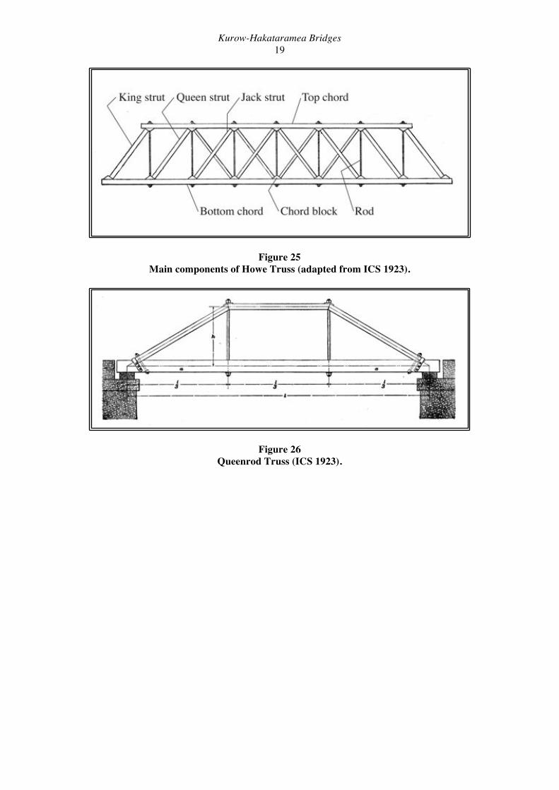
Figure 22 One 40ft. truss being lowered onto a truck for transport to the island for display
(McConnell Dowell).
Figure 23 Spans 26 and 27 after they had been moved to Kurow Island, and were awaiting
reconstruction for display.

Kurow-Hakataramea Bridges 17
Figure 24 The display of spans 26 and 27 under construction on Kurow Island in September 2014
(McConnell Dowell).

Kurow-Hakataramea Bridges 18
Description of the Kurow-Hakataramea Bridges Prior to Demolition The two bridges between Kurow and Hakataramea were initially of similar construction, but the modifications carried out in the 1970s gave them quite different appearances for the last decades of their lives. They are discussed separately below; the north bridge (Bridge No. 1) first. These descriptions are based on a series of inspections undertaken in September 2010, February 2014 and June 2014. An inspection was made on June 9th 2014, the last day that public traffic crossed bridge No. 1, and a further site visit was made on 24th June during deconstruction work. Most attention is paid here to Bridge No. 1, as it was the structure that retained the largest amount of original material. The technical descriptions given below use a number of technical terms that are peculiar to timber truss bridges. The main terms used are outlined in Table 1. Figures 25 and 26 illustrate Howe and Queenrod trusses, the two types of timber truss that were used in the bridges. Table 1: Glossary of terms
Bay The interval in the truss between the pier and the first transom, or between any two transoms.
Bottom chord The horizontal tension members that form the bottom of the truss.
Cap (pier cap) The horizontal member that joins the tops of the piles and provides bearing for the corbels.
Chord block Blocks set into the top and bottom chors upon which the ends of the struts bear.
Corbel The horizontal members that support the ends of the trusses. They cantilever beyond the face of the pier cap.
Counter strut See Strut. Transom (floor beam)
The beam that forms the floor of the Howe Truss and supports the rail beams.
Pier An assembly of inter-connected piles that provides the vertical load-beaaring structure that transfers the bridge loads to the foundations.
Pile The vertical timber member that was driven into the bed of the river to form the foundation for the bridge.
Rail beam The beam that rests on the transoms and supports the sleepers. Rod Vertical steel member in tension that rus between the top and
bottom chords. Strut Diagonal compression member in a Howe Truss that slopes
towards the centre of the truss. From the outside: king strut, queen strut, jack strut. Struts running the opposite was are counter struts.
Span The horizontal portion of the structure between two adjacent piers.
Sway brace A bracing member that connects the outer end of the transom to the top chors to provide lateral stiffening.
Top chord The horizontal compression member that forms the top of the truss.
Wind brace Bracing in the horizontal plane of the bridge, mounted below the deck between the transoms.
Kurow-Hakataramea Bridges 19
Figure 25 Main components of Howe Truss (adapted from ICS 1923).
Figure 26 Queenrod Truss (ICS 1923).

Kurow-Hakataramea Bridges 20
Bridge No. 1 (North Bridge): General Description Bridge No. 1 consisted of 28 spans: seven 40 ft. timber Howe truss spans at either end, and fourteen 20 ft. timber Queenrod truss spans in the middle, all mounted on hardwood timber piles. The bridge deck was 12 ft. wide between the trusses. As described above in the history section steel beams were added to the structure in the 1970s, and these carried the timber (with asphalt overlay) vehicle deck. The trusses were left in place as side protection only and did not act as structural members. For this reason the trusses appear to have received little maintenance since the 1970s, and by the time the bridge was dismantled in 2014 they had become quite decrepit. A number of timber struts were missing, and advanced decay could be seen in many of the timbers, including main chords.
Figure 27 The downstream side of Bridge No. 1 from the island in the middle of the river in 2010.
Figure 28 Span numbering for Bridge No. 1
Original iron elements in the bridge were the vertical ties in the trusses, railway iron swaybraces (on the 40 ft trusses, bent from bull-headed rail) and bolts and fittings. Railway iron cross-bracing on the piers was not original, as rebates cut for larger-section timber bracing were evident on the timber piles, and the original drawings also show timber cross-bracing. Railway Howe truss bridges were sometimes built with iron bottom chords, but the Kurow-Hakataramea bridge had timber chords. By the early 21st century there were numerous

Kurow-Hakataramea Bridges 21
failed and missing elements in the bridge, the most obvious being the failure of Pier 19, in which all of the piles had moved downstream, twisting out of shape the 20 ft. trusses that it supported (Spans 19 & 20). It was in this section of the bridge that the structural role of the steel deck girders was most obvious. The steel H-piers that were installed in the mid-1970s to address the problems with deteriorating and unercut piles remained in service until the bridge was dismantled.
Figure 29 The northernmost four 40 ft trusses (Spans 25 to 28) of Bridge No. 1 in 2010. The
northern trusses in general were in better condition that the southern trusses.
Figure 30 A view of the short 20 ft. trusses in the centre of Bridge No. 1 in 2010. The slight
damming effect of the bridge structure in the river flow can be seen.

Kurow-Hakataramea Bridges 22
Bridge No. 1 Construction Details: Piers The two bridges were originally designed and built as railway bridges, with five to seven piles per pier, while normally a narrow road bridge would only have three or four piles per pier. Most of the timber piles were braced with lengths of railway iron, which replaced earlier timber bracing. The pier caps were timber, the piles and caps being jointed using mortice and tenon joints and iron straps. Timber corbels mounted in the pier caps supported the trusses and rail beams. Many of the pier caps had been strengthened by the addition of galvanised steel channel sections. These construction details are illustrated below (Figures 31 to 37).
Figure 31 Pier 22 in 2010, showing the original pattern of timber piles. This is an example of a 6-pile pier: 7-pile piers had an extra centre pile. This pier had a broken pile (left side), despite the addition of strapping on several piles. The pier cap had also been strengthened by the addition of steel channels.
Figure 32 Annotated section through 6-pile pier and 40 ft. Howe truss. Note the redundant rail
beams (marked ‘A’) that date from the use of the structure as a road/rail bridge (Southern Archaeology)

Kurow-Hakataramea Bridges 23
Figure 33 (Left) Details of markings on a raked pile. The markings indicate that this pile was installed in 1898, and the bottom tip of the pile is 30 feet below the benchmark.
Figure 34 (Right) Markings on a raked pile. This pile was installed in 1928 as part of the repair work after floods in May of that year (see Figure 12 above). The bottom tip of the pile is 41 feet below the benchmark.
Figure 35 Tenon cut into top of pile to mount the pier cap. Detail of piles removed during
demolition in 2014.
Kurow-Hakataramea Bridges 24
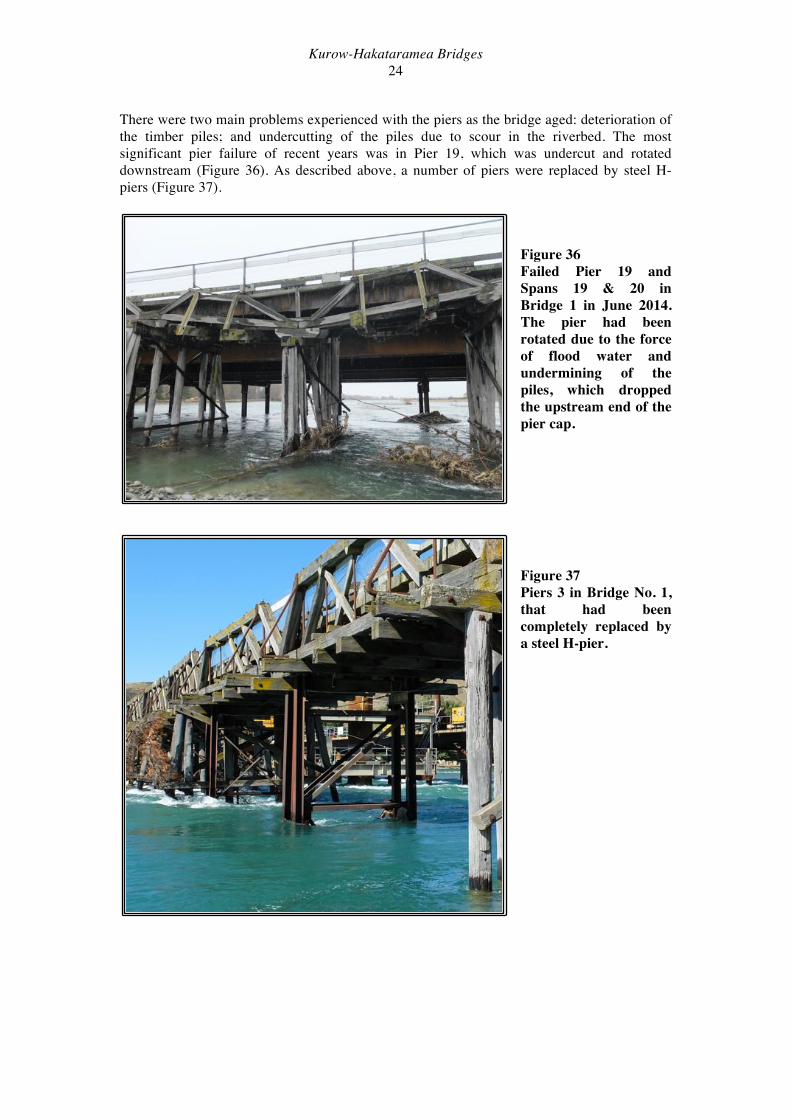
There were two main problems experienced with the piers as the bridge aged: deterioration of the timber piles; and undercutting of the piles due to scour in the riverbed. The most significant pier failure of recent years was in Pier 19, which was undercut and rotated downstream (Figure 36). As described above, a number of piers were replaced by steel H-piers (Figure 37).
Figure 36 Failed Pier 19 and Spans 19 & 20 in Bridge 1 in June 2014. The pier had been rotated due to the force of flood water and undermining of the piles, which dropped the upstream end of the pier cap.
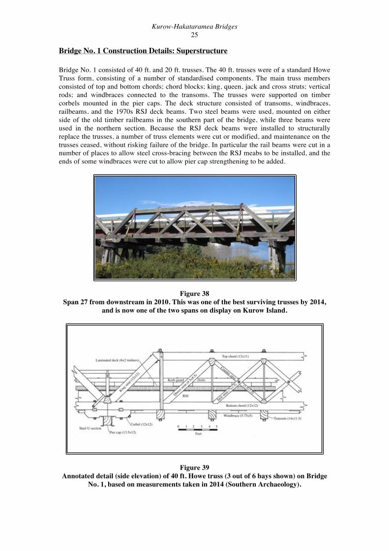
Figure 37 Piers 3 in Bridge No. 1, that had been completely replaced by a steel H-pier.
Kurow-Hakataramea Bridges 25
Bridge No. 1 Construction Details: Superstructure Bridge No. 1 consisted of 40 ft. and 20 ft. trusses. The 40 ft. trusses were of a standard Howe Truss form, consisting of a number of standardised components. The main truss members consisted of top and bottom chords; chord blocks; king, queen, jack and cross struts; vertical rods; and windbraces connected to the transoms. The trusses were supported on timber corbels mounted in the pier caps. The deck structure consisted of transoms, windbraces, railbeams, and the 1970s RSJ deck beams. Two steel beams were used, mounted on either side of the old timber railbeams in the southern part of the bridge, while three beams were used in the northern section. Because the RSJ deck beams were installed to structurally replace the trusses, a number of truss elements were cut or modified, and maintenance on the trusses ceased, without risking failure of the bridge. In particular the rail beams were cut in a number of places to allow steel cross-bracing between the RSJ meabs to be installed, and the ends of some windbraces were cut to allow pier cap strengthening to be added.
Figure 38 Span 27 from downstream in 2010. This was one of the best surviving trusses by 2014,
and is now one of the two spans on display on Kurow Island.
Figure 39 Annotated detail (side elevation) of 40 ft. Howe truss (3 out of 6 bays shown) on Bridge
No. 1, based on measurements taken in 2014 (Southern Archaeology).

Kurow-Hakataramea Bridges 26
Figure 40 Span 1 in Bridge No. 2 in 2010, showing the deterioration in the structure. The queen strut had fallen away from the chord block in the top chord, and the jack struts were also loose.
Figure 41 The upstream join of Spans 4 and 5. This view shows the pier cap, corbel, king struts and bull-head rail sway braces. Figure 42 Detail of the construction and mount at the join of two 40 ft. trusses. The corbel is mounted in the pier cap (covered in gravel in this view), and supports the bottom chords of the trusses. The king struts are mounted against a chord block, which is set into a rebate cut into the chord ends. Note the variation in securing the king struts: on the left the strut is
bolted through to the chord, while on the right an iron strap has been used.
Kurow-Hakataramea Bridges 27
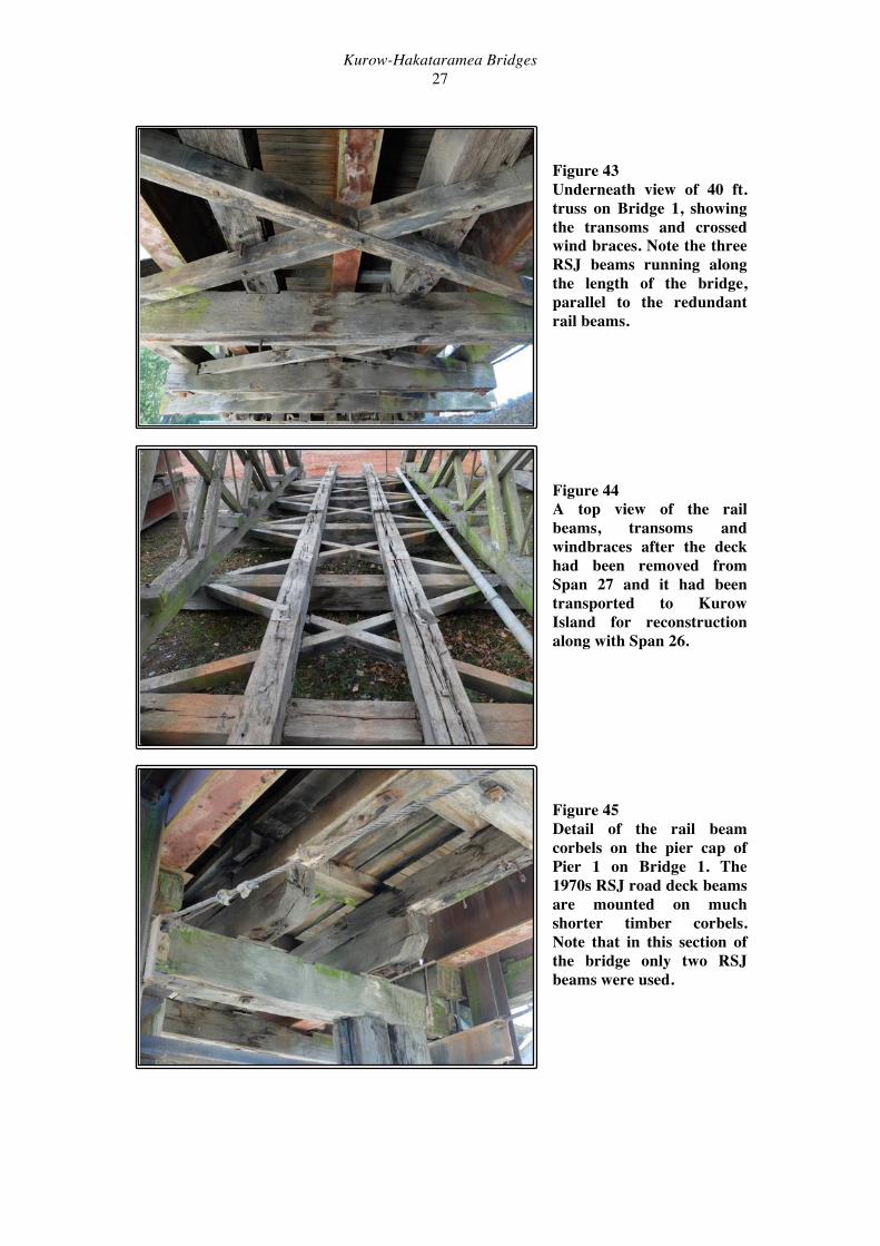
Figure 43 Underneath view of 40 ft. truss on Bridge 1, showing the transoms and crossed wind braces. Note the three RSJ beams running along the length of the bridge, parallel to the redundant rail beams. Figure 44 A top view of the rail beams, transoms and windbraces after the deck had been removed from Span 27 and it had been transported to Kurow Island for reconstruction along with Span 26. Figure 45 Detail of the rail beam corbels on the pier cap of Pier 1 on Bridge 1. The 1970s RSJ road deck beams are mounted on much shorter timber corbels. Note that in this section of the bridge only two RSJ beams were used.
Kurow-Hakataramea Bridges 28
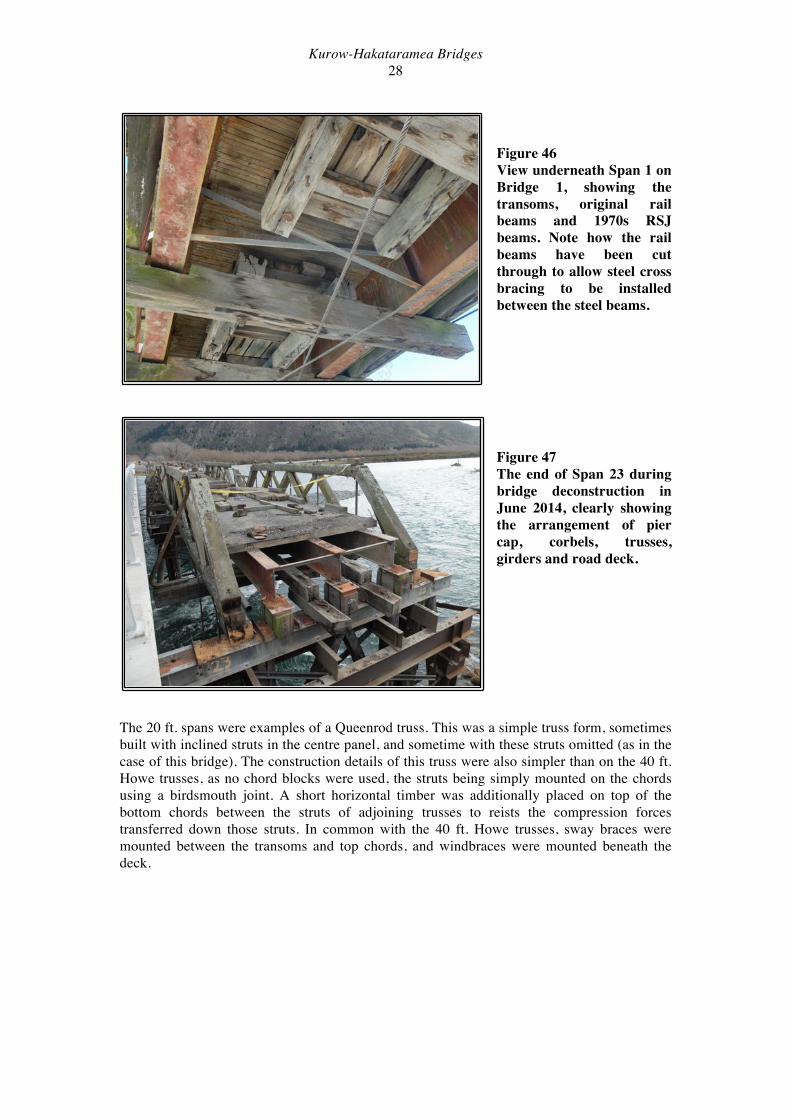
Figure 46 View underneath Span 1 on Bridge 1, showing the transoms, original rail beams and 1970s RSJ beams. Note how the rail beams have been cut through to allow steel cross bracing to be installed between the steel beams.
Figure 47 The end of Span 23 during bridge deconstruction in June 2014, clearly showing the arrangement of pier cap, corbels, trusses, girders and road deck.
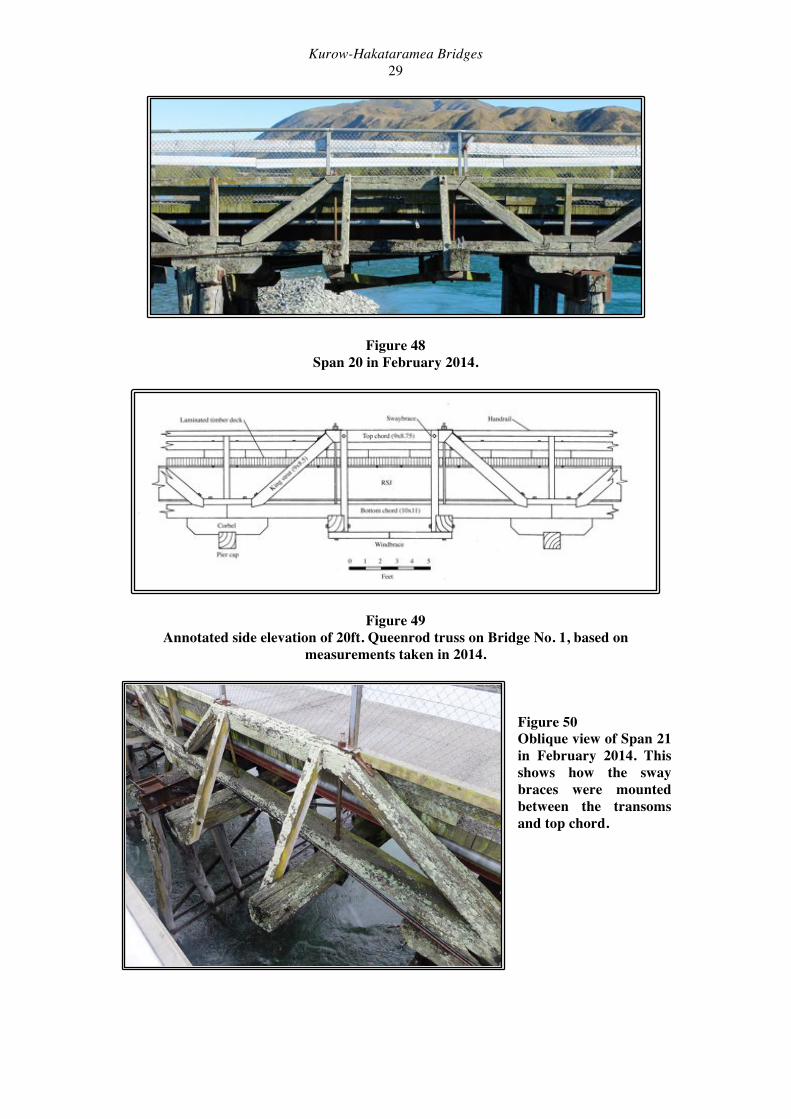
The 20 ft. spans were examples of a Queenrod truss. This was a simple truss form, sometimes built with inclined struts in the centre panel, and sometime with these struts omitted (as in the case of this bridge). The construction details of this truss were also simpler than on the 40 ft. Howe trusses, as no chord blocks were used, the struts being simply mounted on the chords using a birdsmouth joint. A short horizontal timber was additionally placed on top of the bottom chords between the struts of adjoining trusses to reists the compression forces transferred down those struts. In common with the 40 ft. Howe trusses, sway braces were mounted between the transoms and top chords, and windbraces were mounted beneath the deck.
Kurow-Hakataramea Bridges 29
Figure 48 Span 20 in February 2014.
Figure 49 Annotated side elevation of 20ft. Queenrod truss on Bridge No. 1, based on
measurements taken in 2014.
Figure 50 Oblique view of Span 21 in February 2014. This shows how the sway braces were mounted between the transoms and top chord.

Kurow-Hakataramea Bridges 30
Span by Span Record of Bridge No.1 in 2014 In February 2014, during the construction of the replacement bridge, a set of photographs showing each span of the old bridge was taken from the temporary trestle bridge. Figures 51 to 71 show the bridge from the downstream (eastern side) at 10am on February 24th 2014.
Figure 51 Span 1. The shore span at the Kurown Island end of the bridge. Pier No. 1 (right) was reinfored with steel H-piles. The abutment for the new bridge is underconstruction in the left foreground. Figure 52 Span 2. Note the missing struts in the truss structure. Figure 53 Span 3. Pier 3 (left) has been reinforced with steel H-piles, while pier 4 (right) consists only of steel piles.

Kurow-Hakataramea Bridges 31
Figure 54 Span 4. The bottom and top chords have moved apart, and the four centre struts have fallen away from the chord blocks. Pier 5 (right) consists of the original timber piles together with a steel H-pile. Figure 55 Span 5. Span 5 appears to be in reasonable condition. Piers 5 and 6 both consist of timber piles and H-piles. Figure 56 Span 6
Kurow-Hakataramea Bridges 32
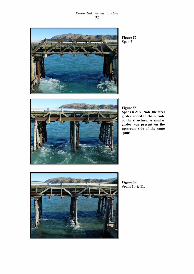
Figure 57 Span 7 Figure 58 Spans 8 & 9. Note the steel girder added to the outside of the structure. A similar girder was present on the upstream side of the same spans.
Figure 59 Spans 10 & 11.

Kurow-Hakataramea Bridges 33
Figure 60 Spans 12 & 13. Figure 61 Spans 14 & 15. Figure 62 Spans 16 & 17.

Kurow-Hakataramea Bridges 34
Figure 63 Spans 18 & 19. Note the collapsed Span 18 and the damage to the transoms of Span 19. The failure of Pier 19 (far right) can also be seen. At the lower left of the picture one of the piers for the new bridge is under construction. Figure 64 Spans 20 & 21 Note the dropped transoms on Span 20. The truss members on the upstream side of Spans 19 and 20 had partially collapsed. Figure 65 Span 22.

Kurow-Hakataramea Bridges 35
Figure 66 Span 23. At the lower left of the picture is one of the piers for the new bridge. Figure 67 Span 24. Figure 68 Span 25. The view is slightly obstructed by the northern abutment for the new bridge that was under construction.
Kurow-Hakataramea Bridges 36
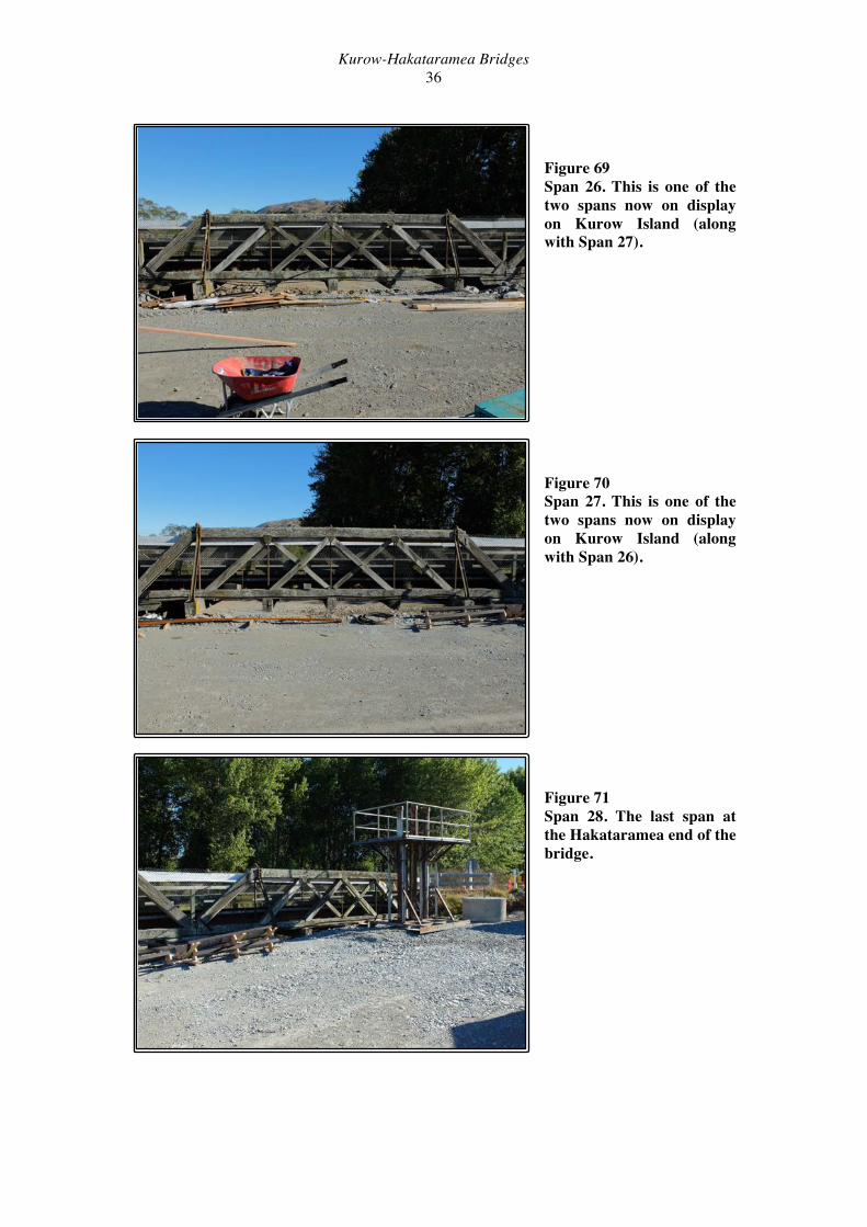
Figure 69 Span 26. This is one of the two spans now on display on Kurow Island (along with Span 27). Figure 70 Span 27. This is one of the two spans now on display on Kurow Island (along with Span 26). Figure 71 Span 28. The last span at the Hakataramea end of the bridge.
Kurow-Hakataramea Bridges 37
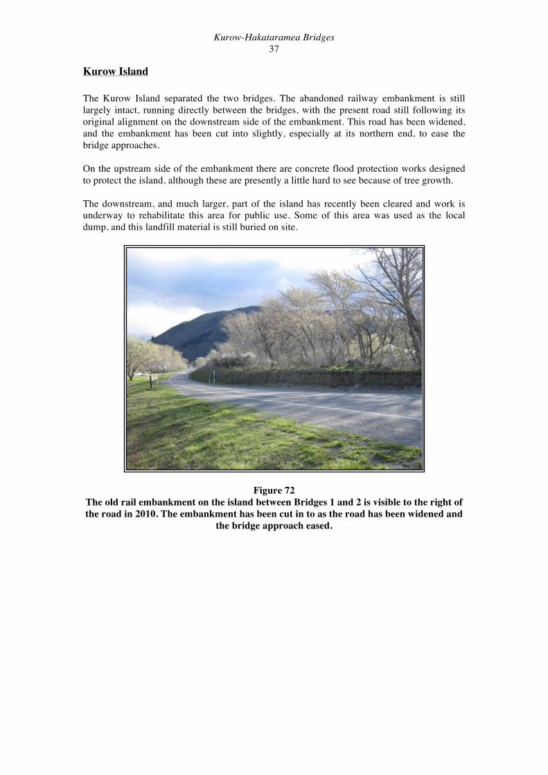
Kurow Island The Kurow Island separated the two bridges. The abandoned railway embankment is still largely intact, running directly between the bridges, with the present road still following its original alignment on the downstream side of the embankment. This road has been widened, and the embankment has been cut into slightly, especially at its northern end, to ease the bridge approaches. On the upstream side of the embankment there are concrete flood protection works designed to protect the island, although these are presently a little hard to see because of tree growth. The downstream, and much larger, part of the island has recently been cleared and work is underway to rehabilitate this area for public use. Some of this area was used as the local dump, and this landfill material is still buried on site.
Figure 72 The old rail embankment on the island between Bridges 1 and 2 is visible to the right of the road in 2010. The embankment has been cut in to as the road has been widened and
the bridge approach eased.

Kurow-Hakataramea Bridges 38
Bridge No. 2 Bridge No. 2 was considerably modified in the 1970s, and much of its length was replaced by an earth embankment, and all timber trusses were removed from the bridge, and replaced by steel girders and Bailey Bridge sides. Its appearance at the end of its life gave little indication of its original form (see Figure 7). From the deck level it appeared to be a Bailey Bridge due to its sides (Figure 73), while from below the original hardwood piers were more obvious. This bridge crossed a less vigorous channel than Bridge No. 1, and the timber piers appeared to be in better condition. The bridge originally crossed a third, southernmost, river channel, but this was cut off by the construction of the embankment in the 1970s.
Figure 73 Bridge No. 2 in 2010, showing the Bailey bridge sides. View from the southern bank,
looking north towards the island.
Figure 74 Bridge No. 2 in 2010, showing the original timber piers supporting the new (1970s) steel
beams and road deck with Bailey Bridge sides. View from the island looking back towards the southern bank.

Kurow-Hakataramea Bridges 39
Bridge No. 2 Construction Details: Piers The pier structures of Bridge No. 2 were largely the same as those of Bridge No. 1, although the timber structures were generally in much better condition. In common with Bridge No. 1, the Bridge 2 piers were originally fitted with timber cross-braces, but most of these had been replaced with iron rails. Most of the piers in the flowing water (under normal river flows) had seven piles, the outside two being raked, while the piers on the bank lacked the raked piles.
Figure 75 Seven pile Pier 3 in Bridge No. 2 in 2014.
Bridge No. 2 Construction Details: Superstructure The superstructure of Bridge No. 2 consisted of three rows of RSJ girders mounted on timber corbels on the pier caps. A nail laminated timber deck was laid over the girders. The Bailey
bridge sides were mounted in either side of the deck, independently supported on timber corbels on the pier caps. Galvanised steel sway braces were mounted between the ends of the pier caps and tops of the Bailey panels. Figure 76 The deck of Bridge 2 in 2014, looking towards Kurow.

Kurow-Hakataramea Bridges 40
Figure 77 One Bailey Bridge panel in 2014. The detail of the laminated timber deck can also be
seen in this view. Figure 78 The maker’s details on the Bailey Bridge panel shown in Figure 77. this example reads “THOS. STOREY, ENGINEERS LTD, ENGLAND, UK PAT 553374.” Other makers are also represented on the bridge. Figure 79 Detail of the underneath of Bridge No. 2, showing the pier cap, corbels, RSJ deck girders and Bailey Bridge panels mounts.

Kurow-Hakataramea Bridges 41
Timber Railway Bridges Prior to the Industrial Revolution, the traditional materials for constructing bridges were stone or timber. The simplest stone bridges were slabs laid on large rocks across a stream course. Such bridges were very limited in the distance that could be spanned and the loads that could be carried. Larger structures used masonry arches to bear both the increased weight of the bridge itself and any crossing loads. Timber bridges could also be constructed from simple beams, the simplest of all being a log laid across a stream. But again, more complex structures could also be built, using timbers under tension or compression to increase the possible spans and load-bearing capabilities. The Industrial Revolution, classically regarded as beginning in 1760, saw the introduction of first iron and later steel as construction materials. The Iron Bridge, built in 1779 over the River Severn in Shropshire, was the first iron bridge in the world (Bracegirdle 1973: 157). The new industrial age not only brought new materials, but also ever increasing loads that bridges had to bear. Britain’s expanding canal and rail networks required aqueducts and viaducts that were required to carry enormous static and dynamic loads. The finest timber viaducts were built by Isambard Kingdom Brunel in Cornwall and Devon from 1844 on. The choice of material was primarily due to cost, as timber was much cheaper than masonry, and the railways servicing this part of the country could not be expected to make the same profits as those in more populous areas. However, superb quality timber at a reasonable cost was available, making these viaducts a practical design. Brunel used yellow pine from Melmel in the Baltic, which had a life span of at least 30 years, and he developed a standardised design that allowed standard units of timber to be used and repair to take place without interrupting traffic (Rolt 1957: 176-177). A total of 67 timber viaducts were built in the west of England, but none now survive; the supply of suitable timber became impossible, and all were eventually replaced with masonry or iron structures. The last of Brunel’s timber viaducts was replaced in 1934 (Bracegirdle 1973: 51). The Chambers’ Encyclopædia (1924: 445) commented in 1924:
“Timber bridges, or frame bridges as they are occasionally called, are in Britain never now employed for railway work by reason of their want of durability, and on account of the much heavier loads imposed on bridges by modern rolling stock. Such railway bridges as have in earlier times been built of timber in Britain have been reconstructed of stone, brick, iron, or steel.”
By the late twentieth century large timber railway bridges had become virtually extinct in Britain, with only the Barmouth Viaduct still in use, and the Aultnaslanash Viaduct still standing (Biddle & Nock 1983: 96, 173). The Barmouth Viaduct is still standing and in occasional use to carry trains (http://en.wikipedia.org/wiki/Barmouth_Viaduct). In the New World timber continued to be used for bridge construction for much longer, economics again playing a role its selection. Timber bridge designs were refined considerably in America, where the ready availability of timber made it an obvious choice of material (Thornton 2001: 86). A number of different truss designs were developed during the nineteenth century, including the Town Lattice Truss, the Howe Truss, the Pratt Truss and the Warren Truss4, of which the Warren and Howe trusses were commonly used for timber bridges in New Zealand (Thornton 2001: 86-87). The Howe Truss, patented in 1840 by William Howe, was the first patent truss to incorporate iron into the timber structure5 (Bennett
4 Warren was British. 5 Such mixed iron and timber structures were termed a ‘combination truss.’

Kurow-Hakataramea Bridges 42
1999: 27). Both Howe and Pratt trusses used timber compression members and iron tension members, the bottom chords of many timber truss railway bridges in New Zealand being made of wrought iron. A number of different timbers were used in New Zealand for bridge building, as there was an ample indigenous supply. However, as had been found in Britain, durability was a problem, and timber type and quality was of paramount importance. Totara proved durable, but kauri and other timbers rotted quickly. As a result, the use of extremely durable (and strong) hardwoods became widespread, and most timber truss bridges were built of these imported timbers. However, decay was still an issue, and the rot often started in the core of the timber at joints where moisture was trapped. As a result, a programme of bridge inspection was undertaken by New Zealand Railways. Small inspection holes were drilled in each timber member, and then plugged with a dowl. Although also constructed using similar timber trusses, the inspection of timber bridges was probably never as rigorous as for rail bridges. Iron and masonry were also used in New Zealand from the early years of settlement. One of the earliest iron bridges was built over the Oreti River at Wallacetown near Invercargill in 1865 (Thornton 2001: 23). An excellent example of an iron truss road bridge is the Beaumont Bridge over the Clutha River, opened in 1887 and still in use today on State Highway 8. However, timber truss bridges continued to be built in New Zealand well into the 1930s. The construction of railway bridges was, or course, dependent on the expansion of the rail network. This received a boost under Vogel’s public works policies of the 1870s, but New Zealand has never had a rail system of that of Britain. However, New Zealand’s often broken terrain called for numerous bridges and other engineering works, often of a major scale; when the Otira Tunnel was finally opened through the Southern Alps in 1923 it ranked as the world’s seventh longest tunnel (Churchman 1988: 12). Of note were numerous bridges built to serve both road and rail transport. The same economic imperatives that made timber the choice of building material also meant that a single bridge was built to serve both purposes. Some 42 or more bridges were constructed for such a dual role, although only four still serve such a purpose. On the Taieri Gorge Railway (ex. Otago Central Branch) at Hindon a railway bridge has recently been converted to also carry road traffic, as the nearby road bridge became unsafe. These combined bridges are discussed in more detail below.
Kurow-Hakataramea Bridges 43
Surviving and Preserved Timber Truss Bridges in New Zealand There are still a number of timber truss bridges surviving in use in New Zealand, and a small number of bridges that are actively preserved as historic structures. In addition, there are a number of disused bridges with an uncertain future. All of these are hard to quantify exactly, particularly the numbers of abandoned but still standing structures, as demolitions continue to remove these bridges. Leitch & Scott in Exploring New Zealand’s Ghost Railways (revised edition 1998) list several bridges that have since been demolished, such as the Riverton Causeway and the Blackball Bridge. The threat of bridge demolition has increased in recent years because of the high value of the hardwood timbers used in their construction. The remaining spans of the Blackball Bridge over the Grey River were dismantled in 2001 for this reason (Wright 2001: 13). The causeway and two timber Howe Trusses across the Pourakino River estuary at Riverton were recently demolished, despite the potential for its retention and maintenance. On the West Coast The Cobden rail bridge over the Grey River (Rapahoe No. 1) and the Arahura road/rail bridge (Bridge 28 Hokitika Line) have both been dismantled in the last ten years because of their deteriorating conditions. Actively preserved timber truss bridges in New Zealand include:
• Mahinapua Creek Bridge (rail). Within a historic reserve administered by DoC. • Fox River Bridge (road). Managed by Friends of the Fox, but has funding issues. • Ngatiawa River Bridge, Reikorangi, nr. Waikanae (see Thornton 2001: 115). • Manganuku Stream Bridge, Waioeka Gorge (road). Administered by DoC. • Waitekauri Bridge (rail). Goldfields Railway Inc. • Pakuratahi Bridge (rail). Rimutaka Rail Trail.
Two of these bridges are on the West Coast of the South Island (Mahinapua and Fox). A major bridge preservation effort on the West Coast has also been the restoration of the Brunner Suspension Bridge (Rogers 2005: 89). It is very hard to quantify the numbers of surviving timber truss bridges that remain in use, and the best guide is to be found in Thornton (2001). However, he does not always specify whether a particular bridge remains in service, and obviously does not take account of more recent demolitions. There are probably some dozens of these bridges still in use, many on roads in remote rural areas. Some timber truss bridges that are known to survive and are still in use are:
• Waimea Creek Bridge (rail). On the Greymouth-Hokitika Railway (Figure 84). • New River Bridge (rail). On the Greymouth-Hokitika Railway (Figure 83). • Akatarawa River Bridges (3 individual bridges)(road). • Lee stream bridge (road) near Mount Hyde, Otago.
Surviving but abandoned timber truss bridges include:
• The Ford Creek Bridge on the abandoned Blackball to Roa section of the Blackball Branch Railway (Figure 85).
• The Totara River Bridge on the abandoned Hokitika to Ross section of the Greymouth-Hokitika Railway (Figure 86).
The Totara River Rail Bridge was completed in 1908, and was situated almost at the very end of the Greymouth-Ross Railway (see Figure 86). The Hokitika to Ross section of the line was

Kurow-Hakataramea Bridges 44
closed in 1980 due to the deterioration of the Hokitika Bridge, but the Totara Bridge was left in place when the line was lifted. According to Phil McVicar (at the time of interview with ONTRACK, and who had worked on the bridge for NZR) a maintenance crew had almost finished a major overhaul of the bridge when the line closed, and replacement dates as late as 1978 can be seen carved into some of the bridge timbers. The bridge consists of five Howe trusses and several simple beams supported on timber piles. All of these bridges have historic value as examples of timber truss bridges. All share the same basic design of truss, but each varies in the size and heaviness of each truss, and the number of trusses used. There now very few surviving multi-truss bridges, and probably none that compare with the 28 trusses of Kurow-Hakatarmea Bridge No. 1. The structure that is probably now most comparable to the Hakataramea Bridge in terms of size is the Totara River Bridge, consisting of five truss spans.
Figure 80 The Mahinapua Creek Bridge in 2007. This bridge is actively managed by the Department of Conservation. It was on the Hokitika to Ross section of the Greymouth to Ross Railway, which closed beyond Hokitika in 1980. Figure 81 The Fox River Bridge in 2007 (J. Breen, DoC West Coast).

Kurow-Hakataramea Bridges 45
Figure 82 The single-span Waitekauri Bridge on the Goldfields Railway in 2010. This railway operates on the preserved section of line between Waihi and Waikino. This photograph gives a good view of the iron bottom chords, typical of Howe Truss bridges build for railway use.
Figure 83 The New River Bridge on the Greymouth-Hokitika Railway in 2007. Originally designed as a road/rail bridge, it now carries only rail. This bridge consists of three Howe trusses.
Figure 84 The Waimea Creek Bridge on the Greymouth-Hokitika Railway in 2007. This bridge consists of three Howe trusses and several simple spans.

Kurow-Hakataramea Bridges 46
Figure 85 The Ford Creek Bridge near Roa on the abandoned Blackball line.
Figure 86 The Totara River Bridge in 2007 from the north bank of the Totara River.

Kurow-Hakataramea Bridges 47
Combined Road/Rail Bridges in New Zealand As discussed above, combined road/rail bridges were a practical response to the expense of bridge construction in a young and rugged country. They came in two main forms: those where road and rail shared the same deck, and double-deck structures. The Kurow-Hakataramea Bridge was an example of the former. Today only four single-deck combined bridges in New Zealand retain both functions. Two are on the Taieri Gorge Railway; one at Hindon (only recently converted to dual use) and one at Sutton. One bridge is on the West Coast, over the Taramakau River (see Figure 87), and the last is at Pekatahi in the Bay of Plenty where the railway line is presently unused, but not formally closed (McQueen 2005: 78).
Figure 87 The Taramakau road/rail bridge on the Greymouth-Hokitika Railway in 2007.
Completed in 1890, it consists of six wrought iron lattice trusses on cast iron piers. Recently Transit New Zealand modified the bridge with a steel superstructure to allow
taller trucks to pass through. Only one double-deck bridge remains in service. In the North Island, a double deck bridge at Okahukura in the King Country is still in use crossing the Ongarue River (Thornton 2001: 165). It is constructed from a mixture of plate girders and steel trusses. A number of bridges that served as combined road/rail bridges but have now lost one function also survive. These include (present use in parentheses):
• The New River Bridge on the Hokitika Line (rail). Timber Howe trusses. See Figure 83 above.
• Wanganui River Bridge, Taumaranui (rail). Steel through trusses. • Karangahake Bridge (road). Double deck, steel Pratt through trusses. • Waimakariri Gorge bridge (rail). Plate girders. • Manuherikia bridge, Alexandra (road). Plate girders and steel truss. • Awatere River Bridge, near Sutton (rail). Double deck, plate girders & steel trusses.
Until 2007 this also carried State Highway 1.

Kurow-Hakataramea Bridges 48
Significance of the Kurow-Kakataramea Bridges The Kurow-Hakataramea Bridges were important heritage structures, although the extent of the modifications to the southern bridge (Bridge No. 2) meant that the northern bridge (Bridge No 2) was the one that retained greatest heritage significance. By the 1970s Bridge No. 2 had been shortened to less than half of its original length, and has had all of its trusses removed. It was therefore a far more compromised structure than Bridge No. 1, which was still of considerable length, and retained its trusses (albeit in a non-structural role) until it was dismantled in 2014. The discussion below is therefore specific to Bridge No. 1, unless stated otherwise. The Kurow-Hakataramea Bridge No. 1 was an example of a construction technology that was used internationally for about 100 years, from the mid-nineteenth to the mid-twentieth centuries. Timber road and rail bridges were built to supply a cost-effective answer to the need for improved communications; in Britain as the effects of the Industrial Revolution were felt in the expansion of the railways, and in the New World as settlement and infrastructure expanded. The benefits of timber bridges included low cost and ease of construction, but these were offset by high maintenance, decay, and load restrictions. The development of well-designed truss structures allowed timber bridges to be very strong, but similar designs could be used for iron and steel bridges, which were more durable. During the twentieth century the use of reinforced concrete construction became widespread, with the great benefit of extreme durability so long as the foundations were sound and the concrete of good quality. The timber Howe Truss was widely used in New Zealand, and many examples are still to be seen today, both derelict and in use. However, it is easy to fall into a false sense of security: these bridges are steadily being demolished and there are no replacements of a similar type. The timber truss bridge represents a period of expansion and growth in New Zealand, where roads and railways were being built and many areas opened up for closer settlement. The timber truss bridge is very much part of the traditional New Zealand landscape. By 2006, of the large multi-span Howe timber truss bridges that once existed on New Zealand’s rail system, only the Cobden, Arahura, Hakataramea and Totara bridges remained (Petchey 2007: 25). The Hakataramea Bridge had 28 spans (14 of which were Howe trusses), the Cobden Bridge (Rapahoe No. 1) had 11 Howe trusses, the Arahura Bridge (Hokitika No. 28) had 7 trusses, and the intact but abandoned Totara River Bridge had 5 trusses. Since then the Cobden, Arahura and Hakataramea bridges have been dismantled, leaving only the abandoned Totara River Bridge, which has no present use and has badly corroded ironwork. The next longest surviving Howe Trus bridges in New Zealand is probably the 3 truss bridges already described (New River, Waimea Creek and Fox River). Other timber truss bridges that have been demolisged since 2000 include the Blackball Rail Bridge, the Riverton Rail Bridge, the Bushey Road Bridge over the Shag River, the Breakneck Road bridge (North Otago) and two small rail bridges in Southland.6 Thus, the recent rate of removal of this type of bridge appears to be high.
6 This is a list of bridges that the author knows to have been dismantled, with no further research undertaken.

Kurow-Hakataramea Bridges 49
Figure 88 The Arahura Bridge in April 2007. All seven trusses of the bridge are visible in this
view. Dismantled in 2008.
Figure 89 The Cobden Bridge over the Grey River in 2003. Dismantled in 2006.
Internationally it is hard to quantify the significance of the Kurow-Hakataramea Bridge, for similar reasons to the New Zealand situation. Many Howe truss railway bridges were built in Australia, North America and elsewhere, as they were strong (although there were numerous failures) and economical of materials. In common with New Zealand many have been replaced by steel or concrete structures. Much work has been done in Australia and America documenting these bridges, often in response to the diminishing numbers of these historic structures, although because of the continuing demolition of old bridges any available inventory of surviving historic bridges is likely to be out of date. In Australia, research carried out in New South Wales showed that of 455 timber truss bridges built in that state in the first 120 years of European settlement, only 19% remained in 1998 (Glencross-Grant 2006).
Kurow-Hakataramea Bridges 50
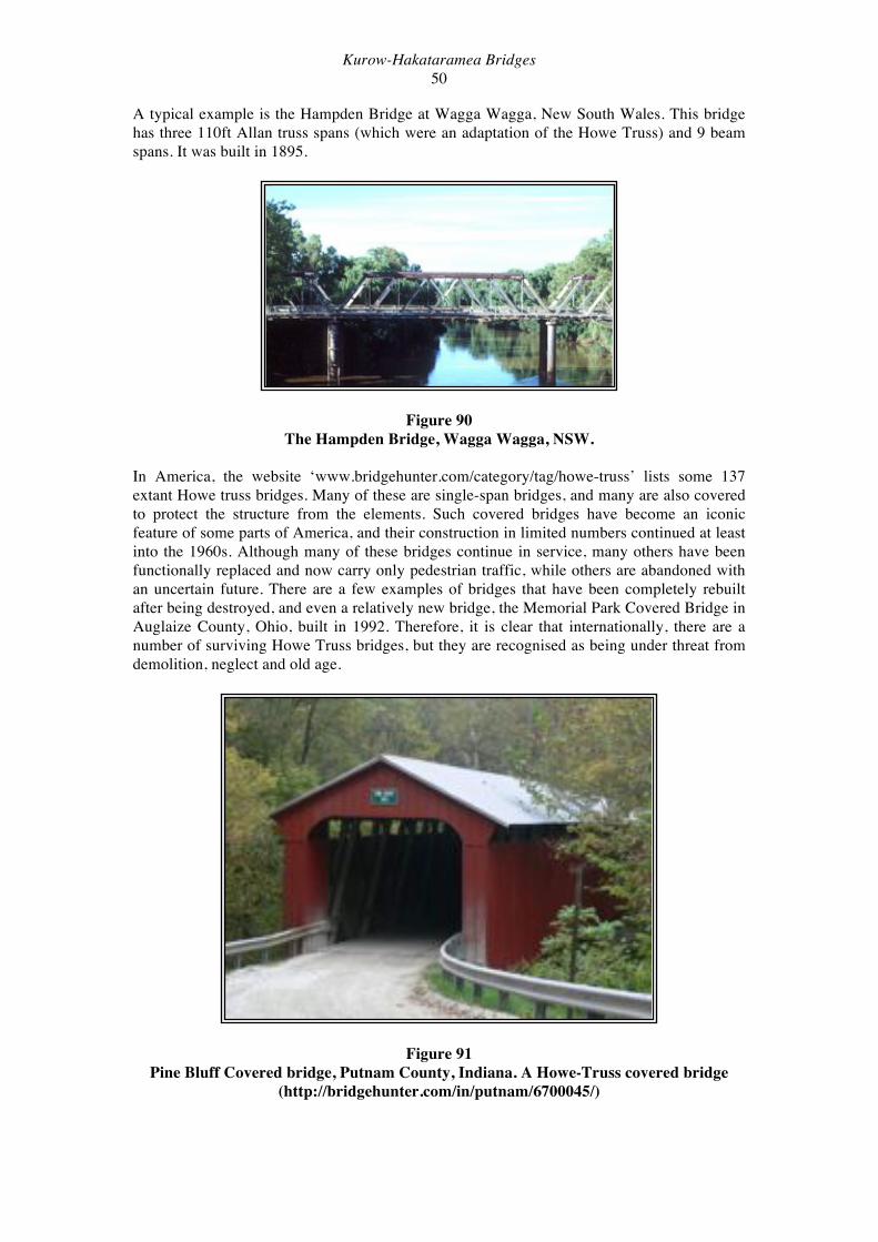
A typical example is the Hampden Bridge at Wagga Wagga, New South Wales. This bridge has three 110ft Allan truss spans (which were an adaptation of the Howe Truss) and 9 beam spans. It was built in 1895.
Figure 90 The Hampden Bridge, Wagga Wagga, NSW.
In America, the website ‘www.bridgehunter.com/category/tag/howe-truss’ lists some 137 extant Howe truss bridges. Many of these are single-span bridges, and many are also covered to protect the structure from the elements. Such covered bridges have become an iconic feature of some parts of America, and their construction in limited numbers continued at least into the 1960s. Although many of these bridges continue in service, many others have been functionally replaced and now carry only pedestrian traffic, while others are abandoned with an uncertain future. There are a few examples of bridges that have been completely rebuilt after being destroyed, and even a relatively new bridge, the Memorial Park Covered Bridge in Auglaize County, Ohio, built in 1992. Therefore, it is clear that internationally, there are a number of surviving Howe Truss bridges, but they are recognised as being under threat from demolition, neglect and old age.
Figure 91 Pine Bluff Covered bridge, Putnam County, Indiana. A Howe-Truss covered bridge
(http://bridgehunter.com/in/putnam/6700045/)

Kurow-Hakataramea Bridges 51
Conclusion The Kurow-Hakataramea Bridge No. 1 was a historically significant bridge, as the last surviving example of the long multi-truss road and road/rail bridges that once existed on the east coast of the South Island and crossed the wide braided rivers that are typical of that area. It was also one of the last of a group of long multi-truss timber bridges around the country. These bridges were once a distinctive feature of the New Zealand landscape, but now even single truss bridges are becoming a rarity. The surviving bridges are at least 80 years old now, and timber bridges require increasing amounts of maintenance once they reach this age. Unfortunately this maintenance and repair is rarely economically viable, and the choice has usually been made to replace the timber bridges with concrete and steel structures. Single spans of the Arahura and Cobden bridges have been preserved on the riverbanks near their original locations as memorials to these bridges, and a a double span of the Kurow-Hakataramea Bridge No. 1 has been similarly preserved on Kurow Island. It is hoped that these two Howe trusses preserve something of the flavour of the repetitive form of these bridges that has now largely disappeared from the east coast landscape. This report has detailed the bridge, its history and its final form in 2014 immediately prior to its demolition, and will serve as a permanent record of this important historic structure.
Kurow-Hakataramea Bridges 52
References Appendices to the Journals of the House of Representatives. 1887, D1; 1888, D1 Bennett, D. (1999) The Creation of Bridges. London, Aurum Press Ltd. Biddle, G. & Nock, O.S. (1983). The Railway Heritage of Britain. London, Michael Joseph. Bracegirdle, B. (1973) The Archæology of the Industrial Revolution. London, Heinemann. Churchman, G.B. & Hurst, T. (2001) The Railways of New Zealand. Second edition, first published 1990. Wellington, Transpress. Cochrane, C. & Murray, R. (2006) “Bridge 1 Rapahoe, Greymouth. Documentation of Structure.” Unpublished report for Ontrack. Encylopaedia of New Zealand (1966) A.H. McLintock (ed). Govt. Printer, Wellington. Glencross-Grant, R. (2006) “The Evolution of Timber Truss Road bridges in New South Wales.” Paper presented at Engineered Wood Products Association 2006 conference. Hall, R.R. (1987) “Te Kohurau: Continuity and Change in a New Zealand Rural District.” Unpublished Phd thesis, Sociology, University of Canterbury. ICOMOS (NZ) Charter (2010) ICS (International Correspondence Schools Ltd.) (1923) Bridge Specifications, Bridge Design, Bridge Drawing. Leitch, D. & Scott, B. (1998) Exploring New Zealand’s Ghost Railways. Revised edition, originally published 1995. Wellington, Grantham House Publishing. McDonald, K.C. (1940) History of North Otago. North Otago Centennial Committee. McEwan, A. (1994) “Built to Last.” (St. Albans Vicarage & Chapel, Kurow). New Zealand Historic Places, 50: 35-36. McNally, C. (2007) “Region 11 SH82, Waitaki River Bridges RP 53/16.70 and RP 53/17.23, Condition Review- 2007” Report by Opus International Consultants to Transit New Zealand. McQueen, E. (2005) Rails in the Hinterland. New Zealand’s Vanishing Railway Landscape. Wellington, Grantham House Publishing. Neave, E. & N. (1980) The Land of Munros, Merinos & Matagouri. Its Kirk, Pioneers & Descendants. D.E. Neave, Kurow. New Zealand Archæological Association, Site Record File. Otago Daily Times (Newspaper, Dunedin) Petchey, P.G. (2002) “Project Aqua. European Cultural Resources and Heritage.” Unpublished report for Meridian Energy.

Kurow-Hakataramea Bridges 53
Petchey, P.G. (2003) “Cobden Railway Bridge, Grey River, Greymouth. Archæological Assessment.” Unpublished report for Tranz Rail. Petchey, P.G. (2007) “Arahura Road/Rail Bridge (Bridge 28 Hokitika Line) Archæological Assessment.” Unpublished report for Ontrack Ltd. Petchey, P.G. (2010) “Kurow-Hakataramea Bridges Heritage Assessment.” Unpublished report for NZ Transport Agency. Rolt, L.T.C. (1957) Isambard Kingdom Brunel. London, Longmans. Scotter, W.H. (1948) Run, Estate and Farm. A History of the Kakanui and Waireka Valleys, North Otago. Otago Centennial Historical Publications. Shortland, E. (1844). Hocken Library, MS 24 typescript. Stevenson, G.B. (1947) Maori and Pakeha in North Otago. A.H. & A.W. Reed, Wellington. Thomson, J.T. (1857) Fieldbook No. 47, LINZ Dunedin. Thornton, G. (2001) Bridging the Gap. Early Bridges in New Zealand, 1830-1039. Auckland, Reed Books. Wright, L. (2001) “West Coast Legacy at Risk.” New Zealand Historic Places, No. 83. Maps & Plans NZMS 260 I40 Kurow Upper Waitaki Bridge plans (1878) NZ Transport Agency. Websites Te Ara Encyclopaedia of New Zealand (www.teara.govt.nz) http://bridgehunter.com/category/tag/howe-truss http://en.wikipedia.org/wiki/Barmouth_Viaduct http://www.past-inc.org/historic-bridges/covered-comstock.html http://oak.arch.utas.edu.au/projects/view_projectinfo.asp?projID=21 http://www.waihirail.co.nz/text/image.html http://www.mrdbridges.com/engineering.php http://www.gw.govt.nz/section627.cfm http://www.ipenz.org.nz/heritage/printfriendly2.cfm?item=89

Kurow-Hakataramea Bridges 54
Appendix A
Measured Drawings: Original Plans (supplied by NZ Transport Agency).

Kurow-Hakataramea Bridges 55
Kurow-Hakataramea Bridges 56
Appendix B
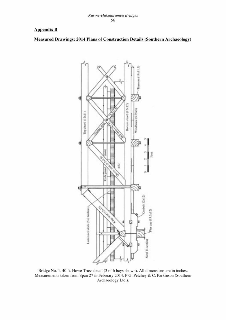
Measured Drawings: 2014 Plans of Construction Details (Southern Archaeology)
Bridge No. 1, 40 ft. Howe Truss detail (3 of 6 bays shown). All dimensions are in inches.
Measurements taken from Span 27 in February 2014. P.G. Petchey & C. Parkinson (Southern Archaeology Ltd.).
Kurow-Hakataramea Bridges 57
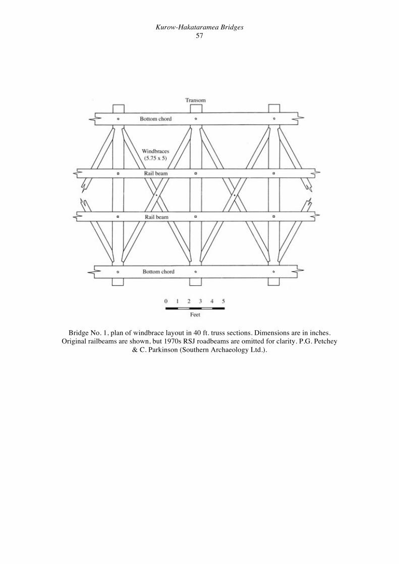
Bridge No. 1, plan of windbrace layout in 40 ft. truss sections. Dimensions are in inches. Original railbeams are shown, but 1970s RSJ roadbeams are omitted for clarity. P.G. Petchey
& C. Parkinson (Southern Archaeology Ltd.).
Kurow-Hakataramea Bridges 58
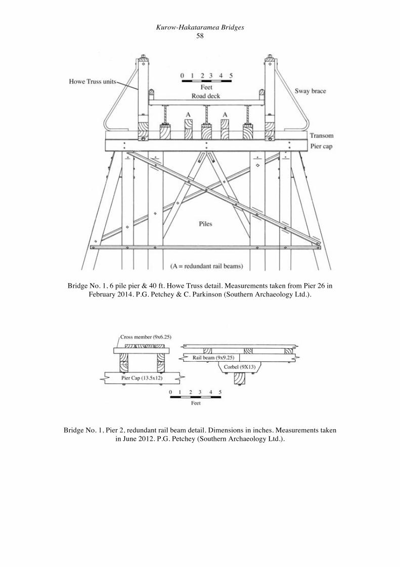
Bridge No. 1, 6 pile pier & 40 ft. Howe Truss detail. Measurements taken from Pier 26 in February 2014. P.G. Petchey & C. Parkinson (Southern Archaeology Ltd.).
Bridge No. 1, Pier 2, redundant rail beam detail. Dimensions in inches. Measurements taken in June 2012. P.G. Petchey (Southern Archaeology Ltd.).
Kurow-Hakataramea Bridges 59
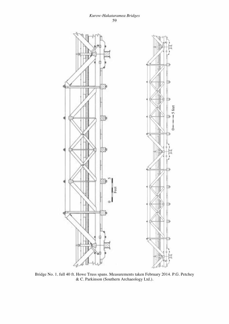
Bridge No. 1, full 40 ft. Howe Truss spans. Measurements taken February 2014. P.G. Petchey & C. Parkinson (Southern Archaeology Ltd.).
Kurow-Hakataramea Bridges 60
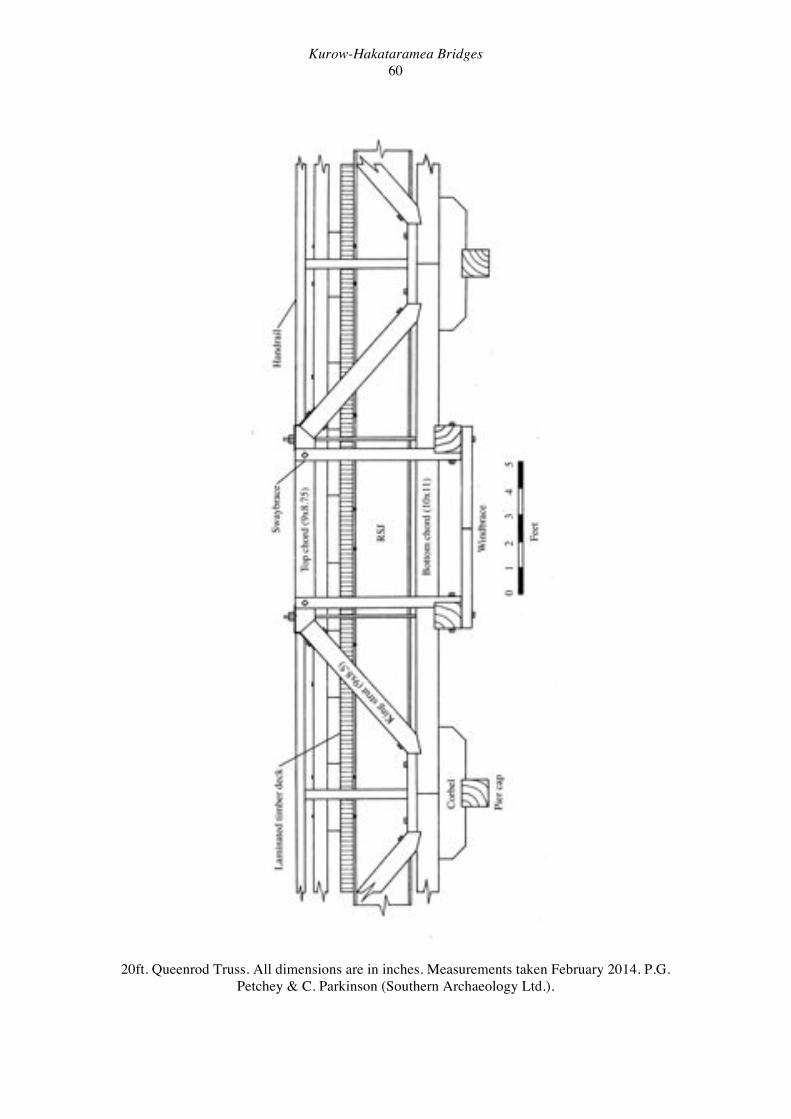
20ft. Queenrod Truss. All dimensions are in inches. Measurements taken February 2014. P.G. Petchey & C. Parkinson (Southern Archaeology Ltd.).

Kurow-Hakataramea Bridges 61
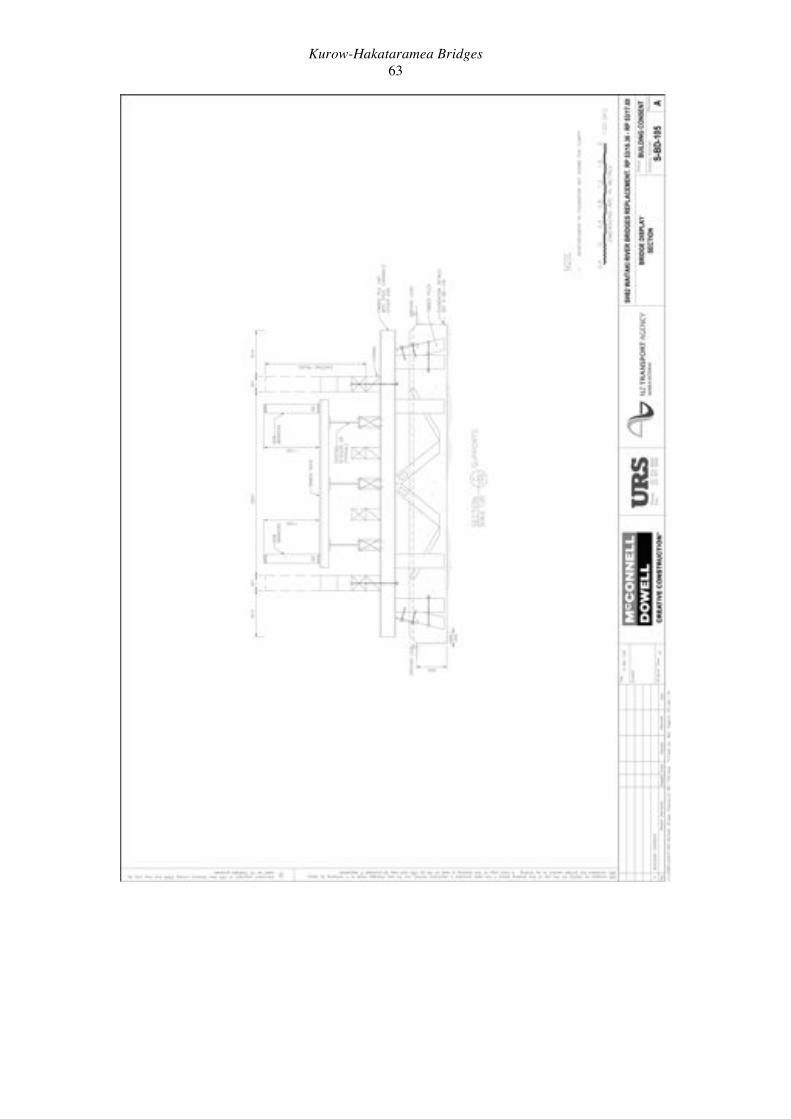
Appendix C
Measured Drawings: Display Trusses (McConnell Dowell)

Kurow-Hakataramea Bridges 62
Kurow-Hakataramea Bridges 63
Kurow-Hakataramea Bridges 64
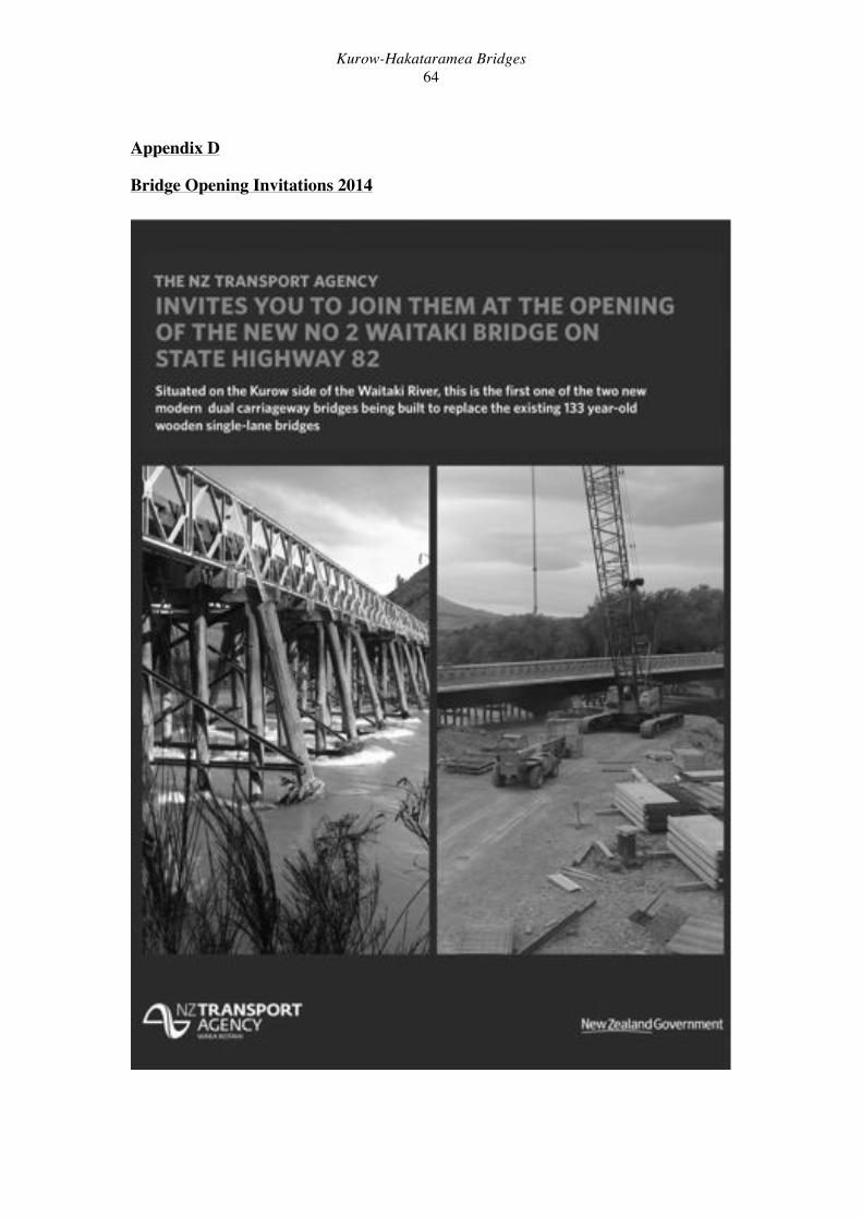
Appendix D
Bridge Opening Invitations 2014

Kurow-Hakataramea Bridges 65
Copyright © 2022 FDOKUMEN