C2 Bridge Checklists
38
139 Appendices C2.1 Steering gear test routines These routines should be carried out at any time, as required, and if there is doubt as to the performance of the steering gear. Checks of steering equipment may also be required by coastal States prior to entry into their waters. Status Date last checked Checked by Remarks Every watch/after prolonged use of autopilot Rudder response to manual steering checked and confirmed from all bridge positions using each steering gear power unit singly and together ¨ Yes Before entering coastal or congested waters Communications between bridge and steering gear compartment checked ¨ Yes Rudder response to manual steering checked and confirmed from all bridge positions using each steering gear power unit singly and together ¨ Yes Before departure (no more than 12 hours before departure) Communications between bridge and steering gear compartment checked ¨ Yes Correct operation of the following tested and confirmed: • Main steering gear* ¨ Yes • Auxiliary steering gear ¨ Yes • Remote steering gear control systems ¨ Yes • Steering positions on the bridge ¨ Yes • Emergency power supply ¨ Yes • All rudder angle indicator repeaters show the correct rudder position ¨ Yes • Remote steering gear control system power failure alarms ¨ Yes C2 Bridge Checklists The checklists in section C2 provide a guide to creating appropriate company and/or on board checklists that suit the particular needs of the ship. Signature blocks are included on some checklists where it is considered appropriate to confirm that the actions have been completed. From the International Chamber of Shipping Bridge Procedures Guide, Sixth Edition
-
Upload
khangminh22 -
Category
Documents
-
view
1 -
download
0
Transcript of C2 Bridge Checklists

139Appendices
C2.1 Steering gear test routines
These routines should be carried out at any time, as required, and if there is doubt as to the performance of the steering gear. Checks of steering equipment may also be required by coastal States prior to entry into their waters.
Status Date last checked
Checked by
Remarks
Every watch/after prolonged use of autopilot
Rudder response to manual steering checked and confirmed from all bridge positions using each steering gear power unit singly and together
¨ Yes
¨ Yes
Before entering coastal or congested waters
Communications between bridge and steering gear compartment checked ¨ Yes
Rudder response to manual steering checked and confirmed from all bridge positions using each steering gear power unit singly and together
¨ Yes
Before departure (no more than 12 hours before departure)
Communications between bridge and steering gear compartment checked ¨ Yes
Correct operation of the following tested and confirmed:
• Main steering gear* ¨ Yes
• Auxiliary steering gear ¨ Yes
• Remote steering gear control systems ¨ Yes
• Steering positions on the bridge ¨ Yes
• Emergency power supply ¨ Yes
• All rudder angle indicator repeatersshow the correct rudder position ¨ Yes
• Remote steering gear control systempower failure alarms ¨ Yes
C2 Bridge ChecklistsThe checklists in section C2 provide a guide to creating appropriate company and/or on board checklists that suit the particular needs of the ship.
Signature blocks are included on some checklists where it is considered appropriate to confirm that the actions have been completed.
From the International Chamber of Shipping Bridge Procedures Guide, Sixth Edition

140 Bridge Procedures Guide, Sixth Edition
• Steering gear power unit failure alarms ¨ Yes
• Automatic isolating arrangements andother automatic equipment ¨ Yes
Emergency steering drills
Emergency steering drills should take place at least every three months and should include direct control from within the steering gear compartment, the communications procedure with the bridge and, where applicable, the operation of alternative power supplies
* Checks and tests
• Confirm that the full rudder movement matches the required capabilities of the steering gear;
• Check the timing of rudder movement from hard-over to hard-over, using each steering gearpower unit singly and together, to make sure it is consistent with previous tests; and
• Visually inspect the steering gear and linkages for leaks or damage.
Changeover procedures
The regular testing of manual steering should be an opportunity for all bridge team members to practise procedures for changing over between different steering modes, as appropriate. Typically, these will include:
• Automatic track-keeping to automatic heading control;
• Automatic heading control to hand steering;
• Hand steering to non-follow-up; and
• Hand steering to emergency steering.
From the International Chamber of Shipping Bridge Procedures Guide, Sixth Edition

141Appendices
C2.2 Example of a bridge manning matrix
This example of a bridge manning matrix planning tool was developed for a specific ship. It is therefore not suitable for manning levels on all ships and should be adapted.
Conditions Master OOW Look- out
Helmsman Pilot Engine Helm
Entering and leaving port
All All M H
Restricted waters
All
Clear weather
Option U Option
Restricted visibility
M H
Coastal waters
All
Clear weather
U A
Restricted visibility
Option Option H
Ocean waters
Daylight
Clear weather
Option U A
Restricted visibility
Option U Option
Darkness
Clear weather
U A
Restricted visibility
Option U Option
At anchorDay All Option U
Night All U
Key: Engine Helm
Manned M
Unmanned U
Hand steering H
Auto A
From the International Chamber of Shipping Bridge Procedures Guide, Sixth Edition

142 Bridge Procedures Guide, Sixth Edition
C2.3 Familiarisation with bridge equipment
Compass and heading devices Tick
Location and operation of the standard magnetic compass and azimuth mirror
Date of last compass swing
Location of deviation card and compass error log
Location and operation of magnetic off-course alarm
Location and operation of the TMC control unit
Location and operation of gyro compass, repeaters and azimuth mirrors
Gyro compass error
Location and operation of off-course alarm
Radar and radar plotting aids Tick
Location and operation of radar(s) including operation performance monitors
Operation of ARPA (or other plotting aids)
Echo sounder Tick
Location and operation of echo sounding devices
Location of echo sounder repeaters
Location of echo sounder spares and spare recording paper (if not digital unit)
Speed and distance logs Tick
Location and operation of speed logs
Location and operation of speed log repeaters
Global Maritime Distress and Safety System (GMDSS) including maritime safety information (MSI) Tick
Location and operation of GMDSS station, isolation of aerials, location of batteries/back-up power
Location and operation of VHF/MF/HF equipment including digital selective calling (DSC)
Location and operation of ship earth station (SES)
Location and operation of NAVTEX receiver
Location and operation of weather fax receiver and any weather routeing program
Location of spare paper for weather fax receiver
From the International Chamber of Shipping Bridge Procedures Guide, Sixth Edition

143Appendices
Location of the GMDSS log
Location and operation of Emergency Position Indicating Radio Beacon (EPIRB)
Position fixing systems Tick
Location and operation of GNSS
Location and operation of terrestrial radio-navigation systems
Location of antenna(s)
General bridge equipment Tick
Location and operation of the chronometer, master clocks system and stopwatch
Location of compass error log
Location of binoculars
Location of sextant(s)
Location of log books
Location and operation of bridge windscreen wipers and clear view screens including water wash
Internal communications Tick
Location and operation of internal communications
Location and operation of emergency internal communications
Propulsion and steering Tick
Location of manoeuvring characteristics information and data
Location and operation of engine telegraph
Location and use of engine movement recorder
Location and operation of thruster controls
Operation of steering, steering changeover and emergency steering systems
Location and use of rate of turn (ROT) indicator
Orders and logs Tick
Location and content of the SMS and Master’s standing orders
Location of Master’s daily/night orders
Location and content of instructions for unmanned spaces
From the International Chamber of Shipping Bridge Procedures Guide, Sixth Edition

144 Bridge Procedures Guide, Sixth Edition
Passage planning and monitoring Tick
Location of passage plan for proposed/current passage
Location of charts for proposed/current passage
Completion of ECDIS familiarisation (see checklist C2.4)
Location of navigational publications, light lists, radio signals, digital and/or hard copies
Location and operation of chart management system
Location of navigation warnings and weather information
Location of Notices to Mariners (NMs), digital and/or hard copies
Automatic Identification System (AIS) Tick
Location and operation of AIS
Alarm systems Tick
Location and operation of BNWAS
Voyage recording Tick
Location and operation of VDR or S-VDR
Recovery/saving data procedure from VDR or S-VDR
Location and operation of bridge audio recording system
Location and operation of the course recorder
Location of spare recording paper for course recorder, and other spares (if electro mechanical)
Location of LRIT equipment
Location of bridge procedures manual, SMS and ship specific procedures
Navigation lights, shapes and signalling equipment Tick
Location and operation of navigation and signal light controls and alarm panel
Location of bridge operated deck lighting
Location of spare bulbs for navigation lights and equipment
Location and operation of daylight signalling lamp
Location of mains sockets and batteries
Understand the recharging procedure for back-up battery supplies
From the International Chamber of Shipping Bridge Procedures Guide, Sixth Edition

145Appendices
Location of flags, shapes and manual sound signalling apparatus
Location and operation of sound signalling panel
Emergency equipment and security Tick
Location of muster point information
Location of spare lifejackets
Location of man overboard lifebuoys and methods of release
Location and operation of fire detection and alarm panel
Location of fire and general alarm activation points
Location of emergency fan stop
Location of watertight door remote controls
Location of emergency fire pump(s) stop/start
Location of counter-piracy equipment
Other Tick
Bridge team member: .......................................................................................................... Date: ....................................................
Master’s signature: ................................................................................................................ Date: ....................................................
The above points are recommendations only. It is essential that the checklist is amended to reflect the bridge equipment installed on board.
From the International Chamber of Shipping Bridge Procedures Guide, Sixth Edition

146 Bridge Procedures Guide, Sixth Edition
C2.4 ECDIS familiarisation
Initial preparation Tick
Identify whether the vessel is approved to use ECDIS for navigation
Identify whether there are company procedures for the use of ECDIS and ensure that these are followed
Identify whether any passwords are needed for the management of the system and, if so, get the details
Identify how one to one familiarisation is supported, e.g. by a CBT package and/or a built-in mode
Identify the primary ECDIS equipment and the facilities for back-up (if the back-up is a second ECDIS of a different type to the primary installation, this familiarisation checklist should be completed for both systems)
Understand the procedures in event of ECDIS failure
Identify the location of user manuals for ECDIS and its back-up
Identify the location of base and update media
Understand the procedures for getting additional chart permits
Understand the position fixing systems that feed the ECDIS. Decide on the method of switching between sources, e.g. primary and secondary position fixing systems
Identify what other systems supply ECDIS, such as speed logs, GNSS, gyro compass, radar/ARPA (acquired targets, radar picture overlay), AIS and echo sounder. For each one, identify the reference framework, e.g. ground, water or ship stabilised
Identify where to find maintenance records related to the ECDIS and service reports, non-conformity reports and inspection, validation reports
Identify the power supply modes and their specifications such as uninterruptible power supply (UPS) duration
Basic operation Tick
Identify how to switch the ECDIS on and off
Identify the function(s), position and general operation of the physical controls and switches, including cursor control, and the access and selection of menu items
Understand how to access the main menu and select menu options
Identify the methods for setting day/night viewing modes, brightness, contrast and colour correction
Identify how to switch between traditional and simplified symbols
From the International Chamber of Shipping Bridge Procedures Guide, Sixth Edition

147Appendices
Identify how to put equipment in route monitoring mode and route planning mode
Identify the methods for scrolling and zooming charts, including the current scale of displayed charts and setting the display to a particular scale
Identify how to select the display base and standard display
Identify how to display other information from ENCs, including the display of All Other Information
Identify how to check that information concerning own ship, e.g. dimensions, is correct
Identify how to select the safety contour and safety depth
Identify how to select two or four colour contour mode
Identify how to select deep and shallow area display options
Identify how to set all other safety parameters
Identify how alarms and other alerts are given by the ECDIS and understand the procedure needed to acknowledge them
Electronic charts Tick
Identify how to access the chart directory and to identify whether charts are ENCs, RNCs or unofficial (private)
Identify how to select a chart for display on the screen
Identify how to load new chart licence keys
Identify how to load base data
Identify how to check the update status of loaded charts
Identify how to update charts using the normal cumulative update procedures
Identify how to apply non-cumulative or electronically transmitted updates
Find out how to apply manual updates
Navigation tools and functions Tick
Identify how to display the legend of general information
Identify how to select information about an object using a pick report/chart query
Identify how category zone of confidence (CATZOC) information can be displayed
Identify how to access the presentation library
Identify what marine information overlays (MIOs) are available and how to access them
From the International Chamber of Shipping Bridge Procedures Guide, Sixth Edition

148 Bridge Procedures Guide, Sixth Edition
Identify the single operator action needed to remove MIOs from the display
Identify the single operator action needed to set the standard display setting
Identify how to view, add, edit and delete NMs
Identify how to access all navigational elements and parameters, such as past track, vectors, position lines (LOP) and anti-grounding cone (AGC)
Identify the facilities provided for the measurement of range and bearing (e.g. EBLs and VRMs) and how they are to be used
Identify the method(s) used for inserting parallel index lines
Identify what other navigational tools are available and how to access them
Identify how to change to using the ECDIS back-up system
Identify the procedure for identifying and reacting to sensor/GNSS failure
Identify how to switch chart text (text for charted objects) on and off
Route planning Tick
Identify how to load existing routes and enable for editing
Identify how to initiate a new route plan
Identify how to initiate and plan alternate routes
Identify how to save route plan
Identify how to add, delete and graphically adjust the position of waypoints
Identify how to add, edit and delete critical points
Identify how to display time varying objects relevant for the timing of the planned voyage
Identify all the features available for planning routes, such as use of straight and curved segments, wheel over positions, turn radius, and inserting pilotage aids
Identify the ship’s procedures for displaying MSI, Temporary and Preliminary (T&P) notices and other relevant notes into the passage plan
Identify how to use the facilities for checking the planned route
Identify how to load the planned route and alternatives into the back-up system
If RCDS mode is available, identify how to use it where ENCs are not available and as appropriate
From the International Chamber of Shipping Bridge Procedures Guide, Sixth Edition

149Appendices
Route monitoring Tick
Identify how to load a pre-planned route
Identify how to select the primary or an alternative route, and how to distinguish between them on the display
Identify the single operator action that selects the charted display of own ship’s position
Identify the available display orientation modes, and how to switch between them (e.g. north up, head up or course up)
Identify the available display motion modes and how to select them and change the parameters, such as the position of own ship on the display when relative motion is selected
If radar or AIS targets can be displayed on the ECDIS, identify what target vector modes are available and how to switch between and differentiate them
Identify how to create time labels along the ship’s track
Become familiar with the route monitoring display, including the display of position, heading, course, speed and time
Identify how to set the length of own ship’s vector and intermediate time marks
Identify how to display radar and AIS MIOs, if available
Identify how to use the ECDIS as the input to a track-keeping autopilot. (This will require reference to the autopilot handbook)
Identify how to input lines of position (LOP) to form the reference for an estimated position (EP)
Identify how to configure the ECDIS to use the above reference for subsequent EP
Identify how to switch to dead reckoning (DR) mode and to identify when the ECDIS is in DR mode
Identify how to use the review facilities of the voyage recorder (if appropriate and not essential knowledge before sailing)
Bridge team member: .......................................................................................................... Date: ....................................................
Master’s signature: ................................................................................................................ Date: ....................................................
From the International Chamber of Shipping Bridge Procedures Guide, Sixth Edition

150 Bridge Procedures Guide, Sixth Edition
C2.5 ECDIS setup
Action Status Remarks
Primary position fixing system set up correctly. Prove the ECDIS is correct by entering a manual fix into the system
¨ Yes
System time configured correctly ¨ Yes
ECDIS setup is replicated on all ECDIS units ¨ Yes
Navigation tools configured correctly ¨ Yes
Safety depth and safety contour settings configured correctly ¨ Yes
System units configured correctly ¨ Yes
All relevant overlays loaded ¨ Yes
Area alerts configured correctly (if system in use allows alarm configuration) ¨ Yes
Docking mode configured correctly ¨ Yes
Navigation alarms configured correctly, including safety frame/anti-grounding cone ¨ Yes
Route alarms configured correctly ¨ Yes
Targets configured correctly ¨ Yes
Preferred radar selected ¨ Yes
Ship data set up correctly ¨ Yes
Audible alarm working correctly ¨ Yes
Chart motion, chart orientation, screen layout, colour palette and additional ENC settings configured correctly
¨ Yes
Correct display setting available for execution of navigation in line with ECDIS check off cards for pilotage and confined waters, and coastal navigation and open ocean
¨ Yes
Correct route loaded for route monitoring ¨ Yes
Correct waypoint and route monitoring information displayed ¨ Yes
Time and date: ............................................................................................................................................................................................
OOW signature: ..........................................................................................................................................................................................
The above points are recommendations only. It is essential that the checklist is amended to reflect the appropriate manufacturer’s operating manuals and company procedures.
From the International Chamber of Shipping Bridge Procedures Guide, Sixth Edition

151Appendices
C2.6 Preparations for departure
Passage plan Status Remarks
Berth to berth passage plan for the intended passage prepared and available on the bridge with the route plotted on up-to-date and appropriate scale charts (official paper or electronic)
¨ Yes
Passage plan checked and approved by the Master ¨ Yes
Passage plan briefed to the bridge team ¨ Yes
Route displayed on ECDIS and/or other electronic navigation aids, as appropriate ¨ Yes
Up-to-date charts and nautical publications available ¨ Yes
Latest NMs (week number) ¨ Yes
Equipment checks (tested and ready for use) Status Remarks
AIS (voyage data updated and correct) ¨ Yes
Anchors, cables and winches ¨ Yes
Ancillary bridge equipment (e.g. binoculars) ¨ Yes
BNWAS ¨ Yes
Clocks synchronised with engine room ¨ Yes
Controllable pitch propeller controls and indicators ¨ Yes
Course and engine movement recorder/bridge movement book ¨ Yes
Deck power ¨ Yes
ECDIS and/or other electronic navigation aids ¨ Yes
Echo sounder ¨ Yes
Electronic position fixing systems ¨ Yes
Emergency engine stops ¨ Yes
Engine(s)/propulsion (ahead and astern) ¨ Yes
GMDSS communications and GMDSS log ¨ Yes
Gyro/magnetic compass and repeaters, including repeater in steering gear area ¨ Yes
Internal communications (particularly bridge to engine room/bridge to mooring stations) ¨ Yes
LRIT ¨ Yes
Navigation lights, shapes and sound signals ¨ Yes
From the International Chamber of Shipping Bridge Procedures Guide, Sixth Edition

152 Bridge Procedures Guide, Sixth Edition
Radar(s) and ARPA ¨ Yes
RPM and ROT indicators ¨ Yes
Signalling equipment including flags, search lights and signal lamps ¨ Yes
Speed and distance log ¨ Yes
Stabilisers ¨ Yes
Steering gear (checklist C2.1) ¨ Yes
Thrusters ¨ Yes
VDR/S-VDR ¨ Yes
Port and pilotage Status Remarks
Master/pilot information exchange checklist completed (checklist C1.1) ¨ Yes
Pilot card prepared (checklist C1.2) ¨ Yes
Pilot boarding time confirmed ¨ Yes
Pilot boarding arrangements ready for disembarkation of the pilot (checklist C1.4) ¨ Yes
Port and VTS channels monitored ¨ Yes
Port, VTS and pilot informed of any special requirements ¨ Yes
Preparations for pilotage complete (checklist C2.8) ¨ Yes
Securing for sea Status Remarks
Cargo and cargo handling equipment secure ¨ Yes
Cargo/passenger details available ¨ Yes
Hull openings secure and watertight ¨ Yes
Stability and draught information available ¨ Yes
Watertight doors closed ¨ Yes
Before sailing Status Remarks
All crew on board ¨ Yes
Anchors cleared away ¨ Yes
Bridge team fit for duty ¨ Yes
Engine room ready ¨ Yes
Mooring stations manned and ready ¨ Yes
MSI checked and communicated to bridge team ¨ Yes
From the International Chamber of Shipping Bridge Procedures Guide, Sixth Edition

153Appendices
Pressure on fire main ¨ Yes
Stowaway/security search completed ¨ Yes
Other Status Remarks
¨ Yes
¨ Yes
¨ Yes
¨ Yes
Time and date: ............................................................................................................................................................................................
OOW signature: ..........................................................................................................................................................................................
The above points are recommendations only. It is essential that the checklist is amended to reflect the appropriate operating manuals and company procedures.
From the International Chamber of Shipping Bridge Procedures Guide, Sixth Edition
154 Bridge Procedures Guide, Sixth Edition
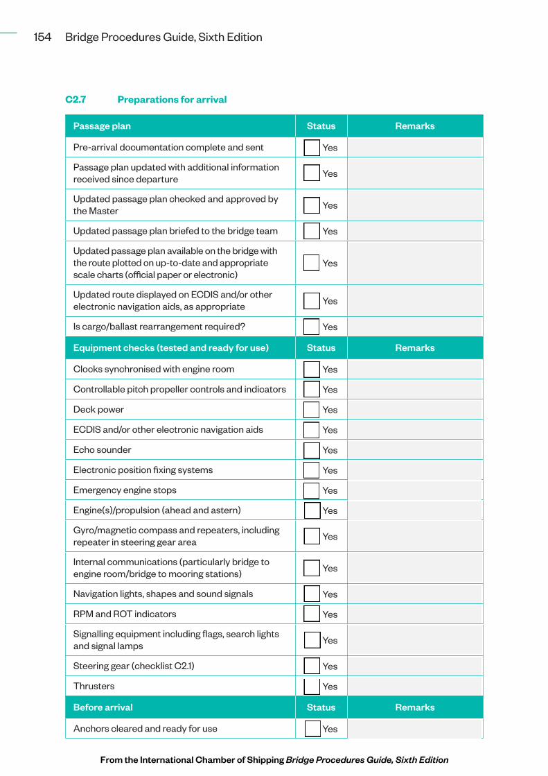
C2.7 Preparations for arrival
Passage plan Status Remarks
Pre-arrival documentation complete and sent ¨ Yes
Passage plan updated with additional information received since departure ¨ Yes
Updated passage plan checked and approved by the Master ¨ Yes
Updated passage plan briefed to the bridge team ¨ Yes
Updated passage plan available on the bridge with the route plotted on up-to-date and appropriate scale charts (official paper or electronic)
¨ Yes
Updated route displayed on ECDIS and/or other electronic navigation aids, as appropriate ¨ Yes
Is cargo/ballast rearrangement required? ¨ Yes
Equipment checks (tested and ready for use) Status Remarks
Clocks synchronised with engine room ¨ Yes
Controllable pitch propeller controls and indicators ¨ Yes
Deck power ¨ Yes
ECDIS and/or other electronic navigation aids ¨ Yes
Echo sounder ¨ Yes
Electronic position fixing systems ¨ Yes
Emergency engine stops ¨ Yes
Engine(s)/propulsion (ahead and astern) ¨ Yes
Gyro/magnetic compass and repeaters, including repeater in steering gear area ¨ Yes
Internal communications (particularly bridge to engine room/bridge to mooring stations) ¨ Yes
Navigation lights, shapes and sound signals ¨ Yes
RPM and ROT indicators ¨ Yes
Signalling equipment including flags, search lights and signal lamps ¨ Yes
Steering gear (checklist C2.1) ¨ Yes
Thrusters ¨ Yes
Before arrival Status Remarks
Anchors cleared and ready for use ¨ Yes
From the International Chamber of Shipping Bridge Procedures Guide, Sixth Edition

155Appendices
Any stabilisers housed ¨ Yes
Bridge team ready ¨ Yes
Cargo/passenger details available ¨ Yes
Engine room ready ¨ Yes
Ship ready for manoeuvring ¨ Yes
If available, use more than one steering gear power unit ¨ Yes
Manual steering engaged ¨ Yes
Mooring stations manned and ready ¨ Yes
Pressure on fire main ¨ Yes
Stability and draught information verified and available ¨ Yes
Watertight doors closed ¨ Yes
Port and pilotage requirements Status Remarks
Master/pilot information exchange (MPX) checklist completed (checklist C1.1) ¨ Yes
Pilot card prepared (checklist C1.2) ¨ Yes
Pilot boarding time confirmed ¨ Yes
Pilot boarding arrangements ready for disembarkation of the pilot (checklist C1.4) ¨ Yes
Port and VTS channels monitored ¨ Yes
Port, VTS and pilot informed of any special requirements ¨ Yes
Preparations for pilotage complete (checklist C2.8) ¨ Yes
Other Status Remarks
¨ Yes
¨ Yes
¨ Yes
¨ Yes
Time and date: ............................................................................................................................................................................................
OOW signature: ..........................................................................................................................................................................................
The above points are recommendations only. It is essential that the checklist is amended to reflect the appropriate operating manuals and company procedures.
From the International Chamber of Shipping Bridge Procedures Guide, Sixth Edition

156 Bridge Procedures Guide, Sixth Edition
C2.8 Pilotage
Action Status Remarks
Appropriate scale charts available with route plotted ¨ Yes
Appropriate flags and navigation lights or shapes displayed ¨ Yes
Bridge appropriately manned to:
• Maintain a proper look-out ¨ Yes
• Monitor the progress of the ship and navigationalsafety ¨ Yes
• Monitor communications between pilot, shore,tugs and mooring craft ¨ Yes
• Carry out orders and instructions given by theMaster and pilot ¨ Yes
Bridge watch and crew standby arrangements ¨ Yes
ECDIS terminals are set up correctly for navigation in pilotage waters with route displayed (checklist C2.5)
¨ Yes
Engine room and mooring stations regularly updated on pilotage progress ¨ Yes
MPX completed and passage plan agreed by the Master (checklist C1.1) ¨ Yes
Pilot briefed on the pilot card (checklist C1.2) and wheelhouse poster (checklist C1.3) concerning manoeuvring characteristics
¨ Yes
Mooring stations informed of berthing arrangements ¨ Yes
Pilot informed of any propulsion or steering gear defects or limitations ¨ Yes
Pilot informed of ship’s heading, speed, engine setting and draught on arrival on the bridge ¨ Yes
Pilot informed of the location of life-saving appliances provided for their use ¨ Yes
Preparation for departure (checklist C2.6) or arrival (checklist C2.7) checks complete ¨ Yes
Working language agreed ¨ Yes
From the International Chamber of Shipping Bridge Procedures Guide, Sixth Edition

157Appendices
Other Status Remarks
¨ Yes
¨ Yes
¨ Yes
¨ Yes
From the International Chamber of Shipping Bridge Procedures Guide, Sixth Edition

158 Bridge Procedures Guide, Sixth Edition
C2.9 Passage planning
Factors to consider when developing a passage plan and associated route
Appraisal Tick
Adequacy and reliability of aids to navigation
Adequacy and reliability of charts and hydrographic data
Appropriate scale charts for ocean, coastal, harbour and berthing phases
Guides to port entry
List of lights
Local area warnings
NAVAREA navigational warnings
New charts and licences ordered as appropriate
Notices to Mariners
Planning charts
List of radio signals
Routeing and load line charts
Sailing directions and pilot books
Tide tables and tidal stream atlases
Passage requirements Tick
Anchoring locations
Any special ship operational requirements for the passage
Bunker calculations
Cargo and any special stowage/carriage restrictions
Communications/GMDSS watchkeeping considerations
Draught restrictions including air draught and under keel clearance (UKC) requirements
Helicopter operations
Load line requirements
Log book requirements
Passage reporting requirements
Passage speed and ETA calculations
Position fixing intervals
From the International Chamber of Shipping Bridge Procedures Guide, Sixth Edition

159Appendices
Reliability of propulsion and steering systems or any known defects affecting navigation or control of vessel
Routeing and reporting measures
Safety contours
Safety depths
Security concerns
Ship-to-ship transfers
Squat
Strength and stability
Watch schedules
Environmental considerations Tick
Ballast water
Emission Control Area (ECA) limits and fuel changeover procedures
MARPOL Special Areas, PSSAs, or national and regional requirements
Notifications/advice to crew on board
Weather/conditions Tick
Abnormal waves
Currents and tides
Heavy weather
Ice
Swell
Tropical storms
Visibility
Weather routeing
Winds
Contingencies Tick
Emergency anchorages
Commit points
Emergency response plans
Notifications and reporting
Plan amendments
From the International Chamber of Shipping Bridge Procedures Guide, Sixth Edition

160 Bridge Procedures Guide, Sixth Edition
Other Tick
Officer responsible – passage plan completed and checked.
Signature: .................................................................................................................................... Date: ....................................................
Master – passage plan checked and approved.
Signature: .................................................................................................................................... Date: ....................................................
Officer responsible – approved passage plan briefed to the bridge team.
Signature: .................................................................................................................................... Date: ....................................................
From the International Chamber of Shipping Bridge Procedures Guide, Sixth Edition
161Appendices
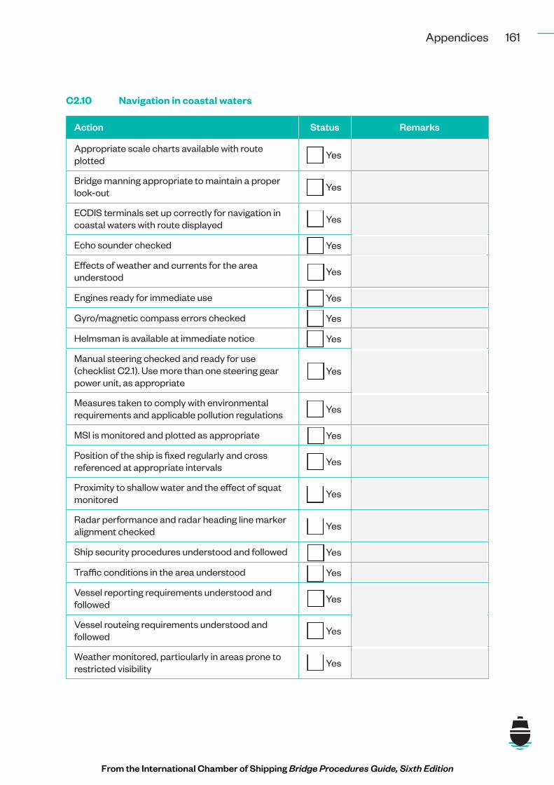
C2.10 Navigation in coastal waters
Action Status Remarks
Appropriate scale charts available with route plotted ¨ Yes
Bridge manning appropriate to maintain a proper look-out ¨ Yes
ECDIS terminals set up correctly for navigation in coastal waters with route displayed ¨ Yes
Echo sounder checked ¨ Yes
Effects of weather and currents for the area understood ¨ Yes
Engines ready for immediate use ¨ Yes
Gyro/magnetic compass errors checked ¨ Yes
Helmsman is available at immediate notice ¨ Yes
Manual steering checked and ready for use (checklist C2.1). Use more than one steering gear power unit, as appropriate
¨ Yes
Measures taken to comply with environmental requirements and applicable pollution regulations ¨ Yes
MSI is monitored and plotted as appropriate ¨ Yes
Position of the ship is fixed regularly and cross referenced at appropriate intervals ¨ Yes
Proximity to shallow water and the effect of squat monitored ¨ Yes
Radar performance and radar heading line marker alignment checked ¨ Yes
Ship security procedures understood and followed ¨ Yes
Traffic conditions in the area understood ¨ Yes
Vessel reporting requirements understood and followed ¨ Yes
Vessel routeing requirements understood and followed ¨ Yes
Weather monitored, particularly in areas prone to restricted visibility ¨ Yes
From the International Chamber of Shipping Bridge Procedures Guide, Sixth Edition

162 Bridge Procedures Guide, Sixth Edition
Other Status Remarks
¨ Yes
¨ Yes
¨ Yes
¨ Yes
From the International Chamber of Shipping Bridge Procedures Guide, Sixth Edition

163Appendices
C2.11 Navigation in ocean waters
Action Status Remarks
Appropriate scale charts available with route plotted ¨ Yes
All measures taken to comply with environmental requirements and applicable pollution prevention regulations
¨ Yes
ECDIS terminals correctly set up for navigation in ocean waters with route displayed (checklist C2.5) ¨ Yes
Bridge manning appropriate for maintaining a proper look-out ¨ Yes
Ship’s position confirmed at appropriate intervals ¨ Yes
Changes in weather monitored and regular barometer observations made ¨ Yes
NAVAREA navigational warning broadcasts and other long range weather reports monitored ¨ Yes
Participation in area reporting systems (e.g. Automated Mutual-Assistance Vessel Rescue System (AMVER)) as appropriate
¨ Yes
Other Status Remarks
¨ Yes
¨ Yes
¨ Yes
¨ Yes
From the International Chamber of Shipping Bridge Procedures Guide, Sixth Edition

164 Bridge Procedures Guide, Sixth Edition
C2.12 Anchoring and anchor watch
Anchoring appraisal and planning Status Remarks
Anchoring plan checked and approved by the Master ¨ Yes
Anchoring position identified that addresses the:
• Availability of appropriate space at theanchorage ¨ Yes
• Proximity of navigational hazards including traffic ¨ Yes
• Scope of anchor cable required/available ¨ Yes
• Suitable seabed type and holding conditions ¨ Yes
• Tidal height checked to confirm that sufficientwater is available for the duration of theanchorage
¨ Yes
• Tidal stream checked with particular referenceto effect on slow speed manoeuvring ¨ Yes
• Weather conditions and available shelter ¨ Yes
Anchors, cables and winches checked and ready for use ¨ Yes
Engine room and anchor party informed of the time of anchoring ¨ Yes
Intended anchor position of the ship reported to the port authority ¨ Yes
Lights, shapes and sound signalling apparatus checked and ready for use
¨ Yes
Ship ready for manoeuvring ¨ Yes
Security measures required by the Ship Security Plan (SSP) ¨ Yes
While at anchor the OOW should: Status Remarks
Check at sufficiently frequent intervals whether the ship is remaining securely at anchor by taking bearings of fixed navigational marks or readily identifiable shore objects
¨ Yes
Identify and plot the ship’s position on the appropriate chart as soon as practicable ¨ Yes
Monitor swinging pattern ¨ Yes
Ensure that inspection rounds of the ship are made periodically ¨ Yes
From the International Chamber of Shipping Bridge Procedures Guide, Sixth Edition

165Appendices
Ensure that a proper look-out is kept ¨ Yes
Ensure that the ship exhibits the appropriate lights and shapes and that appropriate sound signals are made in accordance with all applicable regulations
¨ Yes
Ensure that the state of readiness of the main engines and other machinery is in accordance with the Master’s instructions
¨ Yes
Ensure that vessel access control precautions are maintained ¨ Yes
If visibility deteriorates, call the Master ¨ Yes
Modify AIS status ¨ Yes
Call the Master and undertake all necessary measures if the ship drags anchor ¨ Yes
Observe meteorological and tidal conditions and the sea state ¨ Yes
Take measures to protect the environment from pollution by the ship and comply with applicable pollution prevention regulations
¨ Yes
Other Status Remarks
¨ Yes
¨ Yes
¨ Yes
¨ Yes
From the International Chamber of Shipping Bridge Procedures Guide, Sixth Edition

166 Bridge Procedures Guide, Sixth Edition
C2.13 Restricted visibility
Action Status Remarks
Master informed of reduced visibility as required in Master’s standing orders and the SMS ¨ Yes
Engine room informed ¨ Yes
Bridge manning levels increased, as necessary (checklist C2.2) ¨ Yes
Look-outs posted ¨ Yes
Hand steering selected ¨ Yes
Engines ready for immediate manoeuvre ¨ Yes
All watertight doors and openings closed ¨ Yes
Equipment preparations Status Remarks
AIS ¨ Yes
Echo sounder ¨ Yes
Fog signalling apparatus ¨ Yes
Navigation lights ¨ Yes
Radar, ARPA or other plotting aids ¨ Yes
VHF ¨ Yes
Compliance with COLREGS regulations Status Remarks
Rule 19 – Conduct of vessels in restricted visibility ¨ Yes
Rule 35 – Sound signals in restricted visibility ¨ Yes
Rule 5 – Look-out ¨ Yes
Rule 6 – Safe speed ¨ Yes
Contingency planning Status Remarks
Consider the possibility of anchoring the ship if in doubt and ship in a suitable depth of water ¨ Yes
Other Status Remarks
¨ Yes
¨ Yes
¨ Yes
¨ Yes
From the International Chamber of Shipping Bridge Procedures Guide, Sixth Edition

167Appendices
C2.14 Heavy weather/tropical storm areas
Action Status Remarks
Master informed of the weather conditions ¨ Yes
Engine room informed of the weather conditions ¨ Yes
Crew informed of the need to avoid upper deck areas made dangerous by weather ¨ Yes
Safety lines/hand ropes rigged where necessary ¨ Yes
Ship course and speed adjusted as necessary to ease ship/avoid worst of motion ¨ Yes
Ship manoeuvred to minimise risk of broaching, pooping and/or synchronous rolling ¨ Yes
Weather reports monitored ¨ Yes
Weather reports made to appropriate authorities. In the case of tropical storms, danger messages in accordance with SOLAS
¨ Yes
Secure and/or check securing:
• All weather deck openings (doors/hatches) ¨ Yes
• Anchors and winches ¨ Yes
• Hatch covers, vents and any other openings tocargo holds ¨ Yes
• Cargo (as appropriate) ¨ Yes
• Loose or movable objects in cabins andaccommodation ¨ Yes
• Loose or movable objects on deck ¨ Yes
• Loose or movable objects in the engine room ¨ Yes
• Loose or movable objects in the galley ¨ Yes
• Loose or movable objects in the storerooms ¨ Yes
• All ports and deadlights closed ¨ Yes
Other Status Remarks
¨ Yes
¨ Yes
¨ Yes
¨ Yes
From the International Chamber of Shipping Bridge Procedures Guide, Sixth Edition

168 Bridge Procedures Guide, Sixth Edition
C2.15 Navigation in ice*
Action Status Remarks
Master informed of the proximity to ice ¨ Yes
Additional look-outs posted if appropriate ¨ Yes
Engine room informed of the proximity to ice ¨ Yes
Crew informed of the proximity to ice ¨ Yes
All watertight doors closed ¨ Yes
Speed reduced as appropriate in the conditions ¨ Yes
Hand steering engaged if appropriate ¨ Yes
Frequency of sounding tanks and bilges increased ¨ Yes
Ice advisory service broadcasts monitored ¨ Yes
Danger messages transmitted in accordance with SOLAS ¨ Yes
Other Status Remarks
¨ Yes
¨ Yes
¨ Yes
¨ Yes
* Preparations for navigation in ice for ships operating in polar waters should be in line with the ship’sPolar Water Operational Manual (PWOM).
From the International Chamber of Shipping Bridge Procedures Guide, Sixth Edition
169Appendices
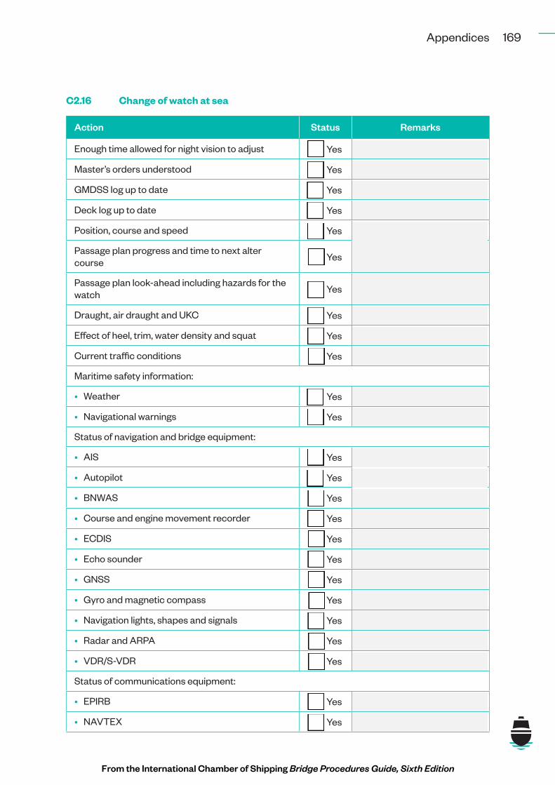
C2.16 Change of watch at sea
Action Status Remarks
Enough time allowed for night vision to adjust ¨ Yes
Master’s orders understood ¨ Yes
GMDSS log up to date ¨ Yes
Deck log up to date ¨ Yes
Position, course and speed ¨ Yes
Passage plan progress and time to next alter course ¨ Yes
Passage plan look-ahead including hazards for the watch ¨ Yes
Draught, air draught and UKC ¨ Yes
Effect of heel, trim, water density and squat ¨ Yes
Current traffic conditions ¨ Yes
Maritime safety information:
• Weather ¨ Yes
• Navigational warnings ¨ Yes
Status of navigation and bridge equipment:
• AIS ¨ Yes
• Autopilot ¨ Yes
• BNWAS ¨ Yes
• Course and engine movement recorder ¨ Yes
• ECDIS ¨ Yes
• Echo sounder ¨ Yes
• GNSS ¨ Yes
• Gyro and magnetic compass ¨ Yes
• Navigation lights, shapes and signals ¨ Yes
• Radar and ARPA ¨ Yes
• VDR/S-VDR ¨ Yes
Status of communications equipment:
• EPIRB ¨ Yes
• NAVTEX ¨ Yes
From the International Chamber of Shipping Bridge Procedures Guide, Sixth Edition

170 Bridge Procedures Guide, Sixth Edition
• SES ¨ Yes
• VHF/MF/HF ¨ Yes
Status of propulsion and steering equipment:
• Engine room watch ¨ Yes
• Hand steering tested ¨ Yes
• Main engines and generators ¨ Yes
• Steering system ¨ Yes
Status of watertight doors ¨ Yes
Status of fire zones ¨ Yes
Any special work in progress ¨ Yes
From the International Chamber of Shipping Bridge Procedures Guide, Sixth Edition

171Appendices
C2.17 Calling the Master
If the Master needs to be called, particularly where there is concern about the safety of the ship, this should be done early enough to allow the Master enough time to understand and respond effectively to the situation.
Failing to call the Master promptly can lead to an increased level of risk of:
• Collision;
• Grounding;
• Safety of life;
• Damage to the environment;
• Ship delays;
• Cargo leaks or spills;
• Property damage;
• Commercial losses; or
• Reputation losses due to delays or damage.
Occasions to call the Master Status Remarks
As required by the SMS, Master’s standing orders and daily orders, including:
• When restricted visibility is encountered orexpected ¨ Yes
• When traffic conditions, density or themovements of other vessels are causing concern ¨ Yes
• When a distress alert has been received or adistress signal has been sighted ¨ Yes
• When difficulties in maintaining course areexperienced ¨ Yes
• When there is significant difference betweenthe latest observed position and the expectedposition of the ship
¨ Yes
• In case of failure to sight land, identify anavigation mark or get soundings by theexpected time
¨ Yes
• When there is unexpected sighting of land ora navigation mark or unexpected change insoundings
¨ Yes
• When amendments to the passage plan requireimmediate approval ¨ Yes
• When there is a breakdown of the engines,propulsion machinery remote control, steeringgear or any essential navigational equipment,alarm or indicator
¨ Yes
From the International Chamber of Shipping Bridge Procedures Guide, Sixth Edition

172 Bridge Procedures Guide, Sixth Edition
• When communications or GMDSS radioequipment malfunctions ¨ Yes
• In heavy weather, if any doubt about thepossibility of weather damage ¨ Yes
• When the ship meets hazards to navigation, e.g.ice or a derelict vessel ¨ Yes
• When there are concerns about the ship’ssecurity ¨ Yes
• In any emergency situation ¨ Yes
• In any cases when the situation is beyond theexperience of the OOW or if there is any doubtabout the safety of the ship, or ability to complywith regulatory requirements
¨ Yes
Other Status Remarks
¨ Yes
¨ Yes
¨ Yes
¨ Yes
From the International Chamber of Shipping Bridge Procedures Guide, Sixth Edition
173Appendices
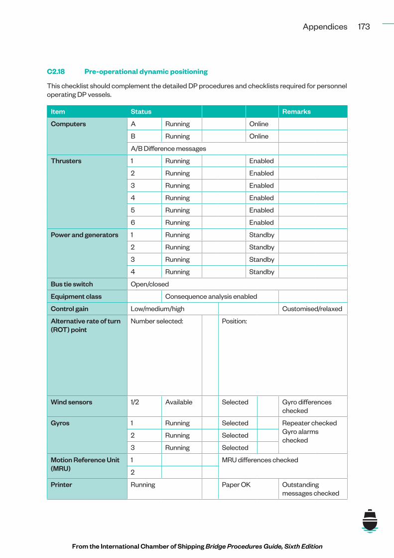
C2.18 Pre-operational dynamic positioning
This checklist should complement the detailed DP procedures and checklists required for personnel operating DP vessels.
Item Status Remarks
Computers A Running Online
B Running Online
A/B Difference messages
Thrusters 1 Running Enabled
2 Running Enabled
3 Running Enabled
4 Running Enabled
5 Running Enabled
6 Running Enabled
Power and generators 1 Running Standby
2 Running Standby
3 Running Standby
4 Running Standby
Bus tie switch Open/closed
Equipment class Consequence analysis enabled
Control gain Low/medium/high Customised/relaxed
Alternative rate of turn (ROT) point
Number selected: Position:
Wind sensors 1/2 Available Selected Gyro differences checked
Gyros 1 Running Selected Repeater checked Gyro alarms checked
2 Running Selected
3 Running Selected
Motion Reference Unit (MRU)
1 MRU differences checked
2
Printer Running Paper OK Outstanding messages checked
From the International Chamber of Shipping Bridge Procedures Guide, Sixth Edition

174 Bridge Procedures Guide, Sixth Edition
Position reference system (PRS)
Differential Global Positioning System (DGPS)
DGPS
1 Running Diff available
IMCA differential quality indicator (DQI) factor
Horizonal dilution of position (HDOP)
AOD (Sec)
DGPS 2 Running Diff available
IMCA DQI Factor
HDOP AOD (sec)
Taut wires Port Deployed Water depth: m
Stbd Deployed Water depth: m
Fan beam Deployed Range/bearing (Rng/Brg):
Reflector location
HPR 1 Running Pole up/down
Transponder deployed
2 Running Pole up/down
Transponder deployed
Communications VHF: Working channels: Tested
UHF: Channels: Tested
Internal Tested
Talkback Tested
Weather forecast
Time received:
Signals displayed
30 minute setting time complete
Maximum continuous rating (MCR) checklist complete
Tasks agreed
Permit to work Reference number: Expiry time:
OOW/DPO Signature: ………………………......................................................................................................… Date:……………..........…..
From the International Chamber of Shipping Bridge Procedures Guide, Sixth Edition

175Appendices
C2.19 False distress alerts
False alert sent on VHF digital selective calling (DSC)
Status Remarks
VHF DSC reset immediately ¨ Yes
Alert on VHF DSC Channel 70 cancelled ¨ Yes
Broadcast message transmitted to ALL STATIONS on VHF Channel 16 giving the ship’s name, call sign and maritime mobile service identity (MMSI) and cancelling the false distress alert
¨ Yes
Details of the false alert and actions to cancel the alert recorded ¨ Yes
False alert sent on MF DSC Status Remarks
MF DSC reset immediately ¨ Yes
Alert cancelled on MF DSC 2187.5 kHz ¨ Yes
Broadcast message transmitted to ALL STATIONS on 2182 kHz giving the ship’s name, call sign and MMSI and cancelling the false distress alert
¨ Yes
Record details of the false alert and actions to cancel the alert ¨ Yes
False alert sent on HF DSC Status Remarks
HF DSC reset immediately ¨ Yes
Alert cancelled on the HF DSC distress frequencies on which it was sent:
• 4207.5 kHz ¨ Yes
• 6312 kHz ¨ Yes
• 8414.5 kHz ¨ Yes
• 12577 kHz ¨ Yes
• 16804.5 kHz ¨ Yes
Broadcast message transmitted to ALL STATIONS giving the ship’s name, call sign and MMSI, and cancelling the false alert on each of the radio-telephony distress frequencies in the bands on which the HF DSC was sent:
• 4125 kHz ¨ Yes
• 6215 kHz ¨ Yes
• 8291 kHz ¨ Yes
• 12290 kHz ¨ Yes
• 16420 kHz ¨ Yes
From the International Chamber of Shipping Bridge Procedures Guide, Sixth Edition
176 Bridge Procedures Guide, Sixth Edition
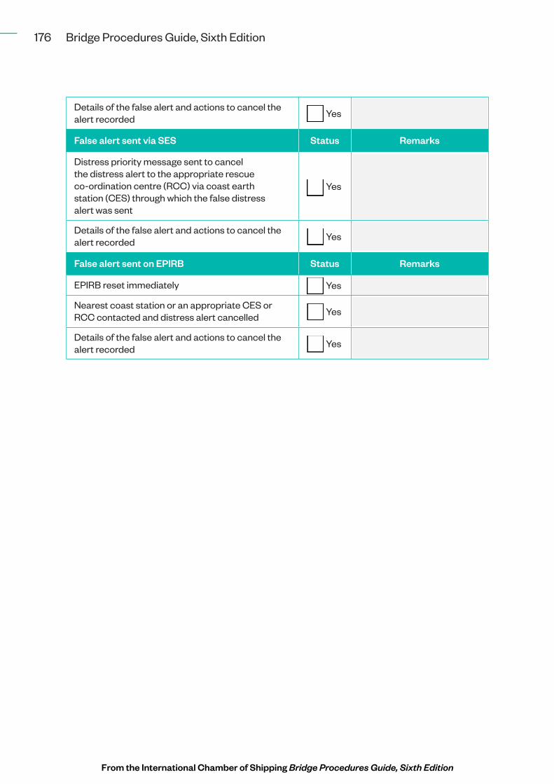
Details of the false alert and actions to cancel the alert recorded ¨ Yes
False alert sent via SES Status Remarks
Distress priority message sent to cancel the distress alert to the appropriate rescue co-ordination centre (RCC) via coast earth station (CES) through which the false distress alert was sent
¨ Yes
Details of the false alert and actions to cancel the alert recorded ¨ Yes
False alert sent on EPIRB Status Remarks
EPIRB reset immediately ¨ Yes
Nearest coast station or an appropriate CES or RCC contacted and distress alert cancelled ¨ Yes
Details of the false alert and actions to cancel the alert recorded ¨ Yes
From the International Chamber of Shipping Bridge Procedures Guide, Sixth Edition