Trabajo Final de Grado - RiuNet
101
Trabajo Final de Grado
-
Upload
khangminh22 -
Category
Documents
-
view
0 -
download
0
Transcript of Trabajo Final de Grado - RiuNet
Trabajo Final de Grado

Latorre López, Miriam
1
Junio de 2017

Latorre López, Miriam
2
Junio de 2017

Latorre López, Miriam
3
Junio de 2017
Grado en Ingeniería electrónica
Industrial y Automática
2012 / 2016

Latorre López, Miriam
4
Junio de 2017
AGRADECIMIENTOS
Para mi equipo en la
universidad, con los que he
compartido horas de
estudios y trabajos en
grupo, sin los que no habría
podido llegar a esta larga y
constante meta. Esta etapa
única termina y aunque el
tiempo y la distancia hagan
de las suyas en esos pasillos,
clases y bares se quedan
guardados todos los
recuerdos que han llenado
de amistad mi corazón.
También a ti, Mi flor,
gracias a tu constancia y
amor incondicional.
Y por último y más
importante, gracias a
vosotras, por la
comprensión, paciencia y
apoyo en los momento
duros, os tenéis ganado el
cielo.
Para la mujer de mi vida, mi madre.
Para mi ejemplo a seguir, mi padre.
Para mí más eterno competidor y referente, mi hermano

Latorre López, Miriam
5
Junio de 2017

Latorre López, Miriam
6
Junio de 2017
ÍNDICE
1. RESUMEN ............................................................................................................... 12
2. INTRODUCCIÓN ..................................................................................................... 14
3. MEMORIA ................................................................................................................ 16
3.1 ANTECEDENTES .............................................................................................. 20
3.2 OBJETO ............................................................................................................ 20
3.3 JUSTIFICACIÓN DEL PROYECTO ................................................................... 21
3.4 BASES DEL PROYECTO................................................................................... 22
3.4.1 LEGISLACIÓN ............................................................................................... 22
3.4.2 ELECCIÓN DEL PLC (programer logic controller) ......................................... 23
3.4.3 SOFTWARE UTILIZADO .............................................................................. 26
3.5 COMUNICACIONES AUTOMATA ................................................................. 28
3.5.1. CONEXIÓN MAQUETA-AUTOMATA ......................................................... 28
3.5.2 CONEXIÓN AUTÓMATA-PC........................................................................ 29
3.5.3 CONEXIÓN AUTÓMATA-PC-MAQUETAS.................................................. 30
3.6 INGENIERIA DEL PROYECTO ...................................................................... 31
3.7 DESCRIPCCIÓN DEL PROCESO .................................................................. 34
3.8 DESCRIPCIÓN DE SCADA ............................................................................ 35
3.9 DIAGRAMA DE PROGRAMACIÓN ............................................................... 41
3.9.1 DIAGRAMA DE FLUJOS SCADA ................................................................ 41
3.9.2 DIAGRAMA DE FLUJOS PROCESO “CINTA”.......................................... 41
3.9.3 DIAGRAMA DE FLUJOS PROCESO “BRAZO” ......................................... 43
3.9.4 DIAGRAMA DE FLUJOS PROCESO “MESA GIRATORIA” ..................... 46
3.9.5 DIAGRAMA DE FLUJOS. INTERCONEXIÓN SCADA - MAQUETAS..... 48
3.10 CONCLUSIONES .............................................................................................. 49
4. PLIEGO DE CONDICIONES ........................................................................................ 50
4.1 DEFINICIÓN Y ALCANCE DEL PLIEGO DE CONDICIONES ........................ 54
4.1.1 OBJETO DEL PLIEGO ................................................................................. 54

Latorre López, Miriam
7
Junio de 2017
4.1.2. DESCRIPCIÓN GENERAL DEL MONTAJE ............................................... 54
4.2 CONDICIONES Y NORMAS DE CARÁCTER GENERAL .................................. 55
4.3 CONDICIONES DE LOS MATERIALES ............................................................. 56
4.4 ORDENADOR PERSONAL .................................................................................. 56
4.5 ESTUDIOS DE LEGISLACIÓN ........................................................................... 58
5. REFERENCIAS BIBLIOGRÁFCAS ........................................................................... 60
6. PRESUPUESTO ......................................................................................................... 64
6.1 HARDWARE ......................................................................................................... 66
6.2 SOFTWARE .......................................................................................................... 67
6.3 RECURO HUMANO ............................................................................................. 67
6.4 COSTE TOTAL DEL PROYECTO ....................................................................... 68
7. ANEXO ....................................................................................................................... 70
ANEXO I: TABLAS ENTRADAS/SALIDAS .............................................................. 724
ANEXO II: CONFIGURACIÓN CX-PROGRAMMER ............................................... 76
ANEXO III: CONFIGURACIÓN CX-SUPERVISOR DEVELOPER .......................... 80
ANEXO IIII: DATASHEE PLC ................................................................................... 84

Latorre López, Miriam
8
Junio de 2017
ÍNDICE DE FIGURAS
Ilustración 1: PLC - E/S .............................................................................................................. 23
Ilustración 2: PLC - CPU ........................................................................................................... 24
Ilustración 3: ENTORNO SCADA .............................................................................................. 25
Ilustración 4: CX-ONE ............................................................................................................... 25
Ilustración 5: CX-PROGRAMMER ............................................................................................ 27
Ilustración 6: CX-SUPERVISOR ................................................................................................ 27
Ilustración 7: CONEXIÓN MAQUETA-PLC .............................................................................. 28
Ilustración 8: MANGUERA 20 X 0.22mm .................................................................................. 29
Ilustración 9: AUTÓMATA - PC ................................................................................................. 30
Ilustración 10: AUTÓMATA - PC - MAQUETA ......................................................................... 31
Ilustración 11: LÍNEA INDEXADA CON DOS UNIDADES DE MECANIZADO ..................... 32
Ilustración 12: 3D - ROBOT TX ................................................................................................. 33
Ilustración 13: CENTRO NEUMÁTICO DE MECANIZADO .................................................... 33
Ilustración 14: PROCESO COMPLETO .................................................................................... 34
Ilustración 15: SCADA - GENERAL ........................................................................................... 36
Ilustración 16: SCADA - GENERAL ........................................................................................... 37
Ilustración 17: SCADA - PROCESO CINTA .............................................................................. 38
Ilustración 18: SCADA - PROCESO BRAZO ............................................................................. 39
Ilustración 19: SCADA - PROCESO MESA ............................................................................... 40
Ilustración 20: DIAGRAMA SCADA ......................................................................................... 41
Ilustración 21: CX-PROGRAMMER 1........................................................................................ 76
Ilustración 22: CX-PROGRAMMER 2........................................................................................ 77
Ilustración 23: CX-PROGRAMMER 3........................................................................................ 77
Ilustración 24: CX-PROGRAMMER 4........................................................................................ 78
Latorre López, Miriam
9
Junio de 2017
Ilustración 25: CX-SUPERVISOR 1 ........................................................................................... 80
Ilustración 26: CX-SUPERVISOR 2 ........................................................................................... 81
Ilustración 27: CX-SUPERVISOR 3 ........................................................................................... 81
Ilustración 28: CX-SUPERVISOR 4 ........................................................................................... 82

Latorre López, Miriam
10
Junio de 2017
ÍNDICE DE TABLAS
Tabla 1: PRESUPUESTO HARDWARE __________________________________________ 66
Tabla 2: PRESUPUESTO SOFTWARE ___________________________________________ 67
Tabla 3: PRESUPUESTO RECURSOS HUMANOS _________________________________ 68
Tabla 4: PRESUPUESTO TOTAL _______________________________________________ 68
Tabla 5: ENTRADAS LÍNEA INDEXADO _________________________________________ 72
Tabla 6: SALIDAS LÍNEA INDEXADO ___________________________________________ 72
Tabla 7: ENTRADAS 3-D-Robot TX _____________________________________________ 73
Tabla 8: SALIDAS 3-D-Robot TX _______________________________________________ 73
Tabla 9: ENTRADAS CENTRO NEUMÁTICO_____________________________________ 74
Tabla 10: SALIDAS CENTRO NEUMÁTICO ______________________________________ 74

Latorre López, Miriam
11
Junio de 2017

Latorre López, Miriam
12
Junio de 2017
1. RESUMEN
El presente proyecto tiene como objetivo la programación, implementación y control de
tres procesos industriales continuos para el mecanizado de una pieza mediante tres controladores
lógicos programables (PLC) y red virtual para el control del conjunto.
El proceso simula una cinta transportadora con un taladro y una fresadora, un brazo robot que
transporta la pieza de una cinta a otra y por último el mecanizado neumático con una estampadora
y una mesa giratoria. Todo el proceso será controlado mediante una interface entre la maquinaria y
la aplicación.
Para poder garantizar el correcto funcionamiento del proceso se han utilizado las maquetas
FischerTechnik comercializadas para fines didácticos que simulan el proceso completo. En la
siguiente fotografía se puede apreciar la distribución de las diferentes estaciones y maquetas que
utilizaremos.
PROCESO COMPLETO

Latorre López, Miriam
13
Junio de 2017

Latorre López, Miriam
14
Junio de 2017
2. INTRODUCCIÓN
En este proyecto de Automatización de un proceso industrial hemos utilizado tres PLC
Omron, un ordenador con las plataformas CX-Programmer y CX-Supervisor y tres maquetas
FischerTechnik.
Las maquetas son diferentes y simulan tres procesos interconectados entre sí, el objetivo es modelar
un proceso real con señales de la misma naturaleza que el proceso físico real. La primera maqueta
es una cinta transportadora dispuesta en forma de U para el transporte intermitente y el mecanizado
de varias piezas a trabajar. Después tenemos un robot de tres ejes con diversos grados de libertad,
un movimiento de rotación y dos de translación, que permiten un giro de 180º, un avance de 90 mm,
y una elevación de 150 mm. El último proceso está compuesto por el centro neumático de
mecanizado con una bandeja para piezas a trabajar; mesa giratoria; unidad de mecanizado;
compresor y cinta transportadora para el transporte de las piezas a trabajar.
La configuración del proceso global está compuesta por tres maquetas trabajando de forma
coordinada de modo que una pieza para ser procesada ha de pasar por las tres estaciones de trabajo.
Mediante el CX-Supervisor se ha diseñado una aplicación SCADA que supervisa, monitoriza y
gestiona toda la secuencia de mecanizado asegurando así que el operario disponga de total libertad
de gestión y seguridad respecto al proceso.

Latorre López, Miriam
15
Junio de 2017

Latorre López, Miriam
16
Junio de 2017
3. MEMORIA

Latorre López, Miriam
17
Junio de 2017

Latorre López, Miriam
18
Junio de 2017
ÍNDICE MEMORIA
3. MEMORIA ........................................................................................................................... 16
3.1 ANTECEDENTES ........................................................................................................ 20
3.2 OBJETO ....................................................................................................................... 20
3.3 JUSTIFICACIÓN DEL PROYECTO ............................................................................. 21
3.4 BASES DEL PROYECTO ............................................................................................ 22
3.4.1 LEGISLACIÓN ........................................................................................................ 22
3.4.2 ELECCIÓN DEL PLC (programer logic controller)..................................................... 23
3.4.3 SOFTWARE UTILIZADO ......................................................................................... 26
3.5 COMUNICACIONES AUTOMATA ......................................................................... 28
3.5.1. CONEXIÓN MAQUETA-AUTOMATA ................................................................. 28
3.5.2 CONEXIÓN AUTÓMATA-PC ................................................................................. 29
3.5.3 CONEXIÓN AUTÓMATA-PC-MAQUETAS.......................................................... 30
3.6 INGENIERIA DEL PROYECTO ............................................................................... 31
3.7 DESCRIPCCIÓN DEL PROCESO ............................................................................ 34
3.8 DESCRIPCIÓN DE SCADA ...................................................................................... 35
3.9 DIAGRAMA DE PROGRAMACIÓN ....................................................................... 41
3.9.1 DIAGRAMA DE FLUJOS SCADA ......................................................................... 41
3.9.2 DIAGRAMA DE FLUJOS PROCESO “CINTA” .................................................... 41
3.9.3 DIAGRAMA DE FLUJOS PROCESO “BRAZO” .................................................... 43
3.9.4 DIAGRAMA DE FLUJOS PROCESO “MESA GIRATORIA” ............................... 46
3.9.5 DIAGRAMA DE FLUJOS. INTERCONEXIÓN SCADA - MAQUETAS ........... 48
3.10 CONCLUSIONES ...................................................................................................... 49

Latorre López, Miriam
19
Junio de 2017

Latorre López, Miriam
20
Junio de 2017
3.1 ANTECEDENTES
La idea del presente proyecto surgió tras la elaboración de las prácticas relacionadas con
la asignatura de Automatización Industrial, en dicha asignatura se utilizaron varios Programable
Logic Controller de otras compañías como TSX Micro de Telemechanique y CQM1H de Omron,
para diferentes proceso automatizados. En esta automatización industrial escogemos el paquete
CX-ONE por diversas razones expuestas a continuación en esta memoria.
La realización del SCADA, que por otra parte ha sido ajena a la asignatura mencionada pero con
el concepto global de programación, se ha realizado mediante el programa CX-Supervisor
desarrollando los elementos de biblioteca necesarios para el entorno HMI personalizado para la
aplicación, aportando así el entorno gráfico.
El desarrollo de la idea surgió al ver el amplio abanico de industrias que funcionan a día de hoy
con autómatas programables, y que mejor idea que simular un proceso industrial para ser aplicado
a nuestra industria.
3.2 OBJETO
Como objeto del trabajo tenemos la simulación de una secuencia real de mecanizado,
hemos utilizado tres maquetas, diseñadas para fines didácticos, para la simulación del proceso y
poder asegurar su correcto funcionamiento. Como complemento un entorno SCADA para poder
representar el funcionamiento de nuestro diseño automático y poder interactuar con el proceso. Por
último hemos utilizado un servidor OPC que hace de interface comunicativa entre los PLC
destinados a este. El proyecto está orientado a la programación real de una secuencia con tales
características y podría ser utilizado por cualquier empresa industrial automatizada.
Latorre López, Miriam
21
Junio de 2017
3.3 JUSTIFICACIÓN DEL PROYECTO
Con este trabajo se pretende diseñar una cadena de mecanizado secuencial que podría
incorporarse en cualquier industria que necesitara un proceso automatizado, adaptándolo a sus
necesidades. La automatización de procesos industriales en nuestro país es un objetivo que se lleva
realizando años atrás, se busca optimizar y rentabilizar todos los procesos de la industrial a la vez
que abaratar costes de fallos humanos, aumentar la seguridad de los operarios y hacer que los
trabajos repetitivos y mono posturales vayan desapareciendo, adaptando a los operarios para la
supervisión de dicha máquina.
La fase final de un Grado universitario, al igual que las antiguas licenciaturas, es exponer los
conocimientos obtenidos a lo largo de los cuatro años de estudios con el “Trabajo final de grado”
(TFG), que básicamente se basa en desarrollar; lo más profesionalmente posible; un proyecto que a
su vez pueda ser tenido en cuenta por su sector.
Realizaremos el TFG con el material disponible en el departamento de Ingeniería de Sistemas
Automáticos (ISA) y con la colaboración del profesor tutor nombrado anteriormente. Los equipos
de control utilizados son los equipos reales que se utilizan en la aplicación industrial real
exceptuando las maquetas que facilitan la programación. El uso de maquetas para los procesos
permite gestionar las mismas señales de control que en un caso real (activaciones de señales, lectura
de fotocélulas y finales de carrera) con un coste de equipamiento e instalación que permite que se
puedan desarrollar este tipo de proyectos dentro de la universidad.
Se desea desarrollar un proyecto que pueda ser introducido en la industria con las adaptaciones
necesarias a cada función concreta.

Latorre López, Miriam
22
Junio de 2017
3.4 BASES DEL PROYECTO
3.4.1 LEGISLACIÓN
La legislación vigente, más prioritaria, a tener en cuenta en el proyecto a la hora de la instalación la
detallamos a continuación:
Reglamento Electrotécnico de Baja Tensión (REBT), así como la Guía
Técnica asociada a éste.
RD 1580/2006, de 22 de diciembre, por el que se regula la
compatibilidad electromagnética de los equipos eléctricos y
electrónicos.
RD 7/1988, de 8 de enero, relativo a las exigencias de seguridad del
material eléctrico (y posteriores modificaciones por RD 154/95).
RD y Normas UNE relativas al montaje, utilización y mantenimiento
de los autómatas.
EN 62061:2005: Seguridad de las máquinas. Seguridad funcional de
sistemas de mando eléctricos, electrónicos y programables relativos a
la seguridad.
EN ISO 16484:2003: Automatización de edificios y sistemas de
control.
EN ISO 16484:2003: Automatización de edificios y sistemas de
control.
Norma IEC-1131 sobre la estandarización de los lenguajes de
programación y sobre los diferentes tipos de autómatas programables
y sus periféricos.
Manual y Guía de Usuario del elemento de control.
Manual de funcionamiento del software utilizado para la
programación.
En el Pliego de condiciones detallaremos con más detenimiento las normas y
legislaciones necesarias.

Latorre López, Miriam
23
Junio de 2017
3.4.2 ELECCIÓN DEL PLC (Programable Logic Controller)
Saber elegir el autómata adecuado para cada ocasión es un aspecto fundamental
para que el proyecto se desarrolle correctamente. Tenemos que conseguir dimensionar
correctamente la aplicación para no quedarnos cortos en prestaciones ni que tengamos
funcionalidades que encarecen y no son necesarias para el proyecto.
Debemos de tener muy claro en que va a consistir el entorno que tenemos que
automatizar, a partir de ahí hemos tenido en cuenta a la hora de elegir nuestro autómata
varios puntos.
A la hora de comenzar necesitamos saber cuántas entradas y salidas (E/S) vamos a
requerir, tanto a nivel digital como analógicas. Para ello hemos hecho un estudio y una
definición de todos los elementos. Las marcas tienen diferentes moldeos de PLC que
aceptan diferentes niveles de E/S. Esto no es un aspecto determinante para elegir una
marca u otra pero sí que lo es para saber que rango de PLC vamos a necesitar.
Es recomendable dimensionar con un margen de seguridad ya que es posible que a
posteriori sea necesario ampliar la instalación. Por ello es muy aconsejable utilizar
equipos de control que permitan la escalabilidad del sistema.
La capacidad del programa y la memoria va en función del tamaño del PLC, a mayor
número de E/S mayor capacidad de programa.
Ilustración 1: PLC - E/S
Latorre López, Miriam
24
Junio de 2017
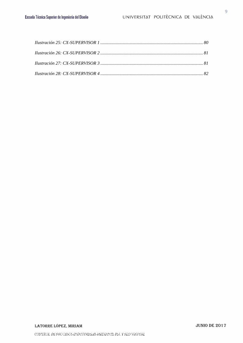
Las diferencias entre CPU de la misma familia suelen ser la capacidad de memoria (E/S)
y la velocidad de procesos de la CPU.
Hemos considerado a determinar dos aspectos:
- Memoria de programa: Se mide en Kpasos y determina cuantos pasos de programa
podemos disponer.
- Memoria de datos: Determina cuanta área interna de programa disponemos. Los datos
de memoria para ser utilizados en el programa como variables suelen ser entradas, salidas,
etapas, variables auxiliares, etc.
A las comunicaciones se puede acceder desde los sistemas de supervisión SCADA hasta
el autómata más pequeño de la fábrica.
Hemos estudiado bien la aplicación e identificado los elementos que debemos comunicar.
Si disponemos de Pantallas o sistemas HMI, considerar si es factible instalar periferia
descentralizada con E/S remotas para economizar la instalación.
Ilustración 2: PLC - CPU
Latorre López, Miriam
25
Junio de 2017
El software es importante, un software evolucionado y probado nos asegurara el correcto
funcionamiento de todo el conjunto de programación.
Un aspecto importante es el tema del precio, existen muchas marcas de PLC que disponen
de software para la programación de sus PLC de forma gratuita. El software propietario
que está asociado a una marca de PLC concreta que comunica mediante esa marca y
también tenemos el software abierto que emplea drivers de comunicación para
interconectar entre distintas marcas de PLC.
En nuestro proceso de automatización nos hemos ajustado a lo que disponemos en el
laboratorio del departamento de Ingeniería de Sistemas y Automática (ISA) pudiendo
disponer de los PLC Omron CJ2M.
Ilustración 3: ENTORNO SCADA
Ilustración 4: CX-ONE

Latorre López, Miriam
26
Junio de 2017
La serie CJ2M es ideal para necesidades de empaquetado y automatización general de
máquinas. La conectividad está asegurada gracias al puerto USB integrado y a la opción
de interfaces RS-232C/422/485 en la CPU. Destacamos sus características:
Siempre accesible mediante el puerto USB estándar
Puerto Ethernet estándar con función de enlace de datos vía EtherNet/IP
Amplio rango de capacidades de programa, de 5 a 60 kPasos, con módulos
opcionales de puerto serie.
La memoria dedicada a la programación mediante bloques de función asegura el
máximo rendimiento cuando se programa de ésta forma.
El software que utilizamos es el CX-One, que permite a los usuarios elaborar, configurar
y programar una serie de dispositivos como PLC, Terminales Programables, sistemas
Motion Control y redes con un solo paquete de software con una sola instalación y número
de licencia. Nuestra licencia es la suministrada a la UPV, licencia de estudiante.
3.4.3 SOFTWARE UTILIZADO
Como ya hemos mencionado anteriormente el software asociado a Omron es el
CX-One, por lo tanto es el que se ha utilizado para el proceso. Dentro de este entorno
encontramos varios programas destinado a diferentes utilidades los utilizados en este caso
han sido el CX-Programmer para la programación en Grafcet (Graphe Fonctionnel de
Commande Etape Transition) del proceso, el CX-Supervisor que se ocupa de gestionar todo
el entorno gráfico y funcional de la pantalla para poder visualizar e interactuar con el
proceso.
CX-Programmer, el software de programación que se utiliza para todas las series de PLC
de Omron, está integrado en el conjunto de programas CX-One.
Integrado en CX-One, el conjunto de programas universal de Omron.
Conexión automática mediante enlaces USB o serie.
Pantallas de configuración sencilla para todas las unidades de PLC.
Herramientas de simulación de PLC incluidas, para realizar pruebas antes de la
descarga del programa al PLC.
CX-Programmer permite trabajar con Estructuras y arrays, temporizadores y contadores,
entradas inteligentes, verificación de control de posición, diagramas funcionales
secuenciales y texto estructurado.

Latorre López, Miriam
27
Junio de 2017
El CX-Supervisor es un software dedicado a todos los procesos relacionados con el
control de máquinas y PC. Se utiliza en tareas de vigilancia y control.
CX-Supervisor permite crear aplicaciones con sus funciones y bibliotecas predefinidas.
Tambien nos permite generar un lenguaje de programación o VBScript. Importando
componentes de Active, se pueden crear aplicaciones flexibles, aumentando su
funcionalidad. Contines librerías gráficas, soporte de imagen, simulación y
mantenimiento remoto.
Ilustración 5: CX-PROGRAMMER
Ilustración 6: CX-SUPERVISOR

Latorre López, Miriam
28
Junio de 2017
3.5 COMUNICACIONES AUTOMATA
Identificaremos las comunicaciones existentes entre las respectivas maquetas, el PLC y
el PC.
3.5.1. CONEXIÓN MAQUETA-AUTOMATA
Enlazamos el puerto de comunicaciones de las maquetas con el autómata mediante el
conector Tipo DB37. Este conector se ha adoptado como estándar en el departamento para
faciliatar el intercambio de equipos de control con el PLC, realmente en una
automatización real esta conexión no se realizaría ya que las conexiones se harían
directamente entre el módulo de E/S y el hardware, sin conectores adicionales.
Ilustración 7: CONEXIÓN MAQUETA-PLC

Latorre López, Miriam
29
Junio de 2017
La placa de entradas y salidas queda comunicada con el módulo de E/S mediante esta
conexión.
Ilustración 8: MANGUERA 20 X 0.22mm
Utilizamos la manguera de veinte hilos de 0.22 mm con apantallamiento conseguimos
interconectar el PLC a la placa de las maquetas y al PC.
3.5.2 CONEXIÓN AUTÓMATA-PC
Para la comunicación entre el autómata y el PC utilizamos la red Ethernet/IP. Este es un
sistema basado en el “Protocolo de control e información”, Ethernet/IP es un sistema
integrado completo, desde la pantalla industrial hasta la red central de la empresa,
asegurando la interconexión mediante el cable de conexión de toda la red.

Latorre López, Miriam
30
Junio de 2017
Ilustración 9: AUTÓMATA - PC
3.5.3 CONEXIÓN AUTÓMATA-PC-MAQUETAS
La interconexión mediante la red Ethernet/IP entre las diferentes maquetas se ha realizado
con tres PLC distintos debido al reducido módulo de E/S. Al utilizar Ethernet/IP todo el
sistema queda interconectado y podemos utilizar simultáneamente las E/S de los tres
módulos en el entorno SCADA. Además al ser un proceso industrial real, cada línea o
proceso lleva su propio sistema de control y lo que hacemos es completar la
sincronización entre ellos. De este modo, si “cae” una estación, el resto funcionara de
forma aislada.
Latorre López, Miriam
31
Junio de 2017
Ilustración 10: AUTÓMATA - PC - MAQUETA
3.6 INGENIERIA DEL PROYECTO
En esta sección vamos a describir la parte física de la que se compone el trabajo,
la maquinaria a modo de maqueta que representa el proceso y nos ayuda a visualizar como
sería el acabado del proyecto real.
Contamos con tres maquetas diferentes de la marca Fischer Technik.
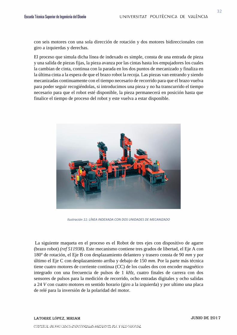
Línea de indexado con dos estaciones de mecanizado (ref 96790). Trata de una cinta
transportadora ensamblada en forma de “U”, se ha utilizado un transporte intermitente
para el traslado de las piezas sobre ella, y las dos paradas en cada puesto de mecanizado
para las diferentes piezas de trabajo.
Contiene dos estaciones de mecanizado, cuatro cintas transportadoras, ocho motores de
corriente continua (DC), cuatro finales de carrera y cinco barreras luminosas que emulan
el funcionamiento de sensores de presencia mediante un fototransistor y una bombilla en
la punta de la lente. Toda la maqueta funciona a 24 V. Las dimensiones totales de la
maqueta son de 475×450×270 mm. Contiene nueve entradas digitales, diez salidas a 24 V
Latorre López, Miriam
32
Junio de 2017
con seis motores con una sola dirección de rotación y dos motores bidireccionales con
giro a izquierdas y derechas.
El proceso que simula dicha línea de indexado es simple, consta de una entrada de pieza
y una salida de piezas fijas, la pieza avanza por las cintas hasta los empujadores los cuales
la cambian de cinta, continua con la parada en los dos puntos de mecanizado y finaliza en
la última cinta a la espera de que el brazo robot la recoja. Las piezas van entrando y siendo
mecanizadas continuamente con el tiempo necesario de recorrido para que el brazo vuelva
para poder seguir recogiéndolas, si introducimos una pieza y no ha transcurrido el tiempo
necesario para que el robot esté disponible, la pieza permanecerá en posición hasta que
finalice el tiempo de proceso del robot y este vuelva a estar disponible.
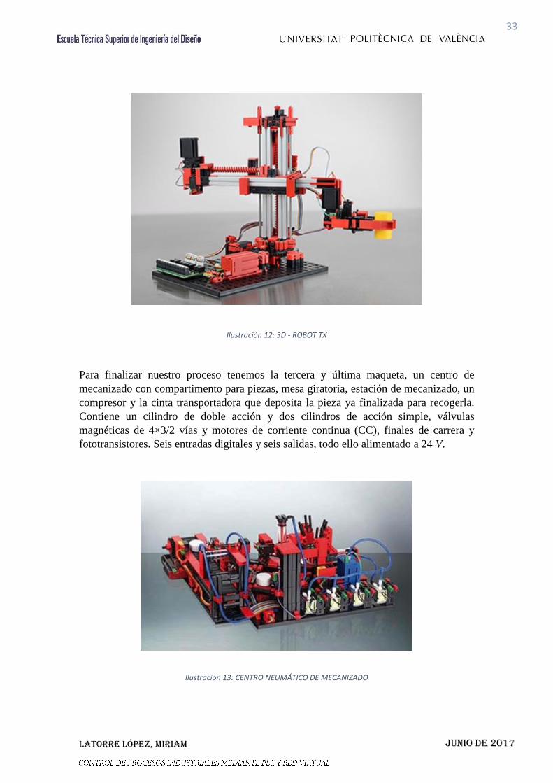
La siguiente maqueta en el proceso es el Robot de tres ejes con dispositivo de agarre
(brazo robot) (ref 511938). Este mecanismo contiene tres grados de libertad, el Eje A con
180º de rotación, el Eje B con desplazamiento delantero y trasero consta de 90 mm y por
último el Eje C con desplazamiento arriba y debajo de 150 mm. Por la parte más técnica
tiene cuatro motores de corriente continua (CC) de los cuales dos con encoder magnético
integrado con una frecuencia de pulsos de 1 kHz, cuatro finales de carrera con dos
sensores de pulsos para la medición de recorrido, ocho entradas digitales y ocho salidas
a 24 V con cuatro motores en sentido horario (giro a la izquierda) y por ultimo una placa
de relé para la inversión de la polaridad del motor.
Ilustración 11: LÍNEA INDEXADA CON DOS UNIDADES DE MECANIZADO
Latorre López, Miriam
33
Junio de 2017
Para finalizar nuestro proceso tenemos la tercera y última maqueta, un centro de
mecanizado con compartimento para piezas, mesa giratoria, estación de mecanizado, un
compresor y la cinta transportadora que deposita la pieza ya finalizada para recogerla.
Contiene un cilindro de doble acción y dos cilindros de acción simple, válvulas
magnéticas de 4×3/2 vías y motores de corriente continua (CC), finales de carrera y
fototransistores. Seis entradas digitales y seis salidas, todo ello alimentado a 24 V.
Ilustración 12: 3D - ROBOT TX
Ilustración 13: CENTRO NEUMÁTICO DE MECANIZADO

Latorre López, Miriam
34
Junio de 2017
3.7 DESCRIPCCIÓN DEL PROCESO
El enlace de las tres maquetas es el siguiente:
Ilustración 14: PROCESO COMPLETO
Se puede observar que el proceso comienza en la línea de indexado, introduciremos la
pieza por la entrada de línea y las cintas se encargan de trasladarla por todo el proceso.
En la línea de indexado la pieza es sometida a dos procesos de mecanizado y posteriormente continua para poder ser recogida por el brazo robot. La pinza recogerá
pieza cuando el sensor 3.I9 este leyendo pieza, para asegurar que no recoge en vacío, el
brazo mediante sus tres ejes, sujeta la pieza con la pinza y rota hasta posicionarse justo
en la entrada del compartimento del centro de mecanizado donde se centra mediante unas
varillas, para entrar en la mesa de rotación en la posición correcta, una vez en la mesa de
ENTRADA LÍNEA
FINAL DE LÍNEA
1.I6
1.I9
3.I5
3.I1

Latorre López, Miriam
35
Junio de 2017
rotación la pieza rota por la estampadora hasta llegar al cilindro de doble efecto que la
desplazara hasta la cinta transportadora que finaliza todo el proceso.
Hay que añadir que dicho proceso se repite tantas veces como especifiquemos en la
aplicación, mediante la tabla de piezas, con un total de 9999, aunque apliando los
contadores podríamos alargarlo, piezas por proceso continuo. También es relevante saber
que la frecuencia de entrada de piezas la marca el sensor de la primera estación de
mecanizado de la línea de indexado, el sensor 1.I6, siempre y cuando la pieza anterior
este, como mínimo, en la primera estación de mecanizado 1.I9.
El proceso completo finaliza cuando la última pieza, marcada por “El pedido” finaliza el
tarea. Seguidamente a la finalización de dicho pedido se produce un apagado de las
máquinas para garantizar una seguridad al recoger las piezas.
3.8 DESCRIPCIÓN DE SCADA
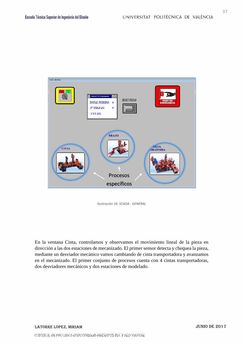
En la aplicación el primer entorno que inicia es la pantalla “General”, la cual nos
da opción a un seguimiento visual de la estación en la que está el proceso mediante los
indicadores led. El inicio del procesado comienza con la introducción del número total de
piezas a realizar, el cual se introduce en la ventana de control mediante el Numeric
Keypad, el número total por proceso continuo no puede superar a las 9999 piezas.
Podremos resetear el proceso tantas veces como queramos, con el interruptor Reset, el
cual nos permite volver a realizar un pedido una vez finalizado o no el anterior.
En la página general encontramos el interruptor de encendido ON/OFF global del
conjunto total de producción y una seta de emergencia para cualquier incidente producido
en el proceso, que detiene inmediatamente la producción y el movimiento de maquinaria
dando opción después a reanudar el pedido o volver a comenzar de cero, dependiendo de
la gravedad de la incidencia.

Latorre López, Miriam
36
Junio de 2017
Ilustración 15: SCADA - GENERAL
A través de esta ventana general podemos abrir las tres ventanas emergentes de control
de proceso específico. Pudiendo controlar y observar por separado el proceso en los tres
bloques de modelado de la pieza. Seleccionando el proceso especifico.
Interruptor
ON/OFF
Control
Numeric
Key pad
Seta
Emergencia
Reset
Latorre López, Miriam
37
Junio de 2017
Ilustración 16: SCADA - GENERAL
En la ventana Cinta, controlamos y observamos el movimiento lineal de la pieza en
dirección a las dos estaciones de mecanizado. El primer sensor detecta y chequea la pieza,
mediante un desviador mecánico vamos cambiando de cinta transportadora y avanzamos
en el mecanizado. El primer conjunto de procesos cuenta con 4 cintas transportadoras,
dos desviadores mecánicos y dos estaciones de modelado.
Procesos
específicos

Latorre López, Miriam
38
Junio de 2017
Ilustración 17: SCADA - PROCESO CINTA
En la segunda ventana, el brazo mecánico transporta la pieza del final de la línea 1, línea
de la cinta, hasta la entrada de la mesa giratoria. El brazo tiene ángulo de giro aproximado
a 225º con 40 cm de margen de movimiento, desde la posición más baja hasta la más alta.
La pinza genera una fuerza de agarre proporcional a la dimensión y el peso. El transporte
de la pieza se realiza seguidamente, conforme va avanzando el proceso. Con esto
finalizamos la segunda fase del proceso completo.
Latorre López, Miriam
39
Junio de 2017
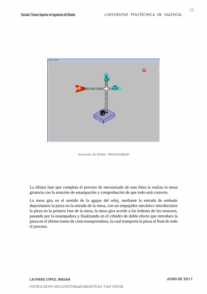
Ilustración 18: SCADA - PROCESO BRAZO
La última fase que completa el proceso de mecanizado de esta línea la realiza la mesa
giratoria con la estación de estampación y comprobación de que todo está correcto.
La mesa gira en el sentido de la agujas del reloj, mediante la entrada de embudo
depositamos la pieza en la entrada de la mesa, con un empujador mecánico introducimos
la pieza en la primera fase de la mesa, la mesa gira acorde a las órdenes de los sensores,
pasando por la estampadora y finalizando en el cilindro de doble efecto que introduce la
pieza en el último tramo de cinta transportadora, la cual transporta la pieza al final de todo
el proceso.

Latorre López, Miriam
40
Junio de 2017
Ilustración 19: SCADA - PROCESO MESA
El proceso se da por finalizado cuando termina con el número total de piezas introducido
en el Numeric Keypad.
En la ventana principal, mediante unos señalizadores led podemos ir visualizando el
avance del proceso sin necesidad de abrir las ventanas emergentes.
A parte cada sensor señaliza su funcionamiento, señalizando en verde si está en activo y
el posicionamiento de los cilindros y los pistones.

Latorre López, Miriam
41
Junio de 2017
3.9 DIAGRAMA DE PROGRAMACIÓN
La programación de dicho proyecto se ha hecho de una manera fácil, intuitiva y ordenada,
con motivo de facilitar el trabajo. El software está diseñado para detectar cualquier
imprevisto que pueda suceder, detiene el proceso inmediatamente para garantizar la
seguridad del operario.
3.9.1 DIAGRAMA DE FLUJOS SCADA
Ilustración 20: DIAGRAMA SCADA
3.9.2 DIAGRAMA DE FLUJOS “LÍNEA DE INDEXADO”
Pag1-GENERAL
Pag2-CINTA
Pag4-MESA
GIRATORIA
Pag3-BRAZO

Latorre López, Miriam
42
Junio de 2017
SENSOR I7
MOTOR
Q5 ON
SENSOR I5
TEMP. 1
MOTOR Q5 OFF
MOTOR Q1 ON
SENSOR I1
MOTOR Q1 OFF
MOTOR Q2 ON
SENSOR I2
MOTOR
Q6 ON
SENSOR I6
MOTOR Q6 OFF
MOTOR Q7 ON
TEMP. 2
MOTOR Q7 OFF
MOTOR Q8 ON
SENSOR I8
TEMP. 3
Latorre López, Miriam
43
Junio de 2017
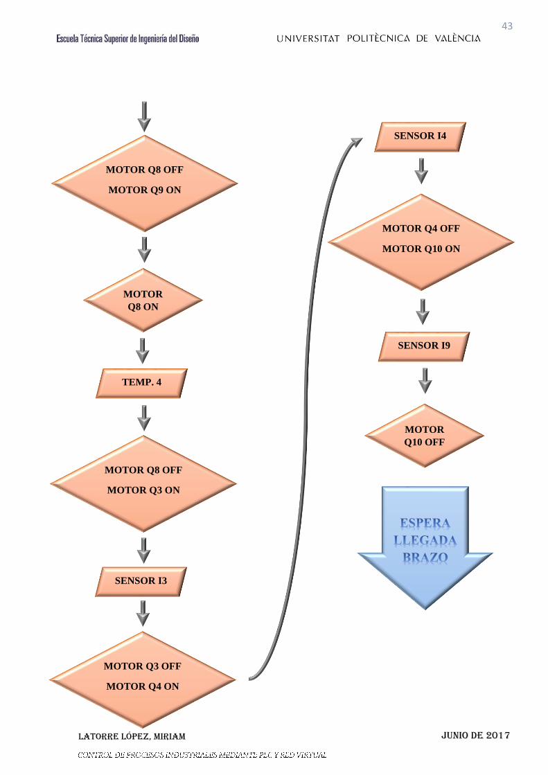
MOTOR
Q8 ON
MOTOR Q8 OFF
MOTOR Q9 ON
TEMP. 4
MOTOR Q8 OFF
MOTOR Q3 ON
SENSOR I3
MOTOR Q3 OFF
MOTOR Q4 ON
SENSOR I4
MOTOR Q4 OFF
MOTOR Q10 ON
SENSOR I9
MOTOR
Q10 OFF
Latorre López, Miriam
44
Junio de 2017
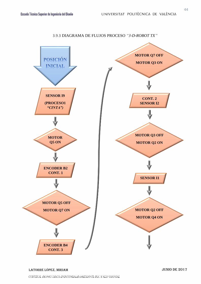
3.9.3 DIAGRAMA DE FLUJOS PROCESO “3-D-ROBOT TX”
MOTOR Q7 OFF
MOTOR Q3 ON
ENCODER B2
CONT. 1
MOTOR Q5 OFF
MOTOR Q7 ON
SENSOR I9
(PROCESO1
“CINTA”)
MOTOR
Q5 ON
ENCODER B4
CONT. 3
CONT. 2
SENSOR I2
MOTOR Q3 OFF
MOTOR Q2 ON
SENSOR I1
MOTOR Q2 OFF
MOTOR Q4 ON

Latorre López, Miriam
45
Junio de 2017
ENCODER B2
CONT. 4
MOTOR Q4 OFF
MOTOR Q8 ON
ENCODER B4
CONT. 5
MOTOR Q8 OFF
MOTOR Q5 ON
ENCODER B2
CONT. 6
MOTOR Q5 OFF
MOTOR Q1 ON
SENSOR I1
SENSOR I1
SENSOR I3
SENSOR I5
SENSOR I6
MOTOR Q1 OFF
MOTOR Q4 ON
MOTOR Q6 ON
MOTOR Q8 ON
MOTOR Q4 OFF
MOTOR Q6 OFF
MOTOR Q8 OFF

Latorre López, Miriam
46
Junio de 2017
3.9.4 DIAGRAMA DE FLUJOS PROCESO “CENTRO NEUMÁTICO”
SENSOR I6
MOTOR
Q7 ON
SENSOR I5
TEMP. 5
MOTOR Q7 OFF
MOTOR Q6 ON
TEMP. 6
MOTOR Q6 OFF
MOTOR Q2 ON
SENSOR I3
SENSOR I4
MOTOR Q2 OFF
MOTOR Q5 ON
SENSOR I4
TEMP. 6
MOTOR
Q2 ON

Latorre López, Miriam
47
Junio de 2017
SENSOR I2
MOTOR Q2 OFF
MOTOR Q3 ON
TEMP. 7
MOTOR Q3 OFF
MOTOR Q4 ON
MOTOR Q1 ON
TEMP. 7

Latorre López, Miriam
48
Junio de 2017
3.9.5 DIAGRAMA DE FLUJOS. INTERCONEXIÓN SCADA -
MAQUETAS
RESET
PIEZAS
INTERRUPTOR
ON / OFF
CONTROLADOR:
Nº PIEZAS TOTALES
SETA
EMERGENCIA
SALIDA PIEZA FINALIZADA
Latorre López, Miriam
49
Junio de 2017
3.10 CONCLUSIONES
Para concluir este trabajo final de grado he realizado una valoración de los
fundamentos teórico y prácticos obtenidos durante estos cuatro años que me han servido
para poder programar y redactar este proyecto. Realizando este trabajo he podido
comprender en mayor amplitud el funcionamiento de estas tecnologías industriales, que
a su vez son las más utilizadas en este campo, así como haber seguido desarrollando
capacidades de síntesis, diseño, implementación, puesta a punto, programación,
identificación y reparación de averías, diagnostico de fallos y elaboración de la
documentación técnica necesaria para la composición global de este proyecto.
He intentado la mayor similitud posible en este proyecto para un uso real de una industria
interesada en automatizar un sector de ella, sin dejarnos a un lado las limitaciones tenidas
durante toda la realización de este trabajo.
Por otro lado, el lado más educativo de este fin, puedo decir que quedo totalmente
satisfecha con la elaboración y el afianzamiento de los conocimientos asimilados antes,
durante y posteriormente al comienzo de este TFG.

Latorre López, Miriam
50
Junio de 2017
4. PLIEGO DE CONDICIONES

Latorre López, Miriam
51
Junio de 2017

Latorre López, Miriam
52
Junio de 2017
ÍNDICE DEL PLIEGO
4. PLIEGO DE CONDICIONES ........................................................................................ 50
4.1 DEFINICIÓN Y ALCANCE DEL PLIEGO DE CONDICIONES ........................ 54
4.1.1 OBJETO DEL PLIEGO ................................................................................. 54
4.1.2. DESCRIPCIÓN GENERAL DEL MONTAJE ............................................... 54
4.2 CONDICIONES Y NORMAS DE CARÁCTER GENERAL .................................. 55
4.3 CONDICIONES DE LOS MATERIALES ............................................................. 56
4.4 ORDENADOR PERSONAL .................................................................................. 56
4.5 ESTUDIOS DE LEGISLACIÓN ........................................................................... 58

Latorre López, Miriam
53
Junio de 2017

Latorre López, Miriam
54
Junio de 2017
4.1 DEFINICIÓN Y ALCANCE DEL PLIEGO DE CONDICIONES
4.1.1 OBJETO DEL PLIEGO
El presente pliego de condiciones tiene como objetivo agrupar las diferentes condiciones
técnicas que se debe seguir para una correcta realización del proyecto mostrado en este
documento.
El objetivo del trabajo final de grado reunido en este documento es el diseño,
implementación y control de tres maquetas distintas, descritas anteriormente, del
fabricante Fischertechnik con la interconexión entre ellas con Ethernet y gobernadas
desde el programa SCADA.
En distintos momentos se pueden tomar soluciones diferentes a las expuestas en dichos
documentos, por la propia naturaleza y el desarrollo tecnológico del mismo, siempre que
se aleguen dichas soluciones sin que ello disminuya la funcionalidad inicialmente
requerida.
4.1.2. DESCRIPCIÓN GENERAL DEL MONTAJE
El orden de ejecución para realizar el proyecto queda reflejado en la siguiente lista:
1. Adquisición de las tres maquetas correspondientes a la ejecución total del
proceso de mecanizado, suministradas por el Departamento de Ingeniería de
Sistemas y Automática.
2. Montaje de tres maquetas consecutivas de mecanizado del fabricante
Fischertechnik.
3. Montaje de cada PLC con sus módulos correspondientes y necesarios para cada
maqueta, si tuviéramos herramientas podría usarse el mismo PLC para las tres
maquetas.
4. Calibración de los empujadores, finales de carrera y sensores de los mimos.
Latorre López, Miriam
55
Junio de 2017
5. Conexionado de las maquetas a los PLC correspondientes.
6. Interconexión y visualización de entradas y salidas.
7. Realización y entorno de los programas utilizados para el control del proceso.
8. Programación del PLC.
9. Comprobación del correcto funcionamiento de las entradas y salidas de las
maquetas y comprobación de la interconexión de dichas maquetas.
10. Comprobación global del correcto funcionamiento PLC-maquetas.
11. Comprobación del correcto funcionamiento de programación utilizado para
gobernar las maquetas.
El encargado de la realización del proyecto debe ser un profesional cualificado capaz de
resolver cualquier problema en cuanto a errores de programación, errores de maquinaria
o errores referidos al PLC y buscar posibles soluciones para los errores de conexionado.
En resumen el ingeniero encargado del proyecto tiene que ser capaz de gestionar sus
recursos y utilizarlos para sacarles el máximo rendimiento posible.
4.2 CONDICIONES Y NORMAS DE CARÁCTER GENERAL
Si durante la realización del proyecto surge algún tipo de fallo en algún material y se
tuviera que remplazar por cualquier motivo, se tendría que sustituir por uno de las mismas
características y siempre con la supervisión del encargado del proyecto. Si se produce
algún fallo la responsabilidad recae sobre la persona que lo haya ejecutado sin la correcta
autorización.
El proyecto debe de cumplir la normativa vigente impuesta para este tipo de proyecto de
automatización industrial.
Latorre López, Miriam
56
Junio de 2017
4.3 CONDICIONES DE LOS MATERIALES
Como los materiales que se utilizan en el presente proyecto son materiales
normalizados, no presentan problemas para ser obtenidos.
Dichos productos no se podrán cambiar por otros de distintas marcas aunque posean las
mismas características, por motivos de incompatibilidad de los programas utilizados. En
caso de no poder evitar la utilización de productos de distintas característica a los
nombrados en este documento, se deberá modificar y adaptar los programas a dichos
productos para conseguir el correcto funcionamiento. El director del proyecto no se
responsabiliza del mal funcionamiento, ya que no son usados los materiales aquí
expuestos. Dado que los autómatas son de una marca conocida y valorada en el sector de
la automatización industrial no debería ser un impedimento conseguir recambios de
materiales con las mismas características.
4.4 ORDENADOR PERSONAL
Para un correcto funcionamiento del proyecto se piden unos requisitos mínimos
tanto de hardware como de software del computador que se utilizara para la
programación.
Dicha parte es importante para el correcto funcionamiento del proceso, debido a que la
comunicación entre el PC y el PLC debe ser correcta.
En este caso se va a utilizar un ordenador de sobremesa el cual ha sido proporcionado
para realizar dicho proyecto, con él se llevara a cabo el traspaso del programa de PC a
PLC para comprobar su funcionamiento, y posteriormente el control mediante el
SCADA.
Las características mínimas para garantizar el correcto y fluido funcionamiento del
proceso en cuanto se refiere al PC son:
Latorre López, Miriam
57
Junio de 2017
CARACTERÍSTICAS DE HARDWARE:
- Microprocesador Pentium II con velocidad de reloj de 333MHz o
superior.
- Memoria RAM 256MB como mínimo.
- Disco duro de 2GB como mínimo.
- Conexión a redes (Ethernet).
- Unidad de CD-ROM, DVD-ROM.
- Ratón y teclado.
CARACTERÍSTICAS DE SOFTWARE:
- CX-Programmer.
- CX-Supervisor Developer.
- Sistema operativo Windows 2000 o superior.
PROGRAMER LOGIC CONTROLLER (PLC)
Las características del PLC se han descrito anteriormente en el punto “3.4.2 Elección del
PLC”.
Cumplirá con las leyes de seguridad eléctrica certificadas, incluyendo las protecciones
eléctricas:
- Cortocircuitos.
- Sobretensiones.
- Perturbaciones presentes en el laboratorio.
- Perturbaciones de red.
- Tensiones de red fuera de rango.
MAQUETAS UTILIZADAS FISCHERTECHNIK
Las características de las tres maquetas utilizadas en el proceso con dos estaciones de
mecanizado y una de estampación se han descrito en el apartado “3.6 Ingeniería del
proyecto”.

Latorre López, Miriam
58
Junio de 2017
Se añaden que las maquetas no presentan peligro alguno para personas por partes
punzantes o cortantes, por atrapamientos o por riesgo de electrificación o fibrilación.
4.5 ESTUDIOS DE LEGISLACIÓN
Se detallara a continuación toda aquella legislación que se tiene que tener en
cuenta para la realización de dicho proyecto:
- Reglamento Electrotécnico de Baja Tensión (REBT), así como la Guía
Técnica asociada a éste.
- RD 1580/2006, de 22 de diciembre, por el que se regula la compatibilidad
electromagnética de los equipos eléctricos y electrónicos.
- RD 7/1988, de 8 de enero, relativo a las exigencias de seguridad del
material eléctrico (y posteriores modificaciones por RD 154/95).
- RD y Normas UNE relativas al montaje, utilización y mantenimiento de
autómatas.
- EN 62061:2005: Seguridad de las máquinas. Seguridad funcional de
sistemas de mando eléctricos, electrónicos, y programables relativos a la
seguridad.
- EN ISO 16484:2003: Automatización de edificios y sistemas de control.
- Norma IEC-1131 sobre la estandarización de los lenguajes de
programación y sobre los diferentes tipos de autómatas programables y
sus periféricos.
- Manual y Guía de Usuario del elemento de control.
- Manual de funcionamiento del software utilizado para la programación.
Antes de su montaje se comprobarán los materiales para evitar el mal funcionamiento de
los mismos.
La legislación que debe llevarse a cabo para esas comprobaciones es la siguiente:
- UNE 20-512-74/2 “Fiabilidad de equipos y componentes electrónicos”.
Latorre López, Miriam
59
Junio de 2017
- UNE 20-504-84 “Métodos de medida de las características antiparásita de
filtros pasivos y otros dispositivos de perturbaciones radioeléctricos“.
- UNE 20-501-85/2 “Ensayos fundamentales, climáticos y de robustez”.
Latorre López, Miriam
60
Junio de 2017
5. REFERENCIAS BIBLIOGRÁFCAS

Latorre López, Miriam
61
Junio de 2017

Latorre López, Miriam
62
Junio de 2017
Referido a las maquetas: http://www.fischertechnik.de/en/Home.aspx
Cinta. Maqueta 1:
http://www.fischertechnik.de/en/desktopdefault.aspx/tabid-24/41_read-
63/usetemplate-2_column_pano/
Brazo robot. Maqueta 2:
http://www.fischertechnik.de/en/desktopdefault.aspx/tabid-24/41_read-
146/usetemplate-2_column_pano/
Mesa giratoria. Maqueta 3:
http://www.fischertechnik.de/en/desktopdefault.aspx/tabid-24/41_read-
341/usetemplate-2_column_pano/
Documentaciones aportada por el tutor del proyecto.
Hardware y Software:
https://omron.es/es/home
https://industrial.omron.es/es/products/programmable-logic-controllers
https://industrial.omron.es/es/products/cj-power-
supplies#specifications_ordering_info
https://industrial.omron.es/es/products/cj-digital-io-
units#specifications_ordering_info
https://industrial.omron.es/es/products/cx-programmer
https://industrial.omron.es/es/products/cx-supervisor
Documentación aportada por el tutor del proyecto.
Referente al entorno y programación:

Latorre López, Miriam
63
Junio de 2017
www.upv.es >> PoliformaT >> Automática Básica (documentación aportada
por la asignatura).
www.upv.es >> PoliformaT >> Sistemas de Producción Industrial
(documentación aportada por la asignatura).
www.upv.es >> PoliformaT >> Automatización Industrial (documentación
aportada por la asignatura).
www.upv.es >> PoliformaT >> Sistemas Robotizados (documentación
aportada por la asignatura).
www.upv.es >> PoliformaT >> Instalaciones Electroneumáticas
(documentación aportada por la asignatura).
Otros:
http://www.tecnodidactica.pe/index.php/catalogsearch/result/index/?dir=desc
&limit=all&mode=list&order=manufacturer&q=MOTOR
Libro: Programación de autómatas: Introducción al Grafcet.

Latorre López, Miriam
64
Junio de 2017
6. PRESUPUESTO

Latorre López, Miriam
65
Junio de 2017

Latorre López, Miriam
66
Junio de 2017
El presupuesto englobara el coste total, teniendo en cuenta que es un proyecto
con fines didácticos con lo que no contaremos con los precios de la maquinaria, solo
tendremos en cuenta el material utilizado en el aula.
Para una visualización más óptima desglosaremos el presupuesto en varias partes y
sumaremos todo para obtener el presupuesto total.
6.1 HARDWARE
Presupuesto dirigido a los componentes hardware utilizados:
MATERIAL DESCRIPCIÓN CANTIDAD €/UNID. €/TOTAL
Monitor Ordenador
sobremesa
1 150€ 150€
Ratón y
teclado
Ordenador
sobremesa
1 40€ 40€
Torre Ordenador
sobremesa
1 500€ 500€
Maqueta 1
(Cinta)
FischerTechnik 1 900€ 900€
Maqueta 2
(Brazo)
FischerTechnik 1 700€ 700€
Maqueta 3
(Mesa)
FischerTechnik 1 900€ 900€
CPU CJ2M Omron 1 639.55€ 639.55€
Fuente de
alimentación
CJ1W-PA202
Omron
1 164.55€ 164.55€
Módulo de
expansión
CJ1W-ID211
Omron
1 280.73€ 280.73€
Módulo E/S CJ1W-OC211
Omron
1 494.19€ 494.19€
TOTAL HARDWARE 4.769,02 €
Tabla 1: PRESUPUESTO HARDWARE

Latorre López, Miriam
67
Junio de 2017
6.2 SOFTWARE
Parte del proyecto referente a la parte software utilizada:
PRODUCTO DESCRIPCIÓN CANTIDAD €/UNID. €/TOTAL
CX-One Entorno
programación
1 1616.40€ 1616.40 €
CX-Supervisor Entorno
programación
1 1237.50€ 1237.50 €
TOTAL SOFTWARE 2.853,90 €
Tabla 2: PRESUPUESTO SOFTWARE
6.3 RECURSOS HUMANOS
El recurso humano que hemos utilizado en este proyecto es referido a la
ingeniera encargada de la programación y redacción de este TFG. Queda excluido el
proceso de montaje de la maqueta ya que no es relevante.
Analizando el proyecto y el trabajo desempeñado valoraremos el precio por hora del
trabajo del ingeniero en 25€.

Latorre López, Miriam
68
Junio de 2017
TAREA DESCRIPCIÓN TIEMPO €/HORA €/TOTAL
Análisis Determinar la
cuantía del
proyecto.
6 25 150 €
CX-
Programmer
Programación
(Grafcet y Ladder).
50 25 1250 €
CX-Supervisor Controlador de
equipos.
35 25 875 €
Implementación De las diferentes
partes.
15 25 375 €
Análisis final Comprobación del
proceso.
5 25 125 €
TOTAL RECURSO HUMANO 2.775 €
Tabla 3: PRESUPUESTO RECURSOS HUMANOS
6.4 COSTE TOTAL DEL PROYECTO
A continuación obtendremos el coste final teniendo en cuenta todos los factores
contemplados para la realización de dicho proyecto.
CONCEPTO PRECIO (€)
Hardware 4.769 €
Software 2.853,90 €
Recurso humano 2.775 €
COSTE TOTAL 10.397,90 €
Tabla 4: PRESUPUESTO TOTAL

Latorre López, Miriam
69
Junio de 2017
Latorre López, Miriam
70
Junio de 2017
7. ANEXOS

Latorre López, Miriam
71
Junio de 2017
Latorre López, Miriam
72
Junio de 2017
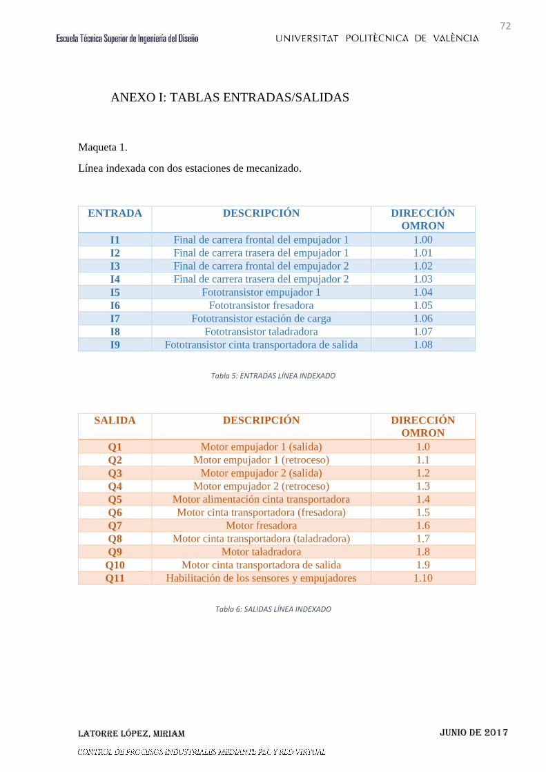
ANEXO I: TABLAS ENTRADAS/SALIDAS
Maqueta 1.
Línea indexada con dos estaciones de mecanizado.
ENTRADA DESCRIPCIÓN DIRECCIÓN
OMRON
I1 Final de carrera frontal del empujador 1 1.00
I2 Final de carrera trasera del empujador 1 1.01
I3 Final de carrera frontal del empujador 2 1.02
I4 Final de carrera trasera del empujador 2 1.03
I5 Fototransistor empujador 1 1.04
I6 Fototransistor fresadora 1.05
I7 Fototransistor estación de carga 1.06
I8 Fototransistor taladradora 1.07
I9 Fototransistor cinta transportadora de salida 1.08
Tabla 5: ENTRADAS LÍNEA INDEXADO
SALIDA DESCRIPCIÓN DIRECCIÓN
OMRON
Q1 Motor empujador 1 (salida) 1.0
Q2 Motor empujador 1 (retroceso) 1.1
Q3 Motor empujador 2 (salida) 1.2
Q4 Motor empujador 2 (retroceso) 1.3
Q5 Motor alimentación cinta transportadora 1.4
Q6 Motor cinta transportadora (fresadora) 1.5
Q7 Motor fresadora 1.6
Q8 Motor cinta transportadora (taladradora) 1.7
Q9 Motor taladradora 1.8
Q10 Motor cinta transportadora de salida 1.9
Q11 Habilitación de los sensores y empujadores 1.10
Tabla 6: SALIDAS LÍNEA INDEXADO
Latorre López, Miriam
73
Junio de 2017
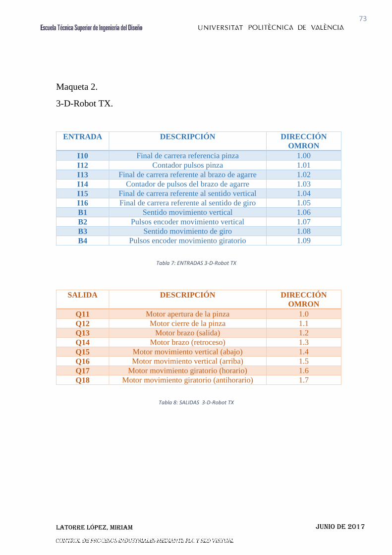
Maqueta 2.
3-D-Robot TX.
ENTRADA DESCRIPCIÓN DIRECCIÓN
OMRON
I10 Final de carrera referencia pinza 1.00
I12 Contador pulsos pinza 1.01
I13 Final de carrera referente al brazo de agarre 1.02
I14 Contador de pulsos del brazo de agarre 1.03
I15 Final de carrera referente al sentido vertical 1.04
I16 Final de carrera referente al sentido de giro 1.05
B1 Sentido movimiento vertical 1.06
B2 Pulsos encoder movimiento vertical 1.07
B3 Sentido movimiento de giro 1.08
B4 Pulsos encoder movimiento giratorio 1.09
Tabla 7: ENTRADAS 3-D-Robot TX
SALIDA DESCRIPCIÓN DIRECCIÓN
OMRON
Q11 Motor apertura de la pinza 1.0
Q12 Motor cierre de la pinza 1.1
Q13 Motor brazo (salida) 1.2
Q14 Motor brazo (retroceso) 1.3
Q15 Motor movimiento vertical (abajo) 1.4
Q16 Motor movimiento vertical (arriba) 1.5
Q17 Motor movimiento giratorio (horario) 1.6
Q18 Motor movimiento giratorio (antihorario) 1.7
Tabla 8: SALIDAS 3-D-Robot TX

Latorre López, Miriam
74
Junio de 2017
Maqueta 3.
Centro neumático de mecanizado.
ENTRADA DESCRIPCIÓN DIRECCIÓN
OMRON
I20 Fototransistor cinta transportadora 1.00
I22 Final de carrera intercambio mesa giratoria 1.01
I23 Final de carrera presa 1.02
I24 Final de carrera mesa giratoria 1.03
I25 Fototransistor entrada piezas 1.04
I26 Interruptor start/stop 1.05
Tabla 9: ENTRADAS CENTRO NEUMÁTICO
SALIDA DESCRIPCIÓN DIRECCIÓN
OMRON
Q21 Motor cinta transportadora 1.2
Q22 Motor mesa giratoria 1.4
Q23 Salida cilindro intercambio de piezas 1.5
Q24 Entrada cilindro intercambio de piezas 1.6
Q25 Cilindro de la presa 1.7
Q26 Cilindro de la entrada de piezas 1.8
Q27 Compresor 1.9
Tabla 10: SALIDAS CENTRO NEUMÁTICO

Latorre López, Miriam
75
Junio de 2017
Latorre López, Miriam
76
Junio de 2017
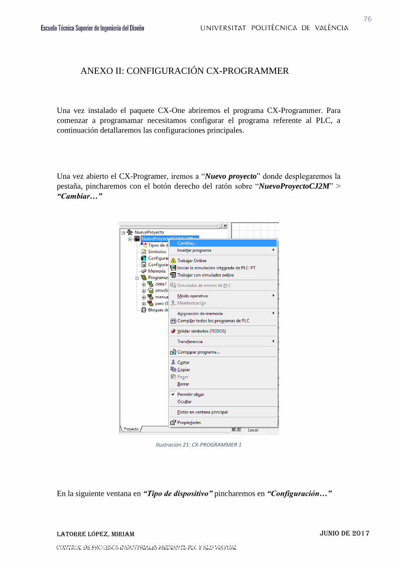
ANEXO II: CONFIGURACIÓN CX-PROGRAMMER
Una vez instalado el paquete CX-One abriremos el programa CX-Programmer. Para
comenzar a programamar necesitamos configurar el programa referente al PLC, a
continuación detallaremos las configuraciones principales.
Una vez abierto el CX-Programer, iremos a “Nuevo proyecto” donde desplegaremos la
pestaña, pincharemos con el botón derecho del ratón sobre “NuevoProyectoCJ2M” >
“Cambiar…”
Ilustración 21: CX-PROGRAMMER 1
En la siguiente ventana en “Tipo de dispositivo” pincharemos en “Configuración…”

Latorre López, Miriam
77
Junio de 2017
Ilustración 22: CX-PROGRAMMER 2
En la pestaña “General” seleccionaremos en “Tipo de CPU” la que hayamos utilizado,
en nuestro caso, “CPU31”, “Aceptamos” y se cerrara la ventana.
Ilustración 23: CX-PROGRAMMER 3

Latorre López, Miriam
78
Junio de 2017
En “Configuración de red [Ethernet/IP]” > “Configuraciones” pestaña “Red” > “PLC
de destino” introduciremos la dirección IP que nos pertenece dependiendo de donde esté
conectado nuestro PLC y “Aceptar”. En este proyecto se han utilizado tres direcciones
distintas, para los tres PLC correspondientes a cada maqueta.
Ilustración 24: CX-PROGRAMMER 4
Volveremos a “Aceptar” en la ventana que queda abierta desde el inicio de la
configuración y ya podremos comenzar a programar teniendo vinculado nuestro PLC al
programa y estando las comunicaciones activas.

Latorre López, Miriam
79
Junio de 2017

Latorre López, Miriam
80
Junio de 2017
ANEXO III: CONFIGURACIÓN CX-SUPERVISOR DEVELOPER
Una vez abierto el programa de supervisión y mando visual CX-Supervisor Developer,
se configurara la comunicación con el PLC.
En “Editor de puntos” hacemos doble clic y en “Atributos E/S” pulsamos
sobre “Configuración” emergerá “Atributos del PLC [Entero]”.
Seleccionamos “AgregarPLC…” situado a la derecha de la ventana.
Ilustración 25: CX-SUPERVISOR 1
En “Nombre del dispositivo” añadiremos un nombre. Seguidamente esta
“Tipo de dispositivo” donde seleccionamos el tipo de CPU que tenemos, en
nuestro caso es la CPU CJ2M. Por ultimo en esta ventana en “Tipo de red”
seleccionamos la red que vayamos a utilizar, en este caso “EtherNet/IP” y
“Aceptar”.

Latorre López, Miriam
81
Junio de 2017
Ilustración 26: CX-SUPERVISOR 2
Ahora configuraremos el tipo de dispositivo, como hemos hecho en el CX-Programer,
entraremos en “Configuración de tipo de dispositivo [CJ2M]”.
Encontramos en la pestaña “General” > “Tipo de CPU” desplegamos y seleccionamos
nuestra CPU, en este caso es la CPU31.
Ilustración 27: CX-SUPERVISOR 3

Latorre López, Miriam
82
Junio de 2017
Por último en “Configuración de red [EtherNet/IP] > “PLC de destino” > “Dirección
IP” introduciremos la dirección IP correspondiente a donde esté situado nuestro PLC.
Ilustración 28: CX-SUPERVISOR 4
Pulsaremos “Aceptar” e ambas ventanas y estará configurado nuestra comunicación con
el PLC, podremos comenzar a programar.

Latorre López, Miriam
83
Junio de 2017

Latorre López, Miriam
84
Junio de 2017
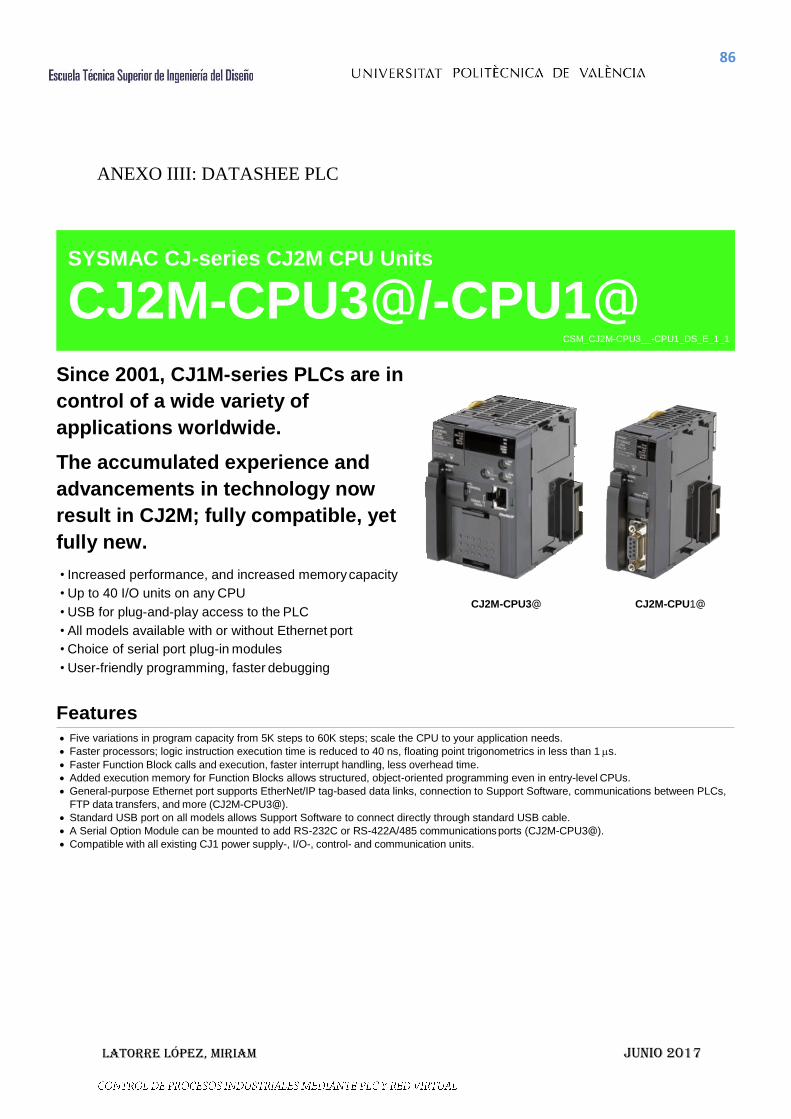
ANEXO IIII: DATASHEE PLC
86
Latorre López, Miriam JuNio 2017
ANEXO IIII: DATASHEE PLC
Since 2001, CJ1M-series PLCs are in
control of a wide variety of
applications worldwide.
The accumulated experience and
advancements in technology now
result in CJ2M; fully compatible, yet
fully new.
• Increased performance, and increased memory capacity
• Up to 40 I/O units on any CPU
• USB for plug-and-play access to the PLC
• All models available with or without Ethernet port
• Choice of serial port plug-in modules
• User-friendly programming, faster debugging
CJ2M-CPU3@ CJ2M-CPU1@
Features
Five variations in program capacity from 5K steps to 60K steps; scale the CPU to your application needs.
Faster processors; logic instruction execution time is reduced to 40 ns, floating point trigonometrics in less than 1 s.
Faster Function Block calls and execution, faster interrupt handling, less overhead time.
Added execution memory for Function Blocks allows structured, object-oriented programming even in entry-level CPUs.
General-purpose Ethernet port supports EtherNet/IP tag-based data links, connection to Support Software, communications between PLCs,
FTP data transfers, and more (CJ2M-CPU3@).
Standard USB port on all models allows Support Software to connect directly through standard USB cable.
A Serial Option Module can be mounted to add RS-232C or RS-422A/485 communications ports (CJ2M-CPU3@).
Compatible with all existing CJ1 power supply-, I/O-, control- and communication units.
SYSMAC CJ-series CJ2M CPU Units
CJ2M-CPU3@/-CPU1@ CSM_CJ2M-CPU3__-CPU1_DS_E_1_1

87
Latorre López, Miriam JuNio 2017
International Standards The standards are abbreviated as follows: U: UL, U1: UL (Class I Division 2 Products for Hazardous Locations), C: CSA, UC: cULus,
UC1: cULus (Class I Division 2 Products for Hazardous Locations), CU: cUL, N: NK, L: Lloyd, and CE: EC Directives.
Contact your OMRON representative for further details and applicable conditions for these standards.
CJ2M CPU Units (Built-in EtherNet/IP)
Product name
Specifications Current
consumption (A)
Model
Standards I/O capacity/ Mountable Units
(Expansion Racks)
Program capacity
Data memory
capacity
LD instruction execution
time
EtherNet/IP
function
Option board slot
5 V
24 V
CJ2M (Built-in EtherNet/IP) CPU Units
2,560 points/ 40 Units (3 Expansion Racks max.)
60K steps 160K words (DM: 32K words, EM: 32K words ×
4 banks)
0.04 s
YES
YES
0.7 (See note.)
CJ2M-CPU35
UC1, CE
30K steps CJ2M-CPU34
20K steps 160K words (DM: 32K words, EM: 32K words ×
1 bank)
CJ2M-CPU33
10K steps CJ2M-CPU32
5K steps CJ2M-CPU31
Note: Add 0.005A, 0.030A and 0.075A when using Serial Communications Option Boards (CP1W-CIF01/11/12), respectively.
CJ2M CPU Units
Product name
Specifications Current
consumption (A)
Model
Standards I/O capacity/ Mountable Units
(Expansion Racks)
Program capacity
Data memory
capacity
LD instruction execution
time
EtherNet/IP
function
Option board slot
5 V
24 V
CJ2M CPU Units
2,560 points/ 40 Units (3 Expansion Racks max.)
60K steps 160K words (DM: 32K words, EM: 32K words ×
4 banks)
0.04 s
0.5 (See note.)
CJ2M-CPU15
UC1, CE
30K steps CJ2M-CPU14
20K steps 160K words (DM: 32K words, EM: 32K words ×
1 bank)
CJ2M-CPU13
10K steps CJ2M-CPU12
5K steps CJ2M-CPU11
Note: Add 0.15A when using NT-AL001 RS-232C/RS-422A Adapters. Add 0.04 A when using CJ1W-CIF11 RS-422A Adapters.
Serial Communications Option Boards (Only CJ2M-CPU3@) The serial communications port can be equipped by installing the serial communications option board to the option board slot in front of CPU unit.
Product name Specifications Model Standards
RS-232C Option Board
One RS-232C port Connector: D-Sub, 9 pin, female Maximum transmission distance: 15m One RS-232C connector (D-Sub, 9 pin, male) is included. (Plug: XM2A-0901, Hood: XM2S-0911-E)
CP1W-CIF01
UC1, N, L, CE RS-422A/485
Option Board
One RS-422A/485 port Terminal block: using ferrules Maximum transmission distance: 50m
CP1W-CIF11
RS-422A/485 Isolated-type Option Board
One RS-422A/485 port (Isolated) Terminal block: using ferrules Maximum transmission distance: 500m
CP1W-CIF12
N, L, CE
Note: It is not possible to use a CP-series Ethernet Option Board (CP1W-CIF41), LCD Option Board (CP1W-DAM01) with a CJ2M CPU Unit.

88
Latorre López, Miriam JuNio 2017
The following accessories come with CPU Unit:
Item Specification
Battery CJ1W-BAT01
End Cover CJ1W-TER01 (necessary to be mounted at the right end of CPU Rack)
End Plate PFP-M (2 pcs)
Serial Port (RS-232C) Connector (see note)
Connector set for serial port connection (D-SUB 9-pin male connector)
Note: Connector is not provided with CJ2M-CPU3@.
General Specifications
Item CJ2M-
CPU1@ CPU3@
Enclosure Mounted in a panel
Grounding Less than 100
CPU Rack Dimensions 90 mm 75 mm 31 mm 90 mm 75 mm 62 mm
Weight 130 g or less 190 g or less (see note)
Current Consumption 5 VDC, 0.5 A 5 VDC, 0.7 A
Use Environment
Ambient Operating Temperature 0 to 55C
Ambient Operating Humidity 10% to 90%
Atmosphere Must be free from corrosive gases.
Ambient Storage Temperature 20 to 70C (excluding battery)
Altitude 2,000 m or less
Pollution Degree 2 or less: Conforms to JIS B3502 and IEC 61131-2.
Noise Immunity 2 kV on power supply line (Conforms to IEC 61000-4-4.)
Overvoltage Category Category II: Conforms to JIS B3502 and IEC 61131-2.
EMC Immunity Level Zone B
Vibration Resistance
Conforms to IEC60068-2-6 5 to 8.4 Hz with 3.5-mm amplitude, 8.4 to 150 Hz
Acceleration of 9.8 m/s2 for 100 min in X, Y, and Z directions (10 sweeps of 10 min each = 100 min total)
Shock Resistance Conforms to IEC60068-2-27 147 m/s2, 3 times in X, Y, and Z directions (100 m/s2 for Relay Output Units)
Battery Life 5 years at 25C
Model CJ1W-BAT01
Applicable Standards Conforms to cULus and EC Directives.
Note: Without a Serial Option Board.
89
Latorre López, Miriam JuNio 2017
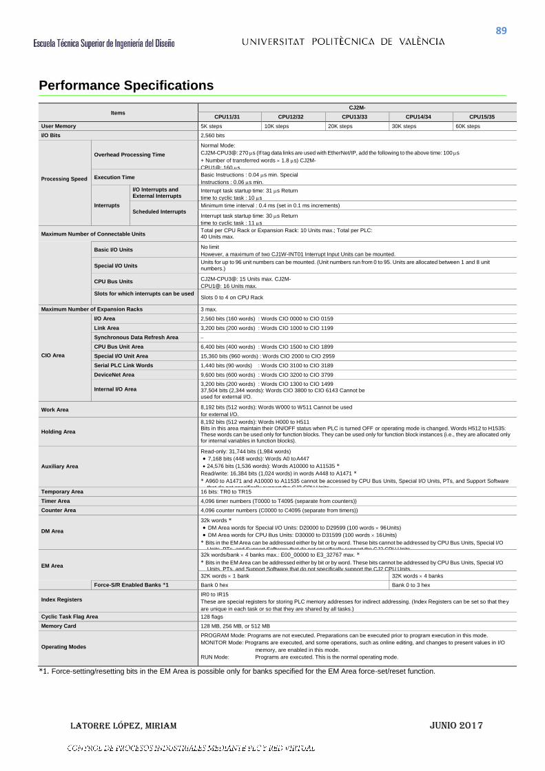
Performance Specifications
Items
CJ2M-
CPU11/31 CPU12/32 CPU13/33 CPU14/34 CPU15/35
User Memory 5K steps 10K steps 20K steps 30K steps 60K steps
I/O Bits 2,560 bits
Processing Speed
Overhead Processing Time
Normal Mode:
CJ2M-CPU3@: 270 s (If tag data links are used with EtherNet/IP, add the following to the above time: 100 s
+ Number of transferred words 1.8 s) CJ2M-
CPU1@: 160 s
Execution Time Basic Instructions : 0.04 s min. Special
Instructions : 0.06 s min.
Interrupts
I/O Interrupts and External Interrupts
Interrupt task startup time: 31 s Return
time to cyclic task : 10 s
Scheduled Interrupts Minimum time interval : 0.4 ms (set in 0.1 ms increments)
Interrupt task startup time: 30 s Return
time to cyclic task : 11 s
Maximum Number of Connectable Units Total per CPU Rack or Expansion Rack: 10 Units max.; Total per PLC: 40 Units max.
Basic I/O Units
No limit
However, a maximum of two CJ1W-INT01 Interrupt Input Units can be mounted.
Special I/O Units Units for up to 96 unit numbers can be mounted. (Unit numbers run from 0 to 95. Units are allocated between 1 and 8 unit numbers.)
CPU Bus Units CJ2M-CPU3@: 15 Units max. CJ2M-
CPU1@: 16 Units max.
Slots for which interrupts can be used Slots 0 to 4 on CPU Rack
Maximum Number of Expansion Racks 3 max.
CIO Area
I/O Area 2,560 bits (160 words) : Words CIO 0000 to CIO 0159
Link Area 3,200 bits (200 words) : Words CIO 1000 to CIO 1199
Synchronous Data Refresh Area
CPU Bus Unit Area 6,400 bits (400 words) : Words CIO 1500 to CIO 1899
Special I/O Unit Area 15,360 bits (960 words) : Words CIO 2000 to CIO 2959
Serial PLC Link Words 1,440 bits (90 words) : Words CIO 3100 to CIO 3189
DeviceNet Area 9,600 bits (600 words) : Words CIO 3200 to CIO 3799
Internal I/O Area
3,200 bits (200 words) : Words CIO 1300 to CIO 1499 37,504 bits (2,344 words): Words CIO 3800 to CIO 6143 Cannot be used for external I/O.
Work Area 8,192 bits (512 words): Words W000 to W511 Cannot be used
for external I/O.
Holding Area
8,192 bits (512 words): Words H000 to H511 Bits in this area maintain their ON/OFF status when PLC is turned OFF or operating mode is changed. Words H512 to H1535: These words can be used only for function blocks. They can be used only for function block instances (i.e., they are allocated only for internal variables in function blocks).
Auxiliary Area
Read-only: 31,744 bits (1,984 words)
7,168 bits (448 words): Words A0 to A447
24,576 bits (1,536 words): Words A10000 to A11535 *
Read/write: 16,384 bits (1,024 words) in words A448 to A1471 *
* A960 to A1471 and A10000 to A11535 cannot be accessed by CPU Bus Units, Special I/O Units, PTs, and Support Software
that do not specifically support the CJ2 CPU Units. Temporary Area 16 bits: TR0 to TR15
Timer Area 4,096 timer numbers (T0000 to T4095 (separate from counters))
Counter Area 4,096 counter numbers (C0000 to C4095 (separate from timers))
DM Area
32k words *
DM Area words for Special I/O Units: D20000 to D29599 (100 words 96 Units)
DM Area words for CPU Bus Units: D30000 to D31599 (100 words 16 Units)
* Bits in the EM Area can be addressed either by bit or by word. These bits cannot be addressed by CPU Bus Units, Special I/O
Units, PTs, and Support Software that do not specifically support the CJ2 CPU Units.
EM Area
32k words/bank 4 banks max.: E00_00000 to E3_32767 max. *
* Bits in the EM Area can be addressed either by bit or by word. These bits cannot be addressed by CPU Bus Units, Special I/O Units, PTs, and Support Software that do not specifically support the CJ2 CPU Units.
32K words 1 bank 32K words 4 banks
Force-S/R Enabled Banks *1 Bank 0 hex Bank 0 to 3 hex
Index Registers
IR0 to IR15
These are special registers for storing PLC memory addresses for indirect addressing. (Index Registers can be set so that they
are unique in each task or so that they are shared by all tasks.)
Cyclic Task Flag Area 128 flags
Memory Card 128 MB, 256 MB, or 512 MB
Operating Modes
PROGRAM Mode: Programs are not executed. Preparations can be executed prior to program execution in this mode.
MONITOR Mode: Programs are executed, and some operations, such as online editing, and changes to present values in I/O
memory, are enabled in this mode.
RUN Mode: Programs are executed. This is the normal operating mode.
*1. Force-setting/resetting bits in the EM Area is possible only for banks specified for the EM Area force-set/reset function.

90
Latorre López, Miriam JuNio 2017
Items CJ2M-
CPU11/31 CPU12/32 CPU13/33 CPU14/34 CPU15/35
Execution Mode Normal Mode
Programming Languages
Ladder Logic (LD), Sequential Function Charts (SFC), Structured Text (ST), and Instruction Lists (IL)
Function Blocks
Maximum number of definitions 256 2,048
Maximum number of instances 256 2,048
FB Program Area 20K steps
Tasks
Type of Tasks
Cyclic tasks Interrupt tasks (Power OFF interrupt tasks, scheduled interrupt tasks, I/O interrupt tasks, and external interrupt tasks)
Number of Tasks
Cyclic tasks: 128 Interrupt tasks: 256 (Interrupt tasks can be defined as cyclic tasks to create extra cyclic tasks. Therefore, the total number of cyclic tasks is actually 384 max.)
Symbols (Variables)
Type of Symbols
Local symbols: Can be used only within a single task in the PLC. Global symbols: Can be used in all tasks in the PLC.
Network symbols (tags)*: I/O memory in the CPU Unit can be externally accessed using symbols, depending on parameter settings.
* Supported only by the CJ2M-CPU3@.
Data Type of Symbols
BOOL (bit) UINT (one-word unsigned binary) UDINT (two-word unsigned binary) ULINT (four-word unsigned binary) INT (one-word signed binary) DINT (two-word signed binary) LINT (four-word signed binary) UINT BCD (one-word unsigned BCD) *2 UDINT BCD (two-word unsigned BCD) *2 ULINT BCD (four-word unsigned BCD) *2 REAL (two-word floating-point) LREAL (four-word floating-point) CHANNEL (word) *2 NUMBER (constant or number) *2 WORD (one-word hexadecimal) DWORD (two-word hexadecimal) LWORD (four-word hexadecimal) STRING (1 to 255 ASCII characters) TIMER (timer) *3 COUNTER (counter) *3
User defined data types (data structures)
Maximum Size of Symbol 32k words
Array Symbols (Array Variables) One-dimensional arrays
Number of Array Elements 32,000 elements max.
Number of Registrable Network Symbols (Tags) *4
2,000 max.
Length of Network Symbol (Tag) Name *4
255 bytes max.
Encoding of Network Symbols (Tags) *4
UTF-8
Data Tracing
Memory Capacity 8,000 words (Up to 32k words 4 banks when EM is specified in CX-Programmer)
Number of Samplings Bits = 31, one-word data =16, two-word data = 8, four-word data = 4
Sampling Cycle 1 to 2,550 ms (Unit: 1 ms)
Trigger Conditions
ON/OFF of specified bit Data comparison of specified word Data size: 1 word, 2 words, 4 words Comparison Method: Equals (=), Greater Than (>), Greater Than or Equals (), Less Than (<), Less Than or Equals (), Not Equal ()
Delay Value 32,768 to +32,767 ms
File Memory Memory Card (128, 256, or 512 Mbytes) (Use the Memory Cards provided by OMRON.) EM file memory (Part of the EM Area can be converted for use as file memory.)
Source/ Comment Memory
Function block program memory, comment file, program indey file, symbol tables
Capacity: 1 Mbytes
*2. Cannot be used in Function blocks. *3. Can be used only in Function blocks. *4. Supported only by the CJ2M-CPU3@.

91
Latorre López, Miriam JuNio 2017
Item CJ2M-
CPU11/31 CPU12/32 CPU13/33 CPU14/34 CPU15/35
Commu- nications
Logical Ports for Communications
Logical Ports 8 ports (Used for SEND, RECV, CMND, PMCR, TXDU, and RXDU instructions.)
Extended Logical Ports
64 ports (Used for SEND2, RECV2, CMND2, and PMCR2 instructions.)
CIP
Communications Specification
Class 3 (Connection
Type) Number of connections: 64
UCMM (Non- connection Type)
Maximum number of clients that can communicate at the same time: 32 Maximum number of servers that can communicate at the same time: 40
Peripheral (USB) Port USB 2.0-compliant B-type connector
Baud Rate 12 Mbps max.
Transmission Distance 5 m max.
Serial Port
CJ2M-CPU1@ interface: Conforms to EIA RS-232C.
CJ2M-CPU3@: No serial ports with default system
One of the following Serial Option Boards can be mounted.
CP1W-CIF01 RS-232C Option Board
CP1W-CIF11 RS-422A/485 Option Board (not isolated, max. transmission distance: 50 m)
CP1W-CIF12 RS-422A/485 Option Board (isolated, max. transmission distance: 500 m)
Communications Method Half-duplex
Synchronization Method Start-stop
Baud Rate 0.3, 0.6, 1.2, 2.4, 4.8, 9.6, 19.2, 38.4, 57.6, or 115.2 (kbps)
Transmission Distance 15 m max.
EtherNet/IP Port
Tra
ns
mis
sio
n S
pe
cif
ica
tio
ns
Media Access Method CSMA/CD
Modulation Baseband
Transmission Paths Star
Baud Rate 100 Mbps (100Base-TX)
Transmission Media Shielded twisted-pair (STP) cable; Categories: 5, 5e
Transmission Distance 100 m (between hub and node)
Number of Cascade Connections
No restrictions if switching hub is used.
Co
mm
un
ica
tio
ns
Sp
ec
ific
ati
on
s
CIP Communications: Tag Data Links
Number of Connections 32
Packet Interval (Refresh period) 1 to 10,000 ms (Unit: 0.5 ms)
Can be set for each connection. (Data will be refreshed at the set interval, regardless of the number of nodes.)
Permissible Communications Band 3,000 pps *5
Number of Registerable Tag 32
Type of Tags CIO, DM, EM, HR, WR, and Network symboles
Number of Tags per Connection 8 (Seven tags if PLC status is included in the segment.)
Maximum Link Data Size per Node 640 words
Maximum Data Size per Connection 20 words (Data is synchronized within each connection.)
Number of Registrable Tag Set 32 (1 connection = 1 segment)
Maximum Tag Set Size 20 words (One word is used when PLC status is included in the segment.)
Maximum Number of Tags Refreshable
in a Single Cycle of CPU Unit *6 Output/send (CPU Unit to EtherNet/IP): 32 Input/receive (EtherNet/IP to CPU Unit): 32
Data Size Refreshable in a Single
Cycle of CPU Unit *6
Output/send (CPU to EtherNet/IP) : 640 words Input/receive (EtherNet/IP to CPU): 640 words
Change of Tag Data Link Parameter
Settings during Operation OK *7
Multi-cast Packet Filter *8 OK
CIP Communications: Explicit Messages
Class 3 (Connection Type) Number of connections: 128
UCMM (Non-connection Type) Maximum number of clients that can communicate at the same time : 16 Maximum number of
servers that can communicate at the same time: 16
CIP Routing OK
(CIP routing is enabled for the following remote Units: CJ1W-EIP21, CJ2H-CPU6@-EIP, CJ2M- CPU3@, and CS1W-
EIP21.)
FINS Communications
FINS/UDP OK
FINS/TCP 16 connections max.

92
Latorre López, Miriam JuNio 2017
*5. "Packets per second" is the number of communications packets that can be processed per second. *6. If the maximum number is exceeded, refreshing will require more than one CPU Unit cycle. *7. When changing parameters, however, the EtherNet/IP port where the change is made will be restarted. In addition, a timeout will temporarily
occur at the other node that was communicating with that port, and it will then recover automatically. *8. The EtherNet/IP port supports an IGMP client, so unnecessary multicast packets are filtered by using a switching hub that supports IGMP
snooping.
Function Specifications
Functions Description
Cycle Time Management
Minimum Cycle Time
A minimum cycle time can be set. (0.2 to 32,000 ms; Unit: 0.1 ms) The minimum cycle time setting can be changed in MONITOR mode.
Cycle Time Monitoring The cycle time is monitored. (0.01 to 40,000 ms; Unit: 0.01 ms)
Background Processing Instructions with long execution times can be executed over multiple cycles to prevent fluctuations in the cycle time.
Unit (I/O) Management
Basic I/O Units, Special I/O Units, and CPU Bus Units
I/O Refreshing
Cyclic Refreshing Cyclic refreshing of Basic I/O Units, Special I/O Units, and CPU Bus Units
Immediate Refreshing I/O refreshing by immediate refreshing instructions
Refreshing by IORF I/O refreshing by IORF instruction
Unit Recognition at Startup The number of units recognized when the power is turned ON is displayed.
Basic I/O Units
Input Response Time Setting
The input response times can be set for Basic I/O Units. The response time can be increased to reduce the effects of chattering and noise at input contacts. The response time can be decreased to enable detecting shorter input pulses.
Load OFF Function All of the outputs on Basic I/O Units can be turned OFF when an error occurs in RUN or MONITOR mode.
Basic I/O Unit Status Monitoring Alarm information can be read from Basic I/O Units and the number of Units recognized can be read.
Reading/writing data using instructions for specific Units
Special instructions can be used to read/write required data for specific Units at high speed.
Special I/O Units and CPU Bus Units
Unit Restart Bits to Restart Units
A Special I/O Unit or CPU Bus Unit can be restarted.
Configuration Management
Automatic I/O Allocation at Startup I/O words can be automatically allocated to the Basic I/O Units that are connected in the PLC to start operation automatically without registering Units into I/O tables.
I/O Table Creation The current unit configuration can be registered in I/O tables to prevent it from being changed, to reserve words, and to set words.
Rack/Slot First Word Settings The first words allocated to a Units on the Racks can be set.
Memory Management
Holding I/O Memory when Changing Operating Modes
The status of I/O memory can be held when the operating mode is changed or power is turned ON. The forced-set/reset status can be held when the operating mode is changed or power is turned ON.
File Memory Files (such as program files, data files, and symbol table files) can be stored in Memory Card, EM File Memory, or Comment Memory.
Built-in Flash Memory The user program and Parameter Area can be backed up to an internal flash memory when they are transferred to the CPU Unit.
EM File Function Parts of the EM Area can be treated as file memory.
Storing Comments I/O comments can be stored as symbol table files in a Memory Card, EM file memory, or comment memory.
EM Configuration EM Area can be set as trace memory or EM file memory.
Memory Cards
Automatic File Transfer at Startup A program file and parameter files can be read from a Memory Card when the power is turned ON.
Program Replacement during PLC Operation The whole user program can be read from a Memory Card to CPU Unit during operation.
Function for Reading and Writing Data from a Memory Card
Data in I/O memory in the CPU Unit can be written to a Memory Card in CSV/TXT format. Data in CSV/TXT format in the Memory Card can be read to I/O memory in the CPU Unit.

93
Latorre López, Miriam JuNio 2017
Function Description
Communications
Peripheral (USB) Port
Peripheral Bus Bus for communications with various kinds of Support Software running on a personal computer. High-speed communications are supported.
Serial Port (Option) *9 Application is possible when a Serial Communications Option Board is mounted.
Host Link (SYSWAY) Communications
Host Link commands or FINS commands placed between Host Link headers and terminators can be sent from a host computer or PT to read/write I/O memory, read/control the operating mode, and perform other operations for PLC.
No-protocol Communications I/O instructions for communications ports (such as TXD/RXD instructions) can be used for data transfer with peripheral devices such as bar code readers and printers.
NT Link Communications
I/O memory in the PLC can be allocated and directly linked to various PT functions, including status control areas, status notification areas, touch switches, lamps, memory tables, and other objects.
Peripheral Bus Bus for communications with various kinds of Support Software running on a personal computer. High-speed communications are supported.
Serial Gateway This gateway enables receiving and automatically converting FINS to the CompoWay/F.
Serial PLC Links Data is exchanged between CPU Units using serial ports without communications programming. PTs set to the 1:N NT Link protocol can be included in the network.
EtherNet/IP Port *10
100Base-TX/10Base-T Protocols: TCP/IP, UDP, ARP, ICMP (ping only), BOOTP Applications: FINS, CIP, POP3, SMTP, SNTP, DNS (Client), FTP (Server)
CIP Communications Service
Tag Data Links Programless cyclic data exchanges with the devices on the EtherNet/IP network.
Message Communications Any CIP commands can be received from the devices on the EtherNet/IP network.
FINS Communications Service
Message Communications
Any FINS commands can be transferred with the devices on the EtherNet/IP network.
Interrupt
Scheduled Interrupts Tasks can be executed at a specified interval (minimum of 0.2 ms, Unit: 0.1 ms).
Resetting and restarting with MSKS(690) When MSKS(690) is executed, the internal timer is restarted and the time to first interrupt is set to a fixed value.
Reading present value of internal timer with MSKS(690)
MSKS(690) can be used to read the time that has elapsed until the schedule interrupt is started or since the previous scheduled interrupt.
Power OFF Interrupts A task can be executed when CPU Unit's power turns OFF.
I/O Interrupt Tasks A task can be executed when an input signal is input to an Interrupt Input Unit.
External Interrupt Tasks A task can be executed when interrupts are requested from a Special I/O Unit or a CPU Bus Unit.
Clock
Clock Function
Clock data is stored in memory. Accuracy (Accuracy depends on the temperature.)
Ambient temperature of 55C : 3.5 to +0.5 min error per month Ambient temperature of 25C : 1.5 to +1.5 min error per month Ambient temperature of 0C : 3 to +1 min error per month
Operation Start Time Storage The time when operating mode was last changed to RUN mode or MONITOR mode is stored.
Operation Stop Time Storage The last time a fatal error occurred or the last time the operating mode was changed to PROGRAM mode is stored.
Startup Time Storage The time when the power was turned ON is stored.
Power Interruption Time Storage The time when the power is turned OFF is stored.
Total Power ON Time Calculation The total time that the PLC has been ON is stored in increments of 10 hours.
Power ON Clock Data Storage A history of the times when the power was turned ON is stored.
User Program Overwritten Time Storage The time that the user program was last overwritten is stored.
Parameter Date Storage The time when the Parameter Area was overwritten is stored.
Power Supply Management
Memory Protection
Holding Area data, DM Area data, EM Area data, Counter Completion Flags, and counter present values are held even when power is turned OFF. CIO Area, Work Area, some Auxiliary Area data, and Timer Completion Flags, timer present values, index registers, and data registers can be protected by turning ON the IOM Hold Bit in the Auxiliary Area, and by also setting the IOM Hold Bit to “Hold” in the PLC Setup.
Power OFF Detection Time Setting
The detection time for power interruptions can be set. AC power supply: 10 to 25 ms (variable) DC power supply: 2 to 5 ms (CJ1W-PD022) or 2 to 20 ms (CJ1W-PD025)
Power OFF Detection Delay Time The detection of power interruptions can be delayed: 0 to 10 ms (Not supported by the CJ1W-PD022.)
Number of Power Interruptions Counter The number of times power has been interrupted is counted.
*9.A Serial Option Board is required to use a serial port for the CJ2M-CPU3@ CJ2M CPU Unit. *10.Supported only by the CJ2M-CPU3@.

94
Latorre López, Miriam JuNio 2017
.
*11.Supported only by the CJ2M-CPU3@.
Function Description
Function Blocks Standard programming can be encapsulated as function blocks.
Languages in Function Block Definitions Ladder programming or structured text
Debugging
Online Editing The program can be changed during operation (in MONITOR or PROGRAM mode), except for block programming areas.
Force-Set/Reset Specified bits can be set or reset. Force-set/reset to the EM Area is enabled by specifying a start bank in parameter setting.
Differentiate Monitoring ON/OFF changes in specified bits can be monitored.
Data Tracing The specified I/O memory data can be stored in the trace memory in the CPU Unit. The triggers can be set.
Continuous Tracing The trace data can be uploaded during data tracing using CX-Programmer, which enables continuously logging the data by constantly uploading the trace data.
Automatically starting tracing when operation starts
Data tracing can be automatically started when operation is started (i.e., when the operating mode is changed from PROGRAM mode to MONITOR or RUN mode).
Storing Location of Error when an Error Occurs The location and task number where execution stopped for a program error is recorded.
Program Check The programs can be checked for items such as no END instruction and FALS/FAL errors at startup.
Self- diagnosis and Restoration
Error Log A function is provided to store predefined error codes in CPU Unit, error information, and time at which the error occurred.
CPU Error Detection CPU Unit WDT errors are detected.
User-defined Failure Diagnosis
Errors can be generated for user-specified conditions: Non-fatal errors (FAL) and fatal errors (FALS). Program section time diagnosis and program section logic diagnosis are supported (FPD instruction).
Load OFF Function This function turns OFF all outputs from Output Units when an error occurs.
RUN Output The RUN output from the CJ1W-PA205R turns ON while CPU Unit is in RUN mode or MONITOR mode.
Basic I/O Load Short-circuit Detection This function provides alarm information from Basic I/O Units that have load short-circuit protection.
Failure Point Detection The time and logic of an instruction block can be analyzes using the FPD instruction.
CPU Standby Detection This function indicates when the CPU Unit is on standby because all Special I/O Units and CPU Bus Units have not been recognized at the startup in RUN or MONITOR mode.
Non-fatal Error Detection
System FAL Error Detection (User-defined non-fatal error)
This function generates a non-fatal (FAL) error when the user-defined conditions are met in program.
Duplicate Refreshing Error Detection
This function detects an error when an immediate refreshing Instruction in an interrupt task is competing with I/O refreshing of a cyclic task.
Basic I/O Unit Error Detection This function detects the errors in Basic I/O Units.
Backup Memory Error Detection
This function detects errors in the memory backup of the user programs and parameter area (backup memory).
PLC Setup Error Detection This function detects setting errors in the PLC Setup.
CPU Bus Unit Error Detection This function detects an error when there is an error in data exchange between the CPU Unit and a CPU Bus Unit.
Special I/O Unit Error Detection
This function detects an error when there is an error in data exchange between the CPU Unit and a Special I/O Unit.
Tag Memory Error Detection *11 This function detects errors in tag memory.
Battery Error Detection This function detects an error when a battery is not connected to the CPU Unit or when the battery voltage drops.
CPU Bus Unit Setting Error Detection
This function detects an error when the model of a CPU Bus Unit in the registered I/O tables does not agree with the model that is actually mounted in the PLC.
Special I/O Unit Setting Error Detection
This function detects an error when the model of a Special I/O Unit in the registered I/O tables does not agree with the model of Unit that is actually mounted.
Option Board Error Detection *11 This function detects the errors in Serial Option Board mounting status.
Fatal Error Detection
Memory Error Detection This function detects errors that occur in memory of the CPU Unit.
I/O Bus Error Detection
This function detects when an error occurs in data transfers between the Units mounted in Rack slots and the CPU Unit and detects when the End Cover is not connected to the CPU Rack or an Expansion Rack.
Unit/Rack Number Duplication Error
This function detects an error when the same unit number is set for two or more Units, the same word is allocated to two or more Basic I/O Units, or the same rack number is set for two or more Racks.
Too Many I/O Points Error Detection
This function detects an error when the total number of I/O points set in the I/O tables or the number of Units per Rack exceeds the specified range.
I/O Setting Error Detection
This function detects an error when the number of Units in the registered I/O tables does not agree with the actual number of Units that is mounted, or an Interrupt Unit has been connected in the wrong position, i.e., not in slot 0 to 4.

95
Latorre López, Miriam JuNio 2017
Function Description
Self- diagnosis and Restoration
Fatal Error Detection
Program Error Detection This function detects errors in programs.
Instruction Processing Error Detection
This function detects an error when the given data value is invalid when executing an instruction, or execution of instruction between tasks was attempted.
Indirect DM/EM BCD Error Detection
This function detects an error when an indirect DM/EM address in BCD mode is not BCD.
Illegal Area Access Error Detection
This function detects an error when an attempt is made to access an illegal area with an instruction operand.
No END Error Detection This function detects an error when there is no END instruction at the end of the program.
Task Error Detection
This function detects an error when there are no tasks that can be executed in a cycle, there is no program for a task, or the execution condition for an interrupt task was met but there is no interrupt task with the specified number.
Differentiation Overflow Error Detection
This function detects an error when too many differentiated instructions are entered or deleted during online editing (131,072 times or more).
Invalid Instruction Error Detection
This function detects an error when an attempt is made to execute an instruction that is not defined in the system.
User Program Area Overflow Error Detection
This function detects an error when instruction data is stored after the last address in user program area.
Cycle Time Exceeded Error Detection
This function monitors the cycle time (10 to 40,000 ms) and stops the operation when the set value is exceeded.
Fatal Error Detection (Continued from previous page)
System FALS Error Detection (User-defined Fatal Error)
This function generates a fatal (FALS) error when the user-defined conditions are met in program.
Version Error Detection This function detects an error when a user program includes a function that is not supported by the current unit version.
Memory Card Transfer Error Detection
This function detects an error when the automatic file transfer from Memory Card fails at startup.
Maintenance
Simple Backup Function This function collectively backs up the data in CPU Unit (user programs, parameters, and I/O memory) and internal backup data in the I/O Units.
Unsolicited Communications A function that allows the PLC to use Network Communications Instruction to send required FINS commands to a computer connected via a Host Link
Remote Programming and Monitoring
Host Link communications can be used for remote programming and remote monitoring through a Controller Link, Ethernet, DeviceNet, or SYSMAC LINK Network. Communications across network layers can be performed. Controller Link or Ethernet : 8 layers DeviceNet or SYSMAC LINK : 3 layers
Automatic Online Connection via Network
Direct Serial Connection
This function enables automatically connecting to the PLC online when the CX-Programmer is directly connected by a serial connection (peripheral (USB) port or serial port).
Via Networks
This function enables connecting the CX-Programmer online to a PLC that is connected via an EtherNet/IP network.
Security
Read Protection using Password
This function protects reading and displaying programs and tasks using passwords. Write protection: Set using the DIP switch. Read protection: Set a password using the CX-Programmer.
FINS Write Protection This function prohibits writing by using FINS commands sent over the network.
Unit Name Function This function allows the users to give any names to the Units. Names are verified at online connection to prevent wrong connection
Hardware ID Using Lot Numbers This function sets operation protection by identifying hardware using the user programs according to lot numbers stored in the Auxiliary Area.
Unit Versions
Units Models Unit version
CJ2M CPU Units
CJ2M-CPU3@ CPU: Unit version 1.0 EIP : Unit version 2.0
CJ2M-CPU1@ CPU: Unit version 1.0

96
Latorre López, Miriam JuNio 2017
Unit Versions and Programming Devices
The following tables show the relationship between unit versions and CX-Programmer versions.
Unit Versions and Programming Devices
CPU Unit
Functions
Required Programming Device
CX-Programmer Programming Console Ver. 9.0 or lower Ver. 9.1 or higher
CJ2M-CPU@@ Unit version 1.0
Functions for unit version 1.0 OK *1 *2
*1.CX-Programmer version 9.1 or higher is required to use CJ2M CPU Units. *2.A Programming Console cannot be used with a CJ2M CPU Unit.
Device Type Setting The unit version does not affect the setting made for the device type on the CX-Programmer. Select the device type as shown in the following table
regardless of the unit version of the CPU Unit.
Series CPU Unit group CPU Unit model Device type setting on
CX-Programmer Ver. 9.1 or higher
CJ Series CJ2M CPU Units CJ2M-CPU3@ CJ2M-CPU1@
CJ2M

97
Latorre López, Miriam JuNio 2017
External Interface
CJ2M-CPU3@ (CJ2M with Built-in EtherNet/IP) A CJ2M-CPU3@ provides two communications ports for external interfaces: a peripheral (USB) port and an EtherNet/IP port.
Serial ports can be added by mounting a Serial Communications Option Board (sold separately) in an option slot.
Battery Compartment LED Indicators
Simple Backup/Memory Card
Power Supply Switch
Used to back up Memory
Card data or turn OFF the
power when removing the
Memory Card.
Also, press the Memory Card
Power Supply Switch to
perform an easy backup
operation.
Memory Card Connector
Connects the Memory Card
to the CPU Unit.
Memory Card Eject Button
Press the eject button to
remove the Memory Card
from the CPU Unit.
DIP Switch
(inside the battery compartment)
Memory Card Indicators
Indicates the Memory Card status
(access and power supply).
Peripheral (USB) Port
Connected to Programming Devices,
such as the CX-Programmer
EtherNet/IP Port
Connected to the information management
system such as Host Computer
Option board slot
Add a serial option board (option)
COMM
COMM
CP1W-CIF01
RS-232C
Option Board
CP1W-CIF11/CIF12
RS-422A/485
Option Board
CJ2M-CPU1@ A CJ2M-CPU1@ provides two communications ports for external interfaces: a peripheral (USB) port and a serial port.
Battery Compartment
Simple Backup/Memory Card
Power Supply Switch
Used to back uk Memory
Card data or turn OFF the
power when removing the
Memory Card.
Also, press the Memory Card
Power Supply Switch to
perform an easy backup
operation.
Memory Card Connector
Connects the Memory Card
to the CPU Unit.
Memory Card Eject Button
Press the eject button to
remove the Memory Card
from the CPU Unit.
LED Indicator
DIP Switch
(inside the battery compartment)
Memory Card Indicators
Indicates the Memory Card status
(access and power supply.)
Peripheral (USB) Port
Connected to Programming Device,
such as the CX-Programmer
Built-in Serial Port
Connected to Programming Devices,
Host Computers, general-purpose
external sevice, Programmable
Terminals, and other sevices.

98
Latorre López, Miriam JuNio 2017
Peripheral (USB) Port
Item Specification
Baud Rate 12 Mbps max.
Transmission Distance 5 m max.
Interface USB 2.0-compliant B-type connector
Protocol Peripheral Bus
EtherNet/IP Port
Item Specification
Media Access Method CSMA/CD
Modulation Baseband
Transmission Paths Star
Baud Rate 100 Mbps (100Base-TX)
Transmission Media Shielded twisted-pair (STP) cable; Categories: 5, 5e
Transmission Distance 100 m (between hub and node)
Number of Cascade Connections No restrictions if switching hub is used.
Communications CIP Communications (tag data links, Explicit Messages). FINS communications
Built-in Serial Port (Only CJ2M-CPU1@)
Item Specification
Communications method Half duplex
Synchronization Start-stop
Baud rate 0.3/0.6/1.2/2.4/4.8/9.6/19.2/38.4/57.6/115.2 kbps *
Transmission distance 15 m max.
Interface EIA RS-232C
Protocol Host Link, NT Link, 1:N, No-protocol, or Peripheral Bus
* Baud rates for the RS-232C are specified only up to 19.2 kbps. The CJ Series supports serial communications from 38.4 kbps to 115.2 kbps, but some computers cannot support these speeds. Lower the baud rate if necessary.
Pin No. Signal Name Direction
1 FG Protection earth
2 SD (TXD) Send data Output
6 3 RD (RXD) Receive data Input
4 RS (RTS) Request to send Output
5 CS (CTS) Clear to send Input
9 6 5 V Power supply
7 DR (DSR) Data set ready Input 5 8 ER (DTR) Data terminal ready Output
9 SG (0 V) Signal ground
Connector hood FG Protection earth
Note: Do not use the 5-V power from pin 6 of the RS-232C port for anything but CJ1W-CIF11 RS-422A Conversion Adapter, NT-AL001 RS-232C/ RS-422A Conversion Adapter and NV3W-M_20L Programmable Terminal. The external device or the CPU Unit may be damaged.

99
Latorre López, Miriam JuNio 2017
Serial Option Board (Only CJ2M-CPU3@) A Serial Option Board can be used with a CJ2M-CPU3@ CJ2M CPU Unit.
Model Port Maximum transmission distance Connection method
CP1W-CIF01 One RS-232C port 15 m Connector: D-sub, 9-pin female
CP1W-CIF11 One RS-422A/485 port (not isolated)
50 m Terminal block: Using ferrules
CP1W-CIF12 One RS-422A/485 port (isolated) 500 m Terminal block: Using ferrules
CP1W-CIF01 RS-232C Option Board
Front Back
Communications Status Indicator
CPU Unit Connector
RS-232 Connector
● RS-232C Connector
5 1
9 6
Pin No. Signal Name Direction
1 FG Protection earth
2 SD (TXD) Send data Output
3 RD (RXD) Receive data Input
4 RS (RTS) Request to send Output
5 CS (CTS) Clear to send Input
6 5 V Power supply
7 DR (DSR) Data set ready Input
8 ER (DTR) Data terminal ready Output
9 SG (0 V) Signal ground
Connector hood FG Protection earth
Note: Do not use the 5-V power from pin 6 of the RS-232C port for anything but CJ1W-CIF11 RS-422A Conversion Adapter, NT-AL001 RS-232C/ RS-422A Conversion Adapter and NV3W-M_20L Programmable Terminal. The external device or the CPU Unit may be damaged.
CP1W-CIF11/CIF12 RS-422A/485 Option Board
Front Back
Communications Status Indicator
CPU Unit
Connector
DIP Switch for
Operation Settings
RS-422A/485 Connector
● RS-422A/485 Terminal Block
RDA-
Tighten the terminal block screws to a torque of 0.28 N·m.
FG
RDB+ SDA- SDB+
COMM
COMM
RDA- RDB+ SDA- SDB+ FG
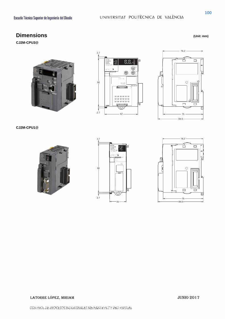
100
Latorre López, Miriam JuNio 2017
Dimensions (Unit: mm)
CJ2M-CPU3@
2.7
90
76.2
2.7 62
75
84.5
CJ2M-CPU1@
2.7
90
2.7
31
76.2
75
84.5

101
Latorre López, Miriam JuNio 2017
Related Manuals
Cat. No. Model Manual Application Description
W472
CJ2H-CPU6@-EIP CJ2H-CPU6@ CJ2M-CPU@@
CJ-series CJ2 CPU Unit Hardware User’s Manual
Hardware specifications for CJ2 CPU Units
Describes the following for CJ2 CPU Units: Overview and features Basic system configuration Part nomenclature and functions Mounting and setting procedure Remedies for errors
Also refer to the Software User’s Manual (W473).
W473
CJ2H-CPU6@-EIP CJ2H-CPU6@ CJ2M-CPU@@
CJ-series CJ2 CPU Unit Software User’s Manual
Software specifications for CJ2 CPU Units
Describes the following for CJ2 CPU Units: CPU Unit operation Internal memory Programming Settings Functions built into the CPU Unit
Also refer to the Hardware User’s Manual (W472)
W474
CJ2H-CPU6@-EIP CJ2H-CPU6@ CJ2M-CPU3@ CJ2M-CPU1@ CS1G/H-CPU@@H CS1G/H-CPU@@-V1 CJ1G/H-CPU@@H CJ1G-CPU@@ CJ1M-CPU@@ NSJ@-@@@@(@)-@@@
CS/CJ/NSJ-series Instructions Reference Manual
Information on instructions
Describes each programming instruction in detail. Also refer to the Software User’s Manual (W473) when you do programming.
W342
CJ2H-CPU6@-EIP CJ2H-CPU6@ CJ2M-CPU@@ CS1G/H-CPU@@H CS1G/H-CPU@@-V1 CS1D-CPU@@H CS1D-CPU@@S CS1W-SCU@@-V1 CS1W-SCB@@-V1 CJ1H-CPU@@H-R CJ1G/H-CPU@@H CJ1G-CPU@@P CJ1M-CPU@@ CJ1G-CPU@@ CJ1W-SCU@@-V1 CP1H-X@@@@-@ CP1H-XA@@@@-@ CP1H-Y@@@@-@ NSJ@-@@@@(@)-@@@
CS/CJ/CP/NSJ-series Communications Command Reference Manual
Information on communications for CS/CJ/CP-series CPU Units and NSJ-series Controllers
Describes C-mode commands and FINS commands Refer to this manual for a detailed description of commands for communications with the CPU Unit using C mode commands or FINS commands. Note: This manual describes the communications
commands that are addressed to CPU Units. The communications path that is used is not relevant and can include any of the following: serial ports on CPU Units, communications ports on Serial Communications Units/Boards, and Communications Units. For communications commands addressed to Special I/O Units or CPU Bus Units, refer to the operation manual for the related Unit.
W465
CJ2H-CPU6@-EIP
CJ2M-CPU3@ CS1W-EIP21 CJ1W-EIP21
CS and CJ Series EtherNet/IP Units CS1W-EIP21, CJ1W-
EIP21, CJ2H-CPU6@- EIP, CJ2M-CPU3@ Operation Manual
Information for EtherNet/IP function of CJ2M built-in Ethernet port
Describes EtherNet/IP port/units. A basic setting, a tag data link, FINS communication, and other function are described.
W463 CXONE-AL@@C-V@/
AL@@D-V@ CX-One Setup Manual
Installing software from the CX- One
Provides an overview of the CX-One FA Integrated Tool Package and describes the installation procedure.
W446
WS02-CXPC@-V@
CX-Programmer Operation Manual
Support Software for Windows computers
CX-Programmer operating procedure
Describes operating procedures for the CX-Programmer. Also refer to the Software User’s Manual (W473) and Instructions Reference Manual (W474) when you do programming.
W447
CX-Programmer Operation Manual Functions Blocks/ Structured Text
W469
CX-Programmer Operation Manual SFC Programming
W366
WS02-SIMC1-E
CS/CJ/CP/NSJ-series CX-Simulator Operation Manual
Operating procedures for CX- Simulator Simulation Support Software for Windows computers Using simulation in the CX- Programmer with CX- Programmer version 6.1 or higher
Describes the operating procedures for the CX-Simulator. When you do simulation, also refer to the CX-Programmer Operation Manual (W446), Software User’s Manual (W473), and CS/CJ/NSJ series Instructions Reference Manual (W474).
W464
CXONE-AL@@C-V@/ CXONE-AL@@D-V@
CS/CJ/CP/NSJ-series CX-Integrator Network Configuration Software Operation Manual
Network setup and monitoring
Describes the operating procedures for the CX-Integrator.