eSCRIBE Agenda Package - Festivals & Events - Wellington ...
Upload
khangminh22Category
view
0download
0
TOWN OF WELLINGTON
WELLINGTON, COLORADO
BIDDING REQUIREMENTSAND
CONTRACT DOCUMENTS
for the construction of the
WELLINGTON WATER RECLAMATION FACILITY PHASE 3IMPROVEMENTS AND EXPANSION
VOLUME 2DIVISION 21 THROUGH DIVISION 30
****
****
JACOBS
Denver, CO
December 2021
© Jacobs 2021. All rights reserved.This document and the ideas and designs incorporated herein, as an instrument of professional service, is the property ofJacobs and is not to be used in whole or part, for any other project without the written authorization of Jacobs.
Project No. WXXZ2950 Copy No.


WELLINGTON WATER RECLAMATION FACILITYPHASE 3 IMPROVEMENTS AND EXPANSION
PW\DEN003\WXXZ2950 TABLE OF CONTENTSDECEMBER 2021 00 01 10 - 1©COPYRIGHT 2021 JACOBS
TABLE OF CONTENTS
Pages
VOLUME 1
PART 1—CONTRACTING REQUIREMENTS
PROJECT FORMS
00 61 13.13 Performance Bond Form ........................................................ 1-00 61 13.16 Payment Bond Form .............................................................. 1-
CONDITIONS OF THE CONTRACT
00 72 00 General Conditions ................................................................ 1-00 73 00 Supplementary Conditions ..................................................... 1-
PART 2—SPECIFICATIONS
DIVISION 01—GENERAL REQUIREMENTS
01 31 13 Project Coordination .............................................................. 1-01 31 19 Project Meetings .................................................................... 1-01 32 00 Construction Progress Documentation.................................... 1-01 33 00 Submittal Procedures ............................................................. 1-01 42 13 Abbreviations and Acronyms ................................................. 1-01 42 20 Metric Measurement .............................................................. 1-01 43 33 Manufacturers’ Field Services ................................................ 1-
Supplement:Manufacturer’s Certificate of Proper Installation .................... 1-
01 45 16.13 Contractor Quality Control ..................................................... 1-01 45 33 Special Inspection, Observation, and Testing ......................... 1-
Contractor’s Statement of Responsibility ............................... 1-Fabricator’s Certificate of Compliance ................................... 1-
01 50 00 Temporary Facilities and Controls ......................................... 1-01 57 13 Temporary Erosion and Sediment Control .............................. 1-01 61 00 Common Product Requirements ............................................. 1-
Supplement:Manufacturer’s Certificate of Compliance .............................. 1-
01 77 00 Closeout Procedures ............................................................... 1-01 78 23 Operation and Maintenance Data ........................................... 1-01 88 15 Anchorage and Bracing .......................................................... 1-01 91 14 Equipment Testing and Facility Startup .................................. 1-

WELLINGTON WATER RECLAMATION FACILITYPHASE 3 IMPROVEMENTS AND EXPANSION
Pages
TABLE OF CONTENTS PW\DEN003\WXXZ295000 01 10 - 2 DECEMBER 2021
©COPYRIGHT 2021 JACOBS
DIVISION 02—EXISTING CONDITIONS
02 41 00 Demolition............................................................................. 1-
DIVISION 03—CONCRETE
03 01 32 Repair of Vertical and Overhead Concrete Surfaces ............... 1-03 01 33 Repair of Horizontal Concrete Surfaces ................................. 1-03 10 00 Concrete Forming and Accessories ........................................ 1-03 15 00 Concrete Joints and Accessories ............................................ 1-03 21 00 Steel Reinforcement............................................................... 1-03 24 00 Fibrous Reinforcing ............................................................... 1-03 30 00 Cast-in-Place Concrete........................................................... 1-
Supplements:Concrete Mix Design, Class 5000F3S1P2C2 ......................... 1-Concrete Mix Design, Class 4500F2S1P1C1 ......................... 1-Concrete Mix Design, Class SM00F2S1P2C1 ........................ 1-Concrete Mix Design, Class 4500F1S1P0C1 ......................... 1-Concrete Mix Design, Class CF00F1S1P0C1......................... 1-Concrete Mix Design, Class 4500F3S1P1C2 ......................... 1-Concrete Mix Design, Class GT00F1S1P0C1 ........................ 1-
03 35 00 Concrete Finishing ................................................................. 1-03 39 00 Concrete Curing..................................................................... 1-03 62 00 Grouting ................................................................................ 1-
Supplement:24-hour Evaluation of Nonshrink Grout Test Form and Grout Testing Procedures .................................................... 1-
03 64 23 Epoxy Resin Injection Grouting ............................................. 1-
DIVISION 04—MASONRY
04 21 13.13 Masonry Veneer .................................................................... 1-04 22 00 Concrete Unit Masonry .......................................................... 1-
DIVISION 05—METALS
05 05 19 Post-Installed Anchors ........................................................... 1-05 05 23 Welding ................................................................................. 1-
Supplement:Welding and Nondestructive Testing Table ............................ 1-
05 12 00 Structural Steel Framing ........................................................ 1-05 21 19 Open Web Steel Joist Framing ............................................... 1-05 31 00 Steel Decking ........................................................................ 1-05 50 00 Metal Fabrications ................................................................. 1-

WELLINGTON WATER RECLAMATION FACILITYPHASE 3 IMPROVEMENTS AND EXPANSION
Pages
PW\DEN003\WXXZ2950 TABLE OF CONTENTSDECEMBER 2021 00 01 10 - 3©COPYRIGHT 2021 JACOBS
05 52 16 Aluminum Railings ................................................................ 1-05 53 00 Metal Gratings ....................................................................... 1-
DIVISION 06—WOOD, PLASTICS, AND COMPOSITES
06 10 00 Rough Carpentry .................................................................... 1-06 41 00 Architectural Wood Casework ............................................... 1-
DIVISION 07—THERMAL AND MOISTURE PROTECTION
07 11 13 Bituminous Dampproofing ..................................................... 1-07 13 13 Bituminous Sheet Waterproofing ........................................... 1-07 17 00 Bentonite Waterproofing ........................................................ 1-07 19 00 Water Repellents .................................................................... 1-07 21 00 Thermal Insulation ................................................................. 1-07 26 16 Belowgrade Vapor Retarders ................................................. 1-07 40 00 Roofing and Siding Panels ..................................................... 1-07 53 23 Ethylene-Propylene-Diene-Monomer Roofing ....................... 1-07 62 00 Sheet Metal Flashing and Trim .............................................. 1-07 70 01 Roof Specialties and Accessories ........................................... 1-07 84 00 Firestopping ........................................................................... 1-07 92 00 Joint Sealants ......................................................................... 1-
DIVISION 08—OPENINGS
08 11 01 Steel Door Assemblies ........................................................... 1-08 30 00 Specialty Doors ...................................................................... 1-08 51 13 Aluminum Windows .............................................................. 1-08 71 00 Door Hardware ...................................................................... 1-08 80 00 Glazing .................................................................................. 1-08 90 00 Louvers .................................................................................. 1-
DIVISION 09—FINISHES
09 22 16 Nonstructural Metal Framing ................................................. 1-09 29 00 Gypsum Board ....................................................................... 1-09 30 00 Tiling ..................................................................................... 1-09 51 23 Acoustical Tile Ceilings ......................................................... 1-09 77 01 Fiberglass-Reinforced Plastic (FRP) Panel Walls ................... 1-09 90 00 Painting and Coating .............................................................. 1-
Supplements:Paint System Data Sheet (PSDS) ............................................ 1-Paint Product Data Sheet (PPDS) ........................................... 1-

WELLINGTON WATER RECLAMATION FACILITYPHASE 3 IMPROVEMENTS AND EXPANSION
Pages
TABLE OF CONTENTS PW\DEN003\WXXZ295000 01 10 - 4 DECEMBER 2021
©COPYRIGHT 2021 JACOBS
DIVISION 10—SPECIALTIES
10 14 00 Signage .................................................................................. 1-Supplements:Sign Schedule ........................................................................ 1-Sign Schedule—Hazardous Material Signs ........................... 1-
10 28 00 Toilet and Bath Accessories ................................................... 1-10 44 00 Fire Protection Specialties and Safety Equipment .................. 1-10 51 00 Lockers .................................................................................. 1-
DIVISION 11 (NOT USED)
DIVISION 12—FURNISHINGS
12 21 00 Window Blinds ...................................................................... 1-
DIVISION 13—SPECIAL CONSTRUCTION
13 34 19 Metal Building Systems ......................................................... 1-
DIVISION 14 THROUGH DIVISION 20 (NOT USED)
VOLUME 2
DIVISION 21—FIRE SUPPRESSION
21 13 13 Wet-Pipe Sprinkler Systems .................................................. 1-
DIVISION 22—PLUMBING
22 07 00 Plumbing Piping Insulation .................................................... 1-22 10 01 Plumbing Piping and Accessories .......................................... 1-22 30 00 Plumbing Equipment ............................................................. 1-
Supplements:Gas Water Heater (Commercial) Data Sheet .......................... 1-Electric Water Heater (Commercial) Data Sheet .................... 1-Domestic Water Expansion Tank Data Sheet ......................... 1-Domestic Hot Water Circulating Pump Data Sheet ................ 1-Backflow Preventers Data Sheet ............................................ 1-
22 40 00 Plumbing Fixtures.................................................................. 1-

WELLINGTON WATER RECLAMATION FACILITYPHASE 3 IMPROVEMENTS AND EXPANSION
Pages
PW\DEN003\WXXZ2950 TABLE OF CONTENTSDECEMBER 2021 00 01 10 - 5©COPYRIGHT 2021 JACOBS
DIVISION 23—HEATING, VENTILATING, AND AIR-CONDITIONING (HVAC)
23 05 14 HVAC Adjustable Frequency Drives ..................................... 1-23 05 93 Testing, Adjusting, and Balancing for HVAC ........................ 1-23 07 00 HVAC Insulation ................................................................... 1-23 09 00 Instrumentation and Control Devices for HVAC .................... 1-23 09 13 HVAC Controls, Field Components, and Instruments ............ 1-23 09 23 Direct-Digital Control System for HVAC .............................. 1-23 31 13 Metal Ducts and Accessories.................................................. 1-23 34 00 HVAC Fans ........................................................................... 1-23 37 00 Air Outlets and Inlets ............................................................. 1-23 77 00 Air Handling Units ................................................................. 1-23 81 00 Unitary Air-Conditioning Equipment ..................................... 1-23 82 00 Terminal Heating and Cooling Units ...................................... 1-
DIVISION 24 AND DIVISION 25 (NOT USED)
DIVISION 26—ELECTRICAL
26 05 02 Basic Electrical Requirements ................................................ 1-26 05 04 Basic Electrical Materials and Methods .................................. 1-26 05 05 Conductors............................................................................. 1-26 05 26 Grounding and Bonding for Electrical Systems ...................... 1-26 05 33 Raceway and Boxes ............................................................... 1-26 05 70 Electrical Systems Analysis ................................................... 1-26 08 00 Commissioning of Electrical Systems .................................... 1-26 09 13 Power Measurement and Control ........................................... 1-26 14 13 Switchboards ......................................................................... 1-26 20 00 Low-Voltage AC Induction Motors ........................................ 1-26 22 00 Low-Voltage Transformers .................................................... 1-26 24 16 Panelboards............................................................................ 1-26 24 19 Low-Voltage Motor Control................................................... 1-26 27 26 Wiring Devices ...................................................................... 1-26 29 23 Low-Voltage Adjustable Frequency Drive System ................. 1-26 32 13.13 Diesel Engine Generator Set .................................................. 1-26 36 23 Bypass-Isolation Automatic Transfer Switches ...................... 1-26 41 00 Facility Lightning Protection .................................................. 1-26 43 00 Surge Protective Devices ....................................................... 1-26 50 00 Lighting ................................................................................. 1-
DIVISION 27 (NOT USED)

WELLINGTON WATER RECLAMATION FACILITYPHASE 3 IMPROVEMENTS AND EXPANSION
Pages
TABLE OF CONTENTS PW\DEN003\WXXZ295000 01 10 - 6 DECEMBER 2021
©COPYRIGHT 2021 JACOBS
DIVISION 28—ELECTRONIC SAFETY AND SECURITY
28 31 00 Fire Detection and Alarm ....................................................... 1-Supplements:Sequence of Operations Matrix .............................................. 1-Plant Fire Alarm Riser Diagram ............................................. 1-Fire and Emergency Alarm System ........................................ 1-
DIVISION 29 AND DIVISION 30 (NOT USED)
VOLUME 3
DIVISION 31—EARTHWORK
31 05 23 Cement and Concrete for Earthwork ...................................... 1-31 10 00 Site Clearing .......................................................................... 1-31 23 13 Subgrade Preparation ............................................................. 1-31 23 16 Excavation ............................................................................. 1-31 23 19.01 Dewatering ............................................................................ 1-31 23 23 Fill and Backfill ..................................................................... 1-31 23 23.15 Trench Backfill ...................................................................... 1-31 32 00 Soil Stabilization ................................................................... 1-31 32 19.16 Geotextile .............................................................................. 1-31 37 00 Riprap .................................................................................... 1-31 41 00 Shoring .................................................................................. 1-
DIVISION 32—EXTERIOR IMPROVEMENTS
32 11 23 Aggregate Base Course .......................................................... 1-32 12 16 Asphalt Paving ...................................................................... 1-32 13 13 Concrete Paving..................................................................... 1-
DIVISION 33—UTILITIES
33 05 13 Manholes ............................................................................... 1-33 05 16.13 Precast Concrete Utility Structure .......................................... 1-33 41 01 Storm Drain Sanitary Sewer and Drainage Piping .................. 1-33 41 01.05 Reinforced Concrete Data Sheet ............................................ 1-33 44 13.13 Catch Basins .......................................................................... 1-
DIVISION 34 (NOT USED)

WELLINGTON WATER RECLAMATION FACILITYPHASE 3 IMPROVEMENTS AND EXPANSION
Pages
PW\DEN003\WXXZ2950 TABLE OF CONTENTSDECEMBER 2021 00 01 10 - 7©COPYRIGHT 2021 JACOBS
DIVISION 35—WATERWAY AND MARINE CONSTRUCTION
35 20 16.25 Fabricated Slide Gates and Stop Logs .................................... 1-Supplement:Slide Gate Schedule ............................................................... 1-
DIVISION 36 THROUGH DIVISION 39 (NOT USED)
DIVISION 40—PROCESS INTERCONNECTIONS
40 05 15 Piping Support Systems ......................................................... 1-Supplements:Table 1: Nonchemical Areas .................................................. 1-Table 2: Chemical Areas ........................................................ 1-
40 05 33 Pipe Heat Tracing .................................................................. 1-40 27 00 Process Piping—General........................................................ 1-40 27 00.01 Cement-Mortar, Glass, and Ceramic-Epoxy-Lined Ductile
Iron Pipe and Fittings Data Sheet ........................................ 1-40 27 00.03 Carbon Steel Pipe and Fittings—General Service
Data Sheet ........................................................................... 1-40 27 00.08 Stainless Steel Pipe and Fittings—General Service
Data Sheet ........................................................................... 1-40 27 00.10 Polyvinyl Chloride (PVC) Pipe and Fittings Data Sheet ......... 1-40 27 00.11 Chlorinated Polyvinyl Chloride (CPVC) Pipe and
Fittings Data Sheet .............................................................. 1-40 27 00.13 Copper and Copper Alloy Pipe, Tubing, and Fittings
Data Sheet ........................................................................... 1-40 27 00.15 Double Wall Containment Piping Data Sheet ......................... 1-40 27 00.22 PVC Pipe and Fittings—Special Service Data Sheet .............. 1-40 27 01 Process Piping Specialties ...................................................... 1-40 27 02 Process Valves and Operators ................................................ 1-
Supplements:Electrically Actuated Valve Schedule..................................... 1-Self-Regulated Valve Schedule .............................................. 1-
40 42 13 Process Piping Insulation ....................................................... 1-Supplement:Service and Insulation Thickness Table .................................. 1-

WELLINGTON WATER RECLAMATION FACILITYPHASE 3 IMPROVEMENTS AND EXPANSION
Pages
TABLE OF CONTENTS PW\DEN003\WXXZ295000 01 10 - 8 DECEMBER 2021
©COPYRIGHT 2021 JACOBS
40 80 01 Process Piping Leakage Testing ............................................. 1-40 90 00 Instrumentation and Control for Process Systems................... 1-
Supplements:Input/Output List ................................................................... 1-Process Control Narratives (PCN) .......................................... 1-Instrument List ...................................................................... 1-Preparation for Testing and Functional Test Forms ................ 1-Performance Test Sheet ......................................................... 1-
40 92 01 Control Panels ....................................................................... 1-Supplements:Control Panel Schedule .......................................................... 1-
40 95 80 Fiber Optic Communication System ...................................... 1-Supplements:As-Built Fiber Optic Cable Installation Form ......................... 1-As-Built Conduit/Innerduct Installation Form ........................ 1-
40 99 90 Package Control Systems ....................................................... 1-
VOLUME 4
DIVISION 41—MATERIAL PROCESSING AND HANDLING EQUIPMENT
41 22 13.13 Overhead Cranes ................................................................... 1-Supplements:Crane Data Sheet: Facility 350 Screw Press Bridge Crane ..... 1-Crane Dimension Sheet: Facility 350 Screw Press Bridge Crane ....................................................................... 1-Crane Data Sheet: Facility 550 UV Workstation Crane .......... 1-Crane Dimension Sheet: Facility UV Workstation Crane ....... 1-
41 22 23.19 Monorail Hoists ..................................................................... 1-Supplements:Influent Pump Station Data Sheet .......................................... 1-Influent Pump Station Hoist/Monorail Dimension Sheet ........ 1-Step Feed Process Building, Lower Level Pump Room Data Sheet .......................................................................... 1-Step Feed Process Building, Lower Level Pump Room Hoist/Monorail Dimension Sheet ........................................ 1-Step Feed Process Building, Upper Level Polymer Room Data Sheet .......................................................................... 1-Step Feed Process Building, Upper Level Polymer Room Hoist/Monorail Dimension Sheet ........................................ 1-
DIVISION 42 (NOT USED)

WELLINGTON WATER RECLAMATION FACILITYPHASE 3 IMPROVEMENTS AND EXPANSION
Pages
PW\DEN003\WXXZ2950 TABLE OF CONTENTSDECEMBER 2021 00 01 10 - 9©COPYRIGHT 2021 JACOBS
DIVISION 43—PROCESS GAS AND LIQUID HANDLING, PURIFICATION,AND STORAGE EQUIPMENT
43 22.56.01 Submersible Propeller Pumps ................................................. 1-Supplements:Mixed Liquor Return Pump Numbers 1 and 2 Data Sheet ..... 1-
DIVISION 44—POLLUTION AND WASTE CONTROL EQUIPMENT
44 42 19.04 Rotary Positive Displacement Blower .................................... 1-Supplements:Blowers 1, 2, and 4 Induction Motor Data Sheet .................... 1-Blowers 3 and 5 Induction Motor Data Sheet ......................... 1-
44 42 19.05 High Speed Turbo Air Blowers .............................................. 1-44 42 24.03 Secondary Clarifier Mechanism (Suction Header/
Manifold Type) ................................................................... 1-Supplement:Secondary Clarifiers 5 and 6 Induction Motor Data Sheet ...... 1-
44 42 25.02 Secondary Clarifier Launder Cover ........................................ 1-44 42 28 Weir and Baffle Plates ........................................................... 1-44 42 30 Floating Decanters ................................................................. 1-44 42 35 Single Entry Drum Screen and Screenings Washer
Compactor .......................................................................... 1-Supplements:Drum Screen Motors 1 and 2 Induction Motor Data Sheet...... 1-Screenings Washer Compactors 1 and 2 Induction Motor Data Sheet ................................................................. 1
44 42 40 Vortex Grit Chamber Equipment ............................................ 1-Supplement:Induction Motor Data Sheet ................................................... 1-
44 42 41 Separator and Grit Washer/Classifier ..................................... 1-Supplement:Induction Motor Data Sheet ................................................... 1-
44 42 48.04 Automatic Composite Sampler(Refrigerated, Peristaltic Type) .............................................. 1-
44 42 56.01 Screw-Induced Flow Centrifugal Pumps ................................ 1-Supplement:RAS Pump Nos. 5, 5/6, and 6 Data Sheet .............................. 1

WELLINGTON WATER RECLAMATION FACILITYPHASE 3 IMPROVEMENTS AND EXPANSION
Pages
TABLE OF CONTENTS PW\DEN003\WXXZ295000 01 10 - 10 DECEMBER 2021
©COPYRIGHT 2021 JACOBS
44 42 56.04 Submersible Pumps ............................................................... 1-Supplements:Aerobic Digester Transfer Pumps 5 and 6 Data Pumps and Motor Data Sheet ......................................................... 1-NPW Supply Pumps Data Sheet............................................. 1-Influent Pumps Nos. 1, 2, 3, and 4 Data Sheet ........................ 1-RAS/WAS Sump Pump No. 1 Data Sheet .............................. 1-
44 42 56.12 Induced Flow (Recessed Impeller) Centrifugal Pumps ........... 1-Supplement:Grit Pumps Nos. 1 and 2 Pump Data Sheet. ........................... 1-
44 42 56.14 Lobe Pumps ........................................................................... 1-Supplements:Screw Press Feed Pumps 1 and 2 Data Sheet.......................... 1-WAS Pumps 5 and 6 Data Sheet ............................................ 1-Scum Pumps 5/6 Data Sheet .................................................. 1-
44 42 56.16 Peristaltic Tube Pump ............................................................ 1-Supplements:Sodium Hypochlorite Feed Pump 1 Data Sheet ...................... 1-Ferric Chloride Feed Pump 1 Data Sheet ............................... 1-Glycerin Feed Pumps 1 and 2 Data Sheet ............................... 1-
44 44 63.01 Polymer Feed System, Liquid ................................................ 1-Supplement:Polymer Feed Pumps 1 and 2 Data Sheet ............................... 1-
44 44 73 UV Disinfection System ........................................................ 1-44 45 16.01 Coarse Bubble Air Diffuser System ....................................... 1-44 45 16.02 Fine Bubble Air Diffuser System ........................................... 1-44 45 16.10 Compressed Gas Mixing System............................................ 1-44 46 13.02 Screw Conveyor System ........................................................ 1-
Supplement:Shaftless Screw Conveyors Induction Motors Data Sheet ...... 1-
44 46 22 Dewatering Screw Press ........................................................ 1-Supplements:Screw Press Induction Motor Data Sheet ............................... 1-Sludge Polymer/Mixer Induction Motor Data Sheet ............... 1-Screw Press Washwater Booster Pumps 1 and 2 Data Sheet ... 1-
DIVISION 45 THROUGH DIVISION 49 (NOT USED)
VOLUME 5
PART 3—DRAWINGS
END OF SECTION

WELLINGTON WATER RECLAMATION FACILITY PHASE 3 IMPROVEMENTS AND EXPANSION
PW\DEN003\WXXZ2950 WET-PIPE SPRINKLER SYSTEMS DECEMBER 2021 21 13 13 - 1 ©COPYRIGHT 2021 JACOBS
SECTION 21 13 13 WET-PIPE SPRINKLER SYSTEMS
PART 1 GENERAL
1.01 REFERENCES
A. The following is a list of standards which may be referenced in this section:
1. National Fire Protection Association (NFPA): a. 13, Installation of Sprinkler Systems. b. 14, Installation of Standpipe and Hose Systems. c. 25, Standard For the Inspections, Testing, and Maintenance of
Water Based Fire Protection Systems. d. 70, National Electrical Code (NEC). e. 1963, Standard for Fire Hose Connections.
2. U.S. Code of Federal Regulations (CFR).
1.02 DEFINITIONS
A. Abbreviations:
1. American National Taper Pipe Thread (NPT). 2. Authority having jurisdiction (AHJ). 3. Hertz (Hz). 4. Pounds per square inch, gauge (psig). 5. Single-pole, double-throw (SPDT). 6. Volts alternating current (V ac). 7. Volts direct current (V dc).
B. High-Pressure Sprinkler Piping: Wet-pipe sprinkler system piping designed to operate at working pressure higher than standard 175 psig, but not higher than 250 psig.
C. Standard-Pressure Sprinkler Piping: Wet-pipe sprinkler system piping designed to operate at working pressure of 175 psig maximum.
D. Wet-Pipe Sprinkler System: Automatic sprinklers are attached to piping containing water and that is connected to water supply through alarm valve. Water discharges immediately from sprinklers when they are opened. Sprinklers open when heat melts fusible link or destroys frangible device.
WELLINGTON WATER RECLAMATION FACILITY PHASE 3 IMPROVEMENTS AND EXPANSION
WET-PIPE SPRINKLER SYSTEMS PW\DEN003\WXXZ2950 21 13 13 - 2 DECEMBER 2021 ©COPYRIGHT 2021 JACOBS
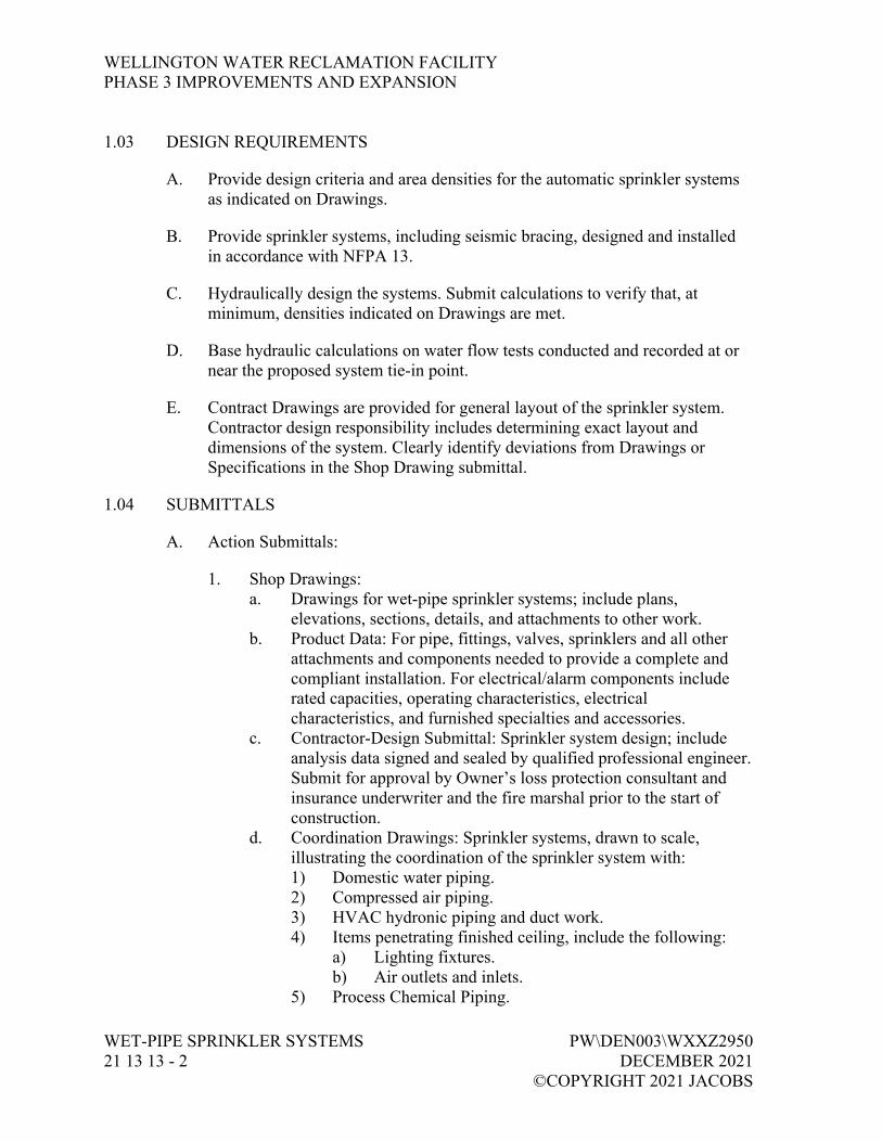
1.03 DESIGN REQUIREMENTS
A. Provide design criteria and area densities for the automatic sprinkler systems as indicated on Drawings.
B. Provide sprinkler systems, including seismic bracing, designed and installed in accordance with NFPA 13.
C. Hydraulically design the systems. Submit calculations to verify that, at minimum, densities indicated on Drawings are met.
D. Base hydraulic calculations on water flow tests conducted and recorded at or near the proposed system tie-in point.
E. Contract Drawings are provided for general layout of the sprinkler system. Contractor design responsibility includes determining exact layout and dimensions of the system. Clearly identify deviations from Drawings or Specifications in the Shop Drawing submittal.
1.04 SUBMITTALS
A. Action Submittals:
1. Shop Drawings: a. Drawings for wet-pipe sprinkler systems; include plans,
elevations, sections, details, and attachments to other work. b. Product Data: For pipe, fittings, valves, sprinklers and all other
attachments and components needed to provide a complete and compliant installation. For electrical/alarm components include rated capacities, operating characteristics, electrical characteristics, and furnished specialties and accessories.
c. Contractor-Design Submittal: Sprinkler system design; include analysis data signed and sealed by qualified professional engineer. Submit for approval by Owner’s loss protection consultant and insurance underwriter and the fire marshal prior to the start of construction.
d. Coordination Drawings: Sprinkler systems, drawn to scale, illustrating the coordination of the sprinkler system with: 1) Domestic water piping. 2) Compressed air piping. 3) HVAC hydronic piping and duct work. 4) Items penetrating finished ceiling, include the following:
a) Lighting fixtures. b) Air outlets and inlets.
5) Process Chemical Piping.

WELLINGTON WATER RECLAMATION FACILITY PHASE 3 IMPROVEMENTS AND EXPANSION
PW\DEN003\WXXZ2950 WET-PIPE SPRINKLER SYSTEMS DECEMBER 2021 21 13 13 - 3 ©COPYRIGHT 2021 JACOBS
6) Process Chemical Equipment. 7) Equipment Floor Hatches.
B. Informational Submittals:
1. Qualification Data: Qualified installer, design technician, and professional engineer.
2. Approved Sprinkler Piping Drawings: Working plans, prepared according to NFPA 13, approved by authorities having jurisdiction, including hydraulic calculations if applicable.
3. Welding certificates. 4. Manufacturer’s printed installation instructions. 5. Fire hydrant flow test report. 6. Field test reports and certificates. 7. Field quality control reports. 8. Operation and Maintenance Data as specified in Section 01 78 23,
Operation and Maintenance Data.
1.05 QUALITY ASSURANCE
A. Comply with the applicable International Fire Code and NFPA 13, Fire Prevention Code, building codes, and government regulations, and requirements of the Owner’s loss protection consultant and insurance underwriter.
B. Provide approvals, permits, and required inspections.
C. Provide materials and equipment UL listed and in compliance with applicable NFPA standards and fire marshal’s requirements. Submit documentation that the specific items furnished under this section for this Project conform to such requirements.
D. Welding Qualifications: Refer to NFPA 13 for qualifications and restrictions.
E. Preinstallation Meeting:
1. In accordance with Section 01 31 19, Project Meetings. 2. Convene minimum 1 week prior to commencing work of this section.
1.06 QUALIFICATIONS
A. Provide layout drawings for fire protection systems prepared by or under the supervision of a NICET Fire Protection Engineering Technician, Level 3 or Level 4, subfield of Fire Protection Engineering Water-Based Systems Layout or as otherwise permitted by State or local Statute. If required by State or local

WELLINGTON WATER RECLAMATION FACILITY PHASE 3 IMPROVEMENTS AND EXPANSION
WET-PIPE SPRINKLER SYSTEMS PW\DEN003\WXXZ2950 21 13 13 - 4 DECEMBER 2021 ©COPYRIGHT 2021 JACOBS
Statute, provide Drawings reviewed and stamped by a registered professional engineer having registration in the State of Colorado or other procedure acceptable to the AHJ. Submit a copy of the current certification of the NICET technician and the registered engineer with the initial submittal.
1.07 PROJECT CONDITIONS
A. Interruption of Existing Sprinkler Service:
1. Do not interrupt sprinkler service to facilities occupied by Owner or others unless permitted under the following conditions and then only after arranging to provide temporary sprinkler service according to requirements indicated: a. Notify Engineer and Owner no fewer than 2 days in advance of
proposed interruption of sprinkler service. b. Do not interrupt sprinkler service without Owner’s written
permission.
1.08 EXTRA MATERIALS
A. Furnish, tag, and box for shipment and storage the following spare parts, special tools, and materials:
Item Quantity
Sprinkler Cabinet One each
Sprinklers Six of each different size unit
Special tools required to maintain or dismantle
One complete set for each different size unit
B. Delivery: In accordance with Section 01 61 00, Common Product Requirements.
PART 2 PRODUCTS
2.01 GENERAL
A. Electrical Components, Devices, and Accessories: Listed and labeled as defined in NFPA 70, by a qualified testing agency, and marked for intended location and application.
B. Sprinkler system equipment, specialties, accessories, installation, and testing: Comply with NFPA 13.
WELLINGTON WATER RECLAMATION FACILITY PHASE 3 IMPROVEMENTS AND EXPANSION
PW\DEN003\WXXZ2950 WET-PIPE SPRINKLER SYSTEMS DECEMBER 2021 21 13 13 - 5 ©COPYRIGHT 2021 JACOBS
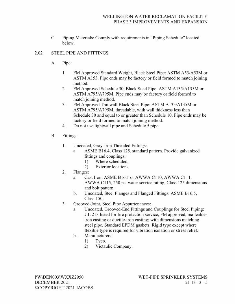
C. Piping Materials: Comply with requirements in “Piping Schedule” located below.
2.02 STEEL PIPE AND FITTINGS
A. Pipe:
1. FM Approved Standard Weight, Black Steel Pipe: ASTM A53/A53M or ASTM A153. Pipe ends may be factory or field formed to match joining method.
2. FM Approved Schedule 30, Black Steel Pipe: ASTM A135/A135M or ASTM A795/A795M. Pipe ends may be factory or field formed to match joining method.
3. FM Approved Thinwall Black Steel Pipe: ASTM A135/A135M or ASTM A795/A795M, threadable, with wall thickness less than Schedule 30 and equal to or greater than Schedule 10. Pipe ends may be factory or field formed to match joining method.
4. Do not use lightwall pipe and Schedule 5 pipe.
B. Fittings:
1. Uncoated, Gray-Iron Threaded Fittings: a. ASME B16.4, Class 125, standard pattern. Provide galvanized
fittings and couplings: 1) Where scheduled. 2) Exterior locations.
2. Flanges: a. Cast Iron: ASME B16.1 or AWWA C110, AWWA C111,
AWWA C115, 250 psi water service rating, Class 125 dimensions and bolt pattern.
b. Uncoated, Steel Flanges and Flanged Fittings: ASME B16.5, Class 150.
3. Grooved-Joint, Steel Pipe Appurtenances: a. Uncoated, Grooved-End Fittings and Couplings for Steel Piping:
UL 213 listed for fire protection service, FM approved, malleable-iron casting or ductile-iron casting; with dimensions matching steel pipe. Standard EPDM gaskets. Rigid type except where flexible type is required for vibration isolation or stress relief.
b. Manufacturers: 1) Tyco. 2) Victaulic Company.

WELLINGTON WATER RECLAMATION FACILITY PHASE 3 IMPROVEMENTS AND EXPANSION
WET-PIPE SPRINKLER SYSTEMS PW\DEN003\WXXZ2950 21 13 13 - 6 DECEMBER 2021 ©COPYRIGHT 2021 JACOBS
4. Certify fittings, couplings, flanges, and flange adaptors used with thinwall pipe or Schedule 10 pipe by the fitting manufacturer as dimensionally compatible with and fully connectable to the pipe used without field modifications.
5. Welded or segmented fittings are not acceptable.
2.03 PIPING SCHEDULE
A. Piping Between Fire Department Connections and Check Valves: Galvanized, standard-weight steel pipe with grooved ends; grooved-end fittings, grooved-end pipe couplings, and grooved joints.
B. Standard-pressure, Wet-pipe Sprinkler System, 2 inches and Smaller:
1. Standard-weight black steel pipe with threaded ends; uncoated, gray-iron threaded fittings; and threaded joints.
2. Standard-weight black steel pipe with plain ends; uncoated, plain-end pipe fittings; and twist-locked joints.
3. Standard-weight galvanized steel pipe with plain ends; galvanized, plain-end pipe fittings; and twist-locked joints.
4. Standard-weight black steel pipe with roll- grooved ends; uncoated, grooved-end fittings for steel piping; grooved-end pipe couplings for steel piping; and grooved joints.
5. Standard-weight galvanized steel pipe with cut-grooved ends; galvanized, grooved-end fittings for steel piping; grooved-end pipe couplings for steel piping; and grooved joints.
6. Standard-weight black steel pipe with plain ends; steel welding fittings; and welded joints.
7. Schedule 5 steel pipe; steel pressure-seal fittings; and pressure-sealed joints.
8. Type L, hard copper tube with plain ends; wrought-copper solder-joint fittings; and brazed joints.
9. Type L, hard copper tube with plain ends; copper pressure-seal fittings; and pressure-sealed joints.
10. 2 inches, Type L, hard copper tube with roll-grooved ends; copper, grooved-end fittings; grooved-end tube couplings; and grooved joints.
C. Standard-pressure, Wet-pipe Sprinkler System, 2-1/2 inches to 6 inches:
1. Standard-weight black steel pipe with threaded ends; uncoated, gray-iron threaded fittings; and threaded joints.
2. Standard-weight black steel pipe with roll-grooved ends; uncoated, grooved-end fittings for steel piping; grooved-end pipe couplings for steel piping; and grooved joints.

WELLINGTON WATER RECLAMATION FACILITY PHASE 3 IMPROVEMENTS AND EXPANSION
PW\DEN003\WXXZ2950 WET-PIPE SPRINKLER SYSTEMS DECEMBER 2021 21 13 13 - 7 ©COPYRIGHT 2021 JACOBS
3. Standard-weight galvanized steel pipe with cut-grooved ends; galvanized, grooved-end fittings for steel piping; grooved-end pipe couplings for steel piping; and grooved joints.
4. Standard-weight black steel pipe with plain ends; steel welding fittings; and welded joints.
2.04 PIPING JOINING MATERIALS
A. Pipe Flange Gasket Materials: AWWA C110/A21.10, rubber, flat face, 1/8 inch (3.2 mm) thick.
1. Class 125, Cast-Iron Flanges and Class 150, Bronze Flat-Face Flanges: Full-face gaskets.
2. Class 250, Cast-Iron Flanges and Class 300, Steel Raised-Face Flanges: Ring-type gaskets.
B. Metal Pipe Flange Bolts and Nuts: ASTM A307 Grade B, galvanized, with galvanized nuts in accordance with ASTM A563 Grade A.
C. Unions: 150 psig galvanized malleable iron, ASTM A197, threaded, ground joint, integral seat.
2.05 VALVES
A. General Requirements:
1. Valves shall be UL listed or FM approved. 2. Minimum Pressure Rating for Standard-Pressure Piping: 175 psig. 3. Minimum Pressure Rating for High-Pressure Piping: 250 psig. 4. Make flanged end and wafer type valves compatible for installation with
flanges as specified.
B. Ball Valves:
1. Standard: UL 1091, except with ball instead of disc. 2. 1-1/2 Inches and Smaller: Bronze body with threaded ends. 3. 2 Inches and 2-1/2 Inches: Bronze body with threaded ends or ductile-
iron body with grooved ends. 4. 3 Inches: Ductile-iron body with grooved ends. 5. Manufacturers:
a. Anvil International, Inc. b. Victaulic Company.

WELLINGTON WATER RECLAMATION FACILITY PHASE 3 IMPROVEMENTS AND EXPANSION
WET-PIPE SPRINKLER SYSTEMS PW\DEN003\WXXZ2950 21 13 13 - 8 DECEMBER 2021 ©COPYRIGHT 2021 JACOBS
C. Iron Butterfly Valves:
1. Standard: UL 1091. 2. Pressure Rating: 175 psig. 3. Body Material: Cast or ductile iron. 4. Stem: Stainless steel. 5. Style: Lug or wafer. 6. Manufacturers:
a. Global Safety Products, Inc. b. NIBCO INC. c. Tyco. d. Victaulic Company.
D. Check Valves:
1. Standard: UL 312. 2. Pressure Rating: 250 psig minimum. 3. Type: Swing check or spring assisted swing check. 4. Body Material: Cast or ductile iron. 5. End Connections: Flanged or grooved. 6. Manufacturers:
a. Kennedy Valve. b. Mueller Company. c. NIBCO INC. d. Tyco. e. Victaulic Company.
E. Iron OS&Y Gate Valves:
1. Standard: UL 262. 2. Pressure Rating: 250 psig minimum. 3. Body Material: Cast or ductile iron. 4. End Connections: Flanged or grooved. 5. Manufacturers:
a. Kennedy. b. Mueller Co.; Water Products Division. c. NIBCO INC. d. Tyco. e. Victaulic Company.
F. Indicating-Type Butterfly Valves:
1. Standard: UL 1091. 2. Pressure Rating: 175 psig minimum.

WELLINGTON WATER RECLAMATION FACILITY PHASE 3 IMPROVEMENTS AND EXPANSION
PW\DEN003\WXXZ2950 WET-PIPE SPRINKLER SYSTEMS DECEMBER 2021 21 13 13 - 9 ©COPYRIGHT 2021 JACOBS
3. Valves 2 Inches and Smaller: a. Valve Type: Ball or butterfly. b. Body Material: Bronze. c. End Connections: Threaded or grooved.
4. Valves 2-1/2 Inches and Larger: a. Valve Type: Butterfly. b. Body Material: Cast or ductile iron. c. Stem Material: Stainless steel. d. End Connections: Flanged, grooved, or wafer.
5. Valve Operation: Weatherproof actuator housing with handwheel and integral dual single-pole, double-throw (SPDT) (Form C) contacts, rated for a minimum of 10 amps at 125/250V ac, 2 amps at 30V dc, 10 mA minimum at 24V dc in tamper-proof cover with mounting and required hardware for attachment to indicated valves visual indicating device.
6. Manufacturers: a. Kennedy Valve. b. NIBCO INC. c. Tyco. d. Victaulic Company.
G. NRS Gate Valves:
1. Standard: UL 262. 2. Pressure Rating: 250 psig minimum. 3. Body Material: Cast iron with indicator post flange. 4. Stem: Nonrising. 5. End Connections: Flanged or grooved. 6. Manufacturers:
a. Kennedy Valve. b. Mueller Co. c. NIBCO INC. d. Tyco. e. Victaulic Company.
2.06 TRIM AND DRAIN VALVES
A. General:
1. Standard: UL’s “Fire Protection Equipment Directory” listing or FM “Approval Guide,” listing.
2. Pressure Rating: 175 psig minimum.
WELLINGTON WATER RECLAMATION FACILITY PHASE 3 IMPROVEMENTS AND EXPANSION
WET-PIPE SPRINKLER SYSTEMS PW\DEN003\WXXZ2950 21 13 13 - 10 DECEMBER 2021 ©COPYRIGHT 2021 JACOBS
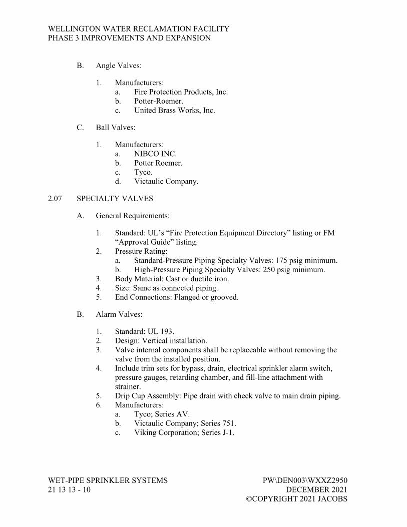
B. Angle Valves:
1. Manufacturers: a. Fire Protection Products, Inc. b. Potter-Roemer. c. United Brass Works, Inc.
C. Ball Valves:
1. Manufacturers: a. NIBCO INC. b. Potter Roemer. c. Tyco. d. Victaulic Company.
2.07 SPECIALTY VALVES
A. General Requirements:
1. Standard: UL’s “Fire Protection Equipment Directory” listing or FM “Approval Guide” listing.
2. Pressure Rating: a. Standard-Pressure Piping Specialty Valves: 175 psig minimum. b. High-Pressure Piping Specialty Valves: 250 psig minimum.
3. Body Material: Cast or ductile iron. 4. Size: Same as connected piping. 5. End Connections: Flanged or grooved.
B. Alarm Valves:
1. Standard: UL 193. 2. Design: Vertical installation. 3. Valve internal components shall be replaceable without removing the
valve from the installed position. 4. Include trim sets for bypass, drain, electrical sprinkler alarm switch,
pressure gauges, retarding chamber, and fill-line attachment with strainer.
5. Drip Cup Assembly: Pipe drain with check valve to main drain piping. 6. Manufacturers:
a. Tyco; Series AV. b. Victaulic Company; Series 751. c. Viking Corporation; Series J-1.

WELLINGTON WATER RECLAMATION FACILITY PHASE 3 IMPROVEMENTS AND EXPANSION
PW\DEN003\WXXZ2950 WET-PIPE SPRINKLER SYSTEMS DECEMBER 2021 21 13 13 - 11 ©COPYRIGHT 2021 JACOBS
2.08 FIRE DEPARTMENT CONNECTIONS
A. Exposed-Type:
1. Standard: UL 405. 2. Type: Exposed, projecting, for wall mounting. 3. Pressure Rating: 175 psig minimum. 4. Body Material: Corrosion-resistant metal. 5. Inlets: Brass with Storz connections according to NFPA 1963 and
matching local fire department requirements; include extension pipe nipples, brass lugged swivel connections, and check devices or clappers. Verify inlet connections with local fire authority.
6. Caps: Brass, lugged type, with gasket and chain. 7. Escutcheon Plate: Round, brass, wall type. 8. Outlet: Back, with pipe threads. 9. Number of Inlets: Two. 10. Escutcheon Plate Marking: Similar to “AUTO SPKR.” 11. Finish: Rough brass or bronze. 12. Outlet Size: 4 inches. 13. Manufacturers:
a. Elkhart Brass Mfg. Company, Inc. b. Guardian Fire Equipment, Inc. c. Potter-Roemer. d. Tyco.
B. Storz Connection:
1. Standard: UL 405. 2. Type: Storz. 3. Pressure Rating: 175 psig minimum. 4. Body Material: Forged aluminum with. 5. Inlets: 4-inch locking Storz fitting. Verify size with local fire
department. 6. Caps: Blind Storz cap with securing cable or chain, forged aluminum
with powder coating finish matching inlet fitting. 7. Escutcheon Plate: Square, brass, wall type. 8. Outlet: 4-inch NPT threads. 9. Body Style: 30-degree angle pattern. 10. Number of Inlets: One. 11. Outlet Location: As indicated or as otherwise required for riser
configuration. 12. Escutcheon Plate Marking: Similar to “AUTO SPKR.” 13. Finish: Powder coat finish. 14. Outlet Size: 4 inches.

WELLINGTON WATER RECLAMATION FACILITY PHASE 3 IMPROVEMENTS AND EXPANSION
WET-PIPE SPRINKLER SYSTEMS PW\DEN003\WXXZ2950 21 13 13 - 12 DECEMBER 2021 ©COPYRIGHT 2021 JACOBS
15. Manufacturers: a. Guardian Fire Equipment, Inc. b. Potter Roemer.
C. Fire Department Outlet Test Fitting:
1. Brass body and polished brass plate lettered HYDRANT. 2. Polished brass female 4-inch NPT by 2-1/2-inch male hose thread
snoots with caps and chains. 3. Two-way hydrant with two outlets and inlet configuration as required
for location. 4. Manufacturers:
a. Elkhart Brass Mfg. Company, Inc. b. Guardian Fire Equipment, Inc. c. Potter Roemer. d. Tyco.
2.09 SPRINKLER SPECIALTY PIPE FITTINGS
A. Branch Outlet Fittings:
1. Standard: UL 213. 2. Pressure Rating: 175 psig minimum. 3. Body Material: Ductile-iron housing with EPDM seals and bolts and
nuts. 4. Type: Mechanical-cross fittings and mechanical-tee. 5. Configurations: Snap-on and strapless, ductile-iron housing with branch
outlets. 6. Size: Dimension to fit on sprinkler main and with outlet connections as
required to match connected branch piping. 7. Branch Outlets: Grooved, plain-end pipe, or threaded. 8. Manufacturers:
a. Tyco. b. Victaulic Company.
B. Flow Detection and Test Assemblies:
1. Standard: UL’s “Fire Protection Equipment Directory” listing or FM “Approval Guide” listing.
2. Pressure Rating: 175 psig minimum. 3. Body Material: Cast-iron or ductile-iron housing with orifice, sight
glass, and integral test valve. 4. Size: Same as connected piping. 5. Inlet and Outlet: Threaded or grooved.

WELLINGTON WATER RECLAMATION FACILITY PHASE 3 IMPROVEMENTS AND EXPANSION
PW\DEN003\WXXZ2950 WET-PIPE SPRINKLER SYSTEMS DECEMBER 2021 21 13 13 - 13 ©COPYRIGHT 2021 JACOBS
6. Manufacturers: a. Reliable Automatic Sprinkler Co., Inc. b. Tyco. c. Victaulic Company.
C. Branch Line Testers:
1. Standard: UL 199. 2. Pressure Rating: 175 psig. 3. Body Material: Brass. 4. Size: Same as connected piping. 5. Inlet: Threaded. 6. Drain Outlet: Threaded and capped. 7. Branch Outlet: Threaded, for sprinkler. 8. Manufacturers:
a. Elkhart Brass Mfg. Company, Inc. b. Potter-Roemer.
D. Sprinkler Inspector’s Test Fittings:
1. Standard: UL’s “Fire Protection Equipment Directory” listing or FM “Approval Guide” listing.
2. Pressure Rating: 175 psig minimum. 3. Body Material: Cast-bronze, cast-iron, or ductile-iron housing with sight
glass. 4. Size: Same as connected piping. 5. Inlet and Outlet: Threaded or grooved. 6. Manufacturers:
a. Tyco. b. Victaulic Company. c. Viking Corporation.
E. Flexible, Sprinkler Hose Fittings:
1. Standard: UL 1474. 2. Type: Flexible braided Type 304 stainless steel flexible tube hose for
connection to sprinkler, and with bracket for connection to ceiling grid. 3. Pressure Rating: 175 psig minimum. 4. Size: Same as connected piping, for sprinkler. 5. Manufacturers:
a. Fivalco Inc. b. FlexHead Industries, Inc. c. Gateway Tubing, Inc. d. Victaulic Company.

WELLINGTON WATER RECLAMATION FACILITY PHASE 3 IMPROVEMENTS AND EXPANSION
WET-PIPE SPRINKLER SYSTEMS PW\DEN003\WXXZ2950 21 13 13 - 14 DECEMBER 2021 ©COPYRIGHT 2021 JACOBS
2.10 SPRINKLERS
A. General:
1. Standard: UL’s “Fire Protection Equipment Directory” listing or FM “Approval Guide” listing.
2. Pressure Rating a. Residential Sprinklers: 175 psig maximum. b. Automatic Sprinklers: 175 psig minimum. c. High-Pressure Automatic Sprinklers: 250 psig minimum.
B. Sprinkler Schedule
1. Use sprinkler types below for the following applications: a. Rooms without Ceilings: Upright sprinklers. b. Rooms with Suspended Ceilings: Pendent sprinklers. c. Wall Mounting: Sidewall sprinklers. d. Spaces Subject to Freezing: Upright sprinklers.
2. Provide sprinkler types below with finishes indicated. a. Concealed Sprinklers: Rough brass, with factory-painted white
cover plate. b. Flush Sprinklers: Bright chrome, with painted white escutcheon. c. Recessed Sprinklers: Bright chrome, with bright chrome
escutcheon. d. Residential Sprinklers: Dull chrome. e. Upright Sprinklers: Chrome plated in finished spaces exposed to
view; rough bronze in unfinished spaces not exposed to view; wax coated where exposed to acids, chemicals, or other corrosive fumes.
C. Automatic Sprinklers with Heat-Responsive Element:
1. Nonresidential Applications: UL 199. 2. See Drawings for additional information. 3. Sprinkler Finishes:
a. Chrome plated. b. Bronze. c. Painted.
4. Special Coatings: a. Wax. b. Lead. c. Corrosion-resistant paint.

WELLINGTON WATER RECLAMATION FACILITY PHASE 3 IMPROVEMENTS AND EXPANSION
PW\DEN003\WXXZ2950 WET-PIPE SPRINKLER SYSTEMS DECEMBER 2021 21 13 13 - 15 ©COPYRIGHT 2021 JACOBS
5. Sprinkler Escutcheons: a. Escutcheons for concealed, flush, and recessed-type sprinklers are
specified with sprinklers. b. Ceiling Mounting: Chrome-plated steel, one piece, flat. c. Sidewall Mounting: Chrome-plated steel, one piece, flat.
6. Sprinkler Guards: a. Standard: UL 199. b. Type: Wire cage with fastening device for attaching to sprinkler.
7. Manufacturers: a. Reliable Automatic Sprinkler Co., Inc. b. Tyco. c. Victaulic Company. d. Viking Corporation.
2.11 ALARM DEVICES
A. Alarm-device types shall match piping and equipment connections.
B. Water Motor-operated Alarm:
1. Standard: UL 753. 2. Type: Mechanically operated, with Pelton wheel. 3. Alarm Gong: Cast aluminum with red enamel factory finish. 4. Size: 10-inch (250-mm) diameter. 5. Components: Shaft length, bearings, and sleeve to suit wall
construction. 6. Inlet: 3/4 inch. 7. Outlet: 1-inch drain connection. 8. UL listed and FM approved. 9. Manufacturers:
a. Tyco. b. Victaulic Company. c. Viking Corporation.
C. Electrically Operated Alarm Bell:
1. Standard: UL 464. 2. Type: Vibrating, metal alarm bell. 3. Size: Minimum 6-inch (150-mm) diameter. 4. Finish: Red enamel factory finish, suitable for outdoor use. 5. UL listed and FM approved.

WELLINGTON WATER RECLAMATION FACILITY PHASE 3 IMPROVEMENTS AND EXPANSION
WET-PIPE SPRINKLER SYSTEMS PW\DEN003\WXXZ2950 21 13 13 - 16 DECEMBER 2021 ©COPYRIGHT 2021 JACOBS
6. Manufacturers: a. Fire-Lite Alarms, Inc.; a Honeywell company. b. Notifier; a Honeywell company. c. Potter Electric Signal Company.
D. Water Flow Indicators:
1. Standard: UL 346. 2. Water Flow Detector: Electrically supervised. 3. Components: Provide device with two sets of SPDT (Form C) contacts.
Provide minimum switch electrical rating of 10 amps at 125/250V ac, 2 amps at 30V dc resistive, 10 mA at 24V dc.
4. Type: Paddle operated. 5. Pressure Rating: 250 psig. 6. Installation: Horizontal or vertical. 7. UL listed and FM approved. 8. Manufacturers:
a. Potter Electric Signal Company. b. System Sensor; a Honeywell company. c. Tyco. d. Viking Corporation.
E. Pressure Switches:
1. Standard: UL 346. 2. Type: Electrically supervised water flow switch with retard feature. 3. Components: Provide device with two sets of SPDT (Form C) contacts.
Provide minimum switch electrical rating of 10 amps at 125/250V ac, 2 amps at 30V dc resistive, 10 mA at 24V dc.
4. Operation: Rising pressure signals water flow. 5. UL listed and FM approved. 6. Manufacturers:
a. Potter Electric Signal Company. b. System Sensor; a Honeywell company. c. Tyco. d. Viking Corporation.
F. Valve Supervisory Switches:
1. Standard: UL 346. 2. Type: Electrically supervised.

WELLINGTON WATER RECLAMATION FACILITY PHASE 3 IMPROVEMENTS AND EXPANSION
PW\DEN003\WXXZ2950 WET-PIPE SPRINKLER SYSTEMS DECEMBER 2021 21 13 13 - 17 ©COPYRIGHT 2021 JACOBS
3. Components: Single unit composed of dual single-pole, double-throw (SPDT) (Form C) contacts, rated for a minimum of 10 amps at 125/250V ac, 2 amps at 30V dc, 10 mA minimum at 24V dc in tamper-proof cover with mounting hardware for attachment to indicated valves.
4. Design: Signals that controlled valve is in other than fully OPEN position.
5. UL listed and FM Approved. 6. Manufacturers:
a. ADT Security Services, Inc. b. Potter Electric Signal Company. c. System Sensor; a Honeywell company.
2.12 MANUAL CONTROL STATIONS
A. Description:
1. UL listed or FM approved. 2. Hydraulic operation, with union, 1/2-inch pipe nipple, and bronze ball
valve. 3. Metal enclosure labeled “MANUAL CONTROL STATION”. 4. Cover held closed by breakable strut to prevent accidental opening.
2.13 CONTROL PANELS
A. Description:
1. Single-area, two-area, or single-area cross-zoned control panel as indicated.
2. NEMA ICS 6, Type 1 enclosure with detector, alarm, and solenoid-valve circuitry for operation of deluge valves.
3. Contain power supply, battery charger, standby batteries, field-wiring terminal strip, electrically supervised solenoid valves, and polarized fire alarm bell, lamp test facility, single-pole, double-throw auxiliary alarm contacts, and rectifier.
4. UL listed and FM approved when used with thermal detectors and Class A detector circuit wiring.
5. Electrical Characteristics: 120V ac, 60 Hz, with 24V dc rechargeable batteries.
6. Manual Control Stations: Electric operation with metal enclosure. Include metal enclosure labeled “MANUAL CONTROL STATION” and cover held closed by breakable strut to prevent accidental opening.

WELLINGTON WATER RECLAMATION FACILITY PHASE 3 IMPROVEMENTS AND EXPANSION
WET-PIPE SPRINKLER SYSTEMS PW\DEN003\WXXZ2950 21 13 13 - 18 DECEMBER 2021 ©COPYRIGHT 2021 JACOBS
2.14 PRESSURE GAUGES
A. Description:
1. Standard: UL 393. 2. Dial Size: 3-1/2-inch to 4-1/2-inch (90-mm to 115-mm) diameter. 3. Pressure Gauge Range: 0 psig to 250 psig minimum. 4. Water System Piping Gauge: Include “WATER” or “AIR/WATER”
label on dial face. 5. Air System Piping Gauge: Include retard feature and “AIR” or
“AIR/WATER” label on dial face. 6. Manufacturers:
a. AMETEK; U.S. Gauge Division. b. Ashcroft, Inc. c. Brecco Corporation. d. WIKA Instrument Corporation.
2.15 SLEEVES AND PENETRATIONS FOR PIPING SYSTEMS
A. Sleeves:
1. Walls: a. Interior and Exterior Walls: Schedule 40 carbon steel. b. Concrete: Cast-iron wall sleeves with integrally cast water stop. c. Interior Partitions: 22-gauge (U.S. Standard) minimum galvanized
sheet steel. 2. Interior Floor: Schedule 40 carbon steel. 3. Slab on Grade: Cast-iron wall sleeves with integrally cast water stop. 4. Underground (Beneath Foundations, Footings, Grade Beams): Standard
weight corrugated steel, bituminous coating inside and outside, with close-fitting bituminous coated plate at each end.
B. Sleeve and Penetration Packing:
1. Modular Wall and Casting Seals: Link-Seal as manufactured by Thunderline Corporation, Flexicraft PipeSeal. Sleeve and modular wall and casting seal to be furnished together as a single integrated unit.
2. Penetration Packing (With or Without Sleeve) for Interior Walls and Interior Elevated Floors: a. UL listed, FM approved materials and sealant systems, by 3M
Fire Barrier Wrap/Strip FS-195+. b. Flexible elastomeric material unless specified otherwise. c. Include additional materials and accessories to meet requirements
of manufacturer and this section. d. Compatible with penetrated surface.

WELLINGTON WATER RECLAMATION FACILITY PHASE 3 IMPROVEMENTS AND EXPANSION
PW\DEN003\WXXZ2950 WET-PIPE SPRINKLER SYSTEMS DECEMBER 2021 21 13 13 - 19 ©COPYRIGHT 2021 JACOBS
e. Hazard Ratings: 1) Pipes Penetrating Fire Rated Walls, Fire Rated Ceilings, and
Fire Rated Floor Slabs (1 hour or greater): Material having maximum flame spread of 25 and maximum smoke develop rating of 50, selected to maintain fire rating of penetrated surface.
2) Pipes Penetrating Other Interior Walls: Material having maximum smoke develop rating of 50, selected to prevent smoke transmission through penetration.
3) Pipes Penetrating Nonrated Interior Floors: Mineral wool and fire-rated caulk.
PART 3 EXECUTION
3.01 PREPARATION
A. Perform fire hydrant flow test according to NFPA 13 and NFPA 291.
B. Submit test results promptly.
3.02 SERVICE-ENTRANCE PIPING
A. Connect sprinkler piping to water service piping for service entrance to building.
B. Install shutoff valve, backflow preventer, pressure gauge, drain, and other accessories indicated at connection to water service piping.
3.03 WATER SUPPLY CONNECTIONS
A. Install shutoff valve, check valve, pressure gauge, and drain at connection to water service.
3.04 PIPING INSTALLATION
A. Locations and Arrangements:
1. Install piping in accordance with approved Shop Drawings, schematics, and diagrams which indicate general location and arrangement of piping.
2. Deviations from approved piping Shop Drawings require written approval from AHJ. Submit written approval to Engineer before deviating from approved working plans.
WELLINGTON WATER RECLAMATION FACILITY PHASE 3 IMPROVEMENTS AND EXPANSION
WET-PIPE SPRINKLER SYSTEMS PW\DEN003\WXXZ2950 21 13 13 - 20 DECEMBER 2021 ©COPYRIGHT 2021 JACOBS
B. Piping Standard: Comply with NFPA 13 sprinkler piping installation requirements.
C. Seismic Design Category (SDC) is shown on Structural General Notes on Drawings.
D. Based on the SDC, seismic bracing is required for this Project.
E. Use listed fittings to make changes in direction, branch takeoffs from mains, and reductions in pipe sizes.
F. Install unions adjacent to each valve in pipe 2 inches and smaller.
G. Install “Inspector’s Test Connections” in sprinkler system piping, complete with shutoff valve, sized and located according to NFPA 13.
H. Install sprinkler piping with drains for complete system drainage.
I. Install sprinkler control valves, test assemblies, and drain risers adjacent to standpipes when sprinkler piping is connected to standpipes.
J. Install automatic drain valve at each check valve for fire department connection, to drain piping between fire department connection and check valve. Install drain piping to and spill over floor drain or to outside building.
K. Install alarm devices in piping systems.
L. Install hangers and supports for sprinkler system piping according to NFPA 13. Comply with NFPA 13 requirements for hanger materials.
M. Install pressure gauges on riser or feed main, at each sprinkler test connection, and at top of each standpipe.
1. Include pressure gauges with connection not less than 1/4 inch and with soft metal seated globe valve, arranged to drain pipe between gauge and valve.
2. Install gauges to permit removal, and where not subject to freezing.
N. Fill sprinkler system piping with water.
O. Install electric heating cables and pipe insulation on sprinkler piping in areas subject to freezing.
P. Install sleeves for piping penetrations of walls, ceilings, and floors. Comply with requirements for sleeves.

WELLINGTON WATER RECLAMATION FACILITY PHASE 3 IMPROVEMENTS AND EXPANSION
PW\DEN003\WXXZ2950 WET-PIPE SPRINKLER SYSTEMS DECEMBER 2021 21 13 13 - 21 ©COPYRIGHT 2021 JACOBS
Q. Install sleeve seals for piping penetrations of concrete walls and slabs. Comply with requirements for sleeve seals.
R. Install escutcheons for piping penetrations of walls, ceilings, and floors. Comply with requirements for escutcheons.
3.05 JOINT CONSTRUCTION
A. Steel Piping:
1. Pressure-Sealed Joints: Join lightwall steel pipe and steel pressure-seal fittings with tools recommended by fitting manufacturer.
2. Welded Joints: Construct joints according to NFPA 13, using qualified processes and welding operators according to Article Quality Assurance. a. Shop-weld pipe joints where welded piping is indicated. b. Do not use welded joints for galvanized-steel pipe.
3. Cut-Grooved and Roll-Grooved Joints: a. Cut square-edge groove or roll rounded-edge groove in end of
pipe according to NFPA 13. b. Install grooved joints in accordance with the manufacturer’s latest
published installation instructions. c. Provide grooved ends clean and free from indentations,
projections, and tool marks. d. Join steel pipe and grooved-end fittings according to NFPA 13 for
steel pipe joints.
B. Dissimilar-Material Piping Joints: Make joints using adapters compatible with materials of both piping systems.
3.06 VALVE AND SPECIALTIES INSTALLATION
A. Install listed fire protection valves, trim and drain valves, specialty valves and trim, controls, and specialties according to NFPA 13 and AHJ.
B. Install listed fire protection shutoff valves supervised open, located to control sources of water supply other than fire department connections. Install permanent identification signs indicating portion of system controlled by each valve.
C. Install check valve in each water supply connection. Install backflow preventers instead of check valves in potable water supply sources.

WELLINGTON WATER RECLAMATION FACILITY PHASE 3 IMPROVEMENTS AND EXPANSION
WET-PIPE SPRINKLER SYSTEMS PW\DEN003\WXXZ2950 21 13 13 - 22 DECEMBER 2021 ©COPYRIGHT 2021 JACOBS
D. Specialty Valves:
1. General Requirements: Install in vertical position for proper direction of flow, in main supply to system.
2. Alarm Valves: Include bypass check valve and retarding chamber drain line connection.
E. Specialty Sprinkler Fittings: Install downstream of control valves instead of specified fittings if indicated in approved Shop Drawings.
3.07 SPRINKLER INSTALLATION
A. Install sprinklers in suspended ceilings in center of narrow dimension of acoustical ceiling panels.
B. Install dry-type sprinklers with water supply from heated space. Do not install pendent or sidewall, wet-type sprinklers in areas subject to freezing.
C. Install sprinklers into flexible, sprinkler hose fittings and install hose into bracket on ceiling grid.
D. Do not install any sprinklers that have been dropped, damaged, or show a visible loss of fluid. Never install any sprinkler with a cracked bulb.
E. Remove sprinkler bulb protector by hand. Do not use any tools or devices that could damage the bulb.
3.08 FIRE DEPARTMENT CONNECTION INSTALLATION
A. Install wall-type, fire department connection.
1. Install protective pipe bollards as shown on Drawings for each fire department connection.
B. Install automatic drain valve at each check valve for fire department connection.
3.09 IDENTIFICATION
A. Install labeling and pipe markers on equipment and piping according to NFPA 13 requirements.
B. Identify system components.
WELLINGTON WATER RECLAMATION FACILITY PHASE 3 IMPROVEMENTS AND EXPANSION
PW\DEN003\WXXZ2950 WET-PIPE SPRINKLER SYSTEMS DECEMBER 2021 21 13 13 - 23 ©COPYRIGHT 2021 JACOBS
3.10 FIELD QUALITY CONTROL
A. Tests and Inspections:
1. Leak Test: After installation, charge systems and test for leaks. Repair leaks and retest until leak free.
2. Test and adjust controls and safeties. Replace damaged and malfunctioning controls and equipment.
3. Flush, test, and inspect sprinkler systems according to NFPA 13. 4. Energize circuits to electrical equipment and devices. 5. Coordinate with fire alarm tests. Operate as required. 6. Coordinate with fire pump tests. Operate as required. 7. Demonstrate that equipment hose threads match local fire department
equipment.
B. Sprinkler piping system is defective if it does not pass tests and inspections.
C. Prepare test and inspection reports.
1. Field Test Reports and Certificates: Indicate and interpret test results for compliance with performance requirements and as described in NFPA 13; include “Contractor’s Material and Test Certificate for Aboveground Piping.”
3.11 MANUFACTURER’S SERVICES
A. Manufacturer’s Representative:
1. Present at Site or classroom designated by Owner, for minimum person-days listed below, travel time excluded: a. 1 person-day for installation assistance and inspection. b. 1 person-day for functional and performance testing and
completion of Manufacturer’s Certificate of Proper Installation. c. 1 person-day for prestartup classroom or Site training. d. 1 person-day for facility startup. e. 1 person-day for post-startup training of Owner’s personnel. Do
not commence training until a detailed lesson plan for each training activity has been accepted by Owner and Engineer.
B. See Section 01 43 33, Manufacturers’ Field Services, and Section 01 91 14, Equipment Testing and Facility Startup.

WELLINGTON WATER RECLAMATION FACILITY PHASE 3 IMPROVEMENTS AND EXPANSION
WET-PIPE SPRINKLER SYSTEMS PW\DEN003\WXXZ2950 21 13 13 - 24 DECEMBER 2021 ©COPYRIGHT 2021 JACOBS
3.12 CLEANING
A. Clean dirt and debris from sprinklers.
B. Remove and replace sprinklers with paint other than factory finish.
END OF SECTION
WELLINGTON WATER RECLAMATION FACILITY PHASE 3 IMPROVEMENTS AND EXPANSION
PW\DEN003\WXXZ2950 PLUMBING PIPING INSULATION DECEMBER 2021 22 07 00 - 1 ©COPYRIGHT 2021 JACOBS
SECTION 22 07 00 PLUMBING PIPING INSULATION
PART 1 GENERAL
1.01 REFERENCES
A. The following is a list of standards which may be referenced in this section:
1. American Society of Heating, Refrigerating & Air-Conditioning Engineers Inc. (ASHRAE): 90.1, Energy-Efficient Design of New Buildings except Low-Rise Residential Buildings.
2. ASTM International (ASTM): a. B209, Standard Specification for Aluminum and Aluminum-Alloy
Sheet and Plate. b. C533, Standard Specification for Calcium Silicate Block and Pipe
Thermal Insulation. c. C534, Standard Specification for Preformed Flexible Elastomeric
Cellular Thermal Insulation in Sheet and Tubular Form. d. C547, Standard Specification for Mineral Fiber Pipe Insulation.
3. National Fire Protection Association (NFPA): 255, Standard Method of Test of Surface Burning Characteristics of Building Materials.
1.02 SUBMITTALS
A. Action Submittals: Product description, include list of materials, thickness for each service scheduled, and locations.
B. Informational Submittals:
1. Proof of compliance for test of products for fire rating, corrosiveness, and compressive strength.
2. Manufacturer’s installation instructions.
1.03 QUALITY ASSURANCE
A. Provide standard, cataloged products, new and commercially available, suitable for service requiring high performance and reliability with low maintenance, and free from all defects.
B. Provide materials by firms engaged in the manufacture of insulation products of the types and characteristics specified herein, whose products have been in use for not less than 5 years.

WELLINGTON WATER RECLAMATION FACILITY PHASE 3 IMPROVEMENTS AND EXPANSION
PLUMBING PIPING INSULATION PW\DEN003\WXXZ2950 22 07 00 - 2 DECEMBER 2021 ©COPYRIGHT 2021 JACOBS
C. UL Listing or satisfactory certified test report from an approved testing laboratory is required to indicate fire hazard ratings for materials proposed for use do not exceed those specified.
1.04 DELIVERY, STORAGE, AND HANDLING
A. Manufacturer’s Stamp or Label:
1. Deliver insulation, jackets, cements, adhesives and coatings with a manufacturer’s stamp or label attached, giving name of manufacturer, brand, and description of material.
2. Insulation Packages and Containers: Mark “asbestos-free.”
PART 2 PRODUCTS
2.01 GENERAL
A. Insulation Exterior: Cleanable, grease-resistant, nonflaking, and nonpeeling.
B. Conform to referenced publications and specified temperature ranges and densities in pounds per cubic foot.
C. Insulation for Fittings, Flanges, and Valves: Premolded, precut, or job-fabricated insulation of same thickness and conductivity as used on adjacent piping.
D. Fire Resistance:
1. Provide noncombustible insulation, adhesives, vapor barrier materials and other accessories, except as specified herein.
2. Use no fugitive or corrosive treatments to impart flame resistance. 3. Flame proofing treatments subject to deterioration as a result of effects
of moisture or high humidity are not acceptable. 4. Fire Hazard Rating for Materials including Facings, Mastics, and
Adhesives: Not to exceed 25 for flame spread without evidence of continued progressive combustion, and 50 for smoke, developed as per tests conducted in accordance with NFPA 255 methods.
5. Materials exempt from fire-resistant rating: a. Nylon anchors. b. Treated wood inserts.
6. Materials exempt from fire-resistant rating when installed in outside locations, buried, or encased in concrete: a. Polyurethane insulation. b. PVC casing. c. Fiberglass-reinforced plastic casing.

WELLINGTON WATER RECLAMATION FACILITY PHASE 3 IMPROVEMENTS AND EXPANSION
PW\DEN003\WXXZ2950 PLUMBING PIPING INSULATION DECEMBER 2021 22 07 00 - 3 ©COPYRIGHT 2021 JACOBS
2.02 PIPE INSULATION
A. Type P1—Fiberglass (ASTM C547, Type 1 (Minus 20 Degrees F to 500 Degrees F):
1. Fiberglass, UL-rated, preformed, sectional rigid, minimum 4 pounds per cubic foot (pcf) density, K factor 0.23 maximum at 75 degrees F mean, with factory-applied all-service jacket (ASJ) composed of reinforced kraft paper and aluminum foil laminate. Provide jacket with self-sealing lap to facilitate closing longitudinal and end joints.
2. Manufacturers and Products: a. CertainTeed; Preformed Pipe Insulation. b. Johns Manville; Micro-Lok HP-T. c. Owens/Corning; Fiberglas Pipe Insulation. d. Knauf Pipe Insulation; Crown Pipe Insulation.
B. Type P2—Elastomeric (ASTM C534, Minus 40 Degrees F to 220 Degrees F):
1. Flexible, closed cell elastomeric. 2. Nominal 6 pcf density, K factor 0.27 maximum at 75 degrees F mean. 3. Water Vapor Transmission: 0.1 perm-inch, or less. 4. Manufacturers and Products:
a. Armacell; AP Armaflex. b. Nomaco; K-Flex LS.
2.03 INSULATION FINISH SYSTEMS
A. Type F1—PVC:
1. Polyvinyl chloride (PVC) jacketing, white, for straight run piping and fitting locations, temperatures to 150 degrees F.
2. Manufacturers and Products: a. Johns Manville; Zeston. b. Ceel-Co; 550.
B. Type F2—Paint:
1. Acrylic latex paint, white, and suitable for outdoor use. 2. Manufacturer and Product: Armstrong; WB Armaflex finish.

WELLINGTON WATER RECLAMATION FACILITY PHASE 3 IMPROVEMENTS AND EXPANSION
PLUMBING PIPING INSULATION PW\DEN003\WXXZ2950 22 07 00 - 4 DECEMBER 2021 ©COPYRIGHT 2021 JACOBS
C. Type F3—Aluminum:
1. Aluminum Roll Jacketing: For straight run piping, wrought aluminum Alloy 3003, Alloy 5005, Alloy 1100, or Alloy 3105 to ASTM B209 with H-14 temper, minimum 0.016-inch thickness, with smooth mill finish.
2. Moisture Barrier: Provide factory-applied moisture barrier, consisting of 40-pound kraft paper with 1-mil-thick low-density polyethylene film, heat and pressure bonded to inner surface of the aluminum jacketing.
3. Fitting Covers: Material as for aluminum roll jacketing, premolded, one- or two-piece covers, which includes elbows, tee/valves, endcaps, mechanical line couplings, and specialty fittings.
4. Manufacturer and Product: RPR Products; INSUL-MATE.
PART 3 EXECUTION
3.01 INSTALLATION OF INSULATION
A. Install insulation products in accordance with manufacturer’s written instructions, and in accordance with recognized industry practices.
B. Apply insulation over clean, finish painted, and dry surfaces.
C. Install insulation after piping system has been pressure tested and leaks corrected.
D. Use insulating cements, lagging adhesives, and weatherproof mastics recommended by insulation manufacturer.
E. Install insulation materials with smooth and even surfaces. Insulate each continuous run of piping with full-length units of insulation, with a single cut piece to complete the run. Do not use cut pieces of scraps abutting each other.
F. Butt insulation joints firmly together to ensure a complete and tight fit over surfaces to be covered.
G. Maintain integrity of vapor barrier jackets on pipe insulation, and protect to prevent puncture or other damage. Seal open ends of insulation with mastic. Sectionally seal butt ends of chilled water and condensate drain piping insulation at fittings with white vapor barrier coating.

WELLINGTON WATER RECLAMATION FACILITY PHASE 3 IMPROVEMENTS AND EXPANSION
PW\DEN003\WXXZ2950 PLUMBING PIPING INSULATION DECEMBER 2021 22 07 00 - 5 ©COPYRIGHT 2021 JACOBS
H. Cover valves, flanges, fittings, and similar items in each piping system with equivalent thickness and composition of insulation as applied to adjoining pipe run. Install factory molded, precut or job-fabricated units. Finish cold pipe fittings with white vapor barrier coating and hot piping with white vinyl acrylic mastic, both reinforced with glass cloth.
I. Extend piping insulation without interruption through walls, floors, and similar piping penetrations, except where otherwise indicated.
J. Install protective metal shields and foamglass inserts where pipe hangers bear on outside of insulation.
K. Insulation on piping that is to be heat traced shall be installed after installation of heat tape.
L. Insulate valve bodies, flanges, and pipe couplings.
M. Insulate and vapor seal hangers, supports, anchors, and other piping appurtenances that are secured directly to cold surfaces.
N. Do not insulate flexible pipe couplings and expansion joints.
O. Do not allow insulation to cover nameplates or code inspection stamps.
P. Install removable insulation sections on devices that require access for maintenance of equipment or removal, such as unions and strainer end plates.
Q. Connection to Existing Piping: Cut back existing insulation to remove portion damaged by piping revisions. Install new insulation.
R. Cold Surfaces: Provide continuous vapor seal on insulation on cold surfaces where vapor barrier jackets are used.
S. Placement:
1. Slip insulation on pipe or tubing before assembly, when practical, to avoid longitudinal seams.
2. Insulate valves and fittings with sleeved or cut pieces of same material. 3. Seal and tape joints.
T. Insulation at Hangers and Supports: Install under piping, centered at each hanger or support.
WELLINGTON WATER RECLAMATION FACILITY PHASE 3 IMPROVEMENTS AND EXPANSION
PLUMBING PIPING INSULATION PW\DEN003\WXXZ2950 22 07 00 - 6 DECEMBER 2021 ©COPYRIGHT 2021 JACOBS
U. Vapor Barrier:
1. Provide continuous vapor barrier at joints between rigid insulation and pipe insulation.
2. Install vapor barrier jackets with pipe hangers and supports outside jacket.
3. Do not use staples and screws to secure vapor sealed system components.
3.02 INSTALLATION OF INSULATION FINISH SYSTEMS
A. Use a continuous friction type joint to hold jacket in-place, providing positive weatherproof seal over entire length of jacket.
B. Secure circumferential joints with preformed snap straps containing weatherproof sealant.
C. On exterior piping, apply coating over insulation and vapor barrier to prevent damage when aluminum fitting covers are installed.
D. Do not use screws or rivets to fasten the fitting covers.
E. Install removable prefabricated aluminum covers on exterior flanges and unions.
F. Caulk and seal exterior joints to make watertight.
3.03 INSULATION APPLICATIONS
A. Potable Cold Water (W1), Nonpotable Water (W2, W3):
1. Type P2, elastomeric. 2. 1-inch thickness for all pipe sizes.
B. Potable Hot and Tempered Water:
1. Type P1, fiberglass. 2. 1-inch thickness for all pipe sizes.
C. Roof Drain and Overflow Drain Sump:
1. Type P1, fiberglass. 2. 1-inch thickness.
WELLINGTON WATER RECLAMATION FACILITY PHASE 3 IMPROVEMENTS AND EXPANSION
PW\DEN003\WXXZ2950 PLUMBING PIPING INSULATION DECEMBER 2021 22 07 00 - 7 ©COPYRIGHT 2021 JACOBS
D. Pipe Hangers:
1. Type P1, Fiberglass: UL-rated, preformed rigid pipe insulation inserts of thickness equal to adjoining insulation, 10 inches in length, with factory-applied, vinyl-coated and embossed vapor barrier jacket with self-sealing lap.
2. Type P2, Elastomeric: Rigid insulation section with 9-inch-long, 16-gauge galvanized steel saddle.
3.04 INSULATION FINISH APPLICATIONS
A. Piping Insulation (Concealed Areas): Factory finish.
B. Piping Insulation (Exposed to View, Indoors):
1. Admin, UV/Blower Building: Type F1, PVC. 2. Headworks Building, Process Building: Type F3, aluminum.
C. Piping Insulation (Outdoors):
1. Type F2, paint (for use with Type P2, elastomeric). 2. Type F3, aluminum.
D. Apply coating of insulating cement where needed to obtain smooth and continuous appearance.
3.05 FIELD QUALITY CONTROL
A. Test factory-applied materials assembled. Field-applied materials may be tested individually.
END OF SECTION


WELLINGTON WATER RECLAMATION FACILITY PHASE 3 IMPROVEMENTS AND EXPANSION
PW\DEN003\WXXZ2950 PLUMBING PIPING DECEMBER 2021 AND ACCESSORIES ©COPYRIGHT 2021 JACOBS 22 10 01 - 1
SECTION 22 10 01 PLUMBING PIPING AND ACCESSORIES
PART 1 GENERAL
1.01 REFERENCES
A. The following is a list of standards which may be referenced in this section:
1. American Gas Association (AGA): a. B109.1, Diaphragm Type Gas Displacement Meters (under
500 Cubic Feet Per Hour Capacity). b. B109.2, Diaphragm Type Gas Displacement Meters (500 Cubic
Feet Per Hour Capacity and Over). 2. American National Standards Institute (ANSI). 3. American Public Works Association (APWA): Uniform Color Code. 4. American Society of Sanitary Engineering (ASSE):
a. 1010, Performance Requirements for Water Hammer Arresters. b. 1050, Performance Requirements for Stack Air Admittance
Valves for Sanitary Drainage Systems. c. 1070, Performance Requirements for Water Temperature Limiting
Devices. 5. ASTM International (ASTM):
a. A47/A47M, Standard Specification for Ferritic Malleable Iron Castings.
b. A53/A53M, Standard Specification for Pipe, Steel, Black and Hot-Dipped, Zinc-Coated, Welded and Seamless.
c. A74, Standard Specification for Cast Iron Soil Pipe and Fittings. d. A105/A105M, Standard Specification for Carbon Steel Forgings
for Piping Applications. e. A126, Standard Specification for Gray Iron Castings for Valves,
Flanges, and Pipe Fittings. f. A179/A179M, Standard Specification for Seamless Cold-Drawn
Low-Carbon Steel Heat-Exchanger and Condenser Tubes. g. A181/A181M, Standard Specification for Carbon Steel Forgings,
for General-Purpose Piping. h. A193/A193M, Standard Specification for Alloy-Steel and
Stainless Steel Bolting for High Temperature or High Pressure Service and Other Special Purpose Applications.
i. A194/A194M, Standard Specification for Carbon and Alloy Steel Nuts for Bolts for High Pressure or High Temperature Service, or Both.
j. A197/A197M, Standard Specification for Cupola Malleable Iron.

WELLINGTON WATER RECLAMATION FACILITY PHASE 3 IMPROVEMENTS AND EXPANSION
PLUMBING PIPING PW\DEN003\WXXZ2950 AND ACCESSORIES DECEMBER 2021 22 10 01 - 2 ©COPYRIGHT 2021 JACOBS
k. A234/A234M, Standard Specification for Piping Fittings of Wrought Carbon Steel and Alloy Steel for Moderate and High Temperature Service.
l. A307, Standard Specification for Carbon Steel Bolts and Studs, 60,000 psi Tensile Strength.
m. A351/A351M, Standard Specification for Castings, Austenitic, for Pressure-Containing Parts.
n. A518/A518M, Standard Specification for Corrosion-Resistant High-Silicon Iron Castings.
o. A536, Standard Specification for Ductile Iron Castings. p. A563, Standard Specification for Carbon and Alloy Steel Nuts. q. A861, Standard Specification for High-Silicon Iron Pipe and
Fittings. r. A888, Standard Specification for Hubless Cast Iron Soil Pipe and
Fittings for Sanitary and Storm Drain, Waste, and Vent Piping Applications.
s. B32, Standard Specification for Solder Metal. t. B61, Standard Specification for Steam or Valve Bronze Castings. u. B62, Standard Specification for Composition Bronze or Ounce
Metal Castings. v. B75/B75M, Standard Specification for Seamless Copper Tube. w. B88, Standard Specification for Seamless Copper Water Tube. x. B98/B98M, Standard Specification for Copper-Silicon Alloy Rod,
Bar, and Shapes. y. B127, Standard Specification for Nickel-Copper Alloy (UNS
N04400) Plate, Sheet, and Strip. z. B139/B139M, Standard Specification for Phosphor Bronze Rod,
Bar, and Shapes. aa. B164, Standard Specification for Nickel-Copper Alloy Rod, Bar,
and Wire. bb. B194, Standard Specification for Copper-Beryllium Alloy Plate,
Sheet, Strip, and Rolled Bar. cc. B306, Standard Specification for Copper Drainage Tube (DWV). dd. C564, Standard Specification for Rubber Gaskets for Cast Iron
Soil Pipe and Fittings. ee. C1277, Standard Specification for Shielded Couplings Joining
Hubless Cast Iron Soil Pipe and Fittings. ff. C1460, Standard Specification for Shielded Transition Couplings
for use with Dissimilar DWV Pipe and Fittings Above Ground. gg. C1540, Standard Specification for Heavy Duty Shielded
Couplings Joining Hubless Cast Iron Soil Pipe and Fittings. hh. D1784, Standard Specification for Rigid Poly(Vinyl Chloride)
(PVC) Compounds and Chlorinated Poly(Vinyl Chloride) (CPVC) Compounds.
WELLINGTON WATER RECLAMATION FACILITY PHASE 3 IMPROVEMENTS AND EXPANSION
PW\DEN003\WXXZ2950 PLUMBING PIPING DECEMBER 2021 AND ACCESSORIES ©COPYRIGHT 2021 JACOBS 22 10 01 - 3
ii. D1785, Standard Specification for Poly(Vinyl Chloride) (PVC) Plastic Pipe, Schedules 40, 80, and 120.
jj. D2000, Standard Classification System for Rubber Products in Automotive Applications.
kk. D2239, Standard Specification for Polyethylene (PE) Plastic Pipe (SIDR-PR) Based on Controlled Inside Diameter.
ll. D2466, Standard Specification for Poly(Vinyl Chloride) (PVC) Plastic Pipe Fittings, Schedule 40.
mm. D2513, Standard Specification for Polyethylene (PE) Gas Pressure Pipe, Tubing, and Fittings.
nn. D2564, Standard Specification for Solvent Cements for Poly(Vinyl Chloride) (PVC) Plastic Piping Systems.
oo. D2683, Standard Specification for Socket-Type Polyethylene Fittings for Outside Diameter-Controlled Polyethylene Pipe and Tubing.
pp. D2855, Standard Practice for Making Solvent-Cemented Joints with Poly(Vinyl Chloride) (PVC) Pipe and Fittings.
qq. D3035, Standard Specification for Polyethylene (PE) Plastic Pipe (DR-PR) Based on Controlled Outside Diameter.
rr. D3261, Standard Specification for Butt Heat Fusion Polyethylene (PE) Plastic Fittings for Polyethylene (PE) Plastic Pipe and Tubing.
ss. D3350, Standard Specification for Polyethylene Plastics Pipe and Fittings Materials.
tt. E438, Standard Specification for Glasses in Laboratory Apparatus.
uu. F656, Standard Specification for Primers for Use in Solvent Cement Joints of Poly(Vinyl Chloride) (PVC) Plastic Pipe and Fittings.
vv. F714, Standard Specification for Polyethylene (PE) Plastic Pipe (SDR-PR) Based on Outside Diameter.
ww. F1412, Standard Specification for Polyolefin Pipe and Fittings for Corrosive Waste Drainage Systems.
xx. F1924, Standard Specification for Plastic Mechanical Fittings for Use on Outside Diameter Controlled Polyethylene Gas Distribution Pipe and Tubing.
yy. F1973, Standard Specification for Factory Assembled Anodeless Risers and Transition Fittings in Polyethylene (PE) and Polyamide 11 (PA11) and Polyamide 12 (PA12) Fuel Gas Distribution Systems.
WELLINGTON WATER RECLAMATION FACILITY PHASE 3 IMPROVEMENTS AND EXPANSION
PLUMBING PIPING PW\DEN003\WXXZ2950 AND ACCESSORIES DECEMBER 2021 22 10 01 - 4 ©COPYRIGHT 2021 JACOBS
6. American Water Works Association (AWWA): a. C104/A21.4, Standard for Cement-Mortar Lining for Ductile-Iron
Pipe and Fittings for Water. b. C110/A21.10, Standard for Ductile-Iron and Gray-Iron Fittings. c. C111/A21.11, Standard for Rubber-Gasket Joints for Ductile-Iron
Pressure Pipe and Fittings. d. C115/A21.15, Standard for Flanged Ductile-Iron Pipe with
Ductile-Iron or Gray-Iron Threaded Flanges. e. C151/A21.51, Standard for Ductile-Iron Pipe, Centrifugally Cast. f. C203, Coal-Tar Protective Coatings and Linings for Steel Water
Pipelines, Enamel and Tape, Hot-Applied. g. C207, Steel Pipe Flanges for Waterworks Service - Sizes 4 In.
Through 144 In. (100 mm Through 3,600 mm). h. C606, Grooved and Shouldered Joints. i. C651, Disinfecting Water Mains.
7. Cast Iron Soil Pipe Institute (CISPI): a. 301, Standard Specification for Hubless Cast Iron Pipe and
Fittings for Sanitary and Storm Drain, Waste, and Vent Piping Applications.
b. 310, Specification for Couplings for Use in Connection with Hubless Cast Iron Soil Pipe and Fittings for Sanitary and Strom Drain, Waste, and Vent Piping Applications.
8. NSF International (NSF): a. NSF/ANSI 61, Drinking Water System Components - Health
Effects. b. NSF/ANSI 372, Drinking Water System Components - Lead
Content. 9. Plumbing and Drainage Institute (PDI): WH 201, Water Hammer
Arresters Standard.
1.02 DESIGN REQUIREMENTS
A. Where pipe diameter, thickness, pressure class, pressure rating, or thrust restraint is not shown or specified, design piping system in accordance with the following:
1. Local plumbing code.
WELLINGTON WATER RECLAMATION FACILITY PHASE 3 IMPROVEMENTS AND EXPANSION
PW\DEN003\WXXZ2950 PLUMBING PIPING DECEMBER 2021 AND ACCESSORIES ©COPYRIGHT 2021 JACOBS 22 10 01 - 5
1.03 SUBMITTALS
A. Action Submittals:
1. Product data sheets. 2. Shop Drawings:
a. Show Contractor recommended changes in location of fixtures or equipment.
b. Anchorage and bracing drawings and data sheets, as required by Section 01 88 15, Anchorage and Bracing.
3. Isometric riser diagrams.
B. Informational Submittals:
1. Anchorage and bracing calculations as required by Section 01 88 15, Anchorage and Bracing.
2. Changes in location of equipment or piping that affect connecting or adjacent work, before proceeding with the Work.
3. Complete list of products proposed for installation. 4. Test records produced during testing. 5. For Polyethylene (PE) Pipe:
a. Certificates of qualification for persons to be fusing PE pipe. b. Experience and training record of persons to be fusing PE pipe. c. Testing Plan:
1) Submit at least 15 days prior to testing; include following as a minimum: a) Testing dates. b) Piping systems and section(s) to be tested. c) Method of isolation. d) Method of conveying water from source to system
being tested. d. Certifications of Calibration: Approved testing laboratory
certificate if pressure gauge for hydrostatic test has been previously used. If pressure gauge is new, no certificate is required.
e. Test report documentation.
PART 2 PRODUCTS
2.01 GENERAL
A. Components and Materials in Contact with Water for Human Consumption: Comply with the requirements of the Safe Drinking Water Act and other applicable federal, state, and local requirements. Provide certification by manufacturer or an accredited certification organization recognized by the

WELLINGTON WATER RECLAMATION FACILITY PHASE 3 IMPROVEMENTS AND EXPANSION
PLUMBING PIPING PW\DEN003\WXXZ2950 AND ACCESSORIES DECEMBER 2021 22 10 01 - 6 ©COPYRIGHT 2021 JACOBS
Authority Having Jurisdiction that components and materials comply with the maximum lead content standard in accordance with NSF/ANSI 61 and NSF/ANSI 372.
1. Use or reuse of components and materials without a traceable certification is prohibited.
2.02 PIPING
A. Piping Schedule: Refer to Section 40 27 00, Process Piping—General.
B. Piping Material: Refer to Section 40 27 00, Process Piping—General.
2.03 HOSE VALVES AND HYDRANTS
A. HV-1, Hose Valve:
1. Sill faucet with removable T-handle, polished chrome finish, and 3/4-inch inlet and hose connection.
2. Manufacturers and Products: a. Chicago; No. 387, with No. E27 vacuum breaker. b. Acorn; No. 8121.
B. HV-2, Hose Valve:
1. Cast bronze globe valve, 1-1/2-inch size, with NPT screwed ends, union bonnet, rising stem, Teflon disc, hand wheel, and NPT by NST hose thread adapter outlet connection.
2. Rated 150-pound SWP, 300-WOG. 3. Manufacturers and Products:
a. Nibco; Catalog No. T-235-Y, Angle No. T-335-Y. b. Crane Co.; Catalog No. 7TF, Angle No. 17TF.
C. HV-3, Wall Hydrant:
1. Nonfreeze exposed with chrome-plated face, integral vacuum breaker, bronze casing, T-handle key, and 3/4-inch inlet and hose connection.
2. Manufacturers and Products: a. J. R. Smith; Figure 5609. b. Josam; 71050 Series.

WELLINGTON WATER RECLAMATION FACILITY PHASE 3 IMPROVEMENTS AND EXPANSION
PW\DEN003\WXXZ2950 PLUMBING PIPING DECEMBER 2021 AND ACCESSORIES ©COPYRIGHT 2021 JACOBS 22 10 01 - 7
D. YH-1, Sanitary Yard Hydrants (Freeze-proof):
1. Freestanding freeze-proof sanitary yard hydrant with automatic draining, integral ASSE 1050 double check backflow preventer, diverter spout, and drainage reservoir below frost line, 3/4-inch hose connection, 1-inch inlet connection.
2. The entire working portion of the hydrant shall be removable without excavation.
3. Bury Depth: 2.5 feet. 4. Manufacturer and Product: Woodford Mfg. Co.; Model S4H.
2.04 PIPE HANGERS AND SUPPORTS
A. Refer to Section 40 05 15, Piping Support Systems.
2.05 INSULATION
A. As specified in Section 22 07 00, Plumbing Piping Insulation.
2.06 VALVES
A. Refer to Section 40 27 02, Process Valves and Operators, and as noted below.
B. General:
1. Furnish complete with necessary operating hand wheels, chain wheels, extension stems, floor stands, worm and gear operators, operating nuts, chains, and wrenches.
2. Renewable Parts Including Discs, Packing, and Seats: Types as recommended by valve manufacturer for intended service.
3. Units shall have name of manufacturer and size of valve cast on body or bonnet or shown on a permanently attached plate in raised letters.
C. Design Features:
1. Brass and bronze components, including appurtenances in contact with water.
2. Alloys containing less than 16 percent zinc and 2 percent aluminum. 3. Alloys are of the following ASTM designations:
a. B61, B62, B98/B98M (Alloy A, B, or D), B139 (Alloy A), B164, B194, and B127.
b. Stainless steel Alloy 18-8 may be substituted for bronze as an option with approval of Engineer.
4. Gland Bolts on Iron Body Valves: Bronze, fitted with brass nuts.

WELLINGTON WATER RECLAMATION FACILITY PHASE 3 IMPROVEMENTS AND EXPANSION
PLUMBING PIPING PW\DEN003\WXXZ2950 AND ACCESSORIES DECEMBER 2021 22 10 01 - 8 ©COPYRIGHT 2021 JACOBS
D. Valve Operators:
1. Open by turning counterclockwise. 2. Worm and Gear Operators On Manually Operated Valves: Totally
enclosed design, proportioned as to permit operation of valve under full operating head with maximum pull of 40 pounds on handwheel or crank.
3. Self-locking type to prevent the disc or plug from creeping. 4. Self-Locking Worm Gears:
a. One-piece design of gear bronze material, accurately machine cut. b. Worm: Hardened alloy steel, with thread ground and polished. c. Reduction gearing shall run in a proper lubricant.
5. Galvanize handwheels.
E. Check Valves 3 Inches and Smaller:
1. Bronze body, wye pattern, threaded ends and cap, regrinding seat, and swing type disc.
2. Rated 125-pound SWP, 200-pound WOG. 3. Manufacturers and Products:
a. Crane; No. 37. b. Walworth Co.; Figure 406.
F. Balancing Valves (Recirculating Hot/Tempered Water):
1. Bronze, calibrated balancing type with provisions for connecting a portable differential pressure meter. Meter connections shall have built-in check valves.
2. An integral pointer shall register degree of valve opening. 3. Construct with internal seals to prevent leakage around rotating element. 4. Rated for 125 psig working pressure at maximum temperature of
250 degrees F. 5. Furnish one pressure gauge type readout meter in carrying case. 6. Furnish with preformed polyurethane insulation valve enclosure,
suitable for use on hot water systems. 7. Manufacturers and Products:
a. Bell & Gossett; No. CB circuit setter. b. TACO; Series 790.
G. Water Pressure Reducing Valves 1/2 Inch Through 2-1/2 Inches:
1. Spring controlled, with a neoprene diaphragm. 2. Sizes and Ratings:
a. PRV-1: 2-inch IPS, maximum 30 gpm, with inlet pressure 80 psig; outlet pressure 65 psig.

WELLINGTON WATER RECLAMATION FACILITY PHASE 3 IMPROVEMENTS AND EXPANSION
PW\DEN003\WXXZ2950 PLUMBING PIPING DECEMBER 2021 AND ACCESSORIES ©COPYRIGHT 2021 JACOBS 22 10 01 - 9
3. Manufacturers and Products: a. Fisher; Type 75. b. Watts; No. 223.
H. Pressure Reducing Valve, Natural Gas, 2 psi to 11-Inch WC:
1. Direct diaphragm, spring controlled cast-iron body, spring aluminum diaphragm and spring case, nitrile disc/diaphragm/O-rings, internal relief, NPT thread ends, 125-psig rated.
2. Size/Rating: Size per Drawings, inlet pressure of 10 [HS1]psig (confirm with site), outlet pressure set at 11-inch water column or as required by equipment connection.
3. Manufacturer and Product: Fisher; S201.
I. Pressure Reducing Valve, Natural Gas, High Pressure:
1. Direct diaphragm, spring controlled cast-iron body, spring aluminum diaphragm and spring case, nitrile disc/diaphragm/O-rings, internal relief, NPT thread ends, 125-psig rated.
2. Valve Body Size: 1/2 inch to 2 inches, as indicated. 3. Inlet pressure of 5 psig to 125 psig, as indicated. 4. Outlet Pressure: Set at 2 psig to 10 psig, as indicated. 5. Valve Orifice Size: 1/4 inch to 1-3/16 inches, as indicated. 6. Manufacturer and Product: Fisher; S201H, S202H, or S202K.
J. Gauge Cock Valves 1/8 Inch to 3/8 Inch:
1. Bronze body, hexagon male and female ends, and tee head. 2. Rated for 125-pound SWP. 3. Manufacturers:
a. Ernst Gage Co. b. Lunkenheimer.
K. Manual Air Vent Valves:
1. With coin-operated air vent. 2. Manufacturers and Products:
a. Bell & Gossett; No. 4V. b. Dole; No. 9.
L. Point of Use Thermostatic Mixing Valve Assembly (3/8-inch Under Sink):
1. Function: Provide tempered water at 0.5 gpm to 2.25 gpm. 2. Listed per ASSE 1070. Bronze body, lead free construction rated to
150 psig maximum inlet pressure.

WELLINGTON WATER RECLAMATION FACILITY PHASE 3 IMPROVEMENTS AND EXPANSION
PLUMBING PIPING PW\DEN003\WXXZ2950 AND ACCESSORIES DECEMBER 2021 22 10 01 - 10 ©COPYRIGHT 2021 JACOBS
3. Inlets: One each, 3/8-inch compression fittings, cold and hot water. 4. Outlet: 3/8-inch compression fittings. 5. Self-contained; no electrical requirements. 6. Performance: With 120 degrees F to 180 degrees F hot inlet and
39 degrees F to 85 degrees F cold inlet, deliver 80 degrees F to 100 degrees F at inlet pressures between 30 psig and 100 psig.
7. Set outlet at 105 degrees F maximum unless otherwise noted. 8. Manufacturers and Products:
a. Watts; LFUSG-B-M2. b. Powers; LFe480. c. Leonard Valve; Model 170-LF.
M. Point of Use Emergency Thermostatic Mixing Valve Assembly (1/2 Inch):
1. Function: Provide tempered water at 2 gpm to 10 gpm. 2. Listed per ASSE 1071. Bronze body, lead free construction rated to
125 psig maximum inlet pressure. 3. Integral thermometer with local indication. 4. Inlets and Outlet: 1/2-inch NPT. 5. Angle check-stop valves on inlets. 6. Compliance with ANSI Z358.1. 7. Self-contained; no electrical requirements. 8. Performance: With 120 degrees F to 180 degrees F hot inlet and
39 degrees F to 85 degrees F cold inlet, deliver 80 degrees F to 100 degrees F at inlet pressures between 30 psig and 100 psig.
9. Set outlet at 85 degrees F. 10. Manufacturers and Products:
a. Leonard Valve Co.; TA-300-LF. b. Haws; Model 9201EW.
N. Thermostatic Mixing Valve Assembly:
1. Function: Provide tempered water at 3 gpm to 50 gpm. 2. Components:
a. High flow mixing valve for 15 gpm to 50 gpm. b. Low flow mixing valve for 3 gpm to 7 gpm. c. Pressure reducing valve. d. Pressure gauge. e. Isolation valve. f. Thermometer. g. Pipe fittings. h. Heavy-gauge steel cabinet with access door and manufacturer’s
standard baked enamel finish.

WELLINGTON WATER RECLAMATION FACILITY PHASE 3 IMPROVEMENTS AND EXPANSION
PW\DEN003\WXXZ2950 PLUMBING PIPING DECEMBER 2021 AND ACCESSORIES ©COPYRIGHT 2021 JACOBS 22 10 01 - 11
3. Inlets: One each, 3/4-inch NPT, cold and hot water. 4. Outlets: 1 inch NPT. 5. Self-contained; no electrical requirements. 6. Performance: With 140 degrees F hot inlet and 60 degrees F cold inlet,
deliver 100 degrees F at inlet pressures between 30 psig and 100 psig. Set outlet at 95 degrees F.
7. Manufacturers and Products: a. Powers Process Controls; Series 430/420 Hydroguard. b. Leonard; Model TM 850.
2.07 MISCELLANEOUS PIPING SPECIALTIES
A. Strainers for Water Service:
1. Iron body, Y-pattern, 125-pound rated, with screwed bronze or bolted iron cap.
2. Screen: Heavy-gauge stainless steel or monel, 30 mesh. 3. Manufacturers and Products:
a. Crane; No. 988-1/2. b. Mueller; No. 758.
B. Flexible Connectors for Stainless Steel Gas Lines:
1. Corrugated, Type 316 stainless steel hose, with 10-inch live length and Type 316 stainless steel male NPT pipe connectors at each end.
2. Manufacturers and Product: a. Flexonics; Braided Rex-Weld. b. Kin-Line.
C. Vacuum Breakers 2 Inches and Smaller:
1. Angle type, as required. 2. Manufacturers:
a. Febco. b. Watts.
D. Water Hammer Arresters:
1. Materials: ASSE 1010 certified, Type L copper tube, HHPP piston with two lubricated EPDM O-rings, FDA approved lubricant, rolled piston stop, wrought copper male thread adapter.
2. Manufacturers and Products: a. Sioux Chief Mfg. Co., Inc.; Series 650 and 660. b. Precision Plumbing Products, Inc.

WELLINGTON WATER RECLAMATION FACILITY PHASE 3 IMPROVEMENTS AND EXPANSION
PLUMBING PIPING PW\DEN003\WXXZ2950 AND ACCESSORIES DECEMBER 2021 22 10 01 - 12 ©COPYRIGHT 2021 JACOBS
E. Water Hose:
1. At each washdown, furnish one 50-foot length of 1-inch or one 50-foot length of 1-1/2-inch hose, sized to match corresponding washdown hose valve/setup. EPDM black cover and EPDM tube, reinforced with two textile braids. Furnish each length with brass male and female NST hose thread couplings to fit hose nozzle(s) and hose valve(s) specified.
2. Rated minimum working pressure of 200 psi. 3. Manufacturers:
a. Goodyear. b. Boston.
F. Hose Nozzles:
1. Furnish to match hose’s provided 1-inch and 1-1/2-inch cast brass satin finish nozzle(s) with adjustable fog, straight-stream, and shutoff features and rubber bumper. Provide nozzle(s) with female NST hose thread.
2. Manufacturers: a. Croker. b. Elkhart.
G. Sleeves:
1. Manufacturers and Products: a. J. R. Smith; Figure 1720. b. Josam; No. 26400.
H. Flashing Sleeves for Roof Penetrations:
1. Built-Up Bituminous Roofing: Fabricate of lead as specified in Section 07 62 00, Sheet Metal Flashing and Trim.
2. Single-Ply Membrane Roofing: Pipe seals as specified in Section 07 70 01, Roof Specialties and Accessories.
I. Insulating Dielectric Unions and Flanges:
1. Galvanically compatible with piping to which attached and pressure ratings suitable for system working pressures.
2. Unions 2 Inches and Smaller: Screwed or solder-joint type. 3. Unions 2-1/2 Inches and Larger: Flanged type, complete with bolt
insulators, dielectric gasket, bolts, and nuts. 4. Manufacturers:
a. Epco Sales, Inc., Cleveland, OH. b. Capitol Insulation Unions.

WELLINGTON WATER RECLAMATION FACILITY PHASE 3 IMPROVEMENTS AND EXPANSION
PW\DEN003\WXXZ2950 PLUMBING PIPING DECEMBER 2021 AND ACCESSORIES ©COPYRIGHT 2021 JACOBS 22 10 01 - 13
J. Air Admittance Valve (AAV):
1. PVC construction with internal air check valve and insect screen. 2. Unit shall meet ASSE 1051 for fixture and branch air admittance valves. 3. Unit shall bear seal of ASSE approval. 4. Manufacturer and Product: Studor, Inc., Dunedin, FL; Maxi-Vent
(2 inches to 4 inches).
K. Joint Solder: 95-5 wire solder, ASTM B32, Grade 95 TA. Lead free, NSF certified. Do not use cored solder.
L. Pipe Joint Sealer: Compound insoluble in water or Teflon tape; approved by NFS for use in potable water.
M. Rubber Gaskets: ASTM C564.
2.08 MEASURING DEVICES
A. Thermometers:
1. Adjustable angle, organic spirit type, blue in color, with 9-inch case and scale range in degrees F, as shown.
2. Furnish with 3-1/2-inch stem length and separable NPT brass thermowell.
3. Manufacturers and Product: a. Trerice Co.; Model A005. b. Weksler.
B. Pressure Gauges:
1. Construction: 3-1/2-inch gauge size, 0 kPa to 690 kPa, 0 psi to 160 psi range, steel case, glass crystal, brass movement, and 1/4-inch NPT lower connection.
2. Furnish with 1/4-inch brass gauge cock. 3. Manufacturers and Products:
a. Ashcroft; Type 1008. b. Marsh; J80. c. Marshalltown.
C. Natural Gas Meters (confirm supplier of meter with utility provider):
1. Maximum Working Pressure: [A: 5] [B: 10] [C: 20] [D: 100] psig. 2. Maximum Flow Rate: [E: 250] [F: 500] [G: 800] [H: 1,000] cubic feet
per hour for 0.6 SG gas at 0.25 psig and 1/2-inch WC differential pressure drop.

WELLINGTON WATER RECLAMATION FACILITY PHASE 3 IMPROVEMENTS AND EXPANSION
PLUMBING PIPING PW\DEN003\WXXZ2950 AND ACCESSORIES DECEMBER 2021 22 10 01 - 14 ©COPYRIGHT 2021 JACOBS
3. Type: Diaphragm gas displacement incompliance with AGA B109.1 [I: and] [J: or] [K: AGA B109.2].
4. Construction: Aluminum body, cover, and handhole plate; Buna-N diaphragm or equivalent molded reinforced material; polyester primer with polyurethane top coat grey finish.
5. Indexing: [L: Circular read] [M: Direct read] in units of cubic [N: feet.] [O: meters.] Provide UV protected index cover for outdoor locations.
6. Compensation: [P: Regular.] [Q: Temperature.] 7. Temperature Rating: Minus 30 degrees F to plus 150 degrees F. 8. Connection: Left Thread [R: NPT,] [S: No. 2, No. 3, or No. 4
Sprague,] size to match piping shown on Drawing [T: ; 10 LT] [U: ; 20 LT] [V: ; 30LT] [W: ; 45LT].
9. Additional Feature Options: a. [X: Remote volume pulser.] b. [Y: Pointer or odometer index.] c. [Z: Pressure compensating index.]
10. Manufacturers: a. Elster American Meter. b. Sensus.[HS2]
PART 3 EXECUTION
3.01 GENERAL
A. Install plumbing systems to meet applicable plumbing code.
B. Field Obstructions:
1. Drawings do not attempt to show exact details of piping. Provide offsets around obstructions.
2. Do not modify structural components, unless approved by Engineer.
C. Sleeves:
1. Pipe sizes shown are nominal sizes, unless shown or specified otherwise.
2. Provide piping passing through walls, floors, or ceilings with standard-weight pipe sleeves.
3. Provide pipes passing through finished walls with chrome-plated canopy flanges.
4. Dry pack sleeves in existing work in-place and provide finished appearance.
5. Pack holes left by removal of existing piping with grout and finish to match adjacent surface.

WELLINGTON WATER RECLAMATION FACILITY PHASE 3 IMPROVEMENTS AND EXPANSION
PW\DEN003\WXXZ2950 PLUMBING PIPING DECEMBER 2021 AND ACCESSORIES ©COPYRIGHT 2021 JACOBS 22 10 01 - 15
D. Provide unions in piping systems at connections to equipment.
E. Provide shielded transition couplings, insulating dielectric unions and flanges between ferrous and nonferrous piping and where otherwise required for electrically insulated connection.
F. Pipe air release valves, water-lubricated bearings, and other appurtenances having water effluent with copper tubing to nearest drain.
G. Provide isolation valves and strainers at pressure regulators.
H. Trench Excavation and Backfill: As specified in Section 31 23 16, Excavation, and Section 31 23 23.15, Trench Backfill.
3.02 INSTALLATION
A. Steel Pipe:
1. Ream, clean, and remove burrs and mill scale from piping before making up.
2. Seal joints with pipe joint sealer or Teflon tape.
B. Copper Tubing:
1. Cut tubing square and remove burrs. 2. Clean both inside of fittings and outside of tubing with steel wool and
hydrochloric acid before soldering. 3. Prevent annealing of fittings and hard-drawn tubing when making
connections. 4. Do not use mitered joints for elbows or notching of straight runs of pipe
for tees.
C. Rigid PVC or CPVC:
1. Cut, make up, and install in accordance with pipe manufacturer’s recommendations.
2. Ream, clean, and remove burrs from cut ends before joining pipe. 3. Lay in trench by snaking pipe from one side to other. 4. Offset: As recommended by manufacturer for maximum temperature
variation between time of solvent welding and final use. 5. Do not lay pipe when temperature is below 40 degrees F or above
90 degrees F when exposed to direct sunlight. 6. Shield ends to be joined from direct sunlight prior to and during laying
operation.

WELLINGTON WATER RECLAMATION FACILITY PHASE 3 IMPROVEMENTS AND EXPANSION
PLUMBING PIPING PW\DEN003\WXXZ2950 AND ACCESSORIES DECEMBER 2021 22 10 01 - 16 ©COPYRIGHT 2021 JACOBS
7. Use strap wrenches only for tightening threaded plastic joints. Do not over tighten fittings.
D. Schedule 40 Black Steel for Natural Gas (Exterior and Interior):
1. Steel Pipe: ASTM A53/A53M, black steel, Schedule 40, Type E or S, Grade B. a. Malleable-Iron Threaded Fittings: ASME B16.3, Class 150,
standard pattern. b. Wrought-Steel Welding Fittings: ASTM A234/A234M for butt
welding and socket welding. c. Unions: ASME B16.39, Class 150, malleable iron with brass-to-
iron seat, ground joint, and threaded ends. d. Forged-Steel Flanges and Flanged Fittings: ASME B16.5,
minimum Class 150, including bolts, nuts, and gaskets of the following material group, end connections, and facings: 1) Material Group: 1.1. 2) End Connections: Threaded or butt welding to match pipe. 3) Lapped Face: Not permitted underground. 4) Gasket Materials: ASME B16.20, metallic, flat, asbestos
free, aluminum o-rings, and spiral-wound metal gaskets. 5) Bolts and Nuts: ASME B18.2.1, carbon steel aboveground
and stainless steel underground. 2. Cathodic protection may be required in addition to protective coating.
Coordinate with requirements in Section 26 42 00, Cathodic Protection. a. Protective Coating for Underground Piping: Factory-applied,
three-layer coating of epoxy, adhesive, and PE. b. Joint Cover Kits: Epoxy paint, adhesive, and heat-shrink PE
sleeves.
E. Polyethylene Piping for Natural Gas:
1. Join pipes, fittings, and flange connections by means of thermal butt-fusion.
2. Perform butt-fusion in accordance with pipe manufacturer’s recommendations as to equipment and technique.
3. Lay pipe snaking from one side of trench to other. 4. Offset: As recommended by manufacturer for maximum temperature
variation between time of solvent welding and during operation. 5. Do not lay pipe when temperature is below 40 degrees F or above
90 degrees F when exposed to direct sunlight. 6. Shield ends to be joined from direct sunlight prior to and during laying
operation.

WELLINGTON WATER RECLAMATION FACILITY PHASE 3 IMPROVEMENTS AND EXPANSION
PW\DEN003\WXXZ2950 PLUMBING PIPING DECEMBER 2021 AND ACCESSORIES ©COPYRIGHT 2021 JACOBS 22 10 01 - 17
7. Joint Fusion: a. Measure and log each joint fusion by an electronic monitoring
device (data logger) affixed to fusion machine capable of being retrieved electronically. Data to be logged shall include the following: 1) Pipe size and dimensions. 2) Machine model and size. 3) Operator identification. 4) Job identification number. 5) Weld number. 6) Fusion, heating, and drag pressure settings. 7) Heater plate temperature. 8) Time stamp showing when weld was performed. 9) Heating and curing time of weld. 10) Curing temperature readings and time stamps of readings. 11) Error messages and warnings for out of range temperature
or pressure settings. b. In addition to logged items above, the following shall be logged or
annotated on report: 1) Location of fused joint by pipeline station or by reference to
pipe Shop Drawing. 2) Ambient temperature and humidity. 3) If internal bead was removed.
F. Water System Balancing: Provide a qualified registered engineer or firm specializing in testing and balancing to adjust domestic water system. Balance system for required water flows at each plumbing fixture, terminal device, and recirculating hot water loop.
G. Water Hammer Arresters:
1. Install in piping systems where shown on Drawings and adjacent to pieces of equipment where quick closing valves are installed.
2. Install at all emergency safety showers and eyewashes. 3. Size and install in accordance with PDI-WH201. 4. Shock arresters to have access panels or to be otherwise accessible.
H. Valves: Install in accordance with manufacturer’s recommendations.
I. Miscellaneous Piping Specialties: Install in accordance with manufacturer’s recommendations.
J. Measuring Devices: Install in accordance with manufacturer’s recommendations.

WELLINGTON WATER RECLAMATION FACILITY PHASE 3 IMPROVEMENTS AND EXPANSION
PLUMBING PIPING PW\DEN003\WXXZ2950 AND ACCESSORIES DECEMBER 2021 22 10 01 - 18 ©COPYRIGHT 2021 JACOBS
3.03 SANITARY AND WASTE DRAINS AND VENTS PIPING
A. Installation:
1. Set piping above floor slab true and plumb. 2. Set exposed risers as close to walls as possible. 3. Slope drain lines at minimum 2 percent slope, unless otherwise noted.
Vent lines shall be installed level or sloped, with no low spots. 4. Where vent stacks pass through roof slab, fit with flashing sleeve
secured to roof. 5. Extend vents minimum 1 foot above roof. 6. Provide cleanouts where shown and where required by code.
3.04 HVAC CONDENSATE PIPING
A. Set piping true and plumb.
B. Slope piping 1/8 inch per foot minimum.
3.05 WATER SUPPLY PIPING
A. Water supply piping includes potable W1, hot water (HW), return hot water (RHW), tempered water (TW and TWR) systems, and nonpotable W2 and W3 systems.
B. Flush water piping systems clean of internal debris, clean faucet aerators, and adjust plumbing fixture valves for manufacturer’s recommended flow.
C. Do not run water piping through electrical rooms, stairwells, or immediately over or within a 3-foot horizontal clearance of electrical panels, motor starters, or environmental control panels.
D. Provide exterior water piping with minimum 2.5 feet of cover or install below frost line, whichever is greater.
E. Hose Valves and Hydrants: Attach handle with setscrew and provide manufacturer’s recommended gravel fill around drain hole of post hydrants.
F. Provide valve operators with position indicators, where indicated, to show position of valve disc or plug.
G. Provide bypass with globe valve for emergency throttling around each reducing valve.
H. Protect buried copper and steel pipe and fittings with a single wrap of coal-tar saturated felt in accordance with AWWA C203.

WELLINGTON WATER RECLAMATION FACILITY PHASE 3 IMPROVEMENTS AND EXPANSION
PW\DEN003\WXXZ2950 PLUMBING PIPING DECEMBER 2021 AND ACCESSORIES ©COPYRIGHT 2021 JACOBS 22 10 01 - 19
I. Vacuum Breakers 2 Inches and Smaller: Install minimum 6 inches above flood line of equipment they serve.
J. Provide manual air vents at high points in domestic hot water system.
3.06 NATURAL GAS PIPING
A. Install in compliance with applicable local gas code.
B. If gas is wet, slope piping 1/4 inch per foot downward in direction of flow. Provide drip traps at low spots.
C. Install drip traps at end of runs and where pipe changes elevation.
D. Provide dirt leg, ground union joint, and isolation valve adjacent to each flexible connector hose at each appliance connection.
E. Label “NATURAL GAS, X PSIG”, at intervals not to exceed 5 feet, indicating fuel type and pressure.
3.07 INSULATION
A. As specified in Section 22 07 00, Plumbing Piping Insulation.
3.08 HANGERS AND SUPPORTS
A. In accordance with Section 40 05 15, Piping Support Systems.
B. Install pre-engineered support equipment in accordance with manufacturer’s recommendations.
C. Hanger Rod Sizing and Spacing for:
1. Steel Pipe:
Pipe Size
Max. Hanger Spacing
(feet) Min. Rod Size
(inches)
1 inch and smaller 6 1/4
1-1/4 through 2-1/2 inches 8 1/4
3 and 4 inches 10 3/8
6 inches 12 3/8
8 inches 12 1/2

WELLINGTON WATER RECLAMATION FACILITY PHASE 3 IMPROVEMENTS AND EXPANSION
PLUMBING PIPING PW\DEN003\WXXZ2950 AND ACCESSORIES DECEMBER 2021 22 10 01 - 20 ©COPYRIGHT 2021 JACOBS
2. Copper Pipe: a. Rod Size: Same as for steel pipe. b. Spacing: 2 feet less per size than for steel pipe, except pipe
1-1/4 inches and smaller shall be supported every 6 feet. 3. Cast Iron Pipe:
a. Rod Size: Same as for steel pipe. b. Spacing: Locate hanger rods at each pipe joint and change of
direction, 10-foot maximum spacing. 4. Plastic Pipe:
a. Rod Size: Same as for steel pipe. b. Spacing: As recommended by manufacturer and required by
applicable plumbing code for flow and temperature in pipe. c. No metal portion of hanger shall contact pipe directly.
D. Attach Support Rods For Horizontal Piping:
1. To steel beams with I-clamps. 2. To concrete with inserts or with flanges fastened with flush shells. 3. To wood with thickness of 2-1/2 inches or more with bolts or angle
clips.
E. Trapeze Hangers:
1. Trapeze hangers may be used in lieu of individual hangers where horizontal piping is arranged with two or more parallel lines.
2. Attach lines to horizontal with U-bolts or one-hole clamps.
F. Vertical Piping:
1. Support by channel type support system and pipe clamps on 10-foot maximum centers.
2. Copper and Plastic Piping: Isolate from channels and pipe clamps with pipe isolators.
G. Insulated Piping: Furnish galvanized protection shield and oversized hangers under insulated piping.
3.09 INTERIM CLEANING
A. As specified in Section 40 27 00, Process Piping—General.
B. Prevent accumulation of weld rod, weld spatter, pipe cuttings and filings, gravel, cleaning rags, and other foreign material within piping during fabrication and assembly.
WELLINGTON WATER RECLAMATION FACILITY PHASE 3 IMPROVEMENTS AND EXPANSION
PW\DEN003\WXXZ2950 PLUMBING PIPING DECEMBER 2021 AND ACCESSORIES ©COPYRIGHT 2021 JACOBS 22 10 01 - 21
C. Examine piping to assure removal of foreign objects prior to assembly.
D. Conventional commercial cleaning methods of cleaning are acceptable if method and cleaning material does not corrode, deform, swell, or otherwise alter physical properties of material being cleaned.
3.10 TESTING
A. As specified in Section 40 80 01, Process Piping Leakage Testing.
3.11 CLEANING AND DISINFECTION
A. As specified in Section 33 13 00, Disinfecting of Water Utility Distribution.
3.12 CORROSION PROTECTION
A. As specified in Section 40 27 00, Process Piping—General.
3.13 PROTECTION OF INSTALLED WORK
A. Protective Covers:
1. Provide over floor and shower drains during construction, to prevent damage to drain strainers and keep foreign material from entering drainage system.
2. Cover roof drains and emergency overflow drains during roofing process so roofing material and gravel do not enter drain piping.
3. Remove at time of Substantial Completion.
3.14 FIELD FINISHING
A. In accordance with Section 40 27 00, Process Piping—General.
3.15 PIPING IDENTIFICATION
A. Refer to Section 40 27 00, Process Piping—General, and Pipe Schedule.
END OF SECTION


WELLINGTON WATER RECLAMATION FACILITY PHASE 3 IMPROVEMENTS AND EXPANSION
PW\DEN003\WXXZ2950 PLUMBING EQUIPMENT DECEMBER 2021 22 30 00 - 1 ©COPYRIGHT 2021 JACOBS
SECTION 22 30 00 PLUMBING EQUIPMENT
PART 1 GENERAL
1.01 REFERENCES
A. The following is a list of standards which may be referenced in this section:
1. American Gas Association (AGA). 2. American Society of Heating, Refrigerating & Air-Conditioning
Engineers, Inc. (ASHRAE): 90.1, Energy Standard for Buildings Except Low-Rise Residential Buildings.
3. American Society of Mechanical Engineer’s (ASME). 4. American Society of Sanitary Engineering (ASSE):
a. 1013, Performance Requirements for Reduced Pressure Principle Backflow Preventers and Reduced Pressure Fire Protection Backflow Preventers.
b. 1015, Performance Requirements for Double Check Backflow Prevention Assemblies and Double Check Backflow Fire Protection Assemblies.
5. American Water Works Association (AWWA): a. C510, Double Check Valve Backflow Prevention Assembly. b. C511, Reduced-Pressure Principle Backflow Prevention
Assembly. c. C550, Protective Interior Coatings for Valves and Hydrants.
6. ASTM International (ASTM): a. A48/A48M, Standard Specification for Gray Iron Castings. b. D4101, Standard Specification for Polypropylene Injection and
Extrusion Materials. 7. Canadian Standards Association (CSA):
a. B64.4, Backflow Preventers, Reduced Pressure Principle Type (RP).
b. B64.5, Backflow Preventers, Double Check Valve Type (DCVA). 8. FM Global (FM). 9. Food and Drug Administration (FDA). 10. Foundation for Cross-Connection Control and Hydraulic Research at
University of Southern California (FCCHR): Manual of Cross-Connection Control.
11. International Code Council (ICC): International Plumbing Code (IPC). 12. National Electrical Code (NEC). 13. National Electrical Manufacturers Association, (NEMA): MG 1, Motors
and Generators.

WELLINGTON WATER RECLAMATION FACILITY PHASE 3 IMPROVEMENTS AND EXPANSION
PLUMBING EQUIPMENT PW\DEN003\WXXZ2950 22 30 00 - 2 DECEMBER 2021 ©COPYRIGHT 2021 JACOBS
14. NSF International (NSF): a. NSF/ANSI 61, Drinking Water System Components - Health
Effects. b. NSF/ANSI 372, Drinking Water System Components - Lead
Content. 15. UL.
1.02 SUBMITTALS
A. Action Submittals:
1. Manufacturer’s product data. 2. Seismic anchorage and bracing drawings and cut sheets, as required by
Section 01 88 15, Anchorage and Bracing.
B. Informational Submittals:
1. Seismic anchorage and bracing calculations as required by Section 01 88 15, Anchorage and Bracing.
2. Component and attachment testing seismic certificate of compliance as required by Section 01 45 33, Special Inspection, Observation, and Testing.
1.03 SPECIAL GUARANTEE
A. Where note below, provide manufacturer’s extended guarantee in writing with Owner named as beneficiary. Special guarantee shall provide for correction, or at the option of the Owner, removal and replacement of products found defective during the stated period after date of Substantial Completion.
PART 2 PRODUCTS
2.01 GENERAL
A. Components and Materials in Contact with Water for Human Consumption: Comply with the requirements of the Safe Drinking Water Act and other applicable federal, state, and local requirements. Provide certification by manufacturer or an accredited certification organization recognized by the Authority Having Jurisdiction that components and materials comply with the maximum lead content standard in accordance with NSF/ANSI 61 and NSF/ANSI 372.
1. Use or reuse of components and materials without a traceable certification is prohibited.

WELLINGTON WATER RECLAMATION FACILITY PHASE 3 IMPROVEMENTS AND EXPANSION
PW\DEN003\WXXZ2950 PLUMBING EQUIPMENT DECEMBER 2021 22 30 00 - 3 ©COPYRIGHT 2021 JACOBS
2.02 WATER HEATERS
A. Gas Water Heater:
1. Description: a. Type: Automatic, vertical, gas-fired, closed combustion, power
direct vent, storage type. b. Regulatory Compliance: ASHRAE 90.1. c. Tank: Steel, glass-lined, 150 psig working pressure. d. Insulation: Foam or fiberglass type with minimum R-value of 16. e. Thermal Trap: Factory installed on inlet and outlet. f. Dip Tube: Required on inlet connection down to bottom section of
tank. g. Anode: Heavy-duty, tank-mounted, screw-in type. h. Pressure/Temperature Relief Valve: ASME rated. i. Connections: Inlet and outlet with factory-installed dielectric
unions and brass drain valve with hose thread. j. Burner: Minimum 80 percent efficient, cast iron, with primary air
injection. k. Vent: Modular electric blower, power direct-vent, with 7-foot
power three-prong connection. Two-pipe closed combustion system.
l. Vent Material: 3-inch Schedule 40 PVC, CPVC, or ABS pipe. Factory roof wall intake and vent terminals.
m. Controls: Fully automatic electronic temperature control, push-button pilot igniter.
n. Warranty: 1 year. 2. Capacity: See data sheets at end of section. 3. Manufacturer: AO Smith.
B. Electric Water Heater (Commercial):
1. Description: a. Automatic, vertical, electric storage type. b. Regulatory Compliance: UL Listed, ASME, ASHRAE 90.1, and
NSF. c. Tank: Steel, glass-lined, 150 psig working pressure, and ASME
rate. d. Insulation: Foam or fiberglass type with minimum R-value per
ASHRAE 90.1. e. Dip Tube: Required on inlet connection down to bottom section of
tank. f. Anode: Heavy-duty, tank mounted, screw-in type. g. Pressure/Temperature Relief Valve: ASME rated.

WELLINGTON WATER RECLAMATION FACILITY PHASE 3 IMPROVEMENTS AND EXPANSION
PLUMBING EQUIPMENT PW\DEN003\WXXZ2950 22 30 00 - 4 DECEMBER 2021 ©COPYRIGHT 2021 JACOBS
h. Connections: Inlet and outlet with factory-installed dielectric unions and brass drain valve with hose thread.
i. Heating Element: Watt-density (maximum of 75 watts per square inch) incoloy sheath; immersion type.
j. Controls: 1) Fully automatic, house in hinged control panel, and
including the following: a) Terminal block. b) Close differential immersion-type thermostat. c) Control transformer for 120-volt circuit and fusing. d) Magnetic contactors for each stage. e) Manual reset high-limit switch. f) Adjustable temperature range, 95 degrees F to
180 degrees F. g) Power circuit fusing as required by NEC and UL.
k. Guarantee: 3 years. 2. Capacity: See data sheet at end of section. 3. Manufacturers:
a. AO Smith. b. Bradford White Corporation. c. Lochinvar Corporation.
C. Electric Water Heater (Emergency Safety Shower Tempered Water Heater for Use in Class I, Division 2, Group D Hazardous Area):
1. Description: a. Automatic, vertical, electric storage type. b. Regulatory Compliance: UL Listed, ASME, ASHRAE 90.1, and
NSF. c. Designed to meet the requirements of ANSI Z358.1 for tepid
water delivery to emergency equipment. d. Tank: 120-gallon, steel, cement-lined, 150 psig working pressure,
and ASME rate. e. Insulation: 3-inch polyurethane foam. f. Dip Tube: required on inlet connection down to bottom section of
tank. g. Anode: Heavy-duty, tank mounted, screw-in type. h. Pressure/Temperature Relief Valve: ASME rated. i. Connections: Inlet and outlet with factory-installed dielectric
unions and brass drain valve with hose thread. j. Heating Element: Watt-density (maximum of 75 watts per square
inch) incoloy sheath; immersion type.

WELLINGTON WATER RECLAMATION FACILITY PHASE 3 IMPROVEMENTS AND EXPANSION
PW\DEN003\WXXZ2950 PLUMBING EQUIPMENT DECEMBER 2021 22 30 00 - 5 ©COPYRIGHT 2021 JACOBS
k. Controls: 1) Fully automatic, house in hinged control panel, and
including the following: a) Terminal block. b) Close differential immersion-type thermostat. c) Control transformer for 120-volt circuit and fusing. d) Magnetic contactors for each stage. e) Manual reset high-limit switch. f) Adjustable temperature range, 95 degrees F to
180 degrees F. g) Power circuit fusing as required by NEC and UL.
l. Guarantee: 3 years. 2. Accessories:
a. Mixing Valve: Providing 85 degrees F tepid water to emergency equipment.
b. Construction: Rated for Class 1, Division 2, Group D environment.
3. Voltage: 480 volt, three-phase. 4. Capacity: 4 kW. 5. Manufacturer and Product:
a. Hubbel; Model EMV-120-85-4-SL. b. “Or-equal.”
2.03 GAS VENT STACK
A. For Gas-Fired Water Heaters:
1. UL listed, Type B double wall, insulated gas vent pipe with rain cap. 2. Stainless steel inner and outer jacket. 3. Insulating thimble. 4. Pier section with cleanout where stack is offset. 5. Manufacturer’s standard fittings as required.
B. Manufacturers and Product:
1. Selkirk; Metalbestos. 2. Van Packer.
2.04 DOMESTIC WATER EXPANSION TANK
A. Description:
1. Type: Prepressurized diaphragm type, horizontal or vertical per data sheets at end of section.
2. Shell: Welded steel.

WELLINGTON WATER RECLAMATION FACILITY PHASE 3 IMPROVEMENTS AND EXPANSION
PLUMBING EQUIPMENT PW\DEN003\WXXZ2950 22 30 00 - 6 DECEMBER 2021 ©COPYRIGHT 2021 JACOBS
3. Diaphragm: FDA-approved, heavy-duty butyl with polypropylene liner. 4. Connection Size: Per data sheets at end of section. 5. Maximum Operating Pressure: Per data sheets at end of section. 6. Maximum Operating Temperature: Per data sheets at end of section. 7. Finish: Manufacturer’s standard air-dry enamel.
B. Capacity: See data sheets at end of section.
C. Manufacturer: AMTROL, Inc.; Model AST.
2.05 DOMESTIC HOT WATER CIRCULATING PUMP
A. Description:
1. Type: In-line, direct-drive, close-coupled centrifugal pump. 2. Construction: Bronze body, stainless steel face plate, glass-filled noryl
impeller, carbon steel shaft, mechanical carbon on ceramic seals, and bronze oil lubricated motor bearings.
3. Motor: Permanent split-capacitor with thermal overload protection. 4. Accessories: Aquastat and automatic timer kit.
B. Capacity: See data sheet at end of section.
C. Manufacturers:
1. Bell & Gossett. 2. Taco, Inc. 3. Grundfos Pump Corporation.
2.06 BACKFLOW PREVENTERS
A. Reduced Pressure Backflow Preventers (1/4 Inch Through 1/2 Inch):
1. Description: a. Regulatory Compliance: AWWA C511, CSA B64.4, ASSE 1013,
ICC (IPC), FM, USC-UL. b. Valve Body: Bronze. c. End Connections: Threaded, NPT. d. Maximum Working Pressure: 175 psi (350 psi test). e. Temperature Range: 32 degrees F to 140 degrees F. f. Shutoff Valve: Full port, resilient seated, bronze ball valve with
bronze ball valve test cock. g. Accessories: Drainline air gap fitting.
2. Sizes: See data sheets at end of section. 3. Manufacturer and Product: Conbraco Industries; Series 20-400.
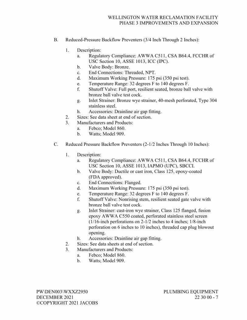
WELLINGTON WATER RECLAMATION FACILITY PHASE 3 IMPROVEMENTS AND EXPANSION
PW\DEN003\WXXZ2950 PLUMBING EQUIPMENT DECEMBER 2021 22 30 00 - 7 ©COPYRIGHT 2021 JACOBS
B. Reduced-Pressure Backflow Preventers (3/4 Inch Through 2 Inches):
1. Description: a. Regulatory Compliance: AWWA C511, CSA B64.4, FCCHR of
USC Section 10, ASSE 1013, ICC (IPC). b. Valve Body: Bronze. c. End Connections: Threaded, NPT. d. Maximum Working Pressure: 175 psi (350 psi test). e. Temperature Range: 32 degrees F to 140 degrees F. f. Shutoff Valve: Full port, resilient seated, bronze ball valve with
bronze ball valve test cock. g. Inlet Strainer: Bronze wye strainer, 40-mesh perforated, Type 304
stainless steel. h. Accessories: Drainline air gap fitting.
2. Sizes: See data sheet at end of section. 3. Manufacturers and Products:
a. Febco; Model 860. b. Watts; Model 909.
C. Reduced Pressure Backflow Preventers (2-1/2 Inches Through 10 Inches):
1. Description: a. Regulatory Compliance: AWWA C511, CSA B64.4, FCCHR of
USC Section 10, ASSE 1013, IAPMO (UPC), SBCCI. b. Valve Body: Ductile or cast iron, Class 125, epoxy-coated
(FDA approved). c. End Connections: Flanged. d. Maximum Working Pressure: 175 psi (350 psi test). e. Temperature Range: 32 degrees F to 140 degrees F. f. Shutoff Valve: Nonrising stem, resilient seated gate valve with
bronze ball valve test cock. g. Inlet Strainer: cast-iron wye strainer, Class 125 flanged, fusion
epoxy AWWA C550 coated, perforated stainless steel screen (1/16-inch perforations on 2-1/2 inches to 4 inches; 1/8-inch perforation on 6 inches to 10 inches), threaded cap plug blowout opening.
h. Accessories: Drainline air gap fitting. 2. Sizes: See data sheets at end of section. 3. Manufacturers and Products:
a. Febco; Model 860. b. Watts; Model 909.

WELLINGTON WATER RECLAMATION FACILITY PHASE 3 IMPROVEMENTS AND EXPANSION
PLUMBING EQUIPMENT PW\DEN003\WXXZ2950 22 30 00 - 8 DECEMBER 2021 ©COPYRIGHT 2021 JACOBS
PART 3 EXECUTION
3.01 INSTALLATION
A. Install, arrange, and connect equipment as shown on Drawings and in accordance with manufacturer’s recommendations.
3.02 FIELD QUALITY CONTROL
A. Pumps: Do not hydrostatic test pumps with mechanical seals.
B. Startup:
1. In accordance with Section 01 91 14, Equipment Testing and Facility Startup, and Section 23 05 93, Testing, Adjusting, and Balancing for HVAC.
2. Piping Systems: Verify that flushing, cleaning, and testing has been completed prior to startup.
3.03 SUPPLEMENTS
A. Supplements listed below, following “End of Section,” are a part of this Specification.
1. Gas Water Heater (Commercial) Data Sheet. 2. Electric Water Heater (Commercial) Data Sheet. 3. Domestic Water Expansion Tank Data Sheet. 4. Domestic Hot Water Circulating Pump Data Sheet. 5. Backflow Preventers Data Sheet.
END OF SECTION

WELLINGTON WATER RECLAMATION FACILITY PHASE 3 IMPROVEMENTS AND EXPANSION
PW\DEN003\WXXZ2950 PLUMBING EQUIPMENT DECEMBER 2021 22 30 00 SUPPLEMENT - 1 ©COPYRIGHT 2021 JACOBS
GAS WATER HEATER (COMMERCIAL)
Gas Water Heater:
Tag Number
Heating Capacity Input
(btuh)
Recovery @ 100F Rise
(gph) Percent
Efficiency Length (inches)
Width (inches)
Height (inches)
Vent Size
(inches)
Firing Control System
Manufacturer, Model No.
350-HW-001 199,000 193 MIN 85% 30 30 72 6 * AO Smith, Model Master-Fit 100-gal
Notes:
1. Firing Control Systems options; F-1 is standing pilot, F-9 is electronic pilot, M-9 is electronic pilot with modulating gas valve.
HW Circulation Pump:
Tag Number Flow Rate
(gpm) Pressure
(feet head) Motor (hp)
Power (volts/phase)
350-P-001 30 12 1/6 120V/1ph
100-P-001 30 30 1/6 120V/1ph
Notes:
1. Circulation pump is appropriate for water heater capacities from 90,000 to 350,000 BTUH.


WELLINGTON WATER RECLAMATION FACILITY PHASE 3 IMPROVEMENTS AND EXPANSION
PW\DEN003\WXXZ2950 PLUMBING EQUIPMENT DECEMBER 2021 22 30 00 SUPPLEMENT - 1 ©COPYRIGHT 2021 JACOBS
ELECTRIC WATER HEATER (COMMERCIAL)
Tag Number
Storage Capacity (gallons)
Total Input (kW)
No. of Elements
Simultaneous Element
Operation Voltage Diameter (inches)
Height (inches) Manufacturer, Model No.
700-WH-001 50 45.0 3 Yes * 21 55 AO Smith, Model DSE-50
700-WH-002 50 45.0 3 Yes * 21 55 AO Smith, Model DSE-50
100-WH-001 120 See Note 2*
* * * * * Hubbel; Model EMV-120-85-4-SL “or-equal”
Notes:
1. Voltages available are 208V/1ph or 3ph, 240V/1ph or 3ph, 277V/1ph, 480V/1ph or 3ph.
1. See Paragraph Electric Water Heater (Emergency Safety Shower Tempered Water Heater for Use in Class I, Division 2, Group D Hazardous Area) for additional information for this water heater.

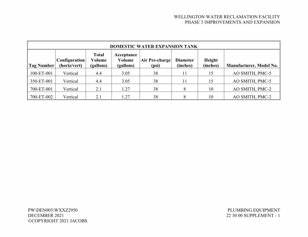
WELLINGTON WATER RECLAMATION FACILITY PHASE 3 IMPROVEMENTS AND EXPANSION
PW\DEN003\WXXZ2950 PLUMBING EQUIPMENT DECEMBER 2021 22 30 00 SUPPLEMENT - 1 ©COPYRIGHT 2021 JACOBS
DOMESTIC WATER EXPANSION TANK
Tag Number Configuration
(horiz/vert)
Total Volume (gallons)
Acceptance Volume (gallons)
Air Pre-charge (psi)
Diameter (inches)
Height (inches) Manufacturer, Model No.
100-ET-001 Vertical 4.4 3.05 38 11 15 AO SMITH, PMC-5
350-ET-001 Vertical 4.4 3.05 38 11 15 AO SMITH, PMC-5
700-ET-001 Vertical 2.1 1.27 38 8 10 AO SMITH, PMC-2
700-ET-002 Vertical 2.1 1.27 38 8 10 AO SMITH, PMC-2


WELLINGTON WATER RECLAMATION FACILITY PHASE 3 IMPROVEMENTS AND EXPANSION
PW\DEN003\WXXZ2950 PLUMBING EQUIPMENT DECEMBER 2021 22 30 00 SUPPLEMENT - 1 ©COPYRIGHT 2021 JACOBS
BACKFLOW PREVENTERS
Tag Number Valve Type1 Size
(inches) Flow Stream
Maximum Operating Flow
(gpm)
Maximum Pressure Drop
(psi) Manufacturer, Model No.
550-BFP-001 DC 2 W1 17 7 Febco, Model 850
100-BFP-001 DC 1-1/2 W1 45 6 Febco, Model 850
350-BFP-001 DC 1-1/2 W1 75 6 Febco, Model 850
700-BFP-001 DC 2 W1 75 6 Febco, Model 850
Notes:
1. Valve Type: RP - Reduced Pressure, DC - Double Check.
2. Flow Streams: DIW - Deionized Water, FP - Fire Protection, IRR - Irrigation Water, LCW - Laboratory Cold Water, TWS - Tempered Water Supply, W1 - Potable Water, W2 - Nonpotable Water, W3 - Plant Water.

WELLINGTON WATER RECLAMATION FACILITY PHASE 3 IMPROVEMENTS AND EXPANSION
PW\DEN003\WXXZ2950 PLUMBING FIXTURES DECEMBER 2021 22 40 00 - 1 ©COPYRIGHT 2021 JACOBS
SECTION 22 40 00 PLUMBING FIXTURES
PART 1 GENERAL
1.01 REFERENCES
A. The following is a list of standards which may be referenced in this section:
1. Americans with Disabilities Act (ADA). 2. American Gas Association (AGA). 3. American Society of Mechanical Engineers (ASME). 4. American Society of Sanitary Engineering (ASSE): 1010, Performance
Requirements for Water Hammer Arresters. 5. ASTM International (ASTM): D4101, Standard Specification for
Polypropylene Injection and Extrusion Materials. 6. Food and Drug Administration (FDA). 7. NSF International (NSF):
a. NSF/ANSI 61, Drinking Water System Components - Health Effects.
b. NSF/ANSI 372, Drinking Water System Components - Lead Content.
8. Plumbing and Drainage Institute (PDI): a. Code Guide 302 and Glossary of Industry Terms. b. WH-201, Water Hammer Arrester Standard.
9. UL.
1.02 SUBMITTALS
A. Action Submittals: Catalog information and rough-in dimensions for plumbing fixtures, products, and specialties.
1.03 REGULATORY REQUIREMENTS
A. Comply with the Americans with Disabilities Act (ADA), and local and state requirements.
PART 2 PRODUCTS
2.01 GENERAL
A. Components and Materials in Contact with Water for Human Consumption: Comply with the requirements of the Safe Drinking Water Act and other applicable federal, state, and local requirements. Provide certification by

WELLINGTON WATER RECLAMATION FACILITY PHASE 3 IMPROVEMENTS AND EXPANSION
PLUMBING FIXTURES PW\DEN003\WXXZ2950 22 40 00 - 2 DECEMBER 2021 ©COPYRIGHT 2021 JACOBS
manufacturer or an accredited certification organization recognized by the Authority Having Jurisdiction that components and materials comply with the maximum lead content standard in accordance with NSF/ANSI 61 and NSF/ANSI 372.
1. Use or reuse of components and materials without a traceable certification is prohibited.
2.02 MANUFACTURERS
A. Fixture Trim:
1. Supply Stops and Traps: a. McGuire. b. American Standard. c. Kohler.
2. Flush Valves: Sloan. 3. Water Closet Seats:
a. Bemis. b. Church. c. Olsonite.
4. Lavatory Supply, Tailpiece, and Trap Insulation: a. McGuire. b. Trap Wrap. c. Truebro.
B. Plumbing Fixtures:
1. Water Closets, Lavatories, and Urinals: a. American Standard. b. Kohler. c. Eljer.
2. Service Sinks: a. Kohler. b. Eljer.
3. Faucet Fittings: a. Sinks:
1) Chicago. 2) T&S Brass.
b. Lavatories: 1) Chicago. 2) Symmons.
WELLINGTON WATER RECLAMATION FACILITY PHASE 3 IMPROVEMENTS AND EXPANSION
PW\DEN003\WXXZ2950 PLUMBING FIXTURES DECEMBER 2021 22 40 00 - 3 ©COPYRIGHT 2021 JACOBS
4. Shower Trim: a. Symmons. b. Powers.
5. Shower Stalls: a. Aqua Glass. b. Fixture Manufacturers.
6. Stainless Steel Sinks: a. Elkay. b. Just.
7. Mop Sinks: a. Stern-Williams. b. Fiat Products Inc. c. Fixture Manufacturers.
8. Drinking Fountains and Electric Water Coolers: a. Elkay. b. Haws. c. Western.
9. Wash Fountains: a. Bradly. b. Acorn. c. Intersan. d. Willoughby.
C. Emergency Showers and Eyewashes:
1. Haws. 2. Western. 3. Guardian.
D. Drainage Products:
1. General: a. Smith. b. Wade. c. Zurn.
2. Acid Resistant: a. Enfield. b. R&G Sloane. c. T&C Plastic Drain Co.

WELLINGTON WATER RECLAMATION FACILITY PHASE 3 IMPROVEMENTS AND EXPANSION
PLUMBING FIXTURES PW\DEN003\WXXZ2950 22 40 00 - 4 DECEMBER 2021 ©COPYRIGHT 2021 JACOBS
E. Plumbing Specialties:
1. Shock Arresters: a. Smith. b. Sioux Chief. c. Precision Plumbing Products.
2. Trap Primers: a. Precision Plumbing Products. b. Smith. c. Wade.
3. Pressure/Temperature Relief Valves: a. Cash Acme. b. Kunkle Valve. c. Watts.
4. Pressure Gauges: a. Ashcroft. b. Marsh. c. Mashalltown.
5. Thermometers: a. Trerice. b. Weksler.
2.03 GENERAL
A. Fixture Trim: Provide plumbing fixture trim where applicable on fixtures.
B. Plumbing Fixtures: Indicated by fixture number as shown on Drawings.
C. Drainage Products: Indicated by fixture number as shown on Drawings.
D. Plumbing Specialties: Indicated by fixture number as shown on Drawings.
E. Exposed fixture connections and piping shall be polished chrome-plated.
2.04 MATERIALS
A. Fixture Trim:
1. Supply Stop: a. Flexible supply with heavy cast brass, loose key, 1/2-inch IPS by
3/8-inch outside diameter tubing angle stop to wall with escutcheon plate; chrome-plated finish.
b. Provide stop with stuffing box. c. Manufacturer: McGuire Manufacturing Company, Inc.

WELLINGTON WATER RECLAMATION FACILITY PHASE 3 IMPROVEMENTS AND EXPANSION
PW\DEN003\WXXZ2950 PLUMBING FIXTURES DECEMBER 2021 22 40 00 - 5 ©COPYRIGHT 2021 JACOBS
2. Trap: a. Chrome-plated, 17-gauge, semicast P-trap with compression ring
cast brass waste and vent connection and cleanout. b. 1-1/2 inches for lavatories and drinking fountains. c. 1-1/2 inches for sinks. d. Manufacturer: McGuire Manufacturing Company, Inc.
3. Water Closet and Urinal Flush Valves: Sloan Valve Co., Royal Continental, low flush, quiet action with screwdriver stop and vacuum breaker.
B. Plumbing Fixtures:
1. DF-1, Drinking Fountain (ADA Compliant, Dual Height): a. Finish: No. 4 satin finish stainless steel rectangular receptors, back
plate. b. Valve: Front pushbutton operated with automatic stream
regulation. c. Trim: Screwdriver stop, strainer, and P-trap with cleanout. d. Cooler: None. e. Manufacturers and Products:
1) Fixture: Haws Drinking Faucet Co.; Model 1119. 2) Mount: Haws Drinking Faucet Co.; Model 6700.4 wall
bracket with Model 6800 carrier. 2. LAV-1, Lavatory (Counter Set, Oval):
a. Fixture: 20 inches by 17 inches, vitreous china, self-rimming. American Standard Companies, Inc.; Aqualyn, Model 0476.028.
b. Faucet: Chicago Faucet Co.; Model 2200-4CP with 0.5-gpm flow restricter.
c. Trim: 3/8-inch supply stop with loose key, 17-gauge chrome-plated cast brass P-trap.
d. Insulation: McGuire Manufacturing Company, Inc.; Prowrap antimicrobial PVC resin seamless insulation for trap, tailpiece, and hot and cold water supply piping.
e. Strainer: McGuire Manufacturing Company, Inc.; Model 155A chrome-plated grid strainer with tailpiece.
3. MS-1, Mop Sink (Floor Mounted): a. Fixture: Stern-Williams Co. Inc.; Model HL-2100-BP; Molded
stone, 36 inches by 24 inches by 12 inches deep with stainless steel bumper guard, back panels and chrome-plated brass drain.
b. Faucet: Chicago Faucet Co.; Model 835-CP, exposed top supplies with hose threads, vacuum breaker, and rod support. Faucet mounted 36 inches above finish floor.
c. Accessories: Stern-Williams Co. Inc.; T-35 hose and T-40 stainless steel mop hanger.
WELLINGTON WATER RECLAMATION FACILITY PHASE 3 IMPROVEMENTS AND EXPANSION
PLUMBING FIXTURES PW\DEN003\WXXZ2950 22 40 00 - 6 DECEMBER 2021 ©COPYRIGHT 2021 JACOBS
4. S-1, Sink (Counter, Stainless Steel, Single Compartment): a. Fixture: 21 inches by 25 inches overall by 8 inches deep,
18-gauge, Type 304 stainless steel, three-hole punch, self-rimming, undercoated, ledge-type. Just Mfg. Co.; Model SL-2125-A-GR.
b. Faucet: Chicago Faucet Co.; Model 2300-8 single handle with 8-inch cover plate.
c. Trim: 1-1/2-inch outside diameter, 17-gauge chrome-plated cast tailpiece and cast brass P-trap with cleanout, and 1/2-inch wall supply stop with loose key.
d. Strainer: Just Mfg. Co.; Model J-35, stainless steel crumb-type. 5. SH-1, Shower (Trim Only, ADA Compliant):
a. Showerhead: Sloan Valve Co.; Model AC-11-B-2.5, with 2.5-gpm flow restricter.
b. Hand Spray: 2.5-gpm flow restricter, 60-inch flexible stainless steel hose with in-line vacuum breaker, quick disconnect, and 24-inch chrome-plated glide bar.
c. Mixing Valve: Powers Process Control; Model L425E-1-5-Y-W-QD, thermostatic-type.
d. Trim: Inlet strainer, check, integral stop, temperature limit stop, two wall hooks, and diverter valve.
6. WC-1, Water Closet (Flush Valve, Floor Mounted, ADA Compliant): a. Fixture: Vitreous china, direct-fed siphon jet action, top spud,
elongated bowl. American Standard Companies, Inc.; Madera 16-1/8 inches, Universal Height EL, Model 2305.100.
b. Trim: Sloan Valve Co.; Royal Continental, Model 111 RC, with flush valve handle pointed to wide side of stall enclosure, 1.6 gallons per flush.
c. Seat: Olsonite Corp.; Model 10 CC-SS, white open front.
C. Safety Equipment:
1. SSH-1, Safety Shower/Eyewash Combination: a. Model: Haws Drinking Faucet Co.; Model 8346. b. Shower: ABS plastic deluge. c. Eyewash: Stainless steel bowl with aerated eye/face wash. d. Valve: Stay open. e. Support: Freestanding, 1-1/4-inch galvanized pipe standard,
stanchion, and floor flange. f. Alarms: Magnetically operated proximity switches. g. Factory applied CRP (corrosive atmospheres coating).
2. SSH-2, Safety Shower/Eyewash Combination (Freeze-proof): a. Model: Haws Drinking Faucet Co.; Model 8317CTFPT. b. Shower: ABS plastic deluge.

WELLINGTON WATER RECLAMATION FACILITY PHASE 3 IMPROVEMENTS AND EXPANSION
PW\DEN003\WXXZ2950 PLUMBING FIXTURES DECEMBER 2021 22 40 00 - 7 ©COPYRIGHT 2021 JACOBS
c. Eyewash: Stainless steel bowl with aerated eye/face wash. d. Valve: Stay open. e. Support: Freestanding, 1-1/4-inch galvanized pipe standard,
stanchion, and floor flange, cable heated and insulated. f. Alarms: Magnetically operated proximity switches.
D. Drainage Products:
1. CO-1, Cleanout (Exterior): a. Material: Taper thread, bronze plug, heavy-duty, scoriated cast-
iron top. b. Manufacturer and Product: Jay R. Smith Mfg. Co.; Model 4263.
2. CO-2, Cleanout: a. Material: Taper thread, bronze plug, scoriated nickel bronze top. b. Manufacturer and Product: Jay R. Smith Mfg. Co.; Model 4023.
3. FCO-1, Floor Cleanout (Finished Areas): a. Material: Tapered thread, bronze plug with round adjustable
scoriated secured nickel bronze top. b. Manufacturer and Product: Jay R. Smith Mfg. Co.; Model 4103S.
4. FCO-2, Floor Cleanout (Unfinished Areas): a. Material: Tapered thread, bronze plug with round adjustable
scoriated secured cast-iron top. b. Manufacturer and Product: Jay R. Smith Mfg. Co.; Model 4243S.
5. FD-1, Floor Drain (Finished Areas): a. Materials: Cast-iron body, adjustable nickel bronze strainer. b. Options: Jay R. Smith Mfg. Co.; Model 2696, trap primer
connection, vandalproof screws. c. Manufacturer and Product: Jay R. Smith Mfg. Co.;
Model 2005T-U-round. 6. FD-2, Floor Drain (Unfinished Areas, General Drainage):
a. Materials: Cast-iron body and grate. b. Options: Sediment bucket, Jay R. Smith Mfg. Co.; Model 2696,
trap primer connection, vandalproof screws. c. Manufacturer and Product: Jay R. Smith Mfg. Co.;
Model 2210T-U. 7. FD-3, Floor Drain (Unfinished Areas, Heavy Drainage):
a. Materials: Cast-iron body and grate. b. Options: Sediment bucket, Jay R. Smith Mfg. Co.; Model 2696,
trap primer connection, vandalproof screws. c. Manufacturer and Product: Jay R. Smith Mfg. Co.;
Model 2233T-U. 8. WCO, Wall Cleanout:
a. Material: Stainless steel cover and screw. b. Manufacturer and Product: Jay R. Smith Mfg. Co.; Model 4472.
WELLINGTON WATER RECLAMATION FACILITY PHASE 3 IMPROVEMENTS AND EXPANSION
PLUMBING FIXTURES PW\DEN003\WXXZ2950 22 40 00 - 8 DECEMBER 2021 ©COPYRIGHT 2021 JACOBS
c. TD-1, Trench Drain (Admin Building): 1) Material: Stainless steel with stainless steel slotted grate. 2) Manufacturer and Product: Zurn; Z890 (Trench No. 89001).
d. Prefab Trenches (See Structural Drawings for Locations): ACO Polymer Products, Inc.; ACO Drain, MiniKlassik KS50 with Type 250D slotted steel cover.
E. Hose Valves: Refer to Section 22 10 01, Plumbing Piping and Accessories.
F. Plumbing Specialties:
1. Water Hammer Arresters: a. Materials: ASSE 1010 certified, Type L copper tube, HHPP piston
with two lubricated EPDM O-rings, FDA approved lubricant, rolled piston stop, wrought copper male thread adapter.
b. Manufacturer and Product: Sioux Chief Mfg. Co., Inc.; Series 650 and 660.
2. TP-1, Trap Priming Valve: a. Materials: Cast bronze, line pressure drop activated, antisiphon
port, 1/2-inch connection. b. Manufacturer and Product: Precision Plumbing Products, Inc.;
Model P-1 trap priming valve and Model DU-4, distribution unit. 3. TP-2, Trap Priming Valve:
a. Materials: Cast bronze, line pressure drop activated, antisiphon port, 1/2-inch connection.
b. Manufacturer and Product: Jay R. Smith Mfg. Co.; Figure 2699. 4. Pressure/Temperature Relief Valve:
a. Materials: ASME/AGA rated, bronze body construction, vacuum relief valve vent in drain, backup emergency safety fuse plug, tamper-resistant bonnet screws, test lever, short thermostat, and automatic reseating.
b. Manufacturer and Product: Watts Industries, Inc.; Series 40. 5. Pressure Gauge:
a. Materials: 3-1/2-inch gauge size, 0 to 160 psi range, steel case, glass crystal, brass movement, and 1/3-inch NPT lower connection.
b. Manufacturer and Product: Ashcroft Dresser Instrument Division, Dresser Industries, Inc.; Type 1008.
6. Thermometer: a. Materials: Adjustable angle, red reading mercury type with 9-inch
case and 30 degrees F to 180 degrees F range, 3-1/2-inch aluminum stem, and separate NPT brass thermowell.
b. Manufacturer and Product: H.O. Trerice Co.; Model A005.
WELLINGTON WATER RECLAMATION FACILITY PHASE 3 IMPROVEMENTS AND EXPANSION
PW\DEN003\WXXZ2950 PLUMBING FIXTURES DECEMBER 2021 22 40 00 - 9 ©COPYRIGHT 2021 JACOBS
G. Sealant: In accordance with Section 07 92 00, Joint Sealants.
PART 3 EXECUTION
3.01 PREPARATION
A. Drawings do not attempt to show exact details of fixtures. Changes in locations of fixtures, advisable in opinion of Contractor, shall be submitted to Engineer for review before proceeding with the Work.
3.02 INSTALLATION
A. Fixture Trim: Install fixture trim where applicable on fixtures.
B. Plumbing Fixtures, Mounting Heights:
1. Standard rough-in catalogued heights, unless shown otherwise on Drawings.
2. Caulk fixtures in contact with finished walls with waterproof, white, nonhardening sealant which will not crack, shrink, or change color with age. See Section 07 92 00, Joint Sealants.
C. Exact fixture location and mounting arrangement shall be as indicated on toilet room elevations and details as shown on Drawings.
D. Unless noted otherwise and as a minimum, fixtures shall be supported as indicated in PDI Code Guide 302.
E. Safety Equipment:
1. System Shutoff Valves: a. Shutoff valves shall give visual indication of position (open or
closed). b. Shutoff valves shall be lockable valves and locked in open
position. 2. Each safety shower, eyewash, combination safety shower/eyewash shall
have red safety signoff tag. After completing requirements listed below, Contractor and Owner shall sign red safety signoff tag. Requirements are as follows: a. Visually check safety shower/eyewash piping for leaks. b. Verify that upon operation, stay-open valves remain open. c. Showerheads to be between 82 inches and 96 inches above
standing surface.

WELLINGTON WATER RECLAMATION FACILITY PHASE 3 IMPROVEMENTS AND EXPANSION
PLUMBING FIXTURES PW\DEN003\WXXZ2950 22 40 00 - 10 DECEMBER 2021 ©COPYRIGHT 2021 JACOBS
d. Shower spray pattern, when valve is full open, shall be a minimum 20 inches in diameter at 60 inches above standing surface.
e. Water arcs from eyewash spray heads must cross. Test with eyewash gauge; Haws Drinking Faucet Co., Model 9015.
f. Minimum flow rates for safety showers shall be 20 gpm. g. Minimum flow rates for eyewashes shall be 3 gpm. h. Tempered water shall be temperature indicated on Drawings.
F. Drainage Products:
1. Floor Drains: Set top flush with floor. Provide membrane clamps where required.
2. Cleanouts: Install where shown or required for purposes intended. Set cover flush with finished floor.
3. Hub Drains: Set top of hub 2 inches above finished floor.
G. Plumbing Specialties:
1. Shock Arresters: a. Install PDI-certified and rated shock arresters, sized and located in
accordance with PDI WH-201 and as shown on Drawings. b. Install adjacent to equipment wherein quick closing valves are
installed. c. Install at each emergency safety shower. d. Shock arresters to have access panels or to be otherwise
accessible. 2. Drain P-Trap Priming:
a. Pipe: Type K, soft copper. b. Trap and prime floor drains and hub drains, unless shown
otherwise on Drawings. No attempt has been made to show trap primer valve locations or trap primer pipe routing.
c. Field route trap primer piping during installation of floor drains and hub drains, and install trap primer valves in mechanical rooms, janitor rooms, or other locations acceptable to Engineer.
d. Priming System: Complete with connection to serving W1 cold water system.
3. Trap Priming Valves: a. Floor drain traps primed with priming valves, 1/2-inch copper to
floor drain. b. Two traps maximum primed from one priming valve or as
recommended by manufacturer. Locate in mechanical spaces or janitor’s rooms and as indicated on Drawings.
c. Provide shutoff valve ahead of priming valves.

WELLINGTON WATER RECLAMATION FACILITY PHASE 3 IMPROVEMENTS AND EXPANSION
PW\DEN003\WXXZ2950 PLUMBING FIXTURES DECEMBER 2021 22 40 00 - 11 ©COPYRIGHT 2021 JACOBS
4. Thermometers and Pressure Gauges: a. Arrange devices to facilitate use and observation. b. Install in orientation that will allow clear observation from ground
level. c. Provide pressure gauges with block valves. d. Install thermometers in thermowells.
H. Caulk penetrations of exterior walls with weatherproof sealant in accordance with Section 07 92 00, Joint Sealants.
I. Adjust water flows in domestic water systems for reasonable water flows at each plumbing fixture, terminal device, and recirculation loop. Flush valve fixtures shall be adjusted for proper flush cycle time and water quantity.
3.03 FIELD QUALITY CONTROL
A. Perform visual inspection for physical damage, blocked access, cleanliness, and missing items.
B. Notify Owner and Engineer 48 hours prior to shower testing. Owner and Engineer reserve the right to witness all tempered water and safety shower testing.
C. Test safety shower and eyewash units. Water flow must be tested at both showerhead and eyewash/face ring.
1. Shower Flow: a. Test with tube-type water gauge (Haws Drinking Faucet Co.,
Model 9010) and 5-gallon container. b. Container shall fill in 10 seconds or less, with a minimum 20-gpm
flow. 2. Eyewash Flow:
a. Test with tube-type water gauge (Haws Drinking Faucet Co., Model 9010) and 1-gallon container.
b. Container shall fill in 20 seconds or less. 3. Contractor shall log, date, and initial inspection upon passing flow tests.
D. Verify alarm operation both locally and systemwide. Notify security prior to test if alarm is connected systemwide.
END OF SECTION


WELLINGTON WATER RECLAMATION FACILITYPHASE 3 IMPROVEMENTS AND EXPANSION
PW\DEN003\WXXZ2950 HVAC ADJUSTABLEDECEMBER 2021 FREQUENCY DRIVES©COPYRIGHT 2021 JACOBS 23 05 14 - 1
SECTION 23 05 14HVAC ADJUSTABLE FREQUENCY DRIVES
PART 1 GENERAL
1.01 REFERENCES
A. The following is a list of standards which may be referenced in this section:
1. Federal Communications Commission Regulations (FCC).2. Institute of Electrical and Electronics Engineers (IEEE):
a. 519, Recommended Practices and Requirements for HarmonicControl in Electrical Power Systems.
b. C62.41, Recommended Practice on Surge Voltages in Low-Voltage AC Power Circuits.
3. International Electro-technical Commission (IEC): 60146,Semiconductor Converters.
4. National Electrical Code (NEC).5. National Electrical Manufacturer’s Association (NEMA):
a. 250, Enclosures for Electrical Equipment (1,000 VoltsMaximum).
b. CP 1, Shunt Capacitors.c. ICS 7.1, Safety Standards for Construction and Guide for
Selection, Installation, and Operation of Adjustable Speed DriveSystems.
d. MG 1, Motors and Generators.e. WC 57, Standard for Control Cables.
6. National Fire Protection Association (NFPA): Electrical Standard forIndustrial Machinery.
7. UL: 508C, Safety Power Conversion Equipment.
1.02 DEFINITIONS
A. This section includes variable speed motor controls referred to as AdjustableFrequency Drives (AFD); also known as Variable Frequency Drives (VFD),Variable Speed Drives (VSD), and Adjustable Speed Drives (ASD).
B. The following terms may be used in this section:
1. ac: Alternating Current.2. AFD: Adjustable Frequency Drive.3. CMOS: Complementary Metal Oxide Semiconductor.4. dc: Direct Current.5. EMI: Electro-Magnetic Interference.

WELLINGTON WATER RECLAMATION FACILITYPHASE 3 IMPROVEMENTS AND EXPANSION
HVAC ADJUSTABLE PW\DEN003\WXXZ2950FREQUENCY DRIVES DECEMBER 202123 05 14 - 2 ©COPYRIGHT 2021 JACOBS
6. FLA: Full Load Amps.7. LCD: Liquid Crystal Display.8. MPR: Motor Protection Relay.9. MTBF: Mean Time Between Failure.10. PID: Proportional, Integral, and Differential.11. PWM: Pulse Width Modulation.12. Rated Load: Load specified for equipment.13. Rated Speed: Nominal rated (100 percent) speed specified for
equipment.14. RFI: Radio Frequency Interference.15. RTD: Resistance Temperature Detector.
1.03 SUBMITTALS
A. Action Submittals:
1. Shop Drawings:a. Wiring diagrams, front and side views of enclosures, overall
dimensions, conduit entrance locations and requirements,nameplate legends, and enclosure details.
b. Data sheets showing voltage, ratings and size of switching andovercurrent protective devices, short circuit ratings, and weights.
c. Specific description of harmonic mitigation provisions beingmade to ensure proper system operation and compliance withIEEE 519.
d. Anchorage and bracing drawings and cut sheets, as required bySection 01 88 15, Anchorage and Bracing.
B. Informational Submittals:
1. Anchorage and bracing calculations as required by Section 01 88 15,Anchorage and Bracing.
2. Manufacturer’s Installation Instructions:a. Indicate application conditions and limitations of use stipulated by
product testing agency specified under regulatory requirements.b. Include instructions for storage, handling, protection,
examination, preparation, installation, and starting of adjustablespeed drive.
3. Operation and maintenance data in conformance with Section 01 78 23,Operation and Maintenance Data. Include wiring and control diagrams.
4. As-built version of equipment schedules.

WELLINGTON WATER RECLAMATION FACILITYPHASE 3 IMPROVEMENTS AND EXPANSION
PW\DEN003\WXXZ2950 HVAC ADJUSTABLEDECEMBER 2021 FREQUENCY DRIVES©COPYRIGHT 2021 JACOBS 23 05 14 - 3
1.04 QUALITY ASSURANCE
A. Provide UL Listed and labeled AFD and all associated equipment inaccordance with UL 508C.
B. Design, construct, and test AFD in accordance with NEMA, NEC, and IECstandards.
C. AFD must meet requirements for RFI as specified by FCC regulations,Part 15, Subpart J, Class A Devices.
D. Harmonics Mitigation:
1. Provide AFD meeting harmonic current distortion limits of IEEE 519,measured at drive input terminals; furnish phase shift transformers, dcbus reactors, ac line reactors, harmonic filters, or other devices asnecessary.
2. Furnish necessary devices and circuits to prevent operation of one drivefrom adversely affecting operation of other drives supplied from sametransformer or same bus.
3. When isolation transformers are used, design to meet K-factorrequirements of drive(s) connected.
4. Harmonics Analysis: Use relevant ANSI standards and local powercompany standards to determine transformer fault and impedance valuesto be used in Harmonics Analysis.
1.05 DELIVERY, STORAGE, AND HANDLING
A. Deliver, store, protect, and handle products to Site, under provisions ofSection 01 61 00, Common Product Requirements.
B. Store in a clean, dry space. Maintain factory wrapping, or provide additionalheavy canvas or heavy plastic cover, to protect units from dirt, water,construction debris, and traffic.
1.06 SPECIAL GUARANTEE
A. Provide manufacturer’s extended guarantee or warranty, with Owner namedas beneficiary, in writing, as special guarantee. Special guarantee shallprovide for correction, or at the option of the Owner, removal and replacementof Work specified in this Specification section found defective during a periodof 3 years after the date of Substantial Completion. Duties and obligations forcorrection or removal and replacement of defective Work shall be as specifiedin the General Conditions.

WELLINGTON WATER RECLAMATION FACILITYPHASE 3 IMPROVEMENTS AND EXPANSION
HVAC ADJUSTABLE PW\DEN003\WXXZ2950FREQUENCY DRIVES DECEMBER 202123 05 14 - 4 ©COPYRIGHT 2021 JACOBS
PART 2 PRODUCTS
2.01 MANUFACTURERS
A. Provide components and accessories specified in this section manufacturedby:
1. Yaskawa (Magnetek).2. Robicon.3. ABB.4. Reliance Electric.5. Graham.6. AC Technology Corporation.7. Toshiba.
2.02 EQUIPMENT SCHEDULES
A. Some specific equipment requirements are listed in Equipment Schedules.Refer to Drawings.
2.03 SERVICE CONDITIONS
A. Ambient Operating Temperature: 32 degrees F to 104 degrees F (0 degree Cto 40 degrees C).
B. Storage Temperature: Minus 40 degrees F to 158 degrees F.
C. Humidity: 0 percent to 95 percent relative (noncondensing).
D. Altitude: 0 foot to 7,300 feet.
2.04 COMPONENTS
A. Ratings:
1. AC Line Voltage Variation: Minus 10 percent to plus 10 percent.2. AC Line Frequency Variation: Minus 3 Hz to plus 3 Hz.3. Frequency Stability: Plus or minus 0.5 percent of maximum frequency.4. Minimum Efficiency: 97 percent drive efficiency at full speed, full load.5. Starting Torque: 100 percent starting torque shall be available from
0.5 Hz to 60 Hz.6. Overload Capability: 120 percent of rated FLA for 60 seconds;
180 percent of rated FLA, instantaneously.7. Harmonic Distortion: As indicated in Article Quality Assurance.
WELLINGTON WATER RECLAMATION FACILITYPHASE 3 IMPROVEMENTS AND EXPANSION
PW\DEN003\WXXZ2950 HVAC ADJUSTABLEDECEMBER 2021 FREQUENCY DRIVES©COPYRIGHT 2021 JACOBS 23 05 14 - 5
8. Motor Audible Noise Level: When operating throughout speed range ofPWM AFD, no more than 3 dB(A) above that designated in NEMAMG 1 for same motor operated at constant speed with 60-Hz supplyvoltage.
9. RFI: As specified by FCC regulations, Part 15, Subpart J, Class ADevices.
10. Short Circuit Rating: Minimum 65 kA RMS, without additional inputfusing.
B. Design:
1. Transform ac input power into frequency and voltage controlled three-phase output power suitable to provide positive speed and torque controlto standard induction motor.
2. Employ a PWM inverter system, consisting of:a. Input Section:
1) Provide AFD input power stage to convert three-phase acline power into a constant dc voltage via a solid state three-phase full wave diode bridge rectifier, with MOVprotection.
2) Design section to be insensitive to phase rotation of ac line.b. Intermediate Section:
1) DC bus as a supply to AFD output section to maintain fixedvoltage with filtering and short circuit protection.
2) Provide AFD diagnostic logic circuit interfaced with dc bus,for continuous monitoring and protection of powercomponents.
3) Provide dc bus reactors and capacitor as necessary forsatisfactory drive operation.
c. Output Section:1) Microprocessor-controlled PWM inverter to convert dc
voltage to variable voltage, adjustable frequency three-phaseac output.
2) Isolate inverter from all power circuits.3) Vary output voltage proportionally with frequency to
maintain a constant ratio of volts to hertz up to 60 Hz.4) Above 60 Hz, maintain constant voltage, with AFD
operating in a constant horsepower output mode.5) Output: PWM sine coded.6) Provide solid state variable frequency power and logic unit.
d. Drive Operation: Stepless.e. Shall not induce voltage line notching back to utility line.

WELLINGTON WATER RECLAMATION FACILITYPHASE 3 IMPROVEMENTS AND EXPANSION
HVAC ADJUSTABLE PW\DEN003\WXXZ2950FREQUENCY DRIVES DECEMBER 202123 05 14 - 6 ©COPYRIGHT 2021 JACOBS
C. Signal Interface:
1. Analog Inputs: AFD shall include two independent remote referenceinputs.a. One shall be 0V dc to 10V dc.b. Second shall be programmable for either 0V dc to 10V dc or
4 mA to 20 mA.c. The bias and gain of each input shall be individually
programmable.2. Digital Inputs:
a. Provide a minimum of five multi-function input terminals, capableof being programmed to determine the function when their state ischanged.
b. These terminals shall provide a minimum of 20 functionsincluding, but not limited to:1) Remote/Local operation selection.2) Detection of external fault condition.3) Remote reset.4) Multi-step speed commands.
c. Provide terminals for remote contacts, to allow starting in theautomatic mode.
d. Include one external fault input, minimum, programmable for anormally open or normally closed contact, for connection to itemssuch as firestats and freezestats.
3. Analog Outputs:a. Include a 0V dc to 10V dc analog output for monitoring, or “speed
tracking” AFD.b. 0V dc to 10V dc analog output signal shall be proportional to
output frequency, output current, output power, or dc bus voltage.4. Digital Outputs:
a. Include one fully rated form “A” contact and one fully rated form“C” contact, capable of being programmed to determine whatconditions must be met in order for them to change state.
b. Provide contacts rated for at least 1 amp at 250V ac.c. Provide a minimum of 10 relay functions including, but not
limited to:1) Speed agree detection.2) Low and high frequency detection.3) Missing frequency reference detection.4) Over-torque/under-torque detection.5) Drive running.6) Drive faulted.

WELLINGTON WATER RECLAMATION FACILITYPHASE 3 IMPROVEMENTS AND EXPANSION
PW\DEN003\WXXZ2950 HVAC ADJUSTABLEDECEMBER 2021 FREQUENCY DRIVES©COPYRIGHT 2021 JACOBS 23 05 14 - 7
D. Enclosure:
1. NEMA 250, enclosure, gasketed, freestanding, enclosure for mountingagainst wall, completely front accessible, and hinged doors.
2. NEMA 250, type as required by the Area Classification Table in theGeneral Section of Drawings.
3. Properly sized to dissipate heat generated by AFD within limits ofspecified operating conditions (including ambient temperature andambient airflow).
4. Top and bottom conduit knockouts.5. Alphanumeric keypad and display, and operator’s controls.6. User terminals for power and control connections.7. Temperature controlled forced ventilation to cool AFD with air at
maximum room ambient temperature of 104 degrees F.8. Enclosure and heat-sink fans shall be readily accessible and not require
removal of AFD power converter.9. Factory Finishing:
a. Primer: Rust-inhibiting coating.b. Finish: Manufacturer’s standard baked enamel finish.
E. Drive Protection:
1. Loss of input signal protection, with a speed default to 80 percent ofmost recent speed.
2. No damage shall occur to AFD while under load if output disconnect isopen.
3. Electronic thermal overload protection for both drive and motor.4. Ground Fault Protection: AFD and motor.5. Overcurrent: Instantaneous overcurrent trip.6. DC undervoltage protection, 70 percent dropout.7. DC overvoltage protection, 130 percent pickup.8. Overtemperature: Drive, inverter, converter, and dc link components.9. Overtemperature: Motor and driven equipment.10. Single-phase protection.11. Reset overcurrent protection (manual or automatic reset).12. Active current limit/torque limit protection.13. Semiconductor fault protection.14. Short-circuit/ground fault protection.15. Serial communication fault protection.16. Microprocessor fault.17. Surge protection for transient overvoltage (6,000V, 80 J surge, tested
per IEEE C62.41).18. Visual display of specific fault conditions.
WELLINGTON WATER RECLAMATION FACILITYPHASE 3 IMPROVEMENTS AND EXPANSION
HVAC ADJUSTABLE PW\DEN003\WXXZ2950FREQUENCY DRIVES DECEMBER 202123 05 14 - 8 ©COPYRIGHT 2021 JACOBS
F. Operational Features:
1. System Operation:a. When in HAND mode, control drive output frequency by increase
and decrease pushbuttons on drive keypad.b. When in AUTO mode, control drive output frequency by a 0V dc
to 10V dc signal, 4 mA to 20 mA signal, or faster/slower floatingpoint contacts, or preset speed.
c. PID set point may be changed with keypad, from a remote 0V dcto 10V dc signal, or 4 mA to 20 mA signal.
2. Manufacturer’s standard features, unless otherwise indicated:a. Sustained power loss.b. Momentary power loss.c. Power interruption.d. Power loss ride through of 2 seconds.e. Start on the fly.f. Stall protection.g. Slip compensation.h. Automatic restart after power return (ability to enable/disable
function).i. Critical frequency lockout (three selectable points minimum, by
1.5-Hz steps in 10-Hz bands, to prevent resonance of system).3. AFD maintenance system software for complete programming and
diagnostics.4. Operate with no motor connected to output terminals.5. Carrier Frequency:
a. Minimum of six settings to allow adjustment in field.b. At or above 5 kHz without derating to satisfy conditions for
current, voltage, and horsepower.6. Factory settings for all parameters, and capability for those settings to
be reset.7. Capability to adjust the following functions, while AFD is running:
a. Forward/Reverse direction.b. Acceleration adjustment from 0 second to 3,600 seconds.c. Deceleration adjustment from 0 second to 3,600 seconds.d. Minimum of six different preset speeds.
8. Analog output gain to calibrate signal for the application used.
G. Diagnostics:
1. Comprehensive for drive adjustment and troubleshooting.2. Visual display of specific fault condition.3. Memory Battery Backup: 100 hours, minimum, during a power loss.
WELLINGTON WATER RECLAMATION FACILITYPHASE 3 IMPROVEMENTS AND EXPANSION
PW\DEN003\WXXZ2950 HVAC ADJUSTABLEDECEMBER 2021 FREQUENCY DRIVES©COPYRIGHT 2021 JACOBS 23 05 14 - 9
4. Status messages will not stop drive from running, but will prevent itfrom starting.
5. Fault Condition Messages and History: First fault protection function tobe activated, ability to store six successive fault occurrences in order.
6. Minimum Faults Numerically:a. Overcurrent (time and instantaneous).b. Overvoltage.c. Undervoltage (dc and ac).d. Overtemperature (drive, motor windings, motor bearing, pump/fan
bearing).e. Serial communication fault.f. Short-circuit/ground fault (motor and drive).g. Motor stalled.h. Semiconductor fault.i. Microprocessor fault.j. Single-phase voltage condition.
H. Operator Interface:
1. Provide a front mounted, sealed keypad AFD operator interface.2. Provide complete programming, operating, monitoring, and diagnostic
capability from keypad.3. Keys provided shall include commands for RUN, STOP, and RESET.4. Provide local-remote pushbutton to conveniently switch between
LOCAL and REMOTE modes.5. Provide AFD display readouts of output frequency in hertz, output
voltage in volts, output current in amps, output power in kilowatts,dc bus voltage in volts, interface terminal status, and fault codes.
6. Provide an easy-to-read illuminated LCD display with English languageas standard.
I. Additional Features:
1. Provide as follows:a. Current Limiting Input Fusing: Fast-acting semiconductor fuses
for protection of AFD semiconductor devices.b. Manual Bypass:
1) Drive and bypass components mounted inside a commonenclosure, same NEMA 250 Type as specified for driveenclosure, fully prewired, and ready for installation as asingle UL Listed device.
2) Input, output, and bypass contactors, to disconnect power toAFD when motor is running in bypass mode.
3) 115V ac control transformer, with fused primary.
WELLINGTON WATER RECLAMATION FACILITYPHASE 3 IMPROVEMENTS AND EXPANSION
HVAC ADJUSTABLE PW\DEN003\WXXZ2950FREQUENCY DRIVES DECEMBER 202123 05 14 - 10 ©COPYRIGHT 2021 JACOBS
4) Thermal overload relay, to protect motor while operating inbypass mode.
5) Circuit breaker/disconnect switch with “through-the-door”handle mechanism.
6) Control and safety circuit terminal strip.7) “DRIVE/OFF/BYPASS” selector switch.8) Pilot lights for “POWER ON” and “FAULT”.9) “NORMAL/TEST” selector switch, to allow testing and
adjustment of AFD while motor is running in bypass mode.10) “HAND/OFF/AUTO” selector switch, to provide
convenient switching between “HAND” and “AUTO”modes.
11) Automatic Bypass Relay: Auto transfer to bypass upondrive fault to automatically transfer to line power, andcontinue motor operation, in event of AFD failure.
c. V/I Output Converter Module: Provide AFD with two analogcurrent outputs, 4 mA to 20 mA.
d. Serial Communication Interface: RS232/RS 485, compatiblewith HVAC control system. Refer to Section 23 09 00,Instrumentation and Control Devices for HVAC.
2.05 ACCESSORIES
A. Equipment Identification Plates: Furnish 16-gauge stainless steelidentification plate securely mounted on each separate equipment componentand control panel in a readily visible location. Plate shall bear 3/8-inch-highengraved block type black enamel filled equipment identification number andletters indicated in this Specification and as shown on Drawings.
B. Lifting Lugs: Furnish suitably attached for equipment assemblies andcomponents weighing over 100 pounds.
2.06 SOURCE QUALITY CONTROL
A. Conduct in-circuit testing of printed circuit boards to ensure proper mountingand correct value of all components.
B. Functionally test final printed circuit board assemblies with computerized testequipment. Preprogram tests and acceptance criteria to confirm controls meetspecifications. Store test results as detailed quality assurance data.
C. Functionally test fully assembled controls with fully loaded induction motors.
D. Inspect and production test, under load, each completed AFD assembly.

WELLINGTON WATER RECLAMATION FACILITYPHASE 3 IMPROVEMENTS AND EXPANSION
PW\DEN003\WXXZ2950 HVAC ADJUSTABLEDECEMBER 2021 FREQUENCY DRIVES©COPYRIGHT 2021 JACOBS 23 05 14 - 11
PART 3 EXECUTION
3.01 INSTALLATION
A. Refer to the Area Classification Table in the General Section of Drawings forinstallation material requirements.
B. Install in accordance with manufacturer’s printed instructions.
3.02 FIELD QUALITY CONTROL
A. Functional Test:
1. Conduct on each AFD.2. Inspect AFD for electrical supply termination connections,
interconnections, proper installation, and quiet operation.
B. Performance Test:
1. Conduct on each AFD.2. Perform under actual or approved simulated operating conditions.3. Test for continuous 6-hour period without malfunction.4. Demonstrate performance by operating during the continuous period
while varying the application load, as the input conditions allow, toverify system performance.
5. Record test data for report.6. With plant load connected to normal utility source and AFD running at
full load, measure total current harmonic distortion (up to and including35th harmonic) at location identified in Article Quality Assurance,Paragraph Harmonics Mitigation.
C. Test Equipment:
1. Use Dranetz, Model No. 626-PA, harmonic distortion monitor andSeries 626 disturbance analyzer or equivalent instrument to documentresults.
2. Provide diagnostic plug-in test card complete with instructions,multiposition selector switch, and meters or built-in diagnostic controlpanel or ROM-based processor for monitoring ac, dc, and digital signalsto assist in troubleshooting and startup of drive.

WELLINGTON WATER RECLAMATION FACILITYPHASE 3 IMPROVEMENTS AND EXPANSION
HVAC ADJUSTABLE PW\DEN003\WXXZ2950FREQUENCY DRIVES DECEMBER 202123 05 14 - 12 ©COPYRIGHT 2021 JACOBS
3.03 MANUFACTURERS’ SERVICES
A. Provide manufacturer’s representative at Site in accordance withSection 01 43 33, Manufacturers’ Field Services, for installation assistance,inspection and Certification of Proper Installation, equipment testing, startupassistance, and training of Owner’s personnel for specified component,subsystem, equipment, or system.
END OF SECTION

WELLINGTON WATER RECLAMATION FACILITYPHASE 3 IMPROVEMENTS AND EXPANSION
PW\DEN003\WXXZ2950 TESTING, ADJUSTING, ANDDECEMBER 2021 BALANCING FOR HVAC©COPYRIGHT 2021 JACOBS 23 05 93 - 1
SECTION 23 05 93TESTING, ADJUSTING, AND BALANCING FOR HVAC
PART 1 GENERAL
1.01 REFERENCES
A. The following is a list of standards which may be referenced in this section:
1. Air Moving and Conditioning Association, Inc. (AMCA): 203, FieldPerformance Measurement of Fan Systems.
2. American Society of Heating, Refrigerating and Air-ConditioningEngineers, Inc. (ASHRAE): HVAC Applications Handbook.
3. Associated Air Balance Council (AABC): National Standards for FieldManagement and Instrumentation Total System Balance.
4. National Environmental Balancing Bureau (NEBB):a. Procedural Standards for Testing, Adjusting, Balancing of
Environmental Systems.b. Procedural Standards for Measuring Sound and Vibration.
5. Sheet Metal and Air Conditioning Contractors’ National Association(SMACNA): HVAC Testing, Adjusting, and Balancing Manual.
1.02 SUBMITTALS
A. Informational Submittals:
1. Documentation of experience record of testing authority.2. Documentation of current AABC or NEBB certifications for those
technicians in responsible charge of the Work under this Contract.3. Submit detailed test and balance procedures, including test conditions
for systems to be tested, prior to beginning the Work.4. Written verification of calibration of testing and balancing equipment.5. Balancing Log Report following completion of system adjustments
including test results, adjustments, and rebalancing procedures.
1.03 QUALITY ASSURANCE
A. Air Balancing and Test Agency Qualifications:
1. Certification by AABC of NEBB for testing, adjusting and balancing ofHVAC systems.
2. Corporately and financially independent organization functioning as anunbiased testing authority.
WELLINGTON WATER RECLAMATION FACILITYPHASE 3 IMPROVEMENTS AND EXPANSION
TESTING, ADJUSTING, AND PW\DEN003\WXXZ2950BALANCING FOR HVAC DECEMBER 202123 05 93 - 2 ©COPYRIGHT 2021 JACOBS
3. Professionally independent of manufacturers, suppliers, and installers ofHVAC equipment being tested.
4. Have a proven record of at least five similar projects.5. Employer of engineers and technicians regularly engaged in testing,
adjusting and balancing of HVAC equipment and systems.
PART 2 PRODUCTS
2.01 MATERIALS
A. Provide materials, tools, test equipment, computers and instrumentationrequired to complete the work included.
B. Test Hole Plugs: Plug test holes in ducts with plugs made for that purpose andreplace any insulation removed to specified conditions.
C. Drives for Belt-Driven Fans:
1. Furnish cast iron or flanged steel sheaves.2. Sheaves and belt combination shall be capable of providing 150 percent
of motor horsepower.
PART 3 EXECUTION
3.01 GENERAL
A. Adjust and balance air and water systems in accordance with standardprocedures and recognized practices of the AABC or SMACNA.
B. Adjust and balance the following systems:
1. Supply, return and exhaust air systems.2. Heating and cooling.
3.02 ADJUSTING AND BALANCING AIR SIDE
A. Preparation:
1. Prior to beginning the Work, perform the following activities:a. Review Shop Drawings and installed system for adequate and
accessible balancing devices and test points.b. Recommend to Engineer dampers that need to be added or
replaced in order to obtain proper air control.c. Verify proper startup procedures have been completed on the
system
WELLINGTON WATER RECLAMATION FACILITYPHASE 3 IMPROVEMENTS AND EXPANSION
PW\DEN003\WXXZ2950 TESTING, ADJUSTING, ANDDECEMBER 2021 BALANCING FOR HVAC©COPYRIGHT 2021 JACOBS 23 05 93 - 3
d. Verify controls installation is complete and system is in stableoperation under automatic control.
e. Verify test instruments have been calibrated to a recognizedstandard and are within manufacturer’s recommended calibrationinterval before beginning the Work.
B. General:
1. When adjustments are made to a portion of a fan system, reread otherportions of that same system to determine effects imposed byadjustments. Readjust as necessary.
2. Lock and mark final positions of balancing dampers with permanent feltpen.
3. Correct fan and airflow measurements for Site elevation.
C. Equipment Data:
1. Collect the following data and included in final report:a. Type of unit.b. Equipment identification number.c. Equipment nameplate data (including manufacturer, model, size,
type, and serial number).d. Motor data (frame, hp, volts, FLA rpm, and service factor).e. Sheave manufacturer, size, and bore.f. Belt size and number.g. Sheave centerline distance and adjustment limits.h. Starter and motor overload protection data.i. Include changes made during course of system balancing.
D. Fan Systems:
1. Measure fan system performance in accordance with AMCA 203.2. In each system at least one airpath from fan to final branch duct
termination shall have dampers fully open. Achieve final air quantitiesby adjusting fan speed.
3. Adjust Fan Air Volumes:a. Adjust fan speeds and motor drives for required equipment air
volumes, with allowable variation of plus 10 percent minus0 percent.
b. After final adjustments, do not operate motor above nameplateamperage on any phase.
c. After final adjustments, do not operate fan above maximum ratedspeed.

WELLINGTON WATER RECLAMATION FACILITYPHASE 3 IMPROVEMENTS AND EXPANSION
TESTING, ADJUSTING, AND PW\DEN003\WXXZ2950BALANCING FOR HVAC DECEMBER 202123 05 93 - 4 ©COPYRIGHT 2021 JACOBS
d. Perform airflow test readings under simulated or actual conditionsof full cooling, full heating, minimum outside air, full outside airand exhaust, and full return air.
e. Provide and make drive and belt changes on motors or fans asrequired to adjust equipment to specified conditions. Drives shallbe able to deliver 150 percent of motor horsepower. Providewritten notice to air handling unit manufacturer and Owner ifdrive or belt changes were made.
4. Adjust outside air dampers, return air dampers, relief air dampers,exhaust air dampers, and motorized louvers for maximum and minimumair requirements.
5. Read and record static pressures at unit inlet and discharge, each filterset, coils, dampers, plenums, and mixing dual-duct or adjustable-volumeboxes, on every supply, return, and exhaust fan for each test condition.
6. Read and record motor amperage on all phases for each test condition.
E. Air Terminal Devices:
1. Terminal Airflow Calibration: Calibrate and set the flow coefficients interminal controller units to ensure controller readings are identical tomeasured values. This shall be a one-point calibration at maximum flowconditions. Record coefficient values.
2. Test each terminal flow device at minimum and maximum flowconditions. Ensure terminal controller is under control at time of eachtest.
3. If airflow of terminal device is derived from two or more flow streams,the individual air streams shall be measured and recorded independentlyfor each test.
4. In each terminal system at least one airpath from terminal to final ducttermination shall have dampers fully open.
5. Adjust air volumes on each terminal to quantity shown, with allowablevariation of plus 10 percent minus 5 percent.
F. Air Outlets and Inlets:
1. In each system at least one air path from fan to final branch ducttermination shall have dampers fully open.
2. Adjust air volumes on supply diffusers and grilles, and on return andexhaust grilles, to the quantity shown, with allowable variation of plusor minus 10 percent.
3. Adjust diffusers and grilles for proper deflection, throw, and coverage.Eliminate drafts and noise where possible.
4. After final adjustments are made secure dampers to prevent movementand mark final positions with permanent felt pen.

WELLINGTON WATER RECLAMATION FACILITYPHASE 3 IMPROVEMENTS AND EXPANSION
PW\DEN003\WXXZ2950 TESTING, ADJUSTING, ANDDECEMBER 2021 BALANCING FOR HVAC©COPYRIGHT 2021 JACOBS 23 05 93 - 5
G. Building Static Pressure:
1. Measure building static pressure relative to outside in perimeterentrances during normal system conditions that would yield widestrange in internal building pressure.
2. NFPA 820 Classified Areas: Adjust building static pressure controlparameters to ensure perimeter entrances are negative to outdoors by0.1-inch WC with entrance doors closed.
3. Non-Classified Areas: Adjust building static pressure control parametersto ensure perimeter entrances are neutral to outdoors with entrancedoors closed.
4. For multi-story buildings, test pressure conditions at ground,intermediate, and upper levels.
3.03 FIELD QUALITY CONTROL
A. General: Perform functional tests as required by Section 01 91 14, EquipmentTesting and Facility Startup.
B. Performance Testing:
1. Electric Heating Coil Testing:a. Adjust system as required to achieve full output from coil.b. Read and record amperages and voltages for all phases.
2. Heating or Sensible Cooling Coil Testing:a. Adjust system as required to achieve design flow conditions for
both air and water sides of coil.b. Measure and record airflow rate, water flow rate, entering air
temperature, entering water temperature, leaving air temperatureand leaving water temperature.
3. Cooling or Dehumidification Coil Testing:a. Adjust system as required to achieve design flow conditions for
both air and water sides of coil.b. Measure and record airflow rate, water flow rate, entering air dry
bulb and wet bulb temperatures, entering water temperature,leaving air dry bulb and wet bulb temperatures and leaving watertemperature.
C. Balancing Log Report Requirements:
1. Include narrative description for each system explaining TABmethodology and assumptions used. Clearly identify test conditions fortests performed. Include control setpoint.
2. Log and record operational information from every test for each system,as necessary to accomplish services described.
WELLINGTON WATER RECLAMATION FACILITYPHASE 3 IMPROVEMENTS AND EXPANSION
TESTING, ADJUSTING, AND PW\DEN003\WXXZ2950BALANCING FOR HVAC DECEMBER 202123 05 93 - 6 ©COPYRIGHT 2021 JACOBS
3. Include equipment data for units tested.4. Include reduced set of HVAC Drawings or system schematic diagrams
with each element uniquely identified and indexed to balance log.5. Indicate recorded site values, and velocity and mass correction factors
used to provide equivalent standard air quantities.6. Include separate section in log, if necessary, describing operating
difficulties in air or water systems that could not be eliminated byspecified procedures. Identify these problems by system and locationwithin building; include outline or summary of condition and its effecton building, and describe corrective actions attempted andrecommended.
D. Quality Control Verification:
1. After adjustments have been completed and balance logs submitted,balancing and testing agency shall be available to demonstrate thefollowing:a. Air and water balancing procedures, vibration tests, and
verification of test results.b. Perform spot tests on a maximum of 20 percent of total diffusers
and grilles, on two air handling fan devices per building, and on10 percent of total water balance fittings, with measuringequipment used in original tests, at random points selected byEngineer.
c. Results of these spot tests shall agree with balance logs withinplus or minus 10 percent. Where this accuracy cannot be verified,rebalance portions of system as requested by Engineer.
d. At completion of rebalance procedures, perform another spot testif required to verify results.
END OF SECTION

WELLINGTON WATER RECLAMATION FACILITYPHASE 3 IMPROVEMENTS AND EXPANSION
PW\DEN003\WXXZ2950 HVAC INSULATIONDECEMBER 2021 23 07 00 - 1©COPYRIGHT 2021 JACOBS
SECTION 23 07 00HVAC INSULATION
PART 1 GENERAL
1.01 REFERENCES
A. The following is a list of standards which may be referenced in this section:
1. American Society of Heating, Refrigerating & Air-ConditioningEngineers, Inc. (ASHRAE): 90.1, Energy Standard for Buildings ExceptLow-Rise Residential Buildings.
2. Association of the Nonwoven Fabric Industry (INDA). IST 80.6, WaterResistance (Hydrostatic Pressure).
3. ASTM International (ASTM):a. B209, Standard Specification for Aluminum and Aluminum-Alloy
Sheet and Plate.b. C547, Standard Specification for Mineral Fiber Pipe Insulation.c. C553, Standard Specification for Mineral Fiber Blanket Thermal
Insulation for Commercial and Industrial Applications.d. C1071, Standard Specification for Fibrous Glass Duct Lining
Insulation (Thermal and Sound Absorbing Material).e. C1139, Standard Specification for Fibrous Glass Thermal
Insulation for Sound Absorbing Blanket and Board for MilitaryApplications.
f. E84, Standard Test Method for Surface Burning Characteristics ofBuilding Materials.
g. G21, Standard Practice for Determining Resistance of SyntheticPolymeric Materials to Fungi.
h. G22, Standard Practice for Determining Resistance of Plastics toBacteria.
4. National Fire Protection Association (NFPA):a. 90A, Standard for the Installation of Air Conditioning and
Ventilating Systems.b. 255, Standard Method of Test of Surface Burning Characteristics
of Building Materials.c. 259, Standard Test Method for Potential Heat of Building
Materials.5. UL.

WELLINGTON WATER RECLAMATION FACILITYPHASE 3 IMPROVEMENTS AND EXPANSION
HVAC INSULATION PW\DEN003\WXXZ295023 07 00 - 2 DECEMBER 2021
©COPYRIGHT 2021 JACOBS
1.02 DEFINITIONS
A. Cold Air Ductwork: Designed to convey mechanically cooled air or returnducts in such systems.
B. Warm Air Ductwork: Designed to convey mechanically heated air or returnducts in such systems.
1.03 SUBMITTALS
A. Action Submittals: Product description, list of materials and thickness for eachservice or equipment scheduled, locations, and manufacturer’s installationinstructions.
B. Informational Submittals:
1. Proof of compliance for test of products for fire rating, corrosiveness,and compressive strength.
2. Operation and Maintenance Data: As specified in Section 01 78 23,Operation and Maintenance Data.
1.04 QUALITY ASSURANCE
A. Materials furnished under this specification shall be standard, catalogedproducts, new and commercially available, suitable for service requiring highperformance and reliability with low maintenance, and free from all defects.
B. Provide materials by firms engaged in the manufacture of insulation productsof the types and characteristics specified herein, whose products have been inuse for not less than 5 years.
C. UL listing or satisfactory certified test report from an approved testinglaboratory is required to indicate fire hazard ratings for materials proposed foruse do not exceed those specified.
1.05 DELIVERY, STORAGE, AND HANDLING
A. Manufacturer’s Stamp or Label:
1. Every package or standard container of insulation, jackets, cements,adhesives and coatings delivered to Project Site for use must havemanufacturer’s stamp or label attached, giving name of manufacturer,brand, and description of material.
2. Insulation Packages and Containers: Marked “asbestos-free.”
WELLINGTON WATER RECLAMATION FACILITYPHASE 3 IMPROVEMENTS AND EXPANSION
PW\DEN003\WXXZ2950 HVAC INSULATIONDECEMBER 2021 23 07 00 - 3©COPYRIGHT 2021 JACOBS
PART 2 PRODUCTS
2.01 GENERAL
A. Insulation Exterior: Cleanable, grease-resistant, nonflaking, and nonpeeling.
B. Insulation: Conform to referenced publications and specified temperatureranges and densities in pounds per cubic foot.
C. Insulation for Fittings, Flanges, and Valves: Premolded, precut, or job-fabricated insulation of same thickness and conductivity as used on adjacentpiping.
D. Fire Resistance:
1. Insulation, Adhesives, Vapor Barrier Materials and Other Accessories,Except as Specified Herein: Noncombustible.
2. Do not use fugitive or corrosive treatments to impart flame resistance.3. Flame proofing treatments subject to deterioration resulting from the
effects of moisture or high humidity are not acceptable.4. Provide materials including facings, mastics, and adhesives, with fire
hazard rating not to exceed 25 for flame spread without evidence ofcontinued progressive combustion, and 50 for smoke, developed as pertests conducted in accordance with ASTM E84 (NFPA 255) methods.
E. Materials exempt from fire-resistant rating:
1. Nylon anchors.2. Treated wood inserts.
F. Materials exempt from fire-resistant rating when installed in outside locations,buried, or encased in concrete:
1. Polyurethane insulation.2. PVC casing.3. Fiberglass-reinforced plastic casing.
2.02 PIPE INSULATION
A. Type P3—Elastomeric (ASTM C534, Minus 40 Degrees F to 220 Degrees F):
1. Flexible, closed cell elastomeric.2. Nominal 6 pcf density, K factor 0.27 maximum at 75 degrees F mean.3. Water vapor transmission 0.1 perm-inch, or less.

WELLINGTON WATER RECLAMATION FACILITYPHASE 3 IMPROVEMENTS AND EXPANSION
HVAC INSULATION PW\DEN003\WXXZ295023 07 00 - 4 DECEMBER 2021
©COPYRIGHT 2021 JACOBS
4. Manufacturers and Products:a. Armacell; AP Armaflex.b. Nomaco; K-Flex LS.
2.03 DUCT INSULATION
A. Type D1—Blanket (ASTM C553, Type 1, Class B3):
1. Fiberglass, nominal 1 pcf density blanket, K factor 0.31 maximum at75 degrees F mean, with factory-applied FSK (foil-scrim-kraft) vaporbarrier jacket, for temperatures to 250 degrees F.
2. Manufacturers and Products:a. CertainTeed; Duct Wrap.b. Johns Manville; Microlite.c. Owens/Corning Fiberglass; Soft R.d. Knauf; Ductwrap.
B. Type D3—Liner (ASTM C1071, Type 1):
1. Fiberglass, nominal 1.5 pcf density liner, K factor 0.25 maximum at75 degrees F mean, black composite coated surface exposed to airstreamto prevent erosion of glass fibers, for temperatures to 250 degrees F.
2. Liquid water repellency rating not less than 4 when tested in accordancewith INDA IST 80.6.
3. Potential heat value not exceeding 3,500 Btu/lb when tested inaccordance with NFPA 259 and meeting the classification of “LimitedCombustible” as defined by NFPA 90A.
4. Maximum rated velocity not less than 6,000 fpm when tested inaccordance with ASTM C1071.
5. Resistant to microbial growth using a “no growth criteria” when testedin accordance with ASTM C1139, ASTM G21, and ASTM G22.
6. Manufacturers and Products:a. CertainTeed; Toughgard.b. Johns Manville; Linacoustic (rectangular), Spinacoustic (Round).c. Knauf; Acoustic Duct Liner.
2.04 INSULATION FINISH SYSTEMS
A. Type F1—PVC:
1. Polyvinyl chloride (PVC) jacketing, white, for straight run piping andfitting locations, temperatures to 150 degrees F.
2. Manufacturers and Products:a. Johns Manville; Zeston.b. Ceel-Co; 550.

WELLINGTON WATER RECLAMATION FACILITYPHASE 3 IMPROVEMENTS AND EXPANSION
PW\DEN003\WXXZ2950 HVAC INSULATIONDECEMBER 2021 23 07 00 - 5©COPYRIGHT 2021 JACOBS
B. Type F2—Paint:
1. Acrylic latex paint, white, and suitable for outdoor use.2. Manufacturer and Product: Armstrong; WB Armaflex finish.
C. Type F3—Aluminum:
1. Aluminum Roll Jacketing: For straight run piping, wrought aluminumAlloy 3003, 5005, 1100 or 3105 to ASTM B209 with H-14 temper,minimum 0.016-inch thickness, with smooth mill finish.
2. Moisture Barrier: Provide factory applied moisture barrier, consisting of40-pound kraft paper with 1-mil-thick low-density polyethylene film,heat and pressure bonded to inner surface of the aluminum jacketing.
3. Fitting Covers: Material as for aluminum roll jacketing, premolded, oneor two piece covers, which includes elbows, tee/valves, end caps,mechanical line couplings, and specialty fittings.
4. Manufacturers and Products:a. RPR Products; INSUL-MATE.b. ITW, Pabco-Childers.
PART 3 EXECUTION
3.01 APPLICATION OF PIPING INSULATION
A. Install insulation products in accordance with manufacturer’s writteninstructions, and in accordance with recognized industry practices.
B. Apply insulation over clean, finish painted, and dry surfaces.
C. Install insulation after piping system has been pressure tested and leakscorrected.
D. Use insulating cements, lagging adhesives, and weatherproof masticsrecommended by insulation manufacturer.
E. Install insulation materials with smooth and even surfaces. Insulate eachcontinuous run of piping with full-length units of insulation, with a single cutpiece to complete the run. Do not use cut pieces of scraps abutting each other.
F. Butt insulation joints firmly together to ensure a complete and tight fit oversurfaces to be covered.

WELLINGTON WATER RECLAMATION FACILITYPHASE 3 IMPROVEMENTS AND EXPANSION
HVAC INSULATION PW\DEN003\WXXZ295023 07 00 - 6 DECEMBER 2021
©COPYRIGHT 2021 JACOBS
G. Maintain integrity of vapor-barrier jackets on pipe insulation, and protect toprevent puncture or other damage. Seal open ends of insulation with mastic.Sectionally seal all butt ends of chilled water and condensate drain pipinginsulation at fittings with white vapor barrier coating.
H. Cover valves, flanges, fittings, and similar items in each piping system withequivalent thickness and composition of insulation as applied to adjoiningpipe run. Install factory molded, precut or job-fabricated units. Finish coldpipe fittings with white vapor barrier coating and hot piping with white vinylacrylic mastic, both reinforced with glass cloth.
I. Extend piping insulation without interruption through walls, floors, andsimilar piping penetrations, except where otherwise indicated.
J. Install protective metal shields and foamglass inserts where pipe hangers bearon outside of insulation.
K. Insulation on piping that is to be heat traced shall be installed after installationof heat tape.
L. Insulate valve bodies, flanges, and pipe couplings.
M. Insulate and vapor seal hangers, supports, anchors, and other pipingappurtenances that are secured directly to cold surfaces.
N. Do not insulate flexible pipe couplings and expansion joints.
O. Do not allow insulation to cover nameplates or code inspection stamps.
P. Install removable insulation sections on devices that require access formaintenance of equipment or removal, such as unions and strainer end plates.
Q. Connection to Existing Piping: Cut back existing insulation to remove portiondamaged by piping revisions. Install new insulation.
R. Cold Surfaces: Provide continuous vapor seal on insulation on cold surfaceswhere vapor barrier jackets are used.
S. Placement:
1. Slip insulation on pipe or tubing before assembly, when practical, toavoid longitudinal seams.
2. Insulate valves and fittings with sleeved or cut pieces of same material.3. Seal and tape joints.

WELLINGTON WATER RECLAMATION FACILITYPHASE 3 IMPROVEMENTS AND EXPANSION
PW\DEN003\WXXZ2950 HVAC INSULATIONDECEMBER 2021 23 07 00 - 7©COPYRIGHT 2021 JACOBS
T. Insulation at Hangers and Supports: Install under piping, centered at eachhanger or support.
U. Vapor Barrier:
1. Provide continuous vapor barrier at joints between rigid insulation andpipe insulation.
2. Install vapor barrier jackets with pipe hangers and supports outsidejacket.
3. Do not use staples and screws to secure vapor sealed systemcomponents.
3.02 INSTALLATION OF DUCTWORK INSULATION
A. General: Install insulation products in accordance with the manufacturer’swritten instructions and in accordance with recognized industry practices.
B. Install insulation materials with smooth and even surfaces.
C. Clean and dry ductwork prior to insulation. Butt insulation joints firmlytogether to ensure complete and tight fit over surfaces to be covered.
D. Maintain integrity of vapor-barrier on ductwork insulation and protect it toprevent puncture and other damage. Tape all punctures.
E. Seal longitudinal and circumferential joints with FSK tape, and finish withfiberglass mesh fabric embedded in vapor barrier mastic.
F. Extend ductwork insulation without interruption through walls, floors, andsimilar ductwork penetrations, except where otherwise indicated.
G. Except as otherwise indicated, omit insulation on ductwork where internalinsulation or sound absorbing linings have been installed.
H. Refer to Section 23 31 13, Metal Ducts and Accessories, for installation ofinternal duct liner.
3.03 INSTALLATION OF EQUIPMENT INSULATION
A. Application Requirements: Insulate where external surface temperature ofequipment is below ambient temperature in the space, including surfaces thathave a recognized possibility for condensation.
B. Install equipment thermal insulation products in accordance withmanufacturer’s written instructions and in compliance with recognizedindustry practices to ensure that insulation serves intended purpose.

WELLINGTON WATER RECLAMATION FACILITYPHASE 3 IMPROVEMENTS AND EXPANSION
HVAC INSULATION PW\DEN003\WXXZ295023 07 00 - 8 DECEMBER 2021
©COPYRIGHT 2021 JACOBS
C. Install insulation materials with smooth and even surfaces and on clear anddry surfaces. Redo poorly fitted joints. Do not use mastic or joint sealer asfiller for gaping joints and excessive voids resulting from poor workmanship.
D. Maintain integrity of vapor-barrier on equipment insulation and protect it toprevent puncture and other damage.
E. Provide removable insulation sections to cover parts of equipment that mustbe opened periodically for maintenance; include metal vessel covers,fasteners, flanges, frames, and accessories.
F. Replace damaged insulation that cannot be repaired satisfactorily, includingunits with vapor barrier damage and moisture-saturated units.
G. Avoid using scrap pieces of insulation where larger sheets will fit.
3.04 INSTALLATION OF INSULATION FINISH SYSTEMS
A. Use a continuous friction type joint to hold jacket in-place, providing positiveweatherproof seal over entire length of jacket.
B. Secure circumferential joints with preformed snap straps containingweatherproof sealant.
C. On exterior piping, apply coating over insulation and vapor barrier to preventdamage when aluminum fitting covers are installed.
D. Do not use screws or rivets to fasten the fitting covers.
E. Install removable prefabricated aluminum covers on exterior flanges andunions.
F. Caulk and seal all exterior joints to make watertight.
3.05 PIPING INSULATION REQUIREMENTS
A. Refrigeration Suction:
1. Type P3, elastomeric.2. 1/2-inch thickness for pipe sizes up to 1 inch.3. 3/4-inch thickness for pipe sizes over 1 inch.
B. Refrigeration Hot Gas Reheat:
1. Type P3, elastomeric.2. 3/4-inch thickness.

WELLINGTON WATER RECLAMATION FACILITYPHASE 3 IMPROVEMENTS AND EXPANSION
PW\DEN003\WXXZ2950 HVAC INSULATIONDECEMBER 2021 23 07 00 - 9©COPYRIGHT 2021 JACOBS
C. Condensate Drain:
1. Type P3, elastomeric.2. 1/2-inch thickness for pipe sizes up to 2-5/8 inches ID.3. 3/4-inch thickness for pipe sizes over 2-5/8 inches ID.
D. Pipe Hangers:
1. Type P3, Elastomeric: Rigid insulation section with 9-inch-long,16-gauge galvanized steel saddle.
3.06 DUCTWORK INSULATION REQUIREMENTS
A. Mechanically Cooled and Heated Supply and Return Air; (Plenum):
1. Type D1, blanket.2. 2-inch thickness.
B. Mechanically Cooled and Heated Supply and Return Air (indoors):
1. Type D3, liner.2. 1-1/2-inch thickness minimum.3. Minimum R-value of R-6 is required, thickness may vary.
C. Mechanically Cooled and Heated Supply Air, Return Air, and Outside Air(outdoors):
1. Type D3, liner.2. 2-inch thickness minimum.3. Minimum R-value of R-12 is required, thickness may vary.
D. Unheated Supply Air:
1. Type D3, liner.2. 1-inch thickness.
E. Air Distribution Devices: Refer to Section 23 37 00, Air Outlets and Inlets, forrequirements.
3.07 INSULATION FINISH REQUIREMENTS
A. Piping, Duct, and Equipment Insulation (Concealed Areas): Factory finish.

WELLINGTON WATER RECLAMATION FACILITYPHASE 3 IMPROVEMENTS AND EXPANSION
HVAC INSULATION PW\DEN003\WXXZ295023 07 00 - 10 DECEMBER 2021
©COPYRIGHT 2021 JACOBS
B. Piping Insulation (Exposed to View, Indoors):
1. Non-Process Areas: Type F1, PVC.2. Process Areas: Type F3, aluminum.
C. Ductwork Insulation (Exposed to View, Indoors): Factory finish.
D. Piping Insulation (Outdoors):
1. Type F2, paint (for use with Type P3, elastomeric).2. Type F3, aluminum.
E. Ductwork Insulation (Outdoors): Type F4, ceramic.
F. Apply coating of insulating cement where needed to obtain smooth andcontinuous appearance.
3.08 FIELD QUALITY CONTROL
A. Test factory-applied materials assembled. Field-applied materials may betested individually.
END OF SECTION

WELLINGTON WATER RECLAMATION FACILITYPHASE 3 IMPROVEMENTS AND EXPANSION
PW\DEN003\WXXZ2950 INSTRUMENTATION ANDDECEMBER 2021 CONTROL DEVICES FOR HVAC©COPYRIGHT 2021 JACOBS 23 09 00 - 1
SECTION 23 09 00INSTRUMENTATION AND CONTROL DEVICES FOR HVAC
PART 1 GENERAL
1.01 REFERENCES
A. The following is a list of standards which may be referenced in this section:
1. American National Standards Institute (ANSI): INCITS 4, InformationSystems - Coded Character Sets - 7-Bit American National StandardCode for Information Interchange (7-Bit ASCII).
2. American Society of Heating, Refrigerating, and Air ConditioningEngineers (ASHRAE):a. Handbook Fundamentals.b. Guideline 3, Reducing Emission of Fully Halogenated
Refrigerants in Refrigeration and Air-Conditioning Equipmentand Systems.
c. 135, Data Communication Protocol for Building Automation andControl Networks.
3. American Society of Mechanical Engineers (ASME): B19.3, SafetyStandard for Compressors for Process Industries.
4. American Water Works Association (AWWA): C704, Propeller-TypeMeters for Waterworks Applications.
5. Electronic Industries Alliance (EIA):a. TIA-232-F, Interface Between Data Terminal Equipment and
Data Circuit-Terminating Equipment Employing Serial BinaryData Interchange.
b. 485, Standard for Electrical Characteristics of Generators andReceivers for Use in Balanced Digital Multi-point Systems.
6. Federal Communications Commission (FCC).7. International Organization for Standardization (ISO): 8802-3,
Information Technology - Telecommunication and InformationExchange Between Systems - Local and Metropolitan Area Networks -Specific Requirements - Carrier Sense Multiple Access with Detection(CSMA/CD) Access Method and Physical Layer Specifications.
8. National Electrical Manufacturers’ Association (NEMA): 250,Enclosures for Electrical Equipment (1,000 Volts Maximum).
9. National Fire Protection Association (NFPA):a. 70, National Electrical Code.b. 90A, Standard for the Installation of Air Conditioning and
Ventilating Systems.10. UL: 916, Standard for Safety Energy Management Equipment.

WELLINGTON WATER RECLAMATION FACILITYPHASE 3 IMPROVEMENTS AND EXPANSION
INSTRUMENTATION AND PW\DEN003\WXXZ2950CONTROL DEVICES FOR HVAC DECEMBER 202123 09 00 - 2 ©COPYRIGHT 2021 JACOBS
1.02 DEFINITIONS
A. The terms “HVAC Control System,” “Automatic Temperature ControlSystem,” “Building Automation System,” and “Environmental Managementand Control System” shall be considered equivalent and used interchangeablyfor the purposes of this Contract.
B. Algorithm: A software procedure for solving a recurrent mathematical orlogical problem.
C. Analog: A continuously varying signal or value (temperature, current,velocity, etc.).
D. Binary: A two-state system where an “ON” condition is represented by a highsignal level and an “OFF” condition is represented by a low signal level.
E. Control Process: Software required to complete control loop from input signalto interlock logic and process calculation to final output signal control.
F. Control Wiring:
1. Wiring, high or low voltage other than power wiring required for properoperation of mechanical systems.
2. Includes conduit, wire and wiring devices to install complete controlsystem including motor control circuits, interlocks, thermostats, PE andEP switches and like devices.
3. Includes wiring from DDC cabinet to all sensors and points defined inthe Points List summary or specified herein and required to executesequence of operation.
4. Includes necessary power wiring to HVAC control devices, digitalcontrollers including terminal units and actuators.
G. Deadband: Temperature range over which no heating or cooling energy issupplied, such as 72 degrees F to 78 degrees F; as opposed to single pointchangeover or overlap, or a range from set point over which no control actionis taken.
H. Direct Digital Control (DDC): Consists of microprocessor-based controllerswith control logic performed by software. Analog-to-digital (A/D) converterstransform analog values into digital signals that microprocessor can use.
I. Power Wiring: Line voltage wiring to mechanical equipment. Line voltagewiring that also serves as control circuit, such as line voltage thermostat orinvolves interlocking with damper shall be considered control wiring.

WELLINGTON WATER RECLAMATION FACILITYPHASE 3 IMPROVEMENTS AND EXPANSION
PW\DEN003\WXXZ2950 INSTRUMENTATION ANDDECEMBER 2021 CONTROL DEVICES FOR HVAC©COPYRIGHT 2021 JACOBS 23 09 00 - 3
J. Abbreviations that may be used in this section:
1. AC: Air Conditioning.2. ATC: Automatic Temperature Control.3. BAS: Building Automation System.4. CHWS/R: Chilled/Hot Water Supply/Return.5. CMOS: Complementary Metal Oxide Semiconductor.6. DDC: Direct Digital Control.7. DX: Direct Expansion.8. EP: Electro-Pneumatic.9. EEPROM: Electronic Erasable Programmable Read Only Memory.10. EMCS: Environmental Management and Control System.11. HCP: HVAC Control Panel.12. HGS/R: Hot Glycol Supply/Return.13. HMI: Human-Machine Interface.14. HOA: Hand-Off-Auto (Switch).15. HVAC: Heating, Ventilation, and Air Conditioning.16. IP: Current (I) - Pressure (P), as in IP transducer.17. LCD: Liquid Crystal Display.18. LED: Light Emitting Diode.19. PE: Pneumatic-Electric.20. PLC: Programmable Logic Controller.21. RAM: Random Access Memory.22. RTD: Resistance Temperature Detectors.23. VAV: Variable Air Volume.24. W3: Nonpotable Water.
1.03 SYSTEM DESCRIPTION
A. General Requirements:
1. Provide control wiring, power wiring, conduit, hardware, and electricalwork associated with the HVAC control system.
2. Provide control wiring between HVAC control panel contacts and fieldcontrol devices, such as duct smoke detectors and motor starter controlcoil contacts.
3. Provide controls necessary for entire system to have fail-safe operation.4. Control sequences and functions including alarms, monitoring and
resetting functions, and operational sequences shall not be limited topoint schedules and sequences of operation.
5. Provide sequences and functions as required to deliver a fullyfunctioning HVAC system.

WELLINGTON WATER RECLAMATION FACILITYPHASE 3 IMPROVEMENTS AND EXPANSION
INSTRUMENTATION AND PW\DEN003\WXXZ2950CONTROL DEVICES FOR HVAC DECEMBER 202123 09 00 - 4 ©COPYRIGHT 2021 JACOBS
B. Control System Types:
1. The following control system types may be used in this Project:a. Electric/Electronic Control System (ELECTRIC):
1) System using simple electric or electronic control devices.2) User interface at control device.
b. Standalone DDC Control System (STANDALONE DDC):1) Microprocessor-based DDC Control System utilizing
standalone DDC controllers.2) No information sharing between controllers.3) User interface at DDC controller.4) Refer to Section 23 09 23, Direct-Digital Control System for
HVAC, for additional requirements.2. Provide control system(s) of architecture defined in Control Type
Schedule, below:
Control Type Schedule
Location System Control Type
All Where operatingsequences call forsimple thermostaticor interlock control
ELECTRIC
All All STANDALONEDDC
C. Performance Requirements:
1. Design control system and equipment to perform under the followingconditions:a. Temperature, Ambient:
1) Summer maximum 93.5 DB/ 60.9 WB degrees F.2) Winter minimum minus 0.2 DB degrees F.3) Based on ASHRAE Handbook fundamentals weather data
for the City of Fort Collins, CO Loveland MunicipalAirport.
b. Temperature, Indoor:1) Heated and Ventilated Process Areas: Summer maximum
103 degrees F; winter minimum 50 degrees F.2) Air-conditioned Electrical Areas: Summer maximum
85 degrees F; Winter minimum 50 degrees F.3) Admin and Lab Areas: Summer maximum 75 degrees F;
winter minimum 65 degrees F.
WELLINGTON WATER RECLAMATION FACILITYPHASE 3 IMPROVEMENTS AND EXPANSION
PW\DEN003\WXXZ2950 INSTRUMENTATION ANDDECEMBER 2021 CONTROL DEVICES FOR HVAC©COPYRIGHT 2021 JACOBS 23 09 00 - 5
D. Refer to Section 01 61 00, Common Product Requirements, for additionalenvironmental performance requirements.
1.04 SUBMITTALS
A. Action Submittals:
1. Complete specifications, descriptive drawings, catalog cuts, anddescriptive literature that includes make, model, dimensions, weight ofequipment, and electrical schematics, for all control system components.
2. Complete system power, interlock, control, and data transmission wiringdiagrams no smaller than 11 inches by 17 inches.
3. Complete drawings and schematics of proposed control system,including panel power requirements.
4. System operating sequences to be programmed, in exact Englishlanguage.
5. Complete points list.6. Interfaces with HVAC Equipment:
a. Schematic diagram of each equipment item.b. Indicate location of each control item in equipment.c. Show equipment manufacturer controls where installed.
7. Panel face layout drawings.8. Damper actuator sizing calculations, in schedule form.9. Automatic control valve sizing calculations, in schedule form.
B. Informational Submittals:
1. Table identifying which member of Contractor’s team is responsible forfurnishing and setting in-place power wiring and control wiring of eachitem or component of HVAC equipment.
2. Recommended procedures for protection and handling of equipment andmaterials prior to installation.
3. Manufacturer’s Certificate of Compliance, in accordance withSection 01 61 00, Common Product Requirements.
4. Manufacturer’s Certificate of Proper Installation, in accordance withSection 01 43 33, Manufacturers’ Field Services.
5. Draft maintenance agreement.6. Confirmation that control system Supplier has received, and coordinated
with all approved HVAC equipment submittals.7. Experience and qualifications of control system Supplier’s proposed
representative who will supervise installation, adjustment, andcalibration of control systems.
8. Performance test plan and schedule.

WELLINGTON WATER RECLAMATION FACILITYPHASE 3 IMPROVEMENTS AND EXPANSION
INSTRUMENTATION AND PW\DEN003\WXXZ2950CONTROL DEVICES FOR HVAC DECEMBER 202123 09 00 - 6 ©COPYRIGHT 2021 JACOBS
9. Test Results:a. Functional and performance test documentation.b. Component calibration sheets for each instrument and panel
component as described in Section 40 90 00, Instrumentation andControl for Process Systems.
10. Operation and Maintenance Data:a. In accordance with Section 01 78 23, Operation and Maintenance
Data. In addition, include the following detailed information:1) Operation and maintenance instructions for control system
as furnished and installed, including control of associatedmechanical and electrical equipment.
2) Record of system adjustments and calibration methods.3) Performance test results.
1.05 QUALITY ASSURANCE
A. Materials, devices, appliances, and equipment used shall be indicated asacceptable by established standards of UL.
B. Codes and Standards: Meet requirements of applicable standards and codes,except when more detailed or stringent requirements are indicated by ContractDocuments, including requirements of this section.
1. UL: Products shall be UL 916-PAZX listed.2. National Electrical Code NFPA 70.3. Federal Communications Commission Part J.
C. Qualifications of HVAC Controls System Supplier:
1. Minimum of 15 years’ experience in design, installation, andmaintenance of fully electronic building automation systems.
2. Minimum of 10 years’ experience in design, installation, andmaintenance of computer based, direct digital control, facilityautomation systems.
3. Minimum of 5 years’ experience as manufacturer’s authorizedrepresentative in design, installation, and maintenance of manufacturer’ssystem and products.
4. Capable of furnishing factory-trained technicians, competent to provideinstruction, routine maintenance, and emergency service onsite within4 hours after receipt of request.
5. Factory trained certified engineering and commissioning staff, andcomplete offsite training facilities.
6. Necessary facilities to provide Owner with complete maintenance,periodic inspection, and service contract. Refer to Article Maintenance.

WELLINGTON WATER RECLAMATION FACILITYPHASE 3 IMPROVEMENTS AND EXPANSION
PW\DEN003\WXXZ2950 INSTRUMENTATION ANDDECEMBER 2021 CONTROL DEVICES FOR HVAC©COPYRIGHT 2021 JACOBS 23 09 00 - 7
D. FCC Regulation: Electronic equipment shall conform to requirements of FCCRegulation, Part 15, Section 15, Governing Radio Frequency ElectromagneticInterference, and be so labeled.
E. Compatibility:
1. System shall have documented history of compatibility by design forminimum of 15 years. Future compatibility shall be supported for noless than 10 years.
2. Compatibility shall be defined as:a. Ability to upgrade existing field panels to current level of
technology, and extend new field panels on previously installednetwork.
b. Ability for any existing field panel microprocessor to beconnected and directly communicate with new field panelswithout bridges, routers, or protocol converters.
1.06 DELIVERY, STORAGE, AND HANDLING
A. Comply with Section 01 61 00, Common Product Requirements.
B. Corrosion Protection:
1. Control panels, enclosures, and other equipment containing electrical orinstrumentation and control devices, including spare parts, shall beprotected from corrosion through use of corrosion-inhibiting vaporcapsules.
2. Prior to shipment, capsules shall be provided within shipping containersand equipment as recommended by capsule manufacturer.
3. During construction period, capsules shall be replaced in accordancewith capsule manufacturer’s recommendations.
1.07 MAINTENANCE
A. Maintenance Service Agreement:
1. Furnish a draft maintenance agreement, prepared and signed by theControls Supplier, to provide the necessary preventive maintenance tokeep the various control systems in proper working condition.
2. Fully describe the maintenance work to be performed and estimate costof the maintenance during the 1-year correction period and thesubsequent year.
3. This service contract shall include 24-hour emergency service, 7 daysper week.

WELLINGTON WATER RECLAMATION FACILITYPHASE 3 IMPROVEMENTS AND EXPANSION
INSTRUMENTATION AND PW\DEN003\WXXZ2950CONTROL DEVICES FOR HVAC DECEMBER 202123 09 00 - 8 ©COPYRIGHT 2021 JACOBS
1.08 EXTRA MATERIALS
A. Furnish, tag, and box for shipment and storage the following special tools:
Item Quantity
Special tools required tomaintain or dismantle
One complete set for each differentsize unit
1. Spare parts shall be available for at least 5 years after SubstantialCompletion.
B. Tools:
1. For each building, furnish one complete set of special toolsrecommended by manufacturer for maintenance, dismantling, or repairof each separate type of equipment item.
2. Furnish toolbox for storage of special tools. Identify purpose by meansof stainless steel or solid plastic nametag attached to box.
PART 2 PRODUCTS
2.01 MANUFACTURERS
A. Materials, equipment, and accessories specified shall be products of thefollowing manufacturers, unless indicated otherwise:
1. Allen Bradley.2. Siemens Building Technologies.3. Johnson Controls.4. The Trane Company.5. Honeywell.
2.02 MATERIALS
A. General:
1. Products used in this installation shall be new, currently undermanufacture, and shall have been applied in similar installations forminimum of 2 years.
2. System shall not be used as test Site for new products, unless explicitlyapproved by Owner’s representative, in writing.
B. Control Components:
1. Control range to obtain specified capacities.

WELLINGTON WATER RECLAMATION FACILITYPHASE 3 IMPROVEMENTS AND EXPANSION
PW\DEN003\WXXZ2950 INSTRUMENTATION ANDDECEMBER 2021 CONTROL DEVICES FOR HVAC©COPYRIGHT 2021 JACOBS 23 09 00 - 9
2. Sensitivity to maintain control points close enough to set point foracceptable offset, without cycling equipment more frequently thanrecommended by manufacturer.
3. Field or computer adjustable to actual set point, ranges. Adjustable toother settings that will provide proper operation of entire control system.
C. Controls Interfacing:
1. Interface controls properly with factory supplied components ofmechanical systems. Coordinate special control interfacingrequirements.
2. For equipment that requires special interfacing with control system,provide equipment with integral controls or provide accessory devicesrequired for operation of total mechanical system.
3. Coordinate interfaces with electrical work as necessary.4. Provide electric, electronic, and mechanical devices as required to
properly interface with prewired control panels furnished with HVACequipment and with other mechanical and electrical components.
2.03 LABELING
A. All products, namely electrical materials, devices, appliances, and equipmentused, shall be indicated as acceptable by established standards of UL andFactory Mutual (FM).
B. Valid label affixed to item shall provide indication of product acceptance byrequired agencies.
C. HVAC control panels and control components that consist of multiplecomponents shall bear UL listing mark on unit.
2.04 SERVICE CONDITIONS
A. Refer to Section 01 61 00, Common Product Requirements, Section 26 05 02,Basic Electrical Requirements, and Electrical Drawings for classification ofareas as hazardous, corrosive, wet, indoor dry, and dust-tight.
B. Use materials and methods, and enclose devices in NEMA enclosure typessuitable for classification indicated, and as required by NFPA 70.
C. Exhaust ductwork shall be considered same classification as area served.
D. Instruments within 3 feet of ducts conveying air from spaces classified asClass I, Division 1 or Division 2 (in accordance with NFPA 70) shall besuitable for same area classification as space exhausted.
WELLINGTON WATER RECLAMATION FACILITYPHASE 3 IMPROVEMENTS AND EXPANSION
INSTRUMENTATION AND PW\DEN003\WXXZ2950CONTROL DEVICES FOR HVAC DECEMBER 202123 09 00 - 10 ©COPYRIGHT 2021 JACOBS
2.05 ELECTRICAL COMPONENTS AND ACCESSORIES
A. Electrical components shall be provided in accordance with requirements ofDivision 26, Electrical.
B. Wiring:
1. In accordance with Section 26 05 05, Conductors, and NFPA 70.2. Insulation shall be rated 600 volts, minimum.
C. Electrical Raceways: In accordance with Section 26 05 33, Raceway andBoxes, and NFPA 70.
D. Provide surge suppressors on each power connection, meeting applicablerequirements of Section 40 90 00, Instrumentation and Control for ProcessSystems.
2.06 FIELD COMPONENTS AND INSTRUMENTS
A. Refer to HVAC controls detailed specification, Section 23 09 13, HVACControls, Field Components, and Instruments.
2.07 MICROELECTRONIC CONTROL COMPONENTS
A. Refer to HVAC controls detailed specification, Section 23 09 23, Direct-Digital Control System for HVAC.
2.08 ACCESSORIES
A. Corrosion-inhibiting vapor capsules as manufactured by:
1. Northern Instruments; Model Zerust VC.2. Hoffman; Model A-HCI.
B. Lifting Lugs: Provide suitably attached for equipment assemblies andcomponents weighing over 100 pounds.
C. Equipment Identification Plates:
1. Provide 16-gauge stainless steel identification plate securely mountedon each separate equipment component and control panel in a readilyvisible location. Plate shall bear 3/8 inch high engraved block type blackenamel filled equipment identification number and letters indicated inthis Specification and as shown.

WELLINGTON WATER RECLAMATION FACILITYPHASE 3 IMPROVEMENTS AND EXPANSION
PW\DEN003\WXXZ2950 INSTRUMENTATION ANDDECEMBER 2021 CONTROL DEVICES FOR HVAC©COPYRIGHT 2021 JACOBS 23 09 00 - 11
2. Provide adjacent to the following control devices, and for equipmentwhose function is not readily apparent.a. Night low limit thermostats.b. Manual override timers.c. START/STOP switches.d. Humidistats.e. Emergency STOP switches.f. Special purpose devices.g. HVAC control panels.
D. Anchor Bolts: Type 316 stainless steel sized by equipment manufacturer,1/2-inch minimum diameter, and as specified in Section 05 50 00, MetalFabrications. Coat in accordance with Section 09 90 00, Painting and Coating.
2.09 EQUIPMENT FINISH
A. Provide materials and equipment with manufacturer’s standard finish system.Provide manufacturer’s standard finish color, except where specific color isindicated.
B. If manufacturer has no standard color, provide gray finish as approved byOwner.
PART 3 EXECUTION
3.01 SEQUENCES OF OPERATION
A. Reference Contract Drawings.
3.02 INSTALLATION
A. General:
1. Install systems and materials in accordance with manufacturer’sinstructions, rough-in drawings, and equipment details.
2. Changes in location or installation of control devices or equipment shallbe approved by Engineer before proceeding with the Work.
3. Mount devices requiring manual reset and all other user serviceablecontrol devices in readily accessible locations.
B. Hazardous and Corrosive Areas:
1. Refer to area classification drawings for hazardous and corrosiverequirements of control equipment and wiring.

WELLINGTON WATER RECLAMATION FACILITYPHASE 3 IMPROVEMENTS AND EXPANSION
INSTRUMENTATION AND PW\DEN003\WXXZ2950CONTROL DEVICES FOR HVAC DECEMBER 202123 09 00 - 12 ©COPYRIGHT 2021 JACOBS
2. Protect control equipment located in areas identified as being corrosiveas follows:a. Use corrosion-inhibiting vapor capsules inside control equipment
enclosures and HCP.b. Replace capsules prior to Owner’s acceptance of equipment.
C. Wiring:
1. General:a. Install electric wire, cable, fittings, and conduit associated with
systems specified in this section, in accordance with requirementsof NFPA 70.
b. Install control and interlock wiring separate from power wiring.c. Number code or color code conductors, excluding those used for
individual zone controls, appropriately for future identificationand servicing of control system.
d. Provide wire markers on each conductor in panel and at loadconnections. Identify circuit with control wire number.
e. Restrain wiring in control panels by plastic ties or ducts.f. Hinge wiring shall be secured at each end so that any bending or
twisting will be around longitudinal axis of wire and bend areashall be protected with sleeve.
g. Arrange wiring neatly, cut to length, and remove surplus wiring.Provide abrasion protection for any wire bundles that pass throughholes or across edges of sheet metal.
h. Use manufacturer’s recommended tool with proper sized anvil forcrimp terminations. No more than two wires may be terminated insingle crimp lug and no more than two lugs may be installed onsingle screw terminal.
i. Wiring shall not be spliced or tapped except at device terminals orterminal blocks.
j. Properly support and run wiring in a neat manner.k. Run wiring parallel or at right angles to building structure.
2. Concealment:a. Generally conceal wiring from view, except in mechanical rooms
and areas where other conduit and piping are exposed; installexposed wiring and conduit to be as unobtrusive as possible.
b. Install line voltage control wiring, wiring exposed to view,surface-mounted wiring, and wiring concealed within walls inconduit, in accordance with Division 26, Electrical.
c. Plenum rated low voltage control wiring system may be usedwithout conduit in concealed, but accessible areas.

WELLINGTON WATER RECLAMATION FACILITYPHASE 3 IMPROVEMENTS AND EXPANSION
PW\DEN003\WXXZ2950 INSTRUMENTATION ANDDECEMBER 2021 CONTROL DEVICES FOR HVAC©COPYRIGHT 2021 JACOBS 23 09 00 - 13
d. Wiring within enclosures shall be neatly bundled and anchored toprevent obstruction to devices and terminals.
e. Conduit shall be sized to suit the number, type, and size ofconductors as specified in Section 26 05 05, Conductors.
D. End-User Accessible Control Components:
1. Do not mark room thermostats.2. Mount user adjustable control components (room thermostats,
humidistats, temperature sensors, humidity sensors, etc.) level and inaccordance with applicable accessibility requirements of local BuildingCode.
E. Control Valves:
1. Verify correctness of installation.2. Verify proper control action.3. Adjust limit switch settings.4. Adjust opening and closing speeds, and travel stops.5. Stroke control valves by means of associated controller.
F. Control Dampers:
1. Verify correctness of installation.2. Verify proper control action.3. Adjust limit switch settings.4. Adjust opening and closing speeds, and travel stops.5. Stroke control dampers by means of associated control output.
G. Adjustable Frequency Drives:
1. Verify control wiring installed to adjustable frequency drive.2. Calibrate and adjust remote speed control loop and feedback loop.3. Verify control actions and interlocks.4. Adjust minimum and maximum speed settings.5. Ramp adjustable frequency drive by simulation of associated controller
output.
H. DDC Controllers:
1. Verify control wiring for correctness.2. Verify power wiring.3. Calibrate and adjust manual and auto control actions of controllers.4. Tune control loop.

WELLINGTON WATER RECLAMATION FACILITYPHASE 3 IMPROVEMENTS AND EXPANSION
INSTRUMENTATION AND PW\DEN003\WXXZ2950CONTROL DEVICES FOR HVAC DECEMBER 202123 09 00 - 14 ©COPYRIGHT 2021 JACOBS
5. Stroke associated final element through controller output.6. Verify set points and alarm functions.
I. HVAC Control Panel (HCP) Equipment:
1. Mount HCPs level, plumb, and securely to wall or column. Verify thatadequate clearance is provided to allow for full front panel swing.
2. Provide field terminations and conduit knockouts forcontrol/instrumentation wiring.
3. Field termination wiring shall have designated instrument tag.4. Panel cutouts shall be cut, punched, or drilled and smoothly finished
with round edges.5. Provide separate conduit entry for each power feeder circuit.6. Signals requiring grounding shall be grounded within panel.7. Field end of conductor shield/drain wires shall be folded back and
placed under heat-shrink tubing without being grounded.8. Panel end of conductor shield/drain wires shall be covered with clear
tubing at panel and grounded.9. Calibrate instrumentation provided on control panels.10. Provide labels for internal panel material (such as, terminal blocks,
power supplies, relays, PLC racks).
3.03 FIELD QUALITY CONTROL
A. Performance and Functional Testing:
1. Tests and certification shall be as specified in Section 01 91 14,Equipment Testing and Facility Startup, and Section 01 43 33,Manufacturers’ Field Services.
2. HVAC controls interface with process control system shall becoordinated with the Work of Section 40 90 00, Instrumentation andControl for Process Systems.
3.04 MANUFACTURER’S SERVICES
A. Provide manufacturer’s services in conformance with requirements ofSection 01 43 33, Manufacturers’ Field Services.
B. Manufacturer’s Representative:
1. Present at Site or classroom as designated by Owner, for minimumperson-days listed below, travel time excluded:a. 1 person-day for installation, assistance, and inspection.b. 1 person-day for functional and performance testing and
Manufacturer’s Certificate of Proper Installation.
WELLINGTON WATER RECLAMATION FACILITYPHASE 3 IMPROVEMENTS AND EXPANSION
PW\DEN003\WXXZ2950 INSTRUMENTATION ANDDECEMBER 2021 CONTROL DEVICES FOR HVAC©COPYRIGHT 2021 JACOBS 23 09 00 - 15
c. 1 person-day for prestartup classroom or Site training.d. 1 person-day for facility startup.e. 1 person-day for post-startup training.
3.05 TRAINING
A. Provide training of Owner’s personnel to enable them to operate HVACequipment in available modes, to adjust set points, and to interpret alarmsignals.
B. Training sessions shall be prepared in advance, and arranged for clear,effective transfer of information in minimum time.
3.06 ADJUSTING AND CALIBRATING
A. Control system shall be adjusted and calibrated by qualified manufacturer’srepresentative.
B. Calibrate control devices at time of installation to ensure measuring andreading accuracy.
C. Adjustment Record:
1. Prepare complete record of system adjustments for each control system.2. Indicate deviations from specified temperatures.3. Include copy of completed record in each copy of Operation and
Maintenance Manual.
3.07 CLEANING AND TOUCHUP PAINTING
A. Touchup scratches, scrapes, or chips in exterior surfaces with finish matchingtype, color, consistency, and type of surface of original finish.
END OF SECTION


WELLINGTON WATER RECLAMATION FACILITYPHASE 3 IMPROVEMENTS AND EXPANSION
PW\DEN003\WXXZ2950 HVAC CONTROLS, FIELDDECEMBER 2021 COMPONENTS, AND INSTRUMENTS©COPYRIGHT 2021 JACOBS 23 09 13 - 1
SECTION 23 09 13HVAC CONTROLS, FIELD COMPONENTS, AND INSTRUMENTS
PART 1 GENERAL
1.01 GENERAL
A. This section is a supplement to Section 23 09 00, Instrumentation and ControlDevices for HVAC.
B. The requirements of this section shall be provided in addition to those listed inSection 23 09 00, Instrumentation and Control Devices for HVAC.
1.02 SUBMITTALS
A. Action Submittals:
1. Shop Drawings: Seismic anchorage and bracing drawings and datasheets, as required by Section 01 88 15, Anchorage and Bracing.
B. Informational Submittals: Seismic anchorage and bracing calculations asrequired by Section 01 88 15, Anchorage and Bracing.
1.03 EXTRA MATERIALS
A. Furnish, tag, and box for shipment and storage the following special tools:
Item Quantity
Special tools required tomaintain or dismantle
One complete set for each differentsize unit
B. HVAC Control Panel (HCP) Spare Lamps: Furnish spare lamps for each typeand color of pilot light used, a minimum of one per HCP, stored inside HCP indummy light sockets secured to back panel surface.
PART 2 PRODUCTS
2.01 HVAC CONTROL PANELS (HCP)
A. Provide at locations shown on Drawings for convenient operator interfacewith control system.

WELLINGTON WATER RECLAMATION FACILITYPHASE 3 IMPROVEMENTS AND EXPANSION
HVAC CONTROLS, FIELD PW\DEN003\WXXZ2950COMPONENTS, AND INSTRUMENTS DECEMBER 202123 09 13 - 2 ©COPYRIGHT 2021 JACOBS
B. A single 120-volt, 20-amp feeder shall serve each HCP, unless otherwiseindicated.
C. HCP Contents: Set point adjustment dials, gauges, receiver controllers,manual timers, time clocks, microprocessor control modules, electronicindication relays, control switches, transformers, pilot lights, alarm lights,display screens, keypads, and other devices necessary for particular system.
D. HCP Construction:
1. Construct each HCP to NEMA 250 rating as indicated in Schedulebelow, except where indicated otherwise:
HVAC Control Panel (HCP) NEMA 250Construction Schedule
Location NEMA 250 Type
Admin/Office Areas 1
Process Areas 4XElectrical Rooms 4
2. Metal enclosure to accommodate secure conduit fittings and protectagainst electrical transients.
3. Hinged front door with locking handle.4. Flush-mount manual switches, pilot lights, and direct-reading gauges on
front panel face.5. Identify front panel mounted devices and HCP with labeling in
accordance with Section 23 09 00, Instrumentation and Control Devicesfor HVAC.
E. Panel Listing: Panels shall bear UL or ETL listing mark stating “LISTEDENCLOSED INDUSTRIAL CONTROL PANEL.”
F. Control Devices:
1. Mount inside HCP.2. Prewired internally.3. Terminate wires leaving HCP at separately numbered terminal strips
(one terminal pair per circuit).4. Furnish individual connectors for every item of mechanical equipment,
integral and remote pilot lights, and other devices described for eachpanel.
5. Refer to Drawings for power and control circuit requirements.6. Identify wires by color coding or numerical tags at both ends.

WELLINGTON WATER RECLAMATION FACILITYPHASE 3 IMPROVEMENTS AND EXPANSION
PW\DEN003\WXXZ2950 HVAC CONTROLS, FIELDDECEMBER 2021 COMPONENTS, AND INSTRUMENTS©COPYRIGHT 2021 JACOBS 23 09 13 - 3
7. Wire control devices without splices to the terminal strip.8. Furnish integral circuit protection for panel mounted control devices.
G. Terminal Blocks:
1. One-piece molded plastic blocks with screw type terminals and barriersrated for 600 volts.
2. Double sided and supplied with removable covers to prevent accidentalcontact with live circuits.
3. Furnish permanent, legible identification, clearly visible with protectivecover removed.
4. Terminate wires at terminal blocks with crimp type, preinsulated, ring-tongue lugs.
5. Size lugs for terminal block screws and for the number and size of wiresterminated.
6. Provide screwdriver access for blade width of a minimum of 3/16 inchor Klein 601 Series screwdrivers. Terminals requiring use of specialscrewdrivers are not acceptable.
H. Schematic Diagrams:
1. Furnish black and white graphic of smooth or engraved laminatedplastic.
2. Mount on front face of HCP showing equipment within respectivesystems.
3. Show pilot lights, pressure gauges, and temperature-indicating dials onschematic in locations that correspond to actual system location.
4. Locate manual selector switches directly below equipment symbolbeing controlled.
I. Miscellaneous Accessories:
1. Furnish panel as-built electrical wiring diagrams and schematics,secured to inside of panel door, or enclosed in plastic jackets placedinside each panel.
2. Install plastic or stick-on labels on interior control devices to identifythem in conjunction with control schematics.
2.02 CONTROL DAMPERS
A. General:
1. Specification applies to control dampers, except those specified to befurnished with equipment.

WELLINGTON WATER RECLAMATION FACILITYPHASE 3 IMPROVEMENTS AND EXPANSION
HVAC CONTROLS, FIELD PW\DEN003\WXXZ2950COMPONENTS, AND INSTRUMENTS DECEMBER 202123 09 13 - 4 ©COPYRIGHT 2021 JACOBS
2. Furnish opposed-blade type for proportional action and parallel-bladetype for two-position action, except where indicated otherwise.
B. Standard Duty Control Dampers (M):
1. Frame:a. Nominal 5 inches deep, minimum 16-gauge (127 mm by
minimum 1.6 mm) roll formed, hat-shaped channel, reinforced atcorners. (Structurally equivalent to 13 gauge (2.3 mm)U-channel.)
b. Material: Match duct material.2. Blades:
a. Style: Single skin with three longitudinal grooves, minimum.b. Orientation: Horizontal or vertical with thrust washers, as
indicated on Drawings.c. Minimum 14 gauge (2 mm) equivalent thickness.d. Material: Match duct material.e. Width: Nominal 6 inches (152 mm).
3. Bearings: Molded synthetic sleeve, turning in extruded hole in frame.4. Seals:
a. Blade Seals: Inflatable PVC-coated fiberglass material andgalvanized steel. Mechanically attached to blade edge.
b. Jamb Seals: Flexible metal compression type.5. Linkage: Concealed in frame.6. Axles:
a. Minimum 1/2 inch (13 mm) diameter, hex-shaped, mechanicallyattached to blade.
b. Material: Plated steel.7. Performance Data as follows:
a. Temperature Rating: Withstand minus 76 degrees F to350 degrees F (minus 60 degrees C to 177 degrees C).
b. Closed Position: Maximum pressure of 13 inches w.g. (3.2 kPa) ata 12-inch blade length.
c. Open Position: Maximum air velocity of 6,000 feet per minute(1,829 meters per minute).
d. Leakage: Maximum 2 cubic feet per minute per square foot(0.6 cubic meter per minute per square meter) at 1 inch w.g.(0.25 kPa) for all sizes 24 inches (610 mm) wide and above.
e. Pressure Drop: Maximum 0.05 inch w.g. (0.01 kPa) at 1,500 feetper minute (457 meters per minute) across 24-inch by 24-inch(610-mm by 610-mm) damper.
8. Accessories as follows:a. Actuator: Refer to Article Control Damper Operators, for
requirements.

WELLINGTON WATER RECLAMATION FACILITYPHASE 3 IMPROVEMENTS AND EXPANSION
PW\DEN003\WXXZ2950 HVAC CONTROLS, FIELDDECEMBER 2021 COMPONENTS, AND INSTRUMENTS©COPYRIGHT 2021 JACOBS 23 09 13 - 5
b. Switch Package: Two-position indicator switches linked directlyto damper blade to remotely indicate damper blade position.
c. Flange: 1-1/2 inches (38 mm), roll formed as part of frame, doubleconfiguration.
d. T-Flange Frame:1) Minimum 6-inch by 1-3/8-inch by 0.125-inch (152 mm by
35 mm by 3.2 mm) aluminum, bolt holes in corners.2) Mates to: TDC, TDF, Ductmate, Nexus, Ward, and other
T-flange duct connections.e. Factory Sleeve: Minimum 20-gauge (1 mm) thickness, minimum
12 inch (305 mm) length.f. Duct Transition Connection: Configuration to suit ductwork cross-
section, as shown on Drawings.9. Manufacturers and Products:
a. Ruskin; Model CD-35.b. American Warming and Ventilating.c. TAMCO.
2.03 CONTROL DAMPER OPERATORS
A. General:
1. Drawings and Control Diagrams indicate only one damper motor foreach motorized damper (M).
2. Select actual quantity of motors required to operate each damper inaccordance with size of damper provided.
3. Coordinate exact quantity of damper motors with electrical work toensure that necessary wiring and conduit is provided for installation.
4. Provide operators for motorized dampers and motorized louvers.
B. Electric Damper Operators:
1. Performance as follows:a. 24V, 60-Hz, modulating.b. Fail Position: Open.
2. Mounting: External side plate or External sleeve.3. Ample power to overcome friction of damper linkage and air pressure
acting on damper blades.4. Furnished with external adjustable stops to limit stroke.5. Operators on modulating dampers that are to be sequenced with other
control devices shall have full relay type pilot positioner andinterconnecting linkage to provide mechanical feedback that willaccurately position and control damper.

WELLINGTON WATER RECLAMATION FACILITYPHASE 3 IMPROVEMENTS AND EXPANSION
HVAC CONTROLS, FIELD PW\DEN003\WXXZ2950COMPONENTS, AND INSTRUMENTS DECEMBER 202123 09 13 - 6 ©COPYRIGHT 2021 JACOBS
6. Intake, relief, and exhaust dampers shall close and return dampers shallopen on control failure, unless indicated otherwise.
7. Operating Torque:a. Provide multiple independent damper sections, each with separate
actuator, as needed to provide minimum of 120 percent ofoperating torque required by damper(s).
b. Required damper operating torque for actuator sizing calculationsshall include friction of damper linkage and 1-inch WC airpressure on damper blades:1) Opposed-Blade Dampers: Minimum 5 inch-pounds per
square foot of damper area, unless higher values arerecommended by damper manufacturer.
2) Parallel-Blade Dampers: Minimum 7 inch-pounds persquare foot of damper area, unless higher values arerecommended by damper manufacturer.
8. Manufacturers:a. Belimo.b. Neptronic.c. Siemens Building Technologies.d. Johnson Controls.e. Honeywell.
2.04 ELECTRIC THERMOSTATS (ET)
A. Office Area Room Thermostat (ET-1):
1. Modulating electric type, except where two-position action is required.2. Temperature Scale: Furnish 50 degrees F to 90 degrees F dial.3. External adjustments.4. Adjustable sensitivity.5. Locking cover.6. Insulating back, where exterior wall mounting is indicated.
B. Process Area Room Thermostat (ET-2):
1. Modulating electric type, except where two-position action is required.2. Temperature Scale: Furnish 50 degrees F to 90 degrees F dial.3. External adjustments.4. Adjustable sensitivity.5. Insulating back where exterior wall mounting is indicated.6. Locking wire protective guard.

WELLINGTON WATER RECLAMATION FACILITYPHASE 3 IMPROVEMENTS AND EXPANSION
PW\DEN003\WXXZ2950 HVAC CONTROLS, FIELDDECEMBER 2021 COMPONENTS, AND INSTRUMENTS©COPYRIGHT 2021 JACOBS 23 09 13 - 7
2.05 ELECTRONIC SENSORS
A. Temperature (TS):
1. General Requirements:a. Sensors and transmitters shall be provided, as outlined in
input/output summary and sequence of operations.b. Temperature sensor shall resistance type, and shall be either two-
wire 1,000-ohm nickel RTD or two-wire 1,000-ohm platinumRTD.
c. The following point types (and accuracy of each) are required, andtheir associated accuracy values include errors associated withsensor, lead wire, and A to D conversion:
Point Type Accuracy
Room Temperature 0.5FDuct Temperature 0.5F
All Others 0.75F2. Room Temperature Sensors with Integral Display:
a. Constructed for either surface or wall box mounting.b. Nonlocking wire protective guards for room temperature sensors
installed in process areas.c. Integral LCD display and four button keypad with the following
capabilities:1) Display room and outside air temperatures.2) Display and adjust room comfort set point.3) Display and adjust fan operation status.4) Timed override request pushbutton with LED status for
activation of after-hours operation.5) Display controller mode.6) Password selectable adjustment of set point and override
modes.3. Duct Temperature:
a. Accuracy: Plus or minus 1 degree F.b. Range:
1) Heating: 30 degrees F to 140 degrees F.2) Cooling: 30 degrees F to 100 degrees F.
c. Element:1) Rigid insertion, 12 inch length, through sealed opening in
center of duct.

WELLINGTON WATER RECLAMATION FACILITYPHASE 3 IMPROVEMENTS AND EXPANSION
HVAC CONTROLS, FIELD PW\DEN003\WXXZ2950COMPONENTS, AND INSTRUMENTS DECEMBER 202123 09 13 - 8 ©COPYRIGHT 2021 JACOBS
2) Averaging, for ducts or plenums with any dimension greaterthan 36 inches. Sealed opening in duct. Sensing elementincorporated in copper capillary a minimum of 20 feet long,serpentined across full area of airflow.
4. Outdoor Temperature:a. Accuracy: Plus or minus 1 degree F.b. Range: Minus 40 degrees F to 140 degrees F.c. Cover: Weathertight, with sealed conduit connection and sun
shield.
B. Differential Pressure:
1. General:a. Temperature compensated.b. Vary output voltage with change in differential pressure. Voltage
shall vary linearly from 0V dc to 10V dc according to differentialpressure between high and low pressure ports.
c. Sensing range shall be suitable for application with linearity of1.5 percent of full scale and offset of less than 1 percent of fullscale.
d. Capable of withstanding up to 150 percent of rated pressurewithout damage.
e. Compatible with 14V dc to 30V dc supply voltage range.2. Duct Air Static Differential Pressure:
a. MAMAC transmitter.b. Dwyer A302 duct probe.c. Install static pressure fittings for differential pressure sensors and
switches at a right angle to the flow.3. Space Air Static Differential Pressure: MAMAC transmitter.
C. Position Indicator:
1. 0 to 100 percent open, for damper, inlet vane, or similar.2. Potentiometer, 0 ohm to 2,000 ohm equals 0 percent to 100 percent.
D. Current Sensors (CS):
1. Fixed Setpoint, Digital Output Current Switch:a. Application: Monitoring status of direct drive equipment.b. Current-operated solid state relay.c. Split core design.d. Trip Setpoint: Fixed.e. Output: Digital switch.
WELLINGTON WATER RECLAMATION FACILITYPHASE 3 IMPROVEMENTS AND EXPANSION
PW\DEN003\WXXZ2950 HVAC CONTROLS, FIELDDECEMBER 2021 COMPONENTS, AND INSTRUMENTS©COPYRIGHT 2021 JACOBS 23 09 13 - 9
f. Sensor Power: Induced from line.g. Manufacturer and Product: Veris; Hawkeye 600/800.
2. Adjustable Setpoint, Digital Output Current Switch:a. Application: Monitoring status of belt drive equipment.b. Current-operated solid state relay.c. Split core design.d. Trip Setpoint: Adjustable.e. Output: Digital switch, with status LED.f. Sensor Power: Induced from line.g. Manufacturer and Product: Veris; Hawkeye 708/908.
3. Adjustable Setpoint, Digital Output, AFD Current Switch:a. Application: Monitoring status of belt-drive or direct-drive
equipment controlled by an AFD.b. Microprocessor-based current-operated solid state relay.c. Automatic compensation for AFD frequency and current changes.d. Split core design.e. Trip Setpoint: Self-calibrating.f. Output: Digital switch, with normal and alarm status LED.g. Sensor Power: Induced from line.h. Manufacturer and Product: Veris; Hawkeye 904.
2.06 MISCELLANEOUS DEVICES
A. General:
1. RTD to voltage (0-volt to 5-volt) converters with zero span adjustmentsfor use with analog inputs.
2. Limited range thermistors are acceptable provided they sense expectedrange for point at specified accuracy with 0-volt to 5-volt output.
3. Auxiliary contacts in each motor starter, Work of Division 26,Electrical.
4. START/STOP relay module for either momentary or maintained switchaction as indicated.
B. Pilot Relays:
1. Plug-in type.2. Interchangeable.3. Mounted on a circuit board.4. Wired to numbered terminal strips.
C. Motorized Step Controllers: Furnish with adjustable (from 1 degree F to10 degrees F) deadband between heating and cooling functions.
WELLINGTON WATER RECLAMATION FACILITYPHASE 3 IMPROVEMENTS AND EXPANSION
HVAC CONTROLS, FIELD PW\DEN003\WXXZ2950COMPONENTS, AND INSTRUMENTS DECEMBER 202123 09 13 - 10 ©COPYRIGHT 2021 JACOBS
D. Receiver Controllers:
1. Modulating temperature, pressure, or humidity type.2. Adjustable gain with amplification ratio up to 40 to 1.3. Dual input (submaster) instruments to have adjustable ratio or reset
range.4. Furnish dials for set point, gain and, where applicable, ratio or reset
range.5. Mount inside HCP.6. Furnish test probe points to permit analysis of input signal(s) without
interrupting controller.7. Capable of being remotely reset from existing building automation
system.
E. Electronic Indication:
1. Furnish temperature-indicating dials or digital read-outs on HCP.2. 2-1/2-inch minimum rectangular.3. Temperature sensing dc bridge circuit.
F. Duct Mounted Ionization Detection (I):
1. Refer to Section 28 31 00, Fire Detection and Alarm, for requirements.2. Furnish duct smoke detectors for air handling systems, number and
location as shown on Drawings.3. Type: Duct mounted, suitable for airstream sensing.4. Voltage: 120V ac.5. Detector Type: Ionization.6. Furnish with remote reset button or key switch.7. Include mounting bracket for installation on the ductwork.8. Coordinate with other trades to accomplish specified Automatic Smoke
Detection shutoff control sequence.9. Manufacturers and Products:
a. BRK Electronics; Model DH1851AC.b. Pyrotronics Pyr-Alarm; Model CA-4.
G. HVAC System Emergency Shutdown Switch (ESS):
1. Wall-mounted, break-glass type manual pull switches for HVAC systememergency shutdown.
2. Noncoded, single action, single pole.3. Surface mounting type.

WELLINGTON WATER RECLAMATION FACILITYPHASE 3 IMPROVEMENTS AND EXPANSION
PW\DEN003\WXXZ2950 HVAC CONTROLS, FIELDDECEMBER 2021 COMPONENTS, AND INSTRUMENTS©COPYRIGHT 2021 JACOBS 23 09 13 - 11
4. Provided with red laminated plastic nameplate with engraved whiteletters 1/2-inch high reading, “VENTILATION SYSTEMEMERGENCY SHUTOFF SWITCH,” wall mounted directly aboveeach switch.
5. Manufacturers and Products:a. Simplex; 2099 Series.b. Edwards; 270 Series.
PART 3 EXECUTION
3.01 INSTALLATION
A. Control Dampers:
1. Install at locations indicated on Drawings and in accordance withmanufacturer’s instructions.
2. Install square and free from racking with blades running horizontally.3. Operate opposed blade dampers from a power blade or drive axle.4. Bracing:
a. Install for multiple section assemblies to support assembly weightand to hold against system pressure.
b. Install at every horizontal and vertical mullion.
END OF SECTION

WELLINGTON WATER RECLAMATION FACILITYPHASE 3 IMPROVEMENTS AND EXPANSION
PW\DEN003\WXXZ2950 DIRECT-DIGITAL CONTROLDECEMBER 2021 SYSTEM FOR HVAC©COPYRIGHT 2021 JACOBS 23 09 23 - 1
SECTION 23 09 23DIRECT-DIGITAL CONTROL SYSTEM FOR HVAC
PART 1 GENERAL
1.01 GENERAL
A. This section is a supplement to Section 23 09 00, Instrumentation and ControlDevices for HVAC.
B. The requirements of this section shall be provided in addition to those listed inSection 23 09 00, Instrumentation and Control Devices for HVAC.
1.02 DEFINITIONS
A. Abbreviations that may be used in this section:
1. BIOS: Basic Input Output System.2. DDC: Direct Digital Control.3. IBM: International Business Machines, Inc.4. LCD: Liquid Crystal Display.5. PC: Personal Computer.6. PID: Process Instrumentation Diagram.7. PI: Pressure Indicator.
B. ASCII: ANSI X3.4, Information Systems—Coded Character Sets—7-BitAmerican National Standard Code for Information Interchange (7-Bit ASCII).
C. BACnet: ASHRAE 135, BACnet, Data Communication Protocol for BuildingAutomation and Control Networks.
D. Distributed Control: System whereby control processing is decentralized andindependent of central computer. Control system is built up of standalonecontrollers. Single controller failure shall not impact more than one system.
E. Ethernet: ISO/IEC 8802-3. The most common high performance peer-to-peerLAN protocol.
F. Human-Machine Interface (HMI): Method by which operator communicateswith HVAC Control System. Allows operator to command, monitor, andprogram control system.
G. Input/Output (I/O): Connections between computer and sensors and actuators.

WELLINGTON WATER RECLAMATION FACILITYPHASE 3 IMPROVEMENTS AND EXPANSION
DIRECT-DIGITAL CONTROL PW\DEN003\WXXZ2950SYSTEM FOR HVAC DECEMBER 202123 09 23 - 2 ©COPYRIGHT 2021 JACOBS
H. Integration:
1. Ability of control system components from different manufacturers toconnect together and provide coordinated control via real-time dataexchange through common communications data exchange protocol.
2. Integration shall extend to operator’s workstation software, which shallsupport user interaction with control system components.
3. Methods of integration include industry standard protocols, such as:BACnet, LonMark/LonTalk, OLE for Process Control (OPC), orintegrator interfaces between manufacturer’s systems.
I. Internet Protocol (IP): Network layer protocol originally created by DefenseAdvanced Research Project Agency to facilitate data communication betweenU.S. Defense Department and defense contractors, including universities andmanufacturers.
J. Interoperability: Ability of equipment to communicate mutually.
K. Local Area Network (LAN): Network in which devices can communicatedirectly without going through intervening routers. LANs commonly used byDDC system Suppliers include Ethernet (ISO 8802-3), ARCNET, EchelonLonTalk, and EIA 485.
L. Master-Slave/Token-Passing (MS/TP): One of the data link layers createdspecifically for use with BACnet messages.
M. Network:
1. System of distributed control units that are linked together oncommunication highway.
2. Allows sharing of point information between control units.3. Provides central monitoring and control of entire system from any
distributed control unit location.4. Primary networks provide peer-to-peer communications.5. Secondary networks provide either peer-to-peer, master-slave, or
supervised token-passing communications.
N. Peripheral: Input/Output equipment used to communicate with computer andmake copies of system outputs. Peripherals include CRT, printer, tape deck,diskette.
O. PID (Proportional, Integral, Derivative) Control Loop: Mathematicalcalculation used to evaluate control input and determine control output valuerequired to maintain input value at set point. Shall have operator adjustablemaximum rate of change, P and D gains, and loop response time delay. Loop
WELLINGTON WATER RECLAMATION FACILITYPHASE 3 IMPROVEMENTS AND EXPANSION
PW\DEN003\WXXZ2950 DIRECT-DIGITAL CONTROLDECEMBER 2021 SYSTEM FOR HVAC©COPYRIGHT 2021 JACOBS 23 09 23 - 3
shall be self-integrating so no integral constant is required and not be subjectto integral windup.
P. Transmission Control Protocol (TCP): Connection-oriented protocol used toconvey multiple related messages (such as: file transfers, Web pages, etc.).
1.03 QUALITY ASSURANCE
A. Compatibility:
1. System shall have documented history of compatibility by design forminimum of 15 years.
2. Future compatibility shall be supported for no less than 10 years.3. Compatibility shall be defined as:
a. Ability to upgrade existing microelectronic controllers to currentlevel of technology, and extend new microelectronic controllerson previously installed network.
b. Ability for any existing microelectronic controller microprocessorto be connected and directly communicate with newmicroelectronic controllers without bridges, routers, or protocolconverters.
1.04 SYSTEM PERFORMANCE
A. System shall conform to the following performance standards:
1. Graphic Display:a. Minimum of 20 dynamic points.b. Current data displayed within 20 seconds of request.
2. Graphic Refresh: System shall update dynamic points with current datawithin 30 seconds.
3. Object Command:a. Maximum time between command of binary object by operator
and reaction by device shall be 10 seconds.b. Analog objects shall start to adjust within 10 seconds.
4. Object Scan: Changes of state and change of analog values shall betransmitted over high-speed network such that any data used ordisplayed at controller or workstation will be current, within prior60 seconds.
5. Alarm Response Time: Maximum time from when object goes intoalarm to when it is annunciated at workstation shall not exceed45 seconds.
6. Program Execution Frequency: Custom and standard applications shallbe capable of running as often as once every 5 seconds. Select executiontimes consistent with mechanical process under control.

WELLINGTON WATER RECLAMATION FACILITYPHASE 3 IMPROVEMENTS AND EXPANSION
DIRECT-DIGITAL CONTROL PW\DEN003\WXXZ2950SYSTEM FOR HVAC DECEMBER 202123 09 23 - 4 ©COPYRIGHT 2021 JACOBS
7. Performance: Programmable Controllers shall be able to execute DDCPID control loops at selectable frequency from at least once every5 seconds. Controller shall scan and update process value and outputgenerated by this calculation at this same frequency.
8. Multiple Alarm Annunciation: Workstations on network shall receivealarms within 5 seconds of each other.
9. Reporting Accuracy: Table 1 lists minimum acceptable reportingaccuracies for values reported by specified system.
Table 1Reporting Accuracy
Measured Variable Reported Accuracy
Space temperature ±0.5°C (±1°F)
Ducted air ±1.0°C (±2°F)
Outside air ±1.0°C (±2°F)
Delta-T ±0.15°C (±0.25°F)
Relative humidity ±5% RH
Air flow (terminal) ±10% of reading1
Air flow (measuring stations) ±5% of reading
Air pressure (ducts) ±25 Pa (±0.1" WC)
Air pressure (space) ±3 Pa (±0.01" WC)
Electrical Power 5% of reading2
1(10%-100% of scale) (cannot read accurately below 10%).2Not including utility supplied meters.
1.05 EXTRA MATERIALS
A. Furnish, tag, and box for shipment and storage the following special tools:
Item Quantity
Special tools required to maintainor dismantle
One complete set for eachdifferent size unit

WELLINGTON WATER RECLAMATION FACILITYPHASE 3 IMPROVEMENTS AND EXPANSION
PW\DEN003\WXXZ2950 DIRECT-DIGITAL CONTROLDECEMBER 2021 SYSTEM FOR HVAC©COPYRIGHT 2021 JACOBS 23 09 23 - 5
PART 2 PRODUCTS
2.01 STANDALONE DDC CONTROL SYSTEM
A. Standalone Custom Controllers:
1. General:a. Provide adequate number of controllers to provide performance
specified in Article System Performance and as indicated onDrawings.
b. Microprocessor based true no-host system; no PC or “host”computer required to perform control functions orcommunications, capable of standalone operation, providingcontrol functions without being connected to a network.
2. Performance:a. Set points, controller operating system, and programming shall be
resident in EEPROM, within controller.b. Capable of executing DDC loops and custom control routines.c. DDC loop control programming with editable proportional,
integral, and derivative control parameters.d. DDC loops shall have editable high and low output limits as well
as editable failure output values.e. Software control reaction time shall be programmable to be no
slower than 5 seconds.f. DDC loops shall be programmable to operate at user defined
intervals with maximum frequency of 1 second.g. Sufficient memory to support its operating system, database, and
programming requirements.3. Environment: Controller hardware shall be suitable for anticipated
ambient conditions.a. Controller shall be mounted in locking enclosure. Refer to
Section 23 09 13, HVAC Controls, Field Components, andInstruments, Article HVAC Control Panels (HCP), for enclosuredetails.
b. Controller used outdoors or in wet ambient conditions shall bemounted within waterproof enclosure and rated for operation atminus 40 degrees C to 65 degrees C (minus 40 degrees F to150 degrees F).
c. Controller used in conditioned ambient shall be mounted in dust-proof enclosure and shall be rated for operation at 0 degrees C to50 degrees C (32 degrees F to 120 degrees F).

WELLINGTON WATER RECLAMATION FACILITYPHASE 3 IMPROVEMENTS AND EXPANSION
DIRECT-DIGITAL CONTROL PW\DEN003\WXXZ2950SYSTEM FOR HVAC DECEMBER 202123 09 23 - 6 ©COPYRIGHT 2021 JACOBS
4. Clock:a. Real time clock that shall remain active during power failure for
up to 7 days under normal operating conditions.b. When controller is used with higher level system, time clock shall
be automatically synchronized with system controller.5. Software:
a. Software for controller setup, programming, and editing ofdatabase.
b. In English language.c. IBM PC compatible.d. PI and PID control loops.e. Programming subroutine blocks available to be used in any
combination for program modifications.f. As a minimum, routines shall include:
1) Time-base or event-based scheduling.2) Offline, fill-in-the-blank programming of controller.3) Operating and programming error messages and diagnostics.4) Database save and restore.5) Adaptive optimum start/stop.6) Run time totalization.7) Alarm detection and dial out.8) Historical Trending: Trend data shall be fully compatible
with Microsoft Access and Excel.g. Documentation:
1) Provide to Owner, before completion of Project:a) Electronic copy of programming tool software.b) Electronic copy of control logic program used in
controller.c) User’s manual for software operation.d) Include appropriate cable for interconnection between
PC serial port and controller.6. Diagnostics:
a. Controller shall contain the following diagnostic information:1) LEDs indicating status of main board, communications
Transmit and Receive, and Binary Output on/off.2) Information regarding failure of analog or change of state of
any binary point. Controller must then capture an image ofall points at value or state at time of event/alarm. This datamust be able to be viewed from a set of screens that arelabeled with alarm point, date and time of occurrence, andcause of failure.
3) Self-test procedure for checking communications andverifying functionality of memory and database.

WELLINGTON WATER RECLAMATION FACILITYPHASE 3 IMPROVEMENTS AND EXPANSION
PW\DEN003\WXXZ2950 DIRECT-DIGITAL CONTROLDECEMBER 2021 SYSTEM FOR HVAC©COPYRIGHT 2021 JACOBS 23 09 23 - 7
4) Upon detection of communication loss, retransmission shallbe attempted.
5) Continuing failure shall cause trouble signal to beannunciated at HCP.
7. External Communication:a. Allow service tool editing of programming while controller is in
total standalone operation.b. Include RS232 port for connection to portable operator interface
device for commissioning, adjustment, diagnosis, upload,download, and editing of data.
c. Provide port for connection to LAN.8. Electrical:
a. Power:1) ON/OFF switch inside cabinet.2) Controller Power: 24V, 50/60 Hz.3) On-board isolation transformer or dedicated transformer,
rated at minimum of 125 percent of maximum powerconsumption, and shall be fused or current limiting type.
4) Battery Backup: Local controller must provide backup of allmemory for period of 7 days under normal operatingconditions if commercial power to controller is interrupted.
b. Connections:1) Plug-in terminal blocks, in accordance with requirements of
Section 23 09 13, HVAC Controls, Field Components, andInstruments, Article HVAC Control Panels (HCP).
2) Logic card containing active electrical components shall beeasily removable from wiring base without use of tools.
3) Provide quick disconnect interconnection with electricalwiring.
c. Immunity to Power and Noise:1) Controller shall be able to operate at 90 percent to
110 percent of nominal voltage rating and shall performorderly shutdown below 80 percent nominal voltage.
2) Operation shall be protected against electrical noise of 5 Hzto 120 Hz and from keyed radios up to 5W at 1 meter(3 feet).
3) Provide filters, as required to comply with applicableFCC regulations.
d. Power Loss/Restart:1) Tolerant of power failures.2) Memory shall be nonvolatile or unit shall hold memory up
to 30 days minimum on backup batteries.

WELLINGTON WATER RECLAMATION FACILITYPHASE 3 IMPROVEMENTS AND EXPANSION
DIRECT-DIGITAL CONTROL PW\DEN003\WXXZ2950SYSTEM FOR HVAC DECEMBER 202123 09 23 - 8 ©COPYRIGHT 2021 JACOBS
3) When power failure has occurred and power is restored,controller shall restart automatically and without operatorintervention.
4) Restart Procedures:a) Come online.b) Update monitored functions.c) Implement special facility startup strategies as
required.5) Resume operation based on current time and status.
9. Input/Output:a. Controller shall be configurable using modular Input/Output
points to allow for system customization and expansion.b. Each controller shall monitor analog inputs and analog outputs,
and perform minimum 10 bit A-to-D and 8 bit D-to-A conversion.c. Local controller shall receive signals from industry standard
sensors and input devices and directly control actuators andcontrol devices.
d. Controller shall have capability to monitor and control thefollowing types of inputs and outputs:1) Analog Inputs:
a) Current: 4 mA to 20 mA.b) Voltage: 0V dc to 10V dc.c) Thermistor.d) 1,000 ohm RTD.
2) Binary Inputs:a) Isolated dry contact closure.b) Pulse.
3) Analog Outputs:a) Current: 4 mA to 20 mA.b) Voltage: 0V dc to 10V dc.
4) Binary Outputs: 24V ac, Triac switch.e. Output points must be available with manual software and
hardware overrides with feedback indication that an output ispresently overridden.
f. Port Isolation:1) Individually, electrically isolated to protect against
transients, spikes, and power surges.2) Optically isolated from each other, controller circuit board,
and from power wiring.3) Optical isolation either as integral component to controller
or as a separate interface device between controller and fieldwiring.
g. Quantity of I/O Points: As required to provide equipment functionas described in sequences of operation.

WELLINGTON WATER RECLAMATION FACILITYPHASE 3 IMPROVEMENTS AND EXPANSION
PW\DEN003\WXXZ2950 DIRECT-DIGITAL CONTROLDECEMBER 2021 SYSTEM FOR HVAC©COPYRIGHT 2021 JACOBS 23 09 23 - 9
10. Expansion Capability:a. Capable of accepting expansion modules for addition of:
1) Memory.2) Input/Output points.
11. Trending:a. Minimum of eight user selectable points shall be able to be
logged, with a minimum of 24 samples per log.b. Start and stop times for each trend log shall be definable or
continuous.12. User Interface:
a. Local keypad and display shall be provided for each controller forinterrogating and editing data.
b. Keypad and display shall comply with Paragraph Human MachineInterface (HMI).
B. Human Machine Interface (HMI):
1. LCD Display Terminal:a. Each DDC Controller shall include LCD display operator
interface allowing user to monitor point status, view alarms, andcontrol output points.
b. Factory installed on controller, with option for remote mounting atleast 250 feet from controller.
c. Capable of accepting user defined, alpha-numeric passcodes,providing discrete user defined levels of security.
d. Able to display current state of any input/output point connectedto controller.
e. Able to modify current state of any output point connected tocontroller, given appropriate security level.
f. Capable of displaying controller status, faults, and diagnosticsincluding:1) Communications errors.2) Controller software versions.3) Input/output point alarms.4) Controller operating mode.
g. Operator interface shall allow display, setup and adjustment of:1) Heating and cooling, occupied and unoccupied set points.2) Viewing alarms.3) Monitoring temperatures, operating modes, on/off statuses,
and failure conditions.4) Units of temperature.
h. Keypad shall have the following:1) Minimum four-line by 20-character backlit LCD display.2) Keypad for interrogating and editing data.

WELLINGTON WATER RECLAMATION FACILITYPHASE 3 IMPROVEMENTS AND EXPANSION
DIRECT-DIGITAL CONTROL PW\DEN003\WXXZ2950SYSTEM FOR HVAC DECEMBER 202123 09 23 - 10 ©COPYRIGHT 2021 JACOBS
3) System security password.4) Set point limits.
C. Remote Communications:
1. Provide modem to allow dial-in for complete EIA/TIA 232F access forsystem monitoring, control, and programming.
2. Possible to retrieve and save system panel’s database and to downloadthat database from remote location over standard telephone lines.
3. Enable auto-dial out of alarms including equipment failures andtemperatures out-of-range for automatic annunciation and logging atremote location.
4. Provide hardwired connections from control panel to indicate failuresignals to central PLC as indicated on airflow schematics.
PART 3 EXECUTION
3.01 GENERAL
A. Refer to Section 23 09 00, Instrumentation and Control Devices for HVAC,for requirements.
END OF SECTION

WELLINGTON WATER RECLAMATION FACILITYPHASE 3 IMPROVEMENTS AND EXPANSION
PW\DEN003\WXXZ2950 METAL DUCTS AND ACCESSORIESDECEMBER 2021 23 31 13 - 1©COPYRIGHT 2021 JACOBS
SECTION 23 31 13METAL DUCTS AND ACCESSORIES
PART 1 GENERAL
1.01 REFERENCES
A. The following is a list of standards which may be referenced in this section:
1. Air Movement and Control Association (AMCA): 500, Test Methodsfor Louvers, Dampers and Shutters.
2. American Society of Heating, Refrigerating, and Air ConditioningEngineers (ASHRAE) Handbook.
3. American Society of Mechanical Engineers (ASME): A13.1, Schemefor the Identification of Piping Systems.
4. Association of the Nonwoven Fabrics Industry (INDA): IST 80.6, WaterResistance (Hydrostatic Pressure).
5. ASTM International (ASTM):a. A36/A36M, Standard Specification for Carbon Structural Steel.b. A90/A90M, Standard Test Method for Weight (Mass) of Coating
on Iron and Steel Articles with Zinc or Zinc-Alloy Coatings.c. A167, Standard Specification for Stainless and Heat-Resisting
Chromium-Nickel Steel Plate, Sheet, and Strip.d. A176, Standard Specification for Stainless and Heat-Resisting
Chromium Steel Plate, Sheet, and Strip.e. A240/A240M, Standard Specification for Chromium and
Chromium-Nickel Stainless Steel Plate, Sheet, and Strip forPressure Vessels and for General Applications.
f. A480/A480M, Standard Specification for General Requirementsfor Flat-Rolled Stainless and Heat-Resisting Steel Plate, Sheet andStrip.
g. A568/A568M, Standard Specification for Steel, Sheet, Carbon,Structural, and High-Strength, Low-Alloy, Hot-Rolled and Cold-Rolled, General Requirements for.
h. A653/A653M, Standard Specifications for Steel Sheet, Zinc-Coated (Galvanized) or Zinc-Iron Alloy-Coated (Galvannealed)by the Hot-Dip Process.
i. A700, Standard Practices for Packaging, Marking, and LoadingMethods for Steel Products for Shipment.
j. A924/A924M, Specification for General Requirements for SheetSteel, Metallic-Coated by the Hot-Dip Process.

WELLINGTON WATER RECLAMATION FACILITYPHASE 3 IMPROVEMENTS AND EXPANSION
METAL DUCTS AND ACCESSORIES PW\DEN003\WXXZ295023 31 13 - 2 DECEMBER 2021
©COPYRIGHT 2021 JACOBS
k. A1008/A1008M, Standard Specification for Steel, Sheet, Cold-Rolled, Carbon, Structural, High-Strength Low-Alloy, High-Strength Low-Alloy with Improved Formability, SolutionHardened, and Bake Hardenable.
l. A1011/A1011M, Standard Specification for Steel, Sheet andStrip, Hot-Rolled, Carbon, Structural, High- Strength Low-Alloy,High-Strength Low-Alloy with Improved Formability, and Ultra-High Strength.
m. B209, Standard Specification for Aluminum and Aluminum-AlloySheet and Plate.
n. C423, Standard Test Method for Sound Absorption and SoundAbsorption Coefficients by the Reverberation Room Method.
o. C916, Standard Specification for Adhesives for Duct ThermalInsulation.
p. C1071, Standard Specification for Fibrous Glass Duct LiningInsulation (Thermal and Sound Absorbing Material).
q. C1139, Standard Specification for Fibrous Glass ThermalInsulation for Sound Absorbing Blanket and Board for MilitaryApplications.
r. E84, Standard Test Method for Surface Burning Characteristics ofBuilding Materials.
s. E96/E96M, Standard Test Methods for Water Vapor Transmissionof Materials.
6. National Air Duct Cleaners Association (NADCA): GeneralSpecifications for the Cleaning of Commercial Heating, Ventilation andAir Conditioning Systems.
7. National Fire Protection Association (NFPA):a. 90A, Standard for the Installation of Air-Conditioning and
Ventilating Systems.b. 90B Standard for the Installation of Warm Air Heating and Air-
Conditioning Systems.c. 96, Standard for Ventilation Control and Fire Protection of
Commercial Cooking Operations.d. 255, Standard Method of Test of Surface Burning Characteristics
of Building Materials.e. 259, Standard Test Method for Potential Heat of Building
Materials.f. 701, Standard Methods of Fire Tests for Flame Propagation of
Textiles and Films.8. Sheet Metal and Air Conditioning Contractors’ National Association
(SMACNA):a. Duct Construction Standards.b. Guidelines for Seismic Restraints of Mechanical Systems.c. Fibrous Glass Duct Construction Standards.

WELLINGTON WATER RECLAMATION FACILITYPHASE 3 IMPROVEMENTS AND EXPANSION
PW\DEN003\WXXZ2950 METAL DUCTS AND ACCESSORIESDECEMBER 2021 23 31 13 - 3©COPYRIGHT 2021 JACOBS
d. Fire, Smoke, and Radiation Damper Installation Guide for HVACSystems.
e. HVAC Air Duct Leakage Test Manual.9. UL:
a. 181, Standard for Safety Factory-Made Air Ducts and Connectors.b. 214, Standard for Tests for Flame-Propagation of Fabrics and
Films.c. 555, Standard for Safety Fire Dampers.d. 555S, Standard for Safety Smoke Dampers.
1.02 DEFINITIONS
A. The following is a list of abbreviations which may be used in this section:
1. CFM: Cubic feet per minute.2. FPM: Feet per minute.3. PCF: Pounds per cubic foot.4. WC: Water column.
B. Sealing Requirements:
1. For the purpose of duct systems sealing requirements specified in thissection, the following definitions apply:a. Seams: Joining of two longitudinally (in direction of airflow)
oriented edges of duct surface material occurring between twojoints. All other duct surface connections made on perimeter aredeemed to be joints.
b. Joints, duct surface connections including:1) Girth joints.2) Branch and subbranch intersections.3) Duct collar tap-ins.4) Fitting subsections.5) Louver and air terminal connections to ducts.6) Access door, and access panel frames and jambs.7) Duct, plenum, and casing abutments to building structures.
1.03 SUBMITTALS
A. Action Submittals:
1. Product Data:a. Rectangular, Rigid Round, and Oval Ductwork:
1) Schedules of duct systems, materials, joints, sealing, gageand reinforcement.
2) SMACNA Figure Numbers for each shop fabricated item.

WELLINGTON WATER RECLAMATION FACILITYPHASE 3 IMPROVEMENTS AND EXPANSION
METAL DUCTS AND ACCESSORIES PW\DEN003\WXXZ295023 31 13 - 4 DECEMBER 2021
©COPYRIGHT 2021 JACOBS
3) Reinforcing details and spacing.4) Seam and joint construction details.5) Hangers and supports, including methods for building
attachment, vibration isolation, and duct attachment.b. Ductwork Accessories:
1) Manufacturer’s product data including catalog sheets,diagrams, standard schematic drawings, installationinstructions and details, details of materials, construction,dimensions of individual components, and finishes,including the following items:a) Fittings and volume control damper installation (both
manual and automatic) details.b) Duct liner.c) Sealing materials.d) Dampers; include leakage, pressure drop, and
maximum back pressure data.e) Duct-mounted access panels and doors.f) Flexible ducts.g) Sheet metal fasteners.
2. Duct Fabrication Drawings (Headworks and Process Buildings only):a. Drawn after actual job measurements are obtained.b. Drawn to a scale not smaller than 1/4 inch equals 1 foot, on
drawing sheets same size as Contract Drawings.c. Include the following features:
1) Fabrication, assembly, and installation details includingplans, elevations, sections, details of components, andattachments to other work.
2) Duct layout, indicating pressure classifications, and sizes inplan view.
3) Duct material and thickness.4) Fittings and volume control damper installation (both
manual and automatic) details.5) Reinforcing details and spacing.6) Seam and joint construction details.7) Penetrations through fire-rated and other partitions.8) Duct accessories and control devices such as automatic
dampers, airflow monitors, terminal units, smoke detectors,regulators, air distribution devices.
9) Hangers and supports, including methods for buildingattachment, vibration isolation, and duct attachment.
10) Fire and smoke damper installations, including sleeves andduct-mounted access door and panel installation.
11) Coordination with ceiling suspension members.

WELLINGTON WATER RECLAMATION FACILITYPHASE 3 IMPROVEMENTS AND EXPANSION
PW\DEN003\WXXZ2950 METAL DUCTS AND ACCESSORIESDECEMBER 2021 23 31 13 - 5©COPYRIGHT 2021 JACOBS
12) Spatial coordination with other systems installed in samespace with duct systems.
13) Coordination of ceiling- and wall-mounted access doors andpanels required for access to dampers and other operatingdevices.
14) Coordination with ceiling-mounted lighting fixtures, airoutlets, and inlets.
15) Coordination of ductwork with sprinkler piping and othermechanical and electrical services, and equipment.
3. Seismic anchorage and bracing drawings and cut sheets, as required bySection 01 88 15, Anchorage and Bracing.
B. Informational Submittals:
1. Seismic anchorage and bracing calculations as required bySection 01 88 15, Anchorage and Bracing.
2. Component and attachment testing seismic certificate of compliance asrequired by Section 01 45 33, Special Inspection, Observation, andTesting.
3. Record Drawings: Include duct systems routing, fittings details, andinstalled accessories and devices.
1.04 QUALITY ASSURANCE
A. Industry Standards:
1. Unless otherwise indicated or specified, sheet metal ductwork shall beconstructed and installed in accordance with SMACNA DuctConstruction Standards relevant to ductwork system being provided.These standards are herein referenced as the SMACNA Manual, unlessotherwise indicated.
2. Comply with ASHRAE Fundamentals Handbook recommendations,except as otherwise indicated.
3. NFPA Compliance: NFPA 90A and NFPA 90B.
B. Manufacturers: Firms regularly engaged in manufacture of ductwork productsof types, materials, and sizes required, whose products have beensatisfactorily used in similar service for not less than 5 years.
C. Suppliers of duct and fitting components shall provide on request thefollowing information:
1. Laboratory performance data for duct, including leakage rate, burstingstrength, collapse strength, seam strength, and pressure loss.

WELLINGTON WATER RECLAMATION FACILITYPHASE 3 IMPROVEMENTS AND EXPANSION
METAL DUCTS AND ACCESSORIES PW\DEN003\WXXZ295023 31 13 - 6 DECEMBER 2021
©COPYRIGHT 2021 JACOBS
2. Laboratory performance data for fittings, including zero-length dynamiclosses.
D. Installer shall be a firm with at least 3 years’ experience of successfulinstallation on ductwork systems similar to that required for this Project.
E. Changes or alterations to layout or configuration of duct system shall be:
1. Specifically approved in writing by Engineer.2. Proposed layout shall provide original design results, without increasing
system total pressure.
1.05 EXTRA MATERIALS
A. Furnish, tag, and box for shipment and storage the following special tools:
Item Quantity
Fusible Links 10 percent of amount installedSpecial tools required to maintainor dismantle
One complete set for each differentsize unit
B. Delivery: In accordance with Section 01 61 00, Common ProductRequirements.
1.06 DELIVERY, STORAGE, AND HANDLING
A. Protect ductwork from dirt, water, and debris. During storage on Job Site,keep ends of ductwork covered to prevent foreign objects and water fromentering ductwork.
B. If fabricated sound-lined ductwork gets wet during installation, remove anddispose of ductwork from the Site.
C. Deliver sealant materials to Site in original unopened containers labeled withmanufacturer, product name and designation, color, expiration period for use,pot life, curing time, and mixing instructions for multi-component materials.
D. Store and handle sealant materials in compliance with manufacturers’recommendations to prevent deterioration or damage due to moisture, high orlow temperatures, contaminants, or other causes.
E. Deliver and store stainless steel sheets with mill-applied adhesive protectivepaper, maintained through fabrication and installation.

WELLINGTON WATER RECLAMATION FACILITYPHASE 3 IMPROVEMENTS AND EXPANSION
PW\DEN003\WXXZ2950 METAL DUCTS AND ACCESSORIESDECEMBER 2021 23 31 13 - 7©COPYRIGHT 2021 JACOBS
PART 2 PRODUCTS
2.01 SCHEDULES
A. Ductwork Schedule:
1. Refer to below and Article Sheet Metal Materials:a. Admin Building: Galvanized steel ductwork.b. Headworks Building: Stainless steel ductwork.c. Process Areas: Aluminum ductwork.
2.02 GENERAL
A. Specified components of this ductwork system, including facings, mastics,and adhesives, shall have fire hazard rating not to exceed 25 for flame spreadwithout evidence of continued progressive combustion, and 50 for smokedeveloped, as per test conducted in accordance with ASTM E84 andNFPA 255 methods.
B. Internally Lined Ductwork: Duct sizes indicated for internally lined ducts arethe clear inside dimensions, and shall be increased in both dimensions bytwice the thickness of the liner.
C. Ductwork thinner than 26-gauge will not be allowed.
D. Ductwork Interior Surfaces:
1. Smooth.2. No sheet metal parts, tabs, angles, or other items may project into air
ducts, unless otherwise specified.3. Seams and joints shall be external.4. For ductwork that is required to be reinforced, use only external
reinforcing.
2.03 SHEET METAL MATERIALS
A. Construct metal duct systems from materials as indicated in Section 2.01,Ductwork Schedule.
B. Where no specific ductwork materials are indicated in Specifications or onDrawings, galvanized steel sheet metal shall be basis of Contract.
C. Galvanized Steel Ductwork:
1. Comply with ASTM A653/A653M and ASTM A924/924M.2. Product Name: Steel Sheet, Zinc Coated (Galvanized Steel).
WELLINGTON WATER RECLAMATION FACILITYPHASE 3 IMPROVEMENTS AND EXPANSION
METAL DUCTS AND ACCESSORIES PW\DEN003\WXXZ295023 31 13 - 8 DECEMBER 2021
©COPYRIGHT 2021 JACOBS
3. Sheet Designation: CS Type B.4. Applicable Specification: ASTM A653/A653M.5. (Zinc) Coating Designation: G90.6. Coating designation in accordance with Test Method A,
ASTM A90/A90M. and ASTM A924/A924M.7. Provide mill-phosphatized finish for ducts exposed to view and for
ducts scheduled to be painted.8. Provide sheet metal packaged and marked as specified in ASTM A700.
D. Aluminum Ductwork:
1. Comply with ASTM B209.2. Aluminum Sheet: Alloy 3003-H14, unless indicated otherwise.3. Aluminum Connectors and Bar Stock: Alloy 6061-T6 or equivalent.
E. Stainless Steel Ductwork:
1. Comply with ASTM A167, ASTM A176, ASTM A240/A240M, andASTM A480/A480M.
2. Stainless Steel Sheet: Type 304, unless indicated otherwise.3. Gauge shall comply with SMACNA manual, unless specified otherwise.4. Finish: No. 2 B (cold-rolled, bright) finish, except as otherwise noted.
F. Exposed Ductwork: Where ductwork is indicated to be exposed to view inoccupied spaces, provide materials which are free from visual imperfectionsincluding pitting, seam marks, roller marks, oil canning, stains, discoloration,and other imperfections, including those which would impair painting.
G. Reinforcement Shapes and Plates: Unless otherwise indicated, providereinforcements of same material as ductwork.
2.04 DUCT SEALING MATERIALS
A. General: The term sealant used here is not limited to materials of adhesive ormastic nature, but also includes tapes and combinations of open weave fabricstrips and mastics.
B. Adhesives, Cements, Sealant, and Installation Accessories: As recommendedby duct manufacturer for application.
C. Solvent-Based Sealants:
1. Ultraviolet light resistant.2. Mildew resistant.3. Flashpoint: Greater than 70 degrees F, SETA CC.

WELLINGTON WATER RECLAMATION FACILITYPHASE 3 IMPROVEMENTS AND EXPANSION
PW\DEN003\WXXZ2950 METAL DUCTS AND ACCESSORIESDECEMBER 2021 23 31 13 - 9©COPYRIGHT 2021 JACOBS
4. Manufacturers and Products:a. Hardcast, Inc.; Versagrip 102.b. Rectorseal; AT-33.c. Childers CP-140.
D. Water-Based Sealants:
1. Listed by manufacturer as nonflammable in wet and dry state.2. Manufacturers and Products:
a. Foster; Series 32.b. Childers; CP-145A, 146.c. Rectorseal; Airlok 181.
2.05 FIRESTOPPING
A. Refer to Section 07 84 00, Firestopping.
2.06 DUCTWORK FASTENERS
A. General:
1. Rivets, bolts, or sheet metal screws.2. Ductwork fasteners shall be same metal as duct being supported, unless
otherwise noted.
B. Self-Drilling Screws:
1. Galvanized Steel Ductwork System: Sheet metal screws shall be hexwasher head (HWH) TEKS® self-drilling type, formed from heat-treated carbon steel with zinc electroplated finish.
2. Aluminum Ductwork System:a. Sheet metal screws shall be hex washer head (HWH) TEKS®
self-drilling type, formed from heat-treated Marutex® stainlesssteel with strength of Type 410 stainless steel and corrosionresistance of Type 304 stainless steel, complete with bonded metaland fiber washer for dielectric separation.
b. Manufacturers:1) DB Building Fasteners, Inc., Santa Fe Springs, CA.2) Clark Craft Fasteners, Tonawanda, NY.
3. Stainless Steel Ductwork System:a. Sheet metal screws shall be hex washer head (HWH) TEKS®
self-drilling type, formed from heat-treated Marutex® stainlesssteel with strength of Type 410 stainless steel and corrosionresistance of Type 304 stainless steel.
WELLINGTON WATER RECLAMATION FACILITYPHASE 3 IMPROVEMENTS AND EXPANSION
METAL DUCTS AND ACCESSORIES PW\DEN003\WXXZ295023 31 13 - 10 DECEMBER 2021
©COPYRIGHT 2021 JACOBS
b. Manufacturers:1) DB Building Fasteners, Inc., Santa Fe Springs, CA.2) Clark Craft Fasteners, Tonawanda, NY.
2.07 DUCTWORK PRESSURE CLASS
A. Construct duct systems to pressure classifications indicated as follows:
1. Supply Ducts: 3-inch WC.2. Return Ducts: 2-inch WC, negative pressure.3. Exhaust Ducts: 2-inch WC, negative pressure.
B. Where no specific duct pressure designations are indicated in Specifications oron Drawings, 2-inch WC pressure class shall be basis of Contract.
2.08 RECTANGULAR DUCTWORK
A. Fabricate rectangular ducts in accordance with SMACNA HVAC DuctConstruction Standards, Metal and Flexible, unless specified otherwise.
B. Crossbreaking or Cross Beading: Crossbreak or bead duct sides that are19 inches and larger and are 20-gauge or less, with more than 10 square feetof unbraced panel area, as indicated in SMACNA Manual, unless they arelined or are externally insulated.
2.09 RECTANGULAR DUCTWORK FITTINGS
A. Fabricate elbows, transitions, offsets, branch connections, and other ductconstruction in accordance with SMACNA HVAC Duct ConstructionStandards, Metal and Flexible.
B. Elbows:
1. Fit square-turn elbows with vane side rails.2. Shop fabricate double-blade turning vanes of same material as
ductwork.3. Fabricate with equal inlet and outlet.4. Rectangular radius elbows with inside radius of 3/4 of duct width in
direction of turn.5. Manufacturers and Products:
a. Elgen; All-Tight.b. Duro-Dyne; Type TR.

WELLINGTON WATER RECLAMATION FACILITYPHASE 3 IMPROVEMENTS AND EXPANSION
PW\DEN003\WXXZ2950 METAL DUCTS AND ACCESSORIESDECEMBER 2021 23 31 13 - 11©COPYRIGHT 2021 JACOBS
2.10 RECTANGULAR DUCTWORK BRANCH CONNECTIONS
A. Branch duct connections to rectangular duct mains shall be made usingfactory fabricated fittings with spot welded tap to main duct connections.
2.11 RECTANGULAR DUCTWORK INSULATION LINER
A. Location: Provide ductwork with internal insulation liner where indicated onDrawings or in Ductwork Schedule.
B. Material:
1. Fiberglass, nominal 1.5 pcf density liner, K factor 0.25 maximum at75 degrees F mean.
2. Black composite coating on surface exposed to airstream to preventerosion of glass fibers, for temperatures to 250 degrees F.
3. Liquid water repellency rating not less than 4.0 when tested inaccordance with INDA IST 80.6.
4. Potential heat value not exceeding 3,500 Btu per hour per pound whentested in accordance with NFPA 259 and meeting classification of“Limited Combustible” as defined by NFPA 90A.
5. Maximum rated velocity not less than 6,000 fpm when tested inaccordance with ASTM C1071.
6. Resistant to microbial growth using a “no growth criteria” when testedin accordance with ASTM C1139.
7. Manufacturers and Products:a. CertainTeed; Toughgard.b. JohnsManville; Linacoustic RC.c. Knauf; Duct Liner M.
C. Thickness: Minimum 1 inch(es) or greater thickness where indicated onDrawings or Ductwork Schedule.
D. R-Value: Minimum 4.2 hours foot squared degrees F per Btu or greater, whereindicated on Drawings or Ductwork Schedule.
E. Liner Adhesive: In accordance with NFPA 90A and ASTM C916.
F. Mechanical Fasteners:
1. Same material as ductwork, suitable for adhesive attachment,mechanical attachment, or welding attachment to duct.

WELLINGTON WATER RECLAMATION FACILITYPHASE 3 IMPROVEMENTS AND EXPANSION
METAL DUCTS AND ACCESSORIES PW\DEN003\WXXZ295023 31 13 - 12 DECEMBER 2021
©COPYRIGHT 2021 JACOBS
2. Provide fasteners that do not damage liner when applied asrecommended by manufacturer, that do not cause leakage in duct, andwill indefinitely sustain 50-pound tensile dead load test perpendicular toduct wall.
3. Fastener Pin Length: As required for thickness of insulation and withoutprojecting more than 1/8 inch into airstream.
4. Adhesive for Attachment of Mechanical Fasteners: In accordance withFire Hazard Classification of duct liner system.
G. Liner Application:
1. Ductwork liner shall be applied at time of ductwork manufacture in anapproved sheet metal workshop.
2. Adhere single layer of indicated thickness of duct liner with 90 percentcoverage of adhesive at liner contact surface area. Multiple layers ofinsulation to achieve indicated thickness is prohibited.
3. Apply coat of adhesive to liner facing in direction of airflow notreceiving metal nosing.
4. Butt transverse joints without gaps and coat joint with adhesive.5. Fold and compress liner in corners of rectangular ducts or cut and fit to
assure butted edge overlapping.6. Longitudinal Joints:
a. Shall not occur except at corners of ducts, unless size of duct andstandard liner product dimensions make longitudinal jointsnecessary.
b. Apply adhesive coating on longitudinal seams in ducts exceeding2,500 fpm air velocity.
7. Secure liner with mechanical fasteners 4 inches from corners and atintervals not exceeding 12 inches transversely around perimeter, at3 inches from transverse joints, and at intervals not exceeding 18 incheslongitudinally.
8. Secure transversely oriented liner edges facing airstream with metalnosing that are either channel or “Z” profile or are integrally formedfrom duct wall at the following locations:a. Fan discharge.b. Intervals of lined duct preceding unlined duct.c. Upstream edges of transverse joints in ducts.
9. Seal insulation edges.10. Repair abrasions or tears with mastic.
2.12 RIGID ROUND DUCTWORK
A. Construct rigid round ducts in accordance with SMACNA HVAC DuctConstruction Standards, Metal and Flexible, unless specified otherwise.
WELLINGTON WATER RECLAMATION FACILITYPHASE 3 IMPROVEMENTS AND EXPANSION
PW\DEN003\WXXZ2950 METAL DUCTS AND ACCESSORIESDECEMBER 2021 23 31 13 - 13©COPYRIGHT 2021 JACOBS
B. Basic Round Diameter: As used in this Article, is inside diameter of size ofround duct.
C. Where space limitations prevent use of round duct or where shown onDrawings, provide ductwork of flat oval construction hydraulically equivalentto round ductwork.
D. Fabricate round ducts with spiral seam construction, except where diametersexceed 72 inches. Fabricate ducts having diameters greater than 72 incheswith longitudinal butt-welded seams.
E. Ductwork seams of Snaplock type shall not be used.
2.13 RIGID ROUND DUCTWORK FITTINGS
A. Construct rigid round ductwork fittings in accordance with SMACNA HVACDuct Construction Standards, Metal and Flexible, unless otherwise specified.
B. 90-Degree Tees, Laterals, and Conical Tees: Fabricate to conform toSMACNA manual with metal thicknesses specified for longitudinal seamstraight duct.
C. Diverging Flow Fittings: Fabricate with a reduced entrance to branch tapswith no excess material projecting from body onto branch tap entrance.
D. Elbows:
1. Fabricate in stamped (die-formed), pleated, or segmented (gored)construction 1.5 times elbow diameter. Two piece segment elbows arenot allowed, except with turning vanes.
2. Segmented Elbows: Fabricate with welded construction.3. Round Elbows 8 Inches and Smaller:
a. Stamped elbows for 45-degree and 90-degree elbows and pleatedelbows for 30, 45, 60, and 90 degrees configuration.
b. Fabricate nonstandard bend angle configurations or nonstandardsized (for example, 3-1/2 inches and 4-1/2 inches) elbows withsegmented construction.
4. Round Elbows 9 Inches Through 14 Inches:a. Segmented or pleated elbows for 30, 45, 60, and 90 degrees.b. Fabricate nonstandard bend angle configurations or nonstandard
sized (for example, 9-1/2 inches and 10-1/2 inches) elbows withsegmented construction.

WELLINGTON WATER RECLAMATION FACILITYPHASE 3 IMPROVEMENTS AND EXPANSION
METAL DUCTS AND ACCESSORIES PW\DEN003\WXXZ295023 31 13 - 14 DECEMBER 2021
©COPYRIGHT 2021 JACOBS
2.14 ROUND DUCTWORK BRANCH CONNECTIONS
A. Branch duct connections (taps) to round duct mains shall be made usingfactory fabricated fittings.
2.15 INSULATED FLEXIBLE DUCT
A. Fabricate in accordance with:
1. UL 181, Class 1.2. NFPA 90A and NFPA 90B.
B. Construction:
1. Outer Jacket: Fire retardant reinforced metalized vapor barrier jacketwith reinforced cross-hatched scrim having a permeance of not greaterthan 0.1 perm when tested in accordance with ASTM E96/E96M,Procedure A.
2. Inner Liner: Tri-laminate of aluminum foil, fiberglass, and aluminizedpolyester.
3. Reinforcing: Galvanized steel wire helix, mechanically locked to andencapsulated by inner liner fabric.
4. Insulation:a. Factory insulated with fiberglass insulation.b. R-value: 6.0 minimum at a mean temperature of 75 degrees F.
5. Internal Working Pressure: Rating shall be minimum 4-inch WCpositive and 5-inch WC negative, with bursting pressure of at least2-1/2 times working pressure.
6. Air Velocity Rating: 4,000 fpm, minimum.
C. Environment: Suitable for continuous operation at temperature range of minus20 degrees F to plus 200 degrees F.
D. Manufacturers and Products:
1. Flex-Master; Type 5M.2. Thermaflex; Type M-KC.3. Hart & Cooley; Type F216.

WELLINGTON WATER RECLAMATION FACILITYPHASE 3 IMPROVEMENTS AND EXPANSION
PW\DEN003\WXXZ2950 METAL DUCTS AND ACCESSORIESDECEMBER 2021 23 31 13 - 15©COPYRIGHT 2021 JACOBS
2.16 DUCTWORK HANGERS AND SUPPORTS
A. General:
1. Attachments, hangers, and supports for ductwork shall be in accordancewith SMACNA Manual referenced for type of duct system beinginstalled.
2. Duct hanging system shall be composed of three elements; upperattachment to building, hanger itself, and lower attachment to duct.
3. Wire hangers are not acceptable.4. Hanger Spacing:
a. Ducts Up to 60 inches in Largest Dimension: 10 feet, maximum.b. Ducts Over 61 inches in Largest Dimension: 8 feet, maximum.
B. Construction Materials:
1. Supporting devices including, but not limited to, angles used for supportand bracing, baseplates, rods, hangers, straps, screws, bolts shall be asfollows:a. Galvanized Steel Ductwork:
1) Indoors: Carbon steel, zinc electroplated.2) Outdoors: Carbon steel, hot-dipped galvanized after
fabrication.b. Aluminum Ductwork Indoors and Outdoors:
1) Carbon steel, hot-dipped galvanized after fabrication.2) Non-metallic pad between lower attachment and ductwork,
to achieve dielectric separation.c. Stainless Steel Ductwork Indoor and Outdoor: Stainless steel,
same ASTM Grade as ductwork.
C. Building Attachments:
1. Concrete inserts, powder-actuated fasteners, or structural steel fastenersappropriate for building materials.
2. Do not use powder-actuated concrete fasteners for lightweight aggregateconcrete or for slabs less than 4 inches thick.
3. Upper Attachment (Concrete):a. Drive pin fastener and expansion nail anchor may be used for
ducts up to 18-inch maximum dimension.b. Threaded stud fastener may be used for ducts up to 36-inch
maximum dimension.c. Concrete attachments shall be made of steel.

WELLINGTON WATER RECLAMATION FACILITYPHASE 3 IMPROVEMENTS AND EXPANSION
METAL DUCTS AND ACCESSORIES PW\DEN003\WXXZ295023 31 13 - 16 DECEMBER 2021
©COPYRIGHT 2021 JACOBS
D. Duct Fasteners: Sheet metal screws, blind rivets, or self-tapping metal screws;compatible with duct materials and conforming to requirements of ArticleDuctwork Fasteners.
E. Trapeze and Riser Supports: Steel shapes conforming to ASTM A36/A36M,hot-dipped galvanized after fabrication.
2.17 DUCTWORK FLEXIBLE CONNECTIONS
A. General:
1. Factory fabricated metal-edged fabric flexible connectors forcommercial or industrial applications.
2. Sheet metal permanently secured to fabric with double fabric fold,double metal crimp.
3. Comply with NFPA 90A and NFPA 90B requirements.4. Airtight and waterproof.
B. Materials:
1. Flame-retarded or noncombustible fabrics, coatings, and adhesivescomplying with UL 181, Class 1.
2. Metal Edges: Construct from same material as ductwork, unlessotherwise noted.
3. Fabric:a. Comply with NFPA 701 or UL 214 (except Teflon coated).b. Woven polyester or nylon for most applications.c. Woven fiberglass for high temperature applications.d. Coating: Vinyl.
C. Construction:
1. Fold and crimp metal edge strips onto fabric as illustrated in SMACNAManual.
2. Standard Metal Edged Connectors: Strip of fabric 3 inches wideattached to two strips of 3-inch-wide sheet metal.
3. Wide Metal Edged Connectors: Strip of fabric 4 inches wide attached totwo strips of 4-inch-wide sheet metal.
4. Extra Wide Metal Edged Connectors: Strip of fabric 6 inches wideattached to two strips of 6-inch-wide sheet metal.
D. Manufacturers and Product:
1. Ductmate; PROflex, Commercial.

WELLINGTON WATER RECLAMATION FACILITYPHASE 3 IMPROVEMENTS AND EXPANSION
PW\DEN003\WXXZ2950 METAL DUCTS AND ACCESSORIESDECEMBER 2021 23 31 13 - 17©COPYRIGHT 2021 JACOBS
2. Ventfabrics.3. Duro-Dyne.
2.18 CEILING ACCESS DOORS
A. As specified in Section 08 30 00, Specialty Doors.
2.19 DUCT INSPECTION DOORS
A. General:
1. Insulated, gasketed, and at least 15 inches by 15 inches when ductdimensions are large enough.
2. On ductwork where largest side dimension is less than 16 inches,furnish inspection doors at least 8 inches by 8 inches.
3. Complete with necessary hardware and either Amerlock 10 or VentlockNo. 100 latches, and Ventlock Series No. 100 hinges.
4. Fabricated of same material as ductwork.
B. Manufacturers:
1. Ventlok.2. Duro-Dyne.3. Flexmaster.
2.20 MANUAL DAMPERS
A. Butterfly Manual Dampers:
1. Fabricate from two gauges heavier than duct in which installed, of samematerial as ductwork.
2. Align operating handle with damper blade.3. Provide 2-inch standoff bracket for insulated duct systems.4. Damper Manufacturers:
a. Ruskin.b. American Warming and Ventilating.
5. Operator Manufacturers and Products:a. Accessible Ductwork: Ventlok; Type 620 or Type 635.b. Accessible Insulated Ductwork: Ventlok; Type 639.c. Concealed Ductwork: Ventlok; Type 677 with extended operating
rod and concealed regulator with plain cover.
B. Manual Opposed-Blade Balancing Dampers:
1. Externally operated gang airfoil, damper blades.

WELLINGTON WATER RECLAMATION FACILITYPHASE 3 IMPROVEMENTS AND EXPANSION
METAL DUCTS AND ACCESSORIES PW\DEN003\WXXZ295023 31 13 - 18 DECEMBER 2021
©COPYRIGHT 2021 JACOBS
2. Fabricate from same material as ductwork.3. Stainless steel or nylon sleeve bearings.4. Construction shall have interlocking edges and maximum 10-inch blade
width.5. Manufacturers and Products:
a. Ruskin; CD102.b. American Warming and Ventilating; Model VC-31.
2.21 BACK DRAFT DAMPERS
A. General: Damper pressure drop ratings shall be based on tests and proceduresperformed in accordance with AMCA 500.
B. Steel Frame, Nonmetallic Blades:
1. Fabrication:a. Frame: 2 inches by minimum 18-gauge (51 mm by minimum
1.6 mm) galvanized steel with windstops to reduce backflow.b. Blades:
1) Style: Single piece, independent.2) Action: Parallel.3) Material: Noncombustible, neoprene coated fiberglass.4) Orientation: Horizontal.5) Width: Maximum 6 inches (152 mm).
c. Rear Bird Screen: Galvanized expanded metal.d. Mounting:
1) Suitable for mounting in vertical or horizontal airflow uppositions.
2) Configured for positions as shown on Drawings.e. Finish: Factory applied air-dried epoxy paint on steel damper
parts.2. Performance Data:
a. Temperature Rating: Withstand minus 30 degrees F to200 degrees F (minus 34 degrees C to 93 degrees C).
b. Maximum Back Pressure: 4-inch WC (1.0 kPa).c. Maximum System Air Velocity: 1,000 fpm (5.1 m/s).d. Maximum Spot Air Velocity: 1,200 fpm (6.1 m/s).
3. Accessories:a. Duct Transition Connection: Rectangular.b. Factory Sleeve: Minimum 20-gauge (1.0 mm) thickness,
minimum 8 inch (203 mm) length.c. Screen:
1) Type: Bird.

WELLINGTON WATER RECLAMATION FACILITYPHASE 3 IMPROVEMENTS AND EXPANSION
PW\DEN003\WXXZ2950 METAL DUCTS AND ACCESSORIESDECEMBER 2021 23 31 13 - 19©COPYRIGHT 2021 JACOBS
2) Location: Front with sleeve.3) Material: Galvanized steel
4. Manufacturers and Products:a. Ruskin; Model NMS2.b. Vent Products, Co.
C. Aluminum, Counterbalanced, Standard Duty:
1. Fabrication:a. Frame: 2 inches by minimum 0.06 inch (51 mm by minimum
1.5 mm), 6063-T5 extruded aluminum channel with front flangeand mitered corners.
b. Blades:1) Style: Single piece, overlap frame.2) Action: Parallel.3) Material: Minimum 0.025-inch (0.6 mm) 6063-T5 formed
aluminum.4) Width: Maximum 6 inches (152 mm).
c. Bearings: Corrosion-resistant, long-life, synthetic, formed assingle piece with axles.
d. Blade Seals: Extruded vinyl, mechanically attached to blade edge.e. Linkage: Concealed in frame.f. Axles: Corrosion-resistant, long-life, synthetic, locked to blade
and formed as single piece with bearings.g. Counterbalances: Adjustable zinc plated steel weights
mechanically attached to blade enabling damper to operate overwide range of pressures.
h. Mounting:1) Suitable for mounting in vertical, horizontal airflow up, and
horizontal airflow down positions.2) Configured for positions as shown on Drawings.
i. Finish: Mill aluminum.2. Performance Data:
a. Temperature Rating: Withstand minus 40 degrees F to200 degrees F (minus 40 degrees C to 93 degrees C).
b. Maximum Back Pressure: 2-inch WC (500 Pa).c. Maximum Spot Air Velocity: 1,000 fpm (5 mps).d. Operation of Blades:
1) Start to Open: 0.01-inch WC (0.002 kPa).2) Fully Open: 0.06-inch WC (0.01 kPa).
e. Pressure Drop: Maximum 0.04-inch WC (0.01 kPa) at 1,000 fpm(305 mpm) through 24-inch by 24-inch (610 mm by 610 mm)damper.

WELLINGTON WATER RECLAMATION FACILITYPHASE 3 IMPROVEMENTS AND EXPANSION
METAL DUCTS AND ACCESSORIES PW\DEN003\WXXZ295023 31 13 - 20 DECEMBER 2021
©COPYRIGHT 2021 JACOBS
3. Accessories:a. Duct Transition Connection: Rectangular.b. Factory Sleeve: Minimum 20-gauge (1.0 mm) thickness,
minimum 12-inch (305 mm) length.c. Screen:
1) Type: Bird.2) Location: Front with sleeve.3) Material: Aluminum
4. Manufacturers and Products:a. Ruskin; Model CBD2.b. Greenheck; Series 160, 360, 460.
2.22 FIRE, FIRE/SMOKE, SMOKE DAMPERS
A. Duct Mounted Fire Dampers in Fire Walls with Rating of 2 Hours or Less:
1. NFPA 90A rated for 1-1/2-hour service.2. Blades, frame, and mounting angles same material as ductwork.3. Accordion style folded blades or air foil type blades for multiblade
dampers.4. 165 degrees F fusible link.5. Approved for installation with 2-hour fire rating.6. Rated, manufactured, tested, and approved in accordance with UL 555.7. Blades out of airstream when open (Style B).8. Furnish with sleeved frame for duct connections.9. Labeled for use in dynamic mode.10. Furnish dynamic and horizontal mounted dampers with springs for
proper closure.11. Corrosive Service Dampers: Type 316 stainless steel.12. Manufacturers and Products:
a. Nailor Industries; Model 0130, Type B or 1200 Series.b. Ruskin; (D)IBD20, Type B or FD60.
2.23 CONTROL DAMPERS
A. Refer Section 23 09 13, HVAC Controls, Field Components, and Instruments,for requirements.
2.24 DUCT INSULATION
A. Refer to Section 23 07 00, HVAC Insulation.

WELLINGTON WATER RECLAMATION FACILITYPHASE 3 IMPROVEMENTS AND EXPANSION
PW\DEN003\WXXZ2950 METAL DUCTS AND ACCESSORIESDECEMBER 2021 23 31 13 - 21©COPYRIGHT 2021 JACOBS
2.25 MISCELLANEOUS ACCESSORIES
A. Louver and Grille Blank-Off Sections:
1. Fabricate from 20-gauge sheets of same material as louver/grille.2. Line with sound attenuation/insulating material.3. Shop-prime and paint outside face of blank-off section with two coats of
flat black exterior paint.
B. Auxiliary Drain Pans:
1. Dimensions: Minimum 6 inches larger in both dimensions thanequipment it is serving and 2 inches high, minimum.
2. Construction: 16-gauge stainless steel with welded joints. Pans shall bewatertight and have hemmed edges.
3. Drain Connection:a. Minimum 1-inch IPS or as shown on Drawings.b. Locate at lowest point of drain pan.c. In lieu of drain connection, float switch may be installed. Float
switch shall shut down air handling equipment upon sensingwater.
C. Accessories Hardware:
1. Instrument Test Holes:a. Cast metal, material to suit duct material, including screw cap and
gasket and flat mounting gasket.b. Size to allow insertion of pitot tube and other testing instruments.c. Provide in length to suit duct insulation thickness.
2. Flexible Duct Clamps:a. Stainless steel band with cadmium-plated hex screw to tighten
band with worm-gear action.b. Provide in sizes from 3 inches to 18 inches to suit duct size.
3. Adhesives: High strength, quick setting, neoprene based, waterproof andresistant to gasoline, and grease.
2.26 DUCTWORK IDENTIFICATION
A. Painted Identification Materials:
1. Stencils: Standard metal stencils, prepared for required applications withletter sizes generally comply with recommendations of ASME A13.1for piping and similar applications, but not less than 1-1/4-inch highletters for ductwork and not less than 3/4-inch-high letters for accessdoor signs and similar operational instructions.

WELLINGTON WATER RECLAMATION FACILITYPHASE 3 IMPROVEMENTS AND EXPANSION
METAL DUCTS AND ACCESSORIES PW\DEN003\WXXZ295023 31 13 - 22 DECEMBER 2021
©COPYRIGHT 2021 JACOBS
2. Stencil Paint: Standard exterior type stenciling enamel; black, except asotherwise indicated; either brushing grade or pressurized spray can formand grade.
3. Identification Paint: Standard identification enamel of colors indicatedor in accordance with ASME A13.1 for colors for systems not identifiedherein.
B. Plastic Duct Markers:
1. General:a. Provide manufacturer’s standard laminated plastic, color coded
duct markers. Conform to the following color code:1) Black text on yellow background: Odorous Air.2) White text on blue background: Services other than
hazardous exhaust and odorous air.3) For other hazardous exhausts, use colors and designs
recommended by ASME A13.1.
C. Nomenclature:
1. Include the following:a. Direction of air flow.b. Duct service (supply, return, exhaust).
D. Manufacturers:
1. W.H. Brady, Co.2. Seton Identification Products.3. Craftmark.4. Brimar Industries, Inc.
2.27 PAINTING OF DUCTWORK
A. Refer to Section 09 90 00, Painting and Coating.
PART 3 EXECUTION
3.01 GENERAL INSTALLATION
A. Miscellaneous:
1. Install sheet metal ductwork and flexible ductwork in accordance withSMACNA Manual, NFPA 90A, and NFPA 90B.
2. Install ductwork using manufacturer’s recommended adhesives, cement,sealant, and insulation accessories.
WELLINGTON WATER RECLAMATION FACILITYPHASE 3 IMPROVEMENTS AND EXPANSION
PW\DEN003\WXXZ2950 METAL DUCTS AND ACCESSORIESDECEMBER 2021 23 31 13 - 23©COPYRIGHT 2021 JACOBS
3. Align ductwork accurately at connections, within 1/8-inch misalignmenttolerance and with internal surfaces smooth.
4. Interface Between Ductwork and Louvers: At locations where ductworkis connected to louver for either intake or exhaust purposes, ductworkshall be installed, sloped, and connected to louver so water enteringductwork system positively drains back to and out of louver.
B. Ductwork Location:
1. Locate ductwork runs vertically and horizontally, unless otherwiseindicated.
2. Avoid diagonal runs wherever possible.3. As indicated by diagrams, details, and notations or, if not otherwise
indicated, run ductwork in shortest route that does not obstruct usablespace or block access for servicing building and equipment.
4. In general, install as close to bottom of structure as possible.5. For ductwork concealed above ceiling, maximize clearance between
bottom of ductwork and top of ceiling construction.6. Hold ducts close to walls, overhead construction, columns, and other
structural and permanent enclosure elements of building.7. Ductwork that must transition and drop below piping or other ductwork
shall be transitioned back to bottom of structure immediately adjacent toobstruction.
C. Penetrations:
1. Provide duct sleeves or prepared openings for duct mains, ductbranches, and ducts passing through roofs, walls and ceilings.
2. Clearances:a. For uninsulated ducts, allow 1-inch clearance between duct and
sleeve, except at grilles, registers, and diffusers.b. For insulated ducts, allow 1-inch clearance between insulation and
sleeve, except at grilles, registers, and diffusers.3. Closure Collars:
a. Minimum 4 inches wide on each side of walls or floors wheresleeves or prepared openings are installed.
b. Fit collars snugly around ducts and insulation.c. Same gauge and material as duct.d. Grind edges of collar smooth to preclude tearing or puncturing
insulation covering or vapor barrier.e. Use fasteners with maximum 6-inch centers on collars.
4. Packing: Mineral fiber in spaces between sleeve or opening and duct orduct insulation.

WELLINGTON WATER RECLAMATION FACILITYPHASE 3 IMPROVEMENTS AND EXPANSION
METAL DUCTS AND ACCESSORIES PW\DEN003\WXXZ295023 31 13 - 24 DECEMBER 2021
©COPYRIGHT 2021 JACOBS
D. Concealment:
1. Wherever possible in finished and occupied spaces, conceal ductworkfrom view by locating in mechanical shafts, hollow wall construction, orabove suspended ceiling.
2. Do not encase horizontal runs in solid partitions, except as specificallyshown.
3. Limit clearance to 1 inch where furring is shown for enclosure orconcealment of ducts, but allow for insulation thickness, if any.
E. Coordination with Other Trades:
1. Coordinate duct installation with installation of accessories, dampers,coil frames, equipment, controls, and other associated work of ductworksystem.
2. Ductwork shall be configured, positioned, and installed to permitinstallation of light fixtures as indicated on Drawings.
3. Coordinate ductwork layout with suspended ceiling, lighting andsprinkler head layouts and similar finished work.
4. Electrical Equipment Spaces: Do not run ductwork through transformervaults and other electrical equipment spaces and enclosures.
F. Shower Room and Toilet Room Exhaust Ductwork:
1. Joints and Seams: Seal watertight.2. Slope branch ducts downward to grille.
G. Fume Hood, Laboratory, and Chlorine Room Exhaust Ductwork:
1. Seal joints and seams with chemical-resistant mastic.2. Rivet butt joints with minimum of eight pop rivets.
3.02 RECTANGULAR DUCTWORK
A. General:
1. Where possible, install ductwork so seams and joints will not be cut forinstallation of grilles, registers, or ceiling outlets.
2. If cutting of seams or joints is unavoidable, reinforce cut portion tooriginal strength.

WELLINGTON WATER RECLAMATION FACILITYPHASE 3 IMPROVEMENTS AND EXPANSION
PW\DEN003\WXXZ2950 METAL DUCTS AND ACCESSORIESDECEMBER 2021 23 31 13 - 25©COPYRIGHT 2021 JACOBS
B. Low Pressure Taps:
1. Use bell mouth or conical fittings with integral locking quadrantdamper. Spin-in fitting shall be sealed at duct tap with a gasket or sealedwith sealant as specified for medium pressure ductwork.
2. Determine location of spin-in after outlet location is determined.3. Fitting shall be securely attached to shaft to prevent damper from
rotating around shaft.
C. Fittings:
1. Use bell-mouth or conical tee fittings for round duct takeoffs fromrectangular mains.
2. Use 45-degree entry fittings conforming to SMACNA requirements forrectangular takeoffs from rectangular or round mains.
3. Make offsets with maximum angle of 45 degrees.4. Use fabricated fittings for changes in directions, changes in size and
shape, and connections.
D. Rectangular Ductwork Transverse Joints:
1. Install each run with a minimum of joints.2. Install couplings tight to duct wall surface with projections into duct at
connections kept to a minimum.3. Mechanical Joint Option:
a. Construct transverse joints with Ductmate 25/35 duct connectorsystems, Ductmate W.D.C.I. Heavy/Lite duct connector systems,or Ductlok J/E duct connector system. Slip-on duct flangeconnectors shall have integral sealant pocket with permanentlyflexible sealant.
b. When using Ductmate W.D.C.I. Heavy/Lite system, constructductwork in accordance with the Ductmate W.D.C.I. Heavy J andLight H Assembly Manual and Duct Construction Standards.
c. When using Ductlok J/E duct connector system, constructductwork in accordance with Ductlok’s Rectangular DuctConstruction Manual for Low, Medium, and High Pressure.
d. For longitudinal seams, use Pittsburgh lock seam sealed internallywith permanently elastic sealer such as Ductmate 5511M mastic.
e. Conform to SMACNA Class A sealing requirements.
3.03 DUCTWORK HANGERS AND SUPPORTS
A. Install ductwork with support systems in accordance with SMACNA Manual,unless otherwise noted.

WELLINGTON WATER RECLAMATION FACILITYPHASE 3 IMPROVEMENTS AND EXPANSION
METAL DUCTS AND ACCESSORIES PW\DEN003\WXXZ295023 31 13 - 26 DECEMBER 2021
©COPYRIGHT 2021 JACOBS
B. Support ducts rigidly with suitable ties, braces, hangers, and anchors of type,which will hold ducts true-to-shape and to prevent buckling.
C. Install additional bracing on ductwork as required, to prevent ballooning orbreathing.
D. Support horizontal ducts within 2 feet of each elbow and within 4 feet of eachbranch intersection.
E. Support vertical ducts at maximum interval of 16 feet and at each floor.
F. Upper attachments to structures shall have allowable load not exceeding1/4 of failure (proof test) load, but are not limited to specific methodsindicated.
G. In new construction, install concrete insert prior to placing concrete.
3.04 FLEXIBLE CONNECTIONS
A. Flexible Collars and Connections:
1. Use between fans and ducts.2. For round ducts, securely fasten flexible connections by zinc-coated
steel clinch-type draw bands.3. For rectangular ducts, lock flexible connections to metal collars.
3.05 DAMPERS
A. General:
1. Inspection:a. Inspect areas to receive dampers.b. Notify Engineer of conditions that would adversely affect
installation or subsequent utilization of dampers.c. Do not proceed with installation until unsatisfactory conditions
are corrected.2. Install dampers at locations indicated on Drawings and in accordance
with manufacturer’s installation instructions.3. Install square and level.4. Handle damper using sleeve or frame. Do not lift damper using blades
or jack-shaft.5. Damper blades and hardware shall operate freely without obstruction.6. Damper blades and hardware that bind within frame or obstructed by
adjacent construction will not be acceptable.

WELLINGTON WATER RECLAMATION FACILITYPHASE 3 IMPROVEMENTS AND EXPANSION
PW\DEN003\WXXZ2950 METAL DUCTS AND ACCESSORIESDECEMBER 2021 23 31 13 - 27©COPYRIGHT 2021 JACOBS
7. When installed, damper frames shall be gasketed or caulked to eliminateleakage between duct and damper frames.
8. Head and sill shall have stops.9. Suitable for installation in mounting arrangement shown.10. Do not compress or stretch damper frame into duct or opening.
B. Manual Dampers:
1. Provide balancing dampers for grilles and diffusers in branch duct asnear main as possible.
2. Add or remove balancing dampers as requested by air balancing firm fornecessary control of air.
C. Back Draft Dampers:
1. Install dampers square and free from racking with blades runninghorizontally.
2. Install bracing for multiple section assemblies to support assemblyweight and to hold against system pressure. Install bracing as needed.
D. Fire Dampers:
1. At ceiling grille and diffuser fire dampers, provide thermal blanketswhere required by local authorities.
2. Install 1-1/2-hour rated, unless otherwise indicated, at locations shownand in accordance with SMACNA Fire, Smoke, and Radiation DamperInstallation Guide for HVAC Systems.
3.06 ACCESS DOORS
A. Ceilings:
1. In accordance with Section 08 30 00, Specialty Doors.2. Install in nonaccessible ceilings as indicated on Drawings.
B. Ductwork:
1. Install access doors in ductwork, in accordance with manufacturer’sinstructions, at each:a. Duct mounted fire damper.b. Duct mounted smoke or ionization detector.c. Electric duct heater.d. Booster coil.e. Humidifier.f. Motorized damper.
WELLINGTON WATER RECLAMATION FACILITYPHASE 3 IMPROVEMENTS AND EXPANSION
METAL DUCTS AND ACCESSORIES PW\DEN003\WXXZ295023 31 13 - 28 DECEMBER 2021
©COPYRIGHT 2021 JACOBS
g. Sail switch.h. Turning vane.i. Volume damper.j. Automatic damper.k. Temperature controller.l. Coil, on both upstream and downstream side.
3.07 EXTERNAL DUCT INSULATION
A. Refer to Section 23 07 00, HVAC Insulation.
3.08 MISCELLANEOUS ACCESSORIES
A. Auxiliary Drain Pans:
1. Under equipment for which pan is shown on Drawings and under allhorizontal air handling units located above ceilings and piping locatedin ceiling space directly above computer facility areas; furnish andinstall auxiliary drain pans.
2. Route drain lines to nearest floor or hub drain independent of any otherdrain.
3. Slope drain pans toward drain connection to promote drainage.
B. Louver and Grille Blank-Off Sections: Attach airtight to louver or grille andinstall to allow for easy removal.
C. Inspection Plates and Test Holes:
1. Where required in ductwork for balance measurements.2. Test holes shall be airtight and noncorrosive with screw cap and gasket.3. Extend cap through insulation.
3.09 DUCT SEALING
A. Seal duct seams and joints as follows: In accordance with SMACNArequirements.
B. If no specific duct sealing requirements are specified, requirements ofSMACNA manual shall govern.
C. Seal externally insulated ducts prior to insulation installation.
D. Provide additional duct sealing as required to comply with Article DuctworkLeakage Testing.
E. Seal all audible leaks.

WELLINGTON WATER RECLAMATION FACILITYPHASE 3 IMPROVEMENTS AND EXPANSION
PW\DEN003\WXXZ2950 METAL DUCTS AND ACCESSORIESDECEMBER 2021 23 31 13 - 29©COPYRIGHT 2021 JACOBS
3.10 FIRESTOPPING
A. Refer to Section 07 84 00, Firestopping.
3.11 BALANCING OF AIR SYSTEMS
A. Perform air balancing in accordance with requirements of Section 23 05 93,Testing, Adjusting, and Balancing for HVAC.
3.12 PROTECTION OF INSTALLED WORK
A. Open ends of installed ductwork systems shall be covered to prevent dust,foreign objects and water from entering ductwork.
B. Ductwork systems shall not be used for air conveyance until adequate airfiltration devices are installed in air handling equipment, to prevent ingress ofconstruction dust.
3.13 CLEANING
A. Ductwork shall be cleaned of rust, dust, and debris, both internally andexternally, before placing in operation.
B. Before installing air outlets, use air handler to blow dry air through entiresystem at maximum attainable velocity. Provide temporary air filters for thisoperation.
C. If duct systems are found to contain construction debris at time of constructioncompletion Contractor shall provide complete ductwork system cleaning inaccordance with NADCA Standards.
END OF SECTION

WELLINGTON WATER RECLAMATION FACILITYPHASE 3 IMPROVEMENTS AND EXPANSION
PW\DEN003\WXXZ2950 HVAC FANSDECEMBER 2021 23 34 00 - 1©COPYRIGHT 2021 JACOBS
SECTION 23 34 00HVAC FANS
PART 1 GENERAL
1.01 REFERENCES
A. The following is a list of standards which may be referenced in this section:
1. Acoustical Society of America (ASA): S2.19, Mechanical Vibration—Balance Quality Requirements of Rigid Rotors—Part 1, Determinationof Permissible Residual Unbalance.
2. Air Movement and Control Association International (AMCA):a. 99, Standards Handbook.b. 201, Fans and Systems.c. 203, Field Performance Measurement of Fan Systems.d. 204, Balance Quality and Vibration Levels for Fans.e. 210, Laboratory Methods of Testing Fans for Certified
Aerodynamic Performance Rating.f. 300, Reverberant Room Method for Sound Testing of Fans.g. 301, Methods for Calculating Fan Sound Ratings from Laboratory
Test Data.3. American Bearing Manufacturers Association (ABMA): 9, Load
Ratings and Fatigue Life for Ball Bearings.4. American Society of Heating, Refrigerating, and Air-Conditioning
Engineers (ASHRAE): 52.2, Method of Testing General VentilationAir-Cleaning Devices for Removal Efficiency by Particle Size.
5. ASTM International (ASTM):a. B117, Standard Practice for Operating Salt Spray (Fog)
Apparatus.b. D2247, Standard Practice for Testing Water Resistance of
Coatings in 100% Relative Humidity.c. D2794, Standard Test Method for Resistance of Organic Coatings
to the Effects of Rapid Deformation (Impact).d. D3363, Standard Test Method for Film Hardness by Pencil Test.e. D4167, Standard Specification for Fiber-Reinforced Plastic Fans
and Blowers.f. E84, Standard Test Method for Surface Burning Characteristics of
Building Materials.6. National Electrical Manufacturers Association (NEMA).7. National Fire Protection Association (NFPA): 45, Standard on Fire
Protection for Laboratories Using Chemicals.8. Occupational Safety and Health Act (OSHA).

WELLINGTON WATER RECLAMATION FACILITYPHASE 3 IMPROVEMENTS AND EXPANSION
HVAC FANS PW\DEN003\WXXZ295023 34 00 - 2 DECEMBER 2021
©COPYRIGHT 2021 JACOBS
9. Society for Protective Coatings (SSPC):a. SP 3, Power Tool Cleaning.b. SP 5, White Metal Blast Cleaning.c. SP 6, Commercial Blast Cleaning.d. SP 10, Near-White Blast Cleaning.
10. UL: 507, Safety Standard for Electric Fans.
1.02 DEFINITIONS
A. The following is a list of abbreviations which may be used in this section:
1. AC: Alternating Current.2. CISD: Chemical Industry, Severe-Duty.3. dB: Decibel.4. DWDI: Double Width, Double Inlet.5. FRP: Fiberglass Reinforced Plastic.6. hp: Horsepower.7. ODP: Open Drip Proof.8. SWSI: Single Width, Single Inlet.9. TEFC: Totally Enclosed, Fan Cooled.10. UV: Ultra Violet11. XP: Explosion Proof.
1.03 SUBMITTALS
A. Action Submittals:
1. Provide following for specified products:a. Identification as referenced in Contract Documents.b. Manufacturer’s name and model number.c. Descriptive specifications, literature, and drawings.d. Dimensions and weights.e. Fan sound power level data (reference 10 to power minus
12 watts) at design operating point.f. Fan Curves:
1) Performance Curves Indicating:a) Relationship of flow rate to static pressure for various
fan speeds.b) Brake horsepower curves.c) Acceptable selection range (surge curves, maximum
revolutions per minute).d) Static pressure, capacity, horsepower demand and
overall efficiency required at duty point, includingdrive losses.

WELLINGTON WATER RECLAMATION FACILITYPHASE 3 IMPROVEMENTS AND EXPANSION
PW\DEN003\WXXZ2950 HVAC FANSDECEMBER 2021 23 34 00 - 3©COPYRIGHT 2021 JACOBS
2) For variable air volume applications, indicate operatingpoints at 100 percent, 80 percent, 60 percent and 40 percentof design capacity on fan curves including data to indicateeffect of capacity control devices such as inlet vanes onflow, pressure, and brake horsepower.
g. Capacities and ratings.h. Construction materials.i. Fan type, size, class, drive arrangement, discharge, rotation, and
bearings.j. Wheel type, diameter, maximum revolutions per minute for fan
class, operating revolutions per minute, and tip speed.k. Motor data, including service factor and operating horsepower, as
specified in Section 26 20 00, Low-Voltage AC Induction Motors.l. Fan shaft first critical speed.m. Belt service factor.n. Drive assembly horsepower rating.o. Sheave horsepower rating.p. Power and control wiring diagrams, including terminals and
numbers.q. Factory run test and vibration test reports.r. Vibration isolation.s. Factory finish system.t. Color selection charts where applicable.u. Corrosion protection coating product data.
2. “Or-Equal” Equipment:a. Where submitted equipment results in change to fan inlet or outlet
ductwork configuration shown on Drawings, submit system effectfactor calculations indicating increased static pressurerequirements as described in AMCA 201.
b. Where submitted equipment results in change to ductwork andequipment configuration shown on Drawings, submit detailedinformation on structural, mechanical, electrical, or othermodifications necessary to adapt arrangement to equipmentfurnished.
B. Informational Submittals:
1. Recommended procedures for protection and handling of products priorto installation.
2. Manufacturer’s installation instructions.3. Manufacturer’s Certificate of Compliance, in accordance with
Section 01 61 00, Common Product Requirements, for the following:a. Motors specified to be premium efficient type.b. FRP fans.

WELLINGTON WATER RECLAMATION FACILITYPHASE 3 IMPROVEMENTS AND EXPANSION
HVAC FANS PW\DEN003\WXXZ295023 34 00 - 4 DECEMBER 2021
©COPYRIGHT 2021 JACOBS
4. Component and attachment testing seismic certificate of compliance asrequired by Section 01 45 33, Special Inspection, Observation, andTesting.
5. Test reports.6. Operation and maintenance data in conformance with Section 01 78 23,
Operation and Maintenance Data. Include as-built version of equipmentschedules.
1.04 QUALITY ASSURANCE
A. Performance Ratings: Tested in accordance with AMCA 210.
B. Sound Ratings: Tested in accordance with AMCA 300.
C. Fabrication: In accordance with AMCA 99.
1.05 EXTRA MATERIALS
A. Furnish, tag, and box for shipment and storage the following spare parts,special tools, and materials:
Item Quantity
Vee Belts One complete set per unit
Special tools required to maintain ordismantle
One complete set for each differentsize unit
B. Delivery: In accordance with Section 01 61 00, Common ProductRequirements.
PART 2 PRODUCTS
2.01 EQUIPMENT SCHEDULES
A. Some specific equipment requirements are listed in Equipment Schedule.Refer to Drawings.
2.02 GENERAL
A. Spark Resistant Construction: Fans required to be spark resistant shall complywith requirements of AMCA 99-0401.
B. Operating Limits: Fans designated to meet a specified fan class shall complywith requirements of AMCA 99-2408.

WELLINGTON WATER RECLAMATION FACILITYPHASE 3 IMPROVEMENTS AND EXPANSION
PW\DEN003\WXXZ2950 HVAC FANSDECEMBER 2021 23 34 00 - 5©COPYRIGHT 2021 JACOBS
C. Acoustical Levels: Equipment selections shall produce sound power levels ineach octave band no greater than shown in Equipment Schedule.
D. Fan Drives:
1. Drive assembly shall be sized for a minimum 140 percent of fan motorhorsepower rating.
2. Furnish multiple drive belts where motor horsepower is 2 hp or larger.3. Sheaves:
a. Capable of providing 150 percent of motor horsepower.b. Unless otherwise noted, furnish belt-driven fans with cast iron or
flanged steel sheaves.4. Drive Adjustment:
a. When fixed-pitch sheaves are furnished, accomplish system airbalancing by either trial of different fixed-pitch sheaves or use oftemporary adjustable-pitch sheaves.
b. Provide trial and final sheaves, as well as drive belts, as required.5. Fan Shafts: First critical speed of at least 125 percent of fan maximum
operating speed.6. Provide speed test openings at shaft locations.7. Belts: Oil and heat resistant, nonstatic type.8. Motors:
a. Motors 20 HP or Smaller:1) Variable pitch V-belt sheaves allowing at least 20 percent
speed variation.2) Final operating point shall be at approximate sheave
midpoint.b. Motors Larger than 20 HP: Fixed-pitch sheaves.c. Furnish motors for V-belt drives with adjustable rails or bases.
9. Weather Cover: For outdoor applications, factory fabricated driveassembly of same material as fan housing, unless specified otherwise.
10. Belt and Shaft Guards:a. Easily removable and to enclose entire drive assembly, meeting
federal, OSHA, and State of Colorado requirements.b. Guard faces of expanded metal having minimum 60 percent free
area for ventilation.c. Bright yellow finish.
E. Finishes:
1. Carbon Steel Parts: Factory finish as follows, unless indicatedotherwise.a. Parts cleaned and chemically pretreated with phosphatizing
process.
WELLINGTON WATER RECLAMATION FACILITYPHASE 3 IMPROVEMENTS AND EXPANSION
HVAC FANS PW\DEN003\WXXZ295023 34 00 - 6 DECEMBER 2021
©COPYRIGHT 2021 JACOBS
b. Alkyd enamel primer.c. Air dry enamel topcoat.
2. Aluminum Parts: Finished smooth and left unpainted, unless statedotherwise.
3. Stainless Steel Parts: Finished smooth and left unpainted.4. Fiberglass Parts: Finished in accordance with Paragraph Fiberglass
Material.
2.03 INLINE FAN, CENTRIFUGAL, SQUARE
A. General:
1. Factory-assembled, centrifugal, inline fan, square housingconfiguration; including housing, fan wheel, drive assembly, motor andaccessories.
2. Bearing AMCA Certified Ratings Seal for sound and air performance.
B. Housing:
1. Construction: All aluminum.2. Integral duct collars.3. Removable side panels, for ease of service.4. Field convertible for side air discharge configuration.5. Predrilled universal mounting brackets for vertical or horizontal
installation.6. Inlets: Aerodynamic aluminum venturi.7. Corrosion-resistant fasteners.8. Drive belt and bearings separated from air steam by enclosure.
C. Wheel:
1. Centrifugal backward inclined, 100 percent aluminum construction.2. Precision machined cast aluminum hub.3. Die-formed airfoil or backward inclined blades.4. Matched to inlet venturi.5. Attached to fan shaft with split taper lock bushing.
D. Shaft, Bearings, Drive:
1. Shafts:a. Turned, ground and polished carbon steel.b. Keyed for sheave installation.
2. Bearings:a. Grease lubricated, precision antifriction ball, self-aligning, pillow
block style, relubricatable or sealed type.

WELLINGTON WATER RECLAMATION FACILITYPHASE 3 IMPROVEMENTS AND EXPANSION
PW\DEN003\WXXZ2950 HVAC FANSDECEMBER 2021 23 34 00 - 7©COPYRIGHT 2021 JACOBS
b. Selected for average life (ABMA 9 L50) of not less than200,000 hours operation at maximum cataloged operating speed.
3. Drives:a. In accordance with Paragraph Fan Drives.b. Factory set to specified fan revolutions per minute.c. Type: Belt or Direct, as indicated in Equipment Schedule.d. Arrangement: As scheduled in Equipment Schedule.
E. Accessories:
1. Provide as scheduled in Equipment Schedule and as follows:a. Belt Guard: Sheet metal construction, OSHA type.b. Motor and Drive Cover:
1) Factory fabricated, OSHA type.2) Sheet metal construction, same material as fan housing.3) Vented, openings sufficient size for proper motor cooling.4) Fan speed controller.
c. Gravity Backdraft Damper: Galvanized steel frame, aluminumblades, brass pivot pins, neoprene seals on damper blade edges,gravity operation, and adjustable counterweight.
d. Motorized Damper: Galvanized steel frame, aluminum blades,neoprene seals on damper blade edges, 24 volt operator.
e. Insulated Housing: Fiberglass insulation, 1-inch thick, foil facedon interior of housing.
f. Filter Box:1) Attached to fan inlet.2) Box construction to match fan housing.3) Integral duct collars.4) Access Doors: Hinged and latched.5) Filter Media: 1-inch pleated disposable type.
g. Inlet Screen: Removable 1-inch mesh screen, aluminumconstruction, overexposed inlets.
h. Disconnect: Factory installed, nonfused, NEMA Type asscheduled.
i. Single Side Discharge: Package consisting of side duct connectioncollar and rear-discharge blank-off panel.
j. Dual Side Discharge: Package consisting of side duct connectioncollars and rear-discharge blank-off panel.
k. Bearing Lubrication Lines:1) Extended to outside of fan housing.2) Terminate with zerk fittings.
l. Spark Resistant Construction Classification: AMCA 99-0401Type C or as scheduled.

WELLINGTON WATER RECLAMATION FACILITYPHASE 3 IMPROVEMENTS AND EXPANSION
HVAC FANS PW\DEN003\WXXZ295023 34 00 - 8 DECEMBER 2021
©COPYRIGHT 2021 JACOBS
m. Corrosion Protection Coating:1) Provide factory-applied corrosion protection coating on the
following:a) Wheel.b) Housing.c) Accessories.d) Interior surfaces in contact with airstream.
2) Coating system shall be epoxy powder coating and inaccordance with Article Corrosion Protection Coating.
F. Manufacturers and Products:
1. Greenheck; Model BSQ (Belt); SQ (Direct).2. Loren Cook; Model SQNB (Belt); SQND (Direct).3. ACME; Centri-Master Model XB Series (Belt); XD (Direct).4. Twin City Fan (Aerovent); Model BSI (Belt); Model ISD (Direct).
2.04 INLINE FAN, TUBULAR CENTRIFUGAL
A. General:
1. Factory-assembled tubular centrifugal fan, belt drive; including housing,fan wheel, drive assembly, motor, and accessories.
2. Fan Performance: AMCA 99-2408 Class as scheduled.3. Bearing AMCA Certified Ratings Seal for sound and air performance.
B. Housings:
1. Material: Type 316 stainless steel.2. Construction:
a. Heavy-gauge rolled metal casing, with continuous seam welding.b. Air straightening vanes at fan outlet, integral with shaft, bearing
support, and outer casing, fully welded.c. Bearing and drive components isolated from air stream within
continuously welded tunnel.d. Lifting lugs welded to housing.e. Mounting brackets, welded to housing, as required for indicated
fan arrangement.3. Bearing Lubrication Lines:
a. Extended to outside of fan housing.b. Type 316 stainless steel construction.c. Terminate with zerk fittings.
4. Inlets: Die-formed bell mouth, matched to fan wheel inlet shroud.

WELLINGTON WATER RECLAMATION FACILITYPHASE 3 IMPROVEMENTS AND EXPANSION
PW\DEN003\WXXZ2950 HVAC FANSDECEMBER 2021 23 34 00 - 9©COPYRIGHT 2021 JACOBS
5. Motor Base Plate: Minimum of 3/16-inch metal plate, welded to fanhousing, to provide belt tensioning and adjustment.
6. Duct Flanges: Angle ring flanges, same diameter as housing, at fan inletand outlet, heavy construction, factory drilled.
C. Wheel:
1. Material: Aluminum construction.2. Centrifugal, one-piece, nonoverloading, backwardly inclined blades.3. Blades continuously welded to inlet shroud and backplate.4. Attached to fan shaft with split taper lock bushing.
D. Shaft, Bearings, Drive:
1. Shafts:a. Turned, ground and polished hot-rolled carbon steel.b. Keyed for sheave installation.c. Corrosion protection coating.
2. Bearings:a. Grease lubricated, precision antifriction ball, self-aligning type.b. Mounted in cast iron pillow block housing.c. Selected for average life (ABMA 9 L50) of not less than
200,000 hours operation at maximum cataloged operating speed.d. Suitable for fan operation in vertical configuration.
3. Drives:a. In accordance with Paragraph Fan Drives.b. Factory set to the specified fan revolutions per minute.c. Type: Belt.d. Arrangement: As scheduled in Equipment Schedule.
E. Roof Mount Accessories:
1. Motor and Drive Cover:a. Factory fabricated; OSHA type.b. Sheet metal construction, same material as fan housing.c. Vented, openings sufficient size for proper motor cooling.
2. Stack Cap:a. Factory fabricated.b. Same material as fan housing.c. Integral backdraft dampers.
3. Curb Base:a. Factory fabricated.b. Sized to adapt fan inlet to roof curb.c. Same material as fan housing.

WELLINGTON WATER RECLAMATION FACILITYPHASE 3 IMPROVEMENTS AND EXPANSION
HVAC FANS PW\DEN003\WXXZ295023 34 00 - 10 DECEMBER 2021
©COPYRIGHT 2021 JACOBS
F. Accessories: Provide as scheduled in Equipment Schedule.
G. Manufacturers and Products:
1. Aerovent; Model CBD.2. Cook; Model TCNH-B.3. Greenheck; Model TCB.
2.05 WALL FAN, PROPELLER, HEAVY DUTY
A. General: Factory-assembled wall propeller fan; including housing, propeller,drive assembly, motor and accessories.
B. Housing:
1. Material: Metal components constructed from materials as indicated inEquipment Schedule.
2. Panel:a. Minimum 14-gauge sheet metal construction.b. Integral formed venturi orifice.c. Continuously welded corners.d. Bolted to frame.
3. Frame:a. Minimum 14-gauge metal construction.b. Continuously welded joints.c. Reinforced motor baseplate.
C. Propeller:
1. Cast aluminum construction.2. Hub keyed and mechanically locked to shaft.
D. Shaft, Bearings, Drive:
1. Shaft:a. Turned, ground, and polished carbon steel.b. Keyed for sheave installation.
2. Bearings:a. Grease lubricated, precision antifriction ball, self-aligning, sealed
pillow block style.b. Mounted in cast iron pillow block housing.c. Selected for average life (ABMA 9 L50) of not less than
200,000 hours operation at maximum cataloged operating speed.3. Drives:
a. In accordance with Paragraph Fan Drives.

WELLINGTON WATER RECLAMATION FACILITYPHASE 3 IMPROVEMENTS AND EXPANSION
PW\DEN003\WXXZ2950 HVAC FANSDECEMBER 2021 23 34 00 - 11©COPYRIGHT 2021 JACOBS
b. Factory set to specified fan revolutions per minute.c. Type: Belt or direct, as indicated in Equipment Schedule.
E. Accessories:
1. Provide as scheduled in Equipment Schedule and as follows:a. Disconnect: Factory-installed, nonfused, NEMA Type as
scheduled.b. Propeller-Side Guard: Galvanized steel construction.c. Motor-Side Guard: Galvanized steel construction.d. Weather Hood:
1) Heavy-gauge galvanized steel construction, to match fanand accessory size.
2) Galvanized steel expanded metal bird screen.e. Wall Housing:
1) Allows fan mounting on interior or exterior wall.2) Heavy-gauge galvanized steel construction.
f. Shutters, Gravity Operated:1) Welded aluminum frame.2) Extruded aluminum blades.3) Felt edge seals.4) Oil impregnated bronze bushings.5) Reverse flange for building exterior mounting. Standard
flange for indoor mounting.g. Shutters, Motor Operated:
1) Welded aluminum frame.2) Extruded aluminum blades.3) Stainless steel edge seals.4) Oil impregnated bronze bushings.5) 120-volt spring return damper actuator with end switch.6) Reverse flange for building exterior mounting. Standard
flange for indoor mounting.h. Spark Resistant Construction:
1) Nonferrous blade assembly.2) Classification: AMCA 99-0401 Type as scheduled.
i. Panel Fan Boot:1) To adapt fan panel to wall louver.2) Size to suit louver dimension as shown on Drawings or
indicated in Specifications.3) Sheet metal construction, same material as fan housing.
j. Corrosion Protection Coating:1) Provide factory-applied corrosion protection coating on
these fan components:a) Housing.

WELLINGTON WATER RECLAMATION FACILITYPHASE 3 IMPROVEMENTS AND EXPANSION
HVAC FANS PW\DEN003\WXXZ295023 34 00 - 12 DECEMBER 2021
©COPYRIGHT 2021 JACOBS
b) Accessories.c) Interior surfaces in contact with airstream.
2) Coating system shall be as scheduled in fan EquipmentSchedule, and shall be in accordance with Article CorrosionProtection Coating.
F. Manufacturers and Products:
1. Aerovent; Model DDP (Direct); Model BP (Belt).2. New York Blower; Model NYC.3. Hartzell; Model Series 02.4. Cook AWB.
2.06 UTILITY BLOWER, CENTRIFUGAL SWSI, FIBERGLASS
A. General:
1. Factory-assembled utility blower; including housing, fan wheel, driveassembly, motor, and accessories.
2. Fiberglass Construction: In accordance ASTM D4167.3. Suitable to convey air at temperatures up to 250 degrees F.4. Fan Performance: AMCA 99-2408 Class as scheduled.5. Airstream Hardware: Type 316 stainless steel.
B. Fiberglass Material:
1. Construction: Resin reinforced fiber cloth and mat.2. Resin:
a. Vinyl ester or other qualified thermosetting resin.b. Selected by fabricator, subject to approval by Engineer and
suitable for intended service with no fillers or thixotropic agents.c. Premium grade and corrosion resistant.d. Structural wall resin may be of different chemical resistance,
subject to conditions of service and approval by Engineer.e. Flame Spread Index:
1) ASTM E84, less than 25; fire retardant additives used onlyin structural layer.
2) Structural wall resin shall contain a minimum of 3 percentantimony trioxide to achieve required flame spread index.
f. For outdoor locations, add ultraviolet absorbers to surfacing resinto improve weather resistance.
g. Color:1) Use no dyes, pigments, or colorants, except in exterior gel
coat.2) Exterior gel coat shall be white.

WELLINGTON WATER RECLAMATION FACILITYPHASE 3 IMPROVEMENTS AND EXPANSION
PW\DEN003\WXXZ2950 HVAC FANSDECEMBER 2021 23 34 00 - 13©COPYRIGHT 2021 JACOBS
h. For interior locations, final coat shall be factory-appliedintumescent coating to achieve designated results for low smokedevelopment.
3. Reinforcement:a. Veil: Chemical surfacing mat, Type C (chemical) glass veil.b. Chopped Strand Mat: Type E glass, minimum 1-1/2 ounces per
square foot, with silane finish and styrene soluble binder.c. Continuous Roving for Chopper Gun Spray-Up: Type E glass.d. Woven Roving: Type E glass, nominal 24 ounces per square yard,
4 by 5 weave, with silane type finish.4. Laminate:
a. Inner Surface (Veil):1) Resin rich, veil reinforced, 10 mils to 20 mils thick.2) Use no additives.3) Finish and binder compatible with lay-up resin.4) Reinforcement Content: Not more than 20 percent.
b. Interior (Corrosion) Layer:1) Resin rich, at least two plies of chopped strand mat, nominal
100 mils to 120 mils thick.2) Use no additives.3) Construct interior layer of resin reinforced with at least two
plies of chopped strand mat backing the veil.4) Reinforcement Content: 25 plus or minus 5 percent.
c. Exterior (Structural) Layer:1) Resin with mat, cloth, woven roving, or chopped strand
glass reinforcement.2) Enough resin present to prevent surface fiber show.3) Exterior surface relatively smooth, with no exposed fibers or
sharp projections.d. Wall Thickness: As required for equipment structural integrity,
but no less than 3/16 inch.C. Housing:
1. Material: Fiberglass.2. Construction:
a. Curved scroll configuration.b. Integral flanges to ensure housing concentricity and housing
strength.c. Flanged outlet to permit duct connection.d. Drain connection located at lowest point of fan housing.e. Inlet:
1) Die-formed bell mouth of fiberglass construction.2) Fiberglass supports.3) Bolted to housing to permit wheel removal.

WELLINGTON WATER RECLAMATION FACILITYPHASE 3 IMPROVEMENTS AND EXPANSION
HVAC FANS PW\DEN003\WXXZ295023 34 00 - 14 DECEMBER 2021
©COPYRIGHT 2021 JACOBS
f. Shaft Seal: Viton construction, located at shaft penetration ofhousing.
3. Base/Pedestal: All-welded heavy gauge Type 316 stainless steel.
D. Wheel:
1. Material: Fiberglass.2. Fan wheel speed not to exceed 90 percent of manufacturer’s listed safe
fan speed.3. Centrifugal, one-piece, nonoverloading, blade type as scheduled.4. Wheel hub permanently bonded to shaft and completely encapsulated in
fiberglass.
E. Shaft, Bearings, Drive:
1. Shafts:a. Turned, ground, and polished Type 304 stainless steel.b. Ends drilled and tapped for wheel installation.c. Keyed for sheave installation.
2. Bearings:a. Grease lubricated, precision antifriction ball, self-aligning type.b. Mounted in cast iron pillow block housing.c. Selected for average life (ABMA 9 L50) of not less than
200,000 hours operation at maximum cataloged operating speed.3. Drives:
a. In accordance with Paragraph Fan Drives.b. Factory set to specified fan revolutions per minute.c. Type: Direct.d. Arrangement: Arrangement 4.
F. Accessories:
1. Provide as scheduled in Equipment Schedule and as follows:a. Housing Access Doors: Bolted and gasketed.b. Curb Base: Molded one-piece fiberglass, seamless construction.c. Disconnect: Factory installed, nonfused, NEMA Type 4X as
scheduled.d. Flanged Inlet: Heavy fiberglass construction, factory drilled and
flanged.e. Shaft Seal: Fiberglass and neoprene construction, located at shaft
penetration of housing.f. Shaft and Bearing Guard: Carbon steel sheet metal for complete
coverage of shaft and bearings.
WELLINGTON WATER RECLAMATION FACILITYPHASE 3 IMPROVEMENTS AND EXPANSION
PW\DEN003\WXXZ2950 HVAC FANSDECEMBER 2021 23 34 00 - 15©COPYRIGHT 2021 JACOBS
g. Motor and Drive Cover:1) Factory fabricated; OSHA type.2) Carbon steel sheet metal construction.3) Vented, openings sufficient size for proper motor cooling.
h. Inlet Screen: Removable 1-inch mesh screen of coated steelconstruction over exposed inlets.
i. Unitary Subbase:1) Structural metal subbase, same material as fan housing.2) Bolted to bottom of fan base/pedestal.3) Drilled for field installation of vibration isolators.
j. Spark Resistant Construction:1) Carbon fiber veil impregnated in housing and wheel
fiberglass resin corrosion barrier.2) Static grounding.3) Classification: AMCA 99-0401 Type as scheduled.
k. Corrosion Protection Coating:1) Provide factory-applied corrosion protection coating on fan
steel components.2) Coating system shall be as scheduled in fan Equipment
Schedule and shall be in accordance with Article CorrosionProtection Coating.
G. Manufacturers and Products:
1. Aerovent; Model RBF.2. New York Blower; Model FE.3. Hartzell; Series 41.4. Greenheck; Model BCSW-FRP.
2.07 CORROSION PROTECTION COATING
A. General:
1. Factory-applied corrosion protection coating for application to fancomponents and accessories, where required by this section.
2. Quality Control:a. Verify dry film thickness before final baking.b. Finished coating system shall be free from voids, checks, cracks,
and blisters.3. Surface Cleaning:
a. Clean parts to be coated as follows:1) Immerse parts in heated cleaning solution to remove
lubricants, machining oils, and residual factorycontamination.

WELLINGTON WATER RECLAMATION FACILITYPHASE 3 IMPROVEMENTS AND EXPANSION
HVAC FANS PW\DEN003\WXXZ295023 34 00 - 16 DECEMBER 2021
©COPYRIGHT 2021 JACOBS
2) Follow with immersion in potable water bath to neutralizeand remove cleaning solution.
3) Chemical Pretreatment: Immerse parts in heated chemicalsolution, iron phosphate for steel, clear/yellow chromate foraluminum.
B. Air Dry Phenolic:
1. Material:a. Phenolic resin, Heresite VR-500 Series, “or-equal.”b. For outdoor applications, apply an UV resistant topcoat, Heresite
UC-5500, “or-equal.”2. Surface Preparation: Sandblast surface to SSPC SP 6.3. Application: Standard air-pressurized spray equipment.4. Curing: Air dry.5. Finished Thickness: 4-mil to 6-mil dry film thickness.6. Performance:
a. Coating shall meet or exceed following criteria:1) Salt Spray Test: Minimum 500-hour duration, ASTM B117
test method.2) Humidity Resistance: Minimum 500-hour duration,
ASTM D2247 test method.3) Service Temperature: Maximum 180 degrees F, continuous.
2.08 MOTORS
A. General:
1. Fan motors shall comply with provisions of Section 26 20 00, Low-Voltage AC Induction Motors.
2. Provide integral self-resetting overload protection on single-phasemotors.
3. Motors for fans specified for use with variable frequency drives shall beinverter duty type.
4. Motors shall not operate into service factor in any case.
B. Motor requirements shall be as follows, unless designated otherwise onEquipment Schedule:
1. Torque Characteristics: Sufficient to accelerate driven loadssatisfactorily.
2. Winding Thermal Protection: None.3. Space Heater: No.4. Number of Speeds: Single.5. Number of Windings: One.

WELLINGTON WATER RECLAMATION FACILITYPHASE 3 IMPROVEMENTS AND EXPANSION
PW\DEN003\WXXZ2950 HVAC FANSDECEMBER 2021 23 34 00 - 17©COPYRIGHT 2021 JACOBS
6. Motor Efficiency: Premium efficient.7. Shaft Type: Solid, carbon steel.8. Mounting: As required for fan arrangement.9. Service Factor: 1.15.
2.09 ACCESSORIES
A. Equipment Identification Plates: Furnish 16-gauge stainless steelidentification plate securely mounted on each separate equipment componentand control panel in a readily visible location. Plate shall bear 3/8-inch highengraved block type black enamel filled equipment identification number andletters indicated in this Specification and as shown on Drawings.
B. Lifting Lugs: Furnish suitably attached for equipment assemblies andcomponents weighing over 100 pounds.
2.10 SOURCE QUALITY CONTROL
A. General:
1. Fan shall operate at single stable point as indicated by fan curve. Fanshaving two potential operating points are not acceptable.
2. Fan and motor combination shall be capable of delivering 110 percentof scheduled air quantity and static pressure. Motor shall not operateinto motor service factor in any listed case.
3. Consider drive efficiency in motor selection according tomanufacturer’s published recommendation or according to AMCA 203,Appendix L.
B. Testing Provisions:
1. Provide tachometer access holes large enough to accept standardtachometer drive shaft.
2. Center punch fan shaft to accommodate tachometer readings.
C. Acoustical Levels:
1. Perform noise tests in accordance with AMCA 300 and AMCA 301.2. Fan sound power levels (dB, Reference 10-12 Watts) shall be no greater
than scheduled values.
D. Balancing:
1. Unless noted otherwise, each fan wheel shall be statically anddynamically balanced to ASA S2.19 Grade G6.3.

WELLINGTON WATER RECLAMATION FACILITYPHASE 3 IMPROVEMENTS AND EXPANSION
HVAC FANS PW\DEN003\WXXZ295023 34 00 - 18 DECEMBER 2021
©COPYRIGHT 2021 JACOBS
2. Fans controlled by variable frequency drives shall be dynamicallybalanced at speeds 25 percent, 50 percent, 75 percent, and 100 percentof design revolutions per minute.
E. Vibration Test:
1. Each fan furnished with 5-hp or larger motor shall have factory runvibration test, including vibration signatures taken on each bearing inhorizontal, vertical, and axial direction.
2. Vibration reading as measured at scheduled rotational speed shall notexceed the following values when fan is rigidly mounted:a. Belt Drive (except Vane Axial): 0.15 inch per second peak
velocity.b. Belt Drive Vane Axial: 0.08 inch per second peak velocity.c. Direct Drive: 0.08 inch per second peak velocity.
3. Written records of run test and vibration test shall be made availableupon request.
PART 3 EXECUTION
3.01 INSTALLATION
A. Install fans level and plumb.
B. Ceiling Units: Suspend units from structure; use steel wire or metal straps.
C. Scroll Drains: Pipe drain connection through running trap to floor drain.
D. Labeling:
1. Label fans in accordance with Article Accessories.2. Mark exhaust fans serving fume hoods with arrows to indicate proper
direction of rotation, in accordance with NFPA 45.
E. Service Access: Locate units to provide access spaces required for motor,drive, bearing servicing, and fan shaft removal.
F. Equipment Support and Restraints:
1. Refer to Section 23 05 48, Vibration Isolation.2. Secure vibration controls to concrete bases using anchor bolts cast in
concrete base.3. Seismic Restraint Snubbers: Install with sufficient clearance so unit
isolators are not restricted for proper free isolation, but do limitmovement in all directions.

WELLINGTON WATER RECLAMATION FACILITYPHASE 3 IMPROVEMENTS AND EXPANSION
PW\DEN003\WXXZ2950 HVAC FANSDECEMBER 2021 23 34 00 - 19©COPYRIGHT 2021 JACOBS
G. Connections:
1. Refer to Section 23 31 13, Metal Ducts and Accessories.2. Isolate duct connections to fans.3. Install ductwork adjacent to fans to allow proper service and
maintenance.
3.02 FIELD QUALITY CONTROL
A. Functional Tests:
1. Verify blocking and bracing used during shipping are removed.2. Verify fan is secure on mountings and supporting devices, and
connections to ducts and electrical components are complete.3. Verify proper thermal-overload protection is installed in motors,
starters, and disconnect switches.4. Verify cleaning and adjusting are complete.5. Disconnect fan drive from motor; verify proper motor rotation direction,
and verify fan wheel free rotation and smooth bearing operation.6. Reconnect fan drive system; align and adjust belts and install belt
guards.7. Verify lubrication for bearings and other moving parts.8. Verify manual and automatic volume control and fire and smoke
dampers in connected ductwork are in fully open position.
B. Performance Tests:
1. Starting Procedures:a. Energize motor and adjust fan to indicated revolutions per minute.b. Measure and record motor voltage and amperage.
2. Operational Test:a. After electrical circuitry has been energized, start units to confirm
proper motor rotation and unit operation.b. Repair or replace malfunctioning units; retest as specified after
repairs or replacement is made.c. Test and adjust control safeties.d. Replace damaged and malfunctioning controls and equipment.

WELLINGTON WATER RECLAMATION FACILITYPHASE 3 IMPROVEMENTS AND EXPANSION
HVAC FANS PW\DEN003\WXXZ295023 34 00 - 20 DECEMBER 2021
©COPYRIGHT 2021 JACOBS
3.03 MANUFACTURER’S SERVICES
A. Manufacturer’s Representative present at Site or classroom designated byOwner, for minimum person-days listed below, travel time excluded:
1. 1 person-day for installation assistance and inspection.2. 1 person-day for functional and performance testing and completion of
Manufacturer’s Certificate of Proper Installation.3. 1 person-day for prestartup classroom or Site training.4. 1 person-day for facility startup.5. 1 person-day for post-startup training of Owner’s personnel.
B. Refer Section 01 91 14, Equipment Testing and Facility Startup.
3.04 ADJUSTING
A. Adjust damper linkages for proper damper operation.
B. Adjust belt tension.
C. Lubricate bearings.
D. Balancing:
1. Perform air system balancing as specified in Section 23 05 93, Testing,Adjusting, and Balancing for HVAC.
2. Replace fan and motor sheaves as required to achieve design airflow.
E. Vibration Testing:
1. Perform field testing on rotating equipment, where specified inSection 23 05 93, Testing, Adjusting, and Balancing for HVAC, todetermine actual operating vibration.
2. If vibration limits described therein are exceeded, rebalance equipmentin-place until design tolerances are met.a. Vibration readings as measured at actual rotational speed shall not
exceed the following values:1) Belt Drive, Flexibility Mounted: 0.25 inch per second peak
velocity.2) Belt Drive, Rigidly Mounted: 0.16 inch per second peak
velocity.

WELLINGTON WATER RECLAMATION FACILITYPHASE 3 IMPROVEMENTS AND EXPANSION
PW\DEN003\WXXZ2950 HVAC FANSDECEMBER 2021 23 34 00 - 21©COPYRIGHT 2021 JACOBS
3.05 CLEANING
A. After completing system installation, including outlet fitting and devices,inspect exposed finish. Remove burrs, dirt, and construction debris, and repairdamaged finishes.
B. On completion of installation, internally clean fans according tomanufacturers’ written instructions. Remove foreign material and constructiondebris. Vacuum fan wheel and cabinet.
END OF SECTION

WELLINGTON WATER RECLAMATION FACILITYPHASE 3 IMPROVEMENTS AND EXPANSION
PW\DEN003\WXXZ2950 AIR OUTLETS AND INLETSDECEMBER 2021 23 37 00 - 1©COPYRIGHT 2021 JACOBS
SECTION 23 37 00AIR OUTLETS AND INLETS
PART 1 GENERAL
1.01 REFERENCES
A. The following is a list of standards which may be referenced in this section:
1. Air-Conditioning, Heating, and Refrigeration Institute (AHRI): 880, AirTerminals.
2. ASTM International (ASTM): C636/C636M, Standard Practice forInstallation of Metal Ceiling Suspension Systems for Acoustical Tileand Lay-in Panels.
3. UL.
1.02 DEFINITIONS
A. NC: Noise Criteria; background sound rating method for indoor sound.
B. VAV: Variable air volume.
C. WC: Water column.
1.03 SUBMITTALS
A. Action Submittals:
1. Shop Drawings:a. Manufacturer’s data and descriptive literature for products
specified.b. Furnish the following information for each type of diffuser,
register, and grille furnished.1) NC sound data.2) Static pressure loss data.3) Throw data.
PART 2 PRODUCTS
2.01 EQUIPMENT SCHEDULES
A. Refer to Drawings.

WELLINGTON WATER RECLAMATION FACILITYPHASE 3 IMPROVEMENTS AND EXPANSION
AIR OUTLETS AND INLETS PW\DEN003\WXXZ295023 37 00 - 2 DECEMBER 2021
©COPYRIGHT 2021 JACOBS
2.02 CEILING DIFFUSERS
A. Premium Louvered Face Diffusers (SG-2):
1. Construction:a. Refer to Equipment Schedule and as follows:
1) Material: Welded steel or aluminum. Provide Aluminumconstruction for diffusers located in locker, toilet, or showerrooms.
2) Finish: Baked white enamel.3) Neck: Round.
2. Removable core section of louvers.3. Continuous sponge rubber gasket at face flange.4. Performance:
a. Refer to Equipment Schedule and as follows:1) Distribution Pattern: Four-way.2) Sound: Maximum NC 30.
5. Manufacturers and Products:a. Krueger; Model SHR (steel) or 5SHR (aluminum).b. Carnes; Type SK (steel) or SE (aluminum).c. Titus; Model TDCA (steel) or TDCA-AA (aluminum).
2.03 SUPPLY GRILLES AND REGISTERS
A. High Capacity Supply Grilles and Registers (SG-1):
1. Construction:a. Refer to Equipment Schedule and as follows:
1) Material: Aluminum.2) Finish: Baked white enamel face finish.3) SR Register Accessories:
a) Gang-operated opposed-blade volume control damper.b) Material to match grille.
2. Industrial type, rectangular shaped.3. 1-1/4-inch minimum flat rectangular frame.4. Individually adjustable front horizontal and rear vertical airfoil shaped
extruded aluminum blades on 3/4-inch centers.5. Continuous sponge rubber gasket at face flange.6. Manufacturer and Product: Titus; AeroBlade Series.

WELLINGTON WATER RECLAMATION FACILITYPHASE 3 IMPROVEMENTS AND EXPANSION
PW\DEN003\WXXZ2950 AIR OUTLETS AND INLETSDECEMBER 2021 23 37 00 - 3©COPYRIGHT 2021 JACOBS
2.04 RETURN, EXHAUST AND TRANSFER GRILLES AND REGISTERS
A. Louvered Return, Exhaust and Transfer Grilles and Registers (RG-1, EG-1):
1. Construction:a. Refer to Equipment Schedule and as follows:
1) Material: Aluminum.2) Finish: Baked white enamel.3) RR and ER Register Accessories:
a) Gang-operated opposed-blade volume control damper.b) Material to match grille.
2. Fixed horizontal louvers set at 35 degrees to 45 degrees.3. 1-inch minimum flat, rectangular frame.4. Manufacturers and Products:
a. Krueger; S80/S580H Series.b. Carnes; Type RAAAH.c. Titus; 350 Series.
B. Perforated Ceiling Return, Exhaust and Transfer Grilles and Registers(RG-2, EG-2):
1. Construction:a. Refer to Equipment Schedule and as follows:
1) Material: Aluminum.2) Finish: Baked white enamel.3) RR and ER Register Accessories:
a) Gang-operated opposed-blade volume control damper.b) Material to match grille.
2. Removable perforated faceplate.3. Size to fit into standard lay-in tee-bar ceiling.4. Round neck.5. Manufacturers and Products:
a. Titus; Model PAR (steel) or PAR-AA (aluminum).b. Krueger; Model 6500 Series.c. Carnes; Type SPRB (steel) or SLRB (aluminum).
PART 3 EXECUTION
3.01 INSTALLATION
A. Refer to architectural reflected ceiling plans for coordination of locations ofceiling-mounted air outlets and inlets with ceiling grids and lighting. Wherelocations of devices shown on mechanical drawings do not agree withlocations that are shown on architectural reflected ceiling plans, reflectedceiling plans shall take precedence. If air outlets or inlets are shown on
WELLINGTON WATER RECLAMATION FACILITYPHASE 3 IMPROVEMENTS AND EXPANSION
AIR OUTLETS AND INLETS PW\DEN003\WXXZ295023 37 00 - 4 DECEMBER 2021
©COPYRIGHT 2021 JACOBS
mechanical drawings, but are not shown on architectural reflected ceilingplans, devices shall be located as near as possible to locations shown onmechanical drawings when coordinating with ceiling.
B. Install diffusers, grilles, and registers tight on their respective mountingsurfaces, level, plumb, and true with room dimensions.
C. Provide appropriate frame to adapt to mounting surface. Provide a 24-inch by24-inch lay-in ceiling module for diffusers, registers, and grilles in lay-inceilings.
D. Support air inlets and outlets where installed in metal suspension systems foracoustical tile and lay-in panel ceilings as specified in applicable buildingcode.
END OF SECTION

WELLINGTON WATER RECLAMATION FACILITYPHASE 3 IMPROVEMENTS AND EXPANSION
PW\DEN003\WXXZ2950 AIR HANDLING UNITSDECEMBER 2021 23 77 00 - 1©COPYRIGHT 2021 JACOBS
SECTION 23 77 00AIR HANDLING UNITS
PART 1 GENERAL
1.01 REFERENCES
A. The following is a list of standards which may be referenced in this section:
1. Air-Conditioning, Heating, and Refrigeration Institute (AHRI): 410,Forced-Circulation Air-Cooling and Air-Heating Coils.
2. Air Movement and Control Association International, Inc. (AMCA):a. 201, Fans and Systems.b. 203, Field Performance Measurement of Fan Systems.c. 204, Balance Quality and Vibration Levels for Fans.d. 300, Reverberant Room Method for Sound Testing of Fans.e. 301, Methods for Calculating Fan Sound Ratings From
Laboratory Test Data.f. 99-0401, Classifications for Spark Resistant Construction.g. 99-2408, Operating Limits for Centrifugal Fans.
3. American Bearing Manufacturers Association (ABMA): 9, LoadRatings and Fatigue Life for Ball Bearings.
4. American Society of Heating, Refrigerating, and Air-ConditioningEngineers (ASHRAE):a. 15, Safety Standard for Refrigeration Systems.b. 52.1, Gravimetric and Dust-Spot Procedures for Testing Air-
Cleaning Devices Used in General Ventilation for RemovingParticulate Matter.
c. 52.2, Method of Testing General Ventilation Air-CleaningDevices for Removal Efficiency by Particle Size.
d. 62.1, Ventilation for Acceptable Indoor Air Quality.5. ASTM International (ASTM):
a. B117, Standard Practice for Operating Salt Spray (Fog)Apparatus.
b. D2247, Standard Practice for Testing Water Resistance ofCoatings in 100% Relative Humidity.
c. D2794, Standard Test Method for Resistance of Organic Coatingsto the Effects of Rapid Deformation (Impact).
d. D3363, Standard Test Method for Film Hardness by Pencil Test.e. E84, Standard Test Method for Surface Burning Characteristics of
Building Materials.

WELLINGTON WATER RECLAMATION FACILITYPHASE 3 IMPROVEMENTS AND EXPANSION
AIR HANDLING UNITS PW\DEN003\WXXZ295023 77 00 - 2 DECEMBER 2021
©COPYRIGHT 2021 JACOBS
6. CSA America (CSA):a. B149.1, Natural Gas and Propane Installation Code.b. Z83.4, Non-Recirculating Direct Gas-Fired Industrial Air Heaters.c. Z83.18, Recirculating Direct Gas-Fired Industrial Air Heaters.
7. Institute of Electrical and Electronics Engineers, Inc. (IEEE): 841,Standard for Petroleum and Chemical Industry - Severe Duty TotallyEnclosed Fan-Cooled (TEFC) Squirrel Cage Induction Motors - Up toand Including 370 kW (500 hp).
8. International Standards Organization (ISO): 9001, Quality ManagementSystems – Requirements.
9. National Electrical Manufacturers Association (NEMA).10. National Fire Protection Association (NFPA):
a. 54, National Fuel Gas Code.b. 90A, Standard for the Installation of Air-Conditioning and
Ventilating Systems.c. 255, Standard Method of Test of Surface Burning Characteristics
of Building Materials.11. Occupational Safety and Health Act (OSHA).12. Society of Protective Coatings (SSPC):
a. SP 3, Power Tool Cleaning.b. SP 5, White Metal Blast Cleaning.c. SP 6, Commercial Blast Cleaning.d. SP 10, Near-White Blast Cleaning.
13. UL:a. 181, Standard for Safety Factory-Made Air Ducts and Connectors.b. 723, Standard for Safety Test for Surface Burning Characteristics
of Building Materials.
1.02 DEFINITIONS
A. The following is a list of abbreviations which may be used in this section:
1. ac: alternating current.2. AFD: Adjustable Frequency Drive.3. AHU: Air Handling Unit.4. cfm: cubic feet per minute.5. CISD: Chemical Industry, Severe-Duty.6. dB: Decibel.7. DX: Direct Expansion.8. DWDI: Double Width, Double Inlet.9. ETL: ETL Testing Laboratories, Inc.10. FM: Factory Mutual Insurance.11. fpm: feet per minute.12. hp: Horsepower.

WELLINGTON WATER RECLAMATION FACILITYPHASE 3 IMPROVEMENTS AND EXPANSION
PW\DEN003\WXXZ2950 AIR HANDLING UNITSDECEMBER 2021 23 77 00 - 3©COPYRIGHT 2021 JACOBS
13. IAQ: Indoor Air Quality.14. IEC: International Electro-technical Commission.15. IRI: Industrial Risk Insurance.16. MAU: Make-Up Air Unit.17. NRC: Noise Reduction Coefficient.18. OD: Outside Diameter.19. ODP: Open Drip Proof.20. O&M: Operations and Maintenance.21. psi: pounds per square inch.22. PVC: Polyvinyl Chloride.23. rpm: revolutions per minute.24. SCR: Silicon Control Rectifier.25. SWSI: Single Width, Single Inlet.26. TEFC: Totally Enclosed, Fan Cooled.27. UV: Ultra Violet.28. VFD: Variable Frequency Drive.29. WC: Water Column.30. XP: Explosion Proof.
1.03 SUBMITTALS
A. Action Submittals:
1. Provide Shop Drawings for products specified, including, as aminimum:a. Unit identification as referenced in Contract Documents.b. Manufacturer’s name and model number.c. Descriptive specifications, literature, and drawings.d. Dimensions and weights for unit, including fully assembled and
shipping sections.e. Acoustics:
1) Fan sound power level data (ref. 10 to power minus12 Watts) at design operating point, based on AMCA 300for unit discharge, inlet and casing.
2) Additional requirements (including by others) to achievespecified sound performance levels.
f. Fans:1) Type, size, quantity, class, drive arrangement, discharge,
rotation and bearings.2) Wheel type, diameter, rpm, and tip speed.3) Performance curves indicating:
a) Relationship of flow rate to static pressure for variousfan speeds.
b) Brake horsepower curves.
WELLINGTON WATER RECLAMATION FACILITYPHASE 3 IMPROVEMENTS AND EXPANSION
AIR HANDLING UNITS PW\DEN003\WXXZ295023 77 00 - 4 DECEMBER 2021
©COPYRIGHT 2021 JACOBS
c) Acceptable selection range (surge curves, maximumsafe operating rpm).
d) Static pressure, capacity, horsepower demand andoverall efficiency required at the duty point, includingdrive losses.
4) For variable air volume applications, indicate operatingpoints at 100 percent, 80 percent, 60 percent, and 40 percentof design capacity on fan curves including data to indicateeffect of capacity control devices such as inlet vanes onflow, pressure and brake horsepower.
g. Coils:1) Type, quantity, dimensions, material of construction,
coatings, if applicable, energy transfer capacity, air pressuredrop, air inlet, and discharge temperature at designconditions.
2) Hydronic Coils: Water pressure drop at design conditions,water inlet and discharge temperature at design conditions,piping connection data, coil fin spacing, coil row depth.
3) DX Coils: Refrigerant saturated suction temperature atdesign conditions, refrigerant piping configuration (rowsplit, face split, intertwined), coil fin spacing, coil rowdepth.
4) Steam Coils: Air pressure drop at design conditions, airdischarge temperature and humidity at design conditions,piping connection data, steam consumption.
5) Evaporative Coolers: Media air pressure drop at designconditions, make-up water consumption, air dischargetemperature and humidity at design conditions, pipingconnection data.
6) Electric Resistance Coils: Voltage, phase, number of stages,safety features, controls.
7) Drain pan details.8) Coil pull details and dimensions for service.
h. Motor(s) type, quantity, and performance data.i. Air filter(s) type, quantity, and performance data.j. Unit capacities and ratings, including airflow and static pressure
summary.k. Construction materials.l. Power and control wiring diagrams, including terminals and
numbers.m. Vibration Isolation:
1) Vibration isolation methods with maximum deflection data.2) Additional requirements (including by others) to achieve
specified vibration isolation levels.

WELLINGTON WATER RECLAMATION FACILITYPHASE 3 IMPROVEMENTS AND EXPANSION
PW\DEN003\WXXZ2950 AIR HANDLING UNITSDECEMBER 2021 23 77 00 - 5©COPYRIGHT 2021 JACOBS
n. Factory finish system, with color selection charts whereapplicable.
o. Seismic anchorage and bracing drawings and data sheets, asrequired by Section 01 88 15, Anchorage and Bracing.
2. “Or-Equal” Equipment:a. Where submitted equipment results in change to fan inlet or outlet
ductwork configuration shown on Drawings, submit system effectfactor calculations indicating increased static pressurerequirements as described in AMCA 201.
b. Where submitted equipment results in change to ductwork andequipment configuration shown on drawings, submit detailedinformation on structural, mechanical, electrical, or othermodifications necessary to adapt arrangement or details shown toequipment furnished.
B. Informational Submittals:
1. Seismic anchorage and bracing calculations as required bySection 01 88 15, Anchorage and Bracing.
2. Manufacturer’s Certificate of Compliance, in accordance withSection 01 61 00, Common Product Requirements.
3. Sample copy of guarantee.4. Manufacturer’s Test Reports for the following:
a. DX cooling coil.b. Air handling unit leak tests.c. Vibration tests.
5. Recommended procedures for protection and handling of products priorto installation.
6. Manufacturer’s installation instructions, including component spacingrequirements.
7. Operation and Maintenance Data:a. In conformance with Section 01 78 23, Operation and
Maintenance Data.b. Include as-built version of equipment schedules.c. Methods for accessing components for maintenance with required
service clearances.
1.04 QUALITY ASSURANCE
A. Fans: Licensed to bear AMCA seal for air flow and sound performance.
WELLINGTON WATER RECLAMATION FACILITYPHASE 3 IMPROVEMENTS AND EXPANSION
AIR HANDLING UNITS PW\DEN003\WXXZ295023 77 00 - 6 DECEMBER 2021
©COPYRIGHT 2021 JACOBS
B. Manufacturer’s Qualifications:
1. The air handling unit manufacturer shall have been successfullymanufacturing air handling units for a period of no less than 5 years.
2. Manufacturer’s qualifications are subject to review by theOwner/Engineer to determine acceptance.
C. Fan Performance:
1. Fan shall operate at single stable point as indicated by fan curve. Fanshaving two potential operating points are not acceptable.
2. Fan and motor combination shall be capable of delivering 110 percentof scheduled air quantity and static pressure.
3. Motor shall not operate into motor service factor in any listed case.4. Accommodate drive efficiency in motor selection according to
manufacturer’s published recommendation, or according to AMCA 203,Appendix L.
D. Thermal Insulation: Shall meet the erosion requirements of UL 181 facing theair stream and fire hazard classification of 25/50 (per ASTM E84 andUL 723).
E. Units with Fuel Gas Heating Sections:
1. Conform to CSA Z83.18 and CSA Z83.4 and provide evidence that airhandler has been tested as a system and found in compliance with thesestandards by an independent national testing laboratory.
2. Conform to NFPA 90A.3. Conform to the NFPA 54.4. Conform to required or specified insurance specifications (FM, IRI,
etc.) for the gas manifold construction.5. For gas fired units, provide a current sensor on the supply fan motor.
When current is outside current sensor limits, the natural gas supply isto be shut down.
1.05 DELIVERY, STORAGE, AND HANDLING
A. Air handling unit manufacturer shall coordinate with the Contractor as to therequirements for proper delivery, storage, and handling of the air handlingunit and its components required in this Specification to ensure that the unit isproperly cared for prior to final installation.

WELLINGTON WATER RECLAMATION FACILITYPHASE 3 IMPROVEMENTS AND EXPANSION
PW\DEN003\WXXZ2950 AIR HANDLING UNITSDECEMBER 2021 23 77 00 - 7©COPYRIGHT 2021 JACOBS
1.06 EXTRA MATERIALS
A. Furnish, tag, and box for shipment and storage the following spare parts,special tools, and materials:
Item Quantity
V-Belts One complete set per unit
High Efficiency Filters Two complete sets per unitPre-filters Four complete sets per unit
Special tools required to maintainor dismantle
One complete set for eachdifferent size unit
B. Delivery: In accordance with Section 01 61 00, Common ProductRequirements.
PART 2 PRODUCTS
2.01 EQUIPMENT SCHEDULES
A. Refer to Drawings.
2.02 SPARK RESISTANT CONSTRUCTION
A. Fans required to be spark resistant shall comply with requirements ofAMCA 99-0401.
2.03 OPERATING LIMITS
A. Fans designated to meet a specified Fan Class shall comply with requirementsof AMCA 99-2408.
2.04 ACOUSTICAL LEVELS
A. Equipment selections shall produce sound power levels in each octave bandno greater than shown in fan equipment schedule.
B. Perform noise tests in accordance with AMCA 300.
2.05 FAN DRIVES
A. Furnish multiple drive belts.
B. Drive assembly shall be sized for a minimum 150 percent of fan motorhorsepower rating.

WELLINGTON WATER RECLAMATION FACILITYPHASE 3 IMPROVEMENTS AND EXPANSION
AIR HANDLING UNITS PW\DEN003\WXXZ295023 77 00 - 8 DECEMBER 2021
©COPYRIGHT 2021 JACOBS
C. Motors for V-belt drives shall be furnished with adjustable rails or bases.
D. Unless otherwise noted, furnish belt-driven fans with cast iron or flanged steelfixed sheaves.
E. Motors: Fixed-pitch sheaves required.
F. Drive Adjustment:
1. When fixed-pitch sheaves are furnished, accomplish system airbalancing by either trial of different fixed-pitch sheaves or use oftemporary adjustable-pitch sheaves.
2. Provide trial and final sheaves, as well as drive belts, as required.
G. Weather Cover: For outdoor applications, factory fabricated drive assembly ofsame material as fan housing, unless specified otherwise.
H. Belt and Shaft Guards:
1. Easily removable and to enclose entire drive assembly, meeting federal,OSHA, and State of Colorado requirements.
2. Guard faces of expanded metal having minimum 60 percent free areafor ventilation.
3. Bright yellow finish.
I. Provide speed test openings at shaft locations.
2.06 FINISHES
A. Carbon Steel Parts:
1. Factory finished as follows, unless indicated otherwise:a. Parts cleaned and chemically pretreated with a phosphatizing
process.b. Alkyd enamel primer.c. Air-dry enamel topcoat.
B. Aluminum Parts: Finished smooth and left unpainted, unless stated otherwise.
C. Stainless Steel Parts: Finished smooth and left unpainted.

WELLINGTON WATER RECLAMATION FACILITYPHASE 3 IMPROVEMENTS AND EXPANSION
PW\DEN003\WXXZ2950 AIR HANDLING UNITSDECEMBER 2021 23 77 00 - 9©COPYRIGHT 2021 JACOBS
2.07 AIR HANDLING UNITS—MODULAR
A. General:
1. Modular air handling unit, constructed by assembly of factory-fabricated modules containing components such as fan units, motor anddrive assembly, heat transfer devices, dampers, plenums, filters,condensate pans, heating units, control devices, and accessories.
2. Required module types as indicated on plans and equipment schedule.3. Assembly shall be a complete and fully functioning system with all
components and accessories as specified.4. Fan Air and Sound Performance: Tested and rated in accordance with
AMCA and guaranteed by manufacturer.
B. Module Casing:
1. General:a. Each module fully enclosed housing, with casing consisting of
sheet metal side, floor and roof panels, mechanically fastened tostructural metal internal frame.
b. Wall panels shall be easily removable. Panel removal shall notaffect structural integrity of unit.
c. Height and width dimensions identical for each module type, for agiven unit size.
d. Lifting lugs and unit support frames, factory installed, to facilitateinstallation.
e. All casing insulated, formed and reinforced sheet metal panels;flat panel design not acceptable.
f. For double wall units, distance between inner and outer panels asrequired to accommodate insulation thickness specified inParagraph Insulation. Units are double wall, unless notedotherwise.
g. Each panel shall be removable from outside of unit withoutaffecting unit structural integrity.
2. Outdoor Units:a. Weathertight and rated for outdoor use.b. Cross broke/sloped roofcap system.c. Drip shield/overhang provided on all four sides of unit.d. Caulked/sealed standing top seams to assure waterproofing.
3. Fasteners: Constructed of same material as respective module panelmaterials.
4. Outer Panels:a. Material: G-90 galvanized steel.

WELLINGTON WATER RECLAMATION FACILITYPHASE 3 IMPROVEMENTS AND EXPANSION
AIR HANDLING UNITS PW\DEN003\WXXZ295023 77 00 - 10 DECEMBER 2021
©COPYRIGHT 2021 JACOBS
b. Indoor Units:1) Walls: Minimum 16-gauge (0.0625 inch) thickness sheet
metal.2) Roof: Minimum 16-gauge (0.0625 inch) thickness sheet
metal.c. Outdoor Units:
1) Walls: Minimum 14-gauge (0.0800 inch) thickness sheetmetal.
2) Roof: Minimum 14-gauge (0.0800 inch) thickness sheetmetal.
5. Inner Panels:a. Walls and Roof:
1) Material: G-90 galvanized steel.2) Minimum 20-gauge (0.0348 inch) thickness sheet metal.
b. Floor Plate:1) Material: G-90 galvanized steel.2) Minimum 14-gauge (0.0800 inch) thickness sheet metal.
6. Frame:a. Material: G-90 galvanized steel.b. Fabricated from minimum 16-gauge metal sections.c. Metal sections joined to form a unitized assembly, for support of
module internal components.7. Joints:
a. Joints between exterior panels and structural frames shall haveseals and gaskets with appropriate material type for air seal andacoustical break.
b. All seams caulked and sealed for an airtight unit.c. Fully through-bolted module to module joints sealed with bulb
type gasketing on both mating modules.8. Insulation:
a. Single Wall Casing Units:1) Insulation secured with adhesive and metal pins.2) Longitudinal insulation joints and butt ends covered by a
sheet metal break to prevent erosion of exposed edges.b. Double Wall Casing Units: Insulation fully encased between
outside and inside panels. Units are double wall, unless notedotherwise.
c. Properties:1) 1-inch thickness, 3 pounds per cubic foot density.2) Units with Perforated Liner:
a) Black composite protective coating on surfaceexposed to airstream.
b) Exposed insulation is not acceptable.

WELLINGTON WATER RECLAMATION FACILITYPHASE 3 IMPROVEMENTS AND EXPANSION
PW\DEN003\WXXZ2950 AIR HANDLING UNITSDECEMBER 2021 23 77 00 - 11©COPYRIGHT 2021 JACOBS
3) Maximum effective thermal conductivity (C) of 0.24 Btuinch per square foot degrees F.
4) Minimum NRC of 0.70 per inch thickness.d. Casing with perforated metal liner furnished with Kinetics KNM
loaded vinyl limp mass barrier, sandwiched between two layers ofinsulation.
e. Manufacturer: Johns Manville.9. Access Doors:
a. Heavy-gauge, oversized access doors insulated, double wallconstruction, internal sheet metal skin.
b. Sized and located to provide easy access to unit internalcomponents.
c. Hinged, latched, and gasketed to provide a weatherproof seal.d. Provide doors on both sides of each module.e. Latches:
1) “Ventlok” style noncorrosive alloy latches operable frominside and outside of unit.
2) For access doors configured to open against unit operatingpressure, provide safety latches that allow access doors topartially open after first handle movement and fully openafter second handle movement.
10. Air Leakage: Maximum of 0.5 cfm per square foot of cabinet area at5-inch WC static pressure.
C. Module Drain Pans:
1. Location: Inside each module, under each cooling coil and whereindicated in these Specifications.
2. IAQ style drain pans, complying with requirements of ASHRAE 62.1.3. Formed sections of minimum 16-gauge (0.0625 inch) Type 316
stainless steel.4. Triple pitched for complete drainage, with no standing water in unit.5. Double Wall Construction:
a. Space between walls filled with foam insulation.b. Sealed moisture tight.c. Welded corners.
6. Drain Connections:a. Type 304 stainless steel, male pipe thread.b. Both ends of pan.c. Extended to exterior of unit cabinet.d. Connection centerline shall be a minimum of 3 inches above base
rail. Drain connections that protrude from the base rail are notacceptable.

WELLINGTON WATER RECLAMATION FACILITYPHASE 3 IMPROVEMENTS AND EXPANSION
AIR HANDLING UNITS PW\DEN003\WXXZ295023 77 00 - 12 DECEMBER 2021
©COPYRIGHT 2021 JACOBS
D. Unit Base:
1. Full perimeter base frame.2. Minimum 10-gauge (0.135 inch) structural steel construction, with
C channel cross support members, on close centers.3. Joints fully welded.4. Fitted with lifting lugs at corner of unit or module.5. Attached to unit at factory unless noted otherwise for field assembly.
E. Supply Fan Module:
1. General:a. Supply air module with fan assembly, consisting of housing
(where applicable), wheel, fan shaft, bearings, motor, lockabledisconnect switch, drive assembly, support structure andaccessories.
b. Casing constructed in accordance with Paragraph Module Casing.c. Suitable to convey air at temperatures up to 250 degrees F.d. Fan Performance: AMCA 99-2408 class rating corresponding to
the static pressure at which the fan is designed to operate.e. Fan Assemblies: Statically and dynamically balanced, designed
for continuous operation at maximum rated fan speed and motorhorsepower.
2. Centrifugal Fan Housing:a. Material: Type 316 stainless steel.b. Construction:
1) Formed and reinforced sheet metal panels, curved scrollconfiguration with shaped cutoff, continuous seam weldingand side angle reinforcement.
2) Flanged and drilled outlet to permit duct connection.3) Spun-formed aerodynamic bell mouth inlet.4) Access doors or panels to allow entry to internal parts and
components.5) Base:
a) All-welded heavy-gauge metal.b) Fan and motor mounted on common base.c) Motor Mount: Adjustable slide mount.
c. Plug Fans: Fabricate without fan scroll and volute housing.d. Hardware: Plated steel.
3. Fan Wheel:a. Centrifugal, one-piece, blade type as scheduled.

WELLINGTON WATER RECLAMATION FACILITYPHASE 3 IMPROVEMENTS AND EXPANSION
PW\DEN003\WXXZ2950 AIR HANDLING UNITSDECEMBER 2021 23 77 00 - 13©COPYRIGHT 2021 JACOBS
b. Forward-Curved Fans:1) DWDI forward curved fan wheel.2) Shallow blades with inlet and tip curved forward in
direction of airflow, metal construction, mechanicallysecured to backplate and inlet flange.
c. Backward Inclined Fans:1) DWDI backward inclined fan wheel.2) Nonoverloading performance characteristics.3) Backward inclined blades, heavy-gauge metal construction,
continuously welded to backplate and curved inlet flange.d. Airfoil Fans:
1) DWDI backward inclined fan wheel.2) Nonoverloading performance characteristics.3) Backward inclined blades, hollow die-formed airfoil design,
heavy gauge metal construction, continuously welded tobackplate and smooth curved inlet flange.
e. Plenum Fans:1) SWSI backward inclined fan wheel.2) Nonoverloading performance characteristics.3) Backward inclined blades, hollow die-formed airfoil design,
heavy-gauge metal construction, continuously welded tobackplate and smooth curved inlet flange.
f. Material: As specified.g. Attached to fan shaft with split taper lock bushing.
4. Fan Shaft, Bearings, Drive:a. Shafts:
1) Turned, ground, and polished carbon steel.2) Ends drilled and countersunk for tachometer readings.3) Keyed for sheave installation.4) Coated with lubricating oil.
b. Bearings:1) Grease lubricated, precision anti-friction ball, self-aligning
type.2) Mounted in cast iron pillow block housing.3) Selected for average life (ABMA 9 L50) of not less than
200,000 hours operation at maximum cataloged operatingspeed.
c. Drives:1) In accordance with Article Fan Drives.2) Factory set to specified fan revolutions per minute.3) Type: Belt.4) Arrangement: As specified.

WELLINGTON WATER RECLAMATION FACILITYPHASE 3 IMPROVEMENTS AND EXPANSION
AIR HANDLING UNITS PW\DEN003\WXXZ295023 77 00 - 14 DECEMBER 2021
©COPYRIGHT 2021 JACOBS
5. Internal Vibration Isolation:a. Fan/Motor Base: Isolate base from unit casing with open spring
isolators with 2-inch deflection.b. Flexible Connectors: Install flexible neoprene coated canvas duct
or rubber seal between fan and unit casing to ensure completeisolation.
6. Accessories:a. Extended Lubrication Lines: For any bearing requiring
lubrication, grease lines shall be extended to fan support bracketon drive side.
b. Fan Drive Belt Guard:1) Unit shall be provided with an OSHA-approved galvanized,
expanded-metal belt guard that totally encloses the drive.2) Belt guard shall be rigidly attached to the bearing support
structure and have a removable front panel.3) A tachometer hole shall be provided opposite the fan shaft.4) Guard shall be of a universal size to accommodate any
applicable drive configuration.
F. Refrigerant Coil Module:
1. General:a. Fin-tube direct expansion refrigerant cooling coil, complete with
refrigerant controls, and related accessories.b. Casing constructed in accordance with Paragraph Module Casing.c. AHRI 410 performance rated and certified.d. Factory tested with air at 300 psig while immersed in an
illuminated water tank.e. Designed and tested in accordance with ASHRAE 15.f. Coil shipped with end connections sealed and filled with a charge
of dry nitrogen.g. Coils designed for use with refrigerant type in associated
refrigerant compressor.2. Coil Assembly:
a. Refrigerant Piping Connections:1) On same side of module.2) Extended a minimum of 5 inches beyond the exterior of the
unit casing, by the manufacturer.b. Coils removable from the unit at header end, unless shown
otherwise on Drawings.c. Clearly label liquid and suction headers on outside of module.
3. Refrigerant Circuiting:a. Distributor arrangement as scheduled.

WELLINGTON WATER RECLAMATION FACILITYPHASE 3 IMPROVEMENTS AND EXPANSION
PW\DEN003\WXXZ2950 AIR HANDLING UNITSDECEMBER 2021 23 77 00 - 15©COPYRIGHT 2021 JACOBS
b. Alternate tube circuited in order to distribute the cooling effectover the entire coil face at reduced load conditions.
c. Refrigerant Distributors: Brass, replaceable nozzle type,connected to the coil by copper tubes.
4. Fins:a. Die-formed plate type, rippled for maximum heat transfer.b. Continuous metal across coil casing; split fins not acceptable.c. Shall have fully drawn collars and be mechanically bonded to
tubes by mechanical expansion of tubes.d. Material: 0.0095-inch aluminum.e. Fin density no greater than 12 fins per inch.
5. Tubes:a. Material: 5/8-inch OD by 0.049-inch wall seamless copper tubing
unless manufacturer recommends different sizeb. Intermediate tube supports shall be supplied on coils over 44-inch
fin length with an additional support every 42-inch multiplethereafter.
6. Headers:a. Located inside module.b. Constructed from seamless copper tubing with die formed tube
holes and brazed joints.c. Refrigerant Piping Connections: Terminate with OD sweat
copper.7. Casings:
a. Construct from minimum 16-gauge (0.0625 inch) Type 316stainless steel.
b. Formed end supports and top and bottom channels.8. Drain Pan:
a. Construction in accordance with Paragraph Module Drain Pans.b. Furnish drain pan under each cooling coil.c. Intermediate Drain Pan:
1) Provide intermediate drain pans on all stacked cooling coils.2) Intermediate pan shall drain to main drain pan through a
copper downspout.9. Electrical/Controls:
a. Hot Gas Bypass:1) Provide for each refrigeration circuit.2) Includes bypass valve and piping, factory installed and
piped.3) Hot gas bypass inlet at refrigerant distributor.
b. Thermal Expansion Valve: Factory installed, with remote bulbfield mounted.
WELLINGTON WATER RECLAMATION FACILITYPHASE 3 IMPROVEMENTS AND EXPANSION
AIR HANDLING UNITS PW\DEN003\WXXZ295023 77 00 - 16 DECEMBER 2021
©COPYRIGHT 2021 JACOBS
10. Accessories:a. Coil Protective Coating:
1) Provide factory applied corrosion protection coating onthese coil components:a) Coil assembly, including exterior surfaces of fins and
tubes.b) Refrigerant piping, headers, distributors, exposed to
the air stream.c) Coil casings.
2) Coating system type shall be factory dip-applied, inaccordance with Article Coil Protective Coating.
G. Access Module:
1. Access module to allow improved access to air handling internalcomponents.
2. Casing constructed in accordance with Paragraph Module Casing.3. Double wall, hinged, removable access doors on both sides of module.4. Minimum depth of 16 inches, larger where shown on Drawings.
H. Filter Module:
1. General:a. Air filtration module, complete with filter media and filter racks.b. Casing constructed in accordance with Paragraph Module Casing.c. Double wall, hinged, removable access doors on both sides of
module.d. Maximum 500 fpm face velocity across filters.
2. Media Schedule:a. Pre Filter:
1) Angled V-bank arrangement.2) Disposable Pleated Type.
b. Main Filter:1) Angled V-bank or Vertical arrangement.2) Disposable Pleated Type or Rigid Cartridge Type.
3. Media Construction:a. General:
1) Contain in a rigid frame.2) Meet UL Class 2 standards.3) Rigid supporting mesh across the leaving face of media.4) Quality certified by ISO 9001.
WELLINGTON WATER RECLAMATION FACILITYPHASE 3 IMPROVEMENTS AND EXPANSION
PW\DEN003\WXXZ2950 AIR HANDLING UNITSDECEMBER 2021 23 77 00 - 17©COPYRIGHT 2021 JACOBS
b. Preformed, Disposable Dry Extended Area Type: Rated at meanefficiency of 60 percent to 65 percent and average arrestance of98 percent in accordance with ASHRAE 52.1, by ASHRAEAtmospheric Dust Test Method.
c. Disposable Pleated Type:1) Pleated panel disposable filters.2) Nonwoven reinforced cotton/poly fabric media with a metal
support grid and heavy duty beverage board-enclosingframe.
3) 2-inch thickness.4) MERV 8 efficiency per ASHRAE 52.2.5) Minimum 30 percent dust spot efficiency and 90 percent
average arrestance in accordance with ASHRAE 52.1.4. Frame and Filter Assembly:
a. Suitable for space indicated.b. Permanent re-usable, side-loading 16-gauge (0.0625 inch) steel
Type 304 stainless steel holding frame, retainer, and sealer frame.c. Filter blank-offs to prevent air bypass around filters, same
material as frame.5. Accessories:
a. Filter Pressure Gauge:1) Each Filter bank shall be furnished with Magnehelic filter
gage (Dwyer Series 2000).2) Adjustable signal flag.
6. Manufacturers:a. Farr.b. Flanders.c. Tri-Dim.d. American Air Filter.
I. Mixing Module:
1. General: Mixing and control of up to 80 percent return air and20 percent outside air streams.
2. Include control dampers on return, exhaust, and outside air inlets.3. Position dampers blades across short or long dimension of each air
opening.4. Linkages arranged so corresponding outside and return air dampers
move together.5. Install damper linkage at factory to provide minimum and maximum
damper segments proportional to required quantities of minimum andmaximum outside air.
6. Damper Construction: In accordance with Paragraph Control Dampers.

WELLINGTON WATER RECLAMATION FACILITYPHASE 3 IMPROVEMENTS AND EXPANSION
AIR HANDLING UNITS PW\DEN003\WXXZ295023 77 00 - 18 DECEMBER 2021
©COPYRIGHT 2021 JACOBS
J. Outside Air Intake Module:
1. Weather Hood: Fully welded construction, fabricated from samematerial as unit casing.
2. Louver: Drainable type, S-shaped rainproof blades, spaced 2 inchesmaximum.
3. 1/2-inch mesh PVC-coated galvanized bird screen on inside face oflouver.
K. Control Dampers:
1. Internally mounted ultra low leak dampers.2. Parallel blade action for two-position applications and opposed blade
action for modulating applications.3. Construction:
a. Extruded aluminum blades.b. Galvanized steel frame, U-shaped galvanized metal sections
securely screwed or welded to unit chassis.c. Vinyl blade seals, stainless steel jam seals.d. Type 304 stainless steel linkage, shafts, and hardware.e. Type 304 stainless steel sleeve bearings.
4. Performance: Leakage rate shall not exceed 5 cfm per square foot at1-inch WC and 9 cfm per square foot at 4-inch WC.
L. Unit Electrical and Controls:
1. General:a. Electrical and control components shall meet requirements of
Division 26 Electrical.b. All electrical and controls components and assemblies UL or ETL
listed and labeled.c. Factory wired units shall bear an ETL or UL label with all
necessary identification marks, electrical data, and cautions, asrequired by NEC.
d. Provide as-built wiring diagrams and schematics for electrical andcontrol systems, secured to inside of control panel door, orenclosed in plastic jackets placed inside control panel.
e. For additional requirements, refer to Specification paragraphs forindividual modules, and Section 23 09 00, Instrumentation andControl Devices for HVAC.
2. Main Power Connection: Provide single point power connection to unit,serving both primary unit voltage and unit control voltage.

WELLINGTON WATER RECLAMATION FACILITYPHASE 3 IMPROVEMENTS AND EXPANSION
PW\DEN003\WXXZ2950 AIR HANDLING UNITSDECEMBER 2021 23 77 00 - 19©COPYRIGHT 2021 JACOBS
3. Main Control Panel:a. Provide unit main control panel, with all electrical and control
components housed in a single enclosure.b. NEMA Type 4X enclosure.c. Factory-mounted on exterior of unit casing, located on unit side.d. Same material/finish as unit casing.e. Adequate spare space for field installation of additional electrical
and control components.f. Access Doors: Hinged, latched, and gasketed to provide a
weatherproof seal.4. Factory Installed Motor Starters:
a. Provide for each constant speed motor.b. Magnetic type, combination starter/disconnect, for fan motor
control. Provide lockable disconnect.c. NEMA Type 4X enclosure.d. Factory installed in unit Main Control Panel.e. Factory wired to motor terminal box.f. Comply with requirements of Section 26 24 19, Low-Voltage
Motor Control.5. Factory Installed Adjustable Frequency Drives:
a. Provide for each motor indicated to be controlled by AFD.b. Factory installed in unit Main Control Panel.c. Factory wired to motor terminal box.d. NEMA Type 4X enclosure.e. Comply with requirements of Section 23 05 14, HVAC
Adjustable Frequency Drives.6. Factory Installed Disconnects:
a. Provide main electric power disconnect for unit.b. Provide electric power lockable disconnect for each module
containing electrical components.c. NEMA Type 4X enclosure.d. Nonfused type.e. Factory installed on outside of fan module cabinet, and factory
wired to electrical component terminals.7. Electrical Convenience Outlets:
a. Duplex type, 120 volt, factory installed and wired.b. Location:
1) On exterior of unit, next to each fan section access door.2) Inside unit Main Control Panel.
8. Control Damper Actuators:a. To suit factory installed control dampers.b. Type: Electric, 24 volt, factory installed, and wired to junction
box.c. Manufacturer: Belimo.

WELLINGTON WATER RECLAMATION FACILITYPHASE 3 IMPROVEMENTS AND EXPANSION
AIR HANDLING UNITS PW\DEN003\WXXZ295023 77 00 - 20 DECEMBER 2021
©COPYRIGHT 2021 JACOBS
M. Accessories: Provide where scheduled in Equipment Schedule.
N. Manufacturers and Products:
1. McQuay; Vision (Indoor), Skyline (Outdoor).2. Trane; Climate Changer, Series M (Indoor), Series T (Outdoor).3. Carrier; 39MN (Indoor), 39MW (Outdoor).4. Temtrol; ITF.5. York.
2.08 MAKE-UP AIR UNITS—INDUSTRIAL
A. General:
1. Custom air handling unit, constructed by assembly of factory-fabricatedcomponents such as fan units, motor and drive assembly, heat transferdevices, dampers, plenums, filters, condensate pans, heating units,control devices and accessories.
2. Required unit components as indicated on plans and equipmentschedule.
3. Assembly shall be a complete and fully functioning system with allcomponents and accessories as specified.
4. Fan Air and Sound Performance: Tested and rated in accordance withAMCA and guaranteed by manufacturer.
B. Unit Casing:
1. General:a. Fully enclosed housing, with casing consisting of sheet metal side,
floor and roof panels.b. Lifting lugs and unit support frames, factory installed, to facilitate
installation.c. All casing to consist of formed and reinforced sheet metal panels,
insulated as indicated; flat panel design not acceptable.d. For double wall units, distance between inner and outer panels as
required to accommodate insulation thickness specified inParagraph Insulation. Double wall units are required, unless notedotherwise.
2. Panel Arrangement: Panels mechanically fastened together forming aself-framing housing with no additional structural support required ormechanically fastened to a fully welded unitized frame assembly.
3. Outdoor Units:a. Weathertight and rated for outdoor use.b. Cross broken and sloped roofcap system.

WELLINGTON WATER RECLAMATION FACILITYPHASE 3 IMPROVEMENTS AND EXPANSION
PW\DEN003\WXXZ2950 AIR HANDLING UNITSDECEMBER 2021 23 77 00 - 21©COPYRIGHT 2021 JACOBS
c. Drip shield/overhang provided on all four sides of unit.d. Caulked/sealed standing top seams to assure waterproofing.
4. Material: Panels, fasteners and structural metal frame membersconstructed from G-90 galvanized steel.
5. Outer Panels:a. Outdoor Units:
1) Walls: Minimum 16-gauge (0.0625 inch) thickness sheetmetal.
2) Roof: Minimum 16-gauge (0.0625 inch) thickness sheetmetal.
6. Inner Panels:a. Walls and Roof: Minimum 20-gauge (0.0348 inch) thickness sheet
metal.b. Floor Plate: Minimum 16-gauge (0.0625 inch) thickness sheet
metal.7. Joints:
a. Joints between exterior panels and structural frames shall haveseals and gaskets with appropriate material type for air seal andacoustical break.
b. Seams caulked and sealed for an airtight unit.c. Fully through-bolted section to section joints.
8. Insulation:a. Double Wall Casing Units: Insulation fully encased between
outside and inside panels.b. Properties:
1) 1-inch thickness, 3 pounds per cubic foot density.2) Units with Perforated Liner or Exposed Insulation: Black
composite protective coating on surface exposed toairstream.
3) Maximum effective thermal conductivity (C) of 0.24 Btuinch per square foot degrees F.
4) Minimum NRC of 0.70 per inch thickness.c. Manufacturer: Johns Manville.
9. Access Doors:a. Heavy-gauge, 0.0625 inch minimum, oversized access doors
insulated, double wall construction, internal sheet metal skin.b. Sized and located to provide easy access to unit internal
components.c. Hinged, latched, and gasketed to provide a weatherproof seal.d. Provide doors on one or both side(s) of each unit.e. Latches:
1) “Ventlok” style noncorrosive alloy latches operable frominside and outside of unit.

WELLINGTON WATER RECLAMATION FACILITYPHASE 3 IMPROVEMENTS AND EXPANSION
AIR HANDLING UNITS PW\DEN003\WXXZ295023 77 00 - 22 DECEMBER 2021
©COPYRIGHT 2021 JACOBS
2) For access doors configured to open against unit operatingpressure, provide safety latches that allow access doors topartially open after first handle movement and fully openafter second handle movement.
C. Drain Pans:
1. Location: Under each cooling coil, and where indicated in theseSpecifications.
2. IAQ style drain pans, complying with requirements of ASHRAE 62.1.3. Formed sections of minimum 16-gauge (0.0625 inch) Type 304
stainless steel.4. Triple pitched for complete drainage, with no standing water in unit.5. Double Wall Construction:
a. Space between walls filled with foam insulation.b. Sealed moisture tight.c. Welded corners.
6. Drain Connections:a. Type 304 stainless steel, male pipe thread.b. Both ends of pan.c. Extended to exterior of unit cabinet.d. Connection centerline shall be a minimum of 3 inches above base
rail. Drain connections that protrude from the base rail are notacceptable.
D. Unit Base:
1. Full perimeter base frame.2. Minimum10-gauge (0.135 inch) structural steel construction, with
C channel cross support members, on close centers.3. All joints fully welded.4. Fitted with lifting lugs at corner of unit.5. Attached to unit at factory, unless noted otherwise for field assembly.
E. Supply Fan Section:
1. General:a. Supply air section with fan assembly, consisting of housing
(where applicable), wheel, fan shaft, bearings, motor, disconnectswitch, drive assembly, support structure, and accessories.
b. Casing constructed in accordance with Paragraph Unit Casing.c. Suitable to convey air at temperatures up to 250 degrees F.d. Fan Performance: AMCA 99-2408 class rating corresponding to
the static pressure at which the fan is designed to operate.

WELLINGTON WATER RECLAMATION FACILITYPHASE 3 IMPROVEMENTS AND EXPANSION
PW\DEN003\WXXZ2950 AIR HANDLING UNITSDECEMBER 2021 23 77 00 - 23©COPYRIGHT 2021 JACOBS
e. Fan Assemblies: Statically and dynamically balanced, designedfor continuous operation at maximum rated fan speed and motorhorsepower.
2. Centrifugal Fan Housing:a. Material: G-90 galvanized steel or Aluminum.b. Construction:
1) Formed and reinforced sheet metal panels, curved scrollconfiguration with shaped cutoff, continuous seam weldingand side angle reinforcement.
2) Flanged and drilled outlet to permit duct connection.3) Spun-formed aerodynamic bell mouth inlet.4) Access doors or panels to allow entry to internal parts and
components.5) Base:
a) All-welded heavy-gauge metal.b) Fan and motor mounted on common base.c) Motor Mount: Adjustable slide mount.
c. Plug Fans: Fabricate without fan scroll and volute housing.d. Hardware: Plated steel.
3. Fan Wheel:a. Centrifugal, one-piece, blade type as scheduled.b. Forward-Curved Fans:
1) DWDI forward curved fan wheel.2) Shallow blades with inlet and tip curved forward in
direction of airflow, metal construction, mechanicallysecured to backplate and inlet flange.
c. Backward Inclined Fans:1) DWDI backward inclined fan wheel.2) Nonoverloading performance characteristics.3) Backward inclined blades, heavy gauge metal construction,
continuously welded to backplate and curved inlet flange.d. Airfoil Fans:
1) DWDI backward inclined fan wheel.2) Nonoverloading performance characteristics.3) Backward inclined blades, hollow die-formed airfoil design,
heavy gauge metal construction, continuously welded tobackplate and smooth curved inlet flange.
e. Material: Aluminum.f. Attached to fan shaft with split taper lock bushing.
4. Fan Shaft, Bearings, Drive:a. Shafts:
1) Turned, ground, and polished carbon steel.2) Ends drilled and countersunk for tachometer readings.
WELLINGTON WATER RECLAMATION FACILITYPHASE 3 IMPROVEMENTS AND EXPANSION
AIR HANDLING UNITS PW\DEN003\WXXZ295023 77 00 - 24 DECEMBER 2021
©COPYRIGHT 2021 JACOBS
3) Keyed for sheave installation.4) Coated with lubricating oil.
b. Bearings:1) Grease lubricated, precision anti-friction ball, self-aligning
type.2) Mounted in cast iron pillow block housing.3) Selected for average life (ABMA 9 L50) of not less than
200,000 hours operation at maximum cataloged operatingspeed.
c. Drives:1) In accordance with Article Fan Drives.2) Factory set to specified fan revolutions per minute.3) Type: Belt.4) Arrangement: 3.
5. Internal Vibration Isolation:a. Fan/Motor Base: Isolate base from unit casing with open spring
isolators with 2-inch deflection.b. Flexible Connectors: Install flexible neoprene coated canvas ducts
between fan and unit casing to ensure complete isolation.6. Accessories:
a. Extended Lubrication Lines: For any bearing requiringlubrication, grease lines shall be extended to fan support bracketon drive side.
b. Fan Drive Belt Guard:1) Unit shall be provided with an OSHA-approved galvanized,
expanded-metal belt guard that totally encloses the drive.2) Belt guard shall be rigidly attached to the bearing support
structure and have a removable front panel.3) A tachometer hole shall be provided opposite the fan shaft.4) Guard shall be of a universal size to accommodate any
applicable drive configuration.
F. Gas Heat Section, Indirect Fired:
1. General:a. Indirect-fired fuel gas heating section, fuel type as scheduled.b. Casing constructed in accordance with Paragraph Unit Casing.c. Entire assembly approved and labelled by ETL or other nationally
recognized certification agency, for both sea level and highaltitude areas.
d. Approved for operation down to minus 20 degrees F ambient air.e. Visual burner inspection port in unit casing.

WELLINGTON WATER RECLAMATION FACILITYPHASE 3 IMPROVEMENTS AND EXPANSION
PW\DEN003\WXXZ2950 AIR HANDLING UNITSDECEMBER 2021 23 77 00 - 25©COPYRIGHT 2021 JACOBS
f. Insulation in burner section covered by a heat-reflective Type 304stainless steel liner.
g. For gas fired units, provide a current sensor on the supply fanmotor. When current is outside current sensor limits, the naturalgas supply is to be shut down.
2. Gas Pipe Train:a. FM and IRI code approved.b. Housed within unit cabinet.c. Pipe Train Components:
1) Flow control valve.2) Fail-safe shut off valve(s).3) Main and pilot gas pressure regulators.4) Manual shut off valves.5) Electric pilot valve.
d. Operating gas pressure range, at unit(s) manifold: As scheduled.3. Heat Exchanger:
a. Primary drum and multitube secondary assembly constructed oftitanium Type 409 stainless steel with multiplane metalturbulators.
b. Floating stress relieved design.c. Condensate drain connection.
4. Burner:a. Blow through positive pressure type.b. Intermittent pilot ignition system.c. Housed within unit cabinet.d. Turndown: Minimum 20 to 1.e. Atmospheric burners or burners requiring power assisted venting
are not acceptable.f. Unit(s) incorporating discharge air control and wherever
specified, shall include 15:1 turndown for all inputs.5. Venting:
a. Installation and venting provisions in accordance withCSA B149.1 and NFPA 54, and local authorities havingjurisdiction.
b. Venting arrangement approved by a nationally recognizedcertification agency.
c. Double acting barometric damper.d. Indoor Units:
1) Type A, C, and/or PS vent.2) Sidewall venting configuration.3) Wall cap.
6. Electrical/Controls:a. Flame Surveillance: solid state programmed flame relay complete
with flame rod.

WELLINGTON WATER RECLAMATION FACILITYPHASE 3 IMPROVEMENTS AND EXPANSION
AIR HANDLING UNITS PW\DEN003\WXXZ295023 77 00 - 26 DECEMBER 2021
©COPYRIGHT 2021 JACOBS
b. Air proving switch.c. Control interlocks.d. Panelboard: Electrical/control components housed in Unit Main
Control Panel; refer to Paragraph Unit Electrical and Controls,enclosure mounted on the outside of unit.
e. For gas fired units, provide a current sensor on the supply fanmotor. When current is outside current sensor limits, the naturalgas supply is to be shut down.
G. Unit Access:
1. Unit access to allow improved access to air handling internalcomponents.
2. Casing constructed in accordance with Paragraph Unit Casing.3. Double wall, hinged, removable access doors on both sides of unit.
H. Filters:
1. General:a. Air filtration section, complete with filter media and filter racks.b. Casing constructed in accordance with Paragraph Unit Casing.c. Double wall, hinged, removable access doors on one or both
side(s) of unit.d. Maximum 500 fpm face velocity across filters.
2. Media Schedule:a. Prefilter:
1) Angled V-bank arrangement.2) Disposable pleated type.
3. Media Construction:a. General:
1) Contain in a rigid frame.2) Meet UL Class 2 standards.3) Rigid supporting mesh across the leaving face of media.4) Quality certified by ISO 9001.
b. Preformed, Disposable Dry Extended Area Type: Rated at meanefficiency of 60 percent to 65 percent and average arrestance of98 percent in accordance with ASHRAE 52.1, by ASHRAEAtmospheric Dust Test Method.
c. Disposable Pleated Type:1) Pleated panel disposable filters.2) Nonwoven reinforced cotton/poly fabric media with a metal
support grid and heavy-duty beverage board-enclosingframe.
3) 2-inch thickness.
WELLINGTON WATER RECLAMATION FACILITYPHASE 3 IMPROVEMENTS AND EXPANSION
PW\DEN003\WXXZ2950 AIR HANDLING UNITSDECEMBER 2021 23 77 00 - 27©COPYRIGHT 2021 JACOBS
4) MERV 8 efficiency per ASHRAE 52.2.5) Minimum 30 percent dust spot efficiency and 90 percent
average arrestance in accordance with ASHRAE 52.1.4. Frame and Filter Assembly:
a. Suitable for space indicated.b. Permanent reusable, side-loading aluminum holding frame,
retainer, and sealer frame.c. Filter blank-offs to prevent air bypass around filters, same
material as frame.5. Accessories:
a. Filter Pressure Gauge:1) Each filter bank shall be furnished with Magnehelic filter
gauge (Dwyer Series 2000).2) Adjustable signal flag.
6. Manufacturers:a. Farr.b. Flanders.c. Tri-Dim.d. American Air Filter.
I. Outside Air Intake:
1. Weather Hood: Fully welded construction, fabricated from samematerial as unit casing.
2. Louver: Drainable type, S-shaped rainproof blades, spaced 2 inchesmaximum.
3. 1/2-inch mesh PVC-coated galvanized bird screen on inside face oflouver.
J. Control Dampers:
1. Internally mounted ultra low leak dampers.2. Parallel blade action.3. Construction:
a. Extruded aluminum blades.b. Galvanized steel frame, U-shaped galvanized metal sections
securely screwed or welded to unit chassis.c. Vinyl blade seals, stainless steel jam seals.d. Type 304 stainless steel linkage, shafts, and hardware.e. Type 304 stainless steel sleeve bearings.
4. Performance: Leakage rate shall not exceed 5 cfm per square foot at1 inch-WC and 9 cfm per square foot at 4-inch WC.

WELLINGTON WATER RECLAMATION FACILITYPHASE 3 IMPROVEMENTS AND EXPANSION
AIR HANDLING UNITS PW\DEN003\WXXZ295023 77 00 - 28 DECEMBER 2021
©COPYRIGHT 2021 JACOBS
K. Unit Electrical and Controls:
1. General:a. Electrical and control components shall meet requirements of
Division 26 Electrical.b. All electrical and controls components and assemblies UL or ETL
listed and labeled.c. Factory wired units shall bear an ETL or UL label with all
necessary identification marks, electrical data, and cautions, asrequired by NEC.
d. Provide as-built wiring diagrams and schematics for electrical andcontrol systems, secured to inside of control panel door, orenclosed in plastic jackets placed inside control panel.
e. For additional requirements, refer to Specification paragraphs forindividual sections and components, and Section 23 09 00,Instrumentation and Control Devices for HVAC.
2. Main Power Connection: Provide single point power connection to unit,serving both primary unit voltage and unit control voltage.
3. Main Control Panel:a. Provide unit main control panel, with electrical and control
components housed in a single enclosure, integral to unit.b. NEMA Type 4X enclosure.c. Recessed enclosure, exterior flush with unit cabinet, located on
unit end or side.d. Compartment ventilated with supply air from unit to provide
adequate cooling of components mounted within.e. Adequate spare space for field installation of additional electrical
and control components.f. Access Doors:
1) Heavy-gauge, insulated, double wall construction, internalsheet metal skin.
2) Sized and located to provide easy access to unit internalcomponents.
3) Hinged, latched, and gasketed to provide a weatherproofseal.
4. Factory Installed Adjustable Frequency Drives:a. Provide for each motor indicated to be controlled by AFD.b. Factory installed in unit Main Control Panel.c. Factory wired to motor terminal box.d. NEMA Type 4X enclosure.e. Comply with requirements of Section 23 05 14, HVAC
Adjustable Frequency Drives.5. Factory Installed Disconnects:
a. Provide main electric power lockable disconnect for unit.

WELLINGTON WATER RECLAMATION FACILITYPHASE 3 IMPROVEMENTS AND EXPANSION
PW\DEN003\WXXZ2950 AIR HANDLING UNITSDECEMBER 2021 23 77 00 - 29©COPYRIGHT 2021 JACOBS
b. Provide electric power lockable disconnect for each sectioncontaining electrical components.
c. NEMA Type 4X enclosure.d. Nonfused type.e. Factory installed on outside of unit cabinet, and factory wired to
electrical component terminals.6. Electrical Convenience Outlets:
a. Duplex type, 120V, factory installed and wired.b. Location:
1) On exterior of unit, next to each fan section access door.2) Inside unit Main Control Panel.
7. Control Damper Actuators:a. To suit factory installed control dampers.b. Type: Electric, 24V, factory installed, and wired to junction box.c. Manufacturer: Belimo.
8. Integral Motor Control System:a. Provide a complete system of motor control for unit motors
including, but not limited to:1) Terminal blocks.2) Motor contactors.3) Motor overload protection.4) Grounding lugs.5) Control transformers.6) Auxiliary contactors and terminals for connection of
external control devices or relays.b. Components located in unit Main Control Panel.
9. Fire Alarm: Circuits (where required) shall be powered from a relay inthe unit circuitry.
L. Accessories: Provide where scheduled in Equipment Schedule.
1. Corrosion Protection Coating:a. Provide factory applied corrosion protection coating on these unit
components:1) Fan wheel (or propeller).2) Fan housing.3) Fan accessories.4) Interior surfaces in contact with air stream.5) Exterior cabinet.
b. Coating system shall be as scheduled in Equipment Schedule, andshall be in accordance with Article Corrosion Protection Coating.
c. Coating system shall be in accordance with Section 09 90 00,Painting and Coating.

WELLINGTON WATER RECLAMATION FACILITYPHASE 3 IMPROVEMENTS AND EXPANSION
AIR HANDLING UNITS PW\DEN003\WXXZ295023 77 00 - 30 DECEMBER 2021
©COPYRIGHT 2021 JACOBS
M. Manufacturers:
1. Engineered Air.2. Aaon.
2.09 MOTORS
A. General:
1. Fan motors shall comply with provisions of Section 26 20 00, Low-Voltage AC Induction Motors.
2. Provide integral self-resetting overload protection on single-phasemotors. Provide IEEE 841 motor, unless noted otherwise.
3. Motors for fans specified for use with variable frequency drives shall beinverter duty type.
4. Fan motors shall not operate into service factor in any case.
B. Motor requirements shall be as follows unless designated otherwise on fanequipment schedule:
1. Torque Characteristics: Sufficient to accelerate driven loadssatisfactorily.
2. Winding Thermal Protection: None.3. Space Heater: No.4. Number of Speeds: Single.5. Number of Windings: One.6. Motor Efficiency: Premium efficient.7. Shaft Type: Solid, carbon steel.8. Mounting: As required for fan arrangement.
2.10 CORROSION PROTECTION
A. General:
1. Factory applied corrosion protection coating for application to unitcomponents and accessories, where in required by this section.
2. Quality Control:a. Verify dry film thickness before final baking.b. Finished coating system shall be free from voids, checks, cracks
and blisters.

WELLINGTON WATER RECLAMATION FACILITYPHASE 3 IMPROVEMENTS AND EXPANSION
PW\DEN003\WXXZ2950 AIR HANDLING UNITSDECEMBER 2021 23 77 00 - 31©COPYRIGHT 2021 JACOBS
3. Surface Cleaning:a. For all coating systems, parts to be coated shall be cleaned as
follows:1) Immerse parts in heated cleaning solution to remove
lubricants, machining oils, and residual factorycontamination.
2) Follow with immersion in potable water bath to neutralizeand remove cleaning solution.
3) Chemical Pretreatment: Immerse parts in heated chemicalsolution, iron phosphate for steel, clear/yellow chromate foraluminum.
B. Air Dry Phenolic:
1. Material:a. Phenolic resin, Heresite VR-500 Series.b. For outdoor applications, apply UV-resistant topcoat, Heresite
UC-5500.2. Surface Preparation: Sandblast surface to SSPC-SP 6.3. Application: Standard air-pressurized spray equipment.4. Curing: Air dry.5. Finished Thickness: 4-mil to 6-mil dry film thickness.6. Performance:
a. Coating shall meet or exceed following criteria:1) Salt Spray Test: Minimum 500-hour duration, ASTM B117
test method.2) Humidity Resistance: Minimum 500-hour duration,
ASTM D2247 test method.3) UV Resistance: UV inhibited life of minimum 10 years
when exposed to sun in State of Florida.4) Service Temperature: Maximum 180 degrees F, continuous.
2.11 COIL PROTECTIVE COATING
A. General:
1. Factory dip-applied protective coating for application to plate fin andtube coils.
2. Coil factory assembled and tested before coating application.3. Coating suitable for coils with maximum 30 fins per inch fin density.
Bridging of product across coil fins is unacceptable.4. After application and proper curing, product shall endure bending of
coil assembly in standard manufacturing process without cracking.

WELLINGTON WATER RECLAMATION FACILITYPHASE 3 IMPROVEMENTS AND EXPANSION
AIR HANDLING UNITS PW\DEN003\WXXZ295023 77 00 - 32 DECEMBER 2021
©COPYRIGHT 2021 JACOBS
5. Apply coating to coil before final factory assembly of equipment.Coating process that requires disassembly of equipment for removal ofcoil to be coated is not acceptable. If protective coating is applied to coilafter factory assembly of equipment, cost for shipping unit to coatingfactory, disassembly, coating process, reassembly, and delivery to Siteshall be borne by Contractor.
B. Coating Material:
1. Use one of the following materials:a. Epoxy Modified Phenolic. Straight phenolic materials are not
acceptable.b. Epoxy or epoxy-urethane.c. Polyelastomer: Complex chain linked polyelastomer material.
C. Coating Process:
1. Coil Inspection and Sealing:a. Inspect coil for open tubes, headers, capillary tubes; repair as
necessary.b. Fill with dry nitrogen, cap and seal, to prevent contamination of
internal coil surfaces with cleaning or coating solutions.2. Coil Cleaning:
a. Immerse coil in heated alkaline cleaning solution to removelubricants, machining oils, and residual factory contamination.
b. Followed with immersion in potable water bath to neutralize andremove cleaning solution.
3. Coating Application:a. Immerse coil assembly in coating bath, including headers, casing,
and heat exchange surfaces.b. Coil shall be completely removed from equipment during coating
application.c. Spray-on coatings are not acceptable.
4. Curing: Oven baked at a metal temperature not to exceed 400 degrees F.5. Quality Control: Free from voids, checks, cracks and blisters.
D. Performance:
1. Coil finish shall meet or exceed the following criteria:a. Salt Spray Test: In accordance with ASTM B117, minimum
3,000-hour duration, with no fin corrosion or degradation.
WELLINGTON WATER RECLAMATION FACILITYPHASE 3 IMPROVEMENTS AND EXPANSION
PW\DEN003\WXXZ2950 AIR HANDLING UNITSDECEMBER 2021 23 77 00 - 33©COPYRIGHT 2021 JACOBS
b. Thermal Efficiency: Loss no greater than 1 percent after coatingapplication.
c. Exposure to UV Light: UV inhibited life of minimum 10 yearswhen exposed to sun in the State of Florida.
E. Manufacturers and Products:
1. Aero-Marine Engineering, Inc.; Technicoat 10-1.2. AST ElectroFin, Inc.; ElectroFin.3. Bronz-Glow; Husky® Coil Coat.
2.12 ACCESSORIES
A. Equipment Identification Plates: Furnish 16-gauge stainless steelidentification plate securely mounted on each separate equipment componentand control panel in a readily visible location. Plate shall bear 3/8-inch highengraved block type black enamel filled equipment identification number andletters indicated in this Specification and as shown.
B. Lifting Lugs: Furnish suitably attached for equipment assemblies andcomponents weighing over 100 pounds.
2.13 SOURCE QUALITY CONTROL
A. Factory Tests and Adjustments: Test equipment actually furnished.
B. Testing Provisions:
1. Provide tachometer access holes large enough to accept standardtachometer drive shaft.
2. Center punch fan shaft to accommodate tachometer readings.
C. Manufacturer’s Tests:
1. Water Coil Test: No leaks when tested underwater with 200 psi air.2. DX Coil Test: Leak tested under water with 300 psi air.3. Electrical Circuits:
a. Tested and checked as to proper function.b. Perform dielectric strength test.
4. Air Handling Unit Cabinet Tests:a. Air Pressure Leak Testing: For modules under positive pressure
located on discharge side of a fan, maximum permissible airleakage shall not exceed one percent of specified airflow, whensubject to 8-inch water gauge differential pressure.

WELLINGTON WATER RECLAMATION FACILITYPHASE 3 IMPROVEMENTS AND EXPANSION
AIR HANDLING UNITS PW\DEN003\WXXZ295023 77 00 - 34 DECEMBER 2021
©COPYRIGHT 2021 JACOBS
b. Panel Deflection Testing: For modules under negative pressurelocated on the suction side of the fan, maximum permissible paneldeflection shall not exceed 1/200th of panel length, when subjectto 8-inch water gauge differential pressure.
c. Leakage Test Failure Guarantee: Upon completion of leakage test,if unit does not meet specified performance for deflection orleakage, Owner may elect to have unit modified to meet specifiedperformance or may request a credit according to performancefailure.
D. Acoustical Test: Perform factory noise tests in accordance with AMCA 300and AMCA 301.
E. Balancing:
1. Completed fan assemblies shall be dynamically balanced to minimumgrade of G 6.3 per AMCA 204 at design operating speed.
2. Fans controlled by variable frequency drives shall be dynamicallybalanced at speeds 25 percent, 50 percent, 75 percent, and 100 percentof design RPM.
F. Vibration Test:
1. Each fan furnished with a 5-hp or larger motor shall have factory runvibration test, including vibration signatures taken on each bearing inhorizontal, vertical, and axial direction.
2. Vibration reading as measured at fan scheduled rotational speed shallnot exceed the following values when fan is rigidly mounted:a. Belt Drive (except Vane Axial): 0.15 in/sec peak velocity.b. Belt Drive Vane Axial: 0.08 in/sec peak velocity.c. Direct Drive: 0.08 in/sec peak velocity.d. Written records of run test and vibration test shall be made
available upon request.
PART 3 EXECUTION
3.01 INSTALLATION
A. Install units level and plumb.
B. Install floor-mounted units on concrete bases.
C. Secure vibration and seismic controls to concrete bases using anchor bolts castin concrete base.

WELLINGTON WATER RECLAMATION FACILITYPHASE 3 IMPROVEMENTS AND EXPANSION
PW\DEN003\WXXZ2950 AIR HANDLING UNITSDECEMBER 2021 23 77 00 - 35©COPYRIGHT 2021 JACOBS
D. Inspect internal casing insulation, seal all exposed edges, and butt joints withmastic to ensure insulation will not be loosened during operation.
E. All condensate drain connections piped and trapped separately for properdrainage.
F. Labeling: In accordance with Article Accessories.
G. Service Access: Locate units to provide access spaces required for filterchanging; motor, drive, and bearing servicing; and fan shaft and coil removal.
H. Equipment Restraints:
1. Restrain equipment against seismic forces as required by Code.2. Restrain equipment against wind loads as required by Code.3. Refer Section 23 05 48, Vibration Isolation and Seismic Control.4. Seismic Restraint Snubbers:
a. Rubber-faced, securely anchored to floor or structure.b. Install with sufficient clearance so unit isolators are not restricted
for proper free isolation, but do limit movement in all directions.
I. Connections:
1. Isolate sheet metal duct connections from all noninternally spring-isolated fan units or other rotating equipment.
2. Install ductwork adjacent to fans so as to allow proper service andmaintenance.
3. Pipe drain pan connection through trap running to floor drain.
3.02 FIELD QUALITY CONTROL
A. Functional Tests:
1. Verify shipping blocking and bracing are removed.2. Verify unit is secure on mountings and supporting devices, and
connections to ducts and electrical components are complete.3. Verify proper thermal-overload protection is installed in motors, starters
and disconnect switches.4. Verify cleaning and adjusting are complete.5. Disconnect fan drive from motor, verify proper motor rotation direction,
and verify fan wheel free rotation and smooth bearing operation.6. Reconnect fan drive system, align and adjust belts and install belt
guards.

WELLINGTON WATER RECLAMATION FACILITYPHASE 3 IMPROVEMENTS AND EXPANSION
AIR HANDLING UNITS PW\DEN003\WXXZ295023 77 00 - 36 DECEMBER 2021
©COPYRIGHT 2021 JACOBS
7. Verify lubrication for bearings and other moving parts.8. Verify manual and automatic volume control and fire and smoke
dampers in connected ductwork are in fully open position.
B. Performance Tests:
1. Starting Procedures:a. Energize motor and adjust fan to indicated rpm.b. Measure and record motor voltage and amperage.
2. Operational Test:a. After electrical circuitry has been energized, start units to confirm
proper motor rotation and unit operation.b. Repair or replace malfunctioning units; retest as specified after
repairs or replacement is made.c. Test and adjust control safeties.d. Replace damaged and malfunctioning controls and equipment.
3.03 ADJUSTING
A. Adjust damper linkages for proper damper operation.
B. Adjust belt tension.
C. Lubricate non-sealed bearings prior to startup.
D. Air Balancing:
1. Perform air system balancing as specified in Section 23 05 93, Testing,Adjusting, and Balancing for HVAC.
2. Replace fan and motor sheaves as required to achieve design airflow.
E. Vibration Testing:
1. Perform field testing on rotating equipment, where specified inSection 23 05 93, Testing, Adjusting, and Balancing for HVAC, todetermine actual operating vibration.
2. If vibration limits described therein are exceeded, rebalance equipmentin-place until design tolerances are met.
3.04 CLEANING
A. On completion of installation, internally clean fans according tomanufacturer’s written instructions. Remove foreign material and constructiondebris. Vacuum fan wheel and cabinet.
WELLINGTON WATER RECLAMATION FACILITYPHASE 3 IMPROVEMENTS AND EXPANSION
PW\DEN003\WXXZ2950 AIR HANDLING UNITSDECEMBER 2021 23 77 00 - 37©COPYRIGHT 2021 JACOBS
B. After completing system installation, including outlet fitting and devices,inspect exposed finish. Remove burrs, dirt, and construction debris, and repairdamaged finishes.
3.05 MANUFACTURER’S SERVICES
A. Provide manufacturer’s representative at Site for installation assistance,inspection and certification of proper installation, equipment testing, startupassistance, and training of Owner’s personnel for specified component,subsystem, equipment, or system.
B. Manufacturer’s Representative present at Site or classroom designated byOwner, for minimum person-days listed below, travel time excluded:
1. 1 person-day for installation assistance and inspection.2. 1 person-day for functional and performance testing and completion of
Manufacturer’s Certificate of Proper Installation.3. 1 person-day for prestartup classroom or Site training.4. 1 person-day for facility startup.5. 1 person-day for post-startup training of Owner’s personnel.6. Training shall not commence until an accepted detailed lesson plan for
each training activity has been reviewed by Owner.
C. Refer Section 01 91 14, Equipment Testing and Facility Startup.
END OF SECTION


WELLINGTON WATER RECLAMATION FACILITYPHASE 3 IMPROVEMENTS AND EXPANSION
PW\DEN003\WXXZ2950 UNITARY AIR-CONDITIONING EQUIPMENTDECEMBER 2021 23 81 00 - 1©COPYRIGHT 2021 JACOBS
SECTION 23 81 00UNITARY AIR-CONDITIONING EQUIPMENT
PART 1 GENERAL
1.01 REFERENCES
A. The following is a list of standards which may be referenced in this section:
1. Air-Conditioning, Heating, and Refrigeration Institute (AHRI): 210/240,Performance Rating of Unitary Air-Conditioning and Air-Source HeatPump Equipment.
2. Air Moving and Conditioning Association (AMCA): Bulletin 300,Setup No. 1.
3. American Gas Association (AGA).4. American Society of Heating, Refrigerating, and Air-Conditioning
Engineers (ASHRAE):a. 52.2, Method of Testing General Ventilation Air-Cleaning
Devices for Removal Efficiency by Particle Size.b. 90.1, Energy Standard for Buildings Except Low-Rise Residential
Buildings.5. American Society of Mechanical Engineers (ASME): BPVC Section IX,
Welding and Brazing Qualifications.6. ASTM International (ASTM):
a. B117, Standard Practice for Operating Salt Spray (Fog)Apparatus.
b. D2370, Standard Test Method for Tensile Properties of OrganicCoatings.
c. D4060, Standard Test Method for Abrasion Resistance of OrganicCoatings by the Taber Abraser.
d. E84, Standard Test Method for Surface Burning Characteristics ofBuilding Materials.
e. G154, Standard Practice for Operating Fluorescent LightApparatus for UV Exposure of Nonmetallic Materials.
7. Canadian Standards Association (CSA).8. ETL Testing Laboratories (ETL).9. International Organization for Standardization (ISO):
a. 9001, Quality Management Systems - Requirements.b. 13256-1, Water-Source Heat Pumps—Testing and Rating for
Performance—Part 1: Water-to-Air and Brine-to-Air Heat Pumps.10. National Electrical Manufacturers Association (NEMA).

WELLINGTON WATER RECLAMATION FACILITYPHASE 3 IMPROVEMENTS AND EXPANSION
UNITARY AIR-CONDITIONING EQUIPMENT PW\DEN003\WXXZ295023 81 00 - 2 DECEMBER 2021
©COPYRIGHT 2021 JACOBS
11. National Fire Protection Association (NFPA): 255, Standard Method ofTest of Surface Burning Characteristics of Building Materials
12. UL: 94, Safety Standard for Tests for Flammability of Plastic Materialsfor Parts in Devices and Appliances.
1.02 DEFINITIONS
A. The following is a list of abbreviations which may be used in this section:
1. AC: Air Conditioning.2. COP: Coefficient of Performance.3. DX: Direct Expansion.4. EER: Energy Efficiency Ratio.5. HP: Heat Pump.6. IR: Infra Red.7. LED: Light Emitting Diode.8. PSC: Permanent Split Capacitor.9. PTAC: Packaged Terminal Air Conditioner.10. SPST: Single Pole, Single Throw.11. TXV: Thermostatic Expansion Valve.12. UV: Ultraviolet.
1.03 SUBMITTALS
A. Action Submittals:
1. Shop Drawings:a. Complete specifications, descriptive drawings, catalog cuts, and
descriptive literature which shall include make, model,dimensions, weight of equipment, and electrical schematics for allproducts specified.
b. Manufacturer’s standard finish color selection for enclosurefinishes.
c. Complete performance data that will indicate full compliance withSpecification:1) Include fan sound power level data (ref. 10 watts to
12 watts) at design operating point, based on AMCABulletin 300, Setup No. 1.
2) Include heating and cooling performance data at designoperating conditions.
d. Air Pressurization Unit: Documentation that media filter modulesare UL rated Class 1.
e. Factory dip-applied protective coating product data.

WELLINGTON WATER RECLAMATION FACILITYPHASE 3 IMPROVEMENTS AND EXPANSION
PW\DEN003\WXXZ2950 UNITARY AIR-CONDITIONING EQUIPMENTDECEMBER 2021 23 81 00 - 3©COPYRIGHT 2021 JACOBS
B. Informational Submittals:
1. Manufacturer’s documentation that media filter modules rated ULClass 1.
2. Manufacturer’s Certificate of Compliance, in accordance withSection 01 61 00, Common Product Requirements, for heat pumps, air-conditioning units, and motors.
3. Detailed information on structural, mechanical, electrical, or othermodifications necessary to adapt arrangement or details shown toequipment furnished.
4. Sample copy of guarantee.5. Test reports.6. Operation and Maintenance Data in conformance with Section 01 78 23,
Operation and Maintenance Data.a. Include wiring and control diagrams for equipment.b. Include as-built version of equipment schedules.
1.04 QUALITY ASSURANCE
A. Heating and Cooling Equipment: Minimum operating efficiencies, defined asCOP and EER, as specified in ASHRAE 90.1.
B. Unit shall be rated (when matched with appropriate outdoor unit) perAHRI 210/240.
C. Units shall be certified by UL and CSA, and shall be UL or ETL listed andlabeled.
D. Cooling performance rated in accordance with AHRI testing procedures.
E. Air Pressurization Unit Manufacturer Qualifications:
1. Manufacturer shall have a minimum of 10 years’ experience in design,fabrication and testing of systems that are 99.95 percent efficient inremoval of these gases.
2. Manufacturer shall be a single source provider of equipment, media, andtesting services, and certified to ISO 9001 standards or adhere to qualitystandards equal to ISO 9001.
3. Welding procedure qualifications and welder performance qualificationsshall conform to the requirements of ASME BPVC Section IX.Welder’s performance qualification records shall be made available toEngineer upon request.

WELLINGTON WATER RECLAMATION FACILITYPHASE 3 IMPROVEMENTS AND EXPANSION
UNITARY AIR-CONDITIONING EQUIPMENT PW\DEN003\WXXZ295023 81 00 - 4 DECEMBER 2021
©COPYRIGHT 2021 JACOBS
1.05 DELIVERY, STORAGE, AND HANDLING
A. Storage: Products shall be carefully stored in a manner that will preventdamage and in an area that is protected from the elements.
B. Protection of Equipment:
1. Box, crate, or otherwise protect from damage and moisture duringshipment, handling, and storage.
2. Protect from exposure to corrosive fumes and keep thoroughly dry at alltimes.
3. Store motors, drives, electrical equipment, and other equipment withantifriction or sleeve bearings in weathertight and heated storagefacilities prior to installation.
4. For extended storage periods, plastic equipment wrappers shall not beused to prevent accumulation of condensate in gears and bearings.
1.06 SPECIAL GUARANTEE
A. Refrigerant Compressors: Furnish manufacturer’s extended guarantee orwarranty, with Owner named as beneficiary, in writing, as special guarantee.Special guarantee shall provide for correction, or at the option of Owner,removal and replacement of compressors specified in this Specification founddefective during a period of 5 years after date of Substantial Completion.Duties and obligations for correction or removal and replacement of defectiveWork as specified in the General Conditions.
1.07 EXTRA MATERIALS
A. Furnish, tag, and box for shipment and storage the following materials:
Item Quantity
Fan Belts One complete set for each belt-driven fan.
Filters One complete set per unit.
B. Delivery: In accordance with Section 01 61 00, Common ProductRequirements.

WELLINGTON WATER RECLAMATION FACILITYPHASE 3 IMPROVEMENTS AND EXPANSION
PW\DEN003\WXXZ2950 UNITARY AIR-CONDITIONING EQUIPMENTDECEMBER 2021 23 81 00 - 5©COPYRIGHT 2021 JACOBS
PART 2 PRODUCTS
2.01 GENERAL
A. Specified components of this section, including insulation, facings, mastics,and adhesives, shall have fire hazard rating not to exceed 25 for flame spreadwithout evidence of continued progressive combustion, and 50 for smokedeveloped, as per test conducted in accordance with ASTM E84 andNFPA 255 methods.
B. Multiple Compressor Units:
1. Provide completely independent refrigeration circuits and controls.2. Indoor unit air coils shall have intermingled circuits, unless specified
otherwise.
2.02 EQUIPMENT SCHEDULES
A. Refer to Drawings.
2.03 SPLIT SYSTEM HIGH WALL AC UNIT, DUCTLESS
A. General:
1. Split system, indoor, DX, ductless, fan coil AC unit, complete with DXcoil, fan, fan motor, piping connectors, electrical controls, andmicroprocessor control system.
2. Suitable for use with air conditioner or heat pump outdoor unit.3. Indoor unit shall be of the same manufacturer as the associated outdoor
unit.
B. Unit Cabinet:
1. High-impact plastic or painted galvanized steel.2. Fully insulated.3. Discharge and inlet grilles, high-impact polystyrene.
C. Evaporator Fan:
1. Tangential direct-drive blower type with air intake at upper front face ofunit and discharge at bottom front.
2. Air Sweep:a. Provide automatic, motor-driven horizontal air sweep as standard.
WELLINGTON WATER RECLAMATION FACILITYPHASE 3 IMPROVEMENTS AND EXPANSION
UNITARY AIR-CONDITIONING EQUIPMENT PW\DEN003\WXXZ295023 81 00 - 6 DECEMBER 2021
©COPYRIGHT 2021 JACOBS
b. Air sweep operation shall be user selectable.c. Vertical direction may be manually adjusted and horizontal air
sweep may be manually set.3. Motor:
a. Open drip-proof, permanently lubricated ball bearing withinherent overload protection.
b. Minimum three speed.
D. DX Evaporator Coil:
1. Copper tube with aluminum fins and galvanized steel tube sheets.2. Fins bonded to tubes by mechanical expansion.3. Condensate Drip Pan:
a. Locate under coil with drain connection for hose attachment toremove condensate.
b. Provide internal trap and auxiliary drip pan under coil header.
E. Controls:
1. Refrigerant Metering:a. Factory installed refrigerant metering device.b. Heat Pump Applications: Reverse flow bypass refrigerant
metering device with internal check valves.2. Automatic restart after power failure at same operating conditions as at
failure.3. Timer function to provide a minimum 15-hour timer cycle for system
AUTO/START/STOP.4. Temperature-sensing controls shall sense return air temperature. Provide
indoor air high discharge temperature shutdown.5. Indoor coil freeze protection.6. Wireless infrared remote control to enter set points and operating
conditions.7. Filter status indication after 250 hours of indoor fan operation.8. Test mode button to run self-diagnostics and aid in troubleshooting.9. AUTO/STOP features shall have integral setback control.10. Automatic air sweep control provides ON or OFF activation of air
sweep louvers.11. Dehumidification mode provides increased latent removal capability by
modulating fan speed and set point temperature.12. Fan only operation provides room air circulation when no cooling is
required.13. Diagnostics to provide continuous checks of unit operation and warn of
possible malfunctions. Error message shall be displayed at unit and atremote controller.

WELLINGTON WATER RECLAMATION FACILITYPHASE 3 IMPROVEMENTS AND EXPANSION
PW\DEN003\WXXZ2950 UNITARY AIR-CONDITIONING EQUIPMENTDECEMBER 2021 23 81 00 - 7©COPYRIGHT 2021 JACOBS
14. Fan Speed Control: User-selectable for high, medium, low ormicroprocessor automatic operation during all operating modes.
15. Time delay shall prevent compressor restart in less than 3 minutes.16. Provide outdoor unit high temperature protection to detect excessive
outdoor unit discharge temperatures.17. Automatic heating-to-cooling changeover to provide automatic heating
and cooling operation. Control shall include deadband to prevent rapidmode cycling.
18. Manual defrost button to initiate defrost cycle from handset.19. Demand defrost shall be provided and shall minimize defrost cycles by
internally adjusting defrost timing based on frost accumulation.20. Provide indoor coil high temperature protection to detect excessive
indoor discharge temperature when unit is in heat pump mode.
F. Air Filters: Filter track with factory-supplied cleanable filters.
G. Accessories:
1. Provide as scheduled in Equipment Schedule and as follows:a. Wall Mount Thermostat Mounting Kit: Locking cover kit
available for IR controller.b. Low Ambient Kit.
H. Manufacturers and Products:
1. Carrier; 40QN Series.2. EnviroAir; Model ECW.3. Mitsubishi; PKA series.4. Trane; Model MCW.
2.04 PACKAGED ROOFTOP GAS HEAT AC UNITS
A. General:
1. Factory assembled, packaged rooftop air-cooled air-conditioning unitwith gas heat.
2. Contained within the unit enclosure shall be factory wiring, piping,controls, compressor, holding charge of R-410A refrigerant.
3. Unit Configuration: Packaged, ground-mount type.
B. Unit Cabinet:
1. Constructed of galvanized steel, phosphatized and coated with bakedenamel finish.
2. Removable access panels with access to internal components.
WELLINGTON WATER RECLAMATION FACILITYPHASE 3 IMPROVEMENTS AND EXPANSION
UNITARY AIR-CONDITIONING EQUIPMENT PW\DEN003\WXXZ295023 81 00 - 8 DECEMBER 2021
©COPYRIGHT 2021 JACOBS
3. Outdoor Compartment: Isolated, with minimum 1/2-inch-thick acousticlining to assure quiet operation.
4. Provide knockouts for unit electrical power and condensate pipingconnections.
5. Supported on steel full-length mounting rails.6. Indoor compartment interior insulated with 1-inch-thick, 1 pound per
cubic foot density, coated glass fiber insulation, attached with adhesivematerial.
7. Duct flanges for connection of supply and return ductwork.8. Weatherproof indoor section.
C. Evaporator Fan:
1. Double-inlet, double-width, forward-curved fan.2. Direct-drive or belt-drive as standard with the unit.3. Motor:
a. Totally enclosed and permanently lubricated, with integraloverload protection.
b. Three speed.
D. DX Evaporator Coil:
1. Coil: Constructed of aluminum fins mechanically bonded to internallyenhanced seamless copper tubes, with galvanized steel tube sheets.
2. Condensate Drain Pan: Plastic, insulated, with primary and secondarydrain fittings.
E. Condenser Fan:
1. Direct-drive propeller type.2. Motors:
a. Totally enclosed, single-phase motors with Class B insulation andpermanently lubricated sleeve bearings.
b. Protected by internal thermal overload protection.3. Shaft: Inherent corrosion resistance.4. Fan Blades: Corrosion-resistant and statically and dynamically
balanced.5. Equip openings with PVC coated protection grille over fan and coil.
F. Compressor:
1. Fully hermetic reciprocating or scroll type.2. Equipped with oil system, operating oil charge, and motor.3. Internal overloads shall protect compressor from over-temperature and
over-current.

WELLINGTON WATER RECLAMATION FACILITYPHASE 3 IMPROVEMENTS AND EXPANSION
PW\DEN003\WXXZ2950 UNITARY AIR-CONDITIONING EQUIPMENTDECEMBER 2021 23 81 00 - 9©COPYRIGHT 2021 JACOBS
4. Motor: NEMA rated, Class F, suitable for operation in a refrigerantatmosphere.
5. Reciprocating Compressors: Equipped with crankcase heaters tominimize liquid refrigerant accumulation in compressor duringshutdown and to prevent refrigerant dilution of oil.
6. Scroll Compressors: High discharge gas temperature protection, ifrequired.
7. Compressor assembly shall be installed on rubber vibration isolators andhave internal spring isolation.
G. Condenser Coil:
1. Constructed of aluminum fins mechanically bonded to internallyenhanced seamless copper tubes, with galvanized steel tube sheets.
2. Coat entire coil with anticorrosion protective coating, where scheduledin Equipment Schedule.
H. Refrigeration Components:
1. Brass external liquid line service valve with service gauge portconnections.
2. Suction line service valve with service gauge connection port.3. Service gauge port connections on compressor suction and discharge
lines with Schrader-type fittings with brass caps.4. Accumulator.5. Filter drier.6. Pressure relief.
I. Gas Heating Section:
1. AGA certified.2. Gas-fired furnace with stainless steel heat exchanger and burners.3. Power vent.4. Manual shutoff valve.5. Automatic gas valve.6. Electronic ignition.7. Suitable for use on natural gas with a heating value of 1,000Btu/cubic
foot supplied at 7 inches of water column gas pressure.
J. Controls:
1. Factory selected, assembled, and tested.

WELLINGTON WATER RECLAMATION FACILITYPHASE 3 IMPROVEMENTS AND EXPANSION
UNITARY AIR-CONDITIONING EQUIPMENT PW\DEN003\WXXZ295023 81 00 - 10 DECEMBER 2021
©COPYRIGHT 2021 JACOBS
2. Refrigerant Metering:a. Factory installed refrigerant metering device.b. Heat Pump Applications: Reverse flow bypass TXV refrigerant
metering device with internal check valves.3. Time delay restart to prevent compressor reverse rotation on single-
phase scroll compressors.4. Automatic restart on power failure.5. Three-pole contactors.6. Safety lockout if outdoor unit safety is open.7. Time delay control sequence shall be provided standard through control
board.8. High pressure and liquid line low pressure switches.9. Automatic outdoor fan motor protection.10. Start capacitor and relay (single-phase units without scroll
compressors).11. Safeties:
a. High condensing temperature protection.b. System diagnostics.c. Compressor motor current and temperature overload protection.d. High pressure relief.e. Outdoor fan failure protection.
K. Air Filters:
1. Rack mounted.2. One-inch thick strainer type with pleated nonwoven fabric media.3. Rated at 30 percent efficiency and 90 percent average arrestance in
accordance with ASHRAE 52.2.4. Manufacturer and Product: Farr, 30/30.
L. Accessories: Provide as scheduled in Equipment Schedule.
M. Manufacturers:
1. Carrier.2. Trane.3. Rheem.4. Lennox International.5. Addison.6. York Air Conditioning.

WELLINGTON WATER RECLAMATION FACILITYPHASE 3 IMPROVEMENTS AND EXPANSION
PW\DEN003\WXXZ2950 UNITARY AIR-CONDITIONING EQUIPMENTDECEMBER 2021 23 81 00 - 11©COPYRIGHT 2021 JACOBS
2.05 HARSH ENVIRONMENT CORROSION PROTECTION SYSTEM
A. General:
1. Corrosion protection system below shall be provided for equipmentwhere scheduled.
2. Exterior and interior surfaces of unit cabinet/casing shall be coated withanticorrosion protection coating as described below.
3. Protective coating to be applied to unit after factory assembly ofequipment.
B. Coating Material:
1. Use one of the following materials:a. Epoxy modified phenolic. Straight phenolic materials are not
acceptable.b. Epoxy or epoxy urethane.c. Complex chain linked polyelastomer material.
C. Cabinet Coating Process:
1. Unit Disassembly:a. Disassemble unit.b. Remove condenser fan motor.c. Mask or pull back exterior wires.
2. Cabinet Cleaning:a. Clean surfaces by residue-free solvent wipe down or steam
cleaner/pressure washer with soap to remove lubricants,machining oils, and residual factory contamination. Do not soakor damage unit insulation.
b. Rinse with clean potable water to remove cleaning solution.3. Coating Application:
a. Etch bare interior and exterior surfaces including:compressor/condenser section, base rails, and underside of unit.Rinse etched surfaces to remove etching solution and residue.
b. Previously painted surfaces to be scuff sanded with 220-grit to320-grit abrasive to remove gloss on original coating. Sandedsurfaces to be cleaned with residue-free solvent wipe down.
c. Clean surfaces and allowed to dry.d. Base Coat: When cabinet is dry, apply primer to interior and
exterior surfaces. Allow to dry minimum of 12 hours.

WELLINGTON WATER RECLAMATION FACILITYPHASE 3 IMPROVEMENTS AND EXPANSION
UNITARY AIR-CONDITIONING EQUIPMENT PW\DEN003\WXXZ295023 81 00 - 12 DECEMBER 2021
©COPYRIGHT 2021 JACOBS
e. Top Coat: When primer is dry, apply final protective coating tointerior and exterior surfaces. Apply two coats for optimumprotection.
f. Allow coating to dry completely before reassembling unit.4. Quality Control: Free from voids, checks, cracks, and blisters.
D. Performance:
1. Cabinet finish shall meet or exceed the following criteria:a. Salt Spray Test: In accordance with ASTM B117, minimum
3,000-hour duration, with no corrosion or degradation.b. Exposure to UV Light: UV inhibited life of minimum 10 years
when exposed to sun.
E. Manufacturers and Products:
1. Aero-Marine Engineering Inc.; Technicoat 10-1.2. AST ElectroFin Inc; Electrofin.3. Blygold; Refamac.
F. Application of coating shall be done by companies certified by the productmanufacturer.
1. Aero-Marine Engineering, Inc.2. MJC, Inc.3. AST ElectroFin, Inc.
G. Refrigerant Coils: Condenser and evaporator coil(s) shall be coated with acorrosion protection coating in accordance with Article Factory Dip-AppliedProtective Coating.
H. Fasteners: Replace factory fasteners with stainless steel components.
2.06 UNITARY EQUIPMENT CONTROLS
A. Electric Thermostat:
1. Two-position electric type.2. Temperature Scale: Furnish 50 degrees F to 90 degrees F scale.3. Adjustments external to units.4. Adjustable sensitivity.5. Nonlocking cover.6. Insulating back, where exterior mounting is indicated.

WELLINGTON WATER RECLAMATION FACILITYPHASE 3 IMPROVEMENTS AND EXPANSION
PW\DEN003\WXXZ2950 UNITARY AIR-CONDITIONING EQUIPMENTDECEMBER 2021 23 81 00 - 13©COPYRIGHT 2021 JACOBS
B. Electronic Multistage AC Unit Controller:
1. Heating and Cooling Stages:a. Four-stage cooling and four-stage heating electronic control.b. Staging delay between each cycle.c. Visual indication of activation of each stage.
2. Integrated thermostat.3. Temperature Scale: Manually adjustable, 55 degrees F to 90 degrees F
scale.4. Duty Cycle:
a. Automatic duty cycling of equipment.b. Manual adjustment for 1-day to 24-day cycle time.c. Manual cycle advance.d. Visual indication of lead unit.
5. Enclosure:a. Single wall-mounted enclosure with operator interface on outside
of panel door.b. NEMA Type 1 enclosure.
6. Operator interface to consist of temperature adjustment, LCD roomtemperature display, and visual indication of lead unit and each coolingand heating stage activation.
7. Adjustments external to controller.8. Adjustable “dead band” between heating and cooling to be between
4 degrees F and 20 degrees F.9. Power loss memory for restoration of sequence of operation in event of
power loss.10. Refer to Section 23 09 00, Instrumentation and Control Devices for
HVAC, for additional controller operation options.11. Manufacturer and Model: Bard; TEC40.
C. Direct Digital Control: Stand-alone control module compatible withtemperature control system.
2.07 FACTORY DIP-APPLIED PROTECTIVE COATING
A. General:
1. Factory dip-applied protective coating for application to plate fin andtube coils.
2. Coil factory assembled and tested before coating application.3. Coating suitable for coils with maximum 30 fins per inch fin density.
Bridging of product across coil fins is unacceptable.4. After application and proper curing, product shall endure bending of
coil assembly in standard manufacturing process without cracking.

WELLINGTON WATER RECLAMATION FACILITYPHASE 3 IMPROVEMENTS AND EXPANSION
UNITARY AIR-CONDITIONING EQUIPMENT PW\DEN003\WXXZ295023 81 00 - 14 DECEMBER 2021
©COPYRIGHT 2021 JACOBS
5. Apply coating to coil before final factory assembly of equipment.Coating process that requires disassembly of equipment for removal ofcoil to be coated is not acceptable. If protective coating is applied to coilafter factory assembly of equipment, cost for shipping unit to coatingfactory, disassembly, coating process, reassembly, and delivery to Siteshall be borne by Contractor.
B. Coating Material:
1. Use one of the following materials:a. Epoxy Modified Phenolic. Straight phenolic materials are not
acceptable.b. Epoxy or epoxy urethane.c. Polyelastomer: Complex chain linked polyelastomer material.
C. Coating Process:
1. Coil Inspection and Sealing:a. Inspect coil for open tubes, headers, capillary tubes; repair as
necessary.b. Fill with dry nitrogen, cap and seal, to prevent contamination of
internal coil surfaces with cleaning or coating solutions.2. Coil Cleaning:
a. Immerse coil in heated alkaline cleaning solution to removelubricants, machining oils, and residual factory contamination.
b. Followed with immersion in potable water bath to neutralize andremove cleaning solution.
3. Coating Application:a. Immerse coil assembly in coating bath, including headers, casing,
and heat exchange surfaces.b. Completed remove coil from equipment during coating
application.c. Spray-on coatings are not acceptable.
4. Curing: Oven baked at metal temperature not to exceed 400 degrees F.5. Quality Control: Free from voids, checks, cracks and blisters.
D. Performance:
1. Coil finish shall meet or exceed the following criteria:a. Salt Spray Test: In accordance with ASTM B117, minimum
3,000-hour duration, with no fin corrosion or degradation.

WELLINGTON WATER RECLAMATION FACILITYPHASE 3 IMPROVEMENTS AND EXPANSION
PW\DEN003\WXXZ2950 UNITARY AIR-CONDITIONING EQUIPMENTDECEMBER 2021 23 81 00 - 15©COPYRIGHT 2021 JACOBS
b. Thermal Efficiency: Loss no greater than 1 percent after coatingapplication.
c. Exposure to UV Light: UV inhibited life of minimum 10 yearswhen exposed to sun in the State of Florida.
E. Manufacturers and Products:
1. Aero-Marine Engineering, Inc.; Technicoat 10-1.2. AST ElectroFin, Inc.; ElectroFin.3. Bronzglow; F-875.
2.08 ELECTRICAL
A. General:
1. Units shall include high and low voltage terminal block connections.2. Control voltage to indoor unit fan shall be 24 volts.3. Motor Starters/Contactors: Factory installed with unitary equipment,
unless otherwise noted.4. Disconnects: Factory installed nonfused disconnects or circuit breakers
on each unit, unless otherwise noted.
B. Motors:
1. Refer to Section 26 20 00, Low-Voltage AC Induction Motors, forgeneral requirements.
2. Unless otherwise stated, electric motors shall comply with thefollowing:a. Voltage, Phase, Horsepower, Synchronous Speed: Refer to
Equipment Schedule for motor driven equipment.b. Enclosure: ODP, unless specified otherwise.c. Torque Characteristics: Sufficient to accelerate driven loads
satisfactorily.d. Winding Thermal Protection: Manufacturer’s standard.e. Space Heater: Manufacturer’s standard.f. Multispeed Motors, Synchronous Speed, Number of Windings:
Manufacturer’s standard.g. Efficiency: Minimum efficiency per Section 26 20 00, Low-
Voltage AC Induction Motors.
2.09 ACCESSORIES
A. Lifting Lugs: Provide suitably attached for equipment assemblies andcomponents weighing over 100 pounds.

WELLINGTON WATER RECLAMATION FACILITYPHASE 3 IMPROVEMENTS AND EXPANSION
UNITARY AIR-CONDITIONING EQUIPMENT PW\DEN003\WXXZ295023 81 00 - 16 DECEMBER 2021
©COPYRIGHT 2021 JACOBS
B. Equipment Identification Plates: Furnish 16-gauge stainless steelidentification plate securely mounted on each separate equipment componentand control panel in a readily visible location. Plate shall bear 3/8-inch-highengraved block type black enamel filled equipment identification number andletters indicated in this Specification.
C. Anchor Bolts: Type 316 stainless steel, sized by equipment manufacturer,1/2-inch minimum diameter, and as specified in Section 05 50 00, MetalFabrications. Quantity as recommended by manufacturer.
2.10 SOURCE QUALITY CONTROL
A. Factory Tests:
1. Direct expansion coils leak tested underwater with 200-psig air.Pressure tested to 450 psig.
2. Electric heating coils tested with 2,000-volt dielectric test.
PART 3 EXECUTION
3.01 INSTALLATION
A. General:
1. Install equipment in accordance with manufacturer’s recommendations,and these Specifications.
2. Set and install equipment so equipment is level and properly supported.3. Ensure piping connections to equipment do not cause strain on
equipment.4. Ensure vibration isolation has been installed per manufacturer’s
instructions and isolation devices are performing satisfactorily.5. Install safety devices as recommended by manufacturer and required by
code.
B. Seal outside air intake watertight to roof curb.
C. Isolate sheet metal duct connections from portions of unit not internallyspring-isolated from fans, or other vibrating or rotating equipment.
D. Inspect internal casing insulation, seal exposed edges, and butt joints withmastic to ensure insulation will not be loosened during operation.

WELLINGTON WATER RECLAMATION FACILITYPHASE 3 IMPROVEMENTS AND EXPANSION
PW\DEN003\WXXZ2950 UNITARY AIR-CONDITIONING EQUIPMENTDECEMBER 2021 23 81 00 - 17©COPYRIGHT 2021 JACOBS
E. Filters:
1. Install set of filters in each unit before operating and leave in placeduring startup and testing to keep equipment and ductwork clean.
2. Do not operate units until filters are installed. If operated without filters,completely clean ductwork, coils, and interior of units.
F. Lubricate unsealed bearings prior to startup.
3.02 FIELD QUALITY CONTROL
A. Initial equipment testing and startup shall be made by authorizedrepresentative of unit manufacturer.
B. Air-cooled outdoor unit shall not be started without complete prestartcheckout of entire refrigerant piping system and charging of system withrefrigerant as recommended by equipment manufacturer.
C. Field Testing: Manufacturer shall provide factory-trained representativeemployed by equipment manufacturer to perform the following services.Supervision only, of Contractor personnel, will not be acceptable.
1. Leak test.2. Refrigerant pressure test.3. Evacuate (if required).4. Dehydrate (if required).5. Charge condensing unit with refrigerant and oil (if required).
3.03 MANUFACTURER’S SERVICES
A. Provide manufacturer’s representative at Site in accordance withSection 01 43 33, Manufacturers’ Field Services, for the following:
1. Inspect installation including external interlock, power connections;supervise initial operation, calibration of operating and safety controlsand supervise electrical testing including insulation resistance of motorsand voltage balance between phases during starting and running.
2. Test Report:a. Submit test reports unit is in safe and proper operating condition.b. Contain pressure and control settings, meg readings, voltage
readings per phase during START and RUN, suction temperatureand pressure, liquid temperature and pressure.
c. List minor discrepancies to be corrected which do not affect safeand reliable operation.
d. One copy of report shall be left in unit control panel.

WELLINGTON WATER RECLAMATION FACILITYPHASE 3 IMPROVEMENTS AND EXPANSION
UNITARY AIR-CONDITIONING EQUIPMENT PW\DEN003\WXXZ295023 81 00 - 18 DECEMBER 2021
©COPYRIGHT 2021 JACOBS
3. One copy of bound installation operation and maintenance service, andparts brochures, including applicable serial numbers, full unitdescription, parts ordering sources, shall be placed in unit control panelat time of starting.
4. Training of Owner’s personnel for specified equipment.
3.04 ADJUSTING AND CLEANING
A. Air System Balancing: As specified in Section 23 05 93, Testing, Adjusting,and Balancing for HVAC.
B. Install set of filters at time of final cleaning as defined in Section 01 77 00,Closeout Procedures.
END OF SECTION

WELLINGTON WATER RECLAMATION FACILITYPHASE 3 IMPROVEMENTS AND EXPANSION
PW\DEN003\WXXZ2950 TERMINAL HEATING ANDDECEMBER 2021 COOLING UNITS©COPYRIGHT 2021 JACOBS 23 82 00 - 1
SECTION 23 82 00TERMINAL HEATING AND COOLING UNITS
PART 1 GENERAL
1.01 REFERENCES
A. The following is a list of standards which may be referenced in this section:
1. Air Moving and Conditioning Association (AMCA): 300, ReverberantRoom Method for Sound Testing of Fans.
2. American Gas Association (AGA).3. American Society of Heating, Refrigerating, and Air-Conditioning
Engineers (ASHRAE): 90.1 IP/SI, Energy Standard for Buildings,Except Low-Rise Residential Buildings.
4. ASTM International (ASTM):a. A106/A106M, Standard Specification for Seamless Carbon Steel
Pipe for High-Temperature Service.b. B117, Standard Practice for Operating Salt Spray (Fog)
Apparatus.5. Canadian Gas Association (CGA).6. Electrical Test Laboratories (ETL).7. National Electrical Manufacturer’s Association (NEMA).8. National Fire Protection Association (NFPA):
a. 54, National Fuel Gas Code.b. 70, National Electrical Code (NEC).c. 90A, Standard for the Installation of Air-Conditioning and
Ventilating Systems.9. Sheet Metal and Air Conditioning Contractors’ National Assoc., Inc.
(SMACNA): Ducted Electric Heat Guide for Air Handling Systems.10. UL: Product Directories.
1.02 DEFINITIONS
A. The following is a list of abbreviations which may be used in this section:
1. AC: Alternating Current.2. CISD: Chemical Industry, Severe-Duty.3. dB: Decibel.4. DWDI: Double Width, Double Inlet.5. FRP: Fiberglass Reinforced Plastic.6. hp: Horsepower.7. ODP: Open Drip Proof.8. PSC: Permanent Split Capacitor.

WELLINGTON WATER RECLAMATION FACILITYPHASE 3 IMPROVEMENTS AND EXPANSION
TERMINAL HEATING AND PW\DEN003\WXXZ2950COOLING UNITS DECEMBER 202123 82 00 - 2 ©COPYRIGHT 2021 JACOBS
9. SWSI: Single Width, Single Inlet.10. TEFC: Totally Enclosed, Fan Cooled.11. UV: Ultraviolet.12. XP: Explosion Proof.
1.03 SUBMITTALS
A. Action Submittals:
1. Shop Drawings:2. Complete specifications, descriptive drawings, catalog cuts, and
descriptive literature which shall include make, model, dimensions,weight of equipment, and electrical schematics for products specified.
3. Manufacturer’s standard finish color selection for cabinet finishes.4. Performance data, including sound power level data (reference 10 power
watts to minus 12 power watts) at design operating point, shall be basedon AMCA 300.
5. Factory dip-applied protective coating product data.
B. Informational Submittals:
1. Manufacturer’s test reports for the following:a. Hot water unit heater(s) coil pressure test.b. Cabinet unit heater electric heating coil.c. Booster heating coil.d. Electric duct heater.
2. Recommended procedures for protection and handling of equipment andmaterials prior to installation.
3. Operation and Maintenance Data: As specified in Section 01 78 23,Operation and Maintenance Data. Include as-built version of equipmentschedules.
1.04 QUALITY ASSURANCE
A. Heating Equipment: Minimum operating efficiencies, specified in theInternational Energy Conservation Code.
PART 2 PRODUCTS
2.01 EQUIPMENT
A. Equipment Schedules: Refer to Drawings.

WELLINGTON WATER RECLAMATION FACILITYPHASE 3 IMPROVEMENTS AND EXPANSION
PW\DEN003\WXXZ2950 TERMINAL HEATING ANDDECEMBER 2021 COOLING UNITS©COPYRIGHT 2021 JACOBS 23 82 00 - 3
2.02 UNIT HEATER, ELECTRIC, SUSPENDED
A. Characteristics:
1. Factory assembled including casing, heater elements, fan wheel, driveassembly, motor, controls and accessories.
2. UL listed.3. Meet requirements of National Electrical Code.4. Three phase heaters shall have balanced phases.5. Casing:
a. Heavy gauge steel casing.b. Baked enamel finish.c. Individual adjustable discharge louvers.d. Protective air inlet louvers or fan guards.
6. Heating elements shall be one of the following types:a. Aluminum finned, copper clad, steel sheath.b. High mass, all steel tubular finned type, copper brazed, in fixed
element banks.c. Nickel-chromium wire elements enclosed in powder filled
aluminum coated steel tubes with permanently fused fins.d. Steel tubes with nickel chromium resistance wire embedded in a
dielectric with steel fins crimped and brazed to the tube.e. Corrosion-resistant steel fins brazed to tubular heating elements.
7. Fan and Motor:a. Totally enclosed motor.b. Direct drive fan.c. Sealed bearings. Permanently lubricated.
8. Controls:a. Thermal overload protection with automatic reset.b. Controls, transformers, and contactors shall be factory assembled,
except wall mounted thermostats when indicated.
B. Accessories and Features:
1. Provide as scheduled in Equipment Schedule and as follows:a. Airflow discharge shall be horizontal.b. Electrical Disconnect: NEMA 4.c. Voltage: In accordance with Equipment Schedule. Wall or Ceiling
mounting bracket.d. Fan delay feature that starts fan after element warmup and stops
fan after element cool down.e. Thermostat: Adjustable, unit or wall mounted, low voltage with a
minimum temperature range of 40 degrees F to 85 degrees F.f. Control transformer.

WELLINGTON WATER RECLAMATION FACILITYPHASE 3 IMPROVEMENTS AND EXPANSION
TERMINAL HEATING AND PW\DEN003\WXXZ2950COOLING UNITS DECEMBER 202123 82 00 - 4 ©COPYRIGHT 2021 JACOBS
C. Manufacturers and Products:
1. Qmark; Type MUH.2. Trane; Type UHEC.3. Modine; Type HER (horizontal discharge).4. Markel; Series 5100.5. Chromolox; Series LUH (horizontal discharge).6. INDEECO; Series UCI.
2.03 UNIT HEATER, GAS, PROPELLER FAN
A. Characteristics:
1. Factory assembled, wired and test fired.2. Dynamically balanced, direct drive, propeller type fan.3. UL listed.4. AGA or CGA certified.5. Minimum 80 percent efficient.6. Steel cabinet with baked enamel or powder coated finish.7. Designed for ceiling suspension.8. Sealed flue product collection chamber.9. Totally enclosed motors with thermal overload protection and vibration
isolation.10. Motor contactor.11. Horizontal discharge with adjustable face louvers.12. Horizontal and vertical vent outlets.13. External gas connection.14. Solid state ignition; a match lit pilot is not acceptable.15. Described by manufacturer in published literature as commercial or
industrial grade.
B. Controls:
1. Fan and limit safety controls.2. Combustion air pressure switch.3. 24-volt control transformer.
C. Accessories and Features:
1. Provide as scheduled in Equipment Schedule and as follows:a. Suitable for natural gas.b. Venting and Combustion:
1) Gravity venting.2) Combustion air from the space.

WELLINGTON WATER RECLAMATION FACILITYPHASE 3 IMPROVEMENTS AND EXPANSION
PW\DEN003\WXXZ2950 TERMINAL HEATING ANDDECEMBER 2021 COOLING UNITS©COPYRIGHT 2021 JACOBS 23 82 00 - 5
c. Electrical disconnect.d. Remote mounted thermostat.
D. Manufacturers:
1. Reznor.2. Modine.3. Trane.
2.04 DUCT HEATER, ELECTRIC, FINNED TUBULAR COIL
A. Characteristics:
1. Electric-resistance blast type finned tubular coil, duct mounted.2. UL or ETL listed.3. Arranged in accordance with NFPA 70.4. UL listed for minimum 100,000 cycles of operation.5. Heaters with more than one stage shall have each stage cover the full-
face area of the coil.6. Coils:
a. Finned tubular nickel/chrome coil encased in a grounded metalsheath and magnesium oxide filler and wrapped with a steel orcopper fin.
b. Coils supported in flanged aluminized steel frames.c. Stainless steel terminal bolts, nuts, and washers.
7. Controls and Safeties:a. Integral airflow safety switch.b. Protective screen on upstream side of coil.c. UL listed integral manually resettable or replaceable secondary
and automatically resettable primary thermal overload cutouts.d. Clearly marked and matched line terminals with attached wiring
diagram.e. Integral fuse blocks with fusing in each leg of each power circuit.f. Built-in disconnect switches for control and power wiring.g. Magnetic contactors with 24-volt holding coils, factory prewired
to terminal strips for line and control connections.h. End mounted control cabinet.i. SCR controls for 0 percent to 100 percent modulation.
B. Manufacturers and Products:
1. Indeeco; Type QUA.2. Brasch.

WELLINGTON WATER RECLAMATION FACILITYPHASE 3 IMPROVEMENTS AND EXPANSION
TERMINAL HEATING AND PW\DEN003\WXXZ2950COOLING UNITS DECEMBER 202123 82 00 - 6 ©COPYRIGHT 2021 JACOBS
2.05 DUCT HEATER, GAS, INDIRECT
A. Characteristics:
1. Factory-assembled, duct mounted, separated combustion, gas-fired ductfurnace, for indoor applications, including housing, burner, heatexchanger, vent blower and motor, controls and accessories.
2. Approved for installation downstream of air-conditioning coil.3. Designed and manufactured in accordance with ANSI definition of
“separate combustion.”4. Design-certified by AGA and approved by CGA.5. Display AGA label.6. ETL or UL Listed.7. Manufacturer must have a minimum of 6 years’ experience with gas-
fired unit heaters using separated combustion techniques.8. Cabinet:
a. Galvanized or aluminized steel cabinet with baked enamel finish.b. Side access for burners with fully gasketed doors.c. Separate electrical, venting and gas control access, with fully
gasketed doors.d. Inlet and outlet flanges for duct connections.e. Type 409 stainless steel bottom drip pan and drain connection.
9. Combustion Air/Venting:a. Power vent blower and motor with stainless steel shaft.b. Vertical combustion air inlet/vent terminal assembly.
10. Burner:a. Equipped with orifices for use with natural gas.b. Material: Type 409 stainless steel.c. Gas Train: Regulated combination redundant gas valve consisting
of combination pilot solenoid valve, electric gas valve, pilot filter,pressure regulator, pilot shut-off, and manual shut-off, all in onebody.
d. Two-stage gas controls.e. Slide-out burner drawer.
11. Heat Exchanger:a. Material: Type 409 stainless steel.b. Minimum Efficiency: 80 percent.c. Provide “finger baffles” for proper air distribution at lower air
flows.d. Provide flared ports (burner air shutters).
12. Controls and Safeties:a. Operating and safety controls required by UL and NEC.b. Prewired and self-contained.
WELLINGTON WATER RECLAMATION FACILITYPHASE 3 IMPROVEMENTS AND EXPANSION
PW\DEN003\WXXZ2950 TERMINAL HEATING ANDDECEMBER 2021 COOLING UNITS©COPYRIGHT 2021 JACOBS 23 82 00 - 7
c. Spark-ignited intermittent safety pilot with continuous retrycontrol system.
d. Electronic flame supervision.e. Timed lockout.f. High limit safety cutout, manual reset.g. Prepurge and post-purge control sequence.h. Combustion air pressure differential switch to verify proper vent
flow before allowing the gas valve to function; adjustable.13. Electrical:
a. Separate line voltage and control voltage terminal strips.b. 24-volt control voltage transformer.
B. Accessories:
1. Provide as scheduled in Equipment Schedule and as follows:a. Vent terminal/combustion air inlet assembly, arranged to allow
single wall or roof penetration.b. Freezestat; timed freeze protection.c. Firestat; mounted in discharge air stream.d. Manual gas shut-off valve and union.e. Thermostat guard with locking cover.f. Thermostat: Two-stage.
C. Manufacturers and Products:
1. Reznor; Model EEDU.2. Modine; Model DFS.
2.06 GAS VENT STACKS
A. Characteristics:
1. Suitable for gas-fired unit heaters and water heaters.2. UL listed Type B double wall, insulated gas vent pipe with rain cap.3. Stainless steel inner and outer jacket.4. Insulating thimble.5. Pier section with cleanout where stack is offset.6. Manufacturer’s standard fittings as required.
B. Manufacturers and Products:
1. Selkirk; Metalbestos.2. Van Packer.

WELLINGTON WATER RECLAMATION FACILITYPHASE 3 IMPROVEMENTS AND EXPANSION
TERMINAL HEATING AND PW\DEN003\WXXZ2950COOLING UNITS DECEMBER 202123 82 00 - 8 ©COPYRIGHT 2021 JACOBS
2.07 FACTORY DIP-APPLIED PROTECTIVE COATING
A. General:
1. Factory dip-applied protective coating for application to plate fin andtube coils.
2. Coil factory assembled and tested before coating application.3. Coating suitable for coils with maximum 30 fins per inch fin density.
Bridging of product across coil fins is unacceptable.4. After application and proper curing, product shall endure bending of
coil assembly in standard manufacturing process without cracking.5. Apply coating to coil before final factory assembly of equipment.
Coating process that requires disassembly of equipment for removal ofcoil to be coated is not acceptable. If protective coating is applied to coilafter factory assembly of equipment, cost for shipping unit to coatingfactory, disassembly, coating process, reassembly, and delivery to Siteshall be borne by Contractor.
B. Coating Material:
1. Use one of the following materials:a. Epoxy modified phenolic. Straight phenolic materials are not
acceptable.b. Epoxy or epoxy urethane.c. Polyelastomer: Complex chain linked polyelastomer material.
C. Coating Process:
1. Coil Inspection and Sealing:a. Inspect coil for open tubes, headers, capillary tubes; repair as
necessary.b. Fill with dry nitrogen, cap and seal, to prevent contamination of
internal coil surfaces with cleaning or coating solutions.2. Coil Cleaning:
a. Immerse coil in heated alkaline cleaning solution to removelubricants, machining oils, and residual factory contamination.
b. Followed with immersion in potable water bath to neutralize andremove cleaning solution.
3. Coating Application:a. Immerse coil assembly in coating bath, including headers, casing,
and heat exchange surfaces.b. Coil shall be completely removed from equipment during coating
application.c. Spray-on coatings are not acceptable.

WELLINGTON WATER RECLAMATION FACILITYPHASE 3 IMPROVEMENTS AND EXPANSION
PW\DEN003\WXXZ2950 TERMINAL HEATING ANDDECEMBER 2021 COOLING UNITS©COPYRIGHT 2021 JACOBS 23 82 00 - 9
4. Curing: Oven baked at a metal temperature not to exceed 400 degrees F.5. Quality Control: Free from voids, checks, cracks and blisters.
D. Performance:
1. Coil finish shall meet or exceed the following criteria:a. Salt Spray Test: In accordance with ASTM B117, minimum
3,000-hour duration, with no fin corrosion or degradation.b. Thermal Efficiency: Loss no greater than 1 percent after coating
application.c. Exposure to UV Light: UV inhibited life of minimum 10 years
when exposed to sun in the State of Florida.
E. Manufacturers and Products:
1. Aero-Marine Engineering, Inc.; Technicoat 10-1.2. AST ElectroFin, Inc.; ElectroFin.3. Bronz-Glow; Husky.
2.08 ELECTRICAL
A. General:
1. Units shall include high and low voltage terminal block connections.2. Control voltage to indoor unit fan shall be 24 volts.3. Motor Starters/Contactors: Factory installed with unitary equipment,
unless otherwise noted.4. Disconnects: Factory installed nonfused disconnects or circuit breakers
on each unit, unless otherwise noted.
B. Motors:
1. Refer to Section 26 20 00, Low-Voltage AC Induction Motors, forgeneral requirements.
2. Unless otherwise stated, electric motors shall comply with thefollowing:a. Voltage, Phase, Horsepower, Synchronous Speed: Refer to
Equipment Schedule for motor driven equipment.b. Enclosure: ODP, unless specified otherwise.c. Torque Characteristics: Sufficient to accelerate driven loads
satisfactorily.d. Winding Thermal Protection: Manufacturer’s standard.e. Space Heater: Manufacturer’s standard.

WELLINGTON WATER RECLAMATION FACILITYPHASE 3 IMPROVEMENTS AND EXPANSION
TERMINAL HEATING AND PW\DEN003\WXXZ2950COOLING UNITS DECEMBER 202123 82 00 - 10 ©COPYRIGHT 2021 JACOBS
f. Multispeed Motors, Synchronous Speed, Number of Windings:Manufacturer’s standard.
g. Efficiency: Minimum efficiency per Section 26 20 00, Low-Voltage AC Induction Motors.
2.09 ACCESSORIES
A. Equipment Identification Plates: Furnish 16-gauge stainless steelidentification plate securely mounted on each separate equipment componentin a readily visible location. Plate shall bear 3/8-inch high engraved block typeblack enamel filled equipment identification number and letters indicated inthis Specification and as shown.
B. Lifting Lugs: Furnish suitably attached for equipment assemblies andcomponents weighing over 100 pounds.
2.10 SOURCE QUALITY CONTROL
A. Functional Test:
1. Perform manufacturer’s standard factory test on equipment.2. Test equipment actually furnished.3. Motor Test: See Section 26 20 00, Low-Voltage AC Induction Motors.4. Equipment with Hot Water Heating Coils: No leaks when tested
underwater with 300-psig air.5. Equipment with Electric Resistance Heating Coils: Test with 2,000-volt
dielectric test.
PART 3 EXECUTION
3.01 INSTALLATION
A. General: Install in strict compliance with manufacturer’s instructions.Maintain clearances around unit as listed in manufacturer’s recommendations.
B. Gas-Fired, Hot Water, Unit Heaters, Fan Coil Units: Mount bottom of unit at8 feet above floor, except where noted otherwise on Drawings or as detailed.
C. Electric Unit Heaters, All Types:
1. Bottom of unit shall be a minimum of 8 feet above finish floor, unlessindicated otherwise.
2. Heater shall be permanently mounted in position indicated with a fixedpower supply.
3. Install so obstructions do not block heater air inlet or outlet.

WELLINGTON WATER RECLAMATION FACILITYPHASE 3 IMPROVEMENTS AND EXPANSION
PW\DEN003\WXXZ2950 TERMINAL HEATING ANDDECEMBER 2021 COOLING UNITS©COPYRIGHT 2021 JACOBS 23 82 00 - 11
D. Gas Vent Stacks: Install in accordance with requirements of NFPA 54.
3.02 MANUFACTURER’S SERVICES
A. Provide manufacturer’s representative at Site in accordance withSection 01 43 33, Manufacturers’ Field Services, for installation assistance,inspection and certification of proper installation, equipment testing, startupassistance, and training of Owner’s personnel for specified equipment.
END OF SECTION


WELLINGTON WATER RECLAMATION FACILITYPHASE 3 IMPROVEMENTS AND EXPANSION
PW\DEN003\WXXZ2950 BASIC ELECTRICAL REQUIREMENTSDECEMBER 2021 26 05 02 - 1©COPYRIGHT 2021 JACOBS
SECTION 26 05 02BASIC ELECTRICAL REQUIREMENTS
PART 1 GENERAL
1.01 RELATED SECTIONS
A. Requirements specified within this section apply to Division 26, Electrical.Work specified herein shall be performed as if specified in the individualsections.
1.02 REFERENCES
A. The following is a list of standards which may be referenced in this section:
1. National Electrical Contractors Association (NECA): NationalElectrical Installation Standards.
2. National Electrical Manufacturers Association (NEMA):a. 250, Enclosures for Electrical Equipment (1000 Volts Maximum).b. Z535.4, Product Safety Signs and Labels.
3. National Fire Protection Association (NFPA): 70, National ElectricalCode (NEC).
1.03 DESIGN REQUIREMENTS
A. Provide anchorage and bracing design drawings, calculations, and relatedinformation where required under Section 01 88 15, Anchorage and Bracing.
B. Provide seismic certification per requirements of Section 01 45 33, SpecialInspection, Observation, and Testing, where required in that section forelectrical equipment listed.
1.04 ELECTRIC SERVICE DIVISION OF RESPONSIBILITY
A. Incoming underground electrical service facilities provided by the servingutility as part of its normal obligation to customers is work provided outsidethis Contract. Under this Contract, provide customer required serviceprovisions and electrical work including, but not limited to, primary trenchand backfill, primary duct system, transformer pad site preparation,transformer pad, metering components and associated conduit, and secondaryfacilities. Schedule and coordinate work of serving utility as required toprovide electric service to the Work.

WELLINGTON WATER RECLAMATION FACILITYPHASE 3 IMPROVEMENTS AND EXPANSION
BASIC ELECTRICAL REQUIREMENTS PW\DEN003\WXXZ295026 05 02 - 2 DECEMBER 2021
©COPYRIGHT 2021 JACOBS
1.05 SUBMITTALS
A. Action Submittals:
1. Provide manufacturers’ data for the following:a. Electrical service components.b. Nameplates, signs, and labels.
2. Anchorage and bracing drawings and catalog information, as requiredby Section 01 88 15, Anchorage and Bracing, for loads inSection 01 61 00, Common Product Requirements.
B. Informational Submittals: Anchorage and bracing calculations, as required bySection 01 88 15, Anchorage and Bracing, for loads in Section 01 61 00,Common Product Requirements.
1.06 QUALITY ASSURANCE
A. Provide the Work in accordance with NFPA 70. Where required by AuthorityHaving Jurisdiction (AHJ), material and equipment shall be labeled or listedby a nationally recognized testing laboratory or other organization acceptableto the AHJ, in order to provide a basis for approval under the NEC.
B. Materials and equipment manufactured within the scope of standardspublished by UL shall conform to those standards and shall have an appliedUL listing mark or label.
C. Provide materials and equipment acceptable to AHJ for Class, Division, andGroup of hazardous area indicated.
1.07 ENVIRONMENTAL CONDITIONS
A. The following areas are classified hazardous Class I, Division 1, Group D,because of the potential for occurrence of hazardous concentrations ofcombustible gases, and for exposure to corrosive environment. Use materialsand methods required for such areas.
1. Inside wet well containing wastewater.
B. The following areas are classified hazardous, Class I, Division 2, Group D,because of the potential for accumulation of hazardous concentrations ofcombustible gases, and for exposure to corrosive environment. Use materialsand methods required for such areas.
1. Enclosed, belowgrade valve and metering vaults with closed pipingsystems containing wastewater.

WELLINGTON WATER RECLAMATION FACILITYPHASE 3 IMPROVEMENTS AND EXPANSION
PW\DEN003\WXXZ2950 BASIC ELECTRICAL REQUIREMENTSDECEMBER 2021 26 05 02 - 3©COPYRIGHT 2021 JACOBS
C. The following areas are classified nonhazardous, wet, and corrosive. Usematerials and methods required for such areas.
1. Inside of dewatering wet well.2. Within 10-foot envelope around lamp washdown area and UV Cleaning
Station in UV Disinfection Building.3. Areas within the Process, Treatment and Chemical Buildings.
D. The following areas are classified nonhazardous and wet. Use materials andmethods required for such areas.
1. Outdoor abovegrade areas not covered above.2. Equipment Room in UV Disinfection Building.3. Belowgrade vaults.4. Screen rooms.
E. The following areas are classified as indoor and dry:
1. Administration and Laboratory Buildings.2. Electrical Rooms.
F. The following areas are not classified. Use dust-tight and oil-tight NEMA 12materials and methods.
1. Areas not covered above.
PART 2 PRODUCTS
2.01 GENERAL
A. Where two or more units of the same class of material or equipment arerequired, provide products of a single manufacturer. Component parts ofmaterials or equipment need not be products of the same manufacturer.
B. Material and equipment installed in heated and ventilated areas shall becapable of continuous operation at their specified ratings within an ambienttemperature range of 40 degrees F to 104 degrees F.
C. Materials and equipment installed outdoors shall be capable of continuousoperation at their specified rating within the ambient temperature range statedin Section 01 61 00, Common Product Requirements.
D. Equip panels installed outdoors in direct sun with sun shields.

WELLINGTON WATER RECLAMATION FACILITYPHASE 3 IMPROVEMENTS AND EXPANSION
BASIC ELECTRICAL REQUIREMENTS PW\DEN003\WXXZ295026 05 02 - 4 DECEMBER 2021
©COPYRIGHT 2021 JACOBS
E. Electrical ratings of materials and equipment that are reduced by increasedelevation shall be derated as required for Site elevation specified inSection 01 61 00, Common Product Requirements.
2.02 EQUIPMENT FINISH
A. Manufacturer’s standard finish color, except where specific color is indicated.If manufacturer has no standard color, finish equipment in accordance withSection 09 90 00, Painting and Coating.
2.03 NAMEPLATES
A. Material: Laminated plastic.
B. Attachment Screws: Stainless steel.
C. Color: White, engraved to a black core.
D. Letter Height:
1. Pushbuttons/Selector Switches: 1/8 inch.2. Other Electrical Equipment: 1/4 inch.
2.04 SIGNS AND LABELS
A. Sign size, lettering, and color shall be in accordance with NEMA Z535.4.
PART 3 EXECUTION
3.01 GENERAL
A. Electrical Drawings show general locations of equipment, devices, andraceway, unless specifically dimensioned. Contractor shall be responsible foractual location of equipment and devices and for proper routing and support ofraceways, subject to approval of Engineer.
B. Check approximate locations of light fixtures, switches, electrical outlets,equipment, and other electrical system components shown on Drawings forconflicts with openings, structural members, and components of other systemsand equipment having fixed locations. In the event of conflicts, notifyEngineer in writing.
C. Install work in accordance with NECA Standard of Installation, unlessotherwise specified.
D. Keep openings in boxes and equipment closed during construction.

WELLINGTON WATER RECLAMATION FACILITYPHASE 3 IMPROVEMENTS AND EXPANSION
PW\DEN003\WXXZ2950 BASIC ELECTRICAL REQUIREMENTSDECEMBER 2021 26 05 02 - 5©COPYRIGHT 2021 JACOBS
E. Lay out work carefully in advance. Do not cut or notch any structural memberor building surface without specific approval of Engineer. Carefully performcutting, channeling, chasing, or drilling of floors, walls, partitions, ceilings,paving, or other surfaces required for the installation, support, or anchorage ofconduit, raceways, or other electrical materials and equipment. Followingsuch work, restore surfaces to original condition.
3.02 ANCHORING, BRACING, AND MOUNTING
A. Equipment anchoring and mounting shall be in accordance withmanufacturer’s requirements for Project design criteria provided inSection 01 61 00, Common Product Requirements, to meet the requirementsof Section 01 88 15, Anchorage and Bracing.
3.03 COMBINING CIRCUITS INTO COMMON RACEWAY
A. Drawings show each homerun circuit to be provided. Do not combine poweror control circuits into common raceways without authorization of Engineer.
B. Homerun circuits shown on Drawings indicate functional wiring requirementsfor power and control circuits. Circuits may be combined into commonraceways in accordance with the following requirements:
1. Analog control circuits from devices in same general area to samedestination.a. No power or ac discrete control circuits shall be combined in same
conduit with analog circuits.b. No Class 2 or Class 3 circuits including, but not limited to, HVAC
control circuits, fire alarm circuits, paging system circuits shall becombined with power or Class 1 circuits.
c. Analog circuits shall be continuous from source to destination. Donot add TJB, splice, or combine into a multi-pair cable withoutauthorization of Engineer.
d. Raceways shall not exceed 40 percent fill.e. Changes shall be documented on Record Drawings.
2. Discrete control circuits from devices in the same general area to thesame destination.a. No power or analog control circuits shall be combined in same
conduit with discrete circuits.b. No Class 2 or Class 3 circuits including, but not limited to, HVAC
control circuits, fire alarm circuits, and paging system circuitsshall be combined with power or Class 1 circuits.
c. Raceways shall not exceed 40 percent fill.d. Changes shall be documented on Record Drawings.

WELLINGTON WATER RECLAMATION FACILITYPHASE 3 IMPROVEMENTS AND EXPANSION
BASIC ELECTRICAL REQUIREMENTS PW\DEN003\WXXZ295026 05 02 - 6 DECEMBER 2021
©COPYRIGHT 2021 JACOBS
3. Power circuits from loads in same general area to same source location(such as: panelboard, switchboard, low voltage motor control center).a. Lighting Circuits: Combine no more than three circuits to a single
raceway. Contractor shall be responsible for increasing conduitand conductor size if derating is required by NEC.
b. Receptacle Circuits, 120 Volt Only: Combine no more than threecircuits to a single raceway. Provide a separate neutral conductorfor each circuit. Contractor shall be responsible for increasingconduit and conductor size if derating is required by NEC.
c. All Other Power Circuits: Do not combine power circuits withoutauthorization of Engineer.
3.04 NAMEPLATES, SIGNS, AND LABELS
A. Arc Flash Protection Warning Signs:
1. Field mark switchboards, motor control centers, panelboards and low-voltage transformers to warn qualified persons of potential arc-flashhazards. Locate marking so to be clearly visible to persons beforeworking on energized equipment.
2. Use arc flash hazard boundary, energy level, PPE level and description,shock hazard, bolted fault current, and equipment name from studyrequired in Section 26 05 70, Electrical Systems Analysis, as basis forwarning signs.
B. Available Fault Current Signs:
1. Install label on service equipment to indicate the maximum availablefault current at the equipment. Labels shall be of sufficient durability forthe environment in which the equipment is installed. Labels shallinclude the following information:a. Equipment name or identification.b. Available fault current at the equipment.c. Date the fault current calculations were performed.
2. Use bolted fault current and equipment name from study required inSection 26 05 70, Electrical Systems Analysis, as basis for the label.
3. Where existing electrical systems are modified, completely removeexisting fault current labels if present, and install new labels inaccordance with the above requirements.

WELLINGTON WATER RECLAMATION FACILITYPHASE 3 IMPROVEMENTS AND EXPANSION
PW\DEN003\WXXZ2950 BASIC ELECTRICAL REQUIREMENTSDECEMBER 2021 26 05 02 - 7©COPYRIGHT 2021 JACOBS
C. Equipment Nameplates:
1. Provide a nameplate to label electrical equipment including switchgear,switchboards, motor control centers, panelboards, motor starters,transformers, terminal junction boxes, disconnect switches, switchesand control stations.
2. Switchgear, motor control center, transformer, and terminal junctionbox nameplates shall include equipment designation.
3. Disconnect switch, starter, and control station nameplates shall includename and number of equipment powered or controlled by that device.
4. Switchboard and panelboard nameplates shall include equipmentdesignation, service voltage, and phases.
3.05 LOAD BALANCE
A. Drawings and Specifications indicate circuiting to electrical loads anddistribution equipment.
B. Balance electrical load between phases as nearly as possible on switchboards,panelboards, motor control centers, and other equipment where balancing isrequired.
C. When loads must be reconnected to different circuits to balance phase loads,maintain accurate record of changes made, and provide circuit directory thatlists final circuit arrangement.
3.06 CLEANING AND TOUCHUP PAINTING
A. Cleaning: Throughout the Work, clean interior and exterior of devices andequipment by removing debris and vacuuming.
B. Touchup Paint:
1. Touchup scratches, scrapes and chips on exterior and interior surfaces ofdevices and equipment with finish matching type, color, and consistencyand type of surface of original finish.
2. If extensive damage is done to equipment paint surfaces, refinish entireequipment in a manner that provides a finish equal to or better thanfactory finish, that meets requirements of Specification, and isacceptable to Engineer.
3.07 PROTECTION FOLLOWING INSTALLATION
A. Protect materials and equipment from corrosion, physical damage, and effectsof moisture on insulation and contact surfaces.

WELLINGTON WATER RECLAMATION FACILITYPHASE 3 IMPROVEMENTS AND EXPANSION
BASIC ELECTRICAL REQUIREMENTS PW\DEN003\WXXZ295026 05 02 - 8 DECEMBER 2021
©COPYRIGHT 2021 JACOBS
B. When equipment intended for indoor installation is installed at Contractor’sconvenience in areas where subject to dampness, moisture, dirt or otheradverse atmosphere until completion of construction, ensure adequateprotection from these atmospheres is provided and acceptable to Engineer.
END OF SECTION
WELLINGTON WATER RECLAMATION FACILITYPHASE 3 IMPROVEMENTS AND EXPANSION
PW\DEN003\WXXZ2950 BASIC ELECTRICAL MATERIALSDECEMBER 2021 AND METHODS©COPYRIGHT 2021 JACOBS 26 05 04 - 1
SECTION 26 05 04BASIC ELECTRICAL MATERIALS AND METHODS
PART 1 GENERAL
1.01 REFERENCES
A. The following is a list of standards which may be referenced in this section:
1. ASTM International (ASTM):a. A1011/A1011M, Standard Specification for Steel, Sheet, and
Strip, Hot-Rolled, Carbon, Structural, High-Strength Low Alloyand High-Strength Low Alloy Formability.
b. E814, Method of Fire Tests of Through-Penetration Fire Stops.2. Canadian Standards Association (CSA).3. Institute of Electrical and Electronics Engineers, Inc. (IEEE): 18,
Standard for Shunt Power Capacitors.4. International Society of Automation (ISA): RP12.06.01, Wiring
Practices for Hazardous (Classified) Locations Instrumentation–Part 1:Intrinsic Safety.
5. National Electrical Manufacturers Association (NEMA):a. 250, Enclosures for Electrical Equipment (1,000 Volts
Maximum).b. C12.1, Code for Electricity Metering.c. C12.6, Phase-Shifting Devices Used in Metering, Marking and
Arrangement of Terminals.d. ICS 2, Industrial Control and Systems: Controllers, Contactors,
and Overload Relays Rated 600 Volts.e. ICS 5, Industrial Control and Systems: Control Circuit and Pilot
Devices.f. KS 1, Enclosed and Miscellaneous Distribution Switches
(600 Volts Maximum).6. National Fire Protection Association (NFPA): 70, National Electrical
Code (NEC).7. UL:
a. 98, Standard for Enclosed and Dead-Front Switches.b. 248, Standard for Low Voltage Fuses.c. 486E, Standard for Equipment Wiring Terminals for use with
Aluminum and/or Copper Conductors.d. 489, Standard for Molded-Case Circuit Breakers, Molded-Case
Switches, and Circuit Breaker Enclosures.e. 508, Standard for Industrial Control Equipment.f. 810, Standard for Capacitors.

WELLINGTON WATER RECLAMATION FACILITYPHASE 3 IMPROVEMENTS AND EXPANSION
BASIC ELECTRICAL MATERIALS PW\DEN003\WXXZ2950AND METHODS DECEMBER 202126 05 04 - 2 ©COPYRIGHT 2021 JACOBS
g. 943, Standard for Ground-Fault Circuit-Interrupters.h. 1059, Standard for Terminal Blocks.i. 1479, Fire Tests of Through-Penetration Fire Stops.
1.02 SUBMITTALS
A. Action Submittals:
1. Provide manufacturers’ data for the following:a. Control devices.b. Control relays.c. Circuit breakers.d. Fused switches.e. Nonfused switches.f. Timers.g. Fuses.h. Magnetic contactors.i. Intrinsic safety barriers.j. Firestopping.k. Enclosures: Include enclosure data for products having
enclosures.2. Seismic anchorage and bracing drawings and cut sheets, as required by
Section 01 88 15, Anchorage and Bracing.
B. Informational Submittals: Seismic anchorage and bracing calculations asrequired by Section 01 88 15, Anchorage and Bracing.
1.03 EXTRA MATERIALS
A. Furnish, tag, and box for shipment and storage the following spare parts andspecial tools:
1. Fuses, 0 Volt to 600 Volts: Six of each type and each current ratinginstalled.
PART 2 PRODUCTS
2.01 MOLDED CASE CIRCUIT BREAKER THERMAL MAGNETIC, LOWVOLTAGE
A. General:
1. Type: Molded case.2. Trip Ratings: 15 amps to 800 amps.3. Voltage Ratings: 120V ac, 240V ac, 277V ac, 480V ac, and 600V ac.
WELLINGTON WATER RECLAMATION FACILITYPHASE 3 IMPROVEMENTS AND EXPANSION
PW\DEN003\WXXZ2950 BASIC ELECTRICAL MATERIALSDECEMBER 2021 AND METHODS©COPYRIGHT 2021 JACOBS 26 05 04 - 3
4. Suitable for mounting and operating in any position.5. UL 489.
B. Operating Mechanism:
1. Overcenter, trip-free, toggle type handle.2. Quick-make, quick-break action.3. Locking provisions for padlocking breaker in OPEN position.4. ON/OFF and TRIPPED indicating positions of operating handle.5. Operating handle to assume a CENTER position when tripped.
C. Trip Mechanism:
1. Individual permanent thermal and magnetic trip elements in each pole.2. Variable magnetic trip elements with a single continuous adjustment 3X
to 10X for frames greater than 100 amps.3. Two and three pole, common trip.4. Automatically opens all poles when overcurrent occurs on one pole.5. Test button on cover.6. Calibrated for 40 degrees C ambient, unless shown otherwise.7. Do not provide single-pole circuit breakers with handle ties where
multi-pole circuit breakers are shown.
D. Short Circuit Interrupting Ratings:
1. Equal to, or greater than, available fault current or interrupting ratingshown.
2. Equal to rating of existing equipment.3. Not less than the following rms symmetrical currents for the indicated
trip ratings:a. Up to 100A, less than 250V ac: 10,000 amps.b. Up to 100A, 250V ac to 600V ac: 14,000 amps.c. Over 100A: 22,000 amps.
4. Series Connected Ratings: Do not apply series connected short circuitratings in NEC 700 Emergency Systems, except where specificallyshown. Where shown, provide UL listed series ratings for the specificbreaker/breaker and fuse/breaker combinations.
E. Ground Fault Circuit Interrupter (GFCI): Where indicated, equip breaker asspecified above with ground fault sensor and rated to trip on 5-mA groundfault within 0.025 second (UL 943, Class A sensitivity, for protection ofpersonnel).
1. Ground fault sensor shall be rated same as circuit breaker.2. Push-to-test button.

WELLINGTON WATER RECLAMATION FACILITYPHASE 3 IMPROVEMENTS AND EXPANSION
BASIC ELECTRICAL MATERIALS PW\DEN003\WXXZ2950AND METHODS DECEMBER 202126 05 04 - 4 ©COPYRIGHT 2021 JACOBS
F. Magnetic Only Type Breakers: Where shown; instantaneous trip adjustmentwhich simultaneously sets magnetic trip level of each individual polecontinuously through a 3X to 10X trip range.
G. Accessories: Shunt trip, auxiliary switches, handle lock ON devices,mechanical interlocks, key interlocks, unit mounting bases, double lugs asshown or otherwise required. Shunt trip operators shall be continuous dutyrated or have coil-clearing contacts.
H. Connections:
1. Supply (line side) at either end.2. Mechanical wire lugs, except crimp compression lugs where shown.3. Lugs removable/replaceable for breaker frames greater than
100 amperes.4. Suitable for 75 degrees C rated conductors without derating breaker or
conductor ampacity.5. Use bolted bus connections, except where bolt-on is not compatible with
existing breaker provisions.
I. Enclosures for Independent Mounting:
1. See Article Enclosures.2. Service Entrance Use: Breakers in required enclosure and required
accessories shall be UL 489 listed.3. Interlock: Enclosure and switch shall interlock to prevent opening cover
with switch in the ON position. Provide bypass feature for use byqualified personnel.
2.02 FUSED SWITCH, INDIVIDUAL, LOW VOLTAGE
A. UL 98 listed for use and location of installation.
B. NEMA KS 1.
C. Short Circuit Rating: 200,000 amps rms symmetrical with Class R, Class J, orClass L fuses installed.
D. Quick-make, quick-break, motor rated, load-break, heavy-duty (HD) type withexternal markings clearly indicating ON/OFF positions.
E. Connections:
1. Mechanical lugs, except crimp compression lugs where shown.

WELLINGTON WATER RECLAMATION FACILITYPHASE 3 IMPROVEMENTS AND EXPANSION
PW\DEN003\WXXZ2950 BASIC ELECTRICAL MATERIALSDECEMBER 2021 AND METHODS©COPYRIGHT 2021 JACOBS 26 05 04 - 5
2. Lugs removable/replaceable.3. Suitable for 75 degrees C rated conductors at NEC 75 degrees C
ampacity.
F. Fuse Provisions:
1. 30-amp to 600-amp rated shall incorporate rejection feature to reject allfuses except Class R.
2. 601-amp rated and greater shall accept Class L fuses, unless otherwiseshown.
G. Enclosures: See Article Enclosures.
H. Interlock: Enclosure and switch to prevent opening cover with switch in ONposition. Provide bypass feature for use by qualified personnel.
2.03 NONFUSED SWITCH, INDIVIDUAL, LOW VOLTAGE
A. NEMA KS 1.
B. Quick-make, quick-break, motor rated, load-break, heavy-duty (HD) type withexternal markings clearly indicating ON/OFF positions.
C. Lugs: Suitable for use with 75 degrees C wire at NEC 75 degrees C ampacity.
D. Auxiliary Contact:
1. Operation: Make before power contacts make and break before powercontacts break.
2. Contact Rating: 7,200VA make, 720VA break, at 600V, NEMA ICS 5Designation A600.
E. Enclosures: See Article Enclosures.
F. Interlock: Enclosure and switch to prevent opening cover with switch in ONposition. Provide bypass feature for use by qualified personnel.
2.04 FUSE, 250-VOLT AND 600-VOLT
A. Power Distribution, General:
1. Current-limiting, with 200,000 ampere rms interrupting rating.2. Provide to fit mountings specified with switches.3. UL 248.

WELLINGTON WATER RECLAMATION FACILITYPHASE 3 IMPROVEMENTS AND EXPANSION
BASIC ELECTRICAL MATERIALS PW\DEN003\WXXZ2950AND METHODS DECEMBER 202126 05 04 - 6 ©COPYRIGHT 2021 JACOBS
B. Power Distribution, Ampere Ratings 1 Amp to 600 Amps:
1. Class: RK-1.2. Type: Dual element, with time delay.3. Manufacturers and Products:
a. Bussmann; Types LPS-RK (600 volts) and LPN-RK (250 volts).b. Littelfuse; Types LLS-RK (600 volts) and LLN-RK (250 volts).
C. Power Distribution, Ampere Ratings 601 Amps to 6,000 Amps:
1. Class: L.2. Double O-rings and silver links.3. Manufacturers and Products:
a. Bussmann; Type KRP-C.b. Littelfuse, Inc.; Type KLPC.
D. Cable Limiters:
1. 600V or less; crimp to copper cable, bolt to bus or terminal pad.2. Manufacturer and Product: Bussmann; K Series.
E. Ferrule:
1. 600 volts or less, rated for applied voltage, small dimension.2. Ampere Ratings: 1/10 amp to 30 amps.3. Dual-element time-delay, time-delay, or nontime-delay as required.4. Provide with blocks or holders as indicated and suitable for location and
use.5. Manufacturers:
a. Bussmann.b. Littlefuse, Inc.
2.05 PUSHBUTTON, INDICATING LIGHT, AND SELECTOR SWITCH
A. Contact Rating: 7,200VA make, 720VA break, at 600 volts, NEMA ICS 5Designation A600.
B. Selector Switch Operating Lever: Standard.
C. Indicating Light: Push-to-test, transformer-type.
D. Pushbutton Color:
1. ON or START: Black.2. OFF or STOP: Red.

WELLINGTON WATER RECLAMATION FACILITYPHASE 3 IMPROVEMENTS AND EXPANSION
PW\DEN003\WXXZ2950 BASIC ELECTRICAL MATERIALSDECEMBER 2021 AND METHODS©COPYRIGHT 2021 JACOBS 26 05 04 - 7
E. Pushbutton and selector switch lockable in OFF position where indicated.
F. Legend Plate:
1. Material: Aluminum.2. Engraving: Enamel filled in high contrasting color.3. Text Arrangement: 11-character/spaces on one line, 14-character/spaces
on each of two lines, as required, indicating specific function.4. Letter Height: 7/64 inch.
G. Manufacturers and Products:
1. Heavy-Duty, Oil-Tight Type:a. General Electric Co.; Type CR 104P.b. Square D Co.; Type T.c. Eaton/Cutler-Hammer; Type 10250T.
2. Heavy-Duty, Watertight, and Corrosion-Resistant Type:a. Square D Co.; Type SK.b. General Electric Co.; Type CR 104P.c. Eaton/Cutler-Hammer; Type E34.d. Crouse-Hinds; Type NCS.
2.06 TERMINAL BLOCK, 600 VOLTS
A. UL 486E and UL 1059.
B. Size components to allow insertion of necessary wire sizes.
C. Capable of termination of control circuits entering or leaving equipment,panels, or boxes.
D. Screw clamp compression, dead front barrier type, with current bar providingdirect contact with wire between compression screw and yoke.
E. Yoke, current bar, and clamping screw of high strength and high conductivitymetal.
F. Yoke shall guide all strands of wire into terminal.
G. Current bar shall ensure vibration-proof connection.
H. Terminals:
1. Capable of wire connections without special preparation other thanstripping.
WELLINGTON WATER RECLAMATION FACILITYPHASE 3 IMPROVEMENTS AND EXPANSION
BASIC ELECTRICAL MATERIALS PW\DEN003\WXXZ2950AND METHODS DECEMBER 202126 05 04 - 8 ©COPYRIGHT 2021 JACOBS
2. Capable of jumper installation with no loss of terminal or rail space.3. Individual, rail mounted.
I. Marking system, allowing use of preprinted or field-marked tags.
J. Manufacturers:
1. Weidmuller, Inc.2. Ideal.3. Electrovert USA Corp.
2.07 MAGNETIC CONTROL RELAY
A. Industrial control with field convertible contacts rated 10 amps continuous,7,200VA make, 720VA break.
B. NEMA ICS 2, Designation: A300 (300 volts) and A600 (600 volts) as per theidentified voltage.
C. Time Delay Relay Attachment:
1. Pneumatic type, timer adjustable from 0.2 second to 60 seconds(minimum).
2. Field convertible from ON delay to OFF delay and vice versa.
D. Latching Attachment: Mechanical latch, having unlatching coil and coilclearing contacts.
E. Manufacturers and Products:
1. Eaton/Cutler-Hammer; D26 Type M.2. General Electric Co.; Type CR120A and CR120B.3. Square D; Type X.
2.08 TIME DELAY RELAY
A. Industrial relay with contacts rated 5 amps continuous, 3,600VA make,360VA break.
B. NEMA ICS 2 Designation: B150 (150 volts).
C. Solid-state electronic, field convertible ON/OFF delay.
D. One normally open and one normally closed contact (minimum).
E. Repeat accuracy plus or minus 2 percent.

WELLINGTON WATER RECLAMATION FACILITYPHASE 3 IMPROVEMENTS AND EXPANSION
PW\DEN003\WXXZ2950 BASIC ELECTRICAL MATERIALSDECEMBER 2021 AND METHODS©COPYRIGHT 2021 JACOBS 26 05 04 - 9
F. Timer adjustment from 1 second to 60 seconds, unless otherwise indicated onDrawings.
G. Manufacturers and Products:
1. Square D Co.; Type XO.2. Eaton/Cutler-Hammer; Type D26MR.3. General Electric Co.; Type CR120.
2.09 RESET TIMER
A. Drive: Synchronous motor, solenoid-operated clutch.
B. Mounting: Semiflush panel.
C. Contacts: 10 amps, 120 volts.
D. Manufacturers and Products:
1. Eagle Signal Controls; Bulletin 125.2. Automatic Timing and Controls; Bulletin 305.
2.10 ELAPSED TIME METER
A. Drive: Synchronous motor.
B. Range: 0 hour to 99,999.9 hours, nonreset type.
C. Mounting: Semiflush panel.
D. Manufacturers and Products:
1. General Electric Co.; Type 240, 2-1/2-inch Big Look.2. Eagle Signal Controls; Bulletin 705.
2.11 MAGNETIC CONTACTOR
A. UL listed.
B. Electrically operated, electrically held.
C. Main Contacts:
1. Power driven in one direction with mechanical spring dropout.2. Silver alloy with wiping action and arc quenchers.
WELLINGTON WATER RECLAMATION FACILITYPHASE 3 IMPROVEMENTS AND EXPANSION
BASIC ELECTRICAL MATERIALS PW\DEN003\WXXZ2950AND METHODS DECEMBER 202126 05 04 - 10 ©COPYRIGHT 2021 JACOBS
3. Continuous-duty, rated 20 amperes.4. Poles: Two.
D. Control: Two-wire.
E. Auxiliary Contacts: One normally open and one normally closed, rated7200VA make, 720VA break, at 600V, A600 per NEMA ICS 5.
F. Enclosures: See Article Enclosures.
G. Manufacturers and Products:
1. Eaton/Cutler-Hammer; Class A201.2. General Electric Co.; CR 353.3. Square D Co.; Class 8910.
2.12 PHASE MONITOR RELAY
A. Features:
1. Voltage and phase monitor relay shall drop out on low voltage, voltageunbalance, loss of phase, or phase reversal.
2. Contacts: Single-pole, double-throw, 10 amperes, 120/240V ac. Whereadditional contacts are shown or required, provide magnetic controlrelays.
3. Adjustable trip and time delay settings.4. Transient Protection: 1,000V ac.5. Mounting: Multipin plug-in socket base.
B. Manufacturer and Product: Automatic Timing and Controls; SLD Series.
2.13 MAGNETIC LIGHTING CONTACTOR
A. Comply with NEMA ICS 2; provide UL 508 listing.
B. Electrically operated by dual-acting, single coil mechanism.
C. Inherently interlocked and electrically held in CLOSED position.
D. Main Contacts:
1. Double-break, continuous-duty, rated 20 amperes, 600 volts, withstandrating of 22,000 amps rms symmetrical at 250 volts.
2. Marked for electric discharge lamps, tungsten, and general purposeloads.

WELLINGTON WATER RECLAMATION FACILITYPHASE 3 IMPROVEMENTS AND EXPANSION
PW\DEN003\WXXZ2950 BASIC ELECTRICAL MATERIALSDECEMBER 2021 AND METHODS©COPYRIGHT 2021 JACOBS 26 05 04 - 11
3. Position not dependent on gravity, hooks, latches, or semipermanentmagnets.
4. Capable of operating in any position.5. Visual indication for each contact.
E. Auxiliary contact relay for two-wire control.
F. One normally open and one normally closed auxiliary contact rated10 amperes continuous, 7,200VA make, 720VA break with NEMAdesignation of A600 (600 volts).
G. Fully rated neutral terminal.
H. Provision for remote pilot lamp with use of auxiliary contacts.
I. Clamp type, self-rising terminal plates for solderless connections.
J. Enclosures: See Article Enclosures.
K. Manufacturers and Products:
1. ASCO.2. Eaton/Cutler-Hammer; Class A202.3. General Electric Co.; Class 360 (electrically held).4. Square D; Class 8903, Type L (electrically held).
2.14 SUPPORT AND FRAMING CHANNELS
A. Carbon Steel Framing Channel:
1. Material: Rolled, mild strip steel, 12-gauge minimum, ASTM A1011/A1011M, Grade 33.
2. Finish: Hot-dip galvanized after fabrication.
B. Paint Coated Framing Channel: Carbon steel framing channel with electro-deposited rust inhibiting acrylic or epoxy paint.
C. PVC-Coated Framing Channel: Carbon steel framing channel with 40-milpolyvinyl chloride coating.
D. Stainless Steel Framing Channel: Rolled, Type 316 stainless steel, 12-gaugeminimum.

WELLINGTON WATER RECLAMATION FACILITYPHASE 3 IMPROVEMENTS AND EXPANSION
BASIC ELECTRICAL MATERIALS PW\DEN003\WXXZ2950AND METHODS DECEMBER 202126 05 04 - 12 ©COPYRIGHT 2021 JACOBS
E. Extruded Aluminum Framing Channel:
1. Material: Extruded from Type 6063-T6 aluminum alloy.2. Fittings fabricated from Alloy 5052-H32.
F. Nonmetallic Framing Channel:
1. Material: Fire retardant, fiber reinforced vinyl ester resin.2. Channel fitting of same material as channel.3. Nuts and bolts of long glass fiber reinforced polyurethane.
G. Manufacturers:
1. B-Line Systems, Inc.2. Unistrut Corp.3. Aickinstrut.
2.15 INTRINSIC SAFETY BARRIER
A. Provides a safe energy level for exposed wiring in a Class I, Division 1 orDivision 2 hazardous area when circuit is connected to power source innonhazardous area.
B. Rating: Power source shall be rated 24V dc, nominal, with not more than250 volts available under fault conditions.
C. Contact Rating: 5 amps, 250V ac.
D. Mounting: Rail or surface.
E. Manufacturers and Products:
1. MTL, Inc.; Series 2000 or Series 3000.2. R. Stahl, Inc.
2.16 FIRESTOPS
A. General:
1. Provide UL 1479 classified hourly fire rating equal to, or greater than,the assembly penetrated.
2. Prevent the passage of cold smoke, toxic fumes, and water before andafter exposure to flame.

WELLINGTON WATER RECLAMATION FACILITYPHASE 3 IMPROVEMENTS AND EXPANSION
PW\DEN003\WXXZ2950 BASIC ELECTRICAL MATERIALSDECEMBER 2021 AND METHODS©COPYRIGHT 2021 JACOBS 26 05 04 - 13
3. Sealants and accessories shall have fire-resistance ratings as establishedby testing identical assemblies in accordance with ASTM E814, by UL,or other testing and inspection agency acceptable to authorities havingjurisdiction.
B. Comply with Section 07 84 00, Firestopping.
2.17 ENCLOSURES
A. Finish: Sheet metal structural and enclosure parts shall be completely paintedusing an electrodeposition process so interior and exterior surfaces as well asbolted structural joints have a complete finish coat on and between them.
B. Color: Manufacturer’s standard color (gray) baked-on enamel, unlessotherwise shown.
C. Barriers: Provide metal barriers within enclosures to separate wiring ofdifferent systems and voltage.
D. Enclosure Selections:
1. Except as shown otherwise, provide electrical enclosures according tothe following table:
Enclosures
Location Finish Environment NEMA 250 Type
Indoor Finished Dry 1
Indoor Unfinished Dry 1
Indoor Unfinished Industrial Use 12
Indoor and Outdoor Any Wet 4
Indoor and Outdoor Any Denoted “WP” 3R
Indoor and Outdoor Any Wet and Corrosive 4X 304Stainless Steel
Indoor and Outdoor Any Wet, Dust or Oil 13
Indoor and Outdoor Any Hazardous Gas 7
Indoor and Outdoor Any Hazardous Dust 9
PART 3 EXECUTION
3.01 GENERAL
A. Install equipment in accordance with manufacturer’s recommendations.

WELLINGTON WATER RECLAMATION FACILITYPHASE 3 IMPROVEMENTS AND EXPANSION
BASIC ELECTRICAL MATERIALS PW\DEN003\WXXZ2950AND METHODS DECEMBER 202126 05 04 - 14 ©COPYRIGHT 2021 JACOBS
3.02 PUSHBUTTON, INDICATING LIGHT, AND SELECTOR SWITCH
A. Install heavy-duty, oil-tight type in nonhazardous, indoor, dry locations,including motor control centers, control panels, and individual stations, unlessotherwise shown.
B. Install heavy-duty, watertight and corrosion-resistant type in nonhazardous,outdoor, or normally wet areas, unless otherwise shown.
3.03 INDUSTRIAL CAPACITORS
A. Provide suitable hangers or mounting brackets for wall or ceiling mounting.
3.04 SUPPORT AND FRAMING CHANNEL
A. Install where required for mounting and supporting electrical equipment,raceway, and cable tray systems.
B. Channel Type:
1. Interior, Wet or Dry (Noncorrosive) Locations:a. Aluminum Raceway: Extruded aluminum or carbon steel with
neoprene material isolators.b. PVC-Coated Conduit: PVC coated.c. Steel Raceway and Other Systems Not Covered: Carbon steel or
paint coated.2. Interior, Corrosive (Wet or Dry) Locations:
a. Aluminum Raceway: Extruded aluminum.b. PVC Conduit: Type 316 stainless steel or nonmetallic.c. PVC-Coated Steel Conduit and Other Systems Not Covered:
Type 316 stainless steel, nonmetallic, or PVC-coated steel.3. Outdoor, Noncorrosive Locations:
a. Steel Raceway: Carbon steel or paint coated framing channel,except where mounted on aluminum handrail, then use aluminumframing channel.
b. Aluminum Raceway and Other Systems Not Covered: Aluminumframing channel or carbon steel with neoprene material isolators.
4. Outdoor Corrosive Locations:a. PVC Conduit: Type 316 stainless steel or nonmetallic.b. Aluminum Raceway: Aluminum or carbon steel with neoprene
material isolators.c. PVC-Coated Steel Conduit and Other Systems Not Covered:
Type 316 stainless steel, nonmetallic, or PVC-coated steel.5. Aluminum Railings: Devices mounted on aluminum railing shall use
aluminum framing channel.

WELLINGTON WATER RECLAMATION FACILITYPHASE 3 IMPROVEMENTS AND EXPANSION
PW\DEN003\WXXZ2950 BASIC ELECTRICAL MATERIALSDECEMBER 2021 AND METHODS©COPYRIGHT 2021 JACOBS 26 05 04 - 15
C. Paint cut ends prior to installation with the following:
1. Carbon Steel Channel: Zinc-rich primer.2. Painted Channel: Rust-inhibiting epoxy or acrylic paint.3. Nonmetallic Channel: Epoxy resin sealer.4. PVC-Coated Channel: PVC patch.
3.05 INTRINSIC SAFETY BARRIERS
A. Install in compliance with ISA RP12.06.01.
B. Arrange conductors such that wiring from hazardous areas cannot short towiring from nonhazardous area.
C. Stencil “INTRINSICALLY SAFE CIRCUIT” on all boxes enclosing barriers.
3.06 FIRESTOPS
A. Install in strict conformance with manufacturer’s instructions. Comply withinstallation requirements established by testing and inspecting agency.
B. Sealant: Install sealant including forming, packing, and other accessorymaterials, to fill openings around electrical services penetrating floors andwalls, to provide firestops with fire-resistance ratings indicated for floor orwall assembly in which penetration occurs.
END OF SECTION


WELLINGTON WATER RECLAMATION FACILITYPHASE 3 IMPROVEMENTS AND EXPANSION
PW\DEN003\WXXZ2950 CONDUCTORSDECEMBER 2021 26 05 05 - 1©COPYRIGHT 2021 JACOBS
SECTION 26 05 05CONDUCTORS
PART 1 GENERAL
1.01 REFERENCES
A. The following is a list of standards which may be referenced in this section:
1. Association of Edison Illuminating Companies (AEIC): CS 8,Specification for Extruded Dielectric Shielded Power Cables Rated5 kV through 46 kV.
2. ASTM International (ASTM):a. A167, Standard Specification for Stainless and Heat-Resisting
Chromium-Nickel Steel Plate, Sheet, and Strip.b. B3, Standard Specification for Soft or Annealed Copper Wire.c. B8, Standard Specification for Concentric-Lay-Stranded Copper
Conductors, Hard, Medium-Hard, or Soft.d. B496, Standard Specification for Compact Round Concentric-
Lay-Stranded Copper Conductors.3. Institute of Electrical and Electronics Engineers, Inc. (IEEE):
a. 48, Standard Test Procedures and Requirements for Alternating-Current Cable Terminations Used on Shielded Cables HavingLaminated Insulation Rated 2.5 kV through 765 kV or ExtrudedInsulation Rated 2.5 kV Through 500 kV.
b. 386, Standard for Separable Insulated Connector Systems forPower Distribution Systems Above 600V.
c. 404, Standard for Extruded and Laminated Dielectric ShieldedCable Joints Rated 2500 V to 500000 V.
4. Insulated Cable Engineer’s Association, Inc. (ICEA):a. S-58-679, Standard for Control Cable Conductor Identification.b. S-73-532, Standard for Control Thermocouple Extensions and
Instrumentation Cables.c. T-29-520, Conducting Vertical Cable Tray Flame Tests with
Theoretical Heat Input of 210,000 Btu/hour.5. National Electrical Manufacturers’ Association (NEMA):
a. CC 1, Electric Power Connectors for Substations.b. WC 57, Standard for Control, Thermocouple Extension, and
Instrumentation Cables.c. WC 70, Standard for Power Cables Rated 2000 Volts or Less for
the Distribution of Electrical Energy.

WELLINGTON WATER RECLAMATION FACILITYPHASE 3 IMPROVEMENTS AND EXPANSION
CONDUCTORS PW\DEN003\WXXZ295026 05 05 - 2 DECEMBER 2021
©COPYRIGHT 2021 JACOBS
d. WC 71, Standard for Nonshielded Cables Rated 2001-5000 Voltsfor Use in the Distribution of Electric Energy.
e. WC 74, 5-46 kV Shielded Power Cable for Use in theTransmission and Distribution of Electric Energy.
6. National Fire Protection Association (NFPA):a. 70, National Electrical Code (NEC).b. 262, Standard Method of Test for Flame Travel and Smoke of
Wires and Cables for Use in Air-Handling Spaces.7. Telecommunications Industry Association (TIA): TIA-568-C,
Commercial Building Telecommunications Cabling Standard.8. UL:
a. 13, Standard for Safety for Power-Limited Circuit Cables.b. 44, Standard for Safety for Thermoset-Insulated Wires and
Cables.c. 62, Standard for Safety for Flexible Cord and Cables.d. 486A-486B, Standard for Safety for Wire Connectors.e. 486C, Standard for Safety for Splicing Wire Connectors.f. 510, Standard for Safety for Polyvinyl Chloride, Polyethylene,
and Rubber Insulating Tape.g. 854, Standard for Safety for Service-Entrance Cables.h. 1072, Standard for Safety for Medium-Voltage Power Cables.i. 1277, Standard for Safety for Electrical Power and Control Tray
Cables with Optional Optical-Fiber Members.j. 1569, Standard for Safety for Metal-Clad Cables.k. 1581, Standard for Safety for Reference Standard for Electrical
Wires, Cables, and Flexible Cords.
1.02 SUBMITTALS
A. Action Submittals:
1. Product Data:a. Wire and cable.b. Wire and cable accessories.c. Cable fault detection system.
2. Manufactured Wire Systems:a. Product data.b. Rating information.c. Dimensional drawings.d. Special fittings.
3. Busway:a. Product data.b. Rating information.c. Dimensional drawings.
WELLINGTON WATER RECLAMATION FACILITYPHASE 3 IMPROVEMENTS AND EXPANSION
PW\DEN003\WXXZ2950 CONDUCTORSDECEMBER 2021 26 05 05 - 3©COPYRIGHT 2021 JACOBS
d. Special fitting.e. Equipment interface information for equipment to be connected to
busways.4. If aluminum conductors are proposed, provide substitution schedule.
Show conduit and aluminum conductor size for each circuit conduit andcopper conductor size. Submit at least 14 days prior to conductorinstallation.
B. Informational Submittals:
1. Journeyman lineman or electrician splicing credentials.2. Factory Test Report for conductors 600 volts and below.3. Factory Test Report per AEIC CS 8, including AEIC qualification
report for conductors above 600 volts.
1.03 QUALITY ASSURANCE
A. Authority Having Jurisdiction (AHJ):
1. Provide the Work in accordance with NFPA 70. Where required by theAHJ, material and equipment shall be labeled or listed by a nationallyrecognized testing laboratory or other organization acceptable to theAHJ in order to provide a basis for approval under NEC.
2. Materials and equipment manufactured within the scope of standardspublished by UL shall conform to those standards and shall have anapplied UL listing mark.
B. Terminations and Splices for Conductors above 600 Volts: Work shall bedone by journeyman lineman with splicing credentials or electrician certifiedto use materials approved for cable splices and terminations.
PART 2 PRODUCTS
2.01 CONDUCTORS 600 VOLTS AND BELOW
A. Conform to applicable requirements of NEMA WC 70.
B. Conductor Type:
1. 120-Volt and 277-Volt Lighting, 10 AWG and Smaller: Solid copper.2. 120-Volt Receptacle Circuits, 10 AWG and Smaller: Solid copper.3. All Other Circuits: Stranded copper.4. Where copper conductors 1/0 AWG or larger are shown, aluminum
conductors of equivalent current-carrying capacity in conduit sizesrequired by NFPA 70 may be substituted.

WELLINGTON WATER RECLAMATION FACILITYPHASE 3 IMPROVEMENTS AND EXPANSION
CONDUCTORS PW\DEN003\WXXZ295026 05 05 - 4 DECEMBER 2021
©COPYRIGHT 2021 JACOBS
C. Insulation: Type THHN/THWN-2.
D. Direct Burial and Aerial Conductors and Cables:
1. Type USE/RHH/RHW insulation, UL 854 listed, orType RHW-2/USE-2.
2. Conform to physical and minimum thickness requirements ofNEMA WC 70.
E. Flexible Cords and Cables:
1. Type SOW-A/50 with ethylene propylene rubber insulation inaccordance with UL 62.
2. Conform to physical and minimum thickness requirements ofNEMA WC 70.
F. Aluminum Conductors: Compact stranding, aluminum alloy with XHHW-2insulation.
2.02 600-VOLT RATED CABLE
A. General:
1. Type TC, meeting requirements of UL 1277, including Vertical TrayFlame Test at 70,000 Btu per hour, and NFPA 70, Article 340, or UL 13meeting requirements of NFPA 70, Article 725.
2. Permanently and legibly marked with manufacturer’s name, maximumworking voltage for which cable was tested, type of cable, and ULlisting mark.
3. Suitable for installation in open air, in cable trays, or conduit.4. Minimum Temperature Rating: 90 degrees C dry locations,
75 degrees C wet locations.5. Overall Outer Jacket: PVC, flame-retardant, sunlight- and oil-resistant.
B. Type 3, 16 AWG, Twisted, Shielded Pair, Instrumentation Cable: Single pair,designed for noise rejection for process control, computer, or data logapplications meeting NEMA WC 57 requirements.
1. Outer Jacket: 45-mil nominal thickness.2. Individual Pair Shield: 1.35-mil, double-faced aluminum/synthetic
polymer overlapped to provide 100 percent coverage.3. Dimension: 0.31-inch nominal OD.4. Conductors:
a. Bare soft annealed copper, Class B, seven-strand concentric,meeting requirements of ASTM B8.

WELLINGTON WATER RECLAMATION FACILITYPHASE 3 IMPROVEMENTS AND EXPANSION
PW\DEN003\WXXZ2950 CONDUCTORSDECEMBER 2021 26 05 05 - 5©COPYRIGHT 2021 JACOBS
b. 20 AWG, seven-strand tinned copper drain wire.c. Insulation: 15-mil nominal PVC.d. Jacket: 4-mil nominal nylon.e. Color Code: Pair conductors, black and red.
5. Manufacturers:a. Okonite Co.b. Alpha Wire Corp.c. Belden.
C. Type 4, 16 AWG, Twisted, Shielded Triad Instrumentation Cable: Singletriad, designed for noise rejection for process control, computer, or data logapplications meeting NEMA WC 57 requirements.
1. Outer Jacket: 45-mil nominal.2. Individual Pair Shield: 1.35-mil, double-faced aluminum/synthetic
polymer, overlapped to provide 100 percent coverage.3. Dimension: 0.32-inch nominal OD.4. Conductors:
a. Bare soft annealed copper, Class B, seven-strand concentric,meeting requirements of ASTM B8.
b. 20 AWG, seven-strand, tinned copper drain wire.c. Insulation: 15-mil nominal PVC.d. Jacket: 4-mil nylon.e. Color Code: Triad conductors black, red, and blue.
5. Manufacturers:a. Okonite Co.b. Alpha Wire Corp.c. Belden.
D. Type 5, 18 AWG, Multitwisted Shielded Pairs, with a Common OverallShield, Instrumentation Cable: Designed for use as instrumentation, processcontrol, and computer cable, meeting NEMA WC 57 requirements.
1. Conductors:a. Bare soft annealed copper, Class B, seven-strand concentric, in
accordance with ASTM B8.b. Tinned copper drain wires.c. Pair drain wire size AWG 20, group drain wire size AWG 18.d. Insulation: 15-mil PVC.e. Jacket: 4-mil nylon.f. Color Code: Pair conductors, black and red with red conductor
numerically printed for group identification.g. Individual Pair Shield: 1.35-mil, double-faced aluminum/synthetic
polymer.

WELLINGTON WATER RECLAMATION FACILITYPHASE 3 IMPROVEMENTS AND EXPANSION
CONDUCTORS PW\DEN003\WXXZ295026 05 05 - 6 DECEMBER 2021
©COPYRIGHT 2021 JACOBS
2. Cable Shield: 2.35-mil, double-faced aluminum/synthetic polymer,overlapped for 100 percent coverage.
3. Cable Sizes:
Number of Pairs
Maximum OutsideDiameter(Inches)
Nominal JacketThickness
(Mils)
4 0.50 45
8 0.68 60
12 0.82 60
16 0.95 80
24 1.16 80
36 1.33 80
50 1.56 80
4. Manufacturers:a. Okonite Co.b. Alpha Wire Corp.c. Belden.
E. Type 6, 18 AWG, Multitwisted Pairs with Common Overall ShieldInstrumentation Cable: Designed for use as instrumentation, process control,and computer cable meeting NEMA WC 57.
1. Conductors:a. Bare soft annealed copper, Class B, seven-strand concentric, in
accordance with ASTM B8.b. Tinned copper drain wire size AWG 18.c. Insulation: 15-mil nominal PVC.d. Jacket: 4-mil nylon.e. Color Code: Pair conductors, black and red with red conductor
numerically printed for group identification.2. Cable Shield: 2.35-mil, double-faced aluminum/synthetic polymer,
overlapped for 100 percent coverage.
Cable Sizes:Number of Pairs
Maximum OutsideDiameter(Inches)
Nominal JacketThickness
(Mils)
4 0.48 45
8 0.63 60

WELLINGTON WATER RECLAMATION FACILITYPHASE 3 IMPROVEMENTS AND EXPANSION
PW\DEN003\WXXZ2950 CONDUCTORSDECEMBER 2021 26 05 05 - 7©COPYRIGHT 2021 JACOBS
Cable Sizes:Number of Pairs
Maximum OutsideDiameter(Inches)
Nominal JacketThickness
(Mils)
12 0.75 60
16 0.83 60
24 1.10 80
36 1.21 80
50 1.50 80
3. Manufacturers:a. Okonite Co.b. Alpha Wire Corp.c. Belden.
F. Type 7, Multiconductor Metal-Clad (UL Type MC) Power Cable:
1. Meeting requirements of UL 44 and UL 1569.2. Conductors:
a. Class B stranded, coated copper.b. Insulation: 600-volt cross-linked polyethylene, UL Type XHHW
or EPR.c. Grounding Conductors: Bare, stranded copper.
3. Sheath:a. UL listed Type MC.b. Continuous welded, corrugated aluminum sheath.c. Suitable for use as grounding conductor.
4. Outer Jacket: PVC per UL 1569.5. Cable shall pass ICEA T-29-520, 210,000 Btu per hour Vertical Tray
Flame Test.6. Cable Sizes:
ConductorSize
MinimumGround
Wire Size(AWG)
No. ofInsulated
Conductors
Max.Outside
Diameter(Inches)
JacketThickness
(Mils)
12 AWG 12 or 3x16 34
0.790.85
50
10 AWG 10 or 3x14 34
0.820.90
50

WELLINGTON WATER RECLAMATION FACILITYPHASE 3 IMPROVEMENTS AND EXPANSION
CONDUCTORS PW\DEN003\WXXZ295026 05 05 - 8 DECEMBER 2021
©COPYRIGHT 2021 JACOBS
ConductorSize
MinimumGround
Wire Size(AWG)
No. ofInsulated
Conductors
Max.Outside
Diameter(Inches)
JacketThickness
(Mils)
8 AWG 10 or 3x14 34
0.851.00
50
6 AWG 8 or 3x12 34
0.991.10
50
4 AWG 8 or 3x12 34
1.081.20
50
2 AWG 6 or 3x10 34
1.241.45
50
1 AWG 6 or 3x10 34
1.401.55
50
1/0 KCM 6 or 3x10 34
1.521.60
50
2/0 AWG 4 or 3x8 34
1.671.75
50
4/0 AWG 4 or 3x8 34
1.932.10
60
250 KCM 4 or 3x8 34
2.112.20
60
350 KCM 3 or 3x8 34
2.392.50
60
500 KCM 2 or 3x8 34
2.802.90
75
7. Manufacturers and Products:a. Okonite Co.; Type CLX.b. Southwire Type MC.c. General Cable, CCW Armored Power.
G. Type 8, Multiconductor Adjustable Frequency Drive Power Cable:
1. Conductors:a. Class B, stranded coated copper.b. Insulation: 600-volt cross-linked polyethylene, UL
Type XHHW-2.c. Grounding Conductors: Insulated stranded copper.

WELLINGTON WATER RECLAMATION FACILITYPHASE 3 IMPROVEMENTS AND EXPANSION
PW\DEN003\WXXZ2950 CONDUCTORSDECEMBER 2021 26 05 05 - 9©COPYRIGHT 2021 JACOBS
2. Sheath:a. UL 1277 Type TC, 90 degrees C.b. Continuous shield, A1/polyester foil, drain wires, overall copper
braid.3. Outer Jacket: Polyvinyl chloride (PVC) per UL 1569.4. Cable Sizes:
ConductorSize
MinimumGround
Wire Size(AWG)
No. ofInsulated
Conductors
Max.Outside
Diameter(Inches)
MinimumJacket
Thickness(Mils)
12 AWG 12 4 0.655 50
10 AWG 10 4 0.769 50
8 AWG 8 4 0.940 50
6 AWG 6 4 1.038 50
4 AWG 4 4 1.180 50
2 AWG 2 4 1.351 50
5. Manufacturers and Products:a. Alpha Wire; Series V.b. Belden; Series 29500.c. LAPP USA; OLFLEX VFD Slim.
H. Type 9, Multiconductor Metal-Clad (UL Type MC) Power Cable forAdjustable Frequency Drive Applications:
1. Meeting requirements of UL 44 and UL 1569.2. Conductors:
a. Class B, stranded coated copper.b. Insulation: 600-volt cross-linked polyethylene, UL Type XHHW
or EPR.c. Grounding Conductors: Bare, stranded copper. Provide three
symmetrical grounding conductors.3. Sheath:
a. UL listed Type MC.b. Continuous welded, corrugated aluminum sheath.c. Suitable for use as grounding conductor.
4. Outer Jacket: PVC per UL 1569.5. Cable shall pass ICEA T-29-520, 210,000 Btu per hour Vertical Tray
Flame Test.

WELLINGTON WATER RECLAMATION FACILITYPHASE 3 IMPROVEMENTS AND EXPANSION
CONDUCTORS PW\DEN003\WXXZ295026 05 05 - 10 DECEMBER 2021
©COPYRIGHT 2021 JACOBS
6. Cable Sizes:
ConductorSize
MinimumGround
Wire Size(AWG)
No. ofInsulated
Conductors
Max.Outside
Diameter(Inches)
JacketThickness
(Mils)
12 AWG 3x16 34
0.790.85
50
10 AWG 3x14 34
0.820.90
50
8 AWG 3x14 34
0.851.00
50
6 AWG 3x12 34
0.991.10
50
4 AWG 3x12 34
1.081.20
50
2 AWG 3x10 34
1.241.45
50
1 AWG 3x10 34
1.401.55
50
1/0 KCM 3x10 34
1.521.60
50
2/0 AWG 3x8 34
1.671.75
50
4/0 AWG 3x8 34
1.932.10
60
250 KCM 3x8 34
2.112.20
60
350 KCM 3x8 34
2.392.50
60
500 KCM 3x8 34
2.802.90
75
7. Manufacturer and Product: Okonite Co.; Type CLX MC-HL.

WELLINGTON WATER RECLAMATION FACILITYPHASE 3 IMPROVEMENTS AND EXPANSION
PW\DEN003\WXXZ2950 CONDUCTORSDECEMBER 2021 26 05 05 - 11©COPYRIGHT 2021 JACOBS
2.03 300-VOLT RATED CABLE
A. General:
1. Type PLTC, meeting requirements of UL 13 and NFPA 70, Article 725.2. Permanently and legibly marked with manufacturer’s name, maximum
working voltage for which cable was tested, type of cable, and ULlisting mark.
3. Suitable for installation in open air, in cable trays, or conduit.4. Minimum Temperature Rating: 105 degrees C.5. Passes Vertical Tray Flame Test.6. Outer Jacket: PVC, flame-retardant, sunlight- and oil-resistant.
B. Type 20, 16 AWG, Twisted, Shielded Pair Instrumentation Cable: Single pair,designed for noise rejection for process control, computer, or data logapplications meeting NEMA WC 57.
1. Outer Jacket: 35-mil nominal.2. Individual Pair Shield: 1.35-mil, double-faced aluminum/synthetic
polymer, overlapped to provide 100 percent coverage.3. Dimension: 0.26-inch nominal OD.4. Conductors:
a. Bare soft annealed copper, Class B, seven-strand concentric,ASTM B8.
b. 20 AWG, seven-strand tinned copper drain wire.c. Insulation: 15-mil PVC.d. Color Code: Pair conductors black and white.
5. Manufacturers:a. Okonite Co.b. Alpha Wire Corp.
C. Type 21, 16 AWG, Twisted, Shielded Triad Instrumentation Cable: Singletriad, designed for noise rejection for process control, computer, or data logapplications meeting requirements of NEMA WC 57.
1. Outer Jacket: 35-mil nominal thickness.2. Individual Pair Shield: 1.35-mil, double-faced aluminum/synthetic
polymer, overlapped to provide 100 percent coverage.3. Dimension: 0.28-inch nominal OD.4. Conductors:
a. Bare soft annealed copper, Class B, seven-strand concentric,ASTM B8.
b. 20 AWG, seven-strand tinned copper drain wire.

WELLINGTON WATER RECLAMATION FACILITYPHASE 3 IMPROVEMENTS AND EXPANSION
CONDUCTORS PW\DEN003\WXXZ295026 05 05 - 12 DECEMBER 2021
©COPYRIGHT 2021 JACOBS
c. Insulation: 15-mil PVC.d. Color Code: Triad conductors; black, red, and white.
5. Manufacturers:a. Okonite Co.b. Alpha Wire Corp.
D. Type 22, 18 AWG, Multitwisted, Shielded Pairs with a Common OverallShield Instrumentation Cable: Designed for use as instrumentation, processcontrol, and computer cable meeting NEMA WC 57.
1. Conductors:a. Bare soft annealed copper, Class B, seven-strand concentric,
ASTM B8.b. Tinned copper drain wires.c. Pair drain wire size AWG 20, group drain wire size AWG 18.d. Insulation: 15-mil PVC.e. Color Code: Pair conductors black and white; white conductor
numerically printed for group identification.f. Individual Pair Shield: 1.35-mil aluminum/mylar.g. Cable Shield: 2.35-mil, double-faced aluminum/synthetic
polymer, overlapped for 100 percent coverage.2. Cable Sizes:
Number of Pairs
Maximum OutsideDiameter(Inches)
Nominal JacketThickness
(Mils)
4 0.50 50
8 0.66 60
12 0.79 60
16 0.91 60
24 1.13 70
36 1.31 70
50 1.55 80
3. Manufacturers:a. Okonite Co.b. Alpha Wire Corp.c. Belden.

WELLINGTON WATER RECLAMATION FACILITYPHASE 3 IMPROVEMENTS AND EXPANSION
PW\DEN003\WXXZ2950 CONDUCTORSDECEMBER 2021 26 05 05 - 13©COPYRIGHT 2021 JACOBS
E. Type 23, 18 AWG, Multitwisted Pairs with Common Overall ShieldInstrumentation Cable: Designed for use as instrumentation, process control,and computer cable meeting NEMA WC 57.
1. Conductors:a. Bare soft annealed copper, Class B, seven-strand concentric,
ASTM B8.b. Tinned copper.c. Group drain wire size AWG 20, minimum.d. Insulation: 15-mil PVC.e. Color Code: Pair conductors black and white; white conductor
numerically printed for group identification.f. Cable Shield: 2.35-mil, double-faced aluminum/synthetic
polymer, overlapped for 100 percent coverage.2. Cable Sizes:
Number of Pairs
Maximum OutsideDiameter(Inches)
Nominal JacketThickness
(Mils)
4 0.48 50
8 0.63 60
12 0.73 60
16 0.77 60
24 0.96 70
36 1.09 70
50 1.45 50
3. Manufacturers:a. Okonite Co.b. Alpha Wire Corp.c. Belden.
F. Type 24, Twisted Pair Fire Alarm Cable, Shielded: Power limited fireprotective signaling circuit cable meeting requirements of NFPA 70,Article 760.
1. Cable: Pass NFPA 262, 70,000 Btu flame test and listed by ColoradoState Fire Marshall.
2. Outer Jacket: Red in color, identified along its entire length as fireprotective signaling circuit cable.

WELLINGTON WATER RECLAMATION FACILITYPHASE 3 IMPROVEMENTS AND EXPANSION
CONDUCTORS PW\DEN003\WXXZ295026 05 05 - 14 DECEMBER 2021
©COPYRIGHT 2021 JACOBS
3. Conductors:a. Solid, tinned, or bare copper, shielded, with stranded tinned
copper drain wire.b. Insulation: 15-mil PVC.c. Shield: Aluminum/mylar spiral wound along entire length.
4. Cable Sizes:
Wire Size
Maximum OutsideDiameter(Inches)
Nominal JacketThickness(Inches)
12 0.36 0.042
14 0.32 0.042
16 0.26 0.037
18 0.23 0.037
5. Manufacturers:a. West Penn Wire.b. Coleman Cable, Inc.
2.04 SPECIAL CABLES
A. Type 30, Unshielded Twisted Pair (UTP) Telephone and Data Cable, 300V:
1. Category 6 UTP, UL listed, and third party verified to comply withTIA/EIA 568-C Category 6 requirements.
2. Suitable for high speed network applications including gigabit ethernetand video. Cable shall be interoperable with other standards compliantproducts and shall be backward compatible with Category 5 andCategory 5e.
3. Provide four each individually twisted pair, 23 AWG conductors, withFEP insulation and blue PVC jacket.
4. NFPA 70 Plenum (CMP) rated; comply with flammability plenumrequirements of NFPA 70 and NFPA 262.
5. Cable shall withstand a bend radius of 1-inch minimum at a temperatureof minus 20 degrees C maximum without jacket or insulation cracking.
6. Manufacturer and Product: Belden; 7852A.
2.05 GROUNDING CONDUCTORS
A. Equipment: Stranded copper with green, Type USE/RHH/RHW-XLPE orTHHN/THWN, insulation.
B. Direct Buried: Bare stranded copper.
WELLINGTON WATER RECLAMATION FACILITYPHASE 3 IMPROVEMENTS AND EXPANSION
PW\DEN003\WXXZ2950 CONDUCTORSDECEMBER 2021 26 05 05 - 15©COPYRIGHT 2021 JACOBS
2.06 ACCESSORIES FOR CONDUCTORS 600 VOLTS AND BELOW
A. Tape:
1. General Purpose, Flame Retardant: 7-mil, vinyl plastic, ScotchBrand 33+, rated for 90 degrees C minimum, meeting requirements ofUL 510.
2. Flame Retardant, Cold and Weather Resistant: 8.5-mil, vinyl plastic,Scotch Brand 88.
3. Arc and Fireproofing:a. 30-mil, elastomer.b. Manufacturers and Products:
1) 3M; Scotch Brand 77, with Scotch Brand 69 glass clothtapebinder.
2) Plymouth; 53 Plyarc, with 77 Plyglas glass cloth tapebinder.
B. Identification Devices:
1. Sleeve:a. Permanent, PVC, yellow or white, with legible machine-printed
black markings.b. Manufacturers and Products:
1) Raychem; Type D-SCE or ZH-SCE.2) Brady, Type 3PS.
2. Heat Bond Marker:a. Transparent thermoplastic heat bonding film with acrylic pressure
sensitive adhesive.b. Self-laminating protective shield over text.c. Machine printed black text.d. Manufacturer and Product: 3M Co.; Type SCS-HB.
3. Marker Plate: Nylon, with legible designations permanently hot stampedon plate.
4. Tie-On Cable Marker Tags:a. Chemical-resistant white tag.b. Size: 1/2 inch by 2 inches.c. Manufacturer and Product: Raychem; Type CM-SCE.
5. Grounding Conductor: Permanent green heat-shrink sleeve, 2-inchminimum.
C. Connectors and Terminations:
1. Nylon, Self-Insulated Crimp Connectors:a. Manufacturers and Products:
1) Thomas & Betts; Sta-Kon.

WELLINGTON WATER RECLAMATION FACILITYPHASE 3 IMPROVEMENTS AND EXPANSION
CONDUCTORS PW\DEN003\WXXZ295026 05 05 - 16 DECEMBER 2021
©COPYRIGHT 2021 JACOBS
2) Burndy; Insulug.3) ILSCO.
2. Nylon, Self-Insulated, Crimp Locking-Fork, Torque-Type Terminator:a. Suitable for use with 75 degrees C wire at full NFPA 70,
75 degrees C ampacity.b. Seamless.c. Manufacturers and Products:
1) Thomas & Betts; Sta-Kon.2) Burndy; Insulink.3) ILSCO; ILSCONS.
3. Self-Insulated, Freespring Wire Connector (Wire Nuts):a. UL 486C.b. Plated steel, square wire springs.c. Manufacturers and Products:
1) Thomas & Betts.2) Ideal; Twister.
4. Self-Insulated, Set Screw Wire Connector:a. Two piece compression type with set screw in brass barrel.b. Insulated by insulator cap screwed over brass barrel.c. Manufacturers:
1) 3M Co.2) Thomas & Betts.3) Marrette.
D. Cable Lugs:
1. In accordance with NEMA CC 1.2. Rated 600 volts of same material as conductor metal.3. Uninsulated Crimp Connectors and Terminators:
a. Suitable for use with 75 degrees C wire at full NFPA 70,75 degrees C ampacity.
b. Manufacturers and Products:1) Thomas & Betts; Color-Keyed.2) Burndy; Hydent.3) ILSCO.
4. Uninsulated, Bolted, Two-Way Connectors and Terminators:a. Manufacturers and Products:
1) Thomas & Betts; Locktite.2) Burndy; Quiklug.3) ILSCO.
WELLINGTON WATER RECLAMATION FACILITYPHASE 3 IMPROVEMENTS AND EXPANSION
PW\DEN003\WXXZ2950 CONDUCTORSDECEMBER 2021 26 05 05 - 17©COPYRIGHT 2021 JACOBS
E. Cable Ties:
1. Nylon, adjustable, self-locking, and reusable.2. Manufacturer and Product: Thomas & Betts; TY-RAP.
F. Heat Shrinkable Insulation:
1. Thermally stabilized cross-linked polyolefin.2. Single wall for insulation and strain relief.3. Dual Wall, adhesive sealant lined, for sealing and corrosion resistance.4. Manufacturers and Products:
a. Thomas & Betts; SHRINK-KON.b. Raychem; RNF-100 and ES-2000.
2.07 CABLE FAULT DETECTION SYSTEM
A. One fault sensor for each phase conductor prewired with lead cable extendingto remote indicator target.
B. Magnetically operated, automatic indicator target.
C. Nonresettable, unless all three phases are fault free.
D. Sensor/indicator target sealed for submersible operation.
E. Trip Rating: 50 amperes.
F. Fault powered with a normal current flow rating in excess of 5 amperes.
G. Portable, Handheld Cable Fault Tester: One.
H. Equip each sensor with auxiliary relay contacts for remote monitoring.
I. Manufacturers and Products:
1. Cooper Industries; Type CR3.2. AB Chance.
2.08 PULLING COMPOUND
A. Nontoxic, noncorrosive, noncombustible, nonflammable, water-basedlubricant; UL listed.
B. Suitable for rubber, neoprene, PVC, polyethylene, hypalon, CPE, and lead-covered wire and cable.

WELLINGTON WATER RECLAMATION FACILITYPHASE 3 IMPROVEMENTS AND EXPANSION
CONDUCTORS PW\DEN003\WXXZ295026 05 05 - 18 DECEMBER 2021
©COPYRIGHT 2021 JACOBS
C. Approved for intended use by cable manufacturer.
D. Suitable for zinc-coated steel, aluminum, PVC, bituminized fiber, andfiberglass raceways.
E. Manufacturers:
1. Ideal Co.2. Polywater, Inc.3. Cable Grip Co.
2.09 BUSWAY
A. Low impedance, copper bus bar, indoor type with full neutral and internalground bus.
B. UL listed for support and spacing provided, meeting NFPA 70 requirements,and totally enclosed throughout its length.
C. Suitable for mounting in vertical (edgewise) or horizontal position withoutderating, and capable of withstanding short-circuit of 100,000 amperes.
2.10 MANUFACTURED WIRING SYSTEMS
A. System Rating:
1. 20 amperes load-carrying capacity each phase with final assembliesconsisting of maximum of three-phase conductors.
2. Composition: Type MC cable with 90 degrees C insulation and strandedcopper conductors.
B. Cable Configuration: Three, single-phase, five-wire circuit with standard colorwire coding:
1. 208/120 Volt: Black, red, blue, white, green.2. 480/277 Volt: Brown, orange, yellow, white, green.
C. Locking Mechanism: Latch/strike with voltage clearly marked on latch.
D. NFPA 262 listed for use in air handling plenums, listed to connect ordisconnect under load, and manufactured in accordance with NFPA 70,Article No. 604.
2.11 WARNING TAPE
A. As specified in Section 26 05 33, Raceway and Boxes.

WELLINGTON WATER RECLAMATION FACILITYPHASE 3 IMPROVEMENTS AND EXPANSION
PW\DEN003\WXXZ2950 CONDUCTORSDECEMBER 2021 26 05 05 - 19©COPYRIGHT 2021 JACOBS
2.12 SOURCE QUALITY CONTROL
A. Conductors 600 Volts and Below: Test in accordance with UL 44 and UL 854.
PART 3 EXECUTION
3.01 GENERAL
A. Conductor installation shall be in accordance with manufacturer’srecommendations.
B. Conductor and cable sizing shown is based on copper conductors, unlessnoted otherwise.
C. Do not exceed cable manufacturer’s recommendations for maximum pullingtensions and minimum bending radii.
D. Terminate conductors and cables, unless otherwise indicated.
E. Tighten screws and terminal bolts in accordance with UL 486A-486B forcopper conductors and aluminum conductors.
F. Cable Lugs: Provide with correct number of holes, bolt size, and center-to-center spacing as required by equipment terminals.
G. Bundling: Where single conductors and cables in manholes, handholes, vaults,cable trays, and other indicated locations are not wrapped together by someother means, bundle conductors from each conduit throughout their exposedlength with cable ties placed at intervals not exceeding 12 inches on center.
H. Ream, remove burrs, and clear interior of installed conduit before pullingwires or cables.
I. Concrete-Encased Raceway Installation: Prior to installation of conductors,pull through each raceway a mandrel approximately 1/4 inch smaller thanraceway inside diameter.
3.02 POWER CONDUCTOR COLOR CODING
A. Conductors 600 Volts and Below:
1. 6 AWG and Larger: Apply general purpose, flame retardant tape at eachend, and at accessible locations wrapped at least six full overlappingturns, covering area 1-1/2 inches to 2 inches wide.
2. 8 AWG and Smaller: Provide colored conductors.
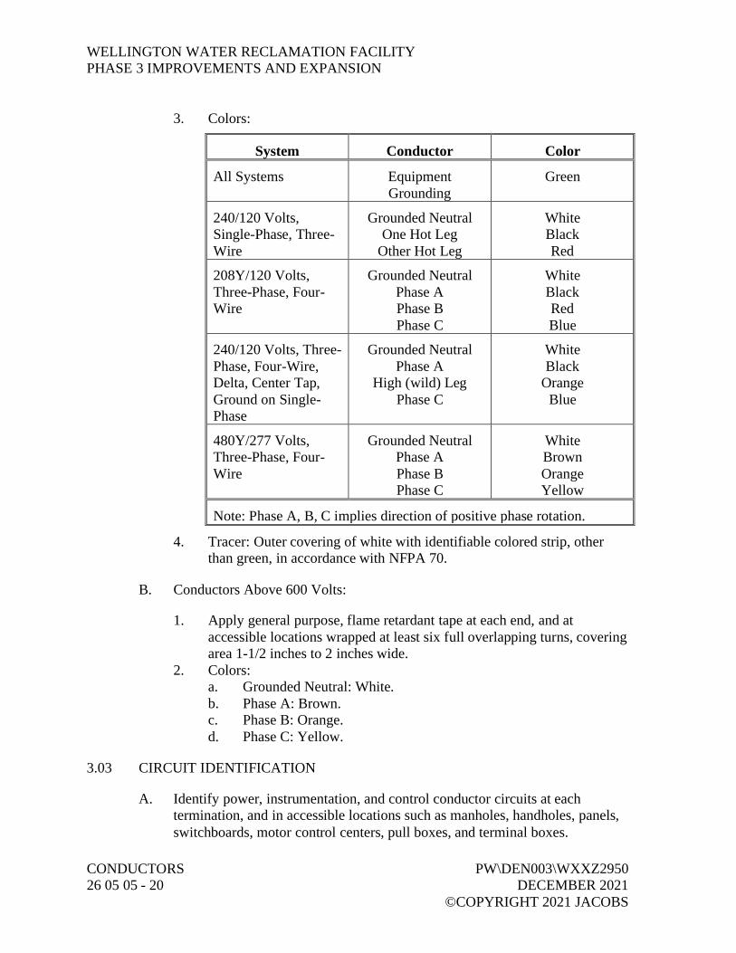
WELLINGTON WATER RECLAMATION FACILITYPHASE 3 IMPROVEMENTS AND EXPANSION
CONDUCTORS PW\DEN003\WXXZ295026 05 05 - 20 DECEMBER 2021
©COPYRIGHT 2021 JACOBS
3. Colors:
System Conductor Color
All Systems EquipmentGrounding
Green
240/120 Volts,Single-Phase, Three-Wire
Grounded NeutralOne Hot Leg
Other Hot Leg
WhiteBlackRed
208Y/120 Volts,Three-Phase, Four-Wire
Grounded NeutralPhase APhase BPhase C
WhiteBlackRedBlue
240/120 Volts, Three-Phase, Four-Wire,Delta, Center Tap,Ground on Single-Phase
Grounded NeutralPhase A
High (wild) LegPhase C
WhiteBlack
OrangeBlue
480Y/277 Volts,Three-Phase, Four-Wire
Grounded NeutralPhase APhase BPhase C
WhiteBrownOrangeYellow
Note: Phase A, B, C implies direction of positive phase rotation.
4. Tracer: Outer covering of white with identifiable colored strip, otherthan green, in accordance with NFPA 70.
B. Conductors Above 600 Volts:
1. Apply general purpose, flame retardant tape at each end, and ataccessible locations wrapped at least six full overlapping turns, coveringarea 1-1/2 inches to 2 inches wide.
2. Colors:a. Grounded Neutral: White.b. Phase A: Brown.c. Phase B: Orange.d. Phase C: Yellow.
3.03 CIRCUIT IDENTIFICATION
A. Identify power, instrumentation, and control conductor circuits at eachtermination, and in accessible locations such as manholes, handholes, panels,switchboards, motor control centers, pull boxes, and terminal boxes.

WELLINGTON WATER RECLAMATION FACILITYPHASE 3 IMPROVEMENTS AND EXPANSION
PW\DEN003\WXXZ2950 CONDUCTORSDECEMBER 2021 26 05 05 - 21©COPYRIGHT 2021 JACOBS
B. Circuits Appearing in Circuit Schedules: Identify using circuit scheduledesignations.
C. Circuits Not Appearing in Circuit Schedules:
1. Assign circuit name based on device or equipment at load end of circuit.2. Where this would result in same name being assigned to more than one
circuit, add number or letter to each otherwise identical circuit name tomake it unique.
D. Method:
1. Conductors 3 AWG and Smaller: Identify with sleeves or heat bondmarkers.
2. Cables and Conductors 2 AWG and Larger:a. Identify with marker plates or tie-on cable marker tags.b. Attach with nylon tie cord.
3. Taped-on markers or tags relying on adhesives not permitted.
3.04 CONDUCTORS 600 VOLTS AND BELOW
A. Install 10 AWG or 12 AWG conductors for branch circuit power wiring inlighting and receptacle circuits.
B. Do not splice incoming service conductors and branch power distributionconductors 6 AWG and larger, unless specifically indicated or approved byEngineer.
C. Connections and Terminations:
1. Install wire nuts only on solid conductors. Wire nuts are not allowed onstranded conductors.
2. Install nylon self-insulated crimp connectors and terminators forinstrumentation and control, circuit conductors.
3. Install self-insulated, set screw wire connectors for two-way connectionof power circuit conductors 12 AWG and smaller.
4. Install uninsulated crimp connectors and terminators forinstrumentation, control, and power circuit conductors 4 AWG through2/0 AWG.
5. Install uninsulated, bolted, two-way connectors and terminators forpower circuit conductors 3/0 AWG and larger.
6. Install uninsulated terminators bolted together on motor circuitconductors 10 AWG and larger.
7. Place no more than one conductor in any single-barrel pressureconnection.

WELLINGTON WATER RECLAMATION FACILITYPHASE 3 IMPROVEMENTS AND EXPANSION
CONDUCTORS PW\DEN003\WXXZ295026 05 05 - 22 DECEMBER 2021
©COPYRIGHT 2021 JACOBS
8. Install crimp connectors with tools approved by connectormanufacturer.
9. Install terminals and connectors acceptable for type of material used.10. Where aluminum conductors are provided, apply oxide-inhibiting
compound at joints and terminations.11. Compression Lugs:
a. Attach with a tool specifically designed for purpose. Tool shallprovide complete, controlled crimp and shall not release untilcrimp is complete.
b. Make connections of copper pigtail to aluminum conductor bymeans of compression type barrel connector and insulate withtape.
c. Install connectors designed for aluminum conductors utilizingcompression barrel termination of conductor and terminating indual rated lug.
d. Do not use plier type crimpers.
D. Do not use soldered mechanical joints.
E. Splices and Terminations:
1. Insulate uninsulated connections.2. Indoors: Use general purpose, flame retardant tape or single wall heat
shrink.3. Outdoors, Dry Locations: Use flame retardant, cold- and weather-
resistant tape or single wall heat shrink.4. Below Grade and Wet or Damp Locations: Use dual wall heat shrink.
F. Cap spare conductors with UL listed end caps.
G. Cabinets, Panels, and Motor Control Centers:
1. Remove surplus wire, bridle and secure.2. Where conductors pass through openings or over edges in sheet metal,
remove burrs, chamfer edges, and install bushings and protective stripsof insulating material to protect the conductors.
H. Control and Instrumentation Wiring:
1. Where terminals provided will accept such lugs, terminate control andinstrumentation wiring, except solid thermocouple leads, with insulated,locking-fork compression lugs.
2. Terminate with methods consistent with terminals provided, and inaccordance with terminal manufacturer’s instructions.

WELLINGTON WATER RECLAMATION FACILITYPHASE 3 IMPROVEMENTS AND EXPANSION
PW\DEN003\WXXZ2950 CONDUCTORSDECEMBER 2021 26 05 05 - 23©COPYRIGHT 2021 JACOBS
3. Locate splices in readily accessible cabinets or junction boxes usingterminal strips.
4. Where connections of cables installed under this section are to be madeunder Section 40 90 00, Instrumentation and Control for ProcessSystems, leave pigtails of adequate length for bundled connections.
5. Cable Protection:a. Under Infinite Access Floors: May install without bundling.b. All Other Areas: Install individual wires, pairs, or triads in flex
conduit under floor or grouped into bundles at least 1/2 inch indiameter.
c. Maintain integrity of shielding of instrumentation cables.d. Ensure grounds do not occur because of damage to jacket over
shield.
I. Extra Conductor Length: For conductors to be connected by others, installminimum 6 feet of extra conductor in freestanding panels and minimum 2 feetin other assemblies.
3.05 CONDUCTOR ARC AND FIREPROOFING
A. Install arc and fireproofing tape on 600-volt single conductors and cables,except those rated Type TC throughout entire exposed length in manholes,handholes, vaults and other indicated locations.
B. Wrap conductors of same circuit entering from separate conduit together assingle cable.
C. Follow tape manufacturer’s installation instructions.
D. Secure tape at intervals of 5 feet with bands of tapebinder. Each band toconsist of a minimum of two wraps directly over each other.
3.06 CABLE FAULT DETECTION SYSTEM
A. Install remote indicator target, externally exposed, on side of equipmentenclosure in which cable terminates.
B. Mounting Height: Minimum 36 inches, maximum 60 inches from floor.
3.07 BUSWAY
A. Install in strict accordance with manufacturer’s recommendations andNFPA 70.
B. Maximum Support Spacing: 10 feet.
WELLINGTON WATER RECLAMATION FACILITYPHASE 3 IMPROVEMENTS AND EXPANSION
CONDUCTORS PW\DEN003\WXXZ295026 05 05 - 24 DECEMBER 2021
©COPYRIGHT 2021 JACOBS
3.08 UNDERGROUND DIRECT BURIAL CABLE
A. Install in trench as specified in Section 31 23 23.15, Trench Backfill.
B. Warning Tape: Install approximately 3 inches above cable, aligned parallel to,and within 12 inches of centerline of the run.
END OF SECTION

WELLINGTON WATER RECLAMATION FACILITYPHASE 3 IMPROVEMENTS AND EXPANSION
PW\DEN003\WXXZ2950 GROUNDING AND BONDINGDECEMBER 2021 FOR ELECTRICAL SYSTEMS©COPYRIGHT 2021 JACOBS 26 05 26 - 1
SECTION 26 05 26GROUNDING AND BONDING FOR ELECTRICAL SYSTEMS
PART 1 GENERAL
1.01 REFERENCES
A. The following is a list of standards which may be referenced in this section:
1. Institute of Electrical and Electronics Engineers (IEEE): C2, NationalElectrical Safety Code (NESC).
2. National Fire Protection Association (NFPA): 70, National ElectricalCode. (NEC).
1.02 SUBMITTALS
A. Action Submittals:
1. Shop Drawings:a. Product data for the following:
1) Mechanical connectors.2) Compression connectors.3) Specialty tools.
1.03 QUALITY ASSURANCE
A. Authority Having Jurisdiction (AHJ):
1. Provide the Work in accordance with NFPA 70, National ElectricalCode (NEC). Where required by the AHJ, provide material andequipment labeled or listed by a nationally recognized testing laboratoryor other organization acceptable to the AHJ to provide a basis forapproval under NEC.
2. Materials and equipment manufactured within the scope of standardspublished by UL:a. Confirm conformance with UL standards.b. Supply with an applied UL listing mark.
PART 2 PRODUCTS
2.01 GROUND ROD
A. Material: Copper.

WELLINGTON WATER RECLAMATION FACILITYPHASE 3 IMPROVEMENTS AND EXPANSION
GROUNDING AND BONDING PW\DEN003\WXXZ2950FOR ELECTRICAL SYSTEMS DECEMBER 202126 05 26 - 2 ©COPYRIGHT 2021 JACOBS
B. Nominal Diameter: Minimum 3/4 inch.
C. Length: 10 feet.
2.02 GROUND CONDUCTORS
A. As specified in Section 26 05 05, Conductors.
2.03 CONNECTORS
A. Compression Type:
1. Compress-deforming type; wrought copper extrusion material.2. Single indentation for conductors 6 AWG and smaller.3. Double indentation with extended barrel for conductors 4 AWG and
larger.4. Barrels prefilled with oxide-inhibiting and antiseizing compound and
sealed.5. Manufacturers:
a. Burndy Corp.; Hyground Irreversible Compression.b. Thomas and Betts Co.c. ILSCO.
B. Mechanical Type: Split-bolt, saddle, or cone screw type; copper alloymaterial.
1. Manufacturers:a. Burndy Corp.b. Thomas and Betts Co.
2.04 GROUNDING WELLS
A. Ground rod box complete with cast-iron riser ring and traffic cover marked“GROUND ROD”.
B. Manufacturers and Products: Lightning and Grounding Systems, Inc.;I-R Series.
PART 3 EXECUTION
3.01 GENERAL
A. Grounding: In compliance with NFPA 70 and IEEE C2.
B. Ground electrical service neutral at service entrance equipment withgrounding electrode conductor to grounding electrode system.

WELLINGTON WATER RECLAMATION FACILITYPHASE 3 IMPROVEMENTS AND EXPANSION
PW\DEN003\WXXZ2950 GROUNDING AND BONDINGDECEMBER 2021 FOR ELECTRICAL SYSTEMS©COPYRIGHT 2021 JACOBS 26 05 26 - 3
C. Ground each separately derived system neutral with common groundingelectrode conductor to grounding electrode system.
D. Bond together all grounding electrodes that are present at each building orstructure served to form one common grounding electrode system.
E. Bond together system neutrals, service equipment enclosures, exposednoncurrent-carrying metal parts of electrical equipment, metal raceways,ground conductor in raceways and cables, receptacle ground connections, andmetal piping systems.
F. Shielded Power Cables: Ground shields at each splice or termination inaccordance with recommendations of splice or termination manufacturer.
G. Shielded Instrumentation Cables:
1. Ground shield to ground bus at power supply for analog signal.2. Expose shield minimum 1 inch at termination to field instrument and
apply heat shrink tube.3. Do not ground instrumentation cable shield at more than one point.
3.02 WIRE CONNECTIONS
A. Ground Conductors: Install in conduit containing power conductors andcontrol circuits above 50 volts.
B. Nonmetallic Raceways and Flexible Tubing: Install equipment groundingconductor connected at both ends to noncurrent-carrying grounding bus.
C. Connect ground conductors to raceway grounding bushings.
D. Extend and connect ground conductors to ground bus in all equipmentcontaining a ground bus.
E. Connect enclosure of equipment containing ground bus to that bus.
F. Bolt connections to equipment ground bus.
G. Bond grounding conductors to metallic enclosures at each end, and tointermediate metallic enclosures.
H. Junction Boxes: Furnish materials and connect to equipment groundingsystem with grounding clips mounted directly on box, or with 3/8-inchmachine screws.

WELLINGTON WATER RECLAMATION FACILITYPHASE 3 IMPROVEMENTS AND EXPANSION
GROUNDING AND BONDING PW\DEN003\WXXZ2950FOR ELECTRICAL SYSTEMS DECEMBER 202126 05 26 - 4 ©COPYRIGHT 2021 JACOBS
I. Metallic Equipment Enclosures: Use furnished ground lug; if none furnished,tap equipment housing and install solderless terminal connected to box withmachine screw. For circuits greater than 20 amps use minimum 5/16-inchdiameter bolt.
3.03 MOTOR GROUNDING
A. Extend equipment ground bus via grounding conductor installed in motorfeeder raceway; connect to motor frame.
B. Nonmetallic Raceways and Flexible Tubing: Install an equipment groundingconductor connected at both ends to noncurrent-carrying grounding bus.
C. Motors Less Than 10 hp: Use furnished ground lug in motor connection box.If none furnished, provide compression, spade-type terminal connected toconduit box mounting screw.
D. Motors 10 hp and Above: Use furnished ground lug in motor connection box.If none furnished, tap motor frame or equipment housing; furnishcompression, one-hole, lug type terminal connected with minimum 5/16-inchbrass threaded stud with bolt and washer.
E. Circuits 20 Amps or Above: Tap motor frame or equipment housing. Installsolderless terminal with minimum 5/16-inch diameter bolt.
3.04 GROUND RODS
A. Install full length with conductor connection at upper end.
B. Install with connection point below finished grade, unless otherwise shown.
C. Space multiple ground rods by one rod length.
D. Install to 8 feet below local frost depth.
3.05 GROUNDING WELLS
A. Install for ground rods located inside buildings, asphalt and paved areas, andwhere shown on Drawings.
B. Install riser ring and cover flush with surface.
C. Place 6 inches of crushed rock in bottom of each well.
WELLINGTON WATER RECLAMATION FACILITYPHASE 3 IMPROVEMENTS AND EXPANSION
PW\DEN003\WXXZ2950 GROUNDING AND BONDINGDECEMBER 2021 FOR ELECTRICAL SYSTEMS©COPYRIGHT 2021 JACOBS 26 05 26 - 5
3.06 CONNECTIONS
A. General:
1. Abovegrade Connections: Install exothermic weld, mechanical, orcompression-type connectors; or brazing.
2. Belowgrade Connections: Install exothermic weld or compression typeconnectors.
3. Remove paint, dirt, or other surface coverings at connection points toallow good metal-to-metal contact.
4. Notify Engineer and Owner prior to backfilling ground connections.
B. Compression Type:
1. Install in accordance with connector manufacturer’s recommendations.2. Install connectors of proper size for grounding conductors and ground
rods specified.3. Install using connector manufacturer’s compression tool having proper
sized dies and operate per manufacturer’s instructions.
C. Mechanical Type:
1. Apply homogeneous blend of colloidal copper and rust and corrosioninhibitor before making connection.
2. Install in accordance with connector manufacturer’s recommendations.3. Do not conceal mechanical connections.
3.07 METAL STRUCTURE GROUNDING
A. Bond metal sheathing and exposed metal vertical structural elements togrounding system.
B. Bond electrical equipment supported by metal platforms to the platforms.
C. Provide electrical contact between metal frames and railings supportingpushbutton stations, receptacles, and instrument cabinets, and racewayscarrying circuits to these devices.
3.08 MANHOLE AND HANDHOLE GROUNDING
A. Install one ground rod inside each manhole and handhole larger than 24-inchby 24-inch inside dimensions.
B. Ground Rod Floor Protrusion: 4 inches to 6 inches above floor.

WELLINGTON WATER RECLAMATION FACILITYPHASE 3 IMPROVEMENTS AND EXPANSION
GROUNDING AND BONDING PW\DEN003\WXXZ2950FOR ELECTRICAL SYSTEMS DECEMBER 202126 05 26 - 6 ©COPYRIGHT 2021 JACOBS
C. Make connections of grounding conductors fully visible and accessible.
D. Connect all noncurrent-carrying metal parts and any metallic racewaygrounding bushings to ground rod with 6 AWG copper conductor.
3.09 TRANSFORMER GROUNDING
A. Bond neutrals of transformers within buildings to system ground network andto any additional indicated grounding electrodes.
B. Bond neutrals of substation transformers to substation grounding grid andsystem grounding network.
C. Bond neutrals of pad-mounted transformers to four locally driven ground rodsand buried ground wire encircling transformer and system ground network.
3.10 LIGHTNING PROTECTION SYSTEMS
A. Bond lightning protection system ground terminals to building or structuregrounding electrode system.
3.11 SURGE PROTECTION EQUIPMENT GROUNDING
A. Connect surge arrestor ground terminals to equipment ground bus.
END OF SECTION

WELLINGTON WATER RECLAMATION FACILITYPHASE 3 IMPROVEMENTS AND EXPANSION
PW\DEN003\WXXZ2950 RACEWAY AND BOXESDECEMBER 2021 26 05 33 - 1©COPYRIGHT 2021 JACOBS
SECTION 26 05 33RACEWAY AND BOXES
PART 1 GENERAL
1.01 REFERENCES
A. The following is a list of standards which may be referenced in this section:
1. American Association of State Highway and Transportation Officials(AASHTO): HB, Standard Specifications for Highway Bridges.
2. ASTM International (ASTM):a. A123/123M, Standard Specification for Zinc (Hot-Dipped
Galvanized) Coatings on Iron and Steel Products.b. A167, Standard Specification for Stainless and Heat-Resisting
Chromium-Nickel Steel Plate, Sheet, and Strip.c. A240/A240M, Standard Specification for Chromium and
Chromium-Nickel Stainless Steel Plate, Sheet, and Strip forPressure Vessels and for General Applications.
d. C857, Standard Practice for Minimum Structural Design Loadingfor Underground Precast Concrete Utility Structures.
e. D149, Standard Test Method for Dielectric Breakdown Voltageand Dielectric Strength of Solid Electrical Insulating Materials atCommercial Power Frequencies.
3. National Electrical Contractor’s Association, Inc. (NECA): Installationstandards.
4. National Electrical Manufacturers Association (NEMA):a. 250, Enclosures for Electrical Equipment (1000 Volts Maximum).b. C80.1, Electrical Rigid Steel Conduit (ERSC).c. C80.3, Steel Electrical Metallic Tubing (EMT).d. C80.5, Electrical Rigid Aluminum Conduit (ERAC).e. C80.6, Electrical Intermediate Metal Conduit (EIMC).f. RN 1, Polyvinyl Chloride (PVC) Externally Coated Galvanized
Rigid Steel Conduit and Intermediate Metal Conduit.g. TC 2, Electrical Polyvinyl Chloride (PVC) Conduit.h. TC 3, Polyvinyl Chloride (PVC) Fittings for Use with Rigid PVC
Conduit and Tubing.i. TC 6, Polyvinyl Chloride (PVC) Plastic Utilities Duct for
Underground Installation.j. TC 14, Reinforced Thermosetting Resin Conduit (RTRC) and
Fittings.k. VE 1, Metallic Cable Tray Systems.

WELLINGTON WATER RECLAMATION FACILITYPHASE 3 IMPROVEMENTS AND EXPANSION
RACEWAY AND BOXES PW\DEN003\WXXZ295026 05 33 - 2 DECEMBER 2021
©COPYRIGHT 2021 JACOBS
5. National Fire Protection Association (NFPA): 70, National ElectricalCode (NEC).
6. Telecommunications Industry Association (TIA): 569B, CommercialBuilding Standard for Telecommunications Pathways and Spaces.
7. UL:a. 1, Standard for Safety for Flexible Metal Conduit.b. 5, Standard for Safety for Surface Metal Raceways and Fittings.c. 6, Standard for Safety for Electrical Rigid Metal Conduit – Steel.d. 6A, Standard for Safety for Electrical Rigid Metal Conduit –
Aluminum, Red Brass and Stainless.e. 360, Standard for Safety for Liquid-Tight Flexible Steel Conduit.f. 514B, Standard for Safety for Conduit, Tubing, and Cable
Fittings.g. 651, Standard for Safety for Schedule 40 and 80 Rigid PVC
Conduit and Fittings.h. 651A, Standard for Safety for Type EB and A Rigid PVC Conduit
and HDPE Conduit.i. 797, Standard for Safety for Electrical Metallic Tubing – Steel.j. 870, Standard for Safety for Wireways, Auxiliary Gutters, and
Associated Fittings.k. 1242, Standard for Safety for Electrical Intermediate Metal
Conduit – Steel.l. 1660, Standard for Safety for Liquid-Tight Flexible Nonmetallic
Conduit.m. 1684, Standard for Safety for Reinforced Thermosetting Resin
Conduit (RTRC) and Fittings.n. 2024, Standard for Safety for Optical Fiber and Communication
Cable Raceway.
1.02 SUBMITTALS
A. Action Submittals:
1. Manufacturer’s Literature:a. Rigid galvanized steel conduit.b. Intermediate metal conduit.c. Electric metallic tubing.d. Rigid aluminum conduit.e. PVC Schedule 40 conduit.f. PVC Schedule 80 conduit.g. PVC tubing (Type EB) conduit.h. PVC-coated rigid galvanized steel conduit, submittal to include
copy of manufacturer’s warranty.i. Flexible metal, liquid-tight conduit.

WELLINGTON WATER RECLAMATION FACILITYPHASE 3 IMPROVEMENTS AND EXPANSION
PW\DEN003\WXXZ2950 RACEWAY AND BOXESDECEMBER 2021 26 05 33 - 3©COPYRIGHT 2021 JACOBS
j. Flexible, nonmetallic, liquid-tight conduit.k. Flexible metal, nonliquid-tight conduit.l. Conduit fittings.m. Wireways.n. Surface metal raceway.o. Device boxes for use in hazardous areas.p. Junction and pull boxes used at or below grade.q. Large junction and pull boxes.r. Terminal junction boxes.
2. Precast Manholes and Handholes:a. Dimensional drawings and descriptive literature.b. Traffic loading calculations.c. Accessory information.
3. Telecommunications Pathway Cable Tray:a. Dimensional drawings, calculations, and descriptive information.b. NEMA load/span designation and how it was selected.c. Support span length and pounds-per-foot actual and future cable
loading at locations, with safety factor used.d. Location and magnitude of maximum simple beam deflection of
tray for loading specified.e. Layout drawings and list of accessories being provided.
4. Equipment and machinery proposed for bending metal conduit.5. Method for bending PVC conduit less than 30 degrees.6. Seismic anchorage and bracing drawings and cut sheets, as required by
Section 01 88 15, Anchorage and Bracing.7. Conduit Layout:
a. Provide drawings for conduit installations, underground andconcealed conduits including, but not limited to, ductbanks, underfloor slabs, concealed in floor slabs, and concealed in walls.
b. Provide plan and section showing arrangement and location ofconduit and duct bank required for:1) Low and medium voltage feeder and branch circuits.2) Instrumentation and control systems.3) Communications systems.4) Empty conduit for future use.
c. Reproducible and Electronic CAD; scale not greater than 1 inchequals 20 feet.
B. Informational Submittals:
1. Seismic anchorage and bracing calculations as required bySection 01 88 15, Anchorage and Bracing.

WELLINGTON WATER RECLAMATION FACILITYPHASE 3 IMPROVEMENTS AND EXPANSION
RACEWAY AND BOXES PW\DEN003\WXXZ295026 05 33 - 4 DECEMBER 2021
©COPYRIGHT 2021 JACOBS
2. Component and attachment testing seismic certificate of compliance asrequired by Section 01 45 33, Special Inspection, Observation, andTesting.
3. Manufacturer’s certification of training for PVC-coated rigid galvanizedsteel conduit installer.
1.03 QUALITY ASSURANCE
A. Authority Having Jurisdiction (AHJ):
1. Provide the Work in accordance with NFPA 70, National ElectricalCode (NEC). Where required by the AHJ, material and equipment shallbe labeled or listed by a nationally recognized testing laboratory or otherorganization acceptable to the AHJ in order to provide a basis forapproval under NEC.
2. Materials and equipment manufactured within scope of standardspublished by UL shall conform to those standards and shall have anapplied UL listing mark.
B. PVC-Coated, Rigid Galvanized Steel Conduit Installer: Certified by conduitmanufacturer as having received minimum 2 hours of training on installationprocedures.
PART 2 PRODUCTS
2.01 CONDUIT AND TUBING
A. Rigid Galvanized Steel Conduit (RGS):
1. Meet requirements of NEMA C80.1 and UL 6.2. Material: Hot-dip galvanized with chromated protective layer.
B. Intermediate Metal Conduit (IMC):
1. Meet requirements of NEMA C80.6 and UL 1242.2. Material: Hot-dip galvanized with chromated and lacquered protective
layer.
C. Electric Metallic Tubing (EMT):
1. Meet requirements of NEMA C80.3 and UL 797.2. Material: Hot-dip galvanized with chromated and lacquered protective
layer.
WELLINGTON WATER RECLAMATION FACILITYPHASE 3 IMPROVEMENTS AND EXPANSION
PW\DEN003\WXXZ2950 RACEWAY AND BOXESDECEMBER 2021 26 05 33 - 5©COPYRIGHT 2021 JACOBS
D. Rigid Aluminum Conduit:
1. Meet requirements of NEMA C80.5 and UL 6A.2. Material: Type 6063, copper-free aluminum alloy.
E. PVC Schedule 40 Conduit:
1. Meet requirements of NEMA TC 2 and UL 651.2. UL listed for concrete encasement, underground direct burial, concealed
or direct sunlight exposure, and 90 degrees C insulated conductors.3. Furnish without factory-formed bell.
F. PVC Schedule 80 Conduit:
1. Meet requirements of NEMA TC 2 and UL 651.2. UL listed for concrete encasement, underground direct burial, concealed
or direct sunlight exposure, and 90 degrees C insulated conductors.
G. Fiberglass Conduit:
1. Meet requirements of NEMA TC 14 and UL 1684.2. Winding: Single circuit with angle as close to 54.75 as possible.3. Resin System: Epoxy based using and anhydride curing agent.4. Use carbon black as ultraviolet inhibitor.5. Toxicity: Conduit shall not contain compounds that can release halogens
in more than trace amounts when burning.6. Dielectric Strength: Exceed 400 volts per mil when tested in accordance
with ASTM D149.7. Jointing System: Two-part epoxy adhesive supplied by conduit
manufacturer.8. Manufacturers:
a. Champion Fiberglass.b. Osburn Associates.c. FRE Composites, Inc.
H. PVC Tubing (Type EB):
1. Meet requirements of NEMA TC 6 and UL 651A.2. UL listed for reinforced concrete encasement and 90 degrees C insulated
conductors.3. Furnish without factory-formed bell.
I. PVC-Coated Rigid Galvanized Steel Conduit:
1. Meet requirements of NEMA RN 1 and ETL.

WELLINGTON WATER RECLAMATION FACILITYPHASE 3 IMPROVEMENTS AND EXPANSION
RACEWAY AND BOXES PW\DEN003\WXXZ295026 05 33 - 6 DECEMBER 2021
©COPYRIGHT 2021 JACOBS
2. Material:a. Meet requirements of NEMA C80.1 and UL 6.b. Exterior Finish: PVC coating, 40-mil nominal thickness; bond to
metal shall have tensile strength greater than PVC.c. Interior finish: Urethane coating, 2-mil nominal thickness.
3. Threads: Hot-dipped galvanized and factory coated with urethane.4. Bendable without damage to interior or exterior coating.
J. PVC-Coated Rigid Aluminum Conduit:
1. Meet requirements of NEMA RN 1.2. Material: Type 6063, copper-free aluminum alloy.
a. Meet requirements of NEMA C80.5 and UL 6A.b. Exterior Finish: PVC coating, 40-mil nominal thickness; bond to
metal shall have tensile strength greater than PVC.c. Interior Finish: Urethane coating, 2-mil nominal thickness.
K. Flexible Metal, Liquid-Tight Conduit:
1. UL 360 listed for 105 degrees C insulated conductors.2. Material: Galvanized steel with extruded PVC jacket.
L. Flexible Metal, Nonliquid-Tight Conduit:
1. Meet requirements of UL 1.2. Material: Galvanized steel.
M. Flexible, Nonmetallic, Liquid-Tight Conduit:
1. Material: PVC core with fused flexible PVC jacket.2. UL 1660 listed for:
a. Dry Conditions: 80 degrees C insulated conductors.b. Wet Conditions: 60 degrees C insulated conductors.
3. Manufacturers and Products:a. Carlon; Carflex or X-Flex.b. T & B; Xtraflex LTC or EFC.
N. Innerduct:
1. Resistant to spread of fire, per requirements of UL 2024.2. Smooth or corrugated HDPE.3. Textile Manufacturer: Maxcell.

WELLINGTON WATER RECLAMATION FACILITYPHASE 3 IMPROVEMENTS AND EXPANSION
PW\DEN003\WXXZ2950 RACEWAY AND BOXESDECEMBER 2021 26 05 33 - 7©COPYRIGHT 2021 JACOBS
2.02 FITTINGS
A. Rigid Galvanized Steel and Intermediate Metal Conduit:
1. General:a. Meet requirements of UL 514B.b. Type: Threaded, galvanized. Set screw and threadless
compression fittings not permitted.2. Bushing:
a. Material: Malleable iron with integral insulated throat, rated for150 degrees C.
b. Manufacturers and Products:1) Appleton; Series BU-I.2) O-Z/Gedney; Type HB.
3. Grounding Bushing:a. Material: Malleable iron with integral insulated throat rated for
150 degrees C, with solderless lugs.b. Manufacturers and Products:
1) Appleton; Series GIB.2) O-Z/Gedney; Type HBLG.
4. Conduit Hub:a. Material: Malleable iron with insulated throat with bonding screw.b. UL listed for use in wet locations.c. Manufacturers and Products:
1) Appleton, Series HUB-B.2) O-Z/Gedney; Series CH.3) Meyers; ST Series.
5. Conduit Bodies:a. Sized as required by NFPA 70.b. Manufacturers and Products (For Normal Conditions):
1) Appleton; Form 35 threaded unilets.2) Crouse-Hinds; Form 7 or Form 8 threaded condulets.3) Killark; Series O electrolets.4) Thomas & Betts; Form 7 or Form 8.
c. Manufacturers (For Hazardous Locations):1) Appleton.2) Crouse-Hinds.3) Killark.
6. Couplings: As supplied by conduit manufacturer.7. Unions:
a. Concrete tight, hot-dip galvanized malleable iron.
WELLINGTON WATER RECLAMATION FACILITYPHASE 3 IMPROVEMENTS AND EXPANSION
RACEWAY AND BOXES PW\DEN003\WXXZ295026 05 33 - 8 DECEMBER 2021
©COPYRIGHT 2021 JACOBS
b. Manufacturers and Products:1) Appleton; Series SCC bolt-on coupling or Series EC three-
piece union.2) O-Z/Gedney; Type SSP split coupling or Type 4 Series,
three-piece coupling.8. Conduit Sealing Fitting:
a. Manufacturers and Products:1) Appleton; Type EYF, EYM, or ESU.2) Crouse-Hinds; Type EYS or EZS.3) Killark; Type EY or Type EYS.
9. Drain Seal:a. Manufacturers and Products:
1) Appleton; Type EYD.2) Crouse-Hinds; Type EYD or Type EZD.
10. Drain/Breather Fitting:a. Manufacturers and Products:
1) Appleton; Type ECDB.2) Crouse-Hinds; ECD.
11. Expansion Fitting:a. Manufacturers and Products:
1) Deflection/Expansion Movement:a) Appleton; Type DF.b) Crouse-Hinds; Type XD.
2) Expansion Movement Only:a) Appleton; Type XJ.b) Crouse-Hinds; Type XJ.c) Thomas & Betts; XJG-TP.
12. Cable Sealing Fitting:a. To form watertight nonslip cord or cable connection to conduit.b. For Conductors with OD of 1/2 inch or Less: Neoprene bushing at
connector entry.c. Manufacturers and Products:
1) Appleton; CG-S.2) Crouse-Hinds; CGBS.
B. Electric Metallic Tubing:
1. Meet requirements of UL 514B.2. Type: Steel body and locknuts with steel or malleable iron compression
nuts. Set screw and drive-on fittings not permitted.3. Electro zinc-plated inside and out.4. Raintight.

WELLINGTON WATER RECLAMATION FACILITYPHASE 3 IMPROVEMENTS AND EXPANSION
PW\DEN003\WXXZ2950 RACEWAY AND BOXESDECEMBER 2021 26 05 33 - 9©COPYRIGHT 2021 JACOBS
5. Coupling Manufacturers and Products:a. Appleton; Type 95T.b. Crouse-Hinds.c. Thomas & Betts.
6. Connector Manufacturers and Products:a. Appleton; Type ETP.b. Crouse-Hinds.c. Thomas & Betts.
C. Rigid Aluminum Conduit:
1. General:a. Meet requirements of UL 514B.b. Type: Threaded, copper-free. Set screw fittings not permitted.
2. Insulated Bushing:a. Material: Cast aluminum, with integral insulated throat, rated for
150 degrees C.b. Manufacturer and Product: O-Z/Gedney; Type AB.
3. Grounding Bushing:a. Material: Cast aluminum with integral insulated throat, rated for
150 degrees, with solderless lugs.b. Manufacturer and Product: O-Z/Gedney; Type ABLG.
4. Conduit Hub:a. Material: Cast aluminum, with insulated throat.b. UL listed for use in wet locations.c. Manufacturers and Products:
1) O-Z/Gedney; Type CHA.2) Thomas & Betts; Series 370AL.3) Meyers; Series SA.
5. Conduit Bodies:a. Manufacturers and Products (For Normal Conditions):
1) Appleton; Form 85 threaded unilets.2) Crouse-Hinds; Mark 9 or Form 7-SA threaded condulets.3) Killark; Series O electrolets.
b. Manufacturers (For Hazardous Locations):1) Appleton.2) Crouse-Hinds.3) Killark.
6. Couplings: As supplied by conduit manufacturer.7. Conduit Sealing Fitting:
a. Manufacturers and Products:1) Appleton; Type EYF-AL or EYM-AL.2) Crouse-Hinds; Type EYS-SA or EZS-SA.3) Killark; Type EY or Type EYS.

WELLINGTON WATER RECLAMATION FACILITYPHASE 3 IMPROVEMENTS AND EXPANSION
RACEWAY AND BOXES PW\DEN003\WXXZ295026 05 33 - 10 DECEMBER 2021
©COPYRIGHT 2021 JACOBS
8. Drain Seal:a. Manufacturers and Products:
1) Appleton; Type EYDM-A.2) Crouse-Hinds; Type EYD-SA or Type EZD-SA.
9. Drain/Breather Fitting:a. Manufacturers and Products:
1) Appleton; Type ECDB.2) Crouse-Hinds; ECD.
10. Expansion Fitting:a. Manufacturers and Products:
1) Deflection/Expansion Movement: Steel City; Type DF-A.2) Expansion Movement Only: Steel City; Type AF-A.
11. Cable Sealing Fittings:a. To form watertight nonslip cord or cable connection to conduit.b. Bushing: Neoprene at connector entry.c. Manufacturer and Product: Appleton; CG-S.
D. PVC Conduit and Tubing:
1. Meet requirements of NEMA TC 3.2. Type: PVC, slip-on.
E. Fiberglass Conduit:
1. Manufactured by same process as conduit.2. Supplied by conduit manufacturer.
F. PVC-Coated Rigid Galvanized Steel Conduit:
1. Meet requirements of UL 514B.2. Fittings: Rigid galvanized steel type, PVC coated by conduit
manufacturer.3. Conduit Bodies: Cast metal hot-dipped galvanized or urethane finish.
Cover shall be of same material as conduit body. PVC coated by conduitmanufacturer.
4. Finish: 40-mil PVC exterior, 2-mil urethane interior.5. Overlapping pressure-sealing sleeves.6. Conduit Hangers, Attachments, and Accessories: PVC-coated.7. Manufacturers:
a. Robroy Industries.b. Ocal.
8. Expansion Fitting:a. Manufacturer and Product: Ocal; OCAL-BLUE XJG.

WELLINGTON WATER RECLAMATION FACILITYPHASE 3 IMPROVEMENTS AND EXPANSION
PW\DEN003\WXXZ2950 RACEWAY AND BOXESDECEMBER 2021 26 05 33 - 11©COPYRIGHT 2021 JACOBS
G. PVC-Coated Rigid Aluminum Conduit:
1. Meet requirements of UL 514B.2. Fittings: As listed for rigid aluminum conduit.3. Finish: 40-mil PVC exterior, 2-mil urethane interior.4. Overlapping pressure-sealing sleeves.5. Conduit Hangers, Attachments, and Accessories: PVC-coated.6. Manufacturers:
a. Robroy Industries.b. Ocal.
H. Flexible Metal, Liquid-Tight Conduit:
1. Metal insulated throat connectors with integral nylon or plastic bushingrated for 105 degrees C.
2. Insulated throat and sealing O-rings.3. Manufacturers and Products:
a. Thomas & Betts; Series 5331.b. O-Z/Gedney; Series 4Q.
I. Flexible Metal, Nonliquid-Tight Conduit:
1. Meet requirements of UL 514B.2. Body: Galvanized steel or malleable iron.3. Throat: Nylon insulated.4. 1-1/4-Inch Conduit and Smaller: One screw body.5. 1-1/2-Inch Conduit and Larger: Two screw body.6. Manufacturer and Product: Appleton; Series 7400.
J. Flexible, Nonmetallic, Liquid-Tight Conduit:
1. Meet requirements of UL 514B.2. Type: High strength plastic body, complete with lock nut, O-ring,
threaded ferrule, sealing ring, and compression nut.3. Body/compression nut (gland) design to ensure high mechanical pullout
strength and watertight seal.4. Manufacturers and Products:
a. Carlon; Type LT.b. O-Z/Gedney; Type 4Q-P.c. Thomas & Betts; Series 6300.
K. Flexible Coupling, Hazardous Locations:
1. Approved for use in atmosphere involved.

WELLINGTON WATER RECLAMATION FACILITYPHASE 3 IMPROVEMENTS AND EXPANSION
RACEWAY AND BOXES PW\DEN003\WXXZ295026 05 33 - 12 DECEMBER 2021
©COPYRIGHT 2021 JACOBS
2. Rating: Watertight and UL listed for use in Class I, Division 1 andDivision 2 areas.
3. Outer bronze braid and an insulating liner.4. Conductivity equal to a similar length of rigid metal conduit.5. Manufacturers and Products:
a. Crouse-Hinds; Type ECGJH or Type ECLK.b. Appleton; EXGJH or EXLK.
L. Watertight Entrance Seal Device:
1. New Construction:a. Material: Oversized sleeve, malleable iron body with sealing ring,
pressure ring, grommet seal, and pressure clamp.b. Manufacturer and Product: O-Z/Gedney; Type FSK or
Type WSK, as required.2. Cored-Hole Application:
a. Material: Assembled dual pressure disks, neoprene sealing ring,and membrane clamp.
b. Manufacturer and Product: O-Z/Gedney; Series CSM.
2.03 OUTLET AND DEVICE BOXES
A. Sheet Steel: One-piece drawn type, zinc-plated or cadmium-plated.
B. Cast Metal:
1. Box: Malleable iron or Cast ferrous metal.2. Cover: Gasketed, weatherproof, malleable iron, or cast ferrous metal,
with stainless steel screws.3. Hubs: Threaded.4. Lugs: Cast mounting.5. Manufacturers and Products, Nonhazardous Locations:
a. Crouse-Hinds; Type FS or Type FD.b. Appleton; Type FS or Type FD.c. Killark.
6. Manufacturers and Products, Hazardous Locations:a. Crouse-Hinds; Type GUA or Type EAJ.b. Appleton; Type GR.
C. Cast Aluminum:
1. Material:a. Box: Cast, copper-free aluminum.b. Cover: Gasketed, weatherproof, cast copper-free aluminum with
stainless steel screws.

WELLINGTON WATER RECLAMATION FACILITYPHASE 3 IMPROVEMENTS AND EXPANSION
PW\DEN003\WXXZ2950 RACEWAY AND BOXESDECEMBER 2021 26 05 33 - 13©COPYRIGHT 2021 JACOBS
2. Hubs: Threaded.3. Lugs: Cast mounting.4. Manufacturers and Products, Nonhazardous Locations:
a. Crouse-Hinds; Type FS-SA or Type FD-SA.b. Appleton; Type FS or Type FD.c. Killark.
5. Manufacturers and Products, Hazardous Locations:a. Crouse-Hinds; Type GUA-SA.b. Appleton; Type GR.
D. PVC-Coated Cast Metal:
1. Type: One-piece.2. Material: Malleable iron, cast ferrous metal, or cast aluminum.3. Coating:
a. Exterior Surfaces: 40-mil PVC.b. Interior Surfaces: 2-mil urethane.
4. Manufacturers:a. Robroy Industries.b. Ocal.
E. Nonmetallic:
1. Box: PVC.2. Cover: PVC, weatherproof, with stainless steel screws.3. Manufacturer and Product: Carlon; Type FS or Type FD, with Type E98
or Type E96 covers.
2.04 JUNCTION AND PULL BOXES
A. Outlet Box Used as Junction or Pull Box: As specified under Article Outletand Device Boxes.
B. Conduit Bodies Used as Junction Boxes: As specified under Article Fittings.
C. Large Sheet Steel Box:
1. NEMA 250, Type 1.2. Box: Code-gauge, galvanized steel.3. Cover: Full access, screw type.4. Machine Screws: Corrosion-resistant.
D. Large Cast Metal Box:
1. NEMA 250, Type 4, 13 and 4X.

WELLINGTON WATER RECLAMATION FACILITYPHASE 3 IMPROVEMENTS AND EXPANSION
RACEWAY AND BOXES PW\DEN003\WXXZ295026 05 33 - 14 DECEMBER 2021
©COPYRIGHT 2021 JACOBS
2. Box: Cast malleable iron, or ferrous metal, electrogalvanized finished,with drilled and tapped conduit entrances and exterior mounting lugs.
3. Cover: Hinged with clamps.4. Gasket: Neoprene.5. Hardware and Machine Screws: ASTM A167, Type 316 stainless steel.6. Manufacturers and Products, Surface Mounted Nonhinged Type:
a. Crouse-Hinds; Series W.b. O-Z/Gedney; Series Y.
7. Manufacturer and Product, Surface Mounted, Hinged Type:O-Z/Gedney; Series YW.
8. Manufacturers and Products, Recessed Type:a. Crouse-Hinds; Type WJBF.b. O-Z/Gedney; Series YR.
E. Large Cast Metal Box, Hazardous Locations:
1. NEMA 250 Type 7 or Type 9 as required for Class, Division, and Groupinvolved.
2. Box: Cast ferrous metal, electro-galvanize finished or copper-freealuminum with drilled and tapped conduit entrances.
3. Cover: Hinged with screws.4. Hardware and Machine Screws: ASTM A167, Type 316 stainless steel.5. Manufacturers and Products:
a. Crouse-Hinds; Type EJB.b. Appleton; Type AJBEW.
F. Large Cast Aluminum Box:
1. NEMA 250 Type 4, 7, 9 and 13.2. Box: Cast copper-free aluminum, with drilled and tapped conduit
entrances and exterior mounting lugs.3. Cover: Nonhinged.4. Gasket: Neoprene.5. Hardware and Machine Screws: ASTM A167, Type 316 stainless steel.6. Manufacturers and Products, Surface Mounted Type:
a. Crouse-Hinds; Series W-SA.b. O-Z/Gedney; Series YS-A, YL-A.c. Killark.
G. Large Stainless Steel Box:
1. NEMA 250 Type 4X.2. Box: 14-gauge, ASTM A240/A240M, Type 304 stainless steel, with
white enamel painted interior mounting panel.
WELLINGTON WATER RECLAMATION FACILITYPHASE 3 IMPROVEMENTS AND EXPANSION
PW\DEN003\WXXZ2950 RACEWAY AND BOXESDECEMBER 2021 26 05 33 - 15©COPYRIGHT 2021 JACOBS
3. Cover: Hinged with clamps.4. Hardware and Machine Screws: ASTM A167, Type 304 stainless steel.5. Manufacturers:
a. Hoffman Engineering Co.b. Robroy Industries.c. Wiegman.
H. Large Steel Box:
1. NEMA 250 Type 1, 3R, 3S and 12.2. Box: 14, 12 and 10-gauge steel, with white enamel painted interior and
gray primed exterior, over phosphated surfaces. Provide gray finish asapproved by Owner.
3. Cover: Hinged with clamps.4. Hardware and Machine Screws: ASTM A167, Type 316 stainless steel.5. Manufacturers:
a. Hoffman Engineering Co.b. Robroy Industries.c. Wiegman.
I. Large Nonmetallic Box:
1. NEMA 250 Type 4X.2. Box: High-impact, fiberglass-reinforced polyester or engineered
thermoplastic, with stability to high heat.3. Cover: Hinged with clamps.4. Hardware and Machine Screws: ASTM A167, Type 316 stainless steel.5. Conduit hubs and mounting lugs.6. Manufacturers and Products:
a. Crouse-Hinds; Type NJB.b. Carlon; Series N, C, or H.c. Robroy Industries.
J. Concrete Box, Nontraffic Areas:
1. Box: Reinforced, cast concrete with extension.2. Cover: Steel diamond plate with locking bolts.3. Cover Marking: ELECTRICAL, TELEPHONE, or as shown.4. Size: 10 inches by 17 inches, minimum.5. Manufacturers and Products:
a. Utility Vault Co.; Series 36-1017.b. Christy, Concrete Products, Inc.; N9.c. Quazite; “PG” Style.

WELLINGTON WATER RECLAMATION FACILITYPHASE 3 IMPROVEMENTS AND EXPANSION
RACEWAY AND BOXES PW\DEN003\WXXZ295026 05 33 - 16 DECEMBER 2021
©COPYRIGHT 2021 JACOBS
K. Concrete Box, Traffic Areas:
1. Box: Reinforced, cast concrete with extension and bottom slab.2. Cover: Steel checked plate; H/20 loading with screw down.3. Cover Marking: ELECTRICAL, TELEPHONE, or as shown.4. Manufacturers and Products:
a. Christy, Concrete Products, Inc.; B1017BOX.b. Utility Vault Co.; 3030 SB.
2.05 TELEPHONE AND DATA OUTLET
A. Provide outlet boxes and cover plates meeting requirements of TIA 569B.
2.06 TERMINAL JUNCTION BOX
A. Cover: Hinged, unless otherwise shown.
B. Interior Finish: Paint with white enamel or lacquer.
C. Terminal Blocks:
1. Separate connection point for each conductor entering or leaving box.2. Spare Terminal Points: 25 percent, minimum.
2.07 SURFACE METAL RACEWAY
A. General:
1. Meet requirements of UL 5.2. Material: Two-piece, code-gauge steel.3. Finish: Factory applied rust inhibiting primer and gray semi-gloss finish
suitable for field painting.4. Configuration: Single, 1-17/32-inch by 2-3/4-inch section, unless
otherwise indicated.
B. Fittings and Accessories:
1. Wire clips at 30 inches on center.2. Couplings, cover clips, supporting clips, ground clamps, and elbows as
required; to comply with manufacturer’s recommendations.
C. Outlets:
1. Provide bracket or device covers as required to support wiring devicesindicated.
WELLINGTON WATER RECLAMATION FACILITYPHASE 3 IMPROVEMENTS AND EXPANSION
PW\DEN003\WXXZ2950 RACEWAY AND BOXESDECEMBER 2021 26 05 33 - 17©COPYRIGHT 2021 JACOBS
2. Wiring Devices and Device Plates: In accordance withSection 26 27 26, Wiring Devices.
3. Manufacturers:a. The Wiremold Co.b. Walker.
2.08 METAL WIREWAYS
A. Meet requirements of UL 870.
B. Type: Steel-enclosed, lay-in type.
C. Cover: Removable, screw type.
D. Rating: Indoor.
E. Finish: Rust inhibiting phosphatizing primer and gray baked enamel.
F. Hardware: Plated to prevent corrosion; screws installed toward the insideprotected by spring nuts or otherwise guarded to prevent wire insulationdamage.
G. Knockouts: Without knockouts, unless otherwise indicated.
H. Manufacturers:
1. Circle AW.2. Hoffman.3. Square D.
2.09 NONMETALLIC WIREWAY
A. Rating: Outdoor, corrosion resistant, raintight, NEMA Type 12 and Type 3R.
B. Type: Fiberglass-enclosed, with removable cover.
C. Captivated, corrosion-resistant cover screws.
D. Oil-resistant gaskets.
E. Meet UL cold impact test to minus 35 degrees C.
F. Manufacturer: Hoffman.

WELLINGTON WATER RECLAMATION FACILITYPHASE 3 IMPROVEMENTS AND EXPANSION
RACEWAY AND BOXES PW\DEN003\WXXZ295026 05 33 - 18 DECEMBER 2021
©COPYRIGHT 2021 JACOBS
2.10 PRECAST MANHOLES AND HANDHOLES
A. Concrete Strength: Minimum, 3,000 psi compressive, in 28 days.
B. Loading: AASHTO, H-20 in accordance with ASTM C857.
C. Access: Provide cast concrete 6-inch or 12-inch risers and access holeadapters between top of manhole and finished grade at required elevations.
D. Drainage:
1. Slope floors toward drain points, leaving no pockets or othernondraining areas.
2. Provide drainage outlet or sump at low point of floor constructed with aheavy, cast iron, slotted or perforated hinged cover, and a minimum4-inch outlet and outlet pipe.
E. Raceway Entrances:
1. Provide on all four sides.2. Provide knockout panels or precast individual raceway openings.3. At entrances where raceways are to be installed by others, provide
minimum 12-inch-high by 24-inch-wide knockout panels for futureraceway installation.
F. Embedded Pulling Iron:
1. Material: 3/4-inch-diameter stock, fastened to overall steelreinforcement before concrete is placed.
2. Location:a. Wall: Opposite each raceway entrance and knockout panel for
future raceway entrance.b. Floor: Centered below manhole or handhole cover.
G. Cable Racks:
1. Arms and Insulators: Adjustable, of sufficient number to accommodatecables for each raceway entering or leaving manhole, including spares.
2. Wall Attachment:a. Adjustable inserts in concrete walls. Bolts or embedded studs not
permitted.b. Insert Spacing: Maximum 3 feet on center for inside perimeter of
manhole.c. Arrange in order that spare raceway ends are clear for future cable
installation.
WELLINGTON WATER RECLAMATION FACILITYPHASE 3 IMPROVEMENTS AND EXPANSION
PW\DEN003\WXXZ2950 RACEWAY AND BOXESDECEMBER 2021 26 05 33 - 19©COPYRIGHT 2021 JACOBS
H. Manhole Frames and Covers:
1. Material: Machined cast iron.2. Diameter: 36-1/2 inch.3. Cover Type: Indented, solid top design, with two drop handles each.4. Cover Loading: AASHTO H-20.5. Cover Designation:
a. Cast, on upper side, in integral letters, minimum 2 inches inheight, appropriate titles:1) Above 600 Volts: ELECTRIC HV.2) 600 Volts and Below: ELECTRIC LV.
I. Handhole Frames and Covers:
1. Material: Steel, hot-dipped galvanized.2. Cover Type: Solid, bolt-on, hinged, torsion spring, of checkered design.3. Cover Loading: AASHTO H-20.4. Cover Designation:
a. Burn by welder, on upper side in integral letters, minimum2 inches in height, appropriate titles:1) 600 Volts and Below: ELECTRIC LV.2) FIBER OPTIC.
J. Hardware: Steel, hot-dip galvanized.
K. Furnish knockout for ground rod in each handhole and manhole.
L. Manufacturers:
1. Utility Vault Co.2. Penn-Cast Products, Inc.3. Concrete Conduit Co.4. Associated Concrete Products, Inc.5. Pipe, Inc.
2.11 ACCESSORIES
A. Duct Bank Spacers:
1. Modular Type:a. Nonmetallic, interlocking, for multiple conduit sizes.b. Suitable for all types of conduit.c. Manufacturers:
1) Underground Device, Inc.2) Carlon.

WELLINGTON WATER RECLAMATION FACILITYPHASE 3 IMPROVEMENTS AND EXPANSION
RACEWAY AND BOXES PW\DEN003\WXXZ295026 05 33 - 20 DECEMBER 2021
©COPYRIGHT 2021 JACOBS
2. Template Type:a. Nonmetallic, custom made one-piece spacers.b. Suitable for all types of conduit.c. Material: HDPE or polypropylene, 1/2-inch minimum thickness.d. Conduit openings cut 1 inch larger than conduit outside diameter.e. Additional openings for stake-down, rebar, and concrete flow
through as required.f. Manufacturer and Product: SP Products; Quik Duct.
B. Identification Devices:
1. Raceway Tags:a. Material: Permanent, nonferrous metal.b. Shape: Round.c. Raceway Designation: Pressure stamped, embossed, or engraved.d. Tags relying on adhesives or taped-on markers not permitted.
2. Warning Tape:a. Material: Polyethylene, 4-mil gauge with detectable strip.b. Color: Red.c. Width: Minimum 3 inches.d. Designation: Warning on tape that electric circuit is located below
tape.e. Identifying Letters: Minimum 1-inch-high permanent black
lettering imprinted continuously over entire length.f. Manufacturers and Products:
1) Panduit; Type HTDU.2) Reef Industries; Terra Tape.
3. Buried Raceway Marker:a. Material: Sheet bronze, consisting of double-ended arrows,
straight for straight runs and bent at locations where runs changedirection.
b. Designation: Engrave to depth of 3/32 inch; ELECTRICCABLES, in letters 1/4-inch high.
c. Minimum Dimension: 1/4 inch thick, 10 inches long, and 3/4 inchwide.
C. Raceway Coating: Clean and paint in accordance with Section 09 90 00,Painting and Coating.
D. Heat Shrinkable Tubing:
1. Material: Heat-shrinkable, cross-linked polyolefin.2. Semi-flexible with meltable adhesive inner liner.3. Color: Black.
WELLINGTON WATER RECLAMATION FACILITYPHASE 3 IMPROVEMENTS AND EXPANSION
PW\DEN003\WXXZ2950 RACEWAY AND BOXESDECEMBER 2021 26 05 33 - 21©COPYRIGHT 2021 JACOBS
4. Manufacturers:a. Raychem.b. 3M.
E. Wraparound Duct Band:
1. Material: Heat-shrinkable, cross-linked polyolefin, precoated with hot-melt adhesive.
2. Width: 50 mm minimum.3. Manufacturer and Product: Raychem; Type TWDB.
PART 3 EXECUTION
3.01 GENERAL
A. Conduit and tubing sizes shown are based on use of copper conductors.Reference Section 26 05 05, Conductors, concerning conduit sizing foraluminum conductors.
B. Comply with NECA Installation Standards.
C. Crushed or deformed raceways not permitted.
D. Maintain raceway entirely free of obstructions and moisture.
E. Immediately after installation, plug or cap raceway ends with watertight anddust-tight seals until time for pulling in conductors.
F. Aluminum Conduit: Do not install in direct contact with concrete. Install inPVC sleeve or cored hole through concrete walls and slabs.
G. Sealing Fittings: Provide drain seal in vertical raceways where condensatemay collect above sealing fitting.
H. Avoid moisture traps where possible. When unavoidable in exposed conduitruns, provide junction box and drain fitting at conduit low point.
I. Group raceways installed in same area.
J. Proximity to Heated Piping: Install raceways minimum 12 inches fromparallel runs.
K. Follow structural surface contours when installing exposed raceways. Avoidobstruction of passageways.

WELLINGTON WATER RECLAMATION FACILITYPHASE 3 IMPROVEMENTS AND EXPANSION
RACEWAY AND BOXES PW\DEN003\WXXZ295026 05 33 - 22 DECEMBER 2021
©COPYRIGHT 2021 JACOBS
L. Run exposed raceways parallel or perpendicular to walls, structural members,or intersections of vertical planes.
M. Block Walls: Do not install raceways in same horizontal course or vertical cellwith reinforcing steel.
N. Install watertight fittings in outdoor, underground, or wet locations.
O. Paint threads and cut ends, before assembly of fittings, galvanized conduit,PVC-coated galvanized conduit, or IMC installed in exposed or damplocations with zinc-rich paint or liquid galvanizing compound.
P. Metal conduit shall be reamed, burrs removed, and cleaned before installationof conductors, wires, or cables.
Q. Do not install raceways in concrete equipment pads, foundations, or beamswithout Engineer approval.
R. Horizontal raceways installed under floor slabs shall lie completely underslab, with no part embedded within slab.
S. Install concealed, embedded, and buried raceways so that they emerge at rightangles to surface and have no curved portion exposed.
T. Install conduits for fiber optic cables, telephone cables, and Category 6 datacables in strict conformance with the requirements of TIA 569B.
3.02 REUSE OF EXISTING CONDUITS
A. Where Drawings indicate existing conduits may be reused, they may bereused only where they meet the following criteria:
1. Conduit is in useable condition with no deformation, corrosion, ordamage to exterior surface.
2. Conduit is sized per the NEC.3. Conduit is of the type specified in Contract Documents.4. Conduit is supported as specified in Contract Documents.
B. Conduit shall be reamed with wire brush, then with a mandrel approximately1/4 inch smaller than raceway inside diameter then cleaned prior to pullingnew conductors.
3.03 INSTALLATION IN CAST-IN-PLACE STRUCTURAL CONCRETE
A. Minimum Cover: 2 inches, including fittings.
WELLINGTON WATER RECLAMATION FACILITYPHASE 3 IMPROVEMENTS AND EXPANSION
PW\DEN003\WXXZ2950 RACEWAY AND BOXESDECEMBER 2021 26 05 33 - 23©COPYRIGHT 2021 JACOBS
B. Conduit placement shall not require changes in reinforcing steel location orconfiguration.
C. Provide nonmetallic support during placement of concrete to ensure racewaysremain in position.
D. Conduit larger than 1 inch shall not be embedded in concrete slabs, walls,foundations, columns, or beams unless approved by Engineer.
E. Slabs and Walls (Requires Engineer Approval):
1. Trade size of conduit not to exceed one-fourth of slab or wall thickness.2. Install within middle two-fourths of slab or wall.3. Separate conduit less than 2-inch trade size by a minimum ten times
conduit trade size, center-to-center, unless otherwise shown.4. Separate conduit 2-inch and greater trade size by a minimum eight times
conduit trade size, center-to-center, unless otherwise shown.5. Cross conduit at an angle greater than 45 degrees, with minimum
separation of 1 inch.6. Separate conduit by a minimum six times the outside dimension of
expansion/deflection fittings at expansion joints.7. Conduit shall not be installed below the maximum water surface
elevation in walls of water holding structures.
F. Columns and Beams (Requires Engineer Approval):
1. Trade size of conduit not to exceed one-fourth of beam thickness.2. Conduit cross-sectional area not to exceed 4 percent of beam or column
cross section.
3.04 CONDUIT APPLICATION
A. Diameter: Minimum 1/2 inch.
B. Exterior, Exposed: PVC-coated rigid aluminum.
C. Interior, Exposed: PVC-coated rigid aluminum.
D. Interior, Concealed (Not Embedded in Concrete): Rigid aluminum, over2 inches.
E. Aboveground, Embedded in Concrete Walls, Ceilings, or Floors:
1. Rigid galvanized steel.2. Electric metallic tubing, for lighting and receptacle circuits only.

WELLINGTON WATER RECLAMATION FACILITYPHASE 3 IMPROVEMENTS AND EXPANSION
RACEWAY AND BOXES PW\DEN003\WXXZ295026 05 33 - 24 DECEMBER 2021
©COPYRIGHT 2021 JACOBS
F. Direct Earth Burial: PVC Schedule 40.
G. Concrete-Encased Ductbank: PVC Schedule 40.
H. Under Slabs-On-Grade: PVC-coated rigid galvanized steel.
I. Transition from Underground or Concrete Embedded to Exposed: PVC-coatedrigid steel conduit.
J. Under Equipment Mounting Pads: PVC-coated rigid steel conduit.
K. Exterior Light Pole Foundations: PVC-coated rigid steel conduit.
L. Corrosive Areas: PVC-coated rigid aluminum.
M. Hazardous Gas Areas: Rigid aluminum, for over 2 inches.
3.05 FLEXIBLE CONNECTIONS
A. For motors, wall or ceiling mounted fans and unit heaters, dry typetransformers, electrically operated valves, instrumentation, and other locationsapproved by Engineer where flexible connection is required to minimizevibration:
1. Conduit Size 4 Inches or Less: Flexible, liquid-tight conduit.2. Conduit Size Over 4 Inches: Nonflexible.3. Wet or Corrosive Areas: Flexible, nonmetallic or flexible metal liquid-
tight.4. Dry Areas: Flexible, metallic liquid-tight.5. Hazardous Areas: Flexible coupling suitable for Class I, Division 1
and 2 areas.
B. Suspended Lighting Fixtures in Dry Areas: Flexible steel, nonliquid-tightconduit.
C. Outdoor Areas, Process Areas Exposed to Moisture, and Areas Required to beOiltight and Dust-Tight: Flexible metal, liquid-tight conduit.
D. Flexible Conduit Length: 18 inches minimum, 60 inches maximum; sufficientto allow movement or adjustment of equipment.
3.06 PENETRATIONS
A. Make at right angles, unless otherwise shown.

WELLINGTON WATER RECLAMATION FACILITYPHASE 3 IMPROVEMENTS AND EXPANSION
PW\DEN003\WXXZ2950 RACEWAY AND BOXESDECEMBER 2021 26 05 33 - 25©COPYRIGHT 2021 JACOBS
B. Notching or penetration of structural members, including footings and beams,not permitted.
C. Fire-Rated Walls, Floors, or Ceilings: Firestop openings around penetrationsto maintain fire-resistance rating using fire penetration seal as specified inSection 07 92 00, Joint Sealants, and as specified in Section 07 84 00,Firestopping, and as specified in Section 26 05 04, Basic Electrical Materialsand Methods.
D. Apply heat shrinkable tubing or single layer of wraparound duct band tometallic conduit protruding through concrete floor slabs to a point 2 inchesabove and 2 inches below concrete surface.
E. Concrete Walls, Floors, or Ceilings (Aboveground): Provide nonshrink groutdry-pack, or use watertight seal device.
F. Entering Structures:
1. General: Seal raceway at first box or outlet with oakum or expandableplastic compound to prevent entrance of gases or liquids from one areato another.
2. Concrete Roof or Membrane Waterproofed Wall or Floor:a. Provide a watertight seal.b. Without Concrete Encasement: Install watertight entrance seal
device on each side.c. With Concrete Encasement: Install watertight entrance seal device
on accessible side.d. Securely anchor malleable iron body of watertight entrance seal
device into construction with one or more integral flanges.e. Secure membrane waterproofing to watertight entrance seal
device in a permanent, watertight manner.3. Heating, Ventilating, and Air Conditioning Equipment:
a. Penetrate equipment in area established by manufacturer.b. Terminate conduit with flexible metal conduit at junction box or
condulet attached to exterior surface of equipment prior topenetrating equipment.
c. Seal penetration with Type 5 sealant, as specified inSection 07 92 00, Joint Sealants.
4. Corrosive-Sensitive Areas:a. Seal conduit passing through chlorine and ammonia room walls.b. Seal conduit entering equipment panel boards and field panels
containing electronic equipment.c. Seal penetration with Type 5 sealant, as specified in
Section 07 92 00, Joint Sealants.
WELLINGTON WATER RECLAMATION FACILITYPHASE 3 IMPROVEMENTS AND EXPANSION
RACEWAY AND BOXES PW\DEN003\WXXZ295026 05 33 - 26 DECEMBER 2021
©COPYRIGHT 2021 JACOBS
5. Existing or Precast Wall (Underground): Core drill wall and installwatertight entrance seal device.
6. Nonwaterproofed Wall or Floor (Underground, without ConcreteEncasement):a. Provide Schedule 40 galvanized pipe sleeve, or watertight
entrance seal device.b. Fill space between raceway and sleeve with expandable plastic
compound or oakum and lead joint, on each side.7. Manholes and Handholes:
a. Metallic Raceways: Provide insulated grounding bushings.b. Nonmetallic Raceways: Provide bell ends flush with wall.c. Install such that raceways enter as near as possible to one end of
wall, unless otherwise shown.
3.07 SUPPORT
A. Support from structural members only, at intervals not exceeding NFPA 70requirements. Do not exceed 8 feet in any application. Do not support frompiping, pipe supports, or other raceways.
B. Multiple Adjacent Raceways: Provide ceiling trapeze. For trapeze-supportedconduit, allow 20 percent extra space for future conduit.
C. Application/Type of Conduit Strap:
1. Aluminum Conduit: Aluminum or stainless steel.2. Rigid Steel or EMT Conduit: Zinc coated steel, pregalvanized steel or
malleable iron.3. PVC-Coated Rigid Steel Conduit: PVC-coated metal.4. Nonmetallic Conduit: Nonmetallic or PVC-coated metal.
D. Provide and attach wall brackets, strap hangers, or ceiling trapeze as follows:
1. Wood: Wood screws.2. Hollow Masonry Units: Toggle bolts.3. Concrete or Brick: Expansion shields, or threaded studs driven in by
powder charge, with lock washers and nuts.4. Steelwork: Machine screws.5. Location/Type of Hardware:
a. Dry, Noncorrosive Areas: Galvanized.b. Wet, Noncorrosive Areas: Stainless steel.c. Corrosive Areas: Stainless steel.

WELLINGTON WATER RECLAMATION FACILITYPHASE 3 IMPROVEMENTS AND EXPANSION
PW\DEN003\WXXZ2950 RACEWAY AND BOXESDECEMBER 2021 26 05 33 - 27©COPYRIGHT 2021 JACOBS
E. Nails or wooden plugs inserted in concrete or masonry for attaching racewaynot permitted. Do not weld raceways or pipe straps to steel structures. Do notuse wire in lieu of straps or hangers.
F. Support aluminum conduit on concrete surfaces with stainless steel ornonmetallic spacers, or aluminum or nonmetallic framing channel.
3.08 BENDS
A. Install concealed raceways with a minimum of bends in the shortest practicaldistance.
B. Make bends and offsets of longest practical radius. Bends in conduits andducts being installed for fiber optic cables shall be not less than 20 times cablediameter, 15 inches minimum.
C. Install with symmetrical bends or cast metal fittings.
D. Avoid field-made bends and offsets, but where necessary, make withacceptable hickey or bending machine. Do not heat metal raceways tofacilitate bending.
E. Make bends in parallel or banked runs from same center or centerline withsame radius so that bends are parallel.
F. Factory elbows may be installed in parallel or banked raceways if there ischange in plane of run, and raceways are same size.
G. PVC Conduit:
1. Bends 30 Degrees and Larger: Provide factory-made elbows.2. 90-Degree Bends: Provide rigid steel elbows, PVC-coated where direct
buried.3. Use manufacturer’s recommended method for forming smaller bends.
H. Flexible Conduit: Do not make bends that exceed allowable conductorbending radius of cable to be installed or that significantly restricts conduitflexibility.
3.09 EXPANSION/DEFLECTION FITTINGS
A. Provide on raceways at structural expansion joints and in long tangential runs.

WELLINGTON WATER RECLAMATION FACILITYPHASE 3 IMPROVEMENTS AND EXPANSION
RACEWAY AND BOXES PW\DEN003\WXXZ295026 05 33 - 28 DECEMBER 2021
©COPYRIGHT 2021 JACOBS
B. Provide expansion/deflection joints for 25 degrees F maximum temperaturevariation.
C. Install in accordance with manufacturer’s instructions.
3.10 PVC CONDUIT
A. Solvent Welding:
1. Apply manufacturer recommended solvent to joints.2. Install in order that joint is watertight.
B. Adapters:
1. PVC to Metallic Fittings: PVC terminal type.2. PVC to Rigid Metal Conduit or IMC: PVC female adapter.
C. Belled-End Conduit: Bevel unbelled end of joint prior to joining.
3.11 PVC-COATED RIGID STEEL AND RIGID ALUMINUM CONDUIT
A. Install in accordance with manufacturer’s instructions.
B. Tools and equipment used in cutting, bending, threading and installation ofPVC-coated rigid conduit shall be designed to limit damage to PVC coating.
C. Provide PVC boot to cover exposed threading.
3.12 WIREWAYS
A. Install in accordance with manufacturer’s instructions.
B. Locate with cover on accessible vertical face of wireway, unless otherwiseshown.
C. Applications:
1. Metal wireway in indoor dry locations.2. Nonmetallic wireway in indoor wet, outdoor, and corrosive locations.
3.13 TERMINATION AT ENCLOSURES
A. Cast Metal Enclosure: Install manufacturer’s premolded insulating sleeveinside metallic conduit terminating in threaded hubs.
WELLINGTON WATER RECLAMATION FACILITYPHASE 3 IMPROVEMENTS AND EXPANSION
PW\DEN003\WXXZ2950 RACEWAY AND BOXESDECEMBER 2021 26 05 33 - 29©COPYRIGHT 2021 JACOBS
B. Nonmetallic, Cabinets, and Enclosures:
1. Terminate conduit in threaded conduit hubs, maintaining enclosureintegrity.
2. Metallic Conduit: Provide ground terminal for connection to maintaincontinuity of ground system.
C. Sheet Metal Boxes, Cabinets, and Enclosures:
1. General:a. Install insulated bushing on ends of conduit where grounding is
not required.b. Provide insulated throat when conduit terminates in sheet metal
boxes having threaded hubs.c. Utilize sealing locknuts or threaded hubs on sides and bottom of
NEMA 3R and NEMA 12 enclosures.d. Terminate conduits at threaded hubs at the tops of NEMA 3R and
NEMA 12 boxes and enclosures.e. Terminate conduits at threaded conduit hubs at NEMA 4 and
NEMA 4X boxes and enclosures.2. Rigid Galvanized, Intermediate or Aluminum Conduit:
a. Provide one lock nut each on inside and outside of enclosure.b. Install grounding bushing at source enclosure.c. Provide bonding jumper from grounding bushing to equipment
ground bus or ground pad.3. Electric Metallic Tubing: Provide gland compression, insulated
connectors.4. Flexible Metal Conduit: Provide two screw type, insulated, malleable
iron connectors.5. PVC-Coated Rigid Galvanized Steel Conduit: Provide PVC-coated,
liquid-tight, metallic connector.6. PVC Schedule 40 Conduit: Provide PVC terminal adapter with lock nut,
except where threaded hubs required above.
D. Motor Control Center, Switchboard, Switchgear and Free-StandingEnclosures:
1. Terminate metal conduit entering bottom with grounding bushing;provide grounding jumper extending to equipment ground bus orgrounding pad.
2. Terminate PVC conduit entering bottom with bell end fittings.

WELLINGTON WATER RECLAMATION FACILITYPHASE 3 IMPROVEMENTS AND EXPANSION
RACEWAY AND BOXES PW\DEN003\WXXZ295026 05 33 - 30 DECEMBER 2021
©COPYRIGHT 2021 JACOBS
3.14 UNDERGROUND RACEWAYS
A. Grade: Maintain minimum grade of 4 inches in 100 feet, either from onemanhole, handhole, or pull box to the next, or from a high point betweenthem, depending on surface contour.
B. Cover: Maintain minimum 1-foot cover above conduit and concreteencasement, unless otherwise shown.
C. Make routing changes as necessary to avoid obstructions or conflicts.
D. Couplings: In multiple conduit runs, stagger so couplings in adjacent runs arenot in same transverse line.
E. Union type fittings not permitted.
F. Spacers:
1. Provide preformed, nonmetallic spacers designed for such purpose, tosecure and separate parallel conduit runs in a trench or concreteencasement.
2. Install at intervals not greater than that specified in NFPA 70 for supportof the type conduit used, but in no case greater than 10 feet.
G. Support conduit so as to prevent bending or displacement during backfillingor concrete placement.
H. Transition from Underground to Exposed: PVC-coated rigid steel conduit.
I. Installation with Other Piping Systems:
1. Crossings: Maintain minimum 12-inch vertical separation.2. Parallel Runs: Maintain minimum 12-inch separation.3. Installation over valves or couplings not permitted.
J. Metallic Raceway Coating: Along entire length, clean and paint in accordancewith Section 09 90 00, Painting and Coating.
K. Provide expansion fittings that allow minimum of 4 inches of movement invertical conduit runs from underground where exposed conduit will befastened to or will enter building or structure.
L. Provide expansion/deflection fittings in conduit runs that exit building orstructure belowgrade. Conduit from building wall to fitting shall be PVC-coated rigid steel.

WELLINGTON WATER RECLAMATION FACILITYPHASE 3 IMPROVEMENTS AND EXPANSION
PW\DEN003\WXXZ2950 RACEWAY AND BOXESDECEMBER 2021 26 05 33 - 31©COPYRIGHT 2021 JACOBS
M. Concrete Encasement:
1. As specified in Section 03 30 00, Cast-in-Place Concrete.2. Concrete Color: Red.
N. Backfill:
1. As specified in Section 31 23 23.15, Trench Backfill. Controlled lowstrength fill is an acceptable bedding and pipe zone material. Backfillmaterial to within 12 inches of surface.
2. Do not backfill until inspected by Engineer.
3.15 UNDER SLAB RACEWAYS
A. Make routing changes as necessary to avoid obstructions or conflicts.
B. Support raceways so as to prevent bending or displacement during backfillingor concrete placement.
C. Install raceways with no part embedded within slab and with no interferencewith slab on grade construction.
D. Raceway Spacing, in a Single Layer or Multiple Layers:
1. 3 inches clear between adjacent 2-inch or larger raceway.2. 2 inches clear between adjacent 1-1/2-inch or smaller raceway.
E. Multiple Layers of Raceways: Install under slab on grade in trench belowbackfill zone, as specified in Section 31 23 23.15, Trench Backfill.
F. Individual Raceways and Single Layer Multiple Raceways: Install at lowestelevation of backfill zone with spacing as specified herein. Where conduitscross at perpendicular orientation, installation of conduits shall not interferewith placement of under slab fill that meets compaction and void limitationsof earthwork specifications.
G. Under slab raceways that emerge from below slab to top of slab as exposed,shall be located to avoid conflicts with structural slab rebar. Coordinateraceway stub ups with location of structural rebar.
H. Fittings:
1. Union type fittings are not permitted.

WELLINGTON WATER RECLAMATION FACILITYPHASE 3 IMPROVEMENTS AND EXPANSION
RACEWAY AND BOXES PW\DEN003\WXXZ295026 05 33 - 32 DECEMBER 2021
©COPYRIGHT 2021 JACOBS
2. Provide expansion/deflection fittings in raceway runs that exit buildingor structure below slab. Locate fittings 18 inches, maximum, beyondexterior wall. Raceway type between building exterior wall to fittingshall be PVC-coated rigid steel.
3. Couplings: In multiple raceway runs, stagger so couplings in adjacentruns are not in same traverse line.
3.16 OUTLET AND DEVICE BOXES
A. General:
1. Install plumb and level.2. Install suitable for conditions encountered at each outlet or device in
wiring or raceway system, sized to meet NFPA 70 requirements.3. Open no more knockouts in sheet steel device boxes than are required;
seal unused openings.4. Install galvanized mounting hardware in industrial areas.
B. Size:
1. Depth: Minimum 2 inches, unless otherwise required by structuralconditions. Box extensions not permitted.a. Hollow Masonry Construction: Install with sufficient depth such
that conduit knockouts or hubs are in masonry void space.2. Ceiling Outlet: Minimum 4-inch octagonal device box, unless otherwise
required for installed fixture.3. Switch and Receptacle: Minimum 2-inch by 4-inch device box.
C. Locations:
1. Drawing locations are approximate.2. To avoid interference with mechanical equipment or structural features,
relocate outlets as directed by Engineer.3. Light Fixture: Install in symmetrical pattern according to room layout,
unless otherwise shown.
D. Mounting Height:
1. General:a. Dimensions given to centerline of box.b. Where specified heights do not suit building construction or
finish, adjust up or down to avoid interference.c. Do not straddle CMU block or other construction joints.

WELLINGTON WATER RECLAMATION FACILITYPHASE 3 IMPROVEMENTS AND EXPANSION
PW\DEN003\WXXZ2950 RACEWAY AND BOXESDECEMBER 2021 26 05 33 - 33©COPYRIGHT 2021 JACOBS
2. Light Switch:a. 48 inches above floor.b. When located next to door, install on lock side of door.
3. Thermostat: 54 inches above floor.4. Telephone Outlet:
a. 15 inches above floor.b. 6 inches above counter tops.c. Wall Mounted: 52 inches above floor.
5. Convenience Receptacle:a. General Interior Areas: 15 inches above floor.b. General Interior Areas (Counter Tops): Install device plate bottom
or side flush with top of backsplash, or 6 inches above countertops without backsplash.
6. Special-Purpose Receptacle: 20 inches above floor or as shown.7. Switch, Motor Starting: 48 inches above floor, unless otherwise
indicated on Drawings.
E. Flush Mounted:
1. Install with concealed conduit.2. Install proper type extension rings or plaster covers to make edges of
boxes flush with finished surface.3. Holes in surrounding surface shall be no larger than required to receive
box.
F. Supports:
1. Support boxes independently of conduit by attachment to buildingstructure or structural member.
2. Install bar hangers in frame construction or fasten boxes directly asfollows:a. Wood: Wood screws.b. Concrete or Brick: Bolts and expansion shields.c. Hollow Masonry Units: Toggle bolts.d. Steelwork: Machine screws.
3. Threaded studs driven in by powder charge and provided with lockwashers and nuts are acceptable in lieu of expansion shields.
4. Provide plaster rings where necessary.5. Boxes embedded in concrete or masonry need not be additionally
supported.
G. Install separate junction boxes for flush or recessed lighting fixtures whererequired by fixture terminal temperature.

WELLINGTON WATER RECLAMATION FACILITYPHASE 3 IMPROVEMENTS AND EXPANSION
RACEWAY AND BOXES PW\DEN003\WXXZ295026 05 33 - 34 DECEMBER 2021
©COPYRIGHT 2021 JACOBS
H. Boxes Supporting Fixtures: Provide means of attachment with adequatestrength to support fixture.
3.17 JUNCTION AND PULL BOXES
A. General:
1. Install plumb and level.2. Installed boxes shall be accessible.3. Do not install on finished surfaces.4. Use outlet boxes as junction and pull boxes wherever possible and
allowed by applicable codes.5. Use conduit bodies as junction and pull boxes where no splices are
required and allowed by applicable codes.6. Install pull boxes where necessary in raceway system to facilitate
conductor installation.7. Install where shown and where necessary to terminate, tap-off, or
redirect multiple conduit runs.8. Install in conduit runs at least every 150 feet or after the equivalent of
three right-angle bends.
B. Flush Mounted:
1. Install with concealed conduit.2. Holes in surrounding surface shall be no larger than required to receive
box.3. Make edges of boxes flush with final surface.
C. Mounting Hardware:
1. Noncorrosive Dry Areas: Galvanized.2. Noncorrosive Wet Areas: Stainless steel.3. Corrosive Areas: Stainless steel.
D. Supports:
1. Support boxes independently of conduit by attachment to buildingstructure or structural member.
2. Install bar hangers in frame construction or fasten boxes directly asfollows:a. Wood: Wood screws.b. Concrete or Brick: Bolts and expansion shields.c. Hollow Masonry Units: Toggle bolts.d. Steelwork: Machine screws.

WELLINGTON WATER RECLAMATION FACILITYPHASE 3 IMPROVEMENTS AND EXPANSION
PW\DEN003\WXXZ2950 RACEWAY AND BOXESDECEMBER 2021 26 05 33 - 35©COPYRIGHT 2021 JACOBS
3. Threaded studs driven in by powder charge and provided with lockwashers and nuts are acceptable in lieu of expansion shields.
4. Boxes embedded in concrete or masonry need not be additionallysupported.
E. At or Below Grade:
1. Install boxes for below grade conduit flush with finished grade inlocations outside of paved areas, roadways, or walkways.
2. If adjacent structure is available, box may be mounted on structuresurface just above finished grade in accessible but unobtrusive location.
3. Obtain Engineer’s written acceptance prior to installation in pavedareas, roadways, or walkways.
4. Use boxes and covers suitable to support anticipated weights.
F. Install Drain/breather fittings in NEMA 250 Type 4 and Type 4X enclosures.
3.18 TELEPHONE AND DATA OUTLET
A. Provide empty 4-11/16-inch square, deep outlet box.
B. Provide blank single gang raised device cover if cables are not installed.
3.19 MANHOLES AND HANDHOLES
A. Excavate, shore, brace, backfill, and final grade in accordance withSection 31 23 16, Excavation, and Section 31 23 23.15, Trench Backfill.
B. Do not install until final raceway grading has been determined.
C. Install such that raceway enters at nearly right angle and as near as possible toend of wall, unless otherwise shown.
D. Grounding: As specified in Section 26 05 26, Grounding and Bonding forElectrical Systems.
E. Identification: Field stamp covers with manhole or handhole number asshown. Stamped numbers to be 1-inch minimum height.
3.20 EMPTY RACEWAYS
A. Provide permanent, removable cap over each end.
B. Provide PVC plug with pull tab for underground raceways with end bells.

WELLINGTON WATER RECLAMATION FACILITYPHASE 3 IMPROVEMENTS AND EXPANSION
RACEWAY AND BOXES PW\DEN003\WXXZ295026 05 33 - 36 DECEMBER 2021
©COPYRIGHT 2021 JACOBS
C. Provide nylon pull cord.
D. Identify, as specified in Article Identification Devices, with waterproof tagsattached to pull cord at each end, and at intermediate pull point.
3.21 IDENTIFICATION DEVICES
A. Raceway Tags:
1. Identify origin and destination.2. For exposed raceways, install tags at each terminus, near midpoint, and
at minimum intervals of every 50 feet, whether in ceiling space orsurface mounted.
3. Install tags at each terminus for concealed raceways.4. Provide noncorrosive wire for attachment.
B. Warning Tape: Install approximately 18 inches above underground orconcrete-encased raceways. Align parallel to, and within 12 inches of,centerline of run.
C. Buried Raceway Marker:
1. Install at grade to indicate direction of underground raceway.2. Install at bends and at intervals not exceeding 100 feet in straight runs.3. Embed and secure to top of concrete base, sized 14 inches long, 6 inches
wide, and 8 inches deep; top set flush with finished grade.
3.22 PROTECTION OF INSTALLED WORK
A. Protect products from effects of moisture, corrosion, and physical damageduring construction.
B. Provide and maintain manufactured watertight and dust-tight seals overconduit openings during construction.
C. Touch up painted conduit threads after assembly to cover nicks or scars.
D. Touch up coating damage to PVC-coated conduit with patching compoundapproved by manufacturer. Compound shall be kept refrigerated according tomanufacturers’ instructions until time of use.
END OF SECTION

WELLINGTON WATER RECLAMATION FACILITYPHASE 3 IMPROVEMENTS AND EXPANSION
PW\DEN003\WXXZ2950 ELECTRICAL SYSTEMS ANALYSISDECEMBER 2021 26 05 70 - 1©COPYRIGHT 2021 JACOBS
SECTION 26 05 70ELECTRICAL SYSTEMS ANALYSIS
PART 1 GENERAL
1.01 REFERENCES
A. The following is a list of standards which may be referenced in this section:
1. American National Standards Institute (ANSI).2. Institute of Electrical and Electronics Engineers, Inc. (IEEE):
a. C57.12.00, Standard General Requirements for Liquid-ImmersedDistribution, Power, and Regulating Transformers.
b. 242, Recommended Practice for Protection and Coordination ofIndustrial and Commercial Power Systems.
c. 399, Recommended Practice for Industrial and Commercial PowerSystem Analysis.
d. 1584, Guide for Performing Arc Flash Hazard Calculations.3. National Electrical Manufacturers Association (NEMA): Z535.4,
Product Safety Signs and Labels.4. National Fire Protection Association (NFPA):
a. 70, National Electrical Code (NEC).b. 70E, Standard for Electrical Safety in the Workplace.
5. Occupational Safety and Health Standards (OSHA): 29 CFR, Part 1910Subpart S, Electrical.
1.02 SUBMITTALS
A. Action Submittals:
1. Short circuit study.2. Protective Device Coordination Study: Submit within 90 days after
approval of short circuit study.3. Harmonic study.4. Arc Flash Study: Submit initial study with protective Device
Coordination Study. Submit final study prior to equipment energization.5. Arc flash warning labels; submit sample with initial study.6. Electronic files on thumb drive of final studies including all engineering
software input files, output reports, and libraries.

WELLINGTON WATER RECLAMATION FACILITYPHASE 3 IMPROVEMENTS AND EXPANSION
ELECTRICAL SYSTEMS ANALYSIS PW\DEN003\WXXZ295026 05 70 - 1 DECEMBER 2021
©COPYRIGHT 2021 JACOBS
1.03 QUALITY ASSURANCE
A. Short circuit and protective device coordination and arc flash studies shall beprepared by manufacturer furnishing switchgear, switchboard, equipment forincoming service or a professional electrical engineer registered in the State ofColorado.
1.04 SEQUENCING AND SCHEDULING
A. Initial complete short circuit study shall be submitted and reviewed beforeEngineer will review Shop Drawings for switchgear, switchboard, andequipment for incoming service equipment.
B. Initial complete protective device coordination and arc flash studies shall besubmitted within 90 days after approval of initial short circuit study.
C. Initial complete arc flash study shall be submitted and accepted prior toenergization of the electrical equipment.
D. Revised short circuit, protective device coordination, and arc flash studies,and arc flash labels shall be submitted 10 days before energizing electricalequipment.
E. Final short circuit, protective device coordination, harmonic, and arc flashstudies shall be completed prior to Project Substantial Completion. Finalversion of study shall include as-installed equipment, materials, and parameterdata or settings entered into equipment based on study.
F. Submit final arc flash labels described herein and in compliance withNEMA Z535.4 prior to Project Substantial Completion.
1.05 GENERAL STUDY REQUIREMENTS
A. Equipment and component titles used in the studies shall be identical toequipment and component titles shown on Drawings.
B. Perform studies using one of the following electrical engineering softwarepackages:
1. SKM Power Tools for Windows.2. ETAP.3. Easy Power.

WELLINGTON WATER RECLAMATION FACILITYPHASE 3 IMPROVEMENTS AND EXPANSION
PW\DEN003\WXXZ2950 ELECTRICAL SYSTEMS ANALYSISDECEMBER 2021 26 05 70 - 3©COPYRIGHT 2021 JACOBS
C. Perform complete fault calculations for each existing, proposed and ultimatesource combination.
1. Source combination may include present and future power companysupply circuits, large motors, or generators.
D. Utilize proposed and existing load data for study obtained from fieldinvestigation of system configuration, wiring information, and equipment.
E. Existing System and Equipment:
1. Extent of existing system to be included in study is all of the existingsystem and equipment.
2. Include fault contribution of existing motors and equipment in study.3. Include impedance elements that affect new system and equipment.4. Include protective devices in series with new equipment.
F. Device coordination time-current curves for low voltage distribution system;include individual protective device time-current characteristics.
1.06 SHORT CIRCUIT STUDY
A. General:
1. Prepare in accordance with IEEE 399.2. Use cable impedances based on copper conductors, except where
aluminum conductors are specified or shown.3. Use bus impedances based on copper bus bars, except where aluminum
bus bars are specified or shown.4. Use cable and bus resistances calculated at 25 degrees C.5. Use medium-voltage cable reactances based on use of typical
dimensions of shielded cables with 133 percent insulation levels.6. Use 600-volt cable reactances based on use of typical dimensions of
THHN/THWN conductors.7. Use transformer impedances 92.5 percent of “nominal” impedance
based on tolerances specified in IEEE C57.12.00.
B. Provide:
1. Calculation methods and assumptions.2. Typical calculation.3. Tabulations of calculated quantities.4. Results, conclusions, and recommendations.5. Selected base per unit quantities.6. One-line diagrams.

WELLINGTON WATER RECLAMATION FACILITYPHASE 3 IMPROVEMENTS AND EXPANSION
ELECTRICAL SYSTEMS ANALYSIS PW\DEN003\WXXZ295026 05 70 - 1 DECEMBER 2021
©COPYRIGHT 2021 JACOBS
7. Source impedance data, including electric utility system and motor faultcontribution characteristics.
8. Impedance diagrams.9. Zero-sequence impedance diagrams.
C. Calculate short circuit interrupting and momentary (when applicable) dutiesfor an assumed three-phase bolted fault at each:
1. Electric utility’s supply termination point.2. Main switchgear, switchboard and motor control center.3. Low-voltage switchgear and switchboards.4. Motor control centers.5. Standby generators.6. Branch circuit panelboards.7. Future load contributions as shown on one-line diagram.
D. Provide bolted line-to-ground fault current study for areas as defined forthree-phase bolted fault short circuit study.
E. Provide bolted line-to-line fault current study for areas as defined for three-phase bolted fault short circuit study.
F. Verify:
1. Equipment and protective devices are applied within their ratings.2. Adequacy of bus bars of switchgear, switchboard and motor control
centers to withstand short circuit stresses.3. Adequacy of transformer windings to withstand short circuit stresses.4. Cable and busway sizes for ability to withstand short circuit heating, in
addition to normal load currents.
G. Tabulations:
1. General Data:a. Short circuit reactances of rotating machines.b. Cable and conduit material data.c. Bus data.d. Transformer data.e. Circuit resistance and reactance values.
2. Short Circuit Data (for each source combination):a. Fault impedances.b. X to R ratios.c. Asymmetry factors.d. Motor contributions.

WELLINGTON WATER RECLAMATION FACILITYPHASE 3 IMPROVEMENTS AND EXPANSION
PW\DEN003\WXXZ2950 ELECTRICAL SYSTEMS ANALYSISDECEMBER 2021 26 05 70 - 5©COPYRIGHT 2021 JACOBS
e. Short circuit kVA.f. Symmetrical and asymmetrical fault currents.
3. Equipment Evaluation:a. Equipment bus bracing, equipment short circuit rating,
transformer, cable, busway.b. Maximum fault current available.
H. Written Summary:
1. Scope of studies performed.2. Explanation of bus and branch numbering system.3. Prevailing conditions.4. Selected equipment deficiencies.5. Results of short circuit study.6. Comments or suggestions.
I. Suggest changes and additions to equipment rating and/or characteristics.
J. Notify Engineer in writing of existing circuit protective devices improperlyrated for new fault conditions.
K. Revise data for “as-installed” condition.
1.07 PROTECTIVE DEVICE COORDINATION STUDY
A. General:
1. Prepare in accordance with IEEE 242.2. Proposed protective device coordination time-current curves for
distribution system, graphically displayed on conventional log-log curvesheets.a. Provide separate curve sheets for phase and ground fault
coordination for each scenario.b. Each curve sheet to have title and one-line diagram that applies to
specific portion of system associated with time-current curves onthat sheet. Limit number of devices shown to four to six.
c. Identify device associated with each curve by manufacturer type,function, and, if applicable, recommended tap, time delay,instantaneous and other settings recommended.
d. Terminate device characteristic curves at a point reflectingmaximum symmetrical or asymmetrical fault current to whichdevice is exposed.
e. Apply motor protection methods that comply with NFPA 70.
WELLINGTON WATER RECLAMATION FACILITYPHASE 3 IMPROVEMENTS AND EXPANSION
ELECTRICAL SYSTEMS ANALYSIS PW\DEN003\WXXZ295026 05 70 - 1 DECEMBER 2021
©COPYRIGHT 2021 JACOBS
B. Plot Characteristics on Curve Sheets:
1. Electric utility’s relays.2. Electric utility’s fuses including manufacturer’s minimum melt, total
clearing, tolerance, and damage bands.3. Medium-voltage equipment relays.4. Medium-voltage and low-voltage fuses including manufacturer’s
minimum melt, total clearing, tolerance, and damage bands.5. Low-voltage equipment circuit breaker trip devices, including
manufacturers tolerance bands.6. Pertinent transformer full-load currents at 100 percent.7. Transformer magnetizing inrush currents.8. Transformer damage curves; appropriate for system operation and
location.9. ANSI transformer withstand parameters.10. Significant symmetrical and asymmetrical fault currents.11. Motor overload relay settings for motors greater than 40 hp.12. Ground fault protective device settings.13. Other system load protective devices for largest branch circuit and
feeder circuit breaker in each motor control center.
C. Primary Protective Device Settings for Delta-Wye Connected Transformer:
1. Secondary Line-to-Ground Fault Protection: Primary protective deviceoperating band within transformer’s characteristics curve, including apoint equal to 58 percent of IEEE C57.12.00 withstand point.
2. Secondary Line-to-Line Faults: 16 percent current margin betweenprimary protective device and associated secondary device characteristiccurves.
D. Separate medium voltage relay characteristics curves from curves for otherdevices by at least 0.4-second time margin.
E. Tabulate Recommended Protective Device Settings:
1. Relays:a. Current tap.b. Time dial.c. Instantaneous pickup.d. Electronic settings data file.
2. Circuit Breakers:a. Adjustable pickups.b. Adjustable time-current characteristics.c. Adjustable time delays.

WELLINGTON WATER RECLAMATION FACILITYPHASE 3 IMPROVEMENTS AND EXPANSION
PW\DEN003\WXXZ2950 ELECTRICAL SYSTEMS ANALYSISDECEMBER 2021 26 05 70 - 7©COPYRIGHT 2021 JACOBS
d. Adjustable instantaneous pickups.e. I2t In/Out.f. Zone interlocking.g. Electronic settings data file.
F. Written Summary:
1. Scope of studies performed.2. Summary of protective device coordination methodology.3. Prevailing conditions.4. Selected equipment deficiencies.5. Results of coordination study.6. Appendix of complete relay and circuit breaker electronic setting files,
submit electronic data files from manufacturer’s software.7. Comments or suggestions.
1.08 HARMONIC STUDY
A. Provide harmonic distortion calculation and study for the system, includingbut not limited to drives in MCC by MCC supplier, separately mounted drivesby second supplier, blowers, and UV systems.
1.09 ARC FLASH STUDY
A. Perform arc flash hazard study after short circuit and protective devicecoordination study has been completed, reviewed and accepted.
B. Perform arc flash study in accordance with NFPA 70E, OSHA 29 CFR,Part 1910 Subpart S, and IEEE 1584.
C. Base Calculation:
1. For each major part of electrical power system, determine the following:a. Flash hazard protection boundary.b. Limited approach boundary.c. Restricted approach boundary.d. Incident energy level.e. Glove class required.
D. Produce arc flash warning labels that list items in Paragraph Base Calculationand the following additional items.
1. Bus name.2. Bus voltage.

WELLINGTON WATER RECLAMATION FACILITYPHASE 3 IMPROVEMENTS AND EXPANSION
ELECTRICAL SYSTEMS ANALYSIS PW\DEN003\WXXZ295026 05 70 - 1 DECEMBER 2021
©COPYRIGHT 2021 JACOBS
E. Produce bus detail sheets that list items in Paragraph Base Calculation and thefollowing additional items:
1. Bus name.2. Upstream protective device name, type, and settings.3. Bus line-to-line voltage.
F. Produce arc flash evaluation summary sheet listing the following additionalitems:
1. Bus name.2. Upstream protective device name, type, settings.3. Bus line-to-line voltage.4. Bus bolted fault.5. Protective device bolted fault current.6. Arcing fault current.7. Protective device trip/delay time.8. Breaker opening time.9. Solidly grounded column.10. Equipment type.11. Gap.12. Arc flash boundary.13. Working distance.14. Incident energy.
G. Analyze short circuit, protective device coordination, and arc flashcalculations and highlight equipment that is determined to be underrated orcauses incident energy values greater than 8 cal/cm2. Propose approaches toreduce energy levels.
H. Prepare report summarizing arc flash study with conclusions andrecommendations which may affect integrity of electric power distributionsystem. As a minimum, include the following:
1. Equipment manufacturer’s information used to prepare study.2. Assumptions made during study.3. Reduced copy of one-line drawing; 11 inches by 17 inches maximum.4. Arc flash evaluations summary spreadsheet.5. Bus detail sheets.6. Arc flash warning labels printed in color on thermally bonded adhesive
backed UV and weather-resistant labels.
WELLINGTON WATER RECLAMATION FACILITYPHASE 3 IMPROVEMENTS AND EXPANSION
PW\DEN003\WXXZ2950 ELECTRICAL SYSTEMS ANALYSISDECEMBER 2021 26 05 70 - 9©COPYRIGHT 2021 JACOBS
PART 2 PRODUCTS
2.01 ARC FLASH WARNING LABELS
A. Arc flash warning labels printed in color on thermally bonded adhesivebacked, UV- and weather-resistant labels.
PART 3 EXECUTION
3.01 GENERAL
A. Adjust relay and protective device settings according to values established bycoordination study.
B. Make minor modifications to equipment as required to accomplishconformance with short circuit and protective device coordination studies.
C. Notify Engineer in writing of required major equipment modifications.
D. Provide laminated one-line diagrams (minimum size 11 inches by 17 inches)to post on interior of electrical room doors.
E. Provide arc flash warning labels on equipment as specified in this section.
END OF SECTION

WELLINGTON WATER RECLAMATION FACILITYPHASE 3 IMPROVEMENTS AND EXPANSION
PW\DEN003\WXXZ2950 COMMISSIONING OFDECEMBER 2021 ELECTRICAL SYSTEMS©COPYRIGHT 2021 JACOBS 26 08 00 - 1
SECTION 26 08 00COMMISSIONING OF ELECTRICAL SYSTEMS
PART 1 GENERAL
1.01 REFERENCES
A. The following is a list of standards which may be referenced in this section:
1. ASTM International (ASTM):a. D877/D877M, Standard Test Method for Dielectric Breakdown
Voltage of Insulating Liquids Using Disk Electrodes.b. D923, Standard Practices for Sampling Electrical Insulating
Liquids.c. D924, Standard Test Method for Dissipation Factor (or Power
Factor) and Relative Permittivity (Dielectric Constant) ofElectrical Insulating Liquids.
d. D971, Standard Test Method for Interfacial Tension of OilAgainst Water by the Ring Method.
e. D974, Standard Test Method for Acid and Base Number byColor-Indicator Titration.
f. D1298, Standard Test Method for Density, Relative Density, orAPI Gravity of Crude Petroleum and Liquid Petroleum Productsby Hydrometer Method.
g. D1500, Standard Test Method for ASTM Color of PetroleumProducts (ASTM Color Scale).
h. D1524, Standard Test Method for Visual Examination of UsedElectrical Insulating Liquids in the Field.
i. D1533, Standard Test Method for Water in Insulating Liquids byCoulometric Karl Fischer Titration.
j. D1816, Standard Test Method for Dielectric Breakdown Voltageof Insulating Liquids Using VDE Electrodes.
2. Institute of Electrical and Electronics Engineers (IEEE):a. 43, Recommended Practice for Testing Insulation Resistance of
Electric Machinery.b. 48, Standard Test Procedures and Requirements for Alternating-
Current Cable Terminators Used on Shielded Cables HavingLaminated Insulation Rated 2.5 kV through 765 kV or ExtrudedInsulation Rated 2.5 kV through 500 kV.
c. 81, Guide for Measuring Earth Resistivity, Ground Impedance,and Earth Surface Potentials of a Ground System.
d. 95, Recommended Practice for Insulation Testing of AC ElectricMachinery (2300V and Above) with High Direct Voltage.

WELLINGTON WATER RECLAMATION FACILITYPHASE 3 IMPROVEMENTS AND EXPANSION
COMMISSIONING OF PW\DEN003\WXXZ2950ELECTRICAL SYSTEMS DECEMBER 202126 08 00 - 2 ©COPYRIGHT 2021 JACOBS
e. 386, Standard for Separable Insulated Connector Systems forPower Distribution Systems Above 600V.
f. 400, Guide for Field Testing and Evaluation of the Insulation ofShielded Power Cable Systems Rated 5 kV and Above.
g. 450, Recommended Practice for Maintenance, Testing, andReplacement of Vented Lead-Acid Batteries for StationaryApplications.
h. C2, National Electrical Safety Code.i. C37.20.1, Standard for Metal-Enclosed Low-Voltage (1000 Vac
and below, 3200V dc and below) Power Circuit BreakerSwitchgear.
j. C37.20.2, Standard for Metal-Clad Switchgear.k. C37.20.3, Standard for Metal-Enclosed Interrupter Switchgear.l. C37.23, Standard for Metal-Enclosed Bus.m. C62.33, Standard Test Methods and Performance Values for
Metal-Oxide Varistor Surge Protective Components.3. Insulated Cable Engineers Association (ICEA):
a. S-93-639, 5-46 kV Shielded Power Cables for Use in theTransmission and Distribution of Electric Energy.
b. S-94-649, Concentric Neutral Cables Rated 5 through 46 kV.c. S-97-682, Standard for Utility Shielded Power Cables Rated
5 through 46 kV.4. InterNational Electrical Testing Association (NETA): ATS, Acceptance
Testing Specifications for Electrical Power Equipment and Systems.5. National Electrical Manufacturers Association (NEMA):
a. AB 4, Guidelines for Inspection and Preventive Maintenance ofMolded Case Circuit Breakers Used in Commercial and IndustrialApplications.
b. PB 2, Deadfront Distribution Switchboards.c. WC 74, 5-46 kV Shielded Power Cable for Use in the
Transmission and Distribution of Electric Energy.6. National Fire Protection Association (NFPA):
a. 70, National Electrical Code (NEC).b. 70B, Recommended Practice for Electrical Equipment
Maintenance.c. 70E, Standard for Electrical Safety in the Workplace.d. 101, Life Safety Code.
7. National Institute for Certification in Engineering Technologies(NICET).
8. Occupational Safety and Health Administration (OSHA): CFR 29,Part 1910, Occupational Safety and Health Standards.

WELLINGTON WATER RECLAMATION FACILITYPHASE 3 IMPROVEMENTS AND EXPANSION
PW\DEN003\WXXZ2950 COMMISSIONING OFDECEMBER 2021 ELECTRICAL SYSTEMS©COPYRIGHT 2021 JACOBS 26 08 00 - 3
1.02 SUBMITTALS
A. Informational Submittals:
1. Submit 60 days prior to performing inspections or tests:a. Testing firm qualifications.b. Schedule for performing inspection and tests.c. List of references to be used for each test.d. Sample copy of equipment and materials inspection form(s).e. Sample copy of individual device test form.f. Sample copy of individual system test form.
2. Energization Plan:a. Prior to initial energization of electrical distribution equipment;
include the following:1) Owner’s representative sign-off form for complete and
accurate arc flash labeling and proper protective devicesettings for equipment to be energized.
2) Staged sequence of initial energization of electricalequipment.
3) Lock-Out-Tag-Out plan for each stage of the progressiveenergization.
4) Barricading, signage, and communication plan notifyingpersonnel of newly energized equipment.
3. Submit test or inspection reports and certificates for each electrical itemtested within 30 days after completion of test.
4. Operation and Maintenance Data:a. In accordance with Section 01 78 23, Operation and Maintenance
Data.b. After test or inspection reports and certificates have been
reviewed by Engineer and returned, insert a copy of each inOperation and Maintenance Manual.
5. Programmable Settings:a. At completion of Performance Demonstration Test, submit final
hardcopy printout and electronic files on compact disc of as-leftsetpoints, programs, and device configuration files for:1) Protective relays.2) Intelligent overload relays.3) Adjustable frequency drives.4) Power metering devices.5) Uninterruptible power supplies.6) Electrical communications modules.

WELLINGTON WATER RECLAMATION FACILITYPHASE 3 IMPROVEMENTS AND EXPANSION
COMMISSIONING OF PW\DEN003\WXXZ2950ELECTRICAL SYSTEMS DECEMBER 202126 08 00 - 4 ©COPYRIGHT 2021 JACOBS
1.03 QUALITY ASSURANCE
A. Testing Firm Qualifications:
1. Corporately and financially independent organization functioning as anunbiased testing authority.
2. Professionally independent of manufacturers, suppliers, and installers ofelectrical equipment and systems being tested.
3. Employer of engineers and technicians regularly engaged in testing andinspecting of electrical equipment, installations, and systems.
4. Supervising engineer accredited as Certified Electrical TestTechnologist by NICET or NETA and having a minimum of 5 years’testing experience on similar projects.
5. Technicians certified by NICET or NETA.6. Assistants and apprentices assigned to Project at ratio not to exceed two
certified to one noncertified assistant or apprentice.7. Registered Professional Engineer to provide comprehensive Project
report outlining services performed, results of such services,recommendations, actions taken, and opinions.
8. In compliance with OSHA CFR 29, Part 1910.7 criteria foraccreditation of testing laboratories or a full member company ofNETA.
B. Test equipment shall have an operating accuracy equal to or greater thanrequirements established by NETA ATS.
C. Test Instrument Calibration: In accordance with NETA ATS.
1.04 SEQUENCING AND SCHEDULING
A. Perform inspection and electrical tests after equipment listed herein has beeninstalled.
B. Perform tests with apparatus de-energized whenever feasible.
1. Scheduled with Engineer prior to de-energization.2. Minimized to avoid extended period of interruption to the operating
plant equipment.
C. Notify Engineer and Owner at least 24 hours prior to performing tests onenergized electrical equipment.

WELLINGTON WATER RECLAMATION FACILITYPHASE 3 IMPROVEMENTS AND EXPANSION
PW\DEN003\WXXZ2950 COMMISSIONING OFDECEMBER 2021 ELECTRICAL SYSTEMS©COPYRIGHT 2021 JACOBS 26 08 00 - 5
PART 2 PRODUCTS (NOT USED)
PART 3 EXECUTION
3.01 GENERAL
A. Perform tests in accordance with requirements of Section 01 91 14,Equipment Testing and Facility Startup.
B. Tests and inspections shall establish:
1. Electrical equipment is operational within industry and manufacturer’stolerances and standards.
2. Installation operates properly.3. Equipment is suitable for energization.4. Installation conforms to requirements of Contract Documents and
NFPA 70, NFPA 70E, NFPA 101, and IEEE C2.
C. Perform inspection and testing in accordance with NETA ATS, industrystandards, and manufacturer’s recommendations.
D. Adjust mechanisms and moving parts of equipment for free mechanicalmovement.
E. Adjust and set electromechanical electronic relays and sensors to correspondto operating conditions, or as recommended by manufacturer.
F. Verify nameplate data for conformance to Contract Documents and approvedSubmittals.
G. Realign equipment not properly aligned and correct unlevelness.
H. Properly anchor electrical equipment found to be inadequately anchored.
I. Tighten accessible bolted connections, including wiring connections, withcalibrated torque wrench/screw driver to manufacturer’s recommendations, oras otherwise specified in NETA ATS.
J. Clean contaminated surfaces with cleaning solvents as recommended bymanufacturer.
K. Provide proper lubrication of applicable moving parts.
L. Inform Engineer of working clearances not in accordance with NFPA 70.
WELLINGTON WATER RECLAMATION FACILITYPHASE 3 IMPROVEMENTS AND EXPANSION
COMMISSIONING OF PW\DEN003\WXXZ2950ELECTRICAL SYSTEMS DECEMBER 202126 08 00 - 6 ©COPYRIGHT 2021 JACOBS
M. Investigate and repair or replace:
1. Electrical items that fail tests.2. Active components not operating in accordance with manufacturer’s
instructions.3. Damaged electrical equipment.
N. Electrical Enclosures:
1. Remove foreign material and moisture from enclosure interior.2. Vacuum and wipe clean enclosure interior.3. Remove corrosion found on metal surfaces.4. Repair or replace, as determined by Engineer door and panel sections
having dented surfaces.5. Repair or replace, as determined by Engineer poor fitting doors and
panel sections.6. Repair or replace improperly operating latching, locking, or interlocking
devices.7. Replace missing or damaged hardware.8. Finish:
a. Provide matching paint and touch up scratches and mars.b. If required because of extensive damage, as determined by
Engineer, refinish entire assembly.
O. Replace fuses and circuit breakers that do not conform to size and typerequired by the Contract Documents or approved Submittals.
3.02 CHECKOUT AND STARTUP
A. Voltage Field Test:
1. Check voltage at point of termination of power company supply systemto Project when installation is essentially complete and is in operation.
2. Check voltage amplitude and balance between phases for loaded andunloaded conditions.
3. Record supply voltage (all three phases simultaneously on same graph)for 24 hours during normal working day.a. Submit Voltage Field Test Report within 5 days of test.
4. Unbalance Corrections:a. Make written request to power company to correct condition if
balance (as defined by NEMA) exceeds 1 percent, or if voltagevaries throughout the day and from loaded to unloaded conditionmore than plus or minus 4 percent of nominal.

WELLINGTON WATER RECLAMATION FACILITYPHASE 3 IMPROVEMENTS AND EXPANSION
PW\DEN003\WXXZ2950 COMMISSIONING OFDECEMBER 2021 ELECTRICAL SYSTEMS©COPYRIGHT 2021 JACOBS 26 08 00 - 7
b. Obtain written certification from responsible power companyofficial that voltage variations and unbalance are within theirnormal standards if corrections are not made.
B. Equipment Line Current Tests:
1. Check line current in each phase for each piece of equipment.2. Make line current check after power company has made final
adjustments to supply voltage magnitude or balance.3. If phase current for a piece of equipment is above rated nameplate
current, prepare Equipment Line Phase Current Report that identifiescause of problem and corrective action taken.
C. Harmonic Tests:
1. Perform tests on drives in MCCs, separately mounted drives, blowersand UV systems.
2. Conduct tests on each 480 volts transformer secondary terminals.3. Verify current injection using power system analysis equipment with
before-installation and after-installation and commissioning tests.4. Provide commissioning on test filters when switching between standby
generation and utility.
3.03 SWITCHGEAR AND SWITCHBOARD ASSEMBLIES
A. Visual and Mechanical Inspection:
1. Insulator damage and contaminated surfaces.2. Proper barrier and shutter installation and operation.3. Proper operation of indicating devices.4. Improper blockage of air-cooling passages.5. Proper operation of drawout elements.6. Integrity and contamination of bus insulation system.7. Check door and device interlocking system by:
a. Closure attempt of device when door is in OFF or OPEN position.b. Opening attempt of door when device is in ON or CLOSED
position.8. Check key interlocking systems for:
a. Key captivity when device is in ON or CLOSED position.b. Key removal when device is in ON or CLOSED position.c. Closure attempt of device when key has been removed.d. Correct number of keys in relationship to number of lock
cylinders.e. Existence of Other Keys Capable of Operating Lock Cylinders:
Destroy duplicate sets of keys.
WELLINGTON WATER RECLAMATION FACILITYPHASE 3 IMPROVEMENTS AND EXPANSION
COMMISSIONING OF PW\DEN003\WXXZ2950ELECTRICAL SYSTEMS DECEMBER 202126 08 00 - 8 ©COPYRIGHT 2021 JACOBS
9. Check nameplates for proper identification of:a. Equipment title and tag number with latest one-line diagram.b. Pushbutton.c. Control switch.d. Pilot light.e. Control relay.f. Circuit breaker.g. Indicating meter.
10. Verify fuse and circuit breaker ratings, sizes, and types conform to thosespecified.
11. Check bus and cable connections for high resistance by low resistanceohmmeter and calibrated torque wrench applied to bolted joints.a. Ohmic value to be zero.b. Bolt torque level in accordance with NETA ATS, Table 100.12,
unless otherwise specified by manufacturer.12. Check operation and sequencing of electrical and mechanical interlock
systems by:a. Closure attempt for locked open devices.b. Opening attempt for locked closed devices.c. Key exchange to operate devices in OFF-NORMAL positions.
13. Verify performance of each control device and feature.14. Control Wiring:
a. Compare wiring to local and remote control and protectivedevices with elementary diagrams.
b. Proper conductor lacing and bundling.c. Proper conductor identification.d. Proper conductor lugs and connections.
15. Exercise active components.16. Perform phasing check on double-ended equipment to ensure proper bus
phasing from each source.
B. Electrical Tests:
1. Insulation Resistance Tests:a. Applied megohmmeter dc voltage in accordance with
NETA ATS, Table 100.1.b. Each phase of each bus section.c. Phase-to-phase and phase-to-ground for 1 minute.d. With switches and breakers open.e. With switches and breakers closed.f. Control wiring except that connected to solid state components.g. Insulation resistance values equal to, or greater than, ohmic values
established by manufacturer.

WELLINGTON WATER RECLAMATION FACILITYPHASE 3 IMPROVEMENTS AND EXPANSION
PW\DEN003\WXXZ2950 COMMISSIONING OFDECEMBER 2021 ELECTRICAL SYSTEMS©COPYRIGHT 2021 JACOBS 26 08 00 - 9
2. Overpotential Tests:a. Applied ac or dc voltage and test procedure in accordance with
IEEE C37.20.1, C37.20.2, C37.20.3, and NEMA PB 2.Alternatively use NETA ATS, Table 100.2.
b. Each phase of each bus section.c. Phase-to-phase and phase-to-ground for 1 minute.d. Test results evaluated on a pass/fail basis.
3. Current Injection Tests:a. For entire current circuit in each section.b. Secondary injection for current flow of 1 ampere.c. Test current at each device.
4. Control Wiring:a. Apply secondary voltage to control power and potential circuits.b. Check voltage levels at each point on terminal boards and each
device terminal.5. Operational Test:
a. Initiate control devices.b. Check proper operation of control system in each section.
3.04 PANELBOARDS
A. Visual and Mechanical Inspection:
1. Include the following inspections and related work:a. Inspect for defects and physical damage, labeling, and nameplate
compliance with requirements of up-to-date drawings andpanelboard schedules.
b. Exercise and perform operational tests of mechanical componentsand other operable devices in accordance with manufacturer’sinstruction manual.
c. Check panelboard mounting, area clearances, and alignment andfit of components.
d. Check tightness of bolted electrical connections with calibratedtorque wrench. Refer to manufacturer’s instructions for propertorque values.
e. Perform visual and mechanical inspection for overcurrentprotective devices.

WELLINGTON WATER RECLAMATION FACILITYPHASE 3 IMPROVEMENTS AND EXPANSION
COMMISSIONING OF PW\DEN003\WXXZ2950ELECTRICAL SYSTEMS DECEMBER 202126 08 00 - 10 ©COPYRIGHT 2021 JACOBS
B. Electrical Tests:
1. Include the following items performed in accordance withmanufacturer’s instruction:a. Insulation Resistance Tests:
1) Applied megohmmeter dc voltage in accordance withNETA ATS, Table 100.1.
2) Each phase of each bus section.3) Phase-to-phase and phase-to-ground for 1 minute.4) With switches and breakers open.5) With switches and breakers closed.6) Control wiring except that connected to solid state
components.7) Insulation resistance values equal to, or greater than, ohmic
values established by manufacturer.b. Ground continuity test ground bus to system ground.
3.05 DRY TYPE TRANSFORMERS
A. Visual and Mechanical Inspection:
1. Physical and insulator damage.2. Proper winding connections.3. Bolt torque level in accordance with NETA ATS, Table 100.12, unless
otherwise specified by manufacturer.4. Defective wiring.5. Proper operation of fans, indicators, and auxiliary devices.6. Removal of shipping brackets, fixtures, or bracing.7. Free and properly installed resilient mounts.8. Cleanliness and improper blockage of ventilation passages.9. Verify tap-changer is set at correct ratio for rated output voltage under
normal operating conditions.10. Verify proper secondary voltage phase-to-phase and phase-to-ground
after energization and prior to loading.
B. Electrical Tests:
1. Insulation Resistance Tests:a. Applied megohmmeter dc voltage in accordance with
NETA ATS, Table 100.5 for each:1) Winding-to-winding.2) Winding-to-ground.
b. Test Duration: 10 minutes with resistances tabulated at30 seconds, 1 minute, and 10 minutes.
WELLINGTON WATER RECLAMATION FACILITYPHASE 3 IMPROVEMENTS AND EXPANSION
PW\DEN003\WXXZ2950 COMMISSIONING OFDECEMBER 2021 ELECTRICAL SYSTEMS©COPYRIGHT 2021 JACOBS 26 08 00 - 11
c. Results temperature corrected in accordance with NETA ATS,Table 100.14.
d. Temperature corrected insulation resistance values equal to, orgreater than, ohmic values established by manufacturer.
e. Insulation resistance test results to compare within 1 percent ofadjacent windings.
2. Perform tests and adjustments for fans, controls, and alarm functions assuggested by manufacturer.
3.06 LIQUID FILLED TRANSFORMERS
A. Visual and Mechanical Inspection:
1. Physical and insulator damage.2. Proper winding connections.3. Bolt torque level in accordance with NETA ATS, Table 100.12, unless
otherwise specified by manufacturer.4. Defective wiring.5. Proper operation of fans, indicators, and auxiliary devices.6. Effective core and equipment grounding.7. Removal of shipping brackets, fixtures, or bracing.8. Tank leaks and proper liquid level.9. Integrity and contamination of bus insulation system.10. Verify tap-changer is set at correct ratio for rated voltage under normal
operating conditions.11. Verify proper secondary voltage phase-to-phase and phase-to-ground
after energization and prior to loading.
B. Electrical Tests:
1. Insulation Resistance Tests:a. Applied megohmmeter dc voltage in accordance with
NETA ATS, Table 100.5 for each:1) Winding-to-winding.2) Winding-to-ground.
b. Test Duration: 10 minutes with resistances tabulated at30 seconds, 1 minute, and 10 minutes.
c. Results temperature corrected in accordance with NETA ATS,Table 100.14.
d. Temperature corrected insulation resistance values equal to, orgreater than, ohmic values established by manufacturer.
e. Insulation resistance test results to compare within 1 percent ofadjacent windings.

WELLINGTON WATER RECLAMATION FACILITYPHASE 3 IMPROVEMENTS AND EXPANSION
COMMISSIONING OF PW\DEN003\WXXZ2950ELECTRICAL SYSTEMS DECEMBER 202126 08 00 - 12 ©COPYRIGHT 2021 JACOBS
2. Perform tests and adjustments for fans, controls, and alarm functions assuggested by manufacturer.
3. Sample insulating oil in accordance with ASTM D923 and havelaboratory test for:a. Dielectric breakdown voltage in accordance with
ASTM D877/D877M or ASTM D1816.b. Acid neutralization number in accordance with ASTM D974.c. Interfacial tension in accordance with ASTM D971.d. Color in accordance with ASTM D1500.e. Visual condition in accordance with ASTM D1524.f. Specific gravity in accordance with ASTM D1298.g. Water content, in parts per million, in accordance with
ASTM D1533.h. Dielectric fluid test results in accordance with NETA ATS,
Table 100.4.i. Power factor at 25 degrees C and at 100 degrees, in accordance
with ASTM D924.j. Maximum power factor, corrected to 20 degrees C, in accordance
with manufacturer’s specifications.
3.07 LOW VOLTAGE CABLES, 600 VOLTS MAXIMUM
A. Visual and Mechanical Inspection:
1. Inspect each individual exposed power cable No. 6 and larger for:a. Physical damage.b. Proper connections in accordance with single-line diagram.c. Cable bends not in conformance with manufacturer’s minimum
allowable bending radius where applicable.d. Color coding conformance with specification.e. Proper circuit identification.
2. Mechanical Connections for:a. Proper lug type for conductor material.b. Proper lug installation.c. Bolt torque level in accordance with NETA ATS, Table 100.12,
unless otherwise specified by manufacturer.3. Shielded Instrumentation Cables for:
a. Proper shield grounding.b. Proper terminations.c. Proper circuit identification.
4. Control Cables for:a. Proper termination.b. Proper circuit identification.

WELLINGTON WATER RECLAMATION FACILITYPHASE 3 IMPROVEMENTS AND EXPANSION
PW\DEN003\WXXZ2950 COMMISSIONING OFDECEMBER 2021 ELECTRICAL SYSTEMS©COPYRIGHT 2021 JACOBS 26 08 00 - 13
5. Cables Terminated Through Window Type CTs: Verify neutrals andgrounds are terminated for correct operation of protective devices.
B. Electrical Tests for Conductors No. 6 and Larger:
1. Insulation Resistance Tests:a. Utilize 1,000V dc megohmmeter for 600-volt insulated
conductors and 500V dc megohmmeter for 300-volt insulatedconductors.
b. Test each conductor with respect to ground and to adjacentconductors for 1 minute.
c. Evaluate ohmic values by comparison with conductors of samelength and type.
d. Investigate values less than 50 megohms.2. Continuity test by ohmmeter method to ensure proper cable
connections.
C. Low-voltage cable tests may be performed by installer in lieu of independenttesting firm.
3.08 MEDIUM-VOLTAGE CABLES, 15 KV MAXIMUM
A. Visual and Mechanical Inspection:
1. Inspect each individual exposed cable for:a. Physical damage plus jacket and insulation condition.b. Proper connections in accordance with single-line diagram or
approved Submittals.c. Proper shield grounding.d. Proper cable support.e. Proper cable termination.f. Cable bends not in conformance with manufacturer’s minimum
allowable bending radius.g. Proper arc and fireproofing in common cable areas.h. Proper circuit and phase identification.
2. Mechanical Connections:a. Proper lug type for conductor material.b. Proper lug installation.c. Bolt torque level in accordance with NETA ATS, Table 100.12,
unless otherwise specified by manufacturers.3. Conductors Terminated Through Window Type CTs: Verify neutrals
and grounds are terminated for correct operation of protective devices.
WELLINGTON WATER RECLAMATION FACILITYPHASE 3 IMPROVEMENTS AND EXPANSION
COMMISSIONING OF PW\DEN003\WXXZ2950ELECTRICAL SYSTEMS DECEMBER 202126 08 00 - 14 ©COPYRIGHT 2021 JACOBS
B. Electrical Tests:
1. Insulation Resistance Tests:a. Utilize 2,500-volt megohmmeter for 5 kV conductors.b. Test each cable individually with remaining cables and shields
grounded.c. Test each conductor with respect to ground and to adjacent
conductors for 1 minute.d. Evaluate ohmic values by comparison with conductors of same
length and type.e. Investigate values less than 50 megohms.
2. Shield Continuity Tests:a. By ohmmeter method on each section of conductor.b. Investigate values in excess of 10 ohms per 1,000 feet of
conductors.3. Acceptance Tests:
a. In accordance with IEEE 400, ICEA S-93-639, NEMA WC 74,ICEA S-94-649, and ICEA S-97-682 for insulated conductors.
b. Each conductor section tested with:1) Splices and terminations in place but disconnected from
equipment.2) Remaining conductors and shields grounded in accordance
with IEEE 400.c. Apply maximum test voltage per NETA ATS, Table 100.6, based
on method (DC, AC, PD, or VLF) used.d. Measure only leakage current associated with conductor.e. Utilize guard ring or field reduction sphere to suppress corona at
disconnected terminations.f. Maximum test voltage shall not exceed limits for terminators
specified in IEEE 48, IEEE 386, or manufacturer’s specifications.g. Apply test voltage in a minimum of five equal increments until
maximum acceptable test voltage is reached.1) Increments not to exceed ac voltage rating of conductor.2) Record dc leakage current at each step after a constant
stabilization time consistent with system charging current.h. Raise conductor to specified maximum test voltage and hold for
15 minutes or as specified by conductor manufacturer. Recordleakage current at 30 seconds and 1 minute, and at 1-minuteintervals, thereafter.
i. Immediately following test, ground conductor for adequate timeperiod to drain insulation stored charge.
j. Test results evaluated on a pass/fail basis.

WELLINGTON WATER RECLAMATION FACILITYPHASE 3 IMPROVEMENTS AND EXPANSION
PW\DEN003\WXXZ2950 COMMISSIONING OFDECEMBER 2021 ELECTRICAL SYSTEMS©COPYRIGHT 2021 JACOBS 26 08 00 - 15
4. New Conductors Spliced to Existing Conductors:a. Prior to performing splices, high potential dc test new conductor
sections.b. After splicing new conductors to existing conductors, disconnect
existing conductors and perform the following tests:1) Shield continuity test.2) Insulation resistance test.3) High potential test with test voltage not to exceed 60 percent
of applied acceptance dc test voltage.
3.09 METAL ENCLOSED BUSWAYS
A. Visual and Mechanical Inspection:
1. Inspect for:a. Proper connections.b. Proper bracing, suspension alignment, and enclosure ground.c. Check if orientation of ventilated bus provides proper cooling in
accordance with manufacturer’s instructions and if ventilationopenings are not blocked.
d. Proper phase relationship using continuity test.e. Supports at maximum allowable intervals.
2. For busways rated for outdoors, check for:a. Check bus orientation for proper location of breathers or weep-
hole plugs.b. Removal of weep-hole plugs.c. Proper installation of joint shields.d. Proper operation of space heaters.
B. Electrical Tests:
1. Insulation Resistance Tests:a. Applied megohmmeter dc voltage in accordance with
NETA ATS, Table 100.1b. Each phase of each bus section.c. Phase-to-phase and phase-to-ground for 1 minute.d. Insulation resistance values equal to, or greater than, ohmic values
established by manufacturer.2. Overpotential Tests:
a. Applied ac or dc voltage in accordance with IEEE C37.23 andNETA ATS, Table 100.19 on busways rated above 600 volts.
b. Phase-to-phase and phase-to-ground for 1 minute.c. Test results evaluated on pass/fail basis.
WELLINGTON WATER RECLAMATION FACILITYPHASE 3 IMPROVEMENTS AND EXPANSION
COMMISSIONING OF PW\DEN003\WXXZ2950ELECTRICAL SYSTEMS DECEMBER 202126 08 00 - 16 ©COPYRIGHT 2021 JACOBS
3. Contact Resistance Tests:a. At each uninsulated bus connection.b. On insulated bus, measure resistance of bus section and compare
values with adjacent phases.
3.10 SAFETY SWITCHES, 600 VOLTS MAXIMUM
A. Visual and Mechanical Inspection:
1. Proper blade pressure and alignment.2. Proper operation of switch operating handle.3. Adequate mechanical support for each fuse.4. Proper contact-to-contact tightness between fuse clip and fuse.5. Cable connection bolt torque level in accordance with NETA ATS,
Table 100.12.6. Proper phase barrier material and installation.7. Verify fuse sizes and types correspond to one-line diagram or approved
Submittals.8. Perform mechanical operational test and verify electrical and
mechanical interlocking system operation and sequencing.
B. Electrical Tests:
1. Insulation Resistance Tests:a. Applied megohmmeter dc voltage in accordance with
NETA ATS, Table 100.1.b. Phase-to-phase and phase-to-ground for 1 minute on each pole.c. Insulation resistance values equal to, or greater than, ohmic values
established by manufacturer.2. Contact Resistance Tests:
a. Contact resistance in microhms across each switch blade and fuseholder.
b. Investigate deviation of 50 percent or more from adjacent poles orsimilar switches.
3.11 MOLDED AND INSULATED CASE CIRCUIT BREAKERS
A. General: Inspection and testing limited to circuit breakers rated 70 amperesand larger and to motor circuit protector breakers rated 50 amperes and larger.
B. Visual and Mechanical Inspection:
1. Proper mounting.2. Proper conductor size.3. Feeder designation according to nameplate and one-line diagram.
WELLINGTON WATER RECLAMATION FACILITYPHASE 3 IMPROVEMENTS AND EXPANSION
PW\DEN003\WXXZ2950 COMMISSIONING OFDECEMBER 2021 ELECTRICAL SYSTEMS©COPYRIGHT 2021 JACOBS 26 08 00 - 17
4. Cracked casings.5. Connection bolt torque level in accordance with NETA ATS,
Table 100.12.6. Operate breaker to verify smooth operation.7. Compare frame size and trip setting with circuit breaker schedules or
one-line diagram.8. Verify that terminals are suitable for 75 degrees C rated insulated
conductors.
C. Electrical Tests:
1. Insulation Resistance Tests:a. Utilize 1,000V dc megohmmeter for 480-volt and 600-volt circuit
breakers and 500V dc megohmmeter for 240-volt circuit breakers.b. Pole-to-pole and pole-to-ground with breaker contacts opened for
1 minute.c. Pole-to-pole and pole-to-ground with breaker contacts closed for
1 minute.d. Test values to comply with NETA ATS, Table 100.1.
2. Contact Resistance Tests:a. Contact resistance in microhms across each pole.b. Investigate deviation of 50 percent or more from adjacent poles
and similar breakers.3. Primary Current Injection Test to Verify:
a. Long-time minimum pickup and delay.b. Short-time pickup and delay.c. Ground fault pickup and delay.d. Instantaneous pickup by run-up or pulse method.e. Trip characteristics of adjustable trip breakers shall be within
manufacturer’s published time-current characteristic toleranceband, including adjustment factors.
f. Trip times shall be within limits established by NEMA AB 4,Table 5-3. Alternatively, use NETA ATS, Table 100.7.
g. Instantaneous pickup value shall be within values established byNEMA AB 4, Table 5-4. Alternatively, use NETA ATS,Table 100.8.
3.12 LOW VOLTAGE POWER CIRCUIT BREAKERS
A. Visual and Mechanical Inspection:
1. Proper mounting, cell fit, and element alignment.2. Proper operation of racking interlocks.3. Check for damaged arc chutes.

WELLINGTON WATER RECLAMATION FACILITYPHASE 3 IMPROVEMENTS AND EXPANSION
COMMISSIONING OF PW\DEN003\WXXZ2950ELECTRICAL SYSTEMS DECEMBER 202126 08 00 - 18 ©COPYRIGHT 2021 JACOBS
4. Proper contact condition.5. Bolt torque level in accordance with NETA ATS, Table 100.12.6. Perform mechanical operational and contact alignment tests in
accordance with manufacturer’s instructions.7. Check operation of closing and tripping functions of trip devices by
activating ground fault relays, undervoltage shunt relays, and otherauxiliary protective devices.
8. Verify primary and secondary contact wipe, gap setting, and otherdimensions vital to breaker operation are correct.
9. Check charging motor, motor brushes, associated mechanism, and limitswitches for proper operation and condition.
10. Check operation of electrically operated breakers in accordance withmanufacturer’s instructions.
11. Check for adequate lubrication on contact, moving, and sliding surfaces.
B. Electrical Tests:
1. Insulation Resistance Tests:a. Utilize 1,000V dc megohmmeter for 480-volt and 600-volt circuit
breakers.b. Pole-to-pole and pole-to-ground with breaker contacts opened for
1 minute.c. Pole-to-pole and pole-to-ground with breaker contacts closed for
1 minute.d. Test values to comply with NETA ATS, Table 100.1.
2. Contact Resistance Tests:a. Contact resistance in microhms across each pole.b. Investigate deviation of 50 percent or more from adjacent poles
and similar breakers.3. Primary Current Injection Test to Verify:
a. Long-time minimum pickup and delay.b. Short-time pickup and delay.c. Ground fault pickup and delay.d. Instantaneous pickup by run-up or pulse method.e. Trip characteristic when adjusted to setting sheet parameters shall
be within manufacturer’s published time-current tolerance band.
3.13 PROTECTIVE RELAYS
A. Visual and Mechanical Inspection:
1. Visually check each relay for:a. Tight cover gasket and proper seal.b. Unbroken cover glass.

WELLINGTON WATER RECLAMATION FACILITYPHASE 3 IMPROVEMENTS AND EXPANSION
PW\DEN003\WXXZ2950 COMMISSIONING OFDECEMBER 2021 ELECTRICAL SYSTEMS©COPYRIGHT 2021 JACOBS 26 08 00 - 19
c. Condition of spiral spring and contacts.d. Disc clearance.e. Condition of case shorting contacts if present.
2. Mechanically check each relay for:a. Freedom of movement.b. Proper travel and alignment.
3. Verify each relay:a. Complies with Contract Documents, approved Submittal, and
application.b. Is set in accordance with recommended settings from
Coordination Study or information provided by manufacturer.
B. Electrical Tests:
1. Insulation resistance test on each circuit to frame, except for solid statedevices.
2. Test on nominal recommended setting for:a. Pickup parameters on each operating element.b. Timing at three points on time-current curve.c. Pickup target and seal-in units.d. Special tests as required to check operation of restraint,
directional, and other elements in accordance with manufacturer’sinstruction manual.
3. Phase angle and magnitude contribution tests on differential anddirectional relays after energization to vectorially verify proper polarityand connections.
4. Current Injection Tests:a. For entire current circuit in each section.b. Secondary injection for current flow of 1 ampere.c. Test current at each device.
3.14 INSTRUMENT TRANSFORMERS
A. Visual and Mechanical Inspection:
1. Visually check current, potential, and control transformers for:a. Cracked insulation.b. Broken leads or defective wiring.c. Proper connections.d. Adequate clearances between primary and secondary circuit
wiring.

WELLINGTON WATER RECLAMATION FACILITYPHASE 3 IMPROVEMENTS AND EXPANSION
COMMISSIONING OF PW\DEN003\WXXZ2950ELECTRICAL SYSTEMS DECEMBER 202126 08 00 - 20 ©COPYRIGHT 2021 JACOBS
2. Verify Mechanically:a. Grounding and shorting connections have good contact.b. Withdrawal mechanism and grounding operation, when
applicable, operate properly.3. Verify proper primary and secondary fuse sizes for potential
transformers.
B. Electrical Tests:
1. Current Transformer Tests:a. Insulation resistance test of transformer and wiring-to-ground at
1,000V dc for 30 seconds.b. Polarity test.c. Ratio and accuracy test.
2. Potential Transformer Tests:a. Insulation resistance test at test voltages in accordance with
NETA ATS, Table 100.9, for 1 minute on:1) Winding-to-winding.2) Winding-to-ground.
b. Polarity test to verify polarity marks or H1-X1 relationship asapplicable.
c. Ratio and accuracy test.3. Insulation resistance measurement on instrument transformer shall not
be less than that shown in NETA ATS, Table 100.5.
3.15 METERING
A. Visual and Mechanical Inspection:
1. Verify meter connections in accordance with appropriate diagrams.2. Verify meter multipliers.3. Verify meter types and scales conform to Contract Documents.4. Check calibration of meters at cardinal points.5. Check calibration of electrical transducers.
3.16 GROUNDING SYSTEMS
A. Visual and Mechanical Inspection:
1. Equipment and circuit grounds in motor control center, panelboard,switchboard, and switchgear assemblies for proper connection andtightness.
2. Ground bus connections in motor control center, panelboard,switchboard, and switchgear assemblies for proper termination andtightness.

WELLINGTON WATER RECLAMATION FACILITYPHASE 3 IMPROVEMENTS AND EXPANSION
PW\DEN003\WXXZ2950 COMMISSIONING OFDECEMBER 2021 ELECTRICAL SYSTEMS©COPYRIGHT 2021 JACOBS 26 08 00 - 21
3. Effective transformer core and equipment grounding.4. Accessible connections to grounding electrodes for proper fit and
tightness.5. Accessible exothermic-weld grounding connections to verify that molds
were fully filled and proper bonding was obtained.
B. Electrical Tests:
1. Fall-of-Potential Test:a. In accordance with IEEE 81, Section 8.2.1.5 for measurement of
main ground system’s resistance.b. Main ground electrode system resistance to ground to be no
greater than 1 ohm(s).2. Two-Point Direct Method Test:
a. In accordance with IEEE 81, Section 8.2.1.1 for measurement ofground resistance between main ground system, equipmentframes, and system neutral and derived neutral points.
b. Equipment ground resistance shall not exceed main groundsystem resistance by 0.25 ohm.
3. Neutral Bus Isolation:a. Test each neutral bus individually with neutral bonding jumper
removed at service entrance or separately derived system.b. Evaluate ohmic values by measuring resistance between ground
bus and neutral bus.c. Investigate values less than 50 megohms.
3.17 GROUND FAULT SYSTEMS
A. Inspection and testing limited to:
1. Zero sequence grounding systems.2. Residual ground fault systems.
B. Visual and Manual Inspection:
1. Neutral main bonding connection to ensure:a. Zero sequence sensing system is grounded ahead of neutral
disconnect link.b. Ground strap sensing system is grounded through sensing device.c. Neutral ground conductor is solidly grounded.
2. Verify control power has adequate capacity for system.3. Manually operate monitor panels for:
a. Trip test.b. No trip test.c. Nonautomatic rest.

WELLINGTON WATER RECLAMATION FACILITYPHASE 3 IMPROVEMENTS AND EXPANSION
COMMISSIONING OF PW\DEN003\WXXZ2950ELECTRICAL SYSTEMS DECEMBER 202126 08 00 - 22 ©COPYRIGHT 2021 JACOBS
4. Zero sequence system for symmetrical alignment of core balancetransformers about current carrying conductors.
5. Relay check for pickup and time under simulated ground faultconditions.
6. Verify nameplate identification by device operation.
C. Electrical Tests:
1. Test system neutral insulation resistance with neutral ground linkremoved; minimum 1 megohm.
2. Determine relay pickup by primary current injection at the sensor. Relaypickup current within plus or minus 10 percent of device dial or fixedsetting.
3. Test relay timing by injecting 300 percent of pick-up current or asspecified by manufacturer. Relay operating time in accordance withmanufacturer’s time-current characteristic curves.
4. Test system operation at 55 percent rated control voltage, if applicable.5. Test zone interlock system by simultaneous sensor current injection and
monitoring zone blocking functions.
3.18 AC INDUCTION MOTORS
A. General: Inspection and testing limited to motors rated 1/2 hp and larger.
B. Visual and Mechanical Inspection:
1. Proper electrical and grounding connections.2. Shaft alignment.3. Blockage of ventilating air passageways.4. Operate motor and check for:
a. Excessive mechanical and electrical noise.b. Overheating.c. Correct rotation.d. Check vibration detectors, resistance temperature detectors, or
motor inherent protectors for functionability and proper operation.e. Excessive vibration, in excess of values in NETA ATS,
Table 100.10.5. Check operation of space heaters.

WELLINGTON WATER RECLAMATION FACILITYPHASE 3 IMPROVEMENTS AND EXPANSION
PW\DEN003\WXXZ2950 COMMISSIONING OFDECEMBER 2021 ELECTRICAL SYSTEMS©COPYRIGHT 2021 JACOBS 26 08 00 - 23
C. Electrical Tests:
1. Insulation Resistance Tests:a. In accordance with IEEE 43 at test voltages established by
NETA ATS, Table 100.1 for:1) Motors above 200 hp for 10-minute duration with
resistances tabulated at 30 seconds, 1 minute, and10 minutes.
2) Motors 200 hp and less for 1-minute duration withresistances tabulated at 30 seconds and 60 seconds.
b. Insulation resistance values equal to, or greater than, ohmic valuesestablished by manufacturers.
2. Calculate polarization index ratios for motors above 200 hp. Investigateindex ratios less than 1.5 for Class A insulation and 2.0 for Class Binsulation.
3. Insulation resistance test on insulated bearings in accordance withmanufacturer’s instructions.
4. Measure running current and voltage, and evaluate relative to loadconditions and nameplate full-load amperes.
3.19 LOW-VOLTAGE MOTOR CONTROL
A. Visual and Mechanical Inspection:
1. Proper barrier and shutter installation and operation.2. Proper operation of indicating and monitoring devices.3. Proper overload protection for each motor.4. Improper blockage of air-cooling passages.5. Proper operation of drawout elements.6. Integrity and contamination of bus insulation system.7. Check door and device interlocking system by:
a. Closure attempt of device when door is in OFF or OPEN position.b. Opening attempt of door when device is in ON or CLOSED
position.8. Check key interlocking systems for:
a. Key captivity when device is in ON or CLOSED position.b. Key removal when device is in OFF or OPEN position.c. Closure attempt of device when key has been removed.d. Correct number of keys in relationship to number of lock
cylinders.e. Existence of other keys capable of operating lock cylinders;
destroy duplicate sets of keys.

WELLINGTON WATER RECLAMATION FACILITYPHASE 3 IMPROVEMENTS AND EXPANSION
COMMISSIONING OF PW\DEN003\WXXZ2950ELECTRICAL SYSTEMS DECEMBER 202126 08 00 - 24 ©COPYRIGHT 2021 JACOBS
9. Check nameplates for proper identification of:a. Equipment title and tag number with latest one-line diagram.b. Pushbuttons.c. Control switches.d. Pilot lights.e. Control relays.f. Circuit breakers.g. Indicating meters.
10. Verify fuse and circuit breaker sizes and types conform to ContractDocuments.
11. Verify current and potential transformer ratios conform to ContractDocuments.
12. Check bus connections for high resistance by low-resistance ohmmeterand calibrated torque wrench applied to bolted joints thermographicsurvey.
13. Ohmic value to be zero.a. Bolt torque level in accordance with NETA ATS, Table 100.12,
unless otherwise specified by manufacturer.b. Thermographic survey temperature gradient of 2 degrees C, or
less per NETA ATS, Table 100.18.14. Check operation and sequencing of electrical and mechanical interlock
systems by:a. Closure attempt for locked open devices.b. Opening attempt for locked closed devices.c. Key exchange to operate devices in OFF-NORMAL positions.
15. Verify performance of each control device and feature furnished as partof motor control center.
16. Control Wiring:a. Compare wiring to local and remote control, and protective
devices with elementary diagrams.b. Check for proper conductor lacing and bundling.c. Check for proper conductor identification.d. Check for proper conductor lugs and connections.
17. Exercise active components.18. Inspect contactors for:
a. Correct mechanical operations.b. Correct contact gap, wipe, alignment, and pressure.c. Correct torque of connections.
19. Compare overload heater rating with full-load current for proper size.20. Compare fuse, motor protector and circuit breaker with motor
characteristics and power factor correction capacitors for proper size.21. Perform phasing check on double-ended motor control centers to ensure
proper bus phasing from each source.

WELLINGTON WATER RECLAMATION FACILITYPHASE 3 IMPROVEMENTS AND EXPANSION
PW\DEN003\WXXZ2950 COMMISSIONING OFDECEMBER 2021 ELECTRICAL SYSTEMS©COPYRIGHT 2021 JACOBS 26 08 00 - 25
B. Electrical Tests:
1. Insulation Resistance Tests:a. Applied megohmmeter dc voltage in accordance with
NETA ATS, Table 100.1.b. Bus section phase-to-phase and phase-to-ground for 1 minute on
each phase.c. Contactor phase-to-ground and across open contacts for 1 minute
on each phase.d. Starter section phase-to-phase and phase-to-ground on each phase
with starter contacts closed and protective devices open.e. Test values to comply with NETA ATS, Table 100.1.
2. Current Injection through Overload Unit at 300 Percent of Motor Full-Load Current and Monitor Trip Time:a. Trip time in accordance with manufacturer’s published data.b. Investigate values in excess of 120 seconds.
3. Control Wiring Tests:a. Apply secondary voltage to control power and potential circuits.b. Check voltage levels at each point on terminal board and each
device terminal.c. Insulation resistance test at 1,000V dc on control wiring, except
that connected to solid state components; 1 megohm minimuminsulation resistance.
4. Operational test by initiating control devices to affect proper operation.
3.20 AUTOMATIC TRANSFER SWITCHES
A. Visual and Mechanical Inspection:
1. Check doors and panels for proper interlocking.2. Check connections for high resistance by low-resistance ohmmeter
calibrated torque wrench applied to bolted joints.3. Check positive mechanical and electrical interlock between normal and
alternate sources.4. Check for proper operation:
a. Manual transfer function switch.b. Generator under load and nonload conditions.c. Auto-exerciser of generator under load and no-load conditions.
5. Verify settings and operation of control devices.

WELLINGTON WATER RECLAMATION FACILITYPHASE 3 IMPROVEMENTS AND EXPANSION
COMMISSIONING OF PW\DEN003\WXXZ2950ELECTRICAL SYSTEMS DECEMBER 202126 08 00 - 26 ©COPYRIGHT 2021 JACOBS
B. Electrical Tests:
1. Insulation Resistance Tests:a. Applied megohmmeter dc voltage in accordance with
NETA ATS, Table 100.1, for each phase with switch CLOSED inboth source positions.
b. Phase-to-phase and phase-to-ground for 1 minute.c. Test values in accordance with manufacturer’s published data.
2. Contact Resistance Test:a. Contact resistance in microhms across each switch blade for both
source positions.b. Investigate values exceeding 500 micro-ohms.c. Investigate values deviating from adjacent pole by more than
50 percent.3. Set and calibrate in accordance with Specifications, manufacturer’s
recommendations, and Coordination Study or information provided bymanufacturer.a. Voltage and frequency sensing relays.b. Time delay relays.c. Engine start and shutdown relays.
4. Perform automatic transfer tests by:a. Simulating loss of normal power.b. Return to normal power.c. Simulating loss of alternate power.d. Simulating single-phase conditions for normal and alternate
sources.5. Monitor and verify operation and timing of:
a. Normal and alternate voltage sensing relays.b. Engine-start sequence.c. Timing delay upon transfer and retransfer.d. Engine cool down and shutdown.e. Interlocks and limit switch functions.f. Engine cool down and shutdown feature.
3.21 LOW VOLTAGE SURGE ARRESTORS
A. Visual and Mechanical Inspection:
1. Adequate clearances between arrestors and enclosures.2. Ground connections to ground bus electrode.

WELLINGTON WATER RECLAMATION FACILITYPHASE 3 IMPROVEMENTS AND EXPANSION
PW\DEN003\WXXZ2950 COMMISSIONING OFDECEMBER 2021 ELECTRICAL SYSTEMS©COPYRIGHT 2021 JACOBS 26 08 00 - 27
B. Electrical Tests:
1. Varistor Type Arrestors:a. Clamping voltage test.b. Rated RMS voltage test.c. Rated dc voltage test.d. Varistor arrestor test values in accordance with IEEE C62.33,
Section 4.4 and Section 4.9.
3.22 STANDBY GENERATOR SYSTEMS
A. Visual and Mechanical Inspection:
1. Proper grounding.2. Blockage of ventilating passageways.3. Proper operation of jack water heaters.4. Integrity of engine cooling and fuel supply systems.5. Excessive mechanical and electrical noise.6. Overheating of engine or generator.7. Proper installation of vibration isolators.8. Proper cooling liquid type and level.9. Operate engine-generator and check for:
a. Excessive mechanical and electrical noise.b. Overheating.c. Correct rotation.d. Check resistance temperature detectors or generator inherent
thermal protectors for functionability and proper operation.e. Excessive vibration.
10. Verify voltage regulator and governor operation will cause unit speedand output voltage to stabilize at proper values within reasonable lengthof time.
11. Proper operation of meters and instruments.12. Compare generator nameplate rating and connection with one-line
diagram or approved Submittal.13. Verify engine-generator operation with adjustable frequency drives
energized and operating under normal load conditions.
B. Electrical and Mechanical Tests:
1. Cold start test by interrupting normal power source with test loadconsisting of connected building load to verify:a. Transfer switch operation.b. Automatic starting operation.

WELLINGTON WATER RECLAMATION FACILITYPHASE 3 IMPROVEMENTS AND EXPANSION
COMMISSIONING OF PW\DEN003\WXXZ2950ELECTRICAL SYSTEMS DECEMBER 202126 08 00 - 28 ©COPYRIGHT 2021 JACOBS
c. Operating ability of engine-generator.d. Overcurrent devices capability to withstand inrush currents.
2. Phase rotation tests.3. Test engine protective shutdown features for:
a. Low oil pressure.b. Overtemperature.c. Overspeed.
4. Load bank test with resistors for each load step. Record voltage,frequency, load current, oil pressure, and engine coolant temperature at15-minute intervals:a. 25 percent applied load for 30 minutes.b. 50 percent applied load for 30 minutes.c. 75 percent applied load for 30 minutes.d. 100 percent applied load for 3 hours.e. Load test results to demonstrate ability of unit to deliver rated load
for test period.5. One-Step Rated kW Load Pickup Test:
a. Perform test immediately after performing load bank test.b. Apply rated load, minus largest rated hp motor, to generator.c. Start largest rated horsepower motor and record voltage drop for
20 cycles minimum with high-speed chart recorder or digitalstorage oscilloscope.
d. Compare voltage drop with maximum allowable voltage dip forspecified starting situation.
3.23 THERMOGRAPHIC SURVEY
A. Provide thermographic survey per NETA ATS Table 100.18 of connectionsassociated with incoming service conductors, bus work, and branch feederconductors No. 4 and larger at each:
1. Low voltage switchgear.2. Switchboard.3. Low voltage motor control center.4. Panelboard.
B. Provide thermographic survey of feeder conductors No. 4 and largerterminating at:
1. Motors rated 50 hp and larger.2. Low voltage disconnect switches.3. Transfer switches.4. Engine-generators.

WELLINGTON WATER RECLAMATION FACILITYPHASE 3 IMPROVEMENTS AND EXPANSION
PW\DEN003\WXXZ2950 COMMISSIONING OFDECEMBER 2021 ELECTRICAL SYSTEMS©COPYRIGHT 2021 JACOBS 26 08 00 - 29
C. Remove necessary enclosure metal panels and covers prior to performingsurvey.
D. Perform with equipment energized during periods of maximum possibleloading per NFPA 70B, Section 20.17.
E. Do not perform survey on equipment operating at less than 40 percent of ratedload. If plant load is insufficient, perform test with supplemental load bankproducing rated load on item being measured.
F. Use thermographic equipment capable of:
1. Detecting emitted radiation.2. Converting detected radiation to visual signal.3. Detecting 1 degree C temperature difference between subject area and
reference point of 30 degrees C.
G. Temperature Gradients:
1. 3 degrees C to 7 degrees C indicates possible deficiency that warrantsinvestigation.
2. 7 degrees C to 15 degrees C indicates deficiency that is to be correctedas time permits.
3. 16 degrees C and above indicates deficiency that is to be correctedimmediately.
H. Provide written report of:
1. Areas surveyed and the resultant temperature gradients.2. Locations of areas having temperature gradients of 3 degrees C or
greater.3. Cause of heat rise and actions taken to correct cause of heat rise.4. Detected phase unbalance.
END OF SECTION


WELLINGTON WATER RECLAMATION FACILITYPHASE 3 IMPROVEMENTS AND EXPANSION
PW\DEN003\WXXZ2950 POWER MEASUREMENT AND CONTROLDECEMBER 2021 26 09 13 - 1©COPYRIGHT 2021 JACOBS
SECTION 26 09 13POWER MEASUREMENT AND CONTROL
PART 1 GENERAL
1.01 REFERENCES
A. The following is a list of standards which may be referenced in this section:
1. American National Standards Institute (ANSI).2. Institute for Electrical and Electronics Engineers, Inc. (IEEE):
a. C37.90, Standard for Relays and Relay Systems Associated withElectric Power Apparatus.
b. C37.90.1, Standard for Surge Withstand Capability (SWC) Testsfor Relays and Relay Systems Associated with Electric PowerApparatus.
c. C57.13, Standard Requirements for Instrument Transformers.3. International Electrotechnical Commission (IEC):
a. 60255-26, Measuring Relays and Protection Equipment—Part 26:Electromagnetic Compatibility Requirements.
b. 60870-5-104, Telecontrol Equipment and Systems—Part 5-104:Transmission Protocols—Network Access for IEC 60870-5-101Using Standard Transport Profiles.
c. 61850, Communication Networks and Systems for Power UtilityAutomation.
4. National Electrical Manufacturers Association (NEMA):a. C12.1, Electric Meters Code for Electricity Metering.b. 250, Enclosures for Electrical Equipment (1,000 Volts
Maximum).5. Telecommunications Industry Association (TIA):
a. 232-F, Interface between Data Terminal Equipment and DataCircuit-Terminating Equipment Employing Serial Binary DataInterchange.
b. 485-A, Electrical Characteristics of Generators and Receivers forUse in Balanced Digital Multipoint Systems.
1.02 DEFINITIONS
A. CT: Current Transformer.
B. DNP: Distributed Network Protocol.
C. LCD: Liquid Crystal Display.

WELLINGTON WATER RECLAMATION FACILITYPHASE 3 IMPROVEMENTS AND EXPANSION
POWER MEASUREMENT AND CONTROL PW\DEN003\WXXZ295026 09 13 - 2 DECEMBER 2021
©COPYRIGHT 2021 JACOBS
D. LED: Light Emitting Diode.
E. MPR: Motor Protection Relay.
F. PLC: Programmable Logic Controller.
G. PT: Potential Transformer.
H. RTD: Resistance Temperature Detectors.
I. UCA: Utility Communications Architecture.
1.03 SUBMITTALS
A. Action Submittals:
1. Instruction manuals for each type of device.2. Special features, licensed programming software.3. Potential and current schematic diagrams.4. Control and metering schematic diagrams.5. Interconnection wiring diagrams.6. Installation and mounting requirements.7. Complete descriptive literature and renewal parts data.
B. Informational Submittals:
1. Programming software used to configure devices, along with settingsfiles necessary to reload or revise settings as left by Contractor.
2. Operation and Maintenance Data: As specified in Section 01 78 23,Operation and Maintenance Data.
PART 2 PRODUCTS
2.01 GENERATOR PROTECTION RELAY (GPR)
A. Primary protection for generator shall be integrated digital relay packagesuitable for incorporation into integrated station control system.
B. Protection Functions:
1. Instantaneous overcurrent when offline (50).2. High-set overcurrent (50).3. Distance (21).4. Ground directional (67).5. Instantaneous and definite time overcurrent for ground (50/51GN).6. Stator thermal modeling and RTD (49).

WELLINGTON WATER RECLAMATION FACILITYPHASE 3 IMPROVEMENTS AND EXPANSION
PW\DEN003\WXXZ2950 POWER MEASUREMENT AND CONTROLDECEMBER 2021 26 09 13 - 3©COPYRIGHT 2021 JACOBS
7. Negative sequence overcurrent (46).8. Bearing overtemperature (38).9. Phase differential (87G).10. Over and undervoltage (59/27).11. Reverse power for anti-motoring (32).12. Inadvertent generator energization (50/27).13. Overspeed (12).14. Voltage restrained phase overcurrent (51V).15. 100 percent stator ground protection (59GN/27TN).16. Bearing vibration (39).17. Voltage phase reversal (47).18. VT fuse failure detection (60FL).19. Breaker failure detection (50BF).20. Trip coil supervision.21. Sequential tripping logic.22. Monitoring and metering of current, voltage, power, power factor,
frequency, temperature, with event recording.
C. User Interface:
1. LCD display with keypad.2. RS232 port, faceplate accessible.3. RS485 port.4. Second Ethernet port.5. Two by 20-character display and keypad.6. Target LED indicators.
D. Communications Protocol:
1. IEC 61850.2. UCA.3. DNP.4. IEC 60870-5-104.
E. Manufacturers and Products:
1. General Electric; Multilin SR489.2. Schweitzer Engineering Laboratories; SEL-700G.
2.02 MOTOR PROTECTION RELAY (MPR)
A. General:
1. Multifunction, microprocessor based, programmable digital device.
WELLINGTON WATER RECLAMATION FACILITYPHASE 3 IMPROVEMENTS AND EXPANSION
POWER MEASUREMENT AND CONTROL PW\DEN003\WXXZ295026 09 13 - 4 DECEMBER 2021
©COPYRIGHT 2021 JACOBS
2. Single, self-contained, door-mounted unit with data input pushbuttonson face of relay.
3. Motor protection against overload, overtemperature, phase reversal,phase unbalance, single-phase, ground fault, jam, underload, andbearing overtemperature, plus starts per hour, differential relay inputover and undervoltage protection, phase loss trip, and phase sequencetrip.
4. Standard thermal curves self-generated within module based on motordata.
5. Motor current integrated with winding temperatures to establish triptimes.
6. Separate trip points for each function.7. Visual display to indicate relay status and operation.8. Read out to include real-time motor data using pushbuttons.9. System data and trip limit points accessible from same display.10. Nonchangeable trip limit points, except with program jumper.11. Separate alarm, auxiliary, and trip output contacts rated 8 amperes,
230 volts.12. Alarm contacts wired to remote alarm indicator.13. Interconnecting wires terminated on terminal boards.
B. Protective Features:
1. Time overcurrent and instantaneous trip functions.2. Winding temperature, motor bearing, and driven equipment bearing
RTD software set and adjustable trip and alarm levels.3. Ground fault alarm and trip.4. Load jam overcurrent and load loss undercurrent.5. Unbalanced current trip and alarm.6. Current trip for phase reversal and phase loss.7. Starts per hour limit.8. Differential relay input.9. Overvoltage and undervoltage protection.10. Voltage trip for phase loss and phase sequence.11. Trip and alarm independently adjustable.12. Loss of protection.13. Measurement and display.14. Three-phase line and percent full load currents.15. Three-phase line voltage.16. kVA and kW.17. Ground current.18. Current unbalance at trip condition only.19. RTD temperatures and hottest RTD.20. Normal operating conditions and trip annunciators.

WELLINGTON WATER RECLAMATION FACILITYPHASE 3 IMPROVEMENTS AND EXPANSION
PW\DEN003\WXXZ2950 POWER MEASUREMENT AND CONTROLDECEMBER 2021 26 09 13 - 5©COPYRIGHT 2021 JACOBS
C. Module Features:
1. Programmable trip, alarm, and auxiliary relays.2. Relay status.3. Settable CT ratio.4. Hold system values at trip.5. Communications output.
D. Manufacturers and Products:
1. Eaton; MP-3000.2. General Electric; Multilin 8698.3. Schweitzer Engineering Laboratories; SEL-701.
2.03 LOCKOUT RELAY (ANSI DEVICE 86)
A. Ratings:
1. Voltage: Up to 600 volts.2. Current: 30 amps continuous.3. Interrupt Rating: 3 amps at 125V dc.4. Contact Resistance: 0.01 ohm maximum.
B. Manufacturer and Product: Electroswitch; Series 24.
2.04 POWER METER (PM)
A. General:
1. Solid state device with LED displays.2. Direct voltage input up to 600V ac.3. Current input via current transformer with 5-ampere secondary.4. Programmable current and potential transformer ratios.5. Programmable limits to activate up to four alarms.6. Selectable Voltage Measurements: Line-to-line or line-to-neutral and
wye or delta.7. Ethernet capable.
B. Simultaneous Display:
1. Volts, three-phase.2. Amperes, three-phase.3. Kilowatts.4. Kilowatt hours.5. Ethernet/IP communications network capable.

WELLINGTON WATER RECLAMATION FACILITYPHASE 3 IMPROVEMENTS AND EXPANSION
POWER MEASUREMENT AND CONTROL PW\DEN003\WXXZ295026 09 13 - 6 DECEMBER 2021
©COPYRIGHT 2021 JACOBS
6. Frequency.7. Power factor.8. kW Demand with programmable period intervals.9. kVA.10. kVAR.11. kVARh.12. Ground leakage mA.13. Voltage Rating: 95V ac to 135V ac.14. Manufacturers and Products:
a. Allen Bradley; Model 5000 Series.b. Eaton; IQ DP-4000.
2.05 INSTRUMENT TRANSFORMERS
A. Current Transformer (CT), 600 Volts and Below:
1. Type: Molded bar or donut.2. Accuracy:
a. 3 percent for relaying.b. 1.2 percent for metering.
3. Shorting type terminal boards for current transformer leads.
B. Potential Transformer (PT), 600 Volts and Below:
1. Type: Molded.2. Accuracy Classification: 0.3 at burden imposed by meters and
instruments, including future.3. Primary Fuses: Two, current-limiting.4. Secondary Fuses: One, current-limiting.
C. Current Transformer (CT), Over 600 Volts:
1. Type:a. Insulated dry indoor.b. Window type for relaying and ground sensing.c. Wound type for metering.
2. Transformer Accuracy: In accordance with IEEE C57.13.a. Class C20 or greater for relaying.b. Class 1.2 maximum for imposed burden for metering.
3. Rating: As indicated.4. Mechanical Rating: Equal to interrupting rating of circuit breakers.5. Thermal Rating: 100 times normal, 1 second.6. Size to operate continuously at rated primary current without insulation
damage.7. Identify polarity with standard mark or symbol.
WELLINGTON WATER RECLAMATION FACILITYPHASE 3 IMPROVEMENTS AND EXPANSION
PW\DEN003\WXXZ2950 POWER MEASUREMENT AND CONTROLDECEMBER 2021 26 09 13 - 7©COPYRIGHT 2021 JACOBS
8. Secondary Wiring: Install in conduit, PVC tubing or wiring trough.9. Isolate from adjacent components and circuits by removable insulating
or metal barriers.10. Window type CTs accessible for replacement without removing high
voltage insulated connections.
D. Potential Transformer (PT), Over 600 Volts:
1. Type: Insulated dry, indoor.2. Rating: 2,400/120-volt, single-phase with 60kV BIL rating.3. One transformers connected phase-to-ground.4. Thermal Capacity: Minimum 55 degrees rise above 30 degrees C
ambient.5. Mechanical Rating: Equal to short-time current carrying capability of
circuit breaker.6. Accuracy classification in accordance with IEEE C57.13 for connected
burden.7. Primary Protection: Two, integral mounted current-limiting fuses.8. Secondary Protection: Single, separately mounted current-limiting fuse.9. Identify polarity with standard marking or symbols.10. Mount on drawout carriage installed in metering module, complete with
secondary wiring.11. Primary and secondary terminals to be disconnected and primary fuses
grounded when rollout carriage is in open position.
2.06 TEST SWITCH MODULE
A. Function: Multipole switch bank for instrument transformer testing.
1. Allows current injection for each phase.2. CT inputs short when current switches are open.3. Ability to visually isolate (open) trip relay output circuits.4. Cover provided.
B. Manufacturers and Products:
1. ABB; Type FT-1 Flexitest.2. GE; Multilin 515.

WELLINGTON WATER RECLAMATION FACILITYPHASE 3 IMPROVEMENTS AND EXPANSION
POWER MEASUREMENT AND CONTROL PW\DEN003\WXXZ295026 09 13 - 8 DECEMBER 2021
©COPYRIGHT 2021 JACOBS
PART 3 EXECUTION
3.01 INSTALLATION
A. In accordance with manufacturer’s written instructions.
B. As defined in Section 26 08 00, Commissioning of Electrical Systems.
3.02 MANUFACTURER’S SERVICES
A. Manufacturer’s Representative: Present at distribution equipment factory,Site, and classroom designated by Owner, for the minimum person-days listedbelow, travel time excluded:
1. 2 person-days to enter, confirm, and assist in testing protective relaysettings and communications configuration at the distributionequipment. Device settings to be based on values generated in thedevice coordination study.
2. 2 person-days for initial energization and start-up of distribution systemequipment.
3. 2 person-days for post-startup training of Owner’s personnel. Trainingshall not commence until an accepted detailed lesson plan for eachtraining activity has been reviewed by the Engineer.
B. See Section 01 43 33, Manufacturers’ Field Services, and Section 01 91 14,Equipment Testing and Facility Startup.
END OF SECTION

WELLINGTON WATER RECLAMATION FACILITYPHASE 3 IMPROVEMENTS AND EXPANSION
PW\DEN003\WXXZ2950 SWITCHBOARDSDECEMBER 2021 26 14 13 - 1©COPYRIGHT 2021 JACOBS
SECTION 26 14 13SWITCHBOARDS
PART 1 GENERAL
1.01 REFERENCES
A. The following is a list of standards which may be referenced in this section:
1. National Electrical Manufacturers Association (NEMA):a. PB 2, Deadfront Distribution Switchboards.b. 250, Enclosures for Electrical Equipment (1000 Volts Maximum).
2. National Fire Protection Association (NFPA): 70, National ElectricalCode (NEC).
3. UL:a. 489, Standard for Safety for Molded-Case Circuit Breakers,
Molded-Case Switches, and Circuit Breaker Enclosures.b. 891, Standard for Safety for Switchboards.c. 1561, Standard for Safety for Dry-Type General Purpose and
Power Transformers.
1.02 SUBMITTALS
A. Action Submittals:
1. Descriptive product information.2. Itemized Bill of Material.3. Dimensional drawings.4. Operational description.5. One-line, three-line, and control schematic drawings.6. Connection and interconnection drawings.7. Circuit Breakers: Copies of time-current characteristics.8. Bus data.9. Incoming line section equipment data.10. Transformer section equipment data.11. Conduit entrance locations.12. Anchoring instructions and details.13. Seismic anchorage and bracing drawings and cut sheets, as required by
Section 01 88 15, Anchorage and Bracing.
B. Informational Submittals:
1. Seismic anchorage and bracing calculations as required bySection 01 88 15, Anchorage and Bracing.

WELLINGTON WATER RECLAMATION FACILITYPHASE 3 IMPROVEMENTS AND EXPANSION
SWITCHBOARDS PW\DEN003\WXXZ295026 14 13 - 2 DECEMBER 2021
©COPYRIGHT 2021 JACOBS
2. Manufacturer’s installation instructions.3. Factory Test Report.4. Component and attachment testing seismic certificate of compliance as
required by Section 01 45 33, Special Inspection, Observation, andTesting.
5. Operation and Maintenance Data: As specified in Section 01 78 23,Operation and Maintenance Data.
6. Manufacturer’s Certificate of Proper Installation, in accordance withSection 01 43 33, Manufacturers’ Field Services.
1.03 QUALITY ASSURANCE
A. Authority Having Jurisdiction (AHJ):
1. Provide the Work in accordance with NFPA 70, National ElectricalCode (NEC). Where required by the AHJ, material and equipment shallbe labeled or listed by a nationally recognized testing laboratory or otherorganization acceptable to the AHJ in order to provide a basis forapproval under NEC.
2. Materials and equipment manufactured within scope of standardspublished by UL shall conform to those standards and shall have anapplied UL listing mark.
1.04 EXTRA MATERIALS
A. Furnish, tag, and box for shipment and storage and deliver prior to 30 percentProject completion the following spare parts:
1. Circuit Breakers and Fuses: One complete set of spare circuit breakersand fuses; fuses should be of each current rating, both power andcontrol.
2. Lights: One complete set of spare indicating lights.3. Paint: One pint, to match enclosure exterior finish in color and quality.4. Indicating Lamp Pullers: Two each.5. Indicating Lamp Resistors and Sockets: Two each.
PART 2 PRODUCTS
2.01 MANUFACTURERS
A. Materials, equipment, and accessories specified in this section shall beproducts of:
1. Eaton/Cutler-Hammer.2. ABB/GE.

WELLINGTON WATER RECLAMATION FACILITYPHASE 3 IMPROVEMENTS AND EXPANSION
PW\DEN003\WXXZ2950 SWITCHBOARDSDECEMBER 2021 26 14 13 - 3©COPYRIGHT 2021 JACOBS
3. Siemens.4. Square D/Schneider Electric.
2.02 GENERAL REQUIREMENTS
A. Equipment suitable for 480-volt, three-phase, three-wire electrical systemhaving available short-circuit current at line terminals of rms symmetricalamperes rating as shown on Drawings.
B. Comply with NEMA PB 2 and UL 891.
C. Switchboard and its major components to be manufactured and assembled bysingle manufacturer in order to achieve standardization for appearance,operation and maintenance, spare parts replacement, and manufacturer’sservices.
D. Lifting lugs on equipment and devices weighing over 100 pounds.
E. Operating Conditions:
1. Ambient Temperature: Maximum 45 degrees C.2. Equipment shall be fully rated without derating for the above operating
conditions.
2.03 STATIONARY STRUCTURE
A. Type: NEMA PB 2 construction, dead front, completely metal enclosed, self-supporting.
B. Sections bolted together to form one rigid assembly capable of being movedinto position and bolted directly to floor without use of floor sills.
2.04 ENCLOSURE
A. Equipment Finish: Baked enamel applied over rust-inhibiting phosphated basecoating.
1. Color:a. Exterior: Gray finish as approved by Owner.b. Interior: White.c. Unpainted Parts: Plated for corrosion resistance.
B. Indoor Enclosure: NEMA 250, Type 1:
1. Rear, full-height, bolt-on panels for each enclosure section.2. Cable Termination Access: Padlock provision.

WELLINGTON WATER RECLAMATION FACILITYPHASE 3 IMPROVEMENTS AND EXPANSION
SWITCHBOARDS PW\DEN003\WXXZ295026 14 13 - 4 DECEMBER 2021
©COPYRIGHT 2021 JACOBS
3. Front Access:a. Service line and load terminations, internal devices, device and
bolted bus connections, and protective device removal,serviceable from front only.
b. Sections aligned across back to permit placement flush againstwall.
c. Working Space: As required by NFPA 70.4. Transition sections as required or shown.5. Side and Top Covers: Removable, captive, screw-on plates with formed
edges on each side.6. Front Cover: Hinged door with formed edges.
2.05 BUSWORK
A. Material: Phase noninsulated copper throughout entire length of sufficientcross section to limit temperature rise at rated current to 55 degrees C.
B. Bus Arrangement: A-B-C, left-to-right, top-to-bottom, and front-to-rear, asviewed from front.
C. Brace for short-circuit currents as shown amperes rms symmetrical.
D. Main Horizontal Bus: Nontapered, continuous current rating as shownamperes.
E. Neutral Bus: Continuous current rating 100 percent of main horizontal busrating.
F. Ground Bus:
1. Copper.2. Rating: 500 amperes.3. Bolted to each vertical section.4. Bus Connections and Joints: Bolted.
G. Extend each bus entire length of switchboard with provisions for extension tofuture units.
2.06 PROTECTIVE DEVICES
A. Insulated-Case Circuit Breakers:
1. Main, Protective Devices: Fixed, individually mounted, UL 489 listedfor 100 percent of continuous ampere rating, suitable for use with

WELLINGTON WATER RECLAMATION FACILITYPHASE 3 IMPROVEMENTS AND EXPANSION
PW\DEN003\WXXZ2950 SWITCHBOARDSDECEMBER 2021 26 14 13 - 5©COPYRIGHT 2021 JACOBS
75 degrees C wire at full 75 degrees C ampacity when mounted inswitchboard.
2. Arrangement: Fully rated main and branch feeder, as shown, circuitbreakers.
3. Frame Sizes: As shown with solid-state trip units.4. Interrupting Rating: RMS symmetrical at rated voltage of 480 volts and
RMS symmetrical short-time rating as per manufacturer.5. Selective override circuit having short-time adjustment for selectivity up
to rated rms short-time rating.6. Two-step, stored energy mechanism with maximum of five cycle
closings.7. Operation: Electric with multiple charge/close and antipump provisions.8. Control Power Voltage: 120V ac.9. Operational Sequence: CHARGE-CLOSE-RECHARGE-OPEN-
CLOSE-OPEN.10. Color-Coded Visual Indicators: Contact OPEN and CLOSE, plus
mechanism CHARGE and DISCHARGED.
B. Molded-Case Circuit Breakers:
1. Branch Feeder Protective Devices: Group mounted, suitable for usewith 75 degree C wire at full 75 degree C ampacity when mounted inswitchboard.
2. Arrangement: Fully rated main and branch feeder circuit breakers.3. Breakers 225-Ampere Frame and Above: Continuously adjustable
magnetic pickups five to ten times trip rating.4. Breakers 600-Ampere Frame and Above: Solid-state trip unit.5. Interrupting Rating: RMS symmetrical at rated voltage of 480 volts and
RMS symmetrical short-time rating as per manufacturer.6. Breakers 2,000-Ampere through 3,000-Ampere Frame: UL 489 listed
and labeled 100 percent application in accordance with NFPA 70.7. Mechanical interlock to prevent opening compartment door while
breaker is in closed position.
C. Breaker Accessories:
1. Shunt trip for mains and feeders.2. Arc Flash Reduction Maintenance Switch (ARMS) and indicating light.3. Undervoltage trip.4. Auxiliary switches.5. Alarm switch.6. Ground fault shunt trip.7. Electrical operator for remote control.

WELLINGTON WATER RECLAMATION FACILITYPHASE 3 IMPROVEMENTS AND EXPANSION
SWITCHBOARDS PW\DEN003\WXXZ295026 14 13 - 6 DECEMBER 2021
©COPYRIGHT 2021 JACOBS
8. Breaker lifter, travel rail on top of switchboard.9. Portable breaker lifter.
2.07 SOLID-STATE TRIP UNIT
A. Flux-shift trip and current sensors.
B. Protective Programmers:
1. Self-powered, automatic rms sensing micro-electronic processor.2. No external relays or accessories.3. Printed circuit cards with gold-plated contacts.4. Programmable Controls:
a. Fixed-point, with repetitive accuracy and precise unit settings.b. Trip adjustments made by nonremovable, discrete step switching.
5. Field-Installable Rating Plugs:a. Long-time pickup LED indicator and test receptacle.b. Matching load and cable requirements.c. Interlocked with tripping mechanism.d. Breaker to remain trip-free with plug removed.e. Keyed rating plugs to prevent incorrect application.
6. Long-time pickup light.7. Selective Coordination Time/Current Curve Shaping Adjustable
Functions:a. Current setting.b. Long-time pickup.c. Long-time delay.d. Instantaneous pickup with short-time for main.e. Short-time pickup for main.f. Short-time delay for main with I^2T function, and IN-OUT
switch.g. Ground fault pickup.h. Ground fault delay with I2T function.i. High instantaneous pickup with short-time delay.j. Zone selective interlock.
8. Fixed, instantaneous pickup for main and feeders.9. Fault Trip Indicators: Mechanical push-to-reset type for overload and
short-circuit overload plus ground fault trip.10. Rejection Pins: For each programmer frame size.
C. Phase Current Sensors:
1. Single-ratio type.2. Fixed, mounted on breaker frame.

WELLINGTON WATER RECLAMATION FACILITYPHASE 3 IMPROVEMENTS AND EXPANSION
PW\DEN003\WXXZ2950 SWITCHBOARDSDECEMBER 2021 26 14 13 - 7©COPYRIGHT 2021 JACOBS
3. Molded epoxy construction.4. One toroidal type for each phase.
2.08 CONTROL WIRING
A. Control, Instrumentation, and Power/Current Circuits: NFPA 70, Type SIS,single-conductor, Class B, stranded copper, rated 600 volts.
B. Transducer Output/Analog Circuits: Shielded cable rated 600 volts,90 degrees C minimum.
C. Conductor Lugs: Preinsulated, self-locking, spade-type, with reinforcedsleeves.
D. Identification: Individually, with permanent wire markers at each end.
E. Enclose in top and vertical steel wiring troughs, and front-to-rear innonmetallic wiring troughs.
F. Splices: Not permitted in switchboard wiring.
2.09 TERMINAL BLOCKS
A. Enclosed in steel wiring troughs.
B. Rated 600 volts, 30 amperes minimum, one-piece barrier type with strapscrews.
C. Shorting type for current transformer leads.
D. Provide terminal blocks for:
1. Conductors connecting to circuits external to switchboard.2. Internal circuits crossing shipping splits.3. Equipment parts requiring replacement and maintenance.
E. Spare Terminals: Not less than 20 percent.
F. Group terminal blocks for external circuit wiring leads.
G. Maintain 6-inch minimum space between columns of terminal blocks.
H. Identification: Permanent, for each terminal and columns of terminal blocks.
I. Manufacturer: General Electric; Type EB-5.

WELLINGTON WATER RECLAMATION FACILITYPHASE 3 IMPROVEMENTS AND EXPANSION
SWITCHBOARDS PW\DEN003\WXXZ295026 14 13 - 8 DECEMBER 2021
©COPYRIGHT 2021 JACOBS
2.10 INSTRUMENTATION AND METERING
A. As specified in Section 26 09 13, Power Measurement and Control.
2.11 POWER METER
A. As specified in Section 26 09 13, Power Measurement and Control.
2.12 IDENTIFICATION
A. Nameplates:
1. Master:a. Deep-etched aluminum, with manufacturer’s name and model
number.b. Riveted to main vertical section.
2. Circuit Breaker Cubicle and Door-Mounted Device:a. Engraved, acrylic.b. Color: Black with white.c. Characters: Block-type, 1/4-inch high.d. Size: Manufacturer’s standard.e. Inscription: As shown on one-line diagram.f. Blank plates for future spaces.g. Attachment Screws: Self-tapping.
B. Section Identification:
1. Stamped metallic, riveted to each vertical section.2. Serial number, bus rating, and section reference number.3. Size: Manufacturer’s standard.
C. Cubicle Labels:
1. Nonmetallic, applied inside each cubicle compartment.2. Device serial number, rating, and description.
D. Metering Instruments: Meter type identified on meter face below pointer ordial.
E. Control Switches: Deep etched, aluminum escutcheon plate.
F. Relays and Devices:
1. Stamped metallic, riveted to instrument case.2. Manufacturer’s name, model number, relay type, and rating data.

WELLINGTON WATER RECLAMATION FACILITYPHASE 3 IMPROVEMENTS AND EXPANSION
PW\DEN003\WXXZ2950 SWITCHBOARDSDECEMBER 2021 26 14 13 - 9©COPYRIGHT 2021 JACOBS
G. Switchboard Sign:
1. Two signs on front of switchboard.2. Engraved, acrylic.3. Size: Manufacturer’s standard.4. Color: Red with white.5. Characters: Gothic-type, 2 inches high.6. Inscription: DANGER/HIGH VOLTAGE/KEEP OUT.7. Attachment: Four rivets each sign.
2.13 FACTORY TESTING
A. Performance tests in accordance with UL 891 and production tests inaccordance with NEMA PB-2.
PART 3 EXECUTION
3.01 INSTALLATION
A. Install in accordance with manufacturer’s instructions and recommendations.
B. Secure to mounting pads with anchor bolts of sufficient size and numberadequate for specified seismic conditions.
C. Install plumb and in longitudinal alignment with pad or wall.
D. Coordinate terminal connections with installation of secondary feeders.
3.02 MANUFACTURER’S SERVICES
A. Furnish manufacturer’s representative in accordance with Section 01 43 33,Manufacturers’ Field Services, for the following services at Site, for minimumperson-days listed below, travel time excluded:
1. 2 person-days for installation assistance, final adjustment, and initialenergization of equipment.
2. 2 person-days for functional and performance testing.3. 1 person-day for adjustment of relay settings.
B. Furnish startup services and training of Owner’s personnel at such times asrequested by Owner.
END OF SECTION


WELLINGTON WATER RECLAMATION FACILITYPHASE 3 IMPROVEMENTS AND EXPANSION
PW\DEN003\WXXZ2950 LOW-VOLTAGE AC INDUCTION MOTORSDECEMBER 2021 26 20 00 - 1©COPYRIGHT 2021 JACOBS
SECTION 26 20 00LOW-VOLTAGE AC INDUCTION MOTORS
PART 1 GENERAL
1.01 RELATED SECTIONS
A. This section applies to low-voltage ac induction motors, whether or notreferenced by a motor-driven equipment specification. If equipmentspecification section deviates from this section in requirements such as,application, horsepower, enclosure type, mounting, shaft type, or synchronousspeed, then those listed requirements shall take precedence over this section.
1.02 REFERENCES
A. The following is a list of standards which may be referenced in this section:
1. American Bearing Manufacturers Association (ABMA):a. 9, Load Ratings and Fatigue Life for Ball Bearings.b. 11, Load Ratings and Fatigue Life for Roller Bearings.
2. Institute of Electrical and Electronics Engineers, Inc. (IEEE):a. 112, Standard Test Procedure for Polyphase Induction Motors and
Generators.b. 620, Guide for the Presentation of Thermal Limit Curves for
Squirrel Cage Induction Machines.c. 841, Standard for Petroleum and Chemical Industry—Premium
Efficiency Severe Duty Totally Enclosed Fan-Cooled (TEFC)Squirrel Cage Induction Motors—Up to and Including 370 kW(500 hp).
3. National Electrical Manufacturers Association (NEMA):a. 250, Enclosures for Electrical Equipment (1,000 Volts
Maximum).b. C50.41, Polyphase Induction Motors for Power Generating
Stations.c. MG 1, Motors and Generators.
4. National Fire Protection Association (NFPA): 70, National ElectricalCode (NEC).
5. UL:a. 83, Standard for Safety for Thermoplastic-Insulated Wire and
Cables.b. 674, Standard for Safety for Electric Motors and Generators for
Use in Division 1 Hazardous (Classified) Locations.c. 2111, Standard for Safety for Overheating Protection for Motors.

WELLINGTON WATER RECLAMATION FACILITYPHASE 3 IMPROVEMENTS AND EXPANSION
LOW-VOLTAGE AC INDUCTION MOTORS PW\DEN003\WXXZ295026 20 00 - 2 DECEMBER 2021
©COPYRIGHT 2021 JACOBS
1.03 DEFINITIONS
A. CISD-TEFC: Chemical industry, severe-duty enclosure.
B. DIP: Dust-ignition-proof enclosure.
C. EXP: Explosion-proof enclosure.
D. Inverter Duty Motor: Motor meeting applicable requirements ofNEMA MG 1, Section IV, Parts 30 and 31.
E. Inverter Ready Motor: Motor meeting applicable requirements ofNEMA MG 1, Section IV, Part 31.4.4.2.
F. Motor Nameplate Horsepower: That rating after any derating required toallow for extra heating caused by the harmonic content in the voltage appliedto the motor by its controller.
G. ODP: Open drip-proof enclosure.
H. TEFC: Totally enclosed, fan-cooled enclosure.
I. TENV: Totally enclosed, nonventilated enclosure.
J. VPI: Vacuum pressure impregnated.
K. WPI: Open weather protected enclosure, Type I.
L. WPII: Open weather protected enclosure, Type II.
1.04 SUBMITTALS
A. Action Submittals:
1. Descriptive information.2. Nameplate data in accordance with NEMA MG 1.3. Additional Rating Information:
a. Service factor.b. Locked rotor current.c. No load current.d. Safe stall time for motors 100 hp and larger.e. Multispeed load classification (for example, variable torque).f. Adjustable frequency drive motor load classification (for example,
variable torque) and minimum allowable motor speed for that loadclassification.
g. Guaranteed minimum full load efficiency and power factor.

WELLINGTON WATER RECLAMATION FACILITYPHASE 3 IMPROVEMENTS AND EXPANSION
PW\DEN003\WXXZ2950 LOW-VOLTAGE AC INDUCTION MOTORSDECEMBER 2021 26 20 00 - 3©COPYRIGHT 2021 JACOBS
4. Enclosure type and mounting (such as, horizontal, vertical).5. Dimensions and total weight.6. Conduit box dimensions and usable volume as defined in NEMA MG 1
and NFPA 70.7. Bearing type.8. Bearing lubrication.9. Bearing life.10. Space heater voltage and watts.11. Description, ratings, and wiring diagram of motor thermal protection.12. Motor sound power level in accordance with NEMA MG 1.13. Maximum brake horsepower required by the equipment driven by the
motor.14. Description and rating of submersible motor moisture sensing system.15. Anchorage and bracing data sheets and drawings as required by
Section 01 88 15, Anchorage and Bracing.
B. Informational Submittals:
1. Anchorage and bracing calculations as required by Section 01 88 15,Anchorage and Bracing.
2. Factory test reports, certified.3. Component and attachment testing seismic certificate of compliance as
required by Section 01 45 33, Special Inspection, Observation, andTesting.
4. Operation and Maintenance Data: As specified in Section 01 78 23,Operation and Maintenance Data.
5. Manufacturer’s Certificate of Proper Installation, in accordance withSection 01 43 33, Manufacturers’ Field Services.
PART 2 PRODUCTS
2.01 MANUFACTURERS
A. Materials, equipment, and accessories specified in this section shall beproducts of:
1. GE/ABB.2. Siemens Energy and Automation, Inc., Motors and Drives Division.3. TECO-Westinghouse Motor Co.4. Toshiba International Corp., Industrial Division.5. WEG Electric Motors Corp.

WELLINGTON WATER RECLAMATION FACILITYPHASE 3 IMPROVEMENTS AND EXPANSION
LOW-VOLTAGE AC INDUCTION MOTORS PW\DEN003\WXXZ295026 20 00 - 4 DECEMBER 2021
©COPYRIGHT 2021 JACOBS
2.02 GENERAL
A. For multiple units of the same type of equipment, furnish identical motors andaccessories of a single manufacturer.
B. In order to obtain single source responsibility, use a single supplier to providedrive motor, its driven equipment, and specified motor accessories.
C. Meet requirements of NEMA MG 1.
D. For motors used in hazardous (classified) locations, Class I, Division 1,Groups B, C, and D, and Class II, Division 1, Groups E, F, and G providemotors that conform to UL 674 and have an applied UL listing mark.
E. Provide motors specifically designed for the use and conditions intended, witha NEMA design letter classification to fit the application.
F. Lifting lugs on motors weighing 100 pounds or more.
G. Operating Conditions:
1. Maximum ambient temperature not greater than 50 degrees C.2. Provide motors suitable for operating conditions without reduction in
nameplate rated horsepower or exceeding rated temperature rise.3. Overspeed in either direction in accordance with NEMA MG 1.
2.03 HORSEPOWER RATING
A. As designated in motor-driven equipment specification.
B. Constant Speed Applications: Brake horsepower of driven equipment at anyoperating condition not to exceed motor nameplate horsepower rating,excluding service factor.
C. Adjustable Frequency and Adjustable Speed Applications (Inverter DutyMotor, Inverter Ready Motor): Driven equipment brake horsepower at anyoperating condition not to exceed motor nameplate horsepower rating,excluding service factor.
2.04 SERVICE FACTOR
A. Inverter-Duty Motors: 1.0 at rated ambient temperature, unless otherwisenoted.
B. Other Motors: 1.15 minimum at rated ambient temperature, unless otherwisenoted.

WELLINGTON WATER RECLAMATION FACILITYPHASE 3 IMPROVEMENTS AND EXPANSION
PW\DEN003\WXXZ2950 LOW-VOLTAGE AC INDUCTION MOTORSDECEMBER 2021 26 20 00 - 5©COPYRIGHT 2021 JACOBS
2.05 VOLTAGE AND FREQUENCY RATING
A. System Frequency: 60 Hz.
B. Voltage Rating: Unless otherwise indicated in motor-driven equipmentspecification:
Voltage Rating
Size Voltage Phase
1/2 hp and smaller 115 1
3/4 hp through 400 hp 460 3
450 hp and larger 4,000 3
C. Suitable for full voltage starting.
D. 100 hp and larger also suitable for reduced voltage starting with 65 percent or80 percent voltage tap settings on reduced inrush motor starters.
E. Suitable for accelerating the connected load with supply voltage at motorstarter supply terminals dipping to 90 percent of motor rated voltage.
2.06 EFFICIENCY AND POWER FACTOR
A. For all motors except single-phase, under 1 hp, multispeed, short-time ratedand submersible motors, or motors driving gates, valves, elevators, cranes,trolleys, and hoists:
1. Efficiency:a. Tested in accordance with NEMA MG 1, Paragraph 12.59.b. Guaranteed minimum at full load in accordance with
NEMA MG 1 Table 12-12, Full-load Efficiencies for NEMAPremium Efficiency Electric Motors Rated 600 Volts or Less(Random Wound), or as indicated in motor-driven equipmentspecification.
2. Power Factor: Guaranteed minimum at full load shall be manufacturer’sstandard or as indicated in motor-driven equipment specification.
2.07 LOCKED ROTOR RATINGS
A. Locked rotor kVA Code F or lower, if motor horsepower not covered byNEMA MG 1 tables.
B. Safe Stall Time: 12 seconds or greater.

WELLINGTON WATER RECLAMATION FACILITYPHASE 3 IMPROVEMENTS AND EXPANSION
LOW-VOLTAGE AC INDUCTION MOTORS PW\DEN003\WXXZ295026 20 00 - 6 DECEMBER 2021
©COPYRIGHT 2021 JACOBS
2.08 INSULATION SYSTEMS
A. Single-Phase, Fractional Horsepower Motors: Manufacturer’s standardwinding insulation system.
B. Motors Rated Over 600 Volts: VPI windings in accordance withNEMA MG 1.
C. Three-phase and Integral Horsepower Motors: Unless otherwise indicated inmotor-driven equipment specification, Class B or Class F at nameplatehorsepower and designated operating conditions, except provide Class B withClass B rise insulation for EXP motors.
2.09 ENCLOSURES
A. Conform to NEMA MG 1.
B. TEFC and TENV: Furnish with drain hole with porous drain/weather plug.
C. Explosion-Proof (EXP):
1. TEFC listed to meet UL 674 and NFPA 70 requirements for Class I,Division 1, Group C and D hazardous locations.
2. Drain holes with drain and breather fittings.3. Integral thermostat opening on excessive motor temperature in
accordance with UL 2111 and NFPA 70.4. Terminate thermostat leads in terminal box separate from main terminal
box.
D. Submersible: In accordance with Article Special Motors.
E. Chemical Industry, Severe-Duty (CISD-TEFC): In accordance with ArticleSpecial Motors.
2.10 TERMINAL (CONDUIT) BOXES
A. Oversize main terminal boxes for motors.
B. Diagonally split, rotatable to each of four 90-degree positions. Threaded hubsfor conduit attachment.
C. Except ODP, furnish gaskets between box halves and between box and motorframe.

WELLINGTON WATER RECLAMATION FACILITYPHASE 3 IMPROVEMENTS AND EXPANSION
PW\DEN003\WXXZ2950 LOW-VOLTAGE AC INDUCTION MOTORSDECEMBER 2021 26 20 00 - 7©COPYRIGHT 2021 JACOBS
D. Minimum usable volume in percentage of that specified in NEMA MG 1,Section 1, Paragraph 4.19 and NFPA 70, Article 430:
Terminal Box Usable Values
Voltage Horsepower Percentage
Below 600 15 through 125 500
Below 600 150 through 300 275
Below 600 350 through 600 225
Above 600 All sizes 200
E. Terminal for connection of equipment grounding wire in each terminal box.
F. Coordinate motor terminal box conduit entries versus size and quantity ofconduits shown on Drawings.
2.11 BEARINGS AND LUBRICATION
A. Horizontal Motors:
1. 3/4 hp and Smaller: Permanently lubricated and sealed ball bearings, orregreasable ball bearings in labyrinth sealed end bells with removablegrease relief plugs.
2. 1 hp through 400 hp: Regreasable ball bearings in labyrinth sealed endbells with removable grease relief plugs.
3. Above 400 hp: Regreasable antifriction bearings in labyrinth sealed endbells with removable grease relief plugs.
4. For Direct Drive Equipment: Minimum 100,000 hours L-10 bearing lifefor ball and roller bearings as defined in ABMA 9 and ABMA 11.
5. For Belt Driven Equipment: Minimum 30,000 hours L-10 bearing lifefor ball and roller bearings as defined in ABMA 9 and ABMA 11.
B. Vertical Motors:
1. Thrust Bearings:a. Antifriction bearing.b. Manufacturer’s standard lubrication 100 hp and smaller.c. Minimum 50,000 hours L-10 bearing life.
2. Guide Bearings:a. Manufacturer’s standard bearing type.b. Manufacturer’s standard lubrication 200 hp and smaller.c. Minimum 100,000 hours L-10 bearing life.

WELLINGTON WATER RECLAMATION FACILITYPHASE 3 IMPROVEMENTS AND EXPANSION
LOW-VOLTAGE AC INDUCTION MOTORS PW\DEN003\WXXZ295026 20 00 - 8 DECEMBER 2021
©COPYRIGHT 2021 JACOBS
C. Regreasable Antifriction Bearings:
1. Readily accessible, grease injection fittings.2. Readily accessible, removable grease relief plugs.
D. Oil Lubrication Systems:
1. Oil reservoirs with sight level gauge.2. Oil fill and drain openings with opening plugs.3. Provisions for necessary oil circulation and cooling.
E. Inverter Duty Rated Motors Larger than 50 hp, Bearing Isolation: Provideelectrically isolated bearings to prevent stray current damage.
2.12 NOISE
A. Measured in accordance with NEMA MG 1.
B. Maximum Sound Level for Motors Controlled by Adjustable Frequency DriveSystems: 3 dBA higher than NEMA MG 1.
2.13 BALANCE AND VIBRATION CONTROL
A. In accordance with NEMA MG 1, Part 7.
2.14 EQUIPMENT FINISH
A. Protect Motor for Service Conditions:
1. ODP Enclosures: Indoor industrial atmospheres.2. Other Enclosures: Outdoor industrial atmospheres, including moisture
and direct sunlight exposure.
B. Internal Finish: Bore and end turns coated with clear polyester or epoxyvarnish.
2.15 SPECIAL FEATURES AND ACCESSORIES
A. Screen Over Air Openings: Corrosion-resistant on motors with ODP, WPI,and WPII enclosures meeting requirements for guarded machine inNEMA MG 1, and attached with stainless steel screws.

WELLINGTON WATER RECLAMATION FACILITYPHASE 3 IMPROVEMENTS AND EXPANSION
PW\DEN003\WXXZ2950 LOW-VOLTAGE AC INDUCTION MOTORSDECEMBER 2021 26 20 00 - 9©COPYRIGHT 2021 JACOBS
B. Winding Thermal Protection:
1. Thermostats:a. Motors for constant speed application 1 hp through 100 hp.
Motors for adjustable speed application 40 hp through 75 hp andlarger.
b. Bi-metal disk or rod type thermostats embedded in statorwindings.
c. Automatic reset contacts rated 120V ac, 5 amps minimum,opening on excessive temperature. (Provide manual reset at motorcontroller.)
d. Leads extending to separate terminal box for motors 100 hp andlarger.
2. Thermistors:a. Motors for constant speed application 100 hp and larger. Motors
for adjustable speed application75 hp and larger.b. Thermistor embedded in each stator phase winding before
winding dip and bake process.c. In intimate contact with winding conductors.d. Epoxy-potted, solid-state thermistor control module mounted in
NEMA 250 Type 4 box on motor, by motor manufacturer,individual thermistor circuits factory-wired to control module.
e. Control module rated for 120V ac power supply.f. Control module automatically reset contact for external use rated
120V ac, 5 amps minimum, opening on abnormally high windingtemperature. Provide manual reset at motor controller.
C. Bearing Temperature Protection:
1. On each bearing of horizontal motors 75 hp and larger.2. On the thrust bearing of each vertical motor 40 hp and larger.3. Bearing temperature sensor/relay, Mercoid, with contact closing on
bearing overtemperature mounted in NEMA 250, Type 4X enclosure.4. Bearing Temperature Detector:
a. 10-ohm precision resistors with calibrated resistance-temperaturecharacteristics.
b. Compatible with monitoring instrumentation provided by Owner.c. Leads brought to separate motor terminal box.
D. Space Heaters:
1. Provide winding space heaters with leads wired out to motor terminalbox.

WELLINGTON WATER RECLAMATION FACILITYPHASE 3 IMPROVEMENTS AND EXPANSION
LOW-VOLTAGE AC INDUCTION MOTORS PW\DEN003\WXXZ295026 20 00 - 10 DECEMBER 2021
©COPYRIGHT 2021 JACOBS
2. Provide extra hole or hub on motor terminal box as required.3. Unless shown otherwise, heater shall be suitable for 120V ac supply,
with wattage suitable for motor frame size.
E. Nameplates:
1. Raised or stamped letters on stainless steel or aluminum.2. Display motor data required by NEMA MG 1, Paragraph 10.39 and
Paragraph 10.40 in addition to bearing numbers for both bearings.3. Premium efficiency motor nameplates to display NEMA nominal
efficiency, guaranteed minimum efficiency, full load power factor, andmaximum allowable kVAR for power factor correction capacitors.
F. Anchor Bolts: Provide meeting manufacturer’s recommendations and ofsufficient size and number for specified seismic condition.
2.16 SPECIAL MOTORS
A. Requirements in this article take precedence over conflicting featuresspecified elsewhere in this section.
B. Chemical Industry, Severe-Duty (CISD-TEFC):
1. In accordance with IEEE 841.2. TEFC in accordance with NEMA MG 1.3. Suitable for indoor or outdoor installation in severe-duty applications
including high humidity, chemical (corrosive), dirty, or saltyatmospheres.
4. Motor Frame, End Shields, Terminal Box, and Fan Cover: Cast iron.5. Ventilating Fan: Corrosion-resistant, nonsparking, external.6. Drain and Breather Fittings: Stainless steel.7. Nameplate: Stainless steel.8. Gaskets between terminal box halves and terminal box and motor frame.9. Extra slinger on rotor shaft to prevent moisture seepage along shaft into
motor.10. Double shielded bearings.11. 125,000 hours minimum L-10 bearing life for direct-connected loads.12. External Finish: Double-coated epoxy enamel.13. Coated rotor and stator air gap surfaces.14. Insulation System, Windings, and Connections:
a. Class F insulation, Class B rise or better at 1.0 service factor.b. Multiple dips and bakes of nonhygroscopic polyester varnish.

WELLINGTON WATER RECLAMATION FACILITYPHASE 3 IMPROVEMENTS AND EXPANSION
PW\DEN003\WXXZ2950 LOW-VOLTAGE AC INDUCTION MOTORSDECEMBER 2021 26 20 00 - 11©COPYRIGHT 2021 JACOBS
15. Service Factor:a. At 40 Degrees C Ambient: 1.15.b. At 65 Degrees C Ambient: 1.00.
16. Safe Stall Time Without Injurious Heating: 20 seconds minimum.
C. Severe-duty Explosion-proof: Meet requirements for EXP enclosures andCISD-TEFC motors.
D. Severe-duty, Dust-ignition-proof: Meet requirements for DIP enclosures andCISD-TEFC motors.
E. Multispeed: Meet requirements for speeds, number of windings, and loadtorque classification indicated in motor-driven equipment specification.
F. Inverter Duty Motor:
1. Motor Supplied Power by Adjustable Voltage and AdjustableFrequency Drives: Inverter duty rated in accordance with NEMAParts 30 and 31.
2. Provide winding insulation rated 1,600 peak volts, minimum.3. Meet or exceed NEMA MG 1 corona inception voltage rating.4. Provide one insulated bearing.5. Suitable for operation over entire speed range indicated.6. Provide forced ventilation where speed ratio is greater than published
range for motor provided.7. When installed in Division 1 hazardous (classified) location, provide
motor identified by manufacturer as suitable use with a variable speeddrive in a Division 1 location.
8. When installed in Division 2 hazardous (classified) locations, providemotor identified by manufacturer as suitable for use with a variablespeed drive in a Division 2 location.
9. Shaft Grounding Device, Motors Larger than 20 hp: Furnish with shaftgrounding brush or conductive micro fiber shaft grounding ring solidlybonded to grounded motor frame in accordance with manufacturer’srecommendations.a. Manufacturers:
1) Grounding Brush: Sohre Turbomachinery, Inc.2) Grounding Ring: EST-Aegis.
G. Inverter Ready Motor (Limited to specified HVAC Division equipment only):
1. Motor Supplied Power by Adjustable Voltage and AdjustableFrequency Drives: Inverter ready per NEMA Part 31.4.4.2.
2. Provide winding insulation rated 1,600 peak volts, minimum.3. Meet or exceed NEMA MG 1 corona inception voltage rating.

WELLINGTON WATER RECLAMATION FACILITYPHASE 3 IMPROVEMENTS AND EXPANSION
LOW-VOLTAGE AC INDUCTION MOTORS PW\DEN003\WXXZ295026 20 00 - 12 DECEMBER 2021
©COPYRIGHT 2021 JACOBS
4. Suitable for operation over entire speed range indicated.5. When installed in Division 1 hazardous (classified) location, provide
motor identified by manufacturer as suitable for use with a variablespeed drive in a Division 1 location.
6. When installed in Division 2 hazardous (classified) location, providemotor identified by manufacturer as suitable for use with a variablespeed drive in a Division 2 location.
H. Submersible Pump Motor:
1. Manufacturers:a. Reliance Electric.b. Xylem Flygt Corp.
2. At 100 Percent Load:a. Motors with Speeds Less than 1,200 rpm: Manufacturer’s
standard.b. Motors with Speeds 1,200 rpm and Greater:
Submersible Pump Motors
Horsepower
GuaranteedMinimumEfficiency
GuaranteedMinimum Power
Factor
5 through 10 80 82
10.1 through 50 85 82
50.1 through 100 87 82
Over 100 89 82
3. Insulation System: Manufacturer’s standard Class B or Class F.4. Motor capable of running dry continuously.5. Enclosure:
a. Hermetically sealed, watertight, for continuous submergence up to65-foot depth.
b. Listed to meet UL 674 and NFPA 70 requirements for Class I,Division 1, Group D hazardous atmosphere.
c. Seals: Tandem mechanical.6. Bearing and Lubrication:
a. Permanently sealed and lubricated, replaceable antifriction guideand thrust bearings.
b. Minimum 15,000 hours L-10 bearing life.7. Inrush kVA/horsepower no greater than NEMA MG 1 and NFPA 70,
Code F.

WELLINGTON WATER RECLAMATION FACILITYPHASE 3 IMPROVEMENTS AND EXPANSION
PW\DEN003\WXXZ2950 LOW-VOLTAGE AC INDUCTION MOTORSDECEMBER 2021 26 20 00 - 13©COPYRIGHT 2021 JACOBS
8. Winding Thermal Protection:a. Thermal sensor and switch assembly, one each phase, embedded
in stator windings and wired in series.b. Switches normally closed, open upon excessive winding
temperature, and automatically reclose when temperature hascooled to safe operating level.
c. Switch contacts rated at 5 amps, 120V ac.9. Motor Seal Failure Moisture Detection:
a. Probes or sensors to detect moisture beyond seals.b. Probe or sensor monitoring module for mounting in motor
controller, suitable for operation from 120V ac supply.c. Monitoring module with control power transformer, probe test
switch and test light, and two independent 120V ac contacts, oneopening and one closing when flux of moisture is detected.
10. Bearing Overtemperature Protection for Motors Larger than 100 hp:a. Sensor on lower bearing housing monitoring bearing temperature.b. Any monitoring relay necessary to provide 120V ac contact
opening on bearing overtemperature.11. Winding thermal protection, moisture detection, and bearing
overtemperature specified above may be monitored by single deviceproviding two independent 120V ac contacts, one closing and oneopening on malfunction.
12. Connecting Cables:a. Two separate cables, one containing power and grounding
conductors, and the other containing control and groundingconductors.
b. Each cable suitable for hard service, submersible duty withwatertight seal where cable enters motor.
c. Length: 30 feet minimum.d. UL 83 listed and sized in accordance with NFPA 70.
I. Inclined Motors:
1. Motors suitable for operation only in horizontal position not acceptable.2. Provide bearings designed for thrust imposed by driven equipment and
by motor rotor when motor is in inclined position.3. Provide lubrication system designed to provide adequate bearing
lubrication when motor is in inclined position.
2.17 FACTORY TESTING
A. Tests:
1. In accordance with IEEE 112 for polyphase motors.

WELLINGTON WATER RECLAMATION FACILITYPHASE 3 IMPROVEMENTS AND EXPANSION
LOW-VOLTAGE AC INDUCTION MOTORS PW\DEN003\WXXZ295026 20 00 - 14 DECEMBER 2021
©COPYRIGHT 2021 JACOBS
2. Routine (production) tests in accordance with NEMA MG 1. Testmultispeed motors at all speeds.
3. For energy efficient motors, test efficiency and power factor at50 percent, 75 percent, and 100 percent of rated horsepower:a. In accordance with IEEE 112, Test Method B, and NEMA MG 1,
Paragraph 12.59. and Paragraph 12.60.b. For motors 500 hp and larger where facilities are not available to
test by dynamometer (Test Method B), determine efficiency byIEEE 112, Test Method F.
c. On motors of 100 hp and smaller, furnish certified copy of motorefficiency test report on an identical motor.
4. Provide certified test reports for all polyphase motors.
B. Test Report Forms:
1. Routine Tests: IEEE 112, Form A-1.2. Efficiency and power factor by Test Method B, IEEE 112, Form A-2,
and NEMA MG 1, Table 12-11.3. Efficiency and power factor by Test Method F, IEEE 112, Forms F-1,
F-2, and F-3.4. Temperature Test: IEEE 112, Form A-2.
PART 3 EXECUTION
3.01 INSTALLATION
A. In accordance with manufacturer’s instructions and recommendations.
B. Align motor carefully and properly with driven equipment.
C. Secure equipment to mounting surface with anchor bolts.
3.02 MANUFACTURER’S SERVICES
A. Furnish manufacturer’s representative at Site in accordance withSection 01 43 33, Manufacturers’ Field Services, for installation assistance,inspection, equipment testing, and startup assistance for motors larger than75 hp.
B. Manufacturer’s Certificate of Proper Installation.
END OF SECTION

WELLINGTON WATER RECLAMATION FACILITYPHASE 3 IMPROVEMENTS AND EXPANSION
PW\DEN003\WXXZ2950 LOW-VOLTAGE TRANSFORMERSDECEMBER 2021 26 22 00 - 1©COPYRIGHT 2021 JACOBS
SECTION 26 22 00LOW-VOLTAGE TRANSFORMERS
PART 1 GENERAL
1.01 REFERENCES
A. The following is a list of standards which may be referenced in this section:
1. Code of Federal Regulations (CFR): 10 CFR Part 431, DOE 2016efficiency.
2. Institute of Electrical and Electronics Engineers (IEEE): C57.96, Guidefor Loading Dry Type Transformers.
3. National Electrical Contractor’s Association (NECA): 409,Recommended Practice for Installing and Maintaining Dry-TypeTransformers.
4. National Electrical Manufacturers Association (NEMA):a. 250, Enclosures for Electrical Equipment (1000 Volts Maximum).b. ST 20, Dry-Type Transformers for General Applications.
5. National Fire Protection Association (NFPA): 70, National ElectricalCode (NEC).
6. UL:a. 486E, Standard for Equipment Wiring Terminals for use with
Aluminum and/or Copper Conductors.b. 489, Standard for Molded-Case Circuit Breakers, Molded-Case
Switches, and Circuit Breaker Enclosures.c. 1561, Standard for Dry-Type, General Purpose, and Power
Transformers.
1.02 SUBMITTALS
A. Action Submittals:
1. Descriptive information.2. Dimensions and weight.3. Transformer nameplate data, including efficiency.4. Schematic and connection diagrams.5. Anchorage and bracing drawings and cut sheets, as required by
Section 01 88 15, Anchorage and Bracing.

WELLINGTON WATER RECLAMATION FACILITYPHASE 3 IMPROVEMENTS AND EXPANSION
LOW-VOLTAGE TRANSFORMERS PW\DEN003\WXXZ295026 22 00 - 2 DECEMBER 2021
©COPYRIGHT 2021 JACOBS
B. Informational Submittals:
1. Anchorage and bracing calculations as required by Section 01 88 15,Anchorage and Bracing.
2. Component and attachment testing seismic certificate of compliance asrequired by Section 01 45 33, Special Inspection, Observation, andTesting.
PART 2 PRODUCTS
2.01 GENERAL
A. UL 1561, NEMA ST 20, unless otherwise indicated.
B. Dry-type, self-cooled, two-winding, with aluminum windings.
C. Units larger than 5 kVA suitable for use with 75 degrees C wire at fullNFPA 70, 75 degrees C ampacity.
D. Efficiency: Meet or exceed DOE 2016 efficiency requirements.
E. Maximum Sound Level per NEMA ST 20:
1. 40 decibels for 0 kVA to 9 kVA.2. 45 decibels for 10 kVA to 50 kVA.3. 50 decibels for 51 kVA to 150 kVA.4. 55 decibels for 151 kVA to 300 kVA.5. 60 decibels for 301 kVA to 500 kVA.
F. Overload capability: Short-term overload per IEEE C57.96.
G. Wall Bracket: For single-phase units, 15 kVA to 37-1/2 kVA, and for three-phase units, 15 kVA to 30 kVA.
H. Vibration Isolators:
1. Rated for transformer’s weight.2. Isolation Efficiency: 99 percent, at fundamental frequency of sound
emitted by transformer.3. Less Than 30 kVA: Isolate entire unit from structure with external
vibration isolators.4. 30 kVA and Above: Isolate core and coil assembly from transformer
enclosure with integral vibration isolator.

WELLINGTON WATER RECLAMATION FACILITYPHASE 3 IMPROVEMENTS AND EXPANSION
PW\DEN003\WXXZ2950 LOW-VOLTAGE TRANSFORMERSDECEMBER 2021 26 22 00 - 3©COPYRIGHT 2021 JACOBS
I. Manufacturers:
1. General Electric Co.2. Square D Co.3. Eaton/Cutler-Hammer.
2.02 GENERAL PURPOSE TRANSFORMER
A. Insulation Class and Temperature Rise: Manufacturer’s standard.
B. Core and Coil:
1. Encapsulated for single-phase units 1/2 kVA to 25 kVA and for three-phase units 3 kVA to 15 kVA.
2. Thermosetting varnish impregnated for single-phase units 37.5 kVA andabove, and for three-phase units 30 kVA and above.
C. Enclosure:
1. Single-Phase, 3 kVA to 25 kVA: NEMA 250, Type 3R, nonventilated.2. Single-Phase, 37-1/2 kVA and Above: NEMA 250, Type 2, ventilated.3. Three-Phase, 3 kVA to 15 kVA: NEMA 250, Type 3R, nonventilated.4. Three-Phase, 30 kVA and Above: NEMA 250, Type 2, ventilated.5. Outdoor Locations: NEMA 250, Type 3R.6. Corrosive Locations: NEMA 250, Type 3R stainless steel.
D. Voltage Taps:
1. Single-Phase, 3 kVA to 10 kVA: Two 5 percent, full capacity, belownormal voltage rating.
2. Single-Phase, 15 kVA and Above: Four 2-1/2 percent, full capacity; twoabove and two below normal voltage rating.
3. Three-Phase, 3 kVA to 15 kVA: Two 5 percent, full capacity, belownormal voltage rating.
4. Three-Phase, 30 kVA and Above: Four 2-1/2 percent, full capacity; twoabove and two below normal voltage rating.
E. Impedance: 1.9 percent minimum on units 75 kVA and larger.
2.03 K-RATED TRANSFORMER
A. Insulation Class and Temperature Rise: Manufacturer’s standard.115 degrees C temperature rise.

WELLINGTON WATER RECLAMATION FACILITYPHASE 3 IMPROVEMENTS AND EXPANSION
LOW-VOLTAGE TRANSFORMERS PW\DEN003\WXXZ295026 22 00 - 4 DECEMBER 2021
©COPYRIGHT 2021 JACOBS
B. Core and Coil: Sized and configured to reduce overheating caused byharmonic components.
C. Enclosure: NEMA 250, Type 2 with weathershield for NEMA 3R rating.
D. Voltage Taps: Six 2.5 percent, full capacity; two above and four below normalvoltage rating.
E. K Factor: K-13.
F. Neutral Bus and Terminal: 200 percent of rated current.
G. Electrostatic shield.
PART 3 EXECUTION
3.01 INSTALLATION
A. Install in accordance with NECA and manufacturer’s instructions.
B. Load external vibration isolator such that no direct transformer unit metal is indirect contact with mounting surface.
C. Provide moisture-proof, flexible conduit for electrical connections.
D. Connect voltage taps to achieve (approximately) rated output voltage undernormal plant load conditions.
E. Provide wall brackets for single-phase units, 15 kVA to 167-1/2 kVA, andthree-phase units, 15 kVA to 30 kVA.
END OF SECTION
WELLINGTON WATER RECLAMATION FACILITYPHASE 3 IMPROVEMENTS AND EXPANSION
PW\DEN003\WXXZ2950 PANELBOARDSDECEMBER 2021 26 24 16 - 1©COPYRIGHT 2021 JACOBS
SECTION 26 24 16PANELBOARDS
PART 1 GENERAL
1.01 REFERENCES
A. The following is a list of standards which may be referenced in this section:
1. National Electrical Contractor’s Association (NECA): 407,Recommended Practice for Installing and Maintaining Panelboards.
2. National Electrical Manufacturers Association (NEMA):a. 250, Enclosures for Electrical Equipment (1000 Volts Maximum).b. 289, Application Guide for Ground Fault Circuit Interrupters.c. KS 1, Enclosed Switches.d. PB 1, Panelboards.e. PB 1.1, General Instructions for Proper Installation, Operation and
Maintenance of Panelboards Rated 600 Volts or Less.3. National Fire Protection Association (NFPA): 70, National Electrical
Code (NEC).4. UL:
a. 67, Standard for Panelboards.b. 98, Standard for Enclosed and Dead-Front Switches.c. 486E, Standard for Equipment Wiring Terminals for use with
Aluminum and/or Copper Conductors.d. 489, Molded-Case Circuit Breakers, Molded-Case Switches, and
Circuit Breaker Enclosures.e. 508, Standard for Industrial Control Equipment.f. 870, Wireways, Auxiliary Gutters and Associated Fittings.g. 943, Ground-Fault Circuit-Interrupters.h. 1699, Standard for Arc-Fault Circuit-Interrupters.
1.02 SUBMITTALS
A. Action Submittals:
1. Manufacturer’s data sheets for each type of panelboard, protectivedevice, accessory item, and component.
2. Manufacturer’s shop drawings including dimensioned plan, section, andelevation for each panelboard type, enclosure, and general arrangement.
3. Tabulation of features for each panelboard to include the following:a. Protective devices with factory settings.b. Provisions for future protective devices.c. Space for future protective devices.

WELLINGTON WATER RECLAMATION FACILITYPHASE 3 IMPROVEMENTS AND EXPANSION
PANELBOARDS PW\DEN003\WXXZ295026 24 16 - 2 DECEMBER 2021
©COPYRIGHT 2021 JACOBS
d. Voltage, frequency, and phase ratings.e. Enclosure type.f. Bus and terminal bar configurations and current ratings.g. Provisions for circuit terminations with wire range.h. Short circuit current rating of assembled panelboard at system
voltage.i. Features, characteristics, ratings, and factory settings of auxiliary
components.j. Anchorage and bracing drawings and cut sheets, as required by
Section 01 88 15, Anchorage and Bracing.
B. Informational Submittals:
1. Anchorage and bracing calculations as required by Section 01 88 15,Anchorage and Bracing.
2. Manufacturer’s recommended installation instructions.3. Component and attachment testing seismic certificate of compliance as
required by Section 01 45 33, Special Inspection, Observation, andTesting.
1.03 QUALITY ASSURANCE
A. Listing and Labeling: Provide products specified in this section that are listedand labeled as defined in NEC Article 100.
1.04 EXTRA MATERIALS
A. Extra Materials:
1. Furnish, tag, and box for shipment and storage the following spare parts,special tools, and material:
Item Quantity
Touch-up paint for panelboards One half-pint container
Special tools required tomaintain or dismantle
One complete set for eachdifferent size unit

WELLINGTON WATER RECLAMATION FACILITYPHASE 3 IMPROVEMENTS AND EXPANSION
PW\DEN003\WXXZ2950 PANELBOARDSDECEMBER 2021 26 24 16 - 3©COPYRIGHT 2021 JACOBS
PART 2 PRODUCTS
2.01 MANUFACTURERS
A. Materials, equipment, and accessories specified in this section shall beproducts of:
1. Eaton/Cutler-Hammer.2. GE/ABB.3. Square D Co.4. Siemens.
B. Panelboards shall be of the same manufacturer as equipment furnished underSection 26 14 13, Switchboards, and Section 26 24 19, Low-Voltage MotorControl.
2.02 GENERAL
A. Provide low voltage panelboards for application at 600V or less in accordancewith this section, including panelboards installed in other equipment specifiedin Section 26 24 19, Low-Voltage Motor Control, Section 26 14 13,Switchboards, and Section 26 32 13.13, Diesel Engine Generator Set.
B. Provide equipment in accordance with NEMA PB 1, NFPA 70, and UL 67.
C. Wire Terminations:
1. Provide panelboard assemblies, including protective devices, suitablefor use with 75 degrees C or greater wire insulation systems atNFPA 70, 75 degrees C conductor ampacity, and in accordance withUL 486E.
2. Lugs for termination of conductors shall comply with Section 26 05 05,Conductors.
3. Lugs for termination of copper feeder phase and neutral conductorsshall be replaceable, bolted mechanical or crimp compression type.
4. Lugs for termination of all aluminum conductors shall be replaceable,bolted, crimp compression type only.
D. Load Current Ratings:
1. Unless otherwise indicated, load current ratings for panelboardassemblies, including bus and circuit breakers, are noncontinuous asdefined by NEC. Continuous ratings shall be 80 percent ofnoncontinuous rating.

WELLINGTON WATER RECLAMATION FACILITYPHASE 3 IMPROVEMENTS AND EXPANSION
PANELBOARDS PW\DEN003\WXXZ295026 24 16 - 4 DECEMBER 2021
©COPYRIGHT 2021 JACOBS
2. Where indicated “continuous” or “100 percent”, selected componentsand protective devices shall be rated for continuous load current at valueshown.
E. Short Circuit Current Rating (SCCR): Integrated equipment short circuitrating for each panelboard assembly shall be no less than the indicated SCCR.
F. Series-Connected Short Circuit Current Ratings: Panelboards shall be fullyrated; application of series-connected device ratings is unacceptable.
2.03 OVERCURRENT PROTECTIVE DEVICES
A. Overcurrent Device Mounting and Arrangement: Design panelboards toaccommodate device installation and replacement without disturbing adjacentdevices and without removing main bus.
B. Overcurrent Protective Devices: In accordance with NEMA KS 1, UL 98, andUL 489. Protective devices shall be adapted to panelboard installation.
C. Provisions for Future Overcurrent Device:
1. Provide space, mountings and bus connections such that like device maybe installed without additional hardware.
2. Panel openings shall be closed with individual removable cover for eachprovision for future device.
3. Unless otherwise indicated, “spaces” in panelboards shall be fullyequipped provision for future like devices.
4. Provisions for future devices shall be suitable devices rated no less than60 amperes.
D. Protective Device Locking: Furnish provisions for handle padlocking formain, subfeed, and branch devices.
E. Branch Protective Devices:
1. Provide Wire Lug Load Connections: Mechanical or crimp compressiontype, removable/replaceable, and suitable for 75 degrees C ratedconductors without derating switch nor conductor ampacity.
2. Provide a nameplate for each circuit, blanks for spares.

WELLINGTON WATER RECLAMATION FACILITYPHASE 3 IMPROVEMENTS AND EXPANSION
PW\DEN003\WXXZ2950 PANELBOARDSDECEMBER 2021 26 24 16 - 5©COPYRIGHT 2021 JACOBS
2.04 CIRCUIT BREAKERS
A. General: Thermal-magnetic unless otherwise indicated, quick-make, quick-break, molded case, of indicating type showing ON/OFF and TRIPPEDpositions of operating handle. Circuit breakers shall comply withSection 26 05 04, Basic Electrical Materials and Methods.
B. Bus Connection: Bolt-on circuit breakers in all panelboards. 225-ampereframe size and greater may be plug-in type where individual positive lockingdevice requires mechanical release for removal.
C. Trip Mechanism:
1. Individual permanent thermal and magnetic trip elements in each pole.2. Variable magnetic trip elements with a single continuous adjustment
3X to 10X for frames greater than 100 amps.3. Two and three pole, common trip.4. Automatically opens all poles when overcurrent occurs on one pole.5. Test button on cover.6. Calibrated for 40 degrees C ambient, unless shown otherwise.
D. Unacceptable Substitution:
1. Do not substitute single-pole circuit breakers with handle ties for multi-pole breakers.
2. Do not use tandem or dual circuit breakers in normal single-pole spaces.
E. Specialty Breakers:
1. Where indicated, provide breakers with the following features:a. Ground Fault Circuit Interrupter (GFCI): Rated to trip on 5-mA
ground fault within 0.025 second (UL 943, Class A sensitivity, forprotection of personnel). Ground fault sensor shall be rated sameas circuit breaker. Breaker shall include push-to-test and resetbuttons.
b. Equipment Ground Fault Interrupter (EGFI): For heat tracecircuits, equip breaker with ground fault sensor and rated to tripon 30-mA ground fault (UL listed for equipment ground faultprotection).
c. Heating and Air Conditioning Rated (HACR): For HVACequipment fed from panelboards, provide breaker UL listed forthe protection of such equipment.

WELLINGTON WATER RECLAMATION FACILITYPHASE 3 IMPROVEMENTS AND EXPANSION
PANELBOARDS PW\DEN003\WXXZ295026 24 16 - 6 DECEMBER 2021
©COPYRIGHT 2021 JACOBS
F. Solid State Trip Units: Equip breakers with solid state trip units in accordancewith Section 26 14 13, Switchboards.
1. Long (Time) Short (Time) Instantaneous (LSI): Electronic trip unit withfixed long-time trip, adjustable short-time trip and delay, and adjustableinstantaneous trip settings.
2. Long (Time) Short (Time) Instantaneous Ground (Fault) (LSIG):Electronic trip unit as above and also with adjustable ground fault tripand delay settings.
2.05 ENCLOSURES
A. General:
1. Provide as specified in Section 26 05 04, Basic Electrical Materials andMethods.
2. Type 1, Type 3R, and Type 3S material code-gauge, hot-dip galvanizedsheet steel with reinforced steel frame.
3. Provide surface-mount panelboard from trim with same dimensions asbox front.
B. Finish: Rust inhibitor prime followed by manufacturer’s standard gray bakedenamel or lacquer.
C. NEMA 250 Type 1 Branch Panelboard Enclosure:
1. Secure front trim to box with concealed trim clamps.2. Overlap flush panelboards front trims with box nominal 3/4 inch on all
sides.3. Provide door in panelboard front trim, with concealed hinges, to access
protective device operating handles.4. Provide multi-point latching for doors over 30 inches in height.5. Door Lock: Secure with flush catch and tumbler lock; all panelboards
keyed alike, with two milled keys each lock.6. Circuit Directory: Metal frame with transparent plastic face and
enclosed card, mounted inside each panel door.7. Column-Type Panelboard Configuration: Narrow cabinet extended as
wireway to overhead junction box equipped with ground and neutralterminal buses.
8. Hinged Front Cover (Door In Door): Entire front trim hinged to surfacebox with standard door within hinged trim cover.

WELLINGTON WATER RECLAMATION FACILITYPHASE 3 IMPROVEMENTS AND EXPANSION
PW\DEN003\WXXZ2950 PANELBOARDSDECEMBER 2021 26 24 16 - 7©COPYRIGHT 2021 JACOBS
D. Multi-Section Panelboards: Where more than one section is required, providemultiple panelboard sections with separate fronts.
1. Sections shall be suitable for individual mounting to be fieldinterconnected to form a single electrical unit.
2. Recessed-mount sections of the same panel shall all have the same sizetubs and flush covers.
3. Surface-mount multi-section panelboards may be comprised of sectionsof unequal heights.
4. Provide feed-through and main lugs in individual sections as requiredfor field assembly of a complete multi-section panelboard. Unlessotherwise indicated, provide feed-through lugs on each section but last.
5. Provide neutral and ground terminal bars in each section.
2.06 BUSSING AND TERMINAL BARS
A. Bus:
1. Material: Copper full sized throughout length.2. Provide for mounting of future protective devices along full length of
bus regardless of number of units and spaces shown. Machine, drill, andtap as required for current and future positions.
B. Equipment Ground Terminal Bus: Copper with suitably sized provisions fortermination of ground conductors, and bonded to box.
1. Provide individual mechanical termination points no less than thequantity of breaker pole positions.
2. Provide individual termination points for all other grounding conductorssuch as feeder, grounding electrode.
3. Termination points shall be bolted crimp compression lugs forconductors 6 AWG and larger.
C. Neutral Terminal Bus: Copper with suitably sized provisions for terminationof neutral conductors, and isolated from box.
1. Provide individual mechanical termination points no less than thequantity of breaker pole positions.
2. Provide individual termination points for all other neutral conductors.3. Termination Points: Bolted crimp compression lugs for conductors
6 AWG and larger.
D. Provision for Future Devices: Equip with mounting brackets, bus connections,and necessary appurtenances for future protective device ampere ratingsindicated.
WELLINGTON WATER RECLAMATION FACILITYPHASE 3 IMPROVEMENTS AND EXPANSION
PANELBOARDS PW\DEN003\WXXZ295026 24 16 - 8 DECEMBER 2021
©COPYRIGHT 2021 JACOBS
2.07 SPECIAL FEATURES
A. General: Where indicated on Drawings or schedules, provide special featuresas specified.
B. Surge Arresters:
1. Comply with Section 26 43 00, Surge Protection Devices.2. Provide protective device within panelboard as disconnecting means
and short circuit protection per manufacturer’s recommendation.3. Provide factory mounting within panelboard utilizing UL-recognized
mounting device.
C. Fire Alarm Circuits: Identify all branch circuits feeding fire detection andalarm panels and equipment with a red, engraved to white core, plasticnameplate attached to the individual branch circuit breakers. Engravenameplates with “FIRE ALARM CIRCUIT”.
PART 3 EXECUTION
3.01 GENERAL
A. Install in accordance with NECA 407, NEMA PB 1.1, and manufacturers’written installation instructions.
B. Install securely, plumb, in-line and square with walls.
C. Install top of cabinet trim 78 inches above floor, unless otherwise shown.Install cabinet so tops of protective device operating handles are no more than78 inches above the floor.
D. Ground Fault Protection: Install panelboard ground fault circuit interrupterdevices in accordance with installation guidelines of NEMA 289.
E. Install filler plates in unused spaces.
F. Wiring in Panel Gutters: Train conductors neatly in groups; bundle and wrapwith nylon wire ties.
G. Mount flush panels uniformly flush with wall finish.
H. Provide typewritten circuit directory for each panelboard.

WELLINGTON WATER RECLAMATION FACILITYPHASE 3 IMPROVEMENTS AND EXPANSION
PW\DEN003\WXXZ2950 PANELBOARDSDECEMBER 2021 26 24 16 - 9©COPYRIGHT 2021 JACOBS
I. In addition to conduit or nipples otherwise required for feeder and branchcircuit wiring between multi-section panelboard sections, provide nipples forbranch circuits two trade sizes larger than required for installed branch circuitwires or an empty 2-inch nipple, or a 1-1/4-inch trade size conduit if tubs aremore than 24 inches apart.
J. Provision for Future Circuits at Flush Panelboards: Stub four 1-inch emptyconduits from panel into accessible ceiling space or space designated to beceiling space in future. Stub four 1-inch empty conduits into raised floor spaceor to accessible location below slab above grade.
K. Provide engraved identification for each protective device.
END OF SECTION


WELLINGTON WATER RECLAMATION FACILITYPHASE 3 IMPROVEMENTS AND EXPANSION
PW\DEN003\WXXZ2950 LOW-VOLTAGE MOTOR CONTROLDECEMBER 2021 26 24 19 - 1©COPYRIGHT 2021 JACOBS
SECTION 26 24 19LOW-VOLTAGE MOTOR CONTROL
PART 1 GENERAL
1.01 REFERENCES
A. The following is a list of standards which shall be followed for this section:
1. Institute of Electrical and Electronics Engineers (IEEE):a. C2, National Electrical Safety Code (NESC).b. C37.20.7, Guide for Testing Metal Enclosed Switchgear Rated up
to 38 kV for Internal Arcing Faults.2. National Electrical Contractors Association (NECA): 402, Standard for
Installing and Maintaining Motor Control Centers.3. National Electrical Manufacturers Association (NEMA):
a. 250, Enclosures for Electrical Equipment (1,000 volts maximum).b. ICS 1, Industrial Control and Systems: General Requirements.c. ICS 2, Controllers, Contactors, and Overload Relays Rated
600 Volts.d. ICS 2.3, Instructions for the Handling, Installation, Operation, and
Maintenance of Motor Control Centers Rated Not More Than600V.
e. ICS 18, Motor Control Centers.f. KS 1, Enclosed and Miscellaneous Distribution Equipment
Switches (600 Volts Maximum).4. National Fire Protection Association (NFPA): 70, National Electrical
Code (NEC).5. UL:
a. 98, Enclosed and Dead-Front Switches.b. 489, Molded-Case Circuit Breakers, Molded-Case Switches, and
Circuit Breaker Enclosures.c. 845, Motor Control Centers.
1.02 DEFINITIONS
A. LCD: Liquid Crystal Display.
B. N.C.: Normally Closed.
C. N.O.: Normally Open.
D. SPD: Surge Protection Device.

WELLINGTON WATER RECLAMATION FACILITYPHASE 3 IMPROVEMENTS AND EXPANSION
LOW-VOLTAGE MOTOR CONTROL PW\DEN003\WXXZ295026 24 19 - 2 DECEMBER 2021
©COPYRIGHT 2021 JACOBS
1.03 SUBMITTALS
A. Action Submittals:
1. Descriptive information.2. Itemized Bill of Material.3. Dimensional drawings, including network cable barrier locations.4. Front Panel Elevations.5. Conduit entrance locations.6. Bus data.7. Protective Devices: Copies of time-current characteristics.8. Operational description.9. Interior Network/Communication cabling and components.10. Communications protocol setup and parameter setting information for
plant control system communication programming.11. Anchorage and bracing drawings and cut sheets, as required by
Section 01 88 15, Anchorage and Bracing.12. Anchoring instructions and details.13. Typed Tabulation:
a. Motor name; tag (equipment) numbers as shown on Drawings.b. Motor horsepower.c. Nameplate full load current.d. Measured load current and voltage.e. Overload model number and setting.f. Protective device trip settings.g. Manufacturer’s solid state starter switch or dip switch or program
settings.h. Attach above typed, tabulated data to a copy of starter
manufacturer’s overload relay or setting selection tables forstarters provided.
14. Control diagrams.15. One-line diagrams.16. Schematic (elementary) diagrams.17. Outline diagrams.18. Wireless unit connection diagrams.19. Interconnection diagrams.
B. Informational Submittals:
1. Anchorage and bracing calculations as required by Section 01 88 15,Anchorage and Bracing.
2. Manufacturer’s installation instructions.3. Factory test reports, certified.

WELLINGTON WATER RECLAMATION FACILITYPHASE 3 IMPROVEMENTS AND EXPANSION
PW\DEN003\WXXZ2950 LOW-VOLTAGE MOTOR CONTROLDECEMBER 2021 26 24 19 - 3©COPYRIGHT 2021 JACOBS
4. Control System Network Interface Testing Report, in accordance withSection 40 90 00, Instrumentation and Control for Process Systems.
5. Operation and Maintenance Data: As specified in Section 01 78 23,Operation and Maintenance Data.
1.04 QUALITY ASSURANCE
A. Provide products manufactured within scope of UL that conform to ULStandards and have applied UL Listing Mark.
1.05 DELIVERY, STORAGE, AND HANDLING
A. Shipping Splits: Established by Contractor to facilitate ingress of equipment tofinal installation location within building.
PART 2 PRODUCTS
2.01 MANUFACTURERS
A. Provide materials, equipment, and accessories specified in this sectionmanufactured by:
1. Eaton2. Schneider Electric.3. Rockwell (Allen-Bradley).
2.02 GENERAL
A. Like Items of Equipment: End product of one manufacturer and samemanufacturer as low voltage switchboard and panelboards for standardization.
B. Make adjustments necessary to wiring, conduit, disconnect devices, motorstarters, branch circuit protection, and other affected material or equipment toaccommodate motors actually provided under this Contract.
C. Controllers: NEMA ICS 1, NEMA ICS 2, Class A.
D. Control Transformer:
1. Two winding, 120-volt secondary, primary voltage to suit.2. Two current-limiting fuses for primary circuit.3. One fuse in secondary circuit with blown fuse indicator.4. Mount within starter unit.
E. Suitable for use with 75 degrees C wire at full NFPA 70, 75 degrees Campacity.

WELLINGTON WATER RECLAMATION FACILITYPHASE 3 IMPROVEMENTS AND EXPANSION
LOW-VOLTAGE MOTOR CONTROL PW\DEN003\WXXZ295026 24 19 - 4 DECEMBER 2021
©COPYRIGHT 2021 JACOBS
F. Lifting lugs on equipment and devices weighing over 100 pounds.
G. Anchor Bolts: Galvanized, 1/2-inch minimum diameter, and as specified inSection 05 50 00, Metal Fabrications.
H. Seismic Zone and Importance Factor: As specified in Section 01 61 00,Common Product Requirements.
I. Operating Conditions:
1. Ambient Temperature: Maximum 45 degrees C.2. Altitude: In accordance with Section 01 61 00, Common Product
Requirements.3. Equipment to be fully rated.
J. Enclosures: In accordance with NEMA 250.
K. Equipment Finish: Manufacturer’s standard.
2.03 SEPARATELY MOUNTED MOTOR CONTROL
A. Manually Operated Starter, Fractional Horsepower:
1. Rating: 16 amperes continuous at 277 volts maximum.2. Single-phase, nonreversing, full voltage with overload protection.3. Toggle operated.4. Enclosure: As shown.5. Neon Light: Red.6. Handle guard/lock-off attachment plate.
B. Manually Operated Starter, Integral Horsepower:
1. Rating: Horsepower rated to maximum of 10 hp at 600 volts withoverload protection.
2. Single-phase or three-phase, nonreversing, full voltage.3. Control: Toggle or pushbutton.4. Enclosure: NEMA 250, Type 4X.5. Red pilot light in series with auxiliary contact.6. Locking in OFF position.7. Two spare auxiliary, field-changeable contacts.
C. Combination Full-Voltage, Magnetic Starter:
1. Rating: Horsepower rated at 600 volts, UL labeled for 22,000 amperesat 480 volts short circuit capacity with overload protection.

WELLINGTON WATER RECLAMATION FACILITYPHASE 3 IMPROVEMENTS AND EXPANSION
PW\DEN003\WXXZ2950 LOW-VOLTAGE MOTOR CONTROLDECEMBER 2021 26 24 19 - 5©COPYRIGHT 2021 JACOBS
2. Three-phase, nonreversing, full voltage.3. Control: As shown on Drawings.4. Disconnect Type: Motor circuit protector.5. Enclosure: NEMA 250, Type 4X.6. Pilot Lights: Red–ON and Green–OFF.7. Padlockable operating handle, capable of up to three locks.
D. Combination Reduced Voltage, Solid State Starter:
1. Rating: Horsepower rated at 600 volts, UL labeled for 22,000 amperesat 480 volts short circuit capacity with overload protection.
2. Three-phase, nonreversing with bypass run contactor.3. Control: As shown on Drawings.4. Disconnect Type: Motor circuit protector.5. Class 10/20/30 electronic overload relay, switch, or dip switch
selectable.6. Kick start, with adjustable torque and time settings.7. Ramp start, selectable current or torque, and adjustable time.8. Smooth stop ramp, adjustable time.9. Phase loss unbalance and phase reversal protection.10. LED display or LCD of fault, N.O. contact to communicate fault
conditions.11. Enclosure: NEMA 250, Type 4X.12. Pilot Lights: Red–ON and Green–OFF.13. Padlockable operating handle, capable of up to three locks.
E. Full Voltage, Magnetic Starter:
1. Rating: Horsepower rated at 600 volts with overload protection.2. Three-phase, nonreversing, full voltage.3. Control: As shown on Drawings.4. Enclosure: NEMA 250, Type 4X.5. Pilot Lights: Red–ON and Green–OFF.6. Padlockable operating handle, capable of up to three locks.
F. Thermal Motor Overload Protection:
1. Inverse-time-limit characteristic.2. Heater: Bimetallic overload, adjustable trip, or directly heated melting
alloy, ratchet principle type element.3. Relay Trip: Quick, Class 10.4. Manual reset.5. Provide in each ungrounded phase.6. Mount within starter unit.

WELLINGTON WATER RECLAMATION FACILITYPHASE 3 IMPROVEMENTS AND EXPANSION
LOW-VOLTAGE MOTOR CONTROL PW\DEN003\WXXZ295026 24 19 - 6 DECEMBER 2021
©COPYRIGHT 2021 JACOBS
G. Solid State Motor Overload Protection:
1. Inverse-time-limit characteristic.2. Phase loss, phase unbalanced, and Class II ground fault protection.3. Current operated electronic circuitry with adjustable trip.4. Class 10/20/30 relay trip, switch selectable.5. N.O. auxiliary contact for remote monitoring.6. Manual reset.7. Provide in each ungrounded phase.8. Mount within starter unit.9. Communications: Microprocessor interface to computer.
2.04 MOTOR CONTROL CENTERS
A. General:
1. In accordance with NEMA ICS 1, NEMA ICS 2, NEMA ICS 18, andUL 845.
2. Provide MCCs rated for arc resistance with a minimum arc durationrating of 100 ms at 480V and 600V.
3. Accessibility Rating:a. MCCs Rated for Arc Resistance: Type 2 accessibility rating as
defined in IEEE Guideline C37.20.7.b. Lineups Containing Clean Power Drives: Type 1 accessibility
rating as defined in IEEE Guideline C37.20.7.4. Voltage Rating: As shown.5. Provide an Ethernet/IP communications network within the motor
control center to interconnect all breaker trip units, overloads, protectiverelays, adjustable frequency drives, and metering devices equipped withcommunications.
6. Ethernet/IP equipped MCCs shall have a minimum of one networkswitch per shipping split, connected together for incorporation into asingle drop based external network.a. Manufacturers and Products:
1) N-Tron; 500 Series.2) “Or-equal.”
7. Provide network devices, cabling, and connectors ODVA compliant forEthernet/IP networks.
8. Short Circuit Rating: As shown on Drawings.9. Main and branch circuit breakers, controllers, wire connections, and
other devices to be front mounted and accessible, unless otherwisenoted.

WELLINGTON WATER RECLAMATION FACILITYPHASE 3 IMPROVEMENTS AND EXPANSION
PW\DEN003\WXXZ2950 LOW-VOLTAGE MOTOR CONTROLDECEMBER 2021 26 24 19 - 7©COPYRIGHT 2021 JACOBS
10. NEMA ICS 18, Part 3.a. Class: I.b. Type: B.c. Wire remote control and signal circuits to separate terminal board
compartment in each motor control center lineup.d. Provide blank spaces on interconnection diagrams to add control
conductor code designations during installation of equipment.
B. Enclosure:
1. Type: NEMA 250 Type 1.2. Vertical Section Standard Indoor Dimensions for NEMA 1 Type:
a. Nominal, 90 inches high, 20 inches wide, 16 inches deep.b. Alternative width dimensions of 24 inches and 30 inches are
acceptable for oversize devices or panels.c. Do not exceed space shown.
3. Construction:a. Sheet steel reinforced with channel or angle irons.b. Butt sections flush, end-to-end against similar section without
bolts, nuts, or cover plates causing interference.c. Removable top cover plates and bottom cover plates.d. Removable plates on end panels for future bus extension.
4. Section Mounting: Removable formed-steel channel sills and liftingangles to meet specified seismic requirements.
5. Horizontal Wiring Compartments: Accessible from front, full width, topand bottom.
6. Vertical Wiring Compartment:a. Full height, isolated from unit starters with separate hinged door
and tie supports.b. No terminal blocks allowed in vertical wireway compartment.c. Provide separate low level signal/network raceway in wireway.
7. Unit Compartment: Individual compartments separated by steel barriersfor each starter, feeder, or other unit capable of being wired from frontwithout unit removal.
8. Compartment Doors: Separate hinged doors for each starter, feeder, orother unit.
9. Door Interlocking: Mechanically interlock starter and feeder doors sodoors cannot be opened with unit energized. Provide defeatermechanism to allow intentional access and energizing at any time byqualified individual.
10. External disconnect handles with ON/OFF and trip positions showing,padlockable in OFF position with up to three-lock capability.
11. Cable Entrance: Main leads enter from top; control and feeder circuitsenter from top and bottom.

WELLINGTON WATER RECLAMATION FACILITYPHASE 3 IMPROVEMENTS AND EXPANSION
LOW-VOLTAGE MOTOR CONTROL PW\DEN003\WXXZ295026 24 19 - 8 DECEMBER 2021
©COPYRIGHT 2021 JACOBS
12. Busway Entrance:a. Pull box with flanged connection for incoming busway, bus
connection to motor control center main power bus, and cableconnection to ground and neutral bus.
b. Match dimensions of incoming busway.
C. Bus:
1. Horizontal Power Bus:a. Three-phase tin-plated, fully insulated, copper, entire width of
control center, rated as shown.b. Completely insulate the horizontal bus prevent arc flash events
from being triggered on the horizontal bus.c. Tin or silver-plated at joints.d. Construct to allow future extension of additional sections.e. Pressure type solderless lugs for each incoming line cable.f. Isolated from top horizontal wireway.
2. Vertical Power Bus:a. Three-phase tin-plated, fully-insulated, copper, full height of
section, rated 300 amperes, 600 amperes,800 amperes,1,200 amperes.
b. Completely isolate and insulate the vertical bus on arc resistantMCCs by means of a labyrinth design barrier.1) Effectively isolate the vertical buses to prevent any fault-
generated gases to pass from one phase to another.2) Include an automatic shutter mechanism that will allow the
unit stabs to engage the vertical bus every 6 inches andprovide complete isolation of the vertical bus when a unit isremoved.
c. Tin-plated at joints.d. Sandwich type bus insulation providing deadfront construction
with starter units removed except for bus stab openings.e. Insulated and isolated barrier, complete with shutters.
3. Neutral Bus:a. 100 percent neutral, entire width of control center.b. Copper, tin-plated.
4. Ground Bus:a. Copper, bare, rated 300, 600 amperes, entire width of control
center and in each vertical wireway.5. Bus Bracing: 65,000 amperes rms symmetrical.
WELLINGTON WATER RECLAMATION FACILITYPHASE 3 IMPROVEMENTS AND EXPANSION
PW\DEN003\WXXZ2950 LOW-VOLTAGE MOTOR CONTROLDECEMBER 2021 26 24 19 - 9©COPYRIGHT 2021 JACOBS
D. Motor Controller Unit:
1. Provide indicated individual components and control devices includingpushbuttons, selector switches, indicating lights, control relays, timedelay relays, and elapsed time meters as specified in Section 26 05 04,Basic Electrical Materials and Methods.
2. Construction:a. Drawout combination type with stab connections for starters
NEMA ICS, Size 5 and smaller.b. Bolt-on combination type with cable connection to riser for
starters NEMA ICS, Size 6 and larger.c. Readily interchangeable with starters of similar size.d. Pull-apart unit control wiring terminal boards capable of accepting
up to 2#14 AWG wires minimum on drawout units.3. Motor Controller Communications:
a. Communicate the following commands and status with the plantcontrol system via the Ethernet/IP network:1) Receive Commands:
a) RUN/STOP.b) SPEED (Adjustable Frequency Drives Only).
2) Status Feedback:a) STOPPED/RUNNING.b) LOCAL/REMOTE.c) SPEED (Adjustable Frequency Drives Only).d) FAIL.e) Current.f) Line Voltage.
b. Communication Devices: Connect to the Plant Control System asshown on the Drawings.
4. Starters:a. NEMA ICS 18, standard rating, except none smaller than
NEMA ICS, Size 1.b. Rating: Horsepower rated at 600 volt, UL labeled for
65,000 amperes at 480 volts short circuit capacity with overloadprotection.
c. Three-phase, nonreversing, unless specified otherwise.d. Disconnect Type: Motor circuit protector.e. Combination Full Voltage, Magnetic Starter:
1) Control: HAND/OFF/AUTO selector switch.2) Pilot Lights: Red–ON and Green–OFF.
f. Combination Adjustable Frequency Drive, Solid State Starter:Drives as specified in Section 26 29 23, Low-Voltage AdjustableFrequency Drive System.
g. Communications: None.

WELLINGTON WATER RECLAMATION FACILITYPHASE 3 IMPROVEMENTS AND EXPANSION
LOW-VOLTAGE MOTOR CONTROL PW\DEN003\WXXZ295026 24 19 - 10 DECEMBER 2021
©COPYRIGHT 2021 JACOBS
h. Padlockable operating handle when de-energized with up to three-lock capability.
i. Unit door interlocked to prevent opening when disconnect is inclosed position.
j. Mechanical interlocked to prevent placing disconnect in ONposition when unit door is open.
k. Minimum Dimensions: 12 inches high by full section width, lessvertical wireway.
5. Disconnecting Device:a. As indicated.b. Padlockable in OPEN position for up to three locks.
6. Circuit Breaker:a. Meet requirements of UL 489.b. Molded case with manufacturer’s recommended trip setting for
maximum motor protection.c. Thermal-magnetic trip or magnetic trip only as shown.d. Tripping indicated by operating-handle position.e. Interrupting capacity required for connection to system with short-
circuit capacity indicated.f. Shunt trip for ground fault protection.
7. Fused Switch:a. Heavy-duty, motor rated, load-break, quick-make, quick-break
type meeting requirements of UL 98 and NEMA KS 1.b. Current-limiting fuses, with rejection clips.
8. Load Detector Relay:a. Manual reset with adjustable differential.b. Manufacturer:
1) Cutler-Hammer; Type D60LA.2) Allen-Bradley; Bulletin 2100.
9. Solid State Motor Overload Protection:a. Inverse-time-limit characteristic.b. Phase loss, phase unbalance and Class II ground fault protection.c. Current operated electronic circuitry with adjustable trip.d. Class 10/20/30 relay trip, switch selectable.e. One N.O. auxiliary contact for remote monitoring.f. Manual reset.g. Provide in each ungrounded phase.h. Mount within starter unit.i. Communications: None.
10. Motor Thermal Protector Interface: Manual-reset interposing relay forconnection to motor-mounted thermal protector system.
11. Ground Fault Protection: Where indicated and as specified in ParagraphMain Protective Device and Feeder Units, except provide instantaneousoperation device.

WELLINGTON WATER RECLAMATION FACILITYPHASE 3 IMPROVEMENTS AND EXPANSION
PW\DEN003\WXXZ2950 LOW-VOLTAGE MOTOR CONTROLDECEMBER 2021 26 24 19 - 11©COPYRIGHT 2021 JACOBS
E. Control Unit:
1. Disconnecting Device: Pull-apart terminal blocks capable ofde-energizing external source control circuits in unit.
2. Control Devices: As indicated and as specified in Section 26 05 04,Basic Electrical Materials and Methods.
3. Control Wiring:a. Copper, 14 AWG, minimum.b. Permanent sleeve type markers with wire numbers applied to each
end of wires.c. Terminate wires using insulated locking fork or ring type crimp
terminals.d. Terminate current transformer leads on shorting type terminal
blocks.
F. Incoming Line Terminal:
1. Construction: As specified in Paragraph, Motor Controller Unit.2. Incoming Service Feeder: As shown on Drawing.3. Mechanical type CU-/AL lugs for 75 degrees C cable.
G. Main Protective Device and Feeder Unit:
1. Construction: As specified in Paragraph Motor Controller Unit.2. Incoming Service Feeder: As shown.3. Instantaneous Trip Mode Selector Switch:
a. Provide switch on main circuit breaker for bypassing long andshort time trip settings, and lowered instantaneous trip settings forincident energy reduction during maintenance. In addition,provide the following:1) Mode Status Light.2) Output contact, rated 5A at 120V ac, for remote Mode status
to Plant Control System.4. Solid State Trip Circuit Breaker:
a. In accordance with UL 489.b. Main and feeder protective device where shown on the Drawings.c. UL labeled as suitable for service entrance where shown on the
Drawings.d. Insulated or molded case breakers with ambient insensitive solid-
state trips and having current sensors and logic circuits integral inbreaker frame.

WELLINGTON WATER RECLAMATION FACILITYPHASE 3 IMPROVEMENTS AND EXPANSION
LOW-VOLTAGE MOTOR CONTROL PW\DEN003\WXXZ295026 24 19 - 12 DECEMBER 2021
©COPYRIGHT 2021 JACOBS
e. Solid-state current control with adjustable ampere setting,adjustable long-time delay, adjustable short-time trip and delayband, fixed or adjustable instantaneous trip, and adjustable groundfault trip and delay band.
f. Setting adjustments to be covered by a sealable, tamper-proof,transparent cover (insulated case breakers only) or bycompartment door for other breakers).
g. Locate trip button on front cover of breaker to permit mechanicalsimulation overcurrent tripping for test purposes and to tripbreaker quickly in emergency situation.
5. Molded Case Circuit Breaker:a. In accordance with UL 489.b. Main and feeder protective device where shown on the Drawings.c. UL labeled as suitable for service entrance where shown on the
Drawings.d. Thermal-magnetic trip and interrupting capacity required for
connection to system with short circuit capacity indicated.e. Indicate tripping by operating-handle position.f. Suitable for use with 75 degrees C wire at full NEC 75 degrees C
ampacity.g. Shunt trip for ground fault protection and phase monitoring relay.
6. Fused Switches:a. Heavy-duty, motor rated, load-break, quick-make, quick-break
type, meeting requirements of UL 98 and NEMA KS 1.b. Suitable for use with 75 degrees C wire at full NEC 75 degrees C
ampacity.c. Current-limiting fuses with rejection clips.
7. Ground Fault Protection:a. Suitable for 480-volt, three-phase, three-wire, solidly grounded
wye system.b. Ground sensors to encircle phase conductors and neutral
conductor where used, and connected to ground relays withadjustable pickup settings and time-current characteristicsindicated.
c. Circuit breaker shunt trip and relay operating from fused 120V accontrol source within control center.
d. Manufacturers and Products:1) Eaton/Cutler-Hammer; GFR.2) GE/ABB; Ground Break.
8. Phase Monitoring Relay:a. Three-phase monitoring relay to protect against low voltage,
voltage unbalance, and phase reversal.b. Manufacturer and Product: Schneider Electric/Square D;
Class 8430 Type MPS or Class 8430 Type MPD.

WELLINGTON WATER RECLAMATION FACILITYPHASE 3 IMPROVEMENTS AND EXPANSION
PW\DEN003\WXXZ2950 LOW-VOLTAGE MOTOR CONTROLDECEMBER 2021 26 24 19 - 13©COPYRIGHT 2021 JACOBS
H. Digital Instruments:
1. Digital Power Meter: As specified in Section 26 09 13, PowerMeasurement and Control.
2. Digital Monitoring Panel:a. Microprocessor-based electronic monitoring package, complete
with keypad or entry keys.b. Monitors and Display Parameters for MCC Starters and
Contactors:1) Status: ON, OFF, tripped, no response.2) Location or address.3) Control voltage.4) Overload alarm.5) Cause of device trip.6) Operations count.7) Run time.8) Set points.9) Starter description and identification.
c. Alpha numeric, LED display or LCD.d. Communications: Interface capability to starters, power meter,
and computer.e. Manufacturers and Products:
1) Eaton/Cutler-Hammer; Central Monitoring Unit.2) GE/ABB; Power Leader, Ethernet/IP.
3. Ground Detection Lights: Heavy-duty oiltight type, with operationexplanation nameplate.
I. Key Interlocks:
1. Two Main and One Tie Breaker Arrangement:a. Two keys available for each group of three locks.b. Two out of three breakers closed at any time.
J. Automatic Transfer Switches: As specified in Section 26 36 23, Bypass-Isolation Automatic Transfer Switches.
K. SPD: As specified in Section 26 43 00, Surge Protection Devices.
L. Transformers: As specified in Section 26 22 00, Low-Voltage Transformers.
M. Panelboards: As specified in Section 26 24 16, Panelboards.
N. Pushbuttons, Indicating Lights, Selector Switches, Elapsed Time Meters,Control Relays, Time-Delay Relays, and Reset Timers: As specified inSection 26 05 04, Basic Electrical Materials and Methods.

WELLINGTON WATER RECLAMATION FACILITYPHASE 3 IMPROVEMENTS AND EXPANSION
LOW-VOLTAGE MOTOR CONTROL PW\DEN003\WXXZ295026 24 19 - 14 DECEMBER 2021
©COPYRIGHT 2021 JACOBS
O. Nameplates:
1. As specified in Section 26 05 02, Basic Electrical Requirements.2. Provide for each motor control center and each unit.3. Engrave with inscription shown on single-line diagram.4. Provide blank nameplates on spaces for future units.5. Attach with stainless steel panhead screws on face of control center.
P. Space Heaters: Thermostatically controlled. Locate in bottom of each verticalsection for operation from 120-volt power source derived internal to MCC.
2.05 SOURCE QUALITY CONTROL
A. Factory Testing:
1. Applicable Standards: NEMA ICS 18, UL 845, and NEC Article 430,Part VIII.
2. Perform standard factory inspection and tests in accordance with NEMArequirements to verify components have been designed to Specification,assembled in accordance with applicable standards, and each unitfunctions in accordance with electrical diagrams.
3. Actual operation shall be performed wherever possible. Otherwise,inspect and perform continuity checks.
4. Verify component devices operated correctly in circuits as shown ondiagrams or as called for in Specification.
5. Control Circuits and Devices:a. Energize circuit at rated voltage.b. Operate control devices.c. Perform continuity check.
6. Instruments, Meters, Protective Relays, and Equipment:a. Verify devices functioned by energizing potential to rated values
with connection to devices made at outgoing terminal blocks.b. Verify protective relays operated for functional checks and trips
manually initiated to verify functioning of operation for indicatorand associated circuits.
7. Perform dielectric tests on primary circuits and equipment, exceptpotential transformers.a. Tests: Phase-to-phase and phase-to-around with 60-cycle test
voltages applied for 1 second at 2,640 volts.8. Verify equipment passed tests and inspection.9. Provide standard factory inspection and test checklists, and final
certified and signed test report.

WELLINGTON WATER RECLAMATION FACILITYPHASE 3 IMPROVEMENTS AND EXPANSION
PW\DEN003\WXXZ2950 LOW-VOLTAGE MOTOR CONTROLDECEMBER 2021 26 24 19 - 15©COPYRIGHT 2021 JACOBS
B. Witnessed Factory Testing:
1. In accordance with Section 40 90 00, Instrumentation and Control forProcess Systems.
2. Perform Equipment Communications Test (ECT) at the factory, with thePICS subcontractor, using the same PLC as being installed at the plant.PLC to be provided by the PICS subcontractor.
3. Include Testing and Coordination Activities:a. Drive parameter verification.b. Nodes/addressing coordination.c. Functional testing of communications-capable devices mounted in
the MCC.4. Complete Witnessed Factory Testing prior to shipping MCC to the Site.
PART 3 EXECUTION
3.01 INSTALLATION
A. General:
1. Install equipment in accordance with NEMA ICS 2.3, IEEE C2,NECA 402, Submittals, and manufacturer’s written instructions andrecommendations.
2. Secure equipment to mounting pads with anchor bolts of sufficient sizeand number adequate for specified seismic conditions.
3. Install equipment plumb and in longitudinal alignment with pad or wall.4. Coordinate terminal connections with installation of secondary feeders.5. Grout mounting channels into floor or mounting pads.6. Retighten current-carrying bolted connections and enclosure support
framing and panels to manufacturer’s recommendations.7. Motor Data:
a. Provide typed, self-adhesive label attached inside each motorstarter enclosure door displaying the following information:1) Motor served by tag number and equipment name.2) Nameplate horsepower.3) Motor code letter.4) Full load amperes.5) Service factor.6) Installed overload relay catalog number.
WELLINGTON WATER RECLAMATION FACILITYPHASE 3 IMPROVEMENTS AND EXPANSION
LOW-VOLTAGE MOTOR CONTROL PW\DEN003\WXXZ295026 24 19 - 16 DECEMBER 2021
©COPYRIGHT 2021 JACOBS
B. Circuit Breakers:
1. Field adjust trip settings of motor starter magnetic-trip-only circuitbreakers.
2. Adjust to approximately 11 times motor rated current.3. Determine motor rated current from motor nameplate following
installation.
C. Thermal Overload Relay:
1. Select and install overload relays and apply settings after actualnameplate full-load current rating of motor has been determined.
2. Initial Settings: In accordance with manufacturer’s recommendation.
D. Solid State Overload Relay:
1. Select and install overload relay and apply settings based upon actualfull-load current of motor. At a minimum, the following settings shall bemade:a. Motor FLA: Set as recommended by manufacturer.b. Jam: 400 percent of FLA, 4-second time delay.c. Current Unbalance: 15 percent, 10-second time delay.d. Ground Fault: Set per manufacturer’s recommendations, 2-second
time delay.e. Phase Reversal: Set per manufacturer’s recommendations, use
default time delay. Set to alarm only, no trip.f. Overvoltage: 550 volt, 10-second time delay. Set to alarm only, no
trip.g. Undervoltage: 410 volt, 10-second time delay. Set to alarm only,
no trip.h. Voltage Unbalance: 6 percent, 10-second time delay. Set to alarm
only, no trip.i. Trip Class: Quick, Class 10.j. Fault Reset (No. 0): Auto. This is the number of auto-reset
attempts after a motor fault. Any fault (not just overload) shalltrigger the fault counter.

WELLINGTON WATER RECLAMATION FACILITYPHASE 3 IMPROVEMENTS AND EXPANSION
PW\DEN003\WXXZ2950 LOW-VOLTAGE MOTOR CONTROLDECEMBER 2021 26 24 19 - 17©COPYRIGHT 2021 JACOBS
3.02 MANUFACTURER’S SERVICES
A. Furnish manufacturer’s representative in accordance with Section 01 43 33,Manufacturers’ Field Services, for the following services at Job Site orclassroom as designated by Owner, for minimum person-days listed below,travel time excluded:
1. 2 person-days for installation assistance, and inspection of installation.2. 2 person-days for functional and performance testing.3. 5 person-days for plant startup.4. 1 person-day for training of Owner’s personnel.
END OF SECTION


WELLINGTON WATER RECLAMATION FACILITYPHASE 3 IMPROVEMENTS AND EXPANSION
PW\DEN003\WXXZ2950 WIRING DEVICESDECEMBER 2021 26 27 26 - 1©COPYRIGHT 2021 JACOBS
SECTION 26 27 26WIRING DEVICES
PART 1 GENERAL
1.01 REFERENCES
A. The following is a list of standards which may be referenced in this section:
1. ASTM International (ASTM): A167, Standard Specification forStainless and Heat-Resisting Chromium-Nickel Steel Plate, Sheet, andStrip.
2. Federal Specifications (FS):a. W-C-596G, General Specification for Connector, Electrical,
Power.b. W-S-896F, Switches, Toggle (Toggle and Lock), Flush Mounted
(General Specification).3. Institute of Electrical and Electronic Engineers, Inc. (IEEE):
a. C62.41.2, Recommended Practice on Characterization of Surgesin Low-Voltage (1,000 volt and less) AC Power Circuits.
b. C62.45, Recommended Practice on Surge Testing for EquipmentConnected to Low-Voltage (1,000 volt and less) AC PowerCircuits.
4. National Electrical Contractors Association (NECA): 1, StandardPractice of Good Workmanship in Electrical Contracting.
5. National Electrical Manufacturers Association (NEMA):a. 250, Enclosures for Electrical Equipment (1000 volts maximum).b. FB 11, Plugs, Receptacles, and Connectors of the Pin and Sleeve
Type for Hazardous Locations.c. WD 1, General Color Requirements for Wiring Devices.d. WD 6, Wiring Devices – Dimensional Specifications.
6. National Fire Protection Association (NFPA): 70, National ElectricalCode (NEC).
7. UL:a. 498, Standard for Safety for Attachment Plugs and Receptacles.b. 508, Standard for Safety for Industrial Control Equipment.c. 943, Standard for Safety for Ground-Fault Circuit-Interrupters.d. 1010, Standard for Safety for Receptacle-Plug Combinations for
Use in Hazardous (Classified) Locations.e. 1436, Standard for Safety for Outlet Circuit Testers and Similar
Indicating Devices.f. 1449, Standard for Safety for Surge Protective Devices (SPD).
WELLINGTON WATER RECLAMATION FACILITYPHASE 3 IMPROVEMENTS AND EXPANSION
WIRING DEVICES PW\DEN003\WXXZ295026 27 26 - 2 DECEMBER 2021
©COPYRIGHT 2021 JACOBS
1.02 SUBMITTALS
A. Action Submittals: Manufacturer’s product data for wiring devices.
PART 2 PRODUCTS
2.01 SWITCHES
A. Switch, General Purpose:
1. NEMA WD 1 and FS W-S-896F.2. Totally enclosed, ac type, with quiet tumbler switch and screw terminal.3. Rivetless one-piece brass or copper alloy contact arm with silver alloy
contact.4. Capable of controlling 100 percent tungsten filament and fluorescent
lamp loads.5. Rating: 20 amps, 120/277 volts.6. Automatic grounding clip and integral grounding terminal on mounting
strap.7. Special Features:
a. Provide the following features in comparable devices whereindicated:1) Three-way and four-way.2) Tamper resistant.3) Key operated with key.4) Locator, illuminated operator.5) Pilot, red illuminated operator.6) Rectangular (decorator) face.7) Three-position, maintained contact, center off.
8. Manufacturers and Products, Industrial Grade:a. Cooper Arrow Hart; AH1200 Series.b. Bryant; 4801 Series.c. Hubbell; 1201 Series.d. Leviton; 1201 Series.
B. Switch, Motor Rated:
1. Type: Two-pole or three-pole, manual motor starting/disconnect switchwithout overload protection.
2. UL 508 listed.3. Totally enclosed snap-action switch. Quick-make, slow-break design
with silver alloy contacts.4. Minimum General Purpose Rating: 30 amperes, 600V ac.

WELLINGTON WATER RECLAMATION FACILITYPHASE 3 IMPROVEMENTS AND EXPANSION
PW\DEN003\WXXZ2950 WIRING DEVICESDECEMBER 2021 26 27 26 - 3©COPYRIGHT 2021 JACOBS
5. Minimum Motor Ratings:a. 2 hp for 120V ac, single-phase, two-pole.b. 3 hp for 240V ac, single-phase, two-pole.c. 15 hp for 480V ac, three-phase, three-pole.
6. Screw-type terminal.7. Manufacturers and Products:
a. Cooper Arrow Hart.b. Hubbell Bryant: HBL78 Series.c. Leviton.
2.02 RECEPTACLES
A. Receptacle, General Purpose:
1. NEMA WD 1 and FS W-C-596G.2. Duplex, two-pole, three-wire grounding type with screw type wire
terminals.3. Impact resistant nylon cover and body, with finder grooves in face,
unless otherwise indicated.4. One-piece mounting strap with integral ground contact (rivetless
construction).5. Contact Arrangement: Contact to be made on two sides of each inserted
blade without detent.6. Rating: 125 volts, NEMA WD 1, Configuration 5-15R, 15 amps, unless
otherwise indicated.7. Size: For 2-inch by 4-inch outlet box.8. Special Features:
a. Provide the following features in comparable devices whereindicated:1) Listed weather-resistant per NEC 406.8 for installation in
damp or wet locations.2) Isolated ground.
9. Industrial Grade Manufacturers and Products:a. Cooper Arrow Hart; 5262 Series.b. Hubbell Bryant; HBL5262 Series.c. Leviton; 5262 Series.
B. Receptacle, Surge Protective Device (SPD):
1. Meet requirements of general-purpose receptacle, except as otherwiseindicated.
2. Configuration: 20 amps, NEMA WD 6, 5-20R, smooth rectangular face.

WELLINGTON WATER RECLAMATION FACILITYPHASE 3 IMPROVEMENTS AND EXPANSION
WIRING DEVICES PW\DEN003\WXXZ295026 27 26 - 4 DECEMBER 2021
©COPYRIGHT 2021 JACOBS
3. Minimum Surge Suppression: 240 joules/15 kA per mode (line toground, line to neutral, and neutral to ground), according toIEEE C62.41.2 and IEEE C62.45.
4. Listed UL 498 receptacle and UL 1449 SPD.5. Alarm Indicators: LED and audible with nylon muting screw in face.6. Minimum Noise Rejection: 30 dB at 500 kHz to 30 mHz.7. Manufacturers and Products:
a. Cooper Arrow Hart; 5262S Series.b. Hubbell Bryant; HBL 5362SA Series.c. Leviton; 7380 Series.
C. Receptacle, Ground Fault Circuit Interrupter:
1. Meet requirements of general-purpose receptacle.2. Listed Class A to UL 943, tripping at 5 mA.3. Rectangular smooth face with push-to-test and reset buttons.4. Listed weather-resistant per NEC 406.8 for installation in damp or wet
locations.5. Feed-through Capability: 20 amps.6. Manufacturers and Products:
a. Hubbell Bryant; GFTR20 Series.b. Cooper Arrow Hart WRVGF20 Series.c. Leviton; 7899 Series.
D. Receptacle, Corrosion-Resistant:
1. Meet requirements of general-purpose receptacle.2. Nickel coated metal parts.3. Manufacturers and Products:
a. Hubbell Bryant; HBL52CM62 Series.b. Leviton; 52CM-62 Series.c. Cooper Arrow Hart; 5262CR Series.
E. Receptacle, USB Charger:
1. Meet requirements of general-purpose receptacle.2. Duplex receptacle with two-port USB charger.3. Listed UL 498 and UL 1310.4. Commercial Grade Manufacturers and Products:
a. Leviton; T5632 Series.b. Cooper; TR7745 Series.c. Hubbell; USB15X2 Series.

WELLINGTON WATER RECLAMATION FACILITYPHASE 3 IMPROVEMENTS AND EXPANSION
PW\DEN003\WXXZ2950 WIRING DEVICESDECEMBER 2021 26 27 26 - 5©COPYRIGHT 2021 JACOBS
2.03 TELEPHONE AND DATA JACK
A. Compatible with Category 6 cable, and backwards compatible withCategory 5 and Category 5e.
1. High-impact thermoplastic body.2. Termination Type:
a. IDC with pair separation towers.b. Compatible with 110-style termination tool.
3. Snap-on cap to secure connections.4. Listed UL 1863.5. Manufacturers and Products:
a. Hubbell; HXJ6 Series.b. Leviton; 61110 Series.
2.04 HAZARDOUS (CLASSIFIED) LOCATION DEVICES
A. Wiring devices for hazardous (classified) locations shall comply withNEMA FB 11 and UL 1010.
B. Switch:
1. Industrial grade, totally enclosed, ac type, with tumbler switch.2. Capable of three-way or four-way operation where indicated on
Drawings.3. Rating: 20 amps at 120/277 volts.4. Material: Cast aluminum back body and cover.5. Hazardous Area Ratings: NEMA 7D, suitable for Class I, Group C and
Group D; Class 2, Groups E, F and G; and Class 3 locations.6. Manufacturers and Products:
a. Killark: XS Series.b. Appleton: EDS Series.
C. Switch, Motor Rated:
1. Enclosed manual motor starter-type, three-pole, non-reversing withoutoverloads.
2. Minimum Motor Rating: 10 hp, 480V ac, three-phase, three-pole.3. Enclosure: NEMA 250, Type 7.4. Operator: External handle with padlocking provisions.5. Manufacturer and Product: Eaton, Type B101.

WELLINGTON WATER RECLAMATION FACILITYPHASE 3 IMPROVEMENTS AND EXPANSION
WIRING DEVICES PW\DEN003\WXXZ295026 27 26 - 6 DECEMBER 2021
©COPYRIGHT 2021 JACOBS
D. Receptacles, General:
1. Contain integral switch which must be closed to energize circuit.2. Design shall permit only an approved plug to be energized.
a. Actuation of switch shall require plug be inserted and rotatedapproximately 45 degrees.
b. Plug shall lock into this position preventing unintendeddisengagement.
c. To remove, plug shall be turned opposite direction as engagementand pulled straight out.
E. General Purpose Receptacle, Explosion Proof, 125 Volts, 20 Amps:
1. Dead front, interlocked, circuit breaking.2. Receptacle Cover: Spring loaded closes when plug is removed.3. Enclosure: Corrosion-resistant, aluminum alloy with less than
0.4 percent copper.4. Finish: Electrostatically applied and baked powder epoxy/polyester.5. External Hardware: Type 316 stainless steel.6. Switch Chamber: Factory sealed to contain switch’s arcing components7. Hazardous Area Ratings: Suitable for Class I, Division 2 NEMA7BCD,
9FG.8. Provide matching plug with each receptacle.9. Manufacturers and Products:
a. Cooper Crouse-Hinds; Ark Guard 2, Series ENR.b. EGS/Appleton Electric; U-Line.c. Killark, a division of Hubbell Inc.; UGR/UGP.
2.05 MULTIOUTLET SURFACE RACEWAY SYSTEM
A. Three-wire grounding simplex receptacles, spaced on 6-inch centers withinsulated grounding conductor to each receptacle.
1. Color: Gray with ivory receptacles.2. Receptacles shall meet applicable requirements of Article Receptacle,
General Purpose.3. Manufacturer and Product: The Wiremold Co.; Plugmold Type 2000.
2.06 DEVICE PLATES
A. Sectional type plate not permitted.

WELLINGTON WATER RECLAMATION FACILITYPHASE 3 IMPROVEMENTS AND EXPANSION
PW\DEN003\WXXZ2950 WIRING DEVICESDECEMBER 2021 26 27 26 - 7©COPYRIGHT 2021 JACOBS
B. Plastic:
1. Material: Specification grade, 0.10-inch minimum thickness,noncombustible, thermosetting.
2. Color: To match associated wiring device.3. Mounting Screw: Oval-head metal, color matched to plate.
C. Stainless Steel:
1. Material: Specification grade, one-piece, 0.040-inch nominal thicknessstainless steel.
2. Finish: ASTM A167, Type 302/304, satin.3. Mounting Screw: Oval-head, finish matched to plate.
D. Cast Metal:
1. Material: Malleable ferrous metal, with gaskets.2. Screw: Oval-head stainless steel.
E. Sheet Steel:
1. Finish: Zinc electroplate.2. Screws: Oval-head stainless steel.3. Manufacturers:
a. Appleton.b. Crouse-Hinds.
F. Weatherproof:
1. Receptacle, Weatherproof Type 1:a. Gasketed, cast-aluminum, with individual cap over each
receptacle opening.b. Mounting Screw and Cap Spring: Stainless steel.c. Manufacturers and Products:
1) Crouse-Hinds; Type WLRD-1.2) Appleton; Type FSK-WRD.
2. Receptacle, Weatherproof Type 2:a. UL listed for wet location while in use.b. Polycarbonate cover.c. Locking type.d. Manufacturer and Product: TayMac; Type Multi-Mac.
3. Switch:a. Gasketed, cast-metal or cast-aluminum, incorporating external
operator for internal switch.b. Mounting Screw: Stainless steel.

WELLINGTON WATER RECLAMATION FACILITYPHASE 3 IMPROVEMENTS AND EXPANSION
WIRING DEVICES PW\DEN003\WXXZ295026 27 26 - 8 DECEMBER 2021
©COPYRIGHT 2021 JACOBS
c. Manufacturers and Products:1) Crouse-Hinds; DS-181 or DS-185.2) Appleton; FSK-1VTS or FSK-1VS.
G. Raised Sheet Steel: 1/2-inch high zinc- or cadmium-plated steel designed forone-piece drawn type sheet steel box.
2.07 FINISHES
A. Wiring device catalog numbers specified in this section do not designatedevice color. Unless otherwise indicated, or required by code, provide colorsas specified below.
B. Wiring Device Connected to Normal Power System:
1. Office Areas: Gray.2. Other Areas: Gray.3. Isolated ground receptacle shall be white.
C. Special purpose and hazardous location devices may be manufacturer’sstandard color (black).
D. Corrosion-resistant receptacle may be manufacturer’s standard color (yellow).
PART 3 EXECUTION
3.01 INSTALLATION, GENERAL
A. Comply with NECA 1.
B. Coordination with Other Trades:
1. Ensure device and its box are protected. Do not place wall finishmaterials over device box and do not cut holes for box with router thatis guided by riding against outside of box.
2. Keep outlet box free of plaster, drywall joint compound, mortar,cement, concrete, dust, paint, and other material that may contaminateraceway system, conductors, and cables.
3. Install device box in brick or block wall such that cover plate does notcross a joint, unless otherwise indicated. Where indicated or directed tocross joint, trowel joint flush with face of wall.
4. Install wiring device after wall preparation, including painting, iscomplete.

WELLINGTON WATER RECLAMATION FACILITYPHASE 3 IMPROVEMENTS AND EXPANSION
PW\DEN003\WXXZ2950 WIRING DEVICESDECEMBER 2021 26 27 26 - 9©COPYRIGHT 2021 JACOBS
C. Conductors:
1. Do not strip insulation from conductors until just before they are splicedor terminated on devices.
2. Strip insulation evenly around conductor using tools designed for thepurpose. Avoid scoring or nicking of solid wire or cutting strands fromstranded wire.
3. Length of free conductors at outlets for devices shall meet provisions ofNFPA 70, Article 300, without pigtails.
4. Existing Conductors:a. Cut back and pigtail, or replace damaged conductors.b. Straighten conductors that remain and remove corrosion and
foreign matter.c. Pigtailing existing conductors is permitted provided outlet box is
large enough.
D. Device Installation:
1. Replace devices that have been in temporary use during construction orthat show signs they were installed before building finishing operationswere complete.
2. Keep each wiring device in its package or otherwise protected until it istime to connect conductors.
3. Do not remove surface protection, such as plastic film and smudgecovers, until last possible moment.
4. Connect devices to branch circuits using pigtails that are not less than6 inches (150 mm) in length.
5. Use torque screwdriver when a torque is recommended or required bymanufacturer.
6. When conductors larger than 12 AWG are installed on 15-amp or20-amp circuits, splice 12 AWG pigtails for device connections.
7. Tighten unused terminal screws on device.8. Device Plates:
a. Do not use oversized or extra deep plate.b. Repair wall finishes and remount outlet box when standard device
plate does not fit flush or does not cover rough wall opening.
3.02 SWITCH INSTALLATION
A. Switch, General Purpose:
1. Mounting Height: See Section 26 05 33, Raceway and Boxes.
WELLINGTON WATER RECLAMATION FACILITYPHASE 3 IMPROVEMENTS AND EXPANSION
WIRING DEVICES PW\DEN003\WXXZ295026 27 26 - 10 DECEMBER 2021
©COPYRIGHT 2021 JACOBS
2. Install with switch operation in vertical position.3. Install single-pole, two-way switch such that toggle is in up position
when switch is on.
B. Switch, Motor Rated:
1. Mounting Height: See Section 26 05 33, Raceway and Boxes.2. Install with switch operation in vertical position such that toggle is in up
position when ON.3. Install within sight of motor when used as disconnect switch.
3.03 RECEPTACLE INSTALLATION
A. Duplex Receptacle:
1. Install with grounding slot up, except where horizontal mounting isshown, in which case install with neutral slot up.
2. Ground receptacle to box with grounding wire only.3. Weatherproof Receptacle:
a. Install in cast metal box.b. Install such that hinge for protective cover is above receptacle
opening.4. Ground Fault Interrupter: Install feed-through model at locations where
ground fault protection is specified for “downstream” conventionalreceptacles.
5. Special-Purpose Receptacle: Install in accordance with manufacturer’sinstructions.
B. Multioutlet Surface Raceway System:
1. Install in accordance with manufacturer’s instructions.2. Wire alternate outlets to each circuit where two-circuit, three-wire
supply is shown.
3.04 DEVICE PLATE INSTALLATION
A. Securely fasten to wiring device; ensure tight fit to box.
B. Flush Mounted: Install with all four edges in continuous contact with finishedwall surface without use of mat or similar material. Plaster fillings will not beacceptable.
C. Surface Mounted: Plate shall not extend beyond sides of box, unless plate hasno sharp corners or edges.

WELLINGTON WATER RECLAMATION FACILITYPHASE 3 IMPROVEMENTS AND EXPANSION
PW\DEN003\WXXZ2950 WIRING DEVICESDECEMBER 2021 26 27 26 - 11©COPYRIGHT 2021 JACOBS
D. Install with alignment tolerance to box of 1/16 inch.
E. Label with designated title.
1. Engrave:a. Character Height: 1/4-inch.b. Filler: Red.
F. Type (Exterior):
1. Switch: Weatherproof.2. Receptacle in Damp Location: Weatherproof Type 1.3. Receptacle in Wet Location: Weatherproof Type 2.
G. Type (Interior):
1. Office Areas: Nylon.2. Other Areas: Nylon.3. Flush Mounted Box: Nylon.4. Surface Mounted, Metal Box:
a. General Purpose Areas (Dry, Non-process): Sheet Steel.b. Other Areas: Cast metal.
5. Surface Mounted, Aluminum Box:a. General Purpose Areas: Stamped.b. Other Areas: Cast metal.
6. Surface Mounted, Sheet Steel Box: Raised sheet steel.7. Surface Mounted, Cast Box: Cast.8. Surface Mounted, Nonmetallic Box: Manufacturer’s standard.9. Receptacle Shown as Weatherproof on Drawings: Weatherproof Type 1.
3.05 IDENTIFICATION
A. Use tape labels for identification of individual wall switches and receptaclesin dry indoor locations.
1. Degrease and clean device plate surface to receive tape labels.2. Use 3/16-inch Kroy black letters on white background, unless otherwise
indicated.3. Identify panelboard and circuit number from which item is served on
face of plate.
B. Identify conductors with durable wire markers or tags inside outlet boxeswhere more than one circuit is present.

WELLINGTON WATER RECLAMATION FACILITYPHASE 3 IMPROVEMENTS AND EXPANSION
WIRING DEVICES PW\DEN003\WXXZ295026 27 26 - 12 DECEMBER 2021
©COPYRIGHT 2021 JACOBS
3.06 FIELD QUALITY CONTROL
A. Perform tests and inspections, and prepare test reports.
B. Test Instrument for 125-Volt 20-Amp Receptacle: Digital wiring analyzerwith digital readout or illuminated LED indicators of measurement.
C. Using test plug, verify device and its outlet box are securely mounted.
D. Line Voltage Range: 105 volts to 132 volts.
E. Percent Voltage Drop under 15-Amp Load: Less than 6 percent; 6 percent orhigher is not acceptable.
F. Ground Impedance: 2 ohms, maximum.
G. GFCI Trip: Test for tripping values specified in UL 1436 and UL 943.
H. Tests shall be diagnostic, indicating damaged conductors, high resistance atcircuit breaker, poor connections, inadequate fault current path, defectivedevices, or similar problems. Correct circuit conditions, removemalfunctioning units and replace with new ones, and retest as specified above.
END OF SECTION

WELLINGTON WATER RECLAMATION FACILITYPHASE 3 IMPROVEMENTS AND EXPANSION
PW\DEN003\WXXZ2950 LOW-VOLTAGE ADJUSTABLEDECEMBER 2021 FREQUENCY DRIVE SYSTEM©COPYRIGHT 2021 JACOBS 26 29 23 - 1
SECTION 26 29 23LOW-VOLTAGE ADJUSTABLE FREQUENCY DRIVE SYSTEM
PART 1 GENERAL
1.01 REFERENCES
A. The following is a list of standards which may be referenced in this section:
1. Electronic Industries Alliance (EIA): 359-A-1, Special Colors.2. Hydraulic Institute Standards (HIS).3. Institute of Electrical and Electronics Engineers (IEEE):
a. 112, Standard Test Procedure for Polyphase Induction Motors andGenerators.
b. 519, Recommended Practices and Requirements for HarmonicControl in Electrical Power Systems.
c. C62.41, Recommended Practice on Surge Voltages in Low-Voltage AC Power Circuits.
4. National Electrical Manufacturer’s Association (NEMA):a. 250, Enclosures for Electrical Equipment (1,000 Volts
Maximum).b. MG 1, Motors and Generators.c. WC 57, Standard for Control, Thermocouple Extensions, and
Instrumentation Cables.5. National Fire Protection Association (NFPA): 79, Electrical Standard
for Industrial Machinery.
1.02 DEFINITIONS
A. Terms that may be used in this section:
1. AFD: Adjustable frequency drive.2. CMOS: Complementary metal oxide semiconductor.3. CSI: Current source inverter.4. EMU: Energy monitoring unit.5. GTO: Gate turn-off thyristor.6. MPR: Motor protection relay.7. MTBF: Mean time between failure.8. PWM: Pulse width modulation.9. ROM: Read only memory.10. RTD: Resistance temperature detector.11. RTU: Remote Telemetry Unit.12. Rated Load: Load specified for equipment.

WELLINGTON WATER RECLAMATION FACILITYPHASE 3 IMPROVEMENTS AND EXPANSION
LOW-VOLTAGE ADJUSTABLE PW\DEN003\WXXZ2950FREQUENCY DRIVE SYSTEM DECEMBER 202126 29 23 - 2 ©COPYRIGHT 2021 JACOBS
13. Rated Speed: Nominal rated (100 percent) speed specified forequipment.
14. TDD: Total demand distortion.15. THD: Total harmonic distortion.16. TTL: Transistor transistor logic.
1.03 SYSTEM DESCRIPTION
A. Performance Requirements:
1. Rated Continuous Operation Capacity: Not less than 1.15 times full loadcurrent rating of driven motor, as indicated on motor nameplate, andsuitable for continuous operation at continuous overload which may beimposed on motor by driven pump operating over specified speed range.
B. Design Requirements:
1. Drive system consisting of adjustable frequency controller, auxiliaryitems, and components necessary for complete operating system.
2. Other equipment is being powered from same bus as adjustablefrequency drives. Ensure proper operation of drives and other loadsunder normal and emergency conditions.
3. Furnish AFDs rated on basis of actual motor full load nameplate currentrating times the service factor.
4. Drive System: Convert incoming three-phase, 60-Hz ac power tovariable voltage, adjustable frequency output for adjustable speedoperation of a standard ac induction squirrel-cage motor, using pulse-width-modulation (PWM) technique to produce adjustable frequencyoutput.
5. System rated for continuous industrial duty and suitable for use withNEMA MG 1, Design B motors.
6. Incoming Line Circuit Breaker: Provide positive means ofdisconnecting incoming power, and overcurrent protection for drivesystem.
7. Incoming Line Reactor: Design to minimize harmonic distortion onincoming power feeder.
1.04 SUBMITTALS
A. Action Submittals:
1. Overall drive system operating data, including efficiencies, inputcurrents, and power factors.

WELLINGTON WATER RECLAMATION FACILITYPHASE 3 IMPROVEMENTS AND EXPANSION
PW\DEN003\WXXZ2950 LOW-VOLTAGE ADJUSTABLEDECEMBER 2021 FREQUENCY DRIVE SYSTEM©COPYRIGHT 2021 JACOBS 26 29 23 - 3
2. Complete system rating, including nameplate data, continuous operationload capability throughout speed range of 0 percent to 120 percent ofrated speed.
3. Complete adjustable frequency controller rating coordinated with motorfull load nameplate current rating; list controller special features beingsupplied.
4. Controller, reactor, harmonic filter, and isolating transformer (ifapplicable) dimensional drawings; information on size and location ofspace for incoming and outgoing conduit.
5. Maximum heat dissipation from enclosure.6. Should separate enclosures and equipment be necessary for filter
elements or power factor correction equipment, provide completedimensional information, including location of space for incoming andoutgoing conduit, weight, maximum heat loss, and minimum currentcarrying capacity and recommended wire size for requiredinterconnecting circuits.
7. Layout of controller face showing pushbuttons, switches, instruments,and indicating lights.
8. Complete system operating description.9. Complete system schematic (elementary) wiring diagrams.10. Complete system interconnection diagrams between controller, drive
motor, and related components or controls external to system, includingwire numbers and terminal board point identification.
11. One-line diagram of system, including component ratings.12. Description of diagnostic features being provided.13. Descriptive literature for control devices such as relays and timers.14. Itemized bill-of-materials listing system components.15. Seismic anchorage and bracing drawings and cut sheets, as required by
Section 01 88 15, Anchorage and Bracing.
B. Informational Submittals:
1. Statement of Supplier qualifications.2. Seismic anchorage and bracing calculations as required by
Section 01 88 15, Anchorage and Bracing.3. Special shipping, storage and protection, and handling instructions.4. Manufacturer’s printed installation instructions.5. Factory functional test reports.6. Certified copy of test report for identical motor tested in accordance
with NEMA MG 1-12.53a and IEEE 112, Test Method B, showingrated load, rated speed efficiency meeting or exceeding specified values;motors not as specified will be rejected.
7. Field test reports.

WELLINGTON WATER RECLAMATION FACILITYPHASE 3 IMPROVEMENTS AND EXPANSION
LOW-VOLTAGE ADJUSTABLE PW\DEN003\WXXZ2950FREQUENCY DRIVE SYSTEM DECEMBER 202126 29 23 - 4 ©COPYRIGHT 2021 JACOBS
8. Component and attachment testing seismic certificate of compliance asrequired by Section 01 45 33, Special Inspection, Observation, andTesting.
9. Suggested spare parts list to maintain equipment in service for period of5 years. Include list of special tools required for checking, testing, partsreplacement, and maintenance with current price information.
10. List special tools, materials, and supplies furnished with equipment foruse prior to and during startup and for future maintenance.
11. Operation and Maintenance Data: As specified in Section 01 78 23,Operation and Maintenance Data.
12. Manufacturer’s Certificate of Proper Installation, in accordance withSection 01 43 33, Manufacturers’ Field Services.
1.05 QUALITY ASSURANCE
A. Supplier: Minimum 5 years’ experience in furnishing similar size and typeadjustable frequency, controlled speed, drive systems.
PART 2 PRODUCTS
2.01 MANUFACTURERS
A. Components and accessories specified in this section shall be products of:
1. Eaton.2. Rockwell (Allen-Bradley).3. Schneider Electric.
2.02 SERVICE CONDITIONS
A. Ambient Operating Temperature: 32 degrees F to 104 degrees F.
B. Storage Temperature: Minus 40 degrees F to 158 degrees F.
C. Humidity: 0 percent to 95 percent relative (noncondensing).
D. Altitude: In accordance with Section 01 61 00, Common ProductRequirements.
E. Frequency Stability: Plus or minus 0.1 percent of maximum frequency.
2.03 COMPONENTS
A. Drive Units:
1. Provide 5 percent line-side reactors.

WELLINGTON WATER RECLAMATION FACILITYPHASE 3 IMPROVEMENTS AND EXPANSION
PW\DEN003\WXXZ2950 LOW-VOLTAGE ADJUSTABLEDECEMBER 2021 FREQUENCY DRIVE SYSTEM©COPYRIGHT 2021 JACOBS 26 29 23 - 5
2. Incorporate switching power supply operating from dc bus, to producePWM output waveform simulating sine wave.
3. Current-limiting semiconductor fuses for protection of internal powersemiconductors.
4. Use transistors for output section.5. Employ dc power discharge circuit so that after removal of input power
dc link capacitor voltage level will decay below 50V dc within 1 minuteafter de-energizing.
6. Operate with open circuited output.7. Input Voltage: 480V ac plus or minus 10 percent.8. Output Voltage: 0 volt to 480 volts, three-phase, 0-Hz to 66-Hz,
minimum.9. Short-Time Overload Capacity: 125 percent of rated load in rms current
for 1 minute following full load, full speed operation.10. Equipment Short-Circuit Rating: Suitable for connection to system with
maximum source three-phase, bolted fault, short-circuit available of42,000 amps rms symmetrical at 480 volts.
11. Diagnostics:a. Comprehensive for drive adjustment and troubleshooting:
1) Memory battery backup; 100-hour minimum during powerloss.
2) Status messages will not stop drive from running but willprevent it from starting.
3) Fault Condition Messages and History:a) First fault protection function to be activated, ability
to store six successive fault occurrences in order.Minimum faults numerically:(1) Overcurrent (time and instantaneous).(2) Overvoltage.(3) Undervoltage (dc and ac).(4) Overtemperature (drive, motor windings, motor
bearing, pump bearing).(5) Serial communication fault.(6) Short-circuit/ground fault (motor and drive).(7) Motor stalled.(8) Semiconductor fault.(9) Microprocessor fault.(10) Single-phase voltage condition.
12. Drive Protection:a. Fast-acting semiconductor fuses.b. Overcurrent, instantaneous overcurrent trip.c. Dc undervoltage protection, 70 percent dropout.d. Dc overvoltage protection, 130 percent pickup.
WELLINGTON WATER RECLAMATION FACILITYPHASE 3 IMPROVEMENTS AND EXPANSION
LOW-VOLTAGE ADJUSTABLE PW\DEN003\WXXZ2950FREQUENCY DRIVE SYSTEM DECEMBER 202126 29 23 - 6 ©COPYRIGHT 2021 JACOBS
e. Overtemperature, drive, inverter, converter, and dc linkcomponents.
f. Overtemperature, motor, and pump.g. Single-phase protection.h. Reset overcurrent protection (manual or automatic reset).i. Active current limit/torque limit protection.j. Semiconductor fault protection.k. Short-circuit/ground fault protection.l. Serial communication fault protection.m. Microprocessor fault.n. Surge protection for transient overvoltage (6,000 volts, 80 joule
surge, tested per IEEE C62.41).o. Visual display of specific fault conditions.
13. Operational Features:a. Use manufacturer’s standard unless otherwise indicated.b. Sustained power loss.c. Momentary power loss.d. Power interruption.e. Power loss ride through (0.1 second).f. Start on the fly.g. Electronic motor overload protection.h. Stall protection.i. Slip compensation.j. Automatic restart after power return (ability to enable/disable
function).k. Critical frequency lockout (three selectable points minimum, by
1.5-Hz steps in 10-Hz bands, to prevent resonance of system).l. Drive maintenance system software for complete programming
and diagnostics.m. Ground fault protection, drive, and motor.n. Operate with no motor connected to output terminals.
B. Rectifier: Three-phase 6-pulse full wave diode bridge rectifier to provideconstant dc voltage to drive’s dc bus.
C. Furnish series choke and capacitors on dc bus to reduce ripple in rectifieroutput and to reduce harmonic distortion reflected into incoming powerfeeders.
D. Controller: Microprocessor-controller PWM inverter to convert to dc voltageto variable voltage, adjustable frequency, three-phase ac output. Outputvoltage shall vary proportionally with frequency to maintain constant ratio ofvolts to hertz up to 60-Hz; above 60-Hz, voltage shall remain constant withdrive operating in constant horsepower output mode.

WELLINGTON WATER RECLAMATION FACILITYPHASE 3 IMPROVEMENTS AND EXPANSION
PW\DEN003\WXXZ2950 LOW-VOLTAGE ADJUSTABLEDECEMBER 2021 FREQUENCY DRIVE SYSTEM©COPYRIGHT 2021 JACOBS 26 29 23 - 7
E. Enclosure:
1. NEMA 250, Type 1, gasketed, freestanding, enclosure for mountingagainst wall, completely front accessible, and hinged doors. Properlysized to dissipate heat generated by controller within limits of specifiedoperating conditions (including ambient temperature and ambientairflow). Enclosure not to exceed dimensions shown on Drawings.
2. Cable termination compartment door interlocked main circuit breaker,defeatable (lockable in the open position), emergency stop pushbutton,alphanumeric keypad and display, and operator’s controls. Componentsand controls specified in Section 26 05 04, Basic Electrical Materialsand Methods.
3. Wire drive from below and above for power and control wiring.4. Size forced-ventilation for periodic operation to cool each unit with
maximum room ambient temperature of 95 degrees F. Furnishredundant fans such that if one fan fails remaining fans furnish adequateventilation for drive when operating at maximum capacity. Furnishfilters on ventilation intakes.
5. Wiring:a. Bundle stranded copper wiring neatly with nylon tie wraps or with
continuous plastic spiral binding.b. Label each terminal for permanent identification of leads.c. Identify each wire at each end with imprinted mylar adhesive-
back wire markers.d. Incorporate in as-installed wiring diagrams for wire and terminal
numbers shown.e. Wiring across door hinge, use 19-strand, NEMA WC 57 Class C
stranding looped for proper twist rather than bending at hinge.f. Wire connections internal to panels by crimp-on terminal types.g. For multiple enclosure systems, complete interconnection wiring
with gasketed enclosure openings for wiring.h. Multipoint plug receptacles for control wiring crossing equipment
shipping splits.6. Selector switches, indicating lights, potentiometers, instruments,
protective devices, and major system components identified by meansof mechanically attached, engraved, laminated nameplates.
F. Operator Interface:
1. Controls:a. Mount drive local control on front door of enclosure and include
control switch and membrane type keypad for the followingoperator functions:1) Start (when in LOCAL mode).
WELLINGTON WATER RECLAMATION FACILITYPHASE 3 IMPROVEMENTS AND EXPANSION
LOW-VOLTAGE ADJUSTABLE PW\DEN003\WXXZ2950FREQUENCY DRIVE SYSTEM DECEMBER 202126 29 23 - 8 ©COPYRIGHT 2021 JACOBS
2) Stop (when in LOCAL mode).3) Speed increase (when in LOCAL mode).4) Speed decrease (when in LOCAL mode).5) Parameter mode selection (recall programmed parameters).6) LOCAL/OFF/REMOTE control selection (in REMOTE,
furnish for remote RUN command digital input and speedincrease/decrease via remote 4 mA to 20 mA analog signal).
7) Fault reset, manual for faults, except loss of ac voltagewhich is automatic upon return.
8) RUN/preset speed.9) Parameter lock, password or key switch lockout of changes
to parameters.10) Start disable, key switch or programmed code.
2. Control circuit disconnect shall de-energize circuits in units that are notde-energized by main power disconnect device.
3. 120 volts, single-phase, 60-Hz circuits for control power and operatorcontrols from internal control power transformer. Furnish power formotor space heaters rated 120 volts.
4. Arrange component and circuit such that failure of a single componentcannot cause cascading failure(s) of other component(s).
5. Alphanumeric Display:a. During normal operation and routine test, the following
parameters shall be available:1) Motor current (percent of drive rated current).2) Output frequency (Hertz).3) Output voltage.4) Running time.5) LOCAL/REMOTE indicator.6) Status of digital inputs and outputs.7) Analog input and output values.8) Output motor current per leg.9) All test points.
6. Adjustable Parameters:a. Set drive operating parameters and indicate in numeric form.
Potentiometers may not be used for parameter adjustment.Minimum setup parameters available:1) Frequency range, minimum, maximum.2) Adjustable acceleration/deceleration rate.3) Volts per Hertz (field weakening point).4) Active current limit/torque limit, 0 percent to 140 percent of
drive rating.5) Adjustable voltage boost (IR compensation).
WELLINGTON WATER RECLAMATION FACILITYPHASE 3 IMPROVEMENTS AND EXPANSION
PW\DEN003\WXXZ2950 LOW-VOLTAGE ADJUSTABLEDECEMBER 2021 FREQUENCY DRIVE SYSTEM©COPYRIGHT 2021 JACOBS 26 29 23 - 9
6) Preset speed (adjustable, preset operating point).7) Provision for adjustment of minimum and maximum pump
speed to be furnished as function of 4 mA to 20 mA remotespeed signal.
G. Signal Interface:
1. Communications: Drive shall communicate to plant SCADA system viaEthernet/IP protocol. Drive shall receive remote control commands andtransmit drive status.
H. Accessories:
1. Equipment Identification Plate: 16-gauge stainless steel with 1/4-inchdie-stamped equipment tag number securely mounted in readily visiblelocation.
2. Lifting Lugs: Equipment weighing over 100 pounds.3. Anchor Bolts: Type 316 stainless steel, and as specified in
Section 05 50 00, Metal Fabrications.
I. Energy Monitoring System: For each drive include an EMU or furnishfunctions within drive system. Communications protocol and signalcompatibility shall be as required for EMUs.
2.04 FACTORY FINISHING
A. Enclosure: Manufacturer’s standard finish.
2.05 SOURCE QUALITY CONTROL
A. Factory Inspections: Inspect control panels for required construction,electrical connection, and intended function.
B. Factory Tests and Adjustments: Test all control panels actually furnished.
C. Record test data for report.
D. Functional Test: Perform manufacturer’s standard tests.
E. Motor Test: See Section 26 20 00, Low-Voltage AC Induction Motors.
PART 3 EXECUTION
3.01 INSTALLATION
A. Install in accordance with manufacturer’s printed instructions.

WELLINGTON WATER RECLAMATION FACILITYPHASE 3 IMPROVEMENTS AND EXPANSION
LOW-VOLTAGE ADJUSTABLE PW\DEN003\WXXZ2950FREQUENCY DRIVE SYSTEM DECEMBER 202126 29 23 - 10 ©COPYRIGHT 2021 JACOBS
3.02 FIELD QUALITY CONTROL
A. Functional Test:
1. Conduct on each controller.2. Inspect controller for electrical supply termination connections,
interconnections, proper installation, and quiet operation.3. Vibration Test:
a. Complete assembly, consisting of motor, load, and flexibleshafting, connected and in normal operation shall not developamplitudes of vibration exceeding limits recommended by HIS.
b. Where loads and drives are separated by intermediate flexibleshafting, measure vibration both at top motor bearing and at twopoints on top pump bearing, 90 degrees apart.
4. Record test data for report.
B. Performance Test:
1. Conduct on each controller.2. Perform under actual or approved simulated operating conditions.3. Test for continuous 12-hour period without malfunction.4. Demonstrate performance by operating continuous period while varying
application load, as input conditions allow, to verify systemperformance.
5. Record test data for report.
3.03 MANUFACTURERS’ SERVICES
A. Manufacturer’s Representative:
1. Present at Site or classroom designated by Owner, the followinginstallation assistance and training:a. Installation, programming, and configuration assistance and
inspection.b. Functional and performance testing and completion of
Manufacturer’s Certificate of Proper Installation.c. Prestartup classroom or Site training.d. Facility startup.e. Post-startup training of Owner’s personnel. Training shall not
commence until an accepted detailed lesson plan for each trainingactivity has been reviewed by Owner.

WELLINGTON WATER RECLAMATION FACILITYPHASE 3 IMPROVEMENTS AND EXPANSION
PW\DEN003\WXXZ2950 LOW-VOLTAGE ADJUSTABLEDECEMBER 2021 FREQUENCY DRIVE SYSTEM©COPYRIGHT 2021 JACOBS 26 29 23 - 11
B. See Section 01 43 33, Manufacturers’ Field Services, and Section 01 91 14,Equipment Testing and Facility Startup.
END OF SECTION


WELLINGTON WATER RECLAMATION FACILITYPHASE 3 IMPROVEMENTS AND EXPANSION
PW\DEN003\WXXZ2950 DIESEL ENGINE GENERATOR SETDECEMBER 2021 26 32 13.13 - 1©COPYRIGHT 2021 JACOBS
SECTION 26 32 13.13DIESEL ENGINE GENERATOR SET
PART 1 GENERAL
1.01 REFERENCES
A. The following is a list of standards which may be referenced in this section:
1. ASTM International (ASTM): A335/A335M, Specification forSeamless Ferritic Alloy-Steel Pipe for High-Temperature Service.
2. California Air Resources Board (CARB).3. Code of Federal Regulations (CRF): Title 40 Volume 18, Control of
Emissions from New and In-Use Non-road Compression-IgnitionEngines.
4. International Organization for Standardization (DIN/ISO): 9001,Quality Management Systems—Fundamentals and Vocabulary.
5. National Electric Manufacturer’s Association (NEMA):a. 250, Enclosures for Electrical Equipment (1,000 Volts
Maximum).b. MG 1, Motors and Generators.
6. National Electrical Contractors Association (NECA): 404,Recommended Practice for Installing Generator Sets.
7. National Fire Protection Association (NFPA):a. 37, Installation and Use of Stationary Combustion Engines and
Gas Turbines.b. 70, National Electric Code.c. 110, Emergency and Standby Power Systems.
8. SAE International (SAE): J1074, Engine Sound Level Measurement.9. UL:
a. 142, Steel Aboveground Tanks for Flammable and CombustibleLiquids.
b. 508, Industrial Control Equipment.c. 1236, Battery Chargers for Charging Engine-Starter Batteries.d. 2085, Protected Aboveground Tanks for Flammable and
Combustible Liquids.e. 2200, Stationary Engine Generator.
1.02 SUBMITTALS
A. Action Submittals:
1. Dimensioned outline drawing showing plan and elevations of enginegenerator set and drive system.

WELLINGTON WATER RECLAMATION FACILITYPHASE 3 IMPROVEMENTS AND EXPANSION
DIESEL ENGINE GENERATOR SET PW\DEN003\WXXZ295026 32 13.13 - 2 DECEMBER 2021
©COPYRIGHT 2021 JACOBS
2. Paragraph by paragraph specification compliance statement, describingdifferences between specified and proposed equipment.
3. Engine and generator weight, and anchoring requirements.4. Catalog information and technical description; include materials for
block, heads, valves, rings, cylinders, pistons, crankshaft, and majorbearings and wear surfaces.
5. Complete list of accessories provided.6. Performance curves showing engine efficiency (fuel consumed per kWh
output), gross fuel consumption rate, and kW output at design ratedoutput, one-half load, and one-quarter load. Account for design altitude,temperature corrections, and engine parasitic loads.
7. Transient and subtransient reactances per unit.8. Output waveform and telephone interference factor (TIF).9. Circuit breaker data, including make model, catalog number, settings,
and time current curves and enclosure size sized for increasedconnection space.
10. Cable termination lug data sheets.11. Control panel instrument identification inscriptions.12. Sample guarantee.13. Electrical schematic and wiring diagrams for the following:
a. Generator control panel.b. Main generator.c. Voltage regulator.d. Battery charging system.e. Governing system.f. Interconnection wiring diagram for automatic transfer switch
specified in Section 26 36 23, Bypass-Isolation AutomaticTransfer Switches.
g. Enclosed electrical components.h. Load bank.
14. Engine generator set motor starting capability and percent voltage dipcurve.
15. Block heater size and voltage.16. Heated fuel strainer system size and voltage.17. Jacket water heater size and voltage.18. Fuel transfer pump size and voltage.19. Subbase tank size and dimensions.20. Noise data for enclosed engine generator at 50 percent, 75 percent, and
full load.21. Exhaust system silencer pipe supports.22. Load bank data.23. Anchorage and bracing drawings and cut sheets as required by
Section 01 88 15, Anchorage and Bracing.

WELLINGTON WATER RECLAMATION FACILITYPHASE 3 IMPROVEMENTS AND EXPANSION
PW\DEN003\WXXZ2950 DIESEL ENGINE GENERATOR SETDECEMBER 2021 26 32 13.13 - 3©COPYRIGHT 2021 JACOBS
B. Informational Submittals:
1. Anchorage and bracing calculations as required by Section 01 88 15,Anchorage and Bracing.
2. Calculations for generator enclosure building, stairs, and accessplatform, including gravity and lateral force resisting system andanchors.
3. Generator set manufacturer qualifications.4. Generator set UL 2200 certification documentation or independent
certification.5. Manufacturer’s Certificate of compliance with specified EPA emissions
requirements in accordance with Section 01 61 00, Common ProductRequirements.
6. Certification, copies of analyses, or test reports demonstratingappropriate vibration analysis and design in all modes.
7. Component and attachment testing seismic certificate of compliance asrequired by Section 01 45 33, Special Inspection, Observation, andTesting.
8. Certified Factory Test Report.9. Operation and Maintenance Data: As specified in Section 01 78 23,
Operation and Maintenance Data.10. Description of parts and service availability.11. Manufacturer’s Certificate of Proper Installation, in accordance with
Section 01 43 33, Manufacturers’ Field Services.12. Special guarantee.
1.03 QUALITY ASSURANCE
A. Authority Having Jurisdiction (AHJ):
1. Provide Work in accordance with NFPA 70, National Electrical Code(NEC). Where required by the AHJ, provide material and equipmentlabeled or listed by a nationally recognized testing laboratory or otherorganization acceptable to the AHJ to provide a basis for approval underNEC.
2. Provide materials and equipment manufactured within the scope ofstandards published by UL in conformance with those standardsdocumented with an applied UL listing mark.

WELLINGTON WATER RECLAMATION FACILITYPHASE 3 IMPROVEMENTS AND EXPANSION
DIESEL ENGINE GENERATOR SET PW\DEN003\WXXZ295026 32 13.13 - 4 DECEMBER 2021
©COPYRIGHT 2021 JACOBS
B. Manufacturer Special Requirements:
1. Generator Set: Listed to UL 2200 or submitted to an independent thirdparty certification process to verify compliance as installed.
2. Generator Set Manufacturer: Certified to ISO 9001 with third partycertification verifying quality assurance in design/development,production, installation, and service, in accordance with ISO 9001.
1.04 SPECIAL GUARANTEE
A. Provide manufacturer’s guarantee or warranty with no deductibles andincluding travel time, service hours, repair parts and expendables (oil, filters,antifreeze and other items required for the complete repair) with Ownernamed as beneficiary, in writing, as special guarantee. Special guarantee shallprovide for correction of the Work specified in this Specification sectionfound defective during a period of 5 years after the date of SubstantialCompletion. Duties and obligations for correction or removal and replacementof defective Work as specified in the General Conditions.
1.05 EXTRA MATERIALS
A. Furnish, tag, and box for shipment and storage the following spare parts andspecial tools:
Item Quantity
Diesel fuel line filter elements 3 complete sets per unit
Lubricating oil filter elements withgasket
3 complete sets per unit
Air cleaner filter element 1 complete set per unitCooling fan drive belt (ifapplicable)
2 complete sets per unit
Hydrometer 1 each
Two-pronged battery voltmeter 1 eachSpare fuses, if used in controlpanel
1 complete set per unit
Spare indicating lamps (ifapplicable)
4 each type used per unit
Touch up paint 1 quart each color used
Special tools required to maintainor dismantle engine generator set
1 complete set for each differentsize unit

WELLINGTON WATER RECLAMATION FACILITYPHASE 3 IMPROVEMENTS AND EXPANSION
PW\DEN003\WXXZ2950 DIESEL ENGINE GENERATOR SETDECEMBER 2021 26 32 13.13 - 5©COPYRIGHT 2021 JACOBS
PART 2 PRODUCTS
2.01 MANUFACTURERS
A. Materials specified in this section shall be products of:
1. Cummins.2. Caterpillar.3. Kohler Power Series.4. MTU.
2.02 SERVICE CONDITIONS
A. Ambient Temperature at Air Intake: 125 degrees F maximum.
B. Ambient Temperature at Engine Generator Set: 125 degrees F maximum.
2.03 GENERAL
A. Ratings:
1. Operate at 1,800 rpm.2. Rated at kW and kVA ratings as per Drawings at 0.8 PF, based on
specified service conditions.3. Voltage and Wires: Per Drawings, 60-Hz.4. Rated based on standby service.
B. Emissions:
1. Engines: Meet emission requirements specified in 40 CFR Chapter IPart 89 for stationary Internal Combustion (IC) engines.
C. Vibration Design:
1. Use vibration analytical techniques to determine shaft critical speeds,and to develop bearing design and shaft balancing to mitigate vibration.
2. Apply torsional analysis and design to mitigate torsional vibration.3. Engine and generator, individually, shall not exhibit vibration in any
plane exceeding 10 mils at continuous rating point, when measured atattachment points to common steel subbase.

WELLINGTON WATER RECLAMATION FACILITYPHASE 3 IMPROVEMENTS AND EXPANSION
DIESEL ENGINE GENERATOR SET PW\DEN003\WXXZ295026 32 13.13 - 6 DECEMBER 2021
©COPYRIGHT 2021 JACOBS
2.04 ENGINE
A. General:
1. Manufacturer’s standard design, unless otherwise specified.2. Engine parts designed with adequate strength for specified duty.
B. Type:
1. Diesel Cycle, four-stroke type with unit mounted radiator and fancooling.
2. Minimum Displacement: As recommended by generator manufacturer.3. Minimum Number of Cylinders: As recommended by generator
manufacturer.
C. Starting System:
1. Type: Automatic, using 12-volt or 24-volt battery-driven starter actingin response to control panel.
2. Starter: Capable of three complete cranking cycles without overheating.3. Batteries:
a. Sized as recommended by engine manufacturer.b. Lead-acid type.c. Capable of providing 15 seconds minimum of cranking current at
0 degree C and three complete 15-second cranking cycles at40 degrees C.
d. Housed in acid-resistant frame isolated from engine generatormain frame.
e. Located such that maintenance and inspection of engine is nothindered.
f. Complete with battery cables and connectors.g. Electric battery warmer plate.
4. Battery Charger:a. UL 1236 listed and labeled.b. 10-amp automatic float, taper and equalize charge type, with plus
or minus 1 percent voltage regulation over a plus or minus10 percent input voltage variation.
c. Temperature compensated to operate over an ambient range ofminus 30 degrees C to 50 degrees C.
d. Located by generator manufacturer in automatic transfer switch,generator control panel, or wall mounted in generator enclosure.
e. Include:1) Ammeter and voltmeter.2) Fused ac input and dc output.
WELLINGTON WATER RECLAMATION FACILITYPHASE 3 IMPROVEMENTS AND EXPANSION
PW\DEN003\WXXZ2950 DIESEL ENGINE GENERATOR SETDECEMBER 2021 26 32 13.13 - 7©COPYRIGHT 2021 JACOBS
3) Power ON pilot light.4) AC failure relay and light.5) Low and high dc voltage alarm relay and light.
f. Alarm relay dry contacts rated 4 amps at 120V ac.g. Wire battery charger status and alarm contacts back to generator
control panel, terminate and identify contacts.
D. Fuel System:
1. Engine driven, mechanical, positive displacement fuel pump.2. Fuel filter with replaceable spin-on canister element.3. Provide fuel cooler, suitable for operation of generator set at full rated
load in ambient temperature specified if required for operation due todesign of engine and installation.
4. Provide a Frame Mounted Tank.5. Heated fuel strainer system.6. As specified under Article Integral Subbase Fuel Tank.7. Fuel Connections to Engine: Flexible hose, suitable for application.
E. Governing System:
1. Electro-mechanical or electro-hydraulic type.2. Regulates speed as required to hold generating frequency within
tolerable limits and within 5 percent of nominal design speed.3. Accessories:
a. Manual speed control device.b. Positive overspeed trip switch.
F. Jacket Water Cooling System:
1. Radiator:a. Consisting of jacket water pump, fan assembly, fan guard, and
duct flange outlet.b. Cooling System: Rated for full load operation in 122 degrees F
(50 degrees C) ambient as measured at alternator air inlet.c. Fan: Suitable for use in a system with 0.5 in H2O restriction.d. Sized based on a core temperature that is 20 degrees F higher than
rated operation temperature.2. Engine Thermostat: As recommended by manufacturer to regulate
engine water temperature.3. Jacket Water Heater:
a. Suitable for operation on 120-volt, single-phase, 60-Hz current.

WELLINGTON WATER RECLAMATION FACILITYPHASE 3 IMPROVEMENTS AND EXPANSION
DIESEL ENGINE GENERATOR SET PW\DEN003\WXXZ295026 32 13.13 - 8 DECEMBER 2021
©COPYRIGHT 2021 JACOBS
b. Maintain engine water temperature at 120 degrees F with anambient temperature of 50 degrees F.
c. Thermostatically controlled.4. Engine Cooling Liquid: Fill cooling system with a 50/50-ethylene
glycol/water mixture prior to shipping.
G. Lubrication System:
1. Type: Full-pressure.2. Accessories:
a. Pressure switch to initiate shutdown on low oil pressure.b. Oil filter with replaceable element.c. Bayonet type oil level stick.d. Valved oil drain extension.
3. Oil Cooling System: Water-cooled heat exchanger utilizing jacketwater.
H. Exhaust System:
1. Muffler: Rated for spark arresting, industrial grade silencing.2. Provide pipe and muffler insulation and jacket as specified in
Section 23 07 00, HVAC Insulation. Wrap exposed length of exhaustpipe and silencer with thermal insulating wrap.
3. Exhaust Pipe: ASTM A335, Grade P11, standard wall, with fittingsselected to match piping materials.
4. Pipe Connections: Welded.5. Engine Connection:
a. Flanged, flexible, corrugated, Type 321 stainless steel expansionfitting, specifically suited for diesel exhaust service.
b. Length as required for flexibility and expansion in pipingarrangement shown on Drawings.
I. Air Intake System: Equip with dry type air cleaner with filter service(restriction) indicator.
2.05 GENERATOR
A. General:
1. Meet requirements of NEMA MG 1.2. Synchronous type with 2/3 pitch, revolving field, drip-proof
construction, air cooled by a direct drive centrifugal blower fan.3. Stator Windings:
a. Skewed for smooth voltage waveform.b. Reconnectable, 12 lead.

WELLINGTON WATER RECLAMATION FACILITYPHASE 3 IMPROVEMENTS AND EXPANSION
PW\DEN003\WXXZ2950 DIESEL ENGINE GENERATOR SETDECEMBER 2021 26 32 13.13 - 9©COPYRIGHT 2021 JACOBS
4. Overspeed Capability: 125 percent.5. Waveform Deviation from Sine Wave: 5 percent maximum.6. Telephone Interference Factor: 50 maximum.7. Total Harmonic Current and Voltage Distortion: 5 percent maximum,
measured at generator main circuit breaker.
B. Insulation System:
1. Class H, with a maximum rise of 125 degrees C over 40 degree Cambient in accordance with NEMA MG 1.
2. Epoxy varnish.
C. Excitation System:
1. Field brushless type or permanent magnet generator (PMG) exciter.2. PMG and Controls: Capable of providing regulated current, at a rate of
300 percent of nameplate current, to a single-phase or three-phase faultfor 10 seconds.
D. Voltage Regulation:
1. Solid state, three-phase sensing type.2. Adjustable output voltage level to plus or minus 5 percent.3. Provisions for proper voltage regulation for existing or future adjustable
frequency drives as part of generator load.4. Conformal coating environmental protection.
E. Voltage and Frequency Regulation Performance:
1. Steady State Voltage Regulation: Less than plus or minus 1 percentfrom no load to continuous rating point.
2. NEMA MG 1 Defined Transient Voltage Dip:a. Less than 20 percent at rapid application of rated load.b. Recovery to rated voltage and frequency within 2 seconds
following initial load application.3. Steady State Frequency Regulation: Plus or minus 1.5-Hz overload
range.

WELLINGTON WATER RECLAMATION FACILITYPHASE 3 IMPROVEMENTS AND EXPANSION
DIESEL ENGINE GENERATOR SET PW\DEN003\WXXZ295026 32 13.13 - 10 DECEMBER 2021
©COPYRIGHT 2021 JACOBS
F. Motor Starting Capability:
1. Apply loads in the order listed in the following table, with ratings asprovided in Drawings.
Load Table (100-GEN-01)
Step Load DescriptionType
(HP, kW, Amps)Starting
TypeLargestMotor
1 100-XFMR-02 and100-XFMR-03
kVA Full voltage N/A
2 Influent pumps HP VFD 20HP
3 Unit Heaters kW Full voltage N/A
4 Makeup Air Unit HP Full voltage 10HP
5 100-DP-01 and100_DP-02
Amps Full voltage N/A
6 Exhaust Fans HP Full voltage 5HP
2. Apply loads in the order listed in the following table, with ratings asprovided in Drawings.
Load Table (350-GEN-01)
Step Load DescriptionType
(HP, kW, Amps)Starting
TypeLargestMotor
1 350-XFMR-02 and350-XFMR-03
kVA Full voltage N/A
2 Large AerationBlowers
HP VFD 150HP
3 Large Bubble AirCompressor
HP VFD 25HP
4 RAS Pumps HP VFD 15
5 WAS Pumps HP VFD 3
6 Clarifiers 5 and 6 HP Reducedvoltage
1
7 350-DP-01,350-DP-02,350-DP-03
Amps Full voltage N/A
8 Makeup Air Units HP Full voltage 5HP
9 Air Handling Unit Amps Full voltage 25A
10 Supply Fans HP Reducedvoltage
2HP
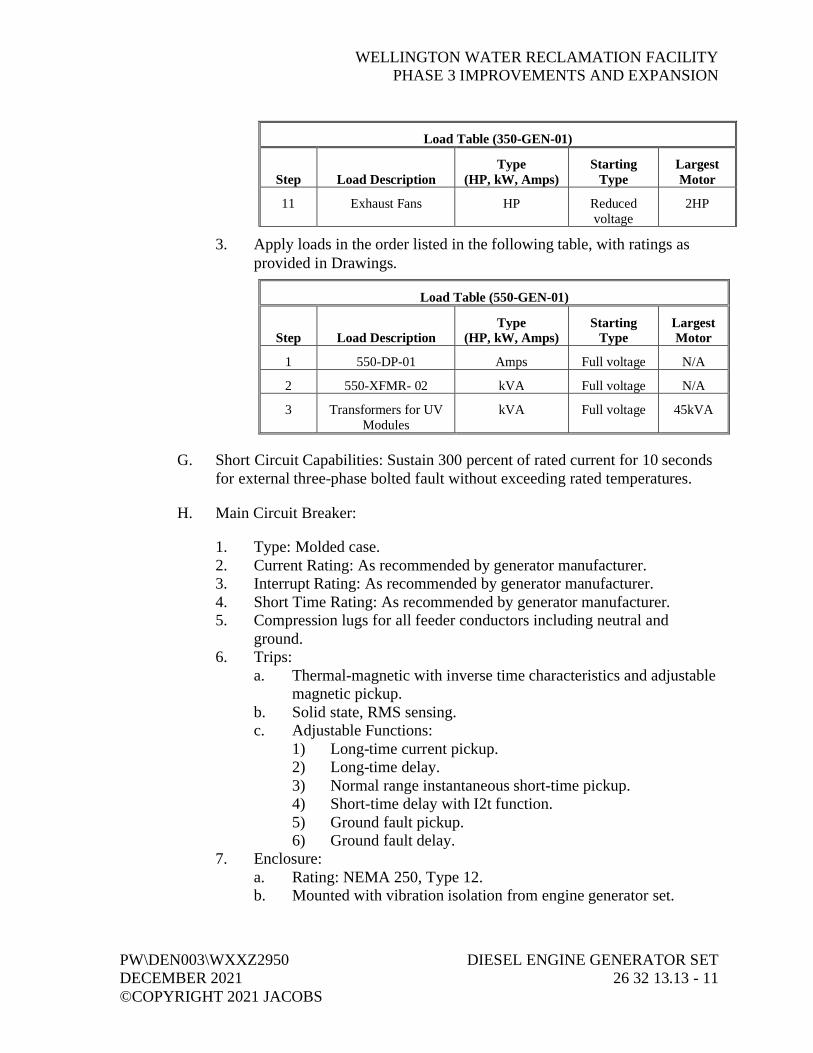
WELLINGTON WATER RECLAMATION FACILITYPHASE 3 IMPROVEMENTS AND EXPANSION
PW\DEN003\WXXZ2950 DIESEL ENGINE GENERATOR SETDECEMBER 2021 26 32 13.13 - 11©COPYRIGHT 2021 JACOBS
Load Table (350-GEN-01)
Step Load DescriptionType
(HP, kW, Amps)Starting
TypeLargestMotor
11 Exhaust Fans HP Reducedvoltage
2HP
3. Apply loads in the order listed in the following table, with ratings asprovided in Drawings.
Load Table (550-GEN-01)
Step Load DescriptionType
(HP, kW, Amps)Starting
TypeLargestMotor
1 550-DP-01 Amps Full voltage N/A
2 550-XFMR- 02 kVA Full voltage N/A
3 Transformers for UVModules
kVA Full voltage 45kVA
G. Short Circuit Capabilities: Sustain 300 percent of rated current for 10 secondsfor external three-phase bolted fault without exceeding rated temperatures.
H. Main Circuit Breaker:
1. Type: Molded case.2. Current Rating: As recommended by generator manufacturer.3. Interrupt Rating: As recommended by generator manufacturer.4. Short Time Rating: As recommended by generator manufacturer.5. Compression lugs for all feeder conductors including neutral and
ground.6. Trips:
a. Thermal-magnetic with inverse time characteristics and adjustablemagnetic pickup.
b. Solid state, RMS sensing.c. Adjustable Functions:
1) Long-time current pickup.2) Long-time delay.3) Normal range instantaneous short-time pickup.4) Short-time delay with I2t function.5) Ground fault pickup.6) Ground fault delay.
7. Enclosure:a. Rating: NEMA 250, Type 12.b. Mounted with vibration isolation from engine generator set.

WELLINGTON WATER RECLAMATION FACILITYPHASE 3 IMPROVEMENTS AND EXPANSION
DIESEL ENGINE GENERATOR SET PW\DEN003\WXXZ295026 32 13.13 - 12 DECEMBER 2021
©COPYRIGHT 2021 JACOBS
8. Surge Protective Devices: Three-phase capacitors and arresters mountedin terminal compartment.
9. Oversize enclosure to accommodate multiple parallel feeder conductors.
2.06 BASEPLATE
A. Mount engine generator set on a rigid common steel base frame.
B. Stiffen base frame to minimize deflections.
2.07 INTEGRAL SUBBASE FUEL TANK
A. General:
1. Full load operation of generator set for 48 hours.2. UL 142 listed and labeled.3. UL 2085 listed and labeled.4. Installation: In compliance with NFPA 37.5. Double-walled, steel construction including the following features:
a. Emergency tank and basin vents.b. Mechanical level gauge.c. Fuel supply and return lines, connected to generator set with
flexible fuel lines as recommended by engine manufacturer and incompliance to UL 2200 and NFPA 37 requirements.
d. Leak detection provisions, wired to generator set control for localand remote alarm indication.
e. High and low level float switches to indicate fuel level. Wireswitches to generator control for local and remote indication offuel level.
f. Basin drain.g. Integral lifting provisions.
2.08 VIBRATION ISOLATORS
A. Performance: Meet code requirements specified in Section 01 61 00, CommonProduct Requirements.
B. Provide vibration isolators, spring/pad type.
C. Include seismic restraints if required by Site location.

WELLINGTON WATER RECLAMATION FACILITYPHASE 3 IMPROVEMENTS AND EXPANSION
PW\DEN003\WXXZ2950 DIESEL ENGINE GENERATOR SETDECEMBER 2021 26 32 13.13 - 13©COPYRIGHT 2021 JACOBS
2.09 AUTOMATIC LOAD TRANSFER CONTROL
A. Provide automatic run controls suitable for remote interface and control byautomatic transfer switch. Engine generator set shall start and run uponclosure of a remote dry contact provided in Section 26 36 23, Bypass-IsolationAutomatic Transfer Switches.
2.10 CONTROL SYSTEM
A. Control Panel:
1. Rating: NEMA 250, Type 12.2. Material: Steel.3. Instrument Identification: Face label or engraved, black, laminated
plastic nameplate with white 1/4-inch-high letters, attached withType 422 stainless steel screws.
4. UL 508 listed.5. Tested to meet or exceed IEEE 587 requirements for voltage surge
resistance.6. Controls: Solid-state, microprocessor based.7. Control Panel: Designed and built by generator manufacturer to provide
operating, monitoring, and control functions for generator set.8. Control Panel Mounting Height: 6 feet 6 inches maximum above where
personnel will access panel, modify mounting height if a sub-base fueltank is used.
B. Instrumentation:
1. Type: Suitable for engine-mounted vibration environment.2. Mounting: Nonshock mounted.3. Alarm and Signal Contacts: Rated 5 amps at 120V ac, dry.4. Fault Indication Lamps: Manufacturer’s standard.5. Meters: Digital with analog display, plus or minus 2 percent accuracy.
C. Operator Controls and Indicators:
1. HANDCRANK/STOP/AUTO/ENGINE TEST selector switch.2. Generator voltage adjustment.3. Voltmeter PHASE SELECTOR switch.4. Ammeter PHASE SELECTOR switch.5. Voltmeter.6. Ammeter.7. Kilowatts (kW).8. Percent kW.9. Power Factor.

WELLINGTON WATER RECLAMATION FACILITYPHASE 3 IMPROVEMENTS AND EXPANSION
DIESEL ENGINE GENERATOR SET PW\DEN003\WXXZ295026 32 13.13 - 14 DECEMBER 2021
©COPYRIGHT 2021 JACOBS
10. FREQUENCY meter.11. Engine OIL PRESSURE indicator.12. Engine jacket WATER TEMPERATURE indicator.13. Engine SPEED indicator (RPM).14. Engine OIL TEMPERATURE indicator.15. RUNNING TIME indicator.16. DC battery voltage.17. Emergency Stop button.
D. Alarm Indicators with Manual Pushbutton RESET:
1. Low oil pressure.2. High jacket water temperature.3. Engine overspeed.4. Engine overcrank.5. Low/high dc voltage.
E. External Interfaces:
1. Furnish a single, common DPDT relay output upon occurrence of alarmcondition.
2. Output: Dry contact rated 5 amps at 120V ac.3. Accept remote dry start contact closure from automatic transfer switch,
rated 10 amps at 32V dc.
F. Functional Requirements:
1. LCD text display of alarm/event descriptions.2. Recranking Lockout: When engine fires, starting control shall
automatically disconnect cranking control to prevent recranking for apreset period of time after engine stop.
3. Overcranking Lockout: Initiate after four cranking cycles of 10 secondson and 10 seconds off or provide continuous cranking cycle with cranktime limiter.
4. Cooldown timer, adjustable from 5 minutes to 60 minutes.5. Alarms:
a. Low coolant level.b. Low fuel level.c. Low battery voltaged. High battery voltage.e. Battery charger failure.
6. Engine shutdown upon any of the following conditions:a. Engine overspeed.b. Emergency stop button depressed.
WELLINGTON WATER RECLAMATION FACILITYPHASE 3 IMPROVEMENTS AND EXPANSION
PW\DEN003\WXXZ2950 DIESEL ENGINE GENERATOR SETDECEMBER 2021 26 32 13.13 - 15©COPYRIGHT 2021 JACOBS
c. High jacket water temperature alarm setpoint and shutdownsetpoint.
d. Low oil pressure alarm setpoint and shutdown setpoint.7. Air Inlet Damper Opening:
a. Upon engine start sequence initiation, a normally closed, drycontact, rated 5 amps at 120V ac, from engine start circuit shallopen to provide a signal to open air inlet dampers.
b. Air Inlet Dampers: Fail open.
G. Special Requirements:
1. Mount battery charger in control panel.2. Mount battery charger instrumentation on face of control panel and
match generator instrumentation.
H. Power Requirements: 120 volts, single-phase. Manufacturers stands internallyconnected.
2.11 OUTDOOR WEATHER-PROTECTIVE ENCLOSURE
A. General:
1. Provide generator set with outdoor enclosure, with entire package listedunder UL 2200.
2. Package shall comply with requirements of NEC for wiring materialsand component spacing.
3. Design total assembly of generator set, enclosure, and subbase fuel tank(when used) to be lifted into place using spreader bars.
4. Housing:a. Provide ample airflow for generator set operation at rated load in
ambient temperature of 100 degrees F.b. Doors:
1) Hinged access doors as required to maintain easy access foroperating and service functions.
2) Lockable and include retainers to hold door open duringservice.
3) Able to open 180 degrees without obstruction, except rearcontrol panel door, which must open at least 135 degrees.
5. Roof: Cambered to prevent rainwater accumulation.6. Openings: Screened to limit rodent access into enclosure.7. Make electrical power and control interconnections within perimeter of
enclosure.

WELLINGTON WATER RECLAMATION FACILITYPHASE 3 IMPROVEMENTS AND EXPANSION
DIESEL ENGINE GENERATOR SET PW\DEN003\WXXZ295026 32 13.13 - 16 DECEMBER 2021
©COPYRIGHT 2021 JACOBS
8. Finishes:a. Prime sheet metal for corrosion protection and finish painted with
manufacturer’s standard color using a two-step electrocoatingpaint process, or equal meeting performance requirementsspecified below.
b. Prime and paint surfaces of metal parts. Minimum coatingrequirements:1) Primer: 0.5 mil to 2.0 mils thick.2) Top Coat: 0.8 mil to 1.2 mils thick.3) Gloss:
a) In accordance with ASTM D523, 80 percent plus orminus 5 percent.
b) Gloss Retention After 1 Year: 50 percent minimum.4) Crosshatch Adhesion: In accordance with ASTM D3359,
4B-5B.5) Impact Resistance: In accordance with ASTM D2794,
120-inch to 160-inch pounds.6) Salt Spray: In accordance with ASTM B117, plus
1,000 hours.7) Humidity: In accordance with ASTM D2247, plus
1,000 hours.8) Water Soak: In accordance with ASTM D2247, plus
1,000 hours.c. Do not paint hoses, clamps, wiring harnesses, and other
nonmetallic service parts.d. Provide corrosion-resistant fasteners designed to minimize
marring of painted surface when removed for normal installationor service work.
9. Enclosure Minimum Steel Thickness: 12-gauge for framework and14-gauge for panels.
10. Hardware and Hinges: Austenitic stainless steel.11. Exhaust Silencer:
a. Install factory-mounted exhaust silencer inside enclosure.b. Exhaust shall exit enclosure through a rain collar and terminate
with a rain cap.c. Provide seamless flexible exhaust connections to generator set.
12. Maintenance Provisions:a. Flexible coolant and lubricating oil drain lines that extend to
exterior of enclosure, with internal drain valves.b. External radiator-fill provision.c. External fuel fill provision (if equipped with a sub-based fuel
tank).

WELLINGTON WATER RECLAMATION FACILITYPHASE 3 IMPROVEMENTS AND EXPANSION
PW\DEN003\WXXZ2950 DIESEL ENGINE GENERATOR SETDECEMBER 2021 26 32 13.13 - 17©COPYRIGHT 2021 JACOBS
13. Provide motorized louvers to minimize air flow through enclosure whengenerator set is not operating. Louvers shall include provisions toprevent accumulation of ice or snow that might prevent operation.
14. Provide rain hoods for inlet ducts.15. Provide external emergency stop switch that is protected from
accidental actuation.16. Provide factory mounted and wired electrical distribution panel to serve
generator set and enclosure. Provisions required include:a. 100-amp distribution panelboard connected to a 120/240V ac
utility service.b. Two duplex GFI receptacles, one inside enclosure, and one
weatherproof receptacle on outside of enclosure.c. Two three-way switches controlling three ac lamps mounted in
vapor tight and gasketed fixtures.d. Factory-wired normal ac service from panelboard to engine
coolant and alternator heaters, and battery charger.17. Sound Attenuation:
a. Provide with sound-attenuated housing which allows generator setto operate at full rated load in an ambient temperature of up to100 degrees F.
b. Design, provide, and install enclosure to reduce sound level ofgenerator set while operating at full rated load to a maximum of89 dBA at any location 7 meters from generator set in a free fieldenvironment when tested in accordance with SAE J1074.
c. Insulate enclosure with nonhydroscopic materials.
2.12 FACTORY FINISHING
A. Engine Generator Set and Instrument Panel: Factory-applied primer and twofinish coats of manufacturer’s standard heat-resistant engine paint.
2.13 FACTORY TESTS
A. General: Conform to NFPA 110.
B. Steady Load Test: Test engine generator set at steady load run of 60 minutesminimum duration at 100 percent full-rated load.
C. Transient Load Test: Conduct transient load test to demonstrate ability to meetload pickup and load release requirements specified.
D. Harmonic Test: Conduct at full load conditions on the actual unit or one of thesame model and size.

WELLINGTON WATER RECLAMATION FACILITYPHASE 3 IMPROVEMENTS AND EXPANSION
DIESEL ENGINE GENERATOR SET PW\DEN003\WXXZ295026 32 13.13 - 18 DECEMBER 2021
©COPYRIGHT 2021 JACOBS
E. Record and Report:
1. Strip chart recording and full harmonic analysis measuring up to 50thharmonic for both voltage and current and three phases simultaneously.
2. Transient response.3. Load/speed stability.4. Engine fuel consumption.5. Power output.6. Harmonic analysis.
PART 3 EXECUTION
3.01 INSTALLATION
A. Level and securely mount engine generator set in accordance withmanufacturer’s recommendations.
B. Install in accordance with NECA 404.
C. Where applicable, mount engine generator set on vibration isolators inaccordance with isolator manufacturer’s recommendations.
3.02 FIELD FINISHING
A. Touch up damaged coating with paint system compatible to existing.
3.03 FIELD TESTS BY GENERATOR MANUFACTURER
A. General:
1. Conform to NFPA 110.2. Fuel provided by Contractor.3. Top off fuel after testing.
B. Performance Test:
1. Perform upon completion of installation.2. Operate 2 hours minimum, 1 hour at 50 percent load and 1 hour at full
load.a. Manufacture shall provide a resistive load bank and all required
connecting materials for the load testing.3. Manufacturer’s representative shall make necessary adjustments.4. Demonstrate ability of engine generator set to carry specified loads.5. Demonstrate engine generator set safety shutdowns.

WELLINGTON WATER RECLAMATION FACILITYPHASE 3 IMPROVEMENTS AND EXPANSION
PW\DEN003\WXXZ2950 DIESEL ENGINE GENERATOR SETDECEMBER 2021 26 32 13.13 - 19©COPYRIGHT 2021 JACOBS
C. Test Report:
1. Record and report the following:a. Electric load on generator.b. Fuel consumption.c. Exhaust temperature.d. Ambient air temperature.e. Safety shutdown performance results.f. Noise levels at Property line.
D. Post-test Requirements:
1. Make final adjustments.2. Replace fuel and oil filters.3. Check belt drive tensions.4. Demonstrate proper operation of equipment, including automatic
operation with control from automatic transfer switch, to Engineer andOwner.
3.04 MANUFACTURER’S SERVICES
A. Manufacturer’s Representative:
1. Present at Site or classroom designated by Owner, for minimum person-days listed below, travel time excluded:a. 2 person-days for installation assistance and inspection.b. 2 person-days for functional and performance testing and
completion of Manufacturer’s Certificate of Proper Installation.c. 2 person-days for prestartup classroom or Site training.d. 2 person-days for facility startup.e. 2 person-days for post-startup training of Owner’s personnel.
Training shall not commence until an accepted detailed lessonplan for each training activity has been reviewed by Owner.
B. See Section 01 43 33, Manufacturers’ Field Services, and Section 01 91 14,Equipment Testing and Facility Startup.
END OF SECTION


WELLINGTON WATER RECLAMATION FACILITYPHASE 3 IMPROVEMENTS AND EXPANSION
PW\DEN003\WXXZ2950 BYPASS-ISOLATION AUTOMATICDECEMBER 2021 TRANSFER SWITCHES©COPYRIGHT 2021 JACOBS 26 36 23 - 1
SECTION 26 36 23BYPASS-ISOLATION AUTOMATIC TRANSFER SWITCHES
PART 1 GENERAL
1.01 REFERENCES
A. The following is a list of standards which may be referenced in this section:
1. Institute of Electrical and Electronics Engineers (IEEE): C37.90.1,Standard for Surge Withstand Capability (SWC) Tests for Relays andRelay Systems Associated with Electric Power Apparatus.
2. National Electrical Manufacturers Association (NEMA):a. ICS 1, General Standards for Industrial Control and Systems:
General Requirements.b. ICS 2, Industrial Control and Systems Controllers, Contactors,
and Overload Relays not more than 2,000V ac or 750V ac.c. ICS 6, Industrial Control and Systems: Enclosures 250,
Enclosures for Electrical Equipment (1,000 Volts Maximum).3. National Fire Protection Association (NFPA): 70, National Electrical
Code (NEC).4. UL: 1008, Transfer Switch Equipment.
1.02 SUBMITTALS
A. Action Submittals:
1. Descriptive product information.2. Dimensional drawings.3. Control diagrams.4. Conduit entrance locations.5. Equipment ratings.6. Anchorage and bracing drawings and cut sheets, as required by
Section 01 88 15, Anchorage and Bracing.
B. Informational Submittals:
1. Anchorage and bracing calculations as required by Section 01 88 15,Anchorage and Bracing.
2. Manufacturer’s Certificate of Compliance, in accordance withSection 01 61 00, Common Product Requirements.
3. Factory test reports.
WELLINGTON WATER RECLAMATION FACILITYPHASE 3 IMPROVEMENTS AND EXPANSION
BYPASS-ISOLATION AUTOMATIC PW\DEN003\WXXZ2950TRANSFER SWITCHES DECEMBER 202126 36 23 - 2 ©COPYRIGHT 2021 JACOBS
4. Component and attachment testing seismic certificate of compliance asrequired by Section 01 45 33, Special Inspection, Observation, andTesting.
5. Operation and Maintenance Data: As specified in Section 01 78 23,Operation and Maintenance Data.
1.03 QUALITY ASSURANCE
A. Authority Having Jurisdiction (AHJ):
1. Provide the Work in accordance with NFPA 70, National ElectricalCode (NEC). Where required by the AHJ, material and equipment shallbe labeled or listed by a nationally recognized testing laboratory or otherorganization acceptable to the AHJ in order to provide a basis forapproval under NEC.
2. Materials and equipment manufactured within the scope of standardspublished by UL shall conform to those standards and shall have anapplied UL listing mark.
PART 2 PRODUCTS
2.01 MANUFACTURERS
A. ASCO.
B. Cummins.
C. Eaton.
2.02 GENERAL
A. Transfer switch to be product of a single manufacturer in order to achievestandardization for appearance, operation, maintenance, spare parts, andmanufacturer’s service.
B. In accordance with applicable standards of NFPA 70, NEMA ICS 1,NEMA ICS 2, NEMA ICS 6, IEEE C37.90.1, and UL 1008.
C. Transfer switch consisting of inherently double-throw power switch unit withinterconnected control module.

WELLINGTON WATER RECLAMATION FACILITYPHASE 3 IMPROVEMENTS AND EXPANSION
PW\DEN003\WXXZ2950 BYPASS-ISOLATION AUTOMATICDECEMBER 2021 TRANSFER SWITCHES©COPYRIGHT 2021 JACOBS 26 36 23 - 3
D. Rated 100 percent, in amperes, for total system transfer of motor, electricheating, discharge lamp loads, and tungsten-filament lamp loads.
1. Switches rated 400 amperes and below suitable for 100 percenttungsten-filament lamp loads.
2. Switches rated above 400 amperes suitable for 30 percent tungsten-filament lamp loads.
E. Main and arcing contacts visible for inspection with cabinet door and barriercovers removed.
F. Number of Switched Poles: As shown on one-line drawing.
G. Nominal Voltage, Full Load Current, and Short Circuit Withstand CurrentRating: As shown on one-line drawing. Provide a three-cycle WithstandCurrent Rating, unless a longer time period is shown on the one-line drawing.
H. Switch Rating: As shown on one-line drawing.
I. Current carrying capacity of arcing contacts shall not be used to determine thetransfer switch rating.
J. Suitable for use with 75 degrees C wire at full NFPA 70, 75 degrees Campacity.
K. Operating Conditions:
1. Ambient Temperature: Maximum 50 degrees C.2. Equipment to be fully rated without any derating for operating
conditions listed above.
2.03 ENCLOSURE
A. Type: NEMA 250, Type 1 with enclosure grounding terminal.
B. Dead front, front accessible cabinet with 14-gauge welded steel construction.
C. Continuously hinged single door, with handle and lock cylinder.
D. Finish: Baked enamel applied over rust-inhibiting, phosphate based coating.
1. Exterior and Interior Color: Provide gray finish as approved by Owner.2. Unpainted Metal Parts: Plated for corrosion resistance.

WELLINGTON WATER RECLAMATION FACILITYPHASE 3 IMPROVEMENTS AND EXPANSION
BYPASS-ISOLATION AUTOMATIC PW\DEN003\WXXZ2950TRANSFER SWITCHES DECEMBER 202126 36 23 - 4 ©COPYRIGHT 2021 JACOBS
2.04 TRANSFER SWITCH
A. Type: Electrically operated, mechanically held, double-throw.
B. Momentarily energized, single-electrically operated mechanism energizedfrom source to which load is to be transferred.
C. Locking mechanism to maintain constant contact pressure.
D. Mechanical interlock switch to ensure only one of two possible switchpositions or time delay in neutral position.
E. Silver alloy contacts protected by arcing contacts.
F. Main and arcing contacts visible when door is open and barrier coversremoved.
G. Manual operating handle for transfer in either direction under unloadedconditions.
H. Internal control wire connections made with ring or spade type terminals, lockwashers, and sleeve type marking labels.
2.05 CONTROL MODULE
A. Completely enclosed.
B. Microprocessor for sensing and logic control with inherent digitalcommunications capability.
C. Plug-in, industrial grade interfacing relays with dust covers.
D. Connected to transfer switch by wiring harness having keyed disconnect plug.
E. Plug-in printed circuit boards for sensing and control logic.
F. Adjustable solid state undervoltage sensors for all three phases of normal andfor three phases of standby source:
1. Pickup 85 percent to 100 percent nominal.2. Dropout 75 percent to 98 percent of pickup setting.
G. Adjustable frequency sensors for standby source:
1. Pickup 90 percent to 100 percent nominal.2. Dropout 87 percent to 89 percent of pickup setting.

WELLINGTON WATER RECLAMATION FACILITYPHASE 3 IMPROVEMENTS AND EXPANSION
PW\DEN003\WXXZ2950 BYPASS-ISOLATION AUTOMATICDECEMBER 2021 TRANSFER SWITCHES©COPYRIGHT 2021 JACOBS 26 36 23 - 5
H. Control module with adjustable time delays:
1. 0.5-second to 6-second engine start delay.2. 0-minute to 5-minute load transfer to emergency delay.3. 0-minute to 30-minute retransfer to normal delay.4. 0-minute to 30-minute unload running time delay.5. 0-minute to 5-minute time delay neutral on retransfer to normal source.6. Switch to bypass any of the above time delays during testing.
I. Form-C start contacts, rated 10 amperes, 32V dc, for two-wire engine control,wired to terminal block.
J. Exerciser, adjustable in 15-minute increments, 7-day dial clock toautomatically exercise generator without load transfer, complete with doormounted NO LOAD and LOAD selector switch.
K. In-phase monitor to control transfer when both sources are within acceptablephase angle limits, or adjustable pneumatic type time delay relay for time-delay-in neutral position.
L. Adjustable 0-minute to 5-minutes time delay relay for engine starting signal.
2.06 METERING INSTRUMENTS
A. Connect meters to load side of transfer switch.
B. Show voltage, current, and kW on an average and per-phase basis, and trackand record peak kW.
2.07 INDICATORS
A. Type: Manufacturer’s standard.
B. Green lens to indicate switch position for normal power source.
C. Red lens to indicate switch position for standby power source.
D. Green lens to indicate normal power source is available within parametersestablished by pickup and dropout settings.
E. Red lens to indicate standby power source is available within parametersestablished by pickup and dropout settings.
F. Provide one normally open and one normally closed, 5 amperes, 120-voltcontact for remote indication when transfer switch is in either position.
WELLINGTON WATER RECLAMATION FACILITYPHASE 3 IMPROVEMENTS AND EXPANSION
BYPASS-ISOLATION AUTOMATIC PW\DEN003\WXXZ2950TRANSFER SWITCHES DECEMBER 202126 36 23 - 6 ©COPYRIGHT 2021 JACOBS
2.08 FACTORY TESTS
A. Test to ensure correct:
1. Operation of individual components.2. Sequence of operation.3. Transfer time, voltage, frequency, and time delay settings.
B. Dielectric strength test per NEMA ICS 1.
PART 3 EXECUTION
3.01 INSTALLATION
A. Install in accordance with manufacturer’s instructions.
B. Secure enclosure to floor using anchor bolts of sufficient size and numberadequate for specified seismic conditions.
3.02 MANUFACTURER’S SERVICES
A. Furnish manufacturer’s representative in accordance with Section 01 43 33,Manufacturers’ Field Services, for the following services at Site, for minimumperson-days listed below, travel time excluded:
1. 2 person-days for installation assistance, final adjustment, and initialenergization of equipment.
2. 2 person-days for functional and performance testing.3. 1 person-day for adjustment of relay settings.
B. Furnish startup services and training of Owner’s personnel at such times asrequested by Owner.
END OF SECTION
WELLINGTON WATER RECLAMATION FACILITYPHASE 3 IMPROVEMENTS AND EXPANSION
PW\DEN003\WXXZ2950 FACILITY LIGHTNING PROTECTIONDECEMBER 2021 26 41 00 - 1©COPYRIGHT 2021 JACOBS
SECTION 26 41 00FACILITY LIGHTNING PROTECTION
PART 1 GENERAL
1.01 REFERENCES
A. The following is a list of standards which may be referenced in this section:
1. Lightning Protection Institute (LPI): 175, Standard of Practice.2. National Fire Protection Association (NFPA):
a. 70, National Electrical Code (NEC).b. 780, Standard for the Installation of Lightning Protection Systems.
3. UL:a. 96, Standard for Lightning Protection Components.b. 96A, Standard for Installation Requirements for Lightning
Protection Systems.
1.02 DESIGN REQUIREMENTS
A. Provide lightning protection system design for structures of the Projectaccording to NFPA 780.
B. Design lightning protection system to comply with applicable provisions ofLPI 175, UL 96, UL 96A, and NFPA 780.
1.03 SUBMITTALS
A. Action Submittals:
1. Reproducible Mylar Drawings:a. Lightning protection system layout.b. Component locations.c. Detailed plans.
2. Down conductor.3. Connecting conductor.4. Bond strap.5. Air terminals.6. Fittings.7. Connectors.8. Ground rods.

WELLINGTON WATER RECLAMATION FACILITYPHASE 3 IMPROVEMENTS AND EXPANSION
FACILITY LIGHTNING PROTECTION PW\DEN003\WXXZ295026 41 00 - 2 DECEMBER 2021
©COPYRIGHT 2021 JACOBS
B. Informational Submittals:
1. Field test report.2. Ground Witness Certification-Form LPI-175A.3. Post-Installation Certification-Form LPI-175B.4. UL 96 Master Label “C” Certification.
1.04 QUALITY ASSURANCE
A. Designer: Lightning protection system design shall be prepared by anLPI-certified master designer. Shop drawings shall be stamped by thedesigner.
B. System components shall be the product of a manufacturer regularly engagedin the manufacturing of lightning protection components in accordance withUL 96.
C. Lightning protection system shall be installed under direct supervision of anLPI 175 Certified Master Installer.
D. Inspection of final installation and grounding connection shall be performedby an LPI-certified inspector.
E. Provide the Work in accordance with NFPA 70. Where required by AuthorityHaving Jurisdiction (AHJ), material and equipment shall be labeled or listedby a nationally recognized testing laboratory or other organization acceptableto the AHJ in order to provide a basis for approval under NEC.
F. Materials and equipment manufactured within the scope of standardspublished by UL shall conform to those standards and shall have an appliedUL listing mark.
PART 2 PRODUCTS
2.01 MANUFACTURERS
A. Materials, equipment, and accessories specified in this section shall beproducts of:
1. Thompson Lightning.2. IPC Protection.3. Erico Eritech Lightning Protection Systems.4. VFC, Inc.

WELLINGTON WATER RECLAMATION FACILITYPHASE 3 IMPROVEMENTS AND EXPANSION
PW\DEN003\WXXZ2950 FACILITY LIGHTNING PROTECTIONDECEMBER 2021 26 41 00 - 3©COPYRIGHT 2021 JACOBS
2.02 GENERAL
A. Complete system shall bear UL 96 Master Label C.
B. System Material: Copper or high copper content, heavy-duty bronze castings,unless otherwise specified.
C. Material shall comply in weight, size, and composition for the class ofstructure to be protected as established by NFPA 780.
2.03 COMPONENTS
A. Air Terminal:
1. Material: Solid copper rods with tapered or blunt points as required forapplication.
2. Diameter: 5/8 inch.3. Length: Sufficient to extend minimum 10 inches above object being
protected.4. UL 96 Label B applied to each terminal.
B. Conductors:
1. Lightning System Conductors: Bare medium hard-drawn strandedcopper, or stranded aluminum as required for the application.
2. Main Down Conductor: Smooth twist stranding size determined byContractor.
3. Connecting Conductor: Concentric stranding size determined byContractor.
4. Bonding Conductor: Flexible strap size determined by Contractor.5. Main down and connecting conductors shall bear the UL 96 Label A,
applied every 10 feet.6. Grounding Conductors: Stranded bare copper.
C. Cable Fastener and Accessories: Capable of withstanding minimum pull of100 pounds.
D. Fittings:
1. Heavy-duty.2. Bolts, Screws, and Related Hardware: Stainless steel.
E. Ground Rods:
1. Material: Copper.

WELLINGTON WATER RECLAMATION FACILITYPHASE 3 IMPROVEMENTS AND EXPANSION
FACILITY LIGHTNING PROTECTION PW\DEN003\WXXZ295026 41 00 - 4 DECEMBER 2021
©COPYRIGHT 2021 JACOBS
F. Grounding Connections:
1. Welds: Exothermic process.2. Fasteners: Bolted clamp type, corrosion-resistant copper alloy.3. Hardware: Silicone bronze.
G. Cable Connections and Splicers:
1. Welds: Exothermic process.2. Fasteners: Bolted clamp type, corrosion-resistant copper alloy.3. Through-Roof Connectors: Straight or right angle with bronze and lead
seal flashing washer.
H. Conduit: Schedule 40 PVC, as specified in Section 26 05 33, Raceway andBoxes.
PART 3 EXECUTION
3.01 GENERAL
A. Workmanship to comply with all applicable provisions of LPI 175, UL 96,UL 96A, and NFPA 780.
B. Aluminum materials shall be used where required to meet the galvaniccorrosion requirements of UL 96A.
C. Provide pitchpockets or method compatible with roofing to waterproof roofpenetrations.
D. Install system in inconspicuous manner so components blend with buildingaesthetics.
3.02 EXAMINATION
A. Verify conditions prior to installation. Actual conditions may requireadjustments in air terminal and ground rod locations.
3.03 INSTALLATION
A. Air Terminals:
1. Supports: Brackets or braces.2. Parapet Bracket Attachment: Lag or expansion bolts.3. Secure base to roof surface with adhesive or pitch compatible with
roofing bond.4. Provide terminal flashing at roof penetrations.

WELLINGTON WATER RECLAMATION FACILITYPHASE 3 IMPROVEMENTS AND EXPANSION
PW\DEN003\WXXZ2950 FACILITY LIGHTNING PROTECTIONDECEMBER 2021 26 41 00 - 5©COPYRIGHT 2021 JACOBS
5. Perimeter Terminals:a. Maximum Spacing: 20 feet.b. Maximum Distance from Outside Edge of Building: 2 feet.
6. Roof Ridge Terminals: Maximum spacing 20 feet.7. Mid-Roof Terminals: Maximum spacing 50 feet.8. Provide blunt point air terminals for applications exposed to personnel.
B. Conductors:
1. Conceal whenever practical.2. Provide 1-inch PVC conduit in building walls or columns for main
downleads and roof risers.3. Support: Maximum spacing for exposed conductors.
a. Vertical: 3 foot.b. Horizontal: 4 foot.
4. Maintain horizontal and vertical conductor courses free from dips orpockets.
5. Bends: Maximum 90 degrees, with minimum 8-inch radius.6. Install air terminal conductors on the structural roof surface before
roofing composition is applied.
C. Bonding:
1. Bond to Main Conductor System:a. Roof-mounted ventilators, fans, air handlers, masts, flues, cooling
towers, handrails, and other sizeable metal objects.b. Roof flashing, gravel stops, insulation vents, ridge vents, roof
drains, soil pipe vents, and other small metal objects if locatedwithin 6 feet of main conductors or another grounded object.
2. Bond each steel column or major framing members to groundingsystem.
3. Bond each main down conductor to grounding system.
D. Grounding System:
1. Grounding Conductor:a. Completely encircle building structure.b. Bury minimum 1 foot below finished grade.c. Minimum 2 feet from foundation walls.
2. Interconnect ground rods by direct-buried copper cables.3. Maximum Resistance: 1 ohms when connected to ground rods.

WELLINGTON WATER RECLAMATION FACILITYPHASE 3 IMPROVEMENTS AND EXPANSION
FACILITY LIGHTNING PROTECTION PW\DEN003\WXXZ295026 41 00 - 6 DECEMBER 2021
©COPYRIGHT 2021 JACOBS
4. Connections:a. Install ground cables continuous between connections.b. Exothermic welded connections to ground rods, cable trays,
structural steel, handrails, and buried and nonaccessibleconnections.
c. Provide bolted clamp type mechanical connectors for all exposedsecondary connections.
d. Use bolted offset parapet bases or through-roof concealed baseassemblies for air terminal connections.
e. Provide interconnections with electrical and telephone systemsand all underground metal pipes.
f. Provide electric service arrestor ground wire to building watermain.
3.04 FIELD QUALITY CONTROL
A. Field Testing:
1. Isolate lightning protection system from other ground conditions whileperforming tests.
2. Resistance: Test ground resistance of grounding system by the fall-of-potential method.a. Test Resistance to Ground: Maximum 1 ohms.b. Install additional ground rods as required to obtain maximum
allowable resistance.3. Test Report:
a. Description of equipment tested.b. Description of test.c. Test results.d. Conclusions and recommendations.e. Appendix, including appropriate test forms.f. Identification of test equipment used.g. Signature of responsible test organization authority.
END OF SECTION
WELLINGTON WATER RECLAMATION FACILITYPHASE 3 IMPROVEMENTS AND EXPANSION
PW\DEN003\WXXZ2950 SURGE PROTECTIVE DEVICESDECEMBER 2021 26 43 00 - 1©COPYRIGHT 2021 JACOBS
SECTION 26 43 00SURGE PROTECTIVE DEVICES
PART 1 GENERAL
1.01 REFERENCES
A. The following is a list of standards which may be referenced in this section:
1. American National Standards Institute (ANSI).2. Department of Defense: MIL-STD-220C, Test Method Standard –
Method of Insertion Loss Measurement.3. Institute of Electrical and Electronics Engineers, Inc. (IEEE):
a. C62.41.1, IEEE Guide on the Surge Environment in Low-Voltage(1,000 V and less) AC Power Circuits.
b. C62.41.2, IEEE Recommended Practice on Characterization ofSurges in Low-Voltage (1,000 V and less) AC Power Circuits.
c. C62.45, IEEE Recommended Practice on Surge Testing forEquipment Connected to Low-Voltage (1,000 V and less) ACPower Circuits.
4. National Fire Protection Association (NFPA): 70, National ElectricalCode (NEC).
5. UL:a. 497A, Standard for Secondary Protectors for Communications
Circuits.b. 1283, Standard for Electromagnetic Interference Filters.c. 1449, Standard for Surge Protective Devices.
1.02 SUBMITTALS
A. Action Submittals:
1. Product data on each suppressor type, indicating component values, partnumbers, and conductor sizes. Include dimensional drawing for each,showing mounting arrangements.
2. Electrical single-line diagram showing location of each SPD.3. Manufacturer’s UL certified test data and nameplate data for each surge
protective device (SPD).

WELLINGTON WATER RECLAMATION FACILITYPHASE 3 IMPROVEMENTS AND EXPANSION
SURGE PROTECTIVE DEVICES PW\DEN003\WXXZ295026 43 00 - 2 DECEMBER 2021
©COPYRIGHT 2021 JACOBS
1.03 QUALITY ASSURANCE
A. UL Compliance and Labeling:
1. SPDs for Power and Signal Circuits: Comply with UL 1449 andcomplimentary listed to UL 1283 as an electromagnetic interferencefilter. Provide units listed and labeled by UL.
2. SPDs for Telephone Circuit Protection: Comply with UL 497A.
B. ANSI Compliance: Use SPD devices in compliance with therecommendations of IEEE C62.41.1, IEEE C62.41.2, and IEEE C62.45.
PART 2 PRODUCTS
2.01 MANUFACTURER
A. Eaton, SPD Series.
B. GE/ABB, Tranquell.
C. Schneider Electric/Square D, Surelogic.
D. Advanced Protection Technologies, Inc.
E. CITEL, MDS Series.
2.02 GENERAL
A. Unless indicated otherwise, provide direct bus-connected and factory-installedSPDs inside distribution equipment.
B. SPD Operating Conditions: Capable of performing at ambient temperaturesbetween minus 40 degrees C and 60 degrees C, at relative humidity rangingfrom 0 percent to 95 percent, and at altitudes ranging from sea level to12,000 feet.
C. Connect SPDs through a fused switch or circuit breaker as selected bymanufacturer. Provide overcurrent protection to allow full surge handlingcapabilities and afford safety protection from thermal overloads and shortcircuits.
D. SPD Short Circuit Current Rating (SCCR): No less than the SCCR ofdistribution equipment.
E. Design SPD devices to protect all modes (L-L, L-N, L-G, N-G) of electricalsystem being used.

WELLINGTON WATER RECLAMATION FACILITYPHASE 3 IMPROVEMENTS AND EXPANSION
PW\DEN003\WXXZ2950 SURGE PROTECTIVE DEVICESDECEMBER 2021 26 43 00 - 3©COPYRIGHT 2021 JACOBS
F. Power Filter: Include a high-frequency extended range power filter for eachSPD complimentary listed to UL 1283 as an electromagnetic interferencefilter.
G. Provide SPDs with the following monitoring and diagnostics:
1. LED-type indication lights to show normal and failed status of eachprotected phase.
2. Surge event counter.3. Form C dry contact which operates when unit fails.
H. Provide UL Type 2 SPDs.
I. EMI/RFI Noise Suppression: Minus 50dB attenuation at 100 kHz, tested perMIL-STD 220C.
J. Voltage Protection Rating (VPR):
Voltage Rating L-N N-G L-G L-L
208Y/120 800 800 800 1200
480Y/277 1200 1200 1200 2000
240 ∆ -- -- 1200 1200
2.03 SERVICE ENTRANCE AND DISTRIBUTION SPD
A. Provide SPD meeting IEEE C62.41.1 and IEEE C62.41.2 Location inaccordance with Category C.
B. Surge Current Capacity:
1. Service Entrance:a. 200 kA per phase.b. 100 kA per mode.
2. Distribution:a. 120 kA per phase.b. 60 kA per mode.
C. Maximum Continuous Operating Voltage (MCOV): Not less than 115 percentof nominal system voltage.
D. Nominal Discharge Current (IN): 20kA.
WELLINGTON WATER RECLAMATION FACILITYPHASE 3 IMPROVEMENTS AND EXPANSION
SURGE PROTECTIVE DEVICES PW\DEN003\WXXZ295026 43 00 - 4 DECEMBER 2021
©COPYRIGHT 2021 JACOBS
2.04 PANELBOARD SPD
A. Provide SPD meeting IEEE C62.41.1 and IEEE C62.41.2 Location inaccordance with Category B.
B. Surge Current Capacity:
1. Distribution: 120 kA per phase; 60 kA per mode.2. Branch: 80 kA per phase; 40 kA per mode.
C. Maximum Continuous Operating Voltage (MCOV): Not less than 125 percentof the nominal system voltage.
D. Nominal Discharge Current (IN): 10kA.
PART 3 EXECUTION
3.01 APPLICATION REQUIREMENTS
A. Provide SPDs when indicated on Drawings or in the equipment specifications.
B. Provide factory-installed SPDs as integral components to new switchgear,switchboards, motor control centers, panelboards and transfer switches.Externally mounted SPDs are not acceptable for new distribution equipment.
C. Externally mounted SPDs are acceptable for SPDs added to existingequipment as described below.
D. Electronic Equipment Paired Cable Conductors: Install data line suppressorsat the low voltage input and output of each piece of equipment, includingtelephone cable entrance.
1. Use secondary protectors on lines that do not exit the structure.2. Use primary protectors on lines that exit and enter the structure.
3.02 GENERAL INSTALLATION REQUIREMENTS
A. Install suppressors according to manufacturer’s recommendations.
B. Install suppressors directly to the cabinet which houses the circuit to beprotected so that the suppressor leads are straight and short, with conductorslaced, running directly to the point of connection within the panel, withoutloops or bends. If bends are unavoidable, no bend may exceed 90 degrees andbending radius may not be less than 6 inches.

WELLINGTON WATER RECLAMATION FACILITYPHASE 3 IMPROVEMENTS AND EXPANSION
PW\DEN003\WXXZ2950 SURGE PROTECTIVE DEVICESDECEMBER 2021 26 43 00 - 5©COPYRIGHT 2021 JACOBS
C. Provide connecting wires as short as possible with gently twisted conductors,tied together, to prevent separation.
1. Maximum Length: 24 inches.
D. Field Installed Conductors: As specified for building wire, not smaller than8 AWG and not larger than 4 AWG. Provide device leads not longer than themaximum length recommended by manufacturer, unless specifically reviewedand approved by manufacturer.
E. Provide dedicated disconnecting means for SPD devices installed at mainservice entrance location, switchgear, and motor control centers. Providededicated 30 ampere to 60 ampere circuit breakers (size dependent upon wiresize used) with number of poles as required, as disconnecting means for SPDdevices. Provide circuit breakers with interrupting capacity equal to thatspecified for other breakers at that location.
END OF SECTION

WELLINGTON WATER RECLAMATION FACILITYPHASE 3 IMPROVEMENTS AND EXPANSION
PW\DEN003\WXXZ2950 LIGHTINGDECEMBER 2021 26 50 00 - 1©COPYRIGHT 2021 JACOBS
SECTION 26 50 00LIGHTING
PART 1 GENERAL
1.01 REFERENCES
A. The following is a list of standards which may be referenced in this section:
1. American Wood Protection Association (AWPA): M6, Brands Used onForest Products.
2. ASTM International (ASTM):a. A123/A123M, Standard Specification for Zinc (Hot-Dip
Galvanized) Coatings on Iron and Steel Products.b. A153/A153M, Standard Specification for Zinc Coating (Hot-Dip)
on Iron and Steel Hardware.c. A572/A572A, Standard Specification for High-Strength Low-
Alloy Columbium-Vanadium Structural Steel.d. A588/A588M, Standard Specification for High-Strength Low-
Alloy Structural Steel, with 50 ksi [345 MPa] Minimum YieldPoint to 4-in. [100-mm] Thick.
e. A595/A595M, Standard Specification for Steel Tubes, Low-Carbon or High-Strength Low-Alloy, Tapered for Structural Use.
f. A615/A615M, Standard Specification for Deformed and PlainCarbon-Steel Bars for Concrete Reinforcement.
g. A1011/A1011M, Standard Specification for Steel, Sheet andStrip, Hot-Rolled, Carbon, Structural, High-Strength Low-Alloy,High-Strength Low-Alloy with Improved Formability, and Ultra-High Strength.
h. D6576, Standard Specification for Flexible Cellular RubberChemically Blown.
i. G154, Standard Practice for Operating Fluorescent LightApparatus for UV Exposure of Nonmetallic Materials.
3. Canadian Standards Association (CSA).4. Certified Ballast Manufacturer (CBM).5. Federal Communications Commission (FCC).6. Illuminating Engineering Society of North America (IESNA):
a. HB-9, Lighting Handbook.b. LM-79, IES Electrical and Photometric Measurements of Solid-
State Lighting Products.c. LM-80, IESNA Approved Method for Measuring Lumen
Maintenance of LED Light Sources.

WELLINGTON WATER RECLAMATION FACILITYPHASE 3 IMPROVEMENTS AND EXPANSION
LIGHTING PW\DEN003\WXXZ295026 50 00 - 2 DECEMBER 2021
©COPYRIGHT 2021 JACOBS
d. RP (Recommended Practices) Series.e. TM-21, Projecting Long Term Lumen Maintenance of LED Light
Sources.7. Institute of Electrical and Electronics Engineers (IEEE): C62.41,
Recommended Practice on Surge Voltages in Low-Voltage AC PowerCircuits.
8. National Electrical Manufacturers Association (NEMA):a. 250, Enclosures for Electrical Equipment (1,000 Volts
Maximum).b. ICS 6, Industrial Control and Systems: Enclosures.
9. National Energy Policy Act.10. National Fire Protection Association (NFPA): 70, National Electrical
Code (NEC) – Softbound Version.11. Rural Utilities Service (RUS): 1728F-700, Specification for Wood
Poles, Stubs and Anchor Logs.12. UL:
a. 773, UL Standard for Safety Plug-In Locking Type Photocontrolsfor Use with Area Lighting - Fourth Edition; Reprint withRevisions Through and Including March 08, 2002.
b. 844, Electric Lighting Fixtures for Use in Hazardous (Classified)Locations.
c. 924, Emergency Lighting and Power Equipment.d. 1598, UL Standard for Safety Luminaires.e. 2108, UL Standard for Safety Low Voltage Lighting
Systems - First Edition; Reprint with Revisions through andIncluding February 24, 2014.
f. 8750, UL Standard for Safety Light Emitting Diode (LED)Equipment for Use in Lighting Products - First Edition; Reprintwith Revisions Through and Including April 1, 2015.
13. U.S. Environmental Protection Agency and U.S. Department of Energy:Energy Star.
1.02 SUBMITTALS
A. Action Submittals:
1. Shop Drawings:a. General:
1) Provide catalog data sheets and pictures for all productslisted below.
2) Proposed Luminaire Substitutions (Interior and Exterior):Provide an electronic photometric file in standard ‘.ies’ fileformat per the Illumination Engineering Society of NorthAmerica (IESNA) for any proposed luminaire substitution

WELLINGTON WATER RECLAMATION FACILITYPHASE 3 IMPROVEMENTS AND EXPANSION
PW\DEN003\WXXZ2950 LIGHTINGDECEMBER 2021 26 50 00 - 3©COPYRIGHT 2021 JACOBS
not identified on the project Luminaire Schedule. Obtain filefrom the luminaire manufacturer or approved independentphotometric testing laboratory. Include the proposedsubstitute luminaire with all options identified on the projectLuminaire Schedule.
b. Interior Luminaires:1) Catalog data sheets with pictures.2) Luminaire material, finish, dimensions, and metal gauge.3) Lens material, pattern, and thickness.4) Candle power distribution curves in two or more planes.5) Candle power chart 0 degree to 90 degrees.6) Lumen output chart.7) Average maximum brightness data in foot lamberts.8) Coefficients of utilization for zonal cavity calculations.9) Mounting or suspension details.10) Heat exchange and air handling data.
c. Exterior Luminaires:1) Catalog data sheets with pictures. Luminaire material,
finish, dimensions, and metal gauge.2) Lens material, pattern, and thickness. Filters.3) IESNA lighting classification (BUG rating).4) Isolux diagram.5) Lighting distribution data and lighting distribution
classification type as defined in IESNA HB 9.6) Fastening details to wall, pendant, or pole.7) For light poles, submit catalog sheet, wind loading, pole
deflection with fixture attached, total weight, all accessories,complete dimensions, and finish.
8) Documentation for Energy Star qualifications for equipmentprovided under this section.
9) Brackets and supports.10) Pole foundations.
d. LED Source Systems:1) General:
a) IESNA LM-80 test reports.b) IESNA TM-21 ratings.c) Operating temperature range. Data sheet (chart/graph)
describing life as a function of temperature.d) Warranty: Light engine and driver.e) Rated life.f) Surge protection.g) Thermal control device, heat sink.h) Enclosure and wiring information.i) Operating voltage range.

WELLINGTON WATER RECLAMATION FACILITYPHASE 3 IMPROVEMENTS AND EXPANSION
LIGHTING PW\DEN003\WXXZ295026 50 00 - 4 DECEMBER 2021
©COPYRIGHT 2021 JACOBS
2) Electronic Module/Light Engine:a) Correlated Color Temperature (CCT).b) Color Rendering Index (CRI).
3) Drivers:a) Input Current Total Harmonic Distortion.b) Power factor.c) Sound rating.d) Dimming system information.
e. Wall box dimmers.f. Dimming systems.g. Emergency Shunt Relay.h. Luminaire lowering device.i. Seismic anchorage and bracing drawings and cut sheets, as
required by Section 01 88 15, Anchorage and Bracing.2. Samples: Submit Samples of each substituted luminaire if requested by
Engineer.
B. Informational Submittals:
1. Anchorage and bracing calculations as required by Section 01 88 15,Anchorage and Bracing.
2. Manufacturer’s printed installation instructions.3. Operation and Maintenance Data: As specified in Section 01 78 23,
Operation and Maintenance Data.
1.03 QUALITY ASSURANCE
A. Authority Having Jurisdiction (AHJ):
1. Provide Work in accordance with NFPA 70, National Electrical Code(NEC). Where required by the AHJ, provide material and equipmentlabeled or listed by a nationally recognized testing laboratory or otherorganization acceptable to the AHJ to provide a basis for approval underNEC.
2. Provide materials and equipment manufactured within the scope ofstandards published by Underwriters Laboratories, Inc. in conformancewith those standards and with an applied UL listing mark.
B. Standard Products:
1. Provide materials and equipment of manufacturers regularly engaged inthe production of products specified in this section and that are of equalmaterial, design, and workmanship.

WELLINGTON WATER RECLAMATION FACILITYPHASE 3 IMPROVEMENTS AND EXPANSION
PW\DEN003\WXXZ2950 LIGHTINGDECEMBER 2021 26 50 00 - 5©COPYRIGHT 2021 JACOBS
2. Provide products that have been in satisfactory commercial or industrialuse for 2 years prior to Bid opening in similar applications under similarcircumstances and of similar size. Provide products that have been onsale on the commercial market through advertisements, manufacturers’catalogs, or brochures during the 2-year period.
3. Material and Equipment Manufacturing Date: Do not use productsmanufactured more than 3 years prior to date of delivery to Site.
1.04 DELIVERY, STORAGE, AND HANDLING
A. Aluminum Poles:
1. Provide manufacturer’s standard protection for the finish duringshipment and installation. At minimum, spirally wrap each pole shaftwith protective paper secured with tape, and ship small parts in boxes.
2. Do not store poles on ground.3. Support poles so they are at least 1 foot above ground level and growing
vegetation.4. Do not remove factory-applied pole wrappings until just before
installing pole.5. Ship poles with bolt circle template, base cover, handhold cover, and
shaft cap or tenon.
1.05 EXTRA MATERIALS
A. Furnish, tag, and box for shipment and storage the following spare parts,special tools, and materials:
Item Quantity
Spare LED fixtures of eachtype
One complete set(s) perunit
PART 2 PRODUCTS
2.01 LUMINAIRES
A. Specific requirements relative to execution of the Work of this section arelocated in Luminaire Schedule on Drawings.
B. Provide luminaires and components tested, listed, and labeled by UL, or otherapproved testing agency.

WELLINGTON WATER RECLAMATION FACILITYPHASE 3 IMPROVEMENTS AND EXPANSION
LIGHTING PW\DEN003\WXXZ295026 50 00 - 6 DECEMBER 2021
©COPYRIGHT 2021 JACOBS
C. Provide luminaires with Illumination Engineering Society of North America(IESNA) formatted photometric files, “.ies” format, certified by the luminairemanufacturer for use with lighting software.
D. Luminaire Labels:
1. External label per ANSI C136.15.2. Internal label per ANSI C136.22.
E. Provide luminaires rated by the manufacturer to start and operate to their fulllumen capacity for rated life of the luminaire at the minimum low andmaximum high ambient temperatures as defined in the Contract Documents attheir installation location.
F. Feed-through type, or separate junction box.
G. Wire Leads: Minimum 18 AWG.
H. Component Access: Accessible and replaceable without removing luminairefrom ceiling.
I. Soffit Installations (Interior or Exterior Damp Locations):
1. UL Labeled: SUITABLE FOR DAMP LOCATIONS.2. Ballast: Removable, prewired.
J. Exterior Installations:
1. UL Labeled: SUITABLE FOR WET LOCATIONS.2. Ballast: Removable, prewired.3. When factory-installed photocells are provided, entire assembly shall
have UL label.
K. Marine Environments:
1. UL Labeled: MARINE, OUTSIDE TYPE.2. Housing: Copper-free, aluminum in accordance with UL 595.
L. Illuminated Exit Signs:
1. Body: As scheduled.2. Face: Translucent.
a. Letters:1) 6-inch high by 3/4-inch stroke.2) Color: As required by the AHJ.
3. Mounting: As indicated.

WELLINGTON WATER RECLAMATION FACILITYPHASE 3 IMPROVEMENTS AND EXPANSION
PW\DEN003\WXXZ2950 LIGHTINGDECEMBER 2021 26 50 00 - 7©COPYRIGHT 2021 JACOBS
4. Directional Arrows: As indicated on Drawings.5. Emergency Self-Diagnostic System:
a. Solid state device with LED display and audible alarm.b. Automatic and manual test unit.c. Test for malfunction of lamps, battery, and charger board.d. Manufacturer: Lithonia.
M. Hazardous Classified Areas:
1. UL Labeled: CLASS I, DIVISION 1, GROUPS C AND D. CLASS I,DIVISION 2, GROUPS C AND D. CLASS II, DIVISION 1,GROUPS F AND G. CLASS II, DIVISION 2, GROUPS F AND G.
2. Fixture Enclosure and Fittings: Copper-free, cast aluminum inaccordance with UL 844.
2.02 LED SOURCE SYSTEMS
A. General:
1. Provide IESNA LM-80 test reports.2. Provide Energy Star compliance for solid state luminaires.3. Listed To: UL 8750 Standard for Safety for Light Emitting Diode
(LED) Equipment for use in Lighting Products.4. Provide RoHS compliant LED light source(s) and driver(s).5. Rated operating temperature range as indicated on the Luminaire
Schedule.6. Warranty: 5 years minimum.
B. Electronic Module/Light Engine:
1. Mount all components to a single plate and factory prewired with quick-disconnect plugs.
2. Include a driver, thermal control device, thermal protector device, andsurge protector device.a. Provide surge protector tested in accordance with
IEEE/ANSI C62.41.2 to Category C Low.3. Provide LEDs mounted to a metal-core circuit board and aluminum heat
sink for optimal thermal management and long life.4. Light Engine Rating per TM-21: 100,000 at 25 degrees C, L70.5. Correlated Color Temperature (CCT): As indicated on the Luminaire
Schedule.6. Color Rendering Index (CRI): Minimum of 80.

WELLINGTON WATER RECLAMATION FACILITYPHASE 3 IMPROVEMENTS AND EXPANSION
LIGHTING PW\DEN003\WXXZ295026 50 00 - 8 DECEMBER 2021
©COPYRIGHT 2021 JACOBS
C. Drivers:
1. Expected life of 100,000 hours at 25 degrees C.2. Provide drivers mounted in an all metal can.3. Operating Voltage Range: 50/60-Hz input source, voltage range as
indicated on the Luminaire Schedule with sustained variations of plus orminus 10 percent voltage with no damage to the driver.
4. Input Current Total Harmonic Distortion: Less than 20 percent up to50 percent of full load rating.
5. Power Factor: Greater than 0.90 for primary application up to50 percent of full load rating.
6. Sound rating: Class A.7. Comply with NEMA 410 for inrush current limits.8. Dimming:
a. Continuously dimmable from 0 percent to 100 percent.b. Dimming Control: 0 volt to 10 volts.c. Provide driver compatible with standalone dimming controls
and/or dimming systems used.
2.03 LIGHTING CONTROL
A. Lighting Switch:
1. Lighting switch as shown on Drawings.2. Bypass Switch: Prewired, externally operated ON/AUTO/OFF, for each
circuit shown.3. Contact Configuration and Rating for Circuits:
a. As indicated on Drawings.b. Rating: 30 amps at 120V ac for operation on LED driver loads.c. Configuration: SPST.
4. Enclosure: NEMA 250, Type 1.5. Manufacturers:
a. Tork.b. Intermatic.c. Paragon Electric Company.
B. Dimming System.
2.04 POLES
A. General:
1. Design for wind load as specified in Section 01 61 00, Common ProductRequirements, while supporting luminaires and other appurtenances.

WELLINGTON WATER RECLAMATION FACILITYPHASE 3 IMPROVEMENTS AND EXPANSION
PW\DEN003\WXXZ2950 LIGHTINGDECEMBER 2021 26 50 00 - 9©COPYRIGHT 2021 JACOBS
Use effective projected areas (EPA) of luminaires and appurtenances incalculations specific to the actual products proposed on each pole.
2. Poles 40 Feet and Shorter: One-piece construction.3. Pole Height: As indicated on Luminaire Schedule.4. Handhole:
a. Provide oval-shaped handhole having a minimum clear opening of2.5 inches by 5 inches.
b. Secure cover with stainless steel captive screws.c. Metal Poles: Provide an internal grounding connection accessible
from handhole near bottom of each pole.5. Do not install scratched, stained, chipped, or dented poles.
B. Aluminum Poles:
1. Manufactured of corrosion-resistant aluminum alloys. Seamlessextruded or spun seamless type with minimum 0.188-inch wallthickness.
2. Shape: Round.3. Provide pole grounding connection designed to prevent electrolysis
when used with copper ground wire.4. Shaft Top: Fitted with cap.5. Base:
a. Anchor bolt mounted and machined to receive lower end of shaft.b. Welded joint between shaft and base.c. Base Cover: Cast aluminum alloy.d. Hardware, Except Anchor Bolts: Either anodized aluminum alloy
or stainless steel.e. Handhole.
6. Provide pole cast-in-place foundations with galvanized steel anchorbolts, threaded at the top end and bent 90 degrees at the bottom end.
7. Provide base covers to match pole and galvanized nuts and washers foranchor bolts.
8. Pole and Bracket Finish: Uniform satin finish to match fixture.
C. Steel Poles:
1. Minimum 11-gauge steel with minimum yield/strength of 48,000 psiand hot-dipped galvanized factory finish.
2. Provide pole grounding connection designed to prevent electrolysiswhen used with copper ground wire.
3. Tapered tubular members, either round in cross section or polygonal.4. Provide one-piece pole shafts of welded construction with no bolts,
rivets, or other means of fastening except as specifically approved.

WELLINGTON WATER RECLAMATION FACILITYPHASE 3 IMPROVEMENTS AND EXPANSION
LIGHTING PW\DEN003\WXXZ295026 50 00 - 10 DECEMBER 2021
©COPYRIGHT 2021 JACOBS
5. Pole Markings: Approximately 3 feet to 4 feet abovegrade and includemanufacturer, year of manufacture, top and bottom diameters, andlength.
6. Base Covers: Structural quality hot-rolled carbon steel plate having aminimum yield of 36,000 psi.
2.05 BRACKETS AND SUPPORTS
A. Features:
1. Not less than 1-1/4-inch galvanized steel pipe secured to pole.2. Slip-fitter or pipe-threaded brackets may be used, but coordinate
brackets to luminaires provided. Provide identical brackets for use withone type of luminaire unless otherwise approved by Engineer.
3. Select brackets for pole-mounted street lights to correctly positionluminaire no lower than mounting height indicated.
4. Mount brackets not less than 24 feet above street.5. Provide special mountings or brackets as indicated on Drawings
fabricated of metal which will not promote galvanic reaction withluminaire head.
2.06 POLE FOUNDATIONS
A. Anchor Bolts: Steel rod having a minimum yield strength of 50,000 psi; atminimum, galvanize the top 12 inches of the rod.
B. Concrete: As specified in Section 03 30 00, Cast-in-Place Concrete.
2.07 IN-LINE FUSE HOLDER AND FUSE
A. Fuse Holder:
1. General: Waterproof, of corrosion-resistant material.2. Rating: 600 volts.
B. Fuse:
1. General: Midget, dual element.2. Rating: 5-amp, voltage as required by application.
C. Manufacturer: Methods Electronics, Inc., Network, Buss Div.

WELLINGTON WATER RECLAMATION FACILITYPHASE 3 IMPROVEMENTS AND EXPANSION
PW\DEN003\WXXZ2950 LIGHTINGDECEMBER 2021 26 50 00 - 11©COPYRIGHT 2021 JACOBS
2.08 LIGHT FIXTURE LOWERING DEVICE
A. Electrical:
1. Contact:a. Material: Silver impregnated/silver plate copper.b. Pressure: Supplied by springs remote from current conductors.c. Electrical Insulation: Provided by porcelain standoffs.
2. Wire Termination: Crimp type connectors.3. Lowering Device:
a. Make and break type, rated for 30 amps at 250V ac so fixtureneed not be remotely isolated before lowering.
b. Provide number of contacts as required for specified light fixtures.
B. Mechanical Operation:
1. Use ball and socket design for ease of alignment and to allow forresidual building vibration and movement.
2. Maintenance-free design.3. System:
a. Support loads of 200 pounds maximum.b. Operated by manual hand-crank winch.
4. Housing: Cast aluminum.5. Operation: Slow pull/quick release method.6. Latching: Single point centered design to facilitate even wear over life
of hanger.
C. System:
1. Upper or fixed housing of lowering devices shall contain:a. Attached pulley.b. Single point latching mechanism.c. Guide.d. Upper (socket) electrical contacts.e. Mast arm for attachment of device to structure.f. Termination location for fixture guide line.
2. Lower or moveable housing of lowering device shall contain:a. Operating line termination.b. Positioning stem and latch assembly.c. Lower (ball) electrical contacts.d. Fixture adapter.
3. Operating Line: High strength/high flexibility stainless steel.
WELLINGTON WATER RECLAMATION FACILITYPHASE 3 IMPROVEMENTS AND EXPANSION
LIGHTING PW\DEN003\WXXZ295026 50 00 - 12 DECEMBER 2021
©COPYRIGHT 2021 JACOBS
4. Each turn in the structure shall provide transitional pulley assembly foroperating line consisting of pulleys, and flare ends (if enclosed inconduit) to prevent cable rub or snags on conduit runs.
5. Encase each operating line run in conduit, or support by pulleys placedat intervals recommended by lowering device manufacturer.
D. Manufacturers:
1. Joslyn.2. Light and Lowering Systems.
2.09 EQUIPMENT IDENTIFICATION
A. Manufacturer’s Nameplate: Provide each item of equipment with a nameplatebearing manufacturer’s name, address, model number, and serial numbersecurely affixed in a conspicuous place; nameplate of distributing agent willnot be acceptable.
B. Provide clear markings located to be readily visible to service personnel.
2.10 FACTORY FINISH
A. Provide electrical equipment with factory-applied painting systems that, atminimum, meet the requirements of NEMA 250 corrosion-resistance test.
PART 3 EXECUTION
3.01 LUMINAIRES
A. General:
1. Install in accordance with manufacturer’s recommendations.2. Provide proper hangers, pendants, and canopies as necessary for
complete installation and meeting specified seismic requirements.3. Provide additional ceiling bracing, hanger supports, and other structural
reinforcements to building required to safely mount.4. Install plumb and level.5. Install each luminaire outlet box with galvanized stud.
WELLINGTON WATER RECLAMATION FACILITYPHASE 3 IMPROVEMENTS AND EXPANSION
PW\DEN003\WXXZ2950 LIGHTINGDECEMBER 2021 26 50 00 - 13©COPYRIGHT 2021 JACOBS
B. Mounting:
1. General:a. Coordinate mounting, fastening, and environmental conditions
with Section 26 05 02, Basic Electrical Requirements.b. Refer to Fastener Schedule in Section 05 50 00, Metal
Fabrications.2. Wall Mounted: Measure mounting heights from center of mounting
plate to finished floor or finished grade, whichever is applicable.3. Pendant Mounted:
a. Provide swivel type hangers and canopies to match luminaires,unless otherwise noted.
b. Space single-stem hangers on continuous-row fluorescentluminaires nominally 48 inches apart.
c. Provide twin-stem hangers on single luminaires.d. Measure mounting heights from bottom of luminaire to finished
floor or finished grade, whichever is applicable.4. Pole Mounted:
a. Provide cast-in-place concrete base.b. Provide branch circuit in-line fuses in pole base handhole.
C. Swinging Type: Provide, at each support, safety cable capable of supportingfour times vertical load from structure to luminaire.
D. Finished Areas:
1. Install symmetrically with tile pattern.2. Locate with centerlines either on centerline of tile or on joint between
adjacent tile runs.3. Install recessed luminaires tight to finished surface such that no spill
light will show between ceilings and sealing rings.4. Combustible Low Density Cellulose Fiberboard: Provide spacers and
mount luminaires 1-1/2 inches from ceiling surface, or use fixturessuitable for mounting on low density ceilings.
5. Junction Boxes:a. Flush and Recessed Luminaires: Locate minimum 1-foot from
luminaire.b. In concealed locations, install junction boxes to be accessible by
removing luminaire.6. Wiring and Conduit:
a. Provide wiring of temperature rating required by luminaire.b. Provide flexible steel conduit.
7. Provide plaster frames when required by ceiling construction.
WELLINGTON WATER RECLAMATION FACILITYPHASE 3 IMPROVEMENTS AND EXPANSION
LIGHTING PW\DEN003\WXXZ295026 50 00 - 14 DECEMBER 2021
©COPYRIGHT 2021 JACOBS
8. Independent Supports:a. Provide each recessed fluorescent luminaire with two safety
chains or two No. 12 soft-annealed galvanized steel wires oflength needed to secure luminaire to building structureindependent of ceiling structure.
b. Select chain or wire with tensile strength and method of fasteningto structure adequate to support luminaire weight.
c. Fasten chain or wire to each end of luminaire.
E. Unfinished Areas: Locate luminaires to avoid conflict with other buildingsystems or blockage of luminaire light output.
1. Fixture Suspension: Provide 3/8-inch threaded steel hanger rods. Scissortype hangers not permitted.
2. Attachment to Steel Beams: Provide flanged beam clips and straight orangled hangers.
F. Building Exterior: Flush-mounted back box and concealed conduit, unlessotherwise indicated.
3.02 EMERGENCY LIGHTING UNIT
A. Install in accordance with manufacturer’s recommendations.
B. Provide permanent circuit connections with conduit and wire.
C. Connect to branch circuit feeding normal lighting in area ahead of all localswitches.
D. Provide separate circuit wiring to luminaire.
3.03 LIGHT FIXTURE LOWERING DEVICE
A. Install per manufacturer’s recommendations.
B. Mount disconnect base unit plumb on rigid structure.
C. Install mountings using stainless steel hardware.
D. Design mounting to withstand static and dynamic loading for at least fivetimes weight of fixture in all directions.
E. Place winch or motor assembly 6 feet to 30 feet from first pulley or disconnectunit.

WELLINGTON WATER RECLAMATION FACILITYPHASE 3 IMPROVEMENTS AND EXPANSION
PW\DEN003\WXXZ2950 LIGHTINGDECEMBER 2021 26 50 00 - 15©COPYRIGHT 2021 JACOBS
F. Use pulley every 6 feet to 30 feet of horizontal straight run.
G. Align centerline of pulley groove with cable path. Cable path shall be freefrom interference.
3.04 POLES
A. Electrical Installations: Conform to IEEE C2 and requirements specifiedherein.
B. Pole Setting:
1. Depth: As indicated on Drawings or footing detail.2. Install poles in straight runs in a straight line.3. Setting Depth:
Length of Pole(feet)
Setting in Soil(feet)
20 5.0
25 5.5
30 5.5
35 6.0
4. Soil Setting: Depths shall apply where pole holes are in soil, sand, orgravel or any combination of these.
5. Setting on Sloping Ground: On sloping ground, measure depth of holefrom low side of hole.
6. Backfill: Tamp pole backfill for the full depth of hole and mound excessfill around pole.
7. Dig holes large enough to permit the proper use of tampers to the fulldepth of the hole.
8. Place backfill in the hole in 6-inch maximum layers and thoroughlytamp.
9. Place surplus earth around the pole in a conical shape and pack tightlyto drain water away.
C. Aluminum Poles: Install according to pole manufacturer’s instructions.
1. Provide cast-in-place concrete base.2. Provide branch circuit in-line fuses in pole base handhole.

WELLINGTON WATER RECLAMATION FACILITYPHASE 3 IMPROVEMENTS AND EXPANSION
LIGHTING PW\DEN003\WXXZ295026 50 00 - 16 DECEMBER 2021
©COPYRIGHT 2021 JACOBS
D. Grounding: Ground noncurrent-carrying parts of equipment including metalpoles, luminaires, mounting arms, brackets, and metallic enclosures asspecified in Section 26 05 26, Grounding and Bonding for Electrical Systems.Where copper grounding conductor is connected to a metal other than copper,provide specially treated or lined connectors suitable for this purpose.
3.05 FIELD FINISHES
A. Paint electrical equipment as required to match finish of adjacent surfaces orto meet the indicated or specified safety criteria. Paint as specified inSection 09 90 00, Painting and Coating.
3.06 FIELD QUALITY CONTROL
A. Upon completion of installation, verify equipment is properly installed,connected, and adjusted. Conduct an operating test to show equipmentoperates in accordance with the requirements of this section.
B. Coordinate lighting and controls installation and testing with commissioningas specified in Section 01 91 14, Equipment Testing and Facility Startup.
3.07 CLEANING
A. Remove labels and markings, except UL listing mark.
B. Wipe luminaires inside and out to remove construction dust.
C. Clean luminaire plastic lenses with antistatic cleaners only.
D. Touch up painted surfaces of luminaires and poles with matching paintordered from manufacturer.
E. Replace defective lamps at time of Substantial Completion.
END OF SECTION

WELLINGTON WATER RECLAMATION FACILITYPHASE 3 IMPROVEMENTS AND EXPANSION
PW\DEN003\WXXZ2950 FIRE DETECTION AND ALARMDECEMBER 2021 28 31 00 - 1©COPYRIGHT 2021 JACOBS
SECTION 28 31 00FIRE DETECTION AND ALARM
PART 1 GENERAL
1.01 REFERENCES
A. The following is a list of standards which may be referenced in this section:
1. Institute of Electrical and Electronics Engineers (IEEE): C62.41, SurgeVoltages in Low-Voltage AC Power Circuits.
2. International Fire Code (IFC): International Building Code (IBC).3. National Fire Protection Association (NFPA):
a. 70, National Electrical Code (NEC).b. 72, National Fire Alarm and Signaling Code.c. 90A, Standard for the Installation of Air Conditioning and
Ventilating Systems.d. 101, Code for Safety to Life from Fire in Buildings and
Structures.e. 820, Fire Protection in Wastewater Treatment and Collection
Facilities.f. 1221 Standard for the Installation, Maintenance and Use of
Emergency Services Communications Systems.4. National Electrical Manufacturers Association (NEMA): 250,
Enclosures for Electrical Equipment (1000 Volts Maximum).5. National Institute for Certification in Engineering Technologies
(NICET).6. Telecommunications Industry Association (TIA):
a. 232, Interface Between Data Terminal Equipment and DataCircuit Terminating Equipment Employing Serial Binary DataInterchange.
b. 485, Electrical Characteristics of Generators and Receivers forUse in Balanced Digital Multipoint Systems.
7. UL:a. 217, Single and Multiple Station Smoke Alarms.b. 228, Door Closures-Holders, With or Without Integral Smoke
Detectors.c. 268, Smoke Detectors for Fire Protective Signaling Systems.d. 286A, Smoke Detectors for Duct Application.e. 464, Audible Signal Appliances.f. 497B, Protectors for Data Communication and Fire Alarm
Circuits.g. 864, Control Units for Fire-Protective Signaling Systems.
WELLINGTON WATER RECLAMATION FACILITYPHASE 3 IMPROVEMENTS AND EXPANSION
FIRE DETECTION AND ALARM PW\DEN003\WXXZ295028 31 00 - 2 DECEMBER 2021
©COPYRIGHT 2021 JACOBS
h. 1449, Standard for Transient Voltage Surge Suppressors.i. 1480, Speakers for Fire-Protective Signaling Systems.j. 1604, Electrical Equipment for Use in Class I and Class II,
Division 2, and Class III Hazardous (Classified) Locations.k. 1638, Visual Signaling Appliances – Private Mode Emergency
and General Utility Signaling.l. 1971, Signaling Devices for the Hearing Impaired.
1.02 DEFINITIONS
A. Addressable: A fire alarm system component with a unique identification thatcan have its status individually identified or that is used to individually controlother functions.
B. AHJ: Authority Having Jurisdiction.
C. CAD: Computer-Aided Design.
D. Coded: Audible or visible signal that conveys information about alarm event.Examples are, number of rings of a bell or flashes of a strobe. This could beused to convey location or type of alarm.
E. dB: Decibels.
F. DXF: Drawing Interchange Format.
G. ECP: Environmental Control Panel.
H. FACP: Fire Alarm Control Panel.
I. HVAC: Heating, Ventilating, and Air Conditioning.
J. IDC: Initiating Device Circuit.
K. I/O: Input/Output.
L. LCD: Liquid Crystal Display.
M. LED: Light-Emitting Diode.
N. MOV: Metal Oxide Varistor.
O. NAC: Notification Appliance Circuit.
P. RAM: Random Access Memory.

WELLINGTON WATER RECLAMATION FACILITYPHASE 3 IMPROVEMENTS AND EXPANSION
PW\DEN003\WXXZ2950 FIRE DETECTION AND ALARMDECEMBER 2021 28 31 00 - 3©COPYRIGHT 2021 JACOBS
Q. SLC: Signaling Line Circuit.
R. SOM: Sequence of Operations Matrix.
S. Zone: A defined area within the protected premises. A zone can define an areafrom which an alarm signal can be received or an area to which a signal canbe sent. The term zone is typically used when describing conventional,nonaddressable systems.
1.03 SYSTEM DESCRIPTION
A. Design Requirements:
1. Contract Drawings show location of fire alarm panel(s) annunciatorpanel(s), duct detectors, emergency alarm components required byIFC 2704 and other elements.a. Other Component Locations and Quantities: Determined by fire
alarm system installer and included as part of installer’s design.b. Other components include, but are not limited to, smoke detectors,
heat detectors, manual pull stations, and notification appliances.c. Design and Installation: Meet requirements of local AHJ.
2. Design, coordinate, and provide system in accordance with buildingcodes indicated in Section 01 61 00, Common Product Requirements.
3. Design conduit layout and wiring interconnection of devices specifiedherein, and for interconnection of flow and supervisory switches andalarm bells as specified in Contract Documents.
4. Coordinate, and include in design, requirements for interfacing withHVAC system.
5. Equipment suitable for addressable fire alarm system.
B. Performance Requirements:
1. Actuation of alarm (smoke or heat detector, flow switch, or othernormally open initiating device contact) or trouble (trouble orsupervisory switch) shall cause the following operations:a. Audible and visual indications of alarmed devices on fire alarm
control panel display, and on remote annunciator.b. Closure of doors held open by electromagnetic devices.c. For remote buildings with subpanels, transmit common alarm or
trouble signal to light appropriate zone lamp at master fire alarmcontrol panel.
d. Master fire alarm control panel shall transmit common alarm ortrouble signal to plant control panel.

WELLINGTON WATER RECLAMATION FACILITYPHASE 3 IMPROVEMENTS AND EXPANSION
FIRE DETECTION AND ALARM PW\DEN003\WXXZ295028 31 00 - 4 DECEMBER 2021
©COPYRIGHT 2021 JACOBS
2. Actuation of duct smoke detectors shall, send signal (contact closure) toenvironmental control panel (ECP) to shut off HVAC equipment andsend a Supervisory Alarm to the fire control panel. Fan equipment shallshutdown in accordance with Section 23 09 00, Instrumentation andControl Devices for HVAC. Contact output to ECP shall be rated for noless than 5A, 250V ac.
3. Actuation of sprinkler flow switch shall alarm at panel.4. Discharge of sprinklers in elevator shaft or machine room shall send
supervised trip signal to elevator controller/circuit breaker to trip onactuation of temperature detector installed adjacent to sprinkler headand with lower setting.
5. Sequence of Operations Matrix at the “End of Section,” describesfunctions of fire alarm system.
1.04 SUBMITTALS
A. Action Submittals:
1. Descriptive product information for each individual system component.2. Dimensional drawings of panels and associated equipment.3. Itemized bill of material.4. Operating and programming instructions.5. Control panel configuration and module data.6. Complete point to point wiring diagrams of system and device
interconnection. Identify spare connection points.7. Alarm initiating, indicating, and supervisory device electrical data.8. Annunciator configuration and module data.9. Plans showing device and panel locations as well as conduit and cable
sizes. Prepare drawings and diagrams on drawing sheets of uniform sizewithout extraneous information. Marked up electrical, HVAC, lightingor similar drawings or copies of catalog data sheets are not acceptable inlieu of required drawings or diagrams.
10. Sequence of Operation Matrix.11. Battery sizing calculations.12. Supervisory power requirements for equipment.13. Alarm power requirements for equipment.14. Power supply rating justification showing power requirements for
system power supplies.15. Voltage drop calculations for wiring runs, demonstrating worst case
condition.16. Conduit fill calculations.17. Sample warranty.18. Recommended types and quantities for spare parts.

WELLINGTON WATER RECLAMATION FACILITYPHASE 3 IMPROVEMENTS AND EXPANSION
PW\DEN003\WXXZ2950 FIRE DETECTION AND ALARMDECEMBER 2021 28 31 00 - 5©COPYRIGHT 2021 JACOBS
19. For each system’s control panel, provide written schedule of active andspare addresses provided on each addressable circuit.
20. Anchorage and bracing drawings and cut sheets, as required bySection 01 88 15, Anchorage and Bracing.
B. Informational Submittals:
1. Experience and qualifications of firm(s) proposed to design and installsystem.
2. Certifications documenting service technician’s training. Certificationshall indicate name of individual, training, dates, systems qualified, andcurrent status.
3. Anchorage and bracing calculations as required by Section 01 88 15,Anchorage and Bracing.
4. Component and attachment testing seismic certificate of compliance asrequired by Section 01 45 33, Special Inspection, Observation, andTesting.
5. Copy of design documents, Shop Drawings, and calculations submittedto code-enforcement authorities.
6. Code-enforcement authority approval letter.7. Factory test reports.8. Detailed program and schedule for testing, inspection, and maintenance
of fire alarm system that satisfies requirements of NFPA 72,manufacturer’s recommendations, and local authority havingjurisdiction.
9. Written documentation for logic modules as programmed, for systemoperation, with matrix showing interaction of input signals with outputcommands.
10. System program hard copy and electronic file in format acceptable toEngineer showing system functions, controls, and labeling of equipmentand devices.
11. Documentation of system voltage, current, and resistance readings takenduring installation, testing, and ATP phases of system installation.
12. System Record Drawings and wiring details including one set ofreproducible masters and drawings in electronic file in a DXF formatsuitable for use in a CAD drafting program.
13. NFPA 72, Record of Completion: Submit to Owner and code-enforcement authorities.
14. NFPA 72, Inspection and Testing Form: Submit to Owner and codeenforcement authorities.
15. Operation and Maintenance Data: As specified in Section 01 78 23,Operation and Maintenance Data.

WELLINGTON WATER RECLAMATION FACILITYPHASE 3 IMPROVEMENTS AND EXPANSION
FIRE DETECTION AND ALARM PW\DEN003\WXXZ295028 31 00 - 6 DECEMBER 2021
©COPYRIGHT 2021 JACOBS
1.05 QUALITY ASSURANCE
A. Qualifications:
1. Provide names of projects, locations, and telephone numbers of personsto contact for at least two installations where Contractor orSubcontractor has installed detection and alarm systems that are similarin size and scope to the Work.
2. Licensed Firm Responsible for System Design, Installation and Testing:Document established reputation in fire alarm system industry having10 years’ experience in design, installation, and testing of fire alarmsystems.
3. System Shop Drawings for code enforcement authority approval shallbe prepared by a technician with minimum of NICET Level IVCertification for fire alarm systems, or a professional engineerregistered in State of Colorado.
4. Technician with minimum of NICET Level III Certification for firealarm systems shall provide general supervision of project executionand shall perform final testing and certification of the system.
5. Technician with minimum of NICET Level II Certification for firealarm systems shall directly supervise all onsite installation activities.
6. Service technician shall be formally trained by manufacturer.
B. Regulatory Requirements:
1. Submit Shop Drawings and system design calculations for approval tothe following code enforcement authorities:a. Town of Wellington, Colorado.b. Larimer County, Colorado.
1.06 SPECIAL GUARANTEE
A. Provide manufacturer’s extended guarantee or warranty, with Owner namedas beneficiary, in writing, as special guarantee. Special guarantee shallprovide for correction, or at the option of the Owner, removal and replacementof Work specified in this Specification section found defective during a periodof 5 years after date of Substantial Completion. Duties and obligations forcorrection or removal and replacement of defective Work shall be as specifiedin the General Conditions.
1.07 MAINTENANCE
A. Maintenance Service: For 2 years after Correction Period, provide maximumof two service calls, at Owner’s request, to make adjustments or repairsrequired to keep system in satisfactory, full operation.
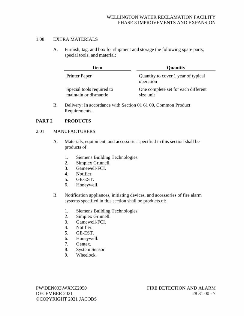
WELLINGTON WATER RECLAMATION FACILITYPHASE 3 IMPROVEMENTS AND EXPANSION
PW\DEN003\WXXZ2950 FIRE DETECTION AND ALARMDECEMBER 2021 28 31 00 - 7©COPYRIGHT 2021 JACOBS
1.08 EXTRA MATERIALS
A. Furnish, tag, and box for shipment and storage the following spare parts,special tools, and material:
Item Quantity
Printer Paper Quantity to cover 1 year of typicaloperation
Special tools required tomaintain or dismantle
One complete set for each differentsize unit
B. Delivery: In accordance with Section 01 61 00, Common ProductRequirements.
PART 2 PRODUCTS
2.01 MANUFACTURERS
A. Materials, equipment, and accessories specified in this section shall beproducts of:
1. Siemens Building Technologies.2. Simplex Grinnell.3. Gamewell-FCI.4. Notifier.5. GE-EST.6. Honeywell.
B. Notification appliances, initiating devices, and accessories of fire alarmsystems specified in this section shall be products of:
1. Siemens Building Technologies.2. Simplex Grinnell.3. Gamewell-FCI.4. Notifier.5. GE-EST.6. Honeywell.7. Gentex.8. System Sensor.9. Wheelock.

WELLINGTON WATER RECLAMATION FACILITYPHASE 3 IMPROVEMENTS AND EXPANSION
FIRE DETECTION AND ALARM PW\DEN003\WXXZ295028 31 00 - 8 DECEMBER 2021
©COPYRIGHT 2021 JACOBS
2.02 GENERAL
A. Material and Equipment:
1. Standard products of their respective manufacturers.2. Models produced for not less than 3 years.3. Equipment: Supported by a service organization that is, in the opinion
of Owner, reasonably convenient to Site.
B. Review details of Project prior to start of the Work, verify dimensions in field,and revise conduit and equipment locations to avoid obstructions and allowinstallation of new equipment.
C. Do not begin system installation prior to receiving written approval of ShopDrawings from Engineer.
2.03 UL COMPLIANCE
A. Products manufactured within scope of UL: Conform to UL Standards andhave an applied UL listing mark.
B. Provide equipment UL listed in accordance with requirements of NFPA.
2.04 SERVICE CONDITIONS
A. Altitude: Not greater than 3,300 feet above sea level.
B. Ambient Temperature:
1. Maximum 45 degrees C.2. Minimum 0 degrees C.
C. Provide equipment fully rated without derating for these conditions.
2.05 FIRE ALARM CONTROL PANELS
A. General:
1. Control panel circuit for 24V dc, power limited, initiating circuits inaccordance with NFPA 70, Article 760.
2. Assembled panel UL 864 listed Product Category UOJ2, as anintegrated control system.
3. Enclosure:a. NEMA 250 Type 1.b. Color: Red.

WELLINGTON WATER RECLAMATION FACILITYPHASE 3 IMPROVEMENTS AND EXPANSION
PW\DEN003\WXXZ2950 FIRE DETECTION AND ALARMDECEMBER 2021 28 31 00 - 9©COPYRIGHT 2021 JACOBS
4. Internally Mounted Module with:a. Transformer with 120V ac input and 21.5V ac output.b. Solid state rectifier for 21.5V ac input and fuse protected, filtered,
and regulated 26V dc no-load output.c. Solid state transfer switch, minimum 8 amp-hours.d. Standby sealed, gelled electrolyte (lead acid) batteries sized for
system operating period of 60 hours of standby mode operation.e. Solid state battery charger.f. Over/under voltage monitor supervisory circuit.g. LEDs for status of normal power, battery trouble, and power
supply module trouble.h. Alarm mode of 5 minutes after standby operation.
5. Local differentiating audible sound device for alarm, trouble, andsupervisory conditions.
6. Full digital transmission protocol.7. Addressable signal transmission protocol to be either digital
pole/response protocol or proprietary communication protocol, with allantilog sensing device signals digitally transmitted to control panel.
8. Form C output circuitry for remote alarm control panel.9. MOV/gas discharge transient protection for power supply module, plus
initiating and indicating alarm devices.10. For addressable systems provide additional 20 percent capacity for
future indicating and initiating devices.11. EMI/RF Protection:
a. Protect control equipment, devices, and wiring against unwantedradiated electro-magnetic interference (EMI) and from effects ofaudio and radio frequencies (RF) that can cause transmission ofspurious alarms.
b. Design system and install to be unaffected (with control cabinetfaceplates installed) by operation of handheld, portable radios ofup to 5 watts, or portable cellular telephones up to 1 watt, within12 inches of system components.
B. Addressable Control Panel:
1. Modular construction with solid state, microprocessor-basedcomponents, programmable central processor unit, back lighted displayof primary control status and essential alarm operating conditions, andconcealed, maintenance, purpose operator’s keypad.
2. With Class A Signaling Line Circuits and Class A NotificationAppliance Circuits.

WELLINGTON WATER RECLAMATION FACILITYPHASE 3 IMPROVEMENTS AND EXPANSION
FIRE DETECTION AND ALARM PW\DEN003\WXXZ295028 31 00 - 10 DECEMBER 2021
©COPYRIGHT 2021 JACOBS
3. Main control module consisting of operator’s keyboard/keypad, localand remote communications and supervision capabilities, system controlmemory, and programming interface.a. Two-line, back lighted, 80 alphanumerical LCD characters with:
1) Visible cursor for entering data information.2) Displayable when cabinet door is open.
b. Primary operators keypad with:1) Acknowledge keys and LEDs for system alarm, supervisory
service, and system trouble conditions.2) Power on LED.3) Alarm silence reset keys.4) Displayable when cabinet door is closed.
c. Pass code protected action display keypad for:1) Circuit/device enable or disable.2) Control on/off.3) Test/status.4) Auto or manual.5) Activate/reset.6) Display historical logs/real time.7) Function/menu.8) Program.9) Delete.10) Displayable when cabinet door is open.
d. Numerical entry and selection keypad, used in conjunction withaction display keypad, to perform control function on systemzones, initiating circuits, or auxiliary relays, and to gain access tosystem information. Displayable when cabinet door is closed.
e. Programmable control keypad with five pass code keys,associated LEDs, and identification labels for:1) Door holder bypass.2) Manual evacuation.3) HVAC shutdown disable.4) Displayable when door is open.
f. Four function keys for control of variable functions related toprimary operations keypad, displayable when door is open.
4. TIA 485, NFPA 72, Class A, Class B, Class C, or Class X data circuitcapability for remote annunciators.
5. Form C relay contacts rated 2 amperes, 24V dc.6. Down loader port for connection to microprocessor-based transponder.7. Power supply interface module generating digital voltage and current
data to LCD with:a. DC power conversion and output terminals.b. Supervision and control of power supply.

WELLINGTON WATER RECLAMATION FACILITYPHASE 3 IMPROVEMENTS AND EXPANSION
PW\DEN003\WXXZ2950 FIRE DETECTION AND ALARMDECEMBER 2021 28 31 00 - 11©COPYRIGHT 2021 JACOBS
8. Modules with coded input on first alarm, local trouble LED, and in/outcapabilities for:a. 120 addressable initiating alarm sensors consisting of
analog/addressable or traditional detector methods.b. Four hardwired I/O points, field selectable in any combination to
be either NFPA 72, Class A or Class B, initiating device circuitsor NFPA 72, Class A or Class B, indicating appliance circuits orauxiliary control circuits.
c. Auxiliary Control Circuit Contacts: Single-pole, double-throw,rated 2 amperes at 24V dc and 0.5 ampere at 120V ac.
9. Auxiliary Control Circuit Contacts: Single-pole, double-throw rated,2 amperes at 24V dc and 0.5 ampere at 120V ac.
10. Two isolated TIA 232 communication port modules.
2.06 CENTRAL PROCESSING CONTROL PANEL
A. Modular construction with solid state, microprocessor-based programmablecontrol processor, printer, one-way communications, operator console, and10 levels of priorities for staging of system events.
B. Single-channel voice communication circuits.
C. Operator Panel:
1. 80-character, two-line, LCD display.2. Individual keys for location information, silence signal, and detector
reset.3. Lamp test pushbutton with associated LED.4. Priority and trouble alarm light-emitting diode and associated
acknowledge pushbuttons.
D. Examine pushbuttons for “Monitor On” and activating control points.
E. Keyboard consisting of 48 keys labeled with letters, numbers, and options forprogramming and operational commands.
F. Printer with thermal print head for 20-column record system events producedin 80-column format.
G. Input/output ports as required for TIA 232 communication to local UL listedprinter and remote printers and CTR/keyboard units.
H. Selectable alarm verification and distribution processing.

WELLINGTON WATER RECLAMATION FACILITYPHASE 3 IMPROVEMENTS AND EXPANSION
FIRE DETECTION AND ALARM PW\DEN003\WXXZ295028 31 00 - 12 DECEMBER 2021
©COPYRIGHT 2021 JACOBS
I. Capable of interfacing with remote panels connected to hardwire circuits with:
1. Analog/addressable or traditional detectors.2. Either normally open or normally closed contacts.3. Supervised and 24V dc operated fire alarm signaling circuits.4. Supervised and operated speakers circuits.5. Capable of interfacing with NFPA 72, hard-wired, Class A and Class B,
initiating device circuits and NFPA 72, hard-wired, Class A andClass B, indicating appliance circuits.
6. Network capability.
2.07 VOICE COMMUNICATIONS CENTER
A. Single-channel module with audio tone and digitized voice message tospeaker upon receipt of preprogrammed command from central processingcontrol panel.
B. One-way communication microphone, ready-to-talk indicator, and local panelspeaker with multiple supervised remote microphone input.
C. Digitized voice/tone generator for voice message and spoken voice coding.
D. Automatic and manual audio control.
E. Separate evacuation, all clear message, and drill voice message and tone.
F. Synchronized redundant voice tone generator.
G. Spoken voice system diagnostic test initiated at voice control panel.
H. Audio tone to be slow whoop preceded by program message.
I. Integral amplifier with automatic transfer switch and 25 VRMS output forredundant voice tone generator.
J. Audio control switch and LED for monitoring status changes in eachcommunication circuit.
K. Actual tone and voice message recorded to digital format for storage in audiocontrol board’s message memory.
L. Central processing control panel to direct audio tone, code, prerecorded ormanual voice message to appropriate audio output circuit.
M. Each audio circuit rated 50 watts.

WELLINGTON WATER RECLAMATION FACILITYPHASE 3 IMPROVEMENTS AND EXPANSION
PW\DEN003\WXXZ2950 FIRE DETECTION AND ALARMDECEMBER 2021 28 31 00 - 13©COPYRIGHT 2021 JACOBS
N. Supervised for wire-to-wire shorts, opens, and grounds.
O. Audio control selector switch and indicating LED module with circuitidentifying labels for monitoring circuit status changes in each speaker circuit.
2.08 SPEAKERS
A. Voice Output: Clear, intelligible, minimum 15 dB above ambient.
B. Cone type speaker, UL 1480 listed, with frequency within range 400-Hz to4,000-Hz.
C. Eight-inch flame retardant and moisture repellant cone speakers, 24-volt,5-watt transformer with multiple taps, 24-gauge steel baffles with baked semi-gloss enamel finish, and surface enclosure.
D. Metal constructed double re-entrant speaker horn with built-in 24-volt,15-watt compression driver having six-position impedance switch, corrosion-resistance plated finish, and surface mounted.
2.09 FIREFIGHTER’S TELEPHONE
A. Red color telephone handset, flexible-coiled, self-winding, 5-foot extensioncord ending in attached plug.
B. Remote phone jack mounted on single gang stainless steel plate with “FireEmergency Phone” engraved on face in red.
C. Recessed-mounted remote telephone cabinet with baked red enamel finish,lockable door, break-glass rod for door release, storage rack for five portabletelephones with “Local Fire Emergency Phone” silk screened in white oncabinet door.
2.10 LED LIGHTED ANNUNCIATOR
A. Modular constructed back illuminated, with group mounted LEDs installed inrecessed mounted cabinet having lockable, full hinged door panel, and redbaked enamel finish.
B. Rectangular LED units extending through black modular insert with two redLEDs per module, engraved zone identification nameplate above each lamp,group mounted with quick disconnect harness, and attached to door byconcealed fasteners.
1. Nameplates:a. 1/2 inch high by 1-1/2 inches wide.

WELLINGTON WATER RECLAMATION FACILITYPHASE 3 IMPROVEMENTS AND EXPANSION
FIRE DETECTION AND ALARM PW\DEN003\WXXZ295028 31 00 - 14 DECEMBER 2021
©COPYRIGHT 2021 JACOBS
b. Two lines with 11 maximum, 3/32-inch-high engraved letters andspaces per line.
c. Black plate surface with white engraved letters.
C. Negative filmed dead front, 1-1/2-inch by 1-1/2-inch zone indicators with onered LED per indicator and four indicators per module, mounted without use offront face fasteners:
1. Five lines with 14 maximum, 1/8-inch high, letters and spaces in1-1/2-inch wide zone indicator.
D. LED test feature with one test switch mounted on cabinet back plate for grouptest of LEDs on each module.
E. Remote system reset key switch, trouble assembly consisting of LED, buzzer,and relay and key switch for trouble silence, two-step drill key switches,operating power trouble LED, and audible tone alarm.
2.11 GRAPHIC ANNUNCIATORS
A. Point annunciation (one LED per device) on graphical panel related to devicelocation.
B. Lamp Test: One test switch mounted on cabinet back plate for group test oflamps on each module.
C. Housing: Aluminum.
D. Remote system reset key switch, trouble assembly consisting of LED, buzzer,and relay and key switch for trouble silence, two-step drill key switches,operating power trouble lamp, and audible tone alarm.
2.12 SERIAL ANNUNCIATORS
A. Modular constructed with 80-character LCD display and remote commandmodules installed in recessed-mounted cabinet having lockable, full hingeddoor panel, and red baked enamel finish.
2.13 ADDRESSABLE DETECTOR BASE
A. Solid state circuitry with integral LED visual alarm, dip switch or programselectable addressing, and common base receptacle for ionization,photoelectric, and heat detectors. Locate device address in base.
B. Constantly monitors detector status and status changes.

WELLINGTON WATER RECLAMATION FACILITYPHASE 3 IMPROVEMENTS AND EXPANSION
PW\DEN003\WXXZ2950 FIRE DETECTION AND ALARMDECEMBER 2021 28 31 00 - 15©COPYRIGHT 2021 JACOBS
C. Suitable for mounting on standard outlet box.
D. Normally open, single-pole contacts rated 3 amperes, 30V dc.
2.14 INDIVIDUAL ADDRESSABLE MODULE
A. Solid state circuitry with selectable latch/nonlatch operating conditions andmounting plate.
B. Monitors single and multiple devices with dry contacts.
C. Suitable for installing inside 4-inch by 4-inch by 2-1/2-inch electrical box.
2.15 INITIATING DEVICE
A. Pull Station, Fire:
1. Double-action station for general alarm.2. Constructed of red molded polycarbonate material, and raised white
letters stating “FIRE.”3. Surface-mounted with hinged front cover having keyed or allen-wrench
reset lock.4. Where required, rated for use in hazardous environments.5. Recessed pull handle for single action lift door and pull handle for
double action operating station with plastic break rod.6. Activated station pull handle, latched in protruding position until reset
by key.7. Stations keyed alike with fire alarm control panel.8. Screw terminal for field connections.9. Manual Pull Station: Dip switch selectable address, and compatible with
fire alarm control panel.
B. Heat Detector:
1. Combination rate-of-rise and fixed, temperature elements with90 degrees C trip setting, complete with addressable mounting base.
2. Nonrestorable fixed temperature elements and self-restoring rate-of-risetemperature elements.
3. Dangling disk indicator for activated fix temperature element and LEDindicator for activated rate-of-rise temperature element.
4. Attach detector bases on surface mounted octagon boxes.5. Conceal surface mounted boxes with surface trim skirt.6. Double-screw terminals for supervised connection.

WELLINGTON WATER RECLAMATION FACILITYPHASE 3 IMPROVEMENTS AND EXPANSION
FIRE DETECTION AND ALARM PW\DEN003\WXXZ295028 31 00 - 16 DECEMBER 2021
©COPYRIGHT 2021 JACOBS
C. Smoke Detector:
1. Photoelectric type with plug-in, twist-lock addressable base inaccordance with UL 268.
2. Solid state circuitry, nonradioactive photo-optic sensing chamber,suitable for device releasing service.
3. Concealed, field adjustable, sensitivity test switch.4. LED; pulsed indication for power availability and steady indication for
activated detectors.5. Self-Compensating Circuitry:
a. Voltage Range: 15V dc to 30V dc, 24V dc nominal.b. Temperature Range: 0 degree C to 38 degrees C.c. Operating Temperature Range: Minus 10 degrees C to
50 degrees C.d. Humidity Range: 0 percent to 95 percent relative humidity.
6. Detectors equipped with insect screen.7. Photoelectric sensors adjusted to within 3 percent of UL 217 window
obturation sensitivity value.
D. Air Duct Smoke Detector:
1. Duct mounted housing with prealigned sampling and exhaust tubes,analog sensing, solid state circuitry, and plug-in, twist-lock addressablebase for photoelectric detector in accordance with UL 286A, NFPA 72,NFPA 90A, and NFPA 101.
2. Sampling tubes to extend full width of branch air return duct.3. Self-Compensating Circuitry:
a. Voltage Range: 15V dc to 30V dc, 24V dc nominal.b. Temperature Range: 0 degrees C to 38 degrees C.c. Humidity Range: 10 percent to 90 percent relative humidity.d. Velocity Range: 400 feet to 4,000 feet per minute.
4. Front mounted LED with pulsed indication for alarm condition.
2.16 NOTIFICATION APPLIANCES
A. Audible Alarm:
1. General:a. Polarized, 24V dc device with sound power measured dB in
accordance with UL 464.b. Separate in/out wire leads for field connections.c. Baked red enamel finish.d. Audibility: In accordance with NFPA 72 and local requirements.

WELLINGTON WATER RECLAMATION FACILITYPHASE 3 IMPROVEMENTS AND EXPANSION
PW\DEN003\WXXZ2950 FIRE DETECTION AND ALARMDECEMBER 2021 28 31 00 - 17©COPYRIGHT 2021 JACOBS
2. Modular Horn:a. Surface basic unit, complete with single projector, designed for
mounting on 4-inch square standard electrical box.b. Manufacturer supplied box with flush grille plate and basic
surface unit for recessed horns.c. Explosion-Proof Horns: Vibrating diode type with sealed wires,
and tapped for 3/4-inch conduit in accordance with UL 1604.3. Modular Bell: Vibrating basic unit complete with 4-inch gong and
outdoor yard hood, designed for mounting on 4-inch weatherproofelectrical box.
4. Explosion-Proof Bell: Vibrating diode type with 6-inch gong, sealedwires, and tapped for 3/4-inch conduit in accordance with UL 1604.Rated for environment as shown on Drawings.
5. Chime: Vibrating type with field adjustable volume control, designedfor mounting on 4-inch square weatherproof electrical box.
6. Multiple-Tone Horn:a. Microprocessor-based, field programmable tone selection and
volume control, suitable for installation indoors and outdoors.b. Program by setting miniature switches to obtain siren tone.
7. Single protection type bell with weatherproof housing, rated for120V ac motor, adjustable mounting bracket, and audible output of115 dB.
B. Visual Alarm, Fire:
1. Polarized, 24V dc, multi-candela indicating output in accordance withUL 1638.
2. Solid state circuitry for high and low intensity control of xenonflashtube.
3. Tamper-proof, translucent molded, polycarbonate, pyramidal shapedlens with “FIRE” in red lettering visible from 180-degree viewing field;red enclosure.
4. Polarized in/out wiring.5. Designed for mounting on wall or ceiling, single-gang electrical box, or
as part of audible/visible base housing.6. Synchronized unit.
C. Visual Alarm in Outdoor or Hazardous Location:
1. Cast metal fixture with red glass globe and guard.2. Rating: 100 candela at 24V dc.3. UL Listed for wet locations when installed outdoors.

WELLINGTON WATER RECLAMATION FACILITYPHASE 3 IMPROVEMENTS AND EXPANSION
FIRE DETECTION AND ALARM PW\DEN003\WXXZ295028 31 00 - 18 DECEMBER 2021
©COPYRIGHT 2021 JACOBS
4. UL Listed for classification of hazardous location where alarm is to beinstalled.
5. Designed for wall mounting.
D. Combination Audible and Visual Alarm:
1. Audible/visible base housing with visual alarm and front mounted hornas specified.
2. Semi-flush mounting on recessed 4-gauge square electrical box orsurface mounted on backbox with adapter.
3. Audibility: In accordance with NFPA 72 and local requirements.4. Synchronous audible/visible output.
2.17 WIRING
A. AC power wiring shall meet requirements of Section 26 05 05, Conductors.
B. Low voltage wiring shall be solid copper or bunch tinned (bonded) strandedcopper, minimum 14 AWG, and shall meet NEC Article 760 for nonpowerlimited service.
C. Network or addressable loop cables shall be as recommended by manufacturerfor installation of their system and UL Listed for Fire Alarm Systems.
2.18 RACEWAYS
A. Conduit used for installation of Fire Alarm system shall follow requirementsas identified in Section 26 05 33, Raceway and Boxes.
2.19 END-OF-LINE RESISTORS
A. Ohmic value and power rating as determined by manufacturer based uponnumber of circuit devices supplied and circuit configuration as installed.
2.20 SURGE SUPPRESSORS
A. Surge Protective Devices (SPD): In accordance with Section 26 43 00, SurgeProtective Devices.
2.21 INTRINSICALLY SAFE MODULE
A. Fused, resistor/zener diode barrier module with output currents limited forNFPA 70, Class I, Class II, Class III, Division 1, Groups A, B, C, D, E, F,and G atmospheres.

WELLINGTON WATER RECLAMATION FACILITYPHASE 3 IMPROVEMENTS AND EXPANSION
PW\DEN003\WXXZ2950 FIRE DETECTION AND ALARMDECEMBER 2021 28 31 00 - 19©COPYRIGHT 2021 JACOBS
B. Surface-mounted backbox with secured, full-hinged access door and bakedred enamel finish.
PART 3 EXECUTION
3.01 GENERAL
A. Coordinate with other trades for mounting and interfacing with fire alarmsystem related devices.
B. Install control panels, initiating and alarm devices, conduit, and wiring forinterconnection of devices specified herein and for interconnection of flowand supervisory switches and alarm bells specified in Section 21 13 13, Wet-Pipe Sprinkler Systems, for complete and operable system.
3.02 INSTALLATION
A. Install and connect fire detection and alarm equipment in accordance withmanufacturer’s instructions and recommendations, and in accordance withapplicable codes and standards.
B. Mount devices in accordance with manufacturer’s instructions.
C. Provide outlet and junction boxes that are compatible with raceway system.
D. Mount detector LEDs so they are readily visible from floor.
E. Arrange sampling tubes and duct detectors to monitor duct area and point ofduct penetration sealed and reinsulated.
F. Program or configure panels and devices, as required to operate as defined bySequence of Operations Matrix included as Supplement at “End of Section.”
G. Install conductors in accordance with Section 26 05 05, Conductors, andNFPA 70, Article 760.
H. Install initiating alarm, signal, and communication conductors in separate andindependent raceway system.
I. Circuit wiring color-code, as established by installer, to be maintainedthroughout installation.
J. Size conductors in accordance with device manufacturer’s recommendations.Increase AWG size of alarm conductors, if necessary, to maintain terminalvoltage drop within acceptable level required by NEC and NFPA.

WELLINGTON WATER RECLAMATION FACILITYPHASE 3 IMPROVEMENTS AND EXPANSION
FIRE DETECTION AND ALARM PW\DEN003\WXXZ295028 31 00 - 20 DECEMBER 2021
©COPYRIGHT 2021 JACOBS
K. Do not install detectors until after construction cleanup is complete, inaccordance with requirements of NFPA. If earlier installation is required byAHJ for protection during construction, clean or replace detectors installedprior to final clean-up.
L. Duct Smoke Detector: Furnish, wire, and connect to fire alarm system inaccordance with this Specification. Install in accordance withSection 23 09 13, HVAC Controls, Field Components, and Instruments.
M. HVAC Equipment: Wire and connect fire alarm system to air handlingsystem, smoke exhaust fan and smoke damper control circuits, and fan statuscontacts. Coordinate work with Section 23 09 00, Instrumentation and ControlDevices for HVAC.
N. Suppression Sprinkler System: Wire and connect to fire alarm system tosuppression sprinkler system. Coordinate work with Section 21 13 13, WetPipe Sprinkler Systems.
3.03 CONDUIT, ELECTRICAL ENCLOSURES, TERMINAL CABINETS, PULLBOXES, AND BACKPLATES
A. Conduit Systems: Dedicated to fire alarm system and containing no unrelatedconductors.
B. Fire Alarm System Conduits: Size and type specified under Section 26 05 33,Raceway and Boxes.
1. Conduit: As specified in Section 26 05 33, Raceway and Boxes.a. Flexible Metallic Conduit: Allowable for whips to devices only.
1) Maximum Length: 6 feet.2) Minimum Diameter: 3/4-inch.3) Set screw type couplings or connectors are specifically
prohibited.2. Size conduits according to conductors contained therein.3. Maximum Cross Sectional Area Percentage Fill for Fire Alarm System
Conduits: 40 percent.
C. Route and install conduit to minimize potential for physical damage, eithermechanical or by fire; avoid interference with existing building systems,facilities or equipment; and to facilitate service and minimize maintenance.Coordinate installation between different trades to avoid conflicts.
1. Solidly attach conduit to building structural members or permanentwalls, except flexible conduit whips to devices. Do not attach conduit toexisting conduit, ductwork, cable trays, other ceiling equipment, drop
WELLINGTON WATER RECLAMATION FACILITYPHASE 3 IMPROVEMENTS AND EXPANSION
PW\DEN003\WXXZ2950 FIRE DETECTION AND ALARMDECEMBER 2021 28 31 00 - 21©COPYRIGHT 2021 JACOBS
ceiling hangers/grids or partition walls, except where necessary toconnect to initiating, evacuation signaling, or auxiliary function devices.
2. Route conduit either parallel or perpendicular to building structuralmembers.
3. Install conduit at a height to avoid obstructing any portion of a window,doorway cable tray, stairway, or passageway. Do not interfere withoperation of existing mechanical or electrical equipment.
4. Locate conduit, junction boxes, pull boxes, terminal cabinets, electricalenclosures, and device backboxes to be readily accessible for inspection,testing, service, and maintenance.
5. Arrange conduit to minimize possibility of water in those conduitsdraining through control panels.a. Arrange conduit, except nipples between control panels, to enter
control cabinets from below.b. Provide three 1/4-inch drain holes in conduit at horizontal low
point beneath each control cabinet.6. Provide bushings at termination of conduit, prior to wire installation.7. Install junction boxes as necessary. Pull conductors through junction
boxes, without splices.8. Install pullboxes in each conduit at intervals not to exceed 100 feet.9. Minimum Pullbox Size: 4-inch square, minimum.10. Size device backboxes and junction boxes to accommodate number of
conductors contained. Extension rings or extension boxes areprohibited.
11. Provide junction boxes, pull boxes, terminal cabinets, device backboxes,and raceways gasketed and weather-tight in accordance withrequirements of Section 26 05 33, Raceway and Boxes.
D. Installation Requirements:
1. Conduit, Junction Boxes, Panels, Electrical Enclosures, Relays andDevice Backboxes in Unfinished Areas: Exposed.
2. Conduit and Device Backboxes in Finished Areas: Concealed in walls,ceiling spaces, electrical shafts or closets, in finished areas, except asnoted on Drawings.
3. Provide escutcheon plates on either side of the wall at exposed conduitwall penetrations.
E. Seal penetrations of walls, floors, and ceilings around conduit(s) inaccordance with Section 07 92 00, Joint Sealants, restoring walls, floors, andceilings to their original condition, fire resistance, and integrity.

WELLINGTON WATER RECLAMATION FACILITYPHASE 3 IMPROVEMENTS AND EXPANSION
FIRE DETECTION AND ALARM PW\DEN003\WXXZ295028 31 00 - 22 DECEMBER 2021
©COPYRIGHT 2021 JACOBS
F. Paint pull boxes, junction boxes, conduit bodies, and terminal cabinets “fireengine red” prior to installation. Provide touch-up painting, of normallyvisible pull boxes, junction boxes, and terminal cabinets prior to finalacceptance testing.
G. Ground conduit by approved ground clamps, and in accordance with NECrequirements.
H. Mount end-of-line resistors on terminal blocks.
I. Install detection and alarm wire in separate conduits. Route outgoing andreturn conductors for each supervised circuit separately as required byNFPA 72.
J. Minimum Separation of Outgoing and Return Conduits: 1 foot vertically and4 feet horizontally.
3.04 IDENTIFICATION
A. Paint junction, terminal, and pulling box covers red and identify withengraved labels by loop number and circuit that it contains.
B. Provide engraved alphanumeric identification for detection and terminaldevices keyed to posted operations and maintenance instructions.
3.05 CONDUCTORS
A. Requirements apply to fire alarm system conductors, including all signalingline, initiating device, indicating appliance, releasing function, remotesignaling, ac and dc power and grounding/shield drain circuits.
B. Conductors:
1. New; do not use wire that has scrapes, nicks, gouges or crushedinsulation.
2. Install in conduit.3. Continuous between devices and between devices and intermediary
terminal cabinets.4. Low voltage conductors shall be minimum size 14 AWG. Smaller
conductors are allowable where shown on approved Shop Drawings aspart of a manufacturer’s specific communications cable (such as, anaddressable system).
5. In accordance with requirements of NEC, Article 760 for power limitedservice.

WELLINGTON WATER RECLAMATION FACILITYPHASE 3 IMPROVEMENTS AND EXPANSION
PW\DEN003\WXXZ2950 FIRE DETECTION AND ALARMDECEMBER 2021 28 31 00 - 23©COPYRIGHT 2021 JACOBS
C. Splices in conductors are specifically prohibited.
D. Types:
1. Conductors, Except AC Power Conductors and Grounding Conductors:Solid copper or bunch tinned (bonded) stranded copper.
2. Stranded copper conductors are acceptable for ac power conductors andgrounding conductors only.
E. Terminations, including field connections to supervisory resistors, diodes,relays or other devices shall be to numbered terminals or terminal strips andreadily accessible for inspection, service, testing and maintenance.
1. Terminations shall be within junction boxes, device backboxes, terminalcabinets, control panels or other suitable metal enclosures.
2. Terminals and terminal strips shall be suitable for the size and numberof conductors connected to them.
3. Uniquely number each conductor termination with durable plastic tagsor uniquely identifiable by a combination of numbers and color codes.Show conductor numbers on Contractor’s Record Drawings (floor plansand detailed wiring diagrams) in a manner allowing ready identificationof conductor terminations.
4. Wire nuts are prohibited.5. Where pigtail devices are factory provided with wires too short to be
connected to terminal strips (such as, solenoids), provide soldered andtaped connections.
F. Control Panel Wiring:
1. Fully dressed and bundled with nylon tie wraps at 3-inch intervals.2. Route bundled wiring parallel to terminal strips within control panels,
with individual conductors turned out at 90 degree angles to theirassociated terminal connections.
3. Bundle ac power conductors and route separately from low voltageconductors. Maintain a minimum 2-inch separation between ac powerconductors and low voltage conductors wherever possible.
4. Size control cabinets to accommodate the requirements of this section.5. Do not use control panels as raceways. Do not route conductors that do
not terminate within a control panel through that control panel.
G. Separate conductors into the following categories:
1. Low voltage circuits that serve devices.2. AC power circuits.

WELLINGTON WATER RECLAMATION FACILITYPHASE 3 IMPROVEMENTS AND EXPANSION
FIRE DETECTION AND ALARM PW\DEN003\WXXZ295028 31 00 - 24 DECEMBER 2021
©COPYRIGHT 2021 JACOBS
H. Install each category of conductors in physically separated, dedicatedconduits, and isolate each category except at common associated controlequipment. Further segregate conductors as necessary to conform to fire alarmsystem manufacturer’s recommendations and as necessary to preventelectrical crosstalk between conductors installed in common conduits.
I. Install as power limited circuits in accordance with NFPA 72, and NEC,Article 760.
J. Conductors looped around terminals are prohibited.
K. Wire nut splices are prohibited.
L. T-tapping of circuits is prohibited.
M. Circuits shall be megger tested to voltage rating of their insulation before finalterminations are made.
3.06 OVERVOLTAGE AND SURGE PROTECTION
A. Install SPD for fire alarm control panel in accordance with manufacturer’srequirements.
3.07 REPAIR/RESTORATION
A. Touch up scratches, mars, and dents, incurred during shipment or installationof equipment.
B. If required because of extensive damage, as determined by Engineer, refinishentire assembly.
C. Keep covers on smoke detectors until areas have been thoroughly cleaned.
3.08 TESTS AND INSPECTION
A. In accordance with Section 01 91 14, Equipment Testing and Facility Startup,and NFPA 72.
B. Demonstrate entire system meets performance requirements specified inArticle System Description.
C. Perform tests in presence of code-enforcement authorities, Owner or Owner’sRepresentative.

WELLINGTON WATER RECLAMATION FACILITYPHASE 3 IMPROVEMENTS AND EXPANSION
PW\DEN003\WXXZ2950 FIRE DETECTION AND ALARMDECEMBER 2021 28 31 00 - 25©COPYRIGHT 2021 JACOBS
D. Individually field test each smoke detector prior to installing device at itsdesignated location to confirm operating condition after shipping and storage.Maintain a dated log indicating system address, type of device, sensitivity andinitials of technician performing test, using test equipment specificallydesigned for that purpose, and submit as part of final acceptancedocumentation. After testing detection devices, base shall be labeled withsystem address, date, and initials of installing technician. Labeling shall not bevisible after installation is complete.
E. Test wiring runs for continuity, short circuits, and grounds before system isenergized. Take resistance, current, and voltage readings as work progressesand document results.
1. Maintain a systematic record of all readings using schedules or charts oftests and measurements. Include readings, dates, and witnesses on thelogging form.
2. Notify Fire Marshal and Owner before start of any required tests.Correct items found at variance with Drawings or Specification duringtesting or inspection.
3. Deliver test reports to Fire Marshal and Owner as completed.
F. Prepare final as-built Sequence of Operations Matrix (See Supplement at Endof Section) referencing each alarm input to every output function affected as aresult of an alarm, trouble, or supervisory condition on that. For outputsprogrammed using more complex logic functions involving “any”, “or”,“not”, “count”, “time”, and “timer” statements; reflect complete outputequation in matrix.
G. Prepare complete listing of device labels for alphanumeric annunciatordisplays and logging printers prior to acceptance test.
1. Test system wiring to demonstrate correct system response and correctsubsequent system operation in event of:a. Open, shorted, and grounded intelligent analog signaling line
circuit.b. Open, shorted, and grounded network signaling line circuit.c. Open, shorted, and grounded conventional initiating device
circuits.d. Primary power or battery disconnected.e. Incorrect device address.f. Loss of data communications between system control panels.
2. Demonstrate system evacuation alarm indicating appliances as follows:a. Alarm notification appliances actuate as programmed.b. Audibility and visibility at required levels.

WELLINGTON WATER RECLAMATION FACILITYPHASE 3 IMPROVEMENTS AND EXPANSION
FIRE DETECTION AND ALARM PW\DEN003\WXXZ295028 31 00 - 26 DECEMBER 2021
©COPYRIGHT 2021 JACOBS
3. System indications shall be demonstrated as follows:a. Correct message display for each alarm input, at control panel,
each remote alphanumeric LCD display.4. Demonstrate system onsite and offsite reporting functions as follows:
a. Correct alarm custom message display, address, device type, dateand time transmitted, for each alarm input.
b. Correct trouble custom message display, address, device type,date and time transmitted, for each alarm input.
c. Trouble signals received for disconnect.5. Demonstrate secondary power capabilities as follows:
a. Disconnect system primary power for a period of time as specifiedherein; at end of period, confirm alarm condition shall be createdand system performance as specified for required duration.
b. Restore system primary power for 48 hours and confirm thatsystem-charging current is normal trickle charge for fully chargedbattery bank.
c. Check system battery voltages and charging currents at fire alarmcontrol panel using test codes and LCD displays
H. If system fails to perform as specified and programmed during acceptancetest, test will be terminated at discretion of acceptance inspector.
1. Retest system, correcting deficiencies and providing test documentationto acceptance inspector.
2. If software changes are required during acceptance test, provide a utilityprogram to compare edited program with original and furnish a printedlist of changes and the system functions, inputs, and outputs affected bychanges. Retest items listed as changed before resuming acceptance test.Submit printed list and log of successful retesting of changed elementsbefore scheduling completion of acceptance test.
3. Acceptance inspector may elect to require complete acceptance test tobe performed again if, in their opinion, modifications to systemhardware or software warrant complete retesting.
I. Upon completion of tests, complete and provide the following:
1. NFPA 72, Record of Completion, and Inspection and Testing Form.2. Certification that final system meets UL.

WELLINGTON WATER RECLAMATION FACILITYPHASE 3 IMPROVEMENTS AND EXPANSION
PW\DEN003\WXXZ2950 FIRE DETECTION AND ALARMDECEMBER 2021 28 31 00 - 27©COPYRIGHT 2021 JACOBS
3.09 MANUFACTURER’S SERVICES
A. Furnish manufacturer’s representative in accordance with Section 01 43 33,Manufacturers’ Field Services, for the following services at Site or classroomas designated by Owner, for minimum person-days listed below, travel timeexcluded:
1. 2 person-days for installation assistance and inspection.2. 2 person-days for functional and performance testing.3. 1 person-day for prestartup classroom or site training.
3.10 SUPPLEMENTS
A. The supplement listed below, following “End of Section,” is a part of thisSpecification.
1. Sequence of Operations Matrix.2. Plant Fire Alarm Riser Diagram.3. Fire and Emergency Alarm System.
END OF SECTION

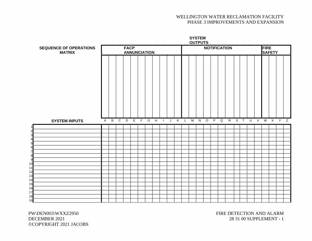
WELLINGTON WATER RECLAMATION FACILITYPHASE 3 IMPROVEMENTS AND EXPANSION
PW\DEN003\WXXZ2950 FIRE DETECTION AND ALARMDECEMBER 2021 28 31 00 SUPPLEMENT - 1©COPYRIGHT 2021 JACOBS
SYSTEMOUTPUTS
SEQUENCE OF OPERATIONSMATRIX
FACPANNUNCIATION
NOTIFICATION FIRESAFETY
SYSTEM INPUTS A B C D E F G H I J K L M N O P Q R S T U V W X Y Z
123456789
10111213141516171819


WELLINGTON WATER RECLAMATION FACILITYPHASE 3 IMPROVEMENTS AND EXPANSION
PW\DEN003\WXXZ2950 FIRE DETECTION AND ALARMDECEMBER 2021 28 31 00 SUPPLEMENT - 1©COPYRIGHT 2021 JACOBS

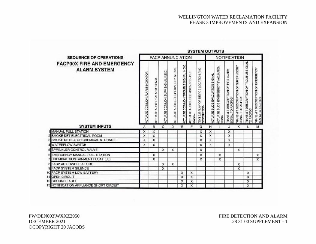
WELLINGTON WATER RECLAMATION FACILITYPHASE 3 IMPROVEMENTS AND EXPANSION
PW\DEN003\WXXZ2950 FIRE DETECTION AND ALARMDECEMBER 2021 28 31 00 SUPPLEMENT - 1©COPYRIGHT 20 JACOBS

Copyright © 2022 FDOKUMEN