Towards Development of a Self-Healing Composite using a Mendable Polymer and Resistive Heating
13
Towards Development of a Self-Healing Composite using a Mendable Polymer and Resistive Heating JONG SE PARK, 1, *KOSUKE TAKAHASHI, 4 ZHANHU GUO, 1 YING WANG, 1 Ed BOLANOS, 3 CHRISTINE HAMANN-SCHAFFNER, 3 ERIN MURPHY, 3 FRED WUDL 3,5 AND H. THOMAS HAHN 1,2 1 Department of Mechanical and Aerospace Engineering, University of California Los Angeles 420 Westwood Blvd., Los Angeles, CA 90095, USA 2 Department of Material Science and Engineering, University of California Los Angeles 420 Westwood Blvd., Los Angeles, CA 90095, USA 3 Department of Chemistry and Biochemistry, University of California Los Angeles 420 Westwood Blvd., Los Angeles, CA 90095, USA 4 Department of Mechanical Sciences and Engineering Tokyo Institute of Technology, Japan 5 Department of Chemistry and Biochemistry, University of California Santa Barbara, CA, USA ABSTRACT: Mendomers are a group of polymers that are mendable upon heating. Specifically, cracks in these polymers have been shown to heal themselves when heated close to the glass transition temperature. The main mechanism behind the healing is the thermally reversible Diels–Alder reaction, where a dicyclopentadiene unit in the polymer backbone breaks apart into two cyclopentadiene terminal groups, which then reunite upon heating. The present study investigates the feasibility of using a mendomer as a matrix for re-mending composites reinforced with graphite fibers. The graphite fibers are used as electrical conductors to provide the necessary heat to the polymer. Specimens were prepared by spreading a monomer, called mendomer, powder on a graphite/epoxy laminate substrate and curing in a vacuum oven. Microcracks were introduced by bending the substrate coupon, and the latter was heated by applying electric currents. The healing behavior was confirmed by disappearance of microcracks that were observed with an optical microscope and a scanning electron microscope (SEM). KEY WORDS: self-healing composite, microcrack, thermally mendable polymer. *Author to whom correspondence should be addressed. E-mail: [email protected] Figures 3, 5, 6 and 8 appear in color online: http://jcm.sagepub.com Journal of COMPOSITE MATERIALS, Vol. 42, No. 26/2008 2869 0021-9983/08/26 2869–13 $10.00/0 DOI: 10.1177/0021998308097280 ß SAGE Publications 2008 Los Angeles, London, New Delhi and Singapore at LAMAR UNIV on January 23, 2009 http://jcm.sagepub.com Downloaded from
Transcript of Towards Development of a Self-Healing Composite using a Mendable Polymer and Resistive Heating

Towards Development of a Self-HealingComposite using a Mendable Polymer and
Resistive Heating
JONG SE PARK,1,* KOSUKE TAKAHASHI,4 ZHANHU GUO,1 YING WANG,1
Ed BOLANOS,3 CHRISTINE HAMANN-SCHAFFNER,3 ERIN MURPHY,3
FRED WUDL3,5
AND H. THOMAS HAHN1,2
1Department of Mechanical and Aerospace Engineering, University of California
Los Angeles 420 Westwood Blvd., Los Angeles, CA 90095, USA2Department of Material Science and Engineering, University of California
Los Angeles 420 Westwood Blvd., Los Angeles, CA 90095, USA3Department of Chemistry and Biochemistry, University of California
Los Angeles 420 Westwood Blvd., Los Angeles, CA 90095, USA4Department of Mechanical Sciences and Engineering
Tokyo Institute of Technology, Japan5Department of Chemistry and Biochemistry, University of California
Santa Barbara, CA, USA
ABSTRACT: Mendomers are a group of polymers that are mendable upon heating.Specifically, cracks in these polymers have been shown to heal themselves whenheated close to the glass transition temperature. The main mechanism behind thehealing is the thermally reversible Diels–Alder reaction, where a dicyclopentadieneunit in the polymer backbone breaks apart into two cyclopentadiene terminalgroups, which then reunite upon heating. The present study investigates thefeasibility of using a mendomer as a matrix for re-mending composites reinforcedwith graphite fibers. The graphite fibers are used as electrical conductors to providethe necessary heat to the polymer. Specimens were prepared by spreading amonomer, called mendomer, powder on a graphite/epoxy laminate substrate andcuring in a vacuum oven. Microcracks were introduced by bending the substratecoupon, and the latter was heated by applying electric currents. The healing behaviorwas confirmed by disappearance of microcracks that were observed with an opticalmicroscope and a scanning electron microscope (SEM).
KEY WORDS: self-healing composite, microcrack, thermally mendable polymer.
*Author to whom correspondence should be addressed. E-mail: [email protected] 3, 5, 6 and 8 appear in color online: http://jcm.sagepub.com
Journal of COMPOSITE MATERIALS, Vol. 42, No. 26/2008 2869
0021-9983/08/26 2869–13 $10.00/0 DOI: 10.1177/0021998308097280� SAGE Publications 2008
Los Angeles, London, New Delhi and Singapore
at LAMAR UNIV on January 23, 2009 http://jcm.sagepub.comDownloaded from

INTRODUCTION
THE CONCEPT OF self-healing involves a damaged material/structure undergoingautonomous repair with minimal external intervention, analogous to the healing
process in living organisms. A self-healing material/structure would be more reliable andlonger lasting with reduced maintenance costs [1]. Currently, there are two major typesof healing techniques. One is based on the use of micro-containers, such as hollow tubes[2–4], hollow fibers [5–7], particles [8], and microcapsules [9–13], to store healing agents.The other uses cross-linked polymers with re-mending capability [20]. The present articleis concerned with the latter.
The first report on the synthesis of cross-linked polymers through the thermallyreversible Diels–Alder (rDA) cycloaddition was in 1979 by Kennedy and Castner [14].Since then many studies in this field have followed [15–19]. Chen et al. [20] prepared a truly‘re-mending’ polymeric material using a multi-diene and multi-dienophile rDA reaction.
These mendable polymers possess several advantages over other self-healing techniques.The polymers by themselves constitute the necessary components for healing, eliminatingthe need for catalysts or healing agents. As a consequence, the healing process does notbring additional compounds to the system that may compromise the structural propertiesof the host material. Moreover, these polymers exhibit the ability to heal repeatedly whenstimulated by multiple cycles of heating.
The mendomer 401 used in the present work is similar in its structure and healingmechanisms to the one developed by Chen et al. [20]. The thermal properties of themendomer were characterized by thermogravimetric analysis (TGA) and differentialscanning calorimetry (DSC). A small amount of mendomer was applied and cured on agraphite/epoxy laminate coupon and cracks were induced by bending the coupon.Electrical currents were then applied to the coupon to provide the heat necessary to healthe cracks.
EXPERIMENTAL
Material
The chemical structure of mendomer 401, whose name refers to the four carbon atoms,zero nitrogen atoms, and one oxygen atom on the tether chain, is shown in Figure 1,
O
O
(a) (b) (c)
O
O
O
OO
O
O
O
O
O
O
O
O
Figure 1. Molecular structures of mendomer series (a) 400, (b) 401, and (c) 602.
2870 J. S. PARK ET AL.
at LAMAR UNIV on January 23, 2009 http://jcm.sagepub.comDownloaded from

along with additional mendomer compounds. Figure 2 shows the polymerization processvia the cracking and healing mechanisms at the molecular level. The bonds formed in theDiels–Alder (DA) dicyclopentadiene adduct are the weakest bonds in the polymer chain,and therefore are the breaking point under loading. Fracture occurs through the rDAreaction, resulting in two cyclopentadiene groups at the broken chain ends. However,the DA reaction is thermally reversible, i.e., upon heat treatment and subsequent coolingthe broken ends are able to recombine to reform a dicyclopentadiene unit.
Differential Scanning Calorimetry (DSC)
To explore the thermal properties of mendomer 401, dynamic DSC (Perkin Elmer) testswere performed at a temperature ramp rate of 2, 5, 7, 10, and 158C/min, under a nitrogenflow rate of 20mL/min, from 25 to 2008C. Since mendomer 401 is a solid powder at roomtemperature, it was ground into fine particles for the DSC tests.
To study the effect of cure conditions on the glass transition behavior, a small amountof mendomer 401 was cured inside a vacuum oven under three different conditions: 1208Cfor 3 h, 1508C for 5 h and 1508C for 20 h. The cured mendomer specimens were thencrushed into small pieces using a mortar and pestle, and analyzed via DSC at atemperature ramp rate of 108C/min under 20mL/min nitrogen flow.
Material Stability
The thermal stability of mendomer 401 was investigated using a Perkin Elmer TGA.The analysis was carried out under an argon flow rate of 50mL/min at 108C/min fromroom temperature to 6008C.
To evaluate the effect of potential oxidation during cure, a small amount of mendomer401 was cured on a glass plate in an air-circulating oven as well as in a vacuum ovenat 1208C for 3 h. After curing, the surfaces of the samples were examined under anoptical microscope.
Healing Experiments
About 0.015 g of mendomer 401 powder was cured in a vacuum oven on a graphite/epoxy substrate coupon. The composite laminate was made of AS4/3502 prepreg fromHexcel in a [02/902]S lay-up and was 1.2mm thick. The coupon was 100mm long and10mm wide. A silicone rubber mold with a cavity 5� 5mm was used to localize themendomer coating at the center of the coupon. Since mendomer 401 has a melting point of1108C, it was cured at 1508C for 5 h in vacuum. The cured specimen was slowly cooleddown to room temperature inside the oven.
n
RDA, cracking
DA, healing
Figure 2. Diels–Alder (cracking) and retro Diels–Alder (healing) reactions of mendomer 401.
Towards Development of a Self-Healing Composite 2871
at LAMAR UNIV on January 23, 2009 http://jcm.sagepub.comDownloaded from
Two different methods were used to induce damage in the mendomer coating. In thefirst method, a razor blade was used to make scratches on the surface. In the secondmethod, a 4411 Instron machine was used to induce microcracks in three-point bendingwith a maximum strain of 1% strain maintained for 1min. The required deflection D wascalculated using the simple bending equation:
D ¼L2
6d"f ð1Þ
where L is the beam span (¼60mm), d is the specimen thickness (¼1.2mm), and "f isthe maximum flexural strain (¼1%). The required deflection was thus 5mm. After thedamages were induced, they were verified on an optical microscope.
The mendomer coating was heated through electrical resistive heating of the substratecoupon. In addition, an air-circulating oven was used for convective heating forcomparison purposes.
CONVECTIVE HEATINGThe specimen with a cracked mendomer coating was placed in an air oven at 1108C
for 10min. After heating, the specimen was slowly cooled to room temperature insidethe oven. Special attention had to be paid to the location of the damage since the damagewas difficult to detect after healing.
ELECTRICAL RESISTIVE HEATINGFor electrical resistive heating, only those specimens with microcracks induced by three-
point bending were used to verify the healing ability. To avoid local heating due to highcontact resistance at electrodes, electrical copper plating was used to connect the electrodesto the composite coupon surface. The graphite/epoxy substrate coupon was maskedusing vinyl tape, except for the polished electrodes area, followed by treatment withconcentrated sulfuric acid to expose carbon fibers from the epoxy resin. After removingthe epoxy resin, the panel was put into the copper sulfate solution for electrodepositionof copper. These freshly prepared copper electrodes were attached with silver paint tostranded wires that were flattened to increase contact area for electrical connection.
To quantify the contact resistance, electrical resistances between two electrodes withdistances 15, 30, 45, and 60mm were measured using a four-probe method to remove theresistance between an alligator clip of the power source and a stranded wire (Figure 3).The resistance results are shown in Figure 4. Since there is no distance between twoelectrodes at the y intercept of Figure 4, it indicates double the contact resistance betweena copper electrode and graphite fibers.
The effective contact resistance of an electrode is Rcontact¼ 0.138/2¼ 0.069�. Theresulting effective conductivity in the thickness direction, �contact, is given by:
�contact ¼t
RcontactS¼
0:1
0:069� ð10� 10Þ¼ 0:01451=�mm ð2Þ
where t and S are the thickness and area, respectively, of the electrode. Note that thethickness of 0.1mm is an assumed value.
2872 J. S. PARK ET AL.
at LAMAR UNIV on January 23, 2009 http://jcm.sagepub.comDownloaded from

A finite element (FE) analysis was conducted to predict the required current to reach thehealing temperature in the composite specimen. The constants used in the analysis aresummarized in Table 1. The electrical conductivities of the composite panel were takenfrom the work of Abry et al. [21], and the thermal conductivities, from the manufacturer,Hexcel. Typical electrical/thermal properties of copper were used for the copper electrodes,
y=0.0058x+0.138
0
0.1
0.2
0.3
0.4
0.5
0.6
0 10 20 30 40 50 60 70
Distance between electrodes (mm)
Res
ista
nce
(Ω)
Figure 4. Electrical resistances between two electrodes at various distances.
10 1 2 3 4 5
10 10 15
100
x
Figure 3. Dimensions of a coupon used for measuring contact resistance.
Table 1. Material properties used in the FE analysis.
Material Properties Units Symbol Value
GFRP Electrical conductivity (1/mm �) �0 34.120�90 0.0240�t 0.0207
Thermal conductivity (W/mm K) l0 4.23� 10�3
l90 0.738�10�3
lt 0.738�10�3
Copper electrode Electrical Conductivity (1/mm �) �copper 59,600Thermal Conductivity (W/mm K) lcopper 401� 10�3
Contact electrode Electrical Conductivity (1/mm �) �contact 0.0145Thermal Conductivity (W/mm K) lcontact 0.5�10�3
Air Ambient temperature (K) 298Joule heat fraction 1.0Heat transfer coefficient (W/mm2 K) h 11.42�10�6
Towards Development of a Self-Healing Composite 2873
at LAMAR UNIV on January 23, 2009 http://jcm.sagepub.comDownloaded from

and the convective heat transfer coefficient h was taken to be the same as for a heatedplate under natural convection [22]. Thermal conductivity of the contact electrodes wasassumed to be 0.5W/mK, which falls between the thermal conductivity of air, 0.03W/mK,and that of a thermal interfacial material in electronic packaging, 0.7W/mK [23].
A schematic of the electrical resistance heating is shown in Figure 5. The FE model forthe eight-layer [02/902]S composite substrate uses 1000 brick elements with four elements inthe thickness direction and the electrodes are represented by 25 brick elements with oneelement in the thickness direction. The steady state electrical/thermal simulation wasconducted using the commercial FE software, ABAQUS. A natural convection boundarycondition was applied to the top and the bottom surfaces of the composite layers withan ambient temperature of 258C. A controlled amount of electrical current was applied tothe four nodes of the element located at the center of the electrode. The elements locatedat the same place in the other electrode are set to 0V. The expected healing temperatureis lower than 1008C and it was found to be achievable at a current of 2 A.
During resistive heating experiments, the current and voltage were monitored and thetemperature was measured using an infrared thermometer. The current was increased to2A and held constant for 20min before being gradually decreased. After heating,the specimen was cooled down to room temperature. A comparison of the temperaturedistribution between simulation and experiment is shown in Figure 6.
RESULTS AND DISCUSSION
Melting and Polymerization of Monomer
The DSC graph of mendomer 401 in Figure 7 shows a broad endothermic peak withoutany sign of an exothermic peak. Earlier results on similar mendomers showed an
10mm
(a)
(b)
Mendomer+ –
Copper plating
CFRP
Silver paint100mm
Figure 5. Electrical resistance heating: (a) schematic of experiment and (b) FE model.
2874 J. S. PARK ET AL.
at LAMAR UNIV on January 23, 2009 http://jcm.sagepub.comDownloaded from

exothermic peak, although small, immediately following the endothermic peak. It ispossible, therefore, that even though the polymerization is exothermic, its evidence in theDSC trace is overshadowed by the strong endothermic melting peak. From the DSCthermograph at a temperature rate of 108C/min, the melting point of mendomer 401is seen to be around 1108C with an associated 74.1 J/g heat of fusion.
Dynamic DSC thermographs at various temperature rates are shown in Figure 8.All DSC graphs are very smooth in the beginning of the endothermic reaction, whichcould be interpreted as the beginning of the melting of mendomer 401 powder. However,with increasing temperature ramp rates, disturbances are observed between 120 and 2108C.
30
40
50
0 20 40 60 80 100
60
70
80
90
100
110
x coordinate (mm)
Tem
pera
ture
(°C
)SimulationExperiment
Figure 6. A comparison of temperature distribution between simulation and experiment.
4
3
2
1
0
20 40 60 80
111.3
100
Temperature (°C)
Hea
t flo
w (
W/g
) en
do u
p
120 140 160
−1
−2
Figure 7. A typical DSC thermograph of mendomer 401 (10 K/min).
Towards Development of a Self-Healing Composite 2875
at LAMAR UNIV on January 23, 2009 http://jcm.sagepub.comDownloaded from

These are likely due to the rDA process. Further experiments are required to establishthis with certainty.
Glass Transition and Healing of Polymer
Figure 9 shows the thermographs of mendomer 401 cured under several differentconditions. A small endothermic peak with energy 3.1 J/g is found around 548C during thefirst run in Figure 9(b), which is presumed to be a glass transition temperature. There is nopeak observed during the second heating cycle. The location of the endothermic peakseems to be related to the cure temperature and time. The mendomer specimens that werecured at 1508C for 20 and 5 h, respectively, exhibit a peak around 100 and 608C; however,those that were cured at 1208C for 3 h have a peak around 408C. A higher curetemperature and a longer cure time shifts the glass transition to a higher temperaturedue to higher-degree of the cross-linking in the polymer. The absence of endothermicpeaks indicates a full cross-linking (curing) of the polymer.
Material Stability
Figure 10 shows the weight change of mendomer 401 over the temperature range fromroom temperature to 6008C at 108C/min. The polymer loses 5% of mass up to 2888Cand 50% of mass up to 4458C. Therefore, the material is stable up to 2888C, decomposingabove that temperature.
The mendomer cured inside the air-circulating oven was dark yellow (Figure 11(a)), andthere were microcracks near the boundary. However, when cured inside a vacuum oven, itwas light yellow with no microcracks (Figure 11(b)). The difference is believed to be due tothe oxidation of mendomer 401, which interferes with cross-linking and results in shortermolecular chains. Therefore, the polymer should be cured under anaerobic conditions.
1.0 2.0 K/min5.0 K/min7.0 K/min10.0 K/min15.0 K/min
0.8
0.6
0.4H
eat f
low
(W
/g)
endo
up
0.2
0.0
−0.2
−0.430 60 90 120
Temperature (°C)
150 180 210
Figure 8. Dynamic DSC thermographs of mendomer 401 with different temperature ramps.
2876 J. S. PARK ET AL.
at LAMAR UNIV on January 23, 2009 http://jcm.sagepub.comDownloaded from

0.2 53.6 1st cycle1st cycle
2nd cycle
1st cycle
2nd cycle
2nd cycle
0.0
−0.2
−0.4
−0.6
−0.8
−1.0
−1.2
−1.4
−1.6
Hea
t flo
w (
W/g
) en
do u
p
0.237.6
41.1
(a) (b)
(c)
0.0
−0.2
−0.4
−0.6
−0.8
−1.0
−1.2
−1.4
Hea
t flo
w (
W/g
) en
do u
p
0.2
0.0
−0.2
−0.4
−0.6
−0.8
−1.0
−1.2
Hea
t flo
w (
W/g
) en
do u
p
Temperature (°C)
20
113.1
40 60 80 100 120 140 160
Temperature (°C)
20 40 60 80 100 120 140 160
Temperature (°C)
20 40 60 80 100 120 140 160
Figure 9. DSC thermographs of mendomer 401cured at: (a) 1208C for 3 h, (b) 1508C for 5 h, and (c) 1508Cfor 20 h.
100
80
60
40
20
0100 200 300
Temperature (°C)
TG
(%
)
400 500 600
Figure 10. TGA result of mendomer 401.
Towards Development of a Self-Healing Composite 2877
at LAMAR UNIV on January 23, 2009 http://jcm.sagepub.comDownloaded from

Healing Ability
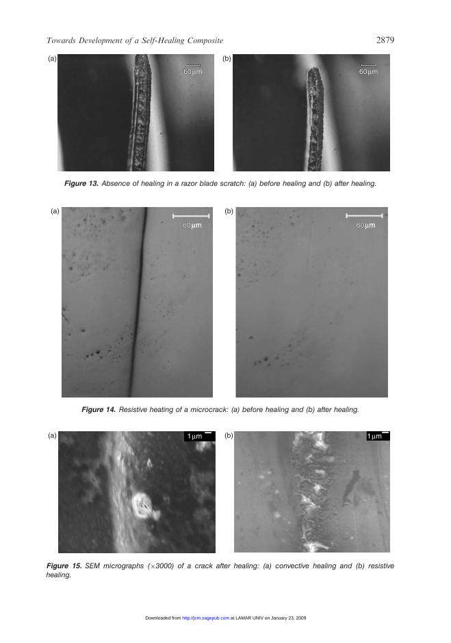
The microcracks induced by three-point bending were healed well in the air-circulatingoven and became almost invisible on the microscope (Figure 12). However, this was notthe case with the scratch induced by a razor blade (Figure 13). In the latter case, thedamaged surfaces are widely separated and are not in contact with each other acrossthe scratch. This would be a limitation on the healing ability of mendomer 401.
The electrical resistive heating was found to work well with the polymer. Figure 14shows a crack in the mendomer coating before and after electrical resistive heating of thesubstrate. Crack healing was observed at a relatively low temperature range of 70–1008C,and was complete within minutes at these temperatures.
To identify the heal morphology, the healed microcracks were examined under ascanning electron microscope (SEM). Figure 15 shows two healed cracks: one healed in the
Substrate
Substrate
(a) (b)
Polymend 401 : Cracks Polymend 401 : No crack
6060μm60μm 6060μm60μm
Figure 11. Mendomer 401 cured in: (a) normal oven and (b) vacuum oven.
6060μm60μm 6060μm60μm
(a) (b)
Figure 12. Convective heating of a microcrack: (a) before healing and (b) after healing.
2878 J. S. PARK ET AL.
at LAMAR UNIV on January 23, 2009 http://jcm.sagepub.comDownloaded from
6060μm60μm 6060μm60μm
(a) (b)
Figure 13. Absence of healing in a razor blade scratch: (a) before healing and (b) after healing.
(a) (b)
6060μm60μm 6060μm60μm
Figure 14. Resistive heating of a microcrack: (a) before healing and (b) after healing.
(a) (b)1mm 1mm
Figure 15. SEM micrographs (�3000) of a crack after healing: (a) convective healing and (b) resistivehealing.
Towards Development of a Self-Healing Composite 2879
at LAMAR UNIV on January 23, 2009 http://jcm.sagepub.comDownloaded from

air-circulating oven and the other healed by electroresistive heating. Both cracks arecompletely closed. However, the former shows more extensive scars than the latter.Although not surprising, it is unclear why these scars are formed, though it can potentiallybe attributed to a phenomenon akin to surface tension during healing.
CONCLUSIONS
The healing ability of mendomer 401 via electrical resistive heating has beendemonstrated by using a graphite/epoxy laminate as a substrate. Microcracks in men-domer coatings on a graphite/epoxy substrate coupon were healed completely when thecoupon was heated electrically. Oxidation should be avoided during curing of the polymer;however, it does not affect healing once the polymer is cured.
To use mendomer 401 as a matrix of self-healing composite, there are several questionsto be solved. First, mechanical properties which are important to be a good matrix forcomposite should be studied. Also, healing efficiency that can be defined by ratios ofultimate strength or toughness of the polymer before and after healing should bequantified. Finally, a scaleable manufacturing process of mendomer should be developedfor fabrication of a self-healing composite.
Although there is considerable work to be done, mendomer 401 is one of the mostattractive candidates as a matrix material for mendable composites according to its healingability, using graphite fibers network which can provide a health monitoring systemin future.
ACKNOWLEDGMENTS
The present paper is based on work supported by the Air Force Office of ScientificResearch through a MURI Grant FA 9550-05-1-0346 to the University of Illinois,Urbana-Champaign. Appreciation is extended to Dr. B. Les Lee for his encouragementand support. Moreover, the authors are grateful to the NSF MCTP (Material CreationTraining Program) under Grant DGE-0114443 for allowing the use of its facilities.
REFERENCES
1. Pang, J.W.C. and Bond, I.P. (2005). A Hollow Fibre Reinforced Polymer CompositeEncompassing Self-healing and Enhanced Damage Visibility, Comp. Sci. Tech., 65: 1791–1799.
2. Dry, C. and McMillan, W. (1996). Three-part Methylmethacrylate Adhesive System as anInternal Delivery System for Smart Responsive Concrete, Smart Mater. Struct., 5(3): 297–300.
3. Dry, C. (2000). Three Design for the Internal Release of Sealants, Adhesives and WaterproofingChemical into Concrete to Release, Cement Concrete Res., 30: 1969–1977.
4. Li, V.C., Lim, Y.M. and Chan, Y.W. (1998). Feasibility Study of a Passive Smart Self-healingCementitious Composite, Composites B, 29(B): 819–827.
5. Dry, C. (1996). Procedure Developed for Self-repair of Polymer Matrix Composite Materials,Comp. Struct., 35(3): 263–269.
6. Motuku, M., Vaidya, U.K. and Janowski, G.M. (1999). Parametric Studies on Self-repairingApproaches for Resin Infused Composites Subjected to Low Velocity Impact, Smart Mater.Struct., 8: 623–638.
2880 J. S. PARK ET AL.
at LAMAR UNIV on January 23, 2009 http://jcm.sagepub.comDownloaded from
7. Bleay, S.M., Loader, C.B., Hawyes, V.J., Humberstone, L. and Curtis, P.T. (2001). A SmartRepair System for Polymer Matrix Composites, Composites A, 32: 1767–1776.
8. Zako, M. and Takano, N. (1999). Intelligent Material Systems using Epoxy Particles to RepairMicrocracks and Delamination Damage in GFRP, J. Int. Mater. Sys. Struct., 10(10): 836–841.
9. White, S.R., Sottos, N.R., Geubelle, P.H., Moore, J.S., Kessler, M.R., Sriram, S.R., Brown,E.N. and Viswanathan, S. (2001). Autonomic Healing of Polymer Composites, Nature, 409:794–797.
10. Kessler, M.R. and White, S.R. (2001). Self-activated Healing of Delamination Damage inWoven Composites, Composites A, 32: 683–699.
11. Brown, E.N., Sottos, N.R. and White, S.R. (2002). Fracture Testing of a Self-healing PolymerComposite, Exp. Mech., 42(4): 372–379.
12. Kessler, M.R., Sottos, N.R. and White, S.R. (2003). Self-healing Structural CompositeMaterials, Composites A, 34: 743–753.
13. Brown, E.N., White, S.R. and Sottos, N.R. (2004). Microcapsule Induced Toughening in a Self-healing Polymer Composite, J. Mater. Sci., 39: 1703–1710.
14. Kennedy, J.P. and Castner, K.F. (1979). Thermally Reversible Polymer Systems byCyclopentadienylation. I. A Model for Termination by Cyclopentadienylation of OlefinPolymerization, J. Polym. Sci., Part A: Polym. Chem., 17: 2039–2054.
15. Canary, S.A. and Stevens, M.P. (1992). Thermally Reversible Crosslinking of Polystyrenevia the Furan-Maleimide Diels-Alder Reaction, J. Polym. Sci., Part A: Polym. Chem., 30:1755–1760.
16. Engle, L.P. and Wagener, K.B. (1993). Thermally Reversible Polymer Linkages. II. LinearAddition Polymers, J. Polym. Sci., Part A: Polym. Chem., 31: 865–875.
17. Gousse, C., Gandini, A. and Hodge, P. (1998). Application of the Diels–Alder Reaction toPolymers Bearing Furan Moieties. 2. Diels–Alder and Retro-Diels–Alder Reactions InvolvingFuran Rings in Some Styrene Copolymers, Macromolecules, 31: 314–321.
18. Jones, J.R., Liotta, C.L., Collard, D.M. and Schiraldi, D.A. (1999). Cross-linking andModification of poly(ethylene teraphthalate-co-2,6-anthracenedicarboxylate) by Diels–AlderReactions with Maleimides, Macromolecules, 32: 5786–5792.
19. Imai, Y., Itoh, H., Naka, K. and Chujo, Y. (2000). Thermally Reversible IPN Organic-inorganicPolymer Hybrids Utilizing the Diels–Alder Reaction, Macromolecules, 33: 4343–4346.
20. Chen, X., Dam, M.A., Ono, K., Mal, A., Shen, H.B., Nutt, S.R., Sheran, K. and Wudl, F.(2002). A Thermally Re-mendable Cross-linked Polymeric Material, Science, 295: 1698–1702.
21. Kwok, N. and Hahn, H.T. (2007). Resistance Heating for Self-healing Composites, J. Comp.Mater., 41: 1635–1654.
22. Abry, J., Bochard, S., Chateauminois, A., Salvia, M. and Girau, G. (1999). In Situ Detectionof Damage in CFRP Laminates by Electrical Resistance Measurements, Comp. Sci. Tech., 59:925–935.
23. Grujicic, M., Zhao, C.L. and Dusel, E.C. (2005). The Effect of Thermal Contact Resistance onHeat Management in the Electronic Packaging, Appl. Surface Sci., 246: 290–302.
Towards Development of a Self-Healing Composite 2881
at LAMAR UNIV on January 23, 2009 http://jcm.sagepub.comDownloaded from