
Towards an Efficient NoC Topology through Multiple Injection Ports
8
1 Towards an Efficient NoC Topology through Multiple Injection Ports Jes´ us Camacho, Jos´ e Flich, Jos´ e Duato Hans Eberle, Wladek Olesinski Departamento de Inform´ atica de Sistemas y Computadores Oracle Universitat Polit` ecnica de Val` encia California Spain USA {jecavil,jflich,jduato}@gap.upv.es {hans.eberle,wladek.olesinski}@oracle.com Abstract—In this paper, we present a flexible network on-chip topology: NR-Mesh (Nearest neighboR Mesh). The topology gives an end node the choice to inject a message through different neighboring routers, thereby reducing hop count and saving latency. At the receiver side, a message may be delivered to the end node through different routers, thus reducing hop count further and increasing flexibility when routing messages. This flexibility allows for maximizing network components to be in switch off mode, thus enabling power aware routing algorithms. Additional benefits are reduced congestion/contention levels in the network, support for efficient broadcast operations, savings in power consumption, and partial fault-tolerance. Our second contribution is a power management technique for the adaptive routing. This technique turns router ports and their attached links on and off depending on traffic conditions. The power management technique is able to achieve significant power savings when there is low traffic in the network. We further compare the new topology with the 2D-Mesh, using either deterministic or adaptive routing. When compared with the 2D- Mesh using deterministic routing, executing real applications in a full system simulation platform, the NR-Mesh topology using adaptive routing is able to obtain significant savings, 7% of reduction in execution time and 75% in energy consumption at the network on average for a 16-Node CMP System. Similar numbers are achieved for a 32-Node CMP system. Index Terms—topology; injection; power consumption; I. I NTRODUCTION As technology scales designers add more functionality on current microprocessors. With the current trend, basic simple processor components (together with cache memories) are replicated, increasing the number of processing elements on the same chip. These chips are known as Chip MultiProcessors (CMPs). This design style is preferred over a design of a big and complex processor core. The reason is the power consumption limitation and the better performance-power con- sumption trade-off of smaller processors. Indeed, there are chip prototypes and real products with tens of processors (e.g. Intel Polaris chip [22] with 80 simple cores, the Single-chip Cloud Computer [20] with 48 x86 compatible processors and Tilera’s 100-core chip [23]). With advances in technology, we can expect chips with hundreds of cores in the near future so the way these cores are connected becomes an important and challenging issue. Although buses, rings, and crossbar topologies were used in initial systems (e.g. Cell Broadband Engine processor [4]), these structures do not scale well and therefore achieve low performance when the number of cores is high. Current CMP systems rely on a 2D-Mesh topology where the router is connected to its neighbors in the north, east, west and south directions. The mesh topology is appealing since it matches the planar surface of the chip easening the tile- based design (a chip is built by replicating the same basic tile design). One negative aspect of the 2D-Mesh topology, however, is its increase in the number of hops when commu- nicating distant nodes. This becomes a problem as the system size increases. The routing algorithm determines which output port a message must take in order to reach its destination. In a 2D-Mesh topology, the most efficient routing algorithm (in terms of implementation complexity and power consumption) is dimension-order routing (DOR). DOR is implemented on every router and requires small logic blocks. The message first moves in the X dimension and then in the Y dimension, always following minimal paths. The low complexity of DOR makes it very appealing for network-on-chip designers. However, DOR is not flexible as it allows only one path for every source-destination pair. Therefore, DOR does not tolerate a single failure since the failure will disconnect several pairs of end nodes. In addition, DOR may lead to congestion in the network. As it does not support alternative paths, messages are forced to follow a single path, and thus, there is no way to avoid or escape from a congested spot in the network. An alternative to DOR is the use of adaptive routing where routers are able to select different output ports for the same destination, depending on the current status of those ports. Thus, local congestion can be alleviated by the use of adaptive routing. Typically, minimal paths are supported by adaptive routing, thus, the message gets closer to its destination on every hop. To avoid deadlocks, an acyclic escape path is implemented as a different virtual channel. If adaptive output ports are not available, then the escape path is taken [7]. As a preliminary study, we have analyzed the average link utilization in 16-tile and 32-tile CMP systems for several ap- plications. The obtained utilization is quite low. Two different topologies, 2D-Mesh and NR-Mesh proposed in this paper, as well as two different routing algorithms, DOR and adaptive routing, have been tested. The link utilization in all the cases is usually below 10%. This low network utilization may lead to a large waste of power consumption. Most of the time, network components (routers and links) are idle but powered on. As power consumption is becoming the limiting design factor in current chips, it is a requirement to adjust the power consumption of the network components to the real needs of applications. If the network could be switched off during the time the components were not used (90% on average), then large savings would be achieved. In [24] it is reported that 30% of total chip power consumption is due to the network. In this paper we propose a flexible network on-chip topol-
-
Upload
independent -
Category
Documents
-
view
0 -
download
0
Transcript of Towards an Efficient NoC Topology through Multiple Injection Ports

1
Towards an Efficient NoC Topology throughMultiple Injection Ports
Jesus Camacho, Jose Flich, Jose Duato Hans Eberle, Wladek OlesinskiDepartamento de Informatica de Sistemas y Computadores Oracle
Universitat Politecnica de Valencia CaliforniaSpain USA
{jecavil,jflich,jduato}@gap.upv.es {hans.eberle,wladek.olesinski}@oracle.com
Abstract—In this paper, we present a flexible network on-chiptopology: NR-Mesh (Nearest neighboR Mesh). The topology givesan end node the choice to inject a message through differentneighboring routers, thereby reducing hop count and savinglatency. At the receiver side, a message may be delivered tothe end node through different routers, thus reducing hop countfurther and increasing flexibility when routing messages. Thisflexibility allows for maximizing network components to be inswitch off mode, thus enabling power aware routing algorithms.Additional benefits are reduced congestion/contention levels inthe network, support for efficient broadcast operations, savingsin power consumption, and partial fault-tolerance.
Our second contribution is a power management techniquefor the adaptive routing. This technique turns router ports andtheir attached links on and off depending on traffic conditions.The power management technique is able to achieve significantpower savings when there is low traffic in the network. Wefurther compare the new topology with the 2D-Mesh, using eitherdeterministic or adaptive routing. When compared with the 2D-Mesh using deterministic routing, executing real applications ina full system simulation platform, the NR-Mesh topology usingadaptive routing is able to obtain significant savings, 7% ofreduction in execution time and 75% in energy consumptionat the network on average for a 16-Node CMP System. Similarnumbers are achieved for a 32-Node CMP system.
Index Terms—topology; injection; power consumption;
I. INTRODUCTION
As technology scales designers add more functionality oncurrent microprocessors. With the current trend, basic simpleprocessor components (together with cache memories) arereplicated, increasing the number of processing elements onthe same chip. These chips are known as Chip MultiProcessors(CMPs). This design style is preferred over a design of abig and complex processor core. The reason is the powerconsumption limitation and the better performance-power con-sumption trade-off of smaller processors. Indeed, there are chipprototypes and real products with tens of processors (e.g. IntelPolaris chip [22] with 80 simple cores, the Single-chip CloudComputer [20] with 48 x86 compatible processors and Tilera’s100-core chip [23]).
With advances in technology, we can expect chips withhundreds of cores in the near future so the way these coresare connected becomes an important and challenging issue.Although buses, rings, and crossbar topologies were used ininitial systems (e.g. Cell Broadband Engine processor [4]),these structures do not scale well and therefore achieve lowperformance when the number of cores is high.
Current CMP systems rely on a 2D-Mesh topology wherethe router is connected to its neighbors in the north, east, westand south directions. The mesh topology is appealing since
it matches the planar surface of the chip easening the tile-based design (a chip is built by replicating the same basictile design). One negative aspect of the 2D-Mesh topology,however, is its increase in the number of hops when commu-nicating distant nodes. This becomes a problem as the systemsize increases.
The routing algorithm determines which output port amessage must take in order to reach its destination. In a2D-Mesh topology, the most efficient routing algorithm (interms of implementation complexity and power consumption)is dimension-order routing (DOR). DOR is implemented onevery router and requires small logic blocks. The message firstmoves in the X dimension and then in the Y dimension, alwaysfollowing minimal paths. The low complexity of DOR makesit very appealing for network-on-chip designers. However,DOR is not flexible as it allows only one path for everysource-destination pair. Therefore, DOR does not tolerate asingle failure since the failure will disconnect several pairs ofend nodes. In addition, DOR may lead to congestion in thenetwork. As it does not support alternative paths, messagesare forced to follow a single path, and thus, there is no wayto avoid or escape from a congested spot in the network.
An alternative to DOR is the use of adaptive routing whererouters are able to select different output ports for the samedestination, depending on the current status of those ports.Thus, local congestion can be alleviated by the use of adaptiverouting. Typically, minimal paths are supported by adaptiverouting, thus, the message gets closer to its destination onevery hop. To avoid deadlocks, an acyclic escape path isimplemented as a different virtual channel. If adaptive outputports are not available, then the escape path is taken [7].
As a preliminary study, we have analyzed the average linkutilization in 16-tile and 32-tile CMP systems for several ap-plications. The obtained utilization is quite low. Two differenttopologies, 2D-Mesh and NR-Mesh proposed in this paper, aswell as two different routing algorithms, DOR and adaptiverouting, have been tested. The link utilization in all the casesis usually below 10%. This low network utilization may leadto a large waste of power consumption. Most of the time,network components (routers and links) are idle but poweredon. As power consumption is becoming the limiting designfactor in current chips, it is a requirement to adjust the powerconsumption of the network components to the real needs ofapplications. If the network could be switched off during thetime the components were not used (90% on average), thenlarge savings would be achieved. In [24] it is reported that30% of total chip power consumption is due to the network.
In this paper we propose a flexible network on-chip topol-

2
ogy (NR-Mesh; Nearest neighboR Mesh) that allows severalalternative paths for most source-destination pairs. A messagecan be injected through four different routers and can bereceived from four different routers. This fact leads to a largeflexibility when routing messages, not only at routers but alsoat network interfaces. Also, the topology has a lower diameterthan the 2D-Mesh topology and provides efficient support forcollective communication and fault tolerance.
As a second proposal, we tackle the power consumptionissue. Complementary to the new topology, we propose arouting algorithm aware of switched off network components.The algorithm will maximize the time network components areswitched off, thus maximizing power savings. The algorithmis based on the adaptive routing algorithm, with modificationson the selection function for the output ports.
With the two proposals, performance is significantly in-creased. Execution time of applications is reduced up to 12%.The energy consumption at the network is also greatly reduced,by up to 92% when experiencing low traffic.
The rest of the paper is organized as follows. In SectionII, the related work is discussed. Then, in Section III, thenew NR-Mesh topology is described. Section IV describes theproposed power-aware routing algorithm. Finally, in SectionV, the topology and algorithms are evaluated, and in SectionVI the paper is concluded.
II. RELATED WORK
Different topologies for CMPs have been proposed duringthe last years. Initially, designs and proposals relied on rings[18] and 2D meshes [26], [24], [25]. Efforts to reduce hopcount have been performed with concentrated meshes [2] (endnodes connected to the same router) and flattened butterflynetworks [13]. Other works [8] reduce hop count by usingexpress channels where a router is connected to several routersalong each direction in the 2D mesh [6]. A complete analysisand comparison of several topologies can be found in [8]. Onespecial case is the Diagonal Mesh (DMesh) topology proposedin [10]. In such topology diagonal links are added betweenrouters. However, all these topologies (including DMesh) relyon the fact that every end node is connected only to one router.In our proposed topology, the end node is connected to fourdifferent routers, thus providing larger benefits.
A similar topology [28] (which we will referred as NR/2-Mesh) has been proposed recently where an end-node isconnected to two routers in a 2D mesh configuration. The maingoal of such approach is for fault-tolerance and not for powersaving. In our case, we provide connectivity to four neighborrouters where the main goal is to reduce power consumption,together with a modified routing algorithm that is aware of thepowered-down links and routers.
Power gating (gated-Vdd) is a well-known technique toreduce static power consumption. In [19] a circuit techniquewas proposed to disconnect (by using a gating transistor) thepower supply. Power gating can be applied at different levels,from complete execution units [11] down to single SRAMcells [5]. For NoCs different works apply the power gatingtechnique. In [5] buffers are power gated and different policiesare proposed. In [16], [17] power gating is applied to virtualchannels. In [21] powering down links is proposed. In [9]static power consumption is reduced by using the concept ofon/off links [21] with power-aware buffers [5], [16], [17]. Theproposed power management algorithm in this paper uses alsothe concept of on/off links. The different proposals for power
gating usually rely on a standard 2D-Mesh, and potentiallycan be applied to NR-Mesh.
III. NR-MESH
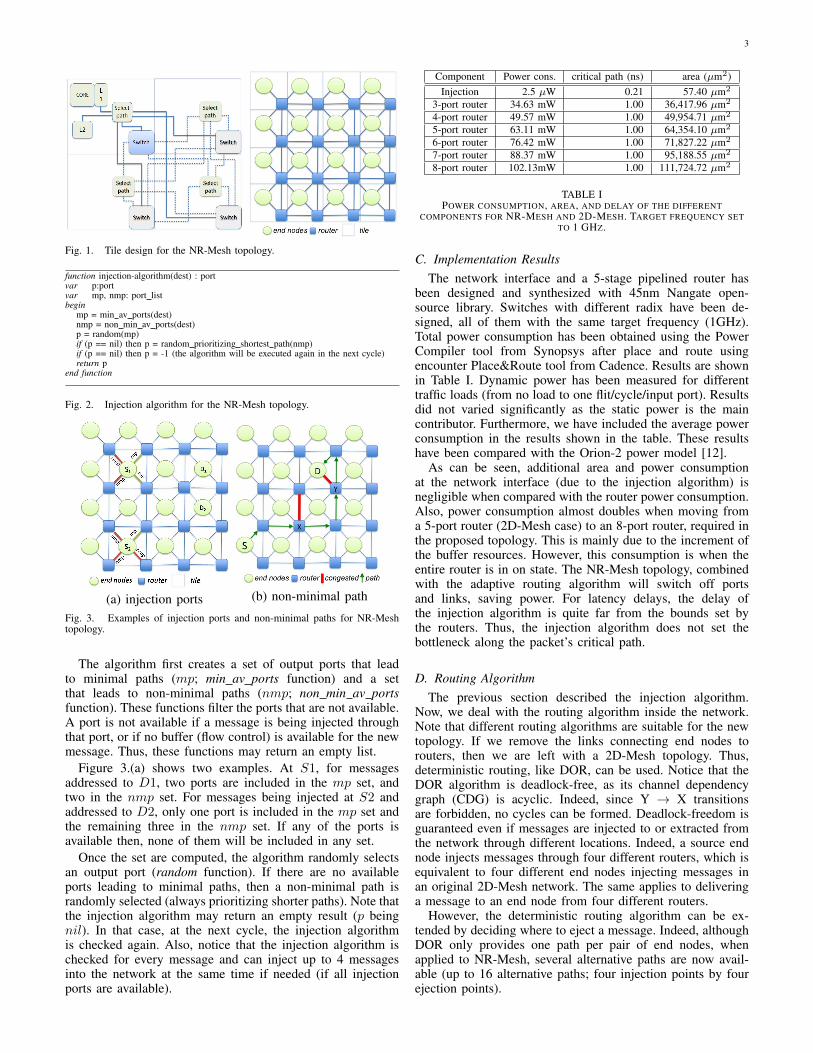
Figure 1 (on the right side) shows the connection patternof the NR-Mesh between end nodes and routers. The networkuses four links to connect every end node to four routers.Several nodes at the boundary of the topology are connected,however, to fewer routers. In particular, some nodes at thecorners are connected to a single router and the remainingboundary nodes are connected to two routers. Note that whencompared with the 2D-Mesh, NR-Mesh offers higher connec-tivity due to added internal links and provides alternative pathsas messages can be injected through up to four different routersand be received from up to four different routers. Please notethat in-transit messages, however, cannot cross in-transit endnodes.
Each end node includes the processor, the L1 data andinstruction cache, a slice of the L2 cache, and a memorycontroller. Since the end node is connected to four routers,additional logic is required at the network interface to decidethe output port to use. We have implemented and measured therequired logic (see section III-B) and we have obtained neg-ligible overheads, except for the longer internal link requiredin the NR-Mesh. The associated control logic is included atthe end-node (see Figure 1). Later, we describe the selectionalgorithm used at the interface.
A key property of the topology is its reduced diameter.For example, NR-Mesh with 16 end nodes has the maximumdistance (between the two most distant corners) of five routerhops while the 2D-Mesh has a distance of seven router hops.This enables reducing the average latency of messages, theexecution time of applications, and the power consumption.
A. Tile-Based DesignNR-Mesh can be adapted to a tile-based design, as seen
in Figure 1. The router is located at the bottom right-mostpart of the tile and connected to four different end nodes,each on a different tile. Each end node includes the selectionfunction. The figure shows also the links connecting end nodesto routers and the links between routers. Links connecting endnodes cross the tile boundary in order to reach other router’stile. The remaining links follow the usual 2D-Mesh layout.
Notice that a tile-based design has the same number ofend nodes and routers. However, for the 16-tile design, 9 endnodes are connected to four routers, 6 end nodes connectedto two routers, and 1 end node connected to one router.Indeed, the last row and column of routers could be removedwithout affecting connectivity. However, these routers provideflexibility when routing messages and will be in off mode mostof the time (in low traffic conditions).
B. Injection AlgorithmThe injection algorithm (Figure 2) is a key component of
the topology. A message can be injected into the networkthrough different ports. Notice, however, that depending onthe final end node destination, some of the injection portswill lead to minimal paths and others will lead to non-minimal (longer) paths. To support full flexibility, the injectionalgorithm considers all the possibilities, although prioritizingports that provide minimal paths.
3
Fig. 1. Tile design for the NR-Mesh topology.
function injection-algorithm(dest) : portvar p:portvar mp, nmp: port listbegin
mp = min av ports(dest)nmp = non min av ports(dest)p = random(mp)if (p == nil) then p = random prioritizing shortest path(nmp)if (p == nil) then p = -1 (the algorithm will be executed again in the next cycle)return p
end function
Fig. 2. Injection algorithm for the NR-Mesh topology.
(a) injection ports (b) non-minimal path
Fig. 3. Examples of injection ports and non-minimal paths for NR-Meshtopology.
The algorithm first creates a set of output ports that leadto minimal paths (mp; min av ports function) and a setthat leads to non-minimal paths (nmp; non min av portsfunction). These functions filter the ports that are not available.A port is not available if a message is being injected throughthat port, or if no buffer (flow control) is available for the newmessage. Thus, these functions may return an empty list.
Figure 3.(a) shows two examples. At S1, for messagesaddressed to D1, two ports are included in the mp set, andtwo in the nmp set. For messages being injected at S2 andaddressed to D2, only one port is included in the mp set andthe remaining three in the nmp set. If any of the ports isavailable then, none of them will be included in any set.
Once the set are computed, the algorithm randomly selectsan output port (random function). If there are no availableports leading to minimal paths, then a non-minimal path israndomly selected (always prioritizing shorter paths). Note thatthe injection algorithm may return an empty result (p beingnil). In that case, at the next cycle, the injection algorithmis checked again. Also, notice that the injection algorithm ischecked for every message and can inject up to 4 messagesinto the network at the same time if needed (if all injectionports are available).
Component Power cons. critical path (ns) area (µm2)Injection 2.5 µW 0.21 57.40 µm2
3-port router 34.63 mW 1.00 36,417.96 µm2
4-port router 49.57 mW 1.00 49,954.71 µm2
5-port router 63.11 mW 1.00 64,354.10 µm2
6-port router 76.42 mW 1.00 71,827.22 µm2
7-port router 88.37 mW 1.00 95,188.55 µm2
8-port router 102.13mW 1.00 111,724.72 µm2
TABLE IPOWER CONSUMPTION, AREA, AND DELAY OF THE DIFFERENT
COMPONENTS FOR NR-MESH AND 2D-MESH. TARGET FREQUENCY SETTO 1 GHZ.
C. Implementation ResultsThe network interface and a 5-stage pipelined router has
been designed and synthesized with 45nm Nangate open-source library. Switches with different radix have been de-signed, all of them with the same target frequency (1GHz).Total power consumption has been obtained using the PowerCompiler tool from Synopsys after place and route usingencounter Place&Route tool from Cadence. Results are shownin Table I. Dynamic power has been measured for differenttraffic loads (from no load to one flit/cycle/input port). Resultsdid not varied significantly as the static power is the maincontributor. Furthermore, we have included the average powerconsumption in the results shown in the table. These resultshave been compared with the Orion-2 power model [12].
As can be seen, additional area and power consumptionat the network interface (due to the injection algorithm) isnegligible when compared with the router power consumption.Also, power consumption almost doubles when moving froma 5-port router (2D-Mesh case) to an 8-port router, required inthe proposed topology. This is mainly due to the increment ofthe buffer resources. However, this consumption is when theentire router is in on state. The NR-Mesh topology, combinedwith the adaptive routing algorithm will switch off portsand links, saving power. For latency delays, the delay ofthe injection algorithm is quite far from the bounds set bythe routers. Thus, the injection algorithm does not set thebottleneck along the packet’s critical path.
D. Routing AlgorithmThe previous section described the injection algorithm.
Now, we deal with the routing algorithm inside the network.Note that different routing algorithms are suitable for the newtopology. If we remove the links connecting end nodes torouters, then we are left with a 2D-Mesh topology. Thus,deterministic routing, like DOR, can be used. Notice that theDOR algorithm is deadlock-free, as its channel dependencygraph (CDG) is acyclic. Indeed, since Y → X transitionsare forbidden, no cycles can be formed. Deadlock-freedom isguaranteed even if messages are injected to or extracted fromthe network through different locations. Indeed, a source endnode injects messages through four different routers, which isequivalent to four different end nodes injecting messages inan original 2D-Mesh network. The same applies to deliveringa message to an end node from four different routers.
However, the deterministic routing algorithm can be ex-tended by deciding where to eject a message. Indeed, althoughDOR only provides one path per pair of end nodes, whenapplied to NR-Mesh, several alternative paths are now avail-able (up to 16 alternative paths; four injection points by fourejection points).

4
function det routing(iport, cur, dest) : portvar p: portvar nmp: set of portsbegin
p = minimal xy port(cur, dest)if (free[p]) return pif (iport==W & y(dest)<y(cur) & x(dest)==x(cur)+1) nmp+=ENif (iport==W & y(dest)>y(cur) & x(dest)==x(cur)+1) nmp+=ESif (iport==E & y(dest)<y(cur) & x(dest)==x(cur)-1) nmp+=WNif (iport==E & y(dest)>y(cur) & x(dest)==x(cur)-1) nmp+=WSif (iport==S & dest at N) nmp+=Nif (iport==N & dest at S) nmp+=Sp = select(nmp)if (p == nil) then p = -1 (the algorithm will be executed again in the next cycle)return p
end function
Fig. 4. Deterministic routing algorithm for the NR-Mesh topology.
As previously said, messages at certain routers may takedifferent output ports based on the current port status. Figure3.(b) shows the case of a message being routed from end nodeS to end node D. The message encounters a port at router X(the north port) that is congested (busy). As D is connected totwo columns, the message can be forwarded to the east routerand then move north. In addition, the message reaches routerY that is considered a destination router (a router where Dis connected to). The message can leave the network throughthat router or, alternatively, if the output port is busy, can beforwarded to the next router (north direction) and reach theend node through that router. Notice that both alternative hopsled to non-minimal paths, thus performed only if the ports arebusy. Besides, no Y-X transitions are taken (deadlock-free).
The deterministic routing algorithm with support for non-minimal paths is described in Figure 4. The function is run onevery router and for every incoming message. The algorithmtakes into account the input port the message arrived from(iport), the current location of the router (cur) in the NR-Mesh structure, and the destination node (dest) of the mes-sage. The first step is to find the output port assuming the DORrouting algorithm (function minimal xy port). Based on thecurrent and destination coordinates, the provided port will beN , E, W , S, or internal. Notice that only one minimal portexists for every message at every router, regardless of thedestination of the message.
The algorithm, then, selects the port if is available (free[p]).However, if the port (either internal or router-to-router port)is busy, the algorithm checks if an extra hop is possible (non-minimal routing). Six cases are considered, none of themintroducing a Y → X transition. For example, if the messageis coming from the W port and the destination is at the north-east (NE) quadrant, then the message can still be routed eitherE or N and reach the destination at the next hop. An endnode is considered to be at the NE quadrant if it can bereached through the current Y column or the next one. Thesame reasoning is used for messages coming from E port.For messages coming through the S port, they can still moveN , but cannot take E or W as this would lead to Y → Xtransitions. The same occurs for messages coming through theN port. Notice also U turns are not allowed by the algorithm.
As a final step, the priority select function returns onlyone output port from the set of non-minimal ports computed.The function gives priority to E and W ports over N and Sports. If no valid output port is selected, the message is routedagain at the next cycle.
The topology also allows the use of adaptive routing (Figure5). In this case, virtual channels are needed to decoupleadaptive paths from escape paths. One alternative is to useone virtual channel to route messages adaptively and one
function adaptive routing(iport, cur, dest) : port, virtual channelvar ap: set of portsbegin
ap = min adap and av ports(cur, dest)if (empty(ap)) return det routing(iport, cur, dest), det vcelse return random(ap), adaptive vc
end function
Fig. 5. Adaptive routing algorithm for the NR-Mesh topology.
virtual channel to route messages through the escape path.The algorithm returns an output port and a virtual chan-nel to be used at the next router. First, the set of outputports providing minimal paths to the destination are retrieved(function min adap and av ports). Notice that only outputports currently available are provided. If at least one port isprovided, then the algorithm takes the port and indicates theadaptive virtual channel that must be used for the message(adaptive vc). However, if the adaptive minimal paths arebusy, then the algorithm takes the deterministic routing path.In particular, the previous function (det routing) is called andthe virtual channel to use is the deterministic one (det vc).
Messages may take adaptive virtual channels and determin-istic virtual channels along their path in any order. In sucha scenario, and in wormhole switching networks, this maylead to deadlocks. Indeed, indirect channel dependencies thatpotentially lead to cycles in the CDG are introduced. However,this is not possible with virtual cut-through switching. Ifwormhole switching is used, then the algorithm must preventmessages moving from deterministic virtual channels back toadaptive virtual channels.
In the evaluation section, we evaluate the NR-Mesh topol-ogy with both routing algorithms, deterministic and adaptive.The adaptive routing algorithm will be later modified in orderto be used in a system where input ports and links are switchedon and off dynamically (second contribution of the paper).
E. Topology Properties
In this section, we explore the main properties of the NR-Mesh topology 1. The first one is its flexibility when injectingand ejecting messages based on the algorithm shown in Figure2. An end node may decide which injection port should beused. At the destination, the routing algorithm, shown inFigures 4 and 5, is able to deliver the message through fourdifferent routers. This flexibility is not available in the original2D-Mesh topology. This property will be exploited when usingthe power management technique, as it will allow resources(ports and links) to be switched off during larger periods oftime. Also, congestion within the network will be alleviated.
As a second property, the NR-Mesh topology exhibits alower diameter. Indeed, the diameter of an N ×N NR-Meshnetwork is 2N − 2 (instead of 2N as in the 2D-Mesh), sinceat the injection and ejection points, one hop per dimensionis saved. This will lead also to lower latency and powerconsumption.
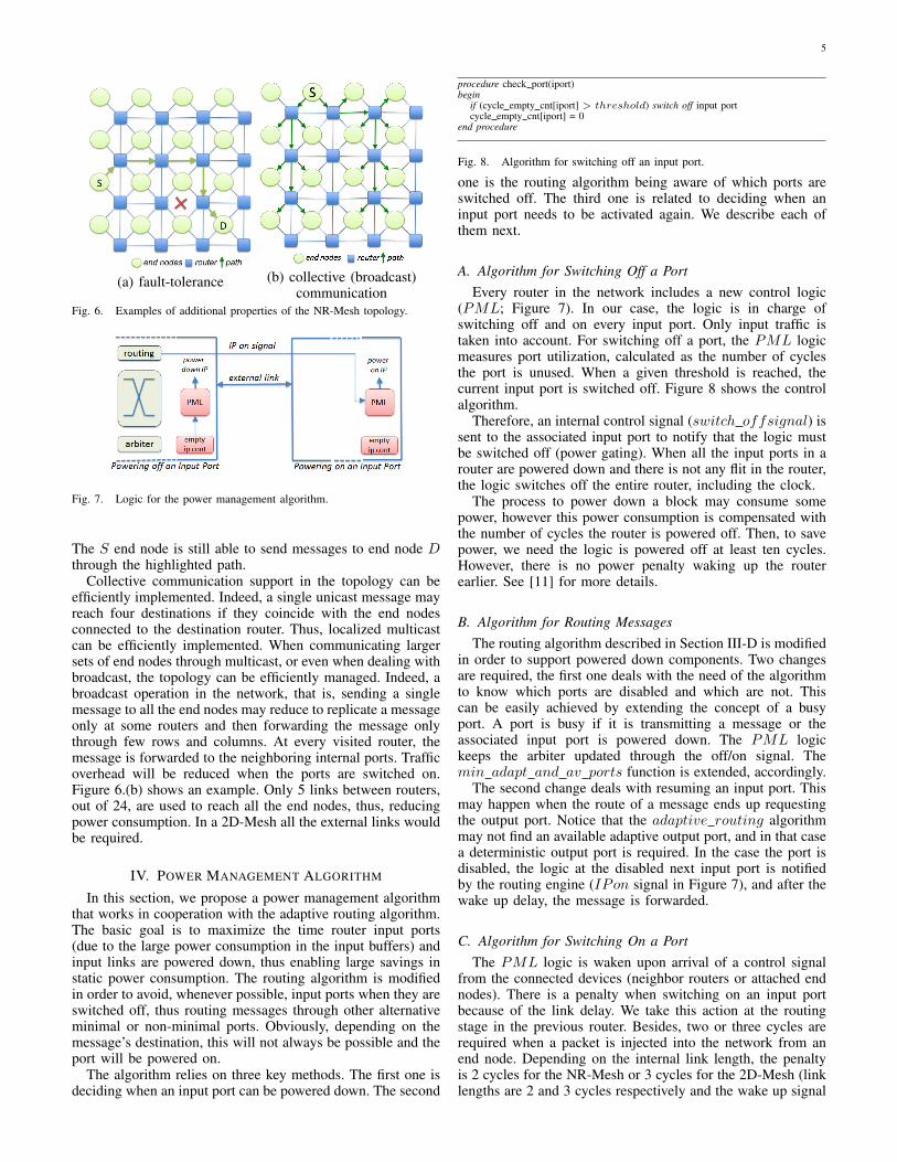
The NR-Mesh topology provides a high degree of faulttolerance. Indeed, network links and even routers could failand still paths from sources to destinations will be available.In contrast, the 2D-Mesh case with DOR routing does nottolerate a single link or switch failure. Figure 6.(a) shows anexample where a link failure is supported by the topology.
1In this paper, we do not evaluate all of them. We focus on the algorithmimplemented on top of the topology. Exploring the additional features of thetopology is left for future work.
5
(a) fault-tolerance (b) collective (broadcast)communication
Fig. 6. Examples of additional properties of the NR-Mesh topology.
Fig. 7. Logic for the power management algorithm.
The S end node is still able to send messages to end node Dthrough the highlighted path.
Collective communication support in the topology can beefficiently implemented. Indeed, a single unicast message mayreach four destinations if they coincide with the end nodesconnected to the destination router. Thus, localized multicastcan be efficiently implemented. When communicating largersets of end nodes through multicast, or even when dealing withbroadcast, the topology can be efficiently managed. Indeed, abroadcast operation in the network, that is, sending a singlemessage to all the end nodes may reduce to replicate a messageonly at some routers and then forwarding the message onlythrough few rows and columns. At every visited router, themessage is forwarded to the neighboring internal ports. Trafficoverhead will be reduced when the ports are switched on.Figure 6.(b) shows an example. Only 5 links between routers,out of 24, are used to reach all the end nodes, thus, reducingpower consumption. In a 2D-Mesh all the external links wouldbe required.
IV. POWER MANAGEMENT ALGORITHM
In this section, we propose a power management algorithmthat works in cooperation with the adaptive routing algorithm.The basic goal is to maximize the time router input ports(due to the large power consumption in the input buffers) andinput links are powered down, thus enabling large savings instatic power consumption. The routing algorithm is modifiedin order to avoid, whenever possible, input ports when they areswitched off, thus routing messages through other alternativeminimal or non-minimal ports. Obviously, depending on themessage’s destination, this will not always be possible and theport will be powered on.
The algorithm relies on three key methods. The first one isdeciding when an input port can be powered down. The second
procedure check port(iport)begin
if (cycle empty cnt[iport] > threshold) switch off input portcycle empty cnt[iport] = 0
end procedure
Fig. 8. Algorithm for switching off an input port.
one is the routing algorithm being aware of which ports areswitched off. The third one is related to deciding when aninput port needs to be activated again. We describe each ofthem next.
A. Algorithm for Switching Off a PortEvery router in the network includes a new control logic
(PML; Figure 7). In our case, the logic is in charge ofswitching off and on every input port. Only input traffic istaken into account. For switching off a port, the PML logicmeasures port utilization, calculated as the number of cyclesthe port is unused. When a given threshold is reached, thecurrent input port is switched off. Figure 8 shows the controlalgorithm.
Therefore, an internal control signal (switch offsignal) issent to the associated input port to notify that the logic mustbe switched off (power gating). When all the input ports in arouter are powered down and there is not any flit in the router,the logic switches off the entire router, including the clock.
The process to power down a block may consume somepower, however this power consumption is compensated withthe number of cycles the router is powered off. Then, to savepower, we need the logic is powered off at least ten cycles.However, there is no power penalty waking up the routerearlier. See [11] for more details.
B. Algorithm for Routing MessagesThe routing algorithm described in Section III-D is modified
in order to support powered down components. Two changesare required, the first one deals with the need of the algorithmto know which ports are disabled and which are not. Thiscan be easily achieved by extending the concept of a busyport. A port is busy if it is transmitting a message or theassociated input port is powered down. The PML logickeeps the arbiter updated through the off/on signal. Themin adapt and av ports function is extended, accordingly.
The second change deals with resuming an input port. Thismay happen when the route of a message ends up requestingthe output port. Notice that the adaptive routing algorithmmay not find an available adaptive output port, and in that casea deterministic output port is required. In the case the port isdisabled, the logic at the disabled next input port is notifiedby the routing engine (IPon signal in Figure 7), and after thewake up delay, the message is forwarded.
C. Algorithm for Switching On a PortThe PML logic is waken upon arrival of a control signal
from the connected devices (neighbor routers or attached endnodes). There is a penalty when switching on an input portbecause of the link delay. We take this action at the routingstage in the previous router. Besides, two or three cycles arerequired when a packet is injected into the network from anend node. Depending on the internal link length, the penaltyis 2 cycles for the NR-Mesh or 3 cycles for the 2D-Mesh (linklengths are 2 and 3 cycles respectively and the wake up signal

6
is sent in the first cycle). Therefore, the signal is sent whenthe injection port is off and needs to be used.
As stated before, the PML logic in the previous router orin the end node is in charge of switching on the next input portagain. To do this, the output port triggers a IPon signal to thenext input port. Upon reception of the signal, the input port isswitched on. Once the input port is woken up (considering theabove delays) and during the necessary arbitration cycle, thefirst flit will be forwarded through the previous output port.
V. PERFORMANCE EVALUATION
In this section, we evaluate the new topology and theadaptive routing algorithm (power saving algorithm). We alsoanalyze, for comparison purposes, the 2D-Mesh network.The comparison has been done in terms of network energyconsumption (power consumption spent during the entire exe-cution of each application) and execution time. For the routingalgorithms, we have used the deterministic Dimension OrderRouting (DOR) algorithm and the adaptive routing algorithmdescribed in Figures 4 and 5. In both topologies, we usethe same number of virtual channels; for the deterministicalgorithm we use 2 VCs, and for the adaptive algorithmwe use 1 adaptive VC and 1 escape VC (implementing thedeterministic routing algorithm).
Components in the network are switched off and on whenusing the adaptive algorithm in both topologies. Notice thatwhen using the 2D-Mesh topology the algorithm will haveless options for skipping powered down links as end nodeswill be connected only to one router. The number of cyclesfor switching the ports on and off has been obtained from [11].We assume that logic requires more than 9 cycles to switchoff a port in order to save power. The threshold to switch offa port is set to 100 and 200 cycles for 16-node and 32-nodeCMP systems, respectively. These studied values exhibited agood trade-off between performance and energy savings.
Power estimates have been obtained from the Orion-2 powermodel [12], assuming a 45nm technology, with a networkfrequency of 1 GHz and 1.1V voltage.
Each end node includes an in-order processor core, anL1 data and instruction cache, an L2 cache bank, and adirectory/memory controller. L1 cache, L2 cache, and thedirectory are connected to the router, and to four routers forthe NR-Mesh topology. One internal port is used to connecteach end node to the router in the 2D-Mesh topology (four inthe NR-Mesh topology).
Besides the 2D-Mesh and NR-Mesh study, in the last part ofthe evaluation we compare the NR-Mesh topology with othersimilar topologies referred in the related work section.
A. Simulation Model
We use SIMICS [14] and GEMS [15] to model a completeand accurate system simulator.
We have replaced the network simulator inside GEMS bygNoCsim, an in-house cycle-accurate event-driven networksimulator. gNoCsim is an event-driven cycle-accurate networksimulator that models the pipelined structure of the gNoCrouter (designed in Verilog) and the network interface de-veloped for the topology. Table II shows the main end nodeparameters, cache coherency protocol and network parameters.
Several Splash-2 [27] applications and a commercial work-load (when comparing with other topologies) [1] have been
Parameter Value Parameter ValueL1 size 128 KB private L1 hit latency 3 cyclesL2 size 8MB shared L2 hit latency 6 cycles
Coher. protocol Directory-based Virtual Networks 5Processors 16 (4× 4)
General network parameters Router parametersFlit size 8 bytes Buffer size 10 flits
Externals links 1c delay VCs 2Internal links 1c delay (2D-M.) Stages 5Internal links 2c delay (NR-M.) Delay per stage 1c delay
TABLE IISIMULATION PARAMETERS.
run, whereby only the parallel section for the Splash appli-cations, and 5000 transactions for the commercial workloadhave been measured.
In the next section, we evaluate the performance achievedfor the different applications when using both topologies (2D-Mesh and NR-Mesh) and deterministic versus adaptive routingalgorithms. When using the adaptive algorithm, the powersaving algorithm is enabled, which leads to few performancepenalty. In the two next subsections, we analyze the acceptedtraffic and the power consumption using synthetic traffic. Laterwe analyze the execution time and energy consumption usingGEMS.
B. Synthetic trafficFigure 9 shows the performance and power results for a 16-
tile system (4 × 4 topologies) under synthetic traffic patterns(uniform, bit-reversal, and bit-complement). Figures a, b, andc show accepted traffic and figures d, e, and f show the powerconsumption.
One thing to notice is the higher throughput achieved by theNR-Mesh topology for the three synthetic traffic patterns. Thisis due to the higher bisection bandwidth and the lower radix ofthe topology. In bit-complement traffic, the throughput of the2D-Mesh is doubled. It can be seen also the adaptive routingalgorithm does not sustain the maximum performance of thedeterministic algorithm. This is due to the extra latency whenswitching on components and the use of non-minimal paths.However, the goal here is power reduction as we see also inthe figure.
We can see at low loads how the adaptive algorithm is ableto significantly reduce the power per bit metric (reductionfactor larger than 2x) in both topologies. For higher trafficrates (near saturation), the adaptive algorithm still achievespower reductions, although not so large. The best combinationin performance and power is, therefore, the NR-Mesh withadaptive routing.
For 32-tile systems (4 × 8 topologies) (not shown due tothe limited space), the tendency is a bit different, specially,for the NR-Mesh. The deterministic case takes more powerto achieve good performance (accepted traffic). The adaptivecase achieves lower power consumption with low traffic ratesand increases for higher traffic demands as in the 16-Nodecase. Besides, in some traffic patterns, when the network sat-urates, the accepted traffic in the NR-Mesh topology decreasescompared with the 16-Node case. In resume, this is a trade offbetween power and performance.
C. GEMS Execution TimeFigure 10.(a) shows execution time for the 16-node CMP
system, for each topology/routing algorithm scenario. Resultsare normalized for the 2D-Mesh/deterministic case for each

7
(a) accepted traffic, uniform (b) accepted traffic, bit-complement (c) accepted traffic, bit-reversal
(d) power consumption, uniform (e) power consumption, bit-complement (f) power consumption, bit-reversalFig. 9. 16-node synthetic traffic comparison. Accepted traffic measured in flits/cycle/tile and power consumption in W.
application. The execution time when using the adaptiverouting algorithm increases slightly in both topologies. Inthis configuration components are being switched off and ondepending on traffic conditions. Some ports are switched offand few cycles later are required for an incoming message(as the other output ports are busy). As the link sometimesneeds to wait one or two cycles to wake it up (as wedescribed before), then some latency penalty is introduced.Also, avoiding ports makes the traffic to take non-minimalpaths with the associated increase in message delay (only inthe NR-Mesh topology). However, this is a trade-off betweenexecution time (performance) and power savings. Such penaltyis less than 2% on average in the 2D-Mesh case. Althoughin the adaptive NR-Mesh the penalty is slightly higher whencomparing with the deterministic case in the same topology,the execution time is always greatly lower than the 2D-Meshcase. A higher threshold for the PML module minimizes thepenalty but leads to a lower percentage of power saving.
Looking at the NR-Mesh case (either deterministic oradaptive routing algorithm), we can see large reductions ofexecution time, up to 12% in Raytrace, when comparedwith the 2D-Mesh case. Indeed, regardless of the algorithm(deterministic or adaptive) the NR-Mesh topology achievesbetter performance than the 2D-Mesh topology.
For a 32-node (not shown due to the similar behavior) CMPsystem the results are similar to the previous case.
D. GEMS Energy ConsumptionNow we compare the total energy consumption in each
application between both algorithms and topologies when bothterms are combined: the average energy consumption per cycleand the total execution time of applications. Figure 10.(b)shows the results obtained for the 16-node CMP system.Results are normalized to the 2D-Mesh deterministic case foreach application.
Large savings are obtained when using both the NR-Meshtopology and the adaptive algorithm: 75% on average for 16-Node CMP System. For 32-Node CMP System (not shown dueto the similar behavior) also good benefits have been achieved:69% on average. Although the 2D-Mesh benefits are greatly
with the use of the adaptive algorithm (switching off unusedcomponents), the NR-Mesh further increases improvements.For instance, Radix application with 16 nodes gets a further14% energy consumption reduction when compared with the2D-Mesh case with adaptive routing. Therefore, the flexibilityprovided by NR-Mesh is of great benefit to the power man-agement algorithm.
E. Comparison with other similar TopologiesIn this final section we compare the performance achieved
when assuming different topologies and using the determin-istic routing algorithms. Also, notice that in this evaluationlinks/routers are not switched off. The goal of this evaluationis to analyze the performance among similar topologies. Inparticular, the NR/2-Mesh and the concentrated mesh topology(C-Mesh) are compared against the NR-Mesh topology. Figure10.(c) shows the normalized execution time (to the NR-Mesh)for different applications and the average results achieved fora 16-tile system. In all the applications, the use of the NR-Mesh topology helped in reducing the execution time, onaverage by 14% when compared to the NR/2-Mesh and by20% when compared to the C-Mesh topology. In the APACHEworkload, execution time is reduced by 23% when comparedto the NR/2-Mesh and by 52% when compared with the C-Mesh topology. The C-Mesh topology is the one with thelowest performance. Although it behaves better in applicationswith low traffic requirements (e.g. BARNES), when trafficrequirements increase (e.g. APACHE), the lower bisectionbandwidth of the application behaves as a bottleneck andhigher contention levels arise. For a 32-tile system (4 × 8)(not shown due to the similar behavior), although relativeperformance of the different topologies is often similar to the16-tile case, the differences between NR-Mesh and the othertopologies are lower, on average, a reduction of 8% and 13%when comparing with the NR/2-Mesh and C-Mesh is achieved,respectively. This can be caused by the higher number of hopsmessages need to take in the NR-Mesh topology. However,still, in this size of systems the NR-Mesh topology improvesthe performance. Notice, however, that reducing performanceis a secondary goal of the NR-Mesh topology. The main

8
(a) execution time comparison (b) energy consumption comparison (c) comparison with similar topologiesFig. 10. Normalized execution time (cycles) and energy consumption (W) for different applications with different topologies and routings algorithms (a andb) and performance comparison (cycles) with similar topologies (c) using a 16-node system.
benefit of the topology is the ability to switch off componentswhile exhibiting adaptiveness as we analyzed in the previoussection.
VI. CONCLUSIONS
In this paper we present the NR-Mesh topology, whereeach end node is connected to four different routers, enablingsignificant benefits when compared to other topologies. Aver-age network latency decreases while contention also reduces.Other benefits are fault tolerance and more efficient collectivecommunication support. The benefit explored in this paper isthe higher flexibility exhibited by the topology to inject andreceive messages, enabling power aware routing algorithms.
Indeed, the NR-Mesh topology is fully exploited whenadaptive routing is combined with a power gating mechanism.To do that, power gating is used to switch on/off input portsin the routers. Due to the low utilization, as the NR-Meshtopology enables multiple alternative paths, energy savings(when compared to the deterministic 2D-Mesh topology) areclearly superior (75% on average for a 16-node CMP reducingexecution time, on average, by 7%). Similar results wereobtained for 32-node systems.
The proposed topology works well for low traffic re-quirements (Splash-2 applications). In a high traffic demandsituation the power consumption will increase, however theexecution time will be reduced, then still obtaining savings inthe total energy consumption.
As a future work we plan to compare the NR-Mesh topologywith other topologies such as 2D-Meshes with express links.Besides, another interesting direction is to take profit for thecollective communication support in the new network on-chiptopology.
ACKNOWLEDGEMENT
This work was supported by the Spanish MEC andMICINN, as well as European Commission FEDER funds,under Grant TIN2009-14475-C04-01.
REFERENCES
[1] Alameldeen, Alaa R. et al. ”Evaluating Non-deterministic Multi-threadedCommercial Workloads,” in Workshop on Computer Architecture Evalu-ation Using Commercial Workloads.
[2] J.D. Balfour and W. J. Dally, ”Design Tradeoffs for Tiled CMP On-ChipNetworks,” in International Conference on Supercomputing, June 2006.
[3] Guy E. Blelloch, et al., ”A Comparison of Sorting Algorithms for theConnection Machine CM-2,” in Proceedings of the Symposium on ParallelAlgorithms and Architectures, pp. 3-16, July 1991.
[4] Broadband Engine Processor available athttp://en.wikipedia.org/wiki/Cell (microprocessor).
[5] X. Chen and L.-S. Peh, ”Leakage Power Modeling and Optimization inInterconnection Networks,” in International Symposium on Low PowerElectronics and Design, pages 90-95, August 2003.
[6] W. J. Dally, ”Express Cubes: Improving the Performance of k-ary n-cube Interconnection Networks,” in IEEE Transactions on Computers,40(9):10161023, September 1991.
[7] J. Duato, ”A New Theory of Deadlock-Free Adaptive Routing inWormhole Networks,” in IEEE Transactions on Parallel and DistributedSystems, 1993.
[8] B. Grot, et. al, ”Express Cube Topologies for On-Chip Interconnects,” inInternational Symposium on High-Performance Computer Architecture,2009.
[9] K. C. Hale, B. Grot, S. W. Keckler, ”Segment Gating for Static EnergyReduction in Networks-on-Chip,” in International Workshop on Network-on-Chip Architectures, December 2009.
[10] Wen-Hsiang Hu et al, ”DMesh: a Diagonally-Linked Mesh Network-on-Chip Architecture”, in First International Workshop on Network on ChipArchitectures Workshop, 2008.
[11] Z. Hu at al, ”Microarchitectural Techniques for Power Gating ofExecution Units,” in International Symposium on Low Power Electronicsand Design, pages 32-37, August 2004.
[12] Andrew Kahng, et al, ”ORION 2.0: A Fast and Accurate NoC Powerand Area Model for Early-Stage Design Space Exploration,” in DesignAutomation and Test in Europe (DATE), Nice, France, April 2009.
[13] J. Kim et al, ”Flattened Butterfly Topology for On-chip networks,” inInternational Symposium on Microarchitecture, December 2007.
[14] Peter S. Magnusson et al., ”Simics: A full system simulation platform,”in Computer, 35(2):50-58, 2002.
[15] M. Martin et al, ”Multifacet, a general execution-driven multiprocessorsimulator (GEMS) toolset,” in Computer Architecture News, September2005.
[16] H. Matsutani et al, ”Run-time Power Gating of On-Chip Routers UsingLook-Ahead Routing.,” in Asia and South Pacific Design AutomationConference, pages 55-60, January 2008.
[17] H. Matsutani et al., ”Adding Slow-Silent Virtual Channels for Low-Power On-Chip Networks,” in International Symposium on Networks-on-Chip, pages 23-32, April 2008.
[18] D. Pham et al., ”Overview of the Architecture, Circuit Design, andPhysical Implementation of a First-Generation Cell Processor,” in IEEEJournal of Solid-State Circuits, 41(1):179196, January 2006.
[19] M. Powell et al, ”Gated-Vdd: a Circuit Technique to Reduce Leakage inDeep-Submicron Cache Memories,” in International Symposium on LowPower Electronics and Design, pages 90-95, July 2000.
[20] Single-chip Cloud Computer available athttp://techresearch.intel.com/articles/Tera-Scale/1826.htm.
[21] V. Soteriou and L.-S. Peh, ”Dynamic Power Management for PowerOptimization of Interconnection Networks Using On/Off Links,” in In-ternational Symposium on High Performance Interconnects, pages 15-20,August 2003.
[22] Teraflops Research Chip available athttp://www.intel.com/pressroom/kits/teraflops.
[23] Tile-Gx Processors Family available athttp://www.tilera.com/products/TILE-Gx.php.
[24] S. Vangal et al., ”An 80-Tile 1.28 TFLOPS Network-on-Chip in 65nmCMOS,” in International Solid-State Circuits Conference, pages 9899,February 2007.
[25] E. Waingold et al., ”Baring It All to Software: RAWMachines,” in IEEEComputer, 30(9):8693, September 1997.
[26] D. Wentzlaff et al., ”On-Chip Interconnection Architecture of the TileProcessor,” in IEEE Micro, 27(5):1531, September/October 2007.
[27] S. C. Woo, M. Ohara, E. Torrie, J. P. Singh, A. Gupta, A., ”TheSPLASH-2 programs: characterization and methodological considera-tions,” in 22nd Annual Int. Symposium on Computer Architecture, Italy,June 22 - 24, pp. 24-36, 1995.
[28] A.E. Zonouz et al. ”A Fault Tolerant NoC Architecture for ReliabilityImprovement and Latency Reduction,” in 2009 Euromicro Conference onDigital System Design, 1999.