
Top Drift Electronics Consortium for the VD Far Detector module
47
Top drift electronics overview D. Autiero IP2I Lyon Top-Electronics CDR Review 4/6/2021
-
Upload
khangminh22 -
Category
Documents
-
view
1 -
download
0
Transcript of Top Drift Electronics Consortium for the VD Far Detector module
Top drift electronics overview
D. Autiero
IP2I Lyon
Top-Electronics CDR Review
4/6/2021

2
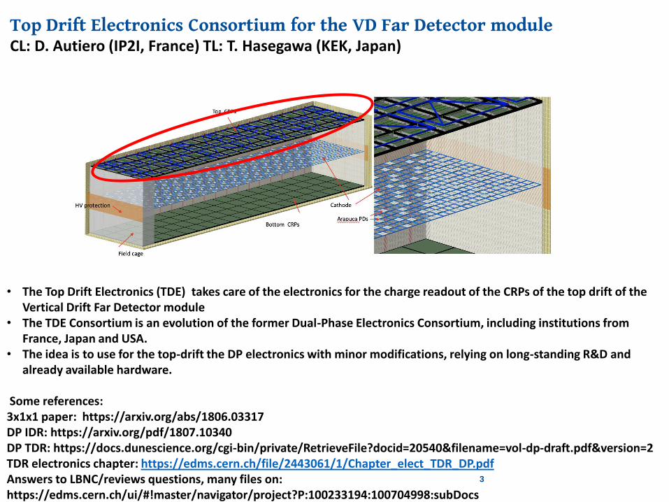
Top Drift Electronics Consortium for the VD Far Detector moduleCL: D. Autiero (IP2I, France) TL: T. Hasegawa (KEK, Japan)
3
• The Top Drift Electronics (TDE) takes care of the electronics for the charge readout of the CRPs of the top drift of the Vertical Drift Far Detector module
• The TDE Consortium is an evolution of the former Dual-Phase Electronics Consortium, including institutions from France, Japan and USA.
• The idea is to use for the top-drift the DP electronics with minor modifications, relying on long-standing R&D and already available hardware.
Some references:3x1x1 paper: https://arxiv.org/abs/1806.03317DP IDR: https://arxiv.org/pdf/1807.10340DP TDR: https://docs.dunescience.org/cgi-bin/private/RetrieveFile?docid=20540&filename=vol-dp-draft.pdf&version=2TDR electronics chapter: https://edms.cern.ch/file/2443061/1/Chapter_elect_TDR_DP.pdfAnswers to LBNC/reviews questions, many files on: https://edms.cern.ch/ui/#!master/navigator/project?P:100233194:100704998:subDocs
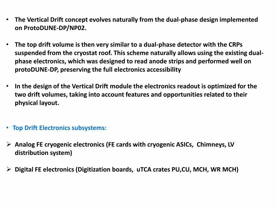
• The Vertical Drift concept evolves naturally from the dual-phase design implemented on ProtoDUNE-DP/NP02.
• The top drift volume is then very similar to a dual-phase detector with the CRPs suspended from the cryostat roof. This scheme naturally allows using the existing dual-phase electronics, which was designed to read anode strips and performed well on protoDUNE-DP, preserving the full electronics accessibility
• In the design of the Vertical Drift module the electronics readout is optimized for the two drift volumes, taking into account features and opportunities related to their physical layout.
• Top Drift Electronics subsystems:
Analog FE cryogenic electronics (FE cards with cryogenic ASICs, Chimneys, LV distribution system)
Digital FE electronics (Digitization boards, uTCA crates PU,CU, MCH, WR MCH)
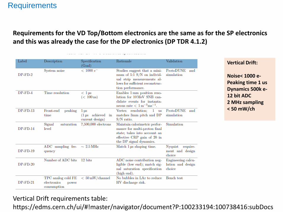
Requirements for the VD Top/Bottom electronics are the same as for the SP electronics and this was already the case for the DP electronics (DP TDR 4.1.2)
Requirements
Vertical Drift:
Noise< 1000 e-Peaking time 1 usDynamics 500k e-12 bit ADC2 MHz sampling< 50 mW/ch
Vertical Drift requirements table:https://edms.cern.ch/ui/#!master/navigator/document?P:100233194:100738416:subDocs
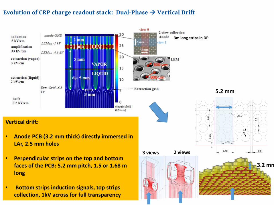
Evolution of CRP charge readout stack: Dual-Phase Vertical Drift
25.01.21 6
Vertical drift:
• Anode PCB (3.2 mm thick) directly immersed in LAr, 2.5 mm holes
• Perpendicular strips on the top and bottom faces of the PCB: 5.2 mm pitch, 1.5 or 1.68 m long
• Bottom strips induction signals, top strips collection, 1kV across for full transparency
5.2 mm
2 views3 views
3.2 mm
3m long strips in DP
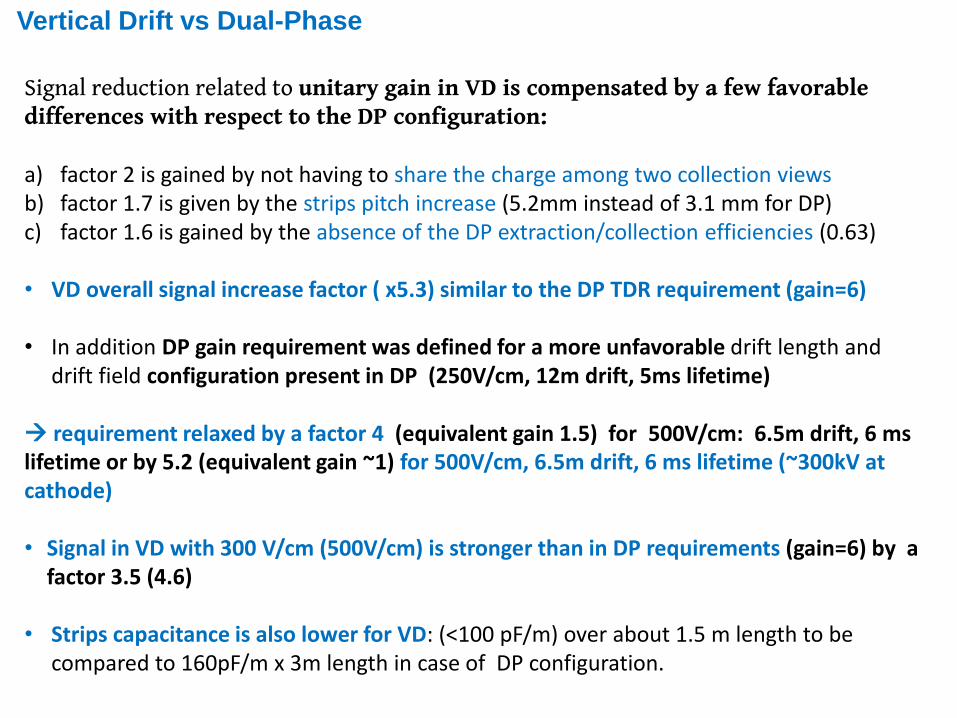
Vertical Drift vs Dual-Phase
Signal reduction related to unitary gain in VD is compensated by a few favorable differences with respect to the DP configuration:
a) factor 2 is gained by not having to share the charge among two collection viewsb) factor 1.7 is given by the strips pitch increase (5.2mm instead of 3.1 mm for DP)c) factor 1.6 is gained by the absence of the DP extraction/collection efficiencies (0.63)
• VD overall signal increase factor ( x5.3) similar to the DP TDR requirement (gain=6)
• In addition DP gain requirement was defined for a more unfavorable drift length and drift field configuration present in DP (250V/cm, 12m drift, 5ms lifetime)
requirement relaxed by a factor 4 (equivalent gain 1.5) for 500V/cm: 6.5m drift, 6 mslifetime or by 5.2 (equivalent gain ~1) for 500V/cm, 6.5m drift, 6 ms lifetime (~300kV at cathode)
• Signal in VD with 300 V/cm (500V/cm) is stronger than in DP requirements (gain=6) by a factor 3.5 (4.6)
• Strips capacitance is also lower for VD: (<100 pF/m) over about 1.5 m length to be compared to 160pF/m x 3m length in case of DP configuration.
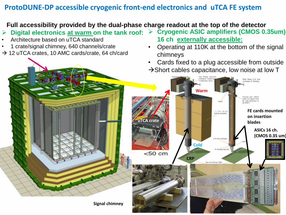
ProtoDUNE-DP accessible cryogenic front-end electronics and uTCA FE system
Cryogenic ASIC amplifiers (CMOS 0.35um)
16 ch externally accessible:
• Operating at 110K at the bottom of the signal
chimneys
• Cards fixed to a plug accessible from outside
Short cables capacitance, low noise at low T
Digital electronics at warm on the tank roof:• Architecture based on uTCA standard
• 1 crate/signal chimney, 640 channels/crate
12 uTCA crates, 10 AMC cards/crate, 64 ch/card
8
ASICs 16 ch.(CMOS 0.35 um)
Full accessibility provided by the dual-phase charge readout at the top of the detector
uTCA crate
Signal chimney
CRP
Warm
Cold
FE cards mountedon insertion blades
9
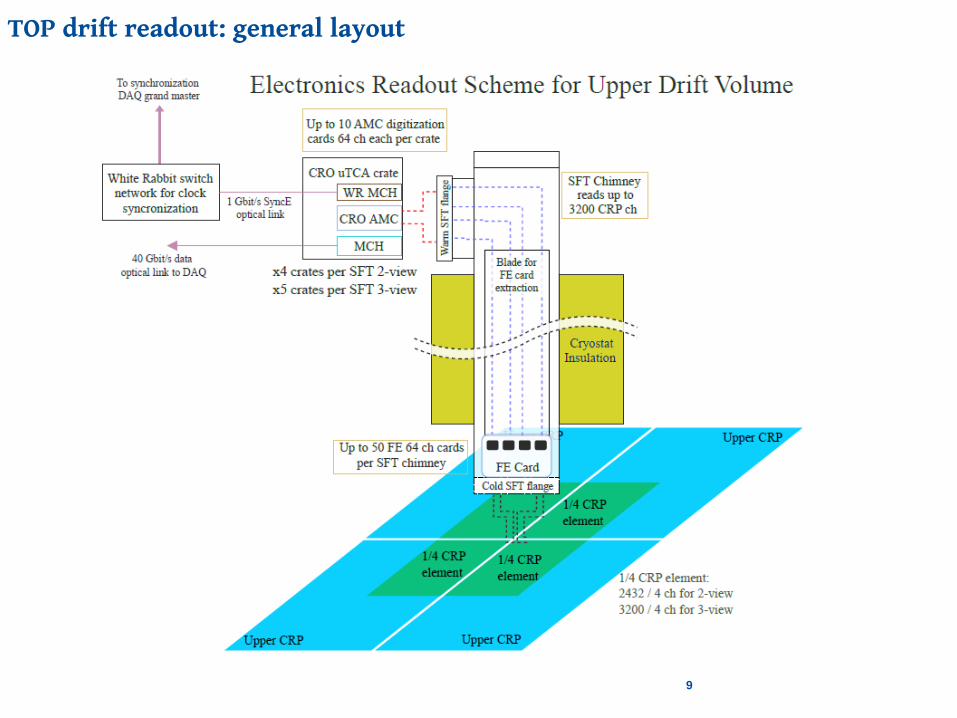
TOP drift readout: general layout
10
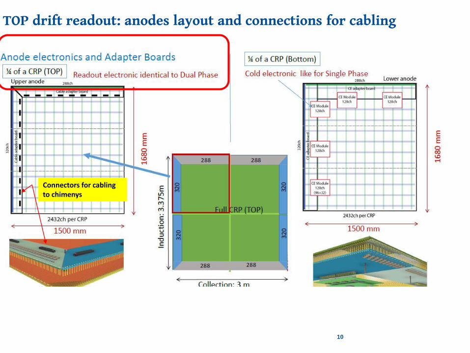
TOP drift readout: anodes layout and connections for cabling
Connectors for cablingto chimenys
11
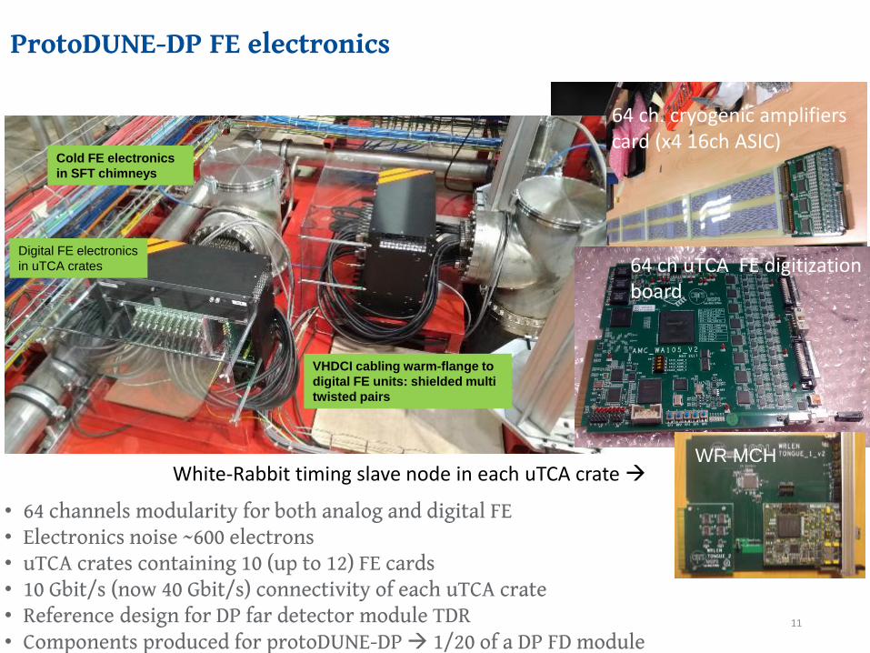
ProtoDUNE-DP FE electronics
• 64 channels modularity for both analog and digital FE• Electronics noise ~600 electrons• uTCA crates containing 10 (up to 12) FE cards• 10 Gbit/s (now 40 Gbit/s) connectivity of each uTCA crate• Reference design for DP far detector module TDR• Components produced for protoDUNE-DP 1/20 of a DP FD module
Digital FE electronics
in uTCA crates
Cold FE electronics
in SFT chimneys
VHDCI cabling warm-flange to
digital FE units: shielded multi
twisted pairs
64 ch. cryogenic amplifiers card (x4 16ch ASIC)
WR MCHWhite-Rabbit timing slave node in each uTCA crate
64 ch uTCA FE digitization board
12
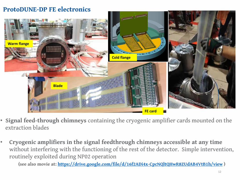
ProtoDUNE-DP FE electronics
• Signal feed-through chimneys containing the cryogenic amplifier cards mounted on the extraction blades
• Cryogenic amplifiers in the signal feedthrough chimneys accessible at any time without interfering with the functioning of the rest of the detector. Simple intervention, routinely exploited during NP02 operation
(see also movie at: https://drive.google.com/file/d/16f2ADi4x-CpcNQltQHwR8ZUdAB4VtB1h/view )
Warm flange
Cold flange
Blade
FE card
13
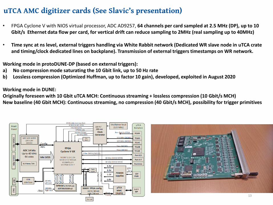
uTCA AMC digitizer cards (See Slavic’s presentation)
• FPGA Cyclone V with NIOS virtual processor, ADC AD9257, 64 channels per card sampled at 2.5 MHz (DP), up to 10 Gbit/s Ethernet data flow per card, for vertical drift can reduce sampling to 2MHz (real sampling up to 40MHz)
• Time sync at ns level, external triggers handling via White Rabbit network (Dedicated WR slave node in uTCA crate and timing/clock dedicated lines on backplane). Transmission of external triggers timestamps on WR network.
Working mode in protoDUNE-DP (based on external triggers): a) No compression mode saturating the 10 Gbit link, up to 50 Hz rateb) Lossless compression (Optimized Huffman, up to factor 10 gain), developed, exploited in August 2020
Working mode in DUNE:Originally foreseen with 10 Gbit uTCA MCH: Continuous streaming + lossless compression (10 Gbit/s MCH)New baseline (40 Gbit MCH): Continuous streaming, no compression (40 Gbit/s MCH), possibility for trigger primitives
14
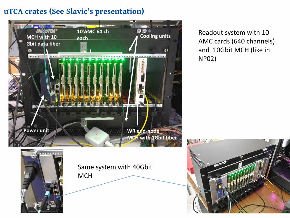
uTCA crates (See Slavic’s presentation)
MCH with 10 Gbit data fiber
Power unit WR end-nodeMCH with 1Gbit fiber
Cooling units10 AMC 64 cheach
Readout system with 10 AMC cards (640 channels) and 10Gbit MCH (like in NP02)
Same system with 40Gbit MCH
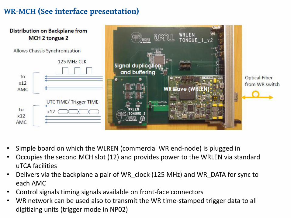
WR-MCH (See interface presentation)
• Simple board on which the WLREN (commercial WR end-node) is plugged in• Occupies the second MCH slot (12) and provides power to the WRLEN via standard
uTCA facilities• Delivers via the backplane a pair of WR_clock (125 MHz) and WR_DATA for sync to
each AMC• Control signals timing signals available on front-face connectors• WR network can be used also to transmit the WR time-stamped trigger data to all
digitizing units (trigger mode in NP02)
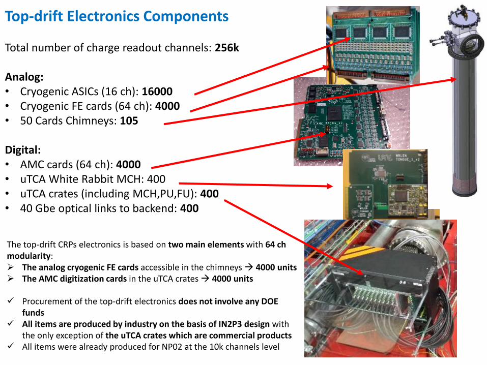
Top-drift Electronics Components
Total number of charge readout channels: 256k
Analog:• Cryogenic ASICs (16 ch): 16000• Cryogenic FE cards (64 ch): 4000• 50 Cards Chimneys: 105
Digital:• AMC cards (64 ch): 4000• uTCA White Rabbit MCH: 400 • uTCA crates (including MCH,PU,FU): 400• 40 Gbe optical links to backend: 400
16
The top-drift CRPs electronics is based on two main elements with 64 chmodularity: The analog cryogenic FE cards accessible in the chimneys 4000 units The AMC digitization cards in the uTCA crates 4000 units
Procurement of the top-drift electronics does not involve any DOE funds
All items are produced by industry on the basis of IN2P3 design with the only exception of the uTCA crates which are commercial products
All items were already produced for NP02 at the 10k channels level
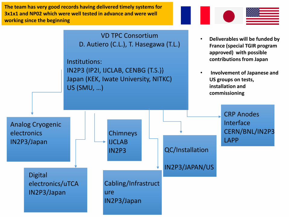
VD TPC ConsortiumD. Autiero (C.L.), T. Hasegawa (T.L.)
Institutions:IN2P3 (IP2I, IJCLAB, CENBG (T.S.))Japan (KEK, Iwate University, NITKC)US (SMU, …)
Analog Cryogenic electronicsIN2P3/Japan
Digital electronics/uTCAIN2P3/Japan
ChimneysIJCLABIN2P3
Cabling/InfrastructureIN2P3/Japan
QC/Installation
IN2P3/JAPAN/US
CRP Anodes InterfaceCERN/BNL/IN2P3LAPP
The team has very good records having delivered timely systems for 3x1x1 and NP02 which were well tested in advance and were wellworking since the beginning
• Deliverables will be funded by France (special TGIR program approved) with possible contributions from Japan
• Involvement of Japanese and US groups on tests, installation and commissioning
18
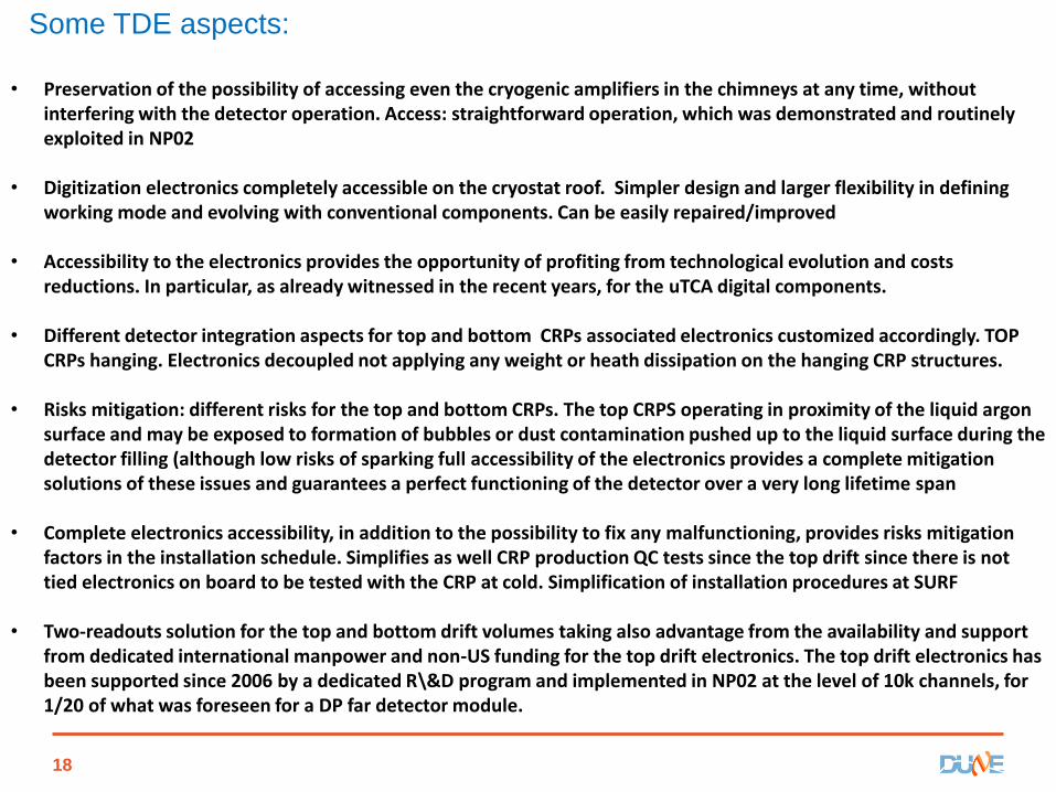
• Preservation of the possibility of accessing even the cryogenic amplifiers in the chimneys at any time, without interfering with the detector operation. Access: straightforward operation, which was demonstrated and routinely exploited in NP02
• Digitization electronics completely accessible on the cryostat roof. Simpler design and larger flexibility in defining working mode and evolving with conventional components. Can be easily repaired/improved
• Accessibility to the electronics provides the opportunity of profiting from technological evolution and costs reductions. In particular, as already witnessed in the recent years, for the uTCA digital components.
• Different detector integration aspects for top and bottom CRPs associated electronics customized accordingly. TOP CRPs hanging. Electronics decoupled not applying any weight or heath dissipation on the hanging CRP structures.
• Risks mitigation: different risks for the top and bottom CRPs. The top CRPS operating in proximity of the liquid argon surface and may be exposed to formation of bubbles or dust contamination pushed up to the liquid surface during the detector filling (although low risks of sparking full accessibility of the electronics provides a complete mitigation solutions of these issues and guarantees a perfect functioning of the detector over a very long lifetime span
• Complete electronics accessibility, in addition to the possibility to fix any malfunctioning, provides risks mitigation factors in the installation schedule. Simplifies as well CRP production QC tests since the top drift since there is not tied electronics on board to be tested with the CRP at cold. Simplification of installation procedures at SURF
• Two-readouts solution for the top and bottom drift volumes taking also advantage from the availability and support from dedicated international manpower and non-US funding for the top drift electronics. The top drift electronics has been supported since 2006 by a dedicated R\&D program and implemented in NP02 at the level of 10k channels, for 1/20 of what was foreseen for a DP far detector module.
Some TDE aspects:
19
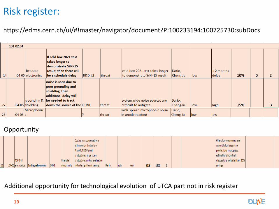
Risk register:
https://edms.cern.ch/ui/#!master/navigator/document?P:100233194:100725730:subDocs
Opportunity
Additional opportunity for technological evolution of uTCA part not in risk register
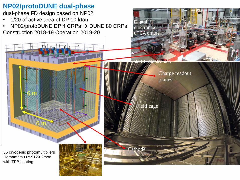
36 cryogenic photomultipliers
Hamamatsu R5912-02mod
with TPB coating
Cathode
Field cage
Charge readout
planes
Digital
electronics in
uTCA crates
Cold FE electronics
NP02/protoDUNE dual-phasedual-phase FD design based on NP02:
• 1/20 of active area of DP 10 kton
• NP02/protoDUNE DP 4 CRPs DUNE 80 CRPs
Construction 2018-19 Operation 2019-20
6 m
6 m
21
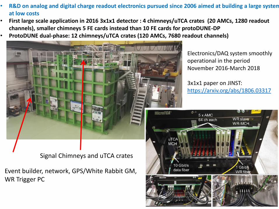
Event builder, network, GPS/White Rabbit GM,WR Trigger PC
Signal Chimneys and uTCA crates
• R&D on analog and digital charge readout electronics pursued since 2006 aimed at building a large system at low costs
• First large scale application in 2016 3x1x1 detector : 4 chimneys/uTCA crates (20 AMCs, 1280 readout channels), smaller chimneys 5 FE cards instead than 10 FE cards for protoDUNE-DP
• ProtoDUNE dual-phase: 12 chimneys/uTCA crates (120 AMCs, 7680 readout channels)
Electronics/DAQ system smoothly operational in the period November 2016-March 2018
3x1x1 paper on JINST: https://arxiv.org/abs/1806.03317
22
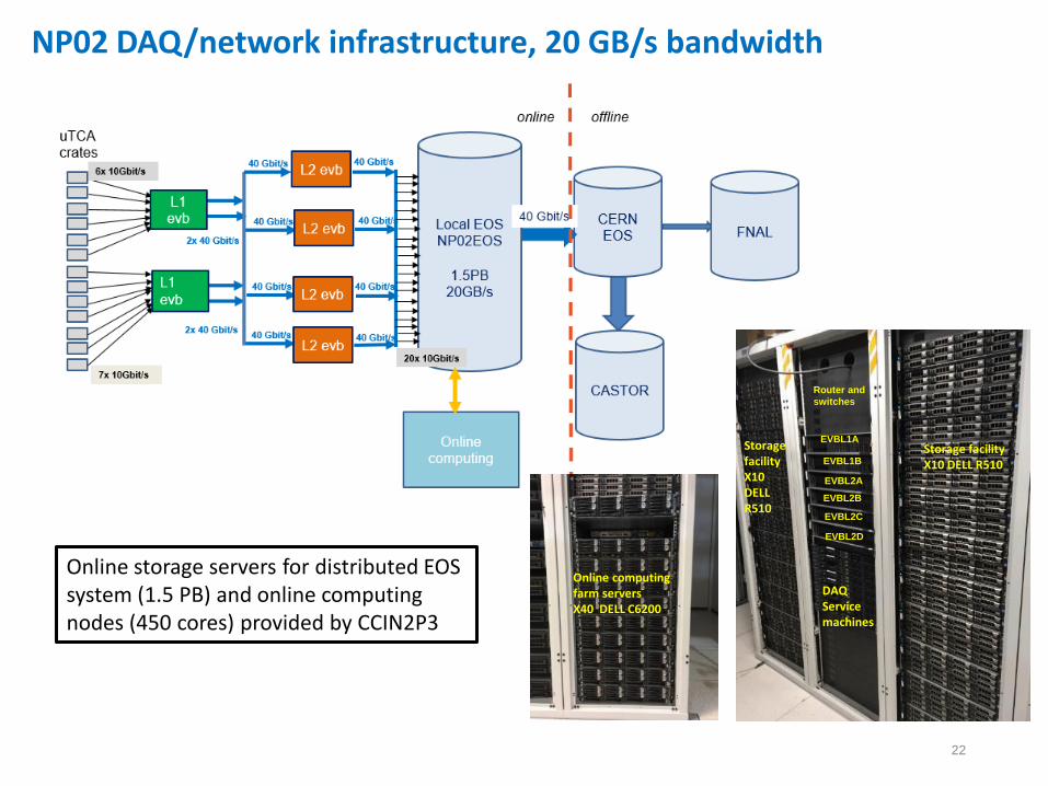
NP02 DAQ/network infrastructure, 20 GB/s bandwidth
Online storage servers for distributed EOS system (1.5 PB) and online computing nodes (450 cores) provided by CCIN2P3
Storage facilityX10 DELL R510
Storage facilityX10 DELLR510
DAQService machines
EVBL1A
EVBL1B
EVBL2A
EVBL2B
EVBL2C
EVBL2D
Router and
switches
Online computing farm serversX40 DELL C6200
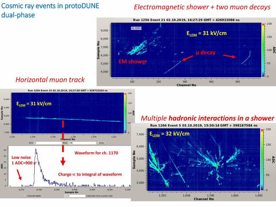
Multiple hadronic interactions in a shower
Electromagnetic shower + two muon decays
Horizontal muon track
Waveform for ch. 1170Low noise1 ADC=900 e
Charge to integral of waveform
ELEM = 31 kV/cm
ELEM = 31 kV/cm
µ decay
EM shower
ELEM = 32 kV/cm
Cosmic ray events in protoDUNE dual-phase
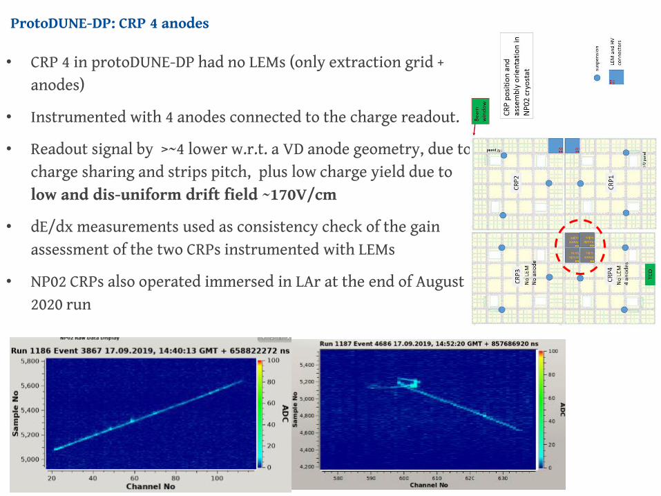
ProtoDUNE-DP: CRP 4 anodes
25.01.21 24
• CRP 4 in protoDUNE-DP had no LEMs (only extraction grid + anodes)
• Instrumented with 4 anodes connected to the charge readout.
• Readout signal by >~4 lower w.r.t. a VD anode geometry, due to charge sharing and strips pitch, plus low charge yield due to low and dis-uniform drift field ~170V/cm
• dE/dx measurements used as consistency check of the gain assessment of the two CRPs instrumented with LEMs
• NP02 CRPs also operated immersed in LAr at the end of August 2020 run
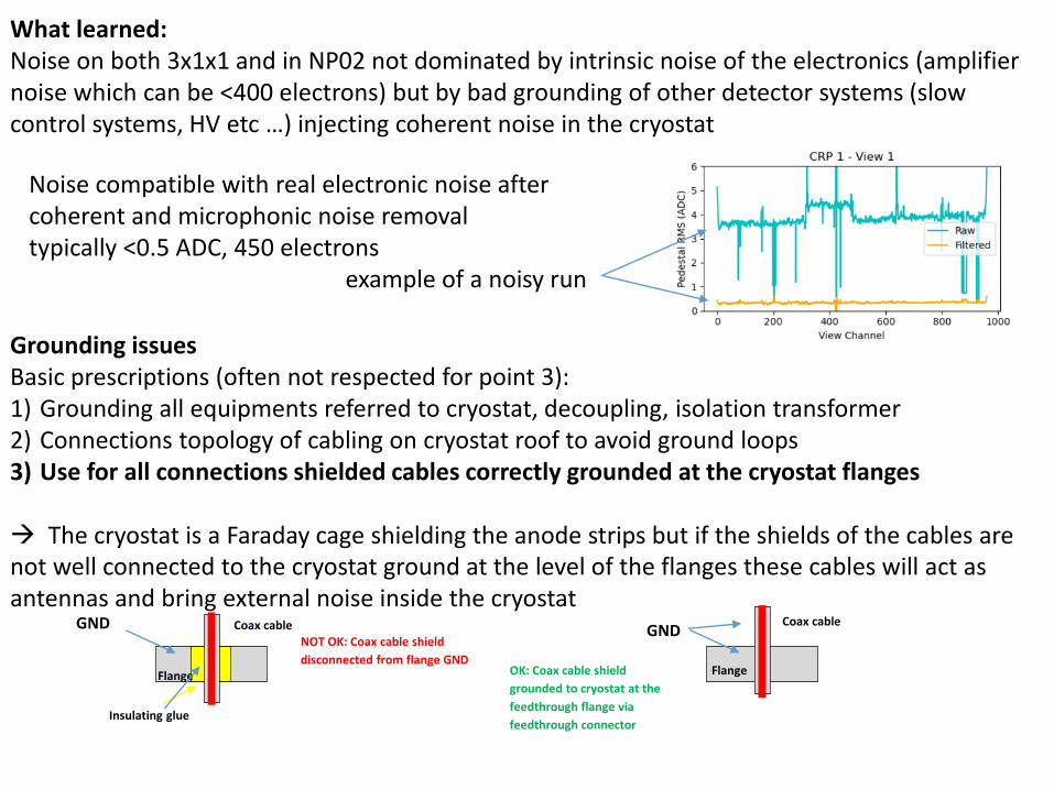
What learned:Noise on both 3x1x1 and in NP02 not dominated by intrinsic noise of the electronics (amplifier noise which can be <400 electrons) but by bad grounding of other detector systems (slow control systems, HV etc …) injecting coherent noise in the cryostat
Grounding issuesBasic prescriptions (often not respected for point 3):1) Grounding all equipments referred to cryostat, decoupling, isolation transformer2) Connections topology of cabling on cryostat roof to avoid ground loops3) Use for all connections shielded cables correctly grounded at the cryostat flanges
The cryostat is a Faraday cage shielding the anode strips but if the shields of the cables are not well connected to the cryostat ground at the level of the flanges these cables will act as antennas and bring external noise inside the cryostat
GND Coax cable
Flange
Insulating glue
NOT OK: Coax cable shield
disconnected from flange GND
GND
Flange
Coax cable
OK: Coax cable shield
grounded to cryostat at the
feedthrough flange via
feedthrough connector
Noise compatible with real electronic noise aftercoherent and microphonic noise removaltypically <0.5 ADC, 450 electrons
example of a noisy run
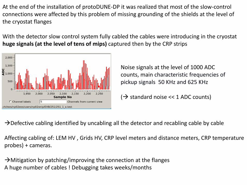
At the end of the installation of protoDUNE-DP it was realized that most of the slow-control connections were affected by this problem of missing grounding of the shields at the level of the cryostat flanges
With the detector slow control system fully cabled the cables were introducing in the cryostat huge signals (at the level of tens of mips) captured then by the CRP strips
Noise signals at the level of 1000 ADC counts, main characteristic frequencies of pickup signals 50 KHz and 625 KHz
( standard noise << 1 ADC counts)
Defective cabling identified by uncabling all the detector and recabling cable by cable
Affecting cabling of: LEM HV , Grids HV, CRP level meters and distance meters, CRP temperature probes) + cameras.
Mitigation by patching/improving the connection at the flangesA huge number of cables ! Debugging takes weeks/months
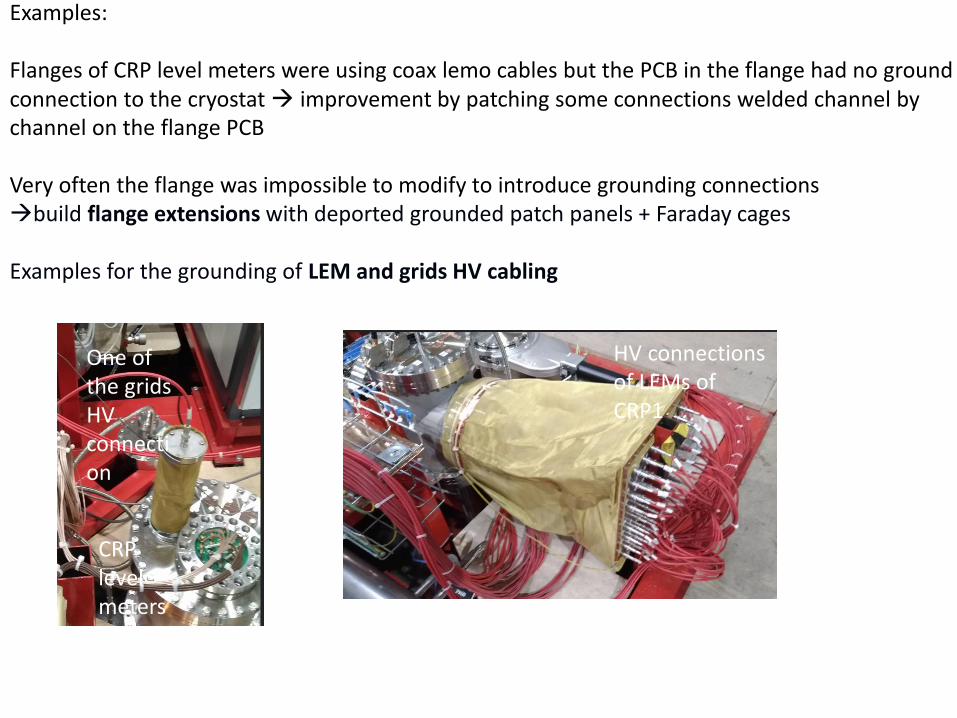
Examples:
Flanges of CRP level meters were using coax lemo cables but the PCB in the flange had no ground connection to the cryostat improvement by patching some connections welded channel by channel on the flange PCB
Very often the flange was impossible to modify to introduce grounding connectionsbuild flange extensions with deported grounded patch panels + Faraday cages
Examples for the grounding of LEM and grids HV cabling
One of the grids HV connection
HV connections of LEMs of CRP1
CRP levelmeters
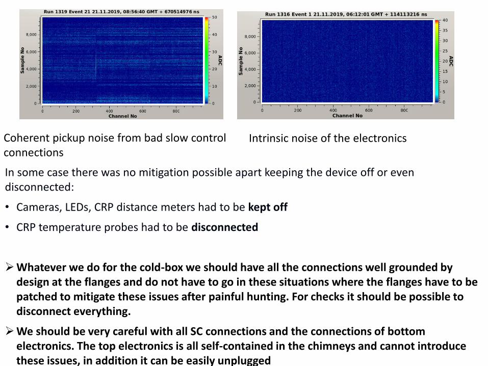
In some case there was no mitigation possible apart keeping the device off or even disconnected:
• Cameras, LEDs, CRP distance meters had to be kept off
• CRP temperature probes had to be disconnected
Whatever we do for the cold-box we should have all the connections well grounded by design at the flanges and do not have to go in these situations where the flanges have to be patched to mitigate these issues after painful hunting. For checks it should be possible to disconnect everything.
We should be very careful with all SC connections and the connections of bottom electronics. The top electronics is all self-contained in the chimneys and cannot introduce these issues, in addition it can be easily unplugged
Coherent pickup noise from bad slow control connections
Intrinsic noise of the electronics
29
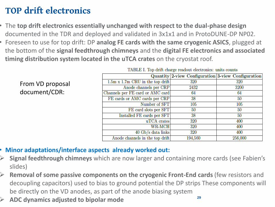
TOP drift electronics
• The top drift electronics essentially unchanged with respect to the dual-phase design documented in the TDR and deployed and validated in 3x1x1 and in ProtoDUNE-DP NP02.
• Foreseen to use for top drift: DP analog FE cards with the same cryogenic ASICS, plugged at the bottom of the signal feedthrough chimneys and the digital FE electronics and associated timing distribution system located in the uTCA crates on the cryostat roof.
• Minor adaptations/interface aspects already worked out: Signal feedthrough chimneys which are now larger and containing more cards (see Fabien’s
slides) Removal of some passive components on the cryogenic Front-End cards (few resistors and
decoupling capacitors) used to bias to ground potential the DP strips These components will be directly on the VD anodes, as part of the anode biasing system
ADC dynamics adjusted to bipolar mode
From VD proposaldocument/CDR:
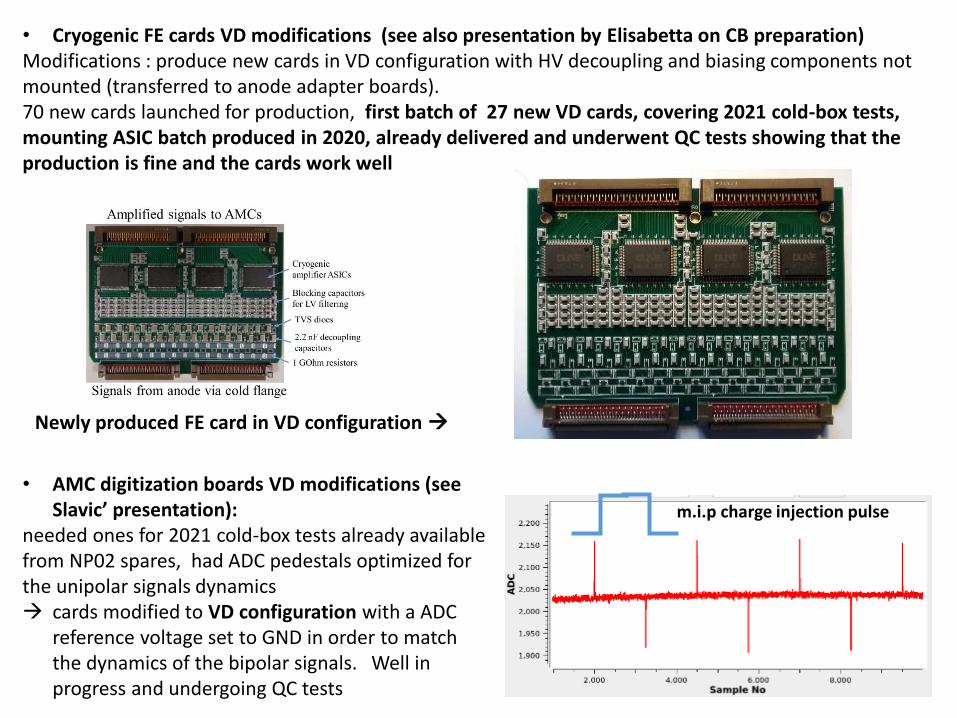
• Cryogenic FE cards VD modifications (see also presentation by Elisabetta on CB preparation)Modifications : produce new cards in VD configuration with HV decoupling and biasing components not mounted (transferred to anode adapter boards). 70 new cards launched for production, first batch of 27 new VD cards, covering 2021 cold-box tests, mounting ASIC batch produced in 2020, already delivered and underwent QC tests showing that the production is fine and the cards work well
Newly produced FE card in VD configuration
• AMC digitization boards VD modifications (see Slavic’ presentation):
needed ones for 2021 cold-box tests already available from NP02 spares, had ADC pedestals optimized for the unipolar signals dynamics cards modified to VD configuration with a ADC
reference voltage set to GND in order to match the dynamics of the bipolar signals. Well in progress and undergoing QC tests
m.i.p charge injection pulse
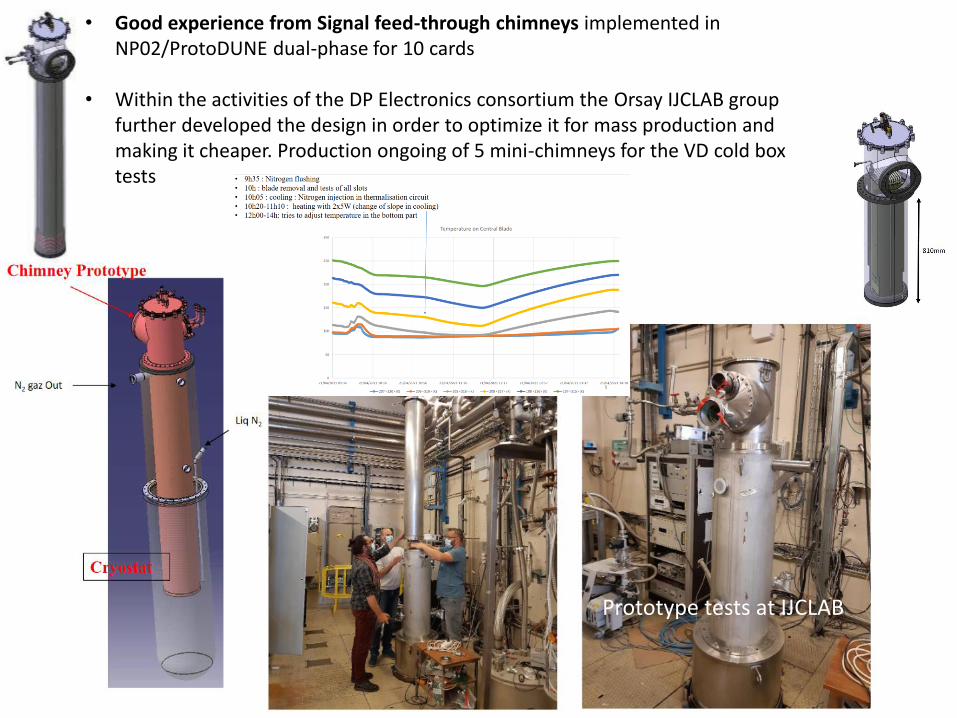
• Good experience from Signal feed-through chimneys implemented in NP02/ProtoDUNE dual-phase for 10 cards
• Within the activities of the DP Electronics consortium the Orsay IJCLAB group further developed the design in order to optimize it for mass production and making it cheaper. Production ongoing of 5 mini-chimneys for the VD cold box tests
Prototype tests at IJCLAB
32
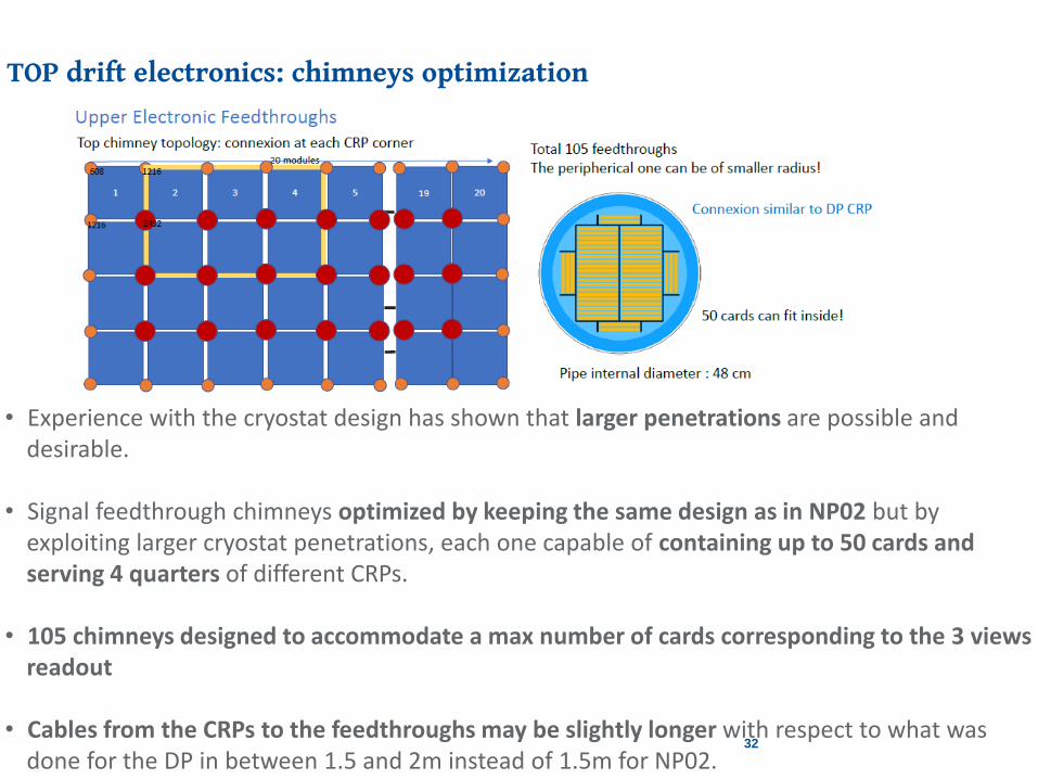
TOP drift electronics: chimneys optimization
• Experience with the cryostat design has shown that larger penetrations are possible and desirable.
• Signal feedthrough chimneys optimized by keeping the same design as in NP02 but by exploiting larger cryostat penetrations, each one capable of containing up to 50 cards and serving 4 quarters of different CRPs.
• 105 chimneys designed to accommodate a max number of cards corresponding to the 3 views readout
• Cables from the CRPs to the feedthroughs may be slightly longer with respect to what was done for the DP in between 1.5 and 2m instead of 1.5m for NP02.
33
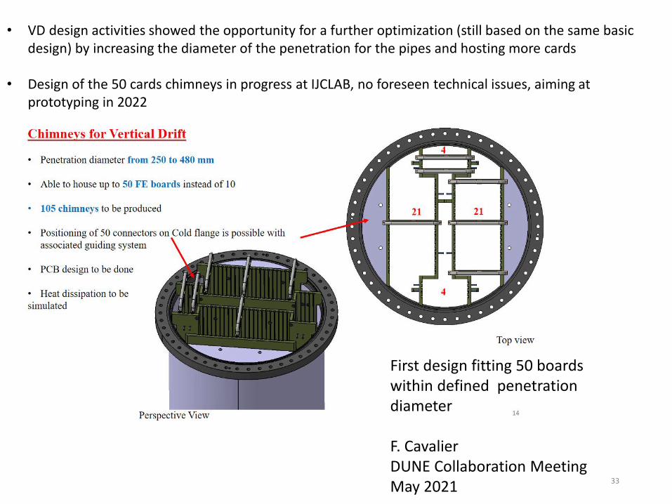
• VD design activities showed the opportunity for a further optimization (still based on the same basic design) by increasing the diameter of the penetration for the pipes and hosting more cards
• Design of the 50 cards chimneys in progress at IJCLAB, no foreseen technical issues, aiming at prototyping in 2022
First design fitting 50 boards within defined penetration diameter
F. CavalierDUNE Collaboration Meeting May 2021
34
TDE – TOP Drift CRPs interface (see interface talks)
34
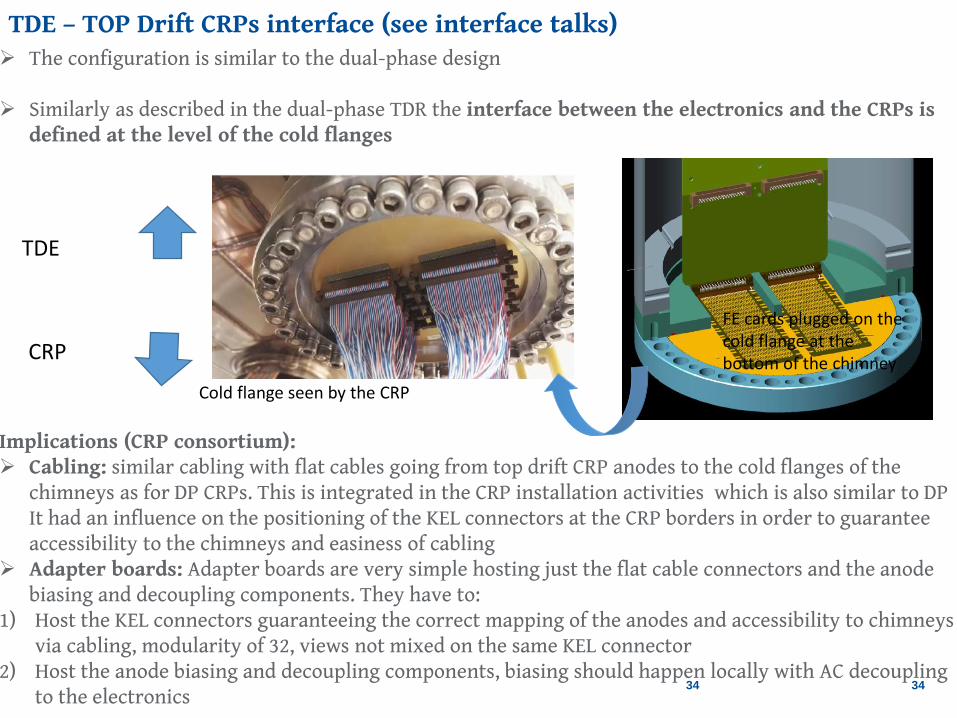
The configuration is similar to the dual-phase design
Similarly as described in the dual-phase TDR the interface between the electronics and the CRPs is defined at the level of the cold flanges
Implications (CRP consortium): Cabling: similar cabling with flat cables going from top drift CRP anodes to the cold flanges of the
chimneys as for DP CRPs. This is integrated in the CRP installation activities which is also similar to DP It had an influence on the positioning of the KEL connectors at the CRP borders in order to guarantee accessibility to the chimneys and easiness of cabling
Adapter boards: Adapter boards are very simple hosting just the flat cable connectors and the anode biasing and decoupling components. They have to:
1) Host the KEL connectors guaranteeing the correct mapping of the anodes and accessibility to chimneys via cabling, modularity of 32, views not mixed on the same KEL connector
2) Host the anode biasing and decoupling components, biasing should happen locally with AC decoupling to the electronics
FE cards plugged on the cold flange at the bottom of the chimney
Cold flange seen by the CRP
TDE
CRP

Vertical-Drift 2021 activities at the CERN Neutrino Platform in 2021-2023• Substituting the already planned DP Phase II tests activities foreseen with the cold-box built in 2018 for
individual CRP tests. Cold-box modified and upgraded from the DP configuration and moved to EHN1.
• Parallel tests of new simplified HV extender design in ProtoDUNE dual-phase/NP02. • Continuation of the cold-box tests campaign in 2022 to define final CRPs for module-0• Module-0 operation in NP02 cryostat foreseen in 2023
Cold-box tests of new CRPs • Dual-phase cold box refurbished and
installed at EHN1 side by side to NP02 by April 2021
• Since June 2021 integration at CERN of all components and commissioning
• First cold-box cycle of a CRP since the end of September 2021
• Tests activity continued in 2022 in preparation for Module-0
protoDUNE-DP/NP02 HV test:• Access to NP02 after warming up February
2021• Removal and insertion of new HV extender
March-June 2021• Cool-down and filling of NP02 July-August 2021• Operation and HV test September-November
2021
CRP
3 m
36
TDE Consortium 2021 test activities (see Elisabetta’s talk):
36
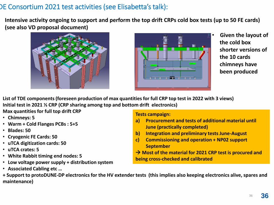
• Intensive activity ongoing to support and perform the top drift CRPs cold box tests (up to 50 FE cards) (see also VD proposal document)
• Given the layout of the cold box shorter versions of the 10 cards chimneys have been produced
List of TDE components (foreseen production of max quantities for full CRP top test in 2022 with 3 views)Initial test in 2021 ½ CRP (CRP sharing among top and bottom drift electronics)Max quantities for full top drift CRP• Chimneys: 5 • Warm + Cold Flanges PCBs : 5+5 • Blades: 50 • Cryogenic FE Cards: 50 • uTCA digitization cards: 50 • uTCA crates: 5• White Rabbit timing end nodes: 5 • Low voltage power supply + distribution system• Associated Cabling etc …+ Support to protoDUNE-DP electronics for the HV extender tests (this implies also keeping electronics alive, spares and maintenance)
Tests campaign:a) Procurement and tests of additional material until
June (practically completed)b) Integration and preliminary tests June-Augustc) Commissioning and operation + NP02 support
September Most of the material for 2021 CRP test is procured and being cross-checked and calibrated
37
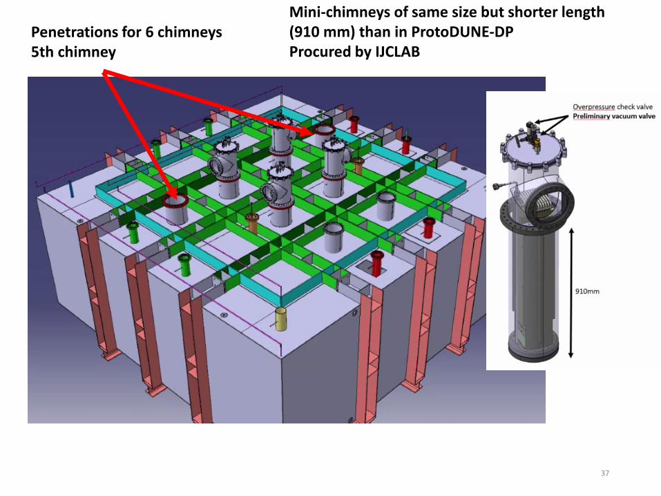
Penetrations for 6 chimneys5th chimney
Mini-chimneys of same size but shorter length (910 mm) than in ProtoDUNE-DPProcured by IJCLAB
38
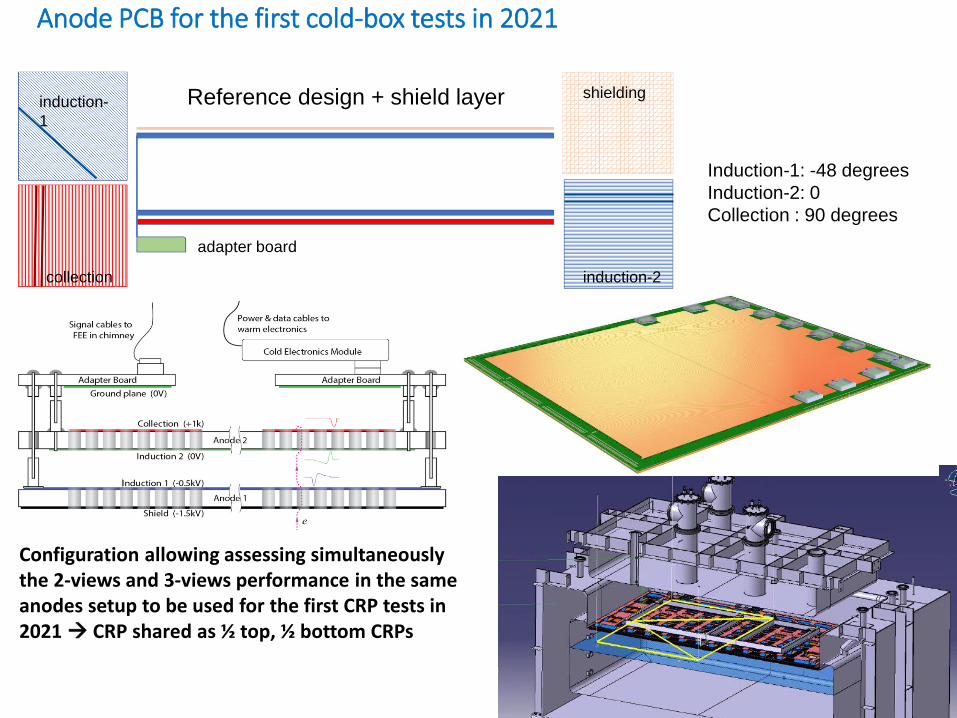
Anode PCB for the first cold-box tests in 2021
Reference design + shield layer shieldinginduction-
1
induction-2
adapter board
collection
Induction-1: -48 degrees
Induction-2: 0
Collection : 90 degrees
Configuration allowing assessing simultaneously the 2-views and 3-views performance in the same anodes setup to be used for the first CRP tests in 2021 CRP shared as ½ top, ½ bottom CRPs
39
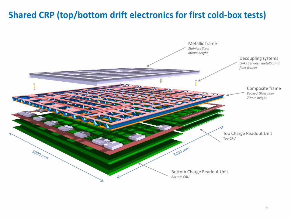
Composite frameEpoxy / Glass fiber70mm height
Decoupling systemsLinks between metallic and fiber frames
Metallic frameStainless Steel80mm height
Top Charge Readout Unit Top CRU
Bottom Charge Readout Unit Bottom CRU
Shared CRP (top/bottom drift electronics for first cold-box tests)
40
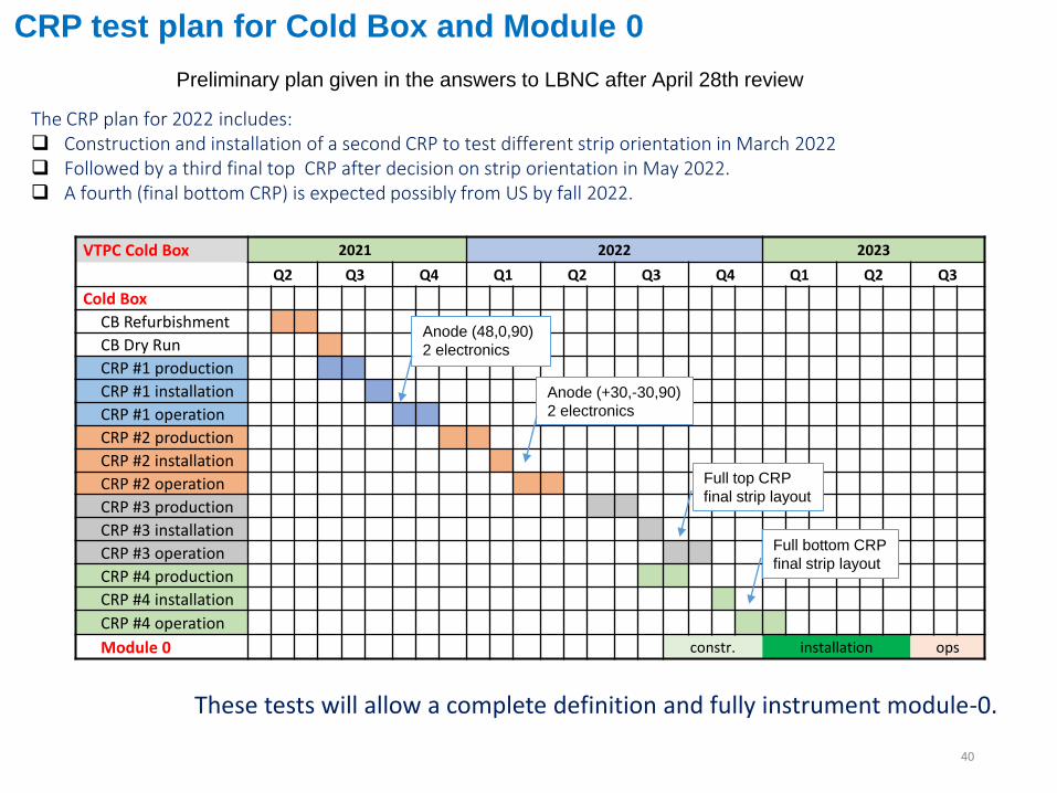
CRP test plan for Cold Box and Module 0
VTPC Cold Box 2021 2022 2023
Q2 Q3 Q4 Q1 Q2 Q3 Q4 Q1 Q2 Q3
Cold Box
CB Refurbishment
CB Dry Run
CRP #1 production
CRP #1 installation
CRP #1 operation
CRP #2 production
CRP #2 installation
CRP #2 operation
CRP #3 production
CRP #3 installation
CRP #3 operation
CRP #4 production
CRP #4 installation
CRP #4 operation
Module 0 constr. installation ops
The CRP plan for 2022 includes: Construction and installation of a second CRP to test different strip orientation in March 2022 Followed by a third final top CRP after decision on strip orientation in May 2022. A fourth (final bottom CRP) is expected possibly from US by fall 2022.
Preliminary plan given in the answers to LBNC after April 28th review
Anode (48,0,90)
2 electronics
Anode (+30,-30,90)
2 electronics
Full top CRP
final strip layout
Full bottom CRP
final strip layout
These tests will allow a complete definition and fully instrument module-0.
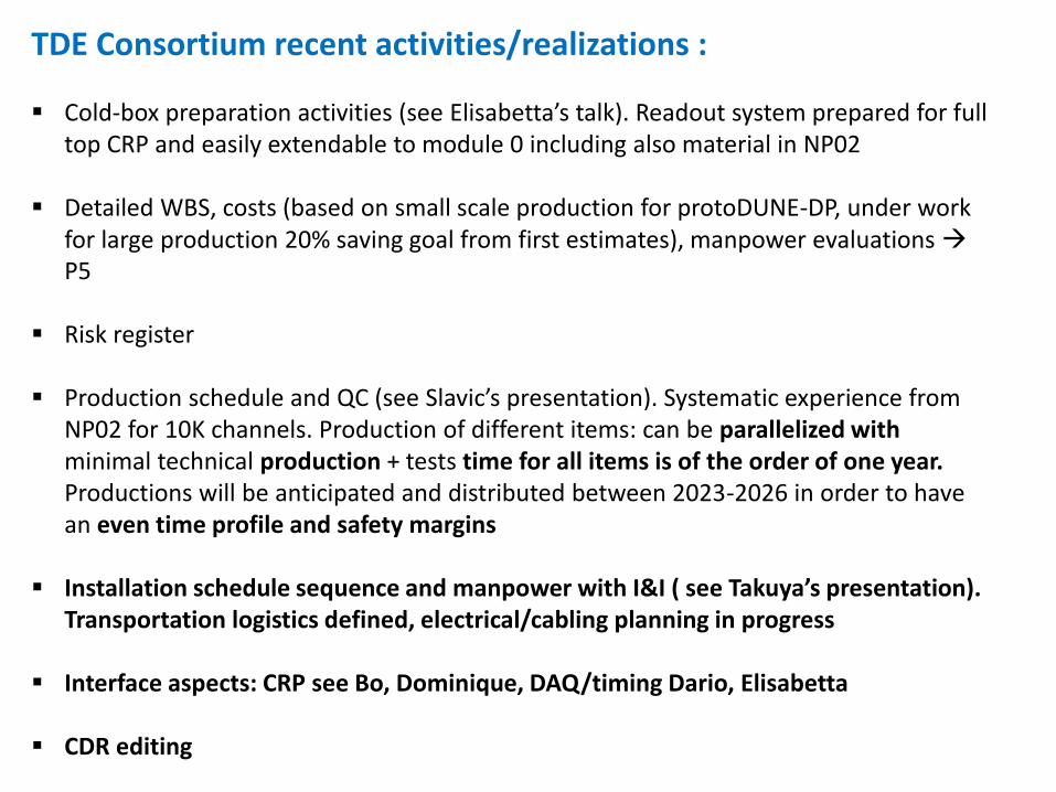
TDE Consortium recent activities/realizations :
Cold-box preparation activities (see Elisabetta’s talk). Readout system prepared for full top CRP and easily extendable to module 0 including also material in NP02
Detailed WBS, costs (based on small scale production for protoDUNE-DP, under work for large production 20% saving goal from first estimates), manpower evaluations P5
Risk register
Production schedule and QC (see Slavic’s presentation). Systematic experience from NP02 for 10K channels. Production of different items: can be parallelized with minimal technical production + tests time for all items is of the order of one year. Productions will be anticipated and distributed between 2023-2026 in order to have an even time profile and safety margins
Installation schedule sequence and manpower with I&I ( see Takuya’s presentation). Transportation logistics defined, electrical/cabling planning in progress
Interface aspects: CRP see Bo, Dominique, DAQ/timing Dario, Elisabetta
CDR editing
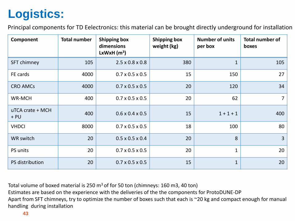
Logistics:
43
Component Total number Shipping boxdimensionsLxWxH (m3)
Shipping box weight (kg)
Number of units per box
Total number of boxes
SFT chimney 105 2.5 x 0.8 x 0.8 380 1 105
FE cards 4000 0.7 x 0.5 x 0.5 15 150 27
CRO AMCs 4000 0.7 x 0.5 x 0.5 20 120 34
WR-MCH 400 0.7 x 0.5 x 0.5 20 62 7
uTCA crate + MCH + PU
400 0.6 x 0.4 x 0.5 15 1 + 1 + 1 400
VHDCI 8000 0.7 x 0.5 x 0.5 18 100 80
WR switch 20 0.5 x 0.5 x 0.4 20 8 3
PS units 20 0.7 x 0.5 x 0.5 20 1 20
PS distribution 20 0.7 x 0.5 x 0.5 15 1 20
Principal components for TD Eelectronics: this material can be brought directly underground for installation
Total volume of boxed material is 250 m3 of for 50 ton (chimneys: 160 m3, 40 ton) Estimates are based on the experience with the deliveries of the the components for ProtoDUNE-DPApart from SFT chimneys, try to optimize the number of boxes such that each is ~20 kg and compact enough for manual handling during installation
44
Conclusions:
• The top drift electronics for the vertical drift capitalizes on the dual-phase electronics design documented in the TDR and successfully deployed in NP02. This is the outcome of a long R&D effort started in 2006. The main elements can be used with little modifications
• This scheme preserves interesting features such as the complete external accessibility of the electronics (including the cryogenic amplifiers) guaranteeing risks minimization and perfect functioning over a very long lifetime span as well as the possibility of profiting of technological/economical evolutions
• Chimneys layout optimized by exploiting larger cryostat penetrations
• Top drift readout layout compatible with both 2/3 views anode readout (+31% channels with 3 views) assumed conservatively as baseline in CDR.
• Full scale integration test with first VD top drift CRP foreseen in 2021 with cold-box program. Preparation of different elements well advanced
• Focus on productions and installation preparation (dedicated discussion at LBNC and at the DUNE collaboration meeting last week), dedicated meetings with DUNE TC happening during the last couple of months with all DUNE Consortia for VD for the CDR and CDR1RR process

45
46
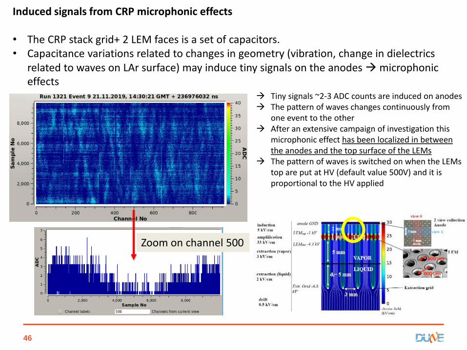
Induced signals from CRP microphonic effects
• The CRP stack grid+ 2 LEM faces is a set of capacitors. • Capacitance variations related to changes in geometry (vibration, change in dielectrics
related to waves on LAr surface) may induce tiny signals on the anodes microphonic effects
Tiny signals ~2-3 ADC counts are induced on anodes The pattern of waves changes continuously from
one event to the other After an extensive campaign of investigation this
microphonic effect has been localized in between the anodes and the top surface of the LEMs
The pattern of waves is switched on when the LEMs top are put at HV (default value 500V) and it is proportional to the HV applied
Zoom on channel 500
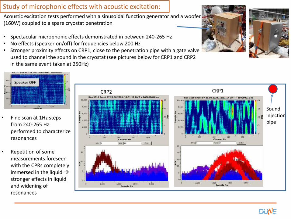
Acoustic excitation tests performed with a sinusoidal function generator and a woofer (160W) coupled to a spare cryostat penetration
• Spectacular microphonic effects demonstrated in between 240-265 Hz• No effects (speaker on/off) for frequencies below 200 Hz• Stronger proximity effects on CRP1, close to the penetration pipe with a gate valve
used to channel the sound in the cryostat (see pictures below for CRP1 and CRP2 in the same event taken at 250Hz)
Speaker OFF
CRP1CRP2
Sound injection pipe
• Fine scan at 1Hz steps from 240-265 Hz performed to characterize resonances
• Repetition of some measurements foreseen with the CPRs completely immersed in the liquid stronger effects in liquid and widening of resonances
Study of microphonic effects with acoustic excitation:


![9Z[RS SR_ Z_ T]Rddc``^ gR]ZU cf]Vd](https://static.fdokumen.com/doc/165x107/63326f1e3108fad7760e9f01/9zrs-sr-z-trddc-grzu-cfvd.jpg)

![CfddZR hV]T`^Vd :_UZR Rd ^VUZRe`c - Daily Pioneer](https://static.fdokumen.com/doc/165x107/632441dff021b67e740875e1/cfddzr-hvtvd-uzr-rd-vuzrec-daily-pioneer.jpg)