Tools for performance simulation of heat, air and moisture ...
20
E-mail: [email protected] Tools for Performance Simulation of Heat, Air and Moisture Conditions of Whole Buildings Monika Woloszyn 1 , Carsten Rode 2 ( ) 1. Université de Lyon, Lyon, F-69003, France; Université Lyon1, Villeurbanne, F-69622; INSA-Lyon, CNRS, UMR5008, CETHIL, INSA-Lyon, bat. Sadi Carnot, 69621 Villeurbanne CEDEX, France 2. Technical University of Denmark, Brovej, Bygning 118, DTU, DK-2800 Kgs. Lyngby, Denmark Received: 21 November 2007 / Revised: 18 January 2008 / Accepted: 28 January 2008 © Tsinghua Press and Springer-Verlag 2008 Abstract Humidity of indoor air is an important factor influencing the air quality and energy con- sumption of buildings as well as durability of building components. Indoor humidity depends on several factors, such as moisture sources, air change, sorption in materials and possible condensation. Since all these phenomena are strongly dependent on each other, numerical predictions of indoor humidity need to be integrated into combined heat and airflow simulation tools. The purpose of a recent international collaborative project, IEA ECBCS Annex 41, has been to advance development in modelling the integral heat, air and moisture transfer processes that take place in “whole buildings” by considering all relevant parts of its constituents. It is believed that full understanding of these processes for the whole building is absolutely crucial for future energy optimization of buildings, as this cannot take place without a coherent and complete description of all hygrothermal processes. This paper will illustrate some of the modelling work that has taken place within the project and present some of the simulation tools used. Keywords modelling, heat, air, moisture, whole building 1 Introduction Humidity of indoor air is an important factor influencing energy consumption of buildings, durability of building components, and the perceived air quality. Indoor humidity depends on several factors, such as moisture sources, airflows, and moisture exchange with materials. As all these phenomena are strongly dependent on each other, numerical predictions of indoor humidity need to be integrated into combined heat and airflow simulation tools. During the past few decades there has been quite some development and increased professional use of tools to simulate some of the processes that are involved in analysis of whole building Heat, Air, and Moisture (HAM) conditions. For instance, fairly comprehensive tools for transient building energy simulation have been well established for more than a decade. A list of such tools can be seen in www.eere.energy.gov/buildings/tools_directory/ and in Crawley et al. (2005). However, the building energy simu- lation tools have so far not been well suited to predict moisture transfer processes in buildings. Airflow simulation tools and Computational Fluid Dynamics (CFD) codes are available which either at a bulk level or in fine volume elements can predict airflow within and between zones of a building, as well as air exchange with the outdoor environment. Some of the tools deal with airborne moisture transport and also represent the heat transfer in the air and in the envelope. However, in general these tools cannot be used to predict moisture exchange between the air in a zone and its adjacent porous walls. Detailed, transient tools have been developed for combined heat, air and moisture transfer within individual constructions that form the building envelope (Hens 2002). Many HAM tools for building envelope simulations require that the indoor environment is specified by the user. However, Build Simul (2008) 1: 5 –24 DOI 10.1007/s12273-008-8106-z REVIEW ARTICLE
-
Upload
khangminh22 -
Category
Documents
-
view
0 -
download
0
Transcript of Tools for performance simulation of heat, air and moisture ...

E-mail: [email protected]
Tools for Performance Simulation of Heat, Air and Moisture Conditions of Whole Buildings
Monika Woloszyn1, Carsten Rode2 ( )
1. Université de Lyon, Lyon, F-69003, France; Université Lyon1, Villeurbanne, F-69622; INSA-Lyon, CNRS, UMR5008, CETHIL, INSA-Lyon, bat. Sadi Carnot, 69621 Villeurbanne CEDEX, France
2. Technical University of Denmark, Brovej, Bygning 118, DTU, DK-2800 Kgs. Lyngby, Denmark
Received: 21 November 2007 / Revised: 18 January 2008 / Accepted: 28 January 2008 © Tsinghua Press and Springer-Verlag 2008
Abstract Humidity of indoor air is an important factor influencing the air quality and energy con- sumption of buildings as well as durability of building components. Indoor humidity depends on several factors, such as moisture sources, air change, sorption in materials and possible condensation. Since all these phenomena are strongly dependent on each other, numerical predictions of indoor humidity need to be integrated into combined heat and airflow simulation tools. The purpose of a recent international collaborative project, IEA ECBCS Annex 41, has been to advance development in modelling the integral heat, air and moisture transfer processes that take place in “whole buildings” by considering all relevant parts of its constituents. It is believed that full understanding of these processes for the whole building is absolutely crucial for future energy optimization of buildings, as this cannot take place without a coherent and complete description of all hygrothermal processes. This paper will illustrate some of the modelling work that has taken place within the project and present some of the simulation tools used.
Keywords modelling, heat, air, moisture, whole building
1 Introduction
Humidity of indoor air is an important factor influencing energy consumption of buildings, durability of building components, and the perceived air quality. Indoor humidity depends on several factors, such as moisture sources, airflows, and moisture exchange with materials. As all these phenomena are strongly dependent on each other, numerical predictions of indoor humidity need to be integrated into combined heat and airflow simulation tools. During the past few decades there has been quite some development and increased professional use of tools to simulate some of the processes that are involved in analysis of whole building Heat, Air, and Moisture (HAM) conditions.
For instance, fairly comprehensive tools for transient building energy simulation have been well established
for more than a decade. A list of such tools can be seen in www.eere.energy.gov/buildings/ tools_directory/ and in Crawley et al. (2005). However, the building energy simu- lation tools have so far not been well suited to predict moisture transfer processes in buildings.
Airflow simulation tools and Computational Fluid Dynamics (CFD) codes are available which either at a bulk level or in fine volume elements can predict airflow within and between zones of a building, as well as air exchange with the outdoor environment. Some of the tools deal with airborne moisture transport and also represent the heat transfer in the air and in the envelope. However, in general these tools cannot be used to predict moisture exchange between the air in a zone and its adjacent porous walls.
Detailed, transient tools have been developed for combined heat, air and moisture transfer within individual constructions that form the building envelope (Hens 2002). Many HAM tools for building envelope simulations require that the indoor environment is specified by the user. However,
Build Simul (2008) 1: 5–24 DOI 10.1007/s12273-008-8106-z
REVIEW ARTICLE
Build Simul (2008) 1: 5–24 6
in reality the assembly of building elements constitute one of the most important factors to determine the indoor climate, and thus there is a mutual link between the building envelope and room conditions.
Development, use and validation of whole-building simulation tools, which are able to represent various physical processes dealing with moisture, heat and air transfer, were greatly encouraged by Subtask 1 (“Modelling and Common Exercises”) of the International Energy Agency project, ECBCS, Annex 41 (“Whole building heat, air and moisture response”). A central ambition has been to combine the capabilities of earlier tools in order to make it possible to describe all relevant hygrothermal processes in a composite building, i.e., to bring a holistic perspective to building physics modelling. The project ended in 2007, and this paper will render an overview of the different tools that have been used and improved.
1.1 Physical phenomena
In order to predict indoor environment and building energy consumption, important heat and mass flows must be described. Mass flows concern air as a whole, as well as some of its specific constituents—water vapour being one of them. For several applications, water vapour should be treated separately. Water vapour also has the particular feature that it may easily condensate or evaporate under conditions that may be found in buildings, and such processes may not only lead to undesired transformations of water, but they also involve a significant conversion of latent heat.
The moisture balance should therefore include both gaseous and liquid forms, e.g., by looking to vapour sources, transport by the air, diffusion and adsorption in solids. Water in its solid form (ice) may also appear in buildings, causing mechanical damages.
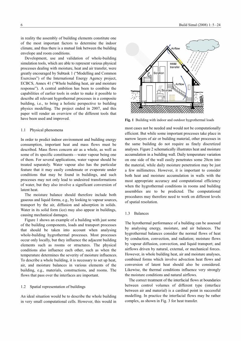
Figure 1 shows an example of a building with just some of the building components, loads and transport processes that should be taken into account when analysing whole-building hygrothermal processes. Most processes occur only locally, but they influence the adjacent building elements such as rooms or structures. The physical conditions also influence each other, such as when the temperature determines the severity of moisture influences. To describe a whole building, it is necessary to set up heat, air, and moisture balances in various elements of the building, e.g., materials, constructions, and rooms. The flows that pass over the interfaces are important.
1.2 Spatial representation of buildings
An ideal situation would be to describe the whole building in very small computational cells. However, this would in
Fig. 1 Building with indoor and outdoor hygrothermal loads
most cases not be needed and would not be computationally efficient. But while some important processes take place in narrow layers of air or building material, other processes in the same building do not require as finely discretized analyses. Figure 2 schematically illustrates heat and moisture accumulation in a building wall. Daily temperature variation on one side of the wall easily penetrates some 20cm into the material, while daily moisture penetration may be just a few millimetres. However, it is important to consider both heat and moisture accumulation in walls with the most appropriate accuracy and computational efficiency when the hygrothermal conditions in rooms and building assemblies are to be predicted. The computational procedures may therefore need to work on different levels of spatial resolution.
1.3 Balances
The hyrothermal performance of a building can be assessed by analysing energy, moisture, and air balances. The hygrothermal balances consider the normal flows of heat by conduction, convection, and radiation; moisture flows by vapour diffusion, convection, and liquid transport; and airflows driven by natural, external, or mechanical forces. However, in whole building heat, air and moisture analyses, combined forms which involve advection heat flows and conversion of latent heat should also be considered. Likewise, the thermal conditions influence very strongly the moisture conditions and natural airflows.
The correct treatment of the interfacial flows at boundaries between control volumes of different type (interface between air and material) is a cardinal point in successful modelling. In practice the interfacial flows may be rather complex, as shown in Fig. 3 for heat transfer.

Build Simul (2008) 1: 5–24
7
Fig. 2 Schematic illustration of temperature and moisture buffering in building materials. Hourly profiles resulting from daily excitations at the right-hand boundary
Fig. 3 Roof with different hygrothermal loads and transport processes
1.4 Numerical methods
All simulation tools presented later in this paper are based on some numerical methods for space and time discretization. Possible numerical methods are Finite Difference Methods (FDM)/Finite Control Volume
(FCV) methods, Finite Element Method (FEM), Response Factor / Transfer Function method.
1.5 Granularity
Granularity is related to the size of the control volume. In buildings a large variation of granularity is available, from the simplest single-zone modelling (whole building = one zone, called coarse-grained) to CFD modelling (one room =
thousands or millions of zones, called very-finely grained). Intermediate approaches use multi-zone modelling, dividing the building, and even sometimes a room, into a few zones with different air characteristics. Similar classification can apply for the granularity of envelope models: from the sim- plest transfer functions, through 1D, over 2D to 3D modelling using control volume or finite elements techniques.
Whole building tools mainly use two granularity classes: The intermediate-grained models (Fig. 4, left)
Multi-zone models for air volumes, where several rooms or groups of rooms are represented, each with different characteristics (each zone is supposed perfectly mixed)
1D models for the envelope, using control volume or finite element techniques, with typical size of mesh between a few millimetres to several centimetres
The coarse-grained models (Fig. 4, right) Single-zone models for air volumes, where the
whole building is represented as one perfectly mixed zone
Transfer function models for the envelope, where dynamic heat and possibly mass fluxes are repres- ented without investigating conditions within the envelope
Fig. 4 Levels of granularity for room air
2 Development of whole building HAM models
The developments could take place by making entirely new models and tools (Tariku et al. 2006), or by extension
Build Simul (2008) 1: 5–24 8
of already existing tools, as for instance: Extending the existing building simulation tools (to
account better for processes linked with the envelope), e.g., Rode and Grau (2003)
Extending the building component simulation tools, e.g., Holm et al. (2003)
A combination of both building simulation and building component simulation tools, e.g., Koronthályová et al. (2004) Several engineering tools were under development during
the period Annex 41 was running, improving their capacities to represent coupled heat, air and moisture response of buildings. Some of them are well known building energy simulation software, such as TRNSYS and EnergyPlus; some have more proprietary use, such as PowerDomus, Clim2000 and SimSPARK. Whole building models take into account location and orientation of the building (climatic zone), various heating, ventilating and air conditioning systems, air infiltration or exfiltration, user behaviour (number of people, activities, moisture and heat production, window ventilation, etc.), and type of room (bathroom, living room, office, etc.). They are mainly situated at the intermediate level of granularity. Some tools are able to support fine level of granularity, for example, by CFD extension of room air modelling. However, these possibilities were not tested in the benchmark cases of the Annex, and therefore are simply mentioned but not described in the following. Management of the overall physical processes for the whole is a matter of not only being able to describe the conditions in the different building elements, but also to correctly account for interfacial transfer and balances.
All tools calculate also moisture level in the indoor air and can account for vapour storage in hygroscopic materials. This last phenomenon is modelled either using simplified (coarse-grained) models or using a detailed description of the heat and mass transfer phenomena in the building envelope. In the last case, moisture level in building elements can also be assessed using the simulation tool.
2.1 General features of whole building HAM models
The following text presents the 17 simulation tools that have been used in Annex 41, which are able to simulate whole building HAM performance. This cannot be an exhaustive list of all whole building HAM simulation tools that may exist in different countries. However, as so many as 39 institutions from 19 countries participated in this project, the results give a good overview of today’s simulation capabilities. Each participant was free to choose the tool he or she wanted to use. The choice was frequently based on beforehand knowledge of and experience with the tool. Often the tool was developed by
the participant’s institution, or it had been used there for several years. Moreover the tools were also benchmarked in so-called “Common Exercises” in the Annex, and some improvements were made to the tools during the project. Presentation and discussions of some of the benchmark cases can be found in Woloszyn and Rode (2007), Holm and Lengsfeld (2007).
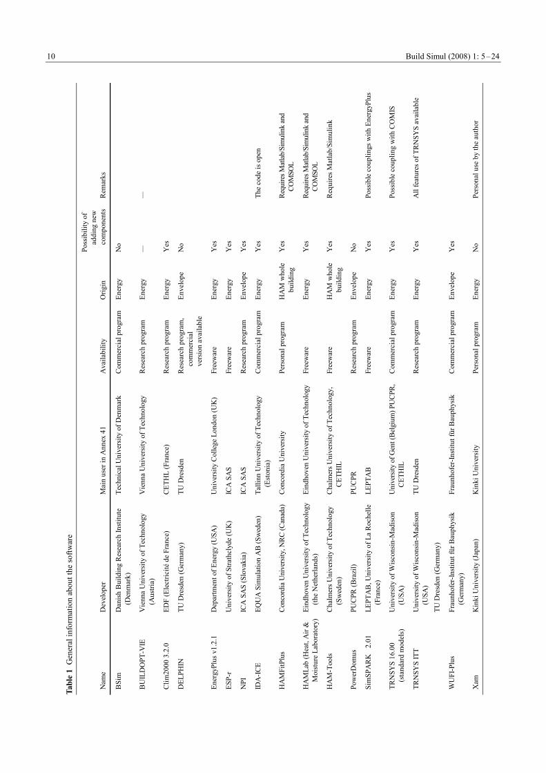
First, a brief introduction is given for all the models, including relevant references and internet sites when available. Then their main features are contrasted in 8 tables. Evidently, it is impossible to give a full description of 17 simulation tools in a limited number of pages. The aim is to give a general overview of the main features, focusing more on moisture modelling and on the interactions between heat, air and moisture transfer mechanisms. The comparison is based on the descriptions given by the users of the tools with the Annex. As it can be seen in Table 1, the “user” is in some cases from the institution which developed the tool, or in some cases he or she is simply an experienced user.
It must also be stated that some of the models are still under active development. Therefore between the moments of writing this paper and using the information some more or less important improvements might have been made.
Table 1 gives the origin of the tool and main institutions working with it in Annex 41. It can be seen that eleven tools are used by the developers, and the six remaining by other institutions. Five tools are commercially available, and also five are freeware. Five are only research tools, and two are personal products. Eleven, i.e., the majority, of the tools are originally energy simulation tools, four tools were building envelope simulation tool, and the last two were directly developed as whole building simulation heat-air-moisture tools.
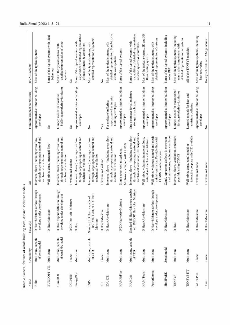
Table 2 gives a first overview of the whole building HAM models implemented in the tools. Most of them can simulate a multi-zone building and heat and mass transfer in the envelope. Four are single-zone tools, and five are able to describe intra-room flows using zonal models or CFD. Of course all of the thirteen multi-zone tools can represent single-zone buildings. Four tools represent in standard version 1-dimensional heat transfer in the envelope, nine 1-dimensional heat and moisture transfer in the envelope and three 1-dimensional heat, air and moisture transfer in the envelope. Finally, only three tools can deal with multi-dimensional coupled transfer at building level. The effect of furniture on indoor relative humidity and temperature is not represented as such, but can be approximated as interior building structures. Some tools use a coarse-grained (lumped) approach. Also, with two exceptions, the tools can represent most of the typical
Build Simul (2008) 1: 5–24
9
HVAC systems. However, in most of the tools, the systems are represented in a rather simplified way, where the action of the system on the indoor conditions is represented without detailed description of the HVAC element itself.
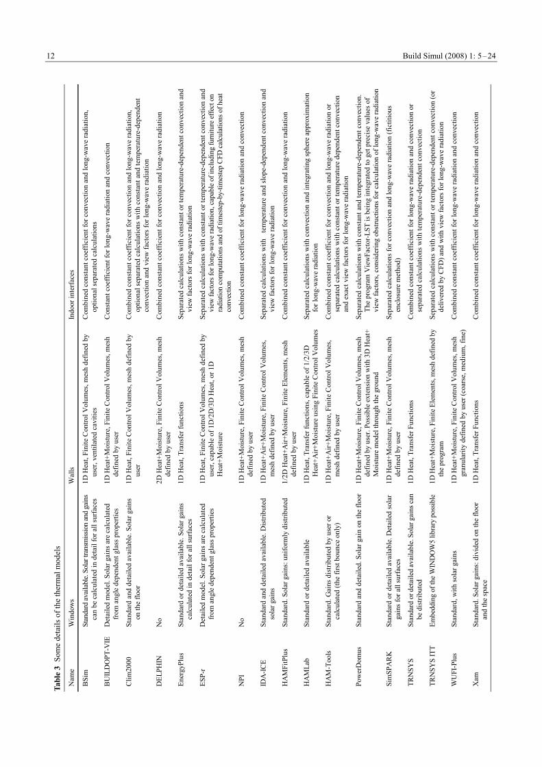
The main elements of the thermal models are contrasted in Table 3. “Standard” window model means use of standard coefficients, such as U-value (heat loss), g (solar gain coefficient) and SC (shading coefficient). Such models also allow for calculations of heat gains according to the position of sun. “Detailed” window model means that the heat transfer is modelled including convection and radiation between and inside the glazing, etc. Some information is also given about the way in which the solar gain is treated. Also wall models are briefly described in Table 3, and especially if they are treated in 1 or 2 dimensions, and what is the main numerical method used (finite control volume —FCV, finite element method —FEM or transfer function). Also principles for computing convection and long-wave radiation are presented in Table 3.
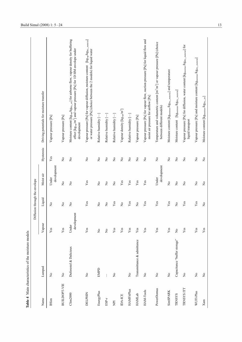
Table 4 details the main characteristics of the moisture models. Thirteen tools include vapour diffusion through the envelope, eight also liquid transport. Moist air movement through the envelope, which is one-dimensional airflow through very permeable constructions excluding cracks, can be simulated by five tools (two more will be available soon), and hysteresis effect of sorption isotherm only by one tool. Also a rather large variety of driving potentials for moisture flow can be seen in Table 4. For example vapour pressure [Pa] is used in nine tools, moisture content [kgmoisture/kgdry_material] in six, relative humidity [—] in four, and vapour concentration [kgvap/m3] in two; some tools using more than one. Moreover, suction pressure [Pa], temperature [℃] and volumetric moisture content [m3/m3] are also used. Some tools use only simplified (coarse-grained) models for moisture buffering.
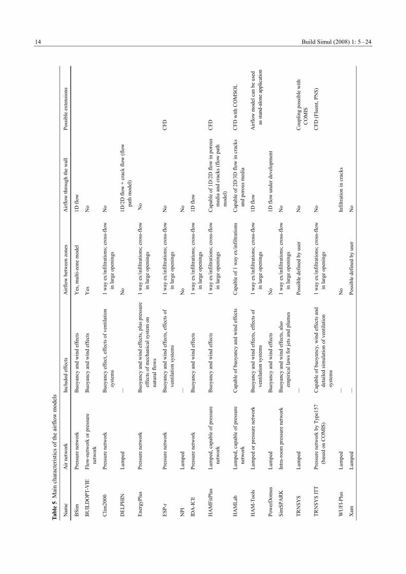
Table 5 depicts the main characteristics of the airflow models in the 17 tools. Six have only lumped representation of the indoor air, eleven are able to use pressure network to represent more accurately interzonal flows and different ventilation systems, and one tool is a zonal model, where several control volumes are used to describe one room. Most of the multi-zone models and the zonal model include wind and buoyancy effect, also one-way flow through the cracks in the envelope and indoor partitions, as well as cross-flow through large openings. In most of the “lumped” models ventilation and infiltration flows can be defined by the user and added to the energy and moisture balances of the indoor air. Also some tools can be coupled with airflow simulation tools, such as COMIS or CFD, to enhance their modelling capacities.
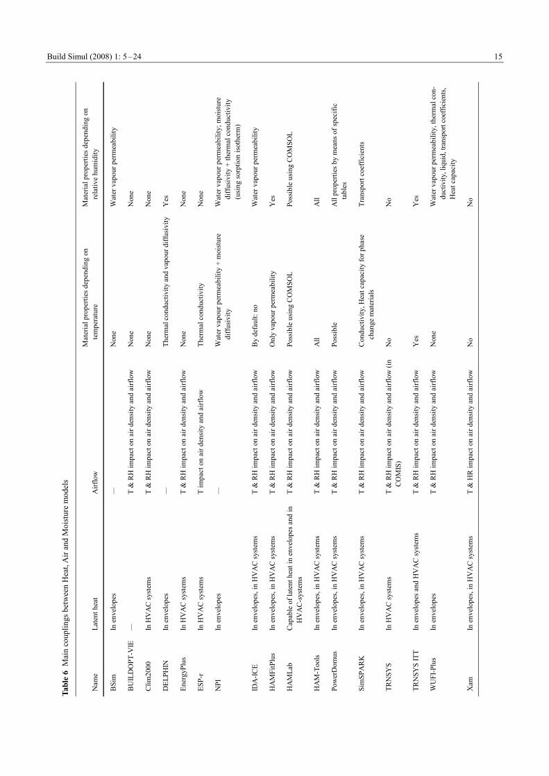
The main couplings between heat, air and moisture models are represented in Table 6. Of course all tools
represent both latent and sensitive contributions of internal sources. Latent heat due to vapour transfer and to condensation/evaporation process is taken into account in most of the codes; however, in most of them it is either in the envelope or in the HVAC system. Only seven tools are able to take both into account. Also most of the multi-zone models (thirteen) can take into account the impact of both humidity and temperature on air density and therefore on buoyancy. Some tools can also represent moisture and temperature impact on some of the material properties.
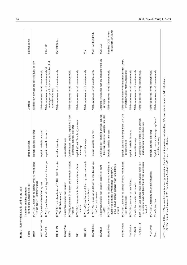
The numerical methods are contrasted in Table 7. Some of the simulation tools use an external solver, such as Matlab for HAMLab, HAM-Tools, and HAMFitPlus. Explicit and implicit methods, as well as constant or variable time-step methods are almost equally distributed. In the envelopes eleven tools use FCV method, four use transfer functions, and two use FEM. If a mesh is used, it is the same for all transfer process (heat, air, and moisture). Moreover in most of the cases (fourteen tools) all equations are simultaneously solved ensuring full coupling between different flows.
All the tools can use variable inputs from weather files; however, not all the information is used. From Table 8 it can be seen that only five tools are able to deal with wind driven rain and eight with heat and moisture transfer through the ground. Wind impact on outdoor convection and on infiltration is rather often represented (twelve tools), as well as the solar shadings from close neighbourhood (twelve tools).
2.2 Introduction of different software
2.2.1 BSim
Rode and Grau (2003 and 2004) present the program BSim2000 (www.bsim.dk), which is a computational design tool for analysis of indoor climate, energy consumption, and daylight performance of building, developed by the Danish Building Research Institute. The core of the system is a common building data model shared by the design tools, and a common database with typical building materials, constructions, windows, and doors. The software can represent a multi-zone building with heat gains, solar radiation through windows (with shadings), heating, cooling, photovoltaic, ventilation, and infiltration, but also transient moisture model for the whole building.
2.2.2 BUILDOPT-VIE
BUILDOPT-VIE is a simulation tool developed at Vienna University of Technology (www.bph.tuwien.ac.at) described in Sofic and Bednar (2007). Development of the first edition of the program started in 2002 and was carried out with
Build Simul (2008) 1: 5–24 10
Tabl
e 1
Gen
eral
info
rmat
ion
abou
t the
softw
are
Nam
e
Dev
elop
er
Mai
n us
er in
Ann
ex 4
1
Ava
ilabi
lity
Orig
in
Poss
ibili
ty o
f ad
ding
new
co
mpo
nent
s
Rem
arks
BSi
m
Dan
ish
Bui
ldin
g R
esea
rch
Inst
itute
(D
enm
ark)
Te
chni
cal U
nive
rsity
of D
enm
ark
Com
mer
cial
pro
gram
En
ergy
N
o
BU
ILD
OPT
-VIE
V
ienn
a U
nive
rsity
of T
echn
olog
y (A
ustri
a)
Vie
nna
Uni
vers
ity o
f Tec
hnol
ogy
Res
earc
h pr
ogra
m
Ener
gy
—
—
Clim
2000
3.2
.0
EDF
(Ele
ctric
ité d
e Fr
ance
) C
ETH
L (F
ranc
e)
Res
earc
h pr
ogra
m
Ener
gy
Yes
DEL
PHIN
TU
Dre
sden
(Ger
man
y)
TU D
resd
en
Res
earc
h pr
ogra
m,
com
mer
cial
ve
rsio
n av
aila
ble
Enve
lope
N
o
Ener
gyPl
us v
1.2.
1
Dep
artm
ent o
f Ene
rgy
(USA
) U
nive
rsity
Col
lege
Lon
don
(UK
) Fr
eew
are
Ener
gy
Yes
ESP-
r U
nive
rsity
of S
trath
clyd
e (U
K)
ICA
SA
S
Free
war
e En
ergy
Y
es
NPI
IC
A S
AS
(Slo
vaki
a)
ICA
SA
S R
esea
rch
prog
ram
En
velo
pe
Yes
IDA
-ICE
EQ
UA
Sim
ulat
ion
AB
(Sw
eden
) Ta
llinn
Uni
vers
ity o
f Tec
hnol
ogy
(Est
onia
) C
omm
erci
al p
rogr
am
Ener
gy
Yes
Th
e co
de is
ope
n
HA
MFi
tPlu
s C
onco
rdia
Uni
vers
ity, N
RC
(Can
ada)
C
onco
rdia
Uni
vers
ity
Pers
onal
pro
gram
H
AM
who
le
build
ing
Yes
Re
quire
s Mat
lab/
Sim
ulin
k an
d CO
MSO
L
HA
MLa
b (H
eat,
Air
&
Moi
stur
e La
bora
tory
) Ei
ndho
ven
Uni
vers
ity o
f Tec
hnol
ogy
(the
Net
herla
nds)
Ei
ndho
ven
Uni
vers
ity o
f Tec
hnol
ogy
Free
war
e En
ergy
Y
es
Requ
ires M
atla
b/Si
mul
ink
and
COM
SOL
HA
M-T
ools
C
halm
ers U
nive
rsity
of T
echn
olog
y (S
wed
en)
Cha
lmer
s Uni
vers
ity o
f Tec
hnol
ogy,
C
ETH
IL
Free
war
e H
AM
who
le
build
ing
Yes
R
equi
res M
atla
b/Si
mul
ink
Pow
erD
omus
PU
CPR
(Bra
zil)
PUC
PR
Res
earc
h pr
ogra
m
Enve
lope
N
o
Sim
SPA
RK
2.
01
LEPT
AB
, Uni
vers
ity o
f La
Roc
helle
(F
ranc
e)
LEPT
AB
Fr
eew
are
Ener
gy
Yes
Po
ssib
le c
oupl
ings
with
Ene
rgyP
lus
TRN
SYS
16.0
0 (s
tand
ard
mod
els)
U
nive
rsity
of W
isco
nsin
-Mad
ison
(U
SA)
Uni
vers
ity o
f Gen
t (Be
lgiu
m) P
UC
PR,
CET
HIL
C
omm
erci
al p
rogr
am
Ener
gy
Yes
Po
ssib
le c
oupl
ing
with
CO
MIS
TRN
SYS
ITT
Uni
vers
ity o
f Wis
cons
in-M
adis
on
(USA
) TU
Dre
sden
(Ger
man
y)
TU D
resd
en
Res
earc
h pr
ogra
m
Ener
gy
Yes
A
ll fe
atur
es o
f TR
NSY
S av
aila
ble
WU
FI-P
lus
Fr
aunh
ofer
-Inst
itut f
ür B
auph
ysik
(G
erm
any)
Fr
aunh
ofer
-Inst
itut f
ür B
auph
ysik
C
omm
erci
al p
rogr
am
Enve
lope
Y
es
Xam
K
inki
Uni
vers
ity (J
apan
) K
inki
Uni
vers
ity
Pers
onal
pro
gram
En
ergy
N
o Pe
rson
al u
se b
y th
e au
thor
Build Simul (2008) 1: 5–24
11
Tabl
e 2
Gen
eral
feat
ures
of w
hole
bui
ldin
g H
eat,
Air
and
Moi
stur
e m
odel
s
Nam
e G
ranu
larit
y En
velo
pe
Air
Furn
iture
(im
pact
on
moi
stur
e)
HV
AC
syst
ems
BSi
m
Mul
ti-zo
ne, c
apab
le
of z
onal
mod
el
1D H
eat+
Moi
sture
, airf
low
thro
ugh
enve
lope
und
er d
evel
opm
ent
Inte
rzon
al fl
ows (
incl
udin
g cr
oss f
low
th
roug
h la
rge
open
ings
), na
tura
l and
m
echa
nica
l ven
tilat
ion
App
roxi
mat
ed a
s int
erio
r bui
ldin
g en
velo
pes
Mos
t of t
he ty
pica
l sys
tem
s
BU
ILD
OPT
-VIE
M
ulti-
zone
1D
Hea
t+M
oist
ure
W
ell m
ixed
zon
e, in
terz
onal
flow
N
o So
me
of th
e ty
pica
l sys
tem
s with
idea
l be
havi
our
Clim
2000
M
ulti-
zone
, cap
able
of
zon
al H
A m
odel
1D
Hea
t, va
pour
diff
usio
n th
roug
h en
velo
pe u
nder
dev
elop
men
t In
terz
onal
flow
s (in
clud
ing
cros
s flo
w
thro
ugh
larg
e op
enin
gs),
natu
ral a
nd
mec
hani
cal v
entil
atio
n
Lum
ped
mod
el fo
r moi
stur
e bu
fferin
g (re
nder
ing+
furn
iture
) M
ost o
f the
typi
cal s
yste
ms,
with
de
taile
d re
pres
enta
tion
of so
me
syst
ems
DEL
PHIN
1
zone
1D
/2D
Hea
t+A
ir+M
oist
ure
1 w
ell m
ixed
vol
ume
No
No
Ener
gyPl
us
Mul
ti-zo
ne
1D H
eat
Inte
rzon
al fl
ows (
incl
udin
g cr
oss f
low
th
roug
h la
rge
open
ings
), na
tura
l and
m
echa
nica
l ven
tilat
ion
App
roxi
mat
ed a
s int
erio
r bui
ldin
g en
velo
pes
Som
e of
the
typi
cal s
yste
ms,
with
ca
pabi
litie
s of d
etai
led
repr
esen
tatio
n of
mos
t sys
tem
s & c
ontro
llers
ESP-
r M
ulti-
zone
, cap
able
of
CFD
St
anda
rd 1
D H
eat,
capa
ble
of
1D/2
D/3
D H
eat,
or 1
D H
eat+
M
oist
ure
Inte
rzon
al fl
ows (
incl
udin
g cr
oss f
low
th
roug
h la
rge
open
ings
), na
tura
l and
m
echa
nica
l ven
tilat
ion
No
Mos
t of t
he ty
pica
l sys
tem
s, w
ith
deta
iled
repr
esen
tatio
n of
syst
ems
NPI
1
zone
1D
Hea
t+M
oist
ure
1
wel
l mix
ed v
olum
e Y
es
No
IDA
-ICE
M
ulti-
zone
1D
Hea
t+A
ir+M
oist
ure
Inte
rzon
al fl
ows
(in
clud
ing
cros
s flo
w
thro
ugh
larg
e op
enin
gs),
natu
ral a
nd
mec
hani
cal v
entil
atio
n
For m
oist
ure
buff
erin
g:
appr
oxim
ated
as i
nter
ior
build
ing
enve
lope
s
Mos
t of t
he ty
pica
l sys
tem
s, w
ith
deta
iled
repr
esen
tatio
n. P
ossi
bilit
y to
cr
eate
ow
n sy
stem
s
HA
MFi
tPlu
s M
ulti-
zone
1D
/2D
Hea
t+A
ir+M
oist
ure
Si
ngle
zon
e: w
ell m
ixed
zon
e.
Mul
ti-zo
ne: c
oupl
ed w
ith C
OM
IS
App
roxi
mat
ed a
s int
erio
r bui
ldin
g en
velo
pes
Som
e of
the
typi
cal s
yste
ms
HA
MLa
b M
ulti-
zone
, cap
able
of
CFD
St
anda
rd 1
D H
eat+
Moi
sture
capa
ble
of 1
D/2
D/3
D H
eat+
Air+
Moi
sture
In
terz
onal
flow
s (
incl
udin
g cr
oss f
low
th
roug
h la
rge
open
ings
), na
tura
l and
m
echa
nica
l ven
tilat
ion,
CFD
capa
bilit
ies
One
par
amet
er fo
r all
moi
stur
e st
orag
e in
eac
h zo
ne
Som
e of
the
typi
cal s
yste
ms,
with
ca
pabi
litie
s of d
etai
led
repr
esen
tatio
n of
som
e sy
stem
s & c
ontro
llers
HA
M-T
ools
M
ulti-
zone
1D
Hea
t+A
ir+M
oist
ure
Wel
l mix
ed v
olum
es, i
nter
zona
l flo
ws,
natu
ral a
nd m
echa
nica
l ven
tilat
ion
A
ppro
xim
ated
as i
nter
ior b
uild
ing
enve
lope
s M
ost o
f the
typi
cal s
yste
ms,
2D a
nd 3
D
floor
hea
ting
syst
ems
Pow
erD
omus
M
ulti-
zone
1D
Hea
t+M
oistu
re, a
irflo
w th
roug
h en
velo
pe u
nder
dev
elop
men
t W
ell m
ixed
vol
umes
, nat
ural
and
mec
h-
anic
al v
entil
atio
n. P
ossi
ble
link
with
C
OM
IS is
und
er a
naly
sis
App
roxi
mat
ed a
s int
erio
r bui
ldin
g en
velo
pes
Mos
t of t
he ty
pica
l sys
tem
s, w
ith
deta
iled
repr
esen
tatio
n of
syst
ems
Sim
SPA
RK
Zo
nal m
odel
1D
Hea
t+M
oist
ure
Zona
l, re
pres
ents
airf
low
s in
one
room
an
d in
tra-ro
oms,
incl
udin
g ve
ntila
tion
App
roxi
mat
ed a
s int
erio
r bui
ldin
g en
velo
pes
Som
e of
the
typi
cal s
yste
ms,
incl
udin
g so
lar D
EC
TRN
SYS
Mul
ti-zo
ne
1D H
eat
In
terz
onal
flow
s, ve
ntila
tion,
ext
ensi
ons
poss
ible
usi
ng C
OM
IS
Lum
ped
mod
el fo
r moi
stur
e bu
f- fe
ring
(rend
erin
g+fu
rnitu
re)
Mos
t of t
he ty
pica
l sys
tem
s, in
clud
ing
man
y so
lar c
ompo
nent
s, w
ith
deta
iled
repr
esen
tatio
n of
syst
ems
TRN
SYS
ITT
Mul
ti-zo
ne
1D H
eat+
Moi
stur
e W
ell m
ixed
zon
e, z
onal
mod
el o
r in
terac
tive c
oupl
ing
with
CFD
avai
lable
Lu
mpe
d m
odel
s for
hea
t and
m
oist
ure
buff
erin
g A
ll of
the
TRN
SYS
mod
ules
WU
FI-P
lus
1 zo
ne
1D H
eat+
Moi
stur
e 1
wel
l mix
ed z
one
App
roxi
mat
ed a
s int
erio
r bui
ldin
g en
velo
pes
Mos
t of t
he ty
pica
l sys
tem
s, in
clud
ing
heat
reco
verin
g
Xam
1
zone
1D
Hea
t+M
oist
ure
1 w
ell m
ixed
zon
e N
o H
ourly
sche
dule
of H
&M
gai
n/si
nk
Build Simul (2008) 1: 5–24 12
Tabl
e 3
Som
e de
tails
of t
he th
erm
al m
odel
s
Nam
e W
indo
ws
Wal
ls In
door
inte
rface
s
BSi
m
Stan
dard
avai
lable.
Sol
ar tr
ansm
issio
n an
d ga
ins
can
be c
alcu
late
d in
det
ail f
or a
ll su
rface
s 1D
Hea
t, Fi
nite
Con
trol V
olum
es, m
esh
defin
ed b
y us
er, v
entil
ated
cav
ities
C
ombi
ned
cons
tant
coe
ffici
ent f
or c
onve
ctio
n an
d lo
ng-w
ave
radi
atio
n,
optio
nal s
epar
ated
cal
cula
tions
BU
ILD
OPT
-VIE
D
etai
led
mod
el. S
olar
gai
ns a
re c
alcu
late
d fro
m a
ngle
dep
ende
nt g
lass
pro
perti
es
1D H
eat+
Moi
stur
e, F
inite
Con
trol V
olum
es, m
esh
defin
ed b
y us
er
Con
stan
t coe
ffic
ient
for l
ong-
wav
e ra
diat
ion
and
conv
ectio
n
Clim
2000
St
anda
rd a
nd d
etai
led
avai
labl
e. S
olar
gai
ns
on th
e flo
or
1D H
eat,
Fini
te C
ontro
l Vol
umes
, mes
h de
fined
by
user
C
ombi
ned
cons
tant
coe
ffici
ent f
or c
onve
ctio
n an
d lo
ng-w
ave
radi
atio
n,
optio
nal s
epar
ated
cal
cula
tions
with
con
stan
t and
tem
pera
ture
-dep
ende
nt
conv
ectio
n an
d vi
ew fa
ctor
s for
long
-wav
e ra
diat
ion
DEL
PHIN
N
o 2D
Hea
t+M
oist
ure,
Fin
ite C
ontro
l Vol
umes
, mes
h de
fined
by
user
C
ombi
ned
cons
tant
coe
ffic
ient
for c
onve
ctio
n an
d lo
ng-w
ave
radi
atio
n
Ener
gyPl
us
St
anda
rd o
r det
aile
d av
aila
ble.
Sol
ar g
ains
ca
lcul
ated
in d
etai
l for
all
surf
aces
1D
Hea
t, Tr
ansf
er fu
nctio
ns
Sepa
rate
d ca
lcul
atio
ns w
ith c
onst
ant o
r tem
pera
ture
-dep
ende
nt c
onve
ctio
n an
d vi
ew fa
ctor
s for
long
-wav
e ra
diat
ion
ESP-
r D
etai
led
mod
el. S
olar
gai
ns a
re c
alcu
late
d fro
m a
ngle
dep
ende
nt g
lass
pro
perti
es
1D H
eat,
Fini
te C
ontro
l Vol
umes
, mes
h de
fined
by
user
, cap
able
of 1
D/2
D/3
D H
eat,
or 1
D
Hea
t+M
oist
ure
Sepa
rate
d ca
lcul
atio
ns w
ith c
onst
ant o
r tem
pera
ture
-dep
ende
nt c
onve
ctio
n an
d vi
ew fa
ctor
s for
long
-wav
e ra
diat
ion,
cap
able
of i
nclu
ding
furn
iture
effe
ct o
n ra
diat
ion
com
puta
tions
and
of t
imes
tep-
by-ti
mes
tep
CFD
cal
cula
tions
of h
eat
conv
ectio
n
NPI
N
o 1D
Hea
t+M
oist
ure,
Fin
ite C
ontro
l Vol
umes
, mes
h de
fined
by
user
C
ombi
ned
cons
tant
coe
ffic
ient
for l
ong-
wav
e ra
diat
ion
and
conv
ectio
n
IDA
-ICE
St
anda
rd a
nd d
etai
led
avai
labl
e. D
istri
bute
d so
lar g
ains
1D
Hea
t+A
ir+M
oist
ure,
Fin
ite C
ontro
l Vol
umes
, m
esh
defin
ed b
y us
er
Sepa
rate
d ca
lcul
atio
ns w
ith
tem
pera
ture
and
slop
e-de
pend
ent c
onve
ctio
n an
d vi
ew fa
ctor
s for
long
-wav
e ra
diat
ion
HA
MFi
tPlu
s St
anda
rd. S
olar
gai
ns: u
nifo
rmly
dis
tribu
ted
1/2D
Hea
t+A
ir+M
oist
ure,
Fin
ite E
lem
ents
, mes
h de
fined
by
user
C
ombi
ned
cons
tant
coe
ffic
ient
for c
onve
ctio
n an
d lo
ng-w
ave
radi
atio
n
HA
MLa
b St
anda
rd o
r det
aile
d av
aila
ble
1D H
eat,
Tran
sfer
func
tions
, cap
able
of 1
/2/3
D
Hea
t+A
ir+M
oist
ure
usin
g Fi
nite
Con
trol V
olum
es
Sepa
rate
d ca
lcul
atio
ns w
ith c
onve
ctio
n an
d in
tegr
atin
g sp
here
app
roxi
mat
ion
for l
ong-
wav
e ra
diat
ion
HA
M-T
ools
Stan
dard
. Gai
ns d
istri
bute
d by
use
r or
calc
ulat
ed (t
he fi
rst b
ounc
e on
ly)
1D H
eat+
Air+
Moi
stur
e, F
inite
Con
trol V
olum
es,
mes
h de
fined
by
user
C
ombi
ned
cons
tant
coe
ffic
ient
for c
onve
ctio
n an
d lo
ng-w
ave
radi
atio
n or
se
para
ted
calc
ulat
ions
with
con
stan
t or t
empe
ratu
re d
epen
dent
con
vect
ion
and
exac
t vie
w fa
ctor
s for
long
-wav
e ra
diat
ion
Pow
erD
omus
St
anda
rd a
nd d
etai
led.
Sol
ar g
ain
on th
e flo
or
1D H
eat+
Moi
stur
e, F
inite
Con
trol V
olum
es, m
esh
defin
ed b
y us
er. P
ossi
ble
exte
nsio
n w
ith 3
D H
eat+
M
oist
ure
mod
el th
roug
h th
e gr
ound
Sepa
rate
d ca
lcul
atio
ns w
ith c
onst
ant a
nd te
mpe
ratu
re-d
epen
dent
con
vect
ion.
Th
e pr
ogra
m V
iew
Fact
or-L
ST is
bei
ng in
tegr
ated
to g
et p
reci
se v
alue
s of
view
fact
ors,
cons
ider
ing
obst
ruct
ions
for c
alcu
latio
n of
long
-wav
e ra
diat
ion
Sim
SPA
RK
St
anda
rd o
r det
aile
d av
aila
ble.
Det
aile
d so
lar
gain
s for
all
surf
aces
1D
Hea
t+M
oist
ure,
Fin
ite C
ontro
l Vol
umes
, mes
h de
fined
by
user
Se
para
ted
calc
ulat
ions
for c
onve
ctio
n an
d lo
ng-w
ave
radi
atio
n (fi
ctiti
ous
encl
osur
e m
etho
d)
TRN
SYS
Stan
dard
or d
etai
led
avai
labl
e. S
olar
gai
ns ca
n be
dis
tribu
ted
1D H
eat,
Tran
sfer
Fun
ctio
ns
Com
bine
d co
nsta
nt c
oeff
icie
nt fo
r lon
g-w
ave
radi
atio
n an
d co
nvec
tion
or
sepa
rate
d ca
lcul
atio
ns w
ith te
mpe
ratu
re-d
epen
dent
con
vect
ion
TRN
SYS
ITT
Embe
ddin
g of
the W
IND
OW
5 lib
rary
pos
sible
1D
Hea
t+M
oistu
re, F
inite
Ele
men
ts, m
esh
defin
ed b
y th
e pr
ogra
m
Sepa
rate
d ca
lcul
atio
ns w
ith c
onst
ant o
r tem
pera
ture
-dep
ende
nt c
onve
ctio
n (o
r de
liver
ed b
y C
FD) a
nd w
ith v
iew
fact
ors f
or lo
ng-w
ave
radi
atio
n
WU
FI-P
lus
Stan
dard
, with
sola
r gai
ns
1D H
eat+
Moi
stur
e, F
inite
Con
trol V
olum
es, m
esh
gran
ular
ity d
efin
ed b
y us
er (c
oars
e, m
ediu
m, f
ine)
C
ombi
ned
cons
tant
coe
ffic
ient
for l
ong-
wav
e ra
diat
ion
and
conv
ectio
n
Xam
St
anda
rd. S
olar
gai
ns: d
ivid
ed o
n th
e flo
or
and
the
spac
e 1D
Hea
t, Tr
ansf
er F
unct
ions
C
ombi
ned
cons
tant
coe
ffic
ient
for l
ong-
wav
e ra
diat
ion
and
conv
ectio
n
Build Simul (2008) 1: 5–24
13
Tabl
e 4
Mai
n ch
arac
teris
tics o
f the
moi
stur
e m
odel
s
D
iffus
ion
thro
ugh
the
enve
lope
Nam
e Lu
mpe
d V
apou
r Li
quid
M
oist
air
Hys
tere
sis
Driv
ing
pote
ntia
ls fo
r moi
stur
e tra
nsfe
r
BSi
m
No
Yes
N
o U
nder
de
velo
pmen
t Y
es
Vap
our p
ress
ure
[Pa]
BU
ILD
OPT
-VIE
N
o Y
es
No
No
No
Vap
our p
ress
ure
[Pa]
Clim
2000
D
ufor
este
l & D
alic
ieux
U
nder
de
velo
pmen
t N
o N
o N
o M
oist
ure
cont
ent [
kgva
p/kg d
ry_ a
ir] fo
r airb
orne
flow
, vap
our d
ensi
ty fo
r buf
ferin
g ef
fect
[kg v
ap/m
3 ] and
vap
our p
ress
ure
[Pa]
for 1
D H
M e
nvel
ope
unde
r de
velo
pmen
t
DEL
PHIN
N
o Y
es
Yes
Y
es
No
Vap
our p
ress
ure [
Pa] f
or v
apou
r diff
usio
n, m
oistu
re c
onte
nt
[kg v
ap/k
g dry
_ mat
eria
l] or
wat
er p
ress
ure
[Pa]
(cho
ice
betw
een
the
2 m
odel
s) fo
r liq
uid
wat
er
Ener
gyPl
us
EM
PD
No
No
No
No
Rel
ativ
e hu
mid
ity [ —
]
ESP-
r —
N
o N
o N
o N
o R
elat
ive
hum
idity
[—]
NPI
N
o Y
es
Yes
N
o N
o R
elat
ive
hum
idity
[ —]
IDA
-ICE
Yes
N
o Y
es
No
Vap
our d
ensi
ty [k
g vap
/m3 ]
HA
MFi
tPlu
s N
o Y
es
Yes
Y
es
No
Rel
ativ
e hu
mid
ity [ —
]
HA
MLa
b Tr
ansm
ittan
ce &
adm
ittan
ce
Yes
N
o Y
es
No
Vap
our p
ress
ure
[Pa]
HA
M-T
ools
No
Yes
Y
es
Yes
N
o V
apou
r pre
ssur
e [P
a] fo
r vap
our f
low
, suc
tion
pres
sure
[Pa]
for l
iqui
d flo
w a
nd
moi
st a
ir pr
essu
re fo
r airf
low
[Pa]
Pow
erD
omus
N
o Y
es
Yes
U
nder
de
velo
pmen
t N
o Te
mpe
ratu
re a
nd v
olum
etric
con
tent
[m3 /m
3 ] or v
apou
r pre
ssur
e [P
a] (c
hoic
e be
twee
n di
ffere
nt m
odel
s)
Sim
SPA
RK
N
o Y
es
Y
es
No
N
o M
oist
ure
cont
ent [
kgm
oist
ure/k
g dry
_ mat
eria
l] an
d te
mpe
ratu
re
TRN
SYS
Cap
acita
nce
“buf
fer s
tora
ge”
No
No
No
No
Moi
stur
e co
nten
t [
kgm
oist
ure/k
g dry
_ mat
eria
l]
TRN
SYS
ITT
No
Yes
Y
es
No
No
Vap
our p
ress
ure
[Pa]
for d
iffus
ion,
wat
er c
onte
nt [k
g moi
stur
e/kg d
ry_ m
ater
ial]
for
liqui
d tra
nspo
rt
WU
FI-P
lus
No
Yes
Y
es
No
No
Vap
our p
ress
ure
[Pa]
and
moi
stur
e co
nten
t [kg
moi
stur
e/kg d
ry_ m
ater
ial]
Xam
N
o Y
es
No
No
No
Moi
stur
e co
nten
t [kg
moi
stur
e/kg d
ry_ a
ir]
Build Simul (2008) 1: 5–24 14
Tabl
e 5
Mai
n ch
arac
teris
tics o
f the
airf
low
mod
els
Nam
e A
ir ne
twor
k In
clud
ed e
ffec
ts
Airf
low
bet
wee
n zo
nes
Airf
low
thro
ugh
the
wal
l Po
ssib
le e
xten
sion
s
BSi
m
Pres
sure
net
wor
k B
uoya
ncy
and
win
d ef
fect
s Y
es, m
ulti-
zone
mod
el
1D fl
ow
BU
ILD
OPT
-VIE
Fl
ow-n
etw
ork
or p
ress
ure
netw
ork
Buo
yanc
y an
d w
ind
effe
cts
Yes
N
o
Clim
2000
Pr
essu
re n
etw
ork
B
uoya
ncy
effe
ct, e
ffec
ts o
f ven
tilat
ion
syst
ems
1 w
ay e
x/in
filtra
tions
; cro
ss-fl
ow
in la
rge
open
ings
N
o
DEL
PHIN
Lu
mpe
d —
N
o 1D
/2D
flow
+ c
rack
flow
(flo
w
path
mod
el)
Ener
gyPl
us
Pres
sure
net
wor
k B
uoya
ncy
and
win
d ef
fect
s, pl
us p
ress
ure
effe
cts o
f mec
hani
cal s
yste
m o
n na
tura
l flo
ws
1 w
ay e
x/in
filtra
tions
; cro
ss-fl
ow
in la
rge
open
ings
N
o
ESP-
r Pr
essu
re n
etw
ork
Buo
yanc
y an
d w
ind
effe
cts,
effe
cts o
f ve
ntila
tion
syst
ems
1 w
ay e
x/in
filtra
tions
; cro
ss-fl
ow
in la
rge
open
ings
N
o C
FD
NPI
Lu
mpe
d
—
No
No
IDA
-ICE
Pr
essu
re n
etw
ork
Buo
yanc
y an
d w
ind
effe
cts
1 w
ay e
x/in
filtra
tions
; cro
ss-fl
ow
in la
rge
open
ings
1D
flow
HA
MFi
tPlu
s Lu
mpe
d, c
apab
le o
f pre
ssur
e ne
twor
k B
uoya
ncy
and
win
d ef
fect
s 1
way
ex/
infil
tratio
ns; c
ross
-flow
in
larg
e op
enin
gs
Cap
able
of 1
D/2
D fl
ow in
por
ous
med
ia a
nd c
rack
s (flo
w p
ath
mod
el)
CFD
HA
MLa
b Lu
mpe
d, c
apab
le o
f pre
ssur
e ne
twor
k C
apab
le o
f buo
yanc
y an
d w
ind
effe
cts
Cap
able
of 1
way
ex/
infil
tratio
ns
Cap
able
of 2
D/3
D fl
ow in
cra
cks
and
poro
us m
edia
C
FD w
ith C
OM
SOL
HA
M-T
ools
Lum
ped
or p
ress
ure
netw
ork
Buo
yanc
y an
d w
ind
effe
cts,
effe
cts o
f ve
ntila
tion
syst
ems
1 w
ay e
x/in
filtra
tions
; cro
ss-fl
ow
in la
rge
open
ings
1D
flow
A
irflo
w m
odel
can
be
used
as
stan
d-al
one a
pplic
atio
n
Pow
erD
omus
Lu
mpe
d B
uoya
ncy
and
win
d ef
fect
s N
o 1D
flow
und
er d
evel
opm
ent
Sim
SPA
RK
In
tra-r
oom
pre
ssur
e ne
twor
k B
uoya
ncy
and
win
d ef
fect
s, al
so
empi
rical
law
s for
jets
and
plu
mes
1
way
ex/
infil
tratio
ns; c
ross
-flow
in
larg
e op
enin
gs
No
TRN
SYS
Lum
ped
—
Poss
ible
def
ined
by
user
N
o C
oupl
ing
poss
ible
with
C
OM
IS
TRN
SYS
ITT
Pres
sure
net
wor
k by
Typ
e157
(b
ased
on
CO
MIS
) C
apab
le o
f buo
yanc
y, w
ind
effe
cts a
nd
deta
iled
sim
ulat
ion
of v
entil
atio
n sy
stem
s
1 w
ay e
x/in
filtra
tions
; cro
ss-fl
ow
in la
rge
open
ings
N
o C
FD (F
luen
t, PN
S)
WU
FI-P
lus
Lum
ped
—
No
Infil
tratio
n in
cra
cks
Xam
Lu
mpe
d —
Po
ssib
le d
efin
ed b
y us
er
No
Build Simul (2008) 1: 5–24
15
Tabl
e 6
Mai
n co
uplin
gs b
etw
een
Hea
t, A
ir an
d M
oist
ure
mod
els
Nam
e La
tent
hea
t A
irflo
w
Mat
eria
l pro
perti
es d
epen
ding
on
tem
pera
ture
M
ater
ial p
rope
rties
dep
endi
ng o
n re
lativ
e hu
mid
ity
BSi
m
In e
nvel
opes
—
N
one
Wat
er v
apou
r per
mea
bilit
y
BU
ILD
OPT
-VIE
—
T
& R
H im
pact
on
air d
ensi
ty a
nd a
irflo
w
Non
e N
one
Clim
2000
In
HV
AC
syst
ems
T &
RH
impa
ct o
n ai
r den
sity
and
airf
low
N
one
Non
e
DEL
PHIN
In
env
elop
es
—
Ther
mal
con
duct
ivity
and
vap
our d
iffus
ivity
Y
es
Ener
gyPl
us
In
HV
AC
syst
ems
T &
RH
impa
ct o
n ai
r den
sity
and
airf
low
N
one
Non
e
ESP-
r In
HV
AC
syst
ems
T im
pact
on
air d
ensi
ty a
nd a
irflo
w
Ther
mal
con
duct
ivity
N
one
NPI
In
env
elop
es
—
Wat
er v
apou
r per
mea
bilit
y +
moi
stur
e di
ffusi
vity
W
ater
vap
our p
erm
eabi
lity;
moi
stur
e di
ffusi
vity
+ th
erm
al c
ondu
ctiv
ity
(usi
ng so
rptio
n is
othe
rm)
IDA
-ICE
In
env
elop
es, i
n H
VA
C sy
stem
s T
& R
H im
pact
on
air d
ensi
ty a
nd a
irflo
w
By
defa
ult:
no
Wat
er v
apou
r per
mea
bilit
y
HA
MFi
tPlu
s In
env
elop
es, i
n H
VA
C sy
stem
s T
& R
H im
pact
on
air d
ensi
ty a
nd a
irflo
w
Onl
y va
pour
per
mea
bilit
y Y
es
HA
MLa
b C
apab
le o
f lat
ent h
eat i
n en
velo
pes a
nd in
H
VA
C-s
yste
ms
T &
RH
impa
ct o
n ai
r den
sity
and
airf
low
Po
ssib
le u
sing
CO
MSO
L Po
ssib
le u
sing
CO
MSO
L
HA
M-T
ools
In
env
elop
es, i
n H
VA
C sy
stem
s T
& R
H im
pact
on
air d
ensi
ty a
nd a
irflo
w
All
All
Pow
erD
omus
In
env
elop
es, i
n H
VA
C sy
stem
s T
& R
H im
pact
on
air d
ensi
ty a
nd a
irflo
w
Poss
ible
A
ll pr
oper
ties b
y m
eans
of s
peci
fic
tabl
es
Sim
SPA
RK
In
env
elop
es, i
n H
VA
C sy
stem
s T
& R
H im
pact
on
air d
ensi
ty a
nd a
irflo
w
Con
duct
ivity
, Hea
t cap
acity
for p
hase
ch
ange
mat
eria
ls
Tran
spor
t coe
ffici
ents
TRN
SYS
In H
VA
C sy
stem
s T
& R
H im
pact
on
air d
ensi
ty a
nd a
irflo
w (i
n C
OM
IS)
No
No
TRN
SYS
ITT
In e
nvel
opes
and
HV
AC
syst
ems
T &
RH
impa
ct o
n ai
r den
sity
and
airf
low
Y
es
Yes
WU
FI-P
lus
In e
nvel
opes
T
& R
H im
pact
on
air d
ensi
ty a
nd a
irflo
w
Non
e W
ater
vap
our p
erm
eabi
lity,
ther
mal
con
- du
ctiv
ity, l
iqui
d, tr
ansp
ort c
oeffi
cien
ts,
Hea
t cap
acity
Xam
In
env
elop
es, i
n H
VA
C sy
stem
s T
& H
R im
pact
on
air d
ensi
ty a
nd a
irflo
w
No
No
Build Simul (2008) 1: 5–24 16
Tabl
e 7
Num
eric
al m
etho
ds u
sed
in th
e to
ols
Nam
e Tr
ansf
er in
bui
ldin
g el
emen
ts
(met
hod
and
typi
cal m
esh
size
) Ti
me
inte
grat
ion
Cou
plin
g Ex
tern
al so
lver
BSi
m
FCV
(HM
), m
esh
can
be d
efin
ed b
y us
er, t
ypic
al si
ze:
few
cm
per
CV
(con
trol v
olum
e)
Impl
icit,
con
stan
t tim
e-st
ep
Inte
rmitt
ently
bet
wee
n th
e di
ffere
nt ty
pes o
f flo
w
BU
ILD
OPT
-VIE
FC
V, m
esh
can
be d
efin
ed b
y us
er
Expl
icit,
var
iabl
e tim
e-st
ep
All
the
equa
tions
solv
ed si
mul
tane
ousl
y
Clim
2000
FC
V (H
), m
esh
is us
er d
efin
ed, t
ypic
al si
ze: f
ew c
m p
er
CV
Im
plic
it, v
aria
ble
time-
step
A
ll th
e eq
uatio
ns so
lved
sim
ulta
neou
sly, i
f co
nver
genc
e pr
oble
m a
ppea
r an
itera
tive
bloc
k m
etho
d ca
n be
use
d
ESA
CA
P
DEL
PHIN
FC
V (H
M) t
ypic
al m
esh
size:
(1D
100
…20
0 El
emen
ts /
2D <
10.0
00 e
lem
ents
) V
aria
ble
time-
step
A
ll th
e eq
uatio
ns so
lved
sim
ulta
neou
sly
CV
OD
E So
lver
Ener
gyPl
us
Tran
sfer
func
tion
for h
eat t
rans
fer
Con
stan
t tim
e-st
ep
ESP-
r FC
V (H
), m
axim
um 2
4 vo
lum
es p
er el
emen
t in
stand
ard
vers
ion
Can
be
chos
en: e
xplic
it, im
plic
it or
Cra
nk
Nic
holso
n, c
onst
ant t
ime-
step
A
ll th
e eq
uatio
ns so
lved
sim
ulta
neou
sly
NPI
FC
V (H
M),
sam
e m
esh
for h
eat a
nd m
oist
ure,
abo
ut
1mm
size
Im
plic
it (C
rank
Nic
holso
n), c
onst
ant
time-
step
A
ll th
e eq
uatio
ns so
lved
sim
ulta
neou
sly
IDA
-ICE
FC
V (H
AM
), m
esh
can
be d
efin
ed b
y us
er, s
ame
mes
h fo
r hea
t, ai
r, an
d m
oist
ure
varia
ble
time-
step
A
ll th
e eq
uatio
ns so
lved
sim
ulta
neou
sly
Yes
HA
MFi
tPlu
s FE
M (H
AM
), m
esh
can
be d
efin
ed b
y us
er, t
ypic
al si
ze:
1 to
5 m
m p
er e
lem
ent
Expl
icit,
var
iabl
e tim
e-st
ep
All
the
equa
tions
solv
ed si
mul
tane
ousl
y M
ATL
AB
CO
MSO
L
HA
MLa
b Tr
ansf
er fu
nctio
n fo
r hea
t tra
nsfe
r, ca
pabl
e of
FEM
(H
AM
) C
ombi
natio
ns o
f im
plic
it, e
xplic
it, co
nsta
nt
time-
step
, cap
able
of v
aria
ble
time-
step
D
iffer
ent s
olut
ions
for h
eat a
nd m
oist
ure
or a
ir an
d en
velo
pe
MA
TLA
B
HA
M-T
ools
FCV
(HM
), m
esh
can
be d
efin
ed b
y us
er. N
o lim
its in
nu
mbe
r of e
lem
ents
. Typ
ical
size
: 1cm
per
CV
, 0.
0001
mm
at c
onta
ct su
rface
s whe
n liq
uid
flow
is
pres
ent
Expl
icit,
var
iabl
e tim
e-st
ep
All
the
equa
tions
solv
ed si
mul
tane
ousl
y St
anda
rd O
DE
solv
ers
incl
uded
in M
ATL
AB
Pow
erD
omus
FC
V (H
M),
mes
h ca
n be
def
ined
by
user
, typ
ical
mes
h si
ze: 1
volu
me/
mm
Im
plic
it, c
onst
ant t
ime-
step
from
1s t
o 24
h is
use
r def
ined
A
ll th
e eq
uatio
ns so
lved
sim
ulta
neou
sly (M
TDM
A –
M
ultiT
riDia
gona
l Mat
rix A
lgor
ithm
)
Sim
SPA
RK
FC
V (H
M),
mes
h ca
n be
use
r def
ined
Im
plic
it, v
aria
ble
time-
step
A
ll th
e eq
uatio
ns so
lved
sim
ulta
neou
sly
TRN
SYS
Tran
sfer
func
tion
for h
eat t
rans
fer
Con
stan
t tim
e-st
ep
All
the
equa
tions
solv
ed si
mul
tane
ously
TRN
SYS
ITT
FEM
(HM
), us
er d
efin
ed m
esh
size
, typ
ical
mes
h si
ze:
50 la
yers
for e
ach
wal
l (di
strib
uted
with
a n
onlin
ear
func
tion)
A c
ombi
natio
n of
impl
icit
and
expl
icit
met
hods
with
var
iabl
e tim
e-st
ep
All
the
equa
tions
solv
ed si
mul
tane
ously
WU
FI-P
lus
FCV
(HM
), ex
pand
ing
and
cont
ract
ing
mes
h Im
plic
it, c
onst
ant t
ime-
step
A
ll th
e eq
uatio
ns so
lved
sim
ulta
neou
sly
Xam
Tr
ansf
er fu
nctio
n Ex
plic
it, c
onst
ant t
ime-
step
, cap
able
of
varia
ble
time-
step
A
ll th
e eq
uatio
ns so
lved
sim
ulta
neou
sly
NO
TE: 1
) Whe
n ES
P-r +
NPI
are
cou
pled
, res
ults
of e
nerg
y si
mul
atio
ns (a
s ind
oor a
ir te
mpe
ratu
re, c
alcu
late
d by
ESP
-r) a
re u
sed
as in
puts
for N
PI c
alcu
latio
n.
2) F
CV
: Fin
ite C
ontro
l Vol
ume;
FEM
: Fin
ite E
lem
ent M
etho
d; H
AM
: Hea
t −A
ir−
Moi
stur
e.
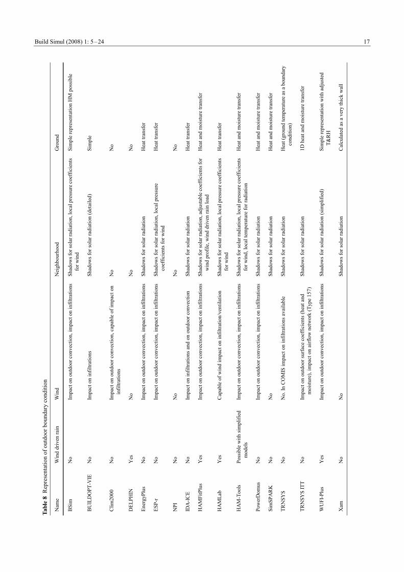
Build Simul (2008) 1: 5–24
17
Tabl
e 8
Rep
rese
ntat
ion
of o
utdo
or b
ound
ary
cond
ition
Nam
e W
ind
driv
en ra
in
Win
d N
eigh
bour
hood
G
roun
d
BSi
m
No
Impa
ct o
n ou
tdoo
r con
vect
ion,
impa
ct o
n in
filtra
tions
Sh
adow
s for
sola
r rad
iatio
n, lo
cal p
ress
ure c
oeffi
cien
ts fo
r win
d Si
mpl
e re
pres
enta
tion
HM
pos
sibl
e
BU
ILD
OPT
-VIE
N
o Im
pact
on
infil
tratio
ns
Shad
ows f
or so
lar r
adia
tion
(det
aile
d)
Sim
ple
Clim
2000
N
o Im
pact
on
outd
oor c
onve
ctio
n, c
apab
le o
f im
pact
on
infil
tratio
ns
No
No
DEL
PHIN
Y
es
No
No
No
Ener
gyPl
us
N
o Im
pact
on
outd
oor c
onve
ctio
n, im
pact
on
infil
tratio
ns
Shad
ows f
or so
lar r
adia
tion
Hea
t tra
nsfe
r
ESP-
r N
o Im
pact
on
outd
oor c
onve
ctio
n, im
pact
on
infil
tratio
ns
Shad
ows f
or so
lar r
adia
tion,
loca
l pre
ssur
e co
effic
ient
s for
win
d H
eat t
rans
fer
NPI
N
o N
o N
o N
o
IDA
-ICE
N
o Im
pact
on
infil
tratio
ns a
nd o
n ou
tdoo
r con
vect
ion
Shad
ows f
or so
lar r
adia
tion
Hea
t tra
nsfe
r
HA
MFi
tPlu
s Y
es
Impa
ct o
n ou
tdoo
r con
vect
ion,
impa
ct o
n in
filtra
tions
Sh
adow
s for
sola
r rad
iatio
n, a
djus
tabl
e coe
ffici
ents
for
win
d pr
ofile
, win
d dr
iven
rain
load
H
eat a
nd m
oist
ure
trans
fer
HA
MLa
b Y
es
Cap
able
of w
ind
impa
ct o
n in
filtra
tion/
vent
ilatio
n Sh
adow
s for
sola
r rad
iatio
n, lo
cal p
ress
ure c
oeff
icie
nts
for w
ind
Hea
t tra
nsfe
r
HA
M-T
ools
Poss
ible
with
sim
plifi
ed
mod
els
Impa
ct o
n ou
tdoo
r con
vect
ion,
impa
ct o
n in
filtra
tions
Sh
adow
s for
sola
r rad
iatio
n, lo
cal p
ress
ure c
oeffi
cien
ts fo
r win
d, lo
cal t
empe
ratu
re fo
r rad
iatio
n H
eat a
nd m
oist
ure
trans
fer
Pow
erD
omus
N
o Im
pact
on
outd
oor c
onve
ctio
n, im
pact
on
infil
tratio
ns
Shad
ows f
or so
lar r
adia
tion
Hea
t and
moi
stur
e tra
nsfe
r
Sim
SPA
RK
N
o N
o Sh
adow
s for
sola
r rad
iatio
n H
eat a
nd m
oist
ure
trans
fer
TRN
SYS
No
No.
In C
OM
IS im
pact
on
infil
tratio
ns a
vaila
ble
Shad
ows f
or so
lar r
adia
tion
Hea
t (gr
ound
tem
pera
ture
as a
bou
ndar
y co
nditi
on)
TRN
SYS
ITT
No
Impa
ct o
n ou
tdoo
r sur
face
coe
ffic
ient
s (he
at a
nd
moi
stur
e), i
mpa
ct o
n ai
rflow
net
wor
k (T
ype
157)
Sh
adow
s for
sola
r rad
iatio
n 1D
hea
t and
moi
stur
e tra
nsfe
r
WU
FI-P
lus
Yes
Im
pact
on
outd
oor c
onve
ctio
n, im
pact
on
infil
tratio
ns
Shad
ows f
or so
lar r
adia
tion
(sim
plifi
ed)
Sim
ple
repr
esen
tatio
n w
ith a
djus
ted
T&R
H
Xam
N
o N
o Sh
adow
s for
sola
r rad
iatio
n
Cal
cula
ted
as a
ver
y th
ick
wal
l

Build Simul (2008) 1: 5–24 18
the focus to optimize the building design for low energy houses. During Annex 41 the tool was further developed to include vapour transfer. It is a multi-zone model which can be used with several hundreds interacting zones. Special attention has been put to prepare the calculation of solar gains through each single window and on the outside of walls by considering the shading by other buildings, overhangs, etc. Transfer in building constructions are cal- culated in one-dimension, based on a FCV method with explicit time integration.
2.2.3 Clim2000
Clim2000 simulation environment has been developed by Electricité de France (Bonneau et al. 1993; Woloszyn et al. 2004). An important feature of Clim2000 is its open structure, allowing combinations of existing components with elements created by the user. A lot of work has gone into validate different Clim2000 models (Lomas et al. 1997; Plathner and Woloszyn 2002). The standard model library includes airflows in multi-zone spaces, energy and moisture sources, and heat transfer through the building envelope. Moisture buffering effect of materials is modelled using a coarse-grained model by Duforestel and Dalicieux (1994).
2.2.4 DELPHIN
The numerical simulation program DELPHIN4 has been developed at the Dresden University of Technology (TUD, www.bauklimatik-dresden.de) as part of research in the field of transport processes in porous building materials. The computer code allows performance analysis of building components under transient climatic boundary conditions and considering moisture and temperature depending material functions. The included material database repres- ents the current research results in material modelling. The new integrated room model allows the calculation of indoor climate in a simplified room as boundary condition for 1D and 2D wall (details see Grunewald 2000; Häupl et al. 2004).
2.2.5 EnergyPlus
EnergyPlus (www.energy-plus.org) is primarily a simulation engine —with a relatively simple user interface, which does not allow the user to input building geometry graphically. More complete interfaces are available from independent third-party developers. Some key capabilities of the simulation engine include variable time steps, con- figurable modular systems integrated with heat balance- based zone simulation, multiple comfort models, daylighting and advanced fenestration, multi-zone airflow, displacement ventilation, flexible system modelling, photovoltaic and solar thermal simulation, and moisture sorption by building
materials using coarse-grained EMPD model (see Crawley et al. 2004; Henninger et al. 2004; Hong et al. 2003).
2.2.6 ESP-r
ESP-r (Clarke 1985 and www.esru.strath.ac.uk) is an integrated modelling system for the assessment of the environmental and energy performance of buildings. It is capable of modelling the heat, power, and fluid flows, within combined building and plant systems when subjected to control actions, as well as visual and acoustic performance of buildings. The package comprises a number of interrelating program modules addressing project management, simulation, results analysis and client report generation. The problem definition exercise is achieved interactively and with the aid of pre-existing databases offering standard construction materials, glazing systems, event profiles, and plant components. Modelling of heat, air, moisture, and electrical power flows can be performed at user determined levels of granularity.
2.2.7 NPI
NPI is a 1D heat and moisture transport model for a system of structures with ideally mixed and time variable ventilated indoor air space (Koronthályová 1998 and 1997). It was developed at the Institute of Construction and Architecture of Slovac Academy of Sciences and is applied in case studies connected mainly with diagnostics of moisture induced damage problems. NPI involves also the depend- ency of material parameters on moisture content. The current version of NPI gradually couples the indoor space only with one type of structure and afterwards, the resulting course of indoor air relative humidity (RH) development is calculated as the weighted mean of the previously calculated indoor air RH developments, in order to ensure fast calculations.
2.2.8 Coupling ESP-r and NPI
An original way of computing whole building energy behaviour is to integrate several simulation tools. Koronthylova et al. (2004) present coupling of NPI and ESP-r, to simulate whole building heat and air transfer, zone airflows, as well as zone heat and moisture transfer in the adjacent building structures (1D) linked with the air and moisture balances in the zone.
The coupling between the tools has been accomplished by the following sequential step algorithm realised in each coupling time (hourly) interval at different levels: The whole building level—simulation of the 3D heat
and air transfer consisting of the modelling of radiation and conduction transfer, together with the air and moisture flows balance of a zone, without hygric inertia (ESP-r)

Build Simul (2008) 1: 5–24
19
Zone level —simulation of heat and moisture transfer in the adjacent envelope structures (1D) linked with the air and moisture balance of the zone (NPI) Post-processing or coupling of the ESP-r and NPI
enables to exploit the capabilities of both particular tools.
2.2.9 IDA-ICE
IDA Indoor Climate and Energy (www.equa.se) is a tool for simulation of building energy consumption. The indoor air quality (IAQ) and thermal comfort is presented by Kalamees (2004) and Sahlin et al. (2004). IDA-ICE covers a large range of phenomena, such as the integrated airflow network and thermal models, CO2 and moisture calculation, vertical temperature gradients and daylight predictions. To calculate moisture transfer in IDA-ICE, the common wall model RCWall should be replaced with HAMWall, developed by Kurnitski and Vuolle (2000). The moisture transfer is modelled by one moisture-transfer potential, the humidity by volume.
2.2.10 HAMFitPlus
HAMFitPlus is developed during the Annex 41 project by Tariku et al. (2006). This whole building hygrothermal simulation tool is used to assess the durability, indoor conditions (occupant comfort), and also energy efficiency of a building in an integrated manner. The model includes heat, air and moisture transfer across building envelope components and the indoor air taking into account the indoor heat and moisture generations, HVAC system, and dynamic HAM interaction with building envelope components.
2.2.11 HAMLab
A new integrated heat, air and moisture modelling toolkit in MATLAB named HAMLab (sts.bwk.tue.nl/hamlab) has been presented by van Schijndel (2007) and de Wit (2006). The implemented numerical model consists of a continuous part for the HVAC system and the indoor climate, solved with a variable time step, and a discrete part, solved with a time step of one hour for the external climate. Combining the MATLAB/Simulink modelling toolkit with COMSOL allows comprehensive modelling of a room with 2D/3D HAM transport in constructions or 2D airflow.
2.2.12 HAM-Tools
HAM-Tools (www.ibpt.org), presented by Sasic Kalagasidis (2004) and Sasic Kalagasidis et al. (2007), is a modular building simulation software, developed in Sweden by Chalmers University of Technology in collaboration with Technical University of Denmark. The main objective of this tool is to obtain simulations of transfer processes related to building physics, i.e., heat and mass transport in
buildings and building components in operating conditions. The model solves heat, air and mass balance equations in an air zone (supposed to be fully mixed) and in the building enclosure, considering air, vapour and liquid transport in one dimension.
2.2.13 PowerDomus
PowerDomus (Mendes et al. 2003; Mendes and Philippi 2005; www.pucpr.br/LST) solves heat and moisture transfer in walls simultaneously according to a method developed by Mendes et al. (2002). The model has an integrated simulation of HVAC systems (Barbosa and Mendes 2007). Seven levels of calculation complexity in HAM models are possible (e.g., with or without moisture transfer, constant or variable material hygrothermal properties, vapour pressure or moisture content driving potentials).
2.2.14 SimSPARK
SimSPARK (Wurtz et al. 2006; Mora et al. 2004; Mendoca et al. 2005) uses zonal models to represent intra-room airflow as well as different models to describe heat and moisture transfer across the building zone envelope, with two of them taking into account moisture adsorption / desorption by building materials. The resulting set of non-linear coupled equations is solved simultaneously by the object-oriented simulation environment, SPARK (gundog.lbl.gov). SimSPARK is suited to parametric studies and complex problems, and can be linked to other simulation tools like EnergyPlus.
2.2.15 TRNSYS
The TRNSYS program (TRaNsient SYstems Simulation, sel.me.wisc.edu/trnsys) is a building energy performance simulation tool with a modular structure. Some other tools (COMIS, Matlab/Simulink, etc.) can be directly linked to the software. The TRNSYS library includes many of the components commonly found in thermal and electrical energy systems, such as solar systems (solar thermal and photovoltaic systems), low energy buildings and HVAC systems, renewable energy systems, cogeneration, fuel cells, etc. It also allows for predictions of the indoor relative humidity, including some buffering effect of materials, using the penetration depth model (Klein et al. 2004).
2.2.16 TRNSYS ITT
TRNSYS ITT is a tool for building simulation that is based on the framework of TRNSYS 14.1 (Klein et al. 2004; Perschk and Meinhold 2007). The wall-model in “Type 56” (module for a multi-zone building) is replaced by a new one (Type 158). The new type is able to consider coupled heat and moisture transfer in the envelope. Diffusion,
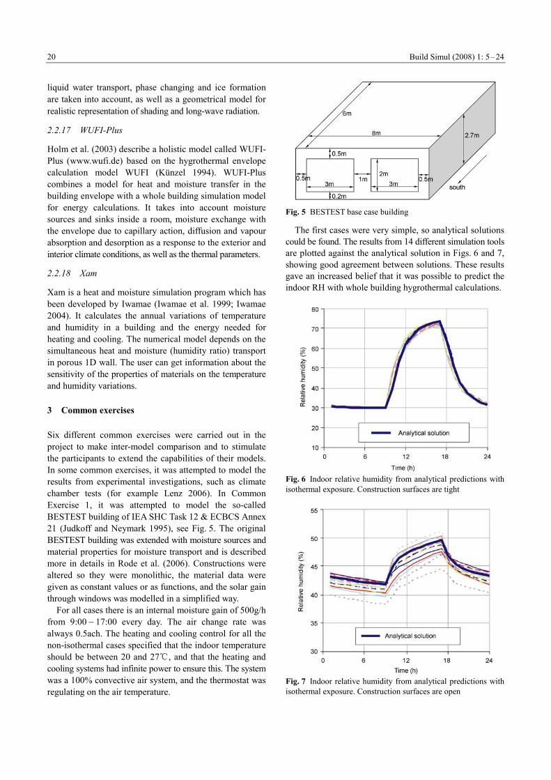
Build Simul (2008) 1: 5–24 20
liquid water transport, phase changing and ice formation are taken into account, as well as a geometrical model for realistic representation of shading and long-wave radiation.
2.2.17 WUFI-Plus
Holm et al. (2003) describe a holistic model called WUFI- Plus (www.wufi.de) based on the hygrothermal envelope calculation model WUFI (Künzel 1994). WUFI-Plus combines a model for heat and moisture transfer in the building envelope with a whole building simulation model for energy calculations. It takes into account moisture sources and sinks inside a room, moisture exchange with the envelope due to capillary action, diffusion and vapour absorption and desorption as a response to the exterior and interior climate conditions, as well as the thermal parameters.
2.2.18 Xam
Xam is a heat and moisture simulation program which has been developed by Iwamae (Iwamae et al. 1999; Iwamae 2004). It calculates the annual variations of temperature and humidity in a building and the energy needed for heating and cooling. The numerical model depends on the simultaneous heat and moisture (humidity ratio) transport in porous 1D wall. The user can get information about the sensitivity of the properties of materials on the temperature and humidity variations.
3 Common exercises
Six different common exercises were carried out in the project to make inter-model comparison and to stimulate the participants to extend the capabilities of their models. In some common exercises, it was attempted to model the results from experimental investigations, such as climate chamber tests (for example Lenz 2006). In Common Exercise 1, it was attempted to model the so-called BESTEST building of IEA SHC Task 12 & ECBCS Annex 21 (Judkoff and Neymark 1995), see Fig. 5. The original BESTEST building was extended with moisture sources and material properties for moisture transport and is described more in details in Rode et al. (2006). Constructions were altered so they were monolithic, the material data were given as constant values or as functions, and the solar gain through windows was modelled in a simplified way.
For all cases there is an internal moisture gain of 500g/h from 9:00 − 17:00 every day. The air change rate was always 0.5ach. The heating and cooling control for all the non-isothermal cases specified that the indoor temperature should be between 20 and 27℃, and that the heating and cooling systems had infinite power to ensure this. The system was a 100% convective air system, and the thermostat was regulating on the air temperature.
Fig. 5 BESTEST base case building
The first cases were very simple, so analytical solutions could be found. The results from 14 different simulation tools are plotted against the analytical solution in Figs. 6 and 7, showing good agreement between solutions. These results gave an increased belief that it was possible to predict the indoor RH with whole building hygrothermal calculations.
Fig. 6 Indoor relative humidity from analytical predictions with isothermal exposure. Construction surfaces are tight
Fig. 7 Indoor relative humidity from analytical predictions with isothermal exposure. Construction surfaces are open

Build Simul (2008) 1: 5–24
21
In the second and the more realistic part of the exercise the building was exposed to a real outdoor climate as represented by the test reference weather of Copenhagen, and a simplified modelling of radiation was adopted. The results shown in Figs. 8 and 9 illustrate the difficulty of carrying out the whole building hygrothermal modelling, as some deviations were quite significant. The differences in the thermal simulation could not explain all the deviation, as it was present also for the case with constant indoor temperature. Some deviations seemed to be the result of how well the solar gains were calculated. Thanks to whole building HAM modelling, some local results for moisture conditions could also be compared: Fig. 9 shows the relative humidity inside the roof structure. For most of the tools, the results agreed with one another, which indicate that the simulations perform correctly when it comes to the calculation of moisture transport in the building enclosure.
Fig. 8 Indoor vapour pressure from numerical calculations with varying indoor temperature in the range 20 to 27℃, but no external radiation
Fig. 9 Relative humidity in the top of the roof from numerical calculations with varying indoor temperature in the range 20 to 27℃. Solar and long-wave radiation is included
All Common Exercises executed as part of Annex 41 Subtask 1, illustrated the complexity of the whole building hygrothermal modelling: it was possible to find a con- sensus among the solutions with different calculation models only for an extremely simple case.
On the other hand, these results also underline the importance of this type of exercises: the existing codes are tested for their suitability for whole building hygrothermal simulation, and new codes have been created, including upgrading and further development of existing codes to be able to handle the moisture simulation. Moreover, the presented results underline some strong points of whole building HAM simulation tools: they are able to simul- taneously predict indoor climate, as well as energy consumption, together with local hygrothermal conditions within the building elements.
4 Conclusion and perspectives
An overall ambition of IEA Annex 41 has been to stimulate the development of information and analytical tools about how a whole building works in terms of its hygrothermal conditions. This has involved modelling of several physical processes pertaining to coupled flow of heat, air, and moisture. And it has involved different building elements at various levels: its spaces, the building envelope with its materials, the interior building structures and furnishing, the system for heating, ventilating and air conditioning, occupants and equipment, and finally the exposure to the exterior environment. The actual challenge in whole building HAM modelling is to ensure a good balance between the many different physical phenomena which interact with each other, rather than to develop models that focus too much on mainly one phenomenon. For example, in most of the existing programs, if moisture is well modelled, then the energy model is rather simple; or if energy is rather well calculated, then moisture behaviour is treated in a simplified way—if not neglected. In this field a lot of progress has been made and encour- aging outcomes resulted from this collaborative project.
The state-of-the-art of existing HAM models and tools at whole building levels, as well as the five Common Exercises designed and performed throughout the course of the Annex, are the major outcome of this collaborative work. The common exercises are well documented and can be successfully used by the scientific community as benchmark tests for model validation and development.
4.1 Specific developments in the used whole building HAM tools
As stated before, one of the purposes of IEA Annex 41 has
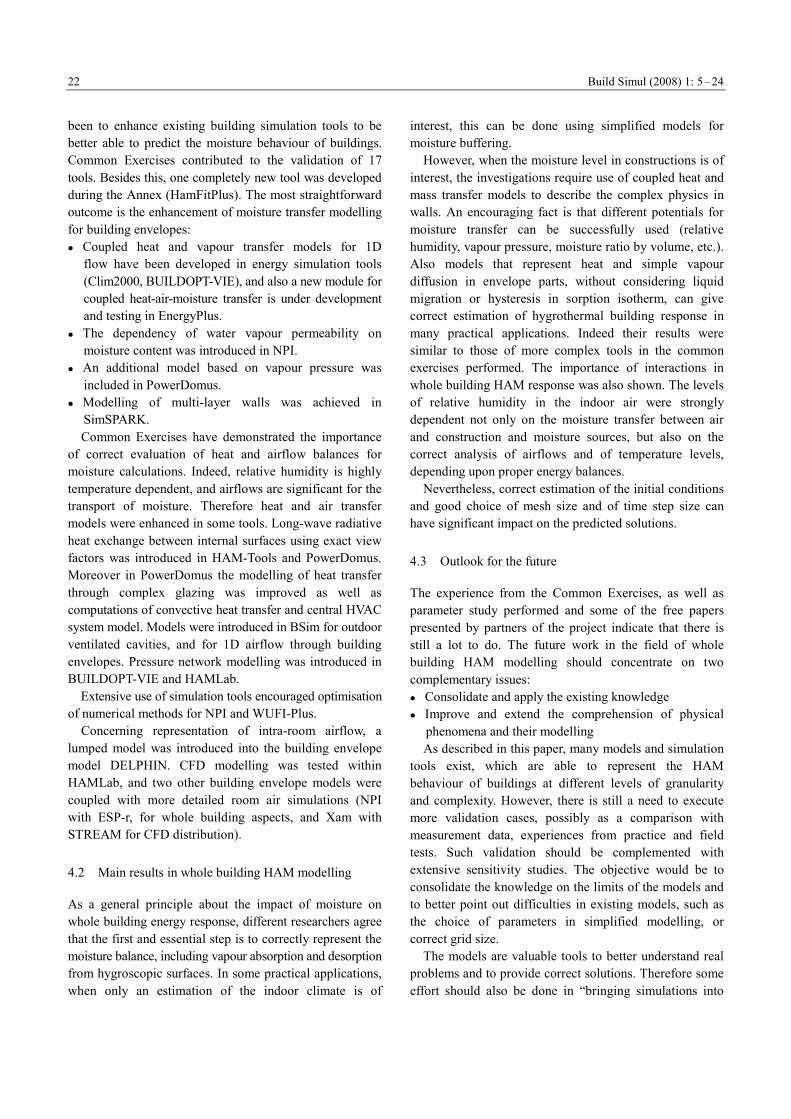
Build Simul (2008) 1: 5–24 22
been to enhance existing building simulation tools to be better able to predict the moisture behaviour of buildings. Common Exercises contributed to the validation of 17 tools. Besides this, one completely new tool was developed during the Annex (HamFitPlus). The most straightforward outcome is the enhancement of moisture transfer modelling for building envelopes: Coupled heat and vapour transfer models for 1D
flow have been developed in energy simulation tools (Clim2000, BUILDOPT-VIE), and also a new module for coupled heat-air-moisture transfer is under development and testing in EnergyPlus.
The dependency of water vapour permeability on moisture content was introduced in NPI.
An additional model based on vapour pressure was included in PowerDomus.
Modelling of multi-layer walls was achieved in SimSPARK. Common Exercises have demonstrated the importance
of correct evaluation of heat and airflow balances for moisture calculations. Indeed, relative humidity is highly temperature dependent, and airflows are significant for the transport of moisture. Therefore heat and air transfer models were enhanced in some tools. Long-wave radiative heat exchange between internal surfaces using exact view factors was introduced in HAM-Tools and PowerDomus. Moreover in PowerDomus the modelling of heat transfer through complex glazing was improved as well as computations of convective heat transfer and central HVAC system model. Models were introduced in BSim for outdoor ventilated cavities, and for 1D airflow through building envelopes. Pressure network modelling was introduced in BUILDOPT-VIE and HAMLab.
Extensive use of simulation tools encouraged optimisation of numerical methods for NPI and WUFI-Plus.
Concerning representation of intra-room airflow, a lumped model was introduced into the building envelope model DELPHIN. CFD modelling was tested within HAMLab, and two other building envelope models were coupled with more detailed room air simulations (NPI with ESP-r, for whole building aspects, and Xam with STREAM for CFD distribution).
4.2 Main results in whole building HAM modelling
As a general principle about the impact of moisture on whole building energy response, different researchers agree that the first and essential step is to correctly represent the moisture balance, including vapour absorption and desorption from hygroscopic surfaces. In some practical applications, when only an estimation of the indoor climate is of
interest, this can be done using simplified models for moisture buffering.
However, when the moisture level in constructions is of interest, the investigations require use of coupled heat and mass transfer models to describe the complex physics in walls. An encouraging fact is that different potentials for moisture transfer can be successfully used (relative humidity, vapour pressure, moisture ratio by volume, etc.). Also models that represent heat and simple vapour diffusion in envelope parts, without considering liquid migration or hysteresis in sorption isotherm, can give correct estimation of hygrothermal building response in many practical applications. Indeed their results were similar to those of more complex tools in the common exercises performed. The importance of interactions in whole building HAM response was also shown. The levels of relative humidity in the indoor air were strongly dependent not only on the moisture transfer between air and construction and moisture sources, but also on the correct analysis of airflows and of temperature levels, depending upon proper energy balances.
Nevertheless, correct estimation of the initial conditions and good choice of mesh size and of time step size can have significant impact on the predicted solutions.
4.3 Outlook for the future
The experience from the Common Exercises, as well as parameter study performed and some of the free papers presented by partners of the project indicate that there is still a lot to do. The future work in the field of whole building HAM modelling should concentrate on two complementary issues: Consolidate and apply the existing knowledge Improve and extend the comprehension of physical
phenomena and their modelling As described in this paper, many models and simulation
tools exist, which are able to represent the HAM behaviour of buildings at different levels of granularity and complexity. However, there is still a need to execute more validation cases, possibly as a comparison with measurement data, experiences from practice and field tests. Such validation should be complemented with extensive sensitivity studies. The objective would be to consolidate the knowledge on the limits of the models and to better point out difficulties in existing models, such as the choice of parameters in simplified modelling, or correct grid size.
The models are valuable tools to better understand real problems and to provide correct solutions. Therefore some effort should also be done in “bringing simulations into
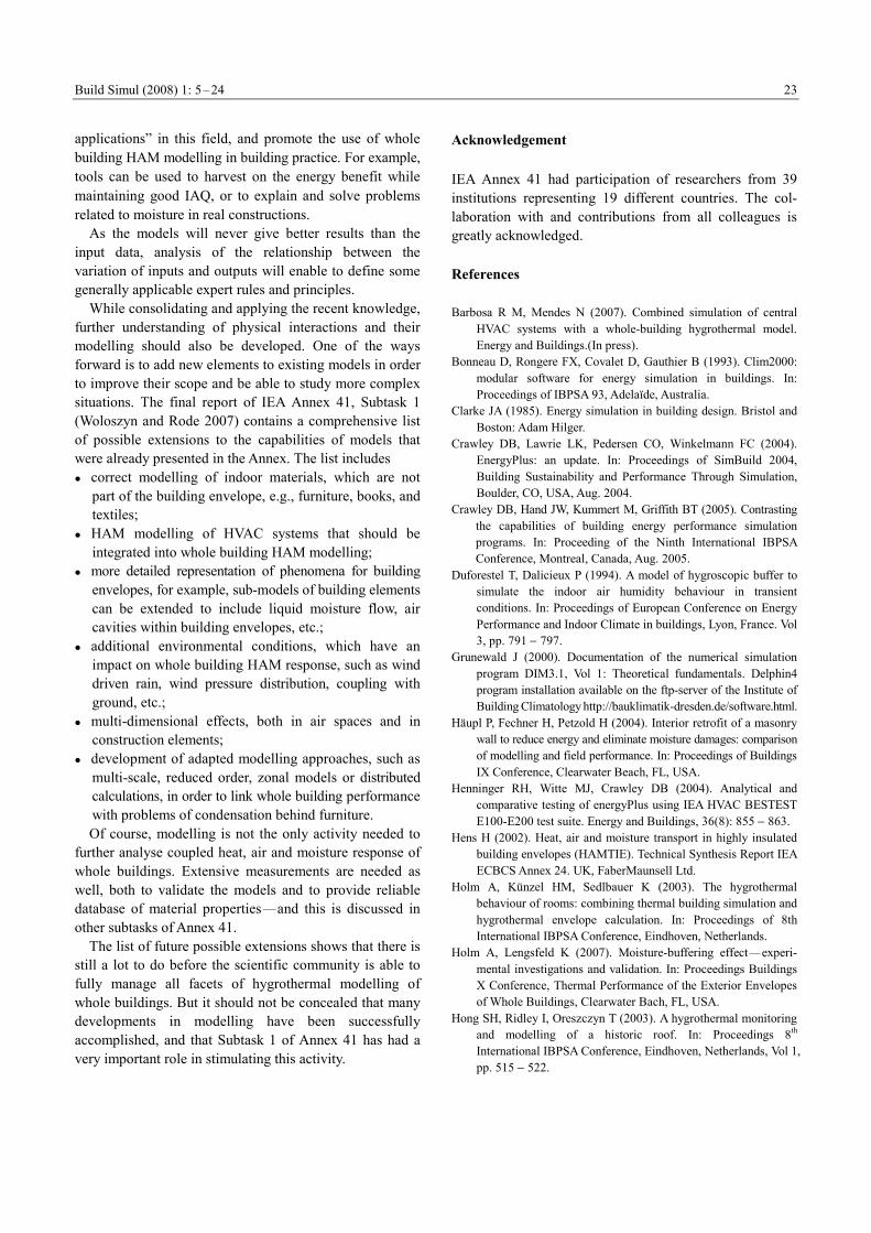
Build Simul (2008) 1: 5–24
23
applications” in this field, and promote the use of whole building HAM modelling in building practice. For example, tools can be used to harvest on the energy benefit while maintaining good IAQ, or to explain and solve problems related to moisture in real constructions.
As the models will never give better results than the input data, analysis of the relationship between the variation of inputs and outputs will enable to define some generally applicable expert rules and principles.
While consolidating and applying the recent knowledge, further understanding of physical interactions and their modelling should also be developed. One of the ways forward is to add new elements to existing models in order to improve their scope and be able to study more complex situations. The final report of IEA Annex 41, Subtask 1 (Woloszyn and Rode 2007) contains a comprehensive list of possible extensions to the capabilities of models that were already presented in the Annex. The list includes correct modelling of indoor materials, which are not
part of the building envelope, e.g., furniture, books, and textiles;
HAM modelling of HVAC systems that should be integrated into whole building HAM modelling;
more detailed representation of phenomena for building envelopes, for example, sub-models of building elements can be extended to include liquid moisture flow, air cavities within building envelopes, etc.;
additional environmental conditions, which have an impact on whole building HAM response, such as wind driven rain, wind pressure distribution, coupling with ground, etc.;
multi-dimensional effects, both in air spaces and in construction elements;
development of adapted modelling approaches, such as multi-scale, reduced order, zonal models or distributed calculations, in order to link whole building performance with problems of condensation behind furniture. Of course, modelling is not the only activity needed to
further analyse coupled heat, air and moisture response of whole buildings. Extensive measurements are needed as well, both to validate the models and to provide reliable database of material properties—and this is discussed in other subtasks of Annex 41.
The list of future possible extensions shows that there is still a lot to do before the scientific community is able to fully manage all facets of hygrothermal modelling of whole buildings. But it should not be concealed that many developments in modelling have been successfully accomplished, and that Subtask 1 of Annex 41 has had a very important role in stimulating this activity.
Acknowledgement
IEA Annex 41 had participation of researchers from 39 institutions representing 19 different countries. The col- laboration with and contributions from all colleagues is greatly acknowledged.
References
Barbosa R M, Mendes N (2007). Combined simulation of central HVAC systems with a whole-building hygrothermal model. Energy and Buildings.(In press).
Bonneau D, Rongere FX, Covalet D, Gauthier B (1993). Clim2000: modular software for energy simulation in buildings. In: Proceedings of IBPSA 93, Adelaïde, Australia.
Clarke JA (1985). Energy simulation in building design. Bristol and Boston: Adam Hilger.
Crawley DB, Lawrie LK, Pedersen CO, Winkelmann FC (2004). EnergyPlus: an update. In: Proceedings of SimBuild 2004, Building Sustainability and Performance Through Simulation, Boulder, CO, USA, Aug. 2004.
Crawley DB, Hand JW, Kummert M, Griffith BT (2005). Contrasting the capabilities of building energy performance simulation programs. In: Proceeding of the Ninth International IBPSA Conference, Montreal, Canada, Aug. 2005.
Duforestel T, Dalicieux P (1994). A model of hygroscopic buffer to simulate the indoor air humidity behaviour in transient conditions. In: Proceedings of European Conference on Energy Performance and Indoor Climate in buildings, Lyon, France. Vol 3, pp. 791 − 797.
Grunewald J (2000). Documentation of the numerical simulation program DIM3.1, Vol 1: Theoretical fundamentals. Delphin4 program installation available on the ftp-server of the Institute of Building Climatology http://bauklimatik-dresden.de/software.html.
Häupl P, Fechner H, Petzold H (2004). Interior retrofit of a masonry wall to reduce energy and eliminate moisture damages: comparison of modelling and field performance. In: Proceedings of Buildings IX Conference, Clearwater Beach, FL, USA.
Henninger RH, Witte MJ, Crawley DB (2004). Analytical and comparative testing of energyPlus using IEA HVAC BESTEST E100-E200 test suite. Energy and Buildings, 36(8): 855 − 863.
Hens H (2002). Heat, air and moisture transport in highly insulated building envelopes (HAMTIE). Technical Synthesis Report IEA ECBCS Annex 24. UK, FaberMaunsell Ltd.
Holm A, Künzel HM, Sedlbauer K (2003). The hygrothermal behaviour of rooms: combining thermal building simulation and hygrothermal envelope calculation. In: Proceedings of 8th International IBPSA Conference, Eindhoven, Netherlands.
Holm A, Lengsfeld K (2007). Moisture-buffering effect— experi- mental investigations and validation. In: Proceedings Buildings X Conference, Thermal Performance of the Exterior Envelopes of Whole Buildings, Clearwater Bach, FL, USA.
Hong SH, Ridley I, Oreszczyn T (2003). A hygrothermal monitoring and modelling of a historic roof. In: Proceedings 8th International IBPSA Conference, Eindhoven, Netherlands, Vol 1, pp. 515 − 522.

Build Simul (2008) 1: 5–24 24
Iwamae A, Hanibuchi H, Chikada T (1999). A windows-based PC-software to design thermal environment in residential houses. In: Proceedings of Building Simulation’99, Vol 3, pp. 1325 − 1330.
Iwamae A (2004). A development of PC software to calculate temperature and humidity variations in residential houses. Publication A41-T1-J-04-1. Presentation for IEA Annex 41 meeting, Glasgow, UK, Oct. 2004.
Judkoff R, Neymark J (1995). Building energy simulation test (BESTEST) and diagnostic method. NREL/TP-472-6231. Golden, Colo.: National Renewable Energy Laboratory, USA.
Kalamees T (2004). IDA ICE: the simulation tool for making the whole building energy and HAM analysis. Publication A41- T1-EE-04-1. Presentation for IEA Annex 41 meeting, Zurich, Switzerland, May 2004.
Klein SA, Beckman WA, Mitchell JW, Duffie JA, et al. (2004). TRNSYS 16—a TRaNsient SYstem Simulation program, User manual. Solar Energy Laboratory. Madison: University of Wisconsin-Madison, USA.
Koronthályová O (1997). The effect of the inner surface material on the indoor relative humidity. In: Proceedings of International Thermal Energy and Environment Congress (ITEEC 97), Ecole Superieure de Technologie Agadir, Vol 2, pp. 557 − 561.
Koronthályová, O (1998). Non-steady model for calculation of indoor air relative humidity. Building Research Journal, 46: 201 − 211.
Koronthályová O, Mihálka P, Matiašovský P (2004). Model for complex simulation of HAM-transfer in a single thermal zone building. Building Research Journal, 2004, 52(4): 199 − 217.
Künzel HM (1994). Simultaneous heat and moisture transport in building components. Dissertation. University of Stuttgart, Stuttgart, available via http://www.building-physics.com.
Kurnitski J, Vuolle M (2000). Simultaneous calculation of heat, moisture, and air transport in a modular simulation environment. In: Proceedings of the Estonian Academy of Sciences Engineering, Mar. 2000, Vol. 6/1, pp. 25 − 47.
Lenz K (2006). CE3 —Two real exposure rooms at FhG. Results of the complete Common Exercise 3. Publication A41-T1-D-06-1. Presentation for IEA Annex 41 meeting, Kyoto, Japan, Apr. 2006.
Lomas KJ et al. (1997). Empirical validation of building energy simulation programs. Energy and Buildings, 26: 253 − 275.
Mendes N, Philippi PC, Lamberts R (2002). A new mathematical method to solve highly coupled equations of heat and mass transfer in porous media. International Journal of Heat and Mass Transfer, 45: 509 − 518.
Mendes N, Oliveira RCLF, dos Santos GH (2003). Domus 2.0: a whole-building hygrothermal simulation program. In: Proceedings of 8th International IBPSA Conference, Eindhoven, Netherlands.
Mendes N, Philippi PC (2005). A method for predicting heat and moisture transfer through multilayered walls based on temperature and moisture content gradients. International Journal of Heat and Mass Transfer, 48: 37 − 51.
Mendonça KC, Wurtz E, Inard C (2005). Predicting temperature and moisture distribution in conditioned spaces using the zonal approach. In: Proceedings of International IBPSA Conference, Montréal, Canada, pp. 763 − 768.
Mora L, Wurtz E, Mendonça KC, Inard C (2004). Effects of coupled heat and moisture transfers through walls upon indoor environment predictions. International Journal of Ventilation, 3(3): 227 − 234.
Perschk A, Meinhold U (2007). Ein Modell zur hygrisch- thermischen Gebäudesimulation mit Hilfe der Kopplung von Zonen- und Feldmodell. Bauphysik, 29(1): 55 − 62. (in German).
Plathner P, Woloszyn M (2002). Interzonal air and moisture transport in a test house: experiment and modelling. Building and Environnement, 37(2): 189 − 199.
Rode C, Grau K (2003). Whole building hygrothermal simulation model. ASHRAE Transactions, 109(1): 572 − 582.
Rode C, Grau K (2004). Calculation tool for whole building hygrothermal analysis building simulation 2000. Publication A41-T1-DK-04-1. Presentation for IEA Annex 41 meeting, Zurich, Switzerland, May 2004.
Rode C, Peuhkuri R, Woloszyn M (2006). Simulation tests in whole building heat and moisture transfer. Paper presented at International Building Physics Conference, Montreal, Canada, Aug. 2006.
Sahlin P, Eriksson L, Grozman P, Johnsson H, Shapovalov A, Vuolle M (2004). Whole-building simulation with symbolic DAE equations and general purpose solvers. Building and Environment, 39(8): 949 − 958.
Sasic Kalagasidis A (2004). HAM-Tools: an integrated simulation tool for heat, air and moisture transfer analyses in building physics. PhD Dissertation. Chalmers University of Technology, Gothenburg, Sweden.
Sasic Kalagasidis A, Weitzmann P, Nielsen TR, Peuhkuri R, Hagentoft C-E, Rode C (2007). The international building physics toolbox in Simulink. Energy and Buildings, 39(6): 665 − 674.
van Schijndel AWM (2007). Integrated heat, air & moisture modelling and simulation. PhD Dissertation. Eindhoven University of Technology.
Sofic M, Bednar T (2007). Analyses of the accuracy of monthly energy balances for assessment of cooling energy demand (Analyse Der Genauigkeit Des Monatsbilanzverfahrens Zur Ermittlung Des Kühlbedarfs Von Nichtwohngebäuden). Bauphysik, 29(3): 202 − 207. (in German).
Tariku F, Kumaran MK, Fazio P (2006). Whole building heat and moisture analysis. Publication A41-T1-C- 06-8. Presentation for IEA Annex 41 meeting, Lyon, France, Oct. 2006.
de Wit MH (2006). Hambase: heat, air and moisture model for building and systems evaluation. Eindhoven, Netherlands: Eindhoven University Press.
Woloszyn M, Rusaouen G, Covalet D (2004). Whole building simulation tools: Clim2000. Publication A41-T1-F-04-3. Presentation for IEA Annex 41 meeting, Zurich, Switzerland, May 2004.
Woloszyn M, Rode C (2007). Annex 41, Subtask 1: Modelling principles and common exercises. Draft Final Report for the Energy Conservation in Buildings and Community Systems executive committee of the International Energy Agency.
Wurtz E, Haghighat F, Mora L, Mendonca KC, Maalouf C, Zhao H, Bourdoukan P (2006). An integrated zonal model to predict transient indoor humidity distribution. ASHRAE Transactions, (112)2: 175 − 186.