Factory Tools
358
EUS1109200 P-Tool Factory Tools
-
Upload
khangminh22 -
Category
Documents
-
view
1 -
download
0
Transcript of Factory Tools

EUS1109200
P-Tool
Factory Tools

General Contents
Before using Factory Tools
1. About this manual i
2. Contents of each chapter i
Chapter 1 Creating and editing the board data
1. Overview 1-1
2. Registering and selecting the board name 1-2
2.1 Registering board names 1-2
2.2 Selecting the board data 1-4
3. Creating board data for individual machines 1-5
3.1 Creating new board data for individual machines 1-5
3.2 Selecting board data for individual machines 1-7
3.3 Deleting board data 1-7
4. Creating the board information 1-8
4.1 Board parameters 1-9
4.2 Mount parameters 1-13
4.3 Sequence parameters 1-15
4.4 Offset parameters 1-17
4.5 Fiducial parameters 1-19
4.5.1 Board fiducial function 1-20
4.5.2 Block fiducial function 1-20
4.5.3 Local fiducial functions 1-21
4.6 Using the badmark functions 1-23
4.6.1 Badmark functions 1-23
4.6.2 Setting the Badmark parameters 1-24
4.7 Height parameters 1-26
4.8 Pre-dispense parameters 1-27
4.9 Dot Dispense parameters 1-28
5. Creating the parts information 1-29
5.1 Creating procedure 1-30
5.2 Basic parameters 1-31
5.2.1 Parameter common to machines 1-31
5.2.2 Parameter for machines other than YS Series machines 1-35
5.2.3 Parameter for YS Series machines only 1-36
5.2.4 Editing the ball lead position information 1-37
5.2.5 Datum Ball automatic setting function of Random arrangement Ball 1-39
5.3 Pick parameters 1-41
5.4 Dip parameters 1-44
EUS1109200

5.5 Mount parameters 1-45
5.6 Vision parameters 1-47
5.7 Shape parameters 1-50
5.8 Tray parameters 1-55
5.9 Option parameters 1-66
5.9.1 Alternative components 1-67
5.10 Side-view camera parameters 1-69
5.11 Dispense parameters 1-70
6. Creating the mark information 1-71
6.1 Creating procedure 1-72
6.2 Basic parameters 1-73
6.3 Shape parameters 1-75
6.4 Vision parameters 1-77
7. Using and editing the database 1-79
7.1 Using the database 1-79
7.1.1 Copying data from the database (Set from Database) 1-79
7.1.2 Storing the data into the database (Copy Back to Database) 1-81
7.2 Editing the database 1-84
7.3 Database matching 1-86
7.4 Function of Database matching from board 1-88
8. Editing the board data 1-91
8.1 Block offset 1-91
8.1.1 Pitch distribution 1-91
8.1.2 Pitch distribution of data after offset distribution 1-93
8.1.3 Block distribution 1-95
8.1.4 Block distribution return 1-98
8.2 Editing the parts information 1-99
8.2.1 Moving the data between machines 1-99
8.2.2 Multiplying the parts data 1-100
8.2.3 Renumbering the parts data 1-102
8.3 Creating the sequence data 1-104
8.3.1 Height correction 1-104
8.3.2 Executing the height correction distribution 1-106
8.3.3 Dispense distribution 1-107
8.4 Creating the dot dispense information 1-109
8.4.1 Dispense distribution 1-109
8.5 Data check 1-111
9. Printing the board data 1-113
9.1 Printing the board data 1-113

Chapter 2 Creating solder-print data
1. Registering and selecting the board data 2-1
1.1 Registering a new board data name 2-1
1.2 Selecting the board data 2-3
2. Board data setting 2-4
2.1 Board data detail setting 2-8
3. Mask data setting 2-11
3.1 Mask data detail setting 2-14
4. Squeegee data setting 2-15
4.1 Squeegee detail setting 2-19
5. Cleaner data setting 2-21
6. Creating the mark data 2-23
6.1 Creating procedure 2-24
6.2 Shape parameters 2-26
6.3 Vision parameters 2-28
Chapter 3 Data optimization
1. Starting and quitting the Optimizer 3-1
1.1 Starting the Optimizer 3-1
1.1.1 Starting the Optimizer from the Board Editor 3-1
1.1.2 Starting the Optimizer from the Feeder Viewer 3-2
1.2 Quitting the Optimizer 3-3
2. Optimizer window 3-4
3. Defining the optimizing conditions 3-7
3.1 Checking the information 3-7
3.2 Setting the basic conditions 3-9
3.2.1 Creating Basic Conditions and Registering a Template 3-9
3.2.2 Setting Enforcement Object of “Height difference to permit overtaking” 3-12
3.2.3 Pallet Number Automatic Decision 3-16
3.3 Setting the detailed conditions 3-19
3.4 Common setting 3-23
3.5 Initial setting 3-24
3.6 Specifying the dump station (option) position 3-25
3.7 Set layout of common parts 3-27
3.7.1 Settings 3-28
3.7.2 Auto Distribution Error 3-28
3.7.3 Reporting parts that cannot be the same layout 3-29
3.8 Setting the optimizing conditions for individual board data 3-30

3.9 Editing the data optimizing conditions 3-33
3.9.1 Editing each file of optimizing conditions 3-33
3.9.2 Editing multiple files of optimizing conditions 3-34
4. Executing data optimization 3-35
4.1 Checking the nozzles 3-38
5. Outputting the feeder setup lists 3-39
6. Changing the line to be optimized 3-41
7. Multi-lane Support 3-42
7.1 Optimize of single combined program 3-42
7.2 Optimize with same kind parts 3-42
7.3 [Set optimization parameters] dialog is extended 3-42
7.4 [Detail] setting is extended. 1 3-43
7.5 [Detail] setting is extended. 2 3-43
7.6 [Detail] setting is extended. 3 3-44
7.7 Result dialog is extended 3-45
Chapter 4 Setup Optimizer
1. About the Setup Optimizer 4-1
2. Executing the Setup Optimizer 4-2
3. Setting the Setup Optimizer sheet 4-5
3.1 Starting the Setup Optimizer sheet 4-5
3.2 Setup Optimizer sheet configuration 4-7
3.3 COMPXPCB worksheet setting 4-10
3.4 StandardTime worksheet setting 4-15
3.5 FeederPlate worksheet setting 4-16
3.6 Nozzle worksheet 4-18
3.7 Executing the Setup Optimizer under the defined conditions 4-19
4. Setting examples on the Setup Optimizer sheet 4-20
4.1 Setting as many feeders as possible 4-20
4.2 Giving priority to the cycle time 4-21
5. Optimizing the board data 4-22
5.1 Optimizing the board currently being set up 4-22
5.2 Optimizing the edited board data 4-24
6. Optimization Monitor 4-25
6.1 Starting the Optimization Monitor 4-25

6.2 Optimization Monitor sheet configuration 4-27
Chapter 5 ASCII data conversion
1. About ASCII data conversion 5-1
2. Creating board data 5-2
3. Creating a conversion font file 5-10
3.1 Create a new font file 5-10
3.2 Editing a font file 5-30
3.3 Delete / copy a font file and change the font file name. 5-31
3.4 Import of font file. 5-32
4. Miscellaneous 5-34
4.1 How to express the logical formula. 5-34
Chapter 6 Database management
1. Unified database management function 6-1
1.1 Outline of operation 6-1
1.2 Feature of “Unified database management” 6-2
1.2.1 Commonness of database 6-2
1.2.2 Management of database 6-3
1.3 Preparation for “Unified database management” 6-4
1.4 Setting 6-5
1.4.1 Setting of Database Folder 6-5
1.4.2 Setting of Y.FacT “Use Database” 6-7
1.5 Database collection 6-8
1.5.1 Method of using Database Matching (Database Write from Board) 6-10
1.5.2 Method of using Parts Database Editor 6-12
1.6 Limitations 6-14
2. “Database Synchronize mode” function 6-15
2.1 Introduction 6-15
2.2 Outline of operation 6-16
2.3 Preparation of database 6-20
2.4 Setting 6-23
2.4.1 YG Series or subsequent machine 6-23
2.4.2 Xg Series 6-24
2.4.3 Y.FacT 6-25
2.4.4 YRS 6-26
2.5 Detailed explanation of operation 6-27
2.5.1 YG Series or subsequent machine 6-27
2.5.2 Xg Series 6-30
2.5.3 Y.FacT 6-32

2.6 Limitations 6-34
2.6.1 Limitations when beginning to operate 6-34
2.6.2 Other limitations 6-34
3. Unified database management support checklist 6-35
3.1 Introduction 6-35
3.2 Unified database management support checklist 6-36
3.2.1 Database backup 6-36
3.2.2 The path for Unified database management 6-36
3.2.3 Database preparation 6-36
3.2.4 Necessity judgment of “Database Synchronize mode function” 6-36
3.2.5 Database Synchronize mode function is necessary 6-37
3.2.6 Database Synchronize mode function is unnecessary 6-39
4. Series Database 6-40
4.1 Outline of functions 6-40
4.2 Detailed explanation of operation 6-40
4.3 Settings 6-41
4.3.1 Setting method 6-41
4.3.2 Database allocation to each machine 6-42
4.4 Limitations 6-43
5. Shape Database 6-44
5.1 Outline of function 6-44
5.2 To use Shape Database 6-45
5.3 Details of function 6-46
5.3.1 Database Matching by Shape Name / Database Matching from Board by Shape Name 6-48
5.3.2 Set from DATABASE automatically after Board data is read – Referring Parts Shape List 6-48
5.3.3 Making of “Parts / Shape List” 6-48
5.4 Transition Tool of Shape Database 6-49
5.4.1 Outline of function 6-49
5.4.2 To use this function 6-50
5.4.3 Flow of processing and composition of each dialog 6-51
5.5 Registration function of “Parts / Shape List” 6-55
5.5.1 Outline of function 6-55
5.5.2 To use this function 6-55
5.5.3 Outline of operation 6-55
5.5.4 The flow of processing and the composition of each dialog 6-61
5.5.5 New registration 6-65
5.6 Limitations 6-69
6. Additional parameter handling on database 6-70
6.1 Outline of function 6-70
6.2 Details of operation 6-70
6.2.1 Pick Pos. Parameters 6-70
6.2.2 Tray Parameters 6-70
6.2.3 Comment 6-70
6.2.4 Target command 6-71

6.3 Settings 6-72
6.4 Moving existing data 6-73
6.4.1 Reason to prepare to introduce 6-73
6.4.2 How to prepare to introduce 6-74
6.5 Limitations 6-74
7. Parts Database Duplicate Check 6-75
7.1 Outline of function 6-75
7.2 Settings 6-75
7.3 How to setup 6-76
7.3.1 Duplicate Data Check Function 6-76
7.3.2 Error Message and its Counter Measures 6-76
7.4 Limitations 6-80
Index

Before using Factory Tools
Contents
1. About this manual i
2. Contents of each chapter i
Microsoft™ and Windows are either registered trademarks or trademarks of Microsoft
Corporation in the United States and/or other countries.

i
Befo
re using
Fac
tory To
ols
1. About this manualThis manual describes how to create and edit board data (PCB data). For information on how to install the Factory Tools and how to use each application, please read the "Factory Tools User's Manual for Standard Functions". For the operating methods for YAMAHA surface mounters, dispensers and solder paste printers, refer to their operation manuals that come with the machine shipped to you.
2. Contents of each chapterThis manual consists of the following chapters.
Chapter 1 Creating and editing board data
•Explainshowtocreateandeditboarddata(PCBdata).
• Explainshowtousethedatabaseandhowtoedititsdata.
Chapter 2 Creating solder-print data
Explainshowtocreateboarddataandeditvariousparametersneededforsolderprinting.
Chapter 3 Data optimization
Explainsthemethodsfordistributingandoptimizingproductionlinedatatoenhancemanufacturingefficiency.
Chapter 4 Setup Optimizer
Maketheboarddatatoseverlmachinesproduction.
Chapter 5 ASCII data conversion
ThisoptionalprogramconvertsCADdataordatacreatedbyothermachinesintoYGXformatdata.
Chapter 6 Database management
Explainsaboutdatabasemanagementandoperation.
Index
Theindexlistedattheendofthismanualhelpsyouquicklyfindwherenecessaryitemsareexplained.

Chapter 1 Creating and editing the board data
Contents
1. Overview 1-1
2. Registering and selecting the board name 1-2
2.1 Registering board names 1-2
2.2 Selecting the board data 1-4
3. Creating board data for individual machines 1-5
3.1 Creating new board data for individual machines 1-5
3.2 Selecting board data for individual machines 1-7
3.3 Deleting board data 1-7
4. Creating the board information 1-8
4.1 Board parameters 1-9
4.2 Mount parameters 1-13
4.3 Sequence parameters 1-15
4.4 Offset parameters 1-17
4.5 Fiducial parameters 1-19
4.5.1 Board fiducial function 1-20
4.5.2 Block fiducial function 1-20
4.5.3 Local fiducial functions 1-21
4.6 Using the badmark functions 1-23
4.6.1 Badmark functions 1-23
4.6.2 Setting the Badmark parameters 1-24
4.7 Height parameters 1-26
4.8 Pre-dispense parameters 1-27
4.9 Dot Dispense parameters 1-28
5. Creating the parts information 1-29
5.1 Creating procedure 1-30
5.2 Basic parameters 1-31
5.2.1 Parameter common to machines 1-31
5.2.2 Parameter for machines other than YS Series machines 1-35
5.2.3 Parameter for YS Series machines only 1-36
5.2.4 Editing the ball lead position information 1-37
5.2.5 Datum Ball automatic setting function of Random arrangement Ball 1-39
5.3 Pick parameters 1-41
5.4 Dip parameters 1-44
5.5 Mount parameters 1-45

5.6 Vision parameters 1-47
5.7 Shape parameters 1-50
5.8 Tray parameters 1-55
5.9 Option parameters 1-66
5.9.1 Alternative components 1-67
5.10 Side-view camera parameters 1-69
5.11 Dispense parameters 1-70
6. Creating the mark information 1-71
6.1 Creating procedure 1-72
6.2 Basic parameters 1-73
6.3 Shape parameters 1-75
6.4 Vision parameters 1-77
7. Using and editing the database 1-79
7.1 Using the database 1-79
7.1.1 Copying data from the database (Set from Database) 1-79
7.1.2 Storing the data into the database (Copy Back to Database) 1-81
7.2 Editing the database 1-84
7.3 Database matching 1-86
7.4 Function of Database matching from board 1-88
8. Editing the board data 1-91
8.1 Block offset 1-91
8.1.1 Pitch distribution 1-91
8.1.2 Pitch distribution of data after offset distribution 1-93
8.1.3 Block distribution 1-95
8.1.4 Block distribution return 1-98
8.2 Editing the parts information 1-99
8.2.1 Moving the data between machines 1-99
8.2.2 Multiplying the parts data 1-100
8.2.3 Renumbering the parts data 1-102
8.3 Creating the sequence data 1-104
8.3.1 Height correction 1-104
8.3.2 Executing the height correction distribution 1-106
8.3.3 Dispense distribution 1-107
8.4 Creating the dot dispense information 1-109
8.4.1 Dispense distribution 1-109
8.5 Data check 1-111
9. Printing the board data 1-113
9.1 Printing the board data 1-113

1-1
1 C
rea
ting a
nd e
diting
the b
oa
rd d
ata
1. OverviewThe board data is indexed by each individual board name. Each board type consists of various information and parameters as shown below, which can be selected or checked with the item icons in the tree view and tabs in the main view. This chapter describes basic methods for creating board data so that you will understand what data is needed for what item. After you have obtained a complete understanding of these methods, begin actual work according to the desired method.
Board name Parts
Pick
Dip
Basic
Vision
Mount
Tray
Option
Side View
Shape
Shape
Vision
Basic
Mount
Sequence
Board
Various parameters
Fiducial
Badmark
Height Displacement
Pre Dispense
Dispense
Dot dispense
Offset
Board
Board data structure
Mark
63100-S1-00
Reference Parameters displayed on the Board Editor may slightly differ depending on the specifications.

1-2
1 C
rea
ting a
nd e
diting
the b
oa
rd d
ata
2. Registering and selecting the board name2.1 Registering board namesTocreatenewboarddataforproduction,youmustfirstregistertheboardname.Therearesomemethodsforregisteringaboardname.
1. Registering a new board name
Ifnobasicdataisfoundinthepreviouslyregisteredboarddata.Youshouldregisteranewboardnamewithemptydata
andthenenternecessarydata.
2. Utilizing board data already registered
Makeacopyofboarddatawhichisalreadyregisteredinthemachine.
3. Converting CAD data or other manufacturer's mounter data
AfterconvertingCADdataorothermanufacturer'smounterdataintoastandardformat,takeitscoordinatedataintothe
FactoryToolstocreatedatathatcanbeusedwithYAMAHAfullvisionseriesmounters.
n The following steps explain the procedure in "1. Registering a new board name".
1 Start the Board Editor.From the Start menu on the Windows taskbar, select "Programs" - "YAMAHA Factory Tools P-Tool" and then click "Board Editor".
2 Select the line to use.When the "Select Editing Line" dialog box appears, select the line (production line) to use and click the [OK] button. The Board Editor window appears.
3 Create new board data.Select "Create New Board Data" from the File menu or click the [New Board Data] button on the toolbar.
Creating new board data
64100-S1-00

1-3
1 C
rea
ting a
nd e
diting
the b
oa
rd d
ata
4 Save the new board data.1. Select "Save Board Data" from the File menu or click the [Save Board Data] button on the toolbar.
The dialog box appears for selecting the board data.
2. Enter a board name within 20 alphanumeric characters from the keyboard.
Also select the file type from the File Type drop-down list.
3. Check or select the folder in which the board data is saved and click the [Save] button.
The registered board name is displayed in the tree view.
n NOTE A space cannot be included in a board name. Use underbars instead.
c CAUTION The following characters, numbers and symbols can be used in board data names. abcdefghijklmnopqrstuvwxyzABCDEFGHIJKLMNOPQRSTUVWXYZ0123456789_
c CAUTION An alert dialog box appears if board data with the same name already exists. Use a different name. (If you want to register the same name by overwriting the previous data, press the [OK] button in the alert dialog box.)
Saving the board data
Enter the board name. Select the file type.64101-S1-00
Initial screen after new board data has been registered
Registered board name is displayed.
64102-S1-00

1-4
1 C
rea
ting a
nd e
diting
the b
oa
rd d
ata
2.2 Selecting the board dataToselectboarddatafromthosealreadyregistered,proceedasfollows.
1 Open the board data.Select "Open Board on This Editor" or "Open Board on New Editor" from the File menu. The "Board data select" dialog box appears.
Reference Clicking the [Open Board on New Editor] button or [Open Board on This Editor] button on the toolbar opens the "Board data select" dialog box.
Opening the board data
64103-S1-00
2 Select the board name.When the "Board data select" dialog box appears, place the cursor on the board name you want to open and click the [Select] button (or directly double-click the board name to open it). The selected board data will be loaded and the board name displayed in the tree view.
Selected board name is displayed.
Selected board name
64104-S1-00

1-5
1 C
rea
ting a
nd e
diting
the b
oa
rd d
ata
3. Creating board data for individual machinesBoard data can be created for individual machines registered in the line.
3.1 Creating new board data for individual machines
1 Start the Board Editor.From the Start menu on the Windows taskbar, select "Programs" - "YAMAHA Factory Tools P-Tool" and then click "Board Editor".
2 Select the line to be used.When two or more lines (production line) are registered, the "Select Editing Line" dialog box appears. Select the line in which you are going to create new board data and click the [OK] button. The Board Editor window appears.
Reference Even when board data is already open and being edited, new board data can be created for individual machines in the same line. In this case, you do not have to select the line, so proceed to step 3.
3 Select the machine for which you want to create new board data.Click the machine icon in the tree view.
4 Create new board data for the selected machine.From the File menu, select "Individual Data" and click "Create New Individual Data". A new parameter setup screen then appears. Set each parameter. (For how to set each parameter, see the following sections in this chapter.)
Creating new Board data for individual machine
64105-S1-00

1-6
1 C
rea
ting a
nd e
diting
the b
oa
rd d
ata
5 Save the board data you have created.1. From the File menu, select "Individual Data" and click "Save Individual Data As".
2. When a dialog box for selecting the board data appears, enter the board name in the data Name
box and select the file type from the File Type drop-down list.
3. Check the destination folder and then click the [Save] button.
The parameter setup screen for the newly created board data is displayed.
Saving the board data for selected machine
Enter the board name.
Select the file type.
64106-S1-00
6 Close the board data setup screen.From the File menu, select "Individual Data" and click "Close Individual Data". The board data setup screen closes and returns to the previous screen.

1-7
1 C
rea
ting a
nd e
diting
the b
oa
rd d
ata
3.2 Selecting board data for individual machinesToloadandeditboarddataalreadyregisteredforindividualmachines,followthesesteps.
1 Open the board data registered for an individual machine.Select the machine and, from the File menu, select "Individual Data" and click "Open Individual Data". The "Board data select" dialog box appears.
Reference You can also select the "Open individual Data" from the context menu that appears when the right mouse button is clicked on the selected machine.
2 Select the board.Place the cursor on the board name you want to open and click the [Select] button (or directly double-click the board name to open it). The selected board data is loaded and displayed on the screen.
Selecting the board data for selected machine
Select the Board name.
64107-S1-00
3.3 Deleting board dataTodeleteboarddataregisteredforindividualmachines,usetheBoardExplorerasexplainedbelow.
1 Select the board data.Select the line or machine in the tree view so that the board data to be deleted is displayed in the main view. Then select the board data to be deleted.
2 Delete the selected board data.1. Select "Delete" from the Edit menu.
Reference You can select the "Delete" command from the context menu that appears by clicking the right mouse button.
2. A confirmation dialog box appears.
Click the [Yes] button to delete the selected board data.

1-8
1 C
rea
ting a
nd e
diting
the b
oa
rd d
ata
4. Creating the board informationThis section describes how to create the board information such as for board size, production methods and parts (electronic component) mounting positions.
Board information parameters
Data No.Pattern NameSkipX, Y, RP. No.Part NameHeadBad.Fid.
Data No.Pattern NameTypeSkipX, Y, R
Data No.Pattern NameSkipX, Y, R, ZModeNo.NameHeadBad.Fid.HeightSeq. (Sequence)Gr. Start (Group Start)Mnt. Order (Mounting Order)Monitor
Data No.Pattern NameTypeNoteX1, Y1Mark 1X2, Y2Mark 2
Data No.Pattern NameTypeNoteX, YMark
Data No.Pattern NameSkipQtyHeadSequenceX, Y, RMarkFeedback
Data No.CommentModeNoteMarkX, Y
Data No.Pattern NameSkipQtyHeadSeq. (Sequence)X, Y, RFid.Bad.
Board Size XYBoard Size HeightCommentBoard Fix DevicePre Fix TimerTrans HeightConveyor TimerAlignmentVacuum CheckRetry SequencePrecede PickTray PriorityDot CheckingRefresh DispenseConveyor Motor SpeedRunning ModeCo-PlanarityConveyor Y Speedetc.
Board
63101-S1-00
Reference Parameters displayed on the board Editor may slightly differ depending on the specifications.

1-9
1 C
rea
ting a
nd e
diting
the b
oa
rd d
ata
4.1 Board parametersTheboardparameterscreenopenswhenyouclicktheboardiconinthetreevieworthe[Board]tabinthedetailview.Settheboardparametersbyreferringtothefollowingdescription.
Board parameter screen
64108-S1-10
Reference Parameter items displayed may slightly differ depending on the specifications.
DualLaneMachinecanproductwithfollowingmountmode.
Mount Mode Feature
Parallel Each head mounts only for each lane.
Alternate Front lane and rear lane are mounted in order.
· It is set automatically when created by combining some single board data according to the parts arrangement. · It is added to Board Information, but it is not able to edit. It is changed only by optimizer.
DualLaneMachinecanproductwithfollowingtransfermode.
Transfer Mode Feature
Asynchronous Transfer Each lane decides the timing to start or finish to transfer.
Synchronous TransferBoth lane synchronize the timing to start or finish to transfer. It is not used with [Parallel Lanes]. Data check error occurs with both setting.
· It is added to Board Information, it is able to edit.
Mount Mode/Transfer Mode
641C0-S1-00

1-10
1 C
rea
ting a
nd e
diting
the b
oa
rd d
ata
A, B: Board Size XY
EnterthelengthoftheboardintheXYdirectionsinmillimeters.Theconveyorwidth(W-axis)willbeadjustedaccording
totheYlengthinautomaticoperation.
X:Lengthintheboardflowdirection
Y:Lengthintheconveyorwidthdirection
BoardBoardBoard flow direction
Board orientation
Conveyor rail
X [mm]
Y [m
m]
63102-S1-00
C: Board Size Height
Enterthethicknessoftheboardinmillimeters.
D: Comment
Youcanenteracommentfortheboardasnecessary.
E: Prod. Board Counter
Enterthenumberofboardsalreadyproduced.Setthisvalueto"0"asastart.
F: Prod. Board Count Max.
Enterthenumberofboardsthatyouwanttoproduce.Whenthisissetto"0",themachinecontinuestoproduceboards
aslongastheyarefedontheconveyor.
G: Prod. Block Counter
Enterthenumberofblocksononeboardwhenproducingmulti-blockboards.
H: Unloader Counter
Specifythenumberofboardstransferredintotheunloader.Setthisvalueto"0"asastart.
I: Unloader Count Max.
Specifythenumberofboardsthatcanbestoredinonerackoftheunloader.Whenthespecifiednumberofboardshas
beenproducedandtransferredoutintotheunloader,themachinestopstransferoftheproductionboarduntilthe
unloaderreplacestherack.Ifthisissetto"0",themachinecontinuesproductionwithoutcheckingthenumberofboards
transferredoutintotheunloader.Enter"0"inthefollowingcases.
•Theunloaderbeingusedprovidesarackswitchingsignaloutput.
•Thissettingdataistobeusedforthemachinejustbeforereflowing.
J: Board Fix Device
Selecttheproperboardclampingmethodaccordingtotheboardtobeproduced.
•“EdgeClamp”:Boardisclampedontheconveyorwiththeedgeclamps,push-inunitandpush-uppins,withoutusingthelocatepins.
•“LocatePin”(option):Boardisclampedontheconveyoronlywiththelocatepins.
•“Pin+PushUP”(option):Boardisclampedontheconveyorwiththelocatepinsandpush-uppins.Thisisthemostaccurateandrecommendedmethod.
K: Pre-Fix Timer
Themachinebeginstoclamptheboardimmediatelyafteritpassesabovetheboardsensorinstalledjustbeforethemain
stopper.Theoptimumclampingtiming(delaytimewithrespecttothesensordetection)dependsontheboardsizeand
conveyorspeed.Usethisparametertosettheclamptiming(0.0to1.9sec.).

1-11
1 C
rea
ting a
nd e
diting
the b
oa
rd d
ata
L: Trans Height
Aftercomponentsaremounted,themachinepermitstheconveyortounloadtheboardwhenthepush-upunitislowered.
Ifcomponentshavealreadybeenmountedonthereversesideoftheboard,thepush-upunitmustbeloweredsufficiently
toavoidinterferencefrompush-uppinswiththosecomponents.Thisparameterspecifiestheheightofthepush-upunit
atwhichtheconveyorisallowedtounloadeachtypeofboard.Enterthedistanceinmillimetersfromthepointwhere
thepush-upunitisraisedtoclamptheboard.Thisdistancecanbe5to50mm.
M: Conveyor Timer
Setto"0.0"sec.fornormalshapeboards.Ifspeciallyconfiguredboards(forexample,boardswithcutoutpartsor
through-holes)areusedandtheexitsensorcannotdetectthemreliably,trysettingthistimerintherangeof0.0to9.9
sec.Theconveyormotorcontinuesturningforthespecifiedtimeevenaftertheboardsensorturnsoff.
N: Alignment
Setto"UseAlign"tochecktheimageofacomponentbyvisionrecognitionduringcomponentpickup.
O: Vacuum Check
Setto"Check"tocheckwhetheracomponentisbeingpickedup,bydetectingthevacuumlevel,aswellaschecking
withthevisionsystem.
P: Retry Sequence
Theretrysequencewhenapickuporrecognitionerroroccurscanbeselectedfromthefollowingmethods.
• "Group":Retryisrepeatedwiththeheadthatcausedanerror,untilcomponentmountingspecifiedasonegroupiscomplete.
• "Block":Retryisperformedwiththeheadthatcausedanerroraftercomponentmountinginoneblockiscomplete.
• "Auto":Retryisperformedwithanyfreeheadaftercomponentmountinginoneblockiscomplete.
Q: Precede Pick
Setto"NotUse"inmostcases.Whensetto"Use",theheadassemblystartsmovingtopickupandrecognizecomponents
assoonastheprecedingboardhasbeenunloadedandthenextboardisloaded.Thiswillshortenthecycletime.
R: Tray Priority
Whentraycomponentsaresupplied,setthisparameterto"Use"inmostcases.Setting"Use"allowsthemachinetopick
upandmountatraycomponentaccordingtothesupplyconditions,soastoshortenthecycletime.
S: Dot Checking
Setto"Use"whenusingthevisioncameratocheckthedispensingconditionssuchasremainingquantityofliquid,
nozzlecloggingandadhesivestrands.TheseconditionsarecheckedbasedonthemarkNo.specifiedinthepre-dispense
data.
T: Refresh Dispense (auto pre-dispensing)
Thisfunctionisusedwiththedotstation(option)tomaintainuniformdispensingdots,byautomaticallypre-dispensing
onthedotstation.
U: Co-Planarity/3D Co-Planarity
Ifthemachinehasanoptionalleadcoplanarityensoror3Dcoplanaritysensor,setto"Use"whenusingit,orsetto
"NotUse"whennotusingit.
V: Conveyor Y Speed
ThisparameterspecifiestheconveyorY-axismovingspeed.Ifthemountedcomponentsmoveorslideontheboarddue
totheY-axismovement,setthisparametertoaslowerspeed.
W: Conveyor method
Selectwhethertofeedasingleboardormultipleboardsatatime.Setto"Single"inmostcases.
X: Conveyor Motor Speed
Changethisparametersettingifyouwanttochangetheconveyormotorspeed(boardtransportspeed).Theconveyor
motorspeedcanbeincreasedupto"Standard+50%"(150%of"Standard"speed)ordecreaseddownto"Standard-90%
(10%of"Standard"speed)in10%steps.
Y: Height before feed-in
Setthemaximumheightofcomponentsalreadymountedontheboardinthepreviousprocess.
Whentheheadmovesacrosstheboard,theheadtravelsataheighthigherthanthissettingsothatitdoesnotinterfere
withanycomponentontheboard.

1-12
1 C
rea
ting a
nd e
diting
the b
oa
rd d
ata
Z: Running Mode
Select"Mount/DotDispense"or"Sequence".Selecting"Mount/DotDispense"enablesthe[Mount]and[DotDispense]tabs
onthisscreenbutdisablesthe[Sequence]tab.Conversely,selecting"Sequence"enablesthe[Sequence]tabbutdisables
the[Mount]and[DotDispense]tabs.
g: Skip Retry
Whenacomponentpickuperrororrecognitionerroroccursorcomponentsrunout,thisparameterdetermineswhether
tomountanothertypeofcomponentswithoutretryingthecomponentplacement.Setto"Use"whenusingthisfunction.
i: Trans Offset U (mm)
DuringboardtransferbytheTaxis,eachstageisusuallyadjustedtoarraythetransferlinesotheTaxisliesalongthe
boardcenter.However,someboardshaveacontourthatisnotstraightinthecenterasshownbelow.Thismakesit
difficultforthetransferclawstogripthecenterofboards,causingunstableboardtransfer.Inthiscase,enteranoffset
valuefromtheboardcentertoadjustthetransferlinetoapositionwherethetransferclawscangriptheboardssecurely.
Eachstagewillshifttoarraythetransferlinebasedontheoffsetvalueenteredhere.
Board
U-axis transfer offset
i+
-Board center
Set transfer line to this position for stable board transfer.
63103-S1-00
j, k: Trans Offset T1, T2 (mm)
Totransferboardssuchasshownbelow,whereacentercut-outportionshouldbegrippedbyatransferclaw,enteran
offsetvalueequaltothedistancefromtheboardouteredgetothecut-out.
Board
T1, T2 axis transfer offset
j kRight-to-left board flow
T1 transfer claw
+ + + +
T2 transfer claw Board
k jLeft-to-right board flow
T2 transfer claw T1 transfer claw
63104-S1-00
l: Adjacent interference avoidance
Setsupwhetherornottousetheadjacentinterferenceavoidancefunction.
Adjacentinterferenceavoidancefunctiondisposesapartandconductspickupoperationagainwhenthepickupposition
isfarfromthecenterofaparttoavoidinterferencebetweenthenozzleandadjacentpart.
Select“Effective”tousetheadjacentinterferenceavoidancefunctionor“Ineffective”whennottouse.
c CAUTION If the amount of displacement is not improved after conducting the pickup operation again, it will be judged as pickup error. Check parts supply condition and installment of the feeder if pickup error occurs frequently.
Reference The board data is set as “effective” if it is optimized for conducting nozzle interference check.

1-13
1 C
rea
ting a
nd e
diting
the b
oa
rd d
ata
4.2 Mount parametersTheMountparameterscreenopenswhenyouclicktheMounticoninthetreevieworthe[Mount]tabinthedetailview.SettheMountparameterssuchasmountingpositionsandpartsNo.byreferringtothefollowingdescription.
Reference Mount parameters are available only when "Running Mode" on the board parameter screen is set to "Mount/DotDispense".
1 12
32 4 5 7 98 10 116
Mount parameter screen
64109-S1-20
1. Execute/Skip
Select"Execute"tomountcomponentswiththisboarddataorselect"Skip"toperform"passoperation"withoutpicking
upandmountingcomponents(headjustmovesasiftopickupandmountcomponents).
2. Pattern Name
Enterthelandpatternnameorsymbol(forexample,R23,U12,etc.)printedontheboard.
3. Skip
Markthecheckboxwhenyouwanttoskipmountingacomponentatindividualmountpoints.Thischeckboxsetting
canbechangedwhenthe[CheckBox]buttonispressed.
4. X,Y
Forsingleboards,entertheXYcoordinatedataofthecenterofthemountingpositionrelativetotheboardorigin.For
multi-blockboards,enterthepositiondatarelativetothereferenceblock.Youcanalsousetheteachingfunctiontoenter
theXYcoordinatedata.
Center of mounting position
Mounting position relative to board origin
Board origin Block repeat No.1
Block 1 Block 2
63105-S1-00

1-14
1 C
rea
ting a
nd e
diting
the b
oa
rd d
ata
5. R
Entertheanglethroughwhichthecomponentmustberotatedafterrecognitionbeforeitismountedontheboard.When
thepickupangleis0deg.,entertherotatinganglefromtheloadingposition,withthecounterclockwisedirection
specifiedasapositive(+)valuewhenviewedfromabove.Whenthepickupangleis90deg.or-90deg.,seethetable
below.
Loading position
Pickup angle 90° -90°
Mounting angle 0°
180°
90°
-90°
Clock
Plus Minus
Mounting angle
63106-S1-00
6. P. No., Part Name
Enterthenumber(No.onthePartsinformationscreen)ofthecomponenttobemounted.Thecomponentnamewillbe
inputautomaticallyaccordingtothepartsNo.
7. Table
Showsthecomponentplacementtable.
8. Head
Entertheheadnumbertobeusedformounting.
9. Bad (badmark)
Enterthelocalbadmarknumbertobeusedforthismountdata.Notethatthissettingisvalidonlywhennecessarydatais
inputonthe[Badmark]tabscreen.Enter"0"herewhennotusingthelocalbadmarkfunction.
10. Fid. (Fiducial mark)
Enterthefiducialmarknumber(point,localor4-pointfiducial)tobeusedforthismountdata.Notethatthissettingis
validonlywhennecessarydataisinputonthe[Fiducial]tabscreen.Enter"0"herewhennotusingthefiducialfunction.
11. Original block number
Indicatestheblocknumberofthepreviouspositionwhenblockexpansionisperformed.
12. [Check Box] button
PressingthisbuttonallowstheSkipcolumntobeedited.Pressingthe[CheckBox]buttonagaingraysouttheSkip
columnandmakingchangesisnolongerpossible.

1-15
1 C
rea
ting a
nd e
diting
the b
oa
rd d
ata
4.3 Sequence parametersTheSequenceparameterscreenopenswhenyouclicktheSequenceiconinthetreevieworthe[Sequence]tabinthedetailview.SettheSequenceparameterssuchasmountingpositionsandpartsNo.byreferringtothefollowingdescription.
Reference Sequence parameters are displayed depending on the specifications.
1 2
3 4 5 6 7
Sequence parameter screen
64110-S1-00
1. Z
Usethisparametertospecify3Dcoordinates.Thisiseffectivewhenyouwanttoperformcomponentmountingor
dispensingmoreaccurately.
2. Mode
Selectthedesiredsequencemodefromamong"Comp","Check","Dot"and"Act".Theselectedmodeistobeusedwith
thesettinginthe"Value"column.
• "Comp":Selectthismodetoperformcomponentmountingorstamping.Thesettinginthe"Value"columnreferstothemarkdatanumber.
• "Check":Selectthismodetoperformdotdispensetestorcomponentmounttest.Thesettinginthe"Value"columnreferstothecomponentdatanumber.
• "Dot":Selectthismodetoperformdotdispense.Thesettinginthe"Value"columnreferstotheliquidquantity.
• "Act":Selectthismodetoperformspecialoperation(customorder).Thesettinginthe"Value"columnreferstotheoperationnumber.
n NOTE When the operation number in the "Value" column is set to "0", no operation is performed but reference is made.
FID(fiducialmark)recognition,Bad(badmark)recognitionandheightcorrectiondataareallenabled,regardlessofthe
selectedsequencemode.

1-16
1 C
rea
ting a
nd e
diting
the b
oa
rd d
ata
3. Height
SpecifytheheightcorrectiondataNo.usedtomakeheightmeasurementwithalaserdisplacementmeter.Theheight
correctiondataNo.isthesequentialNo.shownonthe[Height]tab.
n NOTE When using an average of 2-point measurements, enter the No. for "Local-M".
4. Sequence
When"-1"isspecifiedhere,anoptimaldispensesequenceisautomaticallyselectedaccordingtothenozzletypeand
quantityofdispensingliquid.Setto"-1"inmostcases.(Thiscolumnisenabledwhenthesequencemodeissetto"Dot".)
5. Gr. Start (Group Start)
Markthecheckboxwhenyouwanttodivideacomponentpickupgrouportestgroupintotwogroups.Thisiseffective
whenyouwanttoplacecomponentsonebyone.
6. Mnt. Order (Mounting Order)
Specifythecomponentmountingorderhere.
7. Monitor
Specifyworkcategorieshereforthesequencemonitorthatdisplaystestresultsaccordingtoeachworkcategory.
Workcategoriescanbespecifiedfrom1to10.Noactionwillbeperformedwhen"0"isspecified.Toeditthelabelfora
workcategory,pressthe[MonitorEdit]button.Thelabelcanbeupto19alphanumericcharacters.

1-17
1 C
rea
ting a
nd e
diting
the b
oa
rd d
ata
4.4 Offset parametersTheOffsetparameterscreenopenswhenyouclicktheOffseticoninthetreevieworthe[Offset]tabinthedetailview.SettheOffsetparameterssuchasoffsetdataforeachblockrelativetothereferenceblockofamulti-blockboardconsistingoftwoormoreindependentprintedcircuitsofthesametype.TheXYcoordinatesoftheboardoriginarealsospecifiedhere.
2
1
3 4 5 6 7
Offset parameter screen
64111-S1-10
1. Board Origin
Whensettingtheboardoriginatapositionotherthanthelocatepinasshownbelow,entertheXYcoordinatesrelativeto
thelocatepinposition.
5mm
5mmX
Y
5mm
5mm
5mm
5mm
5mm
5mm
X
Y
X
Y
X
Y
Board origin
Direction of Board flow
Front conveyor rail fixed
Rear conveyor rail fixed
63107-S1-00

1-18
1 C
rea
ting a
nd e
diting
the b
oa
rd d
ata
Whensettingtheboardoriginatapositionotherthanthelocatepinasshownbelow,entertheXYcoordinatesrelative
tothelocatepinposition.
5mm
5mmX
Y
5mm
5mm
5mm5mmX
Y
Direction of Board flow
Direction of Board flow
• Board origin ≠ Locate pin position • Board origin = Board corner
Setting Board origin at a position other than locate pin
When setting the Board origin at this point, enter "X=5.00" and Y=5.00.
When setting the Board origin at the corner of a Board in right-to-left flow (with the front rail fixed), enter "X=-5.00" and Y=-5.00.
63108-S1-00
2. Pattern Name
Entertheblockname.
3. Type
TheboardoriginisspecifiedonthetoprowintheTypecolumn,andblockoffsetdataonthesecondandsubsequentrows.
4. Skip
Markthecheckboxwhenyouwanttoskipmountingcomponentsinindividualblock.Thischeckboxsettingcanbe
changedwhenthe[CheckBox]buttonispressed.
5. XY
EntertheXYcoordinatesoftheoriginineachblockrelativetotheboardorigin.
X
Y
The reference block origin is at the same position as the board origin.
The reference block origin is not the same position as the board origin.
Board origin
Reference block origin
XY data
Board origin and reference block origin
63109-S1-00
6. R
Entertherotationangleofeachblockwithrespecttothereferenceblock.
Reference block direction(Block No.1)
Block direction
R data
R data
0° 180° 90° -90°
Block
Block Block
Blo
ck
Block
63110-S1-00
7. Original block number
Indicatestheblocknumberpriortoblockexpansion.

1-19
1 C
rea
ting a
nd e
diting
the b
oa
rd d
ata
4.5 Fiducial parametersTheFiducialparameterscreenopenswhenyouclicktheFiducialiconinthetreevieworthe[Fiducial]tabinthedetailview.Thefiducialfunctioncorrectslocaldistortionorwarpsonaboardthatmayoccurfromerrorsinmachiningtheboardoutlineandlocatepinholesandboardclampingmechanismfluctuations,byutilizingrecognitionresultsofthefiducialmarksprovidedontheboard.Settheseparametersasexplainedbelowwhenusingthefiducialfunction.Twoorfourfiducialmarksareusedasaset,anditisokayifeachmarkisdifferentinshape.FiducialmarkdatamustberegisteredintheMarkinformationbeforehand.(Seesection6,"Creatingthemarkinformation",inthischapter.)
4
1
5 6 87 9
23
10
Fiducial mark parameter screen
64112-S1-10
1. Board, Block, Local
Fiducialfunctionsarebroadlyclassifiedintothreetypes:"Board"fiducialfunctionspecifiedforaboard,"Block"fiducial
functionspecifiedforeachblockofamulti-blockboard,and"Local"fiducialfunctionrelatedtomountingdata.When
usingthesefiducialfunctions,select"Use"fromthedrop-downlist.
2. Board
Inthetoprowofthegriddisplay,settheboardfiducialmarkdata.
3. Block
Inthesecondrowofthegriddisplay,settheblockfiducialmarkdata.
4. Pattern Name
Enterthefiducialmarknamehere.(Namescannotbeenteredonthetopandsecondrows.)
5. Type
OnthethirdorsubsequentrowsintheTypecolumn,specifythetypeoffiducialfunctionyouwanttouse,byselecting
fromamong"Point","Local","4Local-M"and"4Local-S".
6. X1, Y1
EntertheXYcoordinatesofMark1relativetotheboardorigininmillimeter.
7. Mark 1
EnterthemarkNo.forMark1(markNo.registeredasfiducialmarkintheMarkinformation).
8. X2, Y2
EntertheXYcoordinatesofMark2relativetotheboardorigininmillimeter.
9. Mark 2
EnterthemarkNo.forMark2(markNo.registeredasfiducialmarkontheMarkparameterscreen).Whenthismarkis
identicalwithMark1,enter"0".
n NOTE Although you can enter the XY coordinates of each mark by teaching, we recommend using the accurate CAD data because the fiducial mark settings directly affect the mounting accuracy.
10. Original block number
Indicatestheblocknumberofthepreviouspositionwhenblockexpansionisperformed.

1-20
1 C
rea
ting a
nd e
diting
the b
oa
rd d
ata
4.5.1 Board fiducial functionTheboardfiducialfunctioncorrectsthepositioningerroroftheentireboardbyusingapairoffiducialmarks.Thisfunctionisparticularlyeffectiveincorrectingthepositioningerrorcausedbyboardclampingmechanismfluctuations.Asshowninthefigurebelow,apairoffiducialmarksmustbediagonallylocatedontheentireboard.EntertheXYcoordinates(mm)ofMark1andMark2relativetotheboardorigin.
Mark 1 (X, Y)
Mark 2 (X2, Y2)
Board fiducial marks
Board origin
63111-S1-00
4.5.2 Block fiducial functionTheblockfiducialfunctioncorrectsthepositioningerrorofeachblockonamulti-blockboard,byusingapairoffiducialmarksprovidedintheblock.Thisfunctionisalsoeffectiveincorrectingthepositioningerrorcausedbyboardclampingmechanismfluctuations.Asshowninthefigurebelow,apairoffiducialmarksmustbediagonallylocatedineachblock.EntertheXYcoordinates(mm)ofMark1andMark2relativetotheboardorigininthereferenceblock.
Mark 1 (X1, Y1)
Mark 2 (X2, Y2)
Reference block origin
Block fiducial marks
Block repeat No.2
63112-S1-00
c CAUTION The block fiducial can only be effective for multi-block board data with "block offset" specified on the Offset parameter screen.

1-21
1 C
rea
ting a
nd e
diting
the b
oa
rd d
ata
4.5.3 Local fiducial functionsTherearethreekindsoflocalfiducialfunctionsrelatingtomountdata:"pointfiducial","localfiducial"and"4-pointfiducial"functions.Thesearegenerallycalledthelocalfiducialfunctions.Thelocalfiducialfunctionsareusedtoenhancethelocalmountingpositionaccuracyofindividualmountdata,ratherthanimprovingthemountingpositionaccuracyonanentireboardorblockasisdonebytheboardfiducialorblockfiducialfunction.
1. Point fiducial function
Thepointfiducialfunctionisusedtoenhancethemountingpositionaccuracyonlyofaspecificcomponent.Ingeneral,
astheboardsizebecomeslarger,thelandpatternlayouttendstobecomeinaccurateduetoflexing,twistandexpansion/
shrinkingoftheboard.Therefore,thepointfiducialfunctioniseffectivewhenmountingQFPcomponentswithafine
leadpitchonalargeboard.(Notethattheboardandblockfiducialfunctionsarenoteffectiveinthiscase,althoughthey
areusefulincorrectingapositioningerrorcausedbytheboardclampingfluctuations.)
Thepointfiducialfunctionusesasetoftwofiducialmarksdiagonallylocatedacrossthelandpatternsonwhichyou
wanttoimprovemountingpositionaccuracy.Itisokayifthesetwomarksaredifferentinshape,butusethesamemarks
forthesametypeofcomponent.
Mounting center
Point fiducial marks
Mark 1 (X1, Y1)
Mark 2 (X2, Y2)
63113-S1-00
2. Local fiducial function
Thelocalfiducialfunctionimprovesthemountingpositionaccuracyoftwoormorecomponentswithinaspecifiedarea,
byusingapairoffiducialmarks.Thisfunctionisalsoeffectiveincorrectingthemountingpositionerrorswhentwoor
moredifferenttypesofboardsaresuppliedonthesametransferpallet.Thelocalfiducialmarksmustbearranged
diagonallyacrossthespecifiedarea,butcanbedifferentinshapefromeachother.
Board origin or block offset
Mark 1 (X1, Y1)
Local fiducial marks
Mark 2 (X2, Y2)
63114-S1-00

1-22
1 C
rea
ting a
nd e
diting
the b
oa
rd d
ata
3. 4-point fiducial function
The"4-pointfiducial"functionisusedtoenhancethemountingpositionaccuracybyrecognizing4fiducialmarks
providedonaboard.Thisfunctioniseffectiveinthefollowingcases.
•Boardswith4ormorefiducialmarkswhichmeetthespecificconditions
• Largeboards
•Boardsmadeofmaterialswhichtendtoexpand,flexorwarp(paperphenol,paper,glassepoxy,otherflexiblematerials).
The4-pointfiducialdatasettingsarebasicallythesameasthoseforpointfiducialandlocalfiducialmarks.However,
becausethe4-pointfiducialfunctionrequires4XYcoordinatepoints,youmustusetwodatarows("4Local-M"and
"4Local-S")onthe[Offset]tabinordertoregisteronesetof4-pointfiducialmarks.
(50, 10) (200, 10)
(50, 150)
(0, 0)
(200, 200)Mark 3
Board origin
4-point fiducial marks
Mark 2
Mark 4
Mark 1
63115-S1-00

1-23
1 C
rea
ting a
nd e
diting
the b
oa
rd d
ata
4.6 Using the badmark functions
4.6.1 Badmark functionsThebadmarkfunctionpermitsthemachinetocancelcomponentmountingifthemachinedetectsabadmarkaffixedtothespecifiedpositiononaboard.
The machine mounts components when no badmarks are detected.
Badmark function
The machine skips mounting components when a badmark is detected.
63116-S1-00
Badmarksarebroadlyclassifiedintotwotypes:oneisspecifiedfortheboarddataandtheotherisforthemountdata.Thesebadmarksarefurtherdividedbytheirfunctionsinto"Boardbadmark","Blockbadmark"and"Localbadmark".
n Board badmark
Aboardbadmarkisaffixedonaboardandusedtodeterminewhetherornotthemachinesearchesforblockbadmarks
ontheboard.Forexample,whenamulti-blockboardwithnofaultyblocks(noblockbadmarks)isfedtothemachine,it
isalossoftimetosearchforblockbadmarksonthatboard.Theboardbadmarkfunctionpermitsthemachinetosearch
forblockbadmarksonlywhentheboardbadmarkisdetected.Ifnoboardbadmarkisdetected,themachinemounts
componentsonallblocksoftheboardwithoutsearchingforblockbadmarks.
n Block badmark
Ablockbadmarkisaffixedtoeachblockwhichisdefective.Themachinemountscomponentsonlyonblockswithno
badmarkaffixed.Forexample,ifBlockBisdefectiveinamulti-blockboardconsistingof4blocks(A,B,CandD),affix
ablockbadmarkonBlockBsothattheblockbadmarkfunctionallowsthemachinetoskipmountingonBlockB.
ComponentswillbemountedonlyonBlocksA,CandD.
c CAUTION The block badmark function can only be used for multi-block board data with "block offset" specified on the Offset tab screen.
n Local badmark
Thelocalbadmarkfunctioncancelscomponentmountingbyrecognizingabadmarkspecifiedatamountingpoint.

1-24
1 C
rea
ting a
nd e
diting
the b
oa
rd d
ata
n Badmark operation
Theflowchartbelowshowstypicalmethodsforsettingaboardbadmarkandblockbadmark.
Operationnot performed for
the block
Operationperformed for
the block
Operationperformed for
all blocks
Start
Search board badmark
Detected Not detected
Search block badmark
Badmark operation flows
Detected Not detected
63117-S1-00
4.6.2 Setting the Badmark parametersTheBadmarkparameterscreenopenswhenyouclicktheBadmarkiconinthetreevieworthe[Badmark]tabinthedetailview.SettheBadmarkparametersasexplainedbelowwhenusingthebadmarkfunction.Twoorfourbadmarksareusedasaset,anditisokayifeachmarkisdifferentinshape.Badmarkmarkdatamustberegisteredinthemarkinformationbeforehand.(Seesection6,"Creatingthemarkinformation",inthischapter.)
4
1
5 6 7
823
9
Badmark parameter screen
64113-S1-10
1. Board, Block, Local
Badmarkfunctionsarebroadlyclassifiedintothreetypes:"Board"badmarkfunctionspecifiedforaboard,"Block"
badmarkfunctionspecifiedforeachblockofamulti-blockboard,and"Local"badmarkfunctionrelatedtomounting
data.Whenusingthesebadmarkfunctions,select"Use"fromthedrop-downlist.
2. Board
Inthetoprowofthegriddisplay,settheboardbadmarkdata.
3. Block
Inthesecondrowofthegriddisplay,settheblockbadmarkdata.

1-25
1 C
rea
ting a
nd e
diting
the b
oa
rd d
ata
4. Pattern Name
Enterthebadmarknamehere.(Nonamescanbeenteredonthetopandsecondrows.)
5. Type
Badmarkfunctiontypesarespecifiedhere.(Thesecannotbechanged.)
6. X1, Y1
EntertheXYcoordinatesofthebadmarkrelativetotheboardorigininmillimeters
7. Mark
EnterthemarkNo.forthebadmark(markNo.registeredasmarkinthemarkinformation).
8. Sort
Ifyouwanttosetthedirectiontosearchforbadmarksonamulti-blockboard,selecttheToolmenu,point"Badmark"
andclick"Sort".Thefollowingdialogboxthenappears.
Reference This function is available depending on the specifications.
Dialog box for setting the badmark search direction
64114-S1-00
• Sort
Select"Nosort"or"Nearmark".
• Starting Point
Selectthepositionofalocalbadmarkthatshouldbefirstrecognized.
• Prior Direction
Setthebadmarksearchdirectiononamulti-blockboard.
Badmark search direction
Starting point: Front left
: Badmark
When "Prior Direction" is set to "Y-direction"When "Prior Direction" is set to "X-direction"
63118-S1-00
n NOTE The Badmark parameters do not change even when the above settings for the search direction have been made. These settings will be applied to the board data when production starts.
9. Original block number
Indicatestheblocknumberofthepreviouspositionwhenblockexpansionisperformed.

1-26
1 C
rea
ting a
nd e
diting
the b
oa
rd d
ata
4.7 Height parametersTheHeightparameterscreenopenswhenyouclicktheHeighticoninthetreevieworthe[Height]tabinthedetailview.RefertothefollowingdescriptionwhensettingtheHeightparameterssuchasthepositionsandmethodsformeasuringtheheightwithalaserdisplacementsensor.
Reference Height parameters are displayed depending on the specifications.
1 2 3
Height parameter screen
4
64115-S1-00
1. Comment
Typeanydesiredcommentonthetaskasnecessary.
2. Mode
Makethesettingaccordingtothenumberofheightmeasurementpoints.
•Whenmeasuring1point,setto"Local-M".
•Whenmeasuring2pointstotakeanaverage,makethesettingsin2rows.Setthefirstrowto"Local-M"andthesecondrowto"Local-S".
3. Mark
Enterthemarknumberusedtocorrecttheheightofmarkparameters.
4. X,Y
SettheXandYcoordinates(relativetoHead1)tobemeasured.
1-27
1 C
rea
ting a
nd e
diting
the b
oa
rd d
ata
4.8 Pre-dispense parametersThePre-dispenseparameterscreenopenswhenyouclickthePre-dispenseiconinthetreevieworthe[Pre-dispense]tabinthedetailview.Pre-dispensingshouldusuallybeusedbeforeperformingactualdotdispensinginordertoapplyauniformandcorrectquantityofdispensingliquid.SetorcheckthePre-dispenseparametersbyreferringtothefollowingdescription.
Reference Pre-dispense parameters are displayed depending on the specifications.
3
1
4 5
2
6 7
Pre-dispense parameter screen
64116-S1-00
1. Pre-dispense item
Setwhethertoperformpre-dispensing.Toperformpre-dispensingonthedotstation,select"OnDotStation"fromthe
drop-downlist.
2. Skip
Setwhethertoperformpre-dispensingatindividualpre-dispensingpoints.Thedisplaychangesto"Run(checkboxis
cleared)","Skip(checkboxismarked)"and"Check"eachtimethecheckboxisclicked.Specifythefollowingitemswhen
setto"Check".Thissettingcanbechangedwhenthe[CheckBox]buttonispressed.
•XY:TheheadmovestothespecifiedXYpositiontoperformvisionrecognition.
•Head:Performspre-dispensingwiththespecifiedhead.
•Mark:Setthemarknumberusedtochecktheshapeofdispenseddots.
3. Qty
Setthequantityofpre-dispensingliquid.
4. Sequence
When"-1"isspecifiedhere,anoptimaldispensesequenceisautomaticallyselectedforthepre-dispensingoperation
accordingtothenozzletypeandquantityofdispensingliquid.Setto"-1"inmostcases.
5. X, Y, R
Setthepre-dispensingcoordinatessothedispenseddotsdonotoverlapwitheachother.
6. Mark
Enterthemarknumbertouseforcheckingthedispensingdot.WhentheSkipcolumnissetto"Check",thedispenseddot
conditionwillbecheckedwiththemarkdataspecifiedhere.Ifnotnecessarytocheckthedispenseddotcondition,setto
"0"here.ThisparametersettingwillbeignoredunlesstheSkipcolumnissetto"Check".
7. Feedback
Markthecheckboxtocorrectthedispensingdotsizebyrecognizingitwiththevisioncamera.

1-28
1 C
rea
ting a
nd e
diting
the b
oa
rd d
ata
4.9 Dot Dispense parametersTheDotDispenseparameterscreenopenswhenyouclicktheDotDispenseiconinthetreevieworthe[Pick]tabinthedetailview.SettheDotDispenseparametersbyreferringtothefollowingdescription.
Reference Dot dispense parameters are displayed depending on the specifications.
Reference Dot dispense information can be automatically created by executing "dispense distribution" (See section 8.4.1, "Dispense distribution", in this chapter.)
1 2 43 5 6
Dot Dispense parameter screen
64117-S1-00
1. Skip
Markthecheckboxwhenyouwanttoskipdispensingatindividualpoints.Thischeckboxsettingcanbechangedwhen
the[CheckBox]buttonispressed.
2. Qty
Setthequantityofdotdispensingliquid.
3. Sequence
When"-1"isspecifiedhere,anoptimaldispensesequenceisautomaticallyselectedforthedotdispensingoperation
accordingtothenozzletypeandquantityofdispensingliquid.Setto"-1"inmostcases.
4. X, Y, R
Setthedotdispensingcoordinatessothedispenseddotsdonotoverlapwitheachother.
5. Fid.
Enterthefiducialmarknumbertousefordotdispensing.Setto"0"whennotusingthefiducialfunction.
6. Bad.
Enterthebadmarknumbertousefordotdispensing.Setto"0"whennotusingthebadmarkfunction.

1-29
1 C
rea
ting a
nd e
diting
the b
oa
rd d
ata
5. Creating the par ts informationThis section explains how to create parts data (component data). Parts data consists of various parameters for each parts name registered as illustrated below. A convenient way to set these parameters is to copy sample data of a similar type and shape from the database and then edit only those parameters that are different. Methods for setting parts information parameters are explained according to major parts types that are most frequently used.
Parts
Alignment GroupAlignment TypeRequired NozzlePackageFeeder Type(Pitch Index)Dump WayRetry Times(Conveyor Y Speed)Database NumberCategoryetc.
Feeder Set Pos.Position DefinitionX, YPick AnglePick HeightPick TimerPick SpeedXY SpeedPick&Mount Vacuum CheckPick VacuumPick StartPick ActionPick TangoPick DownPick UpForce ControlTarget Loadetc.
Dipping ActionStation No.Dip. Descent SequenceDip. Descent SpeedDip. Lowend HeightDip. Lowend TimerDip. Rising SequenceDip. Rising SpeedForce ControlTarget Load
Mount HeightMount TimerMount SpeedXY SpeedPick&Mount Vacuum CheckMount VacuumMount StartMount ActionMount TangoMount DownMount UpForce ControlTarget Loadetc.
(Alignment Group)(Alignment Type)Body Size XYBody Size ZRuler OffsetRuler WidthLead NumberLead WidthReflectLLetc.
(Package)(Feeder Type)Comp Amount XYComp Pitch XYCurrent Pos. XYUnit No.Tray Height
Wafer Nozzle TypeWafer DimensionWafer DiameterRing DiameterWafer AngleComp. Pitch XYPallet No.Mark For CompRetry Comp Marketc.
Required NozzleDispense NozzleDispense UnitRef. Pos. XYDot Extent XYDot Amount XYAngle Offset
Alignment Module: Fore, BackLight Main, Coax, SideLighting LevelAuto ThresholdComp. ThresholdComp. ToleranceSearch AreaDatum AngleComp. IntensityMulti MACS
Alternative PartsParts Group No.Use Feeder Optimize
Parts information parameters
Side View CameraBring Back CheckPart ThicknessReverse Check
64118-S1-00
Reference The particular parameters that actually appear enabled will differ somewhat depending on the selected parts type and package style.
1-30
1 C
rea
ting a
nd e
diting
the b
oa
rd d
ata
5.1 Creating procedureClicktheBasiciconunderthePartsiconinthetreeviewtoopenthepartsinformationparameterscreen.Firstenterthepartsnameandthensetvariousparametersasexplainedinthestepsbelow.
1 Click the Basic icon under the Parts icon in the tree view to open the parts parameter screen.
Step 1
Step 2 Step 3
Step 4
Step 6
Parts parameter screen
64119-S1-00
2 Enter the component name in the Part Name column.Enter for example the name printed on the tape reel or on the parts body within 20 alphanumeric characters. A space cannot be included in the name.
3 Enter a comment.Type any desired comment in the Parts Comment column as necessary. Entering comments here is optional.
4 Set the parameters.While selecting the [Basic], [Pick], [Mount], [Vision], [Shape] tabs and so forth, set the necessary parameters in the lower right area. (Refer to the following sections for how to set the parameters.)
5 Repeat the above steps for other parts.Repeat the same procedure from step 2 to register all parts to be mounted on the board.
6 Save the data.Select "Save Board Data" from the File menu or click the [Save Bard Data] button on the toolbar to store the data.

1-31
1 C
rea
ting a
nd e
diting
the b
oa
rd d
ata
5.2 Basic parametersTheBasicparameterscreenopenswhenyouclicktheBasiciconinthetreevieworthe[Basic]tabinthedetailview.Setthebasicparametersforeachpart(electroniccomponent)tobemounted.
Basic parameters
64120-S1-10
Reference Some parameters may not be available depending on the specifications.
5.2.1 Parameter common to machines
A: Alignment Group
Selectfrom"Chip","Ball","IC","Connector"or"Special".
B: Alignment Type
Specifythetypeofcomponentbyreferringtothedescriptionsbelow.
■ Chip
• Std.Chip (Standard chip)
Thissettingdoesnotidentifythecomponent,butdetectsthefourcornersofthecomponentandthencalculatesthecenterandangleofthecomponent.Selectthissettingfirstwhenrecognizingboxtypechips.Ifthecomponentcannotberecognizedbythissetting,tryusing"Sp.Chip"or"SmallChip".
• Melf Chip
ThisisspeciallyforMelfchips.
• Bare Chip
Thisisspeciallyforbarechips.
• Cylinder
Thisissuitedforcomponentswithacylindricalshapeandnodirection.
• Sp.Chip (Special chip)
Thissettinghasaparameterusedtorecognize"LeadWidth"inadditiontothe"Std.Chip"setting.Selectthisitemtorecognizeboxtypechipswhichcannotberecognizedcorrectlybythe"Std.Chip"setting.Ifitisstilldifficulttorecognizethecomponentbythissetting,trywith"Odd.2Ends".
• Small Chip
Thisissuitedforsmallchipcomponentssuchas0603whoselight-reflectingareaissmallerthantheactualsize.

1-32
1 C
rea
ting a
nd e
diting
the b
oa
rd d
ata
■ Ball
• Simple BGA
ThisisspeciallyforBGAcomponents.Thenumberofballleadscanbechecked,buttheballleadpositionsandnicksarenotchecked.
• BGA
ThisisspeciallyforBGAcomponents.Theballleadpositionscanbeeditedtochecktheleadpositionsandnicks.
• Simple FlipChip
Thisisspeciallyforflipchipcomponents.
• FlipChip
Thisisspeciallyforflipchipcomponentsandallowseditingballleadsrandomly.
■ IC
• 2Ends
Thismodehasaparameterusedforrecognizingtheleadwidthandlengthbyusing"LeadWidth"and"ReflectLL."inadditiontothe"Std.Chip"mode.Thismodeissuitableforrecognizingboxtypechipswhichcannotberecognizedby"Std.Chip"or"Sp.Chip".
• Mini Tr/SOT
ThismodeisforminimoldcomponentswiththesameshapeleadsintheNandSdirection,butwhosenumberofleadsineachdirectionisdifferent.
• P-Tr
ThismodeisforcomponentshavingleadsintheNandSdirection,andwhosenumberofleadsineachdirectionisdifferentlike"Mini-Tr/SOT",andalsotheshapeofopposingleadsisdifferent.
• SOP
ThisisforcomponentshavingthesameshapeleadsandsamenumberofleadsintheEandWdirection,andwhoseleadsprotrudeoutfromthemoldedbody.
• SOJ
ThisisforcomponentshavingthesameshapeleadsandsamenumberofleadsintheEandWdirectionlike"SOP",butwhoseleadsdonotprotrudeoutfrommoldedbody.
• QFP
ThisisforcomponentshavingthesameshapeleadsinfourdirectionsofN,S,EandW,andthesamenumberofoppositelypositionedleads(NtoSandEtoW),andwhoseleadprotrudesoutfrommoldedbody.
• PLCC
ThisisforcomponentshavingthesameshapeleadsinfourdirectionsofN,S,EandW,andthesamenumberofoppositelypositionedleads(NtoSandEtoW)like"QFP",butwhoseleadsdonotprotrudeoutfrommoldedbody.
• OffLead
Thisisusedforcomponentswhichcanbedefinedby"Con-NSEW"butsomeoftheleadsareremoved.Enterthissettingforeachdirection.
■ Connector
• Con-E (Connector E)
ThisisforcomponentshavingthesameleadsonlyintheEdirection.
• Con-NSEW (Connector NSEW)
ThissettingissuitedforcomponentshavingleadsinfourdirectionsofN,S,EandW,butthenumberofleadsandtheirshapeineachdirectionaredifferent.Onlyonetypeofleadshapecanbesetforeachdirection.
• Odd.Con
Usethissettingforconnectorssuitablefor"Con-E"havingoffleads.
1-33
1 C
rea
ting a
nd e
diting
the b
oa
rd d
ata
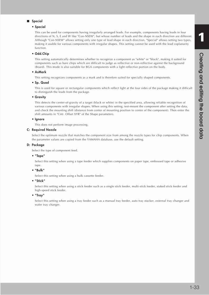
■ Special
• Special
Thiscanbeusedforcomponentshavingirregularlyarrangedleads.Forexample,componentshavingleadsinfourdirectionsofN,S,EandWlike"Con-NSEW",butwhosenumberofleadsandtheshapeineachdirectionaredifferent.Although"Con-NSEW"allowssettingonlyonetypeofleadshapeineachdirection,"Special"allowssettingtwotypes,makingitusableforvariouscomponentswithirregularshapes.Thissettingcannotbeusedwiththeleadcoplanarityfunction.
• Odd.Chip
Thissettingautomaticallydetermineswhethertorecognizeacomponentas"white"or"black",makingitsuitedforcomponentssuchasbarechipswhicharedifficulttojudgeasreflectiveornon-reflectiveagainstthebackground(Board).ThismodeisalsosuitableforBGAcomponentswithalightreflectiveportiononthebody.
• AsMark
Thissettingrecognizescomponentsasamarkandisthereforesuitedforspeciallyshapedcomponents.
• Sp. Quad
Thisisusedforsquareorrectangularcomponentswhichreflectlightatthefoursidesofthepackagemakingitdifficulttodistinguishtheleadsfromthepackage.
• Gravity
Thisdetectsthecenter-of-gravityofatarget(blackorwhite)inthespecifiedarea,allowingreliablerecognitionofvariouscomponentswithirregularshapes.Whenusingthissetting,test-mountthecomponentaftersettingthedata,andcheckthemountingshift(distancefromcenterofmountingpositiontocenterofthecomponent).Thenentertheshiftamountsin"Cntr.OffsetXYR"oftheShapeparameters.
• Ignore
Thisdoesnotperformimageprocessing.
C: Required Nozzle
Selecttheoptimumnozzlethatmatchesthecomponentsizefromamongthenozzletypesforchipcomponents.When
theparametervaluesarecopiedfromtheYAMAHAdatabase,usethedefaultsetting.
D: Package
Selectthetypeofcomponentfeed.
• "Tape"
Selectthissettingwhenusingatapefeederwhichsuppliescomponentsonpapertape,embossedtapeoradhesivetape.
• "Bulk"
Selectthissettingwhenusingabulkcassettefeeder.
• "Stick"
Selectthissettingwhenusingastickfeedersuchasasinglestickfeeder,multi-stickfeeder,stakedstickfeederandhigh-speedstickfeeder.
• "Tray"
Selectthissettingwhenusingatrayfeedersuchasamanualtrayfeeder,autotraystacker,externaltraychangerandwafertraychanger.

1-34
1 C
rea
ting a
nd e
diting
the b
oa
rd d
ata
G: Dump Way
Thisspecifiesthelocationwhereacomponentwillbedumpedifanerrorsuchasrecognitionerrorhasoccurred.Setto
"DumpPOS"forchipcomponentsandsmallcomponents.Whentraycomponentsareused,setto"Sp.DumpBack"to
returnthembacktothetray.WhenaQFPdumpstation(option)isused,setto"station".
H: Retry Times
Thisdetermineshowmanytimesthemachinewillretrythesameoperationifanerrorsuchasarecognitionerrorhas
occurred.Thenumberofretriescanbesetfrom"NORETRY"to"14".Whenthisretrysettingisgreaterthanthemachine
dataretrysetting,themachinedatahaspriority.
I: Conveyor Y Speed
ThisparameterspecifiestheconveyorY-axisspeed.Ifcomponentsmoveorslidejustaftermountedontheboarddueto
theY-axismovement,setthisparametertoalowerspeed.
Fourspeedsareavailable:"FAST","MIDDLE","SLOW"and"VERYSLOW".
J: Database number
Showsthedatabasenumberwhentheparametervalueswerecopiedfromthedatabase.
Whenyouwanttocopytheparametervaluesfromthedatabase,clickthe[Database]buttononthetoolbartoopenthe
databaselist.Thenselectthecopysourcedataandpressthe[Set]buttontomakeacopy.
Parts (electronic component) database list
64121-S1-00
Reference For details on the database, see section 7, "Using and editing the database", in this chapter.
L: Category
Usethedefaultsetting"Normal"toperformcomponentmountingordipping.Whenyouwanttoperformstamping,select
"Stamp".
M: FixCmpRef.
Setthisparameterto"0"innormaloperation.Enterfixedcomponentnumbershereonlywhenused.

1-35
1 C
rea
ting a
nd e
diting
the b
oa
rd d
ata
5.2.2 Parameter for machines other than YS Series machines
E: Feeder Type
Selectthespecificfeedertypetobeusedforcomponentsupply.SelectableitemsdifferdependingonthePackage
parametersetting.Refertothetablebelowtomakeaselection.
■ Feeder Type settings
When"Package"issetto"Tape"
Comp.
Package setting
Feeder Type
settingTape feeder or bulk cassette feeder type
Tape
8mmTape 8mm tape feeder (except for 1005 chip)
8mm1005cmp 8mm tape feeder (for 1005 chip)
12mmEmboss 12mm tape feeder (standard pitch)
12mmLongPitch 12mm tape feeder (long pitch)
16mmEmboss 16mm tape feeder
24mmEmboss 24mm tape feeder
32mmSticky 32mm air-driven feeder with sticky tape
32mmEmboss 32mm embossed air-driven feeder
44mmEmboss 44mm embossed air-driven feeder
56mmEmboss 56mm embossed air-driven feeder
Tape-A to D
Select these settings when using a tape feeder other than the above. Note that you must make necessary settings on the <3/1/A5 FEEDER SPEC. INF> screen. For the setting procedure, refer to the mounter service manual.
Spear1 to 10
8mm0603cmp 8mm tape feeder (for 0603 chip)
*Select"12mmLongPicth"whenusingbothCLtypefeedersandFVtypefeeders.
■ Feeder Type settings
When"Package"issetto"Bulk"
Comp.
Package setting
Feeder Type
settingTape feeder or bulk cassette feeder type
Bulk
Bulk-1005C Bulk feeder for 1005 capacitors. Marked "1005 C" on the feeder.
Bulk-1005R Bulk feeder for 1005 resistors. Marked "1005 R" on the feeder.
Bulk-1608C Bulk feeder for 1608 capacitors. Marked "1608 C" on the feeder.
Bulk-1608R Bulk feeder for 1608 resistors. Marked "1608 R" on the feeder.
Bulk-T0.6CBulk feeder for 2125 capacitors (chip thickness 0.6mm). Marked "2125 T0.6" on the feeder.
Bulk-T0.6R Bulk feeder for 2125 resistors. Marked "2125 T0.6" on the feeder.
Bulk-T1.25CBulk feeder for 2125 capacitors (chip thickness 1.25mm). Marked "2125 T1.25" on the feeder.
HopBulk-1005C Hopper bulk feeder for 1005 capacitor
HopBulk-1005R Hopper bulk feeder for 1005 resistor
HopBulk-1608C Hopper bulk feeder for 1608 capacitor
HopBulk-1608R Hopper bulk feeder for 1608 resistor
HopBulk-T0.6 Hopper bulk feeder for 2125 chip components (chip thickness 0.6mm)
HopBulk-T0.8 Hopper bulk feeder for 2125 chip components (chip thickness 0.8mm)
HopBulk-T1.25 Hopper bulk feeder for 2125 chip components (chip thickness 1.25mm)

1-36
1 C
rea
ting a
nd e
diting
the b
oa
rd d
ata
5.2.3 Parameter for YS Series machines only
E: Feeder type
Displaysthedevicethatsuppliesparts.Thisparameterisautomaticallysetif“R:Tapetype”isset.
F: Feed pitch
Selectsthefeedpitchfromthedrop-downlistbox.
n NOTE This parameter is not shown when the feeder pitch operation is set to “feeder setup”.
P: Feed speed
Selectshowfastthetapeisfedfromthedrop-downlistbox.
Q: Reel diameter size
Specifiesthereeldiameterofatape.(Thisparameterwillbeshownonlywhenthe“R:Tapetype”issetto“8mmtape”.
Selecteither“7inch”or“Largetype(7inchorover)”.Theoptionsetinthisparameterisusedforjudgmentofreel
locationcheckwhenoptimizationisconducted.
Reference 7-inch diameter reel with 8 mm tape can be positioned on either the upper or lower part of the carriage reel holder while large type reel (7 inch or over) can be positioned on the lower part of the carriage reel holder only. The reel can be positioned on only the lower part of the carriage reel holder in case of parts on a tape other than 8 mm tape.
R: Tape type
SelectanoptionifComponentPackageSettingissetto“Tape”.
Selectatapetypefromthedrop-downlistbox.“E:Feedertype”willbeautomaticallysetwhenatapetypeisselected.
Selectanoptionreferringtothefollowingtable.
Comp. Package
settingTape type Feeder type Type of component feeder
Tape 8 mm tape 8 mm tape8 mm tape feeder (including device for 8 mm 1005, 0603 chip)
12 mm tape 12 mm long pitch 12 mm tape feeder (including 12 mm emboss)
16 mm tape 16 mm emboss 16 mm tape feeder
24 mm tape 24 mm emboss 24 mm tape feeder
32 mm tape 32 mm emboss 32 mm embossed tape feeder
44 mm tape 44 mm emboss 44 mm embossed tape feeder
56 mm tape 56 mm emboss 56 mm embossed tape feeder
72 mm tape 72 mm emboss 72 mm embossed tape feeder
Tape A to D Tape A to D
Set when using a tape feeder other than the above ones.
Note that you must make necessary settings of the “feeder spec information” in advance to use the setting.
Spare 1 to 10 Spare 1 to 10

1-37
1 C
rea
ting a
nd e
diting
the b
oa
rd d
ata
5.2.4 Editing the ball lead position informationBallleadpositioninformationcanbeeditedtoimproveaccuracyinrecognizingtheballleadsthatarerandomlyarrangedonballleadcomponentssuchasCSPandmicroBGA.Toedittheballleadpositioninformation,"AlignmentType"intheBasicparametersmustbesetto"BGA"or"FlipChip".
1. When "Alignment Type" is set to "BGA"
1 Open the ball lead position edit screen.Click the [Ball Edit] button on the toolbar. The BGA edit screen opens.
2 Edit the ball lead position data.On the BGA edit screen, edit the ball lead position data so that it matches the actual ball lead arrangement. The ball lead display should be set to ON (dark color) at positions where there are ball leads and to OFF (light color) where there are no ball leads. To switch ON or OFF, place the mouse on the target lead and double-click the mouse button or click the [Set] or [Reset] button.
Number of balls being edited
[Set] button
Position currently being edited
[Reset] button
[Reverse] button
BGA edit screen
64122-S1-00
3 Register the edited data.When you have edited the ball lead position data, click the [OK] button to register it.

1-38
1 C
rea
ting a
nd e
diting
the b
oa
rd d
ata
2. When "Alignment Type" is set to "Flip Chip"
1 Open the Random Ball Edit dialog box.Click the [Ball Edit] button on the toolbar to open the Random Ball Edit dialog box.
Random Ball Edit dialog box
64123-S1-10
2 Define the reference ball lead positions.As the drawing below shows, define the ball leads located as close as possible to the top right, top left, bottom right and bottom left, as the reference ball leads. It is not important which ball lead you select here. In the Random Ball Edit dialog box, specify the reference ball leads as 0 to 7.
b: Reference ball leads
Reference ball lead positions
X+
Y+
X−
Y−
b1b6
b7
b3
b0
b4
b5
b2
63150-S1-00
n NOTE Ball leads other than the reference ball leads should be specified as "---".
3 Enter the coordinates of each reference ball lead.Enter accurate XY coordinates of each reference ball lead relative to the center of the component.
4 Enter the ball lead size.Enter the ball lead diameter in the "C: Std. Ball Diameter" parameter in the Random Ball Edit dialog box. This diameter setting will be applied by default to all registered ball leads.
5 Save the data.When you have edited the random ball lead data, click the [OK] button to save it.
Reference When you want to copy or delete a row in the Random Ball Edit dialog box, click the right mouse button on the target row to display the context menu (right-click menu) and select the command from the menu.

1-39
1 C
rea
ting a
nd e
diting
the b
oa
rd d
ata
5.2.5 Datum Ball automatic setting function of Random arrangement Ball
■ About Random Ball Edit Screen
Ifthe[Auto]buttonisclickedwhenitisinthestatewhereBallinformationwasinputted,theDatumBallisdecidedautomaticallyandtheDatumBallpositionisupdated.
Datum Ball Position
Datum Ball Position
[Auto] button
64187-S1-10
Datum Ball Position
When it is able to set up automatically,the Datum ball position is updated.
64188-S1-00

1-40
1 C
rea
ting a
nd e
diting
the b
oa
rd d
ata
Ifthe[Auto]buttonispushedwhenitisinthestatewheretheDatumBallwassetup,theEa928:ConformDatumBallAutoSetscreenisdisplayed.
Conform Datum Ball Auto Set screen
64189-S1-00
Ea929:DatumBallAutoSetErrorisdisplayedwhentheDatumBallisnotabletobesetupautomatically.Inthiscase,pleasesetupmanually.
Datum Ball Auto Set Error
64190-S1-00
ThegeneratingconditionsofEa929:DatumBallAutoSetError
•WhenBallinformationislessthan4points

1-41
1 C
rea
ting a
nd e
diting
the b
oa
rd d
ata
5.3 Pick parametersThePickparameterscreenopenswhenyouclickthePickiconinthetreevieworthe[Pick]tabinthedetailview.SetthePickparametersbyreferringtothefollowingdescription.
Pick parameters
64124-S1-00
Reference Some parameters may not be available depending on the specifications.
A: Feeder Set No.
Enterthefeedersetnumberofthepositiononthefeederplate(feederknockpinposition)atwhichthefeederisinstalled.
Thisparametersettingisunnecessarywhenthe"Usefeederoptimize"parameterissetto"Yes".WhenusinganMTF
(manualtrayfeeder),enterthefeedersetnumbernearapositionatwhichtheMTFisinstalledonthefeederplate.When
usinganauto/externaltraychanger,usethedefaultsetting.
B: Position Definition
Setto"Automatic"whenthe"Package"parameterissetto"Tape"or"Bulk".(Thecomponentpickuppositionwillbe
calculatedautomatically.)Setto"Teaching"whenstickfeedersortrayfeedersareused.
C, D: XY (pickup position)
Enterthepositionatwhichtheheadpicksupthecomponentfromthefeeder.Theseparametersareskippedwhenthe
PositionDefinitionparameterisset"Automatic".
E: Pick Angle (deg)
•Thisparameterspecifiestheanglethroughwhichthemounterheadrotatestopickupacomponentonthefeeder.Thissettingdeterminestheorientationofthecomponent(recognitionreference)whenitisrecognizedanddisplayedontheoperationmonitor.Normally,setthisparameterto0degreesforhorizontallylongcomponentsintheloadingpositiononthefeeder,andsetto90degreesforverticallylongcomponents.
•Whenusingabulkcassettefeeder,alwayssetthisparameterto90degrees.
•ThepickupanglefortransistorsmustbespecifiedsothattheirleadsfacetheNSdirections.Setthisparameterto0degreesforverticallylongcomponentsintheloadingpositiononthefeeder,andsetto90degreesforhorizontallylongcomponents.Selectthecorrectpickupanglebyreferringtothetablebelow.
•ThepickupangleforSOPcomponentsmustbespecifiedsothattheirleadsfacetheEWdirections.Setthisparameterto0degreesforhorizontallylongcomponentsintheloadingposition,andsetto90degreesforverticallylongcomponents.Selectthecorrectpickupanglebyreferringtothetablebelow.
•ThepickupangleofconnectorsmustbespecifiedsothattheirleadsfacetheEdirection.Selectthecorrectpickupangleaccordingtotheloadingpositionofthecomponentasshowninthefollowingtables.

1-42
1 C
rea
ting a
nd e
diting
the b
oa
rd d
ata
Loading position
Pickup angle
Loading position
Pickup angle
Loading position
Pickup angle
Loading position
Pickup angle
Recognition reference
Loading position
Pickup angle
Recognition reference
Loading position
Pickup angle
Chip Melf
SOP
Mini-mold transistor
Connector E
QFP
0 90 0 90
0 90
0 90 0 90
0 180 90 -90
0 90
N S
E
W
N
S
W E N S
E
W
N
S
W E
N
S
N
S
N S
E
W
N
S
W E N S
E
W
N
S
W E
N
S
WE
Pick Angle (deg)
63119-S1-10
F: Pick Height (mm)
This is the Z-axis height offset value used when the head lowers to pick a component. Set this parameter to "0.0" in
normal operation.
If you want to lower the Z-axis height during component pickup, enter a positive (+) value in the Pick Height field.
Conversely, if you want to raise the Z-axis height, enter a negative (-) value.
G: Pick Timer
This parameter specifies the time duration (in seconds) for which the head stays in the lowered position after detecting
the reference pickup vacuum pressure when picking up a component. For small components such as chip components, it
is okay to set this parameter to "0.00". (The setting value applies to the external tray changer when connected.)
H: Pick Speed (%)
This is the Z-axis speed when the head moves down to pick up a component. Set this parameter to 100 (%) in most cases.
If you want to reduce the speed, enter a smaller value.
I: XY Speed (%)
This is the speed at which the head moves in the XY directions to pick up and mount a component. Set this parameter to
100 (%) in most cases. If you want to reduce the speed, enter a smaller value.
J: Pick&Mount Vacuum Check
Set this parameter to "NORMAL CHK" in most cases. If you want to check pickup errors and mount errors more strictly
(erroneous head return without mounting the component), set to "SPECIAL CHK".
For example, when using QFP or BGA components and you want to check pickup errors and mount errors (erroneous
head return without mounting the component) more strictly, set this parameter to "SPECIAL CHK".
n NOTE When the Pick&Mount Vacuum Check parameter is set to "NORMAL CHK", the machine controls the ascent timing of the head from the lowered position during component pickup or mounting. This parameter setting is valid only when the Vacuum Check parameter on the [Board] tab screen is set to "Check".

1-43
1 C
rea
ting a
nd e
diting
the b
oa
rd d
ata
K: Pick Vacuum
Thisisthereferencevacuumpressureusedforcheckingthepickupvacuumlevel.Usethedefaultsettingandadjustitas
neededinthePartsAdjustmode.
L: Pick Timing
Thisparameterspecifiesthetimingtostartvacuumgenerationwhentheheadpicksupacomponent.Whensetto"Normal",vacuumgenerationstartsbeforetheheadmovesdown.Whensetto"Bottom",vacuumgenerationstartaftertheheadhasmoveddown.Setthisparameterto"Normal"inmostcases.
M: Pick Action
Thisspecifiesthenozzledescentmovementsduringcomponentpickupormounting.Setthisparameterto"Normal"in
mostcases.Settingthisparameterto"DETAIL"allowsyoutosetthePickTango,PickDownandPickUpparameters.For
BGAcomponents,setthisparameterto"QFP".
N: Pick Tango
Setthisparameterto"NORMAL"inmostcases.Whenhigheraccuracyisrequiredtopickupasmallcomponent,setto
"INTOL".(ThisparametercanbeselectedonlywhenthePickActionparameterissetto"DETAIL".
O, P: Pick Down, Pick Up
Selectthenozzledescentorascentsequencethatbestmatchesthecomponent.(Theseparameterscanbeselectedonly
whenthePickActionparameterissetto"DETAIL".)
Q: Force Control
Setwhetherornottoperformloadcontrol.Whenthisparameterissetto"Yes(OnlyUnlock)",noadditionalloadwillbe
appliedafterthecomponentcomesincontactwiththeboard.
R: Target Load (N)
Enterthetargetloadin0.1Nstepsfrom1.0to49.0N.
S: Nozzle Touch Point Offset (mm)
Setthelengthfromthetopsurfaceofthecomponenttothepositionwherethenozzletipmakescontactwiththe
component.

1-44
1 C
rea
ting a
nd e
diting
the b
oa
rd d
ata
5.4 Dip parametersTheDipparameterscreenopenswhenyouclicktheDipiconinthetreevieworthe[Dip]tabinthedetailview.SettheDipparametersbyreferringtothefollowingdescription.
Dip parameters
64125-S1-00
Reference Dip parameters are displayed depending on the specifications.
A: Dipping Action
Select"AfterVision"or"BeforeVision"toperformdippingoperation.Dippingisnotperformedwhen"NotUse"isselected
here.
B: Station No.
EnterthestationNo.shownonthelabelaffixedtotheconnectorbox.Adatacheckerrorwillbeissuedifothernumbers
areused.
D: Dip. Descent Sequence
Selectthespeedfrom"Normal","2StepFast","2StepMiddle"or"2StepSlow"forloweringthehead.Whena2-stepspeed
otherthan"Normal"isselected,theheadspeedswitchestoslowspeedsomemillimetersbeforethetargetpositionwhile
theheadisloweringtothedippingunit.Thishelpsreducethecontactloadappliedonthecomponentbutloweringthe
headtakesmoretime.
E: Dip. Descent Speed
Enterthespeedforloweringtheheadin1%stepsfrom1to100%.
Whena2-stepspeedisselected,thisparameterspecifiesthehigherspeed.
F: Dip. Lowend Height
Setthetargetpositiontolowertheheadin0.01mmstepsfrom-9.99to+9.99mm.Thedownwarddirection(depressing
direction)ispositive(+).
G: Dip. Lowend Timer
SethowlongtheZ-axiswaitsatthebottom(lowerend)afterarrivingatthetargetposition.Enterthetimein0.01second
stepsfrom0.00to+9.99seconds.
H: Dip. Rising Sequence
Selectthespeedfrom"Normal","2StepFast","2StepMiddle"or"2StepSlow"forraisingthehead.Whena2-stepspeed
otherthan"Normal"isselected,theheadspeedswitchestohighspeedsomemillimetersafterleavingthestartposition
whiletheheadisrisingtothedippingunit.
I: Dip. Rising Speed
Enterthespeedforraisingtheheadin1%incrementsfrom1to100%.
Whena2-stepspeedisselected,thisparameterspecifiesthehigherspeed.
J: Force Control
Setwhetherornottoperformloadcontrol.Whenthisparameterissetto"Yes(OnlyUnlock)",noadditionalloadwillbe
appliedafterthecomponentcomesincontactwiththeboard.
K: Target Load
Enterthetargetloadin0.1Nstepsfrom1.0to49.0N.

1-45
1 C
rea
ting a
nd e
diting
the b
oa
rd d
ata
5.5 Mount parametersTheMountparameterscreenopenswhenyouclicktheMounticoninthetreevieworthe[Mount]tabinthedetailview.SettheMountparametersbyreferringtothefollowingdescription.
Mount parameters
64126-S1-00
Reference Some parameters may not be available depending on the specifications.
A: Mount Height (mm)
ThisistheZ-axisheightoffsetvalueusedwhentheheadlowerstomountacomponent.Setthisparameterto"0.0"in
normaloperation.IfyouwanttolowertheZ-axisheightduringcomponentmounting,enterapositive(+)value.
Conversely,ifyouwanttoraisetheZ-axisheight,enteranegative(-)value.
B: Mount Timer
Thisparameterspecifiesthetimeduration(inseconds)forwhichtheheadstaysintheloweredpositionafterdetecting
thereferencemountvacuumpressurewhenmountingacomponent.Inmostcases,itisokaytosetthisparameterto
"0.00".Ifpickupormountoperationisunstable,setalongertimervalue.
C: Mount Speed (%)
ThisisrelatedtothePickSpeedsettinginthePickparameters.(ThesettingvaluechangessimultaneouslyasthePick
Speedsettingischanged.)
D: XY Speed (%)
ThisisrelatedtotheXYSpeedsettinginthePickparameters.(ThesettingvaluechangessimultaneouslyastheXYSpeed
settinginthePickparametersischanged.)
E: Pick&Mount Vacuum Check
Setthisparameterto"NORMALCHK"inmostcases.Ifyouwanttocheckpickuperrorsandmounterrorsmorestrictly
(headreturnwithoutmountingthecomponent),setto"SPECIALCHK".
n NOTE When the Pick&Mount Vacuum Check parameter is set to "NORMAL CHK", the machine controls the ascent timing of the head from the lowered position during component pickup or mounting. This parameter setting is valid only when the Vacuum Check parameter on the [Board] tab screen is set to "Check".
F: Mount Vacuum
Thisisthereferencevacuumpressureusedforcheckingthemountvacuumlevel.Usethedatabasedefaultsettingand
adjustitasneededinthePartsAdjustmode.
G: Mount Action
ThisisrelatedtothePickActionsettinginthePickparameters.(ThesettingvaluechangessimultaneouslyasthePick
Actionsettingischanged.)
H: Mount Tango
Setthisparameterto"NORMAL"inmostcases.Whenhigheraccuracyisrequiredtomountasmallcomponent,setto
"INTOL".(ThisparametercanbeselectedonlywhentheMountActionparameterissetto"DETAIL".
I, J: Mount Down, Mount Up
Selectthenozzledescentorascentsequencethatbestmatchesthecomponent.Usethedefaultvaluesaslongasno
problemsarise.(TheseparameterscanbeselectedonlywhentheMountActionparameterissetto"DETAIL".)

1-46
1 C
rea
ting a
nd e
diting
the b
oa
rd d
ata
K: Force Control
Setwhetherornottoperformloadcontrol.Whenthisparameterissetto"Yes(OnlyUnlock)",noadditionalloadwillbe
appliedafterthecomponentcomesincontactwiththeboard.
L: Target Load (N)
Enterthetargetloadin0.1Nstepsfrom1.0to49.0N.
M: Nozzle Touch Point Offset (mm)
Setthelengthfromthetopsurfaceofthecomponenttothepositionwherethenozzletipmakescontactwiththe
component.

1-47
1 C
rea
ting a
nd e
diting
the b
oa
rd d
ata
5.6 Vision parametersTheVisionparameterscreenopenswhenyouclicktheVisioniconinthetreevieworthe[Vision]tabinthedetailview.SettheVisionparametersbyreferringtothefollowingdescription.
Vision parameters
64127-S1-00
Reference Some parameters may not be available depending on the specifications.
A, B, C: Alignment Module: Fore, Back, Laser
Thisparameterspecifiesthelightingmethodforrecognizingacomponent.
D to F: Light Main, Light Coax, Light Side
Selectthelightingmethodsthatbestmatchthecomponent.Usethedefaultsetting("LightMain"and"LightCoax"
selected)inmostcases.When"AlignmentType"issetto"BGA"andyouwanttochecknicksontheBGAleads,select
"LightSide"only.
G: All Lighting ON
Selectthisparameterwhenusingalllightingmethods"LightMain","LightCox"and"LightSide".(Thisparameteris
availableonlywhentheAlignmentTypeparameterissetto"SOJ"or"Lead-off"or"PLCC".)
H: Lighting Level
Thisparameterspecifiesthereflectedlightbrightness.
I: Auto Threshold
Showsathresholdlevelforstandardchipcomponentthatwasautomaticallycalculatedfromtheacquiredimage.
J: Comp. Threshold
Thisparameterspecifiesthethresholdlevelusedtodiscernthelight-reflectingpart(lead)fromthebackgroundduring
componentrecognition.ThisparameterisskippedforBGAcomponents.
K: Comp. Tolerance
Thisparameterspecifiesthetoleranceforrecognizingacomponent,inanallowableerrorpercentageof0to100%.The
largerthepercentage,thegreaterthetolerance.
L: Search Area (mm)
Thisparameterspecifiestheareawithinwhichthecomponentleadsaresearched.Asthisvalueissetlarger,thesearch
areaisextended,butwithalossintheimageprocessingspeed.
M: Recognition way
Selectthemethodtorecognizethecomponentfromamong"Normal","Insiderecognition",and"Inside+LeadAutoSearch".
Setto"Normal"inmostcases.Ifthe"Normal"settingfailstorecognizethecomponent,thentrysettingto"Inside
recognition"andthen"Inside+LeadAutoSearch".
(ThisparameterisavailableonlywhentheAlignmentTypeparameterissetto"SOJ"or"Lead-off"or"PLCC".)
• Normal
Recognizestheendofeachlead.
• Inside recognition
Recognizes the root of each lead. • Inside+LeadAutoSearch
Recognizestherootofeachleadandalsodetectstheleadsbyextractingapatternthatmeetsthedefinitionsbasedontheleadpitchandleadwidthparameters.

1-48
1 C
rea
ting a
nd e
diting
the b
oa
rd d
ata
N: Datum Angle
Thisparameterspecifiestheangleofcomponentshapedefinition.Usethedefaultsettinginmostcases.
O: Comp. Intensity
Thisparameterspecifiesthethresholdlevelusedtomeasuretheintensityintheoutlineareaofacomponentafteritis
successfullyidentifiedbynormalvisionrecognition.Ifthemeasuredintensitylevelishigherthanthisthreshold,the
recognitionresultisapass.(Thisparameterisvalidonlywhen"AlignmentType"issetto"Std.Chip".)
P: Multi MACS
SetwhethertousetheMultiMACScorrection.Markthecheckboxwhenusingthisfunction.
Q: Co-Planarity Threshold
Setareferencevalue(50to300)usedtoevaluatetheleadco-planaritymeasurementresults.Ifyoudonotwanttouse
theco-planaritycheckfunctionforthiscomponent,setthisparameterto“NotUse”.
R: Co-Planarity Level
Thisisthesensitivitylevelusedtoperformleadco-planaritymeasurement.
Setthisparametertoanoptimumsensitivitylevel(0to9).Forexample,settoaround“5”fornormalleadcomponents,
andsettoaround“2”forcomponentshavingamirroredleadsurfacethatcauseslittleirregularreflectionwhenscanned
byalaser.Thehighertheirregularreflectionontheleadsurface,thelargerthis“Co-PlanarityLevel”parametervalue
shouldbe.
S: Co-Planarity Ruler Offset
Entertheoffsetvaluethatwillbeaddedtothe"RulerOffset"parameterspecifiedonthe[Shape]tabonlywhen
measuringleadco-planarity.
Whenthisoffsetissetto"0",leadco-planaritymeasurementisperformedatthesamepositionasspecifiedby"Ruler
Offset".
Whenaplusvalueisset,leadco-planaritymeasurementisperformedatapositionshiftedinwardfromtheposition
specifiedby"RulerOffset".Whenaminusvalueisset,leadco-planaritymeasurementisperformedatapositionshifted
outwardfromthepositionspecifiedby"RulerOffset".
T: 3D Co-Planarity Threshold
Enterthedesiredtolerancerangeofleadcoplanarity.Acoplanarityerrorisdetectedifnon-uniformityoftheleadbottom
planeexceedsthisvalue.Setto"NotUse"ifyoudonotwanttocheckleadcoplanarity.
U: 3D Inspection Mode
Setto"Standard"inmostcases.Forcomponentswithwireleads,thisparametercanalsobesetto"Fast"ifdesired.
V: 3D Threshold
Thisisthethresholdlevelusedtoprocessanimagerecognizedbythecoplanaritycheckcamera.
W: 3D Main Lighting Level
Thisisthemainlightinglevelusedtorecognizeanimagewiththecoplanaritycheckcamera.
X: 3D Coax Lighting Level
Thisisthecoaxiallightinglevelusedtorecognizeanimagewiththecoplanaritycheckcamera.
Y: 3D Side Lighting Level
Thisisthesidelightinglevelusedtorecognizeanimagewiththecoplanaritycheckcamera.
Z: Bright Area (%)
Settheratio(%)ofthebrightarea(light-reflectingballleadarea)totheentirepackagearea,whichshouldbedetected
whenrecognizingaballleadcomponentsuchasaBGAwiththecoplanaritycheckcamera.

1-49
1 C
rea
ting a
nd e
diting
the b
oa
rd d
ata
a: Height Check (mm)
SetthisparameterwhenyouwanttocheckthefrontandbackofacomponentsuchasanSOPandQFP.Inmostcases,
setavaluewhichisabout70%ofthecomponentheight(thickness).
b: Extra ball check
Setwhetherornottojudgeasrecognitionerrorifthenumberofballsrecognizedduringpartsrecognitionislargerthan
thenumberofballsspecifiedwithballleadpositioninformation.
•CheckedJudgesasrecognitionerrorifthereisaballatapositionnotspecifiedwithballleadpositioninformation.
•UncheckedDoesnotjudgeasrecognitionerrorevenifthereisaballatapositionnotspecifiedwithballleadpositioninformation.
c: Ball matching rate
Specifiesthematchingrateallowedforrecognizingeachballfrom0to100%.Thegreaterthevalue,thegreaterthe
tolerance.

1-50
1 C
rea
ting a
nd e
diting
the b
oa
rd d
ata
5.7 Shape parametersTheShapeparameterscreenopenswhenyouclicktheShapeiconinthetreevieworthe[Shape]tabinthedetailview.SettheShapeparametersbyreferringtothefollowingdescription.
n NOTE Set these parameters after specifying "Alignment Type". If "Alignment Type" is undefined, the following parameters are not displayed.
■ Chip components
Shape parameters
64128-S1-00
A, B: Body Size X, Body Size Y
Enterthecorrectdimensions(mm)measuredwithaverniercaliperormicrometer.
C: Body Size Z
Enterthecorrectthickness(mm)measuredwithaverniercaliperormicrometer.
D: Ruler Offset
Thisparameterspecifiesthedistanceinpixels,fromtheendofthecomponenttoarulerlineusedtomeasurethelead
width.Usethedefaultsettinginmostcases.
E: ReflectLL
Enterthewidthofthesilverleadsprovidedonbothendsofthecomponent.(Standardchipcomponentsdonotusethis
parameter.)
F, G: Align Size X, Y
Enterthecomponentsizethatisactuallyrecognizedbythecamera.(Standardchipcomponentsdonotusethis
parameter.)
N
S
EW
A
C
B
N
S
WE
A
B
D
N
S
EW
A
C
B
N
S
WE
F
G
E
Top view
Top view
A: Body Size XB: Body Size YC: Body Size ZD: Ruler Offset
A – D: Same as aboveE: ReflectLLF: Align Size XG: Align Size Y
Shape parameters for chip components
63120-S1-00

1-51
1 C
rea
ting a
nd e
diting
the b
oa
rd d
ata
■ Mini-mold transistors and SOT
A, B: Body Size X, Body Size Y
Enterthecorrectdimensions(mm)includingtheleads,measuredwithaverniercaliperormicrometer.
C: Body Size Z
Enterthecorrectthickness(mm)measuredwithaverniercaliperormicrometer.
D: Ruler Offset
Enterthedistanceinpixelsfromtheendofthecomponenttoanimaginarylineusedtomeasuretheleadwidthand
pitch.Usethedefaultsettinginmostcases.
E: Ruler Width
Enterthewidthofanimaginarylineusedtomeasuretheleadwidthandpitch.Setthisparameterto"1to2"for
componentswithaleadlengthshorterthan0.3mm,andto"2to3"forcomponentswithaleadlengthlongerthan
0.3mm.Usethedefaultsettinginmostcases.
F, G: Lead Number NS
EnterthenumberofleadsexistingintheNandSdirections.
Pickup angle
Loading position
0° 90°
NS NS
N
S
N
S
Mini-mold transistor and SOP lead direction
63121-S1-00
H, I: Lead Pitch NS
Enterthecorrectleadpitch(lead-to-leadspacing).
J: Lead Width
Enterthecorrectleadwidth
K: ReflectLL
Entertheprojectedlengthofleadswhichreflectlightduringrecognition.Usethedefaultsettinginmostcases.
NS
E
W
B
C
A
N
S
E W
H
K
D
J
A : Body Size X B : Body Size YC : Body Size ZD : Ruler OffsetH : Lead PitchJ: Lead WidthK: Reflect LL
Bottom view
Shape parameters for mini-mold transistors
63122-S1-00
■ SOP
A, B: Body Size X, Body Size Y
Enterthecorrectdimensions(mm)includingtheleads,measuredwithaverniercaliperormicrometer.
C: Body Size Z
Enterthecorrectthickness(mm)measuredwithaverniercaliperormicrometer.
D: Ruler Offset
Enterthedistanceinpixelsfromtheendoftheleadstoanimaginarylineusedtomeasuretheleadwidthandpitch.Use
thedefaultsettinginmostcases.
E: Ruler Width
Enterthewidthoftheimaginarylineusedtomeasuretheleadwidthandpitch.Setthisparameterto"1to2"for
componentswithaleadlengthshorterthan0.3mm,andto"2to3"forcomponentswithaleadlengthlongerthan
0.3mm.Usethedefaultsettinginmostcases.
F: Lead Number
EnterthenumberofleadsexistingintheEorWdirection.

1-52
1 C
rea
ting a
nd e
diting
the b
oa
rd d
ata
G: Lead Pitch
Enterthecorrectleadpitch(lead-to-leadspacing).
H: Lead Width
Enterthecorrectleadwidth
I: ReflectLL
Entertheprojectedlengthofleadswhichreflectlightduringrecognition.Usethedefaultsettinginmostcases.
N
S
EW
N
S
W E
B
C
A
I
G
H
A : Body Size XB : Body Size Y C : Body Size ZG : Lead PitchH : Lead WidthI : Reflect LL
Bottom view
Shape parameters for SOP
63123-S1-00
■ Simple Flip Chip
A, B:Body Size X, Body Size Y
EnterthecorrectdimensionsinmillimetersbyreferringtoCADdata.
C: Body Size Z
EnterthecorrectthicknessinmillimetersbyreferringtoCADdata.
D: Bump Number
EnterthenumberofbumpsexistingalongtheoutermostsideintheNdirection.
E: Bump Diameter
Enterthediameterinmillimeters(0.00to99.99)ofabumpexistingontheoutermostsideintheNdirection.Enterthe
correctdimensionbyreferringtoCADdata.(Seedrawingbelow.)
F: Start Pos X
EntertheX-coordinatepositioninmillimetersofthefirstbumplocatedintheNdirection,relativetothecenterofthe
component.(Seedrawingbelow.)
G: Start Pos Y
EntertheY-coordinatepositioninmillimetersofthefirstbumplocatedintheNdirection,relativetothecenterofthe
component.(Seedrawingbelow.)
H: End Pos X
EntertheX-coordinatepositioninmillimetersofthelastbumplocatedintheNdirection,relativetothecenterofthe
component.(Seedrawingbelow.)
I: End Pos Y
EntertheY-coordinatepositioninmillimetersofthelastbumplocatedintheNdirection,relativetothecenterofthe
component.(Seedrawingbelow.)
J to a: Bump Number S to End Pos. YW
EnterthesettingsintheS,EandWdirectionswhilereferringtotheabovedescriptions(DtoI)anddrawing.
C
B
A
WN
SE
N
S
EW
G E
D
I
F H
Shape parameters for simple flip chip
A: Body Size XB: Body Size YC: Body Size ZD: Bump NumberE: Bump DiameterF: Start Pos XG: Start Pos YH: End Pos X I : Start Pos Y+: Center of component
Bottom view
63124-S1-00

1-53
1 C
rea
ting a
nd e
diting
the b
oa
rd d
ata
■ Flip Chip
A, B: Body Size X, Body Size Y
EnterthecorrectdimensionsinmillimetersbyreferringtoCADdata.
C: Body Size Z
EnterthecorrectthicknessinmillimetersbyreferringtoCADdata.
C
B
A
WN
SE
Shape parameters for flip chip
A: Body Size XB: Body Size YC: Body Size Z
63125-S1-00
■ Simple BGA
A, B: Body Size X, Body Size Y
Enterthecorrectdimensionsmeasuredwithaverniercaliperormicrometer.
C: Body Size Z
Enterthecorrectdiametermeasuredwithaverniercaliperormicrometer.
D: Dot Amount
EnterthetotalnumberofballterminalsoftheBGAcomponent.
E, F: Dot number N, Dot number E
EnterthenumberofballterminalsarrayedintheNandEdirections.Ifthenumberofterminalsperarraydiffersfrom
eachother,enterthelargestnumberofterminalsperarray.
G: BGA pitch
Enterthespacingbetweenballterminals.
H: BGA diameter
Enterthediameterofballterminals.
N
S
EW
B
A C
E
F
G
H
C
A : Body Size XB : Body Size YC : Body Size ZD : Dot AmountE : Dot number NF : Dot number EG : BGA pitchH : BGA diameter
Bottom viewSide view
Shape parameters for BGA component (Simple BGA setting)
63126-S1-00
■ BGA
A, B: Body Size X, Body Size Y
Enterthecorrectdimensionsmeasuredwithaverniercaliperormicrometer.
C: Body Size Z
Enterthecorrectdiametermeasuredwithaverniercaliperormicrometer.
D, E, F: Cntr. Offset XYR
Enterthepickuppositionoffset(positionalshift)relativetothecenterofthecomponent.
G: Dot Amount
EnterthetotalnumberofballterminalsoftheBGAcomponent.
H, I: Dot number N, Dot number E
EnterthenumberofballterminalsarrayedintheNandEdirections.Ifthenumberofterminalsperarraydiffersfrom
eachother,enterthelargestnumberofterminalsperarray.

1-54
1 C
rea
ting a
nd e
diting
the b
oa
rd d
ata
J: BGA pitch N
EnterthespacingbetweenballterminalsdisplayedontheN(North)sideofthevisionmonitor.
K: BGA pitch E
EnterthespacingbetweenballterminalsdisplayedontheE(East)sideofthevisionmonitor.
L: BGA diameter
Enterthediameteroftheballterminals.
M: Binary Level
TheCompThresholdparameterisinvalidwhen"AlignmentType"issetto"BGA"orSimpleBGA".Instead,thebinary
levelcanbeadjustedwiththisparameter.Forexample,ifthewhiteportionintheimageappearslargerthantheactual
area,enterapositive(+)value.
N
S
EW
B
A C
H
I
J
L
C
K
A : Body Size XB : Body Size YC : Body Size Z G : Dot Amount H : Dot number N I : Dot number E J : BGA pitch N K : BGA pitch E L : BGA diameterSide view Bottom view
Shape parameters for BGA component
63127-S1-10
■ Connector E
A, B: Body Size X, Body Size Y
Enterthecorrectdimensions(mm)includingtheleads,measuredwithaverniercaliperormicrometer.
C: Body Size Z
Enterthecorrectthickness(mm)measuredwithaverniercaliperormicrometer.
D, E, F: Cntr. Offset XYR
Entertheleadpositionoffset(positionalshift)relativetothecenterofthecomponent.
G: Ruler Offset
Enterthedistanceinpixelsfromtheendoftheleadstoarulerlineusedtomeasuretheleadwidthandpitch.Usethe
defaultsettinginmostcases.
H: Ruler Width
Enterthewidthofanimaginarylineusedtomeasuretheleadwidthandpitch.Setthisparameterto"1to2"for
componentswithaleadlengthshorterthan0.3mm,andto"2to3"forcomponentswithaleadlengthlongerthan
0.3mm.Usethedefaultsettinginmostcases.
I: LeadNumber
Enterthenumberofleadsexistingononeside.
J: Lead Pitch
Enterthecorrectleadpitch(lead-to-leadspacing).
K: Lead Width
Enterthecorrectleadwidth.
L: ReflectLL
Entertheprojectedlengthofleadswhichreflectlightduringrecognition.Usethedefaultsettinginmostcases.
A : Body Size XB : Body Size Y C : Body Size ZJ : Lead PitchK : Lead WidthL : Reflect LLBottom view
S
N
WE
BC
A
L
J
K
Shape parameters for connector E
63128-S1-00

1-55
1 C
rea
ting a
nd e
diting
the b
oa
rd d
ata
5.8 Tray parametersTheTrayparameterscreenopenswhenyouclicktheTrayiconinthetreevieworthe[Tray]tabinthedetailview.SettheTrayparametersbyreferringtothefollowingdescription.
n NOTE The Tray parameters are available when the "Package" parameter is set to "Stick" or "Tray" and the "Feeder Type" parameter is set to "Multistick", "WideMultiStk", Stick15mm" or "Stick20mm", or "Fix. TF", "Ext. TF" or "Auto TF".
1. When the "Package" parameter is set to "Stick"
Tray parameters
Stick
64129-S1-00
A: Comp. Amount
Enterthenumberofcomponentsloadedinonestickfeeder.
B: Current Pos.
Thisparameterindicateshowmanycomponentshavebeenusedfromthestickfeeder.Usethedefaultsetting.
C: CountOutStop
Whenthisparameterissetto"On",themachineautomaticallystopswhenthespecifiednumberofcomponentsareused
up.Whensetto"Off",themachinereturnstothefirstpositiontocontinuecomponentpickupafterthespecifiednumber
ofcomponentsareusedup.Normallysetthisparameterto"Off".
2. When the "Package" parameter is set to "Tray"
● Parameter setting when using an MTF (manual tray feeder)
Tray parameters
MTF (manual tray feeder)
64130-S1-00
A, B: Comp. Amount XY
EnterthenumberofcomponentsintheXYdirectionsonatray.Whenusingatrayshowninthedrawingbelowfor
example,setthe"Comp.AmountX"to"5"andthe"Comp.AmountY"to"4".

1-56
1 C
rea
ting a
nd e
diting
the b
oa
rd d
ata
C, D: Comp. Pitch XY
Enterthecomponentpitch(centertocenterspacing)inmillimetersintheXYdirections.
E, F: Current Pos. XY
Theseparametersindicatewhichrowandcolumnonatraythecomponentiscurrentlypickedupfrom.Therowand
columnonatrayarecountedfromthetrayorigin(seethedrawingbelow).Normally,enter"1"inboththe"CurrentPos.
X"and"CurrentPos.Y"parameterswhenyouhavecreatednewcomponentinformation.Sincetheseparameters
automaticallychangeasthecomponentsarepickedup,youcancheckwhichrowandcolumnonthetraythe
componentshavebeenusedfrom.
c CAUTION The MTF (manual tray feeder) is installed to the movable conveyor rail. The conveyor width must be adjusted to the board width before setting component information used with the MTF.
1
2
1
3
4
2 3 4 5
1,1 2,1 3,1 4,1 5,1
1,2 2,2 3,2 4,2 5,2
1,3 2,3 3,3 4,3 5,3
1,4 2,4 3,4 4,4 5,4
Current Pos. X
Tray origin
Pallet origin
X-CompPitch
X-Comp. Amount
Y-Comp. Amount
Y-C
ompP
itch
Current Pos. Y
Comp Amount / Current Pitch / Current Pos. settings
63129-S1-00
G, H: Tray Amount XY
TheseparametersspecifythenumberoftrayssetintheXYdirectionsonapallet.ForexampleinFigureA,enter"2"for
theTrayAmountXparameter,and"1"fortheTrayAmountYparameter.InthecaseofFigureB,enter"1"fortheTray
AmountXparameter,and"2"fortheTrayAmountYparameter
I, J: Tray Pitch XY
Theseparameterssetthecenter-to-centerspacingoftheadjacenttraysonapallet.ForexampleinFigureAbelow,enter
"150.00"fortheTrayPitchXparameter,and"0.00"fortheTrayPitchYparameter.InthecaseofFigureB,enter"0.00"
fortheTrayPitchXparameter,and"100.00"fortheTrayPitchYparameter.Whenonlyonetrayissetonapallet,both
theTrayPitchXandTrayPitchYparametersshouldbe"0.00".
K, L: Current Tray XY
Theseparametersindicatewhichrowandcolumnonapalletthetrayiscurrentlyused.Normally,enter"1"forboth
CurrentTrayXandCurrentTrayYparameters.Whenyouspecify"1"fortheseparameters,themachinestartspickup
fromthetrayplacedclosesttothepalletorigin.Normally,enter"1"inbothXYparameters.
150.00
1, 1 2, 1
100.00
1, 2
1, 1
X-CurrentTray
Tray Amount / Tray Pitch settings
Y-CurrentTray
A B
63130-S1-00

1-57
1 C
rea
ting a
nd e
diting
the b
oa
rd d
ata
M: Tray Height
Enterthethickness(mm)ofthetray.
BA
Component Tray
Tray height = A - B
Tray height
63131-S1-00
N, O: WastedSpace Left, Light
WhenanMTF(manualtrayfeeder)isinstalledonthefeeder,theseparametersdefinethefeedersetpositionswhere8mm
tapefeederscannotbeattachedtothefeederplate.TheseparametersshouldbesetwiththeFeederNo.specifiedinStep
5asthereference.
Forexample,whentheMTFoccupiesthefeederplatefromNo.109to135andtheFeederNo.specifiedinStep6is
"120",theleft-handfeedersetpositionsofNo.109to119cannotbeused,soenter"11"fortheWastedSpaceLeft
parameter.Fortheright-handfeedersetpositions,No.121to135cannotbeused,soenter"15"fortheWastedSpace
Rightparameter.
109 135120
No feeders can be installed in this area
Feeder plate MTF
WastedSpace (L) WastedSpace (R)
WastedSpace Left, Right
63132-S1-00
P: CountOutStop
Whenthisparameterissetto"Exist",themachineautomaticallystopswhenthespecifiednumberofcomponentsare
usedup.Whensetto"Nothing",themachinereturnstothefirstpositiontocontinuecomponentpickupafterthe
specifiednumberofcomponentsareusedup.Normallysetthisparameterto"Nothing".

1-58
1 C
rea
ting a
nd e
diting
the b
oa
rd d
ata
● Parameter setting when using an external tray changer or ATS (auto tray stacker)
Tray parameters
External tray changer
64131-S1-00
A, B: Comp. Amount XY
EnterthenumberofcomponentsintheXYdirectionsonatray.Whenusingatrayshowninthefigurebelow,for
example,settheComp.AmountXto"5"andtheComp.AmountYto"4".
C, D: Comp Pitch XY
Enterthecomponentpitch(centertocenterspacing)inmillimetersintheXYdirections.
E, F: Current Pos. XY
Theseparametersindicatewhichrowandcolumnonatraythecomponentiscurrentlypickedupfrom.Therowand
columnonatrayarecountedfromthetrayorigin(seethereferencebelow).Normally,enter"1"inboththeCurrentPos.
XandCurrentPos.Yparameterswhenyouhavecreatednewcomponentinformation.
Sincetheseparametersautomaticallychangeasthecomponentsarepickedup,soyoucancheckwhichrowandcolumn
onthetraythecomponentshavebeenusedfrom.
Reference The pallet origin is the front left corner of the pallet when viewed from the pallet extract neck. The tray origin is the center of the component on the tray which is nearest the pallet origin.
1
2
1
3
4
2 3 4 5
1,1 2,1 3,1 4,1 5,1
1,2 2,2 3,2 4,2 5,2
1,3 2,3 3,3 4,3 5,3
1,4 2,4 3,4 4,4 5,4
Current Pos. X
Tray origin
Pallet origin
X-CompPitch
X-Comp. Amount
Y-Comp. Amount
Y-C
ompP
itch
Current Pos. Y
Comp Amount / Current Pitch / Current Pos. settings
63133-S1-00

1-59
1 C
rea
ting a
nd e
diting
the b
oa
rd d
ata
X
Y
Tray origin
Pallet origin
Pallet origin and tray origin
Pallet extract neck
63134-S1-00
G, H: Tray Amount XY
TheseparametersspecifythenumberoftrayssetintheXYdirectionsonapallet.ForexampleinFigureAonthenext
page,enter"2"fortheTrayAmountXparameter,and"1"fortheTrayAmountYparameter.InthecaseofFigureB,enter
"1"fortheTrayAmountXparameter,and"2"fortheTrayAmountYparameter
I, J: Tray Pitch XY
Theseparameterssetthecentertocenterspacingoftheadjacenttraysonapallet.ForexampleinFigureAbelow,enter
"150.00"fortheTrayPitchXparameter,and"0.00"fortheTrayPitchYparameter.InthecaseofFigureB,enter"0.00"
fortheTrayPitchXparameter,and"100.00"fortheTrayPitchYparameter.Whenonlyonetrayissetonapallet,both
theTrayPitchXandTrayPitchYparametersshouldbe"0.00".
K, L: Current Tray XY
Theseparametersindicatewhichrowandcolumnonapalletthetrayiscurrentlyused.Normally,enter"1"forboth
CurrentTrayXandCurrentTrayYparameters.Whenyouspecify"1"fortheseparameters,themachinestartspickup
fromthetrayplacedclosesttothepalletorigin.Normally,enter"1"inbothXYparameters.
Reference In the X and Y parameters for external tray changers (YTF) and auto tray stackers (ATS), enter the correct XY distance from the pallet origin to the component pickup position.
A B
150.00
100.00
1, 1 1, 1
1, 2
2, 1
Tray
Pallet origin
X-CurrentTray Y-CurrentTray
Tray Amount / Tray Pitch settings
63135-S1-00
M: Tray Height
Enterthethickness(mm)ofthetray.
BA
Component Tray
Tray height = A - B
Tray height
63136-S1-00

1-60
1 C
rea
ting a
nd e
diting
the b
oa
rd d
ata
N, O: Pallet No. Start, Pallet No. Last
Theseparametersindicatethepalletpositionsinatraystackerortraychangerwherethecomponentstobeusedare
stored.Forexample,whenthecomponentsarestoredonthepalletsNo.3to5,enter"3"inthePalletNo.Startand"5"
inthePalletNo.Last.
345
Pallet No. Start / Pallet No. Last
63137-S1-00
P: Pallet No. Current
EnterthepalletpositionNo.tostartfromforcomponentpickup.NormallyenterthesamevalueasspecifiedinthePallet
No.Startparameter.Thisparameterautomaticallychangesascomponentsoneachpalletareusedup.
Q: Pallet Pitch Z
SelecttheverticalpitchofpalletsstoredinthemagazineoftheATSorYTF.
"Normal" :
Select"Normal"whenthepalletstobeusedareverticallystoredatanormalpitch(minimumpitch)inthemagazine.
"Double Pitch" :
Select"DoublePitch"whenthepalletstobeusedareverticallystoredatadoublepitchinthemagazine.
"Triple Pitch" :
Select"TriplePitch"whenthepalletstobeusedareverticallystoredatatriplepitchinthemagazine.
R: CountOutStop
Whenthisparameterissetto"Exist",themachineautomaticallystopswhenthespecifiednumberofcomponentsare
usedup.Whensetto"Nothing",themachinereturnstothefirstpositiontocontinuecomponentpickupafterthe
specifiednumberofcomponentsareusedup.Normallysetthisparameterto"Nothing".
● Parameter setting for wafer tray
[Basic] tab
Tray parameters
Wafer tray: [Basic] tab
64132-S1-00
A: Wafer Nozzle Type
Selecttheoptimumnozzlethatmatchesthesizeofthewafercomponents.
B: Wafer Dimension
Selectthedesiredmethodfromthefollowingitems.
• NotUse
Thismethodusesonlycoordinateinformationonthewafercomponentstopickupeachchipanddoesnotusewafercomponentcountinformation.Select"NotUse"inmostcases.

1-61
1 C
rea
ting a
nd e
diting
the b
oa
rd d
ata
• Use
Thismethodusesboththewafercomponentcoordinateandcountinformationtopickupeachchip.Themachinepicksupchipsonlyintheareaoverlappedbythecircle(definedbywaferdiameter)andthesquare(definedbythepitchandcountinformation).
• Waffle
Selectthismethodwhenusingwaffletraypallets.
• Map
Selectthismethodwhenusingthewafermap.
C: Wafer Diameter
Enterthediameterofthewafer.
Duringcomponentsearch,onlychipswhosecenteriswithinthisdiameteraresearched.
D: Ring Diameter
Entertheinnerdiameteroftheringusedtoholdawaferonthepallet(orinnerdiameterofexpanderring).This
parameterisusedtocalculatespaceneededtopreventtheejectorunitfromstrikingthering.However,thesmallervalue
isusedwhenthespecifiedsizeofthepalletitself(automaticallycheckedbythemachine)issmallerthanthering
diameteryouenteredhere.
Wafer Diameter, Ring Diameter
Wafer Diameter
Ring Diameter
63138-S1-00
E: Wafer Angle
Entertheangleofthewaferdicinglineversusthewaferaxis.Toenterthisparameterbymeasuringitwiththecamera,
usethe[AngleTch]button.
F, G: Comp. Pitch X, Y
EntertheXandYdirectionpitches(centertocenterspacing)oftheadjacentcomponentsonawafer.Whenmeasuring
thecomponentpitchwiththevisioncamera,pressthe[PitchTch]buttontoopenthepitchteachscreenandproceedas
follows.(Thefollowingisanexampleformeasuringthepitchusing4x4componentsarrangedintheXYdirections.)
1.Enter"4"asthenumberofcomponentstobemeasuredintheXYdirections.
2.Alignthecursorwiththecenterofthestartpointcomponentandpressthe[StartPoint]button.
3.Alignthecursorwiththecenteroftheendpointcomponentandpressthe[EndPoint]button.
Thepitchofthecomponentsisthenautomaticallycalculatedandentered.
H: Pallet No.
EnterthepalletNo.tostartfromforcomponentpickup.NormallyenterthesamevalueasspecifiedinthePalletNo.
Startparameter.ThepalletNo.automaticallychangesascomponentsoneachpalletareusedupsoyoucancheckwhich
palletinthemagazineisused.
I: Mark For Comp
Specifythemarkdatanumbertousetofindtheeachcomponentcenter.
J: Retry Comp. Mark
Whentherearecomponentswhosecenterisimpossibletofind,thisparameterdetermineshowmanycomponentsthe
machinewillskipbeforestoppingthemachine.

1-62
1 C
rea
ting a
nd e
diting
the b
oa
rd d
ata
K: Mark For BadSpecifythemarkdatanumberusedtodetectbadmarksonacomponent.Badmarkrecognitionisperformedbasedonthecenterpositionofthecomponent.
L: Retry Bad MarkThisparameterdetermineshowmanycomponentswiththebadmarkwillbedetectedbeforethemachinewillcometoastop.
[Search] tab
Tray parameters
Wafer tray: [Search] tab
64133-S1-00
A: Current Search DirectionSpecifythedirectionforcomponentsearch.
1.Whenusinganewwafer,setthisparametertoadirectionbeginningwith"Init"suchas"Init(R)".
2.Whenusingawaferthathasalreadybeenpartiallyused,settoadirectionnotbeginningwith"Init"suchas“Right”and“Left”.
B: Switch DirectionEnterthealternativesearchdirectiontoswitchtowhenthecenterofthecomponenttobesearchedisoutsidethecircumferencecalculatedfromthewaferdiameter.Thisalternativesearchdirectionmustbeperpendiculartothecurrentsearchdirection.
Search Direction, Switch Direction
: Search start position
Does not scan over this chip because the center of the chip is outside the wafer diameter and performs search in upper direction.
Detects NG and continues search in left direction.
63139-S1-00
C, D: Current Pos. X, YEnterthesearchstartposition.Teachingcanbeusedtoenterthisposition.Theteachingpositionisthedistancefromthecenterofthewaferanddependsonthe"CurrentSearchDirection"and"SwitchDirection"parametersettings.Forexample,ifthe"CurrentSearch"is“Init(R)”andthe"SwitchDirection"parameteris“Upper”,thenyoushouldteachthelowerleftcomponentpositiononthewafer.
E, F: Comp Amount X, YWhenthe"WaferDimension"parameterissettootherthan"NotUse",specifythenumberofcomponentsarrangedintheXYdirections.
G, H: Current Count X, YSpecifythecountpositiontoperformacomponentsearch.Theinitialcountposition(1,1)isinthelowerleftcorner
whenviewedfromthefrontofthemachine.

1-63
1 C
rea
ting a
nd e
diting
the b
oa
rd d
ata
[Pick] tab
Tray parameters
Wafer tray: [Pick] tab
63134-S1-00
A: Pick Height
Thisparameterdeterminestheheight(pressingamount)atwhichthewaferheadpicksupacomponent.Youcansetthis
parameterto0.00mminmostcases.
Theactualheightatwhichthewaferheadpicksupacomponentisasfollows:
LP-axisheightonwafertraychanger+"PickHeight"–Tapethickness–Componentthickness+Wafertraychanger's
headoffset+nozzlethickness
B: Pick Timer
Setthetimeperiodinwhichthewaferhead(LP-axis)stopsaftertheejectorpinpush-upaxis(LU-axis)reachesthe
specifiedheightbeforestartingtomoveupwards.Thisparametercanbesetin0.05secondstepsfrom0.00to0.75
seconds.
C, D: Pick Vel. Up, Pick Vel. Down
Setthespeedatwhichthewaferheadmovesupordowntopickupacomponent.Theseparameterscanbesetin10%
stepsfrom0to100%.
E, F: Head Low Level, Head High Level
Thesearewaferheadvacuumlevelsforcheckingwhetherthewaferheadhaspickedupacomponentfromthewaferor
hasplacedacomponentonthestation.Morespecifically,themachinedeterminesthatacomponenthasbeenpickedup
whenthewaferheadvacuumlevelincreasesabovethe"HeadLowLevel",andthewaferheadthenmovestothestation.
Themachinealsodeterminesthatthecomponenthasbeenplaced(separatedfromthenozzle)whenthewaferhead
vacuumleveldecreasesbelowthe"HeadHighLevel",andthewaferheadthenreturnstothepreviousposition.
G: Tape Thickness
Enterthedicingtapethickness.(0.00to2.55mm)
H: Eject Height
Entertheverticaldistancebywhichtheejectorpinmovesupwhenthewaferheadpicksupachipcomponentfromthe
wafer.(-30.00to30.00mm)
I, J: Eject Vel. Up, Eject Vel. Down
Setthespeedatwhichtheejectorpin(push-uppin)movesupordown.Theseparameterscanbesetin10%stepsfrom0
to100%.
K: Eject Down Timing
Theejectorpin(LU-axis)shouldmovedownwardswhilethewaferhead(LP-axis)pickingupachipcomponentismoving
upwards.So,specifytheascentdistance(millimeters)ofthewaferheadthatallowstheejectorpintostartmoving
downwards.
Theejectorpinactuallystartsmovingdownwardswhenthewaferheadhasmovedupwardsbythedistancespecified
herefromtheheightatwhichthetapeisusuallypeeledoffthecomponent.TheupwarddirectionoftheLU-axisis
positive(+).

1-64
1 C
rea
ting a
nd e
diting
the b
oa
rd d
ata
[Station] tab
Tray parameters
Wafer tray: [Station] tab
64135-S1-00
A: Flip
Setto"Use"toperformface-upcomponentplacementbywhichtheheadshandacomponenttoeachother.Settingto
"NotUse"enablesparameteritemsforthestationandallowsfacedowncomponentplacement.
B: Place Height
Thisparameterdeterminestheheightofthewaferhead(LP-axis)toplaceacomponentontheplacementstation.The
pressingdirection(downwarddirection)oftheLP-axisispositive(+).
Theactualheightatwhichthewaferheadplacesacomponentisasfollows:
LP-axisheightonstation+"PlaceHeight"–Componentthickness+Wafertraychanger'sheadoffset+Nozzlethickness
C: Place Timer
Setthetimeperiodinwhichthewaferhead(LP-axis)stopsafterthewaferheadvacuumleveldecreasesbelowthe
specified"HeadHighLevel"andthestationvacuumlevelincreasesabovethespecified"StationLowLevel"before
startingtomoveupwards.(Thesettingrangeisfrom0.00to0.75sec.)
D, E: Place Vel. Up, Place Vel. Down
Setthespeedatwhichthewaferheadmovesupordowntoplaceacomponentonthestation.Theseparameterscanbe
setin10%stepsfrom0to100%.
F: Station Low Level
Thisisthestationvacuumlevelforcheckingwhetheracomponenthasbeenplacedonthestation.Themachine
determinesthatthecomponenthasbeenplacedonthestationwhenthestationvacuumlevelincreasesabovethe
"StationLowLevel"andthenallowsthewaferhead(LP-axis)tostaythereforthetimespecifiedinthe"PlaceTimer"
parameter.Normally,setthis"StationLowLevel"parametertoabout30%.
G: Station High Level
Thisisthestationvacuumlevelforcheckingwhethertheheadofthemainunithaspickedupacomponentfromthe
station.Themachinedeterminesthatthecomponenthasbeenpickedupfromthestationwhenthestationvacuumlevel
decreasesbelowthe"StationHighLevel".Normally,setthisparametertoabout30%.

1-65
1 C
rea
ting a
nd e
diting
the b
oa
rd d
ata
[Option] tab
Tray parameters
Wafer tray: [Option] tab
64136-S1-00
C: Rotate Vel.
Setthespeedatwhichthewaferheadrotatestopickuporplaceacomponent.Thisparametercanbesetin10%steps
from0to100%.
D: Traverser Vel.
Setthespeedatwhichthewaferheadmovesbetweenthewaferpositionandthestation.Thisparametercanbesetin
10%stepsfrom0to100%.
E: Align Mark
Makethewaferpositioncorrectionsetting.Thisisusedtocorrectthesearchpositionbasedonthealignmentmark
positiondata.
• NotUse
Select"NotUse"whennotusingthisfunction.
• Dir Initialized
Select"DirInitialized"forpalletsetateachstageinthepalletmagazineimmediatelyafterthesearchdirectionwasreset.
• Door Open
Select"DoorOpen"forpalletsetateachstageinthepalletmagazineimmediatelyafterthedoorwasopenedandclosed.
• Every Time
Selectthisitemwhenyouwanttousethisfunctioneachtimepalletsetisperformed.
F, G: Align Mark 1, Align mark 2
Specifythealignmentmarkdatanumberusedtoperformthewaferpositioncorrection.
H, I: Align Mark 1 Pos. X, Y
SpecifytheXYcoordinatesofthealignmentmark1.Enterthecoordinatesrelativetothecenterofthewafer.
J, K: Align Mark 2 Pos. X, Y
SpecifytheXYcoordinatesofthealignmentmark2.Enterthecoordinatesrelativetothecenterofthewafer.

1-66
1 C
rea
ting a
nd e
diting
the b
oa
rd d
ata
5.9 Option parametersTheOptionparameterscreenopenswhenyouclicktheOptioniconinthetreevieworthe[Option]tabinthedetailview.SettheOptionparametersbyreferringtothefollowingdescription.
Option parameters
64137-S1-00
A: Alternative Parts
Thisparameterspecifiesanalternativecomponentnumberwhichcanbeusedifthecurrentcomponentrunsout.When
notneededtospecifyanyalternativecomponent,leaveitat"0".(Fordetailsonalternativecomponents,seethenext
section5.9.1,"Alternativecomponents".)
B: Parts Group No.
Whenanozzlelowerstomountalow-profilecomponentaftertallcomponentshavebeenmountedontheboard,the
neighboringnozzlesmayinterferewiththosetallcomponents.Toavoidthis,componentscanbegroupedbyheightso
thattheyaremountedinthedesiredorder(0to99).Whennomountingorderisneeded,setthisparameterto"0".
C: Use Feeder Optimize
Setto"Yes"whenyouwanttochangethefeedersetpositionsaccordingtoresultsobtainedwiththeOptimizerfunction.
Setto"No"ifyoudonotwanttochangethefeedersetpositions.
E: Pick Pos Correction
Setto"Use"ifyouwanttocorrectthepickuppositionautomatically.Setto"NotUse"whennotusingthisfunction.

1-67
1 C
rea
ting a
nd e
diting
the b
oa
rd d
ata
5.9.1 Alternative componentsWhencomponentsinafeederortrayareusedupduringoperation,thealternativecomponentfunctionallowsthemachinetopickupcomponentsfromanotherfeederspecifiedasalternativecomponents.
● Component switching flow
Inthealternativecomponentfunction,componentfeedisswitchedintheoperationflowexplainedbelow.Whenthe
componentsinthecurrentfeederrunout,themachineallowsautomaticswitchingtothealternativecomponentfeeder
withoutinterruptingoperation.Whenonecycleusingalternativecomponentsiscomplete,themachinestopsanda
messageappearsaskingyoutoresupplythecomponents.
Whentraycomponentsareused,ifthenumberofretriesexceedsthesettingduetoanerrorinthemounter(notrelated
tocomponentsupply),thecomponenttrayincurrentuseautomaticallyswitchestothenexttrayoralternative
componenttray,withoutinterruptingmounteroperation.
Reference In machines equipped with a "nonstop feeder system" (option), components can be resupplied without interrupting operation.
c CAUTION In the case of tray feeder components, if the "Dump Way" parameter on the Parts - Basic screen is set to "Sp. Dump Back", the alternative component function cannot be used. (Auto tray changer can be used.)
YES
YES
NO
NO
Component switch flow
Tape feeder/stick feedercomponents
Out of components
Running
Machine stops
Automatically switches to alternative components
Is one cycle using alternative component group
complete?
Were components resupplied during running?
63140-S1-00

1-68
1 C
rea
ting a
nd e
diting
the b
oa
rd d
ata
YES
YES
NO
NO
Component switching flow
Tray components
Running
Mounter error
Machine stops
Component feed from current tray stops
Automatically switches to next tray or alternative component tray
Is one cycle using alternative component group
complete?
Were components resupplied during operation?
63141-S1-00
Reference For details on how to set alternative components, refer to the programming manual for each series.

1-69
1 C
rea
ting a
nd e
diting
the b
oa
rd d
ata
5.10 Side-view camera parameters
Side-view camera parameters
64156-S1-00
A: Side View Camera
Setstheside-viewcamerarecognitionmode.Selectthemodefromthedrop-downlistbox.
"NotUse"
Doesnotperformside-viewcamerarecognition.
"Normal Mode"
Performsside-viewcamerarecognitioninNormalmode.
Themachinerecognizesthecomponentbasedonthe"thicknessrecognitiontolerance"thatis±50%ofthe"C:BodySize
Z(mm)"parametervaluespecifiedonthe[Shape]tab.
"Detail Mode"
Performsside-viewcamerarecognitioninDetailmode.
Whenthismodeisselected,setthe"C:PartThickness(mm)"parametertothedesiredvalueastheallowablethickness
basedonthe"C:BodySizeZ(mm)"parametervaluespecifiedonthe[Shape]tab.Themachinethenrecognizesthe
componentusingthisvalueasthe"thicknessrecognitiontolerance".
B: Bring Back Check
Thisparameterisavailableonlywhenthe"A:SideViewCamera"parameterissetto"NormalMode"or"DetailMode".
Setswhetherornottousethe"bringback"check.Selectfromthedropdownlistbox.
"NotUse"
Theside-viewcameradoesnotcheckwhetherthenozzlebringsthecomponentbackwithoutplacingitontheboard.
"Use"
Theside-viewcameracheckswhetherthenozzlebringsthecomponentbackafterplacingordiscardingit.
C: Part Thickness (mm)
Thisparameterisavailableonlywhenthe"A:SideViewCamera"parameterissetto"DetailMode".
Settheallowablecomponentthicknessfrom0.000to99.999mmbasedonthe"C:BodySizeZ(mm)"parametervalue
onthe[Shape]tab.Thevaluesethereisusedasthe"thicknessrecognitiontolerance"whentheside-viewcamera
recognizesthecomponent.
Thelargerthesetting,thegreaterthetolerance.
c CAUTION Setting the tolerance too large or too small might cause component placement errors or other problems.
D: Reverse Check (inverted component check)
Thisparameterisavailablewhenthe"A:SideViewCamera"parameterissetto"NormalMode"or"DetailMode".Select
"Use"tocheckthefrontandbacksidesofapickedupcomponentwiththesideviewcameraorselect"NotUse"ifthis
checkisnotneeded.
"Use"
Checksifthefrontandbacksidesofacomponentareinvertedwhilerecognizingitwiththeside-viewcamera.Also
simultaneouslycheckswhetherthepickedupcomponentsizefitswithintheangle-of-viewoftheside-viewcamera.
"NotUse"
Doesnotmakethischeckwiththeside-viewcamera.

1-70
1 C
rea
ting a
nd e
diting
the b
oa
rd d
ata
5.11 Dispense parametersTheDispenseparameterscreenopenswhenyouclicktheDispenseiconinthetreevieworthe[Dispense]tabinthedetailview.SettheDispenseparametersbyreferringtothefollowingdescription.
Dispense parameters
64138-S1-00
Reference Dispense parameters may be displayed depending on the specifications.
A: Required Nozzle
Selectthenozzletousefordispensing.
B: Dispense Nozzle
Selectthenozzletype.
C: Dispense Unit
Setthequantityofdispensingliquid.
D, E: Ref. Pos. X (mm), Y (mm)
Whendispensingadhesive,setthepositionoffsetbetweenthecenterofdispensingareaandthecenterofthecomponent.
Whendispensingsolderpaste,setthepositionoffsetfromthecomponentoutline.
F, G: Dot Extent X (mm), Y (mm)
Setthedispensingarea(XYsize).Thissettingwillbeignoredwhendispensingsolderpaste.
H, I: Dot Amount X, Y
SetthenumberofdispensingdotsintheXandYdirections.Thissettingwillbeignoredwhendispensingsolderpaste.
Dispensing positions
■ 1-shot nozzle for adhesive ■ 2-shot nozzle for adhesive ■ Nozzle for solder paste
X-direction dispensing area Depends on nozzle hole pitch
Reference position Y
Center of component
Reference position
63142-S1-00
J: Angle Offset (deg.)
Settheoffsetanglefordispensinginstepsof5degreesfrom0to+90degreesor0to–90degrees.

1-71
1 C
rea
ting a
nd e
diting
the b
oa
rd d
ata
6. Creating the mark informationThis section describes how to create mark information for fiducial marks used on a board. Mark information consists of various parameters for each mark name registered as illustrated below. A convenient way to set these parameters is to copy sample data of a mark with a similar type and shape from the database and edit only those parameters that are different.
Mark information parameters
Surface TypeAlgorithm TypeMark ThresholdToleranceSearch Area XYOuter LightInner LightCoaxial LightIR Outer LightIR Inner LightCut Outer NoiseCut Inner NoiseSequenceSearch area Offset X, YHeight
Mark TypeDatabase Number(Library Name)
• Fiducial• Badmark• Fid for Bad• Dispense Dot• Fid for Check• Bad for Check• Wafer Fiducial• Wafer Badmark• Fid for Wafer Badmark• Height Correction
Shape TypeMark Out Size(Mark Out Size X)(Mark Out Size Y)(Mark Area)(Mark Outline)
Mark NameComment(Mark Type)
64139-S1-00
Reference The particular parameters that actually appear enabled will differ somewhat depending on the selected "Mark Type" or "Shape Type".

1-72
1 C
rea
ting a
nd e
diting
the b
oa
rd d
ata
6.1 Creating procedureClicktheBasiciconundertheMarkiconinthetreeviewtoopenthemarkinformationscreen.Enterthemarknameandcommentintheuppergriddisplayandthensetvariousparametersasexplainedinthestepsbelow.
Step 2
Step 1
Step 3
Step 4
Step 6
Mark information screen
64140-S1-00
1 Click the Mark icon in the tree view to open the mark information screen.
2 Enter the mark name in the Mark Name column.Enter a different name for each mark within 20 alphanumeric characters. A space cannot be included in the name.
3 Enter a comment.Type any desired comment in the Mark Comment column as necessary. Entering comments here is optional.
4 Set the parameters.While selecting the [Basic], [Shape], [Vision] tabs and so forth, set the necessary parameters in the lower right area. (Refer to the following sections for how to set the parameters.)
5 Repeat the above steps for other marks.Repeat the same procedure from step 2 to register all marks to be used.
6 Save the data.Select "Save Board Data" from the File menu or click the [Save Bard Data] button on the toolbar to store the data.

1-73
1 C
rea
ting a
nd e
diting
the b
oa
rd d
ata
6.2 Basic parametersTheBasicparameterscreenopenswhenyouclicktheBasiciconundertheMarkiconinthetreevieworthe[Basic]tabinthedetailview.
2 1
Mark information
Basic parameters
4
3
6
5
64144-S1-00
Reference Some parameters may not be available depending on the specifications.

1-74
1 C
rea
ting a
nd e
diting
the b
oa
rd d
ata
1. Mark Type
Selectthemarktypefromthedropdownlist.
TheitemselectedherewillappearontheMarkTypecolumnonthegriddisplayintheupperarea.
2. Database Number
Showsthedatabasenumberatthetimetheparametervalueswerecopiedfromthedatabase.Whenyouwanttocopythe
parametervaluesfromthedatabase,pressthe[OverviewDatabase]buttononthetoolbartoopenthedatabaselistdialog
box.Thenselectthecopysourcedataandpressthe[Set]buttontomakeacopy.
Mark database list
64142-S1-00
Reference For details on the database, see section 7, "Using and editing the database", in this chapter.
3. Post Sequence
Thisparameterspecifiestheactionafterameasurementerrorforexamplewhenthemeasurementresultisoutsidethe
rangebetween"UpperLimit"and"LowerLimit"oranerroroccursduringthemeasurement.Selectfrom"Stop","Skip"or
"Select".
• "Stop" :
Themachinestopsimmediatelyafterameasurementerroroccurs.Whenautomaticoperationrestarts,themachinewillrepeatthemeasurementfromthebeginning.
• "Skip" :
Afterameasurementerroroccurs,themachinewillskipdatawiththesamelocalheightNo.(except"0")andlocalbadmarkNo.(except"0")inthesequenceinformation.
• "Select" :
Themachineimmediatelystopsafterameasurementerroroccurs.Youcanthenselect"Stop"or"Skip"asthenextaction.
4. Badmark Mark Rev
Select"Normal"tostoptheworkwhenabadmarkisdetected(operationcontinuesaslongasnobadmarkisdetected),or
select"Reverse"whenyouwanttocontinueworkwhenabadmarkisdetected.
5. Temperature, +Pressure, -Pressure
Usethesefieldstoenteramemoasneeded.
6. Upper Limit, Lower Limit
Entertheupperandlowerlimitsinmillimeterstosetanacceptablemeasurementresultrange.Thedownwarddirectionis
positive(+)andtheupwarddirectionisnegative(-),justaswiththeheadcoordinatesystem.

1-75
1 C
rea
ting a
nd e
diting
the b
oa
rd d
ata
6.3 Shape parametersTheShapeparameterscreenopenswhenyouclicktheShapeiconundertheMarkiconinthetreevieworthe[Shape]tabinthedetailview.
Shape parameters
64143-S1-00
Shape Type
TheShapeTypecanbeselectedfromthefollowing5types.
Setting Description Example
Circle
Square
Triangle
Sp. Shape
Corner
Select to detect a circular mark.
Select to detect a square mark.
Select to detect an equilateral triangular mark.
Select to detect a special mark other than above.
Select to detect a corner of a pattern as a mark.
Shape Type
63143-S1-00

1-76
1 C
rea
ting a
nd e
diting
the b
oa
rd d
ata
A, B: Mark Out Size
Referringtothetablebelow,enterthecorrectvalueinthemarksize.Thisparameterdoesnotappearwhen"MarkType"
onthe[Basic]tabissetto"Badmark".The"SearchArea"parametersappearinstead.
Example Mark Out Size settingShape Type
X
X
Y
Y
Enter the diameter.
Enter the length of each side.
Enter the length of one side.
Enter the X length for the MarkOutSize X, and the Y length for the MarkOutSize Y.
Enter the length of the shorter side displayed within the search area.
Circle
Square
Triangle
Sp. Shape
Corner
"Mark Out Size" settings
63144-S1-00
C: Mark Area
Entertheareaofthemarkinunitsofsquaremillimeters.Thisparameterappearsonlywhen"ShapeType"issetto"Sp.
Shape".
D: Outline
Entertheperimeterlengthofthemarkinunitsofmillimeters.Thisparameterappearsonlywhen"ShapeType"issetto
"Sp.Shape".
n NOTE A recognition error may occur due to environmental conditions such as illumination. In such cases, enter a larger value than previously used for "Tolerance" of the Vision parameters, or set the tolerance to 100%, then perform the vision test in the Mark Adjust mode and enter the obtained data on the area and perimeter. (The mark area and perimeter values are displayed after the vision test is complete.) Return the tolerance to the original value after the data is obtained.
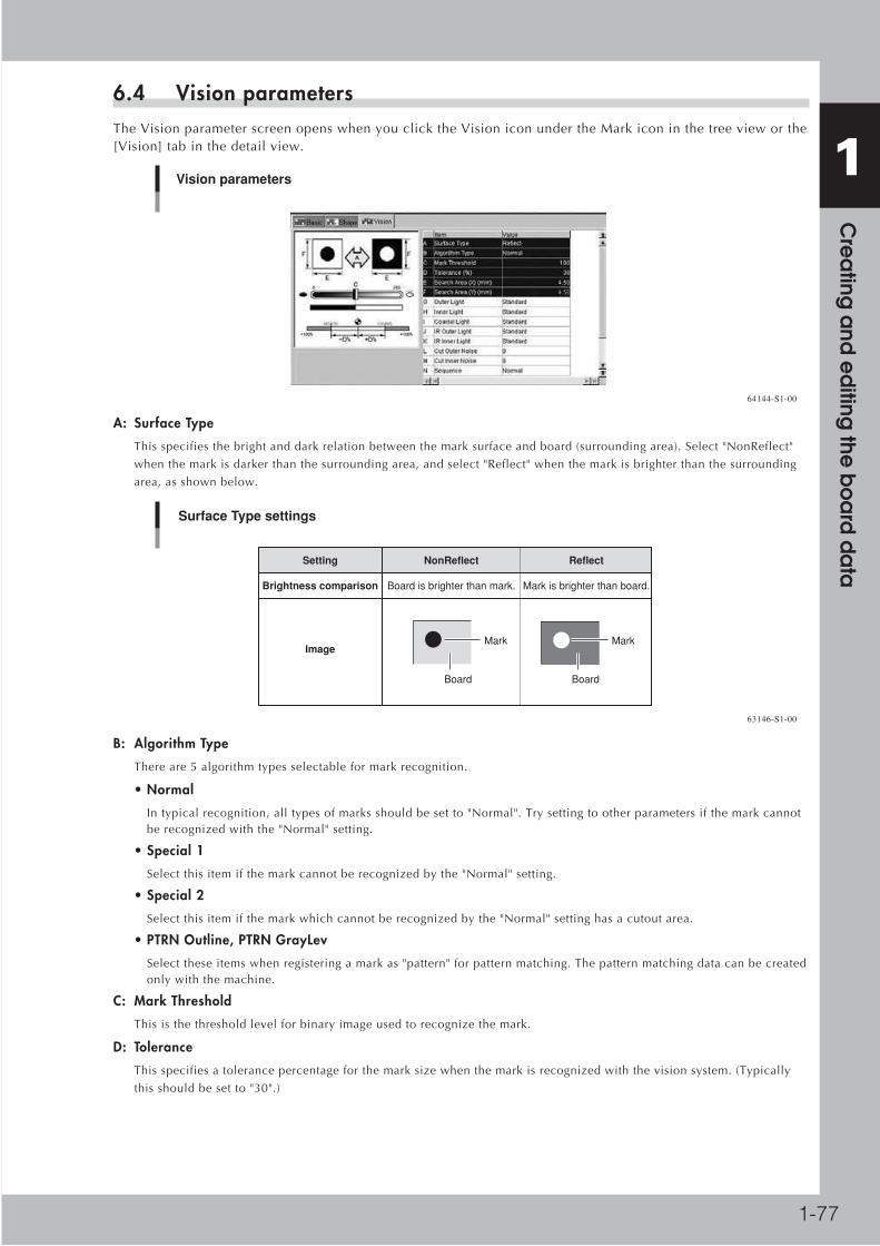
1-77
1 C
rea
ting a
nd e
diting
the b
oa
rd d
ata
6.4 Vision parametersTheVisionparameterscreenopenswhenyouclicktheVisioniconundertheMarkiconinthetreevieworthe[Vision]tabinthedetailview.
Vision parameters
64144-S1-00
A: Surface Type
Thisspecifiesthebrightanddarkrelationbetweenthemarksurfaceandboard(surroundingarea).Select"NonReflect"
whenthemarkisdarkerthanthesurroundingarea,andselect"Reflect"whenthemarkisbrighterthanthesurrounding
area,asshownbelow.
NonReflect
Board is brighter than mark.
Reflect
Mark is brighter than board.
Setting
Brightness comparison
Image
Board
Mark
Board
Mark
Surface Type settings
63146-S1-00
B: Algorithm Type
Thereare5algorithmtypesselectableformarkrecognition.
• Normal
Intypicalrecognition,alltypesofmarksshouldbesetto"Normal".Trysettingtootherparametersifthemarkcannotberecognizedwiththe"Normal"setting.
• Special 1
Selectthisitemifthemarkcannotberecognizedbythe"Normal"setting.
• Special 2
Selectthisitemifthemarkwhichcannotberecognizedbythe"Normal"settinghasacutoutarea.
• PTRN Outline, PTRN GrayLev
Selecttheseitemswhenregisteringamarkas"pattern"forpatternmatching.Thepatternmatchingdatacanbecreatedonlywiththemachine.
C: Mark Threshold
Thisisthethresholdlevelforbinaryimageusedtorecognizethemark.
D: Tolerance
Thisspecifiesatolerancepercentageforthemarksizewhenthemarkisrecognizedwiththevisionsystem.(Typically
thisshouldbesetto"30".)

1-78
1 C
rea
ting a
nd e
diting
the b
oa
rd d
ata
E, F: Search Area XY
Asageneralguide,setthisparametertothemarkdiameterplus3mm.Forexample,whenthemarkdiameteris1mm,set
thisparameterto"4mm"asshownbelow.Ifothermarks(suchasresist,silkprint,otherpatterns)existinthissearcharea,
maketheSearchAreasettingsmaller.
Reference The Search Area parameter is not displayed on the [Vision] tab screen when "Mark Type" of the Basic parameters is set to "Badmark".
1
4
Search AreaMark
Board
Search Area
63147-S1-00
G to K: Light level
Lightingforrecognizingamarkisdividedintoseveralzones.Lightlevelineachzoneisdisplayedhere.Optimumlight
levelscanbefoundintheMarkAdjustmodeexplainedlater.
L, M: Cut Outer Noise, Cut Inner Noise
Theseparametersareusedtocutthenoisethatusuallyappearswithinoroutsidethemarkimagewhenthemarkis
recognizedasabinaryimage.
N: Sequence
Setto"Normal"inmostcases.Iftherecognitionspeedisimportantselect"Quick",orifrecognitionaccuracyisimportant
select"Fine".

1-79
1 C
rea
ting a
nd e
diting
the b
oa
rd d
ata
7. Using and editing the database7.1 Using the databaseYoucanmakeuseofsampledataregisteredinthedatabasetocreate"partsinformation"and"markinformation"moreefficiently.Youcanalsostorethecurrentlyedited"partsinformation"and"markinformation"intothedatabase.Thefollowingsectionsexplainthedatabaseusingpartsinformationscreensasexamples.
7.1.1 Copying data from the database (Set from Database)Tocopydatafromthedatabaseintotheboarddataparametersbeingedited,followthestepsbelow.
1 Select the component of mark to which you want to copy data from the database.
2 Open the database.Select "Database Support" from the Tool menu and then click "Overview Database", or directly click the [Overview Database] button on the toolbar. The Part (or Mark) database list appears.
Reference You can also select the "Database Support" – "Overview Database" command from the context menu that appears when you right-click on the selected component or mark.
Opening the database list
64145-S1-00

1-80
1 C
rea
ting a
nd e
diting
the b
oa
rd d
ata
3 Select the data and copy it into the parameters.In the database list dialog box, select the data to be copied and click the [Set] button. Click the [OK] button in the dialog box that appears, and the selected data is copied from the database.
Database list
Copying from database
64146-S1-00
Reference The same task can be performed with the "Set from Database (F7)" command in the "Database Support" submenu of the Tool menu. In this case, you must first check the database number for the data to be copied and enter that number in the "Database Number" field beforehand.
Reference When you select the "Set from Database All" command from the "Database Support" submenu of the Tool menu, the data will be copied from the database into all the parts (or mark) data with the database number you specified in the "Database Number" field.
4 Click the [Close] button to close the database list.Check that the "Database Number" field in the [Basic] tab grid now shows the correct database number from which you have copied the data.
Data display after copying from database
64147-S1-00

1-81
1 C
rea
ting a
nd e
diting
the b
oa
rd d
ata
7.1.2 Storing the data into the database (Copy Back to Database)Parameterdatayouhaveeditedcanbestoredintothedatabase.
1 Select the component or mark from which you want to copy the data into the database.
2 Open the database.From the Tool menu, select "Database Support" and then click "Overview Database" to open the database list.
Reference You can also open the database list by directly clicking the [Overview Database] button on the toolbar or by selecting the command from the context menu that appears by clicking the right mouse button on the selected component or mark.
Opening the database list
64148-S1-00

1-82
1 C
rea
ting a
nd e
diting
the b
oa
rd d
ata
3 Select the database number where you want to store the data.1. In the database list, select the DB No. (database number) and click the [Write] button.
2. When a conformation dialog box appears, click the [OK] button.
The component data (or mark data) is now stored in the selected database number row.
Database
Storing the data into database
64149-S1-00
c CAUTION New component data (or mark data) is created in the selected database number row where no data is registered. However, if data is present in the selected database number row, the existing data in the database will be overwritten. In this case, an alert dialog box appears to let you confirm this action.
4 When an alert dialog box appears, check the message and select the action.
Database
Alert dialog box
64150-S1-00
Click [Yes]:Click [Yes] to store the data into the selected database number row. The database number where the data is stored will be entered in the "Database Number" field on the [Basic] tab of parts (or mark) information.
Click [No]:Click [No] to cancel storing the data into the selected database number row. The database number will not be entered in the "Database Number" field on the [Basic] tab of parts (or mark) information. Click the [Set Number] button if you want to enter the database number in the "Database Number" field on the [Basic] tab of parts (or mark) information.

1-83
1 C
rea
ting a
nd e
diting
the b
oa
rd d
ata
5 Click the [Close] button to close the database list.Check that the "Database Number" field in the [Basic] tab grid now shows the correct database number you have selected.
Data display after storing data into database
64151-S1-00
Reference The same task can be performed with the "Copy Back to Database" command in the "Database Support" submenu of the Tool menu.
Reference When you select the "Copy Back Database All" command from the "Database Support" submenu of the Tool menu, all data being edited will be copied into the database.

1-84
1 C
rea
ting a
nd e
diting
the b
oa
rd d
ata
7.2 Editing the databaseThepartsdatabaseandmarkdatabasecanbeeditedasneeded.UsethePartsorMarkDatabaseEditortoeditthedatabase.Thefollowingexplainsanexampleofeditingthedatabaseusingpartsinformationscreensasexamples.
1 Select the data to be edited.In the tree view, click the Parts or Mark icon to display the parts or mark information in the main view. Then select the data row you want to edit.
2 Start the Database Editor.From the Tool menu, select "Database Support" and then click "Database Edit" to start the Database Editor. The Database Editor window opens showing the database number assigned to the selected data.
Reference You can also start the Database Editor by directly clicking the [Database Edit] button on the toolbar or by selecting the "Database Support" - "Database Edit" command from the context menu that appears by clicking the right mouse button on the selected data.
Starting the Database Editor
Parts database
Select the data you want edit.
Database No. row for the selected data is highlighted.
64152-S1-00
Reference The "Parts Database Editor" and "Mark Database Editor" commands are also available from the File menu. In this case, selecting the "Parts Database Editor" command starts the Parts Database Editor even when mark data is selected, and vice versa.
3 Edit each parameter.While manipulating the tree view to display each parameter, edit it as needed.
Reference For how to set each parameter, see section 5, "Creating the parts information", or section 6, " Creating the mark information", in this chapter.
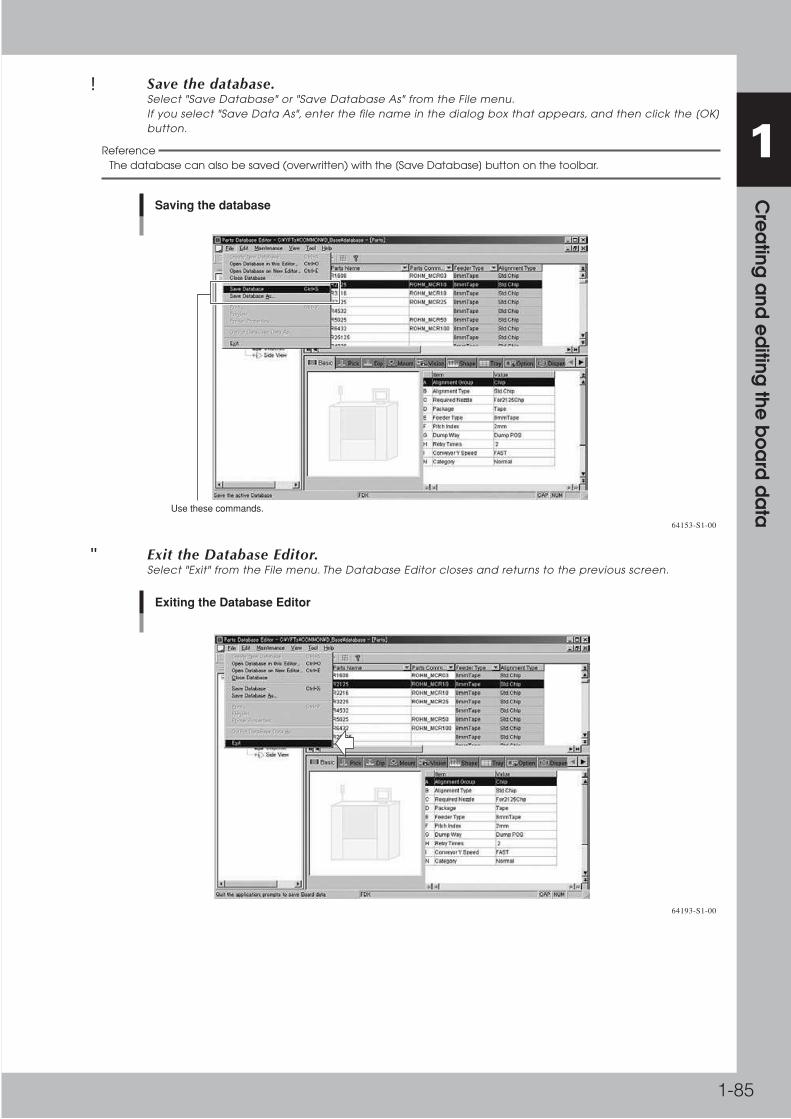
1-85
1 C
rea
ting a
nd e
diting
the b
oa
rd d
ata
4 Save the database.Select "Save Database" or "Save Database As" from the File menu. If you select "Save Data As", enter the file name in the dialog box that appears, and then click the [OK] button.
Reference The database can also be saved (overwritten) with the [Save Database] button on the toolbar.
Saving the database
Use these commands.
64153-S1-00
5 Exit the Database Editor.Select "Exit" from the File menu. The Database Editor closes and returns to the previous screen.
Exiting the Database Editor
64193-S1-00
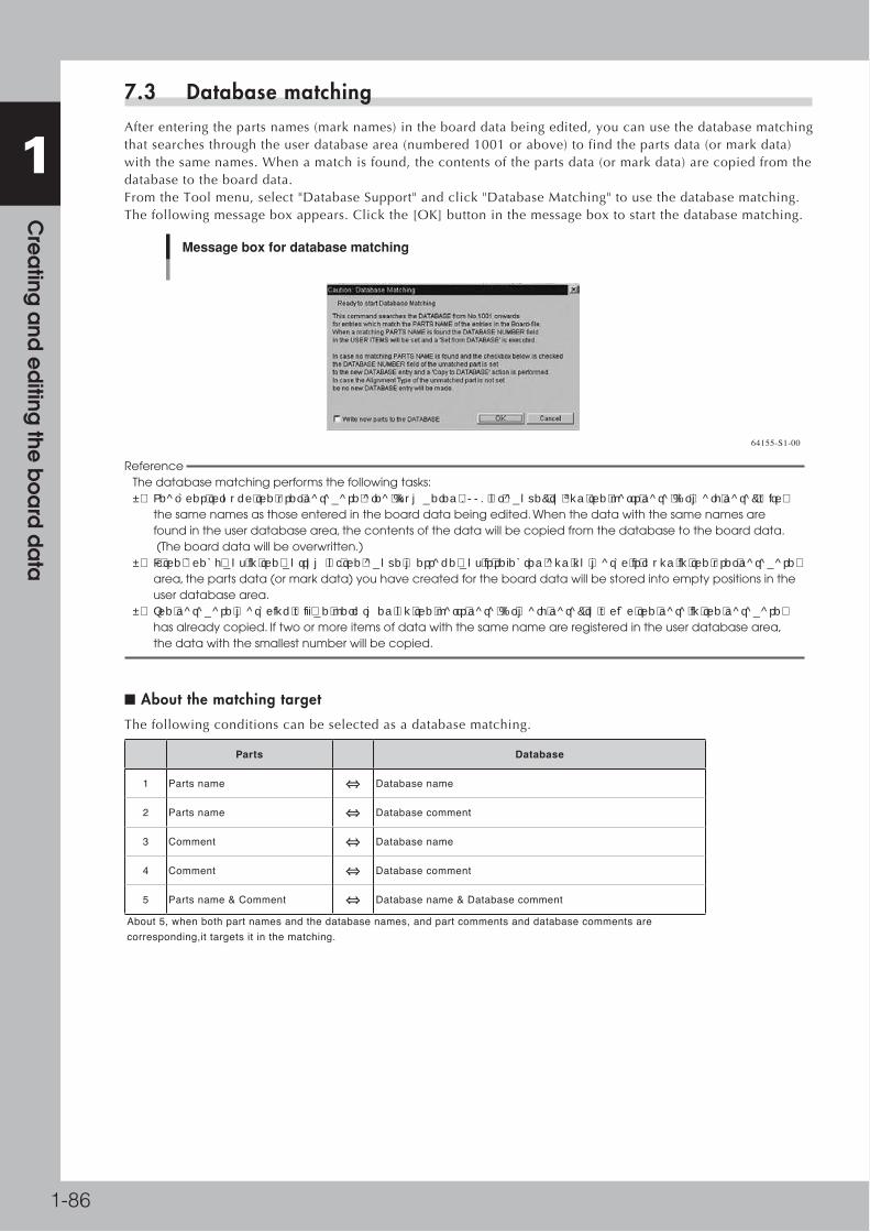
1-86
1 C
rea
ting a
nd e
diting
the b
oa
rd d
ata
7.3 Database matchingAfterenteringthepartsnames(marknames)intheboarddatabeingedited,youcanusethedatabasematchingthatsearchesthroughtheuserdatabasearea(numbered1001orabove)tofindthepartsdata(ormarkdata)withthesamenames.Whenamatchisfound,thecontentsofthepartsdata(ormarkdata)arecopiedfromthedatabasetotheboarddata.FromtheToolmenu,select"DatabaseSupport"andclick"DatabaseMatching"tousethedatabasematching.Thefollowingmessageboxappears.Clickthe[OK]buttoninthemessageboxtostartthedatabasematching.
Message box for database matching
64155-S1-00
Reference The database matching performs the following tasks: • Searches through the user database area (numbered 1001 or above) to find the parts data (or mark data) with the same names as those entered in the board data being edited. When the data with the same names are found in the user database area, the contents of the data will be copied from the database to the board data. (The board data will be overwritten.) • If the check box in the bottom of the above message box is selected and no match is found in the user database area, the parts data (or mark data) you have created for the board data will be stored into empty positions in the user database area. • The database matching will be performed on the parts data (or mark data) to which the data in the database has already copied. If two or more items of data with the same name are registered in the user database area, the data with the smallest number will be copied.
■ About the matching target
Thefollowingconditionscanbeselectedasadatabasematching.
Parts Database
1 Parts name Database name
2 Parts name Database comment
3 Comment Database name
4 Comment Database comment
5 Parts name & Comment Database name & Database comment
About 5, when both part names and the database names, and part comments and database comments are corresponding,it targets it in the matching.

1-87
1 C
rea
ting a
nd e
diting
the b
oa
rd d
ata
■ About Matching operation
Itbecomesprocessinguptonowtothecurrentfortheoperationofthematching.Thissettingofthematchingfromtheboaddatabecomeseffective.Andtheconditionofthematchisdisplayedinthedialog.
Database Matching
64191-S1-00
■ Setting method.
Tousethisfunction,itsetsitwith'OptionSetting'.The'Database'tabin'OptionSetting'isopened.Pleaseselecttheconditionby'DatabaseMatchingCondition'inthescreen.
Option Setting
64192-S1-00
■ Limitations
Therearenolimitations.

1-88
1 C
rea
ting a
nd e
diting
the b
oa
rd d
ata
7.4 Function of Database matching from boardIntheboardeditorofYGOS2,partdataofthenamesameafterNo.1001ofpartdatabase,itwillbewrittenfromthepartdatatoapartdatabase.
Database matching from board
64193-S1-00
Thisfunctionperformsthefollowingoperation.
• Selectionofamenu“Tool|DatabaseSupport|DatabaseMatching|DatabasewritefromBoard”isdisplayedona
menu.
• SpecificationofwhethertoregisterthepartswhichwerenotinagreementinacheckdialogofoperationafterNo.1001
ispossible.
•Databasematchingfromboardcanbeperformedfromacheckdialog.
• InDatabasematchingfromboard,apartdatabaseischangedimmediately.
■ Precondition
• Itisapreconditionthatthepartnameofpartinformationissetup.
■ Menu Selection
• ”Tool|DatabaseSupport|DatabaseMatching|DatabasewritefromBoard”select.
Menu Selection
64194-S1-00

1-89
1 C
rea
ting a
nd e
diting
the b
oa
rd d
ata
■ Execution check dialog
• Whenamenuisselect,thefollowingcheckdialogisdisplayed.
• Specificationofoperation“WritenewpartstotheDATABASE”inthisdialogispossible.
• Anexecutiondialogwillbedisplayedifthe[OK]buttonispushedinanexecutioncheckdialog.
Execution check dialog
64195-S1-00
ThepartswhichdidnotmatchaDatabaseareregisteredintotheemptydomainafterNo.1001.Theregistereddatabasenumberissettothepart.
■ Execution
•Matchingwillbestartedifa[Matching]buttonispushedinthefollowingandanexecutiondialog.
Execution dialog
64196-S1-00

1-90
1 C
rea
ting a
nd e
diting
the b
oa
rd d
ata
•Thefollowingisdisplayedduringmatching.
Displayed during matching
64197-S1-10
■ End
•ThefollowingmessageisdisplayedafteraDatabasematchingfromboardiscompleted.
• Itwillend,ifthe[OK]buttonispushed.
End message
64198-S1-00
■ Restriction matter
When two or more same names as part data exist, the write to a database is performed in order with a small number each, and the part information finally matched at the end is write.

1-91
1 C
rea
ting a
nd e
diting
the b
oa
rd d
ata
8. Editing the board dataThe contents of board data already registered can be efficiently edited or optimized with the Board Editor.
8.1 Block offsetAmulti-blockboardisaprintedcircuitboardconsistingoftwoormoreindependentprintedcircuitsofthesametype.Eachprintedcircuitonamulti-blockboardiscalleda"block".Settingtheblockoffsetallowsthemachinetorepeatthesamemountingoperationineachblockonaboard,basedonthereferenceblockdata.Thisfunctionthereforegreatlysavesthetimerequiredforcreatingdataonmulti-blockboards.
Block Multi-block Board
With the block repeat function, you
can create or change the data on an entire multi-
block Board, by simply creating or editing the reference block data.
Block offset concept
63148-S1-00
8.1.1 Pitch distributionPitchdistributionallowsyoutocreateblockoffsetdatabyjustspecifyingthenumberofblocksandtheblockpitch.
1 Click the Offset icon under the board icon in the tree view to open the Offset information screen.
2 Enter the block offset for block No.1.In the X and Y fields in the No.1 row, enter the block offset for block No. 1 (origin position in block No.1 relative to the board origin). This is used as the reference coordinates for other blocks. You do not have to enter offset here if the origin position in block No.1 is the same as the board origin position. (Leave the XY fields set at "0.00".)
3 Execute pitch distribution.From the Tool menu, select "Block Offset" and then click "Pitch Distribute". The "Pitch Distribution" dialog box appears.
c CAUTION The following conditions must be met to execute pitch distribution. • No offset data is entered for blocks other than block No.1. • Offset coordinates after pitch distribution will be set within the range from –999.999 to 999.999. • The number of blocks after pitch distribution does not exceed 512.
Selecting the "Pitch Distribute" command
Block No.1 offset data 64157-S1-00

1-92
1 C
rea
ting a
nd e
diting
the b
oa
rd d
ata
4 Enter the block pitch and the number of blocks.When the "Pitch Distribution" dialog box appears, enter the block pitch and the number of blocks in the X and Y directions, and then click the [OK] button. The pitch distribution will start.
Origin position in block No.1
Pitch distribution setting
Board origin position
X
Y
64158-S1-00
5 Check the distributed block offset data.After pitch distribution is complete, the offset data distributed over each block is displayed, so check the block offset data. The "Skip" check boxes are all cleared after pitch distribution. If there are blocks where you want to skip mounting components, click the [Check Box] button at the upper left and then mark the "Skip" check boxes. (The "Skip" check boxes can be edited only when the [Check Box] button is pressed.)
Block offset data after pitch distribution
Distributed block offset data"Skip" check box
64159-S1-00

1-93
1 C
rea
ting a
nd e
diting
the b
oa
rd d
ata
8.1.2 Pitch distribution of data after offset distribution
■ Outline of functions
• TheOffsetDatacanbeaddedbyexecutingthePitchDistributefromthestatewhereoffsetdataexists.
• TheOffsetDataispartiallymadeagainbyexecutingthePitchDistributefromthestate where offset data exists.
Therefore,theOffsetDatacanbemadefortheBoardlikethefigurebelow.
Efficiency of creating board data
63151-S1-00
■ Detailed explanation of operation
Line Data
641A0-S1-00

1-94
1 C
rea
ting a
nd e
diting
the b
oa
rd d
ata
■ Additional Pitch Distribute
WhentheOffsetDataexistedasshownintheabovefigure,thePitchDistributewasnotabletobeexecuted.Bytheimprovement,theOffsetDatacanbeaddedbyexecutingthePitchDistributefromthestatewhereOffsetDataexists.ExecutingthePitchDistributefromthestatewhereoffsetdataexists,thefollowingmessageisdisplayed.OffsetDatacanbeaddedbyselecting[Yes].
Additional Pitch Distribute
641A1-S1-00
■ Partial Pitch Distribute
WhentheOffsetDataexistedasshownintheabovefigure,thePitchDistributewasnotabletobeexecuted.Bytheimprovement,theOffsetDataispartiallymadeagainbyexecutingthePitchDistributefromthestatewhereoffsetdataexists.ExecutingthePitchDistributefromthestatewhereoffsetdataexists,thefollowingmessageisdisplayed.When[No]isselected,thefollowingdialogisdisplayed.
Partial Pitch Distribute
641A2-S1-00

1-95
1 C
rea
ting a
nd e
diting
the b
oa
rd d
ata
8.1.3 Block distributionExecutingblockdistributioncopiesthemountdataforthereferenceblockanddistributesitoverallotherblocks.Thedistributedmountdataisautomaticallyenteredanddisplayedonthemountinformationscreenaccordingtotheblocksormountdata.
1 Open the Offset information in the main view.
2 Check the block offset data.At least one item of block offset data must have been entered to execute block distribution.
Checking the block offset data
At least one item of block offset data must have been entered.
64160-S1-00
3 Select "Block distribution" from the Tool menu.From the Tool menu, select "Block Offset" and then click "Block Distribute", or click the [Block Distribute] button on the toolbar. A dialog box appears to let you choose the type of block distribution.
Block distribution
Step464161-S1-00
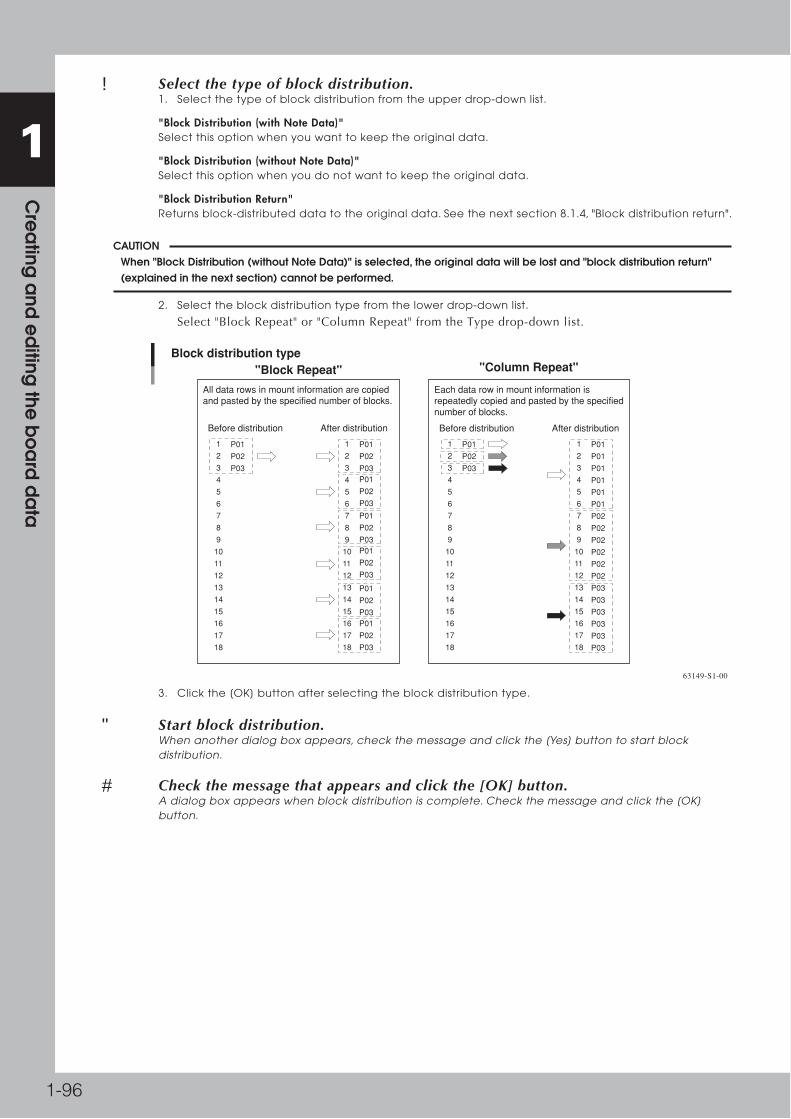
1-96
1 C
rea
ting a
nd e
diting
the b
oa
rd d
ata
4 Select the type of block distribution.1. Select the type of block distribution from the upper drop-down list.
"Block Distribution (with Note Data)"Select this option when you want to keep the original data.
"Block Distribution (without Note Data)"Select this option when you do not want to keep the original data.
"Block Distribution Return"Returns block-distributed data to the original data. See the next section 8.1.4, "Block distribution return".
c CAUTION When "Block Distribution (without Note Data)" is selected, the original data will be lost and "block distribution return" (explained in the next section) cannot be performed.
2. Select the block distribution type from the lower drop-down list.
Select"BlockRepeat"or"ColumnRepeat"fromtheTypedrop-downlist.
Before distribution After distribution Before distribution After distribution
P01
P02
P03
1
2
3
4
5
6
7
8
9
10
11
12
13
14
15
16
17
18
P01
P02
P03
1
2
3
4
5
6
7
8
9
10
11
12
13
14
15
16
17
18
P01
P01
P01
P01
P01
P01
P02
P02
P02
P02
P02
P02
P03
P03
P03
P03
P03
P03
1
2
3
4
5
6
7
8
9
10
11
12
13
14
15
16
17
18
P01
P02
P03 P01
P02
P03
P01
P02
P03 P01
P02
P03
P01
P02
P03 P01
P02
P03
1
2
3
4
5
6
7
8
9
10
11
12
13
14
15
16
17
18
"Block Repeat" "Column Repeat"
Each data row in mount information is repeatedly copied and pasted by the specified number of blocks.
Block distribution type
All data rows in mount information are copied and pasted by the specified number of blocks.
63149-S1-00
3. Click the [OK] button after selecting the block distribution type.
5 Start block distribution.When another dialog box appears, check the message and click the [Yes] button to start block distribution.
6 Check the message that appears and click the [OK] button.A dialog box appears when block distribution is complete. Check the message and click the [OK] button.

1-97
1 C
rea
ting a
nd e
diting
the b
oa
rd d
ata
7 Check the distributed block offset data.The "Skip" check boxes are all cleared after block distribution. If there are blocks where you want to skip mounting components, click the [Check Box] button at the upper left and then mark the "Skip" check boxes. (The "Skip" check boxes can be edited only when the [Check Box] button is pushed in.)
Block offset data after block distribution
"Block Repeat" ("With Note Data")
"Note" means original data still remains.
64162-S1-00
8 Save the board data.

1-98
1 C
rea
ting a
nd e
diting
the b
oa
rd d
ata
8.1.4 Block distribution returnBlockdistributionreturnallowsyoutorestorethedistributedblockoffsettotheoriginaldata.
c CAUTION This command is available only when the "With Note Data" check box was selected before executing block offset distribution.
1 Execute block distribution return.From the Tool menu, select "Block Offset" and then click "Block Distribute Return".
2 Check the message that appears.A confirmation dialog box appears. Check the message and click the [Yes] button.
Block distribution return
64163-S1-00
3 Check the message that appears and click the [OK] button.A dialog box appears when block distribution return is complete. Check the message and click the [OK] button.
4 Check that the original block offset data has been restored.Check that "Note" in the Skip column has disappeared and the original block offset data is now displayed.
Block conversion return
Return from "Block Repeat" ("With Note Data")
Original data before block distribution is displayed.
64164-S1-00
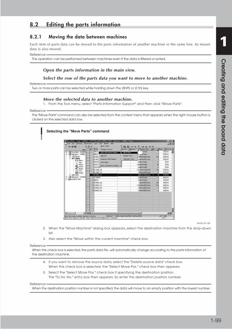
1-99
1 C
rea
ting a
nd e
diting
the b
oa
rd d
ata
8.2 Editing the parts information
8.2.1 Moving the data between machinesEachitemofpartsdatacanbemovedtothepartsinformationofanothermachineinthesameline.Itsmountdataisalsomoved.
Reference This operation can be performed between machines even if the data is filtered or sorted.
1 Open the parts information in the main view.
2 Select the row of the parts data you want to move to another machine.Reference
Two or more parts can be selected while holding down the [Shift] or [Ctrl] key.
3 Move the selected data to another machine.1. From the Tool menu, select "Parts Information Support" and then click "Move Parts".
Reference The "Move Parts" command can also be selected from the context menu that appears when the right mouse button is clicked on the selected data row.
Selecting the "Move Parts" command
64165-S1-00
2. When the "Move Machine" dialog box appears, select the destination machine from the drop-down
list.
3. Also select the "Move within the current machine" check box.
Reference When this check box is selected, the parts data No. will automatically change according to the parts information of the destination machine.
4. If you want to remove the source data, select the "Delete source data" check box.
When this check box is selected, the "Select Move Pos." check box then appears.
5. Select the "Select Move Pos." check box if specifying the destination position.
The "To Ins. No." entry box then appears. So enter the destination position number.
Reference When the destination position number is not specified, the data will move to an empty position with the lowest number.

1-100
1 C
rea
ting a
nd e
diting
the b
oa
rd d
ata
Select the destination machine.
Selecting the destination machine
Select this check box if specifying the destination position number.
Enter the destination position number.
64166-S1-00
6. Click the [OK] button to move the data to the specified machine.
7. When a dialog box appears indicating that the data has moved, click the [OK] button to quit this
function and close the dialog box.
Reference When parts defined for an alternative parts loop are moved, all the parts associated in that loop are moved to the specified machine.
8.2.2 Multiplying the parts dataThisfunctionallowspartsdatatomultiplyintotwoormoreunitsofthesamedata.Thismeansthatthemultiplieddatacanbesuppliedfromtwoormorefeeders.Whenalargeamountofthesamepartsareusedforoneboard,thisfunctionshortensthetimerequiredtoproduceaboard.
Reference This operation can be performed between machines even if the data is filtered or sorted.
1 Open the parts information in the main view.
2 Select the row of the parts data you want to move to another machine.
3 Multiply the selected data.1. From the Tool menu, select "Parts Information Support" and then click "Multiply Parts".
Reference The "Multiply Parts" command can also be selected from the context menu (right-click menu) that appears when the right mouse button is clicked on the selected data row.
Selecting the "Multiply Parts" command
64167-S1-00

1-101
1 C
rea
ting a
nd e
diting
the b
oa
rd d
ata
2. When the "Multiply Parts" dialog box appears.
3. In the "Multiply No." box, type the number you want to multiply by.
Type the number you want to multiply by.
Entering the number to multiply by
Select this check box if using the multiplied data as alternative parts.
64168-S1-00
4. Select the "Altemative Parts Loop" check box if using the multiplied data as alternative parts for the
source parts data.
Reference When the multiplied data is specified as alternative parts, the source parts data and multiplied parts data can be used as alternative parts for each other by making the following settings just like a loop. [Example 1] If parts No.1 data has been multiplied by 2, and you now have parts No.1 and No.2, make the settings as follows: • Set the "Alternative Parts" parameter of parts No.1 to "2". • Set the "Alternative Parts" parameter of parts No.2 to "1". [Example 2] If parts No.1 data has been multiplied by 3, and you now have parts No.1, No.2 and No.3, make the settings as follows: • Set the "Alternative Parts" parameter of parts No.1 to "2". • Set the "Alternative Parts" parameter of parts No.2 to "3". • Set the "Alternative Parts" parameter of parts No.3 to "1".
5. Click the [Multiply] button to multiply the parts data.
6. When a dialog box appears indicating that the parts data has been multiplied, click the [OK] button
to quit this function and close the dialog box.

1-102
1 C
rea
ting a
nd e
diting
the b
oa
rd d
ata
8.2.3 Renumbering the parts dataThepartsdatacanbesortedand/ordeletedwhennotusedinthemountinformation.
1 Open the parts information in the main view.
2 Select any row in the parts data grid display.
3 Renumber the parts data.1. Select "Parts Information Support" from the Tool menu.
2. Click "Renumber Parts". The "Renumber" dialog box appears.
Reference The "Renumber Parts" command can also be selected from the context menu (right-click menu) that appears when the right mouse button is clicked.
Selecting the "Renumber Parts" command
64169-S1-00
"Renumber" dialog box
64170-S1-00

1-103
1 C
rea
ting a
nd e
diting
the b
oa
rd d
ata
3. Select the "Renumber by parts number" or "Renumber by feeder set number" option button.
4. Select the "Renumber" check box.
The "Delete" check box is also selected automatically at this point. Clear this check box if you want
to renumber the data without deleting any data even though they are not currently used.
5. Click the [Execute] button to renumber the data.
A dialog box then appears indicating that renumbering is complete. Click the [OK] button to return
to the previous screen.
Reference If you want to only delete the data that are not currently used, select the "Delete" check box and clear the "Renumber" check box.

1-104
1 C
rea
ting a
nd e
diting
the b
oa
rd d
ata
8.3 Creating the sequence dataThissectionexplainsmethodsforcreatingsequencedatausinglaserheightcorrectionanddispensedistribution.Thesequencefunctionisavailabledependingonthespecifications.
8.3.1 Height correctionAsanoptionalfunctionfori-Cubemachines,alaserdisplacementmetercanbeusedtocorrectthedispensingorcomponentmountingheight.Thisfunctionismainlyusedwiththenozzleheightcorrectionfunctionusingatouchsensor.
n Creating the board data for the height correction function
Tousetheheightcorrectionfunction,"RunningMode"ontheboardparameterscreenmustbesetto"Sequence".Data
formatfortheheightcorrectionfunctionresemblesthe2-pointlocalfiducialmarksetting.Makethesettingsasexplained
below.
1 Set the "Running Mode" parameter.Click the board icon under the board icon in the tree view and then set the "Running Mode" parameter to "Sequence".
2 Set the "Mark Type" parameter.Click the Basic icon under the Mark icon in the tree view and then enter the name in the Mark Name column and set the "Mark Type" parameter to "Height Correction".
Step 2
Step 3Step 4
Mark parameter screen
Setting "Mark Type" to "Height Correction"
64171-S1-00
3 Set the "Post Sequence" parameter.This parameter specifies the action after a measurement error. An error example is when the measurement result is outside the range between "Upper Limit" and "Lower Limit" or an error occurs during the measurement. Select from "Stop", "Skip" or "Select".
"Stop": The machine stops immediately after a measurement error occurs. When automatic operation
restarts, the machine will repeat the measurement from the beginning.
"Skip": After a measurement error occurs, the machine will skip data with the same local height No. (except
"0") and local badmark No. (except "0") in the sequence information.
"Select: The machine immediately stops after a measurement error occurs. You can then select "Stop" or
"Skip" as the next action.
4 Set the upper and lower limits.Enter the upper and lower limits in millimeters to set an acceptable measurement result range. The downward direction is positive (+) and the upward direction is negative (-), just as with the head coordinate system.

1-105
1 C
rea
ting a
nd e
diting
the b
oa
rd d
ata
5 Set the height correction mode.Click the Height icon under the board icon in the tree view or click the [Height] tab in the main view to open the Height parameter screen. Then, enter the comment in the Comment column and set the height correction mode (number of height measurement points) in the Mode column.
• When measuring 1 point, set to "Local-M".
• When measuring 2 points to take an average, make the settings in 2 rows. Set the first row to
"Local-M" and the second row to "Local-S".
Height parameter screen
Mode settingStep 5
Step 6
Step 7
64172-S1-00
6 Enter the mark No.In the Mark column, enter the mark No. you set in steps 2 to 4.
7 Enter the XY coordinates.Enter the XY coordinates to be measured.
8 Enter the height correction No.Select the [Sequence] tab and, in the Height column, specify the number you set on the Height parameter screen in step 5.
n NOTE When using an average of 2-point measurements, enter the No. for "Local-M".
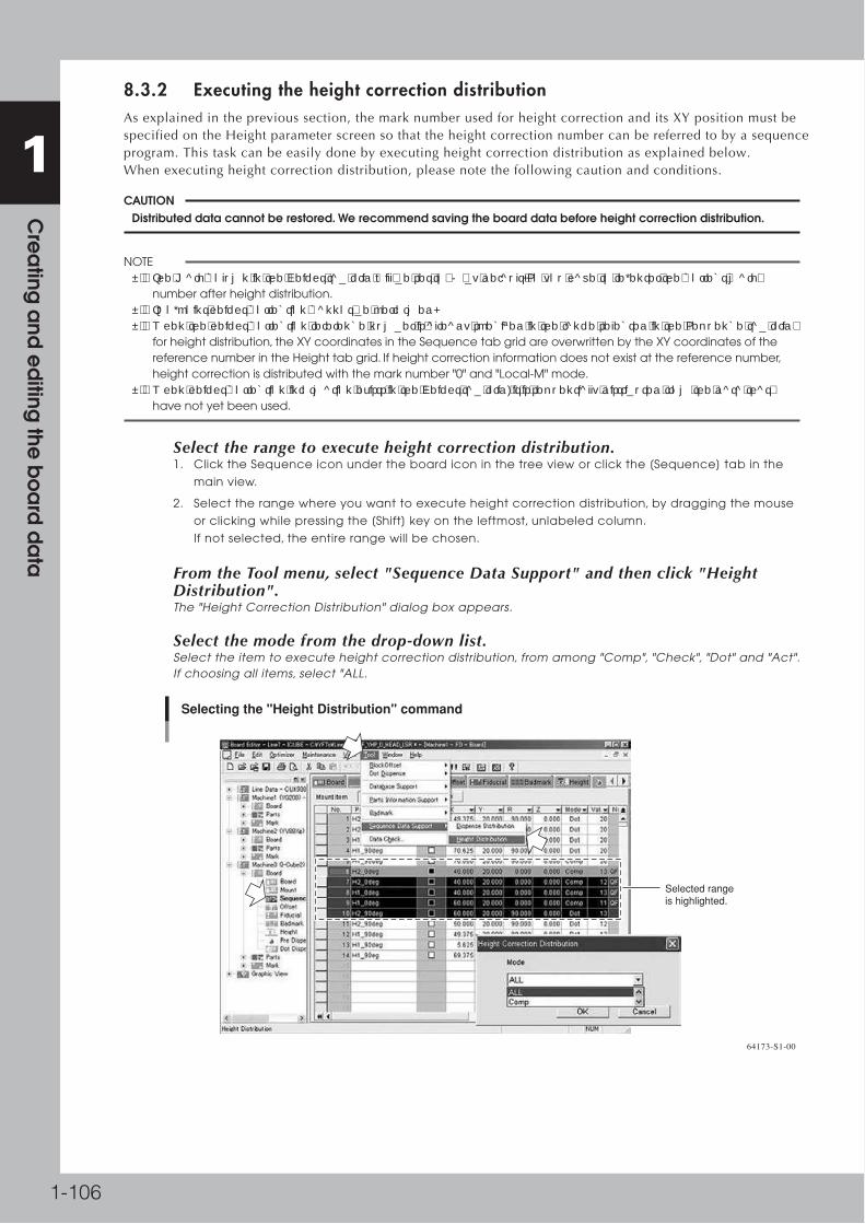
1-106
1 C
rea
ting a
nd e
diting
the b
oa
rd d
ata
8.3.2 Executing the height correction distributionAsexplainedintheprevioussection,themarknumberusedforheightcorrectionanditsXYpositionmustbespecifiedontheHeightparameterscreensothattheheightcorrectionnumbercanbereferredtobyasequenceprogram.Thistaskcanbeeasilydonebyexecutingheightcorrectiondistributionasexplainedbelow.Whenexecutingheightcorrectiondistribution,pleasenotethefollowingcautionandconditions.
c CAUTION Distributed data cannot be restored. We recommend saving the board data before height correction distribution.
n NOTE • The Mark column in the Height tab grid will be set to "0" by default. So you have to re-enter the correct mark number after height distribution. • Two-point height correction cannot be performed. • When the height correction reference number is already specified in the range selected in the Sequence tab grid for height distribution, the XY coordinates in the Sequence tab grid are overwritten by the XY coordinates of the reference number in the Height tab grid. If height correction information does not exist at the reference number, height correction is distributed with the mark number "0" and "Local-M" mode. • When height correction information exists in the Height tab grid, it is sequentially distributed from the data that have not yet been used.
1 Select the range to execute height correction distribution.1. Click the Sequence icon under the board icon in the tree view or click the [Sequence] tab in the
main view.
2. Select the range where you want to execute height correction distribution, by dragging the mouse
or clicking while pressing the [Shift] key on the leftmost, unlabeled column.
If not selected, the entire range will be chosen.
2 From the Tool menu, select "Sequence Data Support" and then click "Height Distribution".The "Height Correction Distribution" dialog box appears.
3 Select the mode from the drop-down list.Select the item to execute height correction distribution, from among "Comp", "Check", "Dot" and "Act". If choosing all items, select "ALL.
Selecting the "Height Distribution" command
Selected range is highlighted.
64173-S1-00

1-107
1 C
rea
ting a
nd e
diting
the b
oa
rd d
ata
4 Execute height correction distribution.Click the [OK] button in the "Height Correction Distribution" dialog box. The following confirmation dialog box then appears. Click the [Yes] button to execute height correction distribution.
Confirmation dialog box
64174-S1-00
5 Enter the mark number.In the Mark column on the Height screen, enter the mark number used for height correction.
Entering mark number
Enter the mark number here.
64175-S1-00
c CAUTION To enable the height correction function, be sure to select "Execute" from the Height drop-down list on the Height screen.
8.3.3 Dispense distributionWhencreatingasequenceprogramthatcontainsdispenseandmountdata,youwillusuallyhavetousethefollowingprocedure.
1.Createmountdata(XYcoordinates,headNo.,partsNo.,etc.).
2.Selectandcopythemountdataandthenpasteitinthesequenceinformationasdotdispensedata.
3.ChangetheModesettingforthepasteddata,from"Comp"to"Dot".
4.IntheParts-Dispensetabgrid,setthe"DispenseUnit"parameterforthedatawhoseModesettingwaschangedto"Dot".
5.ChangetheheadNo.Thedispensedistributionfunctionallowsyoutoperformtheaboveprocedureeasily.
c CAUTION Distributed data cannot be restored. We recommend saving the board data before dispense distribution.
n NOTE • Distributed data will be inserted in the top of the sequence information. • If the "Dispense Unit" parameter in the Parts - Dispense tab grid is not specified, the dispense amount is viewed as "0" when distributed in the sequence information. • Dispense sequence number will be set to "-1". If you want to use another dispenses sequence number, change it after dispense distribution. • Interference check is not performed. • Optimization is not performed.

1-108
1 C
rea
ting a
nd e
diting
the b
oa
rd d
ata
1 Select the range to execute dispense distribution.1. Click the Sequence icon under the board icon in the tree view or click the [Sequence] tab in the
main view.
2. Select the range where you want to execute dispense distribution, by dragging the mouse or clicking
while pressing the [Shift] key on the leftmost, unlabeled column.
If not selected, the entire range will be chosen.
2 Execute dispense distribution.From the Tool menu, select "Sequence Data Support" and then click "Dispense Distribution". When the "Dispense Distribution" dialog box appears, click the [Yes] button.
Selecting the "Dispense Distribution" command
Selected range is highlighted.
64176-S1-00
3 Check the distributed data.Make sure that the distributed data is inserted in the top of the sequence information.
Display after dispense distribution
Dot dispense data is created here.
64177-S1-00

1-109
1 C
rea
ting a
nd e
diting
the b
oa
rd d
ata
8.4 Creating the dot dispense informationThissectionexplainshowtodotdispenseinformationsuchasdispensepositionanddispenseamount.Dotdispenseinformationisdisplayeddependingonthespecifications.
8.4.1 Dispense distributionExecutingdispensedistributionusingdispenseparametersinthemountinformationandpartsinformationcreatesdotdispensedataautomatically.Toexecutethisdispensedistribution,followthesesteps.
c CAUTION Dispense distribution cannot be executed unless the mount information and parts information are specified.
1 Open the Dot Dispense parameter screen in the main view.
2 Execute dispense distribution.From the Tool menu, select "Dot Dispense" and then click "Bond Distribution" or "Solder Distribution". The "Machine Select" dialog box then appears. Select the machine and then click the [OK] button to execute dot distribution. Dot dispense coordinates will be created according to the mount data.
c CAUTION Executing dispense distribution will overwrite the current dispense data.
Dispense distribution
Check the machine to execute dispense distribution.
Select either of these commands.
Distributed data is displayed.
64178-S1-00

1-110
1 C
rea
ting a
nd e
diting
the b
oa
rd d
ata
3 Sort the dispense coordinates.From the Tool menu, select "Dot Dispense" and then click "Sort" or "Sort by every head". If you are going to check alignment amount, select "Sort by every head".
4 Perform an interference check.From the Tool menu, select "Dot Dispense" and then click "Interference Check. This command checks whether the stopper at the nozzle steps on dispensed dots. If such a possibility exists, the related data rows will be displayed, so correct them.
Interference check
Results of interference check are displayed.
64179-S1-00

1-111
1 C
rea
ting a
nd e
diting
the b
oa
rd d
ata
8.5 Data checkTocheckcurrentlyopenboarddataandnozzleinterference,followthesesteps.
1 Select "Data Check" - "Execute Data Check" from the Tool menu.The "Data Check" dialog box appears.
Data check
64180-S1-00
2 Set the items to be checked.In the "Data Check" dialog box, select the items to be checked by placing a check mark.
• Normal Check
Select this check box to check part No. and mark No. consistency in the board data.
• Nozzle Interference Check
Select the "Execute" check box to make a nozzle interference check.
When this is selected, also select either of the following check methods from the drop-down list.
"With mount order"Makes a nozzle interference check on the optimized board data. This method cannot be used for board data that are not optimized. A warning message appears if this method is selected for such board data. Clicking the [OK] button in the warning message automatically changes the selection to "Check all cases".
"Check all cases"Makes a nozzle interference check without regard to the component placement order, or the machine and head to be used. When "Check all cases" is selected, the "Parts Group Number Auto Set" check box becomes available. Select this check box when you want to automatically assign group numbers so as to avoid nozzle interference. Those group numbers are then set in the Parts Group No. field on the [Option] tab in parts information. Optimization should be conducted again to create data for avoiding interference.
3 Click the [Execute] button to start data check.When the data check is complete, a dialog box then appears to show the results.
n NOTE The nozzle interference check results can be checked on the Graphic View. If errors are found, the error status is displayed in color.

1-112
1 C
rea
ting a
nd e
diting
the b
oa
rd d
ata
■ When no error is found:
After"NormalCheck"
Themessage"Datacheckfinished"appears.Clickthe[Close]buttontoquitthedatacheck.
After"NozzleInterferenceCheck"
The"NozzleInterferenceCheckResult"dialogboxappears.Clickthe[OK]buttontoquitthedatacheck.
■ When an error is found:
After"NormalCheck"
The"Boarddataerror"dialogboxappears.Clickthe[OK]buttontoquitthedatacheck.
After"NozzleInterferenceCheck"
The"NozzleInterferenceCheckResult"dialogboxappears.Thisdialogboxshowscolorsusedtodisplaypartsinthe
GraphicView.IntheGraphicView,partcontoursprobablycausinginterferencearedisplayedinthefollowingcolors.
Clickthe[OK]buttontoquitthedatacheck.
■ Nozzle interference check results
Part contour colors Description
BlackIndicates parts which might cause interference with other parts during placement.
RedIndicates parts which might be hit by parts shown in black contour during placement.
Pink Indicates adjacent parts which might interfere with each other.
White Indicates parts which will not cause any interference.
Data check
Graphic View display example
Parts causing interference Parts not causing interference
64181-S1-00
Reference To clear the results shown in the Graphic View, select "Data Check" - "Clear check result" from the Tool menu.

1-113
1 C
rea
ting a
nd e
diting
the b
oa
rd d
ata
9. Printing the board dataThe Board Editor allows you to print information on board data.
9.1 Printing the board data
1 Open the board data you want to print.
2 In the tree view, select the item to be printed.
3 Select "Print" from the File menu.The "Print" dialog box appears.
Reference You can also click the [Print] button on the toolbar to open the "Print" dialog box.
Reference When you are going to print "parts information" or "mark information", another dialog box appears to let you select whether to print "List" or "Detail". Select "List" to print the contents of the main view or select "Detail" to print the contents of the detail view, and then click the [OK] button. The "Print" dialog box will appear.
4 Start printing.After checking the printer settings and the number of copies to print, click the [OK] button to start printing.
Printing the Board data
64182-S1-00

1-114
1 C
rea
ting a
nd e
diting
the b
oa
rd d
ata
● Printer settings
Tomaketheprintersettings:
1.Select"PrinterProperties"fromtheFilemenu.
2.Inthe"Printer"dialogbox,settheprinter,papersizeandorientation.
3.Ifusinganetworkprinter,clickthe[Network]buttonandselecttheprinter.
Printer settings
64183-S1-00
● Print preview
Toopentheprintpreviewwindowtocheckhowthedatawillbeprinted,select"Preview"fromtheFilemenu.Whenyouaregoingtoopentheprintpreviewof"partsinformation"or"markinformation",anotherdialogboxappearstoletyouselectwhethertopreview"List"or"Detail".
Print preview display
64184-S1-00

1-115
1 C
rea
ting a
nd e
diting
the b
oa
rd d
ata
● If the data cannot be printed
CheckthattheprinteriscorrectlyconnectedtoyourPC.IftheprinterisnotyetaddedtoyourPC,additonWindowsasfollows.(TheStartmenuitemsmayslightlydifferdependingontheOS.)
1.FromtheStartmenu,select"Settings"–"Printers"toopenthePrintersfolder.
Start menu
64185-S1-00
2.Double-clicktheAddPrintersicon.
3.WhentheAddPrinterwizardstarts,followtheinstructionsthatappear.
Add Printer wizard
64186-S1-00

Chapter 2 Creating solder-print data
Contents
1. Registering and selecting the board data 2-1
1.1 Registering a new board data name 2-1
1.2 Selecting the board data 2-3
2. Board data setting 2-4
2.1 Board data detail setting 2-8
3. Mask data setting 2-11
3.1 Mask data detail setting 2-14
4. Squeegee data setting 2-15
4.1 Squeegee detail setting 2-19
5. Cleaner data setting 2-21
6. Creating the mark data 2-23
6.1 Creating procedure 2-24
6.2 Shape parameters 2-26
6.3 Vision parameters 2-28

2-1
2 C
rea
ting so
lde
r-print d
ata
1. Registering and selecting the board dataFirst, you must register a new board name to create new data. Register a new board name as follows.
1.1 Registering a new board data name
1 Start the Board Editor.From the Start menu on the Windows taskbar, select "Programs" - "YAMAHA Factory Tools P-Tool" and then click "Board Editor".
2 Select the line to be used.When two or more lines (production lines) are registered, the "Select Editing Line" dialog box appears. Select the line to be used and click the [OK] button.
3 Create new board data.Select "Create New Board Data" from the File menu or click the [New Board Data] button on the toolbar.
Selecting "Create New Board Data" from File menu
64200-S1-00

2-2
2 C
rea
ting so
lde
r-print d
ata
4 Save the new board data. 1. Select "Save Board Data" from the File menu or click the [Save Board Data] button on the toolbar.
The dialog box appears for selecting the board data.
2. Enter a board name (up to 20 alphanumeric characters) from the keyboard.
Also select "Printer Text" , "YGZ" or "Default" from the File Type drop-down list.
3. Check or select the folder in which the board data will be saved and click the [Save] button.
The registered board name is displayed in the tree view.
n NOTE A space cannot be included in a board name. Use underbars in place of the space.
c CAUTION An alert dialog box appears if board data with the same name already exists. Use a different name. (If you want to register the same name by overwriting the previous data, press the [OK] button in the alert dialog box.)
Saving the Board data
Enter the Board name.
Select "Printer Text","YGZ" or "Default".
64201-S1-00

2-3
2 C
rea
ting so
lde
r-print d
ata
1.2 Selecting the board dataToselectboarddatafromthosealreadyregistered,proceedasfollows.
1 Open the board data.Select "Open Board on This Editor" from the File menu or click the [Open Board on This Editor] button on the toolbar. The "Board data select" dialog box appears.
Reference To open the board data, you may also select "Open Board on New Editor" from the File menu or click the [Open Board on New Editor] button on the toolbar.
Opening the board data
64202-S1-00
2 Select the board name. When the "Board data select" dialog box appears, place the cursor on the board name you want to open and click the [Select] button (or directly double-click the board name to open it). The selected board data will be loaded and the board name displayed in the tree view.
Selected board name
Selected Board name is displayed.
64203-S1-00

2-4
2 C
rea
ting so
lde
r-print d
ata
2. Board data settingTo check or edit the board data, select the Print - Board icon in the tree view (or select the [Board] tab in the main view.)
Print – Board screen
1 2 34 5 6
[Detail Setting] button
64204-S1-00
1. Board Fiducial
Setthisparameterto"Use"whenusingfiducialmarksontheboardforpositionalignmentbyvisionrecognition.Ifnot
usingvisionrecognitionthensetto"NotUse".SelectthedesireditemfromtheboardFiducialdrop-downlist.
2. Fiducial Type
When"BoardFiducial"issetto"Use",selectthefiducialtype(numberoffiducialmarkstoberecognized)fromamong"
1Point"to"4Points".Thesemarkscanbedifferentinshapeandsizefromeachother.Selectthedesireditemfromthe
FiducialTypedrop-downlist.
Fiducial Type example (2 points)
(X, Y)(0, 0)
(X, Y)
Board origin
Mark 2
Mark 1
X+
+Y
Board Datum Position (See item D.)
63200-S1-00

2-5
2 C
rea
ting so
lde
r-print d
ata
3. Fiducial Position
Thisparametersetswhethertosharethelocalfiducialmarkpositionwiththeboardandthemask.
Select"Board&MaskIndividual"or"Board&MaskCommon"fromtheFiducialPositiondrop-downlist.
• When "Board&Mask Individual" is selected:
TheFiducialPosition,FiducialTypeandStandardPositionparameterscanbesetseparatelyontheboardandthemask.
• When "Board&Mask Common" is selected:
TheFiducialPosition,FiducialTypeandStandardPositionparametersarejointlysharedbytheboardandmask.A
confirmationmessageboxappearswhenyouselect"Board&MaskCommon".Clickingthe[OK]buttoninthemessage
boxwillcopytheboardfiducialsetting(FiducialPosition,FiducialTypeandStandardPositionparameters)intothemask
fiducialsetting.
Confirmation message
Copying from board fiducial setting to mask fiducial setting
64205-S1-00
Reference If the Fiducial Position, Fiducial Type and/or Standard Position parameter are changed on the board or Mask parameter screen, the change is automatically applied to the other items.
4. X, Y (mm)
EntertheXYcoordinatesofeachfiducialmarkrelativetotheboardorigininmillimeters.Enterthecentercoordinatesin
thecaseofcircular,squareandtriangularmarks.
5. Mark No.
EnterthemarkNo.ofeachfiducialmark.(MarkNo.shouldberegisteredinadvanceontheMarkscreen.)
6. Name
WhenthemarkNo.isentered,thecorrespondingnameautomaticallyappearshere.(Marknameshouldberegisteredin
advanceontheMarkscreen.)
A, B: Borad Size X, Y (mm)
Entertheboardsize(mm)intheXdirection(boardtransferdirection)andintheYdirection.Theconveyorwidth(W-axis)
isadjustedtotheYdimension+0.5mmwhentheboardisclampedduringautomaticoperation.
Board X, Y
Board
Conveyor rail
X [mm]
W=(Y+0.5mm)
Y [m
m]
63201-S1-00
C: Borad Size Z (mm)
Entertheboardthickness(mm).
D: Comment
Typeanydesiredcommentasneeded.Youcanleavethisfieldblank.
E: Solder Name
Enterthesoldernameasneeded.Youcanleavethisfieldblank.

2-6
2 C
rea
ting so
lde
r-print d
ata
F: Borad Datum Position
Setthereferencepositiononaboardselectbyselectingfrom"Center","FrontCenter","RearCenter","FrontLeft","Front
Right,"RearLeft"or"RearRight"asshownbelow.Onstandardmachines,thisissetto"FrontCenter"asthedefault.
Board Datum Position
Board Datum Position
Board
63202-S1-00
Reference The board has "Origin XY", "Fiducial (Mark)" and "Board Inspection Position" parameters as its setting positions .
G,H: Origin X, Y (mm)
IfthefiducialmarkonaboardusesanorigindifferentfromtheBoardDatumPosition,setthepositionaloffset(mm)here
astheOriginXY.
Board Datum Position and Board origin
X-
X+
+Y
+Y
Fixed (front) conveyor rail
Board
Board Datum Position (Front Center)Board origin
63203-S1-00
I: Spin Timer (sec)
Setto"1"secondfornormalshapeboards.Ifspeciallyconfiguredboards(forexample,boardswithcutoutsorthrough-
holes)areusedandtheconveyorexitsensorcannotdetectthemcorrectly,trysettingthistimerbetween0.0and9.9
seconds.Theconveyormotorcontinuesturningforthespecifiedtimeevenaftertheboardsensorturnsoff.
J: Borad Vacuum
Thisparameterisenabledonlyformachinesequippedwithanoptionalvacuumgripper.Setto"NotUse"inmostcases.
Whencurvedboardsorthinboardsaretobeprinted,settingthisparameterto"Use"actuatesthevacuumgrippertofix
theboardfromthebackside.Whenthisparameterissetto"Use",alsospecifyanappropriatetime(msec)intheVacuum
TimerandBoardVacuumsequenceparameters.
K: Vacuum Timer (msec)
WhentheBoardVacuumparameterissetto"Use",setthetimer(msec)heretoinitiatethenextactionafterthepush-up
platehasmovedup.Thisparameterisenabledonlyformachinesequippedwithanoptionalvacuumgripper.
L: Borad Vacuum Sequence
Selectthetimingforboardvacuumoperationfrom"BeforeClamp"or"AfterClamp".Thisparameterisinvalidonlywhen
theBoardVacuumissetto"Use".
M: Edge Clamp
Setthisparameterto"Use"inmostcaseswhenusingtheedgeclampsthatholdtheboardinthemountingpositionby
pushinglaterallyontheboardedge.Ifusingathinceramicboardorthelikethatcannotbesupportedfromtheedges,
setto"NotUse"anduseavacuumgripper(option).
N: Borad Flap
Selectwhethertousetheboardflapsthatpressontheboardedgefromthetoptocorrectcurvatureintheboard.Setthis
parameterto"Use"inmostcases.

2-7
2 C
rea
ting so
lde
r-print d
ata
O: Borad Press (option)
Theboardpressunitholdsdowntheboardsurfacetocorrecttheoverallwarp.Setthisparameterto"Use"whenusing
theboardpressunit(option),orto"NotUse"whennotusingit.(Thisparameterisenabledonlyformachinesequipped
withanoptionalboardpressunit.)
P: Press Timer (msec) (option)
Setthetimeduringwhichtheboardpressstayslowereduntilitstartstorise.
Q: Board Pres Sequence
Setthisparameterto"BeforeClamp"or"AfterClamp"tochangetheboardpressandedgeclampoperationtiming.
Whensetto"BeforeClamp",theboardisfirstsecuredbytheboardpressandthenbytheedgeclamp.
Whensetto"AfterClamp",theboardisfirstsecuredbytheedgeclampandthenbytheboardpress.
R: Push Up Speed (%)
Specifytheascent/descentspeedsforthepush-upplateinpercentage.Settingto"100"isacceptableinmostcases,but
reduceitifyouwanttolessentheimpactwhenthepush-upjigsorpinsmoveupagainsttheboard.
S: Print Execution
Selectwhethertoprintsolderduringoperation.
QWhenthisparameterissetto"Exec",themachineoperatestoprintsolderunderthespecifiedconditions.Whensetto
"Skip",themachineoperateswithoutloweringthesqueegeeheadtotheprintingsurfacesothatsolderprintingis
skipped.
T: Alignment
Selecttheprocessingmethodafterfiducialmarkrecognition.Setto"UseAlign"innormaloperation,andthemachine
immediatelystopswhenamarkrecognitionerroroccurs.Whenthisissetto"IgnoreErr",themachinecontinuesoperation
evenifamarkrecognitionerroroccurs.
U: Print Feedback
Alwayssetthisparameterto"Use"whenproducingboards.(Ifyouwanttocheckthesqueegeeheadmovementwithout
controllingtheprintingpressure,setthisparameterto"NotUse".
V: Board Distortion Tol.(mm)
Thisparameterspecifiestheallowabledistortionlimitwhencheckingthedistortioncomponentintheboardfiducial
recognitionpositionandlocalrecognitionpositionsontheboard.Thedistortioncheckisnotperformedwhenthis
parameterissetto"0.00".
c CAUTION If the distortion component calculated by recognizing the board fiducial marks or local fiducial marks during automatic operation exceeds the allowable limit specified here, an error message box appears and the machine stops.
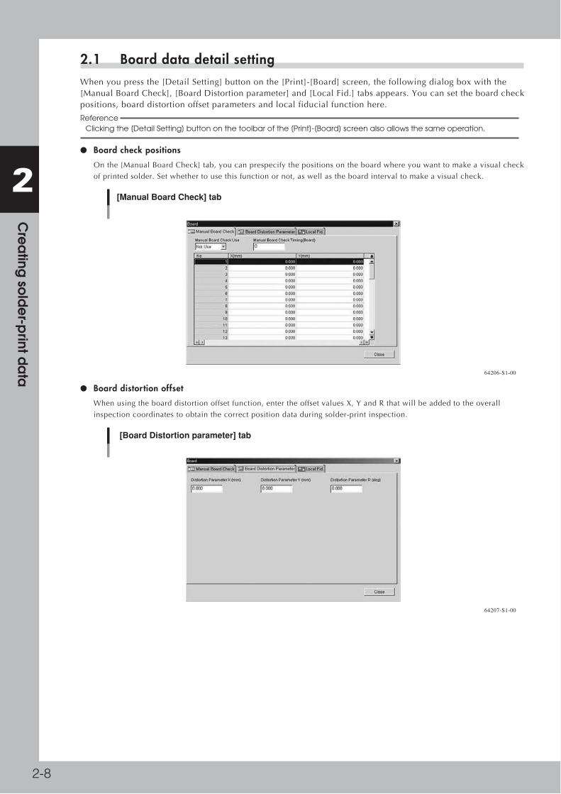
2-8
2 C
rea
ting so
lde
r-print d
ata
2.1 Board data detail settingWhenyoupressthe[DetailSetting]buttononthe[Print]-[Board]screen,thefollowingdialogboxwiththe[ManualBoardCheck],[BoardDistortionparameter]and[LocalFid.]tabsappears.Youcansettheboardcheckpositions,boarddistortionoffsetparametersandlocalfiducialfunctionhere.
Reference Clicking the [Detail Setting] button on the toolbar of the [Print]-[Board] screen also allows the same operation.
● Board check positions
Onthe[ManualBoardCheck]tab,youcanprespecifythepositionsontheboardwhereyouwanttomakeavisualcheck
ofprintedsolder.Setwhethertousethisfunctionornot,aswellastheboardintervaltomakeavisualcheck.
[Manual Board Check] tab
64206-S1-00
● Board distortion offset
Whenusingtheboarddistortionoffsetfunction,entertheoffsetvaluesX,YandRthatwillbeaddedtotheoverall
inspectioncoordinatestoobtainthecorrectpositiondataduringsolder-printinspection.
[Board Distortion parameter] tab
64207-S1-00

2-9
2 C
rea
ting so
lde
r-print d
ata
Whenboardsinthesamelottendtobeelongatedordistortedinthesamedirection,orthesameproblemappearsonly
intheboardfiducialpositions,thenoverallpositiondeviationsmightoccurinthesolder-printinspection.These
deviationscanoccurregardlessofwhetherprintaccuracywasmaintainedbyvisualalignment.Ifthishappens,usethe
boarddistortionoffsetfunctiontoaddcorrectionoffsetstotheoverallinspectioncoordinatestogetthecorrectposition
usingsolder-printinspectionresults(solderposition)oftheprintedboardusedasthereference.
Board distortion offset
1. When the board fiducial positions have elongation or distortion, the board clamping deviation cannot be corrected, and overall position deviations will occur in the solder-print inspection results.
2. Solder accurately printed on the land patterns is recognized by the vision camera and the position offset data is used as feedback. (overall shift)
63204-S1-00
n NOTE The solder-print inspection is run to acquire distortion values so solder-print inspection data must be created in advance. As much objects to be inspected as possible should be entered in order to detect the correct print position for the entire board. (See the "YVP-Xg Solder-print inspection" user's manual for more information.)
● Local fiducial function
Uniformprintingaccuracyatimportantpointscanbeensuredbyrecognizingmarksnearpositionswhereitisessential
tomaintaingoodprintingaccuracy.Thisisespeciallytruewhenprintingonboardwithinthesamelothavingelongation
ordistortionirregularities.The[LocalFid.]taballowsyoutosetthetypeofmarkandpositioncoordinatesofthelocal
fiducialmarksbeingused.
Reference Position correction with local fiducial marks is also used to calculate the print position, as well as calculate the printing position for running the solder-print inspection on machines equipped with the solder-print inspection function (option).
Board fiducial and local fiducial functions
1. This function runs board fiducial recognition and calculates the amount of offset for correcting the board deviation that may occur when clamped on the print table.
2. This function uses board fiducial recognition results to correct the board deviation that may occur when clamped on the print table. It then recognizes the marks at the local fiducial positions that were preregistered.
3. If there is no elongation or distortion on the board then no local fiducial recognition offset is issued. But if elongation or distortion is present, the local fiducial recognition offset (only in XY direction) is added unchanged, to the board fiducial offset.
Board fiducial functionBoard fiducial function
Board fiducial function Local fiducial function
63205-S1-00
Reference When there are multiple positions on the board where you want to essentially maintain satisfactory printing accuracy and the local fiducial function is used on each of these positions, the average of the recognition offset amount for each local fiducial mark is used as the correction offset.

2-10
2 C
rea
ting so
lde
r-print d
ata
Local fiducial mark setting
1 2 3 4 5
64208-S1-00
1. No.
ShowsthelocalfiducialNo.
2. Skip
SetswhethertorunortoskipthelocalfiducialfunctionforthespecifiedNo.Clearthecheckboxifrunningthelocal
fiducialfunction.
3. X(mm), Y(mm)
SetsthepositionforthelocalfiducialmarkpositionforthespecifiedNo.Thecoordinatereferencepositionisthesame
astheboardfiducialmark.
4. Mark No.
SpecifiesthemarkNo.touseforrecognizingthelocalfiducialmarkofthespecifiedNo.
5. Name
ShowsthenameofthemarkdataspecifiedinthemarkNo.
c CAUTION Always set the board fiducial function to "Use" when using the local fiducial function. The board fiducial function is disabled if set to "NotUse".

2-11
2 C
rea
ting so
lde
r-print d
ata
3. Mask data settingTo check or edit the mask data, select the Print - Mask icon in the tree view (or select the [Mask] tab in the main view.)
Print – Mask screen
1 4 5 32 6
[Detail Setting] button
64209-S1-00
1. Mask Fiducial
Setthisparameterto"Useforeveryboard"or"Useforone"whenusingmaskfiducialmarksforpositionalignmentby
visionrecognition.Ifnotusingmarkrecognitionthensetthisto"NotUse".Whensetto"Useforeveryboard",position
alignmentbymarkrecognitionisperformedeachtimeaboardisloadedontheconveyor.When"Useforone"isselected,
positionalignmentbymarkrecognitionisperformedonlywhenthefirstboardisloaded.Selectthedesireditemfromthe
MarkFiducialdrop-downlist.
2. Fiducial Type
When"MaskFiducial"issetto"UseForEveryBoard"or"UseForOnce",selectthefiducialtype(numberoffiducial
markstoberecognized)fromamong"1Point"to"4Points".Thesemarkscanbedifferentinshapeandsizefromeach
other.SelectthedesireditemfromtheFiducialTypedrop-downlist.
Fiducial Type example (2 points)
Mask origin
Mark 1
Mark 2
X+
+Y
(-X, Y)
(X, Y)
63206-S1-00

2-12
2 C
rea
ting so
lde
r-print d
ata
3. Fiducial Position
Thisparametersetswhethertosharethelocalfiducialmarkpositionwiththeboardandthemask.
Select"Board&MaskIndividual"or"Board&MaskCommon"fromtheFiducialPositiondrop-downlist.
• When "Board&Mask Individual" is selected:
TheFiducialPosition,FiducialTypeandStandardPositionparameterscanbesetseparatelyontheboardandthemask.
• When "Board&Mask Common" is selected:
TheFiducialPosition,FiducialTypeandStandardPositionparametersarejointlysharedbytheboardandmask.A
confirmationmessageboxappearswhenyouselect"Board&MaskCommon".Clickingthe[OK]buttoninthemessage
boxwillcopythemaskfiducialsetting(FiducialPosition,FiducialTypeandStandardPositionparameters)intotheboard
fiducialsetting.
Confirmation message
Copying from mask fiducial setting to board fiducial setting
64210-S1-00
Reference If the Fiducial Position, Fiducial Type and/or Standard Position parameter are changed on the board or Mask parameter screen, the change is automatically applied to the other items.
4. X, Y (mm)
EntertheXYcoordinatesofeachfiducialmarkrelativetothemaskorigininmillimeters.
5. Mark No.
EnterthemarkNo.ofeachfiducialmark.(MarkNo.shouldberegisteredinadvanceontheMarkscreen.)
6. Name
WhenthemarkNo.isentered,thecorrespondingnameisautomaticallydisplayedhere.(Marknameshouldberegistered
inadvanceontheMarkscreen.)
A: Mask Name
Enteramaskname.
B Mask Size
Enterthemaskframesize(LxW)inmillimeters.
C: Mask Standard Position
Specifythereferencepositionusedtofabricatethemask,fromamong"Center","Front"and"Rear".
Mask Standard Position (Mask reference position)
Mask Standard Position
Mask Standard Position: Center Front Rear
Board Mask frame
63207-S1-00

2-13
2 C
rea
ting so
lde
r-print d
ata
D, E: Standard Position Offset X, Y
Ifthemaskstandardpositiondeviatesgreatlyfromthe"Center","Front"or"Rear"andthemarkcannotberecognized,set
thepositionaloffsetvalues(millimeters)here.
Standard Position Offset X, Y (when Mask Standard Position is "Center")
Mask center
X- X+
-Y
+Y
Mask Standard Position
63208-S1-00
F: Mask Datum Position
BasedontheMaskStandardPositionandStandardPositionOffsetsettings,selectthepositionusedasthereference
positiononthemaskfromamong"Center","FrontCenter",RearCenter,"FrontLeft","FrontRight","RearLeft"and"Rear
Right"asshownbelow.
Reference The mask has "Mask Origin", "Mask Fiducial (Mark)" and "Mask Inspection Position" parameters as its setting positions.
Mask Datum Position
Mask Datum Position
Board
Mask frame
63209-S1-00
G, H: Mask Origin X, Y (mm)
IfthefiducialmarkonamaskhasanorigindifferentfromtheMaskDatumPosition,setthepositionaloffset(mm)here
astheMaskOrigin.
Mask Origin
Mask originMask Datum Position
When Mask Datum Position is set to "Front Left":
Board
Mask frame+Y
-Y
X+
X-
63210-S1-00
I: Mask Vacuum
Setthisparameterto"Use"whenyouwanttovacuum-gripthemaskontheconveyorrailsduringsolderprinting.Setto
"NotUse"whennotusingthisfunction.
MaskvacuumfunctionisusefulforpreventingapositionalshiftintheYdirectionbetweensqueegees1and2,andalso
forimprovingthesurfacecontactbetweentheboardandthemask.

2-14
2 C
rea
ting so
lde
r-print d
ata
3.1 Mask data detail settingWhenyoupressthe[DetailSetting]buttononthe[Print]-[Mask]screen,thefollowingdialogboxappears.Youcanprespecifythepositionsonthemaskwhereyouwanttomakeavisualcheckaftersolderprinting.Setwhethertousethisfunctionornot,aswellastheboardintervaltomakeavisualcheck.
Reference Clicking the [Detail Setting] button on the toolbar of the [Print]-[Mask] screen also allows the same operation.
Mask check position setup screen
64211-S1-00

2-15
2 C
rea
ting so
lde
r-print d
ata
4. Squeegee data settingTo check or edit the squeegee data, select the Print - Squeegee icon in the tree view (or select the [Squeegee] tab in the main view.)
Print – Squeegee screen
1
[Detail Setting] button
64212-S1-00
1. Squeegee Type
Setto"Double"forstandardYVP-Xgmachines.Formachinesequippedwithanoptionalenclosedheadusingasolder
supplycassette,setto"EnclosedHead".(When"EnclosedHead"isselected,unnecessaryparametersaregrayedout.)
A: Squeegee Detail Type
Selectthesqueegeetypefromthedrop-downlist.
B: One Way/Round
Selectwhethertoprintsolderinonedirectionorinbothdirections.
C: F. & B. Print Condition
Selectwhethertousethesameconditionsfortheforwardandbackwardprinting.Whenthisparameterissetto"Same
Condition",theforwardandbackwardprintingoperationsareperformedundertheconditionsspecifiedforthe"F.
SqueegeeSpeed"and"F.SqueegeeForce",andthesettingsforthe"B.SqueegeeSpeed"and"B.SqueegeeForce"are
disabled.
D, F: F. Squeegee Speed (mm/sec), B. Squeegee Speed (mm/sec)
Settheforwardandbackwardsqueegeemovementspeedstoprintsolder.Findanoptimumspeedwhilecheckingthe
scrapedstateofthesolderonthemask.Ifthisspeedistoofast,thesqueegeemaynotscrapesolderproperly.Iftooslow,
soldermayspreadintothebacksideofthemask.
E, G: F. Squeegee Force (N), B. Squeegee Force (N)
Settheforce(pressure)toapplyaloadtothesqueegeeduringprintingintheforwardandbackwarddirections.Check
thescrapedstateofthesolderonthemasktofindanoptimumsqueegeepressure.Setthispressureatalowerpressureas
longasthesolderisscrapedproperly.Alargersqueegeepressureisrequiredasthesqueegeespeedissetfaster.
H: Solder Supply Stop
Whenthisparameterissetto"Use",themachineautomaticallystopswhensoldersupplyisrequired.
I: Solder Supply Interval (Board)
Setthenumberofboardstobeprintedperonesupplyofsolder,basedontheamountsofsoldersuppliedandused
duringprinting.

2-16
2 C
rea
ting so
lde
r-print d
ata
J: Rolling Stroke (mm)
Specifythedistance(millimeters)fromthepositionatwhichthesqueegeelandsonthemasktotheedgeoftheboard.
Usuallysetto30to45mm.
Rolling stroke
Solder
BoardConveyor
Mask surface
Rolling stroke
Squeegee
63211-S1-00
K: Over Stroke (mm)
Specifythedistance(millimeters)fromtheotheredgeoftheboardtothepositionatwhichthesqueegeetakesoffthe
maskafterprintingsolder.Usuallysetto5to10mm.
Over stroke
Solder
BoardConveyor
Mask surface
Over stroke
Squeegee
63212-S1-00
L: F. Start Offset (Forward movement start offset)
Thisparametersetshowfartoprint(orthatamountofoffset)inwardsontheboardfromthecloseredgeoftheboard(or
loweredgeindrawingbelow).
M: B. Start Offset (Backward movement start offset)
Thisparametersetshowfartoprint(orthatamountofoffset)inwardsontheboardfromthefartheredgeoftheboard(or
upperedgeindrawingbelow).
n NOTE The print range of the squeegee is basically a reference position determined by the F. Start Offset and B. Start Offset parameters. You can use this print range to set the "Rolling Stroke" and "Over Stroke" parameters.
Squeegee print range
Boa
rd s
ize
Y=
130
(mm
)
Over Stroke=10 (mm)
B. Start Offset=30 (mm)
F. Start Offset=50 (mm)
B. Start Offset=30 (mm)
F. Start Offset=50 (mm)Rolling Stroke=40 (mm)
Rolling Stroke=40 (mm)
Over Stroke=10 (mm)
Forw
ard
prin
ting
Retu
rn p
rintin
g
Forw
ard
prin
ting
Retu
rn p
rintin
g
63213-S1-00
Asshowninthedrawingabove,let'sconsidercaseswhereyouprintinthedarkshadedarea50mmfromthecloseredge(loweredgeindrawing)and30mmfromthefarthersideofaboardwhoseYsizeis130mm.Whentherollingstrokeismade40mmandthe"OverStroke"10mmasadistanceforgoodsolderpasteuniformity,theprintmovementrangeofthesqueegeeduringforwardandreturnprintingisthesectionshownbythearrowsinthedrawing.Theparametersettingswillthenbeasfollows.
RollingStroke(mm) 10.000
OverStroke(mm) 40.000
S.StartOffset(mm) 50.000
B.StartOffset(mm) 30.000

2-17
2 C
rea
ting so
lde
r-print d
ata
N: F. & B. Mask Offset
Selectwhethertoapplythesamemanualalignmentoffsetfortheforwardandbackwardprinting.Whenthisparameteris
setto"SameOffset",theforwardandbackwardprintingoperationsareperformedundertheconditionsspecifiedforthe
"F.MaskOffsetX,Y,Z,R",andthesettingsforthe"B.MaskOffsetX,Y,Z,R"aredisabled.
O: F. Mask Offset X (mm)
Whenprintingintheforwarddirection(fromthefrontsidetotheinnerside),themasksurfacemaystretchinthe
advancingdirection,causinganX-directionshiftversusthelandpatterns.Tocorrectthispositionalshift,enteranoffset
valuehere.
Ifshiftedintheplusdirection:Enteraplusoffsetvalue.
Ifshiftedintheminusdirection:Enteraminusoffsetvalue.
P: F. Mask Offset Y (mm)
Whenprintingintheforwarddirection(fromthefrontsidetotheinnerside),themasksurfacemaystretchinthe
advancingdirection,causingaY-directionshiftversusthelandpatterns.Tocorrectthispositionalshift,enteranoffset
valuehere.
Ifshiftedintheplusdirection:Enteraplusoffsetvalue.
Ifshiftedintheminusdirection:Enteraminusoffsetvalue.
Q: F. Mask Offset Z (mm)
Whenprintingintheforwarddirection(fromthefrontsidetotheinnerside),themasksurfacemaystretchintheZ
direction.Enterthisoffsethere.Leavethisparametersetto"0.000"inmostcases.
R: F. Mask Offset R (deg)
Whenprintingintheforwarddirection(fromthefrontsidetotheinnerside),themasksurfacemaystretchinthe
advancingdirection,causingaR-directionshiftversusthelandpatterns.Tocorrectthispositionalshift,enteranoffset
valuehere.
Ifshiftedcounterclockwise:Enteraplusoffsetvalue.
Ifshiftedclockwise:Enteraminusoffsetvalue.
S: B. Mask Offset X (mm)
Whenprintinginthebackwarddirection(fromtheinnersidetothefront),themasksurfacemaystretchintheadvancing
direction,causingaX-directionshiftversusthelandpatterns.Tocorrectthispositionalshift,enteranoffsetvaluehere.
Thisparameterisdisabledwhenthe"F.&B.MaskOffset"issetto"SameOffset".
Ifshiftedintheplusdirection :Enteraplusoffsetvalue.
Ifshiftedintheminusdirection:Enteraminusoffsetvalue.
T: B. Mask Offset Y (mm)
Whenprintinginthebackwarddirection(fromtheinnersidetothefront),themasksurfacemaystretchintheadvancing
direction,causingaY-directionshiftversusthelandpatterns.Tocorrectthispositionalshift,enteranoffsetvaluehere.
Thisparameterisdisabledwhenthe"F.&B.MaskOffset"issetto"SameOffset".
Ifshiftedintheplusdirection:Enteraplusoffsetvalue.
Ifshiftedintheminusdirection:Enteraminusoffsetvalue.
U: B. Mask Offset Z (mm)
Whenprintinginthebackwarddirection(fromtheinnersidetothefront),themasksurfacemaystretchintheZ
direction.Enterthisoffsethere.Leavethisparametersetto"0.000"inmostcases.Thisparameterisdisabledwhenthe"F.
&B.MaskOffset"issetto"SameOffset".
V: B. Mask Offset R (deg)
Whenprintinginthebackwarddirection(fromtheinnersidetothefront),themasksurfacemaystretchintheadvancing
direction,causinganR-directionshiftversusthelandpatterns.Tocorrectthispositionalshift,enteranoffsetvaluehere.
Thisparameterisdisabledwhenthe"F.&B.MaskOffset"issetto"SameOffset".
Ifshiftedcounterclockwise:Enteraplusoffsetvalue.
Ifshiftedclockwise:Enteraminusoffsetvalue.
W: Escape Position
Thisistheescapepositionwherethesqueegeeheadmovesbackfromthesolderprintingareasothatyoucanmake
setupsonthemaskorconveyortablesuchasforsupplyingsolderorchangingtheconveyorunitsetups.Setto"Standard
Position"inmostcases.Ifyouspecifyanotherposition,select"DefinedPosition"andsettheSYandSZcoordinatesfor
the"EscapePositionSYandSZ"parameters.
X, Y: Escape Position SY, SZ
Ifyouwanttospecifytheescapepositionwherethesqueegeeheadmovesbackfromthesolderprintingarea,enterthe
desiredSYandSZ(height)coordinates.Settingsherewillbevalidonlywhenthe"EscapePosition"parameterissetto
"DefinedPosition".

2-18
2 C
rea
ting so
lde
r-print d
ata
Z: Squeegee lowering sequence
Changesthetimingforreplacementoperationofthesqueegeeswhenadoublesqueegeeisused.
Whensetto“Normal”,thesqueegeewillbereplacedduringboardunloading/loadingafterprinting.Incaseofsolder
thatdroolseasily,solderfromthesqueegeeusedinthepreviousprintprocessmaydripontothemaskopening.
Whensetto“Solderdrippingprevention”,thesqueegeewillnotberaisedafterprintingandthesqueegeereplacement
willoccurafterloadingthenextboardtobeprinted.

2-19
2 C
rea
ting so
lde
r-print d
ata
4.1 Squeegee detail settingWhenyouclickthe[DetailSetting]buttononthe[Print]-[Squeegee]screen,theSqueegeedialogboxappearsforadjustingthesolderfillamountandsettingthetimingthattheboardseparatesfromthemaskafterprinting.Varioustypesofdetailsettingscanbeeditedbyselectingthe[Filling(Dry)],[Filling(Wet)],[Filling(Manual)]and[DetachPattern]tabs.
Reference Clicking the [Detail Setting] button on the toolbar of the [Print]-[Squeegee] screen also allows the same operation.
Filling Adjust
Ifyouwanttoadjustthesqueegeespeedandpressuretocompensatefortheboardsolderfillamountjustaftermask
cleaning,makethenecessarysettingsherewhilereferringtothefollowingdescription.
[Filling (Dry) ] tab
1
4 5
2 364213-S1-00
1. Filling (Dry)
Select"Use"fromthedrop-downlistwhenusingthisfunction.Select"NotUse"ifnotusingit.
2. Filling Adjust Count
Specifythenumberofboardsonwhichyouwanttoapplythisfunctionaftermaskcleaning.Thedatalinesuptothe
numberofboardsyouspecifiedbecomevalidtoallowdataentry.(Upto10boardscanbespecified.)
3. Data grid display
ShowsthesqueegeespeedandpressurethatweresetontheSqueegeeparameterscreen.Changetheseparametervalues
asneeded.Notethatincreasingthesqueegeepressureimprovesonlythescrapingoperation.Merelyincreasingthe
squeegeepressuredoesnotincreasethesolderfillamountandmayscrapeoffthesolderorcausethesoldertospread
betweenthemaskandboard.
4. [Filling (Wet)] tab
Ifyouwanttoadjustthesqueegeespeedandpressuretocompensatefortheboardsolderfillamountjustafterautowet
cleaning,selectthistabandmakethenecessarysettings.
5. [Filling (Manual)] tab
Ifyouwanttoadjustthesqueegeespeedandpressuretocompensatefortheboardsolderfillamountjustaftermanual
cleaning,selectthistabandmakethenecessarysettings.
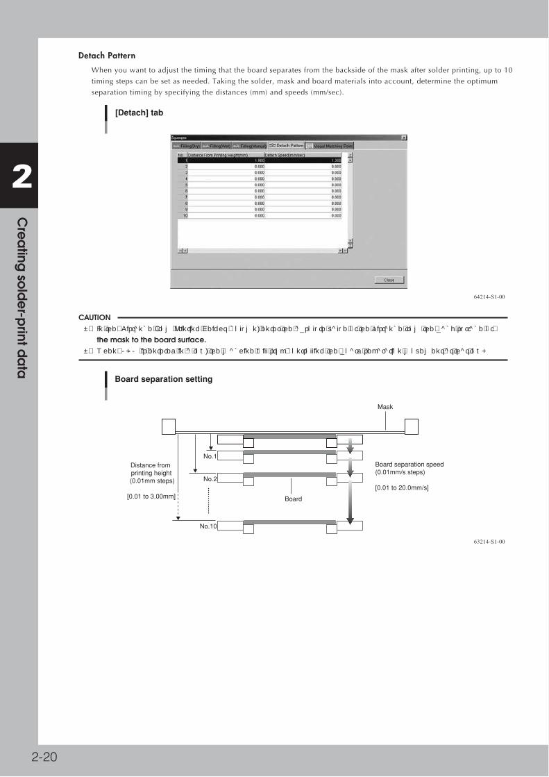
2-20
2 C
rea
ting so
lde
r-print d
ata
Detach Pattern
Whenyouwanttoadjustthetimingthattheboardseparatesfromthebacksideofthemaskaftersolderprinting,upto10
timingstepscanbesetasneeded.Takingthesolder,maskandboardmaterialsintoaccount,determinetheoptimum
separationtimingbyspecifyingthedistances(mm)andspeeds(mm/sec).
[Detach] tab
64214-S1-00
c CAUTION • In the "Distance From Printing Height" column, enter the absolute value of the distance from the back surface of the mask to the board surface. • When "0.00" is entered in a row, the machine will stop controlling the board separation movement at that row.
Board separation setting
Board
Mask
No.1
No.2
Distance from printing height
(0.01mm steps)
[0.01 to 3.00mm]
Board separation speed (0.01mm/s steps)
[0.01 to 20.0mm/s]
No.10
63214-S1-00

2-21
2 C
rea
ting so
lde
r-print d
ata
5. Cleaner data settingTo check or edit the squeegee data, select the Print - Cleaner icon in the tree view (or select the [Cleaner] tab in the main view.)
Print – Cleaner screen
64215-S1-00
Board count control
Setthefollowingparameterstocontrolmaskcleaningbyboardcount(numberofboardsproduced).
A: Cleaning Method
Setthemaskcleaningmethodto"Auto","Manual","Both"or"NotUse".Whensetto"Auto",themaskisautomatically
cleanedaccordingtothespecifiedconditions.Whensetto"Both",themaskcanbecleanedautomaticallyandalso
manually.
B: Auto Cleaning Type
Whenthe"CleaningMethod"issetto"Auto"or"Both",selectwhethertousethecleaningsolvent(alcohol).Setthis
parameterto"Wet"whenusingthesolvent,or"Dry"whennotusingit.Ifyouwanttousebothmethods,setto"Both".
C: Dry Auto Interval (Board)
Settheinterval(boardcount)toperformautomaticmaskcleaningwithoutusingthesolvent.Whenthe"AutoCleaning
Method"parameterissetto"Both"andthe"DryAutoInterval"and"WetAutoInternal"aredesignatedatthesameboard
count,wetautomaticcleaningisgivenpriority.
D: Dry Auto Repeat
Specifythedesiredcountatwhichtorepeatedlymovethecleaningunitbackandforthduringdryautomaticcleaning.
E: Dry Auto Speed (%)
Setthespeed(%)atwhichthecleaningunitmovesunderthemaskduringdryautomaticcleaning.
F: Wet Auto Interval (Board)
Settheinterval(boardcount)toperformautomaticmaskcleaningusingthesolvent.Whenthe"AutoCleaningMethod"
parameterissetto"Both"andthe"DryAutoInterval"and"WetAutoInternal"aredesignatedatthesameboardcount,
wetautomaticcleaningisgivenpriority.
G: Wet Auto Repeat
Specifythedesiredcounttorepeatedlymovethecleaningunitbackandforthduringwetautomaticcleaning.
H: Wet Auto Speed (%)
Setthespeed(%)atwhichthecleaningunitmovesunderthemaskduringwetautomaticcleaning.

2-22
2 C
rea
ting so
lde
r-print d
ata
I: Manual Interval (Board)
Settheinterval(boardcount)toperformmanualmaskcleaning.Whenthisparameterisspecifiedatthesameboard
countas"DryAutoInterval"or"WetAutoInternal",manualcleaningisgivenpriority.
n NOTE When the "Cleaning Method" and "Auto Cleaning Type are set to "Both", dry automatic cleaning, wet automatic cleaning and manual cleaning are all enabled. However, if they are specified at the same board count, only one cleaning method is used according to the priority in order of "Manual", "Wet Auto" and "Dry Auto. (Settings at the lower data lines take priority. When the cleaning is performed by the highest priority method, all board counts are reset.)
Time interval control
Usethiswhenyouwanttoperformmaskcleaningatcertaintimeintervalsevenduringstandbystatus.Forexample,ifthe
"CleaningMethod"issetto"Auto"andthe"Interval"to"10"(minutes),thenthemaskwillbeautomaticallycleanedwhen
10minuteshaveelapsedafteraboardwaslastprintedorthemaskwaslastcleaned.
A: Cleaning Method
Selectthemaskcleaningmethodfrom"Auto","Manual"or"NotUse".Whensetto"Auto",themaskisautomatically
cleanedaccordingtothespecifiedconditions.
B: Auto Cleaning Type
Whenthe"CleaningMethod"issetto"Auto",selectwhethertousethecleaningsolvent(alcohol)byspecifying"Wet"or
"Dry".
C: Interval
Settheinterval(minutes)toperformautomaticmaskcleaning.
D: Repeat
Specifythedesiredcounttorepeatedlymovethecleaningunitbackandforthduringautomaticcleaning.
E: Speed (%)
Setthespeed(%)atwhichthecleaningunitmovesunderthemaskduringautomaticcleaning.

2-23
2 C
rea
ting so
lde
r-print d
ata
6. Creating the mark dataThis section describes how to create fiducial mark data used on boards and masks. Mark data has various parameters for each of the mark names registered as shown below.
Mark data parameters
Surface TypeAlgorithm TypeMark ThresholdToleranceSearch AreaOuter LightInner LightCoaxial LightIR Outer LightIR Inner LightCut Outer NoiseCut Inner Noise
Mark Type
Shape TypeMark Out Size(Mark Out Size X)(Mark Area)(Outline)
Mark NameComment
(Mark Type)
64216-S1-00
Reference Actual parameters that appear depend on the selected "Shape Type" parameter, etc.

2-24
2 C
rea
ting so
lde
r-print d
ata
6.1 Creating procedureWhenyouclicktheBasiciconundertheMarkiconinthetreeview,themarkinformationscreenappearsinthemainview.Enterthemarknameandcommentintheuppergriddisplayandthensetvariousparametersasexplainedinthestepsbelow.
1 Click the Basic icon under the Mark icon in the tree view to open the mark information screen.
Step 2Step 1 Step 3
Step 4
Mark information screen
64217-S1-00
2 Enter the mark name in the Mark Name cell.Enter a different name for each mark within 20 alphanumeric characters. A space cannot be included in the name.
3 Enter a comment.Type any desired comment in the Mark Comment cell as necessary. You can omit entering comments here.

2-25
2 C
rea
ting so
lde
r-print d
ata
4 Set "Mark Type" on the [Basic] tab.Set to "PCB Fiducial" when creating board fiducial mark data, or set to "Mask Fiducial" when creating mask fiducial mark data.
"Mark Type" setting
64218-S1-00
5 Set other parameters.While selecting the [Basic], [Shape], [Vision] tabs and so forth, set the necessary parameters in the right lower list. (See "6.2" to "6.3" in this section.)
6 Repeat the above steps for other marks.Repeat the same procedure to register all marks to be used.
7 Save the data.Select "Save Board Data" or "Save Board Data As" from the File menu to save the data.
Reference Clicking the [Save Board Data] button on the toolbar saves the data over the original data.

2-26
2 C
rea
ting so
lde
r-print d
ata
6.2 Shape parametersInthegridonthe[Mark]-[Shape]tab,setthefollowingparametersrelatingtomarkshape.
Shape parameters
64219-S1-00
Shape Type
The"ShapeType"canbeselectedfromthefollowing5types.
Shape Type settings
Setting Description Example
Circle
Square
Triangle
Sp. Shape
Corner
Select to detect a circular mark.
Select to detect a square mark.
Select to detect an equilateral triangular mark.
Select to detect a special mark other than above.
Select to detect a corner of a pattern as a mark.
63215-S1-00
Reference If using a special mark composed of two or more objects, set "Algorithm" of the Vision parameters as a pattern ("PTRN Outline" or "PTRN GrayLev"). In this case, the "Shape" parameter is ignored during mark recognition so you can set this parameter to any type.
Example of special mark
63216-S1-00

2-27
2 C
rea
ting so
lde
r-print d
ata
A, B: Mark Out Size
Referringtothetablebelow,enterthecorrectvalueinthemarksize.The"MarkSizeX"isdisplayedwhen"MarkType"
onthe[Basic]tabissetto"Sp.Shape".
X
X
Y
Y
Mark Out Size settings
Example Mark Out Size settingShape Type
Circle
Square
Triangle
Sp. Shape
Corner
Enter the diameter.
Enter the length of each side.
Enter the length of one side.
Enter the X length for the MarkOutSize X, and the Y length for the MarkOutSize Y.
Enter the length of the shorter side displayed within the search area.
63217-S1-00
Reference If using a special mark with two or more edges as shown below, enter the size of the shortest side in the rectangular area to be detected.
Mark Out Size setting for special mark
Rectangular area to be detected
63218-S1-00
C: Mark Area
Entertheareaofthemarkinunitsofsquaremillimeters.Thisparameterisdisplayedonlywhen"ShapeType"onthe
[Shape]tabissetto"Sp.Shape".
D: Outline
Entertheperimeterlengthofthemarkinunitsofmillimeters.
Thisparameterisdisplayedonlywhen"ShapeType"onthe[Shape]tabissetto"Sp.Shape".

2-28
2 C
rea
ting so
lde
r-print d
ata
6.3 Vision parametersInthegridonthe[Mark]-[Vision]tab,setthefollowingparametersusedformarkrecognition.
Vision parameters
64220-S1-00
A: Surface Type
Thisspecifiesthebrightanddarkrelationbetweenthemarksurfaceandthesurroundingarea.Select"NonReflect"when
themarkisdarkerthanthesurroundingarea.Select"Reflect"whenthemarkisbrighterthanthesurroundingareaas
shownbelow.
NonReflect
Board is brighter than mark.
Reflect
Mark is brighter than board.
Setting
Brightness comparison
Image Mark Mark
Surface Type setting
63219-S1-00
B: Algorithm Type
Thereare5algorithmtypesselectableformarkrecognition.
Normal
Intypicalrecognition,alltypesofmarksshouldbesetto"Normal".Trysettingtootherparametersifthemarkcannotbe
recognizedwiththe"Normal"setting.
Special 1
Selectthisifthemarkcannotberecognizedwiththe"Normal"setting.
Special 2
Selectthisifthemarkwhichcannotberecognizedwiththe"Normal"settinghasacutoutarea.
PTRN Outline, PTRN GrayLev
Usetheseparametersformarksthatshouldberegisteredasapattern.

2-29
2 C
rea
ting so
lde
r-print d
ata
C: Mark Threshold
Thisisthethresholdlevelforthebinaryimageusedtorecognizethemark.
D: Tolerance
Thisspecifiesatolerancepercentageforthemarksizewhenthemarkisrecognizedwiththevisioncamera.(Typically
thisshouldbesetto"30".)
E, F: Search Area XY
Asageneralguide,setthisparametertothemarkdiameterplus3mm.Forexample,whenthemarkdiameteris1mm,set
thisparameterto"4mm"asshownbelow.Ifothermarks(suchasresist,silkprint,otherpatterns)existinthissearcharea,
makethe"SearchArea"settingsmaller.
Search Area
Search Area
Mark
1mm
4mm
63220-S1-00
G to K: Light level
Lightingforrecognizingamarkisdividedintoseveralzones.Lightlevelineachzoneisdisplayedhere.
L, M: Cut Outer Noise, Cut Inner Noise
These parameters are used to cut the noise that usually appears within or outside the mark image when the mark is recognized as a binary image.

Chapter 3 Data optimizationProductionboarddatacanbeautomaticallyrewrittenintomoreefficientdatawiththeOptimizer.
Contents
1. Starting and quitting the Optimizer 3-1
1.1 Starting the Optimizer 3-1
1.1.1 Starting the Optimizer from the Board Editor 3-1
1.1.2 Starting the Optimizer from the Feeder Viewer 3-2
1.2 Quitting the Optimizer 3-3
2. Optimizer window 3-4
3. Defining the optimizing conditions 3-7
3.1 Checking the information 3-7
3.2 Setting the basic conditions 3-9
3.2.1 Creating Basic Conditions and Registering a Template 3-9
3.2.2 Setting Enforcement Object of “Height difference to permit overtaking” 3-12
3.2.3 Pallet Number Automatic Decision 3-16
3.3 Setting the detailed conditions 3-19
3.4 Common setting 3-23
3.5 Initial setting 3-24
3.6 Specifying the dump station (option) position 3-25
3.7 Set layout of common parts 3-27
3.7.1 Settings 3-28
3.7.2 Auto Distribution Error 3-28
3.7.3 Reporting parts that cannot be the same layout 3-29
3.8 Setting the optimizing conditions for individual board data 3-30
3.9 Editing the data optimizing conditions 3-33
3.9.1 Editing each file of optimizing conditions 3-33
3.9.2 Editing multiple files of optimizing conditions 3-34
4. Executing data optimization 3-35
4.1 Checking the nozzles 3-38
5. Outputting the feeder setup lists 3-39
6. Changing the line to be optimized 3-41
7. Multi-lane Support 3-42
7.1 Optimize of single combined program 3-42
7.2 Optimize with same kind parts 3-42
7.3 [Set optimization parameters] dialog is extended 3-42
7.4 [Detail] setting is extended. 1 3-43

7.5 [Detail] setting is extended. 2 3-43
7.6 [Detail] setting is extended. 3 3-44
7.7 Result dialog is extended 3-45

3-1
3 D
ata
op
timiza
tion
1. Star ting and quitting the OptimizerYou can start the Optimizer from the Board Explorer, Board Editor or Feeder Viewer. This section explains the methods for using the Optimizer by starting it from the Board Editor and Feeder Viewer.
c CAUTION Board data for solder paste printers, dispensers, i-Cube machines and waffle tray data cannot be optimized.
1.1 Starting the Optimizer
1.1.1 Starting the Optimizer from the Board Editor
1 Start the Board Editor.Select "Board Editor" from the Start menu.
2 Select the line.The "Select Editing Line" dialog box appears when two or more lines (production lines) are registered. Select the line to work with the Board Editor and click the [OK] button.
c CAUTION The "Select Editing Line" dialog box does not appear when only one line is registered.
3 Select "Start Optimizer" from the Optimizer menu.The Optimizer window appears as shown below.
Starting the Optimizer
64300-S1-10

3-2
3 D
ata
op
timiza
tion
1.1.2 Starting the Optimizer from the Feeder ViewerFromtheFeederViewer,youcanstarttheOptimizertooptimizeindividualboarddata.TostarttheOptimizertooptimizeindividualboarddata,select"StartOptimizer"fromtheOptimizermenu.
Starting the Optimizer
64301-S1-10
Reference When the Setup Optimizer (option) is installed, multiple board data registered in the plan information can be optimized at one time.

3-3
3 D
ata
op
timiza
tion
1.2 Quitting the OptimizerToquittheOptimizer,followthesesteps.
1 Select "Exit" from the File menu in the Optimizer window.Reference
Clicking the [Close] button in the upper right corner also quits the Optimizer.
2 The Optimizer window closes and returns to the Board Editor window.
Quitting the Optimizer
[Close] button
64302-S1-10

3-4
3 D
ata
op
timiza
tion
2. Optimizer windowWhen the Optimizer starts, the following window appears.
Optimizer window
12
3
5
9
4
87
6
64303-S1-10
1. Menu bar
ThemenubaratthetopoftheOptimizerwindowcontainspull-downmenuswithcommandsgroupedbyfunction.
• File
TheFilemenuallowsyoutoselectcommands,suchastoloadsettings,savechanges,switchthelinesandquittheOptimizer.
• Optimize
TheOptimizemenuallowsyoutoselectcommands,suchastoexecuteoptimization,stopoptimizationanddisplaytheresults.
• Maintenance
TheMaintenancemenuallowsyoutoselectcommandstosetvariousinformationitems.
• Tool
TheToolmenuallowsyoutosaveorcleartraceinformation.
• Help
TheHelpmenudisplaystheprogramversioninformation.
2. Toolbar
AmongtheOptimizerfunctions,thosethatarefrequentlyusedareregisteredasthetoolbarbuttons.
Toolbar
1 2 3 5 6 10 11 124 987
64304-S1-00
1. [Create Setting] button
Opensthe"Setoptimizingparameters"screenforsettingtheoptimizingconditionsforeachboard.Thesameoperationcanbeperformedbyselectingthe"MakeSetting"commandfromtheFilemenuorclickingthe[Create]buttonundertheleft-handgridpane.
2. [Delete Setting] button
Deletestheoptimizingconditionsforeachboard.Thesameoperationcanbeperformedbyselectingthe"DeleteSetting"commandfromtheFilemenuorclickingthe[Delete]buttonundertheleft-handgridpane.

3-5
3 D
ata
op
timiza
tion
3. [Modify Setting] button
Opensthe"Setoptimizingparameters"screenforeditingtheoptimizingconditionsforeachboard.Thesameoperationcanbeperformedbyselectingthe"ModifySetting"commandfromtheFilemenuorclickingthe[Modify]buttonundertheleft-handgridpane.
4. [Collective Editing] button
Opensadialogboxforeditingtheoptimizingconditionsfortwoormoreboardslistedintheleft-handgridpane.Thesameoperationcanbeperformedbyselectingthe"CollectiveEditing"commandfromtheFilemenuorclickingthe[Collective]buttonundertheleft-handgridpane.
5. [Read List] button
Opensthelistofboardsthatwerestoredfordataoptimization.Fromthelist,selecttheboardyouwanttoload.Thesameoperationcanbeperformedbyselectingthe"ReadList"commandfromtheFilemenuorclickingthe[Readlist]buttonundertheright-handgridpane.
6. [Save List] button
Savesthelistofoptimizeddata.Clickingthisbuttonopensadialogboxshowingthelistofoptimizeddata.Youcansavetheoptimizeddatafilesasagroup.Thesameoperationcanbeperformedbyselectingthe"SaveList"commandfromtheFilemenuorclickingthe[Savelist]buttonundertheright-handgridpane.
7. [Add Target] button
Addsanoptimizingconditionsettingtothedataoptimizationlistintheright-handgridpane.Thesameoperationcanbeperformedbyselectingthe"AddTarget"commandfromtheFilemenuorclickingthe[Arrow]buttoninthecenter.
8. [Delete Target] button
Deletesanoptimizingconditionsettingfromthedataoptimizationlistintheright-handgridpane.Thesameoperationcanbeperformedbyselectingthe"DeleteTarget"commandfromtheFilemenuorclickingthe[Delete]buttonundertheright-handgridpane.
9. [Execute] button
Startsoptimizingtheboarddatainthedataoptimizationlist,intheorderfromtoptobottom.Thesameoperationcanbeperformedbyselectingthe"Execute"commandfromtheOptimizemenuorclickingthe[Execute]buttonundertheright-handgridpane.
10. [Cycle time estimate] button
Calculatestheestimatedcycletimeforboarddatainthedataoptimizationlist.Thesameoperationcanbeperformedbyselectingthe"CTestimate"commandfromtheOptimizemenuorclickingthe[CTestimation]buttonundertheright-handgridpane.
11. [Stop] button
Stopstheoptimizationprocess.Thesameoperationcanbeperformedbyselectingthe"Stop"commandfromtheOptimizemenuorclickingthe[Stop]buttonundertheright-handgridpane.
12. [About] button
Showstheprogramversioninformation.Selectingthe"AboutYgEditor"commandfromtheHelpmenualsoshowstheprogramversioninformation.
3. Operation buttons
Theoperationbuttonsunderthegridpaneshavethefollowingfunctions.
• [Modify] button Sameasthe[ModifySetting]buttononthetoolbar.
• [Editing] button Sameasthe[CollectiveEditing]buttononthetoolbar.
• [Create] button Sameasthe[CreateSetting]buttononthetoolbar.
• [Delete] button Sameasthe[DeleteSetting]buttononthetoolbar.
• [Read list] button
Sameasthe[ReadList]buttononthetoolbar.
• [Execute] button
Sameasthe[Execute]buttononthetoolbar.

3-6
3 D
ata
op
timiza
tion
• [Save list] button
Sameasthe[SaveList]buttononthetoolbar.
• [CT estimation] button
Sameasthe[Cycletimeestimate]buttononthetoolbar.
• [Stop] button
Sameasthe[Stop]buttononthetoolbar.
• [Result view] button
Displaysthepastoptimizationresults.Sameasselectingthe"Resultview"commandfromtheOptimizemenu.
4. List of optimizer parameter settings (left-hand grid pane)
Displaysthelistofboardwithoptimizingconditionsdefined.
• Setting File Name
Showsthenamesoffilesthatstoretheoptimizingconditionsyouhavedefined.Thedefaultnameisthesameastheboarddataname,butcanbechangedwhendefiningtheconditions.
• Target Board Name
Showsthenamesoftheboarddatatobeoptimized.
• Save Board Name
Showsthenamesoftheboarddatathathasbeenoptimizedandsaved.
5. List of optimization (right-hand grid pane)
Displaysthelistofboarddatatobeoptimizedoralreadyoptimized.
• Result
Showstheoptimizationstatusandresultsbythemessages"Executing","OK","NG",etc.
• Position
Showstheoptimizationmethod,whethertooptimizeindividuallyorsequentially.Usethe[Sgl]buttonand[Cmn]buttontoswitchtheoptimizationmethod.
• Setting File Name
Showsthenamesoffilesthatstoretheoptimizingconditionsyouhavedefined.
• Trial
Showstheoptimizationcountrepeatedandtheoptimizationcountthatisspecified.
• Line CT (sec)
Showstheoptimizedlinetact.
n NOTE • When the Position column is set to "Single", the board data is optimized under the conditions defined individually. • When the Position column is set to "Common", the board data is optimized while the previously optimized board data is treated as a fixed board.
6. [Move Up] [Move Down] buttons
Movestheselectedboarddataonerowupordowninthedataoptimizationlist(right-handgridpane).
7. [Sgl] button, 8. [Cmn] button
Usethesebuttonstoselecttheoptimizationmethod.
9. Trace view
Displaystheoptimizationstatus.

3-7
3 D
ata
op
timiza
tion
3. Defining the optimizing conditionsThere are two major procedures for defining data optimizing conditions: One is for initial condition settings common to various board data and the other is for individual board data settings.
3.1 Checking the informationBeforesettingtheoptimizationconditions,checktheinformationsuchas"Line","Numberofnozzles"and"Numberoffeeders".Checkorchangethenumberofnozzlesasneededonlywhenthemachinehasnoautonozzlechanger.
● Checking the line information
Youcancheckthepowercoefficientandthecorrectionfactorfortheestimatedcycletimewhichareregisteredforeachmachineintheline.Tocheckthis,select"LineInformation"fromtheMaintenancemenu.ThelineInformationwindowappears.
Line information
64305-S1-00
• Correction factor for estimated cycle time
Thisisusedtocorrectthedifferencebetweentheestimatedcycletimeandactuallymeasuredcycletime.Usethedefault
valuewhenthereisnodifference.Theestimatedcycletimeiscorrectedbyusingthisfactorasfollows:
Displayedvalue=Estimatedcycletime×Correctionfactor÷100
Thecorrectionfactorfortheestimatedcycletimeisanimportantparameterusedtodeterminethemachinepower
coefficient(powerdistribution).Enterthevaluethatreflectsthestatusoftheactualmachineasaccurateaspossible.
Tochangethisvalue,double-clickthefieldandenterthecorrectvalue.
● Checking the number of nozzles
Youcancheckthenumberofnozzlesforeachnozzletypethatcanbeinstalledineachmachineatthesametime.Tocheckthis,select"NozzleNumberInformation"fromtheMaintenancemenu.Thenozzleavaillabilitywindowappears.Ifyouwanttochangethenumberofnozzles,double-clickthefieldandenterthecorrectvalue.
Nozzle information
64306-S1-00

3-8
3 D
ata
op
timiza
tion
● Checking the number of feeders
Youcancheckthenumberoffeedersthatcanbeuseonthelineatthesametime.
Tocheckthis,select"FeederNumberInformation"fromtheMaintenancemenu.Thefeederavailabilitywindowappears.
If you want to change the number of feeders, double-click the field and enter the correct value.
Feeder information
64307-S1-10

3-9
3 D
ata
op
timiza
tion
3.2 Setting the basic conditionsThissectionexplainsthemethodsforsettingbasicconditionstooptimizeboarddata.
3.2.1 Creating Basic Conditions and Registering a TemplateThebasicconditionsyoucreatedcanbesavedasatemplate.Themethodforregisteringabasicconditiontemplateisalsoexplained.
1 Press the [Create] button to set the optimizing conditions.The "Set optimization parameters" screen appears.
Opening the "Set optimization parameters" screen
Step2
Step3
Step4
Step5
Step6
64308-S1-10

3-10
3 D
ata
op
timiza
tion
2 Select the feeder set condition.Select the desired condition from the "Feeder Set Condition" drop-down list.
"Feeder Set Condition" drop-down list
64309-S1-00
■ Feeder set conditions
Feeder set conditions Optimizing location Description
All Parts Fixed Within each machine
Optimizes only the part placement sequence and placement heads.Feeder positions are not optimized.An optimization error occurs with parts whose feeder positions are unspecified.
Move Within Feeders Plate Within each machine
Optimizes the part placement sequence and placement heads, and also optimizes the feeder positions within each feeder plate.Parts with feeder positions unspecified will be optimized within the machine.
Move Within Table
Within eachmachineFront and rearseparately
Optimizes the part placement sequence and placement heads, and also optimizes the feeder positions within each feeder table.Parts with feeder positions unspecified will be optimized within the machine.
Move Within Stage Within each stage
Optimizes the part placement sequence and placement heads, and also optimizes the feeder positions within each stage.Parts with feeder positions unspecified will be optimized within the machine.
Move Within Machine Within eachmachine
Optimizes the part placement sequence and placement heads, and also optimizes the feeder positions within each machine.
Distribute in Line Within linePerforms fixed part data matching on all machines within the line, and then optimizes the part placement sequence,placement heads, and feeder positions within each machine.
Reference • When the feeder set condition is set to “Distribute in Line” while a fixed board is specified, then “fixed data matching” is performed based on the fixed board data for all machines within the line. If the other feeder set conditions are selected, “fixed data matching” is performed based on the fixed board data within the movable range of feeder positions for each condition.
3 Select the target parts.When you have selected "Move Within Machine" in step 3, select "All Parts" or "Only set position undecided parts".
"All Parts" Optimizes all parts registered in the board data.
"Only set position undecided parts" Optimizes parts whose feeder set numbers ("A: Feeder Set No." parameter on the [Parts]-[Pick] tab)
are "0" or invalid.
4 Set the execution level.Select from among "Best Optimization Result", "Standard", and "Short Calculation Time".
"Best Optimization Result" Performs optimization that gives better results than standard mode. Optimization time will be longer.
"Standard" Performs optimization using standard processing.
"Short Calculation Time" Performs optimization more quickly than standard mode. Optimization results are not as good as
standard mode.

3-11
3 D
ata
op
timiza
tion
5 Select the execution options."Nozzle interfere check" When this check box is selected, a nozzle interference check is automatically performed on all
nozzles versus all parts during optimization. Part placement sequence is determined by considering
whether each nozzle interferes with parts to be mounted on the board. If possible interference points
are found, a "Parts Group No." is automatically assigned to the parts that may interfere with a nozzle,
in order to change the part placement sequence.
"Height difference to permit overtaking" Selecting this check box creates data that places parts on a board at fixed height spacings starting
from low profile parts.
6 Set the finish condition.When you have selected "Move Within Machine" from the "Feeder Set Condition" drop-down list in step 2, set the following items.
"Distribution Count" Enter the number of times you want to repeat the optimization task.
"Execution Time" Enter the length of time during which to perform optimization.
c CAUTION The time taken to complete optimization may exceed the time specified here depending on the process. In this case, the optimization ends at a breakpoint.
"When CT is not improved" While repeating the optimization task, if the cycle time does not improve more than the best cycle
time previously obtained, a specified number of times in a row, then the optimization will end.
■ Registering a basic condition template
Thebasicconditionsyouhavesetinsteps2to6canberegisteredasatemplate,whichcanthenbeusedasabasic
conditiontemplatecommontootherboarddata.
Aftersettingthenecessaryconditions,clickthe[Entry]buttoninthe"BasicCondition"groupbox.Whenthe"Template
ListInformation"screenappears,enterthetemplatenameandclickthe[Save]button.
Registering a template
Basic conditions
Enter the template name.
64310-S1-00
Toeditaregisteredtemplate,clickthe[Select]buttoninthe"BasicCondition"groupbox.Whenthe"TemplateList
Information"screenappears,selectthetemplateandclickthe[Read]button.Acheckmarkisplacedinthe"Basic
ConditionTemplate"checkboxinthe"Setoptimizationparameters"screen.Clearthischeckbox,edittheconditions,
andregisterthattemplateagain.

3-12
3 D
ata
op
timiza
tion
3.2.2 Setting Enforcement Object of “Height difference to permit overtaking”"Heightdifferencetopermitovertaking"meansafunctiontodecideamountingorderthatistoputadifferenceoftheheightofbothpartsinthedesignatedrangewhenthepartsthatislowerthanthemaximumheightofallocatedpartsisallocated.Bysettingthis"Heightdifferencetopermitovertaking"intheoptimizer,thisfunctionenablesallocatinginorderoflowparts(lightpartsofthemass)fromtheupstreammachinetothedownstreammachine.SettingofPassingPermissionforEnforcementObjectswithDifferentHeightThisfunctionreducesthenumberoftimesofinertiamovementduringtransporting(stop,start)bymountingtallpartsasmuchaspossibleinthedownstreamsection.Themountingqualitycanbeimprovedbythisfunction.
1 Set “Enforcement Object” of “Height difference to permit overtaking”."Enforcement Object" is limited to each parts supply package by setting a range for maximum height and minimum height of parts.
• "Parts"-"Basic"-"Package"–"Stick"
• "Parts"-"Basic"-"Package"–"Bulk"
• "Parts"-"Basic"-"Package"–"Try"
• "Parts"-"Basic"-"TapeType"–"(AllTape)"
Package
64350-S1-00
Tape Type
64351-S1-00

3-13
3 D
ata
op
timiza
tion
2 Set the maximum and minimum height of parts.When "Setup Enforcement Object" is checked and the [Object Setting] button is clicked, an enforcement object setting window appears. With this dialog, set the range condition of the “Height difference to permit overtaking” for each parts package.
Setting of “Enforcement Object”
Upstream Downstream
AB C
D
Optimize within 1.0mm4.0mm
2.0mm
Maximum height of allocated parts (4mm)
Try parts “C” less than 2mm, and all 72mm tape parts “D” are out of “Height difference to permit overtaking”. They can be mounted in spite of the 1.0mm limitation.
64352-S1-00
■ Explanation of the setting examples1. Because “1.0” is set “Height difference to permit overtaking”, only the parts that is within -1.0mm form
maximum height of allocated parts, are optimized to be allocated on the downstream.
2. When “checked state” is set “Permit all parts to overtake in the stage”, all the parts in the stage, that is out
of “Enforcement Object” of “Height difference to permit overtaking”.
3. Because “unchecked state” is set on “72mm”-“Object” all the parts of “72mm tape” are out of “Enforcement
Object” of “Height difference to permit overtaking”.
4. Because “2.0” is inputted into “Tray”-“Min Height”, the tray parts less than 2.0mm in height are out of
“Enforcement Object” of “Height difference to permit overtaking”.
5. Because “15.0” is input into “Tape-A”-“Max Height”, the Tape-A parts higher than 15mm in height are out of
“Enforcement Object” of “Height difference to permit overtaking”.

3-14
3 D
ata
op
timiza
tion
■ Example of useIn a condition of which “1mm” is set on [Height difference to permit overtaking], When parts A(Parts with
special nozzle A, Tape type 44mm, Parts height 2.5mm) and parts B(Tray parts, Parts height 1mm) are
optimized; parts A are assigned in machine A and parts B are assigned in machine B. [Ea17634] occurred
and optimization failed before. The following is example to avoid this error by using this function.
Conveyor Direction
Machine B
Machine B Machine A
Machine A• Tray Changer Available• Special Nozzle A Unavailable
• Tray Changer Unavailable• Special Nozzle A Available
• “Height difference to permit overtaking” 1mm
Machine setting environment
63310-S1-00
1. In the case of setting “Enforcement Object” in the [Object] check boxAs indicated below, when the check box of [Object Kind] - [Tray] - [Object] and [Object Kind] - [Tray]
- [44mm] are “unchecked state”, these parts are out of “Enforcement Object” of “Height difference to permit
overtaking”.
However, as in this case all tray parts and 44mm tape parts are out of “Enforcement Object”, section 2.
“Setting an Enforcement Object by [Minimum Height] and [Maximum Height]” explains an object
appointment method by parts height.
Method of setting of “Enforcement Object”
64353-S1-00

3-15
3 D
ata
op
timiza
tion
2. In the case of setting “Enforcement Object” in [Max Height] and [Min Height]When tray parts of 1mm in height and 44mm tape parts of 2.5mm in height are taken off from the object of
“Height difference to permit overtaking”, define the setting as shown below.
1) “1.1” is set on “Object Kind” - “Tray” - “Min Height”. (Tray parts of 1mm in height is out of object)
2) “2.6” is set on “Object Kind” - “44mm” - “Min Height”. (44mm tape type parts of 2.5mm in height is out of
object)
25.5mm
2.6mm
1.1mm
0.0mmTray 44mmtape
These ranges are enforcement
Obje
Obje
Out of object
Out of object
Method 1 of setting of “Enforcement Object”
64354-S1-00
And when 44mm tape parts of 2mm in height is object and parts of 2.5mm in height are taken off from the
object of “Height difference to permit overtaking”, define the setting as shown below.
3) “0.0” is set on “Object Kind” - “44mm” - “Min Height”. (44mm tape type parts of 2mm in height is object)
4) “2.4” is set on “Object Kind” - “44mm” - “Max Height”. (44mm tape type parts of 2.5mm in height is out of
object)
25.5mm
2.4mm
0.0mm44mm Tape
These ranges are enforcement
Out of object
This range is enforcement object
Method 2 of setting of “Enforcement Object”
64355-S1-00

3-16
3 D
ata
op
timiza
tion
3.2.3 Pallet Number Automatic DecisionThisoptimizationdecidespalletassignmentfortrayparts,whentherearetraypartsontheboarddatathatneedstobeoptimized.Thisfunctionsetstraypartsfromthetopofthetraychangerinordernottooverlappalletnumbersamongthetrayparts.Itsavesyourtimeandefforttodistributepalletnumbermanuallybytakingawayofoverlappingpalletnumbersamongthetrayparts
c CAUTION This function has the following specifications. Please read the following sentences certainly, and use it with care.
1. This function decides machines / tray changers / pallet numbers by optimization, but it does not change
the pick position (“Parts” – “Pick” – “X (mm)” – “Y (mm)”) etc.
When the parts need assigning to the tray supply device with different outside shape of the pallet or
different origin of the pallet by the optimization, please confirm the pick up position by teaching on the
actual machine.
2. This function can only assign one parts type to one pallet by optimization. Until now, if there is some space
on the pallet, the pallet can put plural parts with plural parts types on the same pallet No, but when
optimization is executed with this “Pallet Number Automatic Decision”, the tray parts which are put on one
pallet become one parts type only.
Tray Part Palet
Even if there is space that can be putanother tray part to the pallet, one pallet isused with one parts type.
A pallet after optimization
63311-S1-00

3-17
3 D
ata
op
timiza
tion
■ Settings
1 To enable "Pallet Number Automatic Decision" function, check [Decide pallet number automatically] of [Exec Option] on the "Set optimization parameters" screen.
n NOTE The initial value is “unchecked state”.
Setting of “Pallet Number Automatic Decision”
64356-S1-00
2 For tray parts set to "No" in the board data tree view via "Parts" - "Option" - "Exec Optimize", "Pallet Number Automatic Decision" is not executed.
n NOTE When you want to use an appropriate “Pallet Number Automatic Decision” for each parts, please use this setting.
An example of “Parts” - “Option”
64357-S1-00

3-18
3 D
ata
op
timiza
tion
3 When this function was enabled and optimization executed, the following items are changed after optimization.
An example of [Parts] - [Tray]
64358-S1-00
• Feeder Type
Either“AutoTC”or“Ext.TC“isset.
(Whenthereare“AutoTC”and“Ext.TC“intheline,atraychangerissetautomaticallybyoptimization.)
• Pallet No. Start
Thestartnumberofthepalletofthetraypartsisset.
• Pallet No. Last
Theendnumberofthepalletofthetraypartsisset.
• Pallet No. Current
[PalletNo.Current]becomessameasavalueof“Parts”–“Tray”–“PalletNo.Start”.
• Pallet Pitch Z
Select“Parts”–“Shape”–“ExternallyMeasuredPartsThickness”fromboarddatatreeview,select“Parts”–“Tray”–“TrayThickness”fromtreeview.Judgingfrom“TrayThickness”and“MachineData”–“TrayChanger”–“PositionCoordinates”–“PalletPitch”ofMachinesettings,anyof“Normal”,“DoublePitch”or“TriplePitch”isautomaticallyset.

3-19
3 D
ata
op
timiza
tion
3.3 Setting the detailed conditionsThissectionexplainsthemethodsforsettingdetailedconditionstooptimizeboarddata.Clickthe[Detail]buttontoopenthe"Setdetailoptimizationparameters"screenandsettheconditions.
Detailed conditions
64311-S1-10
Whentheabovescreenappears,setthenecessaryconditionsbyopeningthe[FixedBoard],[Stage],[Plate]and[Nozzle]tabs.

3-20
3 D
ata
op
timiza
tion
[Fixed Board]
Whensettingafixedboard,clickthe[Add]buttontoopenthe"Boarddataselect"screenandselecttheboarddata.
n NOTE Fixed boards refer to board data using the feeder set positions which are determined and not to be changed by optimization.On the [Fixed Board] tab, you can specify fixed boards so that their feeder positions will be referenced (will not be changed) during optimization. You do not have to specify fixed boards unless necessary to reference them during optimization.
"Set detail optimization parameters" screen
Fixed Board
64312-S1-00
Afteroptimizationisfinishedwithafixedboardspecified,thefeedersetpositionswillbedeterminedasfollows:
Parts with the same name as those registered for the fixed board
Thesepartsaresetinthefeederpositionsusedbythefixedboard.
Parts with a different name from those registered for the fixed board
Thesepartsaresetinthefeederpositionsnotusedbythefixedboard.
Available fixed parts flag (This can be set only when X series or earlier machines are used.)
Fixedpartsthatarealwaysusedinthesamefeedersetpositionsaredividedinto5groups,eachconsistingof100records.Youcanspecifyherewhethertouseeachgroupbyselectingorclearingthecheckbox.Groupswiththecheckboxclearedarenotusedforfixedparts.
n NOTE When the "Copy of parts parameters from the fixed board" check box is checked, the optimized board data will be updated to match the fixed board parts information. Leave this check box cleared if you want to retain the parts information of the board data to be optimized.

3-21
3 D
ata
op
timiza
tion
"Stage"
Stage setting
64313-S1-00
Setthestagestoperformoptimization.Toperformoptimizationonallstages,selectthe"Executeoptimizationonall
stages"checkbox.Toselectastageindividually,clearthe"Executeoptimizationonallstages"checkboxandselectthe
checkboxinthe"Execute"column.
c CAUTION Optimization is performed on each stage, but the cycle time is estimated for the machine. When performingoptimization on the stages of a machine, if there is a stage that is not to be optimized, then it is necessary that the cycle time on that stage can be estimated.
"Plate"
Plate setting
64314-S1-00
Setthefeederplatestoperformoptimization.Toperformoptimizationonallfeederplates,selectthe"Executeoptimizationbyallplateuse"checkbox.Toselectafeederplateindividually,clearthe"Executeoptimizationbyallplateuse"checkboxandselectthecheckboxfortheplatetobeused.FeederplateNo.isdesignatedfrom1to4andfrom5to8,fromtheleftasviewedfromtheoutsideofthemachine.
Feeder plate No. for plate setting (YG300)
Common to right-to-left and left-to-right flow
D D B B
C C A A
Plate1 Plate2 Plate3 Plate4
Plate8 Plate7 Plate6 Plate5
63300-S1-00

3-22
3 D
ata
op
timiza
tion
"Nozzle"
Nozzle setting
64315-S1-00
Thissettingcanbemadeforeachheadandeachtable.Selectthedesirednozzlesettingmethodfromthe"NozzleSuggestion"drop-downlist.
"Auto"
Automaticallydeterminesthenozzleusedwitheachheadbyoptimization.
"Edit"
Selectingthisitemallowseachcolumninthelowergridtobeedited.Youcanmanuallysetthenozzleusedwitheach
head,byselectingitfromthedrop-downlist.
When"Auto"isselected,thenozzleforeachheadisautomaticallydeterminedbyoptimization.
"Current"
Usesthenozzlescurrentlyspecified(determinedbytheprecedingoptimization)forheadsthataresetto"ManualNzlChg"(manualnozzlechange).
■ Registering a detailed condition template
Thedetailedconditionsyouhavesetcanberegisteredasatemplate,whichcanthenbeusedasadetailedconditiontemplatecommontootherboarddata.Aftersettingthenecessaryconditions,clickthe[Entry]buttonatthelowerrightofthe"DetailConditionTemplate"checkbox.Whenthe"TemplateListInformation"screenappears,enterthetemplatenameandclickthe[Save]button.
Registering a template
Detailed conditions
Enter the template name.
64316-S1-00
Toeditaregisteredtemplate,clickthe[Select]buttoninthe"BasicCondition"groupbox.Whenthe"TemplateListInformation"screenappears,selectthetemplateandclickthe[Read]button.Acheckmarkisplacedinthe"DetailConditionTemplate"checkboxinthe"Setoptimizationparameters"screen.Clearthischeckbox,edittheconditions,andregisterthattemplateagain.

3-23
3 D
ata
op
timiza
tion
3.4 Common settingTosetthecommonconditionsforoptimizingboarddata,followthesesteps.
n NOTE Parameters set here will be used as common conditions for optimizing all board data. If you want to change the optimizing conditions for individual board data, then open the "Common Setting" dialog box and set the conditions as needed.
1 From the "Maintenance" menu, select "Common Setting".The "Common Setting" dialog box appears.
"Common Setting" dialog box
Step2
Step3
Step4
64317-S1-00
2 Set the common conditions.Standard Data UnificationThis function merges common data (board size, etc.) shared between machines by using the board data for the most downstream machine as a reference. Select this check box to use this function.
Feeder Layout ModeSelect the desired feeder layout mode by clicking the radio button.
Cycle Time Priority Assigns the feeder positions by giving priority to the cycle time.
Space Priority Assigns the feeder positions by always giving priority to the feeder space.
3 Set the trace view display items."All"Displays all optimization items and status in the trace view (lower pane) of the Optimizer window.
"Only Result"Displays only the optimization results in the trace view (lower pane) of the Optimizer window.
4 Select whether to save the result information.After optimization is complete, the result information such as the cycle time can be saved for each board data. By saving this information, you can check the detailed optimization information at the time the optimization ends. Select the "Save result information for each board" radio button to use this function.
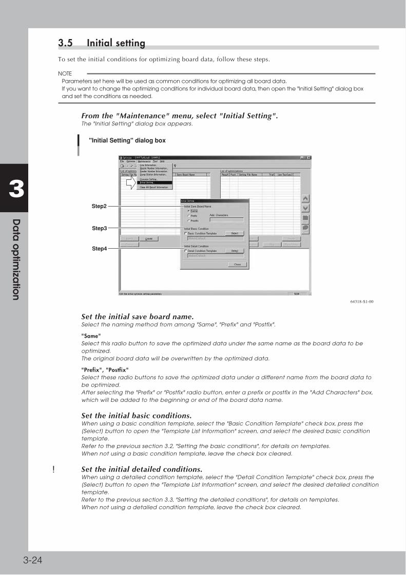
3-24
3 D
ata
op
timiza
tion
3.5 Initial settingTosettheinitialconditionsforoptimizingboarddata,followthesesteps.
n NOTE Parameters set here will be used as common conditions for optimizing all board data. If you want to change the optimizing conditions for individual board data, then open the "Initial Setting" dialog box and set the conditions as needed.
1 From the "Maintenance" menu, select "Initial Setting".The "Initial Setting" dialog box appears.
"Initial Setting" dialog box
Step2
Step3
Step4
64318-S1-00
2 Set the initial save board name.Select the naming method from among "Same", "Prefix" and "Postfix".
"Same"Select this radio button to save the optimized data under the same name as the board data to be optimized. The original board data will be overwritten by the optimized data.
"Prefix", "Postfix"Select these radio buttons to save the optimized data under a different name from the board data to be optimized. After selecting the "Prefix" or "Postfix" radio button, enter a prefix or postfix in the "Add Characters" box, which will be added to the beginning or end of the board data name.
3 Set the initial basic conditions.When using a basic condition template, select the "Basic Condition Template" check box, press the [Select] button to open the "Template List Information" screen, and select the desired basic condition template. Refer to the previous section 3.2, "Setting the basic conditions", for details on templates. When not using a basic condition template, leave the check box cleared.
4 Set the initial detailed conditions.When using a detailed condition template, select the "Detail Condition Template" check box, press the [Select] button to open the "Template List Information" screen, and select the desired detailed condition template. Refer to the previous section 3.3, "Setting the detailed conditions", for details on templates. When not using a detailed condition template, leave the check box cleared.

3-25
3 D
ata
op
timiza
tion
3.6 Specifying the dump station (option) positionMakethissettingtooptimizeboarddataformachinesequippedwithadumpstation(option).Feederpositionswillbeoptimizedbytakingaccountofthedumpstationposition,basedontheconditionsyousethere.
c CAUTION This function cannot be used to change the dump station position and feeder plate spec settings.
1 Set the dump station width information.1. Open the Board Editor or Board Explorer.
2. In the tree view, select the machine icon, click the right mouse button to display the context menu,
and select "Machine Property" to open the VmSpec window.
3. In the tree view on the VmSpec Window, select "Setting" - "Specification Information" - "Dump Station
Specification".
Setting the dump station width information
Set the left and right widths occupied by the dump station.
64319-S1-00
4. In the "Left Possession Width (mm)" and "Right Possession Width (mm)" columns, enter the settings
shown below. Settings differ according to the dump station type, so use caution.
Dump station type Left Possession Width (mm) Right Possession Width (mm)
Current type (Motor-driven belt feed) 40.00 40.00
Previous type (Air cylinder-driven belt feed) 75.00 50.00
2 Start the Optimizer.Start the Optimizer from the Board Editor or Feeder Viewer.

3-26
3 D
ata
op
timiza
tion
3 Set whether to use the dump station.From the "Maintenance" menu, select "Dump Station Information" to open the "Dump Station Setting" screen
and set whether to use each dump station.
"Dump Station Setting" screen
Select whether to use the dump station.
64320-S1-00
Enable separate setting of dump stationWhen this check box is checked, you can set whether to use each dump station individually. Select from the following three items.
Not Use Does not use the dump station regardless of whether there are components that use the dump
station.
Use Uses the dump station regardless of whether there are components that use the dump station.
Auto Uses the dump station when there are components that use the dump station.
(Does not use the dump station unless there are components that use the dump station.)

3-27
3 D
ata
op
timiza
tion
3.7 Set layout of common partsAboutanoptimizationusingfixedboardorsequenceoptimization,whenthepartswiththesamenamescannotbesetonthesamefeedersetposition(thesamelayout),thefollowingtwobehaviorscanbeselected
1. Prior Same Layout
Whenthesamelayoutcannotbeachieved,“Ea17635:PartsThicknessOrderError”isdisplayedandtheoptimizationis
stopped(fordetails,referto“3.7.2.AutoDistributionError”).Ifyouwanttoplacepartswiththesamenameontheexact
sameposition,selectthismode.
2. Prior Optimization
Whenthecommonlayoutcannotbeachieved,thedifferentfeedersetpositionispermitted.Whenyouwanttooutput
theoptimizationresultevenifthesamelayoutusingpartswiththesamenameisnotachieved,selectthismode.
Foranoperationexample,pleaserefertoillustrationbelow.
2010
22 2.00Parts2
3.00Parts11010
21 3.00Parts1
2.00Parts2
1010
21 3.00Parts1
2.00Parts200
21 3.00
2.00
Example of “Prior Same Layout” and “Prior Optimization”
Execute Optimization
Feeder Set No.Mch
Parts1Parts2
Parts Body Size Z (mm)
Parts Body Size Z (mm)
Parts
Feeder Set No.MchParts Parts Body
Size Z (mm)Feeder Set
No.MchParts
Feeder Set No.Mch Parts Body
Size Z (mm)Parts
(Target Board of Optimization)Board Name: OPT[Parts Data]
(Fixed Board)Board Name: FIX[Parts Data]
(Optimization Parameters)• Feeder Positioning Method: ‘Distribute in Line’• Height difference to permit overtaking:‘0.0mm’
Permit Different Layout of Fixed Board
If the layout is the same as that of fixedboard, overtaking of the body size Z occurs.
–> Optimization Failed with Error
1. Prior Same Layout 2. Prior OptimizationBoard Name : OPT[Parts Data]
Board Name : OPT[Parts Data]
* The Other Example of occuring the error using Prior Same Layout
* Overtaking of the parts group number occurs.
* The Fixed board Layout is wrong.–Unreachable Feeder Set No. by nozzle is assigined.
(Ea17635:Parts Thickness Order Error)
64319-S1-00

3-28
3 D
ata
op
timiza
tion
3.7.1 Settings
1 Select “Menu” – “Common Setting” on the “Optimization” screen.
2 Select “Prior Same Layout” or “Prior Optimization” on “Common Setting” – “Common Condition” – “Common Parts Layout”.
n NOTE • The initial state is “Prior Same Layout” in the first installation. • When upgraded from the version that doesn’t support this setting, the initial state is “Prior Optimization”. By the later
upgrades, the former state is kept.
Common Parts Layout
64360-S1-00
3.7.2 Auto Distribution Error
n NOTE This section relates only when “Prior Common Layout” is selected.
Whenthesamelayoutcannotbeachieved,“Ea17635:PartsThicknessOrderError”isdisplayedandtheoptimizationisstopped.
■ Action for the recovery
•Theresultthatsatisfiesboththesettingssuchas“Partsgroupnumber”or“Heightdifferencetopermitovertaking”andthesamelayoutcannotbeoutputted(becausecontradictionoccursamongsettings).Executetheoptimizationwithoutusing“Partsgroupnumber”or“Heightdifferencetopermitovertaking”,orselect“PriorOptimization”.
•Whenfixedboardlayoutiswrong,pleasecorrect
Parts Thickness Order Error
64361-S1-10

3-29
3 D
ata
op
timiza
tion
3.7.3 Reporting parts that cannot be the same layout
n NOTE This section relates only when “Prior Optimization” is selected.
Asaresultofanoptimization,whenthesamepartscannotbesetonthesamefeedersetposition,thefollowingdialogisdisplayedaftertheoptimization.Partsthatcannotbethesamelayoutaredisplayedinthedialog.
[Some parts cannot be set as common layout] Dialog
64362-S1-00
■ Action for the recovery
Aboutthepartsthatcannotbethesamelayout,prepareadditionalpartsandsetuptothedifferentfeedersetposition.
■ Saving the displayed result
ThedisplayedpartslistcanbesavedastheCSV(commaseparatedvalues)formatfile.Click[Save]button,specifythe
filepath,enterthefilenameandsave.
Refertothefileandpreparethelistedpartsadditionally.
Example of the Outputted CSV File
63363-S1-00

3-30
3 D
ata
op
timiza
tion
3.8 Setting the optimizing conditions for individual board dataTosettheoptimizingconditionsforindividualboarddata,followthesesteps.
1 Open the Optimizer window.
2 Click the [Create] button under the left-hand grid pane.The "Set optimizating parameters" screen appears.
3 Select the board data to be optimized.1. Click the [Select] button in the Target board group box to open the "Board data select" dialog box.
Then select the board data and click the [Select] button.
Selecting the board data
64321-S1-10
2. Check the name and location to save the board data.The board name is displayed in the format
defined by "initial setting". If you want to rename the board data and/or change the save location,
click the [Select] button in the "Save Board" group box.When the "Board data select" screen appears,
make the desired changes and click the [Close] button.
Selecting the save location
64322-S1-10

3-31
3 D
ata
op
timiza
tion
4 Set the basic conditions.When a basic condition template has been specified by initial setting, a check mark is placed in the "Basic Condition Template" check box and the template name is displayed.
• When no template has been specified by initial setting: Set each parameter item by referring to the previous section 3.2, "Setting the initial conditions".
• When a template has been specified by initial setting: When using the specified template, proceed to step 5.
When using another template, click the [Select] button to open the "Template List Information"
screen, select the template name you want to use, and click the [Read] button.
Selecting the basic condition template
Selecting the “Basic Condition” templates
64323-S1-00
If not using the template, clear the "Basic Condition Template" check box and then set each parameter item. For details on setting each item, refer to the previous section 3.2, "Setting the initial conditions".
Reference Basic conditions you set here can also be registered as a template.
5 Click the [Detail] button to set detailed conditions.When a detailed condition template has been specified by initial setting, a check mark is placed in the "Derail Condition Template" check box and the template name is displayed.
• When no template has been specified by initial setting: Set each parameter item by referring to the previous section 3.3, "Setting the detailed conditions".
• When a template has been specified by initial setting: When using the specified template, proceed to step 6.
When using another template, click the [Select] button to open the "Template List Information"
screen, select the template name you want to use, and click the [Read] button.
Selecting the detailed condition template
64324-S1-00
If not using the template, clear the "Detail Condition Template" check box and then set each parameter item. For details on setting each item, refer to the previous section 3.3, "Setting the detailed conditions".
Reference Detailed conditions you set here can also be registered as a template.

3-32
3 D
ata
op
timiza
tion
6 Save the setting file.By default the setting file name is identical with the name of the board data to be optimized. Enter the desired name if you want to change the default name. After confirming the name of the setting file, press the [Save setting] button.
Renaming the setting file
Enter the setting file name.
64325-S1-10
7 To optimize another board data, repeat the above procedure.

3-33
3 D
ata
op
timiza
tion
3.9 Editing the data optimizing conditionsDataoptimizingconditionsalreadydefinedcanbeeditedbyanyofthefollowingtwomethods.
3.9.1 Editing each file of optimizing conditionsToediteachfileofoptimizingconditions,followthesesteps.
1 Select the setting file.From the left-hand grid pane (list of board data with optimizing conditions defined), select the setting file you want to edit.
2 Click the [Editing] button.The "Set optimization parameters" screen appears.
3 Edit the optimizing conditions.Set the basic and detailed conditions. For the setting method, refer to 3.7, "Setting the optimizing conditions for individual board data", in this chapter.
4 Save the settings.Check the setting file name to be saved and then click the [Save setting] button.
Editing a file of optimizing conditions
64326-S1-10

3-34
3 D
ata
op
timiza
tion
3.9.2 Editing multiple files of optimizing conditions Twoormorefilesofoptimizingconditionscanbeeditedatonetime.
1 Select the setting file.From the left-hand grid pane (list of board data with optimizing conditions defined), select multiple items of board data you want to edit while holding down the [Shift] and [Ctrl] keys.
2 Click the [Editing] button.The "Collective editing of optimization parameters" screen appears.
Editing multiple files of optimizing conditions
Step1
Step2
Step4
64327-S1-00
3 Edit the optimizing conditions.Select the check boxes for the conditions you want to edit.
"Board Name" Selecting this check box allows you to select the file naming method from among "Same", "Prefix"
and "Postfix". When this check box is unchecked, the files are saved under the same name as the
board data.
"Basic Condition" Set whether to use a basic condition template.
"Detail Condition" Set whether to use a detailed condition template.
4 Save the setting files.Check the settings in the "Save Board" group box and click the [Save setting] button.

3-35
3 D
ata
op
timiza
tion
4. Executing data optimizationWhen you have set the data optimization conditions, execute the data optimization as explained below.
n NOTE When you want to store the optimization result information, you must first make settings for saving the result information before executing data optimization. Refer to section 3.4, "Common setting" for details.
1 Select the board data to be optimized.Place the cursor on the board to be optimized and then click the [Right arrow] button in the center. The board data will be loaded in, and the board name will appear in the data optimization list (right-hand grid pane).
Reference The board data can also be loaded in the optimization list by selecting the "Add Target" command from the File menu or clicking the [Add] button on the toolbar, or double-clicking the board data (or setting file name).
Click this button to load the selected board data into the right-hand list.
Selecting the board data to be optimized
Set the optimization method.
Double-click the board data to open the "Set optimizing parameters" screen.
Double-click to load the board data into the right-hand list.
64328-S1-00
2 Set the optimization method.Click the [Sgl] (single) button or [Cmn] (common) button.
3 Click the [Execute] button to start data optimization.All of the selected board data will be optimized and the results displayed. The optimization results are automatically saved when optimization is complete.

3-36
3 D
ata
op
timiza
tion
4 Check the results.The optimization results are displayed in the trace view (bottom pane). You can also check the results by pressing the [Result View] button when the setting for saving the result information has been made by "common setting".
Optimization result display
Optimization resuls are displayed.
64329-S1-00
5 Save the results.Click the [Save list] button to save the results. If you want to cancel saving, then select "Exit" from the File menu and quit the Optimizer.
NOTE When the [CT Estimation] button is clicked, the estimated cycle time after optimization can be confirmed.

3-37
3 D
ata
op
timiza
tion
■ Checking the optimization results on the Feeder Viewer
Youcanchecktheoptimizationresultsoftheboarddatamarked"OK"intheOpt.columnintheleftpane.Selecttheboarddataintheleftpaneandthenselect"Optimizerresult"fromtheOptimizermenu.The"Optimizerresult"windowappears.
Checking the optimization results
"Optimizer result" window
64330-S1-00

3-38
3 D
ata
op
timiza
tion
4.1 Checking the nozzlesAfteroptimizationiscomplete,youcancheckthenozzletypestobeusedwitheachboardandeachmachine.IntheBoardEditorwindow,opentheboarddataforwhichyouwanttocheckthenozzletypes.Select"RequiredNozzle"fromtheOptimizermenu.The"RequiredNozzles"listthenappears.Whenthemachineisnotequippedwithanozzlestationorthemachineusesaheadnothavinganautonozzlechanger,checkthatthecorrectnozzleisattachedtoeachheadbyreferringtothis"RequiredNozzles"list.
"Required Nozzles" list
64331-S1-00

3-39
3 D
ata
op
timiza
tion
5. Outputting the feeder setup listsAfter optimizing the board data in the Feeder Viewer, you can output, display and print feeder setup lists that show the feeder positions and quantity of parts used with each board data. The output data can be further edited to create "setup instruction sheets" and print them.
n NOTE To use the feeder setup lists, you will need the following software. • Microsoft Excel 2000 or 2003 or 2007
1 Select "Setup Assignment" from the Plan menu.A confirmation dialog box appears.
2 Display the feeder setup lists.1. Click the [OK] button in the confirmation dialog box.
Outputting the feeder setup lists
64332-S1-0
2. When Excel starts up, a macro virus warning message appears.
Click the [Enable Macros] button.
Macro virus warning message
64333-S1-00

3-40
3 D
ata
op
timiza
tion
3. Excel worksheets appear to show the feeder setup lists for each machine.
Check the contents, edit the layout on each worksheet as needed, and print it out.
Feeder setup lists
When "Plural" was selected
64334-S1-00
Reference The displayed worksheets can be further edited to create "setup instruction sheets" and print them.
3 Save the data and close Excel.

3-41
3 D
ata
op
timiza
tion
6. Changing the line to be optimizedTo change the line to be optimized, follow these steps.
1 Select "Select Line" from the File menu.The "Select Editing Line" dialog box appears.
2 Select the line you want to change to and click the [OK] button.The Optimizer window changes to display the selected line.
Optimizer windowChanging the line
64335-S1-00
Reference When you attempt to change a line while the trace information is still displayed, a confirmation message appears asking whether to clear the trace information.

3-42
3 D
ata
op
timiza
tion
7. Multi-lane Support7.1 Optimize of single combined programEachpartsisusedbyalllanejustaftersingleprogramiscombined.Theyaredividedtoalllaneautomaticallyifitisoptimized.Dooptimizeifthesinglecombinedprogramisusedwith[ParallelLanes].
7.2 Optimize with same kind partsThepartsthatitsnameandfeedertypeissameondifferentlaneonthelanewithduallanemachinearecalledassamekindparts.Therearesomecasesthattheyareunifiedtoonepartsinoptimization.Ifsamekindpartshavedifferentpartsgroupnumber,theyarechangedtosamenumber.Butmagnituderelationiskept.Iftheyhavecontradiction,theerrorofoptimizationoccurs
7.3 [Set optimization parameters] dialog is extended"MountLaneDesignation"hasbeenadded.Itisaddedonlywithsingleboarddataandnotdisplayedwithcombinedboarddata.Itisabletodecidetooptimizethesingleboarddataforwhichlane.
[Set optimization parameters] dialog
64365-S1-00

3-43
3 D
ata
op
timiza
tion
7.4 [Detail] setting is extended. 1[Create]button-[Detail]button-"FixedBoard"tabsupportcombinedboarddata.Thecombinedboarddataisactiveforalllaneasfixedboarddata.
Detailed setting of optimization
64366-S1-00
7.5 [Detail] setting is extended. 2[Create]button-[Detail]button-"Stage"tabischangedto"Stage/Lane"tab.Itisabletoselecttheoptimizedlane.Normallyitisrecommendedtooptimizewithalllane.Ifitisnecessarytooptimizewithonlyonelane,changethissetting.
Detailed setting 2 of optimization
64367-S1-00

3-44
3 D
ata
op
timiza
tion
7.6 [Detail] setting is extended. 3[Create]button-[Detail]button-"MountMode"tabhasbeenadded.Normallyitisrecommendedtoset"Auto"tooptimizedwithbestconditionbyoptimizer.
Detailed setting 2 of optimization
64368-S1-00
Mount Mode Decision Meth Contents
Auto Optimizer decides automatically.
Edit Set by manually.
Current Keep the board data setting.
Mount Mode Contents
Auto Optimizer decides automatically.
Parallel Each head mounts only for each lane.
Alternate Front lane and rear lane are mounted in order.

3-45
3 D
ata
op
timiza
tion
7.7 Result dialog is extendedItsupportscombinedboarddata.
•CTofeachlaneisdisplayedon“LineCT(sec)”.
• “CycleTime+Transfer(sec)”isdisplayedonoptimizationlog.Itisthetotaltimeofmountandtransfer.
Itisdifferentbymountmode.
Mount Mode Contents
Parallel [Line CT (sec)]It is Line CT of each lane.
Alternate [Line CT (sec)]It is the total of mount time of each lane. It is mount time of front lane and rear lane. Lane CT of each lane is same.
[Cycle Time + Transfer (sec)]Transfer time is 0.0 because the board is finished to transfer during another lane is mounting.
Trace information
Trace information
64369-S1-00

3-46
3 D
ata
op
timiza
tion
Example : Mount Mode is [Parallel]
64370-S1-00
Example : Mount Mode is [Alternate]
64371-S1-00

Chapter 4 Setup Optimizer
Contents
1. About the Setup Optimizer 4-1
2. Executing the Setup Optimizer 4-2
3. Setting the Setup Optimizer sheet 4-5
3.1 Starting the Setup Optimizer sheet 4-5
3.2 Setup Optimizer sheet configuration 4-7
3.3 COMPXPCB worksheet setting 4-10
3.4 StandardTime worksheet setting 4-15
3.5 FeederPlate worksheet setting 4-16
3.6 Nozzle worksheet 4-18
3.7 Executing the Setup Optimizer under the defined conditions 4-19
4. Setting examples on the Setup Optimizer sheet 4-20
4.1 Setting as many feeders as possible 4-20
4.2 Giving priority to the cycle time 4-21
5. Optimizing the board data 4-22
5.1 Optimizing the board currently being set up 4-22
5.2 Optimizing the edited board data 4-24
6. Optimization Monitor 4-25
6.1 Starting the Optimization Monitor 4-25
6.2 Optimization Monitor sheet configuration 4-27
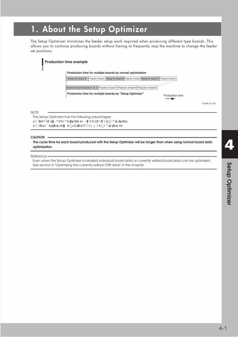
4-1
4 Se
tup O
ptim
izer
1. About the Setup OptimizerThe Setup Optimizer minimizes the feeder setup work required when producing different type boards. This allows you to continue producing boards without having to frequently stop the machine to change the feeder set positions.
Production of board ASetup for board A Production of board BSetup for board B Production of board CSetup for board C
Production of board AShared setup fro boards A, B, C Production of board B Production of board C
Production time example
Production time for multiple boards by normal optimization
Production time for multiple boards by "Setup Optimizer"Production time
63400-S1-00
n NOTE The Setup Optimizer has the following advantages: • Ideal for small-quantity production of various board types • Reduces setup time by using a common board setup.
c CAUTION The cycle time for each board produced with the Setup Optimizer will be longer than when using normal board data optimization
Reference Even when the Setup Optimizer is installed, individual board data or currently edited board data can be optimized. See section 5, "Optimizing the currently edited CPB data", in this chapter.

4-2
4 Se
tup O
ptim
izer
2. Executing the Setup OptimizerThis section describes how to run the Setup Optimizer. If you need to decide some feeder set positions, make the settings on the Setup Optimizer sheet before executing the Setup Optimizer. See section 4, "Setting examples on the Setup Optimizer sheet", in this chapter.
1 Start the Feeder Viewer.1. Select "Feeder Viewer" from the Windows Start menu.
The "Select Line" dialog box appears.
2. Select the line to use for production.
Reference You can start the Feeder Viewer from the Data menu of the Board Explorer or from the File menu of the Board Editor.
2 Select the board data.1. Select "New" from the Plan menu (or click the [New] button on the toolbar).
2. Select "Add Board" from the Edit menu (or click the [Add Board] button on the toolbar) to open the
Board Data Select dialog box.
3. Select the board data you want to optimize.
n NOTE Up to 500 board data items or 2550 parts (components) can be loaded on the Feeder Viewer.
c CAUTION You must select board data that can be individually optimized.
3 From the Optimizer menu, select "Execute Optimizer" – "Setup Optimizer".The "Setup Optimizer setting" dialog box appears.
Starting the Setup Optimizer
64400-S1-10

4-3
4 Se
tup O
ptim
izer
4 Make the Setup Optimizer setting.1. Set the file name to save the optimized data.
For details on the file name setting, refer to section 3 "Setting the optimization conditions", in chapter
3.
c CAUTION On the Factory Tools, the file name can be up to 20 alphanumeric characters. A prefix or postfix can be added to the file name as long as it is within a total of 20 characters. If the file name exceeds 20 characters, a message dialog box will appear. Click the [Yes] button in the message dialog box to automatically shorten the filename. If you want to change the file name manually, click the [No] button and change the file name by using the Board Explorer, etc.
2. Set up "Optimization conditions".
Setting optimization conditions for each setup group Tick this option to set optimization conditions for each setup group.
Setup group Selects a setup group to set optimization conditions.
Basic conditions Activates the Basic Condition Template.
Detailed conditions Activates the Detail Condition Template.
3. Tick "Quit when an error occurs during optimization" if optimization should be stopped when
something goes wrong with optimization.
5 Execute the Setup Optimizer.When finished making the settings in the "Setup Optimizer setting" dialog box, click the [Execute] button.
1. The Setup Optimizer window appears to execute optimization.
Setup Optimizer window
64402-S1-00
Reference When optimizing on the setup being edited with the Feeder Viewer, the file name in the "Setting File Name" column of the optimization window will be "FV_Board data name". (The prefix "FV" is added to the board data name.)

4-4
4 Se
tup O
ptim
izer
2. When the optimization has been completed, the Setup Optimizer window closes and returns to the
Feeder Viewer.
At this point, the board data names in the left pane list are changed according to the setting you
made in step 4.
Feeder Viewer window after optimization
Board data names are changed after optimization
64403-S1-00
6 Check the optimization results.Select "Optimizer Result" from the Optimizer menu. The optimization results of the currently selected board data are displayed.
Optimization result display
64404-S1-00
7 Save the results.

4-5
4 Se
tup O
ptim
izer
3. Setting the Setup Optimizer sheetThe Setup Optimizer sheet is used to determine the Setup Optimizer conditions. When there are feeders that must be installed in the fixed feeder set positions, you can specify their positions on the Setup Optimizer sheets. If there are no such feeders, you do not have to do anything on the Setup Optimizer sheet.
n NOTE The following software is required to use the Setup Optimizer sheet. • Microsoft Excel 2000, Excel 2002 or Excel 2003 or Excel 2007.
c CAUTION Computation expressions and macro programs are written in the Setup Optimizer sheets. Take the following precautions to run the Setup Optimizer sheets correctly. • Do not use the Setup Optimizer sheet in any way that is not described in this manual and do not change the contents of each cell. • Do not delete any row and column. • Some functions need time in order to run the process. When an hourglass appears or a command button stays pressed or a message such as "Recalculating…." is displayed in the status bar of the Setup Optimizer sheet, check how the software is operating (on the display).
c CAUTION The Setup Optimizer sheet does not work on some models. If you try to start the Setup Optimizer sheet for a line containing a model that is not compatible with the Setup Optimizer sheet, it will not start and an error dialog box will appear.
3.1 Starting the Setup Optimizer sheetThissectionexplainsthemethodforstartingtheSetupOptimizersheetbasedonthecurrentlyregisteredboarddata.
1 Start the Feeder Viewer.1. Select "Feeder Viewer" from the Windows Start menu.
The "Select Line" dialog box appears.
2. Select the line to use for production.
Reference You can start the Feeder Viewer from the Data menu of the Board Explorer or from the File menu of the Board Editor.
2 Select the board data.1. Select "New" from the Plan menu (or click the [New] button on the toolbar).
2. Select "Add Board" from the Edit menu (or click the [Add Board] button on the toolbar) to open the
board Data Select dialog box.
3. Select the board data you want to optimize.
n NOTE Up to 100 board data items or 2550 components can be loaded on the Feeder Viewer.
c CAUTION You must select board data that can be individually optimized.
3 Set the board production quantity.In the Production column of the board list (left pane), enter the production quantity.
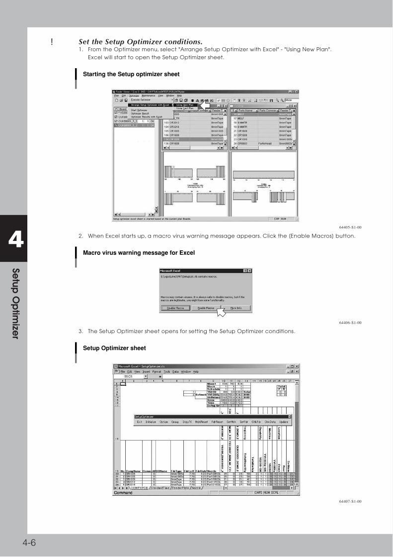
4-6
4 Se
tup O
ptim
izer
4 Set the Setup Optimizer conditions.1. From the Optimizer menu, select "Arrange Setup Optimizer with Excel" - "Using New Plan".
Excel will start to open the Setup Optimizer sheet.
Starting the Setup optimizer sheet
64405-S1-00
2. When Excel starts up, a macro virus warning message appears. Click the [Enable Macros] button.
Macro virus warning message for Excel
64406-S1-00
3. The Setup Optimizer sheet opens for setting the Setup Optimizer conditions.
Setup Optimizer sheet
64407-S1-00

4-7
4 Se
tup O
ptim
izer
3.2 Setup Optimizer sheet configurationTheSetupOptimizersheetconsistsof4worksheetsandafloatingtoolbar,asshownbelow.
Setup Optimizer sheet
Setup Optimizer toolbar
Setup Optimizer worksheets
64408-S1-00
● Setup Optimizer toolbar
Setup Optimizer toolbar
1 2 3 4 5 6 7 8 9 10 11 12
64409-S1-00
1. Exit
ClosestheExcelfileandreturnstotheFeederViewerwindow.
2. Initialize
ReloadstheExcelfiletoletyousettheSetupOptimizerconditionsfromthebeginning.
3. Option
Selectswhethertoenabletheautomaticupdatefunction.
4. Group
Changesthesetupgroupnumber.
5. Stay/X
Switchesthesetupgroupstatusbetween"Stay"and"X".
Reference For details on the setup group status, refer to section 3.3, "COMPXPCB worksheet", in this chapter.
6. MchReset (Machine reset)
Resetsthefeedersetpositionsandcomponentlayoutsonthemachine.
7. FdrReset (Feeder reset)
Resetsthefeedersetpositions.
8. SetMch (machine distribution)
Calculatesadistributionplanforthecomponentsforwhichnomachineshavebeenassigned,bytakingtheoverall
distributionintoaccount.

4-8
4 Se
tup O
ptim
izer
9. SetFdr (Feeder position setting)
Calculatesthefeedersetpositionsforeachsetupgroupinordertominimizethewidthtakenupbythefeederfor
componentswhosefeederpositionsareunspecified.
Machinesarealsoassignedtodataforwhichnomachinesarespecified.
Ifnon-occupiedfeederspaceisinsufficientorfeedersetpositionscannotbeassignedduetoimpropermachinesettings,
thecell(SetNum)ofthosefeedersetpositionswillturnred.
The"SetFdr"dialogboxappearswhenyouclickthe[SetFdr]button.Inthisdialogbox,makesettingsasfollows.
"SetFdr" dialog box
64410-S1-00
1. In the "Setup Group" box, enter the setup group number to set the feeder positions.
2. From the "Non Target" drop-down list, select the feeder type when you want to narrow the choice of
feeder type.
3. In each of "Plt 1" to "Plt4" boxes on each machine, set the priority for using the feeder plates. If there
are unused feeder plates, leave them set to "NotUse".
(For usable area of each feeder plate, see the feeder plate setting on the FeederPlate worksheet.)
4. Click the [OK] button to set the feeder positions.
c CAUTION A message "Plate Setting Error" might appear when the "SetFdr" function is being run. In this case, check the feeder plate setting and correct it to suit the machine. To correct the setting, refer to section 3.5, "FeederPlate worksheet setting", in this chapter.
10. ChkFdr (Feeder interference check)
Checkswhetherthecomponentdatacontainingfeedersetpositionscausesfeederstointerferewitheachother,according
tothesetupgroup.
Ifthefeedersinterferewitheachother,thecell(SetNum)ofthosefeedersetpositionswillbecomered.
The"ChkFdr"dialogboxappearswhenyouclickthe[ChkFdr]button.Inthisdialogbox,makesettingsasfollows.
"ChkFdr" dialog box
64411-S1-00
1. Enter the setup group in the "Setup Group" box.
2. Click the [OK] button to check the feeders for interference.
c CAUTION If feeder set positions have been set manually, execute "ChkFdr" before exiting Excel to make sure that there is no error.
11. ChkData (data setting error check)
CheckswhetherdatasettingintheExcelfileissatisfactory.Ifanerrorthatmightotherwisebefoundwiththischeckis
ignored,theSetupOptimizermightnotworkcorrectly.

4-9
4 Se
tup O
ptim
izer
12. Update (update to latest information)
Inthefollowingcases,clickthe[Update]buttontoupdatethedisplayedcontents.
•Whenthecellcolorhaschangedafterexecuting"SetMch","SetFdr"or"ChkFdr"andyouwanttoreturnthecelltoitsoriginalcolor.
•Whenfeedersetpositionsarespecifiedmanually
•WhentheorderofcomponentdatarowsischangedusingtheExcelsortfunction
Reference To specify the range (component data rows) in which to execute the "MchReset", "FdrReset", "SetMch" and "SetFdr" tasks, follow the procedure below. 1. Select the rows containing the target data and click the tool button for the task you want to execute. 2. Select the "Selected Data" check box in the dialog box that appears. 3. Click the [OK] button. The task will be executed only for the selected component data.
● Setup Optimizer worksheets
Therearethefollowing4worksheetstosettheSetupOptimizerconditions.
• COMPXPCB worksheet
Showsalistofcomponentstobeusedandallowsyoutosetthemachinesandfeederpositions.
TheconditionssetontheStandardTime,FeederPlateandNozzleworksheets(explainedlater)willbereferencedhere.
Fordetails,see3.3,"COMPXPCBworksheetsetting",inthischapter.
• StandardTime worksheet
Allowsyoutosetthemountingtimeperpartaccordingtoeachfeederasneeded,inunitsofseconds.Thedatasethere
willbereferencedtotheCOMPXPCBworksheet.
Fordetails,see3.4,"StandardTimeworksheetsetting",inthischapter.
• FeederPlate worksheet
Allowsyoutosettheinstallationpositionofeachfeederandthefeederplateassignmentaccordingtoeachmachineas
needed.ThedatasetherewillbereferencedtotheCOMPXPCBworksheet.
Fordetails,see3.5,"FeederPlateworksheetsetting",inthischapter.
• Nozzle worksheet
Allowsyoutosettheusablefeedersetpositionsforeachnozzle.ThedatasetherewillbereferencedtotheCOMPXPCB
worksheet.
Fordetails,see3.6,"Nozzleworksheetsetting",inthischapter.

4-10
4 Se
tup O
ptim
izer
3.3 COMPXPCB worksheet settingTheCOMPXPCBworksheetshowsalistofcomponentsforuse.Thedataonthisworksheetcanbesortedbyanyitemsuchasfeedertype,quantityofcomponentstobeusedandfeedersetposition,soyoucaneasilygrasptheproductionsituationanddeterminethemachineandfeedersetpositionswhilecheckingtheunusedareasofthefeederplatesandproductionlinebalance.
c CAUTION After sorting, always click the [Update] button on the Setup Optimizer toolbar.
YoucanalsocopytheCOMPXPCBworksheetontoanotherworksheettomakeasetupinstructionsheetorprintit.
c CAUTION Always use a copy of the COMPXPCB worksheet when making an instruction sheet, etc. The COMPXPCB worksheet might not work correctly if directly edited.
COMPXPCB worksheet
1 2
3 4 5
8 7
6 9 10
11
12 13 14 15 16 17 18 19 20 21 22 23 24 25 26 27 64412-S1-00
1. Mount
Showsthetotalnumberofcomponentstobeusedforeachboarddata.
2. Block
Showsthenumberofblocksregisteredforeachboarddata.
3. Schedule
Showstheproductionvolume(numberofboardstobeproduced).
4. Estimation
ShowsthecycletimeestimatedfromtheStandardTimeworksheet.
c CAUTION The cycle time displayed in "Estimation" differs from the actual cycle time. Run the setup optimization to check the accurate cycle time.
5. Unbalance (Imbalance)
Showsthedifferencebetweenthemaximumandminimumcycletimesamongthemachines.
6. Total
Showstheestimatedcycletimeforallboardswithproductionvolumetakenintoaccount.

4-11
4 Se
tup O
ptim
izer
7. Xsize, Ysize
Showstheboardsize.
8. SetupGroup
Thisisasetupgroupnumberandissetto"1"bydefault.
Whenmakingdifferentsetupsformultipleboards,setthesetupgroupnumberforeachboard.
Ifsetupgroupsettinghasbeenchanged,clickthe[Group]buttonontheSetupOptimizertoolbar.
Whenchangingsetupgroupnumbers,setthemsequentiallylike1,2,3andsoon.
Reference A group means a series of boards to be produced without changing the setup. When the group setting is changed, the setup must also be changed. When two or more groups are used to run setup optimization, the setup can be made while incorporating the setup from the previous group. This reduces the number of components subjected to setup change.
Feederinstallationspacemaybeinsufficientaftersetupgroupsareincreased.Inthiscase,followtheprocedurebelow.
(Method 1) Reducing the number of boards simultaneously to setup optimization:
1.QuittheSetupOptimizersheet.
2.ReturntotheFeederViewerwindow.
3.Selecttheboardssubjectedtosetupoptimization.Thenumberofboardsmustbereducedtomaintainsufficientfeederinstallationspace.
4.StarttheSetupOptimizersheetandsettheoptimizationconditions.
(Method 2) Grouping boards into setup groups:
Whenboardsaregrouped,thelargerthegroupnumber,thelowerthecycletimeduetotheinfluencebypreviousgroups.
1.Inthe"SetupGroup",setthegroupnumberforeachsetofboardstobegrouped.
2.Clickthe[Group]buttonontheSetupOptimizertoolbar.
Aftergrouping,makesurethatafeedersetpositionissetforeachgroup,startingfromgroup1.
9. Total
Showsthefeederplatespaceoccupiedbythefeeders,intermsofthenumberof8-mmfeeders.
"F"indicatesthefrontfeederplate.
"R"indicatestherearfeederplate.
10. Remain
Showstheestimatedfeederplatespacenotusedbyfeeders,intermsofthenumberof8-mmfeeders.
Checkthevalueshownin"M"whenyousetthemachinesmanually,andcheckthevaluesshownin"F"and"R"whenyou
setthefeederpositionsmanually.
• "F"indicatesthefrontfeederplatespace.Calculationisperformedusingcomponentswiththe"SetNum"(feedersetposition)parameterspecified.
• "R"indicatestherearfeederplatespace.Calculationisperformedusingcomponentswiththe"SetNum"(feedersetposition)parameterspecified.
•"M"indicatesthefeederplatespaceforallmachines.Calculationisperformedusingcomponentswiththe"Machine"parameterspecified.
c CAUTION In some cases "M" might not equal the sum of "F" and "R". This happens, for instance, when settings are made in "Machine" but not in "SetNum".
c CAUTION The values shown in "Remain" are just an estimate and might differ from the actual unused feeder set positions.

4-12
4 Se
tup O
ptim
izer
11. Board data name
Showsthenameofboarddataloadedontheworksheet.
12. No
Showsserialnumbers.
13. CompName
Showsthenameofcomponentstobeusedfortheboard.
14. Comment
Showsacommentoneachcomponent.
15. Alt
Notcurrentlyused.
16. DBName
Showsthenameregisteredinthedatabasethatisreferencedtobyeachcomponent.
17. FdrType
Showsthefeedertype.
18. FdrLeft, FdrRight
Showsthewidthtakenupbythefeederonleftandrightorshowsthetraychangernamefortraycomponents.
19. Nozzle
Showsthenozzletobeusedwitheachcomponent.
20. TotalQuantity
Showsthetotalnumberofcomponentstobeusedforeachboard.
21. TotalSetup
Showsthetotalnumberofboarddatathatuseseachcomponent.
22. Capability (component mount capability)
Showswhethercomponentscanbemountedwitheachmachine.
■ Capability parameter
Parameter value Description
1 Component can be mounted with machine.
0 Component cannot be mounted with machine.
23. Machine
Showswhethertosetcomponentsoneachmachine.Thisparametercanbeedited.
When one machine is set to "1", other machines in the same row must be set to "0".■ Machine parameter
Parameter value Description
1 Set component on machine.
0 Do not set component on machine.
24. Location (Front/Rear)
Setthisparameterwhenyouwanttospecifythefrontorrearplateduringoptimizationoffeedersetpositions.
Reference To use the front plate, set as follows: Front 1 Rear 0 SetNum 0 To use the rear plate, set as follows: Front 0 Rear 1 SetNum 0

4-13
4 Se
tup O
ptim
izer
25. SetNum
Usethissettingwhenyouwanttospecifyfeedersetpositionsforcertaincomponentsthatmustnotbechangedonthe
SetupOptimizer.
c CAUTION Before setting the feeder set positions, the "Machine" setting must be made.
Reference When you want to determine all feeder set positions with the Setup Optimizer, set as follows: Front 0 Rear 0 SetNum 0
Reference When using a multi-stick feeder, set as follows: 1. Choose one component from those in the same multi-stick feeder, as a typical component. 2. Set the "FdrLeft" and "FdrRight" parameters to "0.00" for other components in the multi-stick feeder. 3. Specify the "FdrNum" (feeder set position). When specifying the feeder set position manually, other components in the same multi-stick feeder must be set to the same feeder set position. When using the [SetFdr] button on the Setup Optimizer toolbar: 1. Set the feeder set position for the typical component to "0". 2. Click the [SetFdr] button on the Setup Optimizer toolbar. 3. For components other than typical components, specify the same feeder set position used for typical component.
Reference Tray component setting: When an auto tray stacker (ATS) or external tray changer is used, the tray component setting such as the pallet number cannot be entered on the Setup Optimizer sheet. Make the tray component setting before or after running the Setup Optimizer. In this case, you can ignore the "SetNum", "FeederNG" and "NozzleNG" warnings that might appear in the "Status" column. When a manual tray feeder (MTF) is used, specify the feeder set position before running the Setup Optimizer because it cannot be edited on the Setup Optimizer sheet. Also set the FeederPlate worksheet so that other feeders are not assigned in the area used by the MTF.
26. Status
Showsinformationonwhetherthesettingiscorrect.
c CAUTION To display the "Status" information, you must the make the necessary settings on the FeederPlate and Nozzle worksheets. See 3.5,"FeederPlate worksheet setting", and 3.6, "Nozzle worksheet setting", later in this chapter.
■ Status parameter
Parameter value Description
OK Data setting is correct.
Machine Not assigned to machine or machine setting is incorrect.
SetNum Feeder set position is not specified or setting is incorrect.
FeederNGFeeder cannot be set in specified position.(Refer to the FeederPlate worksheet.)
NozzleNGComponent cannot be picked up at specified position.(Refer to the Nozzle worksheet.)
c CAUTION • All components must be assigned to the machine used to mount each component. When the "Status" shows "Machine", specify the machine used to mount the component. • The Setup Optimizer will not work correctly if the "Status" shows "FeederNG" or "NozzleNG". Check each setting and eliminate the error. However, you can ignore "FeederNG" and "NozzleNG" for tray components.

4-14
4 Se
tup O
ptim
izer
27. Component setup status for each setup group
Showsthesetupstatusofcomponentsforeachsetupgroup.
■ Setup group parameter
Parameter value Description
0 Components are used by a setup group.
Stay Components are still set on the machine, but are not used by a setup group.
X Components should be removed from the machine when changing the setup group.
(blank) These components have never been used when two or more setup groups are set.
Reference If two or more setup groups have been set, then the message "Stay" will be displayed for those components used by the previous group but not by the current group. The feeder installation space can be increased by setting "X" (remove) for components for which "Stay" is specified. This allows new components to be added to the group. 1. Select the cell to be edited. 2. Click the [Stay/X] button on the Setup Optimizer toolbar.
c CAUTION Components that should be used (O) or left installed (Stay) on the machine by two or more setup groups, set their feeder positions on the Excel worksheet.

4-15
4 Se
tup O
ptim
izer
3.4 StandardTime worksheet settingTheStandardTimeworksheetallowsyoutosetthetime(seconds)requiredtomountonecomponentfromeachfeeder.Makethissettingasneeded.
n NOTE Settings made here are used to estimate the line balance on the COMPXPCB worksheet.
StandardTime worksheet
64413-S1-00
Reference If you have customized the settings, you must reenter them by using the Setup Optimizer backup files.

4-16
4 Se
tup O
ptim
izer
3.5 FeederPlate worksheet settingTheFeederPlateworksheetallowsyoutosetthefeederplatepositionswhereeachfeedercanbeinstalledandalsotospecifythefeederplatelayout.Clickingthe[Load]buttonforamachineloadsitsfeederplateinformation.
n NOTE Settings made here are used to check the feeder set positions on the COMPXPCB worksheet (FeederNG alarm appears if an error is found) and to determine the feeder set positions automatically.
FeederPlate worksheet
Feeder plate information is loaded.
Click [Load] button for each machine.
64414-S1-00
Thefeederplatelayoutitemsappearbyscrollingtotherightontheworksheetscreen.Specifythefeederplatelayoutasneededwhilereferringtotheexamplebelow.
Plate layout setting
20 feeders × 4 plates
20 feeders × 2 plates (Front side only)
50 feeders × 2 plates
64415-S1-00
c CAUTION Feeder plate spec information on the YVL80 and II series surface mounters cannot be loaded into the FeederPlate worksheet. To specify their feeder plate layout and feeders, refer to the feeder plate spec information from the machine or from the Factory Tools machine property.

4-17
4 Se
tup O
ptim
izer
■ To delete the feeder plate setting
IfthenumberofmachinesregisteredinthelineisreducedduetoupgradingoftheFactoryToolsversionorchangingthe
lineconfiguration,deletethesettingsforthosemachinesremovedfromtheline.
1. Deleting the feeder plate setting
Selectthefeederplatesettingrangefortheremovedmachinesandpressthe[Delete]key.
Thesettingintheselectedrangeofcellswillbedeleted.
Selecting and deleting the feeder plate setting
Drag the mouse to select the range of cells and press [Delete] key.
64416-S1-00
2. Deleting the feeder plate layout setting
Scrolltheworksheettotherightuntilthefeederplatelayoutitemsappear.
Selectthefeederplatelayoutsettingrangefortheremovedmachinesandpressthe[Delete]key.
Thesettingintheselectedrangeofcellswillbedeleted.
Deleting the feeder plate layout setting
Delete unnecessary data.
64417-S1-00

4-18
4 Se
tup O
ptim
izer
3.6 Nozzle worksheetTheFeederPlateworksheetallowsyoutosetthefeedersetpositionsusableforeachnozzle.Clickingthe[Load]buttonforeachmachineloadstheeffectivenozzlesetpositioninformation(feedersetpositionsaccessiblebyeachnozzle).
n NOTE Settings made here are used to check the feeder set positions on the COMPXPCB worksheet (NozzleNG alarm appears if an error is found).
Nozzle worksheet
Effective nozzle set position information is loaded.
Click [Load] button for each machine.
64418-S1-00
c CAUTION If you have changed the line configuration or head spec information, then the valid nozzle set position information must be updated. 1. Select the line number to execute setup optimization. 2. Open the "Line" folder contained in the folder where Factory Tools is installed. For example, open the "Line 1" folder for Line 1. 3. Open the "Prt" folder. 4. Delete all the "Nzlfitx.txt" files (x: number). For example, all files named like "Nzlfit1.txt" or "Nzlfit2.txt" should be deleted. 5. Execute the setup optimization. An Excel file will be automatically created. 6. Click the [LOAD] button for each machine on the Nozzle worksheet.

4-19
4 Se
tup O
ptim
izer
3.7 Executing the Setup Optimizer under the defined conditionsWhensettingoneachworksheetiscomplete,savethedata.ThenapplyittotheFeederViewerandoptimizefeedersetups.asexplainedbelow.
1 Save the data.Click the [Exit] button on the Setup Optimizer toolbar. When the Save dialog box appears, click the [Yes] button. Another dialog box then appears asking whether to apply the Setup Optimizer sheet data to the Feeder Viewer.
2 Apply the data to the Feeder Viewer.Click the [Yes] button in the dialog box to apply the Setup Optimizer sheet data to the Feeder Viewer.
Saving the data
64419-S1-00
3 Execute the Setup Optimizer.Perform optimization by referring to section 2, "Executing the Setup Optimizer", earlier in this chapter.

4-20
4 Se
tup O
ptim
izer
4. Setting examples on the Setup Optimizer sheetThis section gives two examples for making settings on the Setup Optimizer sheet.
4.1 Setting as many feeders as possibleThefollowingstepsexplainhowtosetasmanyfeedersaspossibleinaline.
1 Click the [MchReset] button on the Setup Optimizer toolbar.The "MchReset" dialog box then appears. Click the [OK] button to clear the information on the machines and feeder set positions.
"MchReset" dialog box
64420-S1-00
2 Click the [SetFdr] button on the Setup Optimizer toolbar.The "SetFdr" dialog box appears. Select the feeder plate to which you want to give priority and click the [OK] button. The feeder set position for each component will be optimized.
"SetFdr" dialog box
64421-S1-00
Reference To check the feeder plates on which the feeder set positions are registered, refer to the FeederPlate work sheet. (See section 3.5, "FeederPlate worksheet setting", in this chapter.)

4-21
4 Se
tup O
ptim
izer
4.2 Giving priority to the cycle timeWhentherearefeedersetpositionsavailable,theSetupOptimizerallowsyoutomakesettingssoastogiveprioritytothecycletime.
1 Click the [MchReset] button on the Setup Optimizer toolbar.The "MchReset" dialog box then appears. Click the [OK] button to clear the information on the machines and feeder set positions.
"MchReset" dialog box
64422-S1-00
2 Specify the feeder set positions by manual input.1. To specify the feeder set positions manually, make settings in the "Machine", "Location" and "SetNum"
columns (manual input).
2. When you want to find the optimal feeder set positions with the Setup Optimizer, set "0" in the
"Location" and "SetNum" column.
3. Click the [SetMch] button on the Setup Optimizer toolbar to open the "SetMch" dialog box, and click
the [OK] button.
Machines will be automatically assigned to the components for which no machine has yet been
specified.
"SetMch" dialog box
64423-S1-00

4-22
4 Se
tup O
ptim
izer
5. Optimizing the board dataThe Setup Optimizer optimizes the board currently being set up, or other board data edited on the Feeder Viewer.
5.1 Optimizing the board currently being set upTooptimizetheboarddatayouarecurrentlyeditingontheFeederViewer,select"ExecuteOptimizer"–"SingleOptimizer"or"CommonOptimizer"fromtheOptimizermenu.
n NOTE When "Single Optimizer" is selected, data optimization is performed under conditions set for each board data, When "Common Optimizer" is selected, data optimization is performed while handling board data previously optimized as a fixed board.
■ When "Single Optimizer" is selectedWhen"Singleoptimizer"isselected,theSetupOptimizerstartstooptimizeonlytheboarddatathatyouarecurrently
editingwiththeFeederViewer.
1.FromtheOptimizermenu,select"ExecuteOptimizer"andthenclick"SingleOptimizer".The"Optimizersetting"dialogboxappears.
2.Aconfirmationdialogboxwillappeartoaskwhethersetupgroupnumbershouldbeassignedautomaticallyornot.Clickthe"Yes"buttontoactivatetheautomaticassignment.Groupnumberswillbeenteredautomaticallyinthe"Setupgroup"fieldinthe"Setupboardlist"window.(Differentnumberswillbeenteredforeachboarddata.)
3.Checkorsettheoptimizationconditionsandclickthe[Execute]button.Fordetailsontheoptimizationconditions,refertosection3.3.5,"Initialsetting",inchapter3.
4.Theoptimizationwindowappearsandstartsoptimizingtheboarddata.
5.Whentheboarddatahasbeenoptimized,theoptimizationwindowclosesandreturnstotheFeederViewerwindow.Theword"OK"appearsintheOpt.columnintheleftpanewhenoptimizationwassuccessful,ortheword"NG"appearsifnot.
Optimizing individual Board data
64424-S1-10

4-23
4 Se
tup O
ptim
izer
■ When "Common Optimizer" is selected
When"Commonoptimizer"isselected,theSetupOptimizerstartstosequentiallyoptimizeallboarddatathatiscurrently
loadedintheFeederViewer.
1.FromtheOptimizermenu,select"ExecuteOptimizer"andthenclick"CommonOptimizer".The"Optimizersetting"dialogboxappears.
2.Checkorsettheoptimizationconditionsandclickthe[Execute]button.Fordetailsontheoptimizationconditions,refertosection3.3.5,"Initialsetting",inchapter3.
3.Theoptimizationwindowappearsandstartsoptimizingtheboarddatasequentially.
4.Whentheboarddatahasbeenoptimized,theoptimizationwindowclosesandreturnstotheFeederViewerwindow.Theword"OK"appearsintheOpt.columnintheleftpanewhentheoptimizationwassuccessful,ortheword"NG"appearsifnot.
Optimizing Board data sequentially
64425-S1-10
Reference When optimizing the board in the Feeder Viewer, the prefix "FV" is added to the board data name shown in the "Setting File Name" column in the optimization window.
n NOTE If a value is inputted in the "Setup group", data of the same group are optimized in turn.

4-24
4 Se
tup O
ptim
izer
5.2 Optimizing the edited board data YoucanalsooptimizetheboarddatathathasbeeneditedwiththeFeederViewer.
1.FromtheOptimizermenu,select"ExecuteOptimizer"andthenclick"ModifiedBoardsOptimizer".Aconfirmationmessageappearsaskingifyouwanttooptimizetheeditedboarddata.Clickthe[OK]buttontooptimizeit.
Reference The "Edit Board Optimizer" command is dimmed if no board data has been edited with the Feeder Viewer.
2.Aconfirmationdialogboxwillappeartoaskwhethersetupgroupnumbershouldbeassignedautomaticallyornot.Referto"SingleOptimizer"intheprevioussection"5.1Optimizingtheboardcurrentlybeingsetup"fordetails.
3.The"OptimizerSetting"dialogboxappearsandonlytheeditedboarddataisloaded.Checkorsettheoptimizationconditionsandclickthe[Execute]button.Fordetailsonoptimizationconditions,referto3.3.5,"Initialsetting",inchapter3.
4.Theoptimizationwindowappearsandstartsoptimizingeachboarddata.
Reference When optimizing on a setup currently being edited with Feeder Viewer, the file name in the "Setting File Name" column of the optimization window will be "FV_Board data name". (The prefix "FV" is added to the board data name.)
5.Whentheboarddatahasbeenoptimized,theoptimizationwindowclosesandreturnstotheFeederViewerwindow.Theword"OK"appearsintheOpt.columnintheleftpanewhenoptimizationwassuccessful,ortheword"NG"appearsifnot.
Optimizing the edited board data
64426-S1-10

4-25
4 Se
tup O
ptim
izer
6. Optimization MonitorWhen optimizing multiple board data with the Setup Optimizer, the CPH (number of components that can be mounted per hour) might differ depending on the actual optimization conditions. After optimizing on multiple board data, the Optimization Monitor allows you to check the CPH and load time for each board data or each setup group, and make an automatic calculation to evaluate whether or not the CPH meets the required count. Based on the results obtained with the Optimization Monitor, you can decide whether to re-execute optimization.
6.1 Starting the Optimization MonitorTheOptimizationMonitorcanbestartedwithboarddatathatwassuccessfullyoptimized(resultwas"OK").
1 Open the Feeder Viewer for board data that was successfully optimized.
2 Start the Optimization Monitor.1. Select "Optimizer Results with Excel" from the Optimizer menu.
Starting the Optimization Monitor
64427-S1-00
2. Excel starts up and a macro virus warning message appears. Click the [Enable Macros] button.
Macro virus warning message for Excel
64428-S1-00

4-26
4 Se
tup O
ptim
izer
3. The Optimization Monitor window appears.
Optimization Monitor window
64429-S1-00

4-27
4 Se
tup O
ptim
izer
6.2 Optimization Monitor sheet configurationTheOptimizationMonitorsheetconsistsof3worksheets("Result","Collect","Input")and2customizingworksheets("Template","ChangeLanguage").
c CAUTION Precautionsanddescriptionarealsowrittenoneachworksheet.Alwaysfollowtheinstructions.
"Result" worksheet
TabulatesanddisplaystheCPH,loadtimeandlinecycletimeforeachboarddata(program)orsetupgroup.
Thedisplayedresultscanbesavedandreloadedwiththebuttonsontheworksheet.
Thecharactersandcellsonthe"Result"worksheetaredisplayedincolor.
Red.........Resultsareoutsidethewarningrange
White......Optimizationresultsare"OK".
Pink.........Optimizationresultsare"OK"butmarkswerenotrecognized.
"Result" worksheet
1
2 3
4
"Line No. and name
Results are tabulated according to setup group.
64430-S1-00
1. [End] button
Savesthecurrentdataoverwritingtheoriginaldata,andquitstheOptimizationMonitor.
2. [Reload] button
Reloadsinformationtoapplychangestothecorrespondingcells.
3. [Save] button
SavesthecurrentworksheetsasanotherExcelfile.
Thecurrentlydisplayeddataonthe"Result","Collect"and"Input"worksheetsaresaved.However,sincethe[End],
[Reload]and[Save]buttonswillthenbeunavailable,nodatacanbereloadedintothenewfile.
4. [Open TABLETACT] button
Clickingthisbuttonshowsorhidesthetable(feederplatetable)cycletimeinthemachinecolumnonthe"Result"
worksheet.

4-28
4 Se
tup O
ptim
izer
"Collect" worksheet
TabulatesanddisplaystheCPH,loadtimeandthenumberoffeedersforeachgroup.
"Collect" worksheet
Data on "Result" worksheet
Sum of number of feeders
64431-S1-00
Reference The total number of feeders is displayed only when optimization was executed with the Setup Optimizer.
"Input" worksheet
Usethissheettoentervarioussettingsforcreatingdataonthe"Result"worksheet.
Tochangeasetting,directlyenterthevalueinthecell.Thechangewillbereflectedinthe"Result"worksheetwhenthe
OptimizationMonitorisrestartedorthedataisreloaded.
"Input" worksheet
Enter the change directly.
64432-S1-00
Reference • The "FidRec Time" is the time added to the machine cycle time when the fiducial recognition count is 0 (zero) and the number of components to mount is 1 or more. • The"TransportTime"isthetimeaddedtothelinecycletime.(Linecycletimeisequaltothemaximumvalueof machinecycletime.)

4-29
4 Se
tup O
ptim
izer
"Template" worksheet
Usethissheettosetthecellcolor,changethecolumnwidth,addcolumnsordeletecolumnsinordertocreatea
templateforthe"Result"worksheet.
Settingsyoumakeherearereflectedinthe"Result"worksheetnexttime.
"Template" worksheet
Use English (alphanumeric) characters.
Do not insert columns where cycle time is displayed.
64433-S1-00
c CAUTION 1 Only the cell attributes will be reflected. Buttons will not be reflected even if arranged. 2. A specific name is given to each cell. Do not change or delete the cell names. 3. When a column is inserted, always use alphanumeric characters for its heading. 4. Do not delete the second row showing "Optimize Monitor" and "LineName" 5. Do not insert any column where cycle time is displayed.
"Change Language" worksheet
Onthisworksheet,youcanenterJapanesecharactersthatcorrespondtoEnglish(alphanumeric)characterstringswritten
inthe"Template"worksheet.Usethisworksheetifneeded.
TherearethreeEnglish-Japanesetables.
"Change Language" worksheet
English-Japanese table on each sheet English-Japanese table for error message
English-Japanese table for dialog message
64434-S1-00

4-30
4 Se
tup O
ptim
izer
• English-Japanese table on each sheet
EnglishtoJapaneseconversionisperformedbasedonthistable,soaddtheconversionsourceifitisnotinthetable.
• English-Japanese table for error message
ThisisalistofEnglisherrormessagesandtheircorrespondingJapaneseerrormessages.
Directlyrewritethemessageifyouwanttochangeit.
c CAUTION Never delete the cells.
• English-Japanese table for dialog message
ThisisalistofEnglishdialogmessagesandtheircorrespondingJapanesedialogmessages.
Directlyrewritethemessageifyouwanttochangeit.
c CAUTION Never delete the cells.

Chapter 5 ASCII data conversion
Contents
1. About ASCII data conversion 5-1
2. Creating board data 5-2
3. Creating a conversion font file 5-10
3.1 Create a new font file 5-10
3.2 Editing a font file 5-30
3.3 Delete / copy a font file and change the font file name. 5-31
3.4 Import of font file. 5-32
4. Miscellaneous 5-34
4.1 How to express the logical formula. 5-34

5-1
5 A
SCII d
ata
co
nversio
n
1. About ASCII data conversionVarious CAD data and board data for other manufactures’ mounters stored in ASCII data files can be converted to YAMAHA YGX format data. To perform this data conversion, a "font file" used as the source for converting ASCII data into YGX data must be created in advance. The following Steps explain the procedure for ASCII to YGX data conversion using a font file already created. To create a font file, refer to section 3, "Creating a conversion font file", in this chapter.
Flow to convert the CAD data to YGX data
Is a font file ready?
Select a font file.
Select a machine to save to and boarddata name.
Are info for frontand rear mixed?
Select the side for conversion.
Conversion is performed.
Select fiducial and bad mark to be used.
Conversion has been completed.
Create a new font file.
Select delimiter.
Select quotation character.
Select the contents included in CAD data.
Select the origin of CAD data andmachine.
Select method for acquiring board info.
Select method for acquiring fiducial,bad mark and mounting info.
Select method for acquiring BOM data.
Font file has been created.
NO
YES
NO
YES
Select CAD data / BOM data.
63500-S1-00

5-2
5 A
SCII d
ata
co
nversio
n
2. Creating board dataTo create board data in YGX format from an ASCII data file, use the Board Explorer and follow the Steps below.
1 Start the Board Explore.
2 Select "Ascii Data Conversion" from the Data menu."ASCII Data Conversion" dialog box appears.
3 Select "Data selection" from the Convert menu."CAD data selection" dialog box appears.
Data selection
64500-S1-10
4 Select CAD data, BOM data and Font file to be used.1. Click the [Browse(1)] button next to the "CAD data" text box.
Data selection
64501-S1-10

5-3
5 A
SCII d
ata
co
nversio
n
2. The "CAD data selection" dialog box appears.
“CAD data selection” dialog box
64502-S1-10
Moving to the folder that contains the CAD data to be used.
Reference YAMAHA sample CAD data is stored in the "Ascii" folder in the "Common" folder. Clicking the [Default data folder] button moves to the "Font" folder mentioned above.
3. Select the CAD data to be used and click the [Open] button.
Select the CAD data
64503-S1-10
Reference When the desired file is not listed, select "All Files(*.*)" in the "File Type" box. For listing only files with the specified extension, however the extension does not exist in the File Type list, type the extension in the "User define ext." box and click the [Apply] button.
4. When BOM data is required, click the [Browse(2)] button next to the "BOM data" text box to move to
the folder that contains BOM data. Select the BOM data and click the [Open] button.
Select the BOM data
64504-S1-10
Reference You do not need to select BOM data when the database name of the parts database is included in the mount information of the CAD data.

5-4
5 A
SCII d
ata
co
nversio
n
5. Clicking the FontFile arrow lists the stored font files. Select the font file to be used.
Arrow lists the font files
64505-S1-10
Reference The listed files in the Font File box are those with FMT extension, which are in the "Font" folder in the "Common" folder. The font file created in section 3, "Creating a conversion font file" is usually stored here.
Arrow lists the font files
64549-S1-10

5-5
5 A
SCII d
ata
co
nversio
n
When CAD data for mounting coordinates and CAD data for marks are stored in another files, you need to combine the information in the various files in order to create one board data. Continue to select the CAD data, BOM data and Font file.
Arrow lists the font files
64550-S1-10
When the item of CAD data, BOM data and Font file needs to be deleted, right click on the line to be deleted and click the [Clear] button.
The item to be deleted
64551-S1-10

5-6
5 A
SCII d
ata
co
nversio
n
5 Type the board name for the converted data within 20 alphanumeric characters.If comment is required, type it in the "Comment" box. The typed comment will be shown in the [board Comment] in the [Board] tab of the Board Editor.
Type the board name
64506-S1-10
6 Select the output machine.1. Click the [Change Machine] button.
Select the output machine
64507-S1-10
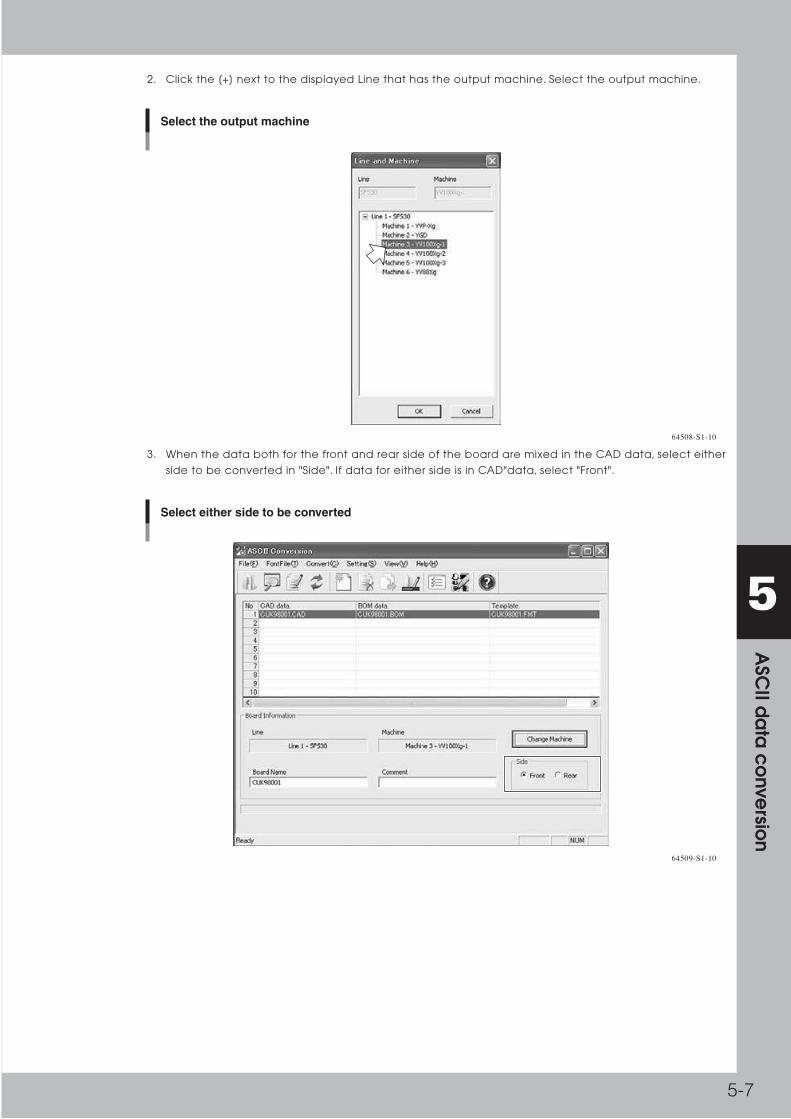
5-7
5 A
SCII d
ata
co
nversio
n
2. Click the [+] next to the displayed Line that has the output machine. Select the output machine.
Select the output machine
64508-S1-10
3. When the data both for the front and rear side of the board are mixed in the CAD data, select either
side to be converted in "Side". If data for either side is in CAD"data, select "Front".
Select either side to be converted
64509-S1-10
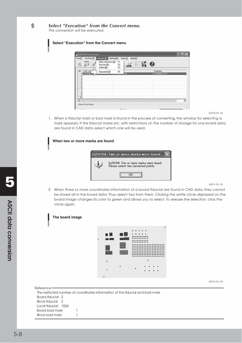
5-8
5 A
SCII d
ata
co
nversio
n
7 Select "Execution" from the Convert menu.The conversion will be executed.
Select “Execution” from the Convert menu
64510-S1-10
1. When a fiducial mark or bad mark is found in the process of converting, the window for selecting a
mark appears. If the fiducial marks etc. with restrictions on the number of storage for one board data,
are found in CAD data, select which one will be used.
When two or more marks are found
64511-S1-10
2. When three or more coordinates information of a board fiducial are found in CAD data, they cannot
be stored all in the board data. Thus, select two from them. Clicking the white circle displayed on the
board image changes its color to green and allows you to select. To release the selection, click the
circle again.
The board image
64512-S1-10
Reference The restricted number of coordinates information of the fiducial and bad mark Board fiducial 2 Block fiducial 2 Local fiducial 1024 Board bad mark 1 Block bad mark 1
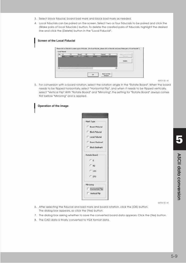
5-9
5 A
SCII d
ata
co
nversio
n
3. Select block fiducial, board bad mark and block bad mark as needed.
4. Local fiducials can be paired on the screen. Select two or four fiducials to be paired and click the
[Make pairs of local fiducials ] button. To delete the created pairs of fiducials, highlight the desired
line and click the [Delete] button in the "Local Fiducial".
Screen of the Local Fiducial
64513-S1-10
5. For conversion with a board rotation, select the rotation angle in the "Rotate Board". When the board
needs to be flipped horizontally, select "Horizontal Flip", and when it needs to be flipped vertically,
select "Vertical Flip".With "Rotate Board" and "Mirroring", the setting for "Rotate Board" always comes
first before "Mirroring" and is applied.
Operation of the image
64514-S1-10
6. After selecting the fiducial and bad mark and board rotation, click the [OK] button.
The dialog box appears, so click the [Yes] button.
7. The dialog box asking whether to save the converted board data appears. Click the [Yes] button.
8. The CAD data is finally converted to YGX format data.

5-10
5 A
SCII d
ata
co
nversio
n
3. Creating a conversion font fileSome sample font files(conversion process files) are provided for converting ASCII data to YGX data. If data conversion cannot be performed successfully by using the sample font files, you can create new font files to utilize data created for various machine models. This allows you to perform data conversion very efficiently. This section explains how to create a font file.
c CAUTION To convert ASCII data to YGX format data, an optional software program is required. The ASCII to YGX conversion function cannot be used without this software.
3.1 Create a new font fileTocreateafontfile,youneedtoopenthe"FontFileEditor"window.
1 Start the "ASCII Conversion".
2 Select "New Font File" from the FontFile menu.1. When the CAD data selection screen is displayed, select CAD data and BOM data.
2. Press the [OK] button to start the font file editor.
Screen of the “New Font File”
64515-S1-20

5-11
5 A
SCII d
ata
co
nversio
n
3 Set the data format.1. Select the delimiter for CAD data or BOM data. Select the "Space" check box for CAD data or BOM
data separated by the space. Select the "Comma( , )" check box for CAD data or BOM data
separated by the comma.
Data format
64516-S1-20
■ Continuous delimiters must be treated as one character When blank characters such as a tab or a space are used to separate the data, they might be used
consecutively to equalize the digit number with the others. In that case, if you want to recognize
them as one character, select "Continuous delimiters must be treated as one character" check box.
2. Select the quotation character.
When the parts name or pattern name in CAD data or BOM data includes the space(s), the string
might be enclosed in some quotation marks such as single(‘) or double(") quotation marks. In that
case, select the quotation marks here.
Reference If the specified delimiter in "Delimiter" is in the string enclosed in the specified quotation marks, the character will not be regarded as a delimiter.
3. Select the contents that are contained in CAD data or BOM data.
■ Data include front and rear board information Select the "Data include front and rear board information" check box when the coordinates data
both for the front and rear side of a board are mixed in the CAD data.

5-12
5 A
SCII d
ata
co
nversio
n
4. Select the origin of the coordinates of CAD data and the machine. Specify the position on a board
that corresponds to the origin coordinates in CAD data. Specify the position of the origin set by the
mounter. The corner represented as "Bottom right corner" and "Bottom left corner" etc. is the corner
of a board. The standard hole (E.g. "Bottom right standard hole" and"Bottom left standard hole") is
the position where it moves 5mm inward from the board corner in both X and Y direction. Example:
Bottom left corner and Bottom left standard hole
Bottom left standard hole
Bottom left corner
5mm
5mm
Bottom left corner and Bottom left standard hole
63501-S1-10
Offset to the origin of the coordinates
64517-S1-10
Clicking "Auto" in "The Origin of the coordinates(CAD Data)" automatically determines the origin
position and offset value for X and Y so that all marks will be recognized and all components will be
mounted on a board
5. Click the [Next] button after all settings are made.
Clicking the [Next] button displays the editor window for each item that has been selected in
"Contents" in order.

5-13
5 A
SCII d
ata
co
nversio
n
Hereafter,wewillexplaintheproceduressupposingthatallcheckboxesareselectedin"Contents".
4 Set the method for acquiring the board information (board size).Basic flow of retrieving each information.
Basic flow of retrieving each information
(1) Select the file containing the information.
(2) Specify the range to search for the line containing information.
(3) Set the conditions to select the line containing the information from the area.
(4) Settings to retrieve required information from each cell of the selected line.
63502-S1-10
(1)
(2)
(4)
(3)
Set the method for acquiring the board information
64518-S1-10

5-14
5 A
SCII d
ata
co
nversio
n
1. Firstly, click either "CAD" or "BOM" to select the source file that contains the board information.
Select the data
64519-S1-10
2. Select the unit for the board size (Length, Width and Height) in the "X,Y unit".
Select the unit for the board size
64520-S1-10

5-15
5 A
SCII d
ata
co
nversio
n
Reference Select [Keyword] button in "Start Line". Click the arrow, view the board information list to search for the board information line from the CAD or BOM data efficiently. It allows quick checking of the board size.
Data window
Check the board size
64521-S1-10
3. Specify how the data is separated in the "Delimiter".
■ Delimited by characters Click the "Delimited by characters" check box when the board size information is separated by
specified characters such as commas and spaces.
■ Fixed In the following example, X coordinate is assigned in the column between the 10th and 15th, Y
coordinate is assigned in the column between the 18th and 23rd. Like this case, when each item has
the fixed room for its own data, select "Fixed" check box.
123456789 123456789 123456789 123456789 123456789 12345678949
50
51
52
53
SMD
SMD
SMD
SMD
SMD
62.25
115.00
50.00
51.75
96.00
72.50
67.10
158.50
80.00
8.00
90.00
90.00
0.00
90.00
90.00
C2140
R16006
C216
R216
R21040
Fixed
63503-S1-10
Reference Even though the data is the fixed-width text file such as an example in "Fixed", the converted information can be acquired by clicking the "Delimited by characters" under the following condition: an appropriate character such as a space or tab is selected in the "Delimiter" in the "Data Format" and "Continuous delimiters must be treated as one character" check box is selected. However, if a blank(s) is included in the strings as follows, the information could be acquired improperly, therefore you need to select "Fixed".
123456789 123456789 123456789 123456789 123456789 12345678949
50
51
52
53
SMD
SMD
SMD
SMD
62.25
115.00
50.00
51.75
96.00
72.50
67.10
158.50
80.00
8.00
90.00
90.00
0.00
90.00
90.00
C2140
R16006
C216
R216
R21040
Fixed
63504-S1-10

5-16
5 A
SCII d
ata
co
nversio
n
4. Select an end Line in which the searching is completed to
■ Line Number Select the line in which the searching for the line containing the board information is completed to.
■ Keyword When there is a string that identifies the last line for the information(like "This is the end of the board
fiducial"), click "Keyword" to specify the desired string. Termination_of_the_Data represents "End Line".
When the first line is selected in the "Start Line" and "Termination_of_the Data" is selected in the "End
Line", the searching will be executed from the first line to the last one.
5. Select a start line.
■ Line Number Select the line in which the searching for the line containing the board information is started from.
■ Keyword When there is a string that identifies the start line for the information(like "if this string is found, the
later information is a board fiducial.), click "Keyword" to specify the desired string.
6. Specify which line is extracted between "Start Line" and "End Line" by setting extraction condition or
exclusion condition. First, find a feature to differentiate a line containing board information and other
lines. In this example, the line containing the character "PCB" is for board information. Like this case,
when there is a feature that identifies the line for board information, click "Extract" to set the
extraction condition. When there is an exception, click [Ignore] to set the exclusion condition.
Set the exclusion condition
64522-S1-10

5-17
5 A
SCII d
ata
co
nversio
n
Hereafter,wewillexplaintheproceduressupposingthat"Extract"isselected.Theprocedurestosettheexclusionconditionarethesame.
7. Specify the location of the feature that allows the differentiation between the line containing the
board information and the others. When "Delimited by characters" is selected in the "Delimiter", right
click on the cell which the distinctive string is entered to select any from Op1 to Op14.
Select from Op1 to Op14
64523-S1-10
In this example, the line containing the character "PCB" is for board information.So right click on the
cell that "PCB" is entered to select the "Op1".
Reference You do not need to use Op1~Op14 in order. Use one Op per feature. When "Fixed" is selected in the "Delimiter", drag the mouse to select the range of the distinctive string, and right click on it to select any from "Selection range is made Op1" to "Selection range is made Op14".
When “Fixed” is selected in the “Delimiter”
64524-S1-10

5-18
5 A
SCII d
ata
co
nversio
n
Wewillexplaintheprocedureshereaftersupposingthat"Delimitedbycharacters"isselectedinthe"Delimiter".When"Fixed"isselected,theproceduremaybeslightlydifferent.
8. Click the [Extraction] button "Extraction condition" window appears. (When "Ignore" is selected, click
the [Exclusion] button.)
9. Specify the distinctive character for the Op selected in Step 7 in the Extraction condition setting
window. When the condition is met, the line will be acquired for the board information.
10. In this example, if the characters specified for Op1 is "PCB", the line will be acquired as the line
containing the board information. So type [Op1="PCB"] in the first line.
Extraction
64525-S1-10
Reference If [Op1="FD1"] is typed in the column "Extraction" of No.1 and [Op1="FD2"] is typed in the colmun "Extraction" of No.2, it means that "Op1is either for FD1 or FD2", which is equivalent to typing [" Op1=FD1 || Op1=FD2 "] in the colmun "Extraction" of No.1. Please refer to " 4 . 1 How to express the logical formula" about allowable operators (such as "=" representing " equal " and "!=" representing " not equal ") in the Extraction condition setting window.
■ Examples of the conditional expression
Extract Meaning
Op1="FD*" When Op1 begins with FD.
Op1!="FD*" When Op1does not begin with FD.
Op1 >= 50 &&Op1 < 60 When Op1 is 50 or more and less than 60.
Op1!="FD" || Op1 != "BD" When Op1 is other than FD, or when Op1 is other than BD.
Thesettingsfor"Extractioncondition"(or"Exclusioncondition")arenowcompleted.

5-19
5 A
SCII d
ata
co
nversio
n
11. Next, specify each cell in the line that is regarded as the board size. Right click on the cell that is
acquired as board width, and select "Size X". Similarly, right click on the cell that is acquired as board
length, and select "Size Y". Right click on the cell that is acquired as board height, and select "Height".
Specify the place of the cell
64526-S1-10
12. The settings for acquiring method of board information are completed. Click the [Next] button.
5 Set the method for acquiring the block offset1. Please refer to Step4 Set the method for acquiring the board information, 1to 10. about the settings
for the "X,Y unit", "Delimiter" and "Extraction condition" etc..
2. (When [Data include front and rear board information] check box is selected.) check box is
selected.) Set the condition of the rear side of the board. Click the [Condition of Rear Info] button.
[Condition of Rear Info] button
64527-S1-10
Use Op1 to Op14 when setting the condition to extract the line for the rear side of the board.
Reference The assigned OP for the "Extraction condition" or "Exclusion condition" can also be reassigned for the [Condition of Rear Info.]

5-20
5 A
SCII d
ata
co
nversio
n
3. In the extracted line, specify "X" in the cell of the X coordinate, "Y" in the cell of the Y coordinate and
"R" in the cell of the angle.
4. Select the "Block coordinate and angle type".
■ Block coordinate type For the coordinates in the line of block offset in CAD data are equivalent to the origin coordinates of
each block, click "Board origin to block origins". For the coordinates in the line of block offset in CAD
data are equivalent to the coordinates of the first mounting position of each block, click "First mount
position to other mount positions" For the coordinates in the line of block offset in CAD data are
equivalent to the coordinates of the block mark of each block, click "First block fiducial to other
block fiducials".
■ Block angle type When the angle in the line of block offset in CAD data is equivalent to the mounting angle of each
block, click "Block angle". When the angle of each block is opposite to the mounting angle of the first
block, (how much the block will be rotated from the first block position and mounted.) click "Angle of
the first mount part".
Example:
The board data with the first block with 90-degree rotation and the second block with 270-degree rotation.A
A
First block Second block
The board data with the first block with 90-degree rotation and the second block with 270-degree rotation
63505-S1-10
When the information regarding the mounting angle for the first block(90 degrees) and that of the
second block(270 degrees) are included in CAD data, click "Block angle". When the CAD data has
the information that the first block is rotated 90 degrees and the second one is rotated 180
degrees,(180-degree rotation of the first block will be the state of the second block.), click "Angle of
the first mount part".
5. Select the "angle".
Specify the unit of the angle if the angle is expressed as the value. When the angle is expressed with
a code, type the number of the codes next to First block Second block the "Number of code" and
type the corresponding relationship between the code and angle needs to be tabulated.
Angle
64528-S1-10

5-21
5 A
SCII d
ata
co
nversio
n
6. (When the [Data include front and rear board information] check box is selected.) Specify the
"Mirror". When the mounting coordinates for both front and rear side of the board are mixed in the
CAD data, the coordinate data of component mount position on the back of PCB is usually
described a layer using projection method.We will explain how to reverse the data of the rear side of
the board at conversion.
■ Y Mirror Convert to the coordinates that are rotated in Y direction centered on X axis.
PP
Y Mirror
63506-S1-10
■ X Mirror Convert to the coordinates that are rotated in X direction centered on Y axis.
P PX Mirror
63507-S1-10
■ None Convert without any rotation.
P PNone
63508-S1-10

5-22
5 A
SCII d
ata
co
nversio
n
7. When skip data is included in block offset data, select Skip Condition.
1 T BLOCK -5.990 7.240 0.000 0
2 T BLOCK -5.990 79.240 0.000 1Skip data
Example of the skip data
63511-S1-10
In such a case that, Block offset data is defined in CAD data.
Last value of the line is for skip information ("0" means Non-Skip, "1"means Skip) Please set the convert
condition like below.
Click the last column and select "Skip", and select Skip condition button. After that define skip
condition. (The block offset data matched to definition will convert to Skip Block.)
Select “Skip”
64552-S1-10
In this case, 1 means "Execute Skip", so set the condition "1" and select close button.
“Skip condition” dialog box
64553-S1-10
How to set skip data conversion condition is same as another setting. For allowable operators refer to
"4.1 How to express the logical formula".
Reference When you define the condition of Op for "Exclusion, Extraction", this Op setting is re-useful for Skip condition setting.
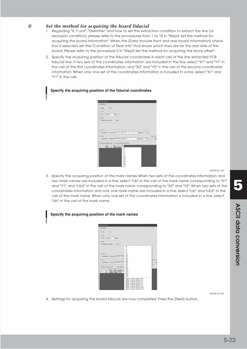
5-23
5 A
SCII d
ata
co
nversio
n
6 Set the method for acquiring the board fiducial1. Regarding "X, Y unit", "Delimiter" and how to set the extraction condition to extract the line (or
exclusion condition), please refer to the procedures from 1 to 10 in "Step4. Set the method for
acquiring the board information". When the [Data include front and rear board information] check
box is selected, set the "Condition of Rear info" that shows which lines are for the rear side of the
board. Please refer to the procedure 2 in "Step5 Set the method for acquiring the block offset".
2. Specify the acquiring position of the fiducial coordinates in each cell of the line extracted PCB
fiducial line. If two sets of the coordinates information are included in the line, select "X1" and "Y1" in
the cell of the first coordinates information, and "X2" and "Y2" in the cell of the second coordinates
information. When only one set of the coordinates information is included in a line, select "X1" and
"Y1" in the cell.
Specify the acquiring position of the fiducial coordinates
64529-S1-20
3. Specify the acquiring position of the mark names When two sets of the coordinates information and
two mark names are included in a line, select "Lib" in the cell of the mark name corresponding to "X1"
and "Y1", and "Lib2" in the cell of the mark name corresponding to "X2" and "Y2". When two sets of the
coordinates information and only one mark name are included in a line, select "Lib" and "Lib2" in the
cell of the mark name. When only one set of the coordinates information is included in a line, select
"Lib" in the cell of the mark name.
Specify the acquiring position of the mark names
64530-S1-20
4. Settings for acquiring the board fiducial are now completed. Press the [Next] button.

5-24
5 A
SCII d
ata
co
nversio
n
7 Set the method for acquiring the block fiducial1. Settings for acquiring the block fiducial are same as the "Step 6 Set the method for acquiring the
board fiducial". Please refer to it.
2. Click the [Next] button after the settings for acquiring the block fiducial.
8 Set the method for acquiring the local fiducial1. Regarding "X, Y unit", "Delimiter" and how to set the extraction condition to extract the line (or
exclusion condition), please refer to the procedures from 1 to 10 in "Step4. Set the method for
acquiring the board information". When the [Data include front and rear board information] check
box is selected, set the "Condition of Rear info" that shows which lines are for the rear side of the
board. Please refer to the procedure 2 in "Step5 Set the method for acquiring the block offset".
2. Set the method for acquiring the X and Y coordinates and the mark name. Please refer to "Step 6 Set
the method for acquiring the board fiducial" as the settings are the same. Please refer to it. (However,
for local fiducial, X1~X4, Y1~Y4 and Lib~Lib4 exist as local fiducial can handle the four point fiducial,)
3. Set the link to the mount information Local fiducial should be linked to the mount information. If the
string that shows the link to the mount information in the line for local fiducial, right click on the cell
and select "Part".
Set the link to the mount information
64531-S1-20
4. Settings for acquiring the local fiducial are now completed.
Press the [Next] button.

5-25
5 A
SCII d
ata
co
nversio
n
9 Set the method for acquiring the point fiducial1. Settings for the point fiducial are same as the "Step 8 Set the method for acquiring the local fiducial".
Please refer to it. ( For local fiducial, there are 4 choices of each X(X1-X4), Y(Y1-Y4) and Lib(Lib-Lib4).
For the point fiducial, there are 2 choices of each X(X1-X2), Y(Y1-Y2) and Lib(Lib-Lib2))
2. Select either absolute coordinates or relative coordinates. When the coordinates of the point fiducial
in the CAD data or BOM data is the one from the PCB origin(absolute coordinates), select "Absolute".
When the coordinates of the point fiducial is the relative coordinates, which is from the specified
component position, select "Relateive".
Select either absolute coordinates or relative coordinates
64532-S1-10
Reference After the conversion process is completed, the coordinates of the point fiducial will be converted to the relative coordinates from the linked component.
3. Settings for acquiring the point fiducial are now completed. Click the [Next] button.
0 Set the method for acquiring the PCB bad mark1. Settings for acquiring the PCB bad mark are almost the same as the "Step 6 Set the method for
acquiring the PCB fiducial ". Please refer to it. (For PCB bad mark, there is only one set of
coordinates, therefore X2 or Y2 does not exist.)
2. Settings for acquiring the PCB bad mark are now completed.Click the [Next] button.
q Set the method for acquiring the block bad mark1. Settings for acquiring the block bad mark are almost the same as the "Step 6 Set the method for
acquiring the PCB fiducial ". Please refer to it. (For block bad mark, there is only one set of
coordinates, therefore X2 or Y2 does not exist.)
2. Settings for acquiring the block bad mark are now completed. Click the [Next] button.
w Set the method for acquiring the local bad mark1. Settings for acquiring the local bad mark are almost the same as the "Step 8 Set the method for
acquiring the local fiducial ". Please refer to it. (For a local bad mark, there is only one set of
coordinates, therefore X2~X4 or Y2~Y4 etc. do not exist.
2. Settings for acquiring the local bad mark are now completed. Click the [Next] button.

5-26
5 A
SCII d
ata
co
nversio
n
e Set the method for acquiring the mount information.1. Regarding "X, Y unit", "Delimiter" and how to set the extraction condition to extract the line (or
exclusion condition), please refer to the procedures from 1 to 10 in "Step4. Set the method for
acquiring the board information". When the [Data include front and rear board information] check
box is selected, set the "Condition of Rear info" that shows which lines are for the rear side of the
board. Please refer to the procedure 2 in "Step5 Set the method for acquiring the block offset".
2. Specify the X and Y coordinates and mounting angle Select "X" in the cell of the X coordinate, "Y" in
the cell of the Y coordinate and "R" in the cell of the mounting angle.
3. Specify the feeder set number. When the feeder set number is included in the line for the mount
information, select the "FeederNo" in the cell.
4. Specify the pattern name. When the pattern name is included in the line for the mount information,
select the "Ref" in the cell.
5. Specify the parts name. When the parts name is included in the line for the mount information, select
the "Parts" in the cell.
6. Specify the database name of the parts database. When the database name of the parts database
is included in the line for the mount information select the "ShapeName" in the cell.
7. Specify the link to the local fiducial, point fiducial and local bad mark. Select "LocalFid" in the cell of
the string that shows the link to the local fiducial,"PointFid" in the cell of the string that shows the link
to the point fiducial, and"LocalBad" in the cell of the string that shows the link to the local bad mark..
Reference When linking the local fiducial, point fiducial and local bad mark to the mount infromation, the pattern name in the mount information may be used as the link in the local fiducial as follows.
8, MK-LOCAL, 10.00, 10.00, MARU01, IC5001
9, MK-LOCAL, 25.00, 25.00, MARU01, IC5001
804 , SMD , 17.50 , 37.50 , 270.00 , IC4001
805 , SMD , 17.50 , 17.50 , 270.00 , IC5001
806 , SMD , 117.00 , 40.00 , 0.00 , CN1
Link to the mount information
Pattern name
[Mount information]
[Local fiducial]
When linking the local fiducial
63509-S1-10
In such case, select "LocalFid" in the cell specified as the pattern name.
Select “LocalFid”
64533-S1-10

5-27
5 A
SCII d
ata
co
nversio
n
8. Set the angel and the rotation direction Specify the unit of the angle if the angle is expressed as the
value. When the angle is expressed with a code, type the number of the codes next to the "Number
of code" and the corresponding relationship between the code and angle needs to be tabulated.
Set the angel and the rotation direction
64534-S1-10
9. When the original data have skip information, set the skip data conversion condition.How to set,
please refer the No.7 chapter of [STEP5: Block offset].
10. Settings for acquiring the mount infromation are now completed. Click the [Next] button.
r Set the method for acquiring the "feeder set information".1. Regarding "X, Y unit", "Delimiter" and how to set the extraction condition to extract the line (or
exclusion condition), please refer to the procedures from 1 to 10 in "Step4. Set the method for
acquiring the board information". When the [Data include front and rear board information] check
box is selected, set the "Condition of Rear info" that shows which lines are for the rear side of the
board. Please refer to the procedure 2 in "Step5 Set the method for acquiring the block offset".
(However, the mount information is not included in the feeder set information, therefore you do not
need to set the "X, Y unit".)
2. Specify the feeder set number When the feeder set number is included in the line for the feeder set
arrangement, select the "FeederNo" in the cell.
3. Specify the parts name When the parts name is included in the line for the feeder set arrangement,
select the "Parts" in the cell.
4. Specify the database name of the parts database When the database name of the parts database
is included in the line for the feeder arrangement, select "Lib" in the cell.
5. Settings for the "feeder set information" are now completed. Click the [Next] button.
t Set the method for acquiring the BOM data1. Regarding "X, Y unit", "Delimiter" and how to set the extraction condition to extract the line (or
exclusion condition), please refer to the procedures from 1 to 10 in "Step4. Set the method for
acquiring the board information". When the [Data include front and rear board information] check
box is selected, set the "Condition of Rear info" that shows which lines are for the rear side of the
board. Please refer to the procedure 2 in "Step5 Set the method for acquiring the block offset"
2. Specify the parts name Select the "Parts" in the cell of the parts name of the line for BOM data.
3. Specify the parts reference Select the "Ref Start" in the cell of the parts reference of the line for BOM
data. When you specify the location of the parts reference, the""Input of the number of Ref item con
…" dialog box appears. Select "Input of the number of items " when parts reference is constant. For
other case, select "To the end". If several references exist in one column, select “Group several Ref in
1 column (free serial number)”.
4. Specify the character that omits the consecutive Refs. If a lot of parts reference corresponding to
the parts name exist and their number is consecutive like from C1000 to C1100, "C1000 – 1100" could
be displayed in order to indicate the number is from C1000 to C1100. In such case, specify the "-
hyphen" as the character that omits the consecutive Refs. When the character other than the
displayed character in the window(slash, hyphen, underscore or tilde) is used as an omitting
character, select the "Other" check box. Click the [Ref Continues character] button to display the
"Ref Continues character" dialog box. Type the omitting character and click the [Close] button.
5. Settings for acquiring the BOM data are now completed. Clicking the [OK] button displays the dialog
box to save the file. When you type a file name and click the [Save] button, the acquiring conditions
that have been created are stored in a font file.

5-28
5 A
SCII d
ata
co
nversio
n
y Make sure that the created font file can be used at conversion1. In the main window select "Data selection" from the “Convert” menu. "CAD data selection" dialog
box appears.
2. After selecting the CAD data, BOM data and the created font file, click the [OK] button.
3. Going back to the main window, select the data to be checked from the list of the CAD data, BOM
data and the font file. Then select "Preview" from the “Convert” menu.
4. The preview window appears. Check to see that the each specified item has the correct string..
■ The tabs other than the "Mounting coordinate" The object lines to be acquired are displayed on a white background.
The lines to be acquired when the opposite side is selected in the "Convert" main window (for
example the lines for the rear side when the convert window is displayed) are displayed on a light
blue background. The lines other than the object lines to be acquired are displayed on a yellow
background. In addition, the characters for Op of lines that match the "Extraction condition" or
"Exclusion condition" are displayed in blue and the characters for Op of the lines that match
"Conditions of Rear Info" are displayed in red.
■ Mounting coordinate tab In the Mounting coordinate tab, it includes the display features about BOM data besides the
features described above. For the conversion with using the BOM data, the searching for the parts
reference, which is included in the CAD data, in the BOM data is executed. If the parts reference is
found, the database name of the parts will be acquired and displayed in the column "Parts" in the
mounting coordinate tab of the preview window.
Preview window
64535-S1-10

5-29
5 A
SCII d
ata
co
nversio
n
Whenseveraldataareselectedinthemainwindow,switchingthe"DataNumber"inthepreviewwindowdisplaystheotherpreviewwindow.
Open the preview window
64536-S1-10
5. If the each specified item does not have the correct strings, click the [Editor] button to edit the font
file, and click the [OK] button to save the changes. The changes made on the font file will be
applied after saving the font file. The preview window appears again.
6. Make sure that the each specified item has the correct string. Click the [Close] button to go back to
the main window. Settings for creating a new font file are now completed.

5-30
5 A
SCII d
ata
co
nversio
n
3.2 Editing a font file
1 Start the ASCII data conversion.
2 Select "Data selection" from the “Convert” menu.The "CAD data selection" dialog box appears.
3 Select CAD data, BOM data and the font file to be edited.When the BOM data does not need to be used, please leave the filed blank. For the font file that has been created with using both CAD data and BOM data, you also need both of them at editing.
4 Click the "Edit Font File" icon on the tool bar.The "Font File Editor" dialog box appears.
“Revise font file” button
64537-S1-10
5 Edit the font file.After editing the font file, click the [OK] button to save it. click the [Cancel] button for not saving the font file.
Settingsforeditingafontfilearenowcompleted.

5-31
5 A
SCII d
ata
co
nversio
n
3.3 Delete / copy a font file and change the font file name.Select"Delete"fromtheFontFilemenutodeletethefontfile.The"Delete"dialogboxappears.Selectthefontfiletobedeletedandclickthe[Execute]button.
Delete a font file
64538-S1-10
Select"Copy"fromtheFontFilemenutocopythefontfile.The"Copy"dialogboxappears.Selectthefontfiletobecopiedandclickthe[Execute]button.Select"Rename"fromtheFontFilemenutochangethefontfilename.The"Rename"dialogboxappears.Selectthefontfiletoberenamedandclickthe[Execute]button.

5-32
5 A
SCII d
ata
co
nversio
n
3.4 Import of font file.
1 Select the menu of FontFile(T) -> Import(I).
2 Select Add button and open file select dialog.
Screen of “Import font file”
64554-S1-10
3 Select Open button, the import file list will be displayed.
4 Select Import button, the import operation will be start.
Start of Import
64555-S1-10

5-33
5 A
SCII d
ata
co
nversio
n
Reference During import operation, the message like below will be displayed.
Message during import operation
64556-S1-10
When same error happened, Select "YES", import operation will be continued, same message is
displayed again.
Select "No", import operation will be continued, and no same message is displayed.
Select "Cancel", import operation is aborted.

5-34
5 A
SCII d
ata
co
nversio
n
4. Miscellaneous4.1 How to express the logical formula.• "Exclusioncondition","Extractioncondition"and"ConditionofRearInfo","SkipCondition"arespecifiedby"formula".• The"formula"consistsof"operator","constant","string"and"identifier".• Ifthe"formula"isexpressedinseverallines,eachlineisdealtwithasOR;"||".• Theformulaisjudgedasbeencorrespondedifthevalueturnsotherthan0.
■ Operator
Applicableoperatorsareasfollows.
Operator Meaning Remarks
==
=Match
If the condition is true, then "1" is returned, otherwise "0" is returned. The result may differ depending on the comparison made by string or numerical value.
Smaller
Bigger
Numerical
value orderString order
1 "1"
2 "10"
10 "2"
For the comparison as a string, the result also defers if the wild card(s) is included in a string.
Wild card Relation String Status
"A?" > "A" Lack of string
= "AA" Matched with string
< "AAA" Excess of string
!=
<>Mismatch
>= Or more
> More than
<= Or less
< Less than
+ Addition Unary plus
(Addition) For an operation as a numerical value, the result turns the added value. For an operation as a string, the result turns the connected one. (Unary plus) String is converted to either integer or decimal number. The sign of the value will not change.
-Subtraction Unary minus
(Subtraction) String is converted to either integer or decimal number. The result turns the subtracted numerical value. (Unary minus) String is converted to either integer or decimal number. The sign of the value will change.
∗ MultiplicationString is converted to either integer or decimal number. The result turns the multiplied numerical value.
/ DivisionString is converted to either integer or decimal number. The result turns the divided numerical value. For the division by 0, the result turns 0.
% SurplusString and decimal number are converted to integer number. The result turns the remain after the division. For the division by 0, the result turns 0.
!
~Negation
String and decimal number are converted to integer number. For other than 0, the result turns 0. For 0, the result turns 1.
&&
&Logical AND
String and decimal number are converted to integer number. Logical AND by bit operation.
Item 1 Item 2 Value
0 0 0
0 1 0
1 1 1

5-35
5 A
SCII d
ata
co
nversio
n
Operator Meaning Remarks
||
|Logical OR
String and decimal number are converted to integer number. Logical OR by bit operation.
Item 1 Item 2 Value
0 0 0
0 1 1
1 0 1
1 1 1
^ Exclusive logical OR
String and decimal number are converted to integer number. Exclusive logical OR by bit operation.
Item 1 Item 2 Value
0 0 0
0 1 1
1 0 1
1 1 0
? : Ternary operation
If the item1 is a string or decimal number, they are converted to integer number. If the item1 is other than 0, the result turns the value of item2. If the item1 is 0, the result turns the value of item3.
( ) Parenthesis The operation within parentheses is prioritized.
Operator priority
Operatorisinterpretedinhigherpriorityorderas
Higher Lower
( )
! ∗ + >= == && ^ || ?
~ / - > = & |
+ % <= !=
- < <>
Ifoperatorswhosepriorityisthesamelevelarenextto,theoneintheleftsidewillbeinterpretedfirst.
<Example>8/3∗2->4
8∗2/3->5

5-36
5 A
SCII d
ata
co
nversio
n
Constant
Constantisclassifiedintothreetypiesbelow.
Constant Type
"abc" String
123 Integer number
4.56 Decimal number
c CAUTION 1. In constant value and the calculated result, the type of constant is prioritized. 2. When there is no difference between the constant value and the calculated result, the type of Item1 is prioritized. 3. Operation is performed with the value automatically converted to the prioritized type. 4. Wild card can be used in a string. ("∗" or "?" is applicable.) 5. Capital letters and lowercase letters are distinguished in a string.( "ABC" and "abc" are interpreted as another string.)
<Example>Typeconversionisperformedasfollows.
String Integer number Decimal number
"AAA" 0 0
"100" 100 100.0
"1.23" 1 1.23
"10" 10 10.0
"8A" 8 8.0
Integer number Decimal number String
0 0.0 "0"
10 10.0 "10"
100 100.0 "100"
Decimal number String Integer number
0.0 "0.000000" 0
10.0 "10.000000" 10
100.0 "100.000000" 100
1.23 "1.230000" 1
<Example>Methodtoperformtheforcefultypeconversion.(bytherulethatgivesthepriorityto the type of item1.)
""+100->"100"(string)
0+"1.23"->1(integernumber)
0.0+"1.23"->1.23(decimalnumber)
<Example>Connectionandadditionofthestring
1+2+3->3+3->6(integernumber)
"1"+2+3->"12"+3->15(integernumber)
1+"2"+3->3+3->6(integernumber)
1+2+"3"->3+"3"->"33"(string)
∗ Thepriorityofthecalculatedresultislowerthanthatoftheconstant,thereforethetypeofitem2isprioritizedinthesecondoperation.

Chapter 6 Database management
Contents
1. Unified database management function 6-1
1.1 Outline of operation 6-1
1.2 Feature of “Unified database management” 6-2
1.2.1 Commonness of database 6-2
1.2.2 Management of database 6-3
1.3 Preparation for “Unified database management” 6-4
1.4 Setting 6-5
1.4.1 Setting of Database Folder 6-5
1.4.2 Setting of Y.FacT “Use Database” 6-7
1.5 Database collection 6-8
1.5.1 Method of using Database Matching (Database Write from Board) 6-10
1.5.2 Method of using Parts Database Editor 6-12
1.6 Limitations 6-14
2. “Database Synchronize mode” function 6-15
2.1 Introduction 6-15
2.2 Outline of operation 6-16
2.3 Preparation of database 6-20
2.4 Setting 6-23
2.4.1 YG Series or subsequent machine 6-23
2.4.2 Xg Series 6-24
2.4.3 Y.FacT 6-25
2.4.4 YRS 6-26
2.5 Detailed explanation of operation 6-27
2.5.1 YG Series or subsequent machine 6-27
2.5.2 Xg Series 6-30
2.5.3 Y.FacT 6-32
2.6 Limitations 6-34
2.6.1 Limitations when beginning to operate 6-34
2.6.2 Other limitations 6-34
3. Unified database management support checklist 6-35
3.1 Introduction 6-35
3.2 Unified database management support checklist 6-36
3.2.1 Database backup 6-36
3.2.2 The path for Unified database management 6-36
3.2.3 Database preparation 6-36
3.2.4 Necessity judgment of “Database Synchronize mode function” 6-36

3.2.5 Database Synchronize mode function is necessary 6-37
3.2.6 Database Synchronize mode function is unnecessary 6-39
4. Series Database 6-40
4.1 Outline of functions 6-40
4.2 Detailed explanation of operation 6-40
4.3 Settings 6-41
4.3.1 Setting method 6-41
4.3.2 Database allocation to each machine 6-42
4.4 Limitations 6-43
5. Shape Database 6-44
5.1 Outline of function 6-44
5.2 To use Shape Database 6-45
5.3 Details of function 6-46
5.3.1 Database Matching by Shape Name / Database Matching from Board by Shape Name 6-48
5.3.2 Set from DATABASE automatically after Board data is read – Referring Parts Shape List 6-48
5.3.3 Making of “Parts / Shape List” 6-48
5.4 Transition Tool of Shape Database 6-49
5.4.1 Outline of function 6-49
5.4.2 To use this function 6-50
5.4.3 Flow of processing and composition of each dialog 6-51
5.5 Registration function of “Parts / Shape List” 6-55
5.5.1 Outline of function 6-55
5.5.2 To use this function 6-55
5.5.3 Outline of operation 6-55
5.5.4 The flow of processing and the composition of each dialog 6-61
5.5.5 New registration 6-65
5.6 Limitations 6-69
6. Additional parameter handling on database 6-70
6.1 Outline of function 6-70
6.2 Details of operation 6-70
6.2.1 Pick Pos. Parameters 6-70
6.2.2 Tray Parameters 6-70
6.2.3 Comment 6-70
6.2.4 Target command 6-71
6.3 Settings 6-72
6.4 Moving existing data 6-73
6.4.1 Reason to prepare to introduce 6-73
6.4.2 How to prepare to introduce 6-74
6.5 Limitations 6-74
7. Parts Database Duplicate Check 6-75
7.1 Outline of function 6-75

7.2 Settings 6-75
7.3 How to setup 6-76
7.3.1 Duplicate Data Check Function 6-76
7.3.2 Error Message and its Counter Measures 6-76
7.4 Limitations 6-80

6-1
6 D
ata
ba
se m
ana
ge
me
nt
1. Unified database management functionThe preparation for the unified management of database use is described in detail. Refer to “3.2 Unified database management support checklist” in this chapter when introducing this function, and prepare for introduction according to the instructions.
1.1 Outline of operation“Unifieddatabasemanagement”meansthatXg/YGSeriesorsubsequentmachineandofflinesoftware(Y.FacT)refertoonedatabase.EachmachineusesthenetworkanditisrecommendedtorefertothedatabaseofY.FacT.
D_Base D_Base D_Base
D_Base
YV100Xg YG100 YG200
Y.FacT
Unified database management
Reference
63601-S1-00
Usually(Default),machineandY.FacTrefertoeachdefaultdatabasefolder.
YV100Xg YG100 YG200 Y.FacT
D_Base D_Base D_Base D_Base
Reference Reference Reference Reference
Default Setting
63602-S1-00
Partsdatabase,markdatabase,andInspectiondatabasecanbemanagedin“Unifieddatabasemanagement”.
■ Database that can be managed
Database Support
Parts database Yes
Mark database Yes
Inspection database Yes

6-2
6 D
ata
ba
se m
ana
ge
me
nt
1.2 Feature of “Unified database management”“Unifieddatabasemanagement”hassomepointsthataremoreeffectivethanthedefaultoperation.
1.2.1 Commonness of databaseToshareandtorefertoonedatabasewithmachineandY.FacT,itexcelsincommonnessofdatabasein“Unifieddatabasemanagement”.BecausemachineandY.FacTrefertoeachdatabase,itisnotpossibletoshareindefaultsetting.
YV100Xg YG100 YG200
Y.FacT
D_Base D_Base D_Base
D_Base
Commonness of database in “Unified database management”
Copy back to Database
Set from Database
63603-S1-00
ThedatathatcopybackfromYV100XgtodatabasecanbesetfromdatabasetoYG200.
YV100Xg YG100 YG200 Y.FacT
D_Base D_Base D_Base D_Base
Commonness of database in “Default setting”
Copy back toDatabase
Set from Database
63604-S1-00
ThedatathatcopybackfromYV100XgtodatabasecannotbesetfromdatabasetoYG200.

6-3
6 D
ata
ba
se m
ana
ge
me
nt
1.2.2 Management of databaseToshareandtorefertoonedatabasewithmachineandY.FacT,itexcelsinmanagementofdatabasein“Unifieddatabasemanagement”.BecausemachineandY.FacTreferstoeachdatabase,managementofdatabaseisnotgoodindefaultsetting.
D_BaseD_Base D_Base D_Base
Back up
For Y.FacT
YV100Xg YG100 YG200 Y.FacT
Management of database in “Unified database management”
63605-S1-00
ItisnecessarytobackupdatabaseonlytoY.FacT.
D_BaseD_BaseD_BaseD_Base
Back up Back up Back up Back up
YV100Xg YG100 YG200 Y.FacT
Management of database in “Default setting”
For Y.FacTFor YG200For YG100For YV100Xg
63606-S1-00
ItisnecessarytobackupdatabasetomachineandY.FacT.
■ Feature of operation
Operation Commonness Management
Unified database management Good Good
Default setting Not Good Not Good

6-4
6 D
ata
ba
se m
ana
ge
me
nt
1.3 Preparation for “Unified database management”Beforestarting“Unifieddatabasemanagement”,itisnecessarytobringthedatathatexistsinBoarddataandanotherdatabasedatatogetherinone.WhenXgSeriesmachineexiststogetherwithYGSeriesorsubsequentmachine,itisnecessarytoactivatetheDatabaseSynchronizemode.ThisisbecausethedatabaseformatsupportedbyXgSeriesandthatbyYGSeriesorsubsequentmachinearedifferent.Fordatabasesynchronizationreferto“2.DatabaseSynchronizemodefunction”inthischapter.
■ Necessity of Database Synchronize mode function
Series combination Database Synchronize mode function
Only Xg Series Unnecessary
Only YG Series and subsequent machines Unnecessary
Xg Series and YG Series or subsequent machines exist together
Necessary
* Only YG200 can be used as either “Xg Series” or “YG Series or subsequent machine”. (FD/MD and FDX/MDX are possible by the selection.)
Itisnecessaryfor“Unifieddatabasemanagement”thatthenetworkofmanagedmachinesandY.FacTisbuiltbyEthernetandthenetworkpathcanrefer.
YV100Xg
D_Base
YV100Xg
D_Base
YG200
D_Base
Y.FacT
D_Base
LAN (Reference)
Possible
Possible
63616-S1-00
Thedatabasecanbemadethesameaboutdosmachinebydatabasedatacommunication,butitisnot“Unifieddatabasemanagement”becausethedatabaseexistsineachmachine.
D_Base D_Base D_BaseD_Base
YV100Xg YV100Xg YG200 Y.FacT
LAN (Reference)
RS232C (Copy)
Impossible
Impossible
63617-S1-00
*ItisnotnecessarytosetupaccordingtothisdocumentifdatabasesetorwriteisexecutedthroughY.FacTonlywithoutreferringtothedatabasefromthemachinetoexecutedatabasesetorwrite.
ThereareFD/MDformat(forXgSeriesorpreviousmachine)andFDX/MDXformat(forYGSeriesorsubsequentmachine)inthedatabase.ItisnecessarytoactivateDatabaseSynchronizemodefunctioninordertoconduct“Unifieddatabasemanagement”whenXgSeriesmachineexiststogetherwithYGSeriesorsubsequentmachine.Pleaseexecutethefunctionsettingreferringto“3.DatabaseSynchronizemodefunction”aftercompletingthepreparationfor“Unifieddatabasemanagement”inthisdocument.

6-5
6 D
ata
ba
se m
ana
ge
me
nt
1.4 Setting“Unifieddatabasemanagement”isenabledbymatchingthereferenceddatabaseofmachinesandY.FacT.Youmustsetupthe<SettingofY.FacT“UseDatabase”>assettingvariesdependingoncombinationsofmachinesfor“Unifieddatabasemanagement”.Thefollowingisaprecautionforusing“Unifieddatabasemanagement”.
1.ItisnecessarythatthenetworkofmanagedmachinesandY.FacTisbuiltbyEthernet,andthenetworkpathcanrefer.
2.Thecommonsettingofnetworkisneededthereferencefolder.
3.TheOSofreferringPClimitsthenumberofpossiblesimultaneousaccessesusers.
OS The number of possible simultaneous accesses users
Windows XP Home 5
Windows2000 Professional
10Windows XP Professional
Windows Vista
1.4.1 Setting of Database FolderWerecommendthatyousetthedatabasefolderofY.FacTasfilesharingconfigurationandassignitasthedatabasefolderreferredtobymachinesandY.FacT.
YV100Xg_1 YV100Xg_2 YV88Xg Y.FacT
D_BaseD_Base D_BaseD_Base
Reference Reference Reference Reference
Setting of Database Folder
63618-S1-00
Y.FacT
“Option Setting” – “Database” tab
64603-S1-00
Machines
“Setup” – “Database” – “Database Utility” screen
64604-S1-10

6-6
6 D
ata
ba
se m
ana
ge
me
nt
ItisalsopossibletoputthedatabasefileonanarbitraryfoldersothatY.FacTandmachinesrefertoit.Inthatcase,specifythedatabasefolderforY.FacTandmachines.
YV100Xg_1 YV100Xg_2 YV88Xg Server
D_Base
Y.FacT
D_Base D_Base D_Base D_Base
Reference Reference Reference Reference Reference
Setting where Y.FacT and machines refer to the same database
63619-S1-00

6-7
6 D
ata
ba
se m
ana
ge
me
nt
1.4.2 Setting of Y.FacT “Use Database”Thesettingof“Unifieddatabasemanagement”isdifferentaccordingtothecombinationofthemachines.
The combination of the machines Setting
Xg Series Machine only FD/MD
YG Series or subsequent machine only FDX/MDX
Xg Series machine exists together with YG Series or subsequent machine
FDX/MDX (with saving FD/MD)
*The YG200/YG200L can be used as either “Xg series” or “YG series or subsequent machine”. (FD/MD or FDX/MDX can be selected with setting)
Xg Series Machine only
Select “FD/MD”
64605-S1-00
YG Series or subsequent machine only
Select “FDX/MDX”
64606-S1-00
Xg Series machine exists together with YG Series or subsequent machine
Select “FDX/MDX (with saving FD/MD)”
64607-S1-00
ItisnecessarytoactivatetheDatabaseSynchronizemodefunctioninordertoconductthe“Unifieddatabasemanagement”whenXgSeriesmachineexiststogetherwithYGSeriesorsubsequentmachine.Fordatabasesynchronizationreferto"2.DatabaseSynchronizemodefunction"inthischapter.

6-8
6 D
ata
ba
se m
ana
ge
me
nt
1.5 Database collectionBeforestarting“Unifieddatabasemanagement”,itisnecessarytobringthedatathatexistsinBoarddataandanotherdatabasedatatogetherinone.Outlineofbringingthedatatogether
Database A
Parts A/B/C : Master data exists in Board data.Parts D/E : Master data exists in Database.Parts F : Master data exists in two or more Database.
All Parts : Master data exists in Database.
Outline of bringing the data together
Outline of bringing the data together
Before data After data
Parts DParts F
Database AParts AParts DParts F
Database BParts BParts EParts F
Database CParts CParts EParts F
Database AParts AParts DParts F
Database BParts BParts EParts F
Database CParts CParts EParts F
Database BParts EParts F
Reference
Reference
Reference
Database
Parts AParts BParts CParts DParts EParts F
63620-S1-00
Therearethefollowingtwomethodsofbringingthedatatogether.
1.MethodofusingDatabaseMatching(DatabaseWritefromBoard)Partsdataisupdatedtothedatabasebythekeyofthepartsnameorpartscommentintheboarddata.Referto“1.5.1MethodofusingDatabaseMatching(DatabaseWritefromBoard)”fordetails.
2.MethodofusingPartsDatabaseEditorYouopentwoormoredatabasebyPartsDatabaseEditor,andyouexecutetheCopy&PasteofthePartsData.InthiscaseyoumustexecuteDatabaseMatching(DatabaseSettoBoard)becausetherelationofPartsdataandDatabaseisnecessary.Referto“1.5.2MethodofusingPartsDatabaseEditor”fordetails.

6-9
6 D
ata
ba
se m
ana
ge
me
nt
Itexplainsasanexampleofoutlineofbringingthedatatogether.
Board A Board B Board C Db A Db B
Parts A M
Parts B M
Parts C M
Parts D R M
Parts E R R M
Parts F U U U U U
(M: Master Parts Data / R: Refer to Database / U: Master Data is unknown)
PartsA/B/CexistsinBoarddata.
PartsD/EexistsinDatabase.
PartsFexistsintwoDatabaseandtheMasterdataisunknown.
Themethodisselectedbythesecases.
· ThecaseofPartsA/B/CPleaseselecttheMethodofusingDatabaseMatching(DatabaseWritefromBoard).
· ThecaseofPartsD/EPleaseselecttheMethodofusingPartsDatabaseEditor.
· ThecaseofPartsFPleasecheckwhichtheMasterdataintwodatabase.AndselecttheMethodofusingDatabaseMatching(DatabaseWritefromBoard).
· ThecaseofexistingPartsA/B/C,PartsD/EandPartsFtogetherPleaseselecttheMethodofusingDatabaseMatching(DatabaseWritefromBoard).
Pleaseselectamethodsuitablebythecondition.

6-10
6 D
ata
ba
se m
ana
ge
me
nt
1.5.1 Method of using Database Matching (Database Write from Board)Partsdataisupdatedtothedatabasebythekeyofthepartsnameorpartscommentintheboarddata.Therefore,itisnecessarythatthePartsdataoftheBoarddatabemadethelatest.Moreover,thedataoverwritesinPartsdataexecutedlaterifthereispartdataonthesamename.Andthedataofthesamenameisnotregisteredtothedatabase.ThefigurebelowshowsthesituationwhenDatabaseMatching(DatabaseWritefromBoard)isrepeatedlyexecuted.
Process of parts information in parts database
Board Data for Matching
Board data A
Parts AParts DParts F
Board data B
Parts BParts EParts F
Board data C
Parts CParts EParts F
Matching
Matching
Matching
* About two or more Board data with data of the same name, the data overwrites in Parts data executed later if there is part data on the same name. And the data of the same name is not registerd to the database.
Database
Parts DParts F
Database
Parts DParts FParts A
Database
Parts DParts FParts AParts BParts E
Database
Parts DParts FParts AParts BParts EParts C
Parts Database Overwritten data
Parts DParts F
Parts F
Parts FParts E
63621-S1-00

6-11
6 D
ata
ba
se m
ana
ge
me
nt
1 Open the Board dataPlease open the Board data with Parts data to register from Board Explorer.
Board data
64608-S1-00
2 Execute Database Matching (Database Write from Board)Please select the menu. [Tool] -> [Database Support] -> [Database Matching] -> [Database Write from Board]
Execute Database Matching
64609-S1-00
Pleasecheckthecheckboxof“Writenewpartstothedatabase”,andpush[OK]button.
Check the check box of “Write new parts to the DATABASE”
64610-S1-00
Thedatabaseisaddedbythisworksincethe1001st.Whenthereispartdataofthesamenameindatabase,thedatadosenotaddtodatabase.
3 Repeat Step1 and Step2Please open the Board data, and repeatedly execute Database Matching (Database Write from Board). Please execute it for all Board data containing information to be registered.
Reference Database Matching (Database Write from Board) can be performed efficiently using the database utility function. Refer to the separate “Factory Tools Common Function” manual for details.

6-12
6 D
ata
ba
se m
ana
ge
me
nt
1.5.2 Method of using Parts Database Editor
1 Start the Parts Database EditorSelect “Parts Database Editor” from the “File” menu of the Board Editor.
Start the Parts Database Editor
64611-S1-00
2 Open the Database file that want to bring the data togetherPlease select and open the Database file that want to bring the data together. It is necessary to start by "Open Database on New editor" to start two or more Database Editor since the second.
*The Database file name is "Database" only.
Please open the Database file by "Open Database on New editor" since the second.
Open the Database file that want to bring the data together
Please select the Database folder.
Please select the Database file type.
64612-S1-00

6-13
6 D
ata
ba
se m
ana
ge
me
nt
3 Bringing the data together.Shortfall data is put on the original Database by line selection copy & paste. Please save the Database file by FDX/MDX format when either is the data of FDX/MDX format. The expanded parameter is initialized if it saves it by FD/MD format.
Bringing the data together
Copy
FromTo
Paste
64613-S1-00
4 Database MatchingYou must execute Database Matching (Database Set to Board) because the relation of Parts data and Database is necessary. Database Matching sets a new Database number in the Board data.
However, it is necessary to relate parts to the database in part name*. Create a relation by executing the matching procedure when there is no relation.
* Parts database matching can be conducted not only with parts name but also with parts comment.
“Relation” means that names correspond or that names are related with shape table (refer to “5.
Database by types” in this chapter).
Reference Database Matching can be performed efficiently using the database utility function. Refer to the separate "Factory Tools Common Function" manual for details on the database utility function.

6-14
6 D
ata
ba
se m
ana
ge
me
nt
1.6 Limitations
· In“Unifieddatabasemanagement”,PCwherethereferringdatabaseexistsisstartedandthenetworkreferenceshouldbepossible.
· WhenthereisnoY.FacT“Unifieddatabasemanagement”ispossible,butitisnotrecommendedbecausebringingthedatatogetherisdifficult.
· InDatabaseMatchingthedataoverwritesinPartsdataexecutedlaterifthereispartdataonthesamename.Andthedataofthesamenameisnotregisteredtothedatabase.
· Referto“4.Databasebymodels”inthischaptertousethemanagementfunctionfordatabasebymodelsofY.FacT.
· Referto“5.Databasebytypes”inthischaptertousethemanagementfunctionfordatabasebytypesofY.FacT.
· TheDatabaseSynchronizemodefunctionshouldbeactivatedtoconduct“Unifieddatabasemanagement”whenXgSeriesmachineexiststogetherwithYGSeriesorsubsequentmachine.Referto“2.DatabaseSynchronizemodefunction”inthischapter.

6-15
6 D
ata
ba
se m
ana
ge
me
nt
2. “Database Synchronize mode” function2.1 IntroductionDetailsofthe“DatabaseSynchronizemode”aredescribed.Referto“3.2Unifieddatabasemanagementsupportchecklist”inthischapterwhenintroducingthisfunction,andprepareforintroductionaccordingtotheinstructions.Thetargetmodelandthesoftwareversionofthesespecificationsareasfollows.
■ Target model and software version of this function
Item name Target Note
Target model
YS Series YG Series Xg Series Offline soft(Y.FacT/YRS)
Software version
YS Series (all versions) YG Series V2.41R0.220 Xg Series V1.20R0.050 Y.FacT (all versions) YRS V2.03R0.010 or later

6-16
6 D
ata
ba
se m
ana
ge
me
nt
2.2 Outline of operationTheDatabaseSynchronizemodeisusedtosolvethefollowingproblem.
■ Problem
TheXgmachine(partsdatabaseFDoperation)andtheYGSeriesorsubsequentmachine(partsdatabaseFDXoperation)
usedifferenttypesofpartsdatabasefile.Therefore,therearethefollowingproblemswhenunifyingthemanagementof
thepartsdatabaseifanXgSeriesmachineexiststogetherwithaYGSeriesorsubsequentmachine.
1.WhentheXgmachineupdatesthedatabaseFD(Copybacktodatabase),themodifiedcontentisnotreflectedinthedatabaseFDXthattheYGSeriesorsubsequentmachineuses.
D_Base D_Base D_BaseD_Base
Problem in a condition where Xg Series machine exists together with YG Series or subsequent machine
YV100Xg YG100 YG200Y.FacT
Copy back to Database
Set from DatabaseParts
DatabaseFD
Parts Database
FDX
63623-S1-00
2.WhentheYGseriesorsubsequentmachineupdatesthedatabaseFDX(Copybacktodatabase),themodifiedcontentisnotreflectedinthedatabaseFDthattheXgmachineuses.
D_Base D_Base D_BaseD_Base
Problem during update of the database FDX
YV100Xg YG100 YG200Y.FacT
Copy back to Database
Set from Database
Parts Database
FD
Parts Database
FDX
63624-S1-00

6-17
6 D
ata
ba
se m
ana
ge
me
nt
■ After using the function
ThedatabaseFDXandthedatabaseFDsynchronizebyusing“DatabaseSynchronizemode”function.Andtheproblem
ofpreviouslydescribingissolved.
1.BoththedatabaseFDXandthedatabaseFDaresettotheYGSeriesorsubsequentmachine.WhenthedatabaseFDismodifiedthrough“CopybacktoDatabase”fromXgmachine,themodifiedcontentisreflectedintheYGSeriesorsubsequentmachine.
D_Base D_Base D_BaseD_Base
Solution of problem 1
YV100Xg YG100 YG200Y.FacT
Copy back to Database
Set from Database Parts Database
FD
Parts Database
FDX
63625-S1-00
2.ThedatabaseFDXandthedatabaseFDarewrittenfromtheYGSeriesorsubsequentmachine.Thecontentofdatabasemodifiedthrough“CopybacktoDatabase”fromtheYGSeriesorsubsequentmachineisthussettotheXgmachine.
D_Base D_Base D_BaseD_Base
Solution of problem 2
YV100Xg YG100 YG200Y.FacT
Set from Database
Copy back to DatabaseParts
DatabaseFD
Parts Database
FDX
63626-S1-00

6-18
6 D
ata
ba
se m
ana
ge
me
nt
Theformatofthedatabasesupportedbyeachmachineseriesisdifferent.“DatabaseSynchronizemodefunction”isthefunctiontosynchronizeandtousethesedifferentdatabases.
■ Database format about each series
FDX/MDX FD/MD
II Series
Not Use Use
X Series
Xg Series
YVOSX
YGOSV1
YG200/YG200L* Use use
YHP-2
Use Not UseYG Series
(except YG200/YG200L)
YS Series
Y.FacT Use Use
* YG200/YG200L can be used for either FD or FDX.
D_Base
Y.FacT (Reference ahead)
Image of Database Synchronize mode
Parts Database
FD
Parts Database
FDX
Synchro.
63607-S1-00

6-19
6 D
ata
ba
se m
ana
ge
me
nt
Thestatethathassynchronizedisasshowninthetablebelow.
■ The state that has synchronized, or not synchronized
Database has synchronized
Database FD Database FDX
No. Parts Name Comment Feeder Type Alignment Type No. Parts Name Comment Feeder Type Alignment Type
1000 Parts1000 1000 8mmTape Std. Chip 1000 Parts1000 1000 8mmTape Std. Chip
1001 Parts1001 1001 16mmEmboss SOP 1001 Parts1001 1001 16mmEmboss SOP
1002 Parts1001 1002 32mmEmboss SOP 1002 Parts1001 1002 32mmEmboss SOP
Database has not synchronized (There is no data in No.1001 of FDX. )
Database FD Database FDX
No. Parts Name Comment Feeder Type Alignment Type No. Parts Name Comment Feeder Type Alignment Type
1000 Parts1000 1000 8mmTape Std. Chip 1000 Parts1000 1000 8mmTape Std. Chip
*1001 Parts1001 1001 16mmEmboss SOP *1001
1002 Parts1001 1002 32mmEmboss SOP 1002 Parts1001 1002 32mmEmboss SOP
Database has not synchronized (The content of No.1001 is different in FD and FDX. )
Database FD Database FDX
No. Parts Name Comment Feeder Type Alignment Type No. Parts Name Comment Feeder Type Alignment Type
1000 Parts1000 1000 8mmTape Std. Chip 1000 Parts1000 1000 8mmTape Std. Chip
*1001 Parts1001 1001 16mmEmboss SOP *1001 Parts5555 5555 8mmEmboss Std. Chip
1002 Parts1001 1002 32mmEmboss SOP 1002 Parts1001 1002 32mmEmboss SOP
• The parts number with an asterisk (*) indicates that the parts data is not synchronized. The parts number without an asterisk (*) indicates that the parts data is synchronized.
The“DatabaseSynchronizemodefunction”isavailableforpartsdatabaseofXgSeries,YGSeriesorsubsequentmachine,andY.FacT.
■ Support model
Model Series Support
Machine
Before X Series No
Xg Series Yes
YG Series or subsequent machine Yes
Offline Soft
Before YGOSV1 No
YGOSV2
Y.FacT Yes
■ Support database
Database Support
Parts database Yes
Mark database No
Inspection database No

6-20
6 D
ata
ba
se m
ana
ge
me
nt
2.3 Preparation of databaseThedatabaseFDandThedatabaseFDXshouldbethesamecontent(aValueofBasic,arecordnum.).OnlythedatabaseFDorthedatabaseFDXmightexistaccordingtocurrentDatabaseUse.Therefore,pleaseexecutetheconfirmationandthepreparationofDatabase,andbeginoperating.
D_Base
Y.FacTD_Base
Y.FacT
D_Base
Y.FacT
Preparation of database
Parts Database
FD
Parts Database
FDX
Parts Database
FD
Parts Database
FDX
Parts Database
FD
Parts Database
FDX
Use only the database FD Use only the database FDX
FD synchronizes with FDX
63627-S1-00
c Caution The mark database is not supported. The database MDX is always used. Mark Database Write from the machine cannot be executed though data is saved in the database MD.
1. Let's execute the backup of the Database.
Referto“■[BackUp],[Restore](BackupandRestorepartsdatabase)”inthesection“2.5.3Y.Fact”forbackup
procedures.
2. The Database is copied to the other according to current Database Use.
n NOTE The Mark Database is not supported for “Database Synchronize mode”. But it is necessary to copy Mark Database.
FD/MDhadbeenselected
ItisnecessarytocopythecontentofDatabaseFDtoDatabaseFDX.ItisnecessarytocopythecontentofDatabaseMDtoDatabaseMDX.
FDX/MDXhadbeenselected
ItisnecessarytocopythecontentofDatabaseFDXtoDatabaseFD.ItisnecessarytocopythecontentofDatabaseMDXtoDatabaseMD.
FDX/MDX(alsosavedonFD/MD)hadbeenselected
FDXcontentsaresavedonFD,sonospecialactionisrequired.MDXcanbeusedasis.

6-21
6 D
ata
ba
se m
ana
ge
me
nt
3. Copy
1 Database Editor is started.You can start Parts Database Editor and Mark Database Editor from Board Editor.
Database Editor is started
64614-S1-00
2 The data of the copy origin is opened.FDX/MDX had been selectedSelect FDX for parts database and MDX for mark database.
FD/MD had been selectedSelect FD for parts database and MD for mark database.
The data of the copy origin is opened
64615-S1-00

6-22
6 D
ata
ba
se m
ana
ge
me
nt
3 “Save Database As” is selected and the save dialog is started.FDX/MDX had been selectedSave as FD for parts database and as MD for mark database.
FD/MD had been selectedSave as FDX for parts database and as MDX for mark database.
Save Database As
64616-S1-00
Itispreparationcompletionintheabove.

6-23
6 D
ata
ba
se m
ana
ge
me
nt
2.4 Setting
2.4.1 YG Series or subsequent machine
■ Machine setting
Set“MachineInformation” “Installationsetting” “DatabaseSynchronizemode”of“Machinesetting”.
Database Synchronize mode
64617-S1-00
Setting Explanation
None “Database Synchronous function” is not used.
Synchronize by machine
“Database Synchronous function” is used. However, it becomes effective when “Database type” is only “FDX/MDX”. Synchronous operation becomes invalid even if set to “Synchronize by machine” when “Database type” is “FD/MD”.
Pleasereadtheboarddataagainafterthesettingchange.Thesettingbecomeseffectivebythisoperation.

6-24
6 D
ata
ba
se m
ana
ge
me
nt
■ “Database path” setting
Thedatabasepathoffileisdisplayedto“Databasepath”of“Databaseutility”dialog.When“DatabaseSynchronizemode”isused,“Databasepath”ofallthetargetmachinesforthesamedatabaseoperationissettothesamepath.
Database path
When “Database Synchronize mode” is used, this path is set to the path of sharing network PC usually.
64618-S1-10
2.4.2 Xg Series
■ Machine setting
Set“MachineInformation” “Installationsetting” “DatabaseSynchronizemode”of“Machinesetting”.
Machine setting
64619-S1-10

6-25
6 D
ata
ba
se m
ana
ge
me
nt
Setting Explanation
None “Database Synchronous mode” is not used.
Synchronize by machine
The database operation (“delete”, “Backup”, “Restore”) is invalidated. This is because there is a possibility of causing the obstacle in “Database Synchronize mode” when only the database FD file is deleted or only the database FD file is restored.
Pleasereadtheboarddataagainafterthesettingchange.Thesettingbecomeseffectivebythisoperation.
■ “Database path” settingThedatabasepathoffileisdisplayedto“Databasepath”of“Databaseutility”dialog.When“DatabaseSynchronizemode”isused,“Databasepath”ofallthetargetmachinesforthesamedatabaseoperationissettothesamepath.
Database path setting
When “Database Synchronize mode” is used, this path is set to the path of sharing network PC usually.
64620-S1-10
2.4.3 Y.FacTThesettingof“DatabaseSynchronizemode”issetby“Option”inY.FacT.Moreover,itisnecessarytoprepareitaccordingtocurrentDatabaseUse.Setupasfollowstoactivatethe“DatabaseSynchronizemode”.
• Set “Use Database” to “FDX/MDX (with saving FD/MD)”
• Set “Database Synchro” to “Synchronize”.
The“DatabaseSynchro”canbesetwhenthe“UseDatabase”issetto“FDX/MDX(withsavingFD/MD)”.Specifythefoldercontainingthepartsdatabase.The“Databasepath”shouldbethesameasthoseofthemachinesthatoperatewiththe“DatabaseSynchronizemode”.Itissetto“Common¥D_Base”undertheYFacTfolderbydefault.
Option Setting
64621-S1-00

6-26
6 D
ata
ba
se m
ana
ge
me
nt
2.4.4 YRSWhenYRSexists,itisnecessarytoset“DatabaseSynchronizemode”byDatabaseYRS.Thesettingof“DatabaseSynchronizemode”issetat“ApplicationSetting”inYRS.(ItisonlyDatabaseYRStoset.)
Itstartsfrom“ApplicationSetting”of“Settings”ofthemenu.
Starting the Application Setting
64622-S1-00
Pleaseputthecheckin“UseDatabaseSynchro”ofthedialog.
Put a check in the “Use Database Synchro” check box
64623-S1-00
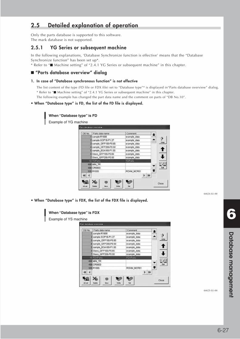
6-27
6 D
ata
ba
se m
ana
ge
me
nt
2.5 Detailed explanation of operationOnlythepartsdatabaseissupportedtothissoftware.Themarkdatabaseisnotsupported.
2.5.1 YG Series or subsequent machineInthefollowingexplanations,‘DatabaseSynchronizefunctioniseffective’meansthatthe“DatabaseSynchronizefunction”hasbeensetup*.*Referto“■Machinesetting”of“2.4.1YGSeriesorsubsequentmachine”inthischapter.
■ “Parts database overview” dialog
1. In case of “Database synchronous function” is not effective
Thelistcontentofthetype(FDfileorFDXfile)setto“Databasetype”*isdisplayedin“Partsdatabaseoverview”dialog.
*Referto“■Machinesetting”of“2.4.1YGSeriesorsubsequentmachine”inthischapter.
Thefollowingexamplehaschangedthepartdatanameandthecommentonpartsof“DBNo.10”.
• When “Database type” is FD, the list of the FD file is displayed.
When “Database type” is FD
Example of YG machine
64624-S1-00
• When “Database type” is FDX, the list of the FDX file is displayed.
When “Database type” is FDX
Example of YS machine
64625-S1-00

6-28
6 D
ata
ba
se m
ana
ge
me
nt
2. In case of “Database synchronous function” is effective
ThelistcontentofthedatabaseFDfileisdisplayedin“Partsdatabaseoverview”dialog.
OnlythedatathatexistsinthedatabaseFDfilebecomestheobjectofthedatabaseoperationin“DatabaseSynchronize
mode”.
ThedatathatexistsonlyinthedatabaseFDXfileisnotdisplayed.
WhenthecontentofthedatabaseFDfileandthedatabaseFDXfileistheexplanation1,thecontentoftheFDfileis
displayedasfollows.
In case of “Database synchronous function” is effective
64626-S1-00
■ [New], [Write] (Copy back to database)
1. In case of “Database synchronous function” is effective
BoththeFDfileandtheFDXfilecontentcanbeupdated,andbothfilessynchronize.
2. In case except above-mentioned
Onlythefile(FDfileorFDXfile)setto“Databasetype”*isupdated.
*Referto“■Machinesetting”of“2.4.1YGSeriesorsubsequentmachine”inthischapter.
■ [Set], [All set] (Read parts database)
1. In case of “Database synchronous function” is effective.
AfterthecontentofthedatabaseFDXfileisread,thecontentofthedatabaseFDfileisread.Thecontentofthedatabase
FDfileissetabouttheoverlappingparameter.AsfortheparameterpartthatexistsonlyinthedatabaseFDXfile,the
contentofthedatabaseFDXfileisset.ThecontentofthedatabaseFDfileissetforthedatathatexistsonlyinthe
databaseFDfile.
2. In case except above-mentioned
Thecontentofthefile(FDfileorFDXfile)setto“Databasetype”*isset.
*Referto“■Machinesetting”of“2.4.1YGSeriesorsubsequentmachine”inthischapter.
■ [Delete] (Delete parts database)
1. In case of “Database synchronous function” is effective
DataisdeletedfromthedatabaseFDfileandthedatabaseFDXfile.
2. In case except above-mentioned
Dataisdeletedfromthefileofthetypesetto“Databasetype”*.
*Referto“■Machinesetting”of“2.4.1YGSeriesorsubsequentmachine”inthischapter.
Reference This feature is available on the YG12, YG12F, YG300, YS series only.

6-29
6 D
ata
ba
se m
ana
ge
me
nt
■ “Database Utility” dialog
Thedatabasefolderpathcanbeset.Thedatabasecanbesaved,andberestored.Moreover,thecontentof“Databasetype”and“DatabaseSynchronizemode”*setcanbeconfirmed.*Referto“■Machinesetting”of“2.4.1YGSeriesorsubsequentmachine”inthischapter.
“Database Utility” dialog [YG Series or subsequent machine]
Example of YG machine
In case of “Database type” is “FDX/MDX” and “Database Synchronize mode” is“Synchronize by machine”, parts database synchronization becomes effective.The content of “Database type” of “Machine setting” is displayed. Setting of“Database type” is done at the “machine setting”.
The content of “Database Synchronize mode” of “Machine setting” is displayed.
The database path of file is set to “Database path” of “Database utility” dialog.When “Database Synchronize mode” is used, “Database path” of all the targetmachines for the same database operation have to be set to the same path.
64627-S1-10
■ [Backup], [Restore] (Backup and Restore parts database)
1. In case of “Database synchronous function” is effective
TheFDfileandtheFDXfilesarebackedup.
2. In case of “Database type”* is “FD/MD” and “Database synchronize mode”* is effective (Only for YG200 and YG200L)
[Backup]and[Restore]buttonsofthepartsdatabasewerenullified.
Sodatabasecannotbesavedandberestored.
Thisisbecausethereisapossibilityofcausingtheobstaclein“DatabaseSynchronizemode”whenonlytheFDfileis
restored.
[BackUp]and[Restore]shouldbeconductedwiththeYGSeriesorsubsequentmachinewithFDXoperationorY.FacT.
*Referto“■Machinesetting”of“2.4.1YGSeriesorsubsequentmachine”inthischapter.
3. In case except above-mentioned
Onlythefileofthetypesetto“Databasetype”*(FDfileorFDXfile)isbackedup.
Itisnotpossibletorestoreitexcludingtheonethatthebackupwastakenby“DatabaseSynchronizemode”(onethattheFDfileandtheFDXfilewerebackedup).*Referto“■Machinesetting”of“2.4.1YGSeriesorsubsequentmachine”inthischapter.

6-30
6 D
ata
ba
se m
ana
ge
me
nt
2.5.2 Xg Series
■ “Parts database overview” dialog
ThelistcontentoftheFDfileisdisplayedin“Partsdatabaseoverview”dialog.
“Parts database overview” dialog
64628-S1-10
■ [New], [Write] (Copy back to database)
When[New](Newregistration)or[Write](Copybacktodatabase)isexecuted,onlythedatabaseFDfileisupdated.
■ [Set], [All set] (Read parts data base)
When[Set]or[Allset]isexecuted,thecontentoftheFDfileisset.

6-31
6 D
ata
ba
se m
ana
ge
me
nt
■ “Database utility” dialog
Thedatabasefolderpathcanbeset.Thedatabasecanbesaved,andberestored.Moreover,thecontentof“DatabaseSynchronizemode”*setcanbeconfirmed.*Referto“■Machinesetting”of“2.4.2XgSeries”inthischapter.
“Database utility” dialog
The content of “Database Synchronize mode” of “Machine setting” is displayed.Setting of “Database type” is done at the “machine setting”.
The database path of file is set to “Database path” of “Database utility” dialog.When “Database Synchronize mode” is used, “Database path” of all the targetmachines for the same database operation have to be set to the same path.
64629-S1-10
■ [Backup], [Restore] (Backup and Restore parts database)
Incaseof“DatabaseSynchronizemode”*iseffective[Backup]and[Restore]buttonsofthepartsdatabasewerenullified.
Sodatabasecannotbesavedandberestored.
Thisisbecausethereisapossibilityofcausingtheobstaclein“DatabaseSynchronizemode”whenonlytheFDfileis
restored.
[BackUp]and[Restore]shouldbeconductedwiththeYGSeriesorsubsequentmachinewithFDXoperationorY.FacT.
n NOTE When “Database Synchronize mode” is used, the software of the Xg machine is also strongly recommended to improve to the supported version.

6-32
6 D
ata
ba
se m
ana
ge
me
nt
2.5.3 Y.FacTWhen“Databasesynchronousfunction”iseffectiveinthefollowingexplanations,itmeansinthefollowingcases.(*Referto“2.4.3Y.FacT”inthischapter.)
■ “Part database overview” dialog
“Part database overview” dialog
64630-S1-10
1.1In case of “Database synchronous function” is effective
ThelistcontentoftheFDfileisdisplayedin“Partsdatabaseoverview”dialog.
OnlythedatathatexistsintheFDfilebecomestheobjectofthedatabaseoperationin“DatabaseSynchro”.
ThedatathatexistsonlyintheFDXfileisnotdisplayed.
2. In case except above-mentioned
Thelistcontentofthetype(FDfileorFDXfile)setto“UseDatabase”isdisplayedin“Partsdatabaseoverview”dialog.
■ [Copy Back to Database], [Copy Back to Database All], [Database Matching] (Database Write from Board)
[CopyBacktoDatabase],[CopyBacktoDatabaseAll]and[DatabaseMatching](DatabaseWritefromBoard)operations
areasfollowsbythesettingof“Databasesynchronousfunction“.
1. In case of “Database synchronous function” is effective
TheFDfileandtheFDXfilebecomeobjectsofthebackup.
2. In case except above-mentioned
Onlythefile(FDfileorFDXfile)setto“UseDatabase”isupdated.
■ [Set from Database], [Set from Database All] and [Database Matching] (Database Set to Board)
[SetfromDatabase],[SetfromDatabaseAll]and[DatabaseMatching](DatabaseSettoBoard)operationsareasfollows
bythesettingof“Databasesynchronousfunction“.
1. In case of “Database synchronous function” is effective
AfterthecontentoftheFDXfileisread,thecontentoftheFDfileisread.
ThecontentoftheFDfileissetabouttheoverlappingparameterpart.Asfortheparameterpartthatexistsonlyinthe
FDXfile,thecontentoftheFDXfileisset.
ThecontentoftheFDfileissetforthedatathatexistsonlyintheFDfile.
2. In case except above-mentioned
Thecontentofthefile(FDfileorFDXfile)setto“UseDatabase”isset.

6-33
6 D
ata
ba
se m
ana
ge
me
nt
■ [Delete] (Delete parts database)[Delete](Deletepartsdatabase)operationsareasfollowsbythesettingof“Databasesynchronousfunction”.
1. In case of “Database synchronous function” is effective
DataisdeletedfromtheFDfileandtheFDXfile.
2. In case except above-mentioned
Dataisdeletedfromthefileofthetypesetto“UseDatabase”(FDfileorFDXfile).
■ [Back Up], [Restore] (Backup and Restore parts database)
Execute[Backup]and[Restore]ofdatabasefromthe“OptionSetting”ofY.FacT.
“Back Up”, “Restore”
Backup” and “Restore” is executed with this button.
64631-S1-10
1. In case of “Database synchronous function” is effective
TheFDfileandtheFDXfilebecomeobjectsofthebackup.
2. In case except above-mentioned
Onlythefileofthetypesetto“UseDatabase”(FDfileorFDXfile)issaved.
c CAUTION It is not possible to restore it excluding the one that the backup was taken by “Database Synchronize mode” (one that the FD file and the FDX file were backed up)

6-34
6 D
ata
ba
se m
ana
ge
me
nt
2.6 LimitationsPleasebeginoperatingfromthesituationinwhichthedatabaseFDsynchronizeswiththedatabaseFDX.ForDetails,referto“2.3Preparationofdatabase”inthischapter.
2.6.1 Limitations when beginning to operate
• About the data of a different database number in FD and FDX
PleasedonotusethedataofadifferentdatabasenumberinFDandFDX.
Itbecomesthefollowingactionswhenusingit.
[BehaviorofYGSeriesorsubsequentmachine(FDXoperation)]
· ThedatathatexistsonlyinFDXisnotread.
· hedatathatexistsonlyinFDoperatesonlybybasicinformationofFD.
• About difference between FD and FDX (The data difference between machines)
WhenthedatathatexistsalsoinFDandFDXisread,thedataofFDissettothebasicparameterandthedataofFDXis
settotheextendedparameterinthemachinethatuses“DatabaseSynchronizemode”.Therefore,whendifferentdatais
registeredinthesamedatabasenumberwithFDandFDX,thestatethattheextendedparametercontradictsthebasic
parameterisgenerated.
2.6.2 Other limitations
• Target database
Thetargetdatabaseofthisfunctionispartsdatabase.
Themarkdatabaseisnotsupportedfor“DatabaseSynchronizemode”.
• Limitation of soft version
Usesoftwaresupporting“DatabaseSynchronizemode”foralltheYGSeriesorsubsequentmachines,Xgmachines,and
Y.FacT.
ContradictionmightbecausedinthedatabaseFDandthedatabaseFDXifthereisamachinethatdoesn'tsetthis
function.
• Limitation of parts database Backup and parts database Restore
TheBackupandRestoreofpartsdatabasebecomesinvalidatthefollowingoperation.“Backup”and“Restore”of
databaseshouldbeconductedwiththeYGSeriesorsubsequentmachinewithFDXoperationorY.FacTinthefollowing
setting.
· Incaseof“DatabaseSynchronizemode”is“Synchronizebymachine”attheXgmachine.
· Incaseof“Databasetype”is“FD/MD”and“DatabaseSynchronizemode”is“Synchronizebymachine”atYG200andYG200L.
• Limitation of parts database Restore
DatabasecanberestoredonlyiftherearebothFDandFDXfilesinrestorationsourcewhenYGSeriesorsubsequent
machine(FDXoperation)uses“DatabaseSynchronizemode”.
ThebackupfilewhereonlyFDorFDXissavedcannotberestored.

6-35
6 D
ata
ba
se m
ana
ge
me
nt
3. Unified database management support checklist3.1 IntroductionThisdescribestheimplementationchecklistfor“Unifieddatabasemanagement”and“DatabaseSynchronizemode”.Thisprocedureisdesignedtohelppreventsettingmistakesandomissions,andtofacilitatesetup.Moreover,printingtheintroductionsupportchecklistenablesasmoothimplementationofthestepsasyouproceed.Refertochapter“1.UnifiedDatabaseManagementfunction”andchapter“2.DatabaseSynchronizemodefunction”fordetailsontheUnifiedDatabaseManagementandtheDatabaseSynchronizemode.

6-36
6 D
ata
ba
se m
ana
ge
me
nt
3.2 Unified database management support checklist
3.2.1 Database backupPleasebackupalldatabasesusednow.
Database backup Check
Was the backup of all existing databases completed?
3.2.2 The path for Unified database managementThepathofunifieddatabasemanagementisdecided,anditfillsitinonthefollowing.Thepathofthesideonwhichthedatabasebereferredtoisenteredinalocalpath,thepathofthesidewhichreferstothedatabaseisenteredinanetworkpath.
Determination of unitary management path Check
local path
network path
3.2.3 Database preparationItisnecessarythatthedatabasefor“Unifieddatabasemanagement”isprepared.Thisisaveryimportantthingfor“Unifieddatabasemanagement”.Pleaseprepareitsurely.
Preparation of “Unified database management” Check
Was the database preparation for “Unified database management” completed?
Reference: Chapter “1. Unified database management function”, “1.5 Database collection”
3.2.4 Necessity judgment of “Database Synchronize mode function”Itcheckswhether“DatabaseSynchronizemodefunction”isnecessaryatthetimeof“Unifieddatabasemanagement”.
Necessity judgment of “Database Synchronize mode function” Check
Necessary Unnecessary
Itjudgeswhether“DatabaseSynchronizemodefunction”necessaryreferringtothetablebelow.Aroundsignisfilledinnecessaryorunnecessarily.
Machine series combination Database Synchronize mode function
Only Xg series Unnecessary
Only YG Series and subsequent machines Unnecessary
Xg Series and YG Series or subsequent machines exist together
Necessary
* The YG200/YG200L can be used as either “Xg Series” or “YG Series or subsequent machine”.
Referto“3.2.5DatabaseSynchronizemodefunctionisnecessary”whenDatabaseSynchronizemodefunctionisnecessary.Referto“3.2.6DatabaseSynchronizemodefunctionisunnecessary”whenDatabaseSynchronizemodefunctionisunnecessary.

6-37
6 D
ata
ba
se m
ana
ge
me
nt
3.2.5 Database Synchronize mode function is necessary
When judged as necessary in “3.2.4 Necessity judgment of Database Synchronize mode function”Hereisanexplanationoftheprocedurewhenitisnecessarytouse“DatabaseSynchronizemodefunction”.Touse“DatabaseSynchronizemodefunction”,aversionofsoftwarehastobeitafteracertainversion.ItupgradesafteracheckoftheversionofthepresentconditionofY.FacTandmachinesoftifneeded.ThesoftversionoftheY.FacTofallunifieddatabasemanagementobjectsisfilledin,andconfirmversionupnecessityornot.
Y.FacT
Version Version up
necessary·unnecessary / Completion
necessary·unnecessary / Completion
necessary·unnecessary / Completion
necessary·unnecessary / Completion
necessary·unnecessary / Completion
Thesoftversionofthemachineofallunifieddatabasemanagementobjectsisfilledin,andconfirmversionupnecessityornot.
Xg series machine : Under V1.20R0.050 needs to be upgraded.
YG series machine : Under V2.41R0.220 needs to be upgraded.
YS Series machine: Compatible in all versions.
Model name Version Version up
necessary·unnecessary / Completion
necessary·unnecessary / Completion
necessary·unnecessary / Completion
necessary·unnecessary / Completion
necessary·unnecessary / Completion
necessary·unnecessary / Completion
necessary·unnecessary / Completion
necessary·unnecessary / Completion
necessary·unnecessary / Completion
necessary·unnecessary / Completion
necessary·unnecessary / Completion

6-38
6 D
ata
ba
se m
ana
ge
me
nt
Thedatabasefor“DatabaseSynchronizemodefunction”isprepared.Thisisaveryimportantthingfor“DatabaseSynchronizemodefunction”.Pleaseprepareitsurely.
Preparation of “Database Synchronize mode function” Check
Was the database preparation for “Database Synchronize mode function” completed?
Reference: Chapter “2. “Database Synchronize mode” function”, “2.3 Preparation of database”
A machine is set up.
Machine setting Check
Is “3.2.2 The path for Unified database management” set for the database path?
Was “Database Synchronize mode function” setup confirmed?
Did it set up to all unified database management objects machines?
Reference: Chapter “2. “Database Synchronize mode” function”, “2.4 Setting”
Y.FacT is set up.
Setting of Y.FacT Check
Is “3.2.2 The path for Unified database management” set for the database folder?
Was “Database Synchronize mode function” setup confirmed?
Reference: Chapter “2. “Database Synchronize mode” function”, “2.4 Setting”
YRS is set up. (When it has YRS.)
Setting of YRS. Check
Was “Database Synchronize mode function” setup confirmed?
Reference: Chapter “2. “Database Synchronize mode” function”, “2.4 Setting”

6-39
6 D
ata
ba
se m
ana
ge
me
nt
3.2.6 Database Synchronize mode function is unnecessary
When judged as unnecessary in “3.2.4 Necessity judgment of Database Synchronize mode function”Hereisanexplanationoftheprocedurewhen“DatabaseSynchronizemodefunction”neednotbeeffectivelydone.Refertochapter“1.UnifiedDatabaseManagement”,“1.4.Setting”fordetailsofsetting.
The machine is set.
Setting of machine Check
Is “3.2.2 The path for Unified database management” set for the database path?
Y.FacT is set up.
Setting of Y.FacT Check
Is “3.2.2 The path for Unified database management” set for the database folder?
Is the use of the database correctly set?

6-40
6 D
ata
ba
se m
ana
ge
me
nt
4. Series Database4.1 Outline of functionsThissectiondescribesthefollowingfunctions.
4.2 Detailed explanation of operationItcomestobeabletotreattwoDatabasesormoreatthesametime.Ex)ForYGSeriesMachine,ForXGSeriesMachine
ThefollowingoperationsareexecutedusingspecifiedDatabaseforeachseries.
• SetfromDatabase
•CopyBacktoDatabase
•DatabaseMatching
•DatabaseMatchingfromboard
Y.Fact
Details of operation
Database for Xg
Database for YG
Xg Line
YG Line
63629-S1-00

6-41
6 D
ata
ba
se m
ana
ge
me
nt
4.3 Settings
4.3.1 Setting methodToenablethisfeature,openthe“Database”–“Databasebymodel”tab,andchangethefollowingsettings.
Series Database Setting
1
3
4
2
64632-S1-10
1 “Use” / “Not Use” drop-down list box
Byselecting“Use”fromthisdrop-downlistbox,theDatabasebymodelfunctionbecomeseffective.
2 “Database Name” Edit Box
EntertheDatabasereferenceName.
Pleaseinputaunique,simplenameidentifyingthecorrespondingmachine.
Whenthenamehasbeeninput,the“Folder”and“Datatype”itemsbecomeeditable.
However,when“FDX/MDX(alsosaveasFD/MD)”isselectedfor“Databaseuse”,“Datatype”cannotbeset.
Thereferenceddatabasefiledoesnotchangeevenifthedatabasenameischanged.
3 “Folder” Edit Box
ItisthefolderwheretheDatabasefileisstored.
Pleaseclick[Browse]button,ifyouwanttobrowse.
4 “Data type” drop-down list box
ItisadatatypeoftheDatabase.
Pleaseselectfrom[FDX]/[FDX(withsavingFD)]/[FD].
Attention:
Forthe“COMMONDatabase”settingintheupperpartofthescreenthesettingpriortoselecting“Use”for“Databaseby
model”willremaineffective.
Notethatformachines,forwhich“Databaseallocationtoeachmachine”isnotperformedasdescribedinthefollowing
section,thisCOMMONDatabasewillbereferredto.

6-42
6 D
ata
ba
se m
ana
ge
me
nt
4.3.2 Database allocation to each machineIntheSeriesDatabasefunction,itisnecessarytodecidewhichDatabaseofeachmachinetouse.Itexplainsthemethodasfollows.
Byright-clickingontheselectedmachineintheBoardExplorertreeviewacontextmenucanbedisplayed.Pleaseselect“ReferencedDatabase”fromthismenu.ThelistoftheDatabaseisdisplayedinthemenu.PleaseselecttheDatabaseallocatedtothemachine.
Database Allocation to each machine
64633-S1-00
Fromthisdatabaselistselectthedatabasetobeassignedtothemachine.Inaddition,whenyouregisteranewmachineusingtheBoardExplorer,youshouldallocatetheDatabase.Evenduringmachinere-registrationtheDatabasecanbechangedifrequired.
c CAUTION Use the COMMON Database setting in the Option Setting screen for the machine to which Database is not allocated.

6-43
6 D
ata
ba
se m
ana
ge
me
nt
4.4 Limitations
•WhenyouedittheDatabasebytheDatabaseEditor,youmustediteachdatabase.Becauseitdoesn'tsynchronizebetweenDatabasesdividedbytheseries.Don'tworry.YoucancopyandpasteadatabetweentwoormoreDatabaseEditors.Butbecareful!ApartofdataisnotpreservedwhendataiscopiedfromtheDatabaseoftheFDXtype,anditpreservestotheDatabaseoftheFDtype.
• Ifthe“PerformSetfromDATABASEautomaticallyafterBoarddataisread.”wascheckedintheOptionSetting,itisexecutedusingspecifiedDatabaseforeachmachine.
• If“Databaseallocationtoeachmachine”(refertoSection4.3.2)isnotsetupforamachine,thestandarddatabase(COMMONDatabase)willbeused.
•WhenthesameDatabaseischangedbytwoormoreapplications,thedatapreservedattheendbecomeseffective.Toavoidconfusing,pleasedonotstartatthesametime.
• IfthesettingoftheDatabasewaswrong,theerrorisdisplayedwhenyouoperatetheDatabase.Pleasecorrectthesettingaccordingtothemessage.

6-44
6 D
ata
ba
se m
ana
ge
me
nt
5. Shape Database5.1 Outline of function
■ Regarding the shape database
Theshapedatabaseallowsseparatemanagementoftablesforboarddatapartnamesanddatabasepartnameswhicharerelatedviaaparts/shapeslist.Therefore,acommondatabasecanbemanaged,andevenifthenumberofboarddatapartsnamesisincreased,theadministrativevolumeofthedatabasecanbedecreased.
The role of the parts/shapes list
Parts/Shapes listBoard data Database dataBoard data Database data
Parts
Parts Parts
Parts
Parts
Parts
Parts
Parts
63650-S1-00
■ About this feature
Withthisfeature,asawildcardsearchforpartnamesintheparts/shapeslistispossible,bymanagingthedatabaseaccordingtoshapedistinction,lessentriesintheparts/shapestablearenecessaryandmorepartscanbemanaged.Partnamesfoundbytheconventionalexactmatchsearchtakepriorityoverwildcardsforassignment.
Summary of this feature
Parts/Shapes listBoard data Database dataBoard data Database data
Parts
Parts Parts
Parts
Parts Parts
Exact match search
1) Exact match search, 2) Wild card search
63651-S1-00

6-45
6 D
ata
ba
se m
ana
ge
me
nt
5.2 To use Shape DatabaseThesettingmethodtousethisfunctionisontheOptionSettingdialog.Open[ShapeDatabase]tabfrom[Database]tab,andchangethefollowingsettings.
Option Setting - use Shape Database
3
4
1
2
64634-S1-10
1.ItcanbeselectedwhetheruseornotuseShapeDatabase.Pleaseselect“Use”.
2.Pleasespecifyfilepathof“Parts/ShapeList”.
3.Whenthesettingof“PerformSetfromDATABASEautomaticallyafterBoarddataisread.”iseffective,“BasedonDatabasenumber.”or“ReferringPartsShapeList.”canbechosen.
4.IntheShapeDatabase,thesettingofthis“DatabaseMatchingcondition”isalsoeffective.Itcanbeselectedwhethertomatchthenameorthecommentasakeybypartsanddatabases.

6-46
6 D
ata
ba
se m
ana
ge
me
nt
5.3 Details of functionThisfeatureoffersaconventionalexactmatchsearchandawildcardsearchforthe“SearchShapeNamefromCorrespondenceList”function.
Exact match search
Exact Match Search and Wild Card Search
Parts/Shape ListShape DB setting/Reverse setting
Finding a shape name from the correspondence list
Summary of data base management according to shape
Database data
Board data
Parts Name
Parts Name
Parts Name Database No.
Shape Name Database No.
61652-S1-00
FortheBoardEditoroption“SetShapeDatabaseInformation”thefollowingoperationisperformed.
1 Select “Database Support (B)” – “Set Shape Database Information (H)” from the “Tools (T)” menu.
2 A part name matching the part name of the selected “Board Data” exactly is searched for in the “Parts/Shape List”. If one is found, proceed to Step 3.If no exact match is found, carry out a wild card search *2, *3 using the wild card on the part defined in the “Parts/Shape List” *1.
3 If found in Step 2, the DB data corresponding to the part name after the 1001st in the database and the shape name in the “Parts/Shape List” is located.
4 These contents overwrite the parts data.
Parts/Shape ListShape DB setting/Reverse setting
1. Select “Database Support (B)” – “Set Shape Database Information (H)” from the “Tools (T)” menu.
4. Set the contents.
3. Find an exact match (after the 1001st).
2. Search for the parts name in the parts/shape list using the board data part name. 1) Exact match search 2) Wild card search
Example for “Set Shape Database Information”
Database data
Board data
Parts Name
Parts Name
Parts Name Database No.
Shape Name Database No.
61653-S1-00

6-47
6 D
ata
ba
se m
ana
ge
me
nt
*1. Where wild card setting is possible
Itislimitedto“PartNames”inthe“Parts/ShapeList”.Itisnotpossibletouseawildcardforapartnameinthe“BoardData”tofindapartnameinthecorrespondencelist.
*2. Symbols used for wild cards
Thesymbols“?”and“*”canbeusedforwildcardsearch.“?”standsforanyonecharacter,while“*”denominatesacharacterstring(includingspaces)ofanylength.Asthesearchforanexactmatchtakespriorityoverthewildcardsearch,theymaybeinterpretedasnormalletters.
*3. Wild card priority
Thewildcardsearchresultsmayincludemultipleparts.Inthiscase,ontheshapecorrespondenceeditingscreen(“BoardExplorer”-“ASCIIDataConversion”-“EditShapeCorrespondence”)partsareassignedbypriorityfromtop(theycanbesortedaccordingtocorrespondencebypressingtheSavebuttononce).
Wild card search priority sequence
Match or search by wild card search in order from top
64670-S1-10

6-48
6 D
ata
ba
se m
ana
ge
me
nt
5.3.1 Database Matching by Shape Name / Database Matching from Board by Shape NameSimilarlyinthematching,partdataintheboarddataandpartdatainthedatabasearerelatedthroughthe“Parts/ShapeList”.In“DatabaseMatchingbyShapeName”and“DatabaseMatchingfromBoardbyShapeName”,thereisnofunctiontoregisterthedatathatdoesn'texistinthedatabasethatexistsinausualDatabaseMatching.Therefore,itmovesfunctionallyascancalled“SetfromDatabaseAllbyShapeName”or“CopyBacktoDatabaseAllbyShapeName”.
5.3.2 Set from DATABASE automatically after Board data is read – Referring Parts Shape ListItisafunctiontoperform"FullShapeDatabasesetting"toallpartsoftheboardautomaticallywhenBoarddataisreadfromtheBoardEditor,enabledbyasetting.Withthisfunction,themarkdataisnotset.Moreover,asimilarfunctioncanbeusedintheFeederViewer.
5.3.3 Making of “Parts / Shape List”IntheShapeDatabase,“Parts/ShapeList”isoperatedasanindex.BecausethisfileisafilethatdidnotexistbeforetheintroductionoftheShapeDatabase,itisnecessarytoregisterPartName/ShapeNamedatanewly.
Whenthisfunctionwasadded,“TransitionToolofPartsDatabase”thatmade“Parts/ShapeList”fromthedatabasethathadbeenusedsofarwaspreparedtotransittoShapeDatabasesmoothly.Moreover,Registrationfunctionof“Parts/ShapeList”usefultomaintain“Tableforparts/shape”madeonceisadded.

6-49
6 D
ata
ba
se m
ana
ge
me
nt
5.4 Transition Tool of Shape DatabaseItexplainsthemethodofmakingthe“Parts/ShapeList”withaTransitionToolofPartsDatabase.
5.4.1 Outline of function“Parts/ShapeList”ismadefromboarddataandthedatabase
Outline of operation
Database selection
Board DataDatabase
Board DataDatabase
Board DataDatabase
Data Check
Parts nameselection
Shape nameselection
Parts nameselection
Shape nameselection
Data Check Data Check
Parts nameselection
Shape nameselection
Parts / Shape List
63632-S1-00

6-50
6 D
ata
ba
se m
ana
ge
me
nt
5.4.2 To use this functionPleasesetthe“ShapeDatabase”inthe“Database”tabofthe“OptionSetting”to“Use”.
“Use” Shape Database
64635-S1-10
Whenthe[Yes]buttoninthedisplayed“TransitionToolofPartsDatabasestartconfirmation”dialogispushed“TransitionToolofPartsDatabase”starts.
Start confirmation dialog
64636-S1-00
Whenthefilepathof“Parts/ShapeList”isnotset,itneedstobesetfirst.Pushthe[No]buttoninthe“TransitionToolofPartsDatabasestartconfirmation”dialog,andspecifythe“Parts/ShapeList”filepathinthe“OptionSetting”dialog.Then,pressthe[OK]buttoninthe“OptionSetting”dialogtoclosethedialogandre-starttheapplication.Openthe“OptionSetting”dialogagainandsettheShapeDatabaseto“Use”.

6-51
6 D
ata
ba
se m
ana
ge
me
nt
5.4.3 Flow of processing and composition of each dialog
■ Transition Tool of Parts Database
Transition Tool of Parts Database
64637-S1-10
Input data
nstallation Folder Installation folder of Y.FacT or machine
Parts Database file name File of database of Installation Folder
Whentheabove-mentionedtwopointsaresetandthedownwardarrowbuttonispushed,thecombinationofspecified“Installationfolder”and“Partsdatabasefilename”isregisteredin“Theconversiondatalist”.
Initialregistrationoftheconversiondatalistisdoneonthefollowingcondition.
Use kind of COMMON Database Registered database file name
FDX/MDX database.fdx
FDX/MDX(with saving FD/MD) database.fdx & database.fd
FD/MD database.fd
If setting of the Series Database in Option Setting is “Use”, additional registration is done.
Use kind of Series Database Registered database file name
FDX database.fdx
FDX(with saving FD) database.fdx & database.fd
FD database.fd
Todeletetheregisteredconversiondata,pleaseselectthelineofthedatathatwantstodelete,andpushthe[Delete]button.Whenthe[Execution]buttonispushed,partdataisreadfromtheboarddataandthe“Parts/ShapeList”makingprocessingisdone.Whentwoormorethisnamedataexistsinthedatabase,“ChangePartsname”dialogisdisplayed.

6-52
6 D
ata
ba
se m
ana
ge
me
nt
Theendconfirmationdialogisdisplayedwhenthecheckonthedataoftheregisteredalldatabasesends,andthe“Shape/PartsList”ismade.
End confirm dialog
64638-S1-00
■ “Change Parts name” dialog“
The“ChangePartsname”dialogisdisplayedwhentwoormoredataofthisnameexists1001stormoreofthedatabases.Thedatanameischangedonthisdialog.
“Change Parts name” dialog
64639-S1-10
Display composition
Parts Database file namePart database file name where two or more data of this name exists
Database name
Name of database that name overlaps (When the matching key on the database side is “Comment”, database comment is used instead of database name)
Number of found database with same name
List of database number of data of the same name (When the matching key on the database side is “Comment”, This list becomes a list of the database number of the same database comment.)

6-53
6 D
ata
ba
se m
ana
ge
me
nt
Toassumethedatanametobeunique,pleasedeletedataforthedatabasenumberdisplayedinthelistorchangethedataname.(The1000thdatabasenumbersorlessarenotcaredevenifthepluralexists.)ThechangeinthedatabaseisnotpreserveduntilthechangeisfixedaboutthecontentchangedonthisdialogbyDatabasechangeconfirmationdialogdescribedlater.
• To delete data
Selectthedatabasenumbertobedeletedfromthelist,andpushthe[Delete]button.
• To change the data name
Selectthedatabasenumbertobechangedthenamefromthelist,inputthedatabasenameafteritchangesto“Changed
Databasename”textbox,andpushthe[Change]button.
ItispossibletocorrectitfromthePartsDatabaseEditorstartingbypushing[DBEditorReference]button.
Whenthedatabasenumberbecomesunique,push[Confirm]button.Thisprocessingisrepeateduntilthedatabasenumberofalldatathatthenameoverlapsbecomesunique.Thesmallestnumberisusedthe1001stormoreoftheretrieveddatabasenumberswhenthe[Confirm]buttonispushedwithoutuniquelydoing.Databasedataonothernumbersisnotused.Inthiscase,theconfirmationdialogisdisplayed.Ifitdoesn'tbecomeaproblem,pleasepush“Yes”.
Data that name overlaps in database
64640-S1-00
• Database change confirmation
Theconfirmationdialogwhethertopreservethechangeinthedatabaseisdisplayedwhenchangingby“ChangeParts
name”dialog.
Database change confirmation dialog
64641-S1-10
Pleasepush[Yes]whenyoupreservethecorrectedcontent.Thechangeisnotpreservedwhen[No]ispushed,and,inthatcase,the“Parts/ShapeList”ismade.

6-54
6 D
ata
ba
se m
ana
ge
me
nt
■ “Shape name selection” dialog
Whentwoormorepartsofthisnameexistinpartsdata,andthedatabasenumber(sincethe1001st)aswhichtheallarethesameisnotspecified,“Shapenameselection”dialogisdisplayed.
“Shape name selection” dialog
64642-S1-10
Parts name Name registered in “Parts / Shape List” as part name - When the part name is specified for a matching key = Part name of part data - When the part comment is specified for a matching key = Part comment of part data
Shape name [ Comment ] Shape name [ Comment ] Name registered in “Parts / Shape List” as shape name (, and [ comment ] ) - When the database name is specified for a matching key = Database Name [ Database Comment ] - When the database comment is specified for a matching key = Database Comment [ Database Name ] * If either the database name or the database comment differs, it is treated as another database
Original part data and database Part data, and Database information on database number that the part data specify
Pleaselocatethedatabaserelatedtothepartnameinthelist,andselecttheshapedatabasenamefromthe“Shapename[Comment]”drop-downlistbox.Afterwards,thecorrespondencedataofthepartnameandtheselectedshapenameisregisteredin“Parts/ShapeList”bypushing[Confirm]button.
• If the part name has already been registered in “Parts / Shape List”
The“Shapenameselection”dialogisdisplayedinthesamewayaswhenitisnotregistered,andtheshapenamethat
hasalreadybeenrelatedisdisplayedatthetopofthelist.(DBNo.markedby“*”)
Shape name selection (has already been registered in “Parts / Shape List”)
64643-S1-10
This“Shapenameselection”dialogisrepeatedlydisplayeduntilallthepartdataisrelatedtothedatabase.

6-55
6 D
ata
ba
se m
ana
ge
me
nt
5.5 Registration function of “Parts / Shape List”After“Parts/ShapeList”fileismadeby“TransitionToolofPartsDatabase”,thecorrespondencetablecanbemaintainedbytheusualdatabaseoperation.Itexplainsanecessaryoperationasfollowsforthat.
Itisalsopossiblethat“ShapeDatabase”operationbeginsbyusingonlythisregistrationfunctionwithoutusing“TransitionToolofPartsDatabase”.
5.5.1 Outline of functionItisafunctiontoadd/editthecorrespondencedatatothe“Part/ShapeList”.WhenthedatabaseisoperatedfromtheBoardEditor,itisexecutedbytheautomaticoperation.Itisusefultomaintainitinadditionafterthe“Part/ShapeList”ismadewiththe“TransitionToolofPartsDatabase”.
5.5.2 To use this functionItisnecessarytochangetothesettingthatusestheShapeDatabasebeforehandtousethisfunction.
“Option Setting” dialog
“Shape Database” is set to “Use”
64644-S1-10
5.5.3 Outline of operationWhenyouoperatethefollowingdatabasetreatment,ifthepartname/shapenamedatathathasbeentreatednowdoesn'texistinthe“Parts/ShapeList”,registrationfunctionof“Parts/ShapeList”starts.
· SetfromDatabase
· CopyBacktoDatabase
· SetfromDatabaseAll
· CopyBacktoDatabaseAll
· DatabaseMatching
· DatabaseMatchingfromBoard
· SetfromDatabasebyShapeName
· CopyBacktoDatabasebyShapeName
· DatabaseMatchingbyShapeName
· DatabaseMatchingfromBoardbyShapeName

6-56
6 D
ata
ba
se m
ana
ge
me
nt
■ Set from Database / Copy Back to Database
Ifthecombinationofthepartnameandthedatabasename(ItwasretrievedfromtheDatabasenumber)doesn'texistinthe“Parts/ShapeList”,theregistrationfunctionisexecuted.Whenanewrecordisaddedtothedatabaseby“CopyBacktoDatabase”,itissimilar.
Thecorrespondencedataismadebasedonthefollowingvalues.
Part Name Part name of part data selecting it now
Shape Name Database name that is retrieved from the database number of part data selecting it now*) When a new database is made by “Copy Back to Database”, the name of the database (in a word, names of former parts) corresponds to the shape name.
Comment It is possible to input it freely
Ifthedatabasethatcorrespondstodatabasenumberofpartsundertheselectiondoesn'texist,theregistrationfunctionisnotexecuted.Moreover,whenlessthan1001stofdatabasenumberisallocated,itissimilar.ThepurposeofthisisdonottohavetorelateitfromittothepreviousdatabasebecausetheShapeDatabasetargetsafterthe1001stofthedatabases.
“Shape name registration” dialog
New registration
64645-S1-00
· If shape name cannot be specified
Whenthepartdataofadifferentdatabasenumberinthesamenameexists,thedatabase(shapename)relatedtothepart
namecannotbespecified.
Theproblemisnotintheexecutionof“SetfromDatabase”/“CopyBacktoDatabase”whensinglepartdatahasbeen
selected.
However,whentwoormorepartdatahasbeenselected,suchasituationmightbehappened.
Inthiscase,theoneneartheheadofthecorrespondingpartdataisgiventopriority.

6-57
6 D
ata
ba
se m
ana
ge
me
nt
■ Set from Database All / Copy Back to Database All
Ifthecombinationisfoundthatofthepartnameandthedatabasename(Itwasretrievedfromthedatabasenumberinthepartdata)doesn'texistinthe“Parts/ShapeList”,theregistrationfunctionisexecuted.Whenanewrecordisaddedtothedatabaseby“CopyBacktoDatabaseAll”,itissimilar.
Thecorrespondencedataismadebasedonthefollowingvalues.
Part Name Part name of part data
Shape Name Database name that is retrieved from the database number of part data*) When a new database is made by “Copy Back to Database All”, the name of the database (in a word, names of former parts) corresponds to the shape name.
Comment It is possible to input it freely.
Thiscombinationofallthepartdataintheboarddataisdisplayedasalist.
Whenthedatabasethatcorrespondstodatabasenumberofthepartdoesn'texist,theregistrationfunctionisnotexecuted.Moreover,whenlessthan1001stofdatabasenumberisallocated,itissimilar.ThepurposeofthisisdonottohavetorelateitfromittothepreviousdatabasebecausetheShapeDatabasetargetsafterthe1001stofthedatabases.Excludingsuchparts,whenthecombinationofthepartdataandthedatabasethatshouldberegisteredexistsevenbyone,theyaredisplayedasalist,andwhetheritregistersisasked.
“Shape name registration” dialog
Registration of two or more data
64646-S1-00
· If shape name cannot be specified
Whenthepartdataofadifferentdatabasenumberinthesamenameexists,thedatabase(shapename)relatedtothepart
namecannotbespecified.
Inthiscase,theoneneartheheadofthecorrespondingpartdataisgiventopriority.

6-58
6 D
ata
ba
se m
ana
ge
me
nt
■ Database Matching / Database Matching from Board
Ifthecombinationisfoundthatofthepartnameandthedatabasename(Itwasretrievedfromthepartname)doesn'texistinthe“Parts/ShapeList”,theregistrationfunctionisexecuted.Whenthecorrespondingpartnameisnotfound,andregistersinthedatabasenewlyafterthe1001stofthedatabases,itissimilar.
Thecorrespondencedataismadebasedonthefollowingvalues.
Part Name Part name of part data*) When the matching key on the part data side is “Comment”, part comment is used instead of part name.
Shape Name Part name of part data ( = database name ) *) When the matching key on the database side is “Comment”, database comment is used instead of database name.
Comment It is possible to input it freely.
Thiscombinationofallthepartdataintheboarddataisdisplayedasalist.
Whenthedatabaseofthesamenameasthepartdoesn'texist,theregistrationfunctionisnotexecuted.Moreover,whendatabasenumberislessthan1001st,itissimilarevenifthedatabaseofthesamenameisfound.ThepurposeofthisisdonottohavetorelateitfromittothepreviousdatabasebecausetheShapeDatabasetargetsafterthe1001stofthedatabases.Excludingsuchparts,whenthecombinationofthepartdataandthedatabasethatshouldberegisteredexistsevenbyone,theyaredisplayedasalist,andwhetheritregistersisasked.
“Shape name registration” dialog
Registration of two or more data
64647-S1-00

6-59
6 D
ata
ba
se m
ana
ge
me
nt
■ Set from Database by Shape Name / Copy Back to Database by Shape Name
“SetfromDatabasebyShapeName”/“CopyBacktoDatabasebyShapeName”ismatchprocessingdonebyassumptionwherethecorrespondencedataalreadyexists.Thecorrespondencedatacannotbemadefrompartdataundertheselectionalone.Therefore,whenthecorrespondencedatadoesn'texist,itisnecessarytomakethecorrespondencedatanewly.
Inthiscase,chooseanexistingdatabasetorelatenamesofpartsselectingitnowandnamesofthedatabase.
“Shape name selection” dialog
Selection from existing database
64648-S1-00
Whentwoormorepartsareexecuted,thisdialogisrepeatedlydisplayeduntilthedatabasenameisrelatedtoallthoseparts.

6-60
6 D
ata
ba
se m
ana
ge
me
nt
■ Database Matching by Shape Name / Database Matching from Board by Shape Name
Thewaythatdisplaysinthelistandasksallthoserightorwrongsofregistration(like“SetfromDatabaseAll”,“CopyBacktoDatabaseAll”,“DatabaseMatching”,“DatabaseMatchingfromBoard”)isnotapplicablein“DatabaseMatchingbyShapeName”and“DatabaseMatchingfromBoardbyShapeName”.Thepurposeistohavetoselecttherelateddatabaseaswellas“SetfromDatabasebyShapeName”and“CopyBacktoDatabasebyShapeName”.
Therefore,namesofpartsandnamesofthedatabasewillberelatedinselectinganexistingdatabaseforallthecorrespondingparts.
“Shape name selection” dialog
Selection from existing database
64649-S1-00

6-61
6 D
ata
ba
se m
ana
ge
me
nt
5.5.4 The flow of processing and the composition of each dialog
■ “Shape name registration” dialog
Adetailedexplanationofeachelementthatcomposesthe“Shapenameregistration”dialogisasfollows.
“Shape name registration” dialog
64650-S1-00
Item Explanation
No. Sequential number on this Parts / Shape data list
Registration The line where this check box is checked is registered in the “Parts / Shape List”. All checks enter immediately after this dialog is displayed. Please remove the check about the correspondence data that doesn't want to register
Parts name Name registered in “Parts / Shape List” as part name
DB No. Database number of original data * If original data ( of database ) doesn't exist or it is not possible to specify it, this item is not displayed.
Shape name Name registered in “Parts / Shape List” as shape name
Comment
* Editable
Comment registered in “Parts / Shape List” It is a comment effective only on the “Parts / Shape List”, and neither the substrate data nor the database also have the relation. Please use it freely to confirm the meaning of the correspondence data later.
Original data (It is a frame under this dialog.) Details of original data of the selection line are displayed. * If original data doesn't exist or it is not possible to specify it, nothing is displayed in this frame.
Register The data of the line where there is a check in “Registration” check box is registered in the “Parts / Shape List”. * When “Registration” check box doesn't exist, all data displayed in the list is registered
Not register This dialog is shut without registering Parts / Shape data in this list.
Whenthisregistrationscreenisopenedfromthe“Shapenameselection”screendescribedlater,the“Registration”itemofthislistisnotdisplayed.Inthiscase,alldatadisplayedwillbesubjectto“Registration”.(Referto“■Case:therelationbetweenpartsanddatabasedoesn'texistatall”inchapter“5.5.5Newregistration”.)

6-62
6 D
ata
ba
se m
ana
ge
me
nt
■ Message of shape name registration confirmation
Whenpartswithouttheshapenameexistwhen“SetfromDatabasebyShapeName”or“CopyBacktoDatabasebyShapeName”or“DatabaseMatchingbyShapeName”or“DatabaseMatchingfromBoardbyShapeName”(hereafter,ShapeDBoperation)isexecuted,therelationprocessingoftheshapenameisexecutedtothoseall.Ifalargeamountofsuchpartsexist,youmaywanttodonottherelationoftheshapenamebuttheShapeDBoperationoveragain.Therefore,theconfirmationmessageisfirstdisplayedoncebeforethe“Shapenameselection”dialogisdisplayed.
Message of registration confirmation
64651-S1-00
Theshapenameselectiondialogisdisplayedbychoosing[Yes]fromthismessagedialog,andtheregistrationfunctionof“Parts/ShapeList”starts.
■ “Shape name selection” dialog
Adetailedexplanationofeachelementthatcomposesthe“Shapenameselection”dialogisasfollows.
“Shape name selection” dialog
64652-S1-00

6-63
6 D
ata
ba
se m
ana
ge
me
nt
Item Explanation
Title of this dialog The number and the status are added to the title of this dialog by the format of “X/Y” in consideration of the case with two or more part names to which the shape name is not found. X : Sequential numbers for parts being processed now Y : Total of parts that are not found of shape name
Parts Overview (It is a list in the upper part of this dialog. ) List of part name to which shape name is not found in Shape DB operation * All part names in this list become the same because it is composed of the purpose that this dialog relates the shape name to one part name.
Database Overview (It is a list in the lower part of this dialog.) It is a list of all databases that can be used from this line. The shape name related to this part name is selected from this list. In Shape Database, because it assumes to be a matching target after the 1001st of the databases, the 1000th database or less are not displayed in the list. * When this list is double-clicked, “Link as shape name” that considers the database of the line to be a shape name is executed.
Database Matching Condition It is the same meaning as the setting of this name of the Option Setting. * Because the setting to select the shape name by part name vs. comment or comment vs. comment is possible, it is displayed here for the confirmation.
Parts Name Names of parts treated on this dialog * When the part comment is specified for a matching key, the comment on parts is displayed here.
Shape Name Shape name related to above-mentioned “Part name” The database name of the line has been selected by Database Overview is displayed. * When the database comment is specified for a matching key, the comment on the database is displayed here.
Database Edit To edit the database of the line has been selected by Database Overview now, the Parts Database Editor is opened.
Refresh Database Overview is updated in the latest database. * Please acquire the database again pushing this button when the database is updated from the outside (ex: Part Database Editor opened from [Database Edit] button).
Link as shape name The name of the database has been selected in Database Overview is related to this part name as a shape name.
Go to next without linking This dialog is shut without relating the shape name to this part name. If parts that are not found shape name exist, the Shape name selection dialog of those parts is displayed after this dialog is shut.
Cancel This dialog is shut without relating the shape name to this part name. Moreover, all the shape names selection processing is discontinued after this. Even if [Cancel] button is pushed, the relation of parts to which the shape name was related before this is not lost.
If“SeriesDatabase”iseffective,thedataofthesamenameastheshapenamehasbeenselectedin“DatabaseOverview”mightnotexistaccordingtotheReferencedDatabase.Atthattime,thestatedisplayswarningtoconfirmwhetherthereisproblem.Whenselectedthedatabasebymistake,trytoselecttheshapenameagainpushing“Cancel”button.

6-64
6 D
ata
ba
se m
ana
ge
me
nt
Warning : There is database not existing the shape name
64653-S1-00

6-65
6 D
ata
ba
se m
ana
ge
me
nt
5.5.5 New registrationItexplainstheoperationexamplewhenthecombinationofpartname/shapenameisnewlyregisteredin“Parts/ShapeList”asfollows.
Reference Basically, it is equal to the operations that treat the database. This registration function accompanies them.
■ Case : database number has already been allocated
Whenanappropriatedatabasenumberhasalreadybeenallocatedtopartsintheboarddata,thoserelationsareusedasitisasparts/shapedata.Pleaseselectthecorrespondingpartdata,andexecute“SetfromDatabase”.After“SetfromDatabase”isexecuted,thefollowingShapenamesregistrationdialogisdisplayedwhenthecombinationofthecorrespondingpartname/databasenamedoesn'texistin“Parts/ShapeList”.
Shape name registration
64654-S1-00
Pleasepush[Register]buttonaftermarkingthe“Registration”checkboxofthedatatoberegisteredonthisdialog.Thecombinationchosenfromthelistas“Registration”targetisregisteredasParts/Shapedata,anditiswritteninthe“Parts/ShapeList”file.
Asimilarfunctionoperatesevenif“CopyBacktoDatabase”or“SetfromDatabaseAll”or“CopyBacktoDatabaseAll”isexecuted.Moreover,asimilarfunctionoperatesforallpartsfromwhichtheyareselectedwhentwoormorepartshavebeenselectedatthesametime.Alltheshapenamescanregistertothepartdatabyexecuting“SetfromDatabaseAll”whenacorrectdatabasenumberisallocatedtoallparts.

6-66
6 D
ata
ba
se m
ana
ge
me
nt
■ Case : the part name and the shape name (database name) are the same
Whenthedatabasehasbeen(name)matchingoperated,thenameiscorrespondingtothedatabaserelatedtopartsandthemintheboarddata.Forthiscase,pleaseexecuteDatabaseMatching.Theshapenameregistrationprocessingaswhichthepartnameandtheshapenamearethesameisexecutedbydoingso.
After“DatabaseMatching”isexecuted,thefollowingShapenamesregistrationdialogisdisplayedwhenthecombinationofthecorrespondingpartname/databasenamedoesn'texistin“Parts/ShapeList”.
Shape name registration
64655-S1-00
Pleasepush[Register]buttonaftermarkingthe“Registration”checkboxesofalldatatoberegisteredonthisdialog.Thecombinationchosenfromthelistas“Registration”targetisregisteredasParts/Shapedata,anditiswritteninthe“Parts/ShapeList”file.
Asimilarfunctionoperatesevenif“DatabaseMatchingfromBoard”isexecuted.

6-67
6 D
ata
ba
se m
ana
ge
me
nt
■ Case : the relation between parts and database doesn’t exist at all
Forinstance,whentheyarepartsnewlyaddedorpartsthathadnotusedthedatabaseuptonow,therelationissurenottobedonebetweenpartsanddatabase.Forthiscase,pleaseselectthecorrespondingparts,andexecute“SetfromDatabasebyShapeName”.Afteritfailsin“SetfromDatabasebyShapeName”,thefollowing“Shapenameselection”dialogisdisplayedwhentheshapenamecorrespondingtothepartnamedoesn'texistin“Parts/ShapeList”.
“Shape name selection” dialog
64656-S1-00
Pleasepush[Linkasshapename]buttonafterselectingthedatabasethatwantstoberelatedasashapenameonthisdialog.Toconfirmit,the“Shapenameregistration”dialogiscontinuouslydisplayed.
“Shape name registration” dialog
64657-S1-00
Selectthe[Register]buttoninthisdialog.ThecombinationdisplayedinthelistisregisteredasParts/Shapedata,anditiswritteninthe“Parts/ShapeList”file.Asimilarfunctionoperatesevenif“CopyBacktoDatabasebyShapeName”or“DatabaseMatchingbyShapeName”/“DatabaseMatchingfromBoardbyShapeName”isexecuted.

6-68
6 D
ata
ba
se m
ana
ge
me
nt
Reference It is also possible to register Parts / Shape data via the “Part database overview” screen when there is no relation between parts and databases at all. Select parts to register from the list of the main view of the Board Editor. Then, open the “Part database overview” screen, and select the database to be related to selected parts. If “Set from Database” is executed from [Set] button on the “Part database overview” screen, the “Shape name registration” dialog is displayed to relate selected part and database as part name / shape name.
“Part database overview” dialog
It opens from this button.
64658-S1-00

6-69
6 D
ata
ba
se m
ana
ge
me
nt
■ Case : the data that wants to register has not existed yet
Firstofall,pleaseprepareallthedatathatwantstoregisterwheneitherthepartdataorthedatabasehasnotbeenregisteredyet.Theoperationafterthatissimilarto“Case:therelationbetweenpartsanddatabasedoesn’texistatall”.
c CAUTION Please take care about the following points when you prepare the part data or the database. The registration function operates similarly when the part data is registered in the database or the database is registered in the board data as parts. Under such a condition, the part name and the shape name (database name) are quite the same, and it is registered in “Parts / Shape List” when registering. If you want to manage the part name and the shape name by a different name, please cancel registration pushing “Not register” button on this registration dialog once. In doing “Set from Database” after the part name or the database name is changed, these names are related mutually.
Cancellation of shape name registration
64659-S1-00
5.6 LimitationsThisfunctionisanadditionofthefunctiontoYGOS(off-line).TheShapeDatabaseoperationtousethePart/ShapeListcannotbeusedinthemachine.Asusual,pleaseusethemethodofallocatingthedatabasenumber.

6-70
6 D
ata
ba
se m
ana
ge
me
nt
6. Additional parameter handling on database6.1 Outline of functionThisfunctionistoaddpickpositionandtrayparameterstothepartsdatahandlingondatabase.Theseparametersarenothandledondatabasebeforebecausetheytendtochangedependingonmachinespecificationsorenvironments.But,therearesomeeffectivesituationstoaddthemaccordingasyourmanagementofthepartsdata.•Tomanagespecialpartsthatitspickpositionisoutofcenterwithallmachinecommonly.•Tomanagetraysupplementcondtionsineachpalletwithallmachinecommonly.Thisfunctionisaddedtoselectwayforhandlingdatabasewithwhichusualwayandnewone.
6.2 Details of operationSomeparametersarechangedtoobjecttocopybetweentheboarddataandthepartsdatabase,forexample“SetfromDatabase”“CopyBacktoDatabase”“DatabaseMatching”“DatabaseMatchingfromboard”,andsoon(fordetails,referto“6.2.4Targetcommand”below).
6.2.1 Pick Pos. ParametersAdditional parameter • Position Definition
• Pick Pos. X • Pick Pos. Y
Condition They are object to copy if the following conditions are satisfied by each package.
Package Tape, Bulk
Position Definition Automatic, Relative
*They are not object if “Position Definition” of the target parts data is “Teaching”.
Package Stick
Position Definition Automatic, Relative
*They are not object if “Position Definition” of the target parts data is “Teaching”.
*They are not object if “Feeder Type” of the source parts data is “Multi Stick” or “Wide Multi Stick”.
Package Tray
Position Definition Teaching
*They are not object if “Feeder Type” of the source parts data is “Fix TF” or “Waffle Tray Changer”.
* If it is not satisfied the conditions above, they are not copied. The result data is same with the situations this function is disabled.
Note When this function is enabled, the parameters above are able to edit on the “Parts Database Editor”.
6.2.2 Tray ParametersAdditional parameter • Tray Amount X
• Tray Amount Y • Tray Pitch X • Tray Pitch Y • Pallet Pitch Z • Count Out Stop
Condition They are object to copy if the source parts data satisfy the following conditions.
Position Definition Tray
*“Count Out Stop” is object to copy if “Package” is also “Stick”.
Note When this function is enabled, the parameters above are able to edit on the “Parts Database Editor”.
6.2.3 CommentAdditional parameter • Part comment
• Mark comment

6-71
6 D
ata
ba
se m
ana
ge
me
nt
6.2.4 Target commandY.FacT Board Explorer
• Click right button on Line name or Machine name – [Database Utility] [Set from Database All (A)] [Copy Back to Database All (L)] [Database Matching (M)] – [Database Set to Board (S)] [Database Matching (M)] – [Database Write from Board (W)]
• The following button on the “Database Utility” screen selected via [Database Utility (U)] from the [Data] menu [Set from Database All] [Copy Back to Database All] [Database Matching] [Database Matching from board]
Board Editor
• The following menu on [Tool (T)] – [Database Support (B)] [Overview Database (O)] – [Set] button [Overview Database (O)] – [Write] button [Set from Database (S)] [Set from Database All (A)] [Copy Back to Database (C)] [Copy Back to Database All (L)] [Database Matching (M)] – [Database Set to Board (S)] [Database Matching (M)] – [Database Write from Board (N)]
Note Besides these options, by selecting “Option (O)” from the “Maintenance (M)” menu and opening the “Database” tab, if “Perform Set from DATABASE automatically after Board data is read” is checked board data is read, automatic database communication is performed internally, also being part of the data management.

6-72
6 D
ata
ba
se m
ana
ge
me
nt
6.3 SettingsSelect“Option(O)”fromthe“Maintenance(M)”menuandopenthe“Database”tab.Checkthefollowingitems.
•Checktheoptions“AddAdsorptionPositionParameterstoDatabaseManagement”,“AddTrayParameterstoDatabaseManagement”,“AddCommentstoDatabaseManagement”onthe“OptionSetting”screen.
Y.FacT Option Setting
64671-S1-00

6-73
6 D
ata
ba
se m
ana
ge
me
nt
6.4 Moving existing dataIfthepartsdataarealreadymanagedwiththepartsdatabase,itisnecessarytopreparethepartsdatabasetointroducethisfunction.Pleasereadthefollowingprocedureandmakeuseofexistingdataandthisfunction.
6.4.1 Reason to prepare to introduceNewparameterstoadddatabasemanagementareregisteredonexistingdatabaseasfollows.
Pick Pos. Parameters
Tape, Bulk, Stick Tray
Position Definition Automatic Teaching*
Pick Pos. X − 0.0
Pick Pos. Y − 0.0
* Tray parts is changed to [Teaching] automatically when it is written to database or set from database.
Tray Parameters
Tray Amount X 1
Tray Amount Y 1
Tray Pitch X 235.000
Tray Pitch Y 180.000
Pallet Pitch Z Normal
Count Out Stop Off
Comment
Blank or initially registered name
Thereissomepossibilitythattheexistingpartsdataisoverwrittenaccidentallywithabovesettingwhenitissetfromdatabase.Thefollowingprocedureisnecessarytoavoidthem.

6-74
6 D
ata
ba
se m
ana
ge
me
nt
6.4.2 How to prepare to introduce
1 Enable this function.
2 Disable function of “Set from database automatically”.Select “Option (O)” from the “Maintenance (M)” menu and open the “Database” tab. Uncheck “Perform Set from DATABASE automatically after Board data is read”.
3 Copy back all existing parts data in the board data to the parts database.Use database utility. Please refer Y.FacT manual, Common, Chapter 2, 5.4.
4 Restore setting of procedure Step2.
5 Set the parts database data to all Y.FacT and machine using common database.With perform set from database automatically after Board data is read, database utility, set from database all, database matching, and so on.
Set the parts database data
Machine 4 Machine 3 Machine 2 Machine 3
Y.FacT
Common Database
Network (LAN)
63660-S1-00
6.5 LimitationsWiththeconditioninwhichY.FacTandmachinesusecommondatabase,ifthereisthemachinethatthisfunctionisdisabled,therearesomefollowingrestrictions.
•Newparameterstoaddhandlingondatabasebythisfunctionarenotsetby“SetfromDatabase”,itisnecessarytoeditafter“SetfromDatabase”.
•Theyarenotcopiedbacktodatabaseby“CopyBacktoDatabase”.Sothemodificationsarenotsettoothermachines.

6-75
6 D
ata
ba
se m
ana
ge
me
nt
7. Par ts Database Duplicate Check7.1 Outline of functionThisfunctionchecksthedatabaseforduplicatedataforthefollowingreasons:
•Preventingmatchingoperationwithduplicatedata.
•Preventingerroneouseditingofdatathatisnottargetofmatching.
•Preventingthecreationofnewduplicatedata.Fortheabovereasons,duplicatedatacheckingofthepartsdatabaseisperformed.
7.2 SettingsTocheckthedatabaseusingtheduplicatedatacheckingfunction,select“Option(O)”fromthe“Maintenance”menuandopenthe“Database”tab.Check“DuplicateDataCheck”.
Parts database duplicate check
64672-S1-00
Item Meaning
Enable to check duplicate of Parts Database Duplicate check of the parts database is done.
Check KeyIt indicates the Check key during duplicate check of the parts database. It is automatically decided from [Database Matching Condition]
Check Key: NameAs the key, Duplicate check of the parts database is done with the parts name of the parts data. Name.
Check Key: CommentAs the key, Duplicate check of the parts database is done with the comment of the parts data.
Check Key: Name&CommentAs the key, Duplicate check of the parts database is done with the parts name & comment of the parts data.

6-76
6 D
ata
ba
se m
ana
ge
me
nt
7.3 How to setupPriortotheintroductionofthisfeatureoperationwasperformedevenwithduplicatedatainthepartsdatabase.Withtheintroductionofthisfeatureduplicateerrorswilloccur.Therefore,aftertheintroductionofthisfeatureitisnecessarytofirstofallresolvetheduplicatedatausingthefollowingfunction.
7.3.1 Duplicate Data Check FunctionTofacilitatetheeliminationofduplicatedataindatabaseeditorcomponent,thefunction“DatabaseDuplicateCheck(D)”hasbeenaddedtothe“Partsdatabaseeditor”–“Tool(T)”menu.Itchecksforduplicatedataandshowsresultsinatable.
Database Duplicate Check (D)
64673-S1-00
Andwhenpartsdatabaseisopened,thesamecheckisautomaticallydoneandshowntheresult.Onthepartsdatabaseeditor,theeditingoperationwhichcreatesnewduplicatedatacanbedonebecauseitenablestocreateandchangethepartsdata.(Warningmessageisshown.)
7.3.2 Error Message and its Counter MeasuresThefollowingerrorsaredisplayedwhentheduplicatecheckiserror.Whentheerrorsoccur,pleasedotheeachcountermeasure.
■ Ea16280
Ea16280
64674-S1-00
CauseChange the parts name or comment (check key) in the database overview, it is duplicate with the existed data.
Counter Measures Enter the parts name or comment that is not duplicate with other data.

6-77
6 D
ata
ba
se m
ana
ge
me
nt
■ Ea16281
Ea16281
64675-S1-00
CauseWhen “copy back to database all” is executed, there are duplicate data in the target parts data for [Copy Back to Database] in the board data.
Counter Measures Change the parts name or comment of duplicate data.
■ Items displayed on the screenMachine (P-Tool Only) Machine name that board data exist.
Parts No. Parts number of duplicate data.
Parts name Parts name of duplicate data.
Comment Parts comment of duplicate data.
DB Name. (P-Tool Only)
Database name that the machine uses. If it is common database, it is “Common database”. If it is series database, it is each database name.
DB No. Target database number for [Copy Back to Database].
■ Ea16282
Ea16282
64676-S1-00
Cause When “copy back to database all” is executed, there are duplicate data in the database.
Counter Measures Change the parts name or comment of duplicate data.
CauseWhen the parts data is written to database ([Copy Back to Database] with overwriting to the existed data), the duplicate data exists in the parts database.
Counter Measures Change the parts name or comment of duplicate data.

6-78
6 D
ata
ba
se m
ana
ge
me
nt
■ Ea16283
Ea16283
64677-S1-00
CauseWhen the parts data is written to database newly, “the target parts data for [Copy Back to Database] in the board data” and “the existed parts data in parts database” are duplicate.
Counter Measures Change either of the parts name or comment, and do again.
CauseWhen “copy back to database all” is executed, “the target parts data for [Copy Back to Database] in the board data” and “the existed parts data in parts database” are duplicate.
Counter Measures Change either of the parts name or comment, and do again.
■ Items displayed on the screenMachine (P-Tool Only) Machine name that board data exist.
Parts No. Parts number of duplicate data.
Parts name Parts name of duplicate data.
Comment Parts comment of duplicate data.
DB Name. (P-Tool Only)
Database name that the machine uses. If it is common database, it is “Common database”. If it is series database, it is each database name.
DB No. Target database number for [Copy Back to Database].
Duplicate DB No. Duplicate Database number in the database.

6-79
6 D
ata
ba
se m
ana
ge
me
nt
■ Ea16284
Ea16284
64678-S1-00
CauseThe database is loaded by parts database editor while[Database Duplicate Check] in the [Tool] menu is executed, and duplicate data are found.
Counter Measures Dispose of the duplicate data using the parts database editor.
■ Items displayed on the screenParts Name Parts number of duplicate data.
Comment Parts name of duplicate data.
DB No. Database number of duplicate data.
Ontheaboveerrorscreen,theresultisabletosavetothefile.Whentapthesavebutton,theresultissavetoCSVfile.
Save to CSV file
64679-S1-00
■ Ea16285
Ea16285
64680-S1-00
Cause Create duplicate data by Replace, Edit, or Copy&Paset.
Counter Measures Enter the parts name or comment that is not duplicate with other data.

6-80
6 D
ata
ba
se m
ana
ge
me
nt
7.4 Limitations
•Thisfunctionsupportspartsdatabaseonly.MarkdatabaseandPrintInspectiondatabasearenotsupported.
•Thetargetpartsdatabaseforduplicatecheckis1001orlater,itisthesameasdatabasematchingfunction.

S-1
IND
EX
Index
A
About this manual i
Alternative components 1-67
B
Badmark
Setting the Badmark parameters 1-24
Badmark functions 1-23
Ball lead position information 1-37
Block badmark 1-23
Block distribution 1-95
Block distribution return 1-98
Block fiducial function 1-20
Block offset 1-91
Board badmark 1-23
Board data
Creating new Board data for individual
machines 1-5
Deleting Board data 1-7
Editing the Board data 1-91
Printing the Board data 1-113
Registering Board names 1-2
Saving the Board data 1-3
Selecting Board data for individual machines
1-7
Selecting the Board data 1-4
Board data detail setting, solder print 2-8
Board data setting, solder print 2-4
Board data, solder print 2-1
Board data structure 1-1
Board fiducial function 1-20
Board information 1-8
Board information parameters 1-8
Board parameters 1-9
C
Cleaner data setting 2-21
D
Database 1-79
Copying data from the database 1-79
Editing the database 1-84
Storing the data into the database 1-81
Using the database 1-79
Database matching 1-86
Data check 1-111
Data optimization
Changing the line to be optimized 3-41
Checking the line information 3-7
Checking the nozzles 3-38
Checking the number of feeders 3-8
Checking the number of nozzles 3-7
Defining the optimizing conditions 3-7,3-42
Editing multiple files of optimizing conditions
3-34
Editing the data optimizing conditions 3-33
Executing data optimization 3-35
Setting the optimizing conditions 3-30
Starting and quitting the Optimizer 3-1
Dip parameters 1-44
Dispense distribution 1-107,1-109
Dispense parameters 1-70
Dot dispense information 1-109
Dot Dispense parameters 1-28
F
Feeder setup lists 3-39
Feeder type 1-36
Fiducial parameters 1-19
H
Height correction 1-104
Height correction distribution 1-106
Height parameters 1-26
I
Interference check 1-110
L
Local fiducial functions 1-21
M
Mark data, solder print 2-23
Creating procedure 2-24
Shape parameters 2-26
Vision parameters 2-28
Mark information 1-71
Basic parameters 1-73
Creating procedure 1-72
Mark information parameters 1-71
Mask check position 2-14
Mask data detail setting 2-14
Mask data setting 2-11
Mount parameters 1-13,1-45
N
Nozzle interference 1-111
O
Offset parameters 1-17
Optimizer
Checking the optimization results 3-37
Outputting the feeder setup lists 3-39
Quitting the Optimizer 3-3
Starting the Optimizer 3-1
Optimizer window 3-4
Option parameters 1-66
P
Parts data
Moving the data between machines 1-99
Multiplying the parts data 1-100
Renumbering the parts data 1-102
Parts information 1-29
Editing the parts information 1-99
Parts information parameters 1-29
Pats information
Basic parameters 1-31
Creating procedure 1-30
Pick parameters 1-41
Pitch distribution 1-91
Pre-dispense parameters 1-27
Printer settings 1-114
Printing the Board data 1-113
Print preview 1-114
S
Sequence data 1-104
Sequence parameters 1-15
Shape parameter, mark for solder print
2-26
Shape parameters
Mark 1-75
Parts 1-50
Side-view camera parameters 1-69
Solder print data
Board data setting 2-4
Cleaner data setting 2-21
Mark data 2-23
Mask data setting 2-11
Registering a new Board data name 2-1
Selecting the Board data 2-3
Squeegee data setting 2-15
Squeegee data setting 2-15
Squeegee detail setting 2-19
T
Tray parameters 1-55
V
Vision parameter, mark for solder print
2-28
Vision parameters
Mark 1-77
Parts 1-47

Programming PC Software
Factory ToolsP-Tool
Sep. 2010Version 2.00
© YAMAHA MOTOR CO., LTD. IM OperationsAll rights reserved. No part of this publication may be
reproduced in any form without the permission of
YAMAHA MOTOR CO., LTD.
Information furnished by YAMAHA in this manual is believed to be reliable. However, no responsibility is assumed for possible inaccuracies or omissions. If you find any part unclear in this manual, please contact YAMAHA or YAMAHA sales representatives.
USER’S MANUAL