Tools and Grounding Catalog | 2016
350
www.hubbellpowersystems.com Tools and Grounding Catalog | 2016
-
Upload
khangminh22 -
Category
Documents
-
view
0 -
download
0
Transcript of Tools and Grounding Catalog | 2016

www.hubbellpowersystems.com
Tools and Grounding Catalog | 2016


Nu
me
rica
l &
Alp
ha
be
tica
l IN
DE
XE
S –
10
Page 10-1May 2016
Section Product
1000 Load Handling Equipment 1100 — Hoists – Mechanical
1150 — Hoists – Powered
1200 — Gins/Booms
1250 — Load Handling Accessories
2000 Hot Line Tools 2100 — Insulated Hand Tools
2150 — Cutters
2200 — Conductor Support
2250 — Transmission Tools
2300 — Jumpers/Load Pick-Up
2350 — Ladders/Platforms
2400 — Cover-Up Equipment
2450 — Instruments and Meters
2500 — Tool Storage/Repair
2550 — Lineman’s Accessories
2600 — Recommended Tools Lists
2650 — Rubber Insulating Gloves
3000 Grounding Equipment
4150 Truck Accessories
Tools & Grounding Catalog 2016
Indexes —Numeric & Alpha
Nu
me
rica
l &
Alp
ha
be
tica
l IN
DE
XE
S –
10
NOTICE: For the latest revision of our Catalog and Literature, visit our web site: www.hubbellpowersystems.com

Nu
me
rical &
Alp
ha
be
tical IN
DE
XE
S –1
0
Page 10-2 May 2016
Phone: 573-682-5521 Email: [email protected] Web: hubbellpowersystems.com
NOTE: Hubbell has a policy of continuous product improvement. We reserve the right to change design and specifications without notice.
These indexes will be out-of-order from time to time because of page updating. Typically, an item that does not appear on the page given in the Index will appear elsewhere in the same catalog section.
Table of Contents
Contents of Tools & Grounding Catalog Sections ........................................................... Cover
Numerical Index by Product Catalog Number ................................................. 10-3 thru 10-12
Alphabetical Index by Product Type ............................................................... 10-13 thru 10-17
This index lists the contents of only the Chance Tool Catalog. Tool Catalog sections are listed on the previous page.These indexes can help you find details on tools to build and maintain your transmission and distribution systems.
Warranty - MaterialHubbell Power Systems, Inc. warrants all products sold by it to be merchantable (as such term is defined in the Uniform Commercial Code) and to be free from defects in material and workmanship. Buyer must notify the Company promptly of any claim under this warranty. The Buyer's exclusive remedy for breach of this warranty shall be the repair or replacement, F.O.B. factory, at the Company's option, of any product defective under the warranty which is returned to the Company within one year from the date of shipment. NO OTHER WARRANTY, WHETHER EXPRESS OR ARISING BY OPERATION OF LAW, COURSE OF DEALING, USAGE OF TRADE OR OTHERWISE IMPLIED, SHALL EXIST IN CONNECTION WITH THE COMPANY'S PRODUCTS OR ANY SALE OR USE THEREOF. The Company shall in no event be liable for any loss of profits or any consequential or special damages incurred by Buyer. The Company's warranty shall run only to the first Buyer of a product from the Company, from the Company's distributor, or from an original equipment manufacturer reselling the Company's product, and is non-assignable and non-transferable and shall be of no force and effect if asserted by any person other than such first Buyer. This warranty applies only to the use of the product as intended by Seller and does not cover any misap-plication or misuse of said product.
Warranty - ApplicationHubbell Power Systems, Inc. does not warrant the accuracy of and results from product or system performance recommendations resulting from any engineering analysis or study. This applies regardless of whether a charge is made for the recommendation, or if it is provided free of charge.
Responsibility for selection of the proper product or application rests solely with the purchaser. In the event of errors or inaccuracies determined to be caused by Hubbell Power Systems, Inc., its liability will be limited to the re-performance of any such analysis or study.
Indexesfor the
Tools & Grounding Catalog 2016
®

Nu
me
rica
l &
Alp
ha
be
tica
l IN
DE
XE
S –
10
Page 10-3May 2016
Catalog Number Page
Catalog Number Page
Catalog Number Page
TOOLS NUMERICAL INDEX
4012 110303301024 125803301025 125803301026 125803301027 125803301028 125803301029 125803302044 125703302046 125703302048 125703302050 125703302052 125703302054 1257033271037 1257033271038 1257033271039 1257033271040 1257056394P 2508056395P 2508058717P 2102058718P 2102058719P 2102058735P 2102059738P 2253059738P 2353066780 2116067137P 4172067137P 4172068270P 2102069214P 2508069326P 2508069598P 2102069599P 2102070358P 220720320048 125920320050 125920320051 125920320052 125920320053 125920320054 1259214PH 1256215GEHSG 3017215LBP 3017216PH 1256218PH 125622301 125322302 1253225GEHSG 3017225LBP 3017235GEHSG 3017235LUGC6 3017235LUGC7 3017236LBP 30173011S 1103640062P 2211C200T 1256C3050008 1256C3050021 1256C3060000 1106C3060000 1107C3060000 2153
C3060000 2510C3060000 2511C3060023 2153C3080685 1154C3080685 1158C3080820 1158C3080856 1154C3080856 1158C3080890 1155C3080890 4193C3080900 1157C3080903 1155C3080903 4193C3080909 1155C3080909 4193C3080925 1154C3080925 1156C3081170 1153C3081171 1153C3081172 1153C3081180 1153C3081190 1153C3081335 1154C3081370 1157C3081380 1157C3081390 1157C3081443 1158C3090438 1103C3090439 1103C3090440 1104C3090441 1104C3090442 1104C3090457 1105C3090458 1105C3160760 1156C4000073 2206C4000075 2209C4000090 1202C4000090 2511C4000152 2263C4000171 2204C4000171 2511C4000172 2204C4000172 2511C4000219 2262C4000268 4155C4000268 4155C4000268 4159C4000268 4171C4000268 4172C4000269 4172C4000269 4171C4000270 4171C4000270 4172C4000315 1202C4000331 2207C4000331 2209C4000345 2205C4000345 4162C4000345 4163C4000351 4159
C4000440 1202C4000445 2262C4000464 1204C4000465 1204C4000469 1204C4000470 1203C4000472 1203C4000475 1203C4000483 1203C4000517 2213C4000574 2216C4000575 2216C4000600 2313C4000612 2257C4000613 2257C4000648 1203C4000690 4171C4000690 4173C4000690 4161C4000690 4162C4000690 4163C4000690 4164C4000691 4171C4000691 4173C4000730 2507C4000744 4155C4000744 4156C4000745 4155C4000746 4155C4000746 4186C4000746 4187C4000746 4188C4000747 4155C4000747 4171C4000747 4173C4000747 4186C4000747 4187C4000747 4188C4000747 4155C4000747 4165C4000747 4166C4000747 4170C4000798 1252C4000799 1252C4000800 1252C4000812 2252C4000812 2511C4000814 2252C4000814 2511C4000815 2252C4000815 2511C4000816 2252C4000816 2511C4000817 2252C4000817 2511C4000818 2252C4000818 2511C4000914 1253C4000915 1253C4000918 1253

Nu
me
rical &
Alp
ha
be
tical IN
DE
XE
S –1
0
Page 10-4 May 2016
Phone: 573-682-5521 Email: [email protected] Web: hubbellpowersystems.com
TOOLS NUMERICAL INDEX
Catalog Number Page
Catalog Number Page
Catalog Number Page
C4000919 1253C4000924 1253C4000925 1253C4001016 2208C4001166 2503C4001175 1108C4001310 2211C4001418 2120C4001467 4160C4001469 4155C4001469 4158C4001469 4157C4001509 2211C4001520 2503C4001582 2117C4001583 2117C4001584 2117C4001585 2117C4001586 2117C4001587 2117C4001612 4154C4001613 4154C4001664 4154C4001669 4171C4001669 4173C4001669 4165C4001677 4154C4001709 4154C4001710 4154C4001711 4154C4001877 4155C4001877 4158C4001877 4157C4001878 4160C4001907 2313C4002320 2514C4002335 2507C4002364 2503C4002365 2503C4002376 4157C4002376 4158C4002377 4158C4002377 4157C4002392 4160C4002393 4160C4002399 1108C4002400 1109C4002538 2504C4002561 2475c4002568 2505C4002719 4154C4010015 2259C4010095 2255C4010168 2261C4010354 2260C4010355 2260C4010356 2260C4010357 2260C4010358 2260
C4010359 2260C4010361 2260C4010362 2260C4010410 2254C4010411 2254C4010455P 2260C4011717 2256C4011718 2256C4011719 2256C4011720 2255C4011721 2255C4011722 2261C4011894P 2254C4011894P 2255C4012144 2253C4012145 2253C4012146 2253C4012146 2511C4012147 2253C4012147 2511C4012148 2253C4012148 2511C4012149 2253C4012149 2511C4012174 2254C4012175 2254C4012176 2254C4012177 2254C4012178 2254C4012179 2254C4012215 2253C4012216 2254C4020023 2357C4020024 2357C4020119 2353C4020139 2354C4020140 2354C4020155 2354C4020276 2358C4020288 2355C4020288 2477C4020402 2353C4020404 2353C4020407 2353C4020411 2353C4020418 2353C4020421 2353C4020422 2353C4020426 2357C4020482 2353C4020512 2353C4020513 2353C4020514 2353C4020533 2553C4020534 2553C4020535 2553C4020558 2553C4020578 2553C4020790 2260
C4021042 2356C4021043 2356C4021055 2357C4021079 2356C4021164 2357C4021173 2357C4030005 2125C4030006 2125C4030011 2119C4030011 2125C4030126 2119C4030126 2125C4030175 2125C4030177 2119C4030177 2125C4030184 2115C4030184 2510C4030185 2115C4030185 2510C4030186 2115C4030186 2510C4030291 2102C4030291 2510C4030292 2102C4030292 2510C4030293 2102C4030293 2510C4030294 2102C4030294 2510C4030295 2102C4030295 2510C4030296 2102C4030296 2510C4030297 2102C4030297 2510C4030298 2102C4030298 2510C4030299 2102C4030299 2510C4030320 2124C4030342 2102C4030342 2510C4030343 2102C4030343 2510C4030457 2457C4030458 2457C4030459 2456C4030459 2457C4030459 2458C4030460 2456C4030460 2457C4030460 2458C4030464 2456C4030464 2457C4030464 2458C4030613 2105C4030614 2105C4030689 2156C4030690 2156

Nu
me
rica
l &
Alp
ha
be
tica
l IN
DE
XE
S –
10
Page 10-5May 2016
TOOLS NUMERICAL INDEX
Catalog Number Page
Catalog Number Page
Catalog Number Page
C4030704 2105C4030731 2156C4030731 2510C4030732 2156C4030732 2510C4030799 2509C4030800 2509C4030803 2471C4030814 2105C4030834 2125C4030838 2453C4030838 2455C4030838 2455C4030838 2457C4030838 2496C4030979 2465C4031017 2107C4031017 2511C4031018 2107C4031018 2511C4031019 2107C4031019 2511C4031020 2107C4031020 2511C4031021 2107C4031021 2511C4031022 2107C4031022 2511C4031022EM 2109C4031022EM 2511C4031023 2107C4031023 2511C4031029 2465C4031035 2103C4031035 2510C4031036 2103C4031036 2510C4031071 2125C4031078 2115C4031085 2116C4031085M 2116C4031112 2119C4031113 2119C4031114 2119C4031140 2465C4031367 2496C4031368 2496C4031369 2496C4031381 2152C4031381 2510C4031382 2152C4031382 2510C4031383 2152C4031383 2510C4031384 2152C4031384 2510C4031416 2126C4031417 2126C4031420 2102
C4031421 2153C4031421 2510C4031422 2153C4031422 2510C4031423 2153C4031423 2510C4031557 2310C4031558 2310C4031559 2310C4031560 2310C4031597 2107C4031597 2511C4031598 2107C4031598 2511C4031599 2107C4031599 2511C4031600 2107C4031600 2511C4031601 2107C4031601 2511C4031602 2107C4031602 2511C4031612 2111C4031631 2309C4031739 2107C4031739 2511C4031762 2453C4031762 2455C4031762 2458C4031763 2458C4031764 2126C4031765 2126C4031766 2126C4031767 2126C4031822 2104C4031850 2104C4031851 2104C4031996 2117C4032036 2105C4032037 2105C4032046 2111C4032046 2113C4032047 2113C4032048 2113C4032049 2113C4032050 2113C4032051 2113C4032052 2113C4032053 2113C4032054 2113C4032055 2113C4032056 2113C4032057 2113C4032058 2113C4032059 2113C4032060 2113C4032061 2113C4032062 2111C4032062 2113
C4032063 2113C4032064 2113C4032065 2113C4032066 2113C4032067 2113C4032068 2113C4032069 2113C4032070 2113C4032071 2113C4032072 2113C4032073 2113C4032074 2113C4032095 2113C4032096 2113C4032097 2113C4032133 2113C4032136 2116C4032137 2116C4032213 2111C4032213 2121C4032213 2158C4032270 2124C4032298 2468C4032299 2468C4032505 2127C4032506 2127C4032525 2127C4032526 2127C4032527 2127C4032600 2110C4032601 2110C4032602 2110C4032603 2110C4032604 2110C4032605 2110C4032813 2511C4032861 2155C4032861 2510C4032862 2155C4032862 2510C4032979 2154C4032980 2154C4032998 2409C4032998 2409C4032998 2514C4032998 2514C4032998 2514C4032999 2409C4032999 2409C4032999 2514C4033060 2103C4033061 2103C4033068 2106C4033068 2511C4033069 2106C4033069 2511C4033178 2476C4033178 2506C4033179 2476

Nu
me
rical &
Alp
ha
be
tical IN
DE
XE
S –1
0
Page 10-6 May 2016
Phone: 573-682-5521 Email: [email protected] Web: hubbellpowersystems.com
TOOLS NUMERICAL INDEX
Catalog Number Page
Catalog Number Page
Catalog Number Page
C4033179 2506C4033220 2473C4033284 2128C4033369 2454C4033369 2455C4033370 2454C4033371 2455C4033371 2455C4033374 2462C4033375 2463C4033402 2455C4033403 2455C4033409 2462C4033431 2463C4033449 2473C4060000 2404C4060002 2406C4060009 2402C4060029 2404C4060030 2404C4060046 2408C4060082 2407C40600826 2407C4060082GA 2407C4060083 2407C40600836 2407C4060083GA 2407C4060084 2407C40600846 2407C4060084GA 2407C4060091 2406C4060092 2406C4060097 2406C4060102 2406C4060164 2402C4060181 2403C4060181GA 2403C4060182 2403C4060182L 2403C4060294 2412C4060295 2412C4060296 2412C4060297 2412C4060298 2412C4060299 2412C4060304 2412C4060305 2412C4060306 2412C4060307 2412C4060308 2412C4060309 2412C4060340 2413C4060341 2413C4060342 2413C4060343 2413C4060346 2409C4060348 2409C4060416 3014C4060452 2414
C4060504 2407C4060514GA 2405C4060530 2409C4060531 2409C4060532 2409C4060532 2409C4060532 2410C4060537 2405C4060547 2404C4060550 2404C4060551 2404C4060557 2405C4060557L 2405C4060564 2404C4070025 2355C4070025 2477C4170122 2554C4170123 2554C4170124 2554C4170125 2554C4170126 2554C4170133 1255C4170134 1255C4170135 1255C4170136 1255C4170137 1255C4170138 1255C4170139 1255C4170140 1255C4170141 1255C4170142 1255C4170143 1255C4170144 2513C4170146 2513C4170147 2512C4170148 2663C4170149 2663C4170150 2663C4170151 2512C4170287 2471C4170337 1154C4170337 1158C4170341 1158C4170343H 1156C4170346 1154C4170346 1156C4170586 1252C4170588 1255C4170589 1255C4170623 2554C4170624 2554C4170625 2554C4170626 2554C4176067 1253C4176086 3026C6000000 2259C6000085 3012C6000152 3025C6000197 3009
C6000198 3009C6000337 3007C6000375 3007C6000386 3006C6000434 3009C6000617 3021C6000618 3021C6000619 3021C6000620 3021C6000621 3021C6000729 3017C6000758 3017C6000785 3020C6000841 3020C6000862 3020C6001584 3024C6001625 3016C6001626 3016C6001700 3024C6001732 3013C6001733 3007C6001734 3009C6001735 3011C6001743 2306C6001743 2308C6001743 3005C6001754 3005C6001757 3009C6001783 3012C6001895 2311C6001896 2311C6001927 3017C6001944 2311C6001945 2311C6001950 3027C6001959 3005C6002100 3014C6002101 3014C6002102 3014C6002145 3020C6002146 3020C6002231 3011C6002232 3011C6002255 3006C6002256 3006C6002271 3005C6002275 2311C6002275 3005C6002276 3005C6002281 3006C6002282 3006C6002300 3014C6002316 3016C6002317 3016C6002386 2312C6002387 2312C6002598 2304C6002599 2304C6002600 2304

Nu
me
rica
l &
Alp
ha
be
tica
l IN
DE
XE
S –
10
Page 10-7May 2016
TOOLS NUMERICAL INDEX
Catalog Number Page
Catalog Number Page
Catalog Number Page
C6002601 2304C6002602 3023C6002603 3023C6002604 3023C6002605 3023C6002606 3022C6002607 3022C6002608 3022C6002609 3022C6002610 3023C6002611 3023C6002612 3023C6002613 3023C6002614 3022C6002615 3022C6002616 3022C6002617 3022C6002618 3023C6002619 3023C6002620 3023C6002621 3023C6002622 3022C6002623 3022C6002624 3022C6002625 3022C6002626 3023C6002627 3023C6002628 3023C6002629 3023C6002630 3022C6002631 3022C6002632 3022C6002633 3022C6002850 3028C6002851 3028C6002852 3028C6002862 2311C6002863 2311C6002989 3028C6002990 3028C6002991 3028C6003102 3017C6003103 3017C6003107 3022C6003108 3022C6003109 3022C6003110 3022C6003111 3022C6003112 3022C6003113 3022C6003114 3022C6003115 3022C6003116 3022C6003117 3022C6003118 3022C6003119 3022C6003120 3022C6003121 3022C6003122 3022
C6010013 2307C6010036 2307C6010037 2307C6010038 2307C6010162 2305C6010163 2305C6010164 2305C6010171 2305C6010172 2305C6010173 2305C6010174 2305C6010190 2304C6010191 2304C6010192 2304C6010193 2304C6010198 2304C6010199 2304C6010200 2304C6010201 2304C6010260 2306C6010261 2306C6010262 2306C6010263 2306C6010269 2305C6010270 2305C6010271 2305C85W 1203CW 2473E3081321P 1154E3081327P 1154E3081334P 1154E3081334P 1158E3081362P 1158E3081434P 1158E4000748P 4155E4000748P 4156E4000749P 4155E4000749P 4156E4000749P 4157E4000750P 4157E4000750P 4156E4000750P 4155E4000751P 4155E4000751P 4156E4000751P 4157E4000752P 4155E4000752P 4156E4000752P 4157E4000752P 4162E4000752P 4163E4001568P 4156E4001568P 4157E4001568P 4161E4001568P 4161E4001568P 4163E4001568P 4164E4001569 4161E4001569 4163E4001569 4164
E4001651 4154E4001652 4154E4001678 4154E4001679 4154E4001689 4154E4001714 4154E4001715 4154E4001827P 4162E4001827P 4163E4001827P 4161E4001953 4154E4002215 4154E4002228P 4179, 4181E4002262 4154E4002293 4154E4010138P 2253E4010380P 4162E4010380P 4163E4011510P 2253E4011998P 2253E4011998P 2257E4012066P 2255E4012068P 2255E4020087 2354E4020092P 2354E4020099 2354E4020138P 2354E4020141 2354E4020525 2354E4020526 2354E4020568 2354E4030498 2457E4030499 2457E4031614P 2111E4032543P 2103E4032742P 2108E4032780 2457E7300009P 2312E96 1260G18102 3008G33631 3012G33632 3012G33633SJ 3011G33634SJ 3011G33672 3007G3369 3007G3370 3026G3405 3010G36051 3006G36221 3008G3626 3024G3627 3024G3803 3010G422810SJ 3013G42291SJ 3013G47541 3025G4758 2302G4765 2302G4775 2302

Nu
me
rical &
Alp
ha
be
tical IN
DE
XE
S –1
0
Page 10-8 May 2016
Phone: 573-682-5521 Email: [email protected] Web: hubbellpowersystems.com
TOOLS NUMERICAL INDEX
Catalog Number Page
Catalog Number Page
Catalog Number Page
GR253X 3032GR43BS2 3032H1760 2118H17601 2118H17601 2452H17601 2455H17601 2455H17601 2459H17601 2511H176010 2118H176010 2511H176012 2118H176012 2511H176014 2118H176014 2511H17602 2118H17602 2511H17603 2118H17603 2511H17604 2118H17604 2511H17605 2509H17605 2511H17606 2118H17606 2511H1761 2118H1761 2511H1770 2118H179010 2118H179010 2511H179012 2118H179012 2511H179014 2118H179014 2511H17908 2118H17908 2511H184010 2258H18406 2258H18408 2258H185519 2115H185519 2511H185520 2115H185520 2511H185525 2115H185525 2511H185526 2115H185526 2511H18612 2157H18716 2157H18716 2510H18736 2157H18736 2510H1876 2452H18761 2452H18762 2452H18762 2455H18762 2459H18763 2452H18763 2459
H18764 2452H18764 2455H18764 2459H18765 2452H18766 2452H18766 2455H18766 2460H18766 2462H18766 2463H18766 2464H18766 2466H18766P 2452H18766S 2452H18766S 2455H18766S 2460H18766S 2462H18766S 2463H18766S 2464H18766S 2466H18767 2452H1879 2459H18912 2116H18912 2510H18913 2116H18913 2510H18915 2116H18915 2510H18916 2116H18916 2510H1917 2507H1921 2507H1949113 2257H1949113 2511H19509 2259H195090 2259H19686 2117H19686 2510H19688 2117H19688 2510H1973814 1204H1973H10 1204H19786 2117H19786 2510H19788 2117H19788 2510H1990ST 2467H20 1203H2006 2158H2006 2511H2020 2158H2036 2158H2036 2511H2038 2158H2038 2511H2056 2158H2056 2511H2058 2158H2058 2511H2106 2158
H2106 2511H21064 2111H21064 2158H2120 2158H2136 2158H2136 2511H2138 2158H2138 2511H2156 2158H2156 2511H2158 2158H2158 2511H3046 2112H304611 2113H304611 2510H304612 2113H304612 2510H304613 2113H304613 2510H304614 2113H304614 2510H304615 2113H304615 2510H304616 2113H304616 2510H304617 2113H304617 2510H304618 2113H304618 2510H30462 2113H304620 2113H304620 2510H304622 2113H304622 2510H304623 2113H304623 2510H304624 2113H304624 2510H30465 2113H30465 2510H30466 2113H30466 2510H30467 2113H30467 2510H30468 2113H30468 2510H30469 2113H30469 2510H314612 2113H314612 2510H314616 2113H314616 2510H314618 2113H314620 2113H314620 2510H314624 2113H314624 2510H33651 2508H33652 2508

Nu
me
rica
l &
Alp
ha
be
tica
l IN
DE
XE
S –
10
Page 10-9May 2016
TOOLS NUMERICAL INDEX
Catalog Number Page
Catalog Number Page
Catalog Number Page
H33653 2508H422114 2114H422116 2114H4455 2118H445564 2122H4455A 2118H4539 2508H45391 2508H45392 2508H45393 2508H45394 2508H45401 2508H45402 2508H45403 2508H45404 2508H45405 2508H45406 2508H45413 2508H45414 2508H4542 2508H45421 2508H45422 2508H45423 2508H45424 2508H464510 2204H46458 2204H46458 2511H464610 2204H464610 2511H464612 2204H464612 2511H46468 2204H46468 2511H464710 2204H464710 2511H464712 2204H464712 2511H464714 2204H464716 2204H464716 2511H467712 2204H467714 2204H467714 2511H47144 2252H47144 2511H47146 2252H47152 2252H47161 2252H47161 2511H47162 2252H47162 2511H47163 2252H47163 2511H47164 2252H47164 2511H47165 2252H47165 2511H47166 2252H47166 2511
H47166 2511H4717 2252H4717 2511H47171 2252H47171 2511H4718 2252H4718 2511H47181 2252H47181 2511H47182 2252H47182 2511H47183 2252H47183 2511H47184 2252H47184 2511H4720114 2261H472084 2261H472096 2261H4721112 1204H4721112 2263H4722 2252H47232 2263H47234 2263H478322 2262H47851 2257H47852 2257H47853 2257H480060 2211H480072 2211H480092 2211H480092INS 2211H4809W 2213H486210A 4155H486210A 4156H486210A 4157H486210A 4162H486210A 4164H486251 2210H48628 2210H4862F 2210H4863 4159H486310 4159H486310 4160H4903M10 2358H4903M12 2358H49041 2355H490410 2352H490410A 2352H490410B 2352H490412 2352H490412A 2352H490412B 2352H490414 2352H490414A 2352H490414B 2352H490416 2352H490416A 2352H490416B 2352H49048 2352
H49048A 2352H49048B 2352H49051 2355H490510 2352H490510A 2352H490510B 2352H490512 2352H490512A 2352H490512B 2352H490514 2352H490514A 2352H490514B 2352H490516 2352H490516A 2352H490516B 2352H490518 2352H490518A 2352H490518B 2352H490520 2352H490520A 2352H490520B 2352H49058 2352H49058A 2352H49058B 2352H49241 2355H49251 2355H49451 2355H4964 2357H496442W 2356H49644W 2356H49646W 2356H49646W 2511H49648W 2356HG303012 2106HG303012 2511HG30302 2106HG30302 2511HG30422 2106HG30425 2106HG37061 3008HG422816SJ 3013HG42296SJ 3013HG42301 2259M17285 2205M1729 2205M17291 2205M17292 2205M17293 2205M1846W 2207M1847 2207M18473 2207M18474 2207M18476 2207M1848W 2207M1849 1253M1858 2509M1860 2118M1867 2102M1889 2122

Nu
me
rical &
Alp
ha
be
tical IN
DE
XE
S –1
0
Page 10-10 May 2016
Phone: 573-682-5521 Email: [email protected] Web: hubbellpowersystems.com
TOOLS NUMERICAL INDEX
Catalog Number Page
Catalog Number Page
Catalog Number Page
M18951 1252M18952 1252M18953 1252M18954 1252M18955 1252M18962 1252M18963 1252M18964 1252M1904 2503M1909 2507M19483 2257M1979 2263M30021 2509M42191 2114M42192 2114M42212 2114M42213 2114M445510 2120M4455102 2119M4455102 2124M4455103 2119M4455103 2125M445512 2119M445512 2120M445515 2119M445515 2120M445516 2120M445517 2120M445519 2119M445519 2121M44552 2119M44552 2120M445522 2119M445522 2121M445523 2121M445525 2121M445528 2119M445528 2121M445529B 2111M445529B 2121M445536 2121M445537 2120M445538 2119M445538 2122M445539 2119M445539 2122M445540 2122M445546 2119M445546 2122M44555 2119M44555 2120M445550 2122M44556 2119M44556 2120M445563 2122M445566 2111M445566 2122M445567 2119M445567 2122
M445569 2122M445570 2123M445571 2123M445572 2123M445577 2123M445578 2123M445579 2119M445579 2123M445580 2123M445582 2119M445582 2123M445584 2119M445584 2119M445584 2123M445585 2123M445587 2124M445588 2124M445589 2124M44559 2110M44559 2111M44559 2120M445592 2124M445593 2124M445596 2119M445596 2124M445597 2124M445598 2124M445598 2467M4660 2509M47241 2261M474010W 2206M474014 2205M474015W 2206M474016W 2206M474017W 2206M474018W 2206M474019W 2206M474020W 2206M47403W 2206M47404W 2206M47405W 2206M47409W 2206M47411 2206M47412 2206M47413 2206M47415 2206M4742 2207M4743 2205M4744 2207M4745 2205M47451 2205M47601W 2208M47602 2208M4760W 2208M480515 2209M480516 2210M480517 2209M480517 2211M480517 2213
M48057 2209M48057 2211M48057 2212M48057 2213M48057 4172M48057 4155M48057 4171M48057 4172M48061 4174M48061 4171M490110W 2357M490121 2357M4931 2408M4933 2408M49371 2404M49372 2404M49374 2404M49376 2404MEAMP11RW 2475MEAMP21RW 2475MEAMP32RN 2475MEAMP32RN2 2475P001001P 4172P0010287P 4173P0010309P 2108P0010419P 2108P0010760P 2102P4000249P 4172P4000250P 4172P4000252P 4172P4000253P 4172P4000254P 4172P4000254P 4172P4000255P 4172P4000255P 4173P4000256P 4172P4000256P 4172P4000256P 4173P4000256P 4173P4000256P 4173P4000682P 4173P4000684P 4173P4000685P 4173P4000686P 4173P4000687P 4173P4000688P 4173P4000689P 4173P4001592P 4172P4001592P 4173P4001594P 4161P4001594P 4162P4001594P 4163P4001594P 4164P4001594P 4165P4001594P 4166P4001594P 4185P4002536P 4185P4002536P 4166P4020041P 2353

Nu
me
rica
l &
Alp
ha
be
tica
l IN
DE
XE
S –
10
Page 10-11May 2016
TOOLS NUMERICAL INDEX
Catalog Number Page
Catalog Number Page
Catalog Number Page
P4030467P 2108P4030467P 2118P4030987P 2108P4030988P 2108P4030989P 2108P4030990P 2108P4030991P 2108P4030992P 2108P4030993P 2108P4030994P 2108P4030995P 2108P4030996P 2108P4030997P 2108P4030998P 2108P4030999P 2108P4031001P 2108P4031002P 2108P4031003P 2108P4031004P 2108P4031005P 2108P4031006P 2108P4031007P 2108P4031008P 2108P4031009P 2108P4031010P 2108P4031011P 2108P4031012P 2108P4031013P 2108P4031014P 2108P4031107P 2102P4031387P 2152P4031387P 2153P4031388P 2152P4031388P 2153P4031977P 2108P4032044P 2102P4032252P 2117P4032283P 2158P4032312P 2102P4032312P 2117P4032312P 2508P4032351P 2108P4032352P 2108P4032514P 2108P4032996P 2111P4033001P 2108P4033002P 2108P4033152P 2102P4060184 2403P4060185 2403P4060186 2403P6001593P 3023P6001623P 3016P6001969P 3016P6001982P 3023P6002069P 3023P610 2511P62110 2510P62110 2510
P62110 2511P62112 2510P62112 2511P62112 2511P62114 2511P62114 2511P6213 2511P6215 2510P6215 2511P6216 2510P6216 2510P6216 2511P6216 2511P6218 2456P6218 2457P6218 2458P6218 2510P6218 2510P6218 2510P6218 2511P6218 2511P6218 2511P6242 2452P6242 2455P6242 2455P6242 2459P6244 2452P6244 2455P6244 2459P6406 2510P6408 2510P64310 2510P64310 2511P64310 2511P64310 2511P64312 2510P64312 2511P64312 2511P64314 2511P64314 2511P6432 2510P6433 2510P6434 2510P6434 2511P6434 2511P6435 2510P6436 2104P6436 2452P6436 2455P6436 2455P6436 2459P6436 2510P6436 2511P6438 2104P6438 2510P6438 2511P644 2511PS105A 2560PS105AC 2560
PS105B 2560PS105BC 2560PS111HLS 2554PS111HLSLH 2554PS160NDxx 2556PS28056HL 2559PS400006 1253PS51N2HL 2557PS52N2HL 2557PS53N2HL 2557PS54N2HL 2557PS683XAP2X 2558PS683XAP3X 2558PS683XAPL 2558PS683XAPM 2558PS683XAPS 2558PS683XAPXL 2558PS86N 2560PS87N 2560PS88BDxx 2556PS88Dxx 2556PSBD141N 2559PSBD142N 2559PSBD143N 2559PSBD144N 2559PSBD145N 2559PSBD16B1N 2559PSBD16B2N 2559PSBD16B3N 2559PSBD16B4N 2559PSBD16B5N 2559PSC0011B10 2657PSC0011B10H 2657PSC0011B11 2657PSC0011B12 2657PSC0011B7 2657PSC0011B8 2657PSC0011B8H 2657PSC0011B9 2657PSC0011B9H 2657PSC0011R10 2657PSC0011R10H 2657PSC0011R11 2657PSC0011R12 2657PSC0011R7 2657PSC0011R8 2657PSC0011R8H 2657PSC0011R9 2657PSC0011R9H 2657PSC0011Y10 2657PSC0011Y10H 2657PSC0011Y11 2657PSC0011Y12 2657PSC0011Y7 2657PSC0011Y8 2657PSC0011Y8H 2657PSC0011Y9 2657PSC0011Y9H 2657PSC0014B10 2657

Nu
me
rical &
Alp
ha
be
tical IN
DE
XE
S –1
0
Page 10-12 May 2016
Phone: 573-682-5521 Email: [email protected] Web: hubbellpowersystems.com
TOOLS NUMERICAL INDEX
Catalog Number Page
Catalog Number Page
Catalog Number Page
PSC0014B10H 2657PSC0014B11 2657PSC0014B12 2657PSC0014B7 2657PSC0014B8 2657PSC0014B8H 2657PSC0014B9 2657PSC0014B9H 2657PSC0014Y10 2657PSC0014Y10H 2657PSC0014Y11 2657PSC0014Y12 2657PSC0014Y7 2657PSC0014Y8 2657PSC0014Y8H 2657PSC0014Y9 2657PSC0014Y9H 2657PSC011B10 2657PSC011B10H 2657PSC011B11 2657PSC011B12 2657PSC011B7 2657PSC011B8 2657PSC011B8H 2657PSC011B9 2657PSC011B9H 2657PSC011R10 2657PSC011R10H 2657PSC011R11 2657PSC011R12 2657PSC011R7 2657PSC011R8 2657PSC011R8H 2657PSC011R9 2657PSC011R9H 2657PSC011Y10 2657PSC011Y10H 2657PSC011Y11 2657PSC011Y12 2657PSC011Y7 2657PSC011Y8 2657PSC011Y8H 2657PSC011Y9 2657PSC011Y9H 2657PSC014B10 2657PSC014B10H 2657PSC014B11 2657PSC014B12 2657PSC014B7 2657PSC014B8 2657PSC014B8H 2657PSC014B9 2657PSC014B9H 2657PSC014BY10 2657PSC014BY10H 2657PSC014BY11 2657PSC014BY12 2657PSC014BY7 2657PSC014BY8 2657
PSC014BY8H 2657PSC014BY9 2657PSC014BY9H 2657PSC014R10 2657PSC014R10H 2657PSC014R11 2657PSC014R12 2657PSC014R7 2657PSC014R8 2657PSC014R8H 2657PSC014R9 2657PSC014R9H 2657PSC014Y10 2657PSC014Y10H 2657PSC014Y11 2657PSC014Y12 2657PSC014Y7 2657PSC014Y8 2657PSC014Y8H 2657PSC014Y9 2657PSC014Y9H 2657PSC111HLDS 2554PSC111HLDS 2554PSC114B10 2658PSC114B10H 2658PSC114B11 2658PSC114B12 2658PSC114B8 2658PSC114B8H 2658PSC114B9 2658PSC114B9H 2658PSC114BCRB10 2659PSC114BCRB10H 2659PSC114BCRB11 2659PSC114BCRB12 2659PSC114BCRB9 2659PSC114BCRB9H 2659PSC114BCYB10 2659PSC114BCYB10H 2659PSC114BCYB11 2659PSC114BCYB12 2659PSC114BCYB9 2659PSC114BCYB9H 2659PSC114RB10 2658PSC114RB10H 2658PSC114RB11 2658PSC114RB12 2658PSC114RB8 2658PSC114RB8H 2658PSC114RB9 2658PSC114RB9H 2658PSC114YB10 2658PSC114YB10H 2658PSC114YB11 2658PSC114YB12 2658PSC114YB8 2658PSC114YB8H 2658PSC114YB9 2658PSC114YB9H 2658
PSC116B10 2658PSC116B10H 2658PSC116B11 2658PSC116B12 2658PSC116B8 2658PSC116B8H 2658PSC116B9 2658PSC116B9H 2658PSC116BCRB10 2659PSC116BCRB10H 2659PSC116BCRB11 2659PSC116BCRB12 2659PSC116BCRB9 2659PSC116BCRB9H 2659PSC116BCYB10 2659PSC116BCYB10H 2659PSC116BCYB11 2659PSC116BCYB12 2659PSC116BCYB9 2659PSC116BCYB9H 2659PSC116RB10 2658PSC116RB10H 2658PSC116RB11 2658PSC116RB12 2658PSC116RB8 2658PSC116RB8H 2658PSC116RB9 2658PSC116RB9H 2658PSC116YB10 2658PSC116YB10H 2658PSC116YB11 2658PSC116YB12 2658PSC116YB8 2658PSC116YB8H 2658PSC116YB9 2658PSC116YB9H 2658PSC13 2409PSC130D 2560PSC1511NDxx 2556PSC214B10 2658PSC214B10H 2658PSC214B11 2658PSC214B12 2658PSC214B8 2658PSC214B8H 2658PSC214B9 2658PSC214B9H 2658PSC214BCRB10 2659PSC214BCRB10H 2659PSC214BCRB11 2659PSC214BCRB12 2659PSC214BCRB9 2659PSC214BCRB9H 2659PSC214BCYB10 2659PSC214BCYB10H 2659PSC214BCYB11 2659PSC214BCYB12 2659PSC214BCYB9 2659PSC214BCYB9H 2659

Nu
me
rica
l &
Alp
ha
be
tica
l IN
DE
XE
S –
10
Page 10-13May 2016
TOOLS NUMERICAL INDEX
Catalog Number Page
Catalog Number Page
Catalog Number Page
PSC214RB10 2658PSC214RB10H 2658PSC214RB11 2658PSC214RB12 2658PSC214RB8 2658PSC214RB8H 2658PSC214RB9 2658PSC214RB9H 2658PSC214YB10 2658PSC214YB10H 2658PSC214YB11 2658PSC214YB12 2658PSC214YB8 2658PSC214YB8H 2658PSC214YB9 2658PSC214YB9H 2658PSC216B10 2658PSC216B10H 2658PSC216B11 2658PSC216B12 2658PSC216B8 2658PSC216B8H 2658PSC216B9 2658PSC216B9H 2658PSC216BCRB10 2659PSC216BCRB10H 2659PSC216BCRB11 2659PSC216BCRB12 2659PSC216BCRB9 2659PSC216BCRB9H 2659PSC216BCYB10 2659PSC216BCYB10H 2659PSC216BCYB11 2659PSC216BCYB12 2659PSC216BCYB9 2659PSC216BCYB9H 2659PSC216RB10 2658PSC216RB10H 2658PSC216RB11 2658PSC216RB12 2658PSC216RB8 2658PSC216RB8H 2658PSC216RB9 2658PSC216RB9H 2658PSC216YB10 2658PSC216YB10H 2658PSC216YB11 2658PSC216YB12 2658PSC216YB8 2658PSC216YB8H 2658PSC216YB9 2658PSC216YB9H 2658PSC218BCRB10 2659PSC218BCRB10H 2659PSC218BCRB11 2659PSC218BCRB12 2659PSC218BCRB9 2659PSC218BCRB9H 2659PSC218BCYB10 2659
PSC218BCYB10H 2659PSC218BCYB11 2659PSC218BCYB12 2659PSC218BCYB9 2659PSC218BCYB9H 2659PSC218CRB10 2660PSC218CRB10H 2660PSC218CRB11 2660PSC218CRB12 2660PSC218CRB8 2660PSC218CRB8H 2660PSC218CRB9 2660PSC218CRB9H 2660PSC218CYB10 2660PSC218CYB10H 2660PSC218CYB11 2660PSC218CYB12 2660PSC218CYB8 2660PSC218CYB8H 2660PSC218CYB9 2660PSC218CYB9H 2660PSC218RB10 2658PSC218RB10H 2658PSC218RB11 2658PSC218RB12 2658PSC218RB8 2658PSC218RB8H 2658PSC218RB9 2658PSC218RB9H 2658PSC218YB10 2658PSC218YB10H 2658PSC218YB11 2658PSC218YB12 2658PSC218YB8 2658PSC218YB8H 2658PSC218YB9 2658PSC218YB9H 2658PSC24CC 2410PSC3081563 1156PSC3090323 1107PSC3090323 2511PSC3090451 1106PSC3090452 1106PSC3090467 1107PSC3090468 1107PSC3090663 1106PSC3120000 1107PSC316BCRB10 2659PSC316BCRB10H 2659PSC316BCRB11 2659PSC316BCRB12 2659PSC316BCRB9 2659PSC316BCRB9H 2659PSC316BCYB10 2659PSC316BCYB10H 2659PSC316BCYB11 2659PSC316BCYB12 2659PSC316BCYB9 2659PSC316BCYB9H 2659
PSC316RB10 2658PSC316RB10H 2658PSC316RB11 2658PSC316RB12 2658PSC316RB8 2658PSC316RB8H 2658PSC316RB9 2658PSC316RB9H 2658PSC316YB10 2658PSC316YB10H 2658PSC316YB11 2658PSC316YB12 2658PSC316YB8 2658PSC316YB8H 2658PSC316YB9 2658PSC316YB9H 2658PSC318BCRB10 2659PSC318BCRB10H 2659PSC318BCRB11 2659PSC318BCRB12 2659PSC318BCRB9 2659PSC318BCRB9H 2659PSC318BCYB10 2659PSC318BCYB10H 2659PSC318BCYB11 2659PSC318BCYB12 2659PSC318BCYB9 2659PSC318BCYB9H 2659PSC318CRB10 2660PSC318CRB10H 2660PSC318CRB11 2660PSC318CRB12 2660PSC318CRB9 2660PSC318CRB9H 2660PSC318CYB10 2660PSC318CYB10H 2660PSC318CYB11 2660PSC318CYB12 2660PSC318CYB9 2660PSC318CYB9H 2660PSC318RB10 2658PSC318RB10H 2658PSC318RB11 2658PSC318RB12 2658PSC318RB8 2658PSC318RB8H 2658PSC318RB9 2658PSC318RB9H 2658PSC318YB10 2658PSC318YB10H 2658PSC318YB11 2658PSC318YB12 2658PSC318YB8 2658PSC318YB8H 2658PSC318YB9 2658PSC318YB9H 2658PSC4000690002 4173PSC4002915 2257PSC4002916 2257

Nu
me
rical &
Alp
ha
be
tical IN
DE
XE
S –1
0
Page 10-14 May 2016
Phone: 573-682-5521 Email: [email protected] Web: hubbellpowersystems.com
TOOLS NUMERICAL INDEX
Catalog Number Page
Catalog Number Page
Catalog Number Page
PSC4002927 2265PSC4002937 4171PSC4002937 4173PSC4004101 2212PSC4004102 2212PSC4004103 2212PSC4004132 1107PSC4012730 2216PSC4012796 2216PSC4030187 2115PSC4030592 2106PSC4032879 2403PSC4032879 2405PSC4032915 2460PSC4032947 2473PSC4033220003 2473PSC4033465 2456PSC4033465 2458PSC4033466 2456PSC4033466 2458PSC4033478 1253PSC4033479 1253PSC4033480 1253PSC4033484 2121PSC4033582 2460PSC4033614 2132PSC4033679 2470PSC4033703 2132PSC4033704 2132PSC4033732 2133PSC4060607 2410PSC4060615 3015PSC4060624 2217PSC4060625 2217PSC4060626 2217PSC4060627 2217PSC4060648 2415PSC4060650 2415PSC4060651 2415PSC416BCRB10 2659PSC416BCRB10H 2659PSC416BCRB11 2659PSC416BCRB12 2659PSC416BCRB9 2659PSC416BCRB9H 2659PSC416BCYB10 2659PSC416BCYB10H 2659PSC416BCYB11 2659PSC416BCYB12 2659PSC416BCYB9 2659PSC416BCYB9H 2659PSC416RB10 2658PSC416RB10H 2658PSC416RB11 2658PSC416RB12 2658PSC416RB9 2658PSC416RB9H 2658PSC416YB10 2658PSC416YB10H 2658
PSC416YB11 2658PSC416YB12 2658PSC416YB9 2658PSC416YB9H 2658PSC4170627 2129PSC4170628 2129PSC4170629 2129PSC4170630 2130PSC4170630 2152PSC4170638 2131PSC4170639 2131PSC4170639B 2131PSC4170640 2131PSC4170641 2131PSC4170642 2131PSC4170643 2131PSC4170644 2131PSC418BCRB10 2659PSC418BCRB10H 2659PSC418BCRB11 2659PSC418BCRB12 2659PSC418BCRB9 2659PSC418BCRB9H 2659PSC418BCYB10 2659PSC418BCYB10H 2659PSC418BCYB11 2659PSC418BCYB12 2659PSC418BCYB9 2659PSC418BCYB9H 2659PSC418CRB10 2660PSC418CRB10H 2660PSC418CRB11 2660PSC418CRB12 2660PSC418CRB9 2660PSC418CRB9H 2660PSC418CYB10 2660PSC418CYB10H 2660PSC418CYB11 2660PSC418CYB12 2660PSC418CYB9 2660PSC418CYB9H 2660PSC418RB10 2658PSC418RB10H 2658PSC418RB11 2658PSC418RB12 2658PSC418RB9 2658PSC418RB9H 2658PSC418YB10 2658PSC418YB10H 2658PSC418YB11 2658PSC418YB12 2658PSC418YB9 2658PSC418YB9H 2658PSC6003080 3028PSC6003103003 3017PSC6003345 3030PSC6003346 3030PSC6003347 3030PSC6003348 3030
PSC6003349 3030PSC6003350 3030PSC6003491 3015PSC6003492 3015PSC6003493 3015PSC6003494 3015PSC6003507 3015PSC6003510 3015PSC6010341 2311PSC6010342 2311PSC6010343 2311PSC6010344 2311PSC6010345 2311PSC6010346 2311PSC6010347 2312PSC6010348 2312PSC78A2HL 2557PSC78B2HL 2557PSC78C2HL 2557PSC78X2HL 2557PSC85N 2560PSC89N 2560PSCGLB12CCG 2662PSCGLB18CCG 2662PSCGLB18CCG 2663PSCGLB30CCS 2662PSCGLB30CCS 2663PSCGLLECMU 2661PSCGLLWCLU 2661PSCGLP10GN10 2661PSCGLP10GN11 2661PSCGLP10GN12 2661PSCGLP10GN8 2661PSCGLP10GN9 2661PSCGLP12CN10 2661PSCGLP12CN11 2661PSCGLP12CN12 2661PSCGLP12CN8 2661PSCGLP12CN9 2661PSCGLP13GN10 2661PSCGLP13GN11 2661PSCGLP13GN12 2661PSCGLP13GN8 2661PSCGLP13GN9 2661PSCGLP14CN10 2661PSCGLP14CN11 2661PSCGLP14CN12 2661PSCGLP14CN8 2661PSCGLP14CN9 2661PSCGLP15CN10 2661PSCGLP15CN11 2661PSCGLP15CN12 2661PSCGLP15CN8 2661PSCGLP15CN9 2661PSCGLP16CN10 2661PSCGLP16CN11 2661PSCGLP16CN12 2661PSCGLP16CN8 2661PSCGLP16CN9 2661

Nu
me
rica
l &
Alp
ha
be
tica
l IN
DE
XE
S –
10
Page 10-15May 2016
TOOLS NUMERICAL INDEX
Catalog Number Page
Catalog Number Page
Catalog Number Page
PSCT6000844001 3007PSE4020569 2353PSE4033454 2456PSE4033454 2458PSE4033455 2456PSE4033473 2456PSE4033473 2458PSP4033458P 2102PSP4033459P 2102PSP4033460P 2102PSP4033461P 2102PSP4033462P 2102PSP4033482P 2102PSP6435004 2510PSP6435005 2510PST4001926 4171, 4180PST4001945 4171, 4176PST4002818 4167, 4170PST4002819 4170PST4002820 4170PST4002821 4170PST4002856 4171, 4178PST4003059 4168, 4169 PST4003111 4154PST4032913 2118PST4032914 2118PST4033708 2152PST4033708 2153PST4033720 2152PST4033720 2153PST6003438 3032S10043 2303S10043 2305S10043 2308S10044 2303S10044 2305S10044 2308S10045 2303S10045 2305S10045 2308S10046 2303S10046 2305S10046 2308S11272 2303S11272 2305S11273 2303S11273 2305S11274 2303S11274 2305S16007 2307S3712 3022S3713 3022S3714 3022S3715 3022S6116 3022S6117 3022S6118 3022S6119 3022S6449 3022
S6450 3022S6451 3022S7568 3022SPM29471 2257T161340H 1260T165640H 1260T165650H 1260T16845H 1260T3060006 3027T3060006 4193T3060007 2510T3060014 2510T3060025 2510T3060028 2510T3060029 2510T3080997 1157T3080997 1158T3080999 1156T3081506 1155T4000838 2262T4000870 1203T4001257 1253T4001258 1253T4001413 2207T4001525 4165, 4170, 4189T4001708 1203T4001753 4157T4001753 4158T4001764 4190T4001824 4161T4001854 4163T4001855 4163T4001856 4164T4001856 4186T4001856 4187T4001856 4188T4001857 4164T4001857 4186T4001857 4187T4001857 4188T4001912 4171, 4183T4001927 4187T4001929 4171, 4179T4001930 4171, 4182T4001931 4175T4001931 4171T4001932 4186T4001933 4191T4001937 1202T4001938 1202T4001939 2214T4001940 2214T4001941 4171, 4177T4001942 4171, 4181T4001943 4171, 4184T4001946 4188T4002007 1202T4002007 2214T4002272 2215
T4002486 4157T4002486 4158T4002486BI 4160T4002529 4169T4002530 4169T4002647 4154T4012265 2255T4020030 2357T4020423 2353T4020619 2356T4020632 2356T4020694 2553T4020899 2354T4020900 2354T4020901 2354T4021195 2357T4030428 2460T4030428 2496T4030602 2496T4030687 2157T4030687 2510T4030786 2452T4030856 2455T4030856 2455T4030856 2455T4030856 2460T4030856 2462T4030856 2496T4030857 2453T4030857 2455T4030857 2455T4030857 2460T4030857 2462T4030857 2496T4031101 2122T4031245 2108T4031246 2108T4031247 2108T4031248 2108T4031248 2108T4031249 2108T4031250 2108T4031251 2108T4032205 2107T4032205 2511T4032261 2452T4032271 2466T4032311 2452T4032398 2452T4032417 2211T4032557 2453T4032781 2457T4032992 2106T4033009 2116T4033159 2473T4033228 2464T4033240 2107T4033349 2107T4033349 2511

Nu
me
rical &
Alp
ha
be
tical IN
DE
XE
S –1
0
Page 10-16 May 2016
Phone: 573-682-5521 Email: [email protected] Web: hubbellpowersystems.com
TOOLS NUMERICAL INDEX
Catalog Number Page
Catalog Number Page
Catalog Number Page
T4033418 2462T4070327 2477T6000252 3025T6000465 3005T6000466 3005T6000641 3018T6000658 3006T6000806 3008T6000819 3007T6000841 3020T6000865 3024T6000891 3021T6001549 3025T6001693 3013T6001737 3025T6001798 3011T6001922 3016T6001964 3025T6001971 3026T6001971 4192T6002131 3017T6002233 3016T6002234 3016T6002246 3017T6002320 3014T6002364 3014T6002375 3017T6002408 3020T6002708 3005T6002841 3028T6002867 3014T6003091 3017T6003092 3017T6003094 3018T6003095 3018T6003096 3018T6003203 3006T6010003 2302T6010039 2302T6010040 2302T6010281 2308T6010282 2308T6010283 2308T6010284 2308T6010285 2308T6010286 2308T6010287 2308T6010288 2308T710112T 2311T710133T 2311T710211T 2311T710233T 2311T730133T 2312T730233T 2312V4010157 2253V4010157 2257V4010158 2253V4010158 2257WPH3 1260
Nu
me
rica
l &
Alp
ha
be
tica
l IN
DE
XE
S –
10
Page 10-17May 2016
TOOLS ALPHABETICAL INDEX
Catalog Number Page
Catalog Number Page
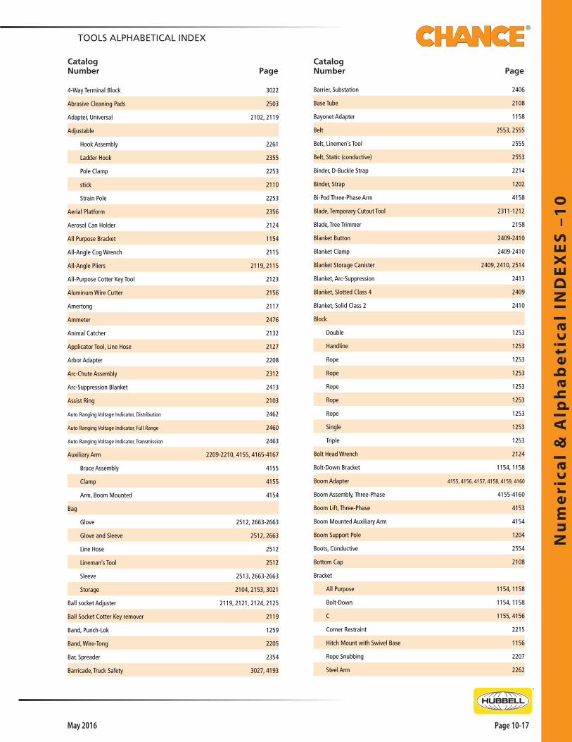
4-Way Terminal Block 3022
Abrasive Cleaning Pads 2503
Adapter, Universal 2102, 2119
Adjustable
Hook Assembly 2261
Ladder Hook 2355
Pole Clamp 2253
stick 2110
Strain Pole 2253
Aerial Platform 2356
Aerosol Can Holder 2124
All Purpose Bracket 1154
All-Angle Cog Wrench 2115
All-Angle Pliers 2119, 2115
All-Purpose Cotter Key Tool 2123
Aluminum Wire Cutter 2156
Amertong 2117
Ammeter 2476
Animal Catcher 2132
Applicator Tool, Line Hose 2127
Arbor Adapter 2208
Arc-Chute Assembly 2312
Arc-Suppression Blanket 2413
Assist Ring 2103
Auto Ranging Voltage Indicator, Distribution 2462
Auto Ranging Voltage Indicator, Full Range 2460
Auto Ranging Voltage Indicator, Transmission 2463
Auxiliary Arm 2209-2210, 4155, 4165-4167
Brace Assembly 4155
Clamp 4155
Arm, Boom Mounted 4154
Bag
Glove 2512, 2663-2663
Glove and Sleeve 2512, 2663
Line Hose 2512
Lineman’s Tool 2512
Sleeve 2513, 2663-2663
Storage 2104, 2153, 3021
Ball socket Adjuster 2119, 2121, 2124, 2125
Ball Socket Cotter Key remover 2119
Band, Punch-Lok 1259
Band, Wire-Tong 2205
Bar, Spreader 2354
Barricade, Truck Safety 3027, 4193
Barrier, Substation 2406
Base Tube 2108
Bayonet Adapter 1158
Belt 2553, 2555
Belt, Linemen’s Tool 2555
Belt, Static (conductive) 2553
Binder, D-Buckle Strap 2214
Binder, Strap 1202
Bi-Pod Three-Phase Arm 4158
Blade, Temporary Cutout Tool 2311-1212
Blade, Tree Trimmer 2158
Blanket Button 2409-2410
Blanket Clamp 2409-2410
Blanket Storage Canister 2409, 2410, 2514
Blanket, Arc-Suppression 2413
Blanket, Slotted Class 4 2409
Blanket, Solid Class 2 2410
Block
Double 1253
Handline 1253
Rope 1253
Rope 1253
Rope 1253
Rope 1253
Rope 1253
Single 1253
Triple 1253
Bolt Head Wrench 2124
Bolt-Down Bracket 1154, 1158
Boom Adapter 4155, 4156, 4157, 4158, 4159, 4160
Boom Assembly, Three-Phase 4155-4160
Boom Lift, Three-Phase 4153
Boom Mounted Auxiliary Arm 4154
Boom Support Pole 1204
Boots, Conductive 2554
Bottom Cap 2108
Bracket
All Purpose 1154, 1158
Bolt-Down 1154, 1158
C 1155, 4156
Corner Restraint 2215
Hitch Mount with Swivel Base 1156
Rope Snubbing 2207
Steel Arm 2262
Nu
me
rical &
Alp
ha
be
tical IN
DE
XE
S –1
0
Page 10-18 May 2016
Phone: 573-682-5521 Email: [email protected] Web: hubbellpowersystems.com
TOOLS ALPHABETICAL INDEX
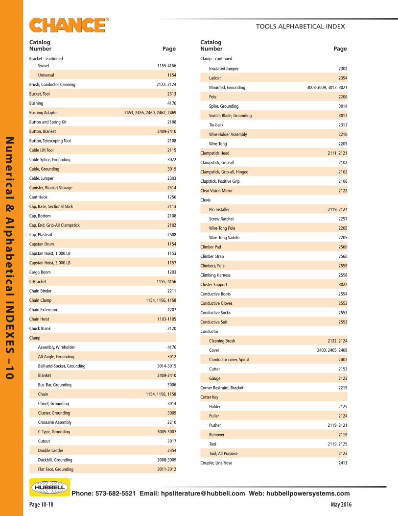
Swivel 1155-4156
Universal 1154
Brush, Conductor Cleaning 2122, 2124
Bucket, Tool 2513
Bushing 4170
Bushing Adapter 2453, 2455, 2460, 2462, 2469
Button and Spring Kit 2108
Button, Blanket 2409-2410
Button, Telescoping Tool 2108
Cable Lift Tool 2115
Cable Splice, Grounding 3022
Cable, Grounding 3019
Cable, Jumper 2303
Canister, Blanket Storage 2514
Cant Hook 1256
Cap, Base, Sectional Stick 2113
Cap, Bottom 2108
Cap, End, Grip-All Clampstick 2102
Cap, Plastisol 2508
Capstan Drum 1154
Capstan Hoist, 1,000 LB 1153
Capstan Hoist, 3,000 LB 1157
Cargo Boom 1203
C-Bracket 1155, 4156
Chain Binder 2211
Chain Clamp 1154, 1156, 1158
Chain Extension 2207
Chain Hoist 1103-1105
Chuck Blank 2120
Clamp
Assembly, Wireholder 4170
All-Angle, Grounding 3012
Ball-and-Socket, Grounding 3014-3015
Blanket 2409-2410
Bus-Bar, Grounding 3006
Chain 1154, 1156, 1158
Chisel, Grounding 3014
Cluster, Grounding 3009
Crossarm Assembly 2210
C-Type, Grounding 3005-3007
Cutout 3017
Double Ladder 2354
Duckbill, Grounding 3008-3009
Flat Face, Grounding 3011-3012
Insulated Jumper 2302
Ladder 2354
Mounted, Grounding 3008-3009, 3013, 3021
Pole 2206
Spike, Grounding 3014
Switch Blade, Grounding 3017
Tie-back 2313
Wire Holder Assembly 2210
Wire-Tong 2205
Clampstick Head 2111, 2121
Clampstick, Grip-all 2102
Clampstick, Grip-all, Hinged 2102
Clapstick, Positive Grip 2106
Clear Vision Mirror 2122
Clevis
Pin Installer 2119, 2124
Screw Ratchet 2257
Wire-Tong Pole 2205
Wire-Tong Saddle 2205
Climber Pad 2560
Climber Strap 2560
Climbers, Pole 2559
Climbing Harness 2558
Cluster Support 3022
Conductive Boots 2554
Conductive Gloves 2553
Conductive Socks 2553
Conductive Suit 2553
Conductor
Cleaning Brush 2122, 2124
Cover 2403, 2405, 2408
Conductor cover, Spiral 2407
Cutter 2153
Gauge 2123
Corner Restraint, Bracket 2215
Cotter Key
Holder 2125
Puller 2124
Pusher 2119, 2121
Remover 2119
Tool 2119, 2125
Tool, All Purpose 2123
Coupler, Line Hose 2413
Catalog Number Page
Catalog Number Page
Bracket - continued Clamp - continued

Nu
me
rica
l &
Alp
ha
be
tica
l IN
DE
XE
S –
10
Page 10-19May 2016
TOOLS ALPHABETICAL INDEX
Cover
Set, Insulator 2408
Ball Stud 3013
Conductor 2403, 2405, 2408
Crossarm 2407-2408
Crossarm End 2406
Cutout 2402
Deadend 2402, 2405
Insulator 2403, 2405
Pole 2404
Pole Top 2406
Post Insulator 2406
Crossarm
Clamp Assembly 2210
Cover 2407-2408
End Cover 2406
Tool Hanger 2118
Cutout
Cover 2402
Flexible Rubber Cover 2410
Tool 2119-2120
Tool, Universal 2121
Cutters
Cutter 2152-2157
Cutter Head 2153
Deadend Cover 2402-2405
Deadend Socket 2255
Dielectric Compound #7 2471
Disconnect Head 2120
Disconnect Head, Non-Metallic 2111
Disconnect Head, Universal 2110-2111
Disconnect Stick 2113
Disconnect Stick, Sectional 2113
Double Ladder Clamp 2354
Drum, Capstan 1154, 1158
Dry Film Lubricant 2507
Elbow
Adapter 2455, 2460, 2462, 2469
Parts 3015
Puller 2104
Electrostatic Precipitator Ground Set 3018
End Cap, Heavy Duty 2117, 2508
Energized Cable Sensor 2471
Energized Insulator Tester 2468
Epoxiglas bond Patching Kit 2507
Epoxiglas
Epoxiglas Plug Kit 2507
Epoxiglas Pole 2508
Epoxiglass Cleaning Kit 2503
Epoxy Sand Kit 2507
Equimat Grounding Grid 3025
Equimat Grounding Grid, Slip Resistant 3027
Extension Arm 2211
Extension Arm, Universal 2212
Extension, Sectional Stick 2113
Extension, Sectional Stick 2113
Extension, Tree Trimmer 2158
Extension, Wire-Tong Saddle 2206
Eye Bolt 2211
Eye Pin 2353
Eye, Pulling 1260
Eyenut 2257
Fall Arrest Lanyard 2559
Ferrule, Aluminum Grounding 3020
Ferrule, Copper Grounding 3019
Fitting, Universal 2108
Flexible Insulated Wrench 2116
Flixible Wrench Head 2122
Folding Rule 2120
Foot Control, Capstan 1154, 1157, 1158
Fork Suspension Tool 2263
Fuse Grappler Tool 2128
Fuse Puller 2123
Fuseholder, Temporary Cutout Tool 2311
Gin
Gin 1202-1203
Gin Pole 1203
Gin, Chain Binder 1202
Gin, Crossarm 1203
Gin, Crossarm, Convertible 1203
Gin, Multi Duty 1203
Gin, Strap Binder 1202
Gin, Swivel Top 1202
Gloss Restorer Kit 2503
Glove and Sleeve Bag 2512, 2663
Glove Bag 2512, 2663-2663
Glove, Rubber 2657-2660
Glove Leather Protectors 2661
Catalog Number Page
Catalog Number Page
Nu
me
rical &
Alp
ha
be
tical IN
DE
XE
S –1
0
Page 10-20 May 2016
Phone: 573-682-5521 Email: [email protected] Web: hubbellpowersystems.com
TOOLS ALPHABETICAL INDEX
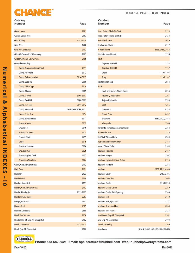
Head, Rotary Blade Tie Stick 2123
Head, Rotary Prong Tie Stick 2122
Heat Shrink Tube 3020
Hex Ferrule, Plastic 2117
Hi-Pot Adapter 2453, 2455, 2458
Hitch-Receiver Mount 1156
Hoist
Capstan, 1,000 LB 1153
Capstan, 3,000 LB 1157
Chain 1103-1105
Strap 1106-1107
Holster, Lineman’s 2554
Hook
Hook and Socket, Strain Carrier 2254
Assembly, Adjustable 2261
Adjustable Ladder 2355
Cant 1256
Conductor 4154
Pigtail Probe 2452
Shepherd 2119, 2122, 2452
Wire-puller 1260
Horizontal Tower Ladder Attachment 2354
Hot Rodder Tool 2125
Hot Stick Wiping Cloth 2503
Hydraulic Conductor Cutter 2156
Impact Elbow Puller 2104
Insulated Handles 2157
Insulated Hanger 2307
Insulated Hydraulic Cable Cutter 2155
Insulated Platform 2356
Insulator 2209, 2211, 4169
Insulator Cover 2403, 2405
Insulator Cover Set 2408
Insulator Cradle 2258-2259
Insulator Cradle Carrier 2259
Insulator Cradle, Side Opening 2260
Insulator Fork 2119
Insulator Fork, Ajustable 2122
Insulator Retaining Plate 2260
Insulator Tool, Plastic 2125
Jaw Holder, Grip-All Clampstick 2102
Jaw, Grip-All Clampstick 2102
J-Hook Assembly 2260
Jib Adapter 4154, 4165-4166, 4169, 4170, 4171, 4185-4188
Glove Liners 2661
Gloves, Conductive 2553
Grip, Pulling 1257-1258
Grip, Wire 1260
Grip-All Clampstick 2102
Grip-All Clampstick, Telescoping 2103
Grippers, Impact Elbow Puller 2105
Ground/Grounding
Clamp, Temporary Cutout Tool 2311
Clamp, All-Angle 3012
Clamp, Ball-and-socket 3014-3015
Clamp, Buss-Bar 3006
Clamp, Chisel Type 3014
Clamp, Cluster 3009
Clamp, C-Type 3005-3007
Clamp, Duckbill 3008-3009
Clamp, Flat Face 3011-3012
Clamp, Mounted 3008-3009, 3013, 3021
Clamp, Spike Type 3014
Clamp, Switch Blade 3017
Ferrule, Copper 3019
Ground Set 3015
Ground Set Tester 2473
Ground, Static 2259
Cable 3019
Ferrule, Aluminum 3020
Grid, Equimat 3025
Grounding Set, Truck 4157
Grounding Simulator 3024
Guide, Grip-All Clampstick 2102
Hack Saw 2121
Hammer 2123
Hand Guard 2509
Handles, Insulated 2157
Handle, Grip-All Clampstick 2102
Handle, Pistol grip 2111-2122
Handline Gin, Tower 2263
Hanger, Insulated 2307
Hanger, Tool 2509
Harness, Climbing 2558
Head, Tree Trimmer 2158
Head repair kit, Grip-All Clampstick 2102
Head, Disconnect 2112-2113
Head, Grip-All Clampstick 2102
Catalog Number Page
Catalog Number Page

Nu
me
rica
l &
Alp
ha
be
tica
l IN
DE
XE
S –
10
Page 10-21May 2016
TOOLS ALPHABETICAL INDEX
Catalog Number Page
Catalog Number Page
Jib Extension 4157
Jib Extension, Wireholder/Sheave 4158
Jib, 3” Round 4186
Jib, 4” Square 4190-4191
Jumper Cable 2303
Jumper Cable Support 2307
Jumper Clamp 2302
Jumper Set 2305-2308
Jumper Terminal 2304
Keeper 4172-7173
Kit, Button and Spring 2108
Kit, Ladder Support 2354
Kit, Universal Tool 2119
Klik Pin 2253, 2353
Knife, Skinning 2122
Knocker 2119, 2125
Ladder
Ladders 2352-2353
Attachment, Horizontal Tower 2354
Attachment, Vertical Pole 2354
Attachment, Vertical Tower 2354
Clamp 2354
Leakage Current Monitor 2355
Monitor 2477
Support Kit 2354
Yoke Assembly 2354
Platform 2358
Service 2358
Spliced 2353
Swivel Hook 2352
Three Rail 2353
Lanyard and Pin Kit 1253
Lanyard, Fall Arrest 2559
Latch, Wireholder 4172-7173
Latch Kit, Rope Block 1253
Latch, Grip-All Clampstick 2102
Leakage Current Monitor 2477
Lever Lift 2208
Lever Type Wire Cutter 2157
Lift Hook Assembly 3018
Lift Hook Extension Pole 3018
Line Fault Locator 2471
Line Hose 2412
Line Hose Bag 2512
Line Hose Coupler 2413
Lineman’s Tool Bag 2512
Link Stick
Crossarm 1107
Head 2121
Hoist 1108
Roller 2252
Spiral 2252
Strain 2252
Suspension 2261
Liners, Glove 2661
Load Looker Ammeter 2476
Load-Pickup Tool 2309
Locating Pin 2119-2120
Lockbar, Grip-All Clampstick 2102
Lubricant, Dry Film 2507
Lubricant, tool 2507
Lug, Elbow Connector 3015
Mast and Brace 2210
Mast Assembly 4155, 4156, 4157, 4161, 4162, 4162
Material Handler 1156
Measuring Rod 2133
Meter Claw 2131
Material Handler Bracket 1156
Mirror, Clear Vision 2119, 2122
Moisture Eater II 2503
Moisture Eater II Wipes 2504
Monitor, Boom 2477
Monitor, Ladder Leakage Current 2355
Mount, Hitch-Receiver 1156
Mount, Truck, Swivel Base 1155
Mounting Bracket, Gin 1203
Multi-Range Voltage Indicator 2464-2466
Nut, Molly Jack, Grip-All Clampstick 2102
Overhead Switch Barrier 2415
Pad, Climber 2560
Paint Brush 2121
Parking Bushing Ground Set 3015
Phasing Tester
Phase Rotation Tester 2459
Phasing Tester, Analog 2452-2453, 2457
Phasing Tester, Digital 2454-2456, 2458
Pike Pole 1256

Nu
me
rical &
Alp
ha
be
tical IN
DE
XE
S –1
0
Page 10-22 May 2016
Phone: 573-682-5521 Email: [email protected] Web: hubbellpowersystems.com
TOOLS ALPHABETICAL INDEX
Catalog Number Page
Catalog Number Page
Pin
Wireholder 4165, 4166, 4169, 4171, 4184
Holder 2119-2120
Drive Lock 2108
Eye 2353
Grip-All Clampstick 2102
Groove, Grip-All Clampstick 2102
Klik 2353, 2253
Pistol Grip Handle 2122
Pivot Base, Platform 2357
Platform
Ladder 2358
Mounting Attachment 2357
Pivot Base 2357
Railing 2357
Aerial 2356
Epoxiglas Insulated 2356
Suspension 2357
Utility 2357
Pliers, All-Angle 2119, 2125
Plug, Telescoping Tool 2108
Pointed Disconnect 2123
Pole
Pole & Ferrule, Telescoping Tool 2108
Clamp 2206
Clamp, Adjustable 2253
Cover 2404
Strap 2557
Tong 1256
Top Cover 2406
Wrench 1256
Epoxiglas 2508
Pike 1256
Protector 2217
Polymer Insulator Tester 2470
Positive Grip Clampstick 2106
Post Insulator Cover 2406
Power-Fuse Lift Stick 2114
Probe
Angle 2452
Shepherd Hook 2455, 2460, 2462-2464, 2466
Straight 2452, 2455, 2460, 2462-2464, 2466
Grounding Elbow 3015
Protectors, Leather Glove 2661
Pruning Saw 2111, 2121, 2158
Puller, Cotter Key 2124
Pulling Eye 1260
Punch-Lok Band 1259
Punch-Lok Tool 1259
Rack, Tool Storage 2509
Railing, Platform 2357
Ratchet
Cable Cutter 2152
Wrench 2116, 2119, 2120, 2124, 2257
Ratcheting Cable Cutter 2154
Reel, Storage 3023
Reel, Take-Up 1156
Removal Tool, Arc Snuffer 2105
Replacement Hardware, Cutters 2152-2153
Replacement Tool, Arc Snuffer 2105
Resistors 2459
Rescue Hook 2132
Resistors, Phasing Tester 2452-2455
Retainer, Telescoping Tool 2108
Rigid Splice 2508
Ring, Assist 2103
Rivet, Drive, Grip-All Clampstick 2102
Rod, Temporary Ground 3023
Roll Pin, Wireholder 4172-7173
Roll Pin, Grip-All Clampstick 2102
Roller 4169
Roller Axle 4169
Roller Axle 4170
Roller Link Stick 2252
Rope 1252
Lock Assembly 2404
Lock Device 1154, 1158
Sheave Assembly 4155, 4168, 4169, 4170
Snubbing Bracket 2207
Composite Fiber 1252
Poly-Dacron 1252
Polypropylene 1252
Rotary Blade Tie Stick Head 2123
Rotary Prong Tie Stick Head 2122
Rotating Ground 3029
Rubber Glove 2657-2660
Nu
me
rica
l &
Alp
ha
be
tica
l IN
DE
XE
S –
10
Page 10-23May 2016
TOOLS ALPHABETICAL INDEX
Catalog Number Page
Catalog Number Page
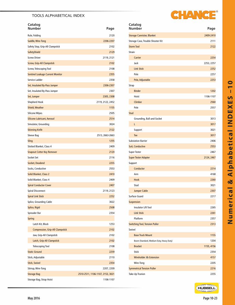
Rule, Folding 2120
Saddle, Wire-Tong 2206-2207
Safety Stop, Grip-All Clampstick 2102
SafetyShield 2129
Screw Driver 2119, 2121
Screw, Grip-All Clampstick 2102
Screw, Telescoping Tool 2108
Sentinel Leakage Current Monitor 2355
Service Ladder 2358
Set, Insulated By-Pass Jumper 2306-2307
Set, Insulated By-Pass Jumper 2307
Set, Jumper 2305, 2308
Shepherd Hook 2119, 2122, 2452
Shield, Weather 1155
Silicone Wipes 2505
Silicone Lubricant, Aerosol 2514
Simulator, Grounding 3024
Skinning Knife 2122
Sleeve Bag 2513, 2663-2663
Sling 1255
Slotted Blanket, Class 4 2409
Snapout Cotter Key Remover 2120
Socket Set 2116
Socket, Deadend 2255
Socks, Conductive 2553
Solid Blanket, Class 2 2410
Solid Blanket, Class 4 2409
Spiral Conductor Cover 2407
Spiral Disconnect 2119, 2123
Spiral Link Stick 2252
Splice, Grounding Cable 3022
Splice, Rigid 2508
Spreader Bar 2354
Spring
Latch Kit, Block 1253
Compression, Grip-All Clampstick 2102
Jaw, Grip-All Clampstick 2102
Latch, Grip-All Clampstick 2102
Telescoping Tool 2108
Static Ground 2259
Stick, Adjustable 2110
Stick, Swivel 2354
Stirrup, Wire-Tong 2207, 2209
Storage Bag 2510-2511, 1106-1107, 2153, 3021
Storage Bag, Strap Hoist 1106-1107
Storage Cannister, Blanket 2409-2410
Storage Case, Trouble Shooter Kit 2111
Storm Tool 2122
Strain
Carrier 2254
Jack 2253, 2257
Link Stick 2252
Pole 2257
Pole, Adjustable 2253
Strap
Binder 1202
Hoist 1106-1107
Climber 2560
Pole 2557
Stud
Grounding, Ball-and-Socket 3013
L 3017
Support 3021
Tee 3017
Substation Barrier 2406
Suit, Conductive 2553
Super Tester 2467
Super Tester Adapter 2124, 2467
Support
Conductor 2214
Arm 4168
Hook 2260
Stud 3021
Jumper Cable 2307
Surface Guard 2217
Suspension
Insulator Lift Tool 2265
Link Stick 2261
Platform 2357
Switching Tool, Tension Puller 2313
Swivel
Base Truck Mount 1155
Boom (Standard, Medium Duty, Heavy Duty) 1204
Bracket 1155, 4156
Stick 2354
Wireholder Jib Extension 4157
Wire-Tong 2205
Symmetrical Tension Puller 2216
Take-Up Trunion 2255
Nu
me
rical &
Alp
ha
be
tical IN
DE
XE
S –1
0
Page 10-24 May 2016
Phone: 573-682-5521 Email: [email protected] Web: hubbellpowersystems.com
TOOLS ALPHABETICAL INDEX
Catalog Number Page
Catalog Number Page
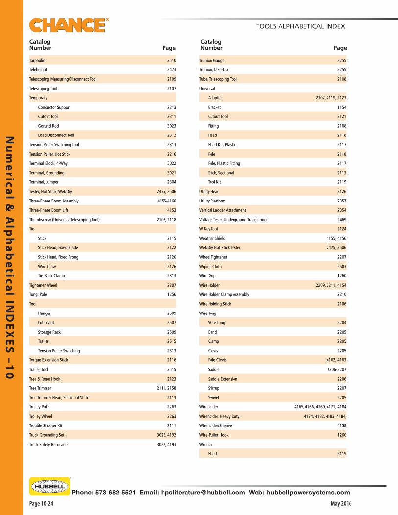
Tarpaulin 2510
Teleheight 2473
Telescoping Measuring/Disconnect Tool 2109
Telescoping Tool 2107
Temporary
Conductor Support 2213
Cutout Tool 2311
Gorund Rod 3023
Load Disconnect Tool 2312
Tension Puller Switching Tool 2313
Tension Puller, Hot Stick 2216
Terminal Block, 4-Way 3022
Terminal, Grounding 3021
Terminal, Jumper 2304
Tester, Hot Stick, Wet/Dry 2475, 2506
Three-Phase Boom Assembly 4155-4160
Three-Phase Boom Lift 4153
Thumbscrew (Universal/Telescoping Tool) 2108, 2118
Tie
Stick 2115
Stick Head, Fixed Blade 2122
Stick Head, Fixed Prong 2120
Wire Claw 2126
Tie-Back Clamp 2313
Tightener Wheel 2207
Tong, Pole 1256
Tool
Hanger 2509
Lubricant 2507
Storage Rack 2509
Trailer 2515
Tension Puller Switching 2313
Torque Extension Stick 2116
Trailer, Tool 2515
Tree & Rope Hook 2123
Tree Trimmer 2111, 2158
Tree Trimmer Head, Sectional Stick 2113
Trolley Pole 2263
Trolley Wheel 2263
Trouble Shooter Kit 2111
Truck Grounding Set 3026, 4192
Truck Safety Barricade 3027, 4193
Trunion Gauge 2255
Trunion, Take-Up 2255
Tube, Telescoping Tool 2108
Universal
Adapter 2102, 2119, 2123
Bracket 1154
Cutout Tool 2121
Fitting 2108
Head 2118
Head Kit, Plastic 2117
Pole 2118
Pole, Plastic Fitting 2117
Stick, Sectional 2113
Tool Kit 2119
Utility Head 2126
Utility Platform 2357
Vertical Ladder Attachment 2354
Voltage Teser, Underground Transformer 2469
W Key Tool 2124
Weather Shield 1155, 4156
Wet/Dry Hot Stick Tester 2475, 2506
Wheel Tightener 2207
Wiping Cloth 2503
Wire Grip 1260
Wire Holder 2209, 2211, 4154
Wire Holder Clamp Assembly 2210
Wire Holding Stick 2106
Wire Tong
Wire Tong 2204
Band 2205
Clamp 2205
Clevis 2205
Pole Clevis 4162, 4163
Saddle 2206-2207
Saddle Extension 2206
Stirrup 2207
Swivel 2205
Wireholder 4165, 4166, 4169, 4171, 4184
Wireholder, Heavy Duty 4174, 4182, 4183, 4184,
Wireholder/Sheave 4158
Wire-Puller Hook 1260
Wrench
Head 2119
Nu
me
rica
l &
Alp
ha
be
tica
l IN
DE
XE
S –
10
Page 10-25May 2016
TOOLS ALPHABETICAL INDEX
Catalog Number Page
Catalog Number Page
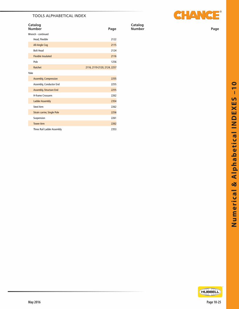
Head, Flexible 2122
All-Angle Cog 2115
Bolt Head 2124
Flexible Insulated 2116
Pole 1256
Ratchet 2116, 2119-2120, 2124, 2257
Yoke
Assembly, Compression 2255
Assembly, Conductor End 2255
Assembly, Structure End 2255
H-frame Crossarm 2262
Ladder Assembly 2354
Steel Arm 2262
Strain carrier, Single Pole 2256
Suspension 2261
Tower Arm 2262
Three Rail Ladder Assembly 2353
Wrench - continued


Phone: 573-682-5521 Email: [email protected] Web: hubbellpowersystems.com
Ho
ists
- M
ech
an
ica
l –
11
00
Page 1101May 2016
MechanicalHoists
Catalog 1100 May 2016
Ho
ists
- M
ech
an
ica
l –
11
00
Ho
ists - Me
cha
nica
l – 11
00
Page 1102
Phone: 573-682-5521 Email: [email protected] Web: hubbellpowersystems.com
May 2016
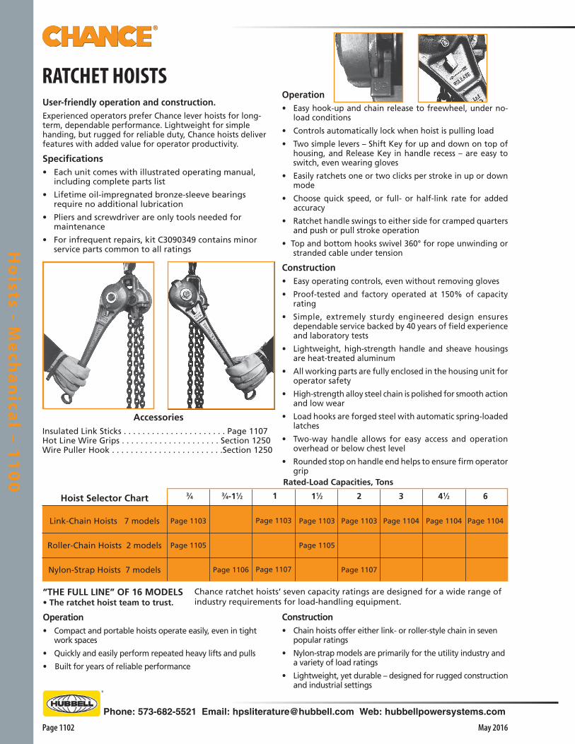
RATCHET HOISTSUser-friendly operation and construction.Experienced operators prefer Chance lever hoists for long-term, dependable performance. Lightweight for simple handing, but rugged for reliable duty, Chance hoists deliver features with added value for operator productivity.
Specifications• Each unit comes with illustrated operating manual,
including complete parts list
• Lifetime oil-impregnated bronze-sleeve bearings require no additional lubrication
• Pliers and screwdriver are only tools needed for maintenance
• For infrequent repairs, kit C3090349 contains minor service parts common to all ratings
AccessoriesInsulated Link Sticks . . . . . . . . . . . . . . . . . . . . . . Page 1107Hot Line Wire Grips . . . . . . . . . . . . . . . . . . . . . Section 1250Wire Puller Hook . . . . . . . . . . . . . . . . . . . . . . . .Section 1250
Rated-Load Capacities, Tons
Hoist Selector Chart
Link-Chain Hoists 7 models
Roller-Chain Hoists 2 models
Nylon-Strap Hoists 7 models
2
Page 1103
Page 1107
3
Page 1104
41⁄2
Page 1104
6
Page 1104
3⁄4
Page 1103
Page 1105
3⁄4-11⁄2
Page 1106
1
Page 1103
Page 1107
11⁄2
Page 1103
Page 1105
Operation• Easy hook-up and chain release to freewheel, under no-
load conditions
• Controls automatically lock when hoist is pulling load
• Two simple levers – Shift Key for up and down on top of housing, and Release Key in handle recess – are easy to switch, even wearing gloves
• Easily ratchets one or two clicks per stroke in up or down mode
• Choose quick speed, or full- or half-link rate for added accuracy
• Ratchet handle swings to either side for cramped quarters and push or pull stroke operation
• Top and bottom hooks swivel 360° for rope unwinding or stranded cable under tension
Construction• Easy operating controls, even without removing gloves
• Proof-tested and factory operated at 150% of capacity rating
• Simple, extremely sturdy engineered design ensures dependable service backed by 40 years of field experience and laboratory tests
• Lightweight, high-strength handle and sheave housings are heat-treated aluminum
• All working parts are fully enclosed in the housing unit for operator safety
• High-strength alloy steel chain is polished for smooth action and low wear
• Load hooks are forged steel with automatic spring-loaded latches
• Two-way handle allows for easy access and operation overhead or below chest level
• Rounded stop on handle end helps to ensure firm operator grip
Construction• Chain hoists offer either link- or roller-style chain in seven
popular ratings
• Nylon-strap models are primarily for the utility industry and a variety of load ratings
• Lightweight, yet durable – designed for rugged construction and industrial settings
“THE FULL LINE” OF 16 MODELS• The ratchet hoist team to trust.
Operation• Compact and portable hoists operate easily, even in tight
work spaces
• Quickly and easily perform repeated heavy lifts and pulls
• Built for years of reliable performance
Chance ratchet hoists’ seven capacity ratings are designed for a wide range of industry requirements for load-handling equipment.

Phone: 573-682-5521 Email: [email protected] Web: hubbellpowersystems.com
Ho
ists
- M
ech
an
ica
l –
11
00
Page 1103May 2016
RATCHET CHAIN HOISTS¾-Ton, 1-Ton, 1 ½-Ton & 2-Ton Ratings
Link-Chain StyleA strong link to reliable performance.
Construction• Proof-tested and factory operated at 150% of capacity
rating
• Lightweight, high-strength handle and sheave housings are heat-treated aluminum
• All working parts are fully enclosed in the housing unit for operator safety
• High-strength alloy steel chain is polished for smooth action and low wear
• Load hooks are forged steel with automatic spring-loaded latches
• Two-way handle allows for easy access and operation overhead or below chest level
• Rounded stop on handle end helps to ensure firm operator grip.
Operation• Easy hook-up and chain release to freewheel, under no-
load conditions
• Controls automatically lock when hoist is pulling load
• Two simple levers – Shift Key for up and down on top of housing, and Release Key in handle recess – are easy to switch, even wearing gloves
• Easily ratchets one or two clicks per stroke in up or down mode
• Choose quick speed, or full- or half-link rate for added accuracy
• Ratchet handle swings to either side for cramped quarters and push or pull stroke operation
• Top and bottom hooks swivel 360° for rope unwinding or stranded cable under tension
Specifications• Each unit comes with illustrated operating manual, including
complete parts list• Lifetime oil-impregnated bronze-sleeve bearings require no
additional lubrication• Pliers and screwdriver are only tools needed for maintenance• For infrequent repairs, kit C3090349 contains minor service
parts common to all ratings• 5-1/2 ft. Standard Lift Distance• 20-in. handle/Aluminum housing
DO NOT:1. LIFT MORE THAN RATED LOAD.2. OPERATE WITH TWISTED OR DAMAGED CHAIN.3. USE IF DAMAGED OR MALFUNCTIONING.4. LIFT PEOPLE OR LOADS OVER PEOPLE.5. USE A HANDLE EXTENDER (CHEATER BAR).6. OBSCURE THIS LABEL.
DO: SEE OPERATING INSTRUCTIONS.OPERATE AND MAINTAIN PER ANSI B30.21HUBBELL POWER SYSTEMS, INC. • CENTRALIA, MO 65240
Two-way handle swings to either side (helpful when reaching
overhead or below chest level to operate hoist). Rounded stop at end helps keep hand on handle.
On al l models on this page, the gate-type latch pushes inward and turns to open the hooks.
Hook-to-HookMinimum
11 in.
11 in.
16 in.
11 in.
Weightkg.
6.3
6.3
10
12.7
Handle Pullat Rating
65 lb.
90 lb.
60 lb.
90 lb.
Catalog No.
C3090438
3011S
C3090439
4012
Rating3/4-Ton
1-Ton
11/2-Ton
2-Ton
lb.
14
14
22
281/2
▲
11/2-Ton▲
2-Ton
▲3⁄4-Ton
▲
1-Ton

Ho
ists - Me
cha
nica
l – 11
00
Page 1104
Phone: 573-682-5521 Email: [email protected] Web: hubbellpowersystems.com
May 2016
RATCHET CHAIN HOISTS3-Ton, 4 ½-Ton & 6-Ton Ratings
Link-Chain StyleHeavy-duty performance by design.
Construction• Proof-tested and factory operated at 150% of capacity
rating
• Lightweight, high-strength handle and sheave housings are heat-treated aluminum
• All working parts are fully enclosed in the housing unit for operator safety
• High-strength alloy steel chain is polished for smooth action and low wear
• Load hooks are forged steel with automatic spring-loaded latches
• Two-way handle allows for easy access and operation overhead or below chest level
• Rounded stop on handle end helps to ensure firm operator grip
Hook-to-HookMinimum
193/4 in.
241/2 in.
241/2 in.
Weightlb.
301/2
47
50
kg.
13.8
21.2
22.5
Handle Pullat Rating
60 lb.
70 lb.
70 lb.
Rating
3-Ton
41/2-Ton
6-Ton
Catalog No.
C3090440
C3090441
C3090442
Link-style chain offers three effective load-rating options.
Operation• Easy hook-up and chain release to freewheel, under
no-load conditions
• Controls automatically lock when hoist is pulling load
• Two simple levers – Shift Key for up and down on top of housing, and Release Key in handle recess – are easy to switch, even wearing gloves
• Easily ratchets one or two clicks per stroke in up or down mode
• Choose quick speed, or full- or half-link rate for added accuracy
• Ratchet handle swings to either side for cramped quarters and push or pull stroke operation
• Top and bottom hooks swivel 360° for rope unwinding or stranded cable under tension
▲
3-Ton
Two-way handle swings to either side (helpful when reaching overhead
or below chest level to operate hoist). Rounded stop at end helps keep hand on handle.
Each unit bears a safety-instruction label in accordance with ANSI specifications, below.
DO NOT:1. LIFT MORE THAN RATED LOAD.2. OPERATE WITH TWISTED OR DAMAGED CHAIN.3. USE IF DAMAGED OR MALFUNCTIONING.4. LIFT PEOPLE OR LOADS OVER PEOPLE.5. USE A HANDLE EXTENDER (CHEATER BAR).6. OBSCURE THIS LABEL.
DO: SEE OPERATING INSTRUCTIONS.OPERATE AND MAINTAIN PER ANSI B30.21HUBBELL POWER SYSTEMS, INC. • CENTRALIA, MO 65240
▲
41⁄2-Ton▲
6-Ton
Specifications• Each unit comes with illustrated operating manual,
including complete parts list• Lifetime oil-impregnated bronze-sleeve bearings
require no additional lubrication• Pliers and screwdriver are only tools needed for
maintenance• For infrequent repairs, kit C3090349 contains minor
service parts common to all ratings• 5-1/2 ft. Standard Lift Distance• 20-in. handle/Aluminum housing

Phone: 573-682-5521 Email: [email protected] Web: hubbellpowersystems.com
Ho
ists
- M
ech
an
ica
l –
11
00
Page 1105May 2016
Each unit bears a safety-instruction label in accordance with ANSI specifications, below.
The efficient way to give productivity a lift.Roller-style (bicycle) chain offers two effective load-rating options from our link-style chain hoist line.
Construction• Proof-tested and factory operated at 150% of
capacity rating
• Lightweight, high-strength handle and sheave housings are heat-treated aluminum
• All working parts are fully enclosed in the housing unit for operator safety
• Two-way handle allows for easy access and operation overhead or below chest level
• Rounded stop on handle end helps to ensure firm operator grip
Operation• Easy hook-up and chain release to freewheel, under
no-load conditions
• Controls automatically lock when hoist is pulling load
• Two simple levers – Shift Key for up and down on top of housing, and Release Key in handle recess – are easy to switch, even wearing gloves
• Easily ratchets one or two clicks per stroke in up or down mode
• Choose quick speed, or full- or half-link rate for added accuracy
• Ratchet handle swings to either side for cramped quarters and push or pull stroke operation
• Top and bottom hooks swivel 360° for rope unwinding or stranded cable under tension
¾- & 1 ½-Ton Ratings
Roller-Chain Style
RATCHET CHAIN HOISTS
Both top and bottom hooks swivel 360° to allow for un-winding action of rope or stranded cable under tension.
▲3⁄4-Ton
▲
11⁄2-Ton
DO NOT:1. LIFT MORE THAN RATED LOAD.2. OPERATE WITH TWISTED OR DAMAGED CHAIN.3. USE IF DAMAGED OR MALFUNCTIONING.4. LIFT PEOPLE OR LOADS OVER PEOPLE.5. USE A HANDLE EXTENDER (CHEATER BAR).6. OBSCURE THIS LABEL.
DO: SEE OPERATING INSTRUCTIONS.OPERATE AND MAINTAIN PER ANSI B30.21HUBBELL POWER SYSTEMS, INC. • CENTRALIA, MO 65240
Two-way handle swings to either side (helpful when reaching overhead
or below chest level to operate hoist). Rounded stop at end helps keep hand on handle.
Hook-to-HookMinimum
13 in.
26 in.
Weightlb.
121⁄2
22
kg.
5.6
10
Handle Pullat Rating
65 lb.
60 lb.
Rating3/4-Ton
11/2-Ton
Catalog No.
C3090457
C3090458
Specifications• Each unit comes with illustrated operating manual,
including complete parts list• Lifetime oil-impregnated bronze-sleeve bearings
require no additional lubrication• Pliers and screwdriver are only tools needed for
maintenance• For infrequent repairs, kit C3090349 contains minor
service parts common to all ratings• 5-1/2 ft. Standard Lift Distance• 20-in. handle/Aluminum housing

Ho
ists - Me
cha
nica
l – 11
00
Page 1106
Phone: 573-682-5521 Email: [email protected] Web: hubbellpowersystems.com
May 2016
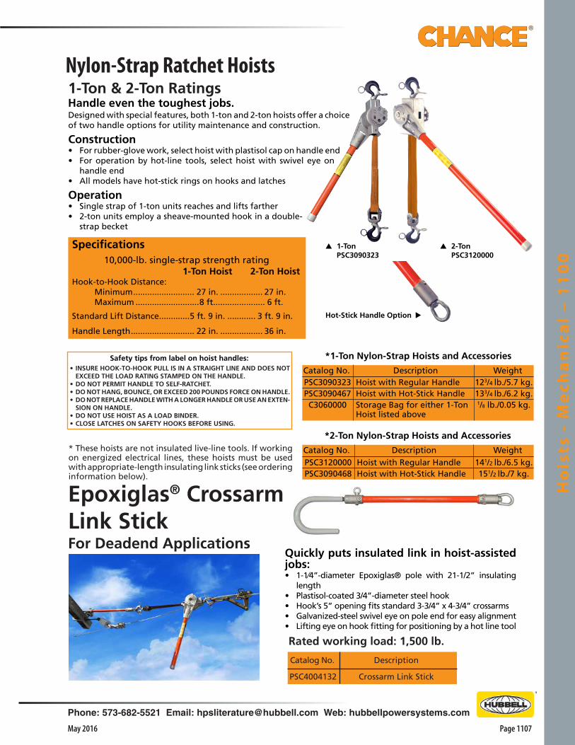
Rubber-Glove StylePSC3090451
Versatile options for your toughest challenges.Designed with special features, two hoist options offer a choice for maintenance and construction.
Construction • For standard duty or electric-utility rubber-glove pro-
cedures, select regular style
• For hotstick operations, select hoist with handling ring on the handle
• Lightweight for easy handling, both styles are ruggedly designed for heavy-duty applications
Operation • Adapts immediately to varying field needs
• Adds 3 feet of lift-distance capability when rigged at the lower rating
• To rig hoist for higher rating, keep load-hook sheave mounted midway on strap when it is becketed (dou-bled, with the end of strap secured to hoist frame)
• To convert to lower rating, secure the load hook sheave through loop in strap free end
Rigged for higher rating (above):Rubber-Glove Style with operating rings on hooks and latches.
Automatic spring-loaded latches on 360° swivel forged-steel hooks, two places.
Heat-treatedaluminum-alloy frame – open designfor easy cleaning in mud or ice.
Interlocking pawls for sure control without brakes that can slip.
Safety-orange30" x 11⁄4"Epoxiglas®
insulated handle, Plastisol end cap seals out dirt.
To change rigging, simply remove split ring from load-hook sheave. Longer reach when rigged for lower rating gives 7-foot lift distance using load-hook sheave secured at strap end.
Both the PSC3090451 & PSC3090452 models also feature:• Take-up wheel with cogs for hand operation and holes for
hot stick operation.
• Easy-access Shift and Release Keys operate by hotsticks or by hand, even with gloves.
Single nylon-web strap rating . . . . . . . . . . . . . .4,500 lb.
Rigged for Rigged for higher rating: lower rating:Hook-to-Hook Distance: Minimum . . . . . . . . 211/2 in. . . . . . . . .211/2 in. Maximum . . . . . . . 6 ft. 7 in. . . . . . . . .9 ft.
Standard LiftDistance . . . . . . . . . . . . . . . . . 3 ft. . . . . . . . . . . 6 ft.
Specifications
Catalog No. Hoist Description Weight PSC3090451 Rubber-Glove Style 121/2 lb./5.4 kg. PSC3090452 Hotstick Hooks & Handle Style 131/2 lb./6 kg.PSC3090663 All-Hotstick Style 131/2 lb./6 kg.
* 3⁄4 – 11⁄2 Ton Nylon-Strap Hoists
Convertible Strap Hoists One Model: ¾- & 1½-Ton Ratings 3 Styles: For Rubber-Glove & Hotstick Work
Accessories
C3060000 Storage bag for strap hoist
Catalog No. WeightDescription1/8 lb./0.05 kg.
*These hoists are not insulated live-line tools. If working on energized electrical lines, these hoists must be used with appropriate length insulating link sticks (see page 1107).
All-Hotstick StylePSC3090663
• Take-up reel is easy to operate by a Grip-All clampstick.
Photo at below right shows rigging for lower rating on Hotstick Style with operating rings on Hooks, latches and Handle.
HotstickHooks & Handle StylePSC3090452
Phone: 573-682-5521 Email: [email protected] Web: hubbellpowersystems.com
Ho
ists
- M
ech
an
ica
l –
11
00
Page 1107May 2016
Catalog No. Description
Crossarm Link StickPSC4004132
• INSURE HOOK-TO-HOOK PULL IS IN A STRAIGHT LINE AND DOES NOT EXCEED THE LOAD RATING STAMPED ON THE HANDLE.
• DO NOT PERMIT HANDLE TO SELF-RATCHET.• DO NOT HANG, BOUNCE, OR EXCEED 200 POUNDS FORCE ON HANDLE.• DO NOT REPLACE HANDLE WITH A LONGER HANDLE OR USE AN EXTEN-
SION ON HANDLE.• DO NOT USE HOIST AS A LOAD BINDER.• CLOSE LATCHES ON SAFETY HOOKS BEFORE USING.
Safety tips from label on hoist handles:
* These hoists are not insulated live-line tools. If working on energized electrical lines, these hoists must be used with appropriate-length insulating link sticks (see ordering information below).
Quickly puts insulated link in hoist-assisted jobs: • 1-1⁄4”-diameter Epoxiglas® pole with 21-1/2” insulating
length• Plastisol-coated 3/4”-diameter steel hook • Hook’s 5” opening fits standard 3-3/4” x 4-3/4” crossarms• Galvanized-steel swivel eye on pole end for easy alignment• Lifting eye on hook fitting for positioning by a hot line tool
Epoxiglas® Crossarm Link StickFor Deadend Applications
Nylon-Strap Ratchet Hoists1-Ton & 2-Ton RatingsHandle even the toughest jobs.
Specifications10,000-lb. single-strap strength rating
1-Ton Hoist 2-Ton HoistHook-to-Hook Distance: Minimum .......................... 27 in. .................. 27 in. Maximum ...........................8 ft. ..................... 6 ft.
Standard Lift Distance .............5 ft. 9 in. ............ 3 ft. 9 in.
Handle Length ........................... 22 in. .................. 36 in.
▲ 1-Ton PSC3090323
▲ 2-Ton PSC3120000
*1-Ton Nylon-Strap Hoists and Accessories
PSC3090323PSC3090467C3060000
Catalog No. WeightDescriptionHoist with Regular HandleHoist with Hot-Stick HandleStorage Bag for either 1-Ton Hoist listed above
123/4 lb./5.7 kg.133/4 lb./6.2 kg.1/8 lb./0.05 kg.
▲ Hot-Stick Handle Option
Designed with special features, both 1-ton and 2-ton hoists offer a choice of two handle options for utility maintenance and construction.
Construction • For rubber-glove work, select hoist with plastisol cap on handle end• For operation by hot-line tools, select hoist with swivel eye on
handle end• All models have hot-stick rings on hooks and latches
Operation • Single strap of 1-ton units reaches and lifts farther• 2-ton units employ a sheave-mounted hook in a double-
strap becket
*2-Ton Nylon-Strap Hoists and Accessories
Catalog No. Description WeightHoist with Regular HandleHoist with Hot-Stick Handle
141/2 lb./6.5 kg.151/2 lb./7 kg.
PSC3120000PSC3090468
Rated working load: 1,500 lb.

Ho
ists - Me
cha
nica
l – 11
00
Page 1108
Phone: 573-682-5521 Email: [email protected] Web: hubbellpowersystems.com
May 2016
Catalog No. WeightLength between end fittings
15" Epoxiglas
18" Epoxiglas
24" Epoxiglas
4 lb./1.8 kg.
5 lb./2.25 kg.
6 lb./2.7 kg.
C4001175
C4002399
C4002400
Rated working load: 4,000 lb.
To permit hot-line work with a nylon-strap ratchet hoist, a properly applied link stick insulates the hoist from an energized conductor.
Construction • 1 ¼”-diameter Epoxiglas pole with a steel hook on one
end• Features butt swivel on end opposite of steel hook
Operation • Attach the hook of the stick to a wire grip using the
hotstick eye to operate hook• Complete application by connecting nylon-strap hoist to
link stick butt swivel and to pole or crossarm
Epoxiglas® Hoist Link SticksEasily adapts to hot-line uses

Phone: 573-682-5521 Email: [email protected] Web: hubbellpowersystems.com
Page 1151May 2016
Ho
ists
- P
ow
ere
d –
11
50
Catalog 1150 May 2016
PoweredHoists
Ho
ists
- P
ow
ere
d –
11
50

Page 1152
Phone: 573-682-5521 Email: [email protected] Web: hubbellpowersystems.com
May 2016
Ho
ists - Po
we
red
– 11
50
Powerful design for tough jobs.Improved design features a multiple-planetary drive/back-stop clutch assembled on the center shaft of a steel gearcase with full-length internal teeth. This design handles more rugged jobs, extends service life and reduces maintenance.
Versatile to various applicationsLightweight, powerful portable hoists move heavyweight
and difficult-access tasks, including:• Setting utility poles • Cell tower erection• Pulling wheeled equipment over obstacles• Raising transformers (even over fences in back lots)• Hoisting heavy insulators• String and tensioning conductors• Pulling indoor and underground cable
Series 90 Capstan Hoists• 1,000-lb. & 3,000-lb. Load Ratings • 12V, 115V, 230V, Hydraulic, Gasoline
For improved load control, steel capstan drum features nickel-plated rope surface, larger radius at load-line wrap and rope hook. Position fall line so it will not pullover end of drum. If rope comes off end of drum and hook catches it, stop hoist, secure load and correct rope position on drum.
Optional Rope Lock – At left: Automatically supports load when fall line is released, until operator resumes hoisting. At right: The release lanyard permits lowering or lifting load with precise control over speed and distance.
Mechanical Advantage of Series 90 Hoists
Simple technique eases all loads• Graph and diagram at right show capstan principle in action• Operator effort remains low for typical loads simply by adding wraps on capstan drum• Such little effort is required, any crew member can run hoistExample: 4 wraps of rope = 1:44 ratio.That is, 1 lb. pull on Fall Line develops 44 lb. on Load Line. Therefore, 20 lb. of pull develops 880 lb. of lift.
——————— TABLE OF CONTENTS ———————— 1,000-lb. Hoists and Accessories . . . Pages 1153 - 63,000-lb. Hoists and Accessories . . . Pages 1157 - 8
• Highly-accurate controls allow loads to be moved a fraction of an inch
• Note: Always use at least as many wraps of rope on the drum to lower a load as required to lift that load
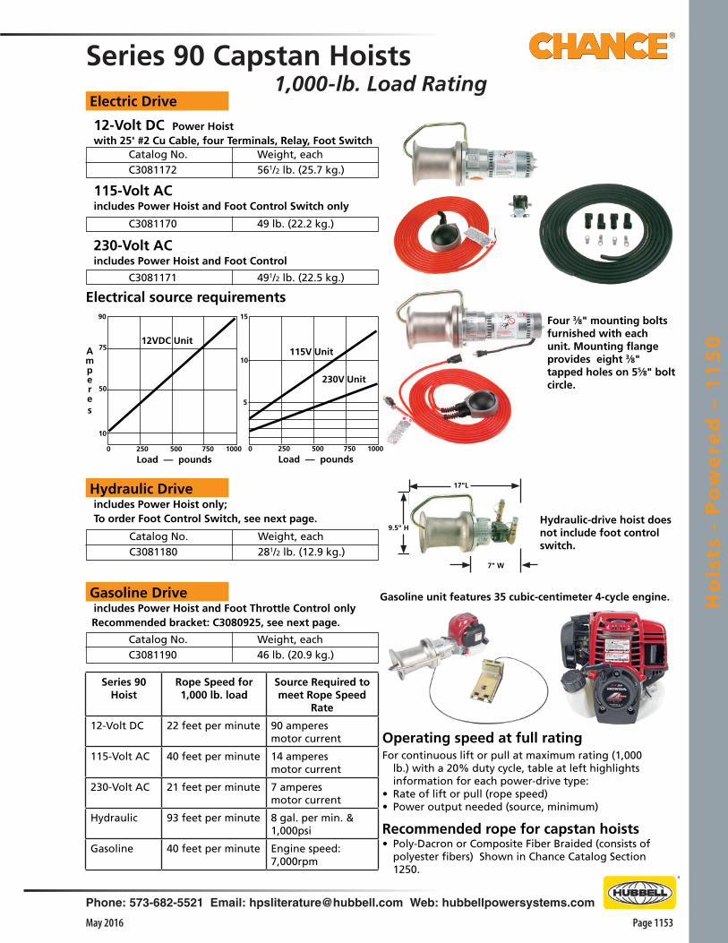
Phone: 573-682-5521 Email: [email protected] Web: hubbellpowersystems.com
Page 1153May 2016
Ho
ists
- P
ow
ere
d –
11
50
Recommended rope for capstan hoists• Poly-Dacron or Composite Fiber Braided (consists of
polyester fibers) Shown in Chance Catalog Section 1250.
Operating speed at full ratingFor continuous lift or pull at maximum rating (1,000
lb.) with a 20% duty cycle, table at left highlights information for each power-drive type:
• Rate of lift or pull (rope speed)• Power output needed (source, minimum)
Series 90 Capstan Hoists1,000-lb. Load Rating
12-Volt DC Power Hoist with 25' #2 Cu Cable, four Terminals, Relay, Foot Switch
Electric Drive
115-Volt AC includes Power Hoist and Foot Control Switch only
230-Volt AC includes Power Hoist and Foot Control
Four 3⁄8" mounting bolts furnished with each unit. Mounting flange provides eight 3⁄8" tapped holes on 55⁄8" bolt circle.
Hydraulic Drive includes Power Hoist only; To order Foot Control Switch, see next page. Hydraulic-drive hoist does
not include foot control switch.
Gasoline unit features 35 cubic-centimeter 4-cycle engine.
Catalog No. Weight, each C3081172 561/2 lb. (25.7 kg.)
C3081170 49 lb. (22.2 kg.)
C3081171 491/2 lb. (22.5 kg.)
Catalog No. Weight, each C3081180 281/2 lb. (12.9 kg.)
Gasoline Drive includes Power Hoist and Foot Throttle Control only Recommended bracket: C3080925, see next page.
Catalog No. Weight, each C3081190 46 lb. (20.9 kg.)
17"L
9.5" H
7" W
Series 90 Hoist
Rope Speed for 1,000 lb. load
Source Required to meet Rope Speed
Rate
12-Volt DC 22 feet per minute 90 amperesmotor current
115-Volt AC 40 feet per minute 14 amperesmotor current
230-Volt AC 21 feet per minute 7 amperes motor current
Hydraulic 93 feet per minute 8 gal. per min. & 1,000psi
Gasoline 40 feet per minute Engine speed: 7,000rpm
0 250 500 750 1000
Load — pounds
5
10
15
0 250 500 750 1000
Load — pounds
10
50
75
90
115V Unit
230V Unit
12VDC UnitAmperes
Electrical source requirements
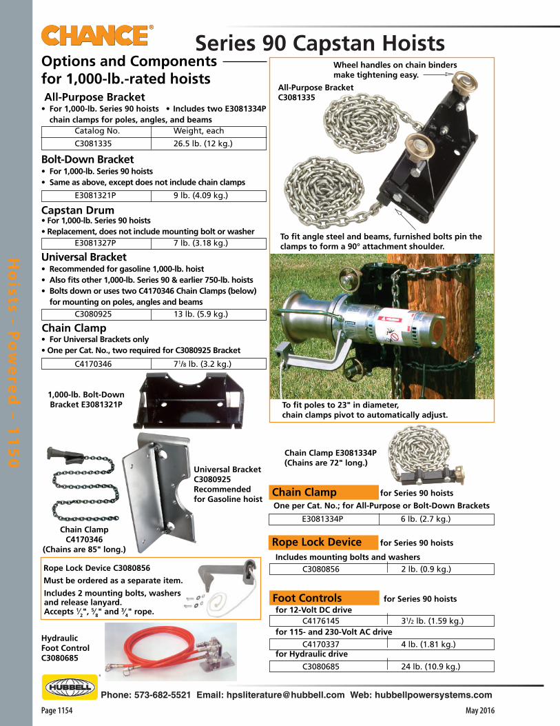
Page 1154
Phone: 573-682-5521 Email: [email protected] Web: hubbellpowersystems.com
May 2016
Ho
ists - Po
we
red
– 11
50
Foot Controls for Series 90 hoists for 12-Volt DC drive
for 115- and 230-Volt AC drive
for Hydraulic drive
Options and Componentsfor 1,000-lb.-rated hoists
1,000-lb. Bolt-Down Bracket E3081321P
Hydraulic Foot ControlC3080685
One per Cat. No.; for All-Purpose or Bolt-Down Brackets
Chain Clamp for Series 90 hoists
Rope Lock Device for Series 90 hoists
Includes mounting bolts and washers
Chain Clamp E3081334P(Chains are 72" long.)
To fit poles to 23" in diameter,chain clamps pivot to automatically adjust.
To fit angle steel and beams, furnished bolts pin the clamps to form a 90° attachment shoulder.
Wheel handles on chain bindersmake tightening easy.
All-Purpose BracketC3081335
• For 1,000-lb. Series 90 hoists • Includes two E3081334P chain clamps for poles, angles, and beams
All-Purpose Bracket
Catalog No. Weight, each
C3081335 26.5 lb. (12 kg.)
Bolt-Down Bracket• For 1,000-lb. Series 90 hoists• Same as above, except does not include chain clamps
E3081321P 9 lb. (4.09 kg.)
Capstan Drum• For 1,000-lb. Series 90 hoists• Replacement, does not include mounting bolt or washer E3081327P 7 lb. (3.18 kg.)
Universal Bracket• Recommended for gasoline 1,000-lb. hoist• Also fits other 1,000-lb. Series 90 & earlier 750-lb. hoists• Bolts down or uses two C4170346 Chain Clamps (below)
for mounting on poles, angles and beams
C3080925 13 lb. (5.9 kg.)
Chain Clamp• For Universal Brackets only • One per Cat. No., two required for C3080925 Bracket
C4170346 71/8 lb. (3.2 kg.)
Universal BracketC3080925Recommended for Gasoline hoist
Must be ordered as a separate item.
Rope Lock Device C3080856
Includes 2 mounting bolts, washers and release lanyard.Accepts 1⁄2", 5⁄8" and 3⁄4" rope.
C3080685 24 lb. (10.9 kg.)
C4176145 31/2 lb. (1.59 kg.)
C4170337 4 lb. (1.81 kg.)
E3081334P 6 lb. (2.7 kg.)
C3080856 2 lb. (0.9 kg.)
Series 90 Capstan Hoists
Chain ClampC4170346
(Chains are 85" long.)

Phone: 573-682-5521 Email: [email protected] Web: hubbellpowersystems.com
Page 1155May 2016
Ho
ists
- P
ow
ere
d –
11
50
Weather Shield for 12-Volt DC hoist only complete with band clamp
Swivel-Base Truck Mountfor 12V, 115V & Hydraulic 1,000-lb. Series 90 Capstan Hoists
Sets at angles needed for variety of jobs• Turntable design permits proper alignment without repositioning service
vehicle
• Heavy-gauge steel base bolts directly to truck body wherever convenient
• Bracket can be pinned at 15-degree interval around circular base for: stringing, tensioning, and sagging conductors; pulling in cable; hoisting equipment; setting poles; and pulling vehicles
This is not a personnel lifting device. A label on the unit warns against lifting people or loads directly above people.
! WARNING
To store hoist on C-bracket, simply remove four bolts. The C-bracket also can be bolted down for fixed-angle.Utilize truck as portable power source• Only 12V, 115V, 230V and Hydraulic 1,000-lb.-rated hoists are recommended for truck mounting
• See page 1153 to order
Swivel-Base Truck MountT3081506
Swivel Base Truck Mount(Assembled Swivel Bracket and C-Bracket at right)
Catalog No. Weight, each T3081506 23 lb. (10.35 kg.)
Catalog No. Weight, each C3080909 1 lb. (0.45 kg.)
C-Bracket C3080890
C-Bracket only — complete with mounting bolts
C3080890 5 lb. (2.25 kg.)
Swivel Bracket C3080903
Swivel Bracket only Catalog No. Weight, each C3080903 18 lb. (8.1 kg.)

Page 1156
Phone: 573-682-5521 Email: [email protected] Web: hubbellpowersystems.com
May 2016
Ho
ists - Po
we
red
– 11
50
Hitch-Receiver Mountfor Swivel-Base Mountfor 12V, 115V, 230V & Hydraulic1,000-lb. Series 90 Capstan Hoists
For AC, Hydraulic & Gasoline 1,000-lb. Series 90 Capstan Hoists (Order hoists on page 1153)MATERIAL HANDLER SPECIAL APPLICATION
Must order separately:• C3080925 Bracket, for poles, beams or angles (page
1154);• Two C4170346 Chain Clamps (page 1154);• Poly-dacron or Polyester Braided Rope (Cat. Sect.
1250);• C4170343H Take-Up Reel with handle (shown above; Capacity: 600 ft. x 1⁄2" rope or 1,500 ft.
x 3⁄8" rope; Weight: 20 lb. / 9 kg.)
Material Handler chassis only Catalog No. Weight, each C3160760 38 lb. (17.2 kg.)
SnatchBlock
LevelWindGuide Load
Rope Reel
CapstanDrum
TensionControlKnob
Idler Pulley
PSC3081563(Hitch Mount Bracket T3080999 with Swivel Base T3081506)
1,000 lb. ratingHitch-Receiver Mount T3080999 as furnished
Catalog No. Description Weight
T3080999Hitch Mount for
Capstan Hoist21 lb./9.56 kg.
PSC3081563Hitch Mount with Swivel
Base62 lb/28.1kg
Idler arm stores simply by moving wingbolt to another hole.
Application and Operation• Portable system sets up fast where large vehicle-mounted
equipment is impractical
• Lifts tools, apparatus, sets poles, and moves materials in warehouse or store yard
• Automatically takes up rope on reel and keeps line out of dirt
• Mounts to wood, concrete, or steel poles and angle-member structures with one bracket and two chain clamps
• Operator can keep all activity in view while controlling lift with tension-adjustment knob and hoist’s foot control
Quick and convenient, fits 2”-square towing receivers
• Faster than any other method, job-ready mount puts capstan hoist in right position for pulling, stringing, and lifting jobs
• With hoist stored on it, mount’s square tube simply inserts and pins in any 2”-square receiver of a Class III or IV towing hitch
Specially designed for swivel-base mount• T3080999 Hitch-receiver Mount features hole pattern
specifically designed to fit Swivel-Base Mount T3081506 (for more details see page 1155)
• Swivel mount’s turntable design permits proper alignment without repositioning service vehicle
• Swivel mount permits pinning bracket at every 15-degree interval around circular base for: stringing, tensioning, and sagging conductors; pulling in cable; hoisting equipment; setting poles; and pulling vehicles
Utilize truck as portable power source• Hitch-Receiver Mount is rated at 1,000 lb. to correspond
with ratings of capstan hoists for which it is intended• Only 12V, 115V and Hydraulic 1,000-lb.-rated hoists are
recommended for truck mounting• See page 1153 to order
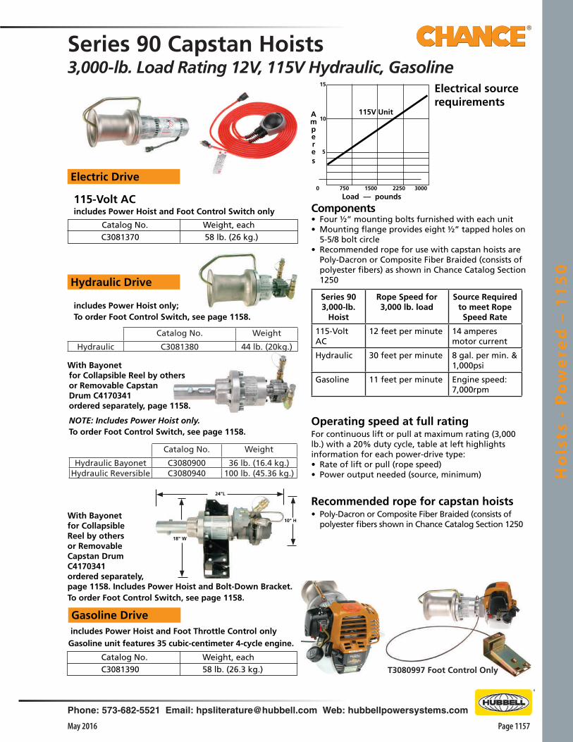
Phone: 573-682-5521 Email: [email protected] Web: hubbellpowersystems.com
Page 1157May 2016
Ho
ists
- P
ow
ere
d –
11
50
T3080997 Foot Control Only
C3081370 58 lb. (26 kg.) Catalog No. Weight, each
Electric Drive
115-Volt AC includes Power Hoist and Foot Control Switch only
15
Hydraulic Drive
includes Power Hoist only; To order Foot Control Switch, see page 1158.
Gasoline Drive includes Power Hoist and Foot Throttle Control only
Catalog No. Weight, each C3081390 58 lb. (26.3 kg.)
With Bayonet for Collapsible Reel by others or Removable Capstan Drum C4170341 ordered separately, page 1158. NOTE: Includes Power Hoist only. To order Foot Control Switch, see page 1158.
Amperes
0 750 1500 2250 3000
Load –– pounds
5
10115V Unit
Electrical source requirements
Components• Four ½” mounting bolts furnished with each unit• Mounting flange provides eight ½” tapped holes on
5-5/8 bolt circle• Recommended rope for use with capstan hoists are
Poly-Dacron or Composite Fiber Braided (consists of polyester fibers) as shown in Chance Catalog Section 1250
Gasoline unit features 35 cubic-centimeter 4-cycle engine.
Series 90 Capstan Hoists3,000-lb. Load Rating 12V, 115V Hydraulic, Gasoline
Recommended rope for capstan hoists• Poly-Dacron or Composite Fiber Braided (consists of
polyester fibers shown in Chance Catalog Section 1250
Operating speed at full ratingFor continuous lift or pull at maximum rating (3,000 lb.) with a 20% duty cycle, table at left highlights information for each power-drive type:• Rate of lift or pull (rope speed)• Power output needed (source, minimum)
Series 90 3,000-lb.
Hoist
Rope Speed for 3,000 lb. load
Source Required to meet Rope Speed Rate
115-Volt AC
12 feet per minute 14 amperesmotor current
Hydraulic 30 feet per minute 8 gal. per min. & 1,000psi
Gasoline 11 feet per minute Engine speed: 7,000rpm
24"L
18" W
10" H
Catalog No. Weight
Hydraulic C3081380 44 lb. (20kg.)
Catalog No. Weight
Hydraulic Bayonet C3080900 36 lb. (16.4 kg.)Hydraulic Reversible C3080940 100 lb. (45.36 kg.)
With Bayonetfor Collapsible Reel by others or RemovableCapstan Drum C4170341ordered separately, page 1158. Includes Power Hoist and Bolt-Down Bracket. To order Foot Control Switch, see page 1158.
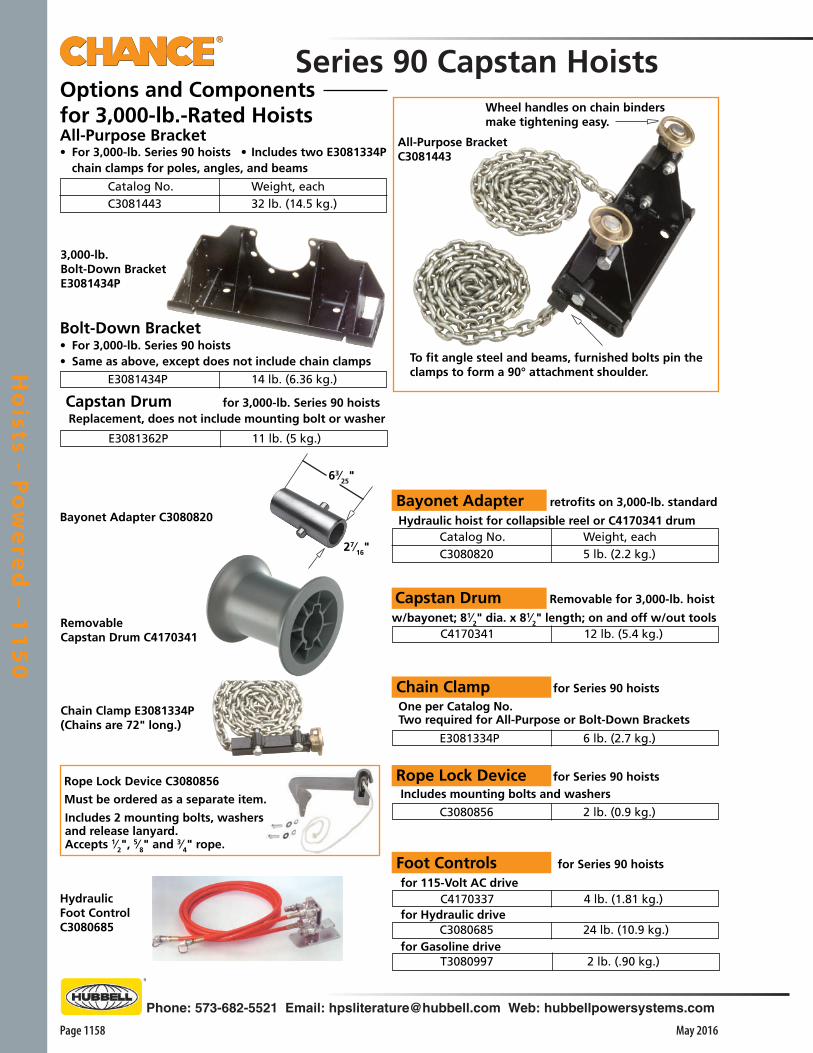
Page 1158
Phone: 573-682-5521 Email: [email protected] Web: hubbellpowersystems.com
May 2016
Ho
ists - Po
we
red
– 11
50
3,000-lb.Bolt-Down BracketE3081434P
Series 90 Capstan HoistsOptions and Components for 3,000-lb.-Rated Hoists
Hydraulic Foot ControlC3080685
• For 3,000-lb. Series 90 hoists • Includes two E3081334P chain clamps for poles, angles, and beams
All-Purpose Bracket
Catalog No. Weight, each C3081443 32 lb. (14.5 kg.)
Bolt-Down Bracket• For 3,000-lb. Series 90 hoists• Same as above, except does not include chain clamps
E3081434P 14 lb. (6.36 kg.)
Capstan Drum for 3,000-lb. Series 90 hoists Replacement, does not include mounting bolt or washer
E3081362P 11 lb. (5 kg.)
Rope Lock Device for Series 90 hoists Includes mounting bolts and washers
C3080856 2 lb. (0.9 kg.)
One per Catalog No. Two required for All-Purpose or Bolt-Down Brackets
Chain Clamp for Series 90 hoists
E3081334P 6 lb. (2.7 kg.)
Capstan Drum Removable for 3,000-lb. hoist
w/bayonet; 81⁄2" dia. x 81⁄2" length; on and off w/out tools C4170341 12 lb. (5.4 kg.)
Bayonet Adapter retrofits on 3,000-lb. standard
Hydraulic hoist for collapsible reel or C4170341 drum Catalog No. Weight, each C3080820 5 lb. (2.2 kg.)
To fit angle steel and beams, furnished bolts pin the clamps to form a 90° attachment shoulder.
Wheel handles on chain bindersmake tightening easy.
All-Purpose BracketC3081443
Foot Controls for Series 90 hoists
for 115-Volt AC drive
for Hydraulic drive
for Gasoline drive C3080685 24 lb. (10.9 kg.)
C4170337 4 lb. (1.81 kg.)
T3080997 2 lb. (.90 kg.)
Must be ordered as a separate item.
Rope Lock Device C3080856
Includes 2 mounting bolts, washers and release lanyard.Accepts 1⁄2", 5⁄8" and 3⁄4" rope.
Chain Clamp E3081334P(Chains are 72" long.)
RemovableCapstan Drum C4170341
Bayonet Adapter C3080820
27⁄16"
63⁄25"

Gin
s a
nd
Bo
om
s –
12
00
Page 1201May 2016
Phone: 573-682-5521 Email: [email protected] Web: hubbellpowersystems.com
InsulatedHand Tools
Warranty - MaterialHubbell Power Systems, Inc. warrants all products sold by it to be merchantable (as such term is defined in the Uniform Commercial Code) and to be free from defects in material and work-manship. Buyer must notify the Company promptly of any claim under this warranty. The Buyer's exclusive remedy for breach of this warranty shall be the repair or replacement, F.O.B. factory, at the Company's option, of any product defective under the warranty which is returned to the Company within one year from the date of shipment. NO OTHER WARRANTY, WHETHER EXPRESS OR ARISING BY OPERATION OF LAW, COURSE OF DEALING, USAGE OF TRADE OR OTHERWISE IMPLIED, SHALL EXIST IN CONNECTION WITH THE COMPANY'S PRODUCTS OR ANY SALE OR USE THEREOF. The Company shall in no event be liable for any loss of profits or any consequential or special damages incurred by Buyer. The Company's warranty shall run only to the first Buyer of a product from the Company, from the Company's distributor, or from an original equipment manufacturer reselling the Company's product, and is non-assignable and non-transferable and shall be of no force and effect if asserted by any person other than such first Buyer. This warranty applies only to the use of the product as intended by Seller and does not cover any misapplication or misuse of said product.
Warranty - ApplicationHubbell Power Systems, Inc. does not warrant the accuracy of and results from product or system performance recommendations resulting from any engineering analysis or study. This applies regardless of whether a charge is made for the recommendation, or if it is provided free of charge.
Responsibility for selection of the proper product or application rests solely with the purchaser. In the event of errors or inaccuracies determined to be caused by Hubbell Power Systems, Inc., its liability will be limited to the re-performance of any such analysis or study.
0.05 to 1.01.1 to 15.015.1 to 36.036.1 to 46.046.1 to 72.572.6 to 121138 to 145161 to 169230 to 242345 to 362500 to 550765 to 800
(ft.-in.) (m)
Nominal Voltagein Kilovolts
Phase-to-Phase
Phase-to-ground exposure
Distance
Phase-to-phase exposure
(ft.-in.) (m)
*2-12-42-73-03-23-74-05-38-611-314-11
*0.640.720.770.900.951.091.221.592.593.424.53
*2-22-72-103-64-34-115-87-612-618-126-0
*0.660.770.851.051.291.501.712.273.805.507.91
Live-Line Work Minimum Approach Distances • Distances agree with OSHA guidelines in Table R-6 of the Federal Register, published 1/31/94. These distances take into consider-ation the highest switching surge an employee will be exposed to on any system with air as the insulating medium and the maximum voltages shown.
• The clear live-line tool dis-tance shall equal or exceed the values for the indicated voltage ranges.
*Avoid contact.
Section
2100
©Copyright 2011 Hubbell Incorporated • 210 North Allen Street • Centralia, MO 65240 USAwww.hubbellpowersystems.com
E-mail: [email protected]
NOTE: Because Hubbell has a policy of continuous product improvement, we reserve the right to change design and specifications without notice.
Printed in USA
NOTICE: For latest revision of our Catalog and Literature, please visit our web site: www.hubbellpowersystems.com
Gins andBooms
Catalog 1200 May 2016
Gin
s a
nd
Bo
om
s –
12
00
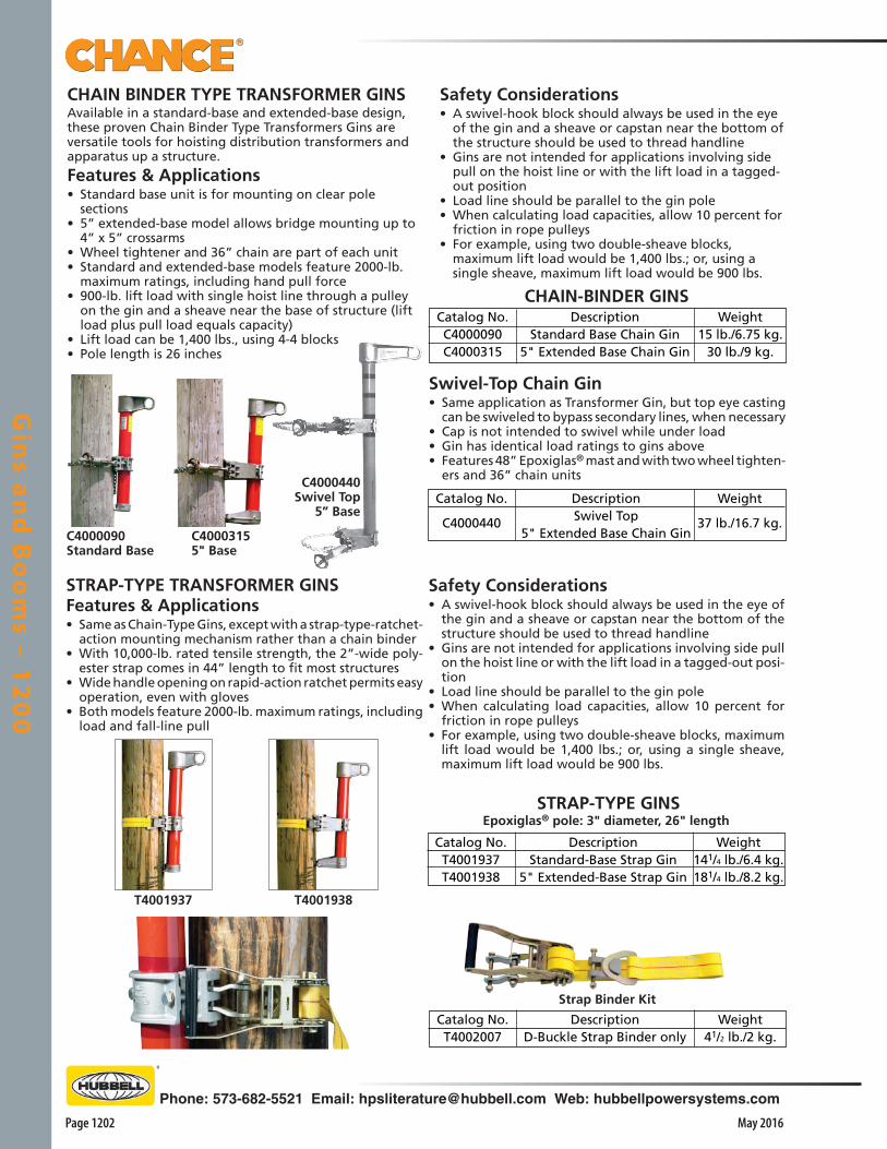
Gin
s an
d B
oo
ms – 1
20
0
Page 1202 May 2016
Phone: 573-682-5521 Email: [email protected] Web: hubbellpowersystems.com
Safety Considerations• A swivel-hook block should always be used in the eye
of the gin and a sheave or capstan near the bottom of the structure should be used to thread handline
• Gins are not intended for applications involving side pull on the hoist line or with the lift load in a tagged-out position
• Load line should be parallel to the gin pole• When calculating load capacities, allow 10 percent for
friction in rope pulleys• For example, using two double-sheave blocks,
maximum lift load would be 1,400 lbs.; or, using a single sheave, maximum lift load would be 900 lbs.
Swivel-Top Chain Gin• Same application as Transformer Gin, but top eye casting
can be swiveled to bypass secondary lines, when necessary• Cap is not intended to swivel while under load• Gin has identical load ratings to gins above• Features 48” Epoxiglas® mast and with two wheel tighten-
ers and 36” chain units
Catalog No.
C4000440
Weight
37 lb./16.7 kg.
DescriptionSwivel Top
5" Extended Base Chain Gin
STRAP-TYPE TRANSFORMER GINSFeatures & Applications• Same as Chain-Type Gins, except with a strap-type-ratchet-
action mounting mechanism rather than a chain binder• With 10,000-lb. rated tensile strength, the 2”-wide poly-
ester strap comes in 44” length to fit most structures• Wide handle opening on rapid-action ratchet permits easy
operation, even with gloves• Both models feature 2000-lb. maximum ratings, including
load and fall-line pull
Catalog No.T4001937T4001938
Weight141/4 lb./6.4 kg.181/4 lb./8.2 kg.
DescriptionStandard-Base Strap Gin
5" Extended-Base Strap Gin
Epoxiglas® pole: 3" diameter, 26" length
T4001938
Strap Binder Kit
Catalog No.T4002007
Weight41/2 lb./2 kg.
DescriptionD-Buckle Strap Binder only
C4000315 5" Base
C4000090Standard Base
T4001937
C4000440 Swivel Top
5” Base
CHAIN BINDER TYPE TRANSFORMER GINSAvailable in a standard-base and extended-base design, these proven Chain Binder Type Transformers Gins are versatile tools for hoisting distribution transformers and apparatus up a structure.
Features & Applications• Standard base unit is for mounting on clear pole
sections• 5” extended-base model allows bridge mounting up to
4” x 5” crossarms• Wheel tightener and 36” chain are part of each unit• Standard and extended-base models feature 2000-lb.
maximum ratings, including hand pull force• 900-lb. lift load with single hoist line through a pulley
on the gin and a sheave near the base of structure (lift load plus pull load equals capacity)
• Lift load can be 1,400 lbs., using 4-4 blocks• Pole length is 26 inches
Catalog No.C4000090C4000315
Weight15 lb./6.75 kg.
30 lb./9 kg.
DescriptionStandard Base Chain Gin
5" Extended Base Chain Gin
Safety Considerations• A swivel-hook block should always be used in the eye of
the gin and a sheave or capstan near the bottom of the structure should be used to thread handline
• Gins are not intended for applications involving side pull on the hoist line or with the lift load in a tagged-out posi-tion
• Load line should be parallel to the gin pole• When calculating load capacities, allow 10 percent for
friction in rope pulleys• For example, using two double-sheave blocks, maximum
lift load would be 1,400 lbs.; or, using a single sheave, maximum lift load would be 900 lbs.
CHAIN-BINDER GINS
STRAP-TYPE GINS
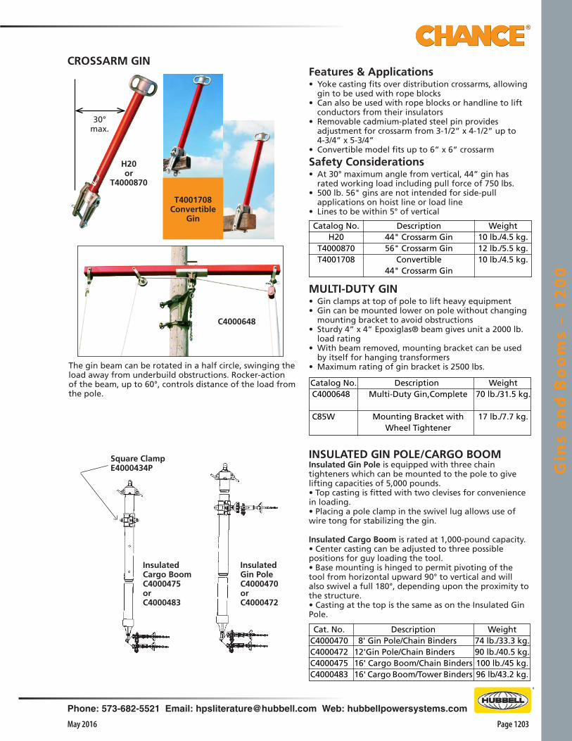
Gin
s a
nd
Bo
om
s –
12
00
Page 1203May 2016
Phone: 573-682-5521 Email: [email protected] Web: hubbellpowersystems.com
INSULATED GIN POLE/CARGO BOOMInsulated Gin Pole is equipped with three chain tighteners which can be mounted to the pole to give lifting capacities of 5,000 pounds.• Top casting is fitted with two clevises for convenience in loading.• Placing a pole clamp in the swivel lug allows use of wire tong for stabilizing the gin.
Insulated Cargo Boom is rated at 1,000-pound capacity.• Center casting can be adjusted to three possible positions for guy loading the tool.• Base mounting is hinged to permit pivoting of the tool from horizontal upward 90° to vertical and will also swivel a full 180°, depending upon the proximity to the structure.• Casting at the top is the same as on the Insulated Gin Pole.
Features & Applications• Yoke casting fits over distribution crossarms, allowing
gin to be used with rope blocks• Can also be used with rope blocks or handline to lift
conductors from their insulators• Removable cadmium-plated steel pin provides
adjustment for crossarm from 3-1/2” x 4-1/2” up to 4-3/4” x 5-3/4”
• Convertible model fits up to 6” x 6” crossarm
Safety Considerations• At 30° maximum angle from vertical, 44” gin has
rated working load including pull force of 750 lbs.• 500 lb. 56" gins are not intended for side-pull
applications on hoist line or load line• Lines to be within 5° of vertical
Catalog No.H20
T4000870T4001708
Weight10 lb./4.5 kg.12 lb./5.5 kg.10 lb./4.5 kg.
Description44" Crossarm Gin56" Crossarm Gin
Convertible44" Crossarm Gin
MULTI-DUTY GIN• Gin clamps at top of pole to lift heavy equipment• Gin can be mounted lower on pole without changing
mounting bracket to avoid obstructions• Sturdy 4” x 4” Epoxiglas® beam gives unit a 2000 lb.
load rating• With beam removed, mounting bracket can be used
by itself for hanging transformers• Maximum rating of gin bracket is 2500 lbs.The gin beam can be rotated in a half circle, swinging the
load away from underbuild obstructions. Rocker-action of the beam, up to 60°, controls distance of the load from the pole.
Catalog No.C4000648
C85W
DescriptionMulti-Duty Gin,Complete
Mounting Bracket with Wheel Tightener
Weight70 lb./31.5 kg.
17 lb./7.7 kg.
C4000648
Square ClampE4000434P
Insulated Cargo BoomC4000475orC4000483
InsulatedGin PoleC4000470orC4000472
Cat. No.C4000470C4000472C4000475C4000483
Weight74 lb./33.3 kg.90 lb./40.5 kg.100 lb./45 kg.96 lb/43.2 kg.
Description 8' Gin Pole/Chain Binders12'Gin Pole/Chain Binders16' Cargo Boom/Chain Binders16' Cargo Boom/Tower Binders
H20or
T4000870
30°max.
T4001708Convertible
Gin
CROSSARM GIN

Gin
s an
d B
oo
ms – 1
20
0
Page 1204 May 2016
Phone: 573-682-5521 Email: [email protected] Web: hubbellpowersystems.com
Features & Applications• 2-1/2” diameter Epoxiglas® poles are used to brace
either heavy-duty or medium-duty Swivel Booms in tripod arrangement
• Poles are anchored to steel tower with tower-type saddles (M4742 and M47413)
BOOM SUPPORT POLE
CatalogNo.
H4721112
Pole Diameter& Length21/2" x 12'
OverallLength12'9"
Weight18.5 lb./8.3 kg.
Catalog No.C4000464
C4000465
C4000469
Weight128 lb./57.6 kg.
140 lb./63 kg.
140 lb./63 kg.
Description16' Boom, 8' Mast, Clamps For Tower Mounting18' Boom, 10' Mast, Clamps For Tower Mounting18' Boom, 10' Mast, Chain Binders for Pole Mounting
SWIVEL BOOM — HEAVY DUTYFeatures & Applications• Used on EHV to swing an insulator cradle with
insulators into a structure for repair• 1,000-lb. capacity with 4” x 4” Epoxiglas® horizontal
boom, coupled with 3” round Epoxiglas mast• Unit rigging requires a link stick and hoisting device in
diagonal position• Clamp on square boom can be adjusted to three
possible positions for loading purposes• Casting on end of boom is fitted with two clevices for
convenient loading• Available with swivel boom on pole-mounted
configuration• Also available with four tower-mounting brackets to fit
towers up to 6” to 6” angle legs
Catalog No.H1973814
H1973H10
Weight70 lb./31.5 kg.
61 lb./27.5 kg.
Description14' Boom, 8' Mast, Clamps For Tower Mounting10' Boom, 6' Mast, Chain Binders for Pole Mounting
C4000469
H1973H10
H4721112
Tower Mounting BracketC4000602
• Same tool is also used as horizontal member for trolley pole changeouts of suspension insulators
SWIVEL BOOM — MEDIUM DUTYFeatures & Applications• Used on transmission structures to lift and move an insulator cradle
with insulators into a convenient work position on a structure• 3”-round Epoxiglas® horizontal boom and vertical mast
are designed for 500-lb. ratings when used in a steel-tower configuration
• 600-lb. rating for wood-pole assembly• Insulated link stick and hoist are used in diagonal position to lift
cradle full of insulators clear of deadendFor tower use, three boom support poles should be added in a tripod configuration as shown in the illustration at left below.

Loa
d H
an
dli
ng
Acc
ess
ori
es
– 1
25
0
Page 1251May 2016
Phone: 573-682-5521 Email: [email protected] Web: hubbellpowersystems.com
Load HandlingAccessories
Catalog 1250 May 2016
Loa
d H
an
dli
ng
Acc
ess
ori
es
– 1
25
0
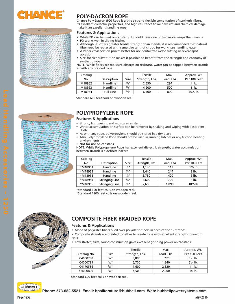
Loa
d H
an
dlin
g A
ccesso
ries – 1
25
0
Page 1252 May 2016
Phone: 573-682-5521 Email: [email protected] Web: hubbellpowersystems.com
POLY-DACRON ROPEChance Poly-Dacron (PD) Rope is a three-strand flexible combination of synthetic fibers. Its excellent dielectric properties, and high resistance to mildew, rot and chemical damage make it an excellent handline rope.
Features & Applications• While PD can be used on capstans, it should have one or two more wraps than manila• PD works well in sliding hitches• Although PD offers greater tensile strength than manila, it is recommended that natural
fiber rope be replaced with same-size synthetic rope for workman handling ease• A wider cross-section proves better for accidental transverse cutting or severe spot
abrasion• Size-for-size substitution makes it possible to benefit from the strength and economy of
synthetic ropesNOTE: While fibers are moisture absorption resistant, water can be tapped between strands as with any braided rope
COMPOSITE FIBER BRAIDED ROPEFeatures & Applications• Made of polyester fibers plied over polyolefin fibers in each of the 12 strands• Composite strands are braided together to create rope with excellent strength-to-weight ratio• Low stretch, firm, round construction gives excellent gripping power on capstans
POLYPROPYLENE ROPEFeatures & Applications• Strong, lightweight and moisture-resistant• Water accumulation on surface can be removed by shaking and wiping with absorbent
cloth• As with any rope, polypropylene should be stored in a dry place• Also, Polypropylene Rope should not be used in running hitches or any friction heating
environments• Not for use on capstansNOTE: While Polypropylene Rope has excellent dielectric strength, water accumulation between strands is a definite hazard
Standard 600 feet coils on wooden reel.
Max.Load, Lbs.
7751,3402,3202,900
TensileStrength, Lbs.
3,880 6,70011,60014,500
Catalog No.C4000798C4000799C4170586C4000800
Approx. Wt.Per 100 Feet
31/2 lb.61/4 lb.11 lb.14 lb.
Size3/8"1/2"5/8"3/4"
DescriptionHandlineHandlineHandline
Stringing LineStringing Line
TensileStrength, Lbs.
1,1302,4403,7805,6007,650
Max.Load, Lbs.
113 244 420 7001,090
*Standard 600 feet coils on wooden reel.†Standard 1200 feet coils on wooden reel.
Size1/4"3/8"1/2"5/8"3/4"
CatalogNo.
†M18951*M18952*M18953*M18954*M18955
Approx. Wt.Per 100 Feet
11/4 lb.3 lb.5 lb.8 lb.
103/4 lb.
DescriptionHandlineHandlineBull Line
TensileStrength, Lbs.
2,6504,2006,700
Max.Load, Lbs.
294500800
Approx. Wt.Per 100 Feet
4 lb.8 lb.
10.5 lb.
Standard 600 feet coils on wooden reel.
Size3/8"1/2"5/8"
CatalogNo.
M18962M18963M18964

Loa
d H
an
dli
ng
Acc
ess
ori
es
– 1
25
0
Page 1253May 2016
Phone: 573-682-5521 Email: [email protected] Web: hubbellpowersystems.com
22302
HAND LINE HOOKFeatures & Applications• Hook can be attached any place along the hand line by two large holes• The long point accommodates most items to be raised and lowered at the
pole• Maximum load of hook is 500 lbs. with load seated at bottom of hook
SNATCH BLOCKSFeatures & Applications• Lightweight, cast-aluminum housing and sheave with hinged, cotter-lock yoke and either forged-
steel or steel meat hook makes for quick, easy rigging in various applications• Hand line and block and tackle efficiency is increased with forged-steel, swivel-eye suspension
ring, plus three-inch sheave operating on bronze oilite bearings• Maximum rope size is 5/8”• Maximum load capacity is 1,250 lbs. on 2230 Series only
C4176067or 22301
Catalog No.C4000914
C4000924
C4000915
C4000925
T4001257
T4001258
Weight121/2 lb.
161/4 lb.
16 lb.
201/2 lb.
141/2 lb.
161/2 lb.
DescriptionTwo Double Blocks with 120' of 1/2"3-Str. Polypropylene RopeTwo Double Blocks with 120' of 1/2"3-Str. Polydacron RopeDouble and Triple Blocks with 150'of 1/2", 3-Str. Polypropylene RopeDouble and Triple Blocks with 150'of 1/2", 3-Str. Polydacron RopeTwo Double Blocks with 120'of 1/2", Composite Fiber Braided Rope Double and Triple Blocks with 150'of 1/2", Composite Fiber Braided Rope
GLASS FIBER FILLED NYLON ROPE BLOCKS
M1849
Catalog No.2230122302
C4176067PS400006
Description with Retainer Latch1250 lb. Block with forged steel hook1250 lb. Block with steel meat hook2500 lb. Block with forged steel hookBall Lok Pin Chain for 22301 or 22302
Weight2 lb./.9 kg.2 lb./.9 kg.6 lb./2.7 kg.
1⁄4 lb./0.11 kg.
Features & Applications• Shells and sheaves are made of high dielectric, fiber-filled natural nylon• Shaft is silicon bronze and sheave bearings are oil-impregnated bronze• Blocks available with Polypropylene or Poly-Dacron rope for minimum
stretch and long life• For working-load considerations, blocks are rated as follows: • Double Sheave Blocks, max. 3,500 lb. • Triple Sheave Blocks, max. 3,500 lb.• Dielectric Strength: Dielectric rating in dry weather is 30,000 Volts
between bearing and mounting bolt nut• Maximum rope size is ½”
HAND LINE BLOCK, SAFETY ORANGE•1,000 lb. working load
•Safety orange color
•Fiberglass reinforced nylon body & sheave
•Side-opening body design for easy rigging
Catalog No.PSC4033479PSC4033480
DescriptionLanyard and Pin Kit
Spring Latch Kit
Weight1/4 lb. / 0.11 kg.1/8 lb. / 0.05 kg.
Components available as separate itemsCatalog No. PSC4033478Weight: 11/4 lb. (0.57 kg.)Rated working load: 1,000 lb. (454 kg.)
Features & Applications• 3”-diameter sheave accepts up to 5/8”-diameter
rope• Plated-steel swivel eye allows 360* orientation• Plated-forged-steel hook has ¾ throat opening,
plus spring-loaded safety latch• Side-opening design includes high-strength
detent-ball pin that is easy to remove and is secured to body with a lanyard
Catalog No.C4000919C4000918
C4000918
C4000919
Weight31/4 lb.31/2 lb.
DescriptionDouble Block with BecketTriple Block without Becket
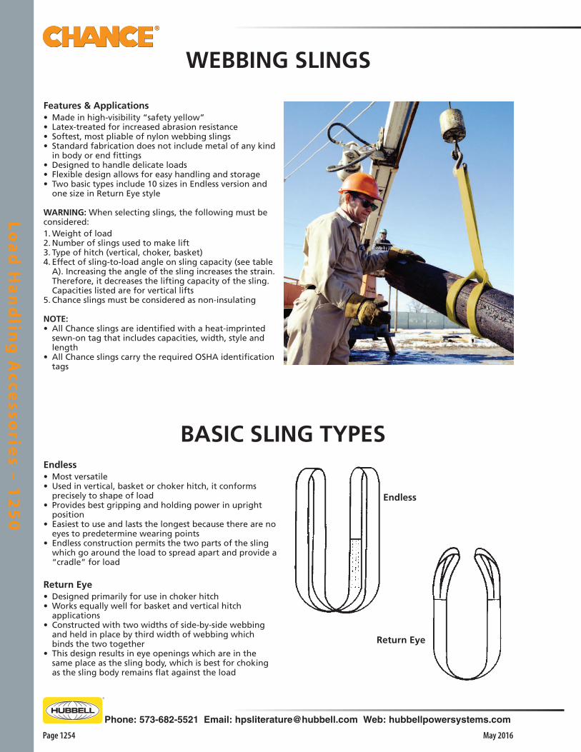
Loa
d H
an
dlin
g A
ccesso
ries – 1
25
0
Page 1254 May 2016
Phone: 573-682-5521 Email: [email protected] Web: hubbellpowersystems.com
Endless• Most versatile• Used in vertical, basket or choker hitch, it conforms
precisely to shape of load• Provides best gripping and holding power in upright
position• Easiest to use and lasts the longest because there are no
eyes to predetermine wearing points• Endless construction permits the two parts of the sling
which go around the load to spread apart and provide a “cradle” for load
Return Eye• Designed primarily for use in choker hitch• Works equally well for basket and vertical hitch
applications• Constructed with two widths of side-by-side webbing
and held in place by third width of webbing which binds the two together
• This design results in eye openings which are in the same place as the sling body, which is best for choking as the sling body remains flat against the load
BASIC SLING TYPES
Features & Applications• Made in high-visibility “safety yellow”• Latex-treated for increased abrasion resistance• Softest, most pliable of nylon webbing slings• Standard fabrication does not include metal of any kind
in body or end fittings• Designed to handle delicate loads• Flexible design allows for easy handling and storage• Two basic types include 10 sizes in Endless version and
one size in Return Eye style
WARNING: When selecting slings, the following must be considered:1. Weight of load2. Number of slings used to make lift3. Type of hitch (vertical, choker, basket)4. Effect of sling-to-load angle on sling capacity (see table
A). Increasing the angle of the sling increases the strain. Therefore, it decreases the lifting capacity of the sling. Capacities listed are for vertical lifts
5. Chance slings must be considered as non-insulating
NOTE: • All Chance slings are identified with a heat-imprinted
sewn-on tag that includes capacities, width, style and length
• All Chance slings carry the required OSHA identification tags
WEBBING SLINGS
Endless
Return Eye

Loa
d H
an
dli
ng
Acc
ess
ori
es
– 1
25
0
Page 1255May 2016
Phone: 573-682-5521 Email: [email protected] Web: hubbellpowersystems.com
*MAXIMUM WORKING LOAD IN POUNDS DO NOT USE SLINGS BEYOND RATED CAPACITY.
CHANCE WEBBING SLINGSRATED LIFTING CAPACITIES
LENGTHFeet
6'3'4'5'6'8'3'4'5'6'8'3'5'
Basket
72004800480048004800480064006400640064006400
1280017200
Choke
2900190019001900190019002500250025002500250050006900
Vertical
3600240024002400240024003200320032003200320064008600
TYPEReturn Eye (Eye
length: Approx. 4")
EndlessEndlessEndlessEndlessEndlessEndlessEndlessEndlessEndlessEndlessEndlessEndless
MAXIMUM CAPACITIES* (LBS.)
1,000 lb.
1,000 lb.
60°
1,000 lb.
707
lb.
1,000 lb.
707 lb.45°
How To Carry Two Full Buckets• Above illustrations typify the stresses imposed
on slings when legs are attached to the load at various angles
• While rated capacities are shown in this catalog, these tables were inserted primarily to show the severe reduction in capacity when a sling is operated at a wide angle
• Whenever head room permits, it is recommended that the angle with the vertical not exceed 45°
• Where head room is small and sling must be spread at an excessive angle, special care must be used in selecting a sling
• In such cases, consult your distributor or Hubbell Power Systems, Inc.
500
lb.
500
lb.
1,000 lb.
1,000 lb.
577
lb. 577 lb.
30°
05101520253035404550556080
TABLE ASLING ANGLES
Stresses perSling Leg
Per 1000 lb.Total Load
50050250851853255257761065370777887210002880
Sling Anglewith
Vertical
▲
WEBBING SLINGS
CATALOGNUMBER
C4170133C4170134C4170135C4170136C4170137C4170138C4170139C4170140C4170141C4170142C4170143C4170588C4170589
WIDTHInches
2"1"1"1"1"1"
13/4"13/4"13/4"13/4"13/4"1"
13/4"

Loa
d H
an
dlin
g A
ccesso
ries – 1
25
0
Page 1256 May 2016
Phone: 573-682-5521 Email: [email protected] Web: hubbellpowersystems.com
EPOXIGLAS® PIKE POLE• The point, secured by a spring-button lock, can be
reversed to protect point and avoid damage to equipment when not in use
• Does not absorb moisture so it will not rot or warp• Features excellent mechanical properties and is
relatively lightweight
EPOXIGLAS® HANDLE CANT HOOK• Replaces the conventional wood handle cant hook• Handle is made of 2” diameter x 4’ long orange
EPOXIGLAS• Hook is one-piece high carbon steel, end upset, forged
and drawn to a point• Gripper casting incorporates two sets of teeth for
improved grip on all pole sizes• Hook base casting is adjustable to set poles of varying
diameters• A hex head bolt and lockwasher hold base casting in
desired position
CatalogNo.
214PH216PH218PH
Pole Diameter& Length2" x 14'2" x 16'2" x 18'
Approx.Weight
101/2 lb./4.8 kg.113/4 lb./5.3 kg.13 lb./5.9 kg.
Catalog No.C3050008
DescriptionCant Hook
Approx. Wt. Ea.10 lb./4.5 kg.
CHANCE POLE TONG• Designed to be used like giant pliers, one worker can
guide a pole into place during installation• Before this tool was developed, it took two workers
with peavey sticks to do the job• Applying pressure to keep the jaws closed, a worker
controls forward, backward, side-to-side, and rotary movements of pole as it is lowered by winch or winch line on a hydraulic boom
• Not necessary to regrip the pole once jaws are firmly hooked slightly above ground level
• Fits poles from 7” to 16” in diameter
Catalog No.C200T
Handle Length3 ft.
Approx. Weight17 lb./6.6 kg.
Catalog No.C3050021
Weight61/2 lb./2.9 kg.
DescriptionPole Wrench
POLE WRENCH• Two-in-one tool performs functions of a cant hook and
pole tong without spiking the pole• With positive control, it grasps poles of round or other
geometric cross sections made of metal, fiber, concrete or wood
• Latex-impregnated nylon-web strap (1-3/4” x 6’) rated at 7.500-lb. tensile strength, securely grips even large-diameter poles
• Rugged design also includes a 2”-diameter x 4’ Chance orange Epoxiglas® handle with plastisol butt cap, a cast-aluminum head and two forged-steel bails.
POLE HANDLING TOOLS
Catalog No. DescriptionApprox. Weight
024095P Pike Pole Point Replacement .49 lb
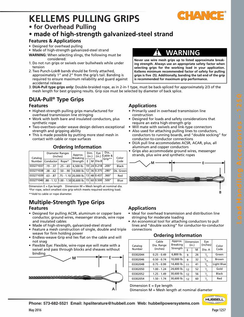
Loa
d H
an
dli
ng
Acc
ess
ori
es
– 1
25
0
Page 1257May 2016
Phone: 573-682-5521 Email: [email protected] Web: hubbellpowersystems.com
Ordering Information
ColorCode
Green
Brown
Light Blue
Gold
Black
Red
1/4
5/16
3/8
1/2
1/2
1/2
Dia. A
Eye(inches)
M
26
32
41
52
56
60
9
9
11
12
12
12
E
Dimension(in.)
6,800 lb.
10,000 lb.
14,400 lb.
24,600 lb.
30,600 lb.
30,600 lb.
Approx.BreakingStrength
CableDia. Range
(inches)
0.25 - 0.49
0.50 - 0.74
0.75 - 0.99
1.00 - 1.24
1.25 - 1.49
1.50 - 1.74
Catalog Number
03302044
03302046
03302048
03302050
03302052
03302054
Dimension E = Eye lengthDimension M = Mesh length at nominal diameter
KELLEMS PULLING GRIPS• for Overhead Pulling• made of high-strength galvanized-steel strandFeatures & Applications• Designed for overhead pulling• Made of high-strength galvanized-steel strandWARNING: When selecting slings, the following must be
considered:1. Do not run grips or swivels over bullwheels while under
tension2. Two Punch-Lok® bands should be firmly attached,
approximately 1” and 2” from the grip’s tail. Banding is required to ensure maximum reliability and guard against accidental release
3. DUA-Pull type grips only: Double-braided rope, as in 2-in-1 type, must be back-spliced for approximately 2/3 of the mesh length for best gripping results. Grip size must be selected by diameter of back splice.
DUA-Pull® Type GripsFeatures • Highest-strength pulling grips manufactured for
overhead transmission line stringing• Work with both bare and insulated conductors, plus
synthetic rope• Two-over/two-under weave design delivers exceptional
strength and gripping ability• This is made possible by putting more steel mesh in
contact with cable or rope surfaces
Applications• Primarily used in overhead transmission line
construction• Designed for loads and safety considerations that
require an extra high-strength grip• Will mate with swivels and link-type connectors• Also used for attaching pulling lines to conductors,
conductors to running boards, and “double socking” for conductor-to-conductor connections
• DUA pull line accommodates ACSR, ACAR, plus, all aluminum and copper conductors
• Grips also accommodate ground wires, messenger strands, plus wire and synthetic ropes
Multiple-Strength Type Grips
033271037
033271038
033271039
033271040
ColorCode
Black
Dk. Green
Red
Blue
.200"
.280"
.360"
.500"
Dia.,Cable &Grip**
0.218
0.375
0.437
0.500
Dia.B
Eye(in.)
10
12
13
15
E
24
36
48
60
M
Dim.(in.)
Catalog Number
Diameter Ranges(inches)
Rope*
.25 - .65
.50 - .90
.75 - 1.10
1.00 - 1.50
Approx.BreakingStrength
6,500 lb.
14,000 lb.
20,000 lb.
30,600 lb.
Dimension E = Eye length Dimension M = Mesh length at nominal dia.*For rope, select smallest size grip which meets required working load.
**Add to cable or rope diameter.
Ordering Information
Conductor
.19 - .37
.38 - .62
.63 - .87
.88 - 1.12
Never use wire mesh grips up to listed approximate break-ing strength. Always use an appropriate safety factor when selecting grips for the working load in your application. Kellems minimum recommended factor of safety for pulling grips is five (5). Additionally, banding the tail end of the grip is recommended for maximum grip performance.
! WARNING
B
M E
EM
A
Features • Designed for pulling ACSR, aluminum or copper bare
conductor, ground wires, messenger strands, wire rope and insulated cables
• Made of high-strength, galvanized-steel strand• Feature a mesh construction of single, double and triple
weave for firm holding power• Endless-weave Grip end lies flat on the cable and will
not snag• Flexible Eye: Flexible, wire-rope eye will mate with a
swivel and pass through blocks and sheaves without binding
Applications• Ideal for overhead transmission and distribution line
stringing for moderate loading• An economical tool for attaching conductors to pull
lines and “double socking” for conductor-to-conductor connections
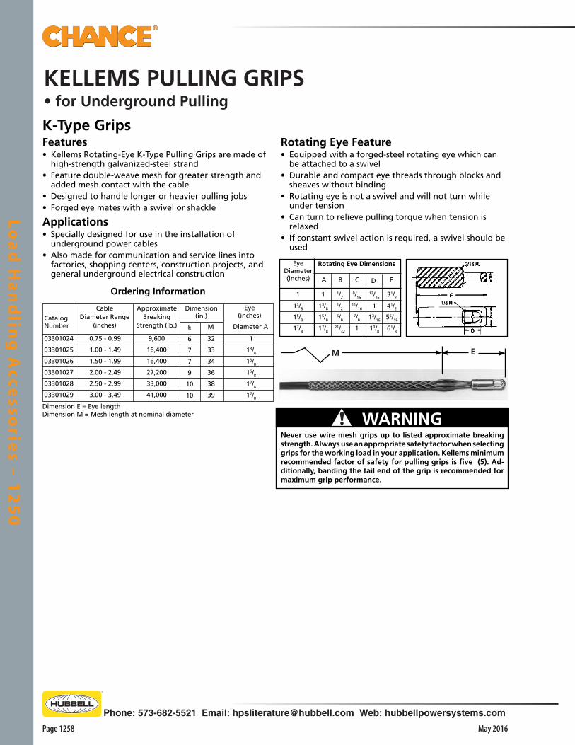
Loa
d H
an
dlin
g A
ccesso
ries – 1
25
0
Page 1258 May 2016
Phone: 573-682-5521 Email: [email protected] Web: hubbellpowersystems.com
M E
K-Type GripsFeatures• Kellems Rotating-Eye K-Type Pulling Grips are made of
high-strength galvanized-steel strand• Feature double-weave mesh for greater strength and
added mesh contact with the cable• Designed to handle longer or heavier pulling jobs• Forged eye mates with a swivel or shackle
Applications• Specially designed for use in the installation of
underground power cables• Also made for communication and service lines into
factories, shopping centers, construction projects, and general underground electrical construction
Rotating Eye Feature• Equipped with a forged-steel rotating eye which can
be attached to a swivel• Durable and compact eye threads through blocks and
sheaves without binding• Rotating eye is not a swivel and will not turn while
under tension• Can turn to relieve pulling torque when tension is
relaxed• If constant swivel action is required, a swivel should be
used
03301024
03301025
03301026
03301027
03301028
03301029
Catalog Number
CableDiameter Range
(inches)
0.75 - 0.99
1.00 - 1.49
1.50 - 1.99
2.00 - 2.49
2.50 - 2.99
3.00 - 3.49
ApproximateBreaking
Strength (lb.)
9,600
16,400
16,400
27,200
33,000
41,000
6
7
7
9
10
10
E
Dimension(in.)
Eye(inches)
Diameter A
1
13/8
13/8
15/8
17/8
17/8
32
33
34
36
38
39
M
Dimension E = Eye lengthDimension M = Mesh length at nominal diameter
Ordering InformationFDCBA
Rotating Eye Dimensions
31/2
41/2
55/16
61/8
13/16
1
13/16
13/8
9/16
11/16
7/8
1
1/2
1/2
5/8
21/32
1
13/8
15/8
17/8
1
13/8
15/8
17/8
EyeDiameter(inches)
Never use wire mesh grips up to listed approximate breaking strength. Always use an appropriate safety factor when selecting grips for the working load in your application. Kellems minimum recommended factor of safety for pulling grips is five (5). Ad-ditionally, banding the tail end of the grip is recommended for maximum grip performance.
! WARNING
KELLEMS PULLING GRIPS• for Underground Pulling
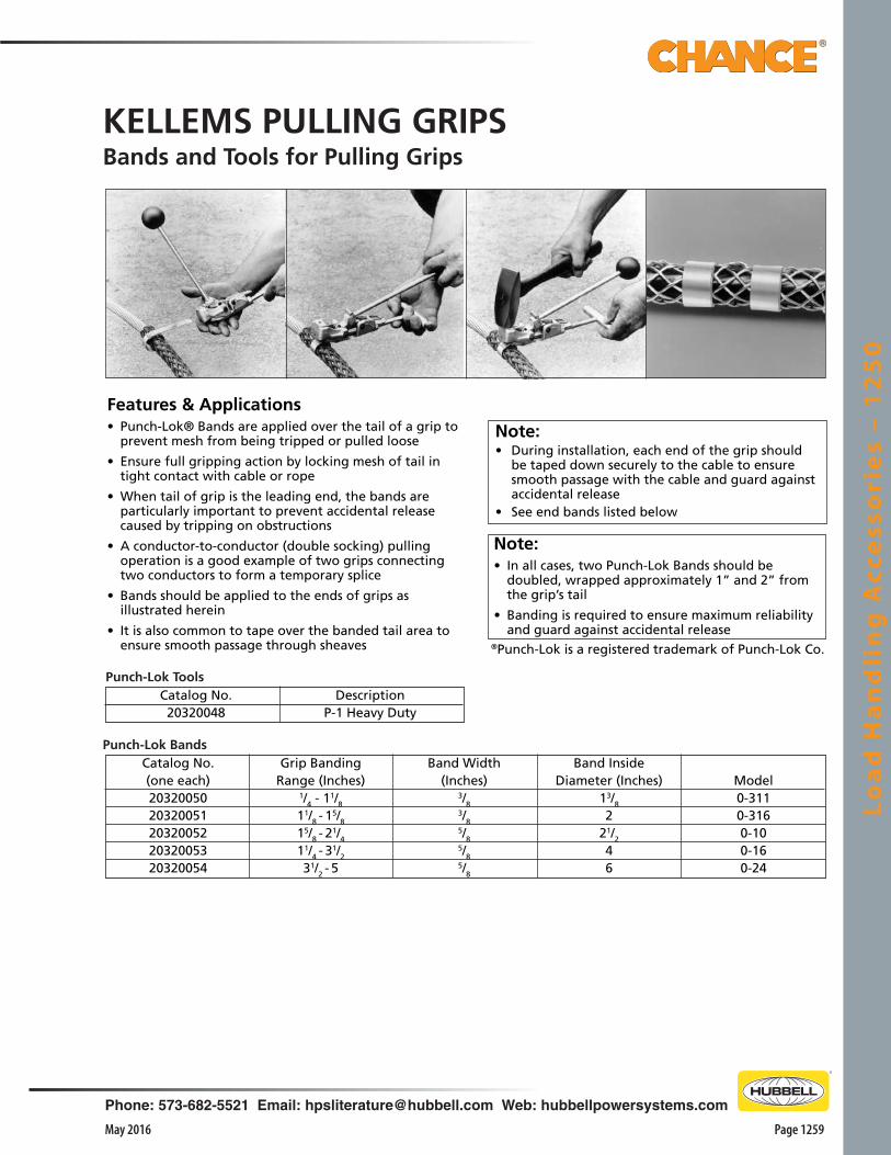
Loa
d H
an
dli
ng
Acc
ess
ori
es
– 1
25
0
Page 1259May 2016
Phone: 573-682-5521 Email: [email protected] Web: hubbellpowersystems.com
®Punch-Lok is a registered trademark of Punch-Lok Co.
Note:• In all cases, two Punch-Lok Bands should be
doubled, wrapped approximately 1” and 2” from the grip’s tail
• Banding is required to ensure maximum reliability and guard against accidental release
Features & Applications• Punch-Lok® Bands are applied over the tail of a grip to
prevent mesh from being tripped or pulled loose
• Ensure full gripping action by locking mesh of tail in tight contact with cable or rope
• When tail of grip is the leading end, the bands are particularly important to prevent accidental release caused by tripping on obstructions
• A conductor-to-conductor (double socking) pulling operation is a good example of two grips connecting two conductors to form a temporary splice
• Bands should be applied to the ends of grips as illustrated herein
• It is also common to tape over the banded tail area to ensure smooth passage through sheaves
Note:• During installation, each end of the grip should
be taped down securely to the cable to ensure smooth passage with the cable and guard against accidental release
• See end bands listed below
Catalog No.20320048
DescriptionP-1 Heavy Duty
Punch-Lok Tools
Punch-Lok BandsCatalog No.(one each)2032005020320051203200522032005320320054
Grip BandingRange (Inches)
1/4 - 11/8
11/8 - 15/8
15/8 - 21/4
11/4 - 31/2
31/2 - 5
Band Width(Inches)
3/83/85/85/85/8
Band InsideDiameter (Inches)
13/8
221/2
46
Model0-3110-3160-100-160-24
KELLEMS PULLING GRIPSBands and Tools for Pulling Grips

Loa
d H
an
dlin
g A
ccesso
ries – 1
25
0
Page 1260 May 2016
Phone: 573-682-5521 Email: [email protected] Web: hubbellpowersystems.com
Standard Pulling Eyes
Features & Applications• Economical resource provides a large offset eye to
accommodate three-ton chain hoist hooks• Leaves anchor eye free with plenty of clearances for
attaching formed wire grips
E95B Adapter Bushing (included)Replacement kit C3031661
Pulling Eye5/8 x 25/8 Lg.Cadmium Plated Bolt with Nut
1 3/4 5/8 1/2
Wire Puller Hook
Catalog No.WPH3
Weight11/2 lb./68 kg.
DescriptionWire-Puller Hook
Hot Line Wire Grips
▲ = for use on small bare wire and cable (solid and strand).
● = for use on bare aluminum, ACSR and copper conductor.
Weight
lb./kg.
3/1.4
6.25/2.8
7.75/3.5
7.75/3.5
WIRE SIZE — AWG OR MCM
Safe
Load,
lb.
4500
8000
8000
8000
Min.
8 Sol. (.120")
4 Str. (.218")
3/0 ACSR (.530")
397.5 ACSR (.740")
Max.
1/0 Str. (.373")
4/0 Str. (.550")
336.4 ACSR (.741")
477 ACSR (.860")
Catalog
No.
T161340H
T16845H
T165640H
T165650H
Jaws
▲
▲
●
●
Features & Applications• Fits most popular porcelain or polymer deadend insula-
tors• For use in cutting deadends and pulling slack on auto-
matic deadends• Holds the insulator and deadend assembly directly iIn
line with the conductor, eliminating the need to hold the insulator up with an insulator fork for inserting wire into the automatic deadend
• Can be applied by hand or with hot stick• Has maximum rated load of 3500 lbs.
Features & Applications• Designed for use with hot line tools or regular line work • Top ring for placing the grip on a hot line with a hot
stick• When released, the grip locks on line and will not fall
off• Holds grip firmly and prevents slipping• Body is heat-treated steel alloy and made to rigid
specifications
• E95B Adapter Bushing quickly adjusts to fit 1/2", 5/8", 3/4", or 1" anchor rods
• By removing the Adapter Bushing, the E96 Pulling Eye fits 1 1/4" rods
• E96 Pulling Eye is inexpensive and easy to use• One man can assemble and hook up in minutes• For working loads to approximately 6,000 pounds
(ultimate strength — 18,000 pounds)
Catalog No.E96
Weight5 lb./272 kg.

Insu
late
d H
an
d T
oo
ls –
21
00
Phone: 573-682-5521 Email: [email protected] Web: hubbellpowersystems.com
Page 2101May 2016
Section
2100
Insu
late
d H
an
d T
oo
ls –
21
00Insulated
Hand Tools
Catalog 2100 May 2016

Insu
late
d H
an
d To
ols – 2
10
0
Page 2102
Phone: 573-682-5521 Email: [email protected] Web: hubbellpowersystems.com
May 2016
069598Jaw Spring
PSP4033460PJaw, stainless steel PSP4033459P
Jaw Holder, aluminum058804PPin
PSP4033458P Safety Stop,stainless steel
058717P Screw, stainless steel PSP4033462PLockbar
P4032044PPlastic Handle
068270PGroove Pin
PSP4033152PCompression Spring
069118P HangerPSP4033482PBlack Plastic Head
P0010742P Hose Clamp
P4032312PEnd Cap(11⁄4" dia.)
PSP4033461PLatch, stainless steel
069599PLatchSpring
058735P Drive Rivet
P4031107P Guide
Molly Jack058719P Nut
Operation• Operating mechanism (or
“shotgun”) incorporates a sliding hand grip that opens the hook to grasp a clamp eyescrew and retract it into tool head
• Latch must be depressed to release locked hand grip that opens the hook
• For smooth operation, investment-cast stainless-steel components include Jaw, Jaw Holder, Safety Stop, Lockbar and Latch illustrated below
• Lexan® tool head is designed for close-quarter operations
• Worker must maintain recommended work distance based solely on the Epoxiglas® pole section of the handle, as the hook and its actuator are metal parts
• Easy-care Grip-All Clampsticks do not require field stripping to clean
• All insulated parts, including the operating rod, are outside the main pole, readily accessible to wipe dry
• External Operating Rod Type • Tested per OSHA & ASTM F711• Versatile tool puts an easy-to-control “finger” on an insulated pole• Primarily designed for installing hot-line and
grounding clamps• Also serves both overhead and underground
circuits with various end fittings
Grip-All ClampsticksExternal Control Rod
To accept grounding clamps with long eyescrews, all Grip-All clampsticks feature 63⁄4 inches of head travel.
Notch in tool head aligns the clamp while the operator places it.
M1867
To convert any Grip-All stick to use all Universal Tool Accessories, the M1867 Adapter secures in the clampstick hook and head housing.
Replacement Parts for External Control Single-Piece and Hinged Grip-All ClampsticksHead Repair Kit, also available as Cat. No. C4031420, includes head, roll pin, epoxy bond kit and instructions.
†For metal universal fitting, add suffix "A".*For storage bags, see Catalog Section 2500.
†Catalog No.
Overall Length Weight *Storage Bag
C4030291 11⁄4" x 4' 9" 53⁄4 lb./2.6 kg. P6434C4030292 11⁄4" x 6' 8" 61⁄2 lb./2.9 kg. P6436
C4030293 11⁄4" x 8' 7" 71⁄4 lb./3.3 kg. P6438C4030294 11⁄4" x 10' 7" 8 lb./3.6 kg. P64310
C4030295 11⁄4" x 12' 7" 83⁄4 lb./3.9 kg. P64312
Single-Piece Style
†For metal universal fitting on handle end of any Single-Piece or Hinged Grip-All, add suffix “A” to the Catalog Number.
†Catalog No. Folded Extended Weight *Storage Bag
C4030296 3'4" 11⁄4" x 6' 9" 8 lb./3.6 kg. P6432
C4030297 4'4" 11⁄4" x 8' 8" 9 lb./4.1 kg. P6432
C4030298 5'4" 11⁄4" x 10' 8" 10 lb./4.5 kg. P6433
C4030299 6'4" 11⁄4" x 12' 8" 101⁄2 lb./4.7 kg. P6435C4030342 7'4" 11⁄4" x 14' 8" 11 lb./5.0 kg. PSP6435005C4030343 8'4" 11⁄4" x 16' 8" 111⁄2 lb./5.2 kg. PSP6435004
Hinged StyleIdeal for troubleshooters with limited tool-storage space in their vehicles, this folding version operates with the same features as the one-piece style.
†For metal universal fitting, add suffix "A".*For storage bags, see Catalog Section 2500.

Insu
late
d H
an
d T
oo
ls –
21
00
Phone: 573-682-5521 Email: [email protected] Web: hubbellpowersystems.com
Page 2103May 2016
RetractedLength5'61⁄2"8'61⁄2"
Extended Tool canlock at each length:
5'101⁄2", 7'11⁄4", 8'33⁄4"8'101⁄2", 10'81⁄4", 12'6", 14'33⁄4"
RetractedLength5'23⁄4"8'23⁄4"
Extended Tool canlock at each length:
5'63⁄4", 6'91⁄2", 8'8'63⁄4", 10'41⁄2", 12'21⁄4", 14'
Grip-All Clampsticks,TelescopingTested per OSHA & ASTM F711
For storage bags, see Catalog Section 2500.
Weight6 lb./2.7 kg.8 lb./3.6 kg.
Catalog No.C4031035C4031036 Factory-installed universal fitting on end
opposite the clampstick head.
Features & Applications• Tested per OSHA & ASTM F711• Available in two sizes, each readily locks at variable working
lengths• Design features rotating coupler and an engineered positive-
lock button with safety stop to keep sections from parting or hook releasing while in use
• Mechanism locks sections into a solid, rattle-free tool• Black head makes it obvious head is not included in minimum approach distance• Can replace several conventional clampsticks• Allows linemen to adhere to safe-working distances and
positioning needs, with fewer sticks• Reduces the number of clampsticks required on a line
truck, saving limited storage space• Engineered interface between sections ensure tool
retracts with full control• Close fit helps keep out dirt and moisture• Top section is made with foam-center Epoxiglas®
insulated pole• Functions of this telescoping style are identical to fixed-
length style• All controls can be easily accessed while wearing gloves• Easy to disassemble, stick must be kept clean and dry
inside to ensure long life
Grip-All Clampstick Assist Ring
Features & Applications• Provides a suspension midpoint for any Grip-All clampstick• Assembly permits support line to attach at smaller ring –
helpful on longer sticks• Insulated, properly-sized Strain Link
Stick should be used in the handline to help maintain safe-working clearances for hotline procedures
• Assist Ring halves assemble simply by threaded fasteners
• Keyhole shape for operating rod permits clampstick to function as usual
*For Strain Link Sticks, see Catalog Section 2250.
Telescoping Style with Universal Fitting on Handle
Weight6 lb./2.7 kg.8 lb./3.6 kg.
Catalog No.C4033060C4033061
For storage bags, see Catalog Section 2500.
Catalog No. Description WeightE4032543P Grip-All Assist Ring 11/2 lb./0.68 kg.
For SAFETYSHIELD™ Hot Stick Barrier to fit tools on this page, see page 2129.

Insu
late
d H
an
d To
ols – 2
10
0
Page 2104
Phone: 573-682-5521 Email: [email protected] Web: hubbellpowersystems.com
May 2016
Impact Elbow Pullers(Grippers not included. Order Grippers separately. See REPLACEMENT GRIPPERS table, page 2104.)
Description†6-foot length†8-foot length
*41⁄2-foot length
Catalog No.C4031822C4031850C4031851
Weight12 lb./5.4 kg.
121⁄4 lb./5.6 kg.111⁄2 lb./5.2 kg.
*41⁄2-foot tool labeled “For Rubber Glove Use Only.”†6- and 8-foot tools meet OSHA insulation requirements.
Storage Bags (Yellow vinyl/fabric)
Bag for 41⁄2' or 6' tool aboveBag for 8' tool above
P6436P6438
ELBOW PULLER TOOLSNote: Grippers are not included with tools on this page. To order grippers interchangeable for 15, 25 and 35 kV, see REPLACEMENT GRIPPERS table on page 2105.
Features & Applications• Tested per OSHA & ASTM F711• Facilitate removing elbow connectors from transformer
bushings and other apparatus• Elbows can be difficult to remove when silicone grease on
the interface of elbow and bushing dries out and hardens over time
• Special integral hook on tool head fits through rubber eye of elbow or metal hook of bushing cap
• Used in this manner, hook adds extra control and pulling power to grippers
For SAFETYSHIELD™ Hot Stick Barrier to fit tools on this page, see page 2129.
IMPACT Elbow-Puller ToolsFeatures & Applications• Lightweight tool uses slide-hammer mechanism to easily
disengage and replace elbows• Tool and grippers help operator to control elbow and stiff
underground cable lead• For sure, balanced grip, 5-lb. slide hammer is plastisol coated
and flared at both ends• For secure handling, both front and rear handgrip areas of
pole are coated with Griptread• Available in three lengths, tools are made of 1-1/4”-diameter
orange Epoxiglas® pole• 6’ to 8’ foot units meet OSHA requirements • 4-1/2’ unit, labeled “For Rubber Glove Use Only”, has 5”-long insulation length
OperationTo pull an elbow connector:• Insert hook through eye on elbow• Close down grippers on elbow by rotating pole• Support tool with one hand on front grip behind handguard
and other hand on slide hammer• Slide hammer from front to rear anvil• Resulting impact should release elbow with sufficient
momentum to withdraw it from bushing without extended arcing
To install an elbow connector:• Follow the same procedures for pulling, EXCEPT use slide
hammer impact against front anvil to help seat the elbow

Insu
late
d H
an
d T
oo
ls –
21
00
Phone: 573-682-5521 Email: [email protected] Web: hubbellpowersystems.com
Page 2105May 2016
ORDERING INFORMATION
DescriptionRemoval Tool
Replacement Tool
Catalog No.C4032037C4032036
Weight1⁄4 lb./0.1 kg.1⁄4 lb./0.1 kg.
ELBOW CONNECTOR TOOLREPLACEMENT GRIPPERS
FOR 15 kV, 25 kV and 34.5 kV ELBOWS
REPLACEMENT GRIPPERS (Also required for Elbow Puller Tools, page 2105)
Catalog No.C4030704C4030613C4030614C4030814
Weight5⁄8 lb./.3 kg.1 lb./.5 kg.5⁄8 lb./.3 kg.1 lb./.5 kg.
Description15 kV Plastic-Coated Grippers25 kV Plastic-Coated Grippers25 kV Uncoated Grippers34.5 kV Plastic-Coated Grippers. Fits RTE200 AMP and 600 AMP Elastimold “T” Elbow
C4030704
Arc Snuffer Removal & Replacement Tools– specifically for use in Grip-All clampsticks –
Features & Applications• Two hot-line tools permit easy retrieval of broken arc snuffers
and installation of replacements• Does not de-energize URD bushings• Designed to ensure adequate electrical clearances• Specifically for use in Grip-All clampsticks• Integral ring on each tool retracts into clampstick• Tool bodies are high-impact plastic with steel inserts• Removal Tool works like bolt extractor and when inserted into
a damaged arc snuffer, it permits retrieval by unscrewing the broken part
• Replacement Tool controls alignment with a spring-action center post that snaps into arc snuffer bore
• Two steel tool lugs engage holes in snuffer collar to transmit tightening torque
• Should only be used on integral screw-in snuffers, such as Cooper Power Systems P/N: 2603710a04
ORDERING INFORMATION
Features & Applications• Provides a sure grip for installing and disconnecting elbow terminators• Grabs the elbow and has a special integral hook that fits through the rubber eye of an elbow
or the metal hook of a bushing cap• Gives lineman complete, positive control, overcoming resistance of stiff underground cable
These tools fit bushing arc snuffers with dimensions given at right.
Tools fit many15 & 25 kV snuffers.
1⁄2" dia.
7⁄8"
1⁄8" dia.
C4032037
C4032036

Insu
late
d H
an
d To
ols – 2
10
0
Page 2106
Phone: 573-682-5521 Email: [email protected] Web: hubbellpowersystems.com
May 2016
Features & Applications• Tested per OSHA & ASTM F711• Used on or around energized lines for forming, bending and positioning jumper
wires• Also used for holding conductors during splicing operations• Gripper, with an eye for extra sticks, will handle No. 6 copper through 1590
kcmil ACSR
Operation• Grips like locking-type pliers• By tightening the knurled nut at control lever, wire-holding jaws can firmly grip
conductor• When doing this, tightening control lever must be in relaxed position about 1”
from pole• To secure conductor grip, push lever down to the pole• To release conductor, simply move the control lever all the way up along the
rod• Head of tool locks in three stop positions, allowing lineman to easily position
conductors• Knurled screw handle below jaw opening adjusts head position from straight
to right to left
With handle positioned as shown in photo above, the knurled nut can be turned to adjust the gripper to the exact wire size.
Head of the tool locks in three positions . . . enables lineman to handle conductor from any angle.
Wire Holding StickC4033068
CatalogNo.
HG30302HG303012HG30422HG30425
Pole Dia. & Overall Length
11⁄4" x 8'6"11⁄4" x 8'6"
Approx.Weight
4 lb./1.8 kg.4 lb./1.8 kg.1 lb./0.45 kg.11⁄8 lb./0.5 kg.
Type HeadRegular Length
Extra LongHG30425Extra long head (above) for use with long eyescrew ground clamps.
Reg. Length Clampstick Head OnlyExtra Long Clampstick Head Only
WIRE-HOLDING STICKS
Conductor Capacity: #6 to 1590 kcmil ACSR (0.162" to 1.5")
For SAFETYSHIELD™ Hot Stick Barrier to fit tools on this page, see page 2129.
Catalog No. C4033068 C4033069 PSC4030592 T4032992
Pole Dia. & Overall Length11⁄4" x 6'5"11⁄4" x 8'5"
11⁄4" x 10'5"11⁄4" x 11'2"
Approx. Weight61⁄2 lb./2.7 kg.63⁄4 lb./3.0 kg.71⁄2 lb./3.4 kg.81⁄4 lb./3.7 kg.
Positive Grip ClampstickFeatures & Applications• Tested per OSHA & ASTM F711• For use on eyescrew grounding or hot line clamps• Can be mounted on the line and tightened at up to 30° angles• Aluminum and bronze fittings
Operation• Install clamp by aligning locking ring with slot in housing• Place eye of clamp in housing• Holding locking ring and clamp in one hand, rotate pole clockwise to
trap eye• Remove clamp by engaging clamp body locking ring and rotating pole
clockwise to trap eye• Butt end is equipped with a combination tool hanger and universal
head
Positive GripClamp StickHG30302
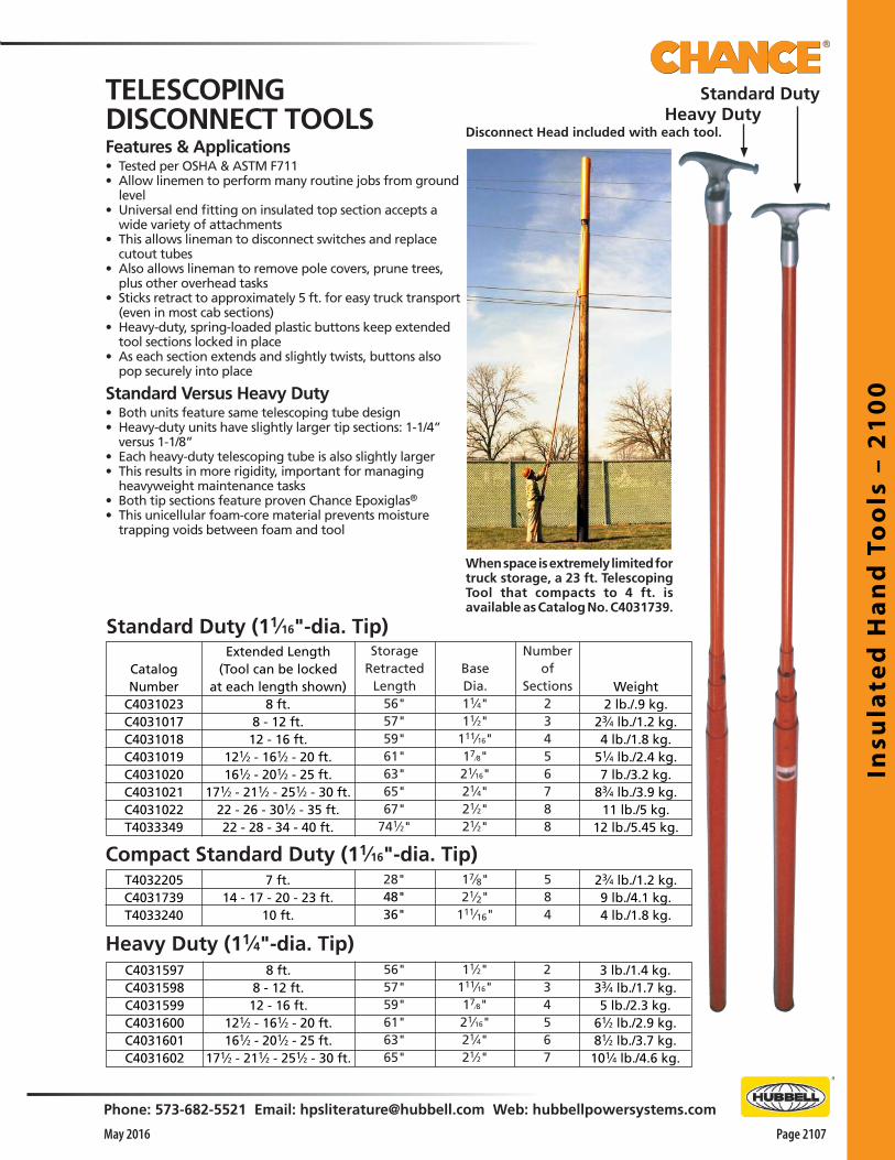
Insu
late
d H
an
d T
oo
ls –
21
00
Phone: 573-682-5521 Email: [email protected] Web: hubbellpowersystems.com
Page 2107May 2016
When space is extremely limited for truck storage, a 23 ft. Telescoping Tool that compacts to 4 ft. is available as Catalog No. C4031739.
Disconnect Head included with each tool.
Standard Duty (11⁄16"-dia. Tip)Number
ofSections
23456788
Weight2 lb./.9 kg.
23⁄4 lb./1.2 kg.4 lb./1.8 kg.
51⁄4 lb./2.4 kg.7 lb./3.2 kg.
83⁄4 lb./3.9 kg.11 lb./5 kg.
12 lb./5.45 kg.
BaseDia.11⁄4"11⁄2"
111⁄16"17⁄8"21⁄16"21⁄4"21⁄2"21⁄2"
StorageRetracted
Length56"57"59"61"63"65"67"
741⁄2"
Extended Length(Tool can be locked
at each length shown)8 ft.
8 - 12 ft.12 - 16 ft.
121⁄2 - 161⁄2 - 20 ft.161⁄2 - 201⁄2 - 25 ft.
171⁄2 - 211⁄2 - 251⁄2 - 30 ft.22 - 26 - 301⁄2 - 35 ft.22 - 28 - 34 - 40 ft.
CatalogNumber
C4031023C4031017C4031018C4031019C4031020C4031021C4031022T4033349
584
7 ft.14 - 17 - 20 - 23 ft.
10 ft.
T4032205C4031739T4033240
17⁄8"21⁄2"
111⁄16"
23⁄4 lb./1.2 kg.9 lb./4.1 kg.4 lb./1.8 kg.
TELESCOPINGDISCONNECT TOOLSFeatures & Applications• Tested per OSHA & ASTM F711• Allow linemen to perform many routine jobs from ground
level• Universal end fitting on insulated top section accepts a
wide variety of attachments• This allows lineman to disconnect switches and replace
cutout tubes• Also allows lineman to remove pole covers, prune trees,
plus other overhead tasks• Sticks retract to approximately 5 ft. for easy truck transport
(even in most cab sections)• Heavy-duty, spring-loaded plastic buttons keep extended
tool sections locked in place• As each section extends and slightly twists, buttons also
pop securely into place
Standard Versus Heavy Duty• Both units feature same telescoping tube design• Heavy-duty units have slightly larger tip sections: 1-1/4”
versus 1-1/8”• Each heavy-duty telescoping tube is also slightly larger• This results in more rigidity, important for managing
heavyweight maintenance tasks• Both tip sections feature proven Chance Epoxiglas®
• This unicellular foam-core material prevents moisture trapping voids between foam and tool
Compact Standard Duty (11⁄16"-dia. Tip)28"48"36"
234567
56"57"59"61"63"65"
8 ft.8 - 12 ft.12 - 16 ft.
121⁄2 - 161⁄2 - 20 ft.161⁄2 - 201⁄2 - 25 ft.
171⁄2 - 211⁄2 - 251⁄2 - 30 ft.
C4031597C4031598C4031599C4031600C4031601C4031602
11⁄2"111⁄16"17⁄8"21⁄16"21⁄4"21⁄2"
3 lb./1.4 kg.33⁄4 lb./1.7 kg.5 lb./2.3 kg.
61⁄2 lb./2.9 kg.81⁄2 lb./3.7 kg.
101⁄4 lb./4.6 kg.
Heavy Duty (11⁄4"-dia. Tip)
Standard DutyHeavy Duty
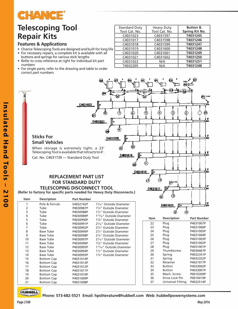
Insu
late
d H
an
d To
ols – 2
10
0
Page 2108
Phone: 573-682-5521 Email: [email protected] Web: hubbellpowersystems.com
May 2016
REPLACEMENT PART LISTFOR STANDARD DUTY
TELESCOPING DISCONNECT TOOL(Refer to factory for specific parts needed for Heavy Duty Disconnects.)
Sticks ForSmall VehiclesWhen storage is extremely tight, a 23’ Telescoping Tool is available that retracts to 4’.
Cat. No. C4031739 — Standard Duty Tool
11⁄16" Outside Diameter11⁄4" Outside Diameter11⁄2" Outside Diameter111⁄16" Outside Diameter17⁄8" Outside Diameter21⁄16" Outside Diameter21⁄4" Outside Diameter21⁄2" Outside Diameter21⁄4" Outside Diameter21⁄16" Outside Diameter17⁄8" Outside Diameter111⁄16" Outside Diameter11⁄2" Outside Diameter11⁄4" Outside Diameter
Item
123456789101112131415161718192021
Description
Pole & FerruleTubeTubeTubeTubeTubeTubeBase TubeBase TubeBase TubeBase TubeBase TubeBase TubeBase TubeBottom CapBottom CapBottom CapBottom CapBottom CapBottom CapBottom Cap
Part Number
E4032742PP4030987PP4030988PP4030989PP4030990PP4030991PP4030992PP4030999PP4030998PP4030997PP4030996PP4030995PP4030994PP4030993PP4031014PP4031013PP4031012PP4031011PP4031010PP4031009PP4031008P
Part Number
P4031007PP4031006PP4031005PP4031004PP4031003PP4031002PP4031001PP4030467PP4032351PP4032352PP4031977PP4033002PP4033001PP0010309PP0010419PP4032514P
Item
22232425262728293031323334353637
Description
PlugPlugPlugPlugPlugPlugPlugThumbscrewSpringSpringRetainerButtonButtonMach. ScrewDrive Lock PinUniversal Fitting
Telescoping ToolRepair KitsFeatures & Applications• Chance Telescoping Tools are designed and built for long life• For necessary repairs, a complete kit is available with all
buttons and springs for various stick lengths• Refer to cross reference at right for individual kit part
numbers• For single parts, refer to the drawing and table to order
correct part numbers
Standard DutyTool Cat. No.
Heavy DutyTool Cat. No.
Button &Spring Kit No.
C4031023 C4031597 T4031245C4031017 C4031598 T4031246C4031018 C4031599 T4031247C4031019 C4031600 T4031248C4031020 C4031601 T4031249C4031021 C4031602 T4031250C4031022 N/A T4031251T4032205 N/A T4031248

Insu
late
d H
an
d T
oo
ls –
21
00
Phone: 573-682-5521 Email: [email protected] Web: hubbellpowersystems.com
Page 2109May 2016
TelescopingMeasuring/Disconnect Tool• One tool does it all • English AND Metric ScalesTested per OSHA & ASTM F711
Features & Applications• Tested per OSHA & ASTM F711• English and metric scales for measuring pole heights and
conductor clearances from ground• Easy-to-read scales feature large black characters on Chance
orange fiberglass sections• English scales are marked with 1’ increments • Each inch is marked in bold numbers and half inches are
indicated with intermediate bars• Removable disconnect head for operating switches and
cutouts• End fitting on insulated top section accepts other Universal
Tool Accessories (Pages 2120 - 2127) for energized conductor applications, all from the ground
• Positive spring-load locking-button mechanism and plug feature prevent tool separation
• Once snapped into place, buttons securely lock into position – no unexpected tool retractions
Operation• To extend tool to desired length, pull out top section and
rotate it until button engages in next section• For measuring aerial distances, continue this process until tip
reaches desired height• Next, set butt of tool on ground and read scale at eye level
for exact distance of tip above ground• To retract, depress button of largest section first, then rotate
it to disengage and collapse section• Continue this process by taking each next smaller section in
turn
*CatalogNumber
C4031022EM
Number ofSections
8
Min.(storage)
5' 7" (1.70m)
Length
Weight11 lb./5.0 kg.
Max.(extended)
34' 9.3" (10.6m)
English AND Metric Scalesfeet, inches, half inches AND meters, decimeters, centimeters
Tool’s top end section is insulated for maximum protection. There are no moisture-trapping voids between foam and tool wall because the tool wall is built around the foam.
Both scales are marked:(on the right) English feet, inches, half inchesAND(on the left) Metric meters, decimeters, centimeters.

Insu
late
d H
an
d To
ols – 2
10
0
Page 2110
Phone: 573-682-5521 Email: [email protected] Web: hubbellpowersystems.com
May 2016
Lockable Lengths, ft.
10,11,12,13,14
12,13,14,15,16,17,18
Ordering Information
Disconnect-Style NEMA Head:
Catalog No.
C4032600
C4032601
Weight
61⁄2 lb./2.9 kg.
8 lb./3.6 kg.
Collapsed
8' 23⁄4"
10' 23⁄4"
• Two-section telescoping tool• Two sizes and three styles
• Universal Fitting* Style
Features & Applications• Tested per OSHA & ASTM F711• For substations and close-clearance worksites• Clearly marked at each 1’ extension lock• One of these tools can replace as many as eight single-
length hotsticks• Adjustable sticks can be stored in short collapsed lengths
and to avoid difficulties of maneuvering extra-long sticks through busswork structures
• Heavy-duty construction o Classified as Heavy-Duty due to its large
(1-1/4”-diameter) insulated top section and 1-1/2”-O.D. epoxy-reinforced fiberglass base tube
• 24” overlap at usable-length extremes o In each size, a 2’ section of Epoxiglas® foam-core top
section remains inside the base section at the longest locked, usable length
o At the shortest locked length, insulated top section extends a full 2’ beyond base
Operation• Easy to use, yet rugged mechanism• High-strength plastic buttons – same as those in other
Chance telescoping tools – keep tools locked at each length• As top section is extended and twisted, lock button pops
into place• One worker can quickly adjust length with a convenient
alignment dot at each 1’ setting on the insulated section that matches another dot at the top of the base section
• Switch-Style Head Bronze, NEMA-Standard
• Disconnect-Style Head Bronze, NEMA-Standard
Extension length is clearly marked at each hole for button engagement.
‡Top section may be removed for use alone since it is essentially a single-piece hotstick of standard Epoxiglas construction with uni-cellular foam center.
C4032604
C4032605
10,11,12,13,14
12,13,14,15,16,17,18
61⁄2 lb./2.9 kg.
8 lb./3.6 kg.
8' 33⁄4"
10' 33⁄4"
Universal Fitting* Style:
10,11,12,13,14
12,13,14,15,16,17,18
C4032602
C4032603
Switch-Style NEMA Head:
61⁄2 lb./2.9 kg.
8 lb./3.6 kg.
8' 2"
10' 2"
*Universal disconnect head (Part No. M4455-9)must be ordered as a separate item for universal-fitting style sticks (Catalog NumbersC4032604 or C4032605).
Heavy-Duty Adjustable Sticks
For SAFETYSHIELD™ Hot Stick Barrier to fit tools on this page, see page 2129.

Insu
late
d H
an
d T
oo
ls –
21
00
Phone: 573-682-5521 Email: [email protected] Web: hubbellpowersystems.com
Page 2111May 2016
Features & Applications• Includes six 4’ sections of field-proven 1-1/4” Epoxiglas® Universal Pole that snap together• Spring-loaded locking buttons for use at 4’, 8’, 12’, 16’, 20’ and 24’ lengths• Butt section has end cap• Fitting on top section with thumbscrew accepts Universal Accessories in kit
Kit Universal Accessories• Aluminum Disconnect Head for opening and closing
switches, and opening enclosed cutouts, has built-in hanger hook
• Non-Metallic Disconnect Head provides additional insulation for indoor substations where busswork and switches are in close proximity. Plastisol cap at top; 19" overall length with 15" long Epoxiglas section
• Clamp Stick Head for use with 6" long eyescrew ground clamps has locking ring with detent ball for on-off operation. Aluminum alloy
• Tree Trimmer mounted on 18" pole adds 1-1⁄2‘ to reach
Kit forms compact 4’ x 9” unit secured by two straps and plated buckles. At 24 pounds, kit easily totes by center carrying handle.
Catalog No.C4032046C4032062M44559E4031614PM445529BH21064C4032213M445566P4032996
Separate orReplacement Components
Top Section Epoxiglas PoleMid Section Epoxiglas PoleAluminum Disconnect HeadNon-Metallic Disconnect HeadClamp Stick HeadTree TrimmerPruning SawPistol Grip Saw HandleStorage Case
Weight21⁄4 lb./1.0 kg.21⁄4 lb./1.0 kg.1⁄8 lb./0.06 kg.11⁄4 lb./0.6 kg.11⁄4 lb./0.6 kg.31⁄2 lb./1.6 kg.1⁄2 lb./0.2 kg.1⁄2 lb./0.2 kg.31⁄4 lb./1.5 kg.
Trouble Shooter Kit
Catalog No.C4031612
DescriptionComplete TroubleShooter Tool Kit
Weight24 lb./10.8 kg.
Tested per OSHA & ASTM F711
with 3-to-1 mechanical advantage pulley and 25’ of furnished rope. Offset universal fitting on trimmer accepts pruning saw
• Pruning Saw with fine-tooth blade for smooth, non-stick action attaches directly to top pole, tree trimmer or pistol grip
• Pistol Grip Saw Handle of aluminum alloy is for use when limbs can be reached and insulation is not needed
• Storage Case of yellow heavy-duty vinyl-impregnated fabric has separate pockets for individual tools and Velcro flap closures

Insu
late
d H
an
d To
ols – 2
10
0
Page 2112
Phone: 573-682-5521 Email: [email protected] Web: hubbellpowersystems.com
May 2016
11⁄4" x 6' and 11⁄2" x 6'1"11⁄4" x 8' and 11⁄2" x 8'1"11⁄4" x 8' and 11⁄2" x 10'1"11⁄4" x 10' and 11⁄2" x 10'1"11⁄4" x 12' and 11⁄2" x 12'1"
SPLICE FOR H3146 SERIES
H304613
Used on Cutouts and Disconnect SwitchesFeatures & Applications• Provide insulation for linemen in opening and closing
disconnect switches and cutouts• Also used for installing and removing open-link fuse links• Poles are made of Epoxiglas®
• NEMA-standard heads of cast bronze• Available in three types: switch head, disconnect head, or
spliced disconnect head
Spliced Disconnect SticksFeatures & Applications• For convenient transporting and/or when greater length is
required• Splice is strong and rigid – easy to assemble and
disassemble• Taking-down feature makes sticks easy to carry on line
trucks and in tool trailers
Fiberglass HeadFeatures & Applications• Provides additional insulation required when bus
and disconnect switch spacings are confined, as in indoor substations
• See illustration at left
CatalogNo.
H30465H30466H30467H30468H30469
H314612H314616H314618H314620H314624
11⁄4" Switch Stick Head
11⁄2" Disconnect Head
Disconnect Sticks
Catalog No.H3046H304611H304612H304613H304614H304617
Head Only11⁄4" x 4'11⁄4" x 6'11⁄4" x 8'11⁄4" x 10'11⁄4" x 12'
Pole Dia. & Length
H30462H304622H304623H304624H304615H304616H304618H304620
Head Only11⁄2" x 6'1"11⁄2" x 8'1"11⁄2" x 10'1"11⁄2" x 12'1"11⁄2" x 16'1"11⁄2" x 18'1"11⁄2" x 20'1"
5 oz./0.14 kg.21⁄4 lb./1.0 kg.213⁄16 lb./1.3 kg.37⁄16 lb./1.5 kg.4 lb./1.8 kg.55⁄16 lb./2.4 kg.6 lb./2.7 kg.69⁄16 lb./3 kg.
4 oz./0.11 kg.11⁄4 lb./0.6 kg.11⁄2 lb./0.7 kg.21⁄4 lb./1.0 kg.23⁄4 lb./1.2 kg.35⁄8 lb./1.6 kg.
Weight
11⁄4" x 4'11⁄4" x 6'11⁄4" x 8'11⁄4" x 10'11⁄4" x 12'
Pole Diameter & Length
11⁄8 lb./0.5 kg.15⁄8 lb./0.7 kg.21⁄8 lb./1.0 kg.25⁄8 lb./1.2 kg.4 lb./1.8 kg.
ApproximateWeight
6 lb./2.7 kg.71⁄2 lb./3.4 kg.81⁄4 lb./3.7 kg.9 lb./4 kg.101⁄2 lb./4.7 kg.11⁄4" Spliced Disconnect Head
For SAFETYSHIELD™ Hot Stick Barrier to fit tools on this page, see page 2129.
Tested per OSHA & ASTM F711
Tested per OSHA & ASTM F711
Top and Bottom
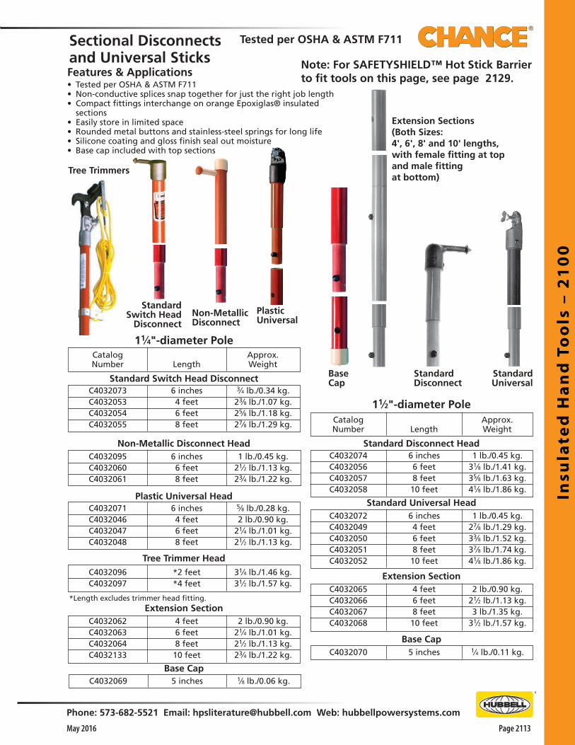
Insu
late
d H
an
d T
oo
ls –
21
00
Phone: 573-682-5521 Email: [email protected] Web: hubbellpowersystems.com
Page 2113May 2016
11⁄2"-diameter PoleCatalogNumber Length
Approx.Weight
StandardSwitch Head
DisconnectNon-MetallicDisconnect
CatalogNumber Length
Approx.Weight
C4032073C4032053C4032054C4032055
Standard Switch Head Disconnect
Tree Trimmer Head
C4032096C4032097
*Length excludes trimmer head fitting.Extension Section
C4032062C4032063C4032064C4032133
C4032069
Base Cap
6 inches4 feet6 feet8 feet
3⁄4 lb./0.34 kg.23⁄8 lb./1.07 kg.25⁄8 lb./1.18 kg.27⁄8 lb./1.29 kg.
*2 feet*4 feet
31⁄4 lb./1.46 kg.31⁄2 lb./1.57 kg.
4 feet6 feet8 feet10 feet
2 lb./0.90 kg.21⁄4 lb./1.01 kg.21⁄2 lb./1.13 kg.23⁄4 lb./1.22 kg.
5 inches 1⁄8 lb./0.06 kg.
C4032095C4032060C4032061
Non-Metallic Disconnect Head6 inches6 feet8 feet
1 lb./0.45 kg.21⁄2 lb./1.13 kg.23⁄4 lb./1.22 kg.
C4032071C4032046C4032047C4032048
Plastic Universal Head6 inches4 feet6 feet8 feet
5⁄8 lb./0.28 kg.2 lb./0.90 kg.
21⁄4 lb./1.01 kg.21⁄2 lb./1.13 kg.
C4032074C4032056C4032057C4032058
C4032072C4032049C4032050C4032051C4032052
Standard Universal Head
Standard Disconnect Head6 inches6 feet8 feet10 feet
1 lb./0.45 kg.31⁄8 lb./1.41 kg.35⁄8 lb./1.63 kg.41⁄8 lb./1.86 kg.
6 inches4 feet6 feet8 feet10 feet
1 lb./0.45 kg.27⁄8 lb./1.29 kg.33⁄8 lb./1.52 kg.37⁄8 lb./1.74 kg.41⁄8 lb./1.86 kg.
Extension SectionC4032065C4032066C4032067C4032068
C4032070
Base Cap
4 feet6 feet8 feet10 feet
2 lb./0.90 kg.21⁄2 lb./1.13 kg.3 lb./1.35 kg.
31⁄2 lb./1.57 kg.
5 inches 1⁄4 lb./0.11 kg.
Sectional Disconnectsand Universal SticksFeatures & Applications• Tested per OSHA & ASTM F711• Non-conductive splices snap together for just the right job length• Compact fittings interchange on orange Epoxiglas® insulated
sections• Easily store in limited space• Rounded metal buttons and stainless-steel springs for long life• Silicone coating and gloss finish seal out moisture• Base cap included with top sections
Tree Trimmers
11⁄4"-diameter Pole
Extension Sections(Both Sizes:4', 6', 8' and 10' lengths,with female fitting at topand male fittingat bottom)
StandardUniversal
PlasticUniversal
StandardDisconnect
Note: For SAFETYSHIELD™ Hot Stick Barrier to fit tools on this page, see page 2129.
Tested per OSHA & ASTM F711
BaseCap
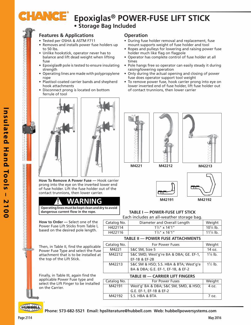
Insu
late
d H
an
d To
ols – 2
10
0
Page 2114
Phone: 573-682-5521 Email: [email protected] Web: hubbellpowersystems.com
May 2016
TABLE I — POWER-FUSE LIFT STICKEach includes an all-weather storage bag.
Features & Applications• Tested per OSHA & ASTM F711• Removes and installs power fuse holders up
to 50 lbs.• Unlike hookstick, operator never has to
balance and lift dead weight when lifting fuse
• Epoxiglas® pole is tested to ensure insulating strength
• Operating lines are made with polypropylene rope
• Plastisol-coated carrier bands and shepherd hook attachments
• Disconnect prong is located on bottom ferrule of tool
Operation• During fuse holder removal and replacement, fuse
mount supports weight of fuse holder and tool• Ropes and pulleys for lowering and raising power fuse
holder much like flag on flagpole• Operator has complete control of fuse holder at all
times• Pole hangs free so operator can easily steady it during
raising/lowering operation• Only during the actual opening and closing of power
fuse does operator support tool weight• To remove power fuse, hook carrier prong into eye on
lower inverted end of fuse holder, lift fuse holder out of contact trunnions, then lower carrier
How To Remove A Power Fuse — Hook carrier prong into the eye on the inverted lower end of fuse holder. Lift the fuse holder out of the contact trunnions, then lower carrier.
M42213M42212M4221
TABLE II — POWER FUSE ATTACHMENTS
Catalog No.M4221
M42212
M42213
For Power FusesS&C SM, Size 5S&C SMD; West’g’re BA & DBA; GE. EF-1,EF-1B & EF-2BS&C SM & HSO; S.S. HBA & BTA; West’g’eBA & DBA; G.E. EF-1, EF-1B, & EF-2
TABLE III — CARRIER LIFT FINGERSCatalog No.
M42191
M42192
For Power FusesWest’g’ BA & DBA; S&C SM, SMD, & HSO;G.E. EF-1, EF-1B & EF-2S.S. HBA & BTA
Catalog No.H422114H422116
Diameter and Overall Length11⁄2" x 14'1"11⁄2" x 16'1"
Weight101⁄4 lb.111⁄4 lb.
Weight14 oz.11⁄8 lb.
11⁄2 lb.
Weight4 oz.
7 oz.
Epoxiglas® POWER-FUSE LIFT STICK• Storage Bag Included
How to Order — Select one of the Power Fuse Lift Sticks from Table l, based on the desired pole length.
Then, in Table II, find the applicable Power Fuse Type and select the Fuse attachment that is to be installed at the top of the Lift Stick.
Finally, in Table III, again find the applicable Power Fuse type and select the Lift Finger to be installed on the Carrier.
Operating lines must be kept clean and dry to avoid dangerous current flow in the rope.
! WARNING M42191 M42192

Insu
late
d H
an
d T
oo
ls –
21
00
Phone: 573-682-5521 Email: [email protected] Web: hubbellpowersystems.com
Page 2115May 2016
Rotary Prong
Rotary Blade
Two-Prong
All Tie Sticks are mounted on 11⁄4" diameter Epoxiglas poles with a tie-wire assistant, hanger bracket.
CatalogNo.
H185519H185520H185525H185526
HeadRotary ProngTwo-ProngRotary ProngRotary Blade
Approx.Weight
3 lb./1.4 kg.4 lb./1.8 kg.
31⁄2 lb./1.6 kg.31⁄4 lb./1.5 kg.
OverallLength
8'3"8'4"8'2"8'3"
For universal tool accessories, see Pages 2120 through 2126.
EndUniversalUniversalRotary BladeUniversal
TIE STICKS
ALL-ANGLE COG WRENCHFeatures & Applications• Tested per OSHA & ASTM F711• 15 ft-lb maximum torque rating• Controls permit operator efficiency in locating the wrench on
energized hardware• Handgrip steadies tool and holds cog housing in place while pole is
rotated, turning cogs to engage wrench on the nut or bolt• Wrench head angle in relation to handle is adjustable within a
range of 140°• Wing nuts on either side of head tightens to hold head in position
during use• Chance Epoxiglas® Hot Line Tool is 1-1/2” in diameter with 3/8”
diameter fiberglass control rod• Aluminum alloy handgrip, bronze alloy cog housing, and hardened
steel gears
H185526
1⁄2-inch square drive
C4030184
Features & Applications• Originally designed to move heavy electrical cables in mines• Also serves as efficient method of moving heavy cables on
the ground• 40” long and has two ½”-diameter spiral grab hooks • Will pick up cables up to 2” diameter by rotating the tool
only quarter turn
CABLE LIFT TOOLDescription
40" Cable Lift ToolCatalog No.C4031078
Weight33⁄8 lb./1.5 kg.
Align the grab hooks on bothsides of cable.
Lift the cableand move todesired position.
Turn the tool 90° clockwise, to slip hooks under cable.
C4031078
TIE STICKSFeatures & Applications• Tested per OSHA & ASTM F711• Made with variety of heads for versatile lineman needs• Rotary Prong Tie Sticks quickly and easily handle looped ties• Two-Prong Tie Sticks effectively handle hot ties with loops• Rotary Blade Tie Sticks swivel for greater freedom of movement than
fixed-blade types
CatalogNo.
All-Angle Cog WrenchDescription
ApproximateWeight
C4030184 6-foot length 7 lb./3.2 kg.C4030185 8-foot length 71⁄2 lb./3.4 kg.C4030186 10-foot length 8 lb./3.6 kg.
PSC4030187 12-foot length 9 lb./4.1 kg.

Insu
late
d H
an
d To
ols – 2
10
0
Page 2116
Phone: 573-682-5521 Email: [email protected] Web: hubbellpowersystems.com
May 2016
H18912 CatalogNumberH18912
H18913
H18915
H18916
066780
Descriptionw/Flexible 1⁄2" Sq. Plug andFixed 1⁄2" Sq. Plugw/Flexible 1⁄2" Sq. Plug andFixed 1⁄2" Sq. Plugw/Flexible 1⁄2" Sq. Plug andUniv. Head - Hole Through Ferrulefor 5⁄8" Turning Rodw/Flexible 1⁄2" Sq. Plug andUniv. Head - Hole Through Ferrulefor 5⁄8" Turning RodRatchet Wrench
OverallLength
6'3"
8'3"
6'3"
8'3"
Approx.Weight
51⁄2 lb./2.5 kg.
61⁄2 lb./2.9 kg.
51⁄2 lb./2.5 kg.
61⁄2 lb./2.9 kg.
11⁄2 lb./0.7 kg.
RatchetWrench066780
Heavy-DutyFLEXIBLE INSULATED WRENCHES — 75 ft.-lb. torque rating
Features & Applications• Tested per OSHA & ASTM F711• 75 ft-lb torque rating• Standard square socket in lower end accepts
½” square-shank ratchet or similar hand tools• Square shank on upper end fits any ½”-drive
socket• Mounted on 1-1/2” diameter Epoxiglas®
extensions• Used for tightening nuts on hardware fittings
on high-voltage lines• Universal joint coil spring limits flexibility, giving
operator socket control at various angles• Spring easily removes for lubrication
Catalog No.C4032137C4032136
Overall Length6 ft. 3 in.8 ft. 3 in.
Weight, each51⁄2 lb./2.5 kg.61⁄2 lb./2.9 kg.
Epoxiglas® Torque Extension Stick for hydraulic power tools
Catalog No.T4033009
DescriptionTorque Extension Stick
Weight5 lb./2.25 kg.
Features & Applications• Tested per OSHA & ASTM F711• 75 ft-lb torque rating• Designed for hot-line work with hydraulic tools on bucket
trucks• 7/16” hexagonal quick-connect fitting couples with a power
tool’s drive socket
• Square detent-ball fitting accepts all ½’-drive wrenches• 1-1/4” x 4’ Epoxiglas® pole handguard is 6” from ferrule
with hex fitting
H18915
Flexible Insulated Wrenches
Note: For SAFETYSHIELD™ Hot Stick Barrier to fit tools on this page, see page 2129.
HEX SOCKET SETSFeatures & Applications• Available in SAE and metric sizes• Each set includes sockets to fit any ½” (12.17 mm) square-shank
tool (such as the Chance All-Angle Cog Wrench and Flexible Insulated Wrench)
Tested per OSHA & ASTM F711SAE (in.) SetCatalog No. C4031085includes 11 deep-well 6-point socketsin sizes from 1/2" through 11⁄8"
METRIC SetCatalog No. C4031085Mincludes 10 deep-well 6-point socketsin sizes from 10mm through 19mm
Features & Applications• Tested per OSHA & ASTM F711• 40 ft-lb torque rating• Used for tightening nuts on hardware fittings
on high-voltage lines
• Universal joint coil spring gives operator flexibility to control socket at various angles
• Spring is easily removed for lubrication• Wrenches are made to fit any ½” square-
shank socket• All wrenches are mounted on 1-1/2”-diameter
Epoxiglas® poles

Insu
late
d H
an
d T
oo
ls –
21
00
Phone: 573-682-5521 Email: [email protected] Web: hubbellpowersystems.com
Page 2117May 2016
Trigger at end of operating rod controls roller to open and close ammeter jaws.
PLASTIC HEAD FORUNIVERSAL TOOLSFeatures & Applications• Sized to retrofit over 1-1/4”-diameter Chance
Epoxiglas® hot-line tools• Available in kit form for shop installation• For users concerned about hotsticks with
metal ferrules that could draw an arc or effect a short circuit in close-clearance worksites
HEAVY-DUTY END CAP
• Kit includes: o Black plastic (glass-filled nylon ferrule with splines to
accept Chance Universal Tool Accessories (Catalog pages 2120 - 2127)
o Thumbscrew to hold the accessory in use o Two drive screws o Instruction tag• Simple procedure requires attaching ferrule to pole with
Epoxiglas® Bond Kit H1917, drilling through holes and installing the drive screws
Pole Dia.and Overall
Length11⁄4" x 6'3"11⁄4" x 8'3"11⁄4" x 6'3"11⁄4" x 8'3"
DescriptionAmertongAmertongHinged AmertongHinged Amertong
Catalog No.H19686H19688H19786H19788
Features & Applications• Designed to withstand rough working conditions• Quickly fits on any 1-1/4”-diameter pole with Chance Epoxy
Bond Kit, Catalog No. H1917• Molded nubs on exterior, ball shape, and thick walls cushion
repeated impacts of use• Black ethylene vinyl acetate material provides optimum
resistance to abrasion and cuts
Catalog No.C4031996
DescriptionPlastic Universal Head Kit:Ferrule, Thumbscrew, 2 Drive Screws, Instructions
Weight
5 oz./0/.14 kg.
Description Heavy-Duty End Cap for 11⁄4" Epoxiglas pole
Catalog No.P4032312P
Both Ends: Plastic Hex Ferrules Installed
*Thumbscrew included with Chance universal fitting.
THREADED HEX FITTING & UNIVERSAL POLESFeatures & Applications• Tested per OSHA & ASTM F711• Insulating black plastic ferrule ac-
cepts threaded-stud fitting unique to Safety Line brand interchangeable tool accessories
• Made from same glass-filled nylon materials as Chance universal-tool ferrules
• Extends insulation to end of tool handle• Ferrule may be ordered either separate for retrofit on
customer poles or factory-installed on 1-1/4”-diameter Epoxiglas® poles
Features & Applications• Tested per OSHA & ASTM F711• Can be adjusted at collar to fit an ammeter• Plastic-coated castings securely grip while protecting the
meter's finish • Fiberglass operating rod for maximum insulation
AMERTONGS
C4001585C4001586C4001587
6-foot length8-foot length10-foot length
21⁄4 lb./1 kg.3 lb./1.4 kg.33⁄4 lb./1.7 kg.
4 lb./1.8 kg.41⁄2 lb./2.0 kg.5 lb./2.3 kg.51⁄2 lb./2.5 kg.
Weight
Opposite Ends:Plastic Hex and Chance Universal* Ferrules
Catalog No.P4032252P
Description Plastic Hex Ferrule only
Weight6 oz./0.17 kg.
Catalog No.C4001582C4001583C4001584
Description6-foot length8-foot length10-foot length
Weight21⁄4 lb./1 kg.3 lb./1.4 kg.33⁄4 lb./1.7 kg.
Fits most meters up to 3.25" width

Insu
late
d H
an
d To
ols – 2
10
0
Page 2118
Phone: 573-682-5521 Email: [email protected] Web: hubbellpowersystems.com
May 2016
CatalogNo.
Description Pole Dia. Overall Length Weight
PST4032913 Pole with one universal head 11⁄4" 4'2" 1.9 lb./0.9 kg.H1760 Pole with one universal head 11⁄4" 8'2" 3.4 lb./1.5 kg.H17601 Pole with one universal head 11⁄4" 6'1" 2.7 lb./1.2 kg.H17602 Rigid spliced pole with one universal head 11⁄4" 4'1" +4' 5.5 lb./2.5 kg.H17603 Pole with two universal heads 11⁄4" 6'3" 3.1 lb./1.4 kg.H17604 Pole with two universal heads 11⁄4" 8'3" 3.8 lb./1.7 kg.H17606 Rigid spliced pole with two universal heads 11⁄4" 4'1" + 4'1" 5.8 lb./2.6 kg.H176010 Pole with two universal heads 11⁄4" 10'3" 4.6 lb./2.1 kg.H176012 Pole with two universal heads 11⁄4" 12'3" 5.3 lb./2.4 kg.H176014 Pole with two universal heads 11⁄4" 14'3" 6.1 lb./2.8 kg.PST4032914 Universal storm tool with two skirts and one universal head 11⁄4" 4'3" 2.2 lb./1.0 kg.H1761 Universal storm tool with two skirts and one universal head 11⁄4" 8'2" 3.6 lb./1.7 kg.H1770 Hinged pole with one universal head 11⁄4" 8'2" 5.4 lb./2.4 kg.H17908 Pole with two universal head, pole hanger 11⁄2" 8'3" 5.8 lb./2.6 kg.H179010 Pole with two universal heads 11⁄2" 10'3" 6.7 lb./3.0 kg.H179012 Pole with two universal heads 11⁄2" 12'3" 7.7 lb./3.5 kg.H179014 Pole with two universal heads 11⁄2" 14'3" 8.8 lb./4.0 kg.H4455 Universal head only 11⁄4" — 0.25 lb./0.11 kg.H4455A Universal head only 11⁄2" — 0.33 lb./0.15 kg.P4030467P Replacement Thumbscrew — — —
Features & Applications• Tested per OSHA & ASTM F711• Designed for use as a hotstick handle for Universal Tools• Made with Epoxiglas® and lightweight aluminum castings• Universal Tools shown on following pages fit under the thumbscrew of
the spline on the Universal Pole• Splines allow angling the tool up to 90° depending on individual tool
design• Universal Adapter M445584 (shown on page 2123) may be added
between the pole and tool to gain any angled desired
Storm Tool for Bad Weather• A Universal Pole with special rubber insulator skirts, designed for
emergency use• Provides extra leakage distance and disrupts water paths• Skirts break up water streams that would otherwise run down pole
Universal Fittings for Spliced Poles• Universal fittings are threaded for use on Epoxiglas® poles with Rigid
Splices• Also see Catalog Section 2500 for Rigid Pole Splices and Epoxiglas® Blank
Poles
Crossarm Tool HangerFeatures & Applications• Adjustable to crossarms in widths from 3-1/4” to
4-1/2” in width (depth of crossarm does not matter)
Catalog No.M1860
DescriptionCrossarm Tool Hanger
Weight2 lb./.9 kg.
Universal Poles
Spliced PolesH17602 & H17606
Hinged Pole H1770
Note: For SAFETYSHIELD™ Hot Stick Barrier to fit tools on this page, see page 2129.
• Crossarm Tool Hanger is made of strong, lightweight aluminum alloy and cadmium-plated steel hardware
H17604
H1761
P4030467PReplacement Thumbscrew
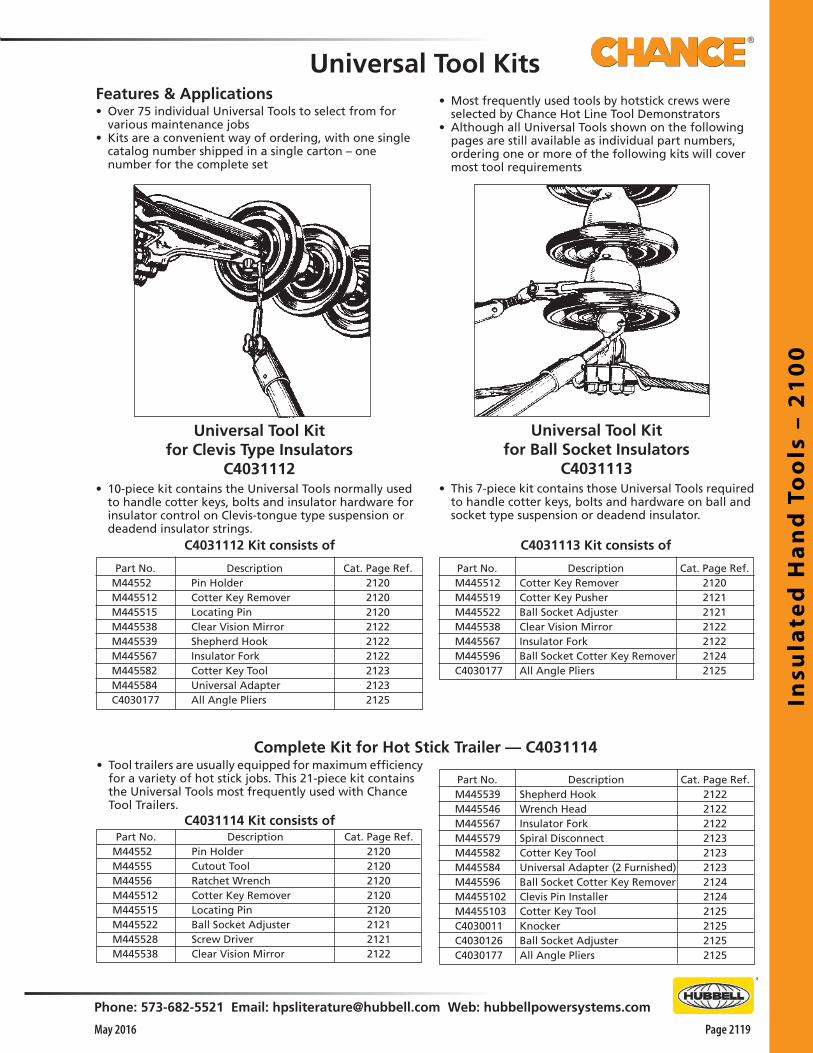
Insu
late
d H
an
d T
oo
ls –
21
00
Phone: 573-682-5521 Email: [email protected] Web: hubbellpowersystems.com
Page 2119May 2016
Universal Tool Kitfor Clevis Type Insulators
C4031112• 10-piece kit contains the Universal Tools normally used
to handle cotter keys, bolts and insulator hardware for insulator control on Clevis-tongue type suspension or deadend insulator strings.
Universal Tool Kitfor Ball Socket Insulators
C4031113• This 7-piece kit contains those Universal Tools required
to handle cotter keys, bolts and hardware on ball and socket type suspension or deadend insulator.
C4031114 Kit consists ofPart No.
M44552M44555M44556M445512M445515M445522M445528M445538
DescriptionPin HolderCutout ToolRatchet WrenchCotter Key RemoverLocating PinBall Socket AdjusterScrew DriverClear Vision Mirror
Cat. Page Ref.21202120212021202120212121212122
Part No.M445539M445546M445567M445579M445582M445584M445596M4455102M4455103C4030011C4030126C4030177
DescriptionShepherd HookWrench HeadInsulator ForkSpiral DisconnectCotter Key ToolUniversal Adapter (2 Furnished)Ball Socket Cotter Key RemoverClevis Pin InstallerCotter Key ToolKnockerBall Socket AdjusterAll Angle Pliers
Cat. Page Ref.212221222122212321232123212421242125212521252125
C4031112 Kit consists of
Part No.M44552M445512M445515M445538M445539M445567M445582M445584C4030177
Cat. Page Ref.212021202120212221222122212321232125
C4031113 Kit consists of
Part No.M445512M445519M445522M445538M445567M445596C4030177
DescriptionCotter Key RemoverCotter Key PusherBall Socket AdjusterClear Vision MirrorInsulator ForkBall Socket Cotter Key RemoverAll Angle Pliers
Cat. Page Ref.2120212121212122212221242125
Universal Tool KitsFeatures & Applications• Over 75 individual Universal Tools to select from for
various maintenance jobs• Kits are a convenient way of ordering, with one single
catalog number shipped in a single carton – one number for the complete set
• Most frequently used tools by hotstick crews were selected by Chance Hot Line Tool Demonstrators
• Although all Universal Tools shown on the following pages are still available as individual part numbers, ordering one or more of the following kits will cover most tool requirements
Complete Kit for Hot Stick Trailer — C4031114• Tool trailers are usually equipped for maximum efficiency
for a variety of hot stick jobs. This 21-piece kit contains the Universal Tools most frequently used with Chance Tool Trailers.
DescriptionPin HolderCotter Key RemoverLocating PinClear Vision MirrorShepherd HookInsulator ForkCotter Key ToolUniversal AdapterAll Angle Pliers

Insu
late
d H
an
d To
ols – 2
10
0
Page 2120
Phone: 573-682-5521 Email: [email protected] Web: hubbellpowersystems.com
May 2016
Chuck Blank (5⁄8" opening)The Chuck Blank can be used for a variety of applications, such as inserting screw drivers, saws, etc. The wing nut tightens the installed tool.Part No. M445537 ............................ 5 oz.
Pin HolderFor replacing pins and bolts. Bolt head fits into a slot and is held tight by spring action. Will take bolts or pins up to 5⁄8" diameter. Fits EEI and NEMA insulators.Part No. M44552 ..........10 oz.
Cutout ToolWhile this tool was designed for removing and replacing the doors of enclosed cutouts, its finger-like grasp makes it useful on many other jobs where a sure grip is required. Jaws open to accommodate an object 3-3⁄4 “ wide. All parts that contact porcelain are plastisol covered.Part No. M44555 ........................13⁄4 lb.
Ratchet Wrench1⁄2"-square driveThis Ratchet Wrench is used for tightening bolts in substation equipment, hardware, transmission and distribution lines, etc.Part No. M44556 ...............................13⁄4 lb.
DisconnectUsed for opening and clos-ing switches, opening en-closed cutouts, etc. Aluminum:Part No. M44559 ........2 oz.Bronze:Part No. C4001418 .....6 oz.
Snapout CotterKey RemoverHammer-like action makes it extremely useful in pulling out stuck cotter keys. Release of the compression spring by a quick
jerk of the pole deals the cotter key a hammer blow without disengaging the eye.Part No. M445512 .....8 oz.
Locating PinUsed as a drift pin in aligning bolt holes as an aid in bolt and pin insertions. Recommended for making hardware connections on tower transmission lines and line deadends where aligning or hardware fitting is difficult.Part No. M445515 ................. 10 oz.
Fixed ProngTie Stick HeadOften preferred for manipulating tie wires which have looped ends. Useful in close quarters where loose ends of tie wire must be rolled up to prevent contact with crossarm or hardware while untying.Part No. M445517 .........................1 lb.
Chuck Blank (5⁄8" opening)Screw drivers, hack saws, and other tools may be inserted in this device and secured by soldering. For wingnut tightened Chuck Blank order No. M445537.Part No. M445510 ................... 41⁄2 oz.
Folding RuleAdaptable to many uses. Particularly suited for obtaining measurements near live conductors in congested areas.Part No. M445516 .... 81⁄2 oz.
Universal Tool Accessories––– See Universal Tool KITS on Page 2119 –––
13⁄8"

Insu
late
d H
an
d T
oo
ls –
21
00
Phone: 573-682-5521 Email: [email protected] Web: hubbellpowersystems.com
Page 2121May 2016
Universal Cutout Tool4-in-1 tool for 100 amp fuse holders and Chance Electronic Sectionalizer. Works on major brands of cutouts (ABB, Chance, S&C) for easy lift out, placement, *opening and closing operations. Holds fuse holder in inverted position, more secure method than a disconnect prong. Lightest weight of its kind (other designs can weigh nearly twice as much). PSC4033484 .......................... 4 oz.
*When opening a cutout, follow all work rules and OSHA regulations. Not for use with loadbreak cutouts.
16.1"Cotter KeyPusherFor ball and socket insulator coupling. Straight end of the tool enters the socket opening to force cotter key out. Curved end forces cotter key back into position.Part No. M445519 ......... 9 oz.
Ball SocketAdjusterUseful in controlling the adapter between clevis clamps and ball and socket insulator pins.Part No. M445522 ..........9 oz.
Paint BrushA three-inch brush for painting around live apparatus. Useful for applying conductor paint on insulator heads.Part No. M445525 ..........9 oz.
Link Stick HeadUse with light conductors. The clamp will hook into a cum-a-long ring. Jaw openings range from .750 to .22. Jaws have rounded edges to prevent scarring conductors. The hook is made of heat-treated aluminum alloy. Screw is Everdur.Part No. M445536 ....................1 lb.
Screw DriverIdeal for a number of odd jobs where an insulated handle is needed.Part No. M445528 ..........................31⁄2 oz.
Clamp Stick HeadA Universal Clamp Stick Head for use with Eye Screw Grounding Clamps.
The 6" head is for long eye screw grounding clamps.Part No. M445529B (6") .......11⁄4 lb.
Universal Tool Accessories––– See Universal Tool KITS on Page 2119 –––
Hack SawExcellent for use at various angles where a hack saw is needed near energized conductors, comes with 10 blades.Part No. M445523 .................................. 1 lb. 12 oz.
P4030369P.............................................. Blade only
Pruning SawThese saws can be used with Chance Pistol-Grip Handle, Tree Trimmers, Universal or Telescoping Tools.
C4032213 ................................ 8 oz.

Insu
late
d H
an
d To
ols – 2
10
0
Page 2122
Phone: 573-682-5521 Email: [email protected] Web: hubbellpowersystems.com
May 2016
Clear VisionMirrorAngle adjustment enables the operator to inspect insulators, switch bases, and other equipment which is difficult to see without coming in contact with energized conductors.Part No. M445538 ............ 14 oz.
Shepherd HookThe self-aligning shepherd hook is designed for pulling and lifting insulator strings. Swivel action permits it to rotate and maintain its alignment with the insulator at all times. Heat treated aluminum alloy.Part No. M445539...........14 oz.
Fixed Blade TieStick HeadFor manipulating tie wires with or without looped ends. The sharp V-notched blade gets into tight places to pry tie wires loose. The head is set at 60° angle from the pole when attached, for ease in operation.Part No. M445540 ................... 8 oz.
Flexible Wrench Head1⁄2"-square driveMade to fit standard wrench sockets. Flexibility permits use at various angles.Part No. M445546 ............... 1 lb.
Skinning KnifeFor cutting or scraping insulation, cleaning conductors, etc., prior to making splices. Its use with a universal pole permits work near energized lines with safety.Part No. M445550 ........... 71⁄2 oz.
Conductor CleaningBrushV-position of brushes gives 2-sided cleaning action. As brushes wear, they can be rotated, by loosening the anchor screws, so that unused bristles will come in contact with conductor.Part No. M445563 ................. 11 oz.Part No. M1889 With Hand Grip............................................... 16 oz.Part No. M1899 Box of 10 Replacement Brushes ..............5 lb.
Storm ToolA universal pole extension with rubber insulator skirts. Splined fitting at top of tool receives other universal tools. Overall length 191⁄2". Part No. H445564 .......................... 11⁄4 lb.
Universal Tool Accessories––– See Universal Tool KITS on Page 2119 –––
4.25"
Rotary ProngTie Stick HeadFor placing insulator ties with looped ends. Head treated aluminum alloy body. Prong swivels freely, permitting a full turn on the tie wire without releasing contact. This minimizes the possibility of kinking or burning the wires.Part No. M445569 ................... 6 oz.
Pistol Grip Saw HandleDeveloped for use with a pruning saw when limbs are convenient and insulation is not needed. Stainless Steel.Part No. M445566 ................... 8 oz.
Adjustable Insulator ForksDesigned to grasp 9" and 10" disk insulators used in deadend construction,will raise most pin type insulators up to 15 lb. Fiber jaws open and close by rotating screw.
Part No. M445567Jaws adjust from 3" to 41⁄4" across inside center of fork .....1 lb. 11 oz.
No. T4031101For polymer insulators, jaws adjust from 21⁄4" to 31⁄2"............1 lb. 6 oz.

Insu
late
d H
an
d T
oo
ls –
21
00
Phone: 573-682-5521 Email: [email protected] Web: hubbellpowersystems.com
Page 2123May 2016
Rotary BladeTie Stick HeadFor manipulating tie wires with or without looped ends. The heat treated aluminum alloy body design permits a swivel action. Wire is wrapped or unwrapped without turning universal pole. A V-notched carbon steel blade grasps tie wire securely.Part No. M445570 ................... 6 oz.
Pointed DisconnectA pointed disconnect head for use on certain types of disconnect switches. Made of aluminum alloy.Part No. M445571 .............. 3 oz.
Conductor GaugeThis aluminum gauge is small, compact, and light. It is used to make a quick, accurate check on the gauge of ACSR, solid or stranded copper conductors.Range: #4 Cu. through 4/0 ACSR.Part No. M445572 ................... 3 oz.
Fuse PullerThe Chance Fuse Puller may be preset to any position desired and locked there by tightening the wing nut. A spring assembly also permits the tool to be preset without locking, so that it will align with the fuse during the pulling operation. The Fuse Puller is opened and closed by turning the pole. Its jaws are plastisol covered.Part No. M445577 (1⁄2" to 11⁄2" Fuse) ...............17⁄8 lb.Part No. M445578 (11⁄2" to 21⁄2" Fuse) .............21⁄2 lb.
HammerUsed for many operations around energized conductors such as moving conductors, suspension clamps and other pieces of hardware requiring a forceful blow.Part No. M445585 ......1 lb.
All-Purpose CotterKey ToolFor pulling and replacing hump-type cotter keys. Particularly suitable for use on clevis pins and ball socket insulators. Easy guiding of cotter key provided by contoured slot and raised eye pin.Part No. M445582 ........................5 oz.
SpiralDisconnectExtremely effective in opening switches and removing and installing cutout doors on porcelain enclosed type cutouts. Also called “Pigtail” Disconnect.Part No. M445579............. 61⁄2 oz.
Universal Tool Accessories––– See Universal Tool KITS on Page 2119 –––
Universal AdapterWhen this adapter is mounted on a universal stick and any universal tool is mounted on the adapter, the tool can be set at almost any angle to the stick. Useful for working in limited access areas.Part No. M445584 ..........5 oz.
Tree & Rope HookThe Universal Tree and Rope Hook is made of aluminum alloy and is attached to a universal pole to push tree limbs out of the way of hot-stick work and to clear rope if it becomes tangled.Part No. M445580 ............... 1 lb.
Full RangeConductor GaugeThis aluminum gauge has multiple range scales to make a quick, accurate check on the gauge of Copper, ACSR, AAAC, AASC/ASC conductors. Includes hard shell storage case.Range:#4 ACSR through 954 kcmil ACSR.PSC4032956 ............................ 9 oz.

Insu
late
d H
an
d To
ols – 2
10
0
Page 2124
Phone: 573-682-5521 Email: [email protected] Web: hubbellpowersystems.com
May 2016
Ball SocketAdjusterUsed on heavy socket clevises, particularly where aluminum suspension and deadend clamps are attached to ball and socket insulators.
Part No. M445587 ........10 oz.
Bolt HeadWrenchUsed on heads of 3⁄4" and 5⁄8" dia. bolts to keep bolt from turning as nut is being tightened. Extremely useful on rural ridge pin type construction — outer edges of wrench are tapered so that they can be wedged between flanges on channel and bolt head to keep bolt from turning.Part No. M445588 . 1 lb. 2 oz.
Ratchet WrenchThis Ratchet Wrench is for tightening square nuts on 5⁄8" pole line hardware, regardless of the length of the bolt running beyond it. The long socket permits wrench handles to swing past crossarm when tightening top ridge pin nut.Part No. M445589 .......................... 21⁄2 lb.
Aerosol Can HolderBy pulling the rope on this tool, a prong reaches out to depress the nozzle of an aerosol can to apply G.E. Insuljel to insulators or insecticides to bee and wasp nests on poles and crossarms. Also useful for applying paint, lubricant, etc., in hard-to-reach places.
C4032270 ................12 oz.
Cotter Key PullerThis Cotter Key Puller is used to partially withdraw a ball-socket cotter key so that the insulator can be removed from another insulator hanger. This puller with its thin prong is preferred for prying out standard keys deeply set on long insulator strings.Part No. M445596 ......................12 oz.
Universal Tool Accessories––– See Universal Tool KITS on Page 2119 –––
Part No. C403032011⁄4" Dia. Tube with clip ...........6 oz.
Part No. M445593 11⁄4" Dia. Tube only..................5 oz.
Clevis Pin InstallerThis tool has particular application on EHV hardware and insulators where the pin must be placed in semi-recessed areas. The three-finger device is spring-loaded with cadmium-plated music wire for positive grip.Part No. M4455102 ..................1 lb.
Tool for“W” KeysThis tool is used for handling the “W” shaped keys used in suspension insulators which are popular in western Europe and Japan.Part No. M445597 ................. 14 oz.
Super Tester AdapterDesigned for attaching a Super Tester (H1990ST, Section 2450) to a Grip-All, a Universal Pole or a Positive-Grip Stick. With this adapter the tester can be used in any position, above or below the lineman.
Part No. M445598................5 oz.
Conductor Cleaning BrushSemi-tubular shape allowslinemen to clean 6" of entirecircumference of conductorwith two stick position.
Part No. M445592 11⁄4" Dia. Tube with Universal Fitting..................13 oz.

Insu
late
d H
an
d T
oo
ls –
21
00
Phone: 573-682-5521 Email: [email protected] Web: hubbellpowersystems.com
Page 2125May 2016
Cotter Key HolderUsed to install cotter keys into semi-recessed hardware such as found on EHV, this tool will hold the keys in position for proper insertion into clevis pins. The tool will hold the key firmly, yet readily release once engagement is madePart No. M4455103 ..................1 lb.
Hot Rodder ToolIdeal for applying line ties and other formed wire products on energized lines. The smaller unit (C4031071) is particularly adaptable to Super Top-Ties®. The loop type work end permits rotational control which is difficult with conventional tying tools.
Weight12 oz.13 oz.
Dim. B.13⁄4"3"
Dim. A.17⁄32"11⁄16"
Part No.C4031071C4030834
All-Angle PliersDesigned to grasp from any angle, and tighten by clockwise rotation of the Universal Tool handle. The jaws are held firmly in position with a wing-nut. Used as a holding device for retaining bolt heads and loose hardware, adjusting arcing horns, replacing cotter keys, etc.Part No. C4030177 ...........11⁄2 lb.
Plastic Insulator ToolPlastic coating of the Chance Ball and Socket Adjuster prevents damage to Epoxilator distribution deadend insulators during lifting or rotating of the insulator. Arms of the tool are designed to fit between the skirts of the insulator.Part No. C4030175 ...........12 oz.
Ball SocketAdjusterSimilar to the M445587 Chance Ball socket Adjuster, this Adjuster is designed to handle socket adapters up to 23⁄4 inches wide.Part No. C4030126 ................ 14 oz.
KnockerDesigned to knock out and pull the cotter keys on fog-type insulators, the Knocker Tool is spring assisted for greater impact in restricted space and under adverse working conditions. The Knocker has a standard universal fitting one end and a Universal fitting one end and a Universal fitting with wingnut on the other end to receive various Cotter Key Tools at top of this page.Part No. C4030011 ................ 10 oz.
Cotter Key ToolThe Cotter Key Tool is a companion tool to Part No. C4030005, both designed for ball and socket type insulator couplings. C4030005 enters the socket opening to force the cotter key out while C4030006, shown here, forces the key back into position. Effectiveness of both tools is enhanced with the use of the Universal Knocker.Part No. C4030006 ................11⁄4 lb.
Cotter Key ToolUsed for ball and socket insulator couplings, this tool is used to push the cotter key into position where great force is required.Part No. C4030005 ................11⁄4 lb.
Universal Tool Accessories––– See Universal Tool KITS on Page 2119 –––
B
A
3.1"2.3"
2.9"
3.1"
1.25"
1.9"
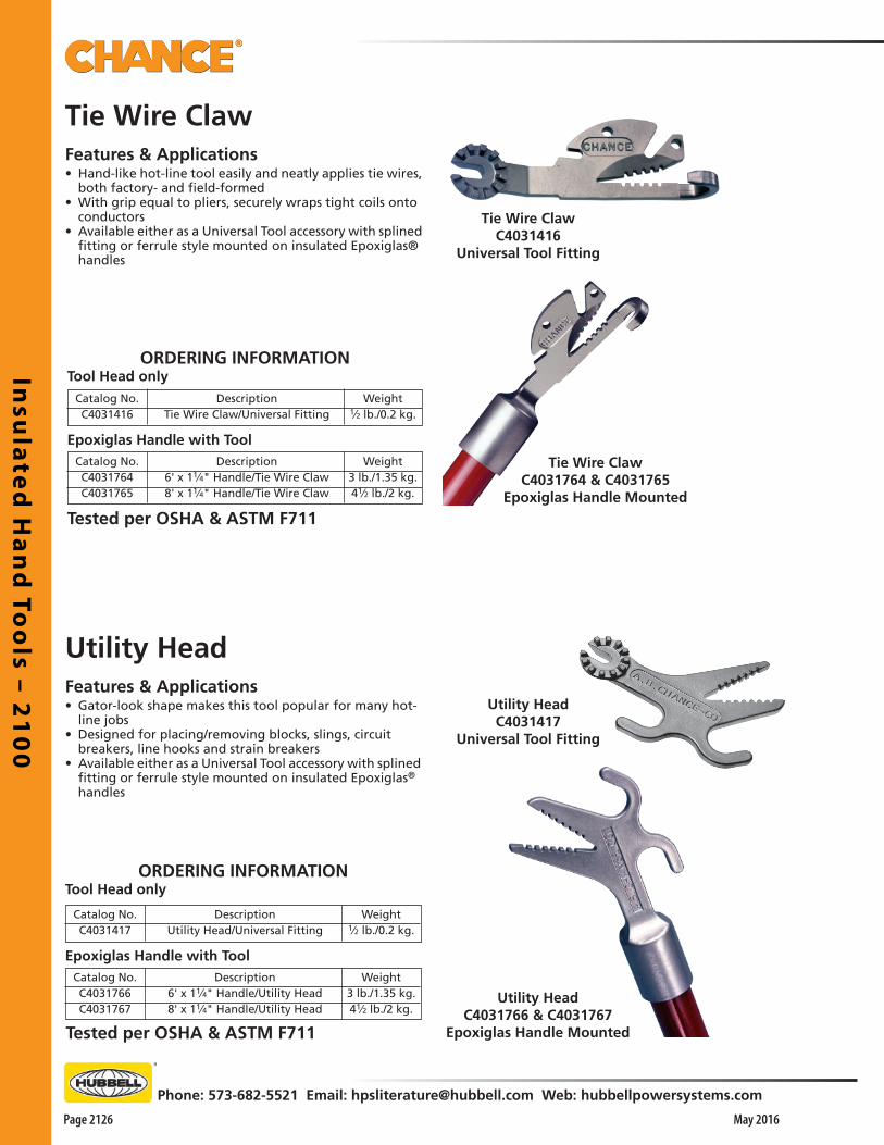
Insu
late
d H
an
d To
ols – 2
10
0
Page 2126
Phone: 573-682-5521 Email: [email protected] Web: hubbellpowersystems.com
May 2016
Utility HeadFeatures & Applications• Gator-look shape makes this tool popular for many hot-
line jobs• Designed for placing/removing blocks, slings, circuit
breakers, line hooks and strain breakers• Available either as a Universal Tool accessory with splined
fitting or ferrule style mounted on insulated Epoxiglas®
handles
Utility HeadC4031766 & C4031767
Epoxiglas Handle Mounted
Utility HeadC4031417
Universal Tool Fitting
ORDERING INFORMATIONTool Head only
Weight1⁄2 lb./0.2 kg.
DescriptionUtility Head/Universal Fitting
Catalog No.C4031417
Epoxiglas Handle with ToolWeight
3 lb./1.35 kg.41⁄2 lb./2 kg.
Description6' x 11⁄4" Handle/Utility Head8' x 11⁄4" Handle/Utility Head
Catalog No.C4031766C4031767
Tie Wire ClawFeatures & Applications• Hand-like hot-line tool easily and neatly applies tie wires,
both factory- and field-formed• With grip equal to pliers, securely wraps tight coils onto
conductors• Available either as a Universal Tool accessory with splined
fitting or ferrule style mounted on insulated Epoxiglas® handles
Tie Wire ClawC4031416
Universal Tool Fitting
Tie Wire ClawC4031764 & C4031765
Epoxiglas Handle Mounted
ORDERING INFORMATIONTool Head only
Weight1⁄2 lb./0.2 kg.
DescriptionTie Wire Claw/Universal Fitting
Catalog No.C4031416
Epoxiglas Handle with ToolWeight
3 lb./1.35 kg.41⁄2 lb./2 kg.
Description6' x 11⁄4" Handle/Tie Wire Claw8' x 11⁄4" Handle/Tie Wire Claw
Catalog No.C4031764C4031765
Tested per OSHA & ASTM F711
Tested per OSHA & ASTM F711

Insu
late
d H
an
d T
oo
ls –
21
00
Phone: 573-682-5521 Email: [email protected] Web: hubbellpowersystems.com
Page 2127May 2016
Hot Line Applicator Toolsfor Rubber Line Hose & Blankets
• Beveled top corner on each blade end helps insert tool between hose lips
• Notice that blades fit in flat area recessed full length on outside of one hose lip
• Grip-All clampstick operates applicator tool to install Class 4 line hose with ease
• Simply rotating the stick clockwise tightens the tool's grasp on the hose lip
• Especially useful for hose couplers, tools with 6" blades also may be used to position rubber blankets and shorter line hose lengths
• Prong on universal tool may be used in several techniques to remove and place line hose couplers, insulator hoods and rubber blankets
• Universal tool mounts by its fitting with thumbscrew• Adjustable hinge feature can be set at various working
angles simply by unscrewing the prong, meshing the pivot cogs and tightening the prong again.
• Clampstick tool features an eyescrew similar to grounding and tap clamps
Catalog No. Description Weight C4032505 Clampstick Tool 6" 1.7 lb./0.8 kg. C4032506 Clampstick Tool 24" 2.5 lb./1.1 kg.
Features & Applications• Designed to grasp the extended lip on Class 4 rubber line
hose• Also permits placement/removal of rubber cover-up
blankets with insulated hotsticks• Available in two styles to fit either clampsticks or universal
hotsticks• Each style comes in three wood blade lengths
Catalog No. Description WeightC4032525 Universal Tool 6" 1.7 lb./0.8 kg.C4032526 Universal Tool 24" 2.5 lb./1.1 kg.C4032527 Universal Tool 36" 3.0 lb./1.4 kg.

Insu
late
d H
an
d To
ols – 2
10
0
Page 2128
Phone: 573-682-5521 Email: [email protected] Web: hubbellpowersystems.com
May 2016
Catalog No.C4033284
DescriptionFuse Grappler Tool
Features & Applications• Helps remove and install power fuses and barriers in pad-
mounted switchgear• Specifically fits S&C Electric Company power fuses SM-
4Z, SM-20, SML-4Z and SML-20• Designed to be attached to an insulated universal tool• Tool features aluminum casting with plastisol coating on
hooks to help avoid scuffing
Fuse Grappler Tool
Weight1⁄2 lb. / 0.23 kg.
Ordering Information
Casting with integral fitting is for direct attachment to universal tool handles

Insu
late
d H
an
d T
oo
ls –
21
00
Phone: 573-682-5521 Email: [email protected] Web: hubbellpowersystems.com
Page 2129May 2016
Features & Applications• Mounts on 1-1/4” or 1-1/2”-daimeter live line tool in
less than a minute• Adds up to a 24”-diameter protective screen between
linemen and a electrical hazard• Used by major electric utilities, co-operatives,
contractors and industrial customers in the U.S. and abroad
• Fits on clampsticks, disconnect sticks, and elbow-puller tools
• Should be mounted on the hotstick nearest the point where an electrical arc flashback may occur
• Made with a flame-retardant transparent polycarbonate protective shield
• Shield is affixed with a nylon fastener to a glass-filled nylon clamp
SAFETYSHIELD™
Hot Stick Barrier
Tested per ASTM Standard F2522-05: Test Method for Determining the Protective Performance of a Shield Attached on Live Line Tools or on Racking Rods for Electrical Arc.
Orange protective storage case and
Instructions are included
with each
SAFETYSHIELD™ Hot Stick Barrier.
• Available in three diameters
Catalog No. Diameter Weight
PSC4170627 16" (406.4 mm) 1 lb. 6 oz. /0.62 kg.
PSC4170628 21" (533.4 mm) 2 lb. 6 oz./1.08 kg.
PSC4170629 24" (609 mm) 2 lb. 14 oz./1.3 kg.

Insu
late
d H
an
d To
ols – 2
10
0
Page 2130
Phone: 573-682-5521 Email: [email protected] Web: hubbellpowersystems.com
May 2016
Tested per ASTM Standard F2522-05: Test Method for Determining the Protective Performance of a Shield Attached on Live Line Tools or on Racking Rods for Electrical Arc.
†See Catalog Section 2150 for these Ratchet Wire Cutters: Catalog No. C4031381, C4031382, C4031383 & C4031384.
Orange protective storage case and Instructions are included with each SAFETYSHIELD™ Hot Stick Barrier.
SAFETYSHIELD™
Hot Stick Barrierfor Ratchet Wire Cutters†
Features & Applications• Mounts on 1-1/4” or 1-1/2”-daimeter live line tool in
less than a minute• Adds up to a 16”-diameter protective screen between
linemen and a electrical hazard• Used by major electric utilities, co-operatives,
contractors and industrial customers in the U.S. and abroad
• Fits on clampsticks, disconnect sticks, and elbow-puller tools
• Should be mounted on the hotstick nearest the point where an electrical arc flashback may occur
• Made with a flame-retardant transparent polycarbonate protective shield
• Shield is affixed with a nylon fastener to a glass-filled nylon clamp
Ordering InformationSAFETYSHIELD™ Hot Stick Barrier
for Ratchet Wire Cutters†
Catalog No. Diameter Weight PSC4170630 16" (406.4 mm) 1 lb. 6 oz. /0.62 kg.
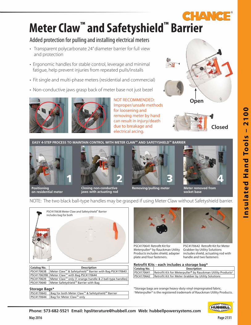
Insu
late
d H
an
d T
oo
ls –
21
00
Phone: 573-682-5521 Email: [email protected] Web: hubbellpowersystems.com
Page 2131May 2016
Closed
Meter Claw™ and Safetyshield™ BarrierAdded protection for pulling and installing electrical meters• Transparent polycarbonate 24” diameter barrier for full view and protection
• Ergonomic handles for stable control, leverage and minimal fatigue, help prevent injuries from repeated pulls/installs
• Fit single and multi-phase meters (residential and commercial)
• Non-conductive jaws grasp back of meter base not just bezel
NOT RECOMMENDED:Improper/unsafe methods for loosening and removing meter by hand can result in injury/death due to breakage and electrical arcing.
EASY 4-STEP PROCESS TO MAINTAIN CONTROL WITH METER CLAW™ AND SAFETYSHIELD™ BARRIER
Catalog No. DescriptionPSC4170638 Meter Claw™ & Safetyshield™ Barrier with Bag PSC4170643PSC4170639B Meter Claw™ with Bag PSC4170644PSC4170639 Meter Claw™ only (1 orange handle & 2 ball-type handles)PSC4170640 Meter Safetyshield™ Barrier with Bag
PSC4170638 Meter Claw and Safetyshield™ Barrier includes bag for both
Positioningon residential meter
1Closing non-conductive jaws with actuating rod
2Removing/pulling meter
3Meter removed from socket base
4
NOTE: The two black ball-type handles may be grasped if using Meter Claw without Safetyshield barrier.
Open
PSC4170642 Retrofit Kit for Meter Grabber by Utility Solutions includes shield, actuating rod with handle and two fasteners
PSC4170641 Retrofit Kit for Meterpuller® by Rauckman Utility Products includes shield, adapter plate and four fasteners.
PSC4170643 Bag for both Meter Claw™ & Safetyshield™ BarrierPSC4170644 Bag for Meter Claw™ only
Retrofit Kits - each includes a storage bag*
Storage Bags* *Storage bags are orange heavy-duty vinyl-impregnated fabric.+Meterpuller® is the registered trademark of Rauckman Utility Products.
Catalog No. DescriptionPSC4170641 Retrofit Kit for Meterpuller® by Rauckman Utility Products+
PSC4170642 Retrofit Kit for Meter Grabber by Utility Solutions

Insu
late
d H
an
d To
ols – 2
10
0
Page 2132
Phone: 573-682-5521 Email: [email protected] Web: hubbellpowersystems.com
May 2016
Animal CatcherFeatures & ApplicationsMUST BE USED WITH HOT STICKS — NOT FOR RUBBER GLOVE USE• Universal attachment end for primary control• Hot stick loop end for activation of the device• Lightweight and compact design• High-visibility orange storage bag
ORDERING INFORMATION
DescriptionAnimal Catcher
Catalog No.PSC4033614
Rescue HookFeatures & Applications• Handle meets ASTM F711 and IEC 60855 specifications• 3/4” high strength steel hook with 18” diameter and coated with black paint • Hook mounted on a 1-1/4” diameter Epoxiglas® pole• Available in 6’ and 8’ handle lengths
ORDERING INFORMATIONEpoxiglas Handle with Tool
Weight7.25 lb./3.29 kg.8.00 lb./3.63kg
Description6' Rescue Hook8' Rescue Hook
Catalog No.PSC4033703PSC4033704

Insu
late
d H
an
d T
oo
ls –
21
00
Phone: 573-682-5521 Email: [email protected] Web: hubbellpowersystems.com
Page 2133May 2016
Insulated Measuring Rod
FOR MEASURING SPANS AND LENGTHS ON ENERGIZED LINES
Features• Orange and black markings to denote 10 centimeter increments up to 3 meters• White collars to denote 50 centimeter increments• This versatile tool may be used with rubber gloves, insulated sticks with universal adapters, or grip-all
clampsticks• Allows user to take angled measurements by adjusting universal connection• The universal connection also reduces storage length to 1.5 meters
ORDERING INFORMATION
Catalog No. Description Weight
PSC4033732 3.0 Meter Measuring Rod 1.3 lbs (0.59 kg)


Cu
tte
rs –
21
50
Phone: 573-682-5521 Email: [email protected] Web: hubbellpowersystems.com
Page 2151May 2016
InsulatedHand Tools
Warranty - MaterialHubbell Power Systems, Inc. warrants all products sold by it to be merchantable (as such term is defined in the Uniform Commercial Code) and to be free from defects in material and work-manship. Buyer must notify the Company promptly of any claim under this warranty. The Buyer's exclusive remedy for breach of this warranty shall be the repair or replacement, F.O.B. factory, at the Company's option, of any product defective under the warranty which is returned to the Company within one year from the date of shipment. NO OTHER WARRANTY, WHETHER EXPRESS OR ARISING BY OPERATION OF LAW, COURSE OF DEALING, USAGE OF TRADE OR OTHERWISE IMPLIED, SHALL EXIST IN CONNECTION WITH THE COMPANY'S PRODUCTS OR ANY SALE OR USE THEREOF. The Company shall in no event be liable for any loss of profits or any consequential or special damages incurred by Buyer. The Company's warranty shall run only to the first Buyer of a product from the Company, from the Company's distributor, or from an original equipment manufacturer reselling the Company's product, and is non-assignable and non-transferable and shall be of no force and effect if asserted by any person other than such first Buyer. This warranty applies only to the use of the product as intended by Seller and does not cover any misapplication or misuse of said product.
Warranty - ApplicationHubbell Power Systems, Inc. does not warrant the accuracy of and results from product or system performance recommendations resulting from any engineering analysis or study. This applies regardless of whether a charge is made for the recommendation, or if it is provided free of charge.
Responsibility for selection of the proper product or application rests solely with the purchaser. In the event of errors or inaccuracies determined to be caused by Hubbell Power Systems, Inc., its liability will be limited to the re-performance of any such analysis or study.
0.05 to 1.01.1 to 15.015.1 to 36.036.1 to 46.046.1 to 72.572.6 to 121138 to 145161 to 169230 to 242345 to 362500 to 550765 to 800
(ft.-in.) (m)
Nominal Voltagein Kilovolts
Phase-to-Phase
Phase-to-ground exposure
Distance
Phase-to-phase exposure
(ft.-in.) (m)
*2-12-42-73-03-23-74-05-38-611-314-11
*0.640.720.770.900.951.091.221.592.593.424.53
*2-22-72-103-64-34-115-87-612-618-126-0
*0.660.770.851.051.291.501.712.273.805.507.91
Live-Line Work Minimum Approach Distances • Distances agree with OSHA guidelines in Table R-6 of the Federal Register, published 1/31/94. These distances take into consider-ation the highest switching surge an employee will be exposed to on any system with air as the insulating medium and the maximum voltages shown.
• The clear live-line tool dis-tance shall equal or exceed the values for the indicated voltage ranges.
*Avoid contact.
Section
2100
©Copyright 2011 Hubbell Incorporated • 210 North Allen Street • Centralia, MO 65240 USAwww.hubbellpowersystems.com
E-mail: [email protected]
NOTE: Because Hubbell has a policy of continuous product improvement, we reserve the right to change design and specifications without notice.
Printed in USA
NOTICE: For latest revision of our Catalog and Literature, please visit our web site: www.hubbellpowersystems.com
Cu
tte
rs –
21
50
Cutters
Catalog 2150 May 2016

Cu
tters – 2
15
0
Page 2152 May 2016
Phone: 573-682-5521 Email: [email protected] Web: hubbellpowersystems.com
7"Ratchet Cable Cuttersfor ACSR or Aluminum & CopperFeatures & Applications• Designed for easier operation• Tested per OSHA & ASTM F711• High-performance design incorporates Delrin rollers and
two-piece operating rod• Roller mechanism travels smoothly along main
Epoxiglas® pole• Linked through the roller support unit, the hinged
operating rod and larger Epoxiglas pole reinforce each other
• Meet OSHA Electrical Rating subpart V-section 1926.951 (d)
• Insulated support pole is Chance orange 1-1/2”-diameter Epoxiglas with Plastisol butt cap
• Operating rod is 3/8”-diameter solid fiberglass rod• Lever handle is 1”-diameter Epoxiglas with rubber
cushion grip• Four standard models offer practical 6-foot or 8-foot
lengths with choice of cutter heads for soft wire or ACSR
• Shear-type steel blades cut without deforming cable• Heads are interchangeable for field changeouts• Soft-Wire Head cuts aluminum cable through 1000 kcmil
bare (1.152”) or jacketed URD (2.125”) and copper through 556 kcmil (1”)
• Spare cutters may be ordered separately below
Integral hanger hook on end casting keeps tool handy on the job site.
CatalogNumber
C4031381
C4031382C4031383
C4031384
Length6 ft.
6 ft.8 ft.
8 ft.
Head1000 kcmil A.A. 500 kcmil Cu. 556 kcmil ACSR1000 kcmil A.A. 500 kcmil Cu. 556 kcmil ACSR
Weight11 lb./4.95 kg.
11 lb./4.95 kg.111⁄2 lb./5.18 kg.
111⁄2 lb./5.18 kg.
Description
CatalogNumber
P4031387P
P4031388P
Description1000 kcmil A.A. 500 kcmil Cu. 556 kcmil ACSR
Weight21⁄4 lb./1 kg.
21⁄4 lb./1 kg.
Head
Ratchet Cable Cutters
Cutter Heads Only
For more details on SAFETYSHIELD™ Hot Stick Barrier to fit tools above, see page 2130.
Improved Soft Wire jaws cut larger URD cables.
Ordering InformationSAFETYSHIELD™ Hot Stick Barrier
for Ratchet Wire Cutters†
Catalog No. Diameter Weight PSC4170630 16" (406.4 mm) 1 lb. 6 oz. /0.62 kg.
Replacement Bolt, Nut, Keeper & Washer Kit:
For A.A. and Cu. head PST4033720For ACSR head PST4033708

Cu
tte
rs –
21
50
Phone: 573-682-5521 Email: [email protected] Web: hubbellpowersystems.com
Page 2153May 2016
• Note: ACSR head is not for use with 15½” handles• Soft-wire head must not be used to cut ACSR as it will
damage the cutting edges• Storage bags to fit short or long cutters should be
ordered as separate items, below• Storage bags are heavy-duty yellow vinyl-impregnated
nylon cloth• Cutters are designed for energized applications• Users must wear rubber gloves and observe all
applicable working clearances when cutting energized conductors
Features & Applications• Three standard models• Choice of insulated long or short handles on cutters
for soft wire, and insulated long handles on cutters for ASCR
• Chance orange 1½” diameter Expoxiglas® handles have black rubber cushion grips
• Shear-type blades cut without deforming cable• Heat-treated tool-steel cutter heads are same as Chance
Ratchet Cable Cutters• Order replacement or spare cutter heads as separate
items, below
Conductor Cutters with Insulated Handles
Maximum Size& Type Conductor
600 MCM A.A./350 MCM Cu.1000 MCM A.A./500 MCM Cu. 336.4 MCM ACSR
Overall211⁄2"35"
331⁄2"
Handles151⁄2"281⁄2"281⁄2"
CatalogNumber
C4031421C4031422C4031423
Lengthlb.41⁄251⁄25
kg.2
2.52.2
Weight
CatalogNumber
C3060023C3060000
Size8" x 23"
12" x 38"
kg.0.20.2
Weight
Storage Bags Only
For Cutters,Catalog NumbersC403-1421C403-1422 orC403-1423
lb.1⁄21⁄2
*Rating for P4031387 Head on 281⁄2" Cutter handles. Used on 151⁄2" Cutter handles, rating for P403-1387 Head is 600 MCM A.A./350 MCM Cu. Do not use to cut ACSR.
†Rating for P4031388 Head on 281⁄2" Cutter handles. P4031388 Head is not for use on 151/2" Cutter handles to cut ACSR.
Cutter Heads Only
CatalogNumber
P4031387P
P4031388P
Description*1000 MCM A.A./
500 MCM Cu.†336.4 MCM ACSR
lb.21⁄4
21⁄4
kg.1
1
Order Storage Bags and extra Cutter Heads as separate items, below.
CONDUCTOR CUTTERSwith Insulated Handles for ACSR or Aluminum & Copper
For Soft Wire(Available with Longor Short Handles)
Replacement Bolt, Nut, Keeper & Washer Kit: For A.A. and Cu. headPST4033720
▲ Replacement Bolt, Nut, Keeper & Washer Kit:For ACSR headPST4033708
▲
Replacement Bolt, Nut, Keeper & Washer Kit:
For A.A. and Cu. head PST4033720For ACSR head PST4033708
For ACSR Wire(Available with LongHandles only)

Cu
tters – 2
15
0
Page 2154 May 2016
Phone: 573-682-5521 Email: [email protected] Web: hubbellpowersystems.com
Features & Applications• Compact size gets into close quarters• Half the size and weight of standard ratchet cutters• Two styles of compact cutters• Ratings match wide range of overhead and underground conductors• For use in confined workspaces such as manholes and
handholes• Open in less than half the space required for long-
handled ratcheting cutters• Small size saves on toolbox and warehouse storage
1000 kcmil URD cable
Operation• Single control allows easy
switching of direction• Pushing thumb slide toward
head allows handle to open wider for rapid opening or closing
• Not for use when cutting – this feature nearly doubles the speed of the “soft” cutters and makes the “hard” cutters open and close about three times faster than normal
Ordering Information
Description
Soft Conductor Cutters
Hard Conductor Cutters
Catalog No.
C4032979
C4032980
Weight
41⁄4 lb. (1.9 kg.)
43⁄8 lb. (2 kg.)
750 kcmil URD cable
556 ACSR(aluminum conductor,
steel reinforced)
Max. opening: 2" (5.08 cm)Length: 18" (45.72 mm)Weight: 43⁄8 lb. (2 kg.)
Max. opening: 23⁄8" (6.03 cm)Length: 191⁄2" (49.53 mm)Weight: 41⁄4 lb. (1.9 kg.)
Soft Style C4032979for only All-Aluminum or Copper up to 1000 kcmil
maximum
Ratcheting Cable Cuttersfor ACSR or Aluminum & Copper
Hard Style C4032980for ACSR up to 556 max. and Aluminum or Copper
up to 750 kcmil max.
These cutters are not insulated hot line tools.
! WARNING
• Release the thumb slide for shorter, more powerful strokes while cutting conductor
• Easy operation, rugged construction• Design of compact cutters is based on simple ratchet
mechanism for long service life• Simple controls and sure ratcheting action makes
working with them easy• C-type jaws are heat-treated for lasting strength and
sharpness• Stampings on the jaws indicate application limits• Despite their small size, they are built to take punishing
field conditions• Reinforced-fiberglass handles are PVC-coated and
protected by a vinyl sleeve• Thick vinyl grips shield the handle ends and help worker
keep a steady grasp• Operating instructions are included with both cutter
styles
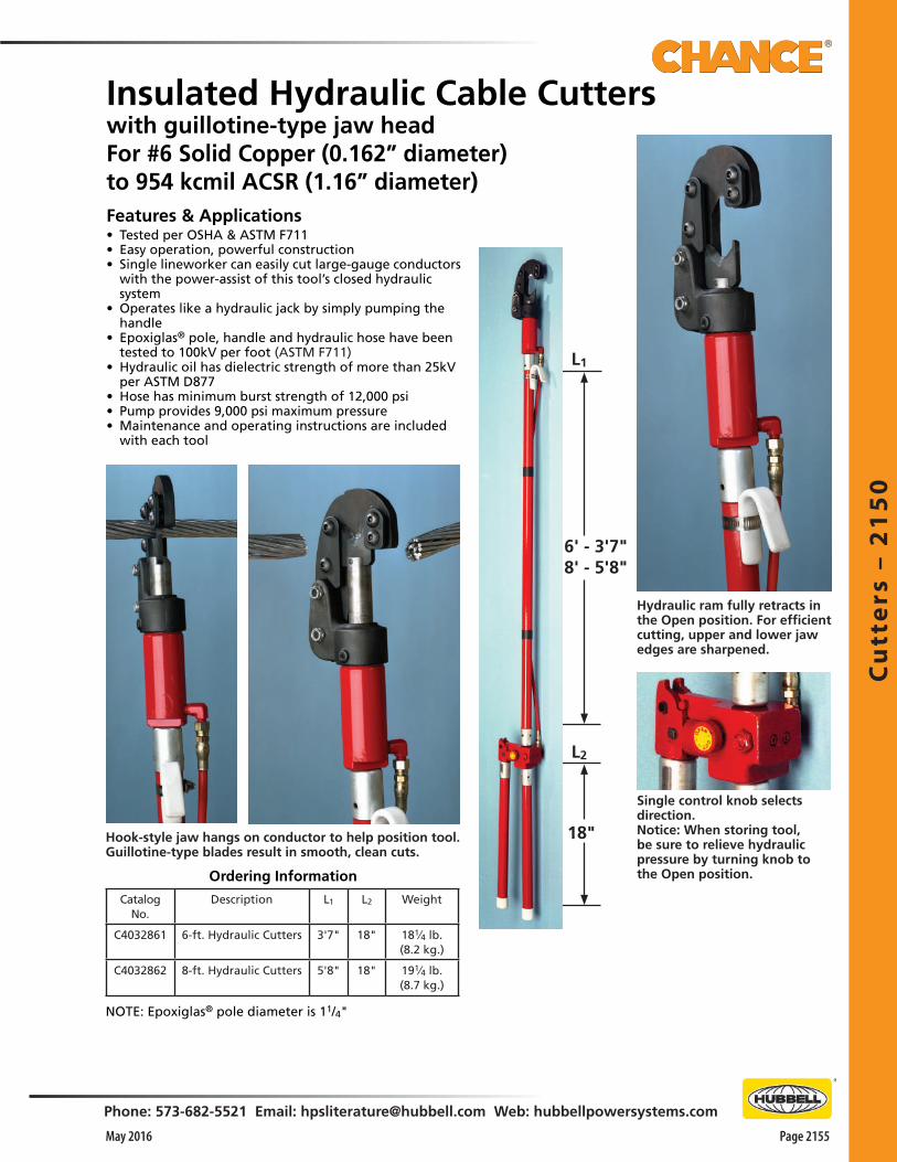
Cu
tte
rs –
21
50
Phone: 573-682-5521 Email: [email protected] Web: hubbellpowersystems.com
Page 2155May 2016
6' - 3'7"8' - 5'8"
18"
L1
L2
Features & Applications• Tested per OSHA & ASTM F711• Easy operation, powerful construction• Single lineworker can easily cut large-gauge conductors
with the power-assist of this tool’s closed hydraulic system
• Operates like a hydraulic jack by simply pumping the handle
• Epoxiglas® pole, handle and hydraulic hose have been tested to 100kV per foot (ASTM F711)
• Hydraulic oil has dielectric strength of more than 25kV per ASTM D877
• Hose has minimum burst strength of 12,000 psi• Pump provides 9,000 psi maximum pressure• Maintenance and operating instructions are included
with each tool
Ordering Information
Hydraulic ram fully retracts in the Open position. For efficient cutting, upper and lower jaw edges are sharpened.
Hook-style jaw hangs on conductor to help position tool. Guillotine-type blades result in smooth, clean cuts.
Single control knob selects direction.Notice: When storing tool, be sure to relieve hydraulic pressure by turning knob to the Open position.
Insulated Hydraulic Cable Cutterswith guillotine-type jaw headFor #6 Solid Copper (0.162” diameter)to 954 kcmil ACSR (1.16” diameter)
Catalog No.
Description L1 L2 Weight
C4032861 6-ft. Hydraulic Cutters 3'7" 18" 181⁄4 lb. (8.2 kg.)
C4032862 8-ft. Hydraulic Cutters 5'8" 18" 191⁄4 lb. (8.7 kg.)
NOTE: Epoxiglas® pole diameter is 11/4"

Cu
tters – 2
15
0
Page 2156 May 2016
Phone: 573-682-5521 Email: [email protected] Web: hubbellpowersystems.com
HYDRAULICALLY OPERATEDCONDUCTOR CUTTER
Features & Applications• Used to cut conductors up to 954 MCM ACSR, all-aluminum
and 500 MCM copper• Operation similar to a hydraulic jack• Knob-handle is turned to enable lineman to operate pump
handle• When cut is completed, knob is turned in opposite direction to
allow cutting head to open• Epoxiglas pole, handle and hydraulic hose have been tested to
100 kV per foot (ASTM F711)• Hydraulic oil has a dielectric strength of 25 + kV per ASTM
D877-64• Hose has a minimum burst strength of 12,000 PSI• Pump provides maximum pressure of 9,000 PSI• Features include jaws designed to cut without flattening con-
ductor• Jaws are adjustable to compensate for wear• Hydraulic hose is located outside pole for easy maintenance• Well balanced, requiring minimum effort to cut large conduc-
tors
Catalog No.C4030731C4030732
Length6'8'
Pole Dia.11⁄4"11⁄4"
RangeTo 954 MCM ACSRTo 954 MCM ACSR
Weight13 lb./5.9 kg.15 lb./6.8 kg.
ALUMINUM WIRE CUTTER
Features & Applications• Wire cutters have a heat treated steel cutter head designed to
cut all-aluminum conductors• Aluminum head and Chance Epoxiglas® handles combine to
make an insulated lightweight tool for easy handling• A lineman’s preference for cutting aluminum jumper cables,
conductors or tie wires• Do not use this tool to cut ACSR conductors
CatalogNo.
C4030689C4030690
DescriptionAll-AluminumWire Cutters
Pole SizeDia.11⁄2"11⁄2"
ConductorRanges
1.033.5MCM1.033.5MCM
Length6'8'
Weight81⁄2 lb./3.8 kg.10 lb./4.5 kg.
Tested per OSHA & ASTM F711
Tested per OSHA & ASTM F711
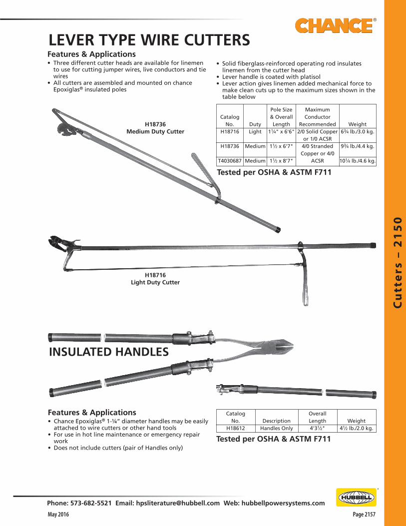
Cu
tte
rs –
21
50
Phone: 573-682-5521 Email: [email protected] Web: hubbellpowersystems.com
Page 2157May 2016
Features & Applications• Chance Epoxiglas® 1-¼” diameter handles may be easily
attached to wire cutters or other hand tools• For use in hot line maintenance or emergency repair
work• Does not include cutters (pair of Handles only)
CatalogNo.
H18612Description
Handles Only
OverallLength4'31⁄2"
Weight41⁄2 lb./2.0 kg.
H18716Light Duty Cutter
LEVER TYPE WIRE CUTTERS
H18736Medium Duty Cutter
• Solid fiberglass-reinforced operating rod insulates linemen from the cutter head
• Lever handle is coated with platisol• Lever action gives linemen added mechanical force to
make clean cuts up to the maximum sizes shown in the table below
Features & Applications• Three different cutter heads are available for linemen
to use for cutting jumper wires, live conductors and tie wires
• All cutters are assembled and mounted on chance Epoxiglas® insulated poles
DutyLight
Medium
Medium
Pole Size& OverallLength
11⁄4" x 6'6"
11⁄2 x 6'7"
11⁄2 x 8'7"
Weight63⁄4 lb./3.0 kg.
93⁄4 lb./4.4 kg.
101⁄4 lb./4.6 kg.
Catalog No.
H18716
H18736
T4030687
MaximumConductor
Recommended2/0 Solid Copper
or 1/0 ACSR4/0 StrandedCopper or 4/0
ACSR
Tested per OSHA & ASTM F711
Tested per OSHA & ASTM F711
INSULATED HANDLES
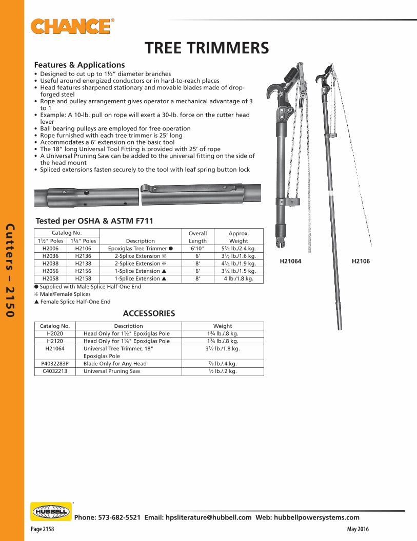
Cu
tters – 2
15
0
Page 2158 May 2016
Phone: 573-682-5521 Email: [email protected] Web: hubbellpowersystems.com
TREE TRIMMERSFeatures & Applications• Designed to cut up to 1½” diameter branches• Useful around energized conductors or in hard-to-reach places• Head features sharpened stationary and movable blades made of drop-
forged steel• Rope and pulley arrangement gives operator a mechanical advantage of 3
to 1• Example: A 10-lb. pull on rope will exert a 30-lb. force on the cutter head
lever• Ball bearing pulleys are employed for free operation• Rope furnished with each tree trimmer is 25’ long• Accommodates a 6’ extension on the basic tool• The 18” long Universal Tool Fitting is provided with 25’ of rope• A Universal Pruning Saw can be added to the universal fitting on the side of
the head mount• Spliced extensions fasten securely to the tool with leaf spring button lock
Catalog No.
11⁄2" PolesH2006H2036H2038H2056H2058
11⁄4" PolesH2106H2136H2138H2156H2158
DescriptionEpoxiglas Tree Trimmer ●
2-Splice Extension ❇2-Splice Extension ❇1-Splice Extension ▲1-Splice Extension ▲
OverallLength6'10"
6'8'6'8'
Approx.Weight
51⁄4 lb./2.4 kg.31⁄2 lb./1.6 kg.41⁄4 lb./1.9 kg.31⁄4 lb./1.5 kg.4 lb./1.8 kg.
Catalog No.H2020H2120H21064
P4032283PC4032213
DescriptionHead Only for 11⁄2" Epoxiglas PoleHead Only for 11⁄4" Epoxiglas PoleUniversal Tree Trimmer, 18"Epoxiglas PoleBlade Only for Any HeadUniversal Pruning Saw
Weight13⁄4 lb./.8 kg.13⁄4 lb./.8 kg.31⁄2 lb./1.8 kg.
7⁄8 lb./.4 kg.1⁄2 lb./.2 kg.
H21064
ACCESSORIES
● Supplied with Male Splice Half-One End❇ Male/Female Splices▲ Female Splice Half-One End
H2106
Tested per OSHA & ASTM F711

Co
nd
uct
or
Su
pp
ort
Eq
uip
me
nt
– 2
20
0
Phone: 573-682-5521 Email: [email protected] Web: hubbellpowersystems.com
Page 2201May 2016
Co
nd
uct
or
Su
pp
ort
Eq
uip
me
nt
–22
00
Conductor SupportEquipment
Catalog 2200 May 2016
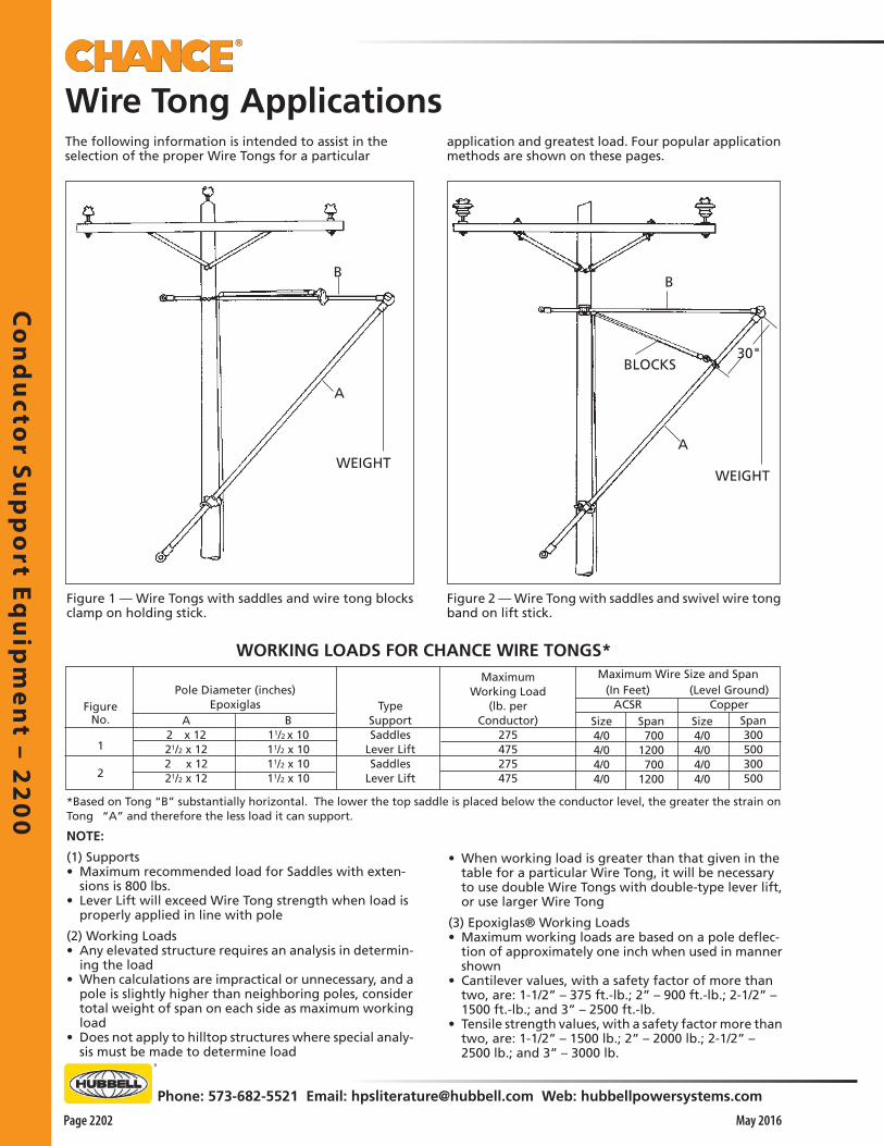
Co
nd
ucto
r Su
pp
ort E
qu
ipm
en
t – 22
00
Page 2202
Phone: 573-682-5521 Email: [email protected] Web: hubbellpowersystems.com
May 2016
Wire Tong ApplicationsThe following information is intended to assist in the selection of the proper Wire Tongs for a particular
application and greatest load. Four popular application methods are shown on these pages.
Figure 1 — Wire Tongs with saddles and wire tong blocks clamp on holding stick.
Figure 2 — Wire Tong with saddles and swivel wire tong band on lift stick.
BLOCKS
WEIGHT
30"
B
A
B
WEIGHT
A
WORKING LOADS FOR CHANCE WIRE TONGS*Maximum Wire Size and Span
Size4/04/04/04/0
Span 7001200 7001200
(Level Ground)Copper
(In Feet)ACSR
Size4/04/04/04/0
MaximumWorking Load
(lb. perConductor)
275475275475
TypeSupportSaddles
Lever LiftSaddles
Lever Lift
B11/2 x 1011/2 x 1011/2 x 1011/2 x 10
A2 x 1221/2 x 122 x 1221/2 x 12
Pole Diameter (inches)Epoxiglas
*Based on Tong “B” substantially horizontal. The lower the top saddle is placed below the conductor level, the greater the strain on Tong “A” and therefore the less load it can support.
FigureNo.
1
2
Span300500300500
NOTE:
(1) Supports• Maximum recommended load for Saddles with exten-
sions is 800 lbs.• Lever Lift will exceed Wire Tong strength when load is
properly applied in line with pole
(2) Working Loads• Any elevated structure requires an analysis in determin-
ing the load• When calculations are impractical or unnecessary, and a
pole is slightly higher than neighboring poles, consider total weight of span on each side as maximum working load
• Does not apply to hilltop structures where special analy-sis must be made to determine load
• When working load is greater than that given in the table for a particular Wire Tong, it will be necessary to use double Wire Tongs with double-type lever lift, or use larger Wire Tong
(3) Epoxiglas® Working Loads• Maximum working loads are based on a pole deflec-
tion of approximately one inch when used in manner shown
• Cantilever values, with a safety factor of more than two, are: 1-1/2” – 375 ft.-lb.; 2” – 900 ft.-lb.; 2-1/2” – 1500 ft.-lb.; and 3” – 2500 ft.-lb.
• Tensile strength values, with a safety factor more than two, are: 1-1/2” – 1500 lb.; 2” – 2000 lb.; 2-1/2” – 2500 lb.; and 3” – 3000 lb.
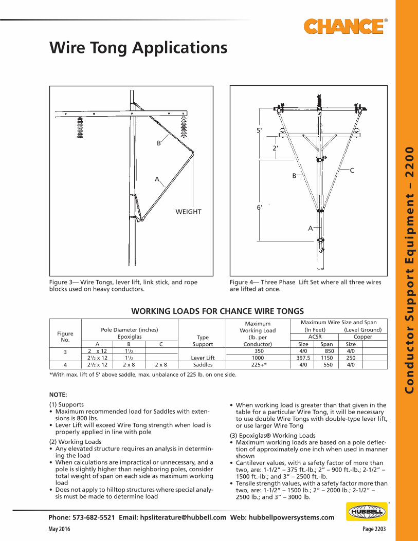
Co
nd
uct
or
Su
pp
ort
Eq
uip
me
nt
– 2
20
0
Phone: 573-682-5521 Email: [email protected] Web: hubbellpowersystems.com
Page 2203May 2016
Wire Tong Applications
WORKING LOADS FOR CHANCE WIRE TONGS
B
A
WEIGHT
5'
2'
BC
A
6'
Figure 4— Three Phase Lift Set where all three wires are lifted at once.
Figure 3— Wire Tongs, lever lift, link stick, and rope blocks used on heavy conductors.
NOTE:
(1) Supports• Maximum recommended load for Saddles with exten-
sions is 800 lbs.• Lever Lift will exceed Wire Tong strength when load is
properly applied in line with pole
(2) Working Loads• Any elevated structure requires an analysis in determin-
ing the load• When calculations are impractical or unnecessary, and a
pole is slightly higher than neighboring poles, consider total weight of span on each side as maximum working load
• Does not apply to hilltop structures where special analy-sis must be made to determine load
• When working load is greater than that given in the table for a particular Wire Tong, it will be necessary to use double Wire Tongs with double-type lever lift, or use larger Wire Tong
(3) Epoxiglas® Working Loads• Maximum working loads are based on a pole deflec-
tion of approximately one inch when used in manner shown
• Cantilever values, with a safety factor of more than two, are: 1-1/2” – 375 ft.-lb.; 2” – 900 ft.-lb.; 2-1/2” – 1500 ft.-lb.; and 3” – 2500 ft.-lb.
• Tensile strength values, with a safety factor more than two, are: 1-1/2” – 1500 lb.; 2” – 2000 lb.; 2-1/2” – 2500 lb.; and 3” – 3000 lb.
Maximum Wire Size and Span
Size4/0
397.54/0
Span 8501150 550
(Level Ground)Copper
(In Feet)ACSR
MaximumWorking Load
(lb. perConductor)
350 1000
225+*
TypeSupport
Lever LiftSaddles
A2 x 1221/2 x 1221/2 x 12
Pole Diameter (inches)Epoxiglas
B11/211/2
2 x 8
C
2 x 8
*With max. lift of 5' above saddle, max. unbalance of 225 lb. on one side.
FigureNo.
3
4
Size4/02504/0
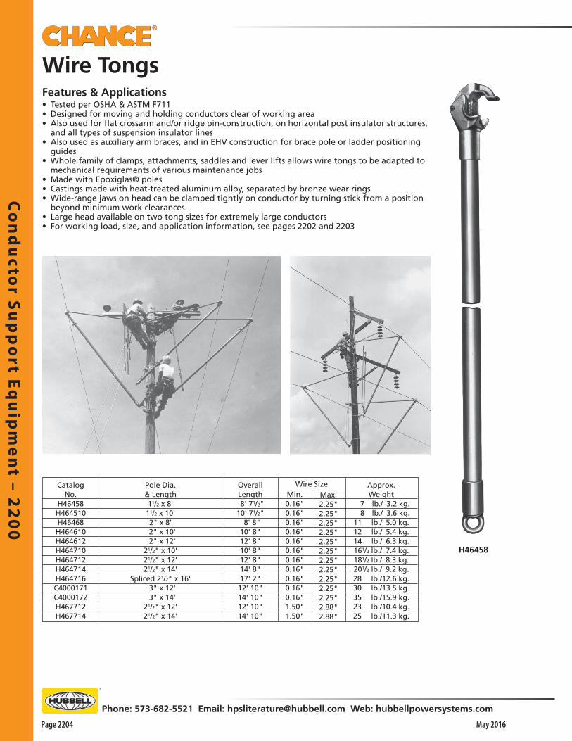
Co
nd
ucto
r Su
pp
ort E
qu
ipm
en
t – 22
00
Page 2204
Phone: 573-682-5521 Email: [email protected] Web: hubbellpowersystems.com
May 2016
Wire TongsFeatures & Applications• Tested per OSHA & ASTM F711• Designed for moving and holding conductors clear of working area• Also used for flat crossarm and/or ridge pin-construction, on horizontal post insulator structures,
and all types of suspension insulator lines• Also used as auxiliary arm braces, and in EHV construction for brace pole or ladder positioning
guides• Whole family of clamps, attachments, saddles and lever lifts allows wire tongs to be adapted to
mechanical requirements of various maintenance jobs• Made with Epoxiglas® poles• Castings made with heat-treated aluminum alloy, separated by bronze wear rings• Wide-range jaws on head can be clamped tightly on conductor by turning stick from a position
beyond minimum work clearances.• Large head available on two tong sizes for extremely large conductors• For working load, size, and application information, see pages 2202 and 2203
Wire SizeOverallLength 8' 71/2" 10' 71/2" 8' 8" 10' 8" 12' 8" 10' 8" 12' 8" 14' 8" 17' 2" 12' 10" 14' 10" 12' 10" 14' 10"
Pole Dia.& Length11/2 x 8'
11/2 x 10'2" x 8'
2" x 10' 2" x 12'21/2" x 10'21/2" x 12'21/2" x 14'
Spliced 21/2" x 16' 3" x 12' 3" x 14'21/2" x 12'21/2" x 14'
CatalogNo.
H46458 H464510 H46468 H464610 H464612 H464710 H464712 H464714 H464716 C4000171C4000172H467712 H467714
Min.0.16"0.16"0.16"0.16"0.16"0.16"0.16"0.16"0.16"0.16"0.16"1.50"1.50"
Max.2.25"2.25"2.25"2.25"2.25"2.25"2.25"2.25"2.25"2.25"2.25"2.88"2.88"
Approx.Weight
7 lb./ 3.2 kg. 8 lb./ 3.6 kg.11 lb./ 5.0 kg.12 lb./ 5.4 kg.14 lb./ 6.3 kg.161/2 lb./ 7.4 kg.181/2 lb./ 8.3 kg.201/2 lb./ 9.2 kg.28 lb./12.6 kg.30 lb./13.5 kg.35 lb./15.9 kg.23 lb./10.4 kg.25 lb./11.3 kg.
H46458

Co
nd
uct
or
Su
pp
ort
Eq
uip
me
nt
– 2
20
0
Phone: 573-682-5521 Email: [email protected] Web: hubbellpowersystems.com
Page 2205May 2016
Wire-Tong Pole Clevis
Cat. No.M474014
Weight14 oz./ 3 kg.
DescriptionWire Tong Saddle Clevis
Features & Applications• Used to attach butt ring of a wire tong, as a crossarm
brace, to a wire tong saddle• Allows wire tong to pivot and engage wire tong arm
stirrup• Wire tong can be attached after arm has been secured
to poleCat. No.M17285
C4000345
Size21/2"3"
Weight21/2 lb./1.1 kg.33/4 lb./1.7 kg.
WIRE TONG SWIVEL
Wire-Tong Saddle Clevis
Features & Applications• Two screws clamp band to wire tong• Each screw is threaded into half of the band and en-
gages a slot in opposite half• This permits halves of the band to be separated by a
sliding action without removing screws• Hinge ring slides on band, allowing rotation of wire
tong when tong is supported by rope blocks• For positive insulation between rope blocks and live
conductors, install band at least the minimum distance for voltage class
• See table on page 2202
WIRE TONG BAND
Cat. No.M17293M1729 M17291M17292
Weight11/2 lb./0.7 kg.15/8 lb./0.7 kg.13/4 lb./0.8 kg.17/8 lb./0.8 kg.
For Pole Dia.11/2"2"
21/2"3"
WIRE TONG BLOCKS CLAMPFeatures & Applications• Use where pull is in line with pole• Secured to wire tong under tension• Rope blocks are connected to clamp ring• This application places pull force in line with top wire
tong• Assists in pulling heavy conductors back into position
Features & Applications• Designed to prevent kinking of conductor• By attaching swivel to left tong and the holding tong
hooked into the clevis attachment, there is only one tong hooked on the conductor
• Clevis pivots to allow tongs to assume correct positions • This avoids the kinking caused by two wire tongs
hooked side-by-side on a conductorWeight
11/2 lb./.07 kg.13/4 lb./.08 kg.
For Pole Dia.2"
21/2"
Cat. No.M4745 M47451
Features & Applications• Clamps around vertical wire tong supporting an auxil-
iary crossarm• Engages butt rings of two wire tongs used as side
braces
Cat. No. For Pole Dia. WeightM4743 11/2" 25/8 lb./1.2 kg.M47431 2" 2.3 lb./1.1 kg.M47432 21/2" 3.0 lb./1.4 kg.

Co
nd
ucto
r Su
pp
ort E
qu
ipm
en
t – 22
00
Page 2206
Phone: 573-682-5521 Email: [email protected] Web: hubbellpowersystems.com
May 2016
Features & Applications• Made of strong, yet lightweight aluminum alloy for handing ease• Will support a maximum of 1000 lbs. (450 kg) without extension• Has a tested working load rating of 800 lbs. (360 kg.) with extension• Clamp is set far enough away from base to provide ample clearance
for most jobs• Can be bolted to the saddle when additional clearance is required• Heat-treated aluminum-alloy extension is 4 inches (100 mm) long• Wheel Type fasteners are easy to apply, hold saddle firmly in place
and prevent riding down • Wheel Tightener can fit into close places, including between crossarm
braces
Wire-Tong Saddles
Description Saddle and Tightener and 11/2" (37.5mm) clamp Saddle and Tightener and 2" (50mm) clamp Saddle and Tightener and 21/2" (62.5mm) clamp Saddle and Tightener and 3" (75mm) clamp Saddle and Tightener less clamp Saddle Wheel Tightener and Clevis Saddle, Tightener, 11/2" (37.5mm) clamp & extension Saddle, Tightener, 2" (50mm) clamp & extension Saddle, Tightener, 21/2" (62.5mm) clamp & extension Saddle, Tightener, 3" (75mm) clamp & extension Saddle, Tightener, extension less clamp Wire Tong Saddle Extension 11/2" (37.5mm) pole clamp only 2" (50mm) pole clamp only 21/2" (62.5mm) pole clamp only 3" (75mm) pole clamp only
Approx. Weight10 lb. 1 oz./4.56 kg.10 lb. 5 oz./4.68 kg.10 lb. 9 oz./4.80 kg.10 lb. 12 oz./4.90 kg. 8 lb. /3.60 kg. 6 lb. 11 oz./3.03 kg.11 lb. 1 oz./5.01 kg.11 lb. 5 oz./5.13 kg.11 lb. 9 oz./5.24 kg.11 lb. 12 oz./5.33 kg. 9 lb. /4.08 kg. 1 lb. /0.45 kg. 2 lb. 1 oz./0.93 kg. 2 lb. 5 oz./1.04 kg. 2 lb. 9 oz./1.20 kg. 2 lb. 12 oz./1.25 kg.
M474010W M474018W M47405W
M47412Pole Clamp
M474020W
C4000073 Extension
Catalog No.M47403WM47404WM47405WM47409WM474010WM474015WM474016WM474017WM474018WM474019WM474020WC4000073 M47411 M47412 M47413 M47415
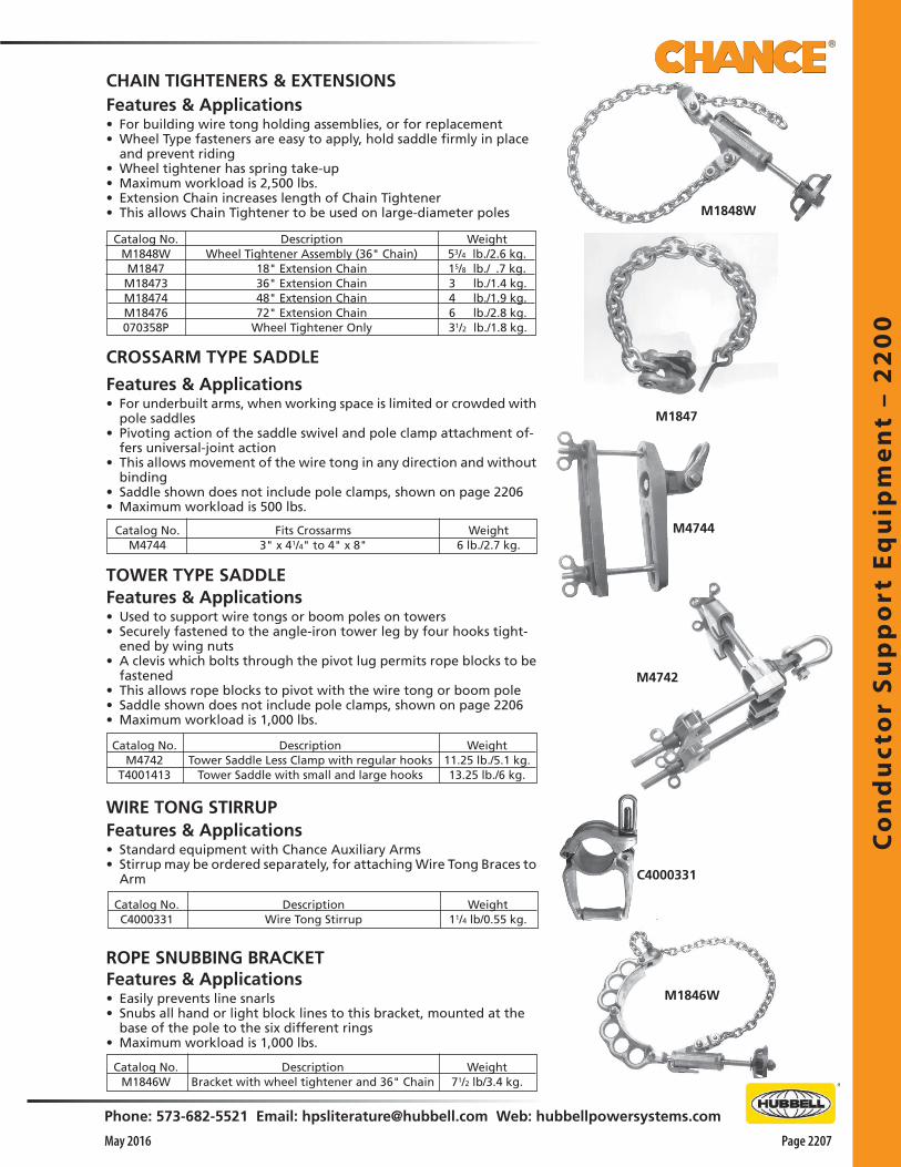
Co
nd
uct
or
Su
pp
ort
Eq
uip
me
nt
– 2
20
0
Phone: 573-682-5521 Email: [email protected] Web: hubbellpowersystems.com
Page 2207May 2016
ROPE SNUBBING BRACKET
Catalog No.M1846W
Weight71/2 lb/3.4 kg.
DescriptionBracket with wheel tightener and 36" Chain
Features & Applications• Easily prevents line snarls• Snubs all hand or light block lines to this bracket, mounted at the
base of the pole to the six different rings• Maximum workload is 1,000 lbs.
Features & Applications• Used to support wire tongs or boom poles on towers• Securely fastened to the angle-iron tower leg by four hooks tight-
ened by wing nuts • A clevis which bolts through the pivot lug permits rope blocks to be
fastened• This allows rope blocks to pivot with the wire tong or boom pole• Saddle shown does not include pole clamps, shown on page 2206• Maximum workload is 1,000 lbs.
TOWER TYPE SADDLE
Catalog No.M4742
T4001413
DescriptionTower Saddle Less Clamp with regular hooks
Tower Saddle with small and large hooks
Weight11.25 lb./5.1 kg.13.25 lb./6 kg.
Catalog No.M4744
Fits Crossarms3" x 41/4" to 4" x 8"
Weight6 lb./2.7 kg.
Features & Applications• For underbuilt arms, when working space is limited or crowded with
pole saddles• Pivoting action of the saddle swivel and pole clamp attachment of-
fers universal-joint action• This allows movement of the wire tong in any direction and without
binding• Saddle shown does not include pole clamps, shown on page 2206• Maximum workload is 500 lbs.
CROSSARM TYPE SADDLE
CHAIN TIGHTENERS & EXTENSIONSFeatures & Applications• For building wire tong holding assemblies, or for replacement• Wheel Type fasteners are easy to apply, hold saddle firmly in place
and prevent riding• Wheel tightener has spring take-up• Maximum workload is 2,500 lbs.• Extension Chain increases length of Chain Tightener • This allows Chain Tightener to be used on large-diameter poles
Catalog No.M1848WM1847 M18473 M18474 M18476 070358P
DescriptionWheel Tightener Assembly (36" Chain)
18" Extension Chain36" Extension Chain48" Extension Chain72" Extension Chain
Wheel Tightener Only
Weight53/4 lb./2.6 kg.15/8 lb./ .7 kg. 3 lb./1.4 kg. 4 lb./1.9 kg. 6 lb./2.8 kg. 31/2 lb./1.8 kg.
M4742
M1846W
M1847
WIRE TONG STIRRUP
Catalog No.C4000331
Weight11/4 lb/0.55 kg.
DescriptionWire Tong Stirrup
Features & Applications• Standard equipment with Chance Auxiliary Arms• Stirrup may be ordered separately, for attaching Wire Tong Braces to
Arm
M1848W
M4744
C4000331
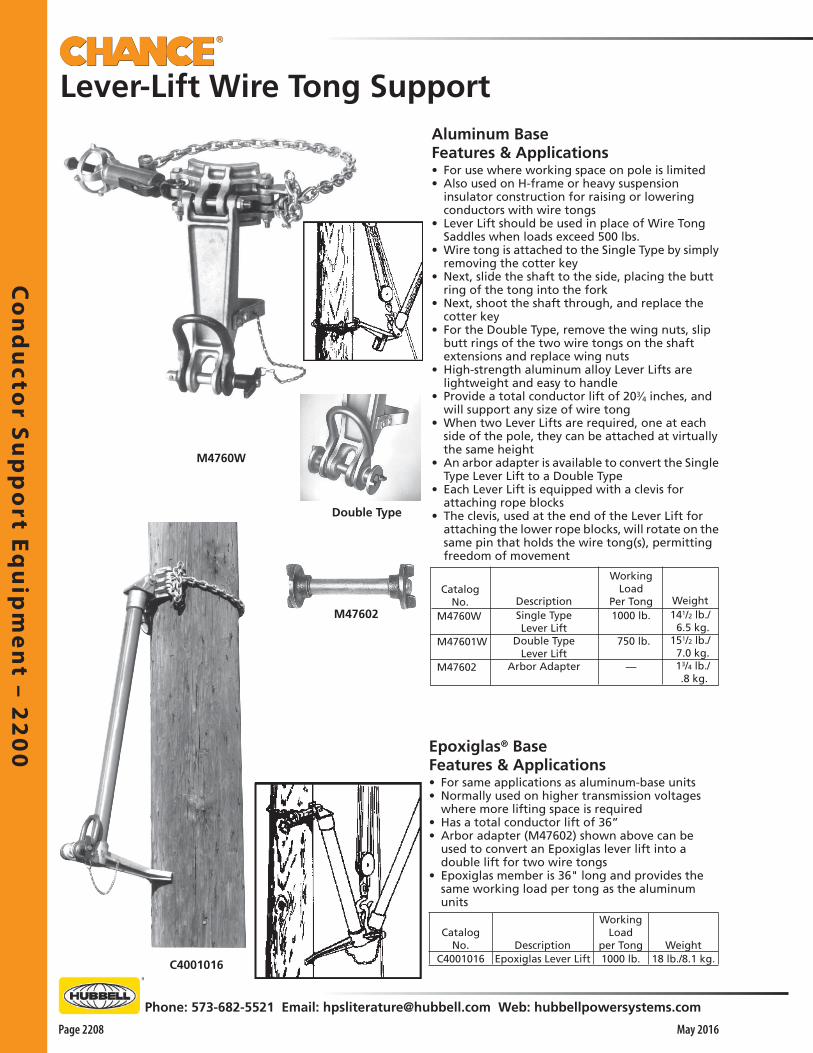
Co
nd
ucto
r Su
pp
ort E
qu
ipm
en
t – 22
00
Page 2208
Phone: 573-682-5521 Email: [email protected] Web: hubbellpowersystems.com
May 2016
Aluminum BaseFeatures & Applications• For use where working space on pole is limited• Also used on H-frame or heavy suspension
insulator construction for raising or lowering conductors with wire tongs
• Lever Lift should be used in place of Wire Tong Saddles when loads exceed 500 lbs.
• Wire tong is attached to the Single Type by simply removing the cotter key
• Next, slide the shaft to the side, placing the butt ring of the tong into the fork
• Next, shoot the shaft through, and replace the cotter key
• For the Double Type, remove the wing nuts, slip butt rings of the two wire tongs on the shaft extensions and replace wing nuts
• High-strength aluminum alloy Lever Lifts are lightweight and easy to handle
• Provide a total conductor lift of 203⁄4 inches, and will support any size of wire tong
• When two Lever Lifts are required, one at each side of the pole, they can be attached at virtually the same height
• An arbor adapter is available to convert the Single Type Lever Lift to a Double Type
• Each Lever Lift is equipped with a clevis for attaching rope blocks
• The clevis, used at the end of the Lever Lift for attaching the lower rope blocks, will rotate on the same pin that holds the wire tong(s), permitting freedom of movement
CatalogNo.
M4760W
M47601W
M47602
Weight141/2 lb./ 6.5 kg.151/2 lb./ 7.0 kg. 13/4 lb./ .8 kg.
DescriptionSingle TypeLever Lift
Double TypeLever Lift
Arbor Adapter
WorkingLoad
Per Tong1000 lb.
750 lb.
—
Double Type
M4760W
C4001016
Epoxiglas® BaseFeatures & Applications• For same applications as aluminum-base units• Normally used on higher transmission voltages
where more lifting space is required• Has a total conductor lift of 36”• Arbor adapter (M47602) shown above can be
used to convert an Epoxiglas lever lift into a double lift for two wire tongs
• Epoxiglas member is 36" long and provides the same working load per tong as the aluminum units
Lever-Lift Wire Tong Support
M47602
Catalog No. Description
WorkingLoad
per Tong WeightC4001016 Epoxiglas Lever Lift 1000 lb. 18 lb./8.1 kg.

Co
nd
uct
or
Su
pp
ort
Eq
uip
me
nt
– 2
20
0
Phone: 573-682-5521 Email: [email protected] Web: hubbellpowersystems.com
Page 2209May 2016
Catalog No.
C4000075Description
Dual Auxiliary Arm, 10 ft., with
Wheel Binder & 1" Fork Wireholder
Weight
33 lb./14.9 kg.
E
B
• All of the auxiliary arm wireholders are the self-latching type• When lowered into wireholder, conductor trips safety latch, locking conductor
into wireholder• Latch must be swiveled with an insulated live line stick to release the conductor
Electrical RatingsGLOSSY, CLEAN AND DRY EPOXIGLAS®
15kV Phase to Phase34kV Phase to Phase with M48057Insulators are used on each wireholder
Rigged as a Side Arm
Dual Auxiliary Arm
Features & Applications• Tested per OSHA & ASTM F711• For use where a changeout of poles, crossarms or insu-
lators is necessary• Standard Chance Epoxiglas® tools are lightweight and
easily rigged• Can be used as a side arm on regular construction, or
alley arm construction• Movable wireholders can be spaced for minimum con-
ductor travel from the crossarm to the temporary arm• Arm is long enough for use as a lifting arm with the
use of three standard Chance Wiretongs• When arm is to be left up overnight or during a period
of possible rain, it should be wiped down with a silicone-treated cloth
• It is also possible to replace the 1" opening M480517 wireholders with 1.5" opening M480515 wireholders.
B
A
B
D
C
Accessory Tools Required For Lifting Arm ApplicationOne A 21/2" x 16' Wire Tong H464716Two B 2" x 8' Wire Tong H46468Two C Pole Type Saddles with Extension M474018W and 21/2" Pole ClampsOne D 21/2" Pole Clevis M17285Plus necessary insulated hand held tools.
Accessory Tools Required For Side Arm Application
One B 2" x 8' Wire Tong H46468One E Pole Type Saddle with Clevis M474015W
Plus necessary insulated hand held tools.
M48057
M4805151.5" opening
C4000562 T-Clamp & Insulator
C4000331 Stirrup
M480517 Wireholder1" opening
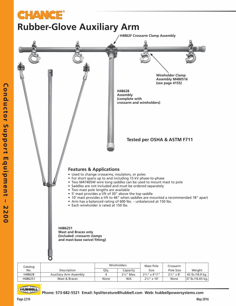
Co
nd
ucto
r Su
pp
ort E
qu
ipm
en
t – 22
00
Page 2210
Phone: 573-682-5521 Email: [email protected] Web: hubbellpowersystems.com
May 2016
H486251Mast and Braces only(included: crossarm clampsand mast-base swivel fitting)
Features & Applications• Used to change crossarms, insulators, or poles• For short spans up to and including 15 kV phase-to-phase• Two M47405W wire tong saddles can be used to mount mast to pole• Saddles are not included and must be ordered separately• Two mast pole lengths are available• 5’ mast provides a lift of 30” above the top saddle• 10’ mast provides a lift to 46” when saddles are mounted a recommended 18” apart• Arm has a balanced rating of 600 lbs. – unbalanced at 150 lbs.• Each wireholder is rated at 150 lbs.
Rubber-Glove Auxiliary Arm
Wireholders Crossarm Pole Size21/2" x 8'
None
Mast PoleSize
21/2" x 4'11"21/2" x 10'
Weight42 lb./18.9 kg.37 lb./16.65 kg.
Qty.4
None
Capacity21/2" Max.
N/A
CatalogNo.
H48628 H486251
DescriptionAuxiliary Arm Assembly
Mast & Braces
H48628Assembly(complete withcrossarm and wireholders)
Wireholder Clamp Assembly M480516 (see page 4155)
H4862F Crossarm Clamp Assembly
Tested per OSHA & ASTM F711
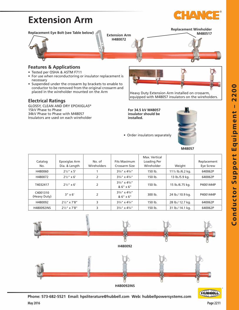
Co
nd
uct
or
Su
pp
ort
Eq
uip
me
nt
– 2
20
0
Phone: 573-682-5521 Email: [email protected] Web: hubbellpowersystems.com
Page 2211May 2016
Extension Arm
Features & Applications• Tested per OSHA & ASTM F711• For use when reconductoring or insulator replacement is
necessary• Suspended under the crossarm by brackets to enable to
conductor to be removed from the original crossarm and placed in the wireholder mounted on the Arm
Electrical RatingsGLOSSY, CLEAN AND DRY EPOXIGLAS®
15kV Phase to Phase34kV Phase to Phase with M48057Insulators are used on each wireholder
• Order insulators separately
Extension Arm H480072
Replacement Wireholder M480517Replacement Eye Bolt (see Table below)
Heavy Duty Extension Arm installed on crossarm, equipped with M48057 insulators on the wireholders.
For 34.5 kV M48057 insulator should be installed.
M48057
CatalogNo.
Epoxiglas ArmDia. & Length
No. ofWireholders
Fits MaximumCrossarm Size
Max. VerticalLoading Per Wireholder Weight
ReplacementEye Screw
H480060 21/2" x 5' 1 33/4" x 43/4" 150 lb. 111/2 lb./6.2 kg. 640062P
H480072 21/2" x 6' 2 33/4" x 43/4" 150 lb. 13 lb./5.9 kg. 640062P
T4032417 21/2" x 6' 233/4" x 43/4"& 6" x 6"
150 lb. 15 lb./6.75 kg. P4001444P
C4001310(Heavy Duty)
3" x 6' 233/4" x 43/4"& 6" x 6"
300 lb. 24 lb./ 10.9 kg. P4001444P
H480092 21/2" x 7'8" 3 33/4" x 43/4" 150 lb. 28 lb./ 12.7 kg. 640062P
H480092INS 21/2" x 7'8" 3 33/4" x 43/4" 150 lb. 31 lb./ 14.1 kg. 640062P
H480092
H480092INS

Co
nd
ucto
r Su
pp
ort E
qu
ipm
en
t – 22
00
Page 2212
Phone: 573-682-5521 Email: [email protected] Web: hubbellpowersystems.com
May 2016
Universal Extension Arms• Fit composite or wood crossarms up to 33⁄4" x 43⁄4"• Cushioned clamp and hanger loop to protect composite arms• Grippers on clamp can be removed for wood crossarms• Design allows removal of components for reconditioning pole• Designed for use with rubber gloves or hot sticks
CROSSARM LOOP(PLASTISOL COATED) & POLE CLAMP
6-ft. Universal Extension Arm PSC4004101
CROSSARM CLAMP(RUBBER GRIPPERS)& POLE END FITTING
WIREHOLDER
Universal Extension ArmRetrofit Kit PSC4004103
CROSSARM LOOP WITH PLASTISOL COATING & POLE CLAMP
CROSSARM CLAMPWITH RUBBER GRIPPERS & POLE END FITTING
BOLT, LOCK-WASHERAND NUT
Universal Extension Arm Retrofit Kit• Allows conversion of wood-only Extension Arms to Universal Extension Arms
Conversion permits easy removal of the Crossarm Clamp for periodic reconditioning of the pole.
Kit instructions show how to cut off the old end fitting and drill for the attachment of the new bolt-on end fitting.
Rubber grippers removed for use on wood crossarms.
Catalog No. Epoxiglas® Arm Dia & Length
Number of Wireholders
Fits Maximum Crossarm Size
Max. Vertical Loading per Wirehoilder
PSC4004101 21⁄2" x 6' 2 33⁄4" x 43⁄4" 150 lb.
PSC4004102 21⁄2" x 5' 1 33⁄4" x 43⁄4" 150 lb.
Electrical RatingsGLOSSY, CLEAN AND DRY EPOXIGLAS®
15kV Phase to Phase34kV Phase to Phase with M48057Insulators are used on each wireholder

Co
nd
uct
or
Su
pp
ort
Eq
uip
me
nt
– 2
20
0
Phone: 573-682-5521 Email: [email protected] Web: hubbellpowersystems.com
Page 2213May 2016
Temporary Conductor Support
For 34.5 kV or when the tool is left overnight, an M48057 insulator should be installed.
*200 lb. total load capacity for H4809W.
CatalogNo.
C4000517Description
Conductor Support, CrossarmWeight
31/2 lb./1.6 kg.
Crossarm MountingFeatures & Applications• Clamps to the crossarm, adjusting to crossarms from 3-1/4" x 4" to 6" x 6"• C-clamp is made of heat-treated aluminum • Can be installed with a Grip-All clampstick • Maximum workload is 150 lbs.
M48057
C4000517
Pole MountingFeatures & Applications• Epoxiglas® temporary conductor support is used to hold energized
distribution conductors• For use during replacement of poles or repair/replacement of pole top and
stand-off insulators• Features wheel tightener for poles up to 14" in diameter• M480517 fork-type, 1" wireholder is standard• Working load: 150 lb. per wireholder• Rated 100 lbs., Side Load, Max.
CatalogNo.
Description Weight
*H4809W Single Conductor Support
20 lb./ 9 kg.
C4001509 Two Conductor Supports
22 lb./10 kg. C4001509 (48" long Epoxiglas arm)
Tested per OSHA & ASTM F711
*H4809W(30" spacing, pole to wireholder)
Tested per OSHA & ASTM F711
Electrical RatingsGLOSSY, CLEAN AND DRY EPOXIGLAS®
15kV Phase to Phase34kV Phase to Phase with M48057Insulators are used on each wireholder

Co
nd
ucto
r Su
pp
ort E
qu
ipm
en
t – 22
00
Page 2214
Phone: 573-682-5521 Email: [email protected] Web: hubbellpowersystems.com
May 2016
Features & Applications• New D-shaped buckle on the strap-free end adds speed
and convenience• Hanging a temporary conductor support involves just
hooking buckle in clasp on bracket and cinching the strap with ratchet handle
• With strap-type ratchet-action mount rather than a chain binder, these supports are same as on page 2211
• Strap and ratchet assembly may be ordered alone for retrofit, below
• Polyester strap offers advantage of less stretch than nylon for this application
• With 10,000-lb. rated tensile strength, 2"-wide strap comes in 44" length to fit most structures
• Wide handle opening on rapid-action ratchet permits easy operation
• Works well even with rubber gloves and leather protectors
• Epoxiglas® temporary conductor support is used to hold energized distribution conductors
• For use during replacement of poles or repair/replacement of pole top and stand-off insulators
• Fork-type wireholder accepts up to 1”-diameter conductor
• Working load: 150 lb. per wireholder on T4001939 only
Electrical RatingsGLOSSY, CLEAN AND DRY EPOXIGLAS®
15kV Phase to Phase34kV Phase to Phase with M48057Insulators are used on each wireholder
Description
D-Buckle Strap Binder only
Weight
41/2 lb./2 kg.
Strap Binder Kitcomplete with D-buckle and Ratchet Mechanism
Description
30" - One Conductor Support
48" - Two Conductor Supports
Weight
14 lb./6.3 kg.
18 lb./8.1 kg.
Catalog No.
*T4001940
T4001939
*200 lb. total load capacity for T4001940.
Strap-Type Temporary Conductor SupportsEpoxiglas® pole: 21⁄2" diameter
D-Buckle Strap On Ratchet Pole Binder• Single- & Double-Wireholder Models
Temporary Conductor Supports
Strap Binder Kit T4002007
Catalog No.
T4002007
Tested per OSHA & ASTM F711

Co
nd
uct
or
Su
pp
ort
Eq
uip
me
nt
– 2
20
0
Phone: 573-682-5521 Email: [email protected] Web: hubbellpowersystems.com
Page 2215May 2016
Corner Restraint Bracket ToolFeatures & Applications• For insulator changes on running corners• Helps isolate pole and hoist during maintenance• D-buckle on strap quickly mounts ratchet pole binder• Adds efficiency to energized changeout of insulators on
distribution running-corner poles• Works with strap hoist to help control each phase
conductor while insulators are changed• Helps restrain conductor while repairs are made• Also acts as load restraint for hoist to pull conductor
back in for reconnection to insulator string• Dual-pin/single-roller set-up lets you rig the bracket for
mounting on either side of pole• So strap always rides on the roller, place roller on
appropriate push-button pin• New D-shaped buckle on the strap-free end adds speed
and convenience• Hanging a temporary conductor support involves just
hooking buckle in clasp on bracket and cinching the strap with ratchet handle
• Bracket rigged on guy side of pole: Used where the conductor is pulled in only a short distance toward the pole
• Bracket rigged on conductor side of pole: Used where the conductor must be pulled in a considerable distance toward the pole
For Hot-line Procedures• For maintenance by hotsticks or rubber-glove
techniques, Corner Restraint Bracket assists in isolating strap hoist from pole, a potential ground
• Also avoids cutting a short section from a poleguard cover-up or using (and possibly damaging) a rubber blanket as a pad between strap and pole
• To insulate the strap hoist, a 12"-long link stick connects the hoist’s hooks to hot-line grips on the conductor
• Poleguards and rubber cover-up are required to isolate the phase being worked from ground and other phase potentials
Maximum Load Rating: 2,000 lb. (900 kg.)
Epoxiglas® member: 21/2" diameter, 6" clear length
Description
Corner Restraint Bracket
Ordering Information
Bracket rigged on conductor side of pole: Used where the conductor must be pulled in a considerable distance toward the pole.
InsulatedLinkSticks
Strap Hoist
Bracket rigged on guy side of pole: Used where the conductor is pulled in only a short distance toward the pole.
InsulatedLinkSticks
StrapHoist
Catalog No.
T4002272
Weight
133/4 lb. / 6.2 kg.
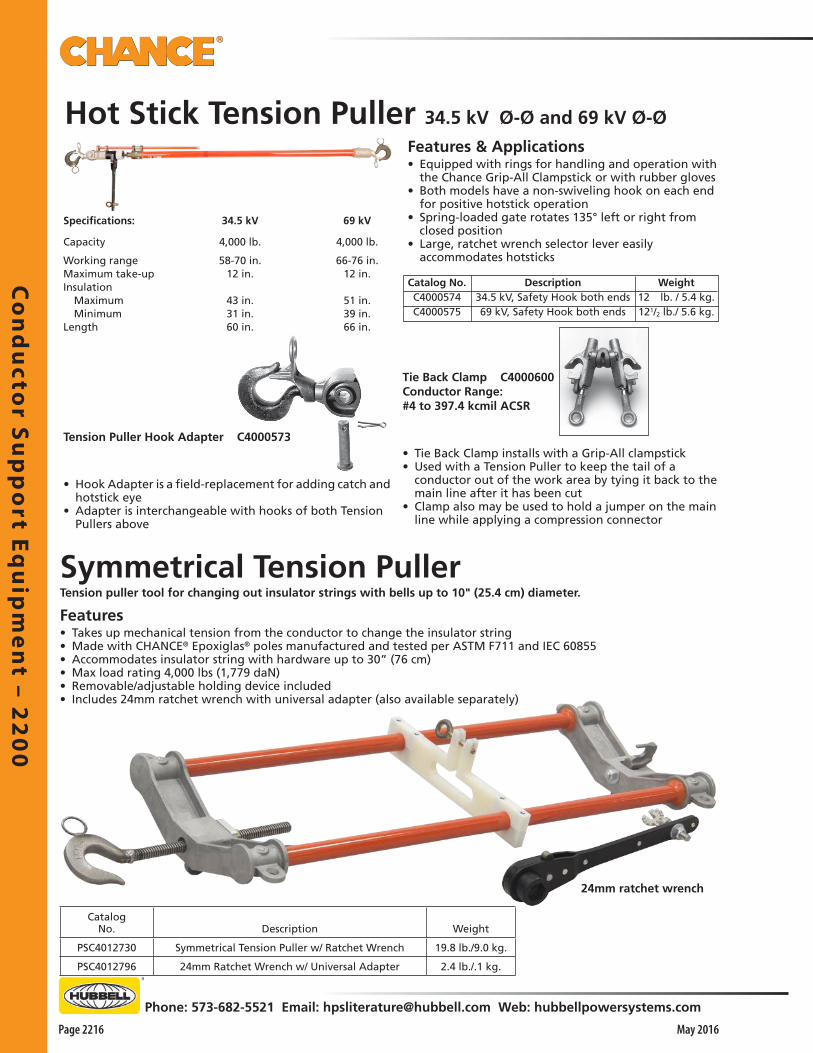
Co
nd
ucto
r Su
pp
ort E
qu
ipm
en
t – 22
00
Page 2216
Phone: 573-682-5521 Email: [email protected] Web: hubbellpowersystems.com
May 2016
• Hook Adapter is a field-replacement for adding catch and hotstick eye
• Adapter is interchangeable with hooks of both Tension Pullers above
• Tie Back Clamp installs with a Grip-All clampstick• Used with a Tension Puller to keep the tail of a
conductor out of the work area by tying it back to the main line after it has been cut
• Clamp also may be used to hold a jumper on the main line while applying a compression connector
Tie Back Clamp C4000600Conductor Range: #4 to 397.4 kcmil ACSR
Tension Puller Hook Adapter C4000573
Specifications:
Capacity
Working rangeMaximum take-upInsulation Maximum MinimumLength
34.5 kV
4,000 lb.
58-70 in.12 in.
43 in.31 in.60 in.
69 kV
4,000 lb.
66-76 in.12 in.
51 in.39 in.66 in.
Hot Stick Tension Puller 34.5 kV Ø-Ø and 69 kV Ø-Ø
Features & Applications• Equipped with rings for handling and operation with
the Chance Grip-All Clampstick or with rubber gloves• Both models have a non-swiveling hook on each end
for positive hotstick operation • Spring-loaded gate rotates 135° left or right from
closed position• Large, ratchet wrench selector lever easily
accommodates hotsticks
Description34.5 kV, Safety Hook both ends69 kV, Safety Hook both ends
Catalog No.C4000574C4000575
Weight12 lb. / 5.4 kg.121/2 lb./ 5.6 kg.
Symmetrical Tension PullerTension puller tool for changing out insulator strings with bells up to 10" (25.4 cm) diameter.
Features• Takes up mechanical tension from the conductor to change the insulator string• Made with CHANCE® Epoxiglas® poles manufactured and tested per ASTM F711 and IEC 60855• Accommodates insulator string with hardware up to 30” (76 cm)• Max load rating 4,000 lbs (1,779 daN)• Removable/adjustable holding device included• Includes 24mm ratchet wrench with universal adapter (also available separately)
24mm ratchet wrench
CatalogNo. Description Weight
PSC4012730 Symmetrical Tension Puller w/ Ratchet Wrench 19.8 lb./9.0 kg.
PSC4012796 24mm Ratchet Wrench w/ Universal Adapter 2.4 lb./.1 kg.
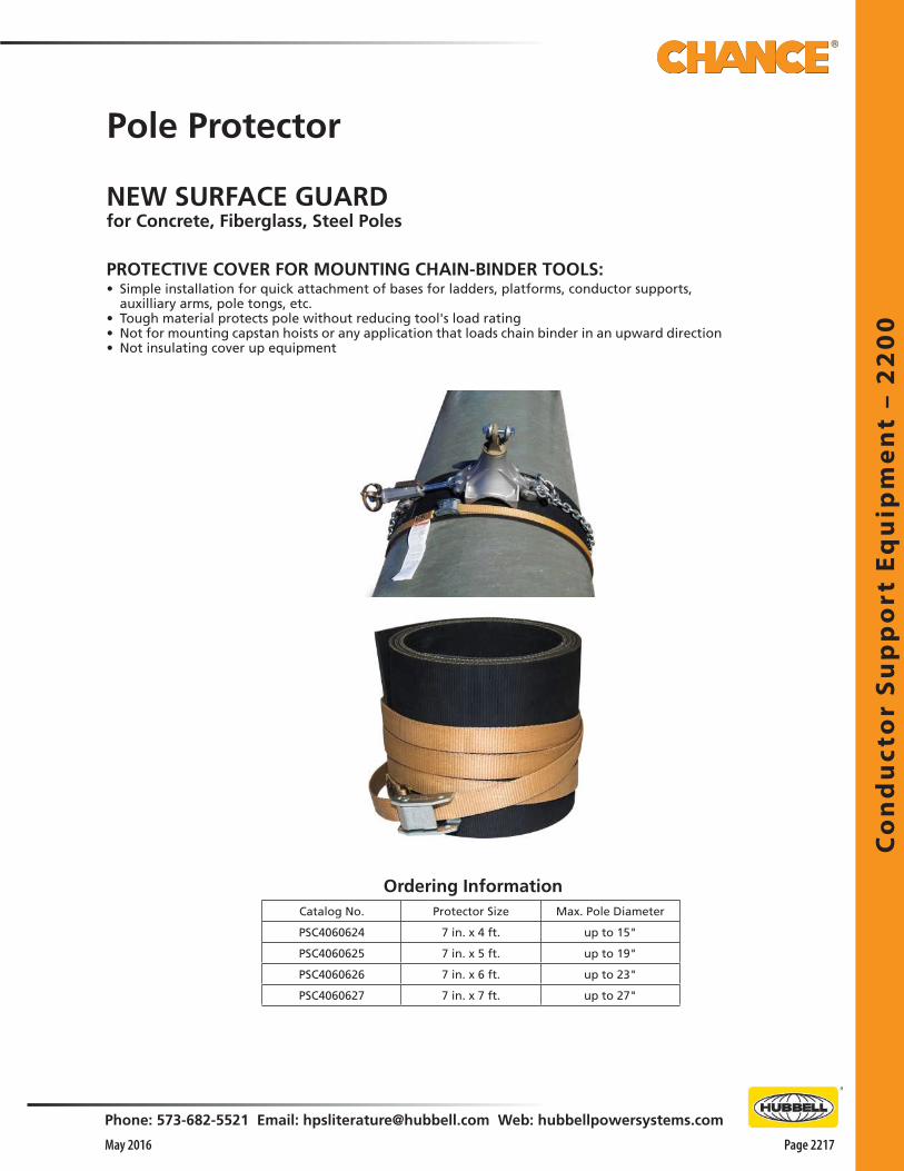
Co
nd
uct
or
Su
pp
ort
Eq
uip
me
nt
– 2
20
0
Phone: 573-682-5521 Email: [email protected] Web: hubbellpowersystems.com
Page 2217May 2016
Pole Protector
NEW SURFACE GUARDfor Concrete, Fiberglass, Steel Poles
PROTECTIVE COVER FOR MOUNTING CHAIN-BINDER TOOLS:• Simple installation for quick attachment of bases for ladders, platforms, conductor supports,
auxilliary arms, pole tongs, etc.• Tough material protects pole without reducing tool's load rating• Not for mounting capstan hoists or any application that loads chain binder in an upward direction• Not insulating cover up equipment
Ordering InformationCatalog No. Protector Size Max. Pole Diameter
PSC4060624 7 in. x 4 ft. up to 15"
PSC4060625 7 in. x 5 ft. up to 19"
PSC4060626 7 in. x 6 ft. up to 23"
PSC4060627 7 in. x 7 ft. up to 27"


Tra
nsm
issi
on
To
ols
– 2
25
0
Phone: 573-682-5521 Email: [email protected] Web: hubbellpowersystems.com
Page 2251May 2016
Tra
nsm
issi
on
To
ols
–2
25
0TransmissionTools
Catalog 2250 May 2016

Tran
smissio
n To
ols – 2
25
0
Page 2252 May 2016
Phone: 573-682-5521 Email: [email protected] Web: hubbellpowersystems.com
SPIRAL LINK STICK
ROLLER LINK STICK
• 1-1/4” pole• Rotating the pole closes the hook, leaving head free
to roll along the conductor
STRAIN LINK STICK
Pole Dia.and
Length11/4" x 15.5"11/4" x 42"
MaximumConductor
Size1510.5 kcmil ACSR1510.5 kcmil ACSR
OverallLength
31"571/2"
CatalogNo.
H4722C4000812
Max.WorkLoad,
lb.35003500
Approx.Wt.,lb.
31/2 /1.6 kg. 41/2 /2.0 kg.
Pole Dia.and
Length11/4" x 4'11/4" x 6'
MaximumConductor
Size605 kcmil ACSR605 kcmil ACSR
OverallLength
58"82"
CatalogNo.
H47144H47146
Max.WorkLoad,
lb.10001000
Approx.Wt.,lb.
33/4 /1.7 kg. 41/4 /1.9 kg.
Max.WorkLoad,
lb.3500350035003500350035006500650065006500650065006500650065006500650065006500
Max. .75 .75 .75 .75 .75 .751.061.061.061.061.061.061.501.502.502.502.502.502.50
Min. .22 .22 .22 .22 .22 .22 .44 .44 .44 .44 .44 .44 .72 .721.001.001.001.001.00
JawOpeningOverall
Length 4'9" 7'3" 9'3"11'3"13'3"15'3" 3'3" 4'9" 6'9" 8'9"10'9"12'9" 5'0" 7'2" 5'2" 7'2" 9'2"11'2"13'2"
Pole Dia.and
Length11/4" x 4'11/4" x 6'11/4" x 8'11/4" x 10'11/4" x 12'11/4" x 14'11/2" x 2'11/2" x 4'11/2" x 6'11/2" x 8'11/2" x 10'11/2" x 12'11/2" x 4'11/2" x 6'11/2" x 4'11/2" x 6'11/2" x 8'11/2" x 10'11/2" x 12'
CatalogNo.
H47152C4000814C4000815C4000816C4000817C4000818H47161H47162H47163H47164H47165H47166H4717H47171H4718H47181H47182H47183H47184
Approx.Wt.,lb.
33/4 /1.7 kg. 51/4 /2.4 kg. 6 /2.7 kg. 63/4 /3.1 kg. 71/2 /3.4 kg. 81/4 /3.7 kg. 43/4 /2.2 kg. 53/4 /2.6 kg. 63/4 /3.1 kg. 73/4 /3.6 kg. 83/4 /4.0 kg. 93/4 /4.4 kg. 97/8 /4.5 kg.117/8 /5.4 kg.111/8 /5.1 kg.13 /5.9 kg.15 /6.8 kg.17 /7.7 kg.19 /8.6 kg.
Features & Applications• Tested per OSHA & ASTM F711• Used as insulation between rope blocks and a hot line
wire grip• For deadend structures and running corners• Attached to conductor close to wire tong to support
conductor loads • Supported from above by rope blocks, which are
operated in unison with rope blocks attached to the wire tong
• Also used to support middle conductor on H-frame structures during insulator or crossarm changes
• Heat-treated aluminum alloy hooks and ferrules for best high-strength/lightweight ratio
• High-quality-steel butt rings for attaching rope blocks or handlines
• Butt swivel spins freely on ball-thrust bearing• Jaw edges are rounded to prevent scarring of
conductors
Features & Applications• Tested per OSHA & ASTM F711• Replaces strain link stick when lineman cannot safely
install one by hand • A lifting eye on the head ferrule enables the lineman
to guide the Spiral Link Stick to the conductor with a hotstick
• 1-1/4" Epoxiglas® pole• Heat-treated aluminum alloy ferrule castings • Galvanized-steel spiral hook and butt ring
Features & Applications• Tested per OSHA & ASTM F711• For spreading and holding conductors at midspan when
relocating poles• Applied to conductor at pole and pulled to position by
hand line on butt ring• Handline should be secured by a temporarily installed
screw anchor or other fixed object• Also used for measuring conductor-to-ground clearance
by attaching measuring tape or length of rope to butt ring

Tra
nsm
issi
on
To
ols
– 2
25
0
Phone: 573-682-5521 Email: [email protected] Web: hubbellpowersystems.com
Page 2253May 2016
2" Adjustable Pole Clamp
12"-Acme-thread Strain Jack
24"-Acme-thread Strain Jack
36"-Acme-thread Strain Jack
Steel Through Pin
Klik Pin
2 lb. / 0.9 kg.
3 lb. / 1.4 kg.
4 lb. / 1.8 kg.
6 lb. / 2.7 kg.3/8 lb. / 0.17 kg.
1/16 lb. / 0.03 kg.
Description
6-ft. Strain Pole
7-ft. Strain Pole
8-ft. Strain Pole
10-ft. Strain Pole
12-ft. Strain Pole
14-ft. Strain Pole
18-ft. Strain Pole
Insulated Section
36 in. (91.44 cm)
48 in. (121.92 cm)
63 in. (160.02 cm)
84 in. (213.36 cm)
102 in. (259.8 cm)
135 in. (342.9 cm)
180 in. (457.2 cm)
Catalog No.
C4012144
C4012145
C4012146
C4012147
C4012215
C4012148
C4012149
Weight
18 lb. / 8.1 kg.
183/4 lb. / 8.4 kg.
191/2 lb. / 8.8 kg.
207/8 lb. / 9.4 kg.
221/4 lb. / 10 kg.
233/4 lb. / 10.7 kg.
261/2 lb. / 11.9 kg.
Overall Length
7 ft.-8 in.
8 ft.-8 in.
9 ft.-11 in.
11 ft.-8 in.
13 ft.-2 in.
15 ft.-11 in.
19 ft.-8 in.
Maximum Voltage Use
72.5 kV
169 kV
242 kV
302 kV
362 kV
552 kV
765 kV
• 7,500-lb. maximum load rating (2"-diameter Epoxiglas pole)• 2-ft. adjustment by Pole Clamp (furnished) in 6" increments on five stainless-steel pins• 12"-long Strain Jack E4011998 furnished as standard• Optional 24" & 36" strain jacks and extra pole clamps available below
Adjustable Strain PolesOrdering Information
Accessories
ADJUSTABLE STRAIN POLES
also require the adjustable, heat-treated aluminum pole clamp
• Pole clamp can be unlocked and positioned by hotsticks
• On cold end, a high-strength steel strain-jack with bronze tongue provides take-up with a ratchet wrench (see page 2257) and trunnions (page 2255))(Wrench and trunnions must be ordered as separate items)
• Standard strain jack included with each strain pole provides 12" of adjustment
• Longer strain jacks (for 24" or 36" of take-up) and extra pole clamps also may be ordered as options below
Features & Applications• Tested per OSHA & ASTM F711• For many transmission and EHV maintenance
applications• Help support conductors while insulators are removed
and replaced• Used with yoke plates and hook assemblies at the
conductor • Also used for structure ends of suspension, V-string or
deadend insulator strings• 5 stainless-steel crosspins are located at 6" intervals on
the 2"-diameter Epoxiglas® poles to support hot-end trunnions or hooks
• Engaging deadend and suspension yokes at the hot end
12" Strain Jack E4011998 included with each Strain Pole listed below.
E4010138P
E4011998P
V4010157P
V4010158
E4011510P
059738P
Clevis furnished with high-strength steel Through Pin E4011510 and Klik Pin P059738P.2-in. Pole Clamp E4010138 included with each Strain Pole listed below.
Insulated Section

Tran
smissio
n To
ols – 2
25
0
Page 2254 May 2016
Phone: 573-682-5521 Email: [email protected] Web: hubbellpowersystems.com
Features & Applications• Tested per OSHA & ASTM F711• Relieve strain from an insulator string to permit removal
from energized lines• Normally used on a single string of insulators• Also used for multiple strings where conductor-end
hardware permits attachment
Maximum load rating for each of the strain-carrier assemblies listed below is 15,000 lb. per insulator string.
Common Features For All Units Listed• Two 2"-dia. Epoxiglas poles• Yokes are 26" wide on pole centers• 2” adjustment in 6" increments on five
stainless-steel pins per pole• 12"-long Strain Jacks
Standard Duty Strain Carriers (6,500 lb.)
Features & Applications• Same basic use as the two-pole strain carrier• Relieves strain while removing a single string of
insulators• Distribution strain carrier has a compression deadend
yoke at the hot end • Insulator-conductor hardware features a compression
lever-type action, gripping tighter as the load increases• Various shoes furnished with the kit fit conductors from
0.292" through 0.806" (No. 2 through 397.5 ACSR)• Maximum load rating for each distribution strain-carrier
assembly listed below is 6,500 lb. per insulator string
• Two 11⁄4"-diameter Epoxiglas poles • Yokes are 18" wide on pole centers • 2-ft. adjustment in 6" increments on five stainless-steel pins per pole • 12"-long Strain Jacks
Back yokehooked to asteel tower with a chain
See page 2257 for Ratchet Wrench M19483.
Catalog
Number
C4012174
C4012175
C4012176
C4012177
C4012216
C4012178
C4012179
Distance Between Yokes
Minimum Maximum
49 " 81"
59 " 93"
74 " 108"
95 " 129"
113 " 147"
146" 180"
191" 225"
Weight,
each assembly
81 lb. / 36.45 kg.
83 lb. / 37.35 kg.
85 lb. / 38.25 kg.
89 lb. / 40.05 kg.
95 lb. / 42.27 kg.
97 lb. / 43.65 kg.
105 lb. / 47.25 kg.
Nominal
Pole Length
6 ft.
7 ft.
8 ft.
10 ft.
12 ft.
14 ft.
18ft.
Heavy Duty Two-Pole Strain Carriers (15,000 lb.)
Catalog
Number
C4010411
C4010410
Weight,
each assembly
82 lb. / 36.9 kg.
92 lb. / 41.4 kg.
Nominal
Pole Length
6 ft.
8 ft.
Distance Between Yokes
Minimum Maximum
471/2" 81"
711/2" 105"
Front yoke hooked intoa wire-grip clamp
Tested per OSHA & ASTM F711
• Available here as complete assemblies – separate components may also be ordered
• For adjustable strain poles, see page 2253• For yokes, sockets and trunnions, see page 2255• Yokes are fabricated from high-strength aluminum plate • Feature a steel chain assembly for anchoring the back
plate to the structure• Conductor-end yoke includes a hook and a machined
socket (C4011894)
See page 2257 for Ratchet Wrench M19483.

Tra
nsm
issi
on
To
ols
– 2
25
0
Phone: 573-682-5521 Email: [email protected] Web: hubbellpowersystems.com
Page 2255May 2016
Two-Pole Strain Carrier Accessories
Deadend Compression Yoke Assembly• Used with Two-Pole Strain Carriers, these units grip
compression sleeves over the compressed area, requiring no shoulder or adapter to pull against
• Heat-treated aluminum castings • Rated at 11,000 lbs. maximum load when used with 2”
adjustable strain poles• Designed specifically for use on extension links• Swing up gate exposes the shoe area of the assembly to
the load and must be closed before taking up tension
Approx.Weight
For Extension Links with 7/8" Shank and 11/2" Collar.
Conductor Range of Fittings
MinimumCopper or
ACSR
CompressionDeadend
BodyMaximum
MaximumCopper or
ACSR
BoltedStrainClampMax.Catalog No.
C4011894
Deadend Sockets• Furnished with the Two-Pole Strain Carrier• Use following catalog number for ordering replacement
Max. Load Rating: 15,000 lb.
Take-Up Trunnions• For replacement or conversion• Bronze-alloy and ball-thrust bearing construction for use
on adjustable strain poles• Equal the capacity of all Chance yokes and provide
maximum efficiency for the lineman• Require M19483 Ratchet
Catalog No.
E4012066P
E4012068P
Description One Large Trunnion, replaces 70356 One Small Trunnion, replaces E4010486
Weight
31/2 lb./1.6 kg.
2 lb./0.9 kg.
Catalog No.C4011720C4011721
Description Conductor End Yoke Assembly Structure End Yoke Assembly
Weight25 lb./11.3 kg.20 lb./ 9.0 kg.
Two-Pole Yokes• Can be ordered separately to make two pole strain
carriers shown on Page 2254• Yokes are fabricated of high strength (3/4"- and 1"-thick)
aluminum plate• Yokes have 26" width between center of adjustable
strain poles used with them• Maximum load ratings are 15,000 lbs. per insulator
string
Catalog No.
C4010095
Description Compression Yoke Assembly Complete with a Hot Line Extension Link for 3/4" and 1" dia. shank & 4 sets of shoes for conductor from 477to 1351 MCM ACSR
Weight
44 lb./19.8 kg.
Deadend Socket
E4012068P(1 only)
E4012066P(1 only)
25/8"5"
C4010095
T4012265 Trunnion Gauge
Includes steel loading chain and attachment hardware.
C4011721
47" ChainM1942 included
W4010255P Shackle
Trunnion Gauge
Catalog No.T4012265
DescriptionTrunnion Gauge for 3/4" Acme threads
Weight1/2 lb./0.25 kg.
Includes hook and C4011894 Socket
C4011720
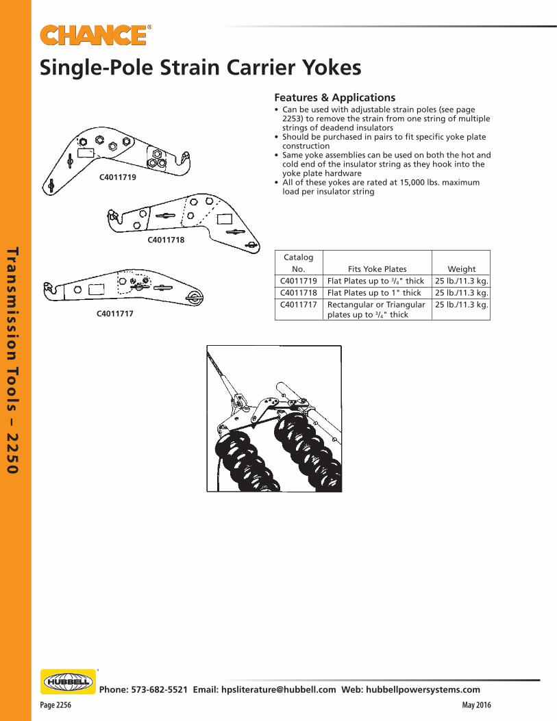
Tran
smissio
n To
ols – 2
25
0
Page 2256 May 2016
Phone: 573-682-5521 Email: [email protected] Web: hubbellpowersystems.com
Single-Pole Strain Carrier Yokes
Weight25 lb./11.3 kg.25 lb./11.3 kg.25 lb./11.3 kg.
CatalogNo.
C4011719C4011718C4011717
Fits Yoke Plates Flat Plates up to 3/4" thick Flat Plates up to 1" thick Rectangular or Triangular plates up to 3/4" thickC4011717
C4011718
Features & Applications• Can be used with adjustable strain poles (see page
2253) to remove the strain from one string of multiple strings of deadend insulators
• Should be purchased in pairs to fit specific yoke plate construction
• Same yoke assemblies can be used on both the hot and cold end of the insulator string as they hook into the yoke plate hardware
• All of these yokes are rated at 15,000 lbs. maximum load per insulator string
C4011719

Tra
nsm
issi
on
To
ols
– 2
25
0
Phone: 573-682-5521 Email: [email protected] Web: hubbellpowersystems.com
Page 2257May 2016
Strain PolesFor Bundle Conductor Yoke PlatesFeatures & Applications• Tested per OSHA & ASTM F711• Accommodate a wide range of yoke plate designs and
hole spacings• Both Strain Poles, of 2"-dia. Epoxiglas® construction,
offer 12,000-pounds maximum load capacity with a 1"
wide clevis for aluminum conductor yoke plates• Commonly used in deadend rigging, for “V” strings
and restrained angles, poles offer two clevis lengths and overall lengths
Strain Jacks E4011998, V4010157 & V4010158
Weight 2.2 lb./1 kg. 3 lb./1.4 kg. 4 lb./1.8 kg. 6 lb./2.8 kg. 5.5 lb./2.5 kg. 8 lb./3.6 kg. 10 lb./4.5 kg. 1 lb./0.5 kg.
Catalog No. M19483 E4011998P V4010157 V4010158 H47851 H47852 H47853 SPM29471
STRAIN JACKS
H1949113
M19483Ratchet Wrench
Strain Pole Accessories
C4000612
WorkingLength
* Distance from centerline of pin to inside end of butt ring.
Catalog No. Description Working Length* Max. Load WeightH1949113 Butt Swivel, Clevis 3.35" x 1" 113" 12,000 lb. 17 lb./7.7 kg.C4000612 Butt Swivel, Clevis 1.56" x 1" 113" 12,000 lb. 14 lb./6.3 kg.C4000613 Butt Swivel, Clevis 1.56" x 1" 134" 12,000 lb. 15 lb./6.8 kg.
PSC4002915 Clevis, Clevis 1.56" x 1" 113" 12,000 lb. 14 lb./6.3 kg.PSC4002916 Clevis, Clevis 1.56" x 1" 134" 12,000 lb. 15 lb./6.8 kg.
H47851Clevis, Ratchet, Screw
DescriptionRatchet WrenchStrain Jack (12" Long) Tongue TypeStrain Jack (24" Long) Tongue TypeStrain Jack (36" Long) Tongue TypeClevis Ratchet Screw 12"Strain Jack (18" Long) Clevis TypeStrain Jack (24" Long) Clevis TypeAcme Eyenut

Tran
smissio
n To
ols – 2
25
0
Page 2258 May 2016
Phone: 573-682-5521 Email: [email protected] Web: hubbellpowersystems.com
Features & Applications• Tested per OSHA & ASTM F711• Three basic types of Insulator Cradles are available for
various insulator changeout requirements: o Transmission Cradle is designed to be used on 69 kV
to 115 kV deadend or suspension strings supported by a pair of wire tongs or link sticks
o EHV Trough-design Cradle is designed to be used on 345 kV to 500 kV deadend or suspension strings and in combination with insulator cradle carriers for moving the insulators (See catalog page 2259)
o EHV Side-Opening Cradle is designed to be used on only EHV deadend strings for removing only one string in a double, triple or quad deadend bundle (See catalog page 2260)
Features & Applications• Used to make insulator changes by supporting the
string while damaged insulators are replaced• Also used to pivot the string so that it may be removed
and lowered to the ground• On deadends or running corners, cradles are used in
conjunction with strain carriers• In straight suspensions, they are used with various
types of link sticks or adjustable strain pole assemblies• Made with three 1-1/2" dia. Epoxiglas® poles• Lightweight, easy to handle and adaptable to many
applications
• Lugs, located at the forward end of the cradle, are used to support the insulator string with a pair of wire tongs or link sticks
• Back end of the cradle is supported by ropes tied at the structure
• Hinged in this manner, insulators may be lowered or raised to the best position for changing damaged insulators
• In some cases, cradle is supported in eyes located on the forward yoke of Two-Pole Strain Carriers
• This is performed when raising or lowering of the insulator string is unnecessary
Insulator Cradles
TRANSMISSION INSULATOR CRADLE
Approx.Weight
193/4 lb./ 8.887 kg.24 lb./11.262 kg.27 lb./13.837 kg.
OverallLength
6-ft. (180cm)8-ft. (240cm)
10-ft. (300cm)
Photo at right shows the insulator cradle being raised or lowered with the use of wire tongs.
RecommendedCapacity
10 10" (250mm) Insulators14 10" (250mm) Insulators18 10" (250mm) Insulators
CradleH18406H18408 orH184010
CatalogNo.
H18406 H18408 H184010
2 pcs. x 9'
Tested per OSHA & ASTM F711
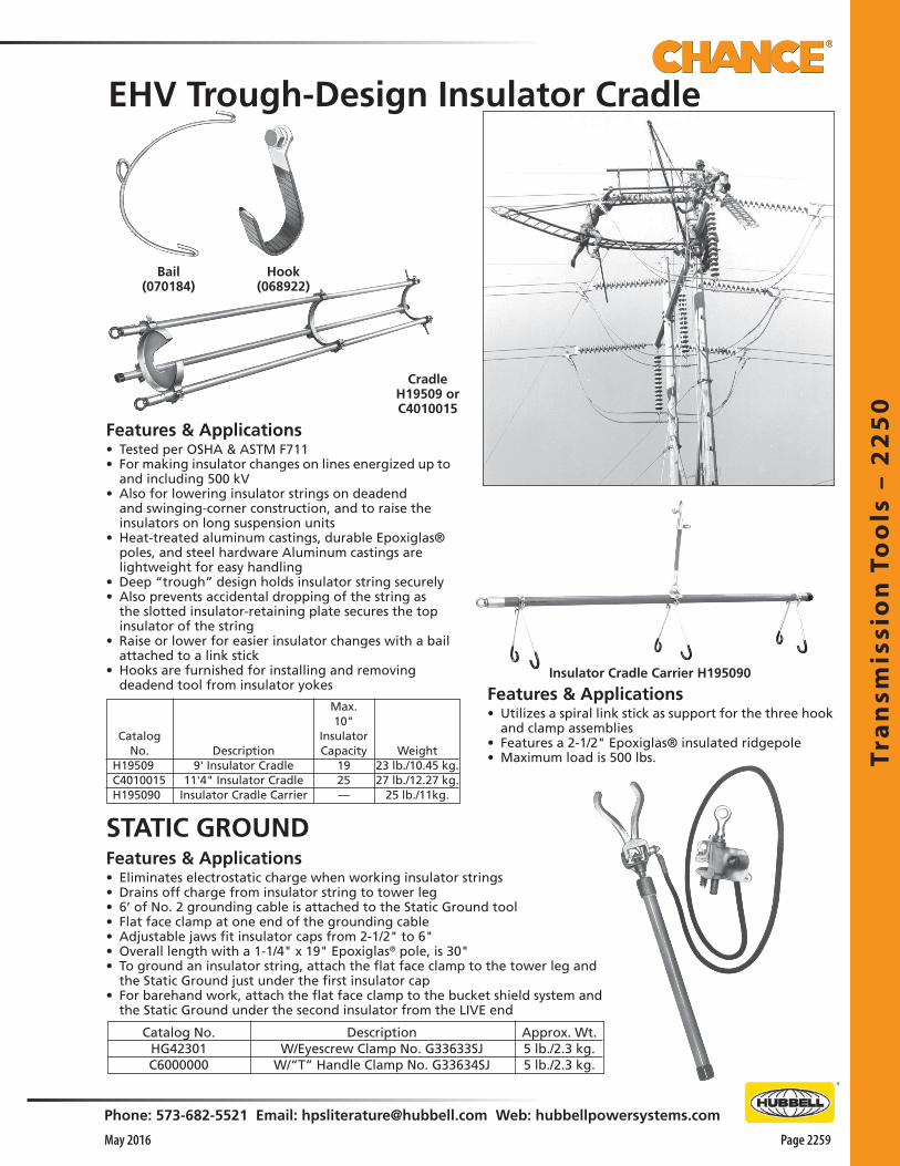
Tra
nsm
issi
on
To
ols
– 2
25
0
Phone: 573-682-5521 Email: [email protected] Web: hubbellpowersystems.com
Page 2259May 2016
Insulator Cradle Carrier H195090
CradleH19509 orC4010015
Hook(068922)
Bail(070184)
EHV Trough-Design Insulator Cradle
Features & Applications• Eliminates electrostatic charge when working insulator strings• Drains off charge from insulator string to tower leg• 6’ of No. 2 grounding cable is attached to the Static Ground tool• Flat face clamp at one end of the grounding cable• Adjustable jaws fit insulator caps from 2-1/2" to 6"• Overall length with a 1-1/4" x 19" Epoxiglas® pole, is 30"• To ground an insulator string, attach the flat face clamp to the tower leg and
the Static Ground just under the first insulator cap• For barehand work, attach the flat face clamp to the bucket shield system and
the Static Ground under the second insulator from the LIVE end
Approx. Wt.5 lb./2.3 kg.5 lb./2.3 kg.
STATIC GROUND
CatalogNo.
H19509 C4010015 H195090
Description9' Insulator Cradle
11'4" Insulator CradleInsulator Cradle Carrier
Max.10"
InsulatorCapacity
1925—
Weight23 lb./10.45 kg.27 lb./12.27 kg.
25 lb./11kg.
Features & Applications• Utilizes a spiral link stick as support for the three hook
and clamp assemblies • Features a 2-1/2" Epoxiglas® insulated ridgepole• Maximum load is 500 lbs.
Catalog No.HG42301C6000000
DescriptionW/Eyescrew Clamp No. G33633SJ
W/“T” Handle Clamp No. G33634SJ
Features & Applications• Tested per OSHA & ASTM F711• For making insulator changes on lines energized up to
and including 500 kV• Also for lowering insulator strings on deadend
and swinging-corner construction, and to raise the insulators on long suspension units
• Heat-treated aluminum castings, durable Epoxiglas® poles, and steel hardware Aluminum castings are lightweight for easy handling
• Deep “trough” design holds insulator string securely • Also prevents accidental dropping of the string as
the slotted insulator-retaining plate secures the top insulator of the string
• Raise or lower for easier insulator changes with a bail attached to a link stick
• Hooks are furnished for installing and removing deadend tool from insulator yokes
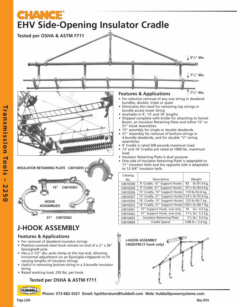
Tran
smissio
n To
ols – 2
25
0
Page 2260 May 2016
Phone: 573-682-5521 Email: [email protected] Web: hubbellpowersystems.com
Description9' Cradle, 15" Support Hooks9' Cradle, 31" Support Hooks13' Cradle, 15" Support Hooks13' Cradle, 31" Support Hooks16' Cradle, 15" Support Hooks16' Cradle, 31" Support Hooks15" Support Hook, one only31" Support Hook, one only
Insulator Retaining PlateCradle Spacer
Weight 93 lb./41.9 kg. 971/2 lb./43.9 kg.119 lb./53.6 kg.
1231/2 lb./55.6 kg.125 lb./56.7 kg.
1301/2 lb./58.7 kg. 10 lb./ 4.5 kg. 111/2 lb./ 5.2 kg. 71/2 lb./ 3.4 kg.5.88 lb. / 2.6 kg.
EHV Side-Opening Insulator Cradle
Features & Applications• For selective removal of any one string in deadend
bundles, double, triple or quad• Eliminates the need for removing top strings in
bundle access lower string• Available in 9’, 13’ and 16’ lengths• Shipped complete with bridle for attaching to Swivel
Boom, an Insulator Retaining Plate and either 15” or 31” Hook Assemblies
• 15” assembly for single or double deadends • 31” Assembly for removal of bottom strings in
4-bundle deadends, and for double “V”-string assemblies
• 9’ Cradle is rated 500 pounds maximum load• 13’ and 16’ Cradles are rated at 1000 lbs. maximum
load• Insulator Retaining Plate is dual purpose• One side of Insulator Retaining Plate is adaptable to
11” insulator bells and the opposite side is adaptable to 12-3/4” insulator bellsINSULATOR RETAINING PLATE C4010455
15" C4010361
HOOKASSEMBLIES
31" C4010362
CatalogNo.
C4010358C4010359C4010356C4010357C4010354C4010355C4010361C4010362C4010455C4010604
Tested per OSHA & ASTM F711
J-HOOK ASSEMBLY C4020790 (1 hook only)
J-HOOK ASSEMBLYFeatures & Applications• For removal of deadend insulator strings• Plastisol-covered steel hook swivels on end of a 2" x 36"
Epoxiglas® pole• Has a 2-1/2" dia. pole clamp at the top end, allowing
horizontal adjustment on an Epoxiglas ridgepole to fit varying lengths of insulator strings
• Useful in removing bottom string in a 3-bundle insulator string
• Rated working load: 250 lbs. per hook
Tested per OSHA & ASTM F711
11/2" dia.
11/2" dia.
21/2" dia.

Tra
nsm
issi
on
To
ols
– 2
25
0
Phone: 573-682-5521 Email: [email protected] Web: hubbellpowersystems.com
Page 2261May 2016
Features & Applications• For use with adjustable strain poles shown on page 2253 • A direct method of relieving load on suspension string • Conductor clamp has contoured seat with a trapping gripper
and is operated by an eyescrew• Conductor range is 1-1/8" to 2-1/2" dia. • Can be positioned every 6" on the strain pole• Hook is self-aligning within a range of 45° either side of verti-
cal• Maximum load is 3,500 lbs.
CatalogNo.
M47241Description
Adjustable Hook AssemblyWeight
6 lb./2.7 kg.
Features & Applications• Optional tools for relieving the load on suspension
insulator strings
• When same crews work on deadend and suspension structures, Adjustable Strain Poles on Page 2253 can be used as base tool for suspension insulator changeouts
SUSPENSION YOKES
C4010168
• C4011722 yoke is used with the H2947 series adjustable strain poles on page 2253
• C4010168 yoke is used with clevis strain poles on page 2257
• Both yokes are fabricated from high strength aluminum plate
• Maximum load of 15,000 lbs. per insulator string
• Has two spring-loaded latches which engage and lock the pole clamp into position on the yoke, 26” apart center-to-center
• Provides adequate clearance for corona rings
• An eyebolt, which may be assembled on either side of the yoke, facilitates rigging
• Yoke is equipped with a swivel saddle designed to cope with the variables of suspension strings on running corners
• Saddle will rotate a full 360°• Saddle will handle conductor yoke plates
up to 1" in thickness
C4011722
Suspension Insulator Tools
Catalog No.
C4011722
C4010168
Weight
26 lb./11.7 kg.
23 lb./10.4 kg.
Description
Strain-Pole Suspension Yoke with 31/2" Swivel Saddle
Clevis Pole Suspension Yoke with 31/2" Swivel Saddle
Suspension Link Stick
M47241
ADJUSTABLE HOOK ASSEMBLY
Features & Applications• For use on conductors from 1-1/2" to 2-1/2" dia. • Can be used with various types of takeup devices at the structure end• Lip of the hook, actuated by an eye screw, swivels to accommodate various conductor sizes• Maximum load is 6,500 lbs.
SUSPENSION LINK STICKS
Pole Dia. & Length11/2" x 84"11/2" x 96"11/2" x 114"
Weight14 lb./6.3 kg.16 lb./7.2 kg.18 lb./8.1 kg.
Catalog No.H472084 H472096 H4720114
Tested per OSHA & ASTM F711
For Adjustable Strain Pole (See Page 2253) or Clevis Pole (See Page 2257)
LEN
GTH
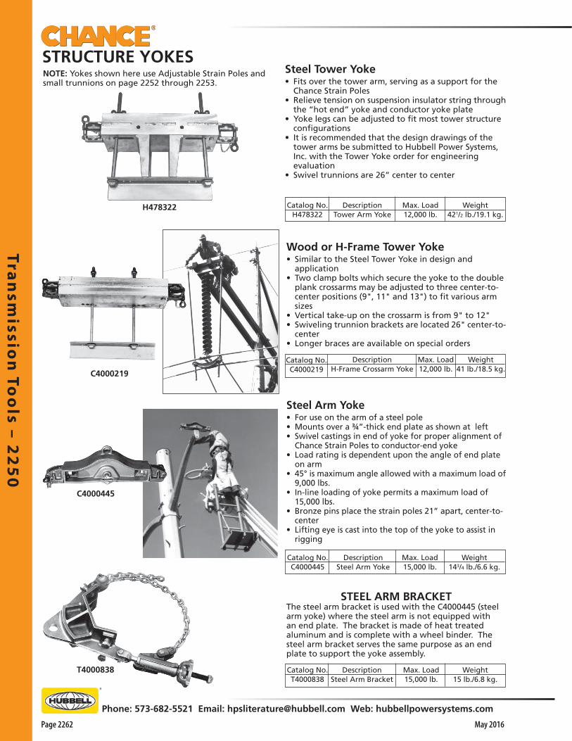
Tran
smissio
n To
ols – 2
25
0
Page 2262 May 2016
Phone: 573-682-5521 Email: [email protected] Web: hubbellpowersystems.com
H478322
T4000838
C4000445
C4000219
Catalog No.H478322
DescriptionTower Arm Yoke
Max. Load12,000 lb.
Weight421/2 lb./19.1 kg.
Steel Tower Yoke• Fits over the tower arm, serving as a support for the
Chance Strain Poles• Relieve tension on suspension insulator string through
the “hot end” yoke and conductor yoke plate• Yoke legs can be adjusted to fit most tower structure
configurations• It is recommended that the design drawings of the
tower arms be submitted to Hubbell Power Systems, Inc. with the Tower Yoke order for engineering evaluation
• Swivel trunnions are 26” center to center
NOTE: Yokes shown here use Adjustable Strain Poles and small trunnions on page 2252 through 2253.
STRUCTURE YOKES
DescriptionSteel Arm Bracket
Max. Load15,000 lb.
Weight143/4 lb./6.6 kg.
Max. Load15,000 lb.
DescriptionSteel Arm Yoke
Catalog No.C4000445
Weight15 lb./6.8 kg.
Weight41 lb./18.5 kg.
Max. Load12,000 lb.
DescriptionH-Frame Crossarm Yoke
Catalog No.C4000219
STEEL ARM BRACKETThe steel arm bracket is used with the C4000445 (steel arm yoke) where the steel arm is not equipped with an end plate. The bracket is made of heat treated aluminum and is complete with a wheel binder. The steel arm bracket serves the same purpose as an end plate to support the yoke assembly.
Steel Arm Yoke• For use on the arm of a steel pole• Mounts over a ¾”-thick end plate as shown at left• Swivel castings in end of yoke for proper alignment of
Chance Strain Poles to conductor-end yoke• Load rating is dependent upon the angle of end plate
on arm• 45° is maximum angle allowed with a maximum load of
9,000 lbs. • In-line loading of yoke permits a maximum load of
15,000 lbs. • Bronze pins place the strain poles 21” apart, center-to-
center• Lifting eye is cast into the top of the yoke to assist in
rigging
Wood or H-Frame Tower Yoke• Similar to the Steel Tower Yoke in design and
application• Two clamp bolts which secure the yoke to the double
plank crossarms may be adjusted to three center-to-center positions (9", 11" and 13") to fit various arm sizes
• Vertical take-up on the crossarm is from 9" to 12"• Swiveling trunnion brackets are located 26" center-to-
center• Longer braces are available on special orders
Catalog No.T4000838

Tra
nsm
issi
on
To
ols
– 2
25
0
Phone: 573-682-5521 Email: [email protected] Web: hubbellpowersystems.com
Page 2263May 2016
C4000152
H47232
TROLLEY POLE COMPONENTS PARTS
DescriptionFork Suspension Tool Attachment for 21/2" PoleTrolley Pole (21/2" x 12')Single Trolley Wheel with 21/2" Pole ClampTandem Trolley Wheel with 21/2" Pole Clamp
Weight151/2 lb./7.0 kg.181/2 lb./8.3 kg. 6 lb./2.7 kg.13 lb./5.9 kg.
Suitable for 101/2" disc insulators on one side and 103/4" disc insulators on the other
Features & Applications• Rolls a string of suspension insulators into the structure so that
damaged units can be replaced• Can be fastened, horizontally under the tower arm, using tower
type wire tong saddles• Two types of Trolley Wheel Units are available with single
(H47234) or tandem (C4000152) wheels o The tandem wheel units are used on extremely long strings
of insulators for better weight distribution o Both trolley wheel types will roll on either a 2-1/2" or 3"
Epoxiglas® pole• Slotted Suspension Insulator Attachment bolts to end of Trolley
Pole and can be fitted under the top insulator• Entire string can be lifted by a slight down pressure on structure
end of Trolley Pole• Insulators are returned to position on Trolley Pole after necessary
changeouts
TROLLEY POLE SUSPENSION INSULATOR TOOL
Weight63/4 lb./3 kg.
Length21"
Catalog No.M1979
DescriptionTower Handline Gin
TOWER GIN• All-Purpose Handline GinFeatures & Applications• 3' x 3" x 1/4" with an aluminum-welded end-plate securing
bronze, free-swivel butt ring • Snatch blocks hooked into butt ring keep handlines from
dragging over tower structure, giving clearance to tools in transit• Bronze mounting hooks are secured with bronze wing nuts on
plated steel bolts• Hook adjustment will fit tower angle from 1-3/4" x 1-3/4" up to
6" x 6"• Maximum load for the gin is 500 lbs.
H47234
Catalog No.H47232
H4721112H47234
C4000152
H4721112 (Tested per OSHA & ASTM F711)

Tran
smissio
n To
ols – 2
25
0
Page 2264 May 2016
Phone: 573-682-5521 Email: [email protected] Web: hubbellpowersystems.com
Chance® Portable Protective Air Gap Tools (PPAG) have been used for live line work for more than 40 years. PPAGs provide an OSHA and IEEE approved method for controlling transmission overvoltages, allowing for reduced minimum approach distances. The PPAG controls transmission overvoltages by providing a shorter flashover air gap between the PPAG horns.
Per OSHA Appendix B to §1910.269 an employer can reduce the minimum approach distance at the worksite by installing portable protective gaps on the system.
PPAG Features and Benefits:• OSHA and IEEE approved method• Simple to install• Allows for use of shorter and lighter tools• Visible at the worksite• Large All-Angle Ground Clamp mounted on the
top end (conductor range 0.258” - 2.88”)• Two permanent Horn Gaps fixed to the pole• Collar on bottom horn for ground set attachment• Rigid male splice on the bottom end for
attachment of an extension pole• 1-1/2” dia. x 12’ long Epoxiglas® Pole
All Angle Clamp
Top Horn
Bottom Horn
Male Splice
Collar
SOLUTION FOR MEETING NEW OSHA TRANSMISSION MINIMUM APPROACH DISTANCES
CHANCE® PORTABLE PROTECTIVE AIR GAP TOOL
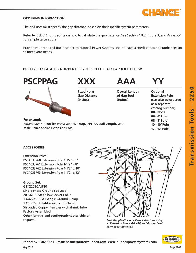
Tra
nsm
issi
on
To
ols
– 2
25
0
Phone: 573-682-5521 Email: [email protected] Web: hubbellpowersystems.com
Page 2265May 2016
The end user must specify the gap distance based on their specific system parameters.
Refer to IEEE 516 for specifics on how to calculate the gap distance. See Section 4.8.2, Figure 3, and Annex C-1 for sample calculations
Provide your required gap distance to Hubbell Power Systems, Inc. to have a specific catalog number set up to meet your needs.
Extension Poles:PSC4033760 Extension Pole 1-1/2” x 6’PSC4033761 Extension Pole 1-1/2” x 8’PSC4033762 Extension Pole 1-1/2” x 10’PSC4033763 Extension Pole 1-1/2” x 12’
Ground Set:G1Y220BCA1F10:Single Phase Ground Set Lead:20’ S6118 2/0 Yellow Jacket Cable 1 G422810SJ All-Angle Ground Clamp1 C6002231 Flat-Face Ground ClampShrouded Copper Ferrules with Shrink TubeFactory AssembledOther lengths and configurations available on request.
Fixed Horn Gap Distance (inches)
Overall Length of Gap Tool (inches)
OptionalExtension Pole(can also be ordered as a separate catalog number)00 - None06 - 6’ Pole08 - 8’ Pole10 - 10’ Pole12 - 12’ Pole
For example:PSCPPAG04714406 for PPAG with 47” Gap, 144” Overall Length, with Male Splice and 6’ Extension Pole.
Typical application on adjacent structure, using an Extension Pole, a Grip-All, and Ground Lead down to lattice tower.
ORDERING INFORMATION
ACCESSORIES
BUILD YOUR CATALOG NUMBER FOR YOUR SPECIFIC AIR GAP TOOL BELOW:
PSCPPAG XXX AAA YY
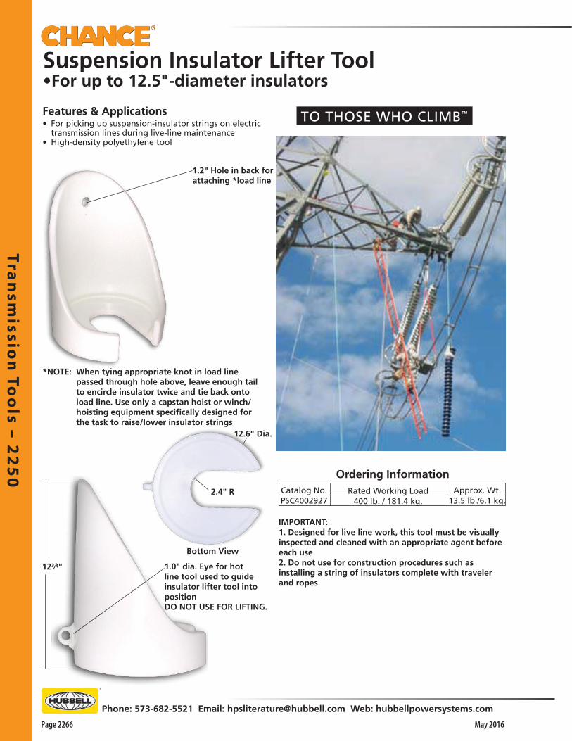
Tran
smissio
n To
ols – 2
25
0
Page 2266 May 2016
Phone: 573-682-5521 Email: [email protected] Web: hubbellpowersystems.com
Suspension Insulator Lifter Tool•For up to 12.5"-diameter insulators
Ordering InformationApprox. Wt.
13.5 lb./6.1 kg.Catalog No.PSC4002927
Rated Working Load400 lb. / 181.4 kg.
Features & Applications• For picking up suspension-insulator strings on electric
transmission lines during live-line maintenance• High-density polyethylene tool
123⁄4" 1.0" dia. Eye for hot line tool used to guide insulator lifter tool into positionDO NOT USE FOR LIFTING.
1.2" Hole in back forattaching *load line
*NOTE: When tying appropriate knot in load line passed through hole above, leave enough tail to encircle insulator twice and tie back onto load line. Use only a capstan hoist or winch/hoisting equipment specifically designed for the task to raise/lower insulator strings
IMPORTANT:1. Designed for live line work, this tool must be visually inspected and cleaned with an appropriate agent before each use2. Do not use for construction procedures such as installing a string of insulators complete with traveler and ropes
12.6" Dia.
2.4" R
Bottom View
TO THOSE WHO CLIMB™

Jum
pe
rs &
Lo
ad
Pic
ku
p T
oo
ls –
23
00
Phone: 573-682-5521 Email: [email protected] Web: hubbellpowersystems.com
Page 2301May 2016
Jum
pe
rs &
Lo
ad
Pic
ku
p T
oo
ls –
23
00
Jumpers &Load Pickup Tools
Catalog 2300 May 2016

Jum
pe
rs & Lo
ad
Pick
up
Too
ls – 23
00
Page 2302 May 2016
Phone: 573-682-5521 Email: [email protected] Web: hubbellpowersystems.com
Description
Pair* ofClamps
Main Line RangeMax.336.4ACSR.721"
Jumper Cable RangeMin.#6
Copper.162"
Max.
2/0
Min.
#2
*Cat No. T6010003 for single clamp.
Cat.No.
G4758
25 kV Ø-Ø Rated — 400 Amp CapacityThe G4765 series Jumper Clamp has:• The same polyethylene material in the handle as other Chance
Jumper Clamps • Handle length below handguard is 7-1/2"
Description
Pair* ofClamps
Main Line RangeMax.477
ACSR.883"
Jumper Cable RangeMin.#6
Copper.162"
Max.
4/0
Min.
#2
*Cat. No. T6010039 for single clamp.
Cat.No.
G4765
35 kV Ø-Ø Rated — 400 Amp CapacityThe G4775 series Jumper Clamp has:• A larger contact opening for use on larger conductor • Handle length below the handguard is 8-3/8"
Description
Pair* ofClamps
Main Line RangeMax.954
ACSR1.165"
Jumper Cable RangeWeight
3 lb./1.4 kg.
Min.#6
Copper.162"
Max.
4/0
Min.
#2
*Cat. No. T6010040 for single clamp.
Cat.No.
G4775
Insulated Jumper ClampsFeatures & Applications• Used for bypassing work areas when equipment is under repair• Also used for upgrading lines and making temporary or
emergency repairs• Handles are tough, high-impact strength polyethylene with a
wide hand guard flange
15 kV Ø-Ø Rated — 300 Amp CapacityThe G4758 series Jumper Clamp has:• Handle length of 5-5/8" below the handguard• Bearing type floating washer lower contact that improves
gripping action and prevents conductor scoring• Metal parts with copper alloy to improve oxidation resistance• 300 amp continuous rating based on using 2/0 Jumper Cable on
tap side
Style I per ASTM F 2321 Standard Specification
Style I per ASTM F 2321 Standard Specification
Style I per ASTM F 2321 Standard Specification
All Chance® Insulated Jumpers meet ASTM F 2321 Standard Specification.
Weight21/4 lb./1.0 kg.
Weight23/4 lb./1.3 kg.
G475815kV
55/8"
G476525kV
71/2"
G477535kV
83/8"

Jum
pe
rs &
Lo
ad
Pic
ku
p T
oo
ls –
23
00
Phone: 573-682-5521 Email: [email protected] Web: hubbellpowersystems.com
Page 2303May 2016
Jumper Cable rated Ø-Ø 15 kVwith EPR Insulation/Jacket
Catalog No.S10043S10044S10045S10046
SizeAWG
#21/02/04/0
Stranding259/No. 26413/No. 24273/No. 23437/No. 21
WeightPer
1000 Ft.438 lb./197 kg.598 lb./269 kg.707 lb./318 kg.
1047 lb./471 kg.
Approx.Ampacity
Rating, Amps200260300400
Approx.CableO.D.
0.779"0.863"0.914"1.065"
Approx.Cond.
Diameter0.322"0.404"0.455"0.602"
Jumper Cable rated Ø-Ø 25 kV and 35 kV with EPR Insulation/Jacket
Features & Applications• Extremely flexible even at low temperatures• Features insulation/jacket combination resistant to abrasion, oil, heat,
moisture and ozone• Orange/Red color of mold-cured ethylene-propylene-base coating
imparts high visibility • AWG size and voltage rating are embossed at 4-foot intervals for easy
identification• For extended service life, an extruded screen interfaces insulation and
conductor• This strand screen improves voltage-stress control by adding dielectric
strength and eliminating internal corona• Insulation and conductor screen meet and exceed ICEA-NEMA standard
S-68-516• For easy handling in adverse conditions, conductors are extra flexible
alloy-coated copper-stranded rope per ASTM B-189 or B-33• Ampacity ratings are based on 90°C conductor temperature at 40°C
ambient
Features & Applications• Extremely flexible even at low temperatures• Features insulation/jacket combination resistant to abrasion, oil, heat,
moisture and ozone• Orange/Red color of mold-cured ethylene-propylene-base coating imparts high visibility • AWG size and voltage rating are embossed at 4-foot intervals for easy
identification• For extended service life, an extruded screen interfaces insulation and
conductor• This strand screen improves voltage-stress control by adding dielectric strength and eliminating internal corona• Insulation and conductor screen meet and exceed ICEA-NEMA standard S-68-516• For easy handling in adverse conditions, conductors are extra flexible alloy-coated copper-stranded rope per ASTM
B-189 or B-33• Ampacity ratings are based on 90°C conductor temperature at 40°C ambient
WeightPer
1000 ft.
801 lb./ 360.5 kg.913 lb./410.9 kg.
985 lb./443.3 kg.
Approx.Ampacity
Rating, Amps
260300
260
Approx.CableO.D.
1.113"1.160"
1.287"
Approx.Cond.
Diameter
0.404"0.450"
0.404"
Stranding
413266
413
SizeAWG
1/02/0
1/0
Catalog No.25 kV Cable:
S11272S11273
35 kV Cable:S11274
For connectors, see page 2304.
Type I per ASTM F 2321 Standard Specification
Type I per ASTM F 2321 Standard Specification
Type I per ASTM F 2321 Standard Specification

Jum
pe
rs & Lo
ad
Pick
up
Too
ls – 23
00
Page 2304 May 2016
Phone: 573-682-5521 Email: [email protected] Web: hubbellpowersystems.com
STUD TERMINALS
PLUG TERMINALS
Features & Applications• Copper Connector Assemblies are necessary to join cable
and clamp together on Jumper Clamps or Load Pickup Tools only
• Threads are 5/8-11 NC for all connectors• Each Catalog Number consists of a copper connector, nut
and lockwasher
Jumper Clamp Connector Assembliesfor 15kV, 25kV & 35kV Jumper Cable
Features & Applications• Shrouded terminals are for use with only grounding clamps
(see Section 3000) and EPR Jumper Cable (Page 2305) • Should only be used as temporary jumper assemblies (and
should not be used with insulated jumper clamps, page 2302)
• Extra heavy-duty shroud prevents excessive cable stress at terminal connection
• To match pressure-type and threaded connectors on grounding clamps, both plug and stud terminal styles are available
Jumper Terminalsfor 15kV EPR Jumper Cable only
C6002598
Cable SizeNo. 21/02/04/0
Weighteach4 oz.4 oz.4 oz.4 oz.
No. ofCrimps
2222
Burndy Die No.(or equivalent)
U165U165U165U166
Section“A”
Section“A”
Type VI per ASTM F 2321 Standard Specification
Weightper
terminal
2 oz.
BurndyDie No.U243U243
U166-206U249
CableSize#21/02/04/0
PLUG TERMINALS (NO THREADS)Type III per ASTM F 2321 Standard Specification
Catalog No.One Unit,
Not InstalledC6010190C6010191C6010192C6010193
#21/02/04/0
U243U243
U166-206U249
3 oz.
STUD TERMINALS (THREADED)Type III per ASTM F 2321 Standard Specification
C6010198C6010199C6010200C6010201
CatalogNo.
C6002598C6002599C6002600C6002601
• Anderson VERSA-CRIMP® compression tools are acceptable for making these crimped connections
• Two crimps in Section “A” with Burndy die numbers (or equivalent) below secure terminal to cable
• Anderson VERSA-CRIMP® compression tools are acceptable for making these crimped connections

Jum
pe
rs &
Lo
ad
Pic
ku
p T
oo
ls –
23
00
Phone: 573-682-5521 Email: [email protected] Web: hubbellpowersystems.com
Page 2305May 2016
336.4MCMACSR
(0.721")
#6 Sol. Cu.
(0.162")
Features & Applications• Used for bypassing work areas when equipment is
under repair• Also used for upgrading lines and making temporary
or emergency repairs• Pre-assembled for popular distribution-system
voltages, 10 sets offer a choice of cable sizes• Continuous-current ratings for sets range from 200 to
400 amperes based on cable size selected • All sets include cable listed below• Ampacity ratings are based on 90°C conductor
temperature at 40°C ambient• AWG size and voltage rating are embossed at 4’
intervals on EPR (ethylene-propylene) insulated jacket• Insulation and conductor screen meet and exceed
ICEA-NEMA standard S-68-516• Extra-flexible conductors are alloy-coated copper-
stranded rope per ASTM B-189 or B-33
• Jumper clamps feature “floating-washer” design and high-impact polyethylene handles with wide handguard flange
• Small 15kV clamp has 5-5/8" handle below handguard
• Large 15 kV and 25kV clamps each has 7-1/2" handle below handguard
• 35kV clamp has 8-3/8" handle below handguard
• NOTE: Adequate rubber gloves must be worn when installing or removing jumper clamps
Small-Conductor Range
Large-Conductor Range
Ordering InformationEach set includes one 12 ft. cable assembledwith two crimp connectors to two jumper clamps.
Reference Cat. No.
#2 2001/0 2602/0 3004/0 400
Continuous Current Rating, Amperes
Size, AWG
S10043S10044S10045S10046
15 kV Jumper Cable
S11272S11273
1/0 2602/0 300
25 kV Jumper Cable
S112741/0 26035 kV Jumper Cable
Catalog No.
C6010163
C6010162
C6010164
Cable
#2
1/0
2/0
Min. Max.
Main Line RangeWeight
8 lb. / 3.6 kg.
93/4 lb. / 4.4 kg.
111/4 lb. / 5 kg.
C6010171
C6010172
C6010173
C6010174
#2
1/0
2/0
4/0
8 lb. / 3.6 kg.
93/4 lb. / 4.4 kg.
111/4 lb. / 5 kg.
151/4 lb. / 7 kg.
#6Sol. Cu.
(0.162")
477MCMACSR
(0.883")
#6 Sol. Cu.
(0.162")
954 MCMACSR
(1.165")
C6010271 1/0 151/2 lb. / 7 kg.
C6010269
C6010270
1/0
2/0
10 lb. / 4.5 kg.
111/2 lb. / 5.2 kg.
#6 Sol. Cu.
(0.162")
477 MCMACSR
(0.883")
Insulated Jumper Sets for 15 kV, 25kV and 35 kVAll Chance® Insulated Jumpers meetASTM F 2321 Standard Specification.
15 kV SetsStyle I, Type I, Class Aper ASTM F 2321 Standard Specification
25 kV SetsStyle I, Type I, Class Aper ASTM F 2321 Standard Specification
35 kV SetStyle I, Type I, Class Aper ASTM F 2321 Standard Specification

Jum
pe
rs & Lo
ad
Pick
up
Too
ls – 23
00
Page 2306 May 2016
Phone: 573-682-5521 Email: [email protected] Web: hubbellpowersystems.com
Features & Applications• Center support for easy application • Available in four jumper-cable sizes• Features mid-span orange 8’-long epoxy-resin, fiberglass-
reinforced-plastic (FRP) tube• Rigid 1-1/2”-O.D. tube serves as a support for easy handling
of jumper set by rubber gloves or hot-line tools• This makes the unit especially handy when jumpering
switchgear, reclosers or cutting in double deadends• Completely pre-assembled• Two non-metallic hangers – one at each end of the FRP
support tube • These hangers provide for parking the by-pass clamps while
moving the jumper set into or out of the work area since the 16’-long jumper cable (with EPR jacket) is secured where it exits the FRP tube, 4’ of cable extend from both ends of the rigid support
• Threaded compression assemblies – each comprising a connector, nut and lockwasher, all of copper – are applied at the cable ends
• Two clamps (each a Chance C6001743) also come installed with cable strain-relief clamps to complete the by-pass jumper set
Insulated Jumper SetsEach: 16-ft. overall length (includes 8-ft. tube)with two C6001743 clamps applied on cable
by copper connector assemblies
Ordering Information
Continuous Current
Rating
200 amperes
260 amperes
300 amperes
400 amperes
Weight
(lb./kg.)
27/12.15
29/13.05
32/14.4
37/16.65
Cable Size,
AWG
#2 – 15kV
1/0 – 15kV
2/0 – 15kV
4/0 – 15kV
Catalog
Number
C6010260
C6010261
C6010262
C6010263
Insulated By-Pass Jumpers• Rated for 15 kV phase-to-phase systems
• Aluminum body with smooth jaws• Bronze eyescrew with fine threads
Clamp Specifications
Recommended Torque 250 inch-pounds
Main Line Range:MinimumMaximum
#6 Solid Copper (0.162")1590 kcmil ACSR (1.5")
Terminal threads 5/8"-11 UNC(plus cable strain-relief clamps)

Jum
pe
rs &
Lo
ad
Pic
ku
p T
oo
ls –
23
00
Phone: 573-682-5521 Email: [email protected] Web: hubbellpowersystems.com
Page 2307May 2016
34.5 kV By-Pass Jumpers20 kV Phase-to-Ground
• Four swivel-action clamp assemblies with a cable diam-eter capacity of from 3/4" to 1-1/2" provide a non-slip grip for jumper cables
• Prevents sagging secondaries and cables touching the ground
• Each clamp is rated to carry 75 lbs.• Epoxiglas® arm is 2-1/2" in diameter by 4' long and
includes wheel tightener for pole mounting
DescriptionCable Support, wheel binder
Weight25 lb./11.3 kg.
INSULATED HANGER• Serves as convenient parking stand for linemen
installing Jumper Clamps or Grounding Clamps on lines up to 34.5 kV
• 1-1/4" x 15" Epoxiglas® pole provides the insulated section
• Bronze double stud fitting is 1/2" x 3-1/2" on each side
CatalogNo.
S16007
Conductor RangeMax.
636 MCM ACSRMin.
#8 Solid Copper
Features & Applications• Solid aluminum rod is epoxi-sealed inside a
polypropylene tube • Tube is silicone-sealed inside a 1-1/2" Chance Hot Stick
handle• Brass couplings are threaded onto the end of the solid
rod, pinned and 3’ of 4/0, clear• Jacketed grounding cable is threaded into the
coupling.• Current capacity is 400 amps
Catalog No.C6010036
C6010037
C6010038
Description8' Epoxiglas, 14' Over-all w/
Threaded Stud Terminals10' Epoxiglas, 16' Over-all w/
Threaded Stud Terminals12' Epoxiglas, 18' Over-all w/
Threaded Stud Terminals
Approx. Wt.18 lb./8.1 kg.21 lb./9.5 kg.24 lb./
10.8 kg.
JUMPER CABLE SUPPORT
C6010013
Catalog No.C6010013
Weight21/4 lb./1.0 kg.

Jum
pe
rs & Lo
ad
Pick
up
Too
ls – 23
00
Page 2308 May 2016
Phone: 573-682-5521 Email: [email protected] Web: hubbellpowersystems.com
Ordering InformationEach set includes cable in length listedassembled by two crimp connectors to two clamps.
15 kV Jumper CableReference
Catalog No. Cable Length Weight
#2 Cable Sets
4/0 Cable Sets
Reference Cat. No.
#2 2001/0 2602/0 3004/0 400
Continuous Current Rating, Amperes
Size, AWG
S10043S10044S10045S10046
• Ampacity ratings are based on 90°C conductor temperature at 40°C ambient
• AWG size and voltage rating are embossed at 4’ intervals on EPR (ethylene-propylene) insulated jacket
• Insulation and conductor screen meet and exceed ICEA-NEMA standard S-68-516
• Extra-flexible conductors are alloy-coated copper-stranded rope per ASTM B-189 or B-33
• Two C-type aluminum grounding clamps with smooth jaws and bronze eyesecrews
o Cat. No. C6001743 (see Catalog Section 3000) o Main Line Range: #6 solid copper (0.162”) through
1590kcmil ACSR (1.50”)• 15kV EPR-insulated jumper cable o Choice of four sizes o Choice of 12- or 15-foot length• Two threaded copper compression ferrules o Installed on cable selected o Assembled to clamps
Insulated Jumper Setsfor 15kV hotstick applications
Style II, Type II, Class Aper ASTM F 2321 Standard Specification
Style II, Type II, Class Aper ASTM F 2321 Standard Specification
1/0 Cable SetsStyle II, Type II, Class Aper ASTM F 2321 Standard Specification
2/0 Cable SetsStyle II, Type II, Class Aper ASTM F 2321 Standard Specification
T6010287 12 feet 16 lb. / 7.3 kg.
T6010288 15 feet 19 lb. / 8.7 kg.
T6010285 12 feet 12 lb. / 5.4 kg.
T6010286 15 feet 16 lb. / 6.4 kg.
T6010283 12 feet 102/3 lb. / 4.8 kg.
T6010284 15 feet 121/2 lb. / 5.6 kg.
T6010281 12 feet 83/4 lb. / 4 kg.
T6010282 15 feet 10 lb. / 4.5 kg.
Features & Applications• Meet ASTM F 2321 Standard Specification• Eight popular sets below serve most applications• Other clamps and cable combinations available upon
request
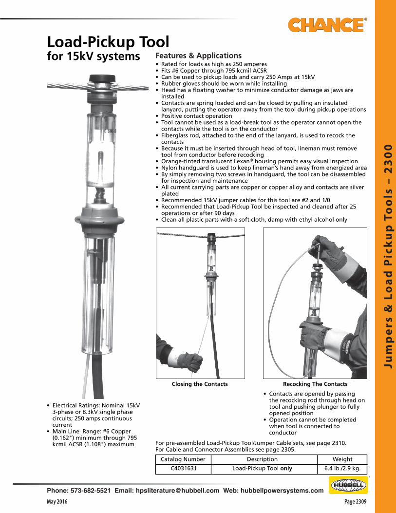
Jum
pe
rs &
Lo
ad
Pic
ku
p T
oo
ls –
23
00
Phone: 573-682-5521 Email: [email protected] Web: hubbellpowersystems.com
Page 2309May 2016
Features & Applications• Rated for loads as high as 250 amperes• Fits #6 Copper through 795 kcmil ACSR• Can be used to pickup loads and carry 250 Amps at 15kV• Rubber gloves should be worn while installing• Head has a floating washer to minimize conductor damage as jaws are
installed • Contacts are spring loaded and can be closed by pulling an insulated
lanyard, putting the operator away from the tool during pickup operations • Positive contact operation• Tool cannot be used as a load-break tool as the operator cannot open the
contacts while the tool is on the conductor• Fiberglass rod, attached to the end of the lanyard, is used to recock the
contacts• Because it must be inserted through head of tool, lineman must remove
tool from conductor before recocking• Orange-tinted translucent Lexan® housing permits easy visual inspection• Nylon handguard is used to keep lineman’s hand away from energized area • By simply removing two screws in handguard, the tool can be disassembled
for inspection and maintenance• All current carrying parts are copper or copper alloy and contacts are silver
plated• Recommended 15kV jumper cables for this tool are #2 and 1/0• Recommended that Load-Pickup Tool be inspected and cleaned after 25
operations or after 90 days• Clean all plastic parts with a soft cloth, damp with ethyl alcohol only
• Electrical Ratings: Nominal 15kV 3-phase or 8.3kV single phase circuits; 250 amps continuous current
• Main Line Range: #6 Copper (0.162") minimum through 795 kcmil ACSR (1.108") maximum
Load-Pickup Toolfor 15kV systems
Catalog Number
C4031631
Description
Load-Pickup Tool only
Weight
6.4 lb./2.9 kg.
Closing the Contacts Recocking The Contacts
• Contacts are opened by passing the recocking rod through head on tool and pushing plunger to fully opened position
• Operation cannot be completed when tool is connected to conductor
For pre-assembled Load-Pickup Tool/Jumper Cable sets, see page 2310.For Cable and Connector Assemblies see page 2305.

Jum
pe
rs & Lo
ad
Pick
up
Too
ls – 23
00
Page 2310 May 2016
Phone: 573-682-5521 Email: [email protected] Web: hubbellpowersystems.com
Weight
(lb./kg.)
17.75/8.05
19.62/8.89
20.8/9.43
23.28/10.55
15 kV Cable
Size
#2
#2
1/0
1/0
Cable
Length
10 ft.
12 ft.
10 ft.
12 ft.
Electrical Ratings: Nominal 15kV 3-phase or 8.3kV single phase circuits.Jumper Clamp: #6 Copper (0.162") minimum through 795 kcmil ACSR (1.108") maximum.
All Units
Features & Applications• Rated for loads as high as 250 amperes• Include load-pickup device, jumper clamp, 15 kV cable• Rated to pickup and carry 250-amp loads at 15kV• Each completely assembled set consists of Load-Pickup
Tool, Jumper Clamp, 15 kV Jumper Cable and cable connectors
• Load-Pickup Tool and Jumper Clamp fit conductors from #6 Copper (0.162") through 795 ACSR kcmil (1.108")
• Four standard sets include options for 10’ or 12’ lengths of either #2 or 1/0 Jumper Cable
• Other pre-assembled sets are available • These sets combine other Chance-Jumper Clamps,
other sizes and lengths of Jumper Cable and appropriate connectors (Catalog pages 2302 and 2306)
• Individual components also may be ordered for customer assembly of various combinations.
Operation & Maintenance• Load-Pickup Tool cannot be used to break loads
because operator cannot open contacts while Tool is installed on conductor
• To recock contacts, operator inserts fiberglass rod through head of Tool to push plunger to fully-opened position
• Rod is supplied attached to end of operating lanyard• Pulling this insulated lanyard closes the spring-loaded
contacts• Positive contact operation• Bearing-type floating washers in jaws of Tool and
Jumper Clamp assure secure gripping but minimal scoring of conductors during installation
• WARNING: Adequate rubber gloves must be worn when using this equipment
• Clean and inspect Load-Pickup Tool after every 25 operations or at least once every 90 days
• Clean all plastic parts with a soft cloth dampened with only ethyl alcohol
• To disassemble Tool, simply remove two screws in handguard
Construction FeaturesLoad-Pickup Tool: o Orange-tinted translucent Lexan® housing permits
easy visual inspection o Current-carrying parts of Copper or Copper alloy o Contact points are silver plated o Handguard of high-impact Nylon keeps hand away from energized area
Jumper Clamp: o Current-carrying parts of Copper alloy o Handles of high-impact Polyethylene o Wide handguard flange keeps hand away from energized area
Load-Pickup Tool SetsPre-assembled for 15kV systems
Recocking the Contacts
Catalog
Number
C4031557
C4031558
C4031559
C4031560
Closing the Contacts
Continuous
Current
200 amps
200 amps
250 amps
250 amps
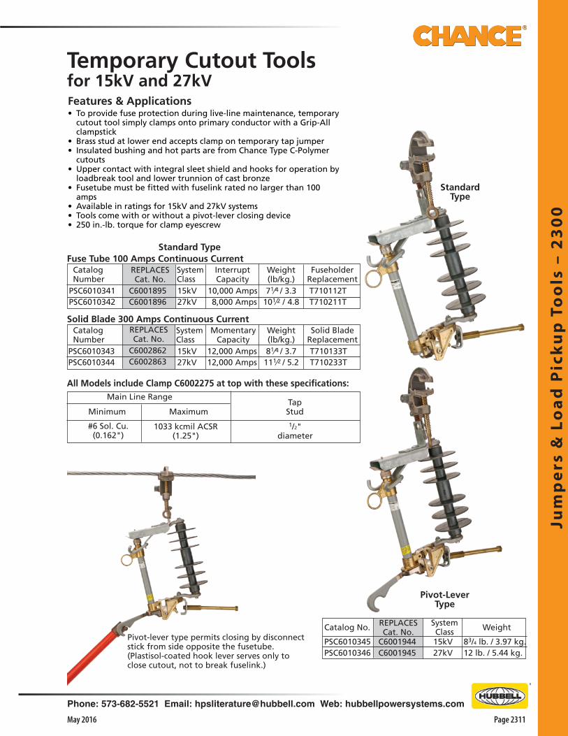
Jum
pe
rs &
Lo
ad
Pic
ku
p T
oo
ls –
23
00
Phone: 573-682-5521 Email: [email protected] Web: hubbellpowersystems.com
Page 2311May 2016
StandardType
FuseholderReplacement
Features & Applications• To provide fuse protection during live-line maintenance, temporary
cutout tool simply clamps onto primary conductor with a Grip-All clampstick
• Brass stud at lower end accepts clamp on temporary tap jumper• Insulated bushing and hot parts are from Chance Type C-Polymer
cutouts• Upper contact with integral sleet shield and hooks for operation by
loadbreak tool and lower trunnion of cast bronze• Fusetube must be fitted with fuselink rated no larger than 100
amps• Available in ratings for 15kV and 27kV systems• Tools come with or without a pivot-lever closing device• 250 in.-lb. torque for clamp eyescrew
Catalog Number
Weight(lb/kg.)
SystemClass15kV27kV
PSC6010341PSC6010342
Fuse Tube 100 Amps Continuous Current
WeightSystemClass15kV27kV
Minimum MaximumTapStud
1033 kcmil ACSR(1.25")
#6 Sol. Cu.(0.162")
Main Line Range
All Models include Clamp C6002275 at top with these specifications:
InterruptCapacity
10,000 Amps 8,000 Amps
71⁄4 / 3.3101⁄2 / 4.8
Temporary Cutout Toolsfor 15kV and 27kV
15kV27kV
PSC6010343PSC6010344
Solid Blade 300 Amps Continuous Current
81⁄4 / 3.7111⁄2 / 5.2
83/4 lb. / 3.97 kg.12 lb. / 5.44 kg.
Standard Type
Solid BladeReplacement
Catalog Number
SystemClass
MomentaryCapacity
12,000 Amps12,000 Amps
T710112T T710211T
T710133T T710233T
1/2"diameter
PSC6010345PSC6010346
Pivot-lever type permits closing by disconnect stick from side opposite the fusetube. (Plastisol-coated hook lever serves only to close cutout, not to break fuselink.)
Pivot-LeverType
Weight(lb/kg.)
REPLACESCat. No.
C6001944C6001945
Catalog No.
REPLACESCat. No.
C6001895C6001896
REPLACESCat. No.
C6002862C6002863

Jum
pe
rs & Lo
ad
Pick
up
Too
ls – 23
00
Page 2312 May 2016
Phone: 573-682-5521 Email: [email protected] Web: hubbellpowersystems.com
• After closing tool blade, the permanent tap can be disconnected
• The load can then be dropped or reconnected by operating blade tool
• It should never be closed into a fault or opened during a fault
*For application on single-phase-to-neutral or three-phase solidly-grounded wye-connected circuits where recovery voltage does not exceed the max. design voltage of the device.
Specifications (both models) Max. loadbreak current: 300 amps Max. momentary rating: †12,000 asym amps†This is a pass-through fault-current rating only. The tool should never be opened or closed when the current exceeds the maximum continuous load current of 300 amps. Main line range (both models) Minimum: #6 solid copper (0.162" dia.) Maximum: 1033 kcmil ACSR (1.25" dia.)Tap stud: 1⁄2" diameter
Temporary Load Disconnect ToolsBoth models include protective carrying case and illustrated operating and maintenance instructions.
Features & Applications• Available in two sizes• Provides a temporary means of connecting and
disconnecting equipment or circuits under load conditions
• Design does not have a fuse and does not provide protection for fault or overcurrent conditions
• Insulated bushing and hot parts are from Chance Type C-Polymer cutouts, including tubular-copper disconnect blade
• Arc-chute-type interrupter gives tool excellent loadbreak capability
• To interrupt load currents, device employs a stainless-steel auxiliary blade within Delrin® arc chute
• Tool simply clamps onto primary conductor with a Grip-All clampstick. Bronze stud at lower end accepts clamp on temporary tap jumper
• 250 in.-lb. torque for clamp eyescrew Installation & Removal • To install the tool, first remove its main blade• Next, secure both clamps of suitable temporary jumper
onto tap stud of tool’s lower hinge• Use a Grip-All clampstick to install tool onto main line
conductor• Use clampstick to secure one of the jumper clamps
onto line with load to be picked up• Use disconnect stick to place blade in lower hinge of
tool• Use disconnect stick in operating ring to close blade
according to safe work procedures• Take care when removing disconnect stick to avoid
opening blade• The equipment or circuit is now energized through the
tool• Before removing tool, first make up a permanent
connection so there are two energizing paths• Use a disconnect stick in the operating ring to open
the blade according to safe work procedures and to remove blade from lower hinge of the tool
• Use a clampstick to take jumper clamp from conductor and secure it on tool stud
• Then use the clampstick to remove the tool from the main line conductor
Operation• Self-contained loadbreak device operates by simple
disconnect stick• No special or portable tools are required to operate
unit• To break current, insert a disconnect stick into
operating ring and rapidly open device• When opening, spring-loaded auxiliary blade snaps
out through the arc chute to elongate, cool and extinguish the confined arc
• Loadbreaking operation is independent of the disconnect stick speed
• To provide a clearly visible break, the disconnect blade hangs in approximately a vertical position
• Unfused or unswitched loads can be disconnected by first installing this tool and a temporary bypass jumper in parallel with permanent tap connection
Temporary Load Disconnect Tools8.3/15kV & 15/27kV applications*
Catalog No. REPLACES Cat. No. Description Disconnect Blade Arc-Chute Assy.
PSC6010347 C6002386 *8.3/15kV Temporary Load Disconnect Tool T730133TE7300009P
PSC6010348 C6002387 *15/27kV Temporary Load Disconnect Tool T730233T

Jum
pe
rs &
Lo
ad
Pic
ku
p T
oo
ls –
23
00
Phone: 573-682-5521 Email: [email protected] Web: hubbellpowersystems.com
Page 2313May 2016
Features & Applications• Tested per OSHA & ASTM F711• For line tension up to 4,000 lbs. with manual hookstick
switch• Maximum ratings: 35 kV Ø-Ø, 600 amps continuous,
150 kV BIL• Permits a live overhead distribution line to be cut• By bearing the mechanical load, it helps create a
parallel circuit• This averts service interruption while the cutting and
related work are performed• May be applied wherever disconnect switch is desired
for temporary sectionalizing• Tool is properly rated concerning line tension,
continuous current, BIL and system voltage• Applications that require cutting a conductor include: o Deadend-structure construction o Overhead switch installation on a structure o In-line switch installation• Combines two Chance products: Epoxiglas® insulated
Weight
22 lb. / 9.9 kg.
Description
Tension Puller Switching Tool
Specifications
Capacity: 4,000 lb. (1,800 kg.) Working Range: 58 to 70 in. (1,473 to 1,778 mm) Maximum Take-up: 12 in. (305 mm) Insulation: Minimum 24 in. (610 mm) Maximum 36 in. (914 mm) Length: 60 in. (1,524 mm)
Installation & Operation• Equipped with rings, tool may be handled and
operated by hot-line tools or rubber-glove live-line techniques
• Illustrated instructions included with each unit give application considerations and procedures for installation, operation and maintenance
• Suspended from hot-line wire grips with the disconnect switch closed, tension puller works like a jack
• Operating the ratchet wrench brings the tool’s two ends closer
• This reduces tension on the conductor between the tool’s hooks
• Hot line jumpers sized to the application are installed on the conductor and the tool’s bypass studs to create a parallel circuit
• Before cutting the conductor, it is securely restrained• Once cut, its long tail is clamped back onto itself• A properly rated portable loadbreak device may now
be hung on the tool’s disconnect hooks and used to open the switch
• Refer to ANSI C37.35 IEEE Guide for the Application, Installation, Operation and Maintenance of High
Voltage Air Disconnecting and Load Intrerrupter Switches
• For proper installation, select from four sizes of hot-line wire grips shown on Chance catalog page 1258 and the full range of jumper equipment in this section
• To secure cut end of conductor, tie back clamp C4000600, shown on Chance catalog page 2264, fits conductors ranging from #4 to 397.4 kcmil ACSR
Operate disconnect switch with only a portable loadbreak tool.
Tension Puller Switching Tool
Catalog No.
C4001907
tension puller and LTD® line-tension disconnect switch• For this special tool, weathershed skirts of a tough,
lightweight polymer have been bonded to the tension puller’s 1-1/2"-diameter Epoxiglas pole
• At both skirt ends, a locating pin aligns a compression clamp to secure switch hot parts to pole
• A bypass stud (1/2"-dia.) added at each end of switch accepts clamps up to 3" wide
• Rigid, H-frame copper switch blade opens to a standard 90°, or to 180° with stop pin removed
• Contact areas are silver-plated for high conductivity• Galvanized-steel hooks are provided for use with a
portable loadbreak device• For easy opening and icebreaking, pull ring (1-1/4"-dia.
eye) activates latch as a pry-lever• Hooks on ends are fixed and do not swivel• Safety latch on hooks has a spring-loaded gate able to
rotate 135 degrees left or right from closed position• Selector lever on ratchet wrench is extra large for
easier operation by hot line tools


Lad
de
rs &
Pla
tfo
rms
– 2
35
0
Phone: 573-682-5521 Email: [email protected] Web: hubbellpowersystems.com
Page 2351May 2016
Lad
de
rs &
Pla
tfo
rms
–23
50Ladders &
Platforms
Catalog 2350 May 2016

Lad
de
rs & P
latfo
rms – 2
35
0
Page 2352 May 2016
Phone: 573-682-5521 Email: [email protected] Web: hubbellpowersystems.com
Features & Applications• Meets ASTM F711 and IEC 61478 - Category 2• Designed to effectively position linemen for
high-voltage maintenance• Make line repairs possible, even in inaccessible
places• Two basic styles of Epoxiglas Hook Ladders are
available o Regular Duty Ladders with 2" siderails for
vertical suspension applications o Heavy Duty Ladders with 2-1/2" siderails for
tagged-out positions
• Hooks are formed from 1"-diameter tempered steel
• These hooks can be swiveled to best fit various angles on structure
• Ladders include 8"-dia. hooks• 14"- or 18"-dia. hooks can be ordered for
other structure applications• Steel chains clip to hooks to assist in securing
ladder to support• Rung material for both rated ladders are
1-1/4" sand-coated Epoxiglas
Rated Working Load per Hook 8" hook 1250 lb.14" hook 1000 lb.18" hook 750 lb.
*Add suffix “A” to catalog number for 14" hooks. Add suffix “B” to catalog number for 18" hooks.
OverallLength
8'10'12'14'16'
Weight42 lb./18.9 kg.46 lb./20.7 kg.52 lb./23.4 kg.60 lb./27.0 kg.68 lb./30.6 kg.
OverallLength
8'10'12'14'16'18'20'
Weight47 lb./21.2 kg.55 lb./24.8 kg.63 lb./28.4 kg.70 lb./31.5 kg.76 lb./34.2 kg.85 lb./38.3 kg.98 lb./44.1 kg.
HEAVY-DUTY HOOK LADDERS 21⁄2" SIDE RAILS
REGULAR-DUTY HOOK LADDERS 2" SIDE RAILS
Epoxiglas® Swivel Hook Ladders
Catalog No.8" Hooks*
H49048 H490410H490412H490414H490416
Distance BetweenSide Rails
141/2"141/2"141/2"141/2"141/2"
Catalog No.8" Hooks*
H49058 H490510H490512H490514H490516H490518H490520
Distance BetweenSide Rails
141/2"141/2"141/2"141/2"141/2"141/2"141/2"
TEMPORARY INSTALLATIONNOW CERTIFIED TO IEC 61478 - CATEGORY 2
Includes full line offering• Ladders: Swivel Hook, spliced and three-rail• Brackets for poles and towers• Accessories: clamps, hooks, spreader bar, swivel sticks• Leakage-current monitor meter kits

Lad
de
rs &
Pla
tfo
rms
– 2
35
0
Phone: 573-682-5521 Email: [email protected] Web: hubbellpowersystems.com
Page 2353May 2016
• Available in various section lengths for convenient transport • Hooks are made of 1" diameter steel and have an 8" diameter arch to hook
over structural shapes • Hooks are complete with steel chains• Larger hooks are available on special order• Heavy-duty Chance Epoxiglas Ladders, manufactured in short,
easy-to-transport lengths, are joined with Chance Rigid Ladder Splice to form unshakable, rigid splice
• Two eye pins with a klik pin in the end of each are supplied with each splice
Three Rail LadderFeatures & Applications• Meets ASTM F711 and IEC 61478 - Category 2• Greater mechanical strength and less deflection
enhance worker efficiency • Designed for working in tagged-out position• Third rail provides for a convenient, centered, safety-
belt-tie• Also divides ladder rung into natural positions for each
foot placement• Specifications include: o 2-1/2" center rail, capped on both ends o 2" side rails with 8" swivel hooks on top and
caps on bottom end of rail o 1-1/4" sanded rungs o Steel tie rods top and bottom o Pinned sleeves on outside rails for spliced ladders
with a 15-1/2" center• Both straight and spliced ladder units are available
Top Section Length10'12'14'16'20'
10' middle section
Weight44 lb./19.8 kg.48 lb./21.6 kg.52 lb./23.4 kg.56 lb./25.2 kg.64 lb./28.8 kg.44 lb./19.8 kg.
SPLICED, HEAVY-DUTY HOOK LADDERS — 21⁄2" SIDE RAILS
Catalog No.C4020418C4020421C4020422
Bottom Section Length8'10'12'
Weight28 lb./12.6 kg.32 lb./14.4 kg.36 lb./16.2 kg.
Klik Pin059738P
Epoxiglas® Spliced Ladders
Eye PinP4020041P
Catalog No.C4020482C4020402C4020404C4020407C4020411T4020423
Description20' Straight Ladder
DescriptionYoke Assembly for Three
Rail Ladder
Weight100 lb./45.0 kg.
Catalog No.C4020119
Catalog No.
PSC4020569
Features & Applications• Meets ASTM F711 and IEC 61478 - Category 2• Available in combinations of up to 32’ in 2-1/2"-dia. side rails• All splices are interchangeable, offering a variety of total reach
Fixed-Length (non-spliced) Ladder Three Ladder Yoke
Spliced Ladders
8' Bottom Section12' Bottom Section
12' Top Section
43 lb./19.4 kg.52 lb./23.4 kg.62 lb./27.9 kg.
C4020512C4020513C4020514

Lad
de
rs & P
latfo
rms – 2
35
0
Page 2354 May 2016
Phone: 573-682-5521 Email: [email protected] Web: hubbellpowersystems.com
Features & Applications• Quick, easy rigging on most types of structure • Converts Chance Epoxiglas® ladder to a platform for live-line maintenance• Sets are designed for steel or wood structures, vertical or horizontal• Support the structure-end of the ladder in a tagged-out position• Sets are designed for use on 2-1/2"-dia. side rail ladders • Can be ordered as sets or individual components• Diagram below shows a typical rigging and working loads with various guy
mountings
Ladder Support Attachments
Cat. No.*E4020141*T4020899*T4020900*T4020901
Length121/2 ft.
6 ft.8 ft.10 ft.
*Swivel Sticks(11⁄4" dia.)
“X” = Ht. ofGuy Position
8' — 0"12 — 0"16' — 0"
Maximum TotalWorking Load
500 lb.400 lb.300 lb.
TotalLadder Length
16 ft.24 ft.32 ft.
Kits Consist OfFollowing:E4020525Vertical AttachmentTowerE4020087Horizontal AttachmentTowerE4020526Vertical AttachmentPoleE4020568Yoke AssemblyE4020099Spreader BarE4020138PLadder Clamp 2-1/2"E4020141 (Also seeSwivel Stick *below)E4020092Double ClampTotal Kit Weight
C4020155Ladder Support KitFor Vertical Attach.
On Wood or Steel Poles
1
1
1
2
2
161.5 lb./27.7 kg.
C4020139Ladder Support KitFor Vertical Attach.
On Towers
1
1
1
2
2
161.5 lb./27.7 kg.
C4020140Ladder Support Kit
For HorizontalAttach. On Tower
1
1
1
2
2
150 lb./22.57 kg.
E4020138PLadder Clamp 2-1/2"
E4020568
E4020525Ladder Support Assemblyfor Vertical Tower Member
E4020568
E4020526Vertical Ladder Support
Attachment for Wood Poles
E4020092Double Clamp
21⁄2" and 11⁄2" Diameter
E4020099Spreader Bar
Tested per OSHA & ASTM F711
E4020568
E4020087Ladder Support Assembly
for Horizontal Tower Member
Ladder Clamp Swivel StickSpreader Bar
Hoist orLoad Take-Up
LOAD
X
Support Assembly

Lad
de
rs &
Pla
tfo
rms
– 2
35
0
Phone: 573-682-5521 Email: [email protected] Web: hubbellpowersystems.com
Page 2355May 2016
Adjustable Ladder Hook
Approx. Wt.,Each†
7 lb./3.2 kg.7 lb./3.2 kg.
For SideRail Dia.
2"21/2"
18" Hook—
H49451
14" HookH49241H49251
8" HookH49041H49051
* Catalog No. includes one (1) Hook, Chain, and Chain Snap.
† Weights listed are for an 8" Hook; 14" Hook 81/2 lb. each; and for 18" Hook 141/2 lb. each.
Features & Applications• Easily attaches in one quick operation• Position on Epoxiglas® side rail, swing bolt around and
tighten wing nut• Made of 1"-dia. heat-treated, rust-resistant steel • Equipped with rugged chain and chain snap for posi-
tive lock between ladder and support• Hooks are rated at 1,000 lbs. per pair
Ladder Monitor KitFeatures & Applications• Used with EHV Barehand maintenance procedure to
detect microamp leakage on ladder before use• Meter connects to ladder and takes readings as ladder
is placed in contact with conductor• It is recommended that readings be taken periodically
to ensure optimum working conditions, which can be altered by a change in atmosphere
• Kit includes: o A 200 micro-amp scale microammeter o 3 clamps for use with three-rail ladder o A cable with clips and adapter to establish contact o A bracket to ground and hold the meter on the
structure o 2 dry cell batteries o Instruction drawings for field assembly o Operating instructions
DescriptionLadder Monitor Kit
Weight7.5 lb./3.4 kg.
Catalog No.C4020288
Chance Sentinel Leakage-Current MonitorFeatures & Applications• Alerts utility-line workers of overcurrent conditions • For aerial devices, including insulated ladders and
truck booms• Sounds an alarm if leakage current reaches a pre-set
level• Leakage setting adjusts from 1 to 1,000 microamperes
in resolution increments of 0.1 microamp• Audible warning eliminates the need to watch LCD
screen current level• Alarm sounds upon overcurrent and continues until
condition is corrected• Jack on instrument panel accepts standard 1/4"
two-conductor phone plug to trigger horn or other external alarm
• Panel test terminal permits continuity check of monitor leads prior to operation
• Before each use, instrument automatically performs rapid electronic self test
• Simple operating steps are printed on the inside lid panel
• Detailed instruction sheet also comes with each unit• Kit includes 1 coaxial cable and battery, plus 2 jumpers
and 3 hose clamps for connections to two- or three-rail ladders
• Brackets on box secure to an earth-grounded structure up to 5/8" thick, such as a transmission tower
• Adjustable hooks can be used with Epoxiglas Hook Ladders to obtain a more convenient position
• Can be attached to an Epoxiglas Service Ladder for use as a temporary hook ladder
• Adjustable Hooks are ideal for suspension use for un-even or sloping supports
Catalog No.*
Catalog No. Description WeightC4070025 Chance Sentinel Kit 9 lb./4.05 kg.

Lad
de
rs & P
latfo
rms – 2
35
0
Page 2356 May 2016
Phone: 573-682-5521 Email: [email protected] Web: hubbellpowersystems.com
6-ft. Standard Aerial PlatformEpoxiglas Railing must be ordered as separate item.
4-ft. Standard Aerial PlatformEpoxiglas Tripod must be ordered as separate item.
Standard Aerial Platforms
Features & Applications• Designed to provide a convenient workstation on an
aerial structure• Quickly mount on structure to help place linemen in
correct working position
Mounting Options & Accessories• Feature a Fixed Pole Mount for jobs that do not
require frequent platform relocation• Pivot Mounts (available below as optional accessories)
allow platform to be swiveled on its horizontal plane for different positions
• For belt-on and as restraining guides for workers, Epoxiglas Tripods or Railings may be added – see page 2357
• For improved footing, three strips of 2” non-skid tape extend the length of the platform
• Bare section near mounting end helps reduce moisture accumulation
• Also provides an area between the working surface and the mount fittings that can be readily wiped clean of dirt and moisture when necessary
Features & Applications• Unique design features 12" of clear insulation • Two 2"-dia. orange Epoxiglas poles connect the platform to the mounting bracket• No other platforms include these insulating members• Manufactured to the same exacting standards as
Chance hot-line tools: OSHA subpart V, section 1926.951(d) and ASTM 711
• Cleaning and care of Epoxiglas components are same as for Chance hot-line tools
• Maximum load rating, all platforms: 500 lbs.
Mounting Options & Accessories• To provide convenient workstations for rubber-glove
work on energized lines, these platforms quickly secure to pole with either of two mounts:
o Fixed mount, for jobs that do not require frequent platform relocation, comes as part of each basic platform and includes a chain binder and wheel tightener
o Pivot mount, optional for easy positioning to ac-cess jobs, permits worker to swivel the mounted platform on its horizontal plane
• For belt-on/restraining guide, add optional Tripod or Railing
• For improved footing, three strips of 2” non-skid tape extend the length of the platform
Description
10-ft. Standard Platform
12-ft. Standard Platform
Weight
86 lb./39.7 kg.
105 lb./47.3 kg.
Each Standard Aerial Platform below is 10" wide andfurnished with an Epoxiglas Railing & Fixed Pole Mount
Weight
40 lb./18 kg.
49 lb./22 kg.
56 lb./25.2 kg.
71 lb./32 kg.
Description
42-in. Standard Platform
4-ft. Standard Platform
6-ft. Standard Platform
8-ft. Standard Platform
Each Standard Aerial Platform listed below is 10" wide and furnished with a Fixed Pole Mount
Maximum Load Rating, all platforms: 500 lb.
Epoxiglas® Insulated Platforms
Catalog No.
H496442W
H49644W
H49646W
H49648W
Catalog No.
T4020632
T4020619
Epoxiglas Tripod and Pivot Base must be ordered as separate items.
Epoxiglas Railing and Pivot Base each must be ordered as separate items.
6-ft. Insulated Platform
4-ft. Insulated Platform
Catalog No. Description WeightC4021042 4-ft. Insulated Platform 49 lb./22 kg.C4021043 6-ft. Insulated Platform 56 lb./25.2 kg.C4021079 8-ft. Insulated Platform 60 lb./27 kg.
Each Epoxiglas Insulated Platform listed below is 10" wideand furnished with a Fixed Pole Mount
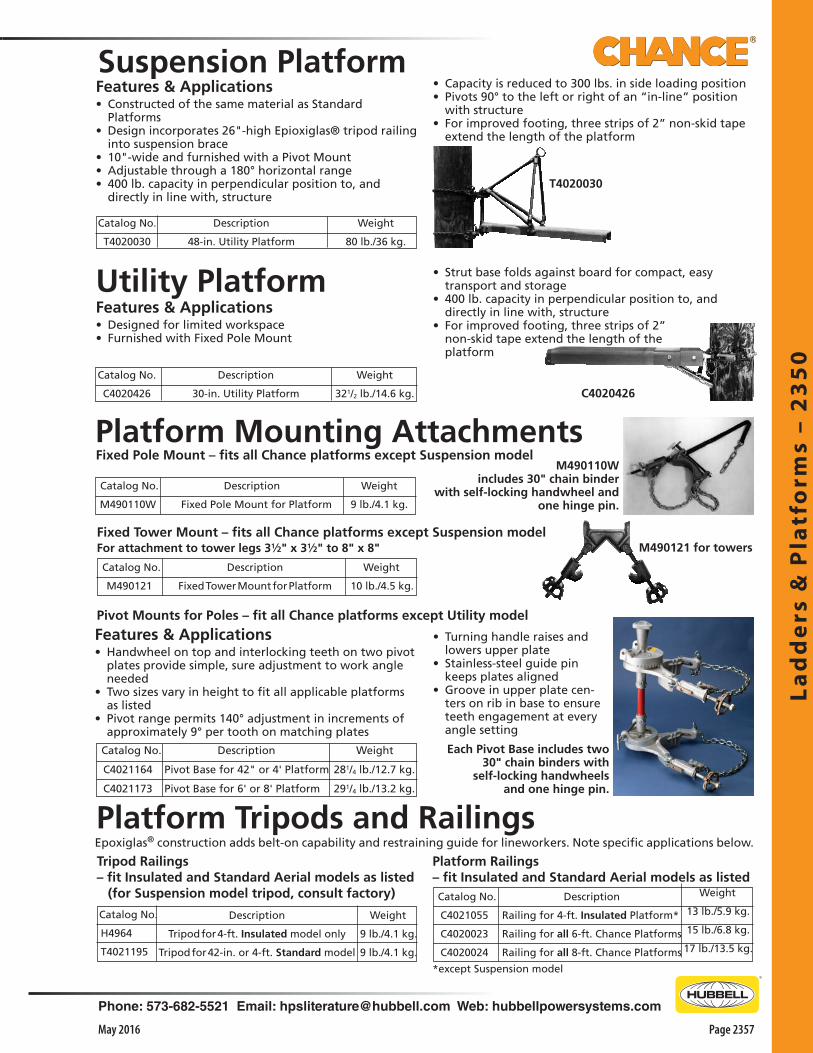
Lad
de
rs &
Pla
tfo
rms
– 2
35
0
Phone: 573-682-5521 Email: [email protected] Web: hubbellpowersystems.com
Page 2357May 2016
Catalog No.
H4964
T4021195
Platform Tripods and Railings
Features & Applications• Constructed of the same material as Standard
Platforms• Design incorporates 26"-high Epioxiglas® tripod railing
into suspension brace• 10"-wide and furnished with a Pivot Mount• Adjustable through a 180° horizontal range• 400 lb. capacity in perpendicular position to, and
directly in line with, structure
Suspension Platform
Catalog No.
C4021164
C4021173
Description
Pivot Base for 42" or 4' Platform
Pivot Base for 6' or 8' Platform
Utility PlatformFeatures & Applications• Designed for limited workspace• Furnished with Fixed Pole Mount
Description
30-in. Utility Platform
Catalog No.
C4020426
Fixed Pole Mount – fits all Chance platforms except Suspension modelPlatform Mounting Attachments
Description
Fixed Pole Mount for Platform
Weight
9 lb./4.1 kg.
Catalog No.
M490110W
M490110Wincludes 30" chain binder
with self-locking handwheel and one hinge pin.
Pivot Mounts for Poles – fit all Chance platforms except Utility model
Features & Applications• Handwheel on top and interlocking teeth on two pivot
plates provide simple, sure adjustment to work angle needed
• Two sizes vary in height to fit all applicable platforms as listed
• Pivot range permits 140° adjustment in increments of approximately 9° per tooth on matching plates
Fixed Tower Mount – fits all Chance platforms except Suspension modelFor attachment to tower legs 31⁄2" x 31⁄2" to 8" x 8"
Catalog No.
M490121
Weight
10 lb./4.5 kg.
Description
Fixed Tower Mount for Platform
Each Pivot Base includes two 30" chain binders with
self-locking handwheelsand one hinge pin.
Weight
9 lb./4.1 kg.
9 lb./4.1 kg.
Description
Tripod for 4-ft. Insulated model only
Tripod for 42-in. or 4-ft. Standard model
Tripod Railings– fit Insulated and Standard Aerial models as listed (for Suspension model tripod, consult factory) Catalog No.
C4021055
C4020023
C4020024
Weight
13 lb./5.9 kg.
15 lb./6.8 kg.
17 lb./13.5 kg.
Description
Railing for 4-ft. Insulated Platform*
Railing for all 6-ft. Chance Platforms
Railing for all 8-ft. Chance Platforms
Platform Railings– fit Insulated and Standard Aerial models as listed
*except Suspension model
Epoxiglas® construction adds belt-on capability and restraining guide for lineworkers. Note specific applications below.
• Capacity is reduced to 300 lbs. in side loading position• Pivots 90° to the left or right of an “in-line” position
with structure• For improved footing, three strips of 2” non-skid tape
extend the length of the platform
T4020030
M490121 for towers
Weight
321/2 lb./14.6 kg.
Weight
281/4 lb./12.7 kg.
291/4 lb./13.2 kg.
C4020426
• Strut base folds against board for compact, easy transport and storage
• 400 lb. capacity in perpendicular position to, and directly in line with, structure
• For improved footing, three strips of 2” non-skid tape extend the length of the platform
Description
48-in. Utility Platform
Catalog No.
T4020030
Weight
80 lb./36 kg.
• Turning handle raises and lowers upper plate
• Stainless-steel guide pin keeps plates aligned
• Groove in upper plate cen-ters on rib in base to ensure teeth engagement at every angle setting

Lad
de
rs & P
latfo
rms – 2
35
0
Page 2358 May 2016
Phone: 573-682-5521 Email: [email protected] Web: hubbellpowersystems.com
Features & Applications• Allows workers to stand or sit at worksite instead of
kneeling on structure • Convenient and efficient• Proven products combine in Chance Platform Ladder:
48"-long Epoxiglas® Ladder and two 20"-long sections of 10"-wide Platform joined side-by-side constitute a bosun’s chair
• Adjustable ladder hooks may be added (see Catalog page 2355)
• Platform Ladder may be suspended and tagged-off with rope, wire tongs or a combination of both in order to maneuver a worker into position
• Platform Ladder folds into a compact package for quick rigging and easy storage
• Although rated for 500-lb. loads, users must give serious consideration to capacity of the point from which it is suspended and the equipment used to suspend it
• For improved footing, three strips of 2” non-skid tape extend the length of the platform
Platform Ladder
Features & Applications• Offer greater safety when working around energized
lines• Easier to transport – much lighter than comparable
wood ladders• Spacing between side rails and rungs meets largest
central station and telephone company specifications • Side rails of 1-1/2"-dia. Epoxiglas are plastic-covered at
top for cushioning• Rubber feet are supplied on bottom end• Rungs are of 13/16"-dia. glass fiber
Epoxiglas® Service Ladders
Weight
36 lb./16.2 kg.
Description
Platform Ladder, no hooks
Catalog No.
C4020276
OverallLength10'-1"12'-1"8'-1"
Catalog No.H4903M10H4903M12H4903M8
Spacing BetweenSide Rails
12"12"12"
Approx.Wt., Ea.16 lb.19 lb.13 lb.
Rated for loads, 250 lbs.

Co
ver-
Up
Eq
uip
me
nt
– 2
40
0
Phone: 573-682-5521 Email: [email protected] Web: hubbellpowersystems.com
Page 2401May 2016
Co
ver-
Up
Eq
uip
me
nt
–24
00Cover-Up
Equipment
Catalog 2400 May 2016

Co
ver-U
p E
qu
ipm
en
t – 24
00
Page 2402 May 2016
Phone: 573-682-5521 Email: [email protected] Web: hubbellpowersystems.com
Features & Applications• Made of orange linear polyethylene • Fits over maximum of two 10” dia. deadend insulators• End of cover will mate with Chance 25kV conductor
covers or rubber line hose to extend protected area• Measures 34”L, 11” W and 12-1/2” from conductor to
unit bottom • Split unit fits easily over the conductor and insulators• Split unit can be tightly clamped together using large
hot stick clamp pin, which is similar to those used in securing rubber blankets
• A Grip-All adapter (included) allows unit to be installed with a clampstick
• Can also be placed into position with rubber gloves and sleeves
Clamping pin can be used in any of three positions indicated.
Deadend Covers25 kV Phase-to-Phase
C4060164
Features & Applications• Tested to ASTM F712• Protects linemen working near most
open-type cutouts rated at 25kV or under
• Will not fit over cutouts with linkbreak levers or similar devices
• Can be placed over the cutout • Locking pin slips behind the cutout
insulator over hanger bracket and into hole on opposite side of cover
Cutout Covers 25 kV Phase-to-Phase
Features & Applications• For all types of high-voltage line maintenance• Most pieces can be installed with rubber gloves or hot
stick application eyes• Common sense rules must always be followed when
using cover-up equipment, including: 1. Cover-up equipment (such as line covers, insulator
covers, cutout covers, and deadend covers) is intended to prevent personnel from making accidental brush contact with energized parts or equipment. Under no conditions should personnel purposely contact the covers, except with adequate rubber gloves, and personnel must always be aware of their position in order to avoid accidental contact with the cover
2. Cover-up equipment (such as pole covers, crossarm guards, crossarm end covers, and pole top covers) is intended to help prevent accidental contact of energized tie wires or conductors with the grounded surface of the pole or crossarm
3. Cover-up equipment must be handled with care to minimize breakage and scratching, and must be kept clean. Maintenance is as important with cover-up
equipment as with other hot line tools. Each cover must be thoroughly inspected before each use to ensure that it has no cracks, deep scratches, or gouges and to ensure that it is clean. Cleaning should be done with a wiping cloth, and if that does not remove all dirt, mild soap and water should be used. Polyethylene covers can be cleaned with Chance Moisture-Eater II solvent-cleaner (see Catalog Section 2500). Caution: Solvents must be avoided unless the user can determine that the material in the particular cover is polyethylene
4. For Temporary Use — Cover-up equipment is designed to be as light and easy to use as possible, hence it is not made from materials that can withstand extended periods of electrical stress. Therefore, Chance cover-up equipment must not be left installed for extended periods, especially if allowed to touch both an energized surface and a possibly grounded surface. The situation would be highly aggravated in rainy or humid weather, when the surfaces of the covers become dirty, etc. Therefore, the covers should be removed at the end of the workday, if possible
Cover-Up Equipment
Cover-up equipment, by necessity, is designed to be as universal as possible. Therefore it is possible, as examples, for (1) a tie wire to touch a potentially grounded pin or other part, (2) a person’s hand to touch the conductor through an opening in the equipment, or (3) a part of a person’s body or other work equipment to contact the conductor through an opening in the cover-up equipment or “in the vicinity of junctions between pieces of cover-up equipment.” These possibilities, as well as other possible contacts, do exist, and the persons using this equipment must be aware of them and consider them on each and every application. Necessary precautions must be taken to prevent these contacts. Under no circumstances is Chance cover-up equipment intended to prevent mechanical equipment from contacting either energized or grounded surfaces.
! WARNING
Catalog No. Description WeightC4060164 Deadend Cover 5 lb./2.3 kg.
Catalog No. Description WeightC4060009 Cutout Cover with Locking Pin 4 lb./1.8 kg.
• Eyes on cover and locking pin allow installation with a Grip-All clampstick
• Cover is made of orange high-impact ABS plastic• Several units can be nested together for convenience
and space saving on truck

Co
ver-
Up
Eq
uip
me
nt
– 2
40
0
Phone: 573-682-5521 Email: [email protected] Web: hubbellpowersystems.com
Page 2403May 2016
P4060184 without Grip-All Adapterfor rubber glove application
P4060185and P4060186without Grip-All Adapterfor rubber-glove application
C4060181GA with Grip-All Adapter
Covers on Horizontal Post Construction
Covers on Crossarm Construction
Conductor and Insulator Covers25 kV Phase-to-Phase (for 36.6 kV Phase-to-Phase conductor covers, see page 2405)Features & Applications• Tested to ASTM F712• A versatile system of covering up a variety of configu-
rations on distribution systems • Conductor and insulator units mate together to cover
pin-type or post-type insulator construction• Can also be used with the deadend cover, shown on
page 2402• Units virtually surround hot parts and hardware to give
linemen extra protection when rubber gloving or using hot sticks
• Covers will couple with major brands of rubber line hose and insulator covers of 25kV class
• Both covers are made of high-density, bright orange polyethylene
• Conductor covers are 5’ long and are available with a Grip-All adapter for hot stick application or without adapter for rubber glove application
• Also available with 4’ Epoxiglas® handles• Maximum conductor size: 666 kcmil ACSR• Insulator covers are 21” long and 8-1/2” wide • Available in two heights: 6” and 9” from conductor to
cover base to fit different size insulators• For use with Grip-All adapter for hot stick application
or without adapter for rubber glove application
Description5' Conductor Cover with4' Epoxiglas Handle5' Conductor Cover with-out Adapter or Handle5' Conductor Cover withGrip-All Adapter
Grip-All AdapterReplacement Kit
Catalog No. C4060181
P4060184
C4060181GA
PSC4032879
Weight5 lb./2.3 kg.
3 lb./1.4 kg.
4 lb./1.8 kg.
1 lb./0.45 kg.
C4060182L
P4060186
Insulator Cover — 9"with Grip-All AdapterInsulator Cover — 9"without Grip-All Adapter
4 lb./1.8 kg.
31/2 lb./1.6 kg.
C4060182
P4060185
Insulator Cover — 6"with Grip-All AdapterInsulator Cover — 6"without Grip-All Adapter
3 lb./1.4 kg.
21/2 lb./1.1 kg.
PSC4032879Grip-All AdapterReplacement Kitas furnished on C4060181GAand C4060514GA Conductor Coversincludes 2 Screws P0010740P and 1 each:Bracket P4060196P, Adapter C4060040, Wing Nut 055067P, Bolt 066713P.
C4060182 and C4060182L with Grip-All Adapter
C4060181with 4-foot Epoxiglas handle

Co
ver-U
p E
qu
ipm
en
t – 24
00
Page 2404 May 2016
Phone: 573-682-5521 Email: [email protected] Web: hubbellpowersystems.com
Pole covers can be placed and removed easily from ground level using Chance telescoping tools.
Features & Applications• Tested to ASTM F712• Meet Class 4 requirements• Protect personnel when raising or lowering a pole
between energized lines• Cover poles during rubber glove maintenance in
confined areas• High-dielectric linear polyethylene covers will not
flash flame• This material will have some softening without
deformation at approximately 170°F, and it will resist brittleness at temperatures to -50°F
• All Chance pole covers are ribbed to reduce cover contact with the pole, thus minimizing creosote contamination
• Nylon button on 4’ and 6’ lengths allows pole covers to be joined together in tandem, where longer lengths are required
• Rope handles help to easily spread the covers and snap them around the pole (Rubber gloves must be worn during this procedure)
• Prolonged contact with an energized conductor must not be allowed
• Button-Nut Kit, T4060214
Pole Covers36.6 kV Phase-to-Phase
Rope Lock AssemblyFeatures & Applications• For securing pole covers on metal, concrete, composite
or wood poles• To help keep pole covers in place, especially on smooth
surfaces
• Easy to place and remove• May be applied midway and/or as a lower support for
pole covers• For use on 6", 9" or 12" diameter pole covers• Instructions are included with each unit for simple in-
stallation by hand and removal from ground level with a hot stick
C4060547Rope Lock Assembly
C4060547 C4060564
Rope Lock AssemblyReplacement rope, 1/2" x 7 ft.
11/2 lb. / 0.75 kg.1/2 lb. / 0.25 kg.
Cat. No. WeightDescription
Catalog No. Overall Length Weight6" Diameter Pole Covers
C4060550 48" overall length 61/2 lb. / 3 kg.C4060551 72" overall length 91/2 lb. / 41/2 kg.
9" Diameter Pole CoversM49371 12" long 21/2 lb./1.1 kg.M49372 24" long 4 lb./1.8 kg.M49374 48" long 9 lb./4.1 kg.M49376 72" long 13 lb./5.9 kg.
12" Diameter Pole CoversC4060029 24" long 51/2 lb./2.5 kg.C4060030 48" long 11 lb./5.0 kg.C4060000 72" long 16 lb./7.2 kg.

Co
ver-
Up
Eq
uip
me
nt
– 2
40
0
Phone: 573-682-5521 Email: [email protected] Web: hubbellpowersystems.com
Page 2405May 2016
Coversfor Conductor, Insulators and Deadends• 36.6 kV Phase-to-Phase • ASTM Class 4 • Tested to ASTM F712
Conductor cover is 5 feet long and includes an adapter for handling by Grip-All clampsticks.
Maximum conductor size: 666 kcmil ACSR.
Catalog No. C4060514GA
Weight51/4 lb./2.36 kg.
Description5 ft. Conductor Cover
Insulator covers fit 61/2" to 9"-diameter pin or post insulators. Each cover includes an adapter for handling by Grip-All clampsticks.
C4060557 C4060557L
3 lb./1.36 kg.31/2 lb./1.6 kg.
12" Insulator Cover161/2" Insulator Cover
Deadend cover fits three 10"-diameter porcelain bells or polymer deadend insulators and includes an adapter for handling by Grip-All clampsticks.
C4060537 51/4 lb./2.36 kg.Deadend Cover
Deadend CoverC4060537
Insulator CoversC4060557 (12" height)andC4060557L (161⁄2" height)
Covers onCrossarm Construction
Covers on HorizontalPost Construction
Insulator CovercoupleswithConductorCoverusing Hot Sticks or Rubber Gloves
Conductor CoverC4060514GA
Deadend Cover couples with Conductor Cover
To meet the Class 4 rating, the deadend cover must be used in conjunction with a rubber insulating blanket covering the coupler to the line cover. Failure to use a blanket to cover the coupler may result in electrical shock, severe injury or death by electrocution.
• Tested to ASTM F712• Meet Class 4 requirements• A versatile system of covering up a variety of
configurations on distribution systems • Conductor and insulator units mate together to cover
pin-type or post-type insulator construction• Units virtually surround hot parts and hardware to give
linemen extra protection when rubber gloving or using hot sticks
• Each item is fitted with an adapter for multi-position handling by Grip-All clampsticks
• These covers also couple with Chance 25 kV covers (catalog pages 2402 and 2403) and Classes 2, 3 and 4 of rubber line hose (pages 2410 and 2411)
• Covers also couple with major brands of rubber insulator hoods
• All covers are high-density, bright orange polyethylene in uniform wall thickness
• Excellent dielectric/puncture strength and perform well from -50° to 170°F
• Ultra-violet stabilizers in material help inhibit degradation as a result of atmospheric exposure
• Conductor cover is 5’ long• V-shaped cover’s bottom edge makes it easy to install• Four indented ribs along cover’s top edge for air gap
between conductor and cover • Maximum conductor size is 666 kcmil ACSR• Insulator covers come in two heights: Either 12" or
16-1/2" tall cover fits 6-1/2" to 9"-diameter pin or post insulators
• Special slits in insulator covers help locate the conductor and hardware when installing covers
PSC4032879Grip-All AdapterReplacement Kitas furnished on C4060181GAand C4060514GA Conductor Coversincludes 2 Screws P0010740P and 1 each:Bracket P4060196P, Adapter C4060040, Wing Nut 055067P, Bolt 066713P.
• Deadend cover fits three 10"-dia. porcelain bells or polymer deadend insulators and couples with line cover
• To meet the Class 4 rating, deadend cover must be used in conjunction with a rubber insulating blanket covering the coupler to the line cover
• Failure to use a blanket to cover the coupler may result in electrical shock, severe injury or death by electrocution.

Co
ver-U
p E
qu
ipm
en
t – 24
00
Page 2406 May 2016
Phone: 573-682-5521 Email: [email protected] Web: hubbellpowersystems.com
46kV Post Insulator Cover25kV Post Insulator Cover
C4060091C4060092
31/2 lb./1.6 kg.3 lb./1.4 kg.
Post Insulator Covers — 46 kV Ø-Ø & 25 kV Ø-Ø• Tested to ASTM F712• Made of high-impact orange ABS plastic• Split on each side forms a passage for the conductor• Bottom portion of T-shape covers the insulator skirts• Horizontal portion covers the conductor and hardware• Horizontal portion is flared at each end to interlock with Chance 36.6 or
46kV spiral conductor covers (see page 2407)• Larger cover may be used on vertical and horizontal 46kV tie top and
clamp top post insulators and Epoxirod® standoffs, pole tops and bi-unit assemblies
• Not for rubber glove installation above 34.5 kV
C4060102 Crossarm End Cover 21/2 lb./1.1 kg.
Crossarm End Cover — 36.6 kV Ø-Ø• Tested to ASTM F712• Covers crossarm end to help prevent tie wires from contacting crossarm
during tying/untying• Helps prevent lineman from contacting a ground potential while in
contact with conductor • Fits over crossarm end up to 5” x 6” with either pin- or post-type
insulator• Made of ABS orange plastic• Slots may be cut in each side to provide passage for double-arming bolts
Catalog No.C4060097
DescriptionPole Top Cover
Weight21/2 lb./1.1 kg.
Pole Top Cover — 36.6 kV Ø-Ø• Tested to ASTM F712• Made of high-impact orange ABS plastic• Helps prevent tie wires from contacting pole when tying/untying ridge
construction• Fits a pole top of up to 10” dia. with single- or double-ridge pin
construction• Maximum bolt length is 16”• Rests on pole top, covering 10-1/2” of the pole top and 4-1/2”of ridge pin• By using the elastic cord furnished with cover, cover-up can be butted
against insulator to cover ridge pin and pole top
C4060097
C4060102
Insulator, Hardware, and Crossarm Covers
C4060091
Substation and Underground BarriersFeatures & Applications• Tested to ASTM F712• Same excellent quality bright-orange linear
polyethylene material as used in many pieces of Chance cover-up equipment
• Available in 4’ x 6’ sheets for use in substations and as underground barriers
• Cutting smaller pieces is accomplished with any hand or power saw
• Form the sheets with a blow torch or in an oven heated to 250°F
• Although sheet becomes increasingly stiff as temperatures drop, it does not become brittle and break at -50°F
• Will not soften or deform at 170°F• Material will not flash flame• Puncture strength is 300 volts per mil.
Weight30 lb./13.5 kg.
Description4 feet x 6 feet x 0.255"
Catalog No.C4060002

Co
ver-
Up
Eq
uip
me
nt
– 2
40
0
Phone: 573-682-5521 Email: [email protected] Web: hubbellpowersystems.com
Page 2407May 2016
Features & Applications• Tested to ASTM F712• 4' or 6' long retractable Epoxiglas® handle for easy
installation from a bucket or platform, in single units or linked together
• Easy-to-install, bright-orange conductor cover • Extra protection with a wide air space between two
thicknesses of solid insulation• Made of tough, durable ABS plastic• Overall length of each cover is 53”• All units can interlock with each other to make up a
chain of guards• 15/36.6 kV units are formed on the ends to fit over
most 15kV insulators• Eliminates the need for an insulator cover• Each double-crossarm unit will fit over two 15kV pin-
type insulators
C4060082
15/36.6 kV unitsare slotted to fit over 15 kV insulators.
C4060040Grip-All Adapteravailable as accessory,interchangeable with Epoxiglas handles.
Cross Section
Catalog No. WeightType of Fitting
C4060082C40600826C4060082GA
4' Epoxiglas handle6' Epoxiglas handle
Grip-All Adapter
101/2 lb./4.7 kg. 111/2 lb./5.2 kg. 91/2 lb./4.3 kg.
46 kV Ø-to-Ø Units
15/36.6 kV Ø-to-Ø Units for Single Crossarm
15/36.6 kV Ø-to-Ø Units for Double Crossarm
91/2 lb./4.1 kg.101/2 lb./4.5 kg.81/2 lb./3.6 kg.
4' Epoxiglas handle6' Epoxiglas handle
Grip-All Adapter
C4060083C40600836C4060083GA
C4060084C40600846C4060084GA
4' Epoxiglas handle6' Epoxiglas handle
Grip-All Adapter
9 lb./4.1 kg.10 lb./4.5 kg.8 lb./3.6 kg.
Spiral Conductor Covers15/36.6 kV and 46 kV Phase-to-Phase
Crossarm Cover Up
Catalog No.C4060504
DescriptionCrossarm Cover Up
Weight21/4 lb. / 1 kg.
Features & Applications• ASTM Class 3 for 26.4 kV phase-to-phase systems• Telescopes to fit exact length requirements• Fits onto wood or steel crossarm sizes up to 3-3/4" x
4-3/4" for energized line work• Two-piece design telescopes from 13.1” to 20.9”• Allows easy adjustment to various lengths• With removable insert in place, gives desired close fit
on pin insulator construction• For the same type fit on post insulators, the insert
simply is not used• An external hotstick adapter on the cover allows easy
placement and removal by a Grip-All clampstick from most access angles
Grip-All adapter
permits handling
with clampstick.
Insert in place for pin insulators
Insert
Insert removedfor post insulators
Sliding sections extendor retract to cover exposed crossarm.
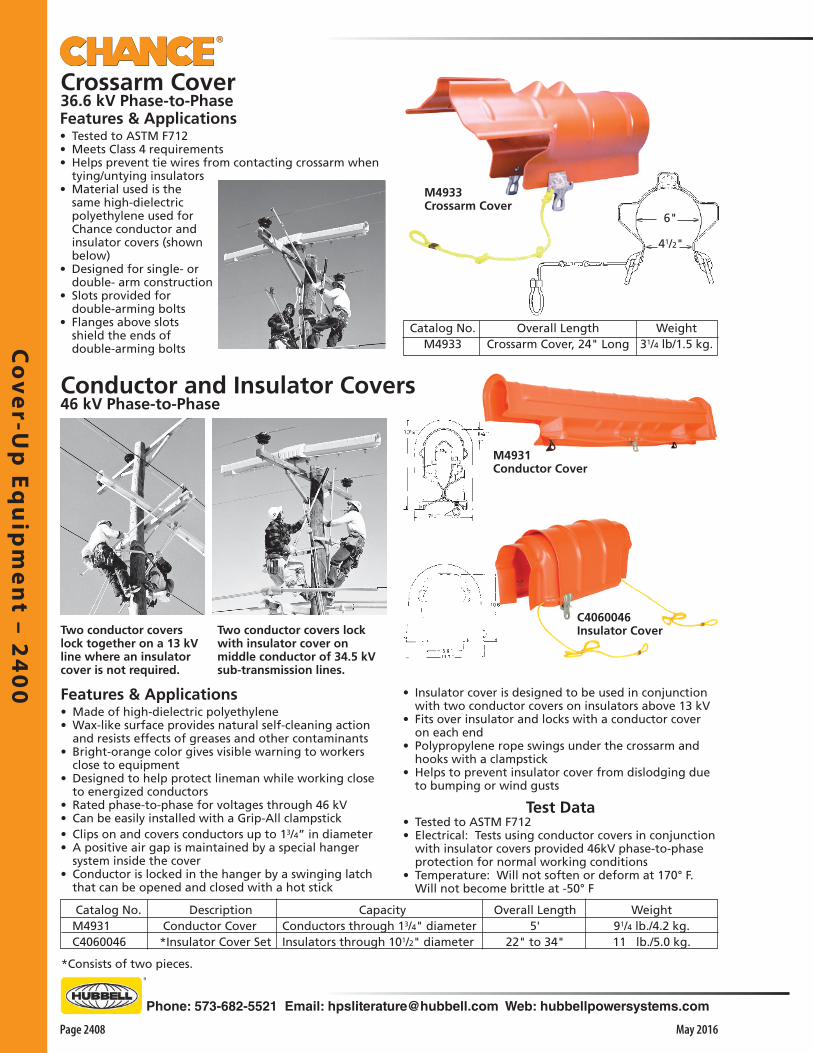
Co
ver-U
p E
qu
ipm
en
t – 24
00
Page 2408 May 2016
Phone: 573-682-5521 Email: [email protected] Web: hubbellpowersystems.com
CapacityConductors through 13/4" diameterInsulators through 101/2" diameter
Features & Applications• Made of high-dielectric polyethylene• Wax-like surface provides natural self-cleaning action
and resists effects of greases and other contaminants• Bright-orange color gives visible warning to workers
close to equipment• Designed to help protect lineman while working close
to energized conductors• Rated phase-to-phase for voltages through 46 kV • Can be easily installed with a Grip-All clampstick• Clips on and covers conductors up to 13/4” in diameter • A positive air gap is maintained by a special hanger
system inside the cover• Conductor is locked in the hanger by a swinging latch
that can be opened and closed with a hot stick
Test Data• Tested to ASTM F712• Electrical: Tests using conductor covers in conjunction
with insulator covers provided 46kV phase-to-phase protection for normal working conditions
• Temperature: Will not soften or deform at 170° F. Will not become brittle at -50° F
Weight91/4 lb./4.2 kg.11 lb./5.0 kg.
Overall Length5'
22" to 34"
Catalog No.M4931C4060046
Description Conductor Cover*Insulator Cover Set
*Consists of two pieces.
Two conductor covers lock together on a 13 kV line where an insulator cover is not required.
Two conductor covers lock with insulator cover on middle conductor of 34.5 kV sub-transmission lines.
M4931Conductor Cover
Conductor and Insulator Covers46 kV Phase-to-Phase
• Insulator cover is designed to be used in conjunction with two conductor covers on insulators above 13 kV
• Fits over insulator and locks with a conductor cover on each end
• Polypropylene rope swings under the crossarm and hooks with a clampstick
• Helps to prevent insulator cover from dislodging due to bumping or wind gusts
Features & Applications• Tested to ASTM F712• Meets Class 4 requirements• Helps prevent tie wires from contacting crossarm when
tying/untying insulators• Material used is the
same high-dielectric polyethylene used for Chance conductor and insulator covers (shown below)
• Designed for single- or double- arm construction
• Slots provided for double-arming bolts
• Flanges above slots shield the ends of double-arming bolts
Catalog No.M4933
Weight31/4 lb/1.5 kg.
Overall LengthCrossarm Cover, 24" Long
Crossarm Cover36.6 kV Phase-to-Phase
M4933Crossarm Cover
6"
41/2"
C4060046Insulator Cover

Co
ver-
Up
Eq
uip
me
nt
– 2
40
0
Phone: 573-682-5521 Email: [email protected] Web: hubbellpowersystems.com
Page 2409May 2016
Rubber Insulating BlanketsFeatures & Applications• Meet ASTM Standard Specification D1048• For Class 4 Type II (ozone-resistant)
Performance-Designed Material• Protect workers from accidental contact with
energized components during line maintenance• Made of ozone/corona-resistant elastomer• Offer excellent performance properties with ASTM
Standard Specification D1048• Special formulation exhibits superior resistance to
long-term aging/checking • Will retain its high-visibility orange color
Versatile Protection, Maximum Rating• Flexible to cover many irregular shapes• Used with conductor covers (flexible or rigid) on
deadends, apparatus, secondary racks, poletop pins and crossarms
• Blankets may be used in applications which require lower class or type
• Designed with perimeter eyelets to accept Chance button C4060532 and most other buttons existing in the field
• 1.5"-diameter center hole on slotted blankets will easily fit around common hardware
• Class 4 • Proof Tested at 40kV AC rms • Maximum Use: 36kV Ø-Ø
Solid Blankets
Accessories
Hot Stick Clamp
Catalog No.
C4060531
Eyes and special
handle shape for
easy placement
by clampstick
Weight81/4 lb. (3.7 kg.)3 lb. (0.45kg)
Description36" x 36", 28 eyelets22" x 22", 12 eyelets
Catalog No.C4060348
PSC4060708
Slotted Blankets
Ordering Information
*For details, see Catalog Section 2500.
DescriptionClamp Pin, Rubber GloveClamp Pin, Hot StickButton, Rubber Blanket*Storage Cannister, no handle*Storage Cannister w/handle
Cat. No.C4060530C4060531C4060532C4032998C4032999
Weight1 lb. (.45 kg.)1 lb. (.45 kg.)
1/8 lb. (.06 kg.)6 lb. (2.7 kg.)
75/8 lb. (3.43 kg.)
Description22" x 22", 28 eyelets36" x 36", 6 eyelets
Catalog No.PSC13C4060346
Weight2.7 lb. (3.7 kg)81/4 lb. (3.7 kg.)
Rubber Glove
Clamp
Cat. No. C4060530
Special handle
shape also fits
clampstick for easy
placement
Cat. No. C4060532

Co
ver-U
p E
qu
ipm
en
t – 24
00
Page 2410 May 2016
Phone: 573-682-5521 Email: [email protected] Web: hubbellpowersystems.com
Class 2 Rubber Insulating Blankets
Flexible Rubber Cutout Covers
• Class 2 • Type I • Proof Tested at 20kV AC rms • Maximum Use: 17kV Ø-Ø
BLACK Solid BlanketsWeight
61/4 lb. (2.8 kg.)Description
36" x 36", 6 eyeletsCatalog No.PSC4060607
Ordering Information
Features & Applications• Meet ASTM Standard Specification D1048• For Class 2 (17kV Ø-Ø maximum use)• Type I (non-ozone-resistant)
Performance-Designed Material• Protect workers from accidental contact with
energized components during line maintenance• Made of natural rubber• Offer excellent performance properties in accordance
with ASTM Standard Specification D1048• Special formulation will retain its excellent physical
properties
Versatile Protection, Maximum Rating• Flexible to cover many irregular shapes• Used with conductor covers (flexible or rigid) on
deadends, apparatus, secondary racks, poletop pins and crossarms
• Blankets may be used in applications through 17kV phase-to-phase maximum
• Designed with perimeter eyelets to accept Chance button C4060532 and most other buttons existing in the field
• For details on buttons, clamp pins and storage cannisters, see page 2409
Features & Applications• For use on overhead cutouts• Conforms to ASTM D1049• For Class 2 (17kV Ø-Ø maximum use) and Class 4 (36kV Ø-Ø maximum use)• Type II (ozone resistant)
Catalog No. Class Dimensions Weight
PSC24CC 2 24" x 15" x 3.75" 7.0 lb.
PSC30CC 4 30" x 20" x 9" 11.0 lb.

Co
ver-
Up
Eq
uip
me
nt
– 2
40
0
Phone: 573-682-5521 Email: [email protected] Web: hubbellpowersystems.com
Page 2411May 2016
Features & Applications• Lightweight - 50% the weight of similar rubber hose• Rated 8.4kV phase to ground / 15kV guarded phase to guarded phase. (Brush contact only)• Meets ASTM F712 Class 2• Available in 5 or 6 ft models• High visibility orange color• Secure locking feature / male and female connecting ends• Larger ID than traditional class 2 rubber hoses (1.75 in. compared to 1.25 in.)
Note: This product has a black inner layer and orange outer layer of material.
If either layer should wear such that the color from the opposite layer is visible, the product must be taken out of service immediately.
Design tested per ASTM specification F712
Keep product clean and dry, moisture and contaminants reduce the dielectric properties. Cover may be cleaned with Chance® Moisture Eater II (see Catalog Section 2500).
Catalog No. Description Weight
PSC40606165' Class 2 Conductor
Cover1.7 lb./0.77 kg.
PSC40606176' Class 2 Conductor
Cover2.0 lb. / 0.90 kg
Class 2 Temporary Conductor Cover15kV Guarded Phase-to-Guarded Phase
Cover will couple with major brands of rubber line hose and insulator covers.(C4060182 Insulator Cover shown on page 2403)
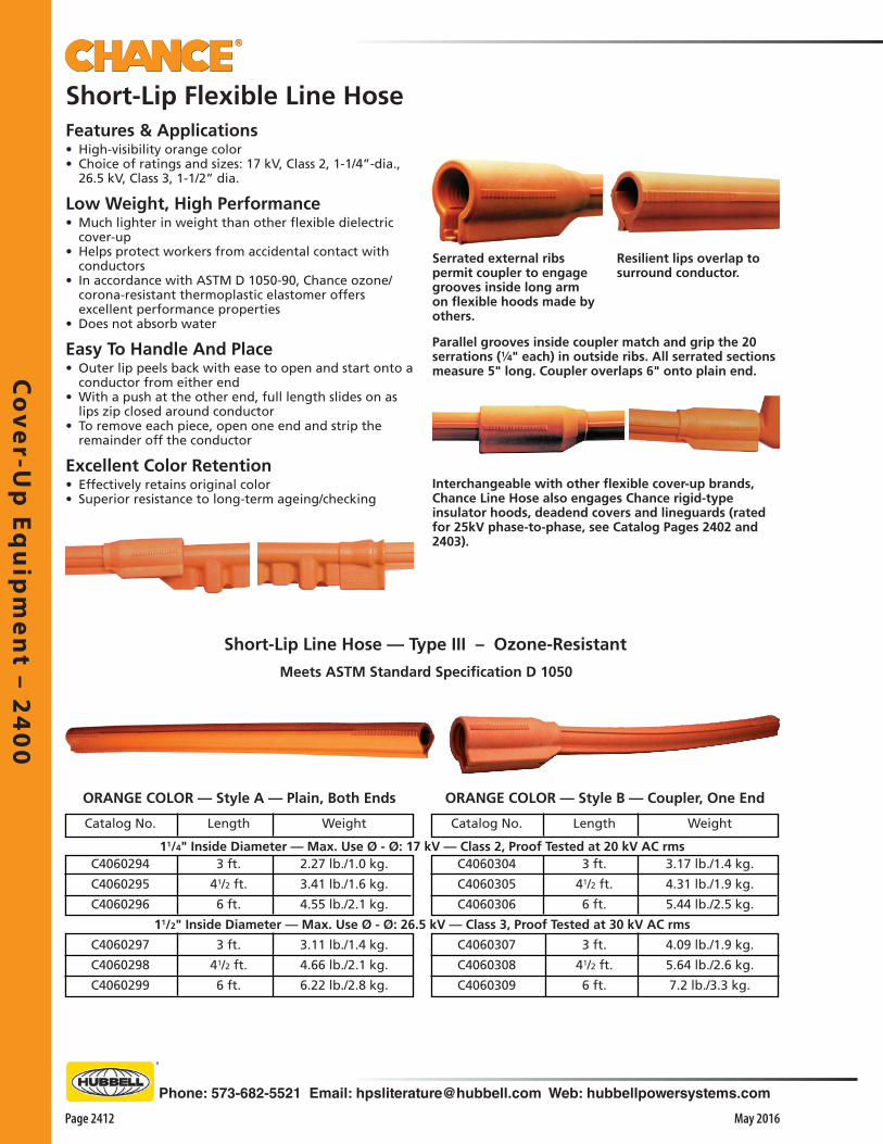
Co
ver-U
p E
qu
ipm
en
t – 24
00
Page 2412 May 2016
Phone: 573-682-5521 Email: [email protected] Web: hubbellpowersystems.com
Meets ASTM Standard Specification D 1050
Short-Lip Line Hose — Type III – Ozone-Resistant
Weight
3.17 lb./1.4 kg.
4.31 lb./1.9 kg.
5.44 lb./2.5 kg.
4.09 lb./1.9 kg.
5.64 lb./2.6 kg.
7.2 lb./3.3 kg.
11/4" Inside Diameter — Max. Use Ø - Ø: 17 kV — Class 2, Proof Tested at 20 kV AC rms
Length
3 ft.
41/2 ft.
6 ft.
3 ft.
41/2 ft.
6 ft.
Catalog No.
C4060294
C4060295
C4060296
C4060297
C4060298
C4060299
Weight
2.27 lb./1.0 kg.
3.41 lb./1.6 kg.
4.55 lb./2.1 kg.
3.11 lb./1.4 kg.
4.66 lb./2.1 kg.
6.22 lb./2.8 kg.
ORANGE COLOR — Style A — Plain, Both Ends ORANGE COLOR — Style B — Coupler, One End
Length
3 ft.
41/2 ft.
6 ft.
3 ft.
41/2 ft.
6 ft.
Catalog No.
C4060304
C4060305
C4060306
C4060307
C4060308
C4060309
11/2" Inside Diameter — Max. Use Ø - Ø: 26.5 kV — Class 3, Proof Tested at 30 kV AC rms
Interchangeable with other flexible cover-up brands, Chance Line Hose also engages Chance rigid-type insulator hoods, deadend covers and lineguards (rated for 25kV phase-to-phase, see Catalog Pages 2402 and 2403).
Parallel grooves inside coupler match and grip the 20 serrations (1⁄4" each) in outside ribs. All serrated sections measure 5" long. Coupler overlaps 6" onto plain end.
Serrated external ribs permit coupler to engage grooves inside long arm on flexible hoods made by others.
Features & Applications• High-visibility orange color• Choice of ratings and sizes: 17 kV, Class 2, 1-1/4”-dia.,
26.5 kV, Class 3, 1-1/2” dia.
Low Weight, High Performance• Much lighter in weight than other flexible dielectric
cover-up• Helps protect workers from accidental contact with
conductors• In accordance with ASTM D 1050-90, Chance ozone/
corona-resistant thermoplastic elastomer offers excellent performance properties
• Does not absorb water
Easy To Handle And Place• Outer lip peels back with ease to open and start onto a
conductor from either end• With a push at the other end, full length slides on as
lips zip closed around conductor• To remove each piece, open one end and strip the
remainder off the conductor
Excellent Color Retention• Effectively retains original color• Superior resistance to long-term ageing/checking
Short-Lip Flexible Line Hose
Resilient lips overlap to surround conductor.

Co
ver-
Up
Eq
uip
me
nt
– 2
40
0
Phone: 573-682-5521 Email: [email protected] Web: hubbellpowersystems.com
Page 2413May 2016
Ordering InformationMeets ASTM Standard Specification D 1050
for Type III — Ozone ResistantClass 4, Proof Tested at 40 kV AC rmsMaximum Use, Phase-to-Phase: 36 kV
Low Weight, High Performance• As much as 25% lighter in weight than other Class 4
flexible cover-up• Helps protect workers from accidental contact with
conductors• In accordance with ASTM D 1050-90, Chance ozone/
corona-resistant thermoplastic elastomer offers excellent performance properties
• Retains high-visibility orange color• Special formulation exhibits superior resistance to long-
term aging/checking• Does not absorb water• Dielectric cover-up system consists of a separate coupler
and three hose lengths• This permits hoses to join to cover straight runs or to
flex to fit contours at bends and angles• Shorter sections may be cut on site from standard
lengths to custom-fit taps, jumpers and like wires
Long lips provide flashover distance to permit use on systems through 36 kV phase-to-phase.
Interchangeable with other brands of extended-lip hose, Chance Class 4 flexible cover-up joins with separate coupler.
Parallel grooves inside the coupler match and grip the 28 serrations (1⁄4" each) in Class 4 hose ribs. All serrated sections on Class 4 hose measure 7 inches long. Coupler overlaps 51⁄4 inches onto hose when engaged.
Catalog No.C4060341C4060342C4060343
Coupler also can join sections Chance 11⁄2"-diameter short-lip Class 3 hose for 26.5 kV phase-to-phase maximum use.
Easy To Handle And Place• Rubber gloves or hot-line tools may be used to apply
Chance Class 4 Line Hose• Lightweight, balanced material composition adds
pliability• Easy to put on, couple, relocate and remove, even
when wearing leather protectors over rubber gloves• Outer lip peels back with ease to open and start onto a
conductor from either end• With a push at the other end, full length slides on as
lips zip closed around conductor• So hose can insert into coupler, Chance bevel-cuts the
serrations on the side ribs• Vertical serrations resist withdrawal from the coupler• Two or more coupled sections stay joined when drawn
along on the conductor and positioned as a unit• Rubber-like material slides readily by hand yet resists
creep or slippage when placed• To remove each piece, open one end and strip
remainder off conductor
For installation by hot-line tools, design provides a flat area debossed full length to accept special applicator tools (see Catalog Section 2100).
Extended-Lip Flexible Line Hose36 kV, Class 4, 11⁄2"-diameter
Coupler
101/2 inchesC4060340 11/2 lb./0.7 kg.
Hose — Style C - Plain, Both ends — 11/2" I.D.
Length3 feet
41/2 feet6 feet
Weight41/2 lb./2 kg.63/4 lb./3 kg.9 lb./4 kg.

Co
ver-U
p E
qu
ipm
en
t – 24
00
Page 2414 May 2016
Phone: 573-682-5521 Email: [email protected] Web: hubbellpowersystems.com
Warning: The ArcSafe Suppression Blanket has been developed by leading industrial and safety engineers, and Workrite believes it to be the best available for its intended purpose. However, explosions and blasts due to electrical faulting may be erratic and unpredictable, and we do not claim that ArcSafe offers total protection. It improves the chances of a worker’s survivability in a life-threatening incident. In addition, ArcSafe is NOT classified as “Electrically Insulated” and must NEVER be used as such. Before using this or any protective product, please avail yourself of all information concerning its use.
Tested Successfully At 42,000 Amps Fault Current• ArcSafe was subjected to fault-current testing at
Chance laboratories• ArcSafe was placed over a small section of 2/0 copper
cable that was faulted to ground, simulating a cable or splice failure
• Maximum fault current generated was 42,432 amps for a duration of 13 cycles
• Other than black deposits, ArcSafe experienced no damage and provided total fault-blast containment
Heavy-Duty Protection In Lightweight Package• Two synthetic fabrics are combined in the ArcSafe™
Suppression Blanket from Workrite (Your Uniform for Life Company)
• Both space-age fabrics are aramid-fiber types• Inner layer is Kevlar® and the outer is NOMEX® III• Kevlar is the same aramid fiber used in combat helmets
and body armor• Flame-resistant NOMEX III is used as cover to protect
Kevlar core from ultraviolet degradation• Blankets consist of thin layers and offer unrivaled
portability• Extremely easy to maneuver in confined spaces• Weigh only 1/5 lb. per square foot ( 5/8 kg. per m2 )
Kevlar ® and NOMEX ® are DuPont registered trademarks for its aramid fibers. Only DuPont makes Kevlar and NOMEX.
Size
4 ft. x 5 ft. (1.2 x 1.5 meters)
4 ft. x 8 ft. (1.2 x 2.4 meters)
ArcSafe™ Arc-Suppression Blankets
Applications and Conforming to OSHA Law• When draped or loosely wrapped over a defective
cable or splice, ArcSafe provides a protective shield for exposed workers
• Velcro® straps sewn on the back help keep ArcSafe where positioned
• ArcSafe blankets meet or exceed OSHA requirements for manhole protection
• Beginning in 1991, OSHA mandates that if cables in manholes appear defective “. . . and cannot be de-energized due to service load conditions, employees may enter the manhole provided they are protected from the possible effects of a failure by shields or other devices that are capable of containing the adverse effects of a fault in the joint.” [29 CFR Part 1910.269(t)(7)]
Arc-Suppression Blankets • for shields against electrical fault blasts(Not Electrically Insulated)
Weight
4 lb./1.8 kg.
61/2 lb./2.9 kg.
Catalog No.
C4060452
C4060453

Co
ver-
Up
Eq
uip
me
nt
– 2
40
0
Phone: 573-682-5521 Email: [email protected] Web: hubbellpowersystems.com
Page 2415May 2016
Overhead Switch Barrier Cover all three phases
Features• Designed to fit 12kV or 25kV disconnect switches• Compatible with 30” and 36” spacing• Puncture Strength - 300 V/mil (approx .25 in thickness)• Provided with Gripall adapters (2 positions)• High visibility orange color• Provided with yellow vinyl bag• Available as individual item or 2 per kit
The Barrier Board is designed to cover all three phases of a 12kV or 25kV horizontal disconnect switch in a substation. The Barrier Board acts as a physical barrier between the open switch and the bus. It lifts easily with shotgun sticks for proper placement. The barrier covers the lower blade portion of the disconnect switch so that work can be performed on the bottom side of the switch.
Catalog No. Description Dimensions Weight
PSC4060648 Board Barrier 84" x 19" x 5" 17 lb. / 7.7 kg.
PSC4060651 Kit (2 Barriers and Bag) 84" x 19" x 5" 35 lb. / 15.9 kg.
PSC4060650 Bag 86" with handles 1 lb. / .45 kg.


Inst
rum
en
ts a
nd
Me
ters
– 2
45
0
Phone: 573-682-5521 Email: [email protected] Web: hubbellpowersystems.com
Page 2451May 2016
Inst
rum
en
ts a
nd
Me
ters
–2
45
0
Instrumentsand Meters
Catalog 2450 May 2016

Instru
me
nts a
nd
Me
ters – 2
45
0
Page 2452 May 2016
Phone: 573-682-5521 Email: [email protected] Web: hubbellpowersystems.com
Features & Applications• Determine phase relationships and approximate
voltage, line-to-line or line-to-ground• Feature two fiberglass poles with end fittings threaded
for interchangeable probes• Probe fittings couple with a high-impedance
component encased in each pole• To complete test circuit, a 22 ft. length of insulated
flexible cable stores on reel affixed to one pole and connects to voltmeter on other pole
• Simple to operate, tester poles first attach to two 6 ft. Epoxiglas® insulating universal handles (included in each kit for proper working clearances)
• Probes can be brought into contact with conductors appropriate for the meter to read phase-to-phase or phase-to-ground voltage
Single-Range Units• For convenience on different systems, toggle
on dual-range units can switch calibration between two scales on meter face
• Can improve readability for low-end values on Hi scale
• Switched to Lo range, those values deflect needle more to give more finite readings
• To check instrument before and after each use, test-point jack in front of meter accepts plug from Phasing Meter Tester, next page
For URD testing, see Hi-Pot Adapters (page 2458) and Adapters for Elbows and Bushings (page 2467).
Accessories
Phasing Testers
Dual-Range Meters 1 & 16 kV Unit 5 & 16 kV Unit
• for †Distribution Circuits
Distribution Phasing TestersSingle-Range Units
Catalog No.H1876H18761
T4032261H18767
Description†16 kV Tester Kit*†16 kV Tester Hook Probes,Case and Manual25 kV Tester Kit*40 kV Tester, Hook Probes,Case and Manual
Weight271⁄2 lb./12.4 kg.23 lb./10.4 kg.
271⁄2 lb./12.4 kg.23 lb./10.4 kg.
Dual-Range UnitsT4030786T4032311T4032398
1 & †16 kV Tester Kit*5 & †16 kV Tester Kit*5 & †16 kV Tester Only
271⁄2 lb./12.4 kg.271⁄2 lb./12.4 kg.23 lb./10.4 kg.
H17601
P6436H18763H18766PH18766SH18766H18765
13⁄4 lb./0.7 kg.
1 lb./0.45 kg.2 lb./0.9 kg.1⁄4 lb./0.1 kg.1⁄4 lb./0.1 kg.
1⁄8 lb./0.05 kg.1⁄8 lb./0.05 kg.
Universal Pole 11⁄4" x 6'— Two NeededBag for Two PolesCase only for TesterPigtail Hook ProbeShepherd Hook ProbeStraight ProbeAngle Probe
H18762
H18764
P6242P6244
Pair of Extension Resistorsfor up to 80 kV (32" long)Pair of Extension Resistorsfor up to 48 kV (21" long)Bag for 48 kV ResistorsBag for 80 kV Resistors
6 lb./2.7 kg.
4 lb./1.8 kg.
1 lb./0.45 kg.11⁄4 lb./0.56 kg.
Extension Resistors, as installed▲
H18765
*Each kit includes two 6’ x 1-1⁄4"-dia. Epoxiglas® universal handles with storage bag, tester, hook probes, case and instruction manual
†To extend any Chance 16 kV Phasing Tester for 48 or 80 kV applications, optional Extension Resistors simply thread on in the field
Extension Resistors

Inst
rum
en
ts a
nd
Me
ters
– 2
45
0
Phone: 573-682-5521 Email: [email protected] Web: hubbellpowersystems.com
Page 2453May 2016
Features & Applications• Versatile for popular distribution voltages• Facilitates testing both underground and overhead
systems• Basic functions include identifying phases and reading
line-to-line or line-to-ground voltage• URD accessories in the Kit also permit cable-fault
detection• Consists of high-impedance components encased in
two fiberglass poles with threaded end fittings for overhead probes or URD adapters
• A 22 ft.-long cable connects to voltmeter pole and stores on reel pole
• To detect faults on URD cable, Hi-Pot Adapter converts AC source to DC pulse
• Effective field method quickly tests new, repaired or suspect spans
Ordering Information
• To check instrument before and after use, Phasing Meter Tester lead plugs into test-point jack by meter
• Other lead clips onto each probe
• Switch on Meter Tester reverses polarity for thorough field-checking procedure
• Complete instructions included
• For convenience on different systems, toggle on meter housing can switch calibration between the two scales on meter face
• Improves readability for low-end values on the Hi (16 kV) scale
• Switched to Lo (5 kV) range, values deflect needle more to give more finite readings
Complete Kit includes:Two 6’ x 1-1/4"-dia. Epoxiglas® universal handles with storage bag, tester with instruction manual and two probes (shepherd hook and pigtail hook) in padded carrying case, plus four items below
TwoBushing
AdaptersOneDCHi-PotAdapter& Instructions
URD Accessories in Kit
PhasingMeterTester (withbattery)in Kit
Catalog No. Description WeightT4032557 Phasing Tester Kit 311/2 lb./14.2 kg. with 16kV Hi-Pot Adapter, 2 URD Bushing Adapters, Phasing Meter Tester
Distribution Phasing Tester Kitfor Overhead and Underground SystemsDual Range: 5kV & 16kV Scales
C4031762T4030857
H17601 HotstickP6436 BagC4030838

Instru
me
nts a
nd
Me
ters – 2
45
0
Page 2454 May 2016
Phone: 573-682-5521 Email: [email protected] Web: hubbellpowersystems.com
• Large direct-reading display • Determine phase relationships and approximate
voltage, line-to-line or line-to-ground• Each tester consists of two fiberglass poles with end
fittings threaded for interchangeable probes• Probe fittings couple with high-impedance component
encased in each pole• To complete the test circuit, a 22 ft. length of insulated
flexible cable stores on the reel affixed to one pole and connects to electronic display module on other pole
• Simple to operate, tester attaches to two 6 ft. Epoxiglas® insulating universal handles (included in each kit for proper working clearances)
• Probes can be brought into contact with conductors for tester to display phase-to-phase or phase-to-ground voltage
• Pushbutton controls permit easy selection of options for display Backlight and Hold features
• When not in use, the unit’s Sleep mode automatically conserves the battery
Hi-Pot & Higher Voltage Test Accessories• For underground cable hi-pot testing• 16 kV Kit C4033402 includes a DC Hi-Pot Adapter• Hi-pot testing cannot be done with the 40 kV unit• Both the 16 kV and 40 kV Kits include underground
bushing and elbow adapters
Digital Phasing Testers
Large direct display with backlight and hold features
• For overhead subtransmission systems, Extension Resistors are available as accessories specific to each Digital Phasing Tester
Available as accessories, Extension Resis-tors simply thread onto the Digital Phasing Tester in the field.
Each Basic Unit Digital Phasing Tester includes the tester unit with meter and reel poles, a pigtail hook probe, a shepherd hook probe, instruction manual and hard shell padded case.
16kV Digital Phasing Tester Basic Unit Cat. No. C4033369 (14 lb./6.36 kg.)
40kV Digital Phasing Tester Basic Unit Cat. No. C4033370 (141⁄2 lb./6.6 kg.) Hi-pot testing cannot be done with the 40kV unit.
Basic Units:
See next page for Tester Kits.
• 16kV and 40kV models, plus 80kV extensions• For Overhead & UndergroundDisplay With Backlight, Hold and Sleep Modes
Extension Resistors as installed for testing up to 80kV ➧

Inst
rum
en
ts a
nd
Me
ters
– 2
45
0
Phone: 573-682-5521 Email: [email protected] Web: hubbellpowersystems.com
Page 2455May 2016
Pair of Extension Resistorsfor up to 80 kV (32" long)Pair of Extension Resistorsfor up to 48 kV (21" long)Bag for 48 kV ResistorsBag for H1876-2 80 kV Resistors
Digital Phasing Testers• For Overhead & Underground
Easy Verification Test• To check instrument before and after use, Phasing Meter Tester lead plugs
into test-point jack by meter• Other lead clips onto each probe. Switch on Meter Tester• Tester reverses polarity for thorough, easy field-checking procedure• Complete instructions are included with each unit
TwoT4030857
BushingAdapters
C4031762DC Hi-PotAdapter
C4030838Phasing Meter Tester
16kV Digital Phasing Tester KitCat. No. C4033402 (221⁄2 lb./10.2 kg.)
T4030856ElbowAdapter
Extension Resistors for 16kV Digital Phasing Tester
TwoT4030857
BushingAdapters
C4030838Phasing Meter Tester
40kV Digital Phasing Tester KitCat. No. C4033403 (211⁄2 lb./9.7 kg.)
Hi-pot testing cannot be done with the 40kV unit.
Two H176016-ft. x 11⁄4"-dia. Epoxiglas® universal poles in P6436 Bag
T4030856ElbowAdapter
C403-3369Digital Phasing Tester
C4033370Digital Phasing Tester
H18762
H18764
P6242P6244
6 lb./2.7 kg.
4 lb./1.8 kg.
1 lb./0.45 kg.11⁄4 lb./0.56 kg.
Extension Resistors for 40kV Digital Phasing Tester
C4033371
P6242
Pair of Extension Resistorsfor up to 80 kV (21" long)Bag for C403-3371 80 kV Resistors
4 lb./1.8 kg.
1 lb./0.45 kg.
NOTICE: Use ONLY the Extension Resistors specified for each Digital Phasing Tester as listed on this page. Extension Resistors are NOT interchangeable between 16kV and 40kV Digital Phasing Testers.
Two H176016-ft. x 11⁄4"-dia. Epoxiglas® universal poles in P643-6 Bag
H18766SH18766
Shepherd Hook ProbeStraight Probe
Accessories1⁄4 lb./0.1 kg.
1⁄8 lb./0.05 kg.

Instru
me
nts a
nd
Me
ters – 2
45
0
Page 2456 May 2016
Phone: 573-682-5521 Email: [email protected] Web: hubbellpowersystems.com
Digital Phasing Testersfor Transmission Circuits• Two models for up to 120 kV or 240 kVFeatures & Applications• Easily determine phase relationships• Read approximate voltage (line-to-line or line-to-
ground) on transmission circuits• Feature two high-impedance components
encapsulated in fiberglass poles, each with an end fitting threaded for interchangeable hook probes
• 22-ft.-long insulated flexible cable from voltmeter stores on reel on other pole
• Two complete kits offer a choice of voltage ranges for specific system applications
• Each kit includes a pair of 1-1⁄2"-dia. insulated handles for proper working clearances
• Individual items listed in each kit’s bill of materials may be ordered separately by reference numbers given
Large direct display with backlight and hold features
10 - 120 kVDigital Phasing Tester
40 - 240 kVDigital Phasing Tester
C403045996" Epoxiglas®
Handles
Catalog No.PSE4033473
DescriptionPhasing Meter Tester with leads
and battery
Weight1 lb./0.45 kg.
Phasing Meter Testerfor Digital Transmission Phasing Testers above
Catalog No.
PSC4033465
PSC4033466
Description
10 - 120 kV Phasing Tester Kit:(1) Instruction Manual(1) PSE4033454 Phasing Tester (64" long)(2) C4030459 Handles (96")(1) P6218 Bag for Handles (108")(1) C4030460 Bag for Tester
40 - 240 kV Phasing Tester Kit:(1) Instruction Manual(1) PSE4033455 Phasing Tester (102" long)(2) C4030459 Handles (96")(1) P6218 Bag for Handles (108")(1) C4030464 Bag for Tester
Weight
39 lb./17.7 kg.
221⁄2 lb.
10 lb.31⁄2 lb.3 lb.
60 lb./27.2 kg.
431⁄2 lb.
10 lb.31⁄2 lb.3 lb.
Ordering Information
PSE4033473Phasing Meter Tester
for Digital Transmission Phasing Testers
Features & Applications• Allows line personnel to determine, in the field, the
operating condition of Chance instruments above• Uses each instrument’s own meter to display its
operating condition• Tester plugs into jack on instrument • Meter readings are noted when tester’s clip is
contacted to each of instrument’s two terminals and tester’s polarity switch is in both of its positions
• Instrument is in proper working order if all four readings are within two units
• Pulling plug from jack automatically disconnects tester’s battery
• 9-volt battery, furnished, usually lasts one year and is easily replaced
• Tester’s durable and compact fiberglass housing will withstand abuse of field applications

Inst
rum
en
ts a
nd
Me
ters
– 2
45
0
Phone: 573-682-5521 Email: [email protected] Web: hubbellpowersystems.com
Page 2457May 2016
C403045996" Epoxiglas®
Handles
Catalog No.C4030838
DescriptionTool with leads and battery
Weight1 lb./0.45 kg.
*Phasing Voltmeter Tester is designed for checking distribution-series voltmeters with extensions for 80 kV and below.
Phasing Meter Testerfor Phasing Testers* (page 2452-2455),Phase Rotation Testers (page 2459),and Energized Insulator Testers (page 2466).Features & Applications• Allows line personnel to determine, in the field, the
operating condition of Chance instruments above• Uses each instrument’s own meter to display its
operating condition• Tester plugs into jack on instrument • Meter readings are noted when tester’s clip is
contacted to each of instrument’s two terminals and tester’s polarity switch is in both of its positions
• Instrument is in proper working order if all four readings are within two units
• Pulling plug from jack automatically disconnects tester’s battery
• 9-volt battery, furnished, usually lasts one year and is easily replaced
• Tester’s durable and compact fiberglass housing will withstand abuse of field applications
Three kits for Transmission CircuitsFeatures & Applications• Determine phase relationships• Read approximate voltage (line-to-line or line-to-
ground) on transmission circuits• Features high-impedance components encapsulated in
fiberglass poles, each with an end fitting threaded for interchangeable hook probes
• 22' long insulated flexible cable from voltmeter stores on reel on other pole
• Three complete kits offer a choice of voltage ranges for specific system applications. Each kit includes a pair of 1-1⁄4"-dia. insulated handles for proper working clearances
• Individual items listed in each kit’s bill of materials may be ordered separately by reference numbers given
AnalogTransmission
Phasing Tester
Catalog No.
C4030457
C4030458
T4032781
Description
69-120 kV Phasing Tester Kit:(1) Instruction Manual(1) E4030498 Tester (62" long)(2) C4030459 Handles (96")(1) P6218 Bag for Handles (108")(1) C4030460 Bag for Tester
69-161 kV Phasing Tester Kit:(1) Instruction Manual(1) E4030499 Tester (75" long)(2) C4030459 Handles (96")(1) P6218 Bag for Handles (108")(1) C4030464 Bag for Tester
69-240 kV Phasing Tester Kit:(1) Instruction Manual(1) E4032780 Tester (98" long)(2) C4030459 Handles (96")(1) P6218 Bag for Handles (108")(1) C4030464 Bag for Tester
Weight
39 lb./17.7 kg.
221⁄2 lb.10 lb.31⁄2 lb.3 lb.
44 lb./20 kg.
271⁄2 lb.10 lb.31⁄2 lb.3 lb.
60 lb./27.2 kg.
431⁄2 lb.10 lb.31⁄2 lb.3 lb.
Ordering Information
C4030838
Analog Phasing Testers

Instru
me
nts a
nd
Me
ters – 2
45
0
Page 2458 May 2016
Phone: 573-682-5521 Email: [email protected] Web: hubbellpowersystems.com
• For testing and subsequent discharging, brass female fitting at smaller end accepts Chance Elbow Adapters or Bushing Adapters for 15 through 35 kV (page 2455)
• Illustrated instruction booklet is included• Units contain high-voltage rectifiers
encapsulated in Chance orange 1-1⁄4" and 1-1⁄2" dia. Epoxiglas® housings
D.C. Hi-Pot URD Test AdaptersFeatures & Applications• Work with Chance Phasing Tool H1876 (page 2452) for
metered readout• For quick, reliable fault detection on underground
cables• Two units are available for phase-to-phase system
voltages up to 16 kV or 35 kV• By converting AC source voltage to a rectified half-
wave, these adapters permit testing of cables with a potential level equal to peak source voltage
• Field-effective method proves especially beneficial for: o Testing new cable before initial energizing o Testing repaired cable before re-energizing o Testing suspect cable spans for faults• Brass male fitting inside larger end threads onto the
meter probe of phasing tool
Hi-Pot Adapters measure only 13" in length for 35 kV unit, and 10" for 16 kV unit, far right.
Catalog No.C4031762C4031763
Description*16 kV Hi-Pot Adapter*35 kV Hi-Pot Adapter
Weight, each1 lb./0.45 kg.
11⁄4 lb./0.57 kg.*Maximum phase-to-phase system voltage.
EnergizedSwitch or
Transformer
Bushing Adapter
DC Hi-PotAdapter
Feed-ThruUniversal Sticks
Bushing Adapter Reel Stick of Phasing Tester
EnergizedSwitch or
Transformer
DisconnectBuriedPrimaryCable
Meter Stick of Phasing Tester
Two Kits for Transmission CircuitsFeatures & Applications• With digital readout and hold function• Otherwise perform same functions as analog testers on
page 2457
Phasing Meter Testerfor Digital Transmission Phasing Testers aboveFeatures & Applications• Exclusively for use with only Digital Phasing Testers
above• Otherwise the functional equivalent of Phasing Meter
Tester on page 2457PSE4033473
Phasing Meter Tester for Digital Transmission
Phasing Testers
Large direct display with backlight and hold features
10 - 120 kVDigital Transmission Phasing Tester
40 - 240 kVDigital Transmission Phasing Tester
Catalog No.
PSC4033465
PSC4033466
Description
10 - 120 kV Phasing Tester Kit:(1) Instruction Manual(1) PSE4033454 Phasing Tester (64" long)(2) C4030459 Handles (96")(1) P6218 Bag for Handles (108")(1) C4030460 Bag for Tester(1) PSE40333473 Meter Tester
40 - 240 kV Phasing Tester Kit:(1) Instruction Manual(1) PSE4033455 Phasing Tester (102" long)(2) C4030459 Handles (96")(1) P6218 Bag for Handles (108")(1) C4030464 Bag for Tester(1) PSE40333473 Meter Tester
Weight
40 lb./18.2 kg.
221⁄2 lb.
10 lb.31⁄2 lb.3 lb.1 lb.
61 lb./27.7 kg.
431⁄2 lb.
10 lb.31⁄2 lb.3 lb.1 lb.
Digital Phasing Testers

Inst
rum
en
ts a
nd
Me
ters
– 2
45
0
Phone: 573-682-5521 Email: [email protected] Web: hubbellpowersystems.com
Page 2459May 2016
Phase Rotation TesterFeatures & Applications• To determine the correct phase-rotation relationship,
this portable instrument features construction similar to Phasing Tester H18761, page 2452
• An additional grounding circuit on the Phase Rotation Tester sets it apart for phase rotation testing
• Tester consists of two fiberglass poles with end fittings threaded for interchangeable probes
• Probe fittings couple with a high-impedance component encased in each pole
• 22 ft. length of insulated cable stores on reel affixed to one pole and connects to voltmeter on other pole
• Grounding terminal below the meter permits connection to a known ground for proper operation
• To check instrument before and after each use, a test-point jack in front of meter accepts the plug from Phasing Meter Tester C4030838, shown on page 2457
Application Range• Attaches to Epoxiglas®
Universal Poles of proper length for voltage being worked
• Meter displays up to 16 kV alone
• Can also read circuits through 80 kV with the thread-on Extension Resistors
Weight23 lb./10.4 kg.6 lb./2.7 kg.4 lb./1.8 kg.
13⁄4 lb./0.7 kg.1 lb./0.45 kg.1 lb./0.45 kg.
11⁄4 lb./0.56 kg.2 lb./0.9 kg.
DescriptionPhase Rotation Tester, 16 kV, with CasePair of Extension Resistors for through 80 kV, Length: 43"Pair of Extension Resistors for through 48 kV, Length: 25"Universal Pole, 11⁄4" x 6', Two NeededBag for Two Universal PolesBag for 48 kV Extension ResistorsBag for 80 kV Extension ResistorsCarrying Case Only for Tester
Catalog No.H1879H18762H18764H17601P6436P6242P6244H18763

Instru
me
nts a
nd
Me
ters – 2
45
0
Page 2460 May 2016
Phone: 573-682-5521 Email: [email protected] Web: hubbellpowersystems.com
Includes the tester unit, a shepherd hook probe, a straight probe, instruction manual and hard shell padded case.
Distribution / Transmission ARVI(Auto-Ranging Voltage Indicator)Cat. No. PSC4032915 (41⁄2 lb./2.0 kg.)
Full Range (600V – 500kV)Auto-Ranging Voltage Indicator (ARVI)
Bright display lights indicate voltage classThis smart new-generation instrument makes hot-line voltage testing easier than ever. Its state-of-the-art electronics eliminate the need for a selector switch. Its automatic-ranging function quickly displays the approximate phase-to-phase voltage class. It provides an easy, reliable means for the operator to determine if a line is:a) De-energized, orb) Carrying less than normal system voltage from any
source or induced charged from an adjacent live circuit, or
c) Energized at full system voltage.
Simple to operate, the tester attaches to an Epoxiglas® insulating universal hot stick of appropriate length to maintain proper OSHA working clearances. A single pushbutton activates the instrument, then a single light indicates either Power On (by glowing solid) or Low Battery (by blinking). With a good battery condition, the instrument performs a confirming self-test by illuminating each of the 12 indicator lights in series while emitting an alternating audible signal.
Then the probe can be brought into contact with the conductor. It automatically begins detecting at approximately 100V and holds the display of one of these phase-to-phase voltage classes: 600V, 4kV, 15kV, 25kV, 35kV, 69kV, 115kV, 161kV, 230kV, 345kV or 500kV. The audible signal begins as a slow beeping that becomes faster as the reading is increased.
When not in use, the unit’s energy-saving Sleep mode automatically conserves the battery.
Voltage Indicator Tester PSC4033582
Plug-in jack on Full-Range ARVI housing permits line personnel to quickly verify its operable
condition with Voltage Indicator Tester (Cat. No. PSC4033582) before and after each use.
MUST BE ORDERED AS A SEPARATE ITEM
Complies with OSHA 1910.269 to Test for Absence of Nominal Voltage• 600V to 500kV • For Overhead and URD Systems
Large easy-to-read display activates each red light, one at a time, beginning at the low end and finally holds on the light for the phase-to-phase voltage class detected.
Accessories
This model adapts to both overhead lines as well as URD
circuits with 200 and 600 Amp elbows, including those with and
without capacitance test-points. Inter-changeable probes and adapters just thread
into the ARVI end fitting and test point (T.P.) setting ap-propriate to each application. Furnished owner’s manual illustrates operating details for all models.
. . . continued on next page . . .
H18766S Shepherd Hook Probe 0.25 lb./0.1 kg.
H18766 Straight Probe 0.13 lb./0.05 kg.
T4030428 15kV only Bushing Adapter 0.5 lb./0.2 kg.
T4030856 15 - 35kV Elbow Adapter 1 lb./0.4 kg.
T4030857 15 - 35kV Bushing Adapter 1.6 lb./0.7 kg.
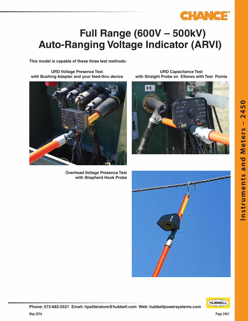
Inst
rum
en
ts a
nd
Me
ters
– 2
45
0
Phone: 573-682-5521 Email: [email protected] Web: hubbellpowersystems.com
Page 2461May 2016
URD Voltage Presence Testwith Bushing Adapter and your feed-thru device
This model is capable of these three test methods:
Full Range (600V – 500kV)Auto-Ranging Voltage Indicator (ARVI)
URD Capacitance Testwith Straight Probe on Elbows with Test Points
FPO
Overhead Voltage Presence Testwith Shepherd Hook Probe

Instru
me
nts a
nd
Me
ters – 2
45
0
Page 2462 May 2016
Phone: 573-682-5521 Email: [email protected] Web: hubbellpowersystems.com
DistributionAuto-Ranging Voltage Indicator (ARVI)
Large easy-to-read display activates each red light, one at a time, beginning at the low end and finally holds on the light for the phase-to-phase voltage class detected.
Includes the tester unit, a shepherd hook probe, instruction manual and hard shell padded case.
Basic ARVI for Overhead ApplicationsCatalog No. C4033374 (51⁄2 lb./2.5 kg.)
Complies with OSHA 1910.269 to Test for Absence of Nominal Voltage• 600V to 69kV • For Overhead & UndergroundBright Display Lights Indicate Voltage Class• Makes hot-line voltage testing easier than ever • State-of-the-art electronics eliminate need for selector
switch• Automatic-ranging function quickly displays
approximate line-to-line voltage class• Provides easy, yet reliable means for operator to
determine if a line is: o De-energized, or o Carrying less than normal system voltage from any
source or induced charged from an adjacent live circuit, or
o Energized at full system voltage• Simple-to-operate tester attaches to an Epoxiglas®
insulating universal handle of appropriate length to maintain proper OSHA working clearances
• Single pushbutton activates the instrument, then a single light indicates either Power On (by glowing solid) or Low Battery (by blinking)
• With good battery condition, instrument performs a confirming self-test
• It does this by illuminating each of the six indicator lights in series while emitting an alternating audible signal
• Then the probe can be brought into contact with the conductor
• It automatically begins detecting at approximately 480 Volts and holds display of one of these voltage classes: 600 V, 4 kV, 15 kV, 25 kV, 35 kV or 69 kV phase-to-phase
• Audible signal begins as a slow beeping, becoming faster as final reading is displayed
• When not in use, unit’s energy-saving Sleep mode automatically conserves battery
Overhead & Underground Capabilities• For overhead testing, a Shepherd Hook probe is
included with the Basic ARVI (Auto-Ranging Voltage Indicator)
• For underground testing, Elbow Adapter T4030856 and
ARVI Kitfor Overhead and Underground
Catalog No. T4033418 (161⁄4 lb./7.37 kg.)Includes the tester unit, shepherd hook probe, elbow adapter, bushing adapter, voltage indicator tester, instruction manual and hard shell padded case.
Bushing Adapter T4030857for 15, 25, 35kV
Elbow Adapter T4030856for 15, 25, 35kV
Voltage Indicator Tester C4033409
ARVIAuto-RangingVoltage Indicator
ARVIAuto-RangingVotage Indicator
H18766SH18766
1⁄4 lb./0.1 kg.1⁄8 lb./0.05 kg.
Shepherd Hook ProbeStraight Probe
Accessories
Bushing Adapter T4030857 are included• They simply thread onto the ARVI in the field to check
for voltage at switch bushings or elbows on cables, using a feed-thru device

Inst
rum
en
ts a
nd
Me
ters
– 2
45
0
Phone: 573-682-5521 Email: [email protected] Web: hubbellpowersystems.com
Page 2463May 2016
Includes the tester unit, a shepherd hook probe, instruction manual and hard shell padded case.
Transmission ARVI(Auto-Ranging Voltage Indicator)Cat. No. C4033375 (51⁄2 lb./2.5 kg.)
TransmissionAuto-Ranging Voltage Indicator (ARVI)
Bright Display Lights Indicate Voltage Class• Makes hot-line voltage testing easier than ever • State-of-the-art electronics eliminate need for selector
switch• Automatic-ranging function quickly displays
approximate line-to-line voltage class• Provides easy, yet reliable means for operator to
determine if a line is: o De-energized, or o Carrying less than normal system voltage from any
source or induced charged from an adjacent live circuit, or
o Energized at full system voltage• Simple-to-operate tester attaches to an Epoxiglas®
insulating universal handle of appropriate length to maintain proper OSHA working clearances
• Single pushbutton activates the instrument, then a single light indicates either Power On (by glowing solid) or Low Battery (by blinking)
• With good battery condition, instrument performs a confirming self-test
• It does this by illuminating each of the six indicator lights in series while emitting an alternating audible signal
• Then the probe can be brought into contact with the conductor
• It automatically begins detecting at approximately 69 kV and holds display of one of voltage classes: 69 kV, 115 kV, 161 kV, 230 kV, 345 kV or 500 kV phase-to-phase
Voltage Indicator Tester C4033431
Plug-in jack on Tester meter housing permits line personnel to quickly verify its operating
condition with a Voltage Indicator Tester (Cat. No. C4033431) before and after each use.
MUST BE ORDERED AS A SEPARATE ITEM
Complies with OSHA 1910.269 to Test for Absence of Nominal Voltage• 69kV to 500kV • For Overhead Conductors
Large easy-to-read display activates each red light, one at a time, beginning at the low end and finally holds on the light for the phase-to-phase voltage class detected.
H18766SH18766
1⁄4 lb./0.1 kg.1⁄8 lb./0.05 kg..
Shepherd Hook ProbeStraight Probe
Accessories
• Audible signal begins as a slow beeping, becoming faster as final reading is displayed
• When not in use, unit’s energy-saving Sleep mode automatically conserves battery

Instru
me
nts a
nd
Me
ters – 2
45
0
Page 2464 May 2016
Phone: 573-682-5521 Email: [email protected] Web: hubbellpowersystems.com
Catalog No.T4033228
Scale1 - 40 kV
Weight51⁄2 lb./2.5 kg.
Light Switch
Easier-To-Read, illuminated Dial • The lighted-dial option sets this unit apart from standard
features on Multi-Range Voltage Detector (MRVD) C4030979, shown on next page
• A long-life bulb, powered by included internal battery, gives a glow to the meter face so scale is easy to read in most conditions
• To conserve the battery, a special switch locks the light off when not in use
• Spring-loaded toggle must be pulled up to move it over the stop between its on and off positions
• This helps keep switch from being flipped on accidentally while unit is not in use
Standard Features • Confirms a line is de-energized prior to performing
maintenance • A field intensity meter, it is calibrated to read
approximate line-to-line voltage when connected to any phase conductor
• Responds to magnitude of field gradient between its end probe and floating electrode (at the universal hotstick-attachment fitting)
• If the universal fitting is close to a ground, another phase or another voltage source, reading should be high
• If it’s close to a jumper or equipment of the same phase, the reading should be low
• Gives metered readout capable of distinguishing actual line voltage from static or feedover from an adjacent line
• Numerical readings can be compared with numerical rather than subjective judgments associated with “fuzz sticking” or “glow-detecting” • Since it is not a voltmeter, no specific accuracy is claimed
by the manufacturer or can be assumed by the user
Operation • Must be mounted on proper length hotstick for the
voltage class involved• Complete instructions are furnished with easy, illustrated
step-by-step procedures• Internal circuit and pushbutton permit check before
and after each use to confirm operational condition of instrument and battery
Includes:• Straight probe for URD elbows with test points• Hook probe for overhead uses• Instructions and storage case
OverheadVoltage-PresenceTest with HookProbe
Self-testButton
▲
Lighted-dial model for systems through 40 kV
H18766SH18766
1⁄4 lb./0.1 kg.1⁄8 lb./0.05 kg.
Shepherd Hook ProbeStraight Probe
Accessories
URD Voltage-PresenceTest on elbows withTest Points can beperformed with Straight Probe when selector is set at TP
Multi-Range Voltage Detector

Inst
rum
en
ts a
nd
Me
ters
– 2
45
0
Phone: 573-682-5521 Email: [email protected] Web: hubbellpowersystems.com
Page 2465May 2016
*For testing URD elbows with test points, only model C4030979 on this page includes straight probe and “TP” setting on selector switch (as well as hook probe for overhead uses).For other URD models and Accessories, see next page.
Ordering Information
Distribution and TransmissionMulti-Range Voltage Detectors
Catalog No.C4030979*C4031029 C4031140
Scales1 - 40 kV
16 - 161 kV69 - 600 kV
Weight51⁄2 lb./2.5 kg.51⁄2 lb./2.5 kg.51⁄2 lb./2.5 kg.
Multi-Range Voltage Detectorsfor Overhead Systems to 600 kV and URD Elbow Test Points*
Overhead Voltage-Presence Test can be performed by all models.
Switch on C4030979* includes Test Point.
Self-testButton
▲
C4031029 or C4031140
C4030979*
URD Voltage-PresenceTest on Elbows withTest Points can beperformed only byModel C4030979* setat TP and fitted withits Straight Probe.
Design Features • Confirms a line is de-energized prior to performing
maintenance • A field intensity meter, it is calibrated to read
approximate line-to-line voltage when connected to any phase conductor
• Responds to magnitude of field gradient between its end probe and floating electrode (at the universal hotstick-attachment fitting)
• If the universal fitting is close to a ground, another phase or another voltage source, reading should be high
• If it’s close to a jumper or equipment of the same phase, the reading should be low
• Gives metered readout capable of distinguishing actual line voltage from static or feedover from an adjacent line
• Numerical readings can be compared with numerical rather than subjective judgments associated with “fuzz sticking” or “glow-detecting” • Since it is not a voltmeter, no specific accuracy is claimed
by the manufacturer or can be assumed by the user
Operation • Must be mounted on proper length hotstick for the
voltage class involved• Complete instructions are furnished with easy, illustrated
step-by-step procedures• Internal circuit and pushbutton permit check before
and after each use to confirm operational condition of instrument and battery

Instru
me
nts a
nd
Me
ters – 2
45
0
Page 2466 May 2016
Phone: 573-682-5521 Email: [email protected] Web: hubbellpowersystems.com
T4032271for Overhead and for URD Loadbreak Elbows
Catalog No.T4032271
DescriptionMRVD, Hook & Straight Probes, Elbows & Bushing Adapters, Case
Weight6 lb./2.7 kg.
Ordering Information
5-15-25-40 kV Multi-Range Voltage Detectorwith TP Setting for Test Point on URD Elbows
*Elbow Adapter also furnished to complete testwhen not using a feed-thru bushing device.
URD Voltage Presence Test URD Voltage Presence Test
andyour feed-thru device*
withBushingAdapter
withStraightProbe
on ElbowswithTest Points
Features & Applications• Test both overhead and underground distribution
systems• For systems in voltage classes from 5 through 40 kV• Provide easy, yet reliable means for operator to
determine if a line is: o De-energized, or o Carrying less than normal system voltage from any
source or induced charged from an adjacent live circuit, or
o Energized at full system voltage• Adapt to both overhead lines as well as URD circuits
with 200 and 600 Amp loadbreak elbows• This includes those with and without capacitance test-
points• Interchangeable probes and adapters • Thread into the MRVD end fitting and the selector
switch dials to the voltage range or test point (T.P.) setting appropriate to each application
• Furnished owner’s manual illustrates operating details for all models.
This model is capable of these three tests:
Multi-Range Voltage Detectorsfor Overhead & URD Systems to 40 kV
H18766SH18766
1⁄4 lb./0.1 kg.1⁄8 lb./0.05 kg.
Shepherd Hook ProbeStraight Probe
Accessories
Self-testButton
▲
Overhead Test

Inst
rum
en
ts a
nd
Me
ters
– 2
45
0
Phone: 573-682-5521 Email: [email protected] Web: hubbellpowersystems.com
Page 2467May 2016
Super Tester Voltage Detector• Dual Range • Audible & Visible IndicatorsFeatures & Applications• Lights blink and alarm sounds when placed in electrostatic field
above trigger threshold • Five flashing red lights alert the operator• High-pitched tones also signal nearby personnel of present
voltage that could be dangerous when applying temporary grounds or performing maintenance
• Can be used to check overhead lines, in substations and around switchgear
• Simply slips over the head of a standard 1-1⁄4"-diameter disconnect stick
• May be used on a Chance Grip-All clampstick, universal, telescoping or positive-grip hot line stick fitted with a special adapter (see table below)
Design Features• Handy three-way switch permits selection of either the 1 - 100 kV
or the 100 - 800 kV range for circuit being tested• Turns off unit to save the battery when not in use• 9-Volt alkaline battery readily installs by removing two knurl-head
screws and sliding off the instrument cover• Test button checks both the battery and the tester• Depressing button activates signal circuits, sounding the tone and
lighting the alarm lamps if the battery is good and unit operable• Comes with instructions packed in lined, reinforced case with
carrying handle
Operation• Turn on tester with selector switch for voltage range required• Check battery and unit by pushing “Test” button• If tone volume is not clear or indicator lights are not bright,
replace battery and recheck• Mount tester on proper hot line tool• For maximum-strength signals, place the tester within following
minimum proximity to the circuit being tested
Phase-to-Phase versus Response Distance
kV (1 - 100kV Range) (100 - 800kV Range)
Distance - inches Distance - inches
2.0….................0
13.8….................4
25.0…...............12
34.5…...............19…...............…..............1
69…..................39…...............….............. 3
115…........................................................ 7
161…......................................................10
230…......................................................20
345…..................................................... 26
525…..................................................... 44WARNING: Instrument damaged by touching 33kV or higher.
Note: Super Tester will not detect any voltage on cable with metallic sheath or semiconductive coating. Super Tester does not discriminate between induced and line voltage types. Device signals in the presence of either and the operator must determine which type before following utility safety working practices for engaging energized conductors.
Ordering InformationCatalog No.
H1990ST
M445598 (Catalog Section 2100)
Description
Super Tester, battery, plastic case
Super Tester Adapter for Grip- All, Universal, Telescoping or Positive-Grip hot line tools
Weight
43⁄4 lb./2.1 kg.
5 oz./0.14 kg.
M445598 Adapter fits into Super Tester either way so you can use it on a Grip-All clampstick or on a splined fitting of Univer-sal, Telescoping or Positive-Grip hot line sticks.

Instru
me
nts a
nd
Me
ters – 2
45
0
Page 2468 May 2016
Phone: 573-682-5521 Email: [email protected] Web: hubbellpowersystems.com
Transmission TesterC4032299
*Carrying case weighs additional 101⁄4 lb. (4.62 kg.)
Catalog No.C4032298C4032299
System ApplicationsDistribution (thru 35 kV)Transmission (44 thru 500 kV)
Weight4 lb./1.8 kg.
5 lb./2.25 kg.
Energized Insulator Testers(each includes instrument, two straight probes,operating instructions and metal carrying case)
Plug-in jack on Insulator Tester meter housing permits line personnel to quickly verify its operable condition with a Phasing Voltmeter Tester (Cat. No. C4030838) before and after each use.
for Distribution and Transmission SystemsOperation• Sensitive voltmeter measures difference in potential
across each insulator in a suspect string• Comparative readings from satisfactory strings in same
operating situation quickly indicate the state of every insulator in the string being tested
• Meter places minimal load on the phase as it requires only a small leakage current to make a reading
• Two straight steel probes threaded into the tester forks simply contact the metal fittings on both ends of each insulator at the same time
• Mounted on a 1-1⁄4"-dia. Epoxiglas® pole with a universal fitting
• Before each use the tester should be attached to the proper length hot stick for the system voltage involved
• Distribution model’s scale reads up to 11 kV• Transmission model’s scale reads a maximum of 16 kV
Applications• Without interrupting service, one of these testers
quickly can check the condition of each insulator in a string
• Greatly reduces maintenance costs• Only insulators identified as damaged require
replacements• No need to change entire strings• Available in two models• Testers serve specific applications: o Deadend insulators on distribution systems through
35 kV o Suspension insulators on 44 kV through 500 kV
transmission systems
Energized Insulator Testers
Distribution TesterC4032298

Inst
rum
en
ts a
nd
Me
ters
– 2
45
0
Phone: 573-682-5521 Email: [email protected] Web: hubbellpowersystems.com
Page 2469May 2016
C4031369for 0 - 10 kV
To check tester’s condition before and after each use, test-point jack in front of meter accepts plug-in lead of Voltmeter Tester (see page 2453).
C4031367
Features & Applications• Portable device checks the AC voltages on
Underground Distribution circuits through 20 kV • Determines approximate line-to-ground voltage of the
circuits• Basic instrument, C4031369, reads voltages up to 10 kV
on meter• Resistance units are encapsulated in an epoxy
compound to protect against mechanical damage• Prevents moisture penetration or accumulation around
resistors • No calibration is required – tool is preset at the factory• Extension resistor is provided for voltages above 10 kV
phase-to-ground. This increases voltage range to 20 kV phase-to-ground.
• Do not use more than one extension resistor element per tool
• Ground connection is made to a stud on the stick below the meter housing
• This stud MUST be electrically connected to a good ground source
• Before the Voltage Tester is used to test elbows or bushings on dead front URD equipment, proper adapter must be attached to tool
• Elbow must be controlled or restrained with an insulated hot stick while using Voltage Tester to check elbows
• Elbow must be properly parked when bushing is being checked
Voltage Tester for Underground Transformers
BushingAdapter
T4030857
ElbowAdapterT4030856
Adapters for 15, 25 and 35 kV only
Units Assembledfor 20 kV Testing
Adapters for 15 kV only
BushingAdapter
T4030428
ElbowAdapterT4030602
Catalog No. DescriptionC4031367 Complete Voltage Tester for 20 kV Ø-G
includes Tester, Extension Resistor, Case and Instruction Booklet
C4031368 1 Extension ResistorC4031369 Voltage Indicator 10 kV Ø-G with Case
and Instruction BookletT4030602 Elbow Adapter for 8.3/15 kV onlyT4030428 Bushing Adapter for 8.3/15 kV onlyT4030856 Elbow Adapter for 15, 25 & 35 kVT4030857 Bushing Adapter for 15, 25 & 35 kVC4030838 Tool with Leads and Battery

Instru
me
nts a
nd
Me
ters – 2
45
0
Page 2470 May 2016
Phone: 573-682-5521 Email: [email protected] Web: hubbellpowersystems.com
Operation• Measures electrical integrity of polymer
insulator• Compares data from known good insulator or
from calibration samples provided• Can be used on energized line or de-
energized • Rechargeable battery• Self contained power supply. Does not rely on
E - field to operate.• Must be used with appropriate length
Epoxiglas® pole with universal fitting• Easy to interpret Go/No Go lights and audible
tones• Data can be viewed and downloaded to
Wi-Fi enabled device• Adjustable probe spacing to fit most
suspension insulators• Rugged carrying case
Applications• Can be used to collect data on energized line
without interrupting service• Use to test insulators before installation for
added security• Used on transmission suspension insulators
69kV and above up to 1.8” in diameter
Polymer Insulator TesterFor Transmission Suspension Insulators
Blue Probe Engaged Power
SwitchBattery Status
Blue Probe Engaged
Green Result Pass
Red Result Fail
Amber Warning/Busy
White Ready/ Power On
Calibration Indicators
Kit includes; Tester, Battery charger, Adapter cables, Calibration samples, Holder and Users Manual
Catalog No. Application Weight
PSC403-3679 Transmission Suspension 69kV thru 500kV 4.2 lbs.

Inst
rum
en
ts a
nd
Me
ters
– 2
45
0
Phone: 573-682-5521 Email: [email protected] Web: hubbellpowersystems.com
Page 2471May 2016
Features & Applications• Allows lineman to determine whether URD cable is
energized or de-energized• Amplifier is designed to give a meter reading• This occurs when small AC voltage between the semi-
conductive sheath and the concentric neutral of the energized URD cable is applied to test probe
• Amplifier is housed in a rugged thermoplastic case
• Self-test contact point is located on top of amplifier housing
• Check meter operation and battery condition by touching test probe to test point
Dielectric Compound No. 7
Dielectric Compound No. 7, a silicone base material, is made for use with load break disconnects and other electrical connecting and terminating devices.
Cat. No. C4170287..................................... 2 oz. Tube
DescriptionURD Cable Sensor, twoleads, two hose clamps,two 9-volt batteries and instructions
Weight5 lb./2.3 kg.
Catalog No.C4030803
• Sensor checks energized condition on concentric-neutral cable below an elbow without test points (as above)
• At cable mid-span (left), hose clamps bridge all strands of concentric neutral at the test location
• Sensor’s neutral lead clips to one of the hose clamps• Tip on probe lead contacts semi-conductive cable
sheath to test voltage
Energized Cable Sensor
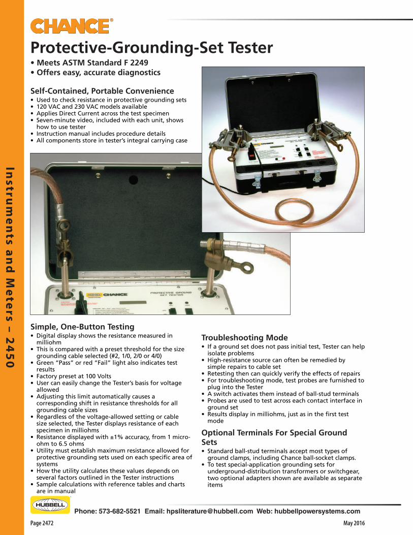
Instru
me
nts a
nd
Me
ters – 2
45
0
Page 2472 May 2016
Phone: 573-682-5521 Email: [email protected] Web: hubbellpowersystems.com
Self-Contained, Portable Convenience• Used to check resistance in protective grounding sets • 120 VAC and 230 VAC models available• Applies Direct Current across the test specimen• Seven-minute video, included with each unit, shows
how to use tester• Instruction manual includes procedure details• All components store in tester’s integral carrying case
Protective-Grounding-Set Tester• Meets ASTM Standard F 2249 • Offers easy, accurate diagnostics
Troubleshooting Mode • If a ground set does not pass initial test, Tester can help
isolate problems• High-resistance source can often be remedied by
simple repairs to cable set• Retesting then can quickly verify the effects of repairs• For troubleshooting mode, test probes are furnished to
plug into the Tester• A switch activates them instead of ball-stud terminals• Probes are used to test across each contact interface in
ground set• Results display in milliohms, just as in the first test
mode
Optional Terminals For Special Ground Sets • Standard ball-stud terminals accept most types of
ground clamps, including Chance ball-socket clamps.• To test special-application grounding sets for
underground-distribution transformers or switchgear, two optional adapters shown are available as separate items
Simple, One-Button Testing • Digital display shows the resistance measured in
milliohm• This is compared with a preset threshold for the size
grounding cable selected (#2, 1/0, 2/0 or 4/0)• Green “Pass” or red “Fail” light also indicates test
results • Factory preset at 100 Volts• User can easily change the Tester’s basis for voltage
allowed • Adjusting this limit automatically causes a
corresponding shift in resistance thresholds for all grounding cable sizes
• Regardless of the voltage-allowed setting or cable size selected, the Tester displays resistance of each specimen in milliohms
• Resistance displayed with ±1% accuracy, from 1 micro-ohm to 6.5 ohms
• Utility must establish maximum resistance allowed for protective grounding sets used on each specific area of systems
• How the utility calculates these values depends on several factors outlined in the Tester instructions
• Sample calculations with reference tables and charts are in manual
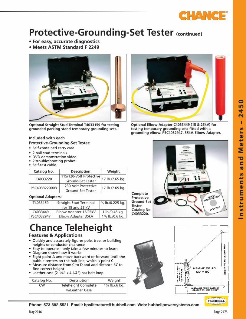
Inst
rum
en
ts a
nd
Me
ters
– 2
45
0
Phone: 573-682-5521 Email: [email protected] Web: hubbellpowersystems.com
Page 2473May 2016
Features & Applications• Quickly and accurately figures pole, tree, or building
heights or conductor clearance• Easy to operate – only take a few minutes to learn• Diagram shows how it works• Sight point A and move backward or forward until the
bubble centers on the hair line, which is point C• Measure distance from C to D and add distance BC to
find correct height• Leather case (2-1⁄4" x 4-1⁄4") has belt loop
Weight11⁄4 lb./.6 kg.
DescriptionTeleheight Complete
w/Leather Case
Catalog No.CW
Chance Teleheight
Optional Elbow Adapter C4033449 (15 & 25kV) for testing temporary grounding sets fitted with a grounding elbow. PSC4032947, 35kV, Elbow Adapter.
Optional Straight Stud Terminal T4033159 for testing grounded-parking-stand temporary grounding sets.
CompleteProtective Ground-SetTesterCatalog No.C4033220.
Optional Adapters:
Included with eachProtective-Grounding-Set Tester:• Self-contained carry case • 2 ball-stud terminals • DVD demonstration video • 2 troubleshooting probes• Self-test cable
Protective-Grounding-Set Tester (continued)
• For easy, accurate diagnostics• Meets ASTM Standard F 2249
Weight
17 lb./7.65 kg.
17 lb./7.65 kg.
Catalog No.
C4033220
PSC4033220003
Description115/120-Volt Protective
Ground-Set Tester230-Volt ProtectiveGround-Set Tester
T4033159 Straight Stud Terminalfor 15 and 25 kV
3⁄4 lb./0.225 kg.
C4033449 Elbow Adapter 15/25kV 1 lb./0.45 kg.PSC4032947 Elbow Adapter 35kV 11/4 lb./0.6 kg.
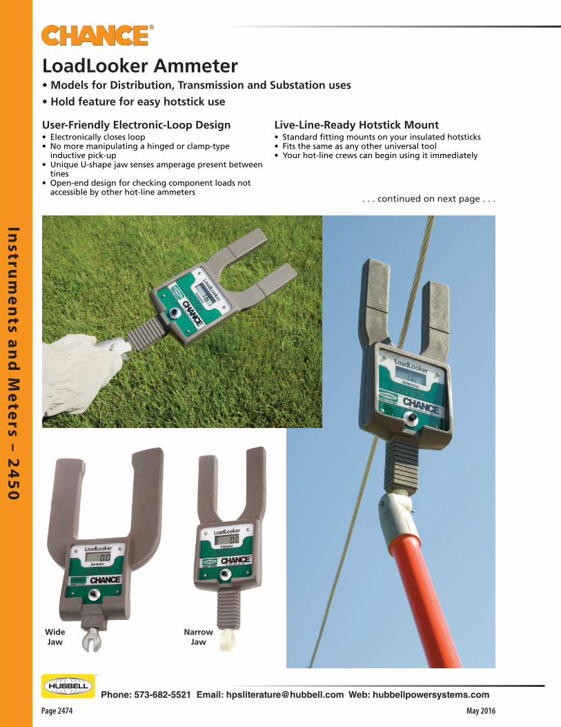
Instru
me
nts a
nd
Me
ters – 2
45
0
Page 2474 May 2016
Phone: 573-682-5521 Email: [email protected] Web: hubbellpowersystems.com
LoadLooker Ammeter• Models for Distribution, Transmission and Substation uses
• Hold feature for easy hotstick use
NarrowJaw
WideJaw
. . . continued on next page . . .
User-Friendly Electronic-Loop Design• Electronically closes loop • No more manipulating a hinged or clamp-type
inductive pick-up• Unique U-shape jaw senses amperage present between
tines• Open-end design for checking component loads not
accessible by other hot-line ammeters
Live-Line-Ready Hotstick Mount• Standard fitting mounts on your insulated hotsticks• Fits the same as any other universal tool• Your hot-line crews can begin using it immediately

Inst
rum
en
ts a
nd
Me
ters
– 2
45
0
Phone: 573-682-5521 Email: [email protected] Web: hubbellpowersystems.com
Page 2475May 2016
Catalog No.
MEAMP11RW
MEAMP21RW
MEAMP32RN
MEAMP32RN2
Weight
3.1 lb. / 1.41 kg.
3.1 lb. / 1.41 kg.
3.1 lb. / 1.41 kg.
3.1 lb. / 1.41 kg.
Max. Voltage (Ø-Ø)
Up to 69 kV
Up to 400kV
Up to 500kV
Up to 500kV
Max. Current
Up to 2,000 amps
Up to 2,000 amps
Up to 5,000 amps
Up to 5,000 amps
Reading Type
True RMS
True RMS
True RMS
True RMS
Jaw Size
3.86"
3.86"
2.50"
2.50"
Replacement CaseCatalog No.
C4002561
Description
Hard Case for LoadLooker Ammeter
Weight
2.5 lb. / 1.13 kg.
LoadLooker Ammeter
General SpecificationsLCD 31⁄2-digit display of Amps, Hold, Low Battery
Battery 9 volt alkaline (included)
Accuracy ±1% +2 Digits
Frequency 50 or 60 Hertz
Operating Temperature -30° to 60° C (-22° to 140° F)
Display Range Automatic Ranging:
0 - 99.9 Amperes, in 0.1-Amp increments. 100 - 1999 Amperes, in 1.0-Amp increments. 2000-5000 Amperes, in 0.1kA Amp increments. Operators Manual and Case included
Rugged, Application-Specific Design• Materials and construction are designed for field-
condition rigors • Typical applications include: o Identifying load imbalances o Verifying accuracy of current transformers o Determining load to select properly sized jumpers o Measuring load before opening switches
Simple Pushbutton Operation, Direct-Reading Accuracy• Push it once to turn on LoadLooker• Push it a second time and LoadLooker will display the
word HOLD • Will continue to display the next reading it “sees” until
you push the button to clear • This lets you bring it down from the line to eye level to
read it• After five idle minutes, unit will turn itself off • You can also manually turn it off by keeping the button
depressed for five seconds• Operator’s Manual and storage case are included
Wide Jawwith
Hard Case
Narrow Jawwith
Soft Case
50 Hertz unit, Case and Operators Manual
Ordering Information60 Hertz unit, Case and Operators Manual

Instru
me
nts a
nd
Me
ters – 2
45
0
Page 2476 May 2016
Phone: 573-682-5521 Email: [email protected] Web: hubbellpowersystems.com
New Controls & Meter for All Requirements• Simple to operate, portable unit• Makes easy work of testing insulated live-line tools • Wet and dry modes selected by a toggle switch • Follows procedures specified by ASTM, IEEE and OSHA• Graduated meter gives precise readout of each tool’s
leakage current
Portable Operating Ease• For testing any length fiberglass-reinforced plastic
(FRP) hot stick up to 3” in dia.• For spot checks at field
jobsites or periodic diagnostics in workshop
• Full-scale test setups for both Wet (75 kV-per-foot) and Dry (100 kV-per-foot)
• Compact, self-contained unit easily carried and operated by one person
• In Setup procedure before each use, a zeroing knob is used to set meter to zero without a tool in the tester
• Furnished Check Bar serves as self-check to ensure tester is functional
• Included video demonstrates “how-to” basics for Setup, Dry and Wet tests
• Owners Manual must be read and understood before operating tester
Catalog No.C4033178C4033179
Wet/Dry Hot Stick Tester115-volt model*230-volt model
Weight20 lb./9.0 kg.20 lb./9.0 kg.
Included with each Tester: • Check bar • Owners operating instruction manual • Demonstration video • Carrying case
Ordering Information
Quantitative Test Results• When placed on tool, displays any increase in leakage
current due to hotstick• Gives immediate indication of stick’s true leakage
condition, independent of stray currents (through the air, internal to testers, etc.) zeroed out in advance
• Detects leakage currents due to surface contamination, internal moisture and such internal conductive materials as carbon tracks
Wet/Dry Hot Stick Testerfor easy, portable compliance with industry standards
*Power-source cord does not include plug on 230-volt model

Inst
rum
en
ts a
nd
Me
ters
– 2
45
0
Phone: 573-682-5521 Email: [email protected] Web: hubbellpowersystems.com
Page 2477May 2016
Truck Boom Leakage-Current Monitor
Ladder Monitor KitFeatures & Applications• Used with EHV Barehand maintenance to detect
microamp leakage on a ladder • Meter is connected to ladder and takes readings when
ladder is in contact with conductor• Recommended that readings be taken periodically to
ensure optimal working conditions which could be altered by change in atmosphere
• Kit includes: o 200 micro-amp scale microammeter o Three clamps to effect use on a three-rail ladder o Cable with clips and adapter to establish contact o Bracket to ground and hold meter on structure o Two dry cell batteries o Instruction drawings for field assembly o Operating instructions
DescriptionLadder Monitor Kit
Weight7.5 lb./3.4 kg.
Catalog No.C4020288
Chance SentinelLeakage-Current Monitor• Alerts utility-line workers of overcurrent conditions • For such aerial devices as insulated ladders and truck
booms• Sounds an alarm if leakage current reaches a pre-set
level• Leakage setting adjusts from 1 to 1,000 microamperes
in resolution increments of 0.1 microamp• Audible warning eliminates need to watch the actual
current level, continuously displayed on digital LCD screen
• Alarm sounds immediately upon overcurrent and continues until the condition is corrected
• Instrument panel jack accepts a standard 1⁄4" two-conductor phone plug to also trigger a truck horn or other external alarm
• Panel test terminal permits a simple continuity check of the monitor leads prior to each operation
Mounting studs on steel box bond directly to truck body.
• Mounts on truck body and hardwires into truck’s 12-Volt system, which eliminates battery changeout
• Sounds an alarm if leakage current reaches a pre-set level
• Alerts utility-line workers of overcurrent conditions on truck booms
• Leakage setting adjusts from 1 to 1,000 microamperes in resolution increments of 0.1 microamp
• Audible warning eliminates need to watch the actual current level, continuously displayed on digital LCD screen
• Alarm sounds immediately upon overcurrent and continues until the condition is corrected
• Instrument panel jack accepts a standard 1⁄4" two-conductor phone plug to also trigger a truck horn or other external alarm
• Panel test terminal permits a simple continuity check of
Catalog No.C4070025
DescriptionChance Sentinel Kit
Weight9 lb./4.05 kg.
Catalog No.T4070327
DescriptionBoom Monitor Kit (12 Volt)
Weight14 lb./6.4 kg.
the monitor leads prior to each operation• Before use, instrument automatically performs a rapid
electronic self-test• Simple operating steps are printed on the inside lid
panel• Detailed instruction sheet included
for EHV Microamp Measurement on Barehand Equipment
• Before use, instrument automatically performs a rapid electronic self-test
• Simple operating steps are printed on inside lid panel
• Detailed instruction sheet included
• Kit includes one coaxial cable and battery, two jumpers and three hose clamps for connections to two- or three-rail ladders
• Brackets on box secure to an earth-grounded structure up to 5⁄8" thick such as a transmission tower

Instru
me
nts a
nd
Me
ters – 2
45
0
Page 2478 May 2016
Phone: 573-682-5521 Email: [email protected] Web: hubbellpowersystems.com
Features & Applications• Bright display lights and audible alarm
indicate voltage class without need to directly contact the conductor
• The class displayed is the approximate phase to phase voltage class
• Used to determine if power lines are at rated voltage, have induced voltage or are de-energized
• Designed as a non-contact Voltage Indicator• Must be used with properly selected universal
hot stick, even with rubber gloves• Designed to be held 6 to 18 inches away
from conductor being tested for presence of voltage
• Advanced feature allows user to temporarily disable range indications for voltages below the user selected range
Design Features• New battery drawer does not require removal
of front panel for replacement of batteries• Requires two AA batteries• Comes with storage bag designed with
snaphook for suspending from belt or in storage
• Lightweight, 1.25lbs versus the 4.75lbs of the Super Tester
Operation• To turn on the meter, press the power switch
until the audible tone is heard• Each LED will light up individually from the
lowest to highest and then the alarm• Bring the indicator within 6 to 18 inches of
the line to be measured• Below 480 volts, the indicator may need to be
6 inches or less away from the line• Once an electrical field is detected, the range
indications will increase as you approach the conductor
• As the voltage field intensity increases, the Proximity “SENSE” LED, Range LED and audible alarm will flash and beep faster
Optional Field Tester• The proximity voltage indicator can be field
tested with the Voltage Indicator Tester PSC4033582
Proximity Voltage Indicator (PVI)600V to 500kV - Audible & Visible Indicators
Catalog No. Application Weight
PSC4033737 Proximity Voltage Indicator and Bag 1-1/4 lbs.
Snaphook on each bag• For suspending from belt or in storage• Leather reinforced tab is stitched to the back of each bag

Inst
rum
en
ts a
nd
Me
ters
– 2
45
0
Phone: 573-682-5521 Email: [email protected] Web: hubbellpowersystems.com
Page 2479May 2016 NOTES
Features & Applications• Visible and audible voltage indicator with
range from Capacitive Test Point up to 80kV Phase-to-Phase
• Bluetooth Connectivity to view MRVI display live on a mobile device
• Mobile app displays the meter face and approximate phase-to-phase and phase-to-ground voltages
• Large, easy-to-read dial face and brightly illuminated pointer indicate the voltage class
• The voltage indicated is the approximate phase-to-phase and phase-to-ground voltage
• Can be used on overhead and underground lines with proper adapters
Design Features• New battery drawer does not require removal
of front panel for replacement of batteries• Requires four AA batteries• Comes with storage bag designed with
snaphook for suspending from belt or in storage
• Lightweight, 1.25lbs versus the 2.5lbs. of the MRVD, C403097
• Works with elbow and bushing adapters for URD applications
Operation• To turn on the meter, press the power switch
until the meter lights turn on and audible tone is heard
• The needle will fully deflect to show the condition of the batteries
• The needle will then go back to the zero and the sense light will blink indicating the MRVI is ready to take a reading
• Hold mode can also be selected by depressing the power button twice in quick succession
• Optional mobile app can be downloaded from the Google Play or Apple iTunes store
Optional Field Tester• The proximity voltage indicator can be field
tested with the Voltage Indicator Tester PSC4033582
Multi-Range Voltage Indicator (MRVI)Capacitive Test Point up to 80kV phase-to-phase – Bluetooth connectivity for mobile device
Catalog No. Application Weight
PSC4033710 Multi-Range Voltage Indicator and Bag 1-1/4 lbs.
PSC4033925 Multi-Range Voltage Indicator and Hard Case 1-1/4 lbs.
Snaphook on each bag• For suspending from belt or in storage• Leather reinforced tab is stitched to the back of each bag
Mobile Device Display

Too
l R
ep
air
& S
tora
ge
– 2
50
0
Phone: 573-682-5521 Email: [email protected] Web: hubbellpowersystems.com
Page 2501May 2016
Too
l R
ep
air
& S
tora
ge
–2
50
0
Tool Repair &Storage
Catalog 2500 May 2016

Too
l Re
pa
ir & S
tora
ge
– 25
00
Page 2502 May 2016
Phone: 573-682-5521 Email: [email protected] Web: hubbellpowersystems.com
Cleaning a polewith ChanceMoisture Eater II
Features & Applications• Chance introduced Epoxiglas® in 1957 • The result of a three-year research and development
program• Epoxiglas® consists of thousands of epoxy resin-
impregnated glass fibers • Fibers are wound around and laid lengthwise over a
unicellular plastic foam core• Foam core consists of millions of individual cells • Cells contain a low boiling inert material which inhibits
moisture absorption and condensation• Unicellular foam is bonded to reinforced walls to obtain
a foam integrity that cannot be matched by other tool manufacturing methods
• Electrical and mechanical advantages of Epoxiglas® Hot Line Tools have been verified by their acceptance for stringent requirements of hot line maintenance
Care of Expoxiglas® Hot Line Tools• Proper care will result in longer tool life, safety and
crew confidence• Keeping hot line tools dry is a key factor in their care• They should never be laid directly on the ground• Keep in truck or a tool trailer until ready for use• Place on a tool rack near the groundman when ready
for use• A clean dry tarpaulin should be spread to prevent tools
from contacting ground• Most line crews have groundman wipe hot stick clean• This is performed with a silicone impregnated Chance
Hot Stick Wiping Cloth immediately before it is sent up the structure for use on energized lines
Repairing Small Ruptures• Surface ruptures in Epoxiglas should be repaired as
soon as discovered• Repairs can be made by removing damaged fibers,
cleaning the void with Chance Moisture Eater II and applying Chance Epoxiglas Bond
• After patch has set, refinish pole (after 24-hour cure time) with Epoxiglas® Gloss Restorer and it is ready for use
Protecting Tools during Transportation• Containers or bags should be used to prevent damage
to surfaces of individual tools• Tools should be mounted on racks in trucks or trailers• Racks should be well padded and hold tools firmly in
order to prevent damage
Cleaning Epoxiglas® Hot Line Tools• Clean and regloss after approximately 10 wipedowns
with Moisture Eater II• Clean and regloss when contaminated by moisture-
bearing and conductive materials• Use Chance cleaner-solvent, Moisture Eater II• Cleaner can be applied with a non-abrasive cloth • For heavy contamination, use abrasive cleaning pads • If gloss finish of pole has been removed, it can be
returned to factory conditions by coating with Chance Gloss Restorer
• This forms a clear, tough coating to prevent future contamination
Epoxiglas® Hot Sticks
Care, Storage and Repair of Epoxiglas® Tools

Too
l R
ep
air
& S
tora
ge
– 2
50
0
Phone: 573-682-5521 Email: [email protected] Web: hubbellpowersystems.com
Page 2503May 2016
Features & Applications• Strong solvent for water and conductive contaminants• Safe to Earth’s ozone layer – free of chlorinated
hydrocarbons• More economical, easier to work with due to lower
evaporation rate• Pleasant, orange scent from citrus-based biodegradable
component
Less Waste• Contains no water and absorbs water in its presence• Removes twice as much water as the original Moisture
Eater• Minimizes chemical waste • Unique formula of Moisture Eater II gives it a much
lower evaporation rate than original formula and other hot-line tool cleaners
Epoxiglas® Cleaning KitFeatures & Applications• Essential for care and maintenance of Epoxiglas® tools • Also cleans insulated boom sections of aerial lift trucks• Helps to ensure maximum life of Epoxiglas products• Do not use on Gel-Coat or painted boom surfaces
4 Parts Of The Kit1. Moisture Eater II — This cleaner should be used
on contaminated Epoxiglas during general tool maintenance and in preparation for reglossing a tool’s surface. Moisture Eater removes moisture and a wide variety of contaminants such as dirt, tar, grease, tree sap, light metal rubbings and old surface coatings without harming the Epoxiglas material
2. Abrasive Cleaning Pads — These pads are used in conjunction with Moisture Eater II to remove contamination that clings to the tool or contamination ground into scars and scuffs in the tools surface. Gloss restorer must be applied after using these pads since cleaning with Moisture Eater II will remove the glossy finish on the tool as well as contamination. The pads may also be used on metal parts to remove oxides and surface corrosion
3. Gloss Restorer Kit — This kit consists of two parts. When mixed and applied to the surface of a cleaned Epoxiglas tool they combine to form a clear, tough coating that replaces the original gloss and protects against contamination and moisture
4. Hot Stick Wiping Cloths — Silicone impregnated cloths are used to wipe down mildly contaminated Epoxiglas, removing dust and dirt, and depositing a thin protective film on the surface of the tool. They give an added measure of protection when used after recoating with gloss restorer
Available in 1-gallon jugasCatalog No. C4002364(also comes in Epoxiglas Cleaning Kit).
Moisture Eater IICleaner-Solventfor hot-line tools, line hose and blankets
1
2
3
4
Description
Moisture Eater II Cleaner, 1 gal./4.23 liters
Epoxiglas Cleaning Kit*
The above kit consists of the following items:(Each may also be ordered separately.)
Moisture Eater II Cleaner, 1 gal./4.23 liters
Abrasive Cleaning Pads (box of 20)
Gloss Restorer Kit
Hot Stick Wiping Cloth (*2 in Kit above)
Catalog No.
C4002364
C4002365
C4002364
C4001166
C4001520
M1904
1
2
3
4
Environment-Friendly Advantages• New formula consists of two solvents: o One for oils, waxes and silicone-type contamination o One for moisture contamination• This combination is ideally suited for cleaning hot-line
tools• A by-product of citrus fruit, one component is
biodegradable; the other component protects it from decomposing until used
• Reformulation eliminates chlorinated solvents harmful to Earth’s ozone layer
• For more technical details, refer to Material Safety Data Sheet ABC/C56

Too
l Re
pa
ir & S
tora
ge
– 25
00
Page 2504 May 2016
Phone: 573-682-5521 Email: [email protected] Web: hubbellpowersystems.com
Moisture Eater II Wipes for hot-line tools, rubber line hose & blanketsFeatures & Applications• Economical, individual packets encourage daily useHelps utilities stay in compliance with OSHA 29 CFR 1910.269(j)
Packaged For Convenience • Small pocket-sized packets • For cleaning of insulated hot-line tools, line hose and
rubber blankets• Zip open a foil packet and pull out the pre-moistened,
lint-free towel• Each wipe is saturated with a half ounce of orange-
scented Moisture Eater II solvent
Workable, Environment-Friendly Formula • Eliminates waste while thoroughly clean tools• Much lower evaporation rate than other hot-line tool
cleaners• Contains no water and absorbs water in its presence• Does not contain chlorinated solvents harmful to the
Earth’s ozone layer• New formula consists of two solvents: o One for oils, waxes and silicone-type contamination o One for moisture contamination• This combination is ideally suited for cleaning hot-line
tools• A by-product of citrus fruit, one component is
biodegradable; the other component protects it from decomposing until used
• Reformulation eliminates chlorinated solvents harmful to Earth’s ozone layer
• For more technical details, refer to Material Safety Data Sheet ABC/C56
DescriptionMoisture Eater II Wipes (1 box of 50 packets)
Ordering Information
Weight2.7 lb. (1.2 kg.)
• Hanger box holds 50 wipes – handy for crew bays, trailers, and trucks
• Sealed wipes mean no more rags to store or try to keep clean in the field
• No more jugs to stow, big spills, evaporation losses or wasteful excesses
Line hose and rubber blankets clean up easily with Moisture Eater II wipes.
Catalog No.C4002538

Too
l R
ep
air
& S
tora
ge
– 2
50
0
Phone: 573-682-5521 Email: [email protected] Web: hubbellpowersystems.com
Page 2505May 2016
Silicone Wipes for hot-line toolsFeatures & Applications• Economical, individual packets encourage daily use• Packaged for easy access on the jobsite• Easy way to encourage daily cleaning• Helps utilities stay in compliance with OSHA 29 CFR 1910.269(j)
Simple and convenient:• Easy-open • Single-use • Disposable
Quick & Easy Extra Protection• Small pocket-sized packets• Encourage frequent care of insulated hot-line tools• Hanger box holds 50 wipes – handy for crew bays,
trailers, and trucks• Sealed wipes mean no more rags to store or try to
keep clean in the field• Zip open a foil packet and pull out the pre-moistened,
lint-free towel• Silicone-saturated 8 x 10” lint-free towel easily cleans
hotsticks• Contain same silicone as Hot Stick Wiping Cloths in
Chance Epoxiglas® Cleaning Kit• Using cloths or Silicone Wipes on fiberglass tools
removes dust• Thin, protective coat helps resist accumulation of dirt
and contaminants
Quick & Easy Extra Protection• The last step in everyday clean-and-wipe routine• Replaces protective film that cleaners such as Moisture
Eater II remove • Also preserves tool surfaces• Used after Chance Gloss Restorer, sealed and
disposable wipes ensure a clean application of a preservative layer on new surfaces
DescriptionSilicone Wipes, one box of 50 packets
Ordering InformationWeight
1.8 lb. (0.8 kg.)Catalog Number
C4002568
Silicone Lubricantfor flexible line hose and general applicationsFeatures & Applications• Makes line hose easy to put on and slide into place• Silicone material also serves as a multi-purpose lubricant• Handy 10 oz. size aerosol package provides convenient
applicator to coat all interior line hose surfaces• Simply spread open the hose near one end and direct
the can nozzle's wide spray pattern inside, working down the hose to its other end
• Soft, clean cloth may be used to wipe silicone on large surfaces
• May be used in place of petroleum-based lubricants• Surfaces to be coated should be clean and dry• For more technical details, refer to Material Safety Data
sheet ABC/C40
C4002320 Silicone Aerosol Lubricant
Catalog No. Can ContentsDescription
10 oz./284 gm.

Too
l Re
pa
ir & S
tora
ge
– 25
00
Page 2506 May 2016
Phone: 573-682-5521 Email: [email protected] Web: hubbellpowersystems.com
New Controls & Meter for All Requirements• Simple to operate, portable unit• Makes easy work of testing insulated live-line tools • Wet and dry modes selected by a toggle switch • Follows procedures specified by ASTM, IEEE and OSHA• Graduated meter gives precise readout of each tool’s
leakage current
Portable Operating Ease• For testing any length fiberglass-reinforced plastic
(FRP) hot stick up to 3” in dia.• For spot checks at field jobsites or periodic diagnostics
in workshop• Full-scale test setups for both Wet (75 kV-per-foot) and
Dry (100 kV-per-foot) • Compact, self-contained unit easily carried and
operated by one person• In Setup procedure before each use, a zeroing knob is
used to set meter to zero without a tool in the tester• Furnished Check Bar serves as self-check to ensure
tester is functional• Included video demonstrates “how-to” basics for
Setup, Dry and Wet tests• Owners Mººanual must be read and understood before operating tester
Catalog No.C4033178C4033179
Wet/Dry Hot Stick Tester115-volt model*230-volt model
Weight20 lb./9.0 kg.20 lb./9.0 kg.
Included with each Tester: • Check bar • Owners operating instruction manual • Demonstration video • Carrying case
Ordering Information
Quantitative Test Results• When placed on tool, displays any increase in leakage
current due to hotstick• Gives immediate indication of stick’s true leakage
condition, independent of stray currents (through the air, internal to testers, etc.) zeroed out in advance
• Detects leakage currents due to surface contamination, internal moisture and such internal conductive materials as carbon tracks
Wet/Dry Hot Stick Testerfor easy, portable compliance with industry standards
*Power-source cord does not include plug on 230-volt model
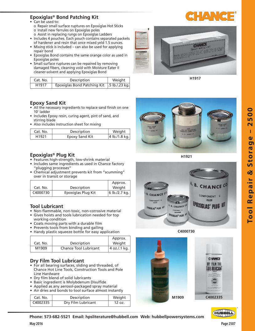
Too
l R
ep
air
& S
tora
ge
– 2
50
0
Phone: 573-682-5521 Email: [email protected] Web: hubbellpowersystems.com
Page 2507May 2016
Epoxiglas® Bond Patching Kit• Can be used to: o Repair small surface ruptures on Epoxiglas Hot Sticks o Install new ferrules on Epoxiglas poles o Assist in replacing rungs on Epoxiglas Ladders• Includes 4 pouches. Each pouch contains separated packets
of hardener and resin that once mixed yeld 1.5 ounces.• Mixing stick is included – can also be used for applying
repair bond • Epoxiglas Bond contains the same orange color as used in
Epoxiglas poles• Small surface ruptures can be repaired by removing
damaged fibers, cleaning void with Moisture Eater II cleaner-solvent and applying Epoxiglas Bond
Weight.5 lb./.23 kg.
DescriptionEpoxiglas Bond Patching Kit
Cat. No.H1917
Epoxy Sand Kit• All the necessary ingredients to replace sand finish on one
10' ladder• Includes Epoxy resin, curing agent, pint of sand, and
stirring blade • Also includes instruction sheet for mixing
Cat. No.H1921
DescriptionEpoxy Sand Kit
Weight4 lb./1.8 kg.
Epoxiglas® Plug Kit• Features high-strength, low-shrink material• Includes same ingredients as used in Chance factory
“plugging processes”• Chemical adjustment prevents kit from “scumming”
over in transit or storage
Dry Film Tool Lubricant• For all bearing surfaces, sliding and threaded, of
Chance Hot Line Tools, Construction Tools and Pole Line Hardware
• Dry film blend of solid lubricants• Basic ingredient is Molybdenum Disulfide• Applied as any aerosol-packaged spray material• Air dries and bonds to tool surface almost instantly
Tool Lubricant• Non-flammable, non-toxic, non-corrosive material• Gives hoists and tools lubrication needed for top
working condition• Coats moving parts with a durable film• Prevents tools from binding and galling• Handy plastic squeeze bottle for easy application
Approx. Weight
4 oz./.1 kg.Description
Chance Tool LubricantCat. No.M1909
H1921
C4000730
M1909
H1917
DescriptionEpoxiglas Plug Kit
Approx. Weight
6 lb./2.7 kg.Cat. No.
C4000730
DescriptionDry Film Lubricant
Weight12 oz.
Cat. No.C4002335
C4002335
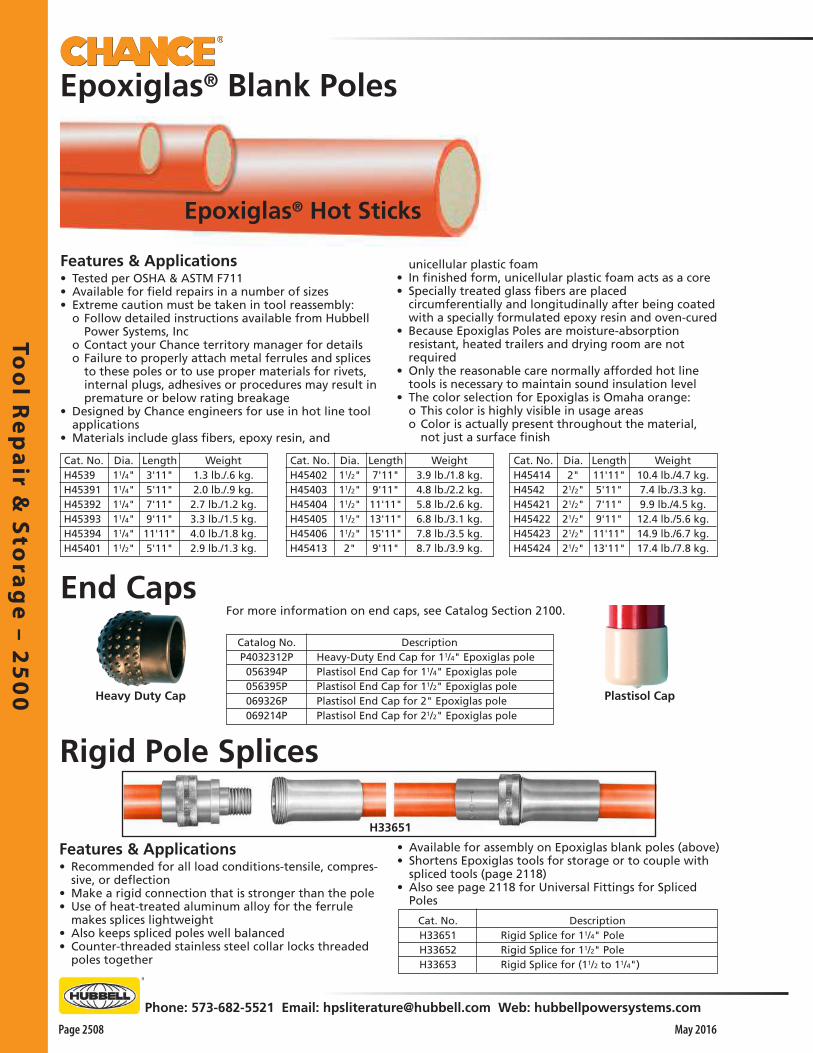
Too
l Re
pa
ir & S
tora
ge
– 25
00
Page 2508 May 2016
Phone: 573-682-5521 Email: [email protected] Web: hubbellpowersystems.com
Rigid Pole Splices
Features & Applications• Recommended for all load conditions-tensile, compres-
sive, or deflection• Make a rigid connection that is stronger than the pole• Use of heat-treated aluminum alloy for the ferrule
makes splices lightweight • Also keeps spliced poles well balanced• Counter-threaded stainless steel collar locks threaded
poles together
Features & Applications• Tested per OSHA & ASTM F711• Available for field repairs in a number of sizes• Extreme caution must be taken in tool reassembly: o Follow detailed instructions available from Hubbell
Power Systems, Inc o Contact your Chance territory manager for details o Failure to properly attach metal ferrules and splices
to these poles or to use proper materials for rivets, internal plugs, adhesives or procedures may result in premature or below rating breakage
• Designed by Chance engineers for use in hot line tool applications
• Materials include glass fibers, epoxy resin, and
unicellular plastic foam• In finished form, unicellular plastic foam acts as a core• Specially treated glass fibers are placed
circumferentially and longitudinally after being coated with a specially formulated epoxy resin and oven-cured
• Because Epoxiglas Poles are moisture-absorption resistant, heated trailers and drying room are not required
• Only the reasonable care normally afforded hot line tools is necessary to maintain sound insulation level
• The color selection for Epoxiglas is Omaha orange: o This color is highly visible in usage areas o Color is actually present throughout the material,
not just a surface finish
Epoxiglas® Blank Poles
Epoxiglas® Hot Sticks
• Available for assembly on Epoxiglas blank poles (above)• Shortens Epoxiglas tools for storage or to couple with
spliced tools (page 2118) • Also see page 2118 for Universal Fittings for Spliced
Poles
End Caps
Heavy Duty Cap Plastisol Cap
For more information on end caps, see Catalog Section 2100.
Length3'11"5'11"7'11"9'11"11'11"5'11"
Weight1.3 lb./.6 kg.2.0 lb./.9 kg.
2.7 lb./1.2 kg.3.3 lb./1.5 kg.4.0 lb./1.8 kg.2.9 lb./1.3 kg.
Dia.11/4"11/4"11/4"11/4"11/4"11/2"
Cat. No.H4539H45391H45392H45393H45394H45401
Length7'11"9'11"11'11"13'11"15'11"9'11"
Weight3.9 lb./1.8 kg.4.8 lb./2.2 kg.5.8 lb./2.6 kg.6.8 lb./3.1 kg.7.8 lb./3.5 kg.8.7 lb./3.9 kg.
Dia.11/2"11/2"11/2"11/2"11/2"2"
Cat. No.H45402H45403H45404H45405H45406H45413
Cat. No.H45414H4542H45421H45422H45423H45424
Length11'11"5'11"7'11"9'11"11'11"13'11"
Weight10.4 lb./4.7 kg.7.4 lb./3.3 kg.9.9 lb./4.5 kg.12.4 lb./5.6 kg.14.9 lb./6.7 kg.17.4 lb./7.8 kg.
Dia.2"
21/2"21/2"21/2"21/2"21/2"
Catalog No.P4032312P
056394P056395P069326P069214P
Description Heavy-Duty End Cap for 11/4" Epoxiglas pole Plastisol End Cap for 11/4" Epoxiglas pole Plastisol End Cap for 11/2" Epoxiglas pole Plastisol End Cap for 2" Epoxiglas pole Plastisol End Cap for 21/2" Epoxiglas pole
Cat. No.H33651H33652H33653
DescriptionRigid Splice for 11/4" PoleRigid Splice for 11/2" PoleRigid Splice for (11/2 to 11/4")
H33651

Too
l R
ep
air
& S
tora
ge
– 2
50
0
Phone: 573-682-5521 Email: [email protected] Web: hubbellpowersystems.com
Page 2509May 2016
Hand Guards
CatalogNo.
M4660Description1 Tool Rack*
No. of ToolsAccommodated
12Weight10 lb.
Hot Line Tool RackFeatures & Applications• Eliminates need for rolls of canvas or other ground
covering devices• Compact, collapsible racks take up little space on line
truck or in trailer• Abrasion-resistant plastisol coating over arms and
center mast protects tools• All metal parts below plastisol are galvanized or
bronze for corrosion resistance• Folding tripod-like legs can be locked in fully opened
or fully closed position• An eye pin, secured by a bead chain, is used to lock
legs in position• Each pair of Tool Racks will support up to 12 tools as
there are 12 arms to a rack• Poles of 3" dia. will easily fit on the arms
* These are normally used in pairs: Quantities of two M4660 should be specified.
NaturalNylon
H17605 M1858
M4660
Hand Tool* Guard spacing below tool head
15....................................... 2'1"34.5.................................... 2'4"69....................................... 3'115..................................... 3'2"161..................................... 4'230..................................... 5'3"345..................................... 8'6"500.....................................11'3"765.....................................14'11"
Minimum InsulationVoltage kV/phase
* These spacings apply to hand tools. Other tools may permit reduced spacings. Always refer to OSHA regulations and your utility work clearance procedures.
Features & Applications• Maintain minimum clearances between hand and
working end of hot line tool• Always refer to OSHA regulations and utility work
clearance procedures
FlexibleRubber
Catalog No. M30021 C4030799 C4030800
Hand Guard DescriptionFlexible rubber for 11/2" dia. poleNatural nylon fits 11/4" dia. poleNatural nylon fits only 11/4" Grip-All
Weight 4 oz./.1 kg. 2 oz./.06 kg. 2 oz./.06 kg.
Catalog No. H17605 M1858
DescriptionNylon-filled Plastic Hook & Steel ClampPolyethylene Hanger for 11/4" Pole
Weight7 oz./.3 kg.7 oz./.3 kg.
Features & Applications• Engage conductors up to 556.5 kcmil ACSR• H17605 Pole Hanger was designed for 1-1/4" or 1-1/2"
dia. Epoxiglas® poles• Includes a black Nylon-filled plastic hook and steel
hose clamp for easy attachment• M1858 Pole Hangers attach to 1-1/4" and 1-1/2"
Epoxiglas poles by heat-shrink plastic tubing • Includes a Polyethylene hook, shrink tubing, tape and
installation instructions
Tool Hangers

Too
l Re
pa
ir & S
tora
ge
– 25
00
Page 2510 May 2016
Phone: 573-682-5521 Email: [email protected] Web: hubbellpowersystems.com
Ratchet
CABLE CUTTERSLever-Type
AMERTONGS
FLEXIBLE INSULATED WRENCHES
Description10 ft. x 10 ft. Tarpaulin12 ft. x 12 ft. Tarpaulin
Tarps & Storage Bags for Hot Line Tools
ALL-ANGLE COG WRENCHESDISCONNECT STICKS
Fixed and Spliced
Features & Applications• All-Purpose Tarps in same yellow heavy-duty vinyl-
impregnated fabric are available in the two sizes at right
• To select the right bag, first locate tool catalog number and specify bag catalog number listed in adjacent column
Hydraulic
Catalog No.T3060025T3060014
GRIP-ALL CLAMPSTICKS
• Chance waterproof storage bags help guard against contaminants and abrasion
• Help maintain the insulating properties of hotline tools
• Yellow heavy-duty vinyl-impregnated fabric lasts for years of rugged service
• Snaps, Velcro® closures and custom-tailored pockets fit appropriate tools listed below and on facing page
Tool Cat No. Bag Cat. No DimensionsC4030184 P6216 8' L x 7.5" WC4030185 P6218 9' L x 7.5" WC4030186 P62110 11' L x 7.5" W
Tool Cat No. Bag Cat. No DimensionsH19686 P6216 8' L x 7.5" WH19688 P6218 9' L x 7.5" WH19786 P6406 6'11" L x 11" WH19788 P6408 8'11" L x 11" W
Tool Cat No. Bag Cat. No Dimensions
H30465, H304611 P6434 5' L x 6.6" WH30466, H304612, H304622 P6436 6'10" L x 6.6" W
H30467, H304613, H304623 P6438 8'10" L x 6.6" WH30468, H304614, H304624 P64310 10'10" L x 6.6" WH30469, H304615, H304617 P64312 12'10" L x 6.6" WH304616, H304618, H304620 N/A
H314612 P6215 5'10" L x 7.5" WH314616, H314618 P6218 9' L x 7.5" W
H314620 P62110 6'10" L x 6.6" WH314624 P62112 13' L x 7.5" W
Tool Cat No. Bag Cat. No Dimensions
H18912, H18915, H18917 P6436 6'10" L x 6.6" WH18913, H18916, H18918 P6438 8'10" L x 6.6" W
C4031381 T3060028 6'9" L x 11" WC4031382 T3060028 6'9" L x 11" WC4031383 T3060029 8'9" L x 11" WC4031384 T3060029 8'9" L x 11" WC4031421 C3060023 2'11" L x 10" W
C4031422,C4031423 C3060000 3'2" L x 12" W
Tool Cat No. Bag Cat. No DimensionsH1876, H18736 P6406 6'11 L: x 11" W
T4030687 P6408 8'11 L: x 11" W
Tool Cat No. Bag Cat. No DimensionsC4030731 &
C4032861T3060007 7' L: x 6" W
C4030732 &
C4032862T3060008 9' L: x 6" W
Tool Cat No. Bag Cat. No Dimensions
C4030291 P6434 5' L x 6.6" WC4030292, C4031035 P6436 6'10" L x 6.6" WC4030293, C4031036 P6438 8'10" L x 6.6" W
C4030294 P64310 10'10" L x 6.6" WC4030295 P64312 12'10" L x 6.6" W
C4030296, C4030297 P6432 4'7" L x 9"C4030298 P6433 5'8" L x 9"C4030299 P6435 6'8" L x 9"C4030342 PSP6435005 7'8" L x 9"C4030343 PSP6435004 8'8" L x 9"
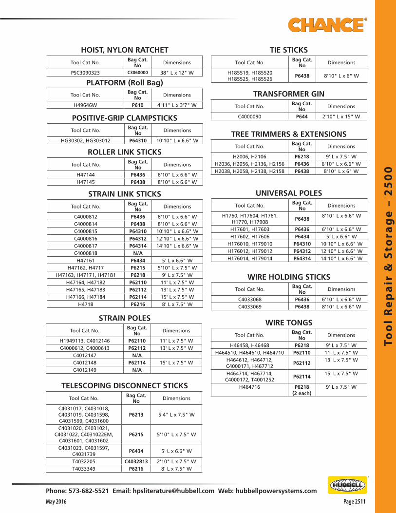
Too
l R
ep
air
& S
tora
ge
– 2
50
0
Phone: 573-682-5521 Email: [email protected] Web: hubbellpowersystems.com
Page 2511May 2016
HOIST, NYLON RATCHET
PLATFORM (Roll Bag)
POSITIVE-GRIP CLAMPSTICKS
ROLLER LINK STICKS
STRAIN LINK STICKS
STRAIN POLES
TIE STICKS
TRANSFORMER GIN
TREE TRIMMERS & EXTENSIONS
UNIVERSAL POLES
WIRE HOLDING STICKS
WIRE TONGS
TELESCOPING DISCONNECT STICKS
Tool Cat No. Bag Cat. No Dimensions
PSC3090323 C3060000 38" L x 12" W
Tool Cat No. Bag Cat. No Dimensions
H49646W P610 4'11" L x 3'7" W
Tool Cat No. Bag Cat. No Dimensions
HG30302, HG303012 P64310 10'10" L x 6.6" W
Tool Cat No. Bag Cat. No Dimensions
H47144 P6436 6'10" L x 6.6" WH47145 P6438 8'10" L x 6.6" W
Tool Cat No. Bag Cat. No Dimensions
C4000812 P6436 6'10" L x 6.6" WC4000814 P6438 8'10" L x 6.6" WC4000815 P64310 10'10" L x 6.6" WC4000816 P64312 12'10" L x 6.6" WC4000817 P64314 14'10" L x 6.6" WC4000818 N/AH47161 P6434 5' L x 6.6" W
H47162, H4717 P6215 5'10" L x 7.5" WH47163, H47171, H47181 P6218 9' L x 7.5" W
H47164, H47182 P62110 11' L x 7.5" WH47165, H47183 P62112 13' L x 7.5" WH47166, H47184 P62114 15' L x 7.5" W
H4718 P6216 8' L x 7.5" W
Tool Cat No. Bag Cat. No Dimensions
H1760, H17604, H1761,H1770, H17908
P64388'10" L x 6.6" W
H17601, H17603 P6436 6'10" L x 6.6" WH17602, H17606 P6434 5' L x 6.6" W
H176010, H179010 P64310 10'10" L x 6.6" WH176012, H179012 P64312 12'10" L x 6.6" WH176014, H179014 P64314 14'10" L x 6.6" W
Tool Cat No. Bag Cat. No Dimensions
C4033068 P6436 6'10" L x 6.6" WC4033069 P6438 8'10" L x 6.6" W
Tool Cat No. Bag Cat. No Dimensions
H46458, H46468 P6218 9' L x 7.5" WH464510, H464610, H464710 P62110 11' L x 7.5" W
H464612, H464712, C4000171, H467712
P6211213' L x 7.5" W
H464714, H467714,C4000172, T4001252
P6211415' L x 7.5" W
H464716 P6218(2 each)
9' L x 7.5" W
Tool Cat No. Bag Cat. No Dimensions
H1949113, C4012146 P62110 11' L x 7.5" WC4000612, C4000613 P62112 13' L x 7.5" W
C4012147 N/AC4012148 P62114 15' L x 7.5" WC4012149 N/A
Tool Cat No. Bag Cat. No Dimensions
H2006, H2106 P6218 9' L x 7.5" WH2036, H2056, H2136, H2156 P6436 6'10" L x 6.6" WH2038, H2058, H2138, H2158 P6438 8'10" L x 6" W
Tool Cat No. Bag Cat. No Dimensions
C4031017, C4031018,C4031019, C4031598,C4031599, C4031600
P6213 5'4" L x 7.5" W
C4031020, C4031021,C4031022, C4031022EM,
C4031601, C4031602P6215 5'10" L x 7.5" W
C4031023, C4031597,C4031739
P6434 5' L x 6.6" W
T4032205 C4032813 2'10" L x 7.5" WT4033349 P6216 8' L x 7.5" W
Tool Cat No. Bag Cat. No Dimensions
H185519, H185520H185525, H185526
P6438 8'10" L x 6" W
Tool Cat No. Bag Cat. No Dimensions
C4000090 P644 2'10" L x 15" W

Too
l Re
pa
ir & S
tora
ge
– 25
00
Page 2512 May 2016
Phone: 573-682-5521 Email: [email protected] Web: hubbellpowersystems.com
GLOVE BAGFeatures & Applications• 18" L x 8" W• One piece front and back, bar-tacked at all corners• Leather-reinforced inside and out for snap• Double-nylon stitched• Gusset has 4” top tapering to 2” bottom
C4170147
Features & Applications• Made of double vinyl laminated open weave nylon cloth• Lightweight and durable with nylon stitching throughout• Standard color of all synthetic material is easy-to-see, bright yellow
LINEMAN’S TOOL BAGFeatures & Applications• 22" L x 11" W x 11" D• Plywood bottom covered inside and out with metal
skids on bottom of bag• Has full separating heavy duty zipper and heavy
webbing handles around bag• Full 4” pocket on inside
Tool and Rubber-GloveProtective Bags and Buckets
C4170148
C4170151
C4170150
COMBINATION GLOVEAND SLEEVE BAGFeatures & Applications• 18" L x 8" W• Separate storage for rubber gloves
and sleeves• Single flap, double-nylon stitching• Reinforced inside and out for snap
LINE HOSE BAGFeatures & Applications• 48" L x 7" Dia.• 3”-wide plastic top ring• Molded plastic bottom with 2” cuff• 3/8” rope handle
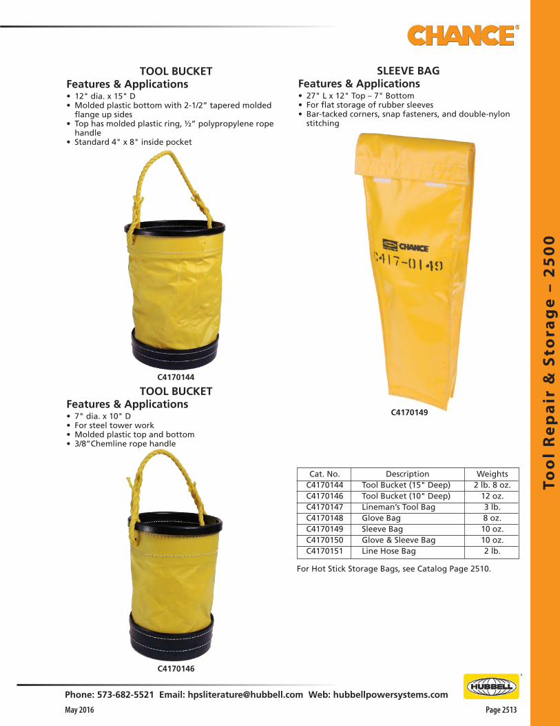
Too
l R
ep
air
& S
tora
ge
– 2
50
0
Phone: 573-682-5521 Email: [email protected] Web: hubbellpowersystems.com
Page 2513May 2016
For Hot Stick Storage Bags, see Catalog Page 2510.
DescriptionTool Bucket (15" Deep)Tool Bucket (10" Deep)Lineman’s Tool BagGlove BagSleeve BagGlove & Sleeve BagLine Hose Bag
Weights2 lb. 8 oz.
12 oz.3 lb.8 oz.
10 oz.10 oz.2 lb.
C4170146
C4170144
C4170149
TOOL BUCKETFeatures & Applications• 7" dia. x 10" D• For steel tower work• Molded plastic top and bottom• 3/8”Chemline rope handle
TOOL BUCKETFeatures & Applications• 12" dia. x 15" D• Molded plastic bottom with 2-1/2” tapered molded
flange up sides• Top has molded plastic ring, ½” polypropylene rope
handle• Standard 4" x 8" inside pocket
Cat. No.C4170144C4170146C4170147C4170148C4170149C4170150C4170151
SLEEVE BAGFeatures & Applications• 27" L x 12" Top – 7" Bottom• For flat storage of rubber sleeves• Bar-tacked corners, snap fasteners, and double-nylon
stitching

Too
l Re
pa
ir & S
tora
ge
– 25
00
Page 2514 May 2016
Phone: 573-682-5521 Email: [email protected] Web: hubbellpowersystems.com
Storage Canistersfor Rubber Insulating BlanketsFeatures & Applications• Proper storage extends blanket life• Provides easy access in service• Long-lasting construction• For physical and contamination protection, canisters
are lightweight yet durable and stow easily on service vehicles and in warehouses
• Cylindrical shape promotes proper treatment – rubber blankets should never be folded, creased or compressed when stored
• Rolling blankets before inserting helps keep them ready for service
• Blankets nested inside each other may be inserted or withdrawn one at a time
• Bright orange color • High-impact-resistant high-density polyethylene for
tough, rust-free resilience• Polypropylene rope keeps tight-fitting cap secured to
canister
C4032998 does not have a handle and is 7" in diameter.
C4032999 has a molded handle and is 10" in diameter.
Storage Canisters for Rubber Insulating Blankets
Catalog No. Description Weight
C4032998 No handle, 7" dia., 37" long 6 lb./2.7 kg.C4032999 With handle, 10" dia., 37" long 75/8 lb./3.43 kg.

Too
l R
ep
air
& S
tora
ge
– 2
50
0
Phone: 573-682-5521 Email: [email protected] Web: hubbellpowersystems.com
Page 2515May 2016
Walk-in Tool Trailers . . . Continued on next page . . .
Your new Walk-In Tool Trailer will provide a convenient way to store, transport and care for your Hot Line Tool sets.
Standard lengths of 16 and 20 feet offer headroom of 6 feet-6 inches.A 7,000-lb. gross vehicle weight rating gives the trailer ample capacity for your job requirements.
Standard Equipment CHECKLIST
Standard features include: • Corrosion-resistant aluminum exterior• Tandem axles • Electric Brakes• Dual rear doors • One curb-side door• Tongue mounted spare tire• Center Interior racking for tool storage• White exterior finish• 7-way 12V Trailer End Connector
Interior Tool Storage
Full Length storage bins on both sides and across front
Overhead rack and thumbscrews for 30 universal tools (Left side) Two full-height center racks
Ladder channel on floor between center racks √√
√√
Exterior and Towing
Breakaway braking system
Spare tire with mounting bracket Adjustable height pintle eye hitch Fold-up hand crank tongue jack
Two safety chains
√√
√√√

Too
l Re
pa
ir & S
tora
ge
– 25
00
Page 2516 May 2016
Phone: 573-682-5521 Email: [email protected] Web: hubbellpowersystems.com
Optional Equipment CHECKLIST
Optional features available In addition to the Standard features and equipment, Walk-In Trailers can be custom ordered with the Options listed below.
Please check the boxes on these two pages to select Options or just get in touch with us to help.
Interior Tool Storage OPTIONS
F
B
A
D
E
Walk-in Tool Trailers . . . Continued on next page . . .
A. Second overhead rack and thumbscrews for 30 universal Tools (Right side)
B. 12Vdc interior lights with two wall switches, select only one option: 1 pair of lights 2 pairs of lights 3 pairs of lights
C. Wall mounted tool rack with 24 supports and eight elastic tiedowns (Left Side)
D. Wall mounted tool rack with 24 supports and eight elastic tiedowns (Right Side)
E. Second interior ladder rack
F. 110/220 Vac “dry room” heater
G. 2 vertical cabinets with 4 shelves each, installed in front of trailer
H. Rhino Lining protective flooring
I. One additional support stud kit (10 per box) for side or center tool racks
Catalog Number T4002528 (not shown)
A
C DG
H

Too
l R
ep
air
& S
tora
ge
– 2
50
0
Phone: 573-682-5521 Email: [email protected] Web: hubbellpowersystems.com
Page 2517May 2016
Walk-in Tool Trailers . . . Continued on next page . . .
J
K
L
O
Optional Equipment CHECKLIST
Optional features available In addition to the Standard features and equipment, Walk-In Trailers can be custom ordered with the Options listed below.
Please check the boxes on these two pages to select Options or just get in touch with us to help.Exterior and Towing OPTIONS
J. 12 Vdc Power Tongue Jack
K. Rear Skid Plate
L. Rear Mounted Bumper 6”
M. Rear Mounted Step Bumper 10” (not shown)
N. 2 5⁄16” Ball Type Hitch (not shown)
O. Rear Ramp Door (not available with rear bumper)
P. 10,000-lb. GVWR [two 5,000-lb. axles] (not shown)
Q. 12,000-lb. GVWR [two 6,000-lb. axles] (not shown)
R. 14,000-lb. GVWR [two 7,000-lb. axles] (not shown)
S. Flipped axles add 4 extra inches of ground clearance (not shown)

Too
l Re
pa
ir & S
tora
ge
– 25
00
Page 2518 May 2016
Phone: 573-682-5521 Email: [email protected] Web: hubbellpowersystems.com
Walk-in Tool TrailersTrailer gross vehicle weight ....................7,000 lb.Tandem axles ...................3,500 lb. capacity, eachTrailer curb weight, empty .....................2,270 lb.Payload capacity ......................................4,730 lb.Brakes .............................. Electric, all four wheelsTires .......................................... 15", load range CHitch weight, empty ..................................210 lb.Hitch with safety chains ... 3" pintle or 2 5/16" ballHitch height ........... Adjustable, 19" through 27"Tongue jack ........... Manual crank with sand padExterior lights and reflectorsPrefinished (white) aluminum skin 0.30" gaugeInterior floor ........................................... PlywoodInterior walls are vinyl coated white.Breakaway system & battery (meets DOT)
Standard Storage Provisions —––––—————• 14"-deep bins (both sides), 20"-deep front bins• Rack for 30 universal tools (left, overhead) • Ladder-rack channel (center, on floor)• Full-height tool racks (center-mounted), 150 plastic-coated supports & 29 elastic tiedowns
Trailer gross vehicle weight .................... 7,000 lb.Tandem axles ...................3,500 lb. capacity, eachTrailer curb weight, empty ..................... 2,770 lb.Payload capacity ...................................... 4,230 lb.Brakes .............................. Electric, all four wheelsTires ...........................................15", load range CHitch weight, empty .................................. 250 lb.Hitch with safety chains ... 3" pintle or 2 5/16" ballHitch height ............Adjustable, 19" through 27"Tongue jack ............Manual crank with sand padExterior lights and reflectorsPrefinished (white) aluminum skin ..0.30" gaugeInterior floor ............................................PlywoodInterior walls are vinyl coated white.Breakaway system & battery (meets DOT)
Standard Storage Provisions ————————• 14"-deep bins (both sides), 20"-deep front bins• Rack for 30 universal tools (left, overhead) • Ladder rack channel (center, floor)• Full-height tool racks (center-mounted), 150 plastic-coated supports & 29 elastic tiedowns
36.0DOOR
14.020.0
24.0
78.0
70.0
76.5
61.0
12.0
102.0
20.0
192.0
189.0
244.0
81.0 86.0
29.045.032.0
16-ft. (body-length) Trailer
52.0
102..0
12.0
20.0
81.0
86.0
41.0
70.0
78.0
24.0
14.0
36.0DOOR
20.0
241.0
244.0296.0
45.0 29.0
20.0
76.5
20-ft. (body-length) Trailer
Fiberglass Pop-Up Tool Trailers

Too
l R
ep
air
& S
tora
ge
– 2
50
0
Phone: 573-682-5521 Email: [email protected] Web: hubbellpowersystems.com
Page 2519May 2016
Fiberglass Pop-Up Tool Trailers. . . Continued on next page . . .
Your new Fiberglass Pop-Up Hot Line Tool Trailer will provide a convenient way to store, transport and care for your Hot Line Tool sets.
The overall length of the trailer is 23 feet. The interior space of the trailer is 17 feet 2 inches with storage for Hot Line Tools up to 14 feet 7 inches.
A 12,000-lb. gross vehicle weight rating gives the trailer ample capacity for your job requirements.
Standard Equipment CHECKLIST
Standard features include: • Tandem axles • Electric Brakes• White exterior finish• Four 8.00 x 14.5 tires• Rectangular-tube steel rear bumper• Manual crank for lid open/close device• Step-up brackets, front and rear, both sides
Interior Tool Storage12 hot line tool compartments
155 adjustable plastic-covered tool supports 20 elastic tie-down straps
1 channel rack for 30 Universal Tool accessories (right side)
√√√√
Exterior and TowingBreakaway braking system
Spare tire with mounting bracket Adjustable height pintle eye hitch Fold-up hand crank tongue jack with castor wheel
Two safety chains
√
√
√√√

Too
l Re
pa
ir & S
tora
ge
– 25
00
Page 2520 May 2016
Phone: 573-682-5521 Email: [email protected] Web: hubbellpowersystems.com
. . . Continued on next page . . . Fiberglass Pop-Up Tool Trailers
Optional Equipment CHECKLIST
In addition to the Standard features and equipment, Fiberglass Pop-Up Hot Line Tool Trailers can be custom ordered with the Options listed below.
Please check the boxes on this page to select Options or just get in touch with us to help.Interior Tool Storage OPTIONS
A. 110/220 Vac “dry room” heater
B. Additional channel rack for 30 Universal Tool accessories
C. Ladder-rack brackets (plastisol coated) mounted on lid
1 pair (right side) 2 pairs
D. Electric motor for lid open/close device (not shown)
E. 2 5/16” ball socket type hitch, adjustable height
A
EC
B

Too
l R
ep
air
& S
tora
ge
– 2
50
0
Phone: 573-682-5521 Email: [email protected] Web: hubbellpowersystems.com
Page 2521May 2016
Fiberglass Pop-Up Tool Trailers
Trailer gross vehicle weight ..................12,000 lb.Tandem axles ...................6,000 lb. capacity, eachTrailer curb weight, empty .....................2,920 lb.Payload capacity ......................................9,180 lb.Brakes .............................. Electric, all four wheelsTires ................ Four 8.00 x 14.5 tires, 3100 lb. ea.Hitch with safety chains .. 3" pintle or 2 5/16" ballHitch height....Adjustable, 15 ½” through 29 ½”Tongue jack ....................................Manual crankLow profile lightweight fiberglass body and lidBreakaway system and battery (meets DOT)
Standard Storage Provisions —––––—————• 12 hot line tool compartments• 155 adjustable plastic-covered tool supports • 20 elastic tie-down straps• 1 channel rack for 30 Universal Tool Accessories (right side)

Lin
em
an
's A
cce
sso
rie
s –
25
50
Page 2551May 2016
Phone: 573-682-5521 Email: [email protected] Web: hubbellpowersystems.com
Lin
em
an
's A
cce
sso
rie
s –2
55
0
Lineman'sAccessories
Catalog 2550 May 2016

Line
ma
n's A
ccesso
ries – 2
55
0
Page 2552 May 2016
Phone: 573-682-5521 Email: [email protected] Web: hubbellpowersystems.com
Features & Applications• Allows linemen to get closer to their work• Clothing is bonded to conductor, placing the lineman
within the field of electricity• Allows him to work with his hand on the conductor
hardware• Transmission line maintenance efficiency and effectiveness
are advanced without endangering lineman and without interrupting customer service.
• For work on voltages through 765 kV• Two-piece conductive suit is made of a blend of Nomex
aramid flame resistant fiber and microscopic stainless steel fiber
• Zepel finish is applied to repel water
• Analysis and tests show the material: o Is extremely strong and tear resistant o Meets or exceeds IEC 60895 Specification for conductive
clothing o Does not degrade with time or number of washings• Overcast stitching on major seams for integrity, durability
and resistance to fraying • Tails and appendages are attached by separate panels with
multiple square and “x” stitches for integrity• Velcro pads are located on strong nylon webbing
suspender harness and cuffs of jacket and pants to provide rapid versatile fitting
• Corrosion-resistant snap fittings on jacket and pants make it easy to suit up
• Large hood, with drawstring, fits over any standard helmet
Conductive SuitEHV Barehand Conductive Suit puts the linemanon the job . . .

Lin
em
an
's A
cce
sso
rie
s –
25
50
Page 2553May 2016
Phone: 573-682-5521 Email: [email protected] Web: hubbellpowersystems.com
Cat. No.
T4020694
Description
Static Belt
Weight
2 oz.
T4020694
Static BeltFeatures & Applications• Worn by linemen working on EHV structures• Serves as a continuous ground to minimize static
discomfort while working near energized lines• Made of same material as Chance Conductive Suits• Should be buckled snugly around the waist, next to
bare skin• Has a 6’ lead that can be attached to the steel structure
Conductive SuitFeatures & Applications• Suit of trousers and jacket in sizes Medium, Large and
Extra Large• See ordering information below
Hood, with drawstring, large enough to fit over safety helmet
GlovesC4020558
SocksC4020578
Description
Conductive Suit — medium
Conductive Suit — large
Conductive Suit — extra large
Conductive Gloves (pair)
Conductive Socks (pair)
Weight
2 lb./.9 kg.
2 lb./.9 kg.
2 lb./.9 kg.1/2 lb./.2 kg.1/3 lb./.2 kg.
Catalog No.
C4020533
C4020534
C4020535
C4020558
C4020578
Ordering Information
• View inside the jacket shows grounding strap of jacket and pants tied together
• This prevents the electrical separation of the jacket from the pants

Line
ma
n's A
ccesso
ries – 2
55
0
Page 2554 May 2016
Phone: 573-682-5521 Email: [email protected] Web: hubbellpowersystems.com
Conductive BootsFeatures & Applications• 8” leather conductive boot • Offers linemen both comfort and protection• Meets all ANSI Specifications for conductive footwear• Has a leg harness with a black conductive sole • A wire molded into the rubber leads up the back with
the conductive rubber strap covering to a conductive snap fitting at the top of the boot
• An additional conductive boot strap is secured through a snap fitting from boot to conductive suit or to leg strap
• This connection again, has a wire built into a nylon and conductive rubber strap
Weight per pair: 61⁄2 lb./2.9 kg.
Linemen’s Holsters
PS111HLS(Tools not included)
PSC111HLDS(Tools not included)
Features & Applications• Manufactured by Bashlin, maker of only premium
holsters for tool belts• Feature double backs which are reinforced for extra
wear• Left handed holsters are available at no extra cost• Add an “LH” to the part number when ordering
No. PS111HLS For pliers, rule, screwdriver, *Channellock®, knife or wrench Ship Wt: 1.25 lb (0.57 kg)
No. PSC111HLDS For pliers, rule, screwdriver, *Channellock®, ratchet driver, knife or wrench Ship Wt: 1.50 lb (0.68 kg)
*Registered trademark of Channellock, Inc.
Mechanical Features• Boot upper is made of top quality, high oil content
leather• Water resistant• Flexible and durable • Finely-crafted stitching and brown finish• Meets ANSI Class 75 steel toe footwear specifications
(75 lb. crush strength) • Has a flexible full stainless steel inner sole, 400 lb. test• Heel counter is molded into the sole to prevent its
pulling away• Welt is neoprene, not rubber or leather, to resist
cracking• Sole is vulcanized under 20,000 pounds of pressure to
the welt, not to upper• Makes the sole more flexible and helps prevent it from
separating from upper• Tempered steel shank is built-in for proper arch support
Electrical Features• Meets ANSI Specifications Z41 for safety-toe footwear• Manufactured to specification of less than 10,000 ohms
from leg strap to boot heel • 100% inspection/testing conducted on each boot as
part of manufacturing process
Do not use groundmen’s or electrician’s holsters on linemen’s tool belts.
Size (EEE widths) 6 7 8 91011121314
* Leg harness straps are included
Catalog No.*C4170623C4170624C4170122C4170123C4170124C4170125C4170126C4170625C4170626

Lin
em
an
's A
cce
sso
rie
s –
25
50
Page 2555May 2016
Phone: 573-682-5521 Email: [email protected] Web: hubbellpowersystems.com
Never carry wire, tools, or anything other than the “positioning” strap in the D-rings of a tool belt. Foreign objects carried in the D-rings may cause the snap to malfunction, and accidental disengagement to occur.
▲ WARNING!
“D” size
Ordering Bashlin Tool BeltsSizing• Proper sizing of lineman’s tool belt is critical• Improperly sized belt is uncomfortable and may cause
an accident or injury• Bashlin tools belts are measured by the “D” size • This is the distance between the heels of the D-rings• All linemen’s tool belts must be ordered according to
the “D” size
Sizing• Locate the point where the heel of the “D” ring
should rest• As the photo illustrates, this is approximately 4" down
from top of hip bone• Begin to measure from this point• Measure around buttocks to same point on opposite
side• When a properly sized tool belt is worn, D-rings will
point nearly straight ahead • Tongue adjustment will also be in center holes as
shown in Photo 3• To properly size Padded Rest-A-Back tool belts, add
2" to your standard “D” measurement
BELT ADJUSTMENT IN INCHES - PER ASTM F887
3
1 2
D Size, Minimum, Center Maximum, Tool inches inches Hole inches Loops
D18 32 36 40 3 D19 33 37 41 3 D20 34 38 42 3 D21 36 40 44 4 D22 37 41 45 4 D23 38 42 46 4 D24 40 44 48 4 D25 41 45 49 4 D26 42 46 50 4 D27 44 48 52 4 D28 45 49 53 4
Falls can cause serious injury or death.▲ WARNING!

Line
ma
n's A
ccesso
ries – 2
55
0
Page 2556 May 2016
Phone: 573-682-5521 Email: [email protected] Web: hubbellpowersystems.com
D18 29-36" D19 30-37" D20 31-38" D21 32-39" D22 33-40" D23 34-41"
D24 35-42" D25 36-43" D26 37-44" D27 38-45" D28 39-46" D29 40-47" D30 41-48"
Upper Tongue Adjustment
BeltSize
Upper Tongue Adjustment
BeltSize
• Bashlin’s Back Support Tool Belts help relieve strain and fatigue
• Use chart to determine proper size• To properly size Padded Rest-A-Back tool belts, add 2"
to your standard “D” measurement• See Page 2555
No. PS88BDXX Ship Wt: 8.50 lb (3.83 kg)
Rest-A-Back
• A practical favorite• 5" cushion section• Nylon back• 6-ply tongue and buckle section • Lightweight, with standard comfort • Bashlin’s S-shaped D-rings • All-leather cushion
The Wrangler
No. PSC1511NDXX Ship Wt: 5.25 lb (2.38 kg)
• Familiar design in a shifting “D” nylon belt• Neoprene-impregnated nylon back• Light, durable and flexible in extreme temperature ranges• Comfortable 5" leather cushion section • Tongue and buckle is 6-ply nylon • Tool loops are leather
The Nylon Deluxe
No. PS160NDXX Ship Wt: 6.00 lb (2.72 kg)
• Superior design and performance• The industry standard• Combines padded, contour cushion section with flares
for the shifting D-rings and a 5-1/2" back• Gives excellent support and climbing comfort• A practical, economical belt
The Floridian
No. PS88DXX Ship Wt: 6.50 lb (2.95 kg)
Linemen’s Tool BeltsAll linemen’s tool belts must be ordered according to “D” size.Example: PSC1511ND18 See how and table on Page 2555.

Lin
em
an
's A
cce
sso
rie
s –
25
50
Page 2557May 2016
Phone: 573-682-5521 Email: [email protected] Web: hubbellpowersystems.com
Features & Applications• Bashlin’s 50 Series and 78 Series pole straps are offered
here • “L” style snaphook has lengthy field history• It has a lock on the back to be released prior to
opening the gate
Pole Straps
78 Series
50 SeriesFeatures & Applications• 6-ply 1-3/4" neoprene coated nylon material• Uses a tongue buckle adjustment
50 Series
78 SeriesFeatures & Applications• Bashlin’s pliable latigo leather straps feature a nylon
insert• Stitching is deeply imbedded in the leather for longer
wear
Always visually confirm the strap is on the D-ring with the gate closed and locked before allowing the strap to support your body weight. Do not just listen for the “click”.
▲ WARNING!
The 50 series straps have red wear indicators in the center to help determine when it is time to replace them. When you see red it is time to remove the strap from service.
▲ WARNING!
Double action locking snaphooks reduce, but do not eliminate, the possibility of accidental disengagement. Caution and proper work methods including keeping the Snap/D ring area free from foreign objects must be practiced at all times. Disabling the gate locks may cause accidents, injury or death.
▲ WARNING!
Length Catalog No. Ship Wt 5' 6" PS51N2HL 3.75 lb (1.7 kg) 6' PS52N2HL 3.75 lb (1.7 kg) 6' 6" PS53N2HL 4.00 lb (1.8 kg) 7' PS54N2HL 4.00 lb (1.8 kg)
Length Catalog No. Ship Wt 5' 6" PSC78X2HL 4.25 lb (1.9 kg) 6' PSC78A2HL 4.25 lb (1.9 kg) 6' 6" PSC78B2HL 4.50 lb (2.0 kg) 7' PSC78C2HL 5.00 lb (2.3 kg)

Line
ma
n's A
ccesso
ries – 2
55
0
Page 2558 May 2016
Phone: 573-682-5521 Email: [email protected] Web: hubbellpowersystems.com
PS683XAP
Bashlin harnesses must be sized and adjusted properly to function properly.
▲ CAUTION!
Connection to the front loop of the PS683XAP harness can be made with carabiners or by looping web or rope through the eye. Snaphooks that may cut the material are not to be used.
▲ CAUTION!
Features & Applications• Bashlin harnesses are normally made from 10,000 lb.
test woven nylon web• Webbing is in contrasting colors (usually orange on the
torso and black on the legs) for easier donning• Meet or exceed all appropriate ANSI, ASTM, and OSHA
requirements• Hardware features a corrosion-resistant coating• Splices are lock stitched with nylon thread of a
contrasting color for easy inspection• Each standard harness is tagged per ANSI/ASTM
requirements with labels shown
Full Body Harnesses
Sizing• Bashlin harness is sized according to torso of the
individual• This involves measuring height and chest, then finding
correct size on chart, according to harness style• Height is first consideration• Move to larger size if chest measurement is too large for
corresponding height• If chest measurement is too small for corresponding
height, choose size dictated by height
1. The user must be properly trained prior to using Bashlin products.
2. Use the proper product for the job.
3. Inspect the harness before each use.
4. Wear the harness tight. It must be tight enough that the buckles hold the material properly and will not disengage accidentally. If the harness is loose, the material can hook on items in the work area, or in the worst case will not perform properly in the event of an arrested fall.
5. Check the buckles, and tighten the straps each time before going aloft.
6. Store the harness properly in a storage bag for longer wear.
▲ WARNING!
Features & Applications• “X”-style harness is available with the 656CM tool belt• Belt can be easily removed from harness when not
needed• Features front attachment point for work positioning
on ladders or rescue• Please state size, and belt “D” size
PS683XAP Climbing Harness
No. PS683XAP_ _ Climbing Harness with a 3" nylon loop for lanyard in back Ship Wt: 8 lb (3.65 kg)
Height5'4" - 5'7" 5'8" - 5'11"6' - 6'3"6'4" - 6'6"6'6"+6'6"+
Chest34" - 36" 36" - 40"42" - 44"46" - 48"48" - 52"52"+
Size"S" Small"M" Medium"L" Large"XL" Extra Large"2X" Double Extra Large"3X" Triple Extra Large
Example: PS683XAPL (= Large)

Lin
em
an
's A
cce
sso
rie
s –
25
50
Page 2559May 2016
Phone: 573-682-5521 Email: [email protected] Web: hubbellpowersystems.com
STEELPSBD16B SERIES
ALUMINUMPSBD14 SERIES
PS28056HL
Features & Applications• Bashlin shock-absorbing 2000 Series lanyards are
recommended for most fall arrest applications• Include an integral polyester core that absorbs forces as
it expands• 1" tubular nylon web with polyester shock absorbing
core, 1-6650 snaphook and a loop end
Fall Arrest Lanyard
Limiting the lanyard length to 6' will not ensure a free fall of 6' or less. The lanyard length, anchor point and work location together will determine the free fall distance.
▲ WARNING!No. PS28056HL Shock absorbing lanyard
Ship Wt: 1.5 lb (0.68 kg)
Pole Climbers
Climbers are to be used by trained personnel only.▲ WARNING!
Features & Applications• Bashlin pole climbers meet ASTM - F887 requirements• Include #2 gaff guard and #5 gaff gauge standard• Nylon straps are standard on Bashlin climbers
BD14 Series• Bashlin’s aluminum alloy offset climber • Features a replaceable, forged steel gaff• Lightweight climber reduces fatigue and adds climbing
comfort• Comparable steel climbers weigh 30% more
Number Description Ship Wt:PSBD141N Bottom straps attached 4.25 lb (1.93 kg)PSBD142N Bottom straps attached, and top straps 4.75 lb (2.15 kg)PSBD143N Bottom straps attached, top straps and #110D pads 5.25 lb (2.38 kg)PSBD144N Bottom straps attached, top straps and #130D pads 5.50 lb (2.49 kg)PSBD145N Bottom straps attached, top straps and #140DS pads 5.75 lb (2.61 kg)
The maximum and standard length for Bashlin 2000 Series fall arrest lanyard is 6 feet. This is to aid the user in compliance with OSHA’s maximum 6 feet free fall for personal fall arrest systems.
▲ CAUTION!
BD16B Series• Rugged, steel alloy adjustable climber• Features replaceable gaff, offset design, roomy ankle area,
and triangular strap ring
PSBD16B1N Bottom straps attached 5.50 lb (2.49 kg)PSBD16B2N Bottom straps attached, and top straps 6.00 lb (2.72 kg)PSBD16B3N Bottom straps attached, top straps and #110D pads 6.50 lb (2.95 kg)PSBD16B4N Bottom straps attached, top straps and #130D pads 6.75 lb (3.06 kg)PSBD16B5N Bottom straps attached, top straps and #140DS pads 7.00 lb (3.18 kg)
Lanyards may be connected to D-Rings on harnesses with web/rope loops, and properly dimensioned carabiners or snaphooks. 3" nylon loop back attachments require web/rope loops or properly dimensioned carabiners. Snaphooks are not to be used with such attachment points.
▲ CAUTION!

Line
ma
n's A
ccesso
ries – 2
55
0
Page 2560 May 2016
Phone: 573-682-5521 Email: [email protected] Web: hubbellpowersystems.com
PS105BC
PSC130D
PS105 Series PadsFeatures & Applications• The original “spur-stay” climber pad• Designed to reduce kick-back and twisting of shank• Insert holds climber for comfort and better gaff
penetration• An excellent choice for the lineman who occasionally
climbs• Available with a straight or angled metal section
Straight Use on Angled Use on Ship Wt:PS105A PSBD16 PS105AC PSBD16 1.5 lb (0.68 kg)PS105B PSBD14 PS105BC PSBD14 1.5 lb (0.68 kg)
PSC130D PadFeatures & Applications• L-shaped design • Light padding for added comfort
No. PSC130D (padded) Ship Wt: 0.7 lb (0.32 kg)
Climber Pads, Straps
Climber StrapsFeatures & Applications• Bashlin nylon climber straps are durable, pliable, and
comfortable• Double riveted and feature a protective buckle shield
Number Description Ship Wt:PSC85N Top straps - 11/16" x 24" 0.6 lb (0.27 kg)
PS86N One piece lower straps 0.6 lb (0.27 kg) - 11/16" x 28" PS87N Two piece lower straps - 11/16" x 28" (original style, to be used on the tri- angular ring of Bashlin climbers. Must be assembled.) 0.7 lb (0.27 kg)
PSC89N Two piece lower straps with split ring - 11/16" x 28" 0.7 lb (0.27 kg)
PSC85N PS86N
PS87N PSC89N

Re
com
me
nd
ed
Ho
t Li
ne
To
ols
Lis
ts –
26
00
Phone: 573-682-5521 Email: [email protected] Web: hubbellpowersystems.com
Page 2601May 2016
InsulatedHand Tools
Section
2100
Re
com
me
nd
ed
Ho
t Li
ne
To
ols
Lis
ts –
26
00
RecommendedHot Line Tools Lists
Catalog 2600 May 2016
Page(s) Hot Line Tools Lists by Applications2602-2603 15 kV Hot Stick Work only2604 15 kV Rubber Glove Work from an Insulated Platform2605-2606 15 kV Hot Stick Work & Rubber Glove Work2607-2608 15 kV Hot Stick Work, Rubber Glove & Underground Work2609 25 kV Rubber Glove Work from an Insulated Platform2610 25 kV Rubber Glove Work from an Insulated Bucket Truck2611 35 kV Rubber Glove Work from an Insulated Platform2612-2613 15, 25 & 35 kV Hot Stick Work only2614-2615 15, 25 & 35 kV Hot Stick Work & Rubber Glove Work2616-2617 15, 25 & 35 kV Hot Stick Work, Rubber Glove & Underground Work2618-2619 15 through 69 kV, 477 kcmil and smaller, Hot Stick Work only2620-2621 69 kV, 477 kcmil and smaller - No Underbuild, Hot Stick Work only2622-2623 69 kV, 477 kcmil and smaller - With Underbuild, Hot Stick Work only2624-2625 69 through 161 kV, 477 kcmil and smaller - No Underbuild, Hot Stick Work only2626-2627 69 through 161 kV, 477 kcmil and smaller - With Underbuild, Hot Stick Work only
Table of Contents
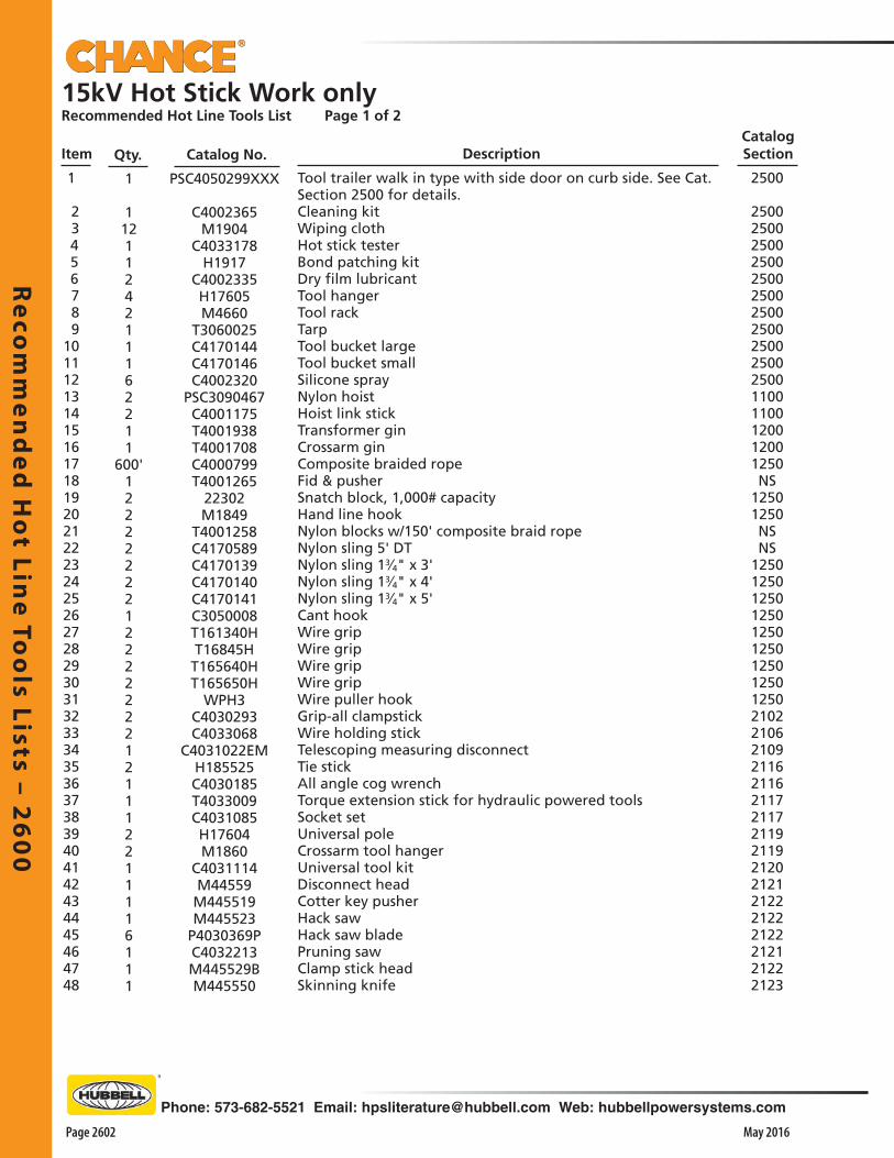
Re
com
me
nd
ed
Ho
t Line
Too
ls Lists – 26
00
Page 2602 May 2016
Phone: 573-682-5521 Email: [email protected] Web: hubbellpowersystems.com
15kV Hot Stick Work onlyRecommended Hot Line Tools List Page 1 of 2
Item Qty.
1
1121124211162211
600'1222222212222222121112211116111
PSC4050299XXX
C4002365M1904
C4033178H1917
C4002335H17605M4660
T3060025C4170144C4170146C4002320
PSC3090467C4001175T4001938T4001708C4000799T4001265
22302M1849
T4001258C4170589C4170139C4170140C4170141C3050008T161340HT16845HT165640HT165650H
WPH3C4030293C4033068
C4031022EMH185525C4030185T4033009C4031085H17604M1860
C4031114M44559M445519M445523
P4030369PC4032213M445529BM445550
Tool trailer walk in type with side door on curb side. See Cat. Section 2500 for details.Cleaning kitWiping clothHot stick testerBond patching kitDry film lubricantTool hangerTool rackTarpTool bucket largeTool bucket smallSilicone sprayNylon hoistHoist link stickTransformer ginCrossarm ginComposite braided ropeFid & pusherSnatch block, 1,000# capacityHand line hookNylon blocks w/150' composite braid ropeNylon sling 5' DTNylon sling 13⁄4" x 3'Nylon sling 13⁄4" x 4'Nylon sling 13⁄4" x 5'Cant hookWire gripWire gripWire gripWire gripWire puller hookGrip-all clampstickWire holding stickTelescoping measuring disconnectTie stickAll angle cog wrenchTorque extension stick for hydraulic powered toolsSocket setUniversal poleCrossarm tool hangerUniversal tool kitDisconnect headCotter key pusherHack sawHack saw bladePruning sawClamp stick headSkinning knife
Description
2500
2500250025002500250025002500250025002500250011001100120012001250NS
12501250NS NS
12501250125012501250125012501250125021022106210921162116211721172119211921202121212221222122212121222123
1 2 3 4 5 6 7 8 9101112131415161718192021222324252627282930313233343536373839404142434445464748
Catalog SectionCatalog No.
Re
com
me
nd
ed
Ho
t Li
ne
To
ols
Lis
ts –
26
00
Phone: 573-682-5521 Email: [email protected] Web: hubbellpowersystems.com
Page 2603May 2016
Catalog SectionItem Qty. DescriptionCatalog No.
11111111112241443132423211
213333844432226121111124424
M445563M1899
T4031101M445585M445587C4030834C4031071C4032861H18716H21064H46458H464510H464712H464716
M47403WM47405WC4000073M17285M4743
M1846WM18474M4744
M4760WM47602
C4001016PSC4000075002
C4000517T4002272H47144
J1541502S16007
PSC6010341C4060181GA
C4060182M49371M49372M49376
C4060097C4060102
M4933C4060084GA
C4060305H1876
C4033374T6000641T6000865C4170151C4032999C4060346C4060348C4060531
Cleaning brushCleaning brush replacementsAdjustable insulator forkHammerBall socket adjusterHot Rodder, largeHot Rodder, smallHydraulic cuttersLight duty cuttersTree trimmerWire tong 11⁄2" x 8'Wire tong 11⁄2" x 10'Wire tong 21⁄2" x 12'Wire tong 21⁄2" x 16' Wire tong saddle 11⁄2"Wire tong saddle 21⁄2"Wire tong saddle extensionWire tong pole clevisWire tong block clampRope snubbing bracketExtension chainCrossarm type saddleLever liftArbor adapterEpoxiglas® lever liftDual auxiliary arm with four M48057 insulators and four C4000268 instead of standard M480517Crossarm conductor supportCorner restraint bracketRoller link stickInsulated jumper setInsulated hangerTemporary cutout toolConductor coverInsulator coverPole cover 9" x 1'Pole cover 9" x 2'Pole cover 9" x 6'Pole top coverCrossarm end coverCrossarm guardSpiral coverFlexible line hosePhasing testerDigital voltage indicatorGround setGrounding set storage bagLine hose bagBlanket canisterBlanket, solidBlanket, slottedHot stick blanket pins
4950515253545556575859606162636465666768697071727374
75767778798081828384858687888990919293949596979899
21002100210021002100210021002150215021502200220022002200220022002200220022002200220022002200220022002200
2200220022502300230023002400240024002400240024002400240024002400245024503000300025002500240024002400
15kV Hot Stick Work onlyRecommended Hot Line Tools List Page 2 of 2
Re
com
me
nd
ed
Ho
t Line
Too
ls Lists – 26
00
Page 2604 May 2016
Phone: 573-682-5521 Email: [email protected] Web: hubbellpowersystems.com
2 2 2 112 2 2 1 1 1 1 2 6 4 424 2 2 1 1
300' 1 2 2 2 2 2 2 2 1 1 213 1 1 1 2 2 1 3 3 3 3 3 31224 2 2 2 2 2 2 1
C4021042C4021055C4021164C4002365
M1904C4002335
M4660T3060025C4170151C4170144C4170146C4032999C4002320C4060346C4060348C4060530
PSC3090323C4001175T4001938T4001708C4000799T4001265
22302C4170139C4170140T161340HT16845H
T165640HC4030293C4033068C4032980M47405WM48057H48628H480060H480072C4000517T4001939T4002272H47144
J1541522S16007
C4031631C4001907C4000600P4060185C4060305
M4933C4060102M49371M49372M49376
C4060097H1876
Epoxiglas® insulated platform 4'Railing for 4' platformPivot for 4' platformCleaning kitWiping clothDry film lubricantTool racksTarpLine hose bagTool bucket largeTool bucket smallBlanket canisterSilicone sprayBlanket, solidBlanket, slottedBlanket pinNylon hoistHoist link stickTransformer ginCrossarm ginComposite braided rope 1⁄2"Fid & pusherSnatch blockNylon slingNylon slingWire gripWire gripWire gripGrip All clampstickWire holding stickRatchet cable cutterWire tong saddlesInsulatorsRubber glove armExtension armExtension armTemporary crossarm conductor supportPole mounted conductor supportCorner restraint bracketRoller link stickInsulated jumper set 15'Insulated hangerLoad pick up toolTension puller switching toolTie back clampInsulator hoodFlexible line hoseCrossarm guardCrossarm end guardPole cover 9" x 1'Pole cover 9" x 2'Pole cover 9" x 6'Pole top coverPhasing tester set
235023502350250025002500250025002500250025002500250024002400240011001100120012001250NS
22501250125012501250125021202100215022002200220022002200220022002200225023002300230023002250240024002400240024002400240024002450
1 2 3 4 5 6 7 8 9101112131415161718192021222324252627282930313233343536373839404142434445464748495051525354
15kV Rubber Glove Work from an Insulated Platform BoardRecommended Hot Line Tools List Page 1 of 1
Item Qty. Catalog No. DescriptionCatalog Section

Re
com
me
nd
ed
Ho
t Li
ne
To
ols
Lis
ts –
26
00
Phone: 573-682-5521 Email: [email protected] Web: hubbellpowersystems.com
Page 2605May 2016
15kV Hot Stick Work & Rubber Glove WorkRecommended Hot Line Tools List Page 1 of 2
Item Qty. Catalog No. DescriptionCatalog Section
1
1121124211162211
600'1222222212222222121112211116111111111
PSC4050299XXX
C4002365M1904
C4033178H1917
C4002335H17605M4660
T3060025C4170144C4170146C4002320
PSC3090467C4001175T4001938T4001708C4000799T4001265
22302M1849
T4001258C4170589C4170139C4170140C4170141C3050008T161340HT16845HT165640HT165650H
WPH3C4030293C4033068
C4031022EMH185525C4030185T4033009C4031085H17604M1860
C4031114M44559M445519M445523
P4030369PC4032213M445529BM445550M445563M1899
T4031101M445585M445587C4030834
Tool trailer walk in type with side door on curb side. See Cat. Section 2500 for details.Cleaning kitWiping clothHot stick testerBond patching kitDry film lubricantTool hangerTool rackTarpTool bucket largeTool bucket smallSilicone sprayNylon hoistHoist link stickTransformer ginCrossarm ginComposite braided ropeFid & pusherSnatch block, 1,000# capacityHand line hookNylon blocks w/150' composite braid ropeNylon sling 5' DTNylon sling 13⁄4" x 3'Nylon sling 13⁄4" x 4'Nylon sling 13⁄4" x 5'Cant hookWire gripWire gripWire gripWire gripWire puller hookGrip-all clampstickWire holding stickTelescoping measuring disconnectTie stickAll angle cog wrenchTorque extension stick for hydraulic powered toolsSocket setUniversal poleCrossarm tool hangerUniversal tool kitDisconnect headCotter key pusherHack sawHack saw bladePruning sawClamp stick headSkinning knifeCleaning brushCleaning brush replacementsAdjustable insulator forkHammerBall socket adjusterHot Rodder, large
2500
25002500250025002500250025002500250025002500250011001100120012001250NS
125012501250 NS
12501250125012501250125012501250125021002100210021002100210021002100210021002100210021002100210021002100210021002100210021002100
1
2 3 4 5 6 7 8 9101112131415161718192021222324252627282930313233343536373839404142434445464748495051525354

Re
com
me
nd
ed
Ho
t Line
Too
ls Lists – 26
00
Page 2606 May 2016
Phone: 573-682-5521 Email: [email protected] Web: hubbellpowersystems.com
15kV Hot Stick Work & Rubber Glove WorkRecommended Hot Line Tools List Page 2 of 2
Item Qty. Catalog No. DescriptionCatalog Section
5556575859606162636465666768697071727374
75767778798081828384858687888990919293949596979899100101102103104105106107108109110111112
11112241443132423211
21333384443222612116111114311111112244246
C4031071C4032861H18716H21064H46458H464510H464712H464716
M47403WM47405WC4000073M17285M4743
M1846WM18474M4744
M4760WM47602
C4001016PSC4000075002
C4000517T4002272H47144
J1541511S16007
PSC6010341C4060181GA
C4060182M49371M49372M49376
C4060097C4060102
M4933C4060084GA
C4060305H1876
C4033374C6001734T6000641T6000865C4170151C4032980H48628M48057
C4031631C4021164C4021173C4021055C4020023C4021042C4021043C4060305C4032999C4060346C4060348C4060530C4002320
2100215021502150220022002200220022002200220022002200220022002200220022002200NS
22002200225023002300230024002400240024002400240024002400240024002450245030003000300025002150220022002310235723572357235723562356240825132409240924092513
Hot Rodder, smallHydraulic cuttersLight duty cuttersTree trimmerWire tong 11⁄2" x 8'Wire tong 11⁄2" x 10'Wire tong 21⁄2" x 12'Wire tong 21⁄2" x 16' Wire tong saddle 11⁄2"Wire tong saddle 21⁄2"Wire tong saddle extensionWire tong pole clevisWire tong block clampRope snubbing bracketExtension chainCrossarm type saddleLever liftArbor adapterEpoxiglas® lever liftDual auxiliary arm with four M48057 insulators and four C4000268 wireholdersCrossarm conductor supportCorner restraint bracketRoller link stickInsulated jumper set 15'Insulated hangerTemporary cutout toolConductor coverInsulator coverPole cover 9" x 1'Pole cover 9" x 2'Pole cover 9" x 6'Pole top coverCrossarm end coverCrossarm guardSpiral coverFlexible line hosePhasing testerAuto-ranging voltage indicatorGround clampGround setGrounding set storage bagLine hose bagRatchet hand cuttersRubber glove auxiliary armInsulators for item # 100Load pick up toolPlatform pivot for 4'Platform pivot for 6'Railing for 4'Railing for 6'Insulated 4' platformInsulated 6' platformFlexible line hoseBlanket canisterBlankets, solid Blankets, slottedHot stick blanket pinsSilicone Spray

Re
com
me
nd
ed
Ho
t Li
ne
To
ols
Lis
ts –
26
00
Phone: 573-682-5521 Email: [email protected] Web: hubbellpowersystems.com
Page 2607May 2016
15kV Hot Stick, Rubber Glove & Underground WorkRecommended Hot Line Tools List Page 1 of 2
Item Qty. Catalog No. DescriptionCatalog Section
1
1121124211162211
600'1222222212222222121112211116111111111111122
PSC4050299XXX
C4002365M1904
C4033178H1917
C4002335H17605M4660
T3060025C4170144C4170146C4002320
PSC3090467C4001175T4001938T4001708C4000799T4001265
22302M1849
T4001258C4170589C4170139C4170140C4170141C3050008T161340HT16845HT165640HT165650H
WPH3C4030293C4033068
C4031022EMH185525C4030185T4033009C4031085H17604M1860
C4031114M44559M445519M445523
P4030369PC4032213M445529BM445550M445563M1899
T4031101M445585M445587C4030834C4031071C4032861H18716H21064H46458H464510
Tool trailer walk in type with side door on curb side. See Cat. Section 2500 for details.Cleaning kitWiping clothHot stick testerBond patching kitDry film lubricantTool hangerTool rackTarpTool bucket largeTool bucket smallSilicone sprayNylon hoistHoist link stickTransformer ginCrossarm ginComposite braided ropeFid & pusherSnatch block, 1,000# capacityHand line hookNylon blocks w/150' composite braid ropeNylon sling 5' DTNylon sling 13⁄4" x 3'Nylon sling 13⁄4" x 4'Nylon sling 13⁄4" x 5'Cant hookWire gripWire gripWire gripWire gripWire puller hookGrip-all clampstickWire holding stickTelescoping measuring disconnectTie stickAll angle cog wrenchTorque extension stick for hydraulic powered toolsSocket setUniversal poleCrossarm tool hangerUniversal tool kitDisconnect headCotter key pusherHack sawHack saw bladePruning sawClamp stick headSkinning knifeCleaning brushCleaning brush replacementsAdjustable insulator forkHammerBall socket adjusterHot Rodder, largeHot Rodder, smallHydraulic cuttersLight duty cuttersTree trimmerWire tong 11⁄2" x 8'Wire tong 11⁄2" x 10'
2500
2500250025002500250025002500250025002500250011001100120012001250NS
125012501250 NS
12501250125012501250125012501250125021002100210021002100210021002100210021002100210021002100210021002100210021002100210021002100210021002100210022002200
1 2 3 4 5 6 7 8 9101112131415161718192021222324252627282930313233343536373839404142434445464748495051525354555657585960

Re
com
me
nd
ed
Ho
t Line
Too
ls Lists – 26
00
Page 2608 May 2016
Phone: 573-682-5521 Email: [email protected] Web: hubbellpowersystems.com
15kV Hot Stick, Rubber Glove & Underground WorkRecommended Hot Line Tools List Page 2 of 2
Item Qty. Catalog No. DescriptionCatalog Section
2200220022002200220022002200220022002200220022002200N/S
220022002250230023002300240024002400240024002400240024002400240024502450301030002500215022002200230023502350235023502350235024002500240024002400210021002450245024502450245030003000300030003000
Wire tong 21⁄2" x 12'Wire tong 21⁄2" x 16' Wire tong saddle 11⁄2"Wire tong saddle 21⁄2"Wire tong saddle extensionWire tong pole clevisWire tong block clampRope snubbing bracketExtension chainCrossarm type saddleLever liftArbor adapterEpoxiglas® lever liftDual auxiliary arm with four M48057 insulators and four C4000268 wireholdersCrossarm conductor supportCorner restraint bracketRoller link stickInsulated jumper set (15 ft.)Insulated hangerTemporary cutout toolConductor coverInsulator coverPole cover 9" x 1'Pole cover 9" x 2'Pole cover 9" x 6'Pole top coverCrossarm end coverCrossarm guardSpiral coverFlexible line hosePhasing testerAuto-ranging voltage indicatorGround setGrounding set storage bagLine hose bagRatchet hand cuttersRubber glove auxiliary armInsulators for item # 100Load pick up toolPlatform pivot for 4'Platform pivot for 6'Railing for 4'Railing for 6'Insulated 4' platformInsulated 6' platformFlexible line hoseBlanket canisterSolid blanketsSlotted blanketsHot stick blanket pinsElbow pullerGrippers 15 kVD.C. Hipot adapterBushing adapterElbow adapterEnergized cable sensorLine/Fault LocatorPenetrator clamp with ground setTemporary underground ground setGrounded parking standGrounding elbowStorage bag for items #122-123-124
H464712H464716
M47403WM47405WC4000073M17285M4743
M1846WM18474M4744
M4760WM47602
C4001016PSC4000075002
C4000517T4002272H47144
J1541511S16007
PSC6010341C4060181GA
C4060182M49371M49372M49376
C4060097C4060102
M4933C4060084GA
C4060305H1876
C4033374T6000641T6000865C4170151C4032980H48628M48057
C4031631C4021164C4021173C4021055C4020023C4021042C4021043C4060305C4032999C4060346C4060348C4060531C4031822C4030704C4031762T4030428T4030602C4030803C4030547T6002233C6000759T6003091C6000729T6000865
41443132423211
213333844432226121111111431111111224424221211112222
6162636465666768697071727374
75767778798081828384858687888990919293949596979899100102103104105106107108109110111112113114115116117118119120121122123

Re
com
me
nd
ed
Ho
t Li
ne
To
ols
Lis
ts –
26
00
Phone: 573-682-5521 Email: [email protected] Web: hubbellpowersystems.com
Page 2609May 2016
2 2 2 112 2 2 1 1 1 1 2 6 4 424 2 2 1 1
300' 1 2 2 2 2 2 2 2 1 1 213 1 1 1 2 2 1 3 3 3 3 3 31224 2 2 2 2 2 1
C4021043C4020023C4021173C4002365
M1904C4002335
M4660T3060025C4170151C4170144C4170146C4032999C4002320C4060346C4060348C4060530
PSC3090323C4002399T4001938T4001708C4000799T4001265
22302C4170139C4170140T161340HT16845H
T165640HC4030293C4033068C4032980M47405WM48057H48628H480060H480072C4000517T4001939T4002272H47144
J2521522S16007
C4001907C4000600P4060185C4060308
M4933C4060102M49371M49372M49376
C4060097T4032261
Epoxiglas® insulated platform 4'Railing for 6' platformPivot for 6' platformCleaning kitWiping clothDry film lubricantTool racksTarpLine hose bagTool bucket largeTool bucket smallBlanket canisterSilicone sprayBlanket, solidBlanket, slottedBlanket pinNylon hoistHoist link stickTransformer ginCrossarm ginComposite braided rope 1⁄2"Fid & pusherSnatch blockNylon slingNylon slingWire gripWire gripWire gripGrip All clampstickWire holding stickRatchet cable cutterWire tong saddlesInsulatorsRubber glove armExtension armExtension armTemporary crossarm conductor supportPole mounted conductor supportCorner restraint bracketRoller link stickInsulated jumper set 25kV 15' longInsulated hangerTension puller switching toolTie back clampInsulator hoodFlexible line hoseCrossarm guardCrossarm end guardPole cover 9" x 1'Pole cover 9" x 2'Pole cover 9" x 6'Pole top coverPhasing tester set
235023502350250025002500250025002500250025002500250024002400240011001100120012001250NS
225012501250125012501250210021002150220022002200220022002200220022002250NS
230023002250240024002400240024002400240024002450
1 2 3 4 5 6 7 8 91011121314151617181920212223242526272829303132333435363738394041424344454647484950515253
25kV Rubber Glove Work from an Insulated Platform BoardRecommended Hot Line Tools List Page 1 of 1
Item Qty. Catalog No. DescriptionCatalog Section

Re
com
me
nd
ed
Ho
t Line
Too
ls Lists – 26
00
Page 2610 May 2016
Phone: 573-682-5521 Email: [email protected] Web: hubbellpowersystems.com
112 2 2 1 1 1 1 2 4 424 6 2 2 1 1
300' 1 2 2 2 2 2 2 2 2 2 2 1 1 2 1 1 1 2 111 1 3 3 3 3 2 2 2 2 2 2151512 1
C4002365M1904
C4002335M4660
T3060025C4170151C4170144C4170146C4032999C4060346C4060348C4060530C4002320
PSC3090451C4001175T4001938T4001708C4000799T4001265
22302M1849
C4170589C4170139C4170140C4170141T161340HT16845H
T165640HC4030293C4033068C4032980M47405W
H48628H480060H480072C4000517T4001939M48057
T4002272H47144
J2521522S16007
PSC6010342M49371M49372M49376
C4060097C4060102
M4933C4060305C4060308P4060185T4032261
Cleaning kitWiping clothDry film lubricantTool racksTarpLine hose bagTool bucket largeTool bucket smallBlanket canisterBlanket, solidBlanket, slottedBlanket pinSilicone lubricantNylon hoist 3⁄4 + 11⁄2 tonHoist link stickTransformer ginCrossarm ginComposite braided rope 1⁄2"Fid & pusherSnatch blockHand line hookNylon sling 13⁄4" x 5' DTNylon sling 13⁄4" x 3'Nylon sling 13⁄4" x 4'Nylon sling 13⁄4" x 5'Wire gripWire gripWire gripGrip All clampstickWire holding stickRatchet cable cutterWire tong saddleRubber glove auxiliary armExtension armExtension armCrossarm conductor supportTemporary conductor supportInsulatorsCorner restraint bracketRoller link stickInsulated jumper set 25kV – 15' longInsulated hangerTemporary cutoutPole cover 9" x 1'Pole cover 9" x 2'Pole cover 9" x 6'Pole top coverCrossarm end guardCrossarm guardFlexible line hose 20kVFlexible line hose 30kVInsulator hoodPhasing tester set
250025002500250025002500250025002500240024002400250011001100120012001250NS
12501250NS
125012501250125012501250210021002150220022002200220022002200220022002250NS
230023002400240024002400240024002400240024002450
1 2 3 4 5 6 7 8 91011121314151617181920212223242526272829303132333435363738394041424344454647484950515253
25kV Rubber Glove Work from an Insulated Bucket TruckRecommended Hot Line Tools List Page 1 of 1Item Qty. Catalog No. Description
Catalog Section
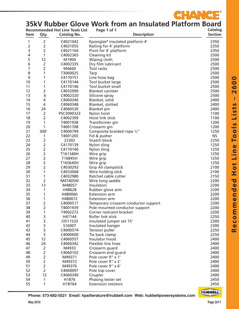
Re
com
me
nd
ed
Ho
t Li
ne
To
ols
Lis
ts –
26
00
Phone: 573-682-5521 Email: [email protected] Web: hubbellpowersystems.com
Page 2611May 2016
2 2 2 112 2 2 1 1 1 1 2 6 4 424 2 2 1 1
300' 1 2 2 2 2 2 2 2 1 1 213 1 1 1 2 2 1 3 3 3 3 31224 2 2 2 2 2 2 12 1 1
C4021042C4021055C4021164C4002365
M1904C4002335
M4660T3060025C4170151C4170144C4170146C4032999C4002320C4060346C4060348C4060530
PSC3090323C4002399T4001938T4001708C4000799T4001265
22302C4170139C4170140T161340HT16845H
T165640HC4030293C4033068C4032980M47405WM48057H48628H480060H480072C4000517T4001939T4002272H47144
J3511533S16007
C4000574C4000600C4060557C4060342
M4933C4060102M49371M49372M49376
C4060097C4060340
H1876H18764
Epoxiglas® insulated platform 4'Railing for 4' platformPivot for 4' platformCleaning kitWiping clothDry film lubricantTool racksTarpLine hose bagTool bucket largeTool bucket smallBlanket canisterSilicone sprayBlanket, solidBlanket, slottedBlanket pinNylon hoistHoist link stickTransformer ginCrossarm ginComposite braided rope 1⁄2"Fid & pusherSnatch blockNylon slingNylon slingWire gripWire gripWire gripGrip All clampstickWire holding stickRatchet cable cutterWire tong saddleInsulatorsRubber glove armExtension armExtension armTemporary crossarm conductor supportPole mounted conductor supportCorner restraint bracketRoller link stickInsulated jumper set 15'Insulated hangerTension pullerTie back clampInsulator hoodFlexible line hoseCrossarm guardCrossarm end guardPole cover 9" x 1'Pole cover 9" x 2'Pole cover 9" x 6'Pole top coverCouplerPhasing tester setExtension resistors
235023502350250025002500250025002500250025002500250024002400240011001100120012001250NS
225012501250125012501250210021002150220022002200220022002200220022002250230023002250225024002400240024002400240024002400240024502450
1 2 3 4 5 6 7 8 910111213141516171819202122232425262728293031323334353637383940414243444546474849505152535455
35kV Rubber Glove Work from an Insulated Platform BoardRecommended Hot Line Tools List Page 1 of 1Item Qty. Catalog No. Description
Catalog Section
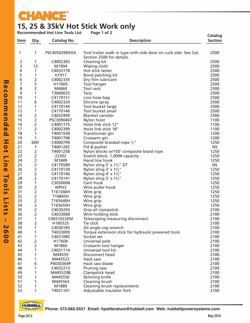
Re
com
me
nd
ed
Ho
t Line
Too
ls Lists – 26
00
Page 2612 May 2016
Phone: 573-682-5521 Email: [email protected] Web: hubbellpowersystems.com
15, 25 & 35kV Hot Stick Work onlyRecommended Hot Line Tools List Page 1 of 2
Item Qty. Catalog No. DescriptionCatalog Section
1
1121125211611222211
600'122222221222222212111221116111111
PSC4050299XXX
C4002365M1904
C4033178H1917
C4002335H17605M4660
T3060025C4170151C4002320C4170144C4170146C4032999
PSC3090467C4001175C4002399T4001938T4001708C4000799T4001265T4001258
22302M1849
C4170589C4170139C4170140C4170141C3050008
WPH3T161340HT16845HT165640HT165650HC4030293C4033068
C4031022EMH185525C4030185T4033009C4031085H17604M1860
C4031114M44559
M445523P4030369PC4032213M445529BM445550M445563
M1889T4031101
Tool trailer walk in type with side door on curb side. See Cat. Section 2500 for details.Cleaning kitWiping clothHot stick testerBond patching kitDry film lubricantTool hangerTool rackTarpLine hose bagSilicone sprayTool bucket largeTool bucket smallBlanket canisterNylon hoistHoist link stick 12"Hoist link stick 18"Transformer ginCrossarm ginComposite braided rope 1⁄2"Fid & pusherNylon blocks w/150' composite braid ropeSnatch block, 1,000# capacityHand line hookNylon sling 5' x 13⁄4" DTNylon sling 3' x 13⁄4"Nylon sling 4' x 13⁄4"Nylon sling 5' x 13⁄4"Cant hookWire puller hookWire gripWire gripWire gripWire gripGrip-all clampstickWire holding stickTelescoping measuring disconnectTie stickAll angle cog wrenchTorque extension stick for hydraulic powered toolsSocket setUniversal poleCrossarm tool hangerUniversal tool kitDisconnect headHack sawHack saw bladePruning sawClampstick headSkinning knifeCleaning brushCleaning brush replacementsAdjustable insulator fork
2500
2500250025002500250025002500250025002500250025002500110011001100120012001250NS
125012501250NS
1250125012501250125012501250125012502100210021002100210021002100210021002100210021002100210021002100210021002100
1 2 3 4 5 6 7 8 91011121314151617181920212223242526272829303132333435363738394041424344454647484950515253
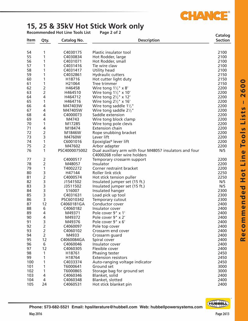
Re
com
me
nd
ed
Ho
t Li
ne
To
ols
Lis
ts –
26
00
Phone: 573-682-5521 Email: [email protected] Web: hubbellpowersystems.com
Page 2613May 2016
Item Qty. Catalog No. DescriptionCatalog Section
5455565758596061626364656667686970717273747576
7778798081828384858687888990919293949596979899100101102103104105
11111111224144441423121
221323333312644322212612111114424
C4030175C4030834C4031071C4031416C4031417C4032861H18716H21064H46458H464510H464712H464716
M47403WM47405WC4000073
M4743M17285M18474M1846WM4760WC6001016M47602
PSC4000075002
C4000517M48057
T4002272H47144
C4000574J1541502J3511502S16007
C4031631PSC6010342C4060181GA
C4060182M49371M49372M49376
C4060097C4060102
M4933C4060084GA
C4060046C4060305H18761H18764
C4033374T6000641T6000865C4060346C4060348C4060531
Plastic insulator toolHot Rodder, largeHot Rodder, smallTie wire clawUtility headHydraulic cuttersHot cutter light dutyTree trimmerWire tong 11⁄2" x 8'Wire tong 11⁄2" x 10'Wire tong 21⁄2" x 12'Wire tong 21⁄2" x 16' Wire tong saddle 11⁄2"Wire tong saddle 21⁄2"Saddle extensionWire tong block clampWire tong pole clevisExtension chainRope snubbing bracketLever liftEpoxiglas® lever liftArbor adapterDual auxiliary arm with four M48057 insulators and four C4000268 roller wire holdersTemporary crossarm supportInsulatorCorner restraint bracketRoller link stickHot stick tension pullerInsulated jumper set (15 ft.)Insulated jumper set (15 ft.)Insulated hangerLoad pick up toolTemporary cutoutConductor coverInsulator coverPole cover 9" x 1'Pole cover 9" x 2'Pole cover 9" x 6'Pole top coverCrossarm end coverCrossarm guardSpiral coverInsulator coverFlexible coverPhasing testerExtension resistorsAuto-ranging voltage indicatorGround setStorage bag for ground setBlanket, solidBlanket, slottedHot stick blanket pin
2100210021002100210021502150215022002200220022002200220022002200220022002200220022002200N/S
22002200220022502250N/SN/S
2300230023002400240024002400240024002400240024002400240024502450245030003000240024002400
15, 25 & 35kV Hot Stick Work onlyRecommended Hot Line Tools List Page 2 of 2
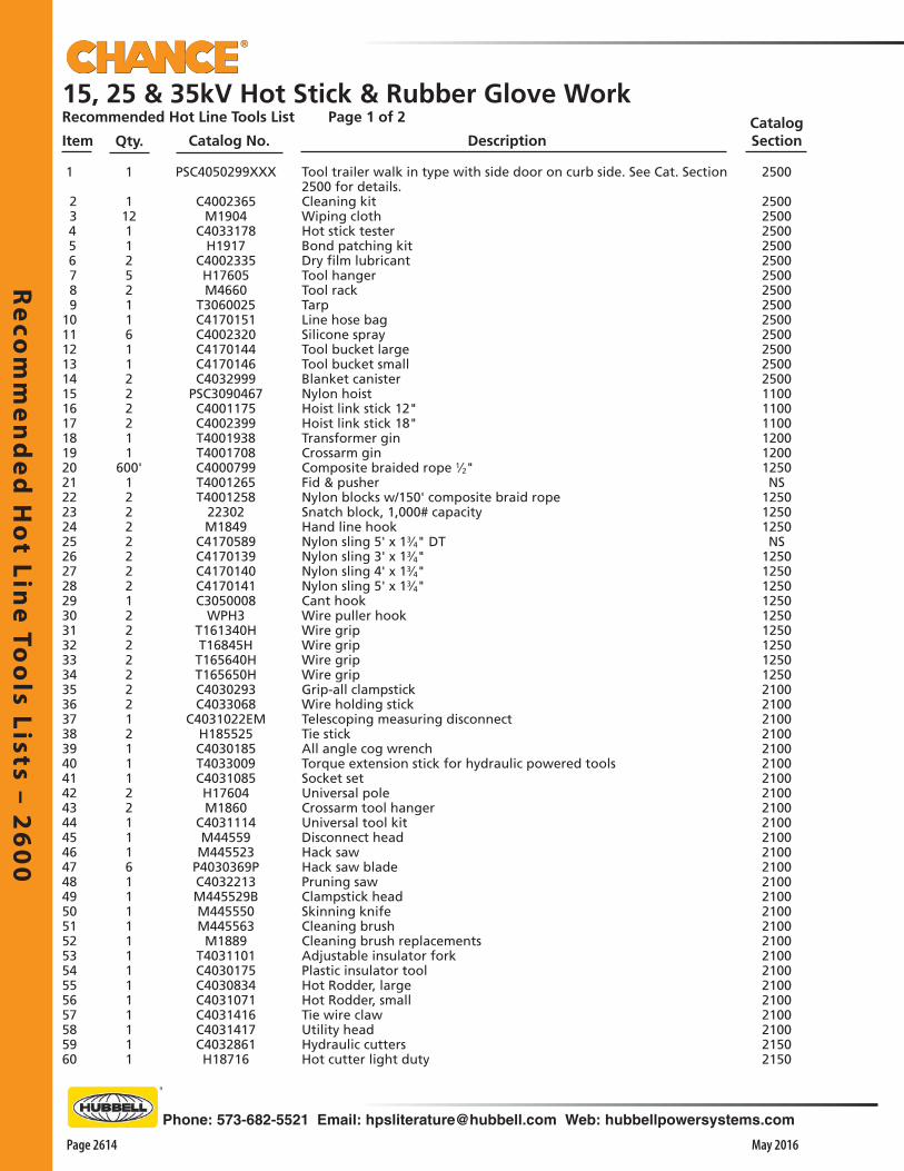
Re
com
me
nd
ed
Ho
t Line
Too
ls Lists – 26
00
Page 2614 May 2016
Phone: 573-682-5521 Email: [email protected] Web: hubbellpowersystems.com
Item Qty. Catalog No. DescriptionCatalog Section
15, 25 & 35kV Hot Stick & Rubber Glove WorkRecommended Hot Line Tools List Page 1 of 2
1
1121125211611222211
600'1222222212222222121112211161111111111111
PSC4050299XXX
C4002365M1904
C4033178H1917
C4002335H17605M4660
T3060025C4170151C4002320C4170144C4170146C4032999
PSC3090467C4001175C4002399T4001938T4001708C4000799T4001265T4001258
22302M1849
C4170589C4170139C4170140C4170141C3050008
WPH3T161340HT16845HT165640HT165650HC4030293C4033068
C4031022EMH185525C4030185T4033009C4031085H17604M1860
C4031114M44559M445523
P4030369PC4032213M445529BM445550M445563M1889
T4031101C4030175C4030834C4031071C4031416C4031417C4032861H18716
Tool trailer walk in type with side door on curb side. See Cat. Section 2500 for details.Cleaning kitWiping clothHot stick testerBond patching kitDry film lubricantTool hangerTool rackTarpLine hose bagSilicone sprayTool bucket largeTool bucket smallBlanket canisterNylon hoistHoist link stick 12"Hoist link stick 18"Transformer ginCrossarm ginComposite braided rope 1⁄2"Fid & pusherNylon blocks w/150' composite braid ropeSnatch block, 1,000# capacityHand line hookNylon sling 5' x 13⁄4" DTNylon sling 3' x 13⁄4"Nylon sling 4' x 13⁄4"Nylon sling 5' x 13⁄4"Cant hookWire puller hookWire gripWire gripWire gripWire gripGrip-all clampstickWire holding stickTelescoping measuring disconnectTie stickAll angle cog wrenchTorque extension stick for hydraulic powered toolsSocket setUniversal poleCrossarm tool hangerUniversal tool kitDisconnect headHack sawHack saw bladePruning sawClampstick headSkinning knifeCleaning brushCleaning brush replacementsAdjustable insulator forkPlastic insulator toolHot Rodder, largeHot Rodder, smallTie wire clawUtility headHydraulic cuttersHot cutter light duty
2500
2500250025002500250025002500250025002500250025002500110011001100120012001250NS
125012501250NS
12501250125012501250125012501250125021002100210021002100210021002100210021002100210021002100210021002100210021002100210021002100210021502150
1 2 3 4 5 6 7 8 9101112131415161718192021222324252627282930313233343536373839404142434445464748495051525354555657585960

Re
com
me
nd
ed
Ho
t Li
ne
To
ols
Lis
ts –
26
00
Phone: 573-682-5521 Email: [email protected] Web: hubbellpowersystems.com
Page 2615May 2016
Item Qty. Catalog No. DescriptionCatalog Section
15, 25 & 35kV Hot Stick & Rubber Glove WorkRecommended Hot Line Tools List Page 2 of 2
Tree trimmerWire tong 11⁄2" x 8'Wire tong 11⁄2" x 10'Wire tong 21⁄2" x 12'Wire tong 21⁄2" x 16' Wire tong saddle 11⁄2"Wire tong saddle 21⁄2"Saddle extensionWire tong block clampWire tong pole clevisExtension chainRope snubbing bracketLever liftEpoxiglas® lever liftArbor adapterDual auxiliary arm with four M48057 insulators and four C4000268 roller wire holdersTemporary crossarm supportInsulatorCorner restraint bracketRoller link stickHot stick tension pullerJumper set 15kV (15 ft.)Jumper set 35kV (15 ft.)Insulated hangerLoad pick up toolTemporary cutoutConductor coverInsulator coverPole cover 9" x 1'Pole cover 9" x 2'Pole cover 9" x 6'Pole top coverCrossarm end coverCrossarm guardSpiral coverInsulator coverFlexible coverPhasing testerExtension resistorsAuto-ranging voltage indicatorGround clampGround setStorage bag for ground setBlanket, solidBlanket, slottedHot stick blanket pinRatchet hand cuttersRubber glove auxiliary armInsulatorInsulated 4' platformInsulated 6' platformRailing for 4' platformRailing for 6' platformPivot for 4' platformPivot for 6' platformFlexible line hose 30kVExtended lip flexible line hoseCouplerHot line applicator toolHot line applicator toolHot line applicator tool
H21064H46458H464510H464712H464716
M47403WM47405WC4000073
M4743M17285M18474M1846WM4760WC4001016M47602
PSC4000075002
C4000517M48057
T4002272H47144
C4000574J1541522J3511533S16007
C4031631PSC6010342C4060181GA
C4060182M49371M49372M49376
C4060097C4060102
M4933C4060084GA
C4060046C4060305H18761H18764
C4033374C6001734T6000641T6000865C4060346C4060348C4060530C4032980H48628M48057
C4021042C4021043C4021055C4020023C4021164C4021173C4060308C4060342C4060340C4032505C4032506C4032507
1224144441423121
2213233333126443222126121111211442411411111112126111
61626364656667686970717273747576
7778798081828384858687888990919293949596979899100101102103104105106107108109110111112113114115116117118119120121
215022002200220022002200220022002200220022002200220022002200N/S
2200220
220022502250NSNS
230023002300240024002400240024002400240024002400240024002450245024503000300030002400 2400 2400215022002200235023502350235023502350240024002400210021002100
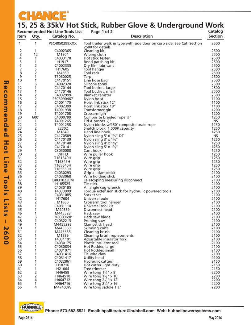
Re
com
me
nd
ed
Ho
t Line
Too
ls Lists – 26
00
Page 2616 May 2016
Phone: 573-682-5521 Email: [email protected] Web: hubbellpowersystems.com
Item Qty. Catalog No. DescriptionCatalog Section
15, 25 & 35kV Hot Stick, Rubber Glove & Underground WorkRecommended Hot Line Tools List Page 1 of 2
1
1121125211611222211
600'1222222212222222121112211161111111111111122414
PSC4050299XXX
C4002365M1904
C4033178H1917
C4002335H17605M4660
T3060025C4170151C4002320C4170144C4170146C4032999
PSC3090467C4001175C4002399T4001938T4001708C4000799T4001265T4001258
22302M1849
C4170589C4170139C4170140C4170141C3050008
WPH3T161340HT16845HT165640HT165650HC4030293C4033068
C4031022EMH185525C4030185T4033009C4031085H17604M1860
C4031114M44559M445523
P4030369PC4032213M445529BM445550M445563M1889
T4031101C4030175C4030834C4031071C4031416C4031417C4032861H18716H21064H46458H464510H464712H464716
M47403W
Tool trailer walk in type with side door on curb side. See Cat. Section 2500 for details.Cleaning kitWiping clothHot stick testerBond patching kitDry film lubricantTool hangerTool rackTarpLine hose bagSilicone sprayTool bucket, largeTool bucket, smallBlanket canisterNylon hoistHoist link stick 12"Hoist link stick 18"Transformer ginCrossarm ginComposite braided rope 1⁄2"Fid & pusher 1⁄2"Nylon blocks w/150' composite braid ropeSnatch block, 1,000# capacityHand line hookNylon sling 5' x 13⁄4" DTNylon sling 3' x 13⁄4"Nylon sling 4' x 13⁄4"Nylon sling 5' x 13⁄4"Cant hookWire puller hookWire gripWire gripWire gripWire gripGrip-all clampstickWire holding stickTelescoping measuring disconnectTie stickAll angle cog wrenchTorque extension stick for hydraulic powered toolsSocket setUniversal poleCrossarm tool hangerUniversal tool kitDisconnect headHack sawHack saw bladePruning sawClampstick headSkinning knifeCleaning brushCleaning brush replacementsAdjustable insulator forkPlastic insulator toolHot Rodder, largeHot Rodder, smallTie wire clawUtility headHydraulic cuttersHot cutter light dutyTree trimmerWire tong 11⁄2" x 8'Wire tong 11⁄2" x 10'Wire tong 21⁄2" x 12'Wire tong 21⁄2" x 16'Wire tong saddle 11⁄2"
2500
2500250025002500250025002500250025002500250025002500110011001100120012001250NS
125012501250NS
12501250125012501250125012501250125021002100210021002100210021002100210021002100210021002100210021002100210021002100210021002100210021502150215022002200220022002200
1 2 3 4 5 6 7 8 9101112131415161718192021222324252627282930313233343536373839404142434445464748495051525354555657585960616263646566
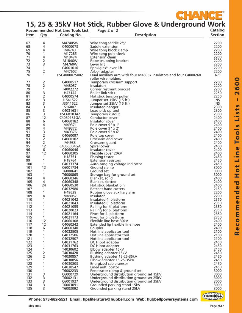
Re
com
me
nd
ed
Ho
t Li
ne
To
ols
Lis
ts –
26
00
Phone: 573-682-5521 Email: [email protected] Web: hubbellpowersystems.com
Page 2617May 2016
Item Qty. Catalog No. DescriptionCatalog Section
15, 25 & 35kV Hot Stick, Rubber Glove & Underground WorkRecommended Hot Line Tools List Page 2 of 2
220022002200220022002200220022002200N/S
22002200220022502250NSNS
230023002300240024002400240024002400240024002400240024002450245024503000300030002400 2400 240021502200220023502350235023502350235024002400240021002100210024502450245024502450245024502450300030003000300030003000
M47405WC4000073
M4743M17285M18474M1846WM4760WC4001016M47602
PSC4000075002
C4000517M48057
T4002272H47144
C4000574J1541522J3511522S16007
C4031631PSC6010342C4060181GA
C4060182M49371M49372M49376
C4060097C4060102
M4933C4060084GA
C4060046C4060305H18761H18764
C4033374C6001734T6000641T6000865C4060346C4060348C4060530C4032980H48628M48057
C4021042C4021043C4021055C4020023C4021164C4021173C4060308C4060342C4060340C4032505C4032506C4032507C4031762C4031763T4030602T4030428T4030857T4030856C4030803C4030547T6002233C6000729T6002131C6001927T6003091T6003092
Wire tong saddle 21⁄2"Saddle extensionWire tong block clampWire tong pole clevisExtension chainRope snubbing bracketLever liftEpoxiglas® lever liftArbor adapterDual auxiliary arm with four M48057 insulators and four C4000268 roller wire holdersTemporary crossarm supportInsulatorsCorner restraint bracketRoller link stickHot stick tension pullerJumper set 15kV (15 ft.)Jumper set 35kV (15 ft.)Insulated hangerLoad pick up toolTemporary cutoutConductor coverInsulator coverPole cover 9" x 1'Pole cover 9" x 2'Pole cover 9" x 6'Pole top coverCrossarm end coverCrossarm guardSpiral coverInsulator coverFlexible cover 20kVPhasing testerExtension resistorsAuto-ranging voltage indicatorGround clampGround setStorage bag for ground setBlanket, solidBlanket, slottedHot stick blanket pinRatchet hand cuttersRubber glove auxiliary armInsulatorInsulated 4' platformInsulated 6' platformRailing for 4' platformRailing for 6' platformPivot for 4' platformPivot for 6' platformFlexible line hose 30kVExtended lip flexible line hoseCouplerHot line applicator toolHot line applicator toolHot line applicator toolDC Hipot adapterDC Hipot adapterElbow adapter 15kVBushing adapter 15kVBushing adapter 15-25-35kVElbow adapter 15-25-35kVEnergized cable sensorLine/Fault locatorPenetrator clamp & ground setUnderground distribution ground set 15kVUnderground distribution ground set 25kVUnderground distribution ground set 35kVGrounded parking stand 15kVGrounded parking stand 25kV
4441423121
221323333312644322212612111121144241141111111212611111122111133333
67686970717273747576
7778798081828384858687888990919293949596979899100101102103104105106107108109110111112113114115116117118119120121122123124125126127128129130131132133134135
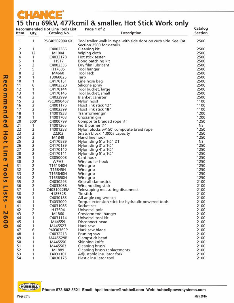
Re
com
me
nd
ed
Ho
t Line
Too
ls Lists – 26
00
Page 2618 May 2016
Phone: 573-682-5521 Email: [email protected] Web: hubbellpowersystems.com
15 thru 69kV, 477kcmil & smaller, Hot Stick Work onlyRecommended Hot Line Tools List Page 1 of 2Item Qty. Catalog No. Description
Catalog Section
1
1121125211611222211
600'1222222212222222121112211161111111
PSC4050299XXX
C4002365M1904
C4033178H1917
C4002335H17605M4660
T3060025C4170151C4002320C4170144C4170146C4032999
PSC3090467C4001175C4002399T4001938T4001708C4000799T4001265T4001258
22302M1849
C4170589C4170139C4170140C4170141C3050008
WPH3T161340HT16845H
T165640HT165650HC4030293C4033068
C4031022EMH185525C4030185T4033009C4031085H17604M1860
C4031114M44559M445523
P4030369PC4032213M445529BM445550M445563M1889
T4031101C4030175
Tool trailer walk in type with side door on curb side. See Cat. Section 2500 for details.Cleaning kitWiping clothHot stick testerBond patching kitDry film lubricantTool hangerTool rackTarpLine hose bagSilicone sprayTool bucket, largeTool bucket, smallBlanket canisterNylon hoistHoist link stick 12"Hoist link stick 18"Transformer ginCrossarm ginComposite braided rope 1⁄2"Fid & pusher 1⁄2"Nylon blocks w/150' composite braid ropeSnatch block, 1,000# capacityHand line hookNylon sling 5' x 13⁄4" DTNylon sling 3' x 13⁄4"Nylon sling 4' x 13⁄4"Nylon sling 5' x 13⁄4"Cant hookWire puller hookWire gripWire gripWire gripWire gripGrip-all clampstickWire holding stickTelescoping measuring disconnectTie stickAll angle cog wrenchTorque extension stick for hydraulic powered toolsSocket setUniversal poleCrossarm tool hangerUniversal tool kitDisconnect headHack sawHack saw bladePruning sawClampstick headSkinning knifeCleaning brushCleaning brush replacementsAdjustable insulator forkPlastic insulator tool
2500
2500250025002500250025002500250025002500250025002500110011001100120012001250NS
125012501250NS
12501250125012501250125012501250125021002100210021002100210021002100210021002100210021002100210021002100210021002100
1 2 3 4 5 6 7 8 9101112131415161718192021222324252627282930313233343536373839404142434445464748495051525354

Re
com
me
nd
ed
Ho
t Li
ne
To
ols
Lis
ts –
26
00
Phone: 573-682-5521 Email: [email protected] Web: hubbellpowersystems.com
Page 2619May 2016
15 thru 69kV, 477kcmil & smaller, Hot Stick Work onlyRecommended Hot Line Tools List Page 2 of 2Item Qty. Catalog No. Description
Catalog Section
1111111224144441623121
221321121133311112644323221231244241111211
55565758596061626364656667686970717273747576
7778798081828384858687888990919293949596979899100101102103104105106107108109110111112113
C4030834C4031071C4031416C4031417C4032861H18716H21064H46458H464510H464712H464716
M47403WM47405WC4000073
M4743M17285M18474M1846WM4760WC6001016M47602
PSC4000075002
C4000517M48057
T4002272H47144H47152
C4010410M1942M19483H18408
C6000000J1541522J3511522
PSC6010342C4021079C4021173C4020024
C4060181GAC4060182M49371M49372M49376
C4060097C4060092C4060102
M4933C4060084GA
C4060046C4060305C4060346C4060348C4060530H18761H18762
C4033374C6001734T6000641T6000865
Hot Rodder, largeHot Rodder, smallTie wire clawUtility headHydraulic cuttersHot cutter light dutyTree trimmerWire tong 11⁄2" x 8'Wire tong 11⁄2" x 10'Wire tong 21⁄2" x 12'Wire tong 21⁄2" x 16' Wire tong saddle 11⁄2"Wire tong saddle 21⁄2"Saddle extensionWire tong block clampWire tong pole clevisExtension chainRope snubbing bracketLever liftEpoxiglas® lever liftArbor adapterDual auxiliary arm with four M48057 insulators and four C4000268 roller wire holdersTemporary crossarm supportInsulatorsCorner restraint bracketRoller wire holderLink stickDistribution strain carrierSteel chainRatchet wrenchInsulator cradleStatic groundJumper set 15kV (15 ft.)Jumper set 35kV (15 ft.)Temporary cutoutInsulated platform 8'Platform pivotPlatform railing for 8'Conductor coverInsulator coverPole cover 9" x 1'Pole cover 9" x 2'Pole cover 9" x 6'Pole top coverPost insulator coverCrossarm end coverCrossarm guardSpiral coverInsulator coverFlexible line hoseBlanket, solidBlanket, slottedHot stick blanket pinPhasing setExtension resistorsAuto-ranging voltage indicatorGround clampGround setBag for ground set
210021002100210021002100210022002200220022002200220022002200220022002200220022002200NS
2200220022002250225022502250225022502250NSNS
23002350235023502400240024002400240024002400240524002400240024002400 2400 2400245024502450300030003000
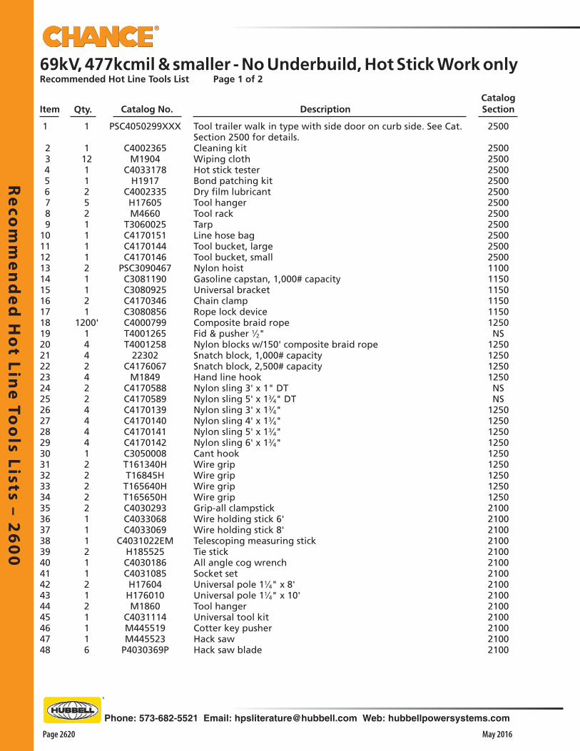
Re
com
me
nd
ed
Ho
t Line
Too
ls Lists – 26
00
Page 2620 May 2016
Phone: 573-682-5521 Email: [email protected] Web: hubbellpowersystems.com
69kV, 477kcmil & smaller - No Underbuild, Hot Stick Work onlyRecommended Hot Line Tools List Page 1 of 2
Item Qty. Catalog No. DescriptionCatalog Section
1
11211252111121121
1200'144242244441222221112112121116
PSC4050299XXX
C4002365M1904
C4033178H1917
C4002335H17605M4660
T3060025C4170151C4170144C4170146
PSC3090467C3081190C3080925C4170346C3080856C4000799T4001265T4001258
22302C4176067
M1849C4170588C4170589C4170139C4170140C4170141C4170142C3050008T161340HT16845HT165640HT165650HC4030293C4033068C4033069
C4031022EMH185525C4030186C4031085H17604H176010M1860
C4031114M445519M445523
P4030369P
Tool trailer walk in type with side door on curb side. See Cat. Section 2500 for details.Cleaning kitWiping clothHot stick testerBond patching kitDry film lubricantTool hangerTool rackTarpLine hose bagTool bucket, largeTool bucket, smallNylon hoistGasoline capstan, 1,000# capacityUniversal bracketChain clampRope lock deviceComposite braid ropeFid & pusher 1⁄2"Nylon blocks w/150' composite braid ropeSnatch block, 1,000# capacitySnatch block, 2,500# capacityHand line hookNylon sling 3' x 1" DTNylon sling 5' x 13⁄4" DTNylon sling 3' x 13⁄4"Nylon sling 4' x 13⁄4"Nylon sling 5' x 13⁄4"Nylon sling 6' x 13⁄4"Cant hookWire gripWire gripWire gripWire gripGrip-all clampstickWire holding stick 6'Wire holding stick 8'Telescoping measuring stickTie stickAll angle cog wrenchSocket setUniversal pole 11⁄4" x 8'Universal pole 11⁄4" x 10'Tool hangerUniversal tool kitCotter key pusherHack sawHack saw blade
2500
25002500250025002500250025002500250025002500110011501150115011501250NS
1250125012501250NSNS
12501250125012501250125012501250125021002100210021002100210021002100210021002100210021002100
1 2 3 4 5 6 7 8 9101112131415161718192021222324252627282930313233343536373839404142434445464748
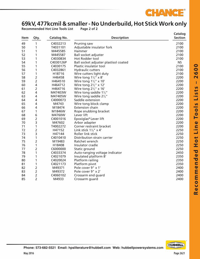
Re
com
me
nd
ed
Ho
t Li
ne
To
ols
Lis
ts –
26
00
Phone: 573-682-5521 Email: [email protected] Web: hubbellpowersystems.com
Page 2621May 2016
69kV, 477kcmil & smaller - No Underbuild, Hot Stick Work onlyRecommended Hot Line Tools List Page 2 of 2
Item Qty. Catalog No. DescriptionCatalog Section
1111111112242444441623123121211112222
49505152535455565758596061626364656667686970717273747576777879808182838485
C4032213T4031101M445585M445587C4030834C4030126PC4030175C4032861H18716H46458H464510H464712H464716
M47403WM47405WC4000073
M4743M18474M1846WM4760WC4001016M47602
T4002272H47152H47144
C4010410M19483H18408
C6000000C4033374C4021079C4020024C4021173M49371M49372
C4060102M4933
Pruning sawAdjustable insulator forkHammerBall socket adjusterHot Rodder toolBall socket adjuster plastisol coatedPlastic insulator toolHydraulic cuttersWire cutters light dutyWire tong 11⁄2" x 8'Wire tong 11⁄2" x 10'Wire tong 21⁄2" x 12'Wire tong 21⁄2" x 16' Wire tong saddle 11⁄2"Wire tong saddle 21⁄2"Saddle extensionWire tong block clampExtension chainRope snubbing bracketLever liftEpoxiglas® Lever liftArbor adapterCorner restraint bracketLink stick 11⁄4" x 4'Roller link stickDistribution strain carrierRatchet wrenchInsulator cradleStatic groundAuto-ranging voltage indicatorInsulated platform 8'Platform railingPlatform pivotPole cover 9" x 1'Pole cover 9" x 2'Crossarm end guardCrossarm guard
21002100210021002100NS
2100 210021002200220022002200220022002200220022002200220022002200220022502250225022502250225024502350235023502400240024002400

Re
com
me
nd
ed
Ho
t Line
Too
ls Lists – 26
00
Page 2622 May 2016
Phone: 573-682-5521 Email: [email protected] Web: hubbellpowersystems.com
69kV, 477kcmil & smaller - with Underbuild, Hot Stick Work onlyRecommended Hot Line Tools List Page 1 of 2
Item Qty.Catalog SectionCatalog No.
1
11211252111121121
1200'1442422444412222211121121211
PSC4050299XXX
C4002365M1904
C4033178H1917
C4002335H17605M4660
T3060025C4170151C4170144C4170146
PSC3090467C3081190C3080925C4170346C3080856C4000799T4001265T4001258
22302C4176067
M1849C4170588C4170589C4170139C4170140C4170141C4170142C3050008T161340HT16845HT165640HT165650HC4030293C4033068C4033069
C4031022EMH185525C4030186C4031085H17604H176010M1860
C4031114M445519
Tool trailer walk in type with side door on curb side. See Cat. Section 2500 for details.Cleaning kitWiping clothHot stick testerBond patching kitDry film lubricantTool hangerTool rackTarpLine hose bagTool bucket, largeTool bucket, smallNylon hoistGasoline capstan, 1,000# capacityUniversal bracketChain clampRope lock deviceComposite braid ropeFid & pusherNylon blocks w/150' composite braid ropeSnatch block, 1,000# capacitySnatch block, 2,500# capacityHand line hookNylon sling 3' x 1" DTNylon sling 5' x 13⁄4" DTNylon sling 3' x 13⁄4"Nylon sling 4' x 13⁄4"Nylon sling 5' x 13⁄4"Nylon sling 6' x 13⁄4"Cant hookWire gripWire gripWire gripWire gripGrip-all clampstickWire holding stick 6'Wire holding stick 8'Telescoping measuring stickTie stickAll angle cog wrenchSocket setUniversal pole 11⁄4" x 8'Universal pole 11⁄4" x 10'Tool hangerUniversal tool kitCotter key pusher
2500
25002500250025002500250025002500250025002500110011501150115011501250NS
1250125012501250NSNS
125012501250125012501250125012501250210021002100210021002100210021002100210021002100
1 2 3 4 5 6 7 8 910111213141516171819202122232425262728293031323334353637383940414243444546
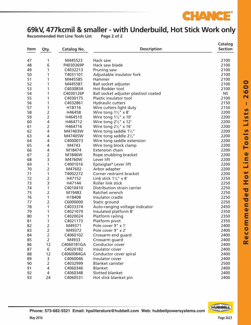
Re
com
me
nd
ed
Ho
t Li
ne
To
ols
Lis
ts –
26
00
Phone: 573-682-5521 Email: [email protected] Web: hubbellpowersystems.com
Page 2623May 2016
Catalog SectionItem Qty. DescriptionCatalog No.
161111111112242444442312123121211112222126123244 24
4748495051525354555657585960616263646566676869707172737475767778798081828384858687888990919293
M445523P4030369PC4032213T4031101M445585M445587C4030834C4030126PC4030175C4032861H18716H46458H464510H464712H464716
M47403WM47405WC4000073
M4743M18474M1846WM4760WC4001016M47602
T4002272H47152H47144
C4010410M19483H18408
C6000000C4033374C4021079C4020024C4021173M49371M49372
C4060102M4933
C4060181GAC4020182
C4060084GAC4060046C4032999C4060346C4060348C4060531
Hack sawHack saw bladePruning sawAdjustable insulator forkHammerBall socket adjusterHot Rodder toolBall socket adjuster plastisol coatedPlastic insulator toolHydraulic cuttersWire cutters light dutyWire tong 11⁄2" x 8'Wire tong 11⁄2" x 10'Wire tong 21⁄2" x 12'Wire tong 21⁄2" x 16' Wire tong saddle 11⁄2"Wire tong saddle 21⁄2"Wire tong saddle extensionWire tong block clampExtension chainRope snubbing bracketLever liftEpoxiglas® Lever liftArbor adapterCorner restraint bracketLink stick 11⁄4" x 4'Roller link stickDistribution strain carrierRatchet wrenchInsulator cradleStatic groundAuto-ranging voltage indicatorInsulated platform 8'Platform railingPlatform pivotPole cover 9" x 1'Pole cover 9" x 2'Crossarm end guardCrossarm guardConductor coverInsulator coverConductor cover spiralInsulator coverBlanket canisterBlanketSlotted blanketHot stick blanket pin
2100210021002100210021002100NS
2100 21502150220022002200220022002200220022002200220022002200220022002250225022502250225022502450235023502350240024002400240024002400240024002500240024002400
69kV, 477kcmil & smaller - with Underbuild, Hot Stick Work onlyRecommended Hot Line Tools List Page 2 of 2

Re
com
me
nd
ed
Ho
t Line
Too
ls Lists – 26
00
Page 2624 May 2016
Phone: 573-682-5521 Email: [email protected] Web: hubbellpowersystems.com
69 thru 161kV, 477kcmil & smaller- No Underbuild, Hot Stick Work onlyRecommended Hot Line Tools List Page 1 of 2Item Qty. Catalog No. Description
Catalog Section
1
11211252111121121
1200'1442422444412222211121121211
PSC4050299XXX
C4002365M1904
C4033178H1917
C4002335H17605M4660
T3060025C4170151C4170144C4170146
PSC3090467C3081190C3080925C4170346C3080856C4000799T4001265T4001258
22302C4176067
M1849C4170588C4170589C4170139C4170140C4170141C4170142C3050008T161340HT16845HT165640HT165650HC4030293C4033068C4033069
C4031022EMH185525C4030186C4031085H17604H176010M1860
C4031114M445519
Tool trailer walk in type with side door on curb side. See Cat. Section 2500 for details.Cleaning kitWiping clothHot stick testerBond patching kitDry film lubricantTool hangerTool rackTarpLine hose bagTool bucket, largeTool bucket, smallNylon hoistGasoline capstan, 1,000# capacityUniversal bracketChain clampRope lock deviceComposite braid ropeFid & pusherNylon blocks w/150' composite braid ropeSnatch block, 1,000# capacitySnatch block, 2,500# capacityHand line hookNylon sling 3' x 1" DTNylon sling 5' x 13⁄4" DTNylon sling 3' x 13⁄4"Nylon sling 4' x 13⁄4"Nylon sling 5' x 13⁄4"Nylon sling 6' x 13⁄4"Cant hookWire gripWire gripWire gripWire gripGrip-all clampstickWire holding stick 6'Wire holding stick 8'Telescoping measuring stickTie stickAll angle cog wrenchSocket setUniversal pole 11⁄4" x 8'Universal pole 11⁄4" x 10'Tool hangerUniversal tool kitCotter key pusher
2500
25002500250025002500250025002500250025002500110011501150115011501250NS
1250125012501250NSNS
125012501250125012501250125012501250210021002100210021002100210021002100210021002100
1 2 3 4 5 6 7 8 910111213141516171819202122232425262728293031323334353637383940414243444546
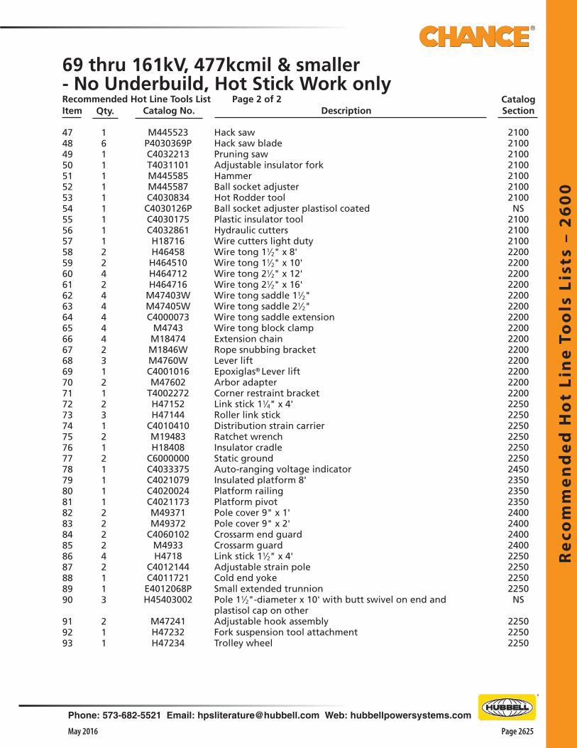
Re
com
me
nd
ed
Ho
t Li
ne
To
ols
Lis
ts –
26
00
Phone: 573-682-5521 Email: [email protected] Web: hubbellpowersystems.com
Page 2625May 2016
69 thru 161kV, 477kcmil & smaller- No Underbuild, Hot Stick Work onlyRecommended Hot Line Tools List Page 2 of 2Item Qty. Catalog No. Description
Catalog Section
16111111111224244444231212312121111222242113
211
4748495051525354555657585960616263646566676869707172737475767778798081828384858687888990
919293
M445523P4030369PC4032213T4031101M445585M445587C4030834C4030126PC4030175C4032861H18716H46458H464510H464712H464716
M47403WM47405WC4000073
M4743M18474M1846WM4760WC4001016M47602
T4002272H47152H47144
C4010410M19483H18408
C6000000C4033375C4021079C4020024C4021173M49371M49372
C4060102M4933H4718
C4012144C4011721E4012068PH45403002
M47241H47232H47234
Hack sawHack saw bladePruning sawAdjustable insulator forkHammerBall socket adjusterHot Rodder toolBall socket adjuster plastisol coatedPlastic insulator toolHydraulic cuttersWire cutters light dutyWire tong 11⁄2" x 8'Wire tong 11⁄2" x 10'Wire tong 21⁄2" x 12'Wire tong 21⁄2" x 16' Wire tong saddle 11⁄2"Wire tong saddle 21⁄2"Wire tong saddle extensionWire tong block clampExtension chainRope snubbing bracketLever liftEpoxiglas® Lever liftArbor adapterCorner restraint bracketLink stick 11⁄4" x 4'Roller link stickDistribution strain carrierRatchet wrenchInsulator cradleStatic groundAuto-ranging voltage indicatorInsulated platform 8'Platform railingPlatform pivotPole cover 9" x 1'Pole cover 9" x 2'Crossarm end guardCrossarm guardLink stick 11⁄2" x 4'Adjustable strain poleCold end yokeSmall extended trunnionPole 11⁄2"-diameter x 10' with butt swivel on end and plastisol cap on otherAdjustable hook assemblyFork suspension tool attachmentTrolley wheel
2100210021002100210021002100NS
2100 2100210022002200220022002200220022002200220022002200220022002200225022502250225022502250245023502350235024002400240024002250225022502250NS
225022502250
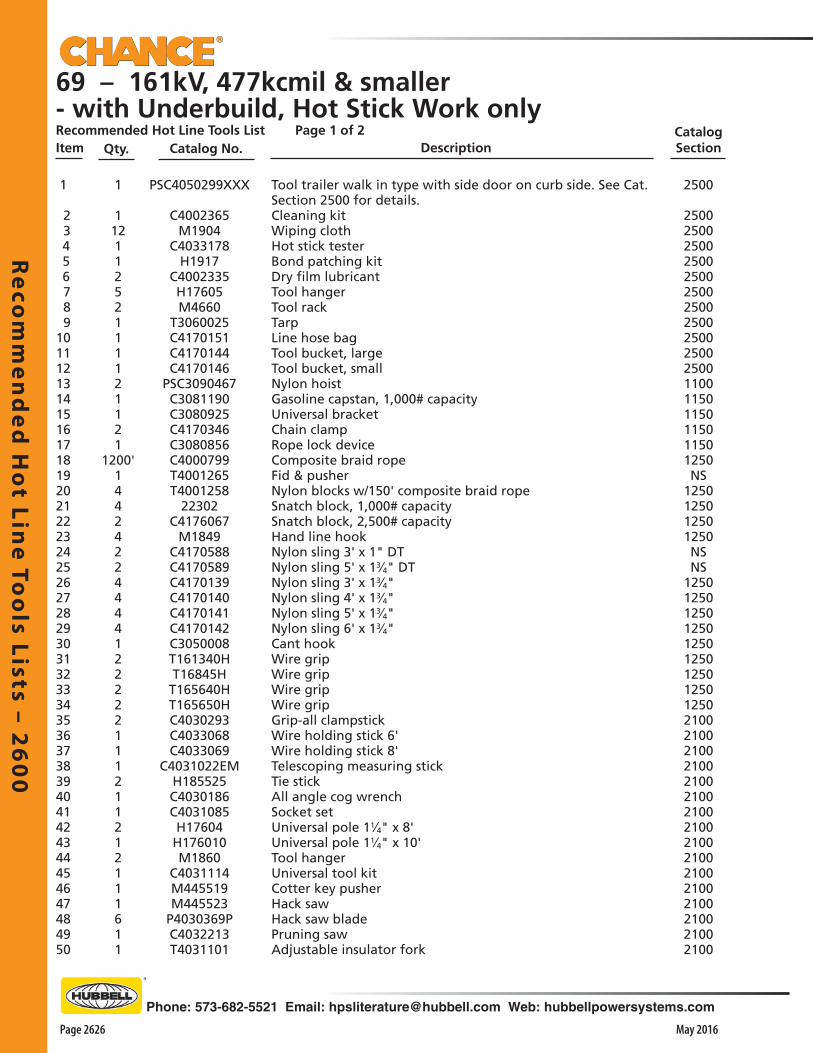
Re
com
me
nd
ed
Ho
t Line
Too
ls Lists – 26
00
Page 2626 May 2016
Phone: 573-682-5521 Email: [email protected] Web: hubbellpowersystems.com
69 – 161kV, 477kcmil & smaller- with Underbuild, Hot Stick Work onlyRecommended Hot Line Tools List Page 1 of 2Item Qty. Description
Catalog SectionCatalog No.
1
11211252111121121
1200'14424224444122222111211212111611
PSC4050299XXX
C4002365M1904
C4033178H1917
C4002335H17605M4660
T3060025C4170151C4170144C4170146
PSC3090467C3081190C3080925C4170346C3080856C4000799T4001265T4001258
22302C4176067
M1849C4170588C4170589C4170139C4170140C4170141C4170142C3050008T161340HT16845HT165640HT165650HC4030293C4033068C4033069
C4031022EMH185525C4030186C4031085H17604H176010M1860
C4031114M445519M445523
P4030369PC4032213T4031101
Tool trailer walk in type with side door on curb side. See Cat. Section 2500 for details.Cleaning kitWiping clothHot stick testerBond patching kitDry film lubricantTool hangerTool rackTarpLine hose bagTool bucket, largeTool bucket, smallNylon hoistGasoline capstan, 1,000# capacityUniversal bracketChain clampRope lock deviceComposite braid ropeFid & pusherNylon blocks w/150' composite braid ropeSnatch block, 1,000# capacitySnatch block, 2,500# capacityHand line hookNylon sling 3' x 1" DTNylon sling 5' x 13⁄4" DTNylon sling 3' x 13⁄4"Nylon sling 4' x 13⁄4"Nylon sling 5' x 13⁄4"Nylon sling 6' x 13⁄4"Cant hookWire gripWire gripWire gripWire gripGrip-all clampstickWire holding stick 6'Wire holding stick 8'Telescoping measuring stickTie stickAll angle cog wrenchSocket setUniversal pole 11⁄4" x 8'Universal pole 11⁄4" x 10'Tool hangerUniversal tool kitCotter key pusherHack sawHack saw bladePruning sawAdjustable insulator fork
2500
25002500250025002500250025002500250025002500110011501150115011501250NS
1250125012501250NSNS
1250125012501250125012501250125012502100210021002100210021002100210021002100210021002100210021002100
1 2 3 4 5 6 7 8 91011121314151617181920212223242526272829303132333435363738394041424344454647484950

Re
com
me
nd
ed
Ho
t Li
ne
To
ols
Lis
ts –
26
00
Phone: 573-682-5521 Email: [email protected] Web: hubbellpowersystems.com
Page 2627May 2016
Catalog SectionItem Qty. DescriptionCatalog No.
1111111224244444231212312121111222242123
21112612324424
51525354555657585960616263646566676869707172737475767778798081828384858687888990
919293949596979899100101
M445585M445587C4030834C4030126PC4030175C4032861H18716H46458H464510H464712H464716
M47403WM47405WC4000073
M4743M18474M1846WM4760WC4001016M47602
T4002272H47152H47144
C4010410M19483H18408
C6000000C4033375C4021079C4020024C4021173M49371M49372
C4060102M4933H4718
C4012144C4011721E4012068P
PSH45403002
M47241H47232H47234
C4060181GAC4060182
C4060084GAC4060046C4032999C4060346C4060348C4060530
HammerBall socket adjusterHot Rodder toolBall socket adjuster plastisol coatedPlastic insulator toolHydraulic cuttersWire cutters light dutyWire tong 11⁄2" x 8'Wire tong 11⁄2" x 10'Wire tong 21⁄2" x 12'Wire tong 21⁄2" x 16' Wire tong saddle 11⁄2"Wire tong saddle 21⁄2"Wire tong saddle extensionWire tong block clampExtension chainRope snubbing bracketLever liftEpoxiglas® Lever liftArbor adapterCorner restraint bracketLink stick 11⁄4" x 4'Roller link stickDistribution strain carrierRatchet wrenchInsulator cradleStatic groundAuto-ranging voltage indicatorInsulated platform 8'Platform railingPlatform pivotPole cover 9" x 1'Pole cover 9" x 2'Crossarm end guardCrossarm guardLink stick 11⁄2" x 4'Adjustable strain poleCold end yokeSmall extended trunnionBlank pole to be 11⁄2" x 10' with butt swivel on end and plastisol cap on otherAdjustable hook assemblyFork suspension tool attachmentTrolley wheelConductor coverInsulator coverSpiral conductor coverInsulator coverBlanket canisterBlanket, solidBlanket, slottedHot stick blanket pin
210021002100NS
2100 2100210022002200220022002200220022002200220022002200220022002200225022502250225022502250245023502350235024002400240024002250225022502250NS
225022502250240024002400240025002400 24002400
69 – 161kV, 477kcmil & smaller- with Underbuild, Hot Stick Work onlyRecommended Hot Line Tools List Page 2 of 2


Ru
bb
er
Insu
lati
ng
Glo
ves
– 2
65
0
Phone: 573-682-5521 Email: [email protected] Web: hubbellpowersystems.com
Page 2651May 2016
Ru
bb
er
Insu
lati
ng
Glo
ves
–26
50
Rubber Insulating Gloves
Catalog 2650 May 2016

Ru
bb
er In
sula
ting
Glo
ves – 2
65
0
Page 2652 May 2016
Phone: 573-682-5521 Email: [email protected] Web: hubbellpowersystems.com
Lineman grade gloves
Chance natural rubber insulating gloves are available in several ASTM voltage classes and a full range of sizes. Manufactured for your ultimate protection and comfort, Chance Lineman Grade Gloves deliver the innovation and dependability you demand.
From the name you trust and the brand you depend on: Chance Lineman Grade Gloves
Table of Contents
SubjectResponsible Manufacturing and Quality Assurance
Guidelines for Inspection and Care
General Reference: Ratings, Labels, Sizing, Protectors
Rubber Insulating Gloves
Low Voltage Class 00 & 0
High Voltage Class 1, 2, 3, 4
Straight Cuff
Bell Cuff
High Voltage Class 2, 3, 4
Contour Cuff
Leather Protector Gloves & Cotton Glove Liners
Storage/Service Bags
Page2653
2654
2656
2657
2658
2659
2660
2661
2662

Ru
bb
er
Insu
lati
ng
Glo
ves
– 2
65
0
Phone: 573-682-5521 Email: [email protected] Web: hubbellpowersystems.com
Page 2653May 2016
Chance® Rubber Insulating GlovesGreen & Made With Environmentally-Responsible ProcessesAqueous Dip Process• Water-based method avoids Volatile Organic Compounds (VOCs) • VOCs are flammable and harmful to the environment• Aqueous Process helps rubber products retain elasticity, flexibility and great
insulation inherent to natural rubber
Biomass Boilers• Steam for Chance® rubber glove production is generated by Biomass boilers• No oil or natural gas is burned in the process• Process burns environmentally friendly byproducts from palm oil industry• This bio-fuel makes the boiler emissions effectively carbon neutral
Waste Water High-Tech Treatment• State-of-the-art water treatment system • Makes all waste water used in glove-making process safe for reuse or
discharge
ISO 14001 Certified For Environmental Management• Designed for high achievement and low impact on environment• Manufacturing plant in Malaysia that produces Chance rubber gloves has
earned ISO 14001 certification• Plant also won environmental-responsibility award from Malaysian
government
Superior Quality AssuranceCritical Measures Taken To Ensure Worker SafetyTop-Quality Assurance• Chance rubber gloves are manufactured in an ISO 9001-certified facility • Industry-leading technological innovations• Promotes product safety• Reduces environmental impact
100% Visually & Electrically Tested• Every pair of gloves is visually inspected inside and outside• Electrically proof tested for 3 minutes per ASTM D120
Full Product Traceability• Every glove is marked with electrical-testing/born-on date • Includes lot code on outside of glove• Safety stamp on inside of glove• These three markings indicate manufacturing location and process
Certified Chemical & Physical Laboratory• Rubber compounds and finished gloves are closely analyzed and inspected• This is completed using the ISO 17025 certified laboratory in the factory
Quality Assurance Inspections• QA visual and electrical checks are performed on all gloves• Every glove shipment is inspected at our distribution center in Centralia,
Missouri

Ru
bb
er In
sula
ting
Glo
ves – 2
65
0
Page 2654 May 2016
Phone: 573-682-5521 Email: [email protected] Web: hubbellpowersystems.com
Rubber Glove Inspection Tips
•Checking or cracks due to UV or ozone
•Splits, cuts or holes from snags and punctures
•Grooves worn due to rope burns or heat exposure
•Weak creases resulting from being left too long inside out or folded
•“Blooms” or “swells” from chemicals, oils
Don’t! • Wear jewelry or sharp objects when using rubber gloves • Wear damaged gloves• Store gloves inside out, folded, or ways causing stretching
or compression• Store gloves near sources of UV, Ozone or heat• Allow gloves to contact petroleum-based products (oil,
gas, solvent, hand creams)
•Electrical puncture
Straight fingers relative to palmhelp preventfatigue of tendonsin back of hands
Reduce Hand Fatiguewith Chance® Rubber Gloves
Oval-shaped fingers help provide “No-Dead-Spots” feel & better dexterity
Naturalrubberformulaprovides excellent flexibility & electricalinsulation
ASTM label assures every glove has been made & tested to ASTM D120
Straight wrist in natural rest position helps avoid fatiguing forearms& hands
Wide cufffor improved comfort &air-flow
Do! • Follow company work procedures and safety rules• Inspect gloves daily for damage• Wear proper leather protectors over rubber gloves• Wash gloves with mild soap and rinse thoroughly with
water• Let gloves air dry at room temperature or less than 120° F
(49° C)• Store gloves in a protective bag

Ru
bb
er
Insu
lati
ng
Glo
ves
– 2
65
0
Phone: 573-682-5521 Email: [email protected] Web: hubbellpowersystems.com
Page 2655May 2016
Manual Inflation:per ASTM F 1236
1 Grasp glove
Perform daily and periodic tests
See industry reference: ASTM F1236 Standard Guide for Visual Inspectionof Electrical Protective Rubber Products
6 Hold close to ear, squeeze to add pressure, listen and feel for pinhole leaks
5 Entrap air by holding in one hand
4 Twirl glove, rotating on rolled ends
3 Press and roll tightly
2 Stretch to seal closed
7 Turn glove inside out and repeat process
Mechanical InflatorsASTM F 1236 maximum inflation limits: • Type I 2 times normal size • Type II 11⁄4 times normal size
Test gloves both Outside
and Inside Out
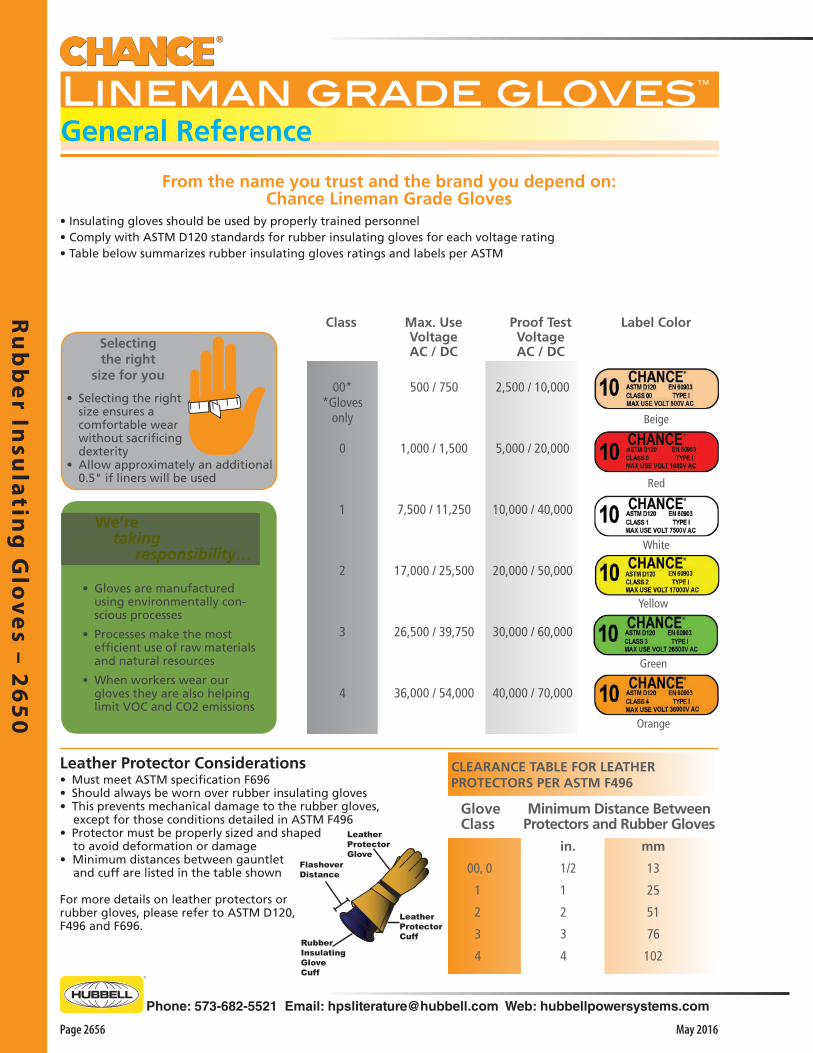
Ru
bb
er In
sula
ting
Glo
ves – 2
65
0
Page 2656 May 2016
Phone: 573-682-5521 Email: [email protected] Web: hubbellpowersystems.com
From the name you trust and the brand you depend on: Chance Lineman Grade Gloves
• Selecting the right size ensures a comfortable wear without sacrificing dexterity
• Allow approximately an additional 0.5" if liners will be used
Selecting the right
size for you
CLEARANCE TABLE FOR LEATHERPROTECTORS PER ASTM F496
in. mm
00, 0 1/2 13
1 1 25
2 2 51
3 3 76
4 4 102
Minimum Distance BetweenProtectors and Rubber Gloves
GloveClass
Leather ProtectorCuff
Rubber InsulatingGloveCuff
FlashoverDistance
LeatherProtectorGlove
• Must meet ASTM specification F696 • Should always be worn over rubber insulating gloves• This prevents mechanical damage to the rubber gloves, except for those conditions detailed in ASTM F496• Protector must be properly sized and shaped to avoid deformation or damage• Minimum distances between gauntlet and cuff are listed in the table shown
For more details on leather protectors orrubber gloves, please refer to ASTM D120,F496 and F696.
Leather Protector Considerations
We’re taking responsibility…
• Gloves are manufactured using environmentally con-scious processes
• Processes make the most efficient use of raw materials and natural resources
• When workers wear our gloves they are also helping limit VOC and CO2 emissions
Class
00**Gloves
only
0
1
2
3
4
Max. Use Voltage AC / DC
500 / 750
1,000 / 1,500
7,500 / 11,250
17,000 / 25,500
26,500 / 39,750
36,000 / 54,000
Proof Test Voltage AC / DC
2,500 / 10,000
5,000 / 20,000
10,000 / 40,000
20,000 / 50,000
30,000 / 60,000
40,000 / 70,000
Label Color
Beige
Red
White
Yellow
Orange
• Insulating gloves should be used by properly trained personnel• Comply with ASTM D120 standards for rubber insulating gloves for each voltage rating• Table below summarizes rubber insulating gloves ratings and labels per ASTM
Green
Lineman grade gloves™
General Reference

Ru
bb
er
Insu
lati
ng
Glo
ves
– 2
65
0
Phone: 573-682-5521 Email: [email protected] Web: hubbellpowersystems.com
Page 2657May 2016
Ergonomic innovation. Superior products. Timely solutions. Just a few of the reasons the industry turns to Hubbell Power Systems and the Chance brand.
Features & Applications• The ultimate source of protection expected from the
Chance name• Offers a new level of comfort and flexibility
• Constructed for high dielectric and physical strength• Exceed ASTM D120• Available in straight cuff lengths of 11" and 14"• Type I Chance Gloves come in red, yellow, black or black-yellow
Lineman grade gloves™
Straight Cuff - ASTM Class 00, 0
Color: RED Class 00 Class 0Size 11” 11” 14”
7 PSC0011R7 PSC011R7 PSC014R78 PSC0011R8 PSC011R8 PSC014R8
8.5 PSC0011R8H PSC011R8H PSC014R8H9 PSC0011R9 PSC011R9 PSC014R9
9.5 PSC0011R9H PSC011R9H PSC014R9H10 PSC0011R10 PSC011R10 PSC014R10
10.5 PSC0011R10H PSC011R10H PSC014R10H11 PSC0011R11 PSC011R11 PSC014R1112 PSC0011R12 PSC011R12 PSC014R12
Color: BLACK Class 00 Class 0Size 11” 14” 11” 14”
7 PSC0011B7 PSC0014B7 PSC011B7 PSC014B78 PSC0011B8 PSC0014B8 PSC011B8 PSC014B8
8.5 PSC0011B8H PSC0014B8H PSC011B8H PSC014B8H9 PSC0011B9 PSC0014B9 PSC011B9 PSC014B9
9.5 PSC0011B9H PSC0014B9H PSC011B9H PSC014B9H10 PSC0011B10 PSC0014B10 PSC011B10 PSC014B10
10.5 PSC0011B10H PSC0014B10H PSC011B10H PSC014B10H11 PSC0011B11 PSC0014B11 PSC011B11 PSC014B1112 PSC0011B12 PSC0014B12 PSC011B12 PSC014B12
Color: YELLOW Class 00 Class 0Size 11” 14” 11” 14”
7 PSC0011Y7 PSC0014Y7 PSC011Y7 PSC014Y78 PSC0011Y8 PSC0014Y8 PSC011Y8 PSC014Y8
8.5 PSC0011Y8H PSC0014Y8H PSC011Y8H PSC014Y8H9 PSC0011Y9 PSC0014Y9 PSC011Y9 PSC014Y9
9.5 PSC0011Y9H PSC0014Y9H PSC011Y9H PSC014Y9H10 PSC0011Y10 PSC0014Y10 PSC011Y10 PSC014Y10
10.5 PSC0011Y10H PSC0014Y10H PSC014Y10H PSC014Y10H11 PSC0011Y11 PSC0014Y11 PSC011Y11 PSC014Y1112 PSC0011Y12 PSC0014Y12 PSC011Y12 PSC014Y12
Color: BLACK UNDER YELLOW Class 0Size 14”
7 PSC014BY78 PSC014BY8
8.5 PSC014BY8H9 PSC014BY9
9.5 PSC014BY9H10 PSC014BY10
10.5 PSC014BY10H11 PSC014BY1112 PSC014BY12

Ru
bb
er In
sula
ting
Glo
ves – 2
65
0
Page 2658 May 2016
Phone: 573-682-5521 Email: [email protected] Web: hubbellpowersystems.com
Features & Applications• The ultimate source of protection expected from the
Chance name• Offers a new level of comfort and flexibility
• Constructed for high dielectric and physical strength• Exceed ASTM D120• Available in straight cuff lengths of 14", 16” and 18"• Type I Chance Gloves come in black or two contrasting
colors
Ergonomic innovation. Superior products. Timely solutions. Just a few of the reasons the industry turns to Hubbell Power Systems and the Chance brand.
From the name you trust and the brand you depend on: Chance Lineman Grade Gloves
Color Black Class 1 Class 2 - -
Size 14" 16" 14" 16" 8 PSC114B8 PSC116B8 PSC214B8 PSC216B8 - - - - -8.5 PSC114B8H PSC116B8H PSC214B8H PSC216B8H - - - - - 9 PSC114B9 PSC116B9 PSC214B9 PSC216B9 - - - - -9.5 PSC114B9H PSC116B9H PSC214B9H PSC216B9H - - - - - 10 PSC114B10 PSC116B10 PSC214B10 PSC216B10 - - - - -10.5 PSC114B10H PSC116B10H PSC214B10H PSC216B10H - - - - -11 PSC114B11 PSC116B11 PSC214B11 PSC216B11 - - - - - 12 PSC114B12 PSC116B12 PSC214B12 PSC216B12 - - - - -
Color Red under Black Class 1 Class 2 Class 3 Class 4size 14" 16" 14" 16" 18" 16 18" 16" 18"8 PSC114RB8 PSC116RB8 PSC214RB8 PSC216RB8 PSC218RB8 PSC316RB8 PSC318RB8 - -8.5 PSC114RB8H PSC116RB8H PSC214RB8H PSC216RB8H PSC218RB8H PSC316RB8H PSC318RB8H - - 9 PSC114RB9 PSC116RB9 PSC214RB9 PSC216RB9 PSC218RB9 PSC316RB9 PSC318RB9 PSC416RB9 PSC418RB9 9.5 PSC114RB9H PSC116RB9H PSC214RB9H PSC216RB9H PSC218RB9H PSC316RB9H PSC318RB9H PSC416RB9H PSC418RB9H 10 PSC114RB10 PSC116RB10 PSC214RB10 PSC216RB10 PSC218RB10 PSC316RB10 PSC318RB10 PSC416RB10 PSC418RB1010.5 PSC114RB10H PSC116RB10H PSC214RB10H PSC216RB10H PSC218RB10H PSC316RB10H PSC318RB10H PSC416RB10H PSC418RB10H11 PSC114RB11 PSC116RB11 PSC214RB11 PSC216RB11 PSC218RB11 PSC316RB11 PSC318RB11 PSC416RB11 PSC418RB11 12 PSC114RB12 PSC116RB12 PSC214RB12 PSC216RB12 PSC218RB12 PSC316RB12 PSC318RB12 PSC416RB12 PSC418RB12
Color Yellow under Black Class 1 Class 2 Class 3 Class 4Size 14" 16" 14" 16" 18" 16" 18" 16" 18"8 PSC114YB8 PSC116YB8 PSC214YB8 PSC216YB8 PSC218YB8 PSC316YB8 PSC318YB8 - - 8.5 PSC114YB8H PSC116YB8H PSC214YB8H PSC216YB8H PSC218YB8H PSC316YB8H PSC318YB8H - - 9 PSC114YB9 PSC116YB9 PSC214YB9 PSC216YB9 PSC218YB9 PSC316YB9 PSC318YB9 PSC416YB9 PSC418YB9 9.5 PSC114YB9H PSC116YB9H PSC214YB9H PSC216YB9H PSC218YB9H PSC316YB9H PSC318YB9H PSC416YB9H PSC418YB9H 10 PSC114YB10 PSC116YB10 PSC214YB10 PSC216YB10 PSC218YB10 PSC316YB10 PSC318YB10 PSC416YB10 PSC418YB1010.5 PSC114YB10H PSC116YB10H PSC214YB10H PSC216YB10H PSC218YB10H PSC316YB10H PSC318YB10H PSC416YB10H PSC418YB10H 11 PSC114YB11 PSC116YB11 PSC214YB11 PSC216YB11 PSC218YB11 PSC316YB11 PSC318YB11 PSC416YB11 PSC418YB11 12 PSC114YB12 PSC116YB12 PSC214YB12 PSC216YB12 PSC218YB12 PSC316YB12 PSC318YB12 PSC416YB12 PSC418YB12
Lineman grade gloves™
Straight Cuff - ASTM Class 1, 2, 3, 4

Ru
bb
er
Insu
lati
ng
Glo
ves
– 2
65
0
Phone: 573-682-5521 Email: [email protected] Web: hubbellpowersystems.com
Page 2659May 2016
Ergonomic innovation. Superior products. Timely solutions. Just a few of the reasons the industry turns to Hubbell Power Systems and the Chance brand.
Features & Applications• The ultimate source of protection expected from the
Chance name• Offers a new level of comfort and flexibility
• Constructed for high dielectric and physical strength• Exceed ASTM D120• Available in bell cuff lengths of 14", 16” and 18"• Type I Chance Gloves come in two contrasting colors
From the name you trust and the brand you depend on: Chance Lineman Grade Gloves
Color Red under Black Class 1 Class 2 Class 3 Class 4Size 14" 16" 14" 16" 18" 16" 18" 16" 18"
9 PSC114BCRB9 PSC116BCRB9 PSC214BCRB9 PSC216BCRB9 PSC218BCRB9 PSC316BCRB9 PSC318BCRB9 PSC416BCRB9 PSC418BCRB9 9.5 PSC114BCRB9H PSC116BCRB9H PSC214BCRB9H PSC216BCRB9H PSC218BCRB9H PSC316BCRB9H PSC318BCRB9H PSC416BCRB9H PSC418BCRB9H 10 PSC114BCRB10 PSC116BCRB10 PSC214BCRB10 PSC216BCRB10 PSC218BCRB10 PSC316BCRB10 PSC318BCRB10 PSC416BCRB10 PSC418BCRB1010.5 PSC114BCRB10H PSC116BCRB10H PSC214BCRB10H PSC216BCRB10H PSC218BCRB10H PSC316BCRB10H PSC318BCRB10H PSC416BCRB10H PSC418BCRB10H11 PSC114BCRB11 PSC116BCRB11 PSC214BCRB11 PSC216BCRB11 PSC218BCRB11 PSC316BCRB11 PSC318BCRB11 PSC416BCRB11 PSC418BCRB11 12 PSC114BCRB12 PSC116BCRB12 PSC214BCRB12 PSC216BCRB12 PSC218BCRB12 PSC316BCRB12 PSC318BCRB12 PSC416BCRB12 PSC418BCRB12
Color Yellow under Black Class 1 Class 2 Class 3 Class 4Size 14" 16" 14" 16" 18" 16" 18" 16" 18"
9 PSC114BCYB9 PSC116BCYB9 PSC214BCYB9 PSC216BCYB9 PSC218BCYB9 PSC316BCYB9 PSC318BCYB9 PSC416BCYB9 PSC418BCYB9 9.5 PSC114BCYB9H PSC116BCYB9H PSC214BCYB9H PSC216BCYB9H PSC218BCYB9H PSC316BCYB9H PSC318BCYB9H PSC416BCYB9H PSC418BCYB9H 10 PSC114BCYB10 PSC116BCYB10 PSC214BCYB10 PSC216BCYB10 PSC218BCYB10 PSC316BCYB10 PSC318BCYB10 PSC416BCYB10 PSC418BCYB1010.5 PSC114BCYB10H PSC116BCYB10H PSC214BCYB10H PSC216BCYB10H PSC218BCYB10H PSC316BCYB10H PSC318BCYB10H PSC416BCYB10H PSC418BCYB10H11 PSC114BCYB11 PSC116BCYB11 PSC214BCYB11 PSC216BCYB11 PSC218BCYB11 PSC316BCYB11 PSC318BCYB11 PSC416BCYB11 PSC418BCYB11 12 PSC114BCYB12 PSC116BCYB12 PSC214BCYB12 PSC216BCYB12 PSC218BCYB12 PSC316BCYB12 PSC318BCYB12 PSC416BCYB12 PSC418BCYB12
Lineman grade gloves™
Bell Cuff - ASTM Class 1, 2, 3, 4

Ru
bb
er In
sula
ting
Glo
ves – 2
65
0
Page 2660 May 2016
Phone: 573-682-5521 Email: [email protected] Web: hubbellpowersystems.com
From the name you trust and the brand you depend on: Chance Lineman Grade Gloves
Features & Applications• The ultimate source of protection expected from the
Chance name• Offers a new level of comfort and flexibility
• Constructed for high dielectric and physical strength• Exceed ASTM D120• Available in contour cuff length of 18"• Type I Chance Gloves come in two contrasting colors
Ergonomic innovation. Superior products. Timely solutions. Just a few of the reasons the industry turns to Hubbell Power Systems and the Chance brand.
Color Red under Black Class 2 Class 3 Class 4Size 18" 18" 18"
8 PSC218CRB8 8.5 PSC218CRB8H 9 PSC218CRB9 PSC318CRB9 PSC418CRB9 9.5 PSC218CRB9H PSC318CRB9H PSC418CRB9H 10 PSC218CRB10 PSC318CRB10 PSC418CRB1010.5 PSC218CRB10H PSC318CRB10H PSC418CRB10H11 PSC218CRB11 PSC318CRB11 PSC418CRB11 12 PSC218CRB12 PSC318CRB12 PSC418CRB12
Color Yellow under Black Class 2 Class 3 Class 4Size 18" 18" 18"
8 PSC218CYB8 8.5 PSC218CYB8H 9 PSC218CYB9 PSC318CYB9 PSC418CYB9 9.5 PSC218CYB9H PSC318CYB9H PSC418CYB9H 10 PSC218CYB10 PSC318CYB10 PSC418CYB1010.5 PSC218CYB10H PSC318CYB10H PSC418CYB10H11 PSC218CYB11 PSC318CYB11 PSC418CYB11 12 PSC218CYB12 PSC318CYB12 PSC418CYB12
Lineman grade gloves™
Contour Cuff - ASTM Class 2, 3, 4

Ru
bb
er
Insu
lati
ng
Glo
ves
– 2
65
0
Phone: 573-682-5521 Email: [email protected] Web: hubbellpowersystems.com
Page 2661May 2016
CLEARANCE TABLE FOR LEATHERPROTECTORS PER ASTM F496
in. mm
00, 0 1/2 13
1 1 25
2 2 51
3 3 76
4 4 102
Minimum Distance BetweenProtectors and Rubber Gloves
GloveClass
Color Red under Black Class 2 Class 3 Class 4Size 18" 18" 18"
8 PSC218CRB8 8.5 PSC218CRB8H 9 PSC218CRB9 PSC318CRB9 PSC418CRB9 9.5 PSC218CRB9H PSC318CRB9H PSC418CRB9H 10 PSC218CRB10 PSC318CRB10 PSC418CRB1010.5 PSC218CRB10H PSC318CRB10H PSC418CRB10H11 PSC218CRB11 PSC318CRB11 PSC418CRB11 12 PSC218CRB12 PSC318CRB12 PSC418CRB12
Color Yellow under Black Class 2 Class 3 Class 4Size 18" 18" 18"
8 PSC218CYB8 8.5 PSC218CYB8H 9 PSC218CYB9 PSC318CYB9 PSC418CYB9 9.5 PSC218CYB9H PSC318CYB9H PSC418CYB9H 10 PSC218CYB10 PSC318CYB10 PSC418CYB1010.5 PSC218CYB10H PSC318CYB10H PSC418CYB10H11 PSC218CYB11 PSC318CYB11 PSC418CYB11 12 PSC218CYB12 PSC318CYB12 PSC418CYB12
PSCGLLECMUMedium DutyExtended cuff12" Length
PSCGLLWCLULightweightWrist length10" Length
Leather Protector Gloves• Crafted to fit properly over all industry-standard rubber insulating gloves• Full compliance with ASTM F696 Standard Specification for Leather Protectors for Rubber Insulating Gloves and Mittens
7 PSCGLP10GN7
8 - 81⁄2 PSCGLP10GN8
9 - 91⁄2 PSCGLP10GN9
10 - 101⁄2 PSCGLP10GN10
11 PSCGLP10GN11
12 PSCGLP10GN12
PSCGLP13GN7
PSCGLP13GN8
PSCGLP13GN9
PSCGLP13GN10
PSCGLP13GN11
PSCGLP13GN12
10-inch Length
Size Catalog No.
*13-inch Length
Low-Voltage Leather Protectors• Goatskin – soft, flexible, strong• Nylon strap with non-metallic buckle
Size Catalog No.
8 - 81⁄2 PSCGLP12CN8
9 - 91⁄2 PSCGLP12CN9
10 - 101⁄2 PSCGLP12CN10
11 PSCGLP12CN11
12 PSCGLP12CN12
PSCGLP14CN8
PSCGLP14CN9
PSCGLP14CN10
PSCGLP14CN11
PSCGLP14CN12
12-inch Length 14-inch Length
High-Voltage Leather Protectors• Cowhide – durable and flexible• Hi-visibility polymeric/leather cuff • Nylon strap with non-metallic buckle
8 - 81⁄2 PSCGLP15CN8
9 - 91⁄2 PSCGLP15CN9
10 - 101⁄2 PSCGLP15CN10
11 PSCGLP15CN11
12 PSCGLP15CN12
PSCGLP16CN8
PSCGLP16CN9
PSCGLP16CN10
PSCGLP16CN11
PSCGLP16CN12
15-inch Length *16-inch Length
PSCGLP13GN10
PSCGLP15CN9
Glove Liners• 100% cotton for warmth and comfort under rubber insulating gloves• One size to fit most• Two weight/length choices• Reversible to fit either hand
PSCGLP10GN9
PSCGLP16CN9
*16” fit straight and contour-cuff rubber gloves
*13” have high-visibility polymeric/leather cuff

Ru
bb
er In
sula
ting
Glo
ves – 2
65
0
Page 2662 May 2016
Phone: 573-682-5521 Email: [email protected] Web: hubbellpowersystems.com
Canvas Storage Bags• Durable cotton canvas with self-hemmed seams• Snap-button closures• Brass grommet drain holes on the bottom to aid ventilation and drying
Snaphook on each bag
• For suspending from belt or in storage• Leather reinforced tab is stitched to the back of each bag
PSCGLB30CCS
CanvasSLEEVE BAG• 30" L x 13" Top• For flat storage of rubber sleeves• Specially designed for extra-curved sleeves• Velcro® strap inside at top to hang sleeves in place
Canvas High VoltageGLOVE BAG• 18" L x 8" Top• For flat storage of rubber gloves
Canvas Low VoltageGLOVE BAG• 12" L x 7" Top• For 11" low voltage gloves
PSCGLB18CCG
PSCGLB12CCG

Ru
bb
er
Insu
lati
ng
Glo
ves
– 2
65
0
Phone: 573-682-5521 Email: [email protected] Web: hubbellpowersystems.com
Page 2663May 2016
Snaphook on each bag
• For suspending from belt or in storage• Leather reinforced tab is stitched to the back of each bag
COMBINATIONGLOVE and SLEEVE BAGFeatures & Applications• 18" L x 8" Top• Separate storage for rubber gloves and sleeves• Single flap, double nylon stitching, Velcro fasteners• Gloves and Sleeves not included
C4170150
SLEEVE BAGFeatures & Applications• 27" L x 12" Top – 7" Bottom• For flat storage of rubber sleeves• Bar-tacked corners• Velcro flap fasteners• Double-nylon stitching• Sleeves not included
C4170149
C4170148
GLOVE BAGFeatures & Applications• 18" L x 8" Top• One-piece front and back, bar-tacked at all corners• Double-nylon stitching, Velcro flap fasteners• Gusset has 4-inch top tapering to 2-inch bottom• Gloves not included


Gro
un
din
g E
qu
ipm
en
t –
30
00
Phone: 573-682-5521 Email: [email protected] Web: hubbellpowersystems.com
Page 3001May 2016
Gro
un
din
g E
qu
ipm
en
t –
30
00
GroundingEquipment
Catalog 3000 May 2016

Gro
un
din
g E
qu
ipm
en
t – 30
00
Page 3002 May 2016
Phone: 573-682-5521 Email: [email protected] Web: hubbellpowersystems.com
To indicate energized conditions on overhead lines, (from left) Chance Auto Ranging Voltage Indicator, Digital Voltage Detector and Multi-Range Voltage Detector. At far right, Energized Cable Sensor performs the same function on URD cable with an exposed concentric neutral and elbows without test points.See Catalog Section 2450, “Instruments and Meters,” for details and ordering information.
General Practices• On de-energized distribution lines, Chance recommends Double-Point grounding • This grounding is at both structures adjacent to worksite: Connect all three phases via ground set, then connect to
ground rod.• Plus a personal ground at the worksite, from any one phase to a cluster bar well below the worker’s feet• On a system without a neutral, Chance recommends connecting down leads to screw ground rods installed at least 20
feet from all structures and barricaded• Only for maintenance tasks during which grounds need not be replaced does Chance find acceptable the Single-Point
grounding method (at only the worksite: Connect all phases together and grounding plus personal ground, as above)• Where adequate phase-to-phase clearances permit, Chance accepts the practice of grounding only the phase being
worked (in the same manner as personal ground, above)
Temporary Grounding EquipmentSafe Working PracticesThere are many reasons for temporary grounding to protect personnel working on de-energized circuits, including:
1. Induced voltage from adjacent energized lines2. Fault-current feedover from adjacent lines3. Lightning strikes anywhere on the circuit4. Switching-equipment malfunction or human error5. Accident-initiated contact with adjacent lines
Since any one of the above could result in re-energizing the circuit, most utilities treat these potential dangers as ever-present and impose strict temporary-grounding work rules. Their crews’ experience often voices these watchwords for the wise to heed:“If you can’t see both ends, it’s hot” and “If it isn't grounded, it isn’t dead.“
Vital Procedure RecommendationsStep One: Testing• With a test instrument, confirm the circuit to be worked
has been de-energized intentionally before ground sets are applied
Step Two: Cleaning• For a good connection, scrub oxides and contaminants
from conductor, buswork or lattice contact points• Chance universal wire brushes make this easy• Serrated-jaw clamps also aid by penetrating surface
contaminants
Step Three: Connecting• Chance insulated Grip-All clampsticks are the proper tools
to apply grounding clamps• Various clampstick lengths and styles are available in
Catalog Section 2100, “Insulated Hand Tools”
Chance Grounding-Set Tester• Ideal for performing function #5 above • Checks the resistance in a protective ground set • Can help locate problems often remedied by simple
repairs• How-to video is included with the tester• See Catalog Section 2450, “Instruments and Meters,”
for details and ordering information
Safety Reviews• Temporary grounding practices should be reviewed on a
regular basis• As part of a total maintenance program, routine reviews
should be scheduled apart from sessions to set new practices for system upgrades and additions
• These basics should be included on a review checklist: 1. Clamp designs specific to each application, 2. Cable sized for fault-current potential (see table on
page 3002) and minimum-slack lengths3. How construction affects placement of grounds4. Work procedures outlined above5. Inspect and test each grounding set
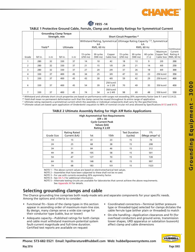
Gro
un
din
g E
qu
ipm
en
t –
30
00
Phone: 573-682-5521 Email: [email protected] Web: hubbellpowersystems.com
Page 3003May 2016
Grounding Clamp TorqueStrength, min Short Circuit Properties A
Grade
Yield B Ultimate
Withstand Rating, SymmetricalkA
RMS, 60 Hz
Ultimage Rating Capacity C D, SymmetricalkA
RMS, 60 HzContinuous
Current Rating A
RMS, 60 Hzlbf-in. n-m lbf-in. n-m15 cycles (250 ms)
30 cycles(500 ms)
Copper Cable Size
15 cycles (250 ms)
30 cycles(500 ms)
60 cycles (1 s)
Maximum Copper Test Cable Size
1 280 32 330 37 14 10 #2 18 13 9 2/0 200
2 280 32 330 37 21 15 1/0 29 21 14 4/0 250
3 280 32 330 37 27 20 2/0 37 26 18 4/0 300
4 330 37 400 45 34 25 3/0 47 33 23 250 kcmil 350
5 330 37 400 45 43 30 4/0 59 42 29 250 kcmil 400
6 330 37 400 45 54 39250 kcmil or 2 2/0 70 49 35 350 kcmil 450
7 330 37 400 45 74 54350 kcmil or 2 4/0 98 69 48 550 kcmil 550
A Withstand and ultimate short circuit properties are based on performance with surges not exceeding 20% asymmetry factor (see 9.1 and 12.3.4.2).B Yield shall mean no permanent deformation such that the clamp cannot be reused throughout its entire range of application. C Ultimate rating represents a symmetrical current which the assembly or individual components shall carry for the specified time. D Ultimate values are based upon application of Onderdonk's equation to 98% of nominal circular mil area allowed by Specifications B172 and B173.
Selecting grounding clamps and cableThe Chance grounding line comprises both ready-made sets and separate components for your specific needs.Among the options and criteria to consider:
• Functional fit—Sizes of the clamp types in this section appear in ascending order of maximum-main-line size. By design, many clamps serve a wide size range for their conductor type (cable, bus or tower)
• Adequate capacity—Published ratings for both clamps and cable must withstand maximum-potential system fault-current magnitude and full-time duration. Certified test reports are available on request
• Coordinated connectors—Terminal (either pressure-type or threaded-type) selected for clamps dictates the cable ferrule type (either plain or threaded) to match
• On-site handling—Application clearances and fit (for overhead conductors and ground wires, transmission tower shapes, URD apparatus or substation buswork) affect clamp and cable dimensions
TABLE 2 Ultimate Assembly Rating for High X/R Ratio ApplicationsHigh Asymmetrical Test Requirements
X/R = 30Cycle Current Peak
Values (kA)Rating X 2.69
Grade SizeRating Rated Current (kA) 1st 15th
Test Duration (cycles)
12t(Mega amps2-s)
1H 15 41 23 15 74
2H 25 68 38 15 208
3H 31 84 46 15 312
4H 39 105 58 15 501
5H 47 127 70 15 728
6H 55 148 82 15 997
7H 68 183 101 15 1523
NOTE 1 – The above current values are based on electromechanical test values.NOTE 2 – Assemblies that have been subjected to these shall not be re-used.NOTE 3 – For use with currents exceeding 20% asymmetry factor.NOTE 4 – See X4.7.2 for additional information.NOTE 5 – Alternate testing circuits are available for laboratories that cannot achieve the above requirements. See Appendix X4 for details.
F855 -14TABLE 1 Protective Ground Cable, Ferrule, Clamp and Assembly Ratings for Symmetrical Current

Gro
un
din
g E
qu
ipm
en
t – 30
00
Page 3004 May 2016
Phone: 573-682-5521 Email: [email protected] Web: hubbellpowersystems.com
1. Clamps
2. Ferrules 4. Support Stud
5. Shrink Tubing
3. Cable
Installation information• Several training aids available on request• Chance videos and technical manuals provide details on
proper installation• Consult your Chance representative for any additional
assistance
How to order a Grounding SetIn addition to the specifying criteria above, each part of a grounding set requires certain choices:1. Clamps • ASTM designations for Type, Class and Grade given
for clamps shown in this section2. Ferrules • Copper or aluminum • Plain or threaded3. Cable • Length required to reach application distances • ASTM Type I with black or yellow elastomer jackets
for temperatures from -40°F (-40°C) through +194°F (+90°C)
• ASTM Type III with clear thermoplastic jacket for temperatures from +14°F (-10°C) through +140°F (+60°) should be used only in well-ventilated areas
4. Support Stud • This option recommended on only one clamp to help
control lifting the set to the first clamp attachment point
5. Shrink Tubing • This translucent option recommended for stress relief
and inspection of cable strands between ferrule and jacket.

Gro
un
din
g E
qu
ipm
en
t –
30
00
Phone: 573-682-5521 Email: [email protected] Web: hubbellpowersystems.com
Page 3005May 2016
C-Type Grounding Clamps
C6001754Aluminum body,
Smooth jaws,Bronze eyescrew
with Acme threads, Tapped for 5⁄8-11 UNC
threaded ferrule
C6002275Aluminum body,
Smooth jaws,Bronze eyescrew
with Acme threads,Bronze pressure-type
terminals
C6002276Aluminum body,Serrated jaws,
Bronze eyescrewwith Acme threads,
Bronze pressure-type terminals
T6000790Bronze body,Smooth jaws,
Bronze T-handle/eyescrewwith fine threads,
Tapped for 5⁄8-11 UNC threaded ferrule
T6002708Aluminum body,Serrated jaws,
Bronze eyescrewwith Acme threads,
Tapped for 5⁄8-11 UNC threaded ferrule
C6001959Bronze body,Smooth jaws,
Bronze T-handle/eyescrewwith fine threads,
Tapped for 5⁄8-11 UNC threaded ferrule
C6001743Aluminum body,
Smooth jaws,Bronze eyescrewwith fine threads,
Tapped for 5⁄8-11 UNC threaded ferrule
T6000465Bronze body,Smooth jaws,
Bronze eyescrewwith fine threads,
Tapped for 5⁄8-11 UNC threaded ferruleor T6000466,
Drilled for 5⁄8-11 UNC threaded ferrule
C6002271Bronze body,Smooth jaws,
Bronze eyescrewwith fine threads,
Tapped for 5⁄8-11 UNC threaded ferrule
Catalog Number
C6001959 T6000465 T6000466 T6000790 C6002271 C6001754 C6002275 C6002276 T6002708 C6001743
ELECTRICAL RATINGSContinuous Current (AMPS) 250 400 350 400 400 400 400
Fault Current - 15 Cycles (AMPS) 21,000 43,000 27,000 43,000 43,000 43,000 43,000
Fault Current - 30 Cycles (AMPS) 15,000 30,000 20,000 30,000 30,000 30,000 30,000
MECHANICAL RATINGSRecommended Torque (in.-lb.) 200 250 250 250 250 250 250
Main Line Range - Max.477 kcmil
ACSR (0.814”)
1033 kcmil ACSR
(1.25”)
750 kcmil Str. Cu.
636 kcmil ACSR (0.998”)
1033 kcmil ACSR
(1.25”)
1033 kcmil ACSR
(1.25”)
1033 kcmil ACSR
(1.25”)
1000 kcmil Cu. 1590 kcmil
ACSR (1.50”)
Main Line Range - Min. #6 Sol. Cu. (0.162”)
#6 Sol. Cu. (0.162”)
#8 Sol. Cu. (0.128”)
#8 Sol. Cu. (0.128”)
#8 Sol. Cu. (0.128”)
#8 Sol. Cu. (0.128”)
#6 Sol. Cu. (0.162”)
Jumper Range - Max. 1/0 Grd. Cable 4/0 Grd. Cable 2/0 Grd. Cable 4/0 Grd. Cable 4/0 Grd. Cable 4/0 Grd. Cable 4/0 Grd. Cable
Jumper Range - Min. #2 Grd. Cable #2 Grd. Cable #2 Grd. Cable #2 Grd. Cable #2 Grd. Cable #2 Grd. Cable #2 Grd. Cable
Weight Each 1 1/2 lb./0.7kg. 2 lb./0.9kg. 1 lb./0.5kg. 1 1/4 lb./0.6 kg. 1 1/4 lb./0.6kg. 1 1/4 lb./0.6kg. 1 1/2 lb./0.7kg.
ASTM DesignationType I Class A Grade 2
Type I Class A Grade 5
Type I Class A Grade 3
Type I Class A Grade 5
Type I Class B
Grade 5
Type I Class B
Grade 5
Type I Class A Grade 5
IEC RatingsJaws Smooth Smooth Smooth Smooth Serrated Serrated SmoothFerrule Threaded Threaded Threaded Plain Plug Plain Plug Threaded Threaded

Gro
un
din
g E
qu
ipm
en
t – 30
00
Page 3006 May 2016
Phone: 573-682-5521 Email: [email protected] Web: hubbellpowersystems.com
C-Type Grounding Clamps
C6002281Aluminum body,
Smooth jaws,Bronze eyescrew
with Acme threadsBronze pressure-type terminal
C6002255Aluminum body,
Smooth jaws,Bronze eyescrew
with Acme threads, Tapped for 5⁄8-11 UNC threaded
ferrule*Unshrouded Ferrules Only
C6002282Aluminum body,Serrated jaws,
Bronze eyescrewwith Acme threads
Bronze pressure-type terminal
C6002256Aluminum body,Serrated jaws,
Bronze eyescrewwith Acme threads,
Tapped for 5⁄8-11 UNC threaded ferrule*Unshrouded Ferrules Only
*C6000386 has 1-1/4" x 6' Epoxiglas® Pole and total weight of 33⁄4 lb. (1.7 kg.).
T6003203Aluminum body,
Smooth jaws,Bronze eyescrew
with Acme threads,Tapped for 5⁄8-11 UNC
threaded ferrule*Unshrouded Ferrules
Only
T6000658Aluminum body,
Smooth jaws,Bronze eyescrew
with Acme threads,Drilled for 5⁄8-11 UNC
threaded ferrule
Catalog Number C6002281 C6002255 C6002282 C6002256 *C6000386 G36051 T6003203 T6000658
ELECTRICAL RATINGS
Continuous Current (amps) 400 400 400 400 400 400 400 400
Fault Current - 15 Cycles (amps) 43,000 43,000 43,000 47,000 43,000 43,000 43,000 47,000
Fault Current - 30 Cycles (amps) 30,000 30,000 30,000 30,000 30,000 30,000
MECHANICAL RATINGS
Recommended Torque (in.-lb.) 250 250 250 250 250 250 250 250
Main Line Range - Max. 2" O.D. Bus 2" O.D. Bus 2" O.D. Bus 2" O.D. Bus 2" O.D. Bus 2" O.D. Bus 2" O.D. Bus 2" O.D. Bus
Main Line Range - Min. #6 Sol. Cu. (0.162”)
#6 Sol. Cu. (0.162”)
#6 Sol. Cu. (0.162”)
#6 Sol. Cu. (0.162”)
#6 Sol. Cu. (0.162”)
#6 Sol. Cu. (0.162")
#6 Sol. Cu. (0.162”)
#6 Sol. Cu. (0.162”)
Jumper Range - Max. 4/0 Grd. Cable
4/0 Grd. Cable
4/0 Grd. Cable
4/0 Grd. Cable
4/0 Grd. Cable
4/0 Grd. Cable
4/0 Grd. Cable
4/0 Grd. Cable
Jumper Range - Min. #2 Grd. Cable #2 Grd. Cable #2 Grd. Cable #2 Grd. Cable #2 Grd. Cable #2 Grd. Cable #2 Grd. Cable #2 Grd. Cable
Weight Each 2 lb./0.9kg. 13⁄4 lb./0.8kg. 2 lb./0.9kg. 13⁄4 lb./0.8kg. * 13⁄4 lb./0.8kg. 13⁄4 lb./0.8kg. 13⁄4 lb./0.8kg.
ASTM DesignationType I Class A Grade 5
Type I Class A Grade 5
Type I Class B
Grade 5
Type I Class B
Grade 5H
Type II Class B Grade 5
Type I Class A Grade 5
Type I Class A Grade 5
Type I Class A
Grade 5H
IEC Ratings 35 kA 35 kA
Jaws Smooth Smooth Serrated Serrated Serrated Smooth Smooth Smooth
Ferrule Plain PlugThreaded
*Unshrouded Only
Plain PlugThreaded
*Unshrouded Only
Plain Plug Plain Plug Threaded Threaded
G36051 Aluminum body,
Smooth jaws,Bronze eyescrew
with Acme threads,Bronze pressure-type terminal
C6000386*Mounted Clamp Aluminum body,Serrated jaws,
Bronze eyescrewwith Acme threads,
Bronze pressure-type terminal

Gro
un
din
g E
qu
ipm
en
t –
30
00
Phone: 573-682-5521 Email: [email protected] Web: hubbellpowersystems.com
Page 3007May 2016
†Rating with twin-grounding cables.
C6000337Aluminum body,
Smooth jaws,Bronze eyescrew
with Acme threads,Bronze pressure-type terminal
T6000819Aluminum body,
Smooth jaws,Bronze eyescrew
with Acme threads,Parking stud
PSCT6000844001Aluminum body,
Smooth jaws,Bronze eyescrew
with Acme threads,Parking stud
G3369Aluminum body,
Smooth jaws,Bronze eyescrew
with Acme threads,Bronze pressure-type terminal
C6000375Aluminum body,Serrated jaws,
Bronze eyescrewwith Acme threads,
Dual drilled for 5⁄8-11 UNC threaded ferrule
C6001733Aluminum body,
Smooth jaws,Bronze eyescrew
with Acme threads, Tapped for 5⁄8-11 UNC threaded ferrule
*Unshrouded Ferrules Only
G33672Aluminum body,
Smooth jaws,Bronze eyescrew
with Acme threads,Bronze pressure-type threads
Bus-Bar Grounding Clamps:
C-Type Grounding Clamps
Catalog Number G33672 C6001733 C6000375 G3369 C6000337 T6000819 PSCT6000844001
ELECTRICAL RATINGS
Continuous Current (AMPS) 400 400 400 400 400 400 400
Fault Current - 15 Cycles (AMPS) 43,000 43,000 †70,000 43,000 43,000 †60,000 47,000 68,000
Fault Current - 30 Cycles (AMPS) 30,000 30,000 †50,000 30,000 30,000 †60,000
MECHANICAL RATINGS
Recommended Torque (in.-lb.) 250 250 300 300 300 300 300
Main Line Range - Max. 2-1⁄2” O.D. Bus 2-1⁄2” O.D. Bus 3” O.D. Bus
4” x 4” Square
4.5” O.D. Bus
6-5⁄8” O.D. Bus 6-5⁄8” O.D. Bus 6-5⁄8” O.D. Bus
Main Line Range - Min. #4 Str. Cu. (0.232”)
#4 Str. Cu. (0.232”)
0.50” O.D. Bus
4/0 Str. Cu. (0.500”) 3-1⁄2” O.D. Bus 3-1⁄2” O.D. Bus 3-1⁄2” O.D. Bus
Jumper Range - Max. 4/0 Grd. Cable 4/0 Grd. Cable 4/0 Grd. Cable 4/0 Grd. Cable 4/0 Grd. Cable Parking Stud Parking Stud
Jumper Range - Min. #2 Grd. Cable #2 Grd. Cable #2 Grd. Cable #2 Grd. Cable #2 Grd. Cable Parking Stud Parking Stud
Weight Each 2-3⁄8 lb./1.1kg. 2-3⁄8 lb./1.1kg. 3 lb./1.4kg. 5-1⁄4 lb./2.4kg. 6 lb./2.7 kg. 5 lb./2.27 kg. 7.8 lb/3.54 kg.
ASTM DesignationType I Class A Grade 5
Type I Class A Grade 5
Type I Class B Grade 7
Type I Class A Grade 5
Type I Class A Grade 6
Type I Class A
Grade 5H
Type I Class A
Grade 7H
IEC Rating (15 cycles) 35 kA 35 kA 35 kAJaws Smooth Smooth Serrated Smooth Smooth Smooth SmoothFerrule Plain Plug Threaded Threaded Plain Plug Plain Plug Parking Stud Parking Stud
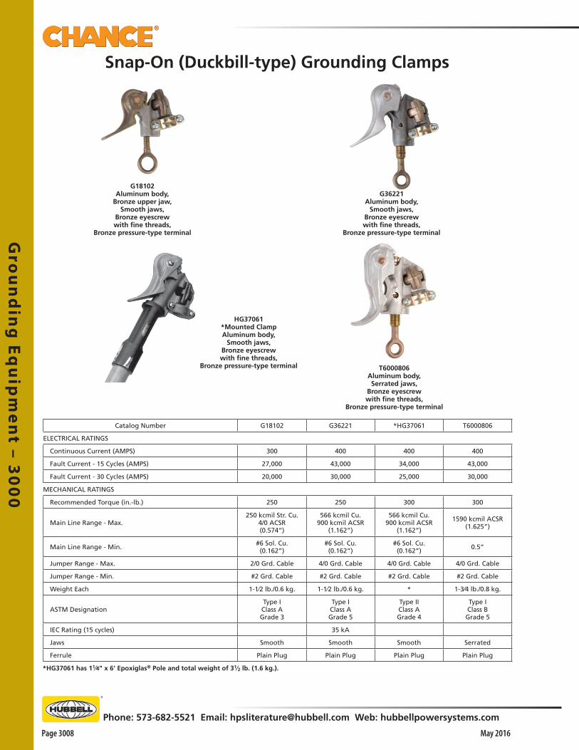
Gro
un
din
g E
qu
ipm
en
t – 30
00
Page 3008 May 2016
Phone: 573-682-5521 Email: [email protected] Web: hubbellpowersystems.com
*HG37061 has 11⁄4" x 6' Epoxiglas® Pole and total weight of 31⁄2 lb. (1.6 kg.).
HG37061*Mounted ClampAluminum body,
Smooth jaws,Bronze eyescrewwith fine threads,
Bronze pressure-type terminal T6000806Aluminum body,Serrated jaws,
Bronze eyescrewwith fine threads,
Bronze pressure-type terminal
G36221Aluminum body,
Smooth jaws,Bronze eyescrewwith fine threads,
Bronze pressure-type terminal
G18102Aluminum body,
Bronze upper jaw,Smooth jaws,
Bronze eyescrewwith fine threads,
Bronze pressure-type terminal
Snap-On (Duckbill-type) Grounding Clamps
Catalog Number G18102 G36221 *HG37061 T6000806
ELECTRICAL RATINGS
Continuous Current (AMPS) 300 400 400 400
Fault Current - 15 Cycles (AMPS) 27,000 43,000 34,000 43,000
Fault Current - 30 Cycles (AMPS) 20,000 30,000 25,000 30,000
MECHANICAL RATINGS
Recommended Torque (in.-lb.) 250 250 300 300
Main Line Range - Max.250 kcmil Str. Cu.
4/0 ACSR (0.574”)
566 kcmil Cu. 900 kcmil ACSR
(1.162”)
566 kcmil Cu. 900 kcmil ACSR
(1.162”)
1590 kcmil ACSR (1.625”)
Main Line Range - Min. #6 Sol. Cu. (0.162”)
#6 Sol. Cu. (0.162”)
#6 Sol. Cu. (0.162”) 0.5”
Jumper Range - Max. 2/0 Grd. Cable 4/0 Grd. Cable 4/0 Grd. Cable 4/0 Grd. Cable
Jumper Range - Min. #2 Grd. Cable #2 Grd. Cable #2 Grd. Cable #2 Grd. Cable
Weight Each 1-1⁄2 lb./0.6 kg. 1-1⁄2 lb./0.6 kg. * 1-3⁄4 lb./0.8 kg.
ASTM DesignationType I Class A Grade 3
Type I Class A Grade 5
Type II Class A Grade 4
Type I Class B
Grade 5
IEC Rating (15 cycles) 35 kA
Jaws Smooth Smooth Smooth Serrated
Ferrule Plain Plug Plain Plug Plain Plug Plain Plug

Gro
un
din
g E
qu
ipm
en
t –
30
00
Phone: 573-682-5521 Email: [email protected] Web: hubbellpowersystems.com
Page 3009May 2016
*C6000198 has 11⁄4" x 6' Epoxiglas® Pole and total weight of 31⁄2 lb. (1.6 kg.).
Snap-On (Duckbill-type) Grounding Clamps
C6001734Aluminum body,
Smooth jaws,Bronze eyescrewwith fine threads,
Tapped for 5⁄8-11 UNC threaded ferrule
C6000198*Mounted ClampAluminum body,Serrated jaws,
Bronze eyescrewwith Acme threads,
Tapped for 5⁄8-11 UNC threaded ferrule
C6000197Aluminum body,Serrated jaws,Bronze eyescrewwith Acme threads,Tapped for 5⁄8-11 UNC threaded ferrule
C6000434Aluminum body,Serrated jaws,
Bronze eyescrewwith fine threads,
Bronze pressure-type terminal
Catalog Number C6001734 *C6000198 C6000197 C6001757 C6000434
ELECTRICAL RATINGS
Continuous Current (AMPS) 400 400 400 400 400
Fault Current - 15 Cycles (AMPS) 43,000 43,000 47,000 43,000 43,000
Fault Current - 30 Cycles (AMPS) 30,000 30,000 30,000 30,000
MECHANICAL RATINGS
Recommended Torque (in.-lb.) 250 250 250 250 250
Main Line Range - Max.566 kcmil Cu.
900 kcmil ACSR (1.162”)
950 kcmil Cu. 1510 kcmil ACSR
(1.506”)
950 kcmil Cu. 1510 kcmil ACSR
(1.506”)2.5”
950 kcmil Cu. 1510 kcmil ACSR
(1.506”)
Main Line Range - Min. #6 Sol. Cu. (0.162”)
#6 Sol. Cu. (0.162”)
#6 Sol. Cu. (0.162”) 0.75” #6 Sol. Cu.
(0.162”)
Jumper Range - Max. 4/0 Grd. Cable 4/0 Grd. Cable 4/0 Grd. Cable 4/0 Grd. Cable 4/0 Grd. Cable
Jumper Range - Min. #2 Grd. Cable #2 Grd. Cable #2 Grd. Cable #2 Grd. Cable #2 Grd. Cable
Weight Each 1-1⁄2 lb./0.7 kg. * 1-1⁄2 lb./0.7 kg. 2-1⁄4 lb./1.0 kg. 1-1⁄2 lb./0.7 kg.
ASTM DesignationType I Class A Grade 5
Type II Class B Grade 5
Type I Class B
Grade 5H
Type I Class A Grade 5
Type I Class B Grade 5
IEC Rating (15 cycles) 35 kA 35 kA
Jaws Smooth Serrated Serrated Smooth Serrated
Ferrule Threaded Threaded Threaded Threaded Plan Plug
C6001757Aluminum body,Smooth jaws,Bronze eyescrewwith fine threads,Tapped for 5⁄8-11 UNC threaded ferrule
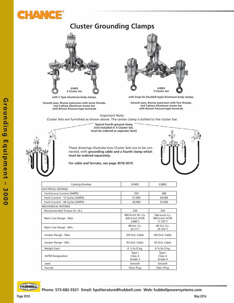
Gro
un
din
g E
qu
ipm
en
t – 30
00
Page 3010 May 2016
Phone: 573-682-5521 Email: [email protected] Web: hubbellpowersystems.com
Cluster Grounding Clamps
G38033-Cluster Set
with Snap-On (Duckbill-type) Aluminum-body clamps,
Smooth jaws, Bronze eyescrews with fine threads,and 3-phase Aluminum cluster bar
with Bronze Pressure-type terminals
G34053-Cluster Set
with C-Type Aluminum-body clamps,
Smooth jaws, Bronze eyescrews with Acme threads,and 3-phase Aluminum cluster bar
with Bronze Pressure-type terminals
Important Note:Cluster Sets are furnished as shown above. The center clamp is bolted to the cluster bar.
Typical fourth ground clamp(not included in 3-Cluster Set,
must be ordered as separate item)
These drawings illustrate how Cluster Sets are to be con-nected, with grounding cable and a fourth clamp which must be ordered separately.
For cable and ferrules, see page 3018-3019.
Catalog Number G3405 G3803
ELECTRICAL RATINGS
Continuous Current (AMPS) 350 400
Fault Current - 15 Cycles (AMPS) 27,000 34,000
Fault Current - 30 Cycles (AMPS) 20,000 25,000
MECHANICAL RATINGS
Recommended Torque (in.-lb.) 250 250
Main Line Range - Max.400 kcmil Str. Cu. 636 kcmil ACSR
(.998”)
566 kcmil Cu. 900 kcmil ACSR
(1.162”)
Main Line Range - Min.#8 Sol. Cu.
(0.12”)#6 Sol. Cu. (0.162”)
Jumper Range - Max. 2/0 Grd. Cable 4/0 Grd. Cable
Jumper Range - Min. #2 Grd. Cable #2 Grd. Cable
Weight Each 4 1⁄2 lb./2 kg. 6 5⁄8 lb./3 kg.
ASTM DesignationType I Class A Grade 3
Type I Class A Grade 4
Jaws Smooth Smooth
Ferrule Plain Plug Plain Plug

Gro
un
din
g E
qu
ipm
en
t –
30
00
Phone: 573-682-5521 Email: [email protected] Web: hubbellpowersystems.com
Page 3011May 2016
C6001735Aluminum body,Serrated jaws,
Bronze eyescrewwith fine threads,
Tapped for 5⁄8-11 UNC threaded ferrule
G33633SJAluminum body,Serrated jaws,
Bronze eyescrewwith fine threads,
Bronze pressure-type terminal
Tower & Flat-Face Grounding Clamps
T6001798Aluminum body,Serrated jaws,
Bronze T-handlewith Acme threads,
Tapped for 5⁄8-11 UNC threaded ferrule
G33634SJAluminum body,Serrated jaws,
Bronze T-handlewith fine threads,
Bronze pressure-type terminal
C6002231Bronze body, Serrated jaws,
Bronze T-handle with Acme threads,Drilled for 5⁄8-11 UNC threaded ferrule
or T6003195,Tapped for 5⁄8-11 UNC threaded ferrule
or T6003009,with Fine Threads T-Handle version
Catalog Number C6002232 G33633SJ C6001735 C6002231 G33634SJ T6001798
ELECTRICAL RATINGS
Continuous Current (AMPS) 400 400 400 400 400 400
Fault Current - 15 Cycles (AMPS) 43,000 27,000 27,000 43,000 27,000 27,000
Fault Current - 30 Cycles (AMPS) 30,000 20,000 20,000 30,000 20,000 20,000
MECHANICAL RATINGS
Recommended Torque (in.-lb.) 250 250 250 250 250 250
Main Line Range - Max. 11⁄2” Angles 11⁄2” Flat
11⁄2” Angles 11⁄2” Flat
11⁄2” Angles 11⁄2” Flat
11⁄2” Angles 11⁄2” Flat
11⁄2” Angles 11⁄2” Flat
11⁄2” Angles 11⁄2” Flat
Main Line Range - Min. 1⁄8” 1⁄8” 1⁄8” 1⁄8” 1⁄8” 1⁄8”
Jumper Range - Max. 4/0 Grd. Cable w/Threaded Stud
2/0 Grd. Cable w/Plain Plug
2/0 Grd. Cable w/Threaded Stud
4/0 Grd. Cable w/Threaded Stud
2/0 Grd. Cable w/Plain Plug
2/0 Grd. Cable w/Threaded Stud
Jumper Range - Min.#2 Grd. Cable w/Threaded
Stud
#2 Grd. Cable w/Plain
Plug
#2 Grd. Cable w/Threaded
Stud
#2 Grd. Cable w/Threaded
Stud
#2 Grd. Cable w/Plain
Plug
#2 Grd. Cable w/Threaded
Stud
Weight Each 2 lb./0.9 kg. 15⁄8 lb./0.7 kg. 11⁄2 lb./0.7 kg. 2 lb./0.9 kg. 15⁄8 lb./0.7 kg. 11⁄2 lb./0.7kg.
ASTM DesignationType I Class B Grade 5
Type I Class B
Grade 3
Type I Class B Grade 3
Type III Class B
Grade 5
Type III Class B Grade 3
Type III Class B
Grade 3
IEC Rating (15 Cycles)
Jaws Serrated Serrated Serrated Serrated Serrated Serrated
Ferrule Threaded Plain Plug Threaded Threaded Plain Plug Threaded
C6002232Bronze body, Serrated jaws,
Bronze eyescrew with Acme threads,Drilled for 5⁄8-11 UNC threaded ferrule
or T6003196,Tapped for 5⁄8-11 UNC threaded ferrule
or PST6003485for Fine Thread Eyescrew version

Gro
un
din
g E
qu
ipm
en
t – 30
00
Page 3012 May 2016
Phone: 573-682-5521 Email: [email protected] Web: hubbellpowersystems.com
Tower & Flat-Face Grounding Clamps
G33631Bronze body,
Serrated jaws,Bronze eyescrewwith fine threads,
Bronze pressure-type terminal
C6000085Aluminum body and retainer,
Bronze scrubber-type contact pads,Bronze T-handle
with fine threads,Bronze pressure-type terminal
G33632Bronze body,
Serrated jaws,Bronze T-handle
with fine threads,Bronze pressure-type terminal
C6001783Bronze body,
Serrated jaws and retainers, Tapped for 5⁄8-11 UNC threaded ferrule
Catalog Number G33631 G33632 C6000085 C6001783
ELECTRICAL RATINGS
Continuous Current (AMPS) 400 400 400 400
Fault Current - 15 Cycles (AMPS) 27,000 27,000 47,000 47,000
Fault Current - 30 Cycles (AMPS) 20,000 20,000
MECHANICAL RATINGS
Recommended Torque (in.-lb.) 250 250 250 300
Main Line Range - Max. 11⁄2” Angles 11⁄2” Flat
11⁄2” Angles 11⁄2” Flat
4” Structural Angles
3⁄4” x 5”Angles or Flats
5⁄8” Rod
Main Line Range - Min. 1⁄8” 1⁄8”2” Structural
Angles1⁄8”
Jumper Range - Max. 2/0 Grd. Cable w/Plain Plug
2/0 Grd. Cable w/Plain Plug
4/0 Grd. Cable w/Plain Plug
4/0 Grd. Cable w/Threaded Stud
Jumper Range - Min. #2 Grd. Cable w/Plain Plug
#2 Grd. Cable w/Plain Plug
#2 Grd. Cable w/Plain Plug
#2 Grd. Cable w/Threaded Stud
Weight Each 21⁄2 lb./1.1 kg. 21⁄2 lb./1.1 kg. 33⁄4 lb./1.1 kg. 5 lb./2.25 kg.
ASTM DesignationType I Class B
Grade 3
Type III Class B
Grade 3
Type III Class B
Grade 5H
Type III Class B
Grade 5H
IEC Rating (15 cycles)
Jaws Serrated Serrated Serrated Serrated
Ferrule Plain Plug Plain Plug Plain Plug Threaded
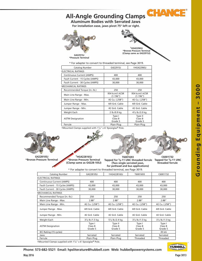
Gro
un
din
g E
qu
ipm
en
t –
30
00
Phone: 573-682-5521 Email: [email protected] Web: hubbellpowersystems.com
Page 3013May 2016
Catalog Number G42291SJ †HG42296SJ
ELECTRICAL RATINGS
Continuous Current (AMPS) 400 400
Fault Current - 15 Cycles (AMPS) 43,000 43,000
Fault Current - 30 Cycles (AMPS) 30,000 30,000
MECHANICAL RATINGS
Recommended Torque (in.-lb.) 250 250
Main Line Range - Max. 954 kcmil ACSR (1.196”)
954 kcmil ACSR (1.196”)
Main Line Range - Min. #2 Cu. (.258”) #2 Cu. (.258”)
Jumper Range - Max. 4/0 Grd. Cable 4/0 Grd. Cable
Jumper Range - Min. #2 Grd. Cable #2 Grd. Cable
Weight Each 2 lb./0.9 kg. 41⁄4 lb./2.0 kg.
ASTM DesignationType I Class B Grade 5
Type II Class B
Grade 5Ferrule Plain Plug Plain Plug
†Mounted Clamps supplied with 11⁄4" x 6' Epoxiglas® Pole.
All-Angle Grounding ClampsAluminum Bodies with Serrated Jaws
†HG42296SJ*Bronze Pressure Terminal(Clamp same as G42291SJ)
For installation ease, jaws pivot 75° left or right.
G42291SJ*Pressure Terminal
* For adapter to convert to threaded terminal, see Page 3019.
†HG422816SJ*Bronze Pressure Terminal
(Clamp same as G4228-10SJ)
C6001732 Tapped for 5⁄8-11 UNC
threaded ferrule
Catalog Number G422810SJ †HG422816SJ T6001693 C6001732
ELECTRICAL RATINGS
Continuous Current (AMPS) 400 400 400 400
Fault Current - 15 Cycles (AMPS) 43,000 43,000 43,000 43,000
Fault Current - 30 Cycles (AMPS) 30,000 30,000 30,000 30,000
MECHANICAL RATINGS
Recommended Torque (in.-lb.) 250 250 250 250
Main Line Range - Max. 2.88” 2.88” 2.88” 2.88”
Main Line Range - Min. #2 Cu. (.258”) #2 Cu. (.258”) #2 Cu. (.258”) #2 Cu. (.258”)
Jumper Range - Max. 4/0 Grd. Cable 4/0 Grd. Cable 4/0 Grd. Cable 4/0 Grd. Cable
Jumper Range - Min. #2 Grd. Cable #2 Grd. Cable #2 Grd. Cable #2 Grd. Cable
Weight Each 31⁄4 lb./1.5 kg. 51⁄4 lb./2.4 kg. 31⁄4 lb./1.5 kg. 31⁄4 lb./1.5 kg.
ASTM DesignationType I Class B
Grade 5
Type II Class B
Grade 5
Type I Class B Grade 5
Type I Class B Grade 5
IEC Rating (15 cycles) 35 kAJaws Serrated Serrated Serrated SerratedFerrule Plain Plug Plain Plug Threaded Threaded
†Mounted Clamps supplied with 11⁄4" x 6' Epoxiglas® Pole.
T6001693 Tapped for 5⁄8-11 UNC threaded ferrule
(Two single serrated jaws,for pothead and bus applications)
G422810SJ*Bronze Pressure Terminal
* For adapter to convert to threaded terminal, see Page 3019.

Gro
un
din
g E
qu
ipm
en
t – 30
00
Page 3014 May 2016
Phone: 573-682-5521 Email: [email protected] Web: hubbellpowersystems.com
Features & Applications• Made with same material as Chance line hose• Nonconductive cover may help prevent flashover on ball
studs installed in enclosed switchgear, switchyards or substations
• Cover is not intended for personnel protection and should not be considered as insulative cover-up equipment
• Resilient ozone/corona-resistant thermo-plastic elastomer does not absorb water
• Special formulation resists aging/checking and retains high-visibility orange color
• Snap-fit keeps cover in place
Grounding Stud Cover – fits onto 1" ball-studs of Apparatus Grounding Clamps above
Long stud shank accepts most types of grounding clamps
Socket clamps provide multi-angle attachment of grounds
*Long Ball Stud T6002364 3" nominal shank lengthWeight, each: 3⁄4 lb./0.34 kg.
Clamp C6002300 withpressure terminal______
for plain-plug ferrule on #2 to 4/0 ground-
ing cable
Clamp C6002100Drilled for 5⁄8-11 UNC
threaded ferruleor
Clamp C6002101 Tapped for 5⁄8-11 UNC
threaded ferrule______for threaded stud ferrule
on #2 to 4/0 grounding cable
*StandardBall Stud C6002102
Weight, each:1⁄2 lb. / 0.23 kg.
*Ball-studs do not interchange with system on page 3014.
• For restricted-space applications and as a truck-grounding system, this compact design delivers a high-current rating usually associated with only large clamps
• Applies to a wide range of switching equipment, including:
o Industrial metalclad gear o Substations – indoors and out o Distribution – overhead and underground• For trucks, a *ball stud permanently mounts on each
body• For three-phase livefront set, see page 3015• Two clamp styles and three ball-stud lengths adapt to
many applications• Clamp bodies, eyescrews and *ball-studs are bronze
alloy• Tin-plated ball-studs have nominal 1"-diameter ball and
stud to fit NEMA terminal pads• Lockwasher and nut are silicone bronze• ASTM Designation of Type I, Class A, Grade 5 for any of
these clamps is met if associated grounding-cable sets are fitted with 5⁄8" copper ferrules as on page 3019
• IEC Rating at 15 cycles of 35 kA for C6002100 and T6002320
Fault Current Ratings 43,000 Amps — 15 cycles 30,000 Amps — 30 cycles
Recommended Installing Torques:Eyescrew 250 inch-pounds *Ball Stud 300 inch-pounds
21⁄8"(1⁄2-13UNC)
41⁄4"
113⁄16"
7"
23⁄4"(1⁄2-13UNC)
315⁄16"
Clamp T6002320 Tapped for 5⁄8-11 UNC
threaded ferrule______for threaded stud ferrule
on #2 to 4/0 grounding cable
Weight, each clamp on this page: 1 lb. / 0.45 kg.
5⁄8" dia. shank
• 5⁄8"-I.D. loop at top permits hot-line tools to “pop” it on and off
• Chance silicone lubricant C4002320 or C4170287 may ease installation and removal
• Not an insulated Cover
3.3"
1" internal threads (1⁄2-13UNC)
5⁄8" dia. shank
Ball-and-socket design for multiple uses
Apparatus Grounding Clamps
*Female-ThreadBall Stud T6002867
5⁄8" dia. shank
Weight, each:1⁄2 lb./0.23 kg.
11⁄2"
Catalog No. Description WeightC4060416 Grounding Stud Cover 1 oz. (28 g.)

Gro
un
din
g E
qu
ipm
en
t –
30
00
Phone: 573-682-5521 Email: [email protected] Web: hubbellpowersystems.com
Page 3015May 2016
5H Ball/Stud Grounding System
Grade 5H Rated • Rated 47kA with X/R = 30• First cycle current peak = 126 kA• Last cycle current peak = 70 kA• Test duration = 15 cycles
Designed and Tested to meet requirements of ASTM F855Table 2 – Ultimate Assembly Rating for High X/R Ratio Applications
Short Ball Stud30 mm Ball
5/8-11 UNC ThreadsCatalog No. PSC6003491
Long Ball Stud30 mm Ball
5/8-11 UNC ThreadsCatalog No. PSC6003492
Short Ball Stud30 mm Ball
5/8-11 UNC Female ThreadsCatalog No. PSC6003493
30 mm Ball Stud CoverCatalog No. PSC4060615Not an insulated cover
4 Hole NEMA Pad Adapterwith permanent short Ball Stud
Grade 5H RatedCatalog No. PSC6003510
Ball Stud Ground Clampaccepts 30 mm Ball Studs
Grade 5H RatedCatalog No. PSC6003494Drilled for 5/8-11 UNC
threaded ferrule
Ball Stud Ground Clampaccepts 30 mm Ball Studs
Grade 5H RatedCatalog No. PSC6003507Tapped for 5/8-11 UNC
threaded ferrule
System componentsBall Stud Clamp which accepts 30 mm Ball Studs(including Long and Short Ball Studs with 5/8-11 UNC threads or Short Ball Stud with 5/8-11 female threads) to meet demands of these higher electromechancical forces.All components must be used with like ground clamps and 4/0 grounding cable to maintain the 5H Rating for grounding in substations.

Gro
un
din
g E
qu
ipm
en
t – 30
00
Page 3016 May 2016
Phone: 573-682-5521 Email: [email protected] Web: hubbellpowersystems.com
Features & Applications• To be used to confirm URD cable is de energized prior to
cutting. After Circuit has been grounded at the Pad Mounted Switch, the ground set with the penetrator clamp may be used as a last check to confirm the cable that will be worked on is de energized.
• Cable with jacket over concentric neutral, special clamps help ensure contact with center conductor
• Chisel-point clamp main-line capacity is 1-1⁄2"• Spike-point clamp main-line capacity is 2-1⁄2" • Screw-type copper-clad ground rod in sets indicated is 24" long
for easy handling• Helix (spiral) and handle are bronze• Each set includes:
o 6-ft. of #2 copper clear-jacket ground cable and ferruleso A penetrator clamp (choice of hardened-steel 1⁄2"-wide
chisel or conical spike)o C-type grounding clamp
Three-Way Grounding Clamp for *ball-stud, conductors, busbars
Features & Applications• By supporting other clamps in three-phase sets, ball
studs reduce installation labor• This can contribute to safety and minimize the number
of clamp connections per conductor in an overhead grounding scheme
• *Ball-studs mount without furnished washers in holes of lower clamp boss
• The tapped holes ship with plastic plugs• Clamp terminal is tapped for 5⁄8"-11 UNC threaded-stud
ferrules on grounding cable from #2 through 4/0• Versatile clamp serves such temporary-grounding uses as: o A truck-grounding system o On industrial metalclad switchgear o Substation buswork, indoors and out o Overhead, underground and substation switches o Three-phase ground sets with special, multi-angle *ball studs
• Compact design delivers high-current rating associated with large clamps
• For grounding trucks or other equipment, *ball stud permanently mounts on each body with furnished lockwasher, flat washer and nut
• Removable stud has recessed-hex end fitting for through-mounting versatility
• Clamp body is aluminum • Acme-threaded eyescrew and *ball-stud are bronze alloy• Tin-plated ball-stud has 20mm (0.788") diameter ball, 7⁄8"-hex
fitting and 1-1⁄2"-long 1⁄2"-13 threads to fit NEMA terminal pads
• ASTM Designation of Type I, Class A, Grade 5 is met if associated grounding-cable sets are fitted with copper ferrules as on page 3018
• IEC rating at 15 cycles of 35 kA
Clamp Main Line Range• Bare Conductors from #8 Sol. Cu. through 636 ACSR• Flat Busbar through 1⁄4" x 1-1⁄4" maximum• Ball-Stud 20mm (0.788") only
Fault current ratings: 43,000 amps — 15 cycles 30,000 amps — 30 cycles
Recommended Installing Torques:Eyescrew 250 inch-pounds *Ball Stud 300 inch-pounds
C6001625
T6002233
*Ball-stud does not interchange with system on page 3013.
T6001922
C6001626
Penetrator clamps and sets for underground cable
Catalog No. Description Weight, eachC6002316 Three-Way Clamp Body only 11⁄2 lb./0.68 kg.
C6002317*20mm (0.788") diameter Ball Stud with flat washer, lockwasher and
nut3⁄8 lb./0.2 kg.
Catalog No. Description Weight, eachC6001626 Chisel Clamp only 13⁄4 lb./0.8 kg.P6001623P Replacement Chisel Point 2 oz./0.09 kg.T6002234 Chisel Set with Ground Rod 93⁄4 lb./4.4 kg.C6001625 Chisel Set without Ground Rod 41⁄2 lb./2 kg.T6001922 Spiked Clamp only 13⁄4 lb./0.8 kg.
P6001969P Replacement Spike Point 2 oz./0.09 kg.T6002233 Spiked Set with Ground Rod 8 lb./3.6 kg.
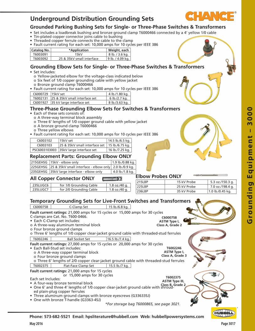
Gro
un
din
g E
qu
ipm
en
t –
30
00
Phone: 573-682-5521 Email: [email protected] Web: hubbellpowersystems.com
Page 3017May 2016
Underground Distribution Grounding Sets
*For storage bag T6000865, see page 3021.
Fault current ratings: 21,000 amps for 15 cycles or 15,000 amps for 30 cyclesC-clamps are Cat. No. T600-0466.• Each C-Clamp set includes: o A three-way aluminum terminal blocko Four bronze ground clampso Three 6’ lengths of 1/0 copper clear-jacket ground cable with threaded-stud ferrules
• Set includes: o Yellow-jacketed elbow for the voltage-class indicated below o Six feet of 1/0 copper grounding cable with yellow jacket o Bronze ground clamp T6000466• Fault current rating for each set: 10,000 amps for 10 cycles per IEEE 386
• Set includes a loadbreak bushing and bronze ground clamp T6000466 connected by a 4’ yellow 1/0 cable• Tin-plated copper connector joins cable to bushing• Threaded copper ferrule connects the cable to the clamp• Fault current rating for each set: 10,000 amps for 10 cycles per IEEE 386
Temporary Grounding Sets for Live-Front Switches and Transformers
Fault current ratings: 21,000 amps for 15 cycles or 15,000 amps for 30 cyclesEach set Includes:• A four-way bronze terminal block• One 6’ and three 4’ lengths of 1/0 copper clear-jacket ground cable with shroud-
ed plain-plug copper ferrules• Three aluminum ground clamps with bronze eyescrews (G33633SJ)• One with bronze T-handle (G3363-4SJ)
Fault current ratings: 27,000 amps for 15 cycles or 20,000 amps for 30 cycles• Each Ball-Stud set includes: o A three-way copper terminal block o Four bronze ground clamps o Three 6’ lengths of 2/0 copper clear-jacket ground cable with threaded-stud ferrules
Grounding Elbow Sets for Single- or Three-Phase Switches & Transformers
Three-Phase Grounding Elbow Sets for Switches & Transformers• Each of these sets consists of: o A three-way terminal block assembly o Three 6’ lengths of 1/0 copper ground cable with yellow jacket o A bronze ground clamp T6000466 o Three yellow elbows• Fault current rating for each set: 10,000 amps for 10 cycles per IEEE 386
Grounded Parking Bushing Sets for Single- or Three-Phase Switches & Transformers
Replacement Parts: Grounding Elbow ONLY
All Copper Connector ONLY Elbow Probes ONLY
T6002375ASTM Type III,
Class B, Grade 2
T6002246ASTM Type I,
Class A, Grade 3
Catalog No. *Application Weight, eachT6003091 15kV 8 lb. / 3.6 kg.T6003092 25 & 35kV small interface 9 lb. / 4.09 kg.
C6000729 15kV set 4 lb./1.80 kg.T6002131 25 & 35kV small interface set 6 lb./2.7 kg.C6001927 35 kV large interface set 8 lb./3.63 kg.
C6003102 15kV set 14.5 lb./6.5 kg.C6003103 25 & 35kV small interface set 15 lb./6.75 kg.
PSC6003103003 35kV large interface set 16 lb./7.25 kg.
215GEHSG 15kV - elbow only 1.9 lb./0.88 kg.225GEHSG 25 & 35kV small interface - elbow only 2.0 lb./0.9 kg.235GEHSG 35kV large interface - elbow only 4.0 lb./1.8 kg.
235LUGC6 for 1/0 Grounding Cable 1.8 oz./40 g.235LUGC7 for 2/0 Grounding Cable 1.8 oz./40 g.
215LBP 15 kV Probe 5.3 oz./150.3 g.225LBP 25 kV Probe 7.0 oz./198.4 g.236LBP 35 kV Probe 1.0 lb./0.45 kg.
C6000758 C-Clamp Set 15 lb./6.8 kg.
C6000758ASTM Type I,
Class A, Grade 2
T6002246 Ball Socket Set 16.5 lb./7.4 kg.
T6002375 Flat-Face Clamp Set 15.5 lb./7 kg.
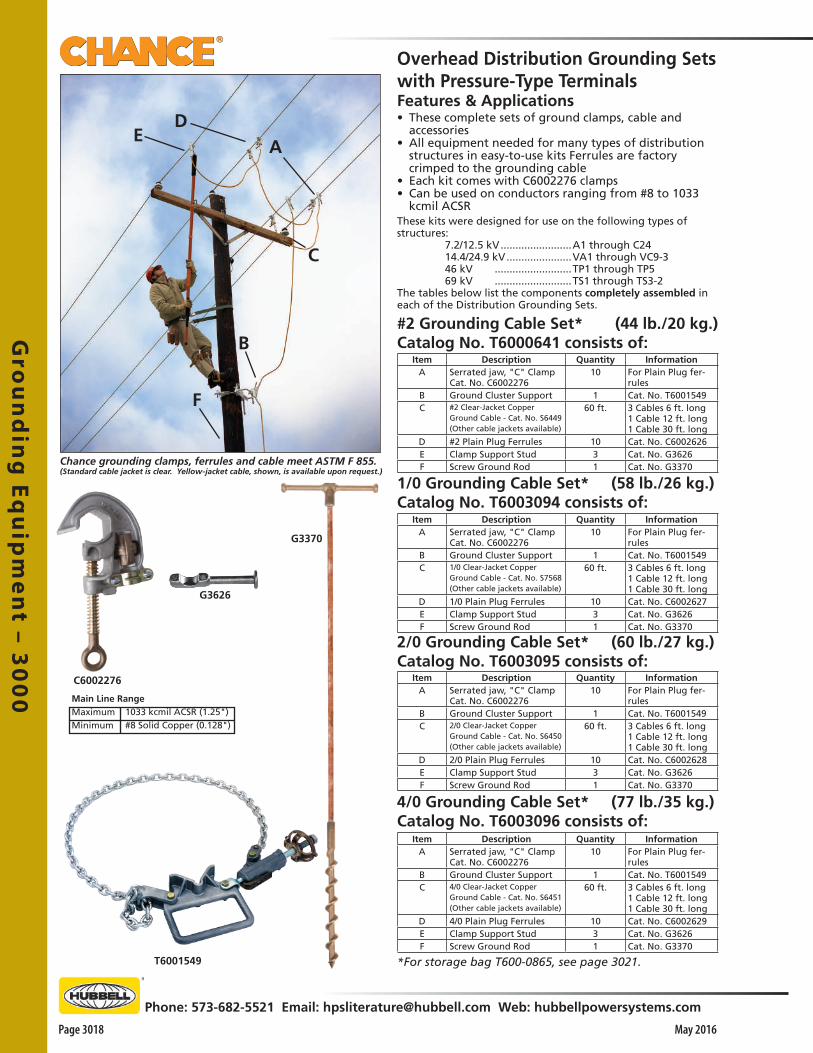
Gro
un
din
g E
qu
ipm
en
t – 30
00
Page 3018 May 2016
Phone: 573-682-5521 Email: [email protected] Web: hubbellpowersystems.com
F
B
C
AD
E
Chance grounding clamps, ferrules and cable meet ASTM F 855.(Standard cable jacket is clear. Yellow-jacket cable, shown, is available upon request.)
1/0 Grounding Cable Set* (58 lb./26 kg.)Catalog No. T6003094 consists of:
#2 Grounding Cable Set* (44 lb./20 kg.)Catalog No. T6000641 consists of:
*For storage bag T600-0865, see page 3021.
Features & Applications• These complete sets of ground clamps, cable and
accessories • All equipment needed for many types of distribution
structures in easy-to-use kits Ferrules are factory crimped to the grounding cable
• Each kit comes with C6002276 clamps• Can be used on conductors ranging from #8 to 1033
kcmil ACSRThese kits were designed for use on the following types of structures: 7.2/12.5 kV ........................A1 through C24 14.4/24.9 kV ......................VA1 through VC9-3 46 kV ..........................TP1 through TP5 69 kV ..........................TS1 through TS3-2The tables below list the components completely assembled in each of the Distribution Grounding Sets.
Overhead Distribution Grounding Setswith Pressure-Type Terminals
2/0 Grounding Cable Set* (60 lb./27 kg.)Catalog No. T6003095 consists of:
4/0 Grounding Cable Set* (77 lb./35 kg.)Catalog No. T6003096 consists of:
T6001549
G3370
G3626
C6002276
1033 kcmil ACSR (1.25")#8 Solid Copper (0.128")
Main Line RangeMaximumMinimum
Item Description Quantity InformationA Serrated jaw, "C" Clamp
Cat. No. C600227610 For Plain Plug fer-
rulesB Ground Cluster Support 1 Cat. No. T6001549C #2 Clear-Jacket Copper
Ground Cable - Cat. No. S6449(Other cable jackets available)
60 ft. 3 Cables 6 ft. long1 Cable 12 ft. long1 Cable 30 ft. long
D #2 Plain Plug Ferrules 10 Cat. No. C6002626E Clamp Support Stud 3 Cat. No. G3626F Screw Ground Rod 1 Cat. No. G3370
Item Description Quantity InformationA Serrated jaw, "C" Clamp
Cat. No. C600227610 For Plain Plug fer-
rulesB Ground Cluster Support 1 Cat. No. T6001549C 1/0 Clear-Jacket Copper
Ground Cable - Cat. No. S7568(Other cable jackets available)
60 ft. 3 Cables 6 ft. long1 Cable 12 ft. long1 Cable 30 ft. long
D 1/0 Plain Plug Ferrules 10 Cat. No. C6002627E Clamp Support Stud 3 Cat. No. G3626F Screw Ground Rod 1 Cat. No. G3370
Item Description Quantity InformationA Serrated jaw, "C" Clamp
Cat. No. C600227610 For Plain Plug fer-
rulesB Ground Cluster Support 1 Cat. No. T6001549C 4/0 Clear-Jacket Copper
Ground Cable - Cat. No. S6451(Other cable jackets available)
60 ft. 3 Cables 6 ft. long1 Cable 12 ft. long1 Cable 30 ft. long
D 4/0 Plain Plug Ferrules 10 Cat. No. C6002629E Clamp Support Stud 3 Cat. No. G3626F Screw Ground Rod 1 Cat. No. G3370
Item Description Quantity InformationA Serrated jaw, "C" Clamp
Cat. No. C600227610 For Plain Plug fer-
rulesB Ground Cluster Support 1 Cat. No. T6001549C 2/0 Clear-Jacket Copper
Ground Cable - Cat. No. S6450(Other cable jackets available)
60 ft. 3 Cables 6 ft. long1 Cable 12 ft. long1 Cable 30 ft. long
D 2/0 Plain Plug Ferrules 10 Cat. No. C6002628E Clamp Support Stud 3 Cat. No. G3626F Screw Ground Rod 1 Cat. No. G3370
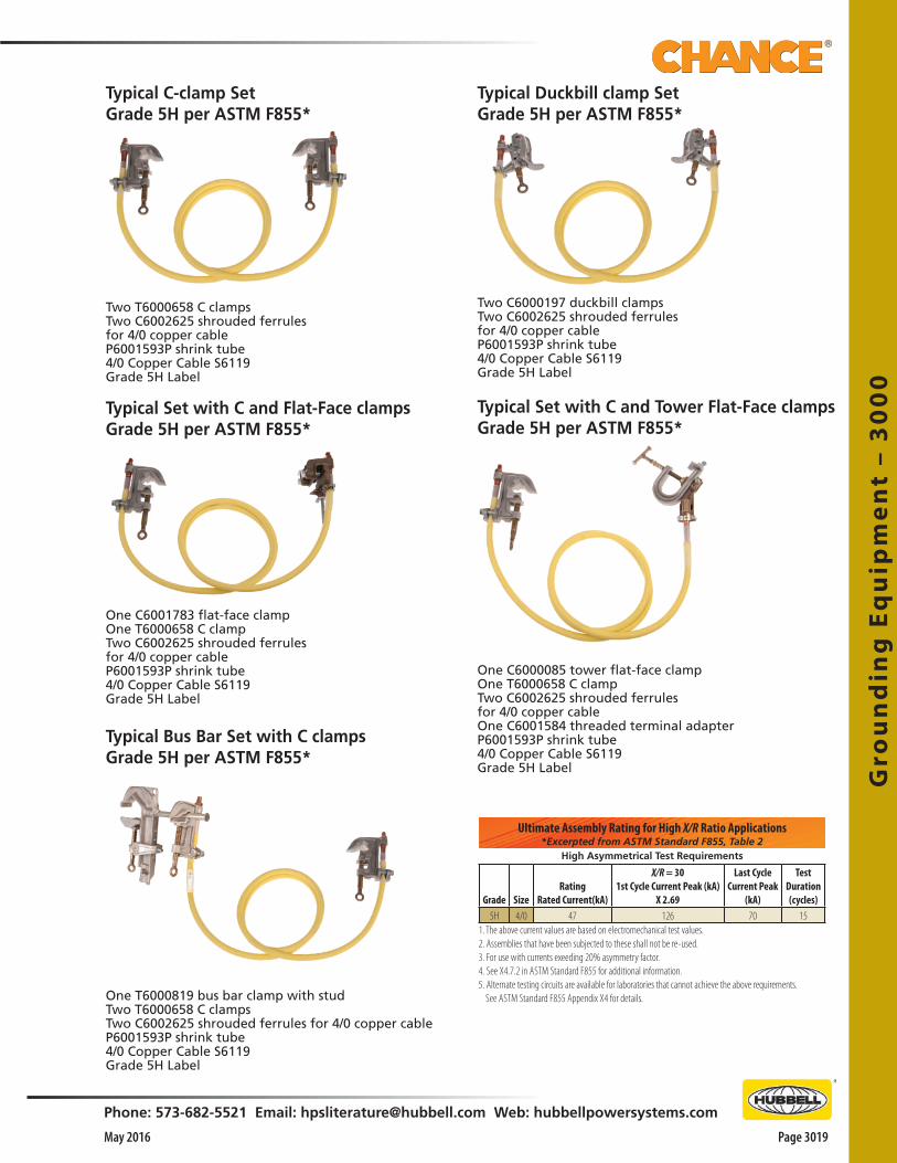
Two T6000658 C clampsTwo C6002625 shrouded ferrulesfor 4/0 copper cableP6001593P shrink tube4/0 Copper Cable S6119Grade 5H Label
Typical C-clamp Set Grade 5H per ASTM F855*
Two C6000197 duckbill clampsTwo C6002625 shrouded ferrulesfor 4/0 copper cableP6001593P shrink tube4/0 Copper Cable S6119Grade 5H Label
Typical Duckbill clamp SetGrade 5H per ASTM F855*
Typical Set with C and Flat-Face clampsGrade 5H per ASTM F855*
Typical Set with C and Tower Flat-Face clampsGrade 5H per ASTM F855*
One C6000085 tower flat-face clampOne T6000658 C clampTwo C6002625 shrouded ferrulesfor 4/0 copper cableOne C6001584 threaded terminal adapterP6001593P shrink tube4/0 Copper Cable S6119Grade 5H Label
One C6001783 flat-face clampOne T6000658 C clampTwo C6002625 shrouded ferrulesfor 4/0 copper cableP6001593P shrink tube4/0 Copper Cable S6119Grade 5H Label
Typical Bus Bar Set with C clampsGrade 5H per ASTM F855*
One T6000819 bus bar clamp with studTwo T6000658 C clampsTwo C6002625 shrouded ferrules for 4/0 copper cableP6001593P shrink tube4/0 Copper Cable S6119Grade 5H Label
Grade SizeRating
Rated Current(kA)
X/R = 301st Cycle Current Peak (kA)
X 2.69
Last CycleCurrent Peak
(kA)
TestDuration(cycles)
5H 4/0 47 126 70 15
High Asymmetrical Test Requirements
Ultimate Assembly Rating for High X/R Ratio Applications*Excerpted from ASTM Standard F855, Table 2
1. The above current values are based on electromechanical test values.2. Assemblies that have been subjected to these shall not be re-used.3. For use with currents exeeding 20% asymmetry factor.4. See X4.7.2 in ASTM Standard F855 for additional information.5. Alternate testing circuits are available for laboratories that cannot achieve the above requirements. See ASTM Standard F855 Appendix X4 for details.
Gro
un
din
g E
qu
ipm
en
t –
30
00
Phone: 573-682-5521 Email: [email protected] Web: hubbellpowersystems.com
Page 3019May 2016
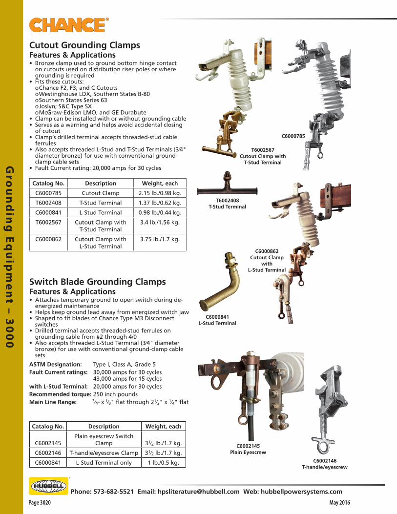
Gro
un
din
g E
qu
ipm
en
t – 30
00
Page 3020 May 2016
Phone: 573-682-5521 Email: [email protected] Web: hubbellpowersystems.com
C6002145Plain Eyescrew
C6002146T-handle/eyescrew
C6000862 Cutout Clamp
with L-Stud Terminal
Cutout Grounding ClampsFeatures & Applications• Bronze clamp used to ground bottom hinge contact
on cutouts used on distribution riser poles or where grounding is required
• Fits these cutouts: o Chance F2, F3, and C Cutouts o Westinghouse LDX, Southern States B-80 o Southern States Series 63 o Joslyn; S&C Type SX o McGraw-Edison LMO, and GE Durabute• Clamp can be installed with or without grounding cable• Serves as a warning and helps avoid accidental closing
of cutout• Clamp’s drilled terminal accepts threaded-stud cable
ferrules• Also accepts threaded L-Stud and T-Stud Terminals (3⁄4"
diameter bronze) for use with conventional ground-clamp cable sets
• Fault Current rating: 20,000 amps for 30 cycles
Switch Blade Grounding ClampsFeatures & Applications• Attaches temporary ground to open switch during de-
energized maintenance• Helps keep ground lead away from energized switch jaw• Shaped to fit blades of Chance Type M3 Disconnect
switches• Drilled terminal accepts threaded-stud ferrules on
grounding cable from #2 through 4/0 • Also accepts threaded L-Stud Terminal (3⁄4" diameter
bronze) for use with conventional ground-clamp cable sets
ASTM Designation: Type I, Class A, Grade 5Fault Current ratings: 30,000 amps for 30 cycles 43,000 amps for 15 cycleswith L-Stud Terminal: 20,000 amps for 30 cyclesRecommended torque: 250 inch poundsMain Line Range: 3⁄4" x 1⁄8" flat through 21⁄2" x 1⁄4" flat
T6002408T-Stud Terminal
T6002567 Cutout Clamp with
T-Stud Terminal
C6000785
Catalog No. Description Weight, each
C6002145Plain eyescrew Switch
Clamp 31⁄2 lb./1.7 kg.
C6002146 T-handle/eyescrew Clamp 31⁄2 lb./1.7 kg.
C6000841 L-Stud Terminal only 1 lb./0.5 kg.
C6000841L-Stud Terminal
Catalog No. Description Weight, each
C6000785 Cutout Clamp 2.15 lb./0.98 kg.
T6002408 T-Stud Terminal 1.37 lb./0.62 kg.
C6000841 L-Stud Terminal 0.98 lb./0.44 kg.
T6002567 Cutout Clamp with T-Stud Terminal
3.4 lb./1.56 kg.
C6000862 Cutout Clamp with L-Stud Terminal
3.75 lb./1.7 kg.
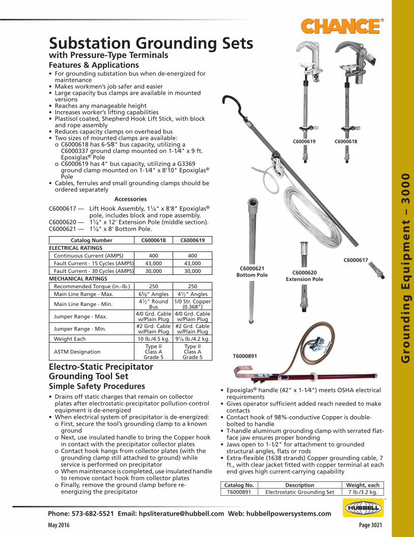
Gro
un
din
g E
qu
ipm
en
t –
30
00
Phone: 573-682-5521 Email: [email protected] Web: hubbellpowersystems.com
Page 3021May 2016
with Pressure-Type TerminalsFeatures & Applications• For grounding substation bus when de-energized for
maintenance• Makes workmen’s job safer and easier• Large capacity bus clamps are available in mounted
versions• Reaches any manageable height• Increases worker’s lifting capabilities• Plastisol coated, Shepherd Hook Lift Stick, with block
and rope assembly• Reduces capacity clamps on overhead bus• Two sizes of mounted clamps are available: o C6000618 has 6-5⁄8" bus capacity, utilizing a
C6000337 ground clamp mounted on 1-1⁄4" x 9 ft. Epoxiglas® Pole
o C6000619 has 4" bus capacity, utilizing a G3369 ground clamp mounted on 1-1⁄4" x 8'10" Epoxiglas® Pole
• Cables, ferrules and small grounding clamps should be ordered separately
Accessories
C6000617 — Lift Hook Assembly, 11⁄4" x 8'8" Epoxiglas®
pole, includes block and rope assembly.C6000620 — 11⁄4" x 12' Extension Pole (middle section).C6000621 — 11⁄4" x 8' Bottom Pole.
Substation Grounding Sets
• Epoxiglas® handle (42" x 1-1⁄4") meets OSHA electrical requirements
• Gives operator sufficient added reach needed to make contacts
• Contact hook of 98%-conductive Copper is double-bolted to handle
• T-handle aluminum grounding clamp with serrated flat-face jaw ensures proper bonding
• Jaws open to 1-1⁄2" for attachment to grounded structural angles, flats or rods
• Extra-flexible (1638 strands) Copper grounding cable, 7 ft., with clear jacket fitted with copper terminal at each end gives high current-carrying capability
C6000619 C6000618
C6000617
C6000620Extension Pole
T6000891
Electro-Static PrecipitatorGrounding Tool SetSimple Safety Procedures• Drains off static charges that remain on collector
plates after electrostatic-precipitator pollution-control equipment is de-energized
• When electrical system of precipitator is de-energized: o First, secure the tool’s grounding clamp to a known
ground o Next, use insulated handle to bring the Copper hook
in contact with the precipitator collector plates o Contact hook hangs from collector plates (with the
grounding clamp still attached to ground) while service is performed on precipitator
o When maintenance is completed, use insulated handle to remove contact hook from collector plates
o Finally, remove the ground clamp before re-energizing the precipitator
C6000621Bottom Pole
Catalog Number C6000618 C6000619ELECTRICAL RATINGS
Continuous Current (AMPS) 400 400Fault Current - 15 Cycles (AMPS) 43,000 43,000Fault Current - 30 Cycles (AMPS) 30,000 30,000
MECHANICAL RATINGSRecommended Torque (in.-lb.) 250 250Main Line Range - Max. 65⁄8” Angles 41⁄2” Angles
Main Line Range - Min. 41⁄2” Round Bus
1/0 Str. Copper (0.368”)
Jumper Range - Max. 4/0 Grd. Cable w/Plain Plug
4/0 Grd. Cable w/Plain Plug
Jumper Range - Min. #2 Grd. Cable w/Plain Plug
#2 Grd. Cable w/Plain Plug
Weight Each 10 lb./4.5 kg. 91⁄4 lb./4.2 kg.
ASTM DesignationType II Class A Grade 5
Type II Class A Grade 5
Catalog No. Description Weight, eachT6000891 Electrostatic Grounding Set 7 lb./3.2 kg.

Chance grounding ferrules and cable meet requirements of ASTM F 855; see table, page 3002.
Gro
un
din
g E
qu
ipm
en
t – 30
00
Page 3022 May 2016
Phone: 573-682-5521 Email: [email protected] Web: hubbellpowersystems.com
Copper Grounding Cable Either aluminum or copper ferrules may be used with copper cable.
• Extra-flexible for handling ease yet strong and tough for long wear
• Jacketing is smooth, abrasion, weather and oil resistant• In accordance with applicable ASTM Specifications,
marked with AWG size approximately every 4 feet• Yellow and black jackets are T-prene rubber compound
with -20°F recommended low temperature• Clear jackets (which allow visual inspection of strand
conditions) are ultraviolet-inhibited Poly Vinyl Chloride (PVC)
• Recommended low temperature for PVC-jacketed cable is 0°F
• Extra-flexible cables, because of their extra-fine strands• Require termination ferrules when used with ground
clamps
Selection Criteria• Shrouded ferrules overlap onto the grounding cable
jacket for stress relief to the terminal. Two crimps secure the ferrule against the bare strands and one crimp applies on the jacket
• Unshrouded ferrules are available with shrink tubing that overlaps the bare cable conductor and jacket for stress relief
• Available either factory-installed in pairs on any cable length specified or as separate individual units, the ferrules install simply with a hydraulic crimping tool. Complete illustrated installation instructions come with the ferrules and include a table for the crimping die sizes to use
See ordering tables for crimping-die sizes applicable.Grounding FerrulesUnshrouded ferrules
Shrouded ferrules
Cable
Sect. B CableSection A
Plain-plug type for pressure-type grounding-clamp terminalsCopper ferrules
Threaded-stud type for tapped or drilled grounding-clamp terminals
Threaded-stud type for tapped or drilled grounding-clamp terminals
†Anderson die-less VERSA-CRIMP™ compression tools require no dies and are capable of making these crimped connections. If using another crimp tool brand, contact that manufacturer for Burndy die equivalents.
Tin-Plated Copper ferrulesPlain-plug type for pressure-type grounding-clamp terminals
Catalog Number
Size AWG Strands* Diameter
(Inches)Approx. O.D.
(Inches)Approx. Wt. (lb./1,000 ft.)
Yellow-Jacket Copper CableS6116 #2 665 0.32 0.55 280S6117 “1/0” 1045 0.41 0.66 425S6118 “2/0” 1330 0.47 0.73 520S6119 “4/0” 2109 0.59 0.87 760
Clear-Jacket Copper CableS6449 #2 665 0.344 0.53 289S7568 “1/0” 1050 0.445 0.63 520S6450 “2/0” 1323 0.487 0.70 546S6451 “4/0” 2107 0.616 0.84 841
Black-Jacket Copper CableS3713 #2 665 0.32 0.55 280S3715 “1/0” 1045 0.41 0.66 425S3712 “2/0” 1330 0.47 0.73 510S3714 “4/0” 2109 0.59 0.87 760
*Varies with manufacturer.
Shrouded plain copper ferrules1 unit each, not installed Catalog No.
Burndy Die No.† or equivalent
Cable Size, AWGSect. A Sect. B
C6002630 U165 U166 #2C6002631 U165 U168 “1/0”C6002632 U165 U-L “2/0”C6002633 U166 U-L “4/0”
Unshrouded plain copper ferrules1 unit each, not installed Catalog No.
Burndy Die No.† or equivalent
Cable Size, AWG
C6002614 U165 #2C6002615 U165 “1/0”C6002616 U165 “2/0”C6002617 U166 “4/0”
Shrouded threaded copper ferrulesC6002622 U165 U166 #2C6002623 U165 U168 “1/0”C6002624 U165 U-L “2/0”C6002625 U166 U-L “4/0”
Unshrouded threaded copper ferrulesC6002606 U165 #2C6002607 U165 “1/0”C6002608 U165 “2/0”C6002609 U166 “4/0”
Shrouded plain tin-plated copper ferrulesC6003119 U165 U166 #2C6003120 U165 U168 “1/0”C6003121 U165 U-L “2/0”C6003122 U166 U-L “4/0”
Unshrouded plain tin-plated copper ferrulesC6003111 U165 #2C6003112 U165 “1/0”C6003113 U165 “2/0”C6003114 U166 “4/0”
Shrouded threaded tin-plated copper ferrulesC6003115 U165 U166 #2C6003116 U165 U168 “1/0”C6003117 U165 U-L “2/0”C6003118 U166 U-L “4/0”
Unshrouded threaded tin-plated copper ferrulesC6003107 U165 #2C6003108 U165 “1/0”C6003109 U165 “2/0”C6003110 U166 “4/0”
Two crimps

Gro
un
din
g E
qu
ipm
en
t –
30
00
Phone: 573-682-5521 Email: [email protected] Web: hubbellpowersystems.com
Page 3023May 2016
Threaded-stud type for tapped or drilled grounding-clamp terminals
1 unit each,not installedCatalog No.C6002618C6002619C6002620C6002621
Burndy Die No.†
or equivalentCableSize,AWG
#21/02/04/0
Sect. AU165U165U165U249
Sect. BU166U168U-LU-L
Shrouded threaded aluminum ferrules
1 unit each,not installedCatalog No.C6002626C6002627C6002628C6002629
Burndy Die No.†
or equivalentCableSize,AWG
#21/02/04/0
Sect. AU165U165U165U249
Sect. BU166U168U-LU-L
Shrouded plain aluminum ferrulesPlain-plug type for pressure-type grounding-clamp terminals
Aluminum ferrules
Shrink tubing for plain ferrulesFeatures & Applications• Clear heat-shrink tubes limit corrosion• Excludes moisture• Stress-relief for cable jacket and ferrule-to-stranding connection
Part No.P6001593PP6001982PP6002069P
1 unit each,not installedCatalog No.C6002610C6002611C6002612C6002613
CableSize,AWG
#21/02/04/0
Burndy Die No.†
or equivalentU165U165U165U249
Unshrouded plain aluminum ferrules
1 unit each,not installedCatalog No.C6002602C6002603C6002604C6002605
CableSize,AWG
#21/02/04/0
Burndy Die No.†
or equivalentU165U165U165U249
Unshrouded threaded aluminum ferrules
• Visual inspection of cable condition through clear heat-shrink tube allows inspection for breakage or corrosion that otherwise requires continuity test
• Factory-assembled units expose 1⁄2" of cable strands at junction point
Shrink tubing for threaded ferrulesFeatures & Applications• Clear heat-shrink tubes limit corrosion• Excludes moisture• Stress-relief for cable jacket and ferrule-to-stranding connection
Lengths 5" 7" 9"
†Anderson die-less VERSA-CRIMP® compression tools require no dies and are capable of making these crimped connections. If using another crimp tool brand, contact that manufacturer for Burndy die equivalents.
†Anderson die-less VERSA-CRIMP® compression tools require no dies and are capable of making these crimped connections. If using another crimp tool brand, contact that manufacturer for Burndy die equivalents.
Factory-crimped, above
• Visual inspection of cable condition through clear heat-shrink tube determines breakage or corrosion that otherwise requires continuity test
• Factory-assembled units expose 1⁄2" of cable strands at junction point
Factory-crimped, above
Part No.P6001593PP6001982PP6002069P
Lengths 5" 7" 9"
Features & Applications

Gro
un
din
g E
qu
ipm
en
t – 30
00
Page 3024 May 2016
Phone: 573-682-5521 Email: [email protected] Web: hubbellpowersystems.com
Conversion TerminalsFeatures & Applications• Threaded-terminal adapters for pressure-type
grounding-clamp terminals
• Simply retrofit bolt-on adapters to convert clamps with pressure-type terminals to accept 5⁄8-11 UNC threaded ferrules
Catalog NumberC6001584
“eyebolt” style,includes shakeproof washer
and nutC6001700
includes steel retainerstraps for cable
Clamp Applications
C Type, Snap-On Flat-Face
All-Angle Clamps
C6001584
C6001700
Typical Application
Typical Application
Storage Bag for Temporary Grounding Clamps-and-Cable Sets
Features & Applications• Easy-to-see, bright-yellow protective bag• Made of double vinyl-laminated open-weave nylon
cloth• Lightweight and durable with nylon stitching
throughout• Full-separating closure constructed with heavy-duty
snaps• Heavy webbing handles• 18" L x 12" W x 15" D
Weight
3 lb.Catalog No.
T6000865
Description
Grounding Storage Bag
Support StudsFeatures & Applications• Can be installed on most Ground Clamps• Replaces restraining strap immediately below terminal• Serves as a mechanical parking stand for a second clamp• Helps prevent "parked" clamp from making contact
with conductor or ground• Particularly beneficial in three-phase grounding
applications
Catalog No.G3626G3627
DescriptionStud for Rear MountStud for Side Mount
Size of Stud7⁄16" x 21⁄2"
7⁄16" x 3"
Weight1⁄2 lb./.2 kg.3⁄4 lb./.3 kg.
G3627
G3626
Dielectric Compound No. 7Dielectric Compound No. 7, a silicone base material, is made for use with load break disconnects and other electrical connecting and terminating devices.
Cat. No. C4170287..................................... 2 oz. Tube
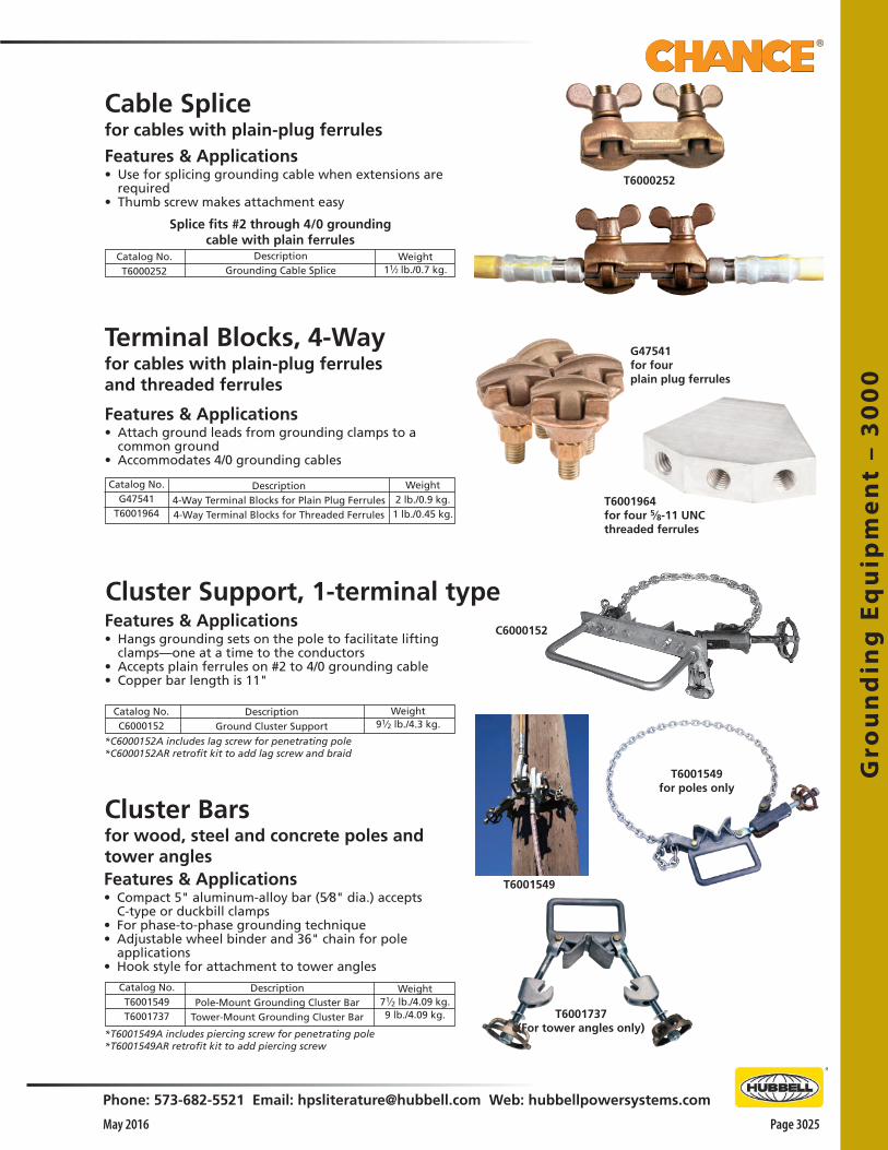
Gro
un
din
g E
qu
ipm
en
t –
30
00
Phone: 573-682-5521 Email: [email protected] Web: hubbellpowersystems.com
Page 3025May 2016
Conversion Terminals
Cluster Barsfor wood, steel and concrete poles and tower anglesFeatures & Applications• Compact 5" aluminum-alloy bar (5⁄8" dia.) accepts
C-type or duckbill clamps • For phase-to-phase grounding technique• Adjustable wheel binder and 36" chain for pole
applications• Hook style for attachment to tower angles
Catalog No.T6001549T6001737
DescriptionPole-Mount Grounding Cluster Bar
Tower-Mount Grounding Cluster Bar
Weight71⁄2 lb./4.09 kg.9 lb./4.09 kg.
Cable Splicefor cables with plain-plug ferrules
Features & Applications• Use for splicing grounding cable when extensions are
required• Thumb screw makes attachment easy
Catalog No.T6000252
DescriptionGrounding Cable Splice
Splice fits #2 through 4/0 grounding cable with plain ferrules
Weight11⁄2 lb./0.7 kg.
Terminal Blocks, 4-Wayfor cables with plain-plug ferrulesand threaded ferrules
Features & Applications• Attach ground leads from grounding clamps to a
common ground• Accommodates 4/0 grounding cables
T6000252
Cluster Support, 1-terminal typeFeatures & Applications• Hangs grounding sets on the pole to facilitate lifting
clamps—one at a time to the conductors• Accepts plain ferrules on #2 to 4/0 grounding cable• Copper bar length is 11"
Catalog No.C6000152
DescriptionGround Cluster Support
Weight91⁄2 lb./4.3 kg.
C6000152
T6001549
T6001549for poles only
T6001737(For tower angles only)
Catalog No.G47541
T6001964
Description4-Way Terminal Blocks for Plain Plug Ferrules4-Way Terminal Blocks for Threaded Ferrules
Weight2 lb./0.9 kg.1 lb./0.45 kg.
G47541for fourplain plug ferrules
T6001964for four 5⁄8-11 UNCthreaded ferrules
*C6000152A includes lag screw for penetrating pole*C6000152AR retrofit kit to add lag screw and braid
*T6001549A includes piercing screw for penetrating pole*T6001549AR retrofit kit to add piercing screw
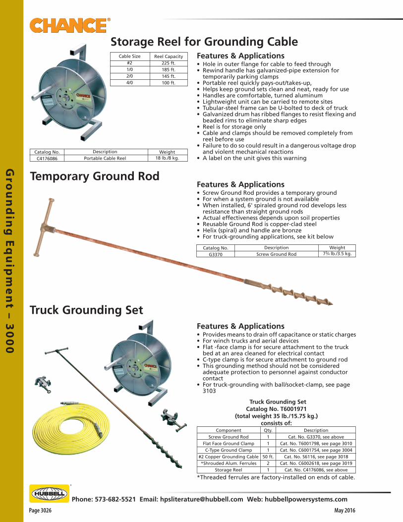
Gro
un
din
g E
qu
ipm
en
t – 30
00
Page 3026 May 2016
Phone: 573-682-5521 Email: [email protected] Web: hubbellpowersystems.com
Storage Reel for Grounding Cable
Catalog No.G3370
DescriptionScrew Ground Rod
Weight73⁄4 lb./3.5 kg.
Features & Applications• Hole in outer flange for cable to feed through• Rewind handle has galvanized-pipe extension for
temporarily parking clamps• Portable reel quickly pays-out/takes-up,• Helps keep ground sets clean and neat, ready for use• Handles are comfortable, turned aluminum• Lightweight unit can be carried to remote sites• Tubular-steel frame can be U-bolted to deck of truck• Galvanized drum has ribbed flanges to resist flexing and
beaded rims to eliminate sharp edges• Reel is for storage only• Cable and clamps should be removed completely from
reel before use• Failure to do so could result in a dangerous voltage drop
and violent mechanical reactions• A label on the unit gives this warning
Cable Size#21/02/04/0
Reel Capacity225 ft.185 ft.145 ft.100 ft.
Catalog No.C4176086
DescriptionPortable Cable Reel
Weight18 lb./8 kg.
Temporary Ground RodFeatures & Applications• Screw Ground Rod provides a temporary ground • For when a system ground is not available• When installed, 6' spiraled ground rod develops less
resistance than straight ground rods• Actual effectiveness depends upon soil properties• Reusable Ground Rod is copper-clad steel• Helix (spiral) and handle are bronze• For truck-grounding applications, see kit below
Truck Grounding SetFeatures & Applications• Provides means to drain off capacitance or static charges • For winch trucks and aerial devices• Flat -face clamp is for secure attachment to the truck
bed at an area cleaned for electrical contact• C-type clamp is for secure attachment to ground rod• This grounding method should not be considered
adequate protection to personnel against conductor contact
• For truck-grounding with ball/socket-clamp, see page 3103
Truck Grounding SetCatalog No. T6001971
(total weight 35 lb./15.75 kg.)consists of:
ComponentScrew Ground Rod
Flat Face Ground ClampC-Type Ground Clamp
#2 Copper Grounding Cable*Shrouded Alum. Ferrules
Storage Reel
Qty.111
50 ft.21
DescriptionCat. No. G3370, see above
Cat. No. T6001798, see page 3010Cat. No. C6001754, see page 3004
Cat. No. S6116, see page 3018Cat. No. C6002618, see page 3019
Cat. No. C4176086, see above
*Threaded ferrules are factory-installed on ends of cable.

Gro
un
din
g E
qu
ipm
en
t –
30
00
Phone: 573-682-5521 Email: [email protected] Web: hubbellpowersystems.com
Page 3027May 2016
Truck Safety Barricade
Features & Applications• Keeps workers and onlookers away from truck when it
is being used in proximity to energized conductors• Six rods, made of bright orange Epoxirod®, provide a
6-foot air space around the entire perimeter of the truck• Safety barricade also includes six pieces of 3-inch long
steel tubing (to be welded to truck by the customer) • Tubing holds barricade rods, 150 feet of yellow rope and
a canvas storage bag• Entire kit requires less storage than traffic cones and can
be quickly installed and removed at each job site
T3060006
DescriptionTruck Safety Barricade
Catalog No.T3060006
Weight21 lb./9.5 kg.
Modular design quickly sets up and takes down for storage in rugged transport case.
Catalog No.C6001950
DescriptionGrounding Simulator Kit
Features & Applications• Demonstrates principles for temporary grounding
practices• Portable instructional aid provides working model of
three-phase system circuit• Powered by a step-down transformer• Plugs into a 110-volt 60-cycle household source• Special light/buzzer unit simulates lineworker in
maintenance on de-energized line• Insulated wires with alligator clip at each end serve as
grounding cable and clamp sets (10 included)• Miniature grounding cluster bar is included for pole
mounting
Grounding Simulator Kit
Weight23 lb. / 10.5 kg.
Operation• To quickly test any proposed configuration, depress
transformer foot switch to energize a fault on the system
• If the light glows and the buzzer sounds on the “worker,” this indicates the grounding system in place fails to provide protection
• If no such signals occur, the scheme of grounding connections does create a protective zone of equalized potential at the worksite
Ordering Information
Durable & Accurate• Durable, aluminum pipe poles • Wood crossarms • Electrically correct, aluminum poles effect the
conductivity which should be assumed for actual poles• Leads from the poles and neutral connect to ground
side on source (transformer)

Gro
un
din
g E
qu
ipm
en
t – 30
00
Page 3028 May 2016
Phone: 573-682-5521 Email: [email protected] Web: hubbellpowersystems.com
Ground Set T6002841 included with Kits onlyConsists of 6 ft. long #2 cable with ferrules applied,Ball Socket clamp (C6002100)and C-Type clamp (T6000465)
Portable, lightweight, high performance• An easy way to help establish an equipotential zone for a lineworker • For standing on during various energized and de-energized work practices• Properly applied, it accomplishes compliance with Occupational Safety and
Health Administration (OSHA) 1910.269: o “Equipotential Zone. Temporary protective grounds SHALL be placed at
such locations and arranged in such a manner as to prevent each employee from being exposed to hazardous differences in electrical potential.”
• Can be taken anywhere needed, is simple to use, maintain and store• Consists of a high-ampacity tinned-copper-braid cable sewn in a grid pattern
onto a vinyl/polyester fabric• Cable terminals permit connecting mat's grid in series with an electrical
ground and subject system component or vehicle• Simply rinsing with water comprises all the care the mat requires• Mat may be folded and stored in a tool bag to help keep it clean and
protected• Complete instructions are included with each unit
. . . continued on the next page . . .
Basic Equi-Mat® Personal Protective Ground GridEach Basic Unit includes a Long Ball Stud and illustrated instructions.
Catalog No. Single 1⁄4" Perimeter Braid PSC6003080* (Bucket) C6002850 C6002851 C6002852
Size
24" x 24" 58" x 58" 58" x 120" 120" x 120"
Weight 5 lb. / 2.3 kg. 8 lb. / 3.6 kg. 13 lb. / 5.9 kg. 20 lb. / 9.1 kg.
KitCatalog No.C6002989C6002990C6002991
Equi-Mat® Personal Protective Ground Grid Size
58" x 58" 58" x 120" 120" x 120"
Weightper Kit
19 lb. / 8.6 kg. 27 lb. / 12.2 kg. 30 lb. / 13.6 kg.
Pre-Packaged KitsEach Pre-Packaged Kit includes Ground Grid (size below with Long Ball Stud and illustrated instructions) plus Ground Set T6002841 and Storage Bag C4170147.
Storage BagC4170147included with Kits onlyCatalog pages 2512-13
Long Ball Stud T6002364included with each Basic Equi-Mat® PersonalProtective Ground Grid (Catalog page 3013)
Accessory Items
Standard (Orange) Equi-Mat®
Personal Protective Ground GridFeatures & Applications• Complies with OSHA 1910.269 for equipotential requirements near vehicles,
underground gear, overhead switches and in substations• Meets ASTM F2715 Standard
*For use in bottom of personnel bucket of lift truck.
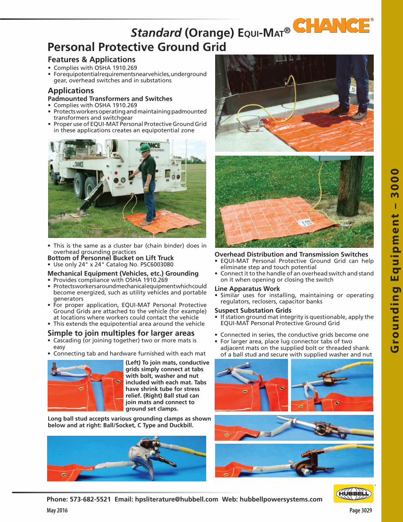
Gro
un
din
g E
qu
ipm
en
t –
30
00
Phone: 573-682-5521 Email: [email protected] Web: hubbellpowersystems.com
Page 3029May 2016
Simple to join multiples for larger areas• Cascading (or joining together) two or more mats is
easy • Connecting tab and hardware furnished with each mat
Features & Applications• Complies with OSHA 1910.269• For equipotential requirements near vehicles, underground
gear, overhead switches and in substations
ApplicationsPadmounted Transformers and Switches• Complies with OSHA 1910.269 • Protects workers operating and maintaining padmounted
transformers and switchgear• Proper use of EQUI-MAT Personal Protective Ground Grid
in these applications creates an equipotential zone
(Left) To join mats, conductive grids simply connect at tabs with bolt, washer and nut included with each mat. Tabs have shrink tube for stress relief. (Right) Ball stud can join mats and connect to ground set clamps.
Long ball stud accepts various grounding clamps as shown below and at right: Ball/Socket, C Type and Duckbill.
• Connected in series, the conductive grids become one• For larger area, place lug connector tabs of two
adjacent mats on the supplied bolt or threaded shank of a ball stud and secure with supplied washer and nut
• This is the same as a cluster bar (chain binder) does in overhead grounding practices
Bottom of Personnel Bucket on Lift Truck• Use only 24" x 24" Catalog No. PSC6003080
Mechanical Equipment (Vehicles, etc.) Grounding• Provides compliance with OSHA 1910.269 • Protects workers around mechanical equipment which could
become energized, such as utility vehicles and portable generators
• For proper application, EQUI-MAT Personal Protective Ground Grids are attached to the vehicle (for example) at locations where workers could contact the vehicle
• This extends the equipotential area around the vehicle
Overhead Distribution and Transmission Switches• EQUI-MAT Personal Protective Ground Grid can help
eliminate step and touch potential• Connect it to the handle of an overhead switch and stand
on it when opening or closing the switch
Line Apparatus Work• Similar uses for installing, maintaining or operating
regulators, reclosers, capacitor banks
Suspect Substation Grids• If station ground mat integrity is questionable, apply the
EQUI-MAT Personal Protective Ground Grid
Standard (Orange) Equi-Mat® Personal Protective Ground Grid

Gro
un
din
g E
qu
ipm
en
t – 30
00
Page 3030 May 2016
Phone: 573-682-5521 Email: [email protected] Web: hubbellpowersystems.com
Slip-Resistant (Black) EQUI-MAT®
Personal Protective Ground GridFeatures & Applications• Complies with OSHA 1910.269 for equipotential requirements near vehicles, underground gear, overhead switches
and in substations• Meets ASTM F2715 Standard
Portable, lightweight, high performance• An easy way to help establish an equipotential zone for
a lineworker • For standing on during various energized and de-
energized work practices• Properly applied, it accomplishes compliance with
Occupational Safety and Health Administration (OSHA) 1910.269:
o “Equipotential Zone. Temporary protective grounds SHALL be placed at such locations and arranged in such a manner as to prevent each employee from being exposed to hazardous differences in electrical potential.”
• Can be taken anywhere needed, is simple to use, maintain and store
• Consists of a high-ampacity tinned-copper-braid cable sewn in a grid pattern onto a vinyl/polyester fabric
• Cable terminals permit connecting mat's grid in series with an electrical ground and subject system component or vehicle
• Simply rinsing with water comprises all the care the mat requires
• Mat may be folded and stored in a tool bag to help keep it clean and protected
• Complete instructions are included with each unit
Slip-Resistant Equi-Mat® Personal Protective Ground GridEach Unit includes Ground Grid, Long Ball Stud and illustrated instructions Catalog No. Single 1⁄4" Perimeter Braid PSC6003345 PSC6003346 PSC6003347
Size
58" x 58" 58" x 120" 120" x 120"
Weight 8 lb. / 3.6 kg. 13 lb. / 5.9 kg. 20 lb. / 9.1 kg.
KitCatalog No.PSC6003348PSC6003349PSC6003350
Equi-Mat® Personal Protective Ground Grid Size
58" x 58" 58" x 120" 120" x 120"
Weightper Kit
19 lb. / 8.6 kg. 27 lb. / 12.2 kg. 30 lb. / 13.6 kg.
Pre-Packaged Slip-Resistant Equi-Mat® KitsEach Kit includes Ground Grid (size below with Long Ball Stud and illustrated instructions) plusGround Set T6002841 and Storage Bag C4170147
Ground Set T6002841 included with Kits onlyConsists of 6 ft. long #2 cable with ferrules applied,Ball Socket clamp (C6002100)and C-Type clamp (T6000465)
Storage Bag C4170147included with Kits onlyCatalog pages 2512-13
Long Ball Stud T6002364included with each Basic Equi-Mat® PersonalProtective Ground Grid (Catalog page 3013)
Accessories
Slip-Resistant material• For rain, snow and ice conditions• Napped surface offers superior footing• For dry conditions, consider the Standard (Orange)
EQUI-MAT® Personal Protective Ground Grid, available in the same sizes and kits
. . . continued on the next page . . .
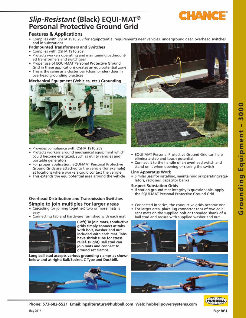
Gro
un
din
g E
qu
ipm
en
t –
30
00
Phone: 573-682-5521 Email: [email protected] Web: hubbellpowersystems.com
Page 3031May 2016
Features & Applications• Complies with OSHA 1910.269 for equipotential requirements near vehicles, underground gear, overhead switches
and in substations
Simple to join multiples for larger areas• Cascading (or joining together) two or more mats is
easy • Connecting tab and hardware furnished with each mat
Padmounted Transformers and Switches• Complies with OSHA 1910.269 • Protects workers operating and maintaining padmount-
ed transformers and switchgear• Proper use of EQUI-MAT Personal Protective Ground
Grid in these applications creates an equipotential zone • This is the same as a cluster bar (chain binder) does in
overhead grounding practices
Mechanical Equipment (Vehicles, etc.) Grounding
(Left) To join mats, conductive grids simply connect at tabs with bolt, washer and nut included with each mat. Tabs have shrink tube for stress relief. (Right) Ball stud can join mats and connect to ground set clamps.
Long ball stud accepts various grounding clamps as shown below and at right: Ball/Socket, C Type and Duckbill.
• Connected in series, the conductive grids become one• For larger area, place lug connector tabs of two adja-
cent mats on the supplied bolt or threaded shank of a ball stud and secure with supplied washer and nut
• Provides compliance with OSHA 1910.269 • Protects workers around mechanical equipment which
could become energized, such as utility vehicles and portable generators
• For proper application, EQUI-MAT Personal Protective Ground Grids are attached to the vehicle (for example) at locations where workers could contact the vehicle
• This extends the equipotential area around the vehicle
Overhead Distribution and Transmission Switches
• EQUI-MAT Personal Protective Ground Grid can help eliminate step and touch potential
• Connect it to the handle of an overhead switch and stand on it when opening or closing the switch
Line Apparatus Work• Similar uses for installing, maintaining or operating regu-
lators, reclosers, capacitor banks
Suspect Substation Grids• If station ground mat integrity is questionable, apply
the EQUI-MAT Personal Protective Ground Grid
Slip-Resistant (Black) EQUI-MAT®
Personal Protective Ground Grid
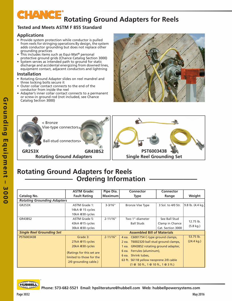
Gro
un
din
g E
qu
ipm
en
t – 30
00
Page 3032 May 2016
Phone: 573-682-5521 Email: [email protected] Web: hubbellpowersystems.com
Rotating Ground Adapters for ReelsTested and Meets ASTM F 855 Standard
GR253X GR43BS2
< BronzeVise-type connectors
Ball-stud connectors>
Rotating Ground AdaptersPST6003438
Single Reel Grounding Set
Rotating Ground Adapters for Reels——————— Ordering Information ———————
Applications• Provide system protection while conductor is pulled
from reels for stringing operations By design, the system adds conductor grounding but does not replace other grounding practices
• This includes items such as Equi-Mat® personal protective ground grids (Chance Catalog Section 3000)
• System serves as intended path to ground for static discharge and accidental energizing from downed lines, equipment contact, adjacent conductors and lightning
Installation• Rotating Ground Adapter slides on reel mandrel and
three locking bolts secure it• Outer collar contact connects to the end of the
conductor from inside the reel• Adapter’s inner collar contact connects to a permanent
or screw-in ground rod (not included, see Chance Catalog Section 3000)
Catalog No. Rotating Grounding Adapters GR253X
GR43BS2
Single Reel Grounding Set PST6003438
Pipe Dia.Maximum
3-3/16"
2-11/16"
2-11/16"
Weight 9.8 lb. (4.4 kg.)
12.75 lb.
(5.8 kg.)
53.75 lb.
(24.4 kg.)
ASTM Grade:Fault Rating
ASTM Grade 1:
14kA @ 15 cycles
10kA @30 cycles
ASTM Grade 5:
43kA @15 cycles
30kA @30 cycles
Grade 3:
27kA @15 cycles
20kA @30 cycles
(Ratings for this set are
limited to those for the
2/0 grounding cable.)
ConnectorType
Bronze Vise Type
Two 1"-diameter
Ball Studs
ConnectorRange
3 Sol. to 4/0 Str.
See Ball Stud
Clamp in Chance
Cat. Section 3000
Assembled Bill of Materials 4 ea. C6001754 C-type ground clamps,
2 ea. T6002320 ball stud ground clamps,
1 ea. GR43BS2 rotating ground adapter,
6 ea. Ferrules (aluminum),
6 ea. Shrink tubes,
63 ft. S6118 yellow neoprene 2/0 cable
(1 @ 50 ft., 1 @ 10 ft., 1 @ 3 ft.)

Tru
ck A
cce
sso
rie
s –
41
50
Phone: 573-682-5521 Email: [email protected] Web: hubbellpowersystems.com
Page 4151May 2016
TruckAccessories
Catalog 4150 May 2016
Tru
ck A
cce
sso
rie
s –
41
50

Truck
Acce
ssorie
s – 41
50
Page 4152 May 2016
Phone: 573-682-5521 Email: [email protected] Web: hubbellpowersystems.com
Features & Applications• Hot-line tool set enables a material-handler boom truck
to lift single- or three-phase system conductors• Operator remains in bucket, positioned to perform such
routine jobs as replacing insulators, crossarms or poles• Each complete unit includes: o 10' Vertical orange Epoxiglas® mast (4" x 4") o 10' Horizontal gray Epoxirod® support arm (2-1/2"
dia.) with four Heavy-Duty Roller-type Wireholders for conventional crossarm construction
o 6' Horizontal gray Epoxirod support arm (2-1/2" dia.) with one additional Wireholder for center mast for armless construction
o Storage bags for all components above• Wireholders latch easily from bucket with hookstick• 12" Epoxirod link insulates each latch-release lanyard• For crossarm construction: 10’ arm attaches at mast top
Wireholders latch easily from bucket with hookstick.12" Epoxirod link insulates each latch-release lanyard.
For armless construction, shorter crossarm mounts midway with single wireholder at top of mast. Notice, too, that center wireholder may be used alone for single-phase lifts.
• Fourth wireholder furnished for crossarm-mounted neutral, not shown
• For armless construction: 6’ arm attaches at proper level on series of mounting holes on mast
Maximum Ratings, all units• Vertical load per wireholder: 300 lb.• *Balanced vertical load: 1,200 lb., includes tool itself Side load per wireholder: 100 lb.
Electrical Ratings:GLOSSY, CLEAN AND DRY EPOXIGLAS®15kV Phase to Phase (20 Inch Min. Wireholder Spacing)34kV Phase to Phase (20 Inch Min. Wireholder Spacing and M4805-7 Insulators are used on each wireholder)
• Jib-mounted • Winch-driven• Constant-load monitor • 1,200-lb. rating*
Three-Phase Boom Lifts
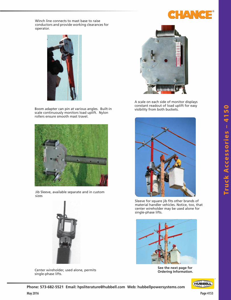
Tru
ck A
cce
sso
rie
s –
41
50
Phone: 573-682-5521 Email: [email protected] Web: hubbellpowersystems.com
Page 4153May 2016
Boom adapter can pin at various angles. Built-in scale continuously monitors load uplift. Nylon rollers ensure smooth mast travel.
Center wireholder, used alone, permits single-phase lifts.
See the next page forOrdering Information.
Winch line connects to mast base to raise conductors and provide working clearances for operator.
A scale on each side of monitor displays constant readout of load uplift for easy visibility from both buckets.
Sleeve for square jib fits other brands of material handler vehicles. Notice, too, that center wireholder may be used alone for single-phase lifts.
Jib Sleeve, available separate and in custom sizes

Truck
Acce
ssorie
s – 41
50
Page 4154 May 2016
Phone: 573-682-5521 Email: [email protected] Web: hubbellpowersystems.com
For Other Sizes, Consult Factory• Slotted opening in longest two models at left accepts rope
sheave for operation by winch mounted on top of boom tip• Sleeve E4001678 works on ALTEC® rigs with winch mounted on
top or bottom of boom tip
Lift-AllE4002293—————Teco/HolanE4001689—————
PitmanE4001714
AsplundhE4001651—————
TelelectE4001652—————Hi-Rangermodel 5HE4001679—————
RO ProductsE4001715
Jib Sleeves ONLY
Jib Application
33/4"-dia., as Asplundh
41/4"-dia., as Telelect
4"-dia., as ALTEC®
27/8"-dia., as Hi-Ranger model 5H
4" x 4"-sq., as Teco or Holan
4" x 5"-sq. as Pitman
51/4"-dia., as R.O. Products
4" x 4" Reach All
4" x 4"-sq., as Hi-Ranger model 6H
with top-mounted winch 43/4"-dia., as Telelect on over-
center model trucks
31/2"-sq., as Lift-All
4" x 4" ALTEC®
4" x 4" ALTEC® Adapter fits AM55
Catalog No.
E4001651
E4001652
E4001678
E4001679
E4001689
E4001714
E4001715
E4001953E4002215
E4002262
PSE4002293
T4002647
PST4003111
Weight
15 lb./6.75 kg.
15 lb./6.75 kg.
20 lb./9.09 kg.
15 lb./6.75 kg.
20 lb./9.09 kg.
20 lb./9.09 kg.
20 lb./9.09 kg.
20 lb./9.09 kg.22 lb./10.8 kg.
15 lb./6.75 kg.
22 lb./10.8 kg.
44 lb./21.6 kg.
20 lb./9.09 kg
Three-Phase Boom Lifts
Features & Applications• Each complete unit includes a jib sleeve in size listed in
addition to: o 10' Vertical orange Epoxiglas® mast (4" x 4") o 10' Horizontal gray Epoxirod® support arm (2-1/2"
dia.) with four Heavy-Duty Roller-type Wireholders for conventional crossarm construction
o 6' Horizontal gray Epoxirod support arm (2-1/2" dia.) with one additional Wireholder for center mast for armless construction
o Storage bags for all components above
Catalog No.C4001612C4001613C4001664C4001677C4001709C4001710C4001711C4002719
Truck ApplicationAsplundh: 33/4"-dia. jibTelelect: 41/4"-dia. jibALTEC®: 4"-dia. jibHi-Ranger model 5H*: 27/8"-dia. jibTeco or Holan: 4" x 4"-sq. jibPitman: 4" x 5"-sq. jibR.O. Products: 51/4"-dia. jibNo Jib Sleeves included. See below for correct size.
*For Hi-Ranger model 6H with top-mounted winch, order E4002215 Jib Sleeve, listed below.
Weight each: 225 lb. / 102 kg.
< Hi-Ranger model 6HE4002215—————
< Reach-AllE4001953
ALTEC® >E4001678—————
Telelect > E4002262
Jib Adapters – Material Handlers
Complete Units
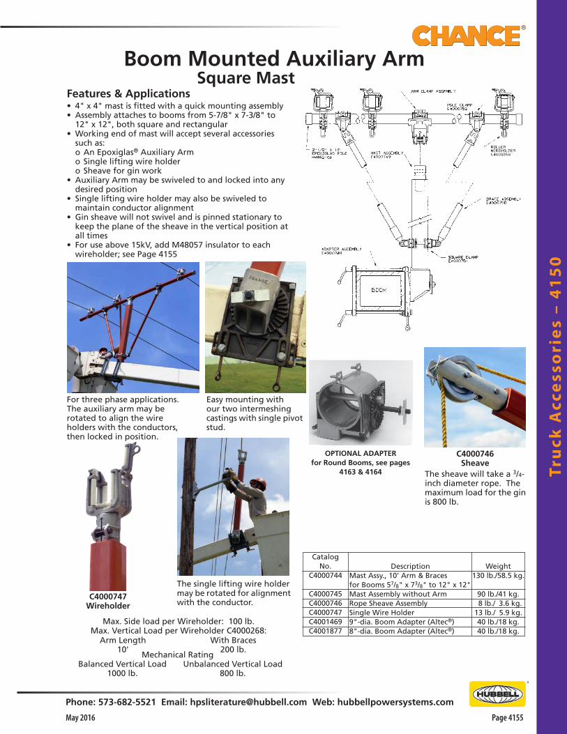
Tru
ck A
cce
sso
rie
s –
41
50
Phone: 573-682-5521 Email: [email protected] Web: hubbellpowersystems.com
Page 4155May 2016
CatalogNo.
C4000744
C4000745C4000746C4000747C4001469C4001877
Description Mast Assy., 10' Arm & Braces for Booms 57/8" x 73/8" to 12" x 12" Mast Assembly without Arm Rope Sheave Assembly Single Wire Holder 9"-dia. Boom Adapter (Altec®) 8"-dia. Boom Adapter (Altec®)
Weight130 lb./58.5 kg.
90 lb./41 kg. 8 lb./ 3.6 kg.13 lb./ 5.9 kg.40 lb./18 kg.40 lb./18 kg.
Features & Applications• 4" x 4" mast is fitted with a quick mounting assembly• Assembly attaches to booms from 5-7/8" x 7-3/8" to
12" x 12", both square and rectangular• Working end of mast will accept several accessories
such as: o An Epoxiglas® Auxiliary Arm o Single lifting wire holder o Sheave for gin work• Auxiliary Arm may be swiveled to and locked into any
desired position• Single lifting wire holder may also be swiveled to
maintain conductor alignment• Gin sheave will not swivel and is pinned stationary to
keep the plane of the sheave in the vertical position at all times
• For use above 15kV, add M48057 insulator to each wireholder; see Page 4155
For three phase applications. The auxiliary arm may be rotated to align the wire holders with the conductors, then locked in position.
Easy mounting with our two intermeshing castings with single pivot stud.
OPTIONAL ADAPTERfor Round Booms, see pages
4163 & 4164 The sheave will take a 3/4-inch diameter rope. The maximum load for the gin is 800 lb.
C4000746Sheave
C4000747Wireholder
The single lifting wire holder may be rotated for alignment with the conductor.
Max. Side load per Wireholder: 100 lb.Max. Vertical Load per Wireholder C4000268:
With Braces200 lb.
Arm Length10'
Mechanical RatingBalanced Vertical Load
1000 lb.Unbalanced Vertical Load
800 lb.
Boom Mounted Auxiliary ArmSquare Mast
E4001568P
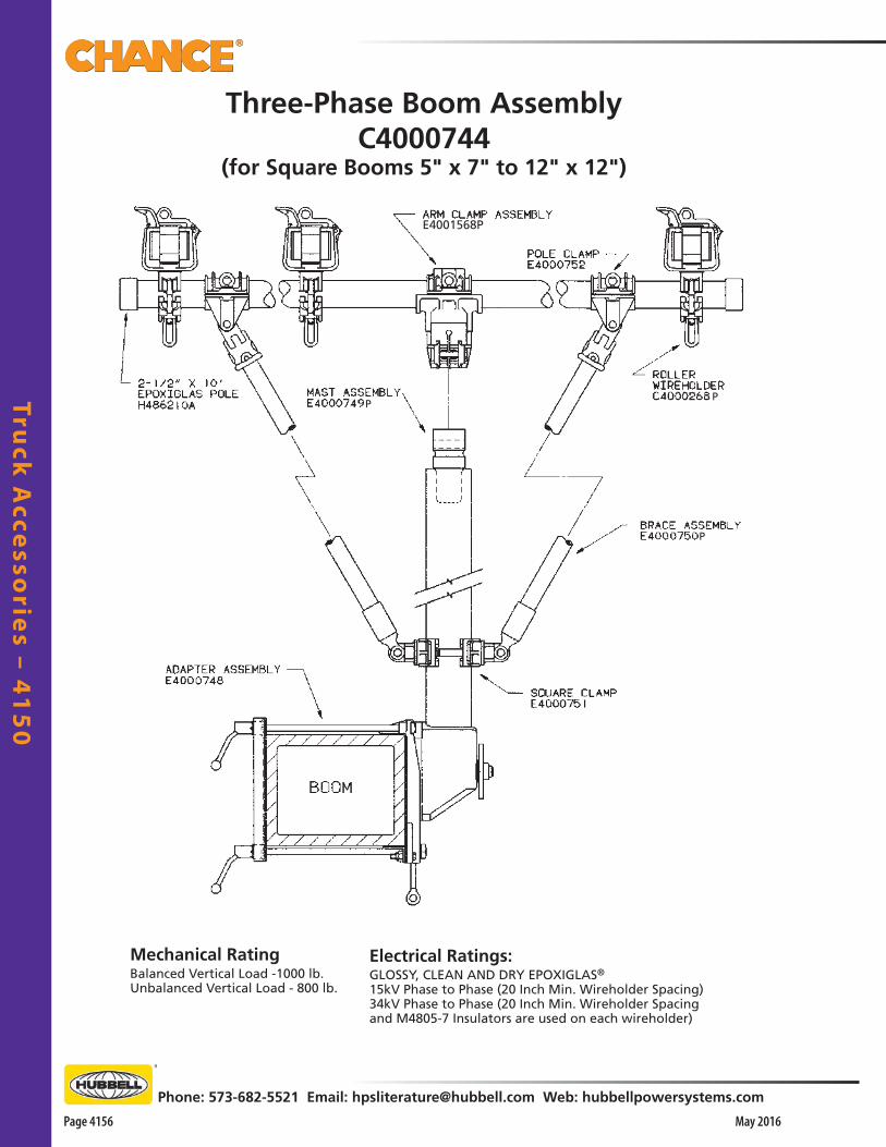
Truck
Acce
ssorie
s – 41
50
Page 4156 May 2016
Phone: 573-682-5521 Email: [email protected] Web: hubbellpowersystems.com
Three-Phase Boom AssemblyC4000744
(for Square Booms 5" x 7" to 12" x 12")
E4001568P
PP
P
Mechanical RatingBalanced Vertical Load -1000 lb.Unbalanced Vertical Load - 800 lb.
Electrical Ratings:GLOSSY, CLEAN AND DRY EPOXIGLAS®
15kV Phase to Phase (20 Inch Min. Wireholder Spacing)34kV Phase to Phase (20 Inch Min. Wireholder Spacing and M4805-7 Insulators are used on each wireholder)
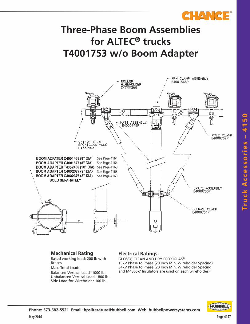
Tru
ck A
cce
sso
rie
s –
41
50
Phone: 573-682-5521 Email: [email protected] Web: hubbellpowersystems.com
Page 4157May 2016
Mechanical RatingRated working load: 200 lb with Braces Max. Total Load:Balanced Vertical Load -1000 lb.Unbalanced Vertical Load - 800 lb.Side Load for Wireholder 100 lb.
Electrical Ratings:GLOSSY, CLEAN AND DRY EPOXIGLAS®
15kV Phase to Phase (20 Inch Min. Wireholder Spacing)34kV Phase to Phase (20 Inch Min. Wireholder Spacing and M4805-7 Insulators are used on each wireholder)
Three-Phase Boom Assembliesfor ALTEC® trucks
T4001753 w/o Boom Adapter
See Page 4164See Page 4164See Page 4163See Page 4163See Page 4163
E4001568P
E4000749P
E4000751P
E4000750P
E4000752P

Truck
Acce
ssorie
s – 41
50
Page 4158 May 2016
Phone: 573-682-5521 Email: [email protected] Web: hubbellpowersystems.com
Boom Adapters for ALTEC® truckswith 8" slide pad on reinforcement collar
T4002486 for 10"-diameter boomsC4002377 for 9"-diameter boomsC4002376 for 8"-diameter booms
(for 4" x 4" mast in T4001753 Three-Phase Boom Assembly)
8", 9" or 10"
8" or 9"
Boom Adapters for ALTEC® trucksC4001469 for 9"-diameter boomsC4001877 for 8"-diameter booms
(for 4" x 4" mast in T4001753 Three-Phase Boom Assembly)

Tru
ck A
cce
sso
rie
s –
41
50
Phone: 573-682-5521 Email: [email protected] Web: hubbellpowersystems.com
Page 4159May 2016
Features & Applications• Consists of a boom mast and arm of Epoxiglas®
construction• For mounting on insulated boom• For use on light construction when handling multiple
conductors• Two-legged mast can be mounted on square or
rectangular shaped booms designed to handle 2,000 lbs. or more
H486310with Braces(fits Booms5" x 7" to10" x 10")
OPTIONAL ADAPTERS for Round Booms(as on Altec® trucks), see
Catalog Page 4160
Boom Auxiliary Arm
H486310H48633 H48634 H4863
C4000351
120 lb/54.0 kg. 121/2 lb./ 5.6 kg. 83/4 lb./ 3.9 kg. 64 lb./28.8 kg.
13 lb./10.35 kg.
10' Assembly with braces Bipod-Arm clamp only Arm Brace Assembly only 4' Bipod Mast only with boom clamps 21/2" x 10' Horizontal Arm
• If boom units of lesser ratings are employed, the lifting and maneuvering application of this unit must be reduced accordingly
• Mechanical rating for a balanced vertical load is 1,000 pounds maximum or a limit of the boom arm in the position used, whichever is the least
• 10' arm, recommended for brace use only, is rated at 200 lbs. per conductor holder
• Chance C4000268 roller wireholders are used on the Boom Auxiliary Arm and Mast
• Each wireholder is rated for 100 lb. max. side load
Mechanical Rating Rated working load: 200 lb with BracesMax. Total Load:Balanced Vertical Load -1000 lb.Side Load for Wireholder 100 lb.
Electrical RatingsGLOSSY, CLEAN AND DRY EPOXIGLAS®
15kV Phase to Phase (20 Inch Min. Wireholder Spacing)34kV Phase to Phase (20 Inch Min. Wireholder Spacingand M4805-7 Insulators are used on each wireholder)

Truck
Acce
ssorie
s – 41
50
Page 4160 May 2016
Phone: 573-682-5521 Email: [email protected] Web: hubbellpowersystems.com
Boom Adapters for ALTEC® truckswith 8" slide pad on reinforcement collar
T4002486BI for 10"-diameter boomsC4002393 for 9"-diameter boomsC4002392 for 8"-diameter booms
(for use with Bi-Pod assembly in H486310 Three-Phase Arm)
8", 9" or 10"
Boom Adapters for ALTEC® trucksC4001467 for 9"-diameter boomsC4001878 for 8"-diameter booms
(for use with Bi-Pod assembly in H486310 Three-Phase Arm)
8" or 9"
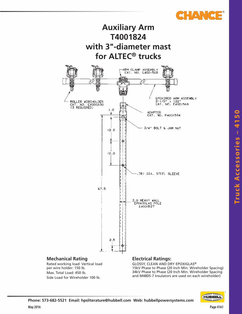
Tru
ck A
cce
sso
rie
s –
41
50
Phone: 573-682-5521 Email: [email protected] Web: hubbellpowersystems.com
Page 4161May 2016
Auxiliary ArmT4001824
with 3"-diameter mastfor ALTEC® trucks
Electrical Ratings:GLOSSY, CLEAN AND DRY EPOXIGLAS®
15kV Phase to Phase (20 Inch Min. Wireholder Spacing)34kV Phase to Phase (20 Inch Min. Wireholder Spacing and M4805-7 Insulators are used on each wireholder)
Mechanical RatingRated working load: Vertical load per wire holder: 150 lb.Max. Total Load: 450 lb.Side Load for Wireholder 100 lb.
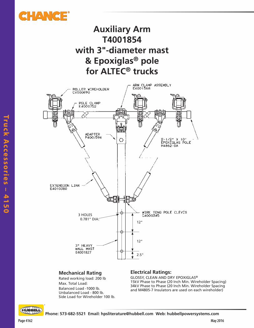
Truck
Acce
ssorie
s – 41
50
Page 4162 May 2016
Phone: 573-682-5521 Email: [email protected] Web: hubbellpowersystems.com
Auxiliary ArmT4001854
with 3"-diameter mast& Epoxiglas® polefor ALTEC® trucks
2.5"
12"
12"
E4001827
3 HOLES 0.781" DIA.
Electrical Ratings:GLOSSY, CLEAN AND DRY EPOXIGLAS®
15kV Phase to Phase (20 Inch Min. Wireholder Spacing)34kV Phase to Phase (20 Inch Min. Wireholder Spacing and M4805-7 Insulators are used on each wireholder)
Mechanical RatingRated working load: 200 lbMax. Total Load:Balanced Load -1000 lb.Unbalanced Load - 800 lb.Side Load for Wireholder 100 lb.

Tru
ck A
cce
sso
rie
s –
41
50
Phone: 573-682-5521 Email: [email protected] Web: hubbellpowersystems.com
Page 4163May 2016
Auxiliary ArmT4001855
with 3"-diameter mast& solid Epoxirod®
for ALTEC® trucks
E40018272.5"
12"
12"
3 HOLES 0.781" DIA.
3" x 67.5" HEAVY WALL MAST
E4001827
Electrical Ratings:GLOSSY, CLEAN AND DRY EPOXIGLAS®
15kV Phase to Phase (20 Inch Min. Wireholder Spacing)34kV Phase to Phase (20 Inch Min. Wireholder Spacing and M4805-7 Insulators are used on each wireholder)
Mechanical RatingRated working load: 200 lbMax. Total Load:Balanced Load -1000 lb.Unbalanced Load - 800 lb.Side Load for Wireholder 100 lb.
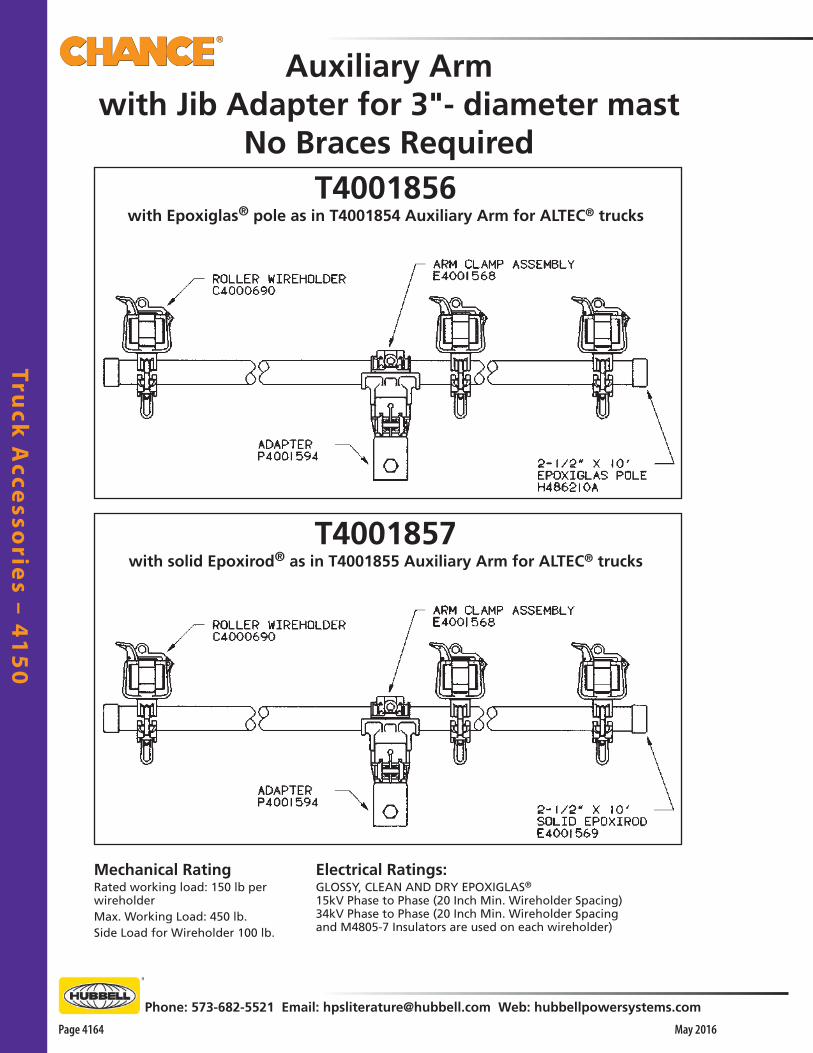
Truck
Acce
ssorie
s – 41
50
Page 4164 May 2016
Phone: 573-682-5521 Email: [email protected] Web: hubbellpowersystems.com
Auxiliary Armwith Jib Adapter for 3"- diameter mast
No Braces Required
T4001857with solid Epoxirod® as in T4001855 Auxiliary Arm for ALTEC® trucks
T4001856with Epoxiglas® pole as in T4001854 Auxiliary Arm for ALTEC® trucks
Electrical Ratings:GLOSSY, CLEAN AND DRY EPOXIGLAS®
15kV Phase to Phase (20 Inch Min. Wireholder Spacing)34kV Phase to Phase (20 Inch Min. Wireholder Spacing and M4805-7 Insulators are used on each wireholder)
Mechanical RatingRated working load: 150 lb per wireholderMax. Working Load: 450 lb.Side Load for Wireholder 100 lb.
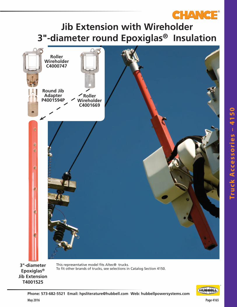
Tru
ck A
cce
sso
rie
s –
41
50
Phone: 573-682-5521 Email: [email protected] Web: hubbellpowersystems.com
Page 4165May 2016
3"-diameterEpoxiglas®
Jib ExtensionT4001525
RollerWireholderC4000747
Round JibAdapter
P4001594PRoller
WireholderC4001669
This representative model fits Altec® trucks.To fit other brands of trucks, see selections in Catalog Section 4150.
Jib Extension with Wireholder3"-diameter round Epoxiglas® Insulation
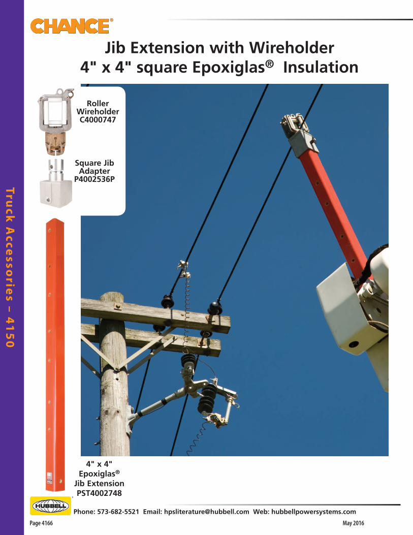
Truck
Acce
ssorie
s – 41
50
Page 4166 May 2016
Phone: 573-682-5521 Email: [email protected] Web: hubbellpowersystems.com
Jib Extension with Wireholder4" x 4" square Epoxiglas® Insulation
4" x 4"Epoxiglas®
Jib ExtensionPST4002748
RollerWireholderC4000747
Square JibAdapter
P4002536P

Tru
ck A
cce
sso
rie
s –
41
50
Phone: 573-682-5521 Email: [email protected] Web: hubbellpowersystems.com
Page 4167May 2016
Jib Extension with Wireholder3"-diameter round Epoxiglas® Insulation
3"-diameterEpoxiglas®
Jib Extensionwith
WireholderPST4002818
This representative model fits Telelect trucks.To fit other brands of trucks, see selections in Catalog Section 4150.

Truck
Acce
ssorie
s – 41
50
Page 4168 May 2016
Phone: 573-682-5521 Email: [email protected] Web: hubbellpowersystems.com
Jib Extension with Sheave and Wireholder3"-diameter round Epoxiglas® Insulation
3"-diameterEpoxiglas®
Jib Extensionwith
Wireholder & SheavePST4003059
This representative model fits Altec® trucks.To fit other brands of trucks, see selections in Catalog Section 4150.

Tru
ck A
cce
sso
rie
s –
41
50
Phone: 573-682-5521 Email: [email protected] Web: hubbellpowersystems.com
Page 4169May 2016
for ALTEC® trucks* with 4" x 4" square jibCat. No. PST4003059
39 lb. / 17.7 kg.)
for ALTEC® trucks*with 4" x 4" square jib
Cat. No. T4002530(23 lb. / 10.43 kg.)
for ALTEC® trucks*with 3" diameter jibCat. No. T4002529(23 lb. / 10.43 kg.)
Combination SwivelWireholder/Sheavefor ALTEC® trucks*
*To fit other brands of trucks, contact Hubbell Power Systems with detailed specifications.
Features & Applications• Eliminates changeovers from Wireholder (for picking up
a phase conductor) to Rope Sheave (for lifting items)• Each combination unit attaches directly to jib• Rated Working Load: Wireholder - 300 lbs. Sheave - 800 lbs.• Both units feature a Large Swivel-Type Roller
Wireholder with 2-1⁄2" x 3-3⁄8" opening and a 7"-dia. Sheave to accept up to 3⁄4"-dia. rope
WARNING: ELECTRIC SHOCK HAZARD. Winch rope can conduct electricity from this device to metal parts on the bucket support. Can cause electrocution death or severe injury. Always remove winch rope from this device when the wireholder is used to support an energized conductor.
Features & Applications• Eliminates changeovers from
Wireholder (for picking up a phase conductor) to Rope Sheave (for lifting items)
• Includes 3"-dia. heavy-wall jib • Rated Working Load: Wireholder - 300 lbs. Sheave - 800 lbs.• Features a Large Swivel-Type
Roller Wireholder with 2-1⁄2" x 3-3⁄8" opening and a 7"-dia. Sheave to accept up to 3⁄4"-dia. rope
31"clear glass(minimum)
Combination SwivelWireholder/Sheave Jib Extensionfor ALTEC® trucks*
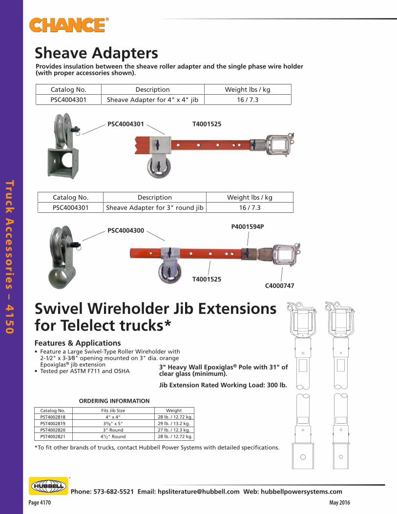
Truck
Acce
ssorie
s – 41
50
Page 4170 May 2016
Phone: 573-682-5521 Email: [email protected] Web: hubbellpowersystems.com
Swivel Wireholder Jib Extensionsfor Telelect trucks*
Sheave Adapters
3" Heavy Wall Epoxiglas® Pole with 31" of clear glass (minimum).
Provides insulation between the sheave roller adapter and the single phase wire holder (with proper accessories shown).
Catalog No.PST4002818PST4002819PST4002820PST4002821
ORDERING INFORMATION
Fits Jib Size4" x 4"
33/8" x 5"3" Round
41/2" Round
Weight 28 lb. / 12.72 kg. 29 lb. / 13.2 kg. 27 lb. / 12.3 kg. 28 lb. / 12.72 kg.
Features & Applications• Feature a Large Swivel-Type Roller Wireholder with
2-1⁄2" x 3-3⁄8" opening mounted on 3" dia. orange Epoxiglas® jib extension
• Tested per ASTM F711 and OSHA
*To fit other brands of trucks, contact Hubbell Power Systems with detailed specifications.
Jib Extension Rated Working Load: 300 lb.
PSC4004301 T4001525
P4001594P
T4001525C4000747
PSC4004300
Catalog No. Description Weight lbs / kg
PSC4004301 Sheave Adapter for 4" x 4" jib 16 / 7.3
Catalog No. Description Weight lbs / kg
PSC4004301 Sheave Adapter for 3" round jib 16 / 7.3

Tru
ck A
cce
sso
rie
s –
41
50
Phone: 573-682-5521 Email: [email protected] Web: hubbellpowersystems.com
Page 4171May 2016
M48057
C4001669for 3" dia. Jib
Auxiliary Arm Attachments• Roller Wireholder — Seven Delrin plastic rollers offer protection to conductors while raising the conductor above the
work area. Accommodates conductors up to and including 1-1/2 inches in dia. The gate is held closed by a spring-loaded latch which must be manually opened
• Insulators— Epoxy based, available as separate items or can be added to existing auxiliary arm wireholders to upgrade for 34.5 kV use
For 21/2" ArmC4000690with 21/2" opening
C4000268with 2" opening
Catalog No. Description Wireholder Type Adapter Weight
C4000270 Small Wireholder Only Small Roller 2” Opening None 3 lb. / 1.4 kg.
C4000268Small wireholder with Clamp
for 2.5” ArmSmall Roller 2” Opening
Clamp for 2.5” Arm
4.4 lb. / 2 kg.
C4000269Small Wireholder with Clamp
and InsulatorSmall Roller 2” Opening
Clamp for 2.5” Arm
and M48057 Insulator
6 lb. / 2.7 kg.
C4000691 Large Wireholder Only Large Roller 2.5” Opening None 4.5 lb. / 2 kg.
C4000690Large wireholder with Clamp
for 2.5” ArmLarge Roller 2.5” Opening
Clamp for 2.5” Arm
4.5 lb. / 2 kg.
PSC4002937Large wireholder with Clamp
for 3” ArmLarge Roller 2.5” Opening
Clamp for 3” Arm
1 lb. / 0.5 kg.
C4000747 Large wireholder with Swivel
FerruleLarge Roller 2.5” Opening
Swivel Fer-rule
8 lb. / 3.6 kg.
C4001669 Large Wireholder for 3”
Diameter JibLarge Roller 2.5” Opening
Ferrule for 3” Diameter
Jib6 lb. / 2.7 kg.
M48061 Heavy Duty Wireholder OnlyHeavy Duty Roller Wirehold-
er 2.43” OpeningNone 24 lb. / 10.9 kg.
T4001931Small Roller Wireholder with
Hi-Ranger AdapterSmall Roller 2” Opening
Hi-Ranger 4 1/8” x 4 1/8”
14 lb. / 6.4 kg.
PST4001945Small Roller Wireholder with
Holan Adapter Small Roller 2” Opening
Holan 3 1/8” x 3 1/8”
10.5 lb. / 4.8 kg.
T4001941Small Roller Wireholder for
Telelect Jib Small Roller 2” Opening
Telelec Jib 3.19” Dia.
9.1 lb. / 4.1 kg.
PST4002856Large wireholder with Ferrule
for 4” x4”Large Roller 2.5” Opening
4.06” x 4.06”
18 lb. / 8.2 kg.
T4001929Large Roller Wireholder with
Hi-Ranger Adapter Large Roller 2.5” Opening
Hi-Ranger 4 1/8” x 4 1/8”
24 lb. / 10.9 kg.
PST4001926Large Roller Wireholder with
Holan Adapter Large Roller 2.5” Opening
Holan 3 1/8” x 3 1/8”
12 lb. / 5.4 kg.
T4001942 Large Roller Wireholder for
Telelect Jib Large Roller 2.5” Opening
Telelec Jib 3.19” Dia.
9 lb. / 4.1 kg.
T4001930Heavy-Duty Roller Wirehold-er with Hi-Ranger Adapter
Heavy Duty Roller Wirehold-er 2.43” Opening
Hi-Ranger 4 1/8” x 4 1/8”
41 lb. / 18.6 kg.
T4001912Heavy-Duty Wireholder with
Holan Adapter Heavy Duty Roller Wirehold-
er 2.43” OpeningHolan 3 1/8”
x 3 1/8”31.5 lb. / 14.3 kg.
T4001943Heavy-Duty Wireholder for
Telelect Jib Heavy Duty Roller Wirehold-
er 2.43” OpeningTelelec Jib 3.19” Dia.
25 lb. / 11.3 kg.

Truck
Acce
ssorie
s – 41
50
Page 4172 May 2016
Phone: 573-682-5521 Email: [email protected] Web: hubbellpowersystems.com
Small Roller Wireholder2" opening
Wireholderonly
C4000270
with clamp for21/2" armC4000268
Epoxy insulatorM48057
0.60"-long stud7/16-14 UNC-2A threads
with clamp&
insulatorC4000269
P4000256PKeepers
P4000256PKeepers
P4000254PRoller
P4000253PRoller
P4000250PRoller Axle
P001001PRoll Pin
P4001592PLatch
P4000255PRoller
P4000252PRoller Axle
P4000251PRoller Axle
P4000249PGate
067137PPin 5/16" x 3"
P4001593PLatch Spring P4000266P
Gate Spring
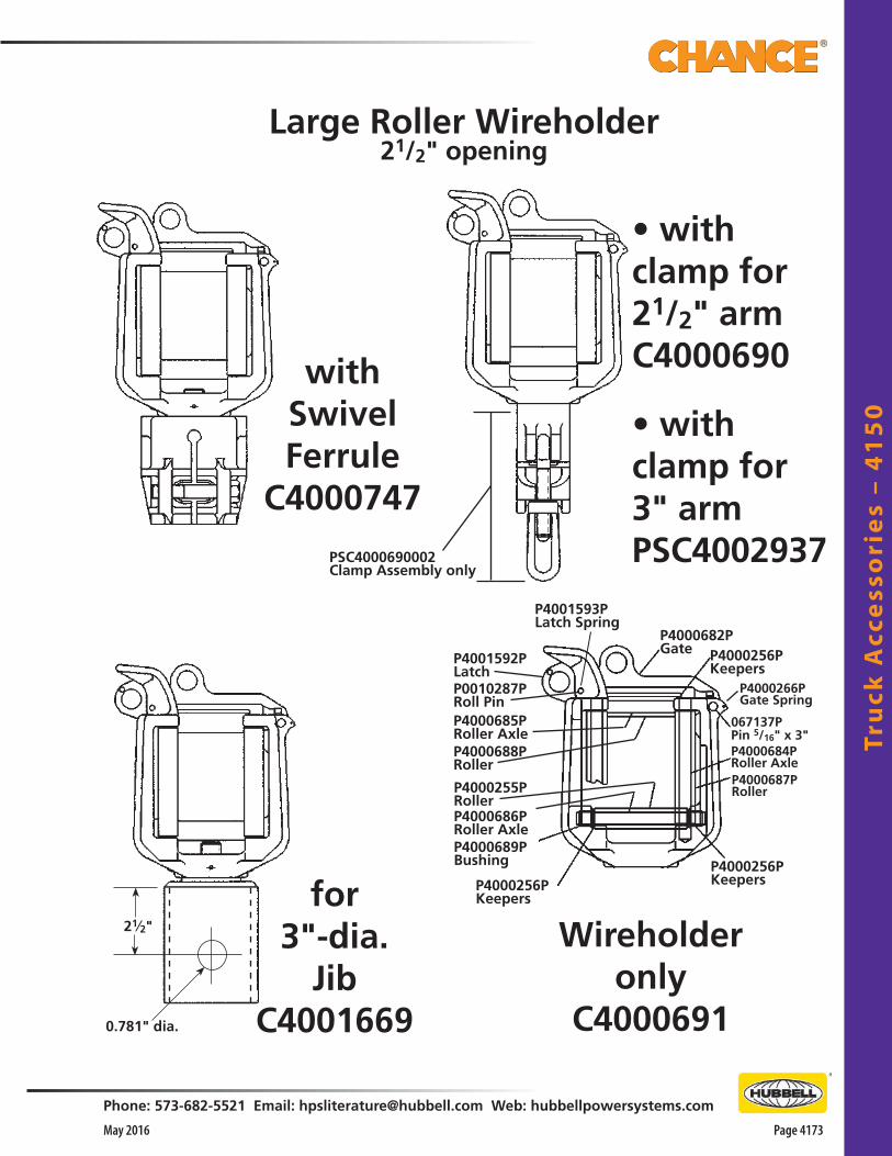
Tru
ck A
cce
sso
rie
s –
41
50
Phone: 573-682-5521 Email: [email protected] Web: hubbellpowersystems.com
Page 4173May 2016
for 3"-dia.
JibC4001669
Large Roller Wireholder21/2" opening
• with clamp for21/2" armC4000690with
SwivelFerrule
C4000747
Wireholderonly
C4000691
21⁄2"
0.781" dia.
• with clamp for3" armPSC4002937PSC4000690002
Clamp Assembly only
P4000688PRoller
P4000685PRoller Axle
P0010287PRoll Pin
P4001592PLatch
P4000255PRollerP4000686PRoller Axle
P4000682PGate P4000256P
Keepers
P4000256PKeepers
067137PPin 5/16" x 3"
P4000256PKeepers
P4000687PRoller
P4000684PRoller Axle
P4000689PBushing
P4001593PLatch Spring
P4000266PGate Spring

Truck
Acce
ssorie
s – 41
50
Page 4174 May 2016
Phone: 573-682-5521 Email: [email protected] Web: hubbellpowersystems.com
Heavy-DutyRoller Wireholder
M48061

Tru
ck A
cce
sso
rie
s –
41
50
Phone: 573-682-5521 Email: [email protected] Web: hubbellpowersystems.com
Page 4175May 2016
Small Roller Wireholderwith Hi-Ranger Adapter
Cat. No. T4001931
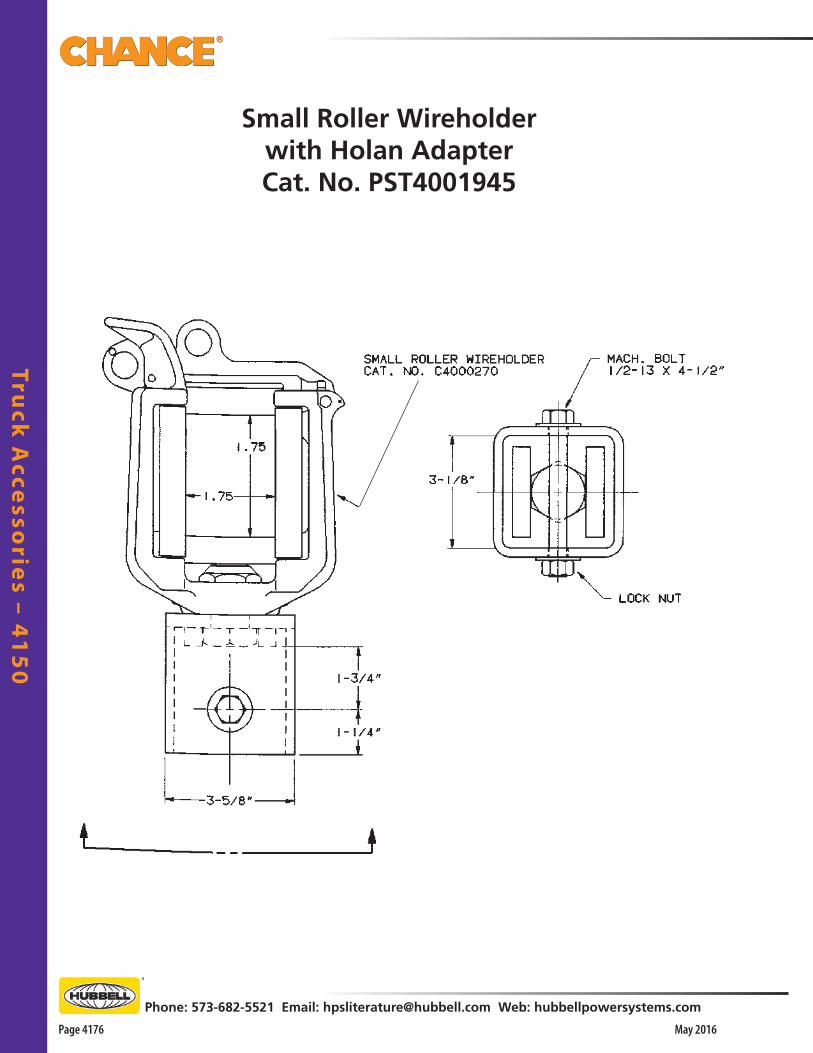
Truck
Acce
ssorie
s – 41
50
Page 4176 May 2016
Phone: 573-682-5521 Email: [email protected] Web: hubbellpowersystems.com
Small Roller Wireholderwith Holan AdapterCat. No. PST4001945
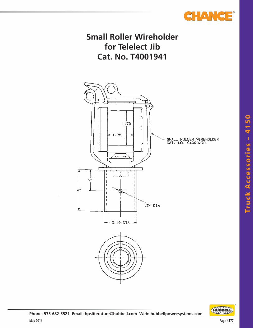
Tru
ck A
cce
sso
rie
s –
41
50
Phone: 573-682-5521 Email: [email protected] Web: hubbellpowersystems.com
Page 4177May 2016
Small Roller Wireholderfor Telelect Jib
Cat. No. T4001941

Truck
Acce
ssorie
s – 41
50
Page 4178 May 2016
Phone: 573-682-5521 Email: [email protected] Web: hubbellpowersystems.com
Large Roller Wireholderwith Altec Adapter
Cat. No. PST4002856

Tru
ck A
cce
sso
rie
s –
41
50
Phone: 573-682-5521 Email: [email protected] Web: hubbellpowersystems.com
Page 4179May 2016
Large Roller Wireholderwith Hi-Ranger Adapter
Cat. No. T4001929
LARGE ROLLER WIREHOLDERCAT. NO. E4002228P

Truck
Acce
ssorie
s – 41
50
Page 4180 May 2016
Phone: 573-682-5521 Email: [email protected] Web: hubbellpowersystems.com
Large Roller Wireholderwith Holan AdapterCat. No. PST4001926
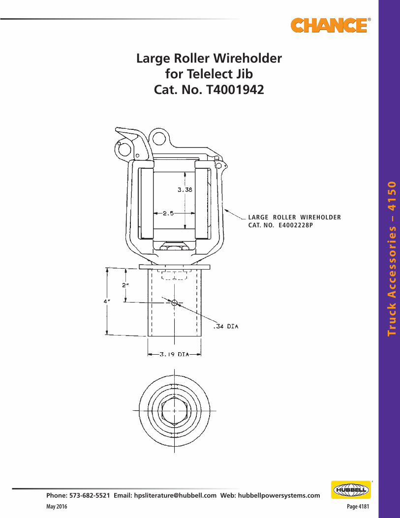
Tru
ck A
cce
sso
rie
s –
41
50
Phone: 573-682-5521 Email: [email protected] Web: hubbellpowersystems.com
Page 4181May 2016
Large Roller Wireholderfor Telelect Jib
Cat. No. T4001942
LARGE ROLLER WIREHOLDERCAT. NO. E4002228P
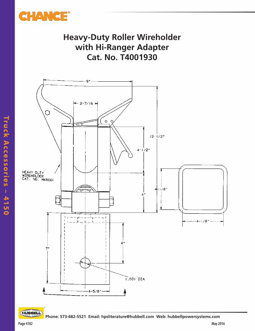
Truck
Acce
ssorie
s – 41
50
Page 4182 May 2016
Phone: 573-682-5521 Email: [email protected] Web: hubbellpowersystems.com
Heavy-Duty Roller Wireholderwith Hi-Ranger Adapter
Cat. No. T4001930

Tru
ck A
cce
sso
rie
s –
41
50
Phone: 573-682-5521 Email: [email protected] Web: hubbellpowersystems.com
Page 4183May 2016
Heavy-Duty Wireholderwith Holan AdapterCat. No. T4001912
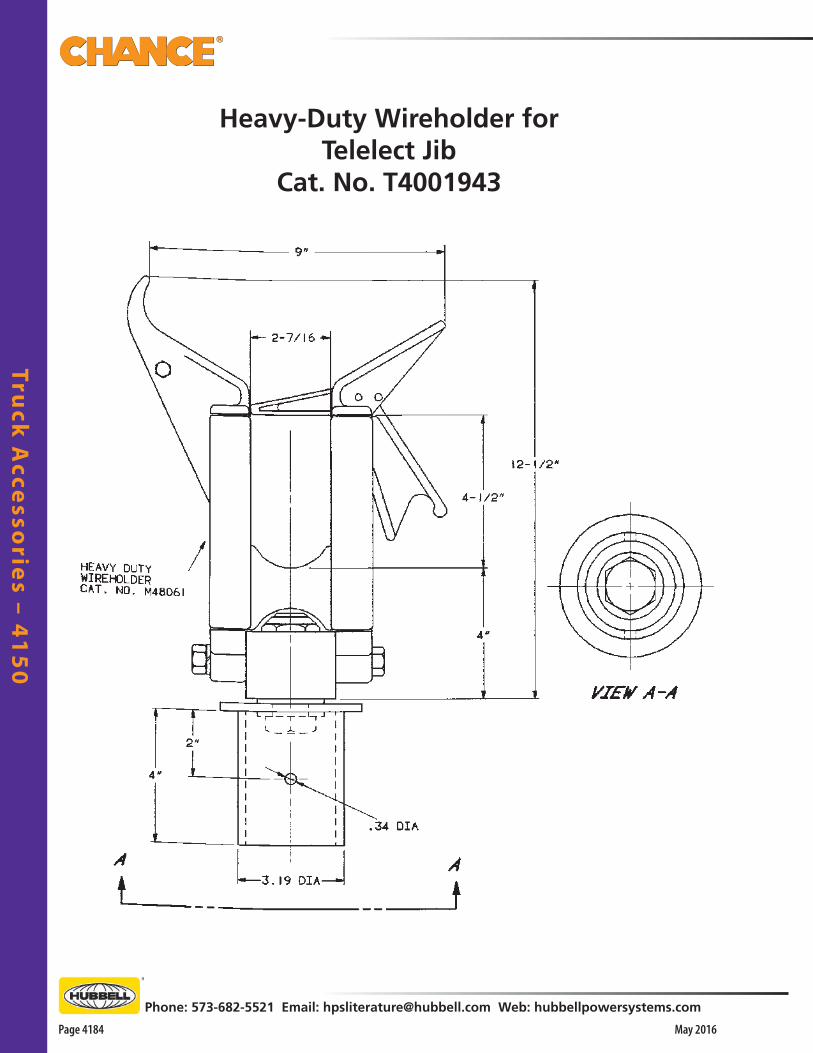
Truck
Acce
ssorie
s – 41
50
Page 4184 May 2016
Phone: 573-682-5521 Email: [email protected] Web: hubbellpowersystems.com
Heavy-Duty Wireholder forTelelect Jib
Cat. No. T4001943
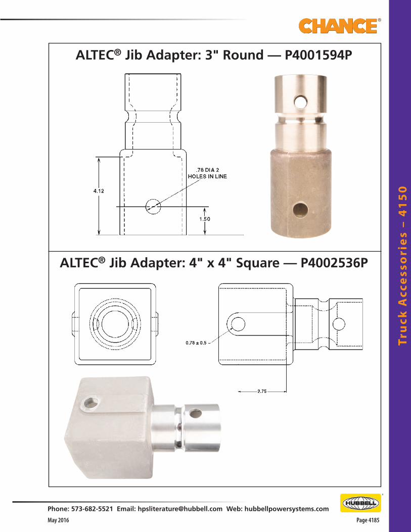
Tru
ck A
cce
sso
rie
s –
41
50
Phone: 573-682-5521 Email: [email protected] Web: hubbellpowersystems.com
Page 4185May 2016
ALTEC® Jib Adapter: 3" Round — P4001594P
ALTEC® Jib Adapter: 4" x 4" Square — P4002536P
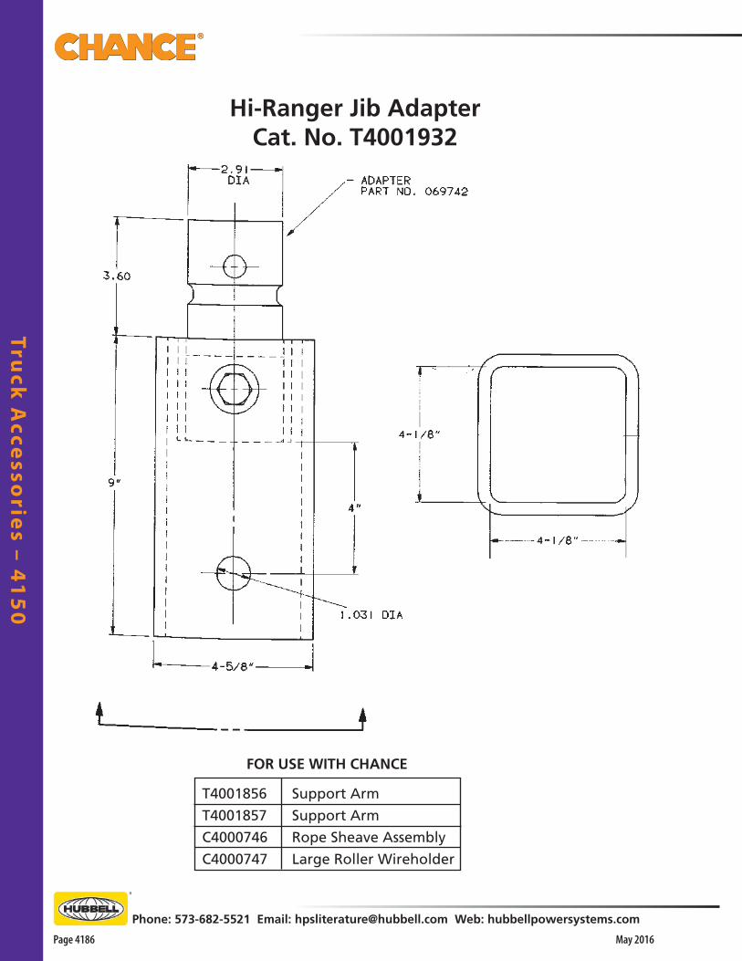
Truck
Acce
ssorie
s – 41
50
Page 4186 May 2016
Phone: 573-682-5521 Email: [email protected] Web: hubbellpowersystems.com
FOR USE WITH CHANCE
T4001856
T4001857
C4000746
C4000747
Support Arm
Support Arm
Rope Sheave Assembly
Large Roller Wireholder
Hi-Ranger Jib AdapterCat. No. T4001932

Tru
ck A
cce
sso
rie
s –
41
50
Phone: 573-682-5521 Email: [email protected] Web: hubbellpowersystems.com
Page 4187May 2016
Holan Jib AdapterCat. No. T4001927
FOR USE WITH CHANCE
T4001856
T4001857
C4000746
C4000747
Support Arm
Support Arm
Rope Sheave Assembly
Large Roller Wireholder
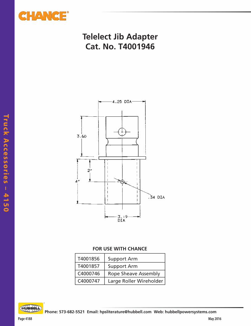
Truck
Acce
ssorie
s – 41
50
Page 4188 May 2016
Phone: 573-682-5521 Email: [email protected] Web: hubbellpowersystems.com
Telelect Jib AdapterCat. No. T4001946
FOR USE WITH CHANCE
T4001856
T4001857
C4000746
C4000747
Support Arm
Support Arm
Rope Sheave Assembly
Large Roller Wireholder

Tru
ck A
cce
sso
rie
s –
41
50
Phone: 573-682-5521 Email: [email protected] Web: hubbellpowersystems.com
Page 4189May 2016
Insulated Jib
3"-diameter JibT4001525
for ALTEC® trucksRated Working Load
1,000 lb.

Truck
Acce
ssorie
s – 41
50
Page 4190 May 2016
Phone: 573-682-5521 Email: [email protected] Web: hubbellpowersystems.com
4" x 4" JibT4001764
for HOLAN trucksRated Working Load
1,200 lb
1.03
1 D
IA H
OLE
(3-
PLA
CES
)
16.5
013
.50
60.0
0
18.0
0
Insulated Jib

Tru
ck A
cce
sso
rie
s –
41
50
Phone: 573-682-5521 Email: [email protected] Web: hubbellpowersystems.com
Page 4191May 2016
4" x 4" JibT4001933
for Reach-All trucksRated Working Load
1,000 lb
17/3
2" D
IA.
THR
U H
OLE
7/8"
DIA
.TH
RU
HO
LE
BO
TH E
ND
S SE
ALE
D
Insulated Jib
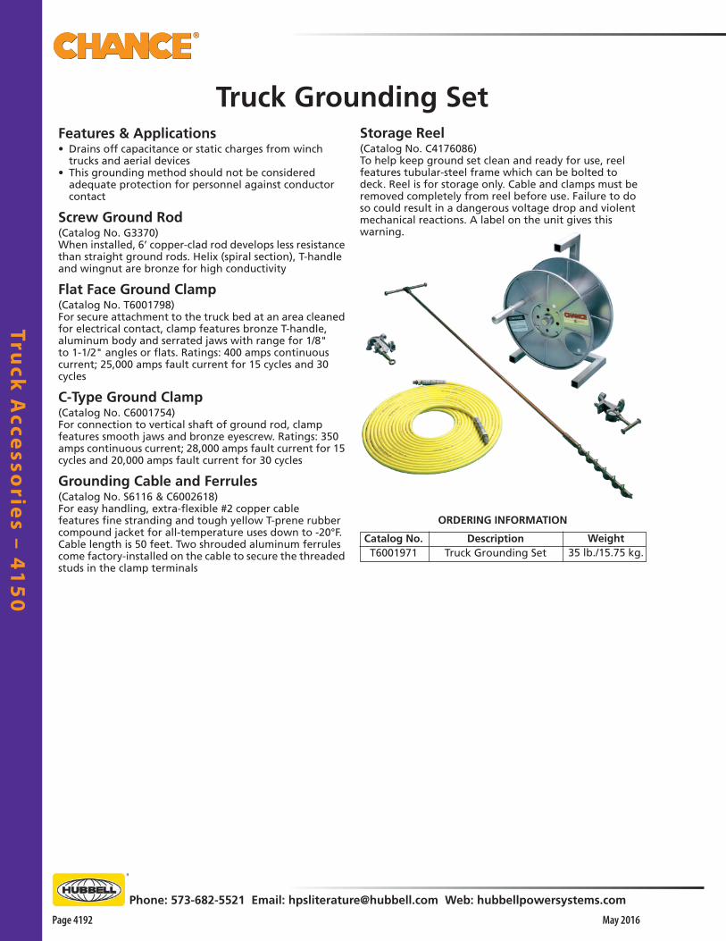
Truck
Acce
ssorie
s – 41
50
Page 4192 May 2016
Phone: 573-682-5521 Email: [email protected] Web: hubbellpowersystems.com
Features & Applications• Drains off capacitance or static charges from winch
trucks and aerial devices• This grounding method should not be considered
adequate protection for personnel against conductor contact
Screw Ground Rod(Catalog No. G3370)When installed, 6’ copper-clad rod develops less resistance than straight ground rods. Helix (spiral section), T-handle and wingnut are bronze for high conductivity
Flat Face Ground Clamp(Catalog No. T6001798)For secure attachment to the truck bed at an area cleaned for electrical contact, clamp features bronze T-handle, aluminum body and serrated jaws with range for 1/8" to 1-1/2" angles or flats. Ratings: 400 amps continuous current; 25,000 amps fault current for 15 cycles and 30 cycles
C-Type Ground Clamp(Catalog No. C6001754)For connection to vertical shaft of ground rod, clamp features smooth jaws and bronze eyescrew. Ratings: 350 amps continuous current; 28,000 amps fault current for 15 cycles and 20,000 amps fault current for 30 cycles
Grounding Cable and Ferrules (Catalog No. S6116 & C6002618)For easy handling, extra-flexible #2 copper cable features fine stranding and tough yellow T-prene rubber compound jacket for all-temperature uses down to -20°F. Cable length is 50 feet. Two shrouded aluminum ferrules come factory-installed on the cable to secure the threaded studs in the clamp terminals
Catalog No.T6001971
ORDERING INFORMATION
DescriptionTruck Grounding Set
Weight35 lb./15.75 kg.
Storage Reel (Catalog No. C4176086)To help keep ground set clean and ready for use, reel features tubular-steel frame which can be bolted to deck. Reel is for storage only. Cable and clamps must be removed completely from reel before use. Failure to do so could result in a dangerous voltage drop and violent mechanical reactions. A label on the unit gives this warning.
Truck Grounding Set

Tru
ck A
cce
sso
rie
s –
41
50
Phone: 573-682-5521 Email: [email protected] Web: hubbellpowersystems.com
Page 4193May 2016
For transport, hoist can remain mounted.
Swivel Bracket C3080903 C-Bracket C3080890
C-Bracket only — complete with mounting bolts
Swivel Bracket only
C3080909 1 lb. (0.45 kg.)
Weather Shield for 12-Volt DC hoist only— complete with band clamp
Swivel-Base Truck Mountfor 12V, 115V, 230V & Hydraulic 1,000-lb. Series 90 Capstan Hoists
Sets At Angles Needed For A Variety Of Jobs• Turntable design permits proper alignment without repositioning service vehicle• Heavy-gauge steel base bolts direct to truck body • Bracket can be pinned at every 15° interval around circular base for: o Stringing o Tensioning o Sagging conductors o Pulling in cable o Hoisting equipment o Setting poles o Pulling vehicles• To remove hoist and bracket from swivel base, simply remove four bolts• C-bracket also can be bolted down for fixed-angle
Utilize truck as portable power source• Only 12V, 115V, 230V and Hydraulic 1,000-lb.-rated
hoists are recommended for truck mounting• See page 1153 to order
This is not a personnel lifting device. A label on the unit warns against lifting people or loads directly above people.
! WARNING
T3060006
Features & Applications• Alerts workers and onlookers to stay away from
truck when it is being used in proximity to energized conductors
• Six rods, made of bright-orange Epoxirod®, provide a 6’ air space around the entire perimeter of truck
• Kit also includes: o Six pieces of 3” long steel tubing (to be welded to
truck by the customer) to hold the barricade rods o 150 feet of yellow rope o A canvas storage bag• Entire kit requires less storage than traffic cones• Can be quickly installed and removed at each job site
Truck Visual Barrier
NOTE: For Hitch-Receiver Mount, see Catalog Section 1150
Catalog No. Description WeightT3060006 Truck Visual Barrier 21 lb./9.5 kg.
Catalog No. Weight, eachC3080903 18 lb. (8.1 kg.)
C3080890 5 lb. (2.25 kg.)

CHANCE® Tools and Grounding Catalog | 2015
www.hubbellpowersystems.com
About Hubbell Power SystemsHubbell Power Systems (HPS) manufactures a wide variety of transmission, distribution, substation, OEM and telecommunications products used by utilities. HPS products are also used in the civil construction, transportation, gas and water industries. Our product line includes construction and switching products, tools, insulators, arresters, pole line hardware, cable accessories, test equipment, transformer bushings and polymer precast enclosures and equipment pads.
Because Hubbell has a policy of continuous product improvement. We reserve the right to change design and specifications without notice.
©Copyright 2016 Hubbell IncorporatedPrinted in U.S.A. 05/16 Bulletin 07-1299
NOTICE: For the latest revision of our Catalog and Literature, visit our web site: www.hubbellpowersystems.com