
Tool Specifications Effect on the Generated Heat during ...
10
International Journal of Applied Engineering Research ISSN 0973-4562 Volume 13, Number 9 (2018) pp. 6569-6578 © Research India Publications. http://www.ripublication.com 6569 Tool Specifications Effect on the Generated Heat during Friction Stir Welding Process Sadiq Aziz Hussein* Adil Kadhim Mashaf Sameer Hashim Ameen Technical Instructors Training Institute, Middle Technical University - Baghdad- Iraq. *Correspondence Author Abstract Solid-state, friction stir welding, is an efficient joining method of a wide range of similar and dissimilar materials. Heat is generated by a rotated tool along the abutting line of the workpieces to be welded. Therefore, the tool specification represents a pivotal factor during the welding process. This study aimed to evaluate the tool materials, tool tilt angle, and tool size effects on the generated heat during the friction stir welding process of AA7075. The welding parameters; rotational and welding speeds were kept constant. Analysis of variance and finite element method were carefully implemented to obtain the results. The results showed that the pin size plays a main role in heat generation process and cannot be neglected as suggested by some other studies. The maximum modeled temperature can attain 658 °C when the pin and shoulder diameters were 8 mm and 15 mm, respectively, while the tilt angle was 3°. Decreasing the pin diameter to 4 mm with same values of the two other factors promoted 502 °C. Keywords: FSW, FEM, tool design, tool materials, tilt angle, temperature distribution. INTRODUCTION In the last three decades, the emerging friction stir welding (FSW) has been addressed as a significant contribution in metal joining process. Since it is environmentally friendly, energy efficient, and versatile, therefore, it can be assumed as the new Green Technology in welding field [1]. FSW offers many significant advantages as compared to the commonly traditional fusion welding methods [2]. The FSW tool could be worn-out due to the associated forces, friction and heat [3,4]. However, the resulted heat has a very important role in the plasticization incident of material during the welding process. One of the extremely important purposes of the FSW tool is to generate an adequate heat during the welding process. This heat is highly contributed to the tool wear incident as well. Therefore, the heat models and temperature distribution of FSW process are well discussed in many available studies. For instance, Frigaard et al. developed a finite difference thermal model that explains the relationship of the generated heat regarding various welding parameters during FSW process [5]. According to their model; heat is relational to the rotational speed and shoulder diameter. Ulysse adopted a visco-plastic model, a similar model was suggested by Nandan et al. for the thermo-mechanical modeling, and both models could inspect the temperature distribution and viscous material flow [6, 7]. The finite elements method (FEM) of FSW deemed an efficient tool to simulate the associated heat and temperature distribution. Besides, FEM provides a better understanding of the metal flow patterns during the welding process. Hence, many software have been used as discussed by He et al. [8]. Tool materials that generally used to weld low strength materials are usually made from various steel grades such as H13 steel. Tungsten-based alloys and cobalt (Co) alloys are used for FSW of high strength materials. Some other tool made of tungsten carbide (WC) is also effectively used. Poly cubic boron nitride (PCBN) is preferred to weld hard alloys such as steel, copper and titanium alloys because of its mechanical and thermal properties [9, 10]. So far, selection procedure of an adequate FSW tool before welding still not clearly demonstrated in the related literature. Some studies examine the tool specifications effect on the related heat in a discriminatory scheme. In this study, an investigation on the conjointly effects of tool: material, tilt and size on the final generated heat. Description of the model Different finite element software have been carried out to evaluate the temperature distribution of the FSW [11]. In the present study, the simulation was carried out by using Altair HyperWorks TM software which is developed by Altair Engineering. HyperWorks can be efficiently used for many modules in; visualization, manufacturing solutions, structural optimization and engineering solutions. Recently, many studies using this software for the FSW simulation [12, 13]. The mass flow of material was assumed to behave as incompressible non- Newtonian and visco-plastic, this assumption is agreed by Nandan et al [7]. The continuity equation for incompressible single-phase flow is explained in index notation for i equal to 1, 2, and 3 which representing x, y, and z directions respectively is [7]: =0 … . . . (1) where u is the plastic flow velocity. Therefore, the steady single phase momentum conservation equations can be written as [7]: = − + ( + )− … … (2) where ρ, µ, v and P; are the density, the dynamic viscosity, the travel velocity and the pressure of the plastic flow, respectively. The viscosity was considered based on the next flow stress formulation [7]:
-
Upload
khangminh22 -
Category
Documents
-
view
3 -
download
0
Transcript of Tool Specifications Effect on the Generated Heat during ...
International Journal of Applied Engineering Research ISSN 0973-4562 Volume 13, Number 9 (2018) pp. 6569-6578
© Research India Publications. http://www.ripublication.com
6569
Tool Specifications Effect on the Generated Heat during Friction Stir
Welding Process
Sadiq Aziz Hussein* Adil Kadhim Mashaf Sameer Hashim Ameen
Technical Instructors Training Institute, Middle Technical University - Baghdad- Iraq. *Correspondence Author
Abstract
Solid-state, friction stir welding, is an efficient joining method
of a wide range of similar and dissimilar materials. Heat is
generated by a rotated tool along the abutting line of the
workpieces to be welded. Therefore, the tool specification
represents a pivotal factor during the welding process. This
study aimed to evaluate the tool materials, tool tilt angle, and
tool size effects on the generated heat during the friction stir
welding process of AA7075. The welding parameters;
rotational and welding speeds were kept constant. Analysis of
variance and finite element method were carefully
implemented to obtain the results. The results showed that the
pin size plays a main role in heat generation process and cannot
be neglected as suggested by some other studies. The maximum
modeled temperature can attain 658 °C when the pin and
shoulder diameters were 8 mm and 15 mm, respectively, while
the tilt angle was 3°. Decreasing the pin diameter to 4 mm with
same values of the two other factors promoted 502 °C.
Keywords: FSW, FEM, tool design, tool materials, tilt angle,
temperature distribution.
INTRODUCTION
In the last three decades, the emerging friction stir welding
(FSW) has been addressed as a significant contribution in metal
joining process. Since it is environmentally friendly, energy
efficient, and versatile, therefore, it can be assumed as the new
Green Technology in welding field [1]. FSW offers many
significant advantages as compared to the commonly
traditional fusion welding methods [2]. The FSW tool could be
worn-out due to the associated forces, friction and heat [3,4].
However, the resulted heat has a very important role in the
plasticization incident of material during the welding process.
One of the extremely important purposes of the FSW tool is to
generate an adequate heat during the welding process. This heat
is highly contributed to the tool wear incident as well.
Therefore, the heat models and temperature distribution of
FSW process are well discussed in many available studies. For
instance, Frigaard et al. developed a finite difference thermal
model that explains the relationship of the generated heat
regarding various welding parameters during FSW process [5].
According to their model; heat is relational to the rotational
speed and shoulder diameter. Ulysse adopted a visco-plastic
model, a similar model was suggested by Nandan et al. for the
thermo-mechanical modeling, and both models could inspect
the temperature distribution and viscous material flow [6, 7].
The finite elements method (FEM) of FSW deemed an efficient
tool to simulate the associated heat and temperature
distribution. Besides, FEM provides a better understanding of
the metal flow patterns during the welding process. Hence,
many software have been used as discussed by He et al. [8].
Tool materials that generally used to weld low strength
materials are usually made from various steel grades such as
H13 steel. Tungsten-based alloys and cobalt (Co) alloys are
used for FSW of high strength materials. Some other tool made
of tungsten carbide (WC) is also effectively used. Poly cubic
boron nitride (PCBN) is preferred to weld hard alloys such as
steel, copper and titanium alloys because of its mechanical and
thermal properties [9, 10].
So far, selection procedure of an adequate FSW tool before
welding still not clearly demonstrated in the related literature.
Some studies examine the tool specifications effect on the
related heat in a discriminatory scheme. In this study, an
investigation on the conjointly effects of tool: material, tilt and
size on the final generated heat.
Description of the model
Different finite element software have been carried out to
evaluate the temperature distribution of the FSW [11]. In the
present study, the simulation was carried out by using Altair
HyperWorksTM software which is developed by Altair Engineering. HyperWorks can be efficiently used for many
modules in; visualization, manufacturing solutions, structural
optimization and engineering solutions. Recently, many studies
using this software for the FSW simulation [12, 13]. The mass
flow of material was assumed to behave as incompressible non-
Newtonian and visco-plastic, this assumption is agreed by
Nandan et al [7].
The continuity equation for incompressible single-phase flow
is explained in index notation for i equal to 1, 2, and 3 which
representing x, y, and z directions respectively is [7]:
𝜕𝑢𝑖
𝜕𝑥𝑖
= 0 … . . . (1)
where u is the plastic flow velocity. Therefore, the steady single
phase momentum conservation equations can be written as [7]:
𝜌𝜕𝑢𝑖𝑢𝑗
𝜕𝑥𝑖
= −𝜕𝑃
𝜕𝑥𝑗
+ 𝜕
𝜕𝑥𝑖
(𝜇𝜕𝑢𝑗
𝜕𝑥𝑖
+ 𝜇𝜕𝑢𝑖
𝜕𝑥𝑗
) − 𝜌𝑣 𝜕𝑢𝑖
𝜕𝑢𝑗
… … (2)
where ρ, µ, v and P; are the density, the dynamic viscosity, the
travel velocity and the pressure of the plastic flow, respectively.
The viscosity was considered based on the next flow stress
formulation [7]:
International Journal of Applied Engineering Research ISSN 0973-4562 Volume 13, Number 9 (2018) pp. 6569-6578
© Research India Publications. http://www.ripublication.com
6570
𝜎𝑒 =1
𝛼 𝑠𝑖𝑛ℎ−1[(
𝑍
𝐴)
1𝑛] … … (3)
The Z value can be calculated as follow:
𝑍 = 𝜀̇𝑒𝑥𝑝 (𝑄
𝑅𝑇) … … (4)
where σe is the flow stress, Z is Zener-Hollomon parameter,
while α, A and n are material constants. Q and R are the
temperature independent activation energy and the gas
constant, respectively. ε̇ is the effective strain rate which is:
𝜀̇ = (2
3 𝜀𝑖𝑗𝜀𝑖𝑗)
1/2
… … (5)
The stress flow and effective strain rate can be used to
determine the viscosity:
𝜇 = 𝜎𝑒
3𝜀̇ … … (6)
The thermal properties and other constants are shown in Table
1.
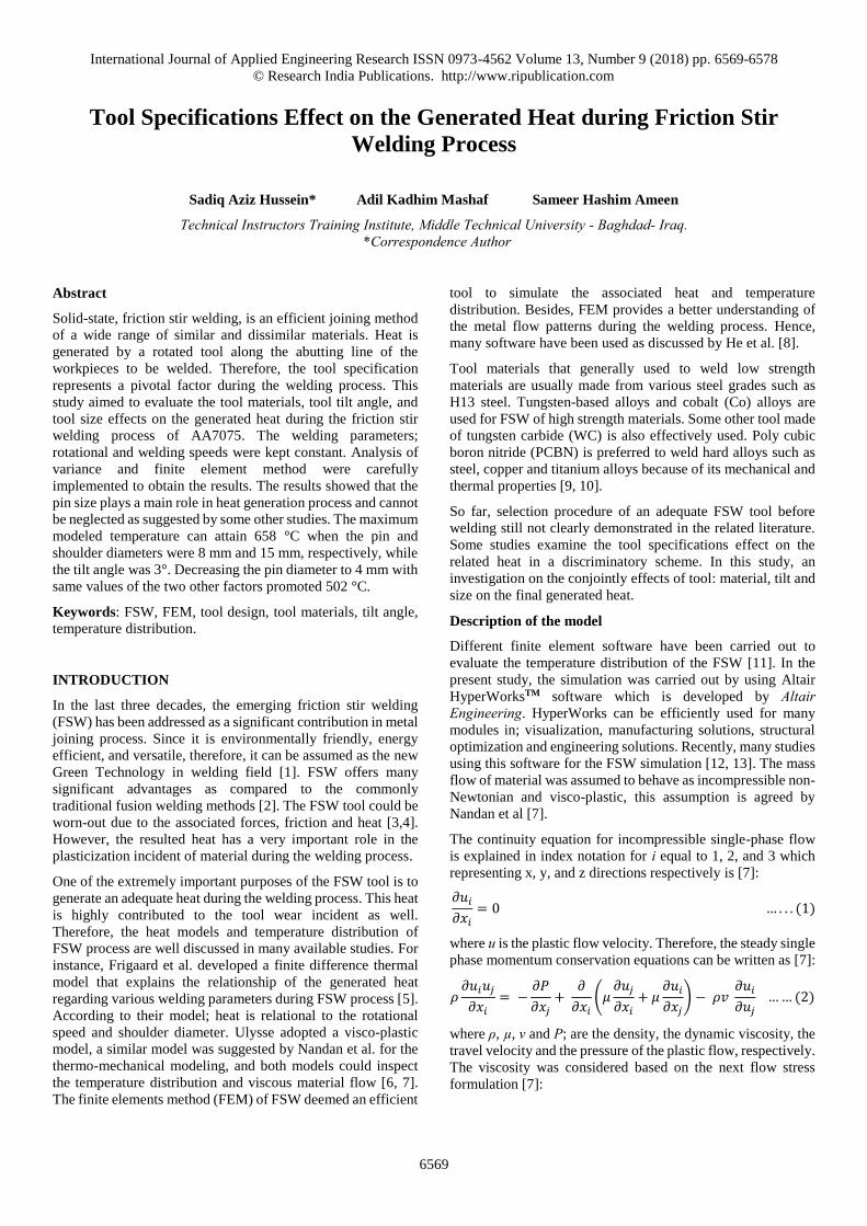
The model dimensions are shown in Figure 1. The element type
which selected for the present analysis was 3D Hexahedral with
20 nodes. The element was 3 degrees of freedom and serves
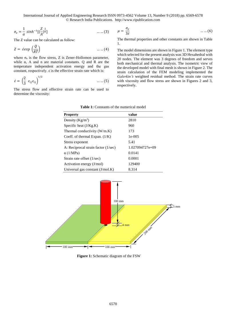
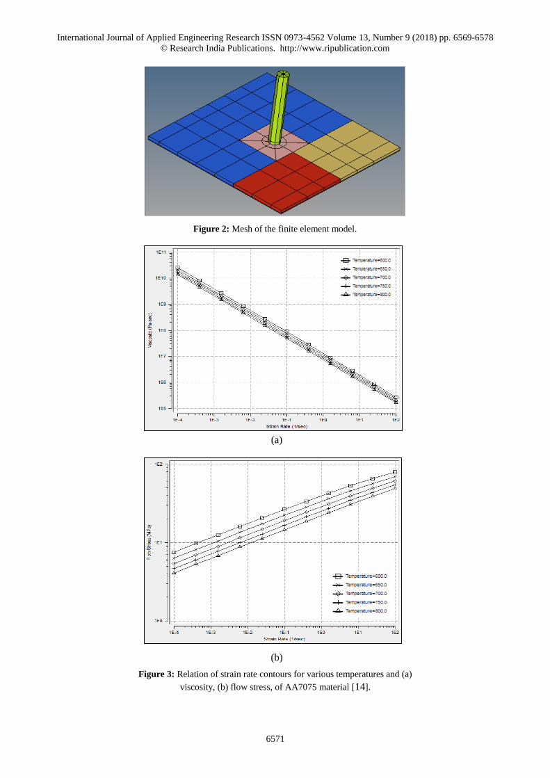
both mechanical and thermal analysis. The isometric view of
the developed model with final mesh is shown in Figure 2. The
strain calculation of the FEM modeling implemented the
Galerkin’s weighted residual method. The strain rate curves
with viscosity and flow stress are shown in Figures 2 and 3,
respectively.
Table 1: Constants of the numerical model
Property value
Density (Kg/m3) 2810
Specific heat (J/Kg.K) 960
Thermal conductivity (W/m.K) 173
Coeff. of thermal Expan. (1/K) 1e-005
Stress exponent 5.41
A: Reciprocal strain factor (1/sec) 1.027094727e+09
α (1/MPa) 0.0141
Strain rate offset (1/sec) 0.0001
Activation energy (J/mol) 129400
Universal gas constant (J/mol.K) 8.314
100 mm 100 mm
100 mm
4 mm
5 mm
Figure 1: Schematic diagram of the FSW
International Journal of Applied Engineering Research ISSN 0973-4562 Volume 13, Number 9 (2018) pp. 6569-6578
© Research India Publications. http://www.ripublication.com
6571
Figure 2: Mesh of the finite element model.
Figure 3: Relation of strain rate contours for various temperatures and (a)
viscosity, (b) flow stress, of AA7075 material [14].
(a)
(b)
International Journal of Applied Engineering Research ISSN 0973-4562 Volume 13, Number 9 (2018) pp. 6569-6578
© Research India Publications. http://www.ripublication.com
6572
The Factorial Analysis of Variance (ANOVA) was employed
to analyze the resulted data. Table 2 explains the factors levels
while the rotational and welding speeds were kept constant.
Table 2: Full Factorial levels
Factor Levels
-1 0 +1
Shoulder diameter (DS) mm 10 12.5 15
Pin diameter (DP) mm 8 6 4
Tilt angle (TA) degree 0 1.5 3
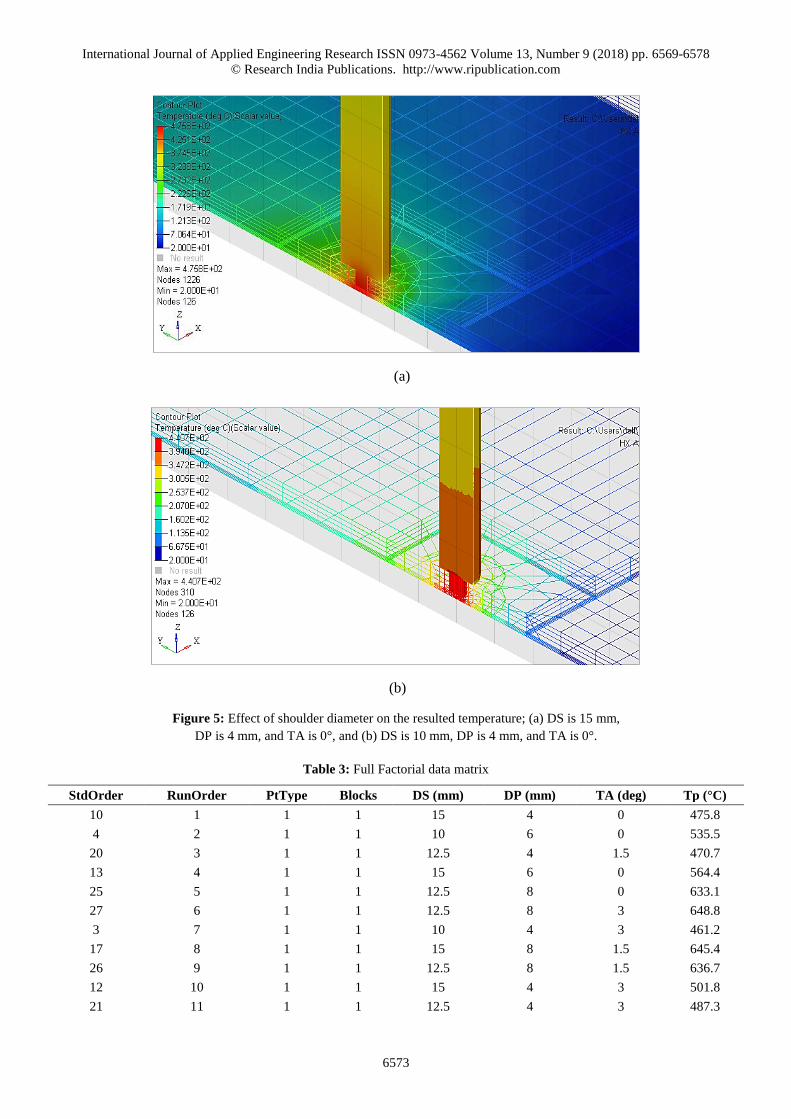
RESULTS AND DISCUSSION
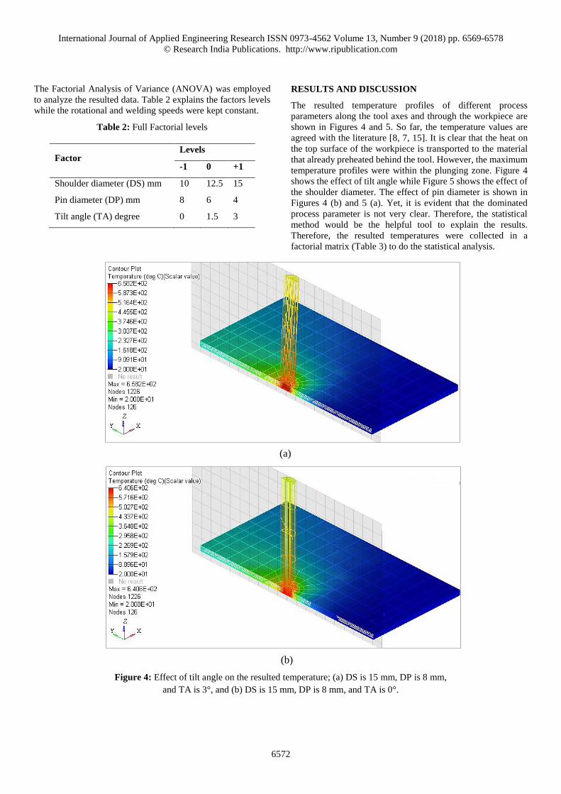
The resulted temperature profiles of different process
parameters along the tool axes and through the workpiece are
shown in Figures 4 and 5. So far, the temperature values are
agreed with the literature [8, 7, 15]. It is clear that the heat on
the top surface of the workpiece is transported to the material
that already preheated behind the tool. However, the maximum
temperature profiles were within the plunging zone. Figure 4
shows the effect of tilt angle while Figure 5 shows the effect of
the shoulder diameter. The effect of pin diameter is shown in
Figures 4 (b) and 5 (a). Yet, it is evident that the dominated
process parameter is not very clear. Therefore, the statistical
method would be the helpful tool to explain the results.
Therefore, the resulted temperatures were collected in a
factorial matrix (Table 3) to do the statistical analysis.
Figure 4: Effect of tilt angle on the resulted temperature; (a) DS is 15 mm, DP is 8 mm,
and TA is 3°, and (b) DS is 15 mm, DP is 8 mm, and TA is 0°.
(b)
(a)
International Journal of Applied Engineering Research ISSN 0973-4562 Volume 13, Number 9 (2018) pp. 6569-6578
© Research India Publications. http://www.ripublication.com
6573
Table 3: Full Factorial data matrix
StdOrder RunOrder PtType Blocks DS (mm) DP (mm) TA (deg) Tp (°C)
10 1 1 1 15 4 0 475.8
4 2 1 1 10 6 0 535.5
20 3 1 1 12.5 4 1.5 470.7
13 4 1 1 15 6 0 564.4
25 5 1 1 12.5 8 0 633.1
27 6 1 1 12.5 8 3 648.8
3 7 1 1 10 4 3 461.2
17 8 1 1 15 8 1.5 645.4
26 9 1 1 12.5 8 1.5 636.7
12 10 1 1 15 4 3 501.8
21 11 1 1 12.5 4 3 487.3
Figure 5: Effect of shoulder diameter on the resulted temperature; (a) DS is 15 mm,
DP is 4 mm, and TA is 0°, and (b) DS is 10 mm, DP is 4 mm, and TA is 0°.
(b)
(a)
International Journal of Applied Engineering Research ISSN 0973-4562 Volume 13, Number 9 (2018) pp. 6569-6578
© Research India Publications. http://www.ripublication.com
6574
StdOrder RunOrder PtType Blocks DS (mm) DP (mm) TA (deg) Tp (°C)
2 12 1 1 10 4 1.5 445.2
8 13 1 1 10 8 1.5 626.8
1 14 1 1 10 4 0 440.7
6 15 1 1 10 6 3 551.8
19 16 1 1 12.5 4 0 463.4
23 17 1 1 12.5 6 1.5 558.6
7 18 1 1 10 8 0 624.5
15 19 1 1 15 6 3 585.8
9 20 1 1 10 8 3 639.3
5 21 1 1 10 6 1.5 538.1
16 22 1 1 15 8 0 640.6
14 23 1 1 15 6 1.5 570.8
24 24 1 1 12.5 6 3 573
22 25 1 1 12.5 6 0 553.6
18 26 1 1 15 8 3 658.2
11 27 1 1 15 4 1.5 484.5
Table 3 Continued….
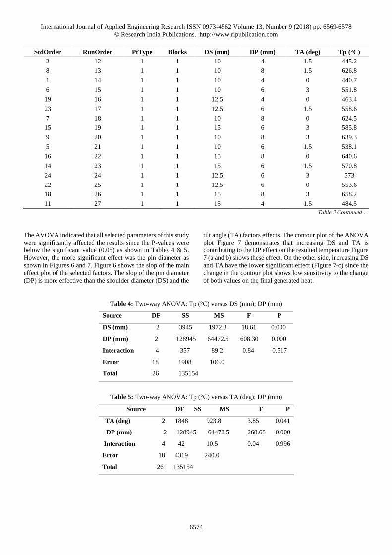
The AVOVA indicated that all selected parameters of this study
were significantly affected the results since the P-values were
below the significant value (0.05) as shown in Tables 4 & 5.
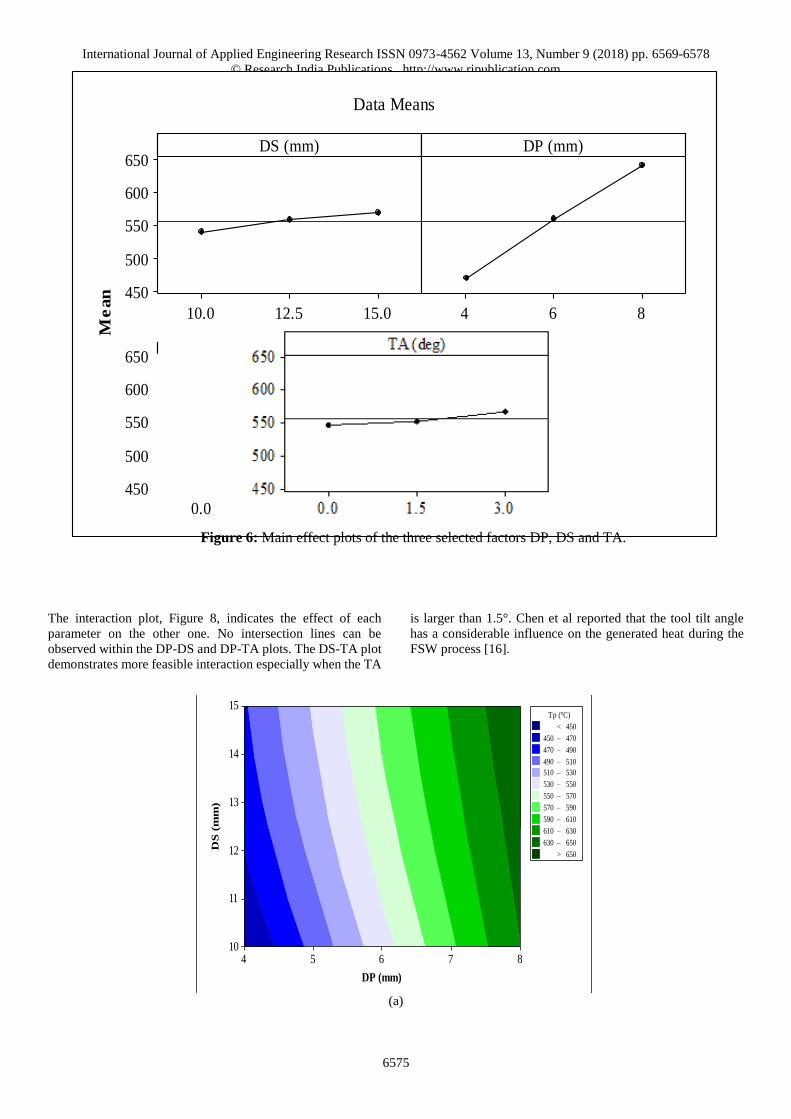
However, the more significant effect was the pin diameter as
shown in Figures 6 and 7. Figure 6 shows the slop of the main
effect plot of the selected factors. The slop of the pin diameter
(DP) is more effective than the shoulder diameter (DS) and the
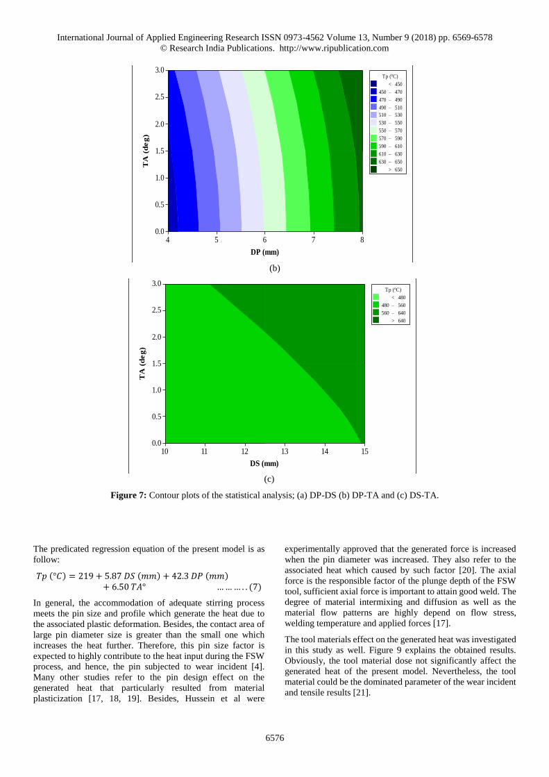
tilt angle (TA) factors effects. The contour plot of the ANOVA
plot Figure 7 demonstrates that increasing DS and TA is
contributing to the DP effect on the resulted temperature Figure
7 (a and b) shows these effect. On the other side, increasing DS
and TA have the lower significant effect (Figure 7-c) since the
change in the contour plot shows low sensitivity to the change
of both values on the final generated heat.
Table 4: Two-way ANOVA: Tp (°C) versus DS (mm); DP (mm)
Source DF SS MS F P
DS (mm) 2 3945 1972.3 18.61 0.000
DP (mm) 2 128945 64472.5 608.30 0.000
Interaction 4 357 89.2 0.84 0.517
Error 18 1908 106.0
Total 26 135154
Table 5: Two-way ANOVA: Tp (°C) versus TA (deg); DP (mm)
Source DF SS MS F P
TA (deg) 2 1848 923.8 3.85 0.041
DP (mm) 2 128945 64472.5 268.68 0.000
Interaction 4 42 10.5 0.04 0.996
Error 18 4319 240.0
Total 26 135154
International Journal of Applied Engineering Research ISSN 0973-4562 Volume 13, Number 9 (2018) pp. 6569-6578
© Research India Publications. http://www.ripublication.com
6575
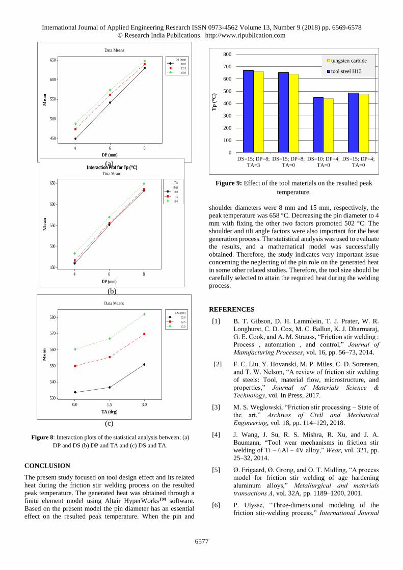
The interaction plot, Figure 8, indicates the effect of each
parameter on the other one. No intersection lines can be
observed within the DP-DS and DP-TA plots. The DS-TA plot
demonstrates more feasible interaction especially when the TA
is larger than 1.5°. Chen et al reported that the tool tilt angle
has a considerable influence on the generated heat during the
FSW process [16].
(a)
DP (mm)
DS
(m
m)
87654
15
14
13
12
11
10
>
–
–
–
–
–
–
–
–
–
–
<
610 630
630 650
650
450
450 470
470 490
490 510
510 530
530 550
550 570
570 590
590 610
Tp (°C)
15.012.510.0
650
600
550
500
450
864
3.01.50.0
650
600
550
500
450
DS (mm)
Me
an
DP (mm)
TA (deg)
Data Means
Figure 6: Main effect plots of the three selected factors DP, DS and TA.
International Journal of Applied Engineering Research ISSN 0973-4562 Volume 13, Number 9 (2018) pp. 6569-6578
© Research India Publications. http://www.ripublication.com
6576
(b)
(c)
Figure 7: Contour plots of the statistical analysis; (a) DP-DS (b) DP-TA and (c) DS-TA.
The predicated regression equation of the present model is as
follow:
𝑇𝑝 (°𝐶) = 219 + 5.87 𝐷𝑆 (𝑚𝑚) + 42.3 𝐷𝑃 (𝑚𝑚)+ 6.50 𝑇𝐴° … … … . . (7)
In general, the accommodation of adequate stirring process
meets the pin size and profile which generate the heat due to
the associated plastic deformation. Besides, the contact area of
large pin diameter size is greater than the small one which
increases the heat further. Therefore, this pin size factor is
expected to highly contribute to the heat input during the FSW
process, and hence, the pin subjected to wear incident [4].
Many other studies refer to the pin design effect on the
generated heat that particularly resulted from material
plasticization [17, 18, 19]. Besides, Hussein et al were
experimentally approved that the generated force is increased
when the pin diameter was increased. They also refer to the
associated heat which caused by such factor [20]. The axial
force is the responsible factor of the plunge depth of the FSW
tool, sufficient axial force is important to attain good weld. The
degree of material intermixing and diffusion as well as the
material flow patterns are highly depend on flow stress,
welding temperature and applied forces [17].
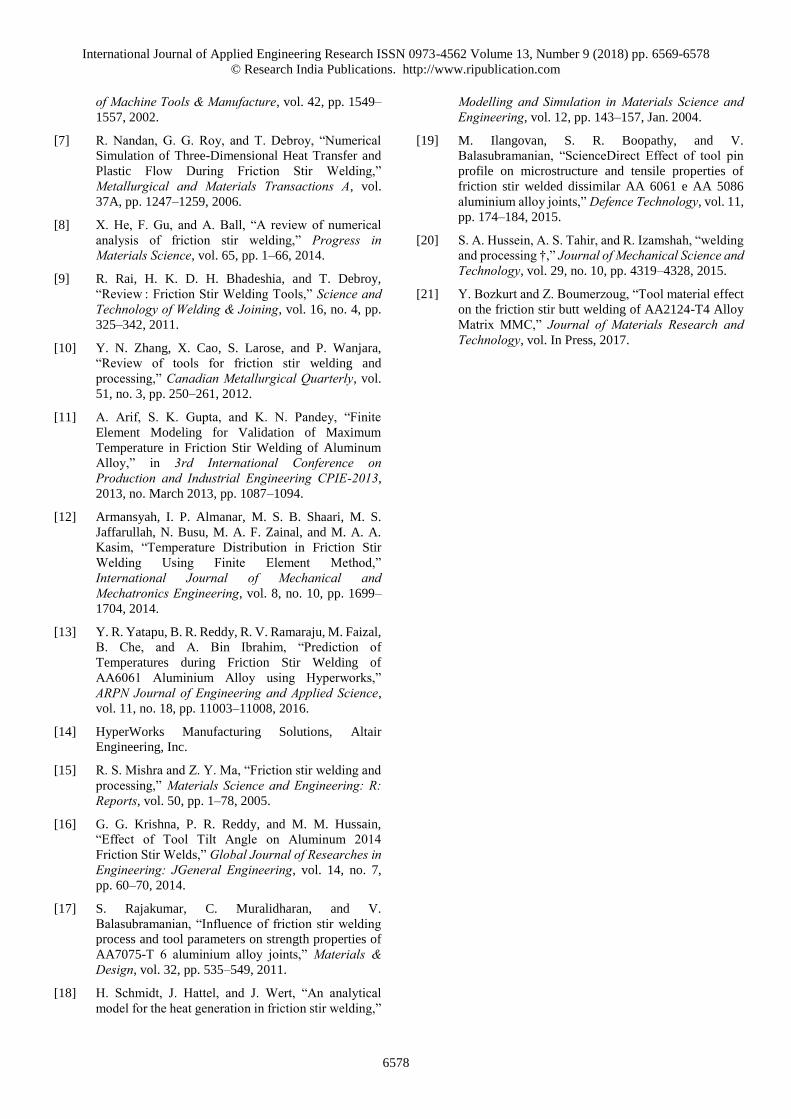
The tool materials effect on the generated heat was investigated
in this study as well. Figure 9 explains the obtained results.
Obviously, the tool material dose not significantly affect the
generated heat of the present model. Nevertheless, the tool
material could be the dominated parameter of the wear incident
and tensile results [21].
DP (mm)
TA
(d
eg
)
87654
3.0
2.5
2.0
1.5
1.0
0.5
0.0
>
–
–
–
–
–
–
–
–
–
–
<
610 630
630 650
650
450
450 470
470 490
490 510
510 530
530 550
550 570
570 590
590 610
Tp (°C)
DS (mm)
TA
(d
eg
)
151413121110
3.0
2.5
2.0
1.5
1.0
0.5
0.0
>
–
–
< 480
480 560
560 640
640
Tp (°C)
International Journal of Applied Engineering Research ISSN 0973-4562 Volume 13, Number 9 (2018) pp. 6569-6578
© Research India Publications. http://www.ripublication.com
6577
CONCLUSION
The present study focused on tool design effect and its related
heat during the friction stir welding process on the resulted
peak temperature. The generated heat was obtained through a
finite element model using Altair HyperWorksTM software.
Based on the present model the pin diameter has an essential
effect on the resulted peak temperature. When the pin and
Figure 9: Effect of the tool materials on the resulted peak
temperature.
shoulder diameters were 8 mm and 15 mm, respectively, the
peak temperature was 658 °C. Decreasing the pin diameter to 4
mm with fixing the other two factors promoted 502 °C. The
shoulder and tilt angle factors were also important for the heat
generation process. The statistical analysis was used to evaluate
the results, and a mathematical model was successfully
obtained. Therefore, the study indicates very important issue
concerning the neglecting of the pin role on the generated heat
in some other related studies. Therefore, the tool size should be
carefully selected to attain the required heat during the welding
process.
REFERENCES
[1] B. T. Gibson, D. H. Lammlein, T. J. Prater, W. R.
Longhurst, C. D. Cox, M. C. Ballun, K. J. Dharmaraj,
G. E. Cook, and A. M. Strauss, “Friction stir welding :
Process , automation , and control,” Journal of Manufacturing Processes, vol. 16, pp. 56–73, 2014.
[2] F. C. Liu, Y. Hovanski, M. P. Miles, C. D. Sorensen,
and T. W. Nelson, “A review of friction stir welding
of steels: Tool, material flow, microstructure, and
properties,” Journal of Materials Science & Technology, vol. In Press, 2017.
[3] M. S. Weglowski, “Friction stir processing – State of
the art,” Archives of Civil and Mechanical Engineering, vol. 18, pp. 114–129, 2018.
[4] J. Wang, J. Su, R. S. Mishra, R. Xu, and J. A.
Baumann, “Tool wear mechanisms in friction stir
welding of Ti – 6Al – 4V alloy,” Wear, vol. 321, pp.
25–32, 2014.
[5] Ø. Frigaard, Ø. Grong, and O. T. Midling, “A process
model for friction stir welding of age hardening
aluminum alloys,” Metallurgical and materials transactions A, vol. 32A, pp. 1189–1200, 2001.
[6] P. Ulysse, “Three-dimensional modeling of the
friction stir-welding process,” International Journal
0
100
200
300
400
500
600
700
800
DS=15; DP=4;
TA=0
DS=10; DP=4;
TA=0
DS=15; DP=8;
TA=0
DS=15; DP=8;
TA=3
Tp
(°C
)
tungsten carbide
tool steel H13
864
650
600
550
500
450
DP (mm)
Me
an
10.0
12.5
15.0
DS (mm)
Data Means
864
650
600
550
500
450
DP (mm)
Me
an
0.0
1.5
3.0
(deg)
TA
Interaction Plot for Tp (°C)Data Means
3.01.50.0
580
570
560
550
540
530
TA (deg)
Me
an
10.0
12.5
15.0
DS (mm)
Data Means
Figure 8: Interaction plots of the statistical analysis between; (a)
DP and DS (b) DP and TA and (c) DS and TA.
(b)
(c)
(a)
International Journal of Applied Engineering Research ISSN 0973-4562 Volume 13, Number 9 (2018) pp. 6569-6578
© Research India Publications. http://www.ripublication.com
6578
of Machine Tools & Manufacture, vol. 42, pp. 1549–
1557, 2002.
[7] R. Nandan, G. G. Roy, and T. Debroy, “Numerical
Simulation of Three-Dimensional Heat Transfer and
Plastic Flow During Friction Stir Welding,”
Metallurgical and Materials Transactions A, vol.
37A, pp. 1247–1259, 2006.
[8] X. He, F. Gu, and A. Ball, “A review of numerical
analysis of friction stir welding,” Progress in Materials Science, vol. 65, pp. 1–66, 2014.
[9] R. Rai, H. K. D. H. Bhadeshia, and T. Debroy,
“Review : Friction Stir Welding Tools,” Science and Technology of Welding & Joining, vol. 16, no. 4, pp.
325–342, 2011.
[10] Y. N. Zhang, X. Cao, S. Larose, and P. Wanjara,
“Review of tools for friction stir welding and
processing,” Canadian Metallurgical Quarterly, vol.
51, no. 3, pp. 250–261, 2012.
[11] A. Arif, S. K. Gupta, and K. N. Pandey, “Finite
Element Modeling for Validation of Maximum
Temperature in Friction Stir Welding of Aluminum
Alloy,” in 3rd International Conference on Production and Industrial Engineering CPIE-2013,
2013, no. March 2013, pp. 1087–1094.
[12] Armansyah, I. P. Almanar, M. S. B. Shaari, M. S.
Jaffarullah, N. Busu, M. A. F. Zainal, and M. A. A.
Kasim, “Temperature Distribution in Friction Stir
Welding Using Finite Element Method,”
International Journal of Mechanical and Mechatronics Engineering, vol. 8, no. 10, pp. 1699–
1704, 2014.
[13] Y. R. Yatapu, B. R. Reddy, R. V. Ramaraju, M. Faizal,
B. Che, and A. Bin Ibrahim, “Prediction of
Temperatures during Friction Stir Welding of
AA6061 Aluminium Alloy using Hyperworks,”
ARPN Journal of Engineering and Applied Science,
vol. 11, no. 18, pp. 11003–11008, 2016.
[14] HyperWorks Manufacturing Solutions, Altair
Engineering, Inc.
[15] R. S. Mishra and Z. Y. Ma, “Friction stir welding and
processing,” Materials Science and Engineering: R: Reports, vol. 50, pp. 1–78, 2005.
[16] G. G. Krishna, P. R. Reddy, and M. M. Hussain,
“Effect of Tool Tilt Angle on Aluminum 2014
Friction Stir Welds,” Global Journal of Researches in Engineering: JGeneral Engineering, vol. 14, no. 7,
pp. 60–70, 2014.
[17] S. Rajakumar, C. Muralidharan, and V.
Balasubramanian, “Influence of friction stir welding
process and tool parameters on strength properties of
AA7075-T 6 aluminium alloy joints,” Materials & Design, vol. 32, pp. 535–549, 2011.
[18] H. Schmidt, J. Hattel, and J. Wert, “An analytical
model for the heat generation in friction stir welding,”
Modelling and Simulation in Materials Science and Engineering, vol. 12, pp. 143–157, Jan. 2004.
[19] M. Ilangovan, S. R. Boopathy, and V.
Balasubramanian, “ScienceDirect Effect of tool pin
profile on microstructure and tensile properties of
friction stir welded dissimilar AA 6061 e AA 5086
aluminium alloy joints,” Defence Technology, vol. 11,
pp. 174–184, 2015.
[20] S. A. Hussein, A. S. Tahir, and R. Izamshah, “welding
and processing †,” Journal of Mechanical Science and Technology, vol. 29, no. 10, pp. 4319–4328, 2015.
[21] Y. Bozkurt and Z. Boumerzoug, “Tool material effect
on the friction stir butt welding of AA2124-T4 Alloy
Matrix MMC,” Journal of Materials Research and Technology, vol. In Press, 2017.