tonto", '",,,,'n - andre"tlCln'HEl. - IDEALS @ Illinois
44
IA'E iAe tonto", '",,,,'n and re"tlCln' HEl. 'Of MA :2 19 TY OF
-
Upload
khangminh22 -
Category
Documents
-
view
0 -
download
0
Transcript of tonto", '",,,,'n - andre"tlCln'HEl. - IDEALS @ Illinois

t~~~ IAE iAe ~l ~-- tonto n
and retlCln HEl ~~ Of
MA 2 19 UIVIVtI1~j TY OF
CONTENTS
PAGE
BENEFITS FROM CONTOUR FARMING AND TERRACING 5
SYSTEMS OF CONTOUR PLOWING AND PLANTING 8
PLANNING CONTOUR AND TERRACE SySTEMS 10 Start Before Erosion Is Serious 10 Contour Farming Is First Step 10 Preliminary Study of a Field 11
LOCATING AND MARKING THE LINES 13 Equipment Is Not Expensive 13 Locating Contour Lines 13 Locating Terrace Lines 14 Staking Out the Terraces 16 Walking Out and Plowing the Lines 19
GRASS WATERWAYS AND TERRACE OUTLETS 20 Poor Outlets Cause Much Trouble 20 Choosing the Outlet Locations 20 Outlets Prepared Before Terracing 22 Outlet Structures Sometimes Needed 24
CONSTRUCTING THE TERRACES 26 Broad-Base Terrace for Illinois 26 Many Terraces Built Too Small 27 Machinery for Terrace Construction ~ 28 Two Ways to Build Ridge 30 Top Terrace Is Built First 33 Making Fills Across Gullies 35 Check the Finished Terrace 36
MAINTAINING A TERRACE SySTEM 37
COST OF TERRACING 39
APPENDIX USE AND CARE OF THE LEVEL 40
Fa -the cover ill1tstration and a 1mmber of other photographs included herein the authors are indebted to the U S Soil Consevation Service
UIbana Illinois April 1941
Cooperative Extension Vork in Agriculture and Home Economics University of Illinois College of Agriculture and the United States Department of Agriculture cooperating
H P R USK Director Acts approved by Congress May 8 and June 30 1914
Save the Soil With Contour Farming and Terracing
By E W LEHMANN and R C HAyl
To STOP or to reduce enormous losses of soil from erosion on 18 million acres of rolling Illinois land farmers are turning to a definite soil-improvement and erosion-control program They
are applying lime and phosphates in order to grow deep-rooted legumes they are growing cover crops retiring land to permanent pasture planting trees adopting contour farming or strip cropping and conshystructing terraces All these practices work together to save the soil and its fertility from being washed away by surface water
One rain washed all this rich topsoil from the adjoining field A system of terraces would have prevented most of the loss (Pulaski county)
Many farmers hesitate to begin contour farming and terracing believing that contour farming with or without terraces is difficult However even tho extra care is needed in maintaining terraces and in crossing them with farming machinery it is no more trouble to farm on the contour than to cross gullies or to farm small patches in fields
IE W LEHMANN Chief in Agricultural Engineering and R C HAY Assoshyciate in Agricultural Engineering Extension The authors wish to acknowledg~ the assistance of the U S Soil Conservation Service in the preparation of this circular
3
Sheet erosion and gullying are rummg this field A deep fill will be reshyquired to terrace across the gash in the foreground (Shelby county)
cut by gullies too deep to cross At any rate any inconvenience is well repaid by the greater crop yields that result from saving the fertility of the soil
Losses of soil carried away by runoff water are sometimes very deceptive Because sheet erosion is not so noticeable as gullying it is thought to be less serious but actually the greatest losses of fertility are often brought about by sheet erosion before serious gullying occurs
Faulty cultivation is respo n sible fo r this desolate scene Only a planting of trees which will take years to grow will redeem the land (Johnson county)
Terraces built like these will control erosion and also serve as guide lines for contour farming (McLean county)
BENEFITS FROM CONTOUR FARMING AND TERRACING
Whether all the various practices that can be used to reduce erosion losses are needed on a given farm depends upon the character and fertility of the soil the type of farming followed the length of the slope and its steepness and the extent to which erosion has already occurred Where slopes are gentle and erosion is not far advanced good soil management alone may serve to keep soil losses in check But even on moderate slopes and fertile soils it is impossible to preshyvent the washing away of soil from cultivated land unless protective measures of some sort are taken-measures such as plowing planting and cultivating on the contour and the construction of terraces
Contour farming is merely the plowing planting and cultivating of land across rather than up and down the slope (pages 6 and 7) On cultivated land having a slope of more than 2 or 3 percent (a fall of more than 2 or 3 feet in 100 feet) contour farming is a basic protective practice used to supplement good soil management The benefit to cultivated land from contour farming and terracing is usually greater than the benefit to uncultivated fields f rom terracing for wellshymanaged permanent pasture or timber is a natural protection against
Contour buffer strips and grass waterway were staked out and left in sod when the rest of the pasture was plowed (McLean county)
erosion Eroded land being retired to pasture however and badly overgrazed and depleted pasture slopes may be benefited by small closeshyspaced terraces or furrows (15 to 25 feet apart depending on the slope) blocked at frequent intervals to hold the runoff Such pasture furrows not only control sheet erosion and gullying but conserve moisture-and this conservation of moisture is often as great a benefit as is the saving of soil
Strip cropping carries contour farming one step farther in preshyventing losses from erosion The simplest form of strip cropping is that in which contour strips of hay crops one or two rods wide are
Cor nfield planted on the contour The contour guide lines can be seen in the center of the picture (Schuyler county)
7 COKTOUR FAR)II G AND TERRACIKG
left at intervals on the slope while the areas between the hay crops are in a cultivated crop In heavy rainstorms the sod strips check and spread the surface runoff and thus reduce erosion They also serve as guide lines for plowing and planting the cultivated areas Terracing is the final device for holding and controlling the flow of runoff water A combination of contour farming or strip cropping and terraces gives the best possible protection to cultivated sloping land
Contour farming whether done with the added protection of tershyraces or without results in better yields of crops because it conserves water and soil and permits power and machinery to be used more efficiently These benefits have been definitely demonstrated not only in carefully controlled tests at various experiment stations but on many farms thruout the corn belt
At the Clarinda (Iowa) Erosion Experiment Station over a fourshyyear period on an 8-percent slope a field farmed on the contour averaged 1 10 inch of runoff water a year and no soil losses whereas a field plowed up and down the slope lost 9Yz inches of runoff and 40 tons of soil an acre a year On fifteen farms cooperating in the U S Soil Conservation Service project in McLean county Illinois the corn yields in 1939 averaged 58 bushels an acre on land farmed on the contour but only 54 bushels an acre on land farmed in straight rO7S up and down the slopes Similarly in Missouri tests losses of soil were found to be 8Yz times as great on unterraced land as on terraced
Contour furrows in this pasture were built with plow scraper and farm tractor (Brown county)
8 CIRCULAR No S13
land in tests in Wisconsin the losses were 7 times as great on untershyraced land A saving of 94 percent in fuel and an increase of 128 percent in number of acres covered per hour when the work was done on the contour were reported by the Kansas Agricultural Experiment Station
SYSTEMS OF CONTO UR PLOWING AND PLANTING
Terraced land should be contour-farmed On cultivated land sloping more than 3 percent contour farming is necessary for successshyful terraces On slopes of less than 3 percent terraced land can be farmed in straight rows if the terraces are carefully maintained Conshytour farming however is recommended even for these slopes because each row becomes a small terrace tending to conserve moisture and to check any erosion between terraces
Farming contoured land whether it is terraced or not presents some problems in dealing with irregularities in length of rows and shape of areas Farmers have used successfully four principal sysshytems of plowing and planting These systems are adapted to buffer strips in strip cropping and to terraces
System A When entire field is in a single crop or when buffer strips of uniform width are left as markers plowing is commonly done in lands around each guide line or buffer strip The full-length rows run parallel to the guide lines both above and below until they meet The point rows then come in the center This method is preferable when corn is to be harvested with a mechanical picker or a corn binder
System B Planting starts just below each contour line or buffer strip or terrace ridge and works down the slope to the next line With terraces the turning in planting and cultivating the point rows is done in the terrace channels with buffer strips the turning is done on the strips
System C When point rows are not cultivated buffer strips of grass or a hay crop of various widths are used The area between these corshyrection strips is plowed as a land Whether correction strips are more desirable than point rows will depend on the size of the areas that will be lost to row crops number of point rows avoided and advantage of raising hay crops in this way
System D The key line is adapted to gentle slopes All rows are planted parallel to one key line usually the straightest or longest This system is not usually suited to strip cropping but is adapted to contour farming on unterraced land without buffer strips
9 CONTOUR FARMING AND TERRACING
A Point rows midway between lines B Point rows end at next line below Entire field is in a cultivated crop Entire field is in a cu ltivated crop
C Point rows not farm ed Space is D Key line system point rows only taken up by a small-grain or hay crop at corners Entire field is in one crop
Fou r methods of contour planting with terraces on buffer strips
In all four of these systems corn must be drilled but drilled corn yields as well as checked corn according to experiments by the Agronshyomy Department University of I llinois and furthermore mechanical pickers operate more easily when husking one ear at a time than when husking several ears as they must when the plants are ar ranged several in a hill
10 CIRCULAR No 513
PLANNING CO NTO UR AND TERRACE SY STEMS
Start Before Erosion Is Serious It is best tho not always possible to begin contour farming and
terracing on cultivated slopes before severe erosion occurs One reason for doing so is that it is easier and far more desirable to prevent the loss of fertile top soil than to try to enrich exposed subsoil Another reason is that the cost of terracing is less and farming operations are simpler if terraces are constructed before gullying is far advanced
On gullied land contour farming without terraces is difficult and often ineffective If terraces are built extra work and expense are required to make earth fills across the gullies With relatively valuable land the extra expense required to make these fills may be justified but with land of low value the high cost of fills often makes terracing impractical The greatest return for the expense and effort put into contour farming and terracing comes from highly productive slopes that are not severely eroded
Contour Farming Is First Step The lines that are established for contour farming should be so
located as to be not only immediately practical for contour farming but at the same time permit terraces to be added after the waterways for the outlets are well sodded Natural draws tending to erode need to be left in sod to prevent the formation of gullies and to make it easier to cross them with machinery Wide well-sodded grass watershyways are needed wherever land is farmed on the contour but they are particularly needed on land to be terraced since every terrace requires one or more such water outlets Development of these two simple erosion-control practices-grass waterways and contour farming-is thus an important step leading to terracing
When a field is to be farmed on the contour without terraces as is done on gentle and more or less uniform slopes only a few contour lines need be established Where the slopes are steeper and less regushylar more guide lines will be needed in order to make it possible to grade the furrows accurately It is best to consider these lines as future terrace markers consequently they ought to be located in the field ~xactly as terraces are located (see cornfield on page 6)
When buffer strips of hay crops are used in contour farming the change to terracing is simple for terraces can be built on the sod trips without disturbing the crops growing between them A second
11 CONTOUR FARMING AND TERRAel G
advantage in starting with strip cropping is that the locations planned for the proposed terraces or outlets can be tested and desirable changes made in the plans before the terraces are built Strip cropping requires no expense other than the use of a level to locate the strips
Preliminary Study of a Field Vhen a field is to be terraced-whether the terracing is to be done
immediately or contour farming without terracing is to be practiced for a few years-a plan should be worked out that takes into considerashytion the entire area involved including any watershed that drains onto the field and the other points mentioned below
Include entire watershed in plans The terrace system must be located yith respect to the top of the slope The vertical distance from the top terrace to the top of the slope should usually not be more than the yertical distance between the other terraces Sometimes water from a field above drains across the field to be terraced or contourshyfarmed If the area above is small the top terrace may be so located that it -ill not drain more than 4 acres When a larger area above is involved the best solution is to terrace the upper field first If it is not terraced a diversion ditch must be built on a nonerosive grade at the upper side of the lower field to carry the water from the upper area to the side of the field where it can be let down thru an outlet that may also serve as a terrace outlet Where the runoff from the upper area drains thru one or two draws it may be possible to establish sod in these water courses and later use them for terrace outlets
Locate suitable outlets One of the most important things to consider in a terracing job is the location of proper outlets Wellshysodded permanent pastures and draws or unpastured woodlots that have a thin stand of trees and a tough sod make good natural outlets
Yhen a suitable natural outlet cannot be found a wide shallow terrace-outlet ditch can be graded down the slope and sodded and if necessary protected by permanent dams When the outlet channel is graded all exposed unproductive subsoil should be covered with topshysoil before seeding or sodding Outlets should be prepared a year or more before the terraces are built
Terraces cannot be emptied legally onto a public highway without permission unless the terraced land drains naturally onto it
Consider adjoining fields Farmers who own adjacent land can sometimes arrange to utilize jointly good outlets along boundary lines by draining terraces from both sides of these outlets
Possible future terracing of other land on the same farm should
]2 CIRCULAR No 513
always be taken into consideration in any terracing plans Whenever practicable the outlets should be so located as to drain terraces from the fields on both sides It is not usually advisable to construct outlets along fence lines or field divisions that are to be changed
Analyze the slopes Fields without abrupt changes hog backs or deep gullies are best adapted to terracing Unfortunately some of the rolling land in Illinois that is subject to harmful erosion is very uneven Terraces on such land often form queer irregular patterns that are difficult to farm on the contour Sometimes the terrace lines on cultivated fields would have to be so crooked and uneven that tershyracing would be of doubtful value Contour farming without terraces may nevertheless be worth while on such fields
Placing all of a slope in one field will often make terracing and contour farming more practicable as will also fencing into pasture or woodland irregular corners extremely steep slopes and badly eroded areas Electric fences may simplify the making of such changes
Does soil erode badly Some soils are much more erosive than others Erosion on a yellow-gray timber soil having a relatively gentle slope may be enough to make terracing worth while whereas a rich brown silt loam prairie soil on a similar slope may give no evidence of erosion On the more erosive soils and on soils underlain with an impervious subsoil terraces are usually spaced at shorter intervals and may well be given more grade than terraces on better soils
Estimate length of terraces An estimate of terrace length will aid in determining the grade to be used when the terraces are staked When terraces are longer than 1600 to 1800 feet an outlet is needed near the center or at each side of the field
Relate to cropping plan If possible fields should be terraced just before they are seeded to alfalfa or clover for the terraces will then settle and become well established before a cultivated crop is planted on them In fields ready to be seeded to permanent pasture and in need of terracing narrow pasture terraces or contour furrows may be built more economically than broad-base terraces
Make farm roads part of plan The farm road should be conshysidered when planning terraces and contours Sometimes a contour road can be constructed on an enlarged terrace When the road is placed at the end of the terraces it should be at the upper end rather than at the outlet If it must be located at the outlet it should parallel the outlet on the outside so as not to cross the terraces Do not allow terraces to discharge directly onto a farm roadbed for the waterway formed by the implement and wagon tracks will start gullies
13 CONTOUR FARMING AND TERRACING
LOCATING AND MARKING THE LINES
Equipment Is Not Expensive Equipment for staking out terrace and contour lines includes a
light drainage level or a farm level a level rod a hatchet or hand ax and several stakes Twenty dollars will usually buy a suitable level and level rod A farmer can often find other farmers in the community wining to purchase the outfit with him
The number of stakes needed will depend on the length of the lines and the unevenness of the ground Stakes usually are set at 50shyfoot intervals but on smooth uniform slopes they may be set at 100shyfoot intervals At bends across draws and around points they should be set at 25-foot intervals Plaster lath make satisfactory stakes They can be used full length pulled and used over again a number of times
A drainage level is recommended for staking out terraces but a farm level if carefully used will give equally good results
bull Two men are needed to stake out a line One handles the level and
the other holds the rod moves the target steps off the distances beshytween points where readings are taken and sets the stakes
Locating Contour Lines When simple contour farming is to be practiced contour guide
lines can be located with a minimum of effort by starting at some convenient point on the slope (usually on the steepest part) and then
14 CIRCULAR No 513
proceeding a measured distance ( usually an even number of corn rows) down from the highest point Set a stake at this point
Set up the level a little higher than this stake and 200 to 300 feet away from it Take a reading on the target while the rodman holds the level rod on the ground beside the stake I f this setting is 5 feet 6 inches this is the height of the instrument above the contour line With this target setting unchanged the rodman paces across the slope about 100 feet nearer the instrument He locates another point at the same elevation as the first stake by moving up and down the slope until the level sights on the target within the nearest inch He repeats this process until he is 200 to 300 feet from the level on the opposite side from which he started The series of located points are thus level that is on the contour
The instrument should now be moved forward and set up 200 to 300 feet beyond the point where the last reading was taken With the rod held at this stake change the target to a reading for the new posishytion of the instrument which is the new height of the instrument above the contour line After taking the back sight proceed as before setting other stakes until the line is located across the field or farm
Other contour lines farther down the slope are needed on long and uneven slopes They also may be located in the manner described above
Locating Terrace Lines
Locating lines for terraces requires more care and accuracy than locating simple contour lines Before actual staking can be started the high point of the area must be found the approximate length of terraces determined and the slope measured in several places
Measure the slope See drawing below When there is conshysiderable variation in slope several such measurements are made in order to determine the most common or controlling slope This per-
G - 2
- 2- 2
4- a OR 4
PAC OFF 100 F-- ON AVERAGE SLOp(
To measure the slope se t up level and take a rod reading at top of s lope then pace 100 feet down the slope and take another rod reading Difference between two readings gives percent of s lope (fall in 100 feet)
15 CONTOUR FARMING AND TERRACING
cent of slope is used to determine the vertical spacing of the terraces as given in Table 2 page 16
Locate top terrace first Usually the top terrace line is staked out first This is a trial line and may require restaking several times before it is finally located Often the top terrace needs to be restaked in order to intercept the heads of small gullies or run above areas showing sheet erosion In rich porous soils showing no appreciable erosion at the top of the slope the top terrace may be placed farther down the slope than indicated in Table 2 provided the area drained does not exceed 4 acres Be sure the location of the top terrace line is satisfactory before locating terraces below it When a steep slope starts in a field locate the first terrace just above the break
If there is an obstruction of some kind in the field-a sink hole a tree a deep gully or a large boulder-it is often best to stake a lower terrace first in such way that it will come just above or below this obstruction The other terraces are then located with reference to this one
Determine the terrace grade In Illinois the grade of a terrace along the channel should never exceed 4 inches in 100 feet Short terraces are usually built with a uniform grade but terraces longer than 400 feet are more satisfactory and have a greater capacity when built with a variable grade the grade being reduced at 400-foot intershyvals from the outlet toward the upper end (see Table 1)
(Table 1)
PROPER FALL IN VARIABLE GRADED TERRACESa
Fall in 100 feet
Length of terrace On average On sandy soil porous soil
inches inches Lower 400 feet 4 30 bullbullbull bull 0 bull 0 bullbull bull bull bullbullbullbullbullbull bull bull bullbull 0 0 bullbull bull 0 bull bull
400-800 feet from outlet end 0 3 20 bull 0 bull 0 bullbull 0 bull 0 bull bull 0 bullbull 0 0
800-1200 feet from outlet end 2 10 bull 0 bullbullbull 0 bullbull 0 bull 0 0
1200-1600 feet from outlet end 0 1 0bull 0 0 0 bullbullbullbull 0 bull 0 0
aAdapted from VSoDA Farmers Bulletin 1789
Terraces on more absorptive types of soil can usually be given slightly less grade than terraces on tight soils On a few fields having a sandy porous subsoil short level terraces with closed ends are being used successfully in Illinois but this practice is not generally recomshymended Terraces longer than 1800 feet should have outlets at both
16 CIRCULAR ~o 513
ends or at some central point if possible vVhen terraces more than 1800 feet long must drain in one direction the lower end should be built wider and higher than the recommended terrace cross-section
Contour buffer strips on which terraces will be built later should have the same grade as the terraces will need
Decide on spacing The best distance to allow between terraces or contour buffer strips that are to serve as terrace markers varies with the slope and to a less extent with the soil type extent of erosion and rainfall A guide to such spacing is supplied by Table 2
(Table 2)
PROPER DISTANCES BETWEEN TERRACES
Distance betweenVertical dropSlope per 100 feet the terraces downbetween terraces the slope
feet 1 foot 1 foot 9 inches 175 2 feet 2 feet 6 inches 125 3 feet 3 feet 100 4 feet 3 feet 6 inches 87Y2 5 feet 4 feet 3 inches 86 6 feet 5 feet 83 7 feet 5 feet 9 inches 82 8 feet 6 feet 3 inches 78
10 feet 6 feet 6 inches 65 12 feet 7 feet 58
Note-The spacings listed in this table are intended for use as a general guide On erosive timber soils and soils having an impervious subsoil they should be deshycreased by as much as 10 percent and they may be increased by 10 percent on rich porous loess soils
On open absorptive soils especially in the northern part of the state this spacing can be increased but on tight badly eroded soils such as frequently occur in southern Illinois the space between tershyraces must be reduced Contour buffer strips to be used as terrace markers should be spaced exactly as terraces are spaced
Staking Out the Terraces
Start with top terrace (1) Start at the outlet of the top terrace unless the high point or some other controlling f eature is not visible or is more than 400 or 500 feet from the outlet Set up the level 200 to 400 feet from the outlet (200 feet is the limit with a farm level with a better quality level sights of 400 feet or more may be taken ) Take a rod reading on the high point and add to that reading the proper
--------------- -- ---
17 CONTOUR FARMI~G AND TERRACI NG
2-6 3 - 6 VERTICAL DROP
~ POINT 6 - 0
Stakes are located with rod and level If rod reading at high point is 2 feet 6 inches and co ntro lling s lope is 4 percent the proper vertical spacing (3 feet 6 inches Table 2) will give a rod reading of 6 feet at the outlet stake
5 -9
~l--=-=--__UU
If a grade of 3 inches in lOO feet is desired on the terrace the target is moved down l Yz inches to 5 feet lOYz inches in o rder to locate the stake SO feet from the outlet Thus the second stake is se t at a point lYz inches higher than the outlet
vertical spacing This vertical spacing will depend on the percent of slope (see Table 2)
The rodman now raises the target to correspond to the rod reading on the high point plus the vertical spacing then to locate the outlet stake of the top terrace he moves down the slope along the outlet until the instrument man sights on the target The stake is set here The rodman then lowers the target to give the proper grade ( Table 1) paces 50 feet in the general direction the terrace line will follow and moves the rod up and down the slope as directed by the instrument man until the desired elevation is located The second stake is set here Other stakes are located in a similar manner until it is necessary to move the level again
This use of rod and level in staking out a terrace line is illustrated by the drawings at the top of this page More complete information is given in the Appendix pages 40 to 43
(2) When the high point or other controlling feature is more than 500 feet from the outlet space the top terrace directly below this
18 CIRCULAR No 51
controlling point in the same manner as described above Then stake the lower end of the terrace toward the outlet beginning not at the outlet but at the stake directly below the controlling point The proshycedure will be the same as that described for staking f om the outlet end except that in going downgrade the target must be raised at each new location General rule in going upgrade in staking a terrace line lower the target in going downgrade raise the target When the lower end of the terrace is staked stake the upper end proceeding upgrade from the stake directly below the controlling point
Staking the other terraces To locate the outlet stake of the second terrace down the slope set up the level as before ZOO to 400 feet from the outlet and somewhat below the first terrace line Then take a rod reading at the outlet stake of the top terrace and add to that the vertical spacing proceeding from there in the same way as in staking the top terrace
In staking the next terrace and succeeding terraces below it is usually best to measure the slope again at several points These slope measurements may be taken by the rodman and instrument man as they return to the outlet from the upper end of the terrace just staked out Ey this method the instrument man has the necessary data for staking the next terrace when he reaches the outlet
When sights are long Stakes are located as directed in the foreshygoing paragraphs until the rodman has moved away from the level the maximum distance for accurate readings-ZOO to 400 feet depending on the quality of the level Then it is necessary to move the instrument (see below)
Judgment and accuracy required Responsibility for the accushyracy of the work in staking out terraces rests with both the instrument man and the rodman Care must be taken to see that the bubble is centered before each reading is taken The level should be checked
- 0-7 00
5-5 ------ - ----_ ----~iKU-
SE COND FI RST POSITION 50 50 POSITION
FALL 2 PER 100 OF LEVEL
When moving the level the rodman holds rod at last located stake while level man moves level to new location past the rodman along the terrace line and sets it up again Rodman then moves target until sighted again by level man Additional stakes are located with reference to this stake as if starting at outlet again
---------
19 Co~no R FARMIKG AND TERRACIXG
frequently and kept in proper adjustment The judgment and care of the rodman detenpines to a large extent the accuracy of the grade and location of the terraces Since readings are taken on the ground it is important that the rod always be set on average ground surface and not in depressions or on high spots (See Appendix pages 40 to 43 on use of the level)
Cross gullies with smooth curve When a terrace is to be conshystructed across a draw or gully set the stakes to form a smooth curve
I D
01 TERRACE CORRECT bullbullbullbullbull TERRACE INCORRECT
25 50 75 1~
SCALE N FEET bull
Js~ twuwMU 112~~
103
-----103 102-shy____ 10 2---shy
In crossing gullies it is better to build the terrace practically straight across than to fo llow the grade line (Arrows indicate direction of slope )
bending up the slope at the gully somewhere between the grade line and a line straight across the gully (above) Never run the line so as to form a V Terraces can frequently be staked almost straight across narrow gullies
In no case should the grade of a terrace ridge leading into a draw or gully be greater than the grade leading toward the outlet preferably it should be less If possible the terrace grade should be increased as it leaves the gully Terraces having outlets at both ends can someshytimes be staked to drain in both directions from a gully or a bend near the middle of the field
Walking Out and Plowing the Lines
After a terrace is staked the short sharp bends and irregularities should be smoothed out To do this the man in charge of the work
20 CIRCULAR No 513
walks along the terrace line and moves the stakes vhere necessary takes may be moved farther on glentle slopes than on steep slopes
Unless the terracing machine is in the field ready to start each terrace line should be marked out with a plow following the walkingshyout Marking each line with a furrow as soon as the line is staked prevents losing stakes or having them changed inadvertently
GRASS WATERWAYS AND TERRAC E OUTLET S
Poor Outlets Cause Much Trouble Terrace outlets are the source of more difficulty than any other
part of a terrace system When not properly located and protected they develop serious gullies that soon get beyond a farmers control Even when they are correctly placed and constructed failure to mainshytain them properly will cause a great deal of trouble
The most common faults of terrace outlets are allowing ater to drain onto steep slopes or areas not properly covered by sod and allowshying it to drain into small narrow ditches or over a vertical bank or head (vaterfall ) in the outlet
Choosing the Outlet Locations Other considerations being favorable the terrace outlet should be
located on that side of the field having the least slope Usually a draw
A well-sodded natural drainageway will carry heavy runoff from t erraces without eroding (McLean county)
Creosoted plank dam with concrete apro n and notch spillway protects lower end of this long sodded terrace outlet ditch This dam was built by the farmer him elf (Montgomery county)
or drainageway can be selected in this location Natural draws make desirable outlets when protected by sod as shown in the picture on page 20 A well-sodded permanent pasture adjoining the field to be terraced also makes a good terrace outlet when the terraces can be drained directly onto it
Unprotected outlets are often the cau se of seriou s overfall erosion An outshylet structure built since this picture was taken is preventing further damage at this spot (Williamson county)
22 CIRCUBR No S13
When terraces discharge on a pasture or in a woodlot the end of the terraces should be offset if possible That is the top terrace should be carried farthest out and each succeeding terrace down the slope should be stopped at least 25 feet short of the one above it Water flowing out of the terraces constructed in this manner will not be concentrated on one narrow strip as it flos down the slope
PERMANENT
PASTU RE j I
Ends of t er races draining onto pasture sod or w oo dland should be stagshygered so that the outlets will not tend to concent rate the drainage water in one narrow strip
Outlets Prepared Before Terracing
When an outlet ditch or draw must be prepared and sodded to prevent erosion the sod should be established before water from the terraces is emptied into the outlet otherwise there is danger of seriou gullying This means that the outlet must be prepared a year or more before terracing or water from the terraces must be diverted temposhyrarily into an adjoining field that has a good cover of sod
Preparation of a sodded terrace outlet may be comparatively simple on a field already in sod that is to be plowed up The outlet may be located on a well-sodded natural drainageway carefully marked off and then left undisturbed when the field is plowed and the terraces constructed If small cuts due to erosion occur in the sodded outlet they may be filled in with transplanted sod
When no sodded draw is available or the most suitable outlet is gullied the following steps are recommended in the preparation and maintenance of a smiddotodded waterway
Step 1 Shape a uniform waterway as straight as practicable and of a width suited to the steepness of slope and the area to be drained (see Table 3) Plow or grade in the low places Disk harrow and roll t o form a firm seedbed for the channel
Step 2 Apply 8 to 10 tons of manure an acre and work it into the seedbed If manure is not available a nitrogenous fertilizer can be used Fertility is essential for a rapid heavy growth of sad
Preparing seedbed for a grass waterway to se rve as a terrace outlet After disking harrowing and rolling to make a firm seedbed manure should be applied to gin the grass a Quick start (St Clair county)
Step 3 Seed 10 to 15 pounds each of redtop and timothy-twice the normal seeding-along with a nurse crop of small grain Bluegrass and white or alsike clover may be added The seed can be broadcast and harrowed lightly or seeded with a disk drill and grass-seeder attachment Scatter plenty of seed on the banks
Step 4 If the first seeding washes out try again If necessary use a mulch of straw or low check dams of straw sod wire or brush to hold the soil in place until the sod is formed
Step 5 Mow the channel regularly in order to prevent the nurse crop from ripening and to control weeds Make it a productive meadow strip instead of waste land full of weeds
L~ e Table 3 (page 24) to find the right dimensions for a terrace outlet ditch The approximate acreage drained by the outlet and the steepness of slope in the channel (feet fall per 100 feet length) must be determined in order to use the table For example an outlet ditch draining 15 acres on a 4-percent slope must be 8 inches deep 11 feet wide at the bottom of the channel and 17 feet wide at the top Outlets on steeper slopes require wider and shallower channels in order to spread the flow of water over a larger surface and hold it below an erosive velocity There is no objection to maintaining wider waterways than pecified in Table 3 but there is danger in narrower ones For additional safety they may be slightly deeper ( up to 6 inches more)
--- ---
24 CIRCULAR Ko 513
(Table 3)
SUGGESTED DIMENSIONS FOR TERRACE OUTLET DITCHES PROTECTED BY SODa
(For rolling cultivated land channels to have at least 4 1 side slope )
Slope Acres drained by ditch of
ditch 2 5 10 15 20 25 30 35 40 45 50 60
Width and depth of channel
1 W ft 6 7 13 14 17 17 18 22 24 25 25 25 Din 6 Q 9 11 11 12 12 12 12 14 15 16 W ft 10 13 19 22 25 25 26 30 32 35 35 36 -
2 w ft 6 10 13 15 16 18 21 21 20 22 23 24
-- shy3
D in W ft
W ft D in
5 10
6 5
6 14
9 6
8 19
13 7
9 21
13 8
9 22
15 8
9 24
15 Q
9 27
17 9
10 28
21 9
11 28
239
11 30I2510
12 31
25 1L
13 33
25 12
W ft 10 13 18 19 21 21 23 27 29 32 33 33 -- shy
4 w ft Din
6 5
7 6
11 7
11 8
15 8
19 8 228 1199
21 9
24 9
25 10
W ft 10 11 16 17 21 25 28 25 26 30 32
5 W D
ft in
6 5
10 5
12 6
17 6
21 6 246 J 257
25 8
25 8
25 8
W ft 10 14 16 21 25 28 30 31 31 31
6 W ft 4 9 16 20 23 24 25 25 D in 5 5 5 5 6 6 6 7 W ft 8 13 20 24 27 28 29 30
7 W ft 5 9 16 22 23 23 24 25 D in 4 5 5 5 5 6 6 7 W ft 8 13 20 26 27 27 28 30
8 W D
ft in
6 4
8 5
18 5 225 1 235
23 6
W ft 9 12 22 26 27 27
9 W ft 7 12 20 22 24 25 W =Bottom width in feet D in W ft
3 9
4 15
4 23
5 26
5 28
5 29
D =Depth in inches W =Top width in feet
10 W ft 7 12 20 20 25 Din 3 4 4 5 5 W ft 9 15 23 24 29
-Adapted from tables in VSDA Farmers Bul 1814 Terrace Outlets and Farm Drainageways In the above table the dimensions to right of and below the heavy black line (5 sec) are not as
safe as those aaove and to the left On steep slopes having larger drainage areas extra preca utions must be taken
Outlet Structures Sometimes Needed Most slopes suitable to terrace outlets can be stabilized with sod
so that outlet structures are not needed The lower end of some outlet ditches or draws however have abrupt overfalls or heads that continue to cut back uphill Under such conditions another outlet location should be chosen if possible to divert the runoff water from the head and thus avoid having to build an outlet structure When another outlet is not practical a dam will have to be built usually a notch spillway type of reinforced concrete creosoted plank or masonry construction
25 COXTOljR FARMING AXD TERRACING
Reinforced concrete dam with notch spillway apron and wing walls proshytects thi s t e rrace outl et Note that headwalls extend well into side banks
Masonry dam with notch spillway protects the lower end o f this terrace outlet An earth levee on each end of the head wall prevents water from cutting around the structure (Schuyler county)
26 CIRCULAR No S13
to control the gully head (pages 21 and 25 ) Usually not more than one or two dams are needed in an outlet
Such outlet dams should be carefully designed to have an adequate weir notch (opening for water flow) head walls extending well into the side banks and an apron with suitable wing walls to prevent cutting at the overfall The grade between structures should not exceed a fall of ~ foot in 100 Yz foot in 100 is preferred )Iost farmers need an engineers services in building a dam if it is to be over 3 feet high
CONSTRUCTING THE TERRACES
Broad-Base Terrace for Illinois The broad-base or Mangum terrace is the best type under Illinoi
conditions for broad ridges and wide channels that will permit the use of tractors multiple-row cultivators grain binders and other modern farm machines are essential Thousands of farms thruout the South and Middle West have terraces of this type
The broad-base terrace is a ridge of earth with a wide flat channel above constructed to a definite grade Dimensions of newly buil t terraces that meet Illinois conditions are shown on page 27 In some sections of Illinois particularly in the southern part where horses and smaller equipment are used narrower terraces are satisfactory
A broad flat top ridge and wide channel are characteris tics o f a goo d broadshybase terrace Ropes show exact outline just after construction
---
27 CONTOUR FARMING AND TERRACING
Many Terraces Built Too Small Building good terraces requires the moving of considerable earth
and usually calls for more time and power than an inexperienced person realizes Farmers who attempt to build their own terraces often stop before the terraces are wide enough and high enough to function properly
~ __~_~4~~~~~T~+~Ifl - - shy ~ 4Wlt7awm
4 - 20-24-------shyA ORIGINAL SLOPE 2 - 5
t------ 18- 20 ------lt-1
~=tt~ffA~ B ~7r-i20 ~O~vm
ORIGI NAL SLOPE 5 - 7
On steeper slopes (C) terraces must be built narrower and higher than on gentle slopes (A ) These dimensions are for newly built terraces After settling the ridges will not be so high as those shown
Some farmers have built terraces too small and have counted on gradually increasing the size by contour plowing and running over them with a drag or small grader each time the field is plowed After a few years the terraces have attained proper dimensions This practice is not however recommended when there is suitable equipment for building the terraces to proper size in the first place
As one gains experience in terrace building l1e will be able to reduce the number of rounds required to build a good terrace and thus keep down the cost
Detailed directions and diagrams for constructing terrace ridges are given on pages 31 to 34
A motor grader in the hands of a skilled operator is a rapid terrace builder This terrace is being built from the upper side only
Machinery for Terrace Construction Altho machines designed especially for terrace construction are
most desirable for this work equipment of other kinds found in most communities can be adapted to terracing The motor graders now widely used on township and county roads will solve the problem in many communities for they are also good machines for terracing Light road graders V -shaped steel ditchers and V-drags and plows are
Whirlwind terracer developed at the Iowa State College builds a terrace by throwing earth with a helical drum after it is loosened by a moldboard plow The labor and power requirements of this machine are relatively low and its capacity high
A blade terracer and crawler tractor are being used to build this terrace in Tazewell county The local soil conservation association owns the terracer
slO and inefficient Large highway graders and crawler-type tractors throw up earth rapidly but lose considerable time in turning
mall-blade terracers pulled by farm tractors or horses are quite satisfactory Such machines are sometimes owned cooperatively by several farmers in a neighborhood By providing their own power and labor farmers can terrace with these machines at a comparatively low cash cost When large acreages are to be terraced and the investment can be justified the larger 8- and 10-foot blade terracers pulled by crawler-type tractors can be used at a lower cost and more rapidly and satisfactorily than any of the smaller blade machines
A small blade terracer pulled by a tractor is building this terrace satisfacshytorily (Madison county)
30 CIRCULAR No 513
Two Ways to Build Ridge
Building from upper side only On slopes steeper than 5 percent most of the earth can be moved more economically from the upper side only enough work being done from below to smooth up and slope the lower side of the ridge (pages 31-33) Following are some of the special feat1res and procedures under this method 1
1 Before beginning to construct a terrace all the shoestring gullies crossing the proposed terrace line are filled This may be done with a team and scraper Allow for settling of loose earth in the fills
2 None of the cut earth is used for filling a cut section a ll cut earth is placed in the ridge over the existing ground line
3 The number of rounds needed to construct a terrace varies of course with the topography condition and type of soil and equipshyment The construction shown on the following pages is intended specifically for a 40-hp crawler-type tractor and a terracer with a 10shyfoot blade The same procedure can be used with a 6- 7- or 8-foot terracer or a road grader of any length of blade
4 To obtain a uniform ridge and prevent the earth from being spread over a large area the tractor must be driven parallel to the ridge
5 When a small terracer and wheel tractor are used the ridge should be kept as flat as possible at all times A common mistake is to try to build the ridge too high immediately making it impossible to get up on it with a farm tractor Farm operations are difficult to perform on the small peaked ridges resulting from faulty construction
6 The top of the ridge must be flattened as shown in Trips 10 16 and 21 A peaked ridge will cause the middle of the tractor to drag so that little or no traction is possible
7 The back slope channel and ridge should be smoothed with regular farming equipment-a harrow for example
Building from both sides On slopes of 5 percent or less terraces are sometimes constructed by moving earth from both sides onto the ridge (page 34) A satisfactory terrace can be built in this manner however the down-grade portion of the terrace ridge is difficult to construct and to maintain Let the ridge thrown up by the first two cuts be the center of the terrace ridge The lower edge of the terrace channel and consequently the grade of the channel (turn to page 35)
IMethod was first developed by the U S Soil Conservation Service and has been used in several Extension demonstrations in Illinois gaining considerable favor in the past few years The description is reproduced here with a few minor changes from Regional Bulletin SCS-418 CCC-389 by M T Ekovich and A Feltner U S Soil Conservation Service Edwardsville Illinois
31 CONTOUR FARMING AND TERRACING
CONSTRUCTION FROM ONE SIDE ONLY
ROUND I
Trip 1 With blade at 30deg run the tractor 0 that the upper track is on the stake line thus putting the point of blade o n the stake line Cut to a depth that will permit rolling earth well off the blade
Trip 2 Run on the oppos ite side of stake line with one track just above the cut A cut of uniform depth all along the blade is made
ROUND II
Trip 3 Vith point of blade cutting just enough to make movement of earth possible move the earth from Trip 2 again st the earth cut in Trip 1
Trip 4 With point cutting lightly and heel held high roll the earth of Trip 3 over the earth of Trip 1 being sure to carry a fu ll load on blade Place the toe and heel so that movement of earth is takin g place over the full length of blade
ROUND III
Trip 5 ~1ake a complete new cut the full length of the blade cutting to a depth of about 2 inches with the point and deep enough with the heel to pick tip a full blade of dirt This cut will clean any stubble or weeds that may hamper subsequent rounds
Trip 6 iVith blade flat move cut made in Trip 5 laterally as far as posshysible making sure that the blade is deshylivering as much earth as possible
ROUND IV
Trip 7 Repeat the operation of Trip 6 m oyi ng earth laterally
Trip 8 Vvith the point cutting slightly roll the loose dirt on top of the ridge
ROUND V
Trip 9 With point cutting lightly move the earth and trash over the ridge widening the ridge and preventing the ridge fr om crowding the channel
ISTAKE LINE
I I
9shyI
~ I
I
~L~~~shyI
~~--~~shy
-----d--~~ I
~~~__+ILC ~~~ ~_______ ~=~
I ~~I -----~shy
32 CIRCULA R N o
Trip 10 Straddle the ridge with the tractor setting the blade at an angle of 45deg or more Take care to keep the blade from sliding off the ridge Flatshytening the ridge makes it easier to build the ridge to the required height in later rounds
ROUND VI
Trip 11 With the angle of the blade back to 30deg and the heel running at the junction of the ridge and channel secshytion make a cut the full length of the blade moving earth to the base of the ridge so that in following trips it can be moved on top of the ridge
Trip 12 With the point cutting enough to roll earth move the earth from the base to the top of ridge Carry earth to the side as far as possible
ROUND VII
Trip 13 Cut to a uniform depth all along the blade with heel placed as shown in drawing
Trip 14 Move earth over to ridge t o the side as far as possible
ROUND VIII
Trip 15 Move earth from Trip 14 and Trip 12 to the center of the ridge
Trip 16 With blade set at about 45deg straddle the ridge and move earth as shown in drawing This packs the ridge and makes it broader
ROUND IX
Trip 17 This trip starts building the backslope Set the blade at about 45deg and run the toe very lightly in the earth so as to eliminate the wavy effect which often develops in cutting the backslope or cutting with the heel of the blade
Trip 18 Move the cut made in Trip 17 Cut lightly with the point for maxishymum side movement
513
LINE
I
I
I
I
I ~~~shy
I
~ iI ~
----+~
--d ~
I I
~~~ I
CO TOUR FARMIKG AKD TERRACING 33
ROUND X
Trip 19 Move earth onto the ridge
Trip 20 Move earth on to top of the ridge
ROUND XI
Trip 21 With b lade a t 45deg and tracshytor on top of ridge spread earth unishyform ly over top of ridge Low spots in the ridge can be filled by raising the heel
Trip 22 With blade at 30deg make a uniform cut in the channel over entire length of blade
ROUND XII
Trip 23 Move earth onto ridge
Trip 24 Spread earth uniformly over ridge
ROUND XIII
Trip 25 With blade at 45deg and in the posItion shown on the drawing cut lightly with the heel T his cut is made to smooth up the backslope
Trip 26 With blade at 45deg moye earth to the side No cut is made here
ROUND XIV
Trip 27 Move earth to the side with sufficient cut to smooth the section
Trip 28 With blade at 45deg clean out the channel placing ea rth on the ridge
ROUND XV
Trip 29 Spread earth over the ridge
Trip 30 With blade square smooth the toe of the ridge as shown in the drawing
The last three rounds might be omitted in many instances if a harshyrow is used to dress up the terraces
34 CIRCULAR No 513
CONSTRUCTION FROM BOTH SIDES
ROUND I
Trips 1 and 2 Make first trip yith point o f blade at stake line moving earth downhill On the return move earth upgra de leaving an uncovered strip 2 to 3 feet wide
ROUND II Trips 3 and 4 Place the two ridges made in T r ip s 1 a nd 2 together at the center of the u ndisturbed strip
ROUND III
Trips 5 and 6 Make a new cut just out side those made in the first round R o ll eart h the full length of the blade
ROUND IV
Trips 7 and 8 Move the earth loosshyened on R ou nd 3 to the center of the ridge
ROUND V
Trips 9 and 10 Make a deep cut just ou tside that of Trip 5 and a shallow cut just ou tside that of Trip 6 Avoid leaving a secondary channel below the ridge
ROUND VI
Trips 11 and 12 Move the earth loosen ed on the previous round onto the sides of the ridge Always keep loose earth moved well into place before making another cut
ROUND VII
Trip 13 Make a new cut outside that of Trip 9 This trip starts the backshyslope
Trip 14 Move loose earth toward the ridge
ROUND VIII
Trip 15 Cu t with the heel of the blade movin g earth into the channel
Trip 16 Move earth loosened in Trip 15 against the ridge
ROUND IX
Trip 17 Smooth the earth moved against t he side of the ridge on Trip 16
STAKE
~c----shy
I 8
10
14
15
10
35 COKTOUR FARMI~G AKD TERRACI ~ G
will follow the stake lineo Leave as wide an undisturbed area under the O
center of the ridge as practicable for it is best not to move earth from the section where a fill is needed This undisturbed width will vary with the size and type of terracing equipment used
A high narrow central portion of the ridge should be built up in the first few rounds for earth can be moved more efficiently when the point of the blade is cutting undisturbed earth at all times The terrace is completed by moving dirt against it from both sides and cutting a vide channel above the ridge
Avoid leaving a channel on the lower side of the terrace ridge for water will accumulate there break over and cut small gullies down to the next terrace
Top Terrace Is Built First Regardless of which terrace is staked out first the top terrace
hould always be built first It must be well constructed for the afety of the lower terraces depends upon its success It is much
better to build the two upper terraces well than to build four or five carelessly or inadequately
The completed terrace ridge should be 16 to 22 feet wide and 16 to 18 inches higher than the channel The channel should be approxishymately the same width as the ridge The bottom of the channel should be 4 to 6 feet wide
Terrace cross-sections suited to Illinois conditions are shown on page 27 After settling the ridge should at no point be less than one foot higher than any point in the channel below A minimum crossshysection of 10 square feet should be maintained thruout
Making Fills Across Gullies A slip scraper fresno or rotary scraper is needed to build the
terrace ridges across gullies These fills must be made wide enough and high enough so they will not break To allow for settling they should be built about 20 percent higher than the ridge on each side of the fill Failure to build fills properly is one of the most common causes of failure of terraces
To take care of water that would otherwise stand in gullies crossed by terrace ridges until it evaporated or seeped away a line of tile can be laid in the gully Ordinarily if the slope of the tile in the gully is more than 3 percent sewer tile should be used for farm drain tile would wash out Second-grade or cull sewer tile can often be obtained at no greater cost than farm drain tile
36 CIRCULAR No 513
Check the Finished Terrace No terrace should be considered completed until it is carefully
examined for minor construction faults and those faults corrected Use the level and rod and take readings on the ridge and in the channel
Checking the grade is the final job in building a terrace No terrace should be considered complete until this is done The stake line on which this terrace is laid out is shown on page 13
at every 50-foot station and at intervening spots that are noticeably high or low High spots in the terrace channel and low spots on the ridge should be marked and corrected to assure the flow of water in the direction desired
If further work extending over several hundred feet needs to be done the terracer is the best implement to use For short deep cuts and fills a fresno or a slip scraper is usually more economical A bullshydozer on a crawler-type tractor will make fills rapidly
4 ~ 8 3 ~O~2_~__ ~X ---------shy
FLOW - LINES
A SO B - 50--- shy
Corrections are likely to be found necessary when a terrace is checked over In the above example the ridge at A is too low and must be built up about 6 inches Channel and ridge at B are correct Channel at C is too high must be cut 3 inches deeper Ridge at C is 6 inches higher than necessary dirt can be used to fill in at A
37 CONTOUR FARMIKG AND TERRACING
MAINTAINING A TERRACE SYSTEM 0 system of terraces however well planned and constructed will
over a period of years give the protection they are expected to give unless they are kept in good repair Careful watching and promptness in making needed repairs will greatly simplify the problem of mainshytenance In fact some terraces rather poorly planned and not properly built have been notably successful because of the owners persistence in repairing and maintaining them
Inspect after heavy rains Careful inspection of terraces the first year after they are built is very important Ridges and fills are settling rapidly this first year After each heavy rain the terraces should be
Most attention is needed at gully fills bends and outlet ends of terraces especially if a cultivated crop is grown the first year after construction
gone over and any breaks immediately repaired with a shovel before damage becomes serious
Watch the outlets The outlet ditch also should be watched so that prompt measures can be taken to stop any serious washing A good od should be maintained in the outlet ditch and in the lower 15 to 20 feet of the terrace channel If small gullies start cutting in the outl et they should be filled with sod tamped firmly into place Any breaks or leaks around permanent dams must be filled and tamped tightly before they become serious or the structure may be washed out and the entire outlet endangered
38 CIRCULAR No 513
Ridge is built up and widened by backfurrowing to its center To kee p the ridge well shaped and not unnecessarily high vary the location o f backshyfurrows on the terrace with each plowing To prevent the dead furrows from coming at the same line o n successive plowings vary the width o f the lands backfurrowed on each terrace
Backfurrow to ridge Once a terrace is well established little attention is required other than backfurrowing to the center of the ridge each time the field is plowed This practice tends to build up and widen the ridge In plowing terraced land on the contour a back-
No turning on plowed g round is n ecessary when this method o f pl owin g contoured land is followed Full-length rounds are run parallel to each terrace or buffer guide line until a fairly narrow strip of unplowed g round is left Short rounds are then plowed out at th e wide places so a s to make the unplowed area uniform in width This unplowed area is plowed las t
39 CONTOUR FARMING A D TERRAeI TG
Properly plowed ridges These terrace ridges have been back-furrowed but the lands between terraces have not yet been plowed (Whiteside county)
furrow is started on each ridge and the land between terraces is plowed out on the contour A method of plowing out the lands between terraces or buffer strips is illustrated on page 38
It is also necessary to keep the channel cleaned out A round or tvO with a small grader or a homemade V-drag in the channel followshying plowing leaves the terrace in good condition
COST OF TERRACING The cost of terracing varies widely with the slope extent of gullying
and equipment The cost per unit of length is more dependable than acreage as a basis for estimating When terracing is done on a custom basis the cost should not exceed one cent per lineal foot of terrace This does not include fills across gullies or outlet preparation-two items whose cost may vary from zero to more than the terracing cost depending on the condition of the field and outlet
The cost per acre can be estimated from the following figures
Approximate Approximate A verage length of ter- A verage length of tershy
spacing of race per acre spacing of race per acre terraces drained terraces drained
feet feet feet feet
175 250 85 510 150 290 80 545 125 350 75 580 100 435 70 620 95 460 65 670 90 bull 485 60 725
40 CIRCULAR No 513
APPENDIX USE AND CARE OF THE LEVEL
Kinds of Levels
Builders or architects levels (sometimes called drainage levels) are available at the offices of some of the county farm advisers They are comparatively expensive but highly accurate In experienced hands they make for more rapid and accurate work in staking out terrace or contour lines than can be done with other types of levels
There are two common kinds of architects levels-dumpy levels and wye levels In the dumpy level the telescope is rigidly fastened to the crossbar in the wye level it rests in two V-shaped supports and is removable
Farm levels are similar in design and operation to builders levels but are less accurate and consequently less expensive They are satisshyfactory for practically all erosion-control work that a farmer is likely to do Farm levels are owned by many farm bureaus as well as by farmers and contractors
With the turret-type of farm level as with the wye level checking is easily done without the use of a rod and at a single setup by merely loosening and inverting the telescope If the reading on a fixed point remains the same both before and after inverting the telescope the instrument is in adjustment
Hand levels can be used for staking out contour lines and for rough quick measurements of slopes and grades They cannot be depended on for staking out terraces For accuracy all readings with a hand level should be relatively short The most simple hand level consists of a sight tube a level bubble vial and a mirror
Carpenters levels may be used for rough work as in staking out contour lines One plan is to fasten sights and mirror on a carpenters level for use on a staff in the same way that a hand level is used Another plan is to use the carpenters level on an A frame
To Set Up the Level
1 Spread the tripod legs far enough apart to insure stability 2 Press the legs firmly into the ground keeping the leveling head as
nearly level as possible 3 Tighten the wing nut on each tripod leg 4 Turn the telescope so that it is over a pair of leveling screws 5 Grasp both screws between thumb and forefinger of both hands
and turn them in opposite directions in order to loosen one and tighten the other at the same time Thus the thumbs move either toward or away from each other The rule to remember is that the bubble fo llows the left thumb For levels having three screws level over each of the threeshyin this case the bubble follows the right thumb
6 Bring the bubble to the center so that the leveling screws are snug against the plate but not too tight
7 Turn the telescope over the other pair of leveling screws and center as before Repeat in both positions for a check
C
41 CO TOUR FARMING AND TERRACING
B
D
Builders Dumpy Level Farm Level A-Telescope A-Telescope B-Level tube B-Level tube C-Cross bar C-Turret D-Spindle D-Leveling screws E-Leveling head E-Leveling head F-Leveling screws F-Tripod head
G-Wing nut on leg bolt The parts of a level with which one who is going to stake out contour or terrace lines should become familiar are shown above Besides these parts three others should be pointed out the eyepiece at the small end of the telescope (A) the cross hairs which can be seen by sighting thru the eyepiece the objective lens at the large end of the telescope
The bubble in the level tube (B) is centered by means of the leveling screws (D on farm level and F on builders level) The tripod is the stand on which the level is fastened for use in the field
Precautions Do not attempt to force a leveling screw when it is tight If you do you may damage the instrument Loosen the other pair of screws if necessary
Always carefully center the bubble before taking a reading Touch the instrument as little as possible Avoid kicking or bumpshy
ing against the tripod legs Do not rest your hand on the level while taking readings
Be sure that you understand the proper use of the rod when it must be extended Remember that the target must be set at the same reading on the face of the rod as the lowest 1eading for the extended rod
Field Signals
When the rodman is too far away to hear spoken instructions signals must be used Even when he is within hearing distance signals are preferable because they are less likely to be misunderstood than spoken instructions The following are the common signals
Raise the target Extend right hand and move it upward For long moves raise the hand a considerable distance but for short moves raise it only slightly
42 CIRCULAR No S13
READ
325 3 3
3 25
310
11t4U- 3 00
A B c Three types of target rods A is graduated in feet and inches B is graduated in feet arid tenths and hundredths of a foot C is called a selfshyreading rod because it is read thru the telescope without the use of a target It also is graduated in decimal parts of a foot
Lower the target Use left hand as indicated above for the right hand except lower it instead of raising it
All right Extend both hands horizontally and move them up and down When the target reaches the point where the horizontal cross hair cuts directly thru the middle of the target the rodman notes the reading indicated by the center of the target
Move to right or left Extend hand in direction wanted using a long sweeping motion for a long distance and a short quick motion for a short distance In staking a terrace line this signal will be used in locating points of nearly equal elevation at definite intervals across a slope
Plumb the rod (hold rod exactly upright) Extend arm full length above head and move slowly in the required direction as shown by the vertical cross hair
Hold the point Extend arm full length above head and wamiddote in a circle (This signal is used when the level is to be moved the rodman must not move the rod until a back sight has been taken after the level has been set up again at another point)
Adjustments of the Farm L evel
Level tube To test the level tube first carefully level the instrument as described above With bubble centered reverse the telescope end for end (180deg) If bubble remains centered the level tube is in adjustment If bubble moves out of center bring it back halfway by means of adjustment screws on ends of level tube Center bubble again and repeat this test adjust the level again if necessary always bring ing the bubble halfway back from its movement out of center
Two-peg test for telescope To test telescope to see if the line of sight is level when the bubble is centered proceed as follows (see page 43) On a fairly level area drive a stake into the ground From this stake
-- -- - - --
---- ---- ----
43 CONTOUR FARMING AND TERRACING
c A B 100------------~middot+1 middot~--------- 100----~
1 POSITION
- - - - - - - - - - - - - - - - - - - ------=----=- ---shy
c B POSITION 2
Positions for two-peg test
(A ) measure off 100 feet or some other convenient distance and set another stake (B) In the same line but in the opposite direction set a third stake (C) the distance AC being equal to AB Remember that the tops of stakes B and C are finally to be set exactly to the same level therefore the ground at these points must be at nearly the same level
N ow set up the level over stake A Hold rod on stake B and set target so horizontal cross hair cuts target in halves The vertical hair should be near the rod but it does not need to bisect it Read target setting on scale and make a note of it Then carry rod to stake C holdshying it on stake C Do not change target setting but change the stake up or down until cross hair bisects target when rod is held on this stake and the bubble is in the center If it is necessary to raise the stake pull it up too far and then drive it back gradually until it is at the right elevashytion This must be done carefully as the accuracy of the result depends on these two stakes being set so the rod reading on each will be the same The two stakes will be at the same level even if the instrument is in error because the distances AB and AC are equal
K ow set up the level about 3 or 4 inches to one side of the stake B and leyel the instrument carefully Set the rod on top of the stake and adjust the target until the center is at the same height as the center of the telescope tube This can be judged quite accurately Leave the target at this same setting and carry the rod to stake C Center the bubble if necessary and see if the horizontal cross hair bisects the target If it does the instrument is in proper adjustment If it does not consult the instruction book for the level or secure some skilled assistance
44 CIRCULAR No 513
SOIL EROSION INmiddot ILLINOIS
AGRICULTURAl EXPERIMENT STATION COLLEGE OF AGIUCULTUQE
VNIVEltSITY OF ILLINOIS
Jm DUTAUCTIVl [aoSlONmiddot4ampOO SQ lol l TIM ala ONLY
bull StRIOU5 ER0510H --4~ 5QMI T IIoamppoundk PASTURE ORtHARP
~HAAU~ ER0510Hmiddot19700 3O MICROP LAND
OLITTIt EROSION -26200 SQMICOOP LAND
Every county in Illinois has some harmful erosion
15M-4-41-20354
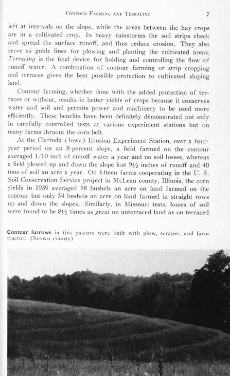
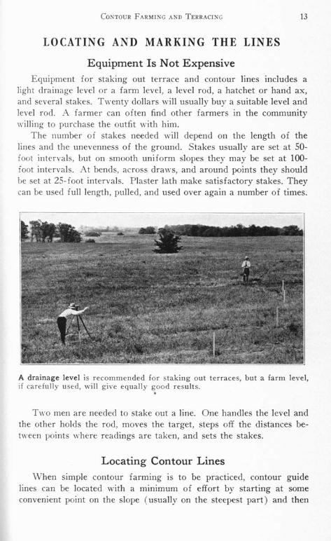
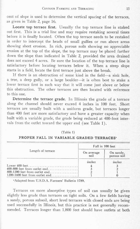
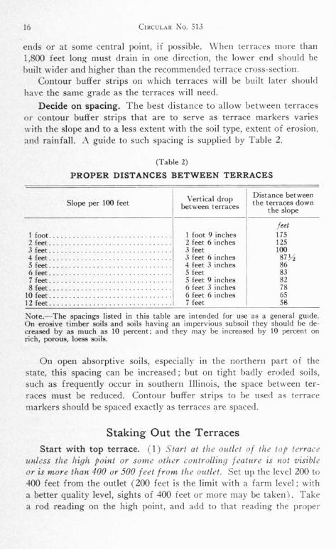
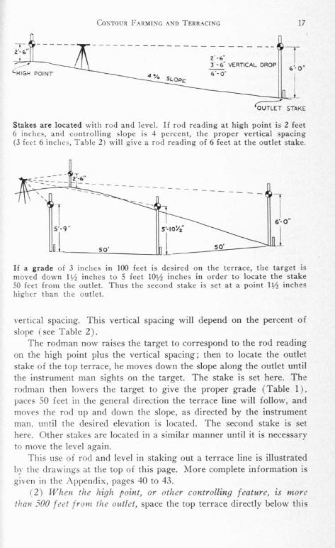
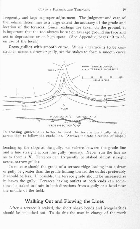
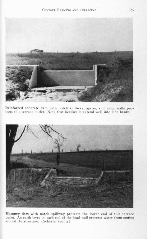
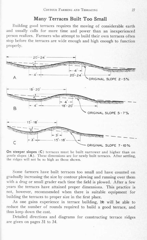
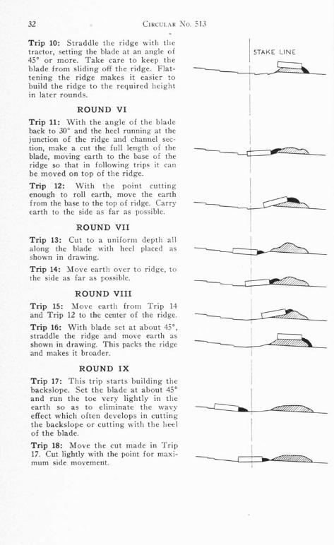
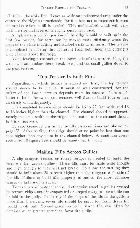
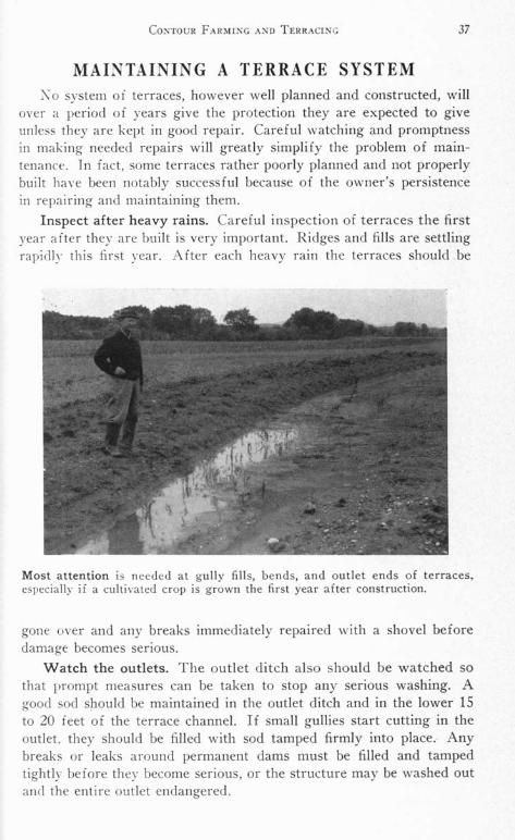
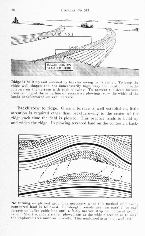
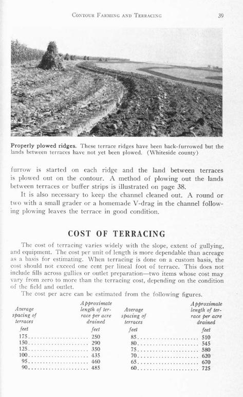