Crest voltmeters - IDEALS @ Illinois
146
Crest Voltm^U
-
Upload
khangminh22 -
Category
Documents
-
view
9 -
download
0
Transcript of Crest voltmeters - IDEALS @ Illinois

Crest Voltm^U


CREST VOLTMETERS
BY
EDGAR DWIGHT DOYLE
B. S. University of Illinois, 1910.
THESIS
Submitted in Partial Fulfillment of the Requirements for the
Degree of
ELECTRICAL ENGINEER
IN
THE GRADUATE SCHOOL
OF THE
UNIVERSITY OF ILLINOIS
1916.

)
V

UNIVERSITY OF ILLINOIS
THE GRADUATE SCHOOL
Apr il 1 „ i9i 6
I HEREBY RECOMMEND THAT THE THESIS PREPARED BY
EDGAR DWIGHT DOYLE
ENTITLED "CREST VOLTMETERS
"
BE ACCEPTED AS FULFILLING THIS PART ON THE REQUIREMENTS FOR THE
PROFESSIONAL DEGREE OF - ELECTRICAL ENGINEER.
Head of Department of Railway .Eng ineering
Recommendation concurred in
* Committee

Ui'JC

1
CREST VOLTMETERS
CONTENTS
PART 1
PageI. INTRODUCTION 4
1. Purpose of Thesis 42. Acknowledgements 4
II. HIGH VOLTAGE TESTS . 5
3. General 54. Types of High Voltage Tests 55. Production of High Voltages 56. Characteristics of High Voltage Waves 97. Measurement of High Voltages 158. Need of Good Crest Voltmeters 16
III .DEVELOPMENT OP CREST VOLTMETERS 16A. Wave Tracers 16
9. General 1610. Mershon's Potentiometer Method 1711. Duncan's Dynamometer Method 1712. Joubert's Condenser Method ......1813. Oscillographs 18
B. Crest Voltmeters 2114. General 2115. Sharp-Farmer Crest Voltmeter ....2116. Chubb -Fortes cue Crest Voltmeter 2317. General Electric Wavemeter as Crest Voltmeter . .2413. Whitehead-Gorton Modification of Chubb-
Fortescue Method 2519. Westinghouse Crest Voltmeter 2720. Simplex "Peak Reading Voltmeter" 28
IV. SOME NEW TYPES OF CREST VOLTMETERS 29A. General 29B. "Type A" Crest Voltmeter 29
21. General Theory and Method 2922. Description 3123. Checks of Device and Application to Testing ... .3324. Check against Oscillograph 3325. Check against Wavemeter 3426. Check at High Frequencies 3827. Application of Crest Voltmeter to Test Problems3828. Investigation of Crest Factor in a High Volt-
age Testing Equipment 3929. Check of Sphere Gap on a Distorted Wave 3930. Measurement of Maximum Voltage in Ignition
Magentos 41C. "Type B" Crest Voltmeter 42
31. General Theory and Method 42


2
CONTENTS
.
Page32. Description 42
33. Testa of "Type B" against "Type A" Voltmeter.... 4234. Effect of Condenser Capacitance on Indications.. 44
D. Conclusion 4735. Characteristics to be Desired in a Crest
Voltmeter 4736. Comparison of Types "A" and "B" 4837. Possible Further Applications of Crest Voltmeters4938. Summary 49
PART II.
Appendix 1. Directions for Setting Un and Using the "Type A"Crest Voltmeter 50
Appendix 2. Kenotron Characteristics and Their Effect on theOperation of the Crest Voltmeter 52
Appendix 3. Poss-ibility of Using Other Valves 59Appendix 4. High Voltage Multipliers 60
Bibliography 68


3
CONTENTS.
LIST OF TABLES. Page
1. Check of "Type A" Crest Voltmeter against Oscillograph... 342. Check of "Type A" Crest Voltmeter against Wavemeter 353. Variation of High Voltage Crest Factor with Load 394. Check of 25 Cm. Sphere Gap on a Distorted Wave 415. Check of "Type B° against "Type A" Voltmeter 446. Effect of Condenser Capacitance on Indication of
"Type B" Crest Voltmeter 467. Variation of Capacitance of Air Condenser with Spacing... 658. Variation of Spark-over Voltage of Condenser with Spacing 65
LIST OF FIGURES.
1. Methods for Regulating Voltage cf Testing Transformers.... 7
2. Arrangements for Obtaining "Impulse Tests" 8
3. Some Generator Wave Forms 104. Variation of Generator Wave Shape with Load 125. Wave Form Distortion from Control Methods. 136. Characteristic Wave Forms from"Impulse Tests" 147. Connection Diagrams for Wave Tracers.. 198. Crest Voltmeter Connection Diagrams 229. One Source of Error in the Whitehead-Gorton Crest
Voltmeter 2610. Mode of Operation. "Type A"Crest Voltmeter 3011. "Type A" Crest Voltmeter Connections 3212. Connections during Check of "Type A" Crest Voltmeter 3613. Waves Checked. Investigation of "Type A" Crest Voltmeter . .3714. Calibration Curve. G.E. Wavemeter as Crest Voltmeter .... .40
15. Effect of Load on Crest Factor .....4016. "Tyue B" Crest Voltmeter Connections 4317. Check of "Type B" Crest Voltmeter against "Type A" Meter. .4518. Volt-ampere Characteristics of a Kenotron 5419. Effect of Leakage on Operation of "Type A" Crest Voltmeter5620. High Voltage Multipliers 61
o o


CREST VOLTKKTERS
PART I
I. INTRODUCTION ,
1. Purpose of Thesis .
The use of high voltage for power transmission is
becoming more and more general. Not only are larger amounts
of energy being transmitted but the distances traversed are
greater. This is rendered feasible only through the employ-
ment of higher operating voltages. High operating voltages
require particularly good insulation in both the transformers
connected to the line and in the line itself.
The purpose of this thesis is to study the various
methods of testing the insulation of apparatus and materials
particularly with respect to the methods of measuring high
voltage. A new instrument for use in high voltage tests is
described and its operation is analyzed.
2. Acknowledgements .
The greater part of the work described in this
thesis, particularly the development of the crest voltmeter,
was done at the Electrical Testing Laboratories, New York
City. Acknowledgement is hereby made for the use of the
material so obtained. Thanks is due to Dr. C. H. Sharp of
the Laboratories to whom credit should be given for the fun-
damental idea and to Dr. I. Langmuir of the General Electric
Research Laboratory, Schenectady, who furnished the hot
cathode rectifier used in the tests described.


II MIUH VOLTAGE TESTS
3. General.
The qualities to be possessed by an insulator for high volt-
age service are many and diversified. It should have considerable
mechanical strength. It should have high insulation resistance. It
should have high dielectric strength. The mechanical strength may
be determined by the regular mechanical tests. The insulation re-
sistance may be determined with a battery of dry cells and a sensi-
tive galvanometer. The dielectric strength can only be determined
by subjecting the insulation to a voltage at least as high, if not
higher, than that which it will be subjected to in service.
4. Types of High Voltage Tests.
High voltage tests may be divided into two classes, "press-
ure" tests and "puncture" tests. The first are of a routine char-
acter and are made on completed apparatus for the purpose of ascer-
taining whether or not the material and workmanship entering into
the apparatus is first class , it having been previously determined
that the type of material would be suitable for the service. "Punc-
ture" tests, on the other hand, are made on samples of insulation
for the purpose of learning its ultimate dielectric strength. As
the tests are necessarily destructive, they are generally made on
comparatively small samples of the materials, for example a puncture
test un high voltage cable is made on a sample not more than ten >
feet long.
5. Production of High Voltages.
High voltage for test purposes may be produced in a number

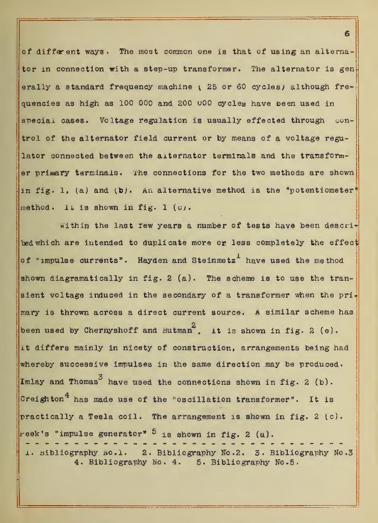
of different ways. The most common one is that of using an alterna-
tor in connection with a step-up transformer. The alternator is gen
erally a standard frequency machine { 25 or 60 cycles; although fre-
quencies as high as 100 000 and 200 U00 cyclea have been used in
special cases. Voltage regulation is usually effected through con-
trol of the alternator field current or by means of a voltage regu-
lator connected between the alternator terminals and the transform-
er primary terminals. The connections for the two methods are shown
in fig. 1» (a) and (to). An alternative method is the "potentiometer*
method. It is shown in fig. 1 (cw.
within the last rew years a number of tests have been descri-
bed which are intended to duplicate more or less completely the effed;
of "impulse currents". Hayden and Steinmetz"1" have used the method
shown diagramatically in fig. 2 (a). The scheme is to use the tran-
sient voltage induced in the secondary of a transformer when the pri =
mary is thrown across a direct current source, a similar scheme has
2been used by Chernyshoff and Butman . it is shown in fig. 2 (e).
it differs mainly in nicety of construction, arrangements being had
whereby successive impulses in the same direction may be produced.
3Imlay and Thomas have used the connections shown in fig. 2 (b).
4Creighton has made use of the "oscillation transformer " . It is
practically a Tesla coil. The arrangement is shown in fig. 2 (c).
week's "impulse generator" 5 is shown in fig. 2 (a).
i. bibliography wo.l. 2. Bibliography No. 2. 3. Bibliography No .3
4. Bibliography No. 4. 5. Bibliography No. 5.


fa) Fie/V Control.


(aj Haydsn £ S+e/n t*> . (b) Im/ayQ Thorn
(ej ChernyshoJ-fQ, Bowman
//1PUL5ETE5TS.

X
AAAA—
1
«53l iV
"""""'Ik

I
3
In addition to the methods indicated above there are sever-
al others which have been used from time to time. The induction
coil has been used in certain instances. High voltage direct current
has been suggested for such cases as underground cable systems where
the capacitance is high. For a discussion of the various methods
available for the production of high voltage direct current see
"Methods of Obtaining High-potential Direct Current" by S. Thomson1 .
6. Characteristics of High Voltage Waves.
The assumption is generally made that the wave form of nor-
mal freouency testing equipments is sinusoidal, both at the terminals
of the alternator and the high tension winding of the step-up trans-
former. As a general rule there is no reason for making such an
assumption for there are a number of factors which cause the wave to
depart from a sine curve. Sine waves at no load are only obtained
where considerable care is exercised in the design of the alternator.
Pig. 3 shows the wave form of a number of alternators and distribution
systems which have come to the attention of the writer. Pig. 3 (a),
(b) and (c) show the wave forms of three generators used by as many
wire and cable manufacturers for testing their product. Pig. 3 (d)
Bhows that of the life test alternator at the Electrical Testing Lab-
oratories. Although this machine is used primarily for tests of in-i
jcandescent lamps, it is also used for such high voltage tests as are
made at the Laboratories. Fig. 3 (e) and (f) are the 25 and 60 cycle
j
system wave forms of one of the large central stations in New York.
Even in cases where the alternator gives a good wave at no
1. Bibliography No. 23.


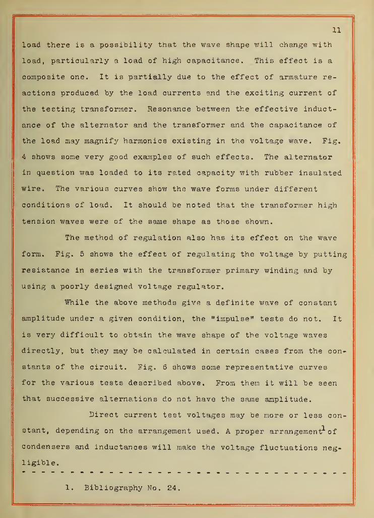
11
load there is a possibility that the wave shape will change with
load, particularly a load of high capacitance. This effect is a
composite one. It is partially due to the effect of armature re-
actions produced "by the load currents and the exciting current of
the testing transformer. Resonance between the effective induct-
ance of the alternator and the transformer and the capacitance of
the load may magnify harmonics existing in the voltage wave. Fig.
4 shows some very good examples of such effects. The alternator
in question was loaded to its rated capacity with rubber insulated
wire. The various curves show the wave forms under different
conditions of load. It should be noted that the transformer high
tension waves were of the same shape as those shown.
The method, of regulation also has its effect on the wave
form. Fig. 5 shov/s the effect of regulating the voltage by putting
resistance in series with the transformer primary winding and by
using a poorly designed voltage regulator.
While the above methods give a definite wave of constant
amplitude under a given condition, the "impulse" tests do not. It
is very difficult to obtain the wave shape of the voltage waves
directly, but they may be calculated in certain cases from the con-
stants of the circuit. Fig. 6 shows some representative curves
for the various tests described above. From them it v/ill be seen
that successive alternations do not have the same amplitude.
Direct current test voltages may be more or less con-
stant, depending on the arrangement used. A proper arrangement'" of
condensers and inductances will make the voltage fluctuations neg-
ligible.
1. Bibliography No. 24.


/3
fffl 1111 Iriffl-i-i HI 11-
1 |-H-l4-|-i4^ffiTl+rff ffirrl 1 1 1 1 1 H 1 1 H+l-H 1 1 11
1 1 U Ml I H H I U 1 1 intl 1 1 1 1 1 14444£4ll4fH MfflfflH-M+H


Arc Effect Nej/,'jMe.
14-.
Arc Effect Pn?<fo>n
/'nop +.
Calculate Oscillation Transforme /? Waves.
(Proc. Aj££.
Calcu lated Impulse Gen
e
f?Ai~of( Wave6.
Fig. 6,

f 1
Jyf~\ \ !

15
7. Measurement of High Voltages.1
Two general methods are available for the measurement of
high voltages , (a) the indicating instrument and (b) the spark gap.
The indicating instrument method may take a number of forms. It may
be a voltmeter connected to some form of ratio device, such as a vol'
tage transformer, a voltmeter coil in the high tension winding or
taps in the same winding. It may be connected to the primary termi-
nals of the transformer or it may even be used directly on the high
tension voltage through a series resistance. High range electrostat-
ic voltmeters are also available in ranges as high as 200 000 volts.
Spark gaps may be used up to the highest attainable volt-
ages. They have been calibrated directly to voltages of the order
of 250 000 volts and calibration curves have been calculated for
voltages as high as 1 000 000 volts.
In standard frequency tests any of the above methods may be
used. The indicating instrument method is the most convenient one,
for one has an indication of the voltage at all times. However the
indications of the voltmeter are proportional to the virtual value of
the voltage while the break down of insulation depends on the maxi-
mum value of the voltage. The spark gap is the only method which
operates on the maximum value of the wave, but although it is capable
of giving accurate indications, it is very inconvenient to use for
it gives no indication of the value of the voltage before it arcs
over. Its use has been very aptly compared with the use of fuses for
the measurement of currents. Extreme care must be exercised in usin^;
the spark gap in testing a^aratus of high capacitance. Destructive
1. Bibliography No. 6.


16
oscillations are very likely to be set up when arc over occurs.
The spark gap is the only available method for measuring
impulse" voltages . Even here it is not entirely satisfactory for the
question of the comparative dielectric spark lags of the gap and the
material being tested enters.
Practically no difficulties occur in measuring high direct
current voltages. Electrostatic voltmeters give entire satisfaction
and it is possible to use D'Arsonval type instruments with series
multipliers where enough power is available.
8. Need of Good Crest Voltmeters.
prom the above it will be seen that while stresses in insu-
lating materials are proportional to the maximum value of the voltage
those instruments which are the most convenient to use all give indi-
cations Proportional to the virtual value. Allowance could be made
for this if the wave were sinusoidal or if it remained constant for
a particular equipment. Unfortunately such is not the case. A field
therefore exists for an instrument which will either indicate the
maximum or crest value of the voltage or which will give the crest
factor (i.e. the ratio of the crest value to the virtual value).
Ill DEVELOPMENT OF CREST VOLTMETERS.
A, Wave Tracers .
9. General.
Wave tracers may be considered as the fore runners of the
crest voltmeter. Not only will they all give readings proportional
to the crest value of the wave, but a number of them have been used


17
as crest voltmeters. A study of the various types is interesting in
view of the later developments.
Wave tracers are of two types, the contactor type and the
vibrator type. The former includes the devices of Joubert, Mershon
and Duncan. The latter includes the oscillographs of Blondel, Dudd-
ell and Irwin.
110. Mershon's Potentiometer Method
.
Mershon's method is shown diagramati cally in fig. 7 (a). It
consisted primarily of a contactor on the shaft of the alternator
which makes contact momentarily. The voltage to be investigated was
opposed to a direct current voltage through this contactor and a
telephone receiver. The direct current voltage was varied until no
sound could be heard in the receiver. The indication of the d.c.
voltmeter was a measure of the a.c voltage at the instant of contact
By shifting the contactor around the shaft the entire wave shape
could be obtained.
2Rosa's wave tracer is an elaboration of the fundamental
idea. The principal difference is the addition of a recording pencil,
which indicates the position of the sliding point of the potentiomet-
er
.
311. Duncan's Dynamometer Method.
Duncan devised a method which enabled a number of waves to
be investigated at the same time with a single contactor. The con-
tactor was in series with the fixed coils of a number of dynamometers
which were connected to a d.c. source. The moving coils of the met-
1. Bibliography No. 9. 2. Bibliography No. 11. 3.Bibliography No. 10


18
ers are connected to the various voltages to be investigated, (See
fig. 7 (b) for connections). The toroue of each meter is equal to
the product of the direct current and the alternating current at th
instant contact is made. During the rest of the cycle the torque is
zero. The meters are calibrated by passing direct current through
the moving coils while the contactor is still operating. The com-
plete curve is taken by shifting the phase of the time of contact.
12. Joubert' s Condenser Method.1
Joubert's method is shown in fig. 7 (c). He used the same
type of contact as Mershon and Duncan, but the voltage is run to
a condenser. The contactor connected the condenser to the circuit
for an instant and at the instant of breaking the circuit, the con~
denser was left with a charge proportional to the voltage at that
instant. The voltage of the condenser was determined by discharging
it through a galvanometer (as in the case of the General Electric
2wavemeter ) or by an electrometer connected across its terminals
( as used by Ryan )
.
13. Oscillographs.
The essential idea of all oscillographs is to cause a small
mirror to follow the variations in a current, no matter how rapidly
they may occur. This has been produced by different inventors in
4various ways. Blondel mounted the mirror on a soft iron strip
placed between the poles of a Powerful electromagnet. The current
to be investigated passed through small coils close to the pole
pieces of the magnet. The interaction of the two fields
1. Bibliography No. 72. Bibliography No. 11
3. Bibliography No. 8
4. Bibliography No. 12

1 «
•


20
caused the iron strip to twist, thereby deflecting a beam of light
which had been thrown on the mirror.
1Duddell mounted the mirror on two conducting filaments
inlaced between the poles of a similar electro -magnet . Current was
sent throu^i the two strips in series. The interaction of the cur-
rent and the magnetic field deflected the strips in opposite direc-
; tions thereby turning the mirror.
2Irwin has produced a similar effect by thermal means. He
has two strips carrying direct current. The alternating current
is sent through the same strips, but in such a manner as to increas
the direct current in one strip while it diminishes it in the other
As a consequence one strip is heated by the alternating current
while the other is cooled by virtue of the same current. One strip
is lengthened while the other is shortened. These movements are
conveyed to the mirror by suitable means and the general effect is
the same as the electro-magnetic oscillograph.
In every case there are two methods of recording the move-
ment of the mirror. One is photographic, the plate or film being
moved across the path of the beam of light. The other is visual
and is the one which is the most convenient for crest voltmeter
work. The beam of light is thrown on a translucent screen and the
width of the band of light may be noted or it may be resolved into
a curve by the equivalent of a rotating mirror.
1. Bibliography No. 13. 2. Bibliography No. 14.

21
B. Crest Voltmeters.
14. General.
The following is a discussion of all of the types of crest
voltmeters which have been described in the technical press. Each is
described and its Principal advantages and dis -advantages enumerated,
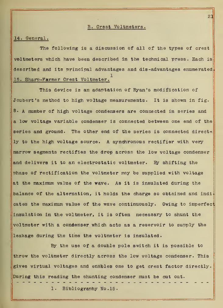
115. Sham-Farmer Crest Voltmeter.
This device is an adaptation of Ryan's modification of
Joubert's method to high voltage measurements. It is shown in fig.
. 8. a number of high voltage condensers are connected in series and
a low voltage variable condenser is connected between one end of the
series and ground. The other end of the series is connected direct-
ly to the high voltage source. A synchronous rectifier with very
narrow segments rectifies the drop across the low voltage condenser
and delivers it to an electrostatic voltmeter. By shifting the
phase of rectification the voltmeter may be supplied with voltage
at the maximum value of the wave. As it is insulated during the
balance of the alternation, it holds the charge so obtained and indi-
cates the maximum value of the wave continuously. Owing to imperfec;
insulation in the voltmeter, it is often necessary to shunt the
voltmeter with a condenser which acts a3 a reservoir to supply the
leakage during the time the voltmeter is insulated.
By the use of a double pole switch it is possible to
\ throw the voltmeter directly across the low voltage condenser. This
gives virtual voltages and enables one to get crest factor directly.
During this reading the shunting condenser must be cut out.
1. Bibliography No. 15.


22
X1
A.(c) White head- Gorton-
Fi 0. 8.

I H H hi H H h H h H rI H H H H i
•
S 1
•
kj

23
The principal advantages of the Sharp -Farmer device are (1)
it may be calibrated on either alternating or direct current, (2) it
gives crest factor as well as crest voltage , (3) it may be used on
a condenser multiplier, a voltmeter coil or a voltage transformer,
(4) it has no frequency error and (5) it indicates the crest voltage
at the instant of reading.
It suffers from the following disadvantages, (1) it require;
a synchronous motor and takes considerable power from either the al-
ternating or direct current circuit, (2) it is limited to comparativ
ely low fundamental frequencies, (3) it must be shifted to obtain th:
crest reading, (4) the contact device is liable to give trouble and
(5) the electrostatic voltmeter is rather sluggish.1
16. Chubb-Fortescue Crest Voltmeter.
Chubb and Fortescue have described a form of crest voltmet-
er which is entirely different from any of the wave tracers which
have been described. They have made use of the fact that the aver-
age value of the charging current of a condenser is proportional to
the maximum value of the voltage impressed on the condenser. The
reasoning is as follows.
If the frequency of the circuit is "f", the time to pass
from a- positive to a negative maximum will be
T « A- .
2f
During this time the condenser current will have increased from zero
to a maximum and decreased to zero again. Its average value equals
the total charge divided by jthe time, JL«e._
1. Bibliography No. 16.

. 1

24
i « 2VC = 4fVCav . ^
2f
or V =
4fC
The average value of the current is read on an instrument of the
D'Areonval type. In order to eliminate the reversed currents of
alternate half cycles, the reversed currents are short circuited by
a synchronous contactor, (see fig. 8 ). The readings must therefore
be multiplied by 2 and the final formula is
iav
.
2fC
By using a suitable condenser the method may be made an absolute one
The advantages of the method are (1) connection is made
directly to the high voltage source, (2) the indications of the
instrument are steady and (3) absolute values may be obtained.
The disadvantages are (1) calibration can only be effected
by calculation, (2) a synchronous motor is required, (3) there is
a considerable chance for trouble from stray electrostatic fields,
(4) the indications vary directly with the frequency and (5) virtual
values must be obtained from a separate instrument.
117. G.E. Waveraeter as a Crest Voltmeter.
"While no one has described the use of the General Electric
wavemeter as a crest voltmeter, it has been used by the writer in
such a capacity to very good advantage. The results of these tests
will be found later in this thesis. Its advantages are (l) the in-


25
di eating instrument is well damped, (2) there is practically no fre-
quency error and (3) it may be calibrated directly on direct current
Its disadvantages are (1) it requires a synchronous motor,
which requires considerable energy and (2) it must be adjusted to
locate the crest value of the wave.1
18. Whi tehead-Gorton Modification of Chubb -Fortes cue Method.
Whitehead and Gorton in their investigation of corona have
made use of the modification of the Chubb-Fortescue method shown in
fig. 8 (c). The synchronous contactor of the original scheme has
been replaced by a pair of mercury arc rectifiers. During one half
cycle the charging current of the condenser is allowed to pass thru
the ammeter while the following half cycle of current is shunted
around the ammeter by the second rectifier.
The advantage of this method over the original one is that
the device requires no adjustment to locate the maximum value of the
wave. In addition it may be used on practically any frequency. The
ammeter may be very nearly dead-beat and will follow any ordinary
fluctuations of voltage.
The disadvantages of the original method remain with the
exception of those pertaining to the motor and contactor. In many
cases the necessity of having two independent direct current sources
will prevent its use. Another disadvantage of such an arrangement
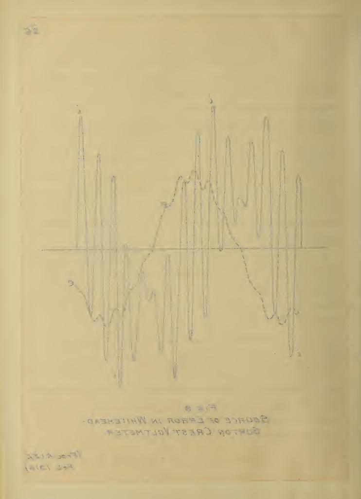
2has been pointed out by Chubb . The arrangement will not give a
correct indication on a voltage wave having more than one maximum
per cycle. Fig. 9( copied from Chubb's paper )shows the voltage and
1. Bibliography No . 17 . 2. Bibliography No. 19.


ZG
Fig. eSource or Error in WhiteheadGorton Crest Voltmeter
(Froc.Aj.E%E.
•* rj
»
current through a condenser on such a wave. It will be noted that
the current passes through zero whenever the voltage has a maximum
or a minimum value. This produces a number of negative loops in the
current wave. These negative loops can not pass through the ammeter
as they are by -passed by the second rectifier. On the other hand
the corresponding positive loops in the next half cycle will pass
through the ammeter. The accuracy of the method depends on the
equation given on page 24, i.e. the crest voltage is proportional to
the algebraic average of the current. Consequently the indication
of the meter will be in error by an amount equal to twice the area
of the negative loo^s in the first half cycle. In certain instances
errors as high as 46 percent have been observed.
219. Westinghouse Crest Voltmeter.
Chubb has taken the previous method and made a very practi-
cal outfit out of it. It is now being supplied by the Westinghouse
Company as a crest voltmeter with high voltage testing equipments.
The mercury arc rectifiers have been replaced with two hot cathode
rectifiers. They are small bulbs filled with mercury vapor and con-
taining a filament and a grid. They resemble the DePorest audi on.
The filaments are heated by currents from two small transformers.
The condenser bushing of the testing transformer serves as the con-
denser whose charging current is to be measured.
This device has the same advantages and disadvantages as
the Whitehead -Gorton arrangement, with the exception of the excita-
• tion of the rectifiers. The latter method is vastly superior to the
1. Bibliography No . 22 . 2. Bibliography No. 19.

28
original one. The use of the condenser bushing has some slight dis-
advantages. Its capacitance changes with voltage and the outfit
mist be calibrated as a unit. It is also probable that there would
be a change of capacitance with frequency. The question of checking
the meter under working conditions is not without its difficulties.
The only available method is the sphere gap. While it is accurate if
corrections be made for air density, it can not be used when testing
loads of high capacitance, for reasons enumerated above, (see p. 15)
On the other hand it is under just such conditions that voltage with
double r>eaks are most likely to be encountered. The device fails
under those conditions where it is most needed.
20 . Simplex "Peak Reading Voltmeter".
The use of the oscillograph as an indicating instrument for
observing maximum values was first suggested by Robinson and Ball.
Lloyd later suggested its use for measuring crest values of voltage1
waves. Middleton and Dawes have perfected such an instrument based
on the oscillograph principle and have used it to a considerable
extent in the testing of wire and cables. The meter is essentially
an oscillograph element arranged for switch board mounting. Switches
are provided for calibrating the meter and for connecting it to a
voltage transformer. The maximum value of the voltage is determined
from the width of a band of light on a translucent screen.
The advantages of this type of meter are (1) it is easily
calibrated and (2) it is dead-beat. Its disadvantages are (1) it is
1. Bibliography No. 18


29
necessary to have a reasonably constant d.c. voltage for excitation
and calibration, (?) the ineter gives only crest values - if virtual
values are desired they must be obtained with another meter., (3)
it is difficult to read peaks such as that shown in fig. 4 (a) and
(4) it must be used on a voltage transformer.
IV. SOME NEW TYPES OF CREST VOLTMETERS*
A. General.
The following types of crest voltmeter are based on what th
:
writer believes is an entirely different principle than that of any
other crest voltmeter. A condenser is put in series with an electri :
valve and is connected across the voltage to be investigated. The
voltage charges the condenser to the maximum voltage of the wave and
the valve prevents the condenser from losing its charge. The volt-
age of the condenser is measured by one of several methods. The dis-
tinction between the two types is entirely one of voltage measure-
ment .
B» "Type A" Crest Voltmeter.
21. General Theory and Method.
The meter consists primarily of a hot cathode rectifier and
an electrostatic voltmeter. The two are connected in series on the
I
voltage. The mode of operation is most easily understood from a
study of fig. 10. In this figure w e w and "i" are the voltage across •
and the current through a condenser on a distorted voltage wave. If
a perfect electric valve be Placed in series with the condenser, it
.will allow current to pass without any voltage drop as long as the
1. Bibliography No. 20.


30

\

31
current is in one direction. If the current tries to reverse, the
valve interposes an infinite resistance in the circuit and the cur-
rent ceases (see "A n fig. 10). However this reversal of current
through the condenser can only occur when the voltage across the
condenser is not changing, i.e. when — =» or in other words when
dt
the voltage wave has a maximum or a minimum value . Since the cur-
rent is trying to change from a positive to a negative value, it
must be a maximum point in the voltage wave. If the valve has in-
finite resistance ( as will be the case with a perfect valve) and
the condenser has perfect insulation, the condenser will remain
charged to this voltage indefinitely if a higher voltage is not
impressed on the circuit. If there be a higher maximum in the volt-
age wave (as shown at C) the current will remain at zero until the
voltage B' is reached (B f = A*) when the current will suddenly in-
crease from B to B w following the curve B"DC until the maximum point
C of the voltage wave is reached. This voltage will be held on the
condenser for no voltage smaller than C can send current through
the valve.
22. Description.
Pig. 11 (a) shows the arrangement usually employed. "K" is
a hot cathode rectifier of the kenotron type1
, manufactured by the
General Electric Company. It was rated at 10 000 volts 5 milliam-
i
peres by Dr. Langmuir of the G.E. Research Laboratory. It consists
of a tungsten filament cathode and a tungsten plate anode in a high-
ly evacuated bulb. The filament is heated to incandescence by a cur--
1. Bibliography No. 21.

32Concfenjcir
rWuiH R
AAA/VT
V
WwwA C Vol-hage.
(0) A£,£xci-ha+/on.
Con denser.
R
B
(b) D.C Exci+a+ion
V
A C Vol+Qie.

••vW^-M.
'EF"V\^"\
iS. K % V\ .fcWOVT Vv o
^

33
rent of approximately 3.5 amperes.
WV" is an electrostatic voltmeter of the Ayrton and Mather
type manufactured by Root. W. Paul. It is a double pivoted instru-
ment and has a range of 60 to 250 volts. The scale is remarkably
uniform for a meter of this type.
The connections are indicated in the figure. The voltmeter
is in series with the kenotron across the voltage. The filament is
heated with current from the transformer "T w which should be connect
ed to the same source as the high voltage transformer whenever poss-
ible. As shown the voltmeter indicates crest voltage. Closing the
switch W S M short circuits the kenotron allowing the voltmeter to in-
dicate virtual volts.
The condenser "C" is put in multiple with the voltmeter for
practical reasons which have been mentioned on page 21. It is a sub-
divided mica condenser having a range of 0.001 to 1.000 microfarads.
25. Checks of Device and Application to Testing.
The "Type A" crest voltmeter has been tested and used under
a number of different conditions. The following is a summary of the
more important work. Unless stated to the contrary, the work was
done at the Electrical Testing Laboratories.
24. Checks Against Oscillograph.
This work was done at the plant of one of the prominent man-
ufacturers of wire and cable near New York City. The original pur-
pose of the tests was to determine the shape of the high voltage test
ing transformer wave under all of the conditions ordinarily encoun-
tered. The transformer was rated at 50 kva. 1100 to 12 500 . 25 000


or 50 000 volts. It was connected directly to an engine-driven alter
nator of 55 kva. capacity. During the test the transformer second-
ary was connected for 12 500 volts and was loaded with a number of
thousand foot coils of No. 8 AWG. copper wire with 5/32 inch rubber
insulation. Primary and secondary voltage wave shapes were obtained
from voltage transformers connected across the two windings. The
crest voltmeter was connected to the secondary of the voltage trans-
former across the high tension winding. Table 1 shows the compara-
tive crest factors obtained by the two methods.
TABLE 1.
Check of "Type A" Crest Voltmeter vs. Oscillograph.
Percent Crest Factor
Wave Crest Voltmeter OscillographFig. 4 -a T35 T5Z
4-b 145 1494-c 155 155
B 4-d 163 159• 4-e 169 175" 4-f 139 132
Average 153 154
It is to be noted that the above tests were made with a Kelvin multi-
cellular voltmeter which showed considerable friction around the
zero position. The above tests are not as reliable as some describee,
later
.
25. Check Against Wavemeter.
The following tests were made on a special generator from
which various distorted waves could be obtained. It consists of
three sine wave generators in the same frame. The first has a frequer.
cy of 60 cycles; the second, 180 cycles and the third, 300 cycles.
The voltages could be varied independently while the phases of the
second and third machines could be adjusted by shifting the armatures


35
in their cradles. Inasmuch as the generator voltage was 120, the
voltmeter v'as connected directly to the generator terminals. The
indication of the crest voltmeter was checked by two independent
methods, (l) using a G. E. wavemeter as a wave tracer and (2) cali-
brating the wavemeter as a crest voltmeter and reading virtual volts
on another meter of the dynamometer type. The set-up employed is
shown in fig. 12. The Procedure was as follows: A wave of the desir-
ed shape was produced by adjusting the voltages and phases of the
generators. Crest and virtual voltages were obtained with the "Type
A" device. The wave was then traced with the wavemeter. At the max-
imum point of the wave the wavemeter voltmeter was read simultaneous-
ly with a dynamometer voltmeter. From the readings so obtained three:
separate calculations could be made of the crest factor.
Fig. 13 shows the three waves investigated. The crest fac-
tors are shown in table 2.
TABLE 2.
Check of"Type A w Cre3t Voltmeter vs. Wavemeter .
Percent Crest Factor.Wave Crest Wavemeter as
Voltmeter Tra cer _ Voltmeter
Fig. 13-a 121.8 121.8 121.3
13 -b 143.5 143.1 143.5w 13-c 209.0 204.0 202.0
From the above it will be seen that there is a very satisfactory
agreement between the various methods. As will be shown later it is •
impossible for this type of meter to give an indication higher than
ithe true value if it is connected correctly. The variations in the
>jcase of wave 13-c may be attributed to errors in reading the several


Ft*. /£.
Check or Tyre A "Gf?E5T V.M-

\ \
A A AAA
4 -»#
s y 'la v \ V > ' ,J

J7
Wave

lB>, *BV fc>N 1SVVV
\
\
\
/

38
instruments
.
As a matter of interest the calibration of the G.E.Waveme ter
as a crest voltmeter at different frequencies has been included as
fig. 14. The calibration was made by running the synchronous motor
on sources of different frequencies, direct current being impressed
on the terminals where alternating current was ordinarily used.
Simultaneous readings were taken of the voltmeter used with the wave-
meter and that across the direct current source. During this test
the capacitance of the condensers employed was approximately 6 mf
.
while the resistance of the voltmeter was about 15 000 ohms.
26. Checks at High Frequencies.
Dushman has stated that the kenotron operated just as satis-
factorily at 100 000 cycles as it does at the lower commercial fre-
quencies. While no opportunity was obtained to make checks at such
frequencies, a few tests were made at frequencies as high as 4 000
cycles. The crest voltmeter was connected to a Vreeland Oscillator
and crest and virtual voltage readings taken. The ^re eland Oscilla-
tor is a generator of pure sine waves. The ratios of the two sets
of readings should therefore have been 1.41. Values as high as 1.6
were observed. This is accounted for by the fact that it is practi-
cally impossible to get the oscillator to give a steady voltage. Even
with the voltmeter connected for a virtual reading one could see
sudden "kicks" . The readings indicate that these kicks were consid-
erably larger than would be suspected and that the kenotron was
sensitive to each one.
t 27. Application of Crest Voltmeter to Test Problems.
The "Type A" crest voltmeter has been applied to the solut-


39
ion of test problems with considerable success. They are included
both to show the utility of the device and to suggest other uses to
those who may be interested in such a device.
28. Investigation of Crest Eactor in a High Vol tage Testing Outfit.
At the same time that the checks reported on page 33 were
made, a complete set of readings of the crest factor were taken un-
der all conditions of load. The results are given below.
TABLE 3.
Variation of High Tension Crest Factor with Load.
Current, Amperes PercentCondition Primary Secondary Crest Factor
Alternator only 149" and transf'r 3.20 145
One coil of wire 2.45 .28 145Two coils it n 4*70 0.57 155Three " 8.0 0.94 163Four " n h 16*4 1.61 169
Five " It If 16.0 1.70 143Six * ft it 17.5 1.85 133Seven " ft « 20.5 2.10 132Eight " «! w 23.4 2.37 134Nine " tf tt 26.3 2.63 135Ten " » » 29.8 2.94 134Eleven" n w 34.0 3.30 139(?)Twelve" n » 3.61 131
Each coil consisted of 1000 feet of No . 8 AWG . copperwith a 5/32 inch wall of rubber insulation. All tests were
made at 12 500 vol ta (high tension)
The above tests show the variation which may exist in a
high voltage test without its being suspected. A study of the amps,
per thousand feet of wire would have shown that some trouble existed
but the only definite information is that obtained from the crest
factors. The results are shown graphically in fig. 15.
29. Check of Sphere Gap on Distorted Voltage Wave.
The following test was made for the purpose of showing the


CRE5T Facto%
NuM0£/r or Coil 3 or Ware.
F/& is.
Va /f ia T" / c? /v of Wave D/^tort/onW ITH LOAP.


41
application of the crest voltmeter to high voltage testing. Distort
ed waves were produced by onerating a 60 cycle, 110 to 246 400 volt
testing transformer from a 220 volt 25 cycle circuit through a small
variable ratio auto transformer having considerable magnetic leakage
A sample wave from this combination is shown in fig. 5 (c). A 25
centimeter sphere gap was connected to the secondary of the transfor
mer?the crest voltmeter and an ordinary iron vane voltmeter being
connected to the primary taps. The results of the test are given
below.
TABLE 4.
Check of 25 Cm. Sphere Gap on a Distorted Wave.
Sphere L.T. Volts by H.T. Kilovolts (Max) by
Gap R.M.S. Crest Sphere CrestInches VM. VM. Gap VM.
4.6 65 122 272 2735.2 70 132 298 2966.0 75 145 330 325
30. Measurement of Maximum Voltage of Ignition Magnetos.
The crest voltmeter has been used to determine the maximum
voltage induced in the primary winding of a high tension ignition
magneto when the interrupter opened the circuit. During this test
a high resistance was used as a multiplier, the crest voltmeter be-
ing tapped across a section of it. On operating the magneto at var-
ious speeds the required readings were obtained. Owing to the fact
that this work was not done by employees of the Electrical Laborato
ries no data can be presented. It should be particularly noted that
in such tests as those described above it is necessary to use a resi
tance type of multiplier. It is obvious that a condenser type would
be of absolutely no use.


42
C. "Type B" Crest Voltmeter.
51« General Theory and Method
.
There are a number of instances where the "Type A" crest
voltmeter will not be as useful as one which will not only indicate
the crest voltage but will show fluctuations in this value. A mod-
ification of the above scheme has been devised which offers advan-
tages for certain purposes. The general arrangement is shown in
fig. 16. It will be noted that it differs from fig. 11 (a) only in
the substitution of a galvanometer "G" and a high resistance MR M for
the electrostatic voltmeter. With the latter arrangement, the volt-
age charges the condenser to a maximum value, the charge being
gradually dissipated in the resistance WR" during the remainder of
the cycle. It would seem at first thought that such an arrangement
would be very susceptible to changes in frequency and wave form, but
the tests made so far do not indicate any such state of affairs.
32. Description.
The valve is the same one described above. The galvanom-
eter is a Paul "Unipivot", pointer type instrument. It is portable
and has a sensitivity of 1 microampere per division with an internal
resistance of 50 ohms. The series resistance is a "Megohm Box"
consisting of ten 100 000 ohm coils connected in series. The conden
ser is a standard mica condenser.
53. Tests of "Type B" against"Type A.
"Type B" has been compared with "Type A M under a number of
different conditions of frequency and wave form. The results of thesf^
tests are shown in table 5 and fig. 17.


43
A/WVAA/W
AC. Supply
Ifei/s -hinee.
AC- Vol-tage.
vVWVV
Connect/ons "TypeB ' Crest Voltmeter.

mmlTU lIU
wSn »
r
—%a/\a/v-—
s
a AAA
o *

TABLE 5.
Check of "Type B" against "Type A" Voltmeter.
T?v»arm ftiiev Hre^t Factor Crest Voltmeter Ind.
Cycles Percent Type A Type B
25 140 .0 122.5 91.8
62 138.5 94.5 70 .0
62 138 .5 103 .3 (? ) 75.0lop • 5 106.5 80.0loo • o 120.0 90.0
62 138.5 134.5 100.062 130.2 94.5 72.062 135.7 130.2 99.062 156.0 125.0 90.5
125 140.0 101.0 75.0125 140.0 118.0 90.0125 140.0 133.0 100.0
34. Effect of Condenser Capacitance on Indications.
Experience has shown that the capacitance of the condenser,
across which the galvanometer and its series multiplier is connected
may have an effect on the indication of the galvanometer. Table 6
shows this effect. It will be noted that the lower the fundamental
frequency, the larger is the limiting value of the capacitance.


o to ZO 30 40 SO 60 70 Bo eo IOO
/"p/cAT/oN s "~Tr3"
Fig. 17.

tl 1%. ' 1
P\ m^~T two >xovv\ «^
i OQ>\
j O^L
I
'a.

TABLE 6.
Effect of Condenser Capacitance on Indications
of "Type B w Crest Voltmeter
.
Frequency Capacitance Crest Voltmeter Ind.
Cycles Microfarads "Type A" "Type B"
9 CL U • -Ltoo c; oo «
o
25 .2 122 .
5
90 .2
26 .4 122 .
6
91 .2
9R 19 9 K 91 .7•7 JL • f
25 0.9 122 .5 91.8
62 122 .3 35 .2
62 .001 122
.
1 ?>7
62 .002 122 .3 41 .5
62 .005 122.3 53 .0
62 .010 122.3 65.862 .015 122.3 73.262 0.020 122.3 78.062 .030 122 . 82 .
8
69 044 J. *c <c • o 8662 .05 1 99. *=? 87 .0
62 .07 1 99 . *3 88.069 1 99 X fiQ 9
62 0.16 122 89.56? .20 19 9 ^ 90 .0
62 .
5
19 9 7 QO£9 122.3 90.0
125 118.0 28.3125 .005 118.0 58.0125 0.05 118.0 87.0125 0.10 118.0 89.0125 0.2 118.0 89.5125 0.3 118.0 89.9125 0.5 118.0 90.0125 0.9 118.0 90 .0

47
D. Conclusion.
35* Characteristics to be Desired in a Crest Voltmeter*
A study of the various types of crest voltmeters and
of the purposes for which they may be used shows that the ideal in-
strument should have the following characteristics.
(a) It should be portable and require very little en-
ergy to operate it. This would serve a two-fold purpose. It makes
the meter available for the use of inspectors and it would enable it
to be used in cases where the available power is small."1"
(b) It should be easily calibrated and should require
no adjusting while it is being used. The first is of prime importan-
ce where it is necessary to convince an inspector that the indication
of the meter is correct. The second characteristic would eliminate
contact devices which have always proven a source of trouble. The
wave form is very likely to change with load and it would be very
difficult to obtain the crest reading in certain cases before punc-
ture had occurred.
(c) It should be possible to operate the meter direct-
ly from the high tension bus or through a voltage transformer.
(d) It should be available for high (radio) frequen-
cies. The use of the oscillation transformer and impact tests is
becoming general and it is necessary to have a method which can be
used in such tests.
(e) It should not be necessary to make a correction
for frequency, nor should there be a possibility of the meter giving
erroneous readings on any form of wave.
1. See §30, page 41.


48
(f) The meter should follow fluctuations in the voltage. Un
der certain conditions the circuit may be very sensitive to slight
changes in frequency. If the voltmeter does not respond to these
changes, the actual voltage on the material may be considerably low-
er than the meter indicates.
(g) The meter should give crest factor as well as crest
voltage. By so doing one has a better knowledge of the conditions
existing in the circuit and anything abnormal will be discovered
earlier.
56. Comparison of Types WA W and MB W.
A comparison of the characteristics of the "Type A" and the
"Type B" crest voltmeter with those of the previous section shows
that the "Tyr>e A" measures up to the standards very well. It has a
low power consumption, the kenotron filament taking about 16 watts.
This energy may be taken from any circuit, however. There are no
moving parts other than the instrument. It is easily calibrated on
either alternating or direct current. It is portable and has no fre-
quency error. Crest factor may be obtained as easily as crest volt-
age. On the other hand it is impossible to get an electrostatic
voltmeter which will compare at all favorably in damping with an
instrument of the D'Arsonval type. It will either be too sluggish
from overdamping or it will oscillate back and forth. The "Type A"
from its mode of operation can not follow fluctuations in the voltag$.
It must be watched for this reason. The principal advantages of the
"Type B" over the "Type A" is the employment of the D'Arsonval move-
ment, affording better damping and the ability to follow voltage


49
fluctuations. The ability to read virtual volts has to be sacrific-
ed. The qualities of portability, etc. are common to both types.
57 . Possible Further Applications of nA w and WB W Cre st Voltmet ers.
It is possible that the quality of holding the maximum volt:
age for an appreciable time may enable the "Type A" device to be
U3ed as a transient voltage recorder. Very little work has been domi
so far along this line, but it is hoped to do so later.
It will be seen that the omission of the condenser from the
"Type B w set up makes an instrument which will read the average val-
ue of a wave. This in connection with a dynamometer type voltmeter
affords a method for easily determining form factor.
38. Suirmary.
The need of a crest voltmeter has been shown. The various
types so far nroposed have been studied and their limitations noted.
Some new types are described in detail. It is felt that they pos-
sess advantages- over the earlier types, particularly for the testing
of electric cables and for high voltage special work.


50PART II.
Ar>r>endix 1. Directions for Setting Up and Using the "Type A w
Crest Voltmeter,
1. Adjustments*
The apparatus should be connected as shown in fig. 11. The
kenotron filament may be heated with either alternating or direct
current. If the former it should preferably be taken from the same
source as the voltage to be investigated. All wires should be so
arranged as to afford no chance for grounds. It is well to use bare
wires so that any faults will be perfectly definite and so be quick-
ly located.
In the absence of any other method of checking up the rela-
tive polarities of the two voltages, the following method may be
used. Connect up the apparatus and take a reading of cre3t voltage.
Reverse the direction of current through the filament and take anoth
er reading keeping the other conditions as before. That connection
which gives the lower crest voltage is the correct one to use.
The capacitance of the shunting condenser may require ad-
justment when the set up is first made owing to the insulation of
the various ^arts changing. The capacitance should be entirely cut
out and gradually increased. As this is done the crest voltage in-
dication will increase for a time and then gradually decrease, due
to the limitations of the kenotron. The capacitance should be cut
down to a value slightly lower than that causing the drop in voltage
2. Using the Crest Voltmeter.
In using the voltmeter for "pressure tests" it is well to


read the virtual volts from time to time by short circui ting the ken
otron. If it is desired to check the crest value without allowing
the voltmeter indication to drop back to the virtual value, it can
be done by momentarily increasing the capacitance of the shunting
condenser. This will disturb the potential of the condenser and it
will take the voltmeter an appreciable time to reach a maximum in-
dication again.


52
Apnendix 2.
Kenotron Characteristics and their Effect on the Operation of the
Crest Voltmeter*
The kenotron is a development of the Research Laboratory of
the General Electric Company and its characteristics have been de-
1scribed at length by the various members of its staff
m They are
repeated here in so far as they have an effect on the operation of
the crest voltmeter.
The kenotron is an electric valve very similar to that in-
vented by Dr. Fleming. It has a heated filament and a metal plate
anode. It differs from the Fleming valve in that its operation is
due to a pure electron discharge, whereas the latter depends on the
presence of a minute quantity of gas for its operation.
If a constant voltage be applied between the anode and the
cathode and the temperature of the filament be raised gradually, the
current through the valve will increase according to the Richardson
equation
i = aNT e T
where a and b are constants for the particular metal used, T is the
absolute temperature of the filament and e is the base of the Naper-
j
ian system of logarithms. The above equation will hold if the volt-
age is high enough to overcome the "space charge voltage". This
idiffers with changes in the dimensions of the filament and plate and
\ it limits the current to a value
i = k Vr3
1. Bibliography No. 21.


53
where k is a constant depending on the dimensions of the kenotron
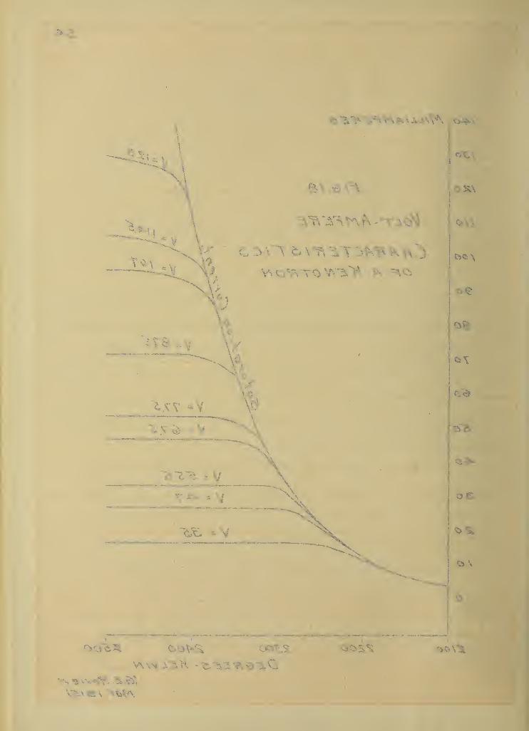
and V is the impressed voltage. Fig. 18 shows the variation of
current through a kenotron with filament temperature and voltage.
The effect of the above characteristics on the crest volt-
meter can be best seen from a study of the three cases,
(a) when operating on direct current
(b) when operating on alternating current with a
perfectly insulated voltmeter
(c) when operating on alternating current with a
poorly insulated voltmeter.
Both the Richardson effect and the space charge effect can
be replaced by equivalent resistances. The first limits the current
-1to a constant value, i.e. R* = k E . On the other hand current
as limited by the space charge varies a3 the 1.5 power of the volt-
0.5age so the "space charge resistance" R B = k* E . Since the two
effects can not exist simultaneously, they will be replaced in the
following discussion by a resistance R°.
If direct current be impressed on the crest voltmeter (of
the "A M type) with perfect insulation, the electrostatic voltmeter
will gradually become charged to the impressed voltage. The value
of R° will have no effect other than to limit the time for the volt-
meter to become fully charged. If the insulation of the voltmeter be
low (or if the meter be of the "B" type) the resistance R° enters
directly. The final indication of the voltmeter can not exceed
—TT of the impressed voltage, where R is the insulation resis-
tance of the voltmeter.
If alternating current be impressed on a voltmeter


54-
Zloo Z2LOO Z3oo Z400 K5oOD - KELV/N
Mar. oi&J

55
having perfect insulation, the final indication is independent of
the resistance of the valve. Rectification occurs in the valve and
the behavior of the voltmeter is the same as if direct current were
impressed on the circuit. On the other hand where the insulation is
low it is practically impossible to predetermine the performance of
the crest voltmeter on alternating current. The following case has
been worked out for the case of sine waves and a perfect valve. The
circuit is shown in fig. 19 (a). MK" is a kenotron, H S M is a switch
which may be used to short circuit MK W,
M C" is a condenser which haj$
a voltmeter in shunt with it and nR w is the shunting insulation re-
sistance. If a sine wave of voltage be impressed on the circuit
(WS W being closed) current will flow through the circuit and will
divide as indicated in fig. 19 (b), where w e w is the voltage, "ir
is the leakage current and "i the current through the condenser.
If "S w be opened, current will pass through the valve as long as it
is positive. As soon as it reaches a zero value it will be inter-
rupted. This will occur when the instantaneous values of w ir
" and
wic
w are equal but of opposite sign. The time when this will
occur is found as follows.
Let e = E sin pt (1)
Then i = E sin pt (2)R
and i c CE cos pt (3)
Equating (2) and (3) and placing the negative sign before the secondj
member of the equation,
E sin pt * - CE cos pt (4)R
or tan pt -CR


57
As soon as the time t' is reached (where t* = arc tan (-CR) )
P
the condenser begins to discharge and the voltage of the condenser
follows the equation
e = sin arc tan (-CR)fc
This will continue until the condenser voltage is the same as the
line voltage (as shown at Mb w in fig.l9-b) when the line voltage
will again be able to send current through the valve. As a conse-
quence, the voltage on the condenser and voltmeter will vary as in-
dicated by the heavy line. If the voltmeter is an electrostatic
meter, the indication will be the root mean square of this voltage,
whereas a D'Arsonval instrument (such as would be used with the
"Type B w) would give an average reading.
It is obvious that the sha^e of this curve will depend
on the capacitance, insulation resistance, frequency, etc. The high
er the insulation resistance, the nearer the crest voltage will the
point "b" occur.
The limitations of the kenotron are most pronounced in
trying to develop a transient voltage indicator.
Let t = duration of maximum value of a transient volt-age E
and C = the capacitance of the condenser
The average current which will have to pass through the kenotron
will be
i = CE/t
Particular care must be taken that this current does not approach
the saturation current of the valve and that the space charge volt-


58
age is low compared with E.
If the filament of a kenotron be heated with direct current
and a high resistance voltmeter (preferably a megohm resistance and
a galvanometer) be connected between the negative end of the fila-
ment and the anode it will be found that the cathode will be at a
potential of from 1 to 2 volts above the anode. If the lead to the
[
!
cathode be transferred to the positive end it will be found that th<»
voltmeter will indicate the voltage consumed by the filament, the
relative polarities of the anode plate and the filament remaining
as before. In all of the tests which have been made by the writer
the first effect has never been noticed except in those cases where
voltage impressed on the valve was zero. The other effect is always
present and must be guarded against. The test is very simple and
has been given in Appendix 1. In every case the difference between
the two maximum voltage readings has been found to equal the fila-
ment voltage.
Where it is necessary to use alternating current of
a frequency different from the voltage being tested, this effect
can not be eliminated. A correction must therefore be applied. If
alternating current of the same frequency but having a phase differ-
ence is used, the effect can be made almost negligble. The voltage
|
on the valve is the resultant of the filament voltage and the test
I voltage. By reversals the two can always be kept within 90° of each'
j other. Assuming that they are 90° apart and that the filament volt-
age is 12<Jb of the test voltage gives a resultant of
100+ |12 = 101.4
or an error of 1.4


59
Appendix 5. Possib i lity of Using Other Valves.
During the investigation, of which this thesis is a summary
a number of attempts were made to use valves other than the kenotrof^
One of the first valves used was a small DeForest audion. It gave
results about 1 percent low on sine waves. No tests were made on
distorted waves.
Another fairly satisfactory valve was made by the Edison
Lamp Works of the General Electric Co. It consisted of two coiled
filaments supported one half inch apart from opposite ends of a
lamp bulb, which had been well evacuated. Readings with this valve
were 3 percent low on sine waves and 5 percent low on waves similar
to that shown in fig. 13 (c).


60
Appendix 4. Hi#i Voltage Multipliers*
While the crest voltmeter has been used directly on voltage;:
as high as 100 000 by Peek, the device is most satisfactory when us-
ed at low voltages ( less than 500 volts). Since crest factor is gen-
erally desired on a high tension wave, it is necessary to reduce the
1- voltage without changing its wave form. Work has shown that the
voltage from a tertiary coil on the transformer has the same wave
shape as the secondary voltage within a very small percentage. How-
ever few transformers have this coil and since voltage transformers
for high voltages are prohibited by their large size and high cost,
other means must be provided.
A volt box arrangement is immediately suggested. The gener-
al scheme is shown in fig.20 (a) . Two impedances are connected in
series between the voltage and ground, the voltmeter being tapped
off between the common point and ground. In general the impedances
may have inductive or capacity reactance or they may be pure resis-
tances. It is not necessary that the impedance be uniformly distrib-
uted. It may be "lumped* as shown in fig. 20 (b). The ratios of
the reactance to the resistance of the two sections must be the same
however or the voltage across the low voltage section will have a
;different wave form from that of the line.
Certain types of multipliers have advantages for specific
cases. The condenser type takes a large leading current, but very
little energy current. Its use is limited to comparatively low fre-
quencies. The resistance type dissipates considerable power at high
1. Bibliography No. 22.


61
(a) Dts fr ib o -heJ Impedance. —1
1"^
(b) Lumped Capac ify
C 2
(c) Air Co nden 5 er
Fl G ZO
Ht6H Vol ta 6£ Multipliers.

A A A A A A A A A
)'
5& y

62
voltages, but may be used to very good advantages in cases where the
loss of power is not objectionable or where the presence of a conden-
ser would change the conditions of the test. There seems to be no
use for the reactance type of multiplier at any but the lower volt-
ages. Here it has no advantages over the voltage transformer and
would not be used.
The principal advantage of the condenser type outside of
the low power consumption, is the ease with which it may be construct
. ed. Sharp and Farmer have used one consisting of a series of glass,
plate condensers connected in series and immersed in a tank of oil.
It is possible in an emergency to use several sheets of galvanized
iron with air as the dielectric. Whenever a train of condensers are
connected in series there is a possibility that they will puncture
and the/entire voltage be impressed on the low voltage condenser. A
film cut out (such as is used with series incandescent lamps) in par-
allel with the low voltage condenser will protect the voltmeter etc.
but there would be a question as to the admittance of that section.
There is also a possibility that the admittance of the high voltage
section may change with voltage due to corona or change in capaci^
tance
.
A condenser with air as a dielectric may be made free of thci
above objections if it is properly designed. Such a condenser is
shown in outline in fig. 20 (c). It consists of a central plate
| condenser surrounded with a guard ring which is connected to earth.
The relative dielectric flux densities are such that the guard ring
will always_ arc_ oyer sooner than_ the_ center plate. _ Th_e .guard jwjig_
1. Bibliography No. 15.

63
also eliminates any fringeing of the lines at the edge of the center
plate and thereby makes the capacitance of the center part inverse-
ly Proportional to the spacing.
The following design h^s been made for an air condenser to
be used with the "Type A" crest voltmeter described on page 31. The
conditions to be met are,
(a) Device to operate at 200 000 volts(max.) to ground.
(b) Crest factor to be obtained with an accuracy of 0.5$.
-10The voltmeter has a capacitance of 1.6 x 10 farads,
while its maximum indication is 250 volts. If crest factor is to be
determined with an accuracy of 0.5 percent, the capacitance of the
voltmeter should not be more than 0.2 percent of the low voltage
condenser to allow for errors in reading the instrument. The low
voltage condenser must have a capacitance of not less than
1,6 x 10 farads = 8 x 10~8 farads, or approximately 0-.1 mf.0.2 $
The capacitance of the high voltage section will be
250 x 0,1 = 1.25 x 10"4 microfarads.200 000
Experiments having shown that the ultimate dielectric
strength of air is 30 kilovolts (max) per centimeter, the minimum
spacing allowable for 200 000 volts would be 6.67 cm. or using a
factor of safety of 2.5, the spacing would be 16 centimeters.
The edges of the plates must be turned up to eliminate flux concen-
tration. A convenient form both from the stand point of calculation
and construction is cylindrical sides and spherical corners. Peek
has stated that corona will not form before spark over where


64
S/r is less than 5.85,
S being the distance between center lines of the cylinders and r
being the radius. For the present case the limiting radius is 4.15
cm. but as the 25 cm. sphere gap has been adopted as a standard size
r = 12.5 will be used.
The capacitance of parallel plates is given by the follow-
ing equation where "C" is in microfarads, and the area "A" and spac-
ing "s" are in sq.cm. and cm. respectively.
-8C = 8.84 x 10 A
s
Hence for a capacitance of 1.25 x 10"" 4 microfarads with a spacing of
16 cm. the area must be 22 600 sq.cm. or since 150 by 150 cm. is
a convenient size, the latter will be used.
The following tables have been worked out to show the capac-
itance and spark over voltage of the various parts of the condenser.
The work has been done by the aid of the tables and formulae contain-
ed in Peek's "Dielectric Phenomena in High Voltage Engineering".
It will be noted that the capacitance of the guard circuit becomes
more and more prominent at the greater spacings and that the guard
ring will always divert the arc overs away from the plates.


65
TABLE 7.
Variation of Capacitance of Air Condenser with Spacing.
Operating Spacing Capacitance, Farads x 10
/ol tage Cm. Plates Cylinders Spheres Total
5 000 .4 4980 462 20 546210 000 0.8 2490 330w \J v 12 2^2?0 000 1 94^ 1490X ~t «7 V
40 000 3.2 622 165 10 79760 000 4*8 415 136 10 56180 000 6.4 311 119 9 439
100 000 8.0 249 107 9 365150 000 12.0 166 88 8 262200 000 16.0 124 78 8 210300 000 24.0 83 65 7 155400 000 32.0 62 60 7 129500 000 40 .0 50 52 6 108
TABLE 8.
Variation of Spark-over Voltage of Condenser with Spacing
OperatingVoltage
SpacingCm.
Spark-over Voltage, Kv. (Max.)Plates Cylinders Spheres
5 000 0.4 12 12 9
10 000 0.8 24 23 1720 000 1.6 48 47 3240 000 3.2 96 94 6260 000 4.8 144 134 9080 000 6.4 192 177 115
100 000 8.0 240 218 140150 00 12.0 360 312 191200 000 16.0 480 400 228300 000 24.0 720 552 275400 000 32 .0 960 681 310500 000 40.0 1600 800 325


66
There are cases where the condenser type of multiplier
can not be used. The resistor type may be of use in such cases.
Several forms are available. One is the water tube resistance. If
such a one is used Provision must be made for the water boiling. A
convenient form is a U tube connected at top and bottom with spec-
ial cooling on one branch. The low voltage section must be in the
same tube for otherwise the variation in the temperature of the wat-
er would affect the calibration of the unit.
Hull"'' has described a very compact resistance which he has
used as a multiplier for a d.c. voltmeter on 100 000 volts. It con-
sists of 1000 voltmeter resistance coils each having 10 000 ohms
resistance. They are mounted on hard wood lattices, 100 to a lattici
the 10 lattices being spaced three inches apart and individual coils
l/2 inch apart. The whole outfit is immersed in a tank of oil. If
the capacitance of the various coils against earth can be made negli
gible this arrangement should be very convenient for crest voltmeter
work.
A comparison of the kva. of the air condenser and the kw.
of the resistor type is of interest. The air condenser when set for
1200 000 volts 60 cycles takes a total of 3.2 kva. Assuming that
Hull's type of resistance could be used for the same voltage, it
would consume 2 kw.
As has been suggested there is no field for an inductance
, type multiplier. At first sight it would seem that it might be used
with an oscillation transformer which has a natural frequency of froi]
1. Bibliography No. 24.


67
100 000 to 300 000 cycles. Such is not the case. If an inductance
were made up of 10 000 turns of No. 20 AWQ. copper wire each turn hav-
ing a diameter of 30 cm. the inductance with the separate turns toucpp
ing each other would only be 3.3 henry s. At 100 000 volts 200 000
cycles the current would be 0.048 amperes or a total of 48 kva. As
the output of an oscillation transformer is limited to a value
considerably below this the arrangement is out of the question.


BIBLIOGRAPHY.
68
Note: No effort has been made to make this bibliography exhaustive.It contains only such references as have a direct bearing onthe matter included in this thesis.
Impulse Tests.
1. Hayden and Steinmetz, Trans. A.I.E.E. 1910, p. 1125
2. Chernyshoff and Butman, Elec Jour. 1915, p. 2823. Imlay and Thomas, Trans. A.I.E.E. 1912, p. 21214. Creighton, Proc. A.I.E.E. May, 1915, p. 7535. Peek, Proc. A.I.E.E. Sept. 1915, p. 1695
Methods of Measuring High Voltages.
6. Kintner, Trans. A.I.E.E. 1905, p. 421
Wave Tracers.
7. Joubert, Comptes Rendus, vol. 91, p. 1618. Ryan, Trans. A.I.E.E. 1889, p.l9. Mershon, Foster's Hand Book, 3rd. Edition, p. 705
J.0 . Duncan, Trans. A.I.E.E. 1892, p. 179.1. Robinson, Trans. A.I.E.E. 1905, p. 185
Oscillographs
.
12. Blondel, Comptes Rendus, 1893, p. 50213. Duddell, Electrician, vol. 39, 1897, p. 63614. Irwin, Electrician, vol.59, 1907,p .226,306
Crest Voltmeters.
15. Sharp and Farmer, Trans. A.I.E.E. 1912, p. 161716. Cubb and Fortes cue, Trans. A.I.E.E. 1913, p. 73917. Whitehead and Gorton, Trans. A.I.E.E. 1914, p. 95118. Middleton and Dawes, Trans A.I.E.E. 1914, p. 118519. Chubb, Proc. A.I.E.E. Feb. 1916,p.l21.20. Sharp and Doyle, Proc. A.I.E.E. Feb. 1916, p. 129
The Kenotron.
21. Dushman, Gen. Elec. Review, 1915, p. 156
Wave Shapes in High Voltage
Transformers
.
22. Work, Proc. A.I.E.E. Feb. 1916, p. 203


69
BIBLIOGRAPHY- cont
.
Production of High Potential Direct Current
23. Thomson, Gen. Elec. Review, 1915, p. 108424. Hull, Gen. Elec. Review, 1916, p. 173


UNIVERSfTY OF ILLINOIS-URBANA
3 0112 082196 17