TM800_D00165_M_XXEN.pdf - Bender
96
Bender GmbH & Co. KG Postfach 1161 · 35301 Grünberg/Germany Londorfer Straße 65 · 35305 Grünberg/Germany Tel.: +49 6401 807-0 · Fax: +49 6401 807-259 E-Mail: [email protected] · www.bender.de Amtsgericht Gießen HRA 1159 Geschäftsführer: Pers. haftende Gesellschafterin: Heinz Nowicki, Winfried Möll, Dipl.-Ing. Wilshaus GmbH D. Christian Bender Amtsgericht Gießen HRB 173 Prokuristin: Commerzbank Gießen Sparkasse Grünberg Deutsche Bank Gießen Sitz der Gesellschaft: Grünberg Monika Schuster IBAN: DE32 5134 0013 0205 2520 00 IBAN: DE88 5135 1526 0000 0119 08 IBAN: DE36 5137 0008 0023 7008 00 USt-IdNr. DE112643173 WEEE-Reg.-Nr. DE 43 124 402 BIC: COBADEFFXXX BIC: HELADEF1GRU BIC: DEUTDEFF513 Product Change Notification CHANGE NOTIFICATION CHANGE TITLE PRODUCT FAMILY DATE OF PUBLICATION PRODUCT PART NUMBER BSKG TM800 front foil design and housing dimensions changed Control Panels February 17, 2022 Housing overview attached TYPE OF CHANGE CLASSIFICATON OF CHANGE 1) PRODUCT CATEGORY DEPARTMENT / LOCATION Mechanical, Foil printing B TM800 BU-H 1) A: Stop of production or design change with influence of approval/ Einstellung der Produktion oder Konstruktionsänderung mit neuer Zulassung benötigt. B: Small change in design without influence of approval/ Geringfügige Änderung des Designs ohne Einfluss der Zulassung C: No influence of product/ Keine Auswirkung auf das Produkt DESCRIPTION OF CHANGE: Front panel design changed. The housing material were changed to aluminum. KEY CHARACTERISTICS OF CHANGE: Front panel design changed. The housing material has been changed to aluminum, this has an impact on the outer dimensions of the housing. Preference types housing/Wallbox*: Type* (Name-W-H-D) UPB bezel frame dimension UPE Tile frame dimension Housing outer dimensions** (WxH) mm Wall cutout dimensions Material UPAF-303-303-120mm W+30mm x H+30mm W-6mm x H-6mm 303x303 W+3mm x H+3mm B22000176 UPAF-303-453-120mm W+30mm x H+30mm W-6mm x H-6mm 303x453 W+3mm x H+3mm B22000177 UPAF-453-453-120mm W+30mm x H+30mm W-6mm x H-6mm 453x453 W+3mm x H+3mm B22000172 UPAF-453-453-150mm W+30mm x H+30mm W-6mm x H-6mm 453x453 W+3mm x H+3mm B22000178 UPAF-453-603-120mm W+30mm x H+30mm W-6mm x H-6mm 453x603 W+3mm x H+3mm B22000173 UPAF-453-603-150mm W+30mm x H+30mm W-6mm x H-6mm 453x603 W+3mm x H+3mm B22000179 UPAF-603-603-120mm W+30mm x H+30mm W-6mm x H-6mm 603x603 W+3mm x H+3mm B22000174 UPAF-603-603-150mm W+30mm x H+30mm W-6mm x H-6mm 603x603 W+3mm x H+3mm B22000181 UPAF-603-753-120mm W+30mm x H+30mm W-6mm x H-6mm 603x753 W+3mm x H+3mm B22000175 UPAF-603-753-150mm W+30mm x H+30mm W-6mm x H-6mm 603x753 W+3mm x H+3mm B22000182 Surface Mounting Two different depth are available 60mm and 120mm. Requires consulting ** Additional 10 mm circumferential housing flange. *Other housing dimensions available on request at extra cost.
-
Upload
khangminh22 -
Category
Documents
-
view
0 -
download
0
Transcript of TM800_D00165_M_XXEN.pdf - Bender

Bender GmbH & Co. KG Postfach 1161 · 35301 Grünberg/Germany Londorfer Straße 65 · 35305 Grünberg/Germany Tel.: +49 6401 807-0 · Fax: +49 6401 807-259 E-Mail: [email protected] · www.bender.de
Amtsgericht Gießen HRA 1159 Geschäftsführer: Pers. haftende Gesellschafterin: Heinz Nowicki, Winfried Möll, Dipl.-Ing. Wilshaus GmbH D. Christian BenderAmtsgericht Gießen HRB 173 Prokuristin: Commerzbank Gießen Sparkasse Grünberg Deutsche Bank Gießen Sitz der Gesellschaft: Grünberg Monika Schuster IBAN: DE32 5134 0013 0205 2520 00 IBAN: DE88 5135 1526 0000 0119 08 IBAN: DE36 5137 0008 0023 7008 00 USt-IdNr. DE112643173 WEEE-Reg.-Nr. DE 43 124 402 BIC: COBADEFFXXX BIC: HELADEF1GRU BIC: DEUTDEFF513
Product Change Notification
CHANGE NOTIFICATION CHANGE TITLE
PRODUCT FAMILY DATE OF
PUBLICATION PRODUCT
PART NUMBER
BSKG TM800 front foil
design and housing dimensions changed
Control Panels
February 17, 2022
Housing overview attached
TYPE OF CHANGE
CLASSIFICATON OF CHANGE1)
PRODUCT CATEGORY
DEPARTMENT / LOCATION
Mechanical, Foil printing B TM800 BU-H
1) A: Stop of production or design change with influence of approval/ Einstellung der Produktion oder Konstruktionsänderung mitneuer Zulassung benötigt.B: Small change in design without influence of approval/ Geringfügige Änderung des Designs ohne Einfluss der ZulassungC: No influence of product/ Keine Auswirkung auf das Produkt
DESCRIPTION OF CHANGE:
Front panel design changed. The housing material were changed to aluminum.
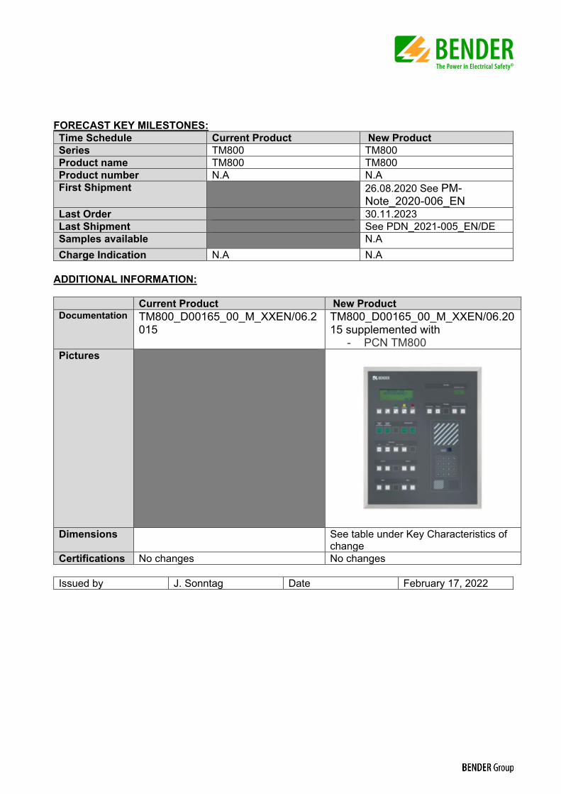
KEY CHARACTERISTICS OF CHANGE: Front panel design changed. The housing material has been changed to aluminum, this has an impact on the outer dimensions of the housing.
Preference types housing/Wallbox*: Type* (Name-W-H-D)
UPB bezel frame dimension
UPE Tile frame dimension
Housing outer dimensions** (WxH) mm
Wall cutout dimensions
Material
UPAF-303-303-120mm W+30mm x H+30mm W-6mm x H-6mm 303x303 W+3mm x H+3mm B22000176 UPAF-303-453-120mm W+30mm x H+30mm W-6mm x H-6mm 303x453 W+3mm x H+3mm B22000177 UPAF-453-453-120mm W+30mm x H+30mm W-6mm x H-6mm 453x453 W+3mm x H+3mm B22000172 UPAF-453-453-150mm W+30mm x H+30mm W-6mm x H-6mm 453x453 W+3mm x H+3mm B22000178 UPAF-453-603-120mm W+30mm x H+30mm W-6mm x H-6mm 453x603 W+3mm x H+3mm B22000173 UPAF-453-603-150mm W+30mm x H+30mm W-6mm x H-6mm 453x603 W+3mm x H+3mm B22000179 UPAF-603-603-120mm W+30mm x H+30mm W-6mm x H-6mm 603x603 W+3mm x H+3mm B22000174 UPAF-603-603-150mm W+30mm x H+30mm W-6mm x H-6mm 603x603 W+3mm x H+3mm B22000181 UPAF-603-753-120mm W+30mm x H+30mm W-6mm x H-6mm 603x753 W+3mm x H+3mm B22000175 UPAF-603-753-150mm W+30mm x H+30mm W-6mm x H-6mm 603x753 W+3mm x H+3mm B22000182 Surface Mounting Two different depth are available 60mm and 120mm. Requires consulting
** Additional 10 mm circumferential housing flange. *Other housing dimensions available on request at extra cost.
FORECAST KEY MILESTONES: Time Schedule Current Product New Product Series TM800 TM800 Product name TM800 TM800 Product number N.A N.AFirst Shipment 26.08.2020 See PM-
Note_2020-006_EN Last Order 30.11.2023 Last Shipment See PDN_2021-005_EN/DE Samples available N.ACharge Indication N.A N.A
ADDITIONAL INFORMATION:
Current Product New Product Documentation TM800_D00165_00_M_XXEN/06.2
015 TM800_D00165_00_M_XXEN/06.2015 supplemented with
- PCN TM800Pictures
Dimensions See table under Key Characteristics of change
Certifications No changes No changes
Issued by J. Sonntag Date February 17, 2022

ManualEN
TM800_D00165_00_M_XXEN/06.2015
TM800
Alarm indicator and operator panelSoftware version: 4.0x

Bender GmbH & Co. KGP.O. Box 1161 • 35301 Gruenberg • GermanyLondorfer Straße 65 • 35305 Gruenberg • GermanyTel.: +49 6401 807-0 • Fax: +49 6401 807-259E-mail: [email protected] • www.bender.de
© Bender GmbH & Co. KGAll rights reserved.
Reprinting only with permissionof the publisher.
Subject to change!
Photos: Bender archives.

Table of Contents
1. How to get the most out of this manual ............................................................. 7
1.1 How to use this manual ......................................................................................................... 7
1.2 Explanation of symbols and notes ..................................................................................... 7
2. Safety instructions .................................................................................................. 9
2.1 Intended use .............................................................................................................................. 9
2.2 Qualified personnel ................................................................................................................. 9
2.3 General safety instructions ................................................................................................... 9
2.4 Delivery conditions, warranty and liability .................................................................. 10
3. System description .............................................................................................. 11
3.1 MEDICS® ................................................................................................................................... 11
3.2 TM800 features ...................................................................................................................... 12
3.3 Functionality of the TM800 ............................................................................................... 13
3.3.1 LC display ................................................................................................................................. 13
3.3.2 Programmable messages .................................................................................................. 14
3.3.3 History memory ..................................................................................................................... 14
3.3.4 Interfaces .................................................................................................................................. 14
3.3.4.1 BMS bus ............................................................................................................................. 14
3.3.4.2 USB interface .................................................................................................................... 15
3.3.5 Programming and reading the TM800 ......................................................................... 15
3.3.5.1 Connection of the personal computer ................................................................... 15
3.3.5.2 Optional software .......................................................................................................... 15
3.3.6 Firmware versions ................................................................................................................. 15
3.4 Mechanical design ................................................................................................................ 16
3.4.1 Module overview .................................................................................................................. 16
3.4.2 BM800 and BM400 modules ............................................................................................. 16
3.4.2.1 BM800 ................................................................................................................................ 16
3.4.2.2 BM400 ................................................................................................................................ 16
3.4.3 Operating and display modules ..................................................................................... 16
3.4.4 Inputs and outputs ............................................................................................................... 17
3.4.4.1 Digital output 1 ............................................................................................................... 17
3.4.4.2 I/O modules ...................................................................................................................... 17
3.4.5 Individual internal components ...................................................................................... 18
3TM800_D00165_00_M_XXEN/06.2015

Table of Contents
4. Installation and connection ............................................................................... 19
4.1 Installation ................................................................................................................................ 19
4.1.1 Overview of enclosure variants ........................................................................................ 19
4.1.2 Unpacking ................................................................................................................................ 20
4.1.3 Installing the flush-mounting type enclosure with bezel frame (UPB) .............. 21
4.1.4 Installing the flush-mounting enclosure with mounting frame (UPE) ............... 22
4.1.5 Mounting the front plate .................................................................................................... 24
4.1.5.1 Flush-mounting type enclosure with bezel frame (UPB) ................................. 24
4.1.5.2 Flush-mounting type enclosure with mounting frame (UPE) ........................ 25
4.1.6 Installation of the surface-mounting enclosure (AP) ................................................ 26
4.1.7 Opening the front plate ...................................................................................................... 27
4.2 Connection ............................................................................................................................... 28
4.2.1 Connection details ................................................................................................................ 28
4.2.2 Modules and connections of the TM800 (connection example) .......................... 29
4.2.3 BMS-bus connection ............................................................................................................ 31
4.2.3.1 Terminating resistor ....................................................................................................... 31
4.3 Examples for connection and address assignment .................................................. 32
4.3.1 Address settings and their meaning ............................................................................... 35
5. Commissioning and testing ............................................................................... 37
5.1 Tests before switching on ................................................................................................... 38
5.2 Tests after switching on ...................................................................................................... 39
5.3 Make settings (parameterisation) .................................................................................... 39
5.3.1 Settings at the TM800 .......................................................................................................... 40
5.3.2 Settings using the TMK-SET software ............................................................................. 41
5.3.3 Tests after parameter setting ........................................................................................... 42
5.4 Periodic verification and service ...................................................................................... 43
5.4.1 Periodic verification .............................................................................................................. 43
5.4.2 Service ........................................................................................................................................ 44
5.4.3 Maintenance ............................................................................................................................ 44
6. Troubleshooting ................................................................................................... 45
6.1 Error messages ........................................................................................................................ 45
6.2 Malfunctions ............................................................................................................................ 46
6.3 Replace flash memory .......................................................................................................... 48
7. Operation ............................................................................................................... 49
7.1 Operator control and display elements ......................................................................... 49
7.2 Quick reference guide .......................................................................................................... 50
4 TM800_D00165_00_M_XXEN/06.2015

Table of Contents
7.2.1 Display under normal operating condition ................................................................. 50
7.2.2 Display during fault condition ......................................................................................... 51
7.2.3 Test function ........................................................................................................................... 52
8. Menu mode: Operation and setting ................................................................. 55
8.1 Switching on and calling the main menu .................................................................... 55
8.2 Menu overview diagram .................................................................................................... 56
8.3 Main menu functions ........................................................................................................... 57
8.4 The main menu ...................................................................................................................... 57
8.4.1 Exit .............................................................................................................................................. 57
8.4.2 Menu2: Values ........................................................................................................................ 57
8.4.3 Menu 3: History ...................................................................................................................... 57
8.4.4 Menu 4: Settings .................................................................................................................... 59
8.4.4.1 Exit ....................................................................................................................................... 59
8.4.4.2 Settings menu 2: Alarm addresses ........................................................................... 59
8.4.4.3 Settings menu 3: Test addresses .............................................................................. 60
8.4.4.4 Settings menu 4: Measurement addresses ........................................................... 61
8.4.4.5 Settings menu 5: Digital inputs ................................................................................. 61
8.4.4.6 Settings menu 6: Buzzer (and LED) .......................................................................... 63
8.4.4.7 Settings menu 7: Common reset .............................................................................. 63
8.4.4.8 Settings menu 8: Clock ................................................................................................. 63
8.4.4.9 Settings menu 9: Language ........................................................................................ 64
8.4.4.10 Settings menu 10: Interface ....................................................................................... 65
8.4.4.11 Settings menu 11: Relays ............................................................................................ 65
8.4.4.12 Settings menu 12: Password ...................................................................................... 66
8.4.4.13 Settings menu 13: Service menu .............................................................................. 66
8.4.5 Menu 5: Control ..................................................................................................................... 67
8.4.5.1 Exit ....................................................................................................................................... 67
8.4.5.2 Control menu 2: Reset (AlarmClear) ........................................................................ 67
8.4.5.3 Control menu 3: EDS Start/Stop ............................................................................... 67
8.4.5.4 Control menu 4: Test communication .................................................................... 68
8.4.5.5 Control menu Reset mode .......................................................................................... 68
8.4.6 Menu 6: External devices .................................................................................................... 68
8.4.7 Menu 7: Info ............................................................................................................................ 70
8.5 Overview of setting options .............................................................................................. 71
9. Technical data ....................................................................................................... 73
9.1 Technical data BM800/BM400 modules ....................................................................... 73
9.1.1 Standards, approvals and certifications ........................................................................ 74
9.2 Dimensions ............................................................................................................................. 75
5TM800_D00165_00_M_XXEN/06.2015

Table of Contents
9.2.1 Surface-mounting enclosure, aluminium, silver matt anodised .......................... 76
9.3 Ordering details ...................................................................................................................... 76
10. Internal components and modules ................................................................ 77
10.1 BM800 and BM400 module ................................................................................................ 77
10.1.1 BM800 and BM400 dimensions ........................................................................................ 77
10.2 Operating and display module BI800S .......................................................................... 78
10.2.1 BI800S dimensions ................................................................................................................ 78
10.2.2 Wiring diagram BI800S ........................................................................................................ 78
10.2.3 Technical data BI800S ......................................................................................................... 78
10.2.4 Ordering information BI800S ............................................................................................ 79
10.3 Operating and display module BI71S ............................................................................. 80
10.3.1 BI71S dimensions ................................................................................................................... 80
10.3.2 Wiring diagram BI71S ........................................................................................................... 80
10.3.3 Technical data BI71S ............................................................................................................. 81
10.3.4 Ordering information BI71S ............................................................................................... 81
10.4 Operating and display module BI72S ............................................................................. 82
10.4.1 BI72S dimensions ................................................................................................................... 82
10.4.2 Wiring diagram BI72S ........................................................................................................... 82
10.4.3 Technical data BI72S ............................................................................................................. 83
10.4.4 Ordering information BI72S ............................................................................................... 83
10.5 I/O module BMI8/8 ................................................................................................................ 84
10.5.1 BMI8/8 dimensions ............................................................................................................... 84
10.5.2 Wiring diagram BMI8/8 ........................................................................................................ 84
10.5.3 Technical data BMI8/8 .......................................................................................................... 85
10.6 I/O module BMI8/4 and BMI0/4 ........................................................................................ 86
10.6.1 BMI8/4 and BMI0/4 dimensions ....................................................................................... 86
10.6.2 Wiring diagram BMI8/4 and BMI0/4 ............................................................................... 86
10.6.3 Technical data BMI8/4 and BMI0/4 .................................................................................. 87
INDEX ........................................................................................................................... 89
6 TM800_D00165_00_M_XXEN/06.2015
1. How to get the most out of this manual
1.1 How to use this manual This operating manual describes the TM800 alarm indicator and operator panel with the software version specified on the title page. The functions and processes described may vary from those fea-tured in other versions. This manual is intended for qualified personnel working in electrical engi-neering and electronics and in particular for those designing, installing and operating electrical equipment in medical locations.
Chapter "Operation" on page 49 can also be used as a quick reference guide by medical personnel.
Before using the devices, please read this operating manual, the supplement entitled "Important safety instructions for Bender Products" and the instruction leaflets supplied with the individual sys-tem components. Keep this document in an easily accessible location near to the devices.
Should you have any further questions, please contact our Technical Sales department. We are also happy to provide on-site service. Contact our Service Department for more information.
Although great care has been taken in the drafting of this operating manual, it may nevertheless contain errors and mistakes. Bender cannot accept any liability for injury to persons or damage to property resulting from errors or mistakes in this manual.
1.2 Explanation of symbols and notes The following terms and symbols are used to denote hazards and instructions in Bender documen-tation:
The signal word indicates that there is a high risk of danger that will result indeath or serious injury if not avoided
This signal word indicates a medium risk of danger that can lead to death or se-rious injury, if not avoided.
This signal word indicates a low level risk that can result in minor or moderateinjury or damage to property, if not avoided.
This symbol denotes information intended to assist the user in making optimumuse of the product.
DANGER
WARNING
CAUTION
7TM800_D00165_00_M_XXEN/06.2015

How to get the most out of this manual
8 TM800_D00165_00_M_XXEN/06.2015

2. Safety instructions
2.1 Intended use In terms of human/machine interface, alarm indicator and operator panels play a crucial role. Their task is to take system information and transform it into clear instructions, particularly in the event of critical operating situations. The flexible TM800 alarm indicator and operator panels provide solu-tions that meet the requirements of modern medical facilities as well as industrial and functional buildings. They are used for
the display and visualisation of operating status, warning and alarm messages
central operation and parameterisation of BMS bus devices (BMS = Bender Measuring Device Interface)
the output of visual and audible warning messages
the display of measured values from Bender monitoring systems with BMS interface, such as MEDICS®, RCMS or EDS
In addition, they are used for the display, control and operation of
operating theatre tables
equipment for supplying medical gases
battery-supported central power supply systems (BSV systems)
air conditioning and ventilation systems
room lighting
communication equipment
and third-party systems.
All technical devices installed in one alarm indicator and operator panel constitute a technology cen-tre in the relevant room.
Please heed the limits of the area of application indicated in the technical specifications. Use which deviates from or is beyond the scope of these technical specifications is considered non-compliant.
Use for the intended purpose also includes:
Device-specific settings compliant with local equipment and operating conditions.
The observation of all information in the operating manual.
Compliance with test intervals.
2.2 Qualified personnel Only appropriately qualified personnel may work with the Bender devices. Personnel who are famil-iar with the installation, commissioning and operation of the equipment and have undergone ap-propriate training are considered qualified. Personnel must have read this manual and understood all instructions relating to safety.
2.3 General safety instructions Bender devices are designed and built in accordance with the state of the art and accepted rules in respect of technical safety. However, the use of such devices may introduce risks to the life and limb of the user or third parties and/or result in damage to Bender devices or other property. Only use
9TM800_D00165_00_M_XXEN/06.2015

Safety instructions
Bender devices:
– As intended
– In perfect working order
– In compliance with the accident prevention regulations and guidelines applicable at the location of use
Eliminate all faults immediately which may endanger safety.
Do not make any unauthorised changes and only use replacement parts and optional accesso-ries purchased from or recommended by the manufacturer of the devices. Failure to observe this requirement can result in fire, electric shock and injury.
Reference signs must always be clearly legible. Replace damaged or illegible signs immediately.
Make sure that the dimensions of the BSV (battery-supported safety power supply), the genera-tor set and the whole wiring are adequate. The applicable national and international standards must be observed here. Only in this way selective operation of safety devices can be achieved and a high degree of safety in case of overload and short circuit can be ensured.
2.4 Delivery conditions, warranty and liability The conditions of sale and delivery set out by Bender apply. Conditions of sale and delivery can be obtained from Bender in printed or electronic format.
10 TM800_D00165_00_M_XXEN/06.2015

3. System description
3.1 MEDICS® The TM800 alarm indicator and operator panel is an integral component of the MEDICS® system. MEDICS® is an intelligent system that guarantees safe power supply in medical locations.
Example of a section of a hospital with the MEDICS® system
Legend to the illustration above MK… Alarm indicator and test combination RCMS… Residual current monitoring system for TN-S systems SMI472 Signal converter for third-party technical equipment (e.g. med. gases, BSV (battery-
supported systems) TM… Alarm indicator and operator panel UFC107E… Changeover and monitoring module for IT systems with EDS insulation fault location system UMC107E… Changeover and monitoring module for IT systems UMC710D… Changeover module for main distribution boards USC710D… Control module for changeover modules (preferably in main distribution boards) SCADA system (Supervisory Control and Data Acquisition)
11TM800_D00165_00_M_XXEN/06.2015

System description
MEDICS® includes:
Single and three-phase monitoring modules. MEDICS® system modules are, for example: UMC…, USC…, UFC… and/or EDS… insulation fault location systems
Display and operating units such as TM… alarm indicator and operator panels or MK… alarm indicator and test combinations
Communication between these components via the BMS bus (two-wire connection).
The connection of third-party technical systems by means of protocol converters (gateways) or via digital inputs and relay outputs.
The real strength of MEDICS® is to be found in communication between all involved components and the resulting information provided to the user. The functionality of the equipment is continuously monitored. Operating states, irregularities, faults and equipment failures are displayed. This means high operational reliability of the installation for the user.
3.2 TM800 features On its backlit LC display, the TM800 displays messages from all BMS-bus devices and digital inputs assigned via alarm addresses. As well as being used as a standalone indicator, the TM800 also sup-ports parallel indication in different rooms. In the event of an alarm message, the yellow LED "WARN-ING" or the red LED "ALARM" lights up and the message appears on the LC display in plain text format. At the same time there is an audible signal (can be acknowledged/muted). If a second mes-sage is received whilst the first is still pending, the audible signal will sound again and the messages will appear alternately on the LC display. The address of the device triggering the alarm can also be called up. The audible signal sounds again once a configurable period of time has elapsed (repetition can be deactivated). Illuminated pushbuttons can be programmed to signal alarms and operating states or for programming operating information. Operator actions or messages can be output via digital outputs.
Internal device parameters (alarm addresses, test addresses…) and the parameter setting of EDS- and RCMS systems can be accessed via the menu system. TM800 can be also be used as a master de-vice in installations with a number of IT and EDS systems. The test button can be used to check the function of the associated devices such as insulation mon-itoring devices, LIM (Line Isolation Monitors) or GFCI (Ground Fault Circuit interrupters). The message is output only on the TM800 on which the test button "TEST" was pressed. The test and its individual evaluations are carried out sequentially. Finally, a message appears indicating either a successful test or a fault.
TM800 features:
Display, control and operation of Bender monitoring systems and third-party systems
Backlit clear LC text display (4 x 20 characters, 8 mm)
Additional text with specific information for technical and medical personnel can be displayed
LEDs in traffic light colours: 3 LEDs for optical differentiation of messages
Predetermined standard texts in 21 languages for Bender MEDICS® systems
1000 freely programmable message texts (with TMK-SET PC software)
Audible alarm (can be acknowledged or muted)
Easy parameterisation:
– with a personal computer (USB interface, BMS bus): TM800, MK800, EDS46x, EDS47x, EDS49x, RCMS460, RCMS470, RCMS490
– via menu: TM800 basic parameters
12 TM800_D00165_00_M_XXEN/06.2015

System description
History memory with real-time clock to store 1000 warning and alarm messages
Variable operator and display modules with a freely programmable function
Easy integration with third-party systems, because operating theatre table controls, medical gases, intercom systems are behind a closed foil surface
Control of third-party systems by flexible I/O modules with galvanic separation
Alarm LED at each input/output for fast diagnosis
Functions can be easily extended by adding I/O modules
Clearly defined structure thanks to an external and internal bus
Non-reflecting, multi-coloured foil surface
Optionally available with an antibacterial foil surface
3.3 Functionality of the TM800
3.3.1 LC display The backlit features four lines of 20 characters. It assists medical and technical personnel during the decision-making process with information that is always clear and unambiguous. Every alarm mes-sage comprises three lines which appear spontaneously and three additional lines which can be dis-played at the touch of a button. The fourth line contains status information (the number of messages, test procedures, menu information).
Below the text display, three LEDs are arranged. They indicate: normal operation (green), warning (yellow) or alarm messages (red). Five buttons are available to acknowledge or to mute alarm and warning messages, for testing the assigned devices and for the menu system.
������� ���� �����
13TM800_D00165_00_M_XXEN/06.2015
System description
3.3.2 Programmable messages Standard message texts can be activated by enabling alarm addresses. These texts are available in 21 national languages. Alarm addresses can be enabled via the device menu system (without per-sonal computer). Individual message texts, each comprising 6 lines à 20 characters can be pro-grammed with the TMK-SET software. Up to three outputs can be assigned to each alarm. An LED (yellow or red) and an audible signal can be assigned to each message. For this purpose, the PC is connected to the USB interface or BMS bus (RS-485). In addition to the buzzer, a relay can be activated that enables, for example, an alarm horn sound in a loud environment.
3.3.3 History memory Warnings and alarms with date and time stamp are automatically written to the history memory. 1000 text messages can be stored. Each subsequent message overwrites the oldest message in the history memory (message 1001 will overwrite message 1 etc.). The history memory can be read out via the operating menu or the TMK-history PC software.
3.3.4 Interfaces Alarm indicator and operator panels feature different interfaces, for communication with third-party systems and/or MEDICS® components:
– Internal BMS bus
– External BMS bus
– USB interface
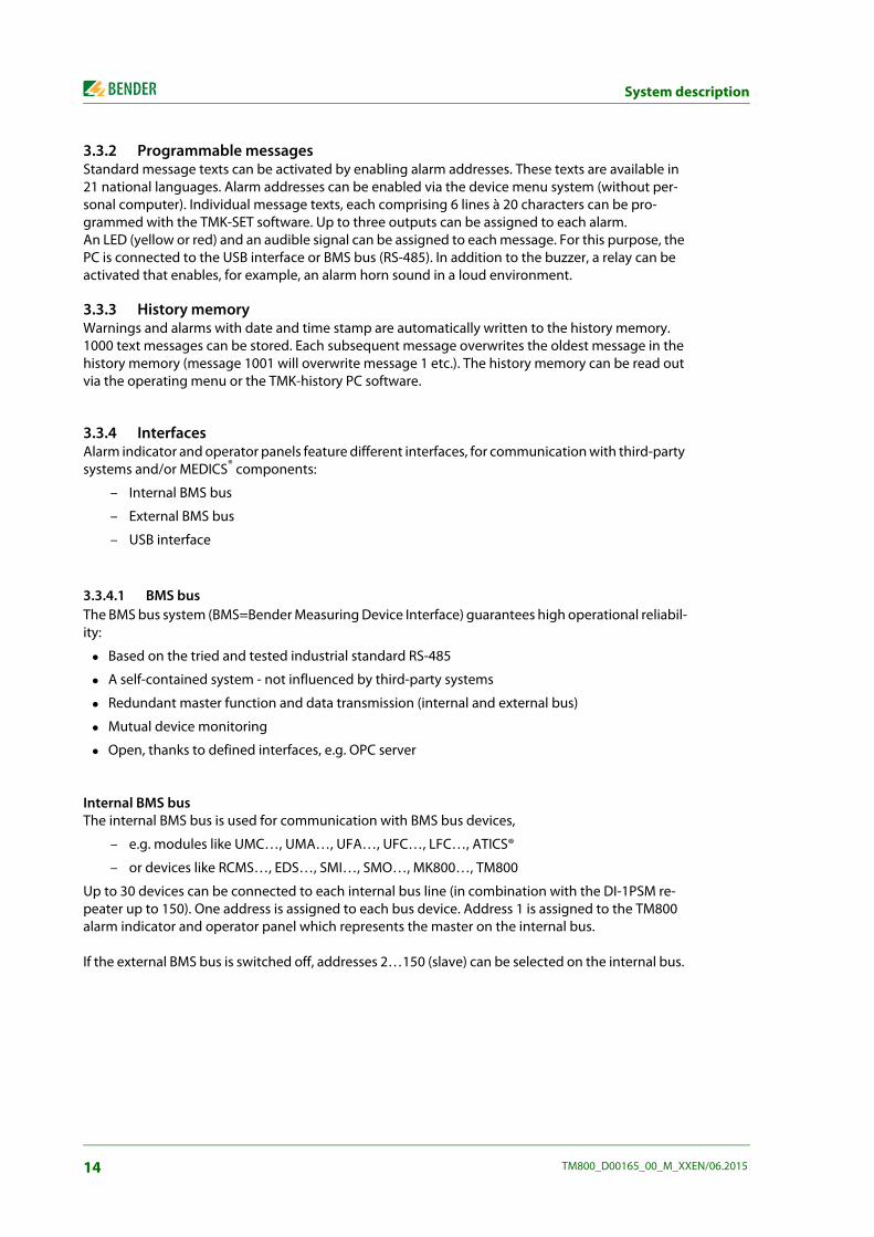
3.3.4.1 BMS bus The BMS bus system (BMS=Bender Measuring Device Interface) guarantees high operational reliabil-ity:
Based on the tried and tested industrial standard RS-485
A self-contained system - not influenced by third-party systems
Redundant master function and data transmission (internal and external bus)
Mutual device monitoring
Open, thanks to defined interfaces, e.g. OPC server
Internal BMS bus The internal BMS bus is used for communication with BMS bus devices,
– e.g. modules like UMC…, UMA…, UFA…, UFC…, LFC…, ATICS®
– or devices like RCMS…, EDS…, SMI…, SMO…, MK800…, TM800
Up to 30 devices can be connected to each internal bus line (in combination with the DI-1PSM re-peater up to 150). One address is assigned to each bus device. Address 1 is assigned to the TM800 alarm indicator and operator panel which represents the master on the internal bus.
If the external BMS bus is switched off, addresses 2…150 (slave) can be selected on the internal bus.
14 TM800_D00165_00_M_XXEN/06.2015

System description
External BMS bus The external BMS bus enables communication with other TM800 alarm indicator and operator pan-els, SMI472-12 or BMS-OPC servers. The master function is cyclically passed to the subsequent mas-ter on the external bus. The TM800, with address 1, however, takes over some special tasks:
– As a "master clock", it synchronises the time of all devices on the internal BMS bus
– It ensures that the required supply voltage is available on the external BMS bus.
Messages can be displayed on any TM800 alarm indicator and operator panel via the external BMS bus. The PC software TMK-SET is used to assign the messages accordingly.
A personal computer is recommended to be connected via the external BMS bus to the TM800 alarm indicator and operator panel. Any information of the TM800 panels connected to the external BMS bus can be displayed and set at a central point. If the personal computer does not feature an RS-485 interface, an RS-232/RS-485 converter DI-2 or a USB/RS-485 converter DI-2USB will be required.
3.3.4.2 USB interface A personal computer can also be connected to the TM800 via the USB interface using a standard-USB device cable (type A/type B). To access the USB interface plug, open the front plate. Only the connected TM800 can be read out and set via the USB interface.
3.3.5 Programming and reading the TM800
3.3.5.1 Connection of the personal computer Connect the TM800 to a personal computer:
directly via the USB interface or
via an RS-232/RS-485 converter DI-2 or a USB/RS-485 converter DI-2USB to the internal or exter-nal BMS bus.
3.3.5.2 Optional software
You can use the PC software TMK-SET to read, display and change the TM800 settings.
You can use the PC software TMK-History to read the history memory of the TM800 (download from http://www.bender-de.com).
BMS-OPC server
3.3.6 Firmware versions The TM800 is controlled by an internal software (firmware).
All devices sharing one external BMS bus must be equipped with compatiblesoftware versions. The following software versions are required:
TM V 4.0 or higher SMI472 V 2.03 or higher
All devices must be set to the same baud rate.
15TM800_D00165_00_M_XXEN/06.2015

System description
3.4 Mechanical design
3.4.1 Module overview The TM800 alarm indicator and operator panels are based on a modular design. The appropriate combination of modules will be made by Bender so that the user is not unnecessarily burdened with planning details. This chapter provides a summary of the applicable modules:
BM800 Module for TM800 alarm indicator and operator panel
BM400 module like BM800, but without an LC display and control buttons
BI… operating and display modules each with five illuminated pushbuttons
BMI… I/O modules (digital inputs, relay outputs, open collector outputs)
Individual components (remote operating table control, intercom systems…)
3.4.2 BM800 and BM400 modules
3.4.2.1 BM800 Module for a TM800 alarm indicator and operator panel with LC display. BM800 features:
– LC display (without a front foil, because this is included already in the front plate of TM800)
– one operating LED, warning and alarm LED each as common alarm LEDs
– 5 control buttons
– Interfaces 2 x RS-485, 1 x USB, 2 x I²C
– Buzzer
3.4.2.2 BM400 BM400 is a module similar to BM800, but without LC display and control buttons. These operating and display modules together with digital I/O modules can be configured to form indicator and op-erator panels.
3.4.3 Operating and display modulesThe operating and display modules consist of 5 elements. Depending on the panel type, different numbers of modules are available (also see "Internal components and modules" on page 77ff).
Type Characteristics
BI800S Operating and display elements to expand the BM800/BM400 modules. 16 BI800S modules can be controlled via I²C bus. One individual function (switch, button, LED etc.) can be assigned to each element.
BI71S Operating and display elements without an I²C bus: 5 illuminated pushbuttons, 5 potential free changeover contacts, max. AC 250 V/8 A.
BI72S Operating and display elements without an I²C bus: 5 illuminated pushbuttons, 5 potential free changeover contacts, max. AC 24 V/0.9 A
16 TM800_D00165_00_M_XXEN/06.2015

System description
3.4.4 Inputs and outputs Digital inputs and outputs as well as relay outputs are available for the control and indication of dif-ferent technical equipment. The I/O modules are controlled via I²C bus.
The digital inputs are designed for a voltage of AC/DC 0…30 V (HIGH=10…30 V; LOW=0…2 V). In practice, these digital inputs are controlled via an internal or external voltage and potential-free con-tacts (N/C or N/O operation, selectable). The voltage required for these inputs can be supplied by the built-in power supply unit. The behaviour of the alarm contact at the digital input (N/O contact or N/C contact) can be assigned via this PC software. That means that the hardware of the alarm indicator and operator panel does not need to be changed in case of subsequent changes of the contact be-haviour.
Digital inputs or outputs (potential free relay contacts or open collector outputs) are controlled by warning or alarm messages, via operating and display modules or the digital inputs. A message, a digital input or an illuminated pushbutton can be assigned to a relay output via the PC software TMK-SET.
The I/O modules are snapped on a DIN rail in the flush-mounting box separately from the display and the pushbutton panels. So the system can easily be expanded. Each input and output provides an alarm LED so that the status is visible at a glance for the technical staff.
3.4.4.1 Digital output 1 When an I/O module BMI8/8, BMI8/4 or BMI0/4 is built in, the first output can be programmed indi-vidually. It can be used for system functions (see "Settings menu 11: Relays" on page 65). The output switches when:
– an internal TM800 device error is recognised
– the test button is pressed (relay will be activated for approx. 1.5 s)
– a device failure is recognised on the BMS bus,
– any warning or alarm message occurs (common alarm)
– the buzzer sounds (relay is activated when buzzer sounding)
The output can also be programmed via TMK-SET like all other outputs.
3.4.4.2 I/O modules
TM800 alarm indicator and operator panels offer safe separation according toIEC 60664 between the relay contacts and the electronics, interface outputs, dig-ital inputs and among each other.
Type Characteristics
BMI8/8 8 digital inputs, 8 open collector outputsThe open collector outputs are capable of driving a load of up to 15 W at an operating voltage of 24 V. They feature flyback diodes for the connection of relays.
17TM800_D00165_00_M_XXEN/06.2015

System description
3.4.5 Individual internal components In addition to the operating functions activated via operating and display modules, often complete operating units from a third-party manufacturer are integrated into the alarm indicator and operator panel. Typical examples are operating table controls or intercom systems. These modules are inte-grated in the alarm indicator and operator panels by Bender so that an aesthetically attractive func-tional solution is available, documented by the official release of the manufacturer. The required connections are made in accordance with the specifications of the respective manufacturer.
Typical examples of third-party systems used in medical locations
BMI8/4 8 digital inputs, 4 relay outputs The digital outputs correspond to those of the BI8/8 module. The potential-free output relays feature one changeover contact eachAC 250 V, 5 A (AC1).
BMI0/4 Expansion for BMI8/4 by 4 relay outputs. The module BMI0/4 can only be used in com-bination with the BMI8/4 module. The potential-free output relays feature one change-over contact each AC 250 V, 5 A (AC1).
Med. gases Intercom systems Operating theatre light
Operating theatre table
Dräger Digicom-Scanvest ALM Maquet
Gehrke Berchtold Trumpf
Schneider Dräger
Stentofon Haraeus
Telecom Behnke
Intercom system – Digicom Dräger Monitor 3G
Type Characteristics
18 TM800_D00165_00_M_XXEN/06.2015

4. Installation and connection
4.1 Installation
4.1.1 Overview of enclosure variants The design of the alarm indicator and operator panels is based on the individual customer require-ments in terms of interior design and the architect's and constructor's needs. In addition to the basic versions also room-high stainless-steel alarm indicator and operator panels or other versions are available.
The foil surface is completely closed, i.e. there are no screws needed for fixing the front plate. The panel is easy to clean so that a high standard of hygiene is guaranteed. For additional protection, the front panel surface can also be delivered with antibacterial surface.
Flush-mounting type enclosure with bezel frame (UPB)
A gap of up to 12 mm between the flush-mounted enclosure and the wall can be concealed by a bez-el frame made of anodised aluminium. This version is recommended to be used for wallpapered walls or walls with non-standard tiles, for example.
Flush-mounting type enclosure with mounting frame (UPE)
The mounting frame permits accurate and close wall mounting. The mounting frame is made of an-odised aluminium. The mounting frame version is preferably used where the enclosure is required to fit exactly the dimension of the tiles.
19TM800_D00165_00_M_XXEN/06.2015
Installation and connection
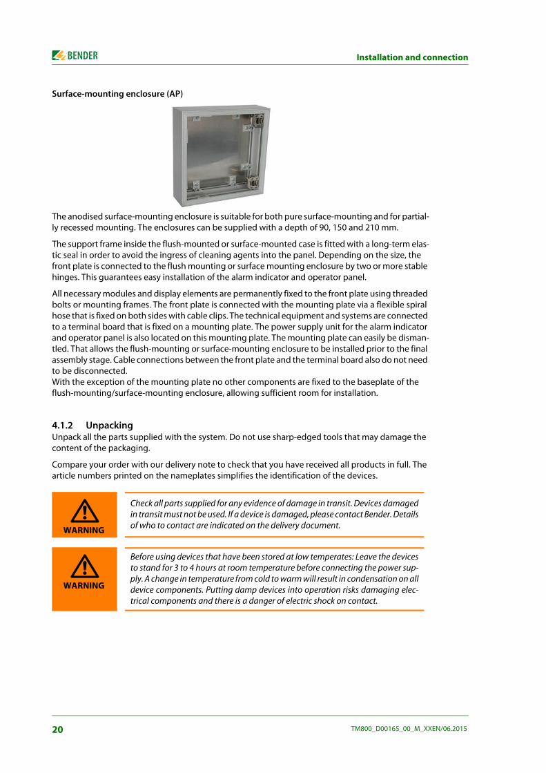
Surface-mounting enclosure (AP)
The anodised surface-mounting enclosure is suitable for both pure surface-mounting and for partial-ly recessed mounting. The enclosures can be supplied with a depth of 90, 150 and 210 mm.
The support frame inside the flush-mounted or surface-mounted case is fitted with a long-term elas-tic seal in order to avoid the ingress of cleaning agents into the panel. Depending on the size, the front plate is connected to the flush mounting or surface mounting enclosure by two or more stable hinges. This guarantees easy installation of the alarm indicator and operator panel.
All necessary modules and display elements are permanently fixed to the front plate using threaded bolts or mounting frames. The front plate is connected with the mounting plate via a flexible spiral hose that is fixed on both sides with cable clips. The technical equipment and systems are connected to a terminal board that is fixed on a mounting plate. The power supply unit for the alarm indicator and operator panel is also located on this mounting plate. The mounting plate can easily be disman-tled. That allows the flush-mounting or surface-mounting enclosure to be installed prior to the final assembly stage. Cable connections between the front plate and the terminal board also do not need to be disconnected. With the exception of the mounting plate no other components are fixed to the baseplate of the flush-mounting/surface-mounting enclosure, allowing sufficient room for installation.
4.1.2 Unpacking Unpack all the parts supplied with the system. Do not use sharp-edged tools that may damage the content of the packaging.
Compare your order with our delivery note to check that you have received all products in full. The article numbers printed on the nameplates simplifies the identification of the devices.
Check all parts supplied for any evidence of damage in transit. Devices damagedin transit must not be used. If a device is damaged, please contact Bender. Detailsof who to contact are indicated on the delivery document.
Before using devices that have been stored at low temperates: Leave the devicesto stand for 3 to 4 hours at room temperature before connecting the power sup-ply. A change in temperature from cold to warm will result in condensation on alldevice components. Putting damp devices into operation risks damaging elec-trical components and there is a danger of electric shock on contact.
WARNING
WARNING
20 TM800_D00165_00_M_XXEN/06.2015

Installation and connection
4.1.3 Installing the flush-mounting type enclosure with bezel frame (UPB) Note: Do not remove the plaster cover and the fixing brackets during the installation to protect the wall-mounting enclosure!
1. Before inserting the cables remove the knockouts. Guide the power supply cables into the enclosure.
2. Install the flush-mounting enclosure in a way that the enclosure (and thus the plaster cover) are approximately 2 mm below the finished surface of the wall.
3. After installing the enclosure securely, remove the plaster cover and the fixing brackets. Then install the bezel frame into the flush mounting enclosure.
Dra
win
g no
.: 9
8002
67
21TM800_D00165_00_M_XXEN/06.2015

Installation and connection
4.1.4 Installing the flush-mounting enclosure with mounting frame (UPE) The front plates are fitted into the wall-mounting enclosure and identified by a number identical to the number of the enclosure. The front plate number must be identical to the enclosure number! Note: Do not remove the plaster cover during the installation to protect the wall-mounting enclo-sure!
1. Before inserting the cables remove the knockouts. Lead the power supply cables into the enclosure.
2. Install the mounting frame and the wall-mounting enclosure (UPE) deeper than the finished wall surface (i.e. tile thickness plus adhesive thickness). Note: The wall-mounting enclosure is partially covered by the wall surface (e.g. tile)
3. Once the enclosure is firmly installed and the joints are filled, the plaster cover can be removed.
Size of the panel and flush-mounting enclosure
Typical tile grid150 mm tile grid= 147 mm tile + 3 mm joint 153 mm tile grid= 150 mm tile + 3 mm joint
Calculation of the panel size Panel dimension = number of tiles x tile grid - one joint width
Example: Panel dimension = 2 x 150 mm - 3 mm Panel dimension = 297 mm
Calculation of the flush-mounting enclosure size Flush-mounting enclosure dimension= Number of tiles x tile grid - one joint width + 10 mm
Example: Flush-mounting enclosure dimension= 2 x 150 mm - 3 mm + 10 mm Flush-mounting enclosure dimension= 307 mm
22 TM800_D00165_00_M_XXEN/06.2015

Installation and connection
wall surface, tilesinside mounted plaster frame, anodized alum-profile, 2mm
brick wallslotted oval head screw, M4x20mmwith washer and nut
mounting lidseal
backbox, 4mmdepth as specified
plaster 3mm
Wal
lbox
to b
e m
ount
edde
eper
than
the
finis
hed
wal
lsur
face
.(i.
e. ti
le th
ickn
ess+
plas
ter)
297
.0
mou
ntin
g lid
147.0
Dra
win
g no
9800
268
23TM800_D00165_00_M_XXEN/06.2015

Installation and connection
4.1.5 Mounting the front plate The front plates are fitted into the flush-mounting enclosure and are marked with a number that is identical to the number of the enclosure. The front plate number must be identical to the enclosure number!
Install the hinges of the front plate as described in the drawing below:
4.1.5.1 Flush-mounting type enclosure with bezel frame (UPB)
beze
l/cov
er fr
ame
+ al
um.-p
rofil
e, 3
mm
wal
l sur
face
bric
k w
all
adju
stab
le h
eigh
t max
. 20m
mse
al
13.0
20.0
slot
ted
pan
head
mac
hine
scr
ew,M
4x16
mm
front
plat
e, 3
mm
, Alu
m.
Alum
. mou
ntin
gpla
te
wel
ded
stud
M4x
5x6x
8+
M4x
12 s
crew
hing
e fix
ing
verti
cal a
djus
tmen
t
horiz
onta
l adj
ustm
ent hing
ehi
nge
hing
e fix
ing
scre
w M
4x8
spac
er W
xHxD
52x
35x1
2
dept
h as
spe
cifie
dM
ount
ing
inst
ruct
ions
see
on
dwg#
980
0267
EO
ptio
nal:
sprin
g ca
tch,
see
dw
g# 9
8002
66E
Fixi
ng in
stru
ctio
ns s
ee o
n dw
g# 9
8003
73EA
+B
rivet
nut
M4
back
box,
4m
m
Dra
win
g no
.: 98
0026
9
24 TM800_D00165_00_M_XXEN/06.2015

Installation and connection
4.1.5.2 Flush-mounting type enclosure with mounting frame (UPE)
in s
ide
mou
ted
plas
ter f
ram
e, a
nodi
zed
alum
-pro
file,
2m
mad
just
able
in d
epth
by
15m
mw
all s
urfa
ce, t
iles
bric
k w
all
seal
plas
ter,
3mm
slot
ted
pan
head
mac
hine
scr
ew,M
4x16
mm
front
plat
e, 3
mm
, Alu
m.
Alum
. mou
ntin
gpla
te
wel
ded
stud
M4x
5x6x
8+
M4x
12 s
crew
hing
e fix
ing
horiz
onta
l adj
ustm
ent
scre
w M
4x8
hing
e fix
ing
verti
cal a
djus
tmen
t Hin
ge
spac
er W
xHxD
42x
35x6
dept
h as
spe
cifie
d
Fixi
ng in
stru
ctio
n se
e on
dw
g# 9
8003
74EA
+B
Mou
ntin
g in
stru
ctio
ns s
ee o
n dw
g# 9
8002
68E
Opt
iona
l: sp
ring
catc
h, s
ee d
wg#
980
0266
E
rivet
nut
M4
back
box,
4m
m
Dra
win
g no
.: 98
0027
2
25TM800_D00165_00_M_XXEN/06.2015
Installation and connection
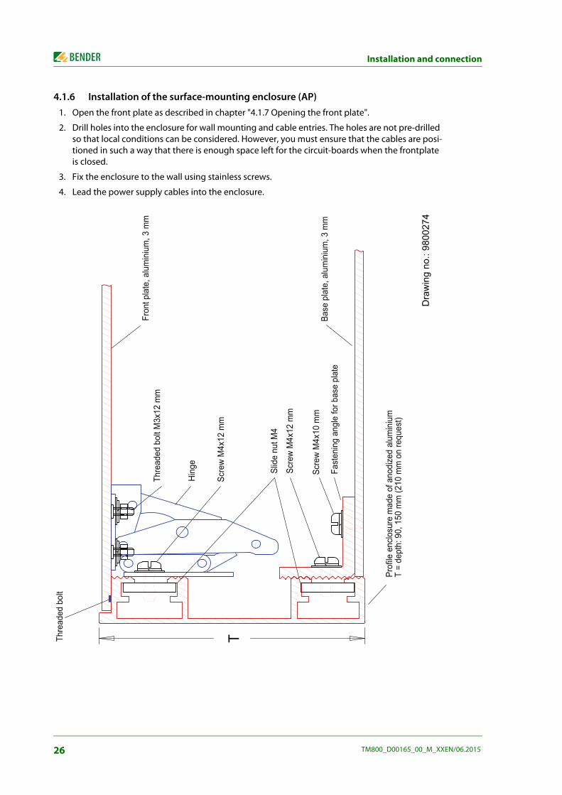
4.1.6 Installation of the surface-mounting enclosure (AP) 1. Open the front plate as described in chapter "4.1.7 Opening the front plate".
2. Drill holes into the enclosure for wall mounting and cable entries. The holes are not pre-drilled so that local conditions can be considered. However, you must ensure that the cables are posi-tioned in such a way that there is enough space left for the circuit-boards when the frontplate is closed.
3. Fix the enclosure to the wall using stainless screws.
4. Lead the power supply cables into the enclosure.
�����������
�
������������
�������
�����
�����
� �������
����������
�
�����
� �������
�����
� �������
�������������������
���� ����
!���� ����"����������"�����
����� ����"����������"�����
#��������������������������$�������
�����
��%��� ��&�'�"��(�����)�
����������*����+
Dra
win
g no
.: 98
0027
4
26 TM800_D00165_00_M_XXEN/06.2015

Installation and connection
4.1.7 Opening the front plate It should only be possible to open the enclosure with a keys or a tool (as, for example a suction cup, screw driver). This is required by the following standards:
VDE 0660, part 500, chapter 7.4.2.2.3. a)
EN 60439-1, chapter 7.4.2.2.3. a)
IEC 60439-1, chapter 7.4.2.2.3. a)
Factory-delivered, TM800 panels come with a textile lug that protrudes betweenthe frame and the front plate. This allows the front plate to be opened for com-missioning without the use of a tool. Make sure this textile lug no longer pro-trudes from the enclosure after commissioning.
Components protruding from the front plate (such as socket-outlets, remote op-erating theatre table control) which could enable the user to hold on to themand to open the alarm indicator and operator panel are secured by means of ascrew located in the middle of the side opposite the hinges: Raised countersunk head screw, M4x10 with rosette.
Suction cup d=80 mmor
Suction cup d=55 mmArt. No. 102851 Art. No. 102850
steel C75 - H&Hspring catch, 12.5mm
welded stud,
front plate, 3 mm, alum.
M3x6 mm
For following wallboxes:
surface-mounting frame(AP) (UPE)
mounting frame(UPB)
bezel frame
backbox, 4 mmD
raw
ing
no.:
9800
266
27TM800_D00165_00_M_XXEN/06.2015

Installation and connection
4.2 Connection
4.2.1 Connection details The following connections are available on modules installed in the lower part of the enclosure:
Connect the supply voltage to the terminals 0 and 230 V of the TM800's power supply unit. The standard supply voltage is AC 230 V.
The terminals for the digital inputs, the open collector outputs and the relay outputs are availa-ble on the associated I/O modules BMI8/8, BMI8/4, BMI0/4. Use cables with a cable cross section of at least 0.75 mm2 for the connection of digital inputs and relay outputs. The maximum cable length per connection is 500 m.
A terminal board allows the connection to the internal and external BMS bus (internal bus = ter-minals iA/iB, external bus = terminals eA/eB). Connect the BMS bus according to the instructions in chapter "4.2.3 BMS-bus connection" and in the "BMS bus" leaflet. Use a shielded cable of at least mm or 0.8 mm cross section for the interface line (e.g. J-Y(St)Y n x 2x0.8). The terminals iS resp. eS are used to connect the shield of the respective BMS bus. The shield must be connected to earth at one end. The shield may in no circumstances be earthed at several points.
Risk of electric shock! Before fitting the enclosure and working on the device connections, make surethat the power supply has been disconnected. Failure to comply with this requirement will expose personnel to the risk of anelectric shock. Furthermore, the electrical installation may be damaged and thedevice destroyed beyond repair.
Connect the TM800 alarm indicator and operator panel exclusively according tothe wiring diagram supplied with the device. Do not make any changes to theinternal wiring. Wiring not conforming to the accompanying diagram or unau-thorised modifications may result in the TM800 malfunctioning or completelyfailing to operate.
If inductive loads and the TM800 share a common voltage source, it is absolutelynecessary to use flyback diodes directly at the inductive load. Always use a sepa-rate power supply for the operation of impulse relays in order to avoid interfer-ences.
Make sure that the power supply of the TM800 is isolated against PE. If this isnot taken into account and a personal computer is connected to the USB inter-face the TM800 or the personal computer may be damaged.
The device contains components that can be damaged by electrostatic dis-charges (ESD). If work requires the opening of the device, the safety precautionsconcerning the dissipation of electrostatic electricity have to be observed.
DANGER
DANGER
CAUTION
CAUTION
CAUTION
28 TM800_D00165_00_M_XXEN/06.2015

Installation and connection
4.2.2 Modules and connections of the TM800 (connection example)
eA eB eS iA iB iS
eA eB eS iA iB iS
BI800
BI800
BI800
BI800
BM800
A
B 1D
6
2
3 4 5
97 8
C
29TM800_D00165_00_M_XXEN/06.2015

Installation and connection
Legend to wiring diagram
TM800 modules
A Back of the front plate
B Mounting plate, installed in the bottom part of the enclosure.
C I2C bus, is used for communication between the modules BM800 (resp. BM400) and the operating and display modules BI800S. The terminals of the two I2C buses must not be interchanged!
D I2C bus, is used for communication between the modules BM800 (or BM400) and the I/O modules BMI8/8, BMI8/4 and BMI0/4. The terminals of the two I2C buses must not be inter-changed!
1 Terminal board for connection to the internal and external BMS bus(internal bus = terminals iA, iB, iS, external bus = terminals eA, eB, eS)
2 Digital inputs of the I/O module BMI8/4, or BMI8/8
3 Open collector outputs of the I/O module BMI8/8
4 Relay outputs of the I/O module BMI8/4
5 Relay outputs of the I/O module BMI0/4
6 Connection of the supply voltage US to the terminals 0 and 230 V of the power supply unit. The standard supply voltage is AC 230 V.
7 Switch S1 to terminate the external BMS bus.
8 Switch S2 to terminate the internal BMS bus.
9 USB connection for programming purposes. Cable: Type A plug on type B plug.
BM800 Module
BI800S Operating and displaying module to expand each BM800/BM400 module by five pushbut-tons
BMI8/8 8 digital inputs, 8 open collector outputs. The open collector outputs are capable of driving a load of up to 15 W, at an operating volt-age of 24 V. They feature flyback diodes for the connection of relays.
BMI8/4 8 digital inputs, 4 relay outputs The digital outputs correspond to those of the BMI8/8 module. The potential-free output relays feature one changeover contact of AC 250 V, 5 A (AC1) each.
BMI0/4 Expansion for BMI8/4 by 4 additional relay outputs. The BMI0/4 module can only be used in conjunction with BMI8/4. The potential-free output relays feature one changeover contact of AC 250 V, 5 A (AC1) each.
Mains Part
Power supply unit of the TM800 alarm indicator and operator panel.
30 TM800_D00165_00_M_XXEN/06.2015

Installation and connection
4.2.3 BMS-bus connection Communication between the TM800 alarm indicator and operator panel and other system compo-nents takes place via two serial interfaces (internal and external BMS bus). These interfaces cables are of two-wire design. See "BMS bus" instruction leaflet for more details about the BMS bus.
The number of bus devices is limited to 30. Install a DI-1PSM repeater if you want to use more devices on the BMS bus. A DI-1PSM also is required when the BMS bus segment of 1200 m is exceeded.
4.2.3.1 Terminating resistor
The BMS bus must be terminated at both ends with terminating resistors of 120 Ω (0.4 W). One ter-minating resistor is installed in each TM800 for the internal and external bus.
If several TM800 alarm indicator and operator panels are connected via the BMS bus, the terminating resistors of the TM800 alarm indicator and operator panels which are not installed at the end of the bus have to be switched off. The same applies to all other devices and modules that are not installed at the end of the bus.
Use the DIP switches S1 and S2 to set the terminating resistor for the internal and external BMS bus: S1 = external BMS bus; S2 = internal BMS bus. Factory setting: S1 and S2: off. The DIP switches are located on the BM800 module adjacent to the interface terminals. Use the DIP switch to select on or off position.
BMS-bus addresses Be sure that the addresses of all devices connected to the bus are correctly assigned. Never assign one address twice. Assign the addresses consecutively without any gaps. Bear in mind that each bus requires one master. A device becomes a master by assigning address 1 to it. Address assignment can be carried out via the menu of the TM800 alarm indicator and operator panel (see "Settings menu 10: Interface" on page 65) or via the basic settings in the TMK-SET software.
Internal BMS bus Select an address between 1 and 150 for the internal bus of the alarm indicator and operator panel (factory setting: 1). The addresses 100…103 are reserved for special tasks (e.g. programming). This setting can only be changed when the external bus has been switched off before. On the internal BMS bus the baud rate is set to a fixed value of 9600 bits/s.
External BMS bus Select an address between 1 and 99 for the BMS bus of the TM800 alarm indicator and operator pan-el. The external bus is primarily used for the connection of several TM800 alarm indicator and operator panels. But also MK800 alarm indicator and test combinations and SMI472-12 signal converters can be connected. Up to 99 devices can be connected. The following applies to the external bus:
When the TM800 alarm indicator and operator panel is the only control device in the system, address 1 (Master) is assigned to it.
Missing or incorrectly installed terminating resistors (e.g. in the middle of thebus) will cause bus instability.
31TM800_D00165_00_M_XXEN/06.2015

Installation and connection
On the external bus, the Master function can be cyclically passed from one address to the next higher one.
4.3 Examples for connection and address assignment
Example Devices on the internal bus
Changeover and monitoring module UMC107E-… with alarm indicator and operator panel TM800 and3 alarm indicator and test combinations MK2430. All components are connected to the TM800 via the in-ternal RS-485 interface.
The addresses are consecutively assigned to additional TM800 alarm indicatorand operator panels (2, 3 etc.). Only when there are no gaps between the ad-dresses, reliable function can be ensured. All devices on the external bus must be equipped with compatible software ver-sions (see chapter "3.3.6 "). All devices must be set to the same baud rate.
CAUTION
32 TM800_D00165_00_M_XXEN/06.2015

Installation and connection
Example 2: Parallel operator panel
Changeover and monitoring module UMC107E-… with an alarm indicator and operator panel TM800 inan operating theatre, a "higher-level" alarm indicator and operator panel TM800 in the technical controlroom and a personal computer to evaluate the history memory of the alarm indicator and operator pan-els. If the personal computer does not have an RS-485 interface, an RS-232/RS-485 converter DI-2 or aUSB/RS-485 converter DI-2USB will be required.
33TM800_D00165_00_M_XXEN/06.2015

Installation and connection
Example 3: Central devices on the BMS bus
A three or four-pole changeover module UMC710D- with two changeover and monitoring modulesUMC107E downstream and messages from the UPS (battery-supported safety power supply) system.Each UMC107E is connected to "its" alarm indicator and operator panel TM800 via the internal BMS bus.The TM800 panels are connected with each other and also to a "higher-level" TM800 in the technicalroom, to the SMI472-12 converter module and to a personal computer for the evaluation of the historymemory via the external BMS bus. If the personal computer does not have an RS-485 interface, an RS-232/RS-485 converter DI-2 or a USB/RS-485 converter DI-2USB will be required.
34 TM800_D00165_00_M_XXEN/06.2015

Installation and connection
4.3.1 Address settings and their meaning
Display Meaning Setting
on TM/MK800 Setting
on TMK-SET External address Internal address
0 (ext. bus on) 0 -- -- --
0 (ext. bus on) 1 TM/MK itself -- dig. IN*
0 (ext. bus off ) M = own addr. TM/MK itself -- dig. IN*
0 (ext. bus off ) M <> own addr Device M on the int. bus of the
own device
ext: 0/int: M int. bus: int M
N = own addr. 0 Device N on the external bus
-- dig. IN*
N = own addr. 1 TM/MK itself -- dig. IN*
N = own addr. M > 1 Device M on the int. bus of the
own device
-- int. bus: int M
N <> own addr. 0 Device N on the external bus
ext: N/int: 0 ext. bus: ext: N, int: 0
N <> own addr. 1 Device N on the external bus
-- ext. bus: ext: N, int: 0
N <> own addr. M > 1 Device M on the int. bus of device
N
ext: N/int: M ext. bus: ext: N, int: M
35TM800_D00165_00_M_XXEN/06.2015

Installation and connection
Explanatory note to the digital inputs (*) Alarm messages from digital inputs on TM/MK800 are always displayed on the device itself regard-less of whether an individual message has been programmed or not (Exception: channel is deactivated). An entry into the alarm address table is not required.
If no individual message is programmed, the standard text will be displayed.
An alarm message can also be programmed to be displayed without text/LED/buzzer (silent message).
Note: Flashing alarm messages are not allowed!
In principle, all alarm messages are stored in the history memory (Exception: channel is deactivated):
If no individual message is programmed, the standard text will be displayed resp. will be stored in the history memory.
If the message has been programmed without a text (silent message), its source (DigIn resp. address and channel No.) will be stored in the history memory (no individual text possible!).
Test messages are only stored in the history memory of the device that triggered the message.
Transmission via BMS bus:
All alarm messages are actively sent (i.e. as a new message) via the external or internal BMS.
Operating messages are actively sent via the external BMS bus and are not stored in the history memory.
Note: Flashing messages must be avoided, where possible, and on no account be sent via the int./ext. BMS bus!
The first 16 digital inputs can be configured as "flashing" and in this case are not signalled via the external BMS. This is only permissible for messages with a flashing frequency of 0.5 Hz!
Inputs that are assigned to operating messages or switching commands are not displayed with a text message or stored into the history memory.
36 TM800_D00165_00_M_XXEN/06.2015

5. Commissioning and testing
Start commissioning according to the following commissioning pattern:
1. Tests before switching on
2. Tests after switching on
3. Set parameters (parameterisation)
4. Settings at the TM800
5. Settings in the TMK-SET software
6. Tests after parameter setting
Write down all settings and keep it together with the device and installation doc-umentation. When setting the TM800 with the configuration softwareTMK-SET, a project filewill be created. Save this file. Create a backup copy of this file and keep it in a safeplace.
37TM800_D00165_00_M_XXEN/06.2015

Commissioning and testing
5.1 Tests before switching on
Continue with chapter "Tests after switching on" on page 39.
��������������� ���������������� ��
������������ ��� ���������������������������������������� ����
����������������������������� �����������������
������� ��������� ����������������������!�"� ���
� #������������������������������ ����
$�������������� ��� ���������� �
�������!�"� ���%����&�'��(��������������� ��
� $�������������� ��� ���������� ���$���)�� �������
����������� ���&!*
����� &������������������������������������ ��%��������� �
����������#�������+����+�&��(
���
���
���
����������!���&�������!���&,�� �-��������������� ���������������������� ��������������������������
������� �
��)�����������
���
���
�
�
�
����������!���&,������!���&,�� �-����������� ��
��������������������� ��
��)�����������
���
�
������������������������������������ ��
��)�����������
���
����� �!�"� ���������������������������������
����� ���
��)�����������.����������)�������������� �� ������������������
���
/����� ��� ��������������������+!�"� ��+����������� ��� ��� ���� �������
��)�����������
���
���������������������������� ��������������������������������
0������ �����������
���
"������ ��������� ��������������������+�����
����������������+
�
�
�
38 TM800_D00165_00_M_XXEN/06.2015

Commissioning and testing
5.2 Tests after switching on
Continue with chapter "Make settings (parameterisation)" on page 39.
5.3 Make settings (parameterisation)
All settings can be carried out using the TMK-SET software. Alternatively, somesettings can be carried out via the TM800 menu (see diagrams).
���������������� ��� ������������%������� ���.12��3(��3 �����45�
� ��)�����������
���$ ������������6������
� ���
#������� ������������ �����7�8��������� �*
�������������������9:�� � ��������� ��� �����������������������������������������6������� ���
�
����������������������� ��
��)�������������������������������
����� ��������������������������������������� ��
���
���
�
$� ���������+;��:'����� �������+��������������������������������������������������������45�
� $���������������������������������'����� ���������
���4����� -�0���������57":���������������������#$������!�"� ��������
�������$� ����������57":����������+"���� ��+�����������������������������������������������
��������45�
� $�����������������������������'����� ���������
���
�����������������<�������45�
� $������������������������������������
������������������������
���
39TM800_D00165_00_M_XXEN/06.2015

Commissioning and testing
5.3.1 Settings at the TM800 The following settings can optionally be carried out via the function buttons at the TM800 or the TMK-SET software. Make a note of the modified settings (setting table).
Continue with chapter "Tests after parameter setting" on page 42.
"��� �������
"���!�"� ������������%����&��'��(
"���� ��������������������������� ���
"�������������������������������������
����������!���&�������!���&,��
0��������������������������������� ������&0#"
��������
$������� �==�������� ������������������������
������������ ��
$�����)� ����������&��
���
"�������&����
0����������������'��� 0�����57":��������������������%�������
>�2�1(
�
"�������+������ +?��������������������������*
8� ��-�"����������������������� �������
�
������ �==�����������
"���������� ��������
�
8� ��������� ��������������������
������
40 TM800_D00165_00_M_XXEN/06.2015

Commissioning and testing
5.3.2 Settings using the TMK-SET software
Continue with chapter "Tests after parameter setting" on page 42.
"��� �������
"���������
"��� �==��
$�����)� ����������&��
����������!���&�������!���&,�
������ �������-�"��������������������������
8� ��-�"��������������������������
"�����������������
"������������ ��-�������������������������
#������� �������������������������� ���
���������
:��������������� ����������������������
���
���
:�������������� �� ���������������������@�����
������ ������� ��� �.���������7�������������
:�������������������
"��������������������������A������ �����������.���
��@�����
����� ���������.������������������� ������
�����
������������������������������������������
���
0��������������������������������� ������&0#"�
"�������+������ +?��������������������������*
���
�
4������������������ #����������������������
���
"���������������� #���������������������
���
41TM800_D00165_00_M_XXEN/06.2015

Commissioning and testing
5.3.3 Tests after parameter setting
(*) Messages which can be created by a BMS device are simulated.
"� ����+:'����� ��������+������������������� �'����� ����������������
45�
���)�����������
"��� �����������������%��������������� ���.
���� �������� �(��$������������������� ������ �������+����������������+�%B(��������������������
������ �� ���������� ��� �����������
���
�
���
������������������������
��)������������������������������������ ��������������� ���������
���������������������� �������
���)�����������
"����������������������������������A������ �������)���������7��.������@������
"����������������� ���������.�������������
� �������������
42 TM800_D00165_00_M_XXEN/06.2015
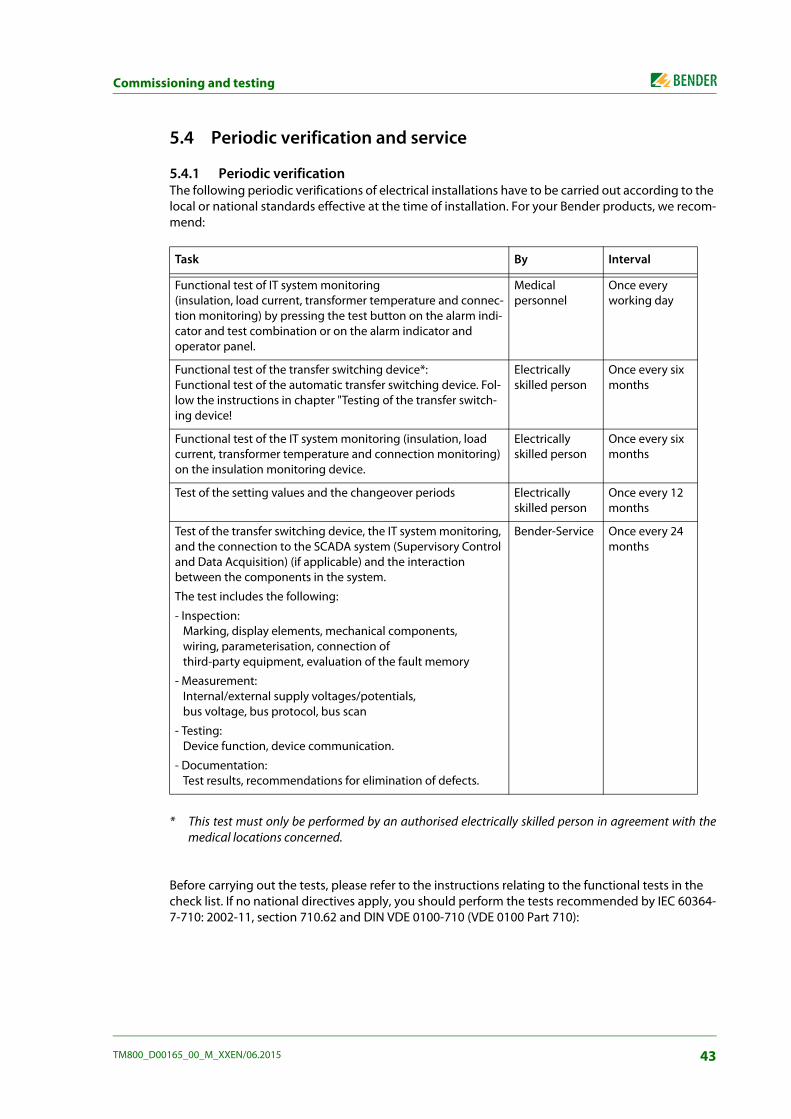
Commissioning and testing
5.4 Periodic verification and service
5.4.1 Periodic verification The following periodic verifications of electrical installations have to be carried out according to the local or national standards effective at the time of installation. For your Bender products, we recom-mend:
* This test must only be performed by an authorised electrically skilled person in agreement with themedical locations concerned.
Before carrying out the tests, please refer to the instructions relating to the functional tests in the check list. If no national directives apply, you should perform the tests recommended by IEC 60364-7-710: 2002-11, section 710.62 and DIN VDE 0100-710 (VDE 0100 Part 710):
Task By Interval
Functional test of IT system monitoring (insulation, load current, transformer temperature and connec-tion monitoring) by pressing the test button on the alarm indi-cator and test combination or on the alarm indicator and operator panel.
Medical personnel
Once every working day
Functional test of the transfer switching device*: Functional test of the automatic transfer switching device. Fol-low the instructions in chapter "Testing of the transfer switch-ing device!
Electrically skilled person
Once every six months
Functional test of the IT system monitoring (insulation, load current, transformer temperature and connection monitoring) on the insulation monitoring device.
Electrically skilled person
Once every six months
Test of the setting values and the changeover periods Electrically skilled person
Once every 12 months
Test of the transfer switching device, the IT system monitoring, and the connection to the SCADA system (Supervisory Control and Data Acquisition) (if applicable) and the interaction between the components in the system.
The test includes the following:
- Inspection: Marking, display elements, mechanical components, wiring, parameterisation, connection of third-party equipment, evaluation of the fault memory
- Measurement: Internal/external supply voltages/potentials, bus voltage, bus protocol, bus scan
- Testing: Device function, device communication.
- Documentation: Test results, recommendations for elimination of defects.
Bender-Service Once every 24 months
43TM800_D00165_00_M_XXEN/06.2015

Commissioning and testing
5.4.2 Service For technical support, commissioning, troubleshooting and periodic verification Bender offers:
First Level Support Technical support by phone or e-mail for all Bender products:
Question about specific customer applications
Commissioning
Troubleshooting
Telephone: +49 6401 807-760*Fax: +49 6401 807-259In Germany only: 0700BenderHelp (Tel. and Fax) E-mail: [email protected]
Repair Service Repair, calibration, update and replacement service for all Bender products
Repair, calibration, testing and analysing Bender products
Hardware and software update for Bender devices
Delivery of replacement devices for faulty or incorrectly delivered Bender devices
Extended warranty for Bender devices with in-house repair service resp. replacement devices at no extra cost
Telephone: +49 6401 807-780** (technical issues) +49 6401 807-784**, -785** (commercial issues)
Fax: +49 6401 807-789E-mail: [email protected]
Please send the devices for repair to the following address: Bender GmbH, Repair-Service, Londorfer Straße 65, 35305 Grünberg
Field Service On-site service for all Bender products
Commissioning, parameter setting, maintenance, trouble shooting for Bender products
Analysis of the electrical installation in the building (power quality test, EMC test, thermogra-phy)
Practical training courses for customers.
Telephone+49 6401 807-752**, -762 ** (technical issues) +49 6401 807-753** (commercial issues)
Fax: +49 6401 807-759E-mail: [email protected]
*Available from 7.00 a.m. to 8.00 p.m. on 365 days of the year (CET/UTC+1) **Mo-Thu 7.00 a.m. - 8.00 p.m., Fr 7.00 a.m. - 13.00 p.m.
Internet: www.bender.de
5.4.3 Maintenance The TM800 alarm indicator and operator panel does not contain any parts that must be maintained. Despite this, the intervals specified for periodic verification should be adhered to.
44 TM800_D00165_00_M_XXEN/06.2015

6. Troubleshooting
6.1 Error messages The following errors are recognised by the BM800 module and indicated on the display. The buzzer emits a beep code corresponding to the error number every 10 seconds. If an optional input/output module exists and if the function "device error" is set in the "Relay" settings menu, also the digital output 1 will also switch.
No. Display Description Task
1 DISPLAY ERROR Display defective Replace BM800 module*
2 I2C-BUS ERROR(X) Error code (X): 1 I²C bus error 2 Ack error when sending the
address 3 Ack error during data trans-
mission 4 Ack error while receiving the
address 5 Ack error while receiving
data 6 Communication problem
Interrupt supply voltage to TM800 for ≥ 3 minutes. If the error continues to exist, BM800 module or I²Cbus cable is defective -> replace*.
3 RTC ERROR Clock chip defective Replace BM800 module*
4 FLASH ERROR Memory module D5 defective Replace memory module D5 (socketed), replace BM800 mod-ule*
5 Address internal ERROR (XXX)
Address of the TM800 on the internal BMS bus is already occu-pied (XXX=current address)
Change the address of TM800 in the menu
6 Overflow ERROR (03) More than 80 alarm messages are present.
Reduce the amount of messages
Overflow ERROR (05) More than 1000 device failure messages are present
Reduce the amount of messages
Overflow ERROR (07) More than 99 text messages are present
Reduce the amount of messages
Overflow ERROR (08) Automatic correction of the his-tory memory is carried out because of voltage interruption.
None
Overflow ERROR (11) Stack Error Make a note of the error code. Contact Bender Service.
7 Checksum ERROR Program memory defective Replace BM800 module*
45TM800_D00165_00_M_XXEN/06.2015

Troubleshooting
*Please make a note of the cause of error, the error number and if applicable the error code. This in-formation facilitates the diagnosis and repair of the equipment.
6.2 Malfunctions Below please find a selection of errors likely to occur and how to eliminate them. This error list does not claim to be exhaustive. Possible error codes occurring after carrying out a test are listed in the chapter "Test function" on page 52f.
8 Address external ERROR (XXX)
Address of the TM800 on the external BMS bus is already occupied (XXX=current address)
Change the address of TM800 in the menu
9 I2C-0-Error I2C-Bus-Interrupt Replace BM800 module*
10 I2C-1-Error I2C-Bus-Interrupt Replace BM800 module*
Error Possible cause Task
No indication on the display of the TM800 alarm indicator and operator panel.
Check AC/DC 24 V power supply; Check the fuse of the power sup-ply unit.
Replace fuse, if required.
No characters on the display, although the display is illumi-nated.
Replace BM800 module*
Function buttons do not operate.
Replace BM800 module*
The common alarm LEDs do not perform any function
Replace BM800 module
Character matrix visible on the display, but firmware doesn't run.
Replace BM800 module
Time of day gets lost in case of short-term voltage failure
Replace BM800 module
Error during the execution of a switching command (No. and address of an operating and display module not found).
Interface of the internal I²C bus defective; ribbon cable or plug defective; address at the operat-ing and display modules not cor-rectly set or assigned twice via DIP switch.
Replace defective partChange the address.
No. Display Description Task
46 TM800_D00165_00_M_XXEN/06.2015

Troubleshooting
Error during the transmission of the assignments or basic settings via the USB inter-face.
Address of the alarm indicator and operator panel not correctly set (menu); alarm indicator and operator panel address does not match the setting in the TMK-SET configuration software; USB cable defective; wrong serial interface (com port) set in TMK-SET software.
Replace defective part Change the setting.
Error during transmission of the assignments or basic set-tings via the external BMS bus.
Address or baud rate of the alarm indicator and operator panel not correctly set (menu); alarm indicator and operator panel address does not match the setting in the TMK-SET con-figuration software; address of externally connected devices incorrectly set; incorrect parame-terisation with TMK-SET; inter-face cables A/B mixed up; RS-485 bus incorrectly terminated or not terminated at all; wrong serial interface set in the TMK-SET soft-ware.
make corrections
Error on internal BMS bus. Device addresses on the internal bus incorrectly set; interface cables A/B mixed up; network incorrectly terminated or not at all; incorrect parameter setting with TMK-SET.
Make corrections
Functional error of the out-put relays.
Incorrect programming of the switching commands with TMK-SET; relay defective.
Make corrections
Functional error of the digital inputs.
Digital inputs not correctly set with TMK-SET. Incorrect connec-tion (does not match pre-assign-ment). Incorrect setting "neutral/medical". Input defective.
Make corrections or replace
Error Possible cause Task
47TM800_D00165_00_M_XXEN/06.2015
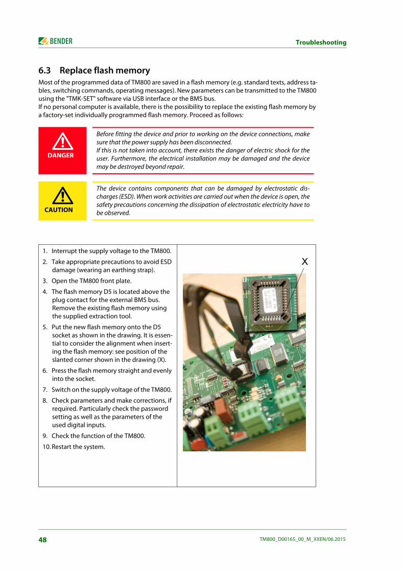
Troubleshooting
6.3 Replace flash memory Most of the programmed data of TM800 are saved in a flash memory (e.g. standard texts, address ta-bles, switching commands, operating messages). New parameters can be transmitted to the TM800 using the "TMK-SET" software via USB interface or the BMS bus. If no personal computer is available, there is the possibility to replace the existing flash memory by a factory-set individually programmed flash memory. Proceed as follows:
Before fitting the device and prior to working on the device connections, makesure that the power supply has been disconnected. If this is not taken into account, there exists the danger of electric shock for theuser. Furthermore, the electrical installation may be damaged and the devicemay be destroyed beyond repair.
The device contains components that can be damaged by electrostatic dis-charges (ESD). When work activities are carried out when the device is open, thesafety precautions concerning the dissipation of electrostatic electricity have tobe observed.
1. Interrupt the supply voltage to the TM800.
2. Take appropriate precautions to avoid ESD damage (wearing an earthing strap).
3. Open the TM800 front plate.
4. The flash memory D5 is located above the plug contact for the external BMS bus. Remove the existing flash memory using the supplied extraction tool.
5. Put the new flash memory onto the D5 socket as shown in the drawing. It is essen-tial to consider the alignment when insert-ing the flash memory: see position of the slanted corner shown in the drawing (X).
6. Press the flash memory straight and evenly into the socket.
7. Switch on the supply voltage of the TM800.
8. Check parameters and make corrections, if required. Particularly check the password setting as well as the parameters of the used digital inputs.
9. Check the function of the TM800.
10. Restart the system.
DANGER
CAUTION
X
48 TM800_D00165_00_M_XXEN/06.2015

7. Operation
This chapter can also be used by the medical personnel as a quick reference guide.
7.1 Operator control and display elements
LED and LCD
1 LED "Operation": Power On indicator, green (only lights up if no warnings or alarms are pending).
2 LED "Warning" warning messages, yellow
3 LED "Fault": alarm messages, red
4 LCD: Display of operating status, warning and alarm messages as well as menu functions.
������� ���� �����
1
765
2
3
4
8 910
49TM800_D00165_00_M_XXEN/06.2015
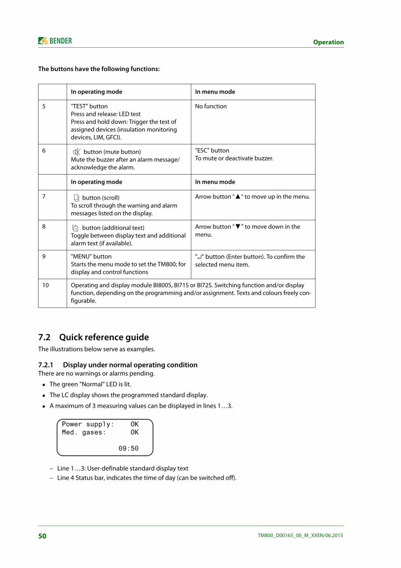
Operation
The buttons have the following functions:
7.2 Quick reference guide The illustrations below serve as examples.
7.2.1 Display under normal operating condition There are no warnings or alarms pending.
The green "Normal" LED is lit.
The LC display shows the programmed standard display.
A maximum of 3 measuring values can be displayed in lines 1…3.
– Line 1…3: User-definable standard display text – Line 4 Status bar, indicates the time of day (can be switched off).
In operating mode In menu mode
5 "TEST" button Press and release: LED test Press and hold down: Trigger the test of assigned devices (insulation monitoring devices, LIM, GFCI).
No function
6 button (mute button) Mute the buzzer after an alarm message/acknowledge the alarm.
"ESC" buttonTo mute or deactivate buzzer.
In operating mode In menu mode
7 button (scroll) To scroll through the warning and alarm messages listed on the display.
Arrow button "▲" to move up in the menu.
8 button (additional text) Toggle between display text and additional alarm text (if available).
Arrow button "▼" to move down in the menu.
9 "MENU" button Starts the menu mode to set the TM800; for display and control functions
"↵" button (Enter button). To confirm the selected menu item.
10 Operating and display module BI800S, BI71S or BI72S. Switching function and/or display function, depending on the programming and/or assignment. Texts and colours freely con-figurable.
Power supply: OK Med. gases: OK
09:50
50 TM800_D00165_00_M_XXEN/06.2015
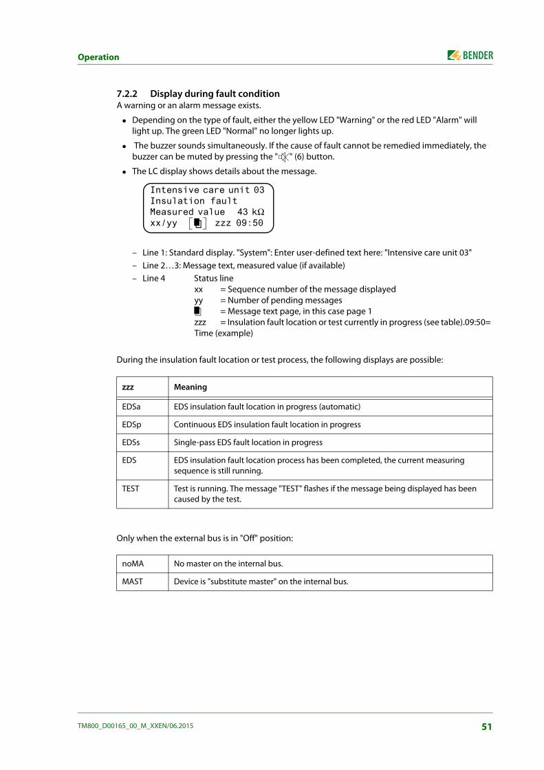
Operation
7.2.2 Display during fault condition A warning or an alarm message exists.
Depending on the type of fault, either the yellow LED "Warning" or the red LED "Alarm" will light up. The green LED "Normal" no longer lights up.
The buzzer sounds simultaneously. If the cause of fault cannot be remedied immediately, the buzzer can be muted by pressing the " " (6) button.
The LC display shows details about the message.
– Line 1: Standard display. "System": Enter user-defined text here: "Intensive care unit 03" – Line 2…3: Message text, measured value (if available) – Line 4 Status line
xx = Sequence number of the message displayedyy = Number of pending messages
= Message text page, in this case page 1zzz = Insulation fault location or test currently in progress (see table).09:50= Time (example)
During the insulation fault location or test process, the following displays are possible:
Only when the external bus is in "Off" position:
zzz Meaning
EDSa EDS insulation fault location in progress (automatic)
EDSp Continuous EDS insulation fault location in progress
EDSs Single-pass EDS fault location in progress
EDS EDS insulation fault location process has been completed, the current measuring sequence is still running.
TEST Test is running. The message "TEST" flashes if the message being displayed has been caused by the test.
noMA No master on the internal bus.
MAST Device is "substitute master" on the internal bus.
Intensive care unit 03 Insulation fault Measured value 43 kΩ xx/yy zzz 09:50
51TM800_D00165_00_M_XXEN/06.2015
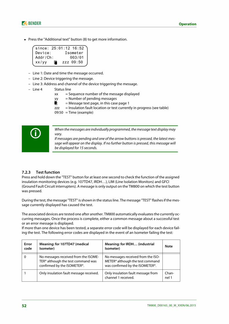
Operation
Press the "Additional text" button (8) to get more information.
– Line 1: Date and time the message occurred. – Line 2: Device triggering the message. – Line 3: Address and channel of the device triggering the message. – Line 4 Status line
xx = Sequence number of the message displayedyy = Number of pending messages
= Message text page, in this case page 1zzz = Insulation fault location or test currently in progress (see table)09:50 = Time (example)
7.2.3 Test function Press and hold down the "TEST" button for at least one second to check the function of the assigned insulation monitoring devices (e.g. 107TD47, IRDH…), LIM (Line Isolation Monitors) and GFCI (Ground Fault Circuit interrupters). A message is only output on the TM800 on which the test button was pressed.
During the test, the message "TEST" is shown in the status line. The message "TEST" flashes if the mes-sage currently displayed has caused the test.
The associated devices are tested one after another. TM800 automatically evaluates the currently oc-curring messages. Once the process is complete, either a common message about a successful test or an error message is displayed. If more than one device has been tested, a separate error code will be displayed for each device fail-ing the test. The following error codes are displayed in the event of an Isometer failing the test:
When the messages are individually programmed, the message text display mayvary.If messages are pending and one of the arrow buttons is pressed, the latest mes-sage will appear on the display. If no further button is pressed, this message willbe displayed for 15 seconds.
Error code
Meaning: for 107TD47 (medical Isometer)
Meaning: for IRDH… (industrial Isometer) Note
0 No messages received from the ISOME-TER® although the test command was confirmed by the ISOMETER®.
No messages received from the ISO-METER® although the test command was confirmed by the ISOMETER®.
1 Only insulation fault message received. Only insulation fault message from channel 1 received.
Chan-nel 1
since: 25:01:12 16:52Device: Isometer Addr/Ch: 003/01xx/yy zzz 09:50
52 TM800_D00165_00_M_XXEN/06.2015
Operation
Information on error codes
For TM800 alarm indicator and operator panels, which are "slaves" on the BMS bus, a timeout of 50 seconds is applicable for error codes 0 and 14.
Error code 14 occurs when a request for a test to be performed on a slave has been made, but the test command cannot be sent because the TM800 has not been queried. In this case, the master was not able to scan the TM800 because the address gap upstream of the TM800 was too large. This error code is not so much an indication of a faulty ISOMETER® but that the BMS bus system is faulty.
2 Only overload message received. Only insulation fault message from channel 2 received.
Chan-nel 2
3 Only insulation fault message and over-load message received.
Chan-nel 1 and 2
4 Only overtemperature message received.
Chan-nel 3
5 Only insulation fault message and over-temperature message received.
Chan-nel 1 and 3
6 Only overload message and overtem-perature message received.
Chan-nel 2 and 3
14 Test command could not be sent because no query was made (slave).
Test command could not be sent because no query was made (slave).
Slave only
15 ISOMETER® did not confirm the test command (no answer).
ISOMETER® did not confirm the test command (no answer).
Error code
Meaning: for 107TD47 (medical Isometer)
Meaning: for IRDH… (industrial Isometer) Note
53TM800_D00165_00_M_XXEN/06.2015

Operation
54 TM800_D00165_00_M_XXEN/06.2015

8. Menu mode: Operation and setting
8.1 Switching on and calling the main menu When the TM800 is connected to the power supply, the following information appears on the dis-play for approx. 3 seconds. Details about the address and the firmware version of the device are dis-played. This information is also available in the "Info" menu.
If there are no messages pending, the standard display will be shown when the starting procedure is completed.
The TMK-SET software allows you to change the standard display and the message texts.
Press the "Menu" button to open the main menu.
The following buttons can be used in the main menu: ESC Exit function or go up one menu level ▲, ▼ Select menu items ↵ Confirm the selected menu item (Enter)
If the TM800 was not connected to the power supply for several days, it may takesome time until the starting procedure has completed (approx. 30 seconds). Inthis case, enter the time and date again.
The menu mode is exited automatically if no buttons are pressed in one of themenus for more than five minutes (exception: "Test communication" in the "Con-trol" menu and "Position mode" in the "External devices" menu).
TM800 Addr.:01/001 Software 4.02 D279 Date: 02.05.12Bender GmbH Grünberg
*********************** SYSTEM READY !**Bender GmbH Grünberg 09:50
1.Exit 2.Values 3.History 4.Settings
55TM800_D00165_00_M_XXEN/06.2015

Menu mode: Operation and setting
8.2 Menu overview diagram The following diagram will help you to navigate through the menus:
Some menus are password-protected. Password protection is only effective if thepassword has been enabled (switched on). When an attempt is made to open one of these menus, the password entryscreen display appears automatically:
Once a valid password has been entered, full access will be given to all menus(except to the service menu) until menu mode is exited.
Please enterPassword 0 0 0
C�:'��
1��3� ���
,�"�������
>�$���
2�/�����
;�:'����� ��������
D����
1�� �������������
C�:'��
2���������������
,�3� ������������
>������� �������
;�!�==��
D�$���������
��$ �)
E�9�������
C�����������
CC�8� ��
C1�#�����
C2�"�����������
C�:'��
1�8�����%� ���$ ���(
2�:�"������&���
,������$����������
>�"�����8��������
56 TM800_D00165_00_M_XXEN/06.2015
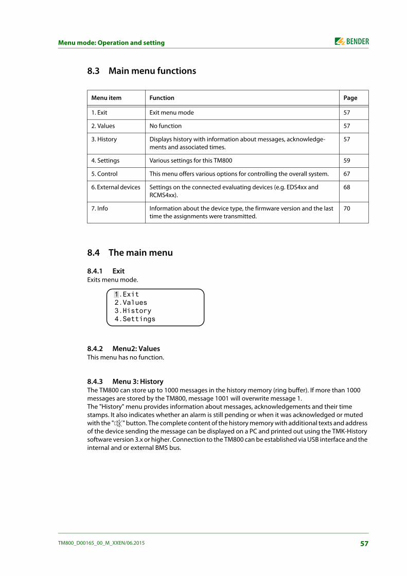
Menu mode: Operation and setting
8.3 Main menu functions
8.4 The main menu
8.4.1 Exit Exits menu mode.
8.4.2 Menu2: Values This menu has no function.
8.4.3 Menu 3: History The TM800 can store up to 1000 messages in the history memory (ring buffer). If more than 1000 messages are stored by the TM800, message 1001 will overwrite message 1. The "History" menu provides information about messages, acknowledgements and their time stamps. It also indicates whether an alarm is still pending or when it was acknowledged or muted with the " " button. The complete content of the history memory with additional texts and address of the device sending the message can be displayed on a PC and printed out using the TMK-History software version 3.x or higher. Connection to the TM800 can be established via USB interface and the internal and or external BMS bus.
Menu item Function Page
1. Exit Exit menu mode 57
2. Values No function 57
3. History Displays history with information about messages, acknowledge-ments and associated times.
57
4. Settings Various settings for this TM800 59
5. Control This menu offers various options for controlling the overall system. 67
6. External devices Settings on the connected evaluating devices (e.g. EDS4xx and RCMS4xx).
68
7. Info Information about the device type, the firmware version and the last time the assignments were transmitted.
70
1.Exit 2.Values 3.History 4.Settings
57TM800_D00165_00_M_XXEN/06.2015
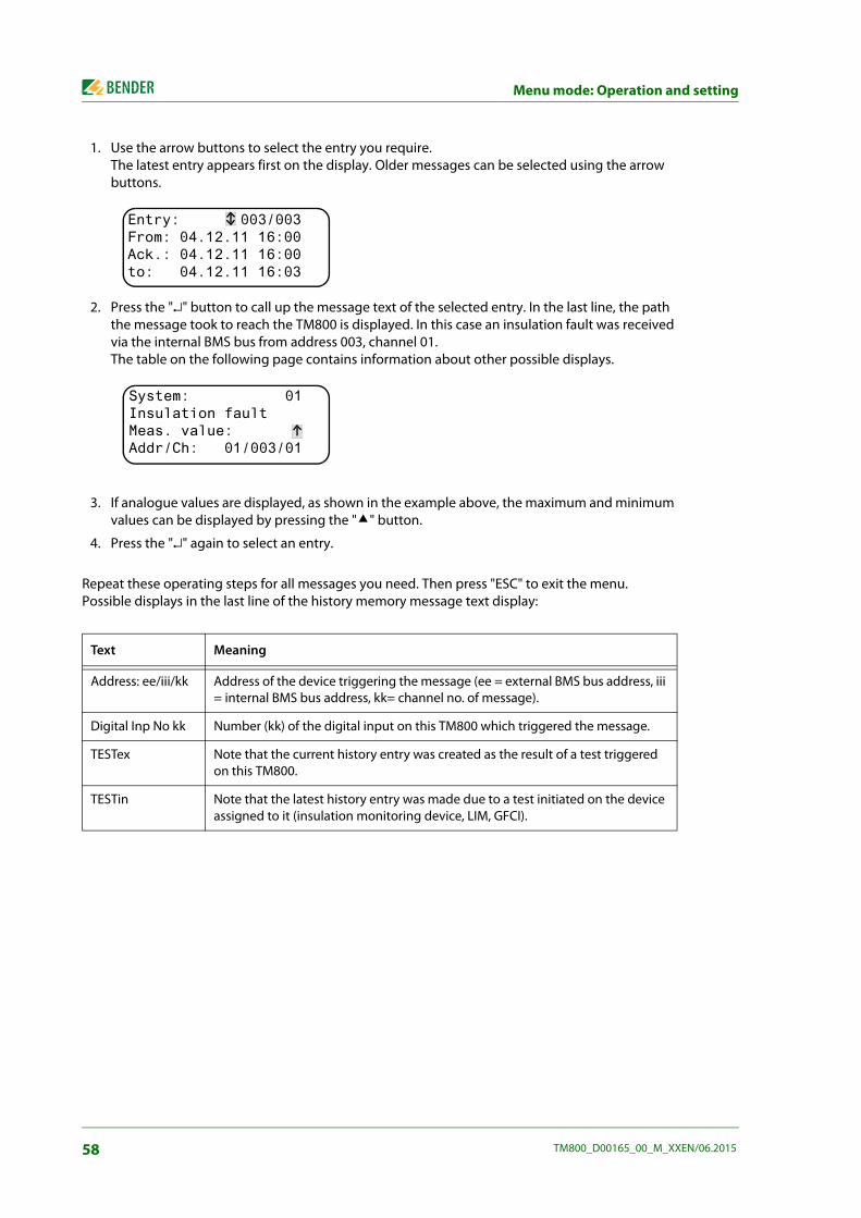
Menu mode: Operation and setting
1. Use the arrow buttons to select the entry you require. The latest entry appears first on the display. Older messages can be selected using the arrow buttons.
2. Press the "↵" button to call up the message text of the selected entry. In the last line, the path the message took to reach the TM800 is displayed. In this case an insulation fault was received via the internal BMS bus from address 003, channel 01. The table on the following page contains information about other possible displays.
3. If analogue values are displayed, as shown in the example above, the maximum and minimum values can be displayed by pressing the "" button.
4. Press the "↵" again to select an entry.
Repeat these operating steps for all messages you need. Then press "ESC" to exit the menu. Possible displays in the last line of the history memory message text display:
Text Meaning
Address: ee/iii/kk Address of the device triggering the message (ee = external BMS bus address, iii = internal BMS bus address, kk= channel no. of message).
Digital Inp No kk Number (kk) of the digital input on this TM800 which triggered the message.
TESTex Note that the current history entry was created as the result of a test triggered on this TM800.
TESTin Note that the latest history entry was made due to a test initiated on the device assigned to it (insulation monitoring device, LIM, GFCI).
Entry: 003/003From: 04.12.11 16:00Ack.: 04.12.11 16:00to: 04.12.11 16:03
System: 01Insulation fault Meas. value:Addr/Ch: 01/003/01
58 TM800_D00165_00_M_XXEN/06.2015

Menu mode: Operation and setting
8.4.4 Menu 4: Settings The following menu items are available for configuring the TM800:
8.4.4.1 Exit Exit menu mode.
8.4.4.2 Settings menu 2: Alarm addresses Bus address setting for devices whose alarm messages are to be displayed on this TM800. The text of individual messages can be modified using the TMK-SET software. Select the addresses of devices whose messages are to be displayed. Set addresses are monitored for presence on the BMS bus; if a device cannot be found on the bus, a corresponding message will appear. If several systems or areas (e.g. several operating theatres) are connected to the TM800, the numbers 1…4 can be assigned to them.
Menu item Function Page
1. Exit Exit "Settings" menu; go up one menu level.
2. Alarm addresses
Bus address setting for devices whose alarm messages are to be dis-played on this TM800.
59
3. Test addresses Setting bus addresses for devices which are required to carry out a test when the "TEST" button is pressed.
60
4. Value addresses
No function 61
5. Digital inputs
Setting of the operating behaviour for digital inputs. 61
6. Buzzer (and LED)
Setting of the frequency and repetition rate of buzzer signal. 63
7. Common reset
Setting whether this TM800 should respond to a common acknowl-edgement initiated via the reset button on a higher-level device.
63
8. Clock Setting of the date and time on the real-time clock on this TM800. At the same time this setting is sent via BMS bus and all other devices are synchronised. The device with address 1 (TM… or MK…) synchronises all other devices every hour.
63
9. Language Selection of the operating language for the TM800 (German or English). 64
10. Interface Setting of the device address and baud rate for this TM800. 65
11. Relay Operating mode and function of digital input 1 of the TM800 65
12. Password Change password, activate/deactivate password. 66
13. Service menu These settings can only be made by authorised Bender Service per-sonnel. Retrieve information about the device status, enter settings for special operating conditions and execute a firmware update.
66
1.Exit 2.Alarm addresses 3.Test addresses 4.Value addresses
59TM800_D00165_00_M_XXEN/06.2015

Menu mode: Operation and setting
1. Exit Back to the main menu 2. Edit table Use the arrow buttons to select the line "No" and confirm with the "↵" button.
Use the arrow buttons to set the external BMS bus address "Ext" and confirm with the "↵" button. Use the arrow buttons to set the internal BMS bus address "Int" and confirm with the "↵" button. Use the arrow buttons to select the external system number "Syst." and confirm with the "↵" button. TM800 always adds a new line at the end of the table. This line can be mod-ified (e.g. 4 000 000 00 off). In this way, other alarm addresses can be activat-ed.
3. Clear table Deactivate all addresses ("off"). "Clear table" is only possible when no test addresses are activated.
Possible settings for the system number "Syst.":
8.4.4.3 Settings menu 3: Test addresses Set the bus addresses for insulation monitoring devices (z. B. 107TD47, IRDH…), transfer switching devices with monitoring functions (ATICS®), LIM (Line Isolation Monitors) and GFCI (Ground Fault Cir-cuit interrupters), which are required to carry out a test when the "TEST" button is pressed. The set-ting can only be made for devices which have also been activated in the "Alarm addresses" menu and/or programmed for individual alarm texts. Individual alarm texts are a minimum requirement for:
Channel 1…3 (setting "107TD47")
Channel 1 (setting "IRDHxxx")
Syst. Meaning
00 There's no text in line 1 of the alarm message.
01…04 Texts of "System 01" to "System 04" are displayed.
T Programmed text is displayed.
Off Deletes the current line of the table
1.Exit No Ext Int Syst. 1 000 003 01---Alarm addresses---
1.Exit 2.Edit table 3.Clear table Indiv. Assignm.: 4
1.Exit 2.Edit table 3.Clear table
1.Exit No Ext Int Type 1 000 003 107TD ---Test addresses---
60 TM800_D00165_00_M_XXEN/06.2015

Menu mode: Operation and setting
1. Exit Back to the main menu 2. Edit table Use the arrow buttons to select the line "No" and confirm with the "↵" button.
Use the arrow buttons to set the external BMS bus address "Ext" and confirm with the "↵" button. Use the arrow buttons to set the internal BMS bus address "Int" and confirm with the "↵" button. Use the arrow buttons to select insulation monitoring device "Type" and confirm with the "↵" button. TM800 always adds a new line at the end of the table. This line can be mod-ified (e.g. 4 000 000 off). In this way other test addresses can be activated.
3. Clear table Deactivate all addresses ("off").
Possible settings for "Type":
8.4.4.4 Settings menu 4: Measurement addresses Currently has no function.
8.4.4.5 Settings menu 5: Digital inputs Setting of the operational characteristics of the digital inputs IN1…IN.. (TM800 in combination with BMI8/8 or BMI8/4 only. The following setting can be made individually for each input: "24V" (high) or "0V" (low). When the input is set to "24V" an alarm message will be sent when the voltage at the input is 24 V. When the input is set to "0V" an alarm message will be sent when the voltage is 0 V. It is for this reason that you should always set unused digital inputs to "off".
1. Exit Back to the main menu 2. Use the arrow buttons to select the operating mode for the digital input and confirm with the "↵"
button,select "0 V", "24 V" or "Off" using the arrow buttons. Press "↵" to ac-cept the entry. Repeat the procedure to set more digital inputs.
3. Function Set the message text category to "neutral" or "medical", see chapter "Alarm texts for the digital inputs" on page 62.
Syst. Meaning
107TD Insulation monitoring device, e. g. 107TD47
IRDHx Industrial insulation monitoring device, e. g. IRDH…
GFCI Ground Fault Circuit Interrupter
LIM Line Isolation Monitor
Off Deletes the current line of the table
Alarm messages for medical gases are signalled by the red "ALARM" LED and thebuzzer sound. The buzzer can be set to mute. The buzzer sounds again every 12minutes as a reminder. Individual settings can only be made using the TMK-SET software.
1.Exit 2.Input: 001: 24V Alarm at 24V ---Digital inputs---
1.Exit 2.Operat. principle 3.Function: neutral
61TM800_D00165_00_M_XXEN/06.2015

Menu mode: Operation and setting
Alarm texts for the digital inputs To all digital inputs a neutral or specific alarm message can be assigned. A neutral alarm message in-dicates the alarm, the channel and the address of the device triggering the alarm. In comparison, a specific alarm message (medical) signals a fixed pre-programmed alarm, e.g. "oxygen". Assign the in-puts according to the table "Neutral and specific alarm messages" The TMK-SET PC software can be used to assign other messages to individual or all digital inputs.
The alarm messages in the following table are sent to other TM… or MK… panels via the BMS bus and displayed there in plain text format. If freely programmable alarm messages need to be dis-played on a different TM… or MK…, the same alarm messages must have been programmed in the displaying device.
Specific alarm messages These messages contain details about medical gases and BSV systems. Alarm messages for medical gases are signalled by the red "ALARM" LED and the buzzer sound. The buzzer sound can be set to mute (acknowledged). The buzzer sounds again every 12 minutes as a reminder. Individual settings can only be made using the TMK-SET software.
Neutral and specific alarm messages
Inputs Neutral alarm messages "FuncNeutral"
Specific alarm messages "Function: Medical" LED
IN1 Alarm: Address/channel XXX/01 Alarm: Oxygen Alarm (red)
IN2 Alarm: Address/channel XXX/02 Alarm: Vacuum
IN3 Alarm: Address/channel XXX/03 Alarm: Nitrous oxide
IN4 Alarm: Address/channel XXX/04 Alarm: Compressed air 5 bar
IN5 Alarm: Address/channel XXX/05 Alarm: Compressed air 8 bar
IN6 Alarm: Address/channel XXX/06 Alarm: Nitrogen
IN7 Alarm: Address/channel XXX/07 Alarm: CO2
IN8 Alarm: Address/channel XXX/08 Alarm: BSV battery operation Warning (yel-low)
IN9 Alarm: Address/channel XXX/09 Alarm: BSV overload
IN10 Alarm: Address/channel XXX/10 Alarm: BSV converter failure
IN11 Alarm: Address/channel XXX/11 Alarm: BSV fault
IN12 Alarm: Address/channel XXX/12 Alarm: BSV test run
IN13 Alarm: Address/channel XXX/13 Alarm: BSV mains operation
IN14 Alarm: Address/channel XXX/14 Alarm: Failure air conditioning
IN15 Alarm: Address/channel XXX/15 Alarm: OP light battery operation
IN16 Alarm: Address/channel XXX/16 Alarm: Sat OP light battery opera-tion
62 TM800_D00165_00_M_XXEN/06.2015

Menu mode: Operation and setting
8.4.4.6 Settings menu 6: Buzzer (and LED) The buzzer will sound in the event of an alarm. Setting of the frequency and repetition rate of the two consecutive buzzer sounds.
1. Exit Back to the main menu 2. Warning 3. Alarm A variety of signals can be preset for "Warning" and "Alarm". An individual
buzzer sound can be set via the TMK-SET software. During the setting proce-dure the selected buzzer signal sounds and the LED lights up or flashes.
8.4.4.7 Settings menu 7: Common reset Set whether this TM800 should respond (on) or not (off) to the acknowledgement of the buzzer sound by pressing the "Buzzer off" button on an MK… or on another TM… panelWhen common acknowledgement is switched on, the buzzer sound of this TM800 can also be ac-knowledged (muted) on an MK… or a TM… that is located in another room. The alarm message itself will remain visible on the display until its cause has been rectified.
1. Exit Back to the main menu. 2. C.Reset Int: Setting for the internal BMS bus:
On Buzzer can be acknowledged externally.Off Buzzer cannot be acknowledged externally.
2. C.Reset Ext.: Setting for the external BMS bus: On Buzzer can be acknowledged externally.Off Buzzer cannot be acknowledged externally.
8.4.4.8 Settings menu 8: Clock This menu is used to set the time, date and date format display. These settings remain stored after a supply failure for approx. 5 days. The clock adjusts itself automatically to the Central European Summer Time (CEST) and wintertime (CET). Adjust the time again if the time no longer corresponds to the local time after automatic switchover. The automatic switchover can be deactivated (menu item "5. Summertime").
1. Exit Back to the main menu 2. Time Set the time (hours and minutes) 3. Date Set the date (DD.MM.YY) 4. Format Select German or American (mm/dd/yy)
1.Exit 2.Warning: 63.Alarm: 8
1.Exit 2.C.Reset Int.: On 3.C.Reset Ext.: On
1.Exit (CET) 2.Time 11:45 3.Date 27.12.11 4.Format: dd.mm.yy
63TM800_D00165_00_M_XXEN/06.2015

Menu mode: Operation and setting
5. Summer time Setting to automatic switchover to central European summer time: auto automatic switchover off no switchover
8.4.4.9 Settings menu 9: Language Selection of the language for the operation of the menu and the display of the messages (alarm and operating messages) for the TM800. Changes take effect immediately.
1. Exit Back to the main menu 2. Menu Set the operating language for the menu: German or English 3. Mess. Select the language for the message display. You may select:
Time and date for the system can be set on any MK… or TM… panel. The settingsare transferred via the BMS bus to the master device (address 1), which transfersthe settings to all other MK…or TM…panels.
German English French Italian
Spanish Portuguese Portuguese (Brazil)
Dutch
Norwegian Swedish Finnish Danish
Polish Hungarian Czech Slovenian
Croatian Serbian Turkish Indonesian
Russian
The language setting activates the language-specific characters. However, user-defined alarm texts remain unchanged.For this reason, you should only programme and transfer individual alarm textsafter language selection.
1.Exit 2.Menu: English3.Messg.: German
64 TM800_D00165_00_M_XXEN/06.2015
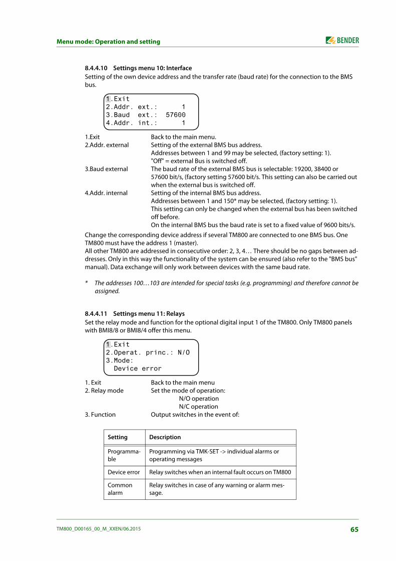
Menu mode: Operation and setting
8.4.4.10 Settings menu 10: Interface Setting of the own device address and the transfer rate (baud rate) for the connection to the BMS bus.
1.Exit Back to the main menu. 2.Addr. external Setting of the external BMS bus address.
Addresses between 1 and 99 may be selected, (factory setting: 1)."Off" = external Bus is switched off.
3.Baud external The baud rate of the external BMS bus is selectable: 19200, 38400 or 57600 bit/s, (factory setting 57600 bit/s. This setting can also be carried out when the external bus is switched off.
4.Addr. internal Setting of the internal BMS bus address. Addresses between 1 and 150* may be selected, (factory setting: 1).This setting can only be changed when the external bus has been switched off before. On the internal BMS bus the baud rate is set to a fixed value of 9600 bits/s.
Change the corresponding device address if several TM800 are connected to one BMS bus. One TM800 must have the address 1 (master). All other TM800 are addressed in consecutive order: 2, 3, 4… There should be no gaps between ad-dresses. Only in this way the functionality of the system can be ensured (also refer to the "BMS bus" manual). Data exchange will only work between devices with the same baud rate.
* The addresses 100…103 are intended for special tasks (e.g. programming) and therefore cannot beassigned.
8.4.4.11 Settings menu 11: Relays Set the relay mode and function for the optional digital input 1 of the TM800. Only TM800 panels with BMI8/8 or BMI8/4 offer this menu.
1. Exit Back to the main menu 2. Relay mode Set the mode of operation:
N/O operation N/C operation
3. Function Output switches in the event of:
Setting Description
Programma-ble
Programming via TMK-SET -> individual alarms or operating messages
Device error Relay switches when an internal fault occurs on TM800
Common alarm
Relay switches in case of any warning or alarm mes-sage.
1.Exit 2.Addr. ext.: 13.Baud ext.: 576004.Addr. int.: 1
1.Exit 2.Operat. princ.: N/O3.Mode: Device error
65TM800_D00165_00_M_XXEN/06.2015

Menu mode: Operation and setting
8.4.4.12 Settings menu 12: Password Change, activate/deactivate password.
1. Exit Back to the main menu 2. Password Change password. Factory setting: 8073. Status: Activate or deactivate password protection.
8.4.4.13 Settings menu 13: Service menu Only Bender service personnel are authorised to make settings in the Service menu. Access to this menu is possible only when the correct password is entered.
In the Service menu, information about the device status can be called up and settings for specific operating conditions can be made.
Device fail-ure
Relay switches as soon as the TM800 recognises a device failure
Test Relay switches for approx. 1 seconds once a test has been started via the "TEST" button on the assigned devices (insulation monitoring devices, LIM, GFCI).
Buzzer The relay switches as soon as the buzzer sounds. Also other signalling devices can be installed to indicate pending messages on the TM800.
Some menus are password-protected. Password protection is only effective if thepassword has been enabled (switched on). When an attempt is made to open one of these menus, the password entryscreen display appears automatically:
Once a valid password has been entered, full access will be given to all menus(except the Service menu) until menu mode is exited.
Setting Description
1.Exit 2.Password: X X X 3.Status: Off
Please enter Password 0 0 0
66 TM800_D00165_00_M_XXEN/06.2015

Menu mode: Operation and setting
8.4.5 Menu 5: Control This menu offers various options for controlling individual devices or the whole system:
8.4.5.1 Exit Exit menu mode.
8.4.5.2 Control menu 2: Reset (AlarmClear) Press the "↵" button to reset fault messages pending on the BMS bus. "Reset done!" will then appear in the last line.
This reset command is sent via the BMS bus. Note that some devices (e.g. PRC487) do not respond to this reset.
8.4.5.3 Control menu 3: EDS Start/Stop Press the "↵" button to start and stop the measuring procedure of the EDS system. This function can only be activated by the master. The current status appears in the last line.
EDS system running Once started, EDS4xx-12 and PGH47x run continuously. If you exit the menu, "EDSp" will appear in the last line of the standard display in order to indicate continuous running *.
Menu item Function Page
1. Exit Exit "Control" menu; go up one menu level. 67
2. Reset (AlarmClear)
To reset all fault messages pending on the BMS bus. 67
3. EDS Start/Stop Manual starting/stopping of test procedure on the EDS system 67
4. Test communication
Testing of communication via the BMS bus (TM800 with BMI8/8 resp. BMI8/4 only).
68
5. Reset mode Determine whether a reset is to be carried out via the internal BMS bus only or also via the external BMS bus.
68
1.Exit 2.Reset (AlarmClear) 3.EDS start/stop 4.Test Communication
1.Exit 2.Reset (AlarmClear) 3.EDS start/stop Reset done!
1.Exit 2.Reset (AlarmClear) 3.EDS start/stop EDS system running
1.Exit 2.Reset (AlarmClear) 3.EDS start/stop EDS system stop
67TM800_D00165_00_M_XXEN/06.2015

Menu mode: Operation and setting
EDS system stop Stops the EDS4xx-12 and PGH47x from continuous operation. If you exit the menu, "EDS" will appear in the last line of the standard display until the cur-rent measurement cycle finishes.
* Other abbreviations that might appear in the last line of the display: EDSa Automatic mode: Insulation fault location has been started by e.g.
ISOMETER®, ATICS® or isoMED427P on PGH47x. EDSs Single mode A single run has been started by IN2 on PGH471.
8.4.5.4 Control menu 4: Test communication Testing the communication via the BMS bus. For this purpose, an error message is simulated on a digital input. This fault message is sent to evaluating devices (such as MK…, TM…, SMO…) via the BMS bus. Check that these devices are responding to the fault message as requested.
Channel 3 Setting of the channel whose message is to be activated.
8.4.5.5 Control menu Reset mode Set whether the reset command should have an effect on the internal BMS bus only or also on the external bus. Setting possibilities
– internally only
– internally and externally
8.4.6 Menu 6: External devices This menu is used to set and control external devices. Functions include for example displaying in-formation about connected devices (address, software version, device type) or continuous display-ing a channel on a connected evaluator.
Select the BMS bus to which the external device is connected.
Internal interface Devices connected to the internal bus of this TM800 can be displayed and adjusted.
External interface Devices connected to the external bus of this TM800 can be displayed and adjusted. If other Bender devices utilising an internal bus (TM…, MK…) are addressed via the external bus, also the devices connected to this internal bus can be displayed and adjusted. Devices which can be parameterised: EDS46x, EDS47x, EDS49x,RCMS460, RCMS470, RCMS490
The device connected to the selected bus will be displayed. Select the address of the external device to be displayed (e.g. EDS4xx-12 or RCMS4xx-12).
1.Exit 2.Channel: 3
-Test communication-
1. Exit 2. Internal interface 3. External interface
68 TM800_D00165_00_M_XXEN/06.2015

Menu mode: Operation and setting
Address, type and version of the connected device are displayed. When no device is detected under this address, the character "?" appears. Use the arrow buttons to select the address of the external device and confirm your selection with the "↵" button.
If the device has been recognised, the TM800 will read the current settings of the connected device. In the first line of the display shows the device type. Use the Up/Down buttons to select the appropriate function or device setting and confirm with the "↵" button. Example:
in the EDS or RCMS menu there are a number of setting possibilities. These are described in more de-tail in the operating manuals for the corresponding systems.
1. Exit (internal!) 001: TM800 V4.04 002: EDS470 V3.20 003: 107TD47 V2.52
1. Exit (107TD47) 2. Position mode
1. Exit (107TD47) 2. Channel 1 Re= 20 KΩ
1. Exit (EDS470) 2. General 3. Channel 4. Relay
69TM800_D00165_00_M_XXEN/06.2015

Menu mode: Operation and setting
8.4.7 Menu 7: Info
Information about the device type, the firmware version and the last time assignments were trans-mitted. Assignments are settings carried out via PC software (e.g. TMK-SET):
Enter standard texts
Assigning texts and functions to the alarm messages and digital inputs of the TM800
Set parameters
Select:
ESC Exit menu mode
▲ Show date of last assignment transmission:
▼(press once) Show version of standard texts and version of the boot loader (internal soft-ware for updates). Number of BI800S and BMIx/x.
▼(press twice) The alarm addresses, test addresses and individual messages and the number of the devices will be displayed. Switching commands: (TM800 with BMI8/4 resp. BMI0/4 only).
↵ Go back to the main menu
TM800 Addr.:01/001 Software 4.02 D279 Date: 02.09.12 www.bender.de
Assignments programmed on: 12.07.13 07:07
Text version: 2.20Bootloader 2.20 Number of BI800 0 Number of BMI X/X 0
Alarm addresses 0 Test addresses 0 Indiv. Assignm. 0 Switch.cmd. T/D: 00/00
70 TM800_D00165_00_M_XXEN/06.2015

Menu mode: Operation and setting
8.5 Overview of setting options The TM800 provides various setting possibilities. The table below shows where the individual parameters can be set.
Para
met
er
Adju
stab
le v
ia
N
ame
Ran
ge
Fact
ory
setti
ng
Use
rse
tting
TM
800/
MK
800
Men
u no
. TM
800/
MK
800
Serv
ice
men
u ite
m
TMK
set
Para
met
er m
enu
Not
e
Buzz
er s
ettin
gs
War
ning
A
larm
(0
),1..9
(0
),1..9
6 8
4.6.
2 4.
6.3
--Bu
zzer
set
tings
Fr
eque
ncy
setti
ng 1
, 2, b
uzze
r int
erva
l for
ALA
RM
and
W
ARN
ING
, sel
ectio
n of
pre
defin
ed m
essa
ges
(pre
set)
Com
mon
rese
t I
nt.
Ext
. y/
n y/
n y y
4.7.
2 4.
7.3
--Bu
zzer
mut
e vi
a bu
s R
S-4
85 in
t.
RS
-485
ext
.
Set
ting
whe
ther
an
exte
rnal
dev
ice
shou
ld re
spon
d to
an
alar
m a
ckno
wle
dgem
ent t
o m
ute
the
buzz
er o
n th
e in
t. (e
xt.)
BM
S
Clo
ck/d
ate
For
mat
S
umm
ertim
e dd
.mm
.yy
/ m
m/d
d/yy
au
to/o
ff
dd.m
m.y
y au
to4.
8.4
4.8.
5 --
Clo
ck /D
ate/
CE
ST
auto
mat
ic
Set
the
time
and
date
/ au
tom
at. s
umm
ertim
e/w
inte
rtim
e on
/off
Lang
uage
Men
u M
essa
ge
Deu
tsch
/Eng
lish
20 la
ngua
ges
Deu
tsch
Deu
tsch
4.9.
2 4.
9.3
--La
ngua
ge
Men
u la
ngua
ge s
ettin
g
Inte
rface
A
ddr.
exte
rnal
Bau
d ex
tern
al
Add
r. in
tern
al
1..9
9/of
f
1980
0.. 5
7600
1.
.150
/off
1
5760
0 1
4.10
.2
4.10
.3
4.10
.4
--
RS
-485
set
tings
ex
tern
al a
ddre
ss
exte
rnal
bau
d ra
te
inte
rnal
add
ress
Sw
itch
off u
nuse
d ex
tern
al in
terfa
ce
Ext
. BM
S o
ff fo
r sin
gle
pane
ls: f
aste
r int
erna
l co
mm
unic
atio
n.
In c
ase
of c
omm
unic
atio
n pr
oble
ms,
redu
ce th
e ba
ud
rate
. In
t. B
MS
off
for p
aral
lel p
anel
: fas
ter e
xter
nal
com
mun
icat
ion.
In
tern
al a
ddre
ss c
an o
nly
be s
et w
hen
the
ext.
BM
S is
sw
itche
d of
f. D
igita
l out
put 1
Fu
nctio
n O
pera
ting
mod
e
4.
11
--
Dig
ital
outp
ut 1
S
ettin
g of
the
func
tion
for t
he fi
rst d
igita
l out
put o
r rel
ay:
Test
/dev
ice
erro
r/com
mon
ala
rm/d
evic
e fa
ilure
/ pr
ogra
mm
able
Pa
ssw
ord
prom
pt
Pas
swor
d S
tatu
s X
X X
on
/off
807
on4.
12.2
4.
12.3
--
Pass
wor
d re
quire
d C
hang
ing
the
pass
wor
d A
ctiv
atin
g/de
activ
atin
g th
e pa
ssw
ord
prom
pt
Res
et m
ode
in
t./in
t.+ex
t. in
t.
5.5
--
Res
et m
ode
*)
Det
erm
ine
the
effe
ct o
f the
RE
SE
T co
mm
and
(for d
evic
es
with
faul
t mem
ory:
ED
S, R
CM
S, I
SOM
ETE
R) v
ia B
MS
H
isto
ry b
uffe
r --
--
--
--
2. H
isto
ry
2.2
Cle
ar H
isto
ry
Dia
gnos
tic in
form
atio
n H
isto
ry m
emor
y re
set
Dis
play
the
num
ber o
f ava
ilabl
e da
ta re
cord
s.
Cle
ar a
ll da
ta re
cord
s in
the
hist
ory
mem
ory.
R
eset
cou
nter
--
--
--
--
3 R
eset
cou
nter
3.2.
Cle
ar R
eset
Cou
nt.
Res
et c
ount
er
rese
t
Dis
play
the
Pow
er-D
own,
Wat
chdo
g an
d ex
tern
al re
set
coun
ters
Res
et a
ll re
set c
ount
ers
--
--
--
--
-- 4.
Dig
italIN
/Tas
kbits
--
Indi
catio
n of
the
digi
tal i
nput
sta
tes
and
task
s --
--
--
--
--
5. B
I800
-In/B
MIx
x-O
ut
-- a)
Tes
t of i
ndiv
idua
l out
puts
: set
the
outp
ut n
umbe
r b)
Dis
play
the
butto
ns th
at a
re p
ress
ed
Tim
e-O
ut in
t. Ti
me-
Out
ext
. 42
ms…
200
ms
10 m
s…10
0 m
s 60
ms
10 m
s
--
6. S
ettin
g Ti
meo
ut/S
P
6.2.
Tim
e-O
ut in
t. 6.
3. T
ime-
Out
ext
.
Tim
eout
R
S485
int.*
) /
RS4
85 e
xt.*
)
Tim
eout
on
int.
BM
S: 0
60 m
s Ti
meo
ut o
n ex
t. B
MS
: 010
ms
at 5
6 kB
d M
ay o
nly
be c
hang
ed fo
r tes
t pur
pose
s!
Dis
play
the
stac
k lo
ad i
n %
(R
: Pro
gram
sta
ck; C
: Dat
a st
ack)
--
--
--
--
--
7. T
imin
g An
alys
is 1
7.
2 R
eset
val
ues
-- In
dica
tion
(and
rese
t) of
the
max
. res
pons
e tim
es w
ith th
e as
soci
ated
add
ress
on
the
int.
and
ext.
bus
71TM800_D00165_00_M_XXEN/06.2015
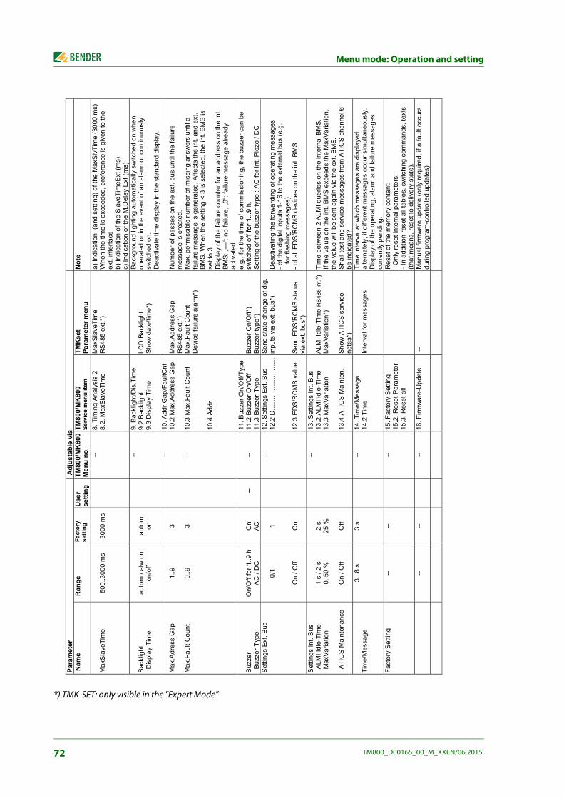
Menu mode: Operation and setting
*) TMK-SET: only visible in the "Expert Mode"
Para
met
er
Adju
stab
le v
ia
N
ame
Ran
ge
Fact
ory
setti
ng
Use
rse
tting
TM
800/
MK
800
Men
u no
. TM
800/
MK
800
Serv
ice
men
u ite
m
TMK
set
Para
met
er m
enu
Not
e
Max
Slav
eTim
e 50
0..3
000
ms
3000
ms
--
8. T
imin
g An
alys
is 2
8.
2. M
axSl
aveT
ime
Max
Slav
eTim
e
RS4
85 e
xt.*
) a)
Indi
catio
n (a
nd s
ettin
g) o
f the
Max
SlvT
ime
(300
0 m
s)
Whe
n th
e tim
e is
exc
eede
d, p
refe
renc
e is
giv
en to
the
ext.
inte
rface
b) In
dica
tion
of th
e Sl
aveT
imeE
xt (m
s)
c) In
dica
tion
of th
e M
.Del
ay E
xt (m
s)
Back
light
D
ispl
ay T
ime
auto
m /
alw
.on
on/o
ff au
tom
on
--
9. B
ackl
ight
/Dis
.Tim
e 9.
2 Ba
cklig
ht
9.3
Dis
play
Tim
e LC
D B
ackl
ight
Sh
ow d
ate/
time*
)
Bac
kgro
und
light
ing
auto
mat
ical
ly s
witc
hed
on w
hen
oper
ated
or i
n th
e ev
ent o
f an
alar
m o
r con
tinuo
usly
sw
itche
d on
. D
eact
ivat
e tim
e di
spla
y in
the
stan
dard
dis
play
.
Max
.Adr
ess
Gap
1.
.93
--
10. A
ddr.G
ap/F
aultC
nt
10.2
Max
.Add
ress
Gap
M
ax.A
ddre
ss G
ap
RS4
85 e
xt.*
) N
umbe
r of p
asse
s on
the
ext.
bus
until
the
failu
re
mes
sage
is c
reat
ed.
Max
.Fau
lt C
ount
0.
.9
3
-- 10
.3 M
ax.F
ault
Cou
nt
10.4
Add
r.
Max
.Fau
lt C
ount
D
evic
e fa
ilure
ala
rm*)
M
ax. p
erm
issi
ble
num
ber o
f mis
sing
ans
wer
s un
til a
fa
ilure
mes
sage
is g
ener
ated
. Affe
cts
the
int.
and
ext.
BM
S. W
hen
the
setti
ng <
3 is
sel
ecte
d, th
e in
t. B
MS
is
set t
o 3.
D
ispl
ay o
f the
failu
re c
ount
er fo
r an
addr
ess
on th
e in
t. B
MS:
„—“:
no fa
ilure
, „0“
: fai
lure
mes
sage
alre
ady
activ
ated
.
Buzz
er
Buz
zer-T
ype
On/
Off
for 1
..9 h
A
C /
DC
O
n AC
--
--
11. B
uzze
r On/
Off/
Type
11
.2 B
uzze
r On/
Off
11.3
Buz
zer-
Type
Bu
zzer
On/
Off*
) Bu
zzer
type
*)
e.g.
, for
the
time
of c
omm
issi
onin
g, th
e bu
zzer
can
be
switc
hed
off f
or 1
...9
h.S
ettin
g of
the
buzz
er ty
pe :
AC
for i
nt. P
iezo
/ D
C
Setti
ngs
Ext
. Bus
0/1
On
/ Off
1 On
--
12. S
ettin
gs E
xt. B
us
12.2
D…
……
……
……
…
12.3
ED
S/R
CM
S v
alue
Send
sta
te c
hang
e of
dig
. in
puts
via
ext
. bus
*)
Send
ED
S/R
CM
S s
tatu
s vi
a ex
t. bu
s*)
Dea
ctiv
atin
g th
e fo
rwar
ding
of o
pera
ting
mes
sage
s
- of t
he d
igita
l inp
uts
1-16
to th
e ex
tern
al b
us (e
.g.
fo
r fla
shin
g m
essa
ges)
- o
f all
ED
S/R
CM
S d
evic
es o
n th
e in
t. B
MS
Setti
ngs
Int.
Bus
A
LMI I
dle-
Tim
e M
axVa
riatio
n
ATI
CS
Mai
nten
ance
1 s
/ 2 s
0.
.50
%
On
/ Off
2 s
25 %
Off
--
13. S
ettin
gs In
t. B
us
13.2
ALM
I Idl
e-Ti
me
13.3
Max
Varia
tion
13.4
ATI
CS
Mai
nten
.
ALM
I Idl
e-Ti
me
RS
485
int.*
) M
axVa
riatio
n*)
Show
ATI
CS
ser
vice
no
tes*
)
Tim
e be
twee
n 2
ALM
I que
ries
on th
e in
tern
al B
MS.
If
the
valu
e on
the
int.
BM
S e
xcee
ds th
e M
axVa
riatio
n,
the
valu
e w
ill b
e se
nt a
gain
via
the
ext.
BM
S.
Sha
ll te
st a
nd s
ervi
ce m
essa
ges
from
ATI
CS
chan
nel 6
be
indi
cate
d?
Tim
e/M
essa
ge
3...8
s
3 s
--
14. T
ime/
Mes
sage
14
.2 T
ime
Inte
rval
for m
essa
ges
Tim
e in
terv
al a
t whi
ch m
essa
ges
are
disp
laye
d al
tern
atel
y, if
diff
eren
t mes
sage
s oc
cur s
imul
tane
ousl
y.
Dis
play
of t
he o
pera
ting,
ala
rm a
nd fa
ilure
mes
sage
s cu
rren
tly p
endi
ng.
Fact
ory
Set
ting
--
--
--
15. F
acto
ry S
ettin
g 15
.2. R
eset
Par
amet
er
15.3
. Res
et a
ll
R
eset
of t
he m
emor
y co
nten
t:
- Onl
y re
set i
nter
nal p
aram
eter
s.
- In
addi
tion
rese
t all
tabl
es, s
witc
hing
com
man
ds, t
exts
(th
at m
eans
, res
et to
del
iver
y st
ate)
.
--
--
--
16. F
irmw
are-
Upd
ate
--
Man
ual f
irmw
are
upda
te (o
nly
requ
ired,
if a
faul
t occ
urs
durin
g pr
ogra
m-c
ontro
lled
upda
tes)
72 TM800_D00165_00_M_XXEN/06.2015

9. Technical data
9.1 Technical data BM800/BM400 modules Insulation coordination according to IEC 60664-1 Rated insulation voltage........................................................................................................................................ AC 250 VRated impulse voltage/pollution degree ................................................................................................................ 4 kV/3Voltage supply TM800 .................................................... via integrated power supply unit, data depending on the type
BM800 module Supply voltage Us .............................................................................................................................................. AC/DC 24 VFrequency range Us ............................................................................................................................... AC 40…60 Hz/DCOperating range Us ...................................................................................................................AC 18…28/DC 19…30 VThe length of time the device can function in the event of a power failure: time, date..................................... > 5 daysRestart in the event of voltage failure for at least.........................................................................................................1.5 sDisplay, characters....................................................................................................................four lines, 4 x 20 charactersStandard message texts in ...............................................................................................................21 national languagesAlarm addresses ........................................................................................................................................................≤ 250Text messages, programmable.................................................................................................................................... 1000 History memory (messages) ........................................................................................................................................1000 Standard text message..............................................................................................................................3 x 20 charactersAdditional text message (press button to access) ...................................................................................3 x 20 charactersAlarm LEDs (three different colours) green (normal), yellow (warning), red (alarm) Menu texts ..................................................................................................................................................German/English Buttons.......................................... 5 (lamp test + test of assigned devices, buzzer mute, additional text, scroll, menu)Power consumption ................................................................................................................................................ ≤ 5 VA
Buzzer Buzzer message ............................................................. can be acknowledged, adoption of characteristics of new valueBuzzer interval .................................................................................................................................................configurableBuzzer frequency .............................................................................................................................................configurableBuzzer repetition configurable
Interface internal/external Interface/protocol............................................................................. 1 x RS-485/BMS internal, 1 x RS-485/BMS externalBaud rate............................................................................................ 9.6 kbit/s internal, 19200…57600 kbit/s externalCable length ........................................................................................................................................................ ≤ 1200 m Cable: twisted pair, one end of shield connected to PE: J-Y(St)Y min. 2x0.8 Terminating resistor ............................120 Ω (0.25 W) can be connected via DIP switch, factory setting: "off" positionDevice address, BMS bus external/internal ............................................................................................ 1…150/1…99 Factory setting device address internal/external ............................................................................1 (master)/1 (master)
Programming Interfaces ................................................................ RS-485 or USB (V2.0/V1.1), USB cable: Type A plug on Type B plugSoftware...............................................................................................................................TMK-SET version 4.x or higherFactory setting password query ............................................................................................................................ activated
73TM800_D00165_00_M_XXEN/06.2015
Technical data
Operating and display modules and I/O modules Operating and display modules BI800S: Max. number of illuminated pushbuttons ...................................................................................................................... 80 Buttons/alarm LEDs per panel ............................................................................................................................................5 Power consumption ................................................................................................................................................ ≤ 2 VAI/O module: Maximum number of inputs and outputs............................................................................................................. 192/192
Environment/EMC EMC .................................................................................................................................................................. EN 61326-1Ambient temperatures:Operating temperature ................................................................................................................................. -5…+55 °CTransport ..................................................................................................................................................... -25…+70 °CLong-term storage ...................................................................................................................................... -25…+55 °CClassification of climatic conditions acc. to IEC 60721:Stationary use (IEC 60721-3-3) ................................................................... 3K5 (no condensation, no formation of ice)Transport (IEC 60721-3-2) .......................................................................................................................................... 2K3Long-term storage (IEC 60721-3-1) ........................................................................................................................... 1K4Classification of mechanical conditions acc. to IEC 60721:Stationary use (IEC 60721-3-3) .................................................................................................................................. 3M4Transport (IEC 60721-3-2) ......................................................................................................................................... 2M2Long-term storage (IEC 60721-3-1) .......................................................................................................................... 1M3Option "W" data different from the standard version:Classification of climatic conditions acc. to IEC 60721:Stationary use (IEC 60721-3-3) ..................................................... 3K5 (condensation and formation of ice is possible)Classification of mechanical conditions acc. to IEC 60721:Stationary use (IEC 60721-3-3) .................................................................................................................................. 3M7
Connection properties (supply voltage, BMS bus): Rigid/flexible/conductor sizes .......................................................................0.2…2.5/0.2…2.5 mm2/AWG 24…-12Flexible with ferrules, without/with plastic sleeve ............................................................ 0.25…2.5/0.25…2.5 mm2
Connection properties (inputs): Rigid/flexible/conductor sizes ....................................................................... 0.08…1.5/0.08…1.5 mm2/AWG 28-16Flexible with ferrules, without/with plastic sleeve .............................................................0.25…1.5/0.25…0.5 mm2
Stripping length ..........................................................................................................................................................7 mmTightening torque ......................................................................................................................................... 0.5…0.6 Nm
OtherOperating mode .................................................................................................................................continuous operationMounting ...................................................................................................................................................display-oriented Connection ...............................................................................................................................................plug-in terminalsDegree of protection, built-in components (DIN EN 60529) ...................................................................................... IP50 Degree of protection, terminals (DIN EN 60529) ........................................................................................................ IP20 Flammability class..................................................................................................................................................UL94V-0 Weight..........................................................................................................................according to the respective version
9.1.1 Standards, approvals and certifications The TM800 remote alarm indicator and operator panels comply with the requirements of IEC 60364-7-710, DIN VDE 0100-710.
74 TM800_D00165_00_M_XXEN/06.2015

Technical data
9.2 Dimensions
Flush-mounting enclosure with internal mounting frame, aluminium, silver matt anodised
The dimensions refer to a tile grid of 150 mm.The enclosure has a wall thickness of 4 mm.
Flush-mounting enclosure with bezel frame, aluminium, silver matt anodised
The enclosure consists of a 4 mm wall thickness.
Type Design Frame outer dimensions(W x H)/mm
Outside dimensions of the
enclosure (W x H)/mm
Dimensions of the wall cutout (W x H)/mm
UPE-1 Tiles 297 x 297 307 x 307 310 x 310
UPE-2 Tiles 447 x 297 457 x 307 460 x 310
UPE-3 Tiles 297 x 447 307 x 457 310 x 460
UPE-4 Tiles 447 x 447 457 x 457 460 x 460
UPE-5 Tiles 447 x 597 457 x 607 460 x 610
UPE-6 Tiles 597 x 447 607 x 457 610 x 460
UPE-7 Tiles 597 x 597 607 x 607 610 x 610
UPE-8 Tiles 597 x 747 607 x 757 610 x 760
Type
Outer dimensions of
the bezel frame (W x H)/mm
Outside dimensions of the
enclosure (W x H)/mm
Outside dimensions of the
wall cutout (W x H)/mm
UPB-1 333 x 333 307 x 307 310 x 310
UPB-2 483 x 333 457 x 307 460 x 310
UPB-3 333 x 483 307 x 457 310 x 460
UPB-4 483 x 483 457 x 457 460 x 460
UPB-5 483 x 633 457 x 607 460 x 610
UPB-6 633 x 483 607 x 457 610 x 460
UPB-7 633 x 633 607 x 607 610 x 610
UPB-8 633 x 783 607 x 757 610 x 760
75TM800_D00165_00_M_XXEN/06.2015

Technical data
9.2.1 Surface-mounting enclosure, aluminium, silver matt anodised
9.3 Ordering details
Type Dimensions (W x H x D)/mm
APK-1 300 x 300 x 150
APK-2 450 x 300 x 150
APK-3 300 x 450 x 150
APK-4 450 x 450 x 150
APK-5 650 x 450 x 150
APK-6 450 x 600x 150
APK-7 600 x 600 x 150
APK-8 600 x 750 x 150
Description Art. No.
USB cable PC -> Alarm indicator and operator panel (Type A - Type B)
--
Parameterisation software: - TMK-SET V 4.0 parameterisation software for MK2430, MK800, TM800, - TMK-History V 3.x for MK2430, MK800, TM800, TM1000 and PRC1470 - USB driver software for MK2430, MK800 and TM800 - MEDISET V1.x parameterisation software for TM1000 and PRC1470
as Internet download
Suction cup d=80 mm 102850
Suction cup d=55 mm 102851
76 TM800_D00165_00_M_XXEN/06.2015

10. Internal components and modules
Connection via I²C bus Communication between the BM800/BM400 and different modules can be established by means of the I²C bus.
10.1 BM800 and BM400 module
10.1.1 BM800 and BM400 dimensions
Assign the addresses in consecutive order. The system can only function reliablywhen there are no gaps between the individual addresses.
Use the module's inputs and outputs for its intended purpose only. It this is nottaken into consideration the module and/or any component connected to itmay be damaged. Example: Never connect open collector outputs or digital inputs to the mainsvoltage! Risk of destruction!
CAUTION
WARNING
77TM800_D00165_00_M_XXEN/06.2015

Internal components and modules
10.2 Operating and display module BI800S The operating and display module BI800S is used to extend BM800/BM400 modules by 5 pushbut-tons each. Per module, 16 operating and display modules (hence 80 individual pushbuttons) can be controlled via the I²C bus. An individual function (switch, pushbutton, LED etc.) can be assigned to each element of a BI800S operating and display module via PC software. The link between the ele-ment and the appropriate input, output or interface is also carried out via the PC software. In addition, acoustical messages can be set to be distinguishable from one another. In case of subse-quent modifications of the functions, the hardware need not to be changed.
10.2.1 BI800S dimensions
10.2.2 Wiring diagram BI800S
1SS100 DIP switch for setting the address on the I²C bus. The addresses 0…15 (7) can be set, see p.c.b. labelling.
2XST100 Connector I²C bus for connecting additional BI800S and connec-tion to the display module.
10.2.3 Technical data BI800S Buttons/alarm LEDs per panelPower consumption ................................................................................................................................................ ≤ 2 VA Address range........................................................................................................................................................... 0…15
1 2
78 TM800_D00165_00_M_XXEN/06.2015
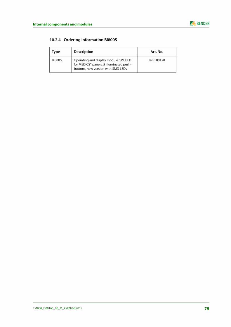
Internal components and modules
10.2.4 Ordering information BI800S
Type Description Art. No.
BI800S Operating and display module SMDLED for MEDICS® panels, 5 illuminated push-buttons, new version with SMD LEDs
B95100128
79TM800_D00165_00_M_XXEN/06.2015
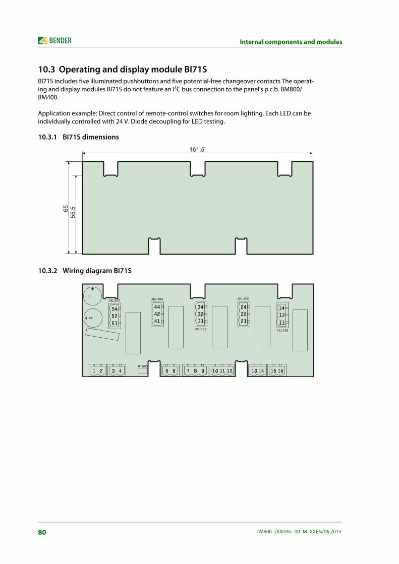
Internal components and modules
10.3 Operating and display module BI71S BI71S includes five illuminated pushbuttons and five potential-free changeover contacts The operat-ing and display modules BI71S do not feature an I²C bus connection to the panel's p.c.b. BM800/BM400.
Application example: Direct control of remote-control switches for room lighting. Each LED can be individually controlled with 24 V. Diode decoupling for LED testing.
10.3.1 BI71S dimensions
10.3.2 Wiring diagram BI71S
C;C.>
;>>>
.>
80 TM800_D00165_00_M_XXEN/06.2015

Internal components and modules
Connections:
10.3.3 Technical data BI71S Overvoltage category ........................................................................................................................................................ IIIPollution degree ................................................................................................................................................................. 2 Rated insulation voltage..............................................................................................................................................250 V Safe separation between the connections..............(1…16), (11…14), (21…24), (31…34, (41…44), (51…54) Voltage test according to IEC 61010-1 (basic insulation/protective separation) ....................................2.21 kV/3.51 kV
Supply: Nominal voltage ....................................................................................................................................... DC 24 V, AC 24 V Maximum current consumption............................................................................................................................. 110 mA
Relay contacts: Maximum current...............................................................................................................8 A at AC 250 V/8 A at DC 24 V Maximum switching load ...............................................................................................................AC 2000 VA/DC 192 W Maximum switching voltageMinimum switching load.......................................................................................................................... 10 mA at DC 5 V
EMC ..................................................................................................................................... IEC 61000-6-2, IEC 61000-6-3 Operating temperature ..........................................................................................................................-25 °C … +55 °C
10.3.4 Ordering information BI71S
1 Us: DC +24 V or AC 24 V 50/60 Hz 2 Us: DC 0 V or AC 24 V 50/60 Hz 3 Lamp test 4 Lamp test 5 Output: GND 6 Output: DC +24 V
7 LED 5, GND 8 LED 5, + 9 LED 4, GND 10 LED 4, + 11 LED 3, GND 12 LED 3, +
13 LED 2, GND 14 LED 2, + 15 LED 1, GND 16 LED 1, +
11, 12, 14 changeover contact K1 21, 22, 24 changeover contact K2 31, 32, 34 changeover contact K3 41, 42, 44 changeover contact K4 51, 52, 54 changeover contact K5
Type Description Art. No.
BI71S Operating and display module with five illuminated pushbuttons, UC 24 V, for TM panels, new version with SMD LEDs
B92024071
81TM800_D00165_00_M_XXEN/06.2015
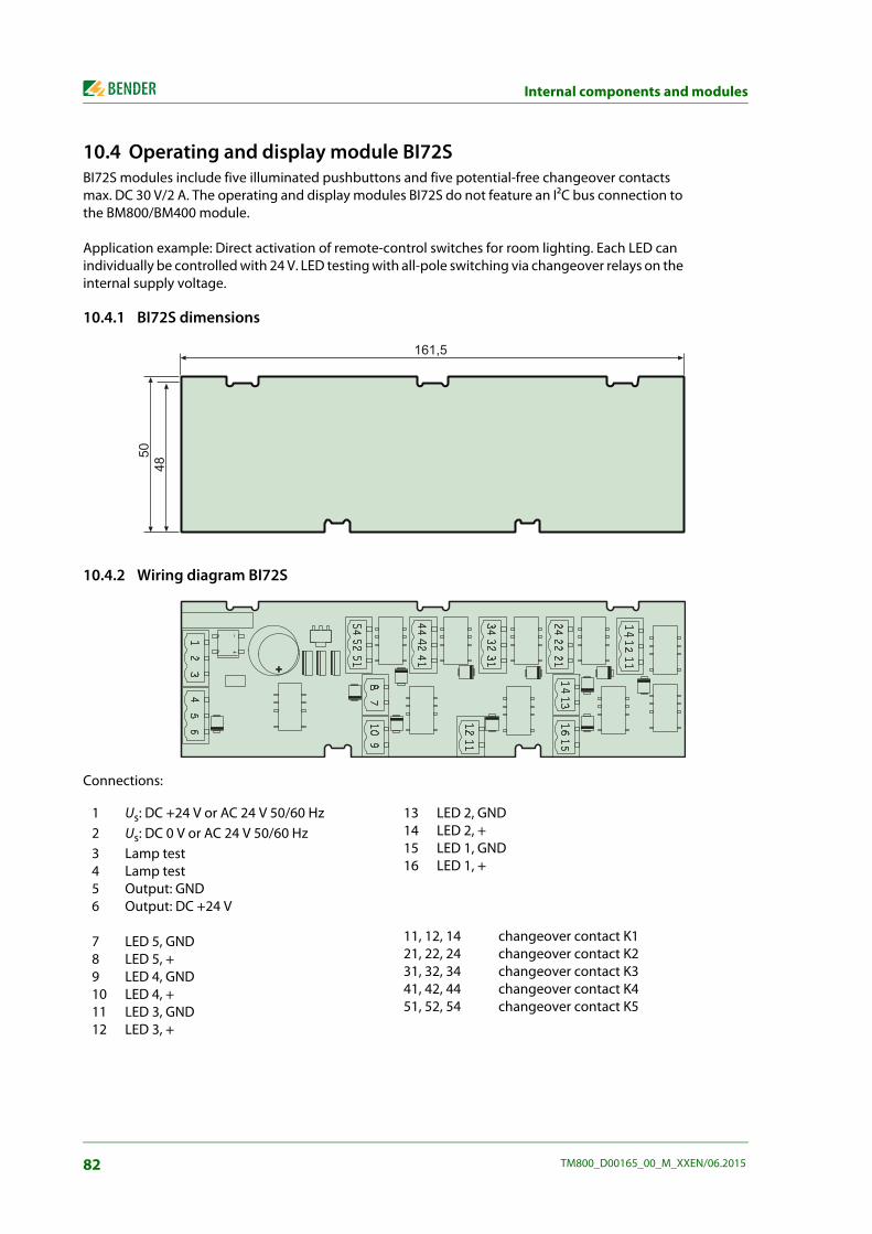
Internal components and modules
10.4 Operating and display module BI72S BI72S modules include five illuminated pushbuttons and five potential-free changeover contacts max. DC 30 V/2 A. The operating and display modules BI72S do not feature an I²C bus connection to the BM800/BM400 module.
Application example: Direct activation of remote-control switches for room lighting. Each LED can individually be controlled with 24 V. LED testing with all-pole switching via changeover relays on the internal supply voltage.
10.4.1 BI72S dimensions
10.4.2 Wiring diagram BI72S
Connections:
1 Us: DC +24 V or AC 24 V 50/60 Hz 2 Us: DC 0 V or AC 24 V 50/60 Hz 3 Lamp test 4 Lamp test 5 Output: GND 6 Output: DC +24 V
7 LED 5, GND 8 LED 5, + 9 LED 4, GND 10 LED 4, + 11 LED 3, GND 12 LED 3, +
13 LED 2, GND 14 LED 2, + 15 LED 1, GND 16 LED 1, +
11, 12, 14 changeover contact K1 21, 22, 24 changeover contact K2 31, 32, 34 changeover contact K3 41, 42, 44 changeover contact K4 51, 52, 54 changeover contact K5
C;C.>
>�,�
82 TM800_D00165_00_M_XXEN/06.2015

Internal components and modules
10.4.3 Technical data BI72S Supply: Nominal voltage ........................................................................................................................................DC 24 V, AC 24 V Maximum current consumption............................................................................................................................. 110 mA
Relay contacts: Maximum current............................................................................................................................................................2 A Maximum switching voltage .................................................................................................................................. DC 30 V
EMC ..................................................................................................................................... IEC 61000-6-2, IEC 61000-6-3 Operating temperature .............................................................................................................................. -25 … +55 °C
10.4.4 Ordering information BI72S
Type Description Art. No.
BI72S Operating and display module SMDLED with five illuminated pushbuttons, AC/DC 24 V, for TM panels, new version with SMD LEDs, contact voltage AC/DC 24 V
B92024072
83TM800_D00165_00_M_XXEN/06.2015

Internal components and modules
10.5 I/O module BMI8/8 The I/O module BMI8/8 features 8 digital inputs and 8 open collector outputs. The open collector outputs are capable of driving a load of up to 15 W at an operating voltage of 24 V. They feature flyback diodes so that the relay can be directly connected.
10.5.1 BMI8/8 dimensions
10.5.2 Wiring diagram BMI8/8
3
1
7
5
4
82
84 TM800_D00165_00_M_XXEN/06.2015

Internal components and modules
Legend to wiring diagram BMI8/8 1 X3, X4 Connector I²C bus for connecting additional I/O modules and connec-
tion to the display module. 2 S1 DIP switch for setting the address on the I²C bus by means of the
bridge SJ (address 0 … 15 = SJ open, address 16 … 23 = SJ closed) 3IN1 …8 Digital inputs 1…8 The digital inputs are controlled by voltage signals.
These can be created by an internal or external voltage and potential-free contacts.
4 V11…V18 Alarm LEDs, light up when voltage is present at the associated digital in-put. Input Alarm LED Input Alarm LED IN1 V11 IN5 V15 IN2 V12 IN6 V16 IN3 V13 IN7 V17 IN4 V14 IN8 V18
5 11…84 Open collector outputs, to control LEDs, relays etc. 6 V20…V27 Alarm LED, lights up when the associated open collector output is
closed. Output Alarm LED Output Alarm LED 11, 14 V20 51, 54 V24 21, 24 V21 61, 64 V25 31, 34 V22 71, 74 V26 41, 44 V23 81, 84 V27
7 A1, A2 Supply voltage US DC 8 R42, R59 Remove the zero-Ω resistance if external US is applied.
10.5.3 Technical data BMI8/8
Supply voltage Supply voltage Us ................................................................................................................................................... DC 24 V Operating range Us ....................................................................................................................................... DC 18…30 V
Inputs Digital inputs Galvanic separation ......................................................................................................................................................... yes Control of digital inputs............................................................................ via potential-free contacts/extraneous voltageOperating principle............................................................... N/O or N/C operation individually selectable for each inputFactory setting ..............................................................................................................................................N/O operationVoltage range (high) .............................................................................................................................. AC/DC 10…30 VVoltage range (low) ................................................................................................................................... AC/DC 0…2 VPower consumption ................................................................................................................................................ ≤ 2 VA Cable length per connection ................................................................................................................................. ≤ 500 mWire cross section at least 0.75 mm²
Outputs Number/type ............................................................................................................................................. 8/open collectorVoltage/power .....................................................................................................................................max. DC 24 V/15 WCable length per connection ................................................................................................................................... ≤ 10 mWire cross section ................................................................................................................................... at least 0.75 mm²
85TM800_D00165_00_M_XXEN/06.2015

Internal components and modules
10.6 I/O module BMI8/4 and BMI0/4 The I/O module BMI8/4 features 8 digital inputs and 4 relay outputs. The potential-free output relays utilise one changeover contact each AC 250 V, 5 A (AC1).
Der I/O module BMI10/4 features 4 relay outputs for the extension of the BMI8/4 module. The BMI0/4 module can only be used in conjunction with BMI8/4. The potential-free output relays utilise one changeover contact each AC 250 V, 5 A (AC1).
10.6.1 BMI8/4 and BMI0/4 dimensions
10.6.2 Wiring diagram BMI8/4 and BMI0/4
BMI8/4 BMI0/4
3
7
9
6
10
1
2
8
4
5
9
86 TM800_D00165_00_M_XXEN/06.2015

Internal components and modules
Legend to wiring diagram BMI8/4 and BMI0/4 1 IN1…8 Digital inputs 1…8
The digital inputs are be controlled either via potential-free contacts or via voltage signals.
2 V11…V18 Alarm LEDs, light up when voltage is present at the associated digitalinput. Input Alarm LED Input Alarm LED IN1 V11 IN5 V15 IN2 V12 IN6 V16 IN3 V13 IN7 V17 IN4 V14 IN8 V18
3 X3, X4 Connector I²C bus for connecting additional I/O modules and connection to the display module.
4 S1 DIP switch for setting the address on the I²C bus by means of the bridge SJ (address 0 … 15 = SJ open, address 16 … 23 = SJ closed).
5 Q1, Q101 Connecting cable between BMI8/4 and BMI0/4 6 V25…V28 Alarm LEDs on the I/O module BMI8/4 light up when
the associated relay is energised. Output Alarm LED 11, 12, 14 V25 21, 22, 24 V26 31, 32, 34 V27 41, 42, 44 V28
7 A1, A2 Supply voltage US DC 8 11, 12, 14… 4 relay outputs on the I/O module BMI8/4
41, 42, 44for the activation of loads
9 51, 52, 54… 4 relay outputs on the I/O module BMI0/4 81, 82, 84 for the activation of loads
10 V103, V104 Alarm LEDs on the I/O module BMI0/4 light up V109, V111 when the associated relay is energised. Output Alarm LED 51, 52, 54 V109 61, 62, 64 V111 71, 72, 74 V104 81, 82, 84 V103
10.6.3 Technical data BMI8/4 and BMI0/4
Supply voltage BMI8/4 Supply voltage Us ................................................................................................................................................... DC 24 V Operating range Us ....................................................................................................................................... DC 18…30 V
Inputs BMI8/4 Digital inputs Galvanic separation ......................................................................................................................................................... yes Activation of the digital inputs................................................................. via potential-free contacts/extraneous voltageOperating principle............................................................... N/O or N/C operation individually selectable for each inputFactory setting ..............................................................................................................................................N/O operationVoltage range (high) .............................................................................................................................. AC/DC 10…30 VVoltage range (low) ................................................................................................................................... AC/DC 0…2 VPower consumption ................................................................................................................................................ ≤ 2 VA
87TM800_D00165_00_M_XXEN/06.2015

Internal components and modules
Outputs BMI8/4 aSwitching elements ..................................................................................... 4 changeover contacts (AC 250 V, 5 A (AC1)Operating principle ................................................................................. N/C operation or N/O operation programmableElectrical service life under rated operating conditions ........................................................10,000 switching operationsContact data acc. to IEC 60947-5-1 Utilisation category ..................................................... AC-13 ............. AC-14 ............. DC-12 ............. DC-12 ........ DC-12 Rated operational voltage...............230 V 230 V 24 V 110 V 220 V Rated operational current ............................................. 5 A ................. 3 A ..................1 A ................. 0.2 A ........... 0.1 AMinimum contact rating................................................................................................................. 1 mA at AC/DC > 10 V
Connections inputs/outputs Cable length per connection..................................................................................................................................≤ 500 mWire cross section at least ................................................................................................................................... 0.75 mm²
88 TM800_D00165_00_M_XXEN/06.2015

INDEX
AAcknowledgement 57, 63Additional text 50, 52Alarm addresses 14, 59Alarm message 13
- neutral 62- specific 62
assigned devices 50Assignments 70Automatic mode 68
BBaud rate 65Beep code 45Bender service personnel 66bezel frame 19BMS bus
- external 15, 31- internal 14, 31
BMS-bus address 65BMS-bus addresses 31Buzzer
- Audio frequency 63- Reminder 61
Buzzer sound 62
CCleaning agents 20Commissioning 37Commissioning pattern 37Common acknowledgement 63Connection 28Control 67Converter
- RS-232/RS-485 15
DDate 63Date format 63Delivery notes 20Design
- modular 16Device address 65Diagram 56Digital inputs 61Dimensions 75
DIP switch 31Display 13Displaying information 68
EEnclosure variants 19Enter button 50Error 45Error list 46Evaluating devices 68External devices 68
FFault
- condition 51Firmware version 15, 55, 70Front plate 20, 24Front plate components 27Functional test 43
GGases
- medical 62
HHinges 27History memory 57
IIndividual alarm texts 60Inputs
- digital 62Installation
- partially recessed 20Installation documentation 37Intended use 9Interfaces 14, 65
JJoint 22
LLanguage 64
LEDs 13
MMain menu 55Maintenance 44Master 31Master password 66Measurement addresses 61Medical gases 61MEDICS® system 11Menu mode 55Message text display 58Mounting frame 19Mounting plate 20
NNational languages 14Navigation 56Normal
- operating condition 50
OOrdering information 76
PParameter setting 39Parameters 71Password 56, 66Periodic verification 44Personnel 9Plaster cover 21
QQuick reference guide 49
RRelay mode 65Repeater DI-1PSM 31Reset 67Reset mode 68
SScroll 50
89TM800_D00165_00_M_XXEN/06.2015
INDEX
Separation- safe 17
Service 44Service menu 66Setting possibilities 71Settings 39, 40, 41, 59Signal converter SMI472-12 31Single mode 68Software 14Software version
- 15Special characters
- language specific 64Standard display 55Starting procedure 55Starting the EDS system 67Status information 13Status line 51, 52Suction cup 27, 76Summertime 63, 64surface-mounting enclosure 20Switching on 38, 39System components 7, 31System number 60
TTerminating resistor
31Tes taddresses 60Test 50, 52
- Error code 52- Error code note 53
Test communication 68Test procedure 67Tests 37Text display 13Time 63
- entire system 64TMK-History 15, 57TMK-SET 39, 41, 59, 61, 62Transfer rate 65
UUSB interface 15
WWiring diagram 30
90 TM800_D00165_00_M_XXEN/06.2015


Bender GmbH & Co. KGP.O. Box 1161 • 35301 Gruenberg • GermanyLondorfer Straße 65 • 35305 Gruenberg • GermanyTel.: +49 6401 807-0 • Fax: +49 6401 807-259E-mail: [email protected] • www.bender.de
Fotos: Bender Archiv. BENDER Group