Titrations Fibel Refractometry Guide - Xylem Analytics
124
Titrations Fibel THEORIE UND PRAXIS DER TITRATION Meters and Electrodes pH, ISE, COND AND O 2 | PRECISE - RELIABLE - SELECTIVE IN LAB AND FIELD IN LAB AND FIELD Lab und ProLab Serien pH, ISE, LF UND O 2 MESSEN — GENAU, ZUVERLÄSSIG, SELEKTIV Lab und ProLab Serien pH, ISE, LF UND O 2 MESSEN — GENAU, ZUVERLÄSSIG, SELEKTIV Refractometry Guide THEORY AND PRACTICE OF REFRACTOMETRY
-
Upload
khangminh22 -
Category
Documents
-
view
4 -
download
0
Transcript of Titrations Fibel Refractometry Guide - Xylem Analytics

Titrations FibelTHEORIE UND PRAXIS DER TITRATION
Meters and ElectrodespH, ISE, COND AND O2 | PRECISE - RELIABLE - SELECTIVEIN LAB AND FIELDIN LAB AND FIELD
Lab und ProLab Serien pH, ISE, LF UND O2 MESSEN — GENAU, ZUVERLÄSSIG, SELEKTIVLab und ProLab Serien pH, ISE, LF UND O2 MESSEN — GENAU, ZUVERLÄSSIG, SELEKTIVRefractometry GuideTHEORY AND PRACTICE OF REFRACTOMETRY

Bellingham + Stanley, a Xylem brandXylem, Longfield Road Tunbridge Wells Kent, TN2 3EYUnited Kingdom
Internet: www.XylemAnalytics.com

FORWARD
This handbook, originally written by Mr. Gil Stanley in 1988 as part of Bellingham + Stanley’s 75th anniversary, seeks to describe the underlying principles on which refractometers operate.
Although written some 30 years ago, the principles outlined herein are still relevant today, making this a very useful go-to reference book for scientists, researchers, academics and those involved in the technical support and the sale of refractometers to the various industries where these vitally important measuring devices are used.
The first part of the book deals with the basic optical principles common to most refractometers in current use. This is followed by an appendix, which explains in greater detail some of the material of the earlier text. The appendix also deals with specific refractive index measurements applied to various types of material.

CONTENTSREFRACTOMETERS - BASIC PRINCIPLES
Refractive Index .....................................................................................12
Critical Angle ..........................................................................................16
Refractometer Prism ..............................................................................18
Telescopes...............................................................................................20
Basic Refractometer ..............................................................................23
TRANSMISSION & REFLECTION MODES
Borderline Quality and Contrast ........................................................28
Borderline Quality – Transmission Mode ..........................................28
Absorption of Light Within the Liquid Film ......................................30
Advantages & Disadvantages of the Reflection Mode .................30
Advantages - Coloured Samples .......................................................30
Advantages - Thickness of Sample Film ...........................................30
Advantages - Prism Size .......................................................................31
Advantages - Instruments with Built-in Light Source .....................31
Advantages - Light Source Requirements ........................................31
Disadvantages of the Reflection Mode ............................................31
Examples of Instruments Employing the Reflection Mode ..........32
Slit Refractometer ..................................................................................32
Refractometer Based on Photodiode Array ....................................33
COLOUR
Dispersion ...............................................................................................35
Spectral Sources – Discharge Lamps, Arc Lamps, Lasers ..............37
Refractometer Using a White Light Source ......................................38
Prism Design ...........................................................................................38
Colour Filters ..........................................................................................39
White Light Sources ..............................................................................40
Direct Vision Prism .................................................................................40

TEMPERATURE EFFECTS
Temperature Control.............................................................................44
Temperature Measurement .................................................................45
Temperature Compensation – Non-Linearity ..................................45
Temperature Compensation ...............................................................46
Mechanical Compensation – Drum & Screw ...................................46
Mechanical Compensation – Thermostatic Bimetal .......................47
Optical Compensation (Goldberg Refractometer) ........................47
Compensation by Calibrated Thermometer ...................................47
Compensation by Use of Zero Adjusting Screw: ............................48
FOCUSING RANGE OF EYEPIECES
Focusing Instruments ............................................................................48
Fixed Focus Instruments ......................................................................48
CALIBRATION
Test Liquids .............................................................................................50
Test Plates ................................................................................................50
SAMPLING TECHNIQUES
Homogeneity of Sample ......................................................................55
Cleanliness ..............................................................................................56
Evaporation .............................................................................................57
Temperature ...........................................................................................57
Spreading the Sample ..........................................................................58
PRISM MATERIALS
Physical Properties ................................................................................58
Chemical Properties ..............................................................................59
Cost Factors ............................................................................................59
Comments on Various Materials used for Prisms ..........................59

Glass .........................................................................................................59
Silica ..........................................................................................................60
Fused Silica .............................................................................................61
Sapphire (Al203) ......................................................................................62
OPTICAL MICROMETER
HIGH ACCURACY REFRACTOMETERS
Scales .......................................................................................................63
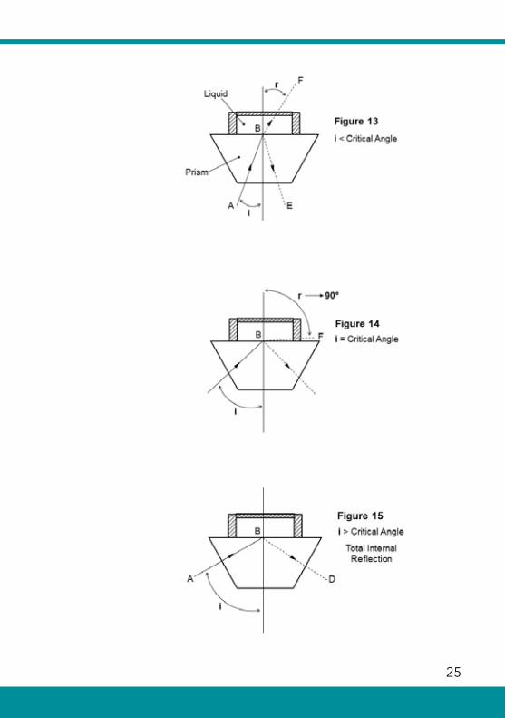
Magnification..........................................................................................64
Range .......................................................................................................64
Borderline Colour Compensation and Light vSources..................64
REFRACTOMETERS USED WITH WAVELENGTHS OTHER THAN SODIUM D
ELECTRONIC REFRACTOMETERS
Photometric Refractometer .................................................................67
Scanning Refractometer ......................................................................67
Electronic Scanning Refractometers (Photodiode Arrays) ...........67
COMBINED PHYSICAL MEASUREMENTS
ACCESSORIES
Flow Cells ................................................................................................69
Volatile Liquid Cell .................................................................................70
Cells for Differential Measurement ....................................................70
Polarising Eyepiece ...............................................................................71
Sample Press...........................................................................................71

APPENDIX
CONNECTION BETWEEN SPEED OF LIGHT AND REFRACTIVE INDEX
FOCUSING RANGE OF EYEPIECES
Diopters ...................................................................................................73
Magnification..........................................................................................74
Focusing Range .....................................................................................76
Eyepiece Types.......................................................................................79
ENTRANCE AND EXIT PUPILS
COLOUR FILTERS
1. Gelatine Filters ...................................................................................84
2. Glass Filters .........................................................................................84
3. Interference Filters ............................................................................84
OPTICAL SURFACE TREATMENTS
Mirrors ......................................................................................................85
Anti-Reflection Coatings ......................................................................86
RELATIVE SPECIFIC REFRACTIVITY
LIGHT SOURCES
Light Sources – Adjustment .................................................................88
Light Sources –Types .............................................................................88
Thermal Sources ....................................................................................88
Non-Thermal Sources ...........................................................................89
Arc Discharge Tubes (Arc Tubes) ........................................................89
Glow Discharge Lamps (Vacuum Tubes) ..........................................90

PROBLEMS OF CONDENSATION WITHIN INSTRUMENTS
TEST PLATES
ELECTRONIC REFRACTOMETERS
Photometric Instruments ......................................................................94
Scanning Instruments (narrow range – fixed detector) .................95
Scanning Instruments (wide range – moving detector) ................96
Refractometers Based on Photodiode Arrays .................................97
RI MEASUREMENT OF VOLATILE SOLUTIONS
RI MEASUREMENT OF EMULSIONS
RI MEASUREMENT OF HYDROGENATIONS
RI MEASUREMENT OF SOLIDS (EXCLUDING GEMS)
Solids in Bulk Form..............................................................................101
Solids in Fragmented Form ............................................................. 101
RI MEASUREMENT OF GEMSTONESImmersion Techniques ...................................................................... 102
RI Determination by Measurement of Apparent Depth ............ 103
Dispersion ............................................................................................ 103
RI Measurement by Reflectivity ....................................................... 104
Double Refraction .............................................................................. 104
Tests Not Based on RI Measurements ............................................ 105
RI MEASUREMENT OF THIN FILMS
RI MEASUREMENT OF RESINS
RI MEASUREMENTS BY INTERFEROMETER
Interferometers ..........................................................................110
SCALES
CONCLUSION


Authors:
Gil F. Stanley
First published in 1988.
Revised 2004Revised 2019
Illustrations and additional content added by Dr. Jeff Pedley (2004) with further revision by Kevin Chapman (2019)

11
Refractometry Guide
Refractometers are Instruments designed to measure an optical constant, which is a characteristic of the material being examined.This optical constant is called Refractive Index and may be used to give valuable information about the material being tested.The fundamental definition of refractive index is based on the speed of light. Now light travels at a constant speed in vacuum (approximately 300,000 km/second), but the speed is reduced when the light passes through any other medium. The ratio of these two speeds is the refractive index of the medium. Thus, we have the following relationship.
Refractive Index of given substance
=
Speed of light in vacuum
Speed of light in substance
The speed of light in air is very nearly the same as the speed of light in vacuum and as most optical work is carried out in a normal atmosphere it is usual to express the refractive index of a material relative to air rather than to a vacuum.
It will be noted that refractive index is a ratio between two speeds and is therefore dimensionless, that is, it is completely defined as a pure number without need of qualification.
Thus, we might say, by way of example; Refractive Index of Water = 1.333
However, it is not convenient to measure these light speeds directly, and refractometers employ other means of determining refractive index.
A consequence of the change in the speed of light in different substances is that when a ray of light passes obliquely from one substance into another, there is a change in the direction of the ray (see appendix A1). This deviation is called Refraction and it is refraction which refractometers usually measure and evaluate as refractive index. It is therefore necessary to understand how refraction occurs in order to understand how refractometers work.
REFRACTOMETERS - BASIC PRINCIPLES

Refractometry Guide
12 13
Refractive IndexThe basic principles of refraction may best be shown by reference to a few simple examples.
Figure 1 shows a ray of light passing from air into a glass block. The various terms used, “Interface”, “Normal”, “Angle of Incidence”, “Angle of Refraction” and “Incident Ray” should be evident from the figure.
Consider a ray A0, which enters the block at an angle of incidence (i) to the normal, and is then refracted at an angle of refraction (r) as shown.
The deviation of the ray, the “Refraction”, follows a law called Snell’s Law, which may be defined as under.
Refractive Index (RI),
n =sin isin r
If a circle is drawn with its centre at point 0, as in Figure 2, it will be seen that another way of expressing n would be:
n =ab
In the example above, the passage of a ray of light was traced through a solid substance, i.e. glass. The same laws, of course, apply in the case of liquids and it is with liquids, and in particular with solutions, that refractometers are largely concerned.
When a substance is dissolved in a liquid, the liquid becomes denser and a corresponding change takes place in its refractive index. The manner of this change may be appreciated by noting that the greater the density of the

Refractometry Guide
12 13
solution, the more the light is slowed in its passage though the solution and, as refractive index is defined as the ratio of the speed of light in air to its speed in the liquid, the refractive index must therefore increase.
It follows from the above, that if we know just how the refractive index changes as the concentration of the liquid changes, then a graph or tabulation can be made relating the concentration to the index. Once this relationship (calibration) has been established, then any unknown concentration can
readily be determined by a measurement of refractive index. In most cases the required calibration is provided within the instrument itself, so that, for example, the percentage of sugar in a solution may be read directly from a previously calibrated scale or as a digital read-out on an automatic instrument.
In the previous example shown in Figure 1, a ray of light was traced as it passed from air into glass. We now consider the glass where a ray of light passes from a liquid, say water into a solid, say glass. To see what happens we return to

Refractometry Guide
14 15
the fundamental definition of refractive index and define the new refractive index in similar fashion.
Refractive Index (water to glass),
n (wg) =speed of light in water
speed of light in glass
Let S (a) = Speed of light in airLet S (w) = Speed of light in waterLet S (g) = Speed of light in glass
We now haveRefractive Index of water - n(w)
n (w) =S (a)
.... (1)S (w)
Refractive Index of glass - n (g)
n (g) =S (a)
........(2)S (g)
From (1)... S (w) =S (a)
n (w)
From (2)... S (g) =S (a)n (g)
Let Refractive Index (Water to Glass) = n (w-g)
Then
n (w-g) = S (w) / S (g) =S (a) / n (w)
S (a) / n (g)

Refractometry Guide
14 15
Hence
n (w-g) =n (g)n (w)
That is
Refractive Index (Water to Glass) =
Refractive Index of Glass
Refractive Index of Water
Referring to Figure 3 and applying Snell’s Law we get:
Refractive Index (Water to Glass) =
sin (i) sin (r)
In considering the passage of light from one medium into another the following points should be noted:
When passing from one medium into a denser medium the light is always deviated towards the normal, that is, angle (i) is always greater than angle (r).
The greater the refractive index the more the light is “bent” at the interface.
In any refracting system, if the direction of the light is reversed then the light will retrace its original path
through the interface. Thus in Figure 3 light directed from point B along BO would be refracted along path OA. In this case the refractive index (ratio) would be inverted as under.
n (glass to water) =
Refractive Index of water
Refractive Index of glass
It follows that if the refractive index is the same on both sides of the interface then the light will pass through without any refraction.
It may be instructive at this stage to examine the refractive indices of some miscellaneous materials.
The refractive index of most materials (in the visible spectrum) lies in the region of 1.3 to 3.0
RutileDiamondSilicaGlassesPlasticsLiquidsWaterGases
2.3/62.41.461.5 to 1.91.4 to 1.71.3 to 2.21.333Very nearly 1
(air n = 1.000292)

Refractometry Guide
16 17
The concept of refractive index is not limited to “visible” light. Thus, for example, germanium is transparent to infra-red light and has a refractive index of 4 (this means that the speed in this material is slowed down to 1/4 of its speed in air).
Critical Angle
Figure 4 traces the path of a ray of light from one medium of refractive index n1 into a denser medium of refractive index n2.
As before the relative refractive index is given by the following,
n =n2
n1
and
n =sin (i)sin (r)
Now let angle (i) increase to 90 degrees as shown. The incident ray is then said to be at grazing incidence to the surface and sin (i) = 1
Hence
n =1
sin (r)

Refractometry Guide
16 17
or
sin (r) =1n
Under these circumstances angle (r) is said to be the Critical Angle and is the maximum angle of refraction possible.
Thus the critical angle (c) is given by
sin (c) =1n
so that
n =1
sin (c)
It follows from the above relationship that if angle (c) could be measured then this would provide a very simple method for determining the refractive index of one medium relative to another as shown in the following examples.
Example 1: Light passing from air into glass
Suppose that the critical angle (c) were measured and found to be 40.813 degrees
Now
n =1
sin (c) and sin (c) = 0.6536
and thus n = 1.530

Refractometry Guide
18 19
Example 2: Light passing from water into glass
Let the refractive index of the glass be 1.6
Suppose that the critical angle (c) were measured and found to be 56.42 degrees
As before
n =1
sin (c)
but now
n =n2
n1 that is
1 =
n2
sin (c) n1 So that n1 = n2 x sin 56.42 n2 = 1.6 and sin 56.42 = 0.8331
Thus refractive index of water n1 = 1.333
Refractometer PrismRefractometers based on critical angle measurements normally employ a prism of glass, silica, sapphire or other suitable transparent material. A typical prism is shown in Figure 5.

Refractometry Guide
18 19
When the instrument is to be used for determining the refractive index of liquids, the liquid may be placed in some kind of glass walled cell above the prism so that light can be passed into the cell and along the prism surface at grazing incidence to form the critical angle. (For this to take place the refractive index of the liquid must be lower than that of the prism and this is generally the case).
Alternatively, the liquid under test may be in the form of a thin film trapped between the prism surface and the surface of an additional ‘illumination’ prism as shown in Figure 6.
The light is passed through the upper illumination prism and along the thin liquid film at grazing incidence to form the critical angle in the main prism. To meet this condition it is important to note that the refractive index of the illumination prism MUST be higher than that of the liquid, otherwise the light would follow some such path as ABC and the critical angle requirement would not be met.
To make the spread of light into the film as effective as possible it is normal practice to produce a diffusing surface on the lower contacting face of the upper illumination prism.

Refractometry Guide
20 21
This surface may be made by fine grinding, etching or by moulding. The diffusing surface scatters light in all directions and some of the scattered light passes along the liquid film at grazing incidence to produce the critical angle.
From a practical point of view it is worth noting that on much used optical refractometers adopting a glass prism, where this diffusing surface has been polished away by repeated cleaning over a long period of time there is a marked loss in the performance of the instrument. To restore the instrument to proper use the surface must then be re-ground. To avoid this, many modern day industrial refractometers use artificial sapphire prisms.
It is also common practice to grind surface S (see Figure 6) to diffuse the incoming light and obtain more uniform illumination.
For reasons of convenience and cost, many simple hand held refractometers use an arrangement as shown in
Figure 7 where the upper illuminating prism shown in fig 6 is replaced by a plastic illumination plate. Again, the light has to pass at grazing incidence along the liquid film to form the critical angle. Incoming light enters the plate at the front end, usually via a diffusing chamfer. From what has already been said, it will be evident that light falling on the upper surface of the plate in the general direction (C) can, in general, play no direct part in the formation of the critical angle.
TelescopesPrevious chapters have discussed critical angle and its importance in the determination of refractive index. The question now arises as to what is the best way of measuring the critical angle. To perform this measurement refractometers usually employ some kind of telescope system.
Figure 8 shows a lens (referred to as the objective) focusing some distant object, perhaps a star, on to a scale* placed in the focal plane of the

Refractometry Guide
20 21

Refractometry Guide
22 23
It is important to note, at this stage, that all the rays of light entering the objective are parallel for each image. If, instead of a star we have some far distant object (the distance being very large compared with the diameter of the objective) then light from each point of the object will enter the objective as a nominally parallel beam giving rise to a point image on the scale. In other words, any sharply defined image point on the scale is the result
objective. The optical axis may be defined as a line passing symmetrically through the centre of the objective, and at right angles to the scale.
If the light from the star enters the objective parallel to the optical axis, a star image will be formed at point A. A second star, close to the first, would produce a second star image at point B, as shown in Figure 9. If we know the focal length (f) of the objective, and the distance AB, then the angular separation between the stars can easily be determined.

Refractometry Guide
22 23
of a beam of parallel light entering the objective from a specific direction. (If the distant object is moved closer to the objective, points on the object will give rise to a non-parallel beam of light entering the objective and will not produce a sharply defined image point. That is, the image will be out of focus). Thus by noting the position of sharply defined points on the scale we can determine the direction of the incoming beams of parallel light.
The scale would normally be viewed under magnification provided by a lens or eyepiece placed in front of the scale shown in Figure 10. An arrangement of objective and eyepiece as described forms a telescope.
(The remarks above refer specifically to visual, as opposed to automatic instruments. In the letter case, the scale would be replaced by some form of electronic detection system).* SCALE . This is a pattern of
fine line, figures etc. in the manner of a ruler, etched on the surface of a glass disc referred to as substrate. The substrate with its scale constitutes a graticule, sometimes called a reticule or reticle (see Figure 12).
Basic RefractometerThe essential elements of a basic refractometer have now been outlined. These elements are shown put together in Figure 11 so as to form a complete instrument consisting of a prism system and a telescope. The telescope is set so that ‘parallel’ light is brought to a focus on the scale.
From what has already been discussed it will be noted that only light leaving the prism system at angles LESS than the critical angle can pass the interface. There can be no rays such as that shown at A leaving the interface at greater than the critical angle. Thus ray B and all rays parallel to B will enter the telescope and form an image on the scale at point P. No light can be imaged in the region PQ but light will

Refractometry Guide
24 25
It will be observed that, in the prism system shown, there will be some deviation of the light rays due to refraction as the light passes surface marked S but allowance for this would be made when calibrating the scale.
TRANSMISSION & REFLECTION MODESSo far, prism systems have been examined in which the light is transmitted through the liquid sample and thence through the prism. This mode of operation is referred to here as the transmission mode. There is, however, another mode of operation, also based on the critical angle, and referred to here as the reflection mode. Consider the prism shown in Figure 13. Here the liquid under test is contained in a cell and is in contact with the upper surface of the prism. (Again it is assumed that the refractive index of the liquid is less than that of the prism, which is normally the case).
be imaged in the region PR. It follows that there will be an abrupt transition from dark to light across the scale as seen through the eye lens. (In practice some additional light is usually introduced to provide enough illumination in the dark part of the field to enable the scale to be seen and read in this region).
Figure 12 shows the appearance of the field of view. The boundary between light and dark is referred to here as the borderline, and its position depends upon the critical angle (c) which, in turn, in determined by the refractive index of the liquid and the refractive index of the prism. The refractive index of the prism will, of course, remain constant but the refractive index of the liquid will depend on the nature of the liquid and its concentration. Thus the scale can be calibrated directly in terms of refractive index. (Scales can, however, be calibrated in terms of many other parameters – see appendix).
Refractometry Guide
24 25

Refractometry Guide
26 27
Let (i) be the angle of incidence of a ray AB which is refracted along a path BF at an angle of refraction (r). Let (i) start at zero and be gradually increased. As (i) is increased (r) will also increase and it value will be determined by Snell’s Law. A point will be reached when angle (r) is 90 degrees as shown in Figure 14.Angle (i) then becomes the critical angle (c). If the incident angle is made greater than (c) then the refracted ray BF will disappear completely and the light is then said to be totally internally reflected along BD (see Figure 15). When light is reflected in this manner NO light is transmitted across the interface.
Figure 13 shows the condition where angle (i) is less than the critical angle and the light is refracted at the interface along BF. However, not all the light follows this course. Some light is reflected back at the interface along BE. As some of the light is lost along BF the intensity of the light along BE must be less than that of the incoming light along AB. This condition continues as
(i) is increased from zero up to the critical angle at which point the ray BF disappears, as indicated in Figure 15 and ray BF assumes the same intensity as the incoming light. As angle (i) is increased from the critical angle (c) up to 90 degrees all the incoming light continues to be reflected without loss.At this stage it will be noted that with the reflection mode of operation described above there will always be some light reflected from the interface irrespective of the value of (i).
(In Figure 13, for the sake of simplicity, no refraction of the rays entering or leaving the lower surface of the prism has been shown).
Figures 13, 14 and 15 all show the sample liquid contained in a cell. However, the liquid may also be in the form of a thin film trapped between two prisms as shown in Figure 6.
Figure 16 shows how the reflection mode may be used in the basic instrument depicted in Figure 11. It will be seen that where the light enters the prism along path AB at an angle of incidence

Refractometry Guide
26 27
The most significant difference, however, lies in the contrast obtainable between the light and dark areas of the fields in the two modes. In the case of the reflection mode. All areas of the field receive some light, and this light degrades the contrast between the two parts of the field.
In consequence, with the reflection mode, the available contrast in the field is always inferior to that obtainable with the transmission mode where, under suitable conditions the dark area can, if desired, be made to appear black.
greater than the critical angle, the light is reflected along BC so that the area of the scale PQ is brightly illuminated. Where the incoming light enters the prism at less than the critical angle, the area PQ is still illuminated, but at a lower level of intensity.
Figure 17 shows the appearance of the field of view when using the reflection mode. As with the transmission mode the field is divided into two areas, a light and a dark area, defining the borderline. As the position of the borderline on the scale is, in both cases, determined by the critical angle, its position will be the same regardless of the mode used. It will also be noticed that, in the two modes, the fields are reversed, that is the light and dark zones are interchanged.

Refractometry Guide
28 29
Borderline Quality and ContrastRefractometers operate by determining the position of the borderline, and therefore, if the borderline is ill defined this will cause an error in the measurement. In consequence, it is important to consider the factors influencing the definition of the borderline.
Borderline Quality – Transmission ModeFigure 18 shows two prisms with a liquid film trapped between them. To obtain the critical angle necessary for the measurement of refractive index it is essential that the light passes along the film at grazing incidence. This is theoretically possible only if the film has zero thickness, so that ray DE lies parallel to the prism surface. The finite thickness of the film gives rise to an error, which is sometimes referred to as shielding error and is a function of the thickness (T) of the liquid film.
Referring again to Figure 18 it will be evident that, for a given thickness of film (T),
the value of (i) will depend upon the distance DE. The smaller DE becomes the more the borderline definition will be degraded. This sets a practical minimum limit on the size of the prism.
Badly controlled film thickness is a fruitful source of error in refractometers employing the transmission mode, and sometimes appears in simple instruments using plastic illumination plates if these plates become distorted.
The error due to this cause is reduced as (T) is reduced but another problem arises if (T) is reduced too much. Light rays within the film are reflected back and forth between the two prism surfaces, and as the film thickness is reduced these rays become more nearly parallel, and a phenomenon known as interference takes place. The result is that the field of view becomes crossed by a series of interference fringes as indicated in Figure 19, and these fringes disguise the borderline.

Refractometry Guide
28 29
Note: For digital refractometers operating in the reflection mode, sample thickness is less critical but has to be deep enough so that internal reflection from the sample air exit is not reflected in to the detector. For this reason, 3mm sample depth is often suggested.
To some extent the situation can be improved by providing a diffusing surface (S) on the upper illuminating prism.In consequence of the two opposed limitations above, a compromise in film thickness is necessary, and on many optical instruments the sample thickness is set at about 0.038mm, where the length of the prism is in the region of perhaps 30mm.

Refractometry Guide
30 31
Absorption of Light within the Liquid FilmIt will be seen from Figure 18, that the light forming the borderline has to pass along the film before entering the lower prism. This may be a distance of several centimetres, and if the liquid is coloured or cloudy there will be a severe loss of light, and the borderline contrast may be upset, or in some cases lost altogether. In instruments using an illumination plate as in Figure 7 (page 19) it is easily forgotten that most of the light forming the borderline does not enter the plate in the direction (C), but via the chamfer at the end of the plate. (A small quantity of light entering in the direction (C) may, however, get scattered within the plate and eventually find its way along the film and make a small contribution to the field illumination).
Advantages & Disadvantages of the Reflection Mode
Advantage - Coloured SamplesThe light is not required to pass through the sample where it would be absorbed, so this mode is more suitable for use with strongly coloured or cloudy materials.
Advantage - Thickness of Sample FilmProviding the operating area of the prism is covered by the sample material the actual thickness of the film is not important. The instrument can, where necessary, work without an illuminating prism or plate and can therefore handle very viscous, sticky or lumpy materials.

Refractometry Guide
30 31
Advantage - Light Source RequirementsIn the reflection mode the light area of the field is produced by total internal reflection with minimal loss of light so that a lower intensity source can be used. This has several benefits, particularly in the case of automatic instruments. An inexpensive, but reliable source, requiring little power, such as a LED, can be housed within the instrument case without problems of excessive heat dissipation.
Disadvantages of the Reflection ModeAs previously discussed, the field contrast at the borderline is normally inferior when employing the reflection mode to that obtainable with the transmission mode. Providing the borderline is well defined, this is acceptable on automatic instruments since electro-optical detection systems can detect extremely small differences in light level. With visual instruments, however, higher contrast is normally preferred and these instruments usually operate
Advantage - Prism SizeIn the case of the transmission mode it will be seen from Figure 18 that, in order to make the rays traversing the liquid film as nearly parallel as possible to the prism surface, the length of the film must be long compared with its thickness. This requirement does not apply in the case of the reflection mode so that the prism can be smaller and work with only a small area illuminated. This is particularly important where prisms have to be made from expensive materials such as synthetic sapphire.
Advantage - Instruments with Built-in Light SourceThe reflection mode is particularly suited to instruments where it is desirable to use a fixed internal light source less liable to accidental disturbance by the operator.

Refractometry Guide
32 33
with the transmission mode. Exceptions to this sometimes occur on high range instruments (i.e. instruments designed to measure high refractive index). These instruments frequently have to deal with sample materials which are coloured, very viscous or lumpy.
Examples of Instruments Employing the Reflection ModeTwo refractometers are described below which illustrate the practical application of the reflection mode.
Slit RefractometerThe slit refractometer, shown in Figure 20, is unusual in that no telescope system is used. Instead, the entrance face of the prism is blanked off except for a narrow slit through which the light from an extended source close to the prism is allowed to pass. No lenses are used in this arrangement which operates in some respects like a pin hole camera. In the absence of a
lens there is no focal plane in which to image the borderline. With this arrangement the borderline can be located in a plane or seen on a screen placed anywhere in the beam of divergent rays emerging from the prism exit face. Neither does the screen have to be set normal to the mid-ray of the beam, but can be set obliquely across the beam as indicated in the diagram. This later feature has particular importance in this type of instrument. It will be seen later that the angular spread of the rays leaving the prism is not a linear function of the refractive index of the sample materials placed on the prism surface. By inclining Plane P at an appropriate angle to the beam it is possible to compensate to a large extent for this non-linearity and thus provide a calibrated scale substantially free of error.
With this optical system there is a large loss of light caused by the narrow slit through which the light has to pass and, in consequence, the arrangement is not suitable for visual instruments. However, the low light level is not a

Refractometry Guide
32 33
problem if a photoelectric detector is employed. In this case the detector would be traversed along the plane (P) to locate the borderline. Such an arrangement formed the basis of the first commercially successful automatic refractometer, the RFM80, manufactured by Bellingham + Stanley.
Refractometer Based on Photodiode Array
This instrument is a further example of a refractometer normally working in the reflection mode.
A photodiode array consists of a linear string of small, closely spaced, light sensitive elements formed on a silicon chip. Usually the array is coupled to a built-in time base which allows the outputs to be scanned and assessed sequentially. Such an arrangement is known as a self scanned array.
If a borderline image is focused on such an array then the position of the borderline on the array can be determined by the number and position of the light activated elements present in the scan.

Refractometry Guide
34 35
Figure 21 shows a typical prism with a sample material on its upper surface. The instrument operates normally in the reflection mode. A light source provides a diverging beam, which, after its passage through the prism, is focused by an objective on to the photodiode array.
Unlike the slit refractometer described earlier, the array is set normal to the mid-ray of the light and the calibration required to compensate for the non-linear response is effected by electronic means.
COLOUREarlier, the refractive index of a substance was defined as the ratio:
Speed of light in a vacuumSpeed of light in a substance
Now the speed of light in any substance depends not only on the nature of the substance, but also on the colour (wavelength) of the light being used. It therefore follows that the refractive index is also a function of the wavelength and must always be linked to the wavelength used in its determination.

Refractometry Guide
34 35
(Wavelengths of light are measured in terms of a unit called an Angstrom Unit (Å), which is defined as 10-10 metres or in terms of a nanometer which is 10-9 metres, and written as [nm]. Up to now, and for the sake of simplicity, only light of one colour (monochromatic light) has been considered. However, the effects of the wavelength of the light source must be taken into account in the design and use of all refractometers.
Consider Figure 4 (page 16). It was shown that the critical angle depends on the refractive index between two different media. If the incoming light is composed of several different wavelengths there will be a separate critical angle for each wavelength and an instrument operating under these conditions would exhibit several borderlines, each borderline corresponding to a particular wavelength. If the incoming light were white then the borderline would be drawn out to form a kind of spectrum composed of all the individual colours in the incoming light.
This spreading out of the light according to the wavelengths of its components is known as Dispersion, and is illustrated in Figure 22. It will be noticed that the shorter wavelengths of the spectrum (violet) are deviated at the interface to a greater extent than are the longer (red) wavelengths.
DispersionIt is convenient to have a definition of dispersion so that different materials can be compared.
For this purpose three refractive index measurements are normally made at specially selected wavelengths corresponding to three well spaced-out lines in the spectrum. The wavelengths commonly selected are as under:
nD For sodium yellow light at wavelength 589 nm nF For hydrogen blue light at
wavelength 486 nm nC For hydrogen red light at
wavelength 656 nm

Refractometry Guide
36 37
The dispersive power of the material is then defined as:
W =(nF - nC)(nd - 1)
A measure of dispersion more frequently used is known as the Abbe V Number and is the reciprocal of (W) above so that
Vd =(nd - 1)(nF - nC)
Due to the difficulties working with hydrogen, the Abbe Number is often defined with reference to mercury and cadmium lines:
Ve =(ne - 1)
(nF' - nc')
Dispersion in the Sample – Effect on the Borderline
The practical effect of dispersion in the sample material is that the borderline is no longer a well defined boundary between a light and dark area of the field, but a coloured zone, the position of which cannot be accurately determined.
It is evident that to produce a properly defined borderline measures must be taken to eliminate, as far as possible, all unwanted colour from the borderline and there are several ways by which this can be done.
There would be an obvious advantage in having all refractive index measurements referred to a few standard wavelengths, and preferably to a single universally agreed wavelength.
When white light, such as sunlight, is dispersed as in Figure 22 or passed through a prism as in Figure 24, the refracted components form a

Refractometry Guide
36 37
which becomes vapourised and emits its characteristic spectrum. Discharge lamps recommended for refractometry are those based on helium, hydrogen, potassium, mercury and sodium.
Sodium light is a readily available and low cost monochromatic source and so is commonly cited as the standard in many scientific methods.
Sodium light is derived from two closely spaced spectral lines of wavelengths 589.0 and 589.6 nm. Where figures are quoted for the mean of this sodium ‘Doublet’ the wavelength is taken as 589.3 nm and the refractive index based on this wavelength is denoted by [D] or [nd].
Lasers, which provide a reliable low power source of highly monochromatic light are frequently used, and extend the choice of wavelength.
pattern of sequential colours (wavelengths).
This spectrum of wavelengths is, in the case of white light, a continuous band comprising all wavelengths.
Spectral Sources – Discharge Lamps, Arc Lamps, LasersSome light sources, however, emit light, not as a continuous spectrum, but as narrow bands or ‘lines’ in the spectrum. These lines correspond to fixed wavelengths and are peculiar to the chemical elements within the light source itself. Such spectral lines never vary in their wavelengths and are used as standards.
A number of recommended standard wavelengths in use are derived from gas discharge lamps used as light sources, and referred to as spectral sources. The illumination from these lamps is generally obtained by passing an electrical current through an envelope containing some particular chemical element. This element may be a metal

Refractometry Guide
38 39
However, it is important to remember that the source is a laser and may present a serious optical risk to the eyesight of the user. It must also be remembered that the light will be polarised and this can lead to peculiar effects not experienced with other sources.
Sometimes it is necessary to isolate some particular line in the spectrum emitted from a spectral source. This is usually done by passing the light through a colour filter having the appropriate absorption characteristics to eliminate parts of the spectrum which are not wanted. Thus allowing only a narrow band of the spectrum to be transmitted.
The use of near monochromatic light of an agreed nominal wavelength, not only overcomes colour problems in the refractometer, but makes possible the standardisation of reference index of all manner of solids and liquids and concentrations of liquids.
Refractometer Using a White Light SourceSpectral sources capable of providing monochromatic light, such as gas discharge lamps are normally bulky and inconvenient to use, and where possible, on visual instruments, other methods of overcoming the colour problem are employed, enabling white light sources to be employed.
Prism DesignColour arises at the sample/prism interface due to the effects of dispersion within the sample and within the material of the prism as has already been discussed.
There will be some colour introduced when the light emerges from the exit face of the prism. Further colour may arise depending on the values given to the angles [A] and [S] shown in Figure 23.
To summarise, there are several parameters which may contribute to the amount of colour appearing on the borderline.

Refractometry Guide
38 39
1. Dispersion of the light within the sample
2. Dispersion of the light within the material of the prism
3. Angle [A]4. Angle [S]5. Refractive index of the prism
material
On certain instruments, and within limits, the parameters 2 to 5 can be chosen to minimise the final colour seen on the borderline. The manipulation of these parameters is essentially a compromise, since no allowance can be made for variations in the dispersion of the sample.
Nevertheless, for many instruments, particularly handheld models of a restricted measuring range, very acceptable results can be obtained.
Colour FiltersThere are some liquids which produce colour on the borderline in spite of all the manipulations referred to above. Sometimes no prism materials can be found with the right optical characteristics for a particular instrument range. In such cases some improvement can be made by introducing a coloured filter into the instrument. Here again, a compromise is required.

Refractometry Guide
40 41
White Light SourcesOptical handheld refractometers may be directed at any convenient extended source of diffused white light such as the sky or a sheet of white paper. Good results are usually obtained from a filament lamp with diffusing bulb (pearl, opal, etc) such as is normally used in a table lamp. Some visual instruments (Abbe type) contain a built-in, or built-on light source. This arrangement avoids the requirement of setting up an external source. However, equally good, and frequently better results may be obtained from a carefully adjusted external source such as that indicated above. Such an external source is not constrained by the need to limit both size and dissipation. When using the reflection mode the light source must be carefully adjusted and the intensity much reduced, perhaps by distancing the source, or by using the internal light shutter on Abbe refractometers when this is provided. This adjustment is necessary in order to obtain the best field contrast which is,
in any case, usually poor when using the reflection mode. Various types of external source may be used. Where a controllable source of high intensity white light is required a microscope type illuminator is sometimes used.
Direct Vision PrismFigure 24 shows a prism commonly used in spectrometer. This prism disperses white light into its component spectral colours. In such a prism all the incoming rays are deviated away from their original direction (marked X in the figure). However, all deviated rays lie to one side of direction X. The red rays will follow path (R) and the violet rays will follow path (V).
Suppose we are particularly interested in a yellow ray of some specific wavelength marked (Y). Angle (D) then represents the deviation caused by the prism for this particular wavelength. The magnitude of angle (D) will depend on the angle of incidence of the white light, the angle (A) of the prism, and

Refractometry Guide
40 41
on the refractive index of the prism for this wavelength.
Figure 25 shows two prisms operating together in series. If the prisms were identical the deviation of any ray by the first prism would be completely compensated by the deviation in the second prism and there would be no overall deviation of the ray.
However, it is possible to select prism materials with different dispersive powers
so that there is an overall dispersion produced by the composite prism. Furthermore, by a suitable combination of prism angles [A1 & A2] the composite prism can allow any one selected wavelength (Y) to pass through without any deviation, while at the same time dispersing all other rays. The prism is then said to be direct for Wavelength Y and is known as a direct vision prism [DV Prism].

Refractometry Guide
42 43
The figure shows a DV prism consisting of two elements. Where a more powerful prism is required three or more elements are sometimes used.
Figure 26 shows a refractometer prism with red and violet rays destined to form a borderline. Because of the dispersion of these rays the borderline will show colour. However, if a DV prism, having the same dispersion characteristics, is inserted as in Figure 27, then providing the orientation of the DV is in the right sense, the two dispersions will cancel out and the border line colour will disappear. In this case the borderline is said to be achromatised – i.e. without colour.
It is, of course, important that the DV prisms are made as direct as possible for the selected wavelength, otherwise errors will be introduced as the prisms are rotated to achromatise the borderline.
In practice, the dispersion of the DV prism is made larger than that likely to be produced by the sample/main prism so that an orientation of the DV prism can always be found to free the borderline of colour.
On some instruments two identical DV prisms are used, and geared to rotate in opposite directions. This has the advantage that any errors in one prism are cancelled out by opposite errors in the other prism when the prisms are adjusted.

Refractometry Guide
42 43
TEMPERATURE EFFECTSWhen liquids are heated they expand, and the density decreases. The light can then pass more rapidly through the less dense liquid and, in consequence, there is a corresponding drop in the refractive index.
The change in refractive index per degree change in temperature is not constant, but increases with temperature. Thus for water we have the values as shown in the table on page 44.
In the case of a refractometer measuring the refractive index of a liquid of similar characteristics to those above and operating at, say 20 °C,
the temperature would have to be controlled to within ±0.5 C, if the refractive index temperature error is not to exceed ±0.00005
Not only liquids are affected in this way by temperature changes. Solids are also affected, but usually to a much smaller degree and this applies to the materials from which the prism are made. If a DV prism is used this will also show small variations in its performance when the temperature changes. Temperature induced variations in the performance of refractometer prisms are normally allowed for in the calibration of the instrument.

Refractometry Guide
44 45
Temperature °C Refractive Index RI Difference0 1.3339493
0.00000191 1.3339474
20 1.33298700.0000905
21 1.332896559 1.3274349
0.000187960 1.3272470
Temperature ControlFrom what has been said above concerning temperature effects, it will be evident that the temperature control of the refractometer is vitally important if accurate measurements are to be made.
Refractometer main prisms are usually mounted within a metal box-like container, which envelopes the prism on all faces other than those through which the light has to pass. This metal container is referred to here as the prism box. There are advantages to be gained from using prism boxes having fairly large thermal capacities since this provides greater thermal stability resulting in more constant measurements.
For temperature stability, most laboratory refractometers
such as the Abbe, Immersion and even early digital refractometers adopted a prism box that included internal passageways through which water could be pumped. This arrangement is referred to as a water jacket. The water jacket is supplied by water circulated from a thermostatically controlled water bath. By this means the temperature of the prism and hence the sample, can be maintained.
However, recent developements within the electronics industry has allowed manufacturers to supply high accuracy refractometers with a built-in, solid-state, Peltier effect systems capable of controlling the prism temperature to higher levels of accuracy and stability to that of circulating

Refractometry Guide
44 45
water baths. So with all things considered (cost of water jacket vs. solidstate Peltier system, maintenance of a water bath and laboratory bench space required), the use of a water bath within the realms of refractometry is now mostly limited to academia.
Temperature MeasurementFor many years, the commonest form of temperature measuring device is the mercury-in-glass thermometer. This was used with its bulb immersed in the water circulating in the prism box water jacket. However, almost all refractometers used today now employ temperature measuring devices with an electrical output such as a platinum foil resistance probe. The probe may sample the temperature in the water jacket, or the temperature of the prism box close to the prism, or may be immersed directly in the sample material under test. Additionally, to provide optimum performance of onboard solid-state temperature control, it is likely
that a digital refracrometer will make use of a number of critically placed temeprature measurement probes throughout the instrument so that ambient air, air flow inside the instrument and even crucial electronic components may be monitored and in some cases corrected for temperature change.
Temperature Compensation – Non-LinearityIn measuring the refractive index of a solution there are problems in devising means of temperature compensation and several factors have to be taken into consideration.
It has been shown that the refractive index of water is not related to temperature in a linear manner. This non-linearity applies to liquid in general. It also applies to solids, but here changes in refractive index with temperature are on a much smaller scale.
Furthermore, the change in refractive index with temperature is also dependent

Refractometry Guide
46 47
on the concentration of the solution and this adds yet another non-linear relationship.
It has also been shown that the laws governing the refraction of the light through the prism lead to a non-linear relationship between the refractive index and the deviation of the rays forming the borderline.
These combined effects become evident from an examination of the non-linear spacing of the scale lines seen in a visual refractometer as indicated in Figure 17 (page 29).
This means that temperature compensation by merely moving the scale, and without reference to the concentration of the liquid, must always produce some error. Such errors may, of course, be acceptable on instruments with restricted range and where reference to correction tables is not warranted.
Temperature CompensationThe need for temperature compensation can be avoided by taking refractive index measurements at a standard controlled temperature, usually 20 °C. Where this is not possible other methods must be employed.
Several methods of temperature compensation frequently found on handheld refractometers are described below.
Mechanical Compensation – Drum & ScrewSome handheld refractometers incorporate an adjusting screw with a drum calibrated in terms of temperature. This drum moves the borderline relative to the scale. The calibration is such that when the drum is set to the temperature of the sample the necessary correction is made to the reading of the scale.

Refractometry Guide
46 47
Mechanical Compensation – Thermostatic BimetalSome handheld refractometers, which claim automatic temperature compensation, employ a bimetal strip, which changes its curvature with change of temperature. This strip moves the scale, or some intermediate optical component in accordance with the change in ambient temperature to bring about the required compensation.
Optical Compensation (Goldberg Refractometer)Some handheld refractometers obtain automatic temperature compensation by the use of a hollow prism filled with a suitable liquid. The optical/thermal characteristics of the liquid are chosen to produce a deflection of the borderline to offset, as closely as possible, the errors in reading arising from temperature changes. This technique does, of course, involve a compromise since the liquid in the hollow prism cannot exactly match the whole range of materials
for which the instrument may be used. Nevertheless, temperature induced errors over wide ranges of temperature are claimed to be acceptably small for most types of sample.
Compensation by Calibrated ThermometerFor certain substances, e.g. sugar solutions, it is found that, at a fixed temperature, the temperature correction factor is not greatly affected by the concentration (typically less than ±0.1 %). Where this error is acceptable it is possible to calibrate a mercury-in-glass thermometer, usually attached to the instrument, directly in terms of the required correction which may then be added to the reading of the instrument. This method of correction is usually limited to handheld instruments and is rarely used now that digital handheld refractometers such as the OPTi®, provide a low cost and safer alternative to mercury/alcohol filled glass thermometers.

Refractometry Guide
48 49
Compensation by Use of Zero Adjusting ScrewThis method applies mostly to handheld instruments fitted with a zero adjusting screw. Consider the use of the instrument at a temperature other than that for which the scale is standardised (normally 20 °C). Suppose the ambient temperature is, say 25 °C.
If the zero adjustment screw is set to make the reading on the scale correct for a known test sample or test piece at 25 °C, then readings of an unknown sample of refractive index close to that of the known sample will be substantially free of temperature error.
FOCUSING RANGE OF EYEPIECES
Focusing InstrumentsInstruments with focusing eyepieces can present the scale image at various apparent distances away from the observer to compensate for nearsightedness (myopia) or farsightedness (hypermetropia). The
focusing range is expressed in diopters. The larger the number of diopters the more the apparent distance of the scale image can be varied. Low power eyepieces require a larger focusing movement than is the case with high power eyepieces and this tends to limit the focusing range otherwise obtainable on some instruments.
A focusing adjustment of ±4 D will take care of all but a small percentage of the population, while ±2 D will cater for some 85%. A focusing eyepiece may still require to be used with spectacles to compensate for certain types of eye defect.
Some eyepieces, and particularly those used on binoculars, carry a scale marked in diopters so that a known setting can be restored quickly if the instrument is passed from hand to hand.
Fixed Focus InstrumentsSome simple handheld instruments such as that shown in Figure 11 (page 22)have fixed focus eyepieces. This means that an image of the scale seen in the

Refractometry Guide
48 49
eyepiece appears at a fixed distance from the observer. This distance is set by the instrument manufacturer and cannot be changed by the user. The distance may be set so that a normal relaxed eye sees the scale image at a great distance away (Infinity, i.e. 0 D – see appendix). Commonly, however the distance is set at about one metre (+1 D).
The mechanical construction of fixed focus eyepieces is simpler than that of focusing types and consequently such eyepieces are cheaper to produce. Furthermore, problems of lubrication are eliminated, and problems of sealing against the penetration of moisture are also largely removed.
However, experience has shown that a large number of people, even when wearing spectacles, have great difficulty in resolving fine line scale images presented by fixed focus instruments. For this reason fixed scale instruments commonly have very thick black scale divisions leading to some loss of reading accuracy.
CALIBRATIONIt is essential to check all refractometers on a regular basis to ensure that there has been no change in the calibration. This means checking the accuracy of reading at various points throughout the range, and where necessary, resetting the instrument to read correctly at some appropriate point.
The checking procedure involves placing upon the main refractometer prism various liquids or solids of known characteristics and comprising these with the instrument readings. The reading error at some selected point (frequently at zero) can then be corrected by the adjusting facilities provided on the instrument. Corrections at two widely spaced points in the range are also possible on certain automatic instruments.

Refractometry Guide
50 51
Test LiquidsThese are usually solutions where the concentration has been accurately determined by weighing and, where necessary, related to refractive index. Great care must be taken with these test solutions to avoid changes in concentration caused by evaporation. This applies at all stages in handling the liquids. It applies even during the operation of transferring the liquid from its container to the prism face. It is recommended that a pipette be used, rather than a rod or spatula, as a means of reducing evaporation. The free surface of the test liquid must not be left exposed.
It is important that strict control of the temperature be maintained when carrying out calibration or zero setting.
For auditability, most refractometer users employ certified solutions procured from ISO17025 accredited calibration laboratories (UKAS in UK or DAKKS in Germany) that provide traceability to internationally recognised
standards such as ICUMSA or NIST.
Careful consideration of refractive index or Brix scale range, toxicity and longevity must be made to select the correct certified reference material to include in a refractometer user's standard operating procedures.
Test PlatesSolid test plates are usually of rectangular form and made from various materials, chiefly quartz, fused silica or glass.
Solid plates have relatively stable refractive indices, and are much less affected by temperature changes than are test liquids, and unlike liquids cannot change their index by evaporation. However, solid plates cannot be used for calibration purposes where low indices are involved since few suitable materials are available with indices below about 1.5.
Plates made from quartz or fused silica have the advantage that, as a result of their original crystalline

Refractometry Guide
50 51
structure, the refractive index, at a given temperature, is fixed and unvarying, so that the plates themselves do not require calibration.
It should be noted that crystalline quartz is bi-refringent, that is it has two refractive indices depending on the angle at which the material is cut from the body of the crystal. These two indices measured at 20 °C and wavelength 589.3 nm are 1.54424 (ordinary ray) and 1.55335 (extraordinary ray).
However, the former index (0-ray) is independent of the cutting direction and is the index used for calibration purposes. Quartz test plates are normally cut to eliminate
the unwanted refractive index.
Unlike crystalline quartz fused silica has only a single refractive index. This is 1.45840 at 20 °C and wavelength 589.3 nm.
Glass test plates have to be accurately measured for refractive index and all plates must be marked with their refractive index, or carry some positive identification.
In use, the test plate is placed on the surface of the refractometer prism and separated from the surface by a thin layer of contact liquid as indicated in Figure 28. There are some important features, which must be understood, concerning the use of the plate.
n1
n2
n3

Refractometry Guide
52 53
The refractive index of the contact liquid must be higher than that of the test plate, otherwise the refractive index of the contact liquid will be measured. This means that liquids, such as water, cannot be used. The contact liquid most frequently used is 1-monobromonaphthalene, which is a hydrocarbon with a relatively high refractive index of 1.660 at 20 °C for sodium light. Also the refractive index of the prism must always exceed that of the test plate. The requirements are summarised above (see Figure 28) and the reasons for the limitations are given in the Appendix.
n2 must be greater than n1 n3 must be greater than n1(n2 may, or may not, be greater than n3)
A very important feature to be noted is that the contact liquid film must be thin and of uniform thickness. This implies the use of the minimum possible quantity of liquid consistent with full coverage of the test plate surface.
First consider the use of the test plate in the transmission
mode. Figure 28 shows the passage of a ray light through a test plate, and then via the contact liquid into the refractometer prism. Rays at grazing incidence along the test plate/liquid interface will form a critical angle (C1). Since the refractive index of the contact liquid is higher than that of the plate, some of the light will be refracted into the liquid and be further refracted at the prism face and will eventually emerge to form the borderline.
At this point it is worth emphasising that the light source must be adjusted to permit the light to enter the plate at grazing incidence along it lower surface. The front edge of the plate must be reasonably square to the contact face and preferably greyed.
It will be noted that the critical angle (C1) will always be equal to angle (A) which is the angle of incidence of the ray upon the prism surface.The refractive index values shown in the two figures are by way of example only.

Refractometry Guide
52 53
Consider a small change in the refractive index of the contact liquid. This will result in a change in the deviation of the ray at point (P). However, it can readily be shown that the change in the deviation at (P) is exactly cancelled by an equal but opposite deviation at (Q). In consequence, the situation is as if there were no contact liquid present and that the plate and prism were in intimate (optical) contact with no air between the surfaces. Angle (C2) would then be the critical angle between the material of the test plate and that of the prism.
Now consider the use of the test plate in the reflection
mode. Figure 29 shows the passage of an incoming ray through the prism, then through the contact liquid to form the critical angle at the liquid/test plate interface. After reflection at the interface the ray traces a path back into the prism from which it emerges to form the borderline. It will be seen that rays leaving the test piece interface are mirror images of the incoming rays.
The same basic principles are involved as in the case of the transmission mode, and the same limitations on the refractive index of the plate, contact liquid, and prism also apply. Small variations in the
n1
n2
n3

Refractometry Guide
54 55
refractive index of the contact liquid produce changes in the critical angle (C1) and the angle of refraction (C2), but the change in the deviation of the ray at P is exactly cancelled out by an equal but opposite change in the deviation at Q. As in the case of the transmission mode, the situation is as if there were no contact liquid present and that the plate and prism were in intimate contact with no air between the surfaces. Angle (C2) would then be the critical angle between the material of the test plate and that of the prism.
It has already been pointed out that, in the reflection mode, there is always less contrast at the borderline than with the transmission mode, and this also applies when using test plates.
In using test plates the normal temperature control must be exercised, and the instrument operated at the temperature for which the plates were calibrated. In the case of quartz or silica plates, data may be available to allow the instrument to be operated at
some alternative temperature or wavelength should this be desired. As with test liquids the light source must be monochromatic or the instrument adjusted to achromatise the borderline.In neither of the two cases described above is there any shielding error (see Borderline Quality – Transmission Mode). The thickness of the liquid film is, of itself, not particularly important. However, a thin film is instrumental in ensuring a higher degree of parallelism between the interfaces and this is very important.
SAMPLING TECHNIQUESAt first sight it might appear that the application of a sample to the surface of the prism would present few problems in the measurement of refractive index. In the majority of cases where the highest measuring accuracy is not required this is the case. However, problems do arise from time to time from causes which are by no means obvious.

Refractometry Guide
54 55
Homogeneity of SampleRefractometers measure the critical angle and this is determined by what takes place at the interface between the prism and the sample. Consequently, measurements can only refer to the refractive index of the material in immediate, intimate contact with the prism surface. This very thin contacting layer of material may not have exactly the same characteristics found in the bulk of the liquid in the container from which the sample was drawn. This may be for several reasons. The bulk liquid might not be homogeneous so that samples could vary depending on their original position in the liquid bulk. For example, denser layers of liquid would tend to settle at the bottom of the container. Again, there may be temperature gradients in the bulk liquid giving rise to changes in density. This situation can be improved by a thorough mixing of the bulk liquid, in which cases the resulting RI measurement would be representative of the average RI of the bulk liquid.
In many cases the definition of the borderline can be improved by agitating or stirring the sample on the prism face. This may make the sample more homogeneous or bring the sample into better contact with the prism surface. This effect can, of course, be more easily studied on a visual instrument where the borderline can be seen. The same phenomenon occurs on automatic instruments and here the operator may only be made aware of what is taking place by measurement readings of an erratic nature or by signals generated from within the instrument indicating an unacceptable borderline. Some digital refractometers employ an algorithm to display a quality number between 0-100 that is relative to the borderline cast by the zero calibration solution (e.g. water) so that a user may numerically consider a sample's quality number to that of the zero solution or to a common/recorded value for that particular sample.

Refractometry Guide
56 57
CleanlinessThe prism surface must be clean. Suitable solvents must be used to remove all grease or other contaminants.
On instruments with plastic illumination plates, and this includes most handheld refractometers, care must be taken to avoid use of solvents which might chemically attack the plate material. Plate materials may be acrylic or polycarbonate. Cleaning agents which are usually safe in this respect include methylated spirits, isopropyl alcohol, soaps, detergents and maybe acetone for stubborn resin samples. Some solvents must be avoided. These include amyl acetate and toluene. (The latter solvent is sometimes recommended as a suitable medium for refractometry but can attack many plastics).
It is important not to leave samples on the prisms after measurements have been taken as some will “glue” them together if left for prolonged periods; causing significant damage to the optics when
prising the prisms apart. Again, some samples will attack the prism surfaces after prolonged contact. This applies particularly to glass prisms with certain types being prone to attack by weak acids such as those found in fruit juices. (Glasses easily attacked in this way are usually avoided by the instrument manufacturer, but for certain instrument ranges alternative glasses are not always available).
Prisms are frequently mounted in the prism box by means of some type of epoxy cement which is immune to attack by most sample materials or cleaning agents.
Some prisms are retained in position by silicone gaskets. In either case the manufacturer should be consulted if samples or cleaning agents are to be used which are likely to interact with these materials.

Refractometry Guide
56 57
EvaporationCare must be taken to prevent changes in sample concentration due to evaporation. A thin film of sample material, when exposed to the atmosphere, quickly changes its concentration, especially where volatile liquids are involved. Samples placed on the prism must never be left uncovered and prism boxes must be closed as soon as the sample has been applied.
This evaporation loss can occur during the time of the transfer of the sample from its container onto the prism, and for accurate measurements it is recommended that, where the viscosity of the sample permits, the sample be applied by pipette rather than by a rod or spatula.
Care must be taken with highly viscous samples where a “pill size” lump of sample forms. The surface of the lump will become enriched by exposure to the air and it will be this surface layer which will contact the prism first. It is essential that this layer by ruptured by
applying pressure to the lump by closing the prism unit, or by other means, thus forcing representative sample material into close contact with the prism surface.
Enrichment of the sample by evaporation cannot be over emphasised. For example, in reading a 15% sugar solution, errors of between 0.5% and 1.0% have been noted, simply caused by transferring the sample to the prism by means of a stirring rod.
TemperatureOne of the most common causes of incorrect measurement is lack of proper temperature control. The sample must be at the required temperature and adequate time allowed for the sample to attain a stable temperature. This is most important especially if bulky samples with high thermal capacity (such as preserves, jams etc) are being tested using the reflection mode. It must be remembered that there is a thermal time lag between the prism surface and the temperature sensor.

Refractometry Guide
58 59
The instrument maker seems to minimise this lag by careful design, but some thermal lag always remains and must be taken into consideration by the operator or automatically using a preprogrammed Method stored within a modern digital refractometer such as an RFM. These Methods may adopt a simple time delay before reading is taken or a more complex algorithm that monitors both sample and measurement stability to predefined limits may be used.
Spreading the SampleThe sample should cover the working area of the prism surface. This applies particularly when the transmission mode is being used on optical instruments. If the coverage is inadequate several problems can arise. There may be poor borderline illumination over parts of the instrument range. For digital refractometers, sample depth should be 2-3mm to prevent light leaching back in to the optical detetctor from the sample/air exit interface.
PRISM MATERIALSThe selection of a prism material by the instrument designer is determined by the physical and chemical properties of the material and the overall cost of manufacturing the prism in the chosen material. Some technical and general information relating to prism material is given in the appendix.
Physical PropertiesThe refractive index of the prism material must be suitable for the intended RI range of the instrument. The RI of the prism must be higher than that of the sample to be measured, otherwise there will be no critical angle formed and no borderline.
The dispersive power of the material may have to be taken into consideration for the reduction of borderline colour.
The prism material should be as hard and scratch resistant as possible to ensure a long useful life of the prism without deterioration of its surfaces.

Refractometry Guide
58 59
The thermal properties of the material, such as conductivity and specific heat, will influence the thermal time lags between sample and prism temperature. However, in most cases, the other properties mentioned here predominate in the selection of prism materials.
Chemical PropertiesThe prism material must be chosen, as far as possible, to be immune to chemical attack by the sample or the cleaning agents likely to be used.
Cost FactorsSometimes the most satisfactory materials from a technical point of view has to be ruled out because of high cost. If, for various reasons, high cost materials such as synthetic saphhire has to be used, this may limit the use of the instrument solely to the reflection mode where smaller prisms can be used.
Comments on Various Materials used for Prisms
GlassThere are many types of optical glass, rather arbitrarily divided into two main categories, crown glass and flint glass. Crown glass is sometimes defined as being one of the alkali- lime-silica type (soda-lime glass) as opposed to flint glass which is a glass to which lead is added. The name was derived from the method of manufacture in which crushed flints were used as a supply of good quality silica to give improved “colour” to the glass. The basic materials for “cut glass” decorative ware are variously termed lead crystal, or lime crystal.
The term crystal in this context is misleading since the material possess no uniquely crystalline properties.
Various chemicals (including rare earths) and frequently barium, zinc and boron are added to the glass to obtain special optical properties.

Refractometry Guide
60 61
For instance, the addition of lead causes the refractive index to rise and glasses can be manufactured with a wide range of dispersive powers.
One optical classification of the various glasses is based on their dispersive powers. Crown glass has a dispersive power (V) of 50 or more, and flint glass 50 or less.
It follows from the above that glasses are complex materials whose refractive index depends on the precise mix of the individual constituents within a given piece of glass.
Optical glass is normally produced by pouring the molten glass from a crucible into a mould. There are always variations in the optical properties from successive batches (melts) of glass.
These variations raise problems in the manufacture of refractometer prisms. Refractometer calibration devices, such as the divided scales seen in the eyepieces of visual instruments, depend upon the difference between the refractive index of the
prism and that of the sample. And if the refractive index of the prism changes, due perhaps to the replacement of a damaged prism by another prism of slightly different index, then a significant error may be introduced. For this reason scales, etc have to be made specially to suit prisms all made from the same melt. Sometimes this problem can be avoided if the prism can be made from a material which has a constant refractive index, such as fused quartz or sapphire.
SilicaSilica (SiO2) occurs in nature in various forms, either free or combined with different bases to produce mineral silicates.
Free silica is found in crystalline or amorphous forms. Amorphous silica in association with various impurities produces such minerals as opal, chert, chalcedony and jasper.
Quartz, which is crystalline silica, has many optical uses. It occurs as hexagonal crystals

Refractometry Guide
60 61
terminating in hexagonal pyramids. Various impurities give rise to minerals such as amethyst, milky quartz, etc. The purest type of quartz is known as a rock crystal, which is colourless and hard enough to scratch glass. Crystalline quartz is a bi-refringent material. (This property has already been referred to in the section entitled “Calibration – Test Plates”).
Natural quartz crystal, of good optical quality, is becoming increasingly difficult and expensive to obtain, and most quartz crystal is now grown artificially to meet the requirements of the electronics industry.
Fused SilicaThis material is usually made by fusing ground crystalline quartz and is sometimes known as fused silica glass. Unlike quartz, fused silica has a single refractive index. This index is constant at a given temperature. The material is harder than glass and is characterised by an exceptionally low coefficient of thermal expansion. It has high immunity to chemical attack. Where its optical properties are appropriate, and the extra cost is warranted, fused silica may be a viable material for the manufacture of refractometer prisms. It is worth noting however that fused silica has a low heat transfer rate and so

Refractometry Guide
62 63
refractometers adopting this medium may suffer from slow sample/prism temperature equilisation.
Sapphire (Al203)Corundum, ruby and natural sapphire are impure forms of aluminium oxide (Al203). Emery, familiar as a very hard grinding material is a mixture of iron oxide and corundum.
Crystalline sapphire is colourless when produced artificially. It is extremely hard and must be processed with diamond powder. The hardness of the material and its high immunity from chemical attack makes the material an attractive choice for refractometer prisms where the very high cost can be justified.
Many modern day digital refractometers designed for industrial process use now adopt artificial sapphire prisms as standrd so that downtime caused by prism damage is totally avoided.
OPTICAL MICROMETERIt is sometimes useful, in optical devices, to displace the line of sight by a known amount.
Figure 30 shows a tilted plane parallel plate of glass introduced into a beam of parallel light, thereby producing a lateral displacement. It will be seen that the rays leaving the plate remain parallel to the original direction after leaving the plate.
A familiar example of this arrangement is seen in some high speed cameras where a rotating block of glass displaces the camera image by an amount closely matched to the speed of the continuously moving film, thus avoiding the need for intermittent film movement.In the diagram:
T = thickness of platen = refractive index of plateI = angle of incidence of light
(tilt of plate) measured in radiansD = lateral displacement of beam

Refractometry Guide
62 63
For smaller angular movements of the plate the lateral displacement is given by
D =T I (n -1)
n
This shows that under these conditions D is directly proportional to the tilt (I) of the plate.
If the incoming light is a parallel beam, no optical aberrations are introduced. However, where the beam is convergent or divergent, the above relationship will remain approximately true providing that the tilt angle (I) is sufficiently small and the angular spread of the beam not too extensive.
Within the constraints above this principle can be used in a refractometer to effect a displacement of the borderline relative to the scale. With such an arrangement the angular movement of the plate may be more convenient to measure than the corresponding small linear movement of the scale which would otherwise have to be supplied directly to the scale.
HIGH ACCURACY REFRACTOMETERSIn some applications it is necessary to aim at the highest possible accuracy of measurement and special instruments for this purpose.
ScalesMost visual refractometers have a calibrated scale from which readings can be taken directly. These are referred to as direct reading instruments. In reading the scale the last digit in the reading is obtained by estimating the position of the borderline within a scale division.
In high accuracy instruments the calibrated scale is replaced by an evenly divided scale where all the scale divisions are identical. The scale image seen in the eyepiece can be moved so that a division line adjacent to the borderline can be brought into coincidence with the borderline and the amount of movement required to do this is displayed on a divided drum in the manner of a micrometer. In fact, such an arrangement is referred

Refractometry Guide
64 65
to as a micrometer eyepiece. Alternatively, an optical micrometer may be used to perform the same function. In either arrangement, errors caused by the need to estimate the position of the borderline are eliminated. Also eliminated are all scale calibration errors.
Since the instrument is not calibrated, the operator must interpret the readings by reference to pre-calculated tables, (at the appropriate wavelength) relating the instrument readings to refractive index, concentration of the sample, or to some other parameter; or by using a spreadsheet or bespoke software application specifically designed to convert specific instrument scale readings to standard results.
MagnificationOn such high accuracy optical refractometers like the immersion refractometer originally designed and manufacturered by Karl Zeiss in the nineteenth century, the overall magnification is
increased. This is of benefit when working with sample material capable of yielding well-defined borderlines.
RangeIn order to increase the magnification of these optical instruments, it is necessary to restrict the instrument range and it is common practice to offer several prisms, each covering part of the total instrument range.
Borderline Colour Compensation and Light Sources
Achromatising (DV) prisms can be a source of instrument error and are in any case direct for only one wavelength, and on some instruments these are deliberately omitted, restricting the instrument to the use of a monochromatic source only. The monochromatic source can, however, be of any wavelength required by the user.

Refractometry Guide
64 65
REFRACTOMETERS USED WITH WAVELENGTHS OTHER THAN SODIUM DMost refractometers are used with either a white light source together with some form of colour compensation or with a spectral source; chiefly sodium light. Another less popular source is mercury light.Refractometers of the Abbe type capable of using an external source are particularly suited to the measurement of refractive index at special wavelengths.
Where compensating prisms (DVs) are used it is necessary to adjust the position of the prisms to a precisely neutral position otherwise considerable errors will result. The techniques to be employed together with correction tables are supplied by the instrument manufacturers. The sample index is given in the form of a correction to be added to, or subtracted from, the displayed index on the standard scale.
High accuracy Abbe type instruments are sometimes used in the infrared region, chiefly with solid materials and certain oil products. Infrared wavelengths are frequently measured in micrometers (usually referred to as microns). One micron is 1/1000 mm or 10-6 metres (μm). Glass optical components, as used in normal refractometers, transmit near-infrared but start to “cut off” at wavelengths about 1.5 to 2 μm and this sets a limit to the useful range of the instrument. Any unwanted visible light from the source may be removed by infrared filters.
The borderline can be viewed using appropriate image converters, or by video equipment according to choice. If video cameras are used, it is recommended that the raster be arranged perpendicularly to the borderline.
The infrared region is of special importance where borderline detection measurements are being made using photodiodes, since these detectors are particularly

Refractometry Guide
66 67
sensitive in this region. Light emitting diodes (LEDs), which have high emission in the near infrared (typically peaking at about 940 nm) are frequently used as light sources.
ELECTRONIC REFRACTOMETERSAutomatic electronic refractometers are of particular value where a large number of measurements are required on a routine basis as, for instance, in an industrial concern, for monitoring the behaviour of a commercial product.
Where the requirement is for only infrequent use of the instrument, limited to perhaps a few measurements a week, there are advantages in using a purely optical instrument for reasons of high reliability and accuracy as well as cost.
In essence, electronic refractometers use the well-established optical principles exactly as employed in conventional optical models.
The major change which occurs is the replacement of the eye by a light measuring element such as a photocell in order to determine the position of the borderline. The output from the detector can then be used in a wide variety of ways to give a presentation of the measurement.
Historically, the major problems in the development of these instruments has been the designing of a detection system of sufficient accuracy and reliability but today, such reliability and precison is achievable with some instruments capable of taking repeatable refractive index measurements up to 6 decimal places or 3 decimals °Brix.
For such detector systems to operate in a stable and consistent manner it is essential to control the level of the illumination from the light source, and for this reason electronic instruments usually have a built-in light source and operate in the reflection mode.

Refractometry Guide
66 67
The operating principles of four typical electronic refractometers are outlined below. More detailed information will be found in the Appendix.
Photometric RefractometerA single solar type cell is positioned in the focal plane of the lens so as to cover the whole instrument range. The output from the cell then depends upon the position of the borderline on the cell. A second cell spaced close to the first cell and in the light part of the field is used to monitor the illumination from the light source. Information from these two cells is then combined to determine the position of the borderline and hence the refractive index of the sample.
Scanning RefractometerIn these instruments the field of view (focal plane of the lens) is, in essence, scanned across a fixed detector. When the detector is covered by the dark part of the field the output is low.
When the borderline passes over the detector a sudden increase in output takes place. The position of the scan when this event occurs is measured and interpreted as refractive index.
Mechanical Scanning Refractometers (early RFM types – Bellingham + Stanley)
These are also scanning instruments, but differ from those above in that no lens is used and the detector is arranged to scan obliquely across the bundle of rays spreading out from the prism. See Figure 20 (page 33).
Electronic Scanning Refractometers (Photodiode Arrays)A brief reference to this type of instrument has already been made. See Figure 21 (page 24). Further information is given in the Appendix.

Refractometry Guide
68 69
COMBINED PHYSICAL MEASUREMENTSRefractometers provide information about a substance by the measurement of refractive index. By taking measurements over a range of wavelengths further data is provided on the dispersive power of the substance. In some cases, particularly in the oil industry, refractive index measurements taken in the infrared region may be of special interest. Yet more data may be obtained from densitometer measurements of specific gravity. Each additional physical parameter which can be determined accumulates knowledge about the nature of the substance or its condition during an industrial process.
For example, the determination of the alcohol content of a (finished) wine requires the measurement of two different parameters, refractive index and specific gravity (See appendix – under Graticules).
Measurement of refractive index coupled with the measurement of polarisation provides valuable information about mixtures of various sugars (sucrose, glucose, fructose, etc.) as well as flavours and fragrances. Likewise, colour absorption using a spectrophotometer may also be of value to the overall assessment.
Yet more information is provided by the measurement of the acidity of a liquid (pH value or acid concnetration determined by titration).
The concept of using combinations of physical measurements together with the refractive index measurements presents many opportunities for the rapid determination of required information about certain samples, but each case has to be treated individually.

Refractometry Guide
68 69
ACCESSORIES
Flow CellsFlow cells are chiefly used on automatic refractometers. Basically the cell consists of a liquid-tight container fixed around and over the prism. The cell is designed to allow sample liquid to be passed via a feed pipe or funnel into the container to flood the prism. After readings have been taken, the sample liquid is discharged from the cell.
Advantages: Automation using a sampler and pump for audit laboartories; or semi-automation of sample application and cleaning, particulry in the sugar industry as well as soft drink production lines.
A temperature probe may be incorporated in the cell, and perhaps within the sample itself, to read the actual temperature of the sample, thus reducing temperature gradient errors.
If successive samples are not incompatible, each sample can flush out the residues of the previous one and thus provide a rapid rate of sampling without the need to clean the prism after each measurement.
Where required, the cell may be used for continuous flow measurements to monitor changes taking place in a laboratory or industrial process, maybe alongside other instruments such as a density meter or polarimeter.
Because of the relatively large bulk of liquid being used, errors due to the evaporation of the sample are minimal.
Disadvantages: Compared with the requirements of refractometer in standalone mode, the flow cell may demand a larger amount of sample to ensure flush through.
The cell is not suitable for highly viscous materials which might block pipes and passage ways.

Refractometry Guide
70 71
Unless the sample is already at the cell temperature set by the temperature control device, time must be allowed for the sample temperature to stabilise. This may take somewhat longer since a larger quantity of sample is involved.
Volatile Liquid Cell
This cell, which is specifically designed to avoid problems of sample evaporation, is described in the appendix (see RI Measurement of Volatile Solutions).
Cell for Differential MeasurementsThe note below refers primarily to the use of the cell on an instrument such as the Abbe operating in the transmission mode.
The use of a differential cell permits two liquid samples to be compared for index measurement against each other. The cell comprises two compartments separated by a thin glass partition. The base
of the cell is a parallel plate of glass of high refractive index. The cell is placed on the prism surface using a contact liquid such as monobromonapthalene to exclude air from the interface. The partition is positioned centrally to run along the major axis of the prism.
The reference and unknown samples are introduced each to one of the compartments of the cell. The light source is positioned level with the upper surface of the base plate of the cell. Two borderlines will be seen extending from the left and right sides of the field and overlapping slightly at the centre at the crosslines. The difference in RI or concentration is determined by placing each in turn on the crosslines and reading off the scale.
The great advantage of such measurements is that once thermal equilibrium has been reached the reference and the sample are being compared under identical conditions. Even a difference in index well beyond the normal resolving

Refractometry Guide
70 71
Also, for refractometers that incorporate Peltier temperature control, a sample presser (or cover) has the additional benefit of enclosing the controlled prism surface, creating a micro environment so that the Peltier devices operate more efficiently in terms of precision and speed of control.
power of the refractometer is immediately apparent.
It is important to note that, due to image forming optics, there is a reversal in the field of view. The borderline due the sample in the left hand compartment appears to the right of the field.
Polarising EyepiecePolarising eyepieces are available for work with bi-refringent materials and as an aid in controlling the intensity of the light when using lasers.
Sample PressA sample press can be very useful on certain types of instrument particularly automatic instruments operating in the reflection mode where it substitutes for the illuminating prism of the conventional prism box.
The press squeezes out the sample into a thin film bringing it into intimate contact with the prism surface. It also prevents evaporation of the sample and excludes unwanted light.

Refractometry Guide
72 73
That is n = A/B ---- (1)
Consider the two triangle OYX and OPY
Angle XOY = (i)Angle OYP = (r)
sin (i) = A/Dsin (r) = B/D
sin (i)=
A / D=
A
sin (r) B / D B
Hence n =sin (i)
sin (r)
Passing reference has already been made to the connection between Snell’s Law, which deals with the refraction of light and the speed of light. The derivation of this law may be appreciated from the very much simplified explanation given below.
Figure A1 shows a beam of light passing from vacuum into some material, say glass. At some instant in time the “front” of the beam of light – wavefront, will have reached a position OX. From point A the light at the boundary of the beam will continue on to point Y on the interface having travelled the distance XY, denoted by A. Meanwhile, the light at the opposite boundary will have entered the glass and travelled a distance B to arrive at point P. The position of the wavefront will now be at PY. Now, although the path distances A and B will be different the travel times will, of course, be the same.
APPENDIX
CONNECTION BETWEEN SPEED OF LIGHT AND REFRACTIVE INDEX
Let Sv = speed of light in vacuum Sg = speed of light in glass T = time to traverse distances
A and B
Distance = speed x time
i.e. A = Sv x T B = Sg x T
Hence Sv = ASg B
But, by the original definition
Sv / Sg = refractive index of glass

Refractometry Guide
72 73
FOCUSING RANGE OF EYEPIECES
DioptersThe diopter (D) is fundamentally a unit of measurement and may be defined as the reciprocal of a length L when L is expressed in metres.
The refractive power of a lens of focal length L meters is defined as 1/L diopters (D).
For example, if the focal length is, say 500 mm then:
L = 0.5 metres, and D = 1/0.5, so that D = 2 diopters
Diopters are sometimes used in other contexts in optics. Thus curvatures of surfaces may be measured in diopters. The measurements would then refer to the reciprocal of the radius of curvature (in metres).
Refractometry Guide
74 75
[The deflection of light through a prism is sometimes expressed as so many centimetres per metre of path length and here, by convention, a deflection of one centimetre is defined as one prism diopter]
MagnificationConsider the simple refractometer shown in Figure 11 (page 22). The design of such an instrument is limited by certain practical constraints. To make the instrument of manageable dimensions the distance L has to be limited and thus also the length of QR of the scale which may be typically about 10 mm long.
Figure A2 shows such a scale, and in order that the divisions can be clearly seen, the angle A must be made adequately large.
With a 10 mm long scale the scale would have to be so close to the eye that the observer would be unable to focus his eye upon it, bearing in mind that about 25 cm is usually accepted as the shortest easy viewing distance for most normal adult eyes. (Also known as the least distance of distinct vision).To overcome this problem a lens is placed in front of the eye as in figure A3.

Refractometry Guide
74 75
As might be expected this lens is called the eye lens. This eye lens produces a virtual image (I) of the scale (O) in a position further from the eye where the eye can clearly focus on the scale image. If the eye is close the eye lens the angle (A) remains substantially unchanged.
(The image is called virtual because, by the action of the lens, the light merely appears to emanate from the image but does not actually do so. In the case of a real image the light actually passes through the image which may be seen on a screen).
The magnification of a single lens or eyepiece may be defined in various ways. Consider Figure A3. The scale (O) subtends an angle (A) at the eye lens. Suppose the scale were moved away from the eye lens to a distance 250 mm (reading distance) the scale would then subtend a new angle (B) at the eye. The ratio A/B would then define the magnification of the eye lens .
Alternatively, and by convention, the magnification may be defined as 250 mm / F (mm) where F is the focal length of the lens. Thus an eye

Refractometry Guide
76 77
lens of 50 mm focus would have a magnifying power of 250 mm/50 mm = 5 times (where imperial units are employed the magnifying power would be defined as 10 in/F in).
The remarks above refer to the magnification of the scale by the eye lens. Consider Figure 11. To obtain the magnification of the instrument as a whole we must treat it as a telescope and here the magnification is given by the ratio L/F and this is the magnification seen on the borderline. It follows therefore that for maximum magnification of the borderline (L) must be made large compared with (F).
The question may well be asked as to what magnification should be used on a refractometer. In the case of a telescope, viewing some distant object, the magnification is limited by the optical aberrations within the telescope or the eye of the observer, and beyond a certain point, no advantage is to be gained merely by increasing the magnification. In the case of
the refractometer the imitation is not generally imposed by the optical components of the instrument, but by the nature of the sample and its ability to produce a well-defined borderline. If the borderline is naturally blurred then any increase in magnification just increases the blur without yielding any useful gain in reading accuracy.
Focusing RangeNow it is a property of a lens that (V) can be changed simply by changing (U). This can be seen from the relationship 1/V = 1/U + 1/F where (F) is the focal length of the lens. The question then arises as to what should be the value of (V). This must depend on the choice of the observer. An observer with “Normal” vision might well choose to let the eye relax, as if to focus on some far distant object. Here the distance (V)would be very large (infinity). Distance (V) might then be put in the form 1/V metres which would be 0 diopters.
Some observers would prefer to make V = say 250 mm, (0.25 metres) in which case, V = 1 / 0.25 metres = 4 diopters

Refractometry Guide
76 77
The change in (U), i.e. movement (R) of the lens to effect this change starting at 0 diopters would be 0 to 4 D focusing range.
Optical instruments, such as binoculars, fitted with helical focusing eyepieces have eyepiece focusing scales extending into a region characterised by negative numbers, and a brief outline is given below of the meaning of these negative numbers.
Figure A4 shows a normal eye focusing light from a distant point from which the rays may be regarded as parallel.Figure A5 shows the same eye focusing rays from a point closer to the eye. Here the lens of the eye changes its curvature to bring the rays once again to a focus on the retina. This process is called accommodation, a facility, which unfortunately deteriorates with age. It will be noted that in the cases

Refractometry Guide
78 79
illustrated the incoming light is either parallel or divergent.
There is an eye defect known as farsightedness, hypermetropia, where the eye ball is too short, or the lens too weak, to allow the eye to accommodate and bring parallel light to a focus on the retina. Such an eye is shown in Figure A6. In this case, bringing the object closer to the observer merely moves the retinal image further to the right of the retina and puts the object further out of focus.
This situation can be rectified by moving the eye lens away from the scale (see Figure A7), so that (U) is made greater than (F.) The virtual image now disappears and the light rays are redirected as if to form an image to the right of the
eye. (If the eye were moved away, the scale image would be a real inverted image, that is, the rays would actually pass through the image. The distance of this image away to the right behind the eye position is measured in diopters in the same way as in the case of the virtual scale image appearing in front of the observer).
We now have two conditions. The first condition is where the focal point (F) lies to the left of the scale. In this region the focusing movements of the eye lens are regarded as positive. The second condition is where the focal point (F) lies to the right of the scale. In this region the focusing movements are regarded as negative. When the focal point lies in the plane of the

Refractometry Guide
78 79
scale then the normal eye sees the scale at infinity and this position on the eyepiece focusing scale is denoted as zero.
Eyepiece TypesThe previous section of the appendix dealt with the behaviour of a single lens used as an eyepiece. However, such an eyepiece would have a very limited performance, and would provide only restricted field of view with low magnification and poor illumination.
For this reason, eyepieces (occulars) normally employ a minimum of two lenses. There are many different designs of eyepiece depending on the required angular field, magnification, eye relief, etc.
A few fairly common types are shown in Figures A8 to A12.
For many applications a two-lens eyepiece consisting of an eye lens and a field lens is adequate. One such eyepiece shown in Figure A9 is known as a Ramsden (positive) eyepiece. The field lens is normally placed fairly close to the scale. The eye lens is mechanically coupled to the field lens and is moved with it as a unit when eyepiece is being focused. Sometimes, however, the field lens is fixed and focusing is then carried out by the eye lens alone. In this case, the scale might be situated, not on a separate substrate, but directly on the flat surface of the field lens.
This type of eyepiece sometimes uses an eye

Refractometry Guide
80 81
lens optically corrected for chromatic defects. The eye lens then usually takes the form of a doublet comprising two lenses of different glass cemented together. This eyepiece is known as an achromatised Ramsden or Kellner eyepiece, and finds many applications in optical instruments for viewing scales and is commonly used in refractometers , telescopes and prism binoculars.
The function of the field lens is twofold. The field lens “gathers up” the divergent rays emanating from the scale (see Figures A13 & A14) and redirects them in a less divergent form so as to pass through the eye lens. As the field lens is close to, or coplanar with the scale, it has little effect upon the magnification of the eyepiece as a whole, which is determined chiefly by the eye lens. Since light, which could be lost in the absence of the field lens, is now passed through the eye lens, the whole field of view is illuminated and not merely a small patch at the centre of the field.
The second important advantage of the field lens is that the eyepiece designer then has two lenses, which, in suitable combination, can be made to yield improved optical characteristics. It will be seen that, whereas the eye lens primarily controls the magnification of the eyepiece, the field lens plays a major role in determining the eye relief.It will be seen from Figure A13 and Figure A14 that for a given eye relief the angular field of view is, in general, determined by the diameters of the eye and field lenses.
Figure A8 shows two types of two-lens eyepiece used in some instruments, particularly microscopes. This is the Huygens (negative) eyepiece. In this eyepiece the relevant focal plane (where the scale would have to be situated) lies between the eye lens and the field lens. Consequently, this type of eyepiece does not lend itself to the direct viewing of graticules and is not normally found in visual refractometers.

Refractometry Guide
80 81

Refractometry Guide
82 83
ENTRANCE AND EXIT PUPILS
The optical systems of certain instruments such as telescopes, microscopes, binoculars, refractometers, etc. employing eyepieces can be likened to “black boxes” containing all the necessary optical components, lenses, mirrors, prisms and so on. This is shown diagrammatically in Figures A15 and A16.
The optics within the box produces a virtual image of the object to be viewed, such as a scale, at some convenient, usually adjustable distance from the eye of the observer, as indicated by the arrow in the figure.
Light from an external source enters the box through an aperture, passes through the box, and finally emerges through a second aperture. Now the optical system within the box is so designed that the light, after leaving the second aperture, is made to converge and pass through an imaginary small aperture some 8 mm to 20 mm in front of the box as indicated in the
figure. This small imaginary aperture, usually circular, through which all the light must pass is called the exit pupil of the system. The exit pupil may be regarded as a real image of the aperture in the front of he box where the light first enters. This first aperture is called the entrance pupil. Frequently the entrance pupil is merely the clear aperture of the object glass. In the case of refractometers the entrance pupil may be the clear aperture of the objective or of the prism system.
Now the eye can only accept light falling within the eye pupil, which ranges between about 2 mm and 8 mm in diameter, depending on the level of illumination. Figure A16 shows the eye placed in the exit pupil of the instrument. It follows that if the exit pupil is larger than the pupil of the eye some of the light will not enter the eye and will be lost. The distance from the “box” or eyepiece to the exit pupil where the eye must be placed is known as the eye relief and is designed to leave space for the observer's eyelashes or spectacles which may have to

Refractometry Guide
82 83

Refractometry Guide
84 85
be worn even with a focusing eyepiece.
For the reasons given above, the size and position of the exit pupil must always be taken in to account in the design of all visual optical instruments.
The exit pupil is, as stated above, a real image of the entrance pupil. This means that the image can be examined by a hand-magnifier as if it were a solid object. This is of interest in the case of the refractometer since the magnifier can, by some small refocusing, also show an image of the sample film on the operating surface of the prism. This provides a very convenient method of checking the illumination of the sample and detecting the presence air bubbles in the sample. The presence of a small number of small bubbles more or less uniformly distributed over the prism surface is not usually of much consequence. An excessive quantity of bubbles would upset the definition of the borderline. If the bubbles persist after re-applications of the sample this may be indicative of mis-aligned
prisms. A refocusing of the hand lens can also show interior parts of the instrument and identify sources of extraneous light.
COLOUR FILTERS
There are several types of colour filter is common use, some of which may be found in refractometers.
1. Gelatine FiltersThese are composed of dyed gelatine films normally mounted between glass plates to protect the soft gelatine from damage.
2. Glass FiltersThese are usually made by the addition of metallic salts to clear glass. They are frequently used in optical instruments to reduce unwanted colour and to enhance the sharpness of scale images.
3. Interference FiltersThis type of filter consists of a glass substrate on which is deposited very thin coatings of various materials (magnesium

Refractometry Guide
84 85
fluoride, zinc sulphide, etc). The thickness of each coating is a fraction of a wavelength and the filter operates by the interference of the light within the coatings. (All the elements of the filter are in themselves devoid of colour). Colour produced by this process of interference gives the familiar iridescence of a soap bubble or the “fire” of an opal.
Interference filters are extremely versatile and can be designed to meet a wide range of colour requirements. By using a number of carefully controlled layers and in combination with other filters, very narrow transmission bands of a few wavelengths width can be achieved.
However, where refractometers are concerned, it must be borne in mind that the narrower the band of transmitted light, the lower will be the illumination of the field of view. And in most cases a filter with a wider band of transmission used in conjunction with a spectral source is to be preferred.
OPTICAL SURFACE TREATMENTS
Several types of surface treatment are to be found on the optical components of instruments.
MirrorsMirrors are classed first or second surface mirrors depending on whether most of the light is reflected by the first optical surface encountered by the light or by the second.
Second surface mirrors, which may be silvered, have the advantage that the reflecting surfaces can be adequately protected from atmospheric damage by means of a backing of copper, varnish, paint, etc. For this reason such mirrors are used for looking-glasses.
However, the disadvantage is that these mirrors also reflect some light from the front air- glass interface and this gives rise to ghost images which are unacceptable in optical instruments.

Refractometry Guide
86 87
First surface mirrors, which do not produce ghost images, are normally formed by the deposition of pure aluminium by evaporation in vacuum. (Silver has a slightly higher reflectance than aluminium but soon tarnishes). During the first few months after deposition, the aluminium is soft and cleaning should be avoided if possible. Later the film hardens due to oxidation and can then be readily cleaned by cotton wool swabs and an optical cleaning agent. The aluminium coating is frequently over-coated by a vacuum deposited coating of silicon monoxide, which gives improved abrasion resistance.
In cases where high reflectivity is of paramount importance special multi-layer coatings of materials such as calcium or magnesium fluoride may be applied. These coatings, which operate by the optical interference within the layers, can increase the reflectivity from about 88% to about 99%.
Anti-Reflection CoatingsThe coating of the surface of a transparent optical component, such as a lens, by multi-layers of various materials can be designed to have the opposite effect to that referred to above and complete destructive interference of the light rays can be made to occur within the layers.
The result is a suppression of reflection and a gain in transmission. Anti-reflection coatings may reduce the reflectivity from about 4% to about 0.5% with a corresponding gain in transmission. This can be of considerable importance where the light has to pass through several surfaces. Optical components treated in this way exhibit the characteristic blue- brown bloom seen on binocular objectives and camera lenses.
These multi-layer coatings are very thin, typically in the order of 0.0001 mm and care must be taken when cleaning such surfaces.

Refractometry Guide
86 87
Multi-layer treatments are impracticable on the operating faces of refractometer prisms.
RELATIVE SPECIFIC REFRACTIVITY
Previous sections of the text dealing with definitions of refractive index, stated that there was a specific relationship between the density of a liquid and its refractive index.
This relationship, somewhat tentative, is affected within the liquid sample of suspended insoluble solids, immiscible liquids, fats, etc.
Thus a sugar solution would in general change its density if insoluble solids were mixed in, but the refractive index would remain unchanged. Again, problems arise with emulsified products where changes in density become difficult or impossible to correlate with refractive index because of the absence of a single definable index.
Meaningful relationships between density and refractive
index cannot, therefore, be determined unless solids, emulsified fats, pulps, etc are first removed by centrifuge, filtration, etc. (While this procedure may be necessary for the determination of concentrations from density measurements using a densitometer, it is not usually for concentration measurements using a refractometer).
Both the density (D) and the refractive index (n) of a substance change if the substance is subjected to change of pressure or temperature.
A number of formulae have been advanced defining approximate relationships between density and refractive index. According to Gladstone and Dale we have
(n-1)= constant
D
A formula proposed by Lorentz and Lorentz is
n² - 1.
1= constant
n² + 2 D

Refractometry Guide
88 89
This formula is said to agree with experimental results for many liquids and gases over a wide range of pressures and temperatures.
Other formulae of an additive nature have been devised to calculate the refractive index of mixtures, which have no chemical effect upon each other.
LIGHT SOURCES
Light Sources – AdjustmentWhatever type of light source is used with a visual refractometer it is important that the source be properly adjusted, both in position and intensity, when accurate readings are to be taken. In some instances when using the reflection mode, better contrast at the borderline and more accurate readings can result from a reduction in light intensity. (Given the right conditions the eye is extremely sensitive in setting cross lines against scales, etc. and vernier type readings are usually repeatable to five arc seconds or better).
Light Sources –TypesLight sources may be classified very broadly under two main headings. There are, however, no sharp demarcations between the classes.
Thermal Sources
Here the light is emitted as a result of high temperature and is broad band.
Examples are:
Sun (surface temperature)5000 to 6000 °C. (Visual refractometers incorporate a telescope section and must not be pointed directly at the sun).
Tungsten filament lamp 2100 °C
Arcs at atmospheric pressure 3000 to 4000 °C
Flames 1920 to 2400 °C

Refractometry Guide
88 89
Non-Thermal SourcesTwo types of source are of particular interest for use with refractometers and are referred to here as arc discharge lamps and glow discharge lamps. Both types of lamp work by the discharge of an electric current through a gas or metallic vapour contained within a sealed envelope of glass or silica. The discharge takes place through a plasma in which neutral atoms are in various stages of excitation and this is the region of maximum light emission.
The light from these sources may be in the form of line spectra, (spectral sources) lines broadened into bands, or continuous spectra according to the metal or vapour within the envelope and on temperature and pressure conditions. (Care must be taken when using these lamps as certain types emit strong radiation in the ultra-violet region and this may be a hazard to skin and eyes).
Arc Discharge Tubes (Arc Tubes)Metal or other additives within these tubes have first to be vaporised and this operation may take between ten seconds and ten minutes depending on the construction of the tube. Such tubes require an external control system incorporating a current limiting ballast and probably a capacitor for power factor correction.
In the case of some lamps, including sodium lamps, the envelope also contains a gas such as neon, which supports the discharge until the metal has sufficiently vaporised. It is the presence of neon which accounts for the typical red glow seen with sodium lamps before the yellow light appears.
Discharge lamps are usually constructed with a vacuum jacket surrounding the sealed inner envelope to minimise heat losses.
The pressure in these lamps may be from approximately 0.03 mm Hg to a great many times atmospheric pressure.

Refractometry Guide
90 91
The voltage drop is usually less than 100 V. These lamps have high efficiency in terms of light output, which may be typically in the region of 100 to 200 lumens/watt.
Arc discharge lamps emit narrow spectral lines, constant in intensity, which can be used to provide a convenient monochromatic source for refractometers.
Glow Discharge Lamps (Vacuum Tubes)These lamps work with a cold cathode and with a high vacuum typically in the order of 0.03 to 20 mm Hg. The potential applied to the tube has, therefore, to be high enough to cause the materials contained within the tubes to ionize. This may be in the region of 70 to 15000 V. When ionized, the tube conducts and shows a glow discharge.
This type of tube is familiar as the source of neon lighting used extensively for advertising. In this application, colours are obtained by the inclusion of neon, helium, argon, mercury, etc. and
by internal fluorescent coatings within the tubes and sometimes by the use of coloured glass.
In contrast to the arc discharge tubes referred to earlier, the glow discharge lamp operates as soon as the high voltage is applied.
Small versions of this type of tube are available for laboratory use and special feedback amplifier control units are also available to stabilise the arc and prevent wander.
PROBLEMS OF CONDENSATION WITHIN INSTRUMENTS
Unlike most optical instruments, refractometers are used in intimate contact with liquids and often in very humid surroundings. Frequently instruments are operated at temperatures below ambient in conditions particularly conducive to condensation.
The prevention of the penetration of moisture into instruments, does therefore,

Refractometry Guide
90 91
present special problems to the instrument designer.
The presence of moisture within a visual optical instrument usually manifests itself as a misting over of the field of view seen in the eyepiece due to condensation on interior optical components. This may be triggered by a drop in the ambient temperature relative to the instrument temperature. Sometimes the condensation will clear with a modest rise in the instrument temperature.
Ventilation of the instrument would help reduce condensation but would also open up a pathway for the ingress of dust particles, the spores of organic growths, and small insects particularly in tropical countries.
It is usually the aim of the designer, therefore, to seal the instrument as far as possible at potential entry points for moisture and to pass all control shafts, adjustment screws, cables, etc through “O” rings, glands and seals of various types. Eyepiece
focusing threads may be lubricated with heavy grease and sometimes a sealed glass disc may be interposed between the adjustable eye lens and the field lens. Such precautions lessen the risk of contamination under normal conditions, but many instruments cannot be sealed adequately in this way.
In addition to the various seals mentioned above many instruments are also fitted with desiccators. These take the form of perforated capsules containing silica gel. This material is a drying agent which absorbs atmospheric moisture and which can be reactivated by heating.
Probably the best way to avoid condensation troubles is for the user to take good care of the instrument and avoid adverse conditions where possible and pay regular attention to the desiccator where one is fitted.
It is an unfortunate fact that many instruments in commercial use in factories are grossly neglected, being allowed to collect layers

Refractometry Guide
92 93
of uncleaned sample and frequently being left standing in trays of liquid. Under these conditions instruments become so encrusted with sample deposits as to become scarcely recognisable.
TEST PLATES
Reference was made earlier in the text to the limitations governing the refractive index of the test plate, the contact liquid and the prism.
Figure A17 shows the passage of a ray of light through the test plate, then through the contact liquid and finally through the prism from whichit emerges to form the borderline.

Refractometry Guide
92 93
Interface No 1
sin A=
n2(1)
sin B n1
Hence
sin B =sin A x n1
(2)n2
Interface No 2
sin B=
n3(3)
sin C n2
Substituting (2) in (3) gives:
sin A x n1=
n3(4)
n2 x sin C n2
That is,
sin C =sin A x n1
(5)n3
Equation (2) -If B is the critical angle at Interface No 1 then A will be 90 degrees and sin A will be equal to 1. Since sin B cannot exceed 1 it follows that n1 must not exceed n2.
Equation (5) –As above, if A = 90 degrees then sin A = 1, but since sin C cannot exceed 1, therefore n1 must not exceed n3.
Thus in practice, both n2 and n3 would be greater than n1. (n2 might, or might not be greater than n3).

Refractometry Guide
94 95
cell) is placed to cover the range with a small overlap at each end. The second cell (reference cell) is placed in the bright part of the field beyond the extreme limit of the range.
The calibration of the instrument then proceeds as follows. With the illumination on, but with no sample applied, the outputs of the two cells are compared in a bridge circuit and adjusted to null. A sample of minimum value is then applied forming a borderline just above the lower edge of the sensing cell. The attenuation caused by the shading of the sensor cell disturbs the bridge and results in an output signal of a certain
ELECTRONIC REFRACTOMETERS
Photometric InstrumentsTwo similar sized cells (solar cells) are used. The physical dimensions are selected according to the range of refractive index to be covered. The length of the cells would be approximately 1.3 times the span of the range at the focal plane. The first cell (sensing
value (minimum). A sample of maximum value is then applied causing the sensor cell to be almost completely shaded, and resulting in a much larger signal (maximum) from the bridge.
Intermediate points will be virtually linear but may be calibrated by samples for greater accuracy. The error signal from the bridge may then be used in a conventional manner to give a display directly in the desired function.This type of instrument has a number of disadvantages. The field characteristics change with time, due normally to the gradual deterioration of the prism surface caused by scratches and discoloration. The characteristics may vary from one sample to another even though the samples may be basically similar. Thus two products of similar concentration and nature, differing only in colour, absorbance or light scattering properties may exhibit differing contrast levels. Such upsets necessitate re-calibration.

Refractometry Guide
94 95
This type of instrument is therefore limited to use on one product only, but still requires verification of calibration from time to time.
Experience has shown that the instrument is best limited to its original context – control of supersaturation in the sugar refining industry, where once the desired level has been achieved, regardless of the displayed output, control of the process can maintained by holding the output at that level.
Scanning Instruments (narrow range – fixed detector)This type of instrument is a considerable advance on the simple photometric instrument described above. The range of interest must have been previously defined and cannot readily be altered. The defined range is scanned by an opaque disc set in the focal plane. A transparent track in the form of a single turn Archimedean spiral is formed in the disc. The lead of the spiral is arranged to match the spatial distance of
the defined range at the focal plane. The disc is followed by a photo-detector of sufficient size to cover the set range (or a similar detector may be used, set in the focal plane of a subsidiary lens immediately following the disc). The disc is driven at a suitable speed and is coupled to an angular transducer. The field is thus scanned by a narrow slot through which the light reaches the detector.
The output from the detector will remain fairly constant until the borderline is reached, and then change to a new level and then remain fairly constant again.
This process is repeated for each revolution of the disc. The detector output signal can be enhanced electronically and then related to the transducer output to identify the angular displacement from the scan start and thus the position of the borderline relative to the total span covered. (Span is the angular or linear distance between beginning and end of range).

Refractometry Guide
96 97
There are variations on a similar theme in which the spinning disc is replaced by other scanning devices. However the general principles are the same.
This type of instrument has certain disadvantages. Although independent of contrast levels and sample colour the inability to alter the range is very important. Each instrument is tailor made to suit a particular need. Wear and tear on the moving parts must be taken into account and in a hostile environment such as an “on-line” application such moving parts can present problems. The accuracy is very much a function of span. The wider the span, the lower the resolving power.
Scanning Instruments (wide range – moving detector)
This principle is used in early Bellingham + Stanley instruments (RFM80/90 Series). The field of view is scanned in its entirety by two small photo-detectors set very close
together and connected in a bridge circuit. Since the cells are as small as practical, the range covered by each is also small, and thus the resolution is high. The carriage carrying the detectors is coupled directly to a displacement transducer. The traversing of the detector pair across the field of view thus widens the effective “range” of the pair but retains the high resolution.With both cells in either the light or dark portion of the field, the bridge output is close to zero. When one cell is in the light and the other in the dark, there is a difference signal resulting in pulse as the borderline in traversed. This can either be treated by using a second differential processing, or by taking the mean of two transducer outputs from a scan in either direction.
The differential voltage form the bridge peaks at a maximum value as the borderline is traversed. This peak voltage (Vp) is used to set a fixed differential voltage comparator value. The scan continues and when the falling differential voltage

Refractometry Guide
96 97
reaches (Vp) the instantaneous transducer output is stored. On the second pass in the opposite direction, the same procedure is followed resulting in a second stored transducer output. The mean of the two stored values is extracted and referred to the calibration law, resulting in a display of the function value at the peak.
There are very few disadvantages with this type of instrument other than that of moving components and the time taken to complete the two scans, typically 3 seconds. The first can be rendered unimportant by careful design of the mechanical and electronic components, the second is not serious
compared with the time necessary in the preparation, application and cleaning off of the sample. The instrument output is displayed in digital form and provision is made to couple the output data to a printer or computer.
Refractometers Based on Photodiode ArraysThis type of instrument, also manufactured by Bellingham + Stanley, has been referred to earlier in the text. Here the moving carriage and cell pair of the scanning instrument above, are replaced by a self scanned array (SSA) positioned in the focal plane, and on which is formed the borderline. The refractometer is designed so that the length of the SSA matches the required instrument range. On switching on, without a sample, but with the illumination on, the output from each element is stored. After application of the sample, the array is again read and compared with the stored values. The result is a spatial representation of the point by point appearance of the field in which the borderline can readily be

Refractometry Guide
98 99
detected and located within a few elements of the array. These few elements are then scanned in greater detail and the precise location of the borderline determined. This positional reference is then referred to the calibration and the function value displayed. These last stages through which the instrument progresses are, of course, purely automatic functions requiring no input on the part of the operator. The time of each scan is measured in milliseconds so that the response is fast, generally less than one second.
Refractometers employing diode arrays have several important advantages. The array system has the inherent capability of assessing the quality of the borderline which can then be signalled to the operator prompting them, where necessary, to re-apply the sample material to obtain a more certain reading. The total elimination of all moving parts is also a major step in improving accuracy and reliability.
RI MEASUREMENT OF VOLATILE SOLUTIONS
On a visual instrument such as an Abbe refractometer employing a hinged prism box, problems can arise when measuring volatile solutions. The conventional prism box traps the sample into a layer approximately 0.04 mm thick. Volatile liquids will evaporate from the sides and at the light entry point of the layer, to be replaced by capillary action from the prism chamber. This process is accelerated at elevated temperatures to the point where the sample may be gone before thermal equilibrium is reached. It is even more serious if

Refractometry Guide
98 99
the sample comprises of low volatility in a highly volatile carrier. There will be differential rates of evaporation leading to fairly rapid changes from the original concentration.
The problem can be overcome, to a large extent, by using a volatile cell accessory. This is a glass block with a depression on one surface. The depression communicates with the opposing face by two fine filling channels. The cell is placed depression side down on to the prism surface. No contact fluid is used. Sample liquid is drawn into a hypodermic syringe, which is then inserted into one of the filling holes and discharged into the cell until fluid emerges from the vent hole. The capacity of the cell is approximately 1.5ml. When filled to the top surface of the block is covered with a glass plate thus completely sealing the chamber.
The prism box is left open and the light source positioned level with the prism surface.
For digital refractometers operating in the reflection mode, a similar cell made simply from glass may be applied around the prism. Sample may then be placed in the cell and a glass cap placed on the top. The instrument presser should be left in the upright position with adjustments made to any proximity sensors so that a reading may be taken.
Alternatively, the use of a flowcell and sipper/pump may be used in a sealed circuit so that evaporation of the volatile sample is prevented.
RI MEASUREMENT OF EMULSIONS
Emulsions are not homogenous solutions and comprise usually one liquid in suspension in another, in the form of minute droplets. Frequently there exists a considerable difference in refractive index between the two liquids, circumstances in which, were they totally miscible, would readily lead to concentration determinations based on the changing index

Refractometry Guide
100 101
of the solution. The relative size of the suspended particles to the wavelength of the light being used plays an important part in the formation and definition of the borderline.
One problem with emulsions, using the transmission mode, is the high absorption, which cuts off the light before it can penetrate a sufficient distance along the film to produce a readable borderline. This situation can sometimes be improved by arranging the light to fall vertically on the sample film as indicated in Figure 7 (page 19) direction C. The borderline is then formed by light scattered along the film from suspended particles within the emulsion.
Despite the lack of miscibility most emulsions exhibit a gradual change of readability ranging from “good” at 0% concentration, deteriorating as concentration increases to a point of complete non-readability then sometimes, although not always, becoming readable again close to 100% concentration. Typical concentrations are soluble oils such those used
in the engineering industry as coolants and hydraulic power fluids used in mining. These emulsions are readable in terms of concentration from 0% (water) up to about 12 to 15% oil/water and this, fortunately, covers most of the field of interest. Above 15% the deterioration of the borderline is rapid and at about 20% there is apparently no borderline present.
RI MEASUREMENT OF HYDROGENATIONS
Hydrogenation may be defined briefly as a chemical reaction involving the addition of hydrogen, present as a gas, to a substance in the presence of catalyst. Examples are the formation of liquid products from coal, and the hydrogenation of fats and oils in the manufacture of margarine, etc.
Although there is no emulsion stage, the effect is very similar to that encountered with emulsions. At the commencement of the process, readings are relative to the extent of hydrogenation, but the borderline disappears

Refractometry Guide
100 101
as the process continues and only becomes visible again when the process is completed.
The refractometer is, therefore, unable to monitor the progression and is unsuitable for arresting the process at a particular time.
RI MEASUREMENT OF SOLIDS (EXCLUDING GEMS)
The preferred method for the testing of a bulk solid depends very much on the nature of the solid, which may be in bulk form, or as small fragments or perhaps as a mounted gemstone.
Solids in Bulk FormSolids such as glasses, which can be optically worked to provide surfaces of sufficient area, can be treated in the same way as the test plates referred to earlier and the same comments apply to the RI of the sample, contact liquid and refractometer prism.
Solids in Fragmented FormSolids such as glass or plastic fragments or transparent fibres require special techniques for the measurement of RI. If these items be immersed in a liquid of matching colour and of like refractive index no deviation of the light takes place when the light passes from the liquid into the solid. Under these circumstances the fragments, etc disappear rather as lumps of ice disappear in water. Here the refractometer is used to measure the refractive index of the liquid and hence that of the sample. A low power microscope is frequently used for the observation of the fragments. Adjustment of the temperature is important, as the RI of the liquid will change

Refractometry Guide
102 103
more rapidly with temperature than will the RI of the solid.
A range of immersion liquids is available with indices ranging from 1.46 (carbon tetrachloride) to 1.74 (methylene iodide). There are some liquids with higher index, but these are unpleasant to handle. Some high index liquids may be measured by placing them in a hollow glass prism and measuring the deviation of the light on a table spectrometer.
The immersion method of measuring the RI of solids is of particular value in forensic investigations for identifying the source of glass or plastic fragments found at the scene of a crime.
RI MEASUREMENT OF GEMSTONESThe testing of gemstones is an extensive subject in its own right and can only briefly be mentioned here. The measurement of RI plays an important role in the identification of gemstones and in the identification of imitation stones. The
measuring techniques employed depend on the particular stone under test and whether the stone be mounted or unmounted.
Critical angle refractometers operating on the general principles covered in the text are in common use. The prisms of these instruments are usually made from dense glass, but other materials may be used such as spinel (MgAI2O4). The upper limit of the range of these instruments is normally set by the index of the contact liquid which sets a practical limit at about 1.81. One instrument manufacturer, however, offers an instrument which uses a strontium titanate (nd 2.418) prism, and the contact fluid is a melt made possible by the electrical heating of the prism. This instrument measures RI up to 2.21.
Immersion TechniquesThis technique, referred to earlier, is of value in identifying small unmounted stones. For instance using methylene iodide as the immersion liquid, diamonds can be

Refractometry Guide
102 103
distinguished from white sapphires which may have been inserted as substitutes in a brooch. Permanant records of the facet shape and size of unmounted stones can be made by taking photographs of the immersed stones.
RI Determination by Measurement of Apparent Depth
Figure A18 shows a section of a refracting medium of thickness T. When viewed in direction AP a point P on the under surface of the medium appears to be situated at Q at a depth D below the upper surface. The distances T and D are usually measured by means of a vernier microscope. The refractive index is then given by T/D.
When applied to gem stones this method is accurate to only about 0.02 RI and is usually confined to unmounted stones.
DispersionThe measurement of dispersion, which, in most cases, increases in a nearly uniform manner with increase in refractive index, can be used as a diagnostic feature. Dispersion measurements are usually made on a table spectrometer, which can also be used to measure the facet angles on a gemstone mounted on the rotatable table of the instrument. The light source may be a mercury vapour lamp or exposed carbon arc fed with various salts to provide the required wavelengths.
In practice, dispersion measurements are hampered by the difficulty of mounting

Refractometry Guide
104 105
the stone correctly on the table and measuring the facet angles and other quicker methods are often preferred for identification purposes. Dispersion in the B-G range [686.7 nm to 430.8 nm] varies from 0.3 for synthetic rutile to 0.007 for fluorspar.
RI Measurement by ReflectivityThere is a relationship between the reflectivity of a transparent material and its refractive index. If the light is at normal incidence then the reflectivity is given by (n-1)²/(n+1)²
This method of assessing refractive index is, in practice, liable to considerable error, and is of use chiefly in distinguishing between stones having marked differences in index. Thus diamond theoretically reflects 17.2% whereas quartz reflects only 4%. Instruments using an infrared LED source and a calibrated meter output are commercially available.
Double RefractionDouble refraction (birefringence) is a characteristic of many gemstones, e.g. quartz, beryl, topaz. The presence of birefringence can be seen by rotating the stone on the refractometer prism. With singly refracting stones only one immovable borderline is seen. With uniaxial stones, in general, two borderlines are seen which move relatively to each other as the stone is rotated. In the case of biaxial stones, in general, two borderlines are seen both of which change position as the stone is rotated. The measurement of birefringence is thus a valuable means of identification of many gemstones.
Refractometry Guide
104 105
Tests Not Based on RI MeasurementsIt will be evident from the comments above that the measurement of RI is of particular importance in the classification of gemstones. However, there are other methods also in common use, which may be mentioned. These include the following:
- Measurement by spectrometer of the position of absorption bands in the spectra of the stones.
- Observation of the behaviour of stones when stimulated to luminescence by ultra-violet light or x-rays.
- Measurement of specific gravity.
Again, certain tests may be specific to certain stones. For example, diamonds may be identified by thermal probes, since diamond has an exceptionally high thermal conductivity.
RI MEASUREMENT OF THIN FILMS
If the necessary techniques are used it is possible to measure the RI of films only a few microns in thickness. The following notes refer specifically to instruments of the Abbe type operating in the transmission mode. Here the light is introduced into the end of the sample film which must be cut as square as possible to the surface of the film.
The film is first placed on a glass plate substrate and section sufficient in area to cover the prism (typically 25mm x 12mm) is cut using a scalpel. Note that the orientation of the sample section within the sheet from which it is cut may be important since many such films are birefringent. (That is to say, the film has two refractive indices, rather than in the manner of the quartz crystal referred to in the section dealing with prism materials).

Refractometry Guide
106 107
The sample is lifted from the substrate and placed on the prism surface. It is essential to exclude air from the interface. If this is not possible, due to the nature of the film it may be necessary to use a minute quantity of contact fluid at the interface, care must, however, be taken to avoid any exuding of the liquid at the front end of the sample.
A sodium source is recommended and this is positioned level with the prism surface. The prism box is left unclosed.
Under certain circumstances, the illumination can be improved by placing a spare illumination prism on top of the film with contact fluid between the prism and the film. Such a source is then adjusted to the usual position for top prism illumination.
The appearance of the field of view will inevitably be of far lower standard than usual, with a profusion of interference fringes immediately above the borderline, further complicated by a second borderline and its fringes in
the case of birefringent films. These can be resolved by the use of a polarising eyepiece accessory. It is strongly advised not to peel off the sample using the scalpel since this may damage the prism. After measurement, the film may be floated off by flooding with alcohol assisted by the use of a sharpened pegwood stick.
An alternative method of measuring the refractive index of very thin films is by the use of an interference technique rather than by the measurement of critical angle. See RI Measurement of Thin Films (Interference Method).
RI MEASUREMENT OF RESINS
There is generally little problem in taking measurements of resins in the liquid phase, other than the obvious need to clean off the sample before it cures, particularly where a closed prism box is involved.
In the case of the solid phase, two methods, both using the transmission mode and relevant to Abbe type

Refractometry Guide
106 107
instruments are suggested below.
Figure A19 shows the sample resin is prepared by first casting it on to a glass plate previously smeared with a release agent. After curing, a section of sufficient area to cover the prism (typically 25 mm x 12 mm) is cut from the sheet. The end of the sample to face the light is cut as square as possible to the flat surface. The sample is then applied to the prism surface using a contact fluid. A good overall contact with the prism is essential. This can usually be verified by examining the exit pupil with an auxiliary lens. See appendix – Entranceand Exit Pupils. The prism box is not closed and the light source must be positioned level with the prism surface.
A common problem is in obtaining a sufficiently good contact with the prism and it may be necessary to grind and polish the surface of the sample to achieve the degree of flatness needed. In this event the resin should be cast in a confining box to give a reasonable thickness.
Figure A20 shows an alternative approach using a special substrate supplied by the instrument manufacturers. This is a glass plate approximately 25 x 12 x 3 mm polished on both surfaces to a high standard of flatness and parallelism. It must have an index greater than that of the sample, preferably close to that of the prism itself. The end of the substrate to face the light is painted black to avoid any spread of the light into the adjoining polished surfaces. The resin is cast onto one of the surfaces to a thickness of about 2 mm using its surface tension to avoid spillage over the edges. When cured, the opposite surface of the substrate is placed on the prism surface with the blackened end towards the source, using a small amount of contact fluid. The light source is positioned level with the resin substrate interface. No correction to the reading is required. If the substrate index is not beyond the range of the instrument it is recommended that its index it noted before use in order that any reading arising from the substrate can be ignored.

Refractometry Guide
108 109
After use the resin should be dissolved off the substrate which should be re-blacked for further use.
Experience has shown that cured resins are frequently highly stressed and lacking in homogeneity. Where this is the case, results tend to be poor and somewhat unreliable.
Built-in stress in sheet materials can, in many cases, be much reduced by a suitable annealing treatment.
It may well be found that the resin is attached by the contact fluid used. This will be evident if, after initial contact and reading the index starts changing as resin is dissolved into the fluid. In this case, it is the best policy to change the contact fluid to one that does not react with the resin. Various vegetable oils may prove acceptable, the only requirement being that the reflective index of the contact fluid must be greater than that of the sample
RI MEASUREMENTS BY INTERFEROMETER
The following notes refer to the RI measurement of gases, liquids and thin films by interference techniques and not by the critical angle methods so far discussed.
First, reference must be made to an important optical concept known as optical path length.
Consider the wavefront of a beam of light passing through some particular medium, perhaps for instance a plate of glass.
Let d = thickness of plateLet n = refractive index of the plateLet c = speed of light in vacuumLet v = speed of light in the plateLet t = time for the wave front to
pass through the plate
Now distance = speed x time
Hence d = v x t ------- ----------(1)

Refractometry Guide
108 109
By definition refractive index, n = c / v ----------------- (2) Combining (1) and (2) gives
nd = c x t = say P
P is known as the optical path length. This implies that the distance nd traversed by the light in time t is the same as the distance which would be traversed by the light in vacuum in the same time.

Refractometry Guide
110 111
INTERFEROMETERS
Instruments used in this type of measurement are known as interferometers, or interference refractometers. It is only possible here to present a very brief outline of how these instruments work, but detailed information is readily available in other literature.
Basically, interferometers take light from a single extended, frequently monochromatic source and split the light into two separate beams by means of a beam splitting device usually in the form of part-reflecting glass plates.
The two beams of light are finally recombined in such a way that the light waves in one beam interfere with the waves in the other to produce interference fringes which can be observed and counted against cross lines in a telescope system.There are several types of interferometer, the more well known being probably the Michelson, Jamin, Mach-Zehnder, Raleigh and Fabry-Perot.
One of these instruments, the Jamin interferometer, is shown diagrammatically in Figure A21. In this instrument the separated beams of light, referred to above, are arranged to pass through two similar sample holders. For the RI measurement of gases these holders would be in the form of identical evacuated glass tubes into which samples gases could be gradually introduced. Gas pressures and temperatures would be noted.
If the gases have different refractive indices, then the optical path lengths within the tubes will gradually change as the gases are introduced and a corresponding change will take place in the fringe pattern seen in the telescope. By counting the shift in fringes as the gases are introduced, differences in path length can be measured and hence differences in refractive index as indicated below.
If the tube length is L, then for air the optical path length will also be L (if the refractive index is taken as 1).

Refractometry Guide
110 111
If now the other tube contains a different gas, then the path length will be Ln where n is the RI of the other gas.
The difference in path length will therefore be
(n-1) L
If the wavelength of the light from the source is λ, then the path difference in "fringes" will be
(n-1) L / λ

Refractometry Guide
112 113
Suppose that the total number of fringes seen to shift after the test gas has been introduced is ∆ then:
(n – 1) L = ∆λ
or n = (Δλ / L) + 1
Some interferometers, including the Jamin and Raleigh, use a compensator system consisting of two identical glass plates, one in each of the light beams. These plates are set at a fixed inclination to one another and the pair are arranged to be turned together by a single knob with a calibrated dial. By this means, as the compensator is turned one path length shortens while the other lengthens. The sensitivity of the compensator can be changed by changing the inclination between the plates. Change in optical path length required for compensation can be calculated from a knowledge of the thickness and refractive index of the plates.
The compensator can be used to keep the fringe pattern stationary as gradual changes
in RI or temperature take place in the tubes. This avoids the need to count fringes and thus speeds up measurement. Sometimes it is convenient to calibrate the dial directly in terms of refractive index.
The Jamin refractometer may be used to make differential measurements between solids and liquids having nearly the same RI. The RI of thin films can also be measured on this instrument.
Since optical path lengths can be measured to at least 1/5 fringe, this type of measurement can be very accurate indeed, particularly when it is required to measure small changes in the RI of a solid or liquid or if the substance is a gas.
SCALES
Refractometers can be equipped with a variety of scales to suit different applications. The most common scales are refractive index (the fundamental or primary scale) and Brix, which is used widely throughout the food industries. Both these

Refractometry Guide
112 113
scales are used for a large number of applications in both quality control/assurance and in research and product development. There are many other refractometer scales which can be and are used but there is often a misunderstanding regarding which scale should be used and what the scale actually means.
We have already learnt that refractive index is a relationship between the speed of light in a vacuum compared to that of a material (or sample). The refractive index value is expressed as a ratio and the number itself is unwieldy (6 decimal places) and so is quite difficult to work with in every day terms. For example, water is 1.332986 RI and 50% sucrose by weight is 1.420087 RI.
The refractometer was invented in the mid nineteenth century by Ernst Abbe to determine optical dispersion in glass lenses being developed for use in microscopes whilst working at the Karl Zeiss Company. For almost 50 years the instrument was solely used
for scientific research but an increase in the consumption of sugar at the turn of the twentieth century and the ability of a refractometer to measure sugar at different concentrations through the production process, soon lead to the development of the first RI related scale.
Formed in 1897, it was the International Commission for Uniform Methods of Sugar Analysis (ICUMSA) that developed this first relationship between refractive index and sucrose percent. From this point, refractometers were commonly supplied with both RI and sucrose scales on a single graticule. One common scale used to express solution strength in food and general industry is Brix.
Brix is actually defined as sucrose % by weight in an aqueous solution at 20 °C and at 589nm; that is, the same as the ICUMSA scale.
When measuring a pure sucrose solution, the Brix value can be said to be TRUE.

Refractometry Guide
114 115
However, for samples that contain other dissolved solids such as phosphoric acid in a cola drink, or are made up of a totally different solute, are expressed as APPARENT.
This is because the components of the sample and the calibrated scale are no longer related. However, as the relationship is stable, Apparent Brix is often quoted simply as Brix as an arbitrary scale for quality control purposes alongside other simple measurements such as density, optical rotation, pH and the like.
One example of this is in the production of fruit juice where Brix provides the overall concentration of the beverage for dilution control in the factory and then titration provides the additional acid content at the final quality control point.
A good example of Apparent Brix scale being used to monitor non-sugar solutions is within industry, where it is used as an arbitrary value to control the concentration of cutting oil & water coolants that are
used to dissipate the heat generated at the tool/product interface during machining.
Since the development of the Brix (sugar) scale, a good number of other application specific concentration scales have been developed. Many are based on published relationships, such as those cited in publications like the CRC Handbook of Chemistry and Physics (CRC). Scales based on published data include table salt (NaCl), ethylene or propylene glycol, chlorides, as well as others developed for the wine industry.
Typical of these are the Oechsle scales, used to indicate the specific gravity of wine using a refractometer

Refractometry Guide
114 115
Many RI to concentration scales are not linear. This makes reading from the scales of optical instruments more difficult in the lower end. As a result, some linear scales have been developed so that it makes it easier for the human eye to interpret the reading; then the actual RI (or other) value is determined using lookup tables or a PC program. Electronic instruments can of course cope with such non-linearity but as many methods have evolved using these linear scales, they remain important. Zeiss and Butyro are good examples of such linear scales.
The Zeiss scale was originally confined to use on Immersion (dipping) refractometers but are still commonplace
instead of a hydrometer. There are at least three Oechsle scales, each slightly different from the others, according to their origins; France, Germany and Switzerland. Other wine scales include Baume, Probable Alcohol (AP), Babo and Klosterneuberger.
Antifreeze can be expressed in RI or % concentration scales when used by installers of heat exchange systems such as solar collectors, or by aircraft engineers for testing wing de-icing fluids sprayed on to planes in winter.
They are also used in automotive applications, where refractometers are not calibrated in terms of antifreeze concentration in water but in terms of the temperature at which a solution would freeze.
Automotive optical refractometers often have more than one scale so that the same instrument may be used to measure battery acid specific gravity, AdBlue® (a diesel exhaust additive that reduces NOx emmissions) or windscreen washer strength.

Refractometry Guide
116 117
on today’s high accuracy digital instruments. By adopting a linear scale, the calculated Brix accuracy of the Immersion refractometer was an impressive 2-decimal places and for many years was the preferred instrument of major soft drinks producers wishing to control the quality of finished colas and more importantly, the yield of costly syrups.
The Zeiss scale is also popular in the brewing and wine industries as, when combined with a specific gravity reading, it is capable of delivering alcohol content of finished beers, wines and ciders to a level acceptable to some customs authorities.
Another example of a linearised scale is that known as Butyro, used to measure vegetable oil and animal fats as well as Ghee in Asia.
This again is arbitrary and can be related by means of tables back to RI or related functions. Unlike RI or sugar scales, the Butyro scale is calibrated at 45 °C as at this temperature, oils and fats are in liquid form and so provide for a much better measurement.
Virtually any solution or mixture, aqueous or not, that has a refractive index related to its concentration can be scaled in a refractometer to provide a direct readout. However, creating a graticule for an optical instrument restricts this,

Refractometry Guide
116 117
CONCLUSION
So to conclude our journey we must remember, a refractometer is not an analytical instrument – it cannot distinguish one chemical from another.
It is a high precision measuring device that simply measures the refractive index of the test sample – a single value. To convert this value into a meaningful quantity, such
so, generally speaking, user scales are only facilitated on digital handheld or laboratory style refractometers. Creating a user scale is relatively simple. Just four or five samples of known concentration covering the required range must be accurately measured to determine its refractive index. Then a polynomial equation is determined that can be loaded to a refractometer so that a direct reading of concentration at any point can be achieved.
Digital refractometers such as the RFM series of instruments manufactured by Bellingham + Stanley can have an extensive library of common scales, as well as the ability to input a user specific polynomials.
User Scale Reading
=A + Bx + Cx2 + Dx3 + Ex4 + Fx5
where: x = measured RI – offset offset = 1.33 A,B,C,D,E & F are polynomial constants
Refractometry Guide
118 119
as a concentration, other information is needed about the chemistry of the test material. A simple scale will only work for a binary mixture. Thus the Brix scale will only provide exact %w/w solids if you use it to measure pure solutions of sucrose in water.
Very often, a specific chemical concentration is not required for quality assurance. In a repetitive manufacturing operation it can be sufficient to measure a repeatable quantity such as Brix.
Reproducibility and accuracy is what is important and this is what a refractometer can provide, with little skill required to obtain a reading.
Modern refractometers eliminate the extraneous parameters that in the past may have limited performance; thus enabling a high end refractometer to give repeatable, accurate results to 5 or even 6 decimal places RI (or to within 0.01
Brix for homogenous sucrose solutions) making them ideal for quality and quantity control in the field, production hall or quality assurance laboratory alike.

Refractometry Guide
118 119
Gra
ph
show
ing
the
rela
tions
hip
s of
con
cent
ratio
n vs
. ref
ract
ive
ind
ex o
f diff
eren
t sub
stan
ces

Refractometry Guide
120 121
Industry Scale Typical Range
Primary Scale Refractive Index (RI) 1.20 - 2.21*
Common Scale Sucrose % by weight (Brix) 0 - 100
Food & Beverage Glucose % 0 - 95
Food & Beverage Fructose % 0 - 95
Food & Beverage Invert Sugar % 0 - 95
Food & Beverage 42 HFCS (high fructose corn syrup) 0 - 95
Food & Beverage 55 HFCS (high fructose corn syrup) 0 - 95
Food & Beverage 90 HFCS (high fructose corn syrup) 0 - 95
Food & Beverage Aqueous Sucrose SG (d 20/20) 1.00000 – 1.44854
Food & Beverage Aqueous Sucrose SG (d 20/4) 0.99824 – 1.44598
Food & BeverageAqueous Sucrose Density (g/cm3)
0.99821 – 1.44594
Food & Beverage Salinity % (NaCl) 0 - 28
Food & Beverage Total Solids % of Waste Milk 5 - 15
Food & Beverage Water in Honey % 10 - 30
Food & Beverage °Butyro 0 - 100
Wine & Beer % Mass w/w (=°Brix or Sucrose %) 0 - 95
Wine & Beer Oechsle (German) 30 - 130
Wine & Beer Oechsle (Swiss) 0 - 130
Wine & Beer °Baumé 0 - 28
Wine & Beer Alcohol Probable (AP) 0 - 22
Wine & Beer KMW (Babo) 0 - 25
Wine & Beer Wort SG 1.000 - 1.120
Wine & Beer °Plato 0 - 30
Wine & Beer°Zeiss (for % Alcohol by Volume with hydrometer)
10 - 135
COMMON SCALES

Refractometry Guide
120 121
Industry Scale Typical Range
Life Science Colostral Quality Poor - PASS
Life Science Seawater PPT 0 - 180
Life Science Seawater Specific Gravity 1.000 - 1.090
Life Science Serum Protein (SG) 0 - 30
Life ScienceUrine Specific Gravity (SG) Human
1.000 - 1.050
Life ScienceUrine Specific Gravity (SG) Large Mammal
1.000 - 1.050
Life ScienceUrine Specific Gravity Small Mammal
1.000 - 1.050
Automotive AdBlue®/DEF (NOx reduction) 0 - 40
Automotive Ethylene Glycol °C Protection 0 to -50
Automotive Ethylene Glycol °F Protection 30 to -40
Automotive Propylene Glycol °C Protection 0 to -50
Automotive Propylene Glycol °F Protection 30 to -40
Automotive Windscreen Washer Fluid 0 to -40
Industrial Calcium Chloride % 0 - 40
Industrial Ethanol % 0 - 20
Industrial Propylene Glycol % by volume 0 - 60
Industrial Ethylene Glycol % by volume 0 - 60
Industrial Ethylene Glycol % by weight 0 - 60
Industrial FSII DiEGME (ASTM D 5006) 0.0 to 0.25
Industrial Methanol % 0 - 40
Industrial Sodium Sulphate % 0 - 22
Industrial Starch % 0 - 30
IndustrialSulfuric Acid SG (d20/20) Battery Acid
1.000 - 1.500
Industrial Urea % (CRC data) 0 - 40
AdBlue® is a registered trademark of the VDA Verband der Automobilindustrie e.V * RI 2.21 - see page 102
COMMON SCALES

Refractometry Guide
122 123
Notes

Refractometry Guide
122 123

Bellingham + Stanley, a Xylem brandInternational
Longfield Road
Tunbridge Wells
Kent, TN2 3EY
United Kingdom
Tel: +44 (0) 1892 500400
Fax: +44 (0) 1892 543115
Internet: www.XylemAnalytics.com
USA
90 Horizon Drive
Suwanee
GA 30024
United States of America
Tel: (678) 804 5730
Fax: (678) 804 5729
Xylem |ˈzīləm|
1) The tissue in plants that brings water upward from the roots;
2) a leading global water technology company.
We’re a global team unified in a common purpose: creating advanced technology solutions to the world’s water challenges. Developing new technologies that will improve the way water is used, conserved, and re-used in the future is central to our work. Our products and services move, treat, analyze, monitor and return water to the environment, in public utility, industrial, residential and commercial building services settings. Xylem also provides a leading portfolio of smart metering, network technologies and advanced analytics solutions for water, electric and gas utilities. In more than 150 countries, we have strong, long-standing relationships with customers who know us for our powerful combination of leading product brands and applications expertise with a strong focus on developing comprehensive, sustainable solutions.
For more information on how Xylem can help you, go to www.xyleminc.com
SI Analytics is a trademark of Xylem Inc. or one of its subsidiaries.
© 2019 Xylem, Inc. 980 092US Version 08/2019
presented by