Structural and thermal analysis of EMIR
12
Structural and Thermal Analysis of EMIR S.Correa * ª, R.Restrepoª, F.Tenegiª, F.J.Fuentesª, V.Sánchezª, S.Barreraª, J.Pérezª, P.Redondoª, A. Villegasª, F.Garzónª, J.Patrónª ªInstituto de Astrofísica de Canarias., Calle Via Láctea s/n, 38200. La Laguna, Tenerife, Spain. ABSTRACT This paper shows the different design concepts and techniques employed in the structural and thermal analysis of EMIR (Espectrógrafo Multiobjeto Infrarrojo), nowadays under development at the Instituto de Astrofísica de Canarias. Keywords: Spectroscopy, Image movement, Structural Analysis, FEA, Cryogenic. 1. INTRODUCTION The EMIR mechanical design is driven by the stringent top level requirements of use in it the Nasmyth foci, by the presence of large optical components, and by the image stability requirement for a rotation of the instrument of 180º better than 55 μm in imaging mode and 5.5 μm in spectroscopic mode along the spectral direction (37 μm in spatial direction). The concept of the EMIR structure has been developed to fulfil the constraints imposed by the optical layout and the accessibility criteria, to minimize flexures (increasing its stiffness) and to meet the GTC interface requirements. The most relevant structural performances are described, including the image movements obtained from the CODE V optical model using the Finite Element Analysis (FEA) data as input. 2. EMIR STRUCTURE DESCRIPTION A general description of the EMIR Mechanical layout can be found in [1]. The Cryostat is supported from the GTC Nasmyth Rotator (NR) flange by the Nasmyth Rotator Adapter (NRA). This attachment causes the whole instrument to rotate together with the NR. At the other end, a Nasmyth Platform Adapter (NPA) helps holding the instrument , providing additional stiffness to minimise the effects of flexure and providing an alignment mechanism in order to facilitate the assembly of the instrument in the telescope and to achieve an appropriate load distribution between the rotator and the platform. The NRA is connected to the instrument’s Support Plate (SP), which is the structural mainframe of the Cryostat. Up to this point, all the components mentioned belong to the “warm” part of the instrument, that is, these components remain at room temperature and pressure. The structural main frame of the Cold Structure of the instrument is the Optical Bench (OB) which holds and pre-cools the optical and mechanical subsystems of EMIR. The OB is supported and thermally isolated from the warm SP by means of three Axial Support Trusses (AST) and six Radial Support Trusses (RST). Figure 1 shows each component of the EMIR structure. 3. OPTICAL BENCH DESIGN The EMIR OB concept is based on a H shaped cold bench formed. The central flat plate, with a preliminary thickness of 65 mm, is the main member where all optical components are supported and it provides stiffness in one direction. Two perpendicular flat plates (lateral plates or “wings”), with a preliminary thickness of 50 mm, provide stiffness in the other direction. The circular plate, with a preliminary thickness of 70 mm, located at the centre of gravity of the cold structure (OB plus all subsystems mounted on it), constitutes the support area in which support trusses (radial and axial ones) are linked with the SP. The interface area of the structure with the first barrel of the collimator has a thickness of 40 mm in order to allow the optical alignment. The OB is a structure which both material and manufacture process is being studied nowadays. The material baseline is Aluminium alloys 6061-T6 or 6082-T6 but depending on the final decision about fabrication it coukd be changed. From the point of view of manufacturing two options are being considered: casting or machining. In the case of machining, the attachment between substructures is being studied too with three options: welding, mechanical assembly with bolts or mixed solution (welded-bolted structure). * e-mail: [email protected] . Phone (34) 922605281; Fax (34) 922605210. Instituto de Astrofísica de Canarias. www.iac.es
-
Upload
independent -
Category
Documents
-
view
2 -
download
0
Transcript of Structural and thermal analysis of EMIR
Structural and Thermal Analysis of EMIR S.Correa
*ª, R.Restrepoª, F.Tenegiª, F.J.Fuentesª, V.Sánchezª, S.Barreraª, J.Pérezª, P.Redondoª, A.
Villegasª, F.Garzónª, J.Patrónª
ªInstituto de Astrofísica de Canarias., Calle Via Láctea s/n, 38200. La Laguna, Tenerife, Spain.
ABSTRACT This paper shows the different design concepts and techniques employed in the structural and thermal analysis of EMIR
(Espectrógrafo Multiobjeto Infrarrojo), nowadays under development at the Instituto de Astrofísica de Canarias.
Keywords: Spectroscopy, Image movement, Structural Analysis, FEA, Cryogenic.
1. INTRODUCTION
The EMIR mechanical design is driven by the stringent top level requirements of use in it the Nasmyth foci, by the
presence of large optical components, and by the image stability requirement for a rotation of the instrument of 180º
better than 55 µm in imaging mode and 5.5 µm in spectroscopic mode along the spectral direction (37 µm in spatial
direction). The concept of the EMIR structure has been developed to fulfil the constraints imposed by the optical layout
and the accessibility criteria, to minimize flexures (increasing its stiffness) and to meet the GTC interface requirements.
The most relevant structural performances are described, including the image movements obtained from the CODE V
optical model using the Finite Element Analysis (FEA) data as input.
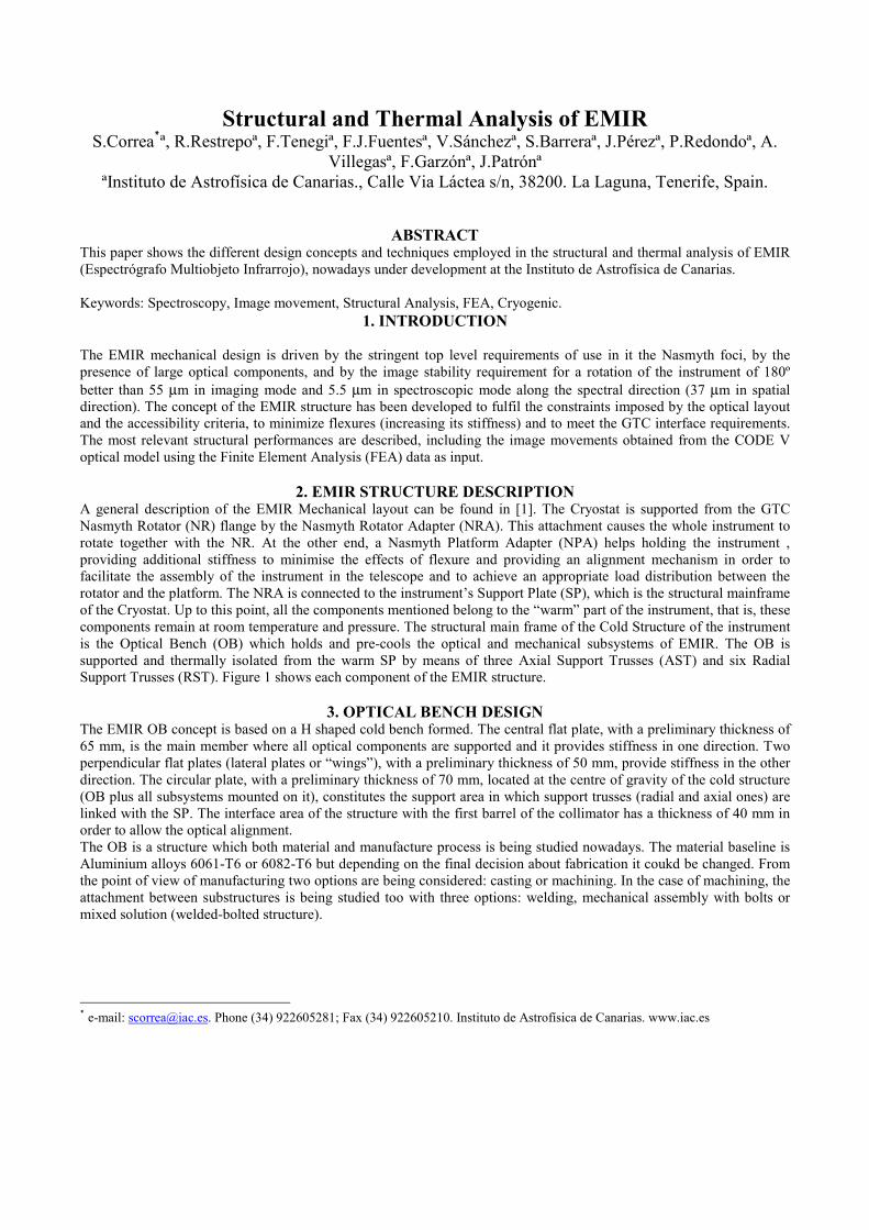
2. EMIR STRUCTURE DESCRIPTION A general description of the EMIR Mechanical layout can be found in [1]. The Cryostat is supported from the GTC
Nasmyth Rotator (NR) flange by the Nasmyth Rotator Adapter (NRA). This attachment causes the whole instrument to
rotate together with the NR. At the other end, a Nasmyth Platform Adapter (NPA) helps holding the instrument ,
providing additional stiffness to minimise the effects of flexure and providing an alignment mechanism in order to
facilitate the assembly of the instrument in the telescope and to achieve an appropriate load distribution between the
rotator and the platform. The NRA is connected to the instrument’s Support Plate (SP), which is the structural mainframe
of the Cryostat. Up to this point, all the components mentioned belong to the “warm” part of the instrument, that is, these
components remain at room temperature and pressure. The structural main frame of the Cold Structure of the instrument
is the Optical Bench (OB) which holds and pre-cools the optical and mechanical subsystems of EMIR. The OB is
supported and thermally isolated from the warm SP by means of three Axial Support Trusses (AST) and six Radial
Support Trusses (RST). Figure 1 shows each component of the EMIR structure.
3. OPTICAL BENCH DESIGN The EMIR OB concept is based on a H shaped cold bench formed. The central flat plate, with a preliminary thickness of
65 mm, is the main member where all optical components are supported and it provides stiffness in one direction. Two
perpendicular flat plates (lateral plates or “wings”), with a preliminary thickness of 50 mm, provide stiffness in the other
direction. The circular plate, with a preliminary thickness of 70 mm, located at the centre of gravity of the cold structure
(OB plus all subsystems mounted on it), constitutes the support area in which support trusses (radial and axial ones) are
linked with the SP. The interface area of the structure with the first barrel of the collimator has a thickness of 40 mm in
order to allow the optical alignment.
The OB is a structure which both material and manufacture process is being studied nowadays. The material baseline is
Aluminium alloys 6061-T6 or 6082-T6 but depending on the final decision about fabrication it coukd be changed. From
the point of view of manufacturing two options are being considered: casting or machining. In the case of machining, the
attachment between substructures is being studied too with three options: welding, mechanical assembly with bolts or
mixed solution (welded-bolted structure).
* e-mail: [email protected]. Phone (34) 922605281; Fax (34) 922605210. Instituto de Astrofísica de Canarias. www.iac.es
Nasmyth Rotator Flange
Cryostat
Nasmyth Rotator Adapter
Nasmyth Platform Adapter
Optical
Bench
Support Trusses
Instrument
Support
Plate
Nasmyth Rotator Flange
Cryostat
Nasmyth Rotator Adapter
Nasmyth Platform Adapter
Optical
Bench
Support Trusses
Instrument
Support
Plate
Figure 1. EMIR Structure
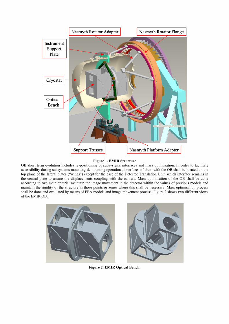
OB short term evolution includes re-positioning of subsystems interfaces and mass optimisation. In order to facilitate
accessibility during subsystems mounting-demounting operations, interfaces of them with the OB shall be located on the
top plane of the lateral plates (“wings”) except for the case of the Detector Translation Unit, which interface remains in
the central plate to assure the displacements coupling with the camera. Mass optimisation of the OB shall be done
according to two main criteria: maintain the image movement in the detector within the values of previous models and
maintain the rigidity of the structure in those points or zones where this shall be necessary. Mass optimisation process
shall be done and evaluated by means of FEA models and image movement process. Figure 2 shows two different views
of the EMIR OB.
Figure 2. EMIR Optical Bench.

4. SUPPORT TRUSSES DESIGN
4.1 Concept
The EMIR OB is supported by means of a Radial Support Trusses (RST) and an Axial Support Trusses (ATS). It
consists of two separate structures that withstand the forces which acts in radial and axial directions. RST consists of an
arrangement of trusses which are loaded in plane through the apex. AST are simple bars directly loaded in tension or
compression.
The concept of the RST is applicable if the ends of the trusses are articulated. In practice the use of bushings or end rods
in cryogenic applications is not feasible; also, the stiffness of this mechanisms is, often, insufficient. The alternative
solution proposed for EMIR is to reduce the bending stiffness of the trusses at their ends: the stiff section of a truss
transforms in a solid section with the axial stiffness, but a much lower moment of inertia and bending stiffness. The
bending of this flexure end provides the stress relief that allows the trusses to accommodate temperature deformations
whilst maintaining a high rigidity in its own plane.
Due to the limitations in the amount of heat conducted through the trusses and the foregone high stresses appearing in the
thinnest section of the flexures, the G10 epoxy composite and the Stainless Steel A-310 will be considered as
manufacturing materials for the trusses and flexures respectively. Figure 3 shows the RST mounted on the OB.
Figure 3. Radial Support Trusses mounted on the OB.
4.2 Flexure characterization
One can find in the literature diverse empiric equations to characterize the rigidity of different flexure types [4,5]. These
equations are based on laboratory experiments and finite elements developments. For EMIR, a specific rod flexure
characterization was developed in order to guarantee the behaviour of the radial trusses. Therefore a parametric study
was done using the programming language of the commercial program Ansys, that characterizes the rigidity of the
flexure due to axial and flexural loads. The parameters of the study are the diameter of the cylinder D and the radius of
the notch r. See Figure 4.

P
P
M
AE
PL=δ
EI
PL
3
3
=δEI
PL
2
2
=δ
PP
PP
MM
AE
PL=δ
EI
PL
3
3
=δEI
PL
2
2
=δ
P
P
M
AE
PL=δ
EI
PL
3
3
=δEI
PL
2
2
=δ
PP
PP
MM
AE
PL=δ
EI
PL
3
3
=δEI
PL
2
2
=δ
Figure 4. Parameter and load cases for the flexure characterization study.
This study provides empirical equations that allow to know the axial and flexural stiffness of the flexure for any
reasonable combination of notch radio and diameter.
Figure 5 shows a typical mesh with the restrictions, symmetry conditions and joints to assure the uniform application of
the load. Figure 5 also shows two examples of results in displacements due to traction and flexion.
Figure 5. Typical mesh of the study (left) and load results due to traction (centre) and flexion (right)
4.3 Flexure Detailed Design
The flexure should fulfil the following requirements:
Axial stiffness: The preliminary calculations have been carried out considering an articulate bar. Adding two flexures in
the ends with the objective of simulating the articulations will cause a change in the axial stiffness of the bar. The flexure
should have enough axial stiffness so that it does not commit the rigidity to traction of the bar.
Flexion stiffness: The rigidity to flexion should be minimized in such a way that the flexure completes its function as
articulation. It is necessary that the flexion stiffness is several orders of magnitude smaller than the bar stiffness.
Stresses: The flexure should absorb the thermal contraction of the central disk of the OB without reaching the elastic
limit.
Once selected the flexure to be used, one can proceeds to the verification of the complete support, analysing the
solicitation due to thermal contraction and the weight of the OB.
Figure 6 shows the four-node tetrahedral mesh used for both analyses. Notice the mesh density used in the area of the
flexures. The flat plate simulates the dimensions of the central disk of the OB.

Figure 6. Finite element mesh use for thermal and elastic analysis
4.3.1 Thermal contraction
The calculation of thermal contractions is carried out as a problem of coupled fields, calculating the distribution of
temperatures along the RST (Figure 7) assuming an uniform temperature of 77K in the plate and 293K in the external
blocks of the RST. Once calculated the distribution of temperatures, these are translated as body loads to the structural
module, in which the displacements of the external blocks of the RST are restricted.
Figure 7. Temperature distribution (left). Thermal contractions of the support (right)
Due to the thermal contraction and the forces produced during the cool down, the centre of the plate moves 1.5 µm in the
X and Y direction, indicating the correct athermalization of the RST, since the high stresses shown in Figure 8, are only
concentrated on the flexures, just as it was expected.

Figure 8. Steady state Von Misses stresses
4.3.2 Gravitational loads
Figure 9 shows the total displacements of the central plate when a load of 12000N, corresponding to the weight of the
OB and the whole cold subsystems, is applied at the centre of the plate.
Figure 9. Displacements of the central disk due to the weight of the optic bench, optical components and
mechanisms.
As it is observed in Figure 9, the maximum displacement of the structure due to the weight of the whole cold mass is
20µm.
The joints between the end of the flexures and the SP are done by means of screws just as it is observed in the Figure 10.
An epoxy will be used to glue the AISI A-310 with the G10. The characteristics of the epoxy and the gluing process will
be defined by experimentation, manufacturing a prototype of the RST and AST in scale 1:2. This prototype will be
cooled down in the EMIR Multipurpose Cryogenic Test System (EMCTS) [1] during 2004. Figure 10 shows the detailed
design of this prototype, mounted in the EMCTS.

Figure 10. Joint details and image of the Support Trusses prototype mounted in the EMCTS
5. IMAGE MOVEMENT CALCULATION
5.1 Errors sources
The image stability budgets are contributed by three main terms:
1. Passive gravitational flexures of the instrument structure, assuming all subsystems are rigidly attached to their
mechanical interface with the OB.
2. Passive module flexures of each optical subsystem with respect to the interface with the OB.
3. Flexure compensator mechanism errors
Term #1 is allocated (in spectroscopy mode) to the relative displacements and tilts of the involved optical elements with
respect to the slit, due to gravitational deformations of the cold structure. The spectroscopic budget is not affected by the
displacement and tilt of the whole instrument with respect to the telescope rotator.
Allocation of term #1 in image mode is to the absolute displacements and tilts of the involved optical elements with
respect to the telescope (the NR flange, where the interface between EMIR and GTC is situated), due to gravitational and
thermal deformations of the support structure and the cold structure.
Term #2 is allocated to the relative displacements and tilts of the involved optical elements with respect to their interface
with the OB.
Term #3 is allocated to the residual errors of the compensation mechanism.
Image displacements due to terms #1 and #2 arise from two different sources:
1. Repetitive and predictive errors due to elastic flexures of the EMIR main structure and substructures. Errors can
be modeled and corrected by the compensator.
2. Non-repetitive errors, including: thermal and structural hysteresis, mechanisms backlash and non-compensated
residuals from the repetitive contributions. These errors cannot be compensated and are the values allocated in
the corresponding Error Budget (EB).
5.2 Flexure compensation
The detector movement along local axis XD and YD is used for compensation of slit image and spectrum displacements
on the detector due to gravitational flexures of EMIR cold structure and involved optical modules.
Movement is performed by a flexure-based mechanisms [1] having the capability of lateral displacements of the detector
on a given range. Image stabilization is performed actively on an open-loop mode, extrapolating the detector X and Y
positions from the calibrated values obtained from a look-up table for a given position respect to the g vector.
The compensation is made on the central field, having a residual movement of the field edge due to non-linear optical
effects. Terms that produces a zero displacement on the center (like rotations) are not compensated.
5.3 Error allocation procedure
Figure 11 shows a schematic breakdown of the instrumental flexure into its mayor components. The division between
structure flexure and module flexure is a practical one, based on the way flexure can be modeled with FEA.
5.3.1 Uncorrected field errors
It includes image movement errors allocated to terms #1 (structure) and #2 (modules) after compensation
5.3.2 Elastic Components
Because of the large FOV of the EMIR camera, the motion on the central field due to flexures is not the same as the one
at the edge of the field. This is a second-order effect compared to the general image translation. However, because the
detector translation cannot correct those differential movements inside the field, it imposes a limit to the mechanical
flexures in EMIR.
Image displacement residuals allocated to gravitational flexures of the instrument structure after compensation are
predicted from a combined FEA/Optical Analysis. The input is a realistic structural configuration of EMIR, obtained
from the structural sensitivity analysis, the optimization criteria and general structural design considerations. The error
sources are the displacements and tilts of each contributing component for the load cases associated to the different
positions of the gravity vector. All these contributions are coupled and their values are obtained using a FEA model of
the structure for each position of g vector. These data are transferred to the optical analysis program as displacements
and tilts of each component. FEA was made using ANSYS 8.0, and the optical analysis was made using CodeV 9.20
The output from the optical model is the variation of the requirement as a function of the rotator angle and the telescope
elevation.
Image displacements allocated to module flexures after compensation are predicted from the results of the FEA of
substructures and the sensitivity analysis
5.3.3 Hysteresis and Backlash
Image error allocated to hysteresis is a 10% of the non-compensated displacements for solid or welded structures (like
the OB)
Image error allocated to elements attached to mechanisms having structural hysteresis, movable elements (like bearings)
and mechanical play is a 30% of the non-compensated displacement. This is the case of the grisms
5.3.4 Compensator errors
Image motion due to detector translation errors is allocated to the absolute accuracy of the translation mechanism (due to
actuator resolution and calibration errors), the incremental accuracy of the mechanism (and control drive), its overall
repeatability and the measurement error of the instrument position
5.4 Finite element model
Modelling and manufacturing are fundamental points related to the structure design. Correct modelling is important
because optical performance of the design is analysed through model results. Moreover, one design can be disregarded
on this basis. On comparing results, models must be equivalent. The word equivalent, however, is difficult to define in
this context and involves many modelling details.
Manufacturing is important because both feasibility and the associated costs. But on designing the structure of an optical
instrument both go together. We must design so that the manufacturing process will not introduce important factors that
cannot be covered by the modelling. Truss elements are really convenient from the weight optimisation standpoint but
perfect hinges do not exist and then, a truss model is not realistic in a displacement model. Beams models are more
realistic, but beams joint stiffness depends on the number of beams meeting at the joint and the kind of beam. A thin
walled beam can present flexibility near the joint that cannot be accurately modelled by simple beam theory. If we will
model with beams, joints must be designed so that beam theory hypothesis is fulfilled.
Another important fact, sometimes disregarded, is that finite element models converge, if the formulation allows it, to the
mathematical model of the physical structure. Then, we need to be sure that our mathematical representation, i.e.: solid,
plates, shells or beams, is correct within the structure.

Elastic
Hysteresis
Structure
Elastic
HysteresisBacklash
Modules
Uncorrected Field Errors
CalibrationErrors
ResolutionErrors
Accuracy Errors
RepeatabilityErrors
Compensator Errors
Image MovementRequirement
Figure 11. Flow chart showing the structure of the image movement error budgets
In our experience, flat or mild twisted plates, can be adequately modelled by plate elements with shear corrected
displacements. Near joint flexibility can be accounted with a fine mesh. This is not the case for a beam. To use small
beam elements will never account for the beam wall flexibility.
The OB structure is simulated with 8 node shell elements. The support trusses and support structure are simulated with
3D beam elements with convenient shear correction factors. The masses of the optical components are simulated with
structural mass element.
Each substructure mass is located at its centre of gravity and attached to the structure interface points with a low stiffness
beam element, to not increase the local stiffness of the structure. The load transmitted is correct but the mass
displacement is meaningless. For all the subsystems no detail more than its weight and structure attachment points are
considered.
Figure 12 shows a representative finite element of the EMIR OB and RST. Notice the joint between the subsystems
masses and the structure. Also OB displacements due to the gravity vector acting in vertical (X) direction are shown.
5.5 Result post processing
The results of the finite element program were processed in order to produce useful data for the optical analysis.
The optical components behaviour is reduced to that of a plane triangle attached to three points at the interface plane.
The displacements and rotations are calculated as follows:
Displacements Ux, Uy and Uz of the three points are averaged. These three points form a triangle which centre is located
–approximately, due to discretization errors- at the interface centre.
Normal vectors to the undistorted and to the distorted triangle were calculated. These vectors are normalized and its
vector product gives us the tip and tilt of the triangle. In order to compute the rotation of the plane around its normal, an
in-plane vector joining the triangle centre of gravity and one of the nodes is defined and normalized. The vector product
between its undistorted and distorted positions is taken as the third rotation.

Figure 12. Finite element mesh and gravitational displacement of the EMIR OB and RST.
5.6 Flexure analysis
The displacements and tilts of the more contributing optical components (camera and detector) -relatives to each local
coordinate system and with the instrument turning about the Z axis are shown in Figure 13 to Figure 14.
Camera Relative Tilts
-2
-1,5
-1
-0,5
0
0,5
1
1,5
2
-3 -2 -1 0 1 2 3
Rotx(arcsec)
Ro
ty(a
rse
c)
Camera Relative Displacements
-15
-10
-5
0
5
10
15
-2 -1,5 -1 -0,5 0 0,5 1 1,5 2
Ux (um)
Uy (
um
)
Figure 13. Camera relative displacements and tilts
Detector Relative Tilts
-2
-1,5
-1
-0,5
0
0,5
1
1,5
2
-1 -0,5 0 0,5 1
Rotx(arcsec)
Ro
ty(a
rsec)
Detector Relative Displacements
-15
-10
-5
0
5
10
15
-6 -4 -2 0 2 4 6
Ux (um)
Uy (
um
)
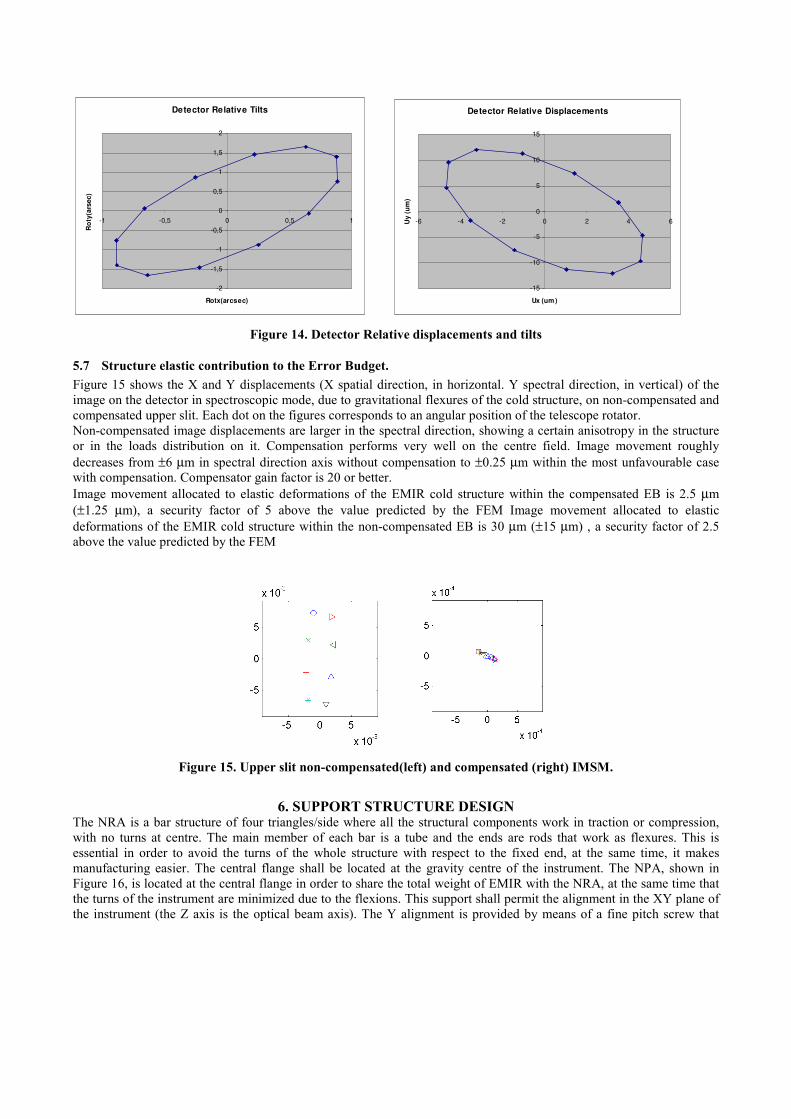
Figure 14. Detector Relative displacements and tilts
5.7 Structure elastic contribution to the Error Budget.
Figure 15 shows the X and Y displacements (X spatial direction, in horizontal. Y spectral direction, in vertical) of the
image on the detector in spectroscopic mode, due to gravitational flexures of the cold structure, on non-compensated and
compensated upper slit. Each dot on the figures corresponds to an angular position of the telescope rotator.
Non-compensated image displacements are larger in the spectral direction, showing a certain anisotropy in the structure
or in the loads distribution on it. Compensation performs very well on the centre field. Image movement roughly
decreases from ±6 µm in spectral direction axis without compensation to ±0.25 µm within the most unfavourable case
with compensation. Compensator gain factor is 20 or better.
Image movement allocated to elastic deformations of the EMIR cold structure within the compensated EB is 2.5 µm
(±1.25 µm), a security factor of 5 above the value predicted by the FEM Image movement allocated to elastic
deformations of the EMIR cold structure within the non-compensated EB is 30 µm (±15 µm) , a security factor of 2.5
above the value predicted by the FEM
Figure 15. Upper slit non-compensated(left) and compensated (right) IMSM.
6. SUPPORT STRUCTURE DESIGN The NRA is a bar structure of four triangles/side where all the structural components work in traction or compression,
with no turns at centre. The main member of each bar is a tube and the ends are rods that work as flexures. This is
essential in order to avoid the turns of the whole structure with respect to the fixed end, at the same time, it makes
manufacturing easier. The central flange shall be located at the gravity centre of the instrument. The NPA, shown in
Figure 16, is located at the central flange in order to share the total weight of EMIR with the NRA, at the same time that
the turns of the instrument are minimized due to the flexions. This support shall permit the alignment in the XY plane of
the instrument (the Z axis is the optical beam axis). The Y alignment is provided by means of a fine pitch screw that

moves the two rolling bearings in opposite sense, displacing the central flange vertically. The X alignment is provided by
means of a lateral screw that displace the whole system horizontally. A central bearing with a preload system is provided
in order to assure a permanent contact between the central flange and the rolling bearings.
Rolling Bearings
Y-alignment screw X-alignment screwTraslation table
Preload system Rolling Bearings
Y-alignment screw X-alignment screwTraslation table
Preload system
Figure 16. Nasmyth Platform Adapter
REFERENCES
1. F.J. Fuentes et al. EMIR Mechanical Design Status. Astronomical Telescopes and Instrumentation. (5492-75). SPIE,
Glasgow, Scotland. UK. 2004.
2. D. Vukobratovich, Advanced Topics in Opto-Mechanics, edited by Siralimited, 1-84, 2001.
3. P.R. Hasting and D. Montgomery, Support of Cooled Components in Astronomical Instruments, Cryogenics, 33, Nº
11, 1032-1036, 1993.
4. S. Henein, Conception des guidages flexibles. Presses Polytechniques.Viena, 2001.
5. A. Slocum, Precision Machine Design. Prentice Hall, New Jersey, 1992.