Development of multilayer thin film filters for the full-sun imager on Solar Orbiter
7
Development of multilayer thin film filters for the Full Sun Imager on Solar Orbiter Frédéric Auchère* a , Xueyan Zhang a , Franck Delmotte b , Evgueni Meltchakov b , Ali BenMoussa c a Institut d’Astrophysique Spatiale, CNRS / Univ. Paris-Sud 11, Bâtiment 121, 91405 Orsay, France; b Laboratoire Charles Fabry, Institut d’Optique, CNRS / Univ. Paris-Sud 11, Campus Polytechnique, RD 128, 91127 Palaiseau Cedex, France c Royal Observatory of Belgium, STCE, Circular Avenue 3, 1180 Brussels, Belgium ABSTRACT Membranes a few hundred nanometers thick are used in EUV optics to make, for example, beams splitters or passband filters. Despite their necessity in numerous applications these components are, because of their thinness, extremely fragile and their implementation in space instruments is always difficult. The authors are developing thin film filters for the Full Sun Imager, one of the EUV telescopes on board the Solar Orbiter mission with objectives of high optical efficiency and mechanical strength. These filters are specifically designed to isolate one or the other of the two passbands (17.4 and 30.4 nm) reflected by the telescope’s dual band mirror coating. In this paper we present the optical properties of the prototype components. Keywords: EUV optics, filters, thin films 1. INTRODUCTION The Extreme Ultraviolet Imager (EUI, see Fig. 1) is a fundamental component in the Solar Orbiter mission profile. EUI is composed of two high resolution imagers, one at Lyman-α and one in the extreme UV at 17.4 nm, and of one dual band full-sun imager (FSI). The FSI was first described by Auchère et al 1 . It is one of the channels of the It is designed to observe the Sun in two narrow bands of the EUV spectrum centered on the 17.4 nm line of Fe X and on the 30.4 nm line of He II. The general layout of the instrument is given in Fig. 2. A 5 mm diameter pupil is located 700 mm in front of an elliptical mirror. A thin film aluminum filter is located 310 mm behind the pupil. Two types of thin film filters (zirconium and magnesium) are held by a filter wheel located close to the 3k × 3k detector. The two types of filters isolate one or the other of the two narrow bands reflected by the dual-band multilayer coating of the mirror 2,3 . The filters are reinforced by nickel mesh grids with 81% geometrical transmission. In this paper, we will focus on the optical properties of the prototype filters. *[email protected]; phone +33 1 69 85 87 33 2. OPTICAL DESIGN 2.1 Specfications In order to isolate one or the other of the two solar emission lines reflected by the dual band coating, two types of mutually exclusive filters are needed to obtain a high transmittance of one of the bands and a sufficient suppression of the other one. Since the entrance filter of the instrument needs to transmit both wavelengths, aluminum is a natural choice. The focal filters must therefore be a low-pass and a high-pass filter, with a cutoff at a wavelength intermediate between the two bands of interest. With a cutoff around 25 nm, magnesium was selected to isolate the long wavelength band. Zirconium was selected to isolate the short wavelength band because of its very low transmittance around 30.4 nm. Both materials need to be encapsulated in aluminum to minimize surface oxidation and to suppress the visible and infrared.
Transcript of Development of multilayer thin film filters for the full-sun imager on Solar Orbiter
Development of multilayer thin film filters for the Full Sun Imager on Solar Orbiter
Frédéric Auchère*a, Xueyan Zhanga, Franck Delmotteb, Evgueni Meltchakovb, Ali BenMoussac aInstitut d’Astrophysique Spatiale, CNRS / Univ. Paris-Sud 11, Bâtiment 121, 91405 Orsay, France; bLaboratoire Charles Fabry, Institut d’Optique, CNRS / Univ. Paris-Sud 11, Campus Polytechnique,
RD 128, 91127 Palaiseau Cedex, France cRoyal Observatory of Belgium, STCE, Circular Avenue 3, 1180 Brussels, Belgium
ABSTRACT
Membranes a few hundred nanometers thick are used in EUV optics to make, for example, beams splitters or passband filters. Despite their necessity in numerous applications these components are, because of their thinness, extremely fragile and their implementation in space instruments is always difficult. The authors are developing thin film filters for the Full Sun Imager, one of the EUV telescopes on board the Solar Orbiter mission with objectives of high optical efficiency and mechanical strength. These filters are specifically designed to isolate one or the other of the two passbands (17.4 and 30.4 nm) reflected by the telescope’s dual band mirror coating. In this paper we present the optical properties of the prototype components. Keywords: EUV optics, filters, thin films
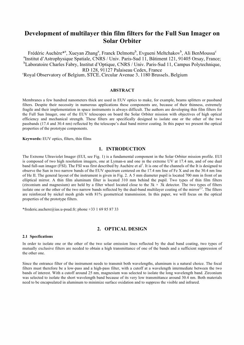
1. INTRODUCTION The Extreme Ultraviolet Imager (EUI, see Fig. 1) is a fundamental component in the Solar Orbiter mission profile. EUI is composed of two high resolution imagers, one at Lyman-α and one in the extreme UV at 17.4 nm, and of one dual band full-sun imager (FSI). The FSI was first described by Auchère et al1. It is one of the channels of the It is designed to observe the Sun in two narrow bands of the EUV spectrum centered on the 17.4 nm line of Fe X and on the 30.4 nm line of He II. The general layout of the instrument is given in Fig. 2. A 5 mm diameter pupil is located 700 mm in front of an elliptical mirror. A thin film aluminum filter is located 310 mm behind the pupil. Two types of thin film filters (zirconium and magnesium) are held by a filter wheel located close to the 3k × 3k detector. The two types of filters isolate one or the other of the two narrow bands reflected by the dual-band multilayer coating of the mirror2,3. The filters are reinforced by nickel mesh grids with 81% geometrical transmission. In this paper, we will focus on the optical properties of the prototype filters. *[email protected]; phone +33 1 69 85 87 33
2. OPTICAL DESIGN 2.1 Specfications
In order to isolate one or the other of the two solar emission lines reflected by the dual band coating, two types of mutually exclusive filters are needed to obtain a high transmittance of one of the bands and a sufficient suppression of the other one. Since the entrance filter of the instrument needs to transmit both wavelengths, aluminum is a natural choice. The focal filters must therefore be a low-pass and a high-pass filter, with a cutoff at a wavelength intermediate between the two bands of interest. With a cutoff around 25 nm, magnesium was selected to isolate the long wavelength band. Zirconium was selected to isolate the short wavelength band because of its very low transmittance around 30.4 nm. Both materials need to be encapsulated in aluminum to minimize surface oxidation and to suppress the visible and infrared.
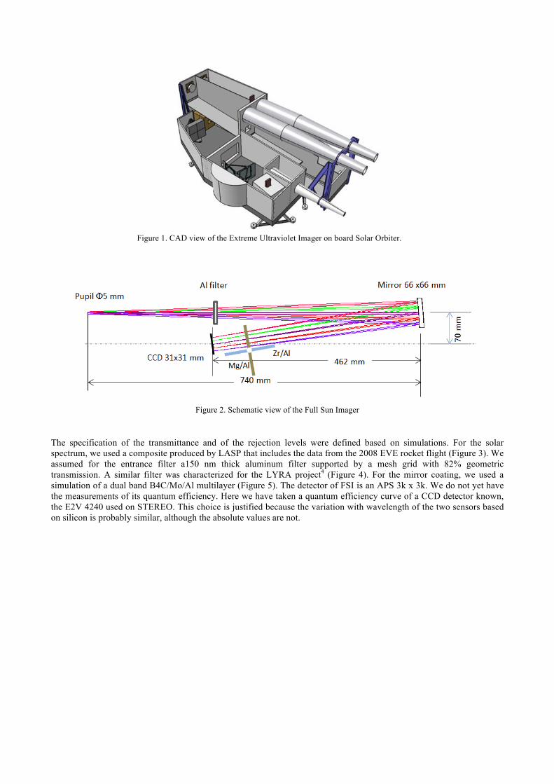
Figure 1. CAD view of the Extreme Ultraviolet Imager on board Solar Orbiter.
Figure 2. Schematic view of the Full Sun Imager
The specification of the transmittance and of the rejection levels were defined based on simulations. For the solar spectrum, we used a composite produced by LASP that includes the data from the 2008 EVE rocket flight (Figure 3). We assumed for the entrance filter a150 nm thick aluminum filter supported by a mesh grid with 82% geometric transmission. A similar filter was characterized for the LYRA project4 (Figure 4). For the mirror coating, we used a simulation of a dual band B4C/Mo/Al multilayer (Figure 5). The detector of FSI is an APS 3k x 3k. We do not yet have the measurements of its quantum efficiency. Here we have taken a quantum efficiency curve of a CCD detector known, the E2V 4240 used on STEREO. This choice is justified because the variation with wavelength of the two sensors based on silicon is probably similar, although the absolute values are not.
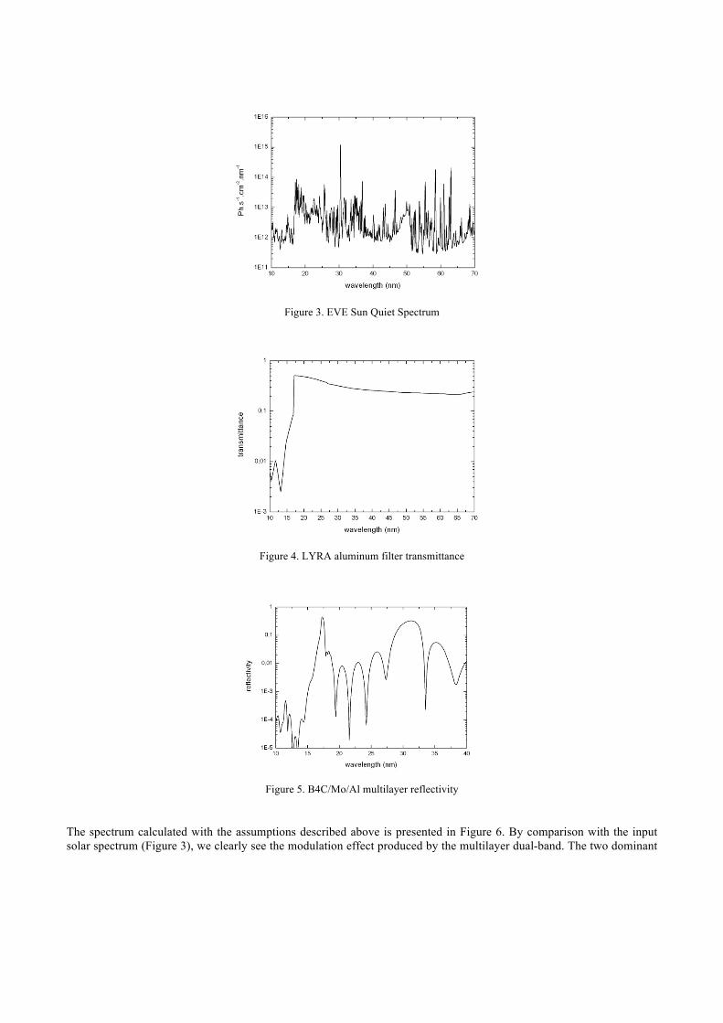
Figure 3. EVE Sun Quiet Spectrum
Figure 4. LYRA aluminum filter transmittance
Figure 5. B4C/Mo/Al multilayer reflectivity
The spectrum calculated with the assumptions described above is presented in Figure 6. By comparison with the input solar spectrum (Figure 3), we clearly see the modulation effect produced by the multilayer dual-band. The two dominant
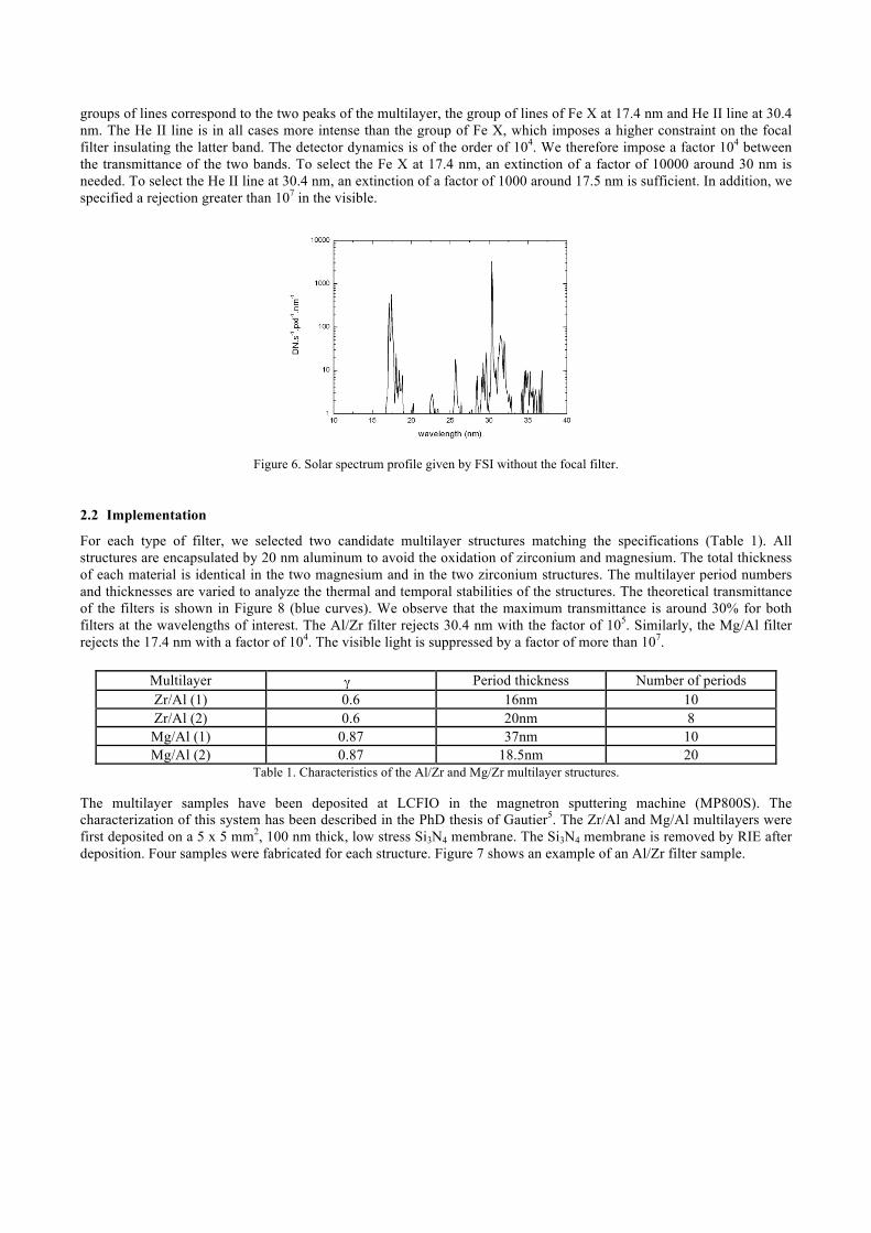
groups of lines correspond to the two peaks of the multilayer, the group of lines of Fe X at 17.4 nm and He II line at 30.4 nm. The He II line is in all cases more intense than the group of Fe X, which imposes a higher constraint on the focal filter insulating the latter band. The detector dynamics is of the order of 104. We therefore impose a factor 104 between the transmittance of the two bands. To select the Fe X at 17.4 nm, an extinction of a factor of 10000 around 30 nm is needed. To select the He II line at 30.4 nm, an extinction of a factor of 1000 around 17.5 nm is sufficient. In addition, we specified a rejection greater than 107 in the visible.
Figure 6. Solar spectrum profile given by FSI without the focal filter.
2.2 Implementation
For each type of filter, we selected two candidate multilayer structures matching the specifications (Table 1). All structures are encapsulated by 20 nm aluminum to avoid the oxidation of zirconium and magnesium. The total thickness of each material is identical in the two magnesium and in the two zirconium structures. The multilayer period numbers and thicknesses are varied to analyze the thermal and temporal stabilities of the structures. The theoretical transmittance of the filters is shown in Figure 8 (blue curves). We observe that the maximum transmittance is around 30% for both filters at the wavelengths of interest. The Al/Zr filter rejects 30.4 nm with the factor of 105. Similarly, the Mg/Al filter rejects the 17.4 nm with a factor of 104. The visible light is suppressed by a factor of more than 107.
Multilayer γ Period thickness Number of periods Zr/Al (1) 0.6 16nm 10 Zr/Al (2) 0.6 20nm 8 Mg/Al (1) 0.87 37nm 10 Mg/Al (2) 0.87 18.5nm 20
Table 1. Characteristics of the Al/Zr and Mg/Zr multilayer structures.
The multilayer samples have been deposited at LCFIO in the magnetron sputtering machine (MP800S). The characterization of this system has been described in the PhD thesis of Gautier5. The Zr/Al and Mg/Al multilayers were first deposited on a 5 x 5 mm2, 100 nm thick, low stress Si3N4 membrane. The Si3N4 membrane is removed by RIE after deposition. Four samples were fabricated for each structure. Figure 7 shows an example of an Al/Zr filter sample.
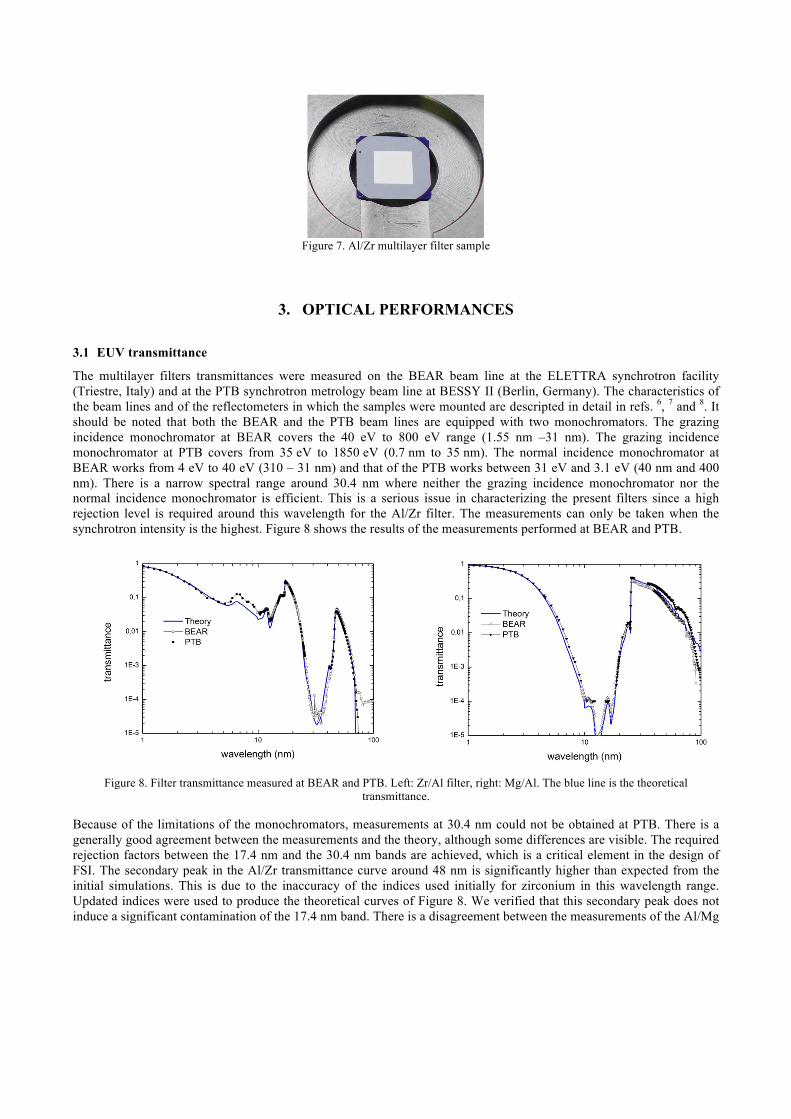
Figure 7. Al/Zr multilayer filter sample
3. OPTICAL PERFORMANCES
3.1 EUV transmittance
The multilayer filters transmittances were measured on the BEAR beam line at the ELETTRA synchrotron facility (Triestre, Italy) and at the PTB synchrotron metrology beam line at BESSY II (Berlin, Germany). The characteristics of the beam lines and of the reflectometers in which the samples were mounted are descripted in detail in refs. 6, 7 and 8. It should be noted that both the BEAR and the PTB beam lines are equipped with two monochromators. The grazing incidence monochromator at BEAR covers the 40 eV to 800 eV range (1.55 nm –31 nm). The grazing incidence monochromator at PTB covers from 35 eV to 1850 eV (0.7 nm to 35 nm). The normal incidence monochromator at BEAR works from 4 eV to 40 eV (310 – 31 nm) and that of the PTB works between 31 eV and 3.1 eV (40 nm and 400 nm). There is a narrow spectral range around 30.4 nm where neither the grazing incidence monochromator nor the normal incidence monochromator is efficient. This is a serious issue in characterizing the present filters since a high rejection level is required around this wavelength for the Al/Zr filter. The measurements can only be taken when the synchrotron intensity is the highest. Figure 8 shows the results of the measurements performed at BEAR and PTB.
Figure 8. Filter transmittance measured at BEAR and PTB. Left: Zr/Al filter, right: Mg/Al. The blue line is the theoretical
transmittance.
Because of the limitations of the monochromators, measurements at 30.4 nm could not be obtained at PTB. There is a generally good agreement between the measurements and the theory, although some differences are visible. The required rejection factors between the 17.4 nm and the 30.4 nm bands are achieved, which is a critical element in the design of FSI. The secondary peak in the Al/Zr transmittance curve around 48 nm is significantly higher than expected from the initial simulations. This is due to the inaccuracy of the indices used initially for zirconium in this wavelength range. Updated indices were used to produce the theoretical curves of Figure 8. We verified that this secondary peak does not induce a significant contamination of the 17.4 nm band. There is a disagreement between the measurements of the Al/Mg
filters performed at BEAR and PTB. In the 30 to 100 nm range, the BEAR measurements are lower than the theory, while the PTB measurements are higher.
The filter transmittance stability has also been investigated. The filters were stored at air and measured two times 4 months apart. The left panel of Figure 9 shows that the Al/Zr filters are very stable (3%, within the measurement uncertainties); the aluminum encapsulation protects the zirconium from oxidizing. The right panel shows a decrease of the Al/Mg filters transmittance. This could be due to an insufficient thickness of the aluminum caper layers causing oxidation of the magnesium.
Figure 9. Stability of the filters transmittances measured at BEAR. Left: Al/Zr filter, right: Al/Mg filter.
3.2 Near UV and visible transmittance
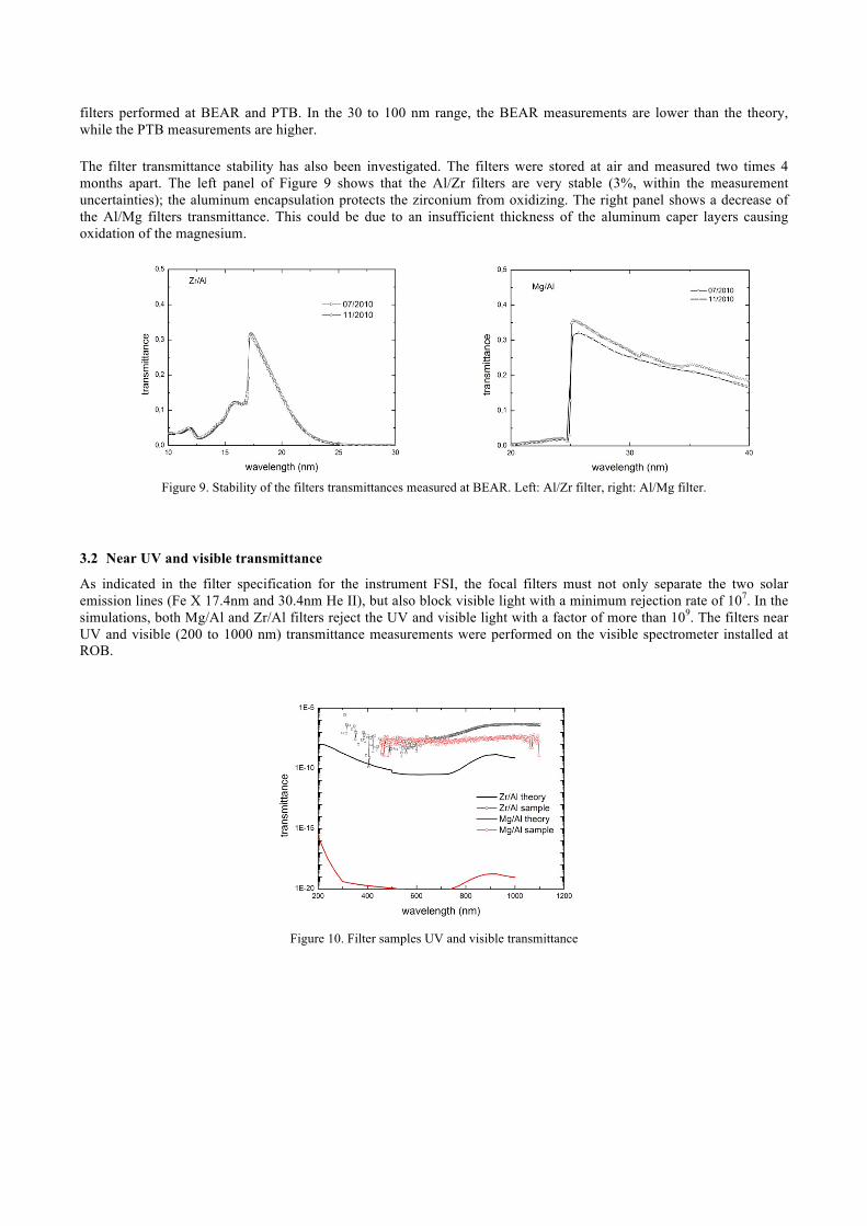
As indicated in the filter specification for the instrument FSI, the focal filters must not only separate the two solar emission lines (Fe X 17.4nm and 30.4nm He II), but also block visible light with a minimum rejection rate of 107. In the simulations, both Mg/Al and Zr/Al filters reject the UV and visible light with a factor of more than 109. The filters near UV and visible (200 to 1000 nm) transmittance measurements were performed on the visible spectrometer installed at ROB.
Figure 10. Filter samples UV and visible transmittance

Figure 10 shows the measured transmittance of the Zr/Al and Mg/Al filters compared with the theoretical calculations. The transmittance of the Zr/Al filter is between 10-7 and 10-8. The transmittance of the Mg/Al filter is close to 10-8. The differences between theory and measurements are probably due to micro- pinholes in the filters. However, both types of filters meet the specifications. Furthermore, we are close to the maximum possible rejection that can be measured with the ROB setup (about 10-8).
4. CONCLUSIONS We have presented the development of thin film Al/Zr and Al/Mg multilayer filters for EUV observations of the Sun. The optical measurements made on the first test sample show in general a good agreement with the theory, although some discrepancies need further investigation. The measurements show that the prototype filters meet the requirements of the Full Sun Imager on Solar Orbiter, thus validating the dual band concept of the instrument.
ACKNOWLEDGEMENTS This work is supported by the R&D program of the Centre National d’Etude Spatiales (CNES). The authors gratefully acknowledge Udo Kroth, Alexander Gottwald and Christian Laubis of the PTB for their kindness in helping us with the EUV measurement. The authors are also thanksful to Angelo Giglia of the BEAR beam line for his efficient work on the EUV measurements.
REFERENCES [1] Auchère, F. et al. ‘‘Innovative designs for the imaging suite on Solar Orbiter’’, Solar Physics and Space Weather
Instrumentation. Edited by Fineschi, Silvano; Viereck, Rodney A. Proceedings of the SPIE, 5901, 298-304 (2005) [2] Hecquet, C. et al. “Design and performance of two-channel EUV multilayer mirrors with enhanced spectral
selectivity”, Appl. Phys., 95(2), 401 (2009) [3] Meltchakov, E. et al. “EUV reflectivity and stability of tri-component Al-based multilayers” SPIE, Paper 8168-45, 5 -
8 September 2011, to be published (2011) [4] BenMoussa, A. et al. ‘‘Pre-flight calibration of LYRA, the solar VUV radiometer on board PROBA2’’, A&A,
508(2), 1085-1094 (2009) [5] Gautier, J. PhD thesis ‘‘Etude et élaboration de revêtements multicouches pour l’optique extrême UV dans la gamme
spectrale 30 – 50 nm’’ (2005) [6] Nannarone S. et al., ‘The BEAR beamline at ELETTRA’’, AIP Conference Proceeding 705, 450, (2004) [7] Scholze, F. et al. ‘‘High-Accuracy EUV Metrology of PTB Using Synchrotron Radiation’, Proceedings of the SPIE,
4344, 402-413 (2001) [8] Richter, M. et al. ‘‘The two normal-incidence monochromator beam lines of PTB at BESSY II’’, Nuclear Instruments
and Methods in Physics Research A, 467–468 (2001)