Gemini Planet Imager autonomous software
9
Gemini Planet Imager Autonomous Software Jennifer Dunn* a , Robert Wooff a , Malcolm Smith a , Dan Kerley a , Dave Palmer b , Steve Jones b , Jason Weiss d , John Angione e , James R. Graham c a National Research Council of Canada, Herzberg Institute of Astrophysics, 5071 W. Saanich Rd., Victoria, BC, V9E 2E7, Canada b Lawrence Livermore National Laboratories, 7000 East Avenue, Livermore, CA 94550. c University of California, Berkeley, CA 94720, NOAO, 950 N. Cherry Avenue, Tuscon AZ 85719. d Dept. of Physics and Astronomy, Univ. of California at Los Angeles, Los Angeles, CA 90095. e Jet Propulsion Laboratories, Casilla 603, La Serena, Chile ABSTRACT The Gemini Planet Imager (GPI) is an “extreme” adaptive optics coronagraph system that will have the ability to directly detect and characterize young Jovian-mass exoplanets. The design of this instrument involves eight principal institutions geographically spread across North America, with four of those sites writing software that must run seamlessly together while maintaining autonomous behaviour. The objective of the software teams is to provide Gemini with a unified software system that not only performs well but also is easy to maintain. Issues such as autonomous behaviour in a unified environment, common memory to share status and information, examples of how this is being implemented, plans for early software integration and testing, command hierarchy, plans for common documentation and updates are explored in this paper. The project completed its preliminary design phase in 2007, and has just recently completed its critical design phase. Keywords: Software, Observatory, Gemini, GPI, Gemini Planet Imager, Software, AO, Coronagraph, Software Engineering, Control System 1. INTRODUCTION The Gemini Planet Imager (GPI) is an “extreme” adaptive optics coronagraph system that will have the ability to directly detect and characterize young Jovian-mass exoplanets [1] . The project has completed its preliminary design phase in 2007 and has just recently completed the critical design phase. This project benefits from the collective knowledge of people from eight different institutions, four of which are providing the software to run both in queue and classical observing modes at the Gemini Observatory. The objective of the instrument software is to provide not just building blocks to control different parts of the instrument, but to provide a complete seamless instrument that will automate the steps required to provide the best contrast images for planet detection. While considering the objectives of individual software projects and the requirements of the GPI instrument as a whole, this paper will describe the behaviour of each autonomous system, how it will be unified by the choices made, how it functions as a single instrument, the command hierarchy and plans for early integration and testing. * [email protected] phone 1 250 363-6912; fax 1 250 363-0045; www.hia-iha.nrc-cnrc.gc.ca Advanced Software and Control for Astronomy II, edited by Alan Bridger, Nicole M. Radziwill Proc. of SPIE Vol. 7019, 701910, (2008) · 0277-786X/08/$18 · doi: 10.1117/12.788032 Proc. of SPIE Vol. 7019 701910-1 2008 SPIE Digital Library -- Subscriber Archive Copy
-
Upload
independent -
Category
Documents
-
view
3 -
download
0
Transcript of Gemini Planet Imager autonomous software

Gemini Planet Imager Autonomous Software
Jennifer Dunn* a, Robert Wooff a, Malcolm Smith a, Dan Kerley a, Dave Palmer b, Steve Jonesb, Jason Weissd, John Angionee, James R. Grahamc
aNational Research Council of Canada, Herzberg Institute of Astrophysics, 5071 W. Saanich Rd., Victoria, BC, V9E 2E7, Canada
bLawrence Livermore National Laboratories, 7000 East Avenue, Livermore, CA 94550. cUniversity of California, Berkeley, CA 94720, NOAO, 950 N. Cherry Avenue, Tuscon AZ 85719.
dDept. of Physics and Astronomy, Univ. of California at Los Angeles, Los Angeles, CA 90095.
eJet Propulsion Laboratories, Casilla 603, La Serena, Chile
ABSTRACT
The Gemini Planet Imager (GPI) is an “extreme” adaptive optics coronagraph system that will have the ability to directly detect and characterize young Jovian-mass exoplanets. The design of this instrument involves eight principal institutions geographically spread across North America, with four of those sites writing software that must run seamlessly together while maintaining autonomous behaviour. The objective of the software teams is to provide Gemini with a unified software system that not only performs well but also is easy to maintain. Issues such as autonomous behaviour in a unified environment, common memory to share status and information, examples of how this is being implemented, plans for early software integration and testing, command hierarchy, plans for common documentation and updates are explored in this paper. The project completed its preliminary design phase in 2007, and has just recently completed its critical design phase. Keywords: Software, Observatory, Gemini, GPI, Gemini Planet Imager, Software, AO, Coronagraph, Software Engineering, Control System
1. INTRODUCTION The Gemini Planet Imager (GPI) is an “extreme” adaptive optics coronagraph system that will have the ability to directly detect and characterize young Jovian-mass exoplanets[1]. The project has completed its preliminary design phase in 2007 and has just recently completed the critical design phase. This project benefits from the collective knowledge of people from eight different institutions, four of which are providing the software to run both in queue and classical observing modes at the Gemini Observatory. The objective of the instrument software is to provide not just building blocks to control different parts of the instrument, but to provide a complete seamless instrument that will automate the steps required to provide the best contrast images for planet detection. While considering the objectives of individual software projects and the requirements of the GPI instrument as a whole, this paper will describe the behaviour of each autonomous system, how it will be unified by the choices made, how it functions as a single instrument, the command hierarchy and plans for early integration and testing.
* [email protected] phone 1 250 363-6912; fax 1 250 363-0045; www.hia-iha.nrc-cnrc.gc.ca
Advanced Software and Control for Astronomy II, edited by Alan Bridger, Nicole M. RadziwillProc. of SPIE Vol. 7019, 701910, (2008) · 0277-786X/08/$18 · doi: 10.1117/12.788032
Proc. of SPIE Vol. 7019 701910-12008 SPIE Digital Library -- Subscriber Archive Copy

IrerIock OutIn
GPI
StatusOCSGPICommands
ZernikesOttload
TrackingCoordinates
TIA Time
Tip Tit Focus
OttIoa%
2. SOFTWARE SYSTEMS GPI’s command structure is hierarchical. There are many different philosophies on the balance of hierarchical control. One model is to have all of the brains at the top which will define and sequence all tasks of the complete body of software. In that situation the subsystems do not do any internal sequencing and the main sequencer needs to be completed prior to all other subsystems, even before the subsystem design is complete. A more balanced model is where the brain only provides the top level of sequencing and executes black boxes on the various subsystems, which is the ideal situation for GPI. The main controller, the Top-Level Computer (TLC), relies on the subsystems for internal sequencing of commands being sent. The TLC doesn’t need to have knowledge of the internal sequencing, whereas the subsystems being built and tested before integration do need that functionality. Each of these subsystems is as large as some stand-alone projects. Each of the subsystems is being built at different sites and must run and pass site acceptance tests before integration into the final instrument. This amplifies the need for each of these subsystems to give the appearance of a black box that can execute sequences independently. Due to the distributed nature of the GPI development team as well as a desire to keep subsystems as autonomous as possible, the design of all software systems do not rely heavily on detailed knowledge about the other subsystems. Instead the output of their processed raw data is passed into shareable memory in agreed upon units for use by other subsystems. This maintains the balance of autonomous behaviour and the need to deliver a seamless instrument. The following figure (Figure 1) shows how GPI fits into the Gemini environment. GPI will receive all commands from the Gemini Observatory Control System (OCS) and provide status back via the Gemini Instrument API (GIAPI). It offloads to the Primary (PCS) and Secondary (SCS) Mirror Control systems, accepts tracking coordinates from the Telescope Control System (TCS) and offloads data to the Data Handling System (DHS). It also accepts and reports signals to the Gemini Interlock System (GIS).
Figure 1 GPI Context Diagram
The goal is to have software practices and standards for all software subsystems that follow the ones used by Gemini. This will also involve plans for early software integration and testing. And this is all going to be achieved while maintaining the developers’ creativity by treating each subsystem autonomously.
Proc. of SPIE Vol. 7019 701910-2

Top-U evel
Computer.(TLC)
AthptiveOptacs
Computer(AOC)
CalibrationSystem(CAL)
Global MemoiyBlock(GMB)
The top level of GPI software decomposition is based on GPI’s major instrument subsystems. The GPI control software has four separate controlling subsystems. The software for each of those four subsystems will run on its own computer, and is being developed at different sites. Those subsystems are:
1. The top-level computer (TLC) that provides the interface for the observatory software and sequencing of the instrument as a whole. Developed at HIA, the TLC ties together the following three subsystems. 2. The adaptive optics (AO) system, developed at LLNL, which uses a fast wavefront sensor to control the shape of two deformable mirrors, and thereby deliver a flat wavefront to the science instrument. 3. The JPL-developed calibration (CAL) system, which provides accurate wavefront phase and amplitude errors to the AO system for correction. It also provides low-order aberration sensing to keep the target star centered on the coronagraph occultor. 4. The integral field spectrograph (IFS) system, which is the science instrument based on a lenslet array, developed at UCLA. The raw science dataset is then post-processed to produce a data cube that will allow for the suppression of residual speckles. The IFS also has the capacity for polarimetric observations and a diagnostic pupil-viewing mode.
Figure 2 Internal GPI Subsystems
The Gemini interface is a new development which will abstract the interfaces to Gemini for GPI and is called the Gemini Instrument API (GIAPI) [2]. The GIAPI libraries provide all the access required to Gemini. The communication engine for the GIAPI will physically exist on the GPI computers and as a result will induce some overhead to the TLC operations. The instrument Glue API is also part of the GIAPI and is required by any process that communicates with the GIAPI [1].
Proc. of SPIE Vol. 7019 701910-3

Fold Mirror
ADC
AO WFS
Pu oil Plane Mas
Power BarI-Wire
FocalPlane Mask
CAL
CAL Source
IFS
The plan is to have all software on each subsystem be developed, run and tested independently at a single partner institute. Interactions between subsystems are controlled by the definition of explicit inter-computer interfaces. Resource contention between systems is reduced since each system has its own resources such as CPU, memory, and disks. As shown in Figure 2 there is one connection between all subsystems to the shareable memory, called the Global Memory Block (GMB), which is where a subsystem publishes data required by other subsystems.
3. TLC INTERNALS The TLC consists of several different components, many of which run as autonomous processes. These components are listed and shown below (Figure 3):
• Command Event Handler: handles the GIAPI to GPI interface • Instrument Sequencer: sequences the instrument as a whole • Status Server: provides status updates to subscribed users • Acceptance Test and Engineering User Interface (ATEUI): engineering interface • Components Controller:
o 11 distinct Assembly SubServer components: handles the coordinated sequencing of a logical grouping of motion controllers, sensors or commands
o 8 instances of the Motion Control Daemon (MCD) component: handles I/O and Galil or Peizo motion controllers.
• 3 Distinct Subsystem SubServers (SUBs): o AOC RPC Server, CAL RPC Server, and IFS RPC Server
• Common Libraries (to handle GMB)
Figure 3 TLC Internal Components
Proc. of SPIE Vol. 7019 701910-4
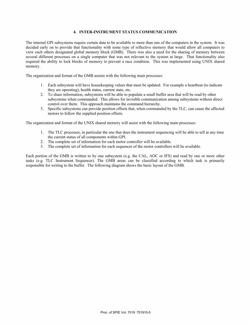
4. INTER-INSTRUMENT STATUS COMMUNICATION The internal GPI subsystems require certain data to be available to more than one of the computers in the system. It was decided early on to provide that functionality with some type of reflective memory that would allow all computers to view each others designated global memory block (GMB). There was also a need for the sharing of memory between several different processes on a single computer that was not relevant to the system at large. That functionality also required the ability to lock blocks of memory to prevent a race condition. This was implemented using UNIX shared memory. The organization and format of the GMB assists with the following main processes:
1. Each subsystem will have housekeeping values that must be updated. For example a heartbeat (to indicate they are operating), health status, current state, etc.
2. To share information, subsystems will be able to populate a small buffer area that will be read by other subsystems when commanded. This allows for invisible communication among subsystems without direct control over them. This approach maintains the command hierarchy.
3. Specific subsystems can provide position offsets that, when commanded by the TLC, can cause the affected motors to follow the supplied position offsets.
The organization and format of the UNIX shared memory will assist with the following main processes:
1. The TLC processes, in particular the one that does the instrument sequencing will be able to tell at any time the current status of all components within GPI.
2. The complete set of information for each motor controller will be available. 3. The complete set of information for each sequencer of the motor controllers will be available.
Each portion of the GMB is written to by one subsystem (e.g. the CAL, AOC or IFS) and read by one or more other tasks (e.g. TLC Instrument Sequencer). The GMB areas can be classified according to which task is primarily responsible for writing to the buffer. The following diagram shows the basic layout of the GMB.
Proc. of SPIE Vol. 7019 701910-5

Figure 4 Global Memory Block
A down-select was done based on benchmarking tests done on the hardware that provided a 64-bit hardware interface. The flexible hardware chosen (Dolphin - PCI Express SCI adapter card) provided the ability to create shared memory on a local machine and then publish that to all subsystems.
5. INTER-SUBSYSTEM COMMAND COMMUNICATION The command interface between the TLC and each subsystem is Remote Procedure Calls (RPC). Each subsystem will have an RPC server that accepts commands from the TLC Instrument Sequencer, as specified in the subsystem ICD. The progress of the execution of each command is written to the GMB by the subsystem, which is monitored by the Status Server, and reported to the rest of the instrument and/or the observatory. There are RPC replies, but no delayed RPC callbacks. Each subsystem is therefore treated like a black box, with a single point RPC interface. This system maintains the command hierarchy with the TLC initiating each command, preventing problems such as the unexpected ordering of events or race conditions.
Proc. of SPIE Vol. 7019 701910-6

I nstument Subsystem Subsystem Global
Sequencer (eq CAL, Ao Thread Mem or' BlockIFS)
Send .
Comm and :r' Check input/ attributes(
>Check7 dependencies
Make it showa busy status
ç's. Send
Reply back . Execute the
Icommand in
I a separatethread
Reportcompletion Istatus
6. SOFTWARE EXAMPLE This section gives a very simple diagram (Figure 5) to illustrate how the hierarchical system functions. The Instrument Sequencer on the TLC sends a client RPC command to the subsystem RPC Server. That server then checks to see if the passed-in attributes are within range and if the subsystem is in a state in which the command can be executed. If so, the subsystem indicates publicly that that command is in progress and sends a reply back to the sender, allowing further commands can be processed by the RPC Server. The Server will then handle the command execution in a separate thread. Completion of the command is signaled in the global memory block.
Figure 5 Simple Command Sequence
Proc. of SPIE Vol. 7019 701910-7

7. DESIGN CONSIDERATIONS Software reuse is a powerful method of reducing overall software costs, increasing software quality, and reducing maintenance costs. In order to increase the potential for software reuse it is important to design the system with reuse in mind without over-generalization. The features that make a function a good candidate for common software are:
• Used by more than one function, • Has more than a couple of lines to implement (otherwise a macro is sufficient), • Can provide enough functionality without overloading the common software with complexity.
One obvious choice for code reuse or common functionality within GPI is access to the Global Memory Block (GMB). Another example is in the use of Remote Procedure Call (RPC) functions. GPI will be composed of a number of independent software programs that interact with each other using RPC mechanisms. This approach was successfully used in Altair (Gemini’s Adaptive Optics system).
8. SOFTWARE RELEASES, INTEGRATION AND TESTING Having the ability to test software between systems before the delivery of equipment is critical. Since all commands must have a simulation mode, this will be possible. An agile method of delivery has been selected, in which complete, testable unit “functions” are delivered in frequent releases allowing end-to-end testing of those functions. This is in contrast to a more traditional Waterfall model where all functionality is provided but only late in the project and generally not bug-free until the very end. The plan is to have regular releases every two months. In fact, releases have already been made during the preliminary and critical design phases. Part of the process has been setting up release procedures and appropriate documentation. The GPI software team has decided to use Doxygen [3] as the documentation generator. This means that tags in the documentation within the source code are used to easily generate user-friendly HTML files. If there is one period in software development that generally tends to be underestimated, it is the delivery of up-to-date documentation with the final deliverable. The use of Doxygen will ease this burden by not only communicating code descriptions, such as function header information, but also providing an easy mechanism to update that documentation as the code evolves.
9. SUMMARY The goal of the GPI Project is to provide an extreme adaptive optics coronagraph spectrograph and imager. The overall measurement of success for GPI software systems will be the release of a cohesive, reliable, efficient, and easy to maintain software system that reaches the observation goals. The various subsystems act autonomously as if they are black boxes and share their information via a sharable memory area. Using agile development will help prevent a stressful testing and integration phase through incremental releases of complete features, with clear documentation and confirmation of requirements being reached throughout the build phase.
Proc. of SPIE Vol. 7019 701910-8
10. ACKNOWLEDGEMENTS The authors gratefully acknowledge the support of the GPI partner institutions,
Lawrence Livermore National Laboratory National Research Council, Herzberg Institute of Astrophysics National Science Foundation Center for Adaptive Optics University of California, Los Angeles Jet Propulsion Laboratory University of California, Santa Cruz University of California, Berkeley American Museum of Natural History Université de Montréal
Jennifer would also like to acknowledge the support of her family: Rodger, Jade, Marina, Christopher, Remington and Martini.
11. REFERENCES 1. James R. Graham, Bruce Macintosh, Rene Doyon, Don Gavel, James Larkin, Marty Levine (6), Ben
Oppenheimer, David Palmer, Les Saddlemyer , Anand Sivaramakrishnan , Jean-Pierre Veran, Kent Wallace “Ground-Based Direct Detection of Exoplanets with the Gemini Planet Imager”, 2007, arXiv:0704.1454 (http://xxx.lanl.gov/abs/0704.1454)
2. Kim Gillies, A. Nunez, J. Dunn, “A new approach for Instrument software at Gemini”, SPIE 2008, in Advanced Software and Control for Astronomy
3. Doxygen source code documentation generator tool, http://www.stack.nl/~dimitri/doxygen/index.html
Proc. of SPIE Vol. 7019 701910-9