
ORBITER User Manual - CiteSeerX
100
ORBITER User Manual (c) 2000-2003 Martin Schweiger 1 ORBITER User Manual ©2000-2003 Martin Schweiger www.medphys.ucl.ac.uk/~martins/orbit/orbit.html 17 December 2003
-
Upload
khangminh22 -
Category
Documents
-
view
1 -
download
0
Transcript of ORBITER User Manual - CiteSeerX

ORBITER User Manual (c) 2000-2003 Martin Schweiger 1
ORBITER User Manual©2000-2003 Martin Schweigerwww.medphys.ucl.ac.uk/~martins/orbit/orbit.html
17 December 2003

ORBITER User Manual (c) 2000-2003 Martin Schweiger 2
CopyrightThe ORBITER software, documentation and the content on the ORBITER website is copy-right 2000-2003 by Martin Schweiger.
ORBITER is free software in the sense that you are free to download, copy and redistribute itfor personal and non-commerical purposes, provided that the copyright notice is retained inthe copy. You are not allowed to charge a fee for the software without the consent of theauthor other than that to cover the cost of the distribution. If a fee is charged it must be madeclear to the purchaser that the software is freeware and that the fee is to cover the distribu-tor's costs of providing the software. Selling ORBITER or parts of it or bundling it into a com-mercial product or using ORBITER to promote a commercial product without the author’sconsent is an infringement of the author’s copyrights.
You are not allowed to modify the Orbiter binary code or the documentation distributed withthe Orbiter software package. You are however allowed to distribute modifications to configu-ration scripts, meshes, or the sample source codes in the Orbitersdk\samples folder, providedthat you make it clear to the recipients that you have made such modifications.
ORBITER is not in the public domain: it is the intellectual property of Martin Schweiger.
Disc laimerThe ORBITER software is provided as is without any warranty of any kind. To the maximumextent permitted by applicable law, Martin Schweiger further disclaims all warranties, includ-ing without limitation any implied or stated warranties of merchantability, fitness for a particu-lar purpose, and noninfringement. The entire risk arising out of the use or performance of thisproduct and documentation remains with recipient. To the maximum extent permitted by ap-plicable law, in no event shall program ORBITER or its suppliers be liable for any consequen-tial, incidental, direct, indirect, special, punitive, recursive, or other damages whatsoever (in-cluding, without limitation, damages for loss of business profits, business interruption, loss ofbusiness information, personal injury, disruption of family life, or other pecuniary loss) arisingout of this agreement or the use of or inability to use the product, even if program ORBITERhas been advised of the possibility of such damages. Because some states/jurisdictions donot allow the exclusion or limitation of liability of consequential or incidental damages, theabove limitation may not apply to the recipient.

ORBITER User Manual (c) 2000-2003 Martin Schweiger 3
Contents1 INTRODUCTION .............................................................................................................5
2 INSTALLATION...............................................................................................................62.1 Hardware requirements ...................................................................................................62.2 Download .........................................................................................................................62.3 Installation........................................................................................................................62.4 Uninstall ...........................................................................................................................7
3 THE LAUNCHPAD.......................................................................................................... 83.1 Scenario tab.....................................................................................................................83.2 Parameters tab ................................................................................................................93.3 Visual effects tab............................................................................................................113.4 Modules tab ...................................................................................................................123.5 Video tab........................................................................................................................133.6 Joystick tab ....................................................................................................................14
4 QUICKSTART ...............................................................................................................15
5 KEYBOARD INTERFACE.............................................................................................205.1 General ..........................................................................................................................205.2 Spacecraft controls ........................................................................................................215.3 External views................................................................................................................225.4 Internal (cockpit) view ....................................................................................................225.5 Menu selections.............................................................................................................24
6 JOYSTICK INTERFACE ...............................................................................................25
7 MOUSE INTERFACE .................................................................................................... 26
8 SPACECRAFT CLASSES ............................................................................................278.1 Delta-glider.....................................................................................................................278.2 Shuttle-A ........................................................................................................................298.3 Shuttle PB (PTV)............................................................................................................308.4 Dragonfly........................................................................................................................318.5 Space Shuttle Atlantis....................................................................................................318.6 International Space Station (ISS) ..................................................................................348.7 Space Station MIR.........................................................................................................358.8 Lunar Wheel Station ......................................................................................................358.9 Hubble Space Telescope...............................................................................................368.10 LDEF Satellite ................................................................................................................37
9 OBJECT INFORMATION..............................................................................................389.1 Vessels ..........................................................................................................................389.2 Spaceports.....................................................................................................................389.3 Celestial bodies..............................................................................................................38
10 CAMERA MODES......................................................................................................... 4010.1 Internal view...................................................................................................................4010.2 External views................................................................................................................4010.3 Selecting the field of view ..............................................................................................4110.4 Storing and recalling camera modes .............................................................................42
11 HEAD-UP DISPLAY...................................................................................................... 4411.1 General information display ...........................................................................................4411.2 Camera target/mode display..........................................................................................4511.3 Engine information display.............................................................................................4511.4 Surface mode.................................................................................................................4611.5 Orbit mode .....................................................................................................................4611.6 Docking mode................................................................................................................46

ORBITER User Manual (c) 2000-2003 Martin Schweiger 4
12 MULTIFUNCTIONAL DISPLAY MODES ..................................................................... 4712.1 COM/NAV receiver setup ..............................................................................................4712.2 Orbit ...............................................................................................................................4812.3 VOR/VTOL.....................................................................................................................5112.4 Horizontal Situation Indicator.........................................................................................5212.5 Docking ..........................................................................................................................5312.6 Surface...........................................................................................................................5512.7 Map ................................................................................................................................5712.8 Align orbital plane ..........................................................................................................5812.9 Synchronise orbit ...........................................................................................................5812.10 Transfer..........................................................................................................................5912.11 Ascent profile (custom MFD mode) ...............................................................................62
13 SPACECRAFT CONTROLS.........................................................................................6313.1 Main, retro and hover engines .......................................................................................6313.2 Attitude thrusters............................................................................................................64
14 RADIO NAVIGATION AIDS ..........................................................................................65
15 BASIC FLIGHT MANOEUVRES...................................................................................6615.1 Surface flight ..................................................................................................................6615.2 Launching into orbit........................................................................................................6615.3 Changing the orbit..........................................................................................................6715.4 Rotating the orbital plane...............................................................................................6815.5 Synchronising orbits ......................................................................................................6915.6 Landing (runway approach) ...........................................................................................7015.7 Docking ..........................................................................................................................71
16 EXTRA FUNCTIONALITY.............................................................................................7316.1 Frame rate monitor ........................................................................................................7316.2 Remote vessel control ...................................................................................................7416.3 Flight data monitor .........................................................................................................74
17 FLIGHT CHECKLISTS.................................................................................................. 7617.1 Mission 1: Delta-glider to ISS ........................................................................................7617.2 Mission 2: ISS to MIR transfer .......................................................................................7817.3 Mission 3: De-orbit from MIR.........................................................................................79
18 “ PLANETARIUM” MODE .............................................................................................80
19 ORBITER CONFIGURATION .......................................................................................8119.1 Master configuration file.................................................................................................8119.2 Planetary systems .........................................................................................................8219.3 Planets ...........................................................................................................................8319.4 Surface bases ................................................................................................................8519.5 Adding objects to surface bases....................................................................................8619.6 Scenario files .................................................................................................................9019.7 Migrating from station to vessel definitions....................................................................94
APPENDIX A SOLAR SYSTEM: CONSTANTS AND PARAMETERS ............................... 96A.1 Astrodynamic constants and parameters ......................................................................96A.2 Planetary mean orbits (J2000).......................................................................................96A.3 Planetary orbital element centennial rates ....................................................................97A.4 Planets: Selected physical parameters .........................................................................97A.5 Rotation elements..........................................................................................................98A.6 Atmospheric parameters................................................................................................98
APPENDIX B CALCULATION OF ORBITAL ELEMENTS..................................................99B.1 Calculating elements from state vectors........................................................................99

ORBITER User Manual (c) 2000-2003 Martin Schweiger 5
1 Introdu ctionORBITER is a free flight simulator that goes beyond the confines of Earth’s atmosphere.Launch the Space Shuttle from Kennedy Space Center to deploy a satellite, rendezvous withthe International Space Station or that the futuristic Delta-glider for a tour through the solarsystem – the choice is yours.
But make no mistake – ORBITER is not a space shooter. The emphasis is firmly on realismand the learning curve can be steep. Be prepared to invest some time and effort to brush upon your orbital mechanics background, and dig your calculator.
At the very least, you should familiarise yourself with the primary spacecraft controls and in-strumentation in this manual to get your ship off the ground. “Advanced” missions like rendez-vous manoeuvres or interplanetary trips will require a lot more effort!
Suggestions, corrections, bug reports (and praise) for the ORBITER software or this docu-mentation are always welcome. The preferred way to post your comments, in particular if theymay be of interest to other users, is via the ORBITER mailing list or the ORBITER web forum,available via links from the official Orbiter site:www.medphys.ucl.ac.uk/~martins/orbit/orbit.html (alias www.orbitersim.com).
Unfortunately I can’t guarantee to answer all Orbiter-related mail sent directly to me.Before posting a bug report make sure you have got the latest ORBITER release, and thatyour problem is not already documented in the FAQ, the bug tracker or the bug forum (all ac-cessible from the ORBITER home page).
ORBITER – the thinking being’s simulator.
Enjoy the ride!
Martin Schweiger

ORBITER User Manual (c) 2000-2003 Martin Schweiger 6
2 Installation
2.1 Hardware requirementsThe standard ORBITER distribution requires the following minimum hardware features:
• 300MHz PC or better (Pentium, Athlon, etc.)• 128MB RAM or more• Windows 95/98/Me/2000/XP• DirectX 7.0 or higher• DirectX compatible 3D graphics accelerator card with at least 16MB of video RAM (32MB
or more recommended) and DXT texture compression support• Approximately 60MB of free disk space for the minimum installation (additional high-
resolution textures and addons will require more space).• DirectX compatible joystick (optional)
Installing high-resolution texture packs or addons may have an impact on performance andcould require significantly higher computing specs.
Since ORBITER keeps evolving these specs tend to become obsolete over time. If youdon’t get a reasonable frame rate (say >= 20fps) using the default Orbiter.cfg on a machinewhich meets the specs then please drop me a note and I will correct the requirement listupward.
2.2 DownloadThe ORBITER distribution can be obtained from one of several Orbiter mirror sites on theinternet. You can find links to these mirrors at the Download page of the ORBITER site,http://www.medphys.ucl.ac.uk/~martins/orbit/orbit.html. Orbiter is distributed in several pack-ages (.zip files). The Base and Textures packages are required, other packages are optional.
All package names contain a 6-digit time stamp (YYMMDD) which allows to identify the modi-fication date of the package. For example, orbiter031020_base.zip contains the base packagebuilt on October 20, 2003. Note that not all current packages may have the same time stamp.In particular, high-resolution planetary texture packages are rarely updated and may have anolder time stamp. Check the download pages for the latest versions of all packages.
2.3 Installation• Create a new folder for the ORBITER installation, e.g. \Program Files\Orbiter_031020.• If a previous version of ORBITER is already installed on your computer, you should not
intall the new version into the same folder, because this could lead to file conflicts. Youmay want to keep your old installation until you have made sure that the latest versionworks without problems. Multiple ORBITER installations can exist on the same computer.
• Download the Base package and Textures packages from an ORBITER download siteinto your new ORBITER folder and unzip them with WinZip or an equivalent utility. Impor-tant: Take care to preserve the directory structure of the packages (for example, in Win-Zip this requires to activate the “Use Folder Names” option).
• After unzipping the packages, make sure your ORBITER folder contains the executable(Orbiter.exe) and, among other files, the Config, Meshes, Scenarios and Textures sub-folders.
• Run Orbiter.exe. This will bring up the ORBITER “Launchpad” dialog, where you can se-lect video options and simulation parameters.
• You are now ready to start ORBITER. Select a scenario from the Launchpad dialog, andclick the “ORBITER” button!

ORBITER User Manual (c) 2000-2003 Martin Schweiger 7
If Orbiter does not show any scenarios in the Scenario tab, or if planets appear plain whitewithout any textures when running the simulation, the most likely reason is that the pack-ages were not properly unpacked. Make sure your Orbiter folder contains the subfolders asdescribed above. If necessary, you may have to repeat the installation process.
2.4 Uninstall• ORBITER does not modify the Windows registry or any system resources, so no compli-
cated uninstallation process is required. Simply delete the Orbiter folder with all contentsand subdirectories. This will uninstall ORBITER completely.

ORBITER User Manual (c) 2000-2003 Martin Schweiger 8
3 The LaunchpadStarting Orbiter.exe brings up the Orbiter Launchpad dialog box. From here, you can• set simulation, video and joystick parameters• load available plugin modules to extend the basic Orbiter functionality• select a startup scenario• open the online help system• launch the Orbiter simulation window, or• exit to the desktop.
From the Launchpad dialog, the simulation can be started by pressing the “ORBITER” button,provided a scenario has been selected. If you are running Orbiter for the first time, you shouldmake sure that the simulation parameters (in particular video options) are properly set beforestarting the simulation.
3.1 Scenario tab
Figure 1: Launchpad dialog, Scenario tab
Scenario:Contains a hierarchical list of available scenarios. Select one and launch it with the “Orbiter”button. Below the list is a description of the currently selected scenario.
Special scenarios:• The (Current state) scenario is automatically generated whenever you exit the simulator.
Use this to continue from the latest exit state.• The Quicksave folder contains in-game saved scenarios generated by pressing
.
Multiple quicksaves are possible. Orbiter saves the quicksave states under the originalscenario name, followed by a quicksave counter. The counter is reset each time thesimulation is launched, so make sure to copy any scenarios you want to keep!
NEW!

ORBITER User Manual (c) 2000-2003 Martin Schweiger 9
Options:• Start paused: Pause simulation on start. Press to unpause after launch.
Save current:Save the current exit state under a new name with a custom description.
Clear qu icksaves:Empty the Quicksave folder.
3.2 Parameters tab
Figure 2: Launchpad dialog, Parameters tab
Realism• Complex flight model: Select the realism of the flight model for spacecraft.• Limited fuel: Un-tick this box to ignore fuel consumption of your spacecraft.Some of the more “realistic” spacecraft, such as the Space Shuttle, may NOT work properlyif “Limited fuel” is not selected, because they rely on the reduction of mass during liftoff as aconsequence of fuel consumption.
Window focus mode• Focus follows mouse: If this option is ticked, the input focus is switched between the
Orbiter simulation window and any open dialog boxes by moving the mouse over the win-dow. If unticked, the focus is switched in normal Windows style by clicking the window.
Orbit stabili sation• Enable stabil isation : If this option is enabled, Orbiter uses a simplified analytic 2-body
method to update the state vectors of orbiting bodies under certain conditions. This canhelp to avoid orbit deterioration at high time compressions.
NEW!
NEW!

ORBITER User Manual (c) 2000-2003 Martin Schweiger 10
• G-field perturbation limit: Defines the upper limit of perturbation [%] of the gravity fieldof the main gravity source under which stabilisation is enabled. A higher value will switchto stabilisation mode even if the 2-body assumption is not very accurate. Default value is0.01 (1%).
• Orbit step limit: This entry allows to limit the application of orbit stabilisation to timesteps which propagate an object by more than a given fraction of its full orbital path. Moreprecisely, orbit stabilisation will only be applied if this condition is satisfied:
rtv πα 2>∆where v is the orbital velocity, r is the length of the radius vector, ∆t is the time step, and αis the user-specified step limit. Default value is α = 0.0001 (0.01%).
• Note: orbit stabilisation is never enabled if any thrusters are active, if aerodynamic forcesare acting on the vessel, and in non-periodic (hyperbolic) orbits.
Stars• Coun t: Number of displayed background stars. Orbiter uses the Hipparcos database of
more than 100000 bright stars. Specifying a large number will provide a more impressivenight sky, but may degrade performance. Set to zero to suppress background stars.
• Brightness : Brightness scaling factor for background stars. Valid range is –4 to 4 (default1). Note that the dynamic range becomes less realistic for large values.
• Contrast: Intensity contrast used for rendering stars. Valid range is 0 to 5 (default 1).If you use only a small part of the database, you may want to increase the contrast (e.g. to1.5) and reduce the brightness (e.g. to 0.8). If you use the full database, values of brightness1.5 and contrast 1.0 give good results.
Technical background: The mapping between a star’s apparent magnitude mv and pixel renderbrightness c is calculated by the clamped linear relationship
+−
−−
= 0001
10 )1(,max,1min cc
mm
mmcc v
where
3.0
,3/22
,2/22
0
1
0
=++=+−=
c
CBm
CBm
with B and C the user-supplied brightness and contrast values. For default values B=1, C=1, thesupported contrast range is thus m0=2 to m1=7.
Instruments• Transparent MFD: Make the onscreen multifunctional displays transparent. This provides
a better view of the 3D environment, but makes it more difficult to read the instruments.• MFD refresh: Time (in seconds) between MFD updates. Shorter intervals provide
smoother updates, but may degrade performance.• Panel scale: Sizing factor for instrument panels. Scale 1 provides optimal visual quality,
but other values may be used to adapt the panel size at low or high screen resolutions.• Panel scroll speed: Determines how fast the panel can be scrolled across the screen
[pixels/second]. Negative values invert the panel scroll direction.
c
mv
c0
1
m0 m1
NEW!

ORBITER User Manual (c) 2000-2003 Martin Schweiger 11
3.3 Visual effects tab
Figure 3: Launchpad dialog, Visual effects tab
Planetary effects• Cloud layers: Render clouds as a separate mesh layer for appropriate planets. May de-
grade performance.• Cloud shadows: Render cloud shadows cast on the planet surface. Only planets whose
configuration files contain a CloudShadowDepth entry < 1 will actually render cloud shad-ows. May degrade performance.
• Horizon h aze: Render intensity-graded (“glowing”) horizon layer for planets with atmos-pheres. May degrade performance.
• Specular reflections from water surfaces: Render water surfaces on planets withspecular reflection effects. May degrade performance.
• Planet night lights: Render city lights on the dark side of planet surfaces where avail-able. May degrade performance.
• Night light level: Defines the brightness of night city lights. Valid range is 0 to 1. (ignoredif planet night lights are disabled)
General effects• Object shadows: Enable dynamic shadows of ground-based objects such as buildings.• Specular reflections from ob jects: Render reflective surfaces like solar panels, window
panes or metallic surfaces. May degrade performance.• Ambient light level: Defines the brightness of the unlit side of planets and moons. Ambi-
ent level 0 is the most realistic, but makes it difficult to spot objects in the dark. Level 255is uniform lighting (no darkness).
• Reentry flames: Render glowing plasma hull during reentry.• Particle streams: Render ionised exhaust gases and vapour trails with particle effects.
May degrade performance.NEW!
NEW!
ORBITER User Manual (c) 2000-2003 Martin Schweiger 12
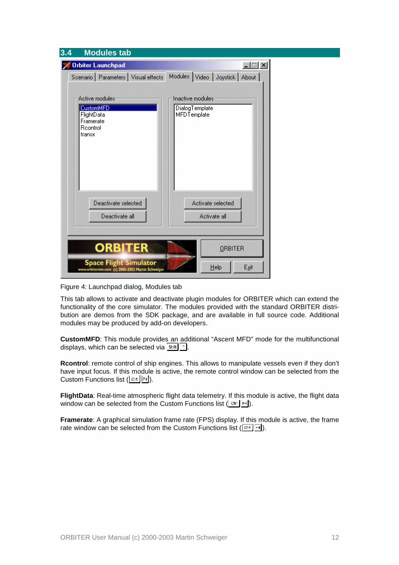
3.4 Modu les tab
Figure 4: Launchpad dialog, Modules tab
This tab allows to activate and deactivate plugin modules for ORBITER which can extend thefunctionality of the core simulator. The modules provided with the standard ORBITER distri-bution are demos from the SDK package, and are available in full source code. Additionalmodules may be produced by add-on developers.
CustomMFD: This module provides an additional “Ascent MFD” mode for the multifunctionaldisplays, which can be selected via .
Rcontrol: remote control of ship engines. This allows to manipulate vessels even if they don’thave input focus. If this module is active, the remote control window can be selected from theCustom Functions list ( ).
FlightData: Real-time atmospheric flight data telemetry. If this module is active, the flight datawindow can be selected from the Custom Functions list ( ).
Framerate: A graphical simulation frame rate (FPS) display. If this module is active, the framerate window can be selected from the Custom Functions list ( ).

ORBITER User Manual (c) 2000-2003 Martin Schweiger 13
3.5 Video tab
Figure 5: Launchpad dialog, Video tab
3D Device: Lists the available hardware and software devices for 3D rendering. Select ahardware device when possible, such as Direct3D HAL or Direct3D T&L HAL. Software de-vices such as RGB Emulation will produce poor performance. Note that some hardware de-vices do not support window mode.
Always enumerate devices : Tick this box if Orbiter does not display 3D devices or screenmodes correctly. This option enforces a hardware scan whenever Orbiter is launched andskips the device data stored in device.dat. Make sure to tick this box after upgrading yourgraphics hardware or DirectX/video drivers to make Orbiter aware of the changes.
Display mode: Select fullscreen or windowed mode. Not all devices support windowed mode.Running in fullscreen mode may improve performance.
Fullscreen mode: Select screen resolution and colour depth for fullscreen mode. Onlymodes supported by the selected device are listed here. Higher resolution and colour depthwill improve the visual appearance at the cost of reduced performance.
Disable vertical sync: Ticking this box allows Orbiter to update a frame without waiting for async signal from the monitor. This can improve frame rates in fullscreen mode, but may leadto visual artefacts (tearing).
Window mode: Select the size of the render window for windowed modes. Select awidth:height ratio close to 4:3 for best results. Large window sizes will reduce performance.
NEW!

ORBITER User Manual (c) 2000-2003 Martin Schweiger 14
3.6 Joystick tab
Figure 6: Launchpad dialog, Joystick tab
Joystick device: Lists all attached joysticks.
Main engine control: Define the joystick axis which controls the main thrusters. Try the dif-ferent options if the throttle control on your joystick doesn’t work in Orbiter.
Igno re thrott le sett ing on launch: If ticked, the joystick throttle will be ignored at the launchof a scenario util the user manipulates it. Otherwise, the throttle setting is used immediately.
Deadzone: Use this to define how soon the joystick will respond when moved out of its centreposition. Smaller values make it respond sooner. Increase if attitude thrusters do not cut outcompletely in neutral position.
Thrott le saturation : Defines the tolerance zone at the minimum and maximum range of thethrottle control at which the joystick reports zero and maximum throttle, respectively. Reduceif main engines do not cut out completely at minimum throttle setting. (Applies only to joy-sticks with throttle control).
If further calibration is required you should use the appropriate tools in the Windows ControlPanel.
NEW!
NEW!

ORBITER User Manual (c) 2000-2003 Martin Schweiger 15
4 Quicks tartThis section demonstrates how to take off and land with one of Orbiter’s default spacecraft,the Delta-glider. If you are using Orbiter for the first time, this will help to familiarise yourselfwith some basic concepts of spacecraft and camera control. You should also read the rest ofthis manual, in particular sections 5 and 6 on keyboard and joystick interface, section 12 oninstrumentation, section 13 on spacecraft controls, and section 15 on basic flight manoeuvres.
Make sure you have configured Orbiter before launching your first simulation, in particular thevideo and joystick parameters (see section 3).
Starting:• Select the New Features/Atmospheric flight/Deltaglider runway takeoff scenario (see
Section 3.1 on scenario selection), and press the “ORBITER” button to launch the sce-nario. You are in control of a powerful spacecraft ready for takeoff at runway 33 of theSLF (Shuttle Landing Facility of the Kennedy Space Center.
• You can always exit the simulation by pressing or , or by clicking “Exit” onthe main menu ( ). Orbiter always saves the current simulation status in the “(Currentstatus)” scenario, so you can continue your flight later by selecting this scenario.
Camera modes:You are in an external camera mode, looking towards your ship.• You can rotate the camera around your ship by pressing and holding down the key
and pressing a cursor key ( ) on the cursor keypad of your keyboard. Alterna-tively, if you have a joystick with a direction controller (“coolie hat”), you can use that torotate the camera.
• To jump into the cockpit of your glider, press . ( always toggles between cockpit andexternal view of the spacecraft you are controlling).
Instrument panels:You should now see the instrument panel of your glider in the lower half of the simulationwindow.• The panel can be scrolled with the cursor keys ( ) on the cursor keypad. To
scroll the panel out of the way, press . You should now be able to see the runwaystretching in front of you. Scrolling the panel is useful if you want to see more of your sur-roundings. Also, if the panel is larger than your simulation window, you can scoll differentparts of the panel into view.
• You can remove the panel altogether and instead bring up a “generic” instrument view bypressing . Some spacecraft types don’t come with custom panels – they only offer thegeneric view.
• Some spacecraft have more than a single panel which can be accessed by pressing in combination with a cursor key. Bring back the panel view with (if you haven’t al-ready done so). Now press . This will bring up the glider’s overhead panel withsome additional controls. Pressing twice will bring up the lower panel with brakeand gear controls.
• For now, switch back to the main panel with .
MFD instruments:The most important and versatile instruments are the two multifunctional displays (MFDs) inthe centre of the instrument panel. Each MFD consists of a square CRT screen and buttonsalong the left, right and bottom edges.• MFDs can be set to different modes: With the mouse, left-click the “Sel” button at the
bottom edge of one of the MFDs. (Alternatively, you can press . MFD keyboardinterfaces always use key combinations, where the left key controls the leftMFD, and the right key controls the right MFD). You will see a list of availablemodes.

ORBITER User Manual (c) 2000-2003 Martin Schweiger 16
• Click on one of the buttons along the left or right edge to select the corresponding mode.If you click the top-left button, the MFD switches to Orbit mode.
• Modes can also be selected directly with a key combination. The key combinationsused for selecting a mode a listed in grey below the modes. (For example, willselect the Orbit mode.)
• Most modes can be controlled with the buttons as well. The button labels change to indi-cate the various mode functions. For example, the Orbit mode has a button labelled“TGT”. This can be used to display the orbit of a target object. Click this button – you willsee a dialog box to select a target object. Press , type “iss” in the text box, and press again. This will show the orbital parameters of the International Space Station in theMFD display.
• To see a short description of the available mode functions, click the “MNU” button at thebottom of the MFD (Alternatively, use ).
• For now, switch the left MFD into Surface mode, and the right MFD into HSI mode.
Takeoff:Your glider is capable of runway takeoffs and landings (if the atmospheric density is sufficientto provide aerodynamic wing forces)• For takeoff, engage main engines at full thrust. You can do this by pushing the Main en-
gine sliders at the right of the panel to the top (make sure you push both sliders simulta-neously!), or by pressing Numpad. until engines are at full throttle. If you have a joy-stick with throttle control, you can use that to engage the main engines.
• Your spacecraft will start to roll. You can check the speed (in meters/second) on theAIRSPD indicator of the Surface MFD, or on the HUD (head-up display) – the value in thegreen box at the top right of the screen.
• When the airspeed reaches 100, pull back on the joystick to rotate, or press and holdNumpad.
• Once clear of the runway, press to raise the landing gear.

ORBITER User Manual (c) 2000-2003 Martin Schweiger 17
When the atmosphere is too thin to produce enough lift for a runway takeoff (for examplewhen taking off from the Moon) or when no runway is available, you can use the glider’shover engines to lift off:• Move the Hover slider on the instrument panel up by clicking and dragging with the
mouse. Alternatively, press the Numpad key until hover engines are fully engaged.• Your glider should now lift off vertically. Once clear of the ground, engage main engines.• As you gain airspeed, you can gradually reduce hover thrust.
Atmospheric flight:In the lower atmosphere, the glider behaves very much like an aircraft. Try the joystick con-trols for pitch, roll and yaw to get a feel for handling at different altitudes. Without a joystick,you can use the numerical keypad ( / Numpad for pitch, ! /" Numpad for roll, and # / $ Numpad
for yaw). The glider has powerful rocket engines, but their performance depends on atmos-pheric pressure (at very low altitudes, it will not even go supersonic).This is a good time to try different camera modes. Open the Camera dialog (% & ), andcheck the effect of different track modes and field of view (FOV) settings.
Landing:• Go around and approach runway 33 of the SLF from the south. Line up with the runway.
Your HSI instrument helps you to maintain the correct approach path and slope. One ofits two displays should already be tuned to the runway ILS system. The HSI contains acourse pointer, deviation and glideslope indicator. It works like a standard aircraft instru-ment, so you may already be familiar with its use. If not, check section 12.4 for details.
• As you approach the runway, you will see PAPI and VASI landing aids in front of and be-side the runway (see section 15.6). The PAPI is of limited use here, because it is adjustedfor the Space Shuttle’s steep descent slope of 20° .
• Throttle back and engage airbrakes (% ' ) to reduce speed. Lower the landing gear( ( ).
• After touchdown, engage left and right wheel brakes () and * ) until you come to a fullstop.
Space flight:So far we have treated the glider much like a conventional aircraft. Now it is time to aim a bithigher ...

ORBITER User Manual (c) 2000-2003 Martin Schweiger 18
• Take off as before. Turn east (use the compass ribbon on the top edge of the HUD, or theone in the Surface MFD display), and pitch up to 50° .
• As you gain altitude, you will notice that your craft starts to behave differently, due to thereduction in atmospheric pressure. One of the effects is a loss of lift, which causes theflight path indicator (the ⊕ HUD marker) slowly to drift down. Another effect is the loss ofresponse from your aerodynamic control surfaces.
• At about 30km altitude your glider will start to drop its nose even while you are pullingback on the stick. Now activate the RCS (Reaction Control System) by right-clicking the“RCS Mode” selector (on the left side of the instrument panel) or by pressing+ ,
Numpad. You are now controlling your craft with attitude thrusters.• Pitch down to about 20° . After leaving the dense part of the atmosphere, you need to gain
tangential velocity to achieve orbit. Your flight path indicator should stay above 0° .• Now is a good time to activate the Orbit mode in one of your MFDs. This shows the
shape of your current orbit (the green curve) in relation to the planet surface (the grey cir-cle), together with a list of orbital parameters along the left side of the display. You shouldswitch the display into “current orbital plane” projection mode, by clicking on the “PRJ”button until “Proj: Ship” is displayed in the top right corner of the display.
• At the moment, your orbit will be a rather eccentric ellipse, which for the most part is be-low Earth’s surface. This means that you are still on a ballistic trajectory rather than in astable orbit. As you keep gaining tangential velocity, the orbit will start to expand. Oncethe green curve is completely above the planet surface (and sufficiently high above theatmosphere) you will have entered orbit.
• At this point, the most important pieces of information from the Orbit display are the or-bital velocity (“Vel”) and apoapsis distance (“ApD”). For a low Earth orbit, you need toachieve a velocity of at least 7800 m/s. Once you reach this value, you will see the orbitrising rapidly above Earth’s surface. At the same time, the apoapsis distance (the highestpoint of the orbit) will start to grow. Keep firing your engines until ApD reaches about6.670M. This corresponds to an altitude of 300km. Now cut the engines.
• You are now nearly in orbit. All that remains to do is raise the periapsis (the lowest pointof the orbit) to a stable altitude. This is done best when you reach apoapsis, which shouldbe half an orbit (or about 45 minutes) from your current position. Time to switch into anexternal camera mode and enjoy the view!
• It is also a good idea to switch the HUD from surface to orbit mode now. Do this by click-ing the “OBT” button in the top left corner of the instrument panel, or by pressing -twice. In this mode, the HUD flight path ladder is aligned with the orbital plane instead ofthe horizon plane. It also shows indicators for prograde (the direction of your orbital ve-locity vector) and retrograde (the opposite direction).
• When you approach apoapsis (You can see how close you are to the apoapsis point bychecking the ApT (time to apoapsis) value in the Orbit MFD. If it takes too long, press .to engage time acceleration, and / to switch back), turn your craft prograde. You can dothis manually, but it is easier to leave it to the automatic attitude control, by simply press-ing the “Prograde” button on the left of the instrument panel.
• Now fire your main engines for final orbit insertion. The two parameters to watch are theorbit eccentricity (“Ecc”) and periapsis distance (“PeD”). The eccentricity value should getsmaller, indicating that the orbit becomes more circular, while the periapsis distance ap-proaches the apoapsis distance (ApD). Once the eccentricity value reaches a minimum,turn the main engines off. You can also deactivate the prograde attitude mode by clicking“Prograde” again.
• Congratulations! You made it into orbit!
Deorbiting:Should you ever want to come back to Earth, you need to deorbit. This means to drop theperiapsis point to an altitude where the orbit intersects the dense part of the atmosphere, sothat your vessel is slowed down by atmospheric friction.• Deorbit burns are performed retrograde. Click the “Retrograde” button, wait until the ves-
sel attitude has stabilised, and engage main engines.• Keep burning until the periapsis point is well below Earth’s surface, then cut the engines.
Strictly speaking, the deorbit burn must be timed precisely, because too shallow a reentry

ORBITER User Manual (c) 2000-2003 Martin Schweiger 19
angle will cause you to skid off the atmosphere, while too steep an angle will turn you intoa shooting star. For now we are not concerned with such fine detail...
• Turn prograde again and wait for your altitude to drop. As you enter the lower part of theatmosphere, friction will cause your velocity to decrease rapidly. Reentries are usuallyperformed with a high angle of attack (AOA) – about 40° for the Space Shuttle.
• Once your aerodynamic control surfaces become responsive again you can turn off theRCS system. Your glider has now turned back into an aircraft.
• You have probably ended up a long way from your launch point at the KSC. Re-enteringtowards a specified landing point requires some practice in timing the deorbit burn andthe reentry flight path. We’ll leave this for a later mission. For now, simply look for a drypatch to land your glider.
• This completes your first orbital excursion!
You are now ready to try more advanced missions. Try the “Launch to docking with the ISS”flight described in section 17. First you might want to learn a bit more about orbital manoeu-vres and docking procedures in section 15.

ORBITER User Manual (c) 2000-2003 Martin Schweiger 20
5 Keyboard interfaceThe key assignment reference in this section and the rest of the manual refers to the key-board layout shown in Figure 7. For other layouts (e.g. language-specific) the key labels maybe different. The relevant criterion for key functions in Orbiter is the position of the key on thekeyboard, not the key label. For example, on the German keyboard, the keys for the “turn or-bit-normal” (; ) and “turn orbit-antinormal” (’ ) will be “Ö” and “Ä”.
Keys from the numerical keypad or the cursor keypad will be denoted by subscript, e.g.0Numpad or 1 Cursorpad.
Note that certain spacecraft may define additional keyboard functions. Check individualmanuals for a detailed description of spacecraft controls and functionality.
Figure 7: Keyboard layout reference
5.1 General2Toggle frame rate info on/off3Toggle display of information about current object and camera mode.4Time warp shortcut: Slow down simulation by factor 10 (down to real-time). See also Time acceleration dialog (5 6 )7Time warp shortcut: Speed up simulation by factor 10 (up to a maximumwarp factor of 10000). See also Time acceleration dialog (5 6 )8Zoom out (increase field of view). See also Camera dialog (5 9 ):Zoom in (decrease field of view). See also Camera dialog (5 9 ); <Undock from a vessel.
(In conjuction with an old-style orbital station: Request docking orundocking clearance if within radio range of the selected station); =Pause/resume simulation.; >Exit to Launchpad dialog.; ?Quicksave scenario.@Toggle internal/external view of the user-controlled spacecraft.; @Open the Camera dialog to select camera target, view mode and field ofview.AToggle tracking mode for external camera views (target-relative / absolutedirection / global frame).; AOpen the Time acceleration dialog. This allows to speed up/slow down thesimulation, and to pause/resume.BSwitch control to a different spacecraft.
Cursor pad
Numpad

ORBITER User Manual (c) 2000-2003 Martin Schweiger 21
CMain menu.D COpen the Custom functions dialog. Contains a list of functions defined inplugin modules, if available.D EOpen the Object Info dialog for object-specific data such as ILS navaidfrequencies etc.D FOpen the Map dialog (spaceports, navaid locations etc.)D GOpen the Navaid Info dialog containing a list of navigational radiobeacons.HIn cockpit view, toggle between onscreen instruments and custom panels(if supported by the spacecraft).D IOpen the Planetarium options dialog for controlling the display of gridsand markers.I“Planetarium mode”: Toggle display of constellations.
5.2 Spacecraft controlsThese keys allow manual maneuvering of the user-controlled spacecraft. See also joystickcontrols. Note some spacecraft may not define all thruster types.
Main/retro thruster controls:D JNumpad
Accelerate by increasing main thruster setting or by decreasing retrothruster setting.D K
NumpadDecelerate by decreasing main thruster setting or by increasing retrothruster setting.L
NumpadKill main and retro thrusters.J
NumpadFire main thrusters at 100% while pressed (overrides permanent setting)K
NumpadFire retro thrusters at 100% while pressed (overrides permanent setting)
Hover thruster controls (where available):MNumpad
Increase hover thruster setting.NNumpad
Decrease hover thruster setting.
Attitude thruster controls (rotational mode):O/ P
NumpadEngage attitude thrusters for rotation around longitudinal axis (bank)Q
/ RNumpad
Engage attitude thrusters for rotation around transversal axis (pitch)S/ T
NumpadRotational mode: Engage attitude thrusters for rotation around verticalaxis (yaw)U
NumpadToggle “Kill rotation” navigation computer mode. Stops spacecraft rotationby engaging appropriate attitude thrusters
Note: In combination with V , thrusters are engaged at 10% max. thrust for fine control.
Attitude thruster controls (linear mode):Q/ R
NumpadEngage attitude thrusters for up/down translation.S
/ TNumpad
Engage attitude thrusters for left/right translation.
P / WNumpad
Engage attitude thrusters for forward/back translation
Note: In combination with V , thrusters are engaged at 10% max. thrust for fine control.

ORBITER User Manual (c) 2000-2003 Martin Schweiger 22
Other controls:XNumpad
Toggle reaction control thruster mode between rotational (engageopposite thruster pairs) and linear (engage parallel thruster pairs)Y X
NumpadEnable/disable reaction control system (RCS). The RCS (if available) is aset of small thrusters which allows attitude (rotation) and linear control ofthe spacecraft.Z X
NumpadEnable/disable manual user control (via keyboard or joystick) ofaerodynamic control surfaces (elevator, rudder, ailerons) if available.[Toggle “Hold altitude” navcomp mode. Maintain current altitude abovesurface by means of hover thrusters only. This will fail if hover thrusterscannot compensate for gravitation, in particular at high bank angles.Combining this mode with the “H-level” mode is therefore useful.\Toggle “H-level” navcomp mode. This mode keeps the spacecraft levelwith the horizon by engaging appropriate attitude thrusters.]Toggle “Turn prograde” navcomp mode. This mode turns the spacecraftinto its orbital velocity vector.^Toggle “Turn retrograde” navcomp mode. This mode turns the spacecraftinto its negative orbital velocity vector._Toggle “Turn orbit-normal” navcomp mode. Rotates spacecraft normal toits orbital plane (in the direction of VR `` × )aToggle “Turn orbit-antinormal” navcomp mode. Rotates spacecraftantinormal to its orbital plane (in the direction of VR `` ×− )b
/ cCursorpad
Trim control (only vessels with aerodynamic surfaces)dApply left wheel brake (where applicable)eApply right wheel brake (where applicable)
5.3 External viewsfMove camera away from target object.gMove camera towards target object.Y
hjilknm Rotate camera around object.
In ground-based camera views, o pqrs will move the observer position, t and uwill change the observer altitude, and pqrs will rotate the observer direction (unlesslocked to the target).
5.4 Internal (cockpit) viewThe two multifunctional displays (MFD) on the left and right side of the screen are controlledvia left/right Shift key combinations, where the left Shift key addresses the left MFD, the rightshift key addresses the right MFD.The Head-up display (HUD) and MFDs are visible only in internal cockpit view.
vMap between onscreen MFD mode and instrument panel mode (ifavailable for the current spacecraft)hjilknmScroll instrument panel.YSwitch to neighbour panel, if available.

ORBITER User Manual (c) 2000-2003 Martin Schweiger 23
wjxlynz |
Toggle HUD display on/off.|Switch HUD mode. HUD reference selection.Orbit HUD: opens reference selection input box.Docking HUD: steps through available NAV receivers. ~ Docking HUD: Reference selection. Can also be used for legacy orbitalstations which do not define XPDR and IDS transmitters. Open a menu for left/right MFD mode selection. Open/page/close the MFD-specific parameter selection menu. Display Align orbital plane mode MFD. Display Docking mode MFD. Display Launch/landing mode MFD. Display Map mode MFD. Display Orbit mode MFD. Display Surface mode MFD. Display Transfer mode MFD. Display Synchronise orbit mode MFD. Turn off MFD.
Docking Mode MFD Input new docking target.
Align orbital plane Mode MFD Input new target object.
Orbit Mode MFD Auto-select reference object. Toggle display mode (list only, graphics only and both) No target orbit. Toggle orbit projection mode (ecliptic, ship’s and target’s orbital plane) Select new reference object (planet or moon) for orbit calculation. Open menu for target selection.
Map Mode MFD Open input box for reference planet/moon selection. Open a menu for target selection.
Transfer Mode MFD Open input box for reference planet/moon selection. Open a menu for source orbit object selection. Open a menu for target selection.

ORBITER User Manual (c) 2000-2003 Martin Schweiger 24
Unselect target. Toggle (hypothetical) transfer orbit display on/off. Toggle numerical multibody trajectory calculation. Refresh numerical trajectory, if displayed. Open input box for time step definition.
/ Rotate transfer orbit ejection longitude. / Decrease/increase transfer orbit major axis.
Synchron ise orbit Mode MFD Input new target object (orbital station or moon) Change reference axis. Select number of entries in the reference transit time list.
/ Rotate reference axis (in manual mode only).
5.5 Menu selectionsMove to previous item in the list.Move to next item in the list.Display sub-list for selected item, if available.Go back to the parent list from a sub-list.Select current item and close list.Cancel list.

ORBITER User Manual (c) 2000-2003 Martin Schweiger 25
6 Joystick interfaceA joystick can be used to operate the attitude and main thrusters of the user-controlledspacecraft manually.
Action EffectPush stick left or right Rotate around vessel’s longitudinal axis (bank)Push stick forward orbackward
Rotate around vessel’s transversal axis (pitch)
Operate rudder controlorPush stick left or right whileholding joystick button 2
Rotate around vessel’s vertical axis (yaw)
Operate throttle control Controls main thruster settings. This is similar to the ¡Numpad and
¢Numpad keyboard controls, but it
affects only the main thrusters, not the retro thrusters.Direction controller (“cooliehat”)
External view: Rotate camera around the observed objectInternal view: Scroll instrument panel (if applicable)

ORBITER User Manual (c) 2000-2003 Martin Schweiger 26
7 Mouse interfaceSpacecraft instrument panels can be operated by the mouse. Most buttons, switches and di-als are activated by pressing the left mouse button. Some elements like multi-way dials mayrespond to both left and right mouse buttons.
In external camera modes, the mouse wheel control (if available) can be used to move thecamera towards or away from the view target. The mouse wheel acts like the £ and ¤ keys.
The mouse can of course also be used to select and manipulate dialog controls.

ORBITER User Manual (c) 2000-2003 Martin Schweiger 27
8 Spacecraft classesThe following standard spacecraft types are currently available in Orbiter. Many more can bedownloaded as add-ons. See the Orbiter web site for a list of add-on repositories.
8.1 Delta-gliderThe Delta-glider is the ideal ship for the novice pilot to get spaceborne. Its futuristic designconcept and extremely low fuel consumption make it easy to achieve orbit, and it can even beused for interplanetary travel. The winged design provides aircraft-like handling in the loweratmosphere, while the vertically mounted hover-thrusters allow vertical takeoffs and landingsindependent of atmospheric conditions and runways.
Delta-glider model andtextures by Roger“Frying Tiger” Long.Instrument panels byMartin Schweiger.
The glider comes with operating landing gear, nose cone docking port, airlock door, deploy-able radiator and animated aerodynamic control surfaces. It now supports particle exhausteffects.
The new version makes use of the new atmospheric flight model for significantly more realis-tic aerodynamic performance.
Technical specifications:Mass 12.0·103 kg (empty orbiter)
11.4·103 kg (main fuel load)0.6·103 kg (RCS fuel load)
24.0·103 kg (total)Length 17.76 mWingspan 17.86 mThrust 2 x 1.2·105 N (main engines)
2 x 2.7·104 N (wing-mounted retro thrusters)3 x 9.0·104 N (hover thrusters)
Isp 4·104 m/s (fuel-specific impulse in vacuum)Inertia (PMI) 15.5 / 22.1 / 7.7 m2
Stall CL 1.0Stall AOA 20°
Main and o verhead instrument panels:Turn the panels on and off with ¥ . The glider supports three panels which can be selectedwith ¦ § and ¦ ¨ .
NEW!

ORBITER User Manual (c) 2000-2003 Martin Schweiger 28
RCS and aerodynamic control selectionThe AF CTRL selector is used to activate control ofaerodynamic surfaces via manual user input. Manipulating thecontrol surfaces is only effective within an atmosphere at suffi-ciently high dynamic pressures. The settings are: OFF (controlsurfaces offline), ON (control surfaces enabled), and PITCH(only pitch control enabled).
The RCS MODE selector sets the Reaction Control System mode which is used to control at-titude in free space. During atmospheric flight, when aerodynamic control surfaces are active,the RCS is usually disabled. The selector can be set to OFF (RCS disabled), ROT (RCS inrotational mode), and LIN (RCS in linear mode).
Both selectors can be set with the left and right mouse buttons. Shortcuts for RCS are©Numpad (ROT/LIN) and ª © Numpad (ON/OFF). Shortcut for AF control is « © Numpad
(ON/OFF).
Main engine gimbal controlBoth main engines can be gimballed independently in pitch andyaw. Gimbal range is ±1.0° in pitch, and ±7.7° in yaw. The yawrange allows to compensate for torque generated by a single en-gine at main thrust.
To use pitch gimballing, the mode selector must be set to “MAN”.The gimbal sliders can then be dragged with the mouse. “CNT”re-centers the pitch gimbals.
NEW!
HUD modeselector
Main/RCSFuel status
AF/RCSselectors
Navmodes
main enginegimbalcontrol
left MFD right MFDenginestatusindicator
main enginecontrol
hoverenginecontrol
pitch trimcontrol
AOAindicator
Slipindicator
Slope/rangeindicator
artificialhorizon
Nosecone/airlockoperation
Torque angularacceleration/angularvelocity indicators
left/rightwheel brake
landing gearcontrol/status
nose conecontrol/status

ORBITER User Manual (c) 2000-2003 Martin Schweiger 29
The yaw gimbal selector has three modes:“MAN” for manual slider control, “CNT” for re-centering gimbals, and “COMP” for compensa-tion mode. There are two compensationmodes available: With “LOCK”, both enginesare set to divergent thrust at their extremelimit, so that both thrust vectors are alignedwith the glider’s centre of gravity; with “AUTO”,both engines are set to parallel thrust, and thegimbal angle is adjusted so that the total thrustvector is aligned with the centre of gravity.
Vessel-specific key controls:¬Operate landing gearOperate nose cone docking mechanism®Open/close outer airlock door¯ °Deploy/retract airbrakes±Deploy/retract radiators
8.2 Shutt le-AThe all-new Shuttle-A, designed by Roger “Frying Tiger” Long. A medium size freight-vessel,designed preliminary for low gravity/low density environments. The current design allows toachieve LEO from Earth’s surface, but you need to plan your ascent carefully not to run out offuel.
The vessel has a set of two main and two hover thrusters, plus a pair of auxiliary thrusterpods which can be rotated 180° for main, hover or retro thrust.
Model design: RogerLong. Instrumentpanels and modulecode: MartinSchweiger.
The new Shuttle-A comes with instrument panels. For operational details and technical speci-fications see the separate Shuttle-A Technical Manual.
Yaw gimbal compensation modes
Lock Auto

ORBITER User Manual (c) 2000-2003 Martin Schweiger 30
Main and o verhead instrument panels:Turn the panels on and off with ² . The Shuttle-A supports two panels which can be selectedwith ³ ´ and ³ µ .
Vessel-specific key controls:¶Operate docking hatch mechanism·Open/close outer airlock door
8.3 Shutt le PB (PTV)The PB is a very agile single-seater. It produces little lift in atmospheric flight, and depends onits hover thrusters for takeoff and landing. Aerodynamic control surfaces are not supported inthis version. Attitude control is performed via the RCS (reaction control system).
Overall design andtextures: Balázs Patyi.Model improvements:Martin Schweiger
Technical specifications:Mass 500 kg (empty orbiter)
750 kg (fuel capacity)
Fuel tank/pumpstatus indicator
Airlock/lockcover control
Navmodeselectors/indicators
left MFD
RCS modeselector
right MFD
main engines hover engines thrust indicators
aux engines aux pod tilt controls

ORBITER User Manual (c) 2000-2003 Martin Schweiger 31
1250 kg (total)Length 7 mThrust 3.0·104 N (main)
2 x 0.75·104 N (hover)Isp 5.0·104 m/s (fuel-specific impulse in vacuum)
8.4 Dragon flyThe Dragonfly is a space tug designed for moving payload in orbit. It may be used to bringsatellites delivered by the Space Shuttle into higher orbits, or to help in the assembly of largeorbital structures.The Dragonfly has no dedicated main thrusters, but a versatile and adjustable reaction controlsystem.THE DRAGONFLY IS NOT DESIGNED FOR ATMOSPHERIC DESCENT OR SURFACELANDING!
Dragonfly originaldesign: MartinSchweiger. Modelimprovements andtextures: Roger Long.Systems simulationand instrument panels:Radu Poenaru.
The Dragonfly is the first vessel to be modelled with detailed electrical and environmentalsystems simulation, contributed by Radu Poenaru. For detailed information see the DragonflyOperations Handbook.
Technical specifications:Mass 7.0·103 kg (empty)
11.0·103 kg (100% fuel)Length 14.8 mWidth 7.2 mHeight 5.6 m
Propu lsion systemRCS mounted in 3 pods (left, right, aft) total 16 thrustersThrust rating 1.0 kN per thrusterIsp 4.0·104 m/s (vacuum)
8.5 Space Shutt le AtlantisThe first “real” spacecraft to appear in the Orbiter standard distribution. Launch configurationconsists of Orbiter, main tank and 2 solid rocket boosters (SRB). The latest Orbiter distribu-
NEW!

ORBITER User Manual (c) 2000-2003 Martin Schweiger 32
tion contains a new Atlantis model by Don Gallagher, and external tank and SRB models byDamir Gulesich.
Atlantis features a functional arm with grappling capabilities and MMU support, contributed byRobert Conley. See Atlantis_MMU_Sat manual for details.
Launch:• Fire main engines at 100%.• SRBs are ignited automatically when main engines reach 95%. SRBs are not controlled
manually. Once ignited, they cannot be shut off.• During launch, attitude is controlled via SRB thrust vectoring. Roll shuttle for required
heading, and decrease pitch during ascent for required orbit insertion.• SRBs separate automatically at T+2:06min. In an emergency, SRBs can be jettisoned
manually with .• Ascent continues with Orbiter main engines. Throttle down as required for 3g max accel-
eration.• Tank separates at T+8:58min (alt 110km) when empty, or manually with .• After tank separation, orbiter switches to OMS (orbital maneuvering system) using inter-
nal tanks, for final orbit insertion. Attitude thrusters (RCS – reaction control system) areactivated.
3D model and textures:Don Gallagher (orbiter)and Damir Gulesich(ET+SRB). Originalmodule code: MartinSchweiger. Originalgrappling, RMS andMMU extensions:Robert Conley. Modulecode extensions: DavidHopkins
Docking:• The orbiter carries a docking attachment in the cargo bay.• Open cargo bay doors before docking.• Docking direction is in orbiter’s +y direction (up). The Docking MFD must be interpreted
accordingly.
RMS manipu lation and g rappling:• The shuttle carries a mechanical manipulator arm in the cargo bay which can be used for
releasing and recapturing satellites, MMU control, etc.• The arm can be used in orbit once the cargo doors have been fully opened.• To bring up the RMS control dialog, press ¹ +Space.• The arm has three joints: the shoulder joint can be rotated in yaw and pitch, the elbow
joint can be rotated in pitch, and the wrist joint can be rotated in pitch, yaw and roll.
NEW!

ORBITER User Manual (c) 2000-2003 Martin Schweiger 33
• To grapple a satellite currently stowed in the cargo bay, movethe RMS tip onto a grappling point, and press “Grapple”. If grap-pling was successful, the button label switches to “Release”.
• To make it easier to identify the grappling points of satellites,you can tick the “Show grapple points” box. This marks all grap-pling points with flashing arrows.
• To release the satellite, press “Release”.• You can also grapple freely drifting satellites if you move the
RMS tip onto a grappling point.• To return a satellite back to Earth, it must be stowed in the cargo
bay. Use the RMS arm to bring the satellite into its correct posi-tion in the payload bay. When the Payload “Arrest” buttonbecomes active, the satellite can be fixed in the bay by pressingthe button. It is automatically released from the RMS tip.
• The RMS arm can be stowed in its transport position by pressingthe RMS “Stow” button. This is only possible as long as noobject is attached to the arm.
• Payload can be released directly from the bay by pressing the“Purge” button.
Technical specifications:OrbiterLength 39.16 mWingspan 24.54 mHeight 14.29 mMass 2041166 kg (liftoff)
104326 kg (end of mission)Max. cargo 28803 kgSME thrust 6.26·106 N (vac.)
5.01·106 N (liftoff)OMS thrust 5.34·104 N (vac.)
Tankb
Length 47.83 mDiameter 9.68 mMass 35425 kg (empty)
719115 kg (propellant)756445 kg (total)
SRBLength 45.7 mDiameter 3.8 m (tube)
5.9 m (max)Mass 87543 kg (empty)
502126 kg (propellant)589670 kg (total)
Thrust 11791820 N (liftoff)
Orbiter+Tank assemblyLength 57.55 mHeight 24.44 m
Orbiter+Tank+SRBs (launch assembly)Length 57.91 mHeight 24.44 m
a: principal moments of inertia tensor, mass-normalised, assuming homogeneous densitydistribution

ORBITER User Manual (c) 2000-2003 Martin Schweiger 34
b: including Orbiter mount brackets
Atlantis-specific key controls:ºJettison: separate SRBs or main tank»Operate cargo bay doors. The cargo bay doors cannot be closed whenthe Ku-band antenna is deployed.¼Operate landing gear (activated only after tank separation)½ ¾Operate split-rudder speed brake.½ ¿Deploy/retract Ku-band antenna. The antenna can only be operated if thecargo bay doors a fully open.½
+Space Open RMS control dialog.
Unlike the futuristic spacecraft designs, Atlantis provides only a small margin of error forachieving orbit. Try some of the other ships before attempting to launch the Shuttle. Limitedfuel must be selected, otherwise Atlantis is too heavy to reach orbit!
8.6 International Space Station (ISS)The International Space Station is a multinational scientific orbital platform currently underconstruction (although its fate is now somewhat in doubt after the Columbia disaster).Orbiter contains the ISS in its completed state. The ISS is a good docking target for Shuttleand other spacecraft missions.
Orbiter now includes Andrew Farnaby’s Project Alpha ISS model.
3D model and texturesby Andrew Farnaby
In Orbiter, the ISS can be tracked with its transponder (XPDR) signal, which by default is setto frequency 131.30.
The ISS contains 5 docking ports. In Orbiter, each is equipped with an IDS (InstrumentDocking System) transmitter. The default IDS frequencies are:
Port 1 137.40Port 2 137.30Port 3 137.20Port 4 137.10Port 5 137.00
For docking procedures see Section 15.7.
NEW!

ORBITER User Manual (c) 2000-2003 Martin Schweiger 35
8.7 Space Station MIRIn Orbiter, the Russian MIR station is still in orbit around Earth and can be used for dockingapproaches. Furthermore, unlike its real-life counterpart, Orbiter’s MIR is orbiting in the planeof the ecliptic, which makes it an ideal platform to launch lunar and interplanetary missions.
MIR model andtextures by JasonBenson
MIR sends a transponder (XPDR) signal at default frequency 132.10 which can be used fortracking the station during a rendezvous manoeuvre.
MIR supports 3 docking ports, with the following IDS transmitter frequencies:
Port 1 135.00Port 2 135.10Port 3 135.20
8.8 Lun ar Wheel StationThis is a large fictional space station in orbit around the Moon. It consists of a wheel, attachedto a central hub with two spokes. The wheel has a diameter of 500 metres and is spinning ata frequency of one cycle per 36 seconds, providing its occupants with a centrifugal accelera-tion of 7.6 m/s2, or about 0.8g, to mimic Earth’s surface gravitational force.
The main problem the station poses to the spacecraft pilot is in performing a docking ma-noeuvre. Docking to a rotating object is only possible along the rotation axis. The wheel hastwo docking ports in the central hub. The docking approach is performed along the axis ofrotation. Before docking, the approching vessel must synchronise its own longitudinal rotationwith that of the station. For docking procedures, see Section 15.7.
Currently, Orbiter’s docking instrumentation works on rotating docking targets only if thevessel’s docking port is aligned with its longitudinal axis of rotation. This is the case forShuttle-A and Dragonfly, but not for the Delta-glider or Space Shuttle.
The wheel station sends a transponder signal at frequency 132.70. The default IDS transmit-ter frequencies for the two docking ports are
Port 1 136.00

ORBITER User Manual (c) 2000-2003 Martin Schweiger 36
Port 2 136.20
Wheel model andtextures: MartinSchweiger
8.9 Hubb le Space TelescopeThe Hubble Space Telescope is the visible/ultraviolet/near-infrared element of the Great Ob-servatories astronomical program. The spacecraft provides an order of magnitude betterresolution than is capable from ground-based telescopes. The objectives of the HST are to:(1) investigate the composition, physical characteristics, and dynamics of celestial bodies; (2)examine the formation, structure, and evolution of stars and galaxies; (3) study the historyand evolution of the universe; and (4) provide a long-term space-based research facility foroptical astronomy. During initial on-orbit checkout of the Hubble's systems, a flaw in the tele-scope's main reflective mirror was found that prevented perfect focus of the incoming light.This flaw was caused by the incorrect adjustment of a testing device used in building the mir-ror. Fortunately, however, Hubble was designed for regular on-orbit maintenance by Shuttlemissions. The first servicing mission, STS-61 in December 1993, fully corrected the problemby installing a corrective optics package and upgraded instruments (as well as replacing othersatellite components). A second servicing mission, scheduled for March 1997, installed twonew instruments in the observatory.
Orbiter provides several Space Shuttle/HST missions for both deployment and recapture op-erations. For Shuttle payload manipulation, see Section 8.5 above.
HST-specific key controls:À ÁDeploy/retract high-gain antennaeÀ ÂOpen/close telescope tube hatchÀ ÃDeploy/fold solar arrays

ORBITER User Manual (c) 2000-2003 Martin Schweiger 37
HST model andtextures by DavidSundstrom
8.10 LDEF SatelliteLong Duration Exposure Facility (LDEF)Deployed in orbit on April 7, 1984 by Shuttle Challenger and intended for retrieval after oneyear, the LDEF satellite was stranded in orbit for six years after the Challenger accident. Thecrew of STS-32 recovered the LDEF from its decaying orbit on January 11, 1990, two monthsbefore it would have re-entered the Earth's atmosphere and would have been destroyed.
The LDEF makes a good object for deployment and retrieval missions in Orbiter.
LDEF mesh by DonGallagher.

ORBITER User Manual (c) 2000-2003 Martin Schweiger 38
9 Object informationUse the object information dialog (Ä Å ) to retrieve data and current parameters about
• the current camera target• spacecraft• spaceports• celestial objects (sun, planets, moons)
9.1 VesselsThe information sheet for spacecraft and orbitalstations contains:
• current mass• size• mass-normalised principal moments of
inertia (PMI)• transponder frequency• equatorial position (longitude and latitude)
above currently orbited planet• altitude• airspeed• horizon-relative attitude (yaw, pitch, roll)• orbital elements in the ecliptic frame of
reference, relative to currently orbited planet(semi-major axis, eccentricity, inclination,longitude of ascending node, longitude ofperiapsis, mean longitude)
• docking port status, if applicable (free/docked vessel, instrument docking system [IDS]transmitter frequency)
• update mode (free-flight/landed, dynamic or stabilised time step updates)
9.2 SpaceportsSpaceport information sheets contain:
• planet/moon and equatorial position• landing pad status (free/landed vessel, and
instrument landing system [ILS] transmitterfrequency)
• Runway information (runway alignment di-rection, length, and ILS transmitter fre-quency)
• Frequencies for any VOR (very high fre-quency omnidirectional radio) transmittersassociated with the spaceport.
9.3 Celestial bod iesInformation sheets for celestial bodies (such as sun, planets and moons) contain:
• physical parameters:• mass (M)

ORBITER User Manual (c) 2000-2003 Martin Schweiger 39
• mean radius (R)• length of siderial (“star”) day (Ts)• obliquity of ecliptic (Ob) – tilt of axis of
rotation against plane of ecliptic• Atmospheric parameters (if applicable):
• atmospheric pressure at zero altitude(p0)
• atmospheric density at zero altitude (r0)• specific gas constant (R)• ratio of specific heats cp/cv (g)
• orbital elements in the ecliptic frame of ref-erence, relative to currently orbited body(semi-major axis, eccentricity, inclination,longitude of ascending node, longitude ofperiapsis, mean longitude)
• current ecliptic position in polar coordinates(longitude, latitude and radius) relative tocurrently orbited body.
• geocentric celestial position (right ascension and declination)

ORBITER User Manual (c) 2000-2003 Martin Schweiger 40
10 Camera modesTo open a camera configuration dialog, press Æ Ç . This allows to• Select the camera target in external views.• Jump back to the current focus object in external or cockpit view. (Shortcut: Ç )• Select the external camera tracking or ground-based mode. (Shortcut: È )• Change the camera field of view (FOV). (Shortcut: É and Ê )• Store and recall camera modes via the preset list.
Figure 8: Camera dialog – target selection list.
10.1 Internal viewIn internal (cockpit) view the player is placed inside the cockpit of his/her spaceship and looksforward. Instrument panels, head-up display (HUD) and multifunctional displays (MFD) areonly shown in internal view. To return to cockpit view from any external views, press Ç , orselect Focus Cockpit from the camera dialog.
To switch between full instrument panel and MFD-only display modes press Ë . Note that in-strument panels may not be available for all spacecraft. Among the standard Orbiter vesseltypes, only the Deltaglider and Shuttle-A currently support panels.
Panels can be scrolled with ÌÍÏÎÐ . If the spacecraft supports multiple panels, they canbe selected with Æ ÌÍÏÎÐ .
For details on HUD and MFD modes, see sections 11 and 12.
10.2 External viewsExternal views allow to have a look at any objects currently populating the simulated solarsystem, including the Sun, planets and moons, spacecraft, orbital stations and surface bases.From cockpit view, an external view of the current spaceship can be selected by pressing Ç .Other objects can be selected from the target list in the Camera dialog (Æ Ç ).
Two types of external camera modes are available:
Track views follow the object. The camera can be rotated around the target object by press-ing Æ ÌÍÏÎÐ keys. The Ñ and Ò keys move the camera towards or away from thetarget. Different camera panning modes for external views can be selected by pressing È orvia the Track tab in the Camera dialog:

ORBITER User Manual (c) 2000-2003 Martin Schweiger 41
• Target-relative: The camera is fixed in the target’s local frame of rotation. Looking at aplanet in this mode for example will rotate the camera together with the planet around itsaxis. Ó ÔÕÖ× will rotate the camera around the target’s local axes.
• Global frame: The camera is fixed in a non-rotating reference frame. Looking at a planetin this mode will show the planet rotating underneath the camera. Ó ÔÕÖ× will ro-tate the camera around the axes of the ecliptic frame of reference.
• Absolute direction : This can be regarded as a mixture of the two modes above: The di-rection into which the camera points is fixed in an absolute frame, but it is tilted with re-spect to the target’s local frame. Ó ÔÕÖ× will rotate the camera around the target’slocal axes.
• Target to …: Positions camera so that the specified object is behind the target.• Target f rom …: Positions camera so the specified object is behind the camera.In Target to … and Target from … modes camera rotation (Ó ÔÕÏÖ× ) is deactivated,but radial camera movement with Ø and Ù is still available.
Ground -based views place the camera at a fixed point on the surface of a planet. This is agood way to follow the launch of a rocket from a spectator’s perspective, or view the final ap-proach of a Shuttle from the control tower. To select a ground-based view, select the Groundtab in the Camera dialog. Pick an observer location by selecting the planet, location, and spotfrom the lists, and click Apply. You can move the observer location by pressingÓ ÔÕÏÖ× , and the observer altitude by pressing Ø and Ù .The speed at which the ob-server moves can be adjusted with the Panning speed slider in the dialog box, in the rangefrom 0.1 to 104 m/s.There are two ways to select the camera orientation: If the Target lock box in the dialog isticked, the camera is always automatically pointing towards the current camera target. If thebox is not ticked, the camera direction can be modified manually by pressing ÔÕÖ× .
See also Section 19.3 on how to add new observer sites to a planet definition file.
Figure 9: Selecting a track camera mode (left) or a ground-based view (right).
In external views a display of target parameters can be toggled by pressing Ú .
10.3 Selecting the field of viewThe camera aperture can be adjusted under the FOV tab in the Camera dialog. The sup-ported range is between 10° and 90° (Orbiter defines the field of view as the vertical aperture,between the top and bottom edge of the simulation window). The most natural aperture de-pends on the size of the simulation window on your screen, and the distance between youreyes and the screen. Typical values are between 40° and 60° .
NEW!

ORBITER User Manual (c) 2000-2003 Martin Schweiger 42
You can adjust the field of view by clicking one of the aperture buttons, moving the slider, orentering a numerical value in the edit box.
Figure 10: Camera field of view selection.
The keyboard shortcuts are Û to decrease the FOV, and Ü to increase the FOV. The cur-rent field of view is displayed in the status section in the top left corner of the simulation win-dow.
10.4 Storing and recalling camera modesOrbiter provides an easy method to store and recall camera modes in a preset list. Click onthe Preset tab in the Camera dialog. Any available modes are listed here. To activate a mode,double-click it in the list, or select the mode and click Recall.
To store the current camera mode as a new preset in the list, simply click Add. This will pro-duce a new entry with a short description. To delete a mode, click Delete, or Clear to clear thewhole list.
Figure 11: The camera mode preset list.
Each entry remembers its track mode, position, target and aperture. The preset list is a goodway to prepare a set of camera angles beforehand (for example to follow a launch) and then
NEW!

ORBITER User Manual (c) 2000-2003 Martin Schweiger 43
activate them quickly without having to adjust the positions manually. The preset list is storedtogether with the simulation state, so it can be shared via a scenario file.

ORBITER User Manual (c) 2000-2003 Martin Schweiger 44
11 Head-up d isplayThe Head-up display (HUD) provides information about the current status of your spacecraftwhen internal (cockpit) view mode is selected. The HUD is switched on/off with Ý Þ . HUDmodes can be selected with Þ . The following modes are available:• Surface: Displays horizon pitch ladder, compass ribbon, altitude and “airspeed”.• Orbit: Displays orbital plane pitch ladder, prograde and retrograde velocity markers• Docking : Displays target distance and relative velocity markers.All HUD modes show engine and fuel status in the top left corner, and general information(time and camera aperture) in the top right corner. Two multifunctional displays (MFDs) canbe displayed independent of the HUD mode (see Section 12).
Figure 12: HUD in surface mode, including generic docking and surface MFDs.
11.1 General information d isplayA block of data with information about simulation time and speed, frame rate and cameraaperture, displayed in the top right corner of the simulation window. This display can beturned on and off with ß .
Universal dateand time
Modified JulianDate (days)
Simulation time(seconds)
Frame rate
Time accelerationfactor
Field of view (cameraaperture)
Viewport dimension(W x H x bpp)
Figure 13: General simulation information
Engineinformationdisplay
Left MFD Right MFD
Direction indicator
Pitch ladder
Altitude AirspeedCompass ribbon
Generalinformation
Navcompmodes
Velocity vector

ORBITER User Manual (c) 2000-2003 Martin Schweiger 45
UT: Universal time counted from 0h at midnight. Unit is mean solar day.MJD: The Julian Date (JD) is the interval of time in mean solar days elapsed since 4713 BC
January 1 at Greenwich mean noon. The Modified Julian Date (MJD) is the JulianDate minus 240 0000.5
Sim: Simulated time (in seconds) elapsed since the start of the simulation.Wrp: Time acceleration factor. This field is not displayed for acceleration factor 1 (real
time).FoV: (vertical) field of view, i.e. viewport camera aperture.FPS: current frame rate (frames per second)Dim: viewport dimension (width and height in pixels, colour depth in bits per pixel)
The display of frame rate and viewport dimension can be turned on and off with the à key.
11.2 Camera target/mode displayThis data block is displayed in external camera modes only, in the top left corner of thesimulation window. It contains information about the camera target and track mode. Thisdisplay can be turned on and off with á .
Camera target
Camera track mode
Camera distance from target
Figure 14: External camera information
View: Name of the current camera target.Mode: The camera mode used for tracking the target.Dist: Distance between camera and target.
11.3 Engine information d isplay
HUD mode
Attitude thrustergroup mode
Fuel status
Main engine:acceleration [m/s2]
Hover engine:acceleration [m/s2]
Trim control setting
Figure 15: Fuel/engine displays
The engine information display is only shown in non-panel views.
Fuel status: Remaining fuel is displayed as percentage of full tanks.Main engine: The horizontal bar shows current main/retro engine thrust as fraction of max.engine thrust. Green indicates main thrusters, orange indicates retro thrusters. The numericalvalue shows acceleration in units of m/s2 (positive for main, negative for retro thrust). Notethat the acceleration may change even if the thrust setting doesn’t, because the ship’s masschanges as fuel is consumed.Hover eng ine: If available, hover engines are mounted underneath the ship’s fuselage to as-sist in surface flight, in particular during takeoff/landing. Display analogous to main engine.Attitude thruster mode: Attitude thrusters are small engines used for rotation and finetranslational adjustments. The display shows the current mode (rotational/translational).Trim sett ing : Displays the current setting of the trim control (if available). Trimming allows toadjust the flight characteristics during atmospheric flight.
For more information about engines and spacecraft control see Section 13.

ORBITER User Manual (c) 2000-2003 Martin Schweiger 46
11.4 Surface modeIndicated by “SRFCE” in the upper left corner.This mode displays a pitch ladder which indicates the ship’s orientation w.r.t. the currentplane of the horizon. The plane of the horizon is defined by its normal vector, from the planetcentre to the spacecraft.The compass ribbon at the top of the screen indicates the ship’s forward direction w.r.t. geo-metric north. A marker shows the direction of the current target (spaceport).The box left below the compass ribbon shows the current altitude [m]. The box right below thecompass ribbon shows the current “airspeed” [m/s] (even if there is no atmosphere).The surface-relative velocity vector direction is marked by “⊕”.
11.5 Orbit modeIndicated by “ORBIT Ref” in the upper left corner, where Ref is the name of the reference ob-ject.This mode displays a pitch ladder relative to the current orbital plane, where the “0” line indi-cates the orbital plane. It also marks the direction of the orbital velocity vector (prograde di-rection) by “⊕ “ and retrograde direction by “+”. If neither the prograde nor retrograde directionis visible, then the direction of the ⊕ marker is indicated by a pointer labeled “PG” (prograde).The reference object for the HUD can be manually selected by pressing â ã .
11.6 Dock ing modeIndicated by “DOCK Tgt” in the upper left corner, where Tgt is the name of the target station.This mode marks the current docking target (orbital station) with a square marker, and dis-plays its name and distance. It also shows the direction and magnitude of the target-relativevelocity vector. The velocity of the target relative to the ship is indicated by “⊕ “. This is the di-rection in which you need to accelerate to synchronise your speed with the target. The oppo-site direction (the velocity of the ship relative to the target) is indicated by “+”. If neither ⊕ nor+ are visible, then the direction of the ⊕ marker is indicated by a pointer. Similarly, if the targetmarker is offscreen, its direction is indicated by a pointer.The target station for the HUD can be manually selected by pressing â ã .

ORBITER User Manual (c) 2000-2003 Martin Schweiger 47
12 Multifunctional display modesTwo multifunctional displays (MFD) can be displayed simultaneously on the screen. MFDsprovide essential information about all spacecraft flight parameters. A range of different MFDmodes is available to assist in various navigational problems such as launch/landing, surfaceflight, orbit determination etc. MFDs are controlled by Shift key combinations, where the leftShift key controls the left MFD, the right Shift key controls the right MFD.MFD modes can be selected either directly (see section 5.4 for keyboard commands) or bypressing ä å to bring up a menu.Each MFD mode may support specific parameters which can be selected with the appropriateShift key combination. You don’t need to remember the key codes, since MFDs which allowparameter selection provide a menu mode which can be selected with ä æ . Pressingä æ again will switch to the next menu page or return to the MFD display. To select amenu item, press ä with the highlighted character key.
12.1 COM/NAV receiver setupThe COM/NAV setup MFD mode provides an interface to the ship’s navaid signal receiverswhich feed data to the navigation instruments. The mode is activated by ä ç or via theComms entry from the MFD mode menu (ä å ).The MFD lists frequency and signal source information for all NAV radios (NAV1 to NAVn).The number of receivers (n) depends on the vessel class. A NAV receiver can be selected byä è and ä é . The selected receiver is highlighted in yellow (see below).
NAV receiver status
frequency
signal source
Figure 16: NAV setup MFD
The frequency of the selected receiver can be tuned in steps of 1kHz with ä ê and ä ë ,and in steps of 0.05kHz with ä ì and ä í , in the range from 85.00kHz to 140.00kHz. Ifa compatible NAV transmitter is within range, the instrument displays information about thesignal source.
Key options:î ïSelect previous NAV receiverî ðSelect next NAV receiverî ñStep down frequency 1 kHz.î òStep up frequency 1 kHzî óStep down frequency 0.05 kHz

ORBITER User Manual (c) 2000-2003 Martin Schweiger 48
ô õStep up frequency 0.05 kHz
Notes:• Certain instruments such as the Launch/Land MFD mode, are slaved to a NAV receiver,
and will only work if a suitable signal is available. This behaviour differs from earlier Or-biter versions, where the data reference was obtained automatically.
• The Object Info (ö ÷ ) and Navaid Info dialogs (ö ø ) are a useful tools to obtain fre-quencies for navaid transmitters such as VOR and ILS beacons.
Figure 17: Info and Navaid dialogs with VOR and ILS frequencies.
12.2 OrbitThe Orbit MFD mode displays a list of elements and parameters which characterise the ship’sorbit around a central body, as well as a graphical representation. In addition, a target object(ship orbital station or moon) orbiting the same central body can be selected, whose orbitalparameters will then be displayed as well.ù ú
opens a menu to specify a target object. Only targets which orbit around the currentreference object will be accepted. The target display can be turned off with
ù ø .
The plane into which the orbits are projected can be selected via ù û
. The current projec-tion plane is indicated in the top right corner of the instrument. Ecliptic projects into the planeof the ecliptic (Earth’s orbital plane). Ship projects into the vessel’s current orbital plane, andTarget projects into the target’s current orbital plane, if a target is specified.
Key options:ô üAuto-select reference object.ô ýToggle display mode (list only, graphics only and both)ô þNo target orbit.ô ÿToggle orbit projection mode (ecliptic, ship’s and target’s orbital plane)ô Select new reference object (planet or moon) for orbit calculation.ô Open menu for target selection.

ORBITER User Manual (c) 2000-2003 Martin Schweiger 49
Reference objectSemi-major axisSemi-minor axis
Periapsis distanceApoapsis distance
Radial distanceEccentricityOrbit period
Time to periapsis passageTime to apoapsis passage
VelocityInclination
Longitude of asc. nodeLongitude of periapsisArgument of periapsis
True anomalyTrue longitudeMean anomaly
Mean longitudeSpacecraft elements Target elements
G-field contribution
Figure 18: Orbit MFD in parameter list mode.
Reference object
Spacecraft orbit
Descending node
Radius vector
Apoapsis
Projectionplane
Periapsis
Ascending node
Target orbit
Planet surface
Figure 19: Orbit MFD in graphic mode.
Notation:• Periapsis: The point of the orbital ellipse closest to the central body.• Apoapsis: The point furthest away from the central body.• Ascending node: The point at which the orbit passes through the ecliptic (or other refer-
ence plane) from below.• Descending node: The point at which the orbit passes through the ecliptic from above.• Radius vector: The vector from the central body to the current position of the orbiting
body.

ORBITER User Manual (c) 2000-2003 Martin Schweiger 50
Reference object
Spacecraft orbit
Descending node
Radius vector
Projectionplane
Periapsis
Ascending node
Figure 20: Hyperbolic orbit around the Moon
For hyperbolic orbits, the following parameters are interpreted specially:SMa: real semi-axis a: distance from coordinate origin (defined by intersection of hyperbola
asymptotes) to periapsisSMi: imaginary semi-axis b = a sqrt(1-e2)ApD: apoapsis distance: not applicableT: orbital period: not applicablePeT: time to periapsis passage; negative after periapsis passageApT: time to apoapsis passage: not applicableMnA: mean anomaly, defined as e sinh H – H, with H hyperbolic eccentric anomaly
G-field contributionThe “G” value at the bottom of the display shows the relative contribution of the current refer-ence body to the total gravity field at the ship’s position. This can be used to estimate the reli-ability of the Keplerian (2-body) orbit calculation. For values close to 1 a 2-body approxima-tion is accurate. For low values the true orbit will deviate from the analytic calculation, result-ing in a change of the orbital elements over time.As a warning indicator, the G display will turn yellow for contributions < 0.8, and red if the se-lected reference object is not the dominant contributor to the gravity field. In that case, will select the dominant object.
For further explanation of orbital elements see Appendix B.

ORBITER User Manual (c) 2000-2003 Martin Schweiger 51
12.3 VOR/VTOLThe VOR/VTOL MFD mode is a navigational instrument used for planetary surface flight andvertical takeoff/landing. In addition to altitude and airspeed readouts it contains a graphical in-dicator of the relative position of a radio navigation transmitter. (VOR: very high frequencyomnidirectional range)
This MFD mode can be slaved to one of the ship’s NAV receivers. The current receiver andfrequency is shown in the upper right corner. If a signal is received, the transmitter ID is dis-played in the second line. If the ship supports more than a single NAV receiver, a different re-ceiver can be selected with . To set the receiver frequency, use the NAV MFD mode(see section 12.1).
The instrument can also be used for vertical instrument landing (VTOL). When slaved to aVTOL transmitter, the target indicator shows the relative position of the corresponding launchpad.
• DIST: distance to NAV transmitter [m]• DIR: direction of NAV transmitter (ship-relative)• HSPD: horizontal airspeed component [m/s]• ALT: altitude [m]. The altitude bar has a range from 1 to 104m (logarithmic scale).• VSPD: vertical airspeed component [m/s]. The vertical speed bar has a range from ±0.1
to ±103m/s (logarithmic scale). Positive vertical speed is indicated by a green bar, nega-tive vertical speed by a yellow or red bar. Red is is a surface impact warning.
• Target ind icator: Shows the horizontal location of the slaved NAV transmitter (ship-rela-tive) on a logarithmic scale. Range: 1 to 104m.
• Hspeed vector: Shows the horizontal component of the airspeed vector (ship-relative) ona logarithmic scale. Range: 0.1 to 103m/s.
• VTOL cone: This circle indicates the admissable deviation from the vertical touchdownvector as a function of altitude. During VTOL landing, the target indicator must remain in-side the VTOL cone. A red circle indicates that the ship is outside the cone. The VTOLcone is displayed only when the MFD is slaved to a VTOL transmitter.
NAV type and id
NAV distance anddirection
horizontal airspeed[m/s]
horizontal speedvector
VTOL cone
target positionindicator
NAV receiverfrequency
vertical speed[m/s]
altitude [m]
vertical speed bar(logarithmic scale)
altitude bar(logarithmic scale)
Figure 21: VOR/VTOL MFD.
Key options: Select NAV receiver

ORBITER User Manual (c) 2000-2003 Martin Schweiger 52
12.4 Horizontal Situation Ind icatorThe Horizontal Situation Indicator (HSI) consists of two independent displays. Each displaycan be slaved to a NAV receiver and show directional and relative bearing information. Theinstruments accept data from surface-based transmitters such as VOR and ILS. The functionis similar to instrument navigation systems found in aircraft.
The display consists of a gyro-compass indicating the current heading at the 12 o’clock posi-tion. The yellow arrow in the centre of the instrument is the course arrow or Omni BearingSelector (OBS). When the slaved NAV radio is tuned to a VOR transmitter, the OBS can beadjusted with the OB- ( ) and OB+ ( ) keys. For ILS transmitters, the OBS isautomatically fixed to the approach direction.The middle section of the course arrow is the Course Deviation Indicator (CDI). It can deflectto the left and right, to show the deviation of the OBS setting from the current bearing to theNAV sender. If the CDI is deflected to the left, then the selected radial is to the left of the cur-rent position.In the lower left corner of the instrument is the TO/FROM indicator. “TO” means that you areworking with a bearing from you to the ground station; “FROM” indicates a radial from theground station to you.
When tuned to an ILS (localiser) transmitter, the instrument shows an additional horizontalglideslope bar for vertical guidance to the runway. If the bar is centered in the instrument, youare on the correct glide slope. If it is in the upper half, the glide slope is above you, i.e. youare too low. If it is in the lower half, the glide slope is below you and you are approaching toohigh.
To use the HSI for surface navigation:• Determine the frequency of the VOR station you want to use (e.g. from the Map or
spaceport info dialog ) and tune one of your NAV receivers to that frequency (onthe COM/NAV MFD, )
• Slave one of the HSI displays to that receiver with .• To fly directly towards the station, turn the OBS indicator until the CDI aligns with the ar-
row, and the TO/FROM indicator shows “TO”.
Left HSI indicator
NAVreceiver,frequencyandidentifier
OBS
CDI
TO/FROMindicator
Glideslope
Localiser
Course
Deviation Bearing Distance
Right HSI indicator
Gyro-compass
NEW!

ORBITER User Manual (c) 2000-2003 Martin Schweiger 53
• Turn the spacecraft until the OBS indicator points to the 12 o’clock position.• If the CDI wanders off to the left or right, turn the spacecraft in that direction until the ar-
row is aligned again.• To fly away from the station, use the same procedure, but make sure that the TO/FROM
indicator shows “FROM”.
To use the HSI for instrument land ing:• Make sure the runway is equipped with ILS (use the spaceport info dialog, ), and
tune one of your NAV receivers to the appropriate frequency.• Slave one of the HSI displays to that receiver.• As soon as the ILS transmitter is in range, the OBS indicator will turn into the approach
direction and can be used as a localiser indicator. At the same time, the glideslope indi-cator will become active. When both indicators are centered to form a crosshair, you areon course and on glideslope to the runway.
Key options: Select NAV receiver Switch focus to left/right HSI instrument Rotate OBS left Rotate OBS right
12.5 Dock ingThe Docking MFD assists during final approach to dock with another vessel or orbital station.The layout is similar to the Landing MFD.Docking approach data can be acquired in three different modes:
• IDS mode: data are acquired from a radio signal sent by the docking target. The IDS (In-strument Docking System) signal is obtained by tuning a NAV receiver to the appropriatefrequency and slaving the Docking MFD to that receiver. The typical range for IDS is~100km. To select a NAV receiver, press . The selected frequency is displayed inthe upper right corner of the MFD.
• Visual mode: Docking parameters are acquired from onboard visual systems (typicallyvideo cameras mounted in the docking port. The visual system aids in docking to targetswhich don’t provide IDS. The typical range for visual mode is ~100m. To switch to visualmode, press .
• Direct target selection: Open target dialog ( ) and enter target name (and optionaldocking port index ≥ 1) directly. (This could be regarded as cheating, but is the only wayto select legacy orbital stations as targets. Direct selection may be dropped in a futureversion).
Apart from their different operational range, the two modes provide are identical in terms ofthe produced MFD display.

ORBITER User Manual (c) 2000-2003 Martin Schweiger 54
IDS source
tangential offsetfrom approach path
tangential velocity
Longitudinalrotation indicator
tangential velocityindicator
Alignment indicator
Approach cone
NAV receiverfrequency
Closing velocity
Target distance
distance bar (logscale)
closing speed bar(log scale)
Approach pathindicator
Figure 22: Docking MFD.
Key options: Select NAV receiver for IDS information input. Switch to visual data acquisition mode. Direct target and docking port selection
• IDS source: identifies the source of the currently received IDS signal.• TOFS: tangential offset from approach path. This value is given in units of the approach
cone radius at the current target distance. TOFS < 1 indicates a position inside the ap-proach cone.
• TVEL: Tangential velocity (velocity relative to target, projected into plane normal to ap-proach path) [m/s]
• DST: Dock-to-dock distance [m]. The bar shows the distance on a logarithmic scale in therange 0.1–103 m.
• CVEL: Closing speed [m/s]. The bar shows the closing speed on a logarithmic scale inthe range 0.1–103 m/s. Yellow indicates positive closing speed.
The circular instrument shows the ship’s alignment with respect to the approach path towardsthe allocated dock.
• Approach path ind icator: The green cross indicates the position of the approach pathrelative to the ship. When centered, the ship is aligned on the approach path. The radialscale is logarithmic in the range 0.1–103 m. Tangential alignment should be performedwith attitude thrusters in linear mode (see Section 13.2).
• Tangential velocity ind icator: The yellow arrow indicates the relative tangential velocityof your vessel with respect to the target. The radial scale is logarithmic in the range 0.01–102 m/s. The numerical value is the tangential velocity [m/s]. To align your ship with theapproach path, engage linear attitude thrusters so that the arrow points towards the ap-proach path indicator.
• Alignment ind icator: The white/red cross indicates the alignment of the ship’s forwarddirection with the approach path direction. When centered, the ship’s forward direction isparallel to the approach path. The cross turns red if misalignment is > 2.5° . The radialscale is linear in the range 0–20° . Rotational alignment should be performed with attitudethrusters in rotational mode (see Section 13.2).
• Long itud inal rotation ind icator: This arrow indicates the ship’s longitudinal alignmentwith the docking port. To align, the indicator must be moved into 12 o’clock position byrotating the ship around its longitudinal axis, by engaging bank attitude thrusters in rota-

ORBITER User Manual (c) 2000-2003 Martin Schweiger 55
tional mode (see Section 13.2). When alignment is achieved, the indicator turns white(misalignment < 2.5° ). Note that this indicator is only displayed when directional alignment(see above) is within 5° .
• Approach cone: The concentric red or green circle indicates the size of the approachcone at the current dock distance. The ship should approach the dock so that the ap-proach path indicator is always inside the approach cone (indicated by a green circle).The approach cone becomes smaller as the ship approaches the dock.
Closing speed should be reduced as the ship approaches the dock (using retro thrusters).The final speed should be < 0.1 m/s.
Notes:• Engine controls are disabled while docked to an orbital station.• To dock successfully, you must approach the dock to within 0.3 m. Additional restrictions
may be implemented in the future (speed, alignment, etc.)• No collision checks are currently performed. If you fail to dock and keep closing in, you
may fly your ship through the target vessel.
12.6 SurfaceThe Surface MFD mode assists in flight close to planetary surfaces. It contains the followingelements:
• Artificial horizon with pitch and bank readouts.• Heading ind icator ribbon• Altitude ind icator with markers for pherihel and aphel altitude• Vertical speed• Vertical acceleration• Airspeed• Acceleration• Angle of attack• Atmospheric data• Equatiorial position (longitude and latitude, and rate of change)
The following atmospheric data are displayed (if applicable):• TMP: Absolute atmospheric freestream temperature [K].• M: Mach number M=v/a, with airspeed v and speed of sound a.• DNS: Atmospheric density ρ [kg m-3]• STP: Static pressure [Pa]• DNP: Dynamic pressure q = ½ ρ v2 [Pa].
NEW!

ORBITER User Manual (c) 2000-2003 Martin Schweiger 56
Figure 23: Surface MFD.
verticalacceleration
indicator[m/s2]
verticalspeed
indicator[m/s]
altitudeindicator
[km]
accelerationindicator
[m/s2]
airspeedindicator
[m/s]
headingindicator[deg.]
artificialhorizon
aphelionmarker
referenceobject
pitchindicator
bankindicator
atmosphericdata
perihelionmarker
equatorialposition andrateangle of
attack [deg]

ORBITER User Manual (c) 2000-2003 Martin Schweiger 57
12.7 MapThe Map MFD mode shows a surface map of a planet or moon, including all available surfacebases. The position of the currently selected base and the distance to it are displayed. In ad-dition, the projections of the orbital planes of the ship and the selected orbital target onto theplanet surface are plotted.
Key options: Open input box for reference planet/moon selection. !Open a menu for target selection.
Reference planet
Parameters forselected target
base
Parameters forselected target
orbiter
Surface bases
Target orbiter
Ship position
Target orbitalplane
Target base
Ship’s orbitalplane
Figure 24: Map MFD.
Target base:• Pos: Equatorial coordinates (longitude, latitude) of selected spaceport.• Dst: Surface distance of ship’s projected position to the target base.• Dir: Direction of the target base as seen from the ship.
Target orbit:• Pos: Equatorial coordinates (longitude, latitude) of the projected target position.• Alt: Target altitude.
Notes:• Only objects (ships, stations or moons) orbiting the current reference planet will be
accepted as orbit targets.• Only bases located on the current reference planet will be accepted as target bases.• Your ship’s orbital plane will only be plotted if you are orbiting the current reference
planet.

ORBITER User Manual (c) 2000-2003 Martin Schweiger 58
12.8 Align o rbital planeThis MFD mode aids in rotating the orbital plane in space so that it corresponds with sometarget plane, e.g. the orbital plane of another object. The instrument contains the relevant or-bital elements (inclination and longitude of the ascending node) of the current and target or-bits. It also shows the relative inclination (angle between the two planes), the angles of thecurrent radius vector towards ascending and descending nodes, the time to intercept the nextnode, and the predicted required thruster burn time. See section 15.3 on how to use this MFDmode.
Key options:" #Input a new target object or target orbital parameters.
Target object
Current inclination
Current longitude ofasc. node
Rel. inclination
Rate of change
Angles toasc./desc. node
Time to node
Predicted thrustertime
Target inclination
Target longitudeof asc. Node
Schematic orbit
Descending node
Radius vector
Intersection withtarget plane
Ascending node
Action
Figure 25: Align Orbital Plane MFD mode.
12.9 Synchronise orbitTarget object
Reference axis
True anomaly ofref. axis
Longitudedifference
Distance [m]
Rel. velocity [m/s]
Time of arrivaldifference
Rel. orbit inclination
Orbit counter
Ship time-on-reference axis
Target time-onreference axis
Ship orbit
Target orbit
Ship radius vector
Target radius vec.
Reference axis
Figure 26: Synchronise Orbit MFD mode.

ORBITER User Manual (c) 2000-2003 Martin Schweiger 59
The Synchronise Orbit MFD assists in catching up with an orbiting body once the orbitalplanes have been aligned (see previous section).The instrument displays the ship’s and target body’s orbits, together with a reference axis andlists the times it will take both objects to reach this axis for a series of orbits.For this instrument to work properly the orbital planes of both objects must coincide. Therelative inclination of the orbital planes is shown in the lower left corner (“RInc”). If this be-comes greater than 1° , realign the planes using the Align Orbital Planes MFD. Once theplanes are aligned, all subsequent manoeuvres should be performed in this plane.
• Target ob ject: The synchronisation target is displayed in the title line. It can be selectedwith $ % .
• Reference ax is: A selectable axis for which timings are computed. Can be selected with$ & from one of the following: orbit intersection 1 and 2 (if applicable), ship and targetapoapsis and periapsis, and manual. The manual axis can be rotated with $ ' and( )
.• True anomaly of ref. axis (RAnm): The direction of the reference axis w.r.t. the ship’s
periapsis direction.• Long itude difference (DLng ): The angle between ship and target as seen from the cen-
tral body.• Distance (Dist): Distance between ship and target [m].• Rel. velocity (RVel): Relative velocity between ship and target [m/s].• Time-of-arr ival difference (DTmin): This is the minimum time difference [s] between the
ship’s and target’s arrival at the reference point for any of the listed orbits (see below).• Rel. orbit inclination (RInc): Inclination between ship’s and target’s orbital planes.• Time-on-reference lists (Sh-ToR and Tg -ToR): A list of time intervals for the ship and
target to reach the selected reference point. The number of orbits can be selected with$ * . The closest matched pair of timings is indicated in yellow. The DTmin value re-fers to this pair.
Key options:+ ,Select target object. Only objects orbiting the same body as the ship willbe accepted.+ -Select reference axis mode. Intersection 1 and 2 are only available if theorbits intersect.+ .
// Rotate reference axis (manual axis mode only).+ 0Select number of orbit timings in the list.
For usage of this MFD mode in orbit synchronisation, see Section 15.5.
12.10 TransferThe Transfer MFD mode is used for calculating transfer orbits between planets or moons (ormore generally, between any objects with significantly different orbits, for which the Sync orbitMFD is not sufficient).
Note that Orbiter now contains Duncan Sharpe’s TransX MFD mode as a plugin module,which supersedes and extends most of the Transfer MFD mode. TransX is described in aseparate document (TransXmanualv3).

ORBITER User Manual (c) 2000-2003 Martin Schweiger 60
Transfer reference
Current sourceorbit true longitude
HTO params:Eject longitude
Time to ejectiondelta velocity
Intercept longitudeTime to intercept
HTO
Current src pos
direction indicator
Current target pos
Rel inclination
Target orbitparams (currentlongitude,longitude atintercept)
Num orbit params
Num orbit
Intersectionindicator
target atintersection
target orbit
Eject indicator
Figure 27: Transfer MFD mode.
The Transfer MFD looks similar to the Orbit MFD: it displays a source and a target orbit, rela-tive to a selectable orbit reference. The source orbit is usually your ship’s current orbit, al-though sometimes a different source is more appropriate (see below). The MFD again as-sumes matching orbital planes of source and target, although this condition usually can not beprecisely satisfied for interplanetary orbits.
Key options:1 2Open input box for reference planet/moon selection.1 3Open a menu for source orbit object selection.1 4Open a menu for target selection.1 5Unselect target.1 6Toggle HTO (hypothetical transfer orbit) display on/off.1 7Toggle numerical multibody trajectory calculation.1 8Refresh numerical trajectory, if displayed.1 9Open input box for time step definition.1 :
/; Rotate transfer orbit ejection longitude.1 </ = Decrease/increase transfer orbit major axis.
Source orbit selectionThe source orbit is the orbit from with to eject into the transfer orbit. Usually the source orbitwill be the ship’s current orbit. In certain situations however it is better to use a differentsource. Consider for example an interplanetary transfer from Earth to Mars, using the Sun asreference. Since the ship’s primary gravitational source will be Earth rather than the Sun, itsorbit w.r.t. the Sun will be strongly distorted by the Earth’s field. In this case it is better to di-rectly use Earth as the source orbit.Whenever the source is not identical to the ship, a small direction indicator will be displayed atthe current source position which shows the ship’s direction w.r.t. the source. This helps withtiming the ejection burn (e.g. direction indicator pointing away from the Sun

ORBITER User Manual (c) 2000-2003 Martin Schweiger 61
Hypothetical transfer orbitUnlike in Orbit mode, this MFD allows you to plot a hypothetical transfer orbit (HTO), whichallows to set up “what if” scenarios, without having to change the actual orbit. The HTO dis-play is toggled on/off via > ? . It is calculated assuming that somewhere along the currentsource orbit a prograde or retrograde orbit ejection burn occurs. The HTO has two parame-ters: the longitude at which the ejection burn occurs (adjusted with > @ /A ) and the veloc-ity change during the burn (adjusted with > B /C ). The HTO is displayed as a dashedgreen curve in the MFD. The position of the ejection burn is indicated by a dashed green ra-dius vector.
A number of parameters is shown when the HTO is turned on:TLe: True longitude of orbit ejection pointDTe: Time to ejection point [s]Dv: Velocity difference resulting from ejection burn [m/s]TLi: True longitude of interception with target orbit (if applicable)DTi: Time to interception with target orbit [s] (if applicable)
Intercept ind icatorIf the source orbit (or, if shown, the HTO) intersects the target orbit, the intersection point ismarked by a grey line, and the intersection longitude is displayed (TLi). The position of thetarget at the time when the ship reaches the intersection point is marked by a dashed yellowline. The objective is to adjust the HTO so that the grey and dashed yellow lines coincide, sothat ship and target arrive at the intersection point simultaneously.
Hohmann transfer orbitA transfer orbit which just touches the target orbit (i.e. where ejection and intersection longi-tude are 180° apart) is called a Hohmann minimum energy transfer orbit, because it mini-mises the amount of fuel used during the orbit ejection and injection points. Transfer orbitswith larger major axis require more fuel, but are faster than Hohmann orbits.
Ejection b urnOnce the HTO has been set up, the ejection burn takes place when the ejection point isreached (when the solid and dashed green lines coincide). The ejection burn is prograde (orretrograde) given the orbit w.r.t. the current orbit reference. As the burn takes place, the cur-rent orbit (solid green line) will approach the HTO. The burn is terminated when the orbit coin-cides with the HTO, and Dv has reached zero. After ejection the HTO should be turned off sothat intercept parameters are displayed for the actual transfer orbit.
Numerical multibody trajectory calculationThe source, target and transfer orbits discussed above are analytic 2-body solutions. TheTransfer MFD however also supports a numerical trajectory calculation, to account for the ef-fect of multiple gravitational sources. The display of the numerical trajectory is toggled with> D . The trajectory is displayed as a solid bright yellow line. The calculation is performedin discrete time steps, starting from the current source position, or (if displayed) from the HTOejection point. Since the calculation of the trajectory can be time-consuming, it is not auto-matically updated, but can be refreshed with > E . The interval between time steps isautomatically adjusted to provide consistent accuracy. The number of time steps, and thusthe length of the trajectory, can be selected via > F . The number of time steps, and thetotal time interval covered by the trajectory, are displayed under “Num orbit” in the MFD.
Interplanetary transfersUsing the Transfer MFD for Earth to Moon orbits should be straightforward. For interplanetarytransfers (e.g. Earth to Mars) a few caveats apply:• For interplanetary transfers, the reference should be the Sun, and the source orbit should
be the planet currently being orbited. This is because the ship’s orbit w.r.t. the Sun will beseverely distorted by the planet.

ORBITER User Manual (c) 2000-2003 Martin Schweiger 62
• The ship should be in an orbit with zero inclination against the ecliptic before ejection.The relative inclination between source and target orbits cannot be adjusted, it is simplygiven by the relative inclination between the planets’ orbits.
• The ejection burn should take place with the Sun in opposition (on the planet’s “dark”side) so that the ship’s orbital velocity is added to the planetary velocity. This is the casewhen the source GIHKJML NPOQL RTSMUWVXL Y[Z\L Z]OQL U_^KV`Y[RaL HbNcYdL Z_VeL Z]fg^_hi^kjmleRTY[noVpJ]SgqsrtZku
• Immediately before the ejection burn, switch the source orbit to your ship, so that Dv canbe estimated.
12.11 Ascent profile (custom MFD mode)This MFD mode is only available if the “Custom MFD” plugin is activated in the Modules sec-tion of the Launchpad dialog. The Ascent profile mode can be selected with v w -v x .The ascent profile records a number of spacecraft parameters and displays them in graphs onthe MFD. The following are recorded:• Altitude as a function of time.• Pitch angle as a function of altitude.• Radial velocity as a function of altitude.• Tangential velocity as a function of altitude.
Figure 28: Ascent profile MFD mode, pages 1 and 2
Key options:y zSwitch display page.y Set altitude range.y |Set radial velocity range.y Set tangential velocity range.
Parameters are sampled at 5-second intervals. A total of 200 samples are stored and cycled.By default, axis ranges are adjusted automatically, but manual range setting is possible.
Circular orbit insertionIn the tangential velocity graph (Vtan), a grey line indicates the orbital velocity for a circularorbit as a function of altitude. If the vessel’s tangential velocity crosses this line for a given al-titude, while simultaneously the radial velocity crosses zero, circular orbit is achieved.

ORBITER User Manual (c) 2000-2003 Martin Schweiger 63
13 Spacecraft controls
13.1 Main, retro and ho ver enginesMain thrusters accelerate the ship forward, retro thrusters accelerate it backward. Main andretro engines can be adjusted with ~ Numpad (to increase main thrust or decrease retrothrust) and ~ Numpad (to decrease main thrust or increase retro thrust). Main and retrothrusters can be killed with ~ Numpad. The permanent setting can be temporarily overrid-den with Numpad (set main thrusters to 100%) and Numpad (set retro thrusters to 100%). Ifavailable, a joystick throttle control can be used to set main thrusters.The ship’s acceleration a resulting from engaging main or retro thrusters depends on the forceF produced by the engine and the ship’s mass m:
aF m=Note that both a and F are vectors, that is, they have a direction as well as a magnitude. Inthe absence of additional forces (such as gravitation or atmospheric drag) the spacecraft willmove with constant velocity v as long as no engines are engaged. When engines are en-gaged, the ship’s velocity will change according to
)()(
tdt
tda
v = or ∫ ′′+=t
t
tdttt0
)()()( 0 avv
Note that for a fixed thruster setting F the acceleration will slowly increase as fuel isconsumed, resulting in a reduction of the ship’s mass m.
Hover engines, if available, are mounted underneath the ship’s fuselage to provide upwardthrust. Hover thrust is increased with Numpad and decreased with Numpad. Hover thrust-ers are useful to compensate for gravitational forces without the need to tilt the ship upward toobtain an upward acceleration component from the main thrusters.
The current main/retro thruster setting and corresponding acceleration is displayed in the up-per left corner of the generic HUD (“Main”). The indicator bar is green for positive (main)thrust, and yellow for negative (retro) thrust. The hover thrust setting is also displayed ifapplicable (“Hovr”). The numerical acceleration value is in units of m/s2. Spacecraft withcustomised instrument panels usually have their own indicators for thrust levels.
Spacecraft equipped with airfoils moving within a planetary atmosphere usually do not requirehover thrusters except for launch and landing, because they produce an upward force (lift)when moving with sufficient airspeed, like a normal aircraft. Lift is speed-dependent and willcollapse below a threshold speed (stall speed).
Main Retro Hover
~ Numpad (perm.) Numpad (temp 100%.)Joystick throttle control
~ Numpad (perm.) Numpad (temp 100%.)
Numpad Numpad
Figure 29: Acceleration from main, retro and hover thrusters.
The maximum vacuum thrust ratings for main, retro and hover thrusters as well as the currentspacecraft mass are displayed in the vessel’s info sheet (~ ). Values are in Newton (1N =

ORBITER User Manual (c) 2000-2003 Martin Schweiger 64
1kg m s-2). Note that the actual ratings may be lower in the presence of ambient atmosphericpressure.
13.2 Attitude thrustersAttitude thrusters are small engines which are engaged in pairs to enable rotation or transla-tion of the spacecraft. In rotation mode, attitude thrusters are fired in cross-linked pairs to pro-duce a rotational moment (e.g. front right and back left to rotate left). In translation mode,thrusters are fired in parallel pairs to produce a linear moment (e.g. front right and back rightto accelerate left). The current attitude mode is indicated in the top left corner of the HUD (AttROT and Att LIN) and can be toggled with Numpad.
Attitude thrusters are controlled with the joystick or keyboard. In rotation mode:
Rotate: Yaw Rotate: Pitch Rotate: Bank
Numpad Numpad
Joystick rudder controlOr
Joystick left/right+Button 2
Numpad Numpad
Joystick forward/back
Numpad Numpad
Joystick left/right
Figure 30: Attitude thrusters in rotational mode.
In translation mode the spacecraft can be linearly accelerated forward/back, left/right andup/down.
Translate Forward/back Translate: Left/right Translate: Up/down
Numpad Numpad
Numpad Numpad
Joystick rudder controlOr
Joystick left/right+Button 2
Numpad Numpad
Joystick forward/back
Figure 31: Attitude thrusters in translational (linear) mode.
For fine control of attitude thrusters with the keyboard use -Numpad key combinations.This engages the engines at 10% thrust.An important control function is the Kill rotation sequence ( Numpad). This will automaticallyengage appropriate attitude thrusters to stop the ship’s rotation.

ORBITER User Manual (c) 2000-2003 Martin Schweiger 65
14 Radio navigation aidsOrbiter uses various types of radio transmitters and receivers to provide information forspacecraft instrument navigation systems. Most vessels are equipped with one or more NAVradio receivers which can be tuned to the frequency of a navigation radio transmitter, andfeed the data to the vessel’s navigation subsystems.
To tune a NAV receiver, open the Comm Control MFD mode ( ), select a receiver( and ), and scan the frequency ( , , , ).
The following types of navaid radio transmitters are currently supported in Orbiter:
• VOR: surface-based omnidirectional radio beacons, typically with a range of several hun-dred kilometres. VOR signals can be fed into the HSI (horizontal situation indicator) MFDor the VTOL/VOR MFD to obtain direction and distance information. A map with VOR lo-cations is available with . Frequencies of VOR transmitters located at a surfacebase are also available from the base’s information sheet ( ).
• VTOL: Surface landing pads for vertical take-off and landing (VTOL) may be equippedwith short-range landing aid transmitters. This signal can be fed to the VTOL/VOR MFDto obtain landing alignment information. A list of available VTOL transmitters can be ob-tained from the information sheet of a surface base ( ).
• ILS: Many runways are equipped with Instrument Landing Systems (ILS) to provideheading and glideslope information. ILS information is used by the HSI MFD mode. ILSfrequencies are available from the runway listing in the information sheets of surfacebases.
• XPDR: Some spacecraft and orbital stations are equipped with transponders for identifi-cation and long-range homing purposes. An XPDR signal can be fed to the Docking MFDto obtain distance and closing speed information. It is also recognised by the DockingHUD mode, which will display a target rectangle, velocity marker and distance informa-tion. The Docking HUD can be slaved to a NAV receiver with . XPDR frequenciescan be obtained from a vessel’s information sheet ( ).
• IDS: Instrument docking system. Most space stations and some spacecraft provide short-range approach signals for their docking ports (typical range 10 km). This signal can befed to the Docking MFD to obtain dock alignment information. It can also be fed to theDocking HUD to display the approach path as a series of rectangles. IDS frequencies areavailable from a vessel’s information sheet ( ).
Note: XPDR and IDS transmitters are only supported for vessel classes, not for dedicatedspace station classes used in previous Orbiter versions. To equip a space station withXPDR and IDS transmitters, it must be defined as a vessel.
To find out how to set up XPDR and IDS transmitters via a cfg script see the 3DModel docu-ment.
NEW!

ORBITER User Manual (c) 2000-2003 Martin Schweiger 66
15 Basic flight manoeuvresThe following flight techniques are mostly my own invention. They seem plausible, but since Iam not a space flight expert (although an enthusiastic amateur) they may be inefficient orplainly wrong. Corrections and suggestions are always welcome.
15.1 Surface flightBy surface flight I mean flight paths close to a planetary surface which are not actually orbits,i.e. where the gravitational field of the planet must be countered by applying an accelerationvector, rather than the free fall situation of an orbit. Surface-to-surface transfers (from onesurface base to another) typically involve surface flight.
If the planet has no atmosphereIn this case the only forces acting on your ship are the planet’s gravitational field and what-ever thrust vectors you apply. Most notably, there is no atmospheric friction to reduce theship’s “airspeed”. This causes a flight model rather different from a normal airplane. The sim-plest, but probably not the most efficient strategy for surface flight is:• Use hover thrusters to balance gravitational acceleration (can be done automatically with
“Hold altitude” nav mode). This also means the ship should be kept level with the horizon.• Navigate with short main thruster bursts.• At high horizontal velocities the flight path may approach an orbital trajectory. In that case
hover thrusters must be reduced to maintain altitude. In the extreme case of horizontalvelocity exceeding the orbital velocity of a circular orbit at zero altitude, the ship will gainaltitude even for disengaged hover thrusters. That means you have entered into an ellipticorbit at periapsis.
If the planet has an atmosphereWhen flying through an atmosphere, the flight model will be similar to an airplane’s, in par-ticular if your ship essentially is an airplane, i.e. has airfoils that produce a lift vector as afunction of airspeed. As with an airplane, you need to apply continuous thrust to counter at-mospheric friction and maintain a constant airspeed. If your ship produces lift, hover thrustersare not necessary unless airspeed falls below stall speed (e.g. during vertical lift-off andlanding). If your ship does not generate a lift vector, hover thrusters must be substituted, orthe ship must be tilted such that the main thrusters provide a vertical component to counterthe gravitational field. Note that “lift” produced by thrusters is independent of airspeed.
15.2 Launching into orbitLaunching from a planetary surface and entering into a low orbit is one of the most basicproblems of space flight. During the early part of the launch the ship needs to apply verticalthrust to overcome the gravitational field and acquire altitude. As the ship approaches the de-sired altitude, the pitch is reduced to increase the horizontal acceleration component, in orderto reach orbital velocity. A stable orbit is achieved as soon as the periapsis distance is suffi-ciently high above the planetary surface so that atmospheric friction can be neglected.Orbits should usually be prograde i.e. rotate in the same direction as the planet surface, toexploit the initial velocity vector provided by the planet. (That is, on Earth ships should belaunched eastwards). This also means that launch sites near the equator are most efficientsince they provide the largest initial velocity.
In Practice:(This assumes the ship is initially placed on the Earth’s surface).• Set HUD to surface mode. Bring up Surface (Shift-S) and Orbit (Shift-O) MFD modes.• Engage hover thrusters to at least 10m/s2.• Once free of the surface, turn towards east (90° on HUD compass ribbon).• Raise nose to 70° pitch, while at the same time engaging full main thrusters.• As air speed increases, bring hover thrusters slowly back to zero.• As you gain altitude, slowly reduce pitch (e.g. 60° at 20km, 50° at 50km, 40° at 80km, etc.

ORBITER User Manual (c) 2000-2003 Martin Schweiger 67
• As the desired altitude is reached (e.g. 200km) the vertical velocity and accelerationshould fall to zero. (by reducing pitch, not by killing the thrusters). Pitch may still be > 0because part of the thrust vector is required to counter gravitation until full orbital velocityis reached.
• As the tangential velocity increases, pitch should be reduced to maintain constant alti-tude.
• As soon as the tangential velocity for a circular orbit is reached (eccentricity = 0) thrustersshould be killed.
15.3 Changing the orbitTo change the shape of the orbit without changing the orbital plane, the thrust vector must beapplied in the orbital plane. The simplest maneuvers involve modifying the apoapsis or peri-apsis distances.• Increase apoapsis distance: Wait until the ship reaches periapsis. Apply thrust vector
prograde (ship orientated along velocity vector, engage main thrusters).• Decrease apoapsis distance: Wait until the ship reaches periapsis. Apply thrust vector
retrograde (ship orientated against velocity vector, engage main thrusters).• Increase periapsis distance: Wait until the ship reaches apoapsis. Apply thrust vector
prograde.• Decrease periapsis distance: Wait until the ship reaches apoapsis. Apply thrust vector
retrograde.
In Practice:Case 1: Assume you want to change from a low circular orbit (200km) into a higher circularorbit (1000km).• Turn ship prograde and engage main thrusters.• Kill thrusters as soon as apoapsis distance reaches 1000km+planet radius (e.g. 7370km
for Earth). Use Orbit MFD mode to monitor this.• Wait until you reach apoapsis.• Turn ship prograde and engage main thrusters.• Kill thrusters as soon as periapsis equals apoapsis and eccentricity is back to 0.
in itia l o rb it
transfe r o rb its
A
P
r2
r1
a 1
ta rge t o rb it
a 2
in itia l o rb it
A
P
r2
r1
ta rge t o rb it
-a 1
-a 2
Figure 32: Moving into a higher orbit involves prograde acceleration at P and A (periapsis andapoapsis of the transfer orbit). Conversely, moving from the higher to the lower orbit requiresretrograde acceleration at A and P.
Case 2: Rotate the argument of periapsis of an elliptic orbit (i.e. rotate the orbital ellipse in itsplane).• Wait until you reach periapsis.• Turn ship retrograde and engage main thrusters until orbit is circular (eccentricity = 0).• Wait until you reach the desired new periapsis position.• Turn ship prograde and engage main thrusters until original eccentricity and apoapsis
distances are re-established.

ORBITER User Manual (c) 2000-2003 Martin Schweiger 68
15.4 Rotating the orbital planeIn order to rendezvous with another orbiting body (e.g. a space station) or to prepare for tran-sit to a moon or planet, the first step is to align the orbital plane (OP) of your ship with that ofthe target. Once you are in the same OP as your target, most of the following navigationalproblems become essentially two-dimensional, which makes them more robust and a loteasier to compute.In terms of the orbital elements, aligning the plane of the orbit with a target plane means tomatch the two elements which define the orientation of the orbit in space: inclination (i) andlongitude of the ascending node (Ω).The principal technique to rotate the OP is to point the spacecraft normal (perpendicular) tothe current orbital plane, and to fire the engines. This will start to rotate the OP around an axisdefined by your current radius vector. Therefore in order to align the orbit with a given targetplane:
• Wait until you reach the intersection (node) of your orbit with the target plane• Rotate the ship to point normal to the current orbit• Fire the engines until the OP aligns with the target plane.
Note:• If the angle between the initial and target OP is large it may be necessary to adjust the
orientation of the spacecraft during the maneuver to keep it normal to the OP.• It may not be possible to align the plane in a single node crossing. If the angle towards
the target plane cannot be reduced further by accelerating normal to the current orbit, cutthe engines and wait for the next node crossing.
• Since the maneuver will take a finite amount of time ∆T, thrusters should be engaged ap-proximately ½ ∆T before intercepting the node.
current orb it
acce le ra tion vecto r
acce le ra tion vecto r
A N
D N
i r
n tn s r s
v sta rge t p lane
Figure 33: Alignment of the orbital plane. rs: radius vector. vs: velocity vector. AN: ascendingnode. DN: Descending node. ns: normal of the current plane. nt: normal of the target plane.
The direction of the normal vector ns is defined by the direction of the cross productrs x vs . Acceleration should be applied in direction –ns in the ascending node (AN), and in di-rection +ns in the descending node(DN). (see Figure 33).
In Practice:• The Align orbital plane MFD mode (Shift-A, see Section 12.8) is designed to aid in plane
alignment. Select the target object (Shift-T).• The HUD should be in Orbit mode. As your ship approaches the intersection with the tar-
get plane, rotate it normal (if at DN) or anti-normal (if at AN) to the current orbital plane.Use the HUD Orbit inclination ladder for this.
• As soon as the time to node (Tn) reaches half the estimated burn time (Tth) the “Engagethruster” indicator will start flashing. Engage full main thrusters. Make sure the relative in-

ORBITER User Manual (c) 2000-2003 Martin Schweiger 69
clination (RInc) decreases, i.e. the rate of change (Rate) is negative, otherwise you maybe pointing in the wrong direction.
• Adjust the ship’s orientation as required to keep normal to orbital plane.• Disengage thrusters as soon as the action indicator turns back to “Kill thruster”.• If the relative inclination was not sufficiently reduced repeat the procedure at the next
node passage.• During the manoeuvre make sure your orbit does not become unstable. Watch in par-
ticular for the eccentricity (use the Orbit MFD to monitor this).
15.5 Synchronising o rbitsThis section assumes that the orbital planes of ship and target have been aligned (see previ-ous section).The next step in a rendezvous manoeuvre after aligning the orbital planes is to modify the or-bit in the plane such that it intercepts the target’s orbit and both ship and target arrive simulta-neously at the interception point. Use the Synchronise Orbit (Shift-Y) MFD to calculate theappropriate orbit.For simplicity we first assume that the ship and target are in a circular orbit with the same or-bital radius (for synchronising the orbital radius see Section 15.3), i.e. both objects have thesame orbital elements except for the mean anomaly. The method for intercepting the target isthen as follows:• Switch the reference mode of the Synchronise Orbit MFD to “Manual” and rotate the axis
to your current position.• Turn your ship prograde (using Orbit HUD mode) and fire main thrusters.• The orbit will become elliptic, with increasing apoapsis distance. Periapsis is your current
position. Simultaneously the orbit period and the times to reference axis will increase.• Kill thrusters as soon as one of the Sh-ToR times coincides with one of the Tg-ToR times.• Then you just have to wait until you intercept the target at the reference axis.• At interception, fire thrusters retrograde to get back to the circular orbit and match velocity
with the target.
ta rget o rb it
sh ipta rget
sh ip o rb itT S
T T
∆tT
S h-ToR (0 ) = T S
T g-ToR (0) = t∆ T
T g-ToR (1) = T + tT T∆
S ynchron isatio n:T = T + tS T T∆
Figure 34: A transition orbit to intercept the target at the next periapsis passage.
Notes:• Instead of increasing the apoapsis distance one could fire retrograde and reduce the
periapsis distance in this manoeuvre. This may be more efficient if the target is ahead ofthe ship. But make sure that periapsis does not become dangerously low!
• It should always be possible to match your next ToR (orbit 0) with the target’s ToR at orbit1. If you are low on fuel it may however be better to match later orbits if this can beachieved with less distortion to the original orbit. For example, if the target is marginallyahead, then to intercept it in the next orbit you need to nearly double your orbital period.
• It is not essential that the orbits are identical or circular at the start of the manoeuvre. It issufficient for them to intersect. In that case it is best to use Intersection 1 or 2 referencemode in the Synchronise MFD.

ORBITER User Manual (c) 2000-2003 Martin Schweiger 70
• You don’t necessarily need to wait until you reach the reference point before firing thrust-ers, but it simplifies matters because otherwise the intersection point itself will move,making the alignment of orbit timings more difficult.
15.6 Landing (runway approach)Some of Orbiter’s spacecraft support powered or unpowered runway approaches, similar tonormal aircraft. Examples are the delta glider and the Space Shuttle. The Shuttle Landing Fa-cility (SLF) at the Kennedy Space Center provides an good opportunity for exercising landingapproaches.
Visual approach ind icatorsThe visual approach aids at the SLF are designed for Shuttle landings. They include a Preci-sion Approach Path Indicator (PAPI) for long-range glide slope alignment, and a Visual Ap-proach Slope Indicator (VASI) for short-range alignment. The PAPI is set up for a glide slopeof 20° (about 6 times as steep as standard aircraft approach slopes!). The VASI is set up for a1.5° slope during the final flare up prior to touchdown.
Precision Approach Path Ind icatorThe PAPI consists of an array of 4 lights, which appear white or red to the pilot depending onhis position above or below the glide slope. At the correct slope there will be 2 white and 2 redlights (see figure). In Orbiter there are 2 PAPI units per approach direction at the SLF, locatedabout 2000 meters in front of the runway threshold.
Above glide slope
Slightly above glide slope
On glide slope
Slightly below glide slope
Below glide slope
Figure 35: PAPI indicator signals
Visual Approach Slope Ind icatorThe VASI consists of a red bar of lights, and a set of white lights in front of them. At the cor-rect slope, the white lights are aligned with the red bar. (see figure). At the SLF, the VASI islocated about 670 meters behind the runway threshold.
Above glide slope
On glide slope
Below glide slope
Figure 36: VASI indicator signals
PA PI T hres h o ld VA SI
2 0°
1 .5 °
2 00 0 6 70

ORBITER User Manual (c) 2000-2003 Martin Schweiger 71
Figure 37: SLF Shuttle approach path
15.7 Dock ingNote: the procedure below refers to docking at a space station which is defined as a vessel.Docking at dedicated station classes used in previous Orbiter versions requires some modifi-cations.
Docking to an orbital station is the last step in the rendezvous manouevre. Assuming youhave intercepted the target station following the preceding steps, here we discuss the finaldocking approach.• Turn on the Docking MFD ( ) and the Docking HUD by pressing until docking
mode is selected.• Tune one of your NAV receivers to the station’s XPDR frequency, if available. The fre-
quency is listed in the station’s information sheet ( ).• Slave the Docking MFD and Docking HUD to that NAV receiver ( and ¡ , re-
spectively)• If not done already, synchronise relative velocity by turning the ship until it is aligned with
the relative velocity marker (⊕) and fire main thrusters until velocity value (V) approacheszero.
• Rotate the ship to face the station (ð marker).• At a range of approx. 10 km, tune a NAV receiver to the IDS (Instrument Docking Sys-
tem) frequency of the designated docking port, if available. Slave Docking MFD andDocking HUD to that receiver, if applicable. This will display orientation and direction in-formation in the MFD, and a visual representation of the approach path in the HUD (rec-tangles).
• Move towards the approach path rectangle furthest away from the station and hold.• Align the ship’s heading with the flight path direction using the ‘X’ indicator in the MFD.• Align the ship’s position on the approach path using the ‘+’ indicator in the MFD. Switch
attitude thrusters to linear mode for this.• Align the ship’s rotation along its longitudinal axis using the arrow indicator in the MFD.• Approach the station by engaging main thrusters briefly. During approach correct your
position continuously using linear attitude thrusters.• Slow down approach speed to less than 0.1m/s before intercepting the dock.• You need to approach the dock to less than 0.3 m for a successful docking manoeuvre.• To disengage from the docking port, press ¢ .

ORBITER User Manual (c) 2000-2003 Martin Schweiger 72
Figure 38: A Shuttle-A class cargo ship after successfully completed docking approach to theISS.
Notes:• For precise attitude control with the keyboard use the attitude thrusters in “low power”
mode (Ctrl + Numpad key).• You can only dock to a port you have been cleared for.• Rotational alignment is not currently enforced, but may be in future versions.• Currently no collision tests are performed, so you might fly straight through the station if
you miss the docking approach.
Docking at rotating stationsStations like Luna-OB1 rotate to use centrifugal forces for emulating gravity – which is nice fortheir inhabitants but makes docking a bit more complicated. Docking is only possible alongthe rotation axis, so at most 2 docking ports can be provided. The docking procedure is simi-lar to the standard one, but once aligned with the approach path, the rotation around theship’s longitudinal axis must be aligned with that of the station.
Important:• Initiate your ship’s longitudinal rotation only immediately before docking (when past the
last approach marker). Once you are rotating, linear adjustments become very difficult.• Once the rotation is matched with the station, don’t hit Numpad5 (Kill rotation) by acci-
dent, or you will have to start the rotation alignment again.
Cheat:Since rotational alignment is not enforced at present, you can simply ignore the rotation of thestation and fly straight in.

ORBITER User Manual (c) 2000-2003 Martin Schweiger 73
16 Extra functionalityOrbiter comes with a default set of plugin modules to enhance the core functionality of thesimulator. To access these additional functions, the appropriate modules must be loaded inthe Modules tab of the Orbiter Launchpad dialog.
Many more plugins are available from 3rd party addon developers. Check out the Orbiter re-positories on the web to find more.
You should only activate modules you want to use, because many plugins may access theCPU even if they are running in the background. Too many active modules can degradesimulation performance.
Some plugins are accessible via the Custom functions dialog. Press £ ¤ to get a list of theavailable functions.
Figure 39: Custom functions dialog for access to plugin functions.
16.1 Frame rate monitorThis is a little dialog box to keep track of Orbiter’s frame rate performance. It shows theframes per second (FPS) in a graphical display over the last 200 seconds. This is a usefultool to estimate the impact of complex scenery and visual effects on the simulation perform-ance. This function is only available if the Framerate module is active (see Section 3.4), andis accessible via the Frame Rate entry in the Custom functions panel (£ ¤ ).
Figure 40: Frame rate monitor.
NEW!
NEW!

ORBITER User Manual (c) 2000-2003 Martin Schweiger 74
16.2 Remote vesse l controlThe Remote Vessel Control plugin allows to remotely control the engines of all spacecraft.This tool is available only if the Rcontrol module is active. The remote control dialog box isaccessible via the Custom functions panel (¥ ¦ ). The dialog contains the a vessel selec-tion list, gauges for main, retro and hover engines, controls for RCS thrusters in rotational andlinear mode, and access to the standard navmode functions.
Figure 41: Remote vessel control dialog.
16.3 Flight data monitorThe flight data monitor graphically displays a number of flight parameters. This tool is avail-able only if the FlightData module is active. The dialog box is accessible via the Custom func-tions panel (¥ ¦ ).
The following parameters are currently supported:
• Altitude against time• Airspeed against time• Lift and drag force against time• Lift over drag ratio (L/D) against time• Mach number against time• Static and dynamic pressure against time
NEW!
NEW!

ORBITER User Manual (c) 2000-2003 Martin Schweiger 75
Figure 42: Flight data monitor

ORBITER User Manual (c) 2000-2003 Martin Schweiger 76
17 Flight checklistsThis section contains point-by-point checklists for some complete flights. While flying thesechecklists, you may want to save regularly (§ ¨ ), so you can pick up from a previous stateif necessary.
17.1 Miss ion 1: Delta-glider to ISSIn this mission we launch the Delta-glider into orbit from runway 33 of the Shuttle Landing Fa-cility (SLF) at the Kennedy Space Center, and perform a rendezvous and docking manoeuvrewith the International Space Station.
• Start Orbiter with the Checklists|DG to ISS scenario. Your glider is ready for takeoff fromSLF runway 33 at the KSC.
• You may need to scroll the instrument panel down a bit (© Cursorpad) to see the runway infront of you. Make sure you can still see the top half of the panel with the MFD screens.
• Your launch is scheduled at MJD=51983.6308 (the Modified Julian Date, or MJD, is Or-biter’s universal time reference, and is shown in the top right corner of the screen). Thisleaves plenty of time to get used to the instrumentation. If you are not yet familiar with theglider’s panel layout, check section 8.1. For details on MFD modes, see section 12.
• The left MFD screen is in Surface mode and shows velocity and altitude data.• The right MFD screen is in Map mode and shows your current location (KSC) as a white
cross. The orbital plane of the ISS is shown as a yellow curve. As time progresses, thecurve will shift across the map, as the Earth rotates under the station’s orbital plane.
• To fast-forward to your launch window, press ª . (Each time you press ª , time acceler-ates by a factor of 10). As you approach launch time, switch back to real-time by pressing«
until the “WRP” indicator in the top left corner of the screen disappears.• Engage main engines (§ ¬ Numpad) to 100% thrust. You may also use the sliders on
the instrument panels or the throttle control on your joystick to operate the main engines.• At ground speed 100 m/s (surface MFD or HUD readout), pull the stick (or press
Numpad) to rotate.• Climb at 10° and retract the landing gear (® ).• Turn right towards heading 140° .• Pitch up steeply to 70° .• At about 30km altitude your glider will start to drop its nose due to decreasing atmos-
pheric pressure, even while you are pulling back on the stick. Now activate the RCS (Re-action Control System) by right-clicking the “RCS Mode” selector (on the left side of theinstrument panel) or by pressing § ¯ Numpad. You are now controlling your craft with at-titude thrusters.
• Pitch down to about 20° . After leaving the dense part of the atmosphere, you need to gaintangential velocity to achieve orbit. Your flight path indicator (the “⊕” symbol on the HUD)should stay above 0° .
• Switch the right MFD to Orbit mode (° ± ). Select the ship’s orbit as reference plane(° ² ) and select ISS as target (° ³ , ‘ISS’).
• Continue at 100% thrust. Maintain your heading, and adjust pitch angle so that the flightpath vector remains slightly above 0° . You will see how your orbit trajectory (green curvein the Orbit MFD) grows.
• Cut thrusters when your apoapsis distance (highest point of the orbit) reaches 6.731M(the “ApD” entry in the left column of the Orbit MFD). This corresponds to an altitude of360 km.
• To enter a circular orbit, you need to perform a further burn at apoapsis. The apoapsispoint should be on the opposite point of your orbit and will take about 45 minutes toreach, so you probably want to time-accelerate. (Check the “ApT” entry in the Orbit MFD– this shows the remaining time to reach apoapsis). At apoapsis, press the “Prograde”button to turn prograde. Once the velocity marker (“⊕”) is centered on the screen, engagemain thrusters until orbit eccentricity (“Ecc”) reaches a minimum, and periapsis distance(“PeD”) equals ApD. (this will require only a short burn!)
• Switch to Orbit HUD mode ( , )

ORBITER User Manual (c) 2000-2003 Martin Schweiger 77
• Switch the left MFD to Align Orbital Plane (µ ¶ ). Select ISS (µ · , ‘ISS’).• Ideally the orbital planes should already be roughly aligned (RInc within 5° ). You now
need to fine-adjust the plane.• As your ship (P) approaches an intersection point with the target plane (AN or DN): Ro-
tate the ship perpendicular to your current orbital plane (90° on the Orbit HUD inclinationladder). If you are approaching the ascending node (AN), turn orbit-antinormal. If you areapproaching the descending node (DN), turn orbit-normal.You can use the Auto-naviga-tion modes ( for orbit-normal and ¹ for orbit-antinormal) to obtain the correct orienta-tion.
• As soon as the “Engage engines” indicator starts flashing, engage full main engines. Therelative inclination between the orbital planes should now decrease.
• Kill thrusters as soon as the “Kill thrust” indicator appears. If you could not reduce the or-bit inclination sufficiently (within 0.5° ) repeat the process at the next nodal point.
• Once the planes are aligned, the next step is intercepting the ISS. Switch to Sync OrbitMFD (µ º ). Switch the reference point to “Intersect 1” or “Intersect 2” “ (µ » ). If theorbits don’t intersect, select “Sh periapsis” instead.
• The two columns on the right of the MFD screen show the times it will take you (Sh-ToR)and your target (Tg-ToR) to pass the reference position at your current orbit (Ob 0) andthe 4 subsequent orbits (Ob 1-4).
• Turn the ship prograde (align with “⊕” velocity marker of the orbit HUD). This can be doneby engaging the Prograde auto-navigation mode (¼ ).
• Fire main engines until Sh-ToR(0) matches Tg-ToR(1). You will now intercept the ISS atyour next passage of the reference point. You may want to engage time acceleration nowuntil you reach the reference point.
• Tune your NAV receivers to the station’s navaid radio transmitters: Select Comm MFDmode (µ ½ ), and tune NAV1 to 131.30 kHz (ISS XPDR frequency) and NAV2 to137.40 kHz (Dock 1 IDS frequency).
• Switch to Docking HUD mode (¾ ,¾ ) and to Docking MFD (µ ¿ ).• Make sure both HUD and Docking MFD are slaved to NAV1 (use À Á to cycle through
the NAV receivers for the HUD, and µ Â for the MFD).• Rotate the ship to align with the HUD relative velocity marker (“⊕”) and fire main engines
until relative velocity is close to zero.• Rotate the ship towards the ISS (ð target designator box) and move to within 5km of the
station. You may want to use attitude thrusters in linear (translatorial) mode for this.Switch between linear and rotational mode with the Numpad/ key.
• Slave HUD and Docking MFD to NAV2. If you are within 10 km of the ISS you will receivethe signal of the IDS system for dock 1, providing alignment information in the MFD and avisual representation (series of rectangles) of the approach path on the HUD.
• Move towards the rectangle furthest away from the station and hold.• Align your ship’s longitudinal axis with the approach path direction (align “X” indicator in
the MFD) using attitude thrusters in rotational mode.• Align your ship’s rotation around its longitudinal axis (align “^” indicator at 12 o’clock posi-
tion in the MFD).• Center your ship on the approach path (align “+” indicator in the MFD) using linear atti-
tude thrusters.• Expose the docking mechanism under the nose cone by pressing à .• Start moving towards the dock with a short burst of the main engines. Closing speed
(CVel) should be gradually reduced as you approach the dock. Final speed should be <0.1 m/s. Re-align ship on the approach path with linear attitude thrusters as required.
• The docking mechanism should engage once you are within 0.3 m of the designateddock. A “Dock” indicator will appear in the MFD once your ship has successfully docked.
• Finished!

ORBITER User Manual (c) 2000-2003 Martin Schweiger 78
Mission 1 completedsuccessfully.
17.2 Miss ion 2: ISS to MIR transferThis mission performs an orbital transfer from the International Space Station to the RussianMIR station (which in Orbiter’s virtual reality is still happily in Earth orbit). Note that in Orbiter,MIR is placed in an ecliptic orbit to make it a platform for interplanetary missions. This meansthat ISS and MIR have a very high relative inclination which makes the transfer very expen-sive in terms of fuel expenditure.
• Start Orbiter with the Checklists|ISS to MIR scenario. Your glider is docked to the ISS.• Press Ä to jump into the glider’s cockpit.• Select target MIR in Orbit MFD: Press Right-Å Æ , Ç , “MIR”.• ISS and MIR orbits have a high relative inclination. To prepare for orbit change, select the
Align plane MFD: Left-Å È , Left-Å É , “MIR”.• Undock from the ISS (Ê Ë ). Once you are clear of the dock, close the nose cone ( Ì ).• Switch to Orbit HUD mode (Í ).• The first burn will take place at the DN (descending node) point. Use time compression to
fast-forward there, but switch back to real-time when the “time-to-node” (Tn) value in theAlign plane MFD is down to 500.
• Prepare attitude for the burn: click the “Orbit normal (+)” button.• When the “Engage engines” indicator in the Align MFD begins to flash, engage full main
engines. The relative orbit inclination (RInc) should start to drop. Terminate the burnwhen the “Kill thrust” indicator appears and the inclination reaches its minimum.
• This is a very long burn (about 900 seconds), so you may want to fast-forward, but do notmiss the end of the burn!
• You probably won’t be able to sufficiently reduce the inclination (less than 0.5° ) in a singleburn. Repeat the process at the AN (ascending node) point. Remember that the glidermust be oriented in the opposite direction for this burn (click “Orbit Normal (-)”)
• Once the orbital planes are aligned, you need to plot a rendezvous trajectory using theSync Orbit MFD. The procedure is the same as in the previous mission.
• Tune your NAV1 receiver to MIR’s transponder frequency at 132.10, and NAV2 to theIDS frequency of Dock 1 at 135.00.
• Once the sync manoeuvre is complete, switch the HUD to Docking mode (Í ,Í ), andswitch one of the MFD displays to Docking (Å Ë ) Slave both HUD and MFD to NAV1.
• 1Proceed with the docking manoeuvre to MIR in the same way as you did for docking atthe ISS in the previous mission. Don’t forget to open the nose cone before making con-tact.

ORBITER User Manual (c) 2000-2003 Martin Schweiger 79
17.3 Miss ion 3: De-orbit f rom MIRThis mission completes your orbital roundtrip with a re-entry to return to Kennedy SpaceCenter.
• Start Orbiter with the Checklists/Deorbit scenario.This picks up where the previous mis-sion ended, with the glider docked to MIR. You are currently over the Pacific, already itthe correct location for the deorbit burn.
• Undock (Î Ï ), and engage retros for a few seconds (Ð Numpad) to get clear of the sta-tion.
• Close the nose cone ( Ñ ).• Turn retrograde ( Ò ).• When the glider’s attitude has stabilised and the retrograde direction is no longer ob-
structed by the station, engage main engines at 100%.• Kill engines when the perihel distance (PeD in Orbit MFD) has decreased to 5.600M.• Turn prograde (Ó ).• When attitude has stabilised, roll the glider level with the horizon (Ô ).• Switch to Surface HUD mode (Õ ).• Turn left MFD into Surface mode (Left-Ö × ).• You should reach 100 km altitude about 4000 km from the target (Dst: 4.000M in Map
MFD). At this point, aerodynamic forces will become noticable.• At 50 km altitude, turn off attitude stabilisation (Ô ), disable the RCS (Î Ø Numpad), and
make sure that “AF CTRL” is set to “ON”.• Lift forces will cause the glider to pitch up. To bleed off energy you should perform left
and right banks. Due to the relatively high lift/drag ratio of the glider you need very steepbank angles (90° ).
• Your current flight path passes south of the KSC, so you should initially bank left to cor-rect your approach path (check Map MFD).
• The bank angle will determine your rate of descent and airspeed. If you come up short tothe KSC, reduce the bank angles to slow your descent and reduce atmospheric decelera-tion. If you come in too fast or too high, increase the bank angles to increase the descentslope and atmospheric friction.
• Timing of the reentry path is not quite as critical as for the Space Shuttle, because theglider can use its engines for a powered approach.
• When the distance to target drops below 500 km, tune your NAV1 receiver to frequency112.70 (KSCX VOR), and NAV2 to frequency 134.20 (Rwy 33 ILS) using the COMMSMFD mode (Right-Ö Ù )
• Turn the right MFD to Horizontal Situation Indicator (HSI) mode (Right-Ö Õ ). Leave theleft display slaved to NAV1, and flip the right display to NAV2 (Right-Ö Ú , Right-Ö Û ).
• Use the course deviation and glide slope indicators of the HSI displays for adjusting theapproach path. They work like standard aircraft instruments.
• Lower landing gear ( Ü ). Deploy airbrakes (Î Ý ) as required. Touchdown speed is 150m/s.
• Use wheel brakes (Þ and Þ ) on rollout until you come to a halt.
Rollout at the KSCSLF.

ORBITER User Manual (c) 2000-2003 Martin Schweiger 80
18 “ Planetarium” modeLost in space? If you lose your bearings in the middle of aninterplanetary flight, Orbiter offers guidance in the form of aninflight “planetarium” with grids and object markers. This modeis controlled via a dialog box (ß à ), and a shortcut forturning the planetarium on and off is à . The following itemsare available:
• Ecliptic grid lines• Equatorial grid lines for current camera target• Constellations• Markers for celestial bodies and vessels
Hardcore space simmers may spurn this as a cheat mode, butfor the rest of us it can be a handy tool, and also helps invisualising the dynamics of planetary systems.
Ecliptic gridTargethorizon
Constellations
Objectmarkers
NEW!

ORBITER User Manual (c) 2000-2003 Martin Schweiger 81
19 ORBITER configurationConfiguration files allow the customisation of various aspects of ORBITER. Configuration fileshave file extension .cfg. The format is
item = valueA semicolon starts a comment, continuing to the end of line.All configuration files except for the master file (see below) are located in a subdirectory de-fined by the ConfigDir entry in the master file, usually “.\Config”.
To find out how to set up the configuration file of a spacecraft class, see the separate3DModel documentation, contained in the Orbitersdk\doc folder (you need to install the SDKpackage to get this document). This document also contains information on the mesh file for-mat for the vessel’s 3D model, and other hints on how to create your own spacecraft.
Scenarios (simulation startup definitions) are located in a subdirectory defined by the Sce-narioDir entry in the master file, usually “.\Scenarios”. They have file extension .scn.
19.1 Master configuration fileThe master configuration file Orbiter.cfg is located in the Orbiter main directory. It containsgeneral settings for graphics modes, subdirectory locations, simulation parameters, etc. Notethat manual editing of Orbiter.cfg should no longer be necessary, because most parameterscan be accessed from the Launchpad dialog.
Item Type DescriptionConfigDir String Subdirectory for configuration files (default .\Config\)MeshDir String Subdirectory for mesh files (default .\Meshes\)TextureDir String Subdirectory for textures (default .\Textures\)HightexDir String Subdirectory for alternative high-resolution planetary
textures (default: .\Textures2\)ScenarioDir String Subdirectory for scenarios (default: .\Scenarios\)DeviceIndex Int Enumeration index for current 3D device (do not edit
manually)DeviceForceEnum Bool If TRUE, enumerate 3D devices at each startModeIndex Int Screen mode index (do not edit manually)Fullscreen Bool TRUE for fullscreen mode, FALSE for windowed modeStereo Bool Currently not used.WindowWidth Int Horizontal window size for windowed modes.WindowHeight Int Vertical window size for windowed modes. The ratio
WindowWidth/WindowHeight should be approximately4/3.
RGBDepth Int Screen colour depth (BPP) for fullscreen modes.JoystickIndex Int Enumeration index for current joystick (0=none; do not
edit manually)JoystickThrottleSaturation
Int Saturation zone for joystick throttle control (0-10000). Asetting of 9000 means that the throttle will saturate overthe last 10% of its range at either end. Default: 9500
JoystickDeadzone Deadzone at joystick axis centres (0-10000). A setting of2000 means the joystick is considered neutral within 20%from the central position. Default: 2500
AmbientLevel Int Ambient light level (brightness of not directly lit surfaces).Valid range is 0-15.
NumStar Int Number of background stars (<= 15984). Default: 3000StarBrightness Float Brightness scaling factor for background stars (0.2 …2).
Default: 1.0ConstellationCol RGB Colour for constellation lines. Default: 0.3 0.3 0.3UnlimitedFuel Bool Ignore spacecraft fuel consumption. Default: FALSEFlightModel Int Flight model realism level (currently supported: 0 and 1)

ORBITER User Manual (c) 2000-2003 Martin Schweiger 82
MFDTransparent Bool Make onscreen multifunctional displays transparent.Default: TRUE
EnableShadows Bool Enable/disable object shadows on planet surfaces.EnableSunGlare Bool Enable sun glare effects.EnableClouds Bool Enable rendering of planetary cloud layers.EnableCloudShadows
Bool Enable rendering of cloud shadows on the ground (alsorequires CloudShadowDepth < 1 in individual planetconfig files)
EnableNightlights Bool Enable rendering of night lighting effects of planetarysurfaces.
NightlightBrightness Int Brightness level of night lighting effects (0-255)EnableWaterReflection
Bool Enable rendering of specular reflections from oceanicsurfaces.
EnableHorizonHaze Bool Enable rendering of atmospheric effects at the horizon.EnableSpecularReflection
Bool Enable specular reflection effects from polished surfaces.
InstrumentUpdateInterval
Float Interval between MFD display updates (seconds)
PanelScale Float Scaling factor for instrument panel display.PanelScrollSpeed Float Speed factor for panel scrolling (pixels per second)PlanetPatchRes Float Resolution factor for planet surfaces. Valid range is 0.1 to
10. Higher values produce higher resolution planetarysurfaces at a given apparent radius, but reduceperformance.
DialogFont_Scale Float Scaling factor for dialog font size. Default: 1.0DialogFont1_Face String Standard dialog font face. Default: ArialActiveModules List List of active plugin modules
19.2 Planetary systemsPlanetary systems contain stars, planets and moons. Each planetary system requires at leastone star.
Star entries:Star<i> = Name
where <i> is an index running from 1 upward. (note: planetary systems with more than onecentral star are not currently supported).
Planet entries:Planet<i> = Name
where <i> is an index running from 1 upward.
Moon entries:<Planet>:Moon<i> = Name
where <Planet> is the name of a planet defined before, and <i> is an index enumerating themoons of this planet, running from 1 upward.
Example:Star1 = SunPlanet1 = MercuryPlanet2 = VenusPlanet3 = EarthEarth:Moon1 = MoonPlanet4 = MarsMars:Moon1 = PhobosMars:Moon2 = Deimos

ORBITER User Manual (c) 2000-2003 Martin Schweiger 83
19.3 PlanetsPlanet configuration files define the planet’s orbital, physical and visual parameters. For anexample see Config\Earth.cfg.
1. General parametersItem Type DescriptionName String Planet nameModule String Name of dynamic link library performing calculations for
the planet (default: none)ErrorLimit Float Max. rel. error for position/velocity calculations (only used
if the module supports precision adjustment)EllipticOrbit Bool If TRUE, use analytic 2-body solution for planet
position/velocity calculation, otherwise update dynamically(ignored if module supports position/velocity calculation)
HasElements Bool If TRUE, the initial position/velocity is calculated from theprovided set of orbital elements, otherwise from an explicitposition/velocity pair (ignored if module supportsposition/velocity calculation)
Notes:• If the module calculates the planet position and velocity from perturbation terms, then the
value of ErrorLimit will affect the number of terms used for the calculation. A lower valuewill increase the number of required terms, and thus the calculation time. The valid rangefor ErrorLimit depends on the module, but is typically 1e-3 áãâåäeäTæ[äeçkè éãè êtáìëîíkïeð[ñ
2. Orbital parameters (Ignored if module supports position/velocity calculation or HasEle-ments = FALSE)Item Type DescriptionEpoch Float Orbital element reference epoch (e.g. 2000)ElReference Flag ParentEquator or Ecliptic : orbit reference frame
(default: Ecliptic)SemiMajorAxis Float Orbit semi-major axis [m]Eccentricity Float Orbit eccentricityInclination Float Orbit inclination against reference plane [rad]LongAscNode Float Longitude of ascending node [rad]LongPerihelion Float Longitude of periapsis [rad]MeanLongitude Float Mean longitude at epoch [rad]
3. Physical parametersItem Type DescriptionMass Float Planet mass [kg]Size Float Mean planet radius [m]
4. Rotation elementsItem Type DescriptionSidRotPeriod Float Siderial rotation period [s]SidRotOffset Float Rotation at epoch [rad]Obliquity Float Obliquity: angle between rotation axis and normal of
reference plane at epoch [rad]LAN Float Longitude of projection of rotation axis onto reference
plane [rad]
5. Atmospheric parameters (only required if planet has atmosphere)Item Type DescriptionAtmPressure0 Float (Mean) atmospheric pressure at zero altitude [Pa]AtmDensity0 Float (Mean) atmospheric density at zero altitude [kg/m3]AtmColor0 Vec3 RGB triplet for atmospheric colour at ground level (0-1
each)

ORBITER User Manual (c) 2000-2003 Martin Schweiger 84
AtmAltLimit Float altitude limit beyond which atmospheric effects can beignored [m]
AtmHorizonAlt Float altitude scale for horizon haze rendering [m]. Default: 0.01of planet radius.
6. Cloud parameters (only required if planet contains a cloud layer)Item Type DescriptionCloudAlt Float Altitude of cloud layer [m]CloudShadowDepth Float Depth (“blackness”) of cloud shadows on the ground (0 ...
1) where 0 = black, 1 = don’t render shadows. Default: 1CloudRotPeriod Float Rotation period of cloud layer against surface [s] (default:
0 – static cloud layer)
7. Visualisation parametersItem Type DescriptionMaxPatchResolution Int Max. resolution level for surface texture maps (1 ... 8)MinCloudResolution Int Min. resolution at which clouds are rendered as separate
layer (1 ... MaxPatchResolution)MaxCloudResolution Int Max. cloud resolution level (MinCloudResolution ... 8)MaxDynamicResolution
Int Reserved
8. Surface bases (only required if planet contains surface bases)Item Type DescriptionNumBases Int Number of spaceports on planet surfaceBase<X> List <X> = 1 ... NumBases. List contains: Name, longitude
[deg], latitude [deg]
9. Ground-based observer sitesThis list contains the locations for ground-based observers (launch cameras, spectators, etc.)which can be selected in the Camera dialog. The format of the list is
BEGIN_OBSERVER<observer list>
END_OBSERVER
List entries have the following format:<site>:<spot>: <lng> <lat> <alt>
where<site> a name which identifies the site (e.g. KSC)<spot> the particular location at the site (e.g. Launch pad 39)<lng> <lat> observer position (equatorial coordinates) [deg]<alt> observer altitude [m] (>0)
The easiest way to find the coordinates for a new observer spot is to open the Camera dialog(ò ó ), and select a nearby location under the Ground tab. Then move the camera to thenew spot using ò ôöõø÷öù and ú û . The coordinates are displayed in the dialog andcan be directly copied into the configuration file.
10. Navbeacon transmitter listThis list contains all navigation radio transmitter specs except those directly associated with aspaceport (see section 19.4). The list format is as follows:
BEGIN_NAVBEACON<NAV list>
END_NAVBEACON
List entries have the following format:

ORBITER User Manual (c) 2000-2003 Martin Schweiger 85
<type> <id> <lng> <lat> <freq> [<range>]where<type> transmitter type. currently supported: VOR<id> identifer code (up to 4 letters)<lng> <lat> transmitter position (equatorial coordinates) [deg]<freq> transmitter frequency [kHz]<range> transmitter range [m] (default: 500 km)
To implement a custom DLL module for planet position/velocity calculations, see SDK docu-mentation.
To add a new planet to a planetary system the following steps are required:
1. Add an entry for the planet in the planetary system configuration file (see previous sec-tion):
Planet<X> = <Planetname>
2. Create a configuration file <Planetname>.cfg for the new planet in the “Config” subdirec-tory, with entries as listed above.
3. Create the required surface texture maps up to the specified resolution (see Section 0).
4. Optionally, create a monochrome (green on black) surface outline bitmap (256x128,BMP) to be used by the Map MFD. The file name should be <Planetname>M.bmp.
19.4 Surface basesTo create a new spaceport on the surface of a planet the following steps are required:1. In the planet’s configuration file
• Increase the entry for NumBases by 1, or add the lineNumBases = 1if no bases are defined for the planet yet.
• Add a lineBase<X> = <Name> <Long> <Lat>where <X> is the base’s numeric ID (should be set to the new value of NumBases),<Name> is the base’s name (which identifies its configuration file), and <Long> and<Lat> define the base’s position on the planet surface in equatorial coordinates(degrees). Eastern Longitudes and northern Latitudes are counted positive, westernlongitudes and southern latitudes are negative.
Example:NumBases = 1Base1 = Habana -82.5 +23.0
2. Create a configuration file for the base, <Name>.cfg, where <Name> corresponds to thebase’s name in the planet configuration file. The format of the base definition file is asfollows:
NAME = <Base name>SIZE = <size>OBJECTSIZE = <osize>MAPOBJECTSTOSPHERE = <spmap>
BEGIN_NAVBEACON<NAV list>
END_NAVBEACON
BEGIN_OBJECTLIST<Object list>
END_OBJECTLIST

ORBITER User Manual (c) 2000-2003 Martin Schweiger 86
where <Base name> is the base’s (logical) name which need not correspond to the entryin the planet configuration file. <Size> is the base’s overall radius in meters.
<osize> is the size of a “typical” object (building, etc.) This value is used by Orbiter todetermine up to what camera distance base objects will be rendered. Objects will not berendered if the apparent size of an object of size <osize>, located at the centre of thebase, would be smaller than 1 pixel. The default value for <osize> is 100.0.
<spmap> is a boolean (default: false).If true, the objects in the object list will be automatically adjusted in elevation to correct forthe planets curvature. This means that objects with elevation 0 will be mapped onto alti-tude 0 of the planet surface.If false, elevation 0 maps onto the flat horizon plane of the base reference point.Note: Currently this function is only implemented for a limited number of base objecttypes.
<NAV list> contains a list navigation radio transmitters associated with the base. The for-mat is identical to that of the Planet config file (see section 19.3).
<Object list> contains a list of objects which make up the visual elements of the base.See next section for details.
19.5 Adding o bjects to surface basesSurface bases are composed of objects (buildings, train lines, hangars, launch pads, etc.)The configuration file for each surface base contains a list of its objects:
BEGIN_OBJECTLIST<Object 0><Object 1>…<Object n-1>
END_OBJECTLIST
Each object entry in the list defines a particular object and its properties (type, position, size,textures, etc.). An object can either be a pre-defined type or a generic mesh. Each object en-try has the following format:
<Type><Parameters>
END
Note that textures used by base objects must be listed in the texture list of the Base.cfgconfiguration file.
The following pre-defined object types are currently supported:
BLOCKA 5-sided “brick” (without a floor) which can be used as a simple generic building, or as part ofa more complex structure. The following parameters are supported:
Parameter Type DescriptionPOS V Centre of the block’s base rectangle (in local coordinates of the
surface base). Note that the y-coordinate is the elevation aboveground. Default: 0 0 0
SCALE V Object size in the three coordinate axes. Default: 1 1 1ROT F Rotation around vertical axis (degrees). Default: 0TEX1 S F F Texture name and u,v scaling factors for walls along the x-axis.
Default: none

ORBITER User Manual (c) 2000-2003 Martin Schweiger 87
TEX2 S F F Texture name and u,v scaling factors for walls along the z-axis.Default: none
TEX3 S F F Texture name and u,v scaling factors for roof. Default: none(V=Vector, F=Float, S=String)
HANGARA hangar-type building with a barrel-shaped roof. The following parameters are supported:
Parameter Type DescriptionPOS V Centre of the object’s base rectangle (in local coordinates of the
surface base). Note that the y-coordinate is the elevation aboveground. Default: 0 0 0
SCALE V Object size in the three coordinate axes. Default: 1 1 1ROT F Rotation around vertical axis (degrees). Default: 0TEX1 S F F Texture name and u,v scaling factors for walls. Default: noneTEX2 S F F Texture name and u,v scaling factors for front gate. Default: noneTEX3 S F F Texture name and u,v scaling factors for roof. Default: none
(V=Vector, F=Float, S=String)
HANGAR2A hangar-type building with a tent-shaped roof. The following parameters are supported:
Parameter Type DescriptionPOS V Centre of the object’s base rectangle (in local coordinates of the
surface base). Note that the y-coordinate is the elevation aboveground. Default: 0 0 0
SCALE V Object size in the three coordinate axes. Default: 1 1 1ROT F Rotation around vertical axis (degrees). Default: 0TEX1 S F F Texture name and u,v scaling factors for front and back walls.
Default: noneTEX2 S F F Texture name and u,v scaling factors for side walls. Default: noneTEX3 S F F Texture name and u,v scaling factors for roof. Default: noneROOFH F Roof height from base to ridge. Default: ½ building height.
(V=Vector, F=Float, S=String)
TANKA fuel tank-like upright cylinder with flat top. The following parameters are supported:
Parameter Type DescriptionPOS V Centre of the object’s base circle (in local coordinates of the surface
base). Note that the y-coordinate is the elevation above ground.Default: 0 0 0
SCALE V Cylinder radii in x and z, and height in y. Default: 1 1 1ROT F Rotation around vertical axis (degrees). Default: 0NSTEP I Number of segments to approximate circle. Default: 12TEX1 S F F Texture name and u,v scaling factors for mantle. Default: noneTEX2 S F F Texture name and u,v scaling factors for top.
(V=Vector, F=Float, I=Integer, S=String)
RUNWAYTexturing for a runway. The texture mapping can be split into segments, to allow inclusion ofmarkings, overruns, etc. This does not include any lighting (see RUNWAYLIGHTS).
Parameter Type DescriptionEND1 V First end point of runway (center line), including any overruns to be
textured.END2 V Secon end point of runway (center line).

ORBITER User Manual (c) 2000-2003 Martin Schweiger 88
WIDTH F Runway width [m]ILS1 F Localiser frequency for approach towards END1 (108.00 to 139.95).
Default: No ILS supportILS2 F Localiser frequency for approach towards END2 (108.00 to 139.95).
This can be the same frequency as ILS1. Default: No ILS support.NRWSEG I Number of texture segmentsRWSEGx I F F F
F FDefinition of segment x (x = 1...NRWSEG).Parameters:1. Number of mesh sub-segments ( üdý_þ2. Fractional length of segment (sum of all segments must be 1)3. texture coordinate u0 of segment4. texture coordinate u1
5. texture coordinate v0
6. texture coordinate v1
RWTEX S Texture name for all segments(V=Vector, F=Float, I=Integer, S=String)
RUNWAYLIGHTSComplete lighting for a single runway, including optional Precision Approach Path Indicator(PAPI) and Visual Approach Slope Indicator (VASI) – see section 15.6. Runway markers areturned off during daytime, but PAPI and VASI indicators are always active.
Parameter Type DescriptionEND1 V First end point of runway (center line).END2 V Second end point of runway (center line).WIDTH F Runway width [m]COUNT1 I Number of lights along the runway center line (≥2). Default: 40PAPI F F F Precision Approach Path Indicator (PAPI). Default: no PAPI.
Parameters:1. Designated approach angle [deg]2. Approach cone aperture [deg]3. Offset of PAPI location from runway endpoints. [m]
VASI F F F Visual Approach Slope Indicator (VASI). Default: no VASIParameters:1. Designated approach angle [deg]2. Distance between white and red indicator lights [m]3. Offset of VASI (red bar) location from runway endpoints [m]
(V=Vector, F=Float, I=Integer)
BEACONARRAYA linear array of illuminated beacons, usable e.g. for taxiway night lighting.
Parameter Type DescriptionEND1 V First end point of beacon array (in local coordinates of the surface
base). Note that the y-coordinate is the elevation above ground.END2 V Second end point of beacon arrayCOUNT I Number of beacons in the array (≥2). Default: 10SIZE F Size (radius) of each beacon light. Default: 1.0COL F F F Beacon colour (RGB) Valid range: 0..1 for each value.
Default: 1 1 1 (white)(V=Vector, F=Float, I=Integer)
SOLARPLANTA grid of ground-mounted solar panels, smart enough to align themselves with the Sun. Thefollowing parameters are supported:
Parameter Type DescriptionPOS V Centre position of the panel grid. Default: 0 0 0

ORBITER User Manual (c) 2000-2003 Martin Schweiger 89
SCALE F Scaling factor for each panel. Default: 1SPACING F F Distance between panels in x and z direction. Default: 40 40GRID I I Grid dimensions in x and z direction. Default: 2 2ROT F Rotation of plant around vertical axis (degrees). Default: 0TEX S [F F] Texture name and u,v scaling factors for panels. Default: none
(V=Vector, F=Float, I=Integer, S=String)
TRAIN1A monorail-type train on a straight track. The following parameters are supported:
Parameter Type DescriptionEND1 V First end point of trackEND2 V Second end point of trackMAXSPEED F Maximum speed of train [m/s] Default: 30SLOWZONE F Distance over which train slows down at end of track [m] Default:
100TEX S Texture name
(V=Vector, F=Float, S=String)
TRAIN2Suspension train on a straight track. The following parameters are supported:
Parameter Type DescriptionEND1 V First end point of trackEND2 V Second end point of trackHEIGHT F Height of suspension track over ground [m] Default: 11MAXSPEED F Maximum speed of train [m/s] Default: 30SLOWZONE F Distance over which train slows down at end of track [m] Default:
100TEX S Texture name
(V=Vector, F=Float, S=String)
LPAD1An octagonal bordered landing pad. Default diameter 80m (at scale 1). Landing pads arenumbered in the order they appear in the list. Can be assigned numbers 1-9. For expectedlayout of texture map see e.g. Textures\Lpad01.dds.
Parameter Type DescriptionPOS V Pad centre coordinates (in local coordinates of the surface base).SCALE F Scaling factor. Default: 1ROT F Rotation around vertical axis (degrees). Default: 0TEX S Texture name. Default: noneNAV F frequency [kHz] of VTOL nav transmitter (valid range: 85.0-140.0,
default: none)(V=Vector, F=Float, S=String)
LPAD2A square landing pad. Default size 80m (at scale 1). Landing pads are numbered in the orderthey appear in the list. Can be assigned numbers 1-99. For expected layout of texture mapsee e.g. Textures\Lpad02.dds.
Parameter Type DescriptionPOS V Pad centre coordinates (in local coordinates of the surface base).SCALE F Scaling factor. Default: 1ROT F Rotation around vertical axis (degrees). Default: 0TEX S Texture name. Default: noneNAV F frequency [kHz] of VTOL nav transmitter (valid range: 85.0-140.0,

ORBITER User Manual (c) 2000-2003 Martin Schweiger 90
default: none)(V=Vector, F=Float, S=String)
MESHGeneric mesh for custom object types. Mesh files must be in ORBITER mesh file format (see3DModel.pdf in the Orbiter SDK package).
Parameter Type DescriptionFILE S Mesh file name (without path and extension). Mesh files must be
located in the mesh subdirectory (see master config file).POS V Position of mesh origin (in local coordinates of the surface base).SCALE V Scaling factors in x and z, and height in y. Default: 1 1 1ROT F Rotation around vertical axis (degrees). Default: 0TEX S Texture name. Default: noneUNDERSHADOWS Object can be covered by shadows cast on the ground by other
objects (e.g. roads, landing pads, etc.). Default: object not coveredby ground shadows
OWNMATERIAL Use materials and textures defined in the mesh file. This overridesthe TEX entry.
LPAD Object is a landing pad.PRELOAD Mesh should be loaded at program start. This can reduce disk
activity during the simulation but increases main memory usage.Default: Load only when used.
(V=Vector, F=Float, S=String)
Notes:• Generic meshes cannot cast shadows. This will be fixed in the future, but shadows will be
required to have a convex hull.• If the mesh only uses a single texture it is more efficient to specify it via the TEX entry
than via the mesh using OWNMATERIAL, because Orbiter can merge objects with thesame TEX entries for improved performance.
19.6 Scenario filesScenarios contain all parameters required to set up the simulation at a particular time. Theyare used for loading and saving simulation states. Scenario files are usually generated auto-matically when saving a simulation. The format description below is primarily intended for de-velopers of scenario editor add-ons.
Format:<Description block><Environment block><Focus block><Camera block><HUD block><Left MFD block><Right MFD block><Station list><Ship list>
Description b lock (optional):Contains a short description of the scenario.BEGIN_DESC
<Description>END_DESC<Description>: ASCII text describing the scenario. CR is converted to space. Empty lines areconverted to CR.
Environment block (optional):

ORBITER User Manual (c) 2000-2003 Martin Schweiger 91
Contains the simulation environment.BEGIN_ENVIRONMENT
<Environment parameters>END_ENVIRONMENT
<Environment parameters>:Parameter Type DescriptionSYSTEM S Name of the planetary system. A configuration file for this
system must exist. Default: “Sol”DATE Contains simulation start time. Allowed formats are:
MJD <mjd> (<mjd>: Modified Julian Date)JD <jd> (<jd>: Julian Date)JE <je> (<je>: Julian Epoch)Default is current simulation time, but this should be avoidedif the scenario contains objects defined by position/velocityvectors, which cannot easily be propagated in time.
Focus block (mandatory):Contains parameters for the user-controlled spacecraft.BEGIN_FOCUS
<Focus parameters>END_FOCUS
<Focus parameters>:Parameter Type DescriptionSHIP S Name of the user-controlled ship. The ship must be listed in
the ship list (see below).
Camera block (optional):Camera mode and parameters. If the camera block is missing, the camera is set to cockpitview in the current focus object.BEGIN_CAMERA
<Camera parameters>END_CAMERA
<Camera parameters>:Parameter Type DescriptionMODE Flag Extern or CockpitTARGET S Camera view target. (external modes only; cockpit mode
always refers to current focus object)POS V Camera position relative to target (external modes only)TRACKMODE Flag
[+String]TargetRelative | AbsoluteDirection | GlobalFrame| TargetTo <ref> | TargetFrom <ref> | Grou nd <ref>(external modes only)
GROUNDLOCATION
F F F longitude (deg), latitude (deg) and altitude (m) of groundobserver (Ground trackmode only)
GROUNDDIRECTION
F F polar coordinates of ground observer orientation (freeGround trackmode only)
FOV F Field of view (degrees)
HUD block (optional):HUD mode and parameters. If the HUD block is missing, no HUD is displayed at startup.BEGIN_HUD
<HUD parameters>END_HUD
<HUD parameters>:Parameter Type Description

ORBITER User Manual (c) 2000-2003 Martin Schweiger 92
TYPE Flag Orbit | Surface | Docking
Left /Right MFD blocks (optional):Left/right MFD type and parameters. If the block is missing, the corresponding MFD is notdisplayed. Note that custom MFD modes may have their own set of parameters.BEGIN_MFD Left/Right
<MFD parameters>END_MFD
<MFD parameters>:Parameter Type DescriptionTYPE Flag MFD type:
Orbit|Surface|Map|Launch|Docking|OAlign|OSync|Transfer
REF S Reference object (Orbit and Map MFD only)TARGET S Target object (for Orbit, OAlign and OSync MFD only)BTARGET S Base target (for Map MFD only)OTARGET S Orbit target (for Map MFD only)PROJ Flag Ecliptic|Ship|Target (for Orbit MFD only)MODE Flag Intersect 1|Intersect 2|Sh periapsis|Sh
apoapsis|Tg periapsis|Tg apoapsis|Manual axis(for OSync MFD only)
MANUALREF F Reference axis position [deg] (for OSync MFD in manualmode only)
LISTLEN I Number or orbit time listings (for OSync MFD only)
Station list:With the support for vessel-vessel docking, stations should now be defined as vessels.Support for dedicated orbital stations is retained for backward compatibility, but may bedropped in a future version.
List of orbital stations. The list is optional, but all stations referred to by the ship list (see be-low) must exist.BEGIN_STATIONS
<Station 0><Station 1>. . .<Station n-1>
END_STATIONS
Station entries: <Station i>:<Station name>[: <Class name>]
<Station parameters>END
<Station name>: station identifier string<Class name>: station class (if applicable). If no class is specified, a .cfg file for the station,
<station name>.cfg is required.
<Station parameters>:Parameter Type DescriptionREF S Reference planet/moon which the station is orbitingEL_MJD F Time in MJD format the orbital elements refer toELEMENTS List Orbital elements (ecliptic reference) consisting of 6 values:
semi-major axis a [m], eccentricity e, inclination i [° ],longitude of ascending node Ω [° ], longitude of periapsis ϖ[° ], mean longitude at EL_MJD L [° ].
ZROT_FREQ F Rotation frequency for spinning stations. If not specified, the

ORBITER User Manual (c) 2000-2003 Martin Schweiger 93
class value is used. Rotation is always around the station’slocal z-axis.
AROT V Orientation: rotation angles of object frame [° ]
Ship list:List of spacecraft. The list must at least contain the vessel referred to by the Focus entry.BEGIN_SHIPS
<Ship 0><Ship 1>. . .<Ship n-1>
END_SHIPS
Ship entries <Ship i>:<Vessel name>[: <Class name>]
<Vessel parameters>END
<Vessel name>: ship identifier string<Class name>: vessel class (if applicable). If no class is specified, a .cfg file for the vessel,
<vessel name>.cfg is required.
<Vessel parameters>:Parameter Type DescriptionSTATUS Flag Landed <planet> | Orbiting <planet> |
Docked <planet>: <station>: <dock>BASE <base>: <lpad> (only for STATUS Landed)HEADING F Orientation (only for STATUS Landed)RPOS V Position rel. to reference (only for STATUS Orbiting)RVEL V Velocity rel. to reference (only for STATUS Orbiting)ELEMENTS List Orbital elements. This is an alternative to RPOS and RVEL
for vessels with STATUS Orbiting. The list contains 7 entries:semi-major axis a [m], eccentricity e, inclination i [° ],longitude of ascending node Ω [° ], longitude of periapsis ϖ[° ], mean longitude at reference date [° ], and reference datein MJD format.
AROT V Orientation: rotation angles of object frame (only for STATUSOrbiting)
VROT V angular velocity [° /s] (only for STATUS Orbiting)FUEL F Fuel level (0 to 1). This entry sets the level of all propellant
resources to the same level. For individual settings, usePRPLEVEL option instead.
PRPLEVEL List List of propellant resource levels. Each entry is of the form<id>: <level>, where <id> is the resource identifier, and<level> is the propellant resource level (0..1).
THLEVEL List List of thruster settings. Each entry is of the form<id>: <level>, where <id> is the thruster identifier (in theorder of thruster creation), and <level> is the thruster level(0..1). Thrusters with level 0 can be omitted.
DOCKINFO List Docking status list. This contains information about alldocked vessels. Each entry is of the form<id>: <rid>, <rvessel> where <id> is the docking portidentifier, <rid> is the docking port identifier of the dockedvessel, and <rvessel> is the name of the docked vessel. Onlyoccupied docking ports are listed. See notes below.
Docking vessels
ORBITER User Manual (c) 2000-2003 Martin Schweiger 94
There are two ways to define vessels as being assembled into a superstructure by dockingthem together:
• Place the vessels so that their docking ports coincide (by using appropriate RPOS, RVEL,AROT and VROT parameters for both). Orbiter will dock two vessels automatically if theirdocking ports are close enough.
• Define the DOCKINFO lists for both vessels so that they reference each other. Orbiter willthen attach the vessels accordingly. Important: The RPOS, RVEL, AROT and VROT pa-rameters of the first vessel in the list which belongs to the superstructure are used to ini-talise the state vectors of the superstructure. All subsequent vessels docked to the samesuperstructure do not need to define these parameters.
19.7 Migrating from station to vesse l definitionsBeginning with version 021201, vessels support multiple docking ports and can be docked toeach other. There is no longer a need for dedicated space station classes. Instead, stationsshould be defined as vessels to make use of the new improved super-structure capabilities(for example, docked vessels behave correctly when one of the vessels fires its engines,while thrust forces are ignored for vessels docked to old-style stations).
Converting a station into a vessel only requires a few simple changes to its configuration andscenario entry.
In the configuration file (.cfg):
• Make sure that the Mass , Size and Inertia entries are present.• You should usually set
EnableFocus = FALSEto disable switching the input focus to the station (unless you explicitly want to make thestation controllable)
• You should usually set EnableXPDR = TRUE XPDR = <step>to equip the station with a homing beacon which assists approaching spacecraft in findingthe station. <step> defines the frequency of the beacon and should be an integerbetween 0 and 639.
• In the dock-list, the approach directions (the second triplet of numbers in each row) mustbe inverted for technical reasons. For example, BEGIN_DOCKLIST 13.67 5.56 0 1 0 0 0 1 0 END_DOCKLISTbecomes BEGIN_DOCKLIST 13.67 5.56 0 -1 0 0 0 1 0 END_DOCKLIST
• In addition, an IDS (Instrument Docking System) can be defined for each dock byappending the frequency step to the end of the dock definition, for example: BEGIN_DOCKLIST 13.67 5.56 0 -1 0 0 0 1 0 588 END_DOCKLISTThe IDS assists vessels during final docking approach. Again, the number must bebetween 0 and 639.
For more details on definition files for vessels, see the 3DModel document in the Orbit-ersdk\doc folder.
In the scenario file(s):
• Move the station entry from the STATIONS list to the SHIPS list.

ORBITER User Manual (c) 2000-2003 Martin Schweiger 95
• Replace REF <body>with STATUS Orbiting <body>to make the entry compatible with vessel scripts. <body> is the name of the planet ormoon the station is orbiting.
• Combine the EL_MJD and ELEMENTS entries EL_MJD = <date> ELEMENTS = <a> <e> <i> <Omega> <omegab> <L>into a single line: ELEMENTS = <a> <e> <i> <Omega> <omegab> <L> <date>
• Go through the list of ships and check whether any of them are docked to the convertedstation via the STATUS Docked entry. If so, they must be converted to a vessel-vesseldocking status using the DOCKINFO commands on both the vessel and the station (seeSection Scenario files above).
Note that an object can be referenced by as a vessel in one scenario, and as a station in an-other scenario. It is therefore not strictly necessary to convert all scenario files.

ORBITER User Manual (c) 2000-2003 Martin Schweiger 96
Appendix A Solar System: Constants and p arametersThis section contains a list of physical and orbital planetary parameters used by Orbiter tobuild its solar system.
A.1 Astrodynamic constants and p arametersConstant Symbol Value
Julian day d 86400 sJulian year yr 365.25 dJulian century Cy 36525 dSpeed of light c 299792458 m/sGaussian gravitationalconstant
k 0.01720209895 (AU 3/d 2) 1/2
Table 1: Defining constants
Constant Symbol ValueMean siderial day 86164.09054 s = 23:56:04.09054Sidereal year (quasar ref. frame) 365.25636 dLight time for 1 AU τA 499.004783806 (± 0.00000001) s
Gravitational constant G 6.67259 (± 0.00030) × 10 -11 kg -1 m3 s -2
General precession in longitude 5028.83 (± 0.04) arcsec/CyObliquity of ecliptic (J2000) ε 84381.412 (± 0.005) arcsecMass: Sun / Mercury 6023600. (± 250.)Mass: Sun / Venus 408523.71 (± 0.06)Mass: Sun / (Earth+Moon) 328900.56 (± 0.02)Mass: Sun / (Mars system) 3098708. (± 9.)Mass: Sun / (Jupiter system) 1047.3486 (± 0.0008)Mass: Sun / (Saturn system) 3497.898 (± 0.018)Mass: Sun / (Uranus system) 22902.98 (± 0.03)Mass: Sun / (Neptune system) 19412.24 (± 0.04)Mass: Sun / (Pluto system) 1.35 (± 0.07) × 10 8
Mass: Moon / Earth 0.012300034 (± 3 × 10 -9 )
Table 2: Primary constants
Constant Symbol ValueAstrono mical un it distance c × τA = AU 1.49597870691 × 10 11 (± 3) m
Heliocentric gravitationalconstant
k2 AU3 d-2 = GMsun 1.32712440018 × 10 20 (± 8 × 10 9) m 3 s -2
Mass: Earth / Moon 81.30059 (± 0.00001)
Table 3: Derived constants
Notes:Data are from the 1994 IAU file of current best estimates. Planetary ranging determines theEarth/Moon mass ratio. The value for 1 AU is taken from JPL's current planetary ephemerisDE-405.
Reference:Standish, E.M. (1995) ``Report of the IAU WGAS Sub-Group on Numerical Standards'', inHighlights of Astronomy (I. Appenzeller, ed.), Table 1, Kluwer Academic Publishers, Dor-drecht.
A.2 Planetary mean orbits (J2000)(Epoch = J2000 = 2000 January 1.5)
Planet(mean)
a [AU] e i [deg] ΩΩ [deg] ϖϖ [deg] L [deg]
Mercury 0.38709893 0.20563069 7.00487 48.33167 77.45645 252.25084Venus 0.72333199 0.00677323 3.39471 76.68069 131.53298 181.97973Earth 1.00000011 0.01671022 0.00005 -11.26064 102.94719 100.46435

ORBITER User Manual (c) 2000-2003 Martin Schweiger 97
Mars 1.52366231 0.09341233 1.85061 49.57854 336.04084 355.45332Jupiter 5.20336301 0.04839266 1.30530 100.55615 14.75385 34.40438Saturn 9.53707032 0.05415060 2.48446 113.71504 92.43194 49.94432Uranus 19.19126393 0.04716771 0.76986 74.22988 170.96424 313.23218Neptune 30.06896348 0.00858587 1.76917 131.72169 44.97135 304.88003Pluto 39.48168677 0.24880766 17.14175 110.30347 224.06676 238.92881
Table 4: Planetary mean orbits
A.3 Planetary orbital element centennial rates(for the mean elements given above)
Planet (rate) a [AU/Cy] e [1/Cy] i [“ /Cy] ΩΩ [“ /Cy] ϖ ϖ [“ /Cy] L [“ /Cy]Mercury 0.00000066 0.00002527 -23.51 -446.30 573.57 538101628.29Venus 0.00000092 -0.00004938 -2.86 -996.89 -108.80 210664136.06Earth -0.00000005 -0.00003804 -46.94 -18228.25 1198.28 129597740.63Mars -0.00007221 0.00011902 -25.47 -1020.19 1560.78 68905103.78Jupiter 0.00060737 -0.00012880 -4.15 1217.17 839.93 10925078.35Saturn -0.00301530 -0.00036762 6.11 -1591.05 -1948.89 4401052.95Uranus 0.00152025 -0.00019150 -2.09 -1681.40 1312.56 1542547.79Neptune -0.00125196 0.0000251 -3.64 -151.25 -844.43 786449.21Pluto -0.00076912 0.00006465 11.07 -37.33 -132.25 522747.90
“ arcsecsCy Julian centurya Semi-major axise eccentricityi inclinationΩ longitude of the ascending nodeϖ longitude of perihelionL mean longitude
Notes:This table contains mean orbit solutions from a 250 yr. least squares fit of the DE 200 plane-tary ephemeris to a Keplerian orbit where each element is allowed to vary linearly with time.This solution fits the terrestrial planet orbits to ~25" or better, but achieves only ~600" for Sat-urn. Elements are referenced to mean ecliptic and equinox of J2000 at the J2000 epoch(2451545.0 JD).
Reference:Explanatory Supplement to the Astronomical Almanac. 1992. K. P. Seidelmann, Ed., p.316(Table 5.8.1), University Science Books, Mill Valley, California.
A.4 Planets: Selected ph ysical parametersPlanet Mean radius [km] Mass [1023kg] Density [g/cm3] Siderial rotation
period [h]Siderial orbitperiod [yr]
Mercury 2440. ±1. 3.301880 5.427 1407.509 0.2408445Venus 6051.84 ±0.01 48.6855374 5.204 -5832.444 0.6151826Earth 6371.01 ±0.02 59.73698968 5.515 23.93419** 0.9999786Mars 3389.92 ±0.04 6.418542 3.9335±0.0004 24.622962 1.88071105Jupiter 69911. ±6. 18986.111 1.326 9.92425 11.856523Saturn 58232. ±6. 5684.6272 0.6873 10.65622 29.423519Uranus 25362. ±12. 868.32054 1.318 17.24 ±0.01 83.747407Neptune 24624. ±21. 1024.569 1.638 16.11 ±0.01 163.72321Pluto* 1151 0.15 1.1 153.28 248.0208
Planet V(1,0) [mag.] Geometric albedo Equatorial gravity [m/s2] Escape velocity [km/s]Mercury -0.42 0.106 3.701 4.435Venus -4.4 0.65 8.87 10.361Earth -3.86 0.367 9.780327 11.186Mars -1.52 0.15 3.69 5.027Jupiter -9.4 0.52 23.12 ± 0.01 59.5Saturn -8.88 0.47 8.96 ± 0.01 35.5

ORBITER User Manual (c) 2000-2003 Martin Schweiger 98
Uranus -7.19 0.51 8.69 ± 0.01 21.3Neptune -6.87 0.41 11.00 ± 0.05 23.5Pluto -1.0* 0.3* 0.655 1.3
All values from reference [1] except Pluto data from [2]. Mercury to Neptune masses derivedfrom GM data in [1] (thanks to Duncan Sharpe for pointing this out).
** Orbiter now uses 23.93447h (= 23h 56m 4.09s) which appears to give better long term sta-bility.
References[1] Yoder, C.F. 1995. ``Astrometric and Geodetic Properties of Earth and the Solar System'' inGlobal Earth Physics, A Handbook of Physical Constants, AGU Reference Shelf 1, AmericanGeophysical Union.
[2] Explanatory Supplement to the Astronomical Almanac. 1992. K. P. Seidelmann, Ed., p.706(Table 15.8), University Science Books, Mill Valley, California.
A.5 Rotation elementsNorth polePlanet
Right ascensionαα1 [° ]
Declination δδ1 [° ]
Obliqu ity of ecliptic*[° ]
Lon gitude of Sun’s transit*[° ]
Mercury 280.99 61.44 7.01 228.31Venus 272.78 67.21 1.27 302.07Earth - 90 23.44 0Mars 317.61 52.85 26.72 262.78Jupiter 268.04 64.49 2.22 157.68Saturn 40.14 83.50 28.05 349.39Uranus 257.29 -15.09 82.19 167.62Neptune 295.25 40.63 29.48 221.13Pluto 311.50 4.14 68.69 225.19
Reference:The Astronomical Almanac 1990 (North pole coordinates)
(*) Derived from north pole coordinates (MS)
A.6 Atmospheric parametersPlanet Surface pressure
[kPa]Surface density[kg/m3]
Scale height[km]
Avg. temp[K]
Wind speeds[m/s]
MercuryVenus 9200 ~65 15.9 737 0.3-1 (surface)Earth 101.4 1.217 8.5 288 0-100Mars 0.61 (variable) ~0.020 11.1 ~210 0-30Jupiter >> 104 ~0.16 at 1 bar 27 ~129
~165 at 1 barup to 150 at <30° latitudeup to 40 else
Saturn >> 104 ~0.19 at 1 bar 59.5 ~97~134 at 1 bar
up to 400 at <30° latitudeup to 150 else
Uranus >> 104 ~0.42 at 1 bar 27.7 ~58~76 at 1 bar
0-200
Neptune >> 104 ~0.45 at 1 bar 19.1-20.3 ~58~72 at 1 bar
0-200
Pluto

ORBITER User Manual (c) 2000-2003 Martin Schweiger 99
Appendix B Calculation o f orbital elementsSix scalar parameters (“elements”) are required to define the shape of an elliptic orbit, its ori-entation in space and a location along its trajectory.a Semi-major axise Eccentricityi InclinationΩ Longitude of ascending nodeω argument of periapsisυ true anomaly
B.1 Calculating elements from state vectorsLet r and v be the cartesian position and velocity vectors of an orbiting object in coordinatesof a reference frame with respect to which the elements of the orbit are to be calculated (e.g.geocentric equatorial for an orbit around Earth, or heliocentric ecliptic for an orbit around theSun). We assume a right-handed system with the x-axis pointing towards the vernal equinox(or other reference direction) and the z-axis pointing upwards.Compute the following auxiliary vectors:
⋅−
−=
−=×=
−+−−=×=
vvrrr
e
hzn
vrh
)(||
1
)0,,(
),,(
2 µµ
v
hh
vrvrvrvrvrvr
xy
xyyxxzzxyzzy
where h is a vector perpendicular to the orbital plane, n points towards the ascending node(the z-component of n is zero), and e is the eccentricity vector (pointing towards the periapsis)with GM=µ , G is the gravitational constant and M is the mass of the central body (neglect-
ing the mass of the orbiter).
Semi-major axis:
Ea
2
µ−= with ||2
2
rµ−= v
E
Eccentricity:
|| e=e or 2
221
µEh
e +=
Inclination:
||arccos
hzh
i =
Long itude of ascending nod e:
||arccos
nxn=Ω (if 0<yn then Ω−=Ω π2 )
Ω is the angle between reference direction (1,0,0) (e.g. vernal equinox) and the ascendingnode.Ω is undefined for equatorial orbits (i = 0), in which case ORBITER by convention sets Ω = 0,i.e. it places the ascending node in the reference direction, which is equivalent to setting
)0,0,1(|| =nn .
Argument of periapsis:

ORBITER User Manual (c) 2000-2003 Martin Schweiger 100
||||arccos
enen ⋅=ω (if 0<ze then ωπω −= 2 )
ω is the angle between the ascending node and the periapsis. ω is undefined for equatorialorbits in which case according to above convention we get
||arccos
exe=ω (if 0<ze then ωπω −= 2 )
ω is also undefined for circular orbits in which case ORBITER by convention places the peri-apsis at the ascending node, i.e. ω = 0.
True anomaly:
||||arccos
rere ⋅=υ (if 0<⋅ vr then υπυ −= 2 )
υ is the angle between the periapsis and object position. Note that this expression is unde-fined for circular orbits, in which case the periapsis coincides with the ascending node ac-cording to the convention above, i.e.
||||arccos
rnrn ⋅=υ (if 0>⋅ vn then υπυ −= 2 )
If in addition the inclination is zero then the true anomaly further simplifies to
||arccos
rxr=υ (if 0>xv then υπυ −= 2 )
Some dependent parameters can be derived from the above elements:
Linear eccentricity:ε = a e
Semi-minor axis:)1( 222 eab −=
Periapsis and apoapsis distances:
)1(
)1(
ead
ead
a
p
+=
−=
Long itude of the periapsis:ωϖ +Ω=
Eccentric anomaly:
e
aE
||1arccos
r−=
Mean anomaly:EeEM sin−=
Mean long itude:ϖ+= ML
True long itude:υϖ +=l
Orbit period:
µπ 32 aT =