Tiago Hipkin Meireles Comunicações sem fios confiáveis para ... - RIA
164
Universidade de Aveiro 2015 Departamento de Eletrónica, Telecomunicações e Informática Tiago Hipkin Meireles Comunicações sem fios confiáveis para aplicações veiculares Wireless protocols to support vehicular safety applications
-
Upload
khangminh22 -
Category
Documents
-
view
2 -
download
0
Transcript of Tiago Hipkin Meireles Comunicações sem fios confiáveis para ... - RIA

Universidade de Aveiro 2015
Departamento de Eletrónica, Telecomunicações e Informática
Tiago Hipkin Meireles
Comunicações sem fios confiáveis para aplicações veiculares Wireless protocols to support vehicular safety applications

Universidade de Aveiro 2015
Departamento de Eletrónica, Telecomunicações e Informática
Tiago Hipkin Meireles
Comunicações sem fios confiáveis para aplicações veiculares Wireless protocols to support vehicular safety applications
Tese apresentada à Universidade de Aveiro para cumprimento dos requisitos necessários à obtenção do grau de Doutor em Programa Doutoral em Engenharia Electrotécnica, realizada sob a orientação científica do Doutor José Alberto Gouveia Fonseca, Professor Associado do Departamento de Eletrónica, Telecomunicações e Informática da Universidade de Aveiro e sob co-orientação do Doutor Joaquim José de Castro Ferreira, Professor Adjunto da Escola Superior de Tecnologia e Gestão de Águeda.
Apoio financeiro da FCT refª SFRH/BD/39183/2007

Dedico este trabalho à Cândida por ser suporte da minha vida e pela sua enorme paciência e dedicação.

o júri
Presidente Doutor António Manuel Rosa Pereira Caetano, Professor Catedrático da Universidade de Aveiro
Vogais Doutor João Nuno Pimentel da Silva Matos, Professor Associado da Universidade de Aveiro.
Doutor José Alberto Gouveia Fonseca, Orientador, Professor Associado da Universidade de Aveiro (Orientador)
Doutor Unai Hernández Jayo, Professor Auxiliar da Universidad de la Iglesia de Deusto, Bilbao - Espanha.
Doutor Paulo José Lopes Machado Portugal, Professor Auxiliar da Faculdade de Engenharia da Universidade do Porto.
Doutor Fernando Manuel Rosmaninho Morgado Ferrão Dias, Professor Auxiliar da Universidade da Madeira.
Doutor José Carlos Meireles Monteiro Metrôlho. Professor Adjunto da Escola Superior de Tecnologia do Instituto Politécnico de Castelo Branco.
Doutor Joaquim José de Castro Ferreira, Professor Adjunto da Escola Superior de Tecnologia e Gestão de Águeda da Universidade de Aveiro. (Coorientador)

agradecimentos
Durante este trabalho aprendi muito, não só sobre a área de estudo da tese, mas também sobre mim próprio, particularmente sobre os meus limites e limitações. Agradeço a Deus por me ajudar a aceitá-las e a tornar-me melhor. Agradeço à Cândida toda a compreensão e apoio dado.
Agradeço à família, aos amigos e colegas de trabalho pela amizade e apoio.
Agradeço ao Nuno Fábio pela colaboração ao longo destes anos, pelas inúmeras discussões de ideias e trabalho conjunto.
Agradeço ao Ricardo pelo apoio prestado nas minhas deslocações a Aveiro e pela amizade e confiança. Agradeço ao professor João Nuno Matos pelo apoio e encorajamento.
Agradeço ao professor Joaquim Ferreira por acreditar e me fazer acreditar nas potencialidades do protocolo V-FTT.
Finalmente, quero agradecer a quem tornou possível este desafio, o professor José Alberto Fonseca que foi extremamente paciente e incansável comigo.

palavras-chave
Comunicações sem fios, comunicações veiculares, I2V, R2V, Aplicações de segurança rodoviária, MAC, FTT, IEEE802.11p, WAVE, ITS-G5.
resumo
Nas últimas décadas tem-se assistido a um aumento do número de veículos a circular nas vias rodoviárias europeias, trazendo consigo um elevado número de acidentes e como consequência muitos feridos e vítimas mortais. Apesar da introdução de sistemas de segurança passivos, tais como cintos de segurança, airbags e de alguns sistemas de segurança activos, tais como o sistema electrónico de travagem (ABS) e o sistema electrónico de estabilidade (ESP), o número de acidentes continua a ser demasiado elevado. Aproximadamente oito por cento dos acidentes fatais na Europa ocorrem em auto-estradas, no caso Português, o número de vítimas mortais tem-se mantido constante ao longo da primeira década do século XXI.
A evolução das comunicações sem fios, acompanhada de políticas europeias e norte-americanas no sentido de reservar frequências próximas dos 5,9GHz para aplicações de segurança no ambiente veicular, levou à especificação de várias normas. A maior parte destas aplicações baseiam-se na possibilidade de usar um sistema confiável de comunicação sem fios para alertar os condutores e passageiros de veículos para eventos ocorridos nas estradas que possam colocar em risco a sua segurança. Exemplos de aplicações de segurança crítica são o aviso de travagem brusca, o aviso de veículo em contra mão e o aviso de acidente na estrada.
Este trabalho contribui para a definição de protocolos de comunicação capazes de garantir que a informação sobre eventos relacionados com situações de segurança crítica, que ocorram em cenários com um elevado número de veículos em zonas urbanas ou na vizinhança dos chamados “pontos negros” das auto-estradas, é disseminada com pontualidade por todos os veículos localizados na zona de interesse Por uma questão da integridade das comunicações e confiança dos condutores, o sistema proposto baseia-se na infra-estrutura do concessionário da auto-estrada, que validará os eventos reportados pelos veículos usando vários meios à sua disposição, como por exemplo sistemas de videovigilância e outros sensores. O uso de uma infra-estrutura de comunicações, que dispõe de cobertura integral a partir de estações fixas, permite uma visão global da zona coberta, evitando os problemas associados a redes baseadas apenas na comunicação entre veículos, que são em geral totalmente ad-hoc. O uso da infra-estrutura permite, entre outras vantagens, controlar o acesso ao meio, evitando simultaneamente intrusões de estranhos ao sistema e o fenómeno conhecido como “chuva de alarmes” desencadeado quando todos os veículos querem aceder simultaneamente ao meio para avisar os restantes da existência dum evento de segurança crítica.

resumo (cont.)
A tese apresentada neste documento defende que é possível garantir informação atempada sobre eventos que põem em risco a segurança dos veículos a partir de uma arquitectura de interligação entre as estações de comunicações fixas, coordenadas entre si, e unidades móveis (veículos) que se registam e se desligam dinamicamente do sistema. Nesta tese faz-se um levantamento exaustivo e sistemático das aplicações de segurança abordando projectos de investigação relacionados, estudam-se as tecnologias de comunicação sem fios disponíveis e a sua possibilidade de suportar aplicações de segurança rodoviária. Desta análise, conclui-se que a norma norte americana WAVE/IEEE802.11p e a europeia ETSI-G5, criadas especificamente para o efeito são as que mais se adequam à finalidade desejada. Considera-se que o cenário de utilização é evolutivo, podendo coexistirem veículos que não dispõem de sistemas de comunicação com outros que suportam a norma WAVE. Dado que o protocolo de acesso ao meio proposto pela norma WAVE não garante um acesso determinístico ao meio partilhado, propõe-se um novo protocolo, o Vehicular Flexible Time-Triggered protocol (V-FTT). Faz-se a análise teórica da viabilidade do protocolo proposto para a norma WAVE e respectiva norma europeia (ETSI-G5). Quantifica-se o protocolo V-FTT para um cenário real: a auto-estrada A5 Lisboa-Cascais, uma das auto-estradas portuguesas mais movimentadas. Conclui-se que o protocolo é viável e garante um atraso restringido temporalmente.

keywords
Wireless communications, vehicular communications, safety vehicular applications, MAC protocol, Flexible Time Triggered protocol, FTT, I2V, R2V, IEEE802.11p, WAVE, ITS-G5.
abstract
In the last decades the number of vehicles travelling in European road has raised significantly. Unfortunately, this brought a very high number of road accidents and consequently various injuries and fatalities. Even after the introduction of passive safety systems, such as seat belts, airbags, and some active safety systems, such as electronic brake system (ABS) and electronic stabilization (ESP), the number of accidents is still too high. Approximately eight per cent of the fatal accidents occur in motorways, in the Portuguese case, the number of fatalities has remained constant in the first decade of the 21st century.
The evolution of wireless communications, along with the north-American and European policies that reserve spectrum near the 5,9GHz band for safety applications in the vehicular environment, has lead to the development of several standards. Many of these applications are based on the possibility of using a wireless communication system to warn drivers and passengers of events occurring on the road that can put at risk their own safety. Some examples of safety applications are the hard-brake warning, the wrong-way warning and the accident warning.
This work aims to contribute in defining a communication protocol that guarantees the timely dissemination of safety critical events, occurring in scenarios with a high number of vehicles or in the neighbourhood of so called motorway “blackspots”, to all vehicles in the zone of interest.
To ensure information integrity and user trust, the proposed system is based on the motorway infrastructure, which will validate all events reported by the vehicles with the usage of several means, such as video surveillance or other sensors. The usage of motorway infrastructure that has full motorway coverage using fixed stations also known as road side units, allows to have a global vision of the interest zone, avoiding the problems associated to networks that depend solely on vehicle to vehicle communication, generally total ad-hoc networks. By using the infrastructure, it is possible to control medium access, avoiding possible badly intended intrusions and also avoiding the phenomenon known as alarm showers or broadcast storm that occur when all vehicles want to simultaneously access the medium to warn others of a safety event.
The thesis presented in this document is that it is possible to guarantee in time information about safety events, using an architecture where the road side units are coordinated among themselves, and communicate with on board units (in vehicles) that dynamically register and deregister from the system. .

Abstract (cont.)
An exhaustive and systematic state of the art of safety applications and related research projects is done, followed by a study on the available wireless communications standards that are able to support them. The set of standards IEEE802.11p and ETSI-G5 was created for this purpose and is found to be the more adequate, but care is taken to define a scenario where WAVE enabled and non-enabled vehicles can coexist. The WAVE medium access control protocol suffers from collision problems that do not guarantee a bounded delay, therefore a new protocol (V-FTT) is proposed, based on the adaptation of the Flexible Time Triggered protocol to the vehicular field. A theoretical analysis of the V-FTT applied to WAVE and ETSI-G5 is done, including quantifying a real scenario based on the A5 motorway from Lisbon to Cascais, one of the busiest Portuguese motorways. We conclude the V-FTT protocol is feasible and guarantees a bounded delay.


xi
Table of Contents
1. INTRODUCTION ................................................................................................................................. 1
1.1. MOTIVATION................................................................................................................................... 1 1.2. EMERGENT WIRELESS COMMUNICATIONS STANDARDS CAN SUPPORT VEHICLE SAFETY
APPLICATIONS ............................................................................................................................................... 3 1.3. THE THESIS ..................................................................................................................................... 5 1.4. CONTRIBUTIONS.............................................................................................................................. 5 1.5. CHAPTER ORGANIZATION................................................................................................................ 6
2. ROAD SAFETY MECHANISMS BASED ON WIRELESS COMMUNICATIONS ..................... 7
2.1. SAFETY APPLICATIONS DATA SOURCES: VEHICLES AND MOTORWAY .............................................. 8 2.2. NON-SAFETY APPLICATIONS IN VEHICULAR ENVIRONMENTS ...................................................... 11 2.3. SAFETY APPLICATIONS IN VEHICULAR ENVIRONMENTS ............................................................... 13 2.4. SAFETY CRITICAL APPLICATIONS CHARACTERISTICS AND MESSAGE SETS .................................... 17 2.5. WIRELESS COMMUNICATIONS STANDARDS TO SUPPORT SAFETY VEHICULAR COMMUNICATIONS. 24 2.6. PROJECTS ABOUT ROAD SAFETY THAT USE VEHICULAR COMMUNICATIONS .................................. 35 2.7. CONCLUSIONS ............................................................................................................................... 39
3. ENABLING TECHNOLOGIES FOR SAFETY VEHICULAR APPLICATIONS ...................... 41
3.1. IEEE 802.11P / WAVE SET OF STANDARDS .................................................................................. 41 3.2. ETSI G-5 SET OF STANDARDS ....................................................................................................... 55 3.3. MAC SOLUTIONS FOR SAFETY APPLICATIONS ............................................................................... 61 3.4. CONCLUSIONS ............................................................................................................................... 69
4. VEHICULAR FLEXIBLE TIME TRIGGERED PROTOCOL (V-FTT)...................................... 71
4.1. INFRASTRUCTURE BASED VEHICLE COMMUNICATIONS FOR SAFETY APPLICATIONS ...................... 71 4.2. THE FLEXIBLE TIME TRIGGERED PROTOCOL (FTT) ...................................................................... 74 4.3. PROPOSED ARCHITECTURE AND PROTOCOL.................................................................................. 77 4.4. V-FTT PROTOCOL DETAILS .......................................................................................................... 89 4.5. CONCLUSIONS ............................................................................................................................... 93
5. SUPPORTING V-FTT ON TOP OF VEHICULAR STANDARDS ............................................... 95
5.1. V-FTT TECHNICAL SOLUTIONS USING IEEE 802.11P/WAVE AND ITS G-5................................. 95 5.2. ANALYSIS OF IMPACT OF WORST CASE SCENARIO ....................................................................... 108 5.3. V-FTT PROTOCOL WORST CASE DELAY ANALYSIS...................................................................... 110 5.4. APPLICATION SCENARIO: A5- AUTO-ESTRADA DA COSTA DO ESTORIL ...................................... 117 5.5. SCHEDULING V-FTT VEHICLE COMMUNICATIONS ...................................................................... 123 5.6. CONCLUSIONS ............................................................................................................................. 126
6. CONCLUSIONS AND FUTURE WORK ....................................................................................... 127
6.1. FUTURE RESEARCH TOPICS......................................................................................................... 129
BIBLIOGRAPHY ....................................................................................................................................... 131
ANNEX A – LIST OF PUBLICATIONS .................................................................................................. 139

xii

xiii
List of Figures
FIG. 1.1 - EVOLUTION OF ROAD ACCIDENTS, FATALITIES AND INJURED IN EU (ADAPTED FROM [1]) .................. 1 FIG. 1.2 – FATALITIES IN MOTORWAYS PER MILLION INHABITANTS IN THE EUROPEAN UNION (ADAPTED FROM
[1]) ........................................................................................................................................................... 2 FIG. 2.1- UMTS EVOLUTION TO LTE ............................................................................................................... 28 FIG. 2.2 - CALM ARCHITECTURE (ADAPTED FROM [25]) ................................................................................. 31 FIG. 2.3 - LATENCY COMPARISON BETWEEN DIFFERENT WIRELESS COMMUNICATION STANDARDS .................. 33 FIG. 2.4 - PROJECTS AND ORGANIZATIONS RELATED TO VEHICULAR TECHNOLOGY IN 2008 [16] ..................... 35 FIG. 3.1 - DSRC ALLOCATED SPECTRUM IN THE UNITED STATES (ADAPTED FROM [49]) ................................. 42 FIG. 3.2- WAVE LAYER ARCHITECTURE IN THE U.S. (ADAPTED FROM [49]) ................................................... 43 FIG. 3.3 - 802.11 DISTRIBUTION SYSTEM AND ACCESS POINTS (ADAPTED FROM [52]) .................................... 45 FIG. 3.4 - CSMA/CA USED IN 802.11 [52] ....................................................................................................... 47 FIG. 3.5 - BACKOFF PROCEDURE FOR IEEE802.11 DCF [52]............................................................................ 48 FIG. 3.6 - WAVE MAC MULTI-CHANNEL CAPABILITY (ADAPTED FROM [51]) ................................................. 50 FIG. 3.7 - WAVE CHANNEL ACCESS OPTIONS: (A) CONTINUOUS, (B) ALTERNATING, (C) IMMEDIATE, (D)
EXTENDED (ADAPTED FROM [51])........................................................................................................... 51 FIG. 3.8 - WAVE SHORT MESSAGE (WSM) FIELDS (ADAPTED FROM [53]) ....................................................... 52 FIG. 3.9 - SPECTRUM ALLOCATION FOR ETSI-G5 (ADAPTED FROM [57]). ........................................................ 55 FIG. 3.10 - ETSI ITS STATION PROTOCOL STACK (ADAPTED FROM [57])......................................................... 56 FIG. 3.11 - RSU POLLS VEHICLE FOR DATA DURING THE COLLISION FREE PHASE (CFP) (ADAPTED FROM [61])
............................................................................................................................................................... 64 FIG. 3.12 - ADAPTABLE RATIO BETWEEN COLLISION FREE PHASE AND CONTENTION PERIOD (ADAPTED FROM
[61]) ....................................................................................................................................................... 64 FIG. 3.13 - CONTROL CHANNEL AND SERVICE CHANNEL DURING I
TH CYCLE (ADAPTED FROM [63])................. 65
FIG. 3.14 - RT-WIFI TDMA LAYER (ADAPTED FROM [65]) ............................................................................. 66 FIG. 4.1 - FTT ELEMENTARY CYCLE STRUCTURE (ADAPTED FROM [9]) ........................................................... 75 FIG. 4.2 - DEFINITION OF SAFETY ZONE (SZ) .................................................................................................... 77 FIG. 4.3 - RSU DISTRIBUTION ALONG THE MOTORWAY .................................................................................... 79 FIG. 4.4 - ROUND ROBIN SCHEME FOR RSU TRANSMISSION SLOT IN THE INFRASTRUCTURE WINDOW (SIW=3) 79 FIG. 4.5 – VEHICLE INFORMATION FLOW DIAGRAM .......................................................................................... 82 FIG. 4.6 - PROPOSED VEHICULAR FTT (V-FTT) PROTOCOL ............................................................................. 83 FIG. 4.7 - TRIGGER MESSAGE FRAME ............................................................................................................... 84 FIG. 4.8 – RSU WARNING MESSAGES (WM) ................................................................................................... 85 FIG. 4.9 – SYNCHRONOUS OBU WINDOW FRAME ............................................................................................. 86 FIG. 4.10 - NUMBER OF VEHICLES PER LANE PER KM FOR AN AVERAGE VEHICLE LENGTH OF 4,58M ................ 90 FIG. 5.1 –IEEE 802.11P/WAVE SYNCHRONIZATION INTERVAL (ADAPTED FROM [93]) ................................... 95 FIG. 5.2 - V-FTT PROTOCOL ON TOP OF IEEE802.11P/WAVE (NORMAL MODE) ............................................. 96 FIG. 5.3 - RSU COVERAGE................................................................................................................................ 98 FIG. 5.4 - SKETCH OF A MOTORWAY CURVE AND RSUS COVERAGE AREAS (25% OVERLAP) ............................ 99 FIG. 5.5 - SOW LENGTH PER LANE (MS) ......................................................................................................... 100 FIG. 5.6 - MAXIMUM SOW LENGTH FOR NORMAL TRAFFIC (NLANES=4)........................................................ 101 FIG. 5.7 - TRIGGER MESSAGE FRAME. ............................................................................................................ 102 FIG. 5.8 - RATIO OF DENIED TRANMISSIONS DUE TO CCH INTERVAL EXPIRY FOR EEBL APPLICATION .......... 109 FIG. 5.9 - RATIO OF DENIED TRANSMISSIONS DUE TO CCH INTERVAL EXPIRY FOR POST-CRASH WARNING
APPLICATION ........................................................................................................................................ 109 FIG. 5.10 - WORST CASE OBU TRANSMISSION INSTANT (TV2I)........................................................................ 111 FIG. 5.11 – UPLINK TIME (TV2I) WORST CASE FOR NORMAL TRAFFIC SCENARIO (FP=0%, CR=750M).............. 112 FIG. 5.12 - UPLINK TIME (TV2I) WORST CASE FOR TRAFFIC JAM SCENARIO (FP=0%, CR=750M)...................... 112 FIG. 5.13 - WORST CASE OF TI2V ..................................................................................................................... 114 FIG. 5.14 - WORST CASE OF EVENT WARNING TIME PER NUMBER OF LANES (NORMAL TRAFFIC) .................... 115 FIG. 5.15 - WORST CASE OF EVENT WARNING TIME PER NUMBER OF LANES (TRAFFIC JAM)............................ 116 FIG. 5.16 – A5 MOTORWAY BLACKSPOTS (ADAPTED FROM [104]) ................................................................. 118 FIG. 5.17 – SAFETY ZONES SUGGESTION FOR A5 MOTORWAY (ADAPTED FROM [105]) .................................. 119 FIG. 5.18- ACCIDENT RISK IS PROPORTIONAL TO VEHICLE SPEED DIFFERENCES (ADAPTED FROM [109]). ....... 123

xiv

xv
List of Tables
TABLE 2.1 – SAFETY CRITICAL APPLICATIONS CHARACTERISTICS (ADAPTED FROM [13][14]) ......................... 17 TABLE 2.2 – TRAFFIC SIGNAL VIOLATION WARNING DATA MESSAGE SET (ADAPTED FROM [13]) ................... 18 TABLE 2.3 – CURVE SPEED WARNING DATA MESSAGE SET (ADAPTED FROM [13]) .......................................... 19 TABLE 2.4 – EMERGENCY ELECTRONIC BRAKE LIGHT DATA MESSAGE SET (ADAPTED FROM [13]) ................. 20 TABLE 2.5 – COLLISION MITIGATION DATA MESSAGE SET (ADAPTED FROM [13]) ............................................ 21 TABLE 2.6 – COOPERATIVE FORWARD COLLISION WARNING MESSAGE SET (ADAPTED FROM [13])................. 22 TABLE 2.7 – EXAMPLE OF AN OBU TABLE OF NEARBY VEHICLES (ADAPTED FROM [13])................................. 23 TABLE 2.8 - LANE CHANGE WARNING MESSAGE SET (ADAPTED FROM [13]) ................................................... 23 TABLE 2.9 – WIRELESS COMMUNICATIONS STANDARDS MAIN CHARACTERISTICS ........................................... 34 TABLE 2.10 – PROJECTS ABOUT VEHICULAR SAFETY USING WIRELESS COMMUNICATIONS .............................. 36 TABLE 2.11 – PROJECTS ABOUT VEHICULAR SAFETY USING WIRELESS COMMUNICATIONS (DETAILS).............. 37 TABLE 3.1 - OFDM MODULATION PARAMETERS (ADAPTED FROM [52]).......................................................... 44 TABLE 3.2 - FCC DEVICE CLASSIFICATION (ADAPTED FROM [6] AND [49])...................................................... 45 TABLE 3.3 - USER PRIORITY (UP) TO ACCESS CATEGORY (AC) MAPPING (ADAPTED FROM [52]).................... 49 TABLE 3.4 - DEFAULT EDCA PARAMETERS (ADAPTED FROM [6]) ................................................................... 49 TABLE 3.5 - EDCA PARAMETERS WHEN USING WAVE MODE (OCB) (ADAPTED FROM [6]) ......................... 49 TABLE 3.6 - EUROPEAN ITS CHANNEL ALLOCATION (ADAPTED FROM [8])....................................................... 56 TABLE 3.7 - ITS G-5 DATA RATES AND CHANNEL SPACING (ADAPTED FROM [8])............................................. 57 TABLE 3.8 - CAM GENERIC STRUCTURE .......................................................................................................... 59 TABLE 3.9 - DENM TRIGGERING AND TERMINATION CONDITIONS (ADAPTED FROM [59]) ............................... 60 TABLE 3.10 - MAC PROTOCOLS FOR VEHICULAR SAFETY APPLICATIONS......................................................... 69 TABLE 4.1 – OBU SLOT PAYLOAD – BASIC SAFETY MESSAGE (BSM)............................................................. 87 TABLE 4.2 - OBU SAFETY EVENTS FLAG TABLE ............................................................................................. 88 TABLE 5.1 – NVRSU- MAXIMUM NUMBER OF VEHICLES COVERED BY EACH RSU (CR= 750M) .......................... 99 TABLE 5.2 – TRANSMISSION DURATION OF A BSM IN AN OFDM 10 MHZ CHANNEL..................................... 100 TABLE 5.3 – MAXIMUM SIZE OF SOWSLOTS FOR A RSU COVERAGE OF 750M WITH 25% OF OVERLAPPING RANGE
............................................................................................................................................................. 100 TABLE 5.4 - MAXIMUM NUMBER OF SOWSLOTS PER CCH INTERVAL (UPPER BOUND)...................................... 101 TABLE 5.5 – UPPER BOUND SIZE OF A TRIGGER MESSAGE (TM) IN BITS ........................................................ 103 TABLE 5.6 – UPPER BOUND TRANSMISSION DURATION OF A TM IN AN OFDM 10 MHZ CHANNEL ................ 103 TABLE 5.7 - TRANSMISSION DURATION OF WARNING MESSAGES IN AN OFDM 10 MHZ CHANNEL............... 104 TABLE 5.8 – UPPER BOUND TRANSMISSION DURATION OF A RSU SLOT USING WAVE (SIW=2) ..................... 104 TABLE 5.9 – UPPER BOUND TRANSMISSION DURATION OF IW USING WAVE................................................. 104 TABLE 5.10 – TRANSMISSION DURATION OF A REGULAR WAVE SERVICE ANNOUNCEMENT .......................... 105 TABLE 5.11 – TRANSMISSION DURATION OF A TM IN AN OFDM 10 MHZ CHANNEL ..................................... 106 TABLE 5.12 – TRANSMISSION DURATION OF IW USING WAVE...................................................................... 106 TABLE 5.13 – TIME LEFT FOR SOW TRANSMISSION IN AN OFDM 10 MHZ CHANNEL.................................... 106 TABLE 5.14 - NUMBER OF SOWSLOTS PER CCH INTERVAL .............................................................................. 107 TABLE 5.15 - MAXIMUM NUMBER OF OBUS IN THE SAME COVERAGE AREA THAN MOBU (SIW=2, CR=750M). 111 TABLE 5.16 – WORST CASE VALUE OF VALIDATION, SCHEDULE AND DOWNLINK TIME (SIW=2, CR=750M) .... 114 TABLE 5.17 - WORST CASE WARNING TIME FOR NORMAL TRAFFIC (NO FP) ................................................... 115 TABLE 5.18 - WORST CASE WARNING TIME FOR TRAFFIC JAM (NO FP)........................................................... 116 TABLE 5.19 – A5 MOTORWAY CHARACTERISTICS (ADAPTED FROM [104] AND [103]).................................... 117 TABLE 5.20 – A5 MOTORWAY BLACKSPOTS (ADAPTED FROM [104])............................................................. 118 TABLE 5.21 – AVERAGE VEHICLE DIMENSIONS (ADAPTED FROM [100])......................................................... 119 TABLE 5.22 – MAXIMUM SIMULTANEOUS NUMBER OF VEHICLES IN EACH SAFETY ZONE .............................. 120 TABLE 5.23 - NUMBER OF RSUS TO PLACE IN A5 MOTORWAY (CR=750M, SR= 1312,5M) .............................. 120 TABLE 5.24 - TWORST VALUE FOR A5 MOTORWAY SCENARIO WITH TRAFFIC JAM (THEORETICAL) .................... 121 TABLE 5.25 – MATLAB V-FTT PARAMETERS .............................................................................................. 121 TABLE 5.26 – MINIMUM AVAILABLE EC LENGTH MATLAB RESULTS FOR SAFETY ZONE 1 (3100M), SIW=2 122 TABLE 5.27 – MINIMUM AVAILABLE EC LENGTH MATLAB RESULTS FOR SAFETY ZONE 1 (3100M), SIW=3 122 TABLE 5.28 - TWORST VALUE FOR A5 MOTORWAY SCENARIO WITH TRAFFIC JAM, SIW=2 .................................. 122 TABLE 5.29 - EXAMPLE OF SCHEDULING TABLE ORDERED BY TIME TO TARGET ............................................. 125

xvi

xvii
List of Acronyms
ABS Antilock Brake System
AC Access Category
ACI Adjacent Channel Interference
ADSL Asymmetric Digital Subscriber Line
AIFS Arbitration Interframe space
AIS Automatic Identification System
AP Access Point
BSM Basic Safety Message
BSS Basic Service Set
CA Certificate Authority
CALM Communication Access for Land Mobiles
CAM Cooperative Awareness Messages
CAN Controller Area Network
CBF Contention-based phase
CBP Contention Based Period
CCH Control Channel
CFCW Cooperative Forward Collision Warning
CFP Contention Free Period or Collision Free Phase
CP Contention Period
Cr Coverage range of an RSU (m)
CSMA/CA Carrier Sense Multiple Access/Collision Avoidance
CSR Connection Setup Request
CTS Clear To Send
CW Contention Window
DAB Digital Audio Broadcasting
DCC Distributed Congested Control
DCF Distribution Coordination Function
DENM Decentralized Environmental Notification Messages
DIFS DCF interframe space
DMB Digital Multimedia Broadcasting
DS Distribution System
DSRC Dedicated Short Range Communications
DSSS Direct Sequence Spread Spectrum
DTIM Delivery Traffic Indication Message
DVB Digital Video Broadcasting

xviii
DVB-H Digital Video Broadcasting Handheld
DVB-T Digital Video Broadcasting Terrestrial
DVD Digital Versatile Disc
E Elementary Cycle duration
EC Elementary Cycle
EDCA Enhanced Distributed Channel Access
EDF Earliest Deadline First
EEBL Emergency Electronic Brake Light
EIFS Extended InterFrame Space
ESP Electronic Stabilization Program
ETSI European Telecommunications Standards Institute
EU European Union
FCC Federals Communication Commission
FCR Force Collision Resolution
FCW Forward Collision Warning
FDMA Frequency Division Multiple Access
FI Frame Information
FNTP Fast Network and Transport Protocol
FP Free Period
FTT Flexible Time Triggered
GGSN Gateway GPRS Support Node
GI Guard Interval
GPRS General Packet Radio Service
GPS Global Positioning System
GSM Global System for Mobile communications
GW Gateway
HMI Human Machine Interface
HSPA High Speed Packet Access
ICSI Intelligent Cooperative Sensing for Improved traffic efficiency
IFS Inter Frame Space
IP Internet Protocol
ISM Industrial, Scientific and Medical
ISO International Organization for Standardization
ITS Intelligent Transportation System
IW Infrastructure Window
LAW Length of Asynchronous Window
LCD Liquid Cristal Display

xix
LLC Logical Link Control
LOS Line Of Sight
lsow length of synchronous OBU window
LSW Lenght of Synchronous Window
lSz length of Safety Zone (m)
LTE Long Term Evolution
LTE-A LTE Advanced
MAC Medium Access Control
MAN Metropolitan Area Network
MBWA Mobile Broadband Wireless Access
MCCA Mesh Coordinated Channel Access
MCS Modulation Coding Scheme
MFR Most Forward within Range
MLME MAC sublayer Management Entity
MME Mobile Management Entity
MOBU maximum number of OBUs present in the same coverage area than the emitter OBU
(OBU sending an event warning)
NAV Network Allocation Vector
NB NodeB
NHTSA National Highway Traffic Safety Administration
nlanes number of lanes for each travel path in motorway [1,n]
NLOS Non Line Of Sight
Nmax absolute maximum number of vehicles that can travel simultaneously in the Safety
Zone
nr number of RSUs in the safety Zone
nSz number of vehicles in the safety zone, it can vary depending on traffic conditions
nv number of OBUs in SIW RSU coverage
NVint union of all sets of vehicles that can listen simultaneously to more than one RSU in a set
of adjacent RSUs.
NVRSU maximum number of vehicles served by an RSU
NVTM number of vehicles slots in the Trigger Message
OBD-II On-board diagnostics
OBU On Board Unit
OCB Outside the context of a BSS
OFDM Orthogonal Frequency Division Multiplexing
Or Overlapping range of RSUs (m)
PCF Point Coordination Function

xx
PIFS PCF interframe space
PLCP Physical Layer Convergence Procedure
PLME Physical Layer Management Entity
PMD Physical Medium Dependent
PPDU PHY Protocol Data Unit
PSID Provider Service Identifier
QoS Quality of Service
R2V Roadside to Vehicle communications
RDS Radio Digital System
RHW Road Hazard Warning
RNC Radio Network Controller
RPM Revolution per Minute
RSU Road Side Unit
RSUID RSU unique identifier (8 bit)
RSUslot RSU slot transmission slot
RT Real-time
RTS Request To Send
Rz total number of RSUs in the Safety Zone
SAE Society of Automotive Engineers
SAM Service Announcement Message
SAP Service Access Point
SCH Service Channel
SIFS Short interframe space
SIW maximum number of adjacent RSUs which transmissions can be heard simultaneously
by an OBU.
SGSN Serving GPRS Support Node
SM size of synchronous OBU message
SOW Synchronous OBU Window, period of time where authorized OBUs send their data to
RSUs
SOWslots maximum number of transmission slots allocated for the next Synchronous OBU
window
Sr spacing between RSUs (m)
STDMA Self organizing TDMA
Sz Safety Zone (area covered by one or more Road Side Units)
TA Traffic Announcement
TCP Transmission Control Protocol
TDMA Time Division Multiple Access

xxi
tdn ratio of denied transmissions due to end of the CCH interval
TETRA TErrestrial Trunked RAdio
tI2V period of time that occurs since a TM and/or WM is scheduled by an RSU until the
transmission of a warning message by the RSUs.
tID temporary OBU Identifier (bits)
TM Trigger Message
Trlength average Truck length (m)
trperct percentage of trucks among the total number of vehicles [0-1]
trs transmission slot in the SOW.
tschedule period of time that occurs since the RSU validates an event and schedules the TM and
WM according to the event.
tSOW [1, z] period of time between the end of the current Trigger Message frame and the
beginning of the Synchronous OBU Window (SOW), measured in μs.
TTI Traffic and Travel Information
tV2I period of time that occurs since the detection of an event by an OBU until the event
transmission to an RSU.
tvalid period of time that occurs since the RSU is effectively warned until the RSU considers
the event is valid.
tworst the worst case in terms of time occurred between an event detection and the instant of
time the last vehicle in the Safety Zone is warned by the RSUs.
UDP User Datagram Protocol
UI User Interface
UMTS Universal Mobile Telecommunications System
UP User Priority
UTC Universal Coordinated Time
UWB Ultra Wide Band
V2I Vehicle to Infrastructure Communications
V2V Vehicle to Vehicle Communications
VANET Vehicular Ad-Hoc Network
VDA Vehicular Deterministic Access
V-FTT Vehicular Flexible Time Triggered Protocol
Vlength average vehicle length (m)
vspacing average spacing between two consecutive vehicles (m)
WAVE Wireless Access for Vehicular Environments
wEC number of Elementary cycles an OBU must wait before its SOW where it will transmit.
WIMAX Worldwide Interoperability for Microwave Access
WIPAN Wireless Personal Area Network
WLAN Wireless Local Area Network

xxii
WM Warning Message
WME WAVE Management Entity
WSA WAVE Service Announcement
WSM WAVE Short Message
WSMP WAVE Short Message Protocol
1
1. Introduction
1.1. Motivation
The number of existing vehicles has largely increased in the last decades. High-speed road
networks are now common in most European countries allowing to travel larger distances in
less time. Unfortunately, the growth of the number of vehicles has increased the number of
road accidents and consequently the number of fatalities or injuries. This has lead to the
increase of safety mechanisms in vehicles, either by developing various passive safety devices,
such as airbags or pre-tension seat belts, or electronic active systems, such as ABS or ESP, that
aim to aid the driver in difficult situations, such as braking hard or a sudden change of
direction. Vehicle’s construction also evolved remarkably such that modern vehicle chassis
absorb the maximum energy of an impact in order to protect passengers.
While it is true that the aforementioned improvements in vehicles have lead to a decrease
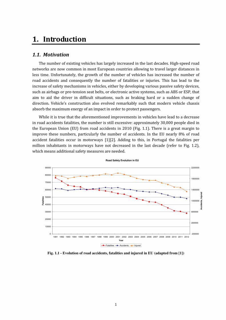
in road accidents fatalities, the number is still excessive: approximately 30,000 people died in
the European Union (EU) from road accidents in 2010 (Fig. 1.1). There is a great margin to
improve these numbers, particularly the number of accidents. In the EU nearly 8% of road
accident fatalities occur in motorways [1][2]. Adding to this, in Portugal the fatalities per
million inhabitants in motorways have not decreased in the last decade (refer to Fig. 1.2),
which means additional safety measures are needed.
Road Safety Evolution in EU
0
10000
20000
30000
40000
50000
60000
70000
80000
90000
1991 1992 1993 1994 1995 1996 1997 1998 1999 2000 2001 2002 2003 2004 2005 2006 2007 2008 2009 2010 2011 2012
Year
Fa
tali
tie
s
-200000
200000
600000
1000000
1400000
1800000
2200000
Ac
cid
en
ts,
Inju
red
Fatalities Accidents Injured
Fig. 1.1 - Evolution of road accidents, fatalities and injured in EU (adapted from [1])

2 1 – Introduction
0
2
4
6
8
10
12
14
2001 2002 2003 2004 2005 2006 2007 2008 2009 2010
year
fata
liti
es p
er
millio
n in
hab
itan
ts
Portugal EU-19
Fig. 1.2 – Fatalities in motorways per million inhabitants in the European Union (adapted from [1])
Several types of events can occur in a motorway, having different degrees of importance in
what concerns the distance to the event and driver reaction time. It is different for a driver to
know an accident has occurred two kilometres ahead, than knowing that a vehicle is braking
hard right ahead of him. Therefore a way of warning drivers about something that can cause
danger would most likely be effective on reducing the number of deaths since this approach
could in fact reduce the number of accidents. Most motorways have visual warnings methods
(e.g. electronic variable sign panels) to inform drivers but usually these signs are too scattered
along the motorway to have the needed effect. This is due to difficulties in the placement of
these signs, since not all areas are suitable due to geographical constraints or visibility issues;
even if possible, it would be too costly to place electronic signs every 100 meter for example.
In addition, it is important to validate any information and select the areas where it will be
disseminated in order to avoid false alarms or overload of useless information to the drivers.
Suburban motorways are accident-prone scenarios since they usually combine high speed
with high volume of traffic. As an example, the busiest Portuguese motorway (A5) has an
average daily traffic of 120.000 vehicles and more than 200 traffic accidents per year. The
IC19, a suburban motorway that leads to the A5 motorway, was considered the most
dangerous road in Portugal in 2013 [2].

1 – Introduction 3
1.2. Emergent wireless communications standards can support
vehicle safety applications
Safety in motorways would benefit from a system that is able to detect events that could
cause some danger and then warn drivers of these dangerous events. Several safety
applications for vehicles that were considered science-fiction some years ago, are now
becoming a reality. In 2008, the EU has enforced laws in order to reserve spectrum for safety
vehicular communications, particularly in the 5.9GHz frequency band: “Today's Commission
Decision provides a single EU-wide frequency band that can be used for immediate and reliable
communication between cars, and between cars and roadside infrastructure. It is 30 MHz of
spectrum in the 5.9 Gigahertz (GHz) band which will be allocated within the next six months by
national authorities across Europe to road safety applications” [3]. Wireless communications
were already used in motorways, mainly for tolling purposes [4], but the purpose of allocating
more 30MHz of spectrum for vehicular communications was to push the development of
safety and infotainment applications for drivers and vehicles passengers.
Recent news from the U.S. National Highway Traffic Safety Administration (NHTSA) claim
that U.S. regulators will “require all new vehicles to be able to "talk" to one another using
wireless technology”. This new rule is expected to be approved in early 2017 [5]. The same
article refers that NHTSA claims that “this technology allows cars on the road to trade basic
safety data, such as speed and position, at a rate of ten times per second. This exchange of
information might help avoid or reduce the severity of 80% of crashes that occur when the driver
is not impaired”.
In the field of vehicular communications, Vehicular Ad-Hoc Network (VANET) is a
particular network where the nodes are vehicles. Due to the rapid movement of the nodes and
the quick variability of their position and number, the topology of these networks varies very
rapidly over time. Also, there are no access points or base stations, i.e., communications are
only made between moving vehicles which makes easy to understand the ad-hoc nature of
such a network. When communications are made directly between vehicles, this is called
vehicle to vehicle communications (V2V).
A long transitory period of time is expected before all vehicles are equipped with on-board
units with wireless communications capabilities and before V2V protocols are mature enough
to be a reality. V2V communications are impaired by the ad-hoc nature of such networks
which does not favour safety and security. Other types of communications are involved in
vehicular networks besides V2V. It might be useful for vehicles to communicate with some
kind of fixed infrastructure, such as a toll or gas station or other road infrastructure. Whenever
this happens it is called vehicle to infrastructure communications (V2I) or infrastructure to
vehicle communications (I2V). Some authors also use roadside to vehicle (R2V) with the same
meaning.
A vehicle can have more than one unit capable of communications, therefore it is common
to refer each communication unit as an on-board unit (OBU). OBUs can also have the capacity
of connecting to the vehicle on-board computer and vehicle sensors. Other communication

4 1 – Introduction
units are placed in roadside infrastructures and are not mobile. These are named road side
units (RSU) in order to differentiate them from OBUs.
Not all wireless communication technologies are able to cope with vehicle high speeds and
rapid variations of network topology. On top of that, vehicular safety applications pose
additional time constraints. The two main communication parameters that affect the
performance of active traffic safety applications are reliability and delay. Reliability means
packets should be received at destination correctly without error and it depends on error
probability of the packets. In active safety applications most of the communication between
vehicles happens by broadcasting, therefore it is a hard task to predict the reliability of these
broadcast messages due to the absence of acknowledgment. Another important
communication parameter in active traffic safety applications is predictable delay. This means
data needs to be delivered to the destination before a certain deadline, which is very common
in active traffic safety applications.
New standards from different organizations, for wireless vehicular applications were
recently defined. The physical and MAC layers are identical in these standards and are based
in IEEE 802.11 Amendment 9 [6], also known as IEEE 802.11p. In the United States the
Wireless Access in Vehicular Environment (WAVE) set of standards includes the IEEE 1609.1-
4 [7] standards, while in Europe vehicular communications were standardized by the ETSI
ITS-G5 set of standards [8]. One measure taken by these standards was to eliminate the
registering process with an access point (AP). Another was to define new network and
transport layers, namely the WAVE Short Message Protocol (WSMP) and Fast Network and
Transport Protocol (FNTP) to avoid the use of IPv6 in order to reduce communication
overhead for safety applications. However, none of these standards is able to offer a
guaranteed maximum delay for medium access by the OBU safety applications. The MAC
protocols proposed in the aforementioned standards can suffer from collisions and other
problems that do not allow determinism in terms of bounded delay. This is particularly true
for dense traffic scenarios with a high number of nodes travelling at high speeds.

1 – Introduction 5
1.3. The Thesis
Our thesis is that it is possible to guarantee that information about events that can put at
risk driver safety is transmitted in due time, and, for this to happen, we propose an
infrastructure based approach where RSUs are coordinated among themselves and where
vehicles OBUs’ dynamically register and deregister from the system. Any vehicle that needs to
report a safety event must have access to the communication medium with predictable delay.
We base our approach on the Flexible Time Triggered (FTT) protocol [9] that was originally
devised for wired communications in order to obtain determinism in communications, i.e.,
predictable delay. We inherit all the properties of the original FTT protocol and we propose
the Vehicular Flexible Time Triggered (V-FTT) protocol, applicable to vehicular
communications, which shall be followed by all registered OBUs that want to be warned of
safety events. The protocol shall be compatible with WAVE and ETSI-G5 standards.
1.4. Contributions
The main contributions from this work are:
- A systematic and detailed state of the art of vehicular safety applications, their timing
and communication requirements, and an extensive survey on related projects in
Europe and other continents, for future memory.
- Definition of a new protocol (V-FTT) involving the creation of Safety Zones in
motorways. The Safety Zones will be managed by RSUs controlled by the motorway
operator. These RSUs will be interconnected and determine the communication
channel access of all compliant OBUs. For that purpose OBUs register themselves with
the RSUs in order to be warned of safety events. The RSUs will be responsible for
warning all OBUs (compliant or non compliant) of any occurrence of safety events.
- Definition of a coordination scheme for Road Side Units so that RSU communications
do not overlap.
- Definition of a new protocol (V-FTT) that guarantees a time bounded delay in medium
access by adapting the Flexible Time Triggered Protocol to the vehicular field and its
recent wireless standards (IEEE 802.11p amendment to IEEE802.11 and ITS-G5). This
protocol allows coexistence of compliant and non-compliant OBUs.
- Definition of a Basic Safety Message (BSM) based on the BSM defined in the WAVE
standard, but including additional information about safety events.
- Several worst-case analysis scenarios of the V-FTT protocol on top of
IEEE802.11/WAVE by quantification of the maximum time delay between the
occurrence of an event and the correspondent warning of an OBU.
- Inclusion of the V-FTT protocol in the Intelligent Cooperative Sensing for Improved
traffic efficiency (ICSI) project (European Commission FP7) [10].

6 1 – Introduction
1.5. Chapter organization
The rest of this work shall be organized the following way:
- In chapter 2 we discuss how to obtain and disseminate safety data in vehicular
environments. We present several current and future applications for vehicles, relying
on wireless communications, with focus on safety applications. We determine their
communication requirements in terms of bandwidth, transmission packet sizes and
maximum latency. We specify possible message sets for the more common safety
applications. We discuss what wireless communication technologies are able to
support vehicular communications and particularly if they are able to support the time
constraints of vehicular safety applications. For a better perspective on the subject, we
present several projects related with vehicular safety and wireless communications.
- In chapter 3 we analyse the most recent standards, both American and European, for
wireless vehicular communications. We demonstrate why these standards do not
guarantee a bounded delay in terms of access to the medium of communication and we
discuss what current MAC protocol proposals exist to overcome that problem.
- In chapter 4 we discuss the advantages and disadvantages of the two main types of
vehicular communication (V2V and I2V) and how they apply to some particular
scenarios. We conclude that for suburban motorways (high vehicle density and speed)
it is best to use an infrastructured approach. For that purpose we propose an
infrastructured based protocol, which is based on the Flexible Time Triggered Protocol
(FTT), tailored for vehicular communications, therefore entitled V-FTT protocol.
- In chapter 5 the V-FTT protocol application to IEEE802.11/WAVE is analysed,
particularly the adaptation of the Elementary Cycle to the Control Channel (CCH)
Interval. Several worst-case scenarios are specified and its respective quantifications
are made in order to analyse the protocol performance in terms of delay. A realistic
application scenario is also devised based on the A5 Lisbon motorway, which is one the
busiest and most dangerous motorways in Portugal.
- Finally, chapter 6 presents the main conclusions and future work directions.

7
2. Road Safety Mechanisms based on wireless
communications
The number of vehicles has largely increased in the last few decades and it was followed by
an increasing concern about occupant’s safety and health, leading to the development of
various passive safety devices (such as airbags or pre-tension seat belts) as well as active
systems (ABS, ESP, etc.). All these safety devices are meant to minimize the effect of accidents,
or at least, offer crash-avoidance technology relying on the driver ability to react soon enough.
For example, ABS improves braking distance but the driver still needs to start braking early
enough to avoid an accident.
A way of warning drivers about something that can cause danger would most likely be
more effective on reducing the number of accidents. Most motorways have visual warnings
methods (e.g. variable message signs) to inform drivers but, due to costs and/or geographical
constraints, these signs are usually too scattered along the motorway to have the needed
effect. A system that detects events that could cause some danger and then warn drivers of
these dangerous events could in fact improve safety in motorways.
Developments on wireless communications have lead to many new ideas about vehicle
safety, involving communication between vehicles (V2V) or between vehicles and some kind
of road infrastructure (Road side unit – RSU). In order to detect these events several data is
needed. It is needed to evaluate road conditions, to identify traffic jams, to detect slow moving
vehicles, obstacles on the road, animals or persons walking, etc. Currently some vehicles can
detect and warn the driver if some vehicle malfunction occurs, such as a low pressure on a tyre
or excessive engine heating. Over the years, several vehicular applications relying on wireless
communications have been designed.
The rest of this chapter is organized as follows: in section 2.1 we will present several
options that can be used to extract information from a vehicle and from the road, as well as the
user interfaces that can be used to convey safety information to the driver or vehicle
passengers. Over the years, several vehicular applications relying on wireless communications
have been designed. Non-safety applications are discussed in section 2.2, followed by a
presentation of some of the more important safety applications in the vehicular field in 2.3. In
section 2.4 several safety applications characteristics will be detailed, with particular
emphasis on the communication type, communication range and maximum allowable latency,
including the specification of a possible message set for each one. We then describe in section
2.5 several wireless communications standards and their applicability to V2V or V2I
communications, having in mind the safety applications constraints. To obtain a better insight
of vehicular communications evolution and historical context we present in section 2.6 several
projects about road safety in Europe, USA and Japan. Some of these projects collect data from
radar or infrared sensors, while others effectively use different wireless vehicular
communication standards.

8 2 – Road Safety Mechanisms based on wireless communications
2.1. Safety applications data sources: Vehicles and motorway
In order to extract information from a vehicle, several options can be considered. Since
1996, all vehicles are equipped with an on-board diagnostics interface (OBD-II), which allows
connecting via Controller Area Network (CAN) or similar standard with the vehicle on-board
computer, in order to obtain vehicle real-time data. Outside sensors can also be applied to the
vehicle in order to obtain information from the surroundings. It is also quite common to obtain
location information from a navigation system such as GPS (Global Positioning System).
Another source of data can be the motorway infrastructure that can provide information about
the road condition, traffic or other events. Also worth to notice are the available user
interfaces in vehicles: the vehicle dashboard, and more recently, small LCD displaying
information from the on-board computer (e.g. fuel consumption) or LCD monitors showing
maps with the vehicle route. We discuss these subjects in the following sub-sections.
2.1.1 Data obtained by vehicles
Vehicle manufacturers have been developing all kind of equipment to give passengers and
drivers comfort and safety, and electronic equipment is very common today; in-vehicle
sensors allow the driver to know various different types of information about the vehicle:
current speed, engine temperature, level of fuel in the fuel tank, average fuel consumption,
vehicle status data (airbag, direction turn, malfunctions, etc.). The on-board diagnostics (OBD-
II) is a system that allows mechanical workshops to obtain a quick diagnostic by simply
connecting to the vehicle on-board computer and obtain data from oxygen sensors, diagnostic
trouble codes and perform some tests on the vehicle. It is also capable of detecting
malfunctions and storing the information on the vehicle’s on-board computer. The OBD-II
interface also allows to obtain vehicle data in real-time, such as fuel pressure, air flow rate,
throttle position, vehicle speed, engine temperature, oxygen sensors and fuel parameters, etc.
Every vehicle manufactured after 1996 is expected to be OBD-II enabled.
Besides the internal vehicle parameters mentioned in the last paragraph, a vehicle can
obtain information from outside the vehicle itself. For example, since the addition of GPS
devices in vehicles, drivers are able to know their precise location and can have navigation aid
with the help of interactive maps. Location based services are growing very fast and location
information can be an added value for any vehicular application. The more common GPS
vehicular applications are related to traffic route but location information can be useful for any
safety or infotainment service. As an example, some vehicle safety applications (e.g. lane
change assistance) need at least 1-1.5m resolution to properly associate vehicle with lanes.
Common GPS resolution might not be sufficient but Differential GPS can be used or even other
methods [11] can be used to improve positioning resolution. Vehicles can also be equipped
with sensors and cameras. It is now common to see some vehicles equipped with parking
sensors and cameras to aid parking, but radar (long-range) or infra-red (short range sensors)
can also be used in motorways to detect obstacles (e.g. other vehicles) in the motorway.
For a safety warning system to work, vehicles must be equipped with a small computing
device that can read all the obtained data and detect some dangerous event. Then it must build

2 – Road Safety Mechanisms based on wireless communications 9
a message with the vehicle status (common data such as speed, location, acceleration, etc.) and
possible detected dangerous events (obstacle ahead, this vehicle is braking hard, etc.) so that
the warning message may be sent to other vehicles. This small computing device is also known
as On-board Unit (OBU) and is capable of receiving and sending messages to other devices
(other OBUs or RSUs).
2.1.2 Data obtained by motorway infrastructures
Along with vehicles, motorways have also suffered some evolution and it is common to see
electronic signs, electronic toll payment booths and other equipments. Motorways usually
have cameras in motorways to detect dense traffic situations or even dangerous events, such
as stopped vehicle or obstacles on the motorway. Magnetic sensors are used near toll
payments in order to identify the vehicles class or category. Sensors can also be used to
measure pavement temperature and humidity, or presence of dangerous gases in tunnels, for
example.
By combining various sources of information, it is possible to detect dangerous events. For
example, ice or snow gathering can be detected using humidity and temperature sensors along
with a camera. A stopped vehicle can be sensed by a camera or a magnetic sensor. A motorway
safety warning system should have various computing devices scattered through the
motorway and these devices should be capable of detecting dangerous events and then inform
affected vehicles trough some kind of central system, so these events can be validated before
dissemination. For that purpose, several wireless communication standards will be discussed
in section 2.5.
2.1.3 Vehicle User Interfaces
It is important to notice that a driver has a variable response time to information given.
Studies show that a driver has a typical reaction time of 0,75s but we must add to this the
perception/decision time. In [12] it was shown that 85% of the drivers take less than 2,5
seconds to respond to an abnormal driving situation. This means that any safety application
must warn the driver with sufficient margin of time for her to react. One of the most important
parameters for UI decision is to minimize the downtime, i.e., the time that the driver is
distracted by the UI and is not looking at the road. This means that a safety user interface
should require none or few interactions from the driver.
Vehicle user interfaces (UI) have not changed much in the last decades. The common dash
board shows vehicle mileage, vehicle speed, RPM, oil temperature and fuel tank. Since the
introduction of on-board computers and introduction of digital radio (RDS) and audio systems,
it is also common to have a small Liquid Crystal Display (LCD) showing some on-board data
such as average fuel consumption or audio information. Regarding a possible user interface for
safety vehicle applications, the main options are:
- Visual interface: it has the advantage of being already available in vehicles. Besides the
small LCD dashboard already mentioned, it is also common to find in some vehicles a
LCD monitor showing maps with the vehicle position and route updated by the GPS
system. Another advantage is that information about a possible dangerous event can
easily include the location of the event.

10 2 – Road Safety Mechanisms based on wireless communications
- Audio interface. An audible message could work well, as long as the system could
override all other in-vehicle audio, but the message has to be short and clear, otherwise
it can take too much time to warn the driver. The system would need to be setup for
each driver and/or environment, since the noise from outside the vehicle can suffer
large variations (several decibels)
- Tactile interface (vibration): A tactile interface (e.g. vibration in steering wheel) does
not distract the driver from the road, although it is insufficient in what concerns giving
details about the event. It would require some learning phase from the driver, in order
to recognize safety warnings. It could be used for dangerous events that need a fast
reaction from the driver, such as vehicles braking hard ahead, but it would be more
effective combined with one of the other solutions.

2 – Road Safety Mechanisms based on wireless communications 11
2.2. Non-Safety Applications in Vehicular Environments
Based on [13][14][15] we discuss some non-safety important applications can be thought
of for comfort of vehicle passengers and/or drivers. We will not make an exhaustive list, but
instead give some examples of non-safety applications that use wireless communications.
These applications are described next, divided into application fields, such as traffic
management, tolling, location based services, global internet services, etc. Although these
applications are not directly related to our work, they can be used by motorway
concessionaries or other operators to add value to the service they offer, since they can prove
to be quite useful for vehicle passengers and drivers.
Traffic Management
- Intelligent On-Ramp Metering - this application uses vehicle-to-infrastructure (V2I)
communication to measure real-time traffic density on the highway and dynamically
alters on-ramp metering signal phasing, allowing a more fluid traffic flow.
- Intelligent Traffic Flow Control - this application uses vehicle-to-infrastructure
communication in order to control a traffic light signal phasing based on real-time
traffic flow.
Tolling
- Free-Flow Tolling - this infrastructure application works on toll roads and uses
communications for toll collection without the need for toll plazas along the roadway.
Location Based Services
- Point of Interest Notification - a roadside unit will periodically broadcast information to
passing vehicles.
- ITS local electronic commerce – ITS stands for Intelligent Transportation System. This
application provides electronic payment in cases like fast food drive through, gas
stations, parking fees or toll fees.
Information from Other Vehicles
- Instant Messaging – this V2V application enables a vehicle to send an instant message to
another vehicle.
Improve navigation
- Enhanced Route Guidance and Navigation - up-to-date and localized navigation
information is sent to vehicles via roadside units.
- Map Downloads and Updates - Maps can be downloaded to a vehicle and vehicle’s
existing maps can be updated by a RSU.
- GPS Correction - the RSU is pre-programmed with its precise location, and it gives this
information to passing vehicles.

12 2 – Road Safety Mechanisms based on wireless communications
- Cooperative positioning improvement - based on map-data, error measurements from
other cars, etc., vehicles can try to reduce GPS positioning errors.
- Parking Spot Locator - application should deliver information about unoccupied
parking lots to vehicles. Vehicles send or request parking information from a RSU.
Improve vehicle-related services
- Fleet management - Logistic companies can:
o send driver advices and information;
o support location tracking and scheduling;
o optimize routing;
o download mission and instructions;
- Area access control - access control is implemented by installing RSUs at the entry and
exit points of restricted areas, such as shipping yards, warehouses, airports, transit-
only ramps and other areas. The RSU receives authorized identity codes or access codes
from approaching OBU equipped vehicles and transmits a message to proceed or that
entry is not allowed. The message could be displayed in the vehicle via in-vehicle
signage. Some examples of access control to:
o parking gates;
o commercial vehicle electronic clearance;
o border crossings.
- Rental car processing - the rental car processing application allows a vehicle to exit the
rental car parking area after being rented and re-enter the parking area where the
rental fee is automatically deducted from the driver’s charge account or other monetary
account. Other RSU are installed so that the rental agency can identify the location of
the rental vehicle in the rental lot.
Hazardous material cargo tracking - tracking of vehicles containing hazardous cargo is
implemented by installing RSUs at the entry and exit points of shipping areas, such as
shipping yards, warehouses, airports, and other areas. The RSUs collect an identity code
and, if desired, a cargo list from approaching or leaving OBU equipped vehicles and
send that information to a tracking program. Tracking information can also be obtained
from the RSU data of weigh station clearance points and border crossings.

2 – Road Safety Mechanisms based on wireless communications 13
2.3. Safety Applications in Vehicular Environments
Safety applications are intended to decrease the number of accidents and consequently the
number of injuries and deaths. In this section, based on several sources ([13] to [15]), various
different safety applications are presented according to their context, for example intersection
collision avoidance, sign extension, vehicle diagnostics and others.
Please note that, in general, the safety applications presented here will not control the
vehicle directly but will instead present a warning to the driver.
Intersection Collision Avoidance
Intersection collisions represent a large percentage of urban and suburban accidents;
therefore some applications have been devised in order to avoid this kind of events.
- Traffic Signal Violation Warning - this application uses infrastructure-to-vehicle (I2V)
communication to warn the driver to stop at the legally prescribed location if the traffic
signal (e.g. red light, stop sign) indicates a stop and it is predicted that the driver will be
in violation and/or requires a high level of braking for a complete stop.
- Left Turn Assistant - the Left Turn Assistant application provides information to drivers
about oncoming traffic to help them make a left turn at a signalized intersection
without traffic lights.
- Stop Sign Movement Assistance - this application provides a warning to a vehicle that is
about to cross through an intersection after having stopped at a stop sign. The warning
is provided in order to avoid a collision with traffic approaching the intersection.
Information is obtained from the infrastructure system, which uses sensors or vehicle
to infrastructure (V2I) communications to detect vehicles moving through an
intersection. When the infrastructure or the in-vehicle application determines that
proceeding through the intersection is unsafe, it provides a warning to the driver.
- Intersection Collision Warning - this application warns drivers when a collision at an
intersection is probable. Infrastructure sensors and/or V2I communications can be
used to detect all vehicles, their position, velocity, acceleration, and turning status while
approaching an intersection. Also weather status and the road shape/surface type can
be variables for calculating the likelihood of a collision. The infrastructure unit or the
in-vehicle unit determines when a collision is imminent and issues a warning to either a
specific vehicle or all drivers in the vicinity, depending on the warning strategy.
Particular care must be taken in order to avoid false alarm situations.
- Blind Merge Warning - this application warns a vehicle if it is attempting to merge from
a location with limited visibility (either for itself or for the oncoming traffic) and
another vehicle is approaching and predicted to occupy the merging space. The RSU is
in view of the primary road and the merging vehicle. It warns both the merging traffic
and the right-of-way traffic of potential collisions. Vehicles notify the infrastructure unit
of their velocity, acceleration, heading and location. The roadside unit calculates
whether a collision is imminent, based on the information sent from the vehicles and

14 2 – Road Safety Mechanisms based on wireless communications
knowledge of the road. The roadside unit will notify all surrounding vehicles if a
collision is likely. It will also provide an all-clear signal when there is no approaching
traffic.
- Pedestrian Crossing Information at Designated Intersections - this application provides
an alert to vehicles if there is danger of a collision with a pedestrian or a child that is on
a designated crossing.
Public safety
Services related to emergency vehicles or emergency situations are presented in this sub-
section.
- Approaching Emergency Vehicle Warning - this application provides the driver a
warning to yield the right of way to an approaching emergency vehicle. The emergency
vehicle broadcast message shall include information regarding its position, lane
information, speed and intended path. The in-vehicle application will use this
information to alert the driver.
- Emergency Vehicle Signal Pre-emption - this application allows an emergency vehicle to
request right of way from traffic signals in its direction of travel. Emergency vehicle
signal pre-emption allows the emergency vehicle to override intersection signal
controls. The intersection roadside unit verifies that the request has been made by an
authorized source and alters the traffic signal and timing to provide right of way to the
emergency vehicle. This application may need to be integrated with the Approaching
Emergency Vehicle Warning application.
- SOS Services - this in-vehicle application will send SOS messages after airbags are
deployed, a rollover is sensed, or the OBU otherwise senses a life-threatening
emergency.
Sign Extension
It is not unusual for drivers to miss signs, for various reasons, either for distraction or
because the signs may not be visible due to vegetation or other obstacles (e.g. other vehicles).
Here some possible applications are presented that provide a sign extension inside the vehicle.
However care must be taken to effectively warn the driver without causing too many
distractions.
- In-Vehicle Signage - the in-vehicle signage application provides the driver with
information that is typically conveyed by traffic signs.
- Low Parking Structure Warning - this application provides drivers with information
concerning the clearance height of a parking structure.
- Wrong Way Driver Warning - this application warns drivers that a vehicle is driving or
about to drive against the flow of traffic.
- Low Bridge Warning / Low Tunnel Warning - Low bridge (or low tunnel) warning is
used to provide warning messages especially to commercial vehicles when they are
approaching a bridge or tunnel of low height.

2 – Road Safety Mechanisms based on wireless communications 15
- Work Zone Warning - Work zone safety warning refers to the detection of a vehicle in
an active work zone area and the indication of a warning to its driver.
- Limited access warning and detour notification - In case of road works a warning that is
sent to vehicles along with detour notification.
Vehicle Diagnostics and Maintenance
In case of a vehicle problem, detected either by the OBU or an RSU, a warning is provided.
- Safety Recall Notice - This application allows the distribution of safety recalls through
I2V communications sent directly to vehicles via roadside units.
- Just-In-Time Repair Notification - This application communicates in-vehicle diagnostics
to the infrastructure and advises the driver of nearby available services.
Assist driver in dangerous traffic situations
Many dangerous traffic situations can occur in everyday’s drive. The applications
presented in this sub-section are meant to help the driver to avoid possible collisions.
- Cooperative Forward Collision Warning - Cooperative forward collision warning system
is designed to aid the driver in avoiding or mitigating collisions with the rear-end of
vehicles in the forward path of travel through driver notification or warning of the
impending collision. The system does not attempt to control the host vehicle in order to
avoid an impending collision.
- Emergency Electronic Brake Light - When a vehicle brakes hard, the Emergency
Electronic Brake Light application sends a message to other vehicles following behind.
- Lane Change Warning/Blind Spot Warning - This application provides a warning to the
driver if an intended lane change may cause a crash with a nearby vehicle, either due to
an approaching vehicle in the intended lane or due to the blind spot of the driver being
already occupied by a vehicle.
- Cooperative Collision Warning - Cooperative collision warning collects surrounding
vehicle locations and dynamics and warns the driver when a collision is likely.
- Pre-Crash Sensing - pre-crash sensing can be used to prepare for imminent, unavoidable
collisions.
- Post-crash Warning - this in-vehicle application warns approaching traffic of a disabled
vehicle (disabled due to an accident or mechanical breakdown) that is stuck in or near
traffic lanes, as determined using map information and GPS. Other similar warnings can
follow the same pattern, like object/animal on road.

16 2 – Road Safety Mechanisms based on wireless communications
Assist driver on special road/weather conditions
Weather and road conditions variations may present some risk for unaware drivers, so
this sub-section presents some applications designed to aid the driver in these situations.
- Vehicle-Based Road Condition Warning - This in-vehicle application will detect marginal
road conditions using on-board systems and sensors (e.g. stability control, ABS), and
transmit a road condition warning, if required, to other vehicles via broadcast.
- Infrastructure based Road Condition Warning - Road condition warning is used to
provide warning messages to nearby vehicles when the road surface is icy, or when
traction is otherwise reduced.
- Curve Speed Warning - Curve speed warning aids the driver in approaching curves at
appropriate speeds. This application will use information communicated from roadside
beacons located ahead of approaching curves. The communicated information from
roadside beacons would include curve location, curve speed limits, curvature and road
surface condition. The in-vehicle system would then determine, using other onboard
vehicle information, such as speed and acceleration, whether the driver needs to be
alerted.
Assist driver on normal traffic
- Highway Merge Assistant - This application warns a vehicle on a highway entrance if
another vehicle is in its merge path (and possibly in its blind spot).
- Visibility Enhancer - This application senses poor visibility situations (fog, glare, heavy
rain, white-out, night, and quick light-to-dark transitions) either automatically or via
user command.
- Cooperative Vehicle-Highway Automation System (Platoon) - This application provides
both positional and velocity control of vehicles in order to operate safely as a platoon
on a highway. This is far from being a reality since it demands a highly reliable control
of the vehicle as well as full penetration of vehicles capable of communicating with each
others.
- Cooperative Adaptive Cruise Control - Cooperative adaptive cruise control will use
vehicle-to-vehicle communication to obtain lead vehicle dynamics and enhance the
performance of current adaptive cruise control.
- Cooperative glare reduction / headlamp aiming - This application allows a vehicle to
automatically switch from high-beams to low-beams when trailing another vehicle.
Each vehicle broadcasts its position and heading in low-light situations. If one vehicle
calculates that another vehicle in front of it is within a specified range, it will warn the
driver to switch from high-beams to low-beams.

2 – Road Safety Mechanisms based on wireless communications 17
2.4. Safety Critical Applications characteristics and message sets
After presenting several safety applications in the previous sub-section, we will now
identify and discuss the main characteristics of some safety applications. Two I2V applications
and four V2V applications were selected. One is related to an urban scenario, one to a non-
urban scenario, the other four are applicable anywhere. This evaluation is based on
information from [13][14] and uses the following parameters:
- Communication type - Infrastructure-to-vehicle (I2V), Vehicle-to-infrastructure (I2V) or
vehicle-to-vehicle (V2V).
- Point-to-point (P2P) or point-to-multipoint communication.
- One way or two-way (2-WAY) communication.
- Transmission mode - describes whether the transmission is triggered by an event
(event-driven / event-triggered) or whether it is sent automatically at regular intervals
(periodic / time-triggered). In case of a periodic transmission, the minimum update
rate (in Hz) or period (in seconds).
- Allowable latency (in msec) - the allowable latency is the maximum duration of the time
interval defined between the instant when information is available to be transmitted
and the instant is it received. If the information arrives after this value then it will not
be useful, it might be too late (similar to the deadline in real-time-systems).
- Maximum required range of communication (in meters) - the communication distance
between two units that is needed to effectively support a particular application.
Table 2.1 summarizes these parameters.
Table 2.1 – Safety Critical applications characteristics (adapted from [13][14])
Application type 2-WAY P2P Latency
(ms)
Max. range
(m)
Transmission Mode
Traffic Signal Violation
Warning
I2V No No 100 250 Periodic (10 Hz)
Curve speed warning I2V No No 1000 200 Periodic (1Hz)
Emergency Electronic Brake
Light
V2V No No 100 300 Periodic (10Hz)
Pre-crash sensing V2V Yes Yes 20 50 Event-driven (50Hz)
Cooperative Forward Collision
Warning
V2V No No 100 150 Periodic (10Hz)
Lane Change/Blind Spot
Warning
V2V No No 100 150 Periodic (10Hz)
The data message set requirements of safety critical applications are presented next.
Please note that these message sets represent applications data payload only, they do not
include any header that should be provided by the communication standard to be used. The
idea is to specify typical message sets that have to be successfully transmitted in due time for
the safety application to be supported. In the next chapter we will evaluate several wireless

18 2 – Road Safety Mechanisms based on wireless communications
communication standard and if they are able or not to support these safety applications and
their communication requirements.
Traffic Signal Violation Warning
As summarized in Table 2.1, the traffic signal system has a transmit-only radio
requirement. The vehicle system in this application scenario only has the requirement to
receive the radio signal. More specifically, the transmissions originating from the traffic signal
would consist of one packet sent every 100 milliseconds. Each packet would contain at least
the following information derived from the instantaneous status of the traffic signal in the
appropriate approach direction.
Table 2.2 – Traffic Signal Violation Warning data message set (adapted from [13])
Description Number of bits Message type 8
Traffic signal status information
Current phase 8
Date and time of current phase 56
Next phase 8
Time remaining until next phase 24
Road shape information
Data per node 32
Data per link to node 72
Road condition/surface 8
Intersection information
Data per link 120
Location (lat/long/elevation) 96
Stopping location (offset) 32
Directionality 16
Traffic signal identification 48
TOTAL PAYLOAD SIZE 528
Curve Speed Warning
Excessive vehicle speed in curves often leads to lane departure, collision, loss of vehicle
control, and/or road departure, any of which may result in some combination of vehicle or
property damage or loss, injury, and even death. Currently, reduced speed limits are regularly
posted on the most troublesome curves, but their safe negotiation is often influenced by more
factors than just road geometry. The driver attempts to take all available factors into account,
sometimes unsuccessfully, when deciding on an appropriate speed in a curve. If the vehicle
was to assess its dynamics, prior knowledge of curve geometry, road surface parameters, and
estimated road surface conditions well in advance of a curve and notify the driver when speed
should be reduced, the driver would be better equipped to negotiate the curve and less likely
to cause an accident.
This application uses information communicated from roadside beacons in view of the
approaching traffic to a curve. Information from the roadside beacon may include curve start
and end locations, road geometry (describing road and lane widths, curvature, bank, and
grade), wet/dry road surface static and sliding coefficients of friction, road shoulder/boundary
conditions, maximum posted speed limit, and road surface condition.

2 – Road Safety Mechanisms based on wireless communications 19
The in-vehicle system combines information from the roadside beacon with vehicle
parameters and on-board sensor data to determine if the driver should be warned to reduce
speed in order to safely negotiate the curve.
Communications from the roadside beacon to approaching vehicles should be periodic,
one-way broadcasts. The broadcast message should repeat at regular intervals 24 hours a day,
regardless of the presence of vehicles. Message content should change only with respect to
road surface condition updates and curve geometry changes. Vehicles must be able to receive
roadside messages, process the information, and provide timely warning to the driver if
current speed exceeds the computed vehicle safe speed for the curve.
A maximum communication range of 200m for the roadside beacon was also arbitrarily
set, but could vary based on local constraints.
Table 2.3 – Curve Speed Warning data message set (adapted from [13])
Description Number of bits Message type 8
Roadside Beacon ID (or RSU ID) 48
Maximum posted speed 7
Curve header (# of curve points) 8
Curve point counter 8
Each curve point (lat, long and curvature) 112
Each curve point bank angle (+-30º) 6
Each curve point road width 8
Each curve point lane width 6
Each curve point shoulder width 5
Each curve point road boundary condition 3
Each curve point road surface condition 8
Weather conditions 8
TOTAL PAYLOAD SIZE 235
Note that total message length will vary depending on the number of curve points used to
describe the total curve. For example, if the curve was relatively short and simple it might only
require 4 curve points. The total basic message length would then be approximately 80 bytes.
If the curve included roadside sensor data and were long and complex, it might require 20
curve points. This curve would then require a message length of approximately 381 bytes.
Emergency Electronic Brake Light (EEBL)
Emergency Electronic Brake Light is a pure V2V application. This application “enhances”
the driver visibility by giving an early notification of a vehicle braking hard even when the
driver’s visibility is limited (e.g. heavy fog, rain, snow, other large vehicle in between).
A normal brake lamp goes on when the driver applies the brake. The Emergency Electronic
Brake Light application might not only enhance the range of a “hard” braking message but also
might provide important information such as acceleration/deceleration rate. At present, brake
lamps do not differentiate level of deceleration and are only useful as far rearward as direct
line of sight allows.
It is assumed that the vehicle in an emergency braking situation would be equipped with a
wireless communication unit. It is also assumed that the message from the vehicle would be

20 2 – Road Safety Mechanisms based on wireless communications
sent to the following vehicles, including the ones that are behind a much larger vehicle (e.g. a
big truck) or another obstacle (e.g. fog).
The message sender needs to have an algorithm to decide if an “emergency braking”
message delivery is necessary (For example: deceleration greater than 0.6g). If a vehicle
determines that it is braking hard then it could use the OBU to share that information with
others. In order to determine if an “emergency braking” message is relevant to the receiving
vehicle, the OBU needs to know the relative location from which the message was originated
(e.g. front, rear, left, right). This can be done based on its GPS information and the GPS
information of the braking vehicle. For example, an “emergency braking” message from a
vehicle in lane 3 may not necessarily apply to a vehicle travelling in lane 1.
Table 2.4 – Emergency Electronic Brake Light data message set (adapted from [13])
Description Number of bits GPS coordinates 96
Time stamp 64
Vehicle speed 16
Vehicle acceleration/deceleration 16
Vehicle heading 16
Vehicle size (length, width, height) 48
GPS antenna offset (relative XYZ) 32
TOTAL PAYLOAD SIZE 288
Pre-Crash Sensing for Collision Mitigation
The main objective of a pre-crash sensing system is to collect relevant information
regarding an impending collision and communicate this information to the vehicle’s occupant
protection system. The information set may include parameters such as crash type
(side/frontal/rear), impact time, impact speed, struck and striking vehicle size and mass, etc.
Examples of collision counter measures enabled by pre-crash sensing include enhanced air
bags, seat-belt pre-tensioning, occupant repositioning, truck/car crash compatibility counter
measures and emergency brake assist among others. In contrast to collision warning
technology, whose primary goal is to help the driver avoid the crash, collision mitigation based
on pre-crash sensing is aimed at reducing injuries once the crash is deemed unavoidable.
Given the short timeframe available to deploy such counter measures, the main technical
challenge for any wireless communication technology is whether it can fully support the high
update rate thought to be necessary for these type of applications (between 50 and 100 Hz).
A generic implementation of pre-crash sensing for collision mitigation is presented in [13].
It uses radar for vehicle detection so the wireless communication will only be used when an
obstacle is detected. The total suggested payload message size is 435 bits and the contents are
presented on Table 2.5. The communication range expected is around 25 meters for most pre-
crash sensing applications. Some long-term applications, such as mitigation by braking based
on pre- crash information, may require up to 50 meters in the worst case scenarios (head-on
collisions). The standard vehicle message is expected to be in a broadcast mode only.

2 – Road Safety Mechanisms based on wireless communications 21
For a cooperative pre-crash sensing, a two-way communication between the affected
vehicles may be required once the radar sensor predicts the eventuality of a collision. In that
case, a two-way communication message is requested from the wireless communication units.
This message would contain the same data mentioned earlier in the standard message. The
update rate however is expected to be around 50 Hz. This should be enough in the case where
the wireless communication ranging information is used only to confirm the type of target that
the radar has detected. The stringent two-way communication requirement and fast update
rate is unique to this application. However, it is only activated in the eventuality of a crash and
does not last more than a second or two. The message size could potentially be reduced since
most of the static vehicle data can be transmitted just once for proper system functionality.
Table 2.5 – Collision mitigation data message set (adapted from [13])
Description Number of bits Message type 8
Vehicle ID / Communication
Address
48
Vehicle Type/Class 4
Vehicle Size and Mass (length,
width, height, mass)
64
Static Vehicle Data
Position Antenna Offset (relative
X,Y,Z)
48
TimeStamp – GPS Milliseconds in
week
32
Time Stamp – GPS week number 16
Vehicle Speed 16
Vehicle Acceleration-longitudinal 16
Vehicle Acceleration-lateral 16
Vehicle Acceleration-vertical 16
Vehicle Heading 8
Vehicle Yaw rate 16
Vehicle Position – Longitude 32
Vehicle Position – Latitude 32
Vehicle Position – Elevation 32
Turn Signal Status- Right 1
Turn Signal Status- Left 1
Brake Position 1
Throttle position 8
Steering Wheel angle 16
Dynamic Vehicle Data
System Health 4
TOTAL PAYLOAD SIZE 435
Cooperative Forward Collision Warning (CFCW) System
A rear-end collision is defined as an on-road, two vehicle collision in which both vehicles
are moving forward in the same direction prior to the collision or a collision in which the
vehicle in the forward path has stopped. The objective of a forward collision warning system is
to increase driver awareness and subsequently reduce deaths, injuries and economic losses
resulting from vehicular rear-end collisions. A forward collision warning system is designed to
aid the driver in avoiding or mitigating collisions with rear-end of vehicles in the forward path
of travel. This is performed through driver notification or warning of the impending collision.

22 2 – Road Safety Mechanisms based on wireless communications
The system does not attempt to control the host vehicle in order to avoid an impending
collision.
A forward collision warning (FCW) system will typically use a forward-looking sensor
mounted at the front of the host vehicle that detects targets (other vehicles or objects) ahead
of the host vehicle and in its field of view. An accurate prediction of the forward lane geometry
ahead of the host vehicle (up to 150 meters) is necessary in order to properly classify the
targets as in-path or out-of-path, and thereby identify potential threats of rear-end collision.
For the regular FCW, incorrect classification of in-path and out-of-path targets leads to false
alarms and missed detections in the system, which may limit deployment and user acceptance.
To predict the forward road geometry ahead of the host vehicle, the system may also use a GPS
receiver for vehicle position measurement, a map database, a vision system that detects lane
markers, a vehicle speed sensor, and a yaw-rate sensor. However, each of these approaches
has limitations.
A cooperative forward collision warning system would use information communicated
from neighbouring vehicles via vehicle-to-vehicle communication in addition to forward
looking sensor data to address these shortcomings.
Table 2.6 – Cooperative Forward Collision Warning message set (adapted from [13])
Description Number of bits Message type 8
Vehicle ID / Communication Address 48
Vehicle Type / Class 4
Vehicle Size (length, width, height) 48
Position Antenna Offset (relative X,Y,Z) 48
Time Stamp – GPS milliseconds in week 32
Time Stamp – GPS week number 16
Vehicle Speed 16
Vehicle Acceleration-longitudinal 16
Vehicle Acceleration-lateral 16
Vehicle Acceleration-vertical 16
Vehicle Heading 8
Vehicle Yaw rate 16
Vehicle Position – Longitude 32
Vehicle Position – Latitude 32
Vehicle Position – Elevation 32
Turn Signal Status- Right 1
Turn Signal Status- Left 1
Brake Position 1
Throttle position 8
Steering Wheel angle 16
System Health 4
TOTAL PAYLOAD SIZE 419
It is expected that vehicles periodically broadcast the standard message set to
neighbouring vehicles within a certain desired range. Current automotive radars used in FCW
systems are capable of track updates at an update rate of 100 ms and have a 150m range of
coverage. Hence, the update rate for vehicle-to-vehicle communication is expected to be at
least 100 ms, and the communication range is expected to be at least 150 m.

2 – Road Safety Mechanisms based on wireless communications 23
Lane Change Warning
This application provides a warning to the driver if an intended lane change may cause a
collision with a nearby vehicle. In [13] it is suggested that the application receives periodic
updates of the position, heading and speed of surrounding vehicles via vehicle-to-vehicle
communication. When the driver signals a lane change intention, the application uses this
communication to predict whether or not there is an adequate gap for a safe lane change,
based on the position of vehicles in the adjacent lane. If the gap between vehicles in the
adjacent lane is not sufficient, the application determines that a safe lane change is not
possible and will provide a warning to the driver. The suggestion in [13] is that each OBU
maintains and updates a nearby vehicle Table such as the one shown below.
Table 2.7 – Example of an OBU table of nearby vehicles (adapted from [13])
Vehicle Velocity
(km/h)
Accel
(m/s2)
Projected
position
Time
stamp
Distance
(m)
Time to
expire
(count)
Relative
azimuth
angle (deg) B 60 1 Xx:xx:xx;
Xx:xx:xx
Hh:mm:ss.ss 3 2 45
C 70 0 Yy:yy:yy;
yy:yy:yy
Hh:mm:ss.ss 2,5 2 95
D 75 0 Zz:zz:zz;
zz:zz:zz
Hh:mm:ss.ss 4 1 180
E 65 0,5 Xy:xy:xy;
Xy:xy:xy
Hh:mm:ss.ss 8 2 5
... ... ... ... ... ... ... ...
Instead of using a V2V communication, since this application relies on high penetration of a
wireless communication vehicle system, we suggest a solution using radar sensors or cameras
and I2V communication. The biggest challenge for this application is in designing a system that
can determine the exact location of a vehicle in tightly-packed traffic, so that the system
doesn’t provide false warnings to the driver. The lane change warning needs a very accurate
position determination. The use of additional sensors such as radar or cameras could make the
application more accurate.
The table for the message set of the proposed V2V solution in [13] is presented next:
Table 2.8 - Lane Change Warning message set (adapted from [13])
Description Number of bits GPS Coordinates 96
Time stamp 64
Vehicle speed 16
Vehicle acceleration 16
Vehicle heading 16
Vehicle size (length, width, height) 48
GPS antenna offset (relative X, Y, Z) 32
TOTAL PAYLOAD SIZE 288

24 2 – Road Safety Mechanisms based on wireless communications
2.5. Wireless communications standards to support safety vehicular
communications.
In order to make cooperative vehicular applications possible, an adequate wireless
communications solution is needed so that vehicles can easily communicate with each other
and/or with the motorway infrastructure. There are several wireless access standards that
could be used as a base for vehicular communication. We discuss them next and analyse their
applicability to vehicular communications.
We will categorize the most important physical layer parameters, such as frequency band,
communication channels, output power, data rate, range of communication and latency. It is
worth to note that some of these parameters are closely inter-related (e.g. more power is
usually equivalent to a wider communication range).
The data rate mentioned here is the transmitted data rate (in bits per second) and has
nothing to do with the quality of received information, which depends on packet error rates
and other issues. The transmitted data rate is primarily related to the type of coding and
modulation scheme used. Often lower data rates provide higher reliability.
Communication range is related to the received data quality. The values we present are the
values stated in each communication standard, which normally assume output power and data
rates directly related to the requirements imposed by the intended application (e.g. voice or
data).
Latency was already defined in the previous chapter and is a very important parameter for
safety vehicular applications. We will use it here as the communication delay between the
start of packet transmission to the start of the packet reception at the end station (peer to peer
or via an access point or base station). This definition of latency is independent of
communication parameters such as throughput or packet size, but depends on the distance
between transmitter and receiver, so when latency is stated it usually depends on the intended
application. We are particularly interested in the maximum latency value, since this is the
worst-case scenario.
The maximum latency value is not only related to the PHY layer, in fact it depends more
often on the Medium Access Control layer (MAC) so we also analyse the MAC protocols used in
each communication standard. Besides the latency we will verify if the MAC has a centralized
or distributed control. Centralized MACs are usually predictable, i.e., the channel access is
guaranteed with a certain maximum delay, thus supporting real-time traffic. We also analyze
the behaviour of the MAC as traffic density increases, which is somehow a measure of
scalability. Finally, it is important that a MAC has different priorities for different types of
traffic, which is another way of mentioning quality of service support (QoS).
The following sub-sections discuss several wireless communication standards, using data
from several sources, with the same approach than the used in the European project
COMeSafety [16].

2 – Road Safety Mechanisms based on wireless communications 25
Digital Broadcast (DAB, DMB, DVB-T, DVB-H)
DAB (Digital Audio Broadcasting) is also known as digital radio. Digital Multimedia
Broadcasting (DMB) is based on the DAB standard and has some similarities with the main
competing mobile TV standard: DVB-H. It is a digital radio transmission system for sending
multimedia (radio, TV, and datacasting) to mobile devices such as mobile phones. As the name
already hints, it is a one way communication protocol, where only downlink communication
(broadcast) is used. It might be used for Infrastructure to Vehicle communications in order to
send safety warnings to vehicles, but it cannot be used for V2I or V2V communications, which
is very limiting.
DMB is an ETSI standard (TS 102 427 and TS 102 428) and uses Band III (174–240 MHz)
and L-Band (1452–1492 MHz). It is unavailable in the USA, but is used in Europe, Canada,
China, India and Australia. The data rate is 2.4Mbps and provides a wide range of
communication: 35km. The setup connection time is 2s and the latency is smaller than 100ms.
It has two channels: the main service channel and a fast information channel. The main service
channel can be divided into several audio and data sub-channels.
Digital Video Broadcasting (DVB) started as DVB-Terrestrial (DVB-T) but has been
developed into DVB-H (for personal stations) with added features in order to meet
requirements of personal stations and battery powered receivers, to distinguish them from
the traditional TV receiver. The standard is the ETSI EN 302 304. It uses the same band as DAB
plus part of UHF IV and V (470-862MHz). The main difference between DAB and DVB is that
the latter provides larger data rates (6 to 31 Mbps) since it is tailored for video broadcast. The
range varies from 16 to 67km and the latency can reach 2 to 4s [17]. In order to support
multimedia interactive TV a set of return channels were standardized to allow bi-directional
communication (bandwidth up to 2Mbps) DVB-RCT (Return Channel Terrestrial) is the
standard specified by ETSI 301958. This return channel is usually wired or at least does not
allow large node mobility.
We conclude that DAB and DVB cannot be used for V2I safety communications, with the
exception of broadcasting safety warnings.
InfraRed
Infrared communications are good for very short range direct communications. They can
be used for V2V communications or I2V communications but need line of sight, which usually
limits I2V communications to the lane closest to the roadside.
The standard used is ISO21214. Four independent infrared channels can be used. The
typical range is 7m but can vary from 1 to 100m. The data rate is 1Mbps (2Mbps in CALM IR,
where CALM stands for Communication Access in Land Mobiles and will be detailed later on).
The connection setup time is less than 20ms [18]. A huge drawback is that it can suffer
interferences from weather conditions (light, rain, snow), since it uses high frequencies. It will
need two transmitters for bidirectional communication. It allows peer to peer, broadcast and
multicast communication.

26 2 – Road Safety Mechanisms based on wireless communications
A reduced protocol stack is available in order to support low delay communications. The
MAC layer uses TDMA for synchronized communications between multiple peers. One of the
peers must be selected as a temporary master in order to organize the TDMA slots. This means
deterministic channel access is guaranteed, however the process of selecting the master is not
bounded. The known latency is then 10ms. Scalability is not an issue, since the range of
communication is small, meaning the number of nodes will not be too large. Finally, CALM-IR
supports 8 different priorities, so QoS is supported.
Infrared communications can suffer interference from sunlight, rain or snow, therefore
they are not reliable enough to be used on its own for vehicular safety applications, although
they can complement other technologies.
WiFi (IEEE 802.11a)
WiFi is a widely used radio system, based on IEEE 802.11. It has a low cost per transceiver
and operates in the ISM 2.4GHz band and 5GHz (IEEE802.11a). If offers high data rates, up to
54Mbps, with ranges of communication varying from 35 m indoor to 5km outdoor. It needs
coverage from Access Points (AP), which increases the minimum delay, since all
communications take place via the infrastructure. A connection setup and registering phase is
needed so the AP recognizes new vehicle nodes. It allows bidirectional and broadcast
communications. It offers 12 non-overlapping channels and has a maximum output power of
30dBm EIRP. The network load must be controlled since the MAC layer uses Carrier Sense
Multiple Access (CSMA), which suffers from unbounded delay due to multiple collisions. This
means real-time communications are not possible using the original IEEE 802.11a, which was
an amendment to IEEE802.11 and was not designed for high mobility, therefore was not
suitable for a vehicular environment, since it does not support fast handoffs that can occur for
vehicles moving at high speeds. However, other amendments provided QoS support and high
mobility and will be discussed below.
Cellular Technologies: GSM/GPRS/UMTS
There are several cellular technologies; two of the most known are GSM (Global System for
Mobile Communications), that uses the 900/1800MHz frequency band, and UMTS (Universal
Mobile Telecommunications System), that uses the 2GHz frequency band. The main
advantages of cellular technology are:
- being a licensed spectrum (no interference from other devices);
- broad coverage;
- reliability;
- being a mature standard.
GSM was designed for voice applications and is circuit switched. GPRS (General packet
radio service) was added to GSM in order to support data communications but it offers low
data rates (<100kbps) and voice has a priority over data in GSM networks. The frequency
band is 900MHz and 1800MHz, with 25 channels and time division multiplexing allowing 8

2 – Road Safety Mechanisms based on wireless communications 27
users per channel. It has a wide range of communication (<35km) and all communication must
take place via the base station. A long initial connection setup time occurs: 10s, fortunately it
provides handover between base stations and this setup time will not be repeated. The latency
varies from 500 to 700ms, which is unacceptable for some safety vehicular applications. Data
is best effort since GSM was designed for voice, in other words, there is no QoS support.
UMTS is a packet based network with support for different QoS classes. It offers better data
rates than GSM. It works in GSM frequencies and 2.1GHz with 5MHz channels. Original data
rates were 384kbps but after HSPA (High Speed Packet Access) improvement downlink can go
up to 14400kbps and uplink 5760kbps. The maximum range of a base station is 2km and the
initial connection setup time is much smaller than GSM: 2,12s. Again, handover is supported,
meaning connection setup time will not be repeated. Since it is a cellular technology, all
communication must go through the base station, implying an increase in the minimum delay.
The latency is much smaller than GSM (200 to 300ms or 100ms if HSPA is used).
The MAC uses CDMA (Code Division Multiple Access) which can cause scalability problems
in dense scenarios, causing the well-known cell-breathing problem, where cell areas decrease
or increase depending on the number of users so that performance does not suffer too much. It
provides priority and QoS support and offers bidirectional communication.
UMTS has several downsides for vehicular communications. Since it operates at licensed
spectrum, vehicle equipment must be licensed by an operator. Since it is not exclusively
deployed for vehicle communications, the cellular network must be shared with several users
from a non-vehicular environment, which can cause issues for safety applications, even with
QoS support, unless telecom operators are willing to change their cellular planning and
application priorities near vehicular environments, which is costly.
Finally, pure V2V communication would not be possible, because all communications
nodes need to be connected to a Base Station. Latency values are on the boundary of some
safety vehicular applications.
Long Term Evolution (LTE)
Long Term Evolution (LTE) is a standard for wireless communications of high data rates
for mobile terminals. It is based on GSM and UMTS, which explains its name (evolution). It
adds capacity and higher data rates to the previous cellular technologies, and has become very
popular, being defined as “4G”, meaning fourth generation of mobile communications. It is
being deployed worldwide (although with different frequencies) and its main advantage
against other technologies (such as WiMAX or MBWA) is that LTE is compatible with previous
cellular technologies (GSM, UMTS).
Its frequency band ranges from 700 to 2960MHz (in order to include GSM frequencies as
well) and it can provide several different channels width (1.4, 3, 5, 10, 15 or 20MHz). Data
rates can go up to 300Mb/s and ranges up to 30km. The standard claims it supports speed
terminals up to 350km/h. Tests have shown a bit rate of 100Mbps while travelling at more
than 100km/h using a 20MHz bandwidth [19]. LTE might be a good candidate for vehicular
communications. It supports QoS and although it has high costs (licensing, deployment), it

28 2 – Road Safety Mechanisms based on wireless communications
should soon be available worldwide since most telecommunication operators are (or already
have) deploying LTE.
Fig. 2.1 depicts the evolution from UMTS to LTE. In UMTS all communications were
centralized and needed to go through the GGSN (Gateway GPRS Support Node) and SGSN
(Serving GPRS Support Node). In LTE one less level of physical hierarchy exists, UMTS NodeB
(NB) existed separately from Radio Network Controllers (RNC), while in LTE an eNodeB (eNB)
combines both, reducing control communications and reducing latency (smaller than 100ms).
This allows V2I communications. V2V communications depend however of an initial
registration with the Mobile Management Entity (MME) and its gateway (GW).
GGSN
SGSN
RNC RNC
MMEGW
MMEGW
NB NB NB NB
eNB
eNB
eNB
eNB
UMTS Architecture LTE Architecture
Fig. 2.1- UMTS evolution to LTE
More recently, LTE-Advanced (LTE-A) is being standardized and promises channels width
up to 100MHz and bit rates up to 1Gps. It may allow V2V communications which could greatly
reduce latency.
In [20] the authors analyse the delivery of Cooperative Awareness Message (CAM) and
Decentralized Environmental Notification Message (DENM) [21] in LTE. They point out that
ETSI and ISO are investigating LTE’s ability to support vehicular cooperative applications. The
authors defend that LTE Advanced (LTE-A) might be applicable to vehicular networks, as long
as several factors are taken care of. One of them is to avoid broadcasting messages to an entire
cell and instead only inform vehicles in a particular area (relevance area), also known as
geocasting. For that to be possible, the core network infrastructure and the back-end server
should intercept uplink traffic before redistributing to other vehicles. This is in fact a way of
transforming a V2V communication into V2I2V, i.e., it is not a pure V2V communication, which

2 – Road Safety Mechanisms based on wireless communications 29
might add some delay. In order to guarantee a minimum delay the core network infrastructure
and back-end server should be carefully designed. The back-end server must know the list of
geographical areas, their coordinates, the cars in any area at all times and their IP address and
position. Therefore each time a vehicle moves from one geographical area to another, it is
informed by the server of its new network location. This adds some complexity and affects the
signalling overhead. This extra signalling might increase the latency so the granularity of the
geographical areas and the location of the server must be well studied.
Another issue to solve is that a LTE device cannot operate in idle mode in order to avoid
the connection setup time necessary to switch to connected mode. This means that LTE
devices that equip vehicles must operate always in connected mode, which might imply a
specific firmware for LTE vehicle devices.
In conclusion, LTE-A seems a promising technology for vehicular communications as long
as telecommunication operators are willing to invest in the back-end server and core network
infrastructure to allow safety cooperative applications. This fact, combined with the low
maturity of the standard at the present time, is a disadvantage.
Wireless Personal Area Networks (802.15) - Bluetooth, ZigBee, UWB
Wireless Personal Area Networks (WPAN) offer a small range of communication. The most
common are: Bluetooth (802.15.1), Ultra Wide Band (802.15.3a and 802.15.4a), Zigbee and
other protocols on top of 802.15.4b.
Bluetooth is the most deployed of the three standards mentioned above. It works at
2.4GHz frequency (ISM band) with 1MHz of channel bandwidth. Its maximum range of
communication is 100m and was originally designed to have a data rate of 723kbps although
there are versions that can go up to 2,1Mbps (or even more on hybrid Bluetooth-WLAN
approaches). The latency is 100ms and it provides 79 channels of communication. Since it is a
well-known technology, its low cost could be an advantage. Bluetooth suffers from
interference from other communication technologies that operate in the same spectrum
nearby. Fortunately Bluetooth specification version 1.2 addresses this problem by defining an
adaptive frequency hopping channel, where bluetooth devices can mark channels that suffer
from interference in order to avoid them [22]. The small range of communications means that
Bluetooth is not an option for vehicular communications, except for in-vehicle
communications.
ZigBee is the most well-known higher layer protocols on top of the 802.15.4 standard. This
last standard can operate at 2.4GHz or at the unlicensed band of 868/915MHz, with data rates
up to 250kb/s. Although it was not intended for vehicular communications it has some useful
characteristics such as fast wake-up and association, bidirectional communication, low
complexity and low cost. It has very low latency and uses Direct Sequence Spread Spectrum
(DSSS) in the physical layer. The main drawback is having a small theoretical range: from 10 to
100 meters. Outdoor tests showed that in certain conditions (clear line of sight) the range can
go up to 1000m. It provides sixteen 5MHz channels at 2.4GHz. It uses Carrier Sense Multiple
Access with Collision Avoidance (CSMA/CA) in the MAC layer combined with Frequency

30 2 – Road Safety Mechanisms based on wireless communications
Division Multiple Access (FDMA) or Time Division Multiple Access (TDMA). The data rate can
be a disadvantage in some situations.
Ultra Wide Band (UWB) is a generic denomination and does not relate to any specific
technology. It is considered UWB if the occupied spectrum is greater than 20 percent of the
centre frequency. UWB has several advantages:
- large channel capacity;
- ability to work with low signal to noise ratio (SNR);
- higher resistance to jamming;
- higher performance in multipath channels;
- Simple transceiver architecture.
The downsides are:
- the need for a high-frequency synchronization, meaning very fast analog to digital
converters (ADCs) are required;
- low transmission power limits its coverage;
- Multiple access interference can occur.
UWB was studied in IEEE 802.15.3a for short range high data-rate applications (110Mbps
at a distance of 10m) but other solutions exist, such as IEEE 802.15.4a for applications that
require long battery life but need a moderate data throughput. IEEE802.15.3a uses 3.1 to
4.8GHz frequency while IEEE805.15.4a uses 5.9 to 19.6GHz. Channels are 1.368GHz and
2.736GHz and 528MHz for IEEE802.15.3a or 500MHz for IEEE802.15.4. Due to its short range,
however, UWB does not seem to fit well for vehicular applications.
WiMAX (IEEE 802.16)
WiMAX is not a single technology but rather a family of interoperable technologies. The
original specification, IEEE 802.16 from 2001, was intended primarily for metropolitan area
networks (MANs) and “last mile” connections using spectrum in the 10 to 66 GHz range. In
2004 the extension 802.16-2004 added additional physical layer specifications (including
Orthogonal Frequency Division Multiplex (OFDM-256 and OFDMA) for the 2 to 11 GHz range
and in 2005 mobile WiMAX (802.16e) was introduced, including handovers between base
stations and roaming between operators at vehicular speeds of up to 120 km/h [23].
IEEE 802.16 offers broadband wireless access (uplink and downlink) with data rates of up
to 70Mbit/s at close range and low speed. The maximum range is 50km but at low data rates.
WiMAX can compete with high speed mobile networks (e.g. UMTS) and wired networks (e.g.
Asymmetric Digital Subscriber Line ADSL). True mobility is only supported by IEEE 802.16e:
15 Mbit/s in 5MHz channels at a maximum range of 5km (typically 1.5km). WiMAX is a cellular
system so all communication must go through an access point which might increase the
minimum delay. Access Points support handover meaning no connection setup phase is
needed when vehicle leaves AP coverage area. Scalability is not an issue, as long as there is

2 – Road Safety Mechanisms based on wireless communications 31
enough hardware to provide access, but of course this increases the solution cost. WiMAX
vendors claim to provide “extremely low latencies”, but no values could be found.
In conclusion, WiMAX could compete with other cellular technologies for infotainment and
comfort services but suffers from the same drawbacks for safety applications, since it is access
point based. Another strong disadvantage is that a WiMAX solution is costly, so most
telecommunication operators have opted for traditional cellular technologies such as UMTS or
LTE, since they are compatible with GSM.
Communications Access for Land Mobiles (CALM)
CALM is the ISO approved framework for heterogeneous packet-switched communication
in mobile environments. CALM also refers to the set of international standards being
developed to support this framework.
An interesting effort is being made in combining different wireless access technologies into
CALM. The idea is to support user transparent communications across various interfaces and
communication media. This interface primarily uses IEEE 802.11p but incorporates a set of
additional standards, such as 802.11, 802.15, 802.16e, 802.20, 2G/3G/4G, infrared
communications and wireless systems in 60GHz band. The aim is to increase flexibility and
redundancy by combining all these different standards. However the addition of different
standards can increase the cost of units. All layers and entities are interconnected via
interfaces, which usually are Service Access Points (SAPs) as defined in [24].
Higher Layers
Network Interface (IPv6)
3G IR WLAN
Network Manager
Interface Manager
2G
GP
RS
ED
GE
...
CD
MA
2k
UM
TS
...
IR-A
IR-B
. ..
WiF
i
M5 .. .
Millimeter
RA
DA
R
MM
-J
MM
-E
WMAN
WiM
AX
...
Broadcast
DA
B
GP
S
...
PAN
Zig B
ee
Bluetoot h
...
Fig. 2.2 - CALM Architecture (adapted from [25])
CALM standards are being developed by ISO TC204/WG16 – Wide Area Communications.
The CALM M5 standard is based on the PHY and MAC layer of IEEE802.11p with the
addition of the MAC layer created by the CAR-2-CAR consortium. CALM M5 supports
omnidirectional communication between moving objects with a minimum data rate of 6 Mbps
up to 300 meters radius, which is particularly useful for vehicle-to-vehicle and low-directive
vehicle-roadside communication. CALM IR complements this by providing highly directive
beams with a typical performance of 2 Mbps up to 100 m range. CALM MM allows for much
higher data rates (on the order of Gbps) in the range of several hundred meters. Directional

32 2 – Road Safety Mechanisms based on wireless communications
communication is useful since the communication range can be confined to a specific object of
set of mobile objects.
Dedicated Short Range Communications (DSRC 5.8GHz)
DSRC is a radio system with focus on short range communication. It is intended for
electronic tolling systems and thus a roadside station is needed which acts as a master and the
vehicle and personal stations as slaves. It has been successfully implemented in several
countries in Europe, collecting information from passing vehicles or informing passing
vehicles about local conditions around the roadside station. The roadside station may be
further connected to a server or to the internet. The European standards in use are: EN12253-
2004 (DSRC L1), EN12795 (DSRC L2), EN12834 (DSRC Application Support), EN13372 (DSRC
Profiles).
It uses 5.8GHz frequency band with four 5MHz channels or two 10MHz channels. Data
rates can vary from 250kpbs to 1Mbps, depending on the power used. The communication
range is very short (3 to 15m) and it offers very low latencies (around 10ms) and short
connection setup time (12ms). The MAC uses TDMA, where the roadside station acts as master
and sends a beacon that vehicles (slaves) use to randomly pick communication slots. The
number of slots is determined by the roadside station. The random choice of slots may cause
collisions meaning that there are no real-time guarantees.
In conclusion, DSRC 5.8GHz is not intended for V2V communications and offers short range
and small data rates, so it is not suited for safety vehicular applications, although it can be used
for roadside message dissemination.
WAVE /ETSI-G5
WAVE stands for Wireless Access in Vehicular Environments and is a radio system based
on the WLAN standard (IEEE 802.11p amendment) with focus on low delay ad-hoc data
communication between vehicle stations and between vehicle and roadside stations, i.e., no
access points are needed. The frequency band is licensed and is 5.9GHz in USA and Europe and
5.8GHz in Japan.
The data rate is the same as IEEE802.11a when using OFDM and 10MHz channels, with
some adaptations to support high vehicular speeds. This means data rates can vary from 3 to
27Mbps. The maximum range of communication is 1000m. Ad-Hoc mode can be used which
means there is no connection setup time, which is very important in vehicular environments,
where vehicles may travel at very high speeds and the period of time they are inside the
communication range of a road side unit is small.
ETSI-G5 is the European version of this standard, sharing the same physical and medium
access layer. The number of channels varies (five in Europe for ETSI-G5, seven in the USA for
WAVE) but generally they are 10MHz, although they can be combined into channels of 20MHz
in some cases. A dedicated control channel was created for transmission of time critical
messages, including safety warnings and service announcements. The other channels are

2 – Road Safety Mechanisms based on wireless communications 33
named service channels and are usually used for non safety data transmission. WAVE was
designed to support low delay data communications, providing very low latency (<100ms).
WAVE’s drawback seems to be CSMA/CA since collisions may occur and no bounded delay can
be guaranteed [26]. The MAC layer uses Enhanced Distributed Channel Access (EDCA) for QoS
support (just as IEEE802.11e) and adds multi-channel (IEEE 1609.4). This means QoS is
supported using four different service classes. ETSI-G5 MAC layer suffers from the same
problems.
The main advantage of both these technologies is that no communication infrastructure is
required, any station can broadcast information, which means Road Side Units can easily reach
vehicles and vice-versa in low latency communications, granted that the MAC issues of no
bounded delay guarantees can be solved.
This will be the scope of our thesis, to guarantee a bounded delay for safety
communications using WAVE’s MAC. Since both WAVE and ETSI-G5 are the most adequate
wireless technologies for vehicular communications, they will be described in a separate
chapter (3).
2.5.1 Wireless standards comparison
After presenting several wireless communication standards main characteristics and their
applicability to vehicular safety communications, we gather the information in Table 2.9.
0.1
0.2
0.3
0.5
0.7
1.0
2.0
3.0
4.0
5.0
6.0
GSM
300-500ms
UMTS
100-300ms
WiFi
3-5s
DAB
2-6s
WiMAX
1-3s
Bluetooth
3-4s
IEEE802.11p
<100ms
LTE
<100ms
Latency
(seconds)
Least stringent latency
requirement for Safety
applications (1s)
Most stringent latency
requirement for Safety
applications (0,2s)
Fig. 2.3 - Latency comparison between different wireless communication standards
In Fig. 2.3 we compare the different latency values of the wireless technologies we
presented in this sub-section. It is easy to conclude that only IEEE802.11p and LTE can be

34 2 – Road Safety Mechanisms based on wireless communications
offer maximum latency values that can support safety applications in vehicular environments.
Table 2.9 resumes all the characteristics of the wireless communications standards presented
earlier, particularly the range of communication, if they support QoS and real-time (RT)
communications, and if high speed mobility is allowed. Again, we conclude that only IEEE
802.11 / WAVE and LTE are able to support vehicular real-time safety applications.
Table 2.9 – Wireless communications standards main characteristics
Standard Frequency Range
(m)
Data
rates
(Mbps)
Latency
(ms)
QoS
and RT
support
Comm.
type
High
speed
support
Digital Broadcast Licensed 16-
67km
2.4-39 <100 No I2V Yes
Infrared Unlicensed 1-100 1-2 10 Yes I2V and
V2V
Yes
WLAN Unlicensed 100 54 3-5sec Yes V2I via
access
point
No
GSM /GPRS Licensed <35km 0.08 500-700 No V2I via
base
station
Yes
UMTS /HSPA Licensed 2km 14 100-300 Yes V2I via
base
station
Yes
LTE Licensed <30km 100 100 Yes V2I via
base
station
Yes
LTE-A Licensed <30km 1000 <100 Yes V2I via
base
station
Yes
Bluetooth Unlicensed 100 2,1 3-4sec No Ad Hoc No
ZigBee Unlicensed 1000 0,25 <100 No Ad Hoc No
UWB Licensed 30 300 No
WiMAX Licensed 50km 70 1-3sec Yes V2I via
base
station
Yes
DSRC Licensed 3-15 0,5 <5 No V2I Yes
IEEE802.11p /
WAVE
Licensed 1000 27 <100 Yes V2I and
V2V
Yes

2 – Road Safety Mechanisms based on wireless communications 35
2.6. Projects about road safety that use vehicular communications
In this section we present some projects and consortiums related to road safety and try to
specify the type of communication involved (V2V, V2I, etc.) as well as the wireless
communication(s) standard(s) used. Whenever possible, we will also analyse the proposed
solutions about their support of time critical safety application. We start with European
projects, followed by U.S. initiatives and a Japanese project.
Due to the high number of fatalities occurred in European motorways, since 2007 the
European Commission has funded several projects related to road safety, with the goal to
increase active traffic safety both for vehicle users as well as other pedestrian users using
cooperative systems. Some of these projects integrate a global one called COMeSafety whose
goal is the coordination and consolidation of projects results to perform standardization of all
V2V and V2I technologies, spectrum support for Intelligent Transportation Systems (ITS)
applications and dissemination of involved technologies. Fig. 2.4 shows some of these projects
in the beginning of this European funding program (2008). The COMeSafety initiative was
born from the eSafety Forum, while the Car 2 Car Consortium was created in order to develop
V2V communications in close relationship with vehicle manufacturers and stakeholders.
Fig. 2.4 - Projects and organizations related to vehicular technology in 2008 [16]
An important initiative is not depicted above: the eCall initiative started in 2002 and aims
to develop an automated vehicle communication system that calls emergency services (112) in
case of a crash. In some countries the initiative is very close to deployment, after several
successful tests.
Since this subject is a worldwide problem we will also include some non-European
projects in Table 2.10 and Table 2.11, which present a summary of information from projects
using vehicle communications related to safety applications, based on [27] to [48].

36 2 – Road Safety Mechanisms based on wireless communications
Table 2.10 – Projects about vehicular safety using wireless communications
Acronym Name Project timeline REGION AKTIV Adaptive and Cooperative Technologies for the Intelligent
Traffic
2006-2010 Europe
ASHRA Advanced Cruise-Assist Highway System Research
Association
2002-2005 Japan
CAMP/VSC-2 Crash Avoidance Metrics Partnership / Vehicle Safety
Communications
2005-2009 USA
CAR2CAR Car 2 Car Communication Consortium 2008-2012 Europe
CICAS Cooperative Intersection Collision Avoidance Systems 2004-2009 USA
COM2REACT Realizing Enhanced Safety and Efficiency in European
Road Transport
2004-2007 Europe
COMeSafety Communications for eSafety 2007-2013 Europe
COOPERS CO-Operative SystEms for Intelligent Road Safety 2006-2010 Europe
CVIS Cooperative Vehicle-Infrastructure Systems 2006-2010 Europe
DRIVE C2X Connecting Vehicles for safe comfortable and green
driving on European Roads
2010-2013 Europe
EVITA E-safety Vehicle InTrusion protected Applications 2008-2011 Europe
GOOD ROUTE Dangerous Goods Transportation Routing, Monitoring and
Enforcement
2006-2009 Europe
HEADWAY Highway Environment Advanced Warning sYstem 2008-2013 Europe
ICSI Intelligent Cooperative Sensing for Improved traffic
efficiency
2012-2015 Europe
INSTANT
MOBILITY
Multimodality for people and goods in urban areas 2011-2015 Europe
MORYNE Enhancement of public transport efficiency trough the use
of mobile sensor networks
2006-2008 Europe
NOW Network on Wheels 2004-2008 Europe
PReVENT Preventive and Active Safety Applications 2004-2008 Europe
RISING Road Information System for Next-Generation Cars 2005-2008 Europe
SAFESPOT Cooperative vehicles and road infrastructure for road
safety
2008-2010 Europe
SAFESPOT Cooperative Systems for Road Safety 2007-2010 Europe
SKY project Start ITS from Kanagawa, Yokohama 2004-2011 Japan
VII/IntelliDrive Vehicle Infrastructure Integration 2005-2008 USA
VSC Vehicle Safety Communications 2006-2009 USA
Watch-over Watch over cooperative vulnerable road users 2006-2008 Europe

2 – Road Safety Mechanisms based on wireless communications 37
Table 2.11 – Projects about vehicular safety using wireless communications (details)
Acronym Communication
Technology
sensors V2V V2I RT Project Focus
AKTIV UMTS/GPRS X X X Design, development and evaluation of
driver assistance systems and efficient
traffic management.
ASHRA N/A X X Accident reduction
CAMP/VSC-2 DSRC / WAVE X X X X Definition of several safety applications
characteristics
CAR2CAR IEEE802.11a X X Create V2V communication standard and
develop active safety applications
CICAS DSRC X Intersection Collision avoidance
COM2REACT WLAN/GPRS X X X Large scale Traffic Management
COMeSAFETY IEEE802.11p
(5,9GHz)
X X Cooperative systems to improve road safety
and traffic efficiency
COOPERS UMTS/GPRS,
DAB, CALM
X X Develop telematic applications that allow
cooperative traffic management between
vehicle and infrastructure.
CVIS – COMM WAVE, CALM ,
DSRC, 2G/3G
X X Create a unified technical solution that
allows all vehicles and infrastructure
elements to communicate
DRIVE C2X IEEE802.11p and
UMTS
X X Assessment of cooperative systems through
various field operational test
EVITA N/A Secure intravehicular communication;
architecture to protect sensitive vehicle data
Good Route GSM/GPRS, GPS,
DSRC
X X X Monitoring and routing dangerous goods
transportation.
Headway IEEE802.11p X X Highway Warning System
ICSI ITS-G5 X X X X Enable cooperative sensing in ITS.
Enable advanced traffic and travel
management strategies, based on reliable
and real-time input data
Instant Mobility UMTS X X specify and test a service that allows a
traveller to receive personalised and real-
time solutions to support the journey
MORYNE TETRAPOL,
WiFi, WiMAX,
GPRS, UMTS
X Public transport traffic management
NOW N/A X X Protocols and data security algorithms for
V2V/V2I communications, V2I electronic
payment; Design of protocols tailored to the
different inter-vehicle specific applications
PReVENT IEEE802.11a X X Develop and demonstrate preventive safety
applications and technologies
RISING IEEE802.11a X increase road safety by providing localized
and real-time Traffic and Travel
Information (TTI) to vehicle drivers
SAFESPOT IEEE 802.11p
draft
X X Prevent road accidents
SKY project DSRC X X Reduce traffic accidents and congestion
VIIC Work Task 3 DSRC-802.11p
(WAVE)
X X develop an information infrastructure to
exchange real-time information between the
roadside and vehicles improving safety and
mobility
VSC DSRC X X identify and specify vehicle safety
applications enabled or enhanced by
wireless communications
Watch-over IEEE802.15.4.a,
UWB, GPS
X Avoid accidents with vulnerable users
(pedestrians, cyclists)

38 2 – Road Safety Mechanisms based on wireless communications
Several projects were created before the definition of a wireless communication standard
that is specific to support vehicle safety applications, therefore their main contribution was
the definition of the safety applications constraints and the communications architecture
needed to support them (e.g. PReVENT, RISING, Watch over). Several consortiums from
vehicle manufacturers and several projects were created in order to standardize interfaces
and protocols and we believe this was very constructive and helped to push the IEEE802.11p
and ETSI-G5 standards. This is the case of the CAR 2 CAR consortium and COMeSafety project.
Most of the projects are related to road safety (vehicle or pedestrians) in several environments
(mostly urban). Traffic congestion was also a common problem addressed by the projects (e.g.
Moryne, Good route). The projects’ demonstration and proof of concepts were done either by
simulations or most of the cases consisted of trials using wireless technologies that are not
tailored for vehicle communications, such as IEEE802.11a or UMTS. Some projects used the
legacy DSRC, which is still in use for tolling purposes in some countries, to demonstrate the
viability of their proposals. This was the case of Good Route, VSC and SKY project, among
others. Few projects, such as COOPERS and CVIS, tried to follow a holistic approach from the
communication standard point of view, meaning they defined an architecture that can fit into
any wireless communication standard, similar to the CALM standard that was presented
earlier in this document. COOPERS in fact used in its trials technologies (DAB) that provided
unacceptable results for some safety applications. Some projects managed to use the
IEEE802.11p standard, although in its initial draft phase. This was the case of SAFESPOT,
Headway, COMeSafety2 and DRIVEC2X. As an example, since the author of this document was
involved in the Headway project, we present a brief description of this project: a prototype
was built in order to test three motorway safety applications: Hard-braking warning, Crash
warning and Tolling services. The draft versions of IEEE802.11p/WAVE were used and RSUs
and OBUs were successfully built using FPGAs, transceivers, power amplifiers developed for
the 5,9GHz band and appropriate antennas. A vehicle user interface was also created using a
mini-PC and a touch-screen device. This mini-PC used the OBD-II interface to obtain real-time
data from the vehicle in order to detect sudden deceleration. This would lead to the generation
of the hard-braking message that was broadcast to other OBUs.
In summary, there were innumerous projects related to road safety and traffic congestion,
we presented a selection of projects that intend to show that the wireless communication
technologies are not mature yet for the support of safety applications and their
communication requirements, although a big effort was made in the last few years to create
standards (IEEE 802.11p and ETSI ITS G5) that can effectively support such applications.
However, we believe that there aren’t results yet to consider those standards mature enough
for a large scale deployment of equipped or enabled vehicles that can transparently support
the safety applications we presented earlier. In the next chapter we present those standards
and focus on the Medium Access Layer problems that can occur in densely populated
scenarios where several vehicles travelling at high speeds might want to access the medium
simultaneously. For that purpose, we believe that there is still work needed to address some of
these standards issues. Some of that work is done in the ICSI project, where the protocol
presented in chapter 4 was included, with some minor modifications to allow the existence of
simultaneous V2I and V2V communications.

2 – Road Safety Mechanisms based on wireless communications 39
2.7. Conclusions
This chapter discussed how to extract information from a vehicle and from the road, in
order to use that information for safety purposes, by adequately informing vehicle drivers,
which can be made by different vehicle interfaces. Wireless communications make possible
the concept of cooperative vehicle applications, which were presented, with focus on the ones
that aim to increase road safety. In order to correctly choose a wireless communication system
that can support the delivery of safety application messages in a vehicular environment, some
of the more relevant safety applications message sets were specified, namely Traffic Signal
Violation Warning, Curve Speed Warning, Emergency Electronic Brake Light, Pre-Crash
Sensing for Collision Mitigation, Cooperative Forward Collision Warning and Lane Change
Warning.
Several wireless communications systems were analysed to check if they could support
V2V or V2I communications and maximum latency constraints of the more demanding safety
applications. We concluded that WAVE/IEEE 802.11p and ETSI-G5 standards were the only
standards that can support safety applications in vehicular environments. LTE-Advanced was
also interesting but due to lack of information about the standard at the time of writing
combined with the high costs of licensed spectrum lead to not considering LTE-A for vehicle
communications.
We also presented several projects about road safety in Europe, USA and Japan. Some of
these projects collect data from radar or infrared sensors, while others effectively use different
wireless communication standards. This allowed a better understanding of the vehicular
communications evolution and historical context.

40 2 – Road Safety Mechanisms based on wireless communications

41
3. Enabling technologies for Safety Vehicular
Applications
After presenting several safety applications in vehicular environments and discussing
what wireless communication standards are more suitable to support them, we focus on the
IEEE802.11p / WAVE set of standards and the ITS-G5 set of standards in Europe, which seem
to be the more appropriate current technologies to support safety vehicular applications.
However, these standards have some limitations in what concerns the MAC layer, since when a
large number of vehicles tries to communicate, medium collisions may occur which causes an
unbounded delay. We discuss the state of the art of MAC/PHY layer solutions for this problem,
focusing on the ones that support safety applications using IEEE 802.11p based on a roadside
infrastructure (V2I, I2V).
3.1. IEEE 802.11p / WAVE set of standards
In this section we present in more detail the set of standards 802.11p/WAVE (Wireless
Access in Vehicular Environments), in use in North America. We discuss the European version
of this set of standards, ITS-G5, in section 3.2. Both standards are tailored for vehicle
communications and share a common basis for the physical and MAC layer, but ITS-G5
enforces the use of two radio channels and also defines new protocols and messages in the
upper layers.
3.1.1 General Architecture
In section 2.5 we already presented some WAVE characteristics that suit the vehicular
environment:
- Very low latency (to support safety real-time applications);
- High data rates available: 3, 6 and 12Mbps (mandatory) but can go up to 27Mbps (for
more demanding applications);
- High speeds (up to 200km/h) support. This is due to several factors: Orthogonal
Frequency Division Multiplex (OFDM) is used to improve immunity to out of channel
interference; the channels are 10MHz which allows receivers to better suit the
characteristics of the radio channel in high speed environments. Finally, there is no
need to establish a Basic Service Set (BSS) as was used in 802.11a, which is particularly
important in an environment where communication links might exist only for a small
amount of time.
Prior to WAVE, in North America, the Federal Communications Commission (FCC)
allocated 75MHz of bandwidth at 5.9GHz for the so-called Dedicated Short Range
Communications (DSRC). The goal was to use the band for public safety vehicle alerts but also
license the band for applications not related to safety.

42 3. Enabling technologies for Safety Vehicular Applications
Ch.172
SCH
Ch.174
SCH
Ch.176
SCH
Ch.178
CCH
Ch.180
SCH
Ch.182
SCH
Ch.184
SCH
5.85
5 G
Hz
5.86
5 G
Hz
5.87
5 G
Hz
5.88
5 G
Hz
5.89
5 G
Hz
5.90
5 G
Hz
5.9 1
5 G
Hz
5.92
5 G
Hz
Ch. 175 (20MHz) Ch. 181 (20MHz)
Fig. 3.1 - DSRC allocated spectrum in the United States (adapted from [49])
In the United States, the allocated spectrum for Dedicated Short Range Communications
(DSRC), where WAVE operates, is from 5.8GHz to 5.925GHz, divided into seven 10MHz
channels with a 5MHz guard at the low end (refer to Fig. 3.1). Some 10MHz channels can be
combined into 20MHz channels in order to increase capacity. The ASTM E2213-03 standard
[50] divides the 75MHz into seven 10MHz channels, including a dedicated control channel
(CCH) reserved to safety relevant applications, system control and management with high
priorities, and other six channels that are used as service channels (SCHs), to support non-
safety relevant applications. Channel 172 was designated exclusively for V2V communications.
IEEE then created a set of standards for the purpose of vehicular communications, based
on the well known IEEE 802.11 standard. An amendment was created: IEEE802.11p –
Wireless Access in Vehicular Environments (WAVE), published in 2010 [6], along with a group
of standards (IEEE 1609.0 to IEEE 1609.12). The IEEE 802.11p PHY layer is based on 802.11a
specifications, using Orthogonal Frequency Division Multiplexing (OFDM) with 10MHz
channels.
The WAVE protocol relies on a basic MAC and an extension MAC [51]. The first uses the
802.11 Distributed Coordination Function (DCF) based in Carrier Sense Multiple Access with
Collision Avoidance (CSMA/CA) and uses Request-To-Send/Clear-To-Send (RTS/CTS) and
Network Allocation Vector (NAV).
The extension MAC layer uses the Enhanced Distributed Channel Access (EDCA)
mechanism originally provided by 802.11e [52], but modified to work in the WAVE multi-
channel environment, implementing two separate EDCA functions, one for the CCH and one for
the SCH.
WAVE supports both the IPv6 protocol stack and a bandwidth efficient, non-IP protocol,
the WAVE short message protocol (WSMP) for single-hop high-priority and time sensitive
safety or road messages [53]. This means WAVE devices do not need to join a Basic Service Set
(BSS) in order to transmit Wave Short Messages (WSMs - special short messages designed for
vehicular environments), contrarily to traditional 802.11 where a device must scan, associate
and then authenticate, joining a BSS in order to start transmitting, which would not be suitable
for vehicular environments.

3. Enabling technologies for Safety Vehicular Applications 43
Non-safety data packets transmission is allowed within a BSS. A station that initiates a BSS
is called provider, a station that joins a BSS is called user. To establish a BSS, the provider has
to periodically broadcast WAVE Service Announcements (WSAs) on the CCH. WSAs contain all
the information identifying the WAVE services it offers and the network parameters necessary
to join a BSS (BSS ID, the SCH this BSS will use, timing information for synchronization
purposes, etc.).
A station should monitor all WSAs on the CCH to learn about the existence and the
operational parameters of available BSSs. After that, the station may join the BSS by simply
switching to the SCH used by this BSS, on the subsequent SCH interval. This procedure will be
explained later on.
Transport Layer - TCP/UDP
Network Layer - IPv6
WAVE MAC Layer(including channel coordination)
(IEEE 1609.4)
LLC Sublayer (IEEE 802.2)
Wave Management Entity (WME)
MAC sublayerManagement
Entity (MLME)
MLME Extension
(IEEE 1609.4)
WAVE Security Services
(IEEE 1609.2)
Network and Transport Layer
WSMP (IEEE 1609.3)
Application LayerSafety Application Layer
Message sublayer
PHY LayerPhysical LayerManagementEntity (PLME)
IEEE 802.11p
Management plane Data plane
Non Safety Applications Safety Applications
Fig. 3.2- WAVE layer Architecture in the U.S. (adapted from [49])
WAVE specifies security services and parameters in 1609.2 [54], including encryption and
authentication measures in order to secure communications from unwanted listeners.
In IEEE 1609.0 the Architecture for Wireless Access in Vehicular Environments (WAVE) is
described. The idea of this standard is to provide an overview of the entire WAVE system, its
components and how it operates. It provides a context for the remaining standards: IEEE

44 3. Enabling technologies for Safety Vehicular Applications
1609.2, IEEE 1609.3, IEEE 1609.4, IEEE 1609.11, IEEE 1609.12 and IEEE 802.11p. Several
concepts present in 1609.0 are explained in 1609 standards.
At the time of the writing, the final version of the 1609.0 standard was not yet finished (the
last active draft was released in June 2013 [56]) and it will probably be the last one to be
released, so that it can serve as a presentation of the WAVE standards.
In the following sub-sections we will further explain the relevant details for our thesis of
the IEEE802.11p/WAVE set of standards, starting with the lower layers.
3.1.2 PHY layer
The PHY layer is divided into two sub-layers, the Physical Medium Dependent (PMD)
sublayer and the Physical Layer Convergence Procedure (PLCP) sublayer. The first one is the
interface with the wireless medium, using the well-known Orthogonal Frequency Division
Multiplexing (OFDM) technique. The PLCP serves as an interface between the MAC layer and
the PHY layer. OFDM is defined in regular 802.11 for three channel widths, 5, 10 and 20 MHz.
In WAVE the most common option is to use 10MHz channels, as was referred earlier.
Every 802.11p device must support transmission and reception at 3, 6 and 12 Mbps. Other
bit rates are optional.
Table 3.1 - OFDM Modulation parameters (adapted from [52])
Modulation
Coding
Rate
(R)
Coded
bits per
subcarrier
(NBPSC)
Coded
bits per
OFDM
Symbol
(NCBPS)
Data bits
per
OFDM
Symbol
(NDBPS)
Data rate
(Mb/s) (20 MHz
channel
spacing)
Data rate
(Mb/s) (10 MHz
channel
spacing)
Data rate
(Mb/s) (5 MHz
channel
spacing)
BPSK 1/2 1 48 24 6 3 1.5
BPSK 3/4 1 48 36 9 4.5 2.25
QPSK 1/2 2 96 48 12 6 3
QPSK 3/4 2 96 72 18 9 4.5
16-QAM 1/2 4 192 96 24 12 6
16-QAM 3/4 4 192 144 36 18 9
64-QAM 2/3 6 288 192 48 24 12
64-QAM 3/4 6 288 216 54 27 13.5
Some concerns exist about adjacent channel interference (ACI), when adjacent channels
operate simultaneously. One possibility is to reduce power or even prohibit transmissions on
channel 174, in order to protect safety transmissions in channel 172 (V2V) (refer to Fig. 3.1 on
page 42). Other solutions delay transmissions on the adjacent SCH in order to protect safety
messages transmission on CCH. In summary, usage restrictions must apply for adjacent service
channels [57].
FCC defined four classes of device, each associated with a maximum allowed transmit
power and desired range. Please refer to Table 3.2.

3. Enabling technologies for Safety Vehicular Applications 45
Table 3.2 - FCC Device classification (adapted from [6] and [49])
Device
Class
Maximum Output
Power (mW)
Maximum
permitted
EIRP (dBm)
Communication
zone (meters)
A 1 23 15
B 10 23 100
C 100 33 400
D 760 33 1000
The other PHY sublayer is the PLCP, whose function in a transmitter is to process the bytes
in a MAC frame so they can be transformed into OFDM symbols for transmission over the air.
PLCP adds PHY layer overhead to the MAC frame in order to create the PHY Protocol Data Unit
(PPDU). The MAC sublayer passes three parameters to the PLCP along with the MAC frame:
- Length of MAC frame;
- Data rate of transmission;
- Transmit power.
In the receiver the PLCP does the opposite: it extracts the MAC frame from the PPDU. The
PPDU format is exactly the same as the regular 802.11 standard, having suffered no change by
the 802.11p amendment, so it will not be discussed here.
3.1.3 MAC layer (IEEE 1609.4)
As the name suggests, the Medium Access Control (MAC) layer defines the rules that each
station must follow in order to access the medium in a shared and efficient way among a set of
stations. The IEEE 802.11 rules are divided into two categories: session based rules and frame
by frame rules.
Station 1
Station 4
Station 2
Station 3
AP
AP DS
BSS 1
BSS 2
Fig. 3.3 - 802.11 Distribution System and Access Points (adapted from [52])

46 3. Enabling technologies for Safety Vehicular Applications
For the case of session based rules, IEEE 802.11 defines a basic service set (BSS) as a set of
stations that agree to exchange information.
There are two types of BSS. The most common is the infrastructure BSS with an Access
Point (AP) that announces the BSS and established parameters and constraints for every
station using the BSS. This AP usually serves as a gateway providing access via a Distribution
System (DS) to additional networks beyond the WLAN, e.g. Internet. Before any station can
transmit data to the AP, it must hear the BSS announcement (in a beacon frame or response
frame), then join, authenticate and associate with the BSS. The other type of BSS is the
independent BSS that has no AP. In this BSS stations communicate directly as peers. The BSS
are announced through beacon frames (that include communication parameters). Listening
stations must synchronize with the announcing station before communicating.
In both cases, all data frames are sent between stations that belong to the same BSS. In a
highly mobile vehicular environment, the MAC sublayer setup process of joining,
authentication and association is quite limiting. For this reason, WAVE defines a new type of
communication “Outside the Context of a BSS” (OCB). This means that there is no need to
belong to a BSS to transmit data frames. This eliminates the MAC sublayer setup process. In
OCB unicast and broadcast messages are allowed. The main advantages of OCB are:
- No use of beacon frame; since a BSS is not used, there is no need to use a beacon frame
whose main goal is to announce the existence of a BSS and its communication
parameters. Some beacons contain information such as data rates or QoS parameters
which are relevant but even those can be transmitted via higher layers communications
(e.g. WSM or WSA in IEEE 1609.3)
- No prior synchronization is needed before communicating; usually 802.11 uses
synchronization between stations to facilitate power management (a station may
alternate between awake and sleep mode). Vehicle devices usually have no power
problems and may wish to monitor a channel continuously (e.g. for safety purposes).
Vehicles are assumed to have access to GPS positioning or other source of
synchronization such as the Timing Advertisement (TA) frame which is a new frame
introduced by IEEE 802.11p to announce information about the sender’s time source.
- Similarly no authentication or association is needed before communicating;
authentication is done in higher layers and is provided by the IEEE 1609.2 standard.
Association is usually used to help the AP bridge frames between a non-AP station
within the BSS and a node on other network. In vehicular networks, most of the
messages reach their destination in a single hop. If multi-hop forwarding is needed it
can be achieved by layer 3 routing.
For the case of frame by frame rules IEEE802.11p uses exactly the same rules as
IEEE802.11. All frames (within or outside a BSS) must follow the Carrier Sense Multiple Access
with Collision Avoidance (CMSA/CA) scheme. The Enhanced Distribution Channel Access
(EDCA) Qos mechanism is also used in 802.11p providing different access priorities through
selection of the idle time and backoff range parameters.

3. Enabling technologies for Safety Vehicular Applications 47
Fig. 3.4 - CSMA/CA used in 802.11 [52]
When a station detects the medium is idle and is able to transmit, it shall wait a time
interval which is called the Inter Frame Space (IFS). Five different IFSs are defined to provide
priority levels for access to the wireless media. Fig. 3.4 shows some of these relationships:
- SIFS short interframe space. SIFS is the shortest of the IFSs. SIFS shall be used when
stations have seized the medium and need to keep it for the duration of the frame
exchange sequence to be performed. Using the smallest gap between transmissions
within the frame exchange sequence prevents other stations, which are required to
wait for the medium to be idle for a longer gap, from attempting to use the medium,
thus giving priority to completion of the frame exchange sequence in progress.
- PIFS PCF interframe space. The PIFS shall be used only by stations operating under the
Point Coordination Function (PCF) to gain priority access to the medium.
- DIFS DCF interframe space. The DIFS shall be used by STAs operating under the
Distribution Coordination Function (DCF) to transmit data frames and management
frames.
- AIFS arbitration interframe space (used by the QoS facility).
- EIFS extended interframe space.
The different IFSs are independent of the bit rate used. The IFS timings are defined as time
gaps on the medium, and the IFS timings (except AIFS) are fixed for each physical layer (even
in multirate-capable physical layers).
A station that has a frame to transmit senses the wireless medium:
- If the medium is idle the station begins transmission of its frame.
- If the medium is busy, the station shall defer until the medium is determined to be idle
without interruption for a period of time equal to DIFS when the last frame detected on
the medium was received correctly, or after the medium is determined to be idle
without interruption for a period of time equal to EIFS when the last frame detected on
the medium was not received correctly. After this DIFS or EIFS medium idle time, the
station shall then generate a random backoff period for an additional deferral time
before transmitting, unless the backoff timer already contains a nonzero value, in which
case the selection of a random number is not needed and not performed. This backoff

48 3. Enabling technologies for Safety Vehicular Applications
period is measured in time slots to wait before transmission. The countdown begins
when the medium becomes idle and is interrupted during other station transmissions,
resuming when the medium is idle again. The number of slots to wait is drawn
randomly from a uniform distribution over the interval [0,CW], where CW stands for
Contention Window. CW is an integer within the range of values aCWmin and aCWmax.
The slot time, aCWmin and aCWmax are parameters dependent on the physical layer.
Fig. 3.5 - Backoff procedure for IEEE802.11 DCF [52]
The backoff procedure is exemplified in Fig. 3.5 for the Distributed Coordinated Function
of IEEE802.11. Station A has just finished transmitting its frame, and stations B, C, D want to
transmit a frame. They all detect the medium is busy and defer their transmission until the end
of station A transmission, while loading their backoff timer with a random value chosen from a
Contention Window. After the Interframe space (DIFS) each station starts decrementing its
backoff timer. Station C reaches 0 and starts transmitting a frame, so stations B and D stop
decrementing their backoff timer. As soon as station C stops transmitting its frame, they
resume their backoff timer countdown. During station C transmission, station E decided to
transmit but detected the medium is busy so it loaded its backoff timer too. This means that
after station C transmission is finished stations B, D and E contend for the medium. But
station’s D backoff timer is the one who finishes countdown first, thus station D wins
contention for the medium.
The backoff procedure for EDCA is quite similar to the one presented in Fig. 3.5, the main
difference is that different Access Categories (AC) exist and for that purpose each access
category will wait a different IFS (AIFS) before sensing the medium. Each AC will have
different lengths for the Contention Window, such that a higher priority AC will have smaller
contention windows than lower priority ACs.
The AIFS is in fact equal to the number of backoff slots determined by AIFSN added to the
minimum interframe space (SIFS), as can be seen in equation (1), adapted from [52], where
aSlotTime and aSIFSTime are physical parameters dependent on the chosen modulation
scheme.
[ ] [ ] aSIFSTimeaSlotTimeACAIFSNACAIFS +×= (1)

3. Enabling technologies for Safety Vehicular Applications 49
IEEE 802.11 defines 8 different user priorities and maps them into four access categories:
background, best effort, video and voice (Table 3.3).
Table 3.3 - User Priority (UP) to Access Category (AC) mapping (adapted from [52])
Priority User Priority (UP) 802.1D
designation
AC Designation
(informative) 1 BK AC_BK Background
2 -- AC_BK Background
0 BE AC_BE Best Effort
3 EE AC_BE Best Effort
4 CL AC_VI Video
5 VI AC_VI Video
6 VO AC_VO Voice
Lowest
Highest 7 NC AC_VO Voice
In 802.11p the default EDCA parameters (Table 3.4) were changed to better suit the
vehicular environment (Table 3.5).
Table 3.4 - Default EDCA Parameters (adapted from [6])
Access Category (AC) CWmin CWmax AIFSN AC_BK - Background aCWmin aCWmax 7
AC_BE - Best Effort aCWmin aCWmax 3
AC_VI – Video (aCWmin+1)/2-1 aCWmax 2
AC_VO – Voice (aCWmin+1)/4-1 (aCWmin+1)/2-1 2
Table 3.5 - EDCA Parameters when using WAVE MODE (OCB) (adapted from [6])
Access Category (AC) CWmin CWmax AIFSN AC_BK - Background aCWmin aCWmax 9
AC_BE - Best Effort aCWmin aCWmax 6
AC_VI – Video (aCWmin+1)/2-1 aCWmin 3
AC_VO – Voice (aCWmin+1)/4-1 (aCWmin+1)/2-1 2
After explaining how the IEEE 802.11 MAC works, we continue with the description of the
IEEE 1609.4, which is designed for a multi-channel environment. This means that separate
logical instances of IEEE 802.11p MAC are maintained, including buffers and state variables for
each channel it operates. Fig. 3.6, taken from the IEEE1609.4 standard [51] shows a two-
channel MAC, one for CCH and other for SCH, each with different buffers for each Access
Category (AC).

50 3. Enabling technologies for Safety Vehicular Applications
Channel Routing
Internal Contention
Channel Selector and Medium Contention
Internal Contention
AC=1 AC=2 AC=3 AC=4 AC=1 AC=2 AC=3 AC=4
SCH (WSM and/or IP)CCH (WSM only)
LLC
PHY
Backoff
algo rithm
IEE
E 8
02.1
1p M
AC
(C
CH
)
IEE
E 8
02.1
1p M
AC
(S
CH
)
Backoff
algorithm
Backo ff
algorithm
Backoff
a lgorithm
Back off
algorithm
Backoff
algorithm
Backoff
algo rithm
Bac koff
algorithm
Fig. 3.6 - WAVE MAC multi-channel capability (adapted from [51])
In order to assure that all devices can find each other, IEEE1609.4 defines that every
device should tune to the same channel from time to time. This channel is the control channel
(CCH) (channel 178). For single radio devices, the channel time is divided into fixed length
synchronization intervals, consisting of CCH and SCH intervals. In order to properly
synchronize, all devices are assumed to have access to Universal Coordinated Time (UTC),
either from a GPS source or other. During a CCH interval devices wanting to find each other or
receive safety information, tune to the CCH. During this period besides safety messages there
are Wave Service Announcements (WSA) announcing the availability of services offered in the
close-by area. The WSA provides information about one or more services and in which SCH
they are offered. The next figure illustrates this time division concept. By default the
synchronization interval is 100ms and the default division is 50ms for each channel (CCH and
SCH).

3. Enabling technologies for Safety Vehicular Applications 51
If a device determines via a WSA that it is interested in accessing a specific service it can
switch to the relevant SCH at the end of the CCH interval and returns to the CCH at the
beginning of the next CCH interval (normal alternating mode –Fig. 3.7 (b)). There are other
options such as:
- Immediate access, where a device switches to the SCH as soon as it receives the WSA –
Fig. 3.7 (c).
- Extended access, where a device can remain on the SCH through one or more
synchronization intervals until service delivery is completed - Fig. 3.7 (d).
- Continuous access, where a device might also remain on the CCH during the SCH
interval if there are no WSAs or services advertised are not currently of interest - Fig.
3.7 (a).
CCH Interval
time
SCH Interval CCH Interval SCH Interval
CCHor
SCH
CCH
SCH
CCH
CCH
SCH
SCH
a)
b)
c)
d)
Fig. 3.7 - WAVE channel access options: (a) continuous, (b) alternating, (c) immediate, (d) extended
(adapted from [51])
John Kenney [49] refers an important problem with WAVE MAC: synchronized frame
collisions. As we explained earlier every device chooses a backoff time when it senses the
medium is busy. The synchronized collisions occur when any two devices choose the same
backoff slot. This is a concern particularly if safety messages are constrained to be sent during
the CCH interval in the CCH, since there could be hundreds of devices in a given area.
The problem can be solved by higher layers. Kenney [49] notices that a consensus is rising
in the industry to send Basic Safety Messages on SCH 172 with no time division. This implies
that vehicles are equipped with two radios, one for safety applications and another for non-
safety applications. It is important to refer that Europe has done exactly the same approach in
Intelligent Transportation System (ITS), by assuming two radios for each vehicle [8]. FCC has
designated channel 172 exclusively for V2V safety communications, which means that future
standards shall address the issue of balancing channel 172 congestion.

52 3. Enabling technologies for Safety Vehicular Applications
3.1.4 Network layer (IEEE 1609.3)
IEEE 1609.3 defines the network layer of WAVE. It is able to use IPv6 and UDP/TCP
protocols, but these internet protocols have a packet overhead with a minimum of 52 bytes for
a UDP/IPv6 packet [49], which is not suitable for short safety messages to be delivered in one
single hop transmission. For this purpose IEEE1609.3 defines a new, non-IP, protocol: the
Wave Short Message Protocol (WSMP). Packets that use the WMSP send Wave Short Messages
(WSMs), with an overhead that varies from 5 to 20 bytes. Since the CCH is used primarily for
service advertisement and safety messages, the use of IPv6 is forbidden on this channel, only
WSMs are allowed along with Wave Service Advertisements (WSA). This allows decreasing
channel congestion, particularly for delivery of safety messages [53].
Version PSIDExt. fields
WSMP WAVE
element IDLength
WSM Data
1 4 Var. 1 2 Var.
WMSP Header
Fig. 3.8 - Wave Short Message (WSM) fields (adapted from [53])
The WSM Header has the following mandatory fields:
- WSMP version: This one byte field contains the current version of WSMP. A receiver
will discard a WSM with a version number higher than it was designed to support.
- The Provider Service Identifier (PSID) identifies the service that the WSM payload is
associated with. A device creates a list of PSIDs that have active receive processes at
higher layers. When a WSM arrives, if the PSID matches one of those in the list, the
WSM is forwarded to that process. Several PSID are being standardized, the
IEEE1609.12 includes some of them [54].
- WSMP Wave Element ID marks the end of the extension fields (which are variable) and
indicates the format of the WSM Data.
- Length: this field indicates the length of the WSM Data field (0-4095 bytes).
The Extension fields are variable and consist of the following three fields with 3 bytes
each:
- Channel Number: represents the channel to be used for transmission (refer to Fig. 3.1
on page 42).
- Data Rate: represents the IEEE 802.11 Data Rate used for transmission.
- Transmit Power Used: A signed integer with resolution of 1 dBm.

3. Enabling technologies for Safety Vehicular Applications 53
Wave Service Advertisements are sent on the CCH during the CCH interval. They announce
services that are offered on SCHs, and can be supported by IPv6 or WSMP. WSAs also inform
which SCH frequency stations must tune in order to access the advertised service. Since WSAs
are broadcasted by service providers without any feedback on their successful reception, each
provider can send multiple copies of WSAs for reliability purposes. For efficiency up to 32
services can be announced in a single WSA.
We will not detail IEEE1609.3 further, since it is out of the scope of our work.
3.1.5 IEEE 1609.2 –WAVE Security Services for Applications and Management Messages
IEEE 1609.2 specifies mechanisms that allow message authentication and privacy of
communications, by providing authentication and encryption of transmissions, so that
confidentiality, authenticity and integrity can be assured, while keeping the processing and
bandwidth overhead to a minimum, in order to cause no harm for safety critical applications.
This standard had a draft trial use version in 2006 and had its final version published in June
2013 [54].
The 1609.2 standard provides authentication methods, by adding a digital signature to a
message, which can be used to identify the sender and verify the message integrity. In order to
sign a message, a sending device must have a private signing key and a certificate containing
the public key associated with that private key. The receiver will use the public key to verify
the signature. A vehicle must use a given certificate for a limited period of time, in order to
increase privacy, so that the vehicle trajectory can not be determined by its safety broadcasts.
For this to be possible, a certificate authority (CA) must exist, either centralized or distributed
among multiple authorities. When a vehicle changes certificate, it will change other identifiers
in its safety messages, namely the source MAC address and temporary ID.
Since the topic is out of scope of our work, we will not detail the encryption methods used.
For our purpose, it is important to quantify the overhead that securing a message may cause to
a safety message. The security will at maximum add 222 bytes but several options were
considered in this standard: one of them is to use a certificate digest (8byte) interleaved with
the full certificate (hundreds of bytes) so small latencies can be achieved [49].
3.1.6 Message formats (application layer)
The application layer includes application processes and protocols that provide support to
applications. A very important example is the SAE J2735 Message Set Dictionary standard [58],
which defines several messages. We are particularly interested in the Basic Safety Message
(BSM). In chapter 2 we discussed and presented several safety vehicular applications. One
conclusion is that there is a significant overlap in the information that each application needs.
This was the reasoning behind the choice of dividing BSM in two parts. Part I includes critical
state information that must be sent in every BSM, while part II is an optional area where
additional data elements and frames can be included.

54 3. Enabling technologies for Safety Vehicular Applications
Other messaging standards are in development. SAE J2945.1 is still in progress but will
include, among other things, the definition of BSM Sending Rate, which is an important
parameter. If BSM are sent too frequently, they might overload the channel, if they are sent too
infrequently safety information might be lost.

3. Enabling technologies for Safety Vehicular Applications 55
3.2. ETSI G-5 set of standards
The European Telecommunications Standards Institute (ETSI) developed a standard for
vehicular communications, with some similarities to IEEE 802.11p/WAVE. We describe its
main characteristics in this sub-section, focusing on the main differences between ETSI–G5
and WAVE. The frequency band is similar: 5.9GHz, but in Europe only five 10MHz channels
were allocated: one control channel (CH 180) and 4 service channels. The spectrum is divided
the following way (refer to Fig. 3.9):
- ITS-G5A band: 30MHz reserved for road safety services - from 5,875 GHz to 5,905 GHz.
- ITS-G5B band: 20MHz reserved for general-purpose ITS services (e.g. traffic routing,
service announcements, multi-hopping)- from 5,855 GHz to 5,875 GHz. Please note that
this band might not be allocated in all European countries.
- ITS-G5C band: this is a legacy band kept in use mainly for tolling purposes and other
ITS applications, since no V2V communication is allowed in this band, only
infrastructure to vehicle communications: 5,470 GHz to 5,725 GHz (not shown in Fig.
3.9).
SC4 SC3 SC1 SC2 CC
5.85
5 G
Hz
5.8 6
5 G
Hz
5.87
5 G
Hz
5.88
5 G
Hz
5 .89
5 G
Hz
5.90
5 G
Hz
5.91
5 G
Hz
5.92
5 G
Hz
ITS-G5B ITS-G5A Future use
Fig. 3.9 - Spectrum allocation for ETSI-G5 (adapted from [57]).
3.2.1 PHY layer
An ETSI ITS station can use more than one communication method as can be seen in the
protocol stack depicted in Fig. 3.10, taken from [57]. ETSI followed the approach of the CALM
standard, where several different PHY layers coexist.

56 3. Enabling technologies for Safety Vehicular Applications
Applications
Facilities
Sec
urity
Man
agem
ent
Networking and Transport
ITS-G5 Wi-Fi UMTS LTE Other
Fig. 3.10 - ETSI ITS Station Protocol Stack (adapted from [57]).
We will focus on ITS-G5, since it shares several characteristics with IEEE802.11. It uses
OFDM and 10MHz channels with 6 and 12Mbps data rates, although different data rates can be
used, similarly to regular IEEE802.11. The following table summarizes channel allocation for
Europe.
Table 3.6 - European ITS channel allocation (adapted from [8])
Channel type Centre
frequency
IEEE
channel
number
Channel
spacing
Default data
rate
TX power
limit
G5CC 5 900 MHz 180 10 MHz 6 Mbit/s 33 dBm EIRP
G5SC2 5 890 MHz 178 10 MHz 12 Mbit/s 23 dBm EIRP
G5SC1 5 880 MHz 176 10 MHz 6 Mbit/s 33 dBm EIRP
G5SC3 5 870 MHz 174 10 MHz 6 Mbit/s 23 dBm EIRP
G5SC4 5 860 MHz 172 10 MHz 6 Mbit/s 0 dBm EIRP
33 dBm EIRP
(DFS master)
G5SC5 5 470 MHz to
5 725 MHz
several Dependent on
channel
spacing 23 dBm EIRP
(DFS slave)
G5CC is the control channel, G5SC1 to G5SC4 are four fixed service channels and G5SC5 is a
variable service channel. The usage of the channels is similar to WAVE:
- G5CC is used for road safety and traffic efficiency applications and may be used for ITS
service announcements of services operated on the service channels.
- G5SC1 and G5SC2 are used for ITS road safety and traffic efficiency applications.
- Other ITS user applications use G5SC3, G5SC4 and G5SC5.
All ITS G5 stations shall be able to always receive on the G5CC (when not transmitting),
except for stations that do not support safety applications. All ITS G5 stations shall be capable
of transmitting on the G5CC. This implies that ITS G5 stations must be dual radio devices so
they are able to simultaneously receive on G5CC and one of G5SC.

3. Enabling technologies for Safety Vehicular Applications 57
Several Modulation Schemes (MCSs) can be used in order to obtain data rates varying from
3 to 27Mbps in 10MHz channels or 12 to 108Mbps in a case a 40MHz channel is used. By
default the control channel (G5CC) uses MCS 2 (6Mbps) and the Service Channels use MCS 4
(12Mbps).
Table 3.7 - ITS G-5 data rates and channel spacing (adapted from [8])
Modulation coding
scheme (MCS)
0 1 2 3 4 5 6 7
Data rate in Mbit/s
40 MHz channel
12 18 24 36 48 72 96 108
Data rate in Mbit/s
20 MHz channel
6 9 12 18 24 36 48 54
Data rate in Mbit/s
10 MHz channel
3 4,5 6 9 12 18 24 27
Modulation scheme BPSK BPSK QPSK QPSK 16-QAM 16-QAM 64-QAM 64-QAM
Coding Rate R ½
¾
½
¾
½
¾
2/3
¾
3.2.2 MAC and network layers
ETSI G5 follows a similar approach to 1609.4 and 1609.3. Single-radio operations are
handled by the MAC layer using a Distributed Congestion Control (DCC) scheme, where CSMA
is used in the MAC layer and Transmit Power Control and Transmit Rate Control in the
network layers. DCC is in fact distributed among several layers, facilities (layer 5), transport
(layer 3) and access layer (layer2).
The DCC access has a channel probing scheme in order to collect statistics on the
communication channel. It provides means of adapting the behaviour of the ITS station to the
actual channel load. Similarly to WAVE, the transmit power and data rate can be set on a per-
message basis, which is a means of adapting the transmission parameters according to the
channel load.
In case a high channel load is detected, the following measures can be adopted:
- Transmit Power Control – transmission power is decreased;
- Transmit Rate Control – the minimum time between packets is increased;
- Transmit Data rate control – a higher modulation scheme is selected.
Such as in WAVE, where WSAs are transmitted on the control channel CCH, ETSI defines
Service Announcement Messages (SAM) transmitted on the G5CC, but in case of congestion
indication by the DCC scheme, SAMs can not be transmitted on the G5CC and are transmitted
elsewhere (G5SC).
The multi-channel scheme used in ETSI is the following:
- T1 – always tuned to the CCH.
- T2 – always tuned to the CCH and optionally tuned to SCH. In case of congestion SAMs
are transmitted in SCH1.

58 3. Enabling technologies for Safety Vehicular Applications
- T3 – always tuned to the CCH and optionally tuned to SCH. In case of congestion SAMs
are transmitted in SCH3.
Every single-radio safety station operates in T1, and every dual radio has one transceiver
operating in configuration T1. This guarantees that every station is tuned to G5CC where
safety messages are broadcast.
3.2.3 Upper layers
In the WAVE standard, IEEE defined a set of safety messages to be used in vehicular
communications. ETSI defines two sets of messages for the same purpose: Cooperative
Awareness Message (CAM) and Decentralized Environmental Notification Message (DENM).
CAM are periodic while DENM are event-based messages [21].
CAM messages include several possible data elements (e.g., CrashStatus, Dimension,
Heading, Latitude, Longitude, Elevation, Longitudinal Acceleration, Speed). Most of the
parameters are compatible with the SAE J2735 standard [58]. The relevant difference between
BSM and CAM is that CAM messages are transmitted periodically and have strict timing
requirements. CAMs are generated by the CAM Management and passed to lower layers
according the following rules [21]:
- Maximum time interval between CAM generations: 1s.
- Minimum time interval between CAM generations: 0,1s.
- Generate CAM when absolute difference between current heading and last CAM
heading is bigger than 4º.
- Generate CAM when distance between current position and last CAM position is bigger
than 4 meter.
- Generate CAM when absolute difference between current speed and last CAM speed is
bigger than 0.5m/s.
These rules are checked every 100ms.
Other timing requirements specify that the processing time of CAM construction does not
exceed 50ms and the system transmission time between message construction and message
being sent does not exceed 50ms (if no other channel load is present).
An example of a generic CAM structure is shown in Table 3.8 . Therefore, the minimum
CAM size will be 42 bytes long where the maximum CAM size is 218 bytes.

3. Enabling technologies for Safety Vehicular Applications 59
Table 3.8 - CAM generic structure
Data item name,
Element/Frame and length
Description
Header
6 byte
Protocol version, message id and vehicle id.
Basic container
18 byte
Consists of position of the object received from a global navigation
satellite system such as GPS, what king of object (car, motorcycle, bus,
truck, pedestrian, etc,) and timestamp from GPS receiver
Basic vehicle container (High-
frequency HF)
14 byte
This field is included in every CAM (high frequency – HF) and contains
information about heading, speed, curvature, driving direction and the role
of the vehicle if applicable (e.g. public transport, special transport,
dangerous good, SOS services, road work etc,)
Basic vehicle container (Low-
frequency LF)
Max. 176 byte
This field is not included in every CAM (low frequency-LF) and it
contains more static data about the vehicle itself such as size, status if
exterior lights, path history (similar to BSM). Most of the time path
history will include 2 to 10 points. This field is at maximum transmitted
every 500ms.
Special container
1 to 4 bytes
This field is included if the role of the vehicle contained in the basic
vehicle container (HF) has indicated if it a special kind of vehicle, where
these additional bytes (1 to 4) are used to better describe the vehicle.
As for DENM messages, they are event triggered messages that were created to be used by
the cooperative Road Hazard Warning (RHW) application in order to alert road users of the
detected events. According to [59] the general processing procedure of a RHW use case is as
follows:
- Upon detection of an event that corresponds to a RHW use case, the ITS station
immediately broadcasts a DENM to other ITS stations located inside a geographical
area and which are concerned by the event.
- The transmission of a DENM is repeated with a certain frequency.
- This DENM broadcasting persists as long as the event is present. According to the type
of the detected event, the DENM broadcasting can be realized by the same ITS station,
temporarily realized by one or several ITS station(s), or relayed by one or several ITS
station(s).
- The termination of the DENM broadcasting is either automatically achieved once the
event disappears after a predefined expiry time, or by an ITS station that generates a
special DENM to inform that the event has disappeared.
- ITS stations, which receive the DENMs, process the information and decide to present
appropriate warnings or information to users, as long as the information in the DENM
is relevant for the ITS station.
The DENM size varies from 59 bytes to 233 bytes.

60 3. Enabling technologies for Safety Vehicular Applications
Table 3.9, taken from [59] provides examples of the triggering and termination conditions
of sending DENM.
In some situations an ITS station can decide not to trigger a DENM even if an event is
detected. This might happen if the ITS station has already received DENM concerning the same
event from other stations.
Table 3.9 - DENM triggering and termination conditions (adapted from [59])
Use case Triggering condition Terminating condition
Emergency electronic brake light Hard braking of a vehicle Automatic after the expiry time
Wrong way driving warning Detection of a wrong way driving
by the vehicle being in wrong
driving direction
Vehicle being in the wrong way
has left the road section
Stationary vehicle – accident e-Call triggering Vehicle involved in the accident
is removed from the road
Stationary vehicle – vehicle
problem
Detection of a vehicle breakdown
or stationary vehicle with
activated warnings
Vehicle is removed from or has
left the road
Traffic condition warning Traffic jam detection End of traffic jam
Signal violation warning Detection of a vehicle
disrespecting signal
Signal violation corrected by the
vehicle
Road work warning Signalled by fix or moving
roadside ITS station
End of the roadwork
Collision risk warning Detection of a
turning/crossing/merging
collision risk by a roadside ITS
station
Elimination of collision risk
Hazardous location Detection of a hazardous location Automatic after the expiry time
Precipitation Detection of heavy rain or snow
by a vehicle
Detection of end of the heavy rain
or snow situation
Road adhesion Detection of a slippery road
condition (ESP activation)
Detection of the end of the
slippery road condition
Visibility Detection of a low visibility
condition (lights activation or
antifog)
Detection of the end of the low
visibility situation
Wind Detection of a strong wind
condition
Detection of the end of the strong
wind condition

3. Enabling technologies for Safety Vehicular Applications 61
3.3. MAC solutions for safety applications
In this section we present, the main proposals found in the literature to overcome the
medium access control (MAC) issues of IEEE802.11p and ETSI-G5, in what concerns real-time
communications guarantees. We focus on infrastructure based solutions, but since few
infrastructure based solutions were found, we also mention V2V solutions that are relevant to
our work.
Two crucial communication parameters that affect the performance of active traffic safety
applications are reliability and delay.
Reliability means packets should be received at destination correctly without error and it
depends on error probability of the packets. In active safety applications most of the
communication between vehicles happens by broadcasting. Predicting the reliability of these
broadcast messages is a hard task due to the absence of acknowledgment. Furthermore,
vehicular networks have characteristics of low antenna heights and high relative speed
between vehicles and RSUs, which makes achieving higher data reliability a difficult job. It is
really important to design a proper MAC scheme, which can help to reduce the interference by
carefully scheduling the channel access and their power levels.
Another important communication parameter in active traffic safety applications is
predictable delay. This means data needs to be delivered to the destination in a predefined
time window. This time window dependent communications is termed as real-time
communications. Mostly all the active traffic safety applications have strict real-time needs.
Another parameter found in infotainment applications is throughput which has less
significance in real-time communications. The real-time communications of packets do not
require high data rate or a low delay, but need a predictable delay which means that the
packets should be received before the time limit with the required probability of error. A
missed deadline may affect the system severely depending upon the application or it may
degrade the performance temporarily. In case of real-time communication, a deadline miss
ratio is a central performance parameter, which should be zero for the case of hard real-time
systems.
In wireless broadcast communication systems, a missed time limit may be caused by two
factors when looking from the MAC layer perspective. The two factors are the packet was
never granted channel access or the packet was not received correctly. The deadline miss ratio
is the probability that a packet does not reach the intended destination before the deadline,
even though the packet is received correctly by the MAC layer from the layer above. Therefore,
the missed time limit is closely related to the channel access delay, i.e., the total time it takes
from channel access request to actual channel access at the MAC layer. In case of the maximum
channel access delay, it should not exceed the message deadline. One of the other reasons for
not receiving the packet successfully is because of interference in the physical channel or in
wireless system.
We explained in section 3.2 that in ETSI G-5, most of the active traffic safety applications
rely on a message that is periodically broadcasted by every vehicle in a period of time:

62 3. Enabling technologies for Safety Vehicular Applications
Cooperative Awareness Message (CAM). CAM messages are a really important part in active
traffic safety applications because these messages are broadcast messages and don’t receive
acknowledgements.
A CAM message is dropped whenever the channel access request for a message
transmission does not result in actual channel access before new CAM messages become
available. This happens because more recent information is available, i.e., it means that the
time to live is exceeded so the CAM message is dropped. There will be temporary reduction in
the performance efficiency of the application, if a periodic message misses a time limit. If the
channel access is denied for consecutive packets of same vehicle and is forced to drop them,
this can become a critical problem.
The MAC scheme should be designed in such a way that it provides a fair channel access to
all vehicles, so that the packet drops should be evenly distributed among all OBUs. Therefore,
fairness and scalability are important parameters in vehicular networks and, consequently,
repeated time limit misses (packet drops) from same OBUs should be taken into account. Even
though packets are successful in granting channel access, they may still not be received
properly because of the unreliable physical communication channel due, e.g., to
electromagnetic interference. Given the broadcast nature of both time-triggered and event-
triggered and messages, the performance measurement parameters like deadline miss ratio
should be redefined if we are taking into account the receiver side. In active traffic safety
applications, the packets throughput depends on the density of vehicles in the interest range.
Furthermore, the interest range and communication range are not necessarily the same; hence
some applications have a larger interest range than the communication range. Multi-hop
communication schemes are used for solving these problems.
As explained in section 3.1, the 802.11p uses CSMA/CA as channel access; this mechanism
can lead to unbounded channel access delays because of the potential random backoff
procedure that makes it an unpredictable protocol. Moreover, the carrier sensing mechanism
preceding each message transmission implies that there is a race for network resources,
resulting in issues like scalability and fairness, e.g., some stations may have to drop several
consecutive messages, because many stations simultaneously try to access the channel. Due to
that, some stations may never get access to the channel before the deadline, whereas other
stations drop zero or a few number of messages. This problem becomes a concern in high
density networks. When the channel is occupied or busy, the vehicles in CSMA must perform a
backoff procedure and during high density periods this mechanism can cause several vehicles
to transmit simultaneously within radio range of each other due to the limited discrete
random numbers in the backoff procedure, impacting on scalability.
It is widely known that, due to very high speed mobility, V2V and V2I communication links
have a very short life time. Moreover, one of the ways of propagating traffic related messages
toward a location close to interest range is through some form of (controlled) broadcast
communication. One strategy of increasing duration of communication links in vehicular
networks is by increasing the transmission range in sparse traffic conditions, where only a few
vehicles may be present on the road. However, increasing the transmission range may
generate high levels of disruptive interference and high-network overhead in dense traffic

3. Enabling technologies for Safety Vehicular Applications 63
conditions. It follows that dynamic adaptation of transmission power in response to changing
traffic density is a critical requirement.
Another possible strategy is assigning different priority levels to various traffic-related
messages according to their urgency or delay requirements. For example, messages related to
an incident on the motorway should be propagated to the intended area on time and in an
accurate manner, in order to avoid congestion and potential secondary accidents.
We will next review infrastructure based vehicle communications proposed solutions that
attempt to deal with some of the problems mentioned above.
3.3.1 Infrastructured based collision free MAC protocols
Annette Böhm et al. [60] describe five different real vehicle traffic scenarios covering both
urban and rural settings at varying vehicle speeds and under varying line-of-sight (LOS)
conditions, discussing the connectivity that could be achieved between the two test vehicles.
The major conclusion from those tests is that connectivity is almost immediately lost with the
loss of LOS. This limitation is a serious drawback for safety-critical applications usage. This
suggests the need for studies regarding the deterioration of signal propagation. The use of
infrastructure to mitigate non-line-of-sight (NLOS) link failures is one solution to address the
situations observed in these tests.
As explained earlier, the IEEE 802.11p MAC method is based on 802.11e Enhanced
Distributed Channel Access (EDCA) with QoS support, where four different access classes are
provided. In IEEE 802.11e, time is divided into superframes, each consisting of a contention-
based phase (CBF) and a collision-free phase (CFP). Unlike other 802.11 WLAN standards, the
802.11p standard does not provide an additional, optional collision-free phase, controlled
centrally by an access point through polling.
Several authors [61] [62] propose a deterministic Medium Access Control (MAC) scheme
for V2I communication by extending the 802.11p standard with a collision-free
communication phase controlled by an access point as provided in other 802.11 WLAN
standards. Collision-free MAC protocols are considered deterministic as data collisions do not
occur and a worst-case delay from packet generation to channel access can be calculated. The
collision-free phase needs support from a “coordinator”, in this case a Road Side Unit (RSU) or
a dedicated centralized vehicle, which takes responsibility for scheduling the traffic and
polling the mobile nodes for data. In this way the channel is assigned for a specific period of
time to each vehicle equipped with an OBU without competition and safety-critical, real-time
data traffic is scheduled in a collision-free manner by the RSU.

64 3. Enabling technologies for Safety Vehicular Applications
POLL POLL
data
data
dataSIFS SIFS SIFS
SIFS
SIFS
Collision Free Phase (CFP)
RSU
Vehicle 1
Vehicle 2
Fig. 3.11 - RSU polls vehicle for data during the Collision Free Phase (CFP) (adapted from [61])
Contention Free Phase (CFP)
Contention Based Phase (CBP)
The ratio CFP/CBP can be adapted to real-time data
traffic demands
Superframe (SF)
Fig. 3.12 - Adaptable ratio between Collision Free Phase and Contention Period (adapted from [61])
Böhm and Jonsson [61] assign each vehicle an individual priority based on its geographical
position, its proximity to potential hazards and the overall road traffic density. This is done by
introducing a real-time layer on top of the normal IEEE 802.11p. A superframe is created in
order to obtain a Collision Free Phase (CFP) and a Contention Based Period (CBP). In the CFP
the RSUs assume the responsibility for scheduling the data traffic and polls mobile nodes for
data. Vehicles then send their heartbeats with position information and additional data (such
as speed, intentions, etc.). A heartbeat message consists of periodic information sent by a
vehicle. Whenever this information is not heard for a number of consecutive periods, the
vehicle is assumed not to be in that area anymore. The RSU sends a beacon to mark the
beginning of a superframe, stating the duration of the CFP, so that each vehicle knows when
the polling phase ends and when to switch to the regular CSMA/CA from IEEE 802.11p, which
is used in the CBP, along with the random backoff mechanism which is similar to IEEE
802.11e.
The length of CFP and CBP is variable. Real-time schedulability analysis is applied to
determine the minimum length of CFP such that all deadlines are guaranteed. The remaining
bandwidth is used for best-effort services and V2V communications.
In order for RSUs to start scheduling vehicle transmission, vehicles must register
themselves by sending out connection setup requests (CSR) as soon as they can hear the RSU.
This is done in the CBP, so a minimum risk exists of vehicles failing to register. They can
however receive information from RSUs and communicate using the CBP. Böhm refers that

3. Enabling technologies for Safety Vehicular Applications 65
vehicles might want to increase the number of heartbeats sent during lane change or in certain
risk areas, but how this is achieved is not clearly explained. Another interesting issue is that a
proactive handover process is defined, based on the knowledge of road path and RSUs
locations. Nothing is mentioned about RSU coordination and how it is done.
Bohm’s protocol has many similarities with Tony Mak et al. [63], who proposed a variant
to 802.11 Point Coordination Function (PCF) mode so it could be applied to vehicular
networks. A control channel is proposed to exist where time is partitioned into periodic
regulated intervals (repetition period). Each period is divided into a contention free period,
also named CFP by the author (with the same meaning as Collision Free Phase used by Böhm),
and an unregulated contention period (CP).
Control Channel
Service Channel
ith cycle
ith CFP ith CP
Beacon frame
CFP start frame
CFP end frame
Group management and Service Announcement Interval
Safety Exchange Interval
Non-Safety Services Interval
Control Channel
Service Channel
ith cycle
ith CFP ith CP
Fig. 3.13 - Control Channel and Service Channel during ith
cycle (adapted from [63])
The scheme is shown in Fig. 3.13 and is similar to Böhm’s, where each vehicle is polled by
an RSU or Access Point (AP) during the CFP, similarly to the PCF of regular 802.11 [52].
Vehicles need to register and deregister so the polling list is kept. For this purpose a group
management interval is created so that vehicles entering and leaving the region can notify the
RSU.
RSU send a beacon in (i-1)th cycle so a CFP is created in the ith cycle. However this beacon is
sent in the CP and contends with other communications. The authors propose that the beacon
is repeated to decrease probability of reception failure of the beacon.
No schedulability analysis is made in [63] but the authors claim that the time between
consecutive polls for vehicles in the RSU coverage area is bounded by T+ deltamax where
deltamax is the maximum CFP duration.

66 3. Enabling technologies for Safety Vehicular Applications
3.3.2 RT-WiFi - TDMA layer
RT-WiFi [64] is a MAC protocol that aims to support real-time communications in
IEEE802.11 networks in industrial environments. It allows a dynamic association of stations
while supporting interference from non real-time devices. Real-Time (RT) stations are
interconnected by a central coordinator (for the case of vehicular communications it could be
an RSU), which has a global vision of all the network traffic. All stations use EDCA, but RT
stations use the Force Collision Resolution (FCR) mechanism, which aims to favour RT stations
when collisions occur between RT and non-RT stations. This is done by simply deactivating
the backoff mechanisms of RT stations. This means that whenever a collision occurs between
one RT station and one or more non-RT stations, there is a high chance that the RT station
messages will be transmitted before the remaining messages. However, FCR does not solve the
collision between RT stations.
SI - Service Interval
Beacon frameC
x – slot period between Start Point
(SP) and End Point (EP) where station X can access the medium
C1
C2
Cnp
C3
...
SP1
EP1/SP
2EP
2/SP
3EP
3SP
npEP
np
Fig. 3.14 - RT-WiFi TDMA Layer (adapted from [65])
For that purpose, a TDMA layer is added so that RT stations can coexist in the same
communication environment. Each RT station will have a slot size for medium transmission
and will only be able to transmit one message per Service Interval (SI). In order to support
interferences from other devices operating in the same frequency and coverage area, the slot
size from the TDMA layer can be dimensioned to have the size of the maximum number of
retransmissions that we want to allow a station to do. This increases the probability of
message delivery. The order and size of the slots can be variable, in order to optimize the
usage of the medium also giving some flexibility to the system. Another claimed advantage is
that RT-WiFi is capable of supporting real-time communication service by controlling only a
small group of stations (RT stations), without the need to update all devices that operate in the
same frequency.
No reference is made about the applicability of RT-WiFi on vehicular communications. It
seems quite complex to implement due to the variable slot size. Besides that, the TDMA cycle
grows linearly with the number of RT stations, which can be tricky if we think of a large
number of vehicles.

3. Enabling technologies for Safety Vehicular Applications 67
3.3.3 Vehicular Deterministic Access (VDA)
Rezgui and Cherkaoui proposed in [66] an adaptation of the Mesh Coordinated Channel
Access (MCCA) standard (used in IEEE802.11s) for IEEE802.11p and named it VDA –
Vehicular Deterministic Access. VDA aims at high-density scenarios and safety messages
delivery within a two-hop range. The mechanism extends the typical 802.11p medium
reservation procedure using schedule VDA opportunities (VDAops) within a two-hop
neighbourhood. These VDAops are negotiated between neighbouring vehicles and then
performed in multiples of time-slot units during the delivery traffic indication message
(DTIM). Similarly to Böhm, the authors propose that the ratio of Contention Free Period and
Contention Period can be adjusted dynamically.
VDA is V2V based and provides better results than regular IEEE802.11p and offers a
bounded delay. In order to integrate non-enabled vehicles, the authors suggest an extended
VDA protocol.
3.3.4 Self-organizing TDMA (STDMA)
Although this protocol was not designed for I2V communications, we include it here since
its approach solves some of IEEE802.11p MAC issues. In time slotted MAC approaches, the
available time is divided into fixed length time slots and further grouped into frames. STDMA
is in commercial use in a collision avoidance system for ships. It is a self-organizing MAC
method, using a non-blocking time slotted MAC scheme. In most non-blocking time slotted
approaches a random access channel is used for slot allocation, where part of the frame is used
for slot allocation but STDMA uses another method: nodes listen to the frame and determine
the current slot allocation, based on what is perceived as free and occupied slots in the frame.
STDMA follows a distributed approach, where ships send their position message in the
automatic identification system (AIS). The AIS frame length is 1 minute and has 2250 slots.
The update rate of the position messages depends on the speed of the ship (the higher the
speed, the higher the update rate).
STDMA always grants channel access for all packets before a predetermined time,
regardless of the number of competing nodes. It is scalable and the channel access delay is
upper bounded.
When no slots are available, simultaneous transmissions are allowed based on position
information, a node that is forced to select an occupied slot will transmit at the same time as
another node situated furthest away from itself.
Studies [67] have shown that STDMA can be well adapted to the vehicular environment for
V2V communications, although it requires tight synchronization through GPS or other global
navigation system. Simulations were made using a frame length of 1 second and the possibility
to change the number of slots from frame to frame. Obtained results show a lower probability
of packet drop when using STDMA instead of CSMA/CA.

68 3. Enabling technologies for Safety Vehicular Applications
3.3.5 MS-Aloha
Ms-Aloha is another slotted MAC protocol specifically designed for VANET, intended for
V2V communications. Similar to STDMA, all nodes must synchronize using GPS and they share
a common periodic frame structure divided into slots. The number of slots is variable. There is
a Frame Information Field (FI) containing information on how each node perceives each slot
(free, busy, collision). The FI is meant to propagate network information over three hops. Each
node infers the state of each slot both by direct sensing and by the correlation among the
received FIs. Based on them, each node generates its own FI using the following mechanism:
- If node A receives a FI announcing slot J engaged by X, then A forwards it. If it receives
two FI announcing the reservation by different nodes of the same slot J, A announces a
collision in J.
- A node tries to reserve a slot simply by picking a free one, based on its direct channel
sensing and on the FIs received.
- The reservation state of a slot is not forwarded more than two-hop far from the
transmitter, in order to enable slot re-use.
The drawback of MS-Aloha is the overhead introduced by FI, which can be minimized by
reducing the node identifier size to 8 bit and using a “label swapping” algorithm in order to
reuse the identifier geographically.

3. Enabling technologies for Safety Vehicular Applications 69
3.4. Conclusions
In this chapter we described the IEEE802.11p / WAVE set of standards and the ITS-G5 set
of standards in Europe, which are currently the more appropriate technologies to support
safety vehicular applications, to the best of our knowledge. These standards share a common
PHY and MAC layer, having their main differences in the upper layers. We showed that the
main limitation of these standards for safety applications occurs in the MAC layer due to the
CSMA/CA protocol, since when a large number of vehicles tries to communicate, medium
collisions may occur causing an unbounded delay.
Table 3.10 - MAC protocols for vehicular safety applications
Protocol V2V / I2V Pros Cons Real-time I2V
(Böhm)
V2I -Guaranteed upper bound delay
-Location based priority zones
-Ratio between contention free
phase and contention based phase
is adaptable to circumstances
-RSU uses polling mechanism
-not clear how vehicles change
their warning message rate
-RSU coordination is not defined
Multi-channel
VANET
V2I/V2V -no real-time analysis
-basis for multi-channel WAVE
proposal
-RSU uses polling mechanism
-RSU Beacon must contend with
other messages
RT-WiFi N/A -centralized mechanism
-allows coexistence of RT
stations and non-RT stations
-no reference to vehicular
environments
-the RT cycle grows with the
number of RT stations
- no study yet on maximum number
of RT stations it can allow
Vehicle
Deterministic
Access (VDA)
V2V -High density scenarios
-Ratio between contention free
phase and contention based phase
is adaptable to circumstances
-provides bounded delay
-Two-hop range
Self-Organizing
TDMA
V2V -Delay is upper bounded
-Simulations proved lower
probability of packet drop than
regular CSMA/CA
-Requires GPS for tight node
synchronization
MS-Aloha V2V -Scalable with upper bounded
delay
-Requires GPS for tight node
synchronization
- Needs short identifier for each
node to reduce overhead and a
“label swapping” algorithm
We discussed a state of the art of MAC/PHY layer solutions for this problem, focusing on
the ones that support infrastructured based safety applications using IEEE 802.11 Table 3.10
resumes the MAC protocols presented in this chapter. Most of the proposals are based on V2V
communications, which offer some drawbacks, when compared to V2I communications.

70 3. Enabling technologies for Safety Vehicular Applications
It is our belief that users place more trust in a safety system that is offered by the
motorway concessionary; a large transitory period is expected before all vehicles are equipped
with fully compatible V2V communications; Finally, V2V protocols are quite complex to
manage in a distributed way. Chapter 4.1 presents a detailed analysis on the advantages and
disadvantages of V2V and V2I communications. In Table 3.10 there is only one proposal that is
based on V2I communications and offers a guaranteed upper bound delay, which is the
proposal from Annete Böhm, but the RSU coordination is not defined, and the fact that RSUs
use a polling mechanism in order to attribute communication slots to vehicles, which does not
work well when a number of vehicles need to report a safety event. For this reason and all the
others presented above, we believe an alternative protocol based on V2I communications is
needed to solve the MAC issues in IEEE802.11 and ITS-G5, particularly for dense scenarios. In
chapter 4 we propose the V-FTT protocol that will be followed by all compliant OBUs in order
to ensure an upper bound delay in safety communications.

71
4. Vehicular Flexible Time Triggered Protocol
(V-FTT)
In this chapter we present our proposal to guarantee timely information about events that
present a risk to driver safety. We start by discussing the advantages and disadvantages of
using an infrastructure based approach for deployment of safety critical communications. We
then present the original flexible time triggered protocol (FTT) that will serve as a basis for
our proposed system architecture, an infrastructure based approach where the Road Side
Units (RSUs) coordinate all safety events communications and On Board Units (OBUs) that
dynamically register and deregister from the system. We end this chapter with a detailed
description of the V-FTT MAC protocol.
4.1. Infrastructure based vehicle communications for safety
applications
We’ve seen in the previous chapters that several vehicular safety applications have been
devised in order to increase safety in road environments; some of these applications are based
on vehicle-to-vehicle communications (V2V), others on vehicle to infrastructure
communications (V2I), or both. In this subsection, we analyse the advantages and
disadvantages of using V2V communications or V2I communications for the deployment of
safety applications. Please note that we use V2I or I2V with the same meaning, since safety
communication between infrastructure and vehicle is usually bidirectional.
Some advantages of deploying safety applications relying on V2V communications are:
- An infrastructure is not needed, which means it is cheaper and easier to deploy.
- In principle V2V offers lower latency than an infrastructure-based solution since the
communication is directly from source to destination [68].
- V2V based networks are attractive for rural areas and developing countries, as it does
not require roadside units and can be easily implemented.
- No specific protocol is required to coordinate different units.
However V2V communications present some strong disadvantages in what concerns safety
applications:
- Proper work of V2V communications requires a certain market penetration before any
effects or improvements can be shown. It was estimated that in order to make the
network usable, at least penetration of 10% is needed. According to [69] and H.
Krishnan, from General Motors it will take a few years (at least five) before we reach
that value of penetration. [70] to [72].
- A V2V system may be vulnerable to a badly intended user that can broadcast some false
information about safety events that cannot be validated by the infrastructure (possibly
using data from other sensors).

72 4- Vehicular Flexible Time Triggered Protocol (V-FTT)
- OBUs will have a processing overhead in some applications. For example, Cooperative
Collision Warning receives information about position, velocity, heading and more from
several surrounding vehicles [13]. An OBU must then compute these values with the
current data from the vehicle, in order to decide if there is a collision risk or not.
- When using V2V communications alarm showers, also known as broadcast storm, can
occur, overloading the medium, unless some protocol is enforced to avoid that situation
[73].
- Because V2V communications are ad-hoc and totally distributed, there is no global
vision of any zone.
- Protocols to enforce determinism in V2V communications, such as cluster membership
and cluster leader election, are heavy in terms of the required communication rounds.
- Connectivity disruptions can occur due to quick topology network changes, vehicle
speed, when the vehicle density is low or totally disconnected scenarios occur. As a
consequence, vehicles are not always able to communicate to each other [74].
- Hopping might be needed in order to relay a message, increasing the end-to-end delay.
- V2V communications have privacy and security issues. In a pure V2V architecture,
authentication and key management becomes extremely difficult to manage, as it
requires a prior knowledge of each vehicle public key in order to verify users’ identity.
However, having a fixed identity can in turn raise a lot of privacy concerns [70].
In summary, V2V communications might be a solution in rural or low to medium dense
areas where the road side unit has a higher cost per user. In urban or suburban areas, where
traffic density and velocities are high and accidents are more probable to occur, it is better to
deploy and maintain RSUs and use I2V communications, which can prevent the V2V issues
already mentioned:
- Security is very important, in V2I communications the RSUs can behave as a broker,
analyzing and editing the received vehicle data, validating safety events by cross-
examining with other sources of information such as cameras, induction loops, or other
available data, therefore minimizing the vulnerability problem.
- Using an infrastructure based approach solves the connectivity disruption problem and
RSUs can also be used to improve positioning information as their position is well-
known [75].
- Some vehicle manufacturers are developing proprietary solutions which do not favour
communication capabilities among vehicles. I2V communications can solve this by
having RSUs that can function as gateways between different vehicle communication
systems.
- The processing overhead can stay on the RSU, meaning OBU equipment can be simple
and inexpensive. This is in fact a benefit for generalization of vehicle equipment.
- The RSU can control the medium access in order to avoid the broadcast storm problem.

4- Vehicular Flexible Time Triggered Protocol (V-FTT) 73
- RSUs (or an entity that coordinates RSUs) can have a global vision of the
communication zone and therefore make better decisions.
- To solve privacy and security issues a centralized key distribution agent can assign
disposable temporary identities to vehicles OBUs. This centralized agency can (via
RSUs) verify the identities of the OBUs. Even in the case of a hybrid approach, where
V2V and V2I communications co-exist, the need for a V2I infrastructure is critical [70].
Adding to all of the above, it is our strong belief that a long period of time is expected
before all the circulating vehicles are factory equipped with IEEE802.11p/WAVE or other
wireless communication system that allows inter-vehicle communication for the purpose of
safety applications. In this transitory period RSUs will play a major role in implementing safety
wireless applications, particularly if vehicles can be fitted with on-board units (OBUs) that are
as inexpensive (or funded) as the current vehicle equipments used for electronic tolling. We
also believe that users will place more trust on a safety system managed by the road
infrastructure than a total ad-hoc V2V system. Therefore we are going to base our application
scenario in an infrastructure-based approach and will describe it in the next sub-sections.

74 4- Vehicular Flexible Time Triggered Protocol (V-FTT)
4.2. The Flexible Time Triggered Protocol (FTT)
In this sub-section we describe the Flexible Time Triggered Protocol (FTT), which is the
basis of our vehicle protocol proposal in the next sub-section. FTT was initially developed to
support both time and event triggered traffic in a Controller Area Network (CAN), in an
efficient, flexible, and timely way, of delivering real-time communication services [76].
Temporal isolation of both types of traffic is enforced by allocating bandwidth exclusively to
each type of traffic. The bus time becomes, then, an alternate sequence of time-triggered and
event-triggered phases. The maximum duration of each phase can be tailored to suit the needs
of a particular application.
Moreover, the FTT protocol supports dynamic communication requirements by using on-
line scheduling with on-line admission control. On-line scheduling allows the communication
system to respond to communication requirements changes during run-time. The on-line
admission control assesses, before commitment, if those changes can jeopardize the traffic
timeliness. In such case they are rejected, therefore the system timeliness is always
maintained.
The FTT paradigm uses an asymmetric architecture, comprising one master and several
slave nodes. The master node is responsible for the management and coordination of the
communication activities and it may also execute application software. The slave nodes
execute the application software as well as the network protocol. The master node implements
the centralized scheduling concept, in which the communication requirements, message
scheduling policy, QoS management and on-line admission control are localized in one single
node, offering a complete knowledge of the instantaneous system requirements as well as the
possibility to make atomic changes over them. Although such a centralized architecture is
considered by many as inadequate to applications with safety and availability requirements,
due to the single point of failure formed by the master node, the use of redundant backup
masters with appropriate election and synchronization mechanisms allows to overcome this
situation.
The scheduling decisions taken in the master are broadcast to the network using a special
periodic control message called trigger message (TM). Slaves decode the TM and transmit
their messages, if instructed to, in a master-slave fashion. The typical overhead of master-slave
communication is substantially reduced by using one single TM to trigger the transmission of
several slave messages, possibly from distinct slaves. This scheme is referred as a
master/multi-slave transmission control.
By using centralized scheduling and consistent interfaces between the scheduler,
dispatcher, QoS manager and admission control, together with the distribution of the schedule
decisions by means of the trigger message, the system gets a high degree of flexibility since:
- Changes on the message set properties, resulting for instance from the admission or
removal of message streams, are performed internally on the master node and
distributed by the network nodes via the trigger message, thus the synchronization of
the update among the network is intrinsically guaranteed.

4- Vehicular Flexible Time Triggered Protocol (V-FTT) 75
- The master holds enough information to know the demands of real-time traffic and
how much leeway the system has, therefore can safely allocate bus bandwidth to other
kinds of traffic without risking the timeliness of real-time traffic.
- The station nodes do not need to be aware of the particular scheduling policy in use,
since they strictly follow the schedule conveyed in the trigger message.
In the FTT paradigm the bus time is slotted in consecutive fixed duration (E) time-slots,
called Elementary Cycles (ECs). The EC starts with the reception of the TM, and all nodes are
synchronized by the reception of this message. Within each EC are defined two consecutive
windows, synchronous and asynchronous, that correspond to two separate phases (refer to
Fig. 4.1).
Asynchronous Window
Elementary Cycle (EC[i])
Synchronous Window
TM SM21SM1 αSM3 AM14AM2 AM5
Asynchronous Window
Elementary Cycle (EC[i+1])
Synchronous Window
TM SM14SM7 idleSM3 AM6AM1 AM3SM5
Fig. 4.1 - FTT Elementary Cycle structure (adapted from [9])
The synchronous window conveys the time-triggered traffic, specified by the trigger
message. The reason why the protocol is named flexible is due to the possibility of allowing the
length of the synchronous window (lsw[i]) to vary from EC to EC, according to the number and
size of messages scheduled for each particular EC. It is however possible to impose a limit to
the maximum size of the synchronous window (LSW), and thus grant to the asynchronous
window a minimum guaranteed bandwidth share. The time-triggered traffic is subject to
admission control and thus all messages accepted by the system have its timeliness
guaranteed (dynamic planning-based scheduling).
The asynchronous window has a duration (law[i]) equal to the remaining time between
the EC trigger message and the synchronous window. It is used to convey event-triggered
traffic, herein called asynchronous because the respective transmission requests can be issued
at any instant, by the application software. Unlike the synchronous traffic, the arbitration
within the asynchronous window is not resolved by the master node. The only information
supplied in the trigger message (either implicitly or explicitly, depending on the particular
implementation) is the duration of the asynchronous window. The use of deterministic
medium-access policies combined with the possibility to define a minimum guaranteed
bandwidth to the asynchronous traffic allows, when required by the application, to pre-
analyze its requirements and compute whether a given set of real-time asynchronous
messages can meet its deadlines in worst-case conditions.
In order to maintain the temporal properties of the time-triggered traffic, such as
composability with respect to the temporal behaviour, the synchronous window must be
protected from the interference of asynchronous requests. A strict temporal isolation between
both phases is enforced by preventing the start of transmissions that could not complete
within the respective window. Since the message lengths are not correlated neither with the

76 4- Vehicular Flexible Time Triggered Protocol (V-FTT)
EC duration neither with the synchronous and asynchronous window durations, a short
amount of idle-time (α) may appear at the end of the asynchronous window.
Any Scheduling policy can be easily implemented for the synchronous messages, e.g., Rate-
Monotonic, Deadline-Monotonic, Earliest Deadline First, etc.
A summary of all FTT properties and the description of its subsystems, Synchronous
Messaging System (SMS) and Asynchronous Messaging System (AMS) can be found in [11] as
well as QoS management in [77].
Although the FTT protocol was initially conceived for use with CAN, it was successfully
adapted to wireless communications protocols giving origin to W-FTT [78]. In the next sub-
sections we will present our proposed architecture and proposal for successfully adapting the
FTT paradigm to the vehicular environment.

4- Vehicular Flexible Time Triggered Protocol (V-FTT) 77
4.3. Proposed Architecture and Protocol
In section 4.1 it was decided to use an infrastructure-based approach to support safety
applications. In terms of V2I communications, low traffic density scenarios have no MAC issues
to solve, since all vehicles have the chance to communicate with the infrastructure. High traffic
scenarios at low travelling speeds can cause some issues for non-safety communications due
to delays, but at these speeds, time critical safety events (in terms of maximum latency) have a
lower probability of occurring.
The particular scenario that can cause some problems for safety events dissemination
occurs when a high number of vehicles travelling at high speeds need to communicate. This is
the case for urban scenarios and motorways near urban areas. Urban scenarios will not be
considered in this work since speeds are considerably lower than in motorways, and several
studies have already been done in urban fields [13][79][80]. Furthermore, it can be assumed
that the mechanisms adopted for urban motorways can be applied to urban scenarios.
We will consider the scenario of motorways near urban areas, since it is common for this
type of motorways to have peak hours of large traffic with vehicles travelling at high speeds.
This combination of high speed and high traffic means we have high probability of event
occurrence and a large number of vehicles that need to be informed and/or to communicate
an event. We start by presenting a possible model for RSU deployment in the following
paragraphs.
4.3.1 Model for RSU deployment in motorways
In order to guarantee timely information about events that present a risk to driver safety,
we define a model for RSU deployment. We expect the deployment of RSUs to be expensive,
assuming they are connected among each other by some kind of wired backbone network,
therefore it is important to carefully choose their placement. In [81] an optimal strategy was
devised, based on vehicle density, average speed and accident probability. A more pragmatic
approach is to start RSU deployment in dense traffic areas (e.g. motorways near urban areas)
and accident-prone zones such as dangerous curves or specific road sections such as tunnels
or bridges. The road locations that have a record of a large number of crashes are also known
as blackspots and we will use this term from this point on [82][2]. In order to be effective, each
blackspot zone must have total RSU coverage.
Fig. 4.2 - Definition of Safety Zone (Sz)

78 4- Vehicular Flexible Time Triggered Protocol (V-FTT)
In our work, we define specific and limited areas covered by RSUs which will be entitled
Safety Zones (SZ).
Whenever a vehicle enters the Sz (A), it must register itself in the infrastructure. So the
RSUs know exactly how many vehicles exist in the Safety Zone. In this process of registration
each vehicle’s OBU will be assigned a temporary identifier (tID). The registration process in the
Safety Zone can rely on a simple protocol: whenever an unregistered OBU receives the
broadcast message from RSUs (containing their ID) it will ask the RSU for its temporary ID in
the Sz. A possible solution is to install RSUs in all entries and exits of the motorway, to keep
track of all vehicles [83]. Vehicles travel at low speeds in the motorway access ramps which
should allow the use of the regular MAC protocol with contention. Each time a vehicle exits the
Safety Zone, its tID can be reused. The OBU identifier management is out of the scope of our
work so it will not be further detailed. Each OBU will be assigned to an RSU during its travel in
the Sz, i.e., each RSU shall be responsible for scheduling the communications of the set of
vehicles circulating in its coverage area.
We can consider this scheme as a distributed master/multi-slave approach, where RSUs
can behave as a single entity having all the knowledge about the safety zone. All safety
communications in the Safety Zone will therefore be controlled by the RSUs, which will
process all the information received from the vehicles and if needed, will cross-check it with
their own information obtained from other sources (e.g. sensors, cameras). Whenever a
vehicle leaves the Sz it will be deregistered from the system (B).
For example, consider an accident occurs in a motorway. A critical warning will be sent to
all the vehicles travelling behind the accident and simple information sent to the vehicles in
the opposite direction. Vehicles that have already passed through the accident site should not
be warned. For this to happen either RSUs send unicast or multicast warnings or they
broadcast warnings and the OBUs take care of selecting if the information is relevant or not.
4.3.2 RSU Infrastructure Window (IW) and RSU Coordination Scheme
In order to control the traffic from OBUs, RSUs will transmit special messages that contain
the information required to instruct OBUs to issue their messages in specific instants in time
so that they don’t conflict. These special messages are called Trigger Messages (TM) and they
inherit from the original Flexible Time-Triggered protocol definition ([9][77]) and further
related research. RSUs shall schedule OBUs communications and therefore they must be able
to coordinate their own transmissions. We assume that RSUs are fully interconnected by a
communication link (e.g. fibre optics backbone) that enables coordination among them. We
also assume that RSUs should be able to listen to vehicles circulating in both directions and
their communication radius is considered to be circular.

4- Vehicular Flexible Time Triggered Protocol (V-FTT) 79
Fig. 4.3 - RSU distribution along the motorway
t
2 31
OBU1
2 34
5 34
5 64
t
t
t
OBU2
OBU3
OBU4
Fig. 4.4 - Round Robin scheme for RSU transmission slot in the Infrastructure Window (SIW=3)
RSUs use the same channel to transmit Trigger Messages, so there is the need to guarantee
that RSUs transmissions do not interfere with each other. If the spacing between RSUs is
enough to avoid interference no coordination is needed but in the other hand this will most
likely create “shadow” zones where OBUs can not listen to RSU transmissions. Besides, an RSU
coverage range can vary due to physical constraints or due to power control issues, which
could create overlap in the coverage range and possible frame collisions.
RSU1 RSU2 RSU3 RSU4
RSU6
RSU7
RSUk
RSU5
...
OBU1 OBU2
OBU3
OBUj
OBU4

80 4- Vehicular Flexible Time Triggered Protocol (V-FTT)
Our RSU coordination proposal assumes that RSUs will more likely be distributed across
the motorway, in such a way that in most cases an OBU can hear 2 or 3 RSUs transmissions.
RSUs will use the same channel and transmit in a reserved window that we call Infrastructure
Window (IW). Within this window we use a slotted approach with time slots reserved for each
RSU. We assume that RSUs are interconnected using fibre optics or any other wired mean of
communications, which can be used for RSU synchronization in order to respect each RSU slot
boundaries. The method of synchronization is out of the scope of our work and further we will
define a mechanism to schedule RSU transmissions taking into consideration overlaps in the
transmission range of such units. This approach avoids RSU frame collisions and enforces
redundancy, since several TMs for the same OBU can be transmitted (one per RSU).
Therefore, consider that:
- Rz is the total number of RSUs in the Safety Zone (Sz).
- SIW is the number of slots to be used in the RSU Infrastructure Window (one slot per
RSU), corresponding to the maximum number of simultaneous RSU transmissions that
an OBU can listen to.
If RSUs are numbered according to their geographical position, RSUi with i=1 to Rz then
RSUi will transmit in a slot that can be calculated by (2):
1)))%(1(()( +−= IWi SiRSUSlot (2)
As an example, if SIW is 3 this means RSU1 will transmit in slot 1, RSU2 in slot 2, RSU3 in
slot3, RSU4 will reuse slot 1 as RSU4 is not in the transmission range of RSU1 (refer to Fig. 4.4).
Refer to Fig. 4.3: assuming this coordination scheme, OBU2, for example, listens to RSU2,
RSU3 and RSU4, while OBU3 listens to RSU3, RSU4 and RSU5.
In summary, we use a round-robin scheme to reuse RSU transmission slots, which is
perfectly suitable for the case of fixed stations such as RSUs, where we know their exact
location and are not expecting new RSUs to be deployed. Other schemes could possibly be
used, such as Slotted Aloha [84], but at this point it would add unnecessary complexity, since
RSU location and coverage ranges are well determined.
Each RSU will transmit its Trigger Message in its transmission slot. The Infrastructure
Window (IW) consists in the set of various Trigger and Warning Messages sent by adjacent
RSUs, which transmissions can be heard simultaneously by an OBU, in a safety zone. The
length of IW is shown in (3), meaning that it is directly proportional to SIW.
IW = SIW*(IFS+RSUslot) (3)

4- Vehicular Flexible Time Triggered Protocol (V-FTT) 81
The length of IW varies from (IFS+RSUslot) to (SIW * (IFS+RSUslot)), where IFS represents
an inter-frame space and SIW is the maximum number of adjacent RSUs which transmissions
can be heard simultaneously by an OBU.
All OBUs receive one or more TM from the RSUs and shall search each TM for its
temporary identifier (tID) in order to know if and when to transmit the OBU safety message.
4.3.3 Vehicular Flexible Time Triggered (V-FTT) Protocol Presentation
To ensure safety we must guarantee that, in a worst-case scenario, all vehicles in the Safety
Zone have the opportunity of transmitting information in useful time, either there are events
to report or not.
Our thesis is that it is possible to guarantee that information about events that can put at
risk driver safety is transmitted in due time, and, for this to happen, we propose an
infrastructure based approach where RSUs are coordinated among themselves and where
vehicles OBUs’ dynamically register and deregister from the system.
As explained earlier in the model for RSU deployment, we assume that all OBUs register
themselves in the Safety Zone. This means that every registered OBU will transmit its
information (speed, position, any safety event) only in the instants determined by the RSUs.
The RSUs are responsible for two main operations:
- To schedule the transmission instants of the vehicle OBUs in what concerns the safety
frames they have to broadcast during the stay in the Safety Zone. Each OBU will have
only one opportunity of transmission per transmission period, but if an OBU is in the
coverage range of more than one RSU, it will receive information about its transmission
slot from several RSUs. This increases probability of successful reception by the OBUs.
- To receive information from the OBUs, edit that information and publish the edited
safety information in the adequate places and instants (might be a broadcast or might
be a communications to selected vehicles(s)).
From the communications point of view, the OBUs must:
- Listen to the RSU transmissions (at least one RSU should be heard) and retrieve the
safety information and dispatching information.
- Always transmit its specific safety frame in the time window defined by the RSUs.

82 4- Vehicular Flexible Time Triggered Protocol (V-FTT)
RSUs receive / model / edit data
Registered OBU
OBD-II vehicle data OBU sensors
Local sensorsvideo cameras
Remote weather information
Selected Vehicles
V2I
I2V
Fig. 4.5 – Vehicle information flow diagram
Each time an RSU receives any OBU safety event or information, it shall cross-validate it
with its own sources of information, as shown in Fig. 4.5 (e.g. cameras, induction loops,
infrared sensors, other vehicles). The information broadcast by the RSU must be trustworthy.
This is needed in order to avoid possible intrusions where a badly intended user can try to
cause a false alarm situation. RSUs must be very careful in validating OBU events and editing
the information that is broadcast to the vehicles in the Safety Zone. Consider, for example, that
a hacker tries to send an Emergency Electronic Brake Light (EEBL) message. If no editing was
made, several vehicles would receive a false alarm which could lead to dangerous situations or
even accidents. This edition operation must obviously be performed in bounded time so that
the results can be transmitted to the OBUs in real-time. Due to the possibility to install high
performance devices at the infrastructure as well as high throughput communication links
with real-time operation capabilities, this operation, although complex, seems possible and
with a controlled cost when compared with the construction and maintenance costs of the
motorway. So, we consider it a viable proposal. However this is out of the scope of this work as
it is focussed on communication protocols.
Going back to the RSU to OBUs communications, please note that non-registered vehicle
OBUs (or non V-FTT compliant OBUs) will also receive safety information from RSUs. They
will, however, not be able to transmit information according to the proposed protocol,
although they can still contend for transmission without any guarantees in the appropriate
window.
The V-FTT protocol will have an elementary cycle (EC), divided into several windows:

4- Vehicular Flexible Time Triggered Protocol (V-FTT) 83
Synchronous OBU Window
(SOW)
(V2I)
1
. . .
2
Elementary Cycle (EC[i])
Free period (FP)
(V2I/V2V)
tSIW
SM
1
SM
2
SM
3
SM
n
Infrastructure Window
(IW)
(I2V)
TM
1
WM
1
TM
2
WM
2. . .
TM
IW
TM
2
WM
IW
Fig. 4.6 - Proposed Vehicular FTT (V-FTT) protocol
- Infrastructure Window (IW) – based on the information received from the OBUs and
some cross-validation with its own sources, the RSUs will construct a schedule for OBU
transmissions. For that purpose each RSU periodically broadcasts a Trigger Message
(TM) containing all identifiers (tID) of the OBUs allowed to transmit safety messages in
the next period of OBU transmission, named Synchronous OBU Window. Based on OBU
information and cross-validation, RSUs identify safety events and send warnings to
OBUs belonging to vehicles affected by those specific safety events (protocol enabled
and others). The warning messages (WM) have variable duration, depending on the
number of occurred events. Each RSU therefore transmits its TM and WM in its
respective RSU transmission slot. The number of RSU slots is defined in the network
configuration, i.e., how many simultaneous RSU transmissions can be received. Since
each RSU slot will have a fixed size, it is important to fairly distribute slot time to TM
and WM. There will be no medium contention during the IW.
- Synchronous OBU Window (SOW) – this is where OBUs have the opportunity to
transmit information to RSUs (V2I) without medium contention. Each OBU will have a
fixed size slot (SM) to transmit vehicle information (speed, acceleration, heading, etc.)
and/or a safety event (e.g. EEBL). The Synchronous OBU Window duration is variable
according the needs of communication, thus the name flexible in the protocol. Each OBU
will have a maximum of one slot per SOW, in order to ensure a fair access to the
medium by all OBUs.
- Free Period (FP) – In the free period a contention period is ensured, where non-
enabled OBUs are able to transmit safety messages and RSUs and OBUs are able to
transmit non-safety short messages. Enabled OBUs may also transmit safety messages
but without any guarantees since they have to contend for the medium. A minimum
size for the FP must be guaranteed in order to reserve a contention period in the
Elementary Cycle. The Free period can also be used for V2V communications if needed.

84 4- Vehicular Flexible Time Triggered Protocol (V-FTT)
4.3.4 Trigger Message (TM)
We now detail the contents of a trigger message (TM). Similarly to the original FTT
protocol, a trigger message is a frame broadcast by each RSU that contains information about
the OBUs that are allowed to transmit safety messages in the next period of OBU transmission
(Synchronous OBU Window). This TM may be transmitted by more than one RSU in order to
increase redundancy. Other measures can be taken in order to avoid the situation where one
OBU fails to hear the TM, but these are out of the scope of our work.
Previously, we have decided that the coordination scheme between RSUs for transmission
in the infrastructure window would be a round-robin scheme. This implies fixed size
transmission slots for each RSU, to ensure that each RSU knows the exact position of its
transmission slot. The RSU slot size will limit the maximum TM length, therefore the choice of
the maximum TM length is crucial, since, if we choose a large enough length to accommodate
all vehicles travelling inside a RSU coverage, bandwidth might be wasted when the number of
vehicles served by an RSU is smaller than the TM number of slots. On the other hand, if we
choose a small maximum length for TM it might not be enough to schedule all vehicles served
by the RSU. We will discuss the TM length later when we discuss the Synchronous OBU
window.
The figure below depicts an example of a trigger message frame, which starts with a field
that identifies the RSU (RSUID), followed by an indication of when the Synchronous OBU
window should start (tSOW), and then by all temporary identifiers (tID) of the OBUs served by
this RSU that are allowed to transmit in the next OBU Window. The transmission slot number
(trs) in the OBU window is shown together with each tID, so that each OBU knows when to
transmit.
. . .tSOW
tID207
tID007
tID622RSU
IDtr
S22tr
S87tr
S33
Fig. 4.7 - Trigger Message frame
- tSOW - period of time between the beginning of this Trigger Message frame and the
beginning of the Synchronous OBU window, measured in μs.
- RSUID - Unique identifier for a Road Side Unit (RSU).
- tID [1 to Nmax] - temporary OBU Identifier, from 1 to Nmax, which is the absolute
maximum number of vehicles that can be served simultaneously in the Safety Zone.
- trs [1 to SOWslots] - OBU transmission slot, from 1 to SOWslots, which is the maximum
number of transmission slots allocated for the next Synchronous OBU window.
In Fig. 4.7 an example is shown where OBUs with ID 207, 007 and 622 are shown to be
allowed to transmit in slots 22, 87 and 33.
As an example, for SIW=3, an OBU may receive up to 3 trigger messages but RSUs
coordinate themselves in order to ensure that the OBU transmission slot in the Synchronous
OBU Window (SOW) is the same in all TMs, since each OBU will only transmit once per SOW.

4- Vehicular Flexible Time Triggered Protocol (V-FTT) 85
4.3.5 Warning Message (WM)
Warning Messages are used by the infrastructure to warn vehicles (I2V) about events that
can be possibly dangerous. Based on OBU information and cross-validation, RSUs identify
safety events and send warnings to OBUs belonging to vehicles affected by safety events
(protocol enabled and others).
. . .WM2
WM1
WM3 WM
n
WM – RSU Warning Message
IFS (Inter Frame Space)
Fig. 4.8 – RSU Warning Messages (WM)
A possible safety message has to include the following fields [85]:
- eventID.
- sourceID.
- transmitterID.
- location.
- additional info.
An OBU receiving the safety message shall use the location data to find out if the event is
“in front” or “behind” its travel path. This is done by comparing the event location with the
current and also recent vehicle locations.
Most of the safety applications will only need the first four fields, while others (such as
curve speed warning) need to send additional data. This means Warning messages (WM) have
a variable size, contrarily to the Synchronous Messages.
We discuss next the Synchronous OBU window contents, where OBUs have the
opportunity of transmitting their safety information.
4.3.6 Synchronous OBU window (SOW)
The OBU window consists in the synchronous V2I window, divided into fixed size OBU
slots (SM) where authorized OBUs must transmit their basic heartbeat information. “A
heartbeat message is a message sent from an originator to a destination that enables the
destination to identify if and when the originator fails or is no longer available” [86]. The

86 4- Vehicular Flexible Time Triggered Protocol (V-FTT)
information transmitted includes for example vehicle speed, vehicle acceleration, vehicle
position, along with any set of events detected by the vehicle (hard braking, malfunction). We
shall define this OBU payload as a Basic Safety Message (BSM).
Please refer to the next figure, where the Synchronous OBU window is detailed.
. . .SM2
SM – Synchronous OBU transmission slot
SM1
SM3
SM4
SMn
BSM – Basic Safety Message
IFS (Inter Frame Space)
1 2 3 4 SOWslots
SOWslots
–
Synchronous OBU window size
Fig. 4.9 – Synchronous OBU window frame
The number of transmission slots in the Synchronous OBU window size (SOWslots) is shown
in (4):
SOWslots: 0 to [(SIW * NVRSU)– ((SIW -1)* NVint)] (4)
where:
- SIW is the maximum number of adjacent RSUs which transmissions can be heard
simultaneously by an OBU.
- NVRSU is the maximum number of vehicles served by an RSU.
- NVint is the union of all sets of vehicles that can listen simultaneously to more than
one RSU in a set of adjacent RSUs.
The number of transmission slots in the Synchronous OBU window (SOWslots) is variable, in
order not to waste bandwidth. It could even be zero in case there are no vehicles in the area
covered by the RSUs. Its maximum size will be the number of vehicles covered by the RSUS,
which will not reach SIW * NVRSU because OBUs will exist that can listen simultaneously to two
or more RSUs, and each OBU will only have one opportunity to transmit per OBU window. This
means RSUs must synchronize in case they serve common OBUs in order to assign them in the
same slot in the OBU window. We remind again that the RSU coordination scheme is out of the
scope of our work.
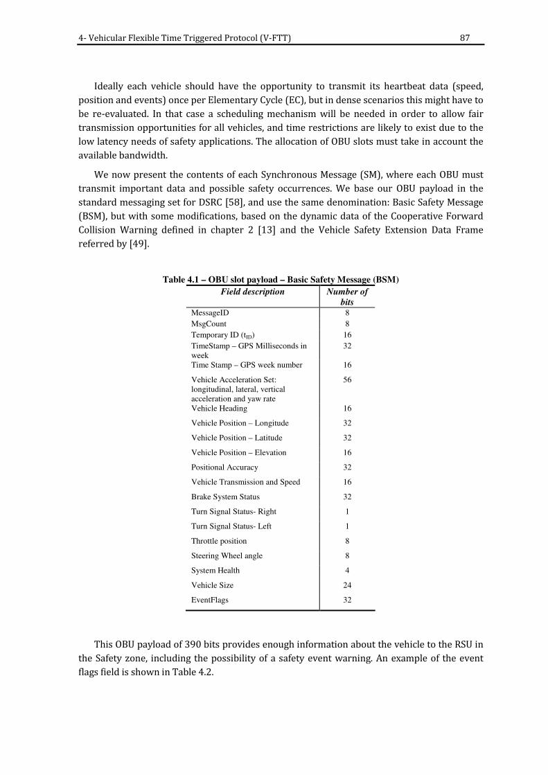
4- Vehicular Flexible Time Triggered Protocol (V-FTT) 87
Ideally each vehicle should have the opportunity to transmit its heartbeat data (speed,
position and events) once per Elementary Cycle (EC), but in dense scenarios this might have to
be re-evaluated. In that case a scheduling mechanism will be needed in order to allow fair
transmission opportunities for all vehicles, and time restrictions are likely to exist due to the
low latency needs of safety applications. The allocation of OBU slots must take in account the
available bandwidth.
We now present the contents of each Synchronous Message (SM), where each OBU must
transmit important data and possible safety occurrences. We base our OBU payload in the
standard messaging set for DSRC [58], and use the same denomination: Basic Safety Message
(BSM), but with some modifications, based on the dynamic data of the Cooperative Forward
Collision Warning defined in chapter 2 [13] and the Vehicle Safety Extension Data Frame
referred by [49].
Table 4.1 – OBU slot payload – Basic Safety Message (BSM)
Field description Number of
bits MessageID 8
MsgCount 8
Temporary ID (tID) 16
TimeStamp – GPS Milliseconds in
week
32
Time Stamp – GPS week number 16
Vehicle Acceleration Set:
longitudinal, lateral, vertical
acceleration and yaw rate
56
Vehicle Heading 16
Vehicle Position – Longitude 32
Vehicle Position – Latitude 32
Vehicle Position – Elevation 16
Positional Accuracy 32
Vehicle Transmission and Speed 16
Brake System Status 32
Turn Signal Status- Right 1
Turn Signal Status- Left 1
Throttle position 8
Steering Wheel angle 8
System Health 4
Vehicle Size 24
EventFlags 32
This OBU payload of 390 bits provides enough information about the vehicle to the RSU in
the Safety zone, including the possibility of a safety event warning. An example of the event
flags field is shown in Table 4.2.

88 4- Vehicular Flexible Time Triggered Protocol (V-FTT)
Table 4.2 - OBU Safety Events Flag Table
Field description Bit
Crash detection 0
Airbag deployment 1
Rollover occurrence 2
Vehicle malfunction 3
Road condition warning 4
...
Hard brake 32

4- Vehicular Flexible Time Triggered Protocol (V-FTT) 89
4.4. V-FTT Protocol Details
After giving a V-FTT protocol overview we will now formalize and develop some concepts
presented in the previous sub-section.
4.4.1 Trigger Message size
In the registration process, each OBU receives a temporary unique identifier (tID) to be
used during its travel through the Safety Zone (SZ). OBU MAC addresses could be used for the
same purpose but a shorter sized ID is more bandwidth efficient.
Number of bits of tID 8 to n
The number of bits of tID will depend on the absolute maximum number of vehicles that
can travel simultaneously in the Safety Zone, Nmax, which depends on the Safety Zone
characteristics (safety zone distance, number of lanes, etc.).
tID is then related to Nmax:
Number of bits of ( ) max2log Nt ID = (5)
Number of bits of ( ) max2log Nt ID =
In order to calculate Nmax we need to know the safety zone characteristics:
- lSz 0 to x (m) length of Safety Zone (m).
- nlanes [1, y] number of lanes for each travel path in motorway.
- Vlength average vehicle length (m).
- Trlength average Truck length (m).
- vspacing average spacing between two consecutive vehicles (m). The
spacing between vehicles is a function of vehicle speed and
traffic density.
- trperct [0, 1] percentage of trucks among the total number of vehicles.
- nSz [0, Nmax] number of vehicles in the safety zone, this number can vary
depending on traffic conditions and presence of trucks.
The number of vehicles in the safety zone is then shown in (6).

90 4- Vehicular Flexible Time Triggered Protocol (V-FTT)
( ) ( )( )( ) lanes
spacingperctlengthperctlength
S
S nvtrTrtrV
ln Z
Z×
+∗+−∗=
1
(6)
Nmax occurs when no trucks are present (trperct=0) and vspacing is minimum which simplifies
the previous equation into (7):
( ) lanes
spacinglength
S
S nvV
ln Z
Z×
+=
(7)
In the next figure a graphical representation is shown where the number of vehicles per
lane per km can be seen in function of the average spacing between vehicles.
average vehicle length=4,58m
0
10
20
30
40
50
60
70
80
10 15 20 25 30 35 40 45 50 55 60 65 70 75 80 85 90 95 100
spacing between vehicles (m)
nu
mb
er
of
veh
icle
s p
er
lan
e p
er
km
Fig. 4.10 - Number of vehicles per lane per km for an average vehicle length of 4,58m
Nmax is the maximum possible number of vehicles in the safety zone shown in (8):
)max(max ZSnN = (8)
In order to determine the size of a Trigger Message, we must determine the following:
- Number of bits of ( ) IWtSOW 2log= ; where the maximum length of the Infrastructure
Window is (SIW * (IFS + RSUslot)).

4- Vehicular Flexible Time Triggered Protocol (V-FTT) 91
- Number of bits of ( ) rID nRSU 2log= , where nr is the total number of RSUs deployed
in the Safety Zone.
The number of RSUs depends on the length of the Safety Zone (lSz) and the coverage range
of each RSU, Cr. This is shown in (9):
=
r
zr
C
lsn
(9)
- Number of bits of ( ) max2log NtID =
- Number of bits of ( ) SOWtrs 2log= , where SOW represents the maximum length of
the Synchronous OBU Window.
Our approach is to use a worst-case scenario where the maximum number of OBUs that
can appear in a TM is majored by the maximum number of vehicles served by an RSU, NVRSU. In
other words, ideally we would like an RSU to be able to include all vehicles in its coverage area
in its Trigger Message. Bandwidth limitations will most likely pose a limit for the number of
OBU slots in the OBU window and consequently limit the length of the TM.
If we name the maximum number of OBUs that can appear in a TM as NVTM we get in (10):
( ) ( ) ( ) ( ) )loglog(loglog 2max222 SOWNNnIWTM VTMr +×++= (10)
4.4.2 Synchronous OBU Window length (lsow)
After determining the size of TM we can also determine the length of the Synchronous OBU
window (lsow). We start by rewriting SOWslots in function of NVTM in (11):
SOWslots 0 to [(SIW * NVTM) – ((SIW -1)* NVint)] (11)
NVint (shown in (12))is the union of all sets of vehicles that can listen simultaneously to
more than one RSU in a set of adjacent RSUs.
U I
)1(
1
int 1
−
=+
=ST
ii
S
i
RSURSUV SSN (12)

92 4- Vehicular Flexible Time Triggered Protocol (V-FTT)
We conclude that the determination of NVTM is crucial for this protocol, since this will
influence the value of SOWslots and consequently the length of synchronous window, lsow,
shown in (13):
( )BSMIFSSOWl slotssow +×= (13)
We recall that each elementary cycle (EC) is divided into an Infrastructure Window (IW), a
Synchronous OBU Window (SOW) and an asynchronous free period (FP), in (14):
FPSOWIWE ++= (14)
The Free Period (FP) corresponds to the remaining time in the Elementary Cycle after the
Infrastructure Window and the OBU window. We must ensure that FP has a minimum
guaranteed size in order to allow non V-FTT communications to happen. FPmin is shown in
(15):
EFP × = σmin where σ є ]0,1[ (15)

4- Vehicular Flexible Time Triggered Protocol (V-FTT) 93
4.5. Conclusions
In this chapter we presented our protocol proposal, the Vehicular Flexible Time Triggered
Protocol (V-FTT), which is an adaptation of the FTT protocol to wireless vehicular
communications. Our approach is infrastructure based in order to guarantee road safety, data
privacy and safety events timeliness delivery in high vehicle density scenarios. We presented a
model where RSUs are deployed near motorway blackspots and are responsible for scheduling
OBU communications as well as broadcasting safety events. The initial OBU registration
process in the Safety Zone relies on the motorways geography: all motorways have access
ramps, therefore RSUs must be present in all entries and exits of the motorway, to keep track
of all vehicles [83]. Vehicles could use any non V-FTT MAC protocol to register themselves in
the Safety Zone using the Free Period. The Free Period can also be used for any V2V
communication if needed. We then detailed and formalized the V-FTT protocol, including the
definition of the Basic Safety Message (BSM) that every OBU must periodically send to the
RSUs.
Our definition of the V-FTT protocol has some issues that must be dealt with. For instance,
since we are using a wireless medium, there might be hidden terminal and exposed terminal
problems. Another important issue is how to ensure that OBU information is credible. Security
is very important, so RSUs must have a mechanism to check OBUs identity and cross-validate
the received data with other means (cameras, induction loops, even information from other
OBUs or RSUs). Data privacy is also very important, so all communications should be
encrypted, in order to protect information. OBU certificates management in order to guarantee
identity is out of the scope of our work but various works can be referenced on this subject
([87] to [90]). Note that security is important to the V-FTT protocol since cryptographic
operations need to be time bounded.
In the case an RSU does not have enough OBUs in its coverage area to fill the Trigger
Message, the space can be used by the RSUs to broadcast safety warnings (WM), so that the
medium keeps busy to OBUs that are non-compliant to the protocol. On the other hand, we
defined the maximum size of the SOW transmission window by considering a worst case
scenario where all OBUs in the area covered by the RSUs have the chance of transmitting in
one Elementary Cycle.
If an RSU is responsible for all OBUs in its coverage area, a handover process must be
thought, in order for an RSU to pass away information and responsibility of an OBU to the
following RSU in the motorway. The fact that vehicles follow a known path (motorway) and
that the RSUs know the speed and positions of their (under control) OBUs can be very useful
for the handover process [91].
To determine the RSU coverage area, a compromise must be made between coverage area
and terminal (vehicle) capacity. More power can augment the area but will most likely
increase channel congestion, while lower transmission power implies fading and loss of
packets, which is not acceptable for safety critical applications.

94 4- Vehicular Flexible Time Triggered Protocol (V-FTT)
In the next chapter we will propose an adaptation of the protocol to the
IEEE802.11p/WAVE standard and its European equivalent (ITS-G5). For that purpose we will
consider worst-case scenario definitions in order to see if the V-FTT protocol provides
bounded delay in communications.

95
5. Supporting V-FTT on top of vehicular
standards
After proposing the V-FTT protocol in the previous chapter we will now study how V-FTT
can be supported by the IEEE 802.11p/WAVE standard for vehicular communications, as well
as the ETSI-G5 standard. We will start by quantifying some of the protocol characteristics,
such as the RSU coverage area and overlapping range between RSUs. That will allow us finding
out the maximum number of vehicles that can be present in each RSU coverage. We define a
worst-case scenario where we attribute slots for all OBUs travelling in the zone covered by SIW
RSUs, where SIW is the maximum number of adjacent RSUs which transmissions can be heard
simultaneously by an OBU. Based on this worst case scenario we determine an upper limit to
the Synchronous OBU Window length. We also quantify value for the Infrastructure Window
length and discuss the importance of guaranteeing a minimum Free Period length in order to
allow non-enable vehicles and/or V2V communications to take place.
We then study the impact of this worst case scenario on the packet loss probability due to
the expiry of transmission chance before the maximum tolerable delay for an application. A
temporal analysis of the protocol follows, where we determine the worst case delay time that
can occur between an event detection and the instant of time a vehicle in the Safety Zone is
effectively warned. We look into a real application scenario: the A5 motorway, one of the most
busiest and dangerous motorways in Portugal. We conclude that V-FTT is feasible in this
realistic scenario. We end the chapter by suggesting a possible scheduling mechanism based
on the creation of an accident risk table, which depends on the relative speed of a vehicle to
the average traffic speed.
5.1. V-FTT technical solutions using IEEE 802.11p/WAVE and ITS G-5
In this subsection we will try to quantify some of the protocol characteristics presented in
chapter 5. In the IEEE802.11p/WAVE standard all vehicles must tune the Control Channel
(CCH) during all Sync Intervals, so this is the appropriate place for all short safety messages to
be sent. The size of the CCH interval is 50ms by default but it can have a maximum of 100ms, if
we consider that we are working in continuous mode [51]. In the European standard ITS G-5
[92] all vehicles shall have two radio devices which mean they will preferably work in
continuous mode.
Fig. 5.1 –IEEE 802.11p/WAVE synchronization interval (adapted from [93])

96 5- Supporting V-FTT protocol on top of vehicular standards
The CCH interval will then be the equivalent to our elementary cycle (EC):
- During the Infrastructure Window (IW), RSUs broadcast the scheduling table along
with the safety messages in the beginning of the CCH interval, immediately after a
Guard Interval (GI). To avoid contention with other devices, no IFS will be used in this
case.
- OBUs have the opportunity to transmit important data to the RSUs during the
Synchronous OBU Window (SOW).
Our approach assumes that:
- The IW and SOW are protected against any other type of communications. To ensure
that there is no contention during those windows, RSUs and enabled OBUs will violate
the minimum IFS of the standard. Vehicles that are not able to register themselves in
the Safety Zone will only be able to transmit in the Free Period.
- All OBUs can hear the RSUs transmissions (no hidden node problem).
- The remaining CCH interval (after IW) for OBU transmission of safety messages should
not be fully used, since the CCH can also be used by other entities for Wave Service
Announcements (WSAs). A “free period” must be preserved so that OBU and/or RSUs
can freely transmit WSAs in the CCH using the regular 802.11p MAC. Moreover, in
certain cases of dense traffic, one CCH interval may not be enough to guarantee that
every OBU has the opportunity to transmit its data. This means that the maximum size
of IW and SOW must be carefully chosen. A scheduling mechanism may also be
introduced in order to guarantee delivering of high-priority OBU safety
communications.
- The next figure shows how the V-FTT protocol adapts to the WAVE Sync interval.
Synchronous OBU Window
(SOW)
. . .
CCH Interval
Free period (FP)
SM
1
SM
2
SM
3
SM
n
G.I.
t
SCH Interval
G.I.
G.I.
. . . . . .
. . .
CCH Interval
1 2
Infrastructure Window
(IW)
TM
1
WM
1
TM
2
WM
2
. . .
TM
IW
TM
2
WM
IW
SIW
Fig. 5.2 - V-FTT protocol on top of IEEE802.11p/WAVE (normal mode)
A relevant assumption is that V-FTT enabled OBUs will share the medium with non V-FTT
enabled OBUs. This implies that a non-compliant OBU could interfere with V-FTT TDMA

5- Supporting V-FTT protocol on top of vehicular standards 97
scheduling, possibly compromising its timeliness, if V-FTT’ protection mechanisms are not put
in place. Providing such protection mechanisms is an essential aspect to a V-FTT successful
implementation. V-FTT’ protection mechanisms should enforce the periodicity of the trigger
message transmission with low jitter, i.e., OBUs must not transmit when RSUs are close to
begin the trigger message transmission. They should also guarantee that non V-FTT compliant
OBU could only transmit during the Free Period. For that purpose, any non-compliant OBU
must see the medium as busy in order not to contend for the medium.
As was seen in chapter 3, the carrier sense mechanism of IEEE 802.11p evaluates if the
medium is free before starting a transmission. If the medium is not free, the message
transmission is postponed for a later time according to the backoff algorithm. Otherwise, the
message is transmitted immediately. A drastic approach can be used in order to gain access to
the medium. A modified station having the ability to transmit a long enough noise sequence
(black-burst), without performing the carrier sense procedure, will eventually force the
remaining stations to evaluate the channel as occupied. Therefore, if the modified station is
able to transmit immediately after the end of the noise sequence, violating the Inter-Frame
Space (IFS), it gains access to the shared medium. This technique, called bandjacking [94], is a
medium access control scheme that provides determinism, even in the presence of other
contention-based technologies, as long as the channel capture is performed during the
shortest IFS. In this sense, bandjacking enables a station to “forcefully gain access” to a
communication channel. There are two types of bandjacking:
- Destructive bandjacking: Transmit the black-burst, ignoring all the information that
exists in the medium, with a length equal to the longest message available. This
possibility would invalidate any message being transmitted at that time and wastes
bandwidth, since during the black-burst no useful information can be transmitted.
- Protective bandjacking: a V-FTT enabled station can eavesdrop the medium and start
transmitting (valid messages) as it becomes free to ensure that at the predefined
instant the medium access is granted. This option is more conservative since it does to
not invalidate on going transmissions. However, it is necessary to guarantee that the
hardware commutation time between Receiver to Transmitter mode is less than the
smallest inter-frame space (IFS).
5.1.1 RSU coverage area
Since some characteristics of the protocol depend on others, we will start by defining the
coverage radius of a RSU (Cr), which influences the maximum number of vehicles served by an
RSU (NVRSU), which in turn influences the maximum sizes of the Infrastructure Window and the
Synchronous OBU window.
In order to define each RSU coverage area a compromise must be made between coverage
area and terminal (vehicle) capacity. More power can augment the area which can lead to but
will most likely increase co-channel interference, while lower transmission power implies
fading and loss of packets, which is not acceptable for safety critical applications.

98 5- Supporting V-FTT protocol on top of vehicular standards
It was shown in chapter 3 that a WAVE device was designed for maximum coverage range
of 1000m ([95] and [42]), but tests proved that 750m is a more realistic range [96]. We will
therefore assume Cr to have a value of 750m:
Cr = 750m
Several studies ([97] to [99]) defend that in WLANs the overlap of coverage area between
Access Points should be between 15% and 25% in order to ease the handover process. Since
vehicular networks deal with high speed travelling mobile stations (vehicles) we will assume
that RSU coverage will have 25% of overlapping. This means that the overlapping range Or is:
Or = Cr x 0,25 = 187,5m
The spacing between RSUs (Sr ) will then be equal to (16):
rrr OCS −×= )2( (16)
Sr= (2 x 750) – 187,5 = 1312,5m
Fig. 5.3 - RSU coverage
If we take in account that motorways usually do not have curves with angles larger than
90º, considering an overlapping range of RSU of 25% and assuming a linear distribution of
RSUs, we conclude that an OBU can only hear a maximum of 2 RSU transmissions
simultaneously. This means that in our case SIW = 2 (refer to Fig. 5.4).
In chapter 5 a tID size of 16 bit was defined. This allows the identification of 65536 distinct
vehicles. Using that value in equation (5) from the previous chapter and assuming that tID can
be reused whenever a vehicle exits the Safety Zone, we find that this tID size allows to define a
Safety Zone such as:
- a motorway with a maximum of 95km with 5 lanes per travel path.
- a motorway with a maximum of 119km with 4 lanes per travel path.
We can re-use equation (7) from chapter 5 to calculate NVRSU in (17):
Motorway RSU RSU coverage

5- Supporting V-FTT protocol on top of vehicular standards 99
( ) lanes
spacinglength
r
VRSU nvV
CN ×
+
×=
2
(17)
RSU3
RSU2
RSU1
Fig. 5.4 - Sketch of a motorway curve and RSUs coverage areas (25% overlap)
Considering an average vehicle length of 4,58m [100] we obtain in Table 5.1 several values
for NVRSU, where vspacing is 10 m for traffic jam and 30 m for normal traffic [101].
Table 5.1 – NVRSU- Maximum number of vehicles covered by each RSU (Cr= 750m)
NVRSU NORMAL TRAFFIC TRAFFIC JAM
1 lane 44 103
2 lanes 87 206
3 lanes 130 309
4 lanes 174 412
5 lanes 217 507
In the following sub-sections we will determine the maximum sizes for SOW and IW.
5.1.2 Synchronous OBU Window length
In this sub-section we will determine the length of the Synchronous OBU Window (SOW)
for use with the IEEE802.11p/WAVE standard.
In the previous chapter, we assumed a worst case scenario of attributing slots for all OBUs
travelling in the zone covered by SIW RSUs. We defined that the length of SOW is
( )BSMIFSSOWl slotssow +×=
We also determined in chapter 5 that the Basic Safety Message (BSM) has a size of 390 bits.
The IFS value depends on the communication standard used. Since WAVE is based on the
802.11 standard, the minimum inter frame space is the Short Inter Frame Space (SIFS), with a

100 5- Supporting V-FTT protocol on top of vehicular standards
value of 32μs for a 10MHz channel [52]. Therefore the time needed to transmit a BSM of 390
bit is shown in the next table, according to the bit rate used.
Table 5.2 – Transmission duration of a BSM in an OFDM 10 MHz channel
BIT RATE BSM BSM+SIFS
3Mbps 288µs 320µs
6Mbps 164µs 196µs
12Mbps 106µs 138µs
It is important to find out the number of slots available for OBU transmission in the
Synchronous OBU Window (SOWslots). In chapter 5 we saw that SOWslots varies from 0 to [(SIW *
NVRSU) – ((SIW -1)* NVint)]. We already determined the values of NVRSU and SIW, we need to
determine the value of NVint, which was presented in chapter 5 as:
U I
)1(
1
int 1
−
=+
=IW
ii
S
i
RSURSUV SSN
In other words NVint is the number of vehicles that can fit in the overlapping range Or. In the
Table 5.3 the maximum values of SOWslots are shown:
Table 5.3 – Maximum size of SOWslots for a RSU coverage of 750m with 25% of overlapping range
SOWslots NORMAL TRAFFIC TRAFFIC JAM
1 lane 76 180
2 lanes 152 360
3 lanes 228 540
4 lanes 304 720
5 lanes 380 900
We can now compute the time needed for transmission of a maximum size SOW, by
multiplying the values from Table 5.3 with Table 5.2. The results are shown in Fig. 5.5 and Fig.
5.6.
SOW length (ms)
0 10 20 30 40 50 60 70
3Mbps
6Mbps
12Mbps
Da
ta R
ate
t (ms)
normal traffic Traffic Jam
Fig. 5.5 - SOW length per lane (ms)

5- Supporting V-FTT protocol on top of vehicular standards 101
t
SCH Interval
G.I.
G.I.
. . . . . .
. . .
CCH IntervalCCH Interval. . .
SCH Interval. . .
G.I.
G.I.
G.I.
CCH Interval. . .
Continuous CCH Interval (100ms)
Max SOW size @ 3Mbps: 97ms
@ 6Mbps: 59ms
12Mbps: 42ms
Fig. 5.6 - Maximum SOW length for normal traffic (nlanes=4)
Since the size of a CCH interval for the WAVE protocol varies from 50ms to 100ms, for the
worst case scenario it is not possible to allow all OBUs to update their status in every EC for
the case of a large motorway and a traffic jam scenario. The CCH interval has a size that will
not be larger than 100ms (it is 50ms by default) so it is easy to roughly determine the
maximum number of vehicles served per CCH interval. The maximum available transmission
time for the SOW window in each CCH interval will be 100ms for the continuous mode or
50ms subtracted by the Guard Interval (4ms) for the normal mode:
Maximum length of SOW = 100ms (continuous mode) or 50ms– GI = 46ms (normal mode)
The SOW length will in fact be smaller than that, since we must also guarantee
transmission time for the IW and reserve a free period for non-enabled OBUs. For now, we will
simply accept the above values as a maximum reference value for the length of SOW obtaining
the following upper bound for the number of SOWslots (dividing by the values in Table 5.2):
Table 5.4 - Maximum number of SOWslots per CCH interval (upper bound)
BIT RATE CONTINUOUS
MODE
NORMAL
MODE
3Mbps 312 143
6Mbps 510 234
12Mbps 724 333
By comparing Table 5.4 with Table 5.3, we conclude that the usual bit rates used for safety
services, 6 and 12Mbps [92], are not enough to serve all vehicles in one full Elementary Cycle,
which means that some sort of scheduling mechanism will be needed. We will refine the SOW
length later on.

102 5- Supporting V-FTT protocol on top of vehicular standards
5.1.3 Infrastructure Window length
After determining the SOW length we will now quantify the Infrastructure Window (IW)
length. The IW is used by each RSU to send the trigger message (TM) along with possible
warning messages (WM). Those messages will be included in each RSU transmission slot. We
recall that this RSU slot has a fixed size. We also concluded above that SIW is equal to 2, thus
meaning that IW will have a duration equal to (18):
( )IFSRSUSIW slotIW +×= (18)
In order to compute the size of RSUslot we will analyse the length of a TM and a WM.
We recall that a Trigger Message (TM) starts with an RSUID, followed by a parameter (tSOW)
that indicates how many μs separate the beginning of this TM from the beginning of the SOW,
and then a series of temporary OBU identifiers (tID) and the respective transmission slot (trs).
. . .tSOW
tID207
tID007
tID622RSU
IDtr
S22tr
S87tr
S33
Fig. 5.7 - Trigger Message frame.
First we need to determine how many bits we need for RSU identification. We will consider
8 bit as a starting value for RSUID, which is enough to identify 256 distinct RSUs, and allows to
cover 168km of motorway for both travel sides, considering our Cr determined earlier.
In order to define the size of the Trigger Message frame, it is important to quantify the
possible maximum value for tsow. The minimum value occurs in the last RSUslot and
corresponds to the duration of the RSUslot. The maximum value occurs in the first RSUslot and
corresponds to
Maximum value for tsow = IW-IFS
We have a circular reference because it seems the TM size depends on the TM itself, but it
is possible to work around this if we consider the absurd case where the IW occupies the
maximum possible available length in a CCH interval in WAVE, i.e., 100ms. Since tsow is
expressed in μs it means we need 17 bits to properly define tsow. We will later refine this value.
In the previous chapter we defined that tID would have 16 bit. As for the number of bits we
need to define the OBU transmission slot, we recall that in the previous sub-section we
determined the maximum number of OBU transmission slots in the SOW (SOWslots) (refer to
Table 5.4 and Table 5.3). The worst-case scenario is when we need to code 725 different OBU
transmission slots. This means we need at least 10 bit for trs.

5- Supporting V-FTT protocol on top of vehicular standards 103
In resume, we determined that:
- RSUID has a length of 8 bits;
- tsow has a maximum length of 17 bits (to be refined later);
- each tID has a length of 16 bits;
- each trs has a length of 10 bits.
In the worst case scenario of a traffic jam, if we need to allow transmission slots for all
OBUs, a TM would occupy:
8 + 17 + 724* (16+10) = 18849 bits
This is the case for the higher bit rate. For 3Mbps, 6Mbps and 12Mbps we determined
(Table 5.4) that the number of SOWslots will never exceed 312 and 510 vehicles, respectively.
The TM may have different sizes according to the transmission rate, as is shown in Table 5.5.
Table 5.5 – Upper bound size of a Trigger Message (TM) in bits
BIT RATE CONTINUOUS MODE NORMAL MODE
3Mbps 8137bit 3743bit
6Mbps 13285bit 6109bit
12Mbps 19573bit 8683bit
In Table 5.6 we show the time it takes to transmit a maximum size TM using WAVE, for
both traffic jam and normal traffic cases. In WAVE we can use bit rates ranging from 3Mbps to
12Mbps. The time needed to transmit a TM is shown in the next table, based on the IEEE
802.11p/WAVE MAC standard, where we add the header and frame check sequence to the
message size, and then calculate the padding bits necessary according to the bit rate used.
Table 5.6 – Upper bound transmission duration of a TM in an OFDM 10 MHz channel
BIT RATE CONTINUOUS
MODE
NORMAL
MODE
3Mbps 2,86ms 1,40ms
6Mbps 2,32ms 1,12ms
12Mbps 1,64ms 0,79ms
We shall now determine the average length of a WM. In chapter 2 we found out that
several type of safety events can occur. For example, the Curve Speed Warning event needs a
235 bit payload. A more common safety message was defined in chapter 5, including the
following fields:
- eventID.
- sourceID.
- transmitterID.
- location.
- additional info.

104 5- Supporting V-FTT protocol on top of vehicular standards
16 bits are enough for the eventID field, sourceID and transmitterID are RSUs, so 8 bits for
each of them will suffice. For the location we will need 112 bits for the GPS coordinates. This
means the minimum size of a WM is 144 bits. According to this, Table 5.7 shows the time
needed to transmit a minimum WM and a curve speed warning message using
IEEE802.11p/WAVE.
Table 5.7 - Transmission duration of Warning Messages in an OFDM 10 MHz channel
BIT RATE BASIC
WARNING
MESSAGE
CURVE SPEED
WARNING
MESSAGE
3Mbps 200µs 232µs
6Mbps 124µs 140µs
12Mbps 82µs 90µs
In order to quantify the size of an RSU slot, we need to find out how many Warning
Messages we need to transmit per EC or CCH interval. This is not the same as asking how many
simultaneous safety events can occur in a RSU coverage, since RSUs might want to broadcast
events that occur outside its coverage area, e.g., an accident that occurs ahead in the path of
travel. We will impose a limit of 10 WMs per RSU Slot. Further studies may revise this number.
If we consider the worst-case scenario of having 10 WMs to be broadcast in each RSU slot,
then each RSU slot needs to have a maximum size of TM+10*WM, which is summarized in
Table 5.8:
Table 5.8 – Upper bound transmission duration of a RSU slot using WAVE (SIW=2)
BIT RATE CONTINUOUS
MODE
NORMAL
MODE
3Mbps 5,18ms 3,72ms
6Mbps 3,72ms 2,52ms
12Mbps 2,54ms 1,69ms
Based on equation (18) we can determine the worst-case maximum size of IW (Table 5.9).
Table 5.9 – Upper bound transmission duration of IW using WAVE
BIT RATE CONTINUOUS
MODE
NORMAL
MODE
3Mbps 10,42ms 7,50ms
6Mbps 7,50ms 5,10ms
12Mbps 5,14ms 3,44ms
In the previous sub-section we concluded that the SOW could not have the size we
determined (refer to Fig. 5.6) since it exceeds the CCH interval. We determined a limit for the
SOW maximum size based on the full length of CCH interval, and consequently a new upper
bound for the IW (since the SOW size influences the TM size and the RSU slot).

5- Supporting V-FTT protocol on top of vehicular standards 105
In the beginning of sub-section 5.1.3 we found we would need 17 bits for tsow and left this
value to be later refined. After determining a more realistic upper bound value for the
Infrastructure Window we can safely reduce the size of tsow from 17 to 14 bits.
This means that TM will have its upper bound size reduced by 3 bits. However, after using
these new values we found out that these 3 bits do not make any difference in the
transmission duration of a TM due to the usage of pad bits in OFDM. We will however update
the TM equation so we can use it when further calculations are needed:
8 + 14 + SOWslots * (17+10)
5.1.4 Free period (FP) length
In this sub-section we will discuss the length of the free period. This length will be variable,
since it depends on the number of vehicles that are present in the area covered by the RSUs.
There is the need of defining a minimum free period length, in order to guarantee
transmission opportunities for non-enabled vehicles and for Wave Service Announcements or
non-safety applications in (19):
( )lCCHIntervaFP × )= σ(min , where 0 < σ < 1 (19)
If we consider σ equal to 10%, it means we will reserve 5 to 10ms to Wave Service
Announcements or other communications. Taking into account the example of a WSA given in
[102] we calculated the duration of a transmission of a regular WSA in the following table. This
allows for 16 to 32 WSAs to be transmitted in one CCH interval, which is acceptable for non-
urban scenarios.
Table 5.10 – Transmission duration of a regular Wave Service Announcement
BIT RATE NORMAL
TRAFFIC
3Mbps 304 µs
6Mbps 172 µs
12Mbps 106 µs
In some particular cases, the FP length can be reduced to zero, if emergency
communications need to use the whole Elementary Cycle.

106 5- Supporting V-FTT protocol on top of vehicular standards
5.1.5 SOW length adjustments
Considering FPmin to have a value of 10% the CCH interval we will recalculate the SOW
maximum size and TM sizes, shown in (20):
SOW = E-GI-IW-FP (GI=0 in continuous mode) (20)
Because of the relationship between TM and SOWslots we start by recalculating the length of
SOW and its respective SOW slots assuming the initial IW length. Since the number of SOWslots
is slightly reduced so does the TM length and the IW length. By reintroducing this new IW
length we obtain a more approximate SOW length and repeat the whole process until the
values are close enough to the previous iteration. In the end, we obtain the following tables for
TM length, IW and SOW length.
Table 5.11 – Transmission duration of a TM in an OFDM 10 MHz channel
BIT RATE FPmin=10% of CCH interval NO FREE PERIOD
CONTINUOUS
MODE
NORMAL
MODE
CONTINUOUS
MODE
NORMAL
MODE
3Mbps 2,34ms 1,08ms 2,60ms 1,21ms
6Mbps 1,94ms 0,91ms 2,16ms 1,01ms
12Mbps 1,41ms 0,67ms 1,56ms 0,75ms
Table 5.12 – Transmission duration of IW using WAVE
BIT RATE FPmin=10% of CCH interval NO FREE PERIOD
CONTINUOUS
MODE
NORMAL
MODE
CONTINUOUS
MODE
NORMAL
MODE
3Mbps 9,39ms 6,86ms 9,90ms 7,12ms
6Mbps 6,74ms 4,68ms 7,18ms 4,89ms
12Mbps 4,68ms 3,20ms 4,99ms 3,36ms
Table 5.13 – Time left for SOW transmission in an OFDM 10 MHz channel
BIT RATE FPmin=10% of CCH interval NO FREE PERIOD
CONTINUOUS
MODE
NORMAL
MODE
CONTINUOUS
MODE
NORMAL
MODE
3Mbps 80,60ms 34,13ms 90,10ms 38,88ms
6Mbps 83,26ms 36,32ms 92,82ms 41,11ms
12Mbps 85,32ms 37,80ms 95,01ms 42,64ms

5- Supporting V-FTT protocol on top of vehicular standards 107
Table 5.14 - Number of SOWslots per CCH interval
BIT RATE FPmin=10% of CCH interval NO FREE PERIOD
CONTINUOUS
MODE
NORMAL
MODE
CONTINUOUS
MODE
NORMAL
MODE
3Mbps 251 106 281 121
6Mbps 424 185 473 209
12Mbps 618 273 688 309
By comparing the results of Table 5.1 and Table 5.14 we can see that in some exceptional
cases it might be worth using the whole CCH interval for the V-FTT protocol, not allowing the
existence of a free period (for a short amount of time) in order to accommodate more vehicles
in the SOW. For larger motorways we reinforce the need of a scheduling mechanism to fairly
allocate OBUs to SOW slots and also to allocate RSU slot time between trigger messages and
warning messages.

108 5- Supporting V-FTT protocol on top of vehicular standards
5.2. Analysis of impact of worst case scenario
Using a similar method to [26] we will now study the impact of the V-FTT protocol,
particularly what happens due to the expiry of transmission chance before the maximum
tolerable delay for an application. For this analysis, we are excluding packet loss probability
derived from transmission losses or other factor such as packet collisions.
Consider that the number of OBUs in SIW RSUs coverage is nv, where:
nv = 1 to N
The ratio of denied transmissions (tdn) due the expiry of CCH interval can then be
determined by equation (21):
0=dnt if nv ≤ SOWslots
−=
N
SOWt slots
dn 1 if nv >SOWslots
(21)
Whenever the number of vehicles fits in the existing Synchronous OBU Window there will
be no denied transmissions since all OBUs can transmit within a CCH interval. If the number of
vehicles exceeds the number of slots in SOW then the probability of not having a transmission
opportunity in the current CCH interval will be higher.
Based on Table 5.14 and the previous equation we can derive the results for two typical
vehicular safety applications (refer to chapter 2): the Emergency Electronic Brake Light
(EEBL)(refer to Fig. 5.8) with a maximum latency of 100ms and the Post crash warning (refer
to Fig. 5.9)with a maximum latency of 500ms.

5- Supporting V-FTT protocol on top of vehicular standards 109
Ratio of denied transmissions due to expiry of CCH Interval (max.latency 100ms)
0
0,1
0,2
0,3
0,4
0,5
0,6
0,7
0,8
0,9
1
1 50 100 150 200 250 300 350 400 450 500 550 600 650 700 750 800 850 900 950 1000
Number of simultaneous OBUs in RSUs coverage range (SIW=2)
Pa
ck
et
loss
pro
bab
ilit
y
3Mbps 6Mbps 12Mbps 3Mbps (noFP) 6Mbps (noFP) 12Mbps (noFP)
Fig. 5.8 - Ratio of denied tranmissions due to CCH Interval expiry for EEBL application
Results show that the ratio of denied tranmissions due to the expiry of transmission
chance is acceptable when using the higher transmission bit rate for the safety applications
with tighter latency constraints. An obvious conclusion is that if we choose not to use the Free
Period for non-enabled vehicles this ratio decreases since we are able to accommodate more
OBUs in the SOW. For the safety applications with higher latency the V-FTT protocol is
perfectly suitable even with lower bit rates. In the next sub-sections we will investigate the
worst-case delay scenario for the V-FTT protocol applied to WAVE.
Ratio of denied transmissions due to expiry of CCH Interval (max. latency 500ms)
0
0,1
0,2
0,3
0,4
0,5
0,6
0,7
0,8
0,9
1
110
020
030
040
050
060
070
080
090
010
0011
0012
0013
0014
0015
0016
0017
0018
0019
0020
0021
0022
0023
0024
0025
0026
0027
0028
0029
0030
00
Number of simultaneous OBUs in RSUs coverage range (SIW=2)
Pac
ke
t lo
ss
pro
bab
ilit
y
3Mbps 6Mbps 12Mbps 3Mbps (noFP) 6Mbps (noFP) 12Mbps (noFP)
Fig. 5.9 - Ratio of denied transmissions due to CCH Interval expiry for Post-Crash Warning
application

110 5- Supporting V-FTT protocol on top of vehicular standards
5.3. V-FTT Protocol worst case delay analysis
We will now analyse our proposed protocol in terms of the time that passes between the
instant of occurrence of an event and the instant a vehicle is warned of the event, i.e., the end-
to-end delay.
Consider that within the set of vehicles travelling in the safety zone, a vehicle detects a
safety event (e.g. accident, problem with vehicle). We will determine the worst case in terms of
time occurred between an event detection and the instant of time the last vehicle in the Safety
Zone is warned by the RSUs. We start by analysing the times involved:
tV2I – period of time that occurs since the detection of an event by an OBU until the event
transmission to an RSU.
tvalid – period of time that occurs since the RSU is effectively warned until the RSU
considers the event is valid.
tschedule – period of time that occurs since the RSU validates an event and schedules the TM
and WM according to the event.
tI2V – period of time that occurs since a TM and/or WM is scheduled by an RSU until the
transmission of a warning message by the RSUs.
To simplify our reasoning we’ll consider for now that transmissions of WM are always
received successfully by all OBUs in the coverage area.
5.3.1 Uplink time (tV2I)
The worst-case for tV2I occurs when an OBU detects the event just after it transmitted its
Basic Safety Message (BSM). This means the OBU will have to wait for its next allocation slot to
transmit. We shall call this OBU the emitter OBU just for reasoning purposes. Consider the
simplest fair scheduling scheme where all OBUs have one transmission opportunity and will
have the second transmission opportunity after all the others had their first. Then the worst
case scenario occurs when the emitter OBU is only allowed to transmit after all the remaining
OBUs in the same coverage area of the Safety Zone have had their chance to transmit. How
many OBUs are involved? The worst-case is when the Safety Zone is completely filled with
vehicles. Those numbers were presented in Table 5.3 (page 100). The maximum number of
OBUs travelling in the Safety Zone depends on the motorway topology, i.e., on the number of
existing lanes per travel path. This means the maximum waiting time for the emitter OBU will
be variable. Consider that the maximum number of OBUs present in the same coverage area
than the emitter OBU is named MOBU. The value of MOBU is in fact the value of Table 5.3
subtracted by one, which is the emitting OBU. Those numbers are shown in Table 5.15.

5- Supporting V-FTT protocol on top of vehicular standards 111
Table 5.15 - Maximum number of OBUs in the same coverage area than MOBU (SIW=2, Cr=750m)
Maximum number of
vehicles (SIW=2)
NORMAL TRAFFIC TRAFFIC JAM
1 lane 75 179
2 lanes 151 359
3 lanes 227 539
4 lanes 303 719
5 lanes 379 899
Since for each Elementary Cycle there is a limit of maximum SOWslots available, the emitter
OBU will have to wait for some ECs until it has the chance to transmit. We shall call it wEC
(number of waiting Elementary cycles). wEC is shown in (22), and is equal to the floor of the
division of MOBU by the maximum number of SOWslots available (refer to Table 5.14).
=
slots
OBUEC
SOW
Mw
(22)
SOW
. . .
Elementary Cycle (EC[i])
FP
t
SM
1
SM
2
SM
3
SM
n
IW
OBU detects event
. . .
. . .
Elementary Cycle (EC[k])
FP
SM
1
SM
2
SM
3
IW
OBU transmits
event
SOW
w
EC
. . . . . .
Fig. 5.10 - Worst case OBU transmission instant (tV2I)
If scheduling is made per elementary cycle, the only guarantee the emitter OBU will have is
that it will be scheduled in the SOW after wEC. The worst case happens when it is scheduled in
the last slot and is shown in (23):
( ) EwSOWt ECIV ×++= 12 (23)

112 5- Supporting V-FTT protocol on top of vehicular standards
Fig. 5.11 and Fig. 5.12 show the results of our calculations for two scenarios, normal traffic
and traffic jam, considering that the free period has no minimum length, since we found that
this is the worst-case scenario. The EC can have a duration of 50ms (N-normal mode) or
100ms (C-continuous mode).
tV2I (normal traffic scenario)
0
50
100
150
200
250
300
350
1 lane 2 lanes 4 lanes
# of lanes per travel path
t v2
I(ms)
N 3Mbps N 6Mbps N 12Mbps C 3Mbps C 6Mbps C 12Mbps
Fig. 5.11 – Uplink time (tV2I) worst case for normal traffic scenario (FP=0%, Cr=750m)
tV2I (traffic jam scenario)
0
100
200
300
400
500
600
700
800
1 lane 2 lanes 4 lanes
# of lanes per travel path
t V2
I (m
s)
N 3Mbps N 6Mbps N 12Mbps C 3Mbps C 6Mbps C 12Mbps
Fig. 5.12 - Uplink time (tV2I) worst case for traffic jam scenario (FP=0%, Cr=750m)
As the number of lanes increases, so does the maximum possible number of vehicles,
which leads to an increase of uplink time. It is interesting to find out that the continuous mode

5- Supporting V-FTT protocol on top of vehicular standards 113
of operation leads to higher uplink time for the case of smaller motorways (two lanes per
travel path or less). This is due to the fact that all vehicles transmissions can be accommodated
in one SOW, and OBUs have to wait a full EC to transmit. It can also be seen that 3Mbps is
insufficient for large motorways and dense scenarios, hence the ITS-G5 determination of using
6Mbps and 12Mbps for safety applications [92]. These results also reinforce the fact that a
scheduling mechanism is needed, since straightforward fair slot allocation can lead to
intolerable values for some safety applications.
5.3.2 Validation time (tvalid) and Scheduling time (tschedule)
The validation time is the period of time that occurs since the RSU has received the event
warning, until it considers the event is valid. The validation time depends on several factors,
since the RSU must compare the information received from several sources in order to
validate the event. The sources were already mentioned in chapter 5: induction sensors,
cameras, radar or even other OBU messages.
The scheduling time is the period of time that occurs since the RSU validates an event and
schedules the TM and WM according to the event.
Both times are usually combined. The worst case happens when the RSU receives the
information in the last slot of SOW. For the case the RSU has the first RSU slot, it means that
the RSU must perform the validation, schedule and build its TM and WM during the Guard
Interval, i.e., in less than 4ms. We will consider that the RSUs have sufficient computation
power to achieve this goal.

114 5- Supporting V-FTT protocol on top of vehicular standards
5.3.3 Downlink time (tI2V)
The worst case downlink time happens when the RSU receives the information from OBUs
in the first SOW slot and it will have to wait until the next Elementary Cycle (EC) for the chance
to transmit (Fig. 5.13).
SOW
. . .
Elementary Cycle (EC[i])
t
SM
1
SM
2
SM
3
SM
n
IW
RSU receives
event information
. . .
Elementary Cycle (EC[i+1])
FP
SM
1
SM
2
SM
3
IW
RSU transmits
information in last
RSU slot
SOW
. . . . . .
FP
Fig. 5.13 - Worst case of tI2V
In conclusion, the validation time and scheduling time is included in tI2V.
We saw earlier that the SOW duration is variable and has a maximum value whenever
FP=0. This means the worst-case of tI2V is in fact equivalent of a full duration of an Elementary
Cycle (E) subtracted by the duration of a TM (refer to (24)).
)(2 TMEt VI −= (24)
The results are summarized in Table 5.16.
Table 5.16 – Worst case value of validation, schedule and downlink time (SIW=2, Cr=750m)
BIT RATE NORMAL MODE CONTINUOUS MODE
3Mbps 48,79ms 97,40ms
6Mbps 48,99ms 97,84ms
12Mbps 49,25ms 98,44ms

5- Supporting V-FTT protocol on top of vehicular standards 115
5.3.4 Worst case time between event detection and OBU warning (tworst)
After determining all the times involved, we can now determine the worst case in terms of
time occurred between an event detection and the instant of time the last vehicle in the Safety
Zone is warned by the RSUs. We shall refer it as tworst and is determined by (25):
( ) ( ) EwTMSOWTMEEwSOWttt ECECVIIVworst ×++−=−+×++=+= 21)( 22 (25)
There is a strong correlation between the duration of the Elementary Cycle (E) and the
value of tworst. At a first glance we could think that reducing E we would reduce tworst but we
must keep in mind that wEC depends on the number of maximum SOWslots per EC, which in turn
depends on E, so reducing E would also reduce SOWslots and increase wEC. The results are
summarized in Table 5.17 and Table 5.18.
Table 5.17 - Worst case warning time for normal traffic (no FP)
NORMAL
TRAFFIC 1 LANE 2 LANES 4 LANES
BIT RATE CONTINUOUS
MODE
NORMAL
MODE
CONTINUOUS
MODE
NORMAL
MODE
CONTINUOUS
MODE
NORMAL
MODE
3Mbps 287,50ms 137,67ms 287,50ms 187,67ms 387,50ms 237,67ms
6Mbps 290,66ms 140,10ms 290,66ms 140,10ms 290,66ms 190,10ms
12Mbps 293,45ms 141,89ms 293,45ms 141,89ms 293,45ms 141,89ms
Worst case of event warning time (normal traffic scenario)
0
50
100
150
200
250
300
350
400
450
1 lane 2 lanes 4 lanes
# of lanes per travel path
t wo
rst (m
s)
N 3Mbps N 6Mbps N 12Mbps C 3Mbps C 6Mbps C 12Mbps
Fig. 5.14 - Worst case of event warning time per number of lanes (normal traffic)

116 5- Supporting V-FTT protocol on top of vehicular standards
Table 5.18 - Worst case warning time for traffic jam (no FP)
TRAFFIC
JAM 1 LANE 2 LANES 4 LANES
BIT RATE CONTINUOUS
MODE
NORMAL
MODE
CONTINUOUS
MODE
NORMAL
MODE
CONTINUOUS
MODE
NORMAL
MODE
3Mbps 287,50ms 187,67ms 387,50ms 237,67ms 478,00ms 729,39ms
6Mbps 290,66ms 140,10ms 290,66ms 190,10ms 381,10ms 532,25ms
12Mbps 293,45ms 141,89ms 293,45ms 191,89ms 383,76ms 434,57ms
Worst case of event warning time (Traffic jam scenario)
0
100
200
300
400
500
600
700
800
1 lane 2 lanes 4 lanes
# of lanes per travel path
t wo
rst (m
s)
N 3Mbps N 6Mbps N 12Mbps C 3Mbps C 6Mbps C 12Mbps
Fig. 5.15 - Worst case of event warning time per number of lanes (traffic jam)
Analysing the results, it is obvious that the worst-case results are not tolerable for the most
stringent delay safety applications. However, some of those maximum latency delays (e.g.
Emergency Electronic Brake Light) were computed for a particular high speed scenario (more
than 100km/h). For the traffic jam scenario, we are not expecting vehicle to travel at such high
speeds. Nevertheless, the results reinforce the need a of using a scheduling mechanism that
allows to serve highest priority OBUs first. Another interesting conclusion can be made: worst-
case results are correlated with the duration of the Elementary Cycle, which means smaller EC
can have better results for the cases where the number of OBUs fits inside one SOW, not
exceeding one EC. However, if using WAVE, the EC must be fixed and equal to the CCH interval.
For other standards, the effect of having a smaller EC in the normal situation latency would
have to be studied.

5- Supporting V-FTT protocol on top of vehicular standards 117
5.4. Application Scenario: A5- Auto-estrada da Costa do Estoril
In this section we will present our application scenario: A5 – Auto-estrada da Costa do
Estoril, which is one of the busiest motorways in Portugal. We analyse the V-FTT protocol
applied to A5 motorway using theoretical worst-case calculations and MATLAB simulations.
5.4.1 A5 motorway general description
This motorway connects Lisbon to Cascais and is 25km long. The average daily traffic load,
based on monthly values in 2009 and first three months of 2010, is close to 74000 vehicles,
although in some sections of the A5 it can reach up to 134000 vehicles [103]. The A5
motorway concessionary, BRISA SA, kindly provided data from peak hour traffic in October
2013. The number of lanes varies throughout its course, as can be seen in Table 5.19.
Table 5.19 – A5 motorway characteristics (adapted from [104] and [103])
A5 subsection Distance Number
of lanes
ADT
(average
daily
traffic)
Number of
accidents
(2003-2006)
Highest
monthly peak
hour Traffic
Viaduto Duarte Pacheco to
Miraflores
4,0km 4 >120.000 177 18728
Miraflores to Linda-a-
Velha
1,5km 3 >120.000 253 7398
Linda-a-Velha to Estádio
Nacional
2,7km 3 >120.000 216 6862
Estádio Nacional to Oeiras 5,4km 3 >120.000 32 6956
Oeiras-Estoril 9,0km 3 >67.000 42 6738
Estoril to Cascais 5,3 km 2 >38.000 N/A N/A
The motorway locations where serious accidents occur or where accidents occur more
frequently are named blackspots. From 1996 to 2006, several blackspots were identified in the
A5 motorway [104]. The author decided to join contiguous blackspots reaching a final number
of 22 blackspots (see Fig. 5.16). The kilometre numbering is the same used in A5, where 0km
corresponds to Lisbon and 27,4km to Cascais. Refer to Table 5.20 for more details.

118 5- Supporting V-FTT protocol on top of vehicular standards
Fig. 5.16 – A5 Motorway blackspots (adapted from [104])
Table 5.20 – A5 Motorway blackspots (adapted from [104])
Blackspot km Blackspot km
1 0,1 to 0,6 12 6,0 to 6,1
2 0,8 to 0,9 13 6,3 to 6,4
3 1,0 to 1,1 14 6,8 to 7,2
4 1,5 to 1,6 15 7,3 to 7,6
5 1,8 to 1,9 16 7,8 to 8,1
6 2,0 to 2,2 17 8,5 to 8,6
7 2,4 to 2,6 18 8,8 to 9,1
8 2,8 to 3,1 19 10,0 to 10,1
9 3,8 to 4,5 20 11,8 to 11,9
10 4,7 to 5,0 21 14,3 to 14,4
11 5,8 to 5,9 22 14,5 to 14,6
Considering that overlapping of RSU coverage will exist, the 22 blackspots presented in
Table 5.20 can be converted in the following three Safety Zones:
- Safety Zone 1 would cover km 0 to km 3,1.
- Safety Zone 2 from km 3,8 to km 5.
- Safety Zone 3 would cover black spot 11 (km 5,8 and 5,9).
In Fig. 5.17 the three Safety Zones are drawn upon the A5 motorway.

5- Supporting V-FTT protocol on top of vehicular standards 119
Safety Zone 1
Safety Zone 2
Safety Zone 3
Fig. 5.17 – Safety Zones suggestion for A5 motorway (adapted from [105])
In order to better understand the A5 motorway environment we provide the following
information about the Portuguese law:
The maximum allowed speed in Portuguese roads is 120km/h.
The maximum vehicle dimensions are [106]:
- Maximum width: 2,6m;
- Maximum height: 4m;
- Maximum length (passenger vehicle): 12m;
- Maximum length (truck): 18m;
We are interested in average vehicle dimensions, as they can prove to be useful for further
calculations.
Table 5.21 – Average vehicle dimensions (adapted from [100])
Vehicle type Average width Average height Average length
Passenger light vehicle 1,75m 2,06m 4,58m
Bus 2,50m 3,45m 11,8m
Truck 2,45m 4m 9m
Lorry with trailer 2,55m 4m 15,60m
In this sub-section we presented a possible application scenario for the V-FTT protocol. In
the next sub-sections we will analyse the V-FTT feasibility in the A5 motorway.

120 5- Supporting V-FTT protocol on top of vehicular standards
5.4.2 V-FTT feasibility using the A5 motorway
We will now quantify some of the variables presented in chapter 5 in what refers to its
application on the A5 motorway scenario. We start by re-using equation (6) from chapter 5:
( ) ( )( )( ) lanes
spacingperctlengthperctlength
S
S nvtrTrtrV
ln Z
Z×
+∗+−∗=
1
We get, for the case of Safety Zone 1, lSz=3100m, lanesn = 4, lengthV = 4,58m, lengthTr = 9m,
spacingv varies between 10m (traffic jam) and 30 m (normal traffic) [101] and perctTr = 0% ,
since the worst-case scenario occurs when more vehicles are inside the Safety Zone. We find
that 359 vehicles can fit in Safety Zone 1 in normal traffic conditions rising to 850 in case of
traffic jam.
Considering that in the future one might extend the Safety Zone to the whole A5 motorway,
re-using equation (6) from chapter 5 with lSz=27400m we obtain a maximum of 7518 vehicles
per travel path. Table 5.22 summarizes the results for the three Safety Zones in A5.
Table 5.22 – Maximum simultaneous number of vehicles in each Safety Zone
SAFETY ZONE NORMAL
TRAFFIC
TRAFFIC JAM
Safety Zone 1 (3100m) 359 850
Safety Zone 2 (1200m) 139 329
Safety Zone 3 (100m) 12 28
Whole A5 Motorway 3170 7518
The spacing between RSUs was determined in equation (16) and is equal to 1312,5m. This
means we can determine the number of RSUs placed in each Safety Zone:
Table 5.23 - Number of RSUs to place in A5 motorway (Cr=750m, Sr= 1312,5m)
SAFETY ZONE NUMBER OF RSUS PER
TRAVEL PATH
Safety Zone 1 (3100m) 4
Safety Zone 2 (1200m) 2
Safety Zone 3 (100m) 1
Whole A5 Motorway 22
Worst-case calculations for A5 Safety Zone1
Now we will analyse Safety Zone 1, which has a length of 3100m. In Table 5.22 we find we
have a maximum of 850 simultaneous vehicles. Since we have at least 4 RSUs it means we will
be below the worst-case scenario defined in Table 5.3 for each RSU coverage. If we divide the
850 vehicles equally throughout the entire Safety Zone (since this is a traffic jam scenario) we

5- Supporting V-FTT protocol on top of vehicular standards 121
find out slightly more than 411 vehicles per RSU coverage, but since RSUs coverage overlap we
will have approximately 360 vehicles per RSU. Repeating the same reasoning and calculations
from section 5.3 we obtain the results shown in Table 5.24.
Table 5.24 - tworst value for A5 motorway scenario with traffic jam (theoretical)
BIT RATE NORMAL
MODE
CONTINUOUS MODE
3Mbps 429ms 378ms
6Mbps 332ms 281ms
12Mbps 334ms 283ms
The main conclusion is that worst-case values are smaller for the A5 motorway scenario
and are applicable for the Cooperative Awareness Messages (CAM) defined in ETSI-G5, since
the maximum time interval between CAM generations is 1 second (1000ms). CAM are used for
the same purpose as our Basic Safety Message. Still, the worst-case values are above the
maximum latency of some of the safety critical applications we presented in chapter 2. V-FTT
guarantees a bounded delay but some scheduling mechanism is needed in order to achieve
more reasonable latency values.
MATLAB scenario for A5 Safety Zone 1
In order to evaluate the V-FTT protocol in the A5 motorway, we used MATLAB together
with an event generator [107] with the parameters shown in Table 5.25:
Table 5.25 – MATLAB V-FTT parameters
PARAMETER VALUES
Lane width 3m
Number of lanes 4
Vehicle length 4,58m
Vehicle spacing average 10m / 30m
RSU coverage range 750m
Safety Zone length 3100
Elementary Cycle 100ms
Modulation BPSK ½ (3 Mbps) / QPSK ½ (6Mbps) / 16-QAM (12Mbps)
SIW 2 / 3
Vehicle speed Randomly selected between
50km/h and 120km/h (constant afterwards)
The MATLAB results show the percentage of the Elementary Cycle that is available after
the SOW and IW. We chose the minimum value of that percentage and multiplied by the
elementary cycle to obtain the results in Table 5.26 (SIW=2) and Table 5.27 (SIW=3)

122 5- Supporting V-FTT protocol on top of vehicular standards
Table 5.26 – Minimum available EC length MATLAB results for Safety Zone 1 (3100m), SIW=2
BIT RATE TRAFFIC
JAM
NORMAL TRAFFIC
3Mbps 66,96ms 66,92ms
6Mbps 76,16ms 76,12ms
12Mbps 89,14ms 89,04ms
Table 5.27 – Minimum available EC length MATLAB results for Safety Zone 1 (3100m), SIW=3
BIT RATE TRAFFIC
JAM
NORMAL TRAFFIC
3Mbps 73,26ms 72,28ms
6Mbps 80,05ms 79,42ms
12Mbps 82,78ms 82,80ms
Analysing the results in the previous table we conclude that in all cases all of the OBUs
travelling in the Safety Zone are scheduled within one Elementary Cycle. If we apply the worst-
case reasoning used in 5.3.4 we obtain the results shown in Table 5.28.
Table 5.28 - tworst value for A5 motorway scenario with traffic jam, SIW=2
BIT RATE EC=50ms EC=100ms
3Mbps 116,52ms 233,04ms
6Mbps 111,92ms 223,84ms
12Mbps 105,43ms 210,86ms
The interesting conclusion is that, for a scenario where all OBUs are scheduled in one
Elementary Cycle (EC), the value of EC has a very large influence on the tworst value. We
reinforce that the values of tworst are the possible worst case scenario and that happens in rare
situations.
WAVE MAC vs V-FTT results
In order to further validate our results, we decided to compare them with some WAVE
MAC evaluations found in the literature.
In [108] the delay achieved for more than 200 nodes competing for medium access was
larger than 400ms even using the highest Access Category (AC) in WAVE’s MAC. The worst-
case results for the V-FTT protocol using 276 simultaneous vehicles in the coverage range are
below 233ms for the lowest bit rate (refer to Table 5.28).

5- Supporting V-FTT protocol on top of vehicular standards 123
5.5. Scheduling V-FTT vehicle communications
We concluded earlier that a scheduling mechanism is needed, since the vehicle density and
the available bandwidth suffer strong variations and there will be cases where the RSUs can
not serve all OBUs in one Elementary Cycle (EC).
Instead of using a simple fair scheme, where all OBUs are allocated a time slot more or less
sequentially, we propose a scheduling mechanism to sort out OBU communications.
A pragmatic approach is to prioritize OBU transmissions of vehicles that have a higher risk
of being involved in an accident. One element that obviously affects that risk is vehicle speed,
since at higher speeds drivers have less time to react and avoid accidents. Adding to this, 40 to
50% of the drivers travel faster than the speed limit [109]. According to Nilsson [110], an
increase of average speed of 1 km/h will result in an increase of accidents of 2% (120 km/h
road) or 4% (50 km/h road). Nilsson also devised the formula shown in (26) ([110]).
( )
( )
2
1
212
=
tv
tvArAr , where t2 > t1
(26)
The higher the speed, the steeper is the increase in accident risk [109].
Another factor that is frequent in motorways is that vehicles may travel at very different
speeds, and it is known that large speed differences also increase the accident probability, as is
shown on the following graphic taken from [109].
Crash rate due to difference of vehicle speed to average traffic speed
0
5
10
15
20
25
30
35
-10 -5 0 5 10 15 20
vehicle speed vd average traffic speed (km/h)
realt
ive c
rash
rate
rural roads (80-120km/h) urban roads (60km/h)
Fig. 5.18- Accident risk is proportional to vehicle speed differences (adapted from [109]).

124 5- Supporting V-FTT protocol on top of vehicular standards
In [83] a position based scheduling policy using the Earliest Deadline First (EDF) scheme is
proposed, where RSUs take responsibility of polling mobile nodes for data and schedule data
traffic. Different priorities are defined according to geographical zones: for example, the closer
a vehicle is to a highway entrance, a temporary road works or a black spot the shorter the
period and deadline it will have, i.e., a higher priority in updating its position, speed and other
important information.
With all this in mind, we propose the following scheduling mechanism:
- Prioritize OBU transmissions for vehicles that are closer to a risk situation than others.
Based on vehicles positions and velocities, RSUs shall create a “risk table” where
priority will be given to vehicles that will take less time to approach the vehicle or a
group of vehicles that are closer to it. For the cases where the value of the time to target
is the same, priority shall be given to vehicles travelling at higher speed.
RSUs are expected to have enough computing power to determine the scheduling table in
time for the next Infrastructure Window.
For each vehicle several time to targets will be calculated dynamically and the smallest
time will be chosen in order to determine its seed in the priority table. The pair of vehicles
with smallest time to target will have higher priority, both the approaching vehicle and the
approached vehicle, since both need to update their data more frequently due to being in
higher risk than other pairs of vehicles. The vehicle with the highest speed in the pair will have
the highest priority.
Consider a set of vehicles
Sv {a,b,c,...,n-1, n} where n is any positive integer.
For each vehicle in the set, we shall determine the “time to target” (refer to (27)) for each
pair of vehicles in the set. Time to target is easily calculated by dividing the module of the
relative position of the pair by the relative speed of the pair of vehicles.
( )( )
ba
ab
ettvv
ppbat
−
−=,arg
(27)
The pair with the lowest ttarget will be the chosen one, in case of tie between one or more
pair of vehicles, the one with smaller relative position will be chosen, as demonstrated in (28):
ttarget(a) = min (ttarget (a,b), ttarget (a,c), ..., ttarget (a,n-1), ttarget (a,n))
(28)

5- Supporting V-FTT protocol on top of vehicular standards 125
The smaller the time to target, the higher is the priority, as can be shown in the following
example:
Table 5.29 - Example of scheduling table ordered by time to target
Vehicle tID Target
vehicle tID
Relative
speed (m/s)
Relative
position (m)
Time to
target (s)
100 19112 15,0 50 3,3
5665 34564 12,5 80 6,4
4024 1023 7,5 150 21,4
Some drawbacks immediately arise from this approach: vehicles that have no surrounding
vehicles near by or travel at very low speeds might not get the chance to update their status in
some scenarios. A minimum period of updating their information via I2V message to the RSU
must be enforced.
Future work involves the validation of this scheduling proposal and subsequent
improvements.

126 5- Supporting V-FTT protocol on top of vehicular standards
5.6. Conclusions
In this chapter we studied how the V-FTT protocol can be applied to the IEEE
802.11p/WAVE standard for safety applications in vehicular environments. We determined
that the coverage range of an RSU should be 750m and that to ease the handover RSUs should
have at least 25% of overlapping range, meaning that spacing between RSUs is 1312,5m. We
then quantified several parameters of the V-FTT protocol using a worst case scenario
approach, and found the length of Trigger Messages, Infrastructure Window and a maximum
value for the Synchronous OBU Window. The process was done by matching the Elementary
Cycle (EC) to IEEE802.11p/WAVE CCH interval and doing calculations made for WAVE normal
mode (CCH interval=50ms) and WAVE continuous mode (CCH interval =100ms) for a worst
case where all OBUs need to be served in one EC for two different scenarios: traffic jam and
normal traffic. We concluded that in emergency situations, it might be worth to reduce the
Free Period duration to zero for a small amount of time in order to serve more vehicles.
We studied the impact of using a worst case scenario on the ratio of denied transmissions
due to the expiry of transmission chance before the maximum tolerable delay for an
application. We concluded that the V-FTT protocol works well below 450 OBUs in the RSUs
coverage area and also concluded that the lower data rate offered by WAVE (3Mbps) is
insufficient for high dense scenarios, which reinforces the option of ITS-G5 of using 6Mbps and
12Mbps for safety communications
We concluded that the V-FTT has a maximum bounded delay and then analysed the worst-
case delay for transmission of an event (using a fair scheduling mechanism) and concluded
that there is the need an appropriate scheduling mechanism, because results show that for the
worst case the delay is above 300ms, which is not acceptable for the most demanding safety
applications.
We presented a real application scenario, which is the A5 motorway (from Lisbon to
Cascais) and a possible model for RSU deployment in this motorway. We discussed how the V-
FTT protocol can be used in the A5 motorway, concluding that for peak hour traffic V-FTT still
guarantees a bounded delay.
We ended by proposing a scheduling mechanism based on the risk of accident probability,
where vehicles with higher probability of accident should have higher priority in accessing the
medium.

127
6. Conclusions and Future Work
A systematic and exhaustive state of the art of vehicular safety applications, their timing
and communication requirements, related projects in Europe and other continents was made.
We analysed the recent developments in vehicular safety, particularly the creation of active
safety applications based on wireless communications. For that purpose we studied their
communication requirements, focusing on latency since some safety applications have strict
timing requirements. We discussed what wireless communication standards could be used for
that purpose and found out that the IEEE802.11p/WAVE and ETSI-G5 standards were the
most promising candidates, at the time this work was done. LTE-Advanced could also be
analysed but no sufficient information was available in time to be included here.
After finding out which wireless communication methods are capable of supporting
vehicle safety communications we realized that the proposed MAC methods in
IEEE802.11p/WAVE and ETSI-G5 do not offer bounded delay guarantees, which is
fundamental for motorway safety. It is our belief that there will exist a long transitory period
before vehicle to vehicle communications are totally functional. We also believe that users
place more trust in a safety system that is offered by the motorway concessionary; we also
discussed on how vehicle to vehicle protocols are quite complex to manage in a distributed
way. Therefore our proposal is based on infrastructure to vehicle communications. We
analyzed other proposals to solve the problem with the MAC methods of the standards
referred above and only one is based on wireless communications between a motorway
infrastructure and vehicles on-board units.. Since it might be too costly to cover an entire
motorway we propose to create Safety Zones in the motorway areas where accidents occur
more frequently, also referred to as blackspots. The Safety Zones are managed by road side
units controlled by the motorway concessionary. These road side units are interconnected and
determine the communication channel access of all compliant vehicle on-board units. For that
purpose, vehicles register themselves whenever entering the motorway, so that road side
units can manage vehicle communications. The road side units are responsible for warning all
vehicle on-board units (compliant or non compliant) of any occurrence of safety events.
We defined a coordination scheme for road side units so that their communications do no
overlap, also allowing them to emit their safety warnings without collisions.
Adapting the Flexible Time Triggered Protocol to the vehicular field, we proposed the
Vehicular Flexible Time Triggered protocol aiming to guarantee a bounded delay in vehicle
communications. Following the original Flexible Time Triggered proposal (devised for cabled
communications) we propose the use of an Elementary Cycle, where a protected
communication period exists where only registered stations (road side units or on-board
units) can communicate. Along with safety warnings, the Road Side units send trigger
messages (TM) with information for on-board units to know the time instant when they are
able to transmit the vehicle information (position, speed, acceleration, etc.) and any safety
event. The motorway infrastructure validates the events using other means (such as cameras
or induction sensors) and edits the information before broadcasting the safety warning. Since
other types of communication besides safety warnings can exist, and also to allow non

128 6- Conclusions and Future Work
registered vehicles to communicate, we reserve a free period before the end of the Elementary
Cycle. The cycle then repeats, with the possibility of changing its periodicity if needed. The
protocol allows coexistence of compliant and non-compliant vehicle on-board units and also
allows the use if vehicle to vehicle communications that can occur in the Free Period if needed.
Besides the V-FTT protocol general definition, we proposed an adaptation to the
IEEE802.11p/WAVE standard. We believe this is the most promising standard due to its
adoption first in the USA and Japan and, after, in the EU which had to handle a complex process
of releasing reserved bandwidth to accommodate spectrum in the 5,9GHz band. We proposed
to adapt the Basic Safety Message (BSM) defined in the original WAVE standard to include
additional information about safety events. CAM messages and DENM messages from ITS-G5
could easily be used in V-FTT as well.
We defined several worst-case analysis scenarios of the V-FTT protocol on top of
IEEE802.11p/WAVE by quantification of the maximum time delay between the occurrence of
an event and the correspondent warning of a vehicle on-board unit. We validated this
adaptation using a fair scheduling system and a worst-case theoretical analysis for
transmission delay and found we could in fact achieve a bounded delay. However, we found
out that for the lower data rate (3Mbps), our results are not tolerable for some safety
applications, particularly those with lower latencies such as Emergency Electronic Brake Light.
This is in line with the ETSI recommendation of using a minimum bit rate of 6Mbps for its ETSI
G5 standard. We ended by demonstrating the V-FTT protocol applicability to a real scenario,
the A5 Portuguese motorway, where high speeds are combined with high traffic volumes. This
was done by theoretical worst case analysis and using MATLAB to compute a realistic
scenario: the A5 motorway, which is the portuguese busiest motorway.
The V-FTT protocol was also included in the Intelligent Cooperative Sensing for Improved
traffic efficiency (ICSI) project (European Commission FP7), allowing several inputs and
discussion from various industry and academic partners.
In the next chapter we will discuss future research directions that are worth investigating.

6- Conclusions and Future Work 129
6.1. Future Research Topics
6.1.1 Handover and vehicle on-board unit registration
Since a road side unit is responsible for all on-board units in its coverage area, a handover
process must be thought, in order for a road side unit to pass away information and
responsibility of an on-board unit to the following road side unit in the motorway. The fact
that vehicles follow a known path (motorway) and that the road side unit has the knowledge
of the speed and positions of their (under control) on-board units can be very useful for the
handover process. This is in the line of research done in Halmstad, Sweden. An analysis of the
signalling overhead generated by the handover process could be done in order to verify if it
has any influence on the V-FTT protocol results. We do believe that the infrastructure of a
motorway should have the installed capacity to deal with that kind of problem.
The initial vehicle on-board unit registration process in the Safety Zone was based on a
solution that needs to install road side units in all entries and exits of the motorway, to keep
track of the vehicles movements. Vehicles can use any non-V-FTT MAC protocol to register
themselves in the Safety Zone using the Free Period. Further analysis is needed in order to
verify if this approach is sufficiently robust or if additional measures could be enforced.
6.1.2 Impact of the bandjacking technique in the V-FTT protocol
It was referred in chapter 6, that in certain situations, to avoid non-enabled stations to
communicate during the protected window, road side units might need to seize the medium
using a technique called bandjacking. Two types of bandjacking were referred. Protective
bandjacking occurs when a V-FTT enabled station starts transmitting as soon as the medium is
idle and before the smallest inter-frame space defined in the communication standard in order
to seize the medium. This was the one used in out analysis.
The other type of bandjacking is called destructive bandjacking because it involves
transmitting a long enough sequence of high power noise (black-burst) to force remaining
stations to evaluate the channel as occupied. The length of the black-burst is equal to the
longest message available. This situation was not studied and it might be worth analysing its
impact in the results of the V-FTT protocol, particularly the increase in latency or the increase
in the probability of an on-board unit having to drop a transmission packet by not having the
opportunity of transmitting during the WAVE standard Control Channel Interval.
6.1.3 Validation of the V-FTT protocol using LTE-Advanced
The applicability of the V-FTT protocol to IEEE802.11p/WAVE was validated in chapter 6,
and since ITS-G5 is very similar to WAVE, in terms of physical layer and MAC layer, we could
easily extend this analysis to ITS-G5. A bigger challenge is to test the applicability of V-FTT in
LTE Advanced. The cell range and the number of base stations have to be studied. One might
think that, by providing cell range with similar coverage than the WAVE road side units, we

130 6- Conclusions and Future Work
could obtain the same results, but several other factors must be analysed, since a high number
of vehicles can cause different problems than in WAVE, such as power management and
interference. Finally, even if we could mimic the application scenario defined in chapter 6 for
WAVE, the cost of deploying a LTE network with the same distribution would be much higher
than a regular IEEE802.11p/WAVE based network, therefore this approach would make no
sense. Further studies are needed taking in account an actual LTE network distribution and its
applicability to vehicular networks, perhaps with some minor changes to improve motorway
coverage.
6.1.4 Impact of the V-FTT protocol in coexisting V2V communications
In the ICSI project [10] a proposal was done to allow the coexistence of I2V
communications and the V-FTT protocol with vehicle to vehicle communications during the
free period of the V-FTT protocol. For that purpose a Cluster Head (CH) selection algorithm
and a Cluster Head frame were defined. In most traffic situations the coexistence of both types
of communications should function well, however further analysis is needed for high traffic
situations in order to determine if a minimum free period is needed to guarantee that
minimum V2V communications (cluster head selection and cluster head frame) can occur.
6.1.5 Scheduling mechanism for vehicle communications using V-FTT
In our work we concluded earlier that an appropriate scheduling mechanism is needed,
since the vehicle density and the available bandwidth suffer strong variations and there will be
cases where the road side units can not serve all on-board units in one Elementary Cycle (EC).
We proposed a scheduling mechanism to sort out on-board unit communications, giving
priority to vehicles that have a higher risk of being involved in an accident. This risk is
calculated based on the vehicles’ relative speed and relative positions. We defined a “time to
target” parameter, which is the time a vehicle takes to reach the closest vehicle and created a
priority table where the vehicles with smaller “time to target” have higher priority in
communicating their Basic Safety Message.
Some drawbacks were identified with this approach: vehicles that have no surrounding
vehicles near by or travel at very low speeds might not get the chance to update their status in
some scenarios. A minimum period of updating their information via a vehicle to
infrastructure message must be enforced. Future work involves the validation of this
scheduling proposal and subsequent improvements.

131
Bibliography
[1] European Road Safety Observatory, CARE Database October 2013
http://ec.europa.eu/transport/road_safety/specialist/statistics/
[2] Autoridade Nacional de Segurança Rodoviária, Relatório Anual de Sinistralidade
Rodoviária, July 2014, Portugal
[3] EU press report, Cars that talk: Commission earmarks single radio frequency for road
safety and traffic management, Brussels, August 5th 2008,
http://europa.eu/rapid/press-release_IP-08-1240_en.htm?locale=en
[4] EN 12253:2004 Dedicated Short-Range Communication – Physical layer using
microwave at 5.8 GHz and others, available at
http://www.cen.eu/cen/pages/default.aspx
[5] Nawaguna, E., U.S. may mandate 'talking' cars by early 2017, Reuters,
http://www.reuters.com/article/2014/02/03/us-autos-technology-rules-
idUSBREA1218M20140203 retrieved February 4th 2014
[6] IEEE 802.11p-2010 Wireless Access in Vehicular Environments, Amendment 6 of
Wireless LAN Medium Access Control (MAC) and Physical Layer (PHY) Specifications, 15
July 2010.
[7] IEEE 1609 WG - Dedicated Short Range Communication Working Group
[8] ETSI ES 202 663 v.1.1.0 Intelligent Transport Systems (ITS); European profile standard
for the physical and medium access control layers of Intelligent Transport Systems
operating in the GHz frequency band, January 2010
[9] The FTT - Flexible Time-Triggered communication paradigm, retrieved from
http://www.ieeta.pt/lse/ftt/protocol.htm on August 2012
[10] Intelligent Cooperative Sensing for Improved traffic efficiency (ICSI), FP7 STREP
project co-funded by the European Commission under the ICT theme (Call 8) of DG
CONN http://www.ict-icsi.eu/
[11] Zheng, J. ,Wu, c., Chu, h., Ji, p., Localization algorithm based on RSSI and distance
geometry constrain for wireless sensor network, 2010 International Conference on
Electrical and Control Engineering (ICECE), 25-27 June 2010
[12] Triggs, T., Harris, W. Reaction time of drivers to road stimuli, Human factors
report No. HFR-12, Australia, June 1982
[13] U.S. Department of Transportation, National Highway Traffic Safety
Administration, Vehicle Safety Communications Project (Task 3 Final Report) -Identify
Intelligent Vehicle Safety Applications - Enabled by DSRC, March 2005
[14] SEVECOM project Deliverable 1.1 – VANETs Security Requirements Final Version
V.2.0, November 21st 2006.

132 Bibliography
[15] ETSI TS 102 637-1 V1.1.1 – Intelligent Transport Systems (ITS), Vehicular
Communications, Basic Set of Applications, Part1: Functional Requirements, 2010
[16] COMeSafety project (Communications for electronical safety) Deliverable 31:
European ITS Communication Architecture, Overall Framework, February 2010
[17] Kozamernik, F., Digital Audio Broadcasting, - radio now and for the future, EBU
Technical Review Autumn 1995.
[18] Schalk, A., Schalk, R., Rumpf, S., ISO CALM-IR: Communication by Invisible Light,
ITSC 2010, available at
http://www.itsc.org.sg/pdf/2010/Section_Four_10_PDF/Four_ISO_CALM_10.pdf
accessed October 2013
[19] Karlsson, J., Riback, M., Initial field performance measurements of LTE, Ericsson
Review Magazine, pp. 22-28, March 2008
[20] Araniti, G., Campolo, C., Condoluci, M., Iera, A., Molinaro, A., LTE for Vehicular
Networking: A Survey, Topics in Automotive Networking and Applications, IEEE
Communications Magazine, May 2013, pp148-157
[21] ETSI Technical Specification 102 637-2: Intelligent Transport Systems (ITS);
Vehicular Communications; Basic Set of Applications; Part 2: Specification of
Cooperative Awareness Basic Service, v.1.2.1 (March 2011)
[22] Kandiar, R., Interference Mitigation Challenges and Solutions in the 2.4 to 2.5-
GHz ISM Band, Cypress, retrieved at http://www.cypress.com/go/AN4004, September
2014.
[23] IEEE 802.16 - IEEE Standard for Air Interface for Broadband Wireless Access
Systems, August 2012
[24] Intelligent transport systems -- Communications access for land mobiles (CALM) -
- ITS station management -- Part 3: Service access points, ISO standard, June 2013
[25] Evensen, K. (Q Free), CALM TUTORIAL Presentation – CALM Architecture and
CALM M5, Dallas, 14th November 2006, accessed July 2013.
[26] Campolo, C., Molinaro, A., Vinel, A., Understanding the Performance of Short-
lived Control Broadcast Packets in 802.11p/WAVE Vehicular Networks, IEEE Vehicular
Networking Conference 2011, VNC 2011.
[27] Car to Car Communication Consortium, official web-site http://www.car-to-
car.org/, accessed October 2008
[28] Cooperative Intersection Collision Avoidance Systems
http://www.its.dot.gov/cicas/ accessed on October 2008
[29] COoperative coMmunication system TO Realise Enhanced safety And EffiCiency
in european road Transport - COM2REACT official website: http://www.com2react-
project.org/ accessed October 2008
[30] Communications for eSafety, http://www.comesafety.org accessed June 2013

Bibliography 133
[31] CO-OPerative SystEms for Intelligent Road Safety http://www.coopers-ip.eu/
accessed October 2008
[32] Cooperative Vehicle-Infrastructure Systems http://www.cvisproject.org/en/
accessed October 2008
[33] DRIVE C2X project http://www.drive-c2x.eu/project accessed June 2013
[34] Good Route project http://www.goodroute-eu.org accessed July 2013
[35] HEADWAYproject http://headway.deetc.isel.pt/ accessed July 2013
[36] INSTANTMOBILITY project Instant Mobility, http://www.instant-
mobility.org/, accessed April 2013.
[37] MORYNE project - Enhancement of public transport efficiency trough the use of
mobile sensor networks http://www.fp6-moryne.org/ accessed on October 2008
[38] PREVENT project http://www.prevent-ip.org/ accessed on October 2008
[39] RISING project - Road Information System for Next-Generation Cars
http://telecom.esa.int/telecom/www/object/index.cfm?fobjectid=19390 accessed on
October 2008
[40] SAFESPOT project - Cooperative Systems for Road Safety, http://www.safespot-
eu.org/pages/page.php accessed on October 2008
[41] Vehicle Infrastructure Integration (VII) Initiative http://www.vehicle-
infrastructure.org/ accessed July 2013
[42] U.S. Department of Transportation, Federal Highway Administration, Vehicle
Infrastructure Integration (VII), VII Architecture and Functional Requirements, version
1.0, April 2005
[43] US Department of Transportation, National Highway Traffic Safety
Administration, Vehicle Safety Communications – Applications (VSC-A) Final Report,
September 2011, accessed July 2013
[44] Watchover project, Watch over cooperative vulnerable road users
http://www.watchover-eu.org/ accessed on October 2008
[45] AKTIV project, Adaptive and Cooperative Technologies for the Intelligent Traffic,
http://www.aktiv-online.org/english/projects.html
[46] Christian Weiβ , V2X communication in Europe- From research projects towards
standardization and field testing of vehicle communication technology, Computer
Networks no. 55, 3103-3119, Science Direct, Elsevier.
[47] EVITa project, E-safety Vehicle InTrusion protected Applications,
http://www.evita-project.org/
[48] Fukushima, Masao, The latest trend of V2X driver assistance systems in Japan,
Computer Networks no. 55, 3134-3141, Science Direct, Elsevier

134 Bibliography
[49] Kenney, John B., Dedicated Short-Range Communications (DSRC) Standards in
the United States, Proceedings of the IEEE | Vol. 99, No. 7, July 2011
[50] ASTM E2213 - 03(2010) Standard Specification for Telecommunications and
Information Exchange Between Roadside and Vehicle Systems — 5 GHz Band Dedicated
Short Range Communications (DSRC) Medium Access Control (MAC) and Physical Layer
(PHY) Specifications, 2010, DOI 10.1520/E2213-03R10.
[51] IEEE Std 1609.4 2010, IEEE Standard for Wireless Access in Vehicular
Environments (WAVE) - Multi-channel Operation, 7 February 2011
[52] IEEE Std 802.11™-2007 (Revision of IEEE Std 802.11-1999) IEEE Standard for
Information technology— Telecommunications and information exchange between
systems— Local and metropolitan area networks— Specific requirements Part 11:
Wireless LAN Medium Access Control (MAC) and Physical Layer (PHY) Specifications, 12
June 2007
[53] IEEE Std 1609.3, IEEE Standard for Wireless Access in Vehicular Environments
(WAVE )- Networking Services, 30 December 2010
[54] IEEE 1609.12-2013, IEEE Standard for Wireless Access in Vehicular
Environments (WAVE) - Identifier Allocations, September 2012
[55] IEEE Std 1609.2 2013, IEEE Standard for Wireless Access in Vehicular
Environments - Security Services for Applications and Management Messages, 26 April
2013
[56] P1609.0/D6.0, IEEE Draft Guide for Wireless Access in Vehicular Environments
(WAVE) – Architecture, June 2013
[57] Campolo, C., Molinaro, A., Multichannel Communications in Vehicular Ad Hoc
Networks: A Survey, IEEE Communications Magazine. May 2013, pp158-169
[58] Dedicated Short Range Communications (DSRC) Message Set Dictionary, SAE Std.
J2735, SAE Int., DSRC Committee, November 2009.
[59] ETSI Technical Specification 102 637-3: Intelligent Transport Systems (ITS);
Vehicular Communications; Basic Set of Applications; Part 3: Specification of
Decentralized Environmental Notification Basic Service, v.1.1.1 (September 2010)
[60] Böhm A. et al., Evaluating CALM M5-based vehicle-to-vehicle communication in
various road settings through field trials, The 4th IEEE LCN Workshop On User MObility
and VEhicular Networks (On-MOVE), Denver CO USA, Oct 2010.
[61] Böhm, A. and Jonsson, M., Real-time Communications Support for Cooperative,
Infrastructure-Based Traffic Safety Applications, International Journal of Vehicular
Technology, Volume 2011, Article ID 54103, 2011.
[62] Milanés V. et al., An Intelligent V2I-Based Traffic Management System, IEEE
Transactions On Intelligent Transportation Systems, Vol. 13, No. 1, March 2012
[63] Mak, T., Laberteaux, K., Sengupta, R., A multi-channel VANET providing
concurrent safety and commercial services, VANET05, September 2005, Germany.

Bibliography 135
[64] Costa, R., RT-WiFi, Um Mecanismo para Comunicação de Tempo-Real em Redes
IEEE802.11 Infraestruturadas, Relatório de Qualificação ao Programa Doutoral em
Engenharia Informática, Faculdade de Engenharia da Universidade do Porto (FEUP),
2011
[65] Costa, R., RT-WiFi: Uma Arquitetura para Comunicação de Tempo-Real em Redes
IEEE 802.11 Infraestruturadas, Tese apresentada no Programa Doutoral em
Engenharia Informática, Faculdade de Engenharia da Universidade do Porto (FEUP),
2013
[66] Rezgui, J., Cherkaoui, S., About Deterministic and non-Deterministic Vehicular
Communications over DSRC/802.11p, Wireless Communications and Mobile Computing,
Wiley, doi: 10.1002/wcm.2270, 2012.
[67] Bilstrup, K., Uhlemann, E., Ström, E., G., Bilstrup, U., On the Ability of the 802.11p
MAC Method and STDMA to Support Real-Time Vehicle-to-Vehicle Communication,
EURASIP Journal on Wireless Communications and Networking, Volume 2009, Article
ID 902414, 2009.
[68] Vegni, A.M., Little, T.D.C., Hybrid vehicular communications based on V2V-V2I
protocol switching, Int. J. Vehicle Information and Communication Systems, Vol. 2, Nos.
3/4, pp.213–231. , December, 2011
[69] Emmelman, M., Bochow, B., Kellum, C., Vehicular Networking, Automotive
Applications and Beyond, John Wiley and Sons, 2010, ISBN 9780470741542
[70] Chandrasekaran, G., VANETs: The Networking Platform for Future Vehicular
Applications, cs.rutgers.edu, 2008. Available at:
http://www.cs.rutgers.edu/~rmartin/teaching/fall08/cs552/position-papers/006-
01.pdf accessed January 2012.
[71] Matheus, K., Morich, R. and Lbke, A., Economic background of car-to-car
communications, IMA, 2004.
[72] Department of Media at General Motors, GM Connected Vehicle Development
Enters Critical Phase, Collaborative project to test vehicle-to-vehicle communications on
Ann Arbor roads, August 2012,
http://media.gm.com/media/us/en/gm/news.detail.html/content/Pages/news/us/e
n/2012/Aug/0821_V2V_Pilot_Program.html, accessed August 2013
[73] Ni, Y., Tseng, Y., Chen, J. and Sheu, S., The Broadcast Storm Problem in a Mobile
Ad Hoc Network, in ACM Mobicom, 1999 pp. 151-162
[74] Moustafa H. and Zhang Y., Vehicular Networks: Techniques, Standards and
Applications, Auerbach publishers, Taylor and Francis Group, 2009.
[75] Schoch, E., Kargl, F., Weber, M., and Leinmuller, T., Communication patterns in
VANETs, IEEE Communications Magazine, 46, 2008.
[76] Almeida, L., Pedreiras, P., Fonseca, J.A.G., The FTT-CAN Protocol: Why and How,
IEEE Transactions on Industrial Electronis, vol. 49, No. 6, December 2002.

136 Bibliography
[77] Pedreiras, P., Almeida, L., The Flexible Time-Triggered (FTT) Paradigm: an
Approach to QoS Management in Distributed Real-Time Systems, International Parallel
and Distributed Processing Symposium, 2003. Proceedings, 2003
[78] Bartolomeu, P., Fonseca, J., Vasques, F., Implementing the Wireless FTT Protocol:
A Feasibility Analysis, Emerging Technologies and Factory Automation (ETFA10),
Bilbao, 2010.
[79] Macek, K., Vasquez, D., Fraichard, T., SiegwartSafe, R., Vehicle Navigation in
Dynamic Urban Scenarios, IEEE Conference on Intelligent Transportation Systems,
Beijing, China, 2008
[80] McCormack, E.D., Legg, B., Technology and Safety on Urban Roadways: The Role
of ITS for WSDOT , Washington State Transportation Center (TRAC), February 2000.
[81] Aslam B., Zou C.C., Optimal Roadside Units Placement along Highways, 8th annual
IEEE Consumer Communications and Networking Conference, Work in Progress
Paper, 2011.
[82] Department of Transport and Main Roads, Queensland Government website
http://www.tmr.qld.gov.au/Safety/Road-safety/Black-spots.aspx accessed on October
2012
[83] Böhm, A. and Jonsson, M., Position-Based Data Traffic Prioritization in Critical,
Real-Time Vehicle-to-InfrastructureCommunication, Proc. IEEE Vehicular Networking
and Applications Workshop (VehiMobil 2009) in conjunction with the IEEE
International Conference on Communications (ICC), Dresden, Germany, June 14, 2009
[84] Scopigno, R., Cozzetti, H.A., Mobile Slotted Aloha for Vanets, 70th IEEE Vehicular
Technology Conference Fall (VTC 2009-Fall), 2009.
[85] Hu B., Gharavi H., A Joint Vehicle-Vehicle/Vehicle-Roadside Communication
Protocol for Highway Traffic Safety, International Journal of Vehicular Technology,
Volume 2011, Article ID 718048, Hindawi Publishing Corporation, 2011
[86] Brown et al.,. US Patent 4,710,926 retrieved 2012-10-09.
[87] Raya M. , Hubaux J.P., Securing vehicular ad hoc networks, Journal of Computer
Security, Vol. 15, No.1, pp-39-68, 2007.
[88] Lin X., Sun, X, Ho, P.H., Shen X., GSIS: a secure and privacy preserving protocol for
vehicular communications, IEEE Transaction on Vehicular Technology, Vol. 56, No.6 pp.
3442-3456, 2007.
[89] Calandriello G., Papadimitratos P., Hubaux J.P., Lioy A., Efficient and robust
pseudonymous authenticatin in VANET, Proceedings of the fourth ACM , international
workshop on Vehicular Ad hoc networks, Montreal, September 2007.
[90] Wasef A., Jiang Y., Shen X., ECMV: Efficient Certificate Management Scheme for
Vehicular Networks, Proceedings of IEEE Globecom ’08, New Orleans, USA, December
2008.

Bibliography 137
[91] Böhm, A. and Jonsson, M., Handover in IEEE 802.11p-based Delay-Sensitive
Vehicle-to-Infrastructure Communication, Research report IDE-0924, School of
Information Science, Computer and Electrical Engineering (IDE), Halmstad University,
Sweden, 2007.
[92] ETSI ITS-G5 standard - Final draft ETSI ES 202 663 V1.1.0, Intelligent Transport
Systems (ITS); European profile standard for the physical and medium access control
layer of Intelligent Transport Systems operating in the 5 GHz frequency band, 2011.
Available at:
http://www.etsi.org/deliver/etsi_es/202600_202699/202663/01.01.00_50/es_2026
63v010100m.pdf retrieved March 2013.
[93] IEEE Std 1609.4 2006, IEEE Trial-Use Standard for Wireless Access in Vehicular
Environments (WAVE) - Multi-channel Operation, 29 November 2006
[94] Bartolomeu P., Ferreira J., and Fonseca J., Enforcing flexibility in real-time
wireless communications: A bandjacking enabled protocol. IEEE Conference on
Emerging Technologies Factory Automation, pages 1–4, September 2009.
[95] Gallagher B., Akatsuka, H., Wireless Communications for Vehicle Safety: Radio
Link Performance & Wireless Connectivity Methods, IEEE Vehicular Technology
Magazine, pp 4- 24, December 2006
[96] Stibor, L., Zang, Y., Reumerman. H., Evaluation of Communication distance of
broadcast messages in a vehicular ad-hoc network using IEEE 802.11p, Wireless
Communication and Networking Conference (WCNC 2007), Hong Kong, 2007
[97] POLYCOM, Best Practices for Deploying Polycom® SpectraLink® 8400 Series
Handsets, White Paper, August 2011
[98] Katzis, K., Pearce, D.A.J., Grace, D., Fixed Channel Allocation Techniques
Exploiting Cell Overlap for High Altitude Platforms, Fifth European Wireless Conference
Mobile and Wireless Systems beyond 3G, Barcelona, Spain, February 2004.
[99] Ancusa, V, Bogdan, R., A Method for Determining Ad-Hoc Redundant Coverage
Area in a Wireless Sensor Network, 2011 2nd International Conference on Networking
and Information Technology, IPCSIT vol.17 (2011)
[100] Crow, A., Recommendations for Traffic Provisions in Built-Up Areas, 1998.
[101] Xu Q., Sengupta R., Mak T., Ko J., Vehicle to Vehicle Safety Messaging in DSRC,
VANET 04, 2004, Proceedings of the 1st ACM international workshop on Vehicular ad
hoc networks.
[102] IEEE Std 1609.3 2012, IEEE Standard for Wireless Access in Vehicular
Environments (WAVE)— Networking Services - Corrigendum 1: Miscellaneous
Corrections, 13 July 2012
[103] INIR- Instituto Nacional de Infra-Estruturas Rodoviárias, Relatório de Tráfego
na Rede Nacional de Auto-estradas, 1º Trimestre de 2010.

138 Bibliography
[104] Guerreiro, T., Análise da Sinistralidade Rodoviária em Portugal – estudo de duas
vias: EN6 e A5, Dissertação para obtenção do grau de Mestre em Engenharia Civil,
Instituto Superior Técnico, September 2008
[105] Googlemap search with “A5 motorway Portugal”, retrieved January 2012
[106] Portaria 1092/97, Limites de peso e dimensão dos veículos (Código da Estrada),
Diário da República, accessible at www.dre.pt .
[107] Dinis, D., Vehicular Flexible Time Triggered Simulator – Technical Report, August
2013
[108] Eichler, S., Performance Evaluation of the IEEE 802.11p WAVE communication
standard, 66th IEEE Vehicular Technology Conference, VTC 2007-Fall, Baltimore, USA,
September 2007
[109] European Road Safety Observatory, Speeding, January 2007,
http://ec.europa.eu/transport/road_safety/specialist/knowledge/pdf/speeding.pdf,
retrieved December 2012
[110] Nilsson, G., Traffic Safety Dimensions and the power model to describe the effect
of speed on safety, Doctoral Thesis, Lund Institute of Technology, Lund, 2004

139
Annex A – List of publications
Year: 2009
Title: WAVE Based Architecture for Safety Services Deployment in Vehicular Networks
Authors: Nuno Ferreira, Tiago Meireles, José Fonseca, João Nuno Matos, Jorge Sales
Gomes.
Conference: 8th IFAC International Conference on Fieldbuses and Networks in Industrial
and Embedded Systems (2009), Hanyang University, Republic of Korea.
Abstract: The use of communication technologies to increase road safety is rising within
the automobile world. Vehicle manufacturers, highway concessionaries, governments and
academic research cooperate to find the best solution to add safety services relying on vehicle
to vehicle communication systems (V2V) and among vehicles and the infrastructure (V2I)
located on the roadside. Safety services, such as collision or sudden hard braking warning have
delay-critical requirements. This paper proposes a WAVE (Wireless Access for Vehicular
Environment) based architecture and a MAC protocol to disseminate time-critical messages
for safety services in highways where the Road Side Units (RSUs) are not present in the instant
a safety event is generated and, consequently, the message dissemination is done only through
vehicles.
Year: 2009
Title: An RSU coordination scheme for WAVE safety services support
Authors: Nuno Ferreira, Tiago Meireles, José A. Fonseca
Conference: ETFA'09 Proceedings of the 14th IEEE international conference on Emerging
technologies & factory automation, ETFA 2009, Mallorca, Spain.
Abstract: The use of wireless communication technologies to increase road safety is rising
within the automobile world. Vehicle to Vehicle (V2V) communications is a very promising
field but the slow vehicle renewal rate combined with the current world economic crisis turns
V2V into a distant scenario. A more viable solution relies on Infrastructure to Vehicle
Communications (I2V) and the use of the Wireless Access for Vehicular Environment (WAVE)
standard, specifically tailored for delivering safety and multimedia messages in a highly
dynamic communication environment. This work-in-progress paper addresses an open issue
in a previous presented infrastructure based solution: the beacon coordination between
adjacent Road Side Units (RSUs) and also a safety message retransmission mechanism
performed by such RSUs.

140 Annex A – List of publications
Year: 2009
Title: Development of Vehicular Communications based on WAVE (802.11p)
Authors: Tiago Meireles, Nuno Ferreira, José A. Fonseca, João N. Matos
Conference: 8th International Conference and Workshop Ambient Intelligence and
Embedded Systems, 23 - 25 September, 2009, Funchal, Portugal
Abstract: The use of communication technology is rising within the automobile world.
Vehicle manufacturers, highway concessionaries, governments, academic researchers and
Industry cooperate in order to develop vehicle communication systems, offering safety
services that can reduce the number of road accidents, as well as providing multimedia
entertainment services to vehicle passengers. Such communication systems, when embedded
on vehicles, will still take many years before having a significant impact on everyday driver
habits, due to the current vehicle renewal rate, which presents a large obstacle to the
deployment of safety services with pure vehicle to vehicle communications (V2V) networks.
We propose a Wireless Access for Vehicular Environments (WAVE) based mixed V2V and
Vehicle to Infrastructure (V2I) communications solution for the transitional period, using a
simple add-on system to the vehicle. Safety services, such as collision or hard-braking warning,
have delay critical requirements. This paper describes two proposals for a WAVE based
architecture and medium access protocol (MAC) to disseminate time-critical messages for
safety services in highways, as well as a prototype for a WAVE compliant communication
system that is being currently developed.
Year: 2010
Title: A 802.11p prototype implementation
Authors: Duarte Carona, António Serrador, Pedro Mar, Ricardo Abreu, Nuno Ferreira,
Tiago Meireles, João Nuno Matos, Jorge Lopes
Conference: Intelligent Vehicles Symposium (IV), 2010 IEEE, 21-24 June 2010, Denver,
USA
Abstract: This paper presents an IEEE 802.11p full-stack prototype implementation to
data exchange among vehicles and between vehicles and the roadway infrastructures. The
prototype architecture is based on FPGAs for Intermediate Frequency (IF) and base band
purposes, using 802.11a based transceivers for RF interfaces. Power amplifiers were also
addressed, by using commercial and in-house solutions. This implementation aims to provide
technical solutions for Intelligent Transportation Systems (ITS) field, namely for tolling and
traffic management related services, in order to promote safety, mobility and driving comfort
through the dynamic and real-time cooperation among vehicles and/or between vehicles and
infrastructures. The performance of the proposed scheme is tested under realistic urban and
suburban driving conditions. Preliminary results are promising, since they comply with most
of the 802.11p standard requirements.

Annex A – List of publications 141
Year: 2010
Title: Emergent Vehicular Communications: Applications, Standards and Implementation
Authors: João Nuno Matos, Arnaldo Oliveira, Tiago Meireles, Nuno Ferreira, Pedro Mar,
José Fonseca, Duarte Carona, António Serrador, Jorge Lopes
Conference: 4.º Congresso do Comité Português da URSI ''Comunicações rádio pessoais:
redes de curto alcance e RFID'', Setembro de 2010, Lisboa, Portugal
Abstract: Nowadays Dedicated Short Range Communications (DSRC) systems are used to
charge vehicles in highways and other infrastructures. Nevertheless wireless communications
are getting pervasive within the automobile world, leading to a vehicular communications
environment where information is exchanged between vehicles and the road infrastructure.
Such network may be supported by the recent Wireless Access for Vehicular Environment
(WAVE) standard, specifically tailored for safety and infotainment information exchange
within the highly dynamic vehicular communication environment. This paper describes the
motivation, the typical application scenarios, the underlying standards and a prototype
implementation for the WAVE based next generation DSRC systems that will support safety
critical and infotainment applications in vehicular environments.
Year: 2011
Title: Safety Services in Infrastructure Based Vehicular Communications
Authors: Tiago Meireles, José Fonseca
Conference: IEEE Conference on Emerging Technologies & Factory Automation, 2011.
ETFA 2011, Toulouse, France
Abstract: The use of communication technologies to increase road safety is rising within
the automobile world. Many entities cooperate to find the best solution to add safety services
relying on vehicle to vehicle communication systems (V2V) and among vehicles and the
infrastructure (V2I) located on the roadside. However due the relatively low vehicle renewal
rate and economy restrictions a large transitory period is expected to happen. Safety services,
such as collision or emergency electronic brake lights have delay-critical requirements. This
work-in-progress paper (WiP) proposes a WAVE (Wireless Access for Vehicular Environment)
based architecture and a MAC protocol where Road Side Units (RSUs) play a central role in
scheduling vehicles safety message transmission with guaranteed bounded delay.

142 Annex A – List of publications
Year: 2015
Title: The Case for Wireless Vehicular Communications Supported by Roadside
Infrasctructure”
Authors: Tiago Meireles, José Fonseca, Joaquim Ferreira
Book: Intelligent Transportation Systems Technologies and Applications, Asier Perallos,
Unai Hernandez-Jayo and Enrique Onieva (ed)
ISBN: 9781118894781
Ed: John Wiley & Sons. 2015.
http://eu.wiley.com/WileyCDA/WileyTitle/productCd-1118894782.html