TI motor control compendium - Texas Instruments
221
“…Absolutely amazing! I wish I had a tool like this when I was learning about motors. Five stars!” Navigating the complexities of motor control -Nikola Tesla Inventor of the AC Induction Motor 2010-2011 Motor Control Compendium By Dave Wilson TI MCU Application Manager for Motor Control Copyright Texas Instruments 2011 www.ti.com/motorcontrol
-
Upload
khangminh22 -
Category
Documents
-
view
0 -
download
0
Transcript of TI motor control compendium - Texas Instruments
“…Absolutely amazing! I wish I had a tool like this when I was learning about motors. Five stars!”
Navigating the complexities of motor control
-Nikola TeslaInventor of the AC Induction Motor
2010-2011
Motor Control CompendiumBy Dave Wilson
TI MCU Application Manager for Motor Control
Copyright Texas Instruments 2011
www.ti.com/motorcontrol

Motor Glossary
Tutorials
Exit

A AC Induction Motor (ACIM)
AirgapAlignment TorqueB Back-EMFBipolar PWMsBrakingBrush DC (BDC) MotorBrushesBrushless DC (BLDC) MotorBrushless Permanent Magnet
(BPM)C Center-aligned PWMsClark transformCommutationCommutatorConverterCritically DampedCycle-by-cycle current limitD d-axisDC BusDC InjectionDead-timeDead-time DistortionDigital ControlDirect Torque Control (DTC)Duty cycleDynamic BrakingE eCAPEfficiencyElectronically Commutated
Motor (ECM)Encoder
F FeedbackFeedforwardField Oriented Control (FOC)Field WeakeningFluxFlux DensityFull SteppingG Gate DriverH H-BridgeHalf BridgeHalf steppingHall-effect sensorsHorsepowerI Intelligent Power Module
(IPM)Interior Permanent Magnet
MotorInverterJ K L Leakage InductanceLeft-hand RuleLEM sensorM Magnetic LeakageMagnetizing InductanceMicrosteppingN Neodymium Iron Boron
(“Neo”)
S SaliencySampling FrequencyScalar ControlSensorless ControlServoShoot-throughShunt current sensingSlipSlip frequencySlip ControlSpace Vector Modulation (SVM)SPM MotorStatorStepper (Motor) (SM)Switched Reluctance (SR) MotorSynchronous RectificationT TachometerThird-harmonic ModulationTorqueTorque ConstantTrapezoidalU UnderdampedUnipolar PWMsUniversal MotorV Variable Speed Drive (VSD)Vector ControlVoltage boostVolts-per-Hertz ControlW WindupX Y Z Z-Transform
Tutorials Exit
P Park TransformPermanent Magnet
Synchronous Motor (PMSM)
Permanent Magnet AC Motor (PMAC)
PI ControlPID ControlPluggingPowerPower FactorPower QuadrantsPulse Width Modulation
(PWM)
Q q-axis
R Reaction TorqueRegenerationRegenerative BrakingReluctanceReluctance TorqueResistive BrakingResolverRight-hand RuleRotor
E continuedePWMeQEP
O ObserversOff-lineOverdamped
Motor Glossary
Tutorials ExitMotor Glossary
Flux
S
N
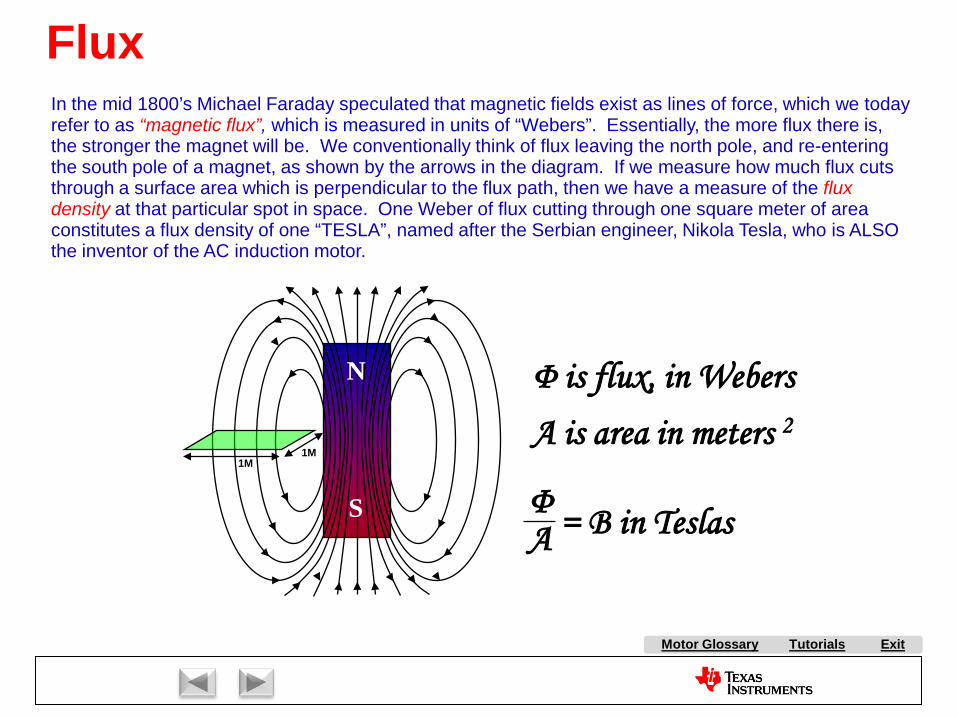
= B in Teslas ΦA
Φ is flux, in Webers
1M1M
A is area in meters 2
In the mid 1800’s Michael Faraday speculated that magnetic fields exist as lines of force, which we today refer to as “magnetic flux”, which is measured in units of “Webers”. Essentially, the more flux there is, the stronger the magnet will be. We conventionally think of flux leaving the north pole, and re-entering the south pole of a magnet, as shown by the arrows in the diagram. If we measure how much flux cuts through a surface area which is perpendicular to the flux path, then we have a measure of the flux density at that particular spot in space. One Weber of flux cutting through one square meter of area constitutes a flux density of one “TESLA”, named after the Serbian engineer, Nikola Tesla, who is ALSO the inventor of the AC induction motor.

A AC Induction Motor (ACIM)
AirgapAlignment TorqueB Back-EMFBipolar PWMsBrakingBrush DC (BDC) MotorBrushesBrushless DC (BLDC) MotorBrushless Permanent Magnet
(BPM)C Center-aligned PWMsClark transformCommutationCommutatorConverterCritically DampedCycle-by-cycle current limitD d-axisDC BusDC InjectionDead-timeDead-time DistortionDigital ControlDirect Torque Control (DTC)Duty cycleDynamic BrakingE eCAPEfficiencyElectronically Commutated
Motor (ECM)Encoder
F FeedbackFeedforwardField Oriented Control (FOC)Field WeakeningFluxFlux DensityFull SteppingG Gate DriverH H-BridgeHalf BridgeHalf steppingHall-effect sensorsHorsepowerI Intelligent Power Module
(IPM)Interior Permanent Magnet
MotorInverterJ K L Leakage InductanceLeft-hand RuleLEM sensorM Magnetic LeakageMagnetizing InductanceMicrosteppingN Neodymium Iron Boron
(“Neo”)
S SaliencySampling FrequencyScalar ControlSensorless ControlServoShoot-throughShunt current sensingSlipSlip frequencySlip ControlSpace Vector Modulation (SVM)SPM MotorStatorStepper (Motor) (SM)Switched Reluctance (SR) MotorSynchronous RectificationT TachometerThird-harmonic ModulationTorqueTorque ConstantTrapezoidalU UnderdampedUnipolar PWMsUniversal MotorV Variable Speed Drive (VSD)Vector ControlVoltage boostVolts-per-Hertz ControlW WindupX Y Z Z-Transform
Tutorials Exit
P Park TransformPermanent Magnet
Synchronous Motor (PMSM)
Permanent Magnet AC Motor (PMAC)
PI ControlPID ControlPluggingPowerPower FactorPower QuadrantsPulse Width Modulation
(PWM)
Q q-axis
R Reaction TorqueRegenerationRegenerative BrakingReluctanceReluctance TorqueResistive BrakingResolverRight-hand RuleRotor
E continuedePWMeQEP
O ObserversOff-lineOverdamped
Motor Glossary
Tutorials ExitMotor Glossary
Right-hand Rule
curr
ent
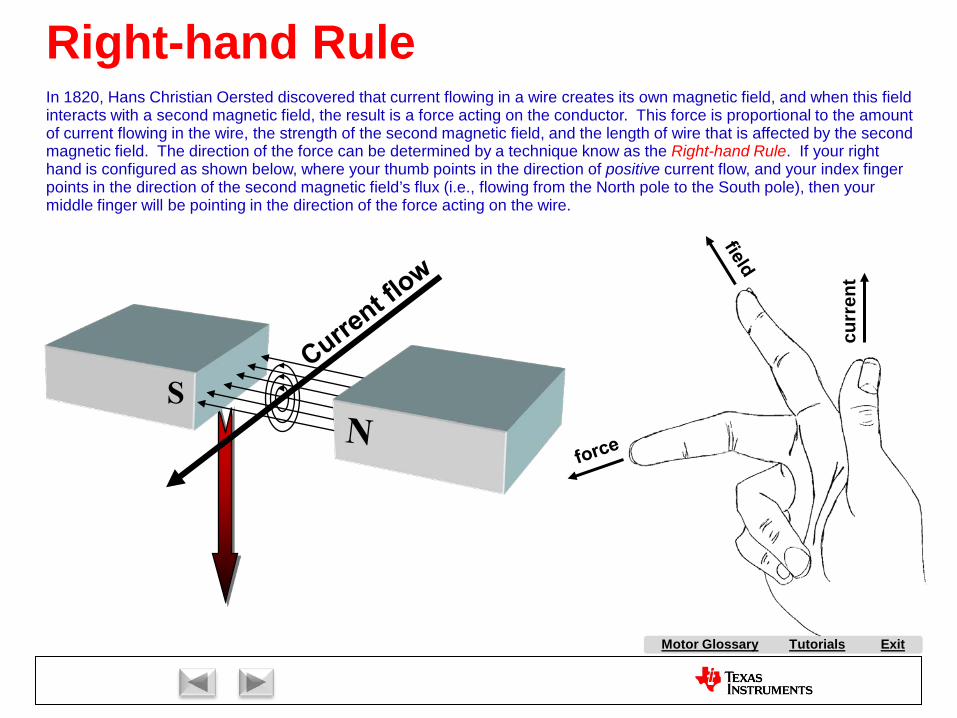
In 1820, Hans Christian Oersted discovered that current flowing in a wire creates its own magnetic field, and when this fieldinteracts with a second magnetic field, the result is a force acting on the conductor. This force is proportional to the amountof current flowing in the wire, the strength of the second magnetic field, and the length of wire that is affected by the secondmagnetic field. The direction of the force can be determined by a technique know as the Right-hand Rule. If your right hand is configured as shown below, where your thumb points in the direction of positive current flow, and your index finger points in the direction of the second magnetic field’s flux (i.e., flowing from the North pole to the South pole), then your middle finger will be pointing in the direction of the force acting on the wire.

A AC Induction Motor (ACIM)
AirgapAlignment TorqueB Back-EMFBipolar PWMsBrakingBrush DC (BDC) MotorBrushesBrushless DC (BLDC) MotorBrushless Permanent Magnet
(BPM)C Center-aligned PWMsClark transformCommutationCommutatorConverterCritically DampedCycle-by-cycle current limitD d-axisDC BusDC InjectionDead-timeDead-time DistortionDigital ControlDirect Torque Control (DTC)Duty cycleDynamic BrakingE eCAPEfficiencyElectronically Commutated
Motor (ECM)Encoder
F FeedbackFeedforwardField Oriented Control (FOC)Field WeakeningFluxFlux DensityFull SteppingG Gate DriverH H-BridgeHalf BridgeHalf steppingHall-effect sensorsHorsepowerI Intelligent Power Module
(IPM)Interior Permanent Magnet
MotorInverterJ K L Leakage InductanceLeft-hand RuleLEM sensorM Magnetic LeakageMagnetizing InductanceMicrosteppingN Neodymium Iron Boron
(“Neo”)
S SaliencySampling FrequencyScalar ControlSensorless ControlServoShoot-throughShunt current sensingSlipSlip frequencySlip ControlSpace Vector Modulation (SVM)SPM MotorStatorStepper (Motor) (SM)Switched Reluctance (SR) MotorSynchronous RectificationT TachometerThird-harmonic ModulationTorqueTorque ConstantTrapezoidalU UnderdampedUnipolar PWMsUniversal MotorV Variable Speed Drive (VSD)Vector ControlVoltage boostVolts-per-Hertz ControlW WindupX Y Z Z-Transform
Tutorials Exit
P Park TransformPermanent Magnet
Synchronous Motor (PMSM)
Permanent Magnet AC Motor (PMAC)
PI ControlPID ControlPluggingPowerPower FactorPower QuadrantsPulse Width Modulation
(PWM)
Q q-axis
R Reaction TorqueRegenerationRegenerative BrakingReluctanceReluctance TorqueResistive BrakingResolverRight-hand RuleRotor
E continuedePWMeQEP
O ObserversOff-lineOverdamped
Motor Glossary

Tutorials ExitMotor Glossary
Left-hand Rule
Direction of Motion
EMF
Left Hand Rule
+
-
A wire moving in a magnetic field will generate a voltage across it whose magnitude is proportional to how many flux lines are cut by the wire per second. The polarity of this back-EMF voltage can be determined by the Left-hand Rule. If you hand is configured as shown below where your index finger is pointing in the direction of the magnetic flux (pointing towards the South pole), and your middle finger is pointing in the direction of motion, then your thumb will be pointing towards the positive end of the wire.

A AC Induction Motor (ACIM)
AirgapAlignment TorqueB Back-EMFBipolar PWMsBrakingBrush DC (BDC) MotorBrushesBrushless DC (BLDC) MotorBrushless Permanent Magnet
(BPM)C Center-aligned PWMsClark transformCommutationCommutatorConverterCritically DampedCycle-by-cycle current limitD d-axisDC BusDC InjectionDead-timeDead-time DistortionDigital ControlDirect Torque Control (DTC)Duty cycleDynamic BrakingE eCAPEfficiencyElectronically Commutated
Motor (ECM)Encoder
F FeedbackFeedforwardField Oriented Control (FOC)Field WeakeningFluxFlux DensityFull SteppingG Gate DriverH H-BridgeHalf BridgeHalf steppingHall-effect sensorsHorsepowerI Intelligent Power Module
(IPM)Interior Permanent Magnet
MotorInverterJ K L Leakage InductanceLeft-hand RuleLEM sensorM Magnetic LeakageMagnetizing InductanceMicrosteppingN Neodymium Iron Boron
(“Neo”)
S SaliencySampling FrequencyScalar ControlSensorless ControlServoShoot-throughShunt current sensingSlipSlip frequencySlip ControlSpace Vector Modulation (SVM)SPM MotorStatorStepper (Motor) (SM)Switched Reluctance (SR) MotorSynchronous RectificationT TachometerThird-harmonic ModulationTorqueTorque ConstantTrapezoidalU UnderdampedUnipolar PWMsUniversal MotorV Variable Speed Drive (VSD)Vector ControlVoltage boostVolts-per-Hertz ControlW WindupX Y Z Z-Transform
Tutorials Exit
P Park TransformPermanent Magnet
Synchronous Motor (PMSM)
Permanent Magnet AC Motor (PMAC)
PI ControlPID ControlPluggingPowerPower FactorPower QuadrantsPulse Width Modulation
(PWM)
Q q-axis
R Reaction TorqueRegenerationRegenerative BrakingReluctanceReluctance TorqueResistive BrakingResolverRight-hand RuleRotor
E continuedePWMeQEP
O ObserversOff-lineOverdamped
Motor Glossary
Tutorials ExitMotor Glossary
Torque
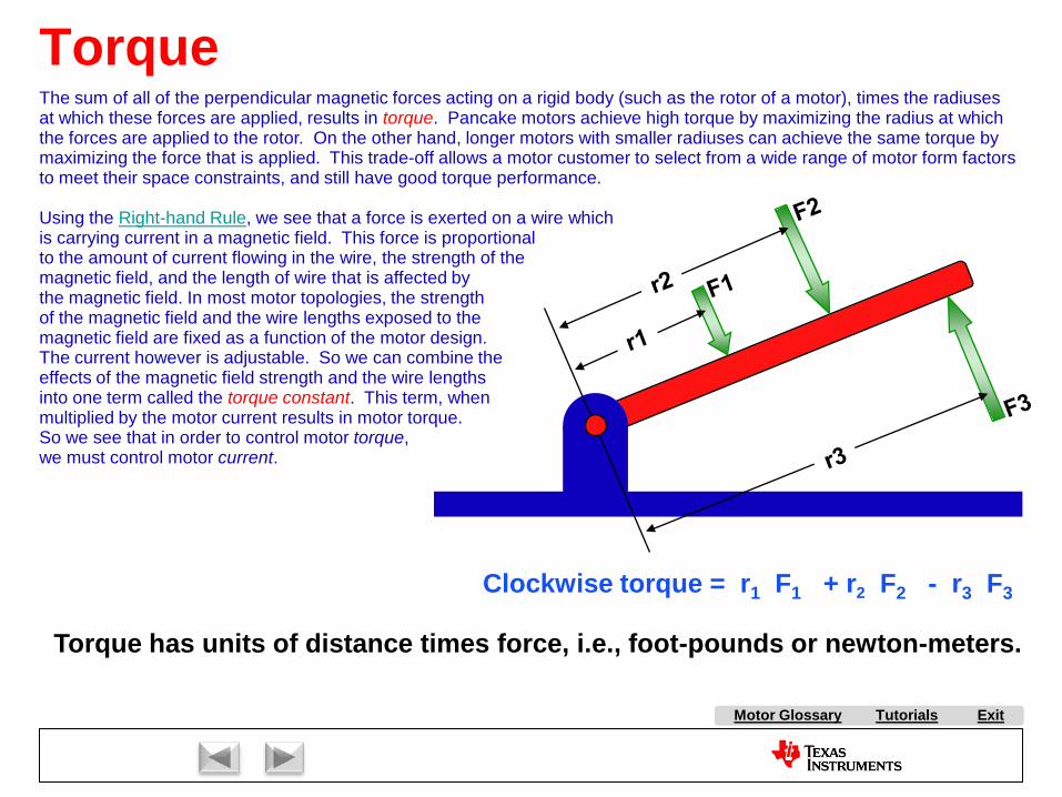
Clockwise torque = r1 F1 + r2 F2 - r3 F3
Torque has units of distance times force, i.e., foot-pounds or newton-meters.
The sum of all of the perpendicular magnetic forces acting on a rigid body (such as the rotor of a motor), times the radiusesat which these forces are applied, results in torque. Pancake motors achieve high torque by maximizing the radius at which the forces are applied to the rotor. On the other hand, longer motors with smaller radiuses can achieve the same torque by maximizing the force that is applied. This trade-off allows a motor customer to select from a wide range of motor form factors to meet their space constraints, and still have good torque performance.
Using the Right-hand Rule, we see that a force is exerted on a wire whichis carrying current in a magnetic field. This force is proportionalto the amount of current flowing in the wire, the strength of themagnetic field, and the length of wire that is affected bythe magnetic field. In most motor topologies, the strengthof the magnetic field and the wire lengths exposed to themagnetic field are fixed as a function of the motor design.The current however is adjustable. So we can combine theeffects of the magnetic field strength and the wire lengthsinto one term called the torque constant. This term, whenmultiplied by the motor current results in motor torque.So we see that in order to control motor torque,we must control motor current.

A AC Induction Motor (ACIM)
AirgapAlignment TorqueB Back-EMFBipolar PWMsBrakingBrush DC (BDC) MotorBrushesBrushless DC (BLDC) MotorBrushless Permanent Magnet
(BPM)C Center-aligned PWMsClark transformCommutationCommutatorConverterCritically DampedCycle-by-cycle current limitD d-axisDC BusDC InjectionDead-timeDead-time DistortionDigital ControlDirect Torque Control (DTC)Duty cycleDynamic BrakingE eCAPEfficiencyElectronically Commutated
Motor (ECM)Encoder
F FeedbackFeedforwardField Oriented Control (FOC)Field WeakeningFluxFlux DensityFull SteppingG Gate DriverH H-BridgeHalf BridgeHalf steppingHall-effect sensorsHorsepowerI Intelligent Power Module
(IPM)Interior Permanent Magnet
MotorInverterJ K L Leakage InductanceLeft-hand RuleLEM sensorM Magnetic LeakageMagnetizing InductanceMicrosteppingN Neodymium Iron Boron
(“Neo”)
S SaliencySampling FrequencyScalar ControlSensorless ControlServoShoot-throughShunt current sensingSlipSlip frequencySlip ControlSpace Vector Modulation (SVM)SPM MotorStatorStepper (Motor) (SM)Switched Reluctance (SR) MotorSynchronous RectificationT TachometerThird-harmonic ModulationTorqueTorque ConstantTrapezoidalU UnderdampedUnipolar PWMsUniversal MotorV Variable Speed Drive (VSD)Vector ControlVoltage boostVolts-per-Hertz ControlW WindupX Y Z Z-Transform
Tutorials Exit
P Park TransformPermanent Magnet
Synchronous Motor (PMSM)
Permanent Magnet AC Motor (PMAC)
PI ControlPID ControlPluggingPowerPower FactorPower QuadrantsPulse Width Modulation
(PWM)
Q q-axis
R Reaction TorqueRegenerationRegenerative BrakingReluctanceReluctance TorqueResistive BrakingResolverRight-hand RuleRotor
E continuedePWMeQEP
O ObserversOff-lineOverdamped
Motor Glossary

Tutorials ExitMotor Glossary
Torque ComponentsThe torque produced by a motor can be divided into two different categories. The first one is called reaction torque or alignment torque. This accounts for the torque created by the reaction between the magnets on the rotor and stator. All motors with the exception of the switched reluctance motor exhibit reaction torque.A lesser known torque component is called reluctance torque. This torque is generated as a result of a magnetic field trying to minimize the reluctance of its flux path. For example, if you place a kitchen knife on a countertop, and approach one end of the knife with a magnet, the knife will move toward the magnet in order to minimize the path of the magnetic field, even though the knife itself is not magnetized. Since the switched reluctance motor does not use a magnet or an electromagnet on the rotor, reluctance torque is its only torque component.Both of these torque components are a function of the alignment between the rotor and stator. Consider for example Figure A, where the rotor and stator magnetic fields are in attractive alignment. The force of attraction goes through the axis of the rotor, so no torque is created. Likewise, Figure B shows repulsive alignment which also has a force vector going through the rotor axis, so again the torque is zero. Between these two extremes, the motor produces reaction torque which peaks when the angle is halfway between 0 degrees and 180 degrees, (i.e., 90 degrees).Some motors rely on BOTH torque components. For example, the Toyota Prius IPM traction motor is designed to have significant contributions from both reaction and reluctance torque. Both torques are plotted as a function of rotor angle alignment to the stator magnetic field, as shown below.
Torq
ue (N
m)
Composite Torque
Reaction Torque
Reluctance Torque
0º 180º90º
Torque Curves for Toyota Prius Traction Motor
-150
0
300
150
Rotor/Stator Magnetic Field Alignment (degrees)Fig. A0 degree alignment
Fig. B180 degree alignment
N
S
N
S
N
SN
S

A AC Induction Motor (ACIM)
AirgapAlignment TorqueB Back-EMFBipolar PWMsBrakingBrush DC (BDC) MotorBrushesBrushless DC (BLDC) MotorBrushless Permanent Magnet
(BPM)C Center-aligned PWMsClark transformCommutationCommutatorConverterCritically DampedCycle-by-cycle current limitD d-axisDC BusDC InjectionDead-timeDead-time DistortionDigital ControlDirect Torque Control (DTC)Duty cycleDynamic BrakingE eCAPEfficiencyElectronically Commutated
Motor (ECM)Encoder
F FeedbackFeedforwardField Oriented Control (FOC)Field WeakeningFluxFlux DensityFull SteppingG Gate DriverH H-BridgeHalf BridgeHalf steppingHall-effect sensorsHorsepowerI Intelligent Power Module
(IPM)Interior Permanent Magnet
MotorInverterJ K L Leakage InductanceLeft-hand RuleLEM sensorM Magnetic LeakageMagnetizing InductanceMicrosteppingN Neodymium Iron Boron
(“Neo”)
S SaliencySampling FrequencyScalar ControlSensorless ControlServoShoot-throughShunt current sensingSlipSlip frequencySlip ControlSpace Vector Modulation (SVM)SPM MotorStatorStepper (Motor) (SM)Switched Reluctance (SR) MotorSynchronous RectificationT TachometerThird-harmonic ModulationTorqueTorque ConstantTrapezoidalU UnderdampedUnipolar PWMsUniversal MotorV Variable Speed Drive (VSD)Vector ControlVoltage boostVolts-per-Hertz ControlW WindupX Y Z Z-Transform
Tutorials Exit
P Park TransformPermanent Magnet
Synchronous Motor (PMSM)
Permanent Magnet AC Motor (PMAC)
PI ControlPID ControlPluggingPowerPower FactorPower QuadrantsPulse Width Modulation
(PWM)
Q q-axis
R Reaction TorqueRegenerationRegenerative BrakingReluctanceReluctance TorqueResistive BrakingResolverRight-hand RuleRotor
E continuedePWMeQEP
O ObserversOff-lineOverdamped
Motor Glossary
Tutorials ExitMotor Glossary
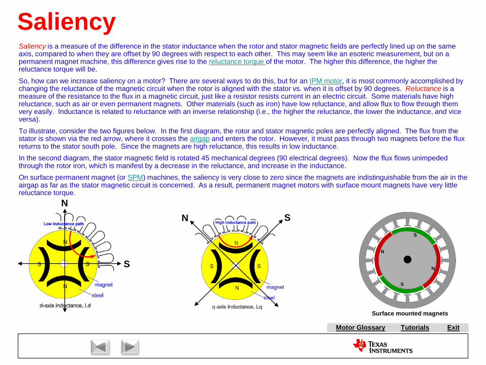
SaliencySaliency is a measure of the difference in the stator inductance when the rotor and stator magnetic fields are perfectly lined up on the same axis, compared to when they are offset by 90 degrees with respect to each other. This may seem like an esoteric measurement, but on a permanent magnet machine, this difference gives rise to the reluctance torque of the motor. The higher this difference, the higher the reluctance torque will be.So, how can we increase saliency on a motor? There are several ways to do this, but for an IPM motor, it is most commonly accomplished by changing the reluctance of the magnetic circuit when the rotor is aligned with the stator vs. when it is offset by 90 degrees. Reluctance is a measure of the resistance to the flux in a magnetic circuit, just like a resistor resists current in an electric circuit. Some materials have high reluctance, such as air or even permanent magnets. Other materials (such as iron) have low reluctance, and allow flux to flow through them very easily. Inductance is related to reluctance with an inverse relationship (i.e., the higher the reluctance, the lower the inductance, and vice versa).To illustrate, consider the two figures below. In the first diagram, the rotor and stator magnetic poles are perfectly aligned. The flux from the stator is shown via the red arrow, where it crosses the airgap and enters the rotor. However, it must pass through two magnets before the flux returns to the stator south pole. Since the magnets are high reluctance, this results in low inductance.In the second diagram, the stator magnetic field is rotated 45 mechanical degrees (90 electrical degrees). Now the flux flows unimpeded through the rotor iron, which is manifest by a decrease in the reluctance, and increase in the inductance.On surface permanent magnet (or SPM) machines, the saliency is very close to zero since the magnets are indistinguishable from the air in the airgap as far as the stator magnetic circuit is concerned. As a result, permanent magnet motors with surface mount magnets have very little reluctance torque.
N
S
N S
Surface mounted magnets
N
N
S
S

A AC Induction Motor (ACIM)
AirgapAlignment TorqueB Back-EMFBipolar PWMsBrakingBrush DC (BDC) MotorBrushesBrushless DC (BLDC) MotorBrushless Permanent Magnet
(BPM)C Center-aligned PWMsClark transformCommutationCommutatorConverterCritically DampedCycle-by-cycle current limitD d-axisDC BusDC InjectionDead-timeDead-time DistortionDigital ControlDirect Torque Control (DTC)Duty cycleDynamic BrakingE eCAPEfficiencyElectronically Commutated
Motor (ECM)Encoder
F FeedbackFeedforwardField Oriented Control (FOC)Field WeakeningFluxFlux DensityFull SteppingG Gate DriverH H-BridgeHalf BridgeHalf steppingHall-effect sensorsHorsepowerI Intelligent Power Module
(IPM)Interior Permanent Magnet
MotorInverterJ K L Leakage InductanceLeft-hand RuleLEM sensorM Magnetic LeakageMagnetizing InductanceMicrosteppingN Neodymium Iron Boron
(“Neo”)
S SaliencySampling FrequencyScalar ControlSensorless ControlServoShoot-throughShunt current sensingSlipSlip frequencySlip ControlSpace Vector Modulation (SVM)SPM MotorStatorStepper (Motor) (SM)Switched Reluctance (SR) MotorSynchronous RectificationT TachometerThird-harmonic ModulationTorqueTorque ConstantTrapezoidalU UnderdampedUnipolar PWMsUniversal MotorV Variable Speed Drive (VSD)Vector ControlVoltage boostVolts-per-Hertz ControlW WindupX Y Z Z-Transform
Tutorials Exit
P Park TransformPermanent Magnet
Synchronous Motor (PMSM)
Permanent Magnet AC Motor (PMAC)
PI ControlPID ControlPluggingPowerPower FactorPower QuadrantsPulse Width Modulation
(PWM)
Q q-axis
R Reaction TorqueRegenerationRegenerative BrakingReluctanceReluctance TorqueResistive BrakingResolverRight-hand RuleRotor
E continuedePWMeQEP
O ObserversOff-lineOverdamped
Motor Glossary
Tutorials ExitMotor Glossary
Horsepower
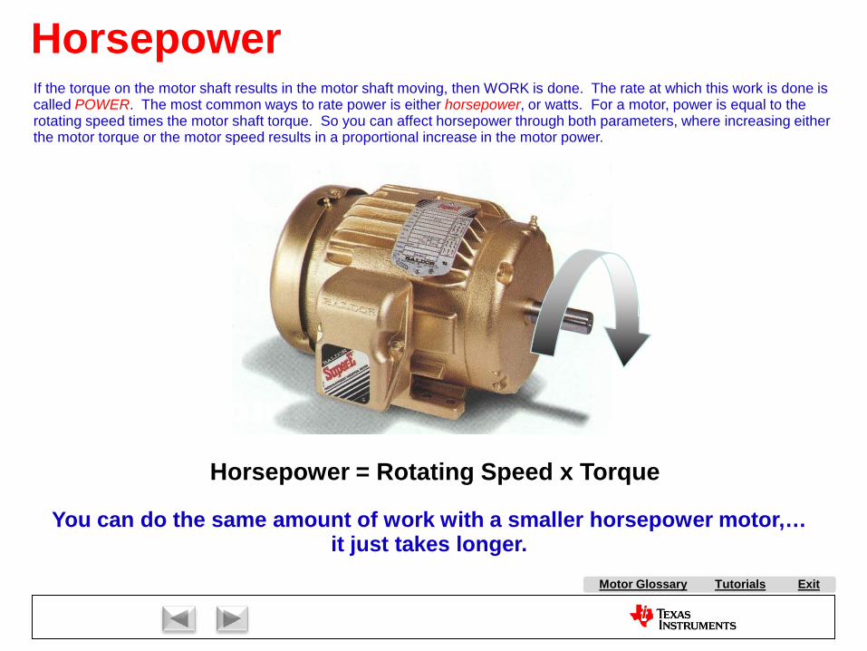
Horsepower = Rotating Speed x Torque
You can do the same amount of work with a smaller horsepower motor,…it just takes longer.
If the torque on the motor shaft results in the motor shaft moving, then WORK is done. The rate at which this work is done is called POWER. The most common ways to rate power is either horsepower, or watts. For a motor, power is equal to the rotating speed times the motor shaft torque. So you can affect horsepower through both parameters, where increasing either the motor torque or the motor speed results in a proportional increase in the motor power.

A AC Induction Motor (ACIM)
AirgapAlignment TorqueB Back-EMFBipolar PWMsBrakingBrush DC (BDC) MotorBrushesBrushless DC (BLDC) MotorBrushless Permanent Magnet
(BPM)C Center-aligned PWMsClark transformCommutationCommutatorConverterCritically DampedCycle-by-cycle current limitD d-axisDC BusDC InjectionDead-timeDead-time DistortionDigital ControlDirect Torque Control (DTC)Duty cycleDynamic BrakingE eCAPEfficiencyElectronically Commutated
Motor (ECM)Encoder
F FeedbackFeedforwardField Oriented Control (FOC)Field WeakeningFluxFlux DensityFull SteppingG Gate DriverH H-BridgeHalf BridgeHalf steppingHall-effect sensorsHorsepowerI Intelligent Power Module
(IPM)Interior Permanent Magnet
MotorInverterJ K L Leakage InductanceLeft-hand RuleLEM sensorM Magnetic LeakageMagnetizing InductanceMicrosteppingN Neodymium Iron Boron
(“Neo”)
S SaliencySampling FrequencyScalar ControlSensorless ControlServoShoot-throughShunt current sensingSlipSlip frequencySlip ControlSpace Vector Modulation (SVM)SPM MotorStatorStepper (Motor) (SM)Switched Reluctance (SR) MotorSynchronous RectificationT TachometerThird-harmonic ModulationTorqueTorque ConstantTrapezoidalU UnderdampedUnipolar PWMsUniversal MotorV Variable Speed Drive (VSD)Vector ControlVoltage boostVolts-per-Hertz ControlW WindupX Y Z Z-Transform
Tutorials Exit
P Park TransformPermanent Magnet
Synchronous Motor (PMSM)
Permanent Magnet AC Motor (PMAC)
PI ControlPID ControlPluggingPowerPower FactorPower QuadrantsPulse Width Modulation
(PWM)
Q q-axis
R Reaction TorqueRegenerationRegenerative BrakingReluctanceReluctance TorqueResistive BrakingResolverRight-hand RuleRotor
E continuedePWMeQEP
O ObserversOff-lineOverdamped
Motor Glossary
Tutorials ExitMotor Glossary
Efficiency
Mechanical output power
Motor losses
Power Expended
Power Stored
Winding(I2R)
Magnetic Hysteresis
Load Dependent Speed or Frequency Dependent
Shaft Contact friction
Windage friction
Eddy currents
Iron Losses
Electro-mechanical Conversion
Input Power
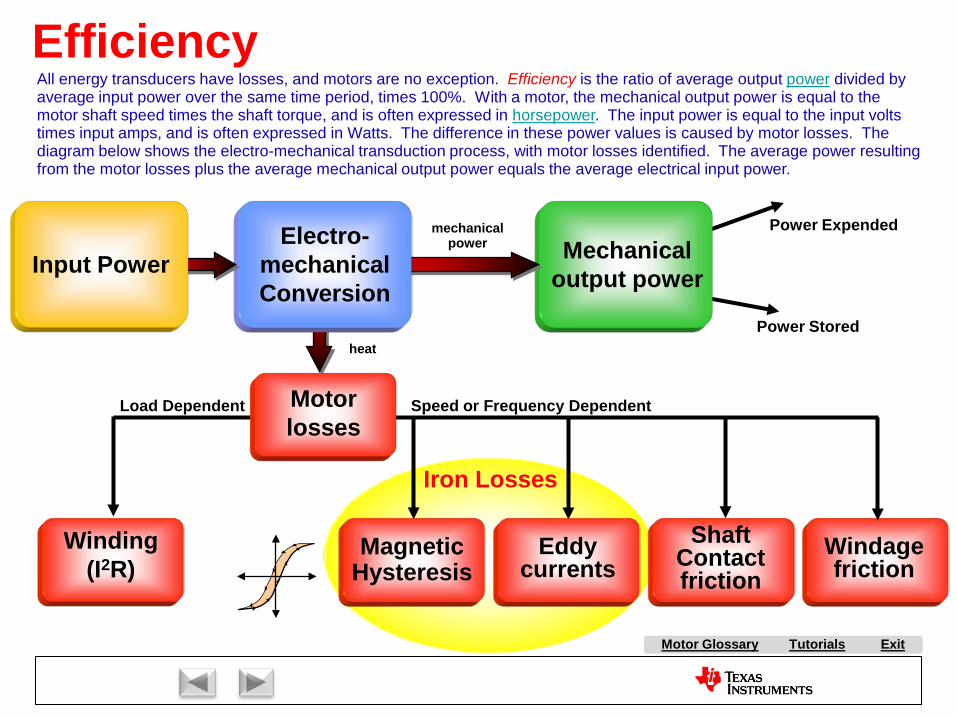
All energy transducers have losses, and motors are no exception. Efficiency is the ratio of average output power divided by average input power over the same time period, times 100%. With a motor, the mechanical output power is equal to the motor shaft speed times the shaft torque, and is often expressed in horsepower. The input power is equal to the input volts times input amps, and is often expressed in Watts. The difference in these power values is caused by motor losses. The diagram below shows the electro-mechanical transduction process, with motor losses identified. The average power resulting from the motor losses plus the average mechanical output power equals the average electrical input power.
mechanical power
heat

A AC Induction Motor (ACIM)
AirgapAlignment TorqueB Back-EMFBipolar PWMsBrakingBrush DC (BDC) MotorBrushesBrushless DC (BLDC) MotorBrushless Permanent Magnet
(BPM)C Center-aligned PWMsClark transformCommutationCommutatorConverterCritically DampedCycle-by-cycle current limitD d-axisDC BusDC InjectionDead-timeDead-time DistortionDigital ControlDirect Torque Control (DTC)Duty cycleDynamic BrakingE eCAPEfficiencyElectronically Commutated
Motor (ECM)Encoder
F FeedbackFeedforwardField Oriented Control (FOC)Field WeakeningFluxFlux DensityFull SteppingG Gate DriverH H-BridgeHalf BridgeHalf steppingHall-effect sensorsHorsepowerI Intelligent Power Module
(IPM)Interior Permanent Magnet
MotorInverterJ K L Leakage InductanceLeft-hand RuleLEM sensorM Magnetic LeakageMagnetizing InductanceMicrosteppingN Neodymium Iron Boron
(“Neo”)
S SaliencySampling FrequencyScalar ControlSensorless ControlServoShoot-throughShunt current sensingSlipSlip frequencySlip ControlSpace Vector Modulation (SVM)SPM MotorStatorStepper (Motor) (SM)Switched Reluctance (SR) MotorSynchronous RectificationT TachometerThird-harmonic ModulationTorqueTorque ConstantTrapezoidalU UnderdampedUnipolar PWMsUniversal MotorV Variable Speed Drive (VSD)Vector ControlVoltage boostVolts-per-Hertz ControlW WindupX Y Z Z-Transform
Tutorials Exit
P Park TransformPermanent Magnet
Synchronous Motor (PMSM)
Permanent Magnet AC Motor (PMAC)
PI ControlPID ControlPluggingPowerPower FactorPower QuadrantsPulse Width Modulation
(PWM)
Q q-axis
R Reaction TorqueRegenerationRegenerative BrakingReluctanceReluctance TorqueResistive BrakingResolverRight-hand RuleRotor
E continuedePWMeQEP
O ObserversOff-lineOverdamped
Motor Glossary
Tutorials ExitMotor Glossary
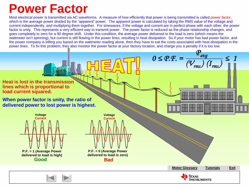
Heat is lost in the transmissionlines which is proportional toload current squared.When power factor is unity, the ratio ofdelivered power to lost power is highest.
0 ≤ P.F. = ≤ 1Pavg
(Vrms ) (Irms )
Power FactorMost electrical power is transmitted via AC waveforms. A measure of how efficiently that power is being transmitted is called power factor, which is the average power divided by the “apparent” power. The apparent power is calculated by taking the RMS value of the voltage and current independently, and multiplying them together. For sinewaves, if the voltage and current are in perfect phase with each other, the power factor is unity. This represents a very efficient way to transmit power. The power factor is reduced as the phase relationship changes, and goes completely to zero for a 90 degree shift. Under this condition, the average power delivered to the load is zero (which means the wattmeter isn’t spinning), but current is still flowing in the power lines, resulting in heat dissipation. So if your motor has bad power factor, and the power company is billing you based on the wattmeter reading alone, then they have to eat the costs associated with heat dissipation in the power lines. To fix this problem, they also monitor the power factor at your factory location, and charge you a penalty if it is too low.
VoltageCurrent
VoltageCurrent
P.F. = 1 (Average Power delivered to load is high)
P.F. = 0 (Average Power delivered to load is zero)
Good Bad

A AC Induction Motor (ACIM)
AirgapAlignment TorqueB Back-EMFBipolar PWMsBrakingBrush DC (BDC) MotorBrushesBrushless DC (BLDC) MotorBrushless Permanent Magnet
(BPM)C Center-aligned PWMsClark transformCommutationCommutatorConverterCritically DampedCycle-by-cycle current limitD d-axisDC BusDC InjectionDead-timeDead-time DistortionDigital ControlDirect Torque Control (DTC)Duty cycleDynamic BrakingE eCAPEfficiencyElectronically Commutated
Motor (ECM)Encoder
F FeedbackFeedforwardField Oriented Control (FOC)Field WeakeningFluxFlux DensityFull SteppingG Gate DriverH H-BridgeHalf BridgeHalf steppingHall-effect sensorsHorsepowerI Intelligent Power Module
(IPM)Interior Permanent Magnet
MotorInverterJ K L Leakage InductanceLeft-hand RuleLEM sensorM Magnetic LeakageMagnetizing InductanceMicrosteppingN Neodymium Iron Boron
(“Neo”)
S SaliencySampling FrequencyScalar ControlSensorless ControlServoShoot-throughShunt current sensingSlipSlip frequencySlip ControlSpace Vector Modulation (SVM)SPM MotorStatorStepper (Motor) (SM)Switched Reluctance (SR) MotorSynchronous RectificationT TachometerThird-harmonic ModulationTorqueTorque ConstantTrapezoidalU UnderdampedUnipolar PWMsUniversal MotorV Variable Speed Drive (VSD)Vector ControlVoltage boostVolts-per-Hertz ControlW WindupX Y Z Z-Transform
Tutorials Exit
P Park TransformPermanent Magnet
Synchronous Motor (PMSM)
Permanent Magnet AC Motor (PMAC)
PI ControlPID ControlPluggingPowerPower FactorPower QuadrantsPulse Width Modulation
(PWM)
Q q-axis
R Reaction TorqueRegenerationRegenerative BrakingReluctanceReluctance TorqueResistive BrakingResolverRight-hand RuleRotor
E continuedePWMeQEP
O ObserversOff-lineOverdamped
Motor Glossary
Tutorials ExitMotor Glossary
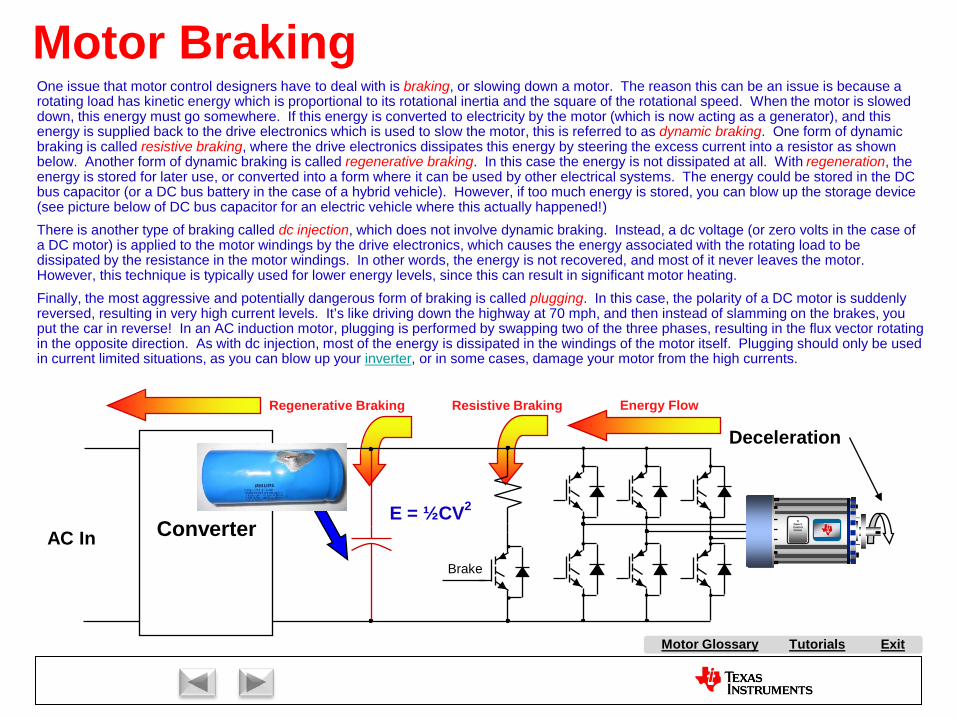
Motor BrakingOne issue that motor control designers have to deal with is braking, or slowing down a motor. The reason this can be an issue is because a rotating load has kinetic energy which is proportional to its rotational inertia and the square of the rotational speed. When the motor is slowed down, this energy must go somewhere. If this energy is converted to electricity by the motor (which is now acting as a generator), and this energy is supplied back to the drive electronics which is used to slow the motor, this is referred to as dynamic braking. One form of dynamic braking is called resistive braking, where the drive electronics dissipates this energy by steering the excess current into a resistor as shown below. Another form of dynamic braking is called regenerative braking. In this case the energy is not dissipated at all. With regeneration, the energy is stored for later use, or converted into a form where it can be used by other electrical systems. The energy could be stored in the DC bus capacitor (or a DC bus battery in the case of a hybrid vehicle). However, if too much energy is stored, you can blow up the storage device (see picture below of DC bus capacitor for an electric vehicle where this actually happened!)There is another type of braking called dc injection, which does not involve dynamic braking. Instead, a dc voltage (or zero volts in the case of a DC motor) is applied to the motor windings by the drive electronics, which causes the energy associated with the rotating load to be dissipated by the resistance in the motor windings. In other words, the energy is not recovered, and most of it never leaves the motor. However, this technique is typically used for lower energy levels, since this can result in significant motor heating.Finally, the most aggressive and potentially dangerous form of braking is called plugging. In this case, the polarity of a DC motor is suddenly reversed, resulting in very high current levels. It’s like driving down the highway at 70 mph, and then instead of slamming on the brakes, you put the car in reverse! In an AC induction motor, plugging is performed by swapping two of the three phases, resulting in the flux vector rotating in the opposite direction. As with dc injection, most of the energy is dissipated in the windings of the motor itself. Plugging should only be used in current limited situations, as you can blow up your inverter, or in some cases, damage your motor from the high currents.
Deceleration
Energy Flow
AC InE = ½CV2
TIDave’sControlCenter
Brake
Converter
Regenerative Braking Resistive Braking

A AC Induction Motor (ACIM)
AirgapAlignment TorqueB Back-EMFBipolar PWMsBrakingBrush DC (BDC) MotorBrushesBrushless DC (BLDC) MotorBrushless Permanent Magnet
(BPM)C Center-aligned PWMsClark transformCommutationCommutatorConverterCritically DampedCycle-by-cycle current limitD d-axisDC BusDC InjectionDead-timeDead-time DistortionDigital ControlDirect Torque Control (DTC)Duty cycleDynamic BrakingE eCAPEfficiencyElectronically Commutated
Motor (ECM)Encoder
F FeedbackFeedforwardField Oriented Control (FOC)Field WeakeningFluxFlux DensityFull SteppingG Gate DriverH H-BridgeHalf BridgeHalf steppingHall-effect sensorsHorsepowerI Intelligent Power Module
(IPM)Interior Permanent Magnet
MotorInverterJ K L Leakage InductanceLeft-hand RuleLEM sensorM Magnetic LeakageMagnetizing InductanceMicrosteppingN Neodymium Iron Boron
(“Neo”)
S SaliencySampling FrequencyScalar ControlSensorless ControlServoShoot-throughShunt current sensingSlipSlip frequencySlip ControlSpace Vector Modulation (SVM)SPM MotorStatorStepper (Motor) (SM)Switched Reluctance (SR) MotorSynchronous RectificationT TachometerThird-harmonic ModulationTorqueTorque ConstantTrapezoidalU UnderdampedUnipolar PWMsUniversal MotorV Variable Speed Drive (VSD)Vector ControlVoltage boostVolts-per-Hertz ControlW WindupX Y Z Z-Transform
Tutorials Exit
P Park TransformPermanent Magnet
Synchronous Motor (PMSM)
Permanent Magnet AC Motor (PMAC)
PI ControlPID ControlPluggingPowerPower FactorPower QuadrantsPulse Width Modulation
(PWM)
Q q-axis
R Reaction TorqueRegenerationRegenerative BrakingReluctanceReluctance TorqueResistive BrakingResolverRight-hand RuleRotor
E continuedePWMeQEP
O ObserversOff-lineOverdamped
Motor Glossary
Tutorials ExitMotor Glossary
Power Quadrants
Second Quadrantnegative speed-positive torque
“reverse-braking”
Generating
Fourth QuadrantPositive speed - negative torque
“forward-braking”
GeneratingThird Quadrant
negative speed - negative torque“reverse-accelerating”
Motoring
First Quadrantpositive speed-positive torque
“forward-accelerating”
Motoring
Torq
ue
SpeedIIIIII IV
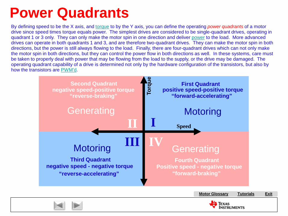
By defining speed to be the X axis, and torque to by the Y axis, you can define the operating power quadrants of a motor drive since speed times torque equals power. The simplest drives are considered to be single-quadrant drives, operating in quadrant 1 or 3 only. They can only make the motor spin in one direction and deliver power to the load. More advanced drives can operate in both quadrants 1 and 3, and are therefore two-quadrant drives. They can make the motor spin in both directions, but the power is still always flowing to the load. Finally, there are four-quadrant drives which can not only make the motor spin in both directions, but they can control the power flow in both directions as well. In these systems, care must be taken to properly deal with power that may be flowing from the load to the supply, or the drive may be damaged. The operating quadrant capability of a drive is determined not only by the hardware configuration of the transistors, but also byhow the transistors are PWM’d.

A AC Induction Motor (ACIM)
AirgapAlignment TorqueB Back-EMFBipolar PWMsBrakingBrush DC (BDC) MotorBrushesBrushless DC (BLDC) MotorBrushless Permanent Magnet
(BPM)C Center-aligned PWMsClark transformCommutationCommutatorConverterCritically DampedCycle-by-cycle current limitD d-axisDC BusDC InjectionDead-timeDead-time DistortionDigital ControlDirect Torque Control (DTC)Duty cycleDynamic BrakingE eCAPEfficiencyElectronically Commutated
Motor (ECM)Encoder
F FeedbackFeedforwardField Oriented Control (FOC)Field WeakeningFluxFlux DensityFull SteppingG Gate DriverH H-BridgeHalf BridgeHalf steppingHall-effect sensorsHorsepowerI Intelligent Power Module
(IPM)Interior Permanent Magnet
MotorInverterJ K L Leakage InductanceLeft-hand RuleLEM sensorM Magnetic LeakageMagnetizing InductanceMicrosteppingN Neodymium Iron Boron
(“Neo”)
S SaliencySampling FrequencyScalar ControlSensorless ControlServoShoot-throughShunt current sensingSlipSlip frequencySlip ControlSpace Vector Modulation (SVM)SPM MotorStatorStepper (Motor) (SM)Switched Reluctance (SR) MotorSynchronous RectificationT TachometerThird-harmonic ModulationTorqueTorque ConstantTrapezoidalU UnderdampedUnipolar PWMsUniversal MotorV Variable Speed Drive (VSD)Vector ControlVoltage boostVolts-per-Hertz ControlW WindupX Y Z Z-Transform
Tutorials Exit
P Park TransformPermanent Magnet
Synchronous Motor (PMSM)
Permanent Magnet AC Motor (PMAC)
PI ControlPID ControlPluggingPowerPower FactorPower QuadrantsPulse Width Modulation
(PWM)
Q q-axis
R Reaction TorqueRegenerationRegenerative BrakingReluctanceReluctance TorqueResistive BrakingResolverRight-hand RuleRotor
E continuedePWMeQEP
O ObserversOff-lineOverdamped
Motor Glossary

Tutorials ExitMotor Glossary
Feedback and Feedforward
More traditional approachBest for disturbance rejection
Better stabilityBest for trajectory tracking
Control structures can generally be classified as one of two topologies. Feedback systems achieve a desired output response by comparing the output signal to the input signal and generating an error signal. This error is then followed by ahigh gain stage so that even a small error results in a large correction response. However, the higher the gain, the harder it is to achieve a stable system. Feedforward systems use knowledge of the system dynamics to achieve a desired output response. The thought process goes something like this: To achieve a desired output, I need to figure out what stimulation signal is required on the input of the system to get that output. By knowing the system transfer function in the forward direction [G(s)], I figure out what the transfer function is going backwards through the system [1/G(s)], and that becomes the transfer function of my feedforward filter. While feedforward systems typically result in snappier response to a change in the commanded input, they aren’t well suited to applications that must tolerate unexpected load disturbances.
A AC Induction Motor (ACIM)
AirgapAlignment TorqueB Back-EMFBipolar PWMsBrakingBrush DC (BDC) MotorBrushesBrushless DC (BLDC) MotorBrushless Permanent Magnet
(BPM)C Center-aligned PWMsClark transformCommutationCommutatorConverterCritically DampedCycle-by-cycle current limitD d-axisDC BusDC InjectionDead-timeDead-time DistortionDigital ControlDirect Torque Control (DTC)Duty cycleDynamic BrakingE eCAPEfficiencyElectronically Commutated
Motor (ECM)Encoder
F FeedbackFeedforwardField Oriented Control (FOC)Field WeakeningFluxFlux DensityFull SteppingG Gate DriverH H-BridgeHalf BridgeHalf steppingHall-effect sensorsHorsepowerI Intelligent Power Module
(IPM)Interior Permanent Magnet
MotorInverterJ K L Leakage InductanceLeft-hand RuleLEM sensorM Magnetic LeakageMagnetizing InductanceMicrosteppingN Neodymium Iron Boron
(“Neo”)
S SaliencySampling FrequencyScalar ControlSensorless ControlServoShoot-throughShunt current sensingSlipSlip frequencySlip ControlSpace Vector Modulation (SVM)SPM MotorStatorStepper (Motor) (SM)Switched Reluctance (SR) MotorSynchronous RectificationT TachometerThird-harmonic ModulationTorqueTorque ConstantTrapezoidalU UnderdampedUnipolar PWMsUniversal MotorV Variable Speed Drive (VSD)Vector ControlVoltage boostVolts-per-Hertz ControlW WindupX Y Z Z-Transform
Tutorials Exit
P Park TransformPermanent Magnet
Synchronous Motor (PMSM)
Permanent Magnet AC Motor (PMAC)
PI ControlPID ControlPluggingPowerPower FactorPower QuadrantsPulse Width Modulation
(PWM)
Q q-axis
R Reaction TorqueRegenerationRegenerative BrakingReluctanceReluctance TorqueResistive BrakingResolverRight-hand RuleRotor
E continuedePWMeQEP
O ObserversOff-lineOverdamped
Motor Glossary
Tutorials ExitMotor Glossary
PI Controller
∫ I
P+ +
+-
error(t)Commanded input
Measured output
Correction signal
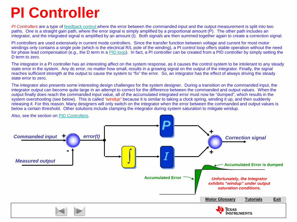
PI Controllers are a type of feedback control where the error between the commanded input and the output measurement is split into two paths. One is a straight gain path, where the error signal is simply amplified by a proportional amount (P). The other path includes an integrator, and the integrated signal is amplified by an amount (I). Both signals are then summed together again to create a correction signal.PI controllers are used extensively in current mode controllers. Since the transfer function between voltage and current for most motor windings only contains a single pole (which is the electrical R/L pole of the winding), a PI control loop offers stable operation without the need for phase lead compensation (e.g., the D term in a PID loop). In fact, a PI controller can be created from a PID controller by simply setting the D term to zero.The integrator in a PI controller has an interesting affect on the system response, as it causes the control system to be intolerant to any steady state error in the system. Any dc error, no matter how small, results in a growing signal on the output of the integrator. Finally, the signal reaches sufficient strength at the output to cause the system to “fix” the error. So, an integrator has the effect of always driving the steady state error to zero.The integrator also presents some interesting design challenges for the system designer. During a transition on the commanded input, the integrator output can become quite large in an attempt to correct for the difference between the commanded and output values. When the output finally does reach the commanded input value, all of the accumulated integrated error must now be “dumped”, which results in the system overshooting (see below). This is called “windup” because it is similar to taking a clock spring, winding it up, and then suddenly releasing it. For this reason. Many designers will only switch on the integrator when the error between the commanded and output values is below a certain threshold. Other solutions include clamping the integrator during system saturation to mitigate windup.Also, see the section on PID Controllers.
Unfortunately, the Integrator exhibits “windup” under output
saturation conditions.
Accumulated Error
Accumulated Error is dumped

A AC Induction Motor (ACIM)
AirgapAlignment TorqueB Back-EMFBipolar PWMsBrakingBrush DC (BDC) MotorBrushesBrushless DC (BLDC) MotorBrushless Permanent Magnet
(BPM)C Center-aligned PWMsClark transformCommutationCommutatorConverterCritically DampedCycle-by-cycle current limitD d-axisDC BusDC InjectionDead-timeDead-time DistortionDigital ControlDirect Torque Control (DTC)Duty cycleDynamic BrakingE eCAPEfficiencyElectronically Commutated
Motor (ECM)Encoder
F FeedbackFeedforwardField Oriented Control (FOC)Field WeakeningFluxFlux DensityFull SteppingG Gate DriverH H-BridgeHalf BridgeHalf steppingHall-effect sensorsHorsepowerI Intelligent Power Module
(IPM)Interior Permanent Magnet
MotorInverterJ K L Leakage InductanceLeft-hand RuleLEM sensorM Magnetic LeakageMagnetizing InductanceMicrosteppingN Neodymium Iron Boron
(“Neo”)
S SaliencySampling FrequencyScalar ControlSensorless ControlServoShoot-throughShunt current sensingSlipSlip frequencySlip ControlSpace Vector Modulation (SVM)SPM MotorStatorStepper (Motor) (SM)Switched Reluctance (SR) MotorSynchronous RectificationT TachometerThird-harmonic ModulationTorqueTorque ConstantTrapezoidalU UnderdampedUnipolar PWMsUniversal MotorV Variable Speed Drive (VSD)Vector ControlVoltage boostVolts-per-Hertz ControlW WindupX Y Z Z-Transform
Tutorials Exit
P Park TransformPermanent Magnet
Synchronous Motor (PMSM)
Permanent Magnet AC Motor (PMAC)
PI ControlPID ControlPluggingPowerPower FactorPower QuadrantsPulse Width Modulation
(PWM)
Q q-axis
R Reaction TorqueRegenerationRegenerative BrakingReluctanceReluctance TorqueResistive BrakingResolverRight-hand RuleRotor
E continuedePWMeQEP
O ObserversOff-lineOverdamped
Motor Glossary

Tutorials ExitMotor Glossary
PID ControllerA common feedback control topology used in many systems today is called the PID Controller. As seen from the diagram below, it gets its name from the fact that the error signal is split into three separate paths which have gain coefficients of P, I, and D. “P” stands for “proportional”, “I” stands for “Integral”, and “D” stands for “differential”. The P and I terms function as described in the section on PI Controllers. The D path involves taking the derivative of the error signal, and then amplifying the derivative term by an amount “D”. This provides additional stability to the control system by providing phase lead to cancel out the phase lag from other poles in the system.
For an intuitive explanation of why the derivative term is required in some systems, consider that you are driving your car, and you see a red light up ahead. Your goal is to position your vehicle to stop just this side of the light. This represents a position servo problem, where the derivative signal represents vehicle speed. Having a D term of zero means that speed information is not incorporated at all in your driving decision-making process. Therefore the control system output won’t go negative (i.e., you won’t put on the brakes) until the position error goes negative. So you would overshoot the stop light, and not start putting on your brakes until after you were past the desired stop destination. This represents an underdamped control response. On the other hand, if the D term is too large, the vehicle speed is significantly amplified in your driving decision-making process. This is like a person who is overly sensitive to how fast they are going, and ride their brakes all the way up to the stop light. You won’t overshoot your destination, but it will take a very long time to get there. This represents an overdamped control response. If the goal is to get to the traffic light as quickly as possible without overshooting, then the correct value of D is somewhere in-between these two extremes. The graph below represents the system response of an actual servo system to a step input command. The responses are plotted for various values of D representing underdamped, overdamped and critically damped responses.
Output
P
D
ΣError signal I∫ddt
Step response of systemfor various values of “D”

A AC Induction Motor (ACIM)
AirgapAlignment TorqueB Back-EMFBipolar PWMsBrakingBrush DC (BDC) MotorBrushesBrushless DC (BLDC) MotorBrushless Permanent Magnet
(BPM)C Center-aligned PWMsClark transformCommutationCommutatorConverterCritically DampedCycle-by-cycle current limitD d-axisDC BusDC InjectionDead-timeDead-time DistortionDigital ControlDirect Torque Control (DTC)Duty cycleDynamic BrakingE eCAPEfficiencyElectronically Commutated
Motor (ECM)Encoder
F FeedbackFeedforwardField Oriented Control (FOC)Field WeakeningFluxFlux DensityFull SteppingG Gate DriverH H-BridgeHalf BridgeHalf steppingHall-effect sensorsHorsepowerI Intelligent Power Module
(IPM)Interior Permanent Magnet
MotorInverterJ K L Leakage InductanceLeft-hand RuleLEM sensorM Magnetic LeakageMagnetizing InductanceMicrosteppingN Neodymium Iron Boron
(“Neo”)
S SaliencySampling FrequencyScalar ControlSensorless ControlServoShoot-throughShunt current sensingSlipSlip frequencySlip ControlSpace Vector Modulation (SVM)SPM MotorStatorStepper (Motor) (SM)Switched Reluctance (SR) MotorSynchronous RectificationT TachometerThird-harmonic ModulationTorqueTorque ConstantTrapezoidalU UnderdampedUnipolar PWMsUniversal MotorV Variable Speed Drive (VSD)Vector ControlVoltage boostVolts-per-Hertz ControlW WindupX Y Z Z-Transform
Tutorials Exit
P Park TransformPermanent Magnet
Synchronous Motor (PMSM)
Permanent Magnet AC Motor (PMAC)
PI ControlPID ControlPluggingPowerPower FactorPower QuadrantsPulse Width Modulation
(PWM)
Q q-axis
R Reaction TorqueRegenerationRegenerative BrakingReluctanceReluctance TorqueResistive BrakingResolverRight-hand RuleRotor
E continuedePWMeQEP
O ObserversOff-lineOverdamped
Motor Glossary

Tutorials ExitMotor Glossary
Observers
Model of H(z)
Integrator Integrator
αβ
It is necessary to measure certain motor operating parameters in order for the motor control system to function properly. Unfortunately, some of these parameters are difficult to measure. For example, trying to obtain a velocity signal that has high resolution and is frequently updated can be problematic at low speeds when using an encoder. Another example involves trying to measure the back-EMF signal buried deep inside the motor. Fortunately, many of these signals are mathematically related to other variables, which ARE observable. For example, the motor velocity is the derivative of the motor’s position. So if we can measure the motor position accurately, we should be able to create a structure that estimates the velocity.The diagram below shows how to construct a velocity observer. We first monitor the output servo position, probably using an encoder. We then compare that with the output of an integrator which is in the red block. The error in this position reading is then used to bias up the integrators inside the red block to insure that the next guess of position <Yo(z)> is closer to the output servo position. Assuming that the integrator output converges to the output servo position, then the observer forces the integrator input to converge to the actual servo velocity! Pretty neat!
There’s just one problem…Trying to follow the output servo position without any knowledge of what is driving the input of the servo system results in velocity lag. This can be best understood with a simple example. Assume you are driving behind a truck, and trying to regulate the position between your front bumper and the truck’s rear bumper. If the truck suddenly slams on the brakes, it’s velocity will decrease quickly before you can even respond. But if you are following a car and can see traffic patterns ahead of that car, you can react more quickly when you see brake lights come on ahead of the car you are following. If you know something about how the driver ahead of you will respond to this stimulation, you can almost precisely mimic the velocity profile of that car with your vehicle without any lag whatsoever. That’s because you are responding to the same input stimulation that the car ahead of you will respond to. This is called feedforwardcompensation.Returning to our example to the left, we must add a feedforward path to our model in order to achieve better position and velocity tracking with NO phase lag.<Press space bar to see this effect>

A AC Induction Motor (ACIM)
AirgapAlignment TorqueB Back-EMFBipolar PWMsBrakingBrush DC (BDC) MotorBrushesBrushless DC (BLDC) MotorBrushless Permanent Magnet
(BPM)C Center-aligned PWMsClark transformCommutationCommutatorConverterCritically DampedCycle-by-cycle current limitD d-axisDC BusDC InjectionDead-timeDead-time DistortionDigital ControlDirect Torque Control (DTC)Duty cycleDynamic BrakingE eCAPEfficiencyElectronically Commutated
Motor (ECM)Encoder
F FeedbackFeedforwardField Oriented Control (FOC)Field WeakeningFluxFlux DensityFull SteppingG Gate DriverH H-BridgeHalf BridgeHalf steppingHall-effect sensorsHorsepowerI Intelligent Power Module
(IPM)Interior Permanent Magnet
MotorInverterJ K L Leakage InductanceLeft-hand RuleLEM sensorM Magnetic LeakageMagnetizing InductanceMicrosteppingN Neodymium Iron Boron
(“Neo”)
S SaliencySampling FrequencyScalar ControlSensorless ControlServoShoot-throughShunt current sensingSlipSlip frequencySlip ControlSpace Vector Modulation (SVM)SPM MotorStatorStepper (Motor) (SM)Switched Reluctance (SR) MotorSynchronous RectificationT TachometerThird-harmonic ModulationTorqueTorque ConstantTrapezoidalU UnderdampedUnipolar PWMsUniversal MotorV Variable Speed Drive (VSD)Vector ControlVoltage boostVolts-per-Hertz ControlW WindupX Y Z Z-Transform
Tutorials Exit
P Park TransformPermanent Magnet
Synchronous Motor (PMSM)
Permanent Magnet AC Motor (PMAC)
PI ControlPID ControlPluggingPowerPower FactorPower QuadrantsPulse Width Modulation
(PWM)
Q q-axis
R Reaction TorqueRegenerationRegenerative BrakingReluctanceReluctance TorqueResistive BrakingResolverRight-hand RuleRotor
E continuedePWMeQEP
O ObserversOff-lineOverdamped
Motor Glossary
Tutorials ExitMotor Glossary
Digital Control
T is the sampling period(Inverse of sampling frequency)
T 2T 3T 4T 5T 6T
e(n) c(t)Controller
Gc(z)
PlantGp(s)
+-
Z. O. Hr(n)
TH(z)
g(n)PWM Module
h(n) c(n)ADC Module
Z. O. H
Σ
Inside the processor
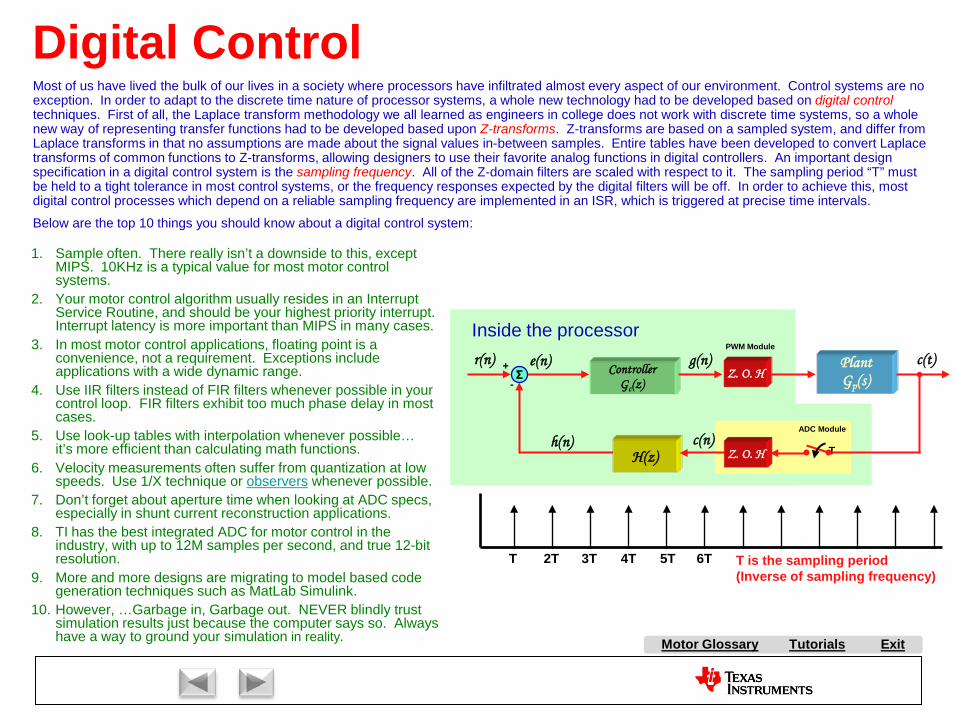
Most of us have lived the bulk of our lives in a society where processors have infiltrated almost every aspect of our environment. Control systems are no exception. In order to adapt to the discrete time nature of processor systems, a whole new technology had to be developed based on digital controltechniques. First of all, the Laplace transform methodology we all learned as engineers in college does not work with discrete time systems, so a whole new way of representing transfer functions had to be developed based upon Z-transforms. Z-transforms are based on a sampled system, and differ from Laplace transforms in that no assumptions are made about the signal values in-between samples. Entire tables have been developed to convert Laplace transforms of common functions to Z-transforms, allowing designers to use their favorite analog functions in digital controllers. An important design specification in a digital control system is the sampling frequency. All of the Z-domain filters are scaled with respect to it. The sampling period “T” must be held to a tight tolerance in most control systems, or the frequency responses expected by the digital filters will be off. In order to achieve this, most digital control processes which depend on a reliable sampling frequency are implemented in an ISR, which is triggered at precise time intervals.
Below are the top 10 things you should know about a digital control system:
1. Sample often. There really isn’t a downside to this, except MIPS. 10KHz is a typical value for most motor control systems.
2. Your motor control algorithm usually resides in an Interrupt Service Routine, and should be your highest priority interrupt. Interrupt latency is more important than MIPS in many cases.
3. In most motor control applications, floating point is a convenience, not a requirement. Exceptions include applications with a wide dynamic range.
4. Use IIR filters instead of FIR filters whenever possible in your control loop. FIR filters exhibit too much phase delay in most cases.
5. Use look-up tables with interpolation whenever possible…it’s more efficient than calculating math functions.
6. Velocity measurements often suffer from quantization at low speeds. Use 1/X technique or observers whenever possible.
7. Don’t forget about aperture time when looking at ADC specs, especially in shunt current reconstruction applications.
8. TI has the best integrated ADC for motor control in the industry, with up to 12M samples per second, and true 12-bit resolution.
9. More and more designs are migrating to model based code generation techniques such as MatLab Simulink.
10. However, …Garbage in, Garbage out. NEVER blindly trust simulation results just because the computer says so. Always have a way to ground your simulation in reality.

A AC Induction Motor (ACIM)
AirgapAlignment TorqueB Back-EMFBipolar PWMsBrakingBrush DC (BDC) MotorBrushesBrushless DC (BLDC) MotorBrushless Permanent Magnet
(BPM)C Center-aligned PWMsClark transformCommutationCommutatorConverterCritically DampedCycle-by-cycle current limitD d-axisDC BusDC InjectionDead-timeDead-time DistortionDigital ControlDirect Torque Control (DTC)Duty cycleDynamic BrakingE eCAPEfficiencyElectronically Commutated
Motor (ECM)Encoder
F FeedbackFeedforwardField Oriented Control (FOC)Field WeakeningFluxFlux DensityFull SteppingG Gate DriverH H-BridgeHalf BridgeHalf steppingHall-effect sensorsHorsepowerI Intelligent Power Module
(IPM)Interior Permanent Magnet
MotorInverterJ K L Leakage InductanceLeft-hand RuleLEM sensorM Magnetic LeakageMagnetizing InductanceMicrosteppingN Neodymium Iron Boron
(“Neo”)
S SaliencySampling FrequencyScalar ControlSensorless ControlServoShoot-throughShunt current sensingSlipSlip frequencySlip ControlSpace Vector Modulation (SVM)SPM MotorStatorStepper (Motor) (SM)Switched Reluctance (SR) MotorSynchronous RectificationT TachometerThird-harmonic ModulationTorqueTorque ConstantTrapezoidalU UnderdampedUnipolar PWMsUniversal MotorV Variable Speed Drive (VSD)Vector ControlVoltage boostVolts-per-Hertz ControlW WindupX Y Z Z-Transform
Tutorials Exit
P Park TransformPermanent Magnet
Synchronous Motor (PMSM)
Permanent Magnet AC Motor (PMAC)
PI ControlPID ControlPluggingPowerPower FactorPower QuadrantsPulse Width Modulation
(PWM)
Q q-axis
R Reaction TorqueRegenerationRegenerative BrakingReluctanceReluctance TorqueResistive BrakingResolverRight-hand RuleRotor
E continuedePWMeQEP
O ObserversOff-lineOverdamped
Motor Glossary
Tutorials ExitMotor Glossary
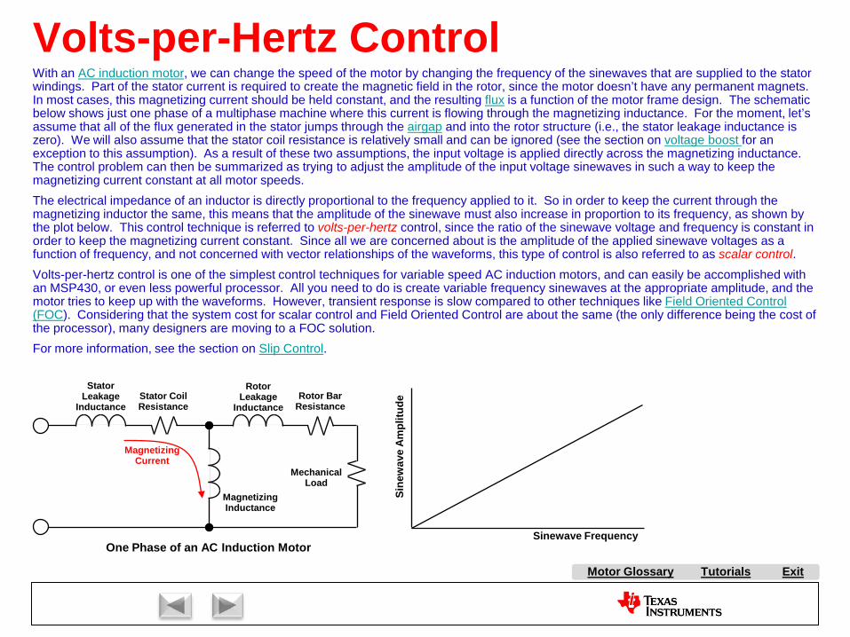
Volts-per-Hertz ControlWith an AC induction motor, we can change the speed of the motor by changing the frequency of the sinewaves that are supplied to the stator windings. Part of the stator current is required to create the magnetic field in the rotor, since the motor doesn’t have any permanent magnets. In most cases, this magnetizing current should be held constant, and the resulting flux is a function of the motor frame design. The schematic below shows just one phase of a multiphase machine where this current is flowing through the magnetizing inductance. For the moment, let’s assume that all of the flux generated in the stator jumps through the airgap and into the rotor structure (i.e., the stator leakage inductance is zero). We will also assume that the stator coil resistance is relatively small and can be ignored (see the section on voltage boost for an exception to this assumption). As a result of these two assumptions, the input voltage is applied directly across the magnetizing inductance. The control problem can then be summarized as trying to adjust the amplitude of the input voltage sinewaves in such a way to keep the magnetizing current constant at all motor speeds.The electrical impedance of an inductor is directly proportional to the frequency applied to it. So in order to keep the current through the magnetizing inductor the same, this means that the amplitude of the sinewave must also increase in proportion to its frequency, as shown by the plot below. This control technique is referred to volts-per-hertz control, since the ratio of the sinewave voltage and frequency is constant in order to keep the magnetizing current constant. Since all we are concerned about is the amplitude of the applied sinewave voltages as a function of frequency, and not concerned with vector relationships of the waveforms, this type of control is also referred to as scalar control. Volts-per-hertz control is one of the simplest control techniques for variable speed AC induction motors, and can easily be accomplished with an MSP430, or even less powerful processor. All you need to do is create variable frequency sinewaves at the appropriate amplitude, and the motor tries to keep up with the waveforms. However, transient response is slow compared to other techniques like Field Oriented Control (FOC). Considering that the system cost for scalar control and Field Oriented Control are about the same (the only difference being the cost of the processor), many designers are moving to a FOC solution.For more information, see the section on Slip Control.
One Phase of an AC Induction Motor
Stator Leakage
Inductance
Rotor Leakage
InductanceStator Coil Resistance
Magnetizing Inductance
Rotor Bar Resistance
Mechanical Load
Magnetizing Current
Sinewave Frequency
Sine
wav
e A
mpl
itude

A AC Induction Motor (ACIM)
AirgapAlignment TorqueB Back-EMFBipolar PWMsBrakingBrush DC (BDC) MotorBrushesBrushless DC (BLDC) MotorBrushless Permanent Magnet
(BPM)C Center-aligned PWMsClark transformCommutationCommutatorConverterCritically DampedCycle-by-cycle current limitD d-axisDC BusDC InjectionDead-timeDead-time DistortionDigital ControlDirect Torque Control (DTC)Duty cycleDynamic BrakingE eCAPEfficiencyElectronically Commutated
Motor (ECM)Encoder
F FeedbackFeedforwardField Oriented Control (FOC)Field WeakeningFluxFlux DensityFull SteppingG Gate DriverH H-BridgeHalf BridgeHalf steppingHall-effect sensorsHorsepowerI Intelligent Power Module
(IPM)Interior Permanent Magnet
MotorInverterJ K L Leakage InductanceLeft-hand RuleLEM sensorM Magnetic LeakageMagnetizing InductanceMicrosteppingN Neodymium Iron Boron
(“Neo”)
S SaliencySampling FrequencyScalar ControlSensorless ControlServoShoot-throughShunt current sensingSlipSlip frequencySlip ControlSpace Vector Modulation (SVM)SPM MotorStatorStepper (Motor) (SM)Switched Reluctance (SR) MotorSynchronous RectificationT TachometerThird-harmonic ModulationTorqueTorque ConstantTrapezoidalU UnderdampedUnipolar PWMsUniversal MotorV Variable Speed Drive (VSD)Vector ControlVoltage boostVolts-per-Hertz ControlW WindupX Y Z Z-Transform
Tutorials Exit
P Park TransformPermanent Magnet
Synchronous Motor (PMSM)
Permanent Magnet AC Motor (PMAC)
PI ControlPID ControlPluggingPowerPower FactorPower QuadrantsPulse Width Modulation
(PWM)
Q q-axis
R Reaction TorqueRegenerationRegenerative BrakingReluctanceReluctance TorqueResistive BrakingResolverRight-hand RuleRotor
E continuedePWMeQEP
O ObserversOff-lineOverdamped
Motor Glossary

Tutorials ExitMotor Glossary
Voltage Boost
One Phase of an AC Induction Motor
Stator Leakage
Inductance
Rotor Leakage
InductanceStator Coil Resistance
Magnetizing Inductance
Rotor Bar Resistance
Mechanical Load
Magnetizing Current
Sinewave FrequencySi
new
ave
Am
plitu
de
Please first read the section on volts-per-hertz control for background information related to this discussion.
At higher sinewave frequencies, we made the assumption that the stator coil resistance and leakage inductance could be ignored. However, as the sinewave frequency gets lower, the impedance of the magnetizing inductance also gets lower. At frequencies typically around 10 Hz, the impedance of the magnetizing inductance gets so low that the stator resistance can no longer be ignored, and more and more of the stator voltage will be dropped across this resistance. To keep the magnetizing current constant and make up for the voltage drop across the resistor, a voltage boost must be applied, as shown in the graph below. Most scalar based motor drives have the ability to add a voltage boost curve, and allow the user to adjust it to conform with the particular motor being controlled.

A AC Induction Motor (ACIM)
AirgapAlignment TorqueB Back-EMFBipolar PWMsBrakingBrush DC (BDC) MotorBrushesBrushless DC (BLDC) MotorBrushless Permanent Magnet
(BPM)C Center-aligned PWMsClark transformCommutationCommutatorConverterCritically DampedCycle-by-cycle current limitD d-axisDC BusDC InjectionDead-timeDead-time DistortionDigital ControlDirect Torque Control (DTC)Duty cycleDynamic BrakingE eCAPEfficiencyElectronically Commutated
Motor (ECM)Encoder
F FeedbackFeedforwardField Oriented Control (FOC)Field WeakeningFluxFlux DensityFull SteppingG Gate DriverH H-BridgeHalf BridgeHalf steppingHall-effect sensorsHorsepowerI Intelligent Power Module
(IPM)Interior Permanent Magnet
MotorInverterJ K L Leakage InductanceLeft-hand RuleLEM sensorM Magnetic LeakageMagnetizing InductanceMicrosteppingN Neodymium Iron Boron
(“Neo”)
S SaliencySampling FrequencyScalar ControlSensorless ControlServoShoot-throughShunt current sensingSlipSlip frequencySlip ControlSpace Vector Modulation (SVM)SPM MotorStatorStepper (Motor) (SM)Switched Reluctance (SR) MotorSynchronous RectificationT TachometerThird-harmonic ModulationTorqueTorque ConstantTrapezoidalU UnderdampedUnipolar PWMsUniversal MotorV Variable Speed Drive (VSD)Vector ControlVoltage boostVolts-per-Hertz ControlW WindupX Y Z Z-Transform
Tutorials Exit
P Park TransformPermanent Magnet
Synchronous Motor (PMSM)
Permanent Magnet AC Motor (PMAC)
PI ControlPID ControlPluggingPowerPower FactorPower QuadrantsPulse Width Modulation
(PWM)
Q q-axis
R Reaction TorqueRegenerationRegenerative BrakingReluctanceReluctance TorqueResistive BrakingResolverRight-hand RuleRotor
E continuedePWMeQEP
O ObserversOff-lineOverdamped
Motor Glossary
Tutorials ExitMotor Glossary
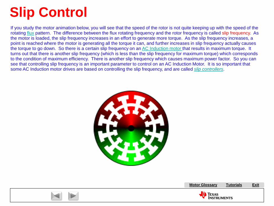
Slip ControlIf you study the motor animation below, you will see that the speed of the rotor is not quite keeping up with the speed of the rotating flux pattern. The difference between the flux rotating frequency and the rotor frequency is called slip frequency. As the motor is loaded, the slip frequency increases in an effort to generate more torque. As the slip frequency increases, a point is reached where the motor is generating all the torque it can, and further increases in slip frequency actually causesthe torque to go down. So there is a certain slip frequency on an AC Induction motor that results in maximum torque. It turns out that there is another slip frequency (which is less than the slip frequency for maximum torque) which corresponds to the condition of maximum efficiency. There is another slip frequency which causes maximum power factor. So you can see that controlling slip frequency is an important parameter to control on an AC Induction Motor. It is so important that some AC Induction motor drives are based on controlling the slip frequency, and are called slip controllers.

A AC Induction Motor (ACIM)
AirgapAlignment TorqueB Back-EMFBipolar PWMsBrakingBrush DC (BDC) MotorBrushesBrushless DC (BLDC) MotorBrushless Permanent Magnet
(BPM)C Center-aligned PWMsClark transformCommutationCommutatorConverterCritically DampedCycle-by-cycle current limitD d-axisDC BusDC InjectionDead-timeDead-time DistortionDigital ControlDirect Torque Control (DTC)Duty cycleDynamic BrakingE eCAPEfficiencyElectronically Commutated
Motor (ECM)Encoder
F FeedbackFeedforwardField Oriented Control (FOC)Field WeakeningFluxFlux DensityFull SteppingG Gate DriverH H-BridgeHalf BridgeHalf steppingHall-effect sensorsHorsepowerI Intelligent Power Module
(IPM)Interior Permanent Magnet
MotorInverterJ K L Leakage InductanceLeft-hand RuleLEM sensorM Magnetic LeakageMagnetizing InductanceMicrosteppingN Neodymium Iron Boron
(“Neo”)
S SaliencySampling FrequencyScalar ControlSensorless ControlServoShoot-throughShunt current sensingSlipSlip frequencySlip ControlSpace Vector Modulation (SVM)SPM MotorStatorStepper (Motor) (SM)Switched Reluctance (SR) MotorSynchronous RectificationT TachometerThird-harmonic ModulationTorqueTorque ConstantTrapezoidalU UnderdampedUnipolar PWMsUniversal MotorV Variable Speed Drive (VSD)Vector ControlVoltage boostVolts-per-Hertz ControlW WindupX Y Z Z-Transform
Tutorials Exit
P Park TransformPermanent Magnet
Synchronous Motor (PMSM)
Permanent Magnet AC Motor (PMAC)
PI ControlPID ControlPluggingPowerPower FactorPower QuadrantsPulse Width Modulation
(PWM)
Q q-axis
R Reaction TorqueRegenerationRegenerative BrakingReluctanceReluctance TorqueResistive BrakingResolverRight-hand RuleRotor
E continuedePWMeQEP
O ObserversOff-lineOverdamped
Motor Glossary

Tutorials ExitMotor Glossary
Clark Transform
( ) ( )tut 23=α
( ) ( ) ( )twtvt 23
23 −=β
u(t) v(t) w(t)β(t)α(t)
A
B
C
w
u
v
A BC
The Clark Transform is one of the steps involved in performing Field Oriented Control (FOC) on a three-phase AC motor. It is actually not a necessary step, but if you don’t do it, the FOC process becomes more tedious. In essence, the Clark transform is a set of mathematical relationships that allow you to represent a three-phase system as a two-phase system, and vice-versa.Consider the three sinewaves u(t), v(t), and w(t), as shown below, which are applied to the C, A, and B stator windings respectively of a three-phase machine. Each winding in the motor is separated spatially from the other windings by 120 degrees, as indicated by the axes A, B, and C in the animation to the right. The instantaneous amplitude of each of the three sinewaves is plotted in real time as a colored vector existing on the axis to which that particular waveform is applied. By adding all of the vectors together, you end up with the resultant black vector, which is rotating!In order to control the instantaneous amplitude and angle of the resultant vector, we need to regulate the three waveforms in real time. While you could do this task with three separate regulators, there is an easier way which is enabled by the Clark transform. Consider the figure below the animation, where we have stopped the animation at a particular location. The resultant black vector is the addition of the u, v, and w vectors. But we can get the SAME resultant vector by only adding two vectors instead of three. In fact, for ANY resultant vector (not just the one shown), we can represent it as the vector addition of an α vector and a β vector, which are at 90 degrees with respect to each other as shown in the illustration. So if we can transform the u, v, and w vectors into equivalent α and βvectors which yield the same resultant vector, then we would only have to regulate TWO values instead of THREE! This is what the forward Clark transform does, as shown by the blue arrow and the blue equations below. The math is very simple, consisting of only three multiplies and one addition.In a typical application, we want to regulate the currents on a three phase motor to get a desired net current (or flux) vector. So we capture the instantaneous three-phase current values with an ADC, and then convert them into equivalent α and β current values using the blue equations below. We then supply these values to TWO current regulators which generate two correction voltages, one for the α axis, and one for the β axis. To apply these two correction voltages to the windings of a three phase machine, we must perform a reverse Clark transform. As you might expect, the reverse Clark transform takes two orthogonal α and β values, and turns them into equivalent u, v, and w values so that they can be applied to the windings of a three phase machine. This is also shown below by the green arrow and green equations.For more information, see the Park Transform, and Field Oriented Control.
α
β
u(t)
v(t)
w(t)
forward
reverse
( ) ( )( ) ( ) ( )( ) ( ) ( )tttw
tttvttu
βα
βαα
31
31
31
31
32
−−=
+−=
=

A AC Induction Motor (ACIM)
AirgapAlignment TorqueB Back-EMFBipolar PWMsBrakingBrush DC (BDC) MotorBrushesBrushless DC (BLDC) MotorBrushless Permanent Magnet
(BPM)C Center-aligned PWMsClark transformCommutationCommutatorConverterCritically DampedCycle-by-cycle current limitD d-axisDC BusDC InjectionDead-timeDead-time DistortionDigital ControlDirect Torque Control (DTC)Duty cycleDynamic BrakingE eCAPEfficiencyElectronically Commutated
Motor (ECM)Encoder
F FeedbackFeedforwardField Oriented Control (FOC)Field WeakeningFluxFlux DensityFull SteppingG Gate DriverH H-BridgeHalf BridgeHalf steppingHall-effect sensorsHorsepowerI Intelligent Power Module
(IPM)Interior Permanent Magnet
MotorInverterJ K L Leakage InductanceLeft-hand RuleLEM sensorM Magnetic LeakageMagnetizing InductanceMicrosteppingN Neodymium Iron Boron
(“Neo”)
S SaliencySampling FrequencyScalar ControlSensorless ControlServoShoot-throughShunt current sensingSlipSlip frequencySlip ControlSpace Vector Modulation (SVM)SPM MotorStatorStepper (Motor) (SM)Switched Reluctance (SR) MotorSynchronous RectificationT TachometerThird-harmonic ModulationTorqueTorque ConstantTrapezoidalU UnderdampedUnipolar PWMsUniversal MotorV Variable Speed Drive (VSD)Vector ControlVoltage boostVolts-per-Hertz ControlW WindupX Y Z Z-Transform
Tutorials Exit
P Park TransformPermanent Magnet
Synchronous Motor (PMSM)
Permanent Magnet AC Motor (PMAC)
PI ControlPID ControlPluggingPowerPower FactorPower QuadrantsPulse Width Modulation
(PWM)
Q q-axis
R Reaction TorqueRegenerationRegenerative BrakingReluctanceReluctance TorqueResistive BrakingResolverRight-hand RuleRotor
E continuedePWMeQEP
O ObserversOff-lineOverdamped
Motor Glossary
Tutorials ExitMotor Glossary
Park Transform
ddq
ddd
iiiiii
θθ
θθ
βα
βα
cossin
sincos
+−=
+= C
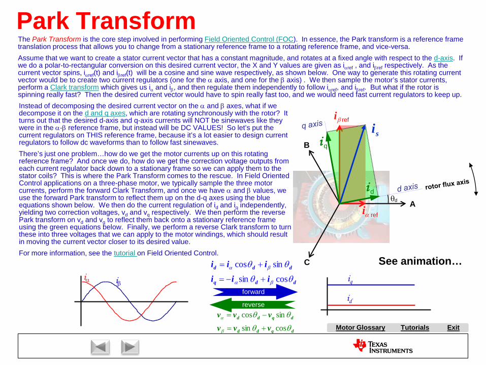
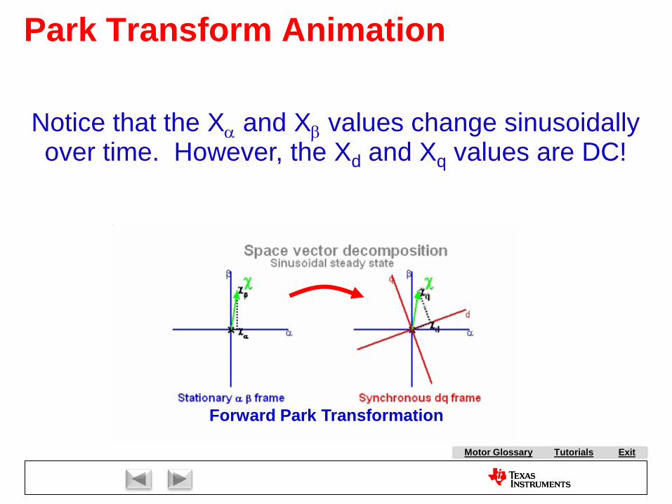
The Park Transform is the core step involved in performing Field Oriented Control (FOC). In essence, the Park transform is a reference frame translation process that allows you to change from a stationary reference frame to a rotating reference frame, and vice-versa.Assume that we want to create a stator current vector that has a constant magnitude, and rotates at a fixed angle with respect to the d-axis. If we do a polar-to-rectangular conversion on this desired current vector, the X and Y values are given as iαref , and iβref respectively. As the current vector spins, iαref(t) and iβref(t) will be a cosine and sine wave respectively, as shown below. One way to generate this rotating current vector would be to create two current regulators (one for the α axis, and one for the β axis) . We then sample the motor’s stator currents, perform a Clark transform which gives us iα and iβ, and then regulate them independently to follow iαref, and iβref. But what if the rotor is spinning really fast? Then the desired current vector would have to spin really fast too, and we would need fast current regulators to keep up.Instead of decomposing the desired current vector on the α and β axes, what if we decompose it on the d and q axes, which are rotating synchronously with the rotor? It turns out that the desired d-axis and q-axis currents will NOT be sinewaves like they were in the α-β reference frame, but instead will be DC VALUES! So let’s put the current regulators on THIS reference frame, because it’s a lot easier to design current regulators to follow dc waveforms than to follow fast sinewaves.There’s just one problem…how do we get the motor currents up on this rotating reference frame? And once we do, how do we get the correction voltage outputs from each current regulator back down to a stationary frame so we can apply them to the stator coils? This is where the Park Transform comes to the rescue. In Field Oriented Control applications on a three-phase motor, we typically sample the three motor currents, perform the forward Clark Transform, and once we have α and β values, we use the forward Park transform to reflect them up on the d-q axes using the blue equations shown below. We then do the current regulation of id and iq independently, yielding two correction voltages, vd and vq respectively. We then perform the reverse Park transform on vd and vq to reflect them back onto a stationary reference frame using the green equations below. Finally, we perform a reverse Clark transform to turn these into three voltages that we can apply to the motor windings, which should result in moving the current vector closer to its desired value.For more information, see the tutorial on Field Oriented Control.
iα iβ
id
iq
αi
βi
A
Bsi
θd
i q
i d
ref
ref
dqdd
dqdd
vvvvvv
θθ
θθ
β
α
cossin
sincos
+=
−=
See animation…
forward
reverse
Tutorials ExitMotor Glossary
Park Transform Animation
Forward Park Transformation
Notice that the Xα and Xβ values change sinusoidally over time. However, the Xd and Xq values are DC!

A AC Induction Motor (ACIM)
AirgapAlignment TorqueB Back-EMFBipolar PWMsBrakingBrush DC (BDC) MotorBrushesBrushless DC (BLDC) MotorBrushless Permanent Magnet
(BPM)C Center-aligned PWMsClark transformCommutationCommutatorConverterCritically DampedCycle-by-cycle current limitD d-axisDC BusDC InjectionDead-timeDead-time DistortionDigital ControlDirect Torque Control (DTC)Duty cycleDynamic BrakingE eCAPEfficiencyElectronically Commutated
Motor (ECM)Encoder
F FeedbackFeedforwardField Oriented Control (FOC)Field WeakeningFluxFlux DensityFull SteppingG Gate DriverH H-BridgeHalf BridgeHalf steppingHall-effect sensorsHorsepowerI Intelligent Power Module
(IPM)Interior Permanent Magnet
MotorInverterJ K L Leakage InductanceLeft-hand RuleLEM sensorM Magnetic LeakageMagnetizing InductanceMicrosteppingN Neodymium Iron Boron
(“Neo”)
S SaliencySampling FrequencyScalar ControlSensorless ControlServoShoot-throughShunt current sensingSlipSlip frequencySlip ControlSpace Vector Modulation (SVM)SPM MotorStatorStepper (Motor) (SM)Switched Reluctance (SR) MotorSynchronous RectificationT TachometerThird-harmonic ModulationTorqueTorque ConstantTrapezoidalU UnderdampedUnipolar PWMsUniversal MotorV Variable Speed Drive (VSD)Vector ControlVoltage boostVolts-per-Hertz ControlW WindupX Y Z Z-Transform
Tutorials Exit
P Park TransformPermanent Magnet
Synchronous Motor (PMSM)
Permanent Magnet AC Motor (PMAC)
PI ControlPID ControlPluggingPowerPower FactorPower QuadrantsPulse Width Modulation
(PWM)
Q q-axis
R Reaction TorqueRegenerationRegenerative BrakingReluctanceReluctance TorqueResistive BrakingResolverRight-hand RuleRotor
E continuedePWMeQEP
O ObserversOff-lineOverdamped
Motor Glossary
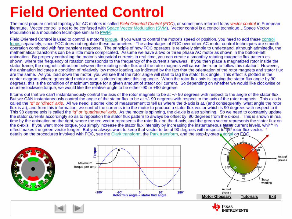
Tutorials ExitMotor Glossary
Field Oriented Control
0.0s 0.3s 0.6s 0.9s 1.2s 1.5s 1.8s 2.1s 2.4s 2.7s 3.0s 3.3s 3.6s-200V
-150V
-100V
-50V
0V
50V
100V
150V
200VV(treaction)
Torq
ue
Maximum torque per amp
Rotor flux angle – stator flux angle
The most popular control topology for AC motors is called Field Oriented Control (FOC), or sometimes referred to as vector control in European literature. Vector control is not to be confused with Space Vector Modulation (SVM). Vector control is a control technique…Space Vector Modulation is a modulation technique similar to PWM.Field Oriented Control is used to control a motor’s torque. If you want to control the motor’s speed or position, you need to add these control loops separately, since FOC does not regulate these parameters. The advantages of FOC over other AC motor control techniques are smooth operation combined with fast transient response. The principle of how FOC operates is relatively simple to understand, although admittedly, the mathematical transforms can be a little more complicated. Assume we have a two or three phase AC motor as shown in the bottom-left animation. By properly controlling the motor’s sinusoidal currents in real time, you can create a smoothly rotating magnetic flux pattern as shown, where the frequency of rotation corresponds to the frequency of the current sinewaves. If you then place a magnetized rotor inside the stator frame, the magnetic attraction between the rotating stator flux and the rotor magnets will cause the rotor to follow this rotation. However, the animation indicates a condition of relatively low motor loading, as indicated by the fact that the orientation of the rotor magnets and stator flux are the same. As you load down the motor, you will see that the rotor angle will start to lag the stator flux angle. This effect is plotted in the center diagram, where generated motor torque is plotted against this lag angle. When the rotor flux axis is lagging the stator flux angle by 90 degrees, this is the condition of maximum torque for a given amount of stator coil current. So depending on whether we would like clockwise or counterclockwise torque, we would like the relative angle to be either -90 or +90 degrees.It turns out that we can’t instantaneously control the axis of the rotor magnets to be at +/- 90 degrees with respect to the angle of the stator flux. But we CAN instantaneously control the angle of the stator flux to be at +/- 90 degrees with respect to the axis of the rotor magnets. This axis is called the “d” or “direct” axis. All we need is some kind of measurement to tell us where the d-axis is at, (and consequently, what angle the rotor flux is at), and from this information, we control the currents into the motor to produce a stator flux vector which is 90 degrees with respect to it. This 90 degree axis is called the “q” or “quadrature” axis. As the motor is spinning, the d-axis is also spinning. So we need to constantly update the stator currents accordingly so as to reposition the stator flux pattern to always be offset by 90 degrees from the d-axis. This is shown in real time by the animation on the right, where the red vector represents the rotor flux on the d-axis, and the green vector represents the stator flux on the q-axis. If you want more torque, you simply increase the stator flux intensity by increasing the instantaneous stator current levels, which in effect makes the green vector longer. But you always want to keep that vector to be at 90 degrees with respect to the rotor flux vector. For more details on the procedures involved with FOC, see the Clark transform, the Park transform, and the step-by-step tutorial on FOC.
0º-90º 90º-180º 180º

A AC Induction Motor (ACIM)
AirgapAlignment TorqueB Back-EMFBipolar PWMsBrakingBrush DC (BDC) MotorBrushesBrushless DC (BLDC) MotorBrushless Permanent Magnet
(BPM)C Center-aligned PWMsClark transformCommutationCommutatorConverterCritically DampedCycle-by-cycle current limitD d-axisDC BusDC InjectionDead-timeDead-time DistortionDigital ControlDirect Torque Control (DTC)Duty cycleDynamic BrakingE eCAPEfficiencyElectronically Commutated
Motor (ECM)Encoder
F FeedbackFeedforwardField Oriented Control (FOC)Field WeakeningFluxFlux DensityFull SteppingG Gate DriverH H-BridgeHalf BridgeHalf steppingHall-effect sensorsHorsepowerI Intelligent Power Module
(IPM)Interior Permanent Magnet
MotorInverterJ K L Leakage InductanceLeft-hand RuleLEM sensorM Magnetic LeakageMagnetizing InductanceMicrosteppingN Neodymium Iron Boron
(“Neo”)
S SaliencySampling FrequencyScalar ControlSensorless ControlServoShoot-throughShunt current sensingSlipSlip frequencySlip ControlSpace Vector Modulation (SVM)SPM MotorStatorStepper (Motor) (SM)Switched Reluctance (SR) MotorSynchronous RectificationT TachometerThird-harmonic ModulationTorqueTorque ConstantTrapezoidalU UnderdampedUnipolar PWMsUniversal MotorV Variable Speed Drive (VSD)Vector ControlVoltage boostVolts-per-Hertz ControlW WindupX Y Z Z-Transform
Tutorials Exit
P Park TransformPermanent Magnet
Synchronous Motor (PMSM)
Permanent Magnet AC Motor (PMAC)
PI ControlPID ControlPluggingPowerPower FactorPower QuadrantsPulse Width Modulation
(PWM)
Q q-axis
R Reaction TorqueRegenerationRegenerative BrakingReluctanceReluctance TorqueResistive BrakingResolverRight-hand RuleRotor
E continuedePWMeQEP
O ObserversOff-lineOverdamped
Motor Glossary

Tutorials ExitMotor Glossary
Field WeakeningAll magnetic motors use flux. It is the flux in the motor that leads to torque which leads to motor movement. The more flux, the more torque in most cases. But there are situations where you can have too much flux.
A coil of wire will generate a back-EMF across its terminals if the flux through the loop of wire is changing. The amplitude of this voltage is dependent on how much the flux cutting through the loop of wire is changing over time (i.e., d-flux/dt). As a motor goes faster and faster, the “d-flux” stays the same, but the “dt” gets smaller and smaller. This tends to increase the back-EMF voltage of the coil. Back-EMF is usually a good thing, as it limits the amount of current that will flow in the coil. Without back-EMF voltage, every motor would essentially draw its stall current all the time. But because of the back-EMF effect, a speed is soon reached where the back-EMF voltage amplitude equals the supply voltage that is driving the motor. At that point, the current goes to zero, and the motor cannot go any faster. If the motor has to go faster, the d-flux/dt in the motor must be reduced. Since the “dt” part of the equation is fixed to the motor speed, the only way to decrease the back-EMF is to decrease the amount of flux which is cutting through the winding. This is called field weakening.
Let’s look at this effect on an AC induction motor. If the motor is being driven by a Volts-per-Hertz control topology, the ratio of voltage to frequency is set in an attempt to keep the flux in the machine at a constant value. As the speed is increased, the sinewave amplitudes increase proportionally, until you reach the point of rated line frequency, where you are applying maximum voltage. If the frequency increases further, the voltage cannot follow it higher, and you get a natural field weakening effect as shown by the graph to the left. On the other hand, if you are using Field Oriented Control, the flux in the machine is controlled directly. So when the rated speed of the motor is reached, you must MANUALLY dial back the d-axis current to lower the flux in the machine to reduce the back-EMF voltage. The graph to the right shows a simulation where a control-loop was used to monitor the voltage amplitude being applied to the motor, and adjust the d-axis reference current accordingly. Other techniques simply use a look-up table designed for that specific motor, where the appropriate value for the d-axis reference current is fetched from the table as a function of motor speed.
Sinewave Frequency
Sine
wav
e Vo
ltage
Rated speed
Flux
Am
plitu
de
Motor Flux
Motor Torque
Motor SpeedMax Speed w/o WeakeningVoltage at max.

A AC Induction Motor (ACIM)
AirgapAlignment TorqueB Back-EMFBipolar PWMsBrakingBrush DC (BDC) MotorBrushesBrushless DC (BLDC) MotorBrushless Permanent Magnet
(BPM)C Center-aligned PWMsClark transformCommutationCommutatorConverterCritically DampedCycle-by-cycle current limitD d-axisDC BusDC InjectionDead-timeDead-time DistortionDigital ControlDirect Torque Control (DTC)Duty cycleDynamic BrakingE eCAPEfficiencyElectronically Commutated
Motor (ECM)Encoder
F FeedbackFeedforwardField Oriented Control (FOC)Field WeakeningFluxFlux DensityFull SteppingG Gate DriverH H-BridgeHalf BridgeHalf steppingHall-effect sensorsHorsepowerI Intelligent Power Module
(IPM)Interior Permanent Magnet
MotorInverterJ K L Leakage InductanceLeft-hand RuleLEM sensorM Magnetic LeakageMagnetizing InductanceMicrosteppingN Neodymium Iron Boron
(“Neo”)
S SaliencySampling FrequencyScalar ControlSensorless ControlServoShoot-throughShunt current sensingSlipSlip frequencySlip ControlSpace Vector Modulation (SVM)SPM MotorStatorStepper (Motor) (SM)Switched Reluctance (SR) MotorSynchronous RectificationT TachometerThird-harmonic ModulationTorqueTorque ConstantTrapezoidalU UnderdampedUnipolar PWMsUniversal MotorV Variable Speed Drive (VSD)Vector ControlVoltage boostVolts-per-Hertz ControlW WindupX Y Z Z-Transform
Tutorials Exit
P Park TransformPermanent Magnet
Synchronous Motor (PMSM)
Permanent Magnet AC Motor (PMAC)
PI ControlPID ControlPluggingPowerPower FactorPower QuadrantsPulse Width Modulation
(PWM)
Q q-axis
R Reaction TorqueRegenerationRegenerative BrakingReluctanceReluctance TorqueResistive BrakingResolverRight-hand RuleRotor
E continuedePWMeQEP
O ObserversOff-lineOverdamped
Motor Glossary
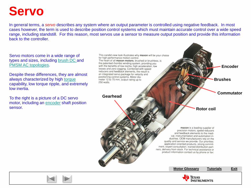
Tutorials ExitMotor Glossary
Rotor coil
Gearhead
Brushes
Commutator
Encoder
ServoIn general terms, a servo describes any system where an output parameter is controlled using negative feedback. In most cases however, the term is used to describe position control systems which must maintain accurate control over a wide speed range, including standstill. For this reason, most servos use a sensor to measure output position and provide this information back to the controller.
Servo motors come in a wide range of types and sizes, including brush DC and PMSM AC topologies.
Despite these differences, they are almost always characterized by high torquecapability, low torque ripple, and extremely low inertia.
To the right is a picture of a DC servo motor, including an encoder shaft position sensor.

A AC Induction Motor (ACIM)
AirgapAlignment TorqueB Back-EMFBipolar PWMsBrakingBrush DC (BDC) MotorBrushesBrushless DC (BLDC) MotorBrushless Permanent Magnet
(BPM)C Center-aligned PWMsClark transformCommutationCommutatorConverterCritically DampedCycle-by-cycle current limitD d-axisDC BusDC InjectionDead-timeDead-time DistortionDigital ControlDirect Torque Control (DTC)Duty cycleDynamic BrakingE eCAPEfficiencyElectronically Commutated
Motor (ECM)Encoder
F FeedbackFeedforwardField Oriented Control (FOC)Field WeakeningFluxFlux DensityFull SteppingG Gate DriverH H-BridgeHalf BridgeHalf steppingHall-effect sensorsHorsepowerI Intelligent Power Module
(IPM)Interior Permanent Magnet
MotorInverterJ K L Leakage InductanceLeft-hand RuleLEM sensorM Magnetic LeakageMagnetizing InductanceMicrosteppingN Neodymium Iron Boron
(“Neo”)
S SaliencySampling FrequencyScalar ControlSensorless ControlServoShoot-throughShunt current sensingSlipSlip frequencySlip ControlSpace Vector Modulation (SVM)SPM MotorStatorStepper (Motor) (SM)Switched Reluctance (SR) MotorSynchronous RectificationT TachometerThird-harmonic ModulationTorqueTorque ConstantTrapezoidalU UnderdampedUnipolar PWMsUniversal MotorV Variable Speed Drive (VSD)Vector ControlVoltage boostVolts-per-Hertz ControlW WindupX Y Z Z-Transform
Tutorials Exit
P Park TransformPermanent Magnet
Synchronous Motor (PMSM)
Permanent Magnet AC Motor (PMAC)
PI ControlPID ControlPluggingPowerPower FactorPower QuadrantsPulse Width Modulation
(PWM)
Q q-axis
R Reaction TorqueRegenerationRegenerative BrakingReluctanceReluctance TorqueResistive BrakingResolverRight-hand RuleRotor
E continuedePWMeQEP
O ObserversOff-lineOverdamped
Motor Glossary

Tutorials ExitMotor Glossary
Airgap
Airgap
All electric motors have an airgap, which is the circular space between the rotor and the stator. On one hand, the motor designer needs to keep the airgap as small as possible in order to minimize the reluctance of the flux which is required to link the rotor and stator together magnetically. On an AC Induction Motor, the flux which links both the rotor and the stator is called the magnetizing flux, and is modeled by a magnetizing inductance which is common to the both the rotor and stator circuits. If the gap is too large, many of the flux lines will not even try to jump it, and will simply find another path. This situation is called magnetic leakage, which is modeled by leakage inductance in both the rotor and stator circuits. Leakage inductance is not good, and should be minimized as much as possible.
However, if the airgap gets too small, the motor manufacturer will not be able to hold the tight tolerances required to keep therotor from rubbing against the stator while it is spinning. Due to the centrifugal forces acting on the rotor at high speeds, some amount of flexing of the rotor material may occur which will expand into the airgap. So designing the motor to have a properairgap is like walking a tightrope where you don’t want to err too much on either side.
One Phase of an AC Induction Motor
Stator Leakage Inductance
Rotor Leakage
InductanceStator Coil Resistance
Magnetizing Inductance
Rotor Bar Resistance
Load Model

A AC Induction Motor (ACIM)
AirgapAlignment TorqueB Back-EMFBipolar PWMsBrakingBrush DC (BDC) MotorBrushesBrushless DC (BLDC) MotorBrushless Permanent Magnet
(BPM)C Center-aligned PWMsClark transformCommutationCommutatorConverterCritically DampedCycle-by-cycle current limitD d-axisDC BusDC InjectionDead-timeDead-time DistortionDigital ControlDirect Torque Control (DTC)Duty cycleDynamic BrakingE eCAPEfficiencyElectronically Commutated
Motor (ECM)Encoder
F FeedbackFeedforwardField Oriented Control (FOC)Field WeakeningFluxFlux DensityFull SteppingG Gate DriverH H-BridgeHalf BridgeHalf steppingHall-effect sensorsHorsepowerI Intelligent Power Module
(IPM)Interior Permanent Magnet
MotorInverterJ K L Leakage InductanceLeft-hand RuleLEM sensorM Magnetic LeakageMagnetizing InductanceMicrosteppingN Neodymium Iron Boron
(“Neo”)
S SaliencySampling FrequencyScalar ControlSensorless ControlServoShoot-throughShunt current sensingSlipSlip frequencySlip ControlSpace Vector Modulation (SVM)SPM MotorStatorStepper (Motor) (SM)Switched Reluctance (SR) MotorSynchronous RectificationT TachometerThird-harmonic ModulationTorqueTorque ConstantTrapezoidalU UnderdampedUnipolar PWMsUniversal MotorV Variable Speed Drive (VSD)Vector ControlVoltage boostVolts-per-Hertz ControlW WindupX Y Z Z-Transform
Tutorials Exit
P Park TransformPermanent Magnet
Synchronous Motor (PMSM)
Permanent Magnet AC Motor (PMAC)
PI ControlPID ControlPluggingPowerPower FactorPower QuadrantsPulse Width Modulation
(PWM)
Q q-axis
R Reaction TorqueRegenerationRegenerative BrakingReluctanceReluctance TorqueResistive BrakingResolverRight-hand RuleRotor
E continuedePWMeQEP
O ObserversOff-lineOverdamped
Motor Glossary
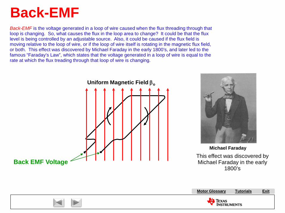
Tutorials ExitMotor Glossary
Back-EMF is the voltage generated in a loop of wire caused when the flux threading through that loop is changing. So, what causes the flux in the loop area to change? It could be that the flux level is being controlled by an adjustable source. Also, it could be caused if the flux field is moving relative to the loop of wire, or if the loop of wire itself is rotating in the magnetic flux field, or both. This effect was discovered by Michael Faraday in the early 1800’s, and later led to the famous “Faraday’s Law”, which states that the voltage generated in a loop of wire is equal to the rate at which the flux treading through that loop of wire is changing.
Michael Faraday
Back EMF Voltage
Uniform Magnetic Field βo
Back-EMF
This effect was discovered by Michael Faraday in the early
1800’s

A AC Induction Motor (ACIM)
AirgapAlignment TorqueB Back-EMFBipolar PWMsBrakingBrush DC (BDC) MotorBrushesBrushless DC (BLDC) MotorBrushless Permanent Magnet
(BPM)C Center-aligned PWMsClark transformCommutationCommutatorConverterCritically DampedCycle-by-cycle current limitD d-axisDC BusDC InjectionDead-timeDead-time DistortionDigital ControlDirect Torque Control (DTC)Duty cycleDynamic BrakingE eCAPEfficiencyElectronically Commutated
Motor (ECM)Encoder
F FeedbackFeedforwardField Oriented Control (FOC)Field WeakeningFluxFlux DensityFull SteppingG Gate DriverH H-BridgeHalf BridgeHalf steppingHall-effect sensorsHorsepowerI Intelligent Power Module
(IPM)Interior Permanent Magnet
MotorInverterJ K L Leakage InductanceLeft-hand RuleLEM sensorM Magnetic LeakageMagnetizing InductanceMicrosteppingN Neodymium Iron Boron
(“Neo”)
S SaliencySampling FrequencyScalar ControlSensorless ControlServoShoot-throughShunt current sensingSlipSlip frequencySlip ControlSpace Vector Modulation (SVM)SPM MotorStatorStepper (Motor) (SM)Switched Reluctance (SR) MotorSynchronous RectificationT TachometerThird-harmonic ModulationTorqueTorque ConstantTrapezoidalU UnderdampedUnipolar PWMsUniversal MotorV Variable Speed Drive (VSD)Vector ControlVoltage boostVolts-per-Hertz ControlW WindupX Y Z Z-Transform
Tutorials Exit
P Park TransformPermanent Magnet
Synchronous Motor (PMSM)
Permanent Magnet AC Motor (PMAC)
PI ControlPID ControlPluggingPowerPower FactorPower QuadrantsPulse Width Modulation
(PWM)
Q q-axis
R Reaction TorqueRegenerationRegenerative BrakingReluctanceReluctance TorqueResistive BrakingResolverRight-hand RuleRotor
E continuedePWMeQEP
O ObserversOff-lineOverdamped
Motor Glossary
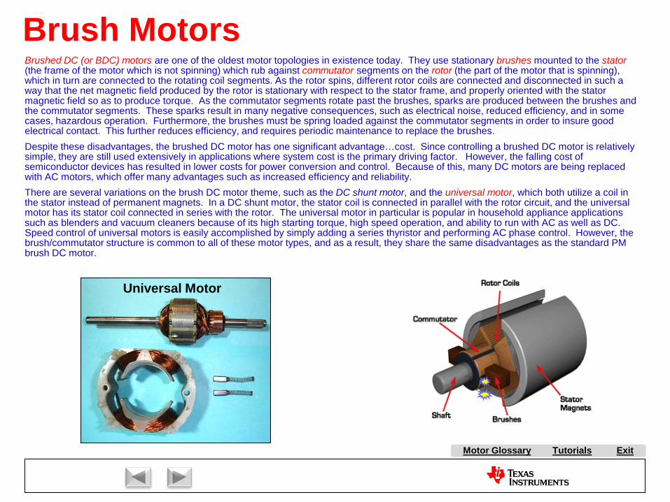
Tutorials ExitMotor Glossary
Brushed DC (or BDC) motors are one of the oldest motor topologies in existence today. They use stationary brushes mounted to the stator(the frame of the motor which is not spinning) which rub against commutator segments on the rotor (the part of the motor that is spinning), which in turn are connected to the rotating coil segments. As the rotor spins, different rotor coils are connected and disconnected in such a way that the net magnetic field produced by the rotor is stationary with respect to the stator frame, and properly oriented with the stator magnetic field so as to produce torque. As the commutator segments rotate past the brushes, sparks are produced between the brushes and the commutator segments. These sparks result in many negative consequences, such as electrical noise, reduced efficiency, and in some cases, hazardous operation. Furthermore, the brushes must be spring loaded against the commutator segments in order to insure good electrical contact. This further reduces efficiency, and requires periodic maintenance to replace the brushes.Despite these disadvantages, the brushed DC motor has one significant advantage…cost. Since controlling a brushed DC motor is relatively simple, they are still used extensively in applications where system cost is the primary driving factor. However, the falling cost of semiconductor devices has resulted in lower costs for power conversion and control. Because of this, many DC motors are being replaced with AC motors, which offer many advantages such as increased efficiency and reliability.There are several variations on the brush DC motor theme, such as the DC shunt motor, and the universal motor, which both utilize a coil in the stator instead of permanent magnets. In a DC shunt motor, the stator coil is connected in parallel with the rotor circuit, and the universal motor has its stator coil connected in series with the rotor. The universal motor in particular is popular in household appliance applications such as blenders and vacuum cleaners because of its high starting torque, high speed operation, and ability to run with AC as well as DC. Speed control of universal motors is easily accomplished by simply adding a series thyristor and performing AC phase control. However, the brush/commutator structure is common to all of these motor types, and as a result, they share the same disadvantages as the standard PM brush DC motor.
Brush Motors
Universal Motor

A AC Induction Motor (ACIM)
AirgapAlignment TorqueB Back-EMFBipolar PWMsBrakingBrush DC (BDC) MotorBrushesBrushless DC (BLDC) MotorBrushless Permanent Magnet
(BPM)C Center-aligned PWMsClark transformCommutationCommutatorConverterCritically DampedCycle-by-cycle current limitD d-axisDC BusDC InjectionDead-timeDead-time DistortionDigital ControlDirect Torque Control (DTC)Duty cycleDynamic BrakingE eCAPEfficiencyElectronically Commutated
Motor (ECM)Encoder
F FeedbackFeedforwardField Oriented Control (FOC)Field WeakeningFluxFlux DensityFull SteppingG Gate DriverH H-BridgeHalf BridgeHalf steppingHall-effect sensorsHorsepowerI Intelligent Power Module
(IPM)Interior Permanent Magnet
MotorInverterJ K L Leakage InductanceLeft-hand RuleLEM sensorM Magnetic LeakageMagnetizing InductanceMicrosteppingN Neodymium Iron Boron
(“Neo”)
S SaliencySampling FrequencyScalar ControlSensorless ControlServoShoot-throughShunt current sensingSlipSlip frequencySlip ControlSpace Vector Modulation (SVM)SPM MotorStatorStepper (Motor) (SM)Switched Reluctance (SR) MotorSynchronous RectificationT TachometerThird-harmonic ModulationTorqueTorque ConstantTrapezoidalU UnderdampedUnipolar PWMsUniversal MotorV Variable Speed Drive (VSD)Vector ControlVoltage boostVolts-per-Hertz ControlW WindupX Y Z Z-Transform
Tutorials Exit
P Park TransformPermanent Magnet
Synchronous Motor (PMSM)
Permanent Magnet AC Motor (PMAC)
PI ControlPID ControlPluggingPowerPower FactorPower QuadrantsPulse Width Modulation
(PWM)
Q q-axis
R Reaction TorqueRegenerationRegenerative BrakingReluctanceReluctance TorqueResistive BrakingResolverRight-hand RuleRotor
E continuedePWMeQEP
O ObserversOff-lineOverdamped
Motor Glossary

Tutorials ExitMotor Glossary
BPM MotorsOne of the most popular categories of motors is the Brushless Permanent Magnet (or BPM) family. As the name implies, this description applies to any motor which does not have brushes, and utilizes permanent magnets in the rotor. Technically, all motors in this category are AC MOTORS, since the stator coils must be driven by AC waveforms to cause rotation. The most common members of this family consist of the Brushless DC (or BLDC) motor, and the Permanent Magnet Synchronous Motor (PMSM, which is sometimes referred to as the Permanent Magnet AC (PMAC) motor). BPM, PMSM, and PMAC nomenclatures are often used interchangeably, since BPM motors are all AC, and they are all synchronous. However, PMSM and PMAC variants usually imply that the windings are driven with sinewaves, which distinguishes them from BLDC motors which are most commonly driven with squarewaves. If the magnets are mounted on the surface of the rotor, it is called a Surface Permanent Magnet (SPM) motor. This topology results in very low torque ripple and very smooth performance. Recently, a variation of the PMSM motor has become more popular, where the rotor magnets are buried inside the rotor structure. These machines are called Interior Permanent Magnet (IPM) motors. Technically, even the Stepper Motor (SM) falls into the BPM category, but it is usually split out as a separate motor type.
The cost of BPM motors has fallen over the last decade, primarily due to the availability of an extremely powerful magnetic compound known as Neodymium Iron Boron, or simply “Neo” for short. Neodymium is a rare earth element with incredibly high flux density capabilities, making it ideally suited for permanent magnets . China is currently the largest supplier of Neodymium, which has brought down the global price for this material, making BPM motors much more affordable.
SPM Motor
B
B
C
CN
S
A
A
BLDC Motor IPM Motor

A AC Induction Motor (ACIM)
AirgapAlignment TorqueB Back-EMFBipolar PWMsBrakingBrush DC (BDC) MotorBrushesBrushless DC (BLDC) MotorBrushless Permanent Magnet
(BPM)C Center-aligned PWMsClark transformCommutationCommutatorConverterCritically DampedCycle-by-cycle current limitD d-axisDC BusDC InjectionDead-timeDead-time DistortionDigital ControlDirect Torque Control (DTC)Duty cycleDynamic BrakingE eCAPEfficiencyElectronically Commutated
Motor (ECM)Encoder
F FeedbackFeedforwardField Oriented Control (FOC)Field WeakeningFluxFlux DensityFull SteppingG Gate DriverH H-BridgeHalf BridgeHalf steppingHall-effect sensorsHorsepowerI Intelligent Power Module
(IPM)Interior Permanent Magnet
MotorInverterJ K L Leakage InductanceLeft-hand RuleLEM sensorM Magnetic LeakageMagnetizing InductanceMicrosteppingN Neodymium Iron Boron
(“Neo”)
S SaliencySampling FrequencyScalar ControlSensorless ControlServoShoot-throughShunt current sensingSlipSlip frequencySlip ControlSpace Vector Modulation (SVM)SPM MotorStatorStepper (Motor) (SM)Switched Reluctance (SR) MotorSynchronous RectificationT TachometerThird-harmonic ModulationTorqueTorque ConstantTrapezoidalU UnderdampedUnipolar PWMsUniversal MotorV Variable Speed Drive (VSD)Vector ControlVoltage boostVolts-per-Hertz ControlW WindupX Y Z Z-Transform
Tutorials Exit
P Park TransformPermanent Magnet
Synchronous Motor (PMSM)
Permanent Magnet AC Motor (PMAC)
PI ControlPID ControlPluggingPowerPower FactorPower QuadrantsPulse Width Modulation
(PWM)
Q q-axis
R Reaction TorqueRegenerationRegenerative BrakingReluctanceReluctance TorqueResistive BrakingResolverRight-hand RuleRotor
E continuedePWMeQEP
O ObserversOff-lineOverdamped
Motor Glossary

Tutorials ExitMotor Glossary
Brushless DC MotorsThe brushless DC (BLDC) motor can be envisioned as a brush DC motor turned inside out, where the permanent magnets are on the rotor, and the windings are on the stator. As a result, there are no brushes and commutators in this motor, and all of the disadvantages associated with the sparking of brush DC motors are eliminated.This motor is referred to as a “DC” motor because its coils are driven by a DC power source which is applied to the stator coils in a predetermined sequential pattern. This creates trapezoidal waveforms (see below) via a process known as commutation. When the current in a BLDC motor is commutated, it is essentially turned off on one phase, and simultaneously switched to another phase. However, “BLDC” is really a misnomer, since the motor is really an AC motor. The current in each coil alternates from positive to negative during each electrical cycle. Another name often used for the BLDC motor is the ECM, or Electronically Commutated Motor, as it is known by in the heating industry.A common misconception about the BLDC motor is related to how it is driven. Unlike an open-loop stepper application where the rotor position is determined by which stator coil is driven, in a BLDC motor, which stator coil is driven is determined by the rotor position. In other words, knowledge of the rotor position is required in order to determine which stator coils to energize. Several techniques exist to do this, but the most popular technique is to monitor the rotor position using hall-effect sensors. Unfortunately, these sensors and their associated connectors and harnesses result in increased system cost, and reduced reliability.In an effort to mitigate these issues, several techniques have been developed to eliminate these sensors, resulting in sensorless operation. Most of these techniques are based upon extracting position information from the back-EMF waveforms of the stator windings while the motor is spinning. However, techniques based on back-EMF sensing fall apart when the motor is spinning slowly or at a standstill, since the back-EMF waveforms are faint or non-existent. As a result, the motor is often crudely started without knowledge of the rotor position until it gets up enough speed to generate measurable back-EMF signals.BLDC motors reign supreme in efficiency ratings, where values in the mid-nineties percent range areroutinely obtained. They also compete for the title of fastest motor in the world, with speeds onsome motors achieving several hundred thousand RPM.The most common BLDC motor topology utilizes a stator structure consisting of three phases.As a result, a standard 6-transistor inverter is the most commonly used power stage.Depending on the operational requirements (sensored vs. sensorless, commutated vs. sinusoidal, PWM vs. SVM, etc.) there are many different ways to drive the transistors to achieve the desired goal, which are too numerous to cover here. This places a significant demand on the flexibility of the PWM generator, which is typically located in the microcontroller. The good news is that all of these requirements are easily achieved in TI’s motor control processors.
B
B
C
CN
S
A
A
0o 60o 120o 180o 240o 300o 360o
Trapezoidal Waveforms
Phase A
Phase B
Phase C

A AC Induction Motor (ACIM)
AirgapAlignment TorqueB Back-EMFBipolar PWMsBrakingBrush DC (BDC) MotorBrushesBrushless DC (BLDC) MotorBrushless Permanent Magnet
(BPM)C Center-aligned PWMsClark transformCommutationCommutatorConverterCritically DampedCycle-by-cycle current limitD d-axisDC BusDC InjectionDead-timeDead-time DistortionDigital ControlDirect Torque Control (DTC)Duty cycleDynamic BrakingE eCAPEfficiencyElectronically Commutated
Motor (ECM)Encoder
F FeedbackFeedforwardField Oriented Control (FOC)Field WeakeningFluxFlux DensityFull SteppingG Gate DriverH H-BridgeHalf BridgeHalf steppingHall-effect sensorsHorsepowerI Intelligent Power Module
(IPM)Interior Permanent Magnet
MotorInverterJ K L Leakage InductanceLeft-hand RuleLEM sensorM Magnetic LeakageMagnetizing InductanceMicrosteppingN Neodymium Iron Boron
(“Neo”)
S SaliencySampling FrequencyScalar ControlSensorless ControlServoShoot-throughShunt current sensingSlipSlip frequencySlip ControlSpace Vector Modulation (SVM)SPM MotorStatorStepper (Motor) (SM)Switched Reluctance (SR) MotorSynchronous RectificationT TachometerThird-harmonic ModulationTorqueTorque ConstantTrapezoidalU UnderdampedUnipolar PWMsUniversal MotorV Variable Speed Drive (VSD)Vector ControlVoltage boostVolts-per-Hertz ControlW WindupX Y Z Z-Transform
Tutorials Exit
P Park TransformPermanent Magnet
Synchronous Motor (PMSM)
Permanent Magnet AC Motor (PMAC)
PI ControlPID ControlPluggingPowerPower FactorPower QuadrantsPulse Width Modulation
(PWM)
Q q-axis
R Reaction TorqueRegenerationRegenerative BrakingReluctanceReluctance TorqueResistive BrakingResolverRight-hand RuleRotor
E continuedePWMeQEP
O ObserversOff-lineOverdamped
Motor Glossary
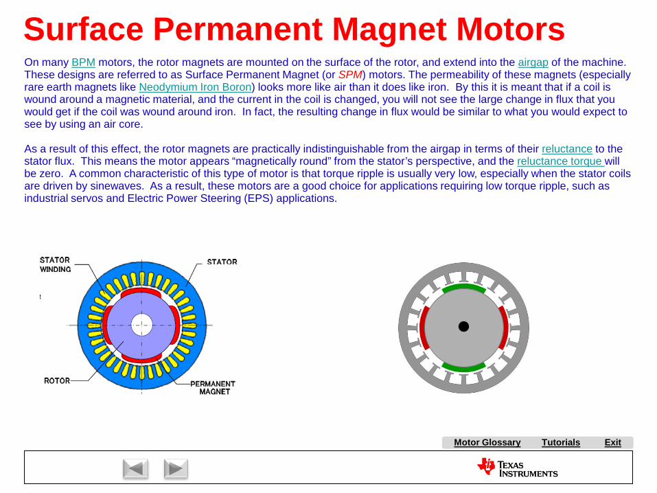
Tutorials ExitMotor Glossary
Surface Permanent Magnet MotorsOn many BPM motors, the rotor magnets are mounted on the surface of the rotor, and extend into the airgap of the machine. These designs are referred to as Surface Permanent Magnet (or SPM) motors. The permeability of these magnets (especially rare earth magnets like Neodymium Iron Boron) looks more like air than it does like iron. By this it is meant that if a coil is wound around a magnetic material, and the current in the coil is changed, you will not see the large change in flux that you would get if the coil was wound around iron. In fact, the resulting change in flux would be similar to what you would expect tosee by using an air core.
As a result of this effect, the rotor magnets are practically indistinguishable from the airgap in terms of their reluctance to the stator flux. This means the motor appears “magnetically round” from the stator’s perspective, and the reluctance torque will be zero. A common characteristic of this type of motor is that torque ripple is usually very low, especially when the stator coils are driven by sinewaves. As a result, these motors are a good choice for applications requiring low torque ripple, such as industrial servos and Electric Power Steering (EPS) applications.

A AC Induction Motor (ACIM)
AirgapAlignment TorqueB Back-EMFBipolar PWMsBrakingBrush DC (BDC) MotorBrushesBrushless DC (BLDC) MotorBrushless Permanent Magnet
(BPM)C Center-aligned PWMsClark transformCommutationCommutatorConverterCritically DampedCycle-by-cycle current limitD d-axisDC BusDC InjectionDead-timeDead-time DistortionDigital ControlDirect Torque Control (DTC)Duty cycleDynamic BrakingE eCAPEfficiencyElectronically Commutated
Motor (ECM)Encoder
F FeedbackFeedforwardField Oriented Control (FOC)Field WeakeningFluxFlux DensityFull SteppingG Gate DriverH H-BridgeHalf BridgeHalf steppingHall-effect sensorsHorsepowerI Intelligent Power Module
(IPM)Interior Permanent Magnet
MotorInverterJ K L Leakage InductanceLeft-hand RuleLEM sensorM Magnetic LeakageMagnetizing InductanceMicrosteppingN Neodymium Iron Boron
(“Neo”)
S SaliencySampling FrequencyScalar ControlSensorless ControlServoShoot-throughShunt current sensingSlipSlip frequencySlip ControlSpace Vector Modulation (SVM)SPM MotorStatorStepper (Motor) (SM)Switched Reluctance (SR) MotorSynchronous RectificationT TachometerThird-harmonic ModulationTorqueTorque ConstantTrapezoidalU UnderdampedUnipolar PWMsUniversal MotorV Variable Speed Drive (VSD)Vector ControlVoltage boostVolts-per-Hertz ControlW WindupX Y Z Z-Transform
Tutorials Exit
P Park TransformPermanent Magnet
Synchronous Motor (PMSM)
Permanent Magnet AC Motor (PMAC)
PI ControlPID ControlPluggingPowerPower FactorPower QuadrantsPulse Width Modulation
(PWM)
Q q-axis
R Reaction TorqueRegenerationRegenerative BrakingReluctanceReluctance TorqueResistive BrakingResolverRight-hand RuleRotor
E continuedePWMeQEP
O ObserversOff-lineOverdamped
Motor Glossary

Tutorials ExitMotor Glossary
Interior Permanent Magnet MotorsOne motor topology that is growing in popularity is the IPM (or Interior Permanent Magnet) motor. This motor has recently been thrust into the arena of public awareness due to the fact that Toyota uses this motor as the electrical traction muscle in its Prius hybrid vehicle. As seen be the rotor cross section to the right, the Prius motor consists of 8 rotor magnets which are buried inside the rotor structure. The permeability of these magnets (especially rare earth magnets like Neodymium Iron Boron) looks more like air than it does like iron. By this it is meant that if a coil is wound around a magnetic material, and the current in the coil is changed, you will not see the large change in flux that you would get if the coil was wound around iron. In fact, the resulting change in flux would be similar to what you would expect to see by using an air core. Therefore, from the vantage point of the stator magnetic circuit, these rotor magnets look like air pockets in the rotor. As a result, the flux lines from the stator poles will be more concentrated along certain axes (see the discussion on saliency). This creates a reluctance torque component which assists the reactance torque caused by the magnetic interactions between the rotor and the stator magnets. The result is a larger torque-per-amp capability in a smaller frame size, and also more efficient operation under certain operating conditions.Another advantage of this motor topology is that it is very difficult to demagnetize the rotor magnets when the stator currents are very high, since the rotor iron surrounding the magnets acts as a magnetic keeper. However, the presence of reluctance torque usually results in more torque ripple (which can actually be felt on the Toyota Prius at very low speeds). Applications requiring extremely low torque ripple will typically use an SPM motor instead.Examples of IPM designs are shown below.

A AC Induction Motor (ACIM)
AirgapAlignment TorqueB Back-EMFBipolar PWMsBrakingBrush DC (BDC) MotorBrushesBrushless DC (BLDC) MotorBrushless Permanent Magnet
(BPM)C Center-aligned PWMsClark transformCommutationCommutatorConverterCritically DampedCycle-by-cycle current limitD d-axisDC BusDC InjectionDead-timeDead-time DistortionDigital ControlDirect Torque Control (DTC)Duty cycleDynamic BrakingE eCAPEfficiencyElectronically Commutated
Motor (ECM)Encoder
F FeedbackFeedforwardField Oriented Control (FOC)Field WeakeningFluxFlux DensityFull SteppingG Gate DriverH H-BridgeHalf BridgeHalf steppingHall-effect sensorsHorsepowerI Intelligent Power Module
(IPM)Interior Permanent Magnet
MotorInverterJ K L Leakage InductanceLeft-hand RuleLEM sensorM Magnetic LeakageMagnetizing InductanceMicrosteppingN Neodymium Iron Boron
(“Neo”)
S SaliencySampling FrequencyScalar ControlSensorless ControlServoShoot-throughShunt current sensingSlipSlip frequencySlip ControlSpace Vector Modulation (SVM)SPM MotorStatorStepper (Motor) (SM)Switched Reluctance (SR) MotorSynchronous RectificationT TachometerThird-harmonic ModulationTorqueTorque ConstantTrapezoidalU UnderdampedUnipolar PWMsUniversal MotorV Variable Speed Drive (VSD)Vector ControlVoltage boostVolts-per-Hertz ControlW WindupX Y Z Z-Transform
Tutorials Exit
P Park TransformPermanent Magnet
Synchronous Motor (PMSM)
Permanent Magnet AC Motor (PMAC)
PI ControlPID ControlPluggingPowerPower FactorPower QuadrantsPulse Width Modulation
(PWM)
Q q-axis
R Reaction TorqueRegenerationRegenerative BrakingReluctanceReluctance TorqueResistive BrakingResolverRight-hand RuleRotor
E continuedePWMeQEP
O ObserversOff-lineOverdamped
Motor Glossary
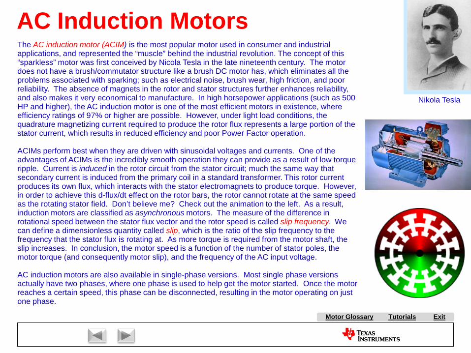
Tutorials ExitMotor Glossary
Nikola Tesla
The AC induction motor (ACIM) is the most popular motor used in consumer and industrial applications, and represented the “muscle” behind the industrial revolution. The concept of this “sparkless” motor was first conceived by Nicola Tesla in the late nineteenth century. The motor does not have a brush/commutator structure like a brush DC motor has, which eliminates all the problems associated with sparking; such as electrical noise, brush wear, high friction, and poor reliability. The absence of magnets in the rotor and stator structures further enhances reliability, and also makes it very economical to manufacture. In high horsepower applications (such as 500 HP and higher), the AC induction motor is one of the most efficient motors in existence, where efficiency ratings of 97% or higher are possible. However, under light load conditions, the quadrature magnetizing current required to produce the rotor flux represents a large portion of the stator current, which results in reduced efficiency and poor Power Factor operation.
ACIMs perform best when they are driven with sinusoidal voltages and currents. One of the advantages of ACIMs is the incredibly smooth operation they can provide as a result of low torque ripple. Current is induced in the rotor circuit from the stator circuit; much the same way that secondary current is induced from the primary coil in a standard transformer. This rotor current produces its own flux, which interacts with the stator electromagnets to produce torque. However, in order to achieve this d-flux/dt effect on the rotor bars, the rotor cannot rotate at the same speed as the rotating stator field. Don’t believe me? Check out the animation to the left. As a result, induction motors are classified as asynchronous motors. The measure of the difference in rotational speed between the stator flux vector and the rotor speed is called slip frequency. We can define a dimensionless quantity called slip, which is the ratio of the slip frequency to the frequency that the stator flux is rotating at. As more torque is required from the motor shaft, the slip increases. In conclusion, the motor speed is a function of the number of stator poles, the motor torque (and consequently motor slip), and the frequency of the AC input voltage.
AC induction motors are also available in single-phase versions. Most single phase versions actually have two phases, where one phase is used to help get the motor started. Once the motor reaches a certain speed, this phase can be disconnected, resulting in the motor operating on just one phase.
AC Induction Motors

A AC Induction Motor (ACIM)
AirgapAlignment TorqueB Back-EMFBipolar PWMsBrakingBrush DC (BDC) MotorBrushesBrushless DC (BLDC) MotorBrushless Permanent Magnet
(BPM)C Center-aligned PWMsClark transformCommutationCommutatorConverterCritically DampedCycle-by-cycle current limitD d-axisDC BusDC InjectionDead-timeDead-time DistortionDigital ControlDirect Torque Control (DTC)Duty cycleDynamic BrakingE eCAPEfficiencyElectronically Commutated
Motor (ECM)Encoder
F FeedbackFeedforwardField Oriented Control (FOC)Field WeakeningFluxFlux DensityFull SteppingG Gate DriverH H-BridgeHalf BridgeHalf steppingHall-effect sensorsHorsepowerI Intelligent Power Module
(IPM)Interior Permanent Magnet
MotorInverterJ K L Leakage InductanceLeft-hand RuleLEM sensorM Magnetic LeakageMagnetizing InductanceMicrosteppingN Neodymium Iron Boron
(“Neo”)
S SaliencySampling FrequencyScalar ControlSensorless ControlServoShoot-throughShunt current sensingSlipSlip frequencySlip ControlSpace Vector Modulation (SVM)SPM MotorStatorStepper (Motor) (SM)Switched Reluctance (SR) MotorSynchronous RectificationT TachometerThird-harmonic ModulationTorqueTorque ConstantTrapezoidalU UnderdampedUnipolar PWMsUniversal MotorV Variable Speed Drive (VSD)Vector ControlVoltage boostVolts-per-Hertz ControlW WindupX Y Z Z-Transform
Tutorials Exit
P Park TransformPermanent Magnet
Synchronous Motor (PMSM)
Permanent Magnet AC Motor (PMAC)
PI ControlPID ControlPluggingPowerPower FactorPower QuadrantsPulse Width Modulation
(PWM)
Q q-axis
R Reaction TorqueRegenerationRegenerative BrakingReluctanceReluctance TorqueResistive BrakingResolverRight-hand RuleRotor
E continuedePWMeQEP
O ObserversOff-lineOverdamped
Motor Glossary

Tutorials ExitMotor Glossary
Stepper MotorsSince their birth in the early 1960’s as a replacement for servos in the computer peripheral industry, stepper motorshave enjoyed extensive use in applications requiring tight position control at an affordable price. Two reasons attributing to the popularity of stepper-based designs are their ability to achieve accurate position control without the requirement of position feedback (open-loop control), and the fact that they can be driven by squarewaves, which can easily be supplied by a digital controller. However, making them behave is often more difficult than other motors, as they are frequently plagued by resonance and acoustic noise problems.
Another common problem with stepper designs is their limited speed range. Consider that on a typical 200 step/rev. stepper, reversing the current in one of the stator coils results in only 1.8° of shaft movement, compared to 100 times that amount of movement when the current is reversed in the stator of a two pole AC machine. As the step frequency increases, a point is reached (at a fairly low RPM) where the current simply can’t commutate in and out of the coils fast enough (due to coil inductance), and the motor torque decreases.
A simplified cross-section of a stepper motor is shown above-right. The rotor is magnetized axially instead of radially, where the north pole is shown facing you, and the south pole is on the other end of the rotor. In reality, the cross section looks more like the figure to the right, which shows a number of teeth on both the rotor and stator structures. When coil A is energized, the stator pole pattern shown in red is impressed upon the stator. This causes rotor teeth 1 and 26 on the rotor to align with stator teeth 1 and 25, as shown to the right. Next, coil A is turned off, and coil B is turned on, resulting in the blue pole pattern on the stator. This causes the rotor to move one “step” so that teeth 7 and 32 on the rotor line up with teeth 7 and 31 on the stator. The process continues through step 3 and step 4, and then repeats back to step one. An animation of this process is shown by the left diagram below. This is called full stepping. Another stepping option is to alternatively turn on one coil and then two coils, as shown in the right animation below. This is called half stepping, which results in 8 states per electrical revolution vs. 4. As a result, half stepping has twice the position resolution as full stepping.
1 2 3 4
A
A
A A
B
B
B
B
Both of the above techniques result in driving the motor with square waves, which are rich in high frequency harmonics which tend to seek out the motor’s resonant frequencies and cause oscillatory behavior. Driving the coils with sinewave currents instead can result in significantly smoother performance. You also get much finer step resolution, which is a function of how finely you can control the current steps in each sinewave. Such a technique is known as microstepping.

A AC Induction Motor (ACIM)
AirgapAlignment TorqueB Back-EMFBipolar PWMsBrakingBrush DC (BDC) MotorBrushesBrushless DC (BLDC) MotorBrushless Permanent Magnet
(BPM)C Center-aligned PWMsClark transformCommutationCommutatorConverterCritically DampedCycle-by-cycle current limitD d-axisDC BusDC InjectionDead-timeDead-time DistortionDigital ControlDirect Torque Control (DTC)Duty cycleDynamic BrakingE eCAPEfficiencyElectronically Commutated
Motor (ECM)Encoder
F FeedbackFeedforwardField Oriented Control (FOC)Field WeakeningFluxFlux DensityFull SteppingG Gate DriverH H-BridgeHalf BridgeHalf steppingHall-effect sensorsHorsepowerI Intelligent Power Module
(IPM)Interior Permanent Magnet
MotorInverterJ K L Leakage InductanceLeft-hand RuleLEM sensorM Magnetic LeakageMagnetizing InductanceMicrosteppingN Neodymium Iron Boron
(“Neo”)
S SaliencySampling FrequencyScalar ControlSensorless ControlServoShoot-throughShunt current sensingSlipSlip frequencySlip ControlSpace Vector Modulation (SVM)SPM MotorStatorStepper (Motor) (SM)Switched Reluctance (SR) MotorSynchronous RectificationT TachometerThird-harmonic ModulationTorqueTorque ConstantTrapezoidalU UnderdampedUnipolar PWMsUniversal MotorV Variable Speed Drive (VSD)Vector ControlVoltage boostVolts-per-Hertz ControlW WindupX Y Z Z-Transform
Tutorials Exit
P Park TransformPermanent Magnet
Synchronous Motor (PMSM)
Permanent Magnet AC Motor (PMAC)
PI ControlPID ControlPluggingPowerPower FactorPower QuadrantsPulse Width Modulation
(PWM)
Q q-axis
R Reaction TorqueRegenerationRegenerative BrakingReluctanceReluctance TorqueResistive BrakingResolverRight-hand RuleRotor
E continuedePWMeQEP
O ObserversOff-lineOverdamped
Motor Glossary
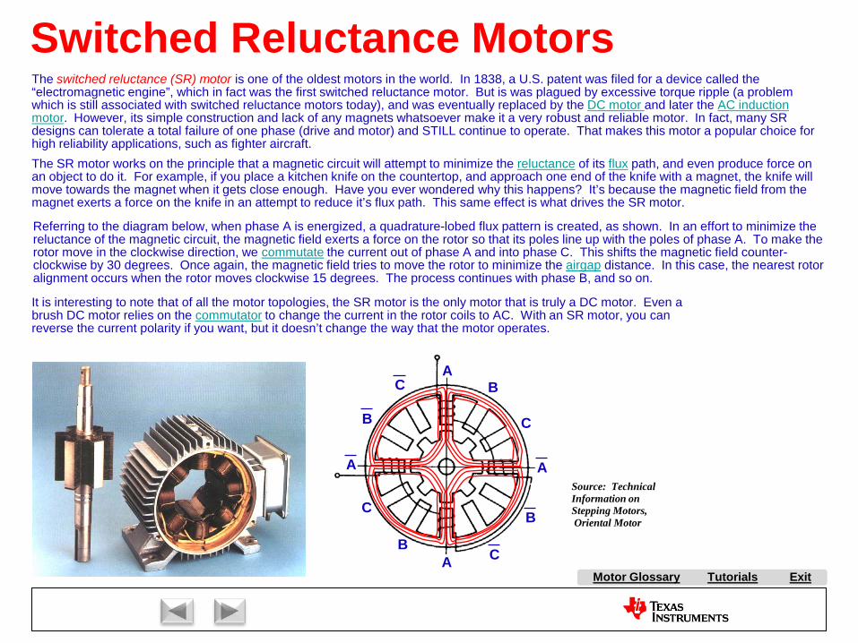
Tutorials ExitMotor Glossary
Switched Reluctance Motors
A
A
A
B
B
C
C
Source: Technical Information on Stepping Motors,Oriental Motor
A
B
B
C
C
The switched reluctance (SR) motor is one of the oldest motors in the world. In 1838, a U.S. patent was filed for a device called the “electromagnetic engine”, which in fact was the first switched reluctance motor. But is was plagued by excessive torque ripple (a problem which is still associated with switched reluctance motors today), and was eventually replaced by the DC motor and later the AC induction motor. However, its simple construction and lack of any magnets whatsoever make it a very robust and reliable motor. In fact, many SR designs can tolerate a total failure of one phase (drive and motor) and STILL continue to operate. That makes this motor a popular choice for high reliability applications, such as fighter aircraft.The SR motor works on the principle that a magnetic circuit will attempt to minimize the reluctance of its flux path, and even produce force on an object to do it. For example, if you place a kitchen knife on the countertop, and approach one end of the knife with a magnet, the knife will move towards the magnet when it gets close enough. Have you ever wondered why this happens? It’s because the magnetic field from the magnet exerts a force on the knife in an attempt to reduce it’s flux path. This same effect is what drives the SR motor.
Referring to the diagram below, when phase A is energized, a quadrature-lobed flux pattern is created, as shown. In an effort to minimize the reluctance of the magnetic circuit, the magnetic field exerts a force on the rotor so that its poles line up with the poles of phase A. To make the rotor move in the clockwise direction, we commutate the current out of phase A and into phase C. This shifts the magnetic field counter-clockwise by 30 degrees. Once again, the magnetic field tries to move the rotor to minimize the airgap distance. In this case, the nearest rotor alignment occurs when the rotor moves clockwise 15 degrees. The process continues with phase B, and so on.
It is interesting to note that of all the motor topologies, the SR motor is the only motor that is truly a DC motor. Even a brush DC motor relies on the commutator to change the current in the rotor coils to AC. With an SR motor, you can reverse the current polarity if you want, but it doesn’t change the way that the motor operates.

A AC Induction Motor (ACIM)
AirgapAlignment TorqueB Back-EMFBipolar PWMsBrakingBrush DC (BDC) MotorBrushesBrushless DC (BLDC) MotorBrushless Permanent Magnet
(BPM)C Center-aligned PWMsClark transformCommutationCommutatorConverterCritically DampedCycle-by-cycle current limitD d-axisDC BusDC InjectionDead-timeDead-time DistortionDigital ControlDirect Torque Control (DTC)Duty cycleDynamic BrakingE eCAPEfficiencyElectronically Commutated
Motor (ECM)Encoder
F FeedbackFeedforwardField Oriented Control (FOC)Field WeakeningFluxFlux DensityFull SteppingG Gate DriverH H-BridgeHalf BridgeHalf steppingHall-effect sensorsHorsepowerI Intelligent Power Module
(IPM)Interior Permanent Magnet
MotorInverterJ K L Leakage InductanceLeft-hand RuleLEM sensorM Magnetic LeakageMagnetizing InductanceMicrosteppingN Neodymium Iron Boron
(“Neo”)
S SaliencySampling FrequencyScalar ControlSensorless ControlServoShoot-throughShunt current sensingSlipSlip frequencySlip ControlSpace Vector Modulation (SVM)SPM MotorStatorStepper (Motor) (SM)Switched Reluctance (SR) MotorSynchronous RectificationT TachometerThird-harmonic ModulationTorqueTorque ConstantTrapezoidalU UnderdampedUnipolar PWMsUniversal MotorV Variable Speed Drive (VSD)Vector ControlVoltage boostVolts-per-Hertz ControlW WindupX Y Z Z-Transform
Tutorials Exit
P Park TransformPermanent Magnet
Synchronous Motor (PMSM)
Permanent Magnet AC Motor (PMAC)
PI ControlPID ControlPluggingPowerPower FactorPower QuadrantsPulse Width Modulation
(PWM)
Q q-axis
R Reaction TorqueRegenerationRegenerative BrakingReluctanceReluctance TorqueResistive BrakingResolverRight-hand RuleRotor
E continuedePWMeQEP
O ObserversOff-lineOverdamped
Motor Glossary
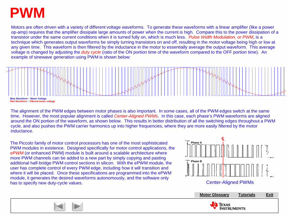
Tutorials ExitMotor Glossary
PWMMotors are often driven with a variety of different voltage waveforms. To generate these waveforms with a linear amplifier (like a power op-amp) requires that the amplifier dissipate large amounts of power when the current is high. Compare this to the power dissipation of a transistor under the same current conditions when it is turned fully on, which is much less. Pulse Width Modulation, or PWM, is a technique which generates output waveforms be simply turning transistors on and off, resulting in the motor voltage being high or low at any given time. This waveform is then filtered by the inductance in the motor to essentially average the output waveform. This average voltage is changed by adjusting the duty cycle (ratio of the ON portion time of the waveform compared to the OFF portion time). An example of sinewave generation using PWM is shown below:
The alignment of the PWM edges between motor phases is also important. In some cases, all of the PWM edges switch at the same time. However, the most popular alignment is called Center-Aligned PWMs. In this case, each phase’s PWM waveforms are aligned around the ON portion of the waveform, as shown below. This results in better distribution of all the switching edges throughout a PWM cycle, and also pushes the PWM carrier harmonics up into higher frequencies, where they are more easily filtered by the motorinductance.
Phase A
Phase B
Blue Waveform – Motor VoltageRed Waveform – Filtered motor voltage
Center-Aligned PWMs
CLThe Piccolo family of motor control processors has one of the most sophisticated PWM modules in existence. Designed specifically for motor control applications, the ePWM (or enhanced PWM) module is built around a scalable architecture where more PWM channels can be added to a new part by simply copying and pasting additional half-bridge PWM control sections in silicon. With the ePWM module, the user has complete control of every PWM edge, including how it will transition and where it will be placed. Once these specifications are programmed into the ePWM module, it generates the desired waveforms autonomously, and the software only has to specify new duty-cycle values.

A AC Induction Motor (ACIM)
AirgapAlignment TorqueB Back-EMFBipolar PWMsBrakingBrush DC (BDC) MotorBrushesBrushless DC (BLDC) MotorBrushless Permanent Magnet
(BPM)C Center-aligned PWMsClark transformCommutationCommutatorConverterCritically DampedCycle-by-cycle current limitD d-axisDC BusDC InjectionDead-timeDead-time DistortionDigital ControlDirect Torque Control (DTC)Duty cycleDynamic BrakingE eCAPEfficiencyElectronically Commutated
Motor (ECM)Encoder
F FeedbackFeedforwardField Oriented Control (FOC)Field WeakeningFluxFlux DensityFull SteppingG Gate DriverH H-BridgeHalf BridgeHalf steppingHall-effect sensorsHorsepowerI Intelligent Power Module
(IPM)Interior Permanent Magnet
MotorInverterJ K L Leakage InductanceLeft-hand RuleLEM sensorM Magnetic LeakageMagnetizing InductanceMicrosteppingN Neodymium Iron Boron
(“Neo”)
S SaliencySampling FrequencyScalar ControlSensorless ControlServoShoot-throughShunt current sensingSlipSlip frequencySlip ControlSpace Vector Modulation (SVM)SPM MotorStatorStepper (Motor) (SM)Switched Reluctance (SR) MotorSynchronous RectificationT TachometerThird-harmonic ModulationTorqueTorque ConstantTrapezoidalU UnderdampedUnipolar PWMsUniversal MotorV Variable Speed Drive (VSD)Vector ControlVoltage boostVolts-per-Hertz ControlW WindupX Y Z Z-Transform
Tutorials Exit
P Park TransformPermanent Magnet
Synchronous Motor (PMSM)
Permanent Magnet AC Motor (PMAC)
PI ControlPID ControlPluggingPowerPower FactorPower QuadrantsPulse Width Modulation
(PWM)
Q q-axis
R Reaction TorqueRegenerationRegenerative BrakingReluctanceReluctance TorqueResistive BrakingResolverRight-hand RuleRotor
E continuedePWMeQEP
O ObserversOff-lineOverdamped
Motor Glossary

Tutorials ExitMotor Glossary
Dead-Time
V+
motor
Half Bridge
Top transistor
Bottom transistor
ONON ON
ONON
Dead-Time
With a half-bridge power structure, you must make sure that the bottom transistor and the top transistor NEVER get turned on at the same time. Doing so will result in large currents flowing through the transistor pair, as a short is created across the DC bus. This condition is called shoot-through. When creating the PWM signals that will drive the transistors, it is not sufficient to simply invert the top signal to create the bottom signal. Doing so may still result in shoot-through current, as most transistors take longer to turn off than they do to turn on.To prevent shoot-through, a dead-time period must exist between the turn-off of one transistor, and the turn-on of the other. There are several ways to generate this timeout period. Many gate drivers that are used in half-bridge circuits have this ability, where the dead-time can be adjusted by additional discrete passive components connected to the gate driver. In the case of a digital PWM module (such as the ePWMmodule on the Piccolo family), the dead-time can be designed into the PWM signals via software by how the PWM thresholds for the top and bottom signals are specified. However, most customers prefer a more failsafe technique based on a separate hardware one-shot timer (which is also included in the ePWM module). This timer can be set to generate a range of dead-time values. For power FET applications, dead-times between 100 nS and 1 uS are common. For larger power systems based on IGBT switches, dead-time may typically vary between 500 nS and 5 uS. To determine the correct dead-time value, the designer must know the turn-off delay for whatever power switch they are using.Unfortunately, adding dead-time to a pair of PWM signals can cause significant dead-time distortion when driving an inductive load such as a motor. It turns out that during the dead-time interval when both transistors are off, the load inductance will drive the inverter output voltage based on its current polarity. As a result, the pulse width at the output of the half-bridge will either be longer or shorter than desired by one dead-time interval. The larger the dead-time is as a ratio to the PWM period, the more severe the waveform distortion will be. An example current waveform showing this distortion was taken from a ½ horsepower three-phase AC induction motor running at low speed. Not only are the peaks of the intended sinewave clipped, but severe zero-crossing distortion can be seen. There are several techniques commonly used which are reasonably effective in providing dead-time distortion correction. Some are based on a-priori knowledge of the distortion effect and simply counter-modulate the PWMs to correct for this. Other techniques involve actually measuring the pulse width at the half-bridge output, and using this information to correct the pulse width.
Current with Correction Disabled
Example of Dead-time Distortion

A AC Induction Motor (ACIM)
AirgapAlignment TorqueB Back-EMFBipolar PWMsBrakingBrush DC (BDC) MotorBrushesBrushless DC (BLDC) MotorBrushless Permanent Magnet
(BPM)C Center-aligned PWMsClark transformCommutationCommutatorConverterCritically DampedCycle-by-cycle current limitD d-axisDC BusDC InjectionDead-timeDead-time DistortionDigital ControlDirect Torque Control (DTC)Duty cycleDynamic BrakingE eCAPEfficiencyElectronically Commutated
Motor (ECM)Encoder
F FeedbackFeedforwardField Oriented Control (FOC)Field WeakeningFluxFlux DensityFull SteppingG Gate DriverH H-BridgeHalf BridgeHalf steppingHall-effect sensorsHorsepowerI Intelligent Power Module
(IPM)Interior Permanent Magnet
MotorInverterJ K L Leakage InductanceLeft-hand RuleLEM sensorM Magnetic LeakageMagnetizing InductanceMicrosteppingN Neodymium Iron Boron
(“Neo”)
S SaliencySampling FrequencyScalar ControlSensorless ControlServoShoot-throughShunt current sensingSlipSlip frequencySlip ControlSpace Vector Modulation (SVM)SPM MotorStatorStepper (Motor) (SM)Switched Reluctance (SR) MotorSynchronous RectificationT TachometerThird-harmonic ModulationTorqueTorque ConstantTrapezoidalU UnderdampedUnipolar PWMsUniversal MotorV Variable Speed Drive (VSD)Vector ControlVoltage boostVolts-per-Hertz ControlW WindupX Y Z Z-Transform
Tutorials Exit
P Park TransformPermanent Magnet
Synchronous Motor (PMSM)
Permanent Magnet AC Motor (PMAC)
PI ControlPID ControlPluggingPowerPower FactorPower QuadrantsPulse Width Modulation
(PWM)
Q q-axis
R Reaction TorqueRegenerationRegenerative BrakingReluctanceReluctance TorqueResistive BrakingResolverRight-hand RuleRotor
E continuedePWMeQEP
O ObserversOff-lineOverdamped
Motor Glossary
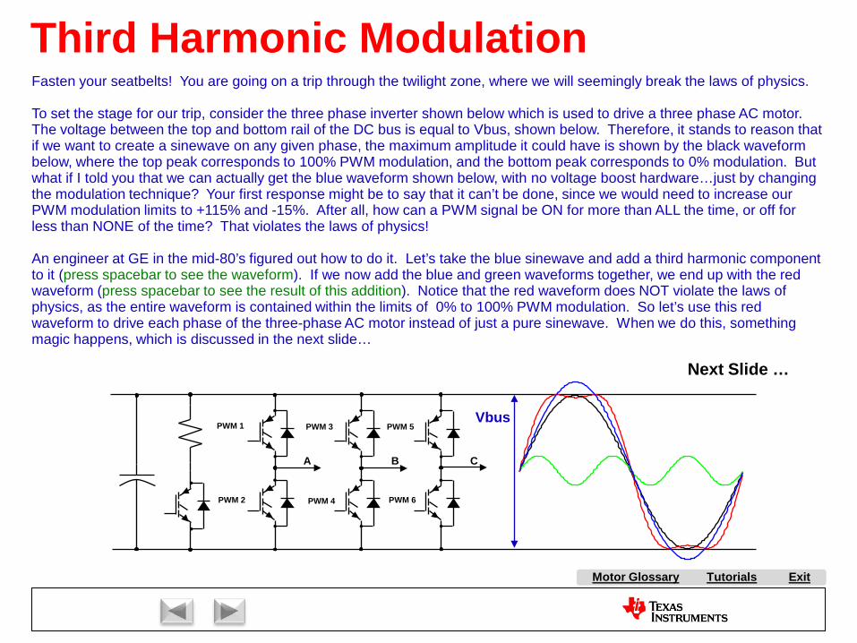
Tutorials ExitMotor Glossary
Third Harmonic Modulation
PWM 1
PWM 2
PWM 3
PWM 4
PWM 5
PWM 6
Vbus
Fasten your seatbelts! You are going on a trip through the twilight zone, where we will seemingly break the laws of physics.
To set the stage for our trip, consider the three phase inverter shown below which is used to drive a three phase AC motor. The voltage between the top and bottom rail of the DC bus is equal to Vbus, shown below. Therefore, it stands to reason thatif we want to create a sinewave on any given phase, the maximum amplitude it could have is shown by the black waveform below, where the top peak corresponds to 100% PWM modulation, and the bottom peak corresponds to 0% modulation. But what if I told you that we can actually get the blue waveform shown below, with no voltage boost hardware…just by changing the modulation technique? Your first response might be to say that it can’t be done, since we would need to increase our PWM modulation limits to +115% and -15%. After all, how can a PWM signal be ON for more than ALL the time, or off for less than NONE of the time? That violates the laws of physics!
An engineer at GE in the mid-80’s figured out how to do it. Let’s take the blue sinewave and add a third harmonic component to it (press spacebar to see the waveform). If we now add the blue and green waveforms together, we end up with the red waveform (press spacebar to see the result of this addition). Notice that the red waveform does NOT violate the laws of physics, as the entire waveform is contained within the limits of 0% to 100% PWM modulation. So let’s use this red waveform to drive each phase of the three-phase AC motor instead of just a pure sinewave. When we do this, something magic happens, which is discussed in the next slide…
A B C
Next Slide …
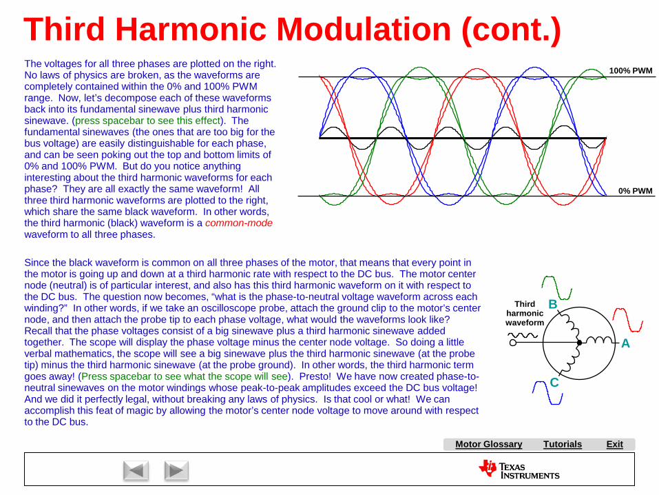
Tutorials ExitMotor Glossary
Third Harmonic Modulation (cont.)The voltages for all three phases are plotted on the right. No laws of physics are broken, as the waveforms are completely contained within the 0% and 100% PWM range. Now, let’s decompose each of these waveforms back into its fundamental sinewave plus third harmonic sinewave. (press spacebar to see this effect). The fundamental sinewaves (the ones that are too big for the bus voltage) are easily distinguishable for each phase, and can be seen poking out the top and bottom limits of 0% and 100% PWM. But do you notice anything interesting about the third harmonic waveforms for each phase? They are all exactly the same waveform! All three third harmonic waveforms are plotted to the right, which share the same black waveform. In other words, the third harmonic (black) waveform is a common-modewaveform to all three phases.
A
B
C
100% PWM
0% PWM
Since the black waveform is common on all three phases of the motor, that means that every point in the motor is going up and down at a third harmonic rate with respect to the DC bus. The motor center node (neutral) is of particular interest, and also has this third harmonic waveform on it with respect to the DC bus. The question now becomes, “what is the phase-to-neutral voltage waveform across each winding?” In other words, if we take an oscilloscope probe, attach the ground clip to the motor’s center node, and then attach the probe tip to each phase voltage, what would the waveforms look like? Recall that the phase voltages consist of a big sinewave plus a third harmonic sinewave added together. The scope will display the phase voltage minus the center node voltage. So doing a little verbal mathematics, the scope will see a big sinewave plus the third harmonic sinewave (at the probe tip) minus the third harmonic sinewave (at the probe ground). In other words, the third harmonic term goes away! (Press spacebar to see what the scope will see). Presto! We have now created phase-to-neutral sinewaves on the motor windings whose peak-to-peak amplitudes exceed the DC bus voltage! And we did it perfectly legal, without breaking any laws of physics. Is that cool or what! We can accomplish this feat of magic by allowing the motor’s center node voltage to move around with respect to the DC bus.
Third harmonic waveform

A AC Induction Motor (ACIM)
AirgapAlignment TorqueB Back-EMFBipolar PWMsBrakingBrush DC (BDC) MotorBrushesBrushless DC (BLDC) MotorBrushless Permanent Magnet
(BPM)C Center-aligned PWMsClark transformCommutationCommutatorConverterCritically DampedCycle-by-cycle current limitD d-axisDC BusDC InjectionDead-timeDead-time DistortionDigital ControlDirect Torque Control (DTC)Duty cycleDynamic BrakingE eCAPEfficiencyElectronically Commutated
Motor (ECM)Encoder
F FeedbackFeedforwardField Oriented Control (FOC)Field WeakeningFluxFlux DensityFull SteppingG Gate DriverH H-BridgeHalf BridgeHalf steppingHall-effect sensorsHorsepowerI Intelligent Power Module
(IPM)Interior Permanent Magnet
MotorInverterJ K L Leakage InductanceLeft-hand RuleLEM sensorM Magnetic LeakageMagnetizing InductanceMicrosteppingN Neodymium Iron Boron
(“Neo”)
S SaliencySampling FrequencyScalar ControlSensorless ControlServoShoot-throughShunt current sensingSlipSlip frequencySlip ControlSpace Vector Modulation (SVM)SPM MotorStatorStepper (Motor) (SM)Switched Reluctance (SR) MotorSynchronous RectificationT TachometerThird-harmonic ModulationTorqueTorque ConstantTrapezoidalU UnderdampedUnipolar PWMsUniversal MotorV Variable Speed Drive (VSD)Vector ControlVoltage boostVolts-per-Hertz ControlW WindupX Y Z Z-Transform
Tutorials Exit
P Park TransformPermanent Magnet
Synchronous Motor (PMSM)
Permanent Magnet AC Motor (PMAC)
PI ControlPID ControlPluggingPowerPower FactorPower QuadrantsPulse Width Modulation
(PWM)
Q q-axis
R Reaction TorqueRegenerationRegenerative BrakingReluctanceReluctance TorqueResistive BrakingResolverRight-hand RuleRotor
E continuedePWMeQEP
O ObserversOff-lineOverdamped
Motor Glossary
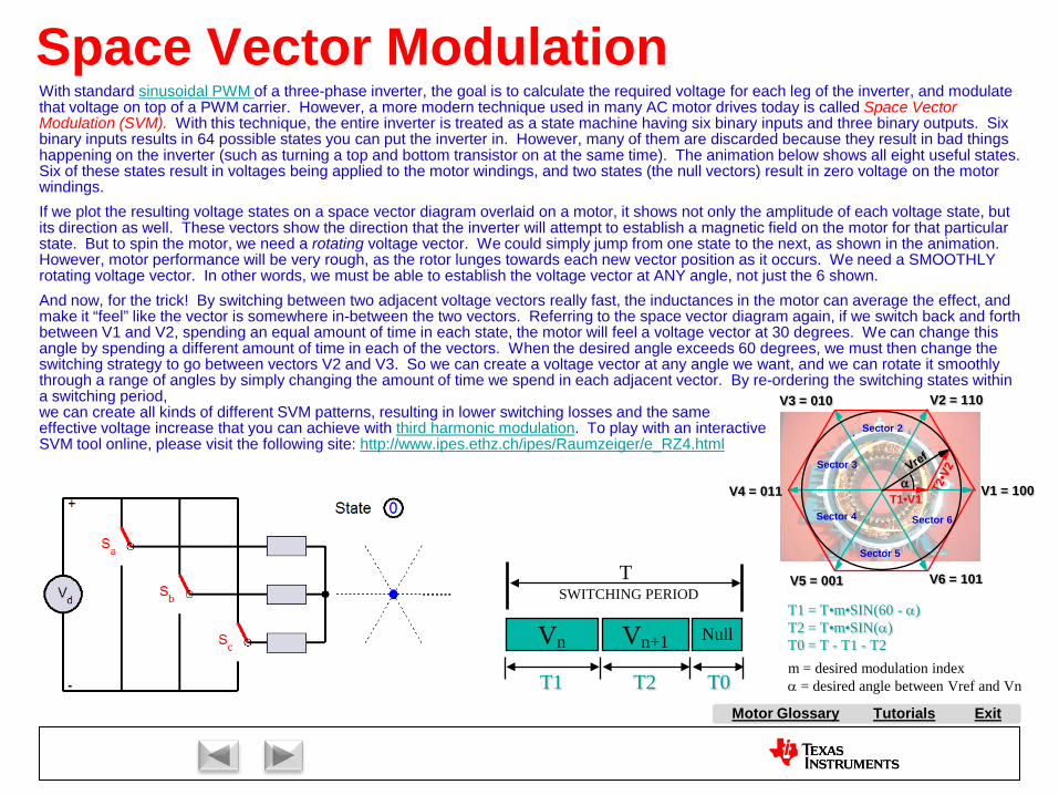
Tutorials ExitMotor Glossary
Space Vector Modulation
SWITCHING PERIOD
Vn+1 NullVn
T
T1 T2 T0
T1 = T•m•SIN(60 - α)T2 = T•m•SIN(α)T0 = T - T1 - T2m = desired modulation indexα = desired angle between Vref and Vn
Sector 5
Sector 6Sector 4
Sector 3
Sector 2
V1 = 100
V2 = 110
V4 = 011
V3 = 010
V5 = 001 V6 = 101
αT1•V1
With standard sinusoidal PWM of a three-phase inverter, the goal is to calculate the required voltage for each leg of the inverter, and modulate that voltage on top of a PWM carrier. However, a more modern technique used in many AC motor drives today is called Space Vector Modulation (SVM). With this technique, the entire inverter is treated as a state machine having six binary inputs and three binary outputs. Sixbinary inputs results in 64 possible states you can put the inverter in. However, many of them are discarded because they result in bad things happening on the inverter (such as turning a top and bottom transistor on at the same time). The animation below shows all eight useful states. Six of these states result in voltages being applied to the motor windings, and two states (the null vectors) result in zero voltage on the motor windings.If we plot the resulting voltage states on a space vector diagram overlaid on a motor, it shows not only the amplitude of each voltage state, but its direction as well. These vectors show the direction that the inverter will attempt to establish a magnetic field on the motor for that particular state. But to spin the motor, we need a rotating voltage vector. We could simply jump from one state to the next, as shown in the animation. However, motor performance will be very rough, as the rotor lunges towards each new vector position as it occurs. We need a SMOOTHLY rotating voltage vector. In other words, we must be able to establish the voltage vector at ANY angle, not just the 6 shown.And now, for the trick! By switching between two adjacent voltage vectors really fast, the inductances in the motor can average the effect, and make it “feel” like the vector is somewhere in-between the two vectors. Referring to the space vector diagram again, if we switch back and forth between V1 and V2, spending an equal amount of time in each state, the motor will feel a voltage vector at 30 degrees. We can change this angle by spending a different amount of time in each of the vectors. When the desired angle exceeds 60 degrees, we must then change the switching strategy to go between vectors V2 and V3. So we can create a voltage vector at any angle we want, and we can rotate it smoothly through a range of angles by simply changing the amount of time we spend in each adjacent vector. By re-ordering the switching states within a switching period, we can create all kinds of different SVM patterns, resulting in lower switching losses and the same effective voltage increase that you can achieve with third harmonic modulation. To play with an interactive SVM tool online, please visit the following site: http://www.ipes.ethz.ch/ipes/Raumzeiger/e_RZ4.html

A AC Induction Motor (ACIM)
AirgapAlignment TorqueB Back-EMFBipolar PWMsBrakingBrush DC (BDC) MotorBrushesBrushless DC (BLDC) MotorBrushless Permanent Magnet
(BPM)C Center-aligned PWMsClark transformCommutationCommutatorConverterCritically DampedCycle-by-cycle current limitD d-axisDC BusDC InjectionDead-timeDead-time DistortionDigital ControlDirect Torque Control (DTC)Duty cycleDynamic BrakingE eCAPEfficiencyElectronically Commutated
Motor (ECM)Encoder
F FeedbackFeedforwardField Oriented Control (FOC)Field WeakeningFluxFlux DensityFull SteppingG Gate DriverH H-BridgeHalf BridgeHalf steppingHall-effect sensorsHorsepowerI Intelligent Power Module
(IPM)Interior Permanent Magnet
MotorInverterJ K L Leakage InductanceLeft-hand RuleLEM sensorM Magnetic LeakageMagnetizing InductanceMicrosteppingN Neodymium Iron Boron
(“Neo”)
S SaliencySampling FrequencyScalar ControlSensorless ControlServoShoot-throughShunt current sensingSlipSlip frequencySlip ControlSpace Vector Modulation (SVM)SPM MotorStatorStepper (Motor) (SM)Switched Reluctance (SR) MotorSynchronous RectificationT TachometerThird-harmonic ModulationTorqueTorque ConstantTrapezoidalU UnderdampedUnipolar PWMsUniversal MotorV Variable Speed Drive (VSD)Vector ControlVoltage boostVolts-per-Hertz ControlW WindupX Y Z Z-Transform
Tutorials Exit
P Park TransformPermanent Magnet
Synchronous Motor (PMSM)
Permanent Magnet AC Motor (PMAC)
PI ControlPID ControlPluggingPowerPower FactorPower QuadrantsPulse Width Modulation
(PWM)
Q q-axis
R Reaction TorqueRegenerationRegenerative BrakingReluctanceReluctance TorqueResistive BrakingResolverRight-hand RuleRotor
E continuedePWMeQEP
O ObserversOff-lineOverdamped
Motor Glossary

Tutorials ExitMotor Glossary
Direct Torque ControlDirect Torque Control (DTC) is a sensorless AC Induction Motor control technique that combines space vector modulation with hysteretic band-limiting control. The technique was made popular by ABB during the 1990s, but the patent has now expired which will allow this technique to become more accessible.
=
→→
is
conj
sempT λIm2
Stator Flux Calculator
Torque Calculator
+ -
Commanded Flux
-+
CommandedTorque
VectorSelector
SVM
Hysteretic Band
Hysteretic Band
dtiRv ssss ∫
−=
→∧→→
λ
increasedecrease
increasedecrease
Texas Instruments
Dave’sMotor Control
Center
Magnitude
Angle
There are several notable differences between DTC and other sensorless techniques:
1. No PWM. When a change in the voltage vector is requested either by the torque loop or the flux loop, it happens immediately. As a result, DTC theoretically has faster response time than systems utilizing standard PWM or SVM since you don’t have to wait for the next PWM cycle for a desired change to propagate to the output. The output voltage is updated asynchronously, and the inverter switching frequency is determined in part by the width of the hysteretic bands. In most cases, the hysteretic comparators, vector selector, and SVM stages are implemented in a customer designed gate array.
2. Stator Flux referenced. The stator flux is much easier to calculate from the motor voltage and current than the rotor flux. In a stator flux referenced design, the torque is determined by multiplying the stator flux vector by the component of the stator current vector which is orthogonal to the stator flux vector, which is shown below.
3. No frame transformations required. While this is technically a field oriented technique, no Clark/Parktransformations are required. All calculations are done in the stationary reference frame, which simplifies the calculations.
Please continue to the next slide for a discussion on how the appropriate voltage vector is selected…
Stator Flux vector
Current vector
Torque Producing
Current
Continued on Next Slide
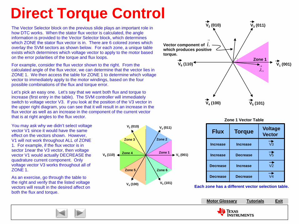
Tutorials ExitMotor Glossary
Direct Torque Control
Vector component of which produces positive torque.
→
is
Zone 1V1 (001)
V3 (011)V2 (010)
V6 (110)
V4 (100) V5 (101)
s
→
λ
Flux Torque Voltage Vector
Increase Increase V3
Increase Decrease V5
Decrease Increase V2
Decrease Decrease V4
Each zone has a different vector selection table.
Zone 1 Vector Table
Zone 1
Zone 2Zone 3
Zone 4
Zone 5 Zone 6
V1 (001)
V3 (011)V2 (010)
V6 (110)
V4 (100) V5 (101)
The Vector Selector block on the previous slide plays an important role in how DTC works. When the stator flux vector is calculated, the angle information is provided to the Vector Selector block, which determines which ZONE the stator flux vector is in. There are 6 colored zones which overlay the SVM sectors as shown below. For each zone, a unique table exists which determines which voltage vector to apply to the motor based on the error polarities of the torque and flux loops.
For example, consider the flux vector shown to the right. From the calculated angle of the flux vector, we can determine that the vector lies in ZONE 1. We then access the table for ZONE 1 to determine which voltage vector to immediately apply to the motor windings, based on the four possible combinations of the flux and torque error.
Let’s pick an easy one. Let’s say that we want both flux and torque to increase (first entry in the table). The SVM controller will immediately switch to voltage vector V3. If you look at the position of the V3 vector in the upper right diagram, you can see that it will result in an increase in the flux vector as well as an increase in the component of the current vector that is at right angles to the flux vector.
You may ask why we didn’t select voltage vector V1 since it would have the same effect on the vectors shown. However, V1 will not work throughout ALL of ZONE 1. For example, if the flux vector is in sector 1near the V3 vector, then voltage vector V1 would actually DECREASE the quadrature current component. Only voltage vector V3 works throughout all of ZONE 1.
As an exercise, go through the table to the right and verify that the listed voltage vectors will result in the desired affect on both the flux and torque.

A AC Induction Motor (ACIM)
AirgapAlignment TorqueB Back-EMFBipolar PWMsBrakingBrush DC (BDC) MotorBrushesBrushless DC (BLDC) MotorBrushless Permanent Magnet
(BPM)C Center-aligned PWMsClark transformCommutationCommutatorConverterCritically DampedCycle-by-cycle current limitD d-axisDC BusDC InjectionDead-timeDead-time DistortionDigital ControlDirect Torque Control (DTC)Duty cycleDynamic BrakingE eCAPEfficiencyElectronically Commutated
Motor (ECM)Encoder
F FeedbackFeedforwardField Oriented Control (FOC)Field WeakeningFluxFlux DensityFull SteppingG Gate DriverH H-BridgeHalf BridgeHalf steppingHall-effect sensorsHorsepowerI Intelligent Power Module
(IPM)Interior Permanent Magnet
MotorInverterJ K L Leakage InductanceLeft-hand RuleLEM sensorM Magnetic LeakageMagnetizing InductanceMicrosteppingN Neodymium Iron Boron
(“Neo”)
S SaliencySampling FrequencyScalar ControlSensorless ControlServoShoot-throughShunt current sensingSlipSlip frequencySlip ControlSpace Vector Modulation (SVM)SPM MotorStatorStepper (Motor) (SM)Switched Reluctance (SR) MotorSynchronous RectificationT TachometerThird-harmonic ModulationTorqueTorque ConstantTrapezoidalU UnderdampedUnipolar PWMsUniversal MotorV Variable Speed Drive (VSD)Vector ControlVoltage boostVolts-per-Hertz ControlW WindupX Y Z Z-Transform
Tutorials Exit
P Park TransformPermanent Magnet
Synchronous Motor (PMSM)
Permanent Magnet AC Motor (PMAC)
PI ControlPID ControlPluggingPowerPower FactorPower QuadrantsPulse Width Modulation
(PWM)
Q q-axis
R Reaction TorqueRegenerationRegenerative BrakingReluctanceReluctance TorqueResistive BrakingResolverRight-hand RuleRotor
E continuedePWMeQEP
O ObserversOff-lineOverdamped
Motor Glossary
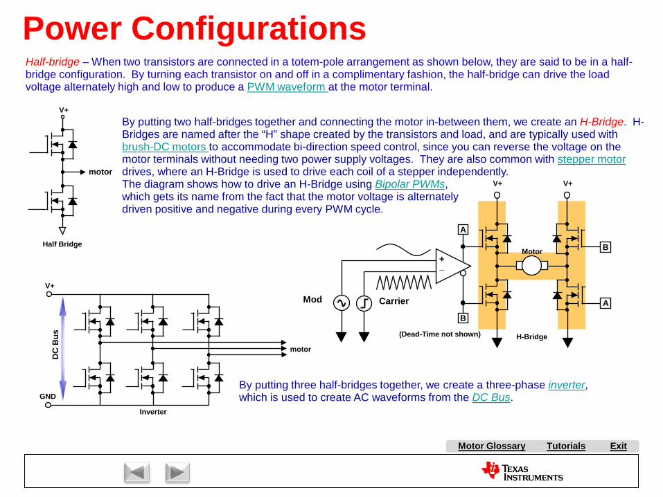
Tutorials ExitMotor Glossary
Power ConfigurationsHalf-bridge – When two transistors are connected in a totem-pole arrangement as shown below, they are said to be in a half-bridge configuration. By turning each transistor on and off in a complimentary fashion, the half-bridge can drive the load voltage alternately high and low to produce a PWM waveform at the motor terminal.
V+
motor
By putting two half-bridges together and connecting the motor in-between them, we create an H-Bridge. H-Bridges are named after the “H” shape created by the transistors and load, and are typically used with brush-DC motors to accommodate bi-direction speed control, since you can reverse the voltage on the motor terminals without needing two power supply voltages. They are also common with stepper motor drives, where an H-Bridge is used to drive each coil of a stepper independently.The diagram shows how to drive an H-Bridge using Bipolar PWMs,which gets its name from the fact that the motor voltage is alternatelydriven positive and negative during every PWM cycle.
Half Bridge
By putting three half-bridges together, we create a three-phase inverter, which is used to create AC waveforms from the DC Bus.
motor
Inverter
V+
GND
DC
Bus
V+
+_
A
B
A
B
CarrierMod
Motor
H-Bridge(Dead-Time not shown)
V+

A AC Induction Motor (ACIM)
AirgapAlignment TorqueB Back-EMFBipolar PWMsBrakingBrush DC (BDC) MotorBrushesBrushless DC (BLDC) MotorBrushless Permanent Magnet
(BPM)C Center-aligned PWMsClark transformCommutationCommutatorConverterCritically DampedCycle-by-cycle current limitD d-axisDC BusDC InjectionDead-timeDead-time DistortionDigital ControlDirect Torque Control (DTC)Duty cycleDynamic BrakingE eCAPEfficiencyElectronically Commutated
Motor (ECM)Encoder
F FeedbackFeedforwardField Oriented Control (FOC)Field WeakeningFluxFlux DensityFull SteppingG Gate DriverH H-BridgeHalf BridgeHalf steppingHall-effect sensorsHorsepowerI Intelligent Power Module
(IPM)Interior Permanent Magnet
MotorInverterJ K L Leakage InductanceLeft-hand RuleLEM sensorM Magnetic LeakageMagnetizing InductanceMicrosteppingN Neodymium Iron Boron
(“Neo”)
S SaliencySampling FrequencyScalar ControlSensorless ControlServoShoot-throughShunt current sensingSlipSlip frequencySlip ControlSpace Vector Modulation (SVM)SPM MotorStatorStepper (Motor) (SM)Switched Reluctance (SR) MotorSynchronous RectificationT TachometerThird-harmonic ModulationTorqueTorque ConstantTrapezoidalU UnderdampedUnipolar PWMsUniversal MotorV Variable Speed Drive (VSD)Vector ControlVoltage boostVolts-per-Hertz ControlW WindupX Y Z Z-Transform
Tutorials Exit
P Park TransformPermanent Magnet
Synchronous Motor (PMSM)
Permanent Magnet AC Motor (PMAC)
PI ControlPID ControlPluggingPowerPower FactorPower QuadrantsPulse Width Modulation
(PWM)
Q q-axis
R Reaction TorqueRegenerationRegenerative BrakingReluctanceReluctance TorqueResistive BrakingResolverRight-hand RuleRotor
E continuedePWMeQEP
O ObserversOff-lineOverdamped
Motor Glossary
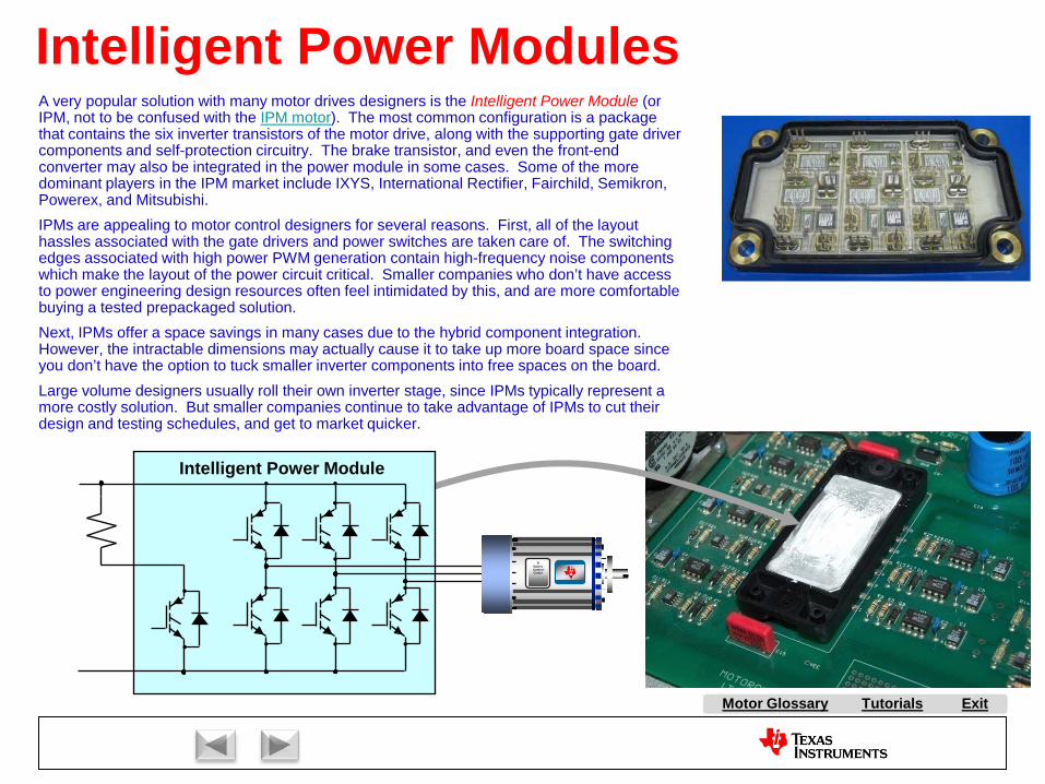
Tutorials ExitMotor Glossary
Intelligent Power ModulesA very popular solution with many motor drives designers is the Intelligent Power Module (or IPM, not to be confused with the IPM motor). The most common configuration is a package that contains the six inverter transistors of the motor drive, along with the supporting gate driver components and self-protection circuitry. The brake transistor, and even the front-end converter may also be integrated in the power module in some cases. Some of the more dominant players in the IPM market include IXYS, International Rectifier, Fairchild, Semikron, Powerex, and Mitsubishi.IPMs are appealing to motor control designers for several reasons. First, all of the layout hassles associated with the gate drivers and power switches are taken care of. The switching edges associated with high power PWM generation contain high-frequency noise components which make the layout of the power circuit critical. Smaller companies who don’t have access to power engineering design resources often feel intimidated by this, and are more comfortable buying a tested prepackaged solution.Next, IPMs offer a space savings in many cases due to the hybrid component integration. However, the intractable dimensions may actually cause it to take up more board space since you don’t have the option to tuck smaller inverter components into free spaces on the board.Large volume designers usually roll their own inverter stage, since IPMs typically represent a more costly solution. But smaller companies continue to take advantage of IPMs to cut their design and testing schedules, and get to market quicker.
TIDave’sControlCenter
Intelligent Power Module

A AC Induction Motor (ACIM)
AirgapAlignment TorqueB Back-EMFBipolar PWMsBrakingBrush DC (BDC) MotorBrushesBrushless DC (BLDC) MotorBrushless Permanent Magnet
(BPM)C Center-aligned PWMsClark transformCommutationCommutatorConverterCritically DampedCycle-by-cycle current limitD d-axisDC BusDC InjectionDead-timeDead-time DistortionDigital ControlDirect Torque Control (DTC)Duty cycleDynamic BrakingE eCAPEfficiencyElectronically Commutated
Motor (ECM)Encoder
F FeedbackFeedforwardField Oriented Control (FOC)Field WeakeningFluxFlux DensityFull SteppingG Gate DriverH H-BridgeHalf BridgeHalf steppingHall-effect sensorsHorsepowerI Intelligent Power Module
(IPM)Interior Permanent Magnet
MotorInverterJ K L Leakage InductanceLeft-hand RuleLEM sensorM Magnetic LeakageMagnetizing InductanceMicrosteppingN Neodymium Iron Boron
(“Neo”)
S SaliencySampling FrequencyScalar ControlSensorless ControlServoShoot-throughShunt current sensingSlipSlip frequencySlip ControlSpace Vector Modulation (SVM)SPM MotorStatorStepper (Motor) (SM)Switched Reluctance (SR) MotorSynchronous RectificationT TachometerThird-harmonic ModulationTorqueTorque ConstantTrapezoidalU UnderdampedUnipolar PWMsUniversal MotorV Variable Speed Drive (VSD)Vector ControlVoltage boostVolts-per-Hertz ControlW WindupX Y Z Z-Transform
Tutorials Exit
P Park TransformPermanent Magnet
Synchronous Motor (PMSM)
Permanent Magnet AC Motor (PMAC)
PI ControlPID ControlPluggingPowerPower FactorPower QuadrantsPulse Width Modulation
(PWM)
Q q-axis
R Reaction TorqueRegenerationRegenerative BrakingReluctanceReluctance TorqueResistive BrakingResolverRight-hand RuleRotor
E continuedePWMeQEP
O ObserversOff-lineOverdamped
Motor Glossary
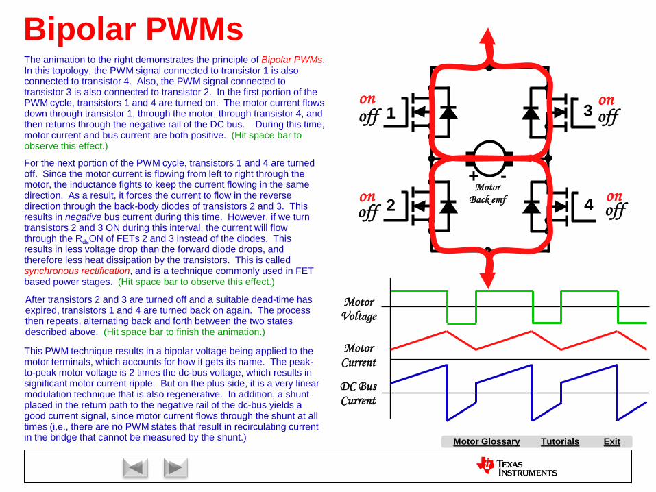
Tutorials ExitMotor Glossary
This PWM technique results in a bipolar voltage being applied to the motor terminals, which accounts for how it gets its name. The peak-to-peak motor voltage is 2 times the dc-bus voltage, which results in significant motor current ripple. But on the plus side, it is a very linear modulation technique that is also regenerative. In addition, a shunt placed in the return path to the negative rail of the dc-bus yields a good current signal, since motor current flows through the shunt at all times (i.e., there are no PWM states that result in recirculating current in the bridge that cannot be measured by the shunt.)
Bipolar PWMs
1
2
3
4+ -
MotorBack emf
MotorVoltage
MotorCurrent
DC BusCurrent
on
on
off
off
off
offon
on
The animation to the right demonstrates the principle of Bipolar PWMs. In this topology, the PWM signal connected to transistor 1 is also connected to transistor 4. Also, the PWM signal connected to transistor 3 is also connected to transistor 2. In the first portion of the PWM cycle, transistors 1 and 4 are turned on. The motor current flows down through transistor 1, through the motor, through transistor 4, and then returns through the negative rail of the DC bus. During this time, motor current and bus current are both positive. (Hit space bar to observe this effect.)
For the next portion of the PWM cycle, transistors 1 and 4 are turned off. Since the motor current is flowing from left to right through the motor, the inductance fights to keep the current flowing in the same direction. As a result, it forces the current to flow in the reverse direction through the back-body diodes of transistors 2 and 3. This results in negative bus current during this time. However, if we turn transistors 2 and 3 ON during this interval, the current will flow through the RdsON of FETs 2 and 3 instead of the diodes. This results in less voltage drop than the forward diode drops, and therefore less heat dissipation by the transistors. This is called synchronous rectification, and is a technique commonly used in FET based power stages. (Hit space bar to observe this effect.)
After transistors 2 and 3 are turned off and a suitable dead-time has expired, transistors 1 and 4 are turned back on again. The process then repeats, alternating back and forth between the two states described above. (Hit space bar to finish the animation.)

A AC Induction Motor (ACIM)
AirgapAlignment TorqueB Back-EMFBipolar PWMsBrakingBrush DC (BDC) MotorBrushesBrushless DC (BLDC) MotorBrushless Permanent Magnet
(BPM)C Center-aligned PWMsClark transformCommutationCommutatorConverterCritically DampedCycle-by-cycle current limitD d-axisDC BusDC InjectionDead-timeDead-time DistortionDigital ControlDirect Torque Control (DTC)Duty cycleDynamic BrakingE eCAPEfficiencyElectronically Commutated
Motor (ECM)Encoder
F FeedbackFeedforwardField Oriented Control (FOC)Field WeakeningFluxFlux DensityFull SteppingG Gate DriverH H-BridgeHalf BridgeHalf steppingHall-effect sensorsHorsepowerI Intelligent Power Module
(IPM)Interior Permanent Magnet
MotorInverterJ K L Leakage InductanceLeft-hand RuleLEM sensorM Magnetic LeakageMagnetizing InductanceMicrosteppingN Neodymium Iron Boron
(“Neo”)
S SaliencySampling FrequencyScalar ControlSensorless ControlServoShoot-throughShunt current sensingSlipSlip frequencySlip ControlSpace Vector Modulation (SVM)SPM MotorStatorStepper (Motor) (SM)Switched Reluctance (SR) MotorSynchronous RectificationT TachometerThird-harmonic ModulationTorqueTorque ConstantTrapezoidalU UnderdampedUnipolar PWMsUniversal MotorV Variable Speed Drive (VSD)Vector ControlVoltage boostVolts-per-Hertz ControlW WindupX Y Z Z-Transform
Tutorials Exit
P Park TransformPermanent Magnet
Synchronous Motor (PMSM)
Permanent Magnet AC Motor (PMAC)
PI ControlPID ControlPluggingPowerPower FactorPower QuadrantsPulse Width Modulation
(PWM)
Q q-axis
R Reaction TorqueRegenerationRegenerative BrakingReluctanceReluctance TorqueResistive BrakingResolverRight-hand RuleRotor
E continuedePWMeQEP
O ObserversOff-lineOverdamped
Motor Glossary
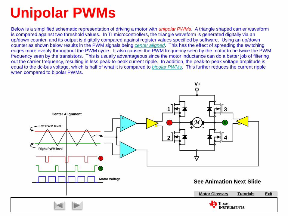
Tutorials ExitMotor Glossary
Unipolar PWMs
R
L
Motor Voltage
Left PWM level
Right PWM level
+
+
-
-RL
V+
1
2
3
4
M+ -
Below is a simplified schematic representation of driving a motor with unipolar PWMs. A triangle shaped carrier waveform is compared against two threshold values. In TI microcontrollers, the triangle waveform is generated digitally via an up/down counter, and its output is digitally compared against register values specified by software. Using an up/down counter as shown below results in the PWM signals being center aligned. This has the effect of spreading the switching edges more evenly throughout the PWM cycle. It also causes the PWM frequency seen by the motor to be twice the PWM frequency seen by the transistors. This is usually advantageous since the motor inductance can do a better job of filtering out the carrier frequency, resulting in less peak-to-peak current ripple. In addition, the peak-to-peak voltage amplitude is equal to the dc-bus voltage, which is half of what it is compared to bipolar PWMs. This further reduces the current ripple when compared to bipolar PWMs.
See Animation Next Slide
Center Alignment

Tutorials ExitMotor Glossary
Unipolar PWMs
1
2
3
4+ -
MotorBack emf
on
on
off
offoff
on on
off
off
on
off
on
MotorVoltage
MotorCurrent
DC BusCurrent

A AC Induction Motor (ACIM)
AirgapAlignment TorqueB Back-EMFBipolar PWMsBrakingBrush DC (BDC) MotorBrushesBrushless DC (BLDC) MotorBrushless Permanent Magnet
(BPM)C Center-aligned PWMsClark transformCommutationCommutatorConverterCritically DampedCycle-by-cycle current limitD d-axisDC BusDC InjectionDead-timeDead-time DistortionDigital ControlDirect Torque Control (DTC)Duty cycleDynamic BrakingE eCAPEfficiencyElectronically Commutated
Motor (ECM)Encoder
F FeedbackFeedforwardField Oriented Control (FOC)Field WeakeningFluxFlux DensityFull SteppingG Gate DriverH H-BridgeHalf BridgeHalf steppingHall-effect sensorsHorsepowerI Intelligent Power Module
(IPM)Interior Permanent Magnet
MotorInverterJ K L Leakage InductanceLeft-hand RuleLEM sensorM Magnetic LeakageMagnetizing InductanceMicrosteppingN Neodymium Iron Boron
(“Neo”)
S SaliencySampling FrequencyScalar ControlSensorless ControlServoShoot-throughShunt current sensingSlipSlip frequencySlip ControlSpace Vector Modulation (SVM)SPM MotorStatorStepper (Motor) (SM)Switched Reluctance (SR) MotorSynchronous RectificationT TachometerThird-harmonic ModulationTorqueTorque ConstantTrapezoidalU UnderdampedUnipolar PWMsUniversal MotorV Variable Speed Drive (VSD)Vector ControlVoltage boostVolts-per-Hertz ControlW WindupX Y Z Z-Transform
Tutorials Exit
P Park TransformPermanent Magnet
Synchronous Motor (PMSM)
Permanent Magnet AC Motor (PMAC)
PI ControlPID ControlPluggingPowerPower FactorPower QuadrantsPulse Width Modulation
(PWM)
Q q-axis
R Reaction TorqueRegenerationRegenerative BrakingReluctanceReluctance TorqueResistive BrakingResolverRight-hand RuleRotor
E continuedePWMeQEP
O ObserversOff-lineOverdamped
Motor Glossary

Tutorials ExitMotor Glossary
Drive ComponentsIn order to make a motor spin at variable speeds, we need to drive it with waveforms at varying frequencies. So the job of a Variable Speed Drive (VSD) is to convert the energy from a high power source (such as a power grid running at 50 or 60 Hz) into powerful output waveforms capable of operating at variable frequencies. The most common way to do this is to first convert the input AC into a high power DC bus. The portion of the motor drive that does this is called the converter. The name comes from the fact that it converts AC into DC. If the converter creates a DC bus voltage by rectifying or boosting AC line voltage, it is called an off-line, or line driven converter. Simple converters consist of nothing more than a rectifier bridge, while more sophisticated converters actually utilize transistors in place of the rectifiers. Converters mayalso have components which allow the current draw from the AC line to be exactly in phase with the AC line’s voltage. Such a Variable Speed Drive is said to have a power factor corrected front end.
As you might expect, the portion of the drive that inverts the DC voltage back into AC is known as the inverter. This is most commonly done by supplying each transistor in the inverter with a pulse width modulated (PWM) signal, resulting in each output of the inverter generating a high voltage, high frequency square wave. The inductance in the motor filters out most of the PWM carrier frequency harmonics, leaving only the lower frequency harmonic that the motor will spin at (see diagram).
AC InTI
Dave’sControlCenter
Brake
Converter
InverterDC Bus +
DC Bus -

A AC Induction Motor (ACIM)
AirgapAlignment TorqueB Back-EMFBipolar PWMsBrakingBrush DC (BDC) MotorBrushesBrushless DC (BLDC) MotorBrushless Permanent Magnet
(BPM)C Center-aligned PWMsClark transformCommutationCommutatorConverterCritically DampedCycle-by-cycle current limitD d-axisDC BusDC InjectionDead-timeDead-time DistortionDigital ControlDirect Torque Control (DTC)Duty cycleDynamic BrakingE eCAPEfficiencyElectronically Commutated
Motor (ECM)Encoder
F FeedbackFeedforwardField Oriented Control (FOC)Field WeakeningFluxFlux DensityFull SteppingG Gate DriverH H-BridgeHalf BridgeHalf steppingHall-effect sensorsHorsepowerI Intelligent Power Module
(IPM)Interior Permanent Magnet
MotorInverterJ K L Leakage InductanceLeft-hand RuleLEM sensorM Magnetic LeakageMagnetizing InductanceMicrosteppingN Neodymium Iron Boron
(“Neo”)
S SaliencySampling FrequencyScalar ControlSensorless ControlServoShoot-throughShunt current sensingSlipSlip frequencySlip ControlSpace Vector Modulation (SVM)SPM MotorStatorStepper (Motor) (SM)Switched Reluctance (SR) MotorSynchronous RectificationT TachometerThird-harmonic ModulationTorqueTorque ConstantTrapezoidalU UnderdampedUnipolar PWMsUniversal MotorV Variable Speed Drive (VSD)Vector ControlVoltage boostVolts-per-Hertz ControlW WindupX Y Z Z-Transform
Tutorials Exit
P Park TransformPermanent Magnet
Synchronous Motor (PMSM)
Permanent Magnet AC Motor (PMAC)
PI ControlPID ControlPluggingPowerPower FactorPower QuadrantsPulse Width Modulation
(PWM)
Q q-axis
R Reaction TorqueRegenerationRegenerative BrakingReluctanceReluctance TorqueResistive BrakingResolverRight-hand RuleRotor
E continuedePWMeQEP
O ObserversOff-lineOverdamped
Motor Glossary
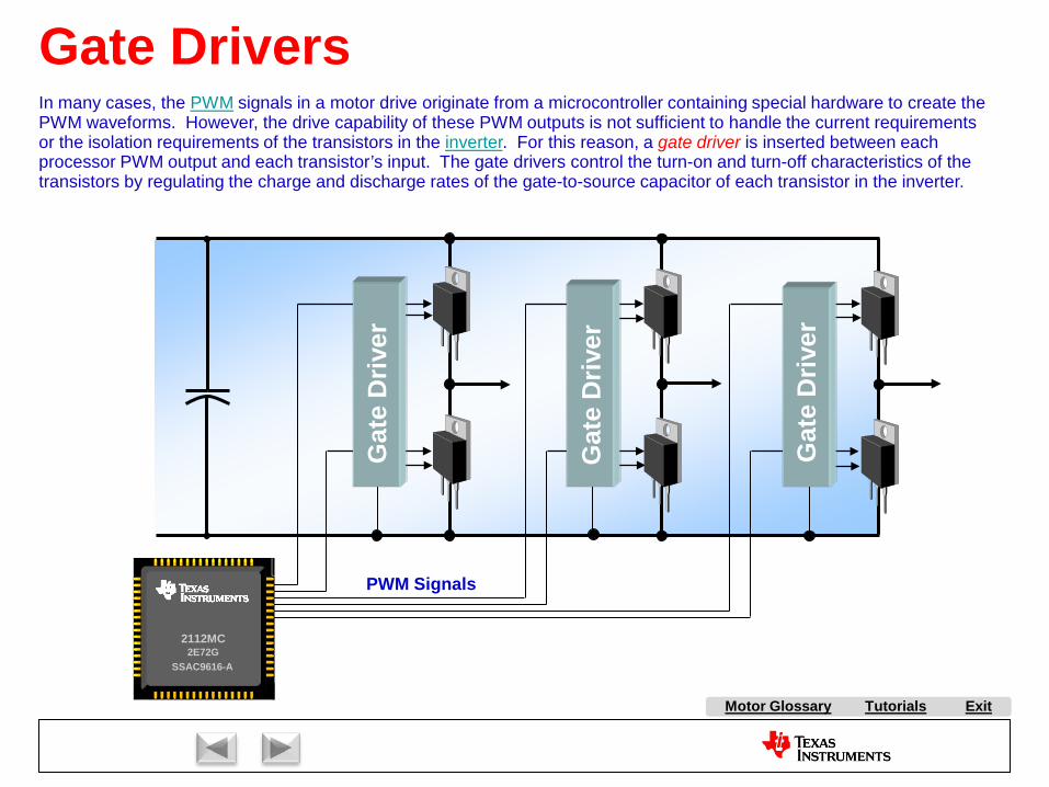
Tutorials ExitMotor Glossary
Gate DriversIn many cases, the PWM signals in a motor drive originate from a microcontroller containing special hardware to create the PWM waveforms. However, the drive capability of these PWM outputs is not sufficient to handle the current requirements or the isolation requirements of the transistors in the inverter. For this reason, a gate driver is inserted between each processor PWM output and each transistor’s input. The gate drivers control the turn-on and turn-off characteristics of the transistors by regulating the charge and discharge rates of the gate-to-source capacitor of each transistor in the inverter.
2E72G2112MC
SSAC9616-A
Gat
e D
river
Gat
e D
river
Gat
e D
river
PWM Signals

A AC Induction Motor (ACIM)
AirgapAlignment TorqueB Back-EMFBipolar PWMsBrakingBrush DC (BDC) MotorBrushesBrushless DC (BLDC) MotorBrushless Permanent Magnet
(BPM)C Center-aligned PWMsClark transformCommutationCommutatorConverterCritically DampedCycle-by-cycle current limitD d-axisDC BusDC InjectionDead-timeDead-time DistortionDigital ControlDirect Torque Control (DTC)Duty cycleDynamic BrakingE eCAPEfficiencyElectronically Commutated
Motor (ECM)Encoder
F FeedbackFeedforwardField Oriented Control (FOC)Field WeakeningFluxFlux DensityFull SteppingG Gate DriverH H-BridgeHalf BridgeHalf steppingHall-effect sensorsHorsepowerI Intelligent Power Module
(IPM)Interior Permanent Magnet
MotorInverterJ K L Leakage InductanceLeft-hand RuleLEM sensorM Magnetic LeakageMagnetizing InductanceMicrosteppingN Neodymium Iron Boron
(“Neo”)
S SaliencySampling FrequencyScalar ControlSensorless ControlServoShoot-throughShunt current sensingSlipSlip frequencySlip ControlSpace Vector Modulation (SVM)SPM MotorStatorStepper (Motor) (SM)Switched Reluctance (SR) MotorSynchronous RectificationT TachometerThird-harmonic ModulationTorqueTorque ConstantTrapezoidalU UnderdampedUnipolar PWMsUniversal MotorV Variable Speed Drive (VSD)Vector ControlVoltage boostVolts-per-Hertz ControlW WindupX Y Z Z-Transform
Tutorials Exit
P Park TransformPermanent Magnet
Synchronous Motor (PMSM)
Permanent Magnet AC Motor (PMAC)
PI ControlPID ControlPluggingPowerPower FactorPower QuadrantsPulse Width Modulation
(PWM)
Q q-axis
R Reaction TorqueRegenerationRegenerative BrakingReluctanceReluctance TorqueResistive BrakingResolverRight-hand RuleRotor
E continuedePWMeQEP
O ObserversOff-lineOverdamped
Motor Glossary
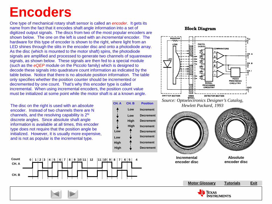
Tutorials ExitMotor Glossary
Encoders
Source: Optoelectronics Designer’s Catalog,Hewlett Packard, 1993
Absolute encoder disc
Incremental encoder disc
One type of mechanical rotary shaft sensor is called an encoder. It gets its name from the fact that it encodes shaft angle information into a set of digitized output signals. The discs from two of the most popular encoders are shown below. The one on the left is used with an incremental encoder. The hardware for this type of encoder is shown to the right, where light from an LED shines through the slits in the encoder disc and onto a photodiode array. As the disc (which is mounted to the motor shaft) spins, the photodiode signals are amplified and processed to generate two channels of squarewave signals, as shown below. These signals are then fed to a special module (such as the eQEP module on the Piccolo family) which is designed to decode these signals into quadrature count information as indicated by the table below. Notice that there is no absolute position information. The table only specifies whether the position counter should be incremented or decremented by one count. That’s why this encoder type is called incremental. When using incremental encoders, the position count value must be initialized at some point while the motor shaft is at a known angle.
CH. A
CH. B
0 1 2 3 4 5 6 7 8 9 10 11 12 11 10 9 8 7 6 5 4Count
CH. A CH. B
Low Increment
High DecrementLow Decrement
High Increment
Position
Low
HighLow
High
DecrementIncrement
Increment
Decrement
The disc on the right is used with an absoluteencoder. Instead of two channels there are N channels, and the resolving capability is 2N
discrete angles. Since absolute shaft angle information is available at all times, this encoder type does not require that the position angle be initialized. However, it is usually more expensive, and is not as popular is the incremental type.

A AC Induction Motor (ACIM)
AirgapAlignment TorqueB Back-EMFBipolar PWMsBrakingBrush DC (BDC) MotorBrushesBrushless DC (BLDC) MotorBrushless Permanent Magnet
(BPM)C Center-aligned PWMsClark transformCommutationCommutatorConverterCritically DampedCycle-by-cycle current limitD d-axisDC BusDC InjectionDead-timeDead-time DistortionDigital ControlDirect Torque Control (DTC)Duty cycleDynamic BrakingE eCAPEfficiencyElectronically Commutated
Motor (ECM)Encoder
F FeedbackFeedforwardField Oriented Control (FOC)Field WeakeningFluxFlux DensityFull SteppingG Gate DriverH H-BridgeHalf BridgeHalf steppingHall-effect sensorsHorsepowerI Intelligent Power Module
(IPM)Interior Permanent Magnet
MotorInverterJ K L Leakage InductanceLeft-hand RuleLEM sensorM Magnetic LeakageMagnetizing InductanceMicrosteppingN Neodymium Iron Boron
(“Neo”)
S SaliencySampling FrequencyScalar ControlSensorless ControlServoShoot-throughShunt current sensingSlipSlip frequencySlip ControlSpace Vector Modulation (SVM)SPM MotorStatorStepper (Motor) (SM)Switched Reluctance (SR) MotorSynchronous RectificationT TachometerThird-harmonic ModulationTorqueTorque ConstantTrapezoidalU UnderdampedUnipolar PWMsUniversal MotorV Variable Speed Drive (VSD)Vector ControlVoltage boostVolts-per-Hertz ControlW WindupX Y Z Z-Transform
Tutorials Exit
P Park TransformPermanent Magnet
Synchronous Motor (PMSM)
Permanent Magnet AC Motor (PMAC)
PI ControlPID ControlPluggingPowerPower FactorPower QuadrantsPulse Width Modulation
(PWM)
Q q-axis
R Reaction TorqueRegenerationRegenerative BrakingReluctanceReluctance TorqueResistive BrakingResolverRight-hand RuleRotor
E continuedePWMeQEP
O ObserversOff-lineOverdamped
Motor Glossary

Tutorials ExitMotor Glossary
Resolvers
Σ Σ Σ
Z-1 Z-1
αβ
+ ++ + +
( )n∧
θ
( )n∧
∆θ
( ) ( ))(ˆ)(sin nnnerror θθ −=
Integrator Integrator
+
cos sin
X
X
Σ+
-
[ ])(nCos θ
[ ])(nSin θ
( ) ( ) ( ) ( ) ( ))(ˆsin)(cos)(ˆcos)(sin)(ˆ)(sin nnnnnn θθθθθθ −=−
In certain applications that demand very rugged and reliable motor shaft position sensing, a rotating transformer topology is used called a resolver. While resolver performance is unmatched for certain industrial and military applications, so is the cost, with some units costing thousands of dollars. By using resolvers, absolute shaft angle measurements can be obtained, and position resolution in the range of 212 to 216 bits per motor revolution are common.The rotor of the resolver is attached to the rotor of the motor that requires position sensing. On the resolver rotor is a coil which is driven with a high carrier frequency, usually somewhere between 8-16 kHz. The stator of the resolver has two coils which are wound in an orthogonal relationship to each other, as shown in the figure bottom-left. When the angle γ is zero, the coupling between the rotor coil and the V1 coil is maximum, and the coupling to the V2 coil is zero, as shown at the very start of the waveform plot below. As the rotor rotates in the counter-clockwise direction, the coupling to the V1 coil decreases, and the coupling to the V2 coil increases. At 90 degrees, the V2 coil coupling is maximum, and the V1 coil coupling is minimum. In effect, the cosine and sine values of the angle γ are modulated onto the V1 and V2 coils using amplitude modulation; the same technology found in an AM radio.By using an ADC with two simultaneously sampled inputs, the rotor shaft angle can be reconstructed by using an angle demodulator running in software, as shown in the bottom-right diagram. If the ADC does not have simultaneous sampling capability, there will be an angle error which is proportional to the conversion time of the ADC. The carrier signal can be generated by a free timer channel on the processor. By connecting the V1 and V2 signals to ADC inputs, and synchronizing the ADC sampling to the timer, the carrier can be stripped off leaving only the red and blue cosine and sine waveforms shown below. The results are more effective when using an ADC with high resolution and a short aperture window. The results of the ADC conversion are then supplied to the inputs of the angle demodulator. By selecting α and β to be large, this increases the gain of the demodulator so that the error signal converges rapidly to zero. Since the error signal is the sine of the difference between the actual angle and the estimated angle, the only way it can converge to zero is if the actual angle equals the estimated angle. Very clever, wouldn’t you say?! The structure of the angle demodulator also provides filtering for the angle estimate as well. Alternatively, you can do a tan-1 calculation using the ADC results, assuming you have a floating point machine.

A AC Induction Motor (ACIM)
AirgapAlignment TorqueB Back-EMFBipolar PWMsBrakingBrush DC (BDC) MotorBrushesBrushless DC (BLDC) MotorBrushless Permanent Magnet
(BPM)C Center-aligned PWMsClark transformCommutationCommutatorConverterCritically DampedCycle-by-cycle current limitD d-axisDC BusDC InjectionDead-timeDead-time DistortionDigital ControlDirect Torque Control (DTC)Duty cycleDynamic BrakingE eCAPEfficiencyElectronically Commutated
Motor (ECM)Encoder
F FeedbackFeedforwardField Oriented Control (FOC)Field WeakeningFluxFlux DensityFull SteppingG Gate DriverH H-BridgeHalf BridgeHalf steppingHall-effect sensorsHorsepowerI Intelligent Power Module
(IPM)Interior Permanent Magnet
MotorInverterJ K L Leakage InductanceLeft-hand RuleLEM sensorM Magnetic LeakageMagnetizing InductanceMicrosteppingN Neodymium Iron Boron
(“Neo”)
S SaliencySampling FrequencyScalar ControlSensorless ControlServoShoot-throughShunt current sensingSlipSlip frequencySlip ControlSpace Vector Modulation (SVM)SPM MotorStatorStepper (Motor) (SM)Switched Reluctance (SR) MotorSynchronous RectificationT TachometerThird-harmonic ModulationTorqueTorque ConstantTrapezoidalU UnderdampedUnipolar PWMsUniversal MotorV Variable Speed Drive (VSD)Vector ControlVoltage boostVolts-per-Hertz ControlW WindupX Y Z Z-Transform
Tutorials Exit
P Park TransformPermanent Magnet
Synchronous Motor (PMSM)
Permanent Magnet AC Motor (PMAC)
PI ControlPID ControlPluggingPowerPower FactorPower QuadrantsPulse Width Modulation
(PWM)
Q q-axis
R Reaction TorqueRegenerationRegenerative BrakingReluctanceReluctance TorqueResistive BrakingResolverRight-hand RuleRotor
E continuedePWMeQEP
O ObserversOff-lineOverdamped
Motor Glossary
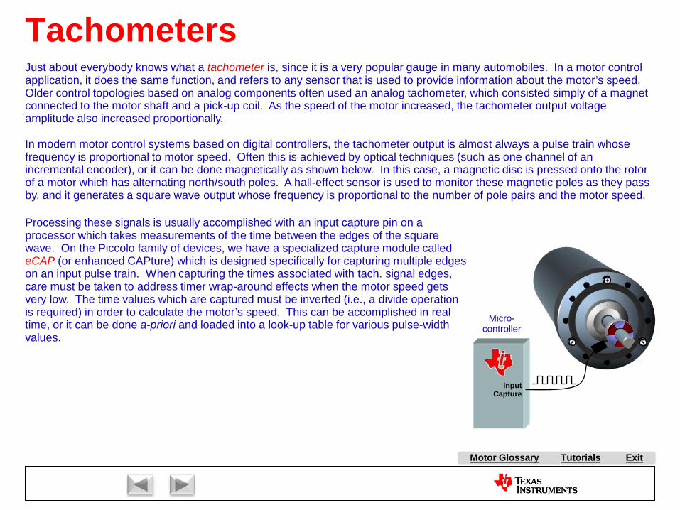
Tutorials ExitMotor Glossary
Tachometers
Micro-controller
Input Capture
Just about everybody knows what a tachometer is, since it is a very popular gauge in many automobiles. In a motor control application, it does the same function, and refers to any sensor that is used to provide information about the motor’s speed.Older control topologies based on analog components often used an analog tachometer, which consisted simply of a magnet connected to the motor shaft and a pick-up coil. As the speed of the motor increased, the tachometer output voltage amplitude also increased proportionally.
In modern motor control systems based on digital controllers, the tachometer output is almost always a pulse train whose frequency is proportional to motor speed. Often this is achieved by optical techniques (such as one channel of an incremental encoder), or it can be done magnetically as shown below. In this case, a magnetic disc is pressed onto the rotorof a motor which has alternating north/south poles. A hall-effect sensor is used to monitor these magnetic poles as they pass by, and it generates a square wave output whose frequency is proportional to the number of pole pairs and the motor speed.
Processing these signals is usually accomplished with an input capture pin on a processor which takes measurements of the time between the edges of the square wave. On the Piccolo family of devices, we have a specialized capture module called eCAP (or enhanced CAPture) which is designed specifically for capturing multiple edges on an input pulse train. When capturing the times associated with tach. signal edges, care must be taken to address timer wrap-around effects when the motor speed gets very low. The time values which are captured must be inverted (i.e., a divide operation is required) in order to calculate the motor’s speed. This can be accomplished in real time, or it can be done a-priori and loaded into a look-up table for various pulse-width values.

A AC Induction Motor (ACIM)
AirgapAlignment TorqueB Back-EMFBipolar PWMsBrakingBrush DC (BDC) MotorBrushesBrushless DC (BLDC) MotorBrushless Permanent Magnet
(BPM)C Center-aligned PWMsClark transformCommutationCommutatorConverterCritically DampedCycle-by-cycle current limitD d-axisDC BusDC InjectionDead-timeDead-time DistortionDigital ControlDirect Torque Control (DTC)Duty cycleDynamic BrakingE eCAPEfficiencyElectronically Commutated
Motor (ECM)Encoder
F FeedbackFeedforwardField Oriented Control (FOC)Field WeakeningFluxFlux DensityFull SteppingG Gate DriverH H-BridgeHalf BridgeHalf steppingHall-effect sensorsHorsepowerI Intelligent Power Module
(IPM)Interior Permanent Magnet
MotorInverterJ K L Leakage InductanceLeft-hand RuleLEM sensorM Magnetic LeakageMagnetizing InductanceMicrosteppingN Neodymium Iron Boron
(“Neo”)
S SaliencySampling FrequencyScalar ControlSensorless ControlServoShoot-throughShunt current sensingSlipSlip frequencySlip ControlSpace Vector Modulation (SVM)SPM MotorStatorStepper (Motor) (SM)Switched Reluctance (SR) MotorSynchronous RectificationT TachometerThird-harmonic ModulationTorqueTorque ConstantTrapezoidalU UnderdampedUnipolar PWMsUniversal MotorV Variable Speed Drive (VSD)Vector ControlVoltage boostVolts-per-Hertz ControlW WindupX Y Z Z-Transform
Tutorials Exit
P Park TransformPermanent Magnet
Synchronous Motor (PMSM)
Permanent Magnet AC Motor (PMAC)
PI ControlPID ControlPluggingPowerPower FactorPower QuadrantsPulse Width Modulation
(PWM)
Q q-axis
R Reaction TorqueRegenerationRegenerative BrakingReluctanceReluctance TorqueResistive BrakingResolverRight-hand RuleRotor
E continuedePWMeQEP
O ObserversOff-lineOverdamped
Motor Glossary
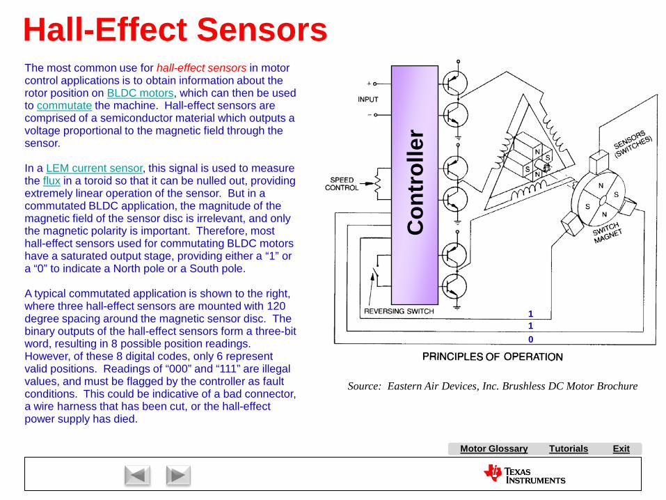
Tutorials ExitMotor Glossary
Hall-Effect Sensors
Con
trol
ler
Source: Eastern Air Devices, Inc. Brushless DC Motor Brochure
110
The most common use for hall-effect sensors in motor control applications is to obtain information about the rotor position on BLDC motors, which can then be used to commutate the machine. Hall-effect sensors are comprised of a semiconductor material which outputs a voltage proportional to the magnetic field through the sensor.
In a LEM current sensor, this signal is used to measure the flux in a toroid so that it can be nulled out, providing extremely linear operation of the sensor. But in a commutated BLDC application, the magnitude of the magnetic field of the sensor disc is irrelevant, and only the magnetic polarity is important. Therefore, most hall-effect sensors used for commutating BLDC motors have a saturated output stage, providing either a “1” or a “0” to indicate a North pole or a South pole.
A typical commutated application is shown to the right, where three hall-effect sensors are mounted with 120 degree spacing around the magnetic sensor disc. The binary outputs of the hall-effect sensors form a three-bit word, resulting in 8 possible position readings. However, of these 8 digital codes, only 6 represent valid positions. Readings of “000” and “111” are illegal values, and must be flagged by the controller as fault conditions. This could be indicative of a bad connector, a wire harness that has been cut, or the hall-effect power supply has died.

A AC Induction Motor (ACIM)
AirgapAlignment TorqueB Back-EMFBipolar PWMsBrakingBrush DC (BDC) MotorBrushesBrushless DC (BLDC) MotorBrushless Permanent Magnet
(BPM)C Center-aligned PWMsClark transformCommutationCommutatorConverterCritically DampedCycle-by-cycle current limitD d-axisDC BusDC InjectionDead-timeDead-time DistortionDigital ControlDirect Torque Control (DTC)Duty cycleDynamic BrakingE eCAPEfficiencyElectronically Commutated
Motor (ECM)Encoder
F FeedbackFeedforwardField Oriented Control (FOC)Field WeakeningFluxFlux DensityFull SteppingG Gate DriverH H-BridgeHalf BridgeHalf steppingHall-effect sensorsHorsepowerI Intelligent Power Module
(IPM)Interior Permanent Magnet
MotorInverterJ K L Leakage InductanceLeft-hand RuleLEM sensorM Magnetic LeakageMagnetizing InductanceMicrosteppingN Neodymium Iron Boron
(“Neo”)
S SaliencySampling FrequencyScalar ControlSensorless ControlServoShoot-throughShunt current sensingSlipSlip frequencySlip ControlSpace Vector Modulation (SVM)SPM MotorStatorStepper (Motor) (SM)Switched Reluctance (SR) MotorSynchronous RectificationT TachometerThird-harmonic ModulationTorqueTorque ConstantTrapezoidalU UnderdampedUnipolar PWMsUniversal MotorV Variable Speed Drive (VSD)Vector ControlVoltage boostVolts-per-Hertz ControlW WindupX Y Z Z-Transform
Tutorials Exit
P Park TransformPermanent Magnet
Synchronous Motor (PMSM)
Permanent Magnet AC Motor (PMAC)
PI ControlPID ControlPluggingPowerPower FactorPower QuadrantsPulse Width Modulation
(PWM)
Q q-axis
R Reaction TorqueRegenerationRegenerative BrakingReluctanceReluctance TorqueResistive BrakingResolverRight-hand RuleRotor
E continuedePWMeQEP
O ObserversOff-lineOverdamped
Motor Glossary
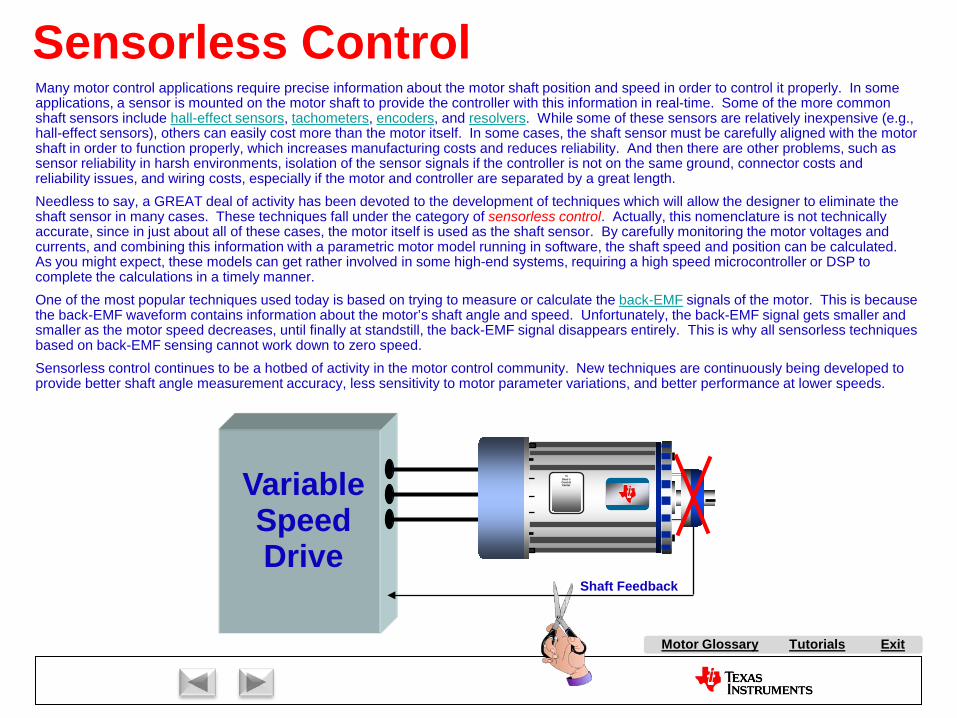
Tutorials ExitMotor Glossary
Sensorless Control
TIDave’sControlCenterVariable
Speed Drive
Shaft Feedback
Many motor control applications require precise information about the motor shaft position and speed in order to control it properly. In some applications, a sensor is mounted on the motor shaft to provide the controller with this information in real-time. Some of the more common shaft sensors include hall-effect sensors, tachometers, encoders, and resolvers. While some of these sensors are relatively inexpensive (e.g., hall-effect sensors), others can easily cost more than the motor itself. In some cases, the shaft sensor must be carefully aligned with the motor shaft in order to function properly, which increases manufacturing costs and reduces reliability. And then there are other problems, such as sensor reliability in harsh environments, isolation of the sensor signals if the controller is not on the same ground, connector costs and reliability issues, and wiring costs, especially if the motor and controller are separated by a great length.Needless to say, a GREAT deal of activity has been devoted to the development of techniques which will allow the designer to eliminate the shaft sensor in many cases. These techniques fall under the category of sensorless control. Actually, this nomenclature is not technically accurate, since in just about all of these cases, the motor itself is used as the shaft sensor. By carefully monitoring the motor voltages and currents, and combining this information with a parametric motor model running in software, the shaft speed and position can be calculated. As you might expect, these models can get rather involved in some high-end systems, requiring a high speed microcontroller or DSP to complete the calculations in a timely manner.One of the most popular techniques used today is based on trying to measure or calculate the back-EMF signals of the motor. This is because the back-EMF waveform contains information about the motor’s shaft angle and speed. Unfortunately, the back-EMF signal gets smaller and smaller as the motor speed decreases, until finally at standstill, the back-EMF signal disappears entirely. This is why all sensorless techniques based on back-EMF sensing cannot work down to zero speed.Sensorless control continues to be a hotbed of activity in the motor control community. New techniques are continuously being developed to provide better shaft angle measurement accuracy, less sensitivity to motor parameter variations, and better performance at lower speeds.

A AC Induction Motor (ACIM)
AirgapAlignment TorqueB Back-EMFBipolar PWMsBrakingBrush DC (BDC) MotorBrushesBrushless DC (BLDC) MotorBrushless Permanent Magnet
(BPM)C Center-aligned PWMsClark transformCommutationCommutatorConverterCritically DampedCycle-by-cycle current limitD d-axisDC BusDC InjectionDead-timeDead-time DistortionDigital ControlDirect Torque Control (DTC)Duty cycleDynamic BrakingE eCAPEfficiencyElectronically Commutated
Motor (ECM)Encoder
F FeedbackFeedforwardField Oriented Control (FOC)Field WeakeningFluxFlux DensityFull SteppingG Gate DriverH H-BridgeHalf BridgeHalf steppingHall-effect sensorsHorsepowerI Intelligent Power Module
(IPM)Interior Permanent Magnet
MotorInverterJ K L Leakage InductanceLeft-hand RuleLEM sensorM Magnetic LeakageMagnetizing InductanceMicrosteppingN Neodymium Iron Boron
(“Neo”)
S SaliencySampling FrequencyScalar ControlSensorless ControlServoShoot-throughShunt current sensingSlipSlip frequencySlip ControlSpace Vector Modulation (SVM)SPM MotorStatorStepper (Motor) (SM)Switched Reluctance (SR) MotorSynchronous RectificationT TachometerThird-harmonic ModulationTorqueTorque ConstantTrapezoidalU UnderdampedUnipolar PWMsUniversal MotorV Variable Speed Drive (VSD)Vector ControlVoltage boostVolts-per-Hertz ControlW WindupX Y Z Z-Transform
Tutorials Exit
P Park TransformPermanent Magnet
Synchronous Motor (PMSM)
Permanent Magnet AC Motor (PMAC)
PI ControlPID ControlPluggingPowerPower FactorPower QuadrantsPulse Width Modulation
(PWM)
Q q-axis
R Reaction TorqueRegenerationRegenerative BrakingReluctanceReluctance TorqueResistive BrakingResolverRight-hand RuleRotor
E continuedePWMeQEP
O ObserversOff-lineOverdamped
Motor Glossary
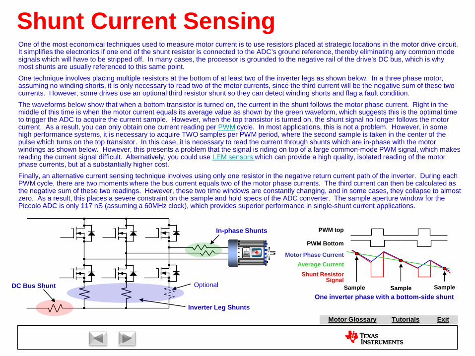
Tutorials ExitMotor Glossary
Shunt Current SensingOne of the most economical techniques used to measure motor current is to use resistors placed at strategic locations in the motor drive circuit. It simplifies the electronics if one end of the shunt resistor is connected to the ADC’s ground reference, thereby eliminating any common mode signals which will have to be stripped off. In many cases, the processor is grounded to the negative rail of the drive’s DC bus, which is why most shunts are usually referenced to this same point.One technique involves placing multiple resistors at the bottom of at least two of the inverter legs as shown below. In a three phase motor, assuming no winding shorts, it is only necessary to read two of the motor currents, since the third current will be the negative sum of these two currents. However, some drives use an optional third resistor shunt so they can detect winding shorts and flag a fault condition.The waveforms below show that when a bottom transistor is turned on, the current in the shunt follows the motor phase current. Right in the middle of this time is when the motor current equals its average value as shown by the green waveform, which suggests this is the optimal time to trigger the ADC to acquire the current sample. However, when the top transistor is turned on, the shunt signal no longer follows the motor current. As a result, you can only obtain one current reading per PWM cycle. In most applications, this is not a problem. However, in some high performance systems, it is necessary to acquire TWO samples per PWM period, where the second sample is taken in the center of the pulse which turns on the top transistor. In this case, it is necessary to read the current through shunts which are in-phase with the motor windings as shown below. However, this presents a problem that the signal is riding on top of a large common-mode PWM signal, which makes reading the current signal difficult. Alternatively, you could use LEM sensors which can provide a high quality, isolated reading of the motor phase currents, but at a substantially higher cost.Finally, an alternative current sensing technique involves using only one resistor in the negative return current path of the inverter. During each PWM cycle, there are two moments where the bus current equals two of the motor phase currents. The third current can then be calculated as the negative sum of these two readings. However, these two time windows are constantly changing, and in some cases, they collapse to almost zero. As a result, this places a severe constraint on the sample and hold specs of the ADC converter. The sample aperture window for the Piccolo ADC is only 117 nS (assuming a 60MHz clock), which provides superior performance in single-shunt current applications.
PWM top
PWM Bottom
Motor Phase Current
Shunt ResistorSignal
Sample Sample Sample
Average Current
TIDave’sControlCenter
DC Bus Shunt
Inverter Leg Shunts
Optional
In-phase Shunts
One inverter phase with a bottom-side shunt

A AC Induction Motor (ACIM)
AirgapAlignment TorqueB Back-EMFBipolar PWMsBrakingBrush DC (BDC) MotorBrushesBrushless DC (BLDC) MotorBrushless Permanent Magnet
(BPM)C Center-aligned PWMsClark transformCommutationCommutatorConverterCritically DampedCycle-by-cycle current limitD d-axisDC BusDC InjectionDead-timeDead-time DistortionDigital ControlDirect Torque Control (DTC)Duty cycleDynamic BrakingE eCAPEfficiencyElectronically Commutated
Motor (ECM)Encoder
F FeedbackFeedforwardField Oriented Control (FOC)Field WeakeningFluxFlux DensityFull SteppingG Gate DriverH H-BridgeHalf BridgeHalf steppingHall-effect sensorsHorsepowerI Intelligent Power Module
(IPM)Interior Permanent Magnet
MotorInverterJ K L Leakage InductanceLeft-hand RuleLEM sensorM Magnetic LeakageMagnetizing InductanceMicrosteppingN Neodymium Iron Boron
(“Neo”)
S SaliencySampling FrequencyScalar ControlSensorless ControlServoShoot-throughShunt current sensingSlipSlip frequencySlip ControlSpace Vector Modulation (SVM)SPM MotorStatorStepper (Motor) (SM)Switched Reluctance (SR) MotorSynchronous RectificationT TachometerThird-harmonic ModulationTorqueTorque ConstantTrapezoidalU UnderdampedUnipolar PWMsUniversal MotorV Variable Speed Drive (VSD)Vector ControlVoltage boostVolts-per-Hertz ControlW WindupX Y Z Z-Transform
Tutorials Exit
P Park TransformPermanent Magnet
Synchronous Motor (PMSM)
Permanent Magnet AC Motor (PMAC)
PI ControlPID ControlPluggingPowerPower FactorPower QuadrantsPulse Width Modulation
(PWM)
Q q-axis
R Reaction TorqueRegenerationRegenerative BrakingReluctanceReluctance TorqueResistive BrakingResolverRight-hand RuleRotor
E continuedePWMeQEP
O ObserversOff-lineOverdamped
Motor Glossary
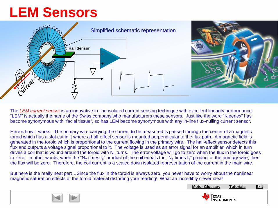
Tutorials ExitMotor Glossary
LEM Sensors
+-
Hall Sensor
The LEM current sensor is an innovative in-line isolated current sensing technique with excellent linearity performance. “LEM” is actually the name of the Swiss company who manufacturers these sensors. Just like the word “Kleenex” has become synonymous with “facial tissue”, so has LEM become synonymous with any in-line flux-nulling current sensor.
Here’s how it works. The primary wire carrying the current to be measured is passed through the center of a magnetic toroid which has a slot cut in it where a hall-effect sensor is mounted perpendicular to the flux path. A magnetic field is generated in the toroid which is proportional to the current flowing in the primary wire. The hall-effect sensor detects this flux and outputs a voltage signal proportional to it. The voltage is used as an error signal for an amplifier, which in turndrives a coil that is wound around the toroid with N2 turns. The error voltage will go to zero when the flux in the toroid goes to zero. In other words, when the “N2 times I2” product of the coil equals the “N1 times I1” product of the primary wire, then the flux will be zero. Therefore, the coil current is a scaled down isolated representation of the current in the main wire.
But here is the really neat part…Since the flux in the toroid is always zero, you never have to worry about the nonlinear magnetic saturation effects of the toroid material distorting your reading! What an incredibly clever idea!
Simplified schematic representation

A AC Induction Motor (ACIM)
AirgapAlignment TorqueB Back-EMFBipolar PWMsBrakingBrush DC (BDC) MotorBrushesBrushless DC (BLDC) MotorBrushless Permanent Magnet
(BPM)C Center-aligned PWMsClark transformCommutationCommutatorConverterCritically DampedCycle-by-cycle current limitD d-axisDC BusDC InjectionDead-timeDead-time DistortionDigital ControlDirect Torque Control (DTC)Duty cycleDynamic BrakingE eCAPEfficiencyElectronically Commutated
Motor (ECM)Encoder
F FeedbackFeedforwardField Oriented Control (FOC)Field WeakeningFluxFlux DensityFull SteppingG Gate DriverH H-BridgeHalf BridgeHalf steppingHall-effect sensorsHorsepowerI Intelligent Power Module
(IPM)Interior Permanent Magnet
MotorInverterJ K L Leakage InductanceLeft-hand RuleLEM sensorM Magnetic LeakageMagnetizing InductanceMicrosteppingN Neodymium Iron Boron
(“Neo”)
S SaliencySampling FrequencyScalar ControlSensorless ControlServoShoot-throughShunt current sensingSlipSlip frequencySlip ControlSpace Vector Modulation (SVM)SPM MotorStatorStepper (Motor) (SM)Switched Reluctance (SR) MotorSynchronous RectificationT TachometerThird-harmonic ModulationTorqueTorque ConstantTrapezoidalU UnderdampedUnipolar PWMsUniversal MotorV Variable Speed Drive (VSD)Vector ControlVoltage boostVolts-per-Hertz ControlW WindupX Y Z Z-Transform
Tutorials Exit
P Park TransformPermanent Magnet
Synchronous Motor (PMSM)
Permanent Magnet AC Motor (PMAC)
PI ControlPID ControlPluggingPowerPower FactorPower QuadrantsPulse Width Modulation
(PWM)
Q q-axis
R Reaction TorqueRegenerationRegenerative BrakingReluctanceReluctance TorqueResistive BrakingResolverRight-hand RuleRotor
E continuedePWMeQEP
O ObserversOff-lineOverdamped
Motor Glossary

Tutorials ExitMotor Glossary
Cycle-by-Cycle Current Limit
+-Desired current limit
MotorCurrent
FromAmplifier
PWMs come backon line automatically
at the start of thenext PWM cycle.
To PWM Disable
TIDave’sControlCenter
T
0
Current limit
PWM
Cycle-by-cycle current limiting is a hardware technique where the motor current is continuously compared to a maximum current limit threshold. Whenever the current crosses the threshold, a fault signal is sent to the PWM generator which turns it off for the remainder of the PWM cycle. However, at the start of the next PWM cycle, assuming that the over-current signal has gone away, the PWM modulerearms and the process repeats. One obvious advantage of this technique is that the current limit function is handled entirely in hardware, which reduces the required software bandwidth. Another effect (which may or may not be an advantage, depending on your application) is that it really limits the PEAK of your current signal, not the AVERAGE of your current signal. The average current will be a function of the peak-to-peak current ripple, which changes as a function of your duty cycle. As a result, cycle-by-cycle limiting is most frequently used for current limit protection, not current regulation.

A AC Induction Motor (ACIM)
AirgapAlignment TorqueB Back-EMFBipolar PWMsBrakingBrush DC (BDC) MotorBrushesBrushless DC (BLDC) MotorBrushless Permanent Magnet
(BPM)C Center-aligned PWMsClark transformCommutationCommutatorConverterCritically DampedCycle-by-cycle current limitD d-axisDC BusDC InjectionDead-timeDead-time DistortionDigital ControlDirect Torque Control (DTC)Duty cycleDynamic BrakingE eCAPEfficiencyElectronically Commutated
Motor (ECM)Encoder
F FeedbackFeedforwardField Oriented Control (FOC)Field WeakeningFluxFlux DensityFull SteppingG Gate DriverH H-BridgeHalf BridgeHalf steppingHall-effect sensorsHorsepowerI Intelligent Power Module
(IPM)Interior Permanent Magnet
MotorInverterJ K L Leakage InductanceLeft-hand RuleLEM sensorM Magnetic LeakageMagnetizing InductanceMicrosteppingN Neodymium Iron Boron
(“Neo”)
S SaliencySampling FrequencyScalar ControlSensorless ControlServoShoot-throughShunt current sensingSlipSlip frequencySlip ControlSpace Vector Modulation (SVM)SPM MotorStatorStepper (Motor) (SM)Switched Reluctance (SR) MotorSynchronous RectificationT TachometerThird-harmonic ModulationTorqueTorque ConstantTrapezoidalU UnderdampedUnipolar PWMsUniversal MotorV Variable Speed Drive (VSD)Vector ControlVoltage boostVolts-per-Hertz ControlW WindupX Y Z Z-Transform
Tutorials Exit
P Park TransformPermanent Magnet
Synchronous Motor (PMSM)
Permanent Magnet AC Motor (PMAC)
PI ControlPID ControlPluggingPowerPower FactorPower QuadrantsPulse Width Modulation
(PWM)
Q q-axis
R Reaction TorqueRegenerationRegenerative BrakingReluctanceReluctance TorqueResistive BrakingResolverRight-hand RuleRotor
E continuedePWMeQEP
O ObserversOff-lineOverdamped
Motor Glossary

Motor Glossary
Tutorials
Exit

Market Overview:
AC Induction Motor Control:
Stepper Motor Control
Brush DC Motor Control:
Brushless DC Motor Control:
With Hall Effect Feedback
Sensorless
Permanent Magnet Synchronous Motor Control
Volts per Hertz Control
Slip Control
Field Oriented Control
Field Oriented Control
ExitMotor Glossary
Tutorials

Tutorials ExitMotor Glossary
50% to 60%of all electricity
generated in most industrialized countriesis consumed by electric motors!
Commercial, Residential
Industrial and Manufacturing
Transportation and Other Motors
Approximately 2200 Billion KWHours generated in the U.S.
each year to drive electric motors.*
*EIA Energy Survey, 2008 data, U.S. DOE

Tutorials ExitMotor Glossary
Energy Crisis 2.0.Solution: Generate MORE Energy?
How about using LESS energy???
Even renewable forms of energy generation have environmental impacts!
Increased costs of energy delivery infrastructure.
Many renewable forms of energy generation are only supplemental in nature.
Electric delivery capacity in many areas is already maxed out!

Tutorials ExitMotor Glossary
Low Hanging Fruit!What if we increase load efficiencies?Up to 40% energy savings is possible in many motor control applications, with minimal performance impact!
Electronic Control is the ticket!

Tutorials ExitMotor Glossary
Electronic adjustable speed drives can control flow rates in pump and blower applications, eliminating throttling valves and dampers, with energy savings of 20%!
Electronic motor controllers can reduce motor flux in applications which are often lightly loaded, with electrical
energy savings up to 40%!
Electronic adjustable speed drives can reduce refrigerant migration in compressor loads, with electrical energy savings up to 30%!(One out of three new home starts in the U.S. employ a heat pump.)
Electronic Motor Control Saves Energy!

Tutorials ExitMotor Glossary
Appliance Opportunities for Motor Control
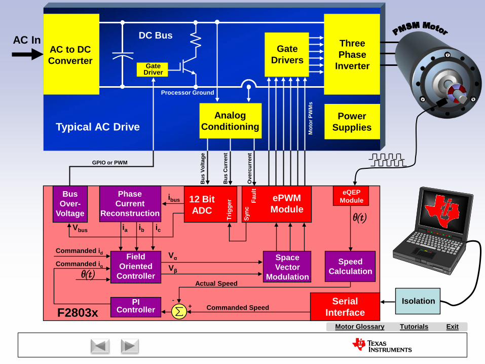
Tutorials ExitMotor Glossary
AC InAC to DCConverter
ThreePhase
Inverter
GateDrivers
DC Bus
GateDriver
PowerSupplies
AnalogConditioning
SerialInterfaceF2803x
12 BitADC
Trig
ger Fa
ult
ePWMModule
Sync
Isolation
eQEPModule
Commanded Speed
Actual Speed
+-PI
Controller
FieldOriented
ControllerCommanded iq
Commanded id
PhaseCurrent
Reconstructionicia
SpaceVector
Modulation
Vα
Vβ
ibusBus
Over-Voltage
GPIO or PWM
SpeedCalculation
ibVbus
Mot
or P
WM
s
Ove
rcur
rent
Bus
Cur
rent
Bus
Vol
tage
Processor Ground
θ(t)
θ(t)
Typical AC Drive
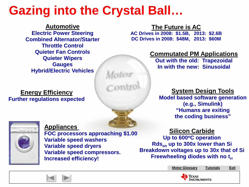
Tutorials ExitMotor Glossary
Gazing into the Crystal Ball…
Energy EfficiencyFurther regulations expected
Commutated PM ApplicationsOut with the old: TrapezoidalIn with the new: Sinusoidal
AppliancesFOC processors approaching $1.00Variable speed washersVariable speed dryersVariable speed compressors.Increased efficiency!
System Design ToolsModel based software generation
(e.g., Simulink)“Humans are exitingthe coding business”
The Future is ACAC Drives in 2008: $1.5B, 2013: $2.6BDC Drives in 2008: $48M, 2013: $60M
AutomotiveElectric Power Steering
Combined Alternator/StarterThrottle Control
Quieter Fan ControlsQuieter Wipers
GaugesHybrid/Electric Vehicles
Silicon CarbideUp to 600oC operation
Rdson up to 300x lower than SiBreakdown voltages up to 30x that of Si
Freewheeling diodes with no trr

Market Overview:
AC Induction Motor Control:
Stepper Motor Control
Brush DC Motor Control:
Brushless DC Motor Control:
With Hall Effect Feedback
Sensorless
Permanent Magnet Synchronous Motor Control
Volts per Hertz Control
Slip Control
Field Oriented Control
Field Oriented Control
ExitMotor Glossary
Tutorials

Brush DC Motors
Copyright Texas Instruments 2011

Tutorials ExitMotor Glossary
Single-loop motor example
N S
Source: Electric Drives, an Integrative Approach,by Ned Mohan, University of Minn. Printing Services, 2000
The magnetic field produced by the current flowing through the loop of wire will interact with the stator permanent magnets to create forces on the loop, causing the rotor to spin counterclockwise. However, when δ reaches 180 degrees, the force vectors will line up through the center of the rotor, and the torque will be zero. To keep the motor spinning, we must reverse the current in the loop of wire at precisely this point. But how do we know that we are at this point? Should we use a shaft sensor of some type?
Actually, there is an easier way (next slide)
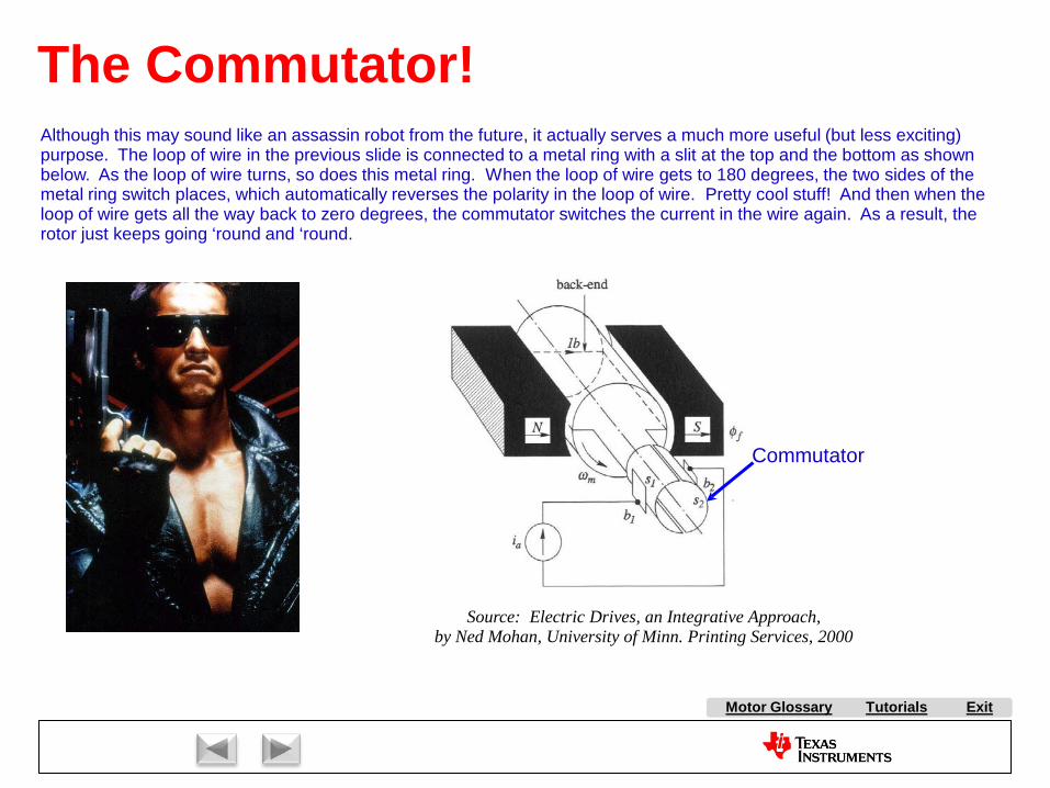
Tutorials ExitMotor Glossary
The Commutator!Although this may sound like an assassin robot from the future, it actually serves a much more useful (but less exciting) purpose. The loop of wire in the previous slide is connected to a metal ring with a slit at the top and the bottom as shown below. As the loop of wire turns, so does this metal ring. When the loop of wire gets to 180 degrees, the two sides of the metal ring switch places, which automatically reverses the polarity in the loop of wire. Pretty cool stuff! And then when the loop of wire gets all the way back to zero degrees, the commutator switches the current in the wire again. As a result, the rotor just keeps going ‘round and ‘round.
Commutator
Source: Electric Drives, an Integrative Approach,by Ned Mohan, University of Minn. Printing Services, 2000
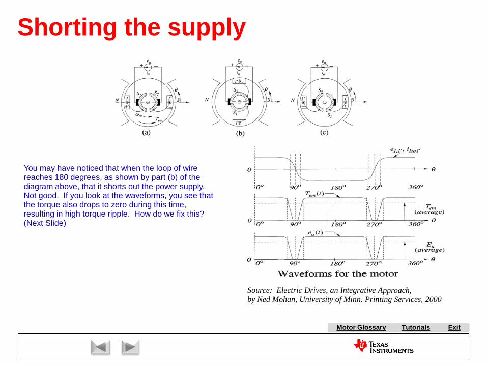
Tutorials ExitMotor Glossary
Shorting the supply
You may have noticed that when the loop of wire reaches 180 degrees, as shown by part (b) of the diagram above, that it shorts out the power supply. Not good. If you look at the waveforms, you see that the torque also drops to zero during this time, resulting in high torque ripple. How do we fix this?(Next Slide)
Source: Electric Drives, an Integrative Approach,by Ned Mohan, University of Minn. Printing Services, 2000
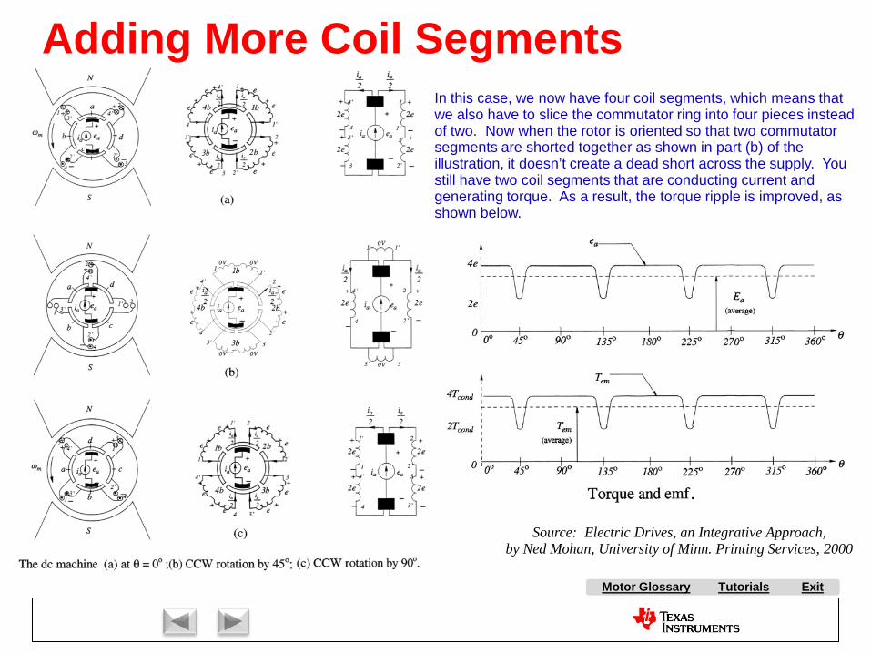
Tutorials ExitMotor Glossary
Source: Electric Drives, an Integrative Approach,by Ned Mohan, University of Minn. Printing Services, 2000
Adding More Coil SegmentsIn this case, we now have four coil segments, which means that we also have to slice the commutator ring into four pieces instead of two. Now when the rotor is oriented so that two commutator segments are shorted together as shown in part (b) of the illustration, it doesn’t create a dead short across the supply. You still have two coil segments that are conducting current and generating torque. As a result, the torque ripple is improved, as shown below.
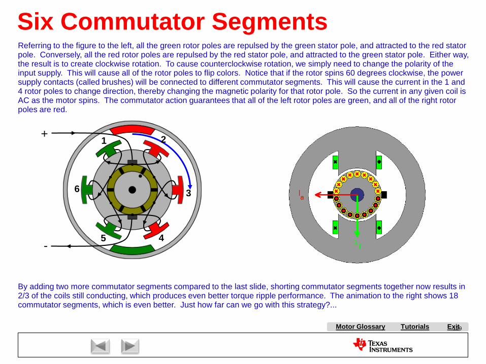
Tutorials ExitMotor Glossary 129
Six Commutator Segments
By adding two more commutator segments compared to the last slide, shorting commutator segments together now results in 2/3 of the coils still conducting, which produces even better torque ripple performance. The animation to the right shows 18commutator segments, which is even better. Just how far can we go with this strategy?...
Referring to the figure to the left, all the green rotor poles are repulsed by the green stator pole, and attracted to the red stator pole. Conversely, all the red rotor poles are repulsed by the red stator pole, and attracted to the green stator pole. Either way, the result is to create clockwise rotation. To cause counterclockwise rotation, we simply need to change the polarity of theinput supply. This will cause all of the rotor poles to flip colors. Notice that if the rotor spins 60 degrees clockwise, the power supply contacts (called brushes) will be connected to different commutator segments. This will cause the current in the 1 and 4 rotor poles to change direction, thereby changing the magnetic polarity for that rotor pole. So the current in any given coil is AC as the motor spins. The commutator action guarantees that all of the left rotor poles are green, and all of the right rotor poles are red.
+
-
1 2
4
3
5
6

Tutorials ExitMotor Glossary
Commutator
BrushesLaminated Rotor
Source: Electric Machinery, by A. E. Fitzgerald, Charles Kingsley Jr., and Stephen D. Umans, McGraw-Hill, 1990
Brush DC Motor CutawayNot sure how many commutator segments this motor has, but it’s a lot! Motors with this many commutator segments result in very low torque ripple, and are usually used in servo applications where torque ripple is critical.
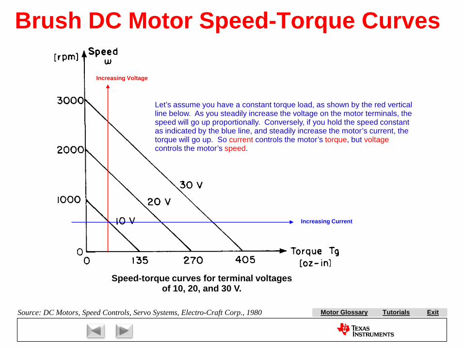
Tutorials ExitMotor Glossary
Speed-torque curves for terminal voltagesof 10, 20, and 30 V.
Source: DC Motors, Speed Controls, Servo Systems, Electro-Craft Corp., 1980
Brush DC Motor Speed-Torque Curves
Let’s assume you have a constant torque load, as shown by the red vertical line below. As you steadily increase the voltage on the motor terminals, the speed will go up proportionally. Conversely, if you hold the speed constant as indicated by the blue line, and steadily increase the motor’s current, the torque will go up. So current controls the motor’s torque, but voltagecontrols the motor’s speed.
Increasing Voltage
Increasing Current

Tutorials ExitMotor Glossary
V6
24
R15{Rt}
L2
{L}
V=I(L2)*Kt
B2
E5
{Kem
f}
E6
{Kd}
V2
{Kf} V3
{-Kf}
max
min
i.c.
{1/(Jmotor + Jload)}E1
V1
PWL(0 0 0.249999 0 0.25 0.8)
E2
{30 / pi}R1
10k
M+
M-
Shaf
t_To
rqueM+
M-
Load
RPM
.tran 0 0.5 0 uic
.param Kt = 0.072
.param Jmotor = 36.7E-6
.param Kemf = 0.072
.param Kf = 0.0128
.param Kd = 9.2E-6
.param Rt = 0.84
.param L = 0.00136
.param Jload = 100E-6
.param pi = 3.1415927
DC MOTOR MODEL
Motor Model (Pittman DC Servo MotorModel 14206 with 24V Winding)
Newton-Meters/AmpVolts/(radian/sec)
Friction Torque LossesMotor Bearings and Brushes
Newton-MetersNewton-Meters/(radian/sec)
Damping Torque Losses
Kilograms/Meter^2Henries
Ohms
Kilograms/Meter^2
LOAD
Speed (Radians/sec)
Total Torque
Cut here tolock rotor
Speed
X
Parameterized DC Motor Model Example
Load Torque
Acceleration = left over torque / inertia
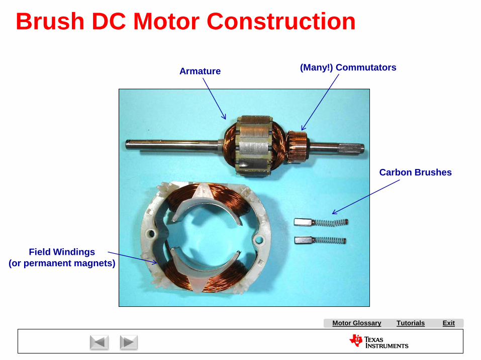
Tutorials ExitMotor Glossary
Brush DC Motor Construction
Armature (Many!) Commutators
Carbon Brushes
Field Windings(or permanent magnets)

Tutorials ExitMotor Glossary
radial rotor current flow
Stator magnets produceaxial magnetic field
Low rotor inertia (high acceleration)No cogging (rotor is non-magnetic)Long brush life (rotor inductance is low) Source: Electric Machinery, by A. E.
Fitzgerald, Charles Kingsley Jr., and Stephen D. Umans, McGraw-Hill,
1990
Brush DC “Pancake” Motor
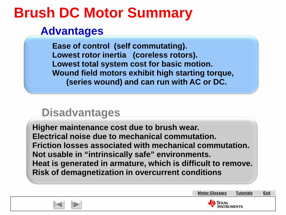
Tutorials ExitMotor Glossary
Higher maintenance cost due to brush wear.Electrical noise due to mechanical commutation.Friction losses associated with mechanical commutation.Not usable in “intrinsically safe” environments.Heat is generated in armature, which is difficult to remove. Risk of demagnetization in overcurrent conditions
Disadvantages
Ease of control (self commutating).Lowest rotor inertia (coreless rotors).Lowest total system cost for basic motion.Wound field motors exhibit high starting torque,
(series wound) and can run with AC or DC.
AdvantagesBrush DC Motor Summary
Market Overview:
AC Induction Motor Control:
Stepper Motor Control
Brush DC Motor Control:
Brushless DC Motor Control:
With Hall Effect Feedback
Sensorless
Permanent Magnet Synchronous Motor Control
Volts per Hertz Control
Slip Control
Field Oriented Control
Field Oriented Control
ExitMotor Glossary
Tutorials

Brushless DC Motors
Copyright Texas Instruments 2011
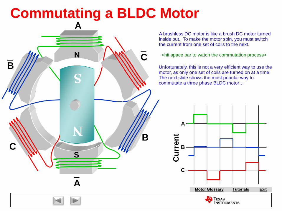
Tutorials ExitMotor Glossary
B
B
C
C
N
S
A
AC
urre
nt
A
B
C
N
S
Commutating a BLDC MotorA brushless DC motor is like a brush DC motor turned inside out. To make the motor spin, you must switch the current from one set of coils to the next.
<hit space bar to watch the commutation process>
Unfortunately, this is not a very efficient way to use the motor, as only one set of coils are turned on at a time. The next slide shows the most popular way to commutate a three phase BLDC motor…
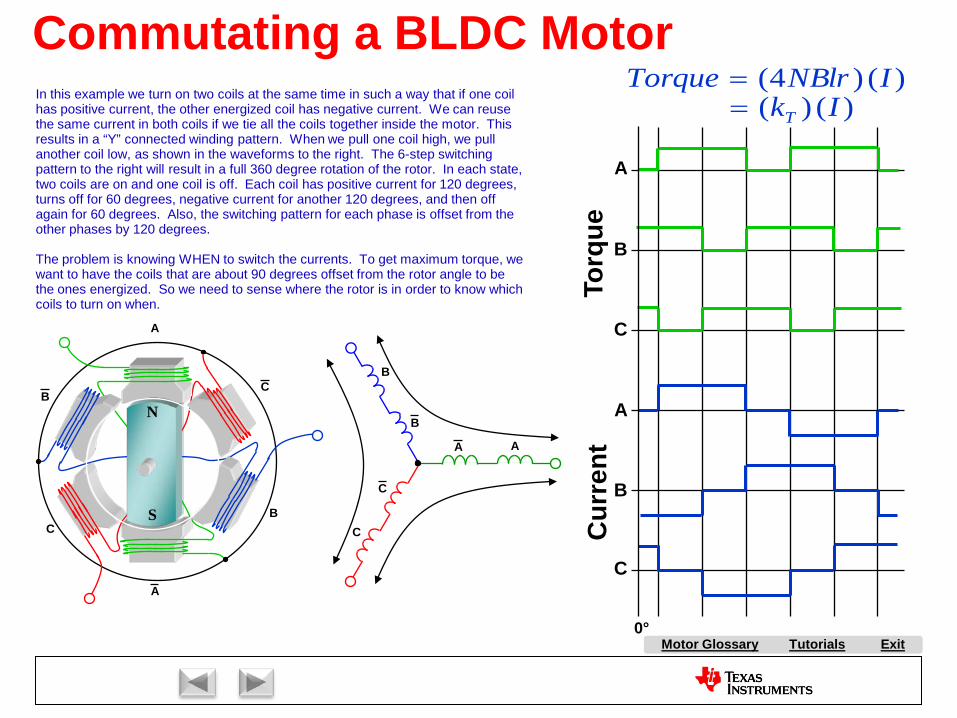
Tutorials ExitMotor Glossary
Torq
ueC
urre
nt
A
B
C
A
B
C
0°
)()4( INBlrTorque =)()( IkT=
B
B
C
C
N
S
A
A
In this example we turn on two coils at the same time in such a way that if one coil has positive current, the other energized coil has negative current. We can reuse the same current in both coils if we tie all the coils together inside the motor. This results in a “Y” connected winding pattern. When we pull one coil high, we pull another coil low, as shown in the waveforms to the right. The 6-step switching pattern to the right will result in a full 360 degree rotation of the rotor. In each state, two coils are on and one coil is off. Each coil has positive current for 120 degrees, turns off for 60 degrees, negative current for another 120 degrees, and then off again for 60 degrees. Also, the switching pattern for each phase is offset from the other phases by 120 degrees.
The problem is knowing WHEN to switch the currents. To get maximum torque, we want to have the coils that are about 90 degrees offset from the rotor angle to be the ones energized. So we need to sense where the rotor is in order to know which coils to turn on when.
AA
C
C
B
B
Commutating a BLDC Motor
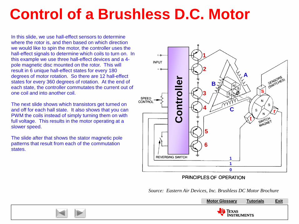
Tutorials ExitMotor Glossary
Control of a Brushless D.C. Motor
1
2
3
4
5
6
BA
C
s
rtC
ontr
olle
rSource: Eastern Air Devices, Inc. Brushless DC Motor Brochure
110
In this slide, we use hall-effect sensors to determine where the rotor is, and then based on which direction we would like to spin the motor, the controller uses the hall-effect signals to determine which coils to turn on. In this example we use three hall-effect devices and a 4-pole magnetic disc mounted on the rotor. This will result in 6 unique hall-effect states for every 180 degrees of motor rotation. So there are 12 hall-effect states for every 360 degrees of rotation. At the end of each state, the controller commutates the current out of one coil and into another coil.
The next slide shows which transistors get turned on and off for each hall state. It also shows that you can PWM the coils instead of simply turning them on with full voltage. This results in the motor operating at a slower speed.
The slide after that shows the stator magnetic pole patterns that result from each of the commutation states.
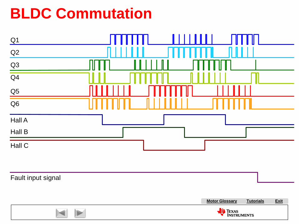
Tutorials ExitMotor Glossary
BLDC CommutationQ1
Fault input signal
Q3
Q4
Q5
Q6
Q2
Hall C
Hall B
Hall A
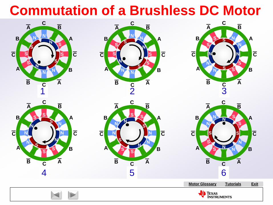
Tutorials ExitMotor Glossary
3
Commutation of a Brushless DC Motor
2
NS
NS
1
NN
S
NS
C
C
CC
A
A
A
A
B
B
B
B
N N
S
S
N
N
S S
65
NS
NS
4
NS
NS
NNS
S
NN
S
S
N
S
N
S
N
N
S
S
NS
S
N
NN
S
S
N
N
S
S
S
N
S
N
S
N
S
N
NS
SN
C
C
CC
A
A
A
A
B
B
B
B
C
C
CC
A
A
A
A
B
B
B
B
C
C
CC
A
A
A
A
B
B
B
B
C
C
CC
A
A
A
A
B
B
B
B
C
C
CC
A
A
A
A
B
B
B
B
NS
NS
NS
SN
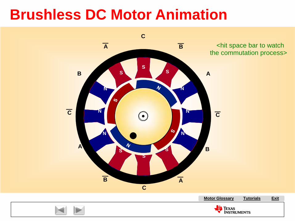
Tutorials ExitMotor Glossary
N
S
S
N
N
N
S
S
N
S
N
S
N
S
S
N
NN
S
S
NNN
S
S
N
N
S
S
S
N
S
N
N
S
N
S
N
N
S
S
S
N
S
N
N
S
S
N
A
C
C
CC
A
A
A
B
B
B
B
Brushless DC Motor Animation
<hit space bar to watch the commutation process>
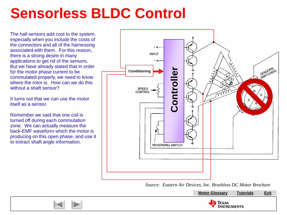
Tutorials ExitMotor Glossary
Sensorless BLDC Control
Con
trol
lerSource: Eastern Air Devices, Inc. Brushless DC Motor Brochure
Conditioning
The hall sensors add cost to the system, especially when you include the costs of the connectors and all of the harnessing associated with them. For this reason, there is a strong desire in many applications to get rid of the sensors. But we have already stated that in order for the motor phase current to be commutated properly, we need to know where the rotor is. How can we do this without a shaft sensor?
It turns out that we can use the motor itself as a sensor.
Remember we said that one coil is turned off during each commutation zone. We can actually measure the back-EMF waveform which the motor is producing on this open phase, and use it to extract shaft angle information.
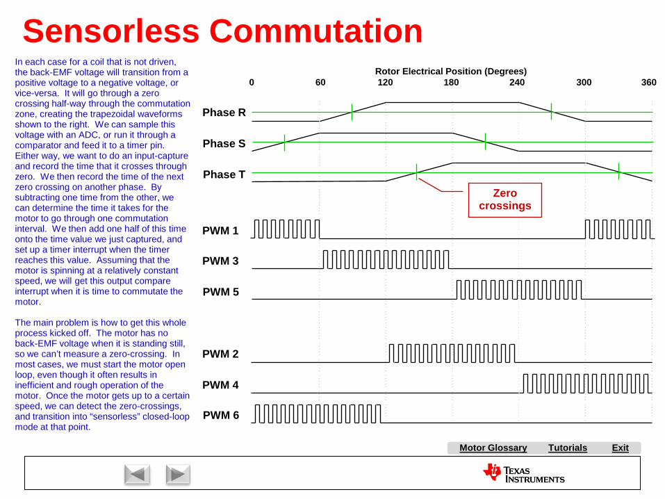
Tutorials ExitMotor Glossary
Sensorless Commutation
PWM 1
PWM 3
PWM 5
PWM 2
PWM 4
PWM 6
Phase R
Phase S
Phase T
0 60 120 180 240 300 360Rotor Electrical Position (Degrees)
Zero crossings
In each case for a coil that is not driven, the back-EMF voltage will transition from a positive voltage to a negative voltage, or vice-versa. It will go through a zero crossing half-way through the commutation zone, creating the trapezoidal waveforms shown to the right. We can sample this voltage with an ADC, or run it through a comparator and feed it to a timer pin. Either way, we want to do an input-capture and record the time that it crosses through zero. We then record the time of the next zero crossing on another phase. By subtracting one time from the other, we can determine the time it takes for the motor to go through one commutation interval. We then add one half of this time onto the time value we just captured, and set up a timer interrupt when the timer reaches this value. Assuming that the motor is spinning at a relatively constant speed, we will get this output compare interrupt when it is time to commutate the motor.
The main problem is how to get this whole process kicked off. The motor has no back-EMF voltage when it is standing still, so we can’t measure a zero-crossing. In most cases, we must start the motor open loop, even though it often results in inefficient and rough operation of the motor. Once the motor gets up to a certain speed, we can detect the zero-crossings, and transition into “sensorless” closed-loop mode at that point.
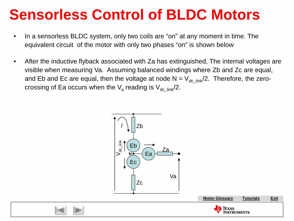
Tutorials ExitMotor Glossary
• In a sensorless BLDC system, only two coils are “on” at any moment in time. The equivalent circuit of the motor with only two phases “on” is shown below
• After the inductive flyback associated with Za has extinguished, The internal voltages are visible when measuring Va. Assuming balanced windings where Zb and Zc are equal, and Eb and Ec are equal, then the voltage at node N = Vdc_link/2. Therefore, the zero-crossing of Ea occurs when the Va reading is Vdc_link/2.
Sensorless Control of BLDC Motors
EaEb
Ec
Vdc
_lin
k
Zb
Zc
Za
Va
I
N
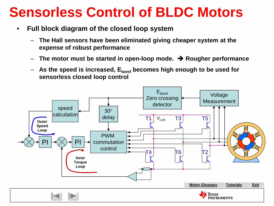
Tutorials ExitMotor Glossary
Sensorless Control of BLDC Motors
VLink
speedcalculation
PI PIPWM
commutationcontrol
T3 T5
T4
T1
T6 T2
VoltageMeasurement
30°delay
EbemfZero crossing
detector
• Full block diagram of the closed loop system– The Hall sensors have been eliminated giving cheaper system at the
expense of robust performance
– The motor must be started in open-loop mode. Rougher performance
– As the speed is increased, Ebemf becomes high enough to be used for sensorless closed loop control
Outer Speed Loop
Inner Torque Loop
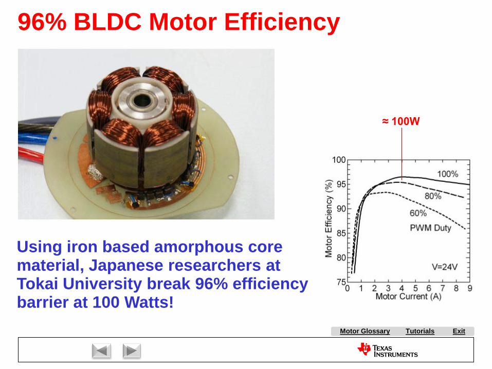
Tutorials ExitMotor Glossary
96% BLDC Motor Efficiency
Using iron based amorphous core material, Japanese researchers at Tokai University break 96% efficiency barrier at 100 Watts!
≈ 100W
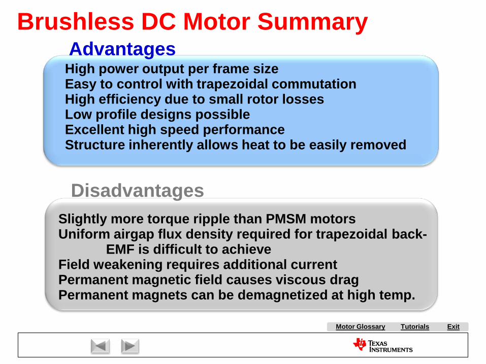
Tutorials ExitMotor Glossary
Disadvantages
AdvantagesHigh power output per frame sizeEasy to control with trapezoidal commutationHigh efficiency due to small rotor lossesLow profile designs possibleExcellent high speed performanceStructure inherently allows heat to be easily removed
Slightly more torque ripple than PMSM motorsUniform airgap flux density required for trapezoidal back-
EMF is difficult to achieveField weakening requires additional currentPermanent magnetic field causes viscous dragPermanent magnets can be demagnetized at high temp.
Brushless DC Motor Summary

Market Overview:
AC Induction Motor Control:
Stepper Motor Control
Brush DC Motor Control:
Brushless DC Motor Control:
With Hall Effect Feedback
Sensorless
Permanent Magnet Synchronous Motor Control
Volts per Hertz Control
Slip Control
Field Oriented Control
Field Oriented Control
ExitMotor Glossary
Tutorials

PMSM Motors
Copyright Texas Instruments 2011

Tutorials ExitMotor Glossary
Torque Ripple from Commutation
0 30 60 90 120 150 180 210 240 270 300 330 360 390
id0
iA
0 30 60 90 120 150 180 210 240 270 300 330 360 390
Torgue
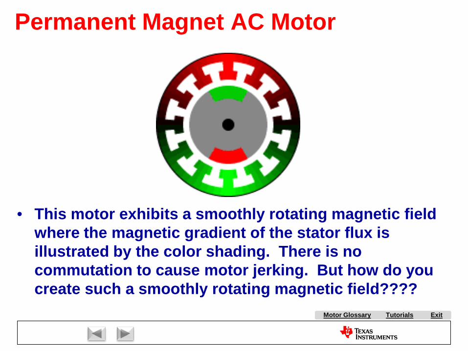
Tutorials ExitMotor Glossary
Permanent Magnet AC Motor
• This motor exhibits a smoothly rotating magnetic field where the magnetic gradient of the stator flux is illustrated by the color shading. There is no commutation to cause motor jerking. But how do you create such a smoothly rotating magnetic field????
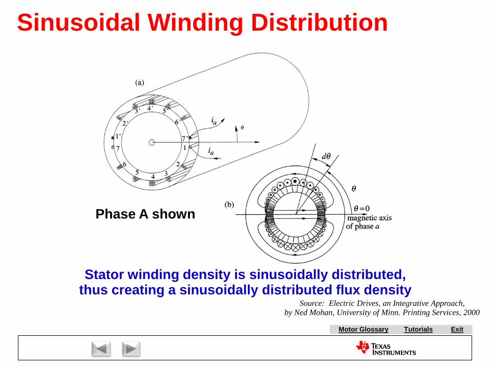
Tutorials ExitMotor Glossary
Sinusoidal Winding Distribution
Stator winding density is sinusoidally distributed,thus creating a sinusoidally distributed flux density
Phase A shown
Source: Electric Drives, an Integrative Approach,by Ned Mohan, University of Minn. Printing Services, 2000
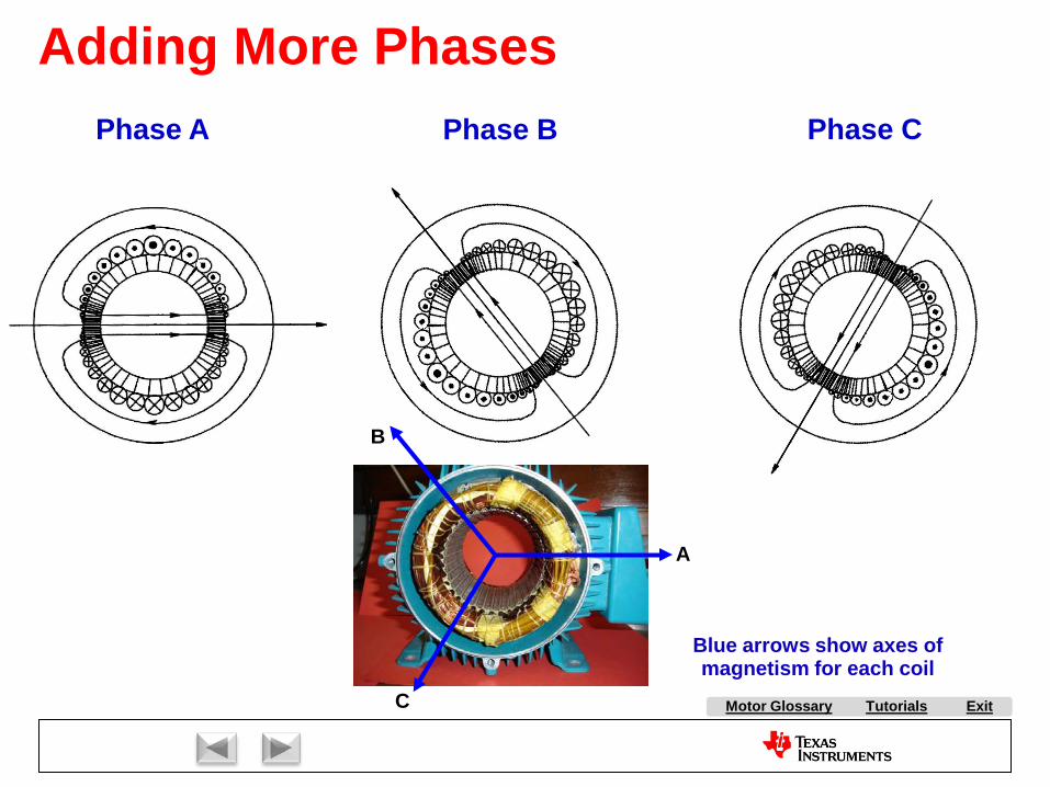
Tutorials ExitMotor Glossary
Adding More PhasesPhase A Phase B Phase C
A
B
C
Blue arrows show axes of magnetism for each coil

Tutorials ExitMotor Glossary
Permanent Magnet Synchronous Motor ControlThis slide is very important, as it shows how the three phases interact to create a rotating magnetic field on the stator. Not only are the coils spatially separated from each other by 120 degrees, but we will drive them with three-phase sine wave currents which are also separated in phase by 120 degrees. This results in three magnetic vectors which pulsate back and forth synchronously with their respective currents, on their respective magnetic axes. If we add these vectors together (as shown by the space vector plot on the bottom-right), the result is a smoothly rotating magnetic vector shown in magenta. As far as the rotor is concerned, the stator looks like it is spinning on the bottom-left, at a frequency equal to the sine wave current frequency. More importantly, this slide shows that we can create a stator magnetic vector at any angle we want by the application of stator currents in the proper ratios. This is the basis for field-oriented control. Simply put, we are orienting the stator field with respect to the rotor field to achieve optimum performance on the motor.
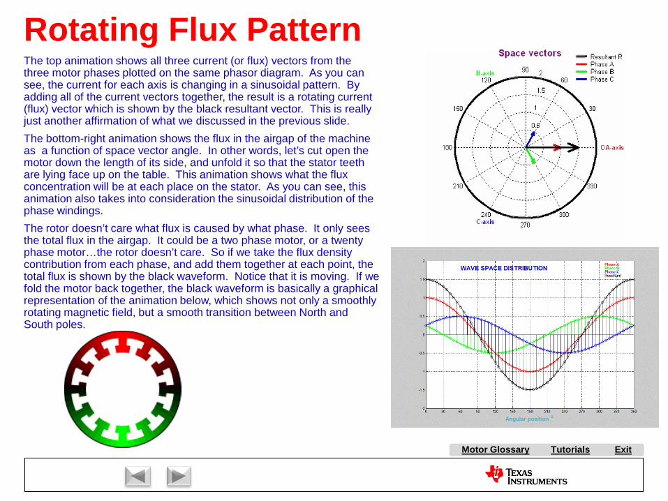
Tutorials ExitMotor Glossary
Rotating Flux PatternThe top animation shows all three current (or flux) vectors from the three motor phases plotted on the same phasor diagram. As you can see, the current for each axis is changing in a sinusoidal pattern. By adding all of the current vectors together, the result is a rotating current (flux) vector which is shown by the black resultant vector. This is really just another affirmation of what we discussed in the previous slide.The bottom-right animation shows the flux in the airgap of the machine as a function of space vector angle. In other words, let’s cut open the motor down the length of its side, and unfold it so that the stator teeth are lying face up on the table. This animation shows what the flux concentration will be at each place on the stator. As you can see, this animation also takes into consideration the sinusoidal distribution of the phase windings.The rotor doesn’t care what flux is caused by what phase. It only sees the total flux in the airgap. It could be a two phase motor, or a twenty phase motor…the rotor doesn’t care. So if we take the flux density contribution from each phase, and add them together at each point, the total flux is shown by the black waveform. Notice that it is moving. If we fold the motor back together, the black waveform is basically a graphical representation of the animation below, which shows not only a smoothly rotating magnetic field, but a smooth transition between North and South poles.
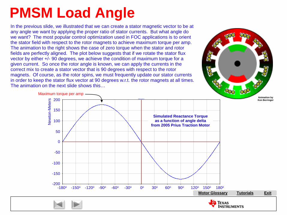
Tutorials ExitMotor Glossary
Animation by Ken Berringer
0.0s 0.3s 0.6s 0.9s 1.2s 1.5s 1.8s 2.1s 2.4s 2.7s 3.0s 3.3s 3.6s-200V
-150V
-100V
-50V
0V
50V
100V
150V
200VV(treaction)
Simulated Reactance Torque as a function of angle delta
from 2005 Prius Traction Motor
0o 30o 60o 90o 120o 150o 180o-30o-60o-90o-120o-150o-180o
50
100
150
200
0
-50
-100
-150
-200
New
ton-
Met
ers
Maximum torque per amp
PMSM Load AngleIn the previous slide, we illustrated that we can create a stator magnetic vector to be at any angle we want by applying the proper ratio of stator currents. But what angle do we want? The most popular control optimization used in FOC applications is to orient the stator field with respect to the rotor magnets to achieve maximum torque per amp. The animation to the right shows the case of zero torque when the stator and rotor fields are perfectly aligned. The plot below suggests that if we rotate the stator flux vector by either +/- 90 degrees, we achieve the condition of maximum torque for a given current. So once the rotor angle is known, we can apply the currents in the correct mix to create a stator vector that is 90 degrees with respect to the rotor magnets. Of course, as the rotor spins, we must frequently update our stator currents in order to keep the stator flux vector at 90 degrees w.r.t. the rotor magnets at all times. The animation on the next slide shows this…

Tutorials ExitMotor Glossary
Orientation of Field for Max Torque
Source: Electric Drives, an Integrative Approach, by Ned Mohan, University of Minn. Printing Services, 2000
(Reluctance torque assumed to be zero)
Axis of rotor flux is fixed with respect to the rotor, i.e., it is “synchronous”.
The green vector represents the stator flux vector which results from the sinusoidal currents being applied to the stator coils.
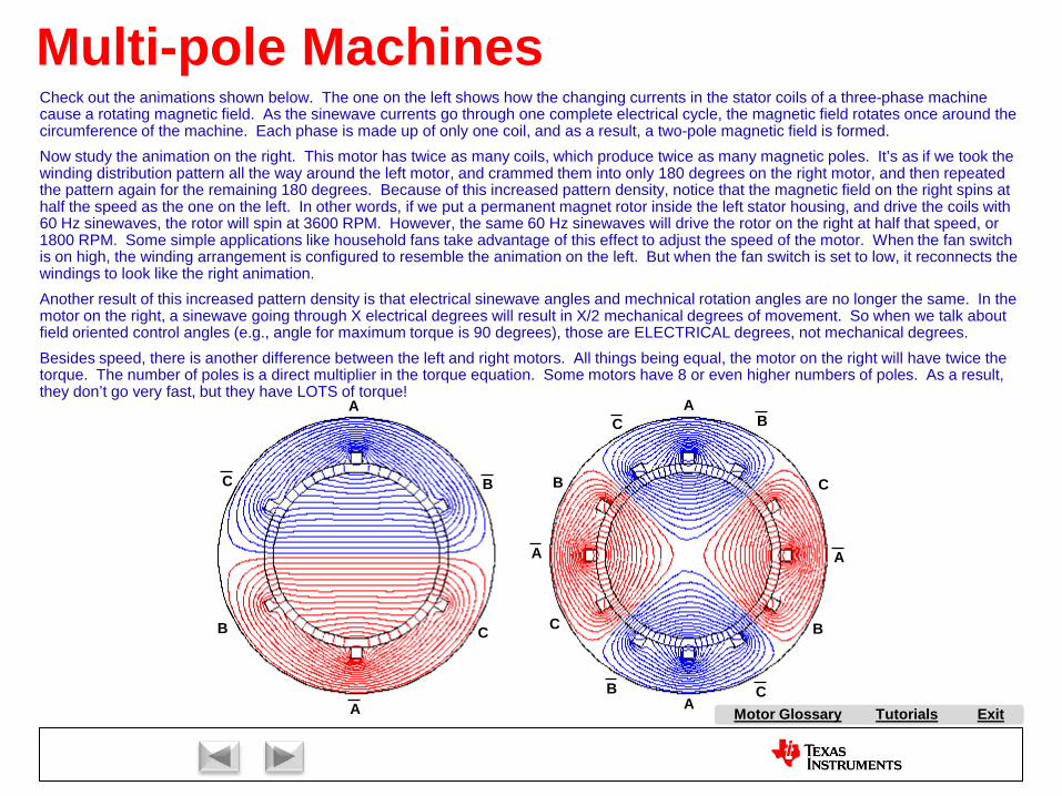
Tutorials ExitMotor Glossary
Multi-pole MachinesCheck out the animations shown below. The one on the left shows how the changing currents in the stator coils of a three-phase machine cause a rotating magnetic field. As the sinewave currents go through one complete electrical cycle, the magnetic field rotates once around the circumference of the machine. Each phase is made up of only one coil, and as a result, a two-pole magnetic field is formed.Now study the animation on the right. This motor has twice as many coils, which produce twice as many magnetic poles. It’s as if we took the winding distribution pattern all the way around the left motor, and crammed them into only 180 degrees on the right motor, and then repeated the pattern again for the remaining 180 degrees. Because of this increased pattern density, notice that the magnetic field on the right spins at half the speed as the one on the left. In other words, if we put a permanent magnet rotor inside the left stator housing, and drive the coils with 60 Hz sinewaves, the rotor will spin at 3600 RPM. However, the same 60 Hz sinewaves will drive the rotor on the right at half that speed, or 1800 RPM. Some simple applications like household fans take advantage of this effect to adjust the speed of the motor. When the fan switch is on high, the winding arrangement is configured to resemble the animation on the left. But when the fan switch is set to low, it reconnects the windings to look like the right animation.Another result of this increased pattern density is that electrical sinewave angles and mechnical rotation angles are no longer the same. In the motor on the right, a sinewave going through X electrical degrees will result in X/2 mechanical degrees of movement. So when we talk about field oriented control angles (e.g., angle for maximum torque is 90 degrees), those are ELECTRICAL degrees, not mechanical degrees. Besides speed, there is another difference between the left and right motors. All things being equal, the motor on the right will have twice the torque. The number of poles is a direct multiplier in the torque equation. Some motors have 8 or even higher numbers of poles. As a result, they don’t go very fast, but they have LOTS of torque!
A
B C
A
BC
A
A
C
C
B
BA
A
C
C
B
B
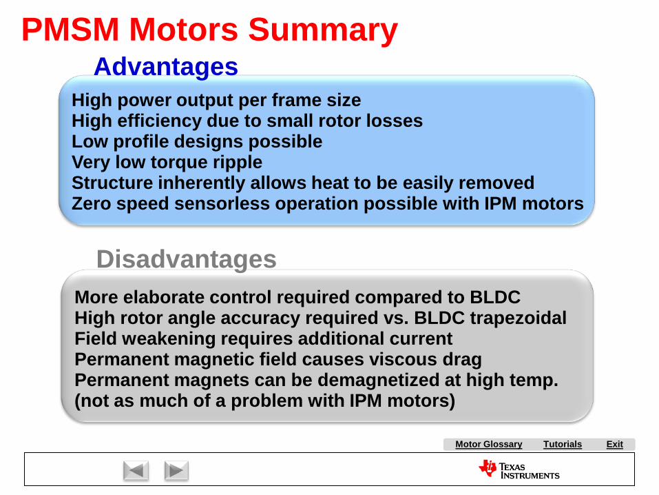
Tutorials ExitMotor Glossary
Disadvantages
AdvantagesPMSM Motors Summary
High power output per frame sizeHigh efficiency due to small rotor lossesLow profile designs possibleVery low torque rippleStructure inherently allows heat to be easily removedZero speed sensorless operation possible with IPM motors
More elaborate control required compared to BLDCHigh rotor angle accuracy required vs. BLDC trapezoidalField weakening requires additional currentPermanent magnetic field causes viscous dragPermanent magnets can be demagnetized at high temp. (not as much of a problem with IPM motors)

Market Overview:
AC Induction Motor Control:
Stepper Motor Control
Brush DC Motor Control:
Brushless DC Motor Control:
With Hall Effect Feedback
Sensorless
Permanent Magnet Synchronous Motor Control
Volts per Hertz Control
Slip Control
Field Oriented Control
Field Oriented Control
ExitMotor Glossary
Tutorials
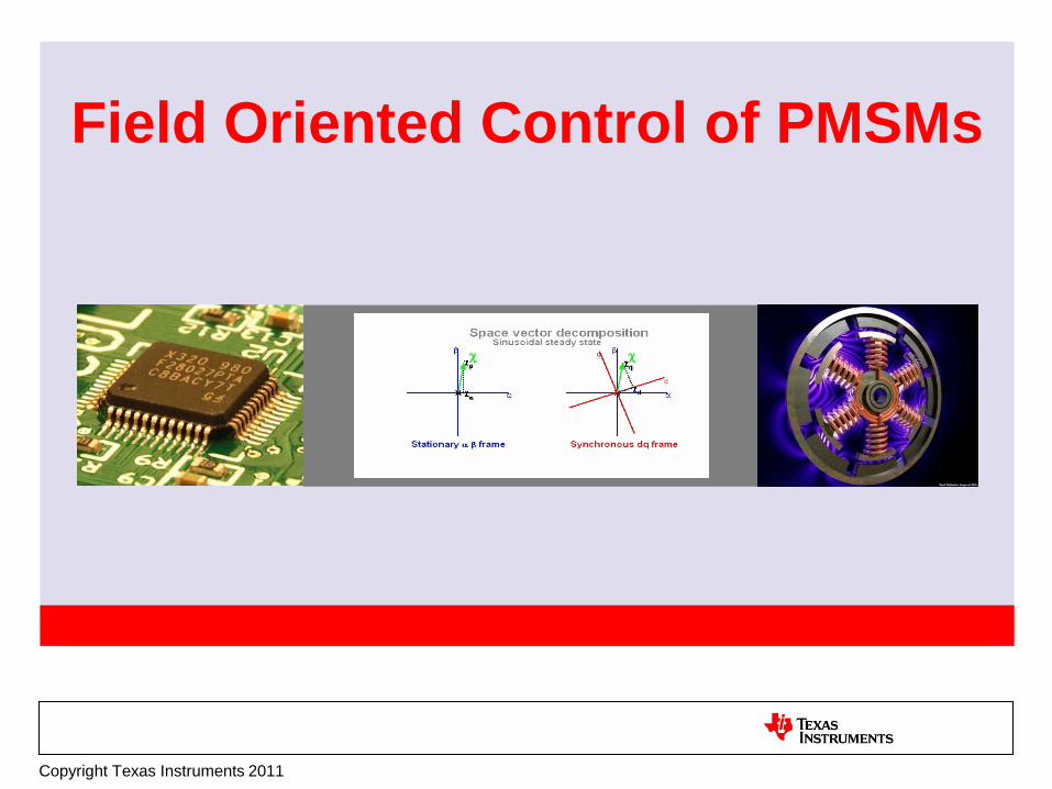
Field Oriented Control of PMSMs
Copyright Texas Instruments 2011

Tutorials ExitMotor Glossary
+24 V
0.015
PWM1
PWM1PWM2
PWM2PWM1
PWM2
PIController
+
-
ADC1
Desired Current
Measured Current
Error Signal
Commutator keeps rotor and stator fields
properly aligned!
Brush DC Motor
How Do You Control Torqueon a DC Motor?
Texas Instruments
Dave’sMotor Control
Center
Measure current already flowing in the motor.1.
1
Compare the measured current with the desired current, and generate an error signal.2.
2
Amplify the error signal to generate a correction voltage.3.
3
Modulate the correction voltage onto the motor terminals.4.
4
Do you understand these 4 steps? If so, you are well on your way to understanding Field Oriented Control! These are the same 4 operations you do for FOC (granted, there are some additional steps required since we don’t have a commutator to properly orient the field on an AC motor, but they all fall under the 4 categories listed here.) In fact, as we go through the FOC process, look at the title of each slide. It will tell you which operation we are currently working on.
<hit space bar to advance through the steps>
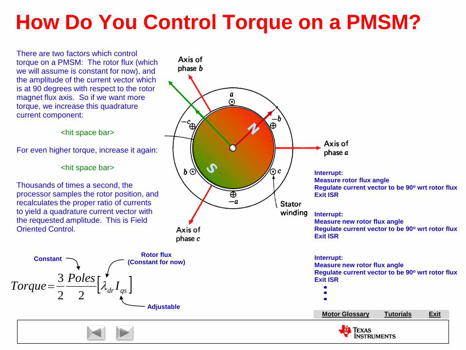
Tutorials ExitMotor Glossary
[ ]qsdr IPolesTorque λ
223
=
How Do You Control Torque on a PMSM?
Constant Rotor flux (Constant for now)
Adjustable
Interrupt:Measure rotor flux angleRegulate current vector to be 90o wrt rotor fluxExit ISR
Interrupt:Measure new rotor flux angleRegulate current vector to be 90o wrt rotor fluxExit ISR
Interrupt:Measure new rotor flux angleRegulate current vector to be 90o wrt rotor fluxExit ISR
There are two factors which control torque on a PMSM: The rotor flux (which we will assume is constant for now), and the amplitude of the current vector which is at 90 degrees with respect to the rotor magnet flux axis. So if we want more torque, we increase this quadrature current component:
<hit space bar>
For even higher torque, increase it again:
<hit space bar>
Thousands of times a second, the processor samples the rotor position, and recalculates the proper ratio of currents to yield a quadrature current vector with the requested amplitude. This is Field Oriented Control.
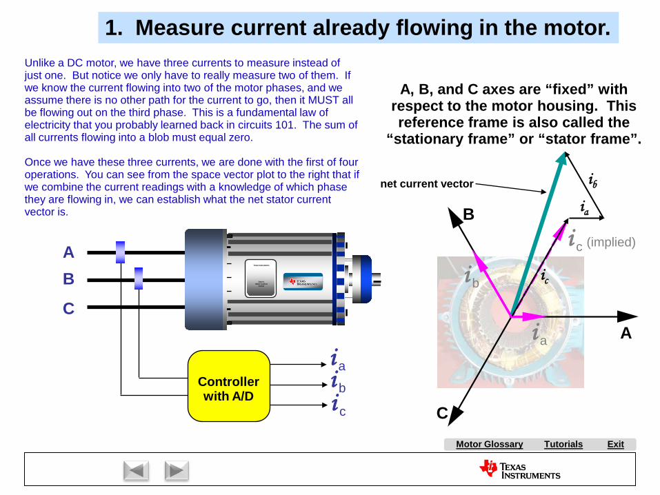
Tutorials ExitMotor Glossary
A
B
C
AB
C
i b
i c
i a
(implied)
Controllerwith A/D
i ai bi c
A, B, and C axes are “fixed” with respect to the motor housing. This reference frame is also called the
“stationary frame” or “stator frame”.
1. Measure current already flowing in the motor.
net current vector
ia
ib
ic
Texas Instruments
Dave’sMotor Control
Center
Unlike a DC motor, we have three currents to measure instead of just one. But notice we only have to really measure two of them. If we know the current flowing into two of the motor phases, and we assume there is no other path for the current to go, then it MUST all be flowing out on the third phase. This is a fundamental law of electricity that you probably learned back in circuits 101. The sum of all currents flowing into a blob must equal zero.
Once we have these three currents, we are done with the first of four operations. You can see from the space vector plot to the right that if we combine the current readings with a knowledge of which phase they are flowing in, we can establish what the net stator current vector is.

Tutorials ExitMotor Glossary
A
B
C
si
2. Compare the measured current (vector) with the desired current (vector), and generate error signals.
We must regulate the current vector magnitude AND angle by regulating ia, ib, and ic.
Is the stator current vector at the correct angle? We won’t know that until we measure the angle that the rotor is at. We want the stator current vector to be at 90 degrees with respect to the where the magnets on the rotor are pointing. For example, let’s say that the rotor flux is along the red axis shown to the right. That means that we want the stator current vector to be along the green axis. If it is not, we must change the phase currents somehow so that the stator current vector snaps into alignment with the green axis.
So, let’s go measure the angle of the rotor…
i b
i c
i a
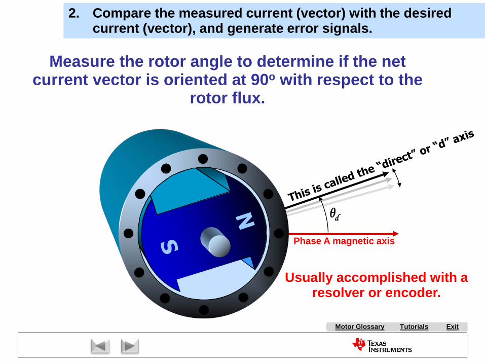
Tutorials ExitMotor Glossary
θd
Measure the rotor angle to determine if the net current vector is oriented at 90o with respect to the
rotor flux.
Usually accomplished with a resolver or encoder.
2. Compare the measured current (vector) with the desired current (vector), and generate error signals.
Phase A magnetic axis
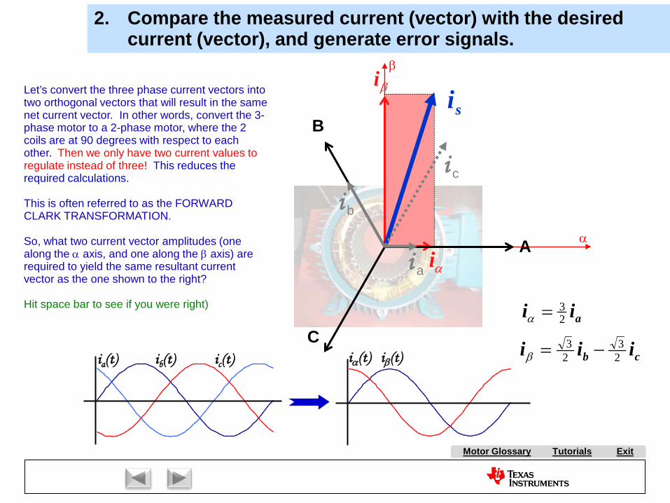
Tutorials ExitMotor Glossary
αi
βiLet’s convert the three phase current vectors into two orthogonal vectors that will result in the same net current vector. In other words, convert the 3-phase motor to a 2-phase motor, where the 2 coils are at 90 degrees with respect to each other. Then we only have two current values to regulate instead of three! This reduces the required calculations.
This is often referred to as the FORWARD CLARK TRANSFORMATION.
So, what two current vector amplitudes (one along the α axis, and one along the β axis) are required to yield the same resultant current vector as the one shown to the right?
Hit space bar to see if you were right)
A
B
C
si
aii 23=α
cb iii 23
23 −=βia(t) ib(t) ic(t) iβ(t)iα(t)
i b
i c
i a
2. Compare the measured current (vector) with the desired current (vector), and generate error signals.
α
β
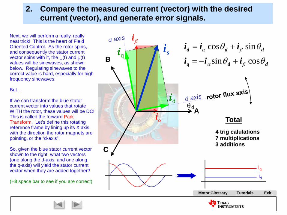
Tutorials ExitMotor Glossary
αi
βi
A
B
C
siddq
ddd
iiiiii
θθ
θθ
βα
βα
cossin
sincos
+−=
+=
4 trig calulations7 multiplications3 additions
Total
θd
2. Compare the measured current (vector) with the desired current (vector), and generate error signals.
Next, we will perform a really, really neat trick! This is the heart of Field Oriented Control. As the rotor spins, and consequently the stator current vector spins with it, the iα(t) and iβ(t) values will be sinewaves, as shown below. Regulating sinewaves to the correct value is hard, especially for high frequency sinewaves.
But…
If we can transform the blue stator current vector into values that rotate WITH the rotor, these values will be DC! This is called the forward Park Transform. Let’s define this rotating reference frame by lining up its X axis with the direction the rotor magnets are pointing, or the “d-axis”.
So, given the blue stator current vector shown to the right, what two vectors (one along the d-axis, and one along the q-axis) will yield the stator current vector when they are added together?
(Hit space bar to see if you are correct)
i q
i d
id
iq

Tutorials ExitMotor Glossary
and are handled independently. Since the comparison is performed in the rotating frame, motor AC frequency
is not seen. Thus, they are DC quantities!
i d +
-
errord(t)
+
-
errorq(t)
i d i q
(commanded)
i d (measured)
i q
i q (commanded)
(measured)
can however be used to weaken the field of the machine.controls amount of torque generated by the motor
i di q
Under normal conditions, we have all the d-axis flux we need supplied by the permanent magnets in the rotor.
So commanded id is set to zero.
This is how much torque we want!
2. Compare the measured current (vector) with the desired current (vector), and generate error signals.
Look at the number in the title block above.
We are now done with the second part of the
FOC process.

Tutorials ExitMotor Glossary
i d
∫ I
P+ +
+-
error(t)
∫ I
P+ +
+-
error(t)
(commanded)
i d (measured)
i q
i q (commanded)
(measured)
vd
vq
3. Amplify the error signals to generate correction voltages.
The PI regulator is a good choice for current regulation
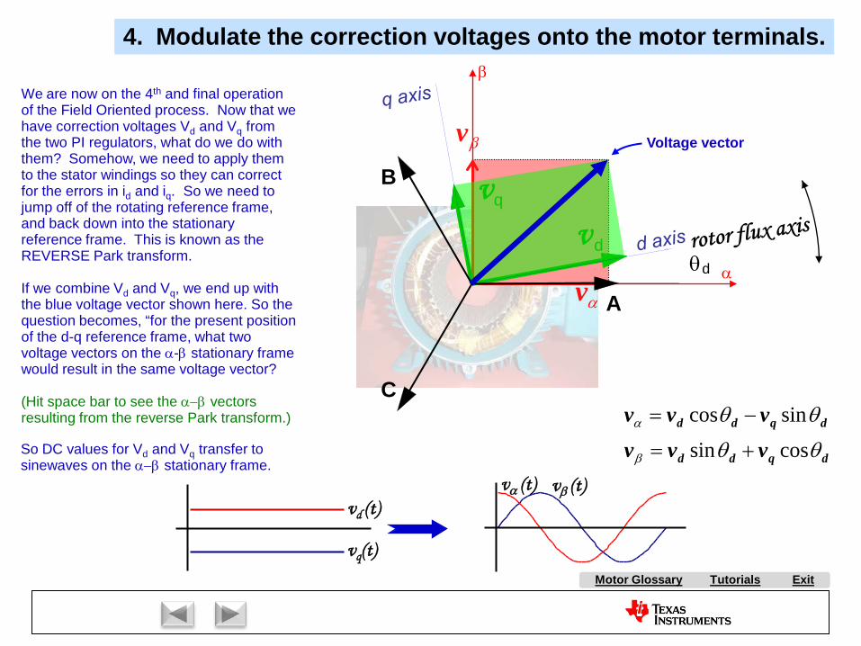
Tutorials ExitMotor Glossary
Voltage vector
αv
βv
dqdd
dqdd
vvvvvv
θθ
θθ
β
α
cossin
sincos
+=
−=
θd
A
B
C
vd
vq
4. Modulate the correction voltages onto the motor terminals.
vd (t)
vq(t)
vα (t) vβ (t)
We are now on the 4th and final operation of the Field Oriented process. Now that we have correction voltages Vd and Vq from the two PI regulators, what do we do with them? Somehow, we need to apply them to the stator windings so they can correct for the errors in id and iq. So we need to jump off of the rotating reference frame, and back down into the stationary reference frame. This is known as the REVERSE Park transform.
If we combine Vd and Vq, we end up with the blue voltage vector shown here. So the question becomes, “for the present position of the d-q reference frame, what two voltage vectors on the α-β stationary frame would result in the same voltage vector?
(Hit space bar to see the α−β vectors resulting from the reverse Park transform.)
α
β
So DC values for Vd and Vq transfer to sinewaves on the α−β stationary frame.
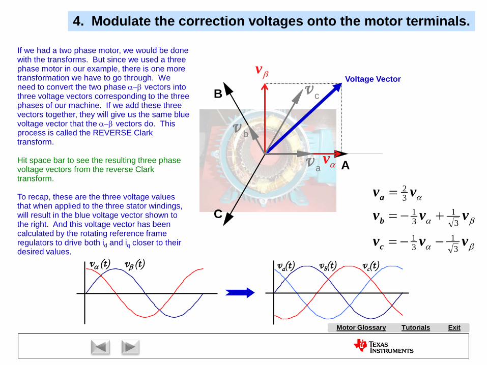
Tutorials ExitMotor Glossary
αv
βv
A
B
C
v a
v c
v b
βα
βα
α
vvv
vvvvv
c
b
a
31
31
31
31
32
−−=
+−=
=
va(t) vb(t) vc(t)vα (t) vβ (t)
4. Modulate the correction voltages onto the motor terminals.
Voltage Vector
If we had a two phase motor, we would be done with the transforms. But since we used a three phase motor in our example, there is one more transformation we have to go through. We need to convert the two phase α−β vectors into three voltage vectors corresponding to the three phases of our machine. If we add these three vectors together, they will give us the same blue voltage vector that the α−β vectors do. This process is called the REVERSE Clark transform.
Hit space bar to see the resulting three phase voltage vectors from the reverse Clark transform.
To recap, these are the three voltage values that when applied to the three stator windings, will result in the blue voltage vector shown to the right. And this voltage vector has been calculated by the rotating reference frame regulators to drive both id and iq closer to their desired values.

Tutorials ExitMotor Glossary
Phase A - top
Phase B - top
Phase B - bottom
Phase C - top
Phase C - bottom
Phase A - bottom
4. Modulate the correction voltages onto the motor terminals.
Over time, under steady-state conditions, the correction voltagesva, vb, and vc will be sine waves phase shifted by 120o.
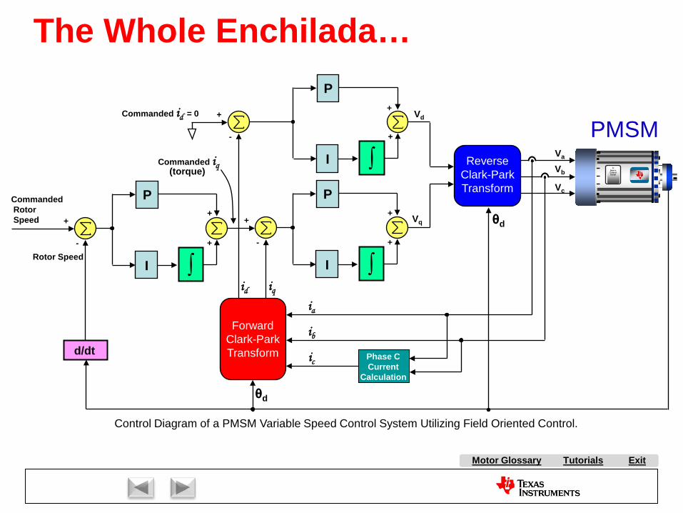
Tutorials ExitMotor Glossary
+
-
CommandedRotorSpeed
P
I ∫
+
+Rotor Speed
Vb
Vc
Va
Control Diagram of a PMSM Variable Speed Control System Utilizing Field Oriented Control.
Commanded id = 0
+
-
P
I ∫
+
+
+
-
P
I ∫
+
+
Commanded iq ReverseClark-ParkTransform
ForwardClark-ParkTransform
id iq
Phase CCurrent
Calculation
ia
ib
icd/dt
θd
θd
Vd
Vq
(torque) TIDave’sControlCenter
PMSM
The Whole Enchilada…

Tutorials ExitMotor Glossary
FOC in a Nutshell
+
-
+
-
PI
PI
Wilson
Reverse Clark-Park Transforms
++
-1Forward
Clark-Park Transforms
i B iq
idi C
i A
Torque Current
Flux Current
Desired Torque
Desired Flux
Vq Vd
Va
Vb Vc
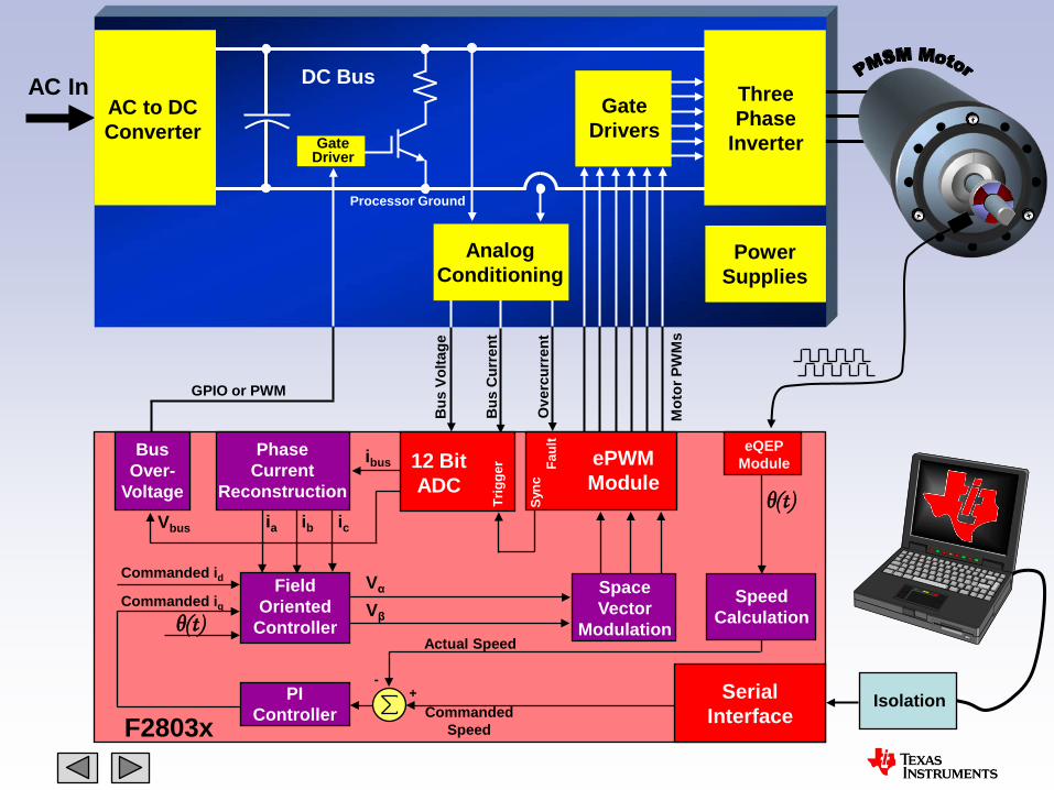
Tutorials ExitMotor Glossary
AC InAC to DCConverter
ThreePhase
Inverter
GateDrivers
DC Bus
GateDriver
PowerSupplies
AnalogConditioning
SerialInterfaceF2803x
12 BitADC
Trig
ger Fa
ult
ePWMModule
Sync
Isolation
eQEPModule
CommandedSpeed
Actual Speed
+-
PIController
FieldOriented
ControllerCommanded iq
Commanded id
PhaseCurrent
Reconstructionicia
SpaceVector
Modulation
Vα
Vβ
ibusBus
Over-Voltage
GPIO or PWM
SpeedCalculation
ibVbus
Mot
or P
WM
s
Ove
rcur
rent
Bus
Cur
rent
Bus
Vol
tage
Processor Ground
θ(t)
θ(t)
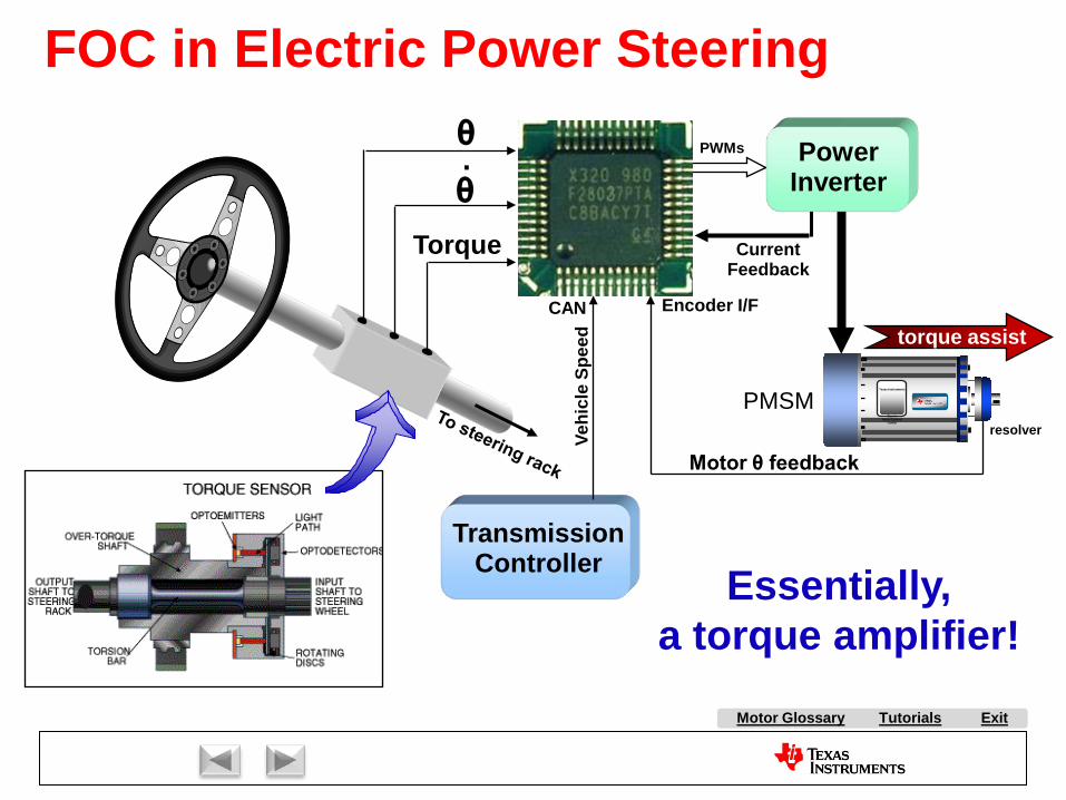
Tutorials ExitMotor Glossary
θθ.
Torque
TransmissionController
CAN
Vehi
cle
Spee
d
PowerInverter
PWMs
CurrentFeedback
Motor θ feedback
Encoder I/F
torque assist
Essentially,a torque amplifier!
PMSMTexas Instruments
Dave’sMotor Control
Center
FOC in Electric Power Steering
resolver
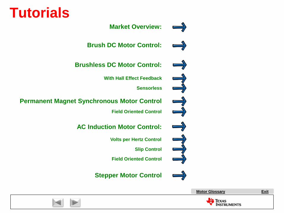
Market Overview:
AC Induction Motor Control:
Stepper Motor Control
Brush DC Motor Control:
Brushless DC Motor Control:
With Hall Effect Feedback
Sensorless
Permanent Magnet Synchronous Motor Control
Volts per Hertz Control
Slip Control
Field Oriented Control
Field Oriented Control
ExitMotor Glossary
Tutorials
AC Induction Motors
Copyright Texas Instruments 2011
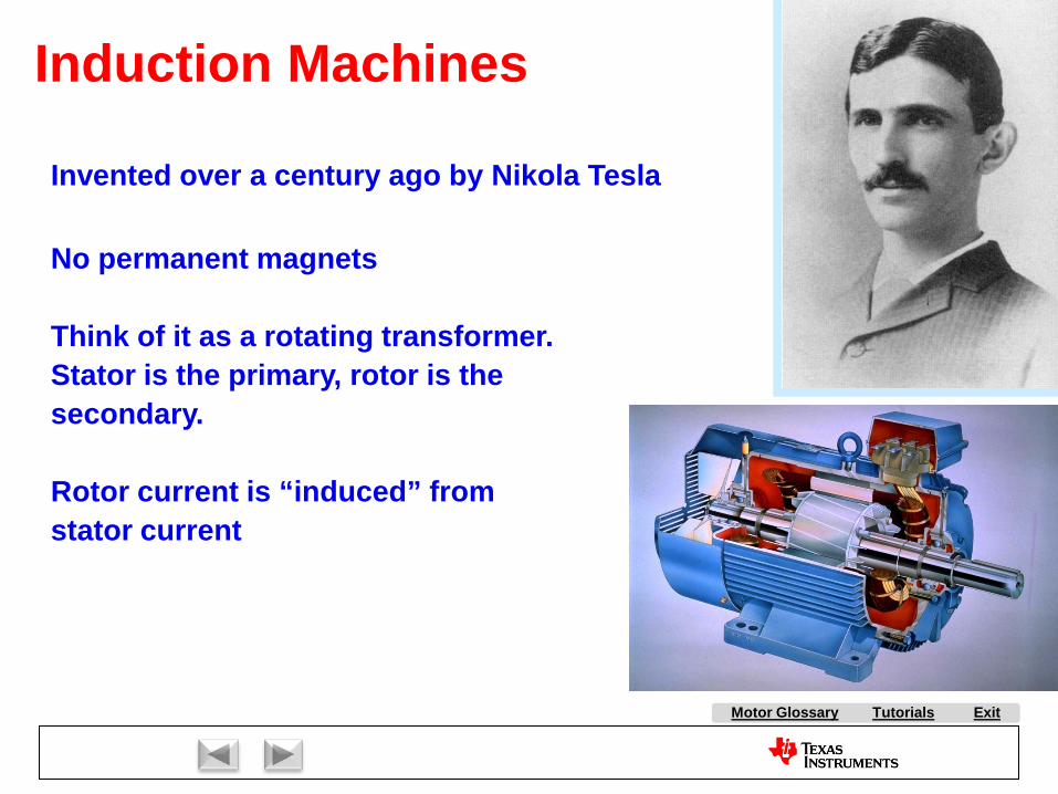
Tutorials ExitMotor Glossary
Induction Machines
No permanent magnets
Think of it as a rotating transformer. Stator is the primary, rotor is the secondary.
Rotor current is “induced” from stator current
Invented over a century ago by Nikola Tesla
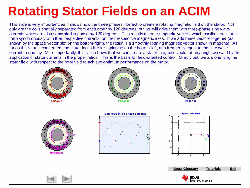
Tutorials ExitMotor Glossary
Rotating Stator Fields on an ACIMThis slide is very important, as it shows how the three phases interact to create a rotating magnetic field on the stator. Not only are the coils spatially separated from each other by 120 degrees, but we will drive them with three-phase sine wave currents which are also separated in phase by 120 degrees. This results in three magnetic vectors which oscillate back and forth synchronously with their respective currents, on their respective magnetic axes. If we add these vectors together (as shown by the space vector plot on the bottom-right), the result is a smoothly rotating magnetic vector shown in magenta. As far as the rotor is concerned, the stator looks like it is spinning on the bottom-left, at a frequency equal to the sine wave current frequency. More importantly, this slide shows that we can create a stator magnetic vector at any angle we want by the application of stator currents in the proper ratios. This is the basis for field-oriented control. Simply put, we are orienting the stator field with respect to the rotor field to achieve optimum performance on the motor.

Tutorials ExitMotor Glossary
AC Induction Motor SlipAs the stator magnetic field rotates, the flux lines jump the airgap and cut through conductors in the rotor. This causes voltages across the rotor conductors, when in turn cause currents to flow in them. This current causes the rotor to set up its own magnetic field, which interacts with the stator magnetic field, causing the rotor to spin. However, under its own power, the rotor can NEVER spin at exactly the same speed that the stator flux does. Don’t believe me? Look at the animation to the right. Follow one particular rotor pole as it rotates, and see how it changes color. Can you guess why the rotor can’t spin as fast as the stator field?
ANSWER: Because if the stator field and rotor are spinning at exactly the same speed, then there will no longer be flux lines cutting through the conductors in the rotor. This means that the rotor current would be zero, and thus the rotor magnetic field would be zero. As a result, there is no torque, and the rotor starts to coast to a stop. But as soon as it slows down just a little bit, then once again you have stator flux cutting through the rotor bars again.
The difference between the stator frequency and the rotor rotational frequency is called SLIP FREQUENCY. The more torque required by the load, the greater the slip frequency will be.
Rotor Conductor
slots
Airgap
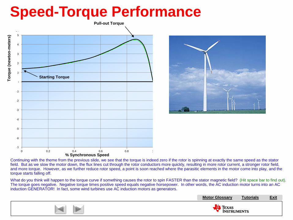
Tutorials ExitMotor Glossary
0s 2s 4s 6s 8s 10s 12s 14s 16s 18s 20s-70V
-60V
-50V
-40V
-30V
-20V
-10V
0V
10V
20V
30V
40V
50V-14KV
V(tem)
% Synchronous Speed
Torq
ue (n
ewto
n-m
eter
s)
0.2 0.4 0.6 0.8 1.2 1.4 1.6 1.8 2.00
Speed-Torque PerformancePull-out Torque
Starting Torque
1.0
Continuing with the theme from the previous slide, we see that the torque is indeed zero if the rotor is spinning at exactly the same speed as the stator field. But as we slow the motor down, the flux lines cut through the rotor conductors more quickly, resulting in more rotor current, a stronger rotor field, and more torque. However, as we further reduce rotor speed, a point is soon reached where the parasitic elements in the motor come into play, and the torque starts falling off.
What do you think will happen to the torque curve if something causes the rotor to spin FASTER than the stator magnetic field? (Hit space bar to find out).The torque goes negative. Negative torque times positive speed equals negative horsepower. In other words, the AC induction motor turns into an AC induction GENERATOR! In fact, some wind turbines use AC induction motors as generators.

Tutorials ExitMotor Glossary
Motoring and Generating ModesAs discussed in the previous slides, the sinusoidal stator currents produce a rotating magnetic field, which is shown by the brown vector in the left animation below. Since the axis of the brown vector corresponds to where the magnetic field is most dense, it will generate the maximum d-flux/dt on the rotor bars that are cutting through the flux on this axis. Assuming the rotor is purely resistive, and rotor leakage inductance is zero, then this axis will also correspond to the axis on the rotor where the current is the greatest (see the larger X’s and dots). From looking at just the rotor, you can see that it also has a sinusoidal distribution of current on its rotor bars, and that this current distribution will result in a magnetic axis for the rotor (the magenta vector) which is 90 degrees offset with respect to the stator magnetic axis. The greater the load is on the motor, the more slip will be created, which causes more d-flux/dt on the rotor bars, which causes the rotor currents to increase, which causes the magenta mmf vector to get bigger. This new mmf from the rotor will attempt to change the flux in the stator. Assuming that the stator windings are being driven by a low impedance source, the stator flux will not change, since it is defined to be the integral of the stator sinewavevoltages (assuming stator resistance and stator leakage inductance are both zero). So the stator circuit responds to this attempt by the rotor to coerce the flux by creating an equal-but-opposite mmf to cancel out the rotor mmf, which is shown by the blue vector. In fact, this is the same effect that happens in a transformer, and explains why primary current flows when a load is connected to the secondary. Therefore, the resulting red stator current vector consists of two parts: the green vector, which is responsible for creating the magnetic field in the machine, and the blue vector, which is required to cancel the rotor mmf, and also accounts for the real work being done by the motor.
The animation to the right shows the case where something is causing the rotor to spin faster than the synchronous speed of the magnetic field. As a result, the d-flux/dt is in the opposite direction, which causes the magenta rotor mmf vector to flip by 180 degrees. The resulting red stator current vector will also dramatically shift its angle, resulting in a large portion of the stator current sinewaves being 180 degrees out of phase with the stator voltage sinewaves. In other words, the AC line power is now negative, and the motor is now acting as a generator.
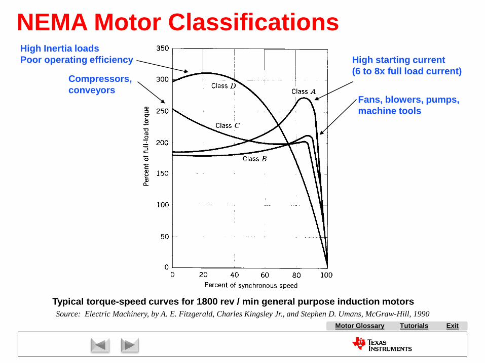
Tutorials ExitMotor Glossary
NEMA Motor ClassificationsHigh starting current(6 to 8x full load current)
Fans, blowers, pumps,machine tools
Compressors,conveyors
High Inertia loadsPoor operating efficiency
Typical torque-speed curves for 1800 rev / min general purpose induction motorsSource: Electric Machinery, by A. E. Fitzgerald, Charles Kingsley Jr., and Stephen D. Umans, McGraw-Hill, 1990
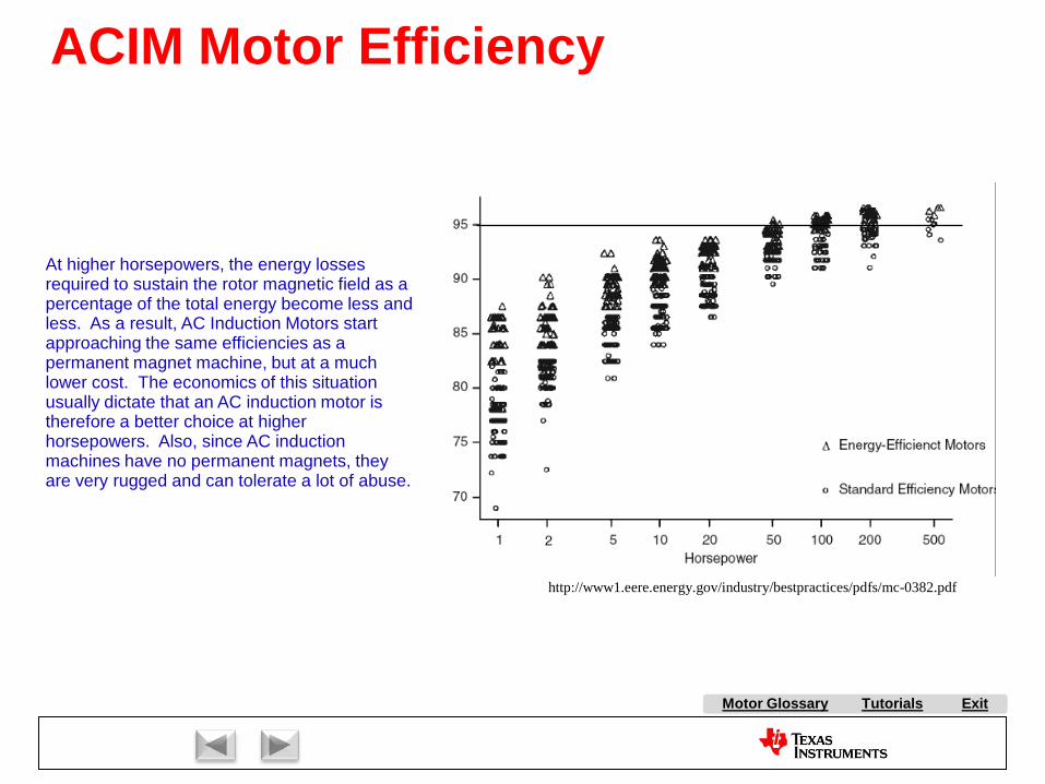
Tutorials ExitMotor Glossary
ACIM Motor Efficiency
http://www1.eere.energy.gov/industry/bestpractices/pdfs/mc-0382.pdf
At higher horsepowers, the energy losses required to sustain the rotor magnetic field as a percentage of the total energy become less and less. As a result, AC Induction Motors start approaching the same efficiencies as a permanent magnet machine, but at a much lower cost. The economics of this situation usually dictate that an AC induction motor is therefore a better choice at higher horsepowers. Also, since AC induction machines have no permanent magnets, they are very rugged and can tolerate a lot of abuse.
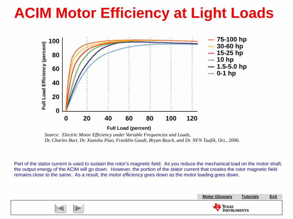
Tutorials ExitMotor Glossary
Full Load (percent)
Full
Load
Effi
cien
cy (p
erce
nt)
0 20 40 60 80 100 120
75-100 hp30-60 hp15-25 hp10 hp1.5-5.0 hp0-1 hp
0
20
40
60
80
100
Source: Electric Motor Efficiency under Variable Frequencies and Loads,Dr. Charles Burt, Dr. Xianshu Piao, Franklin Gaudi, Bryan Busch, and Dr. NFN Tuafik, Oct., 2006.
Part of the stator current is used to sustain the rotor’s magnetic field. As you reduce the mechanical load on the motor shaft,the output energy of the ACIM will go down. However, the portion of the stator current that creates the rotor magnetic fieldremains close to the same. As a result, the motor efficiency goes down as the motor loading goes down.
ACIM Motor Efficiency at Light Loads
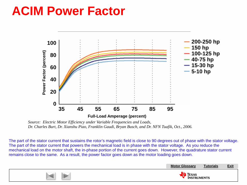
Tutorials ExitMotor Glossary
ACIM Power Factor
Pow
er F
acto
r (pe
rcen
t)
0
20
40
60
80
100
Source: Electric Motor Efficiency under Variable Frequencies and Loads,Dr. Charles Burt, Dr. Xianshu Piao, Franklin Gaudi, Bryan Busch, and Dr. NFN Tuafik, Oct., 2006.
Full-Load Amperage (percent)35 45 55 65 75 85 95
5-10 hp15-30 hp40-75 hp100-125 hp150 hp200-250 hp
The part of the stator current that sustains the rotor’s magnetic field is close to 90 degrees out of phase with the stator voltage. The part of the stator current that powers the mechanical load is in phase with the stator voltage. As you reduce the mechanical load on the motor shaft, the in-phase portion of the current goes down. However, the quadrature stator current remains close to the same. As a result, the power factor goes down as the motor loading goes down.
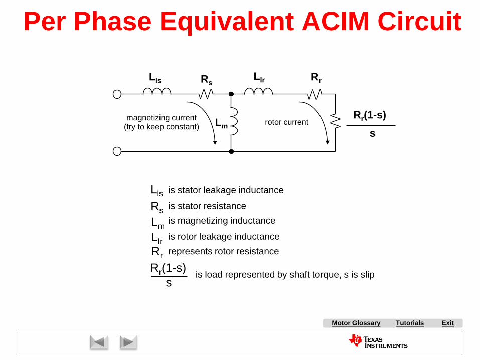
Tutorials ExitMotor Glossary
Lls RsLlr Rr
Rr(1-s)s
is stator leakage inductanceLlsis stator resistanceRsis magnetizing inductanceLmis rotor leakage inductanceLlrrepresents rotor resistanceRr
is load represented by shaft torque, s is slipRr(1-s)s
magnetizing current(try to keep constant) rotor current
Per Phase Equivalent ACIM Circuit
Lm
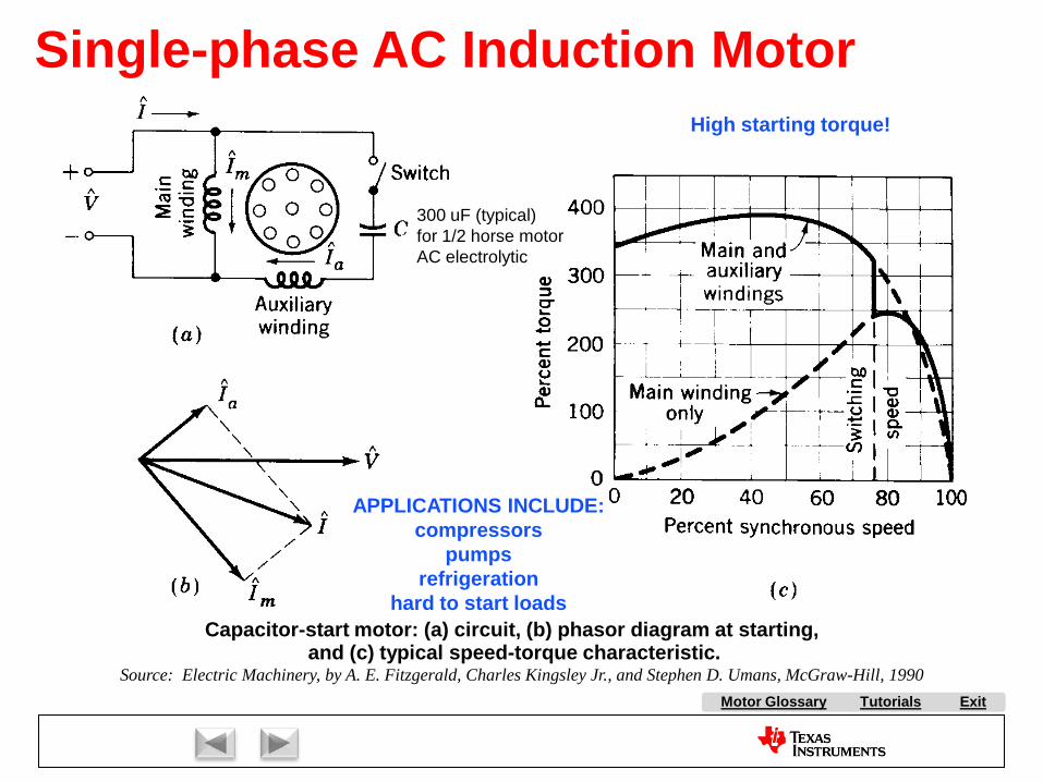
Tutorials ExitMotor Glossary
Single-phase AC Induction MotorHigh starting torque!
APPLICATIONS INCLUDE:compressors
pumpsrefrigeration
hard to start loads
300 uF (typical)for 1/2 horse motorAC electrolytic
Capacitor-start motor: (a) circuit, (b) phasor diagram at starting, and (c) typical speed-torque characteristic.
Source: Electric Machinery, by A. E. Fitzgerald, Charles Kingsley Jr., and Stephen D. Umans, McGraw-Hill, 1990
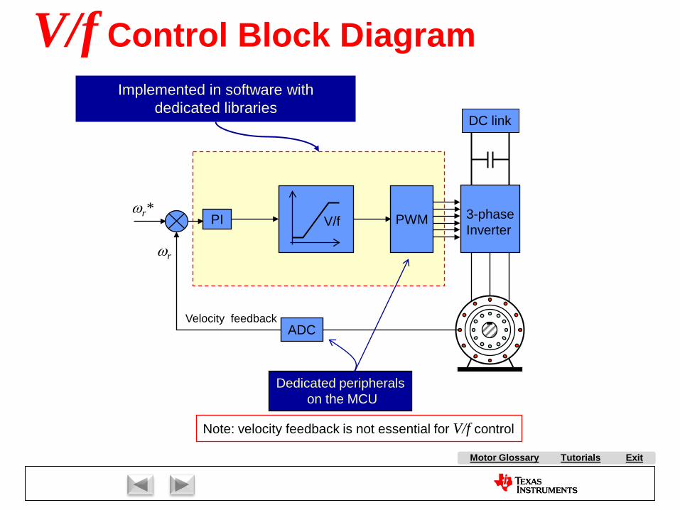
Tutorials ExitMotor Glossary
V/f Control Block Diagram
PWM 3-phaseInverter
DC link
PI V/f
Velocity feedback
ωr
ωr*
Implemented in software with dedicated libraries
Note: velocity feedback is not essential for V/f control
ADC
Dedicated peripheralson the MCU
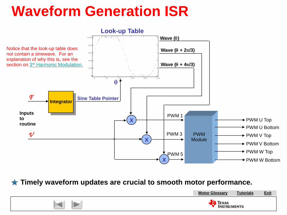
Tutorials ExitMotor Glossary
Waveform Generation ISR
F
θ
Integrator Sine Table Pointer
X
X
X
Look-up Table
V PWMModule
PWM U TopPWM U Bottom
PWM V Top
PWM V Bottom
PWM W Top
PWM W Bottom
Timely waveform updates are crucial to smooth motor performance.
Inputstoroutine
PWM 1
PWM 3
PWM 5
0 50 100 150 200 2500
200
400
600
800
1000
Wave (θ + 2π/3)
Wave (θ + 4π/3)
Wave (θ)
Notice that the look-up table does not contain a sinewave. For an explanation of why this is, see the section on 3rd Harmonic Modulation.

Tutorials ExitMotor Glossary
• There is a complete system for this type of control in the TI libraries. See ACI3_1. The block diagram is shown below:
V/Hz Control Software from TI

Tutorials ExitMotor Glossary
Slip Control
+
-
CommandedRotorSpeed
Desired Slip
+
+
Max
MinZero Speed Boost
Clamp
V/Hz Law
Volts
Actual Rotor Speed
ωsyn
Voltage Limit
PI Controller
InductionMotor
Waveform Generator
TIDave’sControlCenter
Hertz
Slip control is based on a Volts per Hertz control law.
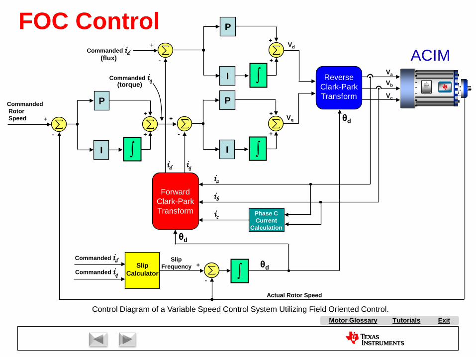
Tutorials ExitMotor Glossary
+
-
CommandedRotorSpeed
P
I ∫
+
+
Actual Rotor Speed
Vb
Vc
Va
Control Diagram of a Variable Speed Control System Utilizing Field Oriented Control.
Commanded id
+
-
P
I ∫
+
+
+
-
P
I ∫
+
+
Commanded iq ReverseClark-ParkTransform
ForwardClark-ParkTransform
id iq
Phase CCurrent
Calculation
ia
ib
ic
∫Commanded id
Commanded iqSlip
Calculator
SlipFrequency +
-
θd
θd
θd
Vd
Vq
(flux)
(torque) TIDave’sControlCenter
ACIM
FOC Control
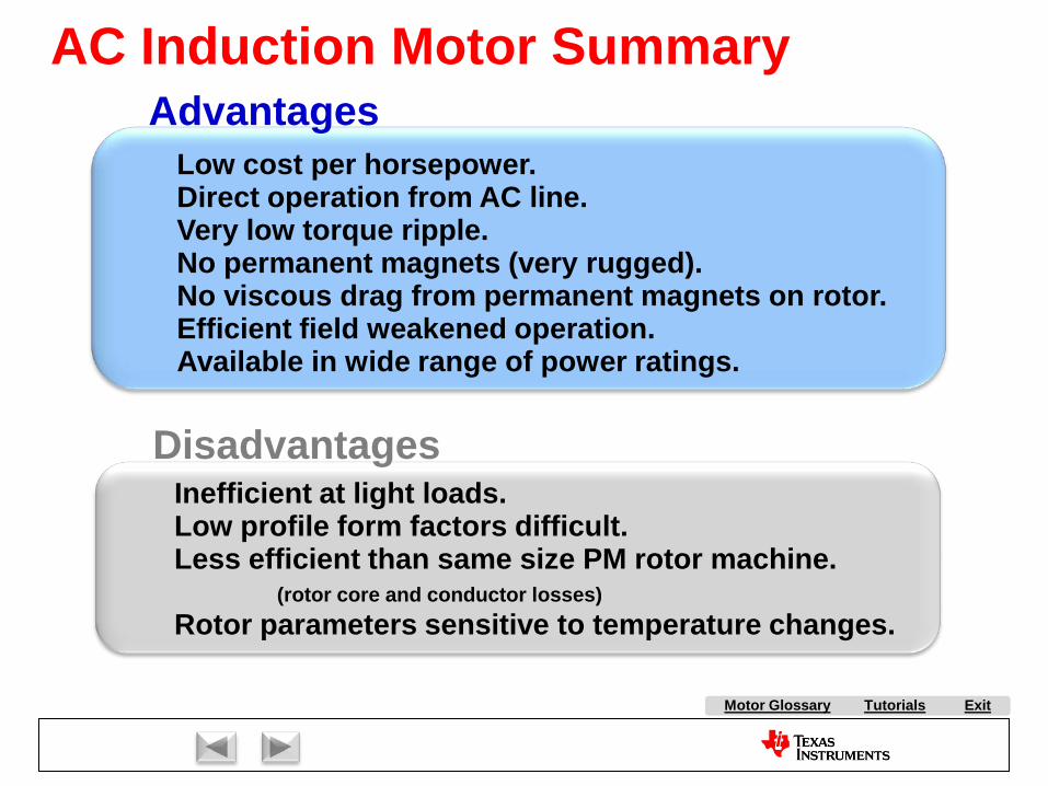
Tutorials ExitMotor Glossary
Disadvantages
AdvantagesLow cost per horsepower.Direct operation from AC line.Very low torque ripple.No permanent magnets (very rugged).No viscous drag from permanent magnets on rotor.Efficient field weakened operation.Available in wide range of power ratings.
Inefficient at light loads.Low profile form factors difficult.Less efficient than same size PM rotor machine.
(rotor core and conductor losses)Rotor parameters sensitive to temperature changes.
AC Induction Motor Summary
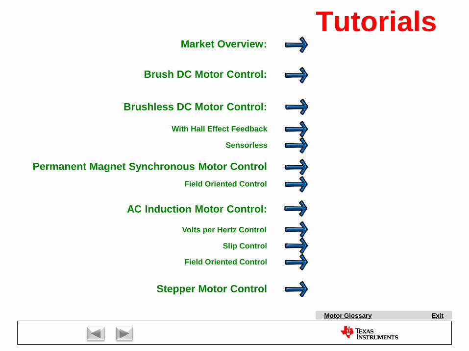
Market Overview:
AC Induction Motor Control:
Stepper Motor Control
Brush DC Motor Control:
Brushless DC Motor Control:
With Hall Effect Feedback
Sensorless
Permanent Magnet Synchronous Motor Control
Volts per Hertz Control
Slip Control
Field Oriented Control
Field Oriented Control
ExitMotor Glossary
Tutorials

Stepper Motors
Copyright Texas Instruments 2011

Tutorials ExitMotor Glossary
• Introduced in the early 60s as an economical replacement to closed-loop DC servo systems.
• Found immediate acceptance in the emerging computer peripheral industry.
Stepper Motors
• Although open-loop stepper control is conceptually easy, complex motor dynamics are often underestimated.
• Available in many topologies and step sizes.
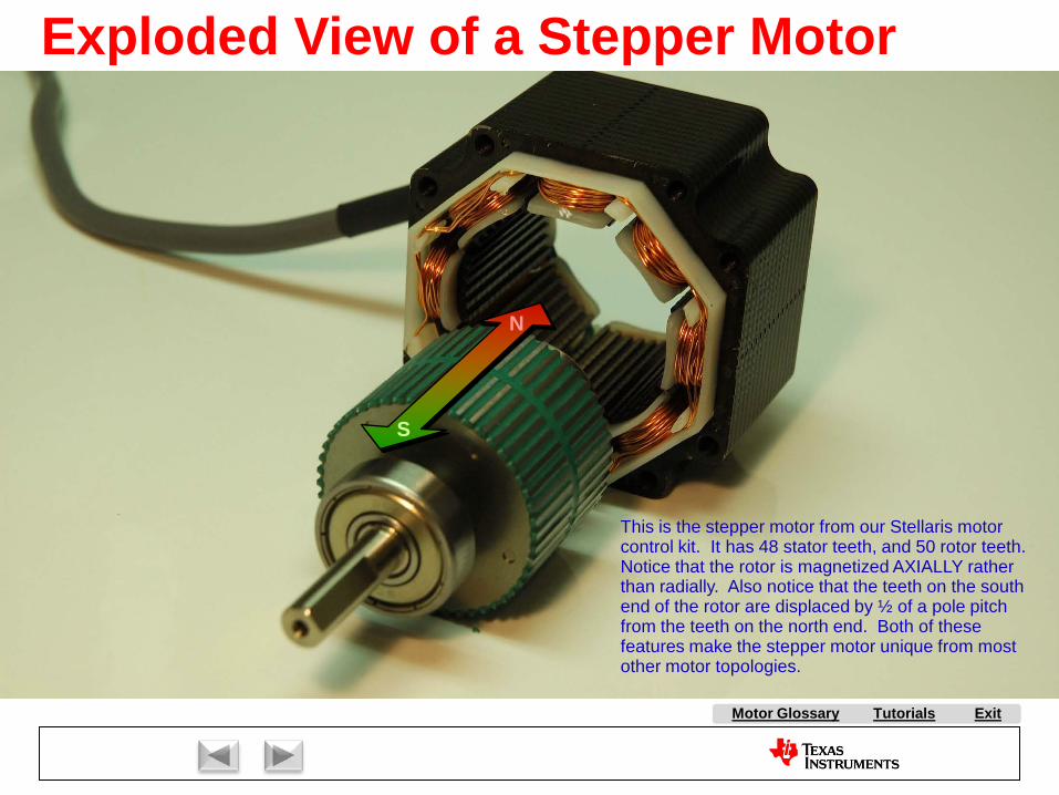
Tutorials ExitMotor Glossary
N
S
This is the stepper motor from our Stellaris motor control kit. It has 48 stator teeth, and 50 rotor teeth. Notice that the rotor is magnetized AXIALLY rather than radially. Also notice that the teeth on the south end of the rotor are displaced by ½ of a pole pitch from the teeth on the north end. Both of these features make the stepper motor unique from most other motor topologies.
Exploded View of a Stepper Motor
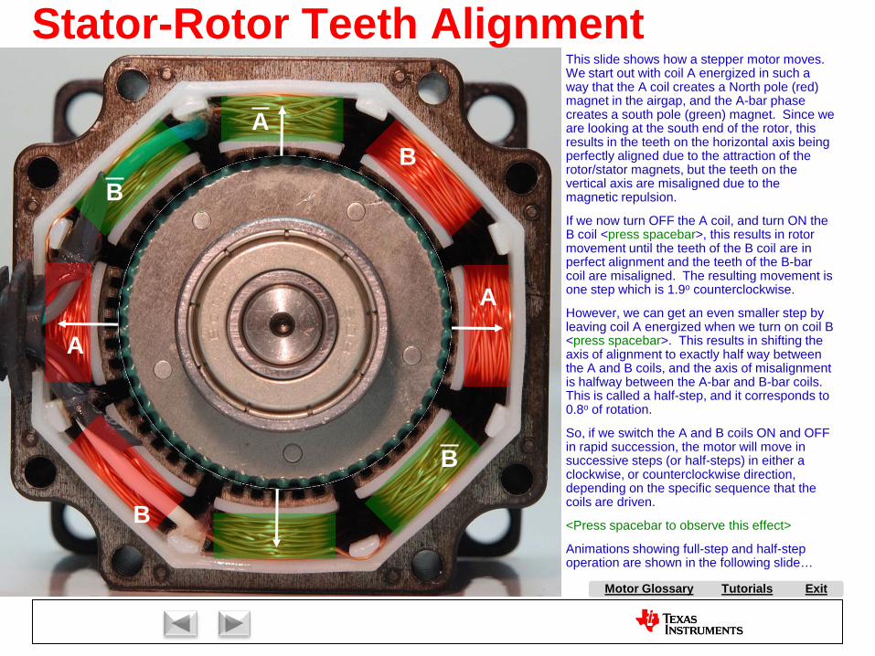
Tutorials ExitMotor Glossary
Stator-Rotor Teeth Alignment
S A
A
A
B
B
B
B
Aligned
Unaligned
This slide shows how a stepper motor moves. We start out with coil A energized in such a way that the A coil creates a North pole (red) magnet in the airgap, and the A-bar phase creates a south pole (green) magnet. Since we are looking at the south end of the rotor, this results in the teeth on the horizontal axis being perfectly aligned due to the attraction of the rotor/stator magnets, but the teeth on the vertical axis are misaligned due to the magnetic repulsion.
If we now turn OFF the A coil, and turn ON the B coil <press spacebar>, this results in rotor movement until the teeth of the B coil are in perfect alignment and the teeth of the B-bar coil are misaligned. The resulting movement is one step which is 1.9o counterclockwise.
However, we can get an even smaller step by leaving coil A energized when we turn on coil B <press spacebar>. This results in shifting the axis of alignment to exactly half way between the A and B coils, and the axis of misalignment is halfway between the A-bar and B-bar coils. This is called a half-step, and it corresponds to 0.8o of rotation.
So, if we switch the A and B coils ON and OFF in rapid succession, the motor will move in successive steps (or half-steps) in either a clockwise, or counterclockwise direction, depending on the specific sequence that the coils are driven.
<Press spacebar to observe this effect>
Animations showing full-step and half-step operation are shown in the following slide…
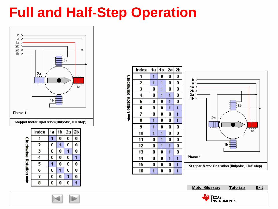
Tutorials ExitMotor Glossary
Full and Half-Step Operation
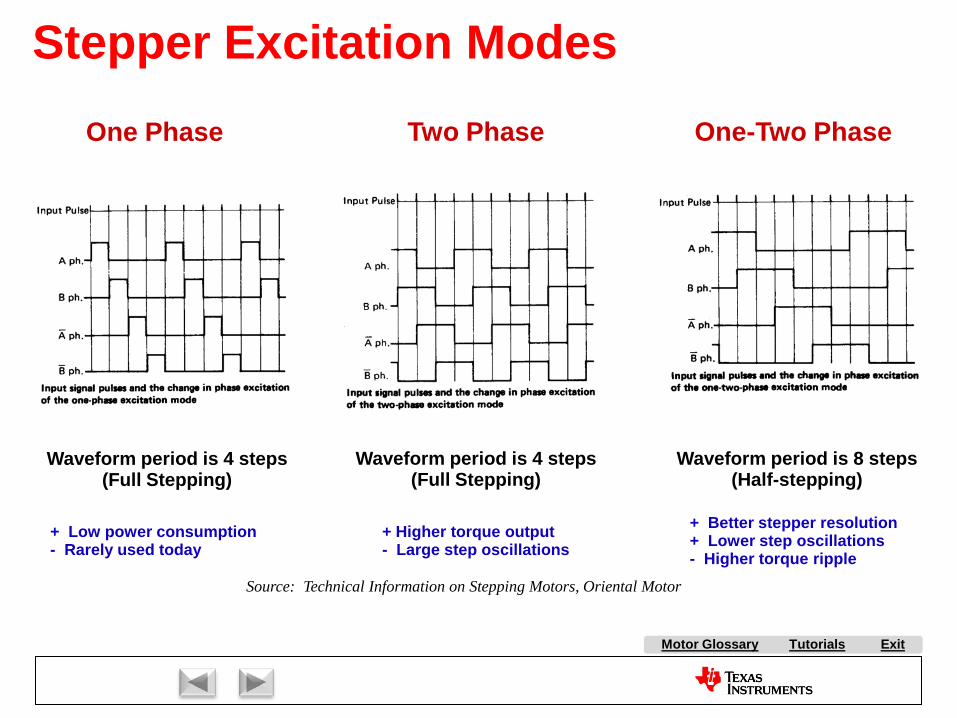
Tutorials ExitMotor Glossary
Waveform period is 4 steps(Full Stepping)
Waveform period is 4 steps(Full Stepping)
Waveform period is 8 steps(Half-stepping)
+ Low power consumption- Rarely used today
+ Higher torque output- Large step oscillations
+ Better stepper resolution+ Lower step oscillations- Higher torque ripple
One Phase Two Phase One-Two Phase
Source: Technical Information on Stepping Motors, Oriental Motor
Stepper Excitation Modes
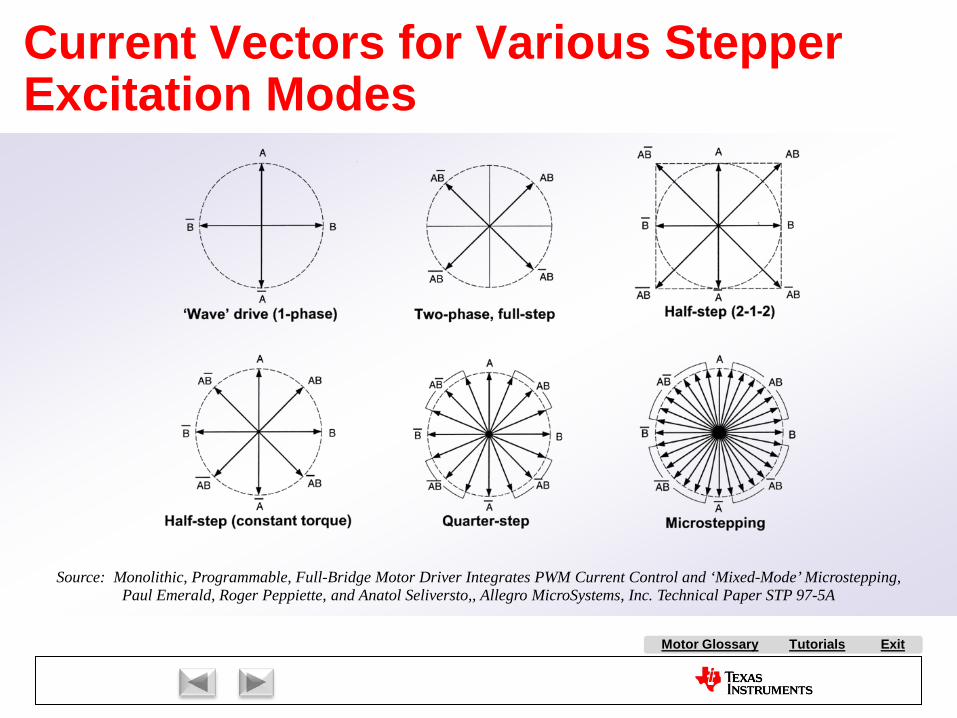
Tutorials ExitMotor Glossary
Source: Monolithic, Programmable, Full-Bridge Motor Driver Integrates PWM Current Control and ‘Mixed-Mode’ Microstepping,Paul Emerald, Roger Peppiette, and Anatol Seliversto,, Allegro MicroSystems, Inc. Technical Paper STP 97-5A
Current Vectors for Various Stepper Excitation Modes
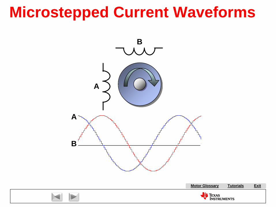
Tutorials ExitMotor Glossary
A
B
A
B
Microstepped Current Waveforms
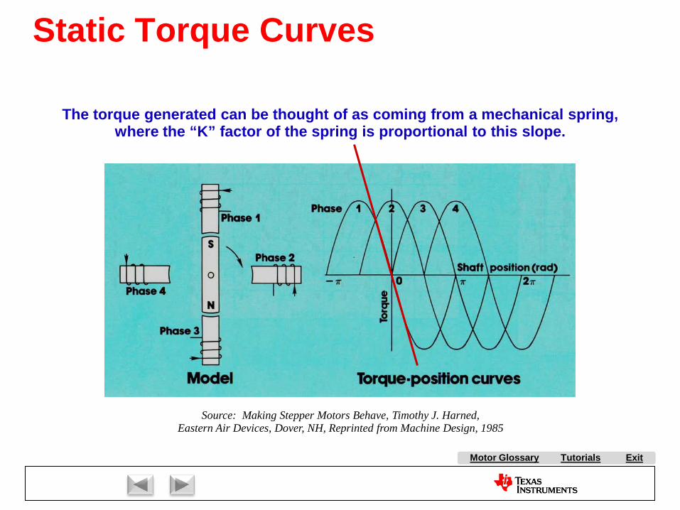
Tutorials ExitMotor Glossary
The torque generated can be thought of as coming from a mechanical spring,where the “K” factor of the spring is proportional to this slope.
Source: Making Stepper Motors Behave, Timothy J. Harned,Eastern Air Devices, Dover, NH, Reprinted from Machine Design, 1985
Static Torque Curves
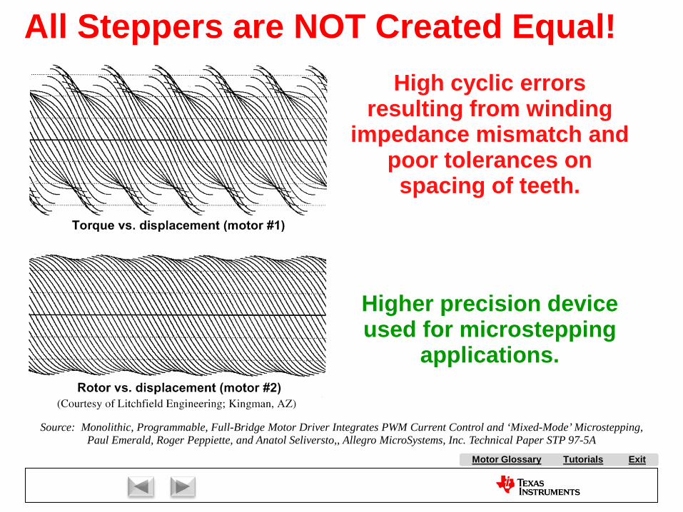
Tutorials ExitMotor Glossary
High cyclic errors resulting from winding
impedance mismatch and poor tolerances on spacing of teeth.
Higher precision device used for microstepping
applications.
Source: Monolithic, Programmable, Full-Bridge Motor Driver Integrates PWM Current Control and ‘Mixed-Mode’ Microstepping,Paul Emerald, Roger Peppiette, and Anatol Seliversto,, Allegro MicroSystems, Inc. Technical Paper STP 97-5A
All Steppers are NOT Created Equal!
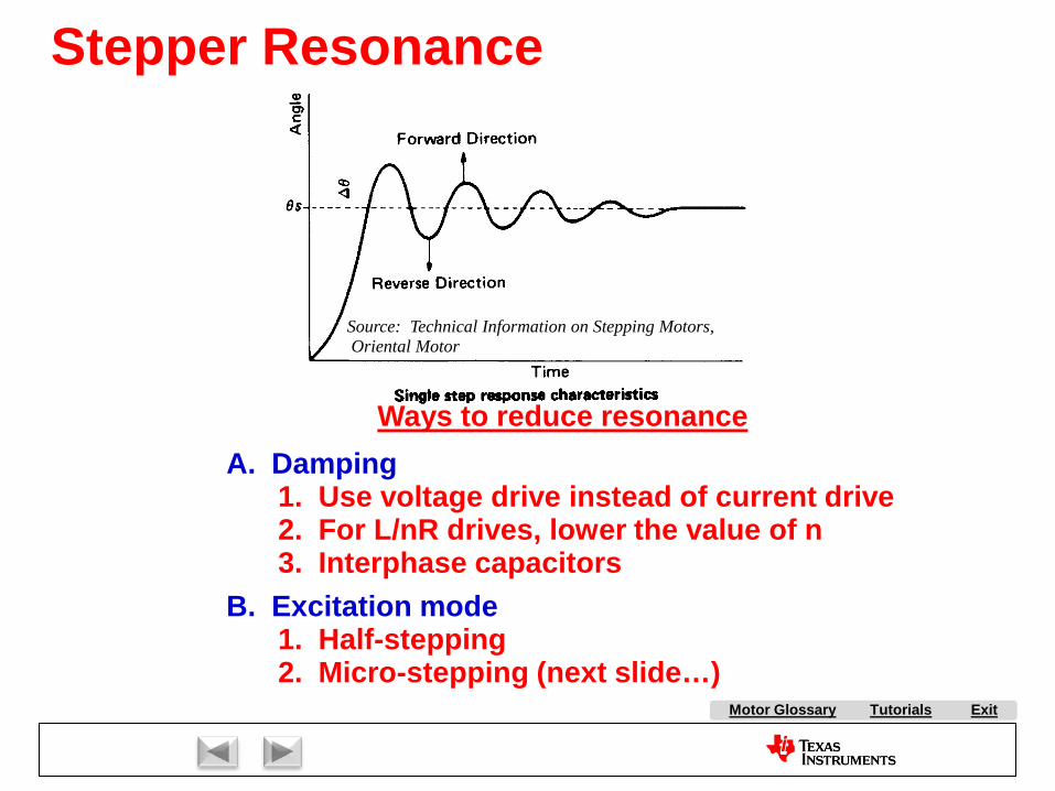
Tutorials ExitMotor Glossary
Ways to reduce resonanceA. Damping
1. Use voltage drive instead of current drive2. For L/nR drives, lower the value of n3. Interphase capacitors
B. Excitation mode1. Half-stepping2. Micro-stepping (next slide…)
Source: Technical Information on Stepping Motors,Oriental Motor
Stepper Resonance
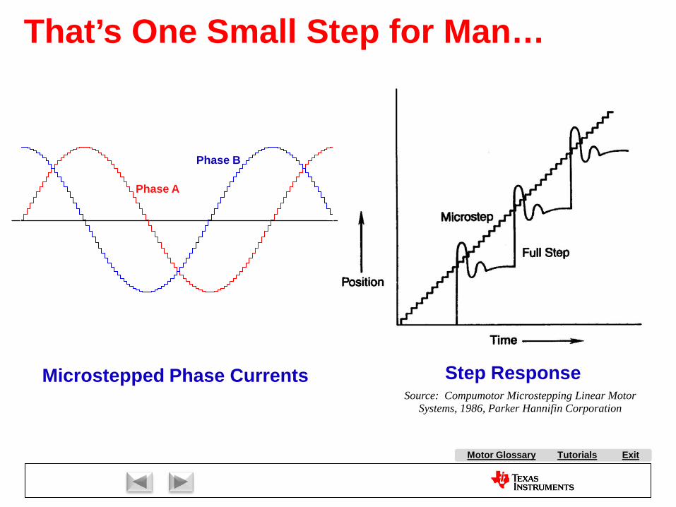
Tutorials ExitMotor Glossary
Microstepped Phase Currents Step ResponseSource: Compumotor Microstepping Linear Motor
Systems, 1986, Parker Hannifin Corporation
AesahPiBesahPii
Phase A
Phase B
That’s One Small Step for Man…
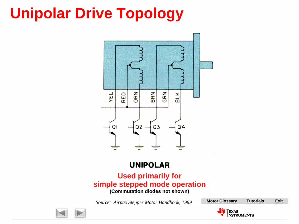
Tutorials ExitMotor Glossary
Used primarily forsimple stepped mode operation
(Commutation diodes not shown)
Source: Airpax Stepper Motor Handbook, 1989
Unipolar Drive Topology
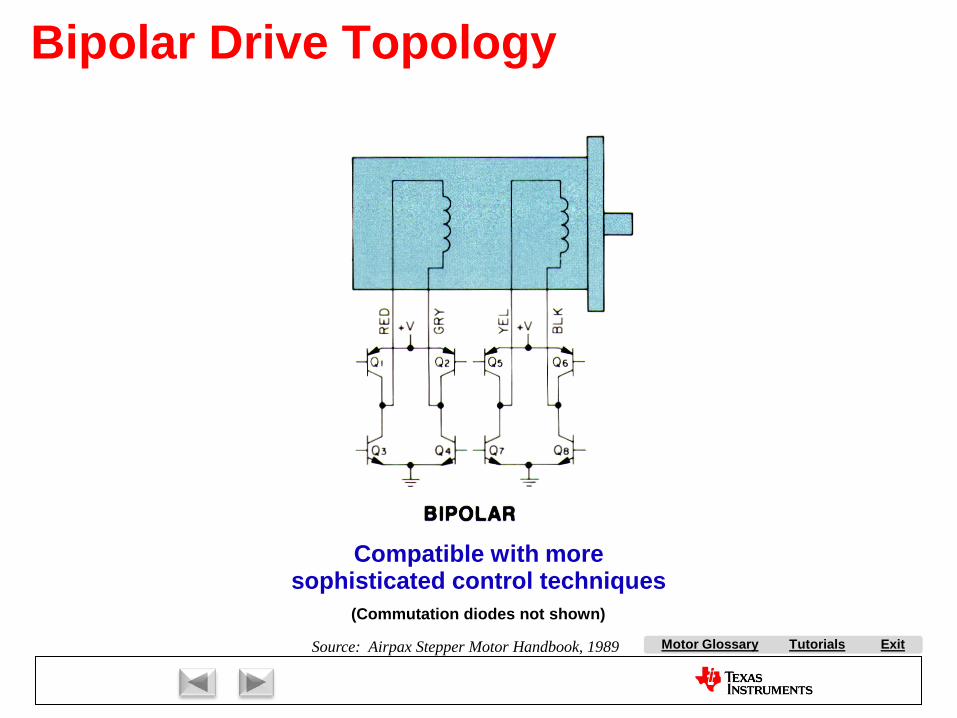
Tutorials ExitMotor Glossary
(Commutation diodes not shown)
Compatible with moresophisticated control techniques
Source: Airpax Stepper Motor Handbook, 1989
Bipolar Drive Topology

Tutorials ExitMotor Glossary
+24 V
0.015
PWM3
PWM3PWM4
PWM4
+24 V
0.015
PWM1
PWM1PWM2
PWM2
MSP430
Coil A
Coil B
Ia Ib
PWM1
PWM2
PWM3
PWM4
Gain+
-
Wavetable
)sin( toω
)cos( toω+
-Gain
ADC2
ADC1
Closed-loop Current Mode Control
Texas Instigants
Dave’sControlCenter
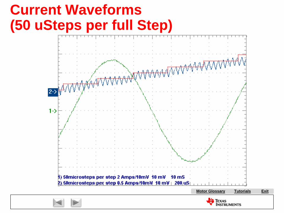
Tutorials ExitMotor Glossary
Current Waveforms(50 uSteps per full Step)

Tutorials ExitMotor Glossary
Stepper Model
R15{Rs}
L2
{Ls}
V=-K*sin((90/{step_angle})*V(angle))
B5
V=K*cos((90/{step_angle})*V(angle))
B6
E11
R1{Rs}
L1
{Ls}
E41
B1
V=I(L1)
B3
V=I(L2)
V=-{Td}*sin((180/{step_angle})*V(angle))
B2
Torque
sine
cosine
sine
cosi
ne
speed
cosine
sine
bemf_A
bemf_B
bemf_A_ref
bemf_B_ref
Va
Vb
STEPPER MOTOR
Detent Torque
Coil A Torque
Coil B Torque
COIL A
COIL B

Tutorials ExitMotor Glossary
Stepper Model Results
MMT STYLE STEPPER MOTOR SINGLE FULL STEP MOVEMENT(Single Phase Driven)
-1.2
-1
-0.8
-0.6
-0.4
-0.2
0
0.2
0.4
0.6
0 0.05 0.1 0.15 0.2 0.25Time (S)
Bac
k EM
F (V
)
0
0.0005
0.001
0.0015
0.002
0.0025
0.003
0.0035
0.004
0.0045
Flux
(V-S
)
Non-Driven Coil back EMFFlux (integral of back EMF)
Open Coil Voltage (Moving Motor)
125ms 175ms 225ms 275ms 325ms 375ms
-1.2V
-1.0V
-0.8V
-0.6V
-0.4V
-0.2V
0.0V
0.2V
0.4V
0.6V-V(bemf_A)
Green waveform: Spice model predictionBlue waveform: Actual measured back-EMF

Tutorials ExitMotor Glossary
Disadvantages
AdvantagesVery economical solution for position control systems.Inherently high torque/position gain.Easy to interface to digital controllers.Heat is generated in stator: easy to remove.Excellent holding torque.Holding torque even when not energized.Precise speed control economically achieved.Inherent zero following error.
Plagued by resonance problems.High inductance and frequent commutation limit high speeds.Certain speeds not permitted due to dynamic instabilities.High vibration resulting from oscillatory behavior.Low efficiency (often operates with high d-axis current) .
Stepper Motor Summary

Market Overview:
AC Induction Motor Control:
Stepper Motor Control
Brush DC Motor Control:
Brushless DC Motor Control:
With Hall Effect Feedback
Sensorless
Permanent Magnet Synchronous Motor Control
Volts per Hertz Control
Slip Control
Field Oriented Control
Field Oriented Control
ExitMotor Glossary
Tutorials
Motor Glossary
Tutorials
Exit
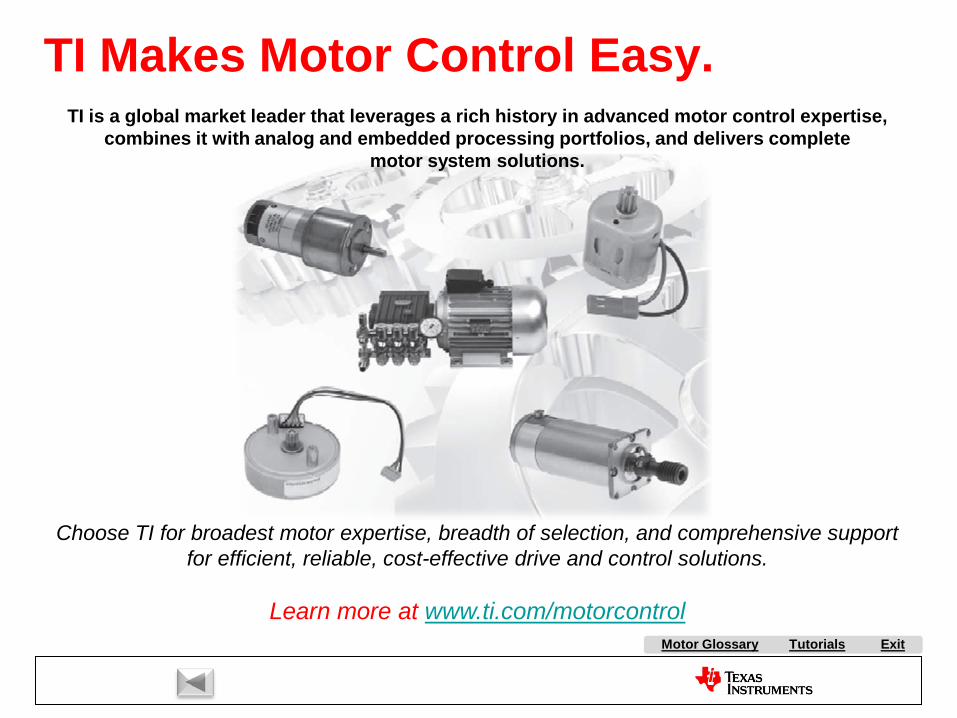
Tutorials ExitMotor Glossary
TI is a global market leader that leverages a rich history in advanced motor control expertise, combines it with analog and embedded processing portfolios, and delivers complete
motor system solutions.
Choose TI for broadest motor expertise, breadth of selection, and comprehensive support for efficient, reliable, cost-effective drive and control solutions.
Learn more at www.ti.com/motorcontrol
TI Makes Motor Control Easy.