Compendium - GlobalSecurity.org
423
U N I T E D N A T I O N S N A T I O N S U N I E S UNITED NATIONS MONITORING, VERIFICATION AND INSPECTION COMMISSION (UNMOVIC) C C o o m m p p e e n n d d i i u u m m T T h h e e M M i i s s s s i i l l e e P P r r o o g g r r a a m m m m e e
-
Upload
khangminh22 -
Category
Documents
-
view
2 -
download
0
Transcript of Compendium - GlobalSecurity.org

U N I T E D N A T I O N S N A T I O N S U N I E S
UNITED NATIONS MONITORING, VERIFICATION AND INSPECTION COMMISSION (UNMOVIC)
CCoommppeennddiiuumm
TThhee MMiissssiillee PPrrooggrraammmmee

TABLE OF CONTENTS CHAPTER IV.I IRAQ’S MISSILE PROGRAMME (THE BEGINNINGS)
CHAPTER IV.II THE BADR-2000 PROJECT CHAPTER IV.III LIQUID PROPELLANT MISSILES DERIVED FROM SCUD
TECHNOLOGY CHAPTER IV.IV MODIFICATIONS OF SA-2 MISSILES INTO BALLISTIC
MISSILES: THE FAHAD 300 AND FAHAD 500 PROGRAMMES
CHAPTER IV.V MODIFICATIONS TO OTHER MISSILES CHAPTER IV.VI RPV/UAV PROGRAMME BEFORE 1991 CHAPTER IV.VII OTHER PROJECTS (SUPER GUN) CHAPTER IV.VIII POST 1991 LIQUID PROPELLANT MISSILE
ACTIVITIES CHAPTER IV.IX POST 1991 SOLID PROPELLANT MISSILES CHAPTER IV.X RPV/UAVs AFTER 1991
CHAPTER IV.XI GUIDANCE AND CONTROL ACTIVITIES 1991-2003
Page 344

UNMOVIC
CHAPTER IV.I
CHAPTER IV.I
IRAQ’S MISSILE PROGRAMME
ACQUISITION BY IRAQ OF FOREIGN MISSILE SYSTEMS AS A PREREQUISITE OF INDIGENOUS MISSILE PROGRAMMES In the early 1970s, in the course of on-going modernization of its Armed Forces, Iraq decided to create a surface-to-surface operational missile force. In 1972, Iraq signed contracts for the procurement of two types of surface-to-surface systems, the FROG-7 with a range of up to 70 km and the SCUD-B with a range of up to 300 km1. The specific operational considerations behind the selection by Iraq of the above systems remain unknown. However, among the factors that led Iraq to their acquisition was possibly their accessibility and specific technical characteristics such as a combination of tactical and operational ranges, fast deployment to firing positions, relatively simple maintenance and large payloads. Other foreign missile systems were also acquired that were not part of the surface-to-surface missile force but were subsequently to be relevant to Iraq’s quest for longer range surface-to-surface missiles. Systems for Surface-to-Surface Missile Force FROG rocket system Figure IV.I.I FROG-7 on launcher
The rocket system, 9K52 (Luna-M), referred to by NATO as FROG-7, was designed in the early 1960s as a tactical artillery rocket system for a divisional level of operations (Figure IV.I.I). Iraq procured a special version developed for use in hot climates. It comprised the 9P113 four-axle eight-wheeled vehicle (BAZ-135) Transporter-Erector-Launcher (TEL), the eight-wheeled 9T29 (ZIL-135) transporter vehicle with a hydraulic crane,
and the fire direction four-wheel drive vehicle GAZ-66 with a meteorological radar mounted on the trailer. The 9.4 metre long double-base solid propellant rocket, 9M21F, with a launch weight of about 2.5 tonnes and a body diameter of 544mm was equipped with the 9N18F high explosive warhead. The 450 kg warhead was filled with 200 kg of high explosive. The rocket’s range was from 12 to 68 km with a Circular Error Probable (CEP - radius of the circle around a target within which 50% of the missiles fired will impact) of 400 metres around the target centre. The rocket was aimed by raising the TEL's rail to the required level of elevation in order to achieve the planned range. A
1 Missiles CAFCD December 2002 Chapter 1.1.1.
Page 345

UNMOVIC
CHAPTER IV.I
limited traverse angle could also be set up on the launch rail assembly. The rocket launch sequence, including ground preparation and firing, required from 15 to 30 minutes. SCUD missile system Figure IV.I.II SCUD-B
The missile system 8K14, NATO code SCUD-B, with the R-17 missile, was designed in the early 1960s as an operational level ballistic missile system (Figure IV.I.II). The 37 tonne four-axle eight-wheeled vehicle, MAZ 543 P (9P117M), over 13 metres long, was used as a TEL. A separate command and control vehicle was used for the target selection and firing. The 11 metre long missile with a body diameter of 880 mm and a launch weight of about 6 tonnes had a 985 kg warhead containing 800 kg of high explosive. The missile propellant consisted of a mixture of kerosene as fuel and Inhibited Red Fuming Nitric Acid (IRFNA) as oxidizer. The propellant weight was over 3 tonnes. The missile range was up to 300 km with a CEP of 450 metres. The inertial guidance and control system consisted of three gyroscopes with four graphite vanes in the motor exhaust section to
adjust the flight path of the missile during the climb following launch and an accelerometer to determine the shut-off time of the engine. The control vanes were only operational during the period of propellant burn within the first 60 seconds of flight. At launch, the missile was raised to the vertical position on the TEL using two hydraulic pumps powering the cradle. A typical launch sequence required from 30 minutes to 1 hour. In the 1970s and 1980s, Iraq procured 819 SCUD-B missiles. Creation of Operational Missile Force Imported hardware, including missiles, warheads, launchers, fuels and ground support equipment began to arrive in Iraq in 1974. Subsequently, the first two missile units were formed in 1975 that provided the foundation of Iraq’s missile force. Missile Unit 135, later known as missile brigade 225, was equipped with the FROG-7 rocket systems and missile brigade 224 operated the SCUD-B missile systems2. These units became fully operational in 1976 following substantial training of Iraqi personnel by the supplier. Training included the handling, maintenance and combat use of the missile systems, which involved procedures for launch preparation, target selection, aiming and firing.
2 Missiles CAFCD December 2002 Chapter 1.1.1.
Page 346

UNMOVIC
CHAPTER IV.I
Combat use Figure IV.I.III Launch of FROG-7
The Iran-Iraq war began in September 1980. Iraq’s initial offensive operation was successful. By 1981, Iraq captured the Khorramshahr port and other parts of western Iran. According to multiple records, Iraq began to launch FROG rockets against Iranian western cities in November 1980 (Figure IV.I.III). In the period from 1980 to 1982, Iraq fired
around 70 FROG rockets against military and civilian targets in Iran. In 1982, however, Iraq’s Armed Forces retreated from some of the territories that it occupied due to counterattacks by the Iranian Forces. The conflict was being transformed into a long, sporadic and exhausting war of attrition. Beginning in 1983, Iran began to launch its major offensive operations against Iraq and, in the period from 1984 to 1986, was able to capture several parts of the Iraqi territory, including the oil-rich portion of the Fao peninsula in the south. In the earlier part of the 1980s, due to the war complications Iraq began to use its SCUD missiles against targets in Iran. Iraq launched SCUD missiles mainly against targets within their 300 km range, including industrial and urban centres. From 1984 to 1987, both sides exchanged missile fire, launching hundreds of SCUD missiles against each other (Figure IV.I.IV). Figure IV.I.IV SCUD-B Launch
However, with their 300 km range limit, SCUD missiles fired by Iraq were not capable of reaching Tehran and other targets in the depth of Iranian territory. This led Iraq to seek longer range foreign missile systems and even to proceed with joint missile projects with other countries. When such attempts had failed (or did not produce immediate results), Iraq established its own indigenous programme to extend the operational range of the SCUD missile to more than 600 km and thus provide a response to Iran’s missile
attacks on Baghdad. This modified missile was named “Al-Hussein”. The exchange of missiles between Iran and Iraq from February to April 1988 became known as the War of the Cities in which Iraq used 189 Al Hussein missiles mainly
Page 347

UNMOVIC
CHAPTER IV.I
against Tehran and other urban targets. Several salvo launches of Al Hussein missiles against Tehran had significant consequences, particularly on the morale of residents in that city. Iraq often stated that the use of Al Hussein missiles in 1988 in the “War of the Cities” was one of the major reasons for the cessation of the Iran-Iraq war. Other Foreign Acquired Systems Ababil-50 Figure IV.I.V Ababil-50 launcher
The experience of the first phase of the Iran-Iraq war led Iraq to expand its missile capabilities and to search for additional tactical rocket systems to cover enemy targets within ranges from 30 to 50 km. Targets with less than a 30 km range were able to be covered by 122mm Multiple Rocket Launcher Systems (MLRS)
procured by Iraq from foreign suppliers. In 1980, Iraq signed a contract with a foreign company on the joint development of a MLRS for direct battlefield support. This MLRS had a range of 40-50 km and a calibre larger than 122 mm. By 1988, this project resulted in the development and production of Ababil-50, a 262mm calibre, 12-barrel, rocket system mounted on the 9 metre long FAP 3235 truck (Figure IV.I.V). Over 4.6 metres long, the 400 kg unguided double-base solid propellant rocket had a maximum range of 50 km with about a two-minute flight time and a speed of 1.2 km/s. The launching was performed either by firing single rockets or in a ripple-firing mode with an interval of two to four seconds. Launching could be accomplished either through a remote control mechanism with a cable connection or directly from the vehicle.
The Ababil-50 system, as well as the FROG rocket system, was not covered by the prohibition imposed on Iraq by Security Council resolution 687 (1991). Through the acquisition of this system and participation in its development and production, Iraq obtained access to some double-base solid propellant missile technology. Iraq also gained the necessary experience and equipment that it later utilized in the refurbishment of foreign double-base solid propellant missiles and, to a degree, for use in other indigenous missile projects.
Page 348

UNMOVIC
CHAPTER IV.I
Other missile procurement, including surface-to-air and coastal defence missiles, were important for Iraq’s attempts to acquire extended range surface-to-surface missiles.
SA-2 missile system Figure IV.I.VI SA-2 missile
In the early 1970s to late 1980s, Iraq procured the S-75M air defence missile system, referred to by NATO as “Guideline” or SA-2 (Figure IV.I.VI). The first version of SA-2 was designed in the mid-1950s and became operational in the 1960s. The SA-2’s V-750/V-755 missile is 11 m long and 500 mm in diameter with a launch weight of 2.5 tonnes. Its propulsion system consists of a 43 tonne thrust double-base solid propellant booster and a 3.5 tonne thrust liquid propellant engine as
a sustainer. It has an effective maximum range of up to 43 km against aerial targets with velocity up to Mach 2. It can be used for the interception of targets at an altitude of up to 25 km. Iraq acquired more than 1,000 SA-2 missiles over a period of 20 years. Iraq endeavored to acquire an SA-2 production facility, along with transfer of technology, through a contract with a foreign country before 1989. Blueprints and technical documentation were delivered to Iraq by the foreign country but the project did not progress further and was terminated. Technically, the SA-2 air defence missile could be launched in a surface-to-surface mode within a range limited by the range of its guidance radar, the self-destruct safety mechanism and the missile’s pressurized air supply. Among Iraq’s efforts to improve its longer-range surface-to-surface missile capabilities, there was a project to convert the SA-2 missile to a surface-to-surface mode, by-passing the inherent limitations. This project was known as the Fahad programme, discussed in detail in a later section of this chapter8.
Page 349

UNMOVIC
CHAPTER IV.I
Coastal defence surface-to-surface and air-to-surface anti-ship cruise missiles Figure IV.I.VII HY-2 Anti-ship cruise missile
In the 1980s, Iraq procured multiple versions of anti-ship cruise missiles, (surface-to-surface and air-to-surface) including P-15, HY-2, C-601 and C-611 (Figure IV.I.VII). The 7.36 metres long liquid propellant P-15/HY-2 surface-to-surface missile with a solid propellant booster had a body diameter of 760mm. It had a launch weight of 3,000 kg and carried a 513 kg high explosive warhead. Its operational range was about 95 km.
Attempts to extend the range of these liquid propellant coastal defence cruise missiles, undertaken by Iraq in the 1980s, are described in chapter IV.V. These initial projects were suspended in 1990 but revived some years later when relevant foreign technology became available.
Page 350

UNMOVIC
CHAPTER IV.II
CHAPTER IV.II
THE BADR-2000 PROJECT1
Iraq had acquired FROG-7 and SCUD-B missiles from abroad in the early 1970’s to create their fledgling surface-to-surface missile force. Subsequently, in 1980 and 1981, Iraq signed contracts with two other foreign sources for the joint development of shorter range surface-to-surface MLRS systems. Iraq also began seeking a ballistic missile with a range capability well beyond the 300 km of the SCUD-B missile. Iraq’s intention for this last mentioned acquisition may well have been to extend its missile force capability for strategic reasons, but most likely it was primarily driven by Iraq’s desire to field a weapon with a range capable of reaching Tehran since, after the first couple of years of the war with Iran, things were proving difficult for Iraq. Iraq entered into negotiations with a foreign country for the development of a missile with a range of around 600 km and signed a contract2 with the foreign country on 21 February 1984 for such a missile system. In Iraq, the project was jointly sponsored by the Ministry of Defence and the State Organisation for Technical Industry (SOTI). According to Iraqi statements3, it was only after the foreign country’s initial proposal that Iraq realized the missile being considered was still only in the development stage. However, at the time Iraq signed the contract for the missile system, which was called the BADR-2000, it was clearly aware of the limited status of its development since the contract itself contained 23 annexes representing various work packages, beginning with concept definition studies and design work to be done. Comment In all probability, Iraq signed the contract with the foreign country in spite of, not because of, the fact that the missile was not fully developed since they were unable to acquire a suitable “off the shelf” missile from any other source. The contract with the foreign country, however, did offer Iraq the opportunity to acquire technology and a capability for indigenous production of solid propellant rockets using modern composite propellant. Through its earlier contracts for MLRS systems, Iraq had acquired a level of capability with traditional double-base propellant, but this type of propellant was not well suited for large rocket motors and the newer composite type propellant had other performance advantages as well. Although the BADR-2000 project was to be subsequently prohibited by the Security Council under resolution 687 (1991), thus resulting in the destruction of much equipment, there was a legacy from this project of some infrastructure, residual equipment and knowledge in solid propellant technology that would be useful for Iraq in following years.
1 Missiles CAFCD December 2002 Chapter 5 Bader-2000. 2 Contract No. A&S/2000/1984, signed 21 February 1984. 3 Missiles CAFCD December 2002 Chapter 5 Bader-2000 Chap 3.1.1.
Page 351

UNMOVIC
CHAPTER IV.II
Description of Missile System The BADR-2000, as described in the concept definition report4, was to be a mobile, two-stage, medium-range, surface-to-surface, ballistic missile system with a separating5 re-entry vehicle as payload. The system included the missile itself and all equipment concerned with transport and handling, firing position survey, trajectory computation, launch preparation, missile launch, command communication, checkout and power supplies as well as service and support equipment. The complete missile system, as described in the initial contract, comprised the following subsystems:
• Missile (flight vehicle), consisting of a first (boost) stage, a second stage for velocity correction and range extension, and a re-entry vehicle containing the warhead
• Subsystem Ground Support Equipment ‐ Mission Control Vehicle ‐ Launch Vehicle ‐ Navigation Vehicle ‐ Command Post Vehicle ‐ Missile Transport Vehicle ‐ Fire Fighting Vehicle (Fire-Brigade) ‐ Maintenance and Repair Vehicle
• Range Test/Trials Equipment Assemblies ‐ Trajectory Survey Equipment ‐ Range Survey Equipment ‐ Ground Telemetry Equipment ‐ Recording and Evaluation Central ‐ Command Destruct Ground Equipment
The information on the missile itself included numerous detailed drawings while the information on the subsystems was principally functional descriptions, albeit given in considerable detail. The difference in level of detail provided essentially reflected the level of progress attained in the overall development of the missile system. The project documentation was more than 1000 pages, and yet in spite of the amount of detailed drawings provided, it would not have been sufficient for Iraq to undertake its own complete indigenous production. Some of the items required for the project had to be obtained from various sub-suppliers. Information was provided on different offers from
4 Ballistic Missile System, Concept Definition Phase, Executive Summary, Vol. 1, 5/08/85, para 2.1. 5 In the original proposal (Contract No. A&S/2000/1984, 21 February 1984, Annex 1) the complete second stage was to be the re-entry vehicle. Only after the concept definition study was it decided to separate the second stage rocket from the front section containing the payload and guidance package which then became the re-entry vehicle.
Page 352

UNMOVIC
CHAPTER IV.II
suppliers for the most complex parts such as gyroscopes, flexible-joint nozzles, computers and software. The contract specified6 that the performance parameters of the missile were to be achieved in three phases of its development, as follows, each with a warhead of 320 kg: Phase 1 Maximum range: 620 km Accuracy7: 1.0% of range Phase 2 Maximum range: 620 km Accuracy: 0.1% of range Phase 3 Maximum range: 750 km Accuracy: 0.1% of range For each successive performance improvement relating to these phases, the corresponding missile was designated as M1, M2 and M3 respectively. The main difference between the M1 and M2 missiles was to be in the guidance package. The third missile modification, M3, was to have the same guidance system as M2 but the liquid propellant engine of the second stage was to be further developed to give the additional range. Within the provisions of the contract, the timescale for development up to commencement of production of the M1 was to be 18 months from when the contract came into force, 40 months for the M2 and 66 months for the M3. Flight Performance According to the design documentation, the missile would be controlled in pitch and yaw during the boost phase by a flexible-joint nozzle thrust vector control system. Roll control during the boost phase was to be provided by vanes (ailerons) on two of the missile’s four tail fins. At the end of the boost phase, the 1st stage motor is separated from the 2nd stage. Over the final 5 seconds or so of boost, the missile is commanded to fly at zero angle of attack to minimize separation transients (pitch/yaw rates etc). At the instant of separation, the liquid propellant engine of the 2nd stage is ignited. The documentation suggested that the liquid propellant engine had to be capable of providing the “cut-off” velocity for the 2nd stage to an accuracy of + 0.5 m/s. After engine shut-off, the 2nd stage would separate from the re-entry vehicle; the attitude of the re-entry vehicle is adjusted to be compatible with the re-entry phase of the trajectory; and finally the re-entry vehicle is “spun up” to minimize inertial perturbations and re-entry dispersions. During re-entry, the safety and arming unit (SAU) would operate. For a sub-munition warhead, the dispensing system would function to enable the payload to be dispensed. A typical trajectory showing the sequence of events is given in Figure IV.II.I.
6 Contract No. A&S/2000/1984, 21 February 1984, Annex 1. 7 Defined in terms of CEP (circular error probable) which is the radius of the circle in which 50% of projectiles fired would land.
Page 353

UNMOVIC
CHAPTER IV.II
Figure IV.II.I. Typical trajectory of BADR-20008
Missile configuration The missile was to consist of two rocket stages and a separable re-entry vehicle. A drawing of the BADR-2000 missile is shown in Figure IV.II.II.
8 Ballistic Missile System, Concept Definition Phase, Executive Summary, Vol. 1, 5/08/85, Fig. 2.2.1.
Page 354

UNMOVIC
CHAPTER IV.II
Figure IV.II.II. Drawing of BADR-2000 missile9
Boost stage rocket motor The first stage boost rocket was 800mm in diameter with a maraging steel case, filled with cast composite HTPB propellant. At the time Iraq negotiated their contract with the foreign country, the design for this motor had already been established. A drawing of the 1st stage motor is shown in Figure IV.II.III.
9 Ballistic Missile System, Concept Definition Phase, Executive Summary, Vol. 1, 5/08/85, Fig. 2.3.1.1.
Page 355

UNMOVIC
CHAPTER IV.II
Figure IV.II.III. Schematic drawing of BADR-2000 first stage boost motor10
Thrust vectoring for missile control in pitch and yaw during the boost phase was to be provided by a flexible-joint nozzle with hydraulically operated actuators powered by pressurized stored helium gas. Drawings of the flexible-joint nozzle construction and of the actuator assembly are shown in Figures IV.II.IV and IV.II.V respectively. The flexible-joint nozzle was an advanced design, using alternating rings of elastomeric material (natural rubber) and steel reinforcements to allow articulation of the nozzle at the throat region.
Figure IV.II.IV Schematic drawing of flexible-joint nozzle11
10 Ballistic Missile System, Concept Definition Phase, Executive Summary, Vol. 1, 5/08/85, Fig. 4.1.1. 11 Ballistic Missile System, Concept Definition Phase, Executive Summary, Vol. 1, 5/08/85, Fig. 4.2.2.
Page 356

UNMOVIC
CHAPTER IV.II
Figure IV.II.V Schematic drawing of actuator assembly for flexible-joint nozzle12
Second stage rocket engine The second stage rocket engine, according to the contract, was to be based on an existing, third-party liquid propellant engine (LPE) using MMH (monomethyl hydrazine) as fuel and nitrogen tetroxide as oxidiser13, each stored in two separate pressurized tanks. At the end of the Concept Definition Phase, the propellants were listed as UDMH (unsymmetrical dimethyl hydrazine) as fuel and MON 7 (mixed oxides of nitrogen) as oxidizer14. A gimbaled nozzle, actuated by compact electro-mechanical units, would provide thrust vector control. The maximum burn time for the engine was 40 seconds. The engine is shut down by two valves that are pyrotechnically activated by the guidance and control package when the missile has attained the required velocity for the selected range. Although a second stage engine design was apparently available to the missile design team at the time of signing the contract, further development work was required and design modifications were carried out in the concept definition phase. An assembly drawing of the LPE is shown in Figure IV.II.VI.
12 Badr Design Concept Report, Structure (12/07/85); and Ballistic Missile System, Concept Definition Phase, Executive Summary, Vol. 1, 5/08/85, Fig. 4.2.4. 13 Contract No. A&S/2000/1984 (21 Feb 1984), Annex 1. 14 Ballistic Missile System, Concept Definition Phase, Executive Summary, Vol. 1, 5/08/85, para 5.6.4.
Page 357

UNMOVIC
CHAPTER IV.II
Figure IV.II.VI. Second stage sustain engine15
During the sustain phase, roll control of the second stage vehicle is provided by the cold gas thruster system housed in the re-entry vehicle. Re-entry vehicle The re-entry vehicle design consisted of the following main parts: nose cone section containing the payload, guidance and control computer with a strap-down sensor package, cold gas thruster system (utilizing stored, high pressure nitrogen), payload initiation system, cruciform tail fins for re-entry stability and an electrical harness including an umbilical plug for testing and configuring the missile software prior to launch. At the time of signing the initial contract, no detailed design of the re-entry vehicle had been made. Only the payload was specified – initially a HE (high energy) explosive warhead, with a retrofit capability for sub-munition (anti-tank and anti-personnel) and fuel-air explosive warheads16. A number of design configurations for the re-entry vehicle were investigated during the subsequent concept definition phase. A drawing of the re-entry vehicle is shown in Figure IV.II.VII. Comment. No evidence was found in any documentation, nor through investigations and interviews carried out later by UN inspectors, for use of BADR-2000 for WMD purposes, including delivery of a nuclear warhead17.
15 Badr Design Concept Report, Structure (12/07/85); and Ballistic Missile System, Concept Definition Phase, Executive Summary, Vol. 1, 5/08/85, Fig. 5.2.1. 16 Contract No. A&S/2000/1984 (21 February 1984), Article 3, item 2; and Annex 1 paras 2.1 and 2.2. 17 See, for example, Report of UNSCOM 45, BM-14, 16 - 30 October 1992.
Page 358

UNMOVIC
CHAPTER IV.II
Figure IV.II.VII. Re-entry vehicle18
Guidance and Control The flight control system had to perform the following functions:
• control and evaluate the internal BITE (built-in test equipment) tests during the pre-launch phase
• initialize the missile, i.e. align the navigation system and set initial data values received from the launch computer prior to launch
• stabilize the missile immediately after launch • control the missile in flight according to commands that are either preset for
guiding the missile along the predetermined flight path or dynamic to correct for external disturbances
• compute navigational data (attitude, velocity and position) for input to the guidance and control loops
• supervise/control the overall mission To carry out these functions, the guidance and control system design comprised a strap-down set of inertial sensors (gyros and accelerometers), an on-board computer with navigational software algorithms, and actuators to mechanically control the thrust vectoring devices. The data transfer between the guidance computer and the actuator control units and other items was based on an ARINC 429 serial bus, although an optional alternate for the strap-down sensor package was a MIL-1553B serial bus. Figure IV.II.VIII shows the functional block diagram of the guidance computer determined during the concept definition phase. 18 Ballistic Missile System, Concept Definition Phase, Executive Summary, Vol. 1, 5/08/85, Fig. 6.7.3.
Page 359

UNMOVIC
CHAPTER IV.II
Figure IV.II.VIII. Block diagram of guidance and control computer19
A block diagram of the integration of the missile electronics with the external systems for system test and maintenance is also reproduced in Figure IV.II.IX.
19 Ballistic Missile System, Concept Definition Phase, Executive Summary, Vol. 2, 5/08/85, Fig. 8.1.3.
Page 360

UNMOVIC
CHAPTER IV.II
Figure IV.II.IX Block diagram of test and integration equipment20.
The BADR-2000 missile design at the time it was being developed utilized current technology and hence would have represented a modern and significant capability for Iraq. Implementation of the Project Under Part 1 of the initial contract, the foreign country had contracted for the development and manufacture of the complete BADR-2000 missile system to specification. In fact, this development was going to be carried out essentially by their sub-contractors (referred to as “sub-suppliers” in the contract). It was the foreign country, nonetheless, that had the contractual obligation to supply the missiles and ancillary equipment to Iraq and to provide training on the operation of the system. Under the original terms, Iraq was to receive 115 missiles (15 type M1, 50 type M2 and 50 type M3)21,22, 6 mobile fire control units, 6 mobile dual launchers, 6 transport vehicles, spare parts for the system and training for the operators. Under Part 2 of the contract, the foreign country was to supply to Iraq the equipment and technical know-how for manufacturing the first stage solid propellant boost motor and to assist in the 20 Ballistic Missile System, Concept Definition Phase, Executive Summary, Vol. 2, 5/08/85, Fig13.2.1. 21 Contract “A & S / 2000 / 1984”, signed 29 Jan 1987, Article 3, Part One, item 2. 22 In the Missiles CAFCD December 2002 Chapter 5 Bader-2000 Chap 3.1.1, Iraq declared 85 missiles for the last version of the contract, owing to a subsequent amendment discussed later.
Page 361

UNMOVIC
CHAPTER IV.II
establishment of a manufacturing plant for the production and testing of HTPB composite propellant grains in Iraq. It was also to deliver equipment and training for the final assembly and testing of the complete missile system. The contract comprised 34 “articles” which defined the contents, terms and conditions of the contract and 23 annexes which largely identified work packages that were required for the development of the missile. By mid-1985, the concept definition phase had been mostly completed and other work was proceeding. On 14 July 1985, an amendment was made to the original contract concerning a variation to the original provisional prices, which resulted in a 10% increase in the contract price. The supply of 6 dual launchers was also amended to 12 single launchers. A second amendment to the original contract was made on 25 October 1985, principally adding a new annex, No. 24. This annex identified necessary equipment and infrastructure, additional to those specified in the original annexes that were required for setting up the production capability for composite propellant motors in Iraq. The delivery schedule in the original contract23 for the actual missiles showed that progressive delivery of the M1 missile, together with launchers and fire control vehicles should have commenced in January 1986. However, by the beginning of 1987, none had been delivered. A third amendment24 to the contract was then made on 29 January 1987 which reduced the numbers to 85 missiles (0 x M1, 24 x M2 and 61 x M3), 4 fire control systems, 8 mobile single launchers and 6 transport vehicles. A new delivery schedule was included, with deliveries to commence in November 1987 and to be completed in 1991. In fact, the only BADR-2000 missiles delivered to Iraq were two mock-ups of the complete missile that were to be used for training. Photos of one mock-up are shown in Figures IV.II.X and IV.II.XI.
23 Contract No. A&S/2000/1984 (21 February 1984), Annex 14. 24 Amendment No. 3 to the Contract “A & S / 2000 / 1984”, signed 29 Jan 1987.
Page 362

UNMOVIC
CHAPTER IV.II
Figure IV.II.X. Mock-up of BADR-2000 re-entry vehicle and second stage
Figure IV.II.XI Mock-up of BADR-2000, nozzle end of first stage.
Page 363
UNMOVIC
CHAPTER IV.II
A conditional requirement for the third amendment to the BADR-2000 contract, itemized as clause 12, was that it would come into force when another contract25 with the foreign country for a smaller missile came into force. The other contract was signed on the same day as the BADR-2000 contract amendment, 29 January 1987. The other smaller missile was to be a single stage ballistic missile using composite propellant and having a maximum range of 120 km26. The contract for this missile was similar to the BADR-2000 contract in that the foreign country was contracted to develop and supply a number of the missiles and to provide all the necessary equipment and technical know-how for Iraq to manufacture them in its own facility which at the time was being set up for the BADR-2000 first-stage motor production. Few documentary details of the smaller missile were provided by Iraq to UN inspectors but the contract document did specify the requirements for the necessary production equipment and extension of existing facilities, an aspect that became relevant later when the identification of proscribed equipment for destruction was taking place in 1992. According to Iraq, the reduction in the number of missiles in the third amendment to the BADR-2000 contract was made in order to use the resulting offset in the contract price to provide part payment for the other missile project for the years 1989-9127. It is clear that, from the outset of its negotiations with the foreign country, Iraq wished not only to acquire a missile system of several hundred kilometers range, but that it was also intent on acquiring the capacity and technology to build composite solid propellant rockets in-country, starting with the BADR-2000 first stage motor. Provisions for acquiring this technology were explicitly included in the original BADR-2000 contract. It was Iraq’s responsibility to provide the basic infrastructure and facilities where these production activities would occur. At the end of 1987, Iraq commenced the construction of three facilities at Latifiyah, Ameriyah and Jerf Al-Sakhar. At Latifiyah, the Taj al-Ma’arik plant was to make the composite propellant; at Ameriyah, the Dhu al-Fiqar plant was to make the motor case and flexible-joint nozzle; and at Jerf al-Sakhar, the al-Yawm al-Azim plant28,29 was to assemble and statically test the rocket motors. The overall construction project for these facilities was known as Project 395 and was carried out by Iraq’s Al Fao State Establishment under the supervision of a foreign firm that Iraq had contracted for the purpose. For the construction of the three facilities, each was given its own project number under Project 395. These were respectively, Project 96, Project 112 and Project 115730.
25 Contract No. “A & S / 200 / 87”. (The number in the contract title is possibly 3200.) As with the BADR-2000 project where the name “BADR” does not appear in the title or anywhere in the contract, the name of the other missile does not appear in the contract document. 26 UNSCOM 28 Report, para 9.2. 27 Missiles CAFCD December 2002 Chapter 5 Bader-2000 Chap 3.1.1. 28 Missiles CAFCD December 2002 Chapter 5 Bader-2000 Chap 3.4 and 3.5 29 These facilities were most recently (2003) known as Al Mamoun Factory, Al Ameen Factory and Al Mutassim Solid Rocket Plant respectively, all belonging to the Rasheed State Company. 30 Missiles CAFCD December 2002 Chapter 5 Bader-2000 Chap 3.2.
Page 364

UNMOVIC
CHAPTER IV.II
At the same time as Iraq negotiated the third amendment to the BADR-2000 contract, it also entered into another contract with the foreign country31 for the “supply of basic materials, component and sub-systems for the BADR-2000 programme … for the manufacture and/or assembly of 17 (seventeen) Units of the BADR-2000-type missile.”32 The basic materials specified were those required for the manufacture of the missile’s first stage. The sub-systems specified were the second stage liquid propellant motor, the re-entry vehicle and the two units for stage separation. The contract explicitly states33 that the materials for the first two propulsion units are for the commissioning of its production plants, and clearly the remaining items were for consolidating the full and proper implementation of the manufacturing and assembly operations of the three factories. Such intent for this contract is not clearly evident in Iraq’s succinct declaration in the 2002 CAFCD which states simply that the contract “was signed to supply 17 missiles (complete missiles comprising solid propellant booster + liquid propellant second stage …”34 Comment Clearly, though, this capability for indigenous production of composite solid propellant rockets was seen by Iraq as an important priority, firstly as a means to ensure acquisition of BADR-2000 missiles and, secondly, for its own future development and production of rockets. The foreign country had commenced making deliveries of equipment for the three factories in 1985 but by 1987, as well as not having delivered any actual missiles, the foreign country was also experiencing difficulties in delivering items of equipment. These difficulties were essentially brought about by concerns from several western countries, regarding proliferation of missile technology, including the BADR-2000 activities. These concerns led to the establishment of the Missile Technology Control Regime (MTCR) in 1987. This had a direct impact on the progress of the BADR-2000 project as those members of the MTCR agreed to apply export restrictions to various items and technology. Thus, in 1988 the foreign country found itself unable to meet the further delivery of either contracted equipment items or any of the actual missiles. Consequently, in early 1989 Iraq, through the Military Industrialization Commission (MIC), terminated its contract with the foreign country and formed an organizational unit under the name of the Belat Al-Shuhada’a Factory to continue the construction and setting up of the three factories for the completion of the BADR-2000 project. To do this, contracts were established with various other foreign companies35 to make good the deficiencies in equipment and technology transfer that were still required. 31 Contract No. A & S / 2001 / 87, signed on 23 November, 1987. 32 idem, Article 3, item 3.1. 33 idem, Article 9, item 9.2. 34 Missiles CAFCD December 2002 Chapter 5 Bader-2000 Chap 3.1.1. 35 Missiles CAFCD December 2002 Chapter 5 Bader-2000 Chap 3.11.
Page 365

UNMOVIC
CHAPTER IV.II
Obviously cognizant of the difficulties that the main contractor and its sub-contractors were experiencing, Iraq searched widely for other potential suppliers of equipment, materials and technology transfer. For example, from March 1987 to May 1988, Iraq received at least four separate offers for the construction of an ammonium perchlorate (AP) plant, although none of these offers materialized. Later, in September 1989, Iraq held talks with a foreign company for an AP plant and technology support36. However, the principal external contractor and its sub-contractors were able to deliver on most of their contracted items. But in May and June 1990, under pressure from the international community if they did not halt all cooperation with Iraq, both companies terminated their contracts and withdrew their experts from Iraq before the full installation and commissioning of the three factories had been completed. Al Shuhada’a Project Following the cancellation of the BADR-2000 contract, Iraq created an organization in 1989 called Belat Al-Shuhada’a Factory (“Blood of the Martyrs”) to continue and complete the work commenced in Iraq for the production of the BADR-2000 1st stage motor and also for the other smaller rocket. Iraq declared that after the Belat Al-Shuhada’a Factory had been established for completing the production of the BADR-2000 first stage, it contacted other missile organizations within Iraq seeking support to complete the manufacture of the other parts of the missile. These other organizations were Project 1728 for the second stage motor, Project 144/5 for the launcher, Al-Karama Project for the gyro system, Project 144 for the missile’s airframe and Al Qaa Qaa State Establishment for the warhead37. According to Iraq’s declaration, each of these organizations, stated it was unable to help since most of the available information they were given was preliminary and was not design and manufacturing documentation38. From the information known to UNSCOM, this was true. Incidental support, however, was provided by other Iraqi organizations, for example Petrochemical 3 (PC3) personnel helped in getting the VAX computer operational at the static test site39. The activities involved in manufacturing and assembling the BADR-2000 first stage motor were divided among three sites (Figure IV.II.XII):
1. The Taj al-Ma‘arik plant – for manufacture of the propellant and filling of motors; 2. The Al-Yawm al-Azim plant – for motor assembly and static testing and 3. The Dhu al-Fiqar plant – for manufacture of the motor cases and the flexible-joint
nozzle; 36 Minutes of talks on the matter of perfection and reparation of composite propellant factory, signed on 3 September 1989; referenced in CAFCD as Annex 4, document 1. 37 Missiles CAFCD December 2002 Chapter 5 Bader-2000 Chap 2.2. 38 Missiles CAFCD December 2002 Chapter 5 Bader-2000 Chap 3.1.1. 39 Missiles CAFCD December 2002 Chapter 7.1.5.
Page 366

UNMOVIC
CHAPTER IV.II
Figure IV.II.XII Location of the sites developed under BADR-2000 project and key support sites.
Page 367

UNMOVIC
CHAPTER IV.II
The Taj Al Ma’arik Plant The factory was originally called ‘Taj Al Ma’arik’(‘Crown of Battles’) but was later known as the Al Mamoun plant of Al Rasheed State Company and is located approximately 60 km south of Baghdad. It was constructed alongside a number of other explosives/propellant production sites that had been built during the Iran-Iraq war, forming a complex that belonged to the Al Qaa Qaa State Establishment (Figure IV.II.XIII and an enlarged plan of the site is shown in Figure IV.II.XIV). The plant was designed by an external sub-contractor40 during the BADR-2000 contract and constructed in the late-1980s expressly for production of composite propellant and the filling of the ‘BADR-2000’ and the smaller solid propellant motors. Iraq declared the plant in its initial declaration but stated that they had not produced any motors as the plant had not become operational before the outbreak of war in January 1991. An early plan of the Taj Al Ma’arik factory is shown in Figure IV.II.XV and a satellite photo of the site in 1998 is shown in Figure IV.II.XVI.
40 Missiles CAFCD December 2002 Chapter 5 Bader-2000 Chap 3.4.
Page 368

UNMOVIC
CHAPTER IV.II
Figure IV.II.XIII Al Qaa Qaa explosives complex, showing location of Taj Al Ma’arik plant (Enlargement “A”)41.
41 Report of UNSCOM 08 BM-03, 08-15 August 1991.
Page 369

UNMOVIC
CHAPTER IV.II
Figure IV.II.XIV. Site layout of Taj Al Ma’arik plant42
42 Report of UNSCOM 08 BM-03, 08-15 August 1991; annotations added.
Page 370

UNMOVIC
CHAPTER IV.II
Figure IV.II.XV Taj al Ma’arik; copy of an original Iraqi drawing.
Figure IV.II.XVI Al Mamoun plant in November 1998
Page 371

UNMOVIC
CHAPTER IV.II
Al-Yawm Al Azim Plant The plant originally named Al Yawm Al Azim (“Great Day”) was also known as the Al Mussayib Rocket Motor Test Facility and Mutassim Solid Rocket Plant and later was known as Al Mutassim site of Al Rasheed State Company. It is located approximately 70 km south of Baghdad and was constructed adjacent to the separately secured former site of the Al Atheer nuclear weapons plant (Figure IV.II.XVII). The Al Atheer plant was incorporated into the Al Rasheed site in the mid-1990’s. Site diagrams and a satellite image are shown in Figures IV.II.VIII, XIX and XX. The site was purpose-built for the final assembly and static testing of BADR-2000 solid-propellant first stage motors. It was also envisaged that future final assembly and static testing of the smaller rocket and other solid propellant rockets would also take place at the site.
Page 372

UNMOVIC
CHAPTER IV.II
Figure IV.II.XVII Location of Al Yawm Al Azim alongside existing Al Atheer nuclear site (Enlargement “C”)43.
43 Report of UNSCOM 08 BM-03, 08-15 August 1991.
Page 373

UNMOVIC
CHAPTER IV.II
Figure IV.II.XVIII Site layout of Al Yawm Al Azim plant44.
44 Report of UNSCOM 08 BM-03, 08-15 August 1991; annotations added.
Page 374

UNMOVIC
CHAPTER IV.II
Figure IV.II.XIX Al Yawm Al Azim plant; copy of an original Iraqi drawing.
Figure IV.II.XX Satellite imagery of Al Mutassim site in July 2000.
Page 375

UNMOVIC
CHAPTER IV.II
Dhu Al Fiqar
The Dhu Al Fiqar factory is located in the south of Baghdad. It was collocated with several other military-industrial facilities in an area known to Iraq as the "Ameriyah Complex". The facility was purpose-built in the mid 1980’s for the production of motor-cases and flexible nozzles for the solid propellant BADR-2000 ballistic missile. There was also a plan to install equipment to manufacture motor-cases and nozzles for the smaller rocket and Ababil 100 at a later date. The plant is currently known as Al Ameen factory of Al Rasheed State Company. Site diagrams and a satellite image of Dhu Al Fiqar are shown in Figures IV.II.XXI, XXII and XXIII. The layout of the site is shown in the following figures. The site consisted of several workshops. Building 311 (8) was set up for motor case production, including manufacture of the cylindrical section, the head-end dome and the motor case flanges. The equipment required for these operations were rolling, cutting, pressing, sand-blasting and welding machines, also thermal treatment equipment. This type of equipment was largely representative of any mechanical engineering workshop. Workshop 411 (16) was designated for production of the BADR-2000 flexible nozzle. Specifically it was to produce the thermal insulation for the nozzle and flexible link and to produce the flexible link itself. Equipment included wrapping machines, special moulds, precision turning, mixers, kneaders, rollers and presses.
Page 376

UNMOVIC
CHAPTER IV.II
Figure IV.II.XXI Site layout of Dhu Al Fiqar plant45.
45 Report of UNSCOM 08) BM-03, 08-15 August 1991; annotations added.
Page 377

UNMOVIC
CHAPTER IV.II
Figure IV.II.XXII Site drawing received by UNSCOM on 16.11.1995 for Dhu Al Fiqar
Figure IV.II.XXIII Satellite imagery of Al Ameen factory in March 2002.
Page 378

UNMOVIC
CHAPTER IV.II
By mid-1990, the Belat Al-Shuhada’a Factory’s three locations collectively had the entire infrastructure and most, if not all, equipment needed for the production of composite propellant rocket motors – motor case and nozzle production equipment46, mixing, casting and curing facilities and static test stands. Raw materials were procured externally, although Iraq still intended to produce its own HTPB with the plant constructed with outside assistance at the Latifiyah site. According to Iraq, full technical support, training and technology transfer, however, did not occur, particularly with the termination of the two principal suppliers’ contracts in May and June 1990. Nonetheless, construction, installation and commissioning of the facilities continued. According to Iraq47, some of the factory equipment was operated in 1990 in a “cold run”, for example, experimenting with motor case welding (using substitute carbon steel, not maraging steel48) and attempting to operate the propellant mixers and static test stand49. These activities were halted in January 1991 when the three facilities were bombed by the Coalition forces and suffered substantial damage to buildings and equipment. Commencing in August 1991, further equipment and buildings were destroyed under the supervision of UN inspection teams in accordance with SCR 687. Items that were related to the proscribed BADR-2000 project were destroyed. Iraq was keen to salvage what it could of the capabilities it had only recently acquired for producing composite propellant rocket motors and argued strenuously that some buildings, equipment and materials had been acquired for other projects, particularly for the other smaller missile, and should not be destroyed50, 51, 52. In view of some evidence adduced to support this, some buildings and dual-use equipment were spared. After careful investigation and consideration, UN inspectors prepared two lists – Annex A comprising items that were to be destroyed and Annex B
46 According to Iraq’s declarations and UNSCOM’s assessment, Iraq did not receive all necessary items for the manufacture of the complex, BADR-2000 flexible-joint nozzle, nor the technical know-how. However, Iraq had the capability for manufacturing fixed, steel nozzles. 47 Missiles CAFCD December 2002 Chapter 5 Bader-2000 Chap 3.3. 48 Apart from learning how to operate the equipment, the major difficulty experienced by the Iraqis related to the material for the BADR-2000 motor case, maraging steel which required good knowledge and skill in welding and heat treatment processes. 49 Report of UNSCOM 45, BM-14, 16 - 30 October 1992. 50 The details of the other missile project, as provided by Iraq, are rather scant. Apart from the contract copy, Iraq produced little more documentary material other than some schematic drawings. It is unclear just what the basis of this project was or what work was done on it. Further, although the other missile is mentioned within the CAFCD in association with information on BADR-2000, it is not included in the list of Iraq’s missile systems, conceptual design, in chapter 4 of the CAFCD. Nevertheless, sufficient evidence was provided to convince the Commission that Iraq did have the intention of using those facilities for the production of that missile and/or other short range missiles or rockets (cf report of UNSCOM 34, BM-10, 13-21 April 1992). 51 Missiles CAFCD December 2002 Chapter 5 Bader-2000 Chap 3.1.1. 52 Missiles CAFCD December 2002 Chapter 5 Bader-2000 Chap 3.13 (translation of Arabic).
Page 379

UNMOVIC
CHAPTER IV.II
listing items that could, with provisos, be used for other purposes53. According to Iraq, no production had commenced at any of the three facilities before the bombing and subsequent destruction of equipment in 1991-199254. UN inspectors were satisfied that no production of BADR-2000 motors had occurred. The three facilities, albeit severely damaged, remained, but the organization that had been created to continue the BADR-2000 project, the Belat Al-Shuhada’a Factory, was abolished by Iraq on 6 April 199255. Following the formal termination of Belat Al Shuhada’a Factory (BADR-2000 completion project), the Al Rasheed Factory was established and took over operation of the three sites. The Al Rasheed Factory subsequently became Al Rasheed State Enterprise. Comment It can be argued that Belat Al-Shuhada’a never really was disbanded. Effectively, all that happened was that the names of the organization and its subordinate elements were changed. While much of the BADR-2000-specific materials and equipment were destroyed, the organization and some of its assets remained intact. The organization, therefore, preserved the basic infrastructure to resume solid propellant missile development. The Iraqi personnel at the three sites had already begun to repair and restore what they could of the damaged facilities once the UN inspection team in August 1991 had identified buildings and equipment to be destroyed in accordance with SCR 687. In the following years, the “new” organization resumed research and development for a long range composite solid propellant missile, with an allowable design range of less than 150 km. This project was called Ababil-10056. Post 1991 Gulf War Destruction of Proscribed BADR-2000 Items Destruction of Proscribed Items at Taj Al Ma’arik plant The site was first inspected by UN inspectors in August 1991. UN inspectors verified that a number of buildings and pieces of equipment such as the x-ray machine, the 120 litre mixer and two 1200 litre mixer bowls had been destroyed or damaged by the coalition bombing.
53 Annexes A and B were formally conveyed to Iraq in a letter from the Executive Chairman on 14 Feb 1992. Some revisions to these Annexes were subsequently made, following meetings and discussions with Iraq. 54 Missiles CAFCD December 2002 Chapter 5 Bader-2000 Chap 3.4 and 3.5.2.1. 55 Missiles CAFCD December 2002 Chapter 5 Bader-2000 Chap 3.4. 56 Missiles CAFCD December 2002 Chapter 5 Bader-2000 Chap 3.13 (translation of Arabic).
Page 380

UNMOVIC
CHAPTER IV.II
Comment The inspection team also assessed, though, that a basic capability remained for producing composite propellant motors. During this first inspection, buildings and other equipment belonging to the prohibited BADR-2000 programme were identified. Items specifically designed for BADR-2000 were ordered destroyed immediately. Other items were catalogued for a later decision. Over the ensuing several months, inspections were made by UN inspectors to supervise or verify the destruction of identified items. At the second inspection (February 1992), inspectors found that the factory was being rebuilt and the Iraqis argued strongly for being able to undertake further allowable production at the facility. In particular, they initially refused to destroy the items in Annex A on the basis that the items had been procured additionally for other programmes and that their destruction would prevent them from undertaking future non-proscribed activities. Eventually, the Iraqis agreed to the destruction of all Annex A items. UNSCOM allowed a number of general purpose, dual-use items to be placed on Annex B and also agreed to the identification of some items as belonging only to the smaller rocket project and hence not required for destruction, in particular, three buildings (nos. 13, 14 and 16). Chemical materials that were slated for destruction - aluminium powder, ammonium perchlorate and hexamethylene di-isocyanate - were sent to the Muthanna site to be destroyed by the UN chemical group along with other chemicals. At the Taj Al Marik plant, the key functions were insulating the motor case, grinding and conditioning AP, mixing propellant and casting and curing motors. Some representative photos from Figure IV.II.XXIV to IV.II.XXXV are shown below of associated buildings and key pieces of equipment for these functions that were destroyed under UNSCOM supervision. Figure IV.II.XXIV. Calendar machine in building 141 (6) for making insulate material for motor case, shown after bombing in Gulf War (left) and as cleaned and restored by Iraqis in February 1992 (right); later destroyed by UNSCOM 34 (April 1992).
Page 381

UNMOVIC
CHAPTER IV.II
Figure IV.II.XXIV Calendar machine
Figure IV.II.XXV APC grinding machines removed from building 146 (30); destroyed under UN supervision
Page 382

UNMOVIC
CHAPTER IV.II
Figure IV.II.XXVI APC dryer removed from building145; destroyed under UN supervision
Figure IV.II.XXVII Building 156 (20) housing a 1200 litre mixer subsequently destroyed under UN supervision
Page 383

UNMOVIC
CHAPTER IV.II
Figure IV.II.XXVIII 1200 litre propellant mixer.
Top (motor and gearbox) of 1200 litre mixer
Page 384

UNMOVIC
CHAPTER IV.II
Figure IV.II.XXIX 1200 litre mixer being destroyed under UN supervision
Figure IV.II.XXX 1200 litre propellant mixer bowl (one of six).
Page 385

UNMOVIC
CHAPTER IV.II
Figure IV.II.XXXI 1200 litre propellant mixer bowl destroyed under UN supervision
Page 386

UNMOVIC
CHAPTER IV.II
Figure IV.II.XXXII. BADR-2000 casting tools; destroyed under UN supervision
Figure IV.II.XXXIII BADR-2000 mandrel; destroyed in Gulf War bombing
Page 387

UNMOVIC
CHAPTER IV.II
Figure IV.II.XXXIV. (a) BADR-2000 casting/curing (b) Casting chamber no. 2 as chamber no. 2 in building 162 (17). destroyed under UN supervision.
Page 388

UNMOVIC
CHAPTER IV.II
Figure IV.II.XXXV BADR-2000 casting/curing chamber lid; destroyed under UN supervision.
Destruction of Proscribed Items at Yawm Al Azim plant As for the Taj Al Ma’arik site, Al Yawm Al Azim plant was first inspected by UN inspectors in August 1991. A number of buildings had been destroyed or damaged by bombing during the Gulf War. UN inspectors noted that, although more than 50% of the principal structures were damaged, very little equipment appeared to have been installed in the structures when they sustained damage. Again, only items specifically designed for BADR-2000 were ordered for immediate destruction. These comprised sheets of maraging steel, motor holding brackets for the static test stand, a mandrel for the nozzle (that had been evacuated from the Dhu Al Fiqar site) and support arms for transport dollies. 238 barrels of AP (ammonium perchlorate) were later sent to Muthanna for destruction. Relevant items were noted and subsequently included in Annexes A or B to UNSCOM’s letter of 14 February 1992, as appropriate. The following Figures IV.II.XXXVI to IV.II.XLII show destroyed equipment from the BADR-2000 project at Yawm Al Azim.
Page 389

UNMOVIC
CHAPTER IV.II
Figure IV.II.XXXVI BADR-2000 static test stand; destroyed by bombing during Gulf War
Page 390

UNMOVIC
CHAPTER IV.II
Figure IV.II.XXXVII BADR-2000 test stand structure destroyed under UN supervision.
Figure IV.II.XXXVIII Test stand fixtures for BADR-2000.
Page 391

UNMOVIC
CHAPTER IV.II
Figure IV.II.XXXIX BADR-2000 test stand fixtures destroyed under UN supervision.
Figure IV.II.XL BADR-2000 test equipment destroyed under UN supervision.
Page 392

UNMOVIC
CHAPTER IV.II
Figure IV.II.XLI Destruction of BADR-2000 test equipment under UN supervision.
Figure IV.II.XLII Destruction of mandrel for nozzle of BADR-2000 under UN supervision.
Page 393

UNMOVIC
CHAPTER IV.II
Destruction of Proscribed Items at Dhu Al Fiqar The Dhu Al Fiqar plant was also first inspected in August 1991 by UN inspectors. Buildings at the site had sustained heavy damage, being approximately 40% destroyed during coalition activity. Although some machinery had been destroyed or severely damaged, the majority of production equipment at the site had been salvaged or remained in situ largely unscathed. The equipment that had been destroyed was mostly in building 311 and consisted of lathes, drilling and milling machines, a rolling machine and some motor case transport dollies. Items specifically designed for BADR-2000 were ordered for immediate destruction. These comprised three jigs for motor case welding and a die for forming the dome head-end. Other items were sealed for a later decision on their fate. Those items were later included, along with similar items from the other two sites, in Annexes A and B of UNSCOM’s letter of 14 February 1992. Some representative photos of items destroyed at Dhu Al Fiqar factory in accordance with UNSCR 687 are shown below on Figures IV.II.XLIII. to IV.II.XLIX Figure IV.II.XLIII Building 311 (8) destroyed by bombing during Gulf War
Page 394

UNMOVIC
CHAPTER IV.II
Figure IV.II.XLIV TIG welding machine; destroyed under UN supervision.
Figure IV.II.XLV Hydraulic press destroyed under UN supervision.
Page 395

UNMOVIC
CHAPTER IV.II
Figure IV.II.XLVI BADR-2000 motor case manufacturing tools verified by UNSCOM 36
Figure IV.II.XLVII BADR-2000 nozzle mandrels and die verified by UN inspectors.
Page 396

UNMOVIC
CHAPTER IV.II
Figure IV.II.XLVIII Rubber kneading machine destroyed under UN supervision.
Figure IV.II.XLIX Annealing oven for BADR-2000 motor case destroyed under UN supervision.
Page 397

UNMOVIC
CHAPTER IV.II
Summary of Destroyed Items for Belat Al Shuhada’a Factory Some items at the Belat Al Shuhada’a Factory’s three sites were destroyed by coalition force bombing during the Gulf War and also by the first UN inspection team in August 1991, as described above. Other items identified at those sites were catalogued for future decision and subsequently placed in two lists which were attached as Annexes A and B to UNSCOM’s letter to Iraq on 14 February 1992. Over succeeding visits by UN inspection teams, these lists were updated and destroyed items were verified. These lists were essentially finalized after a UN inspection in May 1992 and the status of those Annexes (as pertaining to Belat Al Shuhada’a Factory) is shown below. ANNEX A - Items that must be destroyed (* marks an item that has been destroyed; - marks an item that is not destroyed) 1. DHU AL-FIQAR FACTORY * MIG Longitudinal Welder, Seal # 05290, destroyed under UN supervision. * Kneader Extruder, Seal # 05294, destroyed under UN supervision. * CNC Turning Lathe, Seal # 05306; destroyed under UN supervision. * Computer, DEA, Seal #05307, destroyed under UN supervision. * Cooling chamber part, Seal # 05309, destroyed under UN supervision. * Extension measurement unit, Seal # 05310, destroyed under UN supervision. * 3 machines (longitudinal, flange and dome welders), destroyed under UN supervision. * 3 wrapping machines (Seal #5292, #5293, #5636), destroyed under UN supervision. * Colander/extruder for the production of the motor case thermal liner, destroyed under UN supervision. * CNC Lathe, Seal #05634, destroyed under UN supervision. The equipment in Building 311: * Motor case rolling machine, destroyed under UN supervision. * Motor case transport dollies, destroyed under UN supervision.; * Aging oven, destroyed under UN supervision. * Hydraulic press, destroyed under UN supervision. * Motor case external surface sand-blasting unit, destroyed under UN supervision. * X-ray gun with equipment (sealed under #5635), destroyed under UN supervision. * Shearing machine, Seal # 05628, destroyed under UN supervision. The equipment in Building 411: * 2 coolers, destroyed by UNSCOM 31; * Hydraulic press, Seal # 05311, destroyed under UN supervision. * Sand-blasting cabinet, destroyed under UN supervision. * X-Ray machine (Gun), Seal # 05637, destroyed under UN supervision. * X-Ray Controller, Seal # 05638, destroyed under UN supervision. * X-Ray development Console, Seal #05640, destroyed under UN supervision.; * Lathe, Seal #05641, destroyed under UN supervision. * Lathe, Seal #5676 (old seal #05642 has been removed), destroyed under UN supervision.
Page 398

UNMOVIC
CHAPTER IV.II
2. TAJ AL-MA'ARIK FACTORY * Building 148 (oxidizer conditioning building), destroyed under UN supervision. * Building 156, destroyed under UN supervision. * 1200 litre mixer, destroyed under UN supervision. * Building 155, destroyed under UN supervision. * 1200 litre mixer, destroyed under UN supervision. * 6 mixing bowls (1200 litre), destroyed under UN supervision. * Building 162 itself with casting/curing chambers, tilting mechanism and cradle. Building and equipment were destroyed under UN supervision. * Building 141 itself with colander, press, and curing oven for the thermal insulation and degreasing and the sand-blasting machines. Building and equipment were destroyed under UN supervision. * 2 command control units in building 144, destroyed under UN supervision. * Building 145, destruction in progress, destroyed under UN supervision. * 1 dryer removed from Building 145, destroyed under UN supervision. * Building 146, destruction in progress, destroyed under UN supervision. * 2 grinders removed from Building 146, destroyed under UN supervision. * 1 filter removed from Building 146, destroyed under UN supervision. * 1 sifter removed from Building 146, destroyed under UN supervision. * Building 147, destroyed under UN supervision. * Building 168 (former number 165), under consideration; * Two large HTPB tanks near Building 252, destroyed under UN supervision. * Tilting mechanism and cradle in Building 192, destroyed under UN supervision. 3. AL-YAWM AL-AZIM FACTORY * Cooling and heating chamber in Building 525, destroyed under UN supervision. * Cradle for BADR-2000 in Building 520, destroyed under UN supervision. * Building 531, destroyed under UN supervision. * Structure 532, destroyed under UN supervision. * Electronic test equipment, destroyed under UN supervision. ANNEX B – Items for further consideration and decision 1. DHU AL-FIQAR FACTORY - X-Ray spectrometer, Seal # 05308; - Sawing and milling machines; - Building 311 including the X-Ray chamber; - Building 411; The equipment outside the buildings: - Lathe, Seal # 05629; - Drill press, (from Bldg #411), Seal # 05630; - Lathe, (from Bldg #311), Seal # 05631; - Lathe, Seal # 05632;
Page 399

UNMOVIC
CHAPTER IV.II
- Drill press, Seal # 05633. 2. TAJ AL MA'ARIK FACTORY - Bunkered storage buildings 114 through 117, 121 through 125; - Building 172; - Building 163 (under consideration); - Building 164 (under consideration); - Building 252; - Building 191. 3. AL YAWN AL AZIM FACTORY - Building 510; - Building 511; - Building 520; - Building 525; - Building 533; - Building 560 and 561. A footnote was appended to Annex B as follows: “The Special Commission is not in a position to decide upon the requests of Iraq nor the reuse of certain items, including those placed on Annex B, until the Commission receives full, final and complete disclosure under resolution 707 (1991) and Iraq clearly acknowledges its obligations under resolution 715 (1991) and the plan for ongoing monitoring and verification. Until such decisions are taken by the Special Commission, the items concerned shall not be used by Iraq nor moved from their locations known to, or identified by, the Special Commission and the activities for reconstruction in the facilities concerned shall not be carried out.” In addition to verifying the destruction of Annex A items, the team UNSCOM 36/BM 11 also verified the items that had been unilaterally destroyed and later declared in Iraq’s letter of 19 March 1992. It also destroyed several additional items. All these are listed below57. BADR-2000 ITEMS DESTROYED BY UNSCOM 36/BM11 AT DHU AL FIQAR No. Serial No. Description Quantity01. 411-06-34 Mandrel for diffuser 3
411-06-32 Mandrel for external thermal protection spacer 2 411-06-33 Mandrel for diffuser spacer 2 411-06-31 Mandrel for external protection 3 411-06-24 Mould Mandrel for thermal insert 2
02. 411-06-53 Machine tool for diffuser group 2 03. 411-06-19 Mould for butt strap 1
57 Report of UNSCOM 36, BM-11, 14-22 May 1992, Annexes G and H.
Page 400

UNMOVIC
CHAPTER IV.II
04. 411-06-42 Pressing and gluing tool for bladder 1 05. 411-06-45 Die for bladder diffuser spacer 2 06. 411-06-11 Inspection device for diffuser group 5 07. 411-06-15 Gluing tool for diffuser assembly 1 08. 411-06-43 Die for bladder of external thermal protection spacer
assembly 3
09. 411-06-47 Die for bladder of diffuser assembly 2 10. 411-06-41 Die for bladder for external thermal protection
assembly 1
11. 411-06-21 Mould for closure for thermal protection 2 12. 411-06-14 Gluing tool for external thermal protection 13. 411-06-12 Final gluing tool for diffuser 2 14. 411-06-43 Device for bladder external thermal protector 15. 411-06-53 Die for diffuser group 2 16. 411-06-24 Mould Mandrel for thermal insert 2 17. 411-06-12 Final gluing tool for diffuser 2 18. 411-06-47 Die for bladder of diffuser assembly 2 19. 411-06-15 Gluing tool for diffuser assembly 1 20. 411-06-41 Die for bladder external thermal protector 1 21. 411-06-11 Inspection device for thermal diffuser 5 22. 411-06-44 Die for bladder for external protector 3 23. - Assembly welding tool 3 24. - Turning fixture for "Y" flange 4 25. - Turning fixture for aft flange 4 26. - Turning fixture for dome 4 27. - Drilling and control jigs 1 28. - Forward turning tool 1 29. - Tilting mechanism 4 30. - Turning tool for motor cases 2 31. - Forward dome welding assembly tool 1
BADR-2000 ITEMS DESTROYED UNDER UN SUPERVISION AT TAJ-AL MA’ARIK 32. - Mould for pressing dome thermal insulation 1 33. - Mould for the thermal insulation 2 34. - Rings for fixing thermal insulation 2 35. - Tools for lifting motor case (Bldg 41, sandblasting
and degreasing) 4
36. - Rings for fixing the case on the dollies 8 37. - Racks for thermal insulation 5 38. - Front covers for 1st stage 6 39. - Tools with vacuum attachment for applying thermal
insulation to motor case 2
Page 401

UNMOVIC
CHAPTER IV.II
40. - Mandrel for propellant pouring of first stage 1 41. - Mock up of BADR-2000 1 42. - Dollies for BADR-2000 first stage 8
In its CAFCD of December 2002, Iraq declared the following items to have been destroyed58. a. Buildings and Equipment of Belat Al-Shuhada’a Factory which have been destroyed under the supervision of inspection teams. No. Item Quantity1. Grain core (mandrel) 2 pcs 2. Assembling tools for casting (casting top) 2 pcs 3. Tools for forming the end of the motor (displacement plate) 2 pcs 4. Tools for fixing the core from the upper side (casting centering) 2 pcs 5. Tools for fixing the core from the lower side (casting centering) 2 pcs 6. Cover plate 2 pcs 7. A mock-up for Badr/2000 missile 1 pc 8. Building 155 9. Building 156 10. Mixer 1200 litre in building 155, 156 2 pcs 11. Bowl with its covers 3 pcs 12. Control equipment for mixer 1200 litre 2 units 13. Building 148 14. Building 162 15. Casting and curing chamber in Building 162 2 pcs 16. Tilting mechanism and cradle in Building 162 2 pcs 17. Building 141 18. Press 300 tonne in Building 141 1 pc 19. Calendar in Building 141 1 pc 20. Degreasing unit in Building 141 1 pc 21. Sand blasting unit in Building 141 1 pc 22. Building 145 23. Double cone drier in Building 145 1 pc 24. Building 146 25. Grinding machines in Building 146 2 pcs 26. Dust separator in Building 146 2 pcs 27. Sieve sifter in Building 146 1 pc 28. Control equipment for Building 145, 146 1 unit 29. Building 147 30. Large tanks near Building 252 2 pcs 31. Tilting mechanism in Building 192 1 pc 32. Welding positioner (the lower part), seal no. 05296 1 pc 58 Missiles CAFCD December 2002 Chapter 5 Bader-2000 Annex 1.
Page 402

UNMOVIC
CHAPTER IV.II
33. Welding positioner (the upper part), seal no. 95297 1 pc 34. The second welding positioner (the upper part), seal no. 95298 35. The second welding positioner (the lower part), seal no. 95299 36. The third welding positioner (the first part), seal no. 95300 1 pc 37. The third welding positioner (the second part), seal no. 05302 1 pc 38. The third welding positioner (the third part), seal no. 95303 1 pc 39. The third welding positioner (the fourth part), seal no. 05305 1 pc 40. Maraging steel 114 pcs 41. Dollies for Badr/2000 2 pcs 42. Computer for DEA machine, seal 05307 1 pc 43. Instron cooling chamber, seal 95309 1 pc 44. Instron extension measurement unit, seal 05310 1 pc 45. Coolers 2 pcs 46. TIG longitudinal welder, seal no. 05290 1 pc 47. Extruder, seal no. 95294 1 pc 48. CNC Turning lathe, seal 05307 1 pc 49. Hydraulic press 300 ton, seal 05311 1 pc 50. Shearing machine, seal no. 05628 1 pc 51. Turning machine, seal no. 05642, 05641 2 pcs 52. Longitudinal, flange and dome welder (positioners) 3 pcs 53. Wrapping machines 3 pcs 54. Calendar in workshop 411 1 pc 55. Aging oven 1 pc 56. Hydraulic press 1600 tonne 1 pc 57. Sand blasting unit 2 pcs 58. X-ray guns with its equipment in building 311, 411 2 pcs 59. Building 532 60. The test stand of the rocket motor in Building 532 1 pc 61. Electronic equipment for static test 1 unit 62. Cradle for Badr/2000 in Building 520 1 pc 63. Dollies 2 pcs 64. Cooling and heating chamber in Building 525 2 pcs 65. Building 531 b. Items and buildings belonging to Belat Al-Shuhada’a Factory that were destroyed in the air raids 1. Building 141 2. Two furnaces in building 141 3. Thermal insulation equipment in building 141 4. Balances, measuring equipment and different kinds of tools in building 141 5. Building 146 6. Air-conditioning and utility equipment for building 146 7. Building 147
Page 403

UNMOVIC
CHAPTER IV.II
8. Weight and control equipment for building 147 9. Building 151 10. Air-conditioning and utility equipment for building 151 11. Building 153 12. Air-conditioning and utility equipment for building 153 13. A 120 litre mixer with its accessories in building 153 14. Building 155 15. A 1200 litre mixer with its accessories in building 155 16. Air-conditioning and utility equipment in building l55 17. Air-conditioning and utility equipment in building 156 18. Building 162 19. Air-conditioning and utility equipment in building 162 20. Building 142 21. Building 171 22. Assembly, measuring and control equipment in building 171 23. Air-conditioning and utility equipment in building 171 24. Building 172 25. Test, measuring and control equipment in building 172 26. Air-conditioning and utility equipment in building 172 27. Building 173 28. Building 191 29. Air-conditioning and utility equipment in building 191 30. Cleaning and drying equipment in building 191 31. Building 192 32. Control equipment and water pump with its accessories in building 192 33. Store No. 115 with a quantity of raw materials 34. Building 163 35. Building 164 36. Building 165 37. Mechanical workshop, building 61 38. Restaurant building (11) 39. Main utility building which include electric station, boilers, diesel generators, and
water chillers in building (72) 40. Electric sub-station, building (73) 41. Electrical and mechanical external networks 42. C.N.C. machine 43. Milling machine 44. Rolling machine 45. Radial welding machine 46. Circular and radial welding fixture 47. Assembly welding fixture 48. Radial drilling machine 49. Band saw 50. Aging oven 51. Alignment test stand
Page 404

UNMOVIC
CHAPTER IV.II
52. Overhead crane 53. Turning machines/5 54. Drying furnaces/2 55. Curing furnaces/2 56. Three dimensions test machine/DEA 57. Workshop 311 58. Workshop 411 59. Workshop 412 60. Restaurant 61. Stores/3 62. Building 532 63. Building 520 64. Building 562 65. Building 560 66. Building 79 67. Building 510 68. Building 511 69. Building 512 70. Building 513 71. Building 514 72. Building 515 73. Building 525 74. Thrust calibration instrument in building 532
c. Items destroyed unilaterally by Iraq during summer 1991. No. Item Quantity Method of Destruction 1. Moulds and fixtures for rubber parts 31 Cutting by oxyacetylene +
explosives 2. Fixtures and tools for welding 9 Cutting by oxyacetylene 3. Fixtures placed on dollies to
transport the Badr/2000 motor 8 Cutting by oxyacetylene
4. Decoy for Badr/2000 1 Explosives d. Parts for motor case manufacturing declared to have been melted in Nasser Foundry by Iraqi side during summer 1991
No. Item Quantity 1. Rings for motor case (flanges and shims of
TVC) 10 sets (each set containing 7 pcs)
2. Rings for motor case (flange and shims of TVC)
3 sets (each set containing 7 pcs)
Page 405

UNMOVIC
CHAPTER IV.II
Comment. Although there are minor differences between UNSCOM’s records of destroyed items and the CAFCD lists, the accounting of items destroyed from the Belat Al Shuhada’a plants from both sources is substantially the same. In pursuit of its mandate to destroy or render harmless items from the proscribed BADR-2000 project, UNSCOM sought to obtain a full listing of all equipment that had been acquired under that project. As the principal supplier of those equipments, the foreign country that had the BADR-2000 contract was requested to provide to UNSCOM a full listing of items supplied, but it declined to do so. However, UNSCOM was satisfied that it had eventually obtained a full listing through information provided by a supporting government, as well as through its own investigations.
Page 406

UNMOVIC CHAPTER IV.III
CHAPTER IV.III
LIQUID PROPELLANT MISSILES DERIVED FROM SCUD TECHNOLOGY
Genesis of Iraq’s Extended Range Missile Programmes – Birth of the Al Hussein The conversion by Iraq of the foreign 8K14 missile, known as the SCUD-B, into the extended range Al Hussein missile was the most important achievement of Iraq’s missile programmes prior to 1991. This conversion had a significant impact on the pattern of the Iran-Iraq war; some even believe on the actual outcome of the war. Iraq procured 819 SCUD-B missiles, during the 1970s and 1980s. The SCUD-B missile, a liquid propellant missile, was originally designed as a short-range, tactical and operational level ballistic missile with a maximum range of 300 km. It was equipped with a conventional warhead containing 800 kg of high explosives. The missile was capable of reaching targets with an accuracy of approximately 450 metres at maximum range. The missile was intended for areas of troop concentration, military convoys, artillery positions and logistic bases. Iraq began to use SCUD missiles against Iran in the early 1980s, shortly after the beginning of the Iran-Iraq war. In 1985, Iran began to target cities in Iraq, including Baghdad, with its own SCUD missiles. Since the range of SCUD missiles was only 300 km, Tehran, the Iranian capital was out of range of any of Iraq’s missiles. This led Iraq to investigate the possibility of extending the range of its SCUD missiles. To this end, in 1986, a group of Iraqi civilian and military experts was established to increase the range of the SCUD missile to more than 600 km. General Amer Al Sa’adi headed the group with personnel from the Technical and Development Authority, State Organization for Technical Industries (SOTI) and the Field Artillery Directorate (Unit 224). The group started by attempting the relatively simple modifications of reducing the missile payload and modifying the guidance and control system. Several flight tests were conducted. The first and second flight tests, with only payload modification, failed; however, the third one, with an inert payload of 250 kg and modified guidance and control system, reached a range of 450 km without additional fuel and oxidizer. After further modifications to extend the fuel and oxidizer tanks, on 3 August 1987, the missile achieved a range of 615 km. This modified, extended range missile was later named “Al-Hussein”. The use by Iraq of 189 Al Hussein missiles mainly against Tehran and other urban targets in Iran within a short period of time, from February to April 1988, became known as the War of the Cities. Several salvo launches of Al Hussein missiles against Tehran had significant consequences, in particular in terms of morale. Because of the modification to extend the range, the Al Hussein missile was less accurate than the SCUD-B. The simultaneous launching of several Al Hussein missiles against one target compensated
Page 407

UNMOVIC CHAPTER IV.III
for the lower accuracy. Iraq stated that the use of Al Hussein missiles in 1988 was one of the major reasons for the cessation of the Iran-Iraq war. Following the first successful flight test of a modified missile with reduced payload and extended propellant tanks on 3 August 1987, Iraq established Project 144 to continue the work of modification and begin indigenous production. SCUD missiles were converted to Al Hussein missiles and Project 144 produced their own modified missiles based on SCUD technology derived by a process of reverse engineering. Another undertaking of Project 144 was the production of chemical and biological warheads for the Al Hussein missiles in 1990, shortly prior to the Gulf war. In total, 75 special warheads were produced - 50 warheads were filled with CW agents and 25 warheads were filled with BW agents. Project 144 Based upon the successful launch of the modified SCUD-B (8K14) missile, and concurrent with the 1 August 1987 "Law of Military Industrialization" which disbanded SOTI and created the new Military Industrialization Commission (MIC), the "Group Responsible for the Development of the Surface to Surface Missile" was transferred to MIC control. The order directing that this transfer be accomplished was issued within a week of the successful 3 August test. By this time, the group numbered approximately 50 persons. Personnel from the SOTI Research and Development Group were formed into the "Bureau of Research and Engineering Applications" in the newly created MIC and placed in charge of a new project, Project 144, created in September 1987. This Project was placed in charge of the Al-Hussein manufacturing programme and assumed control over the workshops associated with the efforts of the original group. Project 144 established its headquarters and working spaces where the Al Hussein missile was being produced, adjacent to the Technical Battalion, Unit 224, located in the Taji Military complex.1 The Project occupied ten main buildings. Nine of these ten buildings at Al Taji were damaged or destroyed in the 1991 Gulf War. Despite the simplicity of the approach adopted for the modification of the SCUD missile, it required work on several functional elements of the missile, including the warhead, guidance and control, airframe and launcher. To continue the SCUD conversion programme and undertake local manufacture by reverse engineering, Iraq needed to create an industrial infrastructure comprising several specialized workshops. As the Project evolved, it was thus divided into different functionalities, as depicted below, which in turn required additional facilities 2: Project number Purpose/Function
144/1 - Coordination group, created within MIC as the Bureau of Research and Engineering Applications.
1 Missile CAFCD 2002, chapter 5 (144/2), para 3.4.3.1. 2 Missile CAFCD 2002, chapter 1, para 1.1.4 and 1.3.1.
Page 408

UNMOVIC CHAPTER IV.III
144/2 - Manufacturing of the airframe and warhead. 144/3 - Manufacturing of the engine. 144/4 - Modification of gyroscopes and the timer. 144/5 - Modification and manufacturing of the launchers. 144/6 - Responsible for trajectory calculations.
144/7 - Either to manufacture or procure the fuel and oxidizer - not created until June 1989
Specific activities carried out by all elements of Project 144, and the corresponding timeframe and locations, are summarised below:3 Activities Facilities Activities Date Creation of Project 144
Al Taji, 4 workshops
The original R&D team was expanded by 50 specialists and technicians to carry out the modifications of SCUD-B missiles into Al Hussein missiles
September 1987
Missile Modification
Al Taji workshops, Al Qaa Qaa SE
Missile disassembly, fuel and oxidizer tank extensions, harness extension, warhead conversion after emptying at Al Qaa Qaa State Establishment, warhead filling with new H.E. charge at Al Qaa Qaa, gyroscopes modification for the extended range.
October 1987
Creation of subgroups
Al Taji, Al Qaa Qaa SE, Nasser SE
Subgroups were created to organize the work according to specialization, primarily to solve the problems of instability of the missile on re-entry and to elaborate software for flight dynamics and firing tables. There was also the airframe modification group that had carried out conversion tasks in the early stages of development for test flights.
October 1987
Project 144/1 MIC coordination office, Al Taji
It was a coordination office between projects and workshops 144/2, 144/3, 144/4, 144/5 and later 144/6 and 144/7.
September 1987
Project 144/2 Al Taji To modify and produce the Al Hussein missile, to modify and produce the fuel and oxidizer tanks for the Al Hussein missile, to produce the fins, engine cover, instrument
September 1987
3 Missile CAFCD 2002, chapter 1, para 1.3.1.
Page 409

UNMOVIC CHAPTER IV.III
Activities Facilities Activities Date chamber and safe-and-arm fuse for the Al
Hussein missile. To develop other missiles with ranges less than 150 km, e.g. Ababil-50, 122 mm, etc Conversion of the SA-2 air defense surface-to-air missile into surface-to-surface missile - projects Fahad-300 and Fahad-500
1988
Project 144/3 Nasser SE, Al Taji, Al Ameriyah district
Reverse engineering of liquid propellant engines, establish material base (acquisition of equipment, tools, parts) and technology for manufacturing liquid propellant engines.
August/ September 1987
Reverse engineering of the guidance and control system for the SCUD missile
September 1987
Project 144/4 Nasser SE, SE for Electrical Industry, Al Karama project (Waziriyah)
Manufacture stabilizer system of T-72 tank according to contract license, manufacture the guidance and control system for the SCUD missile by reverse engineering
End 1988
Al Qaa Qaa SE,
Modification of SCUD-B launchers (MAZ 543) to be suitable for the Al Hussein missile
September 1987
Project 144/5
Al Dora (State Establishment for Heavy Engineering)
Manufacturing of mobile launchers for the Al Hussein missile similar to original launchers. Construction of fixed launchers in Iraq.
1989 Aug 1990
Project 144/6 MIC Calculations of trajectory and aerodynamics for the development and modification of the SCUD-B to the Al Hussein missile, development of simulation programmes, calculation of trajectory and aerodynamics for the Al Abbas programme, computer and software support for Project 144.
End 1988
Project 144/7 Al Qaa Qaa SE
Evaluation of the possibility of regenerating the expired fuel and oxidizer available to the armed forces, study the possibility of manufacturing fuel and oxidizers for the Al Hussein missile and establishing the material base for manufacturing of the raw materials for fuel and oxidizer.
End 1988
Page 410

UNMOVIC CHAPTER IV.III
Figure IV.III.I. Locations of Project 144 facilities around Baghdad
Page 411

UNMOVIC CHAPTER IV.III
Figure IV.III.II Taji workshops site, Project 144, situated within the Taji Military Base
Page 412

UNMOVIC CHAPTER IV.III
The following information on each of the Project groups within Project 144 is presented as described by Iraq in its declarations and in interviews conducted in conjunction with UN inspections. The first inspection of Project 144 carried out by an UN team occurred in July 1991. Numerous other teams followed in the months and years afterwards. Project 144/1 Project 144/1 was set up primarily as a coordination office between the other sub-projects (groups) and their activities. Its headquarters was set up at Taji, although an office was also retained at the SOTI headquarters (Figures IV.III.I and II). As the overall Project 144 evolved, Project 144/1 also took on other activities, including some warhead activities and the Meteo-1 project, which according to Iraq, was to study the aerodynamic behaviour of the Al Hussein by the use of cameras. At Taji, Building 17 was the main building for Project 144/1’s activities. The manufacturing of chemical warheads was carried out in this building. When UNSCOM carried out its first inspection of Project 144 in July 1991, eleven conical containers for chemical agent were seen in the building. In addition, several dozen rings, which were used for the cylindrical portion of the Al Hussein warhead, were observed. Two unfilled warheads, and three warhead canister sections4 and an operational hand-held welding machine were also in the building (Figure IV.III.III). Figure IV.III.III Al Hussein warhead containers at Al Taji, 7 July 1991.
4 UNSCOM report 3, July 1991, par 10.2.1.
Page 413

UNMOVIC CHAPTER IV.III
Project 144/2 Project 144/2 was established to carry on and extend the work of those initially involved in modifying SCUD missiles for extended range, that is, the development of the Al Hussein missile. Its activities subsequently extended to the development of other missile variants derived from the modification of SCUD missiles. None of these Iraqi-produced, 880mm diameter, liquid propellant missiles should be looked at as an entirely separate project. Rather, all of them can be seen as part of a continuous effort that Iraq undertook to increase the range of its SCUD 8K14 missiles.
The full responsibilities of Project 144/2 were5:
‐ Conversion of 8K14 (SCUD-B) missiles to Al- Hussein missiles. ‐ Production of the Al-Hussein missile airframe system (fuel tank, oxidizer tank,
warhead, equipment bay and engine cover), and its safe-and-arm system by the reverse engineering method.
‐ Development of the Short A1 Hussein, A1 Hijara, A1 Abbas and Tamooz missiles.
‐ Research and development in the field of surface-to-surface missiles. ‐ Support of the Armed forces in the field of missiles generally. ‐ Supervision of the production of artillery rockets and Ababil-50 missiles. ‐ Building of A1 Abid system airframe.
The timeline for development of Iraqi missile variants based on the SCUD missile was as follows: 11 February 1987 first test of a modified SCUD (250 kg warhead) 3 August 1987 first successful test of extended range SCUD (Al Hussein) 28 December 1987 Al Hussein missile validation in its combat form 25 April 1988 first test of Al Abbas missile 9 December 1989 launch of Al Abid missile. 2 January 1990 first test of Short Al Hussein missile 8 April 1990 launch of Al Hussein missile with chemical warhead. 18 April 1990 launch of Al Hijara missile. 27 June1990 launch of Al Hussein missile with separating warhead August - September 1990 production of chemical warhead for Al Hussein October, 1990 production of biological warhead for Al Hussein 28 December 1990 launch of Al Abbas missile with separating warhead.6
5 Missile FFCD 1996, para 3.1 and missiles CAFCD 2002, chapter 5 (144/2), para 3.1. 6 Missile FFCD 1996, para 3.3.
Page 414

UNMOVIC CHAPTER IV.III
A diagrammatic comparison of Iraq’s SCUD-derived missiles is shown in the Figure IV.III.IV. Figure IV.III.IV. SCUD derived missiles developed by Iraq
All four SCUD missile derivatives have the same diameter, and almost the same equipment inside. The differences are in the weight of the payload, lengths of the propellant tanks and the location of the air bottles. The development of Iraqi modified SCUDs was a continuous process. They tested several avenues of modification, many times based on personal preferences of the engineers involved in the programmes. Each attempt received a name, was declared successful and another programme was started. Comment Taking into account the political environment and the behavior of the President of Iraq at that time, it may be speculated that some of the top leaders of the Project 144 programme were looking not only for real progress of the missile, but for the rewards that they
Page 415

UNMOVIC CHAPTER IV.III
received each time when a programme was declared successfully finalized. In addition, Iraq sometimes used different names for almost the same variant in their declarations and documents submitted to the UN. For a good understanding of the SCUD-based missile developments, it is necessary to have knowledge both of the name and technical parameters of each variant developed. Al Hussein Work commenced in 1986 to extend the range of the SCUD missile (Figure IV.III.V). The group that subsequently became Project 144/2 carried out this work. It involved reducing the weight of the warhead and extending the lengths of the propellant tanks. The known technical specifications of the SCUD engine easily satisfied the longer burn time requirement so no work was needed in that respect. The SCUD guidance and control system had to be modified to change the time at which the engine should be shut down. This was a major challenge for the Iraqi engineers but they were eventually successful in finding the way to do this, although a complete understanding of the entire guidance and control system was not achieved. The principal task of the Project 144/2 group after its formation was to continue the conversion of 8K14 missiles to prototype Al Hussein missiles and to continue the testing and evaluation of the missile. To reduce the warhead weight, the high explosive charge was first removed from the warhead section that, with some relatively minor internal modifications, was then refilled with a smaller quantity of high explosive. This work was carried out at the Al Qaa Qaa explosives facility. To increase the amount of liquid propellant required extending the lengths of the oxidizer and fuel tanks. This was achieved by cutting sections of the oxidizer and fuel tanks from one missile and welding them onto the tanks of the missile being converted. To minimize the extent of cannibalization of original SCUD missiles, modification techniques and procedures were continuously optimized by Iraq. From the beginning of the modification process in 1986 until December 1987, 175 original foreign missiles were used to produce 125 Al Hussein missiles. Starting in December 1987, the engineers of Project 144 developed a technique for the conversion of 8K14 missiles to Al-Hussein at a ratio of 4:3. This rate was maintained through the end of 1988. Starting in 1989, SCUD missiles were modified to Al Hussein missiles at a 1:1 ratio by utilizing Iraqi manufactured fuel and oxidizer tank inserts and pipe extensions.7
7 Missile CAFCD 2002, chapter 5 (144/2), para 3.4.3.3.
Page 416

UNMOVIC CHAPTER IV.III
Figure IV.III.V Al Hussein missile.
In modifying SCUD missiles to Al Hussein missiles, the cannibalization involved resulted in some problems in tracking and accounting for missiles. The standard
Page 417

UNMOVIC CHAPTER IV.III
procedure for missile accounting used by the Iraqi Army, in particular Unit 224, was to use the missile passport that was provided by the supplier for each missile delivered to Iraq. This served as a record for each missile concerning for example, maintenance, and movement information and had to be maintained in order for the supplier’s warranty to be valid. During the missile conversion process, Project 144 attempted to marry up the appropriate passport with its corresponding airframe or engine. However, the practice did not exclude that parts could be mixed. When the airframe number and engine number were different, Project 144 used an available passport, which did not necessarily correspond to either the original airframe or engine numbers.8 This in concert with the unilateral destruction by Iraq of some of the missiles remaining after the Gulf War, caused difficulty for Iraq and UN inspectors to account subsequently for the Al Hussein missiles (Photographs of the Al Hussein are in Figures IV.III.VI to VIII). While the conversion process continued and expanded – the number of modification lines increased from one in August 1987 to two in September and to four by December 1987 – several more flight tests were conducted on the prototype Al Hussein design, mostly to evaluate the use of fin extensions. Following a final test on 28 December 1987, Iraq determined that the Al Hussein design to be used from that time onwards would have a high explosive charge of 300 kg and no fin extensions. This was to be the combat form of Al Hussein. As a result of the continued efforts over time to improve the performance of the Al Hussein, various changes were made to the detailed configuration of the missile, resulting in several different versions. These were identified as the H1, H2, H3 and H4 versions, with the H1 version being the original version that was successfully flight tested on 3 August 1987. A summary of the key features and differences among these versions of the Al Hussein are listed below.9, 10 H1 missile: This configuration was the one used for the first successful test flight on 3 August 1987. The necessary modifications to the airframe to convert a SCUD 8 K14 missile into Al-Hussein, H1, were:
1. Decreasing the weight of the warhead to 300 kg. 2. Increasing the length of the fuel tank by 450mm. 3. Increasing the length of the oxidizer tank by 825mm.
H2 missile: Production of this version commenced in December 1987. It was the combat version that was used during the “War of the Cities” in February-April 198811. The largest numbers of Al Hussein missiles produced were of this design. The H2 missile was identical to the H1 missile in dimensions, weight and the modifications to the airframe. The only difference was the transfer of the cylindrical air bottles from the engine compartment to the 8 Missile FFCD 1996, para 3.4.3.4. 9 Missile CAFCD 2002, chapter 5 (144/2), para 3.4.6. 10 Inspection report, UNSCOM FFCD Team, 1-5 February 1996, paras 15, 48-54. 11 Missile CAFCD 2002, chapter 5 (144/2), para 3.4.3.2.
Page 418

UNMOVIC CHAPTER IV.III
instrument bay in an effort to increase the stability of the missile in flight. Some missiles of this type were equipped with a toroidal air bottle. H3 missile: Work commenced on this version after the “War of the Cities” with the objective of improving the accuracy of the Al Hussein. The H3 version was also known as the “Short Al Hussein”. This version is described in more detail below. The first flight test took place on 2 January 1990. A total of 23 H3 missiles were produced. The differences between the airframes of the H2 and the H3 missiles were:
1. The cylindrical part of the warhead was decreased from 360mm to 100mm. 2. The instrument bay was replaced with a 484mm long cylinder that housed the guidance unit and a toroidal air bottle that were attached to the fuel tank. 3. Removal of the cylindrical air bottles.
H4 missile: The differences between the airframe of the H4 and the H2 missile were:
1. The warhead was equipped with a separating section that contained the explosive charge. 2. The instrument bay was removed. 3. The guidance unit and the toroidal air bottle were contained in the space at the rear of the warhead. 4. Removal of the cylindrical air bottles.
According to General Ra’ad, only one H4 missile was made.12 It was flight tested successfully on 27 June 1990.13
12 Record of the Warhead TEM Meeting held in Baghdad at the Iraqi Oil Cultural Center on 06 February 1998 (TEM report - volume 1 (part 3/3). (internal document). 13 Missile CAFCD 2002, chapter 5 (144/2), paras 3.3 and 3.4.5.3.
Page 419

UNMOVIC CHAPTER IV.III
Figure IV.III.VI. Al Hussein missiles stored at Taji (July 1991).
Figure IV.III.VII. Al Hussein missiles stored at Taji (July 1991)
Page 420

UNMOVIC CHAPTER IV.III
Figure IV.III.VIII. Al Hussein missiles presented to UNSCOM for destruction.
The Short Al Hussein14
After the “War of the Cities” (February - April 1988), the Iraqi Army requested Project 144 to improve the accuracy of the Al Hussein missile and to develop firing tables for greater range variation. Since the beginning of the programme, however, one of the basic conclusions drawn from the flight tests performed was that the Al Hussein missile was unstable during reentry and the airframe would often break-up. The lack of ability to reproduce flights, caused by the break-up of the missile’s airframe during re-entry, made it impossible to increase the accuracy of the system and to develop a proper firing table (Figure IV.III.IX).
The Project 144 design team thus began to work on concepts to improve the basic stability of the Al Hussein. Drawing from lessons gained through another SCUD modification programme that had commenced - the Al Abbas programme (described below) - the designers determined that increased stability could be achieved by shortening the missile’s airframe. They thus decreased the length of the warhead from 2650 mm to 2440 mm and the guidance and control section from 850 mm to 500 mm, achieving a total airframe reduction of 560 mm. As an additional measure to prevent the break-up of the missile’s airframe, the Project 144 design team, increased the thickness of the metal wall, using carbon steel, and eliminated all but one of the access ports on the guidance section.
14 Missile CAFCD 2002, chapter 5 (144/2), para 3.4.5.3.
Page 421

UNMOVIC CHAPTER IV.III
Other design changes included a rearrangement of the guidance and control components that allowed some parts to extend into the cavity at the rear of the reduced-mass warhead (250-280 kg of high explosive). In addition, to economize on space as well as for simplicity, the five cylindrical air bottles currently used in the Al Hussein were replaced by a single toroidal air bottle, as used on the HY-2 missile. A foreign company was engaged to produce and supply the toroidal air pressure bottles. Figure IV.III.IX Short Al Hussein missile.
A major problem was encountered with the first few Short Al Husseins manufactured in mating the warhead to the new guidance and control section. This resulted from a mismatch between the mating flange on the Iraqi-made guidance and control section and
Page 422

UNMOVIC CHAPTER IV.III
the foreign-supplied mating rings used in the new warhead. As a consequence, each missile had to be mated with a particular warhead and labeled with identifying markings. Several missiles were so marked before Iraqi engineers developed a means to resolve the problem. The first flight test of the Short Al-Hussein missile took place on 2 January 1990. The goal of this test was to achieve a comparison of performance between different configurations of the Al Hussein. Four missiles were involved. Two missiles were essentially original Al Hussein configurations with one having an Iraqi made airframe; the other two were the Short Al Hussein configuration, one of which had a concrete fill in the warhead (an Al Hijara – see below) and the other had an Iraqi made airframe15. The results of the experiment were not impressive - all missiles suffered failures upon re-entry, although the Short Al-Hussein experienced these failures later in the flight. The design team continued to experiment with the placement of the stiffening rings on the Iraqi-made airframes and a second flight test was conducted on 8 April 1990. However, this missile had the same results as the earlier variants. The Iraqi Army had a further problem with the Short Al-Hussein in that once the warhead was mated to the airframe they would not have access to the guidance section. If any problem occurred with the guidance and control components, the missile had to be removed from the launcher and be sent back to the technical battalion where the warhead could be removed before the guidance problem could be examined. Iraq calculated the (theoretical) range of the Short Al Hussein to be 750 kilometers, although in reality it was shorter (700-720 kilometers) and the missile was normally fired at a range of 680-685 km. Iraq declared that Project 144 had produced 23 Short Al Hussein missiles. No Short Al-Hussein missiles or their components were initially declared to the United Nations or presented for destruction in July 1991. Instead, 17 Short Al Hussein missiles were retained and later unilaterally destroyed in late July 1991. The toroidal air pressure vessels were likewise unilaterally destroyed and later declared in March of 1992. Al Hijara Missiles16 During the same time period when the engineers at Project 144 were working on the Short Al Hussein, they were also looking at the concept of a kinetic energy warhead. The engineers calculated that the increased speed of the Al Hussein missile at impact caused much of the explosive power to be dissipated into the ground. Some thought was given to producing a purely kinetic energy weapon with improved penetrating characteristics that would improve the possibility of damage being inflicted against hard targets, such as hardened buildings and bunkers. It was decided to replace the fuse of the warhead with a lead plug, which shifted the mass of the warhead even further forward, and instead of a
15 Missile CAFCD 2002, chapter 6 annex 1. 16 Missile CAFCD 2002, chapter 5 (144/2), para 3.4.5.3.
Page 423

UNMOVIC CHAPTER IV.III
high-explosive charge, the warhead was filled with concrete (230 kg). This variant of the Al Hussein was called Al Hijara, meaning “stone” (Figure IV.III.X). It was sometimes also referred to as Al Sijeel. Figure IV.III.X Al Hijara missile.
The first test of Al Hijara took place on 2 January 1990 and exhibited the same flight instability problems on re-entry as the other Al Hussein variants. The concrete payload had three steel reinforcement rods in the concrete and it weighed 230 kg (compared to
Page 424

UNMOVIC CHAPTER IV.III
250-280 kg for the Short Al Hussein). The length of the warhead section was also reduced by a further 50mm compared to the Short Al Hussein. The essential feature characterizing the Al Hijara missile was its concrete-filled, kinetic energy warhead. Various statements by Iraq did not make it clear whether the warhead was fitted to the airframe of a Short Al Hussein or a standard Al Hussein, the only difference essentially being in the length of the instrument section. Iraq declared that it produced 10 Al Hijara warheads. During the Gulf War, Iraq launched five al Hijara missiles against Israel in an attempt to strike its nuclear reactor at Dimona. One Al Hijara missile was unilaterally destroyed by Iraq in July 1991 and subsequently declared to the United Nations in March 1992. Four remaining Al Hijara warheads were destroyed by UNSCOM in July 1991. Photos of the four warheads before destruction are shown in Figures IV.III.XI and XII. Figure IV.III.XI Al Hijara warheads before destruction (Taji, July 1991)
Page 425

UNMOVIC CHAPTER IV.III
Figure IV.III.XII Al Hijara warheads (four) before destruction. (Taji, July 1991)
Page 426

UNMOVIC CHAPTER IV.III
Figure IV.III.XIII Comparison of Short Al Hussein and Al Hijara missiles.
Al Abbas missile Iraq declared17 that, following the early success of the Al Hussein modification project, Project 144 was tasked to look at further extending the capability of the Al-Hussein missile to achieve ranges of approximately 900 kilometres. Utilizing procedures similar to those used to support the development of the Al Hussein missile, the engineers of Project 144 determined that by reducing the weight of the explosive charge in the warhead to 100 kilograms, extending the fuel tank by 790 millimeters to 2735 millimeters and extending the oxidizer tank by 1515 millimeters to 5130 millimeters, they would by able to produce a missile that could achieve the required range.
Preliminary work on the Al Abbas project commenced in November 1987. Iraq declared that the design work for Al Abbas missile was then placed on hold because of preparations for the “War of the Cities” which required all the effort to be focused on Al
17 Missile CAFCD 2002, chapter 5 (144/2), para 3.4.5.3.
Page 427

UNMOVIC CHAPTER IV.III
Hussein production. However, Project 144/5 initiated the installation of a fixed-arm launcher facility for the Al Abbas at Tall-Afar. In early April 1988, when the “War of the Cities” results were favorable to Iraq, the decision was made to divert some of the Project 144 assets to finalize Al Abbas missile (Figure IV.III.XIV). Figure IV.III.XIV Al Abbas missile.
Page 428

UNMOVIC CHAPTER IV.III
The production of the first Al Abbas missile did not represent a major problem, since the modification involved only the fuel and oxidizer extensions, a procedure practiced previously by the workshops of Project 144. On 25 April 1988, the first Al Abbas prototype missile was launched with a total expected range of 900 kilometers. Its intended impact point was west of the city of Basra, near Jabal Sanam. Iraq declared that, the missile disintegrated during re-entry, scattering pieces between Nasiriyah and Jabal Sanam, with the warhead reaching a range of 760 kilometers. The tracking of the Al Abbas was performed in the same manner as used previously for the Al Hussein. Unit 224 provided “scouts” to assist in locating the impact point of the Al Abbas. Some hundreds of personnel were utilized in this role during the Al Abbas tests. According to Iraq, the remnants of the missile were so widely scattered that it took the scouts three days to find the warhead impact area. The engineers of Project 144 determined that the reason for the Al Abbas failing to reach its target was because of an incorrect setting inputted to the missile to control range. It was also determined that the disintegration on re-entry was a result of instability caused by the shift in the missile’s center of pressure across the missile center of gravity. To avoid this problem, the engineers of Project 144 decided that for the following Al Abbas missiles they would move five of the six air pressure bottles from the tail section to the front of the missile in the cavity created by the reduced warhead explosive mass. This design feature was also incorporated into the H2 version of Al Hussein missile in an effort to help stabilize that missile's flight. Based upon the result of the first flight test, the leadership of Project 144 decided to conduct a series of flight tests of the Al Abbas in order to determine the correct value of the parameter to be inputted to achieve a range of 900 kilometers. Project 144 prepared three Al Abbas prototypes for these tests. These missiles were identical to the original prototype with the exception of the shifted air bottles. The tests were conducted with inert warheads. The three prototypes were completed in mid-June and transported to the Tall-Afar launch site where they were fired on 27, 28 and 29 June 1988. On each successive firing the input parameter that controlled range was increased. These tests enabled the project team to determine the correct value required for a 900 km range. However, in each of the tests the missile broke up extensively at altitude, indicating that something was wrong with the basic design of the missile. Iraqi engineers agreed that the problem most likely resided in the calculations being made concerning the center of gravity and aerodynamic coefficients. They conducted several studies using different methods, but each method yielded a different result. All parties involved in the project ultimately agreed that the aerodynamic loads on the current design were too high and that the best solution was to have the warhead separate from the rest of the missile airframe during flight. They decided that the best moment for the separation was at 0.5 second after the command to shut off the engine had been given by the missile’s guidance and control system. The delay of 0.5 second was chosen to ensure that all disturbances accompanying the engine shut-off would have died away and would not affect the separated warhead.
Page 429

UNMOVIC CHAPTER IV.III
Because none of the engineers had previous experience with staging (separation) mechanisms, they conducted a survey in the scientific literature on this subject and found two methods of separation. The Bureau of Research and Technical Applications chose the method using a linear charge combined with springs, located in the cylindrical part of the warhead section as shown in Figure IV.III.XV. A number of linear charges were imported and a small number of simple experiments were first carried out at the Al Qaa Qaa establishment, followed by two or three experiments conducted at Project 144’s site at Al Taji on an Al Hussein warhead mounted on rails. The success of these experiments was partial, because the linear charge did not work fully, resulting in the warhead being only partially separated. Nonetheless, the Bureau of Research and Technical Applications decided to go directly to a flight experiment on the Al Abbas using this method for separation. The leading edges of the missile fins were also reinforced to reduce the stress on the fins and keep them from “melting down” or breaking off. On February 12, 1989 a test was conducted using two modified Al Abbas missiles, one variant with a separating warhead and the other one with no separation mechanism. The missile without a separating warhead disintegrated during the reentry. The one with the warhead separation mechanism did not reach the target area at all and fell much shorter downrange. This was attributed to the separation mechanism working only partially, inducing greater than normal drag on the missile. Figure IV.III.XV Separable warhead design with a linear circumferential charge and springs.
Page 430

UNMOVIC CHAPTER IV.III
On 21 August 1989, another flight test was carried out on the Al Abbas with a separating warhead using the linear charge method; the results, however, were the same as in the previous test (Figure IV.III.XVI and XVII). Figure IV.III.XVI Separable warhead equipped with linear charge recovered after flight test - front view. (Haidar farm photo)
Page 431

UNMOVIC CHAPTER IV.III
Figure IV.III.XVII Separable warhead equipped with linear charge recovered after flight test - rear view. (Haidar farm photo)
Due to the previous failures, the separation method was changed to the one preferred by the leadership of Project 144, viz. using explosive bolts instead of the linear charge, together with springs as before. In addition, the plane of separation was moved from the cylindrical part of the warhead body to the conical part, as shown in Figure IV.III.XVIII. Several designs were made of alternative configurations for using the explosive bolts and ground experiments were carried out. These proved without doubt the success of using the explosive bolt method for separation. Accordingly, a flight test was carried out on 27 June 1990, firing an Al Hussein missile18 with a separable warhead fitted with explosive bolts from Tall-Afar towards an area near Najaf. The separated inert warhead (containing reinforced concrete) landed in the target area and the missile body fell behind it by about 15 km, completely intact.
18 Missile CAFCD 2002, chapter 5 (144/2), paras 3.3 and 3.4.5.3.
Page 432

UNMOVIC CHAPTER IV.III
Figure IV.III.XVIII A separable warhead design using explosives bolts.
Separable warhead design using 4 explosive bolts, 8 pins and 4 springs.
The success of the flight test using explosive bolts for separating the warhead was repeated on 28 December 1990 when an Al Abbas missile with a live separable warhead
Page 433

UNMOVIC CHAPTER IV.III
and Iraqi-made airframe was launched from Um Qassir toward Ar Rutba. The separation was successful and the warhead landed in the designated target area at a range of 850-870 km19 Al Tamouz The Al Tamouz missile project had as its aim the development of a missile with a range of 2000 km and a payload of 200 kg. The design comprised a two-stage missile consisting of one SCUD as a first stage and one SA-2 sustainer rocket as a second stage. Iraq declared that the programme started in May 1989 and was terminated two months later in July 1989.20 Iraq21 claimed that only paper studies had been made, although General Ra’ad stated during a meeting in April 199622 that a “mock-up” of the Al Tamouz had been built to show to General Hussein Kamel and General Amer Al Sa’adi and was later dismantled. Among the reasons cited for the abandonment of the programme were problems with the stage separation and inability to place a guidance system on the second stage23. Additionally, General Sa’adi was not keen on the concept, believing that it would not fly.24 Al Abid Space Launch Vehicle As declared by Iraq25, Al Abid was a project to design and manufacture a space launcher capable of putting a satellite into orbit and was an entirely civilian project. The project commenced in 1988 around the end of the Iran/Iraq war. The programme’s declared name was Al Abid, but alternate names such as Bird (Al Ta’ir in Arabic) or Comet were also used, particularly early on. The project was carried out under the auspices of MIMI and involved scientists from Iraq’s Space Research Centre, who had built a 50 kg test satellite and engineers from Project 144, primarily Project 144/2, to develop a launch vehicle, as well as other support groups. According to General Amer Al Sa’adi, though, there was no steering committee for the programme.26 Iraq had initially considered a joint venture with a foreign country to have their satellite launched27 but when this did not work out a decision was made to develop its own launcher. To assist Iraq’s engineers, in mid-1988, Space Research Corporation (SRC), and another team of two specialists were engaged separately for technical support. Their task was to prepare independent studies for a space launcher capable of delivering a 100-300 kg payload to a low earth orbit (about 200-500 km altitude). The delivery system had to be produced using assets already existing in Iraq, mainly SCUD 8K14, versions of
19 Missile CAFCD 2002, chapter 5 (144/2), para 3.4.5.3. 20 Missile CAFCD 2002, chapter 4, Al Tamouz. 21 UNSCOM report 85, Sitrep 9, 19 July 1994. 22 UNSCOM report 137, section 2, interview with Gen Ra’ad. 23 UNSCOM report 85, BM-27, July 1994. 24 UNSCOM report 137, section 2, interview with Gen Ra’ad. 25 Missile CAFCD 2002, chapter 4, Al Abid and in all interviews on the subject. 26 UNSCOM fax dated 8 Apr 1996. Interview with Gen Sa’adi on 7 Apr 1996. 27 UNSCOM report 42 (BM 13), 7-18 Aug 1992. Answers given to UNSCOM report 42 questions, no. 3.
Page 434

UNMOVIC CHAPTER IV.III
indigenously modified SCUD and SA-2 liquid propellant missiles. The SRC had also been working on the development of the Supergun (see Chapter IV.VII). A number of design configurations were studied by SRC. Among the initial design options studied were configurations based on 4, 5 or 6 extended burn-time SCUD rockets as a first stage clustered around another extended burn-time SCUD as second stage, with a specially designed solid propellant rocket as the third stage.28 Another study focused on various configurations using 5 or 7 SCUD-based rockets as a first stage, separated from a second stage modified SCUD rocket by an inter-stage mechanism, and a specially designed rocket for the third stage.29 By early 1989, the SRC proposals had apparently converged on a design comprising 5 clustered modified SCUDs for the first stage; another modified SCUD for the second stage and a double-base propellant rocket for third stage.30 The other team of two foreign specialists provided the results of their studies in two reports31, 32 in February 1989. Their studies were based on design configurations comprising a modified SCUD rocket with strap-on rockets of either four or eight SA-2 liquid propellant rockets or four or eight SCUD rockets. Both a liquid propellant and a solid propellant second stage were considered and a representative apogee motor was used for their parametric calculations. Iraq’s engineers did not pursue launcher designs based on these configurations, apparently preferring SRC’s proposals. Following their initial studies, SRC made a proposal to achieve an earliest possible first launch test by setting up a team of approximately 35 professional staff to work with the other Iraqi team.33 According to a senior Iraqi, though, there was no formal contract with SRC for the launcher’s development, unlike the case with the Supergun. However, SRC personnel continued to be closely associated with the Al Abid project. It was stated that technical support was requested and paid for as needed.34 A proposed schedule was presented by SRC for the development of the Al Abid, as shown in Figure IV.III.XIX, which would achieve a first launch by 12 December 1990.
28 SRC document, “Preliminary Proposal for Satellite Launcher Using Clustered Sadam Rockets”. (internal document). 29 “Project Bird”, SRC document. (internal document). 30 “Project Bird Status Report”, SRC-TR-89852, May 1989. (internal document). 31 “Analysis of SCUD-B Based Rocket with Volga Based Strap-On Boosters, Report No. C-89/001, 1989. (internal document). 32 “Preliminary Study Regarding Future Space Carrier Vehicles”, report No. C-89/002. (internal document) 33 SRC document, “Preliminary Proposal for Satellite Launcher Using Clustered Sadam Rockets”. (internal document). 34 UNSCOM report 45, 29 October 1992. Meeting with Mr Hossam Amin. (internal document).
Page 435

UNMOVIC CHAPTER IV.III
Figure IV.III.XIX Work plan proposed by SRC for an Al Abid launch by 12 December 1990.
Whilst receiving external support, Iraqi specialists from Project 144 were working on their own designs. Several sets of drawings were provided to UN inspectors from the Haidar farm, all of them produced by Project 144/2 between 1989 and 1990, which depicted various versions being considered for the Al Abid. Two of them are presented in Figures IV.III.XX and XXI. The modified arrangement of the jet vanes for the cluster of five SCUD engines is shown in Figure IV.III.XXII.
Page 436

UNMOVIC CHAPTER IV.III
Figure IV.III.XX Version of Al Abid space launch vehicle, dated 9/11/88: First stage - cluster of 5 SCUDs Second stage - 1250mm diameter Third stage - 1250mm Payload -1250mm diameter
Figure IV.III.XX I Version of Al Abid space launch vehicle, dated 9/8/89 (similar to the version tested)
Page 437

UNMOVIC CHAPTER IV.III
Figure IV.III.XX II Configuration of Al Abid first stage showing jet vane arrangement
The Iraqi drawing above, Figure IV.III.XXI, dated 9/8/89, is very similar to a configuration produced by SRC, shown in Figure IV.III.XXIII and dated July 1989.35
35 Project Bird. Aerodynamic Calculations Progress Report, SRC-TM-89872, September 1989, Fig 2. (internal document)
Page 438

UNMOVIC CHAPTER IV.III
Figure IV.III.XXIII Al Abid design configuration produced by SRC, July 1989.
With regard to the payload housing, at the beginning the diameter of the third stage was insufficient to fit the satellite. SRC suggested using an enlarged shroud, as shown in their design drawing in Figure IV.III.XXIII. General Ra’ad proposed a solution with the second and third stage having the same diameter that is, 1250mm, as shown in the Iraqi drawing, Figure IV.III.XX. For this configuration, General Ra’ad designed a clamshell type shroud that was separable from the third stage by explosive bolts.36 The basic vehicle design configuration chosen by the Iraqis by mid-1989 consisted of five clustered, extended burn SCUD engines for the first stage and a 1250mm diameter liquid propellant rocket for the second stage. It is unclear if details of the third stage rocket had been determined at that time, although some evidence points to use of another modified SCUD.37 The major effort at the time was on the first and second stages. The first test launch of the Al Abid occurred in December 198938 at the fixed launch site that had been constructed at Al Anbar. The test took place only six months after the SRC delivered their timeline proposal and 12 months before their proposed test launch date. However, only the first stage of the vehicle tested was operational, while stages two and three were steel mockups. A videotape of the test retrieved from the Haidar Farm showed that the first stage of five clustered SCUD missiles was working successfully until the
36 UNSCOM report 137. 37 e.g. 3rd stage diameter had changed to 880 mm by Sep 1989: Project Bird, Aerodynamic Calculations Progress Report, SRC-TM-89872, Sep 1989. (internal document). 38 Missile CAFCD 2002, chapter 5 (144/2), para 3.4.9.
Page 439

UNMOVIC CHAPTER IV.III
vehicle exploded at 45 seconds. Iraq suspected that the explosive bolts that were being used to effect stage separation functioned prematurely. Photographs of the test vehicle being prepared for the test launch are shown in Figures IV.III.XXIV and XXV.
Figure IV.III.XXIV Al Abid under assembly at Anbar space launch pad
Figure IV.III.XXV Al Abid ready for launch at Anbar space launch pad
The fast development of Al Abid first stage could be explained by the extensive foreign support received. But also, General Amer Al Sa’adi had put General Ra’ad, the manager of Project 144/2, in charge of the airframe group developing Al Abid. General Ra’ad was well known for his practical approach in modifying and developing different versions of the SCUD and his expertise was a key factor in successfully clustering five SCUDS. While primary concentration in the initial flight test was on validating the first stage, work for the second and third stages had also commenced. In the initial design studies undertaken by SRC, the second stage was to be a SCUD with an extended burn-time but with the standard airframe diameter of 880mm. However, by the beginning of 1989 the diameter of the second stage had been increased to 1250mm.39 General Ra’ad who was in charge of the airframe design in Project 144/2 stated in 1996 that this change had come
39 Project Bird – II, Further Iteration Studies of System Orbital Capability, SRC-TR-89832-A, Feb 1989. (internal document).
Page 440

UNMOVIC CHAPTER IV.III
about through discussions with the Al Abid work team headed by General Amer Al Sa’adi.40 General Sa’adi himself said in another interview that it had always been his intention that the second stage of the Al Abid space launch vehicle would be the basis of the delivery vehicle for a nuclear device (discussed below) and that this vehicle would have an internal diameter of 1250mm.41 The main problem that Iraq had with the second stage was that a standard SCUD liquid propellant engine produced only sufficient impulse to achieve their minimum requirements. SRC had highlighted through its early parametric studies that orbital capability, that is, heavier payload or higher orbit, was markedly more sensitive to changes in second stage performance than to changes in the first stage performance.42 They proposed that the performance of the second stage rocket engine could be improved, firstly, by increasing the expansion ratio of the engine nozzle from 10 to 30 by addition of a nozzle skirt and, secondly, by changing the TM 185 fuel to diethylenetriamine (DETA) or a mixture of DETA and unsymmetrical dimethyl hydrazine (UDMH).43 As an alternative to improving the performance of the SCUD liquid propellant engine, Iraq had tried to import a more powerful engine. General Amer Al Sa’adi stated that he visited two foreign countries trying to purchase such an engine but he failed. Both countries offered their services to launch the satellite for Iraq but denied access to a more powerful engine.44 Consequently, Iraq focused on improving the SCUD engine. Project 1728, headed by General Modher, was conducting work in parallel with the work done by Project 144/2, looking to improve the performance of Al Abid second stage engine. A test45 was carried out on 1 Dec 1990 by Project 1728 that used a nozzle extension for increased expansion ratio and UDMH as fuel for higher energy. However, without any cooling to emulate a high altitude condition the skirt melted (Figure IV.III.XXVI) and the test failed after 14 seconds.
40 UNSCOM report 137. 41 Notes on discussions held by IAEA/UNSCOM at NMD on 5-6 Feb 1996, Missile Program. (internal document). 42 SRC document, “Preliminary Proposal for Satellite Launcher Using Clustered Sadam Rockets”, Summary, p 7. (internal document). 43 e.g. in Project Bird Status Report, SRC-TR- 89852, May 1989, sections 3.1 and 3.2.3. (internal document). 44 Interview held at NMD, 5-6 Feb 1996, paras 6-9. (internal document) 45 Missile CAFCD 2002, chapter 5, 144/3 (1728 Project), appendix 5, Table 1.
Page 441

UNMOVIC CHAPTER IV.III
Figure IV.III.XXVI SCUD engine test using UDMH fuel and a nozzle extension skirt.
In addition to investigating the use of UDMH, according to General Modher’s statements46, project 1728 was looking to further develop the capabilities of its engine design group and the Al Abid project provided a good opportunity for doing this. Iraq declared that they came up with the idea to use a new engine with four SCUD combustion chambers and a single turbo-pump for the Al Abid first stage. The new engine would fit the 1250mm airframe, and using a mixture of DETA and UDMH instead of TM 185 fuel would provide an alternative to the cluster of five SCUD missiles. General Modher contracted a former teacher of his from a foreign country to design the turbo-pump, designated as the HF turbo pump, capable of feeding the assembly of four SCUD combustion chambers. General Amer Al-Sa’adi gave the approval for this project just after the Al Abid test in December 1989. To fulfil a request from General Hussein Kamel, the same person had been contracted just prior to starting on the HF turbo pump to design a 30 tonne thrust liquid propellant engine, known as the HK engine. Ultimately, the primary designs of the HK engine and the HF turbo pump were made but they were not completed due to the onset of the 1991 Gulf War.47 Another foreign company was 46 UNSCOM report 137. 47 Missile CAFCD 2002, chapter 5, 144/3 (1728 Project), para 3.11.
Page 442

UNMOVIC CHAPTER IV.III
also contacted in mid-1990 to design and manufacture a similar turbo pump but again due to onset of the 1991Gulf War and its outcome this proposal went no further. Following the partially successful test launch in December 1989, it was decided, according to General Ra’ad, that the combined second and third stages needed to be flight tested separately.48 A test was scheduled for the autumn of 1990. This planned test was referred to as Al Kharief (meaning “Autumn”).49 Al Kharief (alt. sp. Al Harith) The planned flight test of the combined second and third stages of the Al Abid as a separate ground launch vehicle which was declared by Iraq as Al Kharief, together with information obtained during several interviews of key Iraqi personnel, led some UN inspectors to believe that Al Kharief was, in fact, a separate missile project. Iraq insisted in its Missile CAFCD that this was not the case.50 Nonetheless, if the flight test had occurred, it would have served two purposes. At face value, it would have progressed the development of the Al Abid space launch vehicle but also, as discussed below; it would have contributed to the development of a delivery vehicle for the secret nuclear weapon. In the work that continued after the December 1989, Al Abid flight test with its dummy second and third stages, effort concentrated mostly on development of the second stage of the Al Abid (first stage of the Al Kharief test vehicle). General Modher and his team (Project 1728) continued work, independently of General Ra’ad and 144/2, on improvement in performance of the liquid propellant engine and, additionally, on some airframe items, for example, thrust mounts for the 1.25 metre diameter airframe. General Ra’ad continued with his design work, basing his designs on the standard SCUD engine performance. Work on the 1.25 metre diameter airframe was well underway. Due to difficulties in manufacturing, General Ra’ad had placed orders with a foreign engineering company for 20 sets of 1.25 m Z rings for the second stage (10 sets ordered on 9 January 1990 and delivered, and 10 sets ordered on 28 March 1990 that were not delivered)51. In addition, end domes for the tanks were procured from abroad. According to General Ra’ad52, two fuel tanks and one oxidiser tank were manufactured equipped with Z rings and longitudinal stiffeners, on the same principle as in the SCUD. A possible design configuration for the Al Kharief test vehicle, found in the Haider farm documents, is shown in Figure IV.III.XXVII.
48 UNSCOM report 137. 49 Missile CAFCD 2002, chapter 5, para 3.4.9. 50 Missile CAFCD 2002, chapter 5, para 3.4.9. 51 UNSCOM report 137. 52 UNSCOM report 137.
Page 443

UNMOVIC CHAPTER IV.III
Figure IV.III.XXVII. A possible design configuration of Al Kharief test vehicle
Around mid-1990, because the pace of the Al Kharief work was not proceeding quickly enough, and because General Hussein Kamel was pushing for completion of the work for an autumn launch, General Amer Al Sa’adi asked General Ra’ad to convene a meeting where all relevant parties would be represented and specific tasks assigned to each of them. The meeting took place on 17 June 1990. However, because different groups were in conflict with each other and there were other priorities, only Project 144 personnel actually turned up. Little further work occurred on the planned Al Kharief test (or other aspects of the Al Abid project) after this meeting owing to the invasion of Kuwait in August 1990 and subsequent events. General Ra’ad stated several times in interviews in 1996 that, to his knowledge, no results, no documents and no drawings were available in relation to Al Kharief and his work group wrote no final report.53 S 13 - The nuclear weapon delivery system. In early 1987, Iraq started a programme to develop a nuclear explosive “device”. This project had been initiated within the IAEC (Iraq Atomic Energy Commission) and undertaken by PC3 (Petrochemical Group 3 – a name given to disguise its real purpose). According to General Amer Al Sa’adi, the first informal contacts to discuss the integration of the nuclear device with a delivery system had taken place in 1987 between himself and the IAEC.54 Then on 7 May 1988, the first formal meeting was held between PC3 and the Director (General Hussein Kamel) and Deputy Director (General Amer Al Sa’adi) of MIC. At this meeting the IAEC gave the main data regarding the device. The weight was in excess of 2 tonnes and its diameter was 1.25 m; the range required was 650
53 UNSCOM report 137. 54 Interview held at NMD, 5-6 Feb 1996. (internal document).
Page 444

UNMOVIC CHAPTER IV.III
km.55, 56 As these parameters were beyond the capabilities of any of Iraq’s existing missiles the meeting concluded that PC3 would endeavour to reduce the size and weight of the nuclear device as far as possible and MIC would develop a missile that could accommodate the eventual device. At that meeting, the chairman of the IAEC stated that a period of three years had been set for the programme. Since the nuclear weapon project was a secret programme very few Iraqi specialists were informed about it. Only members of Group Four established within PC3 were aware of all the details of the work.57 With the objective in mind of developing a delivery system, work was undertaken within other MIC missile activities that would lead to a suitable nuclear weapon delivery system. According to information provided in interviews, General Amer Al Sa’adi personally managed progress on this objective by ensuring that the direction and activities of missile work under his control catered for this secret project. During an interview in 1996, General Sa’adi was asked for information about the management of the nuclear delivery system and he responded that no document ever contained any reference to that purpose and that everything was only in his mind.58 However, on 2 April 1989, an administrative order was issued by MIC for work on Project S-13. Based on information gathered during interviews59, 60 and documentary evidence produced by Iraq61, S-13 was the project most directly concerned with the long-term development of the delivery system for the nuclear device. General Sa’adi declared to UN inspectors62 that, following the May 1988 meeting; it was his view that it would take several years to develop a delivery system for the nuclear weapon, at least until 1993. He stated that even though the IAEC had indicated a three-year timeline at that meeting for completion of the nuclear device, that is, by 1991, he did not believe that the device would have been ready before 1993. From the information gathered in numerous interviews with General Amer Al Sa’adi, General Ra’ad, the manager of Group Four in PC-3 and some other high ranking scientists involved, three options were pursued by Iraq for a nuclear delivery system:63
1. a missile with diameter 1.25 m capable of delivering a warhead of at least one tonne to a range of almost 1200 km ;
2. a derivative of the Al Hussein/Al Abbas missile designed to deliver a warhead of one tonne up to 650 km and to accommodate a nuclear package of 0.8 m diameter;
3. an essentially unmodified SCUD-B missile, accepting a range limitation of 300 km.
55 Missile CAFCD 2002, chapter 5 (144/2) para 3.4.9. 56 Interview held at NMD, 5-6 Feb 1996, p 5-6. (internal document). 57 Interview held at NMD 5-6 February 1996. (internal document). 58 Record of meeting held at NMD, 7 Feb 1996. (internal document). 59 Interview held at NMD, 5-6 Feb 1996, p 5-6. (internal document). 60 UNSCOM report 137 and missile CAFCD 2002, chapter 5, 144/3 (1728 Project), para 3.4.8. 61 Calculation of project S-13 provided to UNSCOM EC on 1 Oct 1995. (internal document). 62 e.g. Interview held with IAEA and UNSCOM inspectors at NMD, 7 Feb 1996. (internal document). 63 cf. Record of meeting held at NMD, 7 Feb 1996; IAEA fax, dated 5 Mar 1996; UNSCOM fax to IAEA, S-10/96-71, dated 14 Oct 1996. (internal document).
Page 445

UNMOVIC CHAPTER IV.III
Activities under these three options are described in the following paragraphs. Option 1 – the long-term option Following the administrative order issued in April 1989, work commenced on Project S-13. The exact purpose of this project was never explicitly declared. However, several reports were provided to UN inspectors. In one report64, a design is given for a 1.25 m diameter missile with a payload of one tonne, as shown in Figure IV.III.XXVIII. Figure IV.III.XXVIII Design of S-13 presented in the report issued on 7 August 1990
In the report, comparative reference is frequently made to Al Abbas characteristics, suggesting that S-13 may have been seen, at least by some, as an Al Abbas upgrade. The missile diameter and payload given in the S-13 reports, though, are consistent with the requirements for the nuclear weapon. The study results demonstrated maximum ranges between 850 and 1180 km. In numerous interviews with UN inspectors, General Amer Al Sa’adi stated consistently that it had always been his intention that the second stage of the Al Abid space launch vehicle would be the basis for the nuclear delivery vehicle.65
64 Report to Senior Deputy Director of MIC, “Calculations of Project S-13”, 7 Aug 1990. (internal document) 65 e.g. Interview held at NMD, 5-6 Feb 1996, p 6. (internal document)
Page 446

UNMOVIC CHAPTER IV.III
Comment In this context it is understandable why the diameter of the second stage of the Al Abid was changed from 0.8 m to 1.25 m around the beginning of 1989, as noted above in the description of Al Abid project. Furthermore, much of the activity undertaken under the Al Abid programme to improve the performance of the second stage can be readily seen as applicable to a nuclear weapon delivery system with a payload of one tonne. As described in the Al Abid section above, Project 1728 was pursuing its own independent activities to improve the second stage performance through the use of more energetic fuels and alternative liquid propellant engine designs. General Ra’ad and his airframe team, Project 144/2, however, in the development of the Al Abid vehicle design undertook the mainstream activity. These activities included the responsibility given by General Sa’adi to General Raad after the June 1989 meeting to take overall responsibility for coordinating preparations for the Al Kharief test. In interviews relating to his work on the second stage for Al Abid, however, General Ra’ad repeatedly stated that he was unaware of General Sa’adi’s thoughts about using the second stage for a nuclear weapon delivery vehicle.66 He also stated that no one ever approached him about using the Al Kharief concept as a surface-to-surface weapon.67 When asked about S-13, General Ra’ad stated that this was a designator for Al Abbas.68 He further stated that he never worked with a 1.25 m diameter under the S-13 name but that, to his knowledge, it was a study to improve the stability of the Al Abbas missile.69 It was also declared by Iraq that the successful development of the Al Abid second stage could have also provided a long-term solution to improve the Al Abbas capabilities.70 It is unclear if the S-13 project was portrayed as an improvement programme for Al Abbas, but development activities under the S-13 designation were, at least for General Sa’adi, essentially for achieving a long-term solution for a nuclear weapon delivery system. Comment. All the information provided to UN inspectors indicated that there were links between the development activities undertaken for the Al Abid second stage, the S-13 project and an improved Al Abbas, although the precise details of the relationships are unclear. What is clear, however, is that these activities were contributing to the long-term solution for a delivery vehicle for the nuclear weapon under the overall control or oversight of General Amer Al Sa’adi. Option 2 – the “crash programme” option Early in 1990 the Director of MIC, General Hussein Kamel, feeling that the PC3 project was taking too long, instituted a “crash programme” to rapidly complete the project.71,72
66 UNSCOM report 137. 67 UNSCOM report 137. 68 UNSCOM report 137. 69 UNSCOM report 137. 70 Missile CAFCD 2002, chapter 5 (144/2), para 3.4.9. 71 Missile CAFCD 2002, chapter 5 (144/2), para 3.4.9 and chapter 7, para 7.1. 72 Interview held at NMD, 5-6 Feb 1996, pp 6-9. (internal document)
Page 447

UNMOVIC CHAPTER IV.III
To hasten the development of the nuclear device, instead of following the normal path of uranium enrichment, he ordered the reprocessing of Iraq’s safeguarded nuclear fuel. He also knew General Sa’adi’s view that it would take several years to develop a delivery vehicle, but regarded this opinion as too conservative. Accordingly, in August 1990, General Hussein Kamel went directly to General Raad and told him to develop a system in a hurry. He was given a six months timeline. General Ra’ad assumed a device diameter of 880mm and a total payload weight of one tonne and with these requirements developed a preliminary design based on the original Al Abbas missile. With a maximum engine burn time of 103 seconds, he estimated a maximum range of 630 km. Because of the imminent outbreak of war the project did not proceed. In later interviews with UN inspectors, General Ra’ad defended his solution and its probability of success but General Sa’adi characterized it as unrealistic. Option 3 – the fallback option The only proven option that Iraq could have used as a “fall-back” option, as acknowledged by General Amer Al Sa’adi73, would have been to use an existing 8K14 (SCUD-B) missile, since it had the capability of delivering a payload of one tonne, and to accept the range of 300 km. Comment This may explain why there were ten remaining SCUD missiles that Iraq did not modify to Al Hussein missiles. Project 144/2 infrastructure During the last quarter of 1986, a team was established that conducted feasibility studies on the reverse engineering of the SCUD (8K14) missile for the purpose of the indigenous manufacture of this type of missile in Iraq. In parallel, the Project 144 team was working to modify the SCUD missile in order to achieve a longer range. The two groups were put together to decide what the problem was with the failure of the modified SCUD that was flight tested in February 1987. One group said it was instability and the other said it was a guidance and control problem. Management knew they would have severe difficulty fixing the guidance problem and decided to go with the instability problem. The problem concerned the position of the center of gravity with the weight change and elongation of the missile. With this is mind, Project 144/2 worked on developing a design for the new missile. However, Project 144/2 had an inherent deficiency in the area of design capability, a prerequisite for effective reverse engineering efforts. To overcome this shortfall, Project 144/2 established a small design section (less than six people) in September 1987 at the Central Tool Room Plant in the Nasser State Establishment. The Nasser establishment was selected because of its proximity to the Project 144/2 facility at Taji. The Project 144/2 design section relied upon the assistance of Nasser for the measurement of parts and the production of drawings. However, the Project 144/2 design team ran the entire effort, without Nasser knowing exactly what they
73 Record of meeting held at NMD, 7 Feb 1996. (internal document)
Page 448

UNMOVIC CHAPTER IV.III
were working on. They were strictly a supporting agency, providing Project 144/2 with administrative and logistical assistance as required (in addition to the design team at the CTRP, Project 144/2 maintained an administrative office at Nasser as well). Reverse engineering had been a mission statement from the start of Project 144/2. From September to December 1987, this reverse engineering mission could be pursued in parallel with the ongoing modification development effort. As missile airframes were cut up for use in the conversion of other SCUD missiles to Al Hussein missiles, the materials were being analyzed and drawings made. Together with the Project 144/2 leadership, the workshops attempted to identify the technologies required to produce the parts and components in question. While much information was gained through the examination of cannibalized parts, the tempo of modification dictated that the available time for access to these dismantled parts would be limited. In late August 1987, Unit 224 turned over to Project 144 a combat missile that had been filled in 1985 with fuel and oxidizer and was not fired and hence technically considered a non-combat missile. This missile was quickly disassembled, and its parts divided among the relevant workshops and research and development groups. The Engine Group received its initial combat engine for reverse engineering purposes at this time, but it was not from this missile; instead, the engine left over from the 21 April 1987 cannibalization was turned over, with Project 144 retaining this engine for future use. Sketches concerning the extended airframe were made early on, and did not represent a major obstacle to the goals of Project 144/2. Of more concern were the reinforcement rings of the airframe and warhead. For these items, special attention had to be paid to the shape, radius and metal type (metal samples were sent to various establishments in Iraq for analysis). However, the requirements brought on by the impending "War of the Cities" forced the Director of Project 144/2 to cease all reverse engineering efforts by December 1987 in order to fully concentrate on the demands of mass modification. Only the small design team at Nasser continued to work on reverse engineering efforts, continuing as it did to conduct measurements and produce drawings using Nasser CTRP assets. Also, work on the warhead continued and a crude example of it was manufactured and tested on 24 February 1988. At that time, Iraq had no one experienced in the cutting and welding of stainless steel used in the SCUD missile. They received assistance from the Daura refinery and began with a pipe-cutting machine for the circular cutting of the airframe. They eventually lengthened the missile by the use of a hand held argon welder. For alignment, they used theodolite devices and fine wire string. Initially it took fifteen to twenty days to accomplish the extension of the airframe.74 When UN inspections commenced in 1991, Building 16 at Taji was identified as one of eight Project 144/2 buildings. This building was not damaged during the war. It contained several standard, general-purpose drilling and riveting machines.
74 Missile FFCD 1996, para 3.4.5.1.
Page 449

UNMOVIC CHAPTER IV.III
Building 18 was also part of Project 144/2. It was the assembly facility for the Al Hussein missile, with indigenously produced, rather than modified SCUD, propellant tanks. UN inspectors at this building observed fourteen SCUD fuel tanks, all damaged or destroyed, and several pieces of damaged surveying equipment used to align components during assembly. Building 21 was also part of Project 144/2. This building was the welding shop of Project 144/2, where Al Hussein propellant tanks were produced from end domes, which were made at the Al Nasser State Establishment and from cylinders produced in Project 144. They also produced sea mines, made by welding together domes identical in size to those used to produce SCUD/Al Hussein tanks, but made of ordinary steel rather than stainless steel. Over 100 corroded, but undamaged sea mine domes and several damaged missile propellant tank sections were found. Building 22 was also part of Project 144/2. In this building the Iraqis produced the propellant tank inserts that were used to make Al Hussein missiles from SCUDs. One hand held welder and a cutting and drilling machine were found, but they were all completely damaged beyond repair. The building was also completely destroyed. Building 24 was also part of Project 144/2. It was basically the SCUD receiving facility where the missile would be disassembled and the pieces would be sent out to the other Project 144 areas. Once the other Project 144 areas completed their work, the pieces would come back to building 24 for reassembly. Various UN teams found evidence of indigenous production of Al Hussein warheads and fuse components in this building. In addition, UN teams found three heavily damaged missile-carrying racks and destroyed pieces of missile turning and handling equipment. Building 111 was also part of Project 144/2. It was where the Iraqis formed and welded from stainless steel sheets the cylinder sections used in Al Hussein propellant tanks. Fourteen damaged or destroyed cylinder sections, two destroyed forming machines and three destroyed welding machines were observed. Building 112 was also part of Project 144/2. It was the storage building for propellant tank cylinder sections. Although the building was almost completely destroyed, 15 intact cylinder sections could be seen under the rubble. Several heavily damaged or destroyed cylinder sections were also scattered about the building. Building 113 was also part of Project 144/2. This building was used for missile disassembly and reassembly. One intact propellant tank and several destroyed tanks were observed.75
75 UNSCOM report 3, July 1991, para 10.2.
Page 450

UNMOVIC CHAPTER IV.III
Disposition of the Imported SCUD Missiles Iraq declared that it imported 819 combat SCUD-B missiles. Over half of them were modified by Iraq into the Al Hussein missiles. UNSCOM received information from the original supplier on serial numbers of missile engines and other components. This information was essential in establishing the material balance of the 819 SCUD missiles. The following is a summary of the accounting of the 819 SCUD missiles imported: Pre-1980, training 8 Based on documentation provided by
Iraq
Used during the Iran-Iraq war
516 Based on documentation provided by Iraq. Iraq’s data was independently corroborated on some of these firings.
Testing activities for development of Iraq’s modifications of imported missiles and other experimental activities (1985- 1990)
69 Accounting is based on documentation provided by Iraq. Iraq’s data on a number of these test firings was corroborated by independent sources.
Expenditures during the Gulf War (January-March 199 1)
93 Accounting is based on documentation provided by Iraq. Iraq’s data on nearly all of these firings was corroborated by independent sources. A discrepancy in the accounting of a small number of fired missiles exists between Iraq’s data and data provided by other sources.
Destruction pursuant to Security Council resolution 687 (early July 1991)
48 UNSCOM verification during the destruction.
Unilateral destruction by Iraq(mid July and October 1991)
85 Accounting is based on documentation provided by Iraq. UNSCOM carried out laboratory analysis of remnants of the unilaterally destroyed missiles excavated in 1996-1997. The Commission identified remnants from 83 engines out of the 85 missiles declared.76
76 S/1999/94 of 29 January 1994, appendix 1, para 15.
Page 451

UNMOVIC CHAPTER IV.III
Project 144/3- liquid propellant engine production Project 144/3 was originally set up by Iraq as the Project responsible for producing the liquid propellant engine for the Al Hussein missile. The 144/3 factory buildings were located at the Surface-to-Surface Missile storage and support facility at Al Taji. Buildings 38, 106, and a building under construction, were the factories for Project 144/3. UN inspectors observed several pieces of generic production equipment there. Seven undamaged buildings on the west side of the area (buildings 114 and 119-124) were workshops and storage facilities for all SSM factories and for Project 144. Numerous stainless steel scrap metal rings from the production of SCUD/SCUD-variant propellant tank end domes were observed outside building 114.77 Building 121 used to contain numerous lathes, drill presses, and Computer Numerically Controlled (CNC) machines, but no tools or dies for these machines. Building 119 was where the Iraqis claimed to do modifications to air defense systems electronics. The building had been almost entirely emptied of production-related equipment. Building 122 used to contain numerous small parts for the SCUD/SCUD variant missiles. Many more scrap metal rings from the production of end domes were seen outside the building. In addition, 26 graphite bars for production of nose tips for the warhead of the Al-Hussein and large stacks of asbestos used to line the Al-Hussein warhead were observed. Outside building 124 several bulkheads from SCUD warheads were observed. In addition, numerous spare parts were observed in Building 124, including foreign produced components for the SCUD-B front fuse and parts for the base plate fuse, motor section reinforcement rings, and fuel line extensions, and raw materials.78 In Building 39 tools and dies used in the indigenous production of Al-Hussein components were observed.
77 UNSCOM report 10, Jul 1991, Para 7.2.2. 78 UNSCOM report 10, Jul 1991, Para 7.2.2.
Page 452

UNMOVIC CHAPTER IV.III
Figure IV.III.XXIX. A SCUD-B liquid propellant engine (showing cut-away section of combustion chamber and nozzle)
Page 453

UNMOVIC CHAPTER IV.III
Project 144/4 - Modification and reverse engineering of Guidance and Control System The initial knowledge regarding the conceptual design of the SCUD missile’s guidance and control systems were available to Iraq in late 1970, when the equipment for the SCUD Technical Battalion started to be delivered to Iraq. Technical books, testing equipment, training and expertise from the producer were delivered in the same package with the ground support equipment specifically for the technical battalion. Usually in Eastern European countries the technical battalion of each type of missile was provided with engineers/technical officers and technicians capable of providing lower level maintenance services. Those specialists learned thoroughly all the systems and were able to provide troubleshooting at this level in minutes. However, there were protocols that did not allow those specialists to modify or change parts inside the systems. For higher-level maintenance, the producer usually provided the maintenance services. According to Iraq’s declarations, the work on modifying SCUD missile guidance and control systems started in April 1987 after the second failure of the Iraqi modified SCUD missile. A team consisting of guidance and control specialists carried out the research for modifying the 1SB15-timing unit in order to avoid the premature activation of the shut-off system and the activation of the self-destruction mechanism. The research had been successfully done and on 28 April 1987, an Iraqi modified SCUD flew without any incident and reached a range of 450 km79. However, modification of the timer unit is only a part of the process required for a complete modification of the SCUD missile for use as a longer-range missile. For targeting, a “Firing Table” that provides input data for the computer is required. Iraq was not able to develop a reliable firing table nor could it acquire it from other countries. Iraq’s only choice was to set the computer for the maximum range and to establish a map with launching points that correlated with the targets’ positions. Iraq’s use of the modified SCUD (Al Hussein) during the “War of the Cities” against Iran proved that they were able to hit Tehran, but the precision of aiming at a specific target and the decreased weight of the warhead lowered significantly the missile’s value as a tactical weapon. Project 144/4 was assigned the task to modify the timer (1SB15), the accelerometer (1SB12), the self destruction mechanism (1SB23), the missile harness (cables, the raceway etc) and in parallel to conduct a feasibility study concerning the reverse engineering of the SCUD missile for the purpose of indigenous production of the Al Hussein. The task of modification of the available guidance systems was not entirely successful. The Iraqis were not able to modify the time compensation gear of the 1SB12 accelerometer, thus they decided to disable it. Their most difficult work was the alignment of the gyroscope platform to the new modified airframe. These “small” troubles had an important impact on the accuracy of the system, but for Iraq accuracy was not the main concern at that time. It wanted something that could deliver a payload somewhere within the borders of Tehran.
79 Missile CAFCD 2002, chapter 1, para 1.1.3 and chapter 5 paras 3.4.1 to 3.4.5.
Page 454

UNMOVIC CHAPTER IV.III
The study of September 1987 concerning local Iraqi capabilities to assist in manufacturing a future guidance and control system concluded that these systems could be ensured through three channels in parallel as follows:
-acquiring complete guidance and control systems in the form of spare parts from foreign suppliers through available channels. -indigenously manufacturing complete guidance and control systems by reverse engineering the SCUD system -indigenously manufacturing those components within their technical capabilities and acquiring the other necessary guidance and control subsystems through foreign suppliers
Acquiring complete guidance and control systems from foreign suppliers as spare parts.
Iraq had requested additional spare parts for the SCUD missile under an urgent order to its supplier in 1987. Moreover, in 1990 a delegation was dispatched to a foreign country to negotiate purchasing an integrated production line for guidance and control units, but the results were unsuccessful.
Indigenous manufacture of complete systems through reverse engineering the SCUD system
The timeline and milestones for executing Project 144/4 tasks concerning reverse engineering the SCUD guidance and control system were as follows: Last quarter of 1987: -Elaboration of preliminary design drawings of the gyroscope parts at Nasser State Establishment. According to Iraq’s CAFCD this phase can be considered as the start of this activity. -Conducting studies on local manufacturing capabilities. -Analyzing and studying the technical specifications of the SCUD missile guidance and control system. Year 1988: - Checking the gyroscope drawings at the State Establishment of Electrical Industries and re-drawing some of them (due to the inaccuracy of the first set of drawings). - Concluding the gyroscope manufacturing, contracts with two foreign companies. - Completing the drawings of electrical and electronic equipment of the launcher, in addition to searching for electronic alternatives for sub-assemblies and units. Year 1989: - Manufacturing of preliminary samples for some guidance and control subsystems. A few samples of the following devices were produced: Computer (1SB13) Timer (1SB15) Junction box (1SB16) Emergency unit (1SB23)
Page 455

UNMOVIC CHAPTER IV.III
On board switch (C229) Test and firing equipment of the launcher Year 1990: - Completion of manufacturing samples for the missile’s other electric and electronic parts. The total manufactured items at the end of the year 1990 were:
Device Quantity Produced Computer 1SB13 39 Timer 1SB15 35 Junction box 1SB16 27 Emergency unit 1SB23 45 On board switch C229 45 Launching and pre-launch testing equipment
22
Barometric Relay unit ISB24 19 Graphite vanes 25
- Manufacturing many gyroscope parts at Al-Karama Project and other Establishments. - Attempts to assemble the gyroscope using the parts imported from the two foreign companies, in addition to the use of some original parts. In 1991, following the Gulf War, resolution 687 was adopted according to which all samples, documents, imported parts, and locally manufactured parts concerning SCUD missile guidance and control system were to be destroyed, and activities on guidance and control stopped. Iraq declared that all equipment was destroyed - the steel parts of dismantled equipment were melted at Nasser Establishment Foundry and aluminium parts at Electrical Industries Establishment. However, several years later UN inspectors found that several pieces of equipment (such as gyroscopes) had been kept and some engineers were pursuing research activities for reverse engineering them.
Indigenous manufacture of some components and acquisition of other necessary subsystems through foreign suppliers
The Iraqis understood since 1987 that the main parts in the gyroscopes and accelerometers were difficult to manufacture. They started to search for foreign suppliers and manufacturers of gyroscopes and accelerometers. Because of the implementation of the MTCR in 1987, many of the items that Iraq was looking for were covered by national export controls. Iraq developed a good network of relationships and exploited different avenues to bypass the existing regulations. The history of those relationships and the main achievements with regard to each company are presented in the Chapter VI.
Page 456

UNMOVIC CHAPTER IV.III
Figures IV.III.XXX and XXXI show a SCUD accelerometer and gyroscope. These are examples of items that were sought for direct acquisition from foreign sources. Figure IV.III.XXX A 1SB12 accelerometer used in the SCUD-B missile.
Page 457

UNMOVIC CHAPTER IV.III
Figure IV.III.XXXI A 1SB9 pitch gyroscope used in the SCUD-B missile.
The main organizations involved in the programme of Project 144/4
Organization Type of Participation or Support Saddam State Establishment Manufacturing the gears of 1SB12
Nasser State Establishment for Mechanical Industries
- At the last quarter of 1987 Nasser State Establishment had provided the project with a hall to be used for gyroscopes dismantling and set out the preliminary sketches of the gyroscope parts. - During the period mid/1989-end of 1990 Nasser State Establishment was asked to manufacture some parts in order to know its capabilities.
The State Establishment for Electrical Industries
- Providing the project with consultant know-how in the field of electrical motors, manufacturing and testing of electrical materials.
Page 458

UNMOVIC CHAPTER IV.III
Organization Type of Participation or Support - Providing project 144/4 with a working place in addition to assisting the project in the redrawing of sketches of parts that had been carried out at Nasser State Establishment.
Salah Al Din State Establishment
- Manufacturing samples of PCBs for the electronic circuits in 1988 - 1990. - Manufacturing of containers for the electronic device samples for the period 1989 - 1990.
Project - PC3
- Forming a team to assist Al-Karama Project in technical and administrative organizational matters in mid-1990. - Conducting research and development on attempts to produce samples of magnetic materials for the hysterisis motor, torquer and servo unit in 1990. - Conducting an attempt to produce samples for some parts for the missile gyroscopes and T-72 tank gyroscopes during 1990 (about 40 items). - Manufacturing graphite vane samples for SCUD missile (25 samples) and coating one of them. - Conducting research and development on attempts to manufacture a power inverter. Conducting material analysis. - Manufacturing of PCB and metallic boxes
17- Nissan Factory - Casting some samples of gyroscope parts in 1990.
The State Establishment for Mechanical Industries
- Casting samples for the servo unit and the plug of the missile launching and pre-launch testing system, in 1989.
Al-Qadissiyah State Establishment - Manufacturing the servo base and some connectors of AG4 material.
Bader State Establishment - Manufacturing of the timer cams for SCUD modifications.
Al-Sharki plant for Moulds Hoods Manufacturing (Private Sector)
- An attempt to manufacture the gyroscope. - manufacturing the castings of the launcher test Simulator unit.
Page 459

UNMOVIC CHAPTER IV.III
Infrastructure of Project 144/4
Building 15 at Taji was identified as the initial location of Project 144/4. Early work on modification of the SCUD guidance and control system for the Al Hussein was accomplished in this building. However, when UN inspectors visited this building in 1991, nothing relating to guidance and control was observed. The building was almost completely destroyed by the first Gulf War. Although Project 144/4 was established for guidance and control activities, evidence of indigenous production of Al Hussein warheads and certain fuse components were observed. Some Iraqis interviewed, including the engineer in charge of the guidance conversion and research and development effort, stated that Project 144/4 was involved in much more than just guidance related activities. This included indigenous production and foreign acquisition of warhead fusing elements as well as other missile related activities, for example, the indigenous modification and production of HY-2 missiles, apparently to increase the system's range and accuracy. Among the foreign parts identified were the housing blocks for the barometric block, the aneroid box (a barometric switch) solenoids and the bottom-housing element of the safety and arming device, the bottom part and cap of the housing element for the impact fuse, and the holders for fuse contacts. When Project 144/4 began its work on reverse engineering the SCUD-B guidance and control system in September 1987, it utilized the capabilities and facilities at Nasser State Establishment. At the beginning of 1988, the group was transferred by MIC to the State Establishment for Electrical Industries (SEEI). This decision was based on the idea of utilizing the SEEI’s experience in the production of electrical motors, other electronic equipment and precision electromechanical devices. According to Iraq’s declaration, Project 144/4 was tasked to manufacture the stabilising system of the T-72 tank in mid-1988. At the end of 1988, it was thought more convenient to have a separate location for the tank stabilizing system factory and a site adjacent to SEEI was chosen. In March 1990 the new site was named Al Karama Project. In order to obtain expertise and build up infrastructure for the manufacture of missile gyroscopes, Project 144/4 entered into contracts with a foreign country for manufacture of the tank’s gyroscope.
Page 460

UNMOVIC CHAPTER IV.III
Project 144/5- Modifications and production of indigenously designed launchers With the development of the Al Hussein missile there was a need to modify Iraq’s SCUD launchers as soon as possible and to attempt indigenous production of a prototype which incorporated all the desired features of the MAZ 543 SCUD transporter-erector-launcher (TEL). The latter led to the initial development of the Al Waleed launcher, which was designed to do everything the MAZ 543 SCUD TEL vehicle could accomplish, including incorporation of the fire-control electronics and the ability to transport the missile. After the failure of the Al Waleed, the various features were spilt into different vehicles, that is, there was a dedicated transportation vehicle, a dedicated fire-control vehicle and a dedicated launch vehicle which was little more than a fixed launcher bolted onto a flatbed trailer. This simplified approach proved successful and in a normal development cycle, would have been tried first. The head of the launcher team was an expert in hydraulics. This was one of the most difficult mechanical aspects of the launcher design. Throughout the modification and reverse engineering of SCUD-type launders, the electrical control equipment remained the responsibility of the team of engineers who modified and reverse engineered the SCUD-type missiles. This was presumably because it was considered to be a difficult engineering task and hence kept with the core team, but it may also have provided a clear demarcation of responsibility, as a failure of the launcher flight control electronics could cause the missile to fly in a manner that implied a problem with the missile itself. First phase, modification of imported launchers Iraq started to modify the SCUD launcher, in parallel with the modification of the SCUD missile, in order to have it ready for the test flight of the modified missile. The modifications of the first variant SCUD missile consisted of the length increase of the airframe and the fin extensions. The decision was made to raise the support cradles on the MAZ-543 launcher by 10 centimetres, to lengthen the launch table arm by 10 centimetres and the missile launch arm was lengthened by 127 centimetres. The modifications were done by cutting the launch arm at the point just prior to the flexible joint between the launch arm and the clamping pads of the travel locks, and welding the 127 centimetre extension in place. In addition, the external shape of the cabin of the MAZ-543 had to be modified to accommodate the new longer missile. The missile transport trailers were also modified to accommodate the new length of the Al Hussein missile An unmodified SCUD-B on an unmodified trailer is shown in Figure IV.III.XXXII. Figures IV.III.XXXIII and IV.III.XXXIV show, respectively, an unmodified SCUD-B on an unmodified MAZ 543 TEL and on an unmodified launcher.
Page 461

UNMOVIC CHAPTER IV.III
Figure IV.III.XXXII Unmodified SCUD-B on unmodified trailer
Figure IV.III.XXXIII MAZ 543 TEL, unmodified. Figure IV.III.XXXIV SCUD-B on
an unmodified launcher.
Three MAZ-543 TELs were subjected to the 10 centimeter extensions of the cradles and arm launch table described above. The decision was made to do away with the fin extensions on the Al-Hussein missile at the end of 1987 and so the remaining six MAZ-543 TELs were modified only in terms of lengthening the launch arm. The three extended MAZ-543 TELs were not retro-modified as it was assessed that the 10 centimeter extensions would not adversely interfere with the operation of the Al Hussein with standard 8K14 fins.
Page 462

UNMOVIC CHAPTER IV.III
Organisation of Project 144/5 Initially, the group responsible for the modification of the SCUD launcher consisted of the personnel drawn from Unit 224. Its task was to modify a single MAZ-543 TEL to use in test launching of the Al Hussein missile. Approximately three weeks prior to the August 1987 test flight of the Al Hussein prototype, the launcher modification team was re-formed, under the leadership of a SOTI chemical engineer who specialized in hydraulics. Following the success of the 3 August 1987 flight test, the launcher modification team was again restructured in a manner that supported both the efforts associated with the emerging Al Hussein modification programmes as well as efforts focused on starting a programme of reverse engineering. However, initial priority of work for the new launcher research and development group was the modification of all nine active duty MAZ-543 TELS in the Army (including the one already modified). The tenth MAZ-543 was used as an operational trainer in service at the surface-to-surface missile school and was not scheduled for modification at that time. An eleventh MAZ-543, a training TEL, not in an operational status, was subject to modification. The R&D team for this project consisted of approximately six engineers and technicians, plus a technical supervisor from Unit 224, from August to October 1987. The head of the R&D launcher group utilized his contacts at Al Qaa Qaa to obtain support and received two warehouses and a yard at the Al Qaa Qaa's facility in October 1987. The initial focus of effort at Al Qaa Qaa was to continue the modifications of the MAZ-543 TELs. The team developed simple means to test the alignment and weld quality on the modified launchers. An Al-Hussein missile mock-up was produced from a pipe with a similar diameter and loaded onto the modified launcher to check the clamps of the travel locks, to test the strength of the welds, and test launch rotation. Missile erection tests were also conducted to verify the functioning and alignment of the erecting mechanism. The team involved in the modification of the MAZ-543 TEL, had gained considerable experience in the fields of hydraulics and mechanics during the activities of modification of the existing hardware. Following the completion of the modification of the MAZ-543 TELs they were ready to undertake their next mission, the development of an indigenous mobile launcher based upon the reverse engineering of the MAZ-543 TEL. Second phase, reverse engineered mobile SCUD type launcher, Al Waleed According to the operational military requirements, the launcher had to be a totally independent system during combat operations. To have a launcher similar to the MAZ-543 TEL Iraqi engineers had to design a launcher capable of being uploaded with a launch-ready missile, to travel to the launch site, and to prepare and fire the missile without any outside assistance. Without the capability of producing the most complex parts (such as the hydraulic cylinder and hydraulic pumps) extensive use was made of items available in the maintenance kit as spare parts for the MAZ-543 TEL, which was provided by Unit 224. In addition, the launcher rear jacks and launch table arm were
Page 463

UNMOVIC CHAPTER IV.III
cannibalized from a non-operational training TEL (the 11th MAZ-543 launcher, received in 1979). Early efforts towards the production of a prototype for an indigenously produced transporter-erector-launcher, named the Al Waleed, were initiated in early 1988. The team that worked on the launchers received the name Project 144/5 and they were tasked to produce the launcher in an unrealistically short time. The initial model was placed on display at the April 1989 Baghdad Arms Fair, but was not operational because of a series of technical difficulties. The initial Al Waleed prototype mobile launcher was manufactured utilizing a 60 tonne flatbed trailer (part of a purchase of 100 such trailers in 1982). To reduce the stiffness of the trailer platform and to eliminate vibration, which is potentially devastating for the electronics and hydraulics, the team removed the inner rear axle drive (the wheels and an un-powered axle remained). This reduced the overall capacity of the trailer to 40 tonnes (the trailer had three rear axles, rated at 20 t each). Because it was impossible to reverse engineer the hydraulic system of the MAZ 543 TEL, engineers of Project 144/5 were forced to utilize the hydraulic units from commercial cranes. The cranes’ hydraulic units were capable of erecting the launch arm in static events, but were not manufactured according to military specifications. Consequently, they often failed after exposure to vibration caused by road or cross-country movement. The initial model of the Al Waleed was modified and equipped with compressed air systems and primary fuel delivery systems after the arrival of foreign-procured systems (35 sets were delivered). In spite of the flexibility gained through the removal of the third axle drive, the platform remained exceptionally stiff. It lacked an adequate suspension system, and would become easily damaged during movement, especially if carrying a fully fuelled missile. During early transportation tests, the Iraqi engineers noted that the Al Hussein missile airframe experienced considerable deformation as a result of bending that occurred due to the rough ride of the Al Waleed. After several tests it was obvious that the military requirements for an independent mobile launcher were feasible utilizing this early design. Project 144/5 engineers, utilizing a drawing room at their Al Qaa Qaa facility, conducted measurements of the Soviet parts of the MAZ 543. These measurements produced new engineering drawings that were provided to the production establishments for the purpose of producing the desired parts. The State Establishment for Rubber Industries (rubber parts), Badr State Establishment, Saddam State Establishment, and the mechanical workshops of Al Qaa Qaa State Establishment were the establishments that supported this effort. Project 144/5 conducted the hydraulic work on the prototype launcher. The engineers of Project 144/5 encountered serious problems with the initial Al-Waleed design, especially when they tried to stabilize the Al-Waleed prior to launch. The Soviet MAZ-534 utilizes a three-point stabilization system built into the MAZ-543 vehicle that
Page 464

UNMOVIC CHAPTER IV.III
is relatively simple to stabilize and level. The initial Al-Waleed prototype utilized a four-point system, which was leveled manually using standard Soviet bubble levels. This was much more difficult and led to warping of the launch arm and platform, causing the hydraulic system to frequently freeze or lock up. In the middle of 1988, the Research and Development Group 144/4 initiated work on developing launch control electronics. This involved the reverse engineering of the original Soviet system, and the design and manufacture of indigenous components. These systems were produced in the autumn of 1990 and installed onto the Al-Waleed launchers, although they were never used operationally. The Al-Waleed was successfully utilized to launch a single Al-Hussein missile on 27 July 1989. To achieve this, a MAZ-543 had to transport the missile to the launch site. The launch arm, launch table and pneumatic system on the Al-Waleed functioned satisfactorily. The second prototype of the Al-Waleed concentrated on solving the problems associated with the pneumatic, hydraulic and electronic systems. The engineers from Project144/5 had to change the design of the external configuration of the launcher body. This allowed the launcher to accommodate the electrical generator, primary fuel and compressed air systems and the hydraulic power pack. The flatbed trailer used for the second prototype was acquired by the same means as the first. This flatbed was purchased and refurbished by Project 144/5 along similar lines as the first trailer. The results were not any better than the first prototype. Despite the shortcomings of the second prototype, changing the last two pad supporting positions used with the missiles modified its arm. It was then utilized to launch a single SCUD missile for testing purposes on 26 December 1990 in Al-Nikheb zone. It was also slaved by a control vehicle for electronic test support and the 11th MAZ-543 training launcher was used for transporting the SCUD missile. However, the cumulative experience gained through the work associated with the first and second prototype, enabled the engineers of Project 144/5 to draw some basic conclusions, which would serve them in the development of the third model of the Al-Waleed. On the 13 August 1989 a massive explosion occurred at Al Qaa Qaa stores. The damage was so severe that Project 144/5 was relocated into a new facility at Dora, near Baghdad. This move was conducted in October 1989. The engineers of Project 144/5 determined that a mobile launcher based on a compact design similar to the MAZ-543 required a special trailer possessing a good mechanical damping system. In addition, the length and width of the basic trailer had to be reduced since the previous prototype was too long and difficult to maneuver. Another foreign company was contacted by Project 144/5 to see if they had a trailer that would fit their specifications. The Iraqis stipulated that the vehicle had to have excellent suspension for the transportation of sensitive electronic equipment cross-country over desert terrain in support of their oil business. The company was contracted for the provision of 10 sets of hydraulic systems. However, only one set was negotiated. All hydraulic sets were based on hydraulic components selected from a catalogue. Unlike the trailers that arrived in
Page 465

UNMOVIC CHAPTER IV.III
April 1990, the hydraulic systems were never received. Project 144/5 also initiated work on the acquisition of an automatic leveling system for the trailer. Construction of the third prototype launcher, using one of the same company’s trailers was initiated in July 1990. The launch arm and launch table were installed as was the primary fuel and compressed air system. Work was halted by the non-availability of the hydraulic erection mechanism from the company. This model remained in the production building at Dora and was damaged as a result of air raids during the 1991 Gulf War. Later, the launch arm and primary fuel and compressed air system were destroyed under international supervision. Third phase, reverse engineered mobile-type launcher, Al Nida MIC tasked Project 144/5 with the construction of simple mobile-erector launchers (MELs) based upon the fixed-launcher arm design (see below). They were to be mounted on the 50 tonne flatbed trailers, which were originally procured for transporting cranes and heavy equipment in support of the fixed launcher programme. Project 144/5 initiated this effort in August 1990. Six launcher arms of the fixed launcher type were produced between June 1990 and February 1991 and assembled on the 50 tonne flatbed trailers. Comment Two of these arms, those produced in June and July, were diverted from the fixed launcher programme to the Al-Nida effort, accounting for the June start date rather than August. These arms were originally intended for the Wadi Amij fixed launcher site, which explains why only four operational fixed-arm launchers were installed there. The first Al-Nida was produced by September 1990. However, the engineers were experiencing difficulty in aligning the heavy fixed-arm on the trailer. The major problem encountered was associated with keeping the flatbed trailer from twisting out of shape when the launcher arm was mounted. If the launcher arm was not precisely mounted, then difficulties in erecting it would be encountered. The difficulties would be primarily in the hydraulic system. As a result, Project 144/5 was only able to produce six Al-Nida launchers, of which only four were ever made operational. By the end of November 1990, the problems associated with the twisting of the Al-Nida had been overcome and the first three models were ready for delivery to the army. However, MIC was facing problems in convincing Unit 223 to accept the Al-Nida launchers due to several key factors, including additional time required to prepare the Al-Nida for the launch.
The hydraulic system utilized on the Al-Nida, while satisfactory for use in a fixed launcher configuration, was not suitable to be used in a mobile configuration, just as with the Al-Waleed launcher. This was especially the case on the flatbed trailers that exhibited the same poor performance characteristics, that is, stiffness, vibration, and unwieldy dimensions, as the previous trailers used on the first two Al-Waleed prototypes. The hydraulic system suffered from severe reliability problems. The system was prone to locking-up during erection, or even when fully erected having the clamps freezing and
Page 466

UNMOVIC CHAPTER IV.III
failing to open. On the MAZ-543, the Soviets had equipped the system with a manual override that could be manipulated by the operator at group level. On the Al-Nida this feature was not in place, forcing an operator to climb up the erected launch arm to force the clamps open. In order to placate the concerns of the Army, MIC assured Unit 223 that technicians would be assigned from Project 144 and Project 144/5 who would fix any problems as they arose, even during wartime. Given these assurances, the Army grudgingly accepted the Al- Nida, with the first three formally incorporated into Unit 223, in its 3rd Battalion, in late November 1990. The Al-Nida launchers were tested on 2 December 1990 when they were used to launch three Al-Hussein missiles for testing purposes. Two Al-Nida launchers, incorporating a simple modification (removing the rubber layer from one supporting pad), were prepared for use in launching an Al Abbas missile in the middle of December 1990. On 28 December 1990, the two launchers were utilized to launch two Al Abbas missiles from an area near Basra. By the end of December 1990, a fourth Al-Nida was assigned to Unit 223 (Figures IV.III.XXXV to XXXIX). Figure IV.III.XXXV 50 tonne flatbed trailer used for Al Nida mobile launcher
Page 467

UNMOVIC CHAPTER IV.III
Figure IV.III.XXXVI Fixed launcher type arm mounted on flatbed trailer for Al Nida mobile launcher
Figure IV.III.XXXVII Al Hussein Missile on an Al Nida Launcher
Page 468

UNMOVIC CHAPTER IV.III
Figure IV.III.XXXVIII Al Hussein missile being erected on Al Nida launcher.
Figure IV.III.XXXIX Al Hussein missile ready for launch on Al Nida launcher
Indigenous Launch Control Vehicle In support of the Al Nida and fixed launcher programmes, the Research and Development Group 144/4 was called upon to assist in the manufacture of electrical components in support of an indigenous launch control vehicle. The component of this vehicle, which the Research and Development Group 144/4 engineers were most concerned about, was the 2V12 impulse converter. The 2V12 was an electromechanical device used for setting the missile range. The Research and Development Group 144/4 was able to construct a digital model of this device and assembled the initial model for Project 144/5. In tests on the Al-Nida on 2 December1990, all procedures were as for the original 9P117. Finally, the R&D group 144/4 was able to successfully manufacture a total of eight sets. They were assembled in the launch control vehicle at Al-Karama project and received by project 144/5. In addition to the launch control electronics, the launch control vehicle incorporated the primary fuel and compressed air system and the power pack for powering the hydraulic system of the fixed-arm launcher. While the hydraulic generators and primary fuel and compressed air system had been available, the launch control electronics were not available until the autumn of 1990. Sets of launch control electronics originally intended to support the fixed launchers in the western zone were instead diverted for use with the Al Nida launcher. A total of eight launch control vehicles were produced.
Page 469

UNMOVIC CHAPTER IV.III
The Fixed Launcher Project By the end of 1987, MIC and the R&D launcher group realized that the Al-Waleed mobile launcher effort involved very complicated systems, requiring a considerable amount of time and based upon the import of numerous critical parts. Thus, in January 1988, the decision was taken to initiate a fixed launcher programme in parallel in order to increase the options available to MIC and the Army. The programme involved the installation of fixed missile launchers in western Iraq as well as constructing other fixed launchers to support testing and training activities. The Army did not readily embrace the fixed launcher concept, which was viewed as vulnerable. However, MIC was determined to present it to the Iraqi High Command as a valuable asset in the form of a vast network of fixed launchers, which would give Iraq a strategic capability against Israel. A single fixed launcher was installed at Saddam Airfield in January 1988 in order to support the Al-Hussein missile test launches. However, serious problems were encountered with the launcher arm hydraulics of the commercial crane erecting mechanisms, as well as with fixing the hydraulic cylinders used for the launch platform to the concrete base. The hydraulic equipment available in the commercial sector was not suitable for military applications.
A second fixed launcher was installed in Northwestern Iraq to support the Al-Abbas missile test launches. This fixed launcher was installed between January and June 1988. The Tall Afar launcher had basically the same design as the Saddam model, with some design modifications incorporated that overcame the problems associated with fixing the hydraulic cylinders to the concrete base and a longer arm to support the Al-Abbas missile. To assist with launch operations, a commercial crane was brought alongside the launch platform.
Project 144/5 undertook intensive efforts to engineer and produce the launch table and launch arm of the final model of the fixed arm launcher to utilize indigenous capabilities. By this time Iraq had concluded a contract with a foreign company that provided higher quality hydraulic cylinders. Thus, the final fixed launcher design incorporated the foreign company’s hydraulic erection mechanisms.
Iraq planned to construct a total of 40 operational fixed launchers in the western zone. These fixed launchers were to be located in five operational areas (H-3 airfield, Wadi al-Jabariyah, Wadi al-Ratqa, Wadi Amij, and Qasr Amij). Twenty other “stand-by” sites were to be constructed between June 1989 and January 1990 (Figure IV.III.XL). Consisting only of the concrete platform and cable raceway, these sites in theory could be rapidly activated through the installation of pre-positioned launch arms and hydraulic systems stored in warehouses in the western zone. The initial six operational and two standby fixed launchers were installed at H-3 airfield. Following the success of this effort MIC engaged in a massive civil work effort, pouring the foundations for fixed-arm launchers between January and June 1990. To support this effort, Project 144/5 imported ten 50 tonne trailers, which would be used to transport cranes and other heavy support
Page 470

UNMOVIC CHAPTER IV.III
equipment required to operate missiles from the fixed launchers. In addition, ten 8x8 trucks were also purchased. Figure IV.III.XL Map showing locations of fixed launcher areas in western Iraq
Page 471

UNMOVIC CHAPTER IV.III
The plan for the fixed launchers called for Unit 224 to establish forward missile storage and support locations in the western zone, one at Al Qaim to support the Wadi Al Jabariyah and Wadi Al Ratqa sites and one in the vicinity of Al- Rutbah to support the H-3 airfield, Wadi Amij and Qasr Amij sites. At each fixed launcher site a perfectly flat horizontal concrete pad was constructed for the purpose of assisting in the fuelling of the missile prior to mounting on the fixed-arm launcher. Iraq had planned to have a single launch-control vehicle for four fixed launchers. While not all four launchers would be utilized at the same time, it was envisioned that mass launches of 6-8 missiles would occur. As such, missiles were to be prepared and loaded in sequence with the launch control vehicle moving from one fixed-arm launcher to the next until all missiles had been fired. All support vehicles and equipment would then be evacuated from the launch site to avoid detection and destruction from air attacks that were sure to follow such a strike. In the end, only 28 fixed-arm launchers were made operational, six at Wadi Al Jabariyah, six at Wadi al Ratqa, six at H-3 airfield, six at Qasr Amij, and four at Wadi Amij. Two decoy sites consisting of damaged and rejected parts were also placed at Wadi Al Jabariyah as a deception effort. In October and November 1990, MIC undertook to test the mechanical functioning of each installed fixed-arm launcher, using an inert missile as a test load and the launch support vehicle to operate the hydraulic erection mechanism. While each arm functioned properly, MIC was unable to assure the Army, which considered it unsupportable from a survival standpoint. Moreover, the Army was concerned with developing operational plans for its mobile launcher force and the project of fixed launchers did not develop further (Figure IV.III.XLI). Figure IV.III.XLI A fixed launcher in western Iraq
Page 472

UNMOVIC CHAPTER IV.III
After the adoption of Security Council resolution 687 (1991), all 28 active fixed launchers, as well as all stand-by and decoy launchers, were destroyed by Iraq under international supervision. Major components imported in support of Iraq’s launcher programme The following hydraulic cylinder types were used:
o 200 mm diameter, 2500mm stroke (70 pieces) - for the lifting and lowering of the fixed launcher arm
o 100 mm diameter, 750mm stroke (35pieces) - for the lifting and lowering of the launch table
o 63 mm diameter, 70mm stroke (70 pieces) - for locking the stand with the launcher arm
o 40 mm diameter, 400mm stroke (70 pieces) - for holding the missile on the launcher arm.
In addition, the following auxiliary equipment was also supplied:
o Hydraulic power pack units (35), consisting of 35 piston pumps with a 45 litre per minute capacity and capable of producing pressures of up to 200 bar, thirty-five 30 KW electrical motors, and 35 sets of control and directional valves.
o 70 sets of directional valves, designed to operate under 160 bar pressure, and used to control the operation of the lifting and lowering of the launcher arm.
The primary fuelling and compressed air unit consisted of the following components:
o A primary fuel-providing unit consisting of two 50 litre, 20 bar pressure, stainless steel fuel tanks used to pump 35 litre of TG-02 starter fuel to the missile (100 pieces), 30 directional valves used to select the appropriate tank and 65 digital counters used to control the quantity of pumped fuel;
o A compressed air unit, consisting of four 50 litre capacity, 400 bar pressure, cylinders to store compressed air (140 pieces), a 350-210 bar pressure regulator and gauge to operate the ampoule battery of the Al Hussein missile, a 350-20 bar pressure regulator and gauge for pumping the primary fuel from the fuel tank to the missile, and a 350-2 bar pressure regulator and gauge for the filling of the starter fuel tanks from external sources. 35 sets of these gauges were delivered.
Iraq declared80 that, during the Gulf War, it had 14 combat mobile launchers for the SCUD-B and Al Hussein class missiles, including ten, which had been imported, and four, which were indigenously produced. It also had one imported launcher of this type for training purposes. Iraq declared that it had indigenously constructed two mobile
80 S/1999/94 of 29 January 1999. Appendix I, para 19.
Page 473

UNMOVIC CHAPTER IV.III
launchers that had not been made operational, and that it had three experimental prototype mobile launchers. The supplier confirmed the number of imported launchers. Iraq also declared that it had acquired from a foreign supplier ten 50-tonne flatbed trailers suitable for the construction of indigenous mobile launchers. The supplier confirmed this information. Six of these trailers were used for the indigenously produced mobile launchers, called A1 Nida. UNSCOM verified the destruction of the launching equipment erected on these six trailers, but allowed Iraq to use, for non-proscribed purposes, these and the four other, unused trailers that had been imported. Iraq declared that 28 operational fixed launchers for the A1 Hussein class missiles had been deployed. In addition, 28 “stand-by”, training, testing or decoy fixed launchers were constructed or were under construction. A summary of Iraq’s launcher assets and their status is given below: Imported combat 10 5 launchers destroyed under UNSCOM mobile launchers supervision in 1991. 5 launchers destroyed unilaterally by Iraq. Remnants of all 10 launcher vehicle chassis, launching arms and stools were identified in August 1997. It was not possible to identify remnants of all launching and support equipment from these launchers. Imported training 1 Destroyed under UNSCOM supervision in mobile launcher 1991. Indigenous 4 Launching equipment and two associated combat launch control vehicles were destroyed operational mobile unilaterally by Iraq. Accounting is based on launchers documentation provided by Iraq and the
supplier of the trailers. The trailers of the launchers were released by the Commission for use in non-proscribed activities.
Indigenous non-operational 2 Launching equipment and two associated mobile launch control vehicles were destroyed launchers (A1 under UNSCOM supervision. The Nida) trailers of the launchers were released by The Commission for use in non-proscribed activities.
Page 474

UNMOVIC CHAPTER IV.III
50 tonne trailers 4 Released by UNSCOM for use in suitable for A1 non-proscribed activities. 3 of these Nida launchers trailers were seen by UNSCOM. In November 1997, Iraq declared that the fourth, missing trailer had been stolen and could not be located. Indigenous 3 Destroyed under UNSCOM supervision. prototype launchers Fixed launch sites 56 Destroyed under UNSCOM supervision or completed or their destruction certified by UNSCOM. under construction) Completed control 24 2 sets were destroyed under UNSCOM panels for supervision. 22 sets were declared to have indigenous been destroyed by Iraq unilaterally. Some launchers remnants of destroyed panels have been seen by UNSCOM.81 Iraq’s initial misleading statements influenced UNSCOM verification efforts with respect to Iraq’s declarations on combat missile launchers. Prior to March 1992, Iraq claimed that several imported mobile launchers had been destroyed during the Iran-Iraq war. In March 1992, it declared that those launchers had been unilaterally destroyed by Iraq in the summer of 1991.
81 S/1999/94 of 29 January 1999. Appendix I, para 23.
Page 475

UNMOVIC CHAPTER IV.III
Project 144/6 - Computers and software for trajectory calculation With the creation of the "Group Responsible for the Development of the Surface to Surface Missile" in mid-1986, several sub-groups were formed within the group to support calculations involving aerodynamics and trajectory. In addition to conducting manual calculations, the group sought to develop a computerized solution. To assist in this effort, the group procured a "Warka" computer (an indigenous Iraqi product, procured from the local market) for the development of a simple ballistic missile flight prediction programme, using BASIC language. This computer and the team of calculation specialists, was stationed at SOTI headquarters. The first programme for trajectory calculation used a 2 degree of freedom (DOF) model simulation that was completed by the end of 1986. The input parameters for calculations were obtained from "Jane's" Defense Books and from the catalogues delivered from the supplier concerning the 8K14 missile. The computer calculations support team (composed of 3-4 personnel) was able to develop a basic missile flight programme. To validate the programme they compared their results with the data provided by the Army. Another study conducted by this team was on the effects of fin enlargement on missile stability. At that time, the calculations group thought that the static stability margins of the extended range missile could only be positive. Initial calculations conducted on the extended model showed that on the modified SCUD the missile center of gravity would cross the missile center of pressure resulting in a negative static stability margin. While the guidance and control instruments could control such a negative margin during powered flight, it would generate troubles during the re-entry phase when the missile cannot be controlled. As a result, the calculations group developed a model to test the effects on the change in missile center of gravity that would result if the area of the missile fins were enlarged. These calculations showed that an improved margin of stability would thus be achieved and this design change was implemented on the early prototypes tested between 3 August 1987 and 28 December 1987. After the success of the 3 August 1987 test when Project 144 was formed, each sub-group (Project 144/1, 144/2, 144/3, 144/4, 144/5 and 144/6) wanted to acquire their own independent assets, including the ability to conduct their own independent calculations. General Amer Al-Sa’adi, who encouraged competition as a factor of progress, favored this approach. He thought that maximum results were achieved from an intense "brainstorming" approach concerning scientific calculations among experts as opposed to relying upon a centralized source of calculations. Thus, all groups carried out independent calculations. The MIC Bureau for Engineering Applications that continued to oversee the work of Project 144 retained the computerized calculations support group. In this role, the computer simulation specialists provided valuable inputs into the efforts concerning the establishment of firing tables for the Al Hussein missile. Utilizing a 286 PC personal computer and a newly developed 2-DOF-computer simulation programme, the computer team developed a "curve fitting" mathematical method for predicting firing
Page 476

UNMOVIC CHAPTER IV.III
tables. This model was used to check the work done by Project 144 during test flights. The results achieved were roughly the same as the results of the flight tests. Following the success of the Al Hussein modification programme, Iraq decided to initiate the Al Abbas programme to increase the SCUD range from 650 to 900 kilometers. The unfavourable start of the Al Abbas Programme in the spring-summer of 1988 resulted in increasingly harsh debate within Project 144 on how to proceed. The troubles of the missiles’ breaking of the airframe and instability were difficult to solve. In late 1988 the leadership of Project 144, together with the MIC Bureau of Engineering Applications, decided to create a consolidated computer programming and calculations center named Project144/6. Seven computer specialists were recruited from within Project 144. Project 144/6 was provided with office space within MIC Headquarters. The purpose of Project 144/6 was to conduct practical tests concerning the projected performance outputs for ballistic missiles, in principle the Al Abbas and several other prototype modifications of the Al Hussein. These tests primarily involved trajectory calculations and aerodynamic equations involving aerodynamic coefficients.
The calculations conducted in support of the Al Abbas programme were not very reliable. The Iraqi engineers utilized several methods for making these calculations, but each result was different. It was hoped that the computer specialists being assembled at Group 144/6 would be able to overcome these problems. Project 144/6 had troubles from the beginning in the area of software and hardware support. To upgrade the quality of the computers used in Project 144/6, a Data General computer (DG 1400, 1500/8, 15000/10), a workstation (DS/ 7540) and a Micro VAX 11/730 computer were acquired from a non-related military programme. These computers were capable of scientific calculations and sophisticated computer assisted design (CAD) applications, but no supporting software existed that would meet the needs of project 144/6. The DS/7540 could support several terminals, which made it useful as a training tool. It was also useful in that a main objective of Project 144/6 was to create software that specialized in scientific calculation and (CAD) applications. However, Group 144/6 never made the Data General DS/7540 computer operational.
The Micro VAX computer was another unsuccessful acquisition. A foreign company at that time deeply involved with a variety of Iraqi military projects offered to sell the MRDC a MicroVAX computer and related ballistic simulation software, as well as to provide associated training. In support of these activities, Project 144/6 dispatched its head to the foreign company in April 1988 to attend a computer course conducted by the company. This course was conducted on a MicroVAX workstation similar to the one procured. Related software was procured as a result of this course, including aerodynamic coefficient data. A 3-DOF and 6-DOF programme for ballistic trajectory simulation of artillery projectiles was purchased. Unfortunately for the group, the MicroVAX Computer was never operational and these programmes went unused.
Project144/6 received PC-286 personal computers and using BASIC computer language was able to develop a 3-DOF programme specifically to support the ballistic missile
Page 477

UNMOVIC CHAPTER IV.III
related problems. This 3-DOF programme was intended to provide a reliable solution to make up for the lack of a functioning wind tunnel inside Iraq. However, this indigenous programme was not very sophisticated, and the projected flight profiles it produced differed from reality by up to 30 kilometers. Another area of difficulty was in the area of calculating thermodynamics, specifically as they applied to the load forces being exerted on the jet vanes and fins of the Al Abbas missile. These deficiencies in the programming capabilities of the group created frictions between the computer specialists of Project 144/6 and Project 144 leadership and designers. In spite of these problems and difficulties, the efforts of Project 144/6 were then concentrated on the Al Abid project to perform all the required calculations and to study the system. In early 1990, MIC became increasingly concerned about the lack of general computer support available to the Iraqi industry. As a result, a computer development project named Khaleel was established. The Khaleel project was able to attract many talented personnel including hardware and software specialists. When Project 144/6 was dissolved, its head was sent to the Khaleel project, where he continued to provide support to the MIC Bureau of Engineering Applications and Project 144. Within 2-3 months this individual became the head of the Khaleel project, and was engaged in establishing a Company for Specialized Software. However, the Khaleel project kept the 144/6 designator for use in their official correspondence. Also, the Khaleel project continued to provide computational support to Project 144 and to other MIC missile programmes through a special office named “Section of Scientific Calculations” which was composed of the former Project 144/6 personnel.
Page 478

UNMOVIC CHAPTER IV.III
Project 144/7 - Liquid propellant refurbishment and production Together with its imported SCUD missiles, Iraq received a corresponding quantity of propellants. However, the Al Hussein missile required additional quantities of oxidizer, AK 27 I, and the main fuel, TM 185, for the increased burning time (from 60 to more than 80 seconds). Iraq started a large-scale conversion of its SCUD missiles into Al Hussein missiles in 1987. Consequently, the amount of propellant received from the foreign supplier was not sufficient for all their missiles. After some unsuccessful attempts to procure additional amounts of propellants from the supplier, Iraq started an evaluation of possible indigenous production of the propellants. Project 144/7 was established to provide initially propellants for the SCUD-B and Al Hussein missiles. However, the objectives of Project 144/7 were diversified later and according to Iraq’s declarations82, they included:
o Manufacture of the fuel and oxidizer to meet the requirements of the surface-to-surface missile directorate;
o Regeneration of the expired oxidizer and starting fuel (TG-02); o Developing a method to make the liquid fuel component, UDMH, for the C-611
missile and studying the possibility of producing it; o Ensuring the requirements of the surface-surface missile directorate for the
fuelling vehicles (both for fuel and oxidizer) and other accessories; In addition to the SCUD, Iraq had in its arsenal a large variety of liquid propellant missiles, such as SA-2, P-15, HY-2, C-601 and C-611. Primarily, the study performed by Iraqi specialists from Project 144/7 was focused on SCUD propellants; however, it was extended to some other propellants later.
Sequence of activities carried out by Project 144/783:
o Identification of the composition of the SCUD starting fuel, TG-O2 - September 1987
o Preparation of samples of starting fuel TG-O2 - February 1988 o Regeneration of oxidizer - February 1988 o Regeneration of TG-02 - May 1988 o Identification of composition of the SCUD main fuel, TM-185, - August 1988 o Tests of indigenously produced fuels, TM-185, TG-02 and regenerated oxidizer –
December 1988 o Procuring of raw materials for indigenous production – 1990
Propellants used in Iraq’s liquid propellant ballistic and cruise missiles TM-185 Fuel TM-185 fuel is specific for the SCUD type missiles. It is a petroleum derivative. 82 Missile CAFCD 2002 December 2002, chapter 5 (144/7), para 3. 83 Missile CAFCD 2002, chapter 5 (144/7), para 3.3.
Page 479

UNMOVIC CHAPTER IV.III
TG-02 Fuel TG-02 fuel is a mixture used as starter fuel for the SCUD. Because TM 185 fuel does not provide spontaneous ignition in contact with the oxidizer AK 27 I, SCUD missiles are primed with a small quantity of “starter fuel” TG-02. The mixture of TG-02 and AK 27 I oxidiser is hypergolic and provides ignition for the SCUD liquid propellant engine. Large quantities of TG-02 were available in Iraq because this fuel was also used in some other imported foreign missiles such as SA-2, HY-2, P-15, C-601 and C-611. Unsymmetrical dimethyl hydrazine (UDMH) Fuel Hydrazine and its derivatives such as MMH (mono-methyl hydrazine) and UDMH (unsymmetrical dimethyl hydrazine) were chemical substances used as fuels in the many of the liquid propellant missiles developed around 1970. They were more energetic than petroleum derivatives, provided good storage properties, and were not very difficult to produce. Iraq became aware of the advantages of using UDMH as a fuel in 1984 in conjunction with the Badr-2000 project. The Badr-2000 project did not progress according to the initial schedule and Iraq did not receive the missile’s second stage, which was envisaged to have a liquid propellant option that would use UDMH. However, Iraq started to investigate the possible use of UDMH when a foreign company was hired to provide consultancies for the Al Abid space launch vehicle. The consultants proposed using UDMH for the second stage of the space launcher in a study provided to Iraq in 1988. AZ-11 Fuel The fuel AZ-11 is specific to the C-611 cruise missile and consists of two main ingredients, an organic amine and UDMH. IRFNA (inhibited red fuming nitric acid) Oxidizer All of Iraq’s liquid propellant missiles used IRFNA oxidizer. There were three different types which differed only slightly in composition, mainly in concentration of nitric acid / nitrogen tetroxide and type of inhibitor used. Type AK 27 I was used in SCUD and Al Hussein missiles, type AK 27P in C-611 missiles, and type AK 20 K in the SA-2 and HY-2 missiles.
Page 480

UNMOVIC CHAPTER IV.III
Organizational Structure of Project 144/7:84
Refurbishment of propellants Iraq declared that at the beginning of 1987 the armed forces requested Al Qaa Qaa State Establishment to determine the possibility of regenerating the expired oxidizer and the starting fuel TG-02. It was concluded that the propellants could be regenerated to the required specifications. For the regeneration of TG-02, its components were first separated by distillation then remixed in the correct proportions to give new fuel. A contract with a foreign country was signed to evaluate the possibility of treating the expired oxidizer. It was stated by Iraq that the foreign country had submitted an offer that was more expensive than the original price of the imported material. Iraq rejected this offer and the Al Qaa Qaa State Establishment was tasked to study the possibility of regeneration of oxidizers. The AK-27P and AK-20K oxidizers were treated by adding a known quantity of inhibitor to the oxidizer, precipitating corrosion impurities with an agent and then removing them. A calculated amount of nitrogen tetroxide was then added to replace what had been depleted. Another option considered for the treatment of oxidizer containing low concentrations of nitrogen tetroxide was to mix it with a good quality oxidizer using the oxidizer-fuelling vehicle. Iraq declared that more than 400 tonnes of oxidizers were regenerated and returned to the armed forces. All the corrosion inhibitors used for the regeneration of expired oxidizers were imported.
84 FFCD, 1996, par. 3.2.
Project 144/7
Laboratory andmonitoring Dept
Administrationdepartment
Fuel productiondepartment
MaintenanceDepartment
Fuel Lab.
Oxidizer Lab.
Personnel affairs
Warehouses
Planning andFollow-up
Financial affairs
Starting fuelTG-02
Main fuelTM-185
UDMH and AZ-11
Electric equipmentworkshop
Mechanicalworkshop
Oxidizers AK20K, AK27I, AK27P
Page 481

UNMOVIC CHAPTER IV.III
Production of propellants Fuel TG 02 Iraq stated that it had decided not to produce indigenously the components of TG-02 fuel, but to procure its ingredients for the purpose of the final preparation of the fuel. The procurement of the fuel components was more economical in comparison to their indigenous production or even the acquisition of the fuel itself. Fuel TM-185 TM-185 consists mainly of petroleum derivatives. Thus the Dora refinery was tasked to determine its composition and the possibility of producing it indigenously. After determining its composition and evaluating all petroleum derivatives available in Iraq, it was determined that the fuel TM-185 could not be obtained from Iraqi refineries. In addition, TM-185 fuel contained an antioxidant that could not be produced in Iraq. However, these derivatives could be imported individually since they were available from many foreign refineries. UDMH Iraq declared that in late 1988 it was investigating the use of UDMH to improve the performance of the SCUD engine for use in the second stage of the Al Abid space launch vehicle. Therefore, it was decided to study the feasibility of producing UDMH indigenously. PC-3 together with specialists from Project 144/7, Al Muthanna State Establishment, and the Petroleum Research Center were asked to carry out the task of designing a production unit with a capacity of 500 tonnes/year. The group experimented with two processes for preparing UDMH before choosing one of them. Preliminary process flow diagrams were prepared, but no basic decision was issued by January 1991. In the meantime Project 144/7 attempted unsuccessfully to approach a foreign supplier. The issue of UDMH production was linked with another task of Project 144/7, to prepare propellants for the C-611 cruise missile (an air-launched variant of the HY-2). The fuel for the C-611 contains UDMH. Iraq declared that 9 tons of the other components of the fuel were imported in order to produce 10 tons of propellant fuel for the Air Force. Iraq’s attempts to indigenously produce missile fuel and oxidizer were not finalized prior to the 1991 Gulf war. In 1991, some 180 tonne of the remaining raw materials acquired by Iraq for the production of the fuel TM-185 and 561 tonne of other liquid fuel components were transferred to the Dora refinery for commercial use. In addition, 139 tonne of liquid propellant fuel ingredients were destroyed during the coalition aerial bombardment in 1991. Iraq also destroyed, under international supervision, around 55 tonne of one IRFNA inhibitor but was allowed to use 60 tonnes of another for local industrial purposes.
Page 482

UNMOVIC CHAPTER IV.III
PROJECT 1728 Project 1728 was created to work on liquid propellant missile engine manufacturing. It was also given a number of other tasks in the missile field. In some instances, they were put in direct competition with existing projects working on the same exact task. The project leader was General Modher who was also the person in charge of Project 144/3. Project 1728 may have been created by General Modher’s higher aspirations to be in charge of a large project of his own rather than to be only a part of Project 144.
Initially, the true purpose of Project 1728 was hidden from UN inspectors. However, during the period of UN inspections in Iraq, a number of admissions in the missile area were eventually made by Iraq, based on cases built by inspectors using indicators of proscribed activities. This eventually led to the admission by Iraq that Project 1728 had been established and operated specifically for the production of proscribed liquid propellant missile engines, in particular, SCUD missile engines. Iraq originally declared that the purpose of Project 1728 had been the development of welding and other technologies for manufacturing agricultural pumps, but that there was also a group within 1728 charged with studying the possibility of manufacturing SCUD engines by reverse engineering.
However, several indicators emerged to suggest that perhaps the production of liquid propellant engines was the only purpose of Project 1728 and that it was more advanced than had been declared. One indicator was that Iraq declared several projects had existed for the manufacture of the major sub-systems for liquid propellant SCUD-type missiles, except for the missile engine. Other indicators related to SCUD engine parts. For instance, it was learnt that Project 1728 had imported 35 SCUD engine turbo-pumps. The machines and equipment belonging to Project 1728, which Iraq initially declared to have been totally destroyed during the Gulf War of 1991, provided additional indicators.
Through an intense effort, UNSCOM was able to identify, over a long period of time, more than a hundred pieces of equipment that had not in fact been destroyed and were shown to have been procured for and used by Project 1728. These included flow forming machines, vacuum furnaces, specialty welding machines and a balancing machine, among others. These machines, although not collocated within a single facility at the time of inspections, collectively provided all the machines necessary for the production of liquid propellant engines and, hence, were a strong indication that this was what Project 1728 used them for. Based on the accumulating indicators of Project 1728’s real purpose and against strong objections from Iraq, UNSCOM took a decision to destroy a number of pieces of equipment belonging to this project and to prohibit the use of others in non-proscribed missile activities. Iraq finally acknowledged the truth about Project 1728 in its November 1995 FFCD, by admitting that the Project was set up for and dedicated to the production of liquid propellant engines.
When the liquid propellant project group (known initially as 144/3) was formed in August 1987, a temporary work site was chosen at the Nasser State Establishment Central Tool Room Plant (CTRP). This site was chosen to make use of logistical, technical, engineering, commercial and technological capabilities and facilities available. It was
Page 483

UNMOVIC CHAPTER IV.III
here that drawings of disassembled engine parts were made for the purpose of reverse engineering the SCUD liquid propellant engine. Two SCUD engines were received in mid August 1987 for this purpose. General Modher went to a foreign country to find the appropriate equipment to begin work on the manufacture of SCUD engines. This was the first contact with foreign companies for Project 1728. The negotiations were conducted under the name of the Nasser State Establishment and all communication was accomplished through this channel. During December 1987, the Project adopted a production plan for parts. This plan required some parts to be made in other establishments such as the Bader State Establishment, Al-Qadissiyah State Establishment, and the State Establishment for Mechanical Industries and the Saddam State Establishment. The first plan was to produce ten samples for each item of the engine in order to test the manufacturing and technological capabilities and to verify the accuracy of the designs. At the end of 1987, a place in Al Ameriyah district (now known as Al Rafah) was chosen to become the permanent site for the project that was then given the name Project 1728. Al Fao State Establishment, Project 112, was responsible for the construction of the facility. Construction started in December 1987. Al Fao finished the basic buildings in about four months and continued with other buildings and the associated infrastructure works. In May 1988, the equipment and machinery that had been received since the beginning of 1988 was installed.85 The main equipment comprised:
1. Two flow forming machines 2. Plasma cutting machine 3. Vacuum furnace 4. Hydraulic press (350 tonne) 5. Large rolling machine 6. Salt bath aluminium brazing line
Once use of the equipment actually began, it was decided that Al Ameriyah was not a suitable environment for the operation of the vacuum furnace. Al Ameriyah was too dusty. At the end of 1988 a decision was made to move to Al Taji, which was deemed more appropriate, and the main part of Project 1728 then moved there. Al Ameriyah still remained as part of Project 1728. Work continued at the Al Taji site until the first Gulf War. In January 1990, the Al Kadhimia site was taken over by Project 1728. During the 1991 Gulf war, this site was used as an evacuation site for Project 1728. Once Project 1728 moved from Al Ameriyah to Al Taji, the following equipment, which recently had been delivered, was installed also:
85 Missile FFCD 1996, par 3A.
Page 484

UNMOVIC CHAPTER IV.III
1. Laser welding and cutting machine 2. The big vertical vacuum furnace 3. CNC milling machines 4. Conventional lathe machines 5. Conventional milling machines 6. CNC milling machines 7. Hydraulic presses 8. Plasma cutting machine 9. TBT deep drilling machine86
Figures IV.III.XLII to XLIV show collections of engine parts that were produced by Project 1728. Figure IV.III.XLV shows workers assembling the parts for a turbo pump. The photographs were recovered from the Haider Farm documents. Figure IV.III.XLII. Parts of a SCUD-B engine produced in Project 1728 by reverse engineering (solid propellant gas generator, injectors, exhaust pipe heat exchangers).
86 Missile FFCD 1996, par 3A.
Page 485

UNMOVIC CHAPTER IV.III
Figure IV.III.XLIII. Parts of a SCUD-B engine produced in Project 1728 by reverse engineering (nozzle, combustion chamber and various components).
Figure IV.III.XLIV. Turbo pump parts for a SCUD-B engine produced by Project 1728.
Page 486

UNMOVIC CHAPTER IV.III
Figure IV.III.XLV. Workers assembling turbo pumps in Project 1728.
The Project completed its first sample of a combustion chamber and injection head in the middle of 1989. This system was tested with an original SCUD turbo pump in August 1989. The Project lacked proper measuring equipment for evaluating the thrust. Consequently, the test was only observed visually and deemed a success from an operational point of view. However, they did use pressure transducers and a two-channel recorder to measure the pressures of the fuel and oxidizer at the injection head. Engine static tests continued until January 1991 as the Project produced more parts. Results were generally only partially successful at best. Following the establishment of Project 1728, it was decided to construct static test facilities for liquid propellant engines. A first contract was signed with a foreign company in the beginning of 1988 but the contract was not implemented since the company did not obtain the required export license. In mid-1988, a contract was signed with another foreign company. In June 1988, Dr. Modher visited the company and finalized the contract totaling $19 million for the establishment of static test facilities for 1.5 tonne and 15 tonne thrust engines respectively, together with several laboratories. A location for the static test facilities was chosen also in the Al Ameriyah district. Construction work commenced at the end of 1989 and continued till August 1990, when work slowed down and finally stopped at the outbreak of war in January 1991. At the beginning of 1989, however, a temporary test stand was constructed at Al Rafah site in Al Ameriyah using scrap steel from disused oil well towers. The first static test was conducted in June 1989 on a SA-2 engine. Another larger test stand was built there in the second half of 1989 using similar materials. Most of the static tests on SCUD engines and Iraqi produced engines were made on this stand. The stand was destroyed under UN
Page 487

UNMOVIC CHAPTER IV.III
supervision in 1992. A test stand for a larger engine with a thrust of up to 50 tonne had also been planned as the next stage of the expansion, however this was not built. Four flight tests were conducted by Project 1728 between May and December 1990. All tests were conducted with partially manufactured Iraqi engines, which were fitted with imported turbo pumps and original SCUD pressure regulators and stabilizer valves. Three of the tests also used SCUD airframes. Only one test was successful; in the others, the engine exploded at different times during flight.
During this same timeframe, June 1989, Project 1728 was ordered to reverse engineer the SA-2 missile. The objective was to reverse engineer the whole missile. Design drawings were completed at the end of 1989. However, based on their experience with the SCUD engine, a number of parts and subsystems were sought directly from foreign companies for importation. One foreign company was approached in July 1989 for a full technology transfer for manufacturing this missile completely with all its systems. The company offered a quote of $300 million to supply thirteen specialized factories, which would manufacture the missile and ground support systems. Iraq rejected the offer. Work continued on this project within 1728 as a secondary priority until the end of 1990 but no parts were manufactured and the project was only at the level of R&D. Figure IV.III.XLVI SA-2 Missile
In addition to its primary objective to reverse engineer the SCUD engine, Project 1728 was also ordered to reverse engineer the HY-2 engine during the last quarter of 1988. One engine was dismantled at the end of 1989 to complete design drawings. No plan for production was developed, since there was no definitive programme to make use of this type of engine. In addition, Project 1728 had no excess production capabilities. Project 1728 was ordered to work on the reverse engineering of SCUD gyroscopes to compete with Project 144/4, in August 1989. Work on this continued for about two
Page 488

UNMOVIC CHAPTER IV.III
months but the design drawings were not fully completed. They were subsequently destroyed during the war and summer of 1991. In connection with the Al Abid space launcher and S-13 projects, Project 1728 was instructed in February 1990 to design and manufacture a 30 tonne thrust rocket engine. This order came after the failure of Project 1728’s attempts to obtain the technology transfer for a large thrust liquid propellant engine from foreign sources. Related to the same activities, Project 1728 also commenced work in June 1990, with the aid of a foreign expert, on the design of a large turbo-pump that would feed the combustion chambers of four clustered SCUD engines to be used in the first stage of the Al Abid space launch vehicle. Facilities and Sites involved in Support of Project 1728 A number of organizations were involved in the implementation of Project 1728 and/or provided support to it: o Nasser Establishment for Mechanical Industries o Bader State Establishment o Al-Qadissiyah State Establishment o The State Establishment for Mechanical Industries o Saddam State Establishment o Al-Numan Factory o Al-Ra'bea Factory o Salah Al Din State Establishment o Al-Harith Factory o 17 Nissan Factory o Specialized Institute for Engineering Industries
Page 489

UNMOVIC
CHAPTER IV.IV
CHAPTER IV.IV
MODIFICATIONS OF SA-2 MISSILES INTO BALLISTIC MISSILES:
THE FAHAD 300 AND FAHAD 500 PROGRAMMES Iraq declared1 that in 1988 it started two missile projects, Fahad 300 and Fahad 500. These projects involved the modification of the SA-2 surface-to-air missile into a surface-to-surface missile capable of achieving ranges of 300 and 500 km with payloads of 130 kg and 80 kg respectively. Iraq stated that only the Fahad 300 was tested but the project was abandoned in mid-1990 due to the missile’s lack of accuracy. It was declared that the Fahad 500 was never developed. A missile believed to be a Fahad 300 is shown in Figure IV.IV.I.
Figure IV.IV.I: Fahad 300 shown at the 1989 Baghdad International Fair.
Comment This missile was exhibited at the 1989 Baghdad International Fair. Although not identified in the photograph, UNMOVIC believes this is a Fahad 300 because of the absence of the mid-body fins and the repair of their attachment points (part of the conversion to a surface-to-surface missile (SSM)). Following Iraq’s acceptance of Security Council resolution 687 in 1991, on 2 July 1991 UN inspectors examined Iraq’s proscribed missiles that were presented at the Al Taji 1 Missiles CAFCD December 2002 Chapter 4 Fahad 300 & 500
Page 490

UNMOVIC
CHAPTER IV.IV
complex and decided upon their destruction. Along with SCUD-8K14 and modified SCUD missiles and related ground support equipment there were nine modified SA-2 missiles, described as Al Fahad, and associated items, as follows2:
No. Type of Item Location/Remarks 7 missiles (second stage) in bldg 41 2 missiles (second stage) in bldg 97 (damaged by bombing)
1 Al Fahad Missiles
9 Boosters (first stage) in bldg 41 2 Al Fahad warheads In bldg 41 3 Containers for missile fins In bldg 41
UN inspectors supervised the destruction of the seven undamaged Fahad 300 missiles on 3 July 19913. Beforehand, UN inspectors asked that the access panels be removed for verification of the principal components. After the inspectors had measured missile dimensions and recorded the serial numbers, the destruction was accomplished by crushing the missiles with bulldozers. The destruction of the remaining two Al Fahad missiles, shown in Figure IV.IV.II, in the destroyed building 97 was also verified. Six related missile canisters and the related missile fins were also crushed by the bulldozer. Figure IV.IV.II: Damaged Fahad 300 missiles in building destroyed in the1991 Gulf War.
2 Report of UNSCOM-3 BM-1 § 6.2.2. 1-6 July 1991. 3 Report of UNSCOM-3 BM-1 § 6.2.3. 1-6 July 1991.
Page 491

UNMOVIC
CHAPTER IV.IV
Comment A detail of one of the Fahad missiles observed by inspectors at Al Taji is shown in Figure IV.IV.III. The relative positions of the antennas attached to the missile body shows that there were four antennas, thus indicating that Iraq was using its older 20 DSU type SA-2’s for the Fahad programme. Iraq also possessed later type 5Ya23 SA-2 missiles which had only two antennas, located diametrically opposite each other on the missile body.
Figure IV.IV.III: Antenna from one of the SA-2 missiles used in Fahad 300 Programme
At the time of the destruction of the missiles in 1991, UN inspectors paid little attention to the technical aspects of how the SA-2’s were modified. On various occasions subsequently, UNSCOM inspectors interviewed Iraqi officials concerned with the programme in order to gain an understanding of what modifications had been done. At one extensive interview in 19964, General Ra’ad provided a number of details that were consistent with information gained previously by inspectors. According to General Ra’ad, the conversion process to enable the SA-2 to function as a surface-to-surface ballistic missile essentially entailed the following modifications: a. Canceling or disabling the SA-2 missile self-destruct system. The missile self-destruct system normally activates after a set period of flight time.
4"SA-2; Sitrep 02"-DOE-19960319-D-19960307
Page 492

UNMOVIC
CHAPTER IV.IV
b. Defeating the dual thrust mode of the sustainer engine so that the sustainer engine always operated only in one thrust mode. c. Installing an impact sensor for initiation of the warhead. General Ra’ad stated that no modification to the actual warhead was made. d. For operation, a fixed false radar intercept target was set for the SA-2 guidance system and the missile was provided with commands to guide it to that point in the sky. The command radar guided the missile until just after sustainer propellant depletion. At that point the guidance commands were terminated by the operator and the missile continued its flight in a ballistic mode to the target. Range control was obtained by depressing the launcher elevation and choosing a new false target, thus giving a new trajectory and hence range. General Ra’ad denied that any modification had been made to the guidance radar and this is supported by the Iraqis’ technical description of the modifications to the missile system. The missile had no shut-off valve or propellant purging system. Also, General Ra’ad stated that the programme did nothing to null the control surfaces after the termination of command guidance. He stated that at the end of the programme, the project personnel suspected this had a major effect on the cross-range and down-range dispersions. According to General Ra’ad, the maximum down-range dispersion was 20 km and the maximum cross-range miss was 14 km. General Ra’ad suggested that the reasons for the large dispersions were a result of the imprecision of the guidance radar, the inability of the autopilot to control the missile angle of attack, the fact that the liquid propulsion engine had no thrust stabilizer, the lack of a shut-off valve/purging system, the large fins of the missile which provide tremendous lift on re-entry, and the lack of a true aerial target. General Ra’ad stated that the programme had been a two-step project; first, to succeed with the proof of concept and, second, to improve the accuracy of the system. He stated the design goals for the Fahad 300 had been a range of 250-300 km and a CEP5 of 2-3 km. The missile system was flight tested over 20 times6, however it was stated by another person that this represented only ten or so experiments. The maximum targeted range during the experiments was said to be 250 km, while the maximum observed range was 276 km. General Ra’ad stated that the programme failed due to lack of accuracy and that it was canceled without ever completing the first step. When questioned about the Fahad 500 variant, General Ra’ad stated that the basic concept of this programme was identical to the Fahad 300 programme, with two modifications, viz. an increase in volume of the fuel tanks and a reduction of the payload to 80 to 90 kg. General Ra’ad was very evasive when questioned about the total number
5 CEP (Circular Error Probable) is a measure of accuracy and its value is equal to the radius of a circle in which 50% of missiles fired are expected to fall. 6 Missiles CAFCD December 2002 Chapter 4 Fahad 300 (21 flight tests were declared).
Page 493

UNMOVIC
CHAPTER IV.IV
of systems of each type produced; finally agreeing that maybe only one Fahad 500 mock-up had been produced. He also denied that either programme was designed to carry anything other than a unitary high explosive warhead. Comment With regard to the destruction of proscribed Fahad missiles, UN inspectors were unable to verify either Iraq’s declarations regarding missiles consumed in testing or the number of SA-2 missiles modified. Little documentary evidence has been presented by Iraq to confirm the claim that all Fahad missiles had been destroyed. However, Iraq’s statement that it abandoned the Fahad 300/500 projects appears to be credible because of their lack of accuracy and thus low value as military weapons. Moreover, Iraq would have had little difficulty in converting additional SA-2 missiles into Fahad 300s if it had so desired. The Iraq Survey Group reported7 that, according to several sources, there had been at least four projects in recent years to convert SA-2 missiles to surface-to-surface missiles with maximum ranges from 250 km to 500 km. Except for one that was said to have been undertaken in late 1997 or early 1998, the others all commenced after 2000 when UN inspectors were absent from Iraq. If indeed Iraq had recommenced work on the conversion of SA-2s, it is probable that there was more than one project. This is because, even though the earlier 1988 modification of the 20DSU type of SA-2 was technically successful, the SA-2 missiles to be modified after 1998 would have been the later 5IYa23 type that Iraq had also procured. Some different modification procedures would have been required as there were differences between the two types of SA-2. However, the ISG noted that it had been unable to confirm the claims from its sources concerning those projects.
7 Comprehensive Report of the Special Advisor to the DCI on Iraq’s WMD Volume-2 30 September 2004, SA-2 Conversions to Surface-to-Surface Missiles
Page 494

UNMOVIC
CHAPTER IV.V
CHAPTER IV.V
MODIFICATIONS TO OTHER MISSILES
Apart from the modifications to its SCUD-B missiles (Al Hussein variants) and the SA-2 missiles (Fahad 300/500), Iraq had tried to modify several of its other missiles before 1991 for extended range and use in a surface-to-surface role. These projects were declared in Iraq’s 1996 FFCD and again in the 2002 CAFCD. The ones capable of achieving the longest ranges were the SA-3 Pechora, SA-6 KUB and HY-2 (and its variants). Project 144 at Al Taji carried out the modifications. Modification of SA-3 Pechora - Al Barq Project The SA-3 is a two-stage surface-to-air missile with an operational range of up to 25 km (Figure IV.V.I). It was designed to destroy highly manoeuvrable targets at medium and low altitudes. However, the surface-to-air operational range is much lower than its inherent range capability when used as a surface-to-surface ballistic missile. Iraq’s project1 to convert the SA-3 to a surface-to-surface ballistic missile was called Al Barq. The goal was to achieve a range of 200 km.
Figure IV.V.I: SA-3 missiles on launcher in Iraq
Iraqi engineers had a more challenging task in modifying the SA-3 (5V27D) missile because the warhead is a part of the airframe. In addition, both stages of the SA-3 are based on solid propellant, which would need to be modified in order to achieve the target range. These factors
1 Missiles CAFCD December 2002 Chapter 4 Al Barq.
Page 495

UNMOVIC
CHAPTER IV.V
made the missile more difficult to modify. The attempted process of modifying the SA-3 missile was essentially similar to the modification of the SA-2: Iraqi engineers worked to disable the missile’s self-destruct mechanism and to disconnect the radio fuse on the warhead. However, the canards that provide the SA-3 with higher manoeuvrability also make it more difficult to be used in a surface-to-surface mode because without control of the canards, as in the later stages of flight, the attitude of the missile is not controlled. Iraq’s declaration stated that the project was started in early 1988. Several flight tests were carried out, but the maximum range achieved was 117 km and the dispersion was more than several kilometres. This was unacceptable and the project was declared terminated around the end of 1990. Modification of SA-6 KUB - Kasir (Al Quasir) programme The SA-6 is a two-stage, solid propellant surface-to-air missile with an operational range up to 25 km (Figure IV.V.II). The SA-6 has four long slender tube air inlet ducts mounted mid-body between the wings for the integral rocket-ramjet booster. At mid-body, there are four clipped movable triangular wings for pitch and yaw control. Forward of the jettisonable boat-tail are four in-line clipped delta fins with ailerons for roll control. Iraq declared2 a project called Kasir, commenced in January 1989, for the conversion of SA-6 missiles to surface-to-surface missiles. The goal was to reach a range of 100 km.
Figure IV.V.II: SA-6 missile (3M9M3E)
Iraqi engineers encountered similar difficulties with the SA-6 modifications as they had with the SA-3 modifications, that is they could not modify the solid propellant booster and sustainer which was required in order for the SA-6 missile to achieve the desired range. In addition, the 2 Missiles CAFCD December 2002 Chapter 4 Kasir.
Page 496

UNMOVIC
CHAPTER IV.V
SA-6 would have required additional modifications because of the internal structure of its guidance and control system, which is different and more complex than either the SA-2 or SA-3. Iraq declared that flight trials took place in January 1989 and the 10 October 1989, with a maximum range achieved of 62 km and large dispersion. The project was said to have been abandoned at the end of 1989 following the second test flight. Modification of HY-2 and P-15
Iraq declared3 that another of the tasks received by Project 144 was to extend the range of the HY-2 anti-ship cruise missile from 90 km to 150 km. This missile can be ship-launched or ground-launched (Figure IV.V.III). The project started at the beginning of 19884 and was given the name Al Fao 150/200. The approach used by Iraqi engineers to increase the range was similar to the one used for the SCUD: they decreased the weight of the payload from 450 kg to 250 kg. However, Iraq’s declaration makes no mention of increasing the quantity of propellant (unlike SCUD) at that time. In a first test in March 1988, a modified missile was fired at a land target 120 km away. Despite having an enhanced radar cross-section, the target was missed due to a failure of the missile’s radar system. The missile crashed at a distance of 132 km. In a second trial in March, the missile fell to the ground immediately after leaving the launcher. The project was then cancelled, in mid-1988.
Figure IV.V.III: HY-2 anti-ship cruise missile
A parallel project declared by Iraq5 involved the modification of the P-15 missile, a missile similar to the HY-2 (and from which the HY-2 was derived) but launched only from ships.
3 Missiles CAFCD December 2002 Chapter 4 Al-Fao-150 / 200. 4 Iraq’s declaration gives “1989” but the same declaration gives dates of flight testing as 1988 and commencement of the P-15 project also as 1988. 5 Missiles CAFCD December 2002 Chapter 4 P-15
Page 497

UNMOVIC
CHAPTER IV.V
According to Iraq’s declaration, the project began and finished at the same time as the HY-2 range extension project. Comment Although the dates for both projects were concurrent, the declaration states that no modifications were carried out on any P-15 missiles and no test was conducted. Presumably this was because the HY-2 tests were considered unsuccessful. The land target used for the HY-2 tests indicated that it had been Iraq’s intention in these twin projects to modify the HY-2 and P-15 anti-ship missiles to be used as long-range surface-to-surface weapons against land targets. For a number of years following the 1991 Gulf War, no apparent attempt was made by Iraq to revisit the idea of modifying their anti-ship missiles for use as land attack weapons during the period of UN monitoring (even though this was not per se prohibited by Security Council resolution 687). However, in 1999 the concept was resurrected on two fronts – one project was to look at range extension and another to address guidance problems if the missile were used against land targets. These activities first became known when Iraq provided its backlog of semi-annual monitoring declarations and additional material to UNMOVIC in October 2002. As declared, the activities to increase range were based on replacing the original HY-2 liquid propellant sustainer engine with the engine from the C-611 anti-ship missile (Figure IV.V.IV). The C-611 missile was the air-launched version of the HY-2 and its engine, which uses the more energetic fuel AZ-11, was able to provide greater range. Although Iraq did not declare this range extension project formally in its semi-annual declarations, the information was provided in additional supporting documents. The first declared event6 was “on 4 October 1999 [when] a C-611 missile engine was lifted and fixed on a marine missile HY-2 at the Al Karama State Establishment/Al Waziria site”. Static testing of C-611 engines carried out in December 2000 as part of this project was also declared7. Iraq provided documents in which it declared that it had conducted two flight tests using the substituted C-611 engine to increase the range of the HY-2 missile. In these tests, the payload weight was not reduced, unlike the tests conducted previously in 1988. The first test8 was conducted on 1 June 2000 and was a failure, with the missile
6 Semi-Annual Declaration Jul 1998 - Jul 2002 (20020916) / Missile changes 16 Dec 98 - 1 Oct 02.pdf, “Declarable Changes for the Sites Covered by Monitoring in the Missile Field since 16 Dec 1998 until Now”, document provided to UNMOVIC by the Government of Iraq at Vienna on 1 Oct 2002, item no. 54. 7 (1) Semi-Annual Declaration Jul 1998 - Jul 2002 (20020916) / Missile changes 16 Dec 98 - 1 Oct 02.pdf, “Declarable Changes for the Sites Covered by Monitoring in the Missile Field since 16 Dec 1998 until Now”, document provided to UNMOVIC by the Government of Iraq at Vienna on 1 Oct 2002, item nos. 138 (1st test on 19 Dec 2000) and 140 (2nd test on 21 Dec 2000); (2) 2nd test: Additional info to the Semi-Annual Declaration Jul 1998 - Jul 2002 (20021208) / BM / ارب STATIC-ALKARAMA / C-611STATIC.doc – this document gives date of / التجtest as 21 Dec 2001, but comparison with other data would indicate it should be 21 Dec 2000. 8 (1) Semi-Annual Declaration Jul 1998 - Jul 2002 (20020916) / Missile changes 16 Dec 98 - 1 Oct 02.pdf, “Declarable Changes for the Sites Covered by Monitoring in the Missile Field since 16 Dec 1998 until Now”, document provided to UNMOVIC by the Government of Iraq at Vienna on 1 Oct 2002, item no. 95; (2) Additional info to the Semi-Annual Declaration Jul 1998 - Jul 2002 (20021208) / BM / اربال FORM6-navy.doc, “Missile / تجDisposal Notification”; (3) Additional info to the Semi-Annual Declaration Jul 1998 - Jul 2002 (20021208) / BM / ارب .HY-2.doc / Formats (1), (4) & (5) Flight Test Notifications / التج
Page 498

UNMOVIC
CHAPTER IV.V
travelling only 2.3 km from the launcher. The second test9 occurred on 13 August 2001 and was a success with the missile reaching a declared distance of 150 km, further than the predicted 130 km. The second project (or part of the overall project) to modify the HY-2 missile for use against land targets involved modifying the guidance system. This project, called “GPS Guided Missile”, was formally declared in the July 2002 and January 2003 semi-annual declarations, as well as in additional documents10. The objective of the project was to “change the guidance system to attack ground targets”. The modification, as declared, was to use GPS for the guidance and control system. Comment No other details were declared, including modifications to the HY-2 missile’s active radar homing head that would also have been required. The primary facility stated for this project was “404 Group” however it can be safely assumed that the Karama State Establishment at Waziriyah was managing the overall programme. One flight test was declared. It took place on 12 August 2001, one day before the second flight test for increased range and in the same general test area location. For this test, only the guidance and control system of the HY-2 missile was modified. The test was considered unsuccessful because of unsatisfactory accuracy. This project was declared to have started on 1 August 2000 and to have been completed, according to the July 2002 semi-annual monitoring declaration, on 12 August 2001. However, the January 2003 semi-annual declaration stated that the project had just “been terminated recently”.
Figure IV.V.IV: Iraqi HY-2 at Az Zubayr Naval Complex, 27 Jan 2003
9 (1) Additional info to the Semi-Annual Declaration Jul 1998 - Jul 2002 (20021208) / BM / ارب / HY-2.doc / التجFormats (1), (4) & (5) Flight Test Notifications; (2) Additional info to the Semi-Annual Declaration Jul 1998 - Jul 2002 (20021208) / BM / ارب ”FORM6-navy.doc, “Missile Disposal Notification / التج10 (1) Additional info to the Semi-Annual Declaration Jul 1998 - Jul 2002 (20021208) / BM / 43-C / july.2002 / 404 1.doc; (2) Semi-Annual Declaration Jul 2002 - Jan 2003 (20030115) / BM / 43C / 404 1.doc; (3) Additional info to the Semi-Annual Declaration Jul 1998 - Jul 2002 (20021208) / BM / ارب FORM6-navy.doc, “Missile Disposal / التجNotification”; (4) CAFCD, p 808
Page 499

UNMOVIC
CHAPTER IV.V
In relation to its HY-2 modification activities in recent times, Iraq provided further information that it had “moved” twelve C-611 engines to HY-2 missiles11. Also, in all its semi-annual declarations for the Al Feda’a site since January 2000, Iraq declared activities on the production of HY-2 launchers and related equipment, including “preliminary activities”, design and some initial production in 2001. Two firings of HY-2 missiles in August 2001 for the purpose of testing Iraqi-made launchers were declared12. The January 2003 semi-annual declaration for Al Feda’a stated that five launchers had been produced in the previous six months for the Army13. In order to clarify the extent of activities by Iraq on the modification of the HY-2, UN inspectors conducted an inspection at Al Kadhimia on 06 February 2003. The following information was provided14: “A senior engineer stated that the HY-2 anti-ship missile was modified by replacing its engine with a C-611 engine, which is similar. The C-611 is an anti-ship missile launched by the air force. The reason for this change was to increase the range of the HY-2 missile. C-611 missiles are available because there are no aircraft to carry them. There were two flight tests: Test 1 reached 3 km (failure), test 2 according to calculation should have reached 147 km but the actual range reached was 150 km. Three changes were made in the HY-2 missile: change of motor, change of fuel, and change in final guidance electronics to adapt the “opening of the search window” to the new range (it has to be open between 9 and 15 km off the target).” It was stated that the original C-611 range is about 180 km, which is reached after a 40 km gliding phase and a 140 km propelled phase. The information provided by the engineer is consistent with the information given in Iraq’s various declarations. Due to the high priority given to the destruction of the prohibited Al Samoud-2 during the period of UNMOVIC’s inspections, further investigations on the modification of Iraq’s HY-2 missiles for range extension and use against land targets were postponed. The subsequent withdrawal of inspectors on 18 March 2003 did not allow UN inspectors to conduct further investigations. In its 2004 Comprehensive Report, the ISG reported that Iraq had worked on two projects since 1998 to modify the HY-2 missile for extended range. The first15 referred to Iraq’s declared project that involved the replacement of the original HY-2 engine with engines from its C-611 missiles. The information given is essentially consistent with Iraq’s declared data and with UNMOVIC knowledge. The second reported project16, identified as the Jenin Project, was claimed to have a goal of converting the HY-2 anti-ship cruise missile into a 1,000-km-range
11 Additional info to the Semi-Annual Declaration Jul 1998 - Jul 2002 (20021208) / BM / ارب / HY-2.doc / التجtable of C-611 missiles transferred to Al Karama, footnote 2 (in Arabic). 12 Additional info to the Semi-Annual Declaration Jul 1998 - Jul 2002 (20021208) / BM / ارب -FORM6 / التجnavy.doc, “Missile Disposal Notification” 13 Semi-Annual Declaration Jul 2002 - Jan 2003 (20030115) / BM / SUPP / FEDAA.doc 14 Inspection report R2003-M0094-1219, 6 Feb 2003. 15 Comprehensive Report of the Special Advisor to the DCI on Iraq’s WMD, Volume II, 30 September 2004, New Cruise Missile Projects. 16 Comprehensive Report of the Special Advisor to the DCI on Iraq’s WMD, Volume II, 30 September 2004, The Jinin (Jenin) Project.
Page 500

UNMOVIC
CHAPTER IV.V
land-attack cruise missile, which would have been achieved by replacing the HY-2 engine with a modified helicopter turbo-shaft engine. The programme reportedly commenced on 1 June 2002 and was in its early research and development phase when it was interrupted by the return of UN inspectors and cancelled in December 2002. UNMOVIC saw no evidence of such a project and has no knowledge of it.
Page 501

UNMOVIC
CHAPTER IV.VI
CHAPTER IV.VI
RPV/UAV PROGRAMME BEFORE 1991 Introduction Security Council resolution 687 (1991) prohibited Iraq from developing and producing “ballistic missiles” capable of exceeding a range of 150 kilometers (km). Subsequent Security Council documents1 redefined the term delivery means for weapons of mass destruction (WMD) to include Remotely Piloted Vehicles and Unmanned Aerial Vehicle (RPV/UAV), in the prohibition. Definitions The distinction between RPVs and UAVs is not always clear. Remotely Piloted Vehicles (RPVs) are defined as aerial vehicles whose guidance and control throughout the entire flight is directed from remote stations (fixed or mobile) on the ground or in the air. In that sense, a RPV is not capable of autonomous flight at any stage, from taking-off until landing or recovery. Taken in the broad sense as can be seen in Figure IV.VI.I, the definition of UAV includes all unmanned aerial vehicles except missiles and projectiles. Cruise missiles are on the border between missiles and UAVs. However, the narrow sense definition of “UAV” indicates an aerial vehicle capable of autonomous flight in some part of its flight. UAVs have a function of autonomous flight using an autopilot and some form of programmable navigation – such as a computer linked with an Inertial Navigation System (INS) or a Global Positioning System (GPS). Throughout this text the combined term RPV/UAV has been used. In their declarations, Iraq declared their projects, including RPV and UAV under the expression “RPV”. In order to avoid any confusion and misunderstanding, in this chapter, the expression “RPV/UAV” includes all RPV and UAV without distinguishing between them. The airborne delivery systems for WMD are shown below in Figure IV.VI.I.
1 OMV Plan/Annex IV (S/22871/Rev.1 (1991) and S/1995/208 (1995)).
Page 502

UNMOVIC
CHAPTER IV.VI
Figure IV.VI.I Categorization of Airborne Delivery System of WMDs In this compendium chapters IV.VI and IV.X deal with RPV and UAV while Cruise missiles are covered in chapter IV.V. Range In none of the Security Council instruments or documents relating to Iraq, nor in any of UNSCOM’s official documents, is “range” formally defined. The Missile Technology Control Regime (MTCR) provides a definition: the “range” for a RPV/UAV will be determined by a one-way flight using the most fuel-efficient flight profile, e.g. usually at cruise speed and altitude, and that it will be the maximum distance that a RPV/UAV is capable of travelling in the mode of stable flight as measured by the length of the projection of its flight path over the surface of the earth. This definition could be considered as referring to “flight range”. Another concept that might be especially useful in the military case is “operational range”, which could be defined as the radius of the circle of the recoverable area for operational flight. For example, for a RPV/UAV flying twice around a circular course with 10 km radius, its “flight range” would be 125 km, whereas its “operational range” would be 10 km. These two different concepts (or definitions) of “range” are illustrated in Figure IV.VI.II. In relation to the SCR 687 prohibition on range, it is the definition of “flight range” that is applicable for both “UAVs” and “RPVs”.
Missile
UAV (Broad sense)
Ballistic missile
Tactical missile, Guided Munition, etc
Cruise missile [on the border]
RPV (Remotely Piloted)
Possible airborne Delivery System of WMDs except manned aircraft
(Unguided) Rocket, Bomb, Gun, etcProjectile
“RPV/UAV” (in Ch IV.VI and IV.X)
UAV (Autonomously Flyable)
Page 503

UNMOVIC
CHAPTER IV.VI
Figure IV.VI.II Definition of Flight Range The flight range of a UAV is usually determined by its fuel efficiency and the quantity of fuel carried. The flight range of a RPV is usually constrained either by the limits of the telemetry data link from the remote control station or by fuel exhaustion, whichever comes first. Payload “Payload” is also not formally defined in Security Council or UNMOVIC documentation. According to the MTCR definition, payload is the maximum total mass, which can be carried or delivered by a RPV/UAV that is not used to maintain flight. Thus, vehicle structure, engine, fuel, onboard flight subsystems and other components, which are essentially indispensable for the flight, are excluded. The payload can be loaded inside or outside of the airframe and it is usually changeable for the purpose of the flight and is sometimes disposable. But the payload usually deteriorates the performance of the flight. Therefore, the weight, shape, configuration and the position of center-of-gravity all need to be taken into consideration in loading the payload. For example, carried weapons and dissemination systems for CBW agents would be considered as payload of a RPV/UAV. However, onboard equipments, such as flight computer, internal navigation system, engine, servo system and so on, are excluded from the category of payload. In Iraq’s declarations, the recovery parachute was not counted as payload even though the MTCR categorizes parachutes as payload. Hence, if the MTCR definition were used, the payload on Iraqi RPV/UAVs would be larger than the data declared.
Flight Range Length of Projection of
Flight Path over the Surface along Flight Path
Operational Range Radius of Recoverable Area of
Operational Flight
A/B
A/B
A/B
Recoverable Area
Flight Path
Page 504

UNMOVIC
CHAPTER IV.VI
Early RPV/UAV programmes (1987-1991) During the late 1980s, Iraq developed a suite of small RPVs using existing foreign designs and imported components. The Sarab, Shaheen and Sakar series were all produced in small numbers from 1987 until 1989 at the Technical Research Centre (TRC) and Al Faris factory. The Sarab series was used as a target for training anti-aircraft crews (both guns and missiles). Iraq declared that the Shaheen (wingspan 4.8 m, range 20 km) was designed for field photography and was capable of launching flares and radar reflectors. Other small RPVs such as the Sakar-3 had limited range (3 km) and loiter time while the larger Sakar-4 had a wingspan of 4.5 m, an endurance of 1 hour and a maximum speed of 150 km/hour. In March 1989, the TRC research team joined the Al Faris factory and RPVs were assembled and trialed for air defence training as well as surveillance. Although Iraq has declared that the head of biological agent production consulted the leader of the RPV team at TRC in 1988 regarding the possibility of using RPVs to disperse biological agent, according to Iraq this concept was rejected because of the small payload capability of the RPVs and the unreliability of the platform. Iraq stated that there was no intent to use these small RPVs to deliver any biological agent and UN inspectors found no evidence contrary to this statement. Activity on RPVs at the Technical Research Centre At the end of 1987 an order was issued from the MIC to the TRC to develop RPVs for battlefield surveillance (photography and television) similar to the RPVs used by the Iranian Army during the war with Iraq. A number of Iranian RPVs were shot down by the Iraqi Army and one of these was handed over to the TRC. Iraq declared that the Development and Production of Equipment Department (T-2 Department) in TRC was tasked to implement this work and a working team headed by the director of this department was formed. The team included five electronic engineers working on a part time basis on this project. Some other people in the RPV field were transferred from different State Establishments to TRC and a workshop was designated at the Al Salman site for the RPV work. The T-2 Department of the TRC also assisted the BW programme in the aerosol generating project (Zubaidy device) and parallel developments from 1988 to 1989. The essential aim of the project was to develop a remotely controlled aircraft for electronic and photographic surveillance and monitoring for ranges that could be useful for military purposes. Later on, according to Iraq’s declarations, the range of these RPVs was defined by General Hussein Kamel, as a final objective, as not less than 150 km. Work was also carried
Page 505

UNMOVIC
CHAPTER IV.VI
out on remotely piloted aircraft to be used as aerial targets for the purpose of anti-air artillery training after a request presented by the military forces. Iraq declared that it attempted to manufacture the auto-stabilizer for the RPVs by reverse engineering imported systems. Iraq also declared that it tried to buy rate gyroscopes from a foreign company, but delivery of the gyroscopes did not proceed. Other attempts to secure such gyroscopes failed until the gyroscopes were bought from a foreign company by direct payment. Models of the fighter aircraft F15 and F16 were obtained for the purpose of training the anti-aircraft artillery personnel to distinguish such aircraft. There were also attempts to obtain bigger engines in order to achieve greater ranges and higher speeds - two engines of size 342 cc were purchased from abroad and used later on the Sarab-3 plane in order to achieve higher speed. The head of the working team also visited some foreign companies to follow the latest technical developments with regard to RPVs. The visits were aimed at acquiring information which would allow Iraq to increase the flight range to 150 km, but nothing was said to have been achieved at that time. Sakar-3
Figure IV.VI.III Sakar-2 not declared by Iraq “Sakar” in Arabic means “Hawk” in English. Iraq did not declare the Sakar-2 RPV (Figure IV.VI.III) but did declare the Sakar-3. Iraq stated that the Sakar-3 RPV was developed for television surveillance, with the specifications shown in Figure IV.VI.IV, including a maximum payload of 5 kg of photographic equipment. The RPV was designed to carry a TV camera with UHF transmitter to relay the video signal to a base station. The RPV had a 60 cc, two-stroke engine. The actual range of these RPVs was not more than 3 km because there was no suitable long-range guidance and control equipment. The Sakar-3 was launched by an ejector, which was movable and could be used in all types of terrain. Recovery was by a normal sliding landing on plain terrain. The aircraft was controlled during flight by using wireless equipment, which moved the aircraft control surfaces. The material and technical equipment for the Sakar-3 were acquired from foreign companies. A number of technicians were trained abroad on building the body of the RPV using fiberglass and epoxy resin. Electronic materials, including remote control equipment and two auto-stabilizers were also imported and various other electronic components were purchased from different sources. In addition to the production of a number of prototypes for the purpose of experiments, twelve RPVs were manufactured and handed over to Army Aviation. According to Iraq, those RPVs faced many operational difficulties due to design
Page 506

UNMOVIC
CHAPTER IV.VI
problems. The RPVs were returned to the Al Faris Factory and later to the Military Research and Development Commission (MRDC), and most of them were later destroyed during flight trials. Sakar-4 Sakar-4 had television surveillance capabilities and had specifications shown in Figure IV.VI.IV. The RPV was designed to carry a TV camera with a UHF transmitter to relay the video signal to a base station. It was fitted with an auto-stabilizer and had a 120 cc, two-stroke engine. A prototype having a wingspan of 4.5 metres and a payload capability of about 20 kg was built. Only one prototype was built and it crashed during a test flight. The Sakar-4 was launched by an ejector which was movable and could be used in all types of terrain; recovery was achieved by a normal sliding landing on plain terrain. The Sakar-4 was radio-controlled, in the same way as Sakar-3. Figure IV.VI.IV Declared Size of Sakar RPVs
Sakar-3 Sakar-4 Max. Weight 30 kg 75 kg Wingspan 3 m 4.5 m Height 0.68 m 0.86 m Full Length 2.38 m 2.68 m Engine Size 60 cc 120 cc Speed 70-120 km/h 150 km/h Fuel 3 litre 7 litre Range N/A N/A Endurance 40 min 60 min Payload 5 kg 20 kg
Work was also carried out at TRC on two types of air target RPVs based on an imported model aircraft. These planes were similar to those manufactured later at the Al Faris Factory designated as Sarab-2 and Sarab-3. On 16 March 1989, Iraq declared that the RPV project was transferred with its employees from TRC to the Al Faris Factory. The materials were also handed over to the Al Faris Factory. TRC continued to give support in the electronic field to the Al Faris Factory, particularly for the control system and the auto-stabilizer, and the work continued there until August 1990.
Page 507

UNMOVIC
CHAPTER IV.VI
Activity on RPVs at the Al Faris Factory Besides the RPV work at the TRC, Iraq had another RPV programme at Al Faris Factory. The aim of this programme was also to manufacture a small RPV for the purpose of training anti-aircraft artillery crews and to develop an RPV for photographic and television monitoring of the battlefield, following a request presented by the Armed Forces in the last quarter of 1987. The working team was formed from ten amateurs from the Al Fernas Club (for model aircraft), following a request from MIC. The working place was chosen to be the Al Faris Factory site in the Ameriyah area of Baghdad.
Figure IV.VI.V Sarab-1 Sarab-1 A prototype aircraft was brought from the Army Stores and a similar prototype was manufactured from a mould manufactured by the team. One hundred and seventy five 35 cc engines, receivers, transmitters, resin, jelly coat and probes were purchased from overseas (Figure IV.VI.V Sarab-1) Sarab-2 Iraq declared the size of Sarab-2 was smaller than Sarab-1. However, UN inspectors were unable to identify a Sarab-2 from the photographs available from the Haidar Farm. Many of the photographs of the RPVs which Iraq provided to UN inspectors were taken at the 1988 Baghdad Fair.
Page 508

UNMOVIC
CHAPTER IV.VI
Sarab-3
Figure IV.VI.VI Sarab-3 (Target Drone)
The Sarab-3 was based on an imported RPV. A contract was also signed with the same company to supply radar with a range of 30 kilometres. Three prototypes were manufactured for research purposes. Engines of size 342 cc, transmitters and receivers, three parachutes, 30 servos and a transponder were also purchased. As shown in Figure IV.VI.VI, the original imported model did not have landing wheels and the name “Sarab-3” in English can be seen on the fuselage. UN inspectors assessed that this model was a target drone. Figure IV.VI.VII shows a different RPV that is also marked as Sarab-3. This is probably an Iraqi made version based on the original imported aircraft but with a number of modifications. It could be a reconnaissance version. Figure IV.VI.VII Sarab-3 (Reconnaissance) RPV
)
Page 509

UNMOVIC
CHAPTER IV.VI
Figure IV.VI.VIII Shaheen
Shaheen The Shaheen RPV was a prototype for field photography and was capable of launching flares and radar reflectors. The same materials used for the Sarab-3 airplane were used in manufacturing the Shaheen airplane. A flight with a range of 20 km was performed. Figure IV.VI.VIII is probably the Shaheen RPV based on size and description declared by Iraq. The characteristics as declared by Iraq for the Sarab and Shaheen RPVs are shown in Figure IV.VI.IX. Figure IV.VI.IX Declared Characteristics of Sarab and Shaheen RPVs
Sarab-1 Sarab-2 Sarab-3 Shaheen Max. Weight 16 kg 20.3 kg 70.3 kg 80 kg Wingspan 2.4 m 1.6 m 2.49 m 4.82 m Height 0.55 m 0.5 m 0.71 m 1 m Full Length 1.8 m 1.41 m 2.84 m 3.61 m Engine 35 cc 35 cc 342 cc 342 cc Speed N/A 160 km/h 74-300km/h 160-220 km/h Fuel 0.8 kg 1 litre N/A 12 litre Range N/A N/A 5 to 20 km 5 to 20 km Endurance N/A 25 min N/A N/A
According to Iraq, on 22 December 1991, the affiliation (management) of the RPV project, including all its assets, obligations, staff and the site, was transferred from the responsibility of the Al Faris Factory to the MRDC under an order issued by MIC2 although the work for the RPVs remained at the Al Faris site in the Ameriyah area. In addition, other personnel who used to work at MRDC on manufacturing prototypes of RPVs for aerial targets were added to the team in Ameriyah and the total number of the working team reached eighty. Iraq stated that the work on reconnaissance RPVs was halted owing to lack of technical experience and resources and activities were limited to manufacturing RPVs for anti-aircraft crew training and were dependent on local
2 Biological FFCD September 1997, Chapter 10, para 10.3.2.4 and supporting document no. 164
Page 510

UNMOVIC
CHAPTER IV.VI
resources and the remaining materials that had been imported before 1990. The history of Iraq’s smaller RPV/UAV programme prior to the 1991 Gulf War is summarized in Figure IV.VI.X. These activities, resulting in the Yamama series of RPVs, are described in chapter IV.X, Iraq’s RPV/UAV after April 1991. Figure IV.VI.X History of Iraqi Smaller RPV/UAV Projects Imported Mirach-100 Iraq imported a number of Mirach-100 RPVs (Figure IV.VI.XI) and the associated Alamak ground station in the late 1980s. The Mirach-100 is a target drone or RPV designed for reconnaissance, target location and target acquisition. It has a payload capacity of 40 kg and is powered by a turbojet engine. Its range is limited by the distance from the ground station (visual range) although its fuel and propulsion system can sustain a total travel distance of approximately 500 km. The Mirach is equipped with an autopilot and altimeter but not with GPS.
Figure IV.VI.XI Mirach-100
- Sakar-2 - Sakar-3 - Sakar-4 - Air Targets
Projects at TRC
- Sarab-1 - Sarab-2 - Sarab-3 - Shaheen
Al Yamama project - Yamama-11 - Yamama-12 - Yamama-13 - Yamama-4
Projects at Al Faris Projects at MRDC
1987-1989 1991-1987-1991
Page 511

UNMOVIC
CHAPTER IV.VI
MiG-21 RPV Project In its June 1996 BW FFCD3 Iraq declared a project to investigate the modification of a MiG-21 fighter aircraft into an RPV for the dissemination of BW agent using a Mirage F1 drop tank modified to spray liquid agent4. In subsequent FFCDs and its 2002 CAFCD, however, Iraq made no link between the drop tank project and the MiG-21 project. In its December 2002 BW CAFCD Iraq simply declared that the MiG-21 project was to “deliver munitions” in a one-way flight. According to Iraq, in November 1990 a working team from MIC/MRDC and the Air Force Command was charged orally by the deputy director of MIC to conduct a study on modification of a MiG-21 jet fighter (Figure IV.VI.XII) to an RPV. The concept was to use remote control for this aircraft to take off and reach altitude before control would be switched to another plane. The second plane would control the MiG-21 until the autopilot took over at a designated distance from the target. The MiG-21 RPV would then fly towards the target on a one-way mission. Iraq declared that an obsolete MiG-21 was selected for this project in November 1990, and that a MiG-23 autopilot was fitted in the MiG-21 and the aircraft was flown once in January 1991 with a pilot onboard. The flight was judged not completely successful as the pilot had to intervene during the flight and take over the landing due to technical problems.
Figure IV.VI.XII Iraqi MiG-21
The results of the test were submitted to MIC who asked for work to continue to overcome the problems and validate the concept. A second test scheduled for 18 January 1991 was canceled because of the start of the Gulf War. Iraq declared the aircraft was damaged by a bombing attack when the war started.
3 Iraq first disclosed this matter to UNSCOM in August/September 1995; the matter was also declared in Iraq’s November 1995 FFCD. 4 Iraq’s June 1996 BW FFCD, Section 6.2.9 and 11.9.
Page 512

UNMOVIC
CHAPTER IV.VI
Iraq declared that the project was brought to a halt in April 1991 before it could be successfully completed. This being the case, Iraq stated that because the MiG-21 RPV was not perfected, the project did not progress to the point where they finalized fitting the aircraft for payloads such as spray tanks. Comment A MiG-21 configured as a RPV/UAV, given its range and payload, would be a suitable platform for delivering a range of chemical or biological agents. However, UNMOVIC assesses that the modified Mirage drop tank (see Chapter V.X) was probably not intended for the MiG-21, in agreement with Iraq’s statement in its latest declaration (CAFCD). Not only would it have required considerable aeronautical engineering to convert a Mirage drop tank to fit and function on a MiG (the plumbing, mechanical and electrical connections are different and not easily modified) but UNMOVIC also doubts that the MiG-21 could carry the 2200 liters drop tank under the fuselage. It would seem more likely and more logical that if it was the intention to deliver chemical or biological agents from a MiG-21 either the two under-wing 490 litre MiG drop tanks or the 800 litre centre-line tank would be modified. Once the modifications of a drop tank for spraying CB agent had been proven, these modifications could have been applied to any drop tank. In its 19 March 2003 letter, Iraq provided more details of the MiG-21 aircraft involved in this experiment such as engine number, tail number, squadron and location of the remnants (as a memorial at the Air Force HQ in the Mansur district of Baghdad). The only documentary evidence that Iraq had previously submitted was a letter dated April 1991 thanking team members for the autopilot modification. While the letter does not say the project was terminated, neither UN inspectors nor ISG members found evidence to the contrary.
Page 513

UNMOVIC
CHAPTER IV.VII
CHAPTER IV.VII
OTHER PROJECTS
Project Babylon (Supergun)
Overview of the project
According to Iraq’s ballistic missile Full Final and Complete Disclosure (FFCD)1 at the beginning of 1988 MIC decided to procure a 1000mm calibre Super Gun. The FFCD states that this decision was a result of a proposal from Dr. Gerald Bull, a foreign gun ballistics expert who had been working with Iraq as a consultant on their gun systems during the Iran-Iraq war. Dr. Bull’s vision of the Supergun project for Iraq was built upon earlier experiments with similar gun projects starting in the 1960s in other countries, and finally, the HARP2 project in the Caribbean.
Dr. Bull’s company, Space Research Corporation (SRC), signed a contract with Iraq to provide technical assistance for the Supergun concept in March 1988. In May 1988, a project was officially established and given the name Project Babylon. The new project was, according to Iraq, to manufacture and assemble a large-calibre gun capable of firing projectiles at “hyper velocities” as a test-bed for launching satellites into orbit. Iraq also acknowledged possible “military applications”, without specifying what these might be.
Work proceeded quickly. By June of 1988, SRC had already contacted a number of foreign companies with a view to manufacturing components for the project. At least thirteen companies were eventually involved in the manufacture and fabrication of major items. SRC set up an office in MIC headquarters in Baghdad, and staffed it with foreign experts. MIC provided Iraqi staff and the necessary support. In July 1988, the SRC staff selected a suitable site with a 45° inclination in Jebel Sinjar, North West of Mosul, close to the Syrian border.
In order to proceed with the development, Dr. Bull proposed that a smaller system be built first to gain results and experience that would be applied in developing the 1000 mm gun. A decision was taken to devise a system, based on his HARP gun design, consisting of a fixed 350 mm calibre barrel comprised of joined segments, with a total length of 52.5m. A level site adjacent to the Jebel Sinjar site was chosen for this test gun. Iraq stated that it started importing components for the guns at the beginning of 1989. In January and February 1990 the 350mm gun was tested in its horizontal position at Jebel Sinjar. In March 1990 Dr. Bull was assassinated in Brussels, but the project continued. That same month, the 350 mm gun at Jebel Sinjar was dismantled and transported to Jebel Himreen, some 90 km north of Baghdad, where it was set up on the side of a hill at a 45° inclination and a fixed azimuth of 229°. Between 3 June and 24 September 1990, new tests were conducted. The maximum range achieved by the projectile was an estimated 229 km. 1 Missiles FFCD of May 1996. Chapter 5. §3.3. 2 HARP was an acronym for High Altitude Research Programme. The 400mm calibre HARP with a 36m barrel achieved an altitude of 180km with a l80kg projectile.
Page 514

UNMOVIC
CHAPTER IV.VII
In July 1991, Iraq declared the existence of Project Babylon. On 17 July 1991, the Executive Chairman sent a list of questions to Iraq to clarify the status of the Supergun3. The Iraqi response, dated 31 July 1991, was received on 17 August 19914. Drawings related to the Supergun (according to Iraq, “all the related drawings”) were handed to UN inspectors on 8 August 1991. In September 1991, the 350 mm gun at Jebel Himreen was rendered harmless under UN supervision. In October 1991, UN inspectors supervised the destruction of Supergun propellant at Al Qaa Qaa. Finally in November 1991, UN inspectors oversaw the destruction of parts for the 1000 mm Supergun at the Sate Establishment for Automobile Industry, south of Baghdad. Iraq stated that an order was issued in late 1991 canceling the project and reassigning its staff to other establishments.
General Description of the Systems
Iraq declared that five Superguns were planned to be built5: - 2 of 1000 mm calibre; - 2 of 350 mm calibre, 30 m long; - 1 of 350 mm calibre, 52.5 long.
Iraq declared that it also considered a feasibility study for a 600mm calibre gun.
The 1000 mm Gun System
The system design6 consisted of 26 pipes each five to six metres in length, connected to each other by bolts and flanges. The total length of the barrel was 150 metres with an inner diameter of 1000mm (Figure IV.VII.I). At the lower end of the barrel, was a breech comprised of two halves with a port for loading the projectile and the propulsion charge. The two halves of the breech were to be closed after loading the projectile and the charge by closing plates. The barrel was linked by yokes to four hydraulic cylinders working as shock absorbers and two buffers. The system was to be laid on a concrete base, to which it was to be connected by steel brackets and bearings that permitted sliding of the barrel during firing.
3 UNSCOM letter, dated 17 July 1991, from the Executive Chairman requesting information on "Supergun" quoted in UNSCOM/INSP/8/BM-3,12 September 1991, Annex N. 4 Letter, dated 31 July 1991 and received 13 August 1991 by Executive Chairman from Iraqi Ambassador to UN in answer to letter of Executive Chairman dated 17 July 1991. Quoted in UNSCOM/INSP/8/BM-3,12 September 1991, Annex N. 5 Letter, dated 31 July 1991, to Executive Chairman from Iraqi Ambassador to UN, quoted in UNSCOM/INSP/8/BM-3, 12 September 1991, Annex N. 6 Missiles FFCD of May 1996 Chapter 5. §3.4.a.
Page 515

UNMOVIC
CHAPTER IV.VII
Figure IV.VII.I View of Supergun pipe of 1000 mm inner diameter
.
Preliminary designs were prepared for the projectile, which had a conical head form of 400mm diameter and 4320mm length. This projectile was to be inserted into the barrel by filling equipment before the charge, and fixed by sabots. The total length of the charge in the combustion chamber was 10 metres: this was composed of cylindrical parts of 800mm in length and 1040mm in diameter.
Iraq contracted European companies for the manufacture of two 1000mm gun systems. One of these systems was for use in a horizontal position for test firing and was to be located at the Jerf Al-Sakhar area. If successful, this supergun system was then to be transferred to the Jebel Sinjar site (Bekran)7 where it was to be elevated to an angle of 45° and retested. The second gun was to be a spare system in case of an accident or damage during the tests.
The 1000mm Supergun system was never assembled, largely because most of the parts had been confiscated before reaching Iraq. Some ground preparation work for this gun had commenced at the Jebel Sinjar area before being discontinued. However, early in the project’s history, Iraq had decided to proceed with the development of the Supergun by first testing a smaller 350mm calibre system.
7 Jebel Sinjar site could conduct horizontal and 45° inclined tests of 350 mm diameter Supergun (Missiles FFCD May 1996. Chapter 5. §3.3.)
Page 516

UNMOVIC
CHAPTER IV.VII
The Elevated Gun System (350mm diameter and 30m long).
According to Iraq’s declaration8, this system was composed of a barrel consisting of three pipes of 10 metres length and an inner diameter of 350 mm. Bolts and flanges connected these pipes to each other. The first pipe had a white metal lining in the combustion chamber, which could be easily removed. It ended with a breech having a port for loading the projectile and propellant charge. This pipe was supplied with fixtures for shock absorbers (hydraulic cylinders). A sliding plate on steel balls moved by a power screw closed the port. The above-mentioned parts were to be assembled and connected to a cradle rotating on a horizontal axis for adjusting the firing angle by an arm and on a vertical axis for adjusting the firing arc. The vertical axis was fixed on a rotationally mobile assembly on a concrete base that could handle the reaction force and the weight of the gun.
The projectile was 147mm in diameter and 1512mm in length. It had a sabot that was composed of four parts to encircle the projectile from the middle to the rear. The sabot was made of carbon fiber, which could withstand higher stresses but was lightweight. Iraq did not mention any application for this gun system but with the ability to adjust the gun in elevation and azimuth angles it clearly could have had a military application. Iraq declared that the system was not assembled because most of the parts were confiscated prior to delivery to Iraq.
The Horizontal Mobile Gun System (350mm diameter and 52.5metres long)
This system was the only one of Iraq’s Supergun designs that was assembled and tested. It was first used at the Jebel Sinjar site for testing the pipes, the propellant charge type and ignition mechanism and for measuring projectile velocity (Figure IV.VII.II). The system was composed of five pipes, each 10 metres long except for the front one, which was 12.5 metres long. The inner diameter of the pipes was 350mm. The rear pipe had a breech with a port for loading projectiles and propellant charges. The assemblage was on a steel structure, fixed on rail buggies. Steel sections and cast iron blocks were added as additional weights to absorb movement resulting from firing recoil. The system was used for firing several slugs and projectiles: the tests occurred in January and February 1990.
In March 1990, after successful tests at Jebel Sinjar, the system was transferred to the Jebel Himreen site where it was reassembled on the side of a hill as a fixed system at 45° inclination.
8 Missiles FFCD of May 1996. Chapter 5. §3.4.
Page 517

UNMOVIC
CHAPTER IV.VII
Figure IV.VII.II The Horizontal, Rail-Mounted 350 mm diameter Gun System
The Fixed Inclined System
After transfer from the Jebel Sinjar site to Jebel Himreen, the 350mm gun was mounted in a fixed position at 45 degrees elevation to reach optimal ranges; the azimuth was 229 degrees (Figure IV.VII.III). The barrel and breech of the system were the same as used previously at the Jebel Sinjar Site in the horizontal system. It was used as a quarter-scale model, according to Iraq, for conducting field tests on the projectile to record relevant data for use in designing the 1000mm calibre gun.
Figure IV.VII.III The Fixed, Inclined Supergun System (350 mm diameter and 52.5 metres long)
Page 518

UNMOVIC
CHAPTER IV.VII
The barrel was fixed on a slide bearing, permitting it to move. The system was fixed on a steel structure built on a sloping concrete base at 45 degrees on a hillside. Locally made equipment was used for loading the projectile and propelling charge into the combustion chamber. Two closing plates were used for closing the breech. The recoil system worked with two large hydraulic cylinders acting as shock absorbers Figure IV.VII.IV). The recoil distance was about 180cm. The last 10cm of the hydraulic cylinders were supported by two additional hydraulic buffers because of the very large recoil forces generated.
Figure IV.VII.IV Rear part of the fixed, 45°inclined Supergun System
The 138mm Research Gun System
A decision was also taken to establish a firing field for a 138mm gun at Jerf Al-Sakhar. Iraq intended to conduct tests on a prototype quarter-scale projectile with a sabot, using an existing 130mm gun from which the rifling grooves had been removed. Iraq planned for a horizontal test towards a sand hill through the testing rooms. The projectile and the sabot behaviour were to be videoed and its speed to be measured by cameras. According to Iraq’s declarations, civil engineering work started at the Jerf Al Sakhar area, the Saddam General Establishment had begun modifications on the gun and projectile and five high-speed cameras were received, but the work was stopped due to the cancellation of the project.
Technical information
350 mm guns
Iraq declared that the 350mm diameter 52.5metre long gun was built for research and development purposes to obtain results for use in designing the 1000mm calibre gun. The purpose of the other elevated 350mm diameter 30metre long gun design was not declared. The
Page 519

UNMOVIC
CHAPTER IV.VII
maximum and minimum ranges for the 350mm systems as predicted in the designs were as follows9:
Barrel length (m) Sabot type Velocity (m/sec) Range (km)
52.5 Al 2106 1671 2510
249 max 144 min 491 max
30 Aluminum Carbon Fibre
1937 2207
270 364
The number of tubes required for the 350mm guns was three tubes for the 30 metre barrel and five tubes for the 52.5 metre barrel. The internal diameter and length of each tube were as follows:
For the 30metre barrel length:
Tube Internal Diameter (mm) Length (mm)
1st 490 350 10000
2nd 350 10000
3rd 350 10000
For the 52.5 metre barrel length:
Tube Internal Diameter (mm) Length (mm)
1st 370 350 10000
2nd 350 10000
3rd 350 10000
4th 350 10000
5th 350 12500
9 Letter, dated 31 July 1991 and received 13 August 1991 by Executive Chairman from Iraqi Ambassador to UN, in answer to letter of Executive Chairman dated 17 July 1991. Quoted in UNSCOM/INSP/8/BM-3, 12 September 1991, Annex N.
Page 520

UNMOVIC
CHAPTER IV.VII
According to an Iraqi declaration10 the propellant charge used in the 350mm gun system consisted of several partial charges, the number to be specified during experiments (Figure IV.VII.V). Three types of double base propellant were used, of web sizes 8, 9.5 and 11mm.
A partial charge consisted of: - 72 double base grains, each 520gm (seven perforations) - 160 double base propellant rods (single perforation) - 36 single base propellant rods - black powder, 20gm
The requirements for charge assembly were wires, wooden pieces, cylindrical brass pieces, cylindrical plastic pieces, cellulose cylinder, cloth bags and a plastic cover.
Iraq declared that it had yet to resolve the timing for firing the different partial charges.
Propellant charges used during experiments:
Date of Experiment Site Powder Type Number of Partial Charges
Charge Weight
4/1/90 Jebel Sinjar Web 8 mm 5 187.5 kg
5/1/90 ” ” ” ”
15/2/90 ” Web 9.5 mm 6 237.6 kg
15/2/90 ” Web 9.5 mm 7 277.2 kg
3/6/90 Jebel Himreen Web 8 mm 5 198 kg
22/6/90 Jebel Himreen Web 8 mm 5 187 kg
16/7/90 Jebel Himreen Web 8 mm 5 187 kg
24/9/90 Jebel Himreen Web 8 mm 7 262 kg
10 Missiles FFCD of May 1996. Chapter 5. §3.5.3.
Page 521

UNMOVIC
CHAPTER IV.VII
Figure IV.VII.V Propellant charges for 350 mm caliber gun
1000mm gun
According to an Iraqi declaration11, civil engineering requirements for the 1000mm caliber gun were: concrete piles with pile caps, soil embankment and concrete foundations. Work on these started in mid-1989 and stopped at the end of 1990. The maximum preliminary design range was 760 km. The barrel consisted of 26 pipes. The internal diameter and length of each pipe were as follows:
Pipe Internal Diameter (mm) Length (mm)
1st to 3rd 1040 5000
4th to 8th 1020 5000
9th to 26th 1000 6000
11 Letter, dated 31 July 1991, to Executive Chairman from Iraqi Ambassador to UN, quoted in UNSCOM/INSP/8/BM-3,12 September 1991, Annex N.
Page 522

UNMOVIC
CHAPTER IV.VII
The projectiles
According to an Iraqi declaration12 no foreign companies were involved in manufacturing the projectiles, but a foreign company did the designs. The overall design weight of the projectiles was 75 kg for the 350mm system and 1000 kg for the 1000mm system. The design payload was a high explosive charge of 15 kg for the 350mm gun and 408 kg for the 1000mm gun.
The measurements of the projectile were:
Gun Size Length (mm) Diameter (mm) Span across rear fins (mm)
350mm 1512 147 532.5
1000mm Only preliminary designs were prepared: 400mm diameter and 4320mm long
According to the same declaration, eight projectiles were manufactured at the Saddam State Establishment for the 350mm diameter gun. Iraq stated that only one projectile remained as of July 1991 as seven firings were declared: four at Jebel Sinjar and three at Jebel Himreen. All the projectiles fired at Jebel Sinjar and Jebel Himreen were without the high explosive payload charge (15 kg). The weight of the fired projectiles was 67 kg.
The projectiles had a cylindrical body of 147mm diameter and a conical head shape and four fixed tail fins. For firing, the projectile was surrounded by a sabot consisting of four aluminum parts encircled with copper belts. Figure IV.VII.VI show the projectile itself and the projectile fitted with the sabot as used for the tests in the 350mm gun.
12 Letter, dated 31 July 1991, to Executive Chairman from Iraqi Ambassador to UN, quoted in UNSCOM/INSP/8/BM-3,12 September 1991, Annex N.
Page 523

UNMOVIC
CHAPTER IV.VII
Figure IV.VII.VI Three photographs of the projectile and the projectile equipped with sabot
Guidance and Control of the project Babylon13 Iraq declared that no part of the guidance and control system for the 1000mm calibre Babylon system was tested because it was only a planned concept. However, an agreement was reached to
13 Missiles FFCD of May 1996 Chapter 5. Chapter 5. §3.5.2.
Page 524

UNMOVIC
CHAPTER IV.VII
implement this concept on the 350mm calibre system as a preliminary stage for the building of the 1000mm calibre guidance system. The concept was to build passive tracking stations on the predicted path of the projectile. These stations would receive signals, which were emitted from an airborne transmitter fitted on the projectile. The purpose of those stations was to obtain the real path of the projectile so that a guidance philosophy could be developed accordingly. This philosophy consisted of transmitting orders from the ground guidance station to the receiver on the projectile to change the projectile’s path by ±5°. The guidance system was planned to be positioned in the nose of the projectile and the control implemented by canards. The desired accuracy to be obtained using the guidance and control system was 500 metres CEP14. It was declared, however, that no item of the guidance and control concept described above was implemented except for the contracting of a foreign company to build a passive tracking station. Development of the systems Iraq declared that the only organization involved in the decision-making process concerning the initiation and implementation of project Babylon was MIC. No other party or organization participated in these decisions, although several establishments and facilities provided support to the project after its commencement.
The funding for the project was as follows:
Year ID. 1988 600 000 1989 10 000 000 1990 18 000 000 1991 -- 1992 -- Total ID 28 600 000
The key parts of the gun systems were being designed and manufactured by companies in Europe. Local factories manufactured secondary parts and the assembly of all parts was done in Iraq. No foreign companies were involved in manufacturing the projectiles that were tested, but a European company did the designs.
Procurement from abroad
Most of the materials required for the project were imported under the designation, “The Ministry of Industry, PC2, Project 839”, as a front for the project (Figure IV.VII.VII). Some of the materials were imported under the designation “Oil Equipment Co.” Starting in April 1990,
14 Letter, dated 31 July 1991, to Executive Chairman from Iraqi Ambassador to UN, quoted in UNSCOM/INSP/8/BM-3,12 September 1991, Annex N.
Page 525

UNMOVIC
CHAPTER IV.VII
after some of the items sought were blocked for importation, the project's designation for imports was changed, according to the nature of the material, as follows15:
- Machinery and Equipment Repairing Company. - State Establishment for Heavy Engineering Equipment - General Auto and Machinery Trading Company
Figure IV.VII.VII Examples of shipments used for parts of Supergun
Iraq’s establishments and facilities involved16 The State Establishment for Mechanical Industries Attempts at casting sabot Saddam State Establishment Manufacturing of all the parts of 350mm projectile Machining of a small number of sabot parts Machining of bushes of the system elevating body Al Qaa Qaa State Establishment Preparing and assembling the parts of the propellant charges for the 350mm system Following-up the requirements for testing propellant charges, planned to be conducted at Al Kindi Establishment (calorific value, powder activity) Storing the imported quantities of powder Um Al Ma'arik State Establishment Machining the assembly for fixing the 350mm system at Jebel Himreen Mountain
15 Missiles CAFCD of December 2002. Babylon Project §3.9. 16 Missiles FFCD of May 1996. Chapter 5. §3.2.2.
Page 526

UNMOVIC
CHAPTER IV.VII
Al Fao State Establishment Civil engineering work at Jebel Sinjar, Jebel Himreen and Jerf Al-Sakhar sites The Central Factory of the State Establishment for Generating and Transporting Electric Power Machining the copper discs of the projectile slugs Machining some round fins Machining round plastic holders Machining some parts for the projectile and charge filling system Conducting the final machining of some projectiles The Mechanical and Electrical Engineering Factory of the State Establishment of Iraqi Republic Railways Conducting modifications to railway buggies for assembling the 350mm system pipes - Jebel Sinjar site Conducting a number of general mechanical activities The State Establishment for Heavy Engineering Equipment Connecting the breech to the first pipe Cutting and drilling the plate for connecting the rail buggies and connecting them to each other Manufacturing the fixing system for the body of the 350mm system - Jebel Himreen site Nasr State Establishment Machining a number of body parts for rail buggies Casting of projectile slugs Casting plates with a thickness of about 100 to 120mm for increasing the vehicle’s weight Machining the aluminium parts of the sabot Al Kindi State Establishment Measuring rounds by 3D equipment in addition to measuring moment of inertia for a number of them Manufacturing some fixtures for pressure measuring Black oxidizing some parts for display Conducting the final machining of aluminum sabot assembly Measuring powder calorific value and adjusting the properties Measuring the initial velocity by Doppler radar Photographing launching process with high speed camera Some workshops at the establishment were occupied by the project representatives and experts of S.R.C. for conducting the final assembly of the charge igniter
Page 527

UNMOVIC
CHAPTER IV.VII
Results of experimental firings17
The following results relate to the experimental firings carried out with the 350mm calibre Supergun between January and September 1990 at the Jebel Sinjar and Jebel Himreen sites.
Experimental Firings at Jebel Sinjar:
The tests (# 1, 2, 3 and 4) were fired from the horizontal gun mounted on rail buggies at the Jebel Sinjar site for the purpose of testing the pipes and the propellant charge and for measuring muzzle velocity. Results are summarized in the following table.
Test Date Projectile weight (kg)
Total weight (kg)
No. of partial charges
Charge weight (kg))
Max pressure (MPa)
Muzzle velocity (m/s)
1 04/01/1990 66.5 146 5 187.5 132 1557 2 05/01/1990 65.5 142 5 187.5 165 1335 3 15/02/1990 67 147 6 237.6 222 1650 4 15/02/1990 65.5 142 7 277.2 315 -
Experimental Firings at Jebel Himreen
The tests (# 5, 6, 7 and 8) were carried out at the Jebel Himreen site with the 350mm gun in a fixed position at 45° of inclination (Figure IV.VII.VIII). The firing azimuth was 229°. Results of the tests are summarised in the following table.
Test Date Projectile
weight (kg)
Total weight
(kg)
No. of partial charges
Charge weight
(kg)
Max pressure (MPa)
Muzzle velocity
(m/s)
Max altitude
(km)
Range (km)
5 03/06/1990 Slug 5 198 - 1490 (?) - - 6 22/06/1990 67 147 5 187 183 1467 34 123 7 16/07/1990 66 145 5 187 ? 1557 33 118 8 24/09/1990 65.5 142.5 7 262 311 2000 62 229
For test # 8, the range value shown is the theoretically expected range.
17 Missiles FFCD of May 1996. Chapter 5. §3.8.
Page 528

UNMOVIC
CHAPTER IV.VII
Figure IV.VII.VIII Experimental firing of 350mm gun at Jebel Himreen.
Destruction of Supergun Iraq declared the project to UN inspectors in July 1991 and all significant parts of the Supergun were subsequently destroyed under UN supervision. Iraq stated that all the blueprints and engineering drawings relating to the Supergun had been given to the Special Commission18. The components of the destroyed guns were as follows19:
- Each 350mm diameter pipe was cut through behind the flanges at the ends of the pipe. In the case of the 1000mm pipes, the webbing of the flanges was cut through to destroy the integrity of the joints between the pipes (Figures IV.VII.IX and X).
- The buffer cylinder attachment mounting brackets were cut vertically through the bearing
aperture.
- Breeches were cut vertically through the whole section on the centreline of the major axis.
- The buffer and other cylinders were cut vertically through the whole section (including
the piston rod) in two positions, each about one-third of the way along the cylinder. 18 Missiles CAFCD December 2002. Babylon Project §3.3. 19 UNSCOM/INSP/18/BM-5 of 01-14 October 1991, §14.12.
Page 529

UNMOVIC
CHAPTER IV.VII
- Housing assemblies were cut vertically through the whole section along the major axis
(i.e. the cut was parallel to the axis of the mounting bolt holes) - The propellant was destroyed by burning.
Figure IV.VII.IX Destruction of the 350mm diameter Supergun at Jebel Himreen site
Page 530

UNMOVIC
CHAPTER IV.VII
Figure IV.VII.X Destruction of Supergun barrel parts at Iskandariyah.
On December 6, 1991 a UN inspection team20 verified that the agreed requirements for destruction were carried out by Iraqi on all pipes (except for 22 pipes of 1000mm calibre), 15 pairs of top/bottom segments for housing assemblies, 4 buffer cylinder attachment mounting brackets and 4 buffers. On December 9, 1991 a subgroup of the team verified that the required destruction procedures had been applied to all equipment. With regards to the Babylon Project, the Commission concluded that, without equipment and items such as those destroyed under its supervision Iraq did not possess a capability to indigenously produce guns of such type. Comment Investigations of Iraq‘s Supergun programme confirm much of what has been stated in Iraq’s ballistic missile declarations. It is possible that Iraq was seeking Dr. Bull’s assistance in developing a larger space-launch vehicle, the Al Abid, and it is likely that Iraq allowed Dr. Bull to pursue his vision of a Supergun as an incentive for his participation in the Al Abid project. The military aspects of the programme remain unaddressed: the supergun promised a small payload over a long distance within a narrow field of view. Being a fixed site it remained vulnerable to enemy attack. Despite documentation, and physical evidence, there are still areas that are not fully understood and the reason why Iraq continued the project after the death of Dr. Bull remains a question. Perhaps Iraq had invested resources in a project to the point that at least a test of the system was required. The declared purpose of the Supergun programme was as a test-bed for launching satellites into orbit and possible military applications. Iraq said that the 350mm calibre weapon was intended
20 UNSCOM/INSP/23/BM-6 of 01-09 December 1991, §6.1.
Page 531

UNMOVIC
CHAPTER IV.VII
for gaining data to enable the successful completion of the full-size 1000mm calibre Supergun. This indeed appears to have been the purpose of the work at Jebel Sinjar and Jebel Himreen. Among the guns Iraq declared it intended to build was a 350mm diameter, 30 metre long gun (which was never assembled) with adjustable elevation and azimuth angles. Drawings of various designs for the 350mm device depict a projectile with guidance and control and a payload of around 15/20 kg. The intended purpose of this weapon has not been revealed21. No evidence exists to link the Supergun with a WMD programme.
21 UNSCOM/INSP125/BW-27 of 22-30 August 1995. Annex K. In response to query General Hossam Amin National Monitoring Directorate stated: “The objective of the super gun was to have a long range and the other objective was to use it as a launcher for a satellite. These were the ideas of Dr Bull. Personally we do not think this is possible to use the supergun to launch a satellite.”
Page 532

UNMOVIC
CHAPTER IV.VII
Annex: Time table for Project Babylon22
Activity Date - Decision was taken by MIC to produce Babylon systems of 1000mm
calibre (2 sets) Beginning of 1988
- Contract was signed with a foreign company for the purpose of technical assistance March 1988
- Establishing an official project with the name Babylon May 1988 - Contacts were made with foreign companies for importing parts of the
system. June 1988
- Selecting inclined firing site with angle of 45° at Jebel Sinjar mountain by the foreign experts for testing one of the two systems. July 1988
- Decision was taken to execute a smaller system of 350mm calibre, with a 52 metre barrel. Accordingly, a level site was chosen adjacent to the above-mentioned site at Jebel Sinjar for conducting horizontal tests.
Aug. 1988
- Starting the importation of parts for the 350mm system, their assembly and conducting tests.
Beginning of 1989
- Horizontal test of the system - Transferring the parts of the 350 mm system to Jebel Himreen site. March 1990
- Conducting four field tests, the first conducted with a slug and the remainder with locally made rounds. The range covered by the tests was about 240 km.
3 June 90 to 24 Sept. 90
- A letter was sent to the United Nations declaring the Project Babylon Mid July 1991- Iraq provided answers to the questions addressed in UNSCOM letter 31 July 1991 - The inspection team (UNSCOM 8) was handed all the related drawings. 11 Aug. 1991 - Destruction of the 350mm system at Jebel Himreen site Sept 1991 - Destruction of the remainder of propellant charge powder at Al Qaa Qaa
in presence of the inspection teams (UNSCOM 18). Oct. 1991
- Destruction of the 1000mm system parts, all pipes and other parts relevant to the project. Nov. 1991
- Matter was considered closed by inspection teams (UNSCOM 23) 6 Dec. 1991 - An administrative order was issued concerning project cancellation and
distributing its staff to other establishments. late of 1991
22 Missiles FFCD of May 1996. Chapter 5. §3.3.
Page 533

UNMOVIC
CHAPTER IV.VIII
CHAPTER IV.VIII
POST 1991 LIQUID PROPELLANT MISSILE ACTIVITIES Liquid propellant missile projects derived from SA-2 technology
Project G-1 (J-1, Ababil-100) Following its work on modifying the SA-2 missiles to surface-to-surface mode with ranges of 300 and 500 km (Fahad-300 and Fahad-500 projects), Iraq worked between 1991 and 1993 on a project to develop a surface-to-surface missile originally called the “G-1”. It concealed this activity from UN inspectors until after the defection of Lieutenant-General Hussein Kamel (the son-in-law of the president and head of MIC) in 1995. The chronology of Fahad 300/500 and G-1 projects is shown on Figure IV.VIII.I. Figure IV.VIII.I – Chronology of the G-1 project as declared by Iraq
Jan- 90 Jul- 90 Jan- 91 Jul- 91 Jan- 92 Jul- 92 Jan- 93 Jul- 93
Programmes linked to the modification of SA-2 to a surface-to-surface mode
Fahad 300 / 500 ?
Study VL and IL G-1 ?
Inclined Launched G-1
Pre-91 Post-91 At the end of 1995, following the defection of General Hussein Kamel, Iraq informed UN inspectors that in the summer of 1992, after conducting a study for the development of both a vertically-launched (based on SA-2 sustainer), and an inclined-launched missile (based on SA-2 booster and sustainer) designated as the “G-1”, Lieutenant-General Hussein Kamel decided to develop an inclined-launched version. He ordered the development team not to declare its work to UN inspectors1. Subsequently, in its 1996 FFCD, Iraq described a previously undeclared project within a wider missile programme. The overall concept and design of the project was under the responsibility of the Ibn Al Haitham factory, while the Al Karama facility was responsible for the development of guidance and control systems and the Al Sadiq factory for the development of a liquid propellant engine prototype2. According to the declarations of General Ra’ad to UNSCOM in December 1995, the G-1 project began in 1991 and was given the code name G-1 (the chronology of the G-1 Project is shown on Figure IV.VIII.I). Directed by MIC and supervised by General Ra’ad, the effort was an R&D project independent of the Army. The first design was a solid rocket with a range of approximately 110 km. Thereafter, the Iraqis decided to develop a 1 UNSCOM 130 – 9 to 15 Dec 1995. 2 Missiles CAFCD Chapter 1 - December 2002.
Page 534

UNMOVIC
CHAPTER IV.VIII
liquid engine version, based on SA-2 liquid propellant engine design modified to fit Iraqi technology. The SA-2 engine was modified to include a solid propellant gas generator (also named start chamber by Iraqi personnel), shut-off valve system and purging system. Early on in the work, Iraq undertook a survey of gyroscopes available from all missiles in the country. However, the gyroscopes were found to be inadequate. Due to pressure from Lieutenant-General Hussein Kamel, seven tests (six flights, one static) were undertaken between January and April 1993. The tests employed the SA-2 missile airframe in order to assess parts manufactured in Iraq and to verify the overall design concept3. Iraq stated that the longest range achieved during the tests was 134 kilometres. According to the declarations of General Ra’ad, the project was abandoned in May 1993 after the submission of a negative report to Lieutenant-General Hussein Kamel. Iraq also stated that the project was not declared in the FFCD because it had no relationship to the past proscribed programmes4. Overall work on the project was carried out at Ibn Al Haitham, with supporting establishments such as Al Qaa Qaa (production of booster double-base charge), Karama (guidance and control section) and Nasser. Liquid engine development was carried out at the Sadiq Factory. When questioned about the resemblance between the G-1 project and the Fahad-300 project, General Ra’ad stated that there were several differences5:
• Burn time was only 40 seconds at 3.5 tonnes thrust (versus 45 seconds for SA-2 using dual thrust);
• There was no Fahad radar; • Warhead was 450 kilograms as opposed to 250 kilograms.
According to Iraq, the G-1 missile was never intended to reach proscribed ranges. To that end, the burn time had indeed been reduced from 45 to 40 or 32 seconds by filling the tanks with less propellant. The missile was also fitted with an increased payload of 450 kg6. Production of smaller tanks had started in order to reduce the burn time, but Iraq stated that the tanks were never installed on the missile. According to Iraq, some of the hardware associated with the project had been unilaterally melted down after the project was abandoned. Documents and imagery showing the test launches were given to UNSCOM and some components were shown to the inspectors. After the “G-1” project was cancelled in 1993, it was stated that work continued within the Ababil-100 programme with the objective to produce another design for a ground-to-
3 UNSCOM 130 – 9 to 15 Dec 1995 . 4 UNSCOM 130 – 9 to 15 Dec 1995 . 5 UNSCOM 130 – 9 to 15 Dec 1995 . 6 UNSCOM 130 – 9 to 15 Dec 1995 .
Page 535

UNMOVIC
CHAPTER IV.VIII
ground missile based on SA-2 technology. This missile, known initially as Ababil-100 (liquid propellant), was later renamed the Al Samoud. Comment No details of the G-1 programme were declared to UNSCOM until late 1995, that is, some two years after it was said to have been terminated. At that point, due to the method of unilateral destruction associated with this project, UNSCOM was unable to verify all of Iraq's declarations. For example, UNSCOM was unable to verify the ranges achieved in the G-1 missile flight tests. However, UN inspectors assessed that the G1 missile system, as tested, was inherently capable of reaching proscribed ranges. Iraq’s statement that it did not intend for the missile to have a range beyond 150 km (by filling a lesser amount of propellant than what the system could hold) is, in the final analysis, “unverifiable”. Although UN inspectors verified that the indigenously produced tanks were only capable of a relatively small propellant loading, it could not be absolutely certain of when the tanks were produced, for what purpose and what kind of warhead Iraqi planned to use on the missile using with those tanks. It is therefore not possible for UNMOVIC to fully understand Iraq’s declarations on its earlier missile development projects based on the SA-2 missile. Of particular concern is the limited amount of documentary evidence concerning the activities at Al Sadiq Factory. Questions arise as to why this work was not declared to UN inspectors, when similar work on missile development conducted at other facilities was declared. The accounts given by General Ra’ad to explain why the G-1 and the Fahad-300 were two different projects raise some technical issues: • Difference 1: Burn time was only 40 seconds at 3.5 tons thrust (versus 45 seconds for
SA-2 using dual thrust): This burnout time difference was explained by Iraq’s statement that it intended to use tanks incompletely filled with fuel and oxidiser (or smaller tanks). UNMOVIC experts believe that this solution would have likely led to in-flight instability. The behaviour of liquid propellants in the tanks during the launch phase and flight could affect the overall stability of the missile. The mass distribution of the missile is changed and it could be expected that the overall flight stability and ballistics would be affected. • Difference 2: There was no Fahad radar.
No corresponding radar system was developed for the Fahad-300 or Fahad-500 projects because the original SA-2 radar system was appropriate for both. It is unclear to UNMOVIC why General Ra’ad made this comment. Either he was unaware of the real implications of the Fahad projects or he tried to find any explanation to cover up the G-1’s real purpose and avoid any association with the Fahad-300, a prohibited missile.
Page 536

UNMOVIC
CHAPTER IV.VIII
• Difference 3: Warhead was 450 kg as opposed to 250 kg
The warhead declared for the Fahad-300 project was actually 195 kg and not 250 kg, since it was supposed to be the original SA-2 warhead. The mass of 450 kg appears to result from a quick propellant mass calculation to transfer the removed propellant mass into warhead mass for the 32 seconds burnout time solution. A burnout time of 40 seconds instead of 45 seconds implies about 80 kg less than the original propellant total mass. A burnout time of 32 seconds instead of 45 seconds implies about 205 kg less than the original propellant total mass. This solution was not realistic and the G-1 would have only been capable of a very short flight with a 450-kg warhead. During some discussions, Iraq even declared the possibility of a 600-kg warhead7, a design solution that would have been worse than others considered. A realistic technical solution to keep a reasonable, but not prohibited, range was either a larger warhead or a shorter burnout time, but not both. It appears as if Iraq simply chose some numbers (450 kg and 32 seconds) that would result without any doubt in a permissible range (less than 150 km). If this was the case, then it is possible Iraq had simulations of the missile showing that the G-1 with a payload of 250 kg, as declared initially, could have achieved a range greater than 150 km.8 Thus UNMOVIC has difficulties believing that the solution as it was stated by Iraqi experts (450 kg / 32 seconds) was realistic. Thus the technical specifications of the G-1 project remain unclear. UNMOVIC experts believe that the G-1 was probably a follow-up study of the prohibited Fahad-300 project. Al Rafidain Project
A related effort, similar in technology to the “G-1” project, was the Al Rafidain project, which sought to indigenously produce a surface-to-air missile through reverse engineering of the SA-2 missile. Iraq also concealed this activity from UN inspectors until after the defection of Lieutenant-General Hussein Kamel in 1995. Before1991, Iraq had already attempted to produce SA-2 missile liquid propellant engines (Project 1728). The chronology of the Al Rafidain project is presented on Figure IV.VIII.II.
7 UNSCOM 130 – 9 to 15 Dec 1995 . 8 UNSCOM 130 – 9 to 15 Dec 1995 .
Page 537

UNMOVIC
CHAPTER IV.VIII
Figure IV.VIII.II – Chronology of the Al Rafidain Project as declared by Iraq
Jan-90 Jul-90 Jan-91 Jul-91 Jan-92 Jul-92 Jan-93 Jul-93
Programmes linked to reverse-engineering of SA-2 missileProject 1728 (SA-2 engine) ? ?
Al Rafidain
Pre-91 Post-91 Like the G-1 project, the overall concept and design of the Al Rafidain project was under the responsibility of the Ibn Al Haitham factory. In December 1995, during discussions with UN inspectors, General Ra’ad stated that there were three (relevant) missile projects undertaken at Ibn Al Haitham during the time concerned9:
• Repair of SA-2 missiles, which began before the war. • G-1 / Ababil-100 project, which began in August-September 1991. • Al-Rafidain project to reverse-engineer/produce entire SA-2, which began 20
March 1992. According to Iraq’s declarations, this missile “only differed from the G-1 in the volume and number of tanks”. The Al Rafidain missile was declared to have two fuel tanks with a volume larger than for the G-1.10 Also according to Iraq, from the beginning of 1992 until October 1993, the team of engineers at Al Sadiq engineering facility who had worked previously on the reverse engineering of the “Scud” missile (Project 1728) was tasked by Ibn Al Haitham to work on the indigenous manufacture of liquid propellant engines based on the SA-2 design. Several components (combustion chamber, shut-off valves, nozzles, injector heads) were manufactured with the objective of producing five engines. However, Iraq declared, no complete engines were produced. According to the declaration of the facility’s director, Iraq faced technical problems with the brazing process. In order to conceal this activity from UN inspectors, drawing designator numbers were changed to refer to helicopter parts. Iraq later declared, in its 1996 FFCD, that Al Sadiq was charged with the production of liquid propellant engines for the “Ababil-100” project. The Iraqi personnel explained that references to "manufacture" of missiles in documents should actually be interpreted as "R&D." They explained that Lieutenant-General Hussein Kamel did not want to hear anything about "R&D"; he wanted production. Therefore, they used words like "production" or "manufacture" in the documents related to this project. The Al Rafidain project was terminated in mid-1993 when General Ra’ad was removed as the head of Iraq’s missile R&D programme and replaced by General Modher, who became the new director of Ibn Al Haitham. In 1995, the former director of Al Sadiq stated that General Modher was not happy with the work that had been done so far on the reverse
9 UNSCOM 130 – 9 to 15 Dec 1995 . 10 UNSCOM 137 – 25 Mar to 1 Apr 1996 .
Page 538

UNMOVIC
CHAPTER IV.VIII
engineering of the SA-2 engine and that he had melted down some parts at the 17 Nissan Factory. He also told UN inspectors that he still had a chamber and nozzle, along with a gas generator, from the various parts produced for that project. During discussions in 1997, the same former director declared to UN inspectors11 that he did not know anything about the G-1 project and that his work at Al Sadiq was on the liquid propellant engine for the Ababil-100 project. He said that he had heard about the Al Rafidain name, which he said was just another name for the Ababil-100. He added that maybe the G-1 was also another name for the Ababil-100. After General Modher became director at Al Sadiq in 1993 and had terminated the previous liquid propellant engine programme, it was declared that he started to work on the development of the Ababil-100 missile and examined a number of missile designs based on either liquid or solid propulsion. The Ababil-100 (liquid propellant) was later renamed the Al Samoud missile.
Comment Of concern to UNMOVIC was the relationship between the various SA-2 based surface-to-surface missile projects and the Al Rafidain project, the objective and the possible progress of which were not fully documented. It has been determined that the SA-2 missile, in its original configuration, is capable of reaching proscribed ranges if converted to be fired in a surface-to surface mode. The modifications required are not technically complicated, although accuracy will suffer. Any surface-to-surface missile based on the SA-2 engine has an inherent capability of reaching a proscribed range and this was therefore a concern for UN monitoring. The statement by General Ra’ad about the differences between the Al Rafidain project and the G-1 project is very unclear unless he was simply referring to the basic differences between an SA-2 missile and a surface-to-surface missile based on a SA-2 liquid propellant engine. The SA-2 missile has two fuel tanks with both its first version of liquid propellant engine (11D) or its later versions of engines. The first version (Figure IV.VIII.III) had two different fuels: the main fuel, TG-02, used for the engine and a secondary fuel, isopropyl nitrate, used for the Liquid Propellant Gas Generator (to avoid turbine corrosion on the 11D engine).
11 UNSCOM 208 / BM 61 – 22 Sep to 8 Oct 1997 .
Page 539

UNMOVIC
CHAPTER IV.VIII
Figure IV.VIII.III – SA-2 with First Version of Liquid Propellant Engine (11D)
The later versions still had two fuel tanks but used the same fuel TG-02; in addition, the positions of the main fuel tank and the oxidiser tank had been exchanged for mass distribution purposes (Figure IV.VIII.IV). Figure IV.VIII.IV – SA-2 with Later Versions of Liquid Propellant Engine (20DCU and 5Я23)
Thus, the statement made by General Ra’ad that the Al Rafidain was to have two fuel tanks is consistent with the declaration that the Al Rafidain project was for the purpose of the reverse engineering the SA-2 missile while the G-1 project (Ababil-100) was for another purpose. However, the statements made by various Iraqi personnel on the G-1, Al Rafidain and Ababil-100 (liquid propellant) are very confusing. From the beginning, information under these designations provided to UN inspectors was mixed together. It was thus difficult to have a clear understanding of what overlap or distinctions existed between each of them. “Ababil-100” appears to have been used regularly by Iraqis to refer to early missile development activities conducted after 1991. Consequently, it is not possible to fully understand the relationships between the different SA-2 based projects conducted before 1995. During a later inspection, it was declared that one of the goals of the work on liquid propellant engines was to preserve Iraq’s expertise in this area. However, based on the knowledge UNMOVIC presently has on these projects, they are also considered as initial steps towards the development at the time of an indigenous surface-to-surface missile, based on liquid propellant propulsion. The later Al Samoud project is seen as the continued progression of Iraq’s earlier development activities.
Page 540

UNMOVIC
CHAPTER IV.VIII
Ababil-100 (LPE) Project Under General Modher’s direction, from 1993 to 1994, Ibn Al Haitham focussed on the development of the Ababil-100 missile, examining a number of missile designs based on either liquid or solid propulsion. General Modher soon stopped work on the solid propellant designs in favour of the liquid propellant options. Thereafter, the Ababil-100 (liquid propellant) became Iraq’s on-going programme for development of a surface-to-surface liquid propellant missile. The chronology of all of Iraq’s studies on the use of SA-2 technology to develop a surface-to-surface missile is presented in Figure IV.VIII.V. The Ababil-100 project became the programme that Iraq pursued as it came under UN monitoring. Figure IV.VIII.V – Chronology of the Iraqi Projects linked to SA-2 LPE technology
Jan-90 Jul-90 Jan-91 Jul-91 Jan-92 Jul-92 Jan-93 Jul-93 Jan-94 Jul-94 Jan-95 Jul-95 Jul-98 Jan-99 Jan-01 Jul-01 Jan-02 Jul-02 Jan-03
Programmes linked to the modification of SA-2 in a surface-to-surface modeFahad 300 / 500 ?
Study VL and IL G-1 ?
Inclined Launched G-1
Programmes linked to reverse-engineering of SA-2 missileProject 1728 (SA-2 engine) ? ?
Al Rafidain
Merging of the two R&DsAbabil 100 LPE 750
Ababil 100 LPE 600
Al Samoud LPE 500
Al Samoud LPE 760
Pre-91 Post-91 Several liquid propulsion designs for the Ababil-100 were initially considered, including a 600mm diameter, stainless steel missile based on SA-2 engine technology that was designed to be launched vertically. UN inspectors uncovered evidence that this design had been considered as early as August 1992. However, General Modher settled on a design with a 750mm diameter. UN inspectors determined this design to be inherently capable of exceeding the permitted range of 150 km. Consequently, in its 17 March 1994 letter, UNSCOM informed Iraq that “any increase of the diameter in the current design of the Ababil-100 liquid engine missile exceeding 600mm is not permitted”. General Modher thus moved back to a 600mm diameter design. In May 1994, Iraq implemented a new, competitive strategy for the design and development of a surface-to-surface, liquid propellant missile. The two main enterprises,
Page 541

UNMOVIC
CHAPTER IV.VIII
Al Karama and Ibn Al Haitham, split Iraq’s existing stock of machine tools, finished and semi-finished components, and personnel. Al Karama, headed by General Ra’ad, pursued a 500-millimetre diameter, aluminium airframe, design based on the modified SA-2 engine. Ibn Al Haitham continued to follow the 600-millimetre, stainless steel airframe design, but also pursued the solid propellant version of the Ababil-100. In the autumn of 1994, the Ababil-100 liquid missile being developed by Al Karama was renamed Al Samoud to eliminate confusion with the missile being developed by Ibn Al Haitham. By late 1995, Al Karama and Ibn Al Haitham were consolidated under the leadership of General Ra’ad, and became part of Al Karama State Establishment. The liquid propellant engine missile design being developed by Ibn Al Haitham was placed in abeyance leaving only one project based on a liquid propellant engine. The solid-propellant design effort continued, but at a much slower pace.
Al Samoud Project Iraq adopted a very practical approach in developing the Al Samoud missile. Under continuous pressure from high political levels to produce a surface-to-surface missile and with limited capabilities and experience in producing the most complex parts, Iraqi missile experts decided to use components and sub-systems available on SA-2, HY-2, SA-3 and some other missiles existing in Iraq for the first stages of development and later to substitute those parts by indigenous manufactured items. The following paragraphs describe the Al Samoud project (except the G&C part which is presented Chapter IV-XI). Iraq declared that the range capability of the Al Samoud missile was 149 kilometers for a 300-kilogram, non-separating, high explosive warhead. Since the liquid propellant engine used for the Al Samoud was the modified SA-2 engine the propellants employed were the same as used for the SA-2 system. The fuel was TG-02 (also known as Tonka or TEGA 02) which consisted of 50% triethylamine and 50% of a mixture of xylidine isomers and the oxidizer was AK 20K (also known as inhibited red fuming nitric acid - IRFNA or Melange) that consisted of concentrated nitric acid that contains 20% dissolved nitrogen dioxide and a small amount of inhibitor HF (hydrofluoric acid on the order of 0.1%). The theoretical specific impulse of Tonka and IRFNA for the optimum proportion of components is 263 seconds in vacuum and 238 seconds at sea level. Main characteristics of Al Samoud missile
The main characteristics of the Al Samoud missile, as declared by Iraq, are presented in Table IV.VIII.I.
Page 542

UNMOVIC
CHAPTER IV.VIII
Table IV.VIII.I. - Main characteristics of the Al Samoud missile
Parameters
Data
System Total length (mm) 7700 ± 20 Diameter (mm) 500 Propulsion System Liquid engine Type of Warhead HE Warhead section mass (kg) 300 Guidance and Control System Inertial Inert structure mass (kg) (Excluding warhead section)
340 ± 30
Lift off mass (kg) 1500 ± 50 Maximum Range (km) 149 Launch Equipment Vertical launcher Launch Angle (°) 90 Assumed CEP (km) 1 - 3 Burn time Phase 1(s) 52 Propellants Oxidizer Chemical composition AK 20K Oxidizer Mass (kg) 632.5 Mass Flow Rate Phase 1 (kg/s) 11.6 Fuel Chemical composition TEGA 2 Fuel Mass (kg) 192.5 Mass Flow Rate Phase 1 (kg/s) 3.5 Total Mass Flow rate Phase 1 (kg/s) 15.1 Mass mixture Ratio (oxy/fuel) Phase 1 3.3 Propellant Feed mechanism Pumps pressure Engine performance Similar to SA-2 engine
Page 543

UNMOVIC
CHAPTER IV.VIII
Airframe
Initially, the Ababil-100 was made of stainless steel, however the design evolved and the Al Samoud had always been designed to be constructed from aluminium/magnesium (Al/Mg) alloy. The entire airframe including both fuel and oxidiser tanks, instrument section and inter-tank casings were made of rolled and welded 4-5mm Al/Mg alloy, although supporting rings and engine casing were of steel or stainless steel. The Al Samoud configuration is presented in Figure IV.VIII.VI. Figure IV.VIII.VI Al Samoud Configuration
SA-3 Transponder Battery
Stabilizer Fins (Fixed; 4 Total)
Jet Vane Servos (4) Total
Warhead230 kg (approximate)
Instrument Section85 kg
Oxidizer TankDry: 55 kgWet: 687.5 kg
Fuel TankDry: 47 kgWet: 239 kg
Engine Cover / Fin CarrierEngine Mass: 52 kgEngine Cover Mass: 80 kgFin Carrier Mass: 75 kgMisc. Components Mass: 20 kg
Graphite Tip
Concrete Ballast
SA-3 (Pechora) Transponder
SA-3 Transponder Air Bottle
Yaw GyroRoll Gyro
Pitch Gyro
Compesator
Inverter
Resistor Box
Battery
Oxidizer TankElectrical Conduit (External)
Fuel Tank
Propellant System Pressurization Bottle
TurbopumpRegulator
Combustion Chamber
Throat
NozzleRegenerative Cooling System
Jet Vanes (4) Total
Oxidizer Conduit (External)
Exchanger
Timer
Lead Ballast
Page 544

UNMOVIC
CHAPTER IV.VIII
The weight of the missile had evolved during the development phase. According to Iraq’s January 1998 declarations, the weight of the airframe without fuel or warhead was about 370kg. Including the 230kg warhead, this would yield a dry weight of 600kg for the complete missile. However, Iraq declared a weight of 644kg, including warhead, for Flight Test #44. The approximate weight accounting is listed below:
• Warhead section: 230 kg (206-208 kg verified by weighing) • Instrument Section w/Gyros 85 kg • Oxidiser Tank (dry): 55 kg • Fuel Tank (dry): 47 kg • Engine Cover: 80 kg (verified by weighing) • Fin Carrier: 75 kg • Engine: 52 kg • Wiring Harness: 15 kg • Ducts: 5 kg
Total dry weight: 644 kg
Comment The Commission weighed the dry missiles before flight tests of missiles #45 and #47 on 15 October 1998. For missile #45 the dry weight was determined to be 615 kg +/- 0.5 kg and the weight of missile #47 was determined to be 610 kg +/- 0.5 kg. On 16 October 1998, the total weights of these missiles were determined to be 1340.0 kg +/- 0.5 kg for missile #45 and 1351.0 kg +/- 0.5kg for missile #47. Iraq declared that Al Samoud was 500mm in diameter by 7.72m in length. On 19 September 1998 UNSCOM personnel measured the lengths of the six sections, and found:
- Equipment Section: 100 cm - Oxidiser Section: 207 cm - Fuel Section: 146 cm - Engine Cover Section: 87 cm - Tail Section: 86 cm (including fins) - Warhead: 177 cm (with nose tip in place)
giving a total length of 803 mm. Iraq declared Al Samoud as an ongoing programme, whithout a frozen design, thus the discrepancies between the declared and measured length were considered as part of the research and development.
Page 545

UNMOVIC
CHAPTER IV.VIII
Warhead
The dimensions of the warhead declared by Iraq were 1.79m length by 500mm base diameter. The cylindrical (bottom) section of the warhead is 56cm, including the thickness of the 4cm U-ring. During flight tests conducted by Iraq, the Commission observed two different types of warheads. Before Flight Test #44 the warhead did not include an SA-3 transceiver and after Flight Test #44 it did. Installation of a SA-3 transceiver required an internal change in the warhead. The centre of gravity of the missile was apparently unchanged. The warheads were composed of two parts: • A nose cone with graphite tip; • The main section comprising a conical and a cylindrical section, which were welded
together. In the warheads that did not incorporate the SA-3 hardware, the conical section was filled with concrete and sealed in place using a circular plate, which was located at the join between the conical and the cylindrical sections. The cylindrical section was left empty. In the warheads incorporating the SA-3 hardware, the SA-3 hardware was located in the conical section, there was no circular plate, and the cylindrical section had several steel plates welded in line with the missile axis to act as ballast. For both designs the conical section had a layer of asbestos sandwiched between the inner surface of this section and a piece of sheet steel, which was welded in place.
On 07 August 1998 a warhead was weighed (with roughly calibrated scales) in the presence of UN inspectors The result was 240kg for a complete warhead, including transceiver, nose cone, graphite tip, bands, plugs, bolts and screws. Iraq stated that a live warhead would have an additional plate that would cause the total warhead mass to be approximately 280kg. Equipment Section
This section included the guidance and control system and missile electrical power components. It was 100cm long and 50cm in diameter. It had four large access panels on either side of each of two equipment bays to facilitate easy, in-field replacement of the guidance and control components. Al Samoud equipment section was originally made out of stainless steel, but then was switched to Al/Mg alloy. The equipment section included the timer, the battery, the inverter, the exchanger, resistance box, and the wiring for the system. The gyroscope platform was bolted to the front of the equipment section before the warhead was mounted. The gyroscope platform was aligned on the airframe after installation to ensure proper alignment with the control vanes in the tail and with the longitudinal axis of the missile. After the warhead was mounted it was not possible to remove the gyroscopes or the compensator.
Page 546

UNMOVIC
CHAPTER IV.VIII
Oxidiser Tank
The tank was made of 2.85mm stainless steel on earlier models of Al Samoud, and from 4 mm to 5mm thick Al/Mg alloy on later models. The construction comprised a single wall tank, where the tank wall was the outside skin of the missile. At the top and bottom of the tank were rings that were used to bolt the sections together. During flight the tank was pressurized to approximately 5 bars. The flight test missile would stop pressurization of the propellant tanks at 27 seconds after launch. According to Karama officials, beyond this point in flight the missile can continue to operate reliably with no additional pressurization due to the effects of acceleration on the propellant. The oxidiser tank was 50cm in diameter and 207cm in length. Dry weight was 55 kg. The oxidiser mass was 575 kg for 50 seconds burn (given for static tests). The mass of oxidizer was listed as 632.5kg in the declaration, submitted in January 1998. Fuel Tank
The tank is made from 2.85mm stainless steel on earlier models, and 4mm to 5mm aluminum on later models. The construction comprised a single wall tank, where the tank wall was the outside skin of the missile. At the top and bottom of the tank were rings that were used to bolt the sections together. As with the oxidiser tank, during flight the fuel tank was pressurized to approximately 5 bars until 27 seconds into flight. The fuel tank was 50cm in diameter, with a length of 146cm. The dry weight was 47 kg. The fuel mass was 175 kg for a 50 seconds burn (given for static tests). The mass of fuel was listed as 192.5 kg in the declaration submitted in the January 1998.
Comment Lift-off mass has been declared at 1500 +/-50 kg. However, Iraq listed the lift-off mass of several flight tests at 1385 kg. The volumetric maximum amount of propellant that the Al Samoud fuel and oxidizer tanks could hold was 825kg. In practice, the tanks would never be loaded all the way to full because of the need for some ullage space at the tops of the tanks. The reason for filling less than full, in addition to the ullage requirement above, was that there was no desire to test the maximum range of the missile in this phase of the test programme. The declared range objective was 110 km - less than the 150 km allowed. Karama officials estimated that about 70kg of a propellant load was effectively not a contributor to overall thrust. This was due to the combined effects of non thrust-producing engine sputtering at the end of the burn, and due to residual propellant left in the propellant tanks. This value, which seems important, could not be verified by UNSCOM. Iraq declared that the total propellant flow rate was 15.1 kg/sec which is less than the optimum 15.87 kg/sec listed for the SA-2 engine.
Page 547

UNMOVIC
CHAPTER IV.VIII
Engine Cover
This 87cm long section contained the high-pressure air bottle, the high-pressure reducer valves, the low-pressure reducer valves, and the polarised relays. The engine was bolted to the bottom of this section. The engine cover section covered about half of the total engine. The nozzle was actually covered by the tail section, also referred to as the fin carrier. The high-pressure air bottle was pressurised to 350 bars before flight. This pressure was then reduced to 10 and 5 bars by the two pressure reducers. The 5 bars pressurised air was used to pressurise the fuel and oxidiser tanks. The 10 bar air was used by the actuators that control the movement of the graphite control vanes in the tail through the polarised relays. The high-pressure air bottles used on Al Samoud were taken from SA-2 missiles. Iraq tried to manufacture some of them but failed; the indigenously made bottle failed under pressure testing (350-bars working, 550-bars safety). Tail Section (Fin Carrier)
The tail section (also known as the fin carrier) covered the nozzle portion of the engine and contained parts of the control system. The tail section had the following control components: actuators, polarised relays, graphite jet vanes, linkage arm, pneumatic tubing, and connecting wiring. The tail section also had four exterior, fixed fins for aerodynamic stability during flight. The fins were approximately 50cm tall and stood out approximately 35cm from the side of the airframe. The cylindrical body of the tail section measured 50cm in diameter and 68cm in length, which completely enclosed the engine nozzle. Other Airframe Components
The airframe also included a fuel pipe, an oxidiser pipe, high-pressure air tubing, and wiring running down the outside of the tanks. A raceway cover enclosed the air tubing and wiring. The tubing was used to take the high-pressure air from the air bottle to the top of the fuel and oxidiser tanks. The wiring was used to carry the control signals from the compensator to the polarizer relay and the return signal from the servo potentiometer back to the compensator. The fuel and oxidiser pipes transferred the propellants from the side of the tanks to the inlets on the side of the engine. Engine
The Al Samoud engine was basically the SA-2 liquid propellant engine with several modifications required by the following issues: • SA-2 was radio-guided and a phenomenon that occurred during the propellant
depletion (engine sputtering) did not affect too much the desired trajectory. Therefore the SA-2 engine was not provided with a thrust termination system. Al Samoud was not guided along the trajectory therefore to avoid the perturbations generated during the propellant depletion, a shut-off system was required to be installed on the engine.
Page 548

UNMOVIC
CHAPTER IV.VIII
• The SA-2 turbopump was started using gases from the SA-2 booster. Al Samoud did not have a booster therefore its engine was provided with a gas generator.
Iraq fully understood the modifications and had some experience of them since they had formerly worked to reverse engineer the SCUD and SA-2 liquid propellant engines. Shut-off system
The shut-off system consisted of three components: a shut-off valve located on the main fuel inlet line, two shear valves located on the fuel and oxidiser lines leading to the gas generator, and a purging valve which expelled the remaining propellant from the combustion chamber after the shut-off valve had been fired. The method of operation for the shut-off valve was, using the gas pressure produced by the firing of a squib, to cut a hole in the fuel line and fold that piece of metal over to close off the line (similar to the action of a cutter piston). The shear valves, which were also operated through the gas pressure produced by squibs, were designed to completely crimp the lines around which they were fitted. The purging valve released compressed air (at 150 bars) from a small tank mounted on the engine and was opened by a squib as well. Turbo-pump start-up
To replace the gases from the booster used in the SA-2 that initiate the rotation of the turbo-pump unit Iraq used a solid propellant gas generator (SPGG). Iraq had also attempted to use the gas of the SPGG to open the shear valves on the fuel and oxidiser inlet pipes. Engine Control System
The rate of propellant combustion in the engine was controlled by the regulator, which was mounted above the turbo pump. The rate of combustion was proportional to the main combustion chamber pressure, which was input to the regulator. The regulator then varied the quantity of oxidiser flowing into the liquid propellant gas generator (LPGG), which varied the turbine speed and the flow of the fuel and oxidiser from their respective impellers. This returned the main chamber pressure back to desired values, closing the loop. There were two lines leading into the regulator: a pressure line from the combustion chamber head, and a line that brings in oxidiser from the main oxidizer line. There was one line exiting the regulator, which carried the oxidizer to the head of the LPGG. This was a fairly simple system, but did not permit adjustment of the fuel/oxidiser ratio within the combustion chamber. It did provide a good trade-off though, as it was lightweight and had been proven effective in the original SA-2 missiles. It was not possible for Iraqi to manufacture all of the assemblies necessary for the regulator and they were using foreign produced bodies, pins and springs.
Page 549

UNMOVIC
CHAPTER IV.VIII
Al Samoud Test Programme
According to Iraq, the purpose of the first phase of the Al Samoud test programme was to design a working, locally built missile, without any aim-point accuracy requirement. SA-2 components were to be progressively replaced by Iraqi made parts. A second phase of the testing project was to improve the missile range and accuracy, by adding either axial accelerometers or a timer for engine shut-down and propellant shut-off valves. Tests were performed at subsystem level at Al Kamara, Al Kindi and Al Rafah, and flight tests to validate the whole system were performed at the “Kilometre 160 area”, with a launch azimuth of 288º. A summary of the static and flight tests is presented below. Engine static tests performed for Al Samoud
Despite Iraq’s failure to declare its static and flight tests to UNSCOM prior to 1993, there is strong evidence to suggest that the first tests attributed to the Ababil-100 occurred in 1993. In mid-1993, UN inspectors installed cameras to monitor Iraq’s two static test stands, and required Iraq to provide advance notification for static and flight tests. In late 1993 and early 1994, Iraq conducted several static tests using SA-2 engines, some equipped with shut-off and purging valves. Very few Ababil-100 tests were conducted in 1994 and most of 1995, and due to the lack of data it is not possible to present reliable results for this period. But in 1996, a new series of static tests were performed using reverse engineered SA-2 engines; the results are presented in Table IV.VIII.II. Table IV.VIII.II - Static tests performed using reverse engineered SA-2 engines in Al Samoud (500mm)
Test Date
Sequence number
Test Configuration Results declared by Iraq
22-Apr-96 Unknown SA-2 engine with an indigenous solid propellant gas generator
Partial Success. Delay in engine start-up. Readings of pressure and thrust incorrect. Iraq declared that all tested components demonstrated acceptable performance.
13-May 96 Unknown Unknown Unknown 03-Jun-96 Unknown SA-2 engine with
an indigenous solid propellant gas generator
Partial success. Measured outlet pressure values were below specifications by 20%.
Page 550

UNMOVIC
CHAPTER IV.VIII
Test Date
Sequence number
Test Configuration Results declared by Iraq
14-Oct-96 Unknown SA-2 engine with an indigenous solid propellant gas generator
Failure. Closing of the fuel pipe due to jamming of a manual valve.
24-Apr-97 Unknown Unknown Unknown 09-Jun-97 Unknown Unknown Unknown 21-Aug-97 Unknown Unknown Unknown 01-Sep-97 Unknown
SA-2 engine with all indigenous parts.
Success
15-Sep-97 Unknown Unknown Unknown 22-Sep-97 Unknown Supposed SA-2
engine with indigenous LPGG and SPGG
Failure Squib of start chamber fired by mistake before other squibs.
09-Oct-97 Unknown Indigenous engine Partial Success. Unexpected rupture of the diaphragm in the oxidizer start valve
27-Oct-97 Unknown Supposed SA-2 engine with indigenous LPGG and SPGG
Success
08-Dec-97 Unknown Complete Indigenous engine
Failure. Rupture at the welding line between the injection head and the inner cylinder of the combustion chamber.
24-Dec-97 Unknown Complete Indigenous engine
Partial Success Lack of pressure in fuel tank or choking at fuel feeding pipes
12-Jan-98 1L98 Complete Indigenous engine
Success. 30 sec burnout planned but actual 50 sec burnout. Test data was not provided. Iraq claimed there was a communications problem between the telemetry readout board and the recording computer. The engine was not disassembled after the test.
/ 2L98 SA-2 engine with indigenous regulator, SPGG,
Iraq cancelled the test under UNSCOM prohibition to use shut-off and purge valves.
Page 551

UNMOVIC
CHAPTER IV.VIII
Test Date
Sequence number
Test Configuration Results declared by Iraq
oxidizer and fuel intake valves. This engine was planned to have indigenous shut off and purge valve.
17-Mar-98 3L98 SA-2 engine with indigenous regulator, SPGG, oxidizer and fuel intake valves.
Success. Replacement test for cancelled 2L98. The regulator was produced with imported parts. 48 sec burnout - thrust 3.4 ton.
29-Mar-98 4L98 Complete Indigenous engine
Partial Success. A pressure transducer on the main fuel line broke off. The hole in the fuel line affected the fuel flow and caused the engine to operate at approximately 60% efficiency. 47 sec burnout - thrust 3 ton.
06-Apr-98 5L98 Complete indigenous engine with exception of Russian turbine wheel and a partial Russian regulator
Success. Burn-through holes in gas generator inlet and turbine exhaust. 46 sec burnout - thrust 2.9 ton
/
6L98 Complete Indigenous engine
Cancelled
/ 6LM98 SA-2 engine with an indigenous solid propellant gas generator
Cancelled
24-Apr-98 7L98 SA-2 engine with indigenous turbine wheel
Success. 46.5 sec burnout - thrust 3.4 ton
13-Oct-98 8L98 SA-2 engine with an indigenous solid propellant gas generator
Partial Success. SPGG worked improperly.
26-Nov-98 11L98 SA-2 engine with an indigenous solid propellant gas generator
Partial Success. Rupture of transducers caused fuel and oxidizer leaks.
Page 552

UNMOVIC
CHAPTER IV.VIII
Between December 1998 and June 2001, when Iraq abandoned the Al Samoud 500mm version for the Al Samoud 760mm version, Iraq continued to perform static tests of the Al Samoud (500mm) engines. These tests were declared in the missile CAFCD of 7 December 2002. They are presented in Table IV.VIII.III.
Table IV.VIII.III – Other static tests performed of the Al Samoud (500mm)
Test Date Sequence Number
Test Configuration Results declared by Iraq
25-Apr-99 Unknown Al Samoud LPE Unknown 05-Dec-99 Unknown Al Samoud LPE Unknown
15-Jul-00 Unknown SA-2 engine with AZ-11 Fuel
Partial success. Rocket motor test on fuel AZ-11 with AK-20 oxidizer Time of R.M. operation is 15% less than expected and thrust is 7% lower.
08-Aug-00 Unknown SA-2 engine with AZ-11 fuel
Partial success. Evaluation of R.M. performance under different mass flow rate. Time of R.M. operation is 14% less than expected and thrust is accepted.
07-Sep-00 Unknown SA-2 engine with AZ-11 fuel
Success. Evaluation of R.M. performance under different mass flow rate. Time of thrust is accepted.
17-Sep-00 Unknown SA-2 engine with AZ-11 fuel
Partial success. Evaluation of R.M. performance under different mass flow rate. Low thrust level.
12-Oct-00 Unknown SA-2 engine with AZ-11 fuel
Partial success Evaluation of R.M. performance under different mass flow rate. All performance parameters are at low level.
17-Oct-00 Unknown Al Samoud LPE Unknown 18-Mar-01 Unknown Al Samoud LPE Unknown 03-Apr-01 Unknown Al Samoud LPE Unknown 26-Apr-01 Unknown Al Samoud LPE Unknown
Page 553

UNMOVIC
CHAPTER IV.VIII
As presented in Table IV.VIII.III, Iraq carried out several tests with the more powerfull AZ-11 fuel, which contains 11% UDMH, but abandoned this type of fuel due to the low performance reached. Al Samoud missile preparation on the static test stand is presented in Figure IV.VIII.VII. Figure IV.VIII.VII –Al Samoud Static Test Stand at Al Rafah
Wind tunnel tests
Wind tunnel tests were performed at Al Kindi on the jet vanes in 1996, and on a 1:27 scale model of the missile in September 1997, with a wind speed of mach 4. Data from the wind tunnel tests were not provided to the Commission. Flight tests performed on Al Samoud (500mm)
The flight tests carried out on Al Samoud are presented in Table IV.VIII.IV. The configuration of the missile is given for each test.
Page 554

UNMOVIC
CHAPTER IV.VIII
Table IV.VIII.IV - Flight tests performed on Al Samoud (500 mm)
Test Date Test No. Test Configuration Results declared
by Iraq
/ 5a Instrument compartment, fuel and oxidizer tanks, tail section (pneumatic system including air bottles, air valves and piping system, jet vane), engine start chamber, servo unit, gyros, are Iraqi made. Modified SA-2 engine.
Postponed then Cancelled
22-Oct-97 5b Iraqi instrument compartment, fuel and oxidizer tanks, tail section, pneumatic system, air valves and piping system, jet vane components, and engine start chamber. Modified SA-2 engine.
Success. Remnants not found.
30-Mar-98 10 Instrument compartment, fuel and oxidizer tanks, tail section, war head, jet vanes components and roll and yaw gyros Iraqi made. Modified SA-2 engine.
Partial Success
21-Feb-98 11 Instrument compartment, fuel and oxidizer tanks, tail section war head, jet vane components, engine start chamber and engine are Iraqi made Gyros and servos are from SA-2 and HY2 missiles.
Failure
20-Feb-98 20 Jet vanes mechanism, computer, servo units and air frame are Iraqi made; the remaining are from SA-2 and HY-2 components.
Success
/ 21 Instrument compartment, fuel & oxidizer tanks, tail section, warhead, jet vanes components, engine start chamber and engine are Iraqi made. Gyros and servos are from the SA-2 and HY-2 missiles.
Cancelled - engine will be used in a static test
/ 26 Instrument room, fuel and oxidizer tanks, tail section, warhead, jet vanes components, engine start chamber and engine are Iraqi made. Gyros and servos are from the SA-2 and HY2 missiles.
Cancelled for technical reasons
Page 555

UNMOVIC
CHAPTER IV.VIII
Test Date Test No. Test Configuration Results declared
by Iraq
/ 27 Instrument compartment, fuel and oxidizer tanks, tail section, war head, jet vanes components, engine start chamber, pitch and yaw gyros are Iraqi made. Modified SA-2 engine.
Cancelled for technical reasons
/ 28 Instrument compartment, fuel and oxidizer tanks, tail section, war head, jet vanes components, engine start chamber, pitch and yaw gyros are Iraqi made. Modified SA-2 engine.
Cancelled for technical reasons
/
29 Iraqi air frame and computer are assembled with SA-2 engine and HY2 gyros.
Cancelled for technical reasons
11-Aug-98 44 Engine, servo unit and inverter are SA-2 components. Pitch, Yaw and Roll Gyros from HY-2 missile. Transceiver from Pechora missile, other components are Iraqi made.
Success
45 Engine and servo unit are SA-2 components. Pitch and roll ghyros from HY-2 missile. Transceiver from Pechora missile. Yaw gyro, inverter and other components are Iraqi made.
Cancelled due to technical reasons
20-Oct-98 47 Engine, servo unit and inverter are SA-2 components. Pitch, yaw and roll gyros from HY-2 missile. Transceiver from Pechora missile. Other components are Iraqi made.
Failure
Between December 1998 and June 2001, when Iraq abandoned the Al Samoud 500mm design for the Al Samoud 760mm version, Iraq continued to perform flight tests of the Al Samoud 500mm (see Table IV.VIII.V). These were declared in the missile CAFCD of 7 December 2002. Information from supporting governments allowed UNMOVIC to verify the dates and ranges of some of these tests.
Page 556

UNMOVIC
CHAPTER IV.VIII
Table IV.VIII.V – Other flight test carried out on Al Samoud (500mm) between December 1998 and June 2001
Iraq's declaration
Year
Information from Supporting Government
Date Missile Range Remark
1999 01-May-99 Al Samoud 104 1999 31-Aug-99 Al Samoud
(500mm) no result declared
1999 05-Sep-99 05-Sep-99 Al Samoud
(500mm) no result declared
1999 23-Dec-99 Al Samoud
(500mm) no result declared
1999 28-Dec-99 Al Samoud
(500mm) no result declared
2000 17-Feb-00 Al Samoud
(500mm) no result declared
2000 12-Mar-00 12-Mar-00 Al Samoud
(500mm) no result declared
2000 25-Apr-00 25-Apr-00 Al Samoud
(500mm) no result declared
2000 23-May-00 Al Samoud
(500mm) no result declared
2000 13-Nov-00 Al Samoud
(500mm) no result declared
Iraq submitted two notifications on this day, but probably duplication.
2000 15-Nov-00 Al Samoud
(500mm) no result declared
Iraq submitted two notifications on this day, but probably duplication.
2000 20-Nov-00 20-Nov-00 Al Samoud
(500mm) no result declared
2000 12-Dec-00 Al Samoud
(500mm) not found
2001 09-Jan-01 Al Samoud
(500mm) no result declared
2001 13-Jan-01 13-Jan-01 Al Samoud
(500mm) 90
2001 14-Jan-01
2001 21-Jan-01 21-Jan-01 Al Samoud
(500mm) Failure
Page 557

UNMOVIC
CHAPTER IV.VIII
Iraq's declaration
Year
Information from Supporting Government
Date Missile Range Remark
2001 12-Feb-01 Al Samoud
(500mm) 79
2001 16-Feb-01 16-Feb-01 Al Samoud
(500mm) 147
2001 20-Mar-01 20-Mar-01 Al Samoud
(500mm) 106
Iraq submitted two notifications on this day, but probably duplication.
2001 28-Mar-01 Al Samoud
(500mm) 30
2001 29-Mar-01 Al Samoud
(500mm) 34
2001 28-May-01 Al Samoud
(500mm) Launch failed
Iraq submitted three notifications on this day, but probably duplication.
2001 29-May-01 Al Samoud
(500mm) no result declared
2001 11-Jul-01 11-Jul-01 Al Samoud
(500mm) no result declared
2001 12-Jul-01 Al Samoud
(500mm) Launch failed
2001 17-Jul-01 Al Samoud
(500mm) 103
Iraq submitted two notifications on this day, but probably duplication.
2001 20-Aug-01 Al Samoud
(500mm) 45
2001 21-Aug-01 Al Samoud
(50 mm) 84
2001 21-Aug-01 Al Samoud
(500mm) 99
2001 24-Sep-01 Al Samoud
(500mm) 74
Iraq submitted two notifications on this day, but probably duplication.
Page 558

UNMOVIC
CHAPTER IV.VIII
Launchers
In its first attempts to develop a reliable launcher for the Al Samoud (500mm) Iraq used an SA-2 launcher. However, there were several modifications to be made to the beam since the maximum elevation angle was 75 degrees. As seen in Figure IV.VIII.VIII, Iraqi welded two fixtures on the SA-2 launcher beam and replaced the original gas deflector with a launch table. Figure IV.VIII.VIII - Al Samoud (500mm) Figure IV.VIII.IX Al Samoud on modified SA-2 launcher on mobile launcher The SA-2 launcher was heavy and fixed and may have been good for tests but completely inadequate for the Army’s requirements. The time of deployment is one of the main characteristics for a missile launcher designed to be used tactically. Thus Iraq developed a mobile vertical launcher based on 10 tonne truck. The mobile launcher developed by Iraq is presented in Figure IV.VIII.IX Telemetry and tracking system
Iraq did not have any telemetry nor a three dimensional radar capable of tracking ballistic missiles. Iraq tried to use one of the available radars to track the Al Samoud and thus to have some data concerning the behaviour of the missile at least on the first part of the trajectory. Iraqi engineers chose the SA-3 radar (SNP 30) to track the missile. However, because of the small cross-section of the Al Samoud missile they decided to install the SA-3 missile’s transponder on the missile and thus enhance the reliability of tracking. Using
Page 559

UNMOVIC
CHAPTER IV.VIII
this method, only the initial 30 km of the Al Samoud trajectory could be tracked. Iraqi personnel reportedly had a significant amount of difficulty in developing this tracking method. While the Commission requested data from this method, Iraq did not provide any. Because of the lack of data from the flight tests, any analysis of these tests is currently very difficult and limited, especially in determining failure causes. Comment Previously in 1990 Iraq had aquired some expertise in producing liquid propellant surface-to-surface missiles during its extensive work on reverse engineering the SCUD missile. Since SCUD missiles were prohibited, the only way to preserve the expertise and improve the skills of engineers and workers was to continue this work for a similar missile but with a much smaller range. Iraq made great strides towards producing an indigenous, inertially guided, liquid fuelled missile with a range of in excess of 100 km; it was able to manufacture the complete airframe for the Al Samoud (500mm) as well as parts of sub-systems.
Technical Challenges Iraq had several technical challenges in the production of several Al Samoud (500 mm) parts. Despite the fact that Iraq had the technical background necessary to build a complete Al Samoud (500 mm), the lack of experience in missile mass production, poor raw materials and machine tools were the causes of their problems. Most of their machine tools were at least eight years old and had not been well maintained. All the welding done on the Al Samoud (500 mm) was carried out manually and was not of a high standard. The raw materials indigenously produced did not possess the physical properties necessary for application on a ballistic missile. They had considerable porosity problems with their steel and aluminum castings, which were compounded by excessive dimensional errors. They used raw materials out of date, back to before 1990, because they had no ability to produce these materials, and/or import them. Iraq still required either original SA-2 engines, as it was not able to manufacture components such as the turbo-pump, regulator, gyroscopes, actuators, battery, or polarising relays.
Component Production Quality and Repeatability Although able to produce some components, the repeatability of production is very poor, (e.g. turbine blades had an approximately 80% rejection rate after casting, the turbine discs had approximately 60% rejection rate after welding and turning, and the complete disc functioned correctly only approximately 50% of the time). To improve this result General Ra’ad implemented a number of important changes in May 1998. Several jigs and fixtures were produced - previously the Iraqis would stand a SA-2 and a half-built Al Samoud engine side-by-side and try and hold the components in the correct position during welding. Managers of supporting sites were given a tour of Karama and their ideas discussed. Quality standards were agreed between the inspection Department and
Page 560

UNMOVIC
CHAPTER IV.VIII
the Manufacturing Department. The test instrumentation (pressure transducers, load cells, amplifiers, etc) was calibrated independently.
Indigenous Production of Critical Components Iraq’s goal was to produce the remaining components indigenously, i.e. springs, plunger and body (for the regulator), potentiometers, relays, connectors, ball bearings, the air bottle (produced but not able to hold the required pressure), the battery, the reducer valves and the actuators. Iraq has achieved some limited success in the manufacture of the above items; however, the resultant components either did not meet the design specifications or were not as reliable as required.
Al Samoud-2 Project Transition from Al Samoud (500mm) to Al Samoud-2 (760mm)
During technical discussion at Ibn Al Haitham in 200312, General Modher informed UNMOVIC that he returned to the Al Samoud project in June 1999, and immediately attempted to modify the design of the missile by increasing the airframe diameter from 500mm to 760mm in order to achieve greater flight stability. MIC authorities rejected General Modher’s recommendations and insisted that he continue the development of the 500mm version, despite his warnings that, according to technical literature published in the US, Russia, and Europe, stable flight could not be achieved when the L/D (length to diameter ratio) exceeded 14. The 500mm missile configuration, where L/D was 16.3, was not capable of stable flight at ranges greater than 90 km, argued General Modher. However, in accordance with the requirements established by MIC, General Modher pursued the 500mm version, strengthened the airframe and incorporated stricter Guidance and Control (G&C) tolerances. Flight tests confirmed that ranges of less than 100 km were the best that could be achieved with the 500mm airframe. General Modher continued to press his case to his superiors, even as he proceeded to extend the length of the 500mm version of the Al Samoud in an attempt to increase the missile’s range capabilities. According to an interview, to his surprise, a lengthened Al Samoud was tested with the unfavourable ‘static margin of stability’ and achieved a range of 150 km. Thirty-nine additional flight tests were performed with this configuration, with only one reproducing positive results. The 38 failures were caused by flight instabilities, which became evident about 52-54 seconds into the powered flight. By 2001, with no real successes achieved, General Modher once again urged MIC to accept his solution, that is, employ an airframe with a 760mm diameter. The chronology of the leadership of Al Samoud (500 mm) programme is presented on Figure IV.VIII.X and the timeline of Al Samoud (500mm) and Al Samoud (760mm) is presented on Figure IV.VIII.XI.
12 UNMOVIC Inspection Report R2003-M0066 - Kadhimiya - 26 Jan 2003 .
Page 561

UNMOVIC
CHAPTER IV.VIII
Figure IV.VIII.X – Leadership of Al Samoud programme
Jul-93 Jan-94 Jul-94 Jan-95 Jul-95 Jan-96 Jul-96 Jan-97 Jul-97 Jan-98 Jul-98 Jan-99 Jul-99 Jan-00 Jul-00 Jan-01
Al Samoud (500)General Ra'ad Dr. Modher
Figure IV.VIII.XI– Timeline of Al Samoud programme
Jan-99 Jul-99 Jan-00 Jul-00 Jan-01 Jul-01 Jan-02 Jul-02Al Samoud (500)
Al Samoud 2 (760) Iraq provided UNMOVIC with a document in Arabic13 to explain the change of diameter from 500mm to 760mm called: “Study of the effect of agility factor on suppressing vibration resulting from turbulences during the flight of Al Samoud missile”. This document, written by General Modher, mirrored the explanation given by him during the meeting14 with UNMOVIC on 26 January 2003 in Ibn Al Haitham. Comment
UNMOVIC experts studied this document to evaluate the validity of the explanation.15 The explanation given in General Modher’s document, although credible, is not corroborated by the quantitative analysis given in the study. The analysis takes into account only the longitudinal axial oscillations of the missile’s compartment, while the missile in flight is also subject to transversal disturbances (wind factors and effects of thrust control system), which are probably the main cause of the missile instability. This phenomenon is not raised in the Iraqi document. Even if it is presumed that longitudinal vibrations are the determining factor, it is difficult to understand why the values of the dynamic forces cited in the document are dangerous for the airframe. In UNMOVIC’s opinion, the dynamic forces are not significantly large and do not cause intolerable stresses to the airframe. It is possible that, given the large L/D ratio for the Al Samoud (500mm) (L/D=15.4), the Iraqis were experiencing problems with the stability of the frame’s rigidity and/or with a lack of controllability of the missile in flight. In this case, however, a complete dynamic model of transverse and longitudinal oscillations of the airframe and the liquid components must be made available, as well as the dynamic model of the guiding circuit of the guidance system. Without these models the rationale for increasing the airframe diameter from 500mm to 760mm is insufficient.
13 Translation of Arabic Document from CAFCD Ballistic Missile: Study of the effect of agility factor on suppressing vibration resulting from turbulences during the flight of Al Samoud missile . 14 UNMOVIC Inspection Report R2003-M0066 - Kadhimiya - 26 Jan 2003 . 15 “Analysis and evaluation of technical and flight characteristics of Iraq’s ballistic missiles” – January 2003 .
Page 562

UNMOVIC
CHAPTER IV.VIII
According to Iraqi statements16, General Modher started to work on a new design17 for an improved Al Samoud missile, beginning on 15 June 2001. The new design was named Al Samoud-2; it was a shorter version of the original Al Samoud with a larger 760mm diameter. The first successful test of the 760mm version was achieved on 23 August 2001. The missile flew 113 km and demonstrated an acceptable lateral deviation of about 2 degrees. Further examination of the flight test by Iraqi experts showed that their computerised trajectory codes were inaccurate, because of the paucity of aerodynamic data (which could not be acquired because the wind tunnel was non-operational). General Modher’s team made corrections to the code and performed a second test flight on 26 September 2001. The missile reached a range of 143 km, with 3 degrees of lateral deviation. According to General Modher, Iraq lacked the characteristic data (such as, aerodynamic data, uncertainties associated with the angle of attack and thrust levels, thrust cut-off) needed to accurately predict Al Samoud-2 range capability, which resulted in flight tests exceeding the allowable 150 km. So poor was Iraq’s trajectory model that flight tested Al Samoud-2 missiles achieved ranges varying between 120 and 183 km. Nevertheless, Iraq declared that its deployed Al Samoud-2 missiles incorporated some hardware changes, for example, 280 kg warhead mass versus 220 kg used in flight tests, airframe heavier by 10 kg, that would limit the range to less than 150 km. According to General Modher, Iraq had additional rationales for increasing the airframe diameter to 760mm. Among the alternate reasons was the desire to accommodate piping internally to avoid asymmetries along the external airframe that could adversely affect the missile’s aerodynamics. General Modher contended that the resulting better aerodynamics would improve the missile’s accuracy. Al Samoud 2 characteristics
The main specifications of the Al Samoud (500mm) versus the Al Samoud-2 conceptual design data, as declared by Iraq, are presented in Table IV.VIII.VI 18; the dimensions are presented on Figure IV.VIII.XII and the mass breakdown on Table IV.VIII.VI I.
16 UNMOVIC Inspection Report R2003-M0066 - Kadhimiya - 26 Jan 2003 . 17 Note: Even if regarded by General Modher as a new design, the 760 mm diameter design is the resumption of the work he was doing in Ibn Al Haitham before 1995. 18 Missiles CAFCD Chapter 4 – December 2002 .
Page 563

UNMOVIC
CHAPTER IV.VIII
Conceptual design data
Table IV.VIII.VI - Al Samoud-2 characteristics Parameters
Al Samoud-2 Al Samoud (500 mm)
Total length (mm) 7150 7700 ± 20 Diameter (mm) 760 500 Propulsion System Liquid engine Liquid engine Type of Warhead HE HE Warhead section mass (kg) 280 300 Warhead section length (mm) 2125 1770 + 20 Warhead section diameter (mm) 760 500
Guidance and Control System Inertial Inertial Inert structure mass (kg) (Excluding warhead section) 505 ±10 340 ± 30
Lift off mass (kg) 2065 ±11 1500 ± 50 Maximum Range (km) 150 149 Launch Equipment Vertical launcher Vertical launcher Launch Angle (°) 90 90 Burntime Phase 1(s) 83 52 Burnout range (km) 19 14.5 Burnout velocity (m/s) 1091 1080 Burnout altitude (km) 25 17.5 Burnout Mach 3.6 3.5 Apogee/altitude (km) Impact Velocity (m/s) 300 69.419 Assumed CEP (km) ± 3.5 1 - 3 CG Lift off 3.864 3.935 CG Burnout 3.57 3.535 XCP @ M=1.2 5.236 5.8 XCP @ M=4 4.187 3.32 CD @ M=1.2 (Alpha=0) 0.683 0.52 CD @ M=2 (Alpha=0) 0.294 0.425 CD @ M=4 (Alpha=0) 0.289 0.25 CL @ M=1.2 (Alpha=0) / 8.1 CL @ M=2 (Alpha=0) / 6.5 CL @ M=4 (Alpha=0) / 4.35
19 Note: this value should be much higher.
Page 564

UNMOVIC
CHAPTER IV.VIII
Liquid Propellant Engine Parameters
Al Samoud 2 Al Samoud (500 mm)
Engine bay Length (mm) 920 920 Diameter (mm) 200 200 Engine dry mass (kg) 60 60 Propellant details Oxidizer Chemical composition AK 20K AK 20K Fuel Chemical composition TEGA 2 TEGA 2 Tanks Oxidizer Tank Tank Pressure (kg/cm) 3.5 – 5.5 3.5 – 5.5 Tank wall composition Al alloy Al alloy Tank wall thickness (mm) 3 2.85 Fuel Tank Tank Pressure (kg/cm) 3.5 – 5.5 3.5 – 5.5 Tank wall composition Al alloy Al alloy Tank wall thickness (mm) 3 2.85 Nozzle details Nozzle expansion ratio 8.455 8.455 Engine performance Similar to SA-2 engine
Page 565

UNMOVIC
CHAPTER IV.VIII
Figure IV.VIII.XII – Al Samoud-2 dimensions
Iraq-declared that the overall dimensions for the Al Samoud-2 are 7150 mm in length with a diameter of 760mm. The lengths of the different sections are as follows: Warhead section: 2125 mm with the graphite nose tip. Fuel Tank Section 1490 mm including equipment section 2 Equipment Section 1 520 mm Oxidiser Tank Section 2010 mm Tail Section 1005 mm including fins. Total length: 7150 mm Equipment Section 2: 515 mm Engine Cover Section: 1244 mm Tail section: 720 mm without fins.
Al Samoud-2 mass breakdown
Although requested, Iraq did not provide to UNMOVIC the precise mass breakdown of the Al Samoud-2, and UNMOVIC was not able to weigh the dry mass of each missile part (however, estimates have been derived). According to the December 2002 CAFCD, the weight of the airframe without fuel or warhead was 505 kg. Including the 280 kg warhead, this would yield a dry weight of 785 kg for the complete missile. Iraq declared a weight of 2065 ±11 kg, including warhead and fuel. Using detailed data from the Al Samoud (500mm) as a baseline, the mass of other Al Samoud-2 components have been estimated, as shown in the Table IV.VIII.VII. The 115 kg difference between Al Samoud (500mm) and Al Samoud-2 remainded a question to be clarified.
Page 566

UNMOVIC
CHAPTER IV.VIII
Table IV.VIII.VII - Al Samoud-2 mass breakdown
Sub-systems Al Samoud-2 (kg)
Al Samoud (500 mm) (kg)
Warhead 280 30
Propellant Tanks 130 105
Engine 60 52 Equipment Section 1 Unknown N/A Equipment Section 2 Unknown 85 Propulsion Bay Pressurization system Thrust Frame Jet-Vane TVC Rear Skirt / Eng.cover Ducts Wiring Harness Fin Carrier
185 6 5.5 4.3 74.2 5 15 75
175 80 5 15 75
Total Dry Weight (kg) 785 670 Comment. Iraq was able to indigenously produce most of the airframe components, though the quality of workmanship and materials remained a critical factor. Consequently Iraq continued to cannibalise SA-2 missiles20 to support Al Samoud-2 production. Items commonly scavenged included the compressed air bottles, air pressure reducers, filler caps for oxidizer and fuel tanks, and aspirators. To this end, as declared by Iraq, 184 missiles were scavenged to support Al Samoud-2 production.
Warhead Section The location of the warhead on the missile is presented on Figure IV.VIII.XIII and a general presentation of the warhead is given Figure IV.VIII.XIV.
20UNMOVIC Inspection Report R2003-M0166 – Kadhimiya - 05 March 2003 .
Page 567

UNMOVIC
CHAPTER IV.VIII
Figure IV.VIII.XIII – Location of Warhead Section
Figure IV.VIII.XIV – Warhead Section
Dimensions
During the Al Samoud-2 missile tagging operations on 24 December 2002, UNMOVIC inspectors verified randomly the dimensions of four warheads.21 The results are presented in Table IV.VIII.VIII and Figure IV.VIII.XV. The dimensions were consistent with Iraq’s declarations. Table IV.VIII.VIII – Results of measurements
Site WH serial number
A (mm)
B (mm)
C (mm)
D (mm)
E (mm)
ФF (mm)
ФG (mm)
ФH (mm)
049 ~2120 ~1680 ~150 ~260 ~800 680 760 220 Balad 041 ~2120 ~1680 ~150 ~260 ~800 680 760 220 017 - ~1690 ~150 - ~800 680 760 220 Abu
Graib 046 ~2120 ~1680 ~150 ~260 ~800 680 760 220
21 UNMOVIC Inspection Report R2003-M0024 - Taji Technical Battalion - 24 December 2002 .
Page 568

UNMOVIC
CHAPTER IV.VIII
Figure IV.VIII.XV– Dimensions measured on Al Samoud-2 warhead
C
B
A
D
E
Φ GΦ F
Φ H
The Al Samoud-2 warhead structure had a large empty space in the aft section. During the meeting between Iraqi Al Samoud-2 experts and UNMOVIC at Ibn Al Haitham on 26 January 200322, General Modher explained that this empty space would be used to accommodate the guidance and control equipment for guidance along the trajectory or guidance during re-entry phase. A schematic of this configuration is presented in Figure IV.VIII.XVI. Figure IV.VIII.XVI – Air bottles located inside Al Samoud warhead section
General Modher further explained that Iraq had plans to incorporate the enhanced guidance equipment in the future, but for the time being, had added an inert mass of 60 to 70 kg to simulate the guidance mass load. Different views of Al Samoud-2 warheads are presented on Figures IV.VIII.XVII to XIX.
22 UNMOVIC Inspection Report R2003-M0066 - Kadhimiya - 26 Jan 2003 .
Page 569

UNMOVIC
CHAPTER IV.VIII
Figure IV.VIII.XVII - Al Samoud-2 warheads (Al Waziriyah)
Figure IV.VIII.XVIII - Graphite nose tip (Ibn Al Haitham)
Page 570

UNMOVIC
CHAPTER IV.VIII
Figure IV.VIII.XIX - Empty space inside the warhead (Taji Technical Battalion)
Explosive Charge
According to Iraq’s declaration23, the warhead was filled with an explosive charge of 140 ± 3 kg. The charge had the following composition:
• RDX 60% (RDX has a content of 5% wax); • TNT 30%; • Aluminium powder 10%.
The explosive charge was loaded into the front conical section of the warhead frame. The process used to fill the warhead is described below24: • Warhead preparation: Empty WH (Figure IV.VIII.XX) is unloaded from the container and fixed in upright position in front of the mixers shelter (Figure IV.VIII.XXI) with the cone facing down (Figure IV.VIII.XXII). • Warhead filling operation: When the paste is ready, the empty warheads are brought in. Using jigs, the first batch (layer) of paste is poured from the mixer into the warhead’s inner cone. The slurry is allowed to cool and solidify. In order to avoid any gas bubbles present in the composition, the paste is stirred manually with a copper rod. One day later, the operation is repeated, with a second batch of paste being added. Next day, the filling operation is completed by adding the third and last batch (layer) of paste (see Figure IV.VIII.XXIII). After the paste
23 UNMOVIC Inspection Report R2002-M0028 - Warhead Filling Factory - 28 December 2002 . 24 UNMOVIC Inspection Report R2002-M0028 - Warhead Filling Factory - 28 December 2002 .
Page 571

UNMOVIC
CHAPTER IV.VIII
has solidified completely, a protective cover of wax is applied to the exposed explosive surface and then sealed by a steel cover. Figure IV.VIII.XX – Empty warhead Figure IV.VIII.XXI - 200 litre HE Mixer
Figure IV.VIII.XXII – Weighing the warhead
Figure IV.VIII.XXIII - Al Samoud 2 warhead being filled
The warhead frame contained a conduit pipe along the internal wall to house the fuse system wiring, as illustrated in Figure IV.VIII.XXIII. Tagging operations of Al Samoud-2 warheads by UN inspectors are shown on Figure IV.VIII.XXIV.
Page 572

UNMOVIC
CHAPTER IV.VIII
Figure IV.VIII.XXIV - Tagging operations of Al Samoud-2 warheads in December 2002.
Airframe
Most of the airframe, including the fuel and oxidiser tanks, was made from rolled and welded 2.5 or 3mm thick aluminium alloy (AlMg3 AlMg4) sheets. The instrument section 2 and inter-tank casing, which accommodates the instrument section 1, were also made of aluminium, with supporting rings. Engine casing was made of aluminium with supporting steel rings. In 2003, Iraq had difficulties in producing some complex parts of the airframe such as filler caps for fuel and oxidizer tanks and aspirators for propellants. Many of those parts were scavenged from SA-2 missiles. The scavenged missiles were stored in Ibn Al Haitham at the time UNMOVIC was withdrawn from Iraq in March 2003 (Figure IV.VIII.XXV). Figure IV.VIII.XXV - Bodies of scavenged SA-2 missiles (Ibn Al Haitham)
Page 573

UNMOVIC
CHAPTER IV.VIII
Comment The free volume between the oxidizer and fuel tanks was much smaller in the Al Samoud (500mm). The entire equipment section for the Al Samoud (500mm) was located in the forward section of the missile, just below the warhead section. The Al Samoud-2, however, was split into two sections to achieve a more effective mass distribution.
Equipment Section 2
The location of the equipment section 2 on the missile is presented in Figure IV.VIII.XXVI and a general presentation of this section is given Figure IV.VIII.XXVII. Figure IV.VIII.XXVI – Location of Equipment Section 2
The Equipment Section 2 has a volume with 515mm length and 760mm in diameter located at the forward end of the missile, above the fuel tank and aft of the warhead section. Figure IV.VIII.XXVII – Equipment Section 2
The gyroscope platform was located at the forward end of equipment section 2 (Figure IV.VIII.XXVIII). After the warhead is mounted it is not possible to remove the roll, yaw or pitch gyroscopes.
Page 574

UNMOVIC
CHAPTER IV.VIII
Figure IV.VIII.XXVIII - Front of fuel tank section equipped with gyroscope platform (Taji Technical Battalion)
Figure IV.VIII.XXIX - Front of fuel tank section without gyro platform mounted (Al Samoud Factory)
The high-pressure air bottle was pressurised to 320-350 bars before flight (Figure IV.VIII.XXIX). This pressure was then reduced to 10 and 5 bars by the high-pressure reducers. The 5 bar air was used to pressurise the fuel and oxidiser tanks while the 10 bar air was used by the servo system to control the movement of the graphite control vanes in the tail through the polarising relays.
Page 575

UNMOVIC
CHAPTER IV.VIII
Equipment Section 1
The location of the equipment section 1 on the missile is presented on Figure IV.VIII.XXX, this section is presented Figure IV.VIII.XXXI and a view of the oxidizer tank and the equipment section 1 is shown Figure IV.VIII.XXXII.
Figure IV.VIII.XXX – Location of Equipment section 1
Equipment Section 1 occupies a space situated between the oxidizer and the fuel tanks with 520mm length and 760mm in diameter. It included the guidance and control and missile electrical power components. However, the gyroscopes and air bottles were located in the equipment section 2, at the front of the airframe.
Figure IV.VIII.XXXI – Equipment Section 1
The equipment contained in this section was accessable through two large panels located on either side of the equipment bay. The access panels were removable to facilitate in-field replacement of most of the guidance and control components. Al Samoud-2 equipment parts were bolted to a wooden base panel. On one side of the panel were the inverter, exchanger, resistance box, and the wiring for the system. On the opposite side were the battery, timer, and integrators. All of these components were replacable in the field.
Page 576

UNMOVIC
CHAPTER IV.VIII
Figure IV.VIII.XXXII - Oxidizer Tank and Equipment Section 1 (Al Samoud Factory)
Propellant Tanks
According to Iraqi declarations25, the oxidiser and fuel tanks were single walled vessels made of a rolled and welded aluminium alloy (AlMg3 AlMg4) sheet with a thickness of 2.5 to 3mm. The exterior walls of the propellant tanks also served as the outside skin of the airframe, and ringers, located at the top and bottom of each propellant tank were used to bolt the missile sections together. A conduit made of corrugated aluminium, which housed electrical wiring and pressurized air, ran down the centre of each tank. During flight the tanks are pressurized to approximately 5 bars. Differents views of tanks under manufacture are presented on Figures IV.VIII.XXXIII to XXXVIII. Figure IV.VIII.XXXIII - Welding an oxidiser tank (Al Waziriyah)
Figure IV.VIII.XXXIV - Oxidiser tanks under manufacture (Al Waziriyah)
25 Missile CAFCD Chapter 4 – December 2002 .
Page 577

UNMOVIC
CHAPTER IV.VIII
Figure IV.VIII.XXXV - Oxidiser tank filler cap (scavenged from SA-2 missile) (Taji Technical Battalion)
Figure IV.VIII.XXXVI - Fuel tanks under manufacture (Al Waziriyah)
Figure IV.VIII.XXXVII - Propellant tank (Al Waziriyah)
Figure IV.VIII.XXXVIII - Alignment of fuel and oxidiser tank sections (Al Samoud Factory)
Tail Section
The location of the tail section on the missile is presented on Figure IV.VIII.XXXIX and the tail section is presented Figure IV.VIII.XL. Figure IV.VIII.XXXIX – Location of Tail Section
Page 578

UNMOVIC
CHAPTER IV.VIII
Figure IV.VIII.XL – Tail Section
This 1244mm long section contained the engine, flexible pipes which made the link between engine and propellant tanks, four pneumatic actuators with polarising relay and graphite jet vanes, linkage arm, pneumatic tubing, and control system wiring. Fin tails under manufacturing are presented in Figure IV.VIII.XLI and jets vanes are shown on Figure IV.VIII.XLII.
Figure IV.VIII.XLI - Fin Tails under manufacture (Ibn Al Haitham)
Page 579

UNMOVIC
CHAPTER IV.VIII
Figure IV.VIII.XLII - Jet vanes (Taji Technical Battalion)
Propellant System
The Al Samoud-2 missile and the SA-2 missile used the same hypergolic propellants TG-02 and AK-20K (they ignite spontaneously upon contact). The amount of propellant declared for flight tests was somewhere between 742 kg and 1380 kg. General Modher explained 26 that 1380 kg was the maximum amount of propellants that could be loaded into the missile; this figure is consistent with the tank dimensions and the ullage requirement. Comment General Modher estimated that about 70 kg of the propellant load played no role in providing engine thrust because of the combined effects of non thrust-producing engine sputtering at the end of the burn and the residual amount that is left in the propellant tanks. Regarding the latter effect, General Modher declared that during the first flight tests they observed a “vortex effect” at the bottom of the propellant tanks and that they had to modify the propellant intake, which defined the amount of residual propellant that would remain in the tanks. However during the destruction of the Al Samoud-2 missile, inspectors noticed that the Iraqis had used modified “aspirators” from SA-2 missiles, which are designed to avoid this “vortex effect”. It was unclear if General Modher referred to these as the modifications they made to the intakes, or if these “modified SA-2” aspirators were used for the Al Samoud-2 tanks from the beginning.
26 UNMOVIC Inspection Report R2003-M0066 - Kadhimiya - 26 Jan 2003 .
Page 580

UNMOVIC
CHAPTER IV.VIII
Engine
The Al Samoud-2 uses a modified SA-2 sustainer engine. A SA-2 sustainer engine is presented on Figure IV.VIII.XLIII. Figure IV.VIII.XLIII - SA-2 sustainer engine
Iraq attempted to produce the SA-2 engine indigenously from the start of its liquid engine programmes. According to General Modher, in January 2002 Iraq had completed its indigenously produced liquid engine programme and the first (entirely) indigenously produced engine was tested successfully. While some significant success was realized in this effort, the reliability of Iraq’s locally produced engines was questionable. Consequently it was not surprising for UNMOVIC inspectors to find a large number of SA-2 engines gathered by Al Karama State Company for modification for use as Al Samoud-2 engines. The SA-2 engines found at the Al Karama State Company were of two origins: some were purchased from sources outside of Iraq; the others were scavenged from SA-2 missiles owned by the Iraqi Army (Table IV.VIII.IX). When asked why Iraq was modifying SA-2 engines rather than producing Al Samoud-2 engines indigenously, General Modher insisted that the decision was based on economics, and not Iraq’s inability to produce the engines. According to General Modher, it was cheaper for Iraq to import and modify SA-2 engines than to produce them locally.
Page 581

UNMOVIC
CHAPTER IV.VIII
Table IV.VIII.IX – SA-2 engines available in Iraq
Procurement Ordered Delivered SA-2 engines procured by contract 1/2002, dated 11/1/2001 38 38
SA-2 engines procured by contract 2/2002, dated 28/6/2001 96 93
SA-2 engines procured by contract 13/2002, dated 4/5/2002 100 100
SA-2 engines procured by contract 14/2002, dated 13/5/2002 100 100
SA-2 engines procured by contract 24/2002, dated 25/8/2002 50 49
Total SA-2 engines procured by contract 384 380
Total SA-2 engines scavenged from SA-2 missiles from Iraq Army 184
Total of SA-2 engines for Al Samoud 2 missile system 564
Engine working sequence
The engine ignition sequence began with the firing of the pyrotechnic squib on the air bottle. The air bottle pressure ruptured seals in the propellant tank pressurisation valves, allowing the propellant tanks to be pressurised. This action forced the propellants into the supply lines, up to the blocking diaphragms located at the fuel and oxidiser intakes. A second pyrotechnic squib was then fired on the solid propellant gas generator, which ignited the solid propellant grain in the SPGG. The SPGG gas pressure flowed to the turbine and the propellant intake valves. The hot gases drove the turbine and propellant pumps. At the same time the fuel and oxidiser intake blocking diaphragms were ruptured by the SPGG gases, which allowed the propellants to flow into the pumps. The fuel flowed through the turbo pump to the fuel delay reservoir, which began to fill.
The oxidiser was pumped to the manifold located near the end of the nozzle and was routed through the corrugated skin of the nozzle and the combustion chamber, removing the heat. As the oxidiser reached the combustion chamber head, the fuel had filled the delay reservoir and reached the combustion chamber head at the same time. The propellants were then fed to the propellant injector, which sprayed them into the main combustion chamber where they were mixed and ignition occurred. As the propellants began to flow through the injectors, a small portion of fuel and oxidiser were fed to the liquid propellant gas generator LPGG. Hot pressurised gases produced in the LPGG drove the turbine in the turbo-pump. The fuel was fed directly while the oxidiser passed through the thrust regulator valve. The propellants ignited in the LPGG.
Page 582

UNMOVIC
CHAPTER IV.VIII
At the engine shutdown, several pyrotechnic squibs were fired by the missile computer to stop the operation of the engine by activating the shut-off and purge valves. The different flows in the working sequence of the Al Samoud-2 engine are presented in Figure IV.VIII.XLIV. Figure IV.VIII.XLIV – Flows in working sequence of the Al Samoud liquid engine
Page 583

UNMOVIC
CHAPTER IV.VIII
Solid Propellant Gas Generator (SPGG)
The solid propellant gas generator (SPGG) provided the initial hot gases to start the turbine spinning (Figure IV.VIII.XLV). The SPGG consisted of a double-base propellant that was ignited by a pyrotechnic squib and burnt for about 2.5 seconds. Figure IV.VIII.XLV - Indigenous Solid Propellant Gas Generator (SPGG) (Al Samoud Factory)
Liquid Propellant Gas Generator (LPGG)
The liquid propellant gas generator (LPGG) was a small combustion chamber that utilised the engine’s propellants to produce gas pressure to drive the turbine. A photograph is shown Figure IV.VIII.XLVI and a synoptic is presented in Figure IV.VIII.XLVII. Figure IV.VIII.XLVI - Indigenous Liquid Propellant Gas Generator (LPGG) (Al Samoud Factory)
Page 584

UNMOVIC
CHAPTER IV.VIII
Figure IV.VIII.XLVII - Synoptic of the propellant flows in the LPGG
Combustion Chamber Nozzle Assembly
The combustion chamber, nozzle, throat and expansion nozzle were made of two layers of stainless steel each approx 1.2mm thick. Between these two layers was one layer of corrugated stainless steel. This construction allowed the formation of a regenerative cooling jacket, through which the oxidiser could flow towards the chamber head after entering the cooling jacket through the oxidiser manifold which was an annular ring surrounding the expansion chamber. Figure IV.VIII.XLVIII - SA-2 combustion chamber / nozzle assembly
A drawing of the combustion chamber assembled with the nozzle is presented in Figure IV.VIII.XLVIII and a photo is shown in Figure IV.VIII.XLIX. Parts under production are presented in Figure IV.VIII.L and production equipments (flow-forming machine and mandrels) are presented in Figure IV.VIII.LI and LII. Some indigenously produced parts in storage are shown in Figure IV.VIII LIII.
Page 585

UNMOVIC
CHAPTER IV.VIII
Figure IV.VIII.XLIX - Iraqi combustion chamber / nozzle assembly
The combustion chamber head was a stainless steel dome with the main fuel inlet centrally located, and a second, smaller fuel inlet located near the outside of the dome. Two pressure tappings were on the head as well, one of which provided a pressure input to the regulator, and the second could be used for instrumentation purposes. Figure IV.VIII.L - Iraqi parts under production for Al Samoud engine (Ibn Al Haitham, October 1998)
Page 586

UNMOVIC
CHAPTER IV.VIII
Comment Iraq was able to fabricate the Al Samoud engine indigenously, but experienced difficulties in producing items of high quality and reliability. The primary cause of failure stems from the brazing of the corrugated cooling system. UN inspectors estimated that unless Iraq greatly enhanced their brazing skills, indigenous liquid engine production would remain a limiting factor in the manufacture of missiles.
Figure IV.VIII.LI - Flow forming dies/moulds for liquid propellant engine production (Shumouk Stores)
Figure IV.VIII.LII - Flow forming machine and moulds/dies (Al Samoud Factory)
Page 587

UNMOVIC
CHAPTER IV.VIII
Figure IV.VIII.LIII - Storage of indigenously produced parts (Al Samoud Factory)
Turbo-pump
The turbo-pump utilised the gas produced by the Solid Propellant Gas Generator (SPGG) (also named the "start chamber" by Iraq) and the Liquid Propellant Gas Generator (LPGG) to drive a one-stage turbine, which was centrally located on a common shaft, with the fuel and oxidiser pump impellers. The SPGG initiated the turbine spinning then the LPGG kept the turbine spinning when SPGG gas pressure was no longer available. There was no gear reduction between the turbine disc and the impellers. The turbo-pump housing was made of carbon steel and was mounted on a bracket located on the combustion chamber head. A schematic of the turbo-pump is presented Figure IV.VIII.LIV. Two inlets into the turbine were on the fuel pump impeller side, one inlet for the gas produced by the SPGG (start chamber) and one inlet for the gas produced by the LPGG. Each of these inlets was in the shape of a nozzle. A single exhaust pipe from the turbine was present on the oxidiser pump impeller side.
Page 588

UNMOVIC
CHAPTER IV.VIII
Figure IV.VIII.LIV - SA-2 turbo-pump assembly
Iraq modified the pump intakes (also named start valve by Iraq) of the procured engines for fuel and oxidiser to fit the section pipes of the Al Samoud-2 tanks. A picture of the modified intakes is presented Figure IV.VIII.LV. Figure IV.VIII.LV - Turbo pump Fuel (left) and Oxidiser (right) Intakes (Al Samoud Factory)
Iraq also tried to manufacture a turbo-pump with limited results. A picture of indigenous turbo pump housing parts is presented Figure IV.VIII.LVI.
Page 589

UNMOVIC
CHAPTER IV.VIII
Figure IV.VIII.LVI - Indigenous turbo pump housing (Al Samoud Factory)
Thrust regulator
The engine thrust was regulated by a simple system, which did not permit the adjustment of the fuel/oxidiser ratio within the combustion chamber. It controlled only the flow of oxidiser to the combustion chamber by balancing the flow against combustion chamber pressure. A spring inside the regulator acted as the balancing mechanism by ‘sensing’ the main combustion chamber pressure (Figure IV.VIII.LVII). The spring was connected to a valve that controlled the amount of oxidiser that flowed to the gas generator. The spring was adjusted to maintain the desired chamber pressure. It did provide a good trade-off though, as it was lightweight and had been proven effective in the original SA-2 missiles. The regulator used in the Al Samoud-2 engine was a modified version of the one used in the SA-2 engine. Iraq modified the thrust regulator from the original SA-2 design by incorporating a non-corrosion resistant spring.
Page 590

UNMOVIC
CHAPTER IV.VIII
Figure IV.VIII.LVII - Cut away of thrust regulator (Al Samoud Factory)
The thrust regulator was mounted above the turbo-pump. There were two lines leading into the regulator: a pressure line from the combustion chamber head, and a line that brings in the oxidiser from the main oxidiser line. There was one line exiting the regulator, which carried the oxidiser to the head of the LPGG. Comment
From UNMOVIC observations, Iraq was capable of machining all of the assemblies necessary for the regulator, but continued to utilise SA-2 modified regulators available from the scavenged and imported engines. Shut-off System
The original SA-2 engine does not include any shut-off system as such a capability is not needed for the ground-to-air mission. Consequently, the Iraqis added a shut-off system to the Al Samoud-2 engine to comply with a guided ground-to-ground mission profile. The shut-off system consisted of three main components: • Two shut-off valves located on the oxidiser pipes immediately forward of the manifold
surrounding the aft end of the nozzle; • Two shut-off valves located on the fuel and oxidiser lines leading to the liquid
propellant gas generator; • Two oxidiser purge valves, located on the oxidiser pipes leading into the manifold,
which expelled the remaining oxidiser after the shut-off valves had been fired. The firing of pyrotechnic squibs produces gas pressure that allows a piece of metal to move inside the propellant line and fold a sheet of metal to close off the line, which is
Page 591

UNMOVIC
CHAPTER IV.VIII
similar to the action of a cutter piston. The shut-off valves are designed to completely crimp the lines around which they are fitted when operated.
A picture of the shut-off valves is shown Figure IV.VIII.LVIII.
Figure IV.VIII.LVIII- Al Samoud shut-off valves (Al Samoud Factory)
During static tests27 in Al Rafah Liquid Engine Test Facility, UNMOVIC inspectors observed that these shut-off valves did not work reliably. Pictures of the SA-2 engine modified for the Al Samoud-2 missile are shown in Figure IV.VIII.LIX.
27 UNMOVIC Inspection Reports R2003-M047 - 12 January 2003 and R2003-M0069 - 15 January 2003 at Al Rafah Liquid Engine test Facility .
Page 592

UNMOVIC
CHAPTER IV.VIII
Figure IV.VIII.LIX – Al Samoud-2 liquid engine
Page 593

UNMOVIC
CHAPTER IV.VIII
Al Samoud-2 Test Programme
The Al Samoud-2 test programme included static and flight tests. Static tests were performed at the Al Rafah Liquid Engine Test Facility and flight tests to validate the whole system were last performed at “Kilometre 160 area” with a launch azimuth of 288º. Static tests were used to: • Determine by physical measurements the actual technical parameters and the
functioning regimes of the engines; Test and adjust the design and functions of engine components;
• Adjust the designed and desired functioning regime; • Improve the reliability and availability of the engine components; • Check the operational safety of the engine; • Check the quality of manufacture and performance of parts; • Check new solutions to improve the engine or guidance performance; • Develop and improve the liquid propellants. Engine static tests performed for Al Samoud-2
Table IV.VIII.X gives a detailed description of the static tests declared to have been performed for the Al Samoud-2 missile development.
Page 594

UNMOVIC
CHAPTER IV.VIII
Table IV.VIII.X – Static tests results
Test Date System to be tested
Expected Burn Time
(sec)
Expected Pressure
Fuel Tank Diameter
(mm) Fuel Used Results declared by Iraq
01-Aug-01 SA-2 engine with Iraqi vanes and valves
74.00 56+/-2 760.00 TEGA-2 Success (No comment)
17-Oct-01 SA-2 engine with Iraqi turbo pump
50.00 56+/-2 760.00 TEGA-2 Partial Success (No comment)
29-Nov-01 SA-2 engine with new fuel AZ-11 Evaluation of R.M. performance under differed mass flow rate.
45.00 56+/-2 500.00 AZ-11 Partial Success Low level thrust
17-Jan-02 SA-2 engine with stabilizer on combustion chamber with new fuel AZ-11
45.00 56+/-2 760.00 AZ-11 Success Acceptable thrust and time of operation
09-Mar-02 SA-2 engine with stabilizer on combustion chamber and gas generator with new fuel AZ-1
85.00 56+/-2 760.00 AZ-11 Success Acceptable thrust and time operation
27-Mar-02 SA-2 engine with Iraqi start chamber
82.00 56+/-2 760.00 TEGA-2 Success Performance parameters are accepted.
02-Apr-02 SA-2 engine with new oxidizer
82.00 56+/-2 760.00 TEGA-2 Partial Success The performance is 4% lower than normal in the first mode. In the second mode, it's 7% lower than normal.
Page 595

UNMOVIC
CHAPTER IV.VIII
Test Date System to be tested
Expected Burn Time
(sec)
Expected Pressure
Fuel Tank Diameter
(mm) Fuel Used Results declared by Iraq
07-Apr-02 SA-2 engine with HY-2 stabilizer
82.00 56+/-2 760.00 TEGA-2 Success Accepted performance parameter
18-Apr-02 SA-2 engine with HY-2 Stabilizer
82.00 56+/-2 760.00 TEGA-2 Partial Success Performance of the engine is 8% lower than normal
16-May-02 Iraqi turbo pump unit 82.00 56+/-2 760.00 TEGA-2 Partial Success Decoy in the recorded results of pressure and thrust after 24 sec.
12-Jun-02 Al Samoud LPE 02-Jul-02 SA-2 engine with Iraqi
combustion chamber and injection head
82.00 56+/-2 760.00 TEGA-2 Partial Success Decoy in the recorder result of pressure and thrust after 27 sec.
09-Jul-02 SA-2 engine with Iraqi turbo pump unit
82.00 56+/-2 760.00 TEGA-2 Partial Success (no comment)
19-Jul-02 Regulator, Vanes 82.00 56+/-2 760.00 TEGA-2 Success Accepted results
01-Aug-02 Regulator, Vanes, Reducer Rocket engine test with tail section of missile
82.00 56+/-2 760.00 TEGA-2 Success Accepted performance parameters of engine with calibrated regulator to nominal valve.
07-Aug-02 SA-2 engine with Iraqi liquid propellant Gas Generator
82.00 56+/-2 760.00 TEGA-2 Success Similar result as in original Volga engine
Page 596

UNMOVIC
CHAPTER IV.VIII
Test Date System to be tested
Expected Burn Time
(sec)
Expected Pressure
Fuel Tank Diameter
(mm) Fuel Used Results declared by Iraq
30-Aug-02 SA-2 engine with Iraqi Combustion Chamber
82.00 56+/-2 760.00 TEGA-2 Success Similar result as in original SA-2 engine
06-Sep-02 SA-2 engine with Iraqi Turbo pump
82.00 56+/-2 760.00 TEGA-2 Partial Success Small leakage of oxidizer and decoy in operation
07-Oct-02 SA-2 engine with Iraqi Turbo pump
82.00 56+/-2 760.00 TEGA-2 Partial Success Lower result of performance parameter within (8-22%) less than original Volga engine
10-Nov-02 SA-2 engine with turbo pump
82.00 56+/-2 760.00 TEGA-2 Success Similar results of performance parameter as original in Volga engine
17-Nov-02 Modified SA-2 engine for Al Samoud missile
82.00 56+/-2 760.00 TEGA-2 Success Nominal values of performance parameter are evaluated from standard records of pressure and thrust, for the purpose of comparison with Iraqi engine.
Page 597

UNMOVIC
CHAPTER IV.VIII
Test Date System to be tested
Expected Burn Time
(sec)
Expected Pressure
Fuel Tank Diameter
(mm) Fuel Used Results declared by Iraq
25-Nov-02 Complete Iraqi Chamber 82.00 56+/-2 760.00 TEGA-2 Failure Rocket engine operation with 12% decreasing for 8 sec and 20 % decreasing for 12 sec. After the failure, shut-off after 20 sec approximately.
05-Dec-02 SA-2 engine test Evaluation of performance parameters
82.00 56+/-2 760.00 TEGA-2 Success Acceptable performance parameters. Reference Test.
09-Jan-03 Modified SA-2 engine for Al Samoud missile Test to limit of jet vanes
82.00 56+/-2 760.00 TEGA-2 Failure. The engine itself went well. The jet vanes broke during the test, with one jet vane probably at the beginning of the test.
12-Jan-03 Complete indigenous engine
82.00 56+/-2 760.00 TEGA-2 Success The indigenous jet vanes did not withstand the test and were entirely consumed.
27-Jan-03 Modified SA-2 engine for Al Samoud missile Evaluation of jet vanes made from different graphite
82.00 56+/-2 760.00 TEGA-2 Partial success The engine went well. One set of jet vanes didn’t withstand the test The fuel shutoff valve didn’t work. 82 s burnout 2.8 tonnes thrust
Page 598

UNMOVIC
CHAPTER IV.VIII
Test Date System to be tested
Expected Burn Time
(sec)
Expected Pressure
Fuel Tank Diameter
(mm) Fuel Used Results declared by Iraq
04-Feb-03 Modified SA-2 engine for Al Samoud missile Evaluation of jet vanes.
82.00 56+/-2 760.00 TEGA-2 Failure. The engine itself went well. The jet vanes broke during the test.
23-Feb-03 Modified SA-2 engine for Al Samoud missile Evaluation of jet vanes made of Chinese graphite.
82.00 56+/-2 760.00 TEGA-2 Failure. The engine itself went well. The jet vanes broke during the test.
UNMOVIC inspectors observed five Al Samoud-2 engine static tests. For all the observed tests, the engine was contained in the 500mm diameter housing, while the airframe and propellant tanks were 760mm in diameter. General Modher28 explained that they had some 500mm housing remaining in the stockpiles, so they were used to conserve the 760mm housing assets. Additionally, the test stand’s thrust neutralization fixture was configured for the 500mm engine housing. Iraq may not have a calibrated fixture with a diameter of 760mm. Al Samoud-2 flight tests
The first successful test flight of the 760mm version was performed on 23 August 2001, with a range of 113 km and acceptable lateral deviation of about 2 degrees. Iraq declared many Al Samoud-2 flight tests in the missile CAFCD of December 2002. Information from supporting governments allowed UNMOVIC to verify the dates and ranges of some of these tests. Table IV.VIII.XI gives a detailed description of the flight tests declared to have been performed for the Al Samoud-2 missile.
28 UNMOVIC Inspection Report R2003-M047 – Al Rafah Liquid Engine Test Facility – 12 January 2003 .
Page 599

UNMOVIC
CHAPTER IV.VIII
Table IV.VIII.XI – Flight tests results
Date of Launch
Lift-off mass of Missile
(kg)
Mass of Warhead
(kg)
Mass of Propellant
(kg)
Dry mass of Missile
(kg)
Expected Burn time
(s)
Range (km) Results declared by Iraq
23-Aug-01 113 Success Correct launch and stable flight for the first trial.
26-Sep-01 2004 225.00 1261 743 81 154 Partial Success Unstable flight test and range of 100 km is not satisfied.
11-Oct-01 2002 220.00 1272 730 82 142 Success Correct launch and stable flight. Correct shut off and max range.
06-Nov-01 1999 220.00 1281 718 82 Failure Starting failure due to un-opening of start air valve.
07-Nov-01 2003 220.00 1270 733 81 154 Success Correct launch, stable flight and max range is satisfied.
29-Dec-01 2017 220.00 1271 746 82 33 Failure Rocket motor failure after 5 seconds from launch.
09-Jan-02 2006 220.00 1272 734 82 156 Success
Page 600

UNMOVIC
CHAPTER IV.VIII
Date of Launch
Lift-off mass of Missile
(kg)
Mass of Warhead
(kg)
Mass of Propellant
(kg)
Dry mass of Missile
(kg)
Expected Burn time
(s)
Range (km) Results declared by Iraq
10-Jan-02 2011 220.00 1272 739 82 140 Success 31-Jan-02 1994 202.00 1273 721 82 171 Success
Correct launch and max range is satisfied.
14-Mar-02 2009 220.00 1269 740 82 181 Success Correct launch and max range is satisfied.
11-Apr-02 2004 220.00 1270 734 82 164 Success Correct launch and max range is satisfied.
10-May-02 2108 220.00 1380 728 84 183 Success Correct launch and max range is satisfied.
06-Jun-02 2068 220.00 1326 742 82 145 Success Correct launch, stable flight and max firing range is satisfied with acceptable dispersion.
17-Jun-02 2058 220.00 1324 734 82 156 Success Correct launch, stable flight and max firing range is satisfied with acceptable dispersion.
Page 601

UNMOVIC
CHAPTER IV.VIII
Date of Launch
Lift-off mass of Missile
(kg)
Mass of Warhead
(kg)
Mass of Propellant
(kg)
Dry mass of Missile
(kg)
Expected Burn time
(s)
Range (km) Results declared by Iraq
18-Jun-02 2065 220.00 1324 741 82 136 Partial Success Firing range 150 km is not satisfied. Correct launch and stable flight.
18-Jul-02 2008 220.00 1274 734 82 Failure No launching because of starting capsule failure.
18-Jul-02 2014 220.00 1274 740 82 153 Success Correct launch, stable flight and firing range 150 km is satisfied with acceptable dispersion.
23-Jul-02 2010 220.00 1285 725 82 152 Success Correct launch, stable flight and firing range 150km is satisfied with acceptable dispersion.
25-Aug-02 2006 220.00 1285 721 73 163 Partial Success Firing range 125km is not satisfied. Correct launching, stable flight and small side dispersion.
Page 602

UNMOVIC
CHAPTER IV.VIII
Date of Launch
Lift-off mass of Missile
(kg)
Mass of Warhead
(kg)
Mass of Propellant
(kg)
Dry mass of Missile
(kg)
Expected Burn time
(s)
Range (km) Results declared by Iraq
25-Aug-02 2009 220.00 1285 724 78 174 Partial Success Firing range 125 km is not satisfied. Correct launching, stable flight and small side dispersion
30-Oct-02 2021 220.00 1285 736 73 25 Partial Success Missile control failure and range is not satisfied. Correct launch.
30-Oct-02 2021 220.00 1285 736 73 124 Success Correct launch, stable flight and firing range 125km is satisfied with small dispersion.
16-Nov-02 2024 220.00 1285 739 73 166 Partial Success Iraqi telemetry used for the first time Expected range 100km is not satisfied. Correct launch and stable flight for max range.
Page 603

UNMOVIC
CHAPTER IV.VIII
Al Samoud-2 launcher
Iraq had two different versions of the Al Samoud-2 launcher. In both versions, the launcher platform was a Mercedes truck and only one hydraulic cylinder was used to erect the ramp. The launch tables were similar on both launchers. Launcher version 1
The first version was based on a modified Al Samoud (500mm) launcher (Figure IV.VIII.LX). This version used the same single arm concept of the Al Samoud (500mm) launcher but had different launching tables and fixtures. The cradle was located on the arm (see Figure IV.VIII.LXI). Figure IV.VIII.LX - Al Samoud (500mm) launcher version 1
Figure IV.VIII.LXI -Al Samoud-2 launcher version 1 (Al Fedaa Factory)
Page 604

UNMOVIC
CHAPTER IV.VIII
Launcher version 2
The second version used a double arm concept (Figure IV.VIII.LXII and LXIII). The cradle was located between the arms. The design of the erection cylinder was specific to each arm and hence different. Figure IV.VIII.LXII - Al Fedaa Factory - Al Samoud-2 launcher version 2
Figure IV.VIII.LXIII - Al Fedaa Factory - Al Samoud-2 launcher version 2
Page 605

UNMOVIC
CHAPTER IV.VIII
Launch table
Both launchers had the same major components for the hydraulic system and were composed of one hydraulic pump and distributor and four truck-levelling jackets. The pushing cylinder for erecting the arm and the dragging cylinder on the launch table were different for each type of launcher. The launch table was the most complicated part of the launcher and, according to UNMOVIC observations, was partially responsible for the poor accuracy of Al Samoud-2 missile. Indeed, poor alignment before launch, when combined with poor guidance resulted in very poor missile accuracy. The quality of the hydraulic equipment used in both launchers was poor; the Iraqis used hydraulic cylinders and pumps scavenged from industrial equipment. The spinning system of the table did not provide an accurate positioning of the missile prior to launch. The launch table and detail of the spinning system are presented in Figure IV.VIII.LXIV. Figure IV.VIII.LXIV - Launch table and detail of spinning system (Al Fedaa)
Setting box
The setting box was a part of the ground equipment; it was supposed to be used to enter the velocity specification in the memory of the missile integrator box before launch. During flight, the velocity as determined by the accelerometer should be compared to the velocity set before the launch; when the data are identical, the shut-off valve is initiated. However, Al Samoud-2 was deployed without accelerometer. Pictures of setting boxes are shown in Figure IV.VIII.LXV and LXVI.
Page 606

UNMOVIC
CHAPTER IV.VIII
Figure IV.VIII.LXV - Setting box (Al Fateh Factory)
Figure IV.VIII.LXVI - Inside of setting box (Al Fateh Factory)
Page 607

UNMOVIC
CHAPTER IV.VIII
Launching panel
The launching panel was situated in the launcher; it was used to enter flight data in the computer of the missile before launch. A picture of the Al Samoud-2 launching panel is presented Figure IV.VIII.LXVII. Figure IV.VIII.LXVII - Al Samoud-2 launching panel inside the launcher. (Al Fedaa Factory)
Aiming an Al Samoud-2
The principle of aiming the Al Samoud-2 missile before launch is presented in Figure IV.VIII.LXVIII. Three basic components were used to aim the Al Samoud-2 missile:
• An optical quadrant, • A theodolite, • An optical marker.
The latter two items are standard surveyor equipment while the quadrant is a specialized piece of equipment. The quadrant was attached to the reference plate, which in turn was permanently affixed at the base of the airframe (at the factory, this reference plate was aligned to the G&C platform so that the readings from the quadrant were referenced to what the G&C components think was vertical). These plates for the Al Samoud-2 were being reused or adapted from the previous programme.
Page 608

UNMOVIC
CHAPTER IV.VIII
The quadrant provided an angular reference for alignment of the airframe to the intended flight path. The theodolite, located over its reference mark on the ground, was used to establish reference angles with respect to a known heading (usually north) and the intended flight heading. The optical marker, placed over a known reference mark on the ground, was used by the theodolite to determine the angles relative to the known heading. Figure IV.VIII.LXVIII – Aiming an Al Samoud-2
Line ofsight Line of
sight
Theodolite
OpticalMarker
Opticalquadrant
Desiredheading
45Requiredrotation
Angle fromknown headingthrough missile
Known headingfrom North
Performing some mathematics, the operator easily determined the amount of rotation required of the launch table to align fin number one on the missile with the desired flight path heading.
Page 609

UNMOVIC
CHAPTER IV.VIII
Command and control vehicle
The command and control vehicle (Figure IV.VIII.LXIX) was an almost empty vehicle. It accommodated a simple computer (Figure IV.VIII.LXX), which was used for the launching data calculation. The calculations done on this computer were the ones described above and could have easily been done on a simple handheld computer. After calculation, the results were printed out and given to the launcher operators. Figure IV.VIII.LXIX - Command and control vehicle (Al Fedaa Factory)
Figure IV.VIII.LXX - PC accommodated in the “command and control vehicle” (front / back) (Al Fedaa Factory)
Page 610

UNMOVIC
CHAPTER IV.VIII
Al Samoud- 2 destruction
Among the 23 Al Samoud-2 flight tests conducted during the period 2001-2002, 13 exceeded the permitted range of 150 km. These 13 tests included missiles flying from 152 km to 183 km. An international panel of missile experts was convened by UNMOVIC in February 200329 and concluded that the Al Samoud-2 missile was capable of ranges greater than 150 kilometres. UNMOVIC declared the Al Samoud-2 missile prohibited and required Iraq to destroy all Al Samoud-2 missiles, parts, associated logistic equipment and designated production equipment30 under UNMOVIC supervision. The items to be destroyed were as follows:
• The missiles already deployed in the Army (airframes and warheads); • The missiles under final assembly for deployment (airframes and warheads); • The missiles uncompleted and still in production; • The missile launchers and the associated command and control vehicles; • The training missiles (airframes and inert warheads); • The liquid propellant used to fuel the missiles; • The hardware used for the production of the Al Samoud-2 programme; • The SA-2 engines to be used as Al Samoud-2 engines after modifications.
UNMOVIC observed and verified the destruction of the Al Samoud-2 missiles and other identified items, beginning 1 March 2003. The destruction operations were not completed by the time UNMOVIC was withdrawn from Iraq on the morning of the 18 March 2003. Figure IV.VIII.LXXI – Al Samoud-2 airframe being destroyed by crushing
29 Panel in New York HQ 10 - 11 February 2003 . 30 UNMOVIC letter of 21 February 2003 to Dr Amir H. Al-Sa’adi .
Page 611

UNMOVIC
CHAPTER IV.VIII
As of 17 March 2003, UNMOVIC inspectors had observed the destruction of 66% of the deployed Al Samoud-2 missiles, and 33% of the associated logistic equipment. Only five of the 331 engines to be used as Al Samoud-2 engines were destroyed. Table IV.VIII.XII presents a summary of the destruction of the Al Samoud-2 system as of 17 March 2003. Table IV.VIII.XII – Status of destruction
Items Total to be destroyed
(Declared by Iraq)Total destroyed Total
Remaining
Missiles deployed in the Army 75 50 25 Training Missiles in the Army 16 16 0 Missiles under final assembly 6 6 0
Warheads deployed in the Army 70 32 38
Training Warheads in the Army 16 16 0
Warheads under final assembly 6 6 0
Warheads under manufacture 20 20 0
Missile Launchers 9 3 6 Command & Control Vehicles 9 3 6
Engines 331 5 326
While the destruction operations were occurring at Taji Technical Battalion, a second team of UNMOVIC inspectors started to verify the production network (sites for the production) of the Al Samoud-2 missiles. Five sites of Al Karama State Company were heavily involved in this production:
• Al Samoud Factory : hardware production; • Al Fateh Factory : hardware production; • Al Waziriyah : hardware production and programme management; • Al Qudis : guidance and control production; • Al Khadimiyah : missile final assembly.
The production at three of these sites, Al Samoud Factory, Al Fateh Factory and Al Waziriyah, was fully inventoried and verified. All the hardware was brought to the Al Taji Technical Battalion for destruction. Design drawings, software and other documents related to the Al Samoud-2 programme were destroyed directly on-site after being inventoried by UNMOVIC.
Page 612

UNMOVIC
CHAPTER IV.VIII
Production activities at the two remaining sites, Al Khadimiyah and Al Qudis, were frozen, that is, no new production was allowed by UNMOVIC. Inspectors verified the frozen status, but verification of the inventory was not completed before the withdrawal of UNMOVIC. Table IV.VIII.XIII summarizes the production hardware inventory status as of 17 March 2003. Table IV.VIII.XIII – Destruction status of hardware
Sites Production frozen Inventory verified Destroyed Hardware from Al Waziriyah Yes Yes Yes31
Hardware from Al Samoud Factory
Yes Yes Yes32
Hardware from Al Khadimiyah
Yes Partially33 No
Hardware from Al Fateh Factory
Yes Yes Yes34
Hardware from Al Qudis
Yes No No
Iraq declared having 32 missiles in the production process. These missiles were not assembled and UNMOVIC accounted only for the separate components in the production hardware inventory. Since the inventory of Al Khadimiyah site was not fully completed and verified, the status of the destruction of these 32 missiles cannot be assessed. The Al Fedaa Hydraulic Factory was involved in the production of the Al Samoud-2 launchers. The inventory, verification and destruction of the parts and documents related to this production were not started as of 17 March 2003. No liquid propellants used to fuel the Al Samoud-2 missile were made available for destruction as of 17 March 2003. During the entire destruction process, all of the Al Samoud-2 items that were presented at Al Taji Technical Battalion were fully destroyed and buried in pits, which were subsequently covered with concrete. Figure IV.VIII.LXXII presents different pictures taken during the destruction of Al Samoud-2 system.
31 UNMOVIC Inspection Report R2003-M0172 – Al Waziriyah – 17 March 2003 . 32 UNMOVIC Inspection Report R2003-M0169 – Al Samoud Factory – 09 March 2003 . 33 UNMOVIC Inspection Reports R2003-M0163 – Al Khadimiyah – 03 March 2003 and R2003-M0172 – Al Khadimiyah – 05 March 2003 (internal documents). 34 UNMOVIC Inspection Report R2003-M0170 – Al Fateh Factory – 09 March 2003 .
Page 613

UNMOVIC
CHAPTER IV.VIII
Figure IV.VIII.LXXII – Destruction of Al Samoud-2 missile system
Page 614

UNMOVIC
CHAPTER IV.VIII
Page 615

UNMOVIC
CHAPTER IV.VIII
Page 616

UNMOVIC
CHAPTER IV.VIII
Al Samoud (720mm) With the destruction of the Al Samoud-2, Iraq wanted to start the R&D of another liquid propellant engine missile that would satisfy the range limitation set by Security Council resolution 687 (1991). On 8 March 2003, Iraq provided UNMOVIC with the conceptual design35 of a new missile with a 720mm diameter airframe. The new conceptual design is presented in Table IV.VIII.XIV in comparison with the 760mm conceptual design declared for the Al Samoud-2 missile. No assessment was made on this conceptual design before the withdrawal of UNMOVIC inspectors on 14 March 2003 and the subsequent commencement of Operation Iraqi Freedom by the coalition forces.
Comment From its observations, UNMOVIC assessed that Iraqi engineers and scientists had a very good understanding and knowledge of the liquid propellant engine technology used in the SCUD and SA-2 missiles. They used this knowledge as a basis in their design, development, production and testing of their indigenous liquid propellant engine missiles. The Al Samoud-2 was proof that Iraq made substantial progress in this type of technology and was able to design a good liquid propellant missile. However UNMOVIC observed, like UNSCOM had in the past, that Iraqi engineers and scientists had difficulties putting their knowledge into practice and the manufacturing part of a missile programme was still their weakest point. To overcome their production problems, Iraq made great use of spare parts scavenged from other missiles available in Iraq and purchased, as much as possible, spare parts from outside Iraq. Procurement activities for acquisition of spare parts and scavenging of existing missile stocks were critical points in the monitoring of Iraq’s activities related to liquid propellant engine technology in March 2003.
35 NMD Letter Ref 2/1/M/298 of 08 March 2003
Page 617

UNMOVIC
CHAPTER IV.IX
CHAPTER IV.IX
POST 1991 SOLID PROPELLANT MISSILES
Introduction Following the pre-war activities on BADR-2000 and Sakr-200, as described in chapter IV.II of this compendium, Iraq continued its efforts to maintain and develop its capability in solid propulsion after 1991. In August 1991, shortly after inspections started, a UN team discovered that Iraqi personnel had started to repair and restore what they could of the damaged facilities. In the following years, Iraq resumed research and development for a missile with an allowable design range of less than 150 km. This project was called Ababil-1001.
Solid propellant powered missiles such as small surface-to-surface artillery rockets, surface-to-air, and air-to-air missiles, had been in the Iraqi military inventory since long before the Gulf War. The effects of aging and thus service-life expiration had reduced the reliability and safety of their propulsion units to such an extent that Iraq was compelled to undertake a programme of assessment and replacement of the propellant charges. In support of important systems such as FROG-7, Ababil-50, R-27, R-530, SA-2, SA-3, and SA-6, programmes of Service Life Assessment had been put in place. Those shelf-life extension programmes, which involved the replacement of propellant charges provided Iraq with the basis of a general understanding of propellant chemistry and associated physics. This understanding, coupled with an already large investment in propellant manufacturing capability, had given Iraq a potential to produce solid propellant missiles with a range that could have exceeded the 150 km limitation imposed by Security Council resolution 687 (1991). However, the double base propellant technology was suitable only for grains (motors) with a diameter of below 300mm and the destruction of the production equipment related to the BADR-2000 programme dramatically limited Iraqi capabilities with composite propellant technology. In addition, the only 120 litre (30 gallon) mixer, which remained in Iraq, required skills in multiple batch casting technology. Ababil-100 The original requirement for the Ababil-100 (solid propellant) was to develop a 70 to 100 km range missile capable of delivering a 250 to 300 kg payload of cluster bombs2. Iraq declared that the original design was dated at the end of 1988 or at the beginning of 1989 and incorporated a double base propellant design. By the middle of 1989, studies at the Al Rasheed factory concluded that a change to composite propellant would be required to extend the range out to 100 km. Since several small research efforts in composite propellants had been underway in Iraq prior to this design change, Iraq decided that two separate efforts would be undertaken to design a composite propellant Ababil-100. Brigadier-General Marouf led one of these designs with his team and a second competing team was formed and received assistance from a foreign specialist. General Marouf stated that the foreign specialist acted only as a consultant, visited the facility on a monthly basis, and did not contribute to the design team. General Marouf also stated that over time, he became the director of both solid propellant design teams, and slowly the second
1 Missiles CAFCD, Bader-2000 Project (translation of Arabic). 2 UNSCOM 166 / BM 46 - 5 to 24 Jan 1997.
Page 618

UNMOVIC
CHAPTER IV.IX
project fell out of favour and was cancelled. At that moment Ababil-100 solid propellant missile project was not a high priority development system. The rocket motor design selected by General Marouf started as a conceptual design formulated by university students. The design was described as “unique” by General Marouf and employed a single chamber dual-thrust concept. To achieve this design, the motor consisted of a composite propellant sustainer grain along with a smaller double base propellant booster grain cast inside the composite motor. This complicated design never materialized before the Al Rasheed facility was destroyed as a result of bombing during the 1991 Gulf War and subsequent destruction under UN supervision. The most significant development in the Ababil-100 solid propellant project was a test on a subscale motor to simulate the sustainer rocket motor. This subscale test employed a motor which was about 940mm long with an inner diameter of 127mm. The motor had an 80% volume fraction, a grain design similar to the full-scale motor, and the burn time was 2.1 to 2.2 seconds. The only test of this subscale motor was conducted during the spring of 1990; it was reported as a success. After that test General Marouf retired and the project was abandoned for the period up until April 1992. Because of the cancellation of projects 144 and 1728 and the availability of experienced personnel from the Ababil-50 programme, the 88mm, 107mm, and 122 mm rocket systems at the Ibn Al Haitham facility, Iraq decided to reactivate the Ababil-100 project principally as a mean of retaining expertise in rocket motor production. Activity from 1992 to 1996 In 1992 General Ra’ad was in charge of the development of Iraqi missiles. According to General Ra'ad3, the military requirement of the Iraqi Army for a solid propellant missile was: "A mobile-launched missile with a maximum range of 150 km and a 300 kg warhead (high-explosive and sub-munitions) with an accuracy of 200 – 250 metre CEP”. Since the reactivation of the project, Iraq had considered two concepts based on double base and composite propellant. However, both the composite and double base propellant options had technology shortfalls. After Iraq destroyed the 1200 litre (300 gallon) mixers under UN supervision, Iraq had only one 120-litre mixer (30 gallons) available for the production of composite propellant. According to General Ra'ad, a grain of about 500 kg would have been required to achieve the 150 km range. To solve the problem of mixer capacity, General Ra’ad was considering casting segmented grains and then bonding them end-to-end to form a single grain of the desired length. Another problem with composite propellant production was the availability of raw materials. UN inspectors had confiscated a large quantity of materials imported for the BADR-2000 programmed at Belat Al Shuhada’a and transferred them to Muthanna for destruction. The remaining quantity of raw materials was enough to conduct prototype development but not serial production. The approach using a double base propellant involved complex technological problems. The available extruder had the capability to press propellant grain with a diameter less 3 UNSCOM 49 - 22 Mar 1992.
Page 619

UNMOVIC
CHAPTER IV.IX
than a 300mm. Although this extruder, located at Al Qaa Qaa, was suitable for the Ababil-50 (250mm diameter), it was far less than the desired 380-390mm diameter needed in the design concepts of the Ababil-100. In addition to the propellant design options, there was also missile stabilization in flight to be considered and a reliable launcher to be developed, since Iraq had decided that the Ababil-100 would initially be unguided. Iraq declared that either a tube or a rail-launched system was under consideration. Iraq declared that in order to provide at least moderate accuracy, the rocket would need to be spin-stabilized and therefore Iraq considered the tube-launched option with a "grooved" tube, similar to rifling in a gun barrel. The rocket was also to have pop-out fins to maintain spin-stabilization after tube exit. Iraq also stated that manufacturing this type of launcher would have been a difficult task and at that point they conducted only a paper exercise. The rail-launched option would require an additional spin motor similar to the FROG /LUNA M spin motor to achieve proper stabilization. The weight penalties for this option would increase the missile initial mass and subsequently decrease the range. These considerations were all being investigated to determine the best approach according to materials and technology availability. General Ra’ad admitted that with the best stabilization system that Iraq was able to produce, he hoped to achieve a dispersion of 1000 m accuracy at 150 km. Based on the premises that the mixer problem would be solved, Iraq planned to build small motors of 2.54 to 5.1cm (1-2 inch) diameter and test them to determine propellant performance and to obtain practical design and test experience. If these attempts were successful, Iraq stated that the plan was to continue with a 1:4 scale model, and if successful, 1/2 scale and finally a full scale test. General Ra’ad stated that with the limited technology options, they were ready to accept a 70-80 km range missile until better technology and experience were obtained. An underlying objective of the project was to improve the design skills and to train new personnel. The main characteristics of the different options of Ababil-100 studied in 1992 are presented in Table IV.IX.I.
Page 620

UNMOVIC
CHAPTER IV.IX
Table IV.IX.I Main characteristics of the different options of Ababil-100 studied in 1992
Initial Mass 1000 kg Warhead Mass 300 kg Length 6.42 m Diameter 400mm Warhead length 2.32 m Guidance none/spin
Composite Propellant Double Base Propellant Dual Thrust Single Thrust Option 1 Option 2 Prop Mass 492 kg 450 kg 468 kg 440 kg Thrust-1 20.5 t 13.6 t 14.0 t 17.0 t Thrust-2 12.4 t - - - Tburn-1 0.3 s 7.6 s 7.0 s 5.5 s Tburn-2 8.6 s - - - Dgrain-out 390mm 370mm 390mm 350mm Dgrain-in 160mm 142mm 160mm 130mm Dexit 355mm 370mm 364mm 364mm Xcg-i 3.58 m 3.58 m 3.66 m 3.66 m Xcg-bo 2.81 m 2.94 m 2.94 m 3.01 m Xcp 3.89 m 3.89 m 4.00 m 4.00 m Range 114 km 83 km 73 km 64 km Range w/gg - 93 km 82 km 71 km Ispv 250 s 250 s 230 s 230 s Grain config star/slots wagon wheel slotted tube internal/external
Comment. The long-term plan4 of the Al Rasheed Company at that moment was to train people and continue to expand the established organizational structure. Based on a skilled labour force the system would grow in size as the research and production operations expanded. This was a logical and well-structured approach to maintain and improve the experience of the personnel, until the UN economic embargo was lifted. The main plants involved in the development of the Ababil-100 missile were the Al Mamoun, Al Ameen and Al Mutassim facilities under the control of the Al Rasheed factory. The location of these plants is presented on Figure IV.IX.I. Their activities and relationships are presented in the following paragraphs. The location of the supporting establishments is presented in Figure IV.IX.II.
4 UNSCOM 54 - 20 May 1993.
Page 621

UNMOVIC
CHAPTER IV.IX
Figure IV.IX.I
Page 622

UNMOVIC
CHAPTER IV.IX
Figure IV.IX.II
The Al Mamoun plant5 had a limited capability to produce solid propellant for the Ababil-100 programme. There were shortages of propellant ingredients, mixing equipment, and testing equipment. The available quantity of ammonium perchlorate (three tonnes) was enough to support the research activities but was not sufficient to support the production of more then several one-quarter scale motors. Other ingredients such as spherical aluminum powder and hydroxy-terminated polybutadiene (HTPB) were also required for Ababil-100 production. The only available mixer had a nominal working capacity of 120
5 UNSCOM 54 - 20 May 1993
Page 623

UNMOVIC
CHAPTER IV.IX
litres (a maximum of 160 kg) of propellant but the Ababil-100 motors needed at least 450 kg of propellant. The ammonium perchlorate grinder available for producing the various particle sizes needed for propellant was only suitable for laboratory-scale operations. For the mass production of the Ababil-100 a larger grinder with a capability of 50 kg per day, or more, was required. The quality control was also insufficient, leading to some problems with the use of test equipment necessary to determine the basic properties of the propellant. The Al Ameen6 plant faced very severe equipment shortages and that made even the production of a one-quarter scale Ababil-100 motor very difficult. The first attempt to produce a full-scale Ababil-100 mock-up motor case with hand-operated welding equipment from scrap maraging steel resulted in a poor quality product. Comment. Jigs and alignment equipment would have improved Iraq’s results (acceptable welds were demonstrated by the extension of SCUD fuel and oxidizer tanks). Additional equipment would have been required for the production of the maraging steel case, for example, heat treatment facilities for post-welding treatment and X-Ray equipment for the control of the quality of the welds. The Al Mutassim7 plant had the capability to conduct static motor firings in support of the Ababil-100 motor development. The single operating static test stand was used for tests of small test motors for propellant characterization and had demonstrated the capability to test the 28 tonnes maximum thrust Ababil-50 motor. The maximum estimated thrust of the Ababil-100 (dual-thrust slotted-star grain) motor was 22 tonnes. All thrust measurements were said to be single axis (along the motor axis). Comment. In order to support the future possible development of non-spinning missiles or thrust vector control systems for guided missiles, a three-axis thrust measurement capability would be neede. The Ababil-100 programme was compartmented at Ibn Al Haitham within its various divisions. Ibn Al Haitham controlled the design of the Ababil-100 and its major components but provided limited information to the Al Rasheed factory and Al Qaa Qaa establishment for their research activities. Iraq stated that Ibn Al Haitham continued to press Al Rasheed to produce the one-quarter scale motor as soon as possible to maintain a level of effort on the programme. Also, even though the general manager at Al Qaa Qaa protested that double-base propellant versions could not meet the Ababil-100 requirements, even with a larger diameter propellant extruder, Ibn Al Haitham (General Ra’ad) insisted that the double-base propellant versions were still under active consideration. Ibn Al Haitham stated that they were studying both case-bonded and cartridge-loaded composite propellant grain designs using a slotted star and a wagon wheel concept.
6 and 7 UNSCOM 54 - 20 May 1993
Page 624

UNMOVIC
CHAPTER IV.IX
The Al Qaa Qaa establishment's double-base propellant plant produced propellants for various types of ammunition, artillery rockets, mortars, and artillery shells. Iraq stated that the static test stand at Al Qaa Qaa, which was used for the Ababil-50, and other programmes, could have supported the Ababil-100. However, UN inspectors were told that although the stand was intended to have a thrust capability of 25 to 30 tonnes, it had cracked when a seven-ton thrust motor was tested. Then the decision was made to transfer Ababil-50 testing to Al Mutassim, under the coordination of Ibn Al Haitham. The Tho al Fekar8 facility was in charge of the production of the motor-case. It received orders and drawings from Al Rasheed headquarters for the intermediate-scale Ababil-100 motor case, bulkhead, and nozzle flange, but not the nozzle itself. The plant produced one set of this hardware for the model. In early 1994, Iraq claimed that there had been no significant progress in their work on the Ababil-100 solid propellant version because no new capabilities or expertise had been acquired. Ibn Al Haitham concentrated its development activities related to the solid propellant Ababil-100 on one of the composite propellant versions. The double base propellant version, that was to be produced at Al Qaa Qaa, was abandoned. The wagon wheel grain design, using composite propellant was put aside. The slotted-star composite propellant grain design was the primary version retained for the solid propellant Ababil-100. Iraq had continued work on the one-quarter scale test motor for the Ababil-100 and the mandrels needed to cast propellant for these motors. The one-quarter scale motor was used to test the grain design and the mandrels needed to cast the complicated slotted-star grain. Iraq described the one-quarter scale test motor as having the same diameter and propellant grain cross section as the final Ababil-100, but it had one quarter of the total length. Iraq stated that it produced four mandrel prototypes for the one-quarter scale test motors. Two of them were unsuccessful; the mandrels were manufactured before the 1991 Gulf war by the Saddam and Badr establishment. Attempts to remove them from the grain failed because the cured propellant had bonded to the mandrel causing grain damage. Two new designs were fabricated in May 1993, one at Ameen and another at the Saddam Establishment. Because the Al Mamoun plant's capability was limited by the mixer size (120 litres) and a full scale Ababil-100 required at least three bowls, the Al Rasheed Factory ordered the fabrication of two additional propellant mixing bowls for the 120 litre mixer. The Al Nida Establishment attempted to fabricate the bowls. The first mixing bowl received by Al Rasheed was not approved and subsequently returned to Al Nida. Al Rasheed had instructed Al Nida to cease work on the second bowl until the first one was approved. The mixing bowl was still undergoing acceptance tests in 19989. In 199610 after the unification of Ibn Al-Haitham with the Al Karama facility, Iraq decided that the management of the Ababil-100 solid propellant missile project was to be shifted to Al Rasheed. However, Al Rasheed still received some help with supervision
8 UNSCOM 247 / BM 68 - 16 June to 5 July 1998 9 UNSCOM 228 / BM 65 - 10 to 25 March 1998 10 UNSCOM 130 - 9 to 15 December 1995
Page 625

UNMOVIC
CHAPTER IV.IX
and design as required from Ibn Al-Haitham/Karama. After that change in management structure a new strategy was established and the following stages were defined: • The first step was to produce preliminary calculations and designs for the propellant charge, the inhibitor, the motor case and igniters. • The second step was to produce calculations and designs for the simulation model (quarter-scale). • The third step involved development of special tooling for propellant and metal parts production. • The fourth step involved repetition of the simulation model. • The fifth step was the production of a complete prototype. • The final steps were related to static testing and approval and preparation of documents. The scheduled date for static testing was the end of 1997, with a prototype to be achieved by 1998, but at that moment Director General of Al Rasheed factory did not believe that they could achieve these goals. During a UN inspection11 in March and April 1996, Iraq declared that about 150 people were working at Al Rasheed State Establishment (Headquarters). The budget for the fiscal year 1995 was about 130 million Iraqi Dinar (ID) of which 68 million ID were allocated for the salaries for all three establishments (Al Mutassim, Al Mamoun and Al Rasheed), 40 million ID were for the procurement of raw materials and 22 million ID for spare parts. When asked about foreign procurement attempts between 1991 and 1996, the Iraqi representatives stated that the only attempt was for HTPB in 1992-1993 with a local company, which in matter of fact was trying to procure the material abroad. Al Rasheed needed at that time five tonnes of HTPB to produce 57mm increased range gun shells at a rate of 150,000 shells per year. The second resumption of Ababil-100 solid propellant In mid-1997, the Ababil programme12 was resumed with effort in two directions; the improvement of the management with the return of General Marouf as the head of the project and an increase of the budget to set up the necessary facilities and production infrastructure for this project. Then on this basis the Director General of Al Rasheed developed a new timeline and the target dates were as follows: - Project started (May-June 97). - Design of the solid propellant missile. - Preparation of samples. - Simulation motor (completed end of 1997). - ¼ scale motor. - ½ scale motor (scheduled for end of October 1998). - Full scale motor (scheduled for end of July 1999). - Static tests.
11 UNSCOM 137 - 25 Mar to 1 Apr 1996. 12 UNSCOM 228 / BM 65 - 10 to 25 Mar 1998.
Page 626

UNMOVIC
CHAPTER IV.IX
The planning for the development of the Ababil-100 solid propellant missile project included a number of motors. The Al Rasheed Company planned to produce several ¼ and ½-scale motors for tests before moving to full-scale motor manufacture. Iraq planned to test between one and three sub-scale motors, and then produce two full-scale motors for static tests. After completing two successful static tests, the Al Rasheed Company planned to produce 20 full-scale motors as a “zero lot” for MIC. However, there was no requirement from MIC to produce 20 motors; this number was simply an estimation made by Al Rasheed. Budget A document13 dated 26 July 1997, written by General Marouf and referring to the Presidential Order 3872 dated 22 July 1995, placed the budget for the Ababil-100 at $US700,000 in 1997, and $US6,250,000 in 1998. The following amounts were noted (Table IV.IX.II). Table IV.IX.II Ababil-100 budget Establishment Budget Rasheed SE (missile engine group) 15 million ID Karama SE (warhead group) 5 million ID Al Hutteen (valve group) 5 million ID Al Fedaa (launcher group) 30 million ID Al Milad (guidance & control) 20 million ID Aerodynamic group 5 million ID Airframe group 5 million ID
According to the Director General of Al Rasheed the Ababil-100 project was not included in Al Rasheed’s annual budget. It was a separate project funded directly by MIC. The Director General of Al Rasheed was tasked by MIC to conduct research and development and, ultimately, produce the motor for the Ababil-100. To complete this task, he delivered a cost estimate for the project to MIC. After a period of negotiation, Al Rasheed and MIC agreed upon a cost of 300 million Iraqi Dinar and 2 million US dollars for completion of the motor for the Ababil-100 project, with completion being defined as delivery of one to two full-scale prototypes. This budget, agreed upon in September 1997, covered infrastructure improvements, research and development of the rocket motor, testing, and production of two motors for static tests. The Director General of Al Rasheed commented that he thought the funding level was insufficient, and he would likely ask for more funding in the future. The ammonium perchlorate plant had a budget of its own (1.8 million ID from MIC). Comment The later agreed budget of 300 million ID is significantly greater than General Marouf’s original estimate. The discrepancy was never explained.
13 Ref. 228046.
Page 627

UNMOVIC
CHAPTER IV.IX
Infrastructure In March 1998, UN inspectors14 and General Marouf discussed a document of interest concerning the planning for the Ababil-100. This document included the Ababil-100 Tactical and Technical Requirements (TTR), a feasibility study to determine if Iraq had the necessary infrastructure to produce components for the Ababil-100. Major components and sub-components of the missile were listed, followed by various establishments in Iraq that could be involved in the production of these components. Information noted during the discussion is presented in the Table IV.IX.III. Table IV.IX.III – Establishments involved in Ababil-100 project Activity
Infrastructure available
Supporting establishments
Fuses Yes Hutteen Fuze, Al Qaa Qaa, 7 April, Khadisiyah, Al Yarmouk
Warhead Yes Al Karama, Al Qaa Qaa, Hutteen Fuze, Al Rasheed, Naoman
Guidance & Control
No Al Milad, Khadisiyah, Hutteen, Nasr SE, Al Qaa Qaa, Al Kindi (Note: Al Karama is not involved in G&C for the Ababil-100)
Engine Yes (needs development) Al Rasheed, Al Nida, Al Kindi, Al Qaa Qaa, Al Milad, Hydraulic Factory
Airframe Yes Al Milad, Military Engineering College, Iraqi Engineering University
Comment General Marouf was reluctant to give this document to the team. His fear was that UN inspectors would perceive the document as the true Ababil-100 plan, when in fact it was only a preliminary study. UN inspectors and General Marouf discussed the document in detail to ensure there were no misunderstandings. The team did not take the document. During this discussion it became clear that nearly every major defence production establishment was listed as a potential parts supplier. To cast the Ababil-100 propellant grain, Al Rasheed needed to develop the infrastructure to mix 600-700 kg of propellant. Because the capacity of the only available mixer in Iraq was 120 litres, the only method possible was to cast multiple batches, which would require at least three additional mixers. According to the Director General of Al Rasheed, the idea to reverse-engineer the 120 litre mixer was developed in May 1997. At the time, the decision was not related to the Ababil-100, as this project had not yet been renewed. It was merely an attempt to improve the solid propellant infrastructure. However, the mixer, when complete, would be used to support the Ababil-100 project.
14 UNSCOM 228 / BM 65 – 10 to 25 Mar 1998.
Page 628

UNMOVIC
CHAPTER IV.IX
Comment. Because of confusing declarations it was difficult to establish when Al Nida started to produce the mixers. However, in 1997 Al Nida was in the process of manufacturing three 120 litre mixing bowls. Al Nida had manufactured one bowl that was delivered to Al Rasheed for acceptance but reportedly returned twice.
Similarly, the ammonium perchlorate (APC) plant under construction was declared as not designed solely to support the Ababil-100. APC produced from this plant would support other projects such as base-bleed charges and 107mm charges. The Director General of Al Rasheed claimed that the capacity of this plant would be 50 tonnes per year. They estimated an APC production for base-bleed charges at 150 kg per day (250 days production equals 30 tonnes per year). Additional, small APC requirements were for the Saham Saddam missile. The plant would cost about 1.8 billion ID and be financed by MIC. The planned completion date was the end of 1998. The decision to construct the plant was made at the end of 1996 by MIC, and construction began in September 1997. The establishments supporting the design and the construction of the APC plant in Al Rasheed were: Ibn Sina, Ibn Younis, Baiji, Saad Center, Heavy Engineering, Al Nida, Al Zawrah, Al Fao and Zafr Kenir. The Iraqis claimed that the APC plant was of Iraqi design and used Iraqi manufactured equipment. According to the Director General of Al Rasheed, no foreign contacts had been made for design and procurement of equipment for the plant. The production process was developed at Ibn Sina and supported by the Chemical Engineering and Design Center (CEDC), which undertook all designs of equipment for the APC plant. New casting method15 Because only the 120 litre mixer was available in Iraq, Al Rasheed developed a new process, referred to as ‘subsequent casting’, that made use of multiple batches of propellant. In this process, the first batch of propellant was cooled to delay the polymerization process, while the second batch was prepared. After the second batch was prepared, the temperature of the first batch was raised and the two batches were cast together. Casting a propellant grain by this method had been tested in the laboratory, with encouraging results. A five centimetre (two inch) test motor was produced and evaluated. The mechanical properties of the propellant in the joining layer were good, and no disorders or problems were observed during the propellant burn. The results of the test encouraged Iraq to cast an Ababil-100 simulator motor using this method. A simulator motor was cast and tested at the end of 1997. “Small-scale” motor General Marouf stated that two static tests of small-scale Ababil-100 simulator grains were conducted in December 1997. These propellant grains were approximately one-third scale. The first test was a failure, producing a regressive burn. The second test was a success that produced a near constant thrust over the burn time of about 4.3 seconds. 15 UNSCOM 228 / BM 65 – 10 to 25 Mar 1998.
Page 629

UNMOVIC
CHAPTER IV.IX
One Iraqi specialist, from Al Rasheed, stated that the first simulation motor used nearly expired HTPB with a hydroxide ratio of 0.45 percent. He stated that this number was low, and should be about 0.7 percent. The HTPB used came from storage at Al Rasheed. Then eight static tests were carried out in 1998 on different sub-scales of the Ababil-100 motor. Four were carried out on ¼ scale motors and two on ½ scale motors. These tests are presented in Table IV.IX.IV. In summary, only one test of the eight carried out was considered as a success, all the others presented different problems. Table IV.IX.IV – Static tests carried out on sub-scale Ababil-100 in 1998
Date 01/01/98 ¼ scale
23/02/98¼ scale
06/04/98 ¼ scale
03/05/98 ¼ scale
24/05/98 ¼ scale
17/06/98 ¼ scale
08/07/98 ½ scale
04/10/98 ½ scale
Grain Φ(mm) 142.5 142.5 142.5 143 142.5 255
Conduit Φ(mm) 66 66 66 61 / 64 66 ?
Grain length (mm) 960 960 960 986 960 ?
Grain mass (kg) 19.6 19.6 19.6 ? ? ?
Throat Φ(mm) 39 38.2 38.2 39 38.2 70
Result Test failed
Calibra-tion problem
Test failed
Delay after ignition
Success
Test failed. Nozzle ejected
Test failed. Explos-ion
A photo of a sub-scale Ababil-100 motor on static test bench is shown in Figure IV.IX.III.
Page 630

UNMOVIC
CHAPTER IV.IX
Figure IV.IX.III – Sub-scale Ababil-100 motor on static test bench
Foreign procurement attempts16 UN inspectors found supporting evidence of contacts and contracts made with companies from more than 27 countries. Iraq did not have any problem with the procurement of well-known foreign machinery and specific raw materials. According to some Iraqi representatives, they did not have any direct contact with foreign manufacturers because the “local market” was able to satisfy the requirement. Iraq used as much as possible barter trade contracts with oil products. As an example17 of material sought through a front company, Al Rasheed requested the following material :
• APC : 20 tonnes • Aluminum Powder : 3 tonnes • Carbon Fibre : 350 kg • Phenolic Resin : 150 kg • HTPB : 5 tonnes
Guidance and control system18 There was no clear design for the guidance and control system. General Marouf intended to use an inertial guidance system, but no decisions had been made. The Iraqi specialist in charge of guidance and control said the Guided Projectile Research Department of the
16 UNSCOM 228 / BM 65 – 10 to 25 Mar 1998. 17 UNSCOM 228 / BM 65 – 10 to 25 Mar 1998. 18 UNSCOM 228 / BM 65 - 10 to 25 Mar 1998.
Page 631

UNMOVIC
CHAPTER IV.IX
Military Research and Design Centre (MRDC) was given until July 1999 to fulfill this goal. Although approximately 20 people, including support staff, were working on the guidance and control system for the Ababil-100, there was no special guidance and control group or structure supporting this project. When the Ababil-100 project was re-initiated in July 1997, they were instructed to think about developing the guidance and control system “as if the embargo did not exist.” They were given an accuracy requirement of 750 metres at a 150 km range, and told to produce system/instrument specifications to be procured abroad that could achieve this accuracy. The Iraqi specialist in charge of guidance and control said the team discussed the difficulties experienced by Al Karama in developing an Inertial Navigation System (INS), including gyroscopes, for the Al Samoud. The team stated that it was not interested in the types of gyroscopes to be used in the INS, because the INS would be obtained as a complete package (a “black box”). The requirement for the INS was defined as follows:
• INS unit to be either strap-down or stabilized platform; • Boost-phase, mid-course and descent control; • Aerodynamic control surfaces; • Maximum error of 750 metres for range of 150 km.
According to Iraq, the MRDC team replied that in order to fulfill the accuracy requested the INS should have the following characteristics: accelerometers with a measurement range of +/- 30g with a sensitivity of 10-4 g and gyroscopes with drift of 2 degrees/hour or less with freedom of gimbal movement of +/- 60 degrees. The Iraqi specialist in charge of guidance and control said they did not make any calculation to define the characteristics of the INS, they simply looked in catalogues from well-known INS manufacturers. According to him, these specifications met their requirements. Comment These specifications provide an accuracy that is an order of magnitude better than the most recent Al Samoud guidance and control system as well as those to achieve the 750-metre CEP of Ababil-100. That accuracy is on the order of 30-50 metres. Ababil-100 launcher In late 1997, Al Feda’a Hydraulic Factory received a request from General Marouf to study the possibility of producing a launcher for the Ababil-100. The Director General of the Al Feda’a factory proposed, and General Marouf accepted, the following work concept: first to design and develop a fixed launcher for the Ababil-100 and second to proceed on to the mobile launcher. The Director General of Al Feda’a convinced General Marouf (head of the Ababil-100 project) to develop a fixed launcher using scrapped SA-2 launchers. The goal was to have the first prototype ready in the second half of 1998. The budget allocated for this part of the project was approximately 100 million ID.
Page 632

UNMOVIC
CHAPTER IV.IX
The Director General of the Al Feda’a said that at that time, although they had not really started thinking about the mobile launcher for the Ababil-100, they had started researching the semi-automatic leveling system for the mobile launcher. He declared that it was difficult to proceed with the development because the missile specifications themselves had not been fixed (such as fuel weight and dimensions). However, a truck had been brought from Al Karama to study the possibility of using it as a launcher vehicle for the Ababil-100. Status of Ababil-100 solid propellant missile in 199819 An overview of major Ababil-100 components and their status at the time UN inspectors were withdrawn from Iraq at the end of 1998 is summarized in Table IV.IX.V. Table IV.IX.V Status of major components of Ababil-100 missile in 1998 System Status Responsibility Companies / Factories
Airframe
In design, nearly finished Mock-up (Karama)
Meelad (MRDC- Al Furat) - Structure; G&C - Flight Dynamics
- Al Ameen (structure) -Tho Al Fekar (mechanical parts) - Others
Guidance & Control In design Meelad (MRDC) Numerous S. E.
Warhead
- HE exists (Al Samoud) - Cluster - design finished
Al Karama
- Al Numan (bomblets) - Al Huteen (assembling) - Al Qa Qa (Explosives) - Al Mutassem (shroud) -Tho Al Fekar (mechanical parts)
Fuzes (timing) In design Hutteen
- Al Karama (mechanical parts) - Salah al Din (electronics) -Al Salam Center (electronics)
Motor In design Al Rasheed Al Mamoun
- Al Ameen (motor case, nozzle) -Al Qa Qa (pyrotechnics & pyrogen igniter) - Al Khadisiyah (AG-4)
Testing of Components Ongoing Al Rasheed Al Kindi (wind tunnel,
G&C) Testing of motors (static firings of small/scale motors)
Ongoing Al Rasheed Mutasim
Integration, final assembly In design Al Rasheed
Mutasim
Launcher In design Al Feda’a - Salah al Din (electronics) - Other S.E.
19 UNSCOM 247 / BM 68 - 16 June to 5 July 1998.
Page 633

UNMOVIC
CHAPTER IV.IX
Comment. At the end of 1998, Iraq was far from being able to produce a reliable solid propellant missile. The problems they were facing in their composite propellant programme indicated clearly they had not reached the necessary technical level to successfully develop a composite propellant programme. Iraqis knew they lacked technical expertise as well as having deficiencies in equipment and infrastructure.
Page 634

UNMOVIC
CHAPTER IV.IX
Al Fatah project In November 2002, when UNMOVIC resumed inspections, Iraq declared Al Fatah project as an indigenous solid propellant rocket with a range less than 150 km. The first attempt to design a solid propellant missile started at the end of 1988/beginning of 1989 under the name of Ababil-100, which became the Al Fatah in 1999. The chronology of the Ababil-100 and Al Fatah projects are presented in Figure IV.IX.IV. Figure IV.IX.IV – Chronology of the Ababil-100/Al Fatah projects Ju l-88 Jan -89 Jul-89 Jan -90 Jul-90 Jan -91 Ju l-91 Jul-96 Jan -97 Ju l-97 Jan-98 Ju l-98 Jan -99 Ju l-99 Jan -02 Ju l-02 Jan -03
Ababil 100 SRM
Al Fatah Pre-91 Post-91
When UN inspectors were withdrawn from Iraq in December 1998, the Ababil-100 team was on schedule and was working on the ½ scale motor. A few static tests had been performed with mitigated success, mainly due to raw material problems. When UN inspectors returned to Iraq in 2002, inspectors tried to understand the progress that had led the Ababil-100 project to become the Al Fatah project. According to discussions carried out at Al Fatah Company in January 2003 with General Marouf, the Ababil-100 project was stopped in 1999. The building in the Ibn Al Haitham site dedicated to the Ababil-100 programme management was destroyed during the December 1998 air raids. General Marouf explained that after that he moved to another site to continue his work. His new office was located at the site where the Al Faris Drones Factory was previously located. In late 2001, a design centre, named the Al Fatah Company, responsible for Al Fatah programme and associated directly with MIC, was formed and comprised the offices and workshops in the former Al Faris Drones Factory where General Marouf was then located. The Al Faris Drone Factory was moved to Ibn Al Fernas at an unknown date, probably in the beginning of 1999, when General Marouf took over the site for his missile programme. General Marouf confirmed that the Al Fatah20 was a missile requested by the Army. However, at the end of December 1998, the Ababil-100 was stated to be just an R&D programme without any formal request outside MIC. General Marouf explained that the Army began to be interested in the Al Fatah project after the first success of the motor (end of the year 2000). To support his declaration, General Marouf gave the Army Tactical Technical Requirement (TTR)21 document to UNMOVIC regarding the unguided Al Fatah rocket (See Table IV.IX.VI).
20 Note: The difference between a “rocket” and a “missile” is that a missile is a rocket equipped with a guidance and control system. The request of the Army was for an Al Fatah missile, therefore a guided and controlled system, but the Al Fatah deployed was a rocket because it was not equipped with a guidance and control system. 21 UNMOVIC Inspection Report R2003-M0033 Al Fatah 02 Jan 2003.
Page 635

UNMOVIC
CHAPTER IV.IX
Table IV.IX.VI - Al Fatah Army technical and tactical requirements (TTR) as of January 2003
Diameter 500 mm Take-off Mass 1605 ± 10 kg Total missile length 6750 ± 7 mm Warhead High explosive Payload Mass 280 kg (including weight of fuzes) Explosive Mass 167 ± 5 kg (including weight of fuzes) Maximum Range 145 ± 5 km Accuracy ± 9 km CEP Flight Time 195 – 215 s
Description of Al Fatah rocket A general view of Al Fatah missile is presented in Figure IV.IX.V and the main dimensions are given on Figure IV.IX.VI. Figure IV.IX.V - Al Mutassim – Al Fatah missiles presented for tagging by inspectors
Page 636

UNMOVIC
CHAPTER IV.IX
Figure IV.IX.VI – Main dimensions of Al Fatah rocket (drawing provided by Iraq)
Conceptual design The conceptual design of the Al Fatah was declared as two versions, a guided and an unguided version. The main characteristics of the two versions are presented in Table IV.IX.VII. Table IV.IX.VII - Conceptual design of Al Fatah
Parameters Al Fatah Unguided Al Fatah Guided System Total length (mm) 6830 7500 Diameter (mm) 500 500 Propulsion System Solid Rocket motor Solid Rocket motor
Type of Warhead HE / Cluster HE / Cluster Warhead section mass (kg) 270 / 280 270 / 280
Guidance and Control System Strap down Canard Control
Inertial Inert structure mass (kg) (Excluding warhead section)
454 454
Liftoff mass (kg) 1560 Not defined yet Maximum Range (km) 148 ± 2 144 ± 2
Launch Equipment Inclined launcher Inclined launcher
Launch Angle (°) 67 67
Page 637

UNMOVIC
CHAPTER IV.IX
Parameters Al Fatah Unguided Al Fatah Guided Assumed CEP (km) ± 15 ± 0.5
Propellants Type Composite (3-Slot Grain) Composite (3-Slot Grain) Mass (kg) 826±4 826±4 Mass Flow Rate Phase 1 (kg/s) 55 55
Nozzle Expansion Ratio 9.7 9.7 Performance Max pressure (MPa) 11.0
Average Thrust (daN) 13000 13000
Burn time Phase 1(s) 15 15
Specific Impulse (vacuum) (s) 238 238
Specific Impulse (delivered) (s) 230 230
As of March 2003, according to the Iraqi declarations, the development of the Al Fatah missile could be summarized as follows: Warhead:
• High explosive: R&D completed; Impact fuse completed • Cluster: Under development (mostly dependent on the development of the
barometric/proximity fuse; two tests were declared partially successful); Guidance and Control: Under development; Solid propellant motor: R&D completed; Nozzle: R&D completed. The main sub-systems of the Al Fatah are presented on Figure IV.IX.VII. A presentation of the different sub-systems is given in the following paragraphs.
Page 638

UNMOVIC
CHAPTER IV.IX
Figure IV.IX.VII – Al Fatah main sub-systems
Warhead Two types of warhead (WH), high explosive (HE) and cluster (sub-munitions), were developed for the Al Fatah missile. All tests on HE warheads were successfully completed and serial production of them started. In March 2003, all deployed Al Fatah missiles were equipped with HE warheads. The design of the cluster type WH had been partly completed. It could hold about 900 bomblets that had to be released at about 1000-1500 m altitude. Two flight tests of Al Fatah missiles were done with a cluster WH type. One of the test warheads was said to have contained only 742 bomblets. The only study carried out on bomblets was on the anti-personnel type like the one used in Ababil-50. Table IV.IX.VIII presents the main characteristics of the conventional HE and cluster Al Fatah warheads. A drawing of each of them is presented on Figures IV.IX.VIII and IX. Photographs of the cluster warhead are shown in Figure IV.IX.X.
Fuse System Impact Fuse
(HE WH)
Timing Fuse (cluster WH)
Proximity Fuse (for future)
Warhead System High Explosives
type
Propulsion System AP Composite
Propellant with three-star Design Grain
Guidance & Control System
Indigenous System
Actuators
Canards
Page 639

UNMOVIC
CHAPTER IV.IX
Table IV.IX.VIII - Main characteristics of the Al Fatah warheads
Item Conventional HE Cluster
Weight 280 kg with fuse and 274 kg without fuse Length 1750 mm Diameter 500 mm Weight of explosive 160 kg - depends on the WH
body weight -
Type of fuse Impact. - Booster diameter 34 mm - Booster material Tritil. - Number of boosters 1 front, 3 back. - Explosive material 60% RDX; 30% TNT; 8%Al
powder; 2% Wax -
Density of filling 1.65 g/cm3 - Number of bomblets - 900 Diameter of each bomblet - 40 mm Range of effectiveness of each bomblet
- 10 m
Note: Iraq also produced the initiator (detonator) for the warhead (70% RDX – 30% TNT) Figure IV.IX.VIII - Al Fatah HE warhead
Page 640

UNMOVIC
CHAPTER IV.IX
Figure IV.IX.IX - Al Fatah cluster warhead
Figure IV.IX.X - Al Fatah cluster warheads
Aluminium alloy (AlMg5) was used for the production of Al Fatah cluster warhead and carbon steel for the high explosive warhead case. Iraq declared that missiles deployed to the Army were only with HE warheads. The process of filling the warheads with high explosive (HE) had been conducted at Al Qaid warhead filling factory located inside the Al Qaa Qaa State Establishment. The main activities are performed in a facility consisting of five shelters.
Page 641

UNMOVIC
CHAPTER IV.IX
Explosive Charge According to Iraq’s declaration22 the warhead was filled with an explosive charge of 170 ± 3 kg. The charge has the following composition: - RDX 60% (RDX has a content of 5% wax); - TNT 30%; - Aluminium powder 10%. The explosive charge was loaded into the front conical section (Figure IV.IX.XI) of the warhead frame. During filling from the mixing bowl (Figure IV.IX.XII), the warhead is weighed with a rudimentary scale (Figure IV.IX.XIII). The process used to fill the warhead is described below23: • Warhead preparation: Empty WH is unloaded from the container and fixed in upright position (with the cone facing down) in front of the mixers shelter. • Warhead filling operation: When the paste is ready, the empty warheads are brought in. Using jigs, the first batch (layer) of paste is poured from the mixer into the warhead’s inner cone. The slurry is allowed to cool and solidify. In order to avoid any gas bubbles being present in the composition, the paste is stirred manually with a copper rod. One day later, the operation is repeated, with a second batch of paste being added. The next day, the filling operation is completed by adding the third and last batch (layer) of paste. After the paste has solidified completely, a protective cover of wax is applied to the exposed explosive surface and then sealed by a steel cover.
Figure IV.IX.XI - Empty warhead
22 UNMOVIC Inspection Report R2002-M0028 Warhead Filling Factory of 28 December 2002. 23 UNMOVIC Inspection Report R2002-M0028 Warhead Filling Factory of 28 December 2002.
Page 642

UNMOVIC
CHAPTER IV.IX
Figure IV.IX.XII-Weighing the warhead
Figure IV.IX.XIII - 200 litre HE Mixer
Page 643
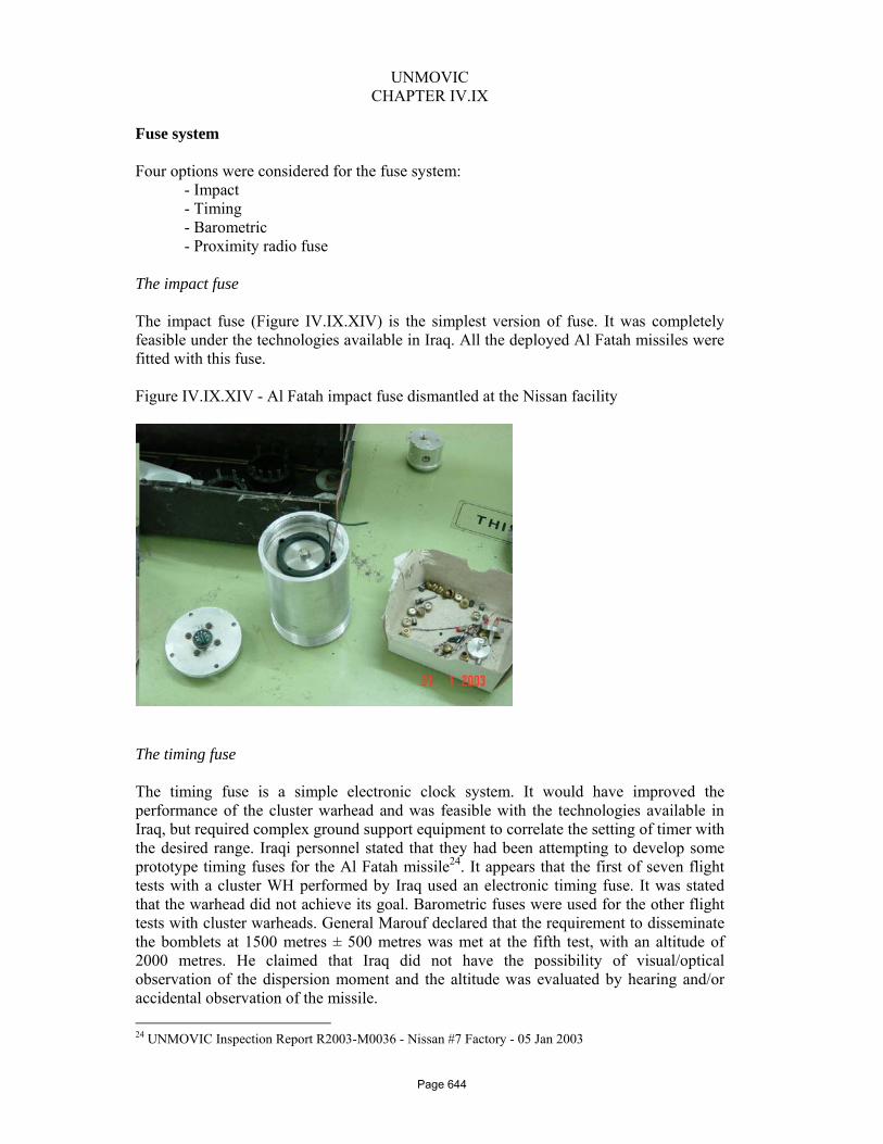
UNMOVIC
CHAPTER IV.IX
Fuse system Four options were considered for the fuse system: - Impact - Timing - Barometric - Proximity radio fuse The impact fuse The impact fuse (Figure IV.IX.XIV) is the simplest version of fuse. It was completely feasible under the technologies available in Iraq. All the deployed Al Fatah missiles were fitted with this fuse. Figure IV.IX.XIV - Al Fatah impact fuse dismantled at the Nissan facility
The timing fuse The timing fuse is a simple electronic clock system. It would have improved the performance of the cluster warhead and was feasible with the technologies available in Iraq, but required complex ground support equipment to correlate the setting of timer with the desired range. Iraqi personnel stated that they had been attempting to develop some prototype timing fuses for the Al Fatah missile24. It appears that the first of seven flight tests with a cluster WH performed by Iraq used an electronic timing fuse. It was stated that the warhead did not achieve its goal. Barometric fuses were used for the other flight tests with cluster warheads. General Marouf declared that the requirement to disseminate the bomblets at 1500 metres ± 500 metres was met at the fifth test, with an altitude of 2000 metres. He claimed that Iraq did not have the possibility of visual/optical observation of the dispersion moment and the altitude was evaluated by hearing and/or accidental observation of the missile. 24 UNMOVIC Inspection Report R2003-M0036 - Nissan #7 Factory - 05 Jan 2003
Page 644

UNMOVIC
CHAPTER IV.IX
During the inspection conducted at the Al Salam Company on 03 February 2003, the Director of the programme declared that he was tasked to develop a timer for Al Fatah fuses. The requirement was made by Nissan #7 Factory a year before. Only six timers were made and delivered during the previous year. They didn’t receive any feed back about the performance of the produced fuses. According to the declaration of the same engineer the Al Fatah timing fuse was a Printed Circuit Board (PCB) with a single 89C51 type microprocessor and one crystal clock of 12 Mhz frequency (Figure IV.IX.XV). The timer was programmable from 10 to 180 seconds. Iraq declared that the timer was inserted in a box with a kind of foam at Nissan #7 Factory. Figure IV.IX.XV - Al Salam Company timer for Al Fatah (03 Feb 2003)
Barometric fuse According to Iraq’s declarations only development studies were completed on this type of fuse. It was being kept as an option for the future to improve the precision of the altitude for cluster warhead initiation. Iraqi personnel stated that at least four flight tests of Al Fatah were performed in 2002 with a cluster WH and barometric fuse. Proximity fuses General Marouf stated25 that proximity fuses were to be used for the cluster warhead in the deployed system, while 7 Nissan Factory representatives insisted that such fuses were not being developed at this time. These conflicting statements were not clarified when UNMOVIC left Iraq in March 2003. The sites involved in fuse activities for Al Fatah are presented in Table IV.IX.IX.
25 UNMOVIC Inspection Report R2003-M0036 – Nissan Factory #7 – 05 Jan 2003.
Page 645

UNMOVIC
CHAPTER IV.IX
Table 9 IV.IX.IX - Sites involved in fuse activities for Al Fatah Type of Fuse
Mechanical parts
Electronic Parts
Comments
Impact Fuse For HE WH. Used in currently deployed missiles.
Electronic Timing Fuse (Electronic Programmable Fuse)
Nissan 7 Company
Al Salam Company
For Cluster WH. Used in the first test. No satisfactory result. Continuing R&D.
Barometric Fuse Nissan 7 Company
Waziriyah Company
For Cluster WH. In R&D. Some successes in flight.
Proximity Fuse None None Conflicting statements
Thermo-chemical battery Since Al Fatah missiles were deployed without a guidance section and associated battery, Iraq had to provide a power supply for the fuses. Because of the low energy requirement for the fuse, they chose a thermo-chemical battery for both Al Fatah impact and timing fuses. Photographs of thermo-chemical battery assembly are presented in Figure IV.IX.XVI and a technical drawing is presented in Figure IV.IX.XVII. Figure IV.IX.XVI - Al Fatah thermo-chemical batteries at Nissan #7 Factory
Page 646

UNMOVIC
CHAPTER IV.IX
Figure IV.IX.XVII - Technical drawing of Al Fatah thermo chemical battery
Guidance & Control Because the Al Fatah guidance and control system was under development and the results achieved were not good Iraq was looking to use a spin motor to stabilize the Al Fatah missile. Al Fatah spin motors were designed by the Al Ameen Company through reverse engineering of FROG-7 missile spin motors. One static test and four flight tests took place using a spin motor. The spin motor was placed forward of the motor case, similar to the FROG-7 rocket, which has a spin motor in place of an instrument section between warhead and motor section. There was no available information on the rotation speed projected or obtained. Since the flight tests failed, the programme was frozen but not abandoned. Due to the delay in development of a reliable guidance system for the Al Fatah, the section was replaced by an “adapter”. Iraq had planned to replace the “adapter” with the guidance system when available. Two different types of Al Fatah missile “adapters” were produced. The length of the adapter was: - 500 mm for the missile with a cluster WH;
- 400 mm for the missile with a HE WH.
The adapters (Figure IV.IX.XVIII) were manufactured only in Al Ameen and the total number produced (until January 2003) was 80 for the HE WH and 44 for the cluster WH. Five of the 44 adapters for cluster WHs were used in the tests. The rest (39) were sent to Al Ameen. For the technical description of the guidance and control section see chapter IV.XI.
Page 647

UNMOVIC
CHAPTER IV.IX
Figure IV.IX.XVIII - Al Fatah adapters (Al Ameen)
Al Fatah propulsion system The Al Fatah missile propulsion system was developed indigenously and its design was suitable for the production capability existing in Iraq at that time. The Fatah propulsion system consists of four main subsystems: igniter, motor case, propellant grain and nozzle which are presented Figures IV.IX.XIX and XX; they are described in the following paragraphs. Figure IV.IX.XIX - Al - Fatah motor in final assembly stage
Page 648

UNMOVIC
CHAPTER IV.IX
Figure IV.IX.XX - Al Fatah rocket motor technical drawing: Assembly Design.
Motor case The Al Fatah motor case was made of 30 CrMoV9 steel and consisted of three metallic cylinders made of 4mm thick sheets. After construction, the motor case was annealed and pressure tested and later delivered to the workshop where the insulation was applied. Iraq imported the 30CrMoV9 steel because it had no indigenous production capability. According to the interviews conducted at the Al Ameen factory26, R&D on motor cases started there at the end of 1999. Serial production (pre-production demonstrators) of motor cases began in early 2000. These motor cases were used for flight tests and minor modifications were made as a result of those flight tests. Detailed design changes were done on specific parts (such as nozzles and bolts) but these were all minor. Only the metallic part of the motor case was made at this facility. Plate was rolled and longitudinally welded to form a tube (Figures IV.IX.XXI and XXII). Three of these tubes were then circumferentially welded together and the end closures welded on to form the pre-machined motor tube. The welds were first tested using an X-Ray machine (Figure IV.IX.XXIII and XXIV) and then the tube was pressure tested (hydraulically) (Figure IV.IX.XXV). The tube rejection rate was 10% initially but in time was reduced to 5%. Al Ubour and Al Fatah motor cases are shown in Figure IV.IX.XXVI.
The main operations of the production process for the motor case were: • cutting the 4mm thick 30CrMoV9 steel sheets; • rolling and longitudinal welding;
26 UNMOVIC Inspection Report R2003-M0053 - Al Amen Factory - 15 Jan 2003
Page 649

UNMOVIC
CHAPTER IV.IX
• circular welding of cylinders; • x-ray inspection after each welding operation; • annealing (heat treatment to relieve the stress and improve the hardness); • sand blasting and then hydro-static test. Figure IV.IX.XXI- Al Ameen rolling machine Figure IV.IX.XXII - Al Ameen circular
welding machine
Figure IV.IX.XXIII- Al Ameen X-ray machine Figure IV.IX.XXIV-Al Ameen
annealing furnace
Figure IV.IX.XXV-Al Ameen hydrostatic test Figure IV.IX.XXVI - Al Ameen Al stand Ubour and Al Fatah motor cases
Page 650

UNMOVIC
CHAPTER IV.IX
In order to produce a much lighter structure, a study regarding the development of a filament wound motor case was started by Al Ameen (contracting it to Military Engineering College). General Marouf stated that he was not aware of this study and refused to admit any connection between it and the Al Fatah programme especially for any change in the motor case material. However the Military Engineering College carried out a technology demonstration programme. All know-how on this technology was to be handed over to Al Ameen Company. After achieving the goal of producing a carbon-epoxy composite motor case, it was expected that nozzles, fins and other components would be produced from composite material. Nozzle The nozzle was composed of two separate convergent and divergent steel sections and a high-density carbon throat. The steel parts were made from solid carbon steel rods and subsequently coated on the interior with thermal protection. The throat was manufactured from carbon rods on standard machine tools. The main operations for the production the Al Fatah nozzle were: • Cutting the metal pieces for divergent and convergent parts; • Forging the parts for divergent and convergent sections; • Welding together the two pieces of the divergent sections; • Machining (turning) and drilling the assembly holes; • Heat treatment; • Application of insulation. The nozzle is manufactured on standard machine tools. Some elements of the nozzle in manufacture are shown in Figures IV.IX.XXVII to XXX. Figure IV.IX.XXVII. Forged and welded Figure IV.IX.XXVIII. Machining divergent sections. divergent sections
Page 651

UNMOVIC
CHAPTER IV.IX
Figure IV.IX.XXIX - Divergent sections Figure IV.IX.XXX - Convergent sections after machining after machining
The motor case insulation The preparation of the motor case occurred at Al Mamoun27. The motor case and nozzle were completely inspected for acceptance when received from Al Ameen. The first step in the process of installing the insulation consisted of grit-blasting the interior of the motor case (manual operation) (Figure IV.IX.XXXI). After cleaning, the motor case was degreased (manual operation) using ethanol as solvent. Figure IV.IX.XXXI - Grit blasting of motor case – Al Mamoun
The insulation sheets (Figure IV.IX.XXXII) for the motor case and dome were completely produced at Al Mamoun (mixing the components, rolling to sheets, hot pressing), except one sheet of 2mm thickness, which was produced at Jaber Al Hayan.
27 UNMOVIC Inspection Report R2003-M0088 - Rasheed State Company – 04 Feb 2003
Page 652

UNMOVIC
CHAPTER IV.IX
The insulation was made from EPDM (ethylene propylene diene monomer). The insulation sheets were manually glued on the inside wall of the motor case. The manufacturing process for the insulation sheets is as follows: • The raw EPDM rubber was cut into very small pieces and mixed with other minor ingredients (except the curing agent) in a horizontal mixer; • The mixture was then sent to a rolling machine where the curing agent was added; • The crude sheets underwent a process of hot pressing into molds (for cases and dome). Figure IV.IX.XXXII - Insulation sheet before and after hot pressing – Al Mamoun
The thickness of the insulation for Al Fatah motor case varied depending on its position and the temperature that it had to withstand, for example, the dome insulation was thicker in the central part and decreased on the edge. Before cutting to final dimensions to fit the Al Fatah motor case, the insulation sheet dimensions were 80 x 80cm or 80 x 100cm with 4mm thickness. The insulation was then bonded inside the case using epoxy resin. No special tools were used for laying the insulation inside the case; the job was done manually.
The liner was applied just before casting. The liner composition was similar to the propellant composition but without the solid components (such as APC, aluminum and ferric oxide). Application was done manually by qualified personnel. The case was suspended vertically then the liner material was applied to a ball of rag secured to the end of a long rod and ‘swabbed’ onto the interior walls on the insulated case. The process took 4-5 hours to be completed and it was very difficult to obtain a complete, uniform coating of the liner material using this technique. After lining, the insulated motor case was inserted into the casting chamber and the mandrel was put in place before propellant casting. Comment. Automated grit-blasting and degreasing units were considered. Reportedly, a grit-blasting machine and a degreasing bath should have been operational in two or three months.
Page 653

UNMOVIC
CHAPTER IV.IX
Nozzle insulation At Al Qadissiyah, a batch of insulation mixture was prepared, consisting mainly of epoxy resin and flakes of carbon fibre. The mixture was then pressed into moulds for both convergent and divergent sections of the nozzle. When cured, the moulded parts were sent to Al Mamoun where they were bonded into the nozzle components (convergent and divergent). For the bonding operation a mixture of epoxy resin (EPON) and graphite powder was used. Then the bonded insulation was machined to the final dimensions. An insulated nozzle convergent section is shown in Figure IV.IX.XXXIII. Figure IV.IX.XXXIII – Moulded insulation for convergent nozzle section.
Nozzle throat The Al Fatah nozzle throat was made from imported high-density graphite rods or blocks. Preliminary machining was done on lathes (Figure IV.IX.XXXIV) then the graphite throat was bonded into the AG-4 bushing (AG-4 bushings were received from Al Qadissiyah). The machining to the final dimensions was also carried out on a lathe. Then the nozzle components were finally assembled (Figure IV.IX.XXXV). Figure IV.IX.XXXIV - Throat machining on lathe
Page 654

UNMOVIC
CHAPTER IV.IX
Figure IV.IX.XXXV - Insertion of carbon throat in the nozzle
Note: The same insulation composition is also used for other rocket nozzles such as Al Nida and Al Ubour. The composite propellant grain A view of the section of the Al Fatah motor grain (3 stars) is shown in Figure IV.IX.XXXVI. Figure IV.IX.XXXVI - Al Fatah Motor Grain
Page 655

UNMOVIC
CHAPTER IV.IX
Propellant composition The Al Fatah composite propellant declared28 by Iraq was a typical HTPB/AP formulation with added aluminium fuel. On 23 January 2003, UNMOVIC took a sample of cured propellant from the grain former of a cast motor and analyzed it29. The results of the analysis were consistent with the data declared by Iraq. With this propellant, Iraq declared a specific impulse of 238 seconds for the Al Fatah motor. Raw materials used for composite propellant production During one inspection30 while observing the casting process, UN inspectors held technical discussions with the process engineer. The following information was provided: • The raw materials, including the ammonium perchlorate (APC), polybutadiene rubber (HTPB), aluminum, cross-linking agent (MAPO), and curing agent (TDI) were all imported from foreign sources. • Iron oxide was sometimes used as a burn rate modifier, though it was not clear if the Iraqi engineer was specifically referring to the Al Fatah, or another system. • Burn rates for each motor produced were verified using small samples cast on the side during the production process. If a significant deviation in burn rate was observed, the nozzle throat of the motor was modified to achieve the desired thrust level. Comment. Iraq declared imports of ammonium perchlorate and other raw materials. Iraq had also built an industrial plant for the production of ammonium perchlorate. The quantity produced and used by Iraq between 1998 and 2002 is unknown and difficult to assess. During inspections31, additional details such as quantities of material and names of Iraqi companies involved were provided by Iraq. During an inspection on 26 December 2002, Iraq declared the importation of the following quantities of raw materials:
Aluminium Powder HTPB
MAPO
45 tonnes 64.86 tonnes 2 tonnes 55 tonnes 20 tonnes 20 tonnes
Documents found by UNMOVIC in the offices of one Iraqi front company revealed information related to the suppliers of some of the declared materials. It appears that
28 UNMOVIC Inspection Report R2002-M0026 - Al Rasheed State Company - 26 December 2002 and UNMOVIC Inspection Report R2003-M0072 - Al Mamoon - 29 January 2003. 29 Report DSTL (UK) FEL/14/03 “The Analysis of a propellant on behalf of UNMOVIC” by Sean Doyle – February 2003. 30 UNMOVIC Inspection Report R2003-M0041 - Al Mamoon - 08 Jan 2003. 31 UNMOVIC Inspection Report R2002-M0026 - Al Rasheed State Company - 26 Dec 2002.
Page 656

UNMOVIC
CHAPTER IV.IX
Iraq used a middleman and imported a significant quantity of materials32 through this network. The following information was revealed.
Name of product Quantity Price per tonne in
US dollars 1- Ammonium perchlorate 400 µm
20 tonnes 16,786,000
2 - Ammonium perchlorate 200 µm
160 tonnes 16,786,000
3 - Ammonium perchlorate 80 µm
20 tonnes 16,786,000
4 – HTPB 40 tonnes 35,508,000 Production of ammonium perchlorate (APC) An APC production plant33 at Al Mutassim was in construction prior to the 2003 Gulf War. Reportedly, APC production plant construction and equipment installation were started in January 2001 and in January 2002 respectively. Iraq stated that the design and procurement of the production equipment was done by Al Rasheed from a foreign company. All the production machines were new and of good quality, being constructed mainly of highly polished stainless steel. The control rooms were equipped with sophisticated control panels. This site belonged to Al Rasheed Company. The APC plant tried to produce a pilot lot of 900 kg of APC but failed due to technical problems. Conditioning / grinding of APC The sizes of APC particles used in Al Fatah motor were 50-60 µm and 200 µm. Two grinders were available in Iraq, one of 15-micron particle size with a capacity of 300 kg per 6 hours, and a second one of 7-11 micron particle size with a capacity of 10 kg in 10 hours with a fixed rpm value. Iraq stated that no back-up grinder was available. Iraq managed to grind enough AP for the five batches required for each Al Fatah motor in a six hour period with the one grinder. Another grinder had only laboratory scale capacity. Equipment to analyze the AP was considered adequate by Iraqi personnel and any errors were compensated by the fact that the ground AP for five batches was blended, and then split into five homogenous lots. Mixing The two 1200 litre (300 gallon) mixers provided for the BADR-2000 were destroyed by Iraq under UN supervision in the early 1990s so, afterwards, the only non-proscribed and available mixer in Iraq was one 120 litre (30 gallon) mixer. However, Iraq was able to manufacture small dimension composite propellant mixers and two more 120 litre mixers,
32 Bashair trading Co file 12 (internal document).
33 UNMOVIC Inspection Report R2003-M0093 - Rasheed State Company - 05 Feb 2003.
Page 657

UNMOVIC
CHAPTER IV.IX
indigenously produced, had been installed at Al Mamoun. (One was fully operational and the other had vacuum and dripping oil problems.) The first mixer was used for pre-mixing of the raw materials (ammonium perchlorate, HTPB and aluminium powder). Then, the pre-mixed materials were transported in the bowl to another building which also contained a 120 litre mixer and where the curing agent (TDI) was added. After 5-8 minutes of mixing the bowl was transferred to the casting chamber located close to the mixer. In the mean time, the mixer blades were cleaned and the mixer prepared for the next pre-mixing bowl, which was standing nearby. The Al Fatah and Al Ubour motors required respectively 5 and 6 or 7 mixer bowls (120 litre) depending on the configuration of the mandrel and the left over material in the mixing bowls. A mixer and 120 litre bowl are shown in Figures IV.IX.XXXVII and XXXVIII. Figure IV.IX.XXXVII - A 120 litre bowl used for Al Fatah motor production – Al Mamoun
Figure IV.IX.XXXVIII - A 120 litre three-blade mixer used for Al Fatah motor production – Al Mamoun
Page 658

UNMOVIC
CHAPTER IV.IX
Al Fatah mandrels Four Al Fatah mandrels pieces were declared; three pieces were at the main site at Al Mamoun (one of them under maintenance) and one piece at an alternative site near Al Mutassim. This quantity of mandrels allowed a maximum output of 8 - 9 cast motors per month. During a meeting with UNMOVIC on 26 December 2002, General Marouf stated34 that the mandrel with a 5-point star grain configuration used for the Ababil-100 in 1998 was used for the first three Al Fatah motors used in flight tests. Later this mandrel was replaced by a simpler 3-point star design and all the Al Fatah motors beginning with flight test four had this configuration. Allegedly, the change was made to increase the motor’s volume fraction. The first static test to validate the 3-point design was conducted on 5 February 2001. The time needed to implement the new 3-point design explained in part the 5-month period between the third and the fourth flight tests. The mandrel had a semi-permanent coating of car paint, which was sprayed with Teflon before introducing it into the motor case to facilitate its removal after the propellant has cured. Mandrels (5 stars and 3 stars) used for Al Fatah are shown in Figure IV.IX.XXXIX. Figure IV.IX.XXXIX - On the left, old (5 stars) and on the right new (3 stars) Al Fatah mandrels - Al Mamoun
34 UNMOVIC Inspection Report R2003-M0033 – Al Fatah Site – 02 Jan 2003.
Page 659

UNMOVIC
CHAPTER IV.IX
Casting There were five casting chambers located in Al Mamoun. One is shown in Figure IV.IX.XL and a schematic diagram is given in Figure IV.IX.XLI. Figure IV.IX.XL - Casting Chambers – Al Mamoun
Figure IV.IX.XLI. – Schematic diagram of casting chamber
30 GALLON BOWL END CLOSURE
ADMISSION OF NITROGEN
SEPARATION PLATE/PISTON
VALVES
CASTING/CURING PIT
MOULD = CASE + MANDREL
Propellant
Vacuum
Page 660

UNMOVIC
CHAPTER IV.IX
Technical description of the Al Fatah Casting Process According to Iraq, the casting process was as follows. The motor chamber was kept under vacuum during the casting operation to minimize bubble formation in the propellant grain and to promote the flow of propellant from the mixing bowl to the motor case. The motor case was in the casting chamber equipped with the mandrel. After the first mixing bowl was emptied completely in the motor case, the mixing of a second bowl was immediately started. After several minutes of mixing, the second bowl was delivered to the casting area and the process described above was repeated. The casting process used for Al Fatah motor production combined the forces of both gravity and vacuum: vacuum was achieved by pumping down the chamber until the manometer reached a value of zero. The level of vacuum obtained was not known. A rigid plate was mounted on the mixing bowl to separate the ambient air from the propellant. The plate also aided in the gravity feed process. If the viscosity of the propellant being cast was too large, and the propellant flow into the motor case was disrupted, nitrogen gas was pumped into the mixing bowl to increase the differential pressure. The casting mandrel was coated with car paint and according to the process engineer on-site, the mandrel was sprayed with Teflon to prevent the propellant from adhering to the mandrel and to facilitate removal after the propellant has cured35. Casting of the Al Fatah required five bowls, each of them containing roughly 180 kg of composite propellant; about 10 kg of residual propellant remained in each bowl. The burning rate for some systems was adjusted by adding iron oxide after a check of AP particle size. Samples of propellant were cast into separate vessels for verification of burning rate and mechanical properties. If a deviant burn rate was obtained, the motor’s nozzle throat diameter was adjusted to achieve the desired ballistic performance. Curing After the casting had been completed, the motor remained in the casting chamber for six to seven days for curing. If the casting chamber was needed to support higher production rates (that is, more than one per week), the motor could be removed from the casting chamber after three days; the cure was completed in a separate building. The maximum production rate for Al Fatah motors appeared to be one every three or four days, according to Iraqi production records. This rate required optimal efficiency for several independent processes. Under UNMOVIC monitoring, Iraq was producing only one motor per week.
35 UNMOVIC Inspection Report R2003-M0041 – Al Mamoun – 08 Jan 2003.
Page 661

UNMOVIC
CHAPTER IV.IX
X-Ray control Iraq had demonstrated the ability to successfully cast composite propellant motors for the Al Fatah missile. After curing, the motors were X-rayed to check for defects. Iraq stated that they had never cast a motor that was subsequently rejected at final X-ray. They did hasten to add that this might have been due to their inability to detect defects, other than those on the surface, due to limitations of the X-ray equipment being used. Further, their X-rays were unable to determine if an de-bond condition existed between the insulation and the case or between the propellant and the insulator. They were also unable to detect bond lines between the five batches of propellant, or ‘swirls’ in the propellant and indications of insufficient mixing of the curatives added to the batches of propellant. Igniter The igniter was a pyrogen type (essentially a small rocket motor, utilizing a small propellant grain). It was produced in Al Mamoun for the Al Fatah missile. Its case and closures were manufactured by flow forming. The internal diameter of the motor case was then insulated at Al Mamoun, and the propellant grain was cast and moulded in the case. Al Qaa Qaa provided the initiator to ignite the igniter grain. The sections were held together by means of a screw thread. The exterior of the igniter case was also insulated at Al-Mamoun. A drawing and a photograph of the Al Fatah motor igniter are presented on Figure IV.IX.XLII. Figure IV.IX.XLII - Al Fatah motor igniter
Fin carrier The fin carrier was a metal sub-section. It consisted of a cylinder, which supports four aerodynamic fixed fins. The assembly was made using rivets. The fin carrier section was then sent to Al Mutassim for final assembly on the Al Fatah missile. Photos of the Al Fatah fin carrier are presented on Figure IV.IX.XLIII.
Page 662
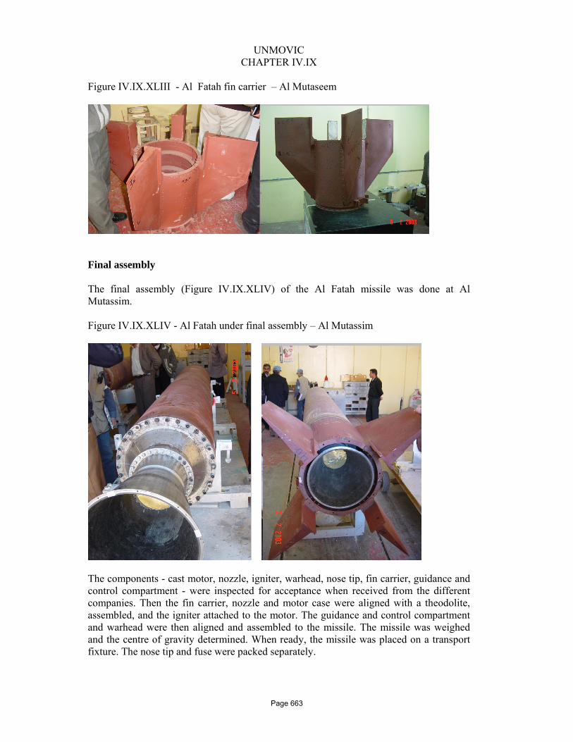
UNMOVIC
CHAPTER IV.IX
Figure IV.IX.XLIII - Al Fatah fin carrier – Al Mutaseem
Final assembly The final assembly (Figure IV.IX.XLIV) of the Al Fatah missile was done at Al Mutassim. Figure IV.IX.XLIV - Al Fatah under final assembly – Al Mutassim
The components - cast motor, nozzle, igniter, warhead, nose tip, fin carrier, guidance and control compartment - were inspected for acceptance when received from the different companies. Then the fin carrier, nozzle and motor case were aligned with a theodolite, assembled, and the igniter attached to the motor. The guidance and control compartment and warhead were then aligned and assembled to the missile. The missile was weighed and the centre of gravity determined. When ready, the missile was placed on a transport fixture. The nose tip and fuse were packed separately.
Page 663

UNMOVIC
CHAPTER IV.IX
Aging Studies No accelerated aging studies were performed on this missile prior to its deployment to the field. According to Iraq, the static tests were all conducted at ambient conditions. No physical property tests were done on the bond line between the different batches of propellants. Refurbishment of equipment Iraq declared36 it had manufactured new solid propellant mixers based on the reverse engineering of the mixer they possessed in 1998. The declaration was consistent with what UNMOVIC observed during the inspections. Iraq also provided37 information regarding the refurbishment of equipment from the former BADR-2000 programme, such as casting chambers and sand blasting machines. This equipment was previously “rendered harmless” under UNSCOM supervision since the BADR-2000 fell under the prohibition set by Security Council resolution 687 (1991). Iraq declared its intention to use this equipment in its current missile programmes (i.e. the Al Fatah, Al Nidaa and Al Ra’ad). Iraq initially stated that the casting chambers used for Al Fatah were procured from abroad but later asserted that they were the ones provided for BADR-2000 and “rendered harmless” under UNSCOM supervision. These chambers were then refurbished and modified by reducing the length from eight metres to six metres. Iraq insisted that the 6-metre length was needed for the casting of an Al Ubour motor. Iraq also stated that the sand blasting machine was the refurbished one “destroyed” under UNSCOM supervision. UNMOVIC also asked about the origins of other equipment in Al Ameen and the lathe machine in the Military College of Engineering which was repaired and transformed into a winding machine. A complete list of all the equipment that Iraq had refurbished was subsequently submitted to UNMOVIC38. The list is presented in the Table IV.IX.X.
36 Missiles Semi-annual declaration July 2002. 37 Missiles Semi-annual declaration July 2002 and CAFCD 2002 Vol. 1. 38 NMD Letter 2-1-M-138 - 28 January 2003.
Page 664

UNMOVIC
CHAPTER IV.IX
Table IV.IX.X – List of former proscribed equipment refurbished by Iraq
Page 665

UNMOVIC
CHAPTER IV.IX
UNMOVIC determined that the refurbished casting chambers had to be destroyed by Iraq under Commission supervision. The destruction of the casting chambers was achieved in several phases39:
• Cutting superstructure over the chambers and the fixtures; • Extraction of the chambers from the pits; • Cutting of the chambers and lids by oxygen torch and electrical torch; • Pouring concrete inside each casting pit to shorten it to 4.0 metres depth; • Transporting of chamber remnants to a hole dug inside Al-Mutassim factory at
about 200 metres from the main gate; • Covering these remnants with concrete.
All these operations were completed under UNMOVIC supervision, from 1 to 6 March 2003. A selection of photographs is presented in Figure IV.IX.XLV.
39 UNMOVIC Inspection Report R2003-M0168 – Al Mamoun – 1 to 6 March 2003.
Page 666

UNMOVIC
CHAPTER IV.IX
Figure IV.IX.XLV – Destruction of casting chambers
�
Page 667

UNMOVIC
CHAPTER IV.IX
Al Fatah Static Tests Between 1998 and 2003, Iraq declared that it conducted 10 static tests on full-scale motors. Figure IV.IX.XLVI shows the nozzle insulation before and after a static test. Figure IV.IX.XLVI - Nozzle and insulation layer before (left) and after (right) static test – Al Mutassim
All static tests were conducted at Al Mutassim on test stand No. 4. Due to the lack of equipment available at Al Mutassim only the diagram of thrust and pressure were recorded during the Al Fatah motor tests and provided to UNMOVIC by Iraq.
Page 668

UNMOVIC
CHAPTER IV.IX
Flight Tests Thirty three (33) flight tests were declared to have been conducted in the absence of UN inspectors during the period 2000 – 2002. The results were declared as shown in Table IV.IX.XI. Table IV.IX.XI – Al Fatah flight test results
Date ofLaunch
MissileNumber
Type ofMissile
FlightTest
Results
Type ofWarhead
Mass ofWarhead
(kg)
Mass ofPropellant
(kg)
Lift of massof Missile
(kg)
Length ofMissile(mm)
CGLocation
(mm)
ThroatDiameter
(mm)
Calculated range
(km)
Range fromlauncher foreach body
Remarks
1-Sep-00 F6 Unguided Failure Dummy 251.0 755.5 1,525.0 6,887.0 3,940.0 118.0 88.0 4.023-Oct-00 F8 Unguided Success Dummy 250.0 763.8 1,530.0 6,958.0 3,985.0 122.0 88.0 83.418-Nov-00 F9 Unguided Success Dummy 241.8 773.9 1,500.0 6,955.0 3,980.0 118.0 145.0 Not found17-Mar-01 F11 Unguided Success Dummy 260.0 863.0 1,560.0 7,200.0 4,130.0 117.0 145.0 117.727-Mar-01 F12 Unguided Success Dummy 261.0 860.5 1,640.0 7,365.0 4,070.0 116.0 145.0 133.029-Apr-01 F13 Controlled Failure Dummy 258.3 862.0 1,649.0 7,365.0 4,070.0 116.0 145.0 88.030-May-01 F14 Controlled Failure Dummy 260.0 862.0 1,649.0 7,367.0 4,100.0 118.0 145.0 7.08-Aug-01 F17 Unguided Success Dummy 261.0 886.0 1,652.0 7,351.0 4,059.0 118.0 145.0 161.0
8-Aug-01 F18 Unguided Failure Dummy 261.0 873.0 1,704.0 6,854.0 3,907.0 119.0 145.0 6.0 A spin motor wasused.
22-Aug-01 F19 Unguided Failure Dummy 261.5 864.0 1,668.0 7,344.0 4,100.0 118.0 145.0 7.0Frontal fins
(canard) wasused.
6-Sep-01 F20 Unguided PartialSuccess
Dummy 267.6 818.0 1,690.0 6,855.0 3,870.0 117.0 145.0 103.0
3-Nov-01 F21 Unguided PartialSuccess
Dummy 280.0 840.0 1,726.0 7,142.0 4,086.0 122.0 145.0 90.0
22-Nov-01 F23 Unguided Success Dummy 282.0 845.0 1,593.0 6,754.0 3,215.0 125.5 145.0 134.015-Dec-01 F24 Unguided Success Dummy 280.0 843.3 1,581.0 6,770.0 3,210.0 122.0 145.0 161.0
5-Dec-01 F22 Unguided Success Dummy 229.2 838.0 1,656.0 7,179.0 3,780.0 119.5 145.0 103.0 A spin motor wasused.
18-Dec-01 F25 Unguided PartialSuccess
Dummy 275.8 831.0 1,585.0 6,754.0 3,620.0 119.0 145.0 Not found
R-40 ControlCanard was
A spin motor wasused.
Page 669

UNMOVIC
CHAPTER IV.IX
Date ofLaunch
MissileNumber
Type ofMissile
FlightTest
Results
Type ofWarhead
Mass ofWarhead
(kg)
Mass ofPropellant
(kg)
Lift of massof Missile
(kg)
Length ofMissile(mm)
CGLocation
(mm)
ThroatDiameter
(mm)
Calculated range
(km)
Range fromlauncher foreach body
Remarks
20-Dec-01 F26 not mentioned Success Dummy 277.6 831.0 1,588.0 6,766.0 3,620.0 121.0 145.0 158.026-Jan-02 M24 F37 not mentioned Success Combat 282.0 827.0 1,595.0 6,757.0 3,625.0 116.9 145.0 151.0
14-Mar-02 F39 not mentionedPartial
SuccessCluster 286.8 822.7 1,603.0 6,888.0 3,793.0 117.0 145.0 143.0 Warhead did not
achieve its goal.22-Apr-02 M55 F46 not mentioned Success Cluster 284.4 828.0 1,579.0 6,676.0 3,782.0 118.0 145.0 147.09-Jun-02 F59 not mentioned Failure Combat 280.0 821.0 1,560.0 6,757.0 3,646.0 117.0 145.0 Not found9-Jun-02 F60 not mentioned Failure Cluster 286.0 827.0 1,585.0 6,829.0 3,735.0 117.0 145.0 Not found
22-Jul-02 M71 F67 Unguided Success
Combatw ith
explosivematerial of
12 kg
272.0 828.0 1,578.0 6,757.0 3,631.0 118.9 145.0 145.0Front & Fixed fins
were used.
18-Aug-02 M78 F75 not mentioned Failure Cluster 286.3 828.0 1,591.0 6,829.0 3,707.0 117.9 145.0 4.022-Aug-02 M90 F76 not mentioned Success Combat 272.2 826.0 1,561.0 6,761.0 3,645.0 119.0 145.0 145.024-Aug-02 M80 F74 not mentioned Success Cluster 282.9 827.0 1,585.0 6,829.0 3,724.0 118.5 145.0 151.130-Sep-02 F70 not mentioned Success Combat 273.2 828.0 1,561.0 6,865.0 3,625.0 116.8 145.0 158.230-Sep-02 F79 not mentioned Success Combat 274.9 832.0 1,561.0 6,856.0 3,645.0 116.8 145.0 154.430-Sep-02 F80 not mentioned Failure Combat 273.9 829.0 1,557.0 6,761.0 3,642.0 117.0 145.0 114.628-Oct-02 M90 F84 not mentioned Success Combat 278.2 831.0 1,612.0 6,754.0 3,594.0 118.0 145.0 147.028-Oct-02 M87 F78 not mentioned Success Combat 275.2 828.0 1,605.0 6,761.0 3,614.0 118.0 145.0 151.125-Nov-02 F43 not mentioned Success Cluster 298.5 825.0 1,615.0 6,828.0 3,677.0 119.5 145.0 131.025-Nov-02 F44 not mentioned Success Cluster 301.0 822.0 1,620.0 6,828.0 3,685.0 114.0 145.0 139.0
Page 670

UNMOVIC
CHAPTER IV.IX
As of March 2003, 33 flight tests and 10 static tests of Al Fatah Missile had been carried out and many missiles were deployed to the Armed Forces. Among the 33 flight tests (Table IV.IX.XI) conducted during the period 2000-2002, eight exceeded the permitted range of 150 km (pink color in Table IV.IX.XI) as admitted by Iraq in their semi-annual monitoring declarations. An international panel of missile experts convened by UNMOVIC in February 200340 concluded that it needed further information on the Al Fatah missile in order to make a final decision on the missile’s inherent capabilities. UNMOVIC asked Iraq to suspend any flight test of the system while this information was sought. The programme manager, General Marouf, was asked to provide additional information on the missile system. He claimed that the Al Fatah missile was still in the development phase, and its performance characteristics were still being studied and optimized. In March 2003, he stated, the final configurations for the unguided and guided versions of the Al Fatah had not been established. Only the unguided version had been deployed to the Army. However, General Marouf insisted that once the Al Fatah would be in mass production, the maximum range would be 145 km, with a warhead mass of between 260 and 320 kg (HE and cluster warhead). General Marouf added that the inert mass of the Al Fatah was not the same for each test that had been conducted. For example, additional insulation material was added during the testing phase, which decreased the total propellant load by 50 kg. Later, General Marouf provided the historical log of the flight tests (presented in Table IV.IX.XI), and detailed information on the inert mass of all components and the propellant mass. UNMOVIC was in the process of analyzing the missile configuration when its inspectors were withdrawn from Iraq in March 2003. Al Fatah Accounting On 19 March 2003, UNMOVIC inspectors had accounted for the possible production of up to 101 Al Fatah motors. According to Iraq’s declarations, 52 were consumed either in tests or destructions between 1999 and 2003. Iraq had declared 37 Al Fatah missiles deployed in the Armed Forces. These missiles were ready for combat use. In addition, in March 2003, Iraq had 12 motors in different stages of production. UNMOVIC has no information on the production status of these motors. UNMOVIC conducted a full accounting41 of all Al Fatah missiles produced and had tagged most of the declared motors or assembled missiles before its inspectors were withdrawn in March 2003.
40 Panel convened in New York HQ, 10 – 11 February 2003. 41 Accounting of Al Fatah Missile System, 10 November 2003 (internal document).
Page 671

UNMOVIC
CHAPTER IV.IX
Al Fatah launcher When launched as a rocket, the Al Fatah had increased requirements for its launch platform. Precise settings for the angles of elevation and azimuth were essential for achieving a reasonable CEP. Indigenous production capabilities were poor and it was, therefore, almost impossible for Iraq to develop a new, indigenous launcher in two years. It was easier for Iraq to modify SA-2 launchers in order to accommodate the Al Fatah missile. The SA-2 launcher was able to withstand the weight of the Al Fatah, it provided the required high precision in orientation and was easy to modify. The main modifications on the SA-2 launcher (Figure IV.IX.XLVII) were the welding of the “beam breaking mechanism” and the extension of the arm in order to minimise the drop of the missile when it left the beam. (Due to its low velocity, the aerodynamic lift force could not compensate for the weight of the missile. The higher initial impulse of the SA-2 provided a smaller drop angle than for the Al Fatah.) Iraq declared that after several launch tests using the rail on the launcher they switched to launch from a canister. This declaration is consistent with the videos submitted by Iraq. Canisters were used for the first time to launch an Al Fatah on the 8th flight test (8 August 2001), and from the 15th (5 Dec 2001) all flight tests were performed using a canister. Concerning the elevation angle, General Marouf declared that the elevation angle chosen was 67 degrees in order to achieve an angle of 61 degrees after the missile dropped as it left the launcher. The guidance and control programme manager, however, declared that the optimum launching angle was 61 degrees. UNMOVIC calculated that 57 degrees elevation would be the optimum angle for maximum range, assuming 3-4 degrees of drop after leaving the beam or the canister. To give mobility to the launcher, Iraq produced two different versions of an Al Fatah mobile launcher. The first one used a tank transport trailer (Figure IV.IX.XLVIII) and the second one used the bed of a truck (Figure IV.IX.XLIX). Both of them were observed during inspections in the Al Feeda Hydraulics Factory. Figure IV.IX.XLVII - SA-2 modified launcher (left - with support for canister; right - detail of welded breaking mechanism) - Al Feeda, 21 11 2002
Page 672

UNMOVIC
CHAPTER IV.IX
Figure IV.IX.XLVIII – SA-2 modified launcher on the tank transport trailer.
This modified SA-2 launcher observed at Al Feeda on 21 Dec 2002 could have been an Al Fatah launcher (without canister). The beam was extended, the beam breaking mechanism welded and the gas deflector removed. Figure IV.IX.XLIX- SA 2 modified launcher (support for canister) on the bed of a truck - Al Feeda, 21 Nov 2002
Command and control vehicle (ground support equipment) Iraq declared that the command and control vehicle used for the Al Fatah had the same hardware structure as the one for Al Samoud-2; the only difference was in the software. Without any guidance and without thrust termination control (end of burning control) the
Page 673

UNMOVIC
CHAPTER IV.IX
Al Fatah was a rocket. Thus, the required data for launch consisted of an elevation angle and the azimuth angle.
Comment. From its observations, UNMOVIC confirmed that Iraqi engineers and scientists had a growing understanding and knowledge of solid propellant engine technology. They used this knowledge as a basis in their design, development, production and testing of their indigenous solid propellant missiles. The Al Fatah is proof that Iraq had made substantial progress in this type of technology and was able to design a good solid propellant missile. From the early 1990s, Iraq had two technology projects, the Al Samoud liquid propellant engine and the Ababil-100 solid rocket motor. The two programmes had varying priority during the 1990s according to the manager, but the two programmes were probably pursued to maintain the competence of the personnel in liquid engines and solid propellant. At the end of the 1990s, the progress made in liquid propellant engines was greater than in solid propellants. The main reason was that at the beginning Iraq started to develop the Al Samoud by using components available in Iraq; they produced only the airframe and integrated SA-2 components. The Ababil-100 project was more ambitious. It was not possible for Iraq to use the grain of another available missile in the manufacture of a new solid propellant missile; a new grain had to be developed. This was a real challenge due to the lack of knowledge and experience of the personnel and lack of specific tools (mandrel) and equipment (mixers of the right size). During this period, the guidance and control of the Ababil-100 solid propellant motor programme was not a priority. When the UN inspectors returned to Iraq in 2003, the Al Fatah missile was in mass production and 37 were deployed in the Army as rockets (without guidance and control systems). However, the guidance and control system was still under development. In 4 years, in the absence of UN inspectors, Iraq managed to develop a solid rocket motor, while during nearly 10 years in the presence of UN inspectors they did not manage to make any significant progress on Ababil-100.
Page 674

UNMOVIC
CHAPTER IV.IX
Ababil-50 Project/Al Nidaa Iraq’s Ababil-50 MLRS was first displayed publicly in 1998, at an Iraqi defence exhibition. In 1980, Iraq signed a contract with a foreign company on the joint development of a double-base propellant Multiple Rocket Launcher System (MLRS) with a maximum range of 50 km. The ballistic calculation showed that a calibre larger than 122mm would be required for achieving such a range. Also Iraq planned to produce a complete system that would include command, meteorological, supply, observation and other ground support vehicles. As a part of the joint programme contract, Iraq received several hundred Ababil-50 rockets from its contract partner before 1990. In addition, according to the same contract Iraq received the production documentation, know how and assistance to manufacture its own Ababil-50 rockets and launchers. When UNMOVIC arrived in Iraq in 2002, Iraq had started to convert double-base propellant Ababil-50 rockets into a composite propellant rocket named Al Nidaa. Ababil-50 system The Ababil-50 system is a 262mm 12-barrel rocket system mounted on a heavy truck chassis. The overall length of all rockets is 4.656 metres. The rocket has a maximum range of 50 km. By the opening and closing of four different types of aerodynamic brakes, four different ranges can be attained: 24, 28, 37 and 50 km. The probable dispersion at maximum range is claimed to be 220 metres in range and 175 metres in azimuth. The two-stage rocket motor used double-base propellant. The booster stage used 10 kg of propellant and burnt for 200 ms to generate 8,000 kg of thrust to propel the rocket clear of the launch tube. The second (sustainer) motor then cut in to burn for five seconds and generate 18,000 kg of thrust to produce a maximum velocity of 1,200 m/s. The time of flight to maximum range was 110 seconds. Two types of warhead were developed for this MLRS. The first one was an Armour-Piercing High-Explosive (APHE), with an inertial-type impact fuse with Super Quick (SQ) or graze action. This type of rocket weighed 389 kg and the warhead weighed 91 kg. The second one was a cargo/cluster warhead containing 288 dual-purpose bomblets. The rocket also weighed 389 kg, with the warhead weighing 91 kg. Each bomblet had a shaped anti-armour charge capable of penetrating over 60mm of armour, while the anti-personnel fragmentation effects were augmented by approximately 420 small steel spheres which are scattered, along with the usual bomblet fragments, over a lethal radius of 10 metres. This warhead contained an Electronic-Time (ET) fuse. In early 1990, Iraq started to work on the Ababil-50 missile and launcher. The main technologies involved in manufacturing the Ababil-50 were lathe machining, welding and flow forming for the metal parts, and double-base extrusion for the propellant. The Al Nidaa State Establishment was tasked in March 1992 to produce dies, moulds and parts for the rocket system and on 22 August 1993 they received 56 drawings to achieve this work. However, according to the declarations of the Director General of Al Nidaa in
Page 675

UNMOVIC
CHAPTER IV.IX
1997, this project had only a medium priority and the work was never completed and was stopped in 1995 when the Ibn Al Haitham and Al Karama establishments merged.42 According to an engineer, Al Nidaa had received materials from the Tho Al Fekar Mechanical Plant of the Al Rasheed State Establishment to produce parts for the Ababil-50. In March 1997, Al Nidaa received a high priority for its Ababil-50 work from the Mechanical Plant. In response, Al Nidaa changed the location of some of its machines. At the end of 1997, the final assembly of the Ababil-50 rocket was eventually located in Al Mutassim State Establishment, where it was in March 2003 (Figure IV.IX.L and LI). The Al Fedaa Hydraulic Factory produced and assembled equipment for the Ababil-50 rocket. In addition, Al Fedaa was tasked to produce fixtures and tools for maintenance and life extension for the Ababil-50. The Director General of the Al Fedaa Hydraulic Factory stated that when the shelf life for the rockets expired they would need to be disassembled for testing and for substituting expired elements. The Al Qaa Qaa Double-base Production Plant was in charge of producing the double-base grains for the Ababil-50 booster and sustainer. MIC also tasked the Al Fedaa Hydraulic Factory in 1997 to study the possibility of producing the launcher for the Ababil-50. When UNSCOM left Iraq in December 1998, the project was still on-going. By that time the Ababil-50 project was about 12 years old and the establishments involved had not yet succeeded in producing and integrating all the sub-systems43. The main characteristics of the Ababil-50 are presented in the Table IV.IX.XII. Table IV.IX.XII - Main characteristics of the Ababil-50
Parameters Ababil-50 System Total length (mm) 4656 Diameter (mm) 262 Propulsion System Solid rocket motor Type of Warhead HE / Cluster Warhead section mass (kg) 91 Liftoff mass (kg) 389 Maximum Range (km) 50 Launch Equipment Multi-tube launcher Assumed CEP (m) 220 Propellants Type Extruded double-base Booster /Sustainer Mass (kg) 10 / 130 Performance Average Thrust (daN) 18000 Burn time Booster (s) 0.2 Burn time Sustainer (s) 5
42 UNSCOM 208 / BM 61 – 22 Sep to 8 Oct 1997. 43 UNSCOM 208 / BM 61 – 22 Sep to 8 Oct 1997.
Page 676

UNMOVIC
CHAPTER IV.IX
When UNMOVIC entered Iraq in November 2002, Iraq was successfully assembling indigenous Ababil-50 rockets in Al Mutassim as shown on Figures IV.IX.L and IV.IX.LI.
Figure IV.IX.L - Ababil-50 parts – Motor cases and warheads
Figure IV.IX.LI - Ababil-50 under final assembly in Al Mutassim
Page 677

UNMOVIC
CHAPTER IV.IX
Al Nidaa In its December 2002 declaration, Iraq declared that it had initiated a programme to extend the range of the Ababil-50 from 50 km to 70 km by replacing the double-base solid propellant grain with a composite solid propellant grain. The project was named Al Nidaa. The main characteristics of the Al Nidaa missile are presented in Table IV.IX.XIII. Iraq declared that this project was initiated in April 1999 and completed by the end of 2002. Iraq declared that it successfully achieved the solid propellant replacement. The mandrel for the Al Nidaa was indeed observed in Al Mamoun factory (Figure IV.IX.LII) but no static or flight test was performed during UNMOVIC’s presence in Iraq. Figure IV.IX.LII – Mandrel for Al Nidaa Motor Grain
Many Ababil-50 rockets were observed in Iraq, but without verifying the grain, it was difficult to establish which type of propellant was in these rockets.
Page 678

UNMOVIC
CHAPTER IV.IX
Table IV.IX.XIII Main characteristics of Al Nidaa
Parameters Al Nidaa System Total length (mm) 4650 Diameter (mm) 262 Propulsion System Solid rocket motor Type of Warhead Cluster Warhead section mass (kg) 87 Lift-off mass (kg) / Maximum Range (km) 71 Launch Equipment Multi-tube launcher Assumed CEP (m) / Propellants Type Composite Booster /Sustainer Mass (kg) / Performance Average Thrust (daN) / Burn time Booster (s) / Burn time Sustainer (s) /
The composite propellant formulation was not declared but it seemed that Iraq used the same composition as the one used on the Al Fatah and the Al Ubour projects. Comment The Ababil-50 system was not covered by the prohibition imposed on Iraq by Security Council resolution 687 (1991). However, through the acquisition of this system and active participation in its development and production, Iraq obtained access to some double-base solid propellant missile technology and gained experience and machinery that it later utilized for the refurbishing of foreign double-base solid propellant missiles and to a certain degree in the framework of other indigenous missile projects. In the Al Nidaa project, Iraq replaced a double-base solid propellant grain with a composite solid propellant grain. UNMOVIC lacked the time to verify Iraq’s declaration that it had successfully completed this project. Iraq’s ability to successfully upgrade the solid propellant from double-base to composite would confirm an improvement in its solid propellant technology from what it was able to achieve in 1998.
Page 679

UNMOVIC
CHAPTER IV.IX
Al Raad In 2002, Iraq declared an on-going project to modify its FROG-7 missiles into an improved version named Al Raad. In a similar way to the improvement achieved in the conversion of Ababil-50 into the Al Nidaa, Iraq tried to replace the life-expired double-base sustainer grain of the FROG-7 with a composite propellant grain. The 1080 kg double-base propellant grain was replaced with 1450 kg of composite propellant. This modification was supposed to extend the range of the rocket to about 128 km. The composite solid propellant was manufactured in Al Mamoun Factory. A picture of the mandrel is presented in Figure IV.IX.LIII. Detailed information about FROG-7 missile was provided in the Chapter IV.I.
Figure IV.IX.LIII - Mandrel for Al Raad Motor Grain
Iraq declared four successful static tests of the modified motor between April 2001 and September 2002. It also declared two partially successful flight tests in July 2001 and July 2002.
UNMOVIC witnessed one failed flight test in December 2002 where the Al Raad rocket exploded in flight 44. The Iraqis did not provide any explanation for this failure and did
44 UNMOVIC Inspection Report R2002-M0002 – Ashwa Valley - 12 Dec 2002
Page 680

UNMOVIC
CHAPTER IV.IX
not test any other Al Raad rockets before UNMOVIC was withdrawn from Iraq in March 2003. Pictures of the Al Raad rocket are presented in Figure IV.IX.LIV. Figure IV.IX.LIV– Al Raad. Nozzle end view (left) – Preparation for flight test (right)
Comment. As well as the Ababil-50 rocket system, the FROG-7 system was not covered by the prohibition imposed on Iraq by Security Council resolution 687 (1991). However, through the acquisition of this system, Iraq obtained access to some experience in this type of missile using a spin motor for flight-stabilization. The Al Raad project would have become an item of increased interest for UNMOVIC’s monitoring as the declared intended range was 128 km, just 22 km below the maximum allowed range.
Page 681

UNMOVIC
CHAPTER IV.IX
Al Ubour In its 2002 declaration, Iraq identified a new rocket motor project named Al Ubour. Iraq declared that the project was initiated at the end of 1998. According to Iraq’s declaration, the Al Ubour was an R&D project for a surface-to-air missile. Propulsion system (Rocket Motor) The propulsion system was a composite solid propellant motor with a two-phase thrust profile. The main characteristics of the Al Ubour missile are presented in Table IV.IX.XIV. An Al Ubour motor on the static firing test stand at Al Mutassim is shown in Figure IV.IX.LV and a drawing of the mandrel provided by Iraq is presented in Figure IV.IX.LVI.
Figure IV.IX.LV - Al Ubour Static Test at Al Mutassim
The motor case of the Al Ubour was manufactured in the Al Ameen Factory and filled with propellant at the Al Mamoun Factory. The propellant casting process was similar that for Al Fatah, using multiple batch casting, and required 6-7 batches mixed in the 120 litre mixing bowls. Al Fatah State Establishment was in charge of the rocket motor project but General Marouf, Director General of Al Fatah State Establishment, always declared that his facility was merely supporting the project and was not aware of the complete design of the missile. The Al Harith Company was declared in charge of this project.
Page 682

UNMOVIC
CHAPTER IV.IX
Table IV.IX.XIV - Main characteristics of Al Ubour missile
Parameters Al Ubour System Total length (mm) 8700 Diameter (mm) 500 Propulsion System Solid Rocket motor
Type of Warhead Fragmenting High Explosive
Warhead section mass (kg) 150 Guidance and Control System Rear Surface Control Liftoff mass (kg) / Maximum Range (km) 80 Launch Equipment Tube Launcher Assumed CEP (m) / Propellants Type Composite / Dual Thrust Mass (kg) ~ 985 kg Performance Average Thrust (daN) ~ 22000 Burn time Booster Phase (s) ~ 2.5 Burn time Sustainer Phase (s) ~ 7.5 Total Burn time (s) ~ 10
Figure IV.IX.LVI - Al Ubour mandrel design.
Page 683

UNMOVIC
CHAPTER IV.IX
Two static tests were declared for this motor. UNMOVIC witnessed the second test on 12 January 2003. The results provided by Iraq are presented on Figure IV.IX.LVII. Figure IV.IX.LVII - Al Ubour static test results.
Launcher Al Ubour was declared as a surface-to-air missile launched in a vertical plane from a canister45 (Figures IV.IX.LVIII and LIX). During an inspection at the Al Feeda Hydraulics Factory, UNMOVIC inspectors saw the first Al Ubour launcher. The observations were consistent with the declaration but in the semi-annual monitoring declaration of January 2003, a new conceptual design, “inclined launcher”, was declared. No findings related to this new launcher were found during inspections. Without complete knowledge of the guidance of this missile, the new “inclined launcher” would increase the capabilities of Al Ubour if used as a surface-to-surface missile. The size of the Al Ubour motor had already given cause to UNMOVIC inspectors for close monitoring. No additional information was available about the ground support equipment or guidance. Figure IV.IX.LVIII - Al Ubour canister - Al Feeda Factory
45 UNMOVIC Inspection Report R2002-M0018 – Al Feeda Factory - 21 Dec 2002
Page 684

UNMOVIC
CHAPTER IV.IX
Figure IV.IX.LIX. Al Ubour – Transporter, erector, launcher vehicle - Al Feeda Factory.
Comment. The surface-to-air missile system, Al Ubour, as declared with a 80 km range was not covered by the prohibition imposed on Iraq by Security Council resolution 687 (1991). In March 2003, the rocket motor was still under development and the final design was not yet available. UNMOVIC was concerned that the rocket motor produced for Al Ubour could have been used to produce a surface- to-surface missile with a range longer than 150 km. The rocket motor witnessed during the 12 January 2003 static test was very heavy and the airframe/nozzle assembly could have been easily improved to achieve a much lighter system that would then reach a longer range and become a monitoring concern for UNMOVIC.
Page 685

UNMOVIC
CHAPTER IV.X
CHAPTER IV.X
RPV/UAVs AFTER 1991
In 1991, under Security Council resolution 687, Iraq was prohibited from developing and producing ballistic missiles capable of exceeding a range of 150 kilometres. In 1995, a revision1 of Annex IV to the Plan for Ongoing Monitoring and Verification expanded formally the prohibitions applicable to ballistic missiles to include drones and other RPV/UAV (Remotely Piloted Vehicle/Unmanned Aerial Vehicle) systems. This section covers the L-29 Al Baia’a aircraft conversion project and smaller RPV/UAV projects that were undertaken in Iraq after the 1991 Gulf War. Al Baia’a L-29 RPV Project (1995-2001) Between 1968 and 1981, Iraq imported 78 L-29 jet trainer aircraft for pilot training. In 1988 these aircraft were retired from operational service and during the mid-1990s 12 of them were allocated to the Al Baia’a Project (Figure IV.X.I). As declared by Iraq, the objective of this project was to convert some of the L-29 aircraft to unmanned aerial vehicles for air defence training2. Documents3 provided by Iraq to UN inspectors referred to unmanned aircraft for use as air targets. The documents also indicated enthusiasm and personal involvement of Udai Saddam Hussein (Saddam Hussein’s eldest son) in this project. Other documents provided to UN inspectors included a letter from the President relating to this specific issue and a request from the Air Force to the Military Industrialization Commission (MIC) and the Al Faris Factory. Both the Air Force request and Udai’s order stated that the objective of the project was to develop a full-dimension air target for air defence training. The concept was to use the L-29 for training in target acquisition and tracking, not to shoot it down. According to Iraqi statements, the L-29 would be more representative of a real target than a smaller RPV. Although Iraq had stated in previous declarations that 12 L-29 airframes were to have been utilized or associated with the Al Baia’a project, in its 19 March 2003 letter4 Iraq declared nine L-29 trainers belonging to the “Al Baia’a” Project (according to previous statements three L-29s were to be used for test beds for the project and not to be converted into RPVs themselves). The aircraft designated for conversion into RPVs had the following numbers: ‘1124’, ‘1125’, ‘1137’, ‘1144’, ‘1148’, ‘1149’, ‘1151’, ‘1153’ and ‘1155’5. In Table IV.X.I shows the condition and status of the Al Baia’a airplanes as of March 2003.
1 OMV Plan / Annnex IV. Doc S/1995/208 of 17 March 1995. 2 Semi-annual declaration / 43C / Rasheed / Baia’a of July 1998. 3 UNSCOM 232/BM-62, July 1998, 3.1.1 and 3.1.2. 4 Iraqi letter dated 19 March 2003, from the Presidential Adviser, Amer al-Sa’adi to the Executive Chairman of UNMOVIC. 5 Iraq’s letter dated 19 March 2003.
Page 686

UNMOVIC
CHAPTER IV.X
Figure IV.X.I Al Baia’a L-29 RPV (aircraft # 1148 at Al Mutassim Airfield)
Table IV.X.I Status of L-29s for Al Baia’a Project6 Aircraft
No. Condition Status
as of March 2003
Remarks
1 1124 Out of use7, not modified
Engine not functioning
At Al Mutassim airfield. Out of use. Brought in for routine model flight maintenance for L-29 pilots. Without engine
2 1125 Out of use, not modified
Engine not functioning
Out of use. At Al Mutassim airfield. Body obsolete. No engine
3 1137 Modified Broken up Crashed on runway during ground control training on 26 February 2002. At Al Mutassim airfield.
4 1144 Modified Destroyed except for front section
Front section currently at Ibn Fernas company. Midsection and rear section destroyed in enemy bombardment of Al Mutassim airfield in 1998. Debris in hangar.
5 1148 Out of use Prepared for conversion by removal of instruments and pilots’ seat.
Out of use because of nominal and actual obsolescence of engine and body. At Al Mutassim airfield.
6 Iraqi letter dated 19 March 2003. 7 Original Iraqi declaration stated ‘Out of use’, which means ‘Out of Service’.
Page 687

UNMOVIC
CHAPTER IV.X
Aircraft No.
Condition Status as of March 2003
Remarks
6 1149 Test model Without engine Obsolete. Frame only. Out of service. Was used for calibration purposes to establish instruments and equipment at the beginning of the project in 1995-1996. In scrap yard of Ibn Fernas Company.
7 1151 Not modified
Totally destroyed
Subjected to enemy bombardment in hangar at Al Mutassim airfield on third return in 1998. Debris in hangar.
8 1153 Modified Broken up Crashed during first test and fell south-west of Kufri on 27 January 1998.
9 1155 Modified Broken up Crashed during first test on 7 October 2000. Debris in Haditha region 10 km from Al Mutassim airfield.
The size and characteristics of the L-29, as shown in Table IV.X.II are according to information provided in the 2002 CAFCD. The list of flight tests is in Table IV.X.III. Table IV.X.II Declared data regarding the L-29 RPV
Parameter Value Full Length 10.8 metres Body Width 3.126 metres Wingspan 10.3 metres Engine Jet Engine Declared Range 80 km Guidance System by ground guidance & control station Project Initiated 1 November 1995 Project Terminated November 2001 Objective Target for training of Air Defence troops
Page 688

UNMOVIC
CHAPTER IV.X
Table IV.X.III: List of Flight Tests of L-29 RPV
Flight Test No.
A/C No.
Date of Test
Flight Course Remarks
1 1st Test 1137 13/04/97 Al Mutassim airfield
2 2nd Test 1137 01/06/97 Al Mutassim airfield
3 3rd Test 1153 27/01/98 Al Mutassim airfield
Aircraft broke up during test due to loss of control.
4 N/A 1137 26/02/00 N/A Aircraft took off abruptly and crashed immediately on the runway.
5 4th Test 1155 07/10/00 Al Mutassim airfield
Aircraft broke up during flight due to a technical failure and loss of control.
In January 2002, Iraq declared that the project had been ‘terminated’ although no termination date was given. However, in the July 2002 semi-annual monitoring declaration, Iraq stated that the project ‘continued’. In 2003, UNMOVIC inspections found that the Al Baia’a Project appeared to have ceased in late 2001. During an inspection at Ibn Fernas8 on 4 March 2003, the Iraqi representative, who had been a former manager of the Al Baia’a project and Deputy Director of Ibn Fernas since August 2001, was asked about L-29 flights at Al Mutassim airfield after the declared end of RPV flights. He stated that the pilots associated with the programme were required to fly at least every two weeks. There was a requirement to keep and fly L-29’s at Al Mutassim airfield, and this continued through 2001. He stated that the “actual” termination of the L-29 RPV project coincided with the successful testing of the RPV-20 in November 2001. The reasons for termination of the project were stated as follows:
• Successful testing of RPV-20 in November 2001. • Concerns over safety given the size of the aircraft and the two crashes that had
occurred away from the airfield. • Concerns over the availability of spares and essential components and the fact that
they were difficult to acquire abroad (such components for the smaller RPVs were stated to be far easier to acquire).
Despite these reasons and the representative’s statement that the L-29 RPV project actually finished in November 2001, no written order to terminate the activities on the L-29 was made available to UN inspectors. An Iraqi investigation of the final crash was conducted and a report was produced in 2001. The successful test of the RPV-20 was stated to have occurred on 6 November 2001, following which all RPV/UAV resources at Ibn Fernas were dedicated to the development of the smaller unmanned aerial vehicles,
8 Inspection report, R2003-B0144-1160, at Ibn Fernas on 4 March 2003.
Page 689

UNMOVIC
CHAPTER IV.X
such as ‘Al Musayara’ (RPV-20 and RPV-30) and ‘Al Quds’ (RPV-20A and RPV-30A) projects. Several individuals involved in the L-29 RPV project were requested by UNMOVIC for private interview; one air force pilot was interviewed9, one engineer declined and two other pilots were not available for interview. Iraq provided a list of individuals associated with the L-29 RPV project in its 19 March 2003 letter. This list failed to include some individuals known to be involved in the project. The reason for this omission is not clear. According to the copy of a letter10 provided by Iraq, the last flight of an L-29 RPV was to transfer an L-29 (aircraft # 1124) from Al Sahra Airfield to Al Mutassim Airfield on 13 May 2001. The Al Baia’a L-29 RPV airframes verified by UNMOVIC in March 2003 are listed in Table IV.X.IV. Table IV.X.IV List of Al Baia’a L-29 Aircraft Verified during UNMOVIC activities in March 2003
Aircraft No.
Verified Site No.
Date Remarks Declared
1 1111(?) Not Verified
- - Tail section at Samarra East during UNSCOM 232
Not declared11
2 1124 Verified 1430 05/03/03 Confirmed Tail number Declared 3 1125 Verified 1430 05/03/03 Confirmed Tail number Declared 4 1129 Verified 1380 10/03/03 Confirmed Tail number Not declared12 5 1132 Verified 1380 10/03/03 Confirmed Tail number Not declared13 6 1137 Verified 1430 05/03/03 Stated to be 1137 Declared
1160 04/03/03 Stated to be 1144 (front) 7 1144 Verified 1430 05/03/03 Stated to be 1144 (tail)
Declared
8 1148 Verified 1430 05/03/03 Confirmed Tail number Declared 9 1149 Verified 1160 04/03/03 Confirmed Tail number Declared 10 1151 Verified 1430 05/03/03 Confirmed Tail number Declared 11 1153 Not
Verified - - Crashed at 76 km from
Samarra East Airfield Declared
12 1155 Not Verified
- - Crashed at 10 km from Samarra East Airfield
Declared
9 Inspection Report, R2003-B9002-Interview and R2003-M0160-Interview, on 28 February at Al Hayatt Hotel, Baghdad. 10 Letter H/4/70 dated 13 May 2001- Air Force College to the Aeronautical Engineering Department about the transfer of an L-29 from Al Sahra Airfield to Al Mutassim Airfield. 11 Iraq did not declare ‘1111’ as a L-29 trainer or a L-29 RPV. However, it appears in UNSCOM 232. 12 Iraq declared ‘1129’ as a L-29 trainer, but not as a L-29 RPV. However, it appears in UNSCOM 232. 13 Iraq declared ‘1132’ as a L-29 trainer, but not as a L-29 RPV. However, it appears in UNSCOM 232.
Page 690
UNMOVIC
CHAPTER IV.X
Smaller RPV/UAV Projects Apart from the Al Baia’a L-29 aircraft conversion project, Iraq undertook a number of other projects on smaller RPVs in the years following the 1991 Gulf War. In 1995, Iraq first declared the Yamama Project. This project was a continuation of the earlier activities that had been conducted at Al Faris before 1991 to develop small RPVs for aerial targets, as described earlier in chapter IV.VI. In May 1999, Iraq declared that it started a new project called the Al Musayara 20 (“Guided”) and in August 2000 another called Al Musayara 30, also called RPV-20 and RPV-30 respectively. Both were to have the capacity for a surveillance payload and be capable of autonomous flight. The semi-annual declaration of January 2003 cited the commencement of another two new projects, the “RPV-20A” and the “RPV-30A”, designated as “Al Quds Project” (“Jerusalem Project” in English). Al Yamama Project (1991-2003) According to Iraq’s 1995, 1996 and 1997 biological declarations14, on 22 December 1991 the Al Faris Factory was transferred to come under the auspices of the Military Research and Development Centre (MRDC) by an order issued from MIC. The existing project staff was also transferred from Al Faris Factory to MRDC and some other personnel who used to work at MRDC in this field were added so that the total number of the working team reached eighty. The site of the activities remained the same, in the Ameriyah area. The aim was to continue the research and development and manufacturing activities in reconnaissance and aerial target RPVs that had been on-going prior to the 1991 Gulf War. Work on small aerial target RPVs continued. The project to develop a series of these target RPVs was given the new name Yamama (“Pigeon”). Production of Yamama RPVs commenced in 1994 following the signing of contracts with the Air Defence Command. In October 1994, although the activities stayed at the same site (in Al Ameriyah area), the RPV project was again transferred with all its assets and staff to come under the State Establishment for Production Processes Design15, which had been created in March 1992 and was based at Al Taji. This State Establishment itself subsequently became the Ibn Fernas State Company in February 1998. In 1999, the drone factory at Ameriyah was relocated with all its activities to the Ibn Fernas State Company site at Al Taji.16 Iraq declared that the initial contracts with the Air Defence Command were for the supply of 15 Yamama-11, 10 Yamama-12, and 5 Yamama-13 RPVs for use as aerial targets for training air defence crews. The specifications of these RPVs, together with those for the Yamama-4, are shown in Table IV.X.V. 14 Biological FFCD Chapter 11 of November 1995; Biological FFCD Chapter 11 of June 1996; Biological FFCD Annex X.2.2 of September 1997. 15 Biological FFCD, § 10.3.3.6 of September 1997. 16 Missile CAFCD, Chapter 8 of December 2002.
Page 691

UNMOVIC
CHAPTER IV.X
Table IV.X.V Declared Specifications of Yamama RPVs
The Yamama-11, 12 and 13 were initially declared in 1995, but the Yamama-4 was only first declared in a letter dated 19 March 2003 following an inspection made by UNMOVIC on 4 March 2003 at Ibn Fernas State Company. During that inspection, Iraq declared that one RPV observed by inspectors was used to train ground crews and was identified as ‘Yamama-4’ (Pigeon-4). Photographs of the Yamama-11 and -12 are shown in Figures IV.X.II and III and the Yamama-4 is shown in Figure IV.X.IV. Figure IV.X.II Yamama-11 Figure IV.X.III Yamama-12 (Ibn Fernas on 19 December 2002) (Ibn Fernas on 10 February 2003)
17 Inspection Report, R2003-B0144-1160, at Ibn Fernas Centre on 4 March 2003.
Yamama-11 Yamama-12 Yamama-13 Yamama-4 Max. Weight 16 kg 28 kg 55 kg N/A Wingspan 2.45 metres 2.46 metres 3.2 metres 4.25 metres Max. Fuselage Width 0.19 metres 0.26 metres N/A 0.36 metres Full Length 1.89 metres 2.34 metres 2.46 metres 3.15 metres Engine size 35 cc 70 cc 272 cc 200 cc17 Speed 140 km/h 70-130 km/h 220 km/h N/A Ceiling 1.5 km 1.5 km N/A N/A Range N/A 5.8 km 30 km N/A Endurance 40 min N/A 45 min N/A
Page 692

UNMOVIC
CHAPTER IV.X
Figure IV.X.IV Yamama-4 (Ibn Fernas on 19 December 2002)
During the inspection on 4 March 2003 it was explained that the Yamama-11, 12 and 13 were numerically designated as such since they were the first design/concept (1-first numeral) and the first group, second group and so on (second numeral). Therefore, Yamama 11 was the first concept and first group of vehicle, and so on. No reason was given for the designation of the Yamama-4, although it came after the first three. Flight tests declared for the Yamama-11 are listed in Table IV.X.VI. Table IV.X.VI List of Flight Tests of Yamama-1118 Payload Date of
Test Test Range Flight
Course Remarks
1 Corner reflectors and metal body plating.
07/01/03 Airfield 37, Taqwa airfield, Tammuz test base.
Local, 800m radius
Aerial target to check efficiency of Roland missile. Flight conducted by Air Defence Command.
2 Ditto 08/01/03 Airfield 37 Ditto Ditto 3 Ditto 13/01/03 Airfield 37 Ditto Ditto 4 Ditto
Various times
Al Mutassim airfield
Local, 500m radius
To train ground controllers. Flights conducted by Ibn Fernas Company.
18 Iraqi letter dated 19 March 2003 and Inspection Report, R2003-MD009/2-1475 at Airfield 37 on 13 January 2003.
Page 693

UNMOVIC
CHAPTER IV.X
The characteristics of all the RPVs in the Yamama series are given in Table IV.X.VII. Table IV.X.VII Characteristics of Yamama Series RPVs19
Type of RPV Purpose Payload Remarks
Yamama-11 Used as aerial targets to train AA gun crews and new controllers
None Contracts concluded with Armed Forces
Yamama-12 Used as aerial targets to train Strela missile crews
Heat flares installed on wing-tips
Contracts concluded with Air Defence
Yamama-1320
Used as aerial targets to train radar missile crews
Corner reflectors installed
One contract concluded (1995) with Air Defence
Yamama-4 Used as target to train AA crews and new controllers
Corner reflectors and heat flares installed
No contract so far concluded with users
In the 2002 Missile CAFCD, Iraq declared that the Air Defence Command signed a contract dated 1 August 2002 to buy 4 Yamama-11 and 28 RPV-20, and another contract dated 24 September 2002 to obtain 12 Yamama-12 and 36 RPV-2021. According to its letter dated 19 March 2003, Iraq declared that it had produced a total of 80 Yamama aircraft and that they were for training of radar operators and anti-aircraft (AA) gun crews, as indicated in Table IV.X.VII. Of the 80 Yamama RPVs produced, 55 were Yamama-11, 17 were Yamama-12, 5 were Yamama-13 and 3 were Yamama-422. The same letter also indicated that a few of the Yamama RPVs, first produced in 1994, were still on hand in March 2003. In the ISG report23, it is stated that Iraq’s Military Research and Development Committee (MRDC) worked on the Yamama UAV project between 1995 and 1997, and that this project formed the foundation of subsequent indigenous UAV development in Iraq. The Yamama project consisted of three designs, the Al Yamama-2, Al Yamama-3, and Al Yamama-4. The Al Yamama-2 and -4 UAVs were propeller-driven with pusher piston
19 Iraqi letter dated 19 March 2003. 20 It is stated “Yamamah-17” in English translation of Iraqi 19 March letter, but in the original Arabic letter it is “Yamamah-13”. 21 Missile CAFCD Chapter 8 of December 2002. 22 Although it was declared that the first Yamama-4 was produced in 1995, only 3 were declared to have been produced in all, according to Iraq’s 19 March 2003 letter. 23 The Comprehensive Report of the Special Advisor to the DCI on Iraqis WMD. § Al Yamamah Project of 30 September 2004.
Page 694

UNMOVIC
CHAPTER IV.X
engines and the Al Yamama-3 was jet powered. This information differs in detail from that available to UNMOVIC. Al Musayara Project (1999-2003) Al Musayara Project comprised two aircraft, Al Musayara-20, and Al Musayara-30, also known as RPV-20 and RPV-30. The numbers of “20” and “30” signify the payload weight in kilogrammes. “Musayara” in Arabic means “Guided” in English. RPV-20 Iraq declared that it started a new project in May 1999, aimed at the design and construction of a drone with a flight range of 100 km, an endurance of one hour and a programmable control, guidance and navigation system using the Global Positioning System (GPS)24. The drone was to be used for target training and for surveillance and reconnaissance. Its payloads were to include a TV camera, flares, chaff and a jammer25. The RPV-20 is similar in shape to the Yamama-4, as seen from Figures IV.X.IV and IV.X.V. It is slightly smaller as shown by a comparison of dimensions given in Table IV.X.V (for Yamama-4) and Figures IV.X.VI and IV.X.VII (for RPV-20). Figure IV.X.V RPV-20 (Production Type) at Ibn Fernas on 03 January 2003
The RPV-20 was designed and produced by Ibn Fernas State Company. In the design concept, the onboard navigational system had an industrial PC with a GPS receiver. A gyroscope with two axes was used to maintain stable flight. The RPV-20 was launched from the back of a pick-up truck and once stable flight had been achieved using remote control, it was capable of autonomous pre-programmed flight by using GPS. The RPV-20
24 Missile CAFCD, Chap.8 of December 2002. 25 Semi-annual declaration/43-C/Ibn-Fernas/RP-20 of July1999.
Page 695

UNMOVIC
CHAPTER IV.X
was in fact a UAV by the definition used in this compendium. At the end of flight when the engine is switched off, a parachute is deployed for landing and recovery. Some dimensions and configuration aspects of the RPV-20, as determined by UNMOVIC inspectors, are shown in Figures 6 and 7. These are consistent with data declared by Iraq. Figure IV.X.VI Dimensions of RPV-20 Wings
480 cm
67 cm
163 cm
49 cm
25 cm
40 cm
49 cm
90 cm
42 cm
Page 696

UNMOVIC
CHAPTER IV.X
Figure IV.X.VII Dimensions and Configuration of RPV-20 Fuselage
Parachutebox44
cm
230 cm 35 cm
77 cm 24 cm 50 cm
27 cm 38 cm 42 cm 30 cm
Fuel Tank (12L)
Recorder
Engine
TelemetrytransmetterBackup batteries Gyroscope 6V batteryServo-commands
PCpower supply
Converterprotection card
Camera Computer + GPS
Remote controlreceiver
27 cm
26 cm
42 c
m
29 c
m
The engine observed on the RPV-20 was a dual cylinder piston engine and declared by Iraq to have a rating of 22 or 26 hp and a fuel consumption rate of 12 litres per hour26. The engine is shown in Figure IV.X.VIII.
26 Inspection Reports R2003-M0103-1160 on 10 Feb 2003, and R2003-B0144-1160 on 4 Mar 2003 at Ibn Fernas.
Page 697

UNMOVIC
CHAPTER IV.X
Figure IV.X.VIII Piston Engine on RPV-20 (Ibn Fernas on 10 February 2003)
Iraq declared that the size of the fuel tank for the RPV-20 was 12 litres27. This is consistent with the tanks observed by inspectors during inspections. In Figure IV.X.IX the fuel tank is shown mounted in a RPV-20, covered by a layer of foam and with a data recorder sitting on top. Figure IV.X.IX Fuel tank in RPV-20 (under data recorder and layer of foam)
Although Iraq declared in its CAFCD that the range specification for the RPV-20 was 100 km, several declared flights were longer. Iraq’s letter dated the 19 March 200328
27 Iraqi letter dated 19 March 2003 and Inspection Report R2003-M0103-1160 on 10 Feb 2003. 28 Iraqi letter dated 19 March 2003.
Page 698

UNMOVIC
CHAPTER IV.X
detailed 15 flight tests conducted between 6 November 2001 and 11 March 2003. The shortest flight distance was 12 km and the longest was 124 km; the latter occurred on 27 June 2002 on a “racetrack” circuit of 11 or 12 km radius during 45 minutes of flight. All declared flight tests for RPV-20 are shown in Table IV.X.VIII. Tests were mainly conducted at Al Mutassim airfield but other places were also used such as Airfield 3729 and the 2nd Corps sector which is located in the eastern part of Iraq.
Table IV.X.VIII List of Flight Tests of RPV-20 (as declared in July 2001[a], January 2002 [b] missile semi-annual declarations, and Iraq’s letter dated 19 March 2003[c])
Purpose of Flight Test
Date of Test
Test course Remarks/Source of Information:
1 1st flight test 06/11/01 12 km circuit at Al Mutassim airfield
Flight at 400 m altitude. a c
2 2nd flight test 12/11/01 or 13/11/01
32 km circuit at Al Mutassim Airfield
Flight at 500 m altitude,
a bc
3 3 rd flight test 26/11/01 64 km circuit at Al Mutassim airfield
Flight at 600 m altitude. a c
4 Max range (4th flight test)
02/12/1 114 km circuit at Al Mutassim airfield
Test to determine the maximum flight range using all of the 12 litre tank’s fuel. Flight at 1,600 m altitude.
a c
5 Max Altitude (5th flight test)
10/12/01 60-70 km circuit at Al Mutassim airfield
Test to determine the maximum altitude attainable. Flight at 3,400 m altitude.
a c
6 Observation test (6th flight test)
24/01/02 60 km circuit at Al Mutassim airfield
Users invited to observe aircraft. Flight at 2,300 m altitude.
a c
7 Flight test 24/04/02 (N/A) Test to improve the flight control system. The result was a success.
b
8 Video camera check
13/05/02 14 km circuit at Al Mutassim airfield
Aircraft broke up 14 km from takeoff area due to increase in generator voltage.
bc
9 Inspection test 18/06/02 68 km circuit at Al Mutassim airfield
Test to ascertain performance of Voltage protection circuit.
c
29 Also called “Zone 37” or “Strip 37”.
Page 699

UNMOVIC
CHAPTER IV.X
Purpose of Flight Test
Date of Test
Test course Remarks/Source of Information:
10 Initial test to check alternate gyro setting
27/06/02 12 km circuit at Al Mutassim airfield
Initial test to check alternate gyro setting.
c
11 Check-up flight of gyroscope settings and stabilizer and timing.
27/06/0230 124 km circuit at Al Mutassim airfield
Inspection test of adjusted gyroscope settings and performance check of accuracy of stabilizer and timing. The second flight covered a total distance of 120 km in 45 min at an average speed of 165 kph.
c
12 Observation test (demonstration flight test)
08/07/02 119 km round trip in the 2nd Army Corps sector
Observation in light of request of Ministry of Defence, representatives of all categories attending.
bc
13 Flight test 01/08/02 (N/A) To improve the flight control system. The result was a success.
b
14 Automatic parachute landing test
16/01/03 Tammuz airbase to Airfield 3731. 79 km.
Takeoff from Tammuz airbase and landing in Airfield 37
c
15 Test efficiency of Roland missiles
08/02/03 Airfield 37 Corner reflectors and metal plating for test of Roland missiles.
c
16 Test efficiency of Roland missiles
05/03/03 Airfield 37 Ditto c
17 Test efficiency of Roland missiles
11/03/03 Airfield 37 Ditto c
A summary of some of the characteristics of the RPV-20 is given in Table IV.X.IX.
Table IV.X.IX: Characteristics of RPV-20
Parameter Value Name of RPV RPV-20 Alternative Name Al Musayara-20 (“Guided-20”), Drone-20, RPV type 20 Weight of structure 118 kg Payload weight 20 kg
30 On the same day, according to the statement of Mr. Colin Powell on 5 February 2003 at the Security Council, the US detected Iraq’s UAV in a test flight that went 500 km non-stop on autopilot in the race track pattern. 31 Also called “Zone 37” or “Strip 37”.
Page 700

UNMOVIC
CHAPTER IV.X
Parameter Value Payload Three different types:
1- Video camera (colour CCD) with transmitter and/or video recorder for surveillance and reconnaissance 2- Corner reflector as training aid for air defence 3- Jammer
Propulsion system Dual cylinder piston engine with 22 or 26 hp Fuel consumption 12 litre/hour Fuel capacity 12 litres Tested range 124 km Data recording Colour CCD camera and tape recorder on board Speed 165 km/hour Flight time per tank 56 minutes Flight altitude Maximum 3.4 km Recovery Parachute released by remote control for landing Telemetry FM/FSK flight data: altitude, speed, coordinates from GPS Navigational method
Ground command and control during take off phase; after this, autonomous via GPS and onboard PC.
Iraq declared that Ibn Fernas had two contracts for more than 64 RPV-20s32. One contract was signed in August 2002 with the Air Defence Command for 28 RPVs (2 without autopilot) and another contract dated 24 September 2002, was with the Ministry of Defence (Armament and Supply Directorate) for 30 fully equipped RPVs and 6+ without autopilot. Eight ground stations were included in the order. By the beginning of Coalition action on 20 March 2003, a total of 4 RPVs complete with navigation systems and 36 airframes had been produced33. RPV-30 Iraq first declared the RPV-30 in its January 2001 semi-annual declaration, under the name of “Al Musayara-30”. Similarly as for the Al Musayara-20 (RPV-20), it was later more commonly referred to as “RPV-30”. Iraq stated that this RPV had a design payload of 30 kg and a design range of 100 km. The RPV-30 project resulted from a request by the military end-users to install a 30 kg electronic warfare payload which was already available to them but which the RPV-20 was unable to carry34. The RPV-30 would also be able to carry out the same functions as the RPV-20, that is, carry payloads that included a TV camera for surveillance, flares and chaff. Like the RPV-20, it would be capable of remotely controlled or autonomous flight. The main differences between RPV-20 and RPV-30 occur in their payload, shape and engine capacity. Besides the payload (20 kg versus 30 kg), the shapes of the two RPVs
32 Missiles CAFCD Chapter 8 of December 2002 33 Iraqi letter dated 19 March 2003. 34 Missiles CAFCD Chapter 8 of December 2002
Page 701

UNMOVIC
CHAPTER IV.X
were quite different. On the RPV-30 its tail wings were mounted on the fuselage, while the tail wings of the RPV-20 were connected to the fuselage by two tail booms providing a supporting structure. There were two types of RPV-30 at Ibn Fernas. One was Model No.1 which crashed during its first flight test on 4 August 2001 due to excessive weight and was being used only for display. The other type of RPV-30, Model No.2, is shown in Figure IV.X.X. It was observed by inspectors in March 2003 with no control or navigation equipment installed because, it was stated, the required engines had not been obtained and no orders had been received from the Armed Forces35. The 2002 CAFCD36 and the January 2001 semi-annual declaration37 stated that RPV-30 was equipped with a “Piston Engine”; a 32 hp “rotary engine” attached with a 26” propeller with a pitch of 28 degrees38. The fuel tank observed in the RPV-30 appeared similar to the one in the RPV-20 and is also stated to be of 12 litre capacity.
Figure IV.X.X RPV-30 (Model No.2) without engine (Ibn Fernas on 04 Mar 2003)
The characteristics of the RPV-30 are shown in Table IV.X.X and the dimensions of Model No.2, as measured by UNMOVIC inspectors39, are shown in Figure IV.X.XI. The wingspan and length of Model No.2 were measured as 477cm and 470cm, but they were declared as 552cm and 410cm respectively in the CAFCD and in all semi-annual declarations since first declared in January 2001. The declared data presumably are those for Model No.1. One of the differences between the two models is the position where the wing is connected to its fuselage. Model No.1 has a low wing position (connected to the bottom of the fuselage), while Model No.2 has a high wing position (connected to the top of the fuselage) as shown in Figures IV.X.X and XI. 35 Iraqi letter dated 19 March 2003. 36 Missiles CAFCD, Chapter 4 of December 2002. 37 Semi-annual declaration, 43C of January 2001. 38 Inspection Report R2003-B0144-1160 at Ibn Fernas Centre on 4 March 2003. 39 Inspection Report R2003-B0144-1160 at Ibn Fernas Centre on 4 March 2003.
Page 702

UNMOVIC
CHAPTER IV.X
Table IV.X.X Characteristics of RPV-30
Parameter Value Alternative Name Al Musayara-30 (“Guided-30”), 30 kg drone Status Prototype under research Types Two different types:
-Model No.1: Low wing (wing connected to the bottom of fuselage) -Model No.2: High wing (wing connected to the top of fuselage)
Weight of structure 165 kg Payload weight 30 kg Propulsion system Piston engine had been declared, but a 32 hp rotary engine was
observed mounted at the rear end of the fuselage of Model No.1, equipped with a 26 inch propeller with a pitch of 28 degrees. Model No.2 awaiting engines (presumably new).
Test range Al Mutassim Airfield Navigational method Ground command and control during take off phase; after this,
autonomous via GPS and onboard PC.
Page 703

UNMOVIC
CHAPTER IV.X
Figure IV.V.XI Dimensions of RPV-30 (Model No.2)
In its December 2002 Missile CAFCD and its January 2003 semi-annual monitoring declaration, Iraq stated that no flight tests had occurred. But in its letter dated 19 March 2003, Iraq declared that flight tests had occurred, on 4 August 2001 and 30 October 2001. These were the initial flight tests of Model No.1 and No.2 respectively as listed in Table IV.X.XI. During an inspection at Ibn Fernas, Iraqi personnel stated that a 10 minute flight test also occurred in April or May 200240. It was declared that only one of each model had been produced41.
40 Inspection Report R2003-B0144-1160 at Ibn Fernas Centre on 4 March 2003. 41 Iraqi letter dated 19 March 2003.
Page 704

UNMOVIC
CHAPTER IV.X
Table IV.X.XI List of Declared Flight Tests of RPV-3042
Purpose of flight
Date of Test
Test course Remarks
1 First model flight test
04/08/01 Local, 2km radius at Al Mutassim airfield
Initial test flight of first model; failed because of overweight
2 Second model flight test
30/10/01 Local, 2km radius at Al Mutassim airfield
Initial flight test of second model; showed flight instability and need for more than 26 hp engine.
Al Quds Project (2000-2003) Al Quds Project consisted of RPV-20A and RPV-30A, the numbers of “20” and “30” indicating the payload weight in kilogrammes. “Quds” in Arabic means “Jerusalem” in English. RPV-20A In its January 2003 Missile semi-annual declaration, Iraq declared two new experimental RPVs, which it called the RPV-20A and RPV-30A or ‘Al Quds Project’. The RPV-20A and RPV-30A were described as experimental prototypes aimed at reducing the weight of the RPV-20 and RPV-30 respectively. Iraq declared that the design values for payload and flight range were to be 20 kg and 50 km respectively for both RPVs. The project was being undertaken within the Research and Development Department at Ibn Fernas43. It was declared to have commenced in August 200244 although one project engineer said during inspection that the first prototype had been tested at the end of 200145. It is possible that he was confusing this with the first flight test of the RPV-20, which occurred on 6 November 2001. The RPV-20A had eight versions numbered from Q1 to Q8, the prefix Q coming from the name of the Al “Quds” project. Seven versions of RPV-20A were observed during UNMOVIC’s inspection activities. Two of these were at Ibn Fernas (Q546 and Q6)47, and the others (Q1, Q3, Q4, Q7 and Q8) were at Al Mutassim Airfield48; all had a yellow and 42 Iraqi letter dated 19 March 2003. 43 Inspection Report R2003-B0144-1160 at Ibn Fernas Center on 4 March 2003. 44 Semi-annual declaration Ibn Firnas of January 2003. 45 Inspection Report R2003-B0145-1430 at Al Mu’tasim Airfield on 5 March 2003. 46 At the inspection at Ibn Fernas on 4 Mar 2003 the aircraft was identified as Q8 but on the following day the Ibn Fernas personnel at Al Mutassim airfield stated that it had to have been the Q5. Furthermore, the photo of the “Q8” shows the rear horizontal stabiliser on top of the tail assembly which is consistent with the information for Q5 but not for Q8. 47 Inspection Report R2003-B0144-1160 at Ibn Fernas on 4 March 2003. 48 Inspection Report R2003-B0145-1430 at Al Mu’tasim Airfield on 5 March 2003.
Page 705

UNMOVIC
CHAPTER IV.X
black paint scheme. Of the seven versions observed, three were intact and four were destroyed. A whip antenna of about 80cm length was observed on one of the aircraft. The fuselage and wings of the RPV-20A (except for Q7) were made of fiberglass while several other parts were made of aluminium. The attachment position for the engine was at the rear end of the fuselage. No payload was declared by Iraq or observed by inspectors. There were some differences among the prototype versions of RPV-20A as follows49: 1. The tail aerofoil was mounted on the bottom of the tail assembly for the Q3, 4, 7 and 8. 2. The tail aerofoil was mounted on the top of the tail assembly for the Q1, 5 and 6. 3. The parachute was deployed from the bottom of the vehicle for the Q 1, 5, 6 and 8. 4. The parachute was deployed from the top of the vehicle for the Q3, 4 and 7. 5. The engine on Q5 was larger than that used on other versions. 6. The shape of Q7 was completely different from others because it was constructed from
a truncated L-29 fuel tank. A prototype version of the RPV-20A (Q4) is shown in Figure IV.X.XII.
Figure IV.X.XII RPV-20A (Al Mutassim Airfield on 10 February 2003)50
At Al Mutassim airfield on 5 March 2003, project personnel stated that an RPV-20A had been successfully tested on a 15- minute flight (about 27 km) in early January 2003. With the successful testing of the Q8 version (shown above but see footnote regarding the Q4 designation), Iraq stated that the RPV-20A development was completed and it was to be passed to the Production Department at Ibn Fernas. Iraq also stated that there was no Q9 in the series because the successful testing of the Q8 version of the RPV-20A led the project team to move on to Q10, which was the RPV-30A51. In Iraq’s letter of 19 March
49 Inspection report R2003B0145-1430 at Samarra East Airfield on 5 March 2003. 50 The vehicle shown is actually Q8. The cover which is marked “Q4” had come from the Q4 prototype (compared with Inspection report BW-NONE-1430, 5 March 2003); Q8 had been written faintly alongside the Q4 lettering. 51 Inspection Report R2003-B0145-1430 at Al Mu’atasim Airfield on 5 March 2003.
Page 706

UNMOVIC
CHAPTER IV.X
200352 and its January 2003 semi-annual declaration, though, Iraq indicated that the RPV-30A had commenced earlier, in 2002. The dimensions of the Q8 version of the RPV-20A were measured by inspectors and found to be consistent with those declared by Iraq. They are shown in Figure IV.X.XIII. Figure IV.X.XIII Dimensions of RPV-20A (Type Q8)
52 Iraqi letter dated 19 March 2003.
Page 707

UNMOVIC
CHAPTER IV.X
Flight tests of the RPV-20A prototypes, as given in Iraq’s 19 March letter, are listed in Table IV.X.XII.
Table IV.X.XII List of Flight Tests of RPV-20A53
Type of RPV Date of Test
Test course Remarks
1 RPV-20A (Q1)
04/02/02 Local, 500 m radius at Al Mutassim airfield
Test done by Ibn Fernas Company. Broke up during experimental testing.
2 RPV-20A (Q2)
15/02/02 Ditto Ditto
3 RPV-20A (Q3)
03/03/02 Ditto Ditto
4 RPV-20A (Q4)
24/04/02 Ditto Ditto
5 RPV-20A (Q5)
N/A N/A
6 RPV-20A (Q6)
N/A N/A
7 RPV-20A (Q7)
07/10/02 Ditto Ditto
8 RPV-20A (Q8)
17/01/03 Local, 1.5 km radius at Al Mutassim airfield.
Result was successful. 15 minute flight for 27 km.54
The fuel tank for the RPV-20A, observed both at Ibn Fernas and Al Mutassim airfield, was constructed of metal and was calculated (by UN inspectors) to have an estimated capacity of 10 litres. It is shown in Figure IV.X.XIV.
53 Iraqi letter dated 19 March 2003. 54 In the letter of 19 Mar 2003, this cell contains “Ditto” but on p.7 it states only five models were destroyed during testing. A successful test result is consistent with statements made during inspections at Ibn Fernas on 4 Mar 2003 and at Al Mutassim airfield on 5 Mar 2003.
Page 708

UNMOVIC
CHAPTER IV.X
Figure IV.X.XIV Fuel tank of RPV-20A (Type Q8)
During the inspection at Al Mutassim airfield on 5 March 200355, UNMOVIC inspectors observed that the RPV-20A (Q8) had a GPS switch and wiring in the fuselage (Figure IV.X.XV). It was stated by the project personnel present that the aircraft had never been tested with GPS but that it was a provision for possible future use. This concept is consistent with the need to replicate capabilities of the RPV-20. When installed, the autonomous flight capability would mean that the RPV-20A was actually a UAV.
Figure IV.X.XV GPS switch and wiring inside the RPV-20A Fuselage (Al Mutassim Airfield 05 Mar 2003)
55 Inspection report R2003B0145-1430 at Samarra East Airfield on 5 March 2003.
Page 709

UNMOVIC
CHAPTER IV.X
A summary of the characteristics of the RPV-20A is shown in Table IV.X.XIII.
Table IV.X.XIII Characteristics of RPV-20A
Parameter Value Name of RPV RPV-20A (Q1~Q8) Project Name Al Quds Project (“Jerusalem” Project) Status Prototype to obtain a weight reduction Types 8 versions: Q1 to Q8 Weight of structure 65 to 100 kg Payload weight 20 kg Propulsion system A two stroke 9hp/100cc piston engine mounted on the rear end of
the fuselage. A larger engine was used on the Q5. Fuel Capacity 10~12 litres, metal fuel tank Flight time 15 minutes for 27 km (Q8) Recovery Parachute released by radio-command for landing the RPV. RPV-30A UNMOVIC observed an RPV-30A with black and white colouring at Al Mutassim Airfield during three inspections in February 2003. The aircraft is shown in Figure IV.X.XVI. It had the markings Quds 10 (Jerusalem 10) and Q10. Although Iraq had declared that the “airframe subsystem” was made of fiberglass56, the fuselage was observed to be made from an aluminium L-29 auxiliary fuel tank. The wings were constructed of fiberglass and some other elements were made of polystyrene. A whip antenna with a length of about 80cm was attached to the fuselage. The body of the RPV-30A consisted of five compartments: in order, from front to rear, the first was a small compartment containing lead ballast, the next housed the parachute, the third was for control (and guidance), the fourth housed the fuel tank and the fifth and last compartment was empty apart from wiring to the tail assembly57.
56 Semi-annual declaration/43C of January 2003. 57 Inspection report R2003-B0145-1430 at Al Mu’atasim Airfield on 05 March 2003.
Page 710

UNMOVIC
CHAPTER IV.X
Figure IV.X.XVI RPV-30A (Al Mutassim airfield on 05 March 2003)
At the inspection on 10 February 2003, there was one engine mounted on the front of the plane and another engine at the aft section of the fuselage. At the inspections on 17 February and 5 March 2003, only the engine on the front of the aircraft was present. The front engine (S/N 411071) was a single cylinder, 100cc, 8 hp engine and the rear engine was a 150cc engine capable of 12 hp. Iraq stated that both engines are used for launch of the RPV-30A but that neither engine would or could be shut off during flight. Iraq also stated that another reason for having two engines was to provide a safety factor in the event of engine failure, as the aircraft was capable of flying on one engine58. The measured wingspan of the RPV-30A was 745cm59, although the semi-annual monitoring declaration showed 440 cm60. After the site inspection when the wing was measured, Iraq sent an official letter to the head of BOMVIC stating that a typing error had occurred and the correct wingspan was 740cm instead of 440 cm61. Iraq later declared 745cm in its 19 March letter62. The dimensions of the RPV-30A as measured by inspectors are shown in Figure IV.X.XVII. These are consistent with the measurements declared by Iraq, taking into account the corrected wingspan value.
58 Inspection report R2003-B0145-1430 at Al Mu’atasim Airfield on 05 March 2003. 59 Inspection report R2003-M0117-1430 at Al Mu’atasim Airfield on 17 February 2003. 60 Semi-annual declaration/43C of January 2003. 61 Iraqi letter, Ref. 2/1/M/226, dated 18 February 2003, from Maj. Gen. Eng. Hossam M. Amin, NMD, to C.I. UNMOVIC-13, in BOMVIC. 62 Iraqi letter dated 19 March 2003.
Page 711

UNMOVIC
CHAPTER IV.X
Figure IV.X.XVII Dimensions of RPV-30A (shown without second engine)
Iraq’s semi-annual declaration of January 2003 gave the commencement date for the RPV-30A as August 2002. Only one flight test, apparently successful, has been declared when the aircraft flew under remote control for 30 minutes, covering a distance of about 55 km in a circuit of 1.5 km radius from the control point63. A project engineer stated during inspection at Al Mutassim airfield64 that the test occurred on 22 January 2003, although the 19 March letter gave the date as 4 February 2003. The fuel tank of the RPV-30A observed during inspections was a plastic container of approximate dimensions 33.5cm by 22cm by 32cm, with an estimated capacity of 20-23 litres. It is shown in Figure IV.X.XVIII. 63 Iraqi letter dated 19 March 2003 and Inspection report R2003-B0145-1430 at Al Mutassim Airfield on 5 March 2003. 64 Inspection report R2003-B0145-1430 at Al Mu’atasim Airfield on 5 March 2003.
Page 712

UNMOVIC
CHAPTER IV.X
Figure IV.X.XVIII Fuel tank of RPV-30A
The characteristics of the RPV-30A are summarized in Table IV.X.XIV. Table IV.X.XIV Characteristics of RPV-30A
Parameter Value Name of RPV RPV-30A (Q10) Project Name Al Quds Project (“Jerusalem” Project) Status Prototype under development and test to produce a structure
of lower weight. Weight of structure 130 kg Payload weight 20 kg65 Propulsion system Two piston engines with 8hp/100cc front engine and a
12hp/150cc engine at the rear end of the fuselage. Fuel capacity 20-23 liters, plastic fuel tank of approx. 33.5cm x 22cm x
32cm Flight time 30 minutes for 55 km Navigational method Ground command and control during take off and flight. Fuselage Aluminum
65 Iraq declared the payload for the RPV-30A as 20 kg (Semi-annual declaration Jan 2003). However, if the RPV-30A was being developed to reduce the weight of the RPV-30, as stated, it would be more likely that the design payload capacity for the RPV-30A was 30 kg.
Page 713

UNMOVIC
CHAPTER IV.X
Other RPV/UAV Projects Iraq had other projects related to RPV/UAVs including a modification to a Mirach-100 RPV and in a letter dated 19 March 200366, Iraq declared that it had produced a radar decoy and an RPV, which simulated a cruise missile for training purposes. The radar decoy, declared in January 1999, was called “Al Shirak” and its flight range was stated as 26 km. During site inspections, UNMOVIC noticed some other undeclared RPVs such as a Predator study model, a vehicle with a V-shape tail and some others which appeared incomplete67. Modified Mirach-100 Project (1996) During an inspection of the Al Faris factory in 199868, Iraq declared to UN inspectors that the Mirach-100s acquired in the late 1980s were to be launched from helicopters. Because the helicopters had been under constant maintenance since the 1991 Gulf War, the RPVs could not be launched and had been left inoperative. UN inspectors also observed at the factory a modified Mirach-100 (Serial Number 12), shown in Figure IV.X.XIX, that had a stretched fuselage, wings from a Grubner G-109 aircraft and an elevator with two vertical stabilizers taken from another aircraft. The Iraqis declared that a three-month research and development effort had occurred in 1996 to improve aerodynamic performance, increase stability and decrease fuel consumption of the RPV. The Iraqi engineer who worked on the project described this effort as an “engineering curiosity”. The previous site manager had requested the work. No wind tunnel test had been carried out. The engineer stated that the modified Mirach-100 had never flown and suggested that experimentation on this airframe had ceased. The mission of the modified Mirach-100 was not clearly defined. The Mirach-100s were no longer in use in 1998 but some components were being utilized for the L-29 RPV (Al Baia’a) Project. During UNMOVIC inspections, no Mirach-100 or modified Mirach-100s were observed.
66 Iraqi letter dated 19 March 2003. 67 Inspection report R2003-MD012-3253 at Al Faris Drone Directorate (RPV Factory in Ibn Fernas State Company) on 3 January 2003. This inspection was scheduled for site #3253 Al Faris Drone Directorate, but inspectors confirmed that the drone factory at the old Al Faris site in Ameriyah had relocated to the Ibn Fernas State company site #1160 in Taji. 68 UNSCOM 232/BM-62 July 1998 Section 3.2 and 4.3
Page 714

UNMOVIC
CHAPTER IV.X
Figure IV.X.XIX Modified Mirach-100 (Al Faris factory, 15 July 1998)
Al Shirak Radar Decoy Project (1997-2003) In a 19 March 2003 letter on Iraqi RPV programmes, Iraq listed in its table of RPVs a Radar Decoy for jamming enemy radar. Since 1999, Iraq had declared this radar decoy in its semi-annual declarations69 as “Al Shirak” and called it an “AG-projectile”, although declaring it had folding wings and a free 2-axis gyro for flight control. In its semi-annual monitoring declarations, Iraq stated that the Al Shirak project was initiated in March 1997. Iraq declared that it had a maximum range of 26 km, was powered by a solid propellant rocket motor (7 seconds burn time), could accommodate a 23 kg payload containing corner reflectors and a repeater jammer and it was launched from a Mirage F-1 aircraft70. The declared size of the Al Shirak radar decoy was 2.6 metres in length with a wingspan of 1.6 metres, as shown in Table IV.X.XV. The primary site for this project was Ibn Fernas State Company, and Al Fat’h, Al Karama and Al Rasheed were supporting facilities.71 Iraq declared ten flight tests were conducted from 27 October 1998 to 23 September 2002. Iraq stated that four Al Shiraks were destroyed during testing and three were in production in March 200372. UNMOVIC inspectors did not observe any of these radar decoys during their on-site inspections. Cruise Missile Model Project (1992-2003) In its 19 March 2003 letter, Iraq declared a miniature model cruise missile in its list of RPVs. The declared characteristics of this model are shown in Table IV.X.XV. Iraq declared that this vehicle was an aerial target for training air defence crews to distinguish
69 Semi-annual declarations of January 1999 and January 2003. 70 Missile CAFCD of December 2002 Chap 4. 71 Semi-annual declaration/43C of July 2002. 72 Iraqi letter of 19 March 2003.
Page 715

UNMOVIC
CHAPTER IV.X
shapes and two models had been supplied to Air Defence Command in 1994. It was declared that only one still existed in 2003. UNMOVIC inspectors did not observe this cruise missile model during inspection. However, the RPV in the centre of the photograph, shown in Figure IV.X.XXI, taken at Ibn Fernas in January 2003 is presumed to be this cruise missile model as it appears to be consistent with the diagrams and dimensions declared by Iraq. Table IV.X.XV Declared Characteristics of Al Shirak Radar Decoy and Cruise Missile Model
Figure IV.X.XX Cruise Missile Model (Ibn Fernas on 3 January 2003)
Predator Study Model Project (2001-2003) Iraq declared that it had started research on the US made Predator reconnaissance aircraft one of which was shot down in 2001 or 2002.73 The so-called “Predator study model” is shown in Figure IV.X.XX. It was observed in Building 29 at the Ibn Fernas State 73 Iraqi letter dated 19 March 2003.
Parameter Al Shirak Decoy Cruise Missile Model
Payload 23 kg N/A Maximum Weight N/A 28 kg Wingspan 1.600 m 2.215 m Maximum Fuselage Width 0.260 m 0.265 m Full Length 2.600 m 2.965 m
Engine Solid propellant (7 sec) 35 cc
Range 26 km N/A Launch Equipment Mirage F1 N/A Speed N/A 80 km/h
Page 716

UNMOVIC
CHAPTER IV.X
Company on 3 January 2003. The Iraqis stated that they were using the Predator that had been shot down to learn about advanced technologies that they could use in their own RPVs. This project had not been declared by Iraq although there is an allusion to the Predator remains in the 19 March 2003 letter. As can be seen in Figure IV.X.XXI, its basic shape is like a RPV-20 or a Yamama-4, but the fuselage is larger.
Figure IV.X.XXI Mock-up of new RPV under construction (Ibn Fernas on 03 January 2003)
Undeclared RPV/UAVs at Ibn Fernas State Company The photograph shown in Figure IV.X.XXII was taken at Ibn Fernas State Company on 3 January 200374. As can be seen in that picture, there are some RPVs, which do not appear to have been declared in the 2002 CAFCD or other Iraqi documents. There is a RPV with a V-shape tail on the floor and a vehicle similar to “Sarab 3” with a small sweptback vertical tail. The red and yellow vehicle on the stand is similar, although different, to a RPV-20 or a Yamama-4, which itself was not declared until the March 2003 letter. The red plane on the right appears to be the Cruise Missile Model as mentioned before. UNMOVIC did not have time to follow-up on pending questions relating to these RPV/UAVs before the inspectors were withdrawn in March 2003.
74 Inspection report R2003-MD012-3253 at Al Faris Drone Directorate (Ibn Fernas) on 3 January 2003. This inspection was scheduled for site #3253, the old site for the Al Faris drone factory in Ameriyah, but inspectors confirmed that the drone factory had been relocated to site #1160, the Ibn Fernas State Company at Taji.
Page 717

UNMOVIC
CHAPTER IV.X
Figure IV.X.XXII Undeclared RPV/UAVs at Ibn Fernas State Company (Ibn Fernas on 03 January 2003)
Undeclared RPV/UAVs at the Military College of Engineering The Military College of Engineering (MCE) was located about 25 km from BOMVIC. Although it was not directly involved in work on the RPV-20, 20A, 30 or 30A, the College did have a number of small RPV/UAVs for student familiarity and experimentation. The photograph in Figure IV.X.XXIII was taken at the RPV laboratory of that college on 6 February 200375. As shown, the two items in the centre appear to be Russian R-40 missiles. On the left lower corner of the picture, parts of two RPVs can be seen, which had not been declared to UNMOVIC.
75 Inspection report R2003-M0095-3316 at the Military College of Engineering on 6 February 2003.
Page 718

UNMOVIC
CHAPTER IV.X
Figure IV.X.XXIII Undeclared RPV/UAVs at the Military College of Engineering
Jet-Powered RPV/UAV Projects Iraq declared in March 2003 that they had imported four jet engines and accessories76 for their RPV/UAV projects. The items were delivered between December 2000 and February 2002. However, Iraq did not declare any jet-powered RPV/UAV project using these jet engines in their semi-annual declarations nor in the CAFCD of December 2002. The only declared activity involving a jet-powered RPV was the modification of the Mirach-100 RPV discussed above. However, during the inspection of Ibn Fernas on 4 March 2003, inspectors were shown what was said to be the remains of a jet-powered UAV in the scrap yard. The ISG report contained two references to jet-powered RPV projects in Iraq. One was stated to be the Yamama-3 which used a TS-21 turbo-starter from Russian Su-7/FITTER (sic) aircraft 77. The other referred to initial work at Al Rashid airfield on the Al Quds project that was said to involve turbo-starter engines from older Russian MiG and Sukhoi fighter aircraft and the turbojet engine from the Mirach-100 project78. UNMOVIC has no substantive information to confirm or support the ISG reported activities.
76 Iraqi Letter dated 19 March 2003 on their RPV projects, p.21. 77 The Comprehensive Report of the Special Advisor to the DCI on Iraqis WMD. § Al Yamamah Project of 30 September 2004. 78 The Comprehensive Report of the Special Advisor to the DCI on Iraqis WMD. § Al Quds UAV Program of 30 September 2004. .
Page 719
UNMOVIC
CHAPTER IV. XI
CHAPTER IV.XI
GUIDANCE AND CONTROL ACTIVITIES 1991 - 2003
Activities from 1991 to 1998
Redirection of Iraq’s Guidance and Control programme after First Gulf War Since the establishment of Project 144/4 in 1988, Iraq tried unsuccessfully to reverse engineer SCUD missile gyroscopes and accelerometers. However, while working on this project they acquired production equipment and some knowledge and skills regarding the production of guidance and control systems for surface-to-surface missiles.
In 1991, following the adoption of Security Council Resolution 687, all missiles with a range over 150 km became prohibited for Iraq. Thus, SCUD missiles, including all the related equipment, became prohibited and Iraq was not allowed to continue research and development or to produce components for this type of missile. With SCUD-type missiles being prohibited, the longest range ballistic missile available in Iraq was the Frog-7 with a range of 70-80 km. In order to possess missiles with the maximum range authorized by the UN, Iraq carried out several studies between 1991 and 1995 to modify and reverse engineer the SA-2 surface-to-air missile to a surface-to-surface mode missile (G1 and Al Rafidain programmes). These activities used a modified SA-2 guidance system.
In early 1992, Iraq declared that the main focus of the Al-Karama plant, the centre for the former Project 144/4, was to work on a gyro-stabilized gun platform for the T-72 tank. In addition, General Hussein Kamel (then head of the Iraqi Military Industrialisation Commission) stated that only basic studies had previously been made there on the SCUD gyroscopes which was undertaken by six technicians, who were now engaged in the tank work. But later in 19951, General Modher disclosed that around November 1993, General Hussein Kamel had called him personally and gave him the order to reverse-engineer gyroscopes of the SCUD, and then the task was given to Al Karama’s engineers. General Modher stated that General Hussein Kamel’s intention for this project was to develop a production line for the Ababil-1002 gyroscope units and he wanted "the entire thing done in 3-4 months." The idea was not to reproduce SCUD gyroscopes for the Ababil, but rather to "take design ideas from the SCUD and build something similar in function for the Ababil-100."
In 1993, the Al Karama Establishment had the greatest potential (expertise and production equipment) to produce guidance and control equipment. Al Karama Establishment possessed laboratory areas for the analysis of chemical and mechanical properties (quality of specific materials), a laboratory for control of processing and producing parts, circuits, as well as workshops for
1 Inspection report UNSCOM 130.1 of 9-15 December 1995. 2 See chapter “liquid propellant missile “
Page 720

UNMOVIC
CHAPTER IV. XI
producing wire winding devices (transformers, stators, electrical machines) and equipment for environmental and mechanical test3. Nevertheless, Iraq’s attempt to produce gyroscopes and accelerometers was a failure. According to Iraq, the failure was due to imprecise electro-mechanical devices manufactured because Iraqi scientists and engineers could not overcome the technological hurdles. To solve the problem Iraq relied on foreign procurement. Iraq confirmed this by showing UN inspectors a large number of gyroscopes parts (approximately 50 units) which had been ordered and received by Iraqi from foreign companies.
Al Samoud G&C package In 1993, the Ababil-100 liquid propellant missile programme was renamed Al Samoud. It was a continuation of Iraq’s past activities with liquid propellant ballistic missiles. Iraq’s main objective was to develop a missile with a range of 150 km, with a guidance concept similar to the one used in SCUD. Accuracy was not a priority. The principle of the Al Samoud guidance and control (G&C) system is presented in Figure IV.XI.I. Figure IV.XI.I - Al Samoud G&C diagram
Jet vanes
To engine shut-off valve
Gyro potentiometersCaging mechanisms
The thrust vector control system used in the Al Samoud missile was basic; it compensated the pitch, yaw and roll error-angles of the missile and implemented the pitch programme during the boost 3 Inspection report UNSCOM 42 of 7-18 August 1992
Page 721

UNMOVIC
CHAPTER IV. XI
phase, as jet vanes were used. The error measurements were conducted using three gyroscopes. The measurements of the angular deviations of the gyroscopes were made by potentiometers measuring the rotation of the outer gimbals relative to the base plate. The error signal (the difference between the actual angle and the desired angle as measured by the three gyro potentiometers) was processed to generate the required commands and to modify the angle of the four jet vanes controlling the direction of the motor thrust. The missile had to fly within the margins of the guidance plane which required that the deviation in yaw and roll angles had to be compensated to be kept equal to zero. To reach the right attitude angle in pitch at the end of the boost phase it was necessary to modify the pitch angle from 90 degrees at launch to 45 degrees at the end of the boost phase. In the SCUD guidance system, the pitch angle is determined by a pitch potentiometer which is mechanically rotated with an electrical step motor and a cam called the pitch programmer. In the Al Samoud guidance system, the pitch gyroscope is fixed, and an electrical signal, proportional to the required deviation, is generated by an electronic system called “Programmer”. The main difference between the SCUD guidance system and Al Samoud guidance system is in the hardware. The SCUD guidance system was made in the early 1950s using micro mechanical devices because electronic components were not yet available. The SCUD’s main guidance subsystems, 1SB 12 (including accelerometer and other parts), 1SB9 (including pitch gyroscope and other parts) and 1 SB 10 (yaw and roll gyroscopes and other parts), consist of very complex mechanisms and Iraq was not able to reverse engineer them. These subsystems are presented on Figure IV.XI.II. Instead, Iraq developed a guidance and control system using sensors scavenged from other missiles and replaced the complex micro-mechanical parts with indigenously made electronic circuits.
Figure IV.XI.II - SCUD gyro sensors subsystems
Al Samoud guidance and control system consisted of: - 3 gyroscopes; - 1 longitudinal accelerometer (no lateral accelerometer); - 4 channels (Pitch, Yaw, Roll, Velocity) guidance electronics (“computer”);
1 SB 9
1SB 10
1SB 12
Page 722

UNMOVIC
CHAPTER IV. XI
- 4 servos to control the position of the 4 jet vanes; - Ancillary equipment such as power supply battery, inverter, harness, timer, exchanger etc.
Gyroscopes Initially Iraq scavenged HY-2 gyroscopes for the production of Al Samoud guidance. Two HY-2 gyroscopes were slightly modified and used for roll and yaw and a third HY-2 gyroscope was modified and equipped with an Iraqi made programmer for pitch. Photographs of modified HY-2 gyroscopes are shown in Figures IV.XI.III and IV.
Figure IV.XI.III - Modified HY-2 pitch gyroscope with the “programmer” card
Figure IV.XI.IV - Assembly of modified HY-2 yaw and roll gyroscopes
Page 723

UNMOVIC
CHAPTER IV. XI
The HY-2 gyroscopes were limited in number and therefore Iraq had to produce its own gyroscopes. Iraq declared that it made some attempts to produce gyroscopes indigenously using imported electrical motors in early 1997. In 1997 an Iraqi specialist stated that they had difficulties in the gyroscope field especially with the pitch gyroscopes but some progress was achieved in the performance of the roll and yaw gyroscopes produced with the imported components. Iraq declared that roll and yaw gyroscopes had passed all the tests and had achieved repeatability measurements after going through environmental testing and they were first used in a flight test on 30 March 1998. However, the pitch gyroscope used in the same flight was an HY-2 gyroscope and the compensator was Iraqi made. The result of the flight was a failure. From January 1997 to early 1998, Iraq managed to assemble one prototype of a pitch gyroscope using imported components. Imported parts for the gyroscope are shown Figure IV.XI.V. This gyroscope (presented in Figure IV.XI.VI) was environmentally tested at Al Kindi for vibration and other loads. Several other tests were performed at the Waziriyah Plant. But the Iraqis were not able to achieve the required design specifications. The design goal was to obtain a drift rate of 10 degrees/hour but the result achieved was 20 degrees/hour and in addition the gyroscope performed inconsistently with poor repeatability. So the performance of the pitch gyroscope was considered unacceptable.
Figure IV.XI.V – Components imported for gyroscope production
Page 724

UNMOVIC
CHAPTER IV. XI
Figure IV.XI.VI - Iraqi made gyroscope produced with imported parts
Several flight tests were conducted in the period 1997 to 1998 using variously HY-2 gyroscopes and combinations of HY-2 and indigenously assembled gyroscopes; overall the tests were not successful. In 1998 when UN inspectors were withdrawn, Iraq lacked the technical ability to produce the most complex elements of gyroscopes indigenously such as motors, rotors, potentiometers and ball bearings. The lack of sufficient experience and the low quality of the imported items resulted mostly in failures of the indigenously produced gyroscopes. Accelerometers Even with perfect gyroscopes (free of drift), a reliable guidance system requires a minimum of two accelerometers, one along the missile longitudinal axis to determine the missile speed and one in a direction perpendicular to the guidance plane (lateral accelerometer). The longitudinal accelerometer will give a signal proportional to the longitudinal acceleration of the missile (including a gravity component, which will be taken into account). This signal will be integrated versus time to calculate the missile speed value. This value will be compared to the required value as a function of desired range to command engine shut-off when that injection speed is achieved. The lateral accelerometer should detect any external lateral perturbation such as wind. Iraqi specialists initially considered two
Page 725

UNMOVIC
CHAPTER IV. XI
types of accelerometers: first was a gyro-accelerometer or PIGA (Pendulum Integrator Gyro Accelerometer) and the second was a pendulum servo accelerometer. One Iraqi engineer stated that they tried to build a motor for the PIGA accelerometer but the lack of magnetic alloy (Vicalloy) made it impossible. Iraq’s main concern was the longitudinal accelerometer used to trigger the shut-off valve of the engine. Iraq carried out ground tests using the accelerometers scavenged from an R-40 missile but never incorporated them in a flight tested missile. At that time (1998) the Iraqis were planning to use the scavenged R-40 accelerometer for the Al Samoud flight test as soon as the engine shut-off valve was tested successfully in a static test. Actuators In April 1997, a static test of the control system (actuators and jet-vanes) was performed at the Al Rafah test stand. The test was repeated in September 1997 in order to consolidate the guidance and control reliability. In the first static test of the Al Samoud missile, the guidance and control system used the original actuators from the SA-2 system and Iraqi made graphite jet vanes. In the second static test, two SA-2 actuators and two Iraqi-made actuators were used in order to compare their performance. Based on these tests, the SA-2 actuators were used later in the first flight test and Iraqi-made actuators were used in the second flight test (Figure IV.XI.VII). Both flight tests were said to have been successful.
Figure IV.XI.VII SA-2 actuators used in Al Samoud missile
Iraqi-made actuator housings with SA-2 internal components
Graphite jet vane - view is looking aft out base of missile. Servos convert the pneumatic control signals to linear motion that is used to rotate the jet vanes via L-shaped control arms.
Pneumatic tubing from the polarizer relay used to power the actuators
Page 726

UNMOVIC
CHAPTER IV. XI
Other components of guidance and control system Iraq declared that they were able to manufacture indigenously the following items: inverter, timer, exchanger, resistor box, electrical wiring, and emergency box (Figures IV.XI.VIII, IX and X). However, the Al Karama missile facility did not possess the capability to produce precision parts such as relays, electrical motors and micro mechanical parts and these components were replaced with parts taken from disassembled SA-2 components.
Figure IV.XI.VIII SA-2 battery used in Al Samoud programme
Figure IV.XI.IX SA-2 electromechanical inverter used in Al Samoud missile
Page 727

UNMOVIC
CHAPTER IV. XI
Figure IV.XI.X SA-2 polarizer relay used in Al Samoud programme
Flight tests Table IV.XI.I presents the flight tests conducted on Al Samoud missile from October 1997 to October 1998, as declared by Iraq. The configuration of the main components and the results of the tests are given for each flight test. In these flight tests, due to the difficulties in achieving the required accuracy for the accelerometers, Iraq did not use any accelerometers. They compensated for the predictable lateral perturbations by offsetting the azimuth to take into account those perturbations, for example, wind when known. Because a shut off valve was not developed at that time, Iraqi did not use a longitudinal accelerometer. The missile engine functioned to the depletion of propellants. Since no telemetry and/or trajectory tracking equipment were available during the flight tests, the only way to assess the performances of the baseline G&C system was from observation of flight tests results that is, from video records and impact points.
Table IV.XI.I - Al Samoud flight tests
Launch Date 10/22/97 2/20/98 2/21/98 3/30/98 8/11/98 10/20/98
Gyroscopes
HY-2
Gyros
HY-2 Gyros,
Iraqi Pitch
Programmer
HY-2 Gyros,
Iraqi Pitch
Programmer
1 HY-2
gyro, 2-Iraqi
gyros
HY-2
Gyros
2 HY-2s, 1
Iraqi (Yaw)
Compensator Iraqi Iraqi Iraqi Iraqi Iraqi Iraqi
Timer Iraqi Iraqi Iraqi Iraqi Iraqi Iraqi
Inverter SA-2 Iraqi SA-2 Iraqi SA-2 Iraqi
Battery SA-2 SA-2 SA-2 SA-2 SA-2 SA-2
Page 728

UNMOVIC
CHAPTER IV. XI
Servo SA-2 Iraqi SA-2 SA-2 SA-2 SA-2
Polarizer Relay SA-2 SA-2 SA-2 SA-2 SA-2 SA-2
Air Bottle Iraqi SA-2 SA-2 SA-2 SA-2 SA-2
Reducer SA-2 SA-2 SA-2 SA-2 SA-2 SA-2
Jet Vanes Iraqi Iraqi Iraqi Iraqi Iraqi Iraqi
Regulator SA-2 SA-2 Iraqi with
foreign
parts
Iraqi with
foreign
parts
SA-2 SA-2
Start Valves SA-2 SA-2 Iraqi SA-2 SA-2 SA-2
Shutoff Valve None None None None None None
Start Chamber Iraqi Iraqi Iraqi Iraqi Iraqi Iraqi
Gas Generator SA-2 SA-2 Iraqi SA-2 SA-2 SA-2
Result Assumed Success
Success 93 km range
Failure Oxidizer valve failed
Failure 18km range
Success 80 km
Failure (Looped)
Comment In December 1998 when UN inspectors were withdrawn from Iraq, Iraq’s technical capability for the production of inertial navigation systems was poor. Seven years of severe sanctions, the continuous presence of UNSCOM inspectors in the field, an inexperienced and poorly trained labor force did not allow Iraq to advance in production of sensors such as gyroscopes and accelerometers. Iraq had very few real specialists in guidance system production. Some of the Iraqi specialists were trained in different foreign countries before 1990 and their knowledge was based on the unclassified information available at that time.
The economic sanctions and the monitoring system conducted with the presence of UN inspectors in Iraq from 1991 to 1998 contributed in limiting Iraq’s progress in production of guidance and control systems because of Iraq’s inability to import critical components. Activities from 1998 to 2003 Introduction Just after UNSCOM’s withdrawal in 1998, Iraq started a sustained effort for developing more reliable missile systems and the associated production capabilities. They declared three main programmes for surface-to-surface missile systems, one based on the liquid propellant engine (Al Samoud which evolved into Al Samoud-2 in 2001), one based on composite solid propellant (the Al Fatah) and one for a cruise missile based on the modification of the HY-2 anti ship missile.
Page 729

UNMOVIC
CHAPTER IV. XI
Iraq had increased its efforts in establishing a better infrastructure for the production of guidance and control equipment. The Al Samoud-2 and Al Fatah missile programmes were in an advanced stage of development and only their guidance systems were still holding back their mass production. However, with the desire to rapidly field longer range surface-to-surface missiles, Iraq pursued production of the Al Samoud-2 missiles without the inertial control for engine shut-off and produced Al Fatah missiles without any guidance system at all. The MIC had modified the structure of several subordinate companies and increased the infrastructure of Al Karama State Company by adding two new facilities, the Al Qudis Factory and the Al Fateh Factory. The Al Fateh factory was established in 1999 following the bombing of Waziriyah and Ibn Al Haitham. In 2002 – 2003 several new buildings including a clean room planned for 10,000 particles/m3 were under construction in Al Fateh. Al Qudis had as its main task to develop and produce the guidance section of Al Samoud-2 while Al Meelad was in charge with the Al Fatah guidance. The structure of the Iraqi guidance and control production infrastructure and the main activities of each facility are presented in Figure IV.XI.XI Figure IV.XI.XI Organizational diagram of MIC facilities involved in guidance systems production
Al KaramaCompany
Al QudisFactory
Al FatehFactory
Al BattanyCompany
Al SalamCompany
Telemetry
Gyro plateforms gyros
MIC
Al MeladCompany
Gyro units
Convertor
clean room
integration
Timer
Integration
Testing
Prelaunching
Battery
Servo-system
Computer
Exchanger
Harness
Programs
Al KindyCompany
Tests
Wazyryah
Integration
Page 730

UNMOVIC
CHAPTER IV. XI
Al Samoud-2 guidance systems Guidance scheme Iraq was successful in developing the Al Samoud-2 missile within a very short time frame. Since the preliminary tests of the 760mm airframe version of Al Samoud proved that relatively stable flight could be achieved, Iraq decided that the mass production should start. Iraq used the available inertial navigation system which was developed for the Al Samoud; however, the HY-2 gyroscopes were replaced by SA-2 gyroscopes. Iraq used the SA-2 gyroscopes scavenged from its own missiles and in addition it imported 120 SA-2 autopilots (with gyroscopes inside). A timer which had been added to the SA-2 engine controlled the engine shut off system, since accelerometers were not available. Despite these improvements the Al Samoud-2 CEP was still below the desired value stated in technical requirements. Since the CEP was not the main concern, Iraq decided that work could be done to improve the CEP when new equipment became available. In 2003 Iraq declared the guidance and control system employed in the Al Samoud-2 missile was still incomplete. The accuracy of the missile was said to be 1-10 degrees lateral, ± 25 km range. The system was still under development and the Iraqis expected to reach ± 3.5 km accuracy in range after replacing the timer with an accelerometer. As observed by UNMOVIC inspectors, the guidance and control system of Al Samoud-2 missile was a “strap down” type system composed of the following parts: -Gyroscopes -Programmer -Timer for shut off valve -Computer -Inverter 400 Hz (electro-mechanical or electronic) -Actuators -Jet vanes -Air bottles -Battery In addition, Iraq planned to use black boxes and telemetry for collecting data during flight tests of missiles. The Block Diagram of Al Samoud-2 guidance and control system (including ailerons and/or canard for future development) provided by Iraq, is shown below in Figure IV.XI.XII.
Page 731

UNMOVIC
CHAPTER IV. XI
Figure IV.XI.XII - Block Diagram of Al Samoud-2 G&C system4
Pitch Gyro
Yaw Gyro
Roll Gyro
CompensatorAnalog Computer
PitchCompensator
YawCompensator
RollCompensator
SummingAmplifiers
PneumaticServos
Jet Vanes
Feeback
Ailerons
Program.
The pitch controlled part of the flight trajectory of the Al Samoud-2 missile, as supplied by Iraq, is depicted in Figure IV.XI.XIII5. In this configuration, a timer was used for engine shut-off. After engine shut-off no guidance signal was applied to the system. The maximum speed is around 3 Mach (1100 m/sec).
Figure IV.XI.XIII - Pitch Control diagram
4 11 19 67
1 deg/s
0.6 deg/s
0.65 deg/s
t
Angle
45
4 Inspection report R2003-M0076 Waziriyah of 01 Feb 2003 5 Inspection report R2003-M0076 Waziriyah of 01 Feb 2003
Page 732

UNMOVIC
CHAPTER IV. XI
Alignment for launching Regarding the alignment of the Al Samoud-2 missile, a gyro-compass was used to establish the North reference and the required azimuth setting was then transferred optically to the missile through a theodolite. The launcher was leveled using a bubble type leveling device. The Iraqi army possessed equipment to determine meteorological data to a maximum altitude of 15 km, thus for higher altitudes, the Iraqi Army engineers resorted to extrapolations. Al Samoud-2 guidance and control system production Iraq declared6 the Al Samoud-2 missile as its main liquid propellant programme. When UNMOVIC started its inspections in 2002, the Iraqi liquid propellant missile programme, Al Samoud-2, had reached the production stage. Based on information received and verified during the inspections of Al Samoud-2 missiles, UNMOVIC assessed that the most complex components used in the production of the Al Samoud-2 were taken from SA-2 missiles. Examples of the SA-2 parts used included the liquid propellant engines, acid batteries, inverters, gyroscopes, air-bottles, air reducers, air valves, actuators, fuel /oxidizer and the supply valves. Iraq had acquired the knowledge of the conceptual design and production of components for guidance and control systems before 1991, during its activities on reverse engineering of the SCUD. By December 1998, Iraq was able to produce some of the guidance components indigenously, including the design, mechanical parts, printed circuit boards, and assembled printed circuit boards with components. The electronic components such as resistors, capacitors and integrated circuits were locally purchased from unknown origins (Iraq’s so-called local market). However, the shortage of raw materials, deficiency in qualified manpower, the poor condition of the production equipment and the increased pressure to provide a surface-to-surface missile system to the Army forced Iraq to cannibalize their SA-2 missiles. At the same time Iraq attempted to import most of the complex items needed for Al Samoud-2 production. The SA-2 system was one of the world’s most mass produced surface-to-air missile systems. After more than 30 years of service the SA-2 system had become obsolete and its production was cancelled. Some of the Iraqi specialists studied in countries which operated SA-2 missiles and were aware that some of these SA-2 missiles would have been decommissioned. Iraq’s front companies were tasked to find a place where SA-2 missiles were dismantled and to purchase the needed parts. They were successful and through several contracts, hundreds of SA-2 parts and some 300 liquid propellant engines were imported.
6 Missile CAFCD /chapter 4/annex 2.
Page 733

UNMOVIC
CHAPTER IV. XI
Gyroscopes Iraq cannibalised 184 SA-2 missiles from the Army and imported 120 autopilots to provide the needed gyros for its Al Samoud-2 missiles. The SA-2 autopilot includes 1 two-degree of freedom gyroscope (Figure IV.XI.XIV) and 2 one-degree of freedom gyroscopes. However, the Iraqis were only able to use the two-degree of freedom gyroscopes. The scavenged and imported gyroscopes would have allowed Iraq to make about 100 complete gyro-platforms for its Al Samoud-2 (for each platform three two-degree of freedom gyroscopes were used). In 2003, Iraq declared that it had deployed 75 Al Samoud-2 missiles and had 6 missiles under final assembly. Iraq further claimed to have had 32 missiles under manufacture, but the status of the gyro-platforms for these missiles was unknown at the start of the war in March 2003. Figure IV.XI.XIV - SA-2 two-degree of freedom gyroscopes used for Al Samoud-2
The gyroscopes are assembled on a platform at Al Qudis, tested, then disassembled and sent to Ibn al Haitham for final assembly on the missile.
Page 734

UNMOVIC
CHAPTER IV. XI
Programmer The programmer is used to control the pitch angle of the missile during the flight. The Al Samoud-2 programmer was designed and produced by Iraq (Figure IV.XI.XV). Figure IV.XI.XV - Iraqi made Al Samoud-2 programmer
Timer The timer was used to operate the liquid propellant engine shut-off valves; it was fully Iraqi designed and produced (Figure IV.XI.XVI). The timer was designed for a fixed range of 150 km, meaning that the missiles could only be fired to maximum range. The Iraqis declared that they planned to use different timers for different ranges (75, 100, 125 and 150km).
Page 735

UNMOVIC
CHAPTER IV. XI
Figure IV.XI.XVI - Iraqi made Al Samoud-2 timer
Computer The computer was an analog computer fully Iraqi designed and produced (Figures IV.XI.VII and VIII). Figure IV.XI.VII - Iraqi made Al Samoud-2 computer
Page 736

UNMOVIC
CHAPTER IV. XI
Figure IV.XI.VIII - Electronic cards of an Iraqi made Al Samoud-2 computer
Inverter The Inverter (27V DC to 3-phase 120V - 400 Hz AC) was used to generate the electric power for the gyroscopes. Two versions were used:
- An electromechanical one, which was the inverter used in the SA-2 missile. - An electronic one, which was fully Iraqi designed and produced.
The Iraqis declared that before 1998 they had difficulties procuring some of the components needed to manufacture the electronic inverter. Technological progress worldwide in the production of high power and high frequency electronic components in the 1990s meant that these items became increasingly available on the world market. The Al Samoud-2 could use either the electronic or electromechanical inverter (Figures IV.XI.XIX and XX). The electromechanical inverter, however, has a much larger mass. Iraqis employed both types of inverters for the Al Samoud-2, however, a mass compensation was not observed and Iraq provided no details on this issue.
Page 737

UNMOVIC
CHAPTER IV. XI
Figure IV.XI.XIX - Iraqi made electronic inverter
Figure IV.XI.XX - SA-2 electromechanical inverter
Actuators In 1998, Iraq conducted some studies to indigenously produce actuators. The results were encouraging but in 2001 when Iraq started the production of Al Samoud-2 they preferred to use the SA-2 actuators for the operational missile. In addition to the operational missiles Iraq produced 7 training missiles which were equipped with SA-3 actuators (Figures IV.XI.XXI and XXII).
Page 738

UNMOVIC
CHAPTER IV. XI
Figure IV.XI.XXI - SA-3 (5V27D) actuators used for Al Samoud-2 training missiles
Figure IV.XI.XXII - SA-2 (20 DSU) actuators used on operational Al Samoud-2 missiles
Jet vanes Jet vanes are used to control the missile during powered flight. The jet vanes used on the Al Samoud-2 were Iraqi designed and produced, but the graphite raw material was imported. On 27 January 2003, Iraq conducted an Al Samoud-2 engine static test with jet vanes made of two different graphite qualities (two jet vanes were declared to be manufactured with graphite imported from one country and two with graphite imported from another country) to verify that graphite quality was the reason for the failure of the jet vanes that had been experienced in previous tests. Two jet vanes survived the static test, while the other two were entirely destroyed (Figure IV.XI.XXIII).
Page 739

UNMOVIC
CHAPTER IV. XI
Figure IV.XI.XXIII - Al Samoud-2 graphite jet vane test (before and after test)
The calibration of the jet vanes was done on two calibration test stands at Al Qudis (see Figure XXIV) Figure IV.XI.XXIV - Al Samoud-2 jet vanes calibration stand.
Air bottles Different types of air bottles associated with the air pressure reducer are used to supply air to the propellant tanks and the pneumatics actuators. (Figure IV.XI.XXV) It was observed during the inspections that two configurations were used:
- One SA-2 plus two R-40 air bottles - One HY-2 plus one SA-2 air bottles
Page 740

UNMOVIC
CHAPTER IV. XI
Figure IV.XI.XXV - Air bottles mounted in the front equipment section (one SA-2 plus two R-40 air bottles)
Pressure reducers Pressure reducers (from 360 atmospheres to 10 atmospheres and 5 atmospheres) are used to reduce the air pressure from the air bottle to the working pressure needed for the actuators and for pressurizing the propellant tanks (Figure IV.XI.XXVI). Figure IV.XI.XXVI - SA-2 air pressure reducer
Page 741

UNMOVIC
CHAPTER IV. XI
Battery The SA-2 battery was used to supply electrical power to the Al Samoud-2 missile, as in its predecessor Al Samoud (Figure IV.XI.XXVII). It provides 27V - 20 A for 5-10 min. However, for a shorter time, it can provide more than 60 A. Iraq imported a large quantity of SA-2 batteries. Figure IV.XI.XXVII - SA-2 battery
Final integration and final tests The final integration of the guidance and control system on the missile was performed at the Ibn al Haitham factory. After integration, the Al Samoud-2 missiles were weighed, axially aligned, and functionally tested using an Iraqi made Firing Control Panel (Figure IV.XI.XXVIII). According to Iraq’s declarations, there was no balancing machine at the facility to measure the centre of gravity (CG) of the assembled missile. The CG of the missile was calculated using the measured data of each section. Based on Iraqi declaration, sub-assemblies were integrated using a jig and theodolite to ensure proper axial alignment.
Page 742

UNMOVIC
CHAPTER IV. XI
Figure IV.XI.XXVIII - Al Samoud-2 Firing Control Panel
Flight test measurement equipment Black box Iraq did not have a reliable telemetry system for studying the behavior of its missiles during the flight tests. However, in Iraq’s declarations a black box specially designed for acquiring data during the flight tests was mentioned. The black box (Figure IV.XI.XXIX) included a solid-state memory chip (“flash memory”) to store the recorded data during the flight of the missile. The system had 12 - 16 channels, consisting of A/D-converters (8 bit) and a microcontroller. The Iraqis hoped to achieve a 10 % success rate in recovering this black box after a test. Two black boxes were to be used on each missile during flight tests; however, their location inside the missile was not detailed. Iraqi personnel declared black boxes were integrated in several Al Samoud-2 missile tests. However, none of the black boxes were successfully recovered after flight tests. The reasons given were that either the black box was destroyed by impact or lost in the impact area.
Page 743

UNMOVIC
CHAPTER IV. XI
Figure IV.XI.XXIX - Al Samoud-2 Black box
Telemetry During flight tests, a high-speed camera was used to verify the launch angle. Ground based radars from the Army were utilized for tracking the missile during its trajectory. The trajectory data was processed at the Ibn Al Haitham site. Iraq declared that it intended to integrate a telemetry system to the Al Samoud-2 for the acquisition of flight test data. During the last Al Samoud-2 flight test conducted on 16 November 2002 an indigenously made telemetry system was used onboard the missile. However, during this test, communication with the missile was lost before engine shut-off, thus telemetry data could not be used to determine the coordinates of the engine burnout. For the future, Iraq planned to use an improved telemetry system on the missiles. The system to be used would have a range of 40 km and could transmit 12 channels of data expandable up to 32 or 64 channels. The telemetry system was to incorporate 3 antennas each with a 5° beam width. On the ground data would be received every 20 seconds. No information was given either as to where the transponder would be located onboard the missile, or on details about the sensors used to monitor the missile performance. The telemetry unit and the telemetry ground station were under development at Al Battani Centre (Figure IV.XI.XXX).
Page 744

UNMOVIC
CHAPTER IV. XI
Figure IV.XI.XXX – Prototype of telemetry unit
Self destruction No self-destruct system was used on missiles fired during development. Al Samoud-2 guidance improvements Although Iraq had implemented a guidance and control unit in the Al Samoud-2 missiles deployed, Iraq continued to develop an improved system. Two of the activities declared by Iraq in this area are described below: The shut-off system In mid-2002, Iraq declared that it started a new research and development study to increase the accuracy of its Al Samoud-2 missile. This new configuration included a velocity measurement (accelerometer and integrator) for the command of shut-off valves and a second accelerometer for measuring lateral deviation.
Page 745

UNMOVIC
CHAPTER IV. XI
The block diagram7 of the shut-off valve command is presented in Figure IV.XI.XXXI:
Figure IV.XI.XXXI – The diagram of engine shut-off control system
Accelerometer
Integrator
Setting
Shut-Off Signal
ComparatorAcceleration Velocity
Velocity Ref. Iraq studied two types of accelerometers, the AK-5 and the A-15, for use in the shut-off system and in the flight trajectory control of the Al Samoud-2 missile (Figures IV.XI.XXXII and III). Figure IV.XI.XXXII - AK-5 accelerometers
7 Inspection report R2003-M0076 Waziriyah of 01 Feb 2003.
Page 746

UNMOVIC
CHAPTER IV. XI
Figure IV.XI.XXXIII - A-15 accelerometers
To support their research, Iraq was looking to import components for the engine shut-off control system. In one contract8 Iraq asked for 300 sets of engine shut-off control system components (accelerometers and electronic switches). Comment A notification form, regarding the contract 219/2002, was received on 13 of March 2003 and considering the normal Iraqi practice (to provide information concerning imported items only after they were delivered) it might be assumed that those items had been delivered to Iraq. However, the withdrawal of UNMOVIC inspectors did not allow this to be verified. “Continuous control during the flight” During a meeting9, UNMOVIC was informed that an improvement consisting of “guidance along the trajectory” or “terminal guidance” for Al Samoud-2 missile was ongoing. Iraqi specialists declared that Iraq was conducting R&D at a theoretical level on simulations and development of a guidance algorithm, with emphasis on stability analysis of the system. The concept as described by an Iraqi specialist10 is illustrated in Figure IV.XI.XXXIV.
8 Contract 219/October /2002. 9 Inspection report R2003-M0076 Waziriyah 01 Feb 2003. 10 Inspection report R2003-M0076 Waziriyah 01 Feb 2003.
Page 747

UNMOVIC
CHAPTER IV. XI
Figure IV.XI.XXXIV - Al Samoud-2 Flight Trajectory with aerodynamic control with ailerons
65 deg
22 km
45 km
18 km <150 km
Shut-Off
25 km
Aerodynamic controlby ailerons
(under development)
Free flight phase
Control by jet-vanes
In this configuration, after engine shut-off, the missile would fly without active control to its apogee, at about an altitude of 45 km. As the missile begins its descent, it would be controlled using ailerons added to the fins or by canard fins. Aerodynamic control during descent would require additional air bottles to power the fin actuators. During the same meeting it was stated that MG-4 gyros or VB951 fiber-optic gyros were planned to be used in the system. MG-4 is a dynamically tuned gyroscope and has a drift rate of 0.1- 0.5 °/hour. The VB951 fiber-optic gyro has a drift rate of 0.3 °/hour. During another meeting11 General Modher the Director General of Karama when asked about the empty space inside of the warhead, provided a drawing (Figure IV.XI.XXXV) showing the location of three air bottles which were declared to provide compressed air for actuators which control the ailerons.
11 Inspection report R2003-M066 Kadhimiya of 26 Jan 2003
Page 748

UNMOVIC
CHAPTER IV. XI
Figure IV.XI.XXXV - Al Samoud-2 drawing with 3 additional air bottles to be used for the ailerons
General Modher also stated during the meeting that the inertial navigation system (INS) equipped with MG4 gyroscopes would be used for the new development. Comment Since no actual work with hardware had commenced, it was difficult to verify Iraqi statements. However, the imported MG-4 INS were equipped with electrical stepper motors according to the contract. Thus the Iraqi statement concerning additional air bottles required for powering the actuators is puzzling. In addition, the 3 INS equipped with MG-4 received initially failed during testing (discussed below). It is difficult to understand why the INS equipped with MG-4 were still considered by the Al Karama specialists. Al Fatah Guidance and Control System Iraq declared that Al Fatah was planned to be a guided missile with a range of 145 km. However, because there was pressure to deploy the missile as early as possible, even though a guidance system had not yet been fully developed, production of the missile without a guidance system commenced. Forty four of these missiles were deployed to the army in 2002. At the same time, the development of a guidance and control system continued. In Iraq’s December 2002 CAFCD both unguided and guided versions of the Al Fatah missile were declared. According to Iraq’s semiannual monitoring declarations, Al Meelad was the facility in charge of the development of the guidance section for Al Fatah missile. Several UNMOVIC inspections were
Page 749

UNMOVIC
CHAPTER IV. XI
conducted to clarify the development status of Al Fatah guidance section and the main Iraqi scientists involved in this programme were interviewed. The Director of the missile guidance and control group at Al Meelad Factory stated12 that in 1998 a decision was taken to produce a missile having 150 km range with 0.1% (that is 150 metres for a 150 km flight) CEP value. It was thus planned to manufacture a modern strap down inertial navigation system, with 2 or 3 gyroscopes (with 0.1° per hour drift) and 3 accelerometers (with 10-4 g accuracy).
Guidance and control system based on modern imported components As a first step to acquire a modern guidance system, given an inadequate technical/industrial base for producing one locally, Iraq imported three INS units for use in R&D studies.13 Each of the imported units comprised a guidance computer, a sensor unit (2 MG-4 gyros, 3 A-15 accelerometers and related electronic circuitry) and an electrical servo unit with one driver and 4 stepper motors. These INS units were purchased in 1999 and were received in 2001 or early 200214. The personnel at Al Meelad stated that these units were faulty and could not be used because the gyroscopes took 1.5 hour to reach 70°C ± 0.5°C which is the temperature required for stable operation of those gyroscopes and even at that temperature the gyroscopes were found to be not stable. They also claimed there was a problem with the power system. As a consequence, Operational Units did not accept those systems for practical and tactical reasons.
Three imported INS units equipped with MG-4 gyroscopes were observed by UNMOVIC inspectors at Al Meelad in February 2003. The components of these units are presented in Figures IV.XI.XXXVI to XL: Figure IV.XI.XXXVI - Imported INS composed of 2 MG-4 Gyros (two channel each), 3 A-15 Accelerometers and related electronics circuit.
12 Inspection report R2003-M0081 Al Meelad of 2 Feb 2003; and Inspection report R2003-M0142 Al Meelad of 23 Feb 2003. 13 Inspection report R2003-M0142 Al Meelad of 23 Feb 2003. 14 Inspection report R2003-M0043 Al Meelad of 9 Jan 2003.
Page 750

UNMOVIC
CHAPTER IV. XI
Figure IV.XI.XXXVII- MG-4 gyroscope top view
Figure IV.XI.XXXVIII - On Board Computer of INS
Figure IV.XI.XXXIX - Driver Unit for Stepper Motor
Page 751

UNMOVIC
CHAPTER IV. XI
Figure IV.XI.XL - Stepper Motor
Iraq provided to UN inspectors a block diagram15 of the guidance system intended to be produced using these imported components. The diagram is shown in Figure IV.XI.XLI
Figure IV.XI.XLI - Block Diagram of Al Fatah guidance and control system to be produced using
imported components.
Digital Computer& Autopilot
Digital Servos(Stepper Motors) Canards
2 Gyros3 Acceleros
Driver
Feedback
15 Inspection report R2003-M0142 Al Meelad 23 Feb 2003.
Page 752

UNMOVIC
CHAPTER IV. XI
In addition to the 3 imported INS units16 that used MG-4 gyros and A-15 accelerometers observed at Al Meelad, UNMOVIC inspectors also observed three other INS units that contained Fibre Optic Gyros (FOG) and A-16 accelerometers. One unit was assembled while the other two were as separate components. Iraq stated that these units had been procured by Al Karama and distributed to Al Meelad to be used in guidance and control studies for Al Fatah and Al Ubour projects.17 Comment No details were provided during inspections in February 2003 on progress in developing a guidance system for Al Fatah based on the imported modern components. From information gained during inspections, it appeared that little progress had been achieved
Information from Iraq’s Semiannual monitoring Declarations18,19,20,21 covering the period July 1998 to July 2002 provided some information to UNMOVIC on Iraq’s activities in guidance and control, including the importation of a variety of inertial sensors and various testing equipment. UNMOVIC requested copies of all the contracts related to those parts and equipments.
On 27 January 2003 Iraq provided UNMOVIC with copies of 5 contracts related to supplies of guidance and control items for Al Karama State Company. Within those contracts only Contract 209 dated February 2002 specifies the importations of INS equipped with MG4 gyroscopes A-15/A16 accelerometers and GPS, which is a similar description to the INS units observed by UNMOVIC inspectors at Al Meelad. This contract consists of five annexes. Annex 1 specified the configuration of the system that has to be delivered for testing, Annex 2 specified the software required for the integration of the INS on the missile, Annex 3 was for the manufacturing documentation and related testing equipment, Annex 4 was for 100 sets of components for complete INS and Annex 5 was for technical assistance and consultation. According to the language of the contract, the item supplied under Annex 1 was for testing and acceptance It is difficult to explain why the Iraqis at Al Meelad stated that the 3 units that were tested failed and yet similar items forming the bulk of the contract were subsequently delivered. Thirty-nine MG-4 gyroscopes and 90 sensor fixtures were observed by inspectors at Al Qudis where gyroscope platforms were assembled.22 The intention to develop a modern, accurate guidance system for Al Fatah was never abandoned but because of uncertainties associated with the acquisition of a modern system, a decision had already been taken early on to pursue two development paths in parallel. The other path was based on indigenous production using older components scavenged from other Iraqi missiles. 16 Inspection report R2003-M0043 Al Meelad of 09 January 2003. 17 Inspection report R2003-M0142 Al Meelad of 23 Feb 2003. 18 Additional information to semiannual declaration July 2002 Al Meelad AnnexIV. 19 Semiannual declaration January 2003 Al Meelad AnnexIV. 20 Additional information to semiannual declaration July 2002 Al Qudis AnnexIV. 21 Semiannual declaration January 2003 Al Qudis AnnexIV. 22 Inspection report R2003-M0085 Al Qudis 03 February 2003.
Page 753

UNMOVIC
CHAPTER IV. XI
Indigenously produced guidance system using scavenged components Iraq declared that it planned to indigenously produce another guidance system with an accuracy of 2-3 km. It was stated23 that in the initial development of an indigenous system, gyroscopes, accelerometers and canards from SA-2 and R-40 missiles were used for stability control of the missile. Two flight tests using these parts were carried out in March and May 2001; both tests were claimed to be successful.24
The Director of guidance and control at Al Meelad stated that a decision was taken in June 2002 to design a new system replacing the R-40 accelerometer by two AK-5 or A-15 accelerometers (one longitudinal and one lateral). A block diagram of the system design, provided by Iraq, is given in Figure IV.XI.XLII.
Figure IV.XI.XLII - Block Diagram of Al Fatah guidance and control system prototype.
Digital Computer& Autopilot
PneumaticServos
Canards
3 VolgaGyros
Feeback
The flight trajectory of Al Fatah missile, illustrating this guidance and control concept, is shown below in Figure IV.XI.XLIII.
23 Inspection report R2003-M0081 Al Meelad of 2 Feb 2003. 24 Inspection report R2003-M0081 Al Meelad of 02 Feb 2003.
Page 754

UNMOVIC
CHAPTER IV. XI
Figure IV.XI.XLIII - Al Fatah missile trajectory
60-65 deg
60 km
~ 35 km
Control by canards15 sBurn-out
35 s
61 deg
According to information provided by the Director of Al Meelad’s guidance and control division, the rocket motor burn-out occurs at 15 seconds and the canards are then locked at the 35th second of flight and stay locked till the end of flight. With this approach an accuracy of 2.5 to 3 km CEP was expected. Comment Because the Al Fatah missile guidance and control system did not incorporate a thrust termination system it is difficult to believe that a 2.5-3 km CEP could be achieved. One prototype of this system had been produced and was observed by UNMOVIC inspectors at Al Meelad on 9 January 2003. This is shown in Figure IV.XI.XLIV. (Later, in March 2003, three additional prototype guidance sections were observed by UNMOVIC inspectors at Al Karama’s Waziriyah site.25)
25 Inspection report R2003-M0162 Waziriyah of 03 Mar 2003.
Page 755

UNMOVIC
CHAPTER IV. XI
Figure IV.XI.XLIV - Al Fatah Guidance and Control Section prepared for tests (Al Meelad January 2003)
Iraq stated that the weight of the prototype was about 150 kg and its length was 150 cm. Iraq planned to reduce the length to 130 cm. The configuration of this prototype was comprised of: - three SA-2 gyroscopes - an indigenously produced “All in One” guidance computer. - four actuators and canards from R-40 missiles. - air bottle and air reducers from SA-2. - battery from SA-2 - accelerometers from R-40. The components used in this indigenously produced system are described below. Gyroscopes Three SA-2 gyroscopes were used for Al Fatah inertial navigation system production. Due to the smaller diameter of Al Fatah (500 mm) compared to the Al Samoud-2 (760mm), the gyroscopes were placed in a different configuration resembling the guidance of Al Samoud (500mm) (Figure IV.XI.XLV).
Page 756

UNMOVIC
CHAPTER IV. XI
Figure IV.XI.XLV Al Fatah gyro platform (Al Meelad February 2003)
Accelerometers Iraqi specialists stated that they used accelerometer(s) taken from R-40 (Figure IV.XI.XLVI) in the Al Fatah guidance section. They explained that the accelerometers were not part of the guidance system but were to be used for obtaining measurements of the missile’s stability.26
Figure IV.XI.XLVI - R 40 accelerometers (Al Meelad February 2003)
26 Inspection report R2003-M0142-1039, 23 Feb 2003.
Page 757

UNMOVIC
CHAPTER IV. XI
Comment Since the Al Fatah missile did not include a thrust termination mechanism an axial accelerometer would not have been needed. Computer The computer used in the guidance system was indigenously made. Iraqi personnel referred to it as an “all in one” computer. UNMOVIC did not have the opportunity to see the schematics of this computer nor the hardware used in it (Figure IV.XI.XLVII). Comment It is possible that Iraqi personnel called it “all in one” because the analog to digital conversion of input signals (errors from gyroscopes and feedback from actuators), data processing and digital to analog conversion of the commands were performed in the same unit. Figure IV.XI.XLVII - “All In One” digital computer used in the Al Fatah guidance and control prototype (Al Meelad January 2003).
Actuators and canards The actuators used in the Al Fatah guidance and control prototype system were taken from R-40 air-to-air missiles. Figures IV.XI.XLVIII and XLIX show the Al Fatah guidance and control system prototype equipped with R-40 canards and actuators.
Page 758

UNMOVIC
CHAPTER IV. XI
Figure IV.XI.XLVIII Al Fatah prototype with R-40 canards and actuators (Al Meelad January 2003)
Figure IV.XI.XLIX R-40 actuator (detail) used in Al Fatah prototype system (Al Meelad February 2003)
Air bottle and pressure reducers The air bottle and pressure reducers used in Al Fatah guidance and control prototype system were taken from SA-2 surface-to-air missiles (Figure IV.XI.L).
Page 759

UNMOVIC
CHAPTER IV. XI
Figure IV.XI.L SA-2 air bottle and pressure reducers used in Al Fatah prototype (Al Meelad February 2003)
Battery The power supply incorporated in the Al Fatah guidance and control prototype system was an SA-2 battery and an indigenously made inverter (Figure IV.XI.LI). Figure IV.XI.LI SA-2 battery used in Al Fatah prototype (Al Meelad February 2003)
Page 760

UNMOVIC
CHAPTER IV. XI
Telemetry Iraqi specialists declared that the same system presented for Al Samoud-2 would be used for Al Fatah. The range and the parameters should have been almost the same and no other development was required. Iraq declared that the Al Fatah guidance system was under development in 2003. A flight test of the guidance system had been planned for early January 200327 but this did not occur since at that time UNMOVIC requested Iraq to stop all activities on Al Fatah while an assessment was made on whether it was a proscribed missile.
Other studies FOG INS equipped with GPS Iraq declared three INS FOG 19 (inertial navigation systems based on fiber optic gyroscopes) equipped with GPS in its July 2002 semiannual declarations for the Al Meelad facility (Figures IV.XI.LII, LIII and LIV). UNMOVIC inspectors observed these units and in addition observed a further five such items in the Al Qudis facility which was declared later in the January 2003 semiannual monitoring declaration. For the above-mentioned equipment, Iraq received technical books, software and instructions for using and assembling them on INS usable for missiles. UNMOVIC requested and received a copy of all these technical books. In addition, Iraq provided UNMOVIC with a copy of the contract which specified 8 INS FOG 19 and 4 INS LRG (equipped with laser ring gyroscopes). Although all the eight INS FOG 19 declared by Iraq were observed by UNMOVIC inspectors, the 4 INS LRG were neither declared nor observed. It is not known if these items had been delivered at that time. The INS FOG 19 were stated on different occasions to be for R&D studies for Al Samoud-2, Al Fatah and Al Ubour.
27 Flight test notification (flight test sequence number FT 01 03), dated 20 Dec 2002.
Page 761

UNMOVIC
CHAPTER IV. XI
Figure IV.XI.LII Inertial navigation system with fiber optic gyroscopes (Al Meelad February 2003)
Figure IV.XI.LIII A-16 accelerometer and power supply unit of FOG INS (Al Meelad February 2003)
Page 762

UNMOVIC
CHAPTER IV. XI
Figure IV.XI.LIV GPS reported to be linked with FOG INS in the Iraqi system.
.
HY-2 GPS guided On 1 October 2002 Iraq submitted to UNMOVIC “Declarable changes for the sites covered by monitoring in the missile field since 16 Dec 1998 until now”. In this declaration28 Iraq mentioned that “on 4 Oct 1999 a C-611 missile engine was lifted and fixed on a marine missile HY-2 at Al Karama State Establishment/Al Waziriyah site”. It was the first indication that Iraq had not completely abandoned the programme of range extension for this missile that had previously been attempted in 198929. In the December 2002 CAFCD and in the January 2003 semi-annual monitoring declaration, Iraq declared a programme30 “GPS GUIDED MISSILE” developed by Waziriyah and “Group 404” with the objective to “change the guidance system to attack ground target” for HY-2 missile but its range was not modified from the original 95 km. However, in “Additional information to the semiannual declarations July 1998 - July 200231, Iraq declared that they conducted two tests to “increase the range of HY-2” on 1 June 2000 and 13 August 2001.
28 Declarable changes for the sites covered by monitoring in the missile field since 16 Dec 1998 until now (at point 54) 29 Al Fao programme 30 July 2002 semi annual declaration, Dec 2002 CAFCD page 808,January 2003 Semi annual declaration 31 Additional information to the semiannual declarations July 1998 - July 2002 /BM/ Form 6 /navy /HY-2
Page 763

UNMOVIC
CHAPTER IV. XI
In order to clarify these activities UNMOVIC conducted an inspection in Al Kadhimia on 6 February 2003. One Iraqi specialist stated32 that the HY-2 anti-ship missile was modified by replacing the engine with one from a C-611, which is similar. The C-611 is an anti ship missile launched by the Air Force. The reason for this change was to increase the range of the HY-2 missile. C-611 missiles were available because there were no aircraft to carry them. Also it was stated that two flight tests were carried out: Test 1 reached 3 km (failure), test 2 according to calculation should have reached 147 km but the actual range reached was 150 km. The changes made in the HY-2 missile were:
• change of motor (the liquid propellant engine of C-611 used AZ-11 a more energetic fuel) • change in final guidance electronics to adapt the “opening of the search window” to the new range.
Comment Although Iraqi specialists from Al Qudis and Al Meelad stated that INS FOG equipped with GPS were acquired by Karama as an alternate option for the continuous guidance of Al Samoud-2 and Al Fatah missile it is technically difficult to associate those items with missiles which have a velocity much above the technical limits of this GPS. The GPS imported by Iraq with the INS FOG 19 had no capability of operating at high velocity but was adequate for a low velocity missile such as HY-2 (0.9Mach). It is possible that Iraqis used the FOG INS and the GPS in the guidance and control system for the “GPS guided HY-2”. Production line for spinning mass gyroscopes and INS for an unspecified missile. In early 1999, Iraq used a chain of front companies; Armos33, Al Shera’a and Babil to acquire the know-how and the equipment for the production and testing of an unspecified liquid propellant missile34. As a part of this contract, Iraq indirectly approached several individuals from a foreign country to develop an inertial navigation system, to design testing facilities and to procure machine tools and tests stands for a gyroscope production-maintenance workshop. In comparison with all the guidance and control activities conducted by Iraq since 1991, Contract 2/99 was the most comprehensive attempt to build a reliable production capability for guidance and control systems. According to documents retrieved from Armos’s computers by UN inspectors (letters and reports from Armos to Al Karama) almost 80% of the 55 items contracted were delivered in late 2002. UNMOVIC was not able to conduct a full verification of those items since a copy of Contract 2/99 was only provided by Iraq close to the inspectors’ withdrawal. However, based on information from Iraq’s semi-annual monitoring declarations, pieces of equipment that fitted the description of some items in contract 2/99 were located in Al Meelad and Al Waziriyah. UNMOVIC inspectors also observed a new 10,000 ppm clean room under construction at the Al Fateh site but were unable to 32 Inspection report R 2003-M0094 Kadhimiya of 06 Feb 2003. 33 Contract 2/99 (Contract 4/99) Armos files. 34 Contract 2/99 contains, in addition to items related to guidance and control, pieces of equipment related to the production of the whole missile, e.g. a flow forming machine, several welding machines, and a vacuum furnace.
Page 764

UNMOVIC
CHAPTER IV. XI
identify which type of gyroscope was planned to be produced. Iraqi personnel declared that at the Al Fateh site a new building B3 (F3) had been constructed that “would be used by the Al-Qudis Factory to produce guidance and control systems”. The clean room had provisions for ten workstations, numerous storage bins and additional assembly space35. Building B3 was complete and almost ready to accommodate the newly imported equipment in March 2003. Comment In March 2003 when UNMOVIC was withdrawn from Iraq, the status of guidance and control production capabilities in Iraq was as follows: Iraq’s engineers and scientists had a good knowledge of SCUD, surface-to-air and air-to-air missile guidance systems and they were using this knowledge as the basis for their design, development, production and testing of other guidance systems. For the Al Samoud-2 Guidance and Control programme, Iraq incorporated the knowledge and experience gained from SCUD and SA-2 missiles. As the first step they used the same guidance concept as in the SCUD missile using components scavenged from SA-2 and R-40 missiles available in Iraq. As a result they obtained an operational guidance system but with poor performance. In parallel to the production of the deployed Al Samoud-2 guidance system, they were carrying out research for a more capable digital guidance system by utilizing modern components. For Al Fatah missile, Iraq had a similar approach as for the Al Samoud-2 project; they had a two track approach in the design and development of the guidance and control system. One was the development of a guidance and control system using guidance concept similar to SCUD missile and using the components available in their inventory (for example, SA-2 gyroscopes, R-40 actuators and canards). In parallel, they were conducting research for a guidance system using modern components. Due to the lack of modern equipment and qualified personnel Iraq had not been able to produce sensitive components like gyroscopes and accelerometers, but they apparently were attempting to set up an indigenous production facility at Al Fateh.
35 Inspection report R2002-M0001 Al Fateh of 11 Dec 2002.
Page 765