Occultations et résurgences du secret dans Buried Child de Sam Shepard
Upload
khangminh22Category
view
0download
0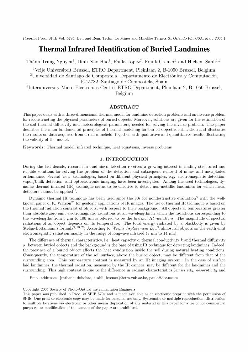
Preprint Proc. SPIE Vol. 5794, Det. and Rem. Techn. for Mines and Minelike Targets X, Orlando FL, USA, Mar. 2005 1
Thermal Infrared Identification of Buried LandminesThanh Trung Nguyen1, Dinh Nho Hao1, Paula Lopez2, Frank Cremer3 and Hichem Sahli1,3
1Vrije Universiteit Brussel, ETRO Department, Pleinlaan 2, B-1050 Brussel, Belgium2Universidad de Santiago de Compostela, Departamento de Electronica y Computacion,
E-15782, Santiago de Compostela, Spain3Interuniversity Micro Electronics Centre, ETRO Department, Pleinlaan 2, B-1050 Brussel,
Belgium
ABSTRACT
This paper deals with a three-dimensional thermal model for landmine detection problems and an inverse problemfor reconstructing the physical parameters of buried objects. Moreover, solutions are given for the estimation ofthe soil thermal diffusivity and meteorological parameters, needed for solving the inverse problem. The paperdescribes the main fundamental principles of thermal modelling for buried object identification and illustratesthe results on data acquired from a real minefield, together with qualitative and quantitative results illustratingthe validity of the model.
Keywords: Thermal model, infrared technique, heat equations, inverse problems
1. INTRODUCTION
During the last decade, research in landmines detection received a growing interest in finding structured andreliable solutions for solving the problem of the detection and subsequent removal of mines and unexplodedordonnance. Several ’new’ technologies, based on different physical principles, e.g. electromagnetic detection,vapor/builk detection, and optoelectronic imaging, have been investigated. Among the used technologies, dy-namic thermal infrared (IR) technique seems to be effective to detect non-metallic landmines for which metaldetectors cannot be applied14.
Dynamic thermal IR technique has been used since the 80s for nondestructive evaluation3 with the well-known paper of K. Watson25 for geologic applications of IR images. The use of thermal IR technique is based onthe thermal radiation contrast of objects, with respect to their background. All objects at temperatures greaterthan absolute zero emit electromagnatic radiations at all wavelengths in which the radiations corresponding tothe wavelengths from 3 µm to 100 µm is referred to be the thermal IR radiations. The magnitude of spectralradiations of an object depends on its temperature. The total energy radiated by a blackbody is given byStefan-Boltzmann’s formula9, 13, 26. According to Wien’s displacement Law9, almost all objects on the earth emitelectromagnatic radiation mainly in the range of longwave infrared (8 µm to 14 µm).
The difference of thermal characteristics, i.e., heat capacity c, thermal conductivity k and thermal diffusivityα, between buried objects and the background is the base of using IR technique for detecting landmines. Indeed,the presence of a buried object affects the heat conduction inside the soil during natural heating conditions.Consequently, the temperature of the soil surface, above the buried object, may be different from that of thesurrounding area. This temperature contrast is measured by an IR imaging system. In the case of surfacelaid landmines, the thermal radiation, measured by the IR camera, may be different for the landmines and thesurrounding. This high contrast is due to the difference in radiant characteristics (emissivity, absorptivity and
Email addresses: ntthanh, dnhohao, hsahli, [email protected], [email protected]
Copyright 2005 Society of Photo-Optical instrumentaion EngineersThis paper was published in Proc. of SPIE 5794 and is made available as an electronic preprint with the permission ofSPIE. One print or electronic copy may be made for personal use only. Systematic or multiple reproduction, distributionto multiple locations via electronic or other means duplication of any material in this paper for a fee or for commercialpurposes, or modification of the content of the paper are prohibited.

Preprint Proc. SPIE Vol. 5794, Det. and Rem. Techn. for Mines and Minelike Targets X, Orlando FL, USA, Mar. 2005 2
reflectivity) between the landmines and the background soil. From the measured images, one can easily detectthe presence of abnormal objects.
However, to detect and identify buried objects, a thorough analysis of the thermal behaviour of the surveyedarea, by considering the thermal parameters of both background and buried objects, is needed. This is achievedin two steps.
• The first step, referred to as forward thermal model, aims at modelling the temporal behaviour of the soiltemperature, under natural heating conditions, with the presence of buried landmines. This is based onthe solution of an initial boundary value problem for a three-dimensional heat transfer equation. Althoughheat transfer processes in solids have been analysed thoroughly6, 20, only few thermal models have beenproposed for landmine detection problems. Among the existing models, I. K. Sendur and B. A. Baertlein21
proposed a three-dimensional thermal model for homogeneous soil containing a buried anti-tank minemodelled as TNT object. The authors considered smooth and Gaussian distributed rough surfaces, andproposed a radiometric model for thermal signatures released from the soil surface and from other sources.The considered radiometric model, instead of using apparent temperature, allows approximating the realtemperature of the surface from measured IR images. The same radiometric model has been also studiedby P. Pregowski et al.19. A three-dimensional model, for homogeneous soil containing buried landmines andconsidering both the explosive (TNT) and the casing of the landmine, has been introduced by K. Khanaferand K. Vafai11. In their paper, the authors analysed the effect of the casing on the temporal behaviour ofthe soil temperature distribution taking into account rough soil surfaces and diurnal cycle.
These models helped understanding the effect of buried landmines on the soil temperature. However, theirvalidity, by comparing the simulated and experimental results, have not been studied. This has been donein our early works14, 16, where we proposed and validated, using indoor and outdoor experiments, a 3Dthermal model for homogeneous soil and buried landmines characterised by their TNT and considering flatsoil surface. A 2D thermal model has been also investigated by S. Sjokvist et al.22–24.
• The second step, referred to as inverse problem setting for landmine detection, consists of using thesethermal models for the detection and identification of the buried objects, i.e., estimate the position, (c1, c2),the sectional radius r, the height h, the depth d, and the thermal diffusivity αt of the buried object (seefigure 1). Here, we are faced with an ill-posed inverse problem of determining the location (position, depthand height), size and the physical properties of buried objects from diurnal thermal observations on thesoil surface. Although inverse problems in heat conduction have been intensively studied1, 2, 4, 5, 8, 12, to ourknowledge, only our previous work, P. Lopez et al.14, 15, applied them for landmine detection. In14, 15 thedepth (of burial) and the thermal diffusivity, of a buried object have been estimated, when its location inthe soil volume is known. Moreover, in the later work, we considered known the soil characteristics andthe incoming heat flux parameters.
To apply thermal modelling for detecting landmines in a real minefield7, several parameters, such as specificheat, thermal conductivity, thermal diffusivity, emissivity, solar absorptivity, etc. have to be estimated. Moreover,one should take into account the relationship between the real soil surface temperature and the ’intensity’ of theacquired IR images. This relationship is not straightforward, indeed, the measured thermal ’intensity’ is affectedby the solar radiation, the emission of the air, as well as the soil roughness. Finally, the ill-posedness of theinverse problem may cause large errors, in the estimated parameters, with small errors in the input data. Allthese aspects are considered in this paper.
The paper is organised as follows. In Section 2, we first state mathematically the full process of detectinglandmines using thermal modelling. This model requires, among other parameters, the soil thermal diffusivity,the soil thermal emissivity, the solar absorption, the sky absorption, and the convective heat transfer coefficients.These parameters depend on the local soil characteristics and the meteorological (weather) conditions during thethermal observations. From measured soil temperatures at different locations and depths, in Section 3, we presenta method of estimating the soil thermal diffusivity and the derivation of the soil temperature (in the verticaldirection) proportionally to the heat flux on the soil surface. The other parameters such as solar absorptivity,the soil emissivity, etc. are estimated as described in Section 4 using weather data. The model given by Lopez14

Preprint Proc. SPIE Vol. 5794, Det. and Rem. Techn. for Mines and Minelike Targets X, Orlando FL, USA, Mar. 2005 3
is used for the estimation of the thermal diffusivity of the buried objects and their depths of burial. In Section 5,we present some results of the inverse problems for the estimation of the physical parameters of soil and buriedobjects, using data acquired in a real minefield within the United Nations Buffer Zone in Cyprus. The operatedstand-off thermal IR survey system and the anomaly detection algorithm are described in Cremer et al.7
2. MATHEMATICAL FORMULATION
In this section, we describe the mathematical equations governing the heat transfer process inside the soil and theburied objects, as well as the necessary boundary conditions. Moreover, the formulation of the inverse problemsfor buried object detection is given.
2.1. Governing equation
Consider a rectangular parallelepiped domain Ω within the three-dimensional soil volume containing a possiblyburied target (see figure 1). We denote by Γ1 and Γ2 the top and bottom surfaces of the domain, respectively.Γ1, being the soil surface and the only portion of the volume accessible for measurements. We assume that thesoil and the target are isotropic solids with specific heat c(x, y, z) (J/(kg K)), density ρ(x, y, z) (kg/m3) andthermal conductivity k(x, y, z) (W/(m K)). We also assume that the soil moisture content variation is negligible.Then, the temperature distribution, T (x, y, z, t), (x, y, z, t) ∈ Ω × [0, te], of the considered volume (the soil andthe possibly buried object) under natural heating conditions, satisfies the following partial differential equation
cρ∂T
∂t=
∂
∂x
(k
∂T
∂x
)+
∂
∂y
(k
∂T
∂y
)+
∂
∂z
(k
∂T
∂z
). (1)
In the case of homogeneous or piecewise homogeneous solid, equation (1) has the form
∂T
∂t= α(x, y, z)∆T, (2)
where α = k/(cρ) (m2/s) is the thermal diffusivity of the solid.
2.2. Initial and boundary conditions
In order to solve (1) or (2), one should know the initial distribution of temperature (T (x, y, z, t = 0)), as well asthe boundary conditions, e.g., the incoming or outgoing heat flows on the boundary, ∂Ω, of the domain. Theseconditions are described as follows
1. The initial condition expresses the soil temperature at the initial time instant t = 0
T (x, y, z, t = 0) = g(x, y, z), ∀(x, y, z) ∈ Ω. (3)
2. The sufficient deep depth condition, assumes that the soil temperature at sufficient deep depth, z0, doesnot depend on the diurnal heat transfer process.
T (x, y, z0, t) = T∞, ∀(x, y, z0, t) ∈ Γ2 × [0, te]. (4)
From our experimental observations, z0 is set to 50 cm (see section 5).
3. The surface heat flux, establishes the incoming heat flux, qnet, through the portion of the soil volumeaccessible for measurements, i.e. the air-soil interface (soil surface) Γ1
−k∂T
∂z= qnet for (x, y, z) ∈ Γ1, (5)
The estimation of qnet will be considered in detail in Section 4.

Preprint Proc. SPIE Vol. 5794, Det. and Rem. Techn. for Mines and Minelike Targets X, Orlando FL, USA, Mar. 2005 4
rd
h1
x
y
z
c2
c1
Γ1
Γ2
Ω
Figure 1. Model of the soil domain containing a buried object
4. The domain is assumed to insulate the outgoing as well as the incoming heat flows from surrounding areasof the soil, i.e., there is no heat flowing in the horizontal direction on the boundary of Ω. This hypothesisis reasonable if the soil is homogeneous and the considered domain is large enough so that we can neglectthe effect of the buried objects to the boundary of the domain. In this case, the heat balance takes placeon the surrounding boundary of the domain during the analysis period. This condition is given by
∂T
∂~n= 0 for (x, y, z) ∈ ∂Ω \ (Γ1 ∪ Γ2), (6)
where ~n is the outward unit normal vector of ∂Ω.
Equation (1) or (2) with the initial and boundary conditions (3)–(6) define the forward thermal model forlandmine detection.
2.3. Inverse problems for buried landmines detectionAs mentioned before, the aim of the inverse problem setting for landmine detection is to detect (locate) thepresence of an abnormal object and characterise it as being mine or not, i.e. estimate it’s physical thermalcharacteristics. In this problem, we aim at reconstructing the internal characteristics of the soil based onmeasured temperatures on the surface. This problem is stated as follows.
Let αs being the thermal diffusivity of the bare soil, and suppose the existence of a buried object withthermal diffusivity αt occupying a sub-domain Ω1 of Ω. Moreover, the sub-domain is assumed to be a cylinderwith sectional center (c1, c2) in the horizontal plane, height h, sectional radius r and is located at depth d (seefigure 1).
The soil temperature distribution T (x, y, z, t) is described by the boundary value problem (2)–(6) with piece-wise constant thermal diffusivity
α =
αt in Ω1
αs in Ω \ Ω1
(7)
The aim of the inverse problem is to reconstruct the parameters αt, r, h, d, c1, c2 from measured soil surfacetemperatures, T (x, y, z = 0, t) = θ(x, y, t), at t = t1, t2, . . . , tn. This problem can be written in the form of anoptimization problem:
minαt,r,h,d,c1,c2
12
tn∑t=t1
∫
Γ1
|T (x, y, 0, t)− θ(x, y, t)|2 dxdy, (8)
where T (x, y, z, t) is the solution of the forward model (2)–(6) with piecewise constant thermal diffusivity α. Insection 5 we will consider numerical methods for solving the forward problem (2)–(6) and inverse problem (8).

Preprint Proc. SPIE Vol. 5794, Det. and Rem. Techn. for Mines and Minelike Targets X, Orlando FL, USA, Mar. 2005 5
3. SOIL THERMAL DIFFUSIVITY ESTIMATION
In order to model the heat transfer process in a given soil, it is necessary to know its specific heat, density,thermal conductivity and thermal diffusivity characteristics. Although the characteristics of different materials,including soil types, have been given in the literature, they can not be used directly. Indeed, soil characteristicsare dependent on the location and moisture content of the soil.
In this section, we propose a simple method to estimate the soil diffusivity from soil temperature profilesmeasured by thermocouples placed at different depths. We consider a domain of homogeneous soil withoutburied objects. In this domain, the three-dimensional equation (1), with the given temperature on the domainboundary, can be simplified to a one-dimensional problem describing the soil diurnal temperature distributionin depth:
∂T∂t = α∂2T
∂x2 , a ≤ x ≤ b, 0 ≤ t ≤ te,
T (x, 0) = g(x), a ≤ x ≤ b,
T (a, t) = fa(t), 0 ≤ t ≤ te,
T (b, t) = fb(t), 0 ≤ t ≤ te,
(9)
where α is a constant (the soil is considered homogeneous), and T = T (x, t;α) is the soil temperature at depthx and time t. The functions fa(t) and fb(t) are temperature profiles at given depths a and b, respectively, whileg(x) is the initial distribution of the soil temperature in depth.
Consistent estimates of the coefficient α is obtained by least squares minimization, i.e., find the coefficient αsuch that the difference between the simulated solution of (9) and the measured data is minimal:
minα>0
12
te∫
0
[T (c, t; α)− fc(t)]2dt, (10)
where T (x, t; α) is the solution of the Dirichlet problem (9). For which, (i) fa and fb are approximated fromthe measured data, (ii) the initial condition g is approximated by interpolating the measured temperaturesat different depths at time t = 0, and (iii) c, (a < c < b), a depth for which soil temperature profile fc ismeasured. For solving the inverse problem (10), we refer the reader to the paper of Kravaris and Seinfeld12
and the references therein for different numerical methods. For the forward model (9) we used the well-knownCrank-Nicolson scheme17 for heat equations.
Figure 2 illustrates the obtained results using data acquired during minefield trials7. Figure 2 (left) shows themeasured soil temperature profiles at different depths. Figure 2 (right) shows the error evolution when solvingequation (9); the minimum is obtained with α = 5.3× 10⁻⁷ (m2/s). Figure 2 (middle) shows a good agreementbetween the measured and the simulated (using the estimated soil thermal diffusivity) soil temperature.
0 5 10 15 20 25 30 35 40−5
0
5
10
15
20Soil temperature at different depths
Time (hour)
So
il te
mp
era
ture
(0C
)
Surface3cm8cm18cm48cm
0 5 10 15 20 25 30 35 400
2
4
6
8
10
12
14
16
Time (hour)
So
il te
mp
era
ture
(oC
)
Measured soil temperature and simulation at diffusivity = 5.3e−007(m2/s)
measured at 3cmsimulated at 3cmmeasured at 8cmsimulated at 8cmmeasured at 18cmsimulated at 18cm
1 2 3 4 5 6 7 8 9 10
x 10−7
0
0.2
0.4
0.6
0.8
1
1.2
1.4
1.6
1.8
2Evolution of error of soil diffusivity estimation
Soil diffusivity (m2/s)
Err
or
(0C
)
Figure 2. Soil thermal diffusivity estimation; Left: Measured soil temperature profile; Middle: Measured soil temperaturesversus simulated soil temperatures; Right: Error Evolution
Preprint Proc. SPIE Vol. 5794, Det. and Rem. Techn. for Mines and Minelike Targets X, Orlando FL, USA, Mar. 2005 6
4. BOUNDARY PARAMETERS ESTIMATION
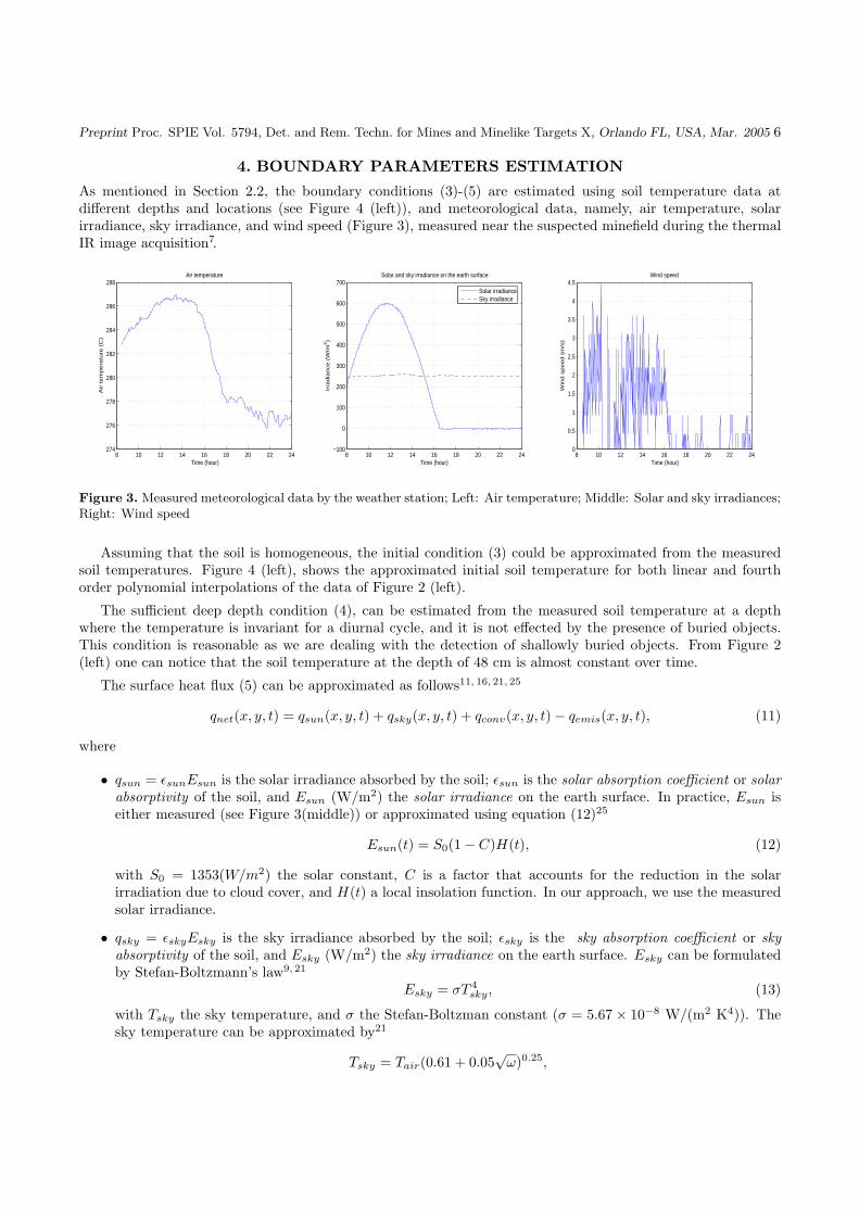
As mentioned in Section 2.2, the boundary conditions (3)-(5) are estimated using soil temperature data atdifferent depths and locations (see Figure 4 (left)), and meteorological data, namely, air temperature, solarirradiance, sky irradiance, and wind speed (Figure 3), measured near the suspected minefield during the thermalIR image acquisition7.
8 10 12 14 16 18 20 22 24274
276
278
280
282
284
286
288Air temperature
Time (hour)
Air t
em
pe
ratu
re (
C)
8 10 12 14 16 18 20 22 24−100
0
100
200
300
400
500
600
700
Time (hour)
Irra
dia
nce
(W
/m2)
Solar and sky irradiance on the earth surface
Solar irradianceSky irradiance
8 10 12 14 16 18 20 22 240
0.5
1
1.5
2
2.5
3
3.5
4
4.5Wind speed
Time (hour)
Win
d s
pe
ed
(m
/s)
Figure 3. Measured meteorological data by the weather station; Left: Air temperature; Middle: Solar and sky irradiances;Right: Wind speed
Assuming that the soil is homogeneous, the initial condition (3) could be approximated from the measuredsoil temperatures. Figure 4 (left), shows the approximated initial soil temperature for both linear and fourthorder polynomial interpolations of the data of Figure 2 (left).
The sufficient deep depth condition (4), can be estimated from the measured soil temperature at a depthwhere the temperature is invariant for a diurnal cycle, and it is not effected by the presence of buried objects.This condition is reasonable as we are dealing with the detection of shallowly buried objects. From Figure 2(left) one can notice that the soil temperature at the depth of 48 cm is almost constant over time.
The surface heat flux (5) can be approximated as follows11, 16, 21, 25
qnet(x, y, t) = qsun(x, y, t) + qsky(x, y, t) + qconv(x, y, t)− qemis(x, y, t), (11)
where
• qsun = εsunEsun is the solar irradiance absorbed by the soil; εsun is the solar absorption coefficient or solarabsorptivity of the soil, and Esun (W/m2) the solar irradiance on the earth surface. In practice, Esun iseither measured (see Figure 3(middle)) or approximated using equation (12)25
Esun(t) = S0(1− C)H(t), (12)
with S0 = 1353(W/m2) the solar constant, C is a factor that accounts for the reduction in the solarirradiation due to cloud cover, and H(t) a local insolation function. In our approach, we use the measuredsolar irradiance.
• qsky = εskyEsky is the sky irradiance absorbed by the soil; εsky is the sky absorption coefficient or skyabsorptivity of the soil, and Esky (W/m2) the sky irradiance on the earth surface. Esky can be formulatedby Stefan-Boltzmann’s law9, 21
Esky = σT 4sky, (13)
with Tsky the sky temperature, and σ the Stefan-Boltzman constant (σ = 5.67× 10⁻⁸ W/(m2 K4)). Thesky temperature can be approximated by21
Tsky = Tair(0.61 + 0.05√
ω)0.25,

Preprint Proc. SPIE Vol. 5794, Det. and Rem. Techn. for Mines and Minelike Targets X, Orlando FL, USA, Mar. 2005 7
with ω the water vapour pressure in the atmosphere, expressed in mmHg, and Tair the air temperature.Combining the two above equations, we get:
Esky = σT 4air(0.61 + 0.05
√ω) ≈ 0.61σT 4
air. (14)
The sky irradiance can also be measured as shown in Figure 3 (middle), from which, one can notice thecorrelation between the solar and sky irradiances.
• qconv(W/m2) is the heat transfer, by convection, between the soil and the air. It refers to the transport ofheat between the surface and the atmosphere by motion of the air. In 1701, Isaac Newton considered theconvective process and suggested that the cooling would be such that13
dTs
dt∼ (Ts − Tair).
So the net heat flux by convection can be written as,
qconv = h(Tair − Tsoil),
where h is the convective heat transfer coefficient ; it depends on the wind speed. In practice, Kahle10
approximated it byqconv(x, y, t) = ρacpaCd(W (t) + 2)(Tair(t)− Tsoil(x, y, t)), (15)
with ρa the density of the air, cpa the specific heat of the air, Cd the wind drag coefficient (normally chosento be 0.002) and W (t) the wind speed.
• qemis(W/m2) is the thermal emittance of the soil. It corresponds to the thermal radiation emitted by thesoil:
qemis = εsoilσT 4soil, (16)
where εsoil is the thermal emissivity of the soil, and Tsoil the temperature at the soil surface. FromKirchoff’s Law9, the thermal emissivity of the soil is equal to the sky absorptivity εsky.
In summary, equation (11) can be rewritten as:
qnet(x, y, t) = εsunEsun(t) + εconv(W (t) + 2)(Tair(t)− Tsoil(x, y, t))
+ εskyEsky(t)− εsoilσ T 4soil(x, y, t)
(17)
with, Tair(t), Esun(t), Esky(t), and W (t) measured, with the help of a weather station, as illustrated in Figure3.
To estimate the the boundary condition (5), using equation (17), one should estimate the unknown coefficientsεsun, εsky, εconv and εsoil. This is done by solving the following minimization problem
minεsun,εsky,εconv,εsoil
12
te∫
0
| − ∂T
∂z(t)− εsun
kEsun(t)− εconv
k(W (t) + 2)(Tair(t)− Tsoil(x, y, t))
− εsky
kEsky(t) +
εsoil
kσ T 4
soil(x, y, t)|2dt.
(18)
where −∂T∂z (t) is an approximation of the heat flux in the bare soil area, calculated as the derivative of the
solution of the problem (9) using the estimated soil diffusivity (equation (10)). Note that, from equation (5),−∂T
∂z (t) = qnet(t)/k, k being the unknown soil conductivity, so in (18), we estimate εsun/k, εsky/k, εconv/kand εsoil/k instead of the coefficients εsun, εsky, εconv and εsoil. Figure 4 (right) shows the approximationof the surface heat flux. Solving the above minimization problem, we obtain εsun/k = 0.4574 (m K/W),εsky/k = 0.5416 (m K/W), εsoil/k = 0.6725 (m K/W), εconv/k = 1.8634 (m K/W).
Preprint Proc. SPIE Vol. 5794, Det. and Rem. Techn. for Mines and Minelike Targets X, Orlando FL, USA, Mar. 2005 8
0 0.1 0.2 0.3 0.4 0.50
2
4
6
8
10
12
14
16
18
Depth (m)
So
il te
mp
era
ture
(0C
)
Approximation of initial condition
4th poly. inter.Linear inter.Data
8 10 12 14 16 18 20 22 24−150
−100
−50
0
50
100
150Incoming heat flux on the soil surface
Time (hour)
He
at flu
x (
W/m
2)
From simulationWith estimated parameters
Figure 4. Initial and boundary conditions estimation; Left: initial temperature condition; Right: Approximated surfaceheat flux
Detected anomaly
5 10 15 20 25 30 35
5
10
15
20
25
30
35
40
An IR image at 0:5
5 10 15 20 25 30 35
5
10
15
20
25
30
35
40
An IR image at 9:58
5 10 15 20 25 30 35
5
10
15
20
25
30
35
40
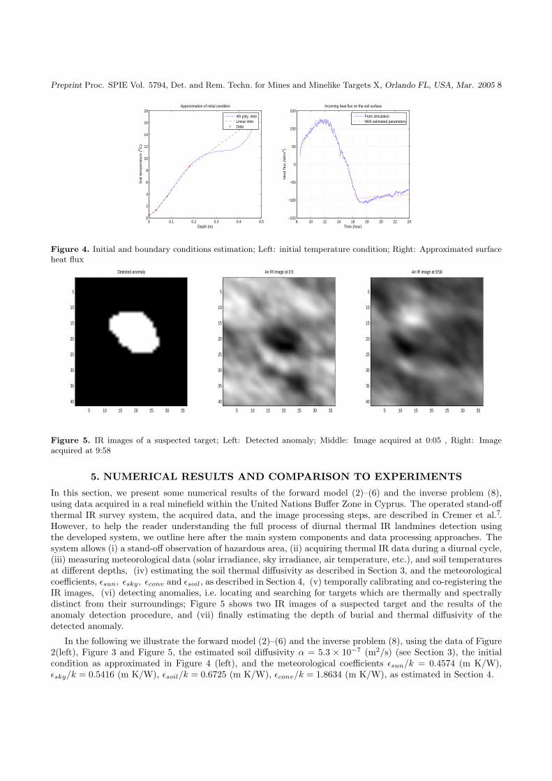
Figure 5. IR images of a suspected target; Left: Detected anomaly; Middle: Image acquired at 0:05 , Right: Imageacquired at 9:58
5. NUMERICAL RESULTS AND COMPARISON TO EXPERIMENTS
In this section, we present some numerical results of the forward model (2)–(6) and the inverse problem (8),using data acquired in a real minefield within the United Nations Buffer Zone in Cyprus. The operated stand-offthermal IR survey system, the acquired data, and the image processing steps, are described in Cremer et al.7.However, to help the reader understanding the full process of diurnal thermal IR landmines detection usingthe developed system, we outline here after the main system components and data processing approaches. Thesystem allows (i) a stand-off observation of hazardous area, (ii) acquiring thermal IR data during a diurnal cycle,(iii) measuring meteorological data (solar irradiance, sky irradiance, air temperature, etc.), and soil temperaturesat different depths, (iv) estimating the soil thermal diffusivity as described in Section 3, and the meteorologicalcoefficients, εsun, εsky, εconv and εsoil, as described in Section 4, (v) temporally calibrating and co-registering theIR images, (vi) detecting anomalies, i.e. locating and searching for targets which are thermally and spectrallydistinct from their surroundings; Figure 5 shows two IR images of a suspected target and the results of theanomaly detection procedure, and (vii) finally estimating the depth of burial and thermal diffusivity of thedetected anomaly.
In the following we illustrate the forward model (2)–(6) and the inverse problem (8), using the data of Figure2(left), Figure 3 and Figure 5, the estimated soil diffusivity α = 5.3 × 10⁻⁷ (m2/s) (see Section 3), the initialcondition as approximated in Figure 4 (left), and the meteorological coefficients εsun/k = 0.4574 (m K/W),εsky/k = 0.5416 (m K/W), εsoil/k = 0.6725 (m K/W), εconv/k = 1.8634 (m K/W), as estimated in Section 4.

Preprint Proc. SPIE Vol. 5794, Det. and Rem. Techn. for Mines and Minelike Targets X, Orlando FL, USA, Mar. 2005 9
The forward thermal model (2)–(6), has been solved using a simple explicit finite difference scheme as de-scribed in Ozisik18, page 420. The numerical result of the simulation for the NR22C1, anti-personnel plastic,mine buried at 1 cm deep is plotted in Figure 6. In this simulation we assumed the mine as a TNT objectwith thermal diffusivity of 1.139 × 10⁻⁷ (m2/s). Figure 6 (left) depicts the simulated soil surface temperaturesabove the mine and in the surrounding area, and the measured soil surface temperature. The figure shows agood agreement between the simulation and the measured soil surface temperature. Figure 6 (right) shows thethermal contrast between the soil temperature above the mine and the surrounding area. As it can be seen,during sun shine, the soil above the mine was hotter than the surrounding area and it became cooler duringthe night. Moreover, the highest thermal contrast took place around noon. This result can be explained fromthe fact that, when the sun was shining, there was an incoming heat flux through the soil surface. In this case,the mine blocked the heat flow from the surface due to its small thermal conductivity or thermal diffusivity.Consequently, the soil above the mine became hotter than the surrounding area. During the night, there wasan outgoing heat flow from the bottom of the soil volume. The mine blocked the heat flow resulting in coolertemperature above the mine than the surrounding area. The same results have been obtained in the previousworks of Sendur and Baertlein21, Khanafer and Vafai11 and Lopez et al.16.
5 10 15 20 25 30 35−5
0
5
10
15
20Evolution of soil temperature
Time (hour)
Te
mp
era
ture
(oC
)
Simulation at bare soil areaSimulation on the top of mineMeasured soil temperature
5 10 15 20 25 30 35−1.5
−1
−0.5
0
0.5
1
1.5
2Temperature contrast between mine and bare soil on the surface
Time (hour)
Te
mp
era
ture
co
ntr
ast
(oC
)
Figure 6. Forward model; Left: Simulated and measured soil temperatures on the surface; Right: Thermal contrast
The quality of the acquired images has been analysed before solving the inverse problem. As it can be seenfrom Figure 5 (middle), Figure 5 (right), and the size of the detected anomaly of Figure 5 (left), the temporalco-registration is not perfect. This explains the irregular in shape of the measured contrast of Figure 7 (right).However, from Figure 7 (left), depicting the measured soil surface temperature versus the apparent thermal IRtemperature, one can notice that the two temperatures follow the same behaviour with a small shift. Figure 7(right) shows the simulated thermal contrast, considering that the suspected target is a NR22C1 mine buried at3 cm, versus the measured thermal contrast. As it can be seen, during the night, with reasonable co-registratedimages, the measured and simulated thermal contrasts are similar in shape.
For solving the inverse problem, we used an early work14, 15 to estimate the depth of burial and the thermaldiffusivity of the detected object of Figure 5. The inputs to the inverse problem are the acquired thermal IRimages, and the spatial position (center) and radius of the object, estimated from the image of Figure 5 (left).Figure 8 illustrates the error evolution of the thermal diffusivity and depth of burial estimation, respectively. Asit can be seen, the depth is estimated at 6 cm and thermal diffusivity 2× 10⁻⁷ (m2/s).
6. CONCLUSIONS
In this paper, we presented the full process for landmine detection using thermal modelling. The difficultyin estimating physical and meteorological parameters of the soil has been solved. The forward model, usingthese estimated parameters, showed a good agreement with the measured data. The inverse problem has been

Preprint Proc. SPIE Vol. 5794, Det. and Rem. Techn. for Mines and Minelike Targets X, Orlando FL, USA, Mar. 2005 10
5 10 15 20 1 6 11−5
0
5
10
15
20Measured real and apparent temperature
Time (hour)
So
il te
mp
era
ture
(0C
)
Real temperatureApparent temperature
5 10 15 20 1 6 11−5
0
5
10
15
20
Time (hour)
So
il te
mp
era
ture
(0C
)
Thermal behaviour of the soil temperature measured by an IR camera
Above the mineBare soil
5 10 15 20 1 6 11−1.5
−1
−0.5
0
0.5
1
1.5
2Thermal contrast on the soil surface
Time (hour)
Th
erm
al co
ntr
ast (0
C)
SimulatedMeasured
Figure 7. Image quality analysis; left: measured soil surface temperature versus the apparent thermal IR temperature,Middle: Apparent thermal IR behaviour; Right: Thermal IR contrast versus simulated contrast
0 5 10 15 200.55
0.56
0.57
0.58
0.59
0.6
0.61
0.62 Evolution of the eror of thermal diffusivity estimation
Iteration
Err
or
(0C
)
0 5 10 150.55
0.6
0.65
0.7
0.75
0.8
0.85
0.9
0.95
1
1.05 Evolution of the eror of depth estimation
Depth (cm)
Err
or
(0C
)
Figure 8. Evolution of error of depth and thermal diffusivity estimation; Left: Error of diffusivity estimation; Right:Error of depth of burial estimation
solved using a the model presented in early works14–16, where the location and radius of the buried object areconsidered known using several anomaly detection procedures7, 15, 16 we developed. Future work consists indeveloping efficient numerical methods for solving the forward problem and considering the full inverse problemi.e. augmenting the estimation for both the physical parameters and the location of the buried objects.
ACKNOWLEDGEMENTS
This work has been partly funded by the European Commision, under the CLEARFAST project IST-2000-25173.The authors would like to thank the other project partners, namely, TAMAM, RLS, and BACTEC. Furthermorewe would like to thank the UN (UMAS, UNDP), the MACC and Armour Group for their support and for givingus the opportunity to perform the field trial in Cyprus.
REFERENCES1. O. M. Alifanov. Inverse Heat Transfer Problems. Springer-Verlag, Berlin, Germany, 1994.2. O. M. Alifanov, E. Artyukhin, and S. Rumyantsev. Extreme Methods for Solving Ill-posed Problems with
Applications to Inverse Heat Transfer Problems. Begell House Publisher, New York, 1995.

Preprint Proc. SPIE Vol. 5794, Det. and Rem. Techn. for Mines and Minelike Targets X, Orlando FL, USA, Mar. 2005 11
3. D. L. Balageas, J. C. Krapez, and P. Ceilo. Pulsed photothermal modeling of layered materials. Journal ofApplied Physis, 59(2):348–357, 1986.
4. J. Beck, B. Blackwell, and S. R. St-Clair, Jr. Inverse Heat Conduction. Ill-posed Problems. John Willeyand Sons, New York, 1995.
5. H. D. Bui. Inverse Problems in the Mechanics of Materials: An Introduction. CRC Press, 1994.6. H. S. Carslaw and J. C. Jaeger. Conduction of Heat in Solids. Oxford University Press, Oxford, second
edition, 1959.7. F. Cremer, T. T. Nguyen, L. Yang, and H. Sahli. Stand-off thermal IR minefield survey, system concept
and experimental results. In R. S. Harmon, J. T. Broach, and J. H. Holloway, Jr., editors, Proceedings ofSPIE 5794, Detection and remediation technologies for mine and minelike targets X, 2005.
8. D. N. Hao. Methods for Inverse Heat Conduction Problems. Peter Lang, Frankfurt am Main, Bern, NewYork, Paris, 1998.
9. P. A. M. Jacobs. Thermal infrared characterization of ground targets and backgrounds. SPIE OpticalEngineering Press, Bellingham (WA), USA, 1996.
10. A. B. Kahle. A simple thermal model of the earth’s surface for geologic mapping by remote sensing. Journalof Geophysical Research, 82:1673–1680, 1977.
11. K. Khanafer and K. Vafai. Thermal analysis of buried land mines over a diurnal cycle. IEEE Transactionson Geoscience and Remote Sensing, 40(2):461–473, February 2002.
12. C. Kravaris and J. H. Seinfeld. Identification of parameters in distributed parameter systems by regulariza-tion. SIAM Journal of Control and Optimization, 23(2):217–241, March 1985.
13. J. H. Lienhard IV and J. H. Lienhard V. A heat transfer textbook. Plogiston Press, Cambridge MA, thirdedition, 2004.
14. P. Lopez. Detection of landmines from measured infrared images using thermal modelling of the soil. PhDthesis, University of Santiago de Compostela, 2003.
15. P. Lopez, H. Sahli, D. L. Vilarino, and D. Cabello. Detection of pertubations in thermal IR signatures:an inverse problem for buried land mine detection. In A. L. Gyekenyesi and P. J. Shull, editors, Proc. ofSPIE, vol. 5046, Nondestructive Evaluation and Health Monitoring of Aerospace Materials and CompositesII, pages 242–252, Orlando (FL), USA, Apr. 2003.
16. P. Lopez, L. Van Kempen, H. Sahli, and D. C. Ferrer. Improved thermal analysis of buried landmines. IEEETransactions on Geoscience and Remote Sensing, 4(9):1965–1975, 2004.
17. G. I. Marchuk. Splitting and alternating direction methods. In P. G. Ciaglet and J. L. Lions, editors,Handbook of Numerical Mathematics, volume 1: Finite Difference Methods. Elsevier Science Publisher B.V.,North-Holland, Amsterdam, The Netherlands, 1990.
18. M. N. Ozisik. Boundary value Problems of Heat Conduction. Dover Publication, INC, New York, USA,1968.
19. P. Pregowski, W. Swiderski, W. T. Walczak, and B. Usowicz. Role of time and space variability of moistureand density of sand for thermal detection of buried objects - modeling and experiments. In D. H. LeMieuxand J. R. Snell, Jr., editors, Proceeding of SPIE 3700, Thermosense XXI, pages 444–455, 1999.
20. A. A. Samarskii and P. N. Vabishchevich. Computational Heat Transfer, volume 1: Mathematical Modelling.John Wiley & Sons, Chichester, England, 1995.
21. I. K. Sendur and B. A. Baertlein. Numerical simulation of thermal signatures of buried mines over a diurnalcycle. In A. C. Dubey, J. F. Harvey, J. T. Broach, and R. E. Dugan, editors, Proceedings of SPIE 4038,Detection and Remediation Technologies for Mines and Minelike Targets V, pages 156–167, Aug 2000.
22. S. Sjokvist. Heat transfer modelling and simulation in order to predict thermal signatures - the case of buriedland mines. PhD thesis, Linkopings university, SE-581 83 Linkopings, Sweden, 1999.
23. S. Sjokvist, R. Garcia-Padron, and D. Loyd. Heat transfer modelling of solar radiated soil, including moisturetransfer. In Third Baltic Heat Transfer Conference, pages 707–714, Gdansk, Poland, 22-24 September 1999.IFFM Publishers, ISBN 8-3907-5269-7.

Preprint Proc. SPIE Vol. 5794, Det. and Rem. Techn. for Mines and Minelike Targets X, Orlando FL, USA, Mar. 2005 12
24. S. Sjokvist, M. Georgson, S. Ringberg, M. Uppsall, and D. Loyd. Thermal effects on solar radiated sandsurfaces containing landmines - a heat transfer analysis. In Fifth international conference on advancedcomputational methods in heat transfer, pages 177–187, Cracow, Poland, 17-19 June 1998. ComputationalMechanics Publications.
25. K. Watson. Geologic applications of thermal infared images. In Proceedings of the IEEE, volume 63, pages128–137, 1975.
26. M. C. Wendl. Fundamental of heat transfer: Theory and application. Class note for ME 371, WashingtonUniversity, 2003.
Copyright © 2022 FDOKUMEN