Thermal effects on adhesively bonded composite repair of cracked aluminum panels
12
ELSEVIER Theoretical and Applied Fracture Mechanics 26 (I 997) I - 12 theoretical and applied fracture mechanics Thermal effects on adhesively bonded composite repair of cracked aluminum panels S. Naboulsi ’ , S. Mall * Depurtment of Aeronautics und Astronautics, Air Force Institute oj’Techn&gy. Wright-Patterson AFB. OH 454337765, USA Abstract This study introduces the two-dimensional finite element analysis involving three layer technique to investigate the adhesively bonded composite repair of cracked metallic structure under thermo-mechanical loading. The thermal loading involves, in this study, the temperature drop such as seen during the bonding process. Three patch materials having different stiffnesses and coefficients of thermal expansion are investigated to analyze the thermal effects on the damage tolerance of the crack in the repaired structure and of the debond in the adhesive bondline. For the single sided repair, the patch material having the maximum mismatch in the coefficient of thermal expansion with that of the cracked aluminum plate provides the better damage tolerance capability for both the crack in the panel and the debond in the adhesive. On the other hand, for double sided repair, the patchmaterial havingthe minimal mismatch in the coefficientof thermal expansion with that of the cracked plate provides the better damage tolerance capability. 1. Introduction The efficiency of repair technique involving adhe- sively bonded composite patch to increasethe dura- bility and damage tolerance of cracked aerospace metallic structures at a low cost has been demon- strated [l-3]. Bonded composite patch retards the crack growth, i.e. reduces the stressintensity factor by bridging the stresses between the cracked plate and composite patch. Repaired structures are usually subjected to two types of loading: thermal and me- chanical loadings. For the mechanical loading, sev- eral studies have been conducted to investigate the mechanicsof bonded composite patch to repair the cracked metallic structure assuming isothermal con- dition, especially to analyze the redistribution of stresses in the repaired structure and to compute the stressintensity factor after repair [4-61. ’ Corresponding author. ’ Research Associate. The curing process required to adhesively bond the composite patch to the cracked structure results in thermal stresses(residual stresses)due to the mismatch of their coefficients of thermal expansion. Also, the drop in temperature at cruise altitude of the aircraft induces additional thermal stresses (thermal fatigue) in the repaired structure with bonded com- posite patch. These thermal loadings would, thus, causea redistribution of stresses acting on the crack in the repaired structure and on the debond front in the bondline, if any. It may, hence, effect the durabil- ity and damage tolerance of the repaired structure. The characterization of the thermal stresses and their effects on the performance of the repaired structure is, therefore, neededfor the better understandingand efficient designing of composite patches [7]. The objective of this study is, hence, to investi- 0167.8442/97/$17.00 Copyright 0 1997 Elsevier Science B.V. All rights reserved. PI/ SO167-8442(96)00028-6
-
Upload
independent -
Category
Documents
-
view
0 -
download
0
Transcript of Thermal effects on adhesively bonded composite repair of cracked aluminum panels

ELSEVIER Theoretical and Applied Fracture Mechanics 26 (I 997) I - 12
theoretical and applied fracture
mechanics
Thermal effects on adhesively bonded composite repair of cracked aluminum panels
S. Naboulsi ’ , S. Mall * Depurtment of Aeronautics und Astronautics, Air Force Institute oj’Techn&gy. Wright-Patterson AFB. OH 454337765, USA
Abstract
This study introduces the two-dimensional finite element analysis involving three layer technique to investigate the adhesively bonded composite repair of cracked metallic structure under thermo-mechanical loading. The thermal loading involves, in this study, the temperature drop such as seen during the bonding process. Three patch materials having different stiffnesses and coefficients of thermal expansion are investigated to analyze the thermal effects on the damage tolerance of the crack in the repaired structure and of the debond in the adhesive bondline. For the single sided repair, the patch material having the maximum mismatch in the coefficient of thermal expansion with that of the cracked aluminum plate provides the better damage tolerance capability for both the crack in the panel and the debond in the adhesive. On the other hand, for double sided repair, the patch material having the minimal mismatch in the coefficient of thermal expansion with that of the cracked plate provides the better damage tolerance capability.
1. Introduction
The efficiency of repair technique involving adhe- sively bonded composite patch to increase the dura- bility and damage tolerance of cracked aerospace metallic structures at a low cost has been demon- strated [l-3]. Bonded composite patch retards the crack growth, i.e. reduces the stress intensity factor by bridging the stresses between the cracked plate and composite patch. Repaired structures are usually subjected to two types of loading: thermal and me- chanical loadings. For the mechanical loading, sev- eral studies have been conducted to investigate the mechanics of bonded composite patch to repair the cracked metallic structure assuming isothermal con- dition, especially to analyze the redistribution of
stresses in the repaired structure and to compute the stress intensity factor after repair [4-61.
’ Corresponding author. ’ Research Associate.
The curing process required to adhesively bond the composite patch to the cracked structure results in thermal stresses (residual stresses) due to the mismatch of their coefficients of thermal expansion. Also, the drop in temperature at cruise altitude of the aircraft induces additional thermal stresses (thermal fatigue) in the repaired structure with bonded com- posite patch. These thermal loadings would, thus, cause a redistribution of stresses acting on the crack in the repaired structure and on the debond front in the bondline, if any. It may, hence, effect the durabil- ity and damage tolerance of the repaired structure. The characterization of the thermal stresses and their effects on the performance of the repaired structure is, therefore, needed for the better understanding and efficient designing of composite patches [7].
The objective of this study is, hence, to investi-
0167.8442/97/$17.00 Copyright 0 1997 Elsevier Science B.V. All rights reserved. PI/ SO167-8442(96)00028-6

2 S. Nuhoul.si. S. Mall/ Theoretical and Applied Fracture Mechnnics 26 (1997) I - I2
gate the thermal effects on cracked aluminum panels repaired with adhesively bonded composite patches. Due to the small thickness of the adhesive compared to the plate or the composite patch, the three-dimen- sional finite element analysis requires large number of elements across the thickness even with a very large aspect ratio, which results in a very high computational cost. This study will, thus, focus on alternate but an accurate two-dimensional finite ele- ment model, involving three layer technique, to in- vestigate the thermal effects on repaired structures. This three layer technique was recently introduced by the authors [8]. First, the three layer technique will be validated with the previous studies which have been conducted under isothermal condition only (no temperature change). After showing its accuracy, the use of the three layer technique will be extended to investigate the thermal effects on the cracked aluminum panel repaired with bonded composite patch.
2. Three layer model
The three layer technique uses two-dimensional finite element analysis consisting of three layers to model cracked plate, adhesive and composite patch. This technique is different where the adhesive is modeled as an elastic continuum medium replacing the shear spring elements (non-continuum body) used in the previous two-dimensional finite element anal- yses [5,6,9,10]. The motivation behind modeling the adhesive as a continuum is to, first, provide an economical two-dimensional finite element model with the minimal difference from the three-dimen- sional model. Second, it would capture the character- istics of adhesive realistically which would be re- quired to model thermal effects, nonlinear material behavior, progressive damage etc.
In the three layer technique, two-dimensional Mindlin plate elements with transverse shear defor- mation capability are used for all three layers; cracked plate, adhesive and composite patch. In both the symmetric (patch on both side of the cracked plate) and unsymmetric (patch on one side only) repairs, constraint equations are used to enforce the compati- bility conditions along the plate-adhesive and the adhesive-patch interface based on Mindlin plate as-
sumption. These constraint equations enforce the displacement compatibility between the three layers, model the bending effects for the unsymmetric re- pairs, and simulate the bilinear displacement effects that occurs in the symmetric repairs.
The Mindlin plate theory assumes linear displace- ment field along the thickness for all three layers; cracked plate, adhesive and composite patch,
ui, = i-4; + zq, (1)
“> = ii; + zq, (2)
ui;=iii,, (3)
where the superscript symbol i is either c, a or p to denote cracked plate, adhesive or composite patch, respectively (e.g. the thickness coordinate z’ is zc for the cracked plate, za for the adhesive and zp for the composite patch), iii, it, and Zi are the mid- plane displacements along the x-, y- and z-direction, respectively, zj and 3; are the rotations of the cross-section along the x-axis and y-axis, where x and y are in the plane of each layer and z’ is in the thickness direction of the ith layer defined as,
h’ hi -pZkl. (4)
where h’ is the layer thickness. Also, the geometric compatibility conditions are enforced along the plate-adhesive and adhesive-patch interface. At the plate-adhesive interface, where the z-coordinates for the cracked plate and the adhesive are equal, zc = za, the displacement field’s constraint equations reduce to
UC = u”, , u; = u;, l4’;= u”;. (5)
Similarly, at the adhesive-patch interface where the z-coordinates for the adhesive and patch are equal, z’= zp, the displacement field’s constraint equations reduce to
uP = ua 1 1’
uP = ua Y Y’
u!J = ua. (6)
During the life service of adhesively bonded patch repair, a debond between the cracked plate and the adhesive, or the adhesive and the composite patch could occur as a result of a defect or imperfection during the bonding process, due to the high stress state such as that near the cohesive crack tip, due to

S. Nuhoulsi. S. Mull / Theoretictd and Applied Fracture Mechanics 26 (1997) I-12 3
fatigue, etc. In either case debond reduces the effec- tive area and the amount of stresses being bridged between the cracked plate and the composite patch which causes the redistribution of stresses with a concentration at the debond front. At debond along plate-adhesive and adhesive-patch interface, the geo- metric compatibility conditions are no longer satis- fied (i.e. Eqs. (5) and (6) are no longer valid). Note that the three layer model is different from a single Mindlin plate in the sense that the three layer’s rotations are independent of each other and only use displacement constraints at the interfaces to enforce geometric compatibility.
3. Fracture mechanics
Cracks that exist in bonded patch repair are classi- fied into two types; cohesive and adhesive cracks. First, the cohesive cracks are those which exist in the cracked plate and assumed to be through-the-thick- ness cracks. These cracks are short to medium in size such that using the patching technique reduces crack growth and insures the integrity of the structure without catastrophic failure. Second, the adhesive cracks are those which initiate at either the plate-ad- hesive or adhesive-patch interface causing a debond. These adhesive cracks or debond have different chat- acteristics in unsymmetric and symmetric repairs where the former encounter bending stresses which leads to peeling stresses. These peeling stresses are known to be more critical than the shear stresses since the adhesive failure resistance is much weaker under peeling stresses compared to that under the shearing stresses, and could, thus, cause a higher debond growth rate leading to an earlier patch failure if ignored.
First, for the cohesive crack, the strain energy release rates for the opening (1) mode is computed by using the modified crack closure method [ 11,121,
1 1 G, = lim ~~ uzF;Au + lim -M.; AO,,
+ AU+o 2Aa
where Au and A0, are the crack opening displace- ment and rotation at the first node in front of the crack tip, F, and M., are force and moment required
to close the crack and ha is the virtual crack extension and it is equal to the length of the first element in front of the crack tip. To use the modified crack closure technique, only a reasonably small size elements in the vicinity of the crack tip are required (i.e. the virtual crack extension, Aa is small com- pared to the crack length, 2a). Note that in the case of symmetric patch, rotations are restricted and be- come negligible. In this study, all patch repairs are subjected to uniaxial loading in a direction perpen- dicular to the cohesive crack and only the dominant stress intensity factor mode I is presented for the cohesive crack (i.e. mode II and III are small in comparison to mode I>. For linear elastic continuum, the mode I stress intensity factor is computed using the strain energy release rate according to
(8)
where /3 is equal to unity for plane stress and 1 - u* for plane strain and E is the Young’s modulus. Further, in this study a self-similar crack extension is assumed. A detailed discussion of non-self-similar crack extension is given by Sih [13].
Second, for the ‘adhesive’ crack or ‘debond’, the strain energy release rate is required to predict the debond growth behavior. The technique adopted to calculate the debond’s strain energy release rate is based on the modified crack closure method. Note that the adhesive crack has no physical dimension through the thickness and the strain energy release rate is defined as the strain energy per unit area in the debond plane. Considering two plates which are adhesively bonded, the adhesive crack’s strain en- ergy release rates at the interface in term of the plates’ midplane section displacements and rotations are
G, = lim Euro AN;. (AE: - Aw,),
1 + lim -F,, .
~~-0 2AAa
4 S. Nuhoulsi. S. Mall/Theoretical und Applied Fracture Mechanics 26 (1997) 1-12
G,,, = lim Au o~7,-(hii,-A~l)
1 + lim -
AU-O 2AA.a
where overbar indicates bottom plate quantities and no bar indicates upper plate quantities, AU,, AU,, AZ:, Aa,, and A8, are the debond opening displace- ments and rotations along the tangential, normal and out-of-plane directions of lower plate, at the first node in front of the debond front, similarly Au,,
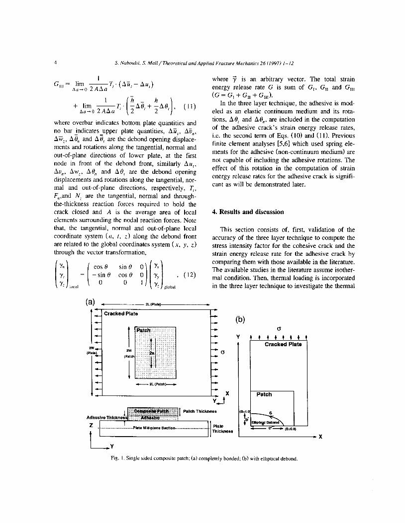
Au,, Aw,, At$ and A 19, are the debond opening displacements and rotations along the tangential, nor- mal and out-of-plane directions, respectively, T,, F,,,and NC are the tangential, normal and through- the-thickness reaction forces required to hold the crack closed and A is the average area of local elements surrounding the nodal reaction forces. Note that, the tangential, normal and out-of-plane local coordinate system (n, t, z) along the debond front are related to the global coordinates system (x, y, z) through the vector transformation,
where 7 is an arbitrary vector. The total strain energy release rate G is sum of G,, G,, and G,,, (G = G, + G,, + G,,,).
In the three layer technique, the adhesive is mod- eled as an elastic continuum medium and its rota- tions, AB, and Ad,, are included in the computation of the adhesive crack’s strain energy release rates, i.e. the second term of Eqs. (10) and (11). Previous finite clement analyses [5,6] which used spring ele- ments for the adhesive (non-continuum medium) are not capable of including the adhesive rotations. The effect of this rotation in the computation of strain energy release rates for the adhesive crack is signifi- cant as will be demonstrated later.
4. Results and discussion
This section consists of, first, validation of the accuracy of the three layer technique to compute the stress intensity factor for the cohesive crack and the strain energy release rate for the adhesive crack by comparing them with those available in the literature. The available studies in the literature assume isother- mal condition. Then, thermal loading is incorporated in the three layer technique to investigate the thermal
(a) - 73. (PIaD)-e L
- Cracked Plate 4 4 (W
z 1 . . . .._............_..____ PYe Mldplsne SIGtloR _._..______._____..__._. pm
I-
t Thickness
Y
Y
<s
#+#++t## Cracked Plate
Fig. I. Single sided composite patch; (a) completely bonded; (b) with elliptical debond.

S. Nuboulsi, S. Mull/ Theoreticul and Applied Fracture Mechanics 26 (19971 I-12 5
Patch Layer
Adhesive Layer
Cracked Plate Layer
Fig. 2. Three layer FEM modeling of single sided repair; cracked
plate, adhesive and patch.
effects on the damage tolerance of the repaired struc- ture with the bonded composite patch.
4.1. Cohesive crack
In the three layer technique, the cracked plate, adhesive and composite patch for both single sided repair (unsymmetric, Fig. 1 a) and double sided repair (symmetric), the cracked plate, adhesive and com- posite patch are modeled as continuum elastic medium using four noded shell elements available in the commercial finite element code ABAQUS (see Fig. 2). The material properties and dimensions of the single sided repair are given in Table 1 which are the same for the double sided repair except for the
Table 1 Material properties and dimensions of single sided repair
Layer Length L (mm) Width W (mm) Thickness h (mm) Material properties
Aluminum plate 180.0 120.0 2.2900 E = 71.02 GPa, u = 0.32 Adhesive 76.0 38.0 0.1016 G = 0.965 GPa, u = 0.32
Composite patch 76.0 38.0 0.7620 E, = 208 GPa, E, = E, = 25.44 GPa
G2, = 4.94GPa. G,, = G,,= 7.24GPa
patch thickness equal to 0.127 mm. Boron/epoxy composite patch is used in both types of repair. The cohesive central crack length is 2a = 50.0 mm. A uniformly distributed stress in the y-direction, aY, equal to 0.689 MPa is applied. A comparison of the stress intensity factor between the three layer tech- nique and the previous studies 16,141 are shown in Table 2 under isothermal condition where the stress intensity factor is normalized with respect to o,,G. Note that the stress intensity factors are calculated assuming that the local stress field near the crack tip is in the state of plane strain for single sided repair and plane stress for double sided repair as in Ref. [61. Results (Table 2) from the present two-dimensional finite element analysis where adhesive is modeled as continuum layer are in a better agreement with their counterparts from the three-dimensional analysis [6] than those from the previous two-dimensional finite element analysis where adhesive is modeled as dis- crete spring elements [5,6]. This clearly shows the validity and advantage of the present three layer technique.
Due to the mismatch in the coefficient of thermal expansion between the cracked plate and the com- posite patch, the temperature change, such as during the curing process required for bonding, causes the redistribution of stresses in the repaired structure
“1) = 0 ,035, “,* = “,, = 0.1677
Table 2
Normalized stress intensity factor at midplane for boron/epoxy repairs
Type of repair Three layer model 2-D present study Chue et al. [ 141 3-D
Single sided 0.570 0.48 I Double sided 0.263 0.215
Sun et al. [6] 2-D
0.536 0.246
Sun et al. [6] 3-D
0.612 0.263

6 S. Nuhoul.ri. S. h4all/Theorctical und Applied Frcccture Mechunics 26 (1997) I-12
globally and the stress field acting on the crack face locally. Depending on the type of stress field acting on the crack face, i.e. tensile (opening of crack) or compressive (closing of crack), the damage tolerance of the repaired structure will be affected. Further- more, the intensity of the thermal stresses will be affected by the type of composite material used to patch the cracked structure.
In this study, boron/epoxy, graphite/epoxy and glare composites are investigated to understand the role of the composite patch material on the repaired structure under thermal loading. Glare is the hybrid material which consists of bonded alternating thin aluminum alloy sheets and glass/epoxy prepregs. Note that, out of these three patch materials, boron/epoxy has the highest stiffness, followed by graphite/epoxy. Glare’s stiffness is less than the aluminum plate (see Table 3). However, glare’s co- efficient of thermal expansion matches better with that of the aluminum than those of boron/epoxy and graphite/epoxy. Thus, these three different compos- ite patches are chosen to investigate how the high stiffness patch material (boron/epoxy and graphite/epoxy) and a patch material having a coef- ficient of thermal expansion matched well with that of the cracked aluminum plate, affect the damage tolerance of the structure after repair. Note that there
Table 3 Material properties of composite patches
Properties Boron/epoxy Oraphite/epoxy Glare Aluminum
E, (GPa) 208.0 138.0 64.0 71.02 E, (GPa) 25.4 9.7 48.0
VIZ 0.1677 0.3 0.33 0.32 G (GPa) 1l 7.2 6.9 16.6 G,, (GPa) 1.2 6.9 16.6 Gz3 (GPa) 4.9 3.2 14.6 a; a (10--6”C- (lo-60c-- ‘) ‘) 23.0 4.5 - 27.0 0.7 24.2 17.3 22.7
a, (lO~“Y~ ‘) 23.0 27.0 24.2
are many factors involved in choosing a patch mate- rial (e.g. cost, maintenance, environment, fatigue behavior, ease of bonding, etc.). In this study these patch materials are investigated under thermo-mech- anical load only and investigation of other effects is beyond the scope of this paper.
Furthermore, the damage tolerance for the re- paired structure is function of the composite patch thickness. As the composite patch thickness in- creases, the higher is its capacity in bridging stresses away from the cracked region. However, the opti- mum patch thickness may be influenced by different factors: the patch composite material, load and type
o= 100.0 MPa
t-Y = 2.29 mm
Epoxy (Mechanical Load)
re (Mechanical Load)
xy (Mechanical Load)
Glare (ThermsMechanzal Load) I
““Q. -. . . . ...* . . . . . . . . . . . . BO~O~~EPOXY (Thermo-Mechanical Load)
“‘“.y*. --**- . . . . . . . . . . . . “”
----~ 0.... . . . . . . . . ..-..
. . . . . . . . . . . . -0 ~----*--...~ . . . . . . . . . . . . * ..,.....
. _ . . . . . . . . . +
Graphite/Epoxy (Thermo-Mechanical Load)
0 ’ I 0.5 1 1.5 F&h 2.5 3 3.5 4
Thickness Fig. 3. Stress intensity factor versus patch thickness for single sided repair with and without temperature change 4T of - 5O.O”C.

S. Nuboulsi. S. Mall/ Theoreticul and Applied Fructurr Mechanics 26 (1997) I-12 7
of repair (single or double sided). In practice, the patch thickness is designed according to stiffness ratio (SR) which ranges from 1 .O to about 1.2 in general. The stiffness ratio (SR) is defined as
EPhP
In the present study, the finite element modeling of the thermal loading is based on the steady state thermo-mechanical analysis. The thermal stresses are computed for a given temperature change, AT. In this study, the mechanical properties for the cracked plate, adhesive and composite patch are assumed independent of temperature. The coefficient of ther- mal expansion for the adhesive (a modified epoxy) is taken to be 50 X 10-6”C-‘. To simulate the residual stresses due to the bonding process, or the thermal stresses caused by the cruise altitude of the aircraft, a temperature drop AT is applied and the thermal stresses are computed. Note that, during the bonding process, a free expansion at the outer edge of the repaired panels are assumed in this study. This is a realistic simulation of the curing process of patched specimen under the laboratory environment. A dis- cussion on the constraint effect of the edges due to the global structure rigidity is given in Ref. [14]. The edge effect is no longer an issue to simulate the cruise altitude temperature drop, since the entire structure is subjected simultaneously to the same temperature drop and the edge effect becomes in- significant.
For the single sided repair, the effects of the composite patch thickness on the cohesive crack stress intensity factor is shown in Fig. 3. The patch thickness plotted in Fig. 3 cover stiffness ratio from 1 .O to 1.2 for all three patch materials. For the mechanical loading with isothermal assumption (i.e. no temperature change), the increase in the patch thickness leads to a decrease in the stress intensity factor at the midplane of the aluminum plate for all three patch materials, i.e. an increase in the damage tolerance of repaired structure. This also shows that as the patch thickness increases, the damage toler- ance increases at slower rate showing an optimal patch thickness beyond which further increase is not of any benefit. By including the thermal effects due to a decrease in temperature (AT = - 5O.o”C), there is a decrease in the cohesive crack stress intensity
factor. This decrease is maximum with the graphite/epoxy patch followed by boron/epoxy patch. Glare patch provided the minimum reduction. This is attributed to the mismatch between coeffi- cients of thermal expansion of aluminum plate and the patch material which causes compressive stresses in the aluminum plate with the single sided repair. The mismatch is maximum with graphite/epoxy and minimum with glare. So, it generates the maximum compressive residual stress at the cohesive crack front during the temperature drop for graphite/epoxy single sided patch. These residual compressive stresses are countered when the applied mechanical load is of tensile type.
In the single sided repair, both mechanical and thermal loading generate bending in the repaired structure, but in opposite direction (i.e. opposite sign). The out-of-plane bending as a result of tem- perature drop causes the crack to close. Assuming the linear elastic behavior, the amount of applied stress required to counter this out-of-plane bending which bring back the plate to the unbent position is computed and its value increases with increasing temperature drop, AT. For example, the amount of applied stresses required to counter the out-of-plane bending for boron/epoxy patch is shown in Fig. 4 for different temperature drops, AT. A similar calcu- lation for the three patch materials with temperature drop, AT of - 89.O”C are shown in Fig. 5 for two stiffness ratios, SR = 1 .O and SR = 1.2. Fig. 5 shows that the graphite/epoxy and boron/epoxy requires
Fig. 4. Stress intensity factor versus applied stress for boron/epoxy patch in single sided repair with stiffness ratio of I.0 for different
temperature changes.

8 S. Nuhnulsi, S. Mall/ Theoretical und Applied Fracrure Mechanics 26 (1997) I-12
0.9.
0.6 -
b u
0.7.
2 0.6.
.*
I OS-
I% r 0.4.
z
i?
0.3.
v)
Fig. 5. Stress intensity factor versus applied stress for single sided
repair with temperature change of - 89.O”C.
greater mechanical stress which must be applied to counter the bending effects by the thermal stresses than that for glare patch. These stresses corresponds to the location on abscissa of Fig. 5 where the stress intensity factor is zero. Also, the increase in the stiffness ratio (SRI from 1 .O to 1.2 have a small improvement in this stress level. Fig. 5 also shows the variation of the stress intensity factor as function of applied stress after the curing process involving AT of - 89.O”C. This clearly shows that glare patch has the least damage tolerance capacity at the lower applied stress (i.e. less than 189 MPa) in comparison to boron/epoxy or graphite/epoxy patch for the same stiffness ratio (SRI.
For double sided repairs, the bending effects are eliminated due to the symmetry. The influence of the composite patch thickness on the cohesive crack stress intensity factor is shown in Fig. 6. For the mechanical loading under isothermal condition, the increase in the patch thickness leads to a decrease in the stress intensity factor for all three patch materi- als. However, by including the thermal effects, for the temperature drop, AT = - 1 50.0°C, it shows an increase of the crack stress intensity factor. This is due to the mismatch of the coefficient of thermal expansion between the composite patch and the alu- minum plate which puts the aluminum plate under tension, i.e. it opens the crack. The tensile thermal stresses induced on the cohesive crack cause an increase in the stress intensity factor. This increase, for example, is shown in Fig. 7 for boron/epoxy
0.1
0.05 t 0.5
slam ( Thermdk.chaniCd Load)
*‘----..m . . . . . . . . . . . . . . . .._.........
~o,~n~poxy (Mechanical Load)
1 1.5 3.5 4
Fig. 6. Stress intensity factor versus patch thickness for double sided repair with and without the temperature change of - 15O.o”C.
patch for increasing temperature drop, AT. For dou- ble sided repair when thermal effects are included, the use of glare patch is more efficient since it provides the minimal coefficient of thermal expan- sion mismatch and leads to a better damage tolerance of the repaired structure in comparison to either boron/epoxy or graphite/epoxy patch. This is fur- ther illustrated in Fig. 8, where stress intensity factor for the cohesive crack is plotted as a function of applied stresses (assuming linear elastic behavior) for the temperature drop, AT = - 15O.O”C. In Fig. 8, the cohesive crack stress intensity factor at zero stress is due to the thermal loading. Lastly, in Fig. 6, it is interesting to note that the increase in patch thickness or stiffness ratio does not always provide the reduction in the stress intensity factor, or increase
Fig. 7. Stress intensity factor versus applied stress for
boron/epoxy, double sided repair and stiffness ratio of 1.0 for
different temperature changes.

S. Nuboulsi, S. Mull/ Theoretical and Applied Fracture Mechunics 26 (1997) l-12 9
0.5 -
‘1’2 m@rma-Mechanical Load .
- Mechanical Load
1 100 1SOMPa
Applied Stress
Fig. 8. Stress intensity factor versus applied stress for double sided repairs and stiffness ratios of 1.0 and 1.2 with temperature
change of - 15O.O”C.
in the damage tolerance as it is evident with boron/epoxy and graphite/epoxy double sided patch repair.
In summary, for single sided repairs, boron/epoxy and graphite/epoxy patches having high stiffness provide better damage tolerance in comparison to glare having coefficient of thermal expansion better matched with aluminum but low stiffness. On the other hand, glare patches perform more efficiently than boron/epoxy and graphite/epoxy patches for double sided repairs. Further, it should be noted that the use of glare patch requires large thickness to satisfy the current design requirement of stiffness ratio. For example, the glare patch thickness required to repair 2.29 mm thick, aluminum cracked plate for stiffness ratio 1.2 is 3.0507 mm which is thicker than the aluminum cracked plate. In aerospace applica- tions, the thickness of the composite patch is critical, especially at certain locations such as airplane wings, where air flow is optimized for efficient flying and maneuverability. Furthermore, the air flow at the location of thick patch may introduce undesirable aerodynamics conditions which are so far being ig- nored in the repaired aerospace structure utilizing thin patches.
4.2. Adhesive crack
For adhesive crack, the present three layer tech- nique is also used to analyze an elliptical debond in
the repaired structure which is documented in previ- ous studies [15,16]. A two-dimensional quarter model for an elliptical debond in the adhesive is shown in Fig. lb. The semi-major axis for the elliptical debond, 2c’ is equal to 50.0 mm. The elliptical debond aspect ratio, r which is the ratio of the semi-major axis, 2 c* to the semi-minor axis, 2 b * , is equal to 0.4. The dimensions and material properties for the debond model are given in Table 1
For the single sided repair, the comparison of total debond strain energy release rate is shown in Fig. 9 (assuming isothermal condition) which is nor- malized with respect to crh’. Note that, for the three layer technique, the total debond strain energy re- lease rates are presented with and without the adhe- sive rotations. The reason behind including and ex- cluding the adhesive rotation is to demonstrate the fundamental difference in modeling the adhesive layer between the three layer technique and previous study [6]. In this previous study and earlier study [5], shear spring element to model the adhesive is used which ignores the effects of adhesive rotations. On the other hand, the present three layer technique models the adhesive as a continuum elastic medium which can account the adhesive rotation effects. Thus, total strain energy release rate in the case, where the adhesive rotations are excluded from the computation, is in a reasonable agreement with the previous study [6] as shown in Fig. 9. On the other hand, inclusion of adhesive rotations, increases the strain energy release rate as expected. For the double sided repair where the bending effects do not exist
-16. , . , s d .-_ _ __ _.- - - tg 1.4
___ _----.-
2 ,’
,’
Fig. 9. Comparison of total strain energy release rate at elliptical debond front in single sided repair.

IO S. Ndmuki, S. Mall/ Theoretical and Applied Frcrcturr Mechanics 26 (1997) I-12
- Prewous study 161
06.f. ’ I 0.1 02 03 0.4 0.5 0.6 0.7 0.6 0.9 1
Normalized Arc Length, S
Fig. 10. Comparison of total strain energy release rate at elliptical debond front in double sided repair.
and rotation effects are insignificant, the adhesive rotation is no longer an issue and it is shown in Fig. 10 (assuming isothermal condition). Here, total strain energy release rates, from the present and previous study [6], are in agreement with each other.
Using the three layer model, a comparison be- tween the debond strain energy release rate for both single sided and double sided repairs, where the same amount of patching material is used in both repairs, show the expected trend, i.e. larger values for the single sided repair which indicate an addi- tional contribution due to the bending (in unsymmet- ric repair), Fig. 11. A similar comparison in the previous study [6] where the adhesive is modeled with spring elements showed, to the previous au- thors’ [6] surprise, that the total debond strain energy
, , , , , ,
1 -A
1 Narmalrzed Arc Length, S
Fig. Il. Comparison of total strain energy release rate of debond
for single and double sided repair.
4,5 x lo-’
0 43 120.0 MPa a4 tt 3 2.29 m m I
Arc Length, S
Fig. 12. Strain energy release rate along the debond front for boron/epoxy, graphite/epoxy and glare, single sided repair and
stiffness ratio of 1.0 with and without the temperature change of - 89.O”C.
release rate is larger in the double sided repair than that in the single sided repair. Thus, this indicates the advantage of modeling the adhesive as a continuum media in order to characterize the debond effects in the bonded patch repairs.
With the inclusion of the thermal loading, the strain energy release rates along the debond front are shown in Figs. 12 and 13 for single and double sided repairs, respectively, using three composite patch materials (boron/epoxy, graphite/epoxy and glare) with stiffness ratio of 1 .O. For all three patch materi- als, the thermal effect increases the strain energy
10 ’ I
or 120.0 MPa hC=229mm
0.1 0.2 0.3 04 0.5 0.6 0.7 0.6 0.9 1
Arc Length, S
Fio 13. Strain energy release rate along the debond front for boyon/epoxy, graphite/epoxy and glare, double sided repair and stiffness ratio of 1.0 with and without the temperature change of
- 15O.O”C.

S. Nahoulsi. S. Mull/ Theoretical und Applied Frcrcture Mechanics 26 (1997) I-12 11
Table 4 Normalized stress intensity factor at mid-plane of cracked plate
Type of repair Patch material Without debond With debond
mechanical thermo-mechanical mechanical thermo-mechanical Single sided repair boron/epoxy 0.545 0.03 I 0.650 0.038
graphite/epoxy 0.506 0.0 0.657 0.0 glare 0.400 0.273 0.604 0.407
Double sided repair boron/epoxy 0.229 0.429 0.364 0.722 graphite/epoxy 0.214 0.475 0.364 0.817 glare 0.210 0.270 0.356 0.458
release rate along the debond front for both single and double sided repairs. Furthermore, for the adhe- sive crack, the most critical region along the debond front is the area in the vicinity of the cohesive crack tip where the debond growth would occur, and this is consistent with the experimental observations by Ratwani [ 15,171 and Denney and Mall [18]. For the single sided repair, strain energy release rate is maxi- mum at this location (i.e. in the vicinity of the cohesive crack tip) with the glare patch when ther- mal effects are included. However, it is the minimum in the double sided repair. This suggests that glare patch is the least efficient in comparison to boron/epoxy or graphite/epoxy when debond is an issue in the single sided repair. On the other hand, it is the most efficient with the debond in the case of double sided repair.
For the single sided and double sided repairs, the stress intensity factors for the cohesive crack under mechanical and thermo-mechanical loadings are shown in Table 4 with and without the elliptical debond. The stress intensity factors presented in Table 4 are for cohesive crack length 2a = 48 (i.e 1 mm behind the debondline). The mechanical load applied in this case is a uniform load of a 120 MPa and the drop in temperature is - 89.O”C for the single sided repair and - lSO.O”C for the double sided repair. Note that for the thermo-mechanical case, it assumes that the debond exists prior to the temperature drop. As expected, Table 4 shows that the stress intensity factor for the cohesive crack increases in the presence of the elliptical debond for both the mechanical and thermo-mechanical cases. This is due to the reduction in the effective area that bridges the stresses between the cracked plate and the composite patch. It also shows that this increase
in the stress intensity factor due to the debond is significant in the double sided repair especially un- der thermo-mechanical load. The zero stress intensity factor in Table 4 indicates that the crack faces are under compression.
5. Conclusions
The two-dimensional finite element method in- volving three layer technique, to analyze the cracked metallic panel repaired with the bonded single or double sided composite patch under thermo-mecha- nical loading, is presented. The thermal component of the thermo-mechanical loading simulates the cool-down process during adhesive bonding of patch on the panel with free-edges, or the temperature drop seen by the repaired structure of the aircraft at cruise altitude. The thermal effects on patch thickness and material properties are investigated. The three patch materials, boron/epoxy, graphite/epoxy and glare, are investigated to demonstrate how patch with high stiffness and having the considerable mismatch in the coefficient of thermal expansion with that of the cracked aluminum plate, i.e. boron/epoxy or graphite/epoxy, compares to patch with low stiff- ness but having a better match of the coefficient of thermal expansion with that of the aluminum plate, i.e. glare.
For single sided repairs, the thermal effects from the temperature drop increases the damage tolerance of the repaired structure for all three patch materials. Furthermore, for the cohesive crack (i.e. crack in plate), boron/epoxy or graphite/epoxy patch pro- vides better damage tolerance capability than glare patch. The same feature is also observed for the

12 S. Nahoulsi. S. Mall/ Theorerical and Applied Fracture Mechanics 26 (1997) I- ‘2
debond’s damage tolerance in the adhesive bondline. For double sided repairs, the thermal effects from
the temperature drop decreases the damage tolerance of the repaired structure for all three patch materials. In this case, the use of glare patch provides the least decrease in the damage tolerance of both cohesive and debond cracks when compared with boron/epoxy and graphite/epoxy patches.
Finally, this study provides an efficient tool to analyze the cracked structure repaired with adhe- sively bonded composite patch subjected to the thermo-mechanical loading. This analytical tool can be used to select the appropriate patch material and to design the patch configuration.
Acknowledgements
This work was supported by the Flight Dynamics Directorate (Mr. Mike Zeigler and Captain Jason Denney), Wright Laboratory, Wright-Patterson Air Force Base.
References
[I] Baker, A.A.A., Summary of work on applications of ad- vanced fiber components at tile Aeronautical Research Lab, J. Compos. 9, I I- 16 ( 1987).
[2] Baker, A.A.. R.J. Callinan, M.J. Davis, R. Jones and J.F. Williams, Repair of Mirage III aircraft using BFRP crack
patching technique, Theor. Appl. Fracr. Mech. 2, I- 16 (1984).
[3] Baker, A.A. and R. Jones, Bonded Repair oj’Aircrafr Struc-
fures (Martinus Nijhoff Publishers, 1988) ch. 4-5.
[4] Rose L.R.F., An application of the inclusion analogy for bonded reinforcements, Inr. 1. Solids Sfrucr. 17, 827-838
(1981). [5] Ratwani, M.M., Analysis of cracked adhesively bonded lami-
nated structures, AIAA J. 17, 988-994 (1979).
[6] Sun. C.T., J. Klug and C. An 4n. ‘:. of cracked
aluminum plates repaired with bon- ’ camp site patches, AIAA J. 342). 369-374 (1996).
[7] Baker, A.A., G.A. Hawkes and E.J. Lumley, Fiber-composite
reinforcement of cracked aircraft structures, in: Proc. of the
2nd Int. Conf: on Composire Ma:erials, Toronto, Metallurgi-
cal Society of AIME (1978) pp 649-668.
[S] Naboulsi, S. and S. Mall, Modeling of cracked metallic structure with bonded composite patch using three layer technique, Compos. Srrucr. (1996) accepted for publication.
[9] Ratwani, M.M., A parametric Study of fatigue crack growth
behavior in adhesively bonded metallic structures, J. Eng.
Mater. Technol. 100, 46-51 (1978).
[IO] Sun, C.T. and C. Arendt, Bending effects of unsymmetric adhesively bonded composite repairs on cracked aluminum
panels, in: Proc. FAA /NASA Inr. Symp. on Advanced Struc-
tural Integrity Methods for Airframe Durability und Damage
Tolerance, Vol. I, Hampton, VA, May 4-6 (1994). [I 11 Rybicki, E.F. and E.F. Kamrinen, A finite element calcula-
tion of stress intensity factors by a modified crack closure
integral, Eng. Frucr. Mech. 9, 931-938 (1977). 1121 Young, M.J. and CT. Sun, On the strain energy release rate
for a cracked plate subjected to out-of-plane bending mo- ment, lot. J. Fruct. 60, 227-247 (1993).
[ 131 Sih, G.C. Design of Adhesive Joints: stress and failure, in:
ed. E. Miller, Phstics Products Design Handbook, Part B
(Marcel Dekker, 1983) pp. 305-367. [14] Chue, C.H., L.C. Chang and J.S. Tsai, Bonded repair of a
plate with inclined central crack under biaxial loading, Com-
pas. Sfrucf. 28, 39-45 (1994). [15] Ratwani, M.M., Characterization of fatigue crack growth in
bonded structure analysis of cracked bonded structures, Air
Force Flight Dynamics Loborarory AFFADL-TR=II, Vol. II,
July (1977). [ 161 Baker, A.A., Fatigue crack propagation studies on aluminum
panels patched with boron/epoxy composites, in: In?. Conf:
on Aircraj Damage Assessment and Repair, Melbourne.
Ausrraliu, pp. 209-2 15, August ( 199 I ). [ 171 Ratwani, M.M., Characterizurion of fatigue crack growrh in
bonded sfrucfures crack growth prediction in bonded struc-
lures, Vol. I, Air Force Flight Dynamics Laboratory AF- FADL-TR-77-3 1 (1977).
[18] Denney, J.J. and S. Mall, Effect of disbond on fatigue behavior of cracked aluminum pane1 with bonded composite patch, AIAA J. (1996) submitted.