The VIDAS Digital Image-Processing System
14
MP . GRG The VIDAS Digital Image-Processing System R. Brent Ostrumr Prepared for presentation at the Midwestern Association of Forensic Scientists 1994Fall Meeting Cleveland, Ohio Oct.11-15,1994 l. Mailing/Contact address: Examiner of Questioned Documents, R.C.M.P. Forensic Laboratory Document Section, P.O. Box 6500, REGINA, Saskatchewan, Canada S4P 3J7 Tel: (306) 780-5811 Fax: (306) 780-7571
-
Upload
cbsa-asfc-gc -
Category
Documents
-
view
1 -
download
0
Transcript of The VIDAS Digital Image-Processing System

MP . GRG
The VIDAS Digital Image-Processing System
R. Brent Ostrumr
Prepared for presentation at the
Midwestern Association of Forensic Scientists1994Fall MeetingCleveland, OhioOct.11-15,1994
l. Mailing/Contact address:
Examiner of Questioned Documents, R.C.M.P. Forensic Laboratory Document Section, P.O. Box 6500, REGINA, Saskatchewan, Canada S4P 3J7
Tel: (306) 780-5811 Fax: (306) 780-7571
TITLE: The VIDAS Digital Image-Processing System.
ABSTRACT:
This paper gives an overview of the digital image-processing system installed in the R,C.M.P.Forensic Laboratory Regina Document Section - a ZeissÆ(ontron VIDAS system. The system is
described in detail with discussion of the components incorporated. Capabilities of the VIDAS are
outlined with particular attention to several applications usefrrl for Forensic Document Examination.Some customized macros are described and general comments and observations with respect toimage-processing and document examination are provided.
KEYWORDS:
Questioned Documents, Digital Image-Processing, Special Lighting, Image Analysis, VIDAS,DIPS, Enhancment, Typewiting, Handwriting, Photocopy, Measurement, Forensic.
The VIDAS Digital Image-Processing System by R. Brent Ostrum, RCMP F.L. Regina.
Presented atthe 1994 MAFS Meeting, Clevelarid, OHIO Page#2.

Introduction:
The following is a hardcopy record of a presentation given atthe 1994 Fall MAFS Meeting by theauthor. The presentation outlines, in some detail, the image-processing system in use at theR.C.M. Police Forensic Laboratory Document Section in Regina, Saskatchewan, Canada. Thissystem is a V.LD.A.S. system customized to perform special-lighting and other imaging tasks ofinterest to Document Examiners. Many of these abilities may be of interest to other forensicdisciplines as well.
Figwes on the following pages correspond to slide images from the presentation. Comments and
other pertinent information are provided as captions for each figure, as appropriate. Althoughseveral of the original slides are full-colour they have been reproduced in black-and-white due to
'publishing'restrictions. It should also be noted that actual on-screen images are always superior
to the results depicted as either slides or hard-copy.
For further details about any of the information provided in this paper please contact the authordirectly at the following address:
R. Brent Ostrum, Document ExaminerR.C.M. PoliceForensic Lab ReginaP.O. Box 6500REGINA, Saskatchewan, CanadaS4P 3J7
Tel: (306) 780-581 IFax: (306) 780-7571
ACKNOWLEDGEMENT:
I would like to thank IVft. N.E. Perreaux, Forensic Photographer, R.C.M. Police Forensic LabRegina, for his expert and timely assistance in the preparation of this paper and presentation.
The VIDAS Digital Image-Processing Svstem by R. Brent Ostrum, RCMP F.L. Regina.
Presented at the 1994 MAFS Meeting, Cleveland, OHIO Page #3.

Slide #1: The author of this paper is a Forensic Document Examineremployed by the R.C.M. Police in their forensic laboratory in Regina,
Saskatchewan, Canada.
Slide #2: The FLR Document Section acquired their VIDAS approximately ayear ago.
The system is manufactured by Kontron Elektronik, Germany and marketed and supported
by Zeiss in North America. Members of the FLR Document Section have been evaluating
the VIDAS to assess how suitable it is for forensic document work during the past year.
A full report on that evaluation should be available later in 1994 and specific
details are not provided in this presentation.
Note: the VIDAS is a 'newer' version of a similar system described in a paper by Dan Purdy
and Marc Gaudreau presented atthe 1992 ASQDE meeting'
The VIDAS Digital Image-Processing System by R. Brent Ostrum, RCMP F.L. Regina.
Presented at the 1994 MAIS Meeting, Cleveland, OHIO Page fl 4.
CMP-GRCFore,,sic L¿b
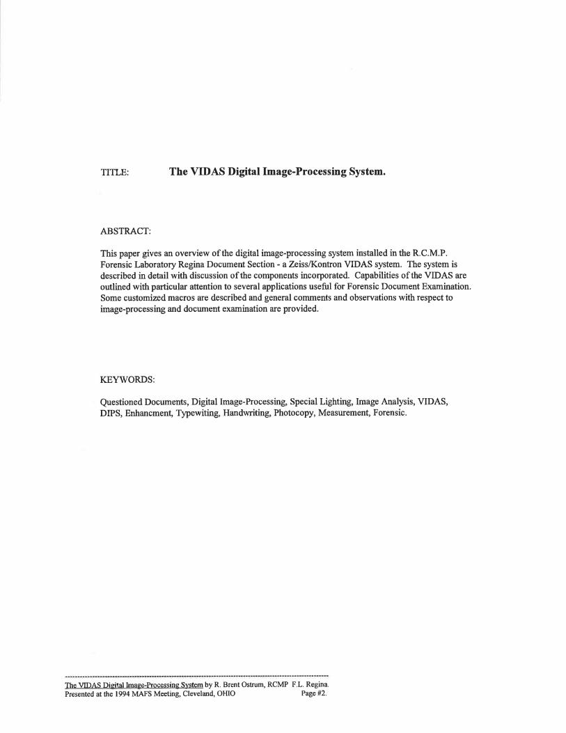
Slide #3: The VIDAS system is physically located in the FLR photography section studio.
This allows considerable control over ambient lighting conditions. Items shown in the
above figure include: VSC-I (to left), computer desk (center) with tower-style computeron the floor and special lighting area (to right) with cameras, lights, etc.
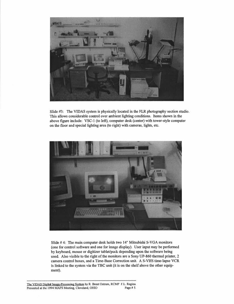
Slide # 4: The main computer desk holds two 14" Mitsubishi S-VGA monitors(one for control software and one for image display). User input may be performed
by keyboard, mouse or digitizer tablelpuck depending upon the software beingused. Also visible to the right of the monitors are a Sony UP-860 thermal printer,2camera control boxes, and a Time-Base Correction unit. A S-VHS time-lapse VCRis linked to the system via the TBC unit (it is on the shelf above the other equip-ment).
The VIDAS Digital Image-Processing System by R. Brent Ostrum, RCMP F.L. Regina.
Presented at the 1994 MAFS Meeting, Cleveland, OHIO Page # 5,

Slide #5: The computer is a Kontron-built IBM compatible 486-DX2 (66Mhz). The installedcomponents/features include: EISA bus, SCSI controller, 540 Mb hard drive, 90 Mb removable Bernoullidrive. The key DIP component is the framegrabber which is a proprietary Kontron card. It offers 24-bitfull-colour, has 3 Mb freely-configurable memory on-board and will accept either NTSC or PAL videosignals. A US Robotics 14400 modem can also be seen on top of the computer.
Slide # 6: In order to perform special-lighting examinations the VIDAS uses some customized inputdevices. There are two PAl-configuration cameras connected (each is software selectable). For visiblelighting there is a Dage/lVfTI NC72E CCD camera and for IR lighting there is a Dage/IVITI Lead-sulfidetube camera (sensitive to 1800 nm). Three lenses are used interchangeably: a Nikon 28mm lens, a Contax60mm Planar lens and a Navitar Zoom 6000 lens for macro/micro work. Camera control boxes allowprecise control over gain, black level, gamma, bandwidth and so on. The custom filter wheel has three
platters each holding up to seven 50 mm camera filters. The filters installed match those of the VSC-Iwith additional cutoff filters for I100, 1200, and 1300 nm as well as three RGB dichroic filters for colourseparations.
The VIDAS Digital Image-Processing System by R. Brent Ostrum, RCMP F.L. Regina.
Prosented atthe 1994 MAFS Meeting, Cleveland, OHIO Page # 6.

Slide #7: Main lighting comes from to daylight flourescent units attached to the copy stand. A Foster &Freeman MH400 allows for selective incident lighting from UV through the entire visible spectrum withuser-selectable bandwidths. A Schott KLl500 Electronic fibre-optic light source provides strong direc-tional lighting that can also be filtered at the source. Other UV and IR sources are also used as needed
Slide # 8: The primary ouþut device for the VIDAS is an Hewlett-Packard LaserJet IV printer which has
been upgraded with an XLI PhotoJet MIO board to provide 2400 dpi ouþut (halftones @ 150 lpi with 256
greys). The XLI board has not yet been fully tested but it appears to work very well. The laser printer is
used for most hard-copy buta Sony UP-860 thermal printer is also used for quick, and very good, copies ofimages displayed on the image monitor. It is connected in-line between the framegrabber'video out'portand the display monitor and provides high-resolution copies with excellent grey-scale rendition. The
drawbacks to the thermal prints are the small size (9.5 cm x 7 cm), their deterioration over time or withexposure to light and heat and the difFrcuþ ofincorporation into reports, etc.
The VIDAS Digital Image-Processing Svstem by R. Brent Ostrum, RCMP F.L. Regina.
Presented at the 1994 MAFS Meeting, Clevela¡rd, OHIO Page# 7.

VIDAS "functions" - lnain. SETUP
.IN/OUTPUT
' ENHANGE
. SEGMENT
. BINARY
. TúEASURE
. DATA OUT
. UTILITY
' EDIT
. REMOTE
. coLouR
. FLOATFfT
Slide #9: The main'scientific'image-processing software used is the VIDAS Release 2.5 software
developed by Konfion. It is a DOS-based package that is highly functional and configurable to the user's
needs and preferences. It has a menu-driven option and the figure above lists the primary menu choices
when working in that setup. The arrangement corresponds to the natural progression in most DIP analyses
from setup and input to enhancement, segmentation, and so on. Like their competitors Kontron is continu-ally developing their software - a new Windows-based version is expected shortly. At the time of writing,it is Zeiss policy to provide software upgrades at no additional cost - a policy ofgreat concern to any user
over the long term.
This is the main VIDAS menu formacros relating to Forensic Document Examination.
A selection is made using tho mouso or digitizer puck,the user simply follows instructions that appear on the screen.
These macros were w¡itten by Kontron/Zeiss progrrimmers(with some later modifioation by FLR personnel).
Slide # l0: Like most DIP software, the VIDAS package can be customized by means of macros and,
to date, several macros have been written specifically for forensic document work. The menu shown
above incorporates six of the original macros (plus two setup routines). Other useful macros have also
been developed but they have not yet been incorporated into this menu yet.
The VIDAS Digital Image-Processing S)¡stem by R. Brent Ostrum, RCMP F.L. Regina.
Presentsd atlhe 1994 MAFS Meeting, Cleveland, OHIO Page #8.

COIJNT ESC CPI LETTER
Rr#na.9kFcb. 2O
Âe T lltq r
thta arl grtI ¿r¿'r PaoPlesenÙ I ¡¡¡ sI an Ln sl¡åraas. A8 I .¿as Iû ülFerlî I
êùIha
I sÞ sure by notrvrrotrg aud eu deePlcæt ebouê I e¡n Ion ¡r rME. ltte lgIÈesfûe &G s ÈrlI r¡an ne?erbdo Ð ùhlg ¡Bata.
2.555.492.352.552.552.7s2.942.355. l0aa<2.55
Mean:
10
ll
ABOVE:ment data
9.964.53
10.799.969.969.258.64
10.794.989,259,96
8.99
I2
3
45
67
8
9
am
leeâ
avviin
ithhe
excerpt of numerical escape-ftom macro.
LEtr'T: visual image as viewed on-scfeen.
Slide #11: Typewriting escapement macro. The left side of the above figure shows the resulting on-screen image after the macro has run, while the right side exemplifies the numerical data generated by themacro. In running the macro, the user'tags'the first and last characters of interest and the software selects
all characters in between automatically, measures the'spacing' and calculates the escapement and charac-
ters per inch. This version of the macro calculates escapement for an entire line of typewritten text (or aportion of a line). Another variation measures 'pair-wise' escapement for selected pairs of letters.
Please note with all the images displayed the on-screen results are superior (in some cases greatly supe-
rior) to either the slides or hard-copy images. This is one area we are trying to improve upon,
R. C. M. POLICE F.L.R. DOCUMENTS SECTION
FILENAME: test DATE: OCTOBER 5, 1994
CHARACTER ALIGNMENT
Distance in mm.-0.021089-0.00r99s-0.003683
-0.003683-0.00488
|20!21U22y23
-0.0170770.0026310.00144792184
(and repeated for second line)
IMAGE#1
IMAGE # 1: macro results on-screen. Lines a¡e selected by the examiner and a baseline calculated for each. Theposition of characters above/beloilon the line is then determined automatically.
ABOVE RIGHT: character alignment measurements - numerical data from macro. The examiner must take note ofall descending cha¡acters as they always have negative values.
Slide #12: Typewriting alignment macro. This macro measures mis-alignments above and below the
baseline of typewritten text.
Line/CountUtU2U3U4!s
The VIDAS Digital Image-Processing System by R. Brent Ostrum, RCMP F.L. Regina.
Presented at the 1994 MAFS Meeting, Cleveland, OHIO Page #9.

FILENAME: test DATE:OCTOBER5, 1994
LINE SPACING
Distance in mm,43t4t241239251041243139241241241241241243t471
MEAN: 4236 VARIANCE: .0924
IMAGE #1:
IMAGE # I : macro results on-screen. Baseline is determined for each line automatically and the distance betweeneach calculated.
ABOVE RIGHT: line spacing measurements - numerical data from macro. Note that the choice of measurementunits is arbitrary - in this case it is millimeters but any scaling is possible.
Slide #13: Typewriting line-spacing macro. This macro calculates line spacing of typewritten text. In thepresent version the examiner tags one character per line - this does not allow for character to character varia-tion. A newer version is being developed that'averages' all characters to produce the baseline. Note also thatthere are several statistical options built into the program that can optionally be applied to any parameter
measured. In this case, only the mean and variance are displayed but a wide variety of other statistics are
available. Data can also be exported for use with dBase or Lotus.
L ne/CourtI)1
4
5
67
8
9t0ll12
13
14
l5
IMAGE#I IMAGE#2.
IMAGE #3
Image #l: Freely-written signature (Kl).lmagefl2 'Traced'copy of Kl.Image #3: Image 2 subtracted from Image 1.
Differences are emphasized as
white and black areæ (areas in
NorE: on-screen image i, tur-.:iÏ,To::iil:T ffiiålil]*nn : *0, and brack: green.
Slide #14: Registration/Overlay macro. This macro has many uses - in the example shown above it isused to emphasize the degree of similarity/divergence between two signatures (one freely-written and the
other a tracing). This involves aligning the images and subtracting one from the other. The resulting on-
screen image is full-colour with areas of divergence displayed as bright red and green against a light greybackground making them very easy to see. If desired, the user may also determine how well the twoimages superimpose by measuring the size of the areas of similarþ or divergence.
The VIDAS Digital Image-Processing Svstem by R. Brent Ostrum, RCMP F.L. Regina.
Presented at the 1994 MAFS Meeting, Cleveland, OHIO Page #10.

R C M POLICE FLR DOCTJMENTSSECTION
FILENAME: tesl DATE:OCTOBER5,1994
TONER
Magniñcation = I 00234E+00 Rotat¡on: 5 27867E-01 degToleruce=0019896cm
Trash mark no23
4
Length eror ¡n cm-t 776f58-153 558948-03
8 988588-03
Rolat¡on eror in degrees-2 48689E 14
I 35809E-01
I 19233E-01
ABOVE: toner measurements - numerical escapement datafrom macro.
LEFT: visual image as viewed on-screen. Vector lengthsand rotation errors of4 relevant toner marks on two differentimages are calculated.
Slide #15: Toner macro. This macro measures toner trash-marks to determine how closely they matchon two different documents. In order to allow for variation in machine magnification (and/or interveningcopies), the macro uses two toner marks as reference points. All other marks are measured for distancefrom reference point I at an angle determined from the line between reference points I and 2.
Again, this macro normally displays the results on-screen in full-colour with each sample being given adifferent colour.
IMAGE #1 IMAGE #2.
IMAGE #3
Image #l: Representative ESDA lift.
lmage#2: 6 ESDAs digitally superimposed.
Image #3: 2xzoom of 'signafure' in image 2.
Name 'Bobbie' is clearly visible.
Slide #1: ESDA enhancement. This macro assists the 'digital superimposition' of ESDA lifts in a manner
analogous to manual superimposition. The procedure is derived from a paper presented by Baier(ASQDE, 1988) and it can dramatically improve the information obtained with the ESDA. In this exam-
ple, 6 ESDA lifts were taken and'averaged'. None of the original lifts provided enough detail alone toread the message or determine the name and manually superimposing them \ryas not effective. The macro
result speaks for itself.
The VIDAS Digital Image-Processing System by R, Brent Ostrum, RCMP F.L. Regina.
Presented at the 1994 MAFS Meeting, Cleveland, OHIO Page # I I .

IMAGE #I IMAGE #2
IMAGE #3. IMAGE #4.
IMAGE #1: IR Luminescence with VSC-I (Bl-Gr @ 7l5nm);4 images captured and combined with VIDAS,
IMAGE #2: IR Luminescence with VIDAS (LST camer4 Bl-Gr @ 715 nm);single image.
IMAGE #3: image I after normalization of the image.
Some contrast improvement is evident,IMAGE #4: image 2 after notmalization of the image.
Image detail in original now becomes obvious.
Slide #17: VSC-I v€rsus VIDAS. This figure compares results obtained using the VSC-I and a custom-ized VIDAS for IR luminescence. The VIDAS does provide somewhat beffer results mainly due to the
ability to fine-tune the equipment but it also exacts a toll on the user - ie. you have to think about what youare doing moreso than with the VSC-I. Please also note that the VSC-I used in this example is notworking very well and a new unit would undoubtedly perform much better.
"t--
l,Mffi i {{ &rr*rl) fï,w ß Lt:.i. ss r9¡'lÈ:1, r st s,lsl. I tË ø"1+
ffi|w rffi &i*üFpl
IMAGE #I. IMAGE #2.
Two simple measuring options provided bv VIDAS
Image #l: interactive point-to-point measurement option.(the user selects each point with the cursor)
tmage #2: .F;'.tåi'lJ*T:T iï',äffìi":i,ï',:: a rough size rererence
Slide # 18: The VIDAS provides several options for measuring features of interest. Measurements may be
based on object-specific features, densitometric features, field-specific features or interactive designation (as
in image #1 above).
The VIDAS Digital Image-Processing System by R, Brent Ostrum, RCMP F.L. Regina,
Presented atlhe 1994 MAFS Meeting, Cleveland, OHIO Page #12,

l'¡sL f t¡r¡r ie¡ lr a¡rf .¡r.m I'lrì lt{ I'll;¡ill
kru pass
H i.r¡lr pa.s
BdFd -ìÌès
Fe,r it¡â ic
I- irìeêr
Ìlarrrtflr.*urr
{iector
Sir*:
IlRtlsru0rlrh
lìpo Ls'
STOP
I
EÐU
This is the main VIDAS menu forFast-Fourier Transform (FFT) filters
A selection is made using the mouse or digitizer puck,
the user simply follows instructions that appear on the screen.
Other FFT filters are also available - eg. Wiener filtering.
Slide #19: The figwe above depicts a menu macro from which the user can select one of several built-inFFT filters. Other FFT options are available but not on this menu. One sfrength of the VIDAS is its
ability to perform a wide variety of FFT analyses quickly and easily. Pre-defined masks can be selected ora ne\il mask can be easily created. Kontron also offers a hardware 'upgrade' called the IBAS which is an
array processor that provides greater speed for FFT analyses should it be required.
IMAGE #I. IMAGE #2.
IMAGE #3
Image # l: Original image with noisy backgrd.
Image #2: Background enhanced.
Image #3: Foreground enhanced.
Periodic "noise" can be either removed orenhanced using a selective filter applied inthe fourie¡ (FFT) domain.
Slide #20: This is an example of the removal or enhancement of periodic features in an image. Dependingupon the desired effect the 'noisy'background may be removed or enhanced. The results shown above
were obtained with the 'Periodic' option on the FFT menu sho\iln earlier. There are other methods that willproduce similar results but this one is very effective.
The VIDAS Digital Image-Processing System by R. Brent Ostrum, RCMP F.L. Regina.
Presented at the 1994 MAFS Meeting, Cleveland, OHIO Page #13.

IMAGE #l: bluned original.
IMAGE#3: debluned-difference of GAUSS.
IMAGE #2: debluned -WEINER FFT filter.
IMAGE #4: debluned -Unsharp masking.
Slide # 2l: This figure exemplifies a VIDAS FFT option that is not on the main FFT menu -the Wiener filter, This is a very powerful FFT filter useful for debluning images when the
bluning function is known or can be estimated or calculated. The results of a Wienerdebluning operation are compared to those of two common spatial methods of debluning(difference of gaussian and unsharp masking). There are, of coutse, other deblurring optionsbut few come close to the results of the Wiener filter.
Concluding statement:
The VIDAS digital image processing system is a very eflective and efficient tool that can be used for a wide variety ofdocument examination tasks. It is a robust and powerful image-processing system; both with respect to the hardware and
software. It is a full-fledged and full-featured DIP system and, as such, requires some degree of both technical abilþand understanding of image-processing concepts in order to take advantage of what it offers. It should be noted that the
latter will also apply to most, if not all, DIP systems on the market today. It is not realistic to think that anyone could sit
down at a DIP workstation and be instantly productive.
On the positive side, the VIDAS macros described in this paper help matters considerably. They work quite well and
simplifr specific tasks making the system very user-friendly for those tasks. But they are not perfect and require fine-tuning and further development. It should be noted that the VIDAS was obtained, in part, to serye as a'test platform'.
As such we ultimately hope to use it to create a usable and portable collection of image-processing applicationsexpressly designed for document examiners,
This presentation has been a brief overview of the VIDAS with examples of its use by practising document examiners. Itis not intended to be an endorsement of the product, nor a recommendation to purchase such a system. On the otherhand, if you are thinking about acquiring a DIP system for document examination work, then the VIDAS can and should
be included on your list ofpotential choices.
The author can be reached at the address given on page 3 directly to discuss the information provided in this paper ingreater detail.
The VIDAS Digital Image-Processing System by R. Brent Ostrum, RCMP F.L. Regina.
Presented at the 1994 MAFS Meeting, Cleveland, OHIO Page #14.