The Systems and Design Philosophy of Mosquito 2.0
10
The Systems and Design Philosophy of Mosquito 2.0 Allison Ahern, Robert Gillig, Jason Julius, and Woodrow Walker Underwater Robotics Team, Milwaukee School of Engineering Milwaukee, Wisconsin, USA Abstract The MSOE Underwater Robotics Team is a fifth year student organization at the Milwaukee School of Engineering. Last year, the team attended the international competition at NASA’s Neutral Buoyancy Laboratory and placed fifth attracting the attention of the new students and faculty members. This year’s ROV, Mosquito 2.0, was designed specifically to be compact, practical and modular, focusing on adaptability and stability to be able to complete any scheduled task, while being able to change critical systems for future endeavors. A subsystem approach to design allowed a lot of collaboration to happen since each part of the ROV could be worked on separately and brought together with ease. 1. Introduction/purpose The MSOE Underwater Robotics Team competes in the Marine Advanced Technology Education (MATE) international ROV competition. Last year, the team took fifth place at the international competition which took place at the NASA Neutral Buoyancy Laboratory in Houston, TX. This year, the competition took place in Long Beach and the theme was commerce, entertainment, health, and safety in port cities. 1 For the competition, there is a specific set of tasks related to what an actual ROV would be used to do. These tasks include but are not limited to picking up/moving/flipping objects, taking measurements, measuring temperature, and collecting samples. Most of the tasks are simulated using PVC pipe. For this year’s competition, the team started with last year’s ROV, Mosquito, and kept a few of the major systems the same such as the frame, dry housing, and thrusters. Other systems such the the manipulator and control system were changed to better fit this year’s mission. 2. Design Rationale All designs are a combination of: efficiency, economics and practicality and every decision made always has a trade off with a set of pros/cons. Our design process was heavily influenced by 3D printing, allowing our designs to be quickly developed from brainstorming to implementation in less than a few days and sometimes produce a turn around in a few hours. 1 Funding for travel to the competition provided by WSGC
-
Upload
khangminh22 -
Category
Documents
-
view
2 -
download
0
Transcript of The Systems and Design Philosophy of Mosquito 2.0

The Systems and Design Philosophy of Mosquito 2.0
Allison Ahern, Robert Gillig, Jason Julius, and Woodrow Walker Underwater Robotics Team, Milwaukee School of Engineering
Milwaukee, Wisconsin, USA Abstract The MSOE Underwater Robotics Team is a fifth year student organization at the Milwaukee School of Engineering. Last year, the team attended the international competition at NASA’s Neutral Buoyancy Laboratory and placed fifth attracting the attention of the new students and faculty members. This year’s ROV, Mosquito 2.0, was designed specifically to be compact, practical and modular, focusing on adaptability and stability to be able to complete any scheduled task, while being able to change critical systems for future endeavors. A subsystem approach to design allowed a lot of collaboration to happen since each part of the ROV could be worked on separately and brought together with ease.
1. Introduction/purpose The MSOE Underwater Robotics Team competes in the Marine Advanced Technology Education (MATE) international ROV competition. Last year, the team took fifth place at the international competition which took place at the NASA Neutral Buoyancy Laboratory in Houston, TX. This year, the competition took place in Long Beach and the theme was commerce, entertainment, health, and safety in port cities.1 For the competition, there is a specific set of tasks related to what an actual ROV would be used to do. These tasks include but are not limited to picking up/moving/flipping objects, taking measurements, measuring temperature, and collecting samples. Most of the tasks are simulated using PVC pipe. For this year’s competition, the team started with last year’s ROV, Mosquito, and kept a few of the major systems the same such as the frame, dry housing, and thrusters. Other systems such the the manipulator and control system were changed to better fit this year’s mission. 2. Design Rationale All designs are a combination of: efficiency, economics and practicality and every decision made always has a trade off with a set of pros/cons. Our design process was heavily influenced by 3D printing, allowing our designs to be quickly developed from brainstorming to implementation in less than a few days and sometimes produce a turn around in a few hours.
1 Funding for travel to the competition provided by WSGC

Flow Diagram Showing the Team’s Process
The design process above gives a broad overview of how our team iterates through our designs. The team first assessed the needed task to be completed from the competition manual. Simulation is critical to the modern day engineer. Simulating the electrical and mechanical systems using a wide variety of programs such as MultiSim, Simulink and SolidWorks allowed the team to make analysis oriented design decisions and spending less time trial and error. However, all the simulated analysis in the world does not take the place of prototype testing driven by hard data. Thrust and gripper testing was completed in a laboratory setting using force sensors to gauge power needs and achievable thrust. Electrical designs were tested on breadboards and scopes. Once a reliable design was established final implementation onto the ROV would take place. The modular design allowed the team to work on each subsystem independently testing and prototyping then bringing the system together for final implementation. 2.1 Frame Compacting the design into a frame that only incorporates the necessities keeps the weight down and increases utility. The frame was printed in ABS which has a lower density of 1.05g/cm3, compared to PC’s density of 1.22g/cm3, thus saving weight while gaining performance. With ABS being more elastic than PC, the frame is able to better hold up to the rough handling that the ROV experiences on a regular basis. The sparse filled honeycomb pattern keeps the frame rigid while saving 0.8kg of mass.
3D model of the newest frame, featuring the weight saving honeycomb structure
2.2 Dry housing It was decided to use a cylinder dry housing because cylinders have
much better hydrodynamic properties with their lower drag coefficients compared to a rectangular prism. That allows for faster acceleration while also reducing the effects of undesired currents pushing the ROV around. The only downside is that they require more focus on organization and planning in order for all the electronics to fit.

Assembled dry housing after a pressure test to verify seals
The team decided to go with two customized 10cm acrylic tube enclosure from Blue Robotics that have been tested to depths of 100 meters. The electronics are split among both tubes to reduce total ROV size. The clearness of the tubes allows for verifying that no water has entered the enclosure and that the system is running with the status LEDs. The enclosure has a vent to hold the two caps in place with pressure differential, and uses a dual o ring system for sealing. Two straps were added to prevent the caps from coming off in the event of a bulkhead getting caught on something. The straps also double as a way to secure the tubes to the frame. 2.3 Buoyancy/ballast The goal for buoyancy was to keep mass low in order to keep acceleration/maneuverability high (Newton’s law, F=ma). Extra mass or flotation was only added to balance the ROV and make it neutrally buoyant in water. The team aimed to keep all naturally negatively buoyant items towards the bottom of the ROV and all positively buoyant items towards the top to keep the center of gravity towards the bottom and to keep the ROV in tension. 2.4 Thrusters The team used a brushed bilge pump solution. Opening a bilge pump showed a quality shaft seal that should increase in sealing performance under pressure and a motor that filled the entire space given as the motor case is modeled around the motor. That allows for an excellent power/size ratio and a reliable seal.
SolidWorks Rendering of a modified bilge pump with a Kort nozzle as a propeller shroud
Eight Tsunami 1200 GPH bilge pumps were used, four vertical, and four vectored horizontal. The thrusters were mounted at 37.5 degrees to create a best case combination of agile turning
and quick forward/backward movements. While a 45 degree angle would improve lateral thrust,

it would also reduce the more commonly used forward and backward thrust. This form of vectored thrusting eliminates the need for lateral thrusters, allowing for reduced weight. They
were placed so the water flow is as unobstructed as possible, while allowing for a balanced application of the force.
2.5 Thruster guards Designing the thruster guards was walking a fine line between safety and efficiency. The original design was made to cover the thruster props and provide an efficiency boost using a Kort nozzle design to aid in thrust performance. The guard would then be attached to the bottom of the modified bilge pump with a compression zip-tie on extruded arms. These arms were designed to flow with the basic shape of the guard while providing the least amount of resistant to water flow as possible. The guard originally had a honeycombed mesh to prevent unwanted objects, such as fingers, to be sucked into the prop, however was removed do to a major drop in efficiency because of the decreased water flow. This problem was fixed with the finalized design by increasing the clearance between the prop and the guard and moving towards a modified Kort nozzle design to improve thrust. This modified Kort nozzle was engineered to act similar to how airfoils work for aircraft wings and incorporate the design into a safe but efficient model for improving thrust. The final design was tested and verified to provide a 60% increase in thrust, for a measured thrust of 3.15 kgf.
2.6 Bulkheads The team uses the SubConn bulkheads which have never leaked and have proven themselves over and over again over the years. The lightly corroded nuts on the bulkheads were replaced with new stainless nuts, and the O-rings were replaced with new Buna-n O-rings. The old nuts corroded because they were zinc plated and zinc has a 0.85 V galvanic difference from the brass on the bulkheads. The stainless only has a 0.10 V galvanic difference, resulting in a lower chance for corrosion. To help reduce weight and better manage wiring internal wiring in the confined space, the wires coming from the bulkheads were shortened to the exact lengths needed. Since the tether bulkheads are regularly removed, screw caps were added to guarantee a quality electrical connection and to eliminate the chance of the tether becoming unplugged during the ROV’s operation. 2.7 Microcontroller The Tiva C is the connected microcontroller used on the ROV. It’s low cost, high performance, with a 120MHz ARM processor (with 150 million instructions per second), 90 GPIO, and a built in Ethernet port. The processor has a floating point unit that is useful for performing kinematic calculations and running control loops. That eliminates the need and extra development time to transfer calculations to fixed point integer math. It also contains a high precision, integrated 12-bit ADC that provides a precise way of monitoring current and voltage currents without needing to add additional components. There is a team-designed/built breakout board that adds buffering to all outside connections, reducing the chance of the Tiva C from getting damaged. Output buffers also improve signal quality with the increased current capacity, and provides the necessary logic level shifting to bring the signals to 5V over the Tiva

C’s 3.3V logic. Signal degradation to servos and sensors has been an issue that has been faced by the team in the past, and the output buffers fix that.
2.8 Motor controllers This year the team decided to try designing custom H-bridge motor drivers using high power mosfets and a prepackaged H-bridge fet driver IC. This design was going to be implemented to allow for the replacing of the current regulator, which was taking up an entire tube on the robot, to a much smaller regulator by using the 48V provided by the tether instead of a stepped down 12V. This is accomplished by adjusted duty cycles and some very heavy filtering across the motor to smooth out the spikes in voltage. During prototype testing, the driver was able to output the expected voltage of 12V when in a static power applied mode. The major issue was with switching direction; as the driver was switching the motor direction a large amount of shoot through current went through the all the mosfets in the driver causing components to be destroyed. The team then re-evaluated the time it would take to get a competition ready controller, and it was decided to change to a commercially available controller. The Polulu G2 18v25 High Power motor controllers provide a reliable brushed motor controller with a several features for adjusting PWM frequency, acceleration/deceleration, under and over voltage cutoffs, temperature monitoring, thermal shutoff, and motor braking/regeneration. Each motor controller receives its own PWM signal instead of chaining multiple controllers together. It’s a more reliable design that allows the ROV to partially function in the case of a single point of failure. There is also a built in watchdog functionality that disables the motor if a command hasn’t been received in the past second. The motor controllers themselves are physically compact, and thoroughly tested. This controller drastically reduced space as well by having far less wiring and filtering capacitors, retrofitted connectors for a breakout board, and much smaller, discrete components. 2.9 Voltage regulators For any load greater than a few watts, a switching regulator is used since they are much more efficient than an alternative linear regulator. The switching regulator used is a TDK-Lambda PAF700s operating at an efficiency of 90%, and an input voltage range of 36-72V allowing for spikes and drops on tether voltage. The PAF700 also has electrically isolated outputs which provides additional safety and helps to reduce the possibility of external noise from interfering with the ROV. It is turned to 13.8V, from its nominal 12.0V, allowing for the electrical system to get 15% more power out of the Tsunami 1200 GPH bilge pumps. Slightly boosted voltage also helps to account for voltage drops through wiring, motor controllers, and LC filters. It provides a steady voltage as long as the input voltage is within operating range. The small overvoltage applied to the “12V” rail is still within specifications for all devices connected to it. Using a regulated source on the ROV allows for more predictable operation under varying surface power supplies and power conditions. It also gives the onboard electronics and motors a close low impedance power source that doesn’t suffer from the
somewhat large tether resistance/inductance. Voltage stays constant as a result of not changing under load from the resistive losses through the tether as current increases.
Eagle Rendering of the Team Designed PAF700 breakout-board, with LC filters, voltage tuning circuitry, and
input/output connectors
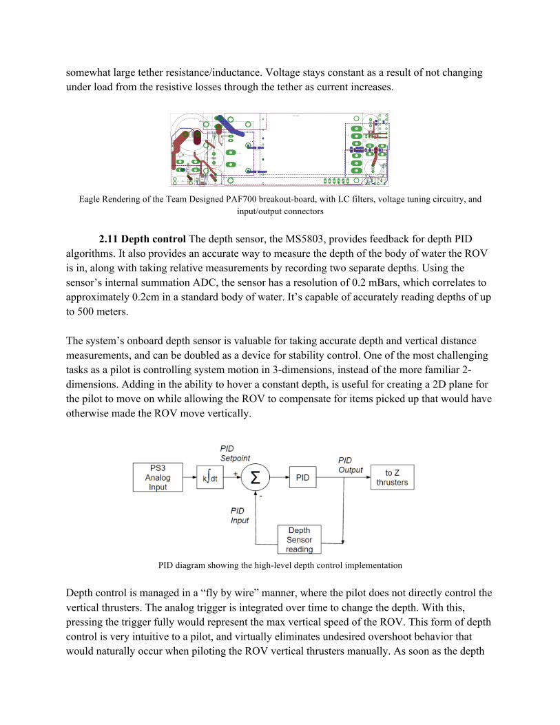
2.11 Depth control The depth sensor, the MS5803, provides feedback for depth PID algorithms. It also provides an accurate way to measure the depth of the body of water the ROV is in, along with taking relative measurements by recording two separate depths. Using the sensor’s internal summation ADC, the sensor has a resolution of 0.2 mBars, which correlates to approximately 0.2cm in a standard body of water. It’s capable of accurately reading depths of up to 500 meters. The system’s onboard depth sensor is valuable for taking accurate depth and vertical distance measurements, and can be doubled as a device for stability control. One of the most challenging tasks as a pilot is controlling system motion in 3-dimensions, instead of the more familiar 2- dimensions. Adding in the ability to hover a constant depth, is useful for creating a 2D plane for the pilot to move on while allowing the ROV to compensate for items picked up that would have otherwise made the ROV move vertically.
PID diagram showing the high-level depth control implementation
Depth control is managed in a “fly by wire” manner, where the pilot does not directly control the vertical thrusters. The analog trigger is integrated over time to change the depth. With this, pressing the trigger fully would represent the max vertical speed of the ROV. This form of depth control is very intuitive to a pilot, and virtually eliminates undesired overshoot behavior that would naturally occur when piloting the ROV vertical thrusters manually. As soon as the depth

trigger is released the ROV will hold the precise depth of when the trigger was released. This form of control eliminates the need to manually enter and exit a depth hold mode and provides seamless interaction and allows the pilot to better focus on the tasks at hand instead of stabilizing the ROV.
It was important that the thrusters would not be in an oscillating or “thrashing” state. Thruster oscillation would heavily load and stress the motor controllers and motors themselves. To solve this we discovered that scheduling with two different sets of gains, and aggressive and a conservative set of gains, were needed for the system to have fast and stable response while previously holding a steady state value. With gain scheduling enabled, the conservative gains are enabled when the ROV is within 8mm of the desired set point. Our final tuning gains allow the system to respond to a 75 cm depth step/change within 3 seconds, with only 4 cm of initial overshoot and a final steady state jitter of 0.8 cm.
2.12 Software management Git and BitBucket were used to manage software, allowing for advanced versioning and backups. Using git allowed the team to easily revert to older working versions if a change was made that breaks system functionality. Git’s branching functionality was also used to keep development and stable branches separate, the development branch was used to try out new features, while the stable branch was always available as a fallback option. The software was broken down into different files for each feature, allowing for clear organization and enhanced readability, while also keeping individual file sizes down to eliminate confusion.
Basic flowchart showing general flow of the ROV’s team designed and created software components
Java code running on a laptop provides feedback from the ROV’s sensors and set thruster values. Whenever possible, the PlayStation 4 controller is used to provide input to the system. The PS4

controller was chosen for its ideal joystick placement, large amount of buttons available for input, and its widespread use. Its able to be read over USB, providing enhanced stability in noisy environments, or Bluetooth, allowing pilot to move around which was especially handy in testing. The HMI connects to the ROV via a UDP stream that is updated at 50Hz. UDP allows for efficient data transfer with minimal overhead, though some packets might be dropped occasionally.
2.13 Cameras Video signals are transmitted over UTP wire using impedance matching
baluns. The cameras only receive power from within the dry housing while all video signals are passed straight to the tether through an inline IP68 Ethernet plug. Power is filtered with an RLC filter to help isolate cameras from system noise (like motors) and to produce a cleaner picture. The video multiplexer is on the surface to reduce amount of electronics and wiring needed on the ROV, and allows for some setups to have multiple displays.
2.14 Tether The standard operation of the ROV uses a maximum of approximately
500W. With this information and an estimated tether length of 22 meters, voltage drops and power carrying capacities can be calculated, assuming a 48V power supply is used. 16 gauge wire is then the smallest gauge wire that can be safely used to meet the power demands of the system. A large voltage drop is found acceptable for the system due to all of the onboard systems running off of regulators designed to accept a wide range of voltage inputs. 16 gauge wire used on the ROV is a high flex silicone covered wire made up of 208 strands, and has an ampacity of 35 amps.
Cat7 STP cable is used for all signal transmission. One for Ethernet communication and one for video signals. The tether is detachable for easier transport and ability to add future tether extensions to accommodate deeper areas. All of the separate wires are kept together with 12.5mm nylon cable mesh. Tether strain relief is provided to securely attach tether to the ROV and prevent tether from applying unnecessary force to bulkheads 2.15 Manipulator Since the base ROV was being used from last year the focus was mainly on the payload tools. This led to a full redesign of how the gripper system works while keeping the base design intact. A 3D printed gear box was used to get a specific reduction of 7.5:1 on the previous gripper. This solution worked for a short period of time, however was prone to breakage after repeated use. The team decided to transfer over to a more compact ceramic and metal gearbox made by Matex that would deliver a 5:1 reduction from the bilge pump.

Matex Gearbox
A speed reduction was still needed so that the gripper could maintain a usable close speed. This was achieved by using a higher pitched ACME lead screw that transmitted the gripping strength. Moving from 12 threads per inch to 16 threads per inch would give us the needed grip time. Next step was making the gripper more adaptable to the mission tasks. This required an overhaul of the gripper motion. Initial team brainstorming theorized that having the ability to move the whole gripper would reduce the need to reposition the ROV around the mission props. This was implemented by adding another bilge pump motor to drive a forward and backward motion lead screw shown in the image below. This plays well into the team’s design rationale of wanting a modular design, by having the gripper assembly slide onto this upper assembly the gripper could be easily replace by another tool that needed the same motion.
Top Slider
The whole assembly can then be put into a folded traveling mode, where the gripper is detached and the slider is pushed to the middle of the ROV. This saved space during transportation and storage. A lot of the mission tasks have the ROV grabbing circular objects, so the gripper claws were designed with this in mind. One specific task was turning a valve which the current gipper could not do. To do this, a spur bevel gear design was proposed and prototyped to work well, however slipping occurred during power transmission to the valve. To reduce the possibility of slipping occurring, a helical bevel design was used as shown in figure below.
Spur bevel gear vs helical bevel gear design
This component once again was designed to be modular and can be replaced with a different mission tool. Overall the gripper redesign was a success and the added motion pared with the control system will make the ROV more reliable and adaptable to mission tasks.

3. Conclusion Overall, the ROV worked fairly well at the competition. One of the motor controllers gave out during the first run, which the team suspects has to do with a bad ground connection. Other than that, no major issues occurred with any of the systems. One future improvement to the ROV for next year is a more robust control system to prevent any issues like the one we experienced at the competition. Another improvement is adding more specific payload tools. The ROV was unable to do a few of the tasks at the competition because it lacked a specific payload to complete the task. Next time, the team can design for each task in order to be better prepared. 4. Acknowledgment None of the work done on the ROV would have happened without the hard work done by the MATE Competition and associated volunteers. Additionally, this ROV was made possible by material and monetary donations from the following: Advanced Circuits—Donation of PCBs Midwest ROV, LLC—Technical support and monetary donation MSOE—For providing excellent facilities and faculty mentors/advisors Milwaukee Tool—For donation of a wide variety of and and power tools OpenROV—Donation of a depth sensor/IMU SolidWorks—Donation of licenses for the team MacArtney/SubConn—For providing an exceptional discount on bulkhead connectors TDK-Lambda—Donation of 3 DC/DC regulators Polulu—For giving the team a generous discount on the motor controller UWM Freshwater Science—For technical support and use of facilities References MATE. (2012). Marine Advanced Technology Education. Retrieved from http://www.marinetech.org/ Stackpole, E. (2013). OpenROV. Retrieved from http://openrov.com/ Steven, M., Bohm, H., & Jensen, V. (2010). Underwater Robotics: Science,Design & Fabrication. MATE.