Structure and dynamics of liquid helium systems and their ...
26 September 1995 OCR Output
Geneva, Switzerland
July 17-21 1995, Columbus - Ohio, USACryogenic Engineering Conference and International Cryogenic Materials Conference,
specific R&D programme in these domains.engineering challenge in applied superconductivity and cryogenicsf and has thus required aunprecedented luminosity of 1034 cm·2.s·l. Therefore, the LHC also represents a majorit will provide proton-proton collisions with a center-of-mass energy of 14 TeV and at anbelow 2 K,3 to be installed in the 26.7 km circumference tunnel of the present LEP collider,ring of high-field, twin-aperture superconducting magnets2 operating in superfluid heliumDecember 1994, will be the next major research facility in high-energy physics} Based on a
The Large Hadron Collider (LHC) project, approved by the CERN Council in
INTRODUCTION
as well as magnet resistive transitions.operation, including response of the system to transients such as current ramp and discharge,industrial PLCs connected to an industrial supervision system. We report on performance incooldown of the 109 kg cold mass. The system is fully instrumented, controlled by dedicatedand auxiliary magnet circuits, as well as a 120 kW liquid nitrogen vaporizer for controlledalso includes 15 kA, 1.6 kA, 500 A, 250 A and 50 A current lead pairs for powering of maininstalled capacities of 120 W @ 1.8 K and 10 g/s supercritical helium at 4.5 K. The systembuilt and are operating a dedicated cryogenic system feeding the LHC Test String, withcryomagnets. Based on existing large—capacity cryogenic infrastructure, we have designed,providing refrigeration at the 1.9 K, 4.5-to-20 K, and 50·to-75 K levels to the LHCof the machine lattice. This also corresponds to the length of the elementary cooling loopstesting and operation of a 50-m long superconducting magnet string, representing a half-cell
A maj or milestone in the preparation of the Large Hadron Collider (LHC) proj ect is the
ABSTRACT
L. Serio, A. Suraci, L. Tavian and R. van WeelderenTh. Goiffon, H. Guinaudeau, Ph. Lebrun, M. Marquet,
A. Bézaguet, J. Casas—Cubi1los, B. Flemsaeter, B. Gaillard—Grenadier,
TEST STRING: DESIGN, CONSTRUCTION AND FIRST OPERATION
THE SUPERFLUID HELIUM CRYOGENIC SYSTEM FOR THE LHC
CERN-AT-95-40— gl $9 f"
"HCN°‘°3”llIIIIIIllIlllllllllllllllllllllllllllllCERN AT/95-40 (CR)
CERN LIBRARIES, G ENEVA
EUROPEAN ORGANIZATION FOR NUCLEAR RESEARCH’/ _

acts as a linear cold source of large developed heat exchange area and at quasi-constant OCR Outputpressurized (1 bar) superfluid helium bath through a corrugated heat exchanger tube.°· 7 ThisString Retum Box (SRB), and the saturated superfluid helium circuit coupled to the
The principal components of the cryogenic system are the String Feed Box (SFB), theother two dipoles will be installed as soon as they become available.obtained with this configuration are sufficient to validate the basic technical choices, theextreme conditions that will be encountered in the LHC tunnel. Even though the resultsstring, on a concrete beam with a slope of 1.4 % (see figure 1), to exactly reproduce theprototypes, one quadrupole (Q) and only two dipoles (D1 and D2) were installed in thethe first time at the end of 1994.5 Due to delays in the delivery of the 10 m-long dipole
The first version of the LHC test string was assembled, commissioned and operated for
PRINCIPLES OF OPERATION AND SYSTEM LAYOUT
report on the spring 1995 campaign and present main results conceming cryogenics,recalling basic operating principles of test string cryogenics, we describe system layout,operation of a full-scale magnet string, representing a half-cell of the machine lattice. Afteraccelerator systems - magnets, cryogenics and vacuum - are concerned, is the testing and
An important milestone in the validation of the basic technical choices, as far as main
Figure 1. General view of LHC Test String
·
·-, i'YI*!~,s!";:#?¥¢»V»‘ ~
`
p _ p »
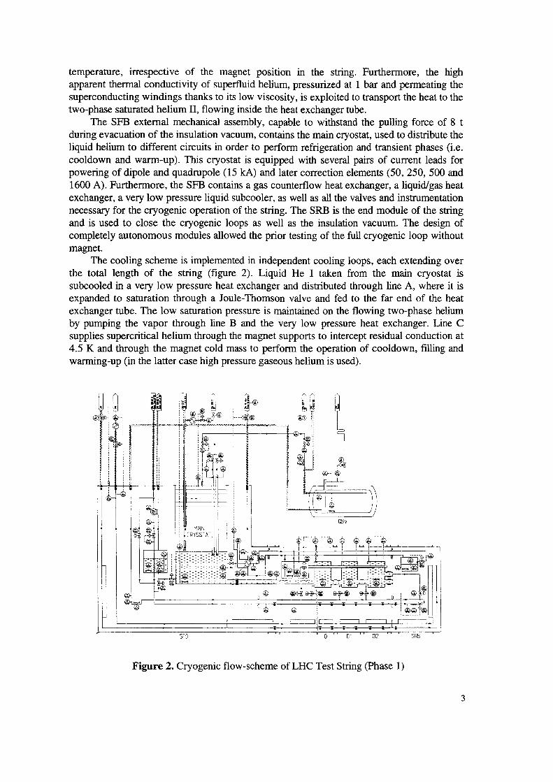
Figure 2. Cryogenic flow—scheme of LHC Test String (Phase 1) OCR Output
SFB 0 " [ll " U2 " ` SRE
so we<i> o
Q@ ®°*$ @ **¥‘®® Ui ._-... ’1J3:3—·7q"":¥®;`;"":¥@:`;—·;" l®....,s...i..i...&{l¤2$2§2§2§2.éL @ 1 l©©l<?~@~@lg ® @1:%
@ @,9 Q. @,,,.
I ll l el gil l%l¥;g~g¤llll .© lGBV
illiki@1 ®
i ®
l flfoho
M '
L. . Aw (@5%
warming-up (in the latter case high pressure gaseous helium is used).4.5 K and through the magnet cold mass to perform the operation of cooldown, filling andsupplies supercritical helium through the magnet supports to intercept residual conduction atby pumping the vapor through line B and the very low pressure heat exchanger. Line Cexchanger tube. The low saturation pressure is maintained on the flowing two-phase heliumexpanded to saturation through a Joule-Thomson valve and fed to the far end of the heatsubcooled in a very low pressure heat exchanger and distributed through line A, where it isthe total length of the string (figure 2). Liquid He I taken from the main cryostat is
The cooling scheme is implemented in independent cooling loops, each extending overmagnet.
completely autonomous modules allowed the prior testing of the full cryogenic loop withoutand is used to close the cryogenic loops as well as the insulation vacuum. The design ofnecessary for the cryogenic operation of the string. The SRB is the end module of the stringexchanger, a very low pressure liquid subcooler, as well as all the valves and instrumentation1600 A). Furthermore, the SFB contains a gas counterflow heat exchanger, a liquid/gas heatpowering of dipole and quadrupole (15 kA) and later correction elements (50, 250, 500 andcooldown and warm—up). This cryostat is equipped with several pairs of current leads forliquid helium to different circuits in order to perform refrigeration and transient phases (i.e.during evacuation of the insulation vacuum, contains the main cryostat, used to distribute the
The SFB external mechanical assembly, capable to withstand the pulling force of 8 ttwo-phase saturated helium H, flowing inside the heat exchanger tube.superconducting windings thanks to its low viscosity, is exploited to transport the heat to theapparent thermal conductivity of superfluid helium, pressurized at l bar and permeating thetemperature, irrespective of the magnet position in the string. Furthermore, the high

temperature higher than the one given by the thermometers installed in the magnets. OCR Outputfew tens of minutes. This effect, not completely understood, might be due to a sensoroccurrence of a quench they all yielded a reading 60 % below the one expected and this for arange from 0 to 3 MPa and a response that strongly depends on the temperature. After the
The magnet pressure is measured by using piezoresistive cold sensors"‘ with a typicalfurthermore the magnets are never operated in this temperature range.in normal liquid helium because of the difficulty to have an isothermal liquid helium I bath;the distributed heat exchanger. No effort was done to make in—situ temperature calibrationstemperature reference was given by the pressure of the saturated liquid helium flowing insideextremely good thermal conductance of pressurized superfluid liquid helium. Thecalibration was done for temperatures below 2 K to within better than 0.01 K thanks to the0.05 K at an absolute temperature that could range between 1.8 K and 1.9 K. Thishigh as 0.2 K while the magnets temperature needs to be regulated to within better thanhad to be recalibrated in situ because they presented temperature offsets that could be asplatinum and Allen-Bradley resistance thermometer pairs. The Allen—Bradley thermometers
Magnet temperature measurements are done in the 300 K to 1.6 K range by using a
WPU.
with ambient temperature differential pressure and thermal flowmeters at the outlet of thesuperconducting magnets. Tests were also done to compare the two cryogenic flowmetersinterference between cold pressure transducer and the main 12 kA current bus feeding theconfirmed the correct operation of the Venturi in spite of possible electromagnetic
flowmeter” at 4.5 K and a thermal flowmeter at 2.2 K are used. The thermal mass flowmeterTo measure liquid helium mass flow in the superfluid helium cooling circuit a Venturi
not need to be calibrated individually.the liquid level gauges and platinum thermometers have a standard response curve and dotemperature and pressure sensors, liquid level gauges and mass flowmeters. Of these only
The LHC test string is equipped with the following cryogenic instruments:
INSTRUMENTATION AND PROCESS CONTROL
nitrogen/gaseous helium heat exchanger and a 25 kW heater.temperature—controlled gaseous helium in the range 300 to 80 K, using a liquidexpelled after a quench and the Cooling and Warming-up Unit (CWU), which providesfrom the magnets after a quench, the balloon system (300 m’) to recover the gaseous heliumBuffer Vessel (QBV)(2000 L) capable of recovering the total volume of liquid dischargedPumping Unit (WPU) to pump on the saturated superfluid helium up to 6 g/s, a Quenchcomprises a 6 kW cryogenic plant capable of producing 18 g/s of liquid helium, a Warm
The system also makes full use of the pre-existing cryogenic infrastructure" thatthe quench trigger and discharging helium in line D.2 MPa maximum design pressure of the cold mass by opening the quench relief va1ve“ on
After a magnet resistive transition,‘° the resulting pressure rise is contained below thelocal cryogenic components of the superfluid cooling loop and an insulation vacuum barrier.
The short straight section cryostatg is based on the same design principle and houses thenon-metallic composite materials and the use of multilayer reflective insulation.refrigeration, the support and positioning of the large cold mass by cylindrical post made of
Main features of the dipole cryostatg are the integration of all pipes distributingsupport to intercept heat at the 90 K level.
Line E and F are used to supply liquid nitrogen to the thermal shield and magnet
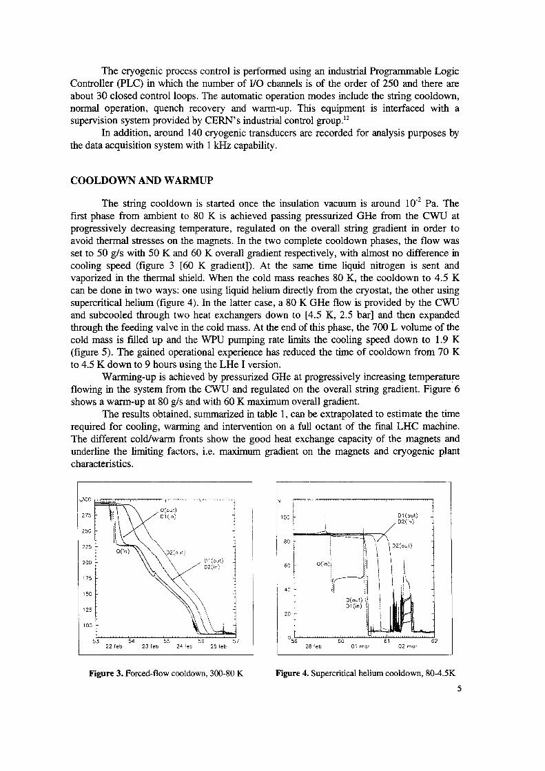
Figure 3. Forced-flow cooldown, 300-80 K Figure 4. Supercritical helium cooldown, 80-4.5K OCR Output
22 feb 23feb 24 feb 25 feb 28 feb Ol mor O2 mor53 54 55 56 57 59 60 B1
100
20 L125
[]1(§n)\\\\own) I
150 4¤ [ ‘l lh175 E g""`*}
\ \ / 6O[ gpm)200
H5? ¤<¤¤> \\_\w....; l l°2‘°“"W A "
250
%%¤¤<t~> ~¤¤ P 3%*, mf-#r·~-·—#e—+#~r~ O(o¤t) l
OO X3
characteristics.
underline the limiting factors, i.e. maximum gradient on the magnets and cryogenic plantThe different cold/warm fronts show the good heat exchange capacity of the magnets andrequired for cooling, warming and intervention on a full octant of the final LHC machine.
The results obtained, summarized in table 1, can be extrapolated to estimate the timeshows a warm-up at 80 g/s and with 60 K maximum overall gradient.flowing ir1 the system from the CWU and regulated on the overall string gradient. Figure 6
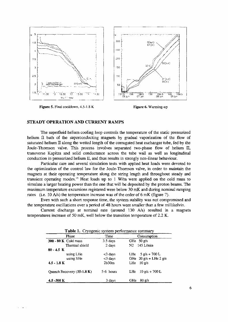
Warming-up is achieved by pressurized GHe at progressively increasing temperatureto 4.5 K down to 9 hours using the LHe I version.(figure 5). The gained operational experience has reduced the time of cooldown from 70 Kcold mass is filled up and the WPU pumping rate limits the cooling speed down to 1.9 Kthrough the feeding valve in the cold mass. At the end of this phase, the 700 L volume of theand subcooled through two heat exchangers down to [4.5 K, 2.5 bar] and then expandedsupercritical helium (figure 4). In the latter case, a 80 K GHe flow is provided by the CWUcan be done in two ways: one using liquid helium directly from the cryostat, the other usingvaporized in the thermal shield. When the cold mass reaches 80 K, the cooldown to 4.5 Kcooling speed (figure 3 [60 K gradient]). At the same time liquid nitrogen is sent andset to 50 g/s with 50 K and 60 K overall gradient respectively, with almost no difference inavoid thermal stresses on the magnets. In the two complete cooldown phases, the flow wasprogressively decreasing temperature, regulated on the overall string gradient in order tofirst phase from ambient to 80 K is achieved passing pressurized GHe from the CWU at
The string cooldown is started once the insulation vacuum is around l0" Pa. The
COOLDOWN AND WARMUP
the data acquisition system with 1 kI~Iz capability,In addition, around 140 cryogenic transducers are recorded for analysis purposes by
supervision system provided by CERN’s industrial control group}normal operation, quench recovery and warm-up. This equipment is interfaced with aabout 30 closed control loops. The automatic operation modes include the string cooldown,Controller (PLC) in which the number of I/O channels is of the order of 250 and there are
The cryogenic process control is performed using an industrial Programmable Logic
4.5 -300 K OCR Output 3 davs GHe 80 2/s
Quench Recovery (35-1.8 K) 5-6 hours LHe 10 g/s + 700 L
4.5 - 1.8 K 2h30m LHe 10 g/susing SHe <3 days GHe 20 g/s + LI-Ie 2 g/susing LI-Ie <3 days LHe 5 g/s + 700 L
80 - 4.5 K
Thermal shield 2 days N2 145 L/min
300 - 80 K Cold mass 3.5 days GHe 50 g/s
TimePhase Consumption
Table 1. Crvogenic system performance surnm
temperatures increase of 50 mK, well below the transition temperature of 2.2 K.Current discharge at nominal rate (around 130 A/s) resulted in a magnets
the temperature oscillations over a period of 48 hours were smaller than a few millikelvin.Even with such a short response time, the system stability was not compromised and
rates (i.e. 10 A/s) the temperature increase was of the order of 6 mK (tigure 7).maximum temperature excursions registered were below 30 mK and during nominal rampingsimulate a larger heating power than the one that will be deposited by the proton beams. Thetransient operating modes}5 Heat loads up to 1 W/m were applied on the cold mass tomagnets at their operating temperature along the string length and throughout steady andthe optimization of the control law for the Joule-Thomson valve, in order to maintain the
Particular care and several simulation tests with applied heat loads were devoted toconduction in pressurized helium H, and thus results in strongly non-linear behaviour.transverse Kapitza and solid conductance across the tube wall as well as longitudinalJoule-Thomson valve. This process involves separated two-phase flow of helium H,saturated helium H along the wetted length of the corrugated heat exchanger tube, fed by thehelium II bath of the superconducting magnets by gradual vaporization of the flow of
The superfluid helium cooling loop controls the temperature of the static pressurized
STEADY OPERATION AND CURRENT RAMPS
Figure 6. Warming-upFigure 5. Final cooldown, 4.5-1.8 K
ny5 JMg jur1575158 159 15%160.511 11.30 12 jf13.3C 14 14.30
1.5
— 50 1/;, . . 1 E€§}“'°‘A%%'”¤2<—·=¤<R ` 1.; ger — ,_..?’€L..-.- .... - - ,. J01 w)\ 000) 1
100 A /'2.5 / \ J g` D2~ir1) `150
y 4 , \ 1w V
3.5 200
` `.""""\ \`\\. .._. -
250 V`—·®\
r ,/‘ ./ / / / / / { I 1 J, ,/%(¤ut) Q(;°)·i/ ’Yvv,. — DW) In
4.5 0(mm500

transition with all discharge valves opened-12.8 kA transition with 2 discharge valves blocked-13.1 kA OCR OutputFigure 9. Thermohydraulic effects of a resistive Figure 10. Therrnohydraulic effects of a resistive
{0 500 1000 1500 2000 2500 $200 0 500 1000 1500 2000 2500 5200
2 P Ly>.\ 1 >\ l gg;d/-\ f!o1(1¤l\‘
~T`E· 1f§ !°1" *‘“‘> 5 15<>¤*’\§tGi \g$; \\ \
. · own) 8 L I}D2(out)
/.01 ) 10 1¤2<¤~*g 3%%1..-—~#*r`
increasing the spacing between these valves, thus gaining in cost and reliability.contained increase in peak pressure in the case of a single valve opening has justifiedtwo typical pressure transients varying the number of discharge valves opened. Theorder of 4 to l, while practically no liquid was left in the cold mass. Figures 9 and 10 showvalves and the recovery line, respectively, in the QBV and in the balloons, was always of thegaseous helium recovered after being expelled from the cold mass through the dischargedischarge valves used and the sequence of firing the magnet heaters. The ratio of liquid to13 kA (corresponding to a field of 9 T) varying mainly two parameters: the number ofis suddenly discharged in the liquid helium bath. Tests were performed mostly at a current ofa resistive transition of a magnet (figure 8), when the energy stored in the coils (several MJ)
One of the main goals of this campaign was the analysis of thermohydraulic effects of
GNET RESISTIVE TRANSITIONS AND RECOVERY
the string and response to current rampingFigure 7. Stability of magnets tcmpcraturcs along Figure 8. Rccovcries after resistive transition
0 0 0 0 0 ·—hours17 186 0 0 0 0 0 ·— 0 ·— cu wv <.• uu ·—· B 9 10 11 12 13 14 15 15
1 85 L.._.;_--..L--.-1...--J.L '`,—·x.'\x·\»·v\J`~"»/*x—r~{’ ./J R/»_ P,heat exchongeq 5. .
LSB " T scturuiion in L1 01111) 21 1
1.87 1D ; { M1 1 10 I §1 1
1.88 2* P!D2(out) B 1 | 25 >
_ # A @H 1.89 ‘‘‘‘`‘‘‘ """T».¤*».<‘~v--·;" —D2(in)292)
10 I I $0} Ag ] ¤w(¤u¢)
1.9
D2(0ut)Currem /_/ikA 40
T ® 12 ’ 55 E
Trondheim (1995).Cooling Loop for the LHC Magnet String", Diploma Thesis, Norwegian Institute of Technology,15. B. Flemsaeter, "Contribution to the Dynamic Analysis and Optimal Control of the Superfluid Helium
14. Siemens KPY
Supercritical and Superfluid Helium", Adv. Crya. Eng., 39B p 1051-1058 (1994)13. A. Rivetti, G. Martini and G. Birello, "l\/letrological Performances of Ventury Flowmeters in Normal,Superconducting Magnets", Adv. Cryo. Eng., 39A pp. 641-648 (1994)B. Vullierrne, "Cryogenic Infrastructure for the Superfluid Helium Testing of LHC Prototype12. V. Benda, G. Duraffour, A. Guiard-Marigny, Ph. Lebrun, F. Mornal, R. Saban, V. Sergo, L. Tavian and
at this conference.
Performance of a Superfluid Helium Relief Valve for the LHC Superconducting Magnets", paper presented11. H. Danielsson, G. Ferlin, B. Jenninger, C. Luguet, S.E. Milner and J .M. Rieubland, "CryogenicLHC Dipole Prototypes after Quench", paper presented at this conference.10. G. Gerin, B. Vullierrne and R. van Weelderen, "Measurement of the Thermo-Hydraulic Behaviour ofAdv. Cryo. Eng. 39A, pp. 663-670 (1994).Prototype Superfluid Helium Cryostat for the Short Straight Sections of the CERN Large Hadron Collider",9. W. Cameron, B. Jenny, G. Riddone, P. Rohmig and R. van Weelderen, "Design and Construction of aDipole Cryostats", Cryogenics 32 ICEC Supplement, pp. 191-194 (1992).8. J .C. Brunet, J. Kerby, Ph. Lebrun, P. Rohmig, B. Szeless and L.R. Williams, "Design of LHC Prototype656 (1994).Superfluid Helium Model Cryoloop for the CERN Large Hadron Collider", Adv. Cryo. Eng. 39A, pp. 6497. A. Bézaguet, J. Casas-Cubillos, Ph. Lebrun, M. Marquet, L. Tavian and R. van Weelderen, "TheProject at CERN", Cryogenics 32 ICEC Supplement, pp.l18-121 (1992).Concept and First Experimental Validation of the Superfluid Helium System for the Large Hadron Collider6. J. Casas—Cubillos, A. Cyvoct, Ph. Lebrun, M. Marquet, L. Tavian and R. van Weelderen, "Designpresented at the Particle Accelerator Conference, Dallas (1995).5. P. Faugeras, for the LHC String Team, "Assembly and Commissioning of the LHC Test String", paper429-433 (1994).4. L. Evans, "Advanced Technology Issues in the LHC Project", Proc. EPAC'94 Vol.1, World Scientific, pp.34 ICEC Supplement, pp.1-8 (1994).3. Ph. Lebrun, "Superfluid Helium Cryogenics for the Large Hadron Collider Project at CERN", Cryogenicsat the Applied Superconductivity Conference, Boston (1994).2. R. Perin for the LHC Magnet Team, "Status of LHC Programme and Magnet Development", invited paper(1995).1. L.R. Evans, "The Large Hadron Collider", invited paper at the Particle Accelerator Conference, Dallas
REFERENCES
preparing and run the first experimental campaign of the string.The authors wish to thank the LHC String Team for the valuable work performed in
ACKNOWLEDGEMENTS
of the string.In line with the results obtained, only two discharge valves will be installed, one at each endcontrol system strategies will be updated profiting from the operational experience gained.superfluid helium cooling loop in counter-current two—phase flow. At the same time thecryogenic system slightly modified to allow the verification of the performance of the
After a short surmner shut—down, the string will be upgraded with a new dipole and thechoices of LHC cryogenics.
The first operation of the string was very successful and has validated the basic design
CONCLUSIONS AND FUTURE OUTLOOK
Copyright © 2022 FDOKUMEN