The plastic bending of sheet-metal and strip and the after - Pure
23
The plastic bending of sheet-metal and strip and the after- bending spring-back Citation for published version (APA): Veenstra, P. C. (1966). The plastic bending of sheet-metal and strip and the after-bending spring-back. (TH Eindhoven. Afd. Werktuigbouwkunde, Laboratorium voor mechanische technologie en werkplaatstechniek : WT rapporten; Vol. WT0163). Technische Hogeschool Eindhoven. Document status and date: Published: 01/01/1966 Document Version: Publisher’s PDF, also known as Version of Record (includes final page, issue and volume numbers) Please check the document version of this publication: • A submitted manuscript is the version of the article upon submission and before peer-review. There can be important differences between the submitted version and the official published version of record. People interested in the research are advised to contact the author for the final version of the publication, or visit the DOI to the publisher's website. • The final author version and the galley proof are versions of the publication after peer review. • The final published version features the final layout of the paper including the volume, issue and page numbers. Link to publication General rights Copyright and moral rights for the publications made accessible in the public portal are retained by the authors and/or other copyright owners and it is a condition of accessing publications that users recognise and abide by the legal requirements associated with these rights. • Users may download and print one copy of any publication from the public portal for the purpose of private study or research. • You may not further distribute the material or use it for any profit-making activity or commercial gain • You may freely distribute the URL identifying the publication in the public portal. If the publication is distributed under the terms of Article 25fa of the Dutch Copyright Act, indicated by the “Taverne” license above, please follow below link for the End User Agreement: www.tue.nl/taverne Take down policy If you believe that this document breaches copyright please contact us at: [email protected] providing details and we will investigate your claim. Download date: 29. Aug. 2022
-
Upload
khangminh22 -
Category
Documents
-
view
2 -
download
0
Transcript of The plastic bending of sheet-metal and strip and the after - Pure

The plastic bending of sheet-metal and strip and the after-bending spring-backCitation for published version (APA):Veenstra, P. C. (1966). The plastic bending of sheet-metal and strip and the after-bending spring-back. (THEindhoven. Afd. Werktuigbouwkunde, Laboratorium voor mechanische technologie en werkplaatstechniek : WTrapporten; Vol. WT0163). Technische Hogeschool Eindhoven.
Document status and date:Published: 01/01/1966
Document Version:Publisher’s PDF, also known as Version of Record (includes final page, issue and volume numbers)
Please check the document version of this publication:
• A submitted manuscript is the version of the article upon submission and before peer-review. There can beimportant differences between the submitted version and the official published version of record. Peopleinterested in the research are advised to contact the author for the final version of the publication, or visit theDOI to the publisher's website.• The final author version and the galley proof are versions of the publication after peer review.• The final published version features the final layout of the paper including the volume, issue and pagenumbers.Link to publication
General rightsCopyright and moral rights for the publications made accessible in the public portal are retained by the authors and/or other copyright ownersand it is a condition of accessing publications that users recognise and abide by the legal requirements associated with these rights.
• Users may download and print one copy of any publication from the public portal for the purpose of private study or research. • You may not further distribute the material or use it for any profit-making activity or commercial gain • You may freely distribute the URL identifying the publication in the public portal.
If the publication is distributed under the terms of Article 25fa of the Dutch Copyright Act, indicated by the “Taverne” license above, pleasefollow below link for the End User Agreement:www.tue.nl/taverne
Take down policyIf you believe that this document breaches copyright please contact us at:[email protected] details and we will investigate your claim.
Download date: 29. Aug. 2022

() _I ~~ N· cri/bj -':_J/ .. ~ ........ : .'~~.--.~ __ __ R l12S,'2.
THE PLASTIC BENDING OF SHEET
METAL AND STRIP AND THE AFTER
BENDING SPRING-BACK.

THE PLASTIC BENDING OF SHEET-METAL AND STRIP
AND THE AFTER-BENDING SPRING-BACK.
by
PROF.DR.P.C.VEENSTRA
Technological University Eindhoven The Netherlands
Paper for the meeting of the C. I. R. P. in Paris.
September 1966.

Summary.
The report deals with the plastic bending and the elastic spring-back of steel sheet and strip and the calculation of the machine forces to be applied. It proves that in order to be able to perform calculations of this sort the classical material properties are of less interest and that there is an increasing need for knowledge of the behaviour in the plastic region. In particular investigation into the true stress-strain relationships is wanted. Numerical examples are given for the bending of steel sheet with bending tools and the bending of U - profiles. As a matter of fact the present work describes further development of the theories formulated by Alexander Geleji *) and thus it is meant as a basis for laboratory .research in this field.
*) Bildsame Formung in Rechnung und Versuch. Akademie Verlag, Berlin 1961.
5

Sommaire.
Ce rapport presente les.resultats obtenu's au cours d'une etude sur la resistance A la flexion plastique et la flexion elastique de tOle d' acier etde bande d racier. inclusivement Ie calcul de la pression requise. nest montre que les caracteristiques usuelles des materiaux en cas de calcul sont de moins importance. mais contrairement la theorie de la connaissance du proc6eie plastique sera necessaire. Surtout des recherches scientifiques concernant la relation entre la vraie tension et l'allongement sont d'urgence. Des exemples arithmetiques sont presentes pour flechir de UHe d' acier en moyen d' outils A fl~chir et pour acier profile. Dans Ie fait cette etudes est une extension des theories donnees par Alexander Geleji *) et est faite pour creer une base pour continuer des recherches scientifiques encette matiere.
*) Bildsame Formung in Rechnung und Versuch. Akademie Verlag, Berlin 1961.
7

Zusammenfassung.
Gegenstand dieses Beitrages sind der plastische Biegevorgang nebst elastischer Riickfederung von Stahlblech und Band, und die rechnerische Ermittlung der erforderlichen Presskraft. Es stellt sich heraus. dass die iiblichen Werkstoff-Normgrossen bei Berechnungen dieser Art bestenfalls nur annahernd zum Ziel Fiihren. Der Bedarf an Kenntnis des plastischen Materialverhaltens nimmt standig zu. Besonders die Erforschung der Beziehung zwischen wahrer Spannung und Dehnung ist unumglinglich. Es werden zahlenmassige Rechenbeispiele fUr das Biegen von Stahlblech und U -Stahl durchgefiihrt. Die vorliegende Arbeit ist im Wesentlichen eine Ausbreitung der von Alexander Geleji *) entwickelten Theorien, und ist in dieser Form als eine Grundlage fUr Forschungsarbeiten im Versuchsfeld vorgesehen.
*) Bildsame Formung in, Rechnung und Versuch. Akademie Verlag, Berlin 1961.
9

1. INTRODUCTION AND PRELIMINARIES.
This report deals with the calculation of the machine force to be applied when bending sheet-metal and strip of a homogeneous and isotropic composition. In connection it is investigated to which amount overbending with respect to the nominal bending-angle must be performed in order to compensate for the elastic spring-back of the material. It is assumed that the material in the plastic region satisfies the Huber-Henckyvon Mises condition of plasticity:
where u is defined as the effective stress. When accepting that the true stress-strain relationship of the material is re-presented by: m
(j ;;;;; C.E
where E is the effective strain given by:
1
E :;;;:[- E +E +E ] _ 2 (2 2 2)"2 312 3
---3)
the plasticity condition eq.1. holds generally hi the plastic region. This implies that the theory accounts for strain-hardening effects, represented by the exponent m in eq. 2. Principally the strain E is considered being the natural (logarithmic) strain. However, in a first approximation as in the process of bending the ultimate strain rarely exceeds the value of 50% and moreover the average value over the cross,,;..section keeps well below this figure, the natural strain is replaced by the gauge-strain:
In(l+E)~E
This approximation slightly over-estimates the final results to be obtained. Finally it is assumed that the strain-str~ss curve of the material is symmetric, which implies an equal behaviour in tension and in compression and the presence of a neutral plane during bending in the plastic region. A plane cross-section is supposed staying plane during bending.
11

2. THE BENDING MOMENT.
12
A sheet of material with the thickness h and the width b is bend to the radius r with respect to the neutral plane. The distribution of strain in the direction Y in a cross-section is given by (fig. 1):
y E
Y = r
-------------------------------4)
wher.e h h
-'2 E y !$ii2" Hence the stress distribution is represented by:
(i = El.. Y r
-----5)
in the elastic inner layer where:
o :E;
Here E stands for the modulus of elasticity and (if for the flow stress of the material. In the plastic regions as defined by:
m 6)
holds: u = c. {l} y r
The bending moment corresponding with the radius r now can be calculated:
or:
=
M b
2b[ E r
Eh3 e
12r
f o
he/2
f 0
+
b/2
u y• y dy + f he/2
2 C Y dy +-
m
2C m
(m+2)r
r
h/2
f ym+1 dy]
he/2
] ---7)

y
I I m
-/ vy=C Ly plastic I
I I
I
elasti
------ -I ~Wuy~E~
C he h ___ x
----.~ 1 ----
I I
I plasti C I
I I I I I
Y r LY=r
fig. 1 The distribution of stress over a cross-section.
13

Substitution of the value of he according to eq. 5 renders:
M b = 2
3
3 CI f
2 r 2C [- ~ m+2
---'-'-m {2} (m+2) r
being the bending moment per unit width in order to achieve the radius of bending r. Obviously, as for steel the values of Cl
f and E differ two orders of magnitude a
fair approximation of eq. 8 referring to small radii of bending is given by:
M b
2C
(m+2) r
--------9) m
which implies that if the radius of bending decreases the thickness he of the elastic layer becomes very soon a neglectable part of the total material thickness h. This fact is demonstrated in fig. 2 where the ratio he/h has been plotted as a function of the strain of bending in the outer layer of a steel sheet. (E 21.1010 N/m2, Clf = 3.108 N/m2)
A numerical evaluatlonof eqs 8,9 is given in fig. 5, valid for steel sheetmechanically behaving according to figs. 3 and 4 and thus characterised by the values m = 0,22 and C = 8,15.108 N/m2• The flow stress amounts Clf = 3.10 8 N/m2, the modulus of elasticity E == 21.1010
N/m2•
The thickness h == 5.lO-3m.
3. THE SPRING-BACK.
14
When unloading the material after bending to the small radius ro in which case eq.9 is valid, due to the elastic component in the plastic region the sheet will spring back to a radius r. In order to restore the situation under load an elastic moment (per unit width) :
M Eh3
= b 12 { ~ --------10)
o has to be applied. Thus during the bending process the moment according to' eq.10 is inequilibrium with the one as formulated by eq.9 :
from which is derived:
E h3
12
r r
o ==
3C E(m+2)
2C m
(m+2)r
{ ~r} o
m-l r r
o
---11)
+ 1

Q.040
0.035
0.030
0,025
0,0 20
0.015
0,010
0.005
o
J I I ultimate bending ;,train~
L = J!. 2r
I
I
\ '1\
I
'" '" ~ 005 OJ O,2S 50 0.
fig. 2 The ratio of the thickness of the elastic layer ness as a function of ultimate bending strain.
10 2 8 2 Steel, E = 21.10 N/m. O'f = 3.10 N/m .
O. 5
0,00143
. he ratIo 11
to the sheet thick-
15

8
7
6
5
4
3
2
16
effective stress u I I
i--(Nm-a..l0')
~ ~
~~ r"
i ~ I
!
/ V
/' / I
0.1
fig. 3
0.2 0.3 0.4 0.5 0.6 0.7 effective strain r
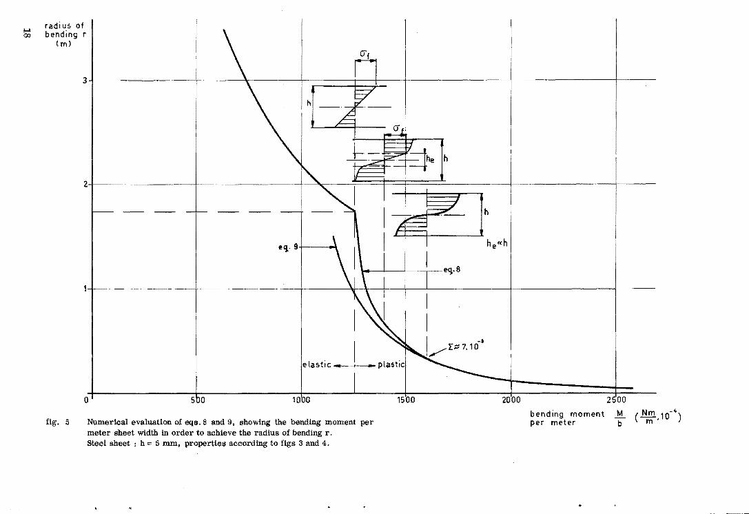
True stress-strain curve of the steel investigated. Steel DIN - 8t V.

effective stress a 5 (Nm-a. 108
)
'* 3
2
101
9 8 7 6
5 I
I
I
I
i-' :.-f- i-oI!
----f--
~ -------4
3
2
-1 a 10 2
--f------ - ..
._ .. -
. 4 5 6 7 8 910 1 3
~.
I
~ i-' I-'"
-~ ~ ~ ~
2 3 it 567891
effective strain r
fig. 4 True stress-strain curve of the steel investigated, from which follows:
Ii = 8,15. 2°,22
17
radiu$ of bending r
( m)
3
elastic ..... t---+-__ ... plastic
o 5 0 1500
fig. 5 Numerical evaluation of eqs. 8 and 9, showing the bending moment per meter sheet width in order to achieve the radius of bending r. Steel sheet: h:; 5 mm, properties according to figs 3 and 4.
h
~eCJ·8
2000
bending moment per meter
2 00
M b

h where - E is the maximum bending strain in the outer layer (ultimate
2ro 0
strain), from which follows for the spring-back:
r r
o ~ 1+
3C 1-m
E(m+2) E o
--------12}
A numerical example referring to the steel with the properties as mentioned before is tabulated below:
0 0 , E ° 78
I .. ~-
0,02 0,047 0,03 0,065 0,06 0,115 0,08 0,14 0,10 0,17 0,20 0,28 0,30
I 0,39
r/r 0
. r/r % 0
1,11 11 1,081 8,1 1,046 4,6 1,038 3,8 1,033 3,3 1,018 1,8 1,013 1,3
3C E(m+2)
=
3. 8,15. 108 ---=-----=
10 21. 2,22. 10
-J 5,24. 10
This table has been plotted in fig. 6 where the values are compared with those experimentally known. The differences may readily be explained by systematic errors in the materials constants applied and by changes in the modulus of elasticity in the plastic region.
4. APPLICATIONS.
Bending with press tools
A bend~ operation when using beRding tools as shown in fig. 7 is considered. As is clear from the mechanical analysis the reaction force on the bending die amounts P and hepce the press force is: F 2 P sin ;, when the final angle of bending arrives at the value a..
The bending moment in the cross-section of symmetry is: a.
M = 2 P r cos 2"
Combining with eq. 9) renders a solution of P and hence of F:
F = 2 b C m+2 {~}
m+2 1
m+l r
tan a.
2 -----13)
19

: 20
12
spring-back
..!... (0/0 ) r 0 11
10
9
8
7
6
5
4
3
r--
(
---
I
\ \ \\ \\ \\
\"\ " '\ ~
I
I
.. -~.-.
I
~-
'- .--~.
~ i----.--.~----. ... ............... ~ 2
o
fig. 6
~ .... -1
I""
,
0,1 0.2 0;3
bending strain r
The spring-back of steel sheet after bending according to eq. 12. o - calculated. * - experimental values.

F
fig. 7 Bending with bending tools.
21

When introducing:
as the radius of the press tool, and expressing r t in terms of the material thickness:
rt
== f.h -------------------------14)
this means that the bending strain:
E == h
2r == 1
2f+l ----------------- 15)
o
Thus in bending operations characterised by a given value of the ratio f the material is exposed to a constant value of ultimate bending strain. Substituting eq.15 into eq.13 renders:
F= C.b.h
(m+2) (2f+l) m+l.
a. tan 2 -------- 16)
which is the press force required to bend a sheet of the dimensions b.h. over an angle a. using a tool with the radius rt == fh. The relation eq. 16 predicts the existence of a linear dependence of press force on sheet thickness, provided a constant value of f = ~t . As shown in fig. 8 this is fully confirmed by experimental observation. Numerical analysis based on relation 16 applied to steel sheet b = 0,1 m and h == 0,01 m, an angle of bending a. = 900 , a press tool radius of rt = 0,014 m and hence a ratio f 1,4 and using the numerical values of the material properties as mentioned before gives a press force of F = 7,2 105N (= 7,2 tf), which again is very close to reality. The spring-back is found by combination of eqs.12 and 15:
~ = 1 + 3C (2f+l)l-m ro E(m+2)
which gives in the case discussed:
r - = 1,5% ro
-------17)
Thus the tool angle to be machined into the die in order to obtain rectangular bending must amount .~
The bending of U - profiles
The principle of the bending operation is shown in fig. 9. The net machine force as the difference between the press force and the counter force amounts F. The mechanical analysis shows a reaction force Pt on the edge of the bending die which introduces the frictional force p. Pt along the die. The reactionforce due to pure bendi,ng is P.
22
(
I
\

..
press force per meter
5heet width 5
(~) m
fig. 8
100
F
A "
~ ~ ~ I
I 0.= 90°
elCpe imental V value)
/ /
V
V "
J
/
90
80
70
60
50
40
30 -,-----
20
10
o
/ /
/
/ 2 4 6 10 12 14
. . -~ sheet thIckness (m.l0 )
The press force when bending over CI. 900 for a constant value of the r
tool/sheet ratio f ht '" 1,4.
Properties of the steel according to figs 3 and 4.
23

I
F+F
c----t----.. PC05a + j.J.Pt sin a
h
h
fig. 9 Bending of U - profiles. Mechanical analysis in the case of zero radius in the bending die.
24

In a phase of the bending proces given by the angle Q. mechanical equilibrium. requires:
Pt
cos a = P cos a + p, Pt
sin a
and hence: P
P t :::: 1- p, tan a
Thus the net machine force is:
F 2 Pt
cos a = 2 P cos a I-p,tan a
---- ------18)
The bending moment in the cross-section determined by the distance x (fig. 9)
amounts:
M = P.x x
By geometrical analysis it readily can be shown that holds:
I-sin a
coso.
where again r t is the radius of the press tool and h the sheet-thickness. h
Using eq. 9 where r = r +-t 2'
it follows:
P = 2Cb 1 cos a
rt
+ h' I-sin a ---19)
Again expressing the press tool radius in the sheet thickness:
r-t = f. h
and combining eqs.19 and 18 gives as a final result:
F :::: C.b.h l+sin a
1- p, tan a -----20)
(m+2) (2f+lf(f+l)
It is remarked that this relation suggests the presence of a machine force case when a :::: O. However in the derivation has been made use of eq. 9, supposes considerable plastic deformation of the material. In fact in the situation a :::: 0 the active tool radius r t = co and hence f leading to F = O.
in the which
:::: c:c
25

Analysis of the very initial lase of the proces should be made by using eq. 8 instead of eq. 9, in order to describe the transition from elastic to plastic bending. In the scope of the present work this analysis is considered being not important. From the formula 20 the impossibility of bending rectangular profiles is evident, because of the fact that the coefficient of friction JJ. > 0
The machine force grows to infinity as soon as: 1
tan a :::: -JJ.
and hence the limiting condition in the process is:
1 tan It < -
JJ.
which implies: It < 900•
In conclusion fig. 10 shows the influence of the coefficient of friction on the maximum achievable bending angle for a given machine tonnage rating.
26

100
P re!;5 force N 105
(tf)
90
80
70
60
so
40
30
20
10
o
fig. 10
IJ.I= 0,50
1
/ machine rating 1/
/ / ~
V ~ ~ -~
r /
15 30 4'5 6D 7
1 I
IJ.=
1-r-IJ.=
~IJ.==
1 j If) /
11-
L l .L 81 .1.87 '90
78 84
0.10 0.05
0.01
opo
bending angle
The bending of U - profiles. The influence of the friction in the bending die on the maximum achievable bending angle at given machine tonnage rating. Steel sheet b 100 mm, h = 10 mm, f = 1,4.
27


![05-03ChapGere[1] | Bending | Beam (Structure) - xdocs.net](https://static.fdokumen.com/doc/165x107/6323c1d9be5419ea700ebf89/05-03chapgere1-bending-beam-structure-xdocsnet.jpg)