Preparation of Vanadium Oxides from a Vanadium (IV) Strip ...
Seismic Bearing Capacity of Shallow Strip FootingsEmbedded in Slope
Deepankar Choudhury1 and K. S. Subba Rao2
Abstract: The seismic bearing capacity factors for shallow strip footings embedded in sloping ground with general c-� soil are found outby using the limit equilibrium method. The seismic forces are considered as pseudostatic forces acting both on the footing and on the soilbelow the footing. A composite failure surface involving planar and logspiral is considered in the analysis. A new methodology toestablish minimum bearing capacity factors has been adopted by numerical iteration technique to determine the critical focus of thelogspiral. Three different types of failure surfaces are considered depending on the embedment depth and ground inclinations. The seismicbearing capacity factors with respect to cohesion, surcharge and unit weight components viz. Ncd, Nqd, and N�d, respectively, are found outseparately for various values of soil friction angles and seismic acceleration coefficients both in the horizontal and vertical directions,ground inclinations, and embedment depths. Results of the present study are reported in tabular form. The effect of parametric variationon seismic bearing capacity factors has been studied. Comparisons of the proposed method with available theories in the seismic case arealso presented.
DOI: 10.1061/�ASCE�1532-3641�2006�6:3�176�
CE Database subject headings: Seismic analysis; Bearing capacity; Limit equilibrium; Footings; Slopes; Computation.
Introduction
Estimation of bearing capacity of shallow foundation is an impor-tant parameter in the design of any substructures. Construction offootings below inclined ground is also a common practice be-cause of land cost effectiveness or to maintain natural terrain ofthe ground or for many other reasons. Very little research hadbeen carried out for the footings embedded in sloping ground.Meyerhof �1957, 1963�, Hansen �1970�, Vesic �1973�, and a fewothers have studied the bearing capacity of shallow footings em-bedded in slopes under static condition. Nowdays, research in thearea of seismic bearing capacity is very much in demand becauseof the devastating effect of the foundations under earthquakeconditions.
Researchers like Sarma and Iossifelis �1990�, Budhu andAl-Karni �1993�, Richards et al. �1993�, Dormieux and Pecker�1995�, Paolucci and Pecker �1997�, Soubra �1997, 1999�, Kumarand Rao �2002�, Kumar �2003�, and Choudhury and Subba Rao�2005� had studied the seismic bearing capacity of shallow foot-ings for horizontal ground. But the study for sloping ground isvery limited. Sawada et al. �1994�, Sarma �1999� and Askari andFarzaneh �2003� had given the solution for seismic bearing capac-ity of shallow foundations near sloping ground, but not for foun-
1Assistant Professor, Dept. of Civil Engineering, Indian Institute ofTechnology Bombay, Powai, Mumbai 400 076, India �correspondingauthor�. E-mail: [email protected]
2Professor, Dept. of Civil Engineering, Indian Institute of Science,Bangalore 560 012, India.
Note. Discussion open until October 1, 2006. Separate discussionsmust be submitted for individual papers. To extend the closing date byone month, a written request must be filed with the ASCE ManagingEditor. The manuscript for this paper was submitted for review and pos-sible publication on May 25, 2004; approved on February 14, 2005. Thispaper is part of the International Journal of Geomechanics, Vol. 6, No.
3, May 1, 2006. ©ASCE, ISSN 1532-3641/2006/3-176–184/$25.00.176 / INTERNATIONAL JOURNAL OF GEOMECHANICS © ASCE / MAY/JUN
dations embedded in sloping ground. Recently, by upper-boundlimit analysis, Zhu �2000� had given only N� values under earth-quake conditions for surface footing on sloping ground. Kumarand Kumar �2003� also carried out the limit equilibrium analysisfor seismic bearing capacity factors of surface footing on slopesonly. Analysis using the method of characteristics for seismicbearing capacity factors of surface footing on slopes was given byKumar and Rao �2003�. But the seismic bearing capacity factorsfor most practical situations of footings embedded in slopingground are still scarce.
In this paper, the limit equilibrium method is used to obtain theseismic bearing capacity factors of shallow footings embedded insloping ground. A composite failure surface is considered in theanalysis. A new methodology to obtain the minimum bearing ca-pacity factor by searching for a critical focus of the logspiralfailure zone is proposed in the present analysis along with theconcept of partial mobilization of passive resistance on the rareside of the failure under seismic condition. The formations ofdifferent failure surfaces are also shown logically depending onthe geometry of the problem based on the ground inclination andembedment depth of the foundation.
Method of Analysis
The limit equilibrium method of analysis is adopted in the presentpaper. Pseudostatic seismic forces are considered along with otherstatic forces. Homogeneous, isotropic c-� soil with surcharge isassumed in the analysis. Soil is assumed to be a rigid, perfectlyplastic medium satisfying the Mohr–Coulomb failure criterion.The seismic acceleration coefficients are denoted as kh and kv inthe horizontal and vertical directions, respectively. One sided fail-ure mechanism is assumed to occur in the seismic case with the
formation of an asymmetrical elastic wedge with full mobilizationE 2006

of the passive resistance on one side and partial mobilization onthe other side.
Consider a horizontal shallow strip footing of base AD, em-bedded in a sloping ground XY �Fig. 1�. Inclination of the groundsurface XY with respect to the horizontal is �. Df�embedmentdepth measured along the centerline of the footing,B�width of the footing with Df /B�1, L�length of the footing,and L�B. The base angles of the elastic wedge ADE are denotedby �1 and �2. In the static case �1=�2=�, but for the seismiccase �1��2, in keeping with the direction of horizontal seismicacceleration and facing toward the inclined ground as shown inFig. 1.
In Fig. 1, the forces acting on the footing are denoted askhqudB and �1−kv�qudB where qud�ultimate seismic bearing ca-pacity of the footing. The failure zone in the soil below the foot-ing is divided into three parts, viz. Zone I, triangular wedge, ZoneII, logarithmic spiral, and Zone III, passive planar zone. Fig. 2shows these three zones clearly for a shallow footing when�=00. The forces acting are khW1 and �1−kv�W1 for zone I, khW2
and �1−kv�W2 for Zone II, and khW3 and �1−kv�W3 for Zone III,where W1, W2, and W3 are the weights of Zones I, II, and III
Fig. 1. Failure surfaces for Type 1
Fig. 2. Failure surfaces considered by Choudhury and Subba R
INTERNATION
respectively. The surcharge loads acting at the footing level arekh�Df and �1−kv��Df. The critical directions of seismic accelera-tions coefficients kh and kv are shown in Fig. 2 which leads to theminimum seismic bearing capacity factors and this is in goodagreement with the observation of Budhu and Al-Karni �1993�.
The forces acting on the wedge ADE are shown in Fig. 3.These forces are as follows: on the face DE, the forces are Pp�d1,Ppqd1, and Ppcd1, which are the unit weight, surcharge, and cohe-sion components of the total seismic passive resistance Ppd1.While Pp�d1 is assumed to act at one third the height above thebase �Point E�, the other two components are assumed to act atthe midheight of the face DE having vertical height H. Thesepassive forces are acting at an angle of � to the normal, as fullmobilization of passive resistance is assumed to occur on this sideof the wedge and the adhesion Ca1=c .DE, where c�unit cohe-sion. On the face AE, with the same vertical height H, the corre-sponding seismic passive force components of the total seismicpassive resistance mPpd2 will be mobilized partially as mPp�d2,mPpqd2, and mPpcd2, where m�mobilization factor and it is de-fined as
m =tan �2
tan ��1�
Selection of Failure Surface
From the geometry, depending on the values of the embedmentratio Df /B and slope angle �, the formation of three differenttypes of failure surfaces may occur. In Fig. 1, the failure surface iscomposed of the triangular wedge Zone I, ADE, followed by alogarithmic spiral Zone II, DEF, and then followed by a partialplanar passive Zone III, as DFG. This combination of failuresurfaces is termed “Type 1” failure surface. The exit angle atground at point G is the same as given by Subba Rao andChoudhury �2005�. Here, line DG makes an angle �� with thehorizontal line DM. Hence the problem reduces to a passive earth
005� �with permission, Springer Science and Business Media�
ao �2AL JOURNAL OF GEOMECHANICS © ASCE / MAY/JUNE 2006 / 177
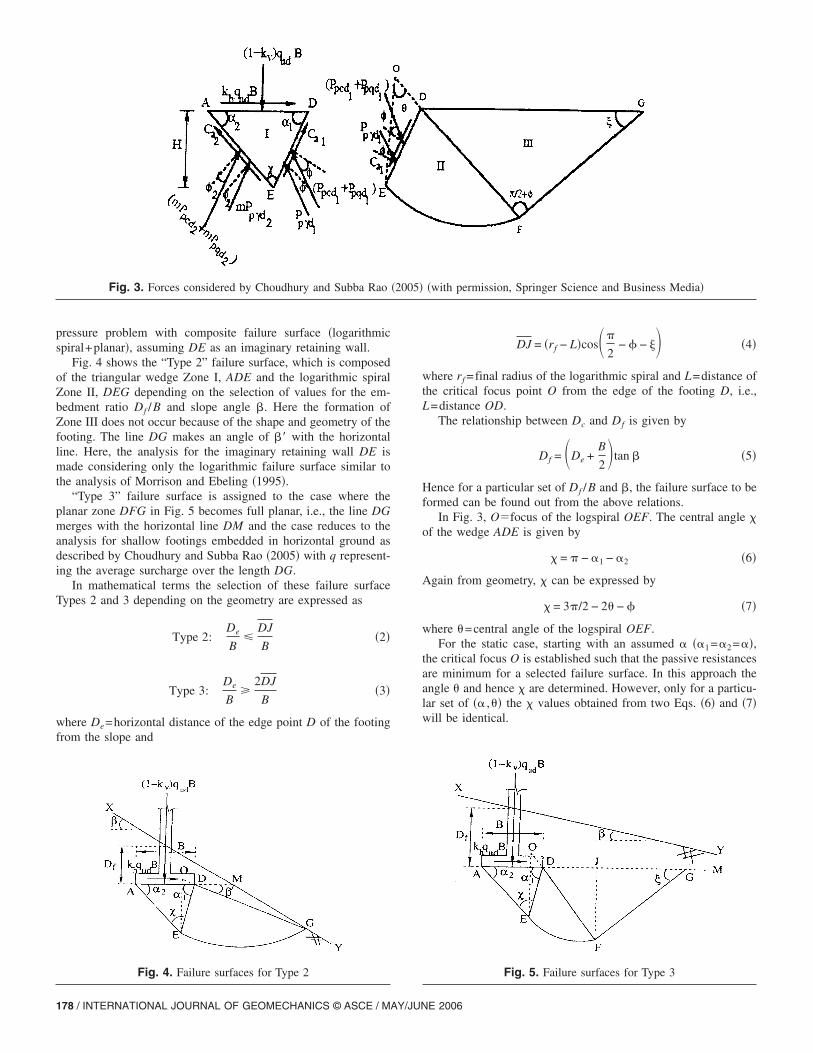
pressure problem with composite failure surface �logarithmicspiral+planar�, assuming DE as an imaginary retaining wall.
Fig. 4 shows the “Type 2” failure surface, which is composedof the triangular wedge Zone I, ADE and the logarithmic spiralZone II, DEG depending on the selection of values for the em-bedment ratio Df /B and slope angle �. Here the formation ofZone III does not occur because of the shape and geometry of thefooting. The line DG makes an angle of �� with the horizontalline. Here, the analysis for the imaginary retaining wall DE ismade considering only the logarithmic failure surface similar tothe analysis of Morrison and Ebeling �1995�.
“Type 3” failure surface is assigned to the case where theplanar zone DFG in Fig. 5 becomes full planar, i.e., the line DGmerges with the horizontal line DM and the case reduces to theanalysis for shallow footings embedded in horizontal ground asdescribed by Choudhury and Subba Rao �2005� with q represent-ing the average surcharge over the length DG.
In mathematical terms the selection of these failure surfaceTypes 2 and 3 depending on the geometry are expressed as
Type 2:De
B�
DJ
B�2�
Type 3:De
B
2DJ
B�3�
where De=horizontal distance of the edge point D of the footingfrom the slope and
Fig. 3. Forces considered by Choudhury and Subba Rao
Fig. 4. Failure surfaces for Type 2
178 / INTERNATIONAL JOURNAL OF GEOMECHANICS © ASCE / MAY/JUN
DJ = �rf − L�cos�
2− � − �� �4�
where rf =final radius of the logarithmic spiral and L=distance ofthe critical focus point O from the edge of the footing D, i.e.,L=distance OD.
The relationship between Dc and Df is given by
Df = �De +B
2�tan � �5�
Hence for a particular set of Df /B and �, the failure surface to beformed can be found out from the above relations.
In Fig. 3, O�focus of the logspiral OEF. The central angle �of the wedge ADE is given by
� = − �1 − �2 �6�
Again from geometry, � can be expressed by
� = 3/2 − 2 − � �7�
where =central angle of the logspiral OEF.For the static case, starting with an assumed � ��1=�2=��,
the critical focus O is established such that the passive resistancesare minimum for a selected failure surface. In this approach theangle and hence � are determined. However, only for a particu-lar set of �� , � the � values obtained from two Eqs. �6� and �7�will be identical.
�with permission, Springer Science and Business Media�
Fig. 5. Failure surfaces for Type 3
�2005�
E 2006
Determination of Seismic Bearing Capacity
Considering all the forces acting on the triangular zone ADE �Fig.3�, from the horizontal equilibrium of all the forces the seismicbearing capacity qud is given by
qud =1
khB�Ppd1 sin��1 − �� − mPpd2 sin��2 − �2�
+ Ca2 cos �2 − Ca1 cos �1 − khW� �8�
From the vertical equilibrium of all the forces
qud =1
�1 − kv�B�Ppd1 cos��1 − �� + mPpd2 cos��2 − �2�
+ Ca2 sin �2 + Ca1 sin �1 − �1 − kh�W� �9�
The ultimate seismic bearing capacity qud is expressed in the fol-lowing form:
qud = cNcd + qNqd + 0.5�BN�d �10�
where Ncd, Nqd, and N�d=seismic bearing capacity factors. Theminimum of each component is found out by considering thethree individual cases as follows: Case �i� c�0, �=q=0; Case �ii�q�0, �=c=0; and Case �iii� ��0, c=q=0.
The principle of superposition is assumed as valid and theminimum of each component is used to obtain the minimum seis-mic bearing capacity. The expressions for each bearing capacityfactor term viz., Ncd, Nqd, and N�d are given in the Appendixbased on the horizontal and vertical equilibrium of the forcesshown in Fig. 3.
Determination of �1 and m
In the static case, full mobilization of passive earth pressure onboth the sides AD and DE of the wedge ADE will occur due tosymmetry. Here, m=1, i.e., �2=�.
To evaluate the seismic bearing capacity factors, say Ncd, somevalue of �1 is first assumed, and with known value of centralangle �, �2 is obtained. Iteration is carried out in the range of � to�180−�−1�0 with an interval of 0.0010 for �1. Again some valueof �2 is assumed to obtain m using Eq. �1�. The values of �2 areiterated from 0 to � with an interval of 0.010. For only a particu-lar set of �1 and m, the two values of Ncd using two equilibriumequations in the Appendix viz. Eqs. �12� and �15� will be the
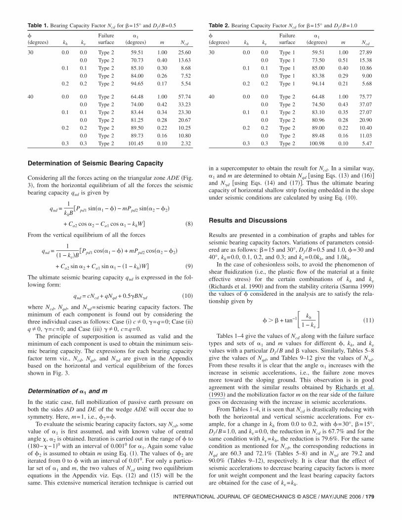
Table 1. Bearing Capacity Factor Ncd for �=15° and Df /B=0.5
��degrees� kh kv
Failuresurface
�1
�degrees� m Ncd
30 0.0 0.0 Type 2 59.51 1.00 25.60
0.0 Type 2 70.73 0.40 13.63
0.1 0.1 Type 2 85.10 0.30 8.68
0.0 Type 2 84.00 0.26 7.52
0.2 0.2 Type 2 94.65 0.17 5.54
40 0.0 0.0 Type 2 64.48 1.00 57.74
0.0 Type 2 74.00 0.42 33.23
0.1 0.1 Type 2 83.44 0.34 23.30
0.0 Type 2 81.25 0.28 20.67
0.2 0.2 Type 2 89.50 0.22 10.25
0.0 Type 2 89.73 0.16 10.80
0.3 0.3 Type 2 101.45 0.10 2.32
same. This extensive numerical iteration technique is carried out
INTERNATION
in a supercomputer to obtain the result for Ncd. In a similar way,�1 and m are determined to obtain Nqd �using Eqs. �13� and �16��and N�d �using Eqs. �14� and �17��. Thus the ultimate bearingcapacity of horizontal shallow strip footing embedded in the slopeunder seismic conditions are calculated by using Eq. �10�.
Results and Discussions
Results are presented in a combination of graphs and tables forseismic bearing capacity factors. Variations of parameters consid-ered are as follows: �=15 and 30°, Df /B=0.5 and 1.0, �=30 and40°, kh=0.0, 0.1, 0.2, and 0.3; and kv=0.0kh, and 1.0kh.
In the case of cohesionless soils, to avoid the phenomenon ofshear fluidization �i.e., the plastic flow of the material at a finiteeffective stress� for the certain combinations of kh and kv�Richards et al. 1990� and from the stability criteria �Sarma 1999�the values of � considered in the analysis are to satisfy the rela-tionship given by
� � � + tan−1� kh
1 − kv� �11�
Tables 1–4 give the values of Ncd along with the failure surfacetypes and sets of �1 and m values for different �, kh, and kvvalues with a particular Df /B and � values. Similarly, Tables 5–8give the values of Nqd, and Tables 9–12 give the values of N�d.From these results it is clear that the angle �1 increases with theincrease in seismic accelerations, i.e., the failure zone movesmore toward the sloping ground. This observation is in goodagreement with the similar results obtained by Richards et al.�1993� and the mobilization factor m on the rear side of the failuregoes on decreasing with the increase in seismic accelerations.
From Tables 1–4, it is seen that Ncd is drastically reducing withboth the horizontal and vertical seismic accelerations. For ex-ample, for a change in kh from 0.0 to 0.2, with �=30°, �=15°,Df /B=1.0, and kv=0.0, the reduction in Ncd is 67.7% and for thesame condition with kv=kh, the reduction is 79.6%. For the samecondition as mentioned for Ncd, the corresponding reductions inNqd are 60.3 and 72.1% �Tables 5–8� and in N�d are 79.2 and90.0% �Tables 9–12�, respectively. It is clear that the effect ofseismic accelerations to decrease bearing capacity factors is morefor unit weight component and the least bearing capacity factors
Table 2. Bearing Capacity Factor Ncd for �=15° and Df /B=1.0
��degrees� kh kv
Failuresurface
�1
�degrees� m Ncd
30 0.0 0.0 Type 1 59.51 1.00 27.89
0.0 Type 1 73.50 0.51 15.38
0.1 0.1 Type 1 85.00 0.40 10.86
0.0 Type 1 83.38 0.29 9.00
0.2 0.2 Type 1 94.14 0.21 5.68
40 0.0 0.0 Type 2 64.48 1.00 75.77
0.0 Type 2 74.50 0.43 37.07
0.1 0.1 Type 2 83.10 0.35 27.07
0.0 Type 2 80.96 0.28 20.90
0.2 0.2 Type 2 89.00 0.22 10.40
0.0 Type 2 89.48 0.16 11.03
0.3 0.3 Type 2 100.98 0.10 5.47
are obtained for the case of kv=kh.
AL JOURNAL OF GEOMECHANICS © ASCE / MAY/JUNE 2006 / 179
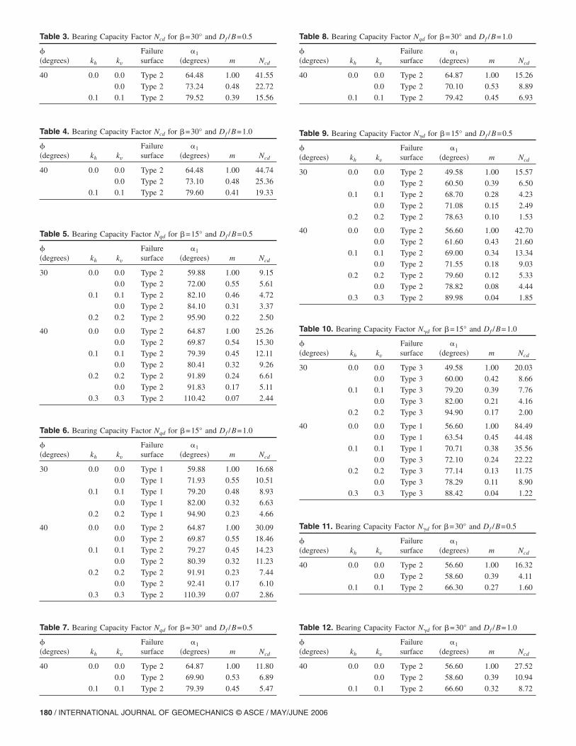
Table 3. Bearing Capacity Factor Ncd for �=30° and Df /B=0.5
��degrees� kh kv
Failuresurface
�1
�degrees� m Ncd
40 0.0 0.0 Type 2 64.48 1.00 41.55
0.0 Type 2 73.24 0.48 22.72
0.1 0.1 Type 2 79.52 0.39 15.56
Table 4. Bearing Capacity Factor Ncd for �=30° and Df /B=1.0
��degrees� kh kv
Failuresurface
�1
�degrees� m Ncd
40 0.0 0.0 Type 2 64.48 1.00 44.74
0.0 Type 2 73.10 0.48 25.36
0.1 0.1 Type 2 79.60 0.41 19.33
Table 5. Bearing Capacity Factor Nqd for �=15° and Df /B=0.5
��degrees� kh kv
Failuresurface
�1
�degrees� m Ncd
30 0.0 0.0 Type 2 59.88 1.00 9.15
0.0 Type 2 72.00 0.55 5.61
0.1 0.1 Type 2 82.10 0.46 4.72
0.0 Type 2 84.10 0.31 3.37
0.2 0.2 Type 2 95.90 0.22 2.50
40 0.0 0.0 Type 2 64.87 1.00 25.26
0.0 Type 2 69.87 0.54 15.30
0.1 0.1 Type 2 79.39 0.45 12.11
0.0 Type 2 80.41 0.32 9.26
0.2 0.2 Type 2 91.89 0.24 6.61
0.0 Type 2 91.83 0.17 5.11
0.3 0.3 Type 2 110.42 0.07 2.44
Table 6. Bearing Capacity Factor Nqd for �=15° and Df /B=1.0
��degrees� kh kv
Failuresurface
�1
�degrees� m Ncd
30 0.0 0.0 Type 1 59.88 1.00 16.68
0.0 Type 1 71.93 0.55 10.51
0.1 0.1 Type 1 79.20 0.48 8.93
0.0 Type 1 82.00 0.32 6.63
0.2 0.2 Type 1 94.90 0.23 4.66
40 0.0 0.0 Type 2 64.87 1.00 30.09
0.0 Type 2 69.87 0.55 18.46
0.1 0.1 Type 2 79.27 0.45 14.23
0.0 Type 2 80.39 0.32 11.23
0.2 0.2 Type 2 91.91 0.23 7.44
0.0 Type 2 92.41 0.17 6.10
0.3 0.3 Type 2 110.39 0.07 2.86
Table 7. Bearing Capacity Factor Nqd for �=30° and Df /B=0.5
��degrees� kh kv
Failuresurface
�1
�degrees� m Ncd
40 0.0 0.0 Type 2 64.87 1.00 11.80
0.0 Type 2 69.90 0.53 6.89
0.1 0.1 Type 2 79.39 0.45 5.47
180 / INTERNATIONAL JOURNAL OF GEOMECHANICS © ASCE / MAY/JUN
Table 8. Bearing Capacity Factor Nqd for �=30° and Df /B=1.0
��degrees� kh kv
Failuresurface
�1
�degrees� m Ncd
40 0.0 0.0 Type 2 64.87 1.00 15.26
0.0 Type 2 70.10 0.53 8.89
0.1 0.1 Type 2 79.42 0.45 6.93
Table 9. Bearing Capacity Factor N�d for �=15° and Df /B=0.5
��degrees� kh kv
Failuresurface
�1
�degrees� m Ncd
30 0.0 0.0 Type 2 49.58 1.00 15.57
0.0 Type 2 60.50 0.39 6.50
0.1 0.1 Type 2 68.70 0.28 4.23
0.0 Type 2 71.08 0.15 2.49
0.2 0.2 Type 2 78.63 0.10 1.53
40 0.0 0.0 Type 2 56.60 1.00 42.70
0.0 Type 2 61.60 0.43 21.60
0.1 0.1 Type 2 69.00 0.34 13.34
0.0 Type 2 71.55 0.18 9.03
0.2 0.2 Type 2 79.60 0.12 5.33
0.0 Type 2 78.82 0.08 4.44
0.3 0.3 Type 2 89.98 0.04 1.85
Table 10. Bearing Capacity Factor N�d for �=15° and Df /B=1.0
��degrees� kh kv
Failuresurface
�1
�degrees� m Ncd
30 0.0 0.0 Type 3 49.58 1.00 20.03
0.0 Type 3 60.00 0.42 8.66
0.1 0.1 Type 3 79.20 0.39 7.76
0.0 Type 3 82.00 0.21 4.16
0.2 0.2 Type 3 94.90 0.17 2.00
40 0.0 0.0 Type 1 56.60 1.00 84.49
0.0 Type 1 63.54 0.45 44.48
0.1 0.1 Type 1 70.71 0.38 35.56
0.0 Type 3 72.10 0.24 22.22
0.2 0.2 Type 3 77.14 0.13 11.75
0.0 Type 3 78.29 0.11 8.90
0.3 0.3 Type 3 88.42 0.04 1.22
Table 11. Bearing Capacity Factor N�d for �=30° and Df /B=0.5
��degrees� kh kv
Failuresurface
�1
�degrees� m Ncd
40 0.0 0.0 Type 2 56.60 1.00 16.32
0.0 Type 2 58.60 0.39 4.11
0.1 0.1 Type 2 66.30 0.27 1.60
Table 12. Bearing Capacity Factor N�d for �=30° and Df /B=1.0
��degrees� kh kv
Failuresurface
�1
�degrees� m Ncd
40 0.0 0.0 Type 2 56.60 1.00 27.52
0.0 Type 2 58.60 0.39 10.94
0.1 0.1 Type 2 66.60 0.32 8.72
E 2006
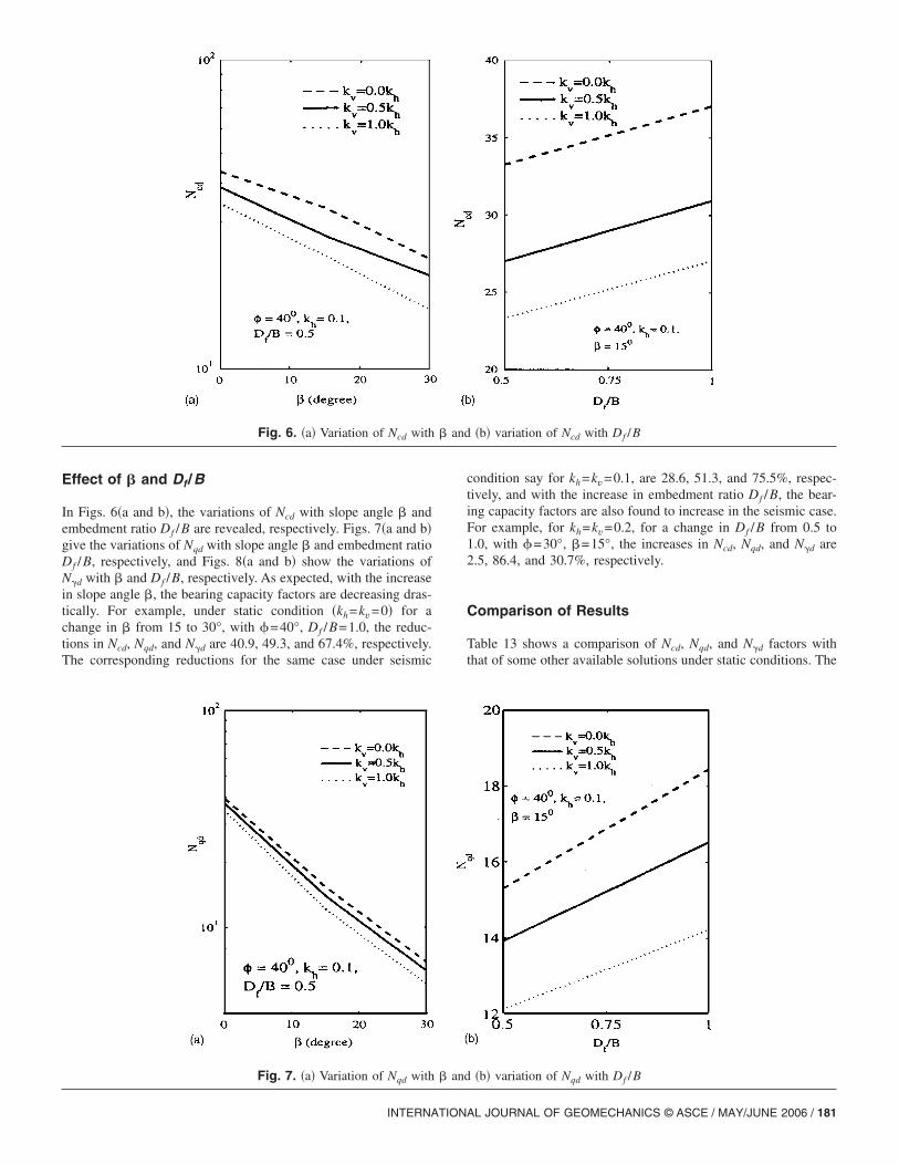
Effect of � and Df /B
In Figs. 6�a and b�, the variations of Ncd with slope angle � andembedment ratio Df /B are revealed, respectively. Figs. 7�a and b�give the variations of Nqd with slope angle � and embedment ratioDf /B, respectively, and Figs. 8�a and b� show the variations ofN�d with � and Df /B, respectively. As expected, with the increasein slope angle �, the bearing capacity factors are decreasing dras-tically. For example, under static condition �kh=kv=0� for achange in � from 15 to 30°, with �=40°, Df /B=1.0, the reduc-tions in Ncd, Nqd, and N�d are 40.9, 49.3, and 67.4%, respectively.The corresponding reductions for the same case under seismic
Fig. 6. �a� Variation of Ncd with
Fig. 7. �a� Variation of Nqd with
INTERNATION
condition say for kh=kv=0.1, are 28.6, 51.3, and 75.5%, respec-tively, and with the increase in embedment ratio Df /B, the bear-ing capacity factors are also found to increase in the seismic case.For example, for kh=kv=0.2, for a change in Df /B from 0.5 to1.0, with �=30°, �=15°, the increases in Ncd, Nqd, and N�d are2.5, 86.4, and 30.7%, respectively.
Comparison of Results
Table 13 shows a comparison of Ncd, Nqd, and N�d factors withthat of some other available solutions under static conditions. The
�b� variation of Ncd with Df /B
�b� variation of Nqd with Df /B
� and
� and
AL JOURNAL OF GEOMECHANICS © ASCE / MAY/JUNE 2006 / 181
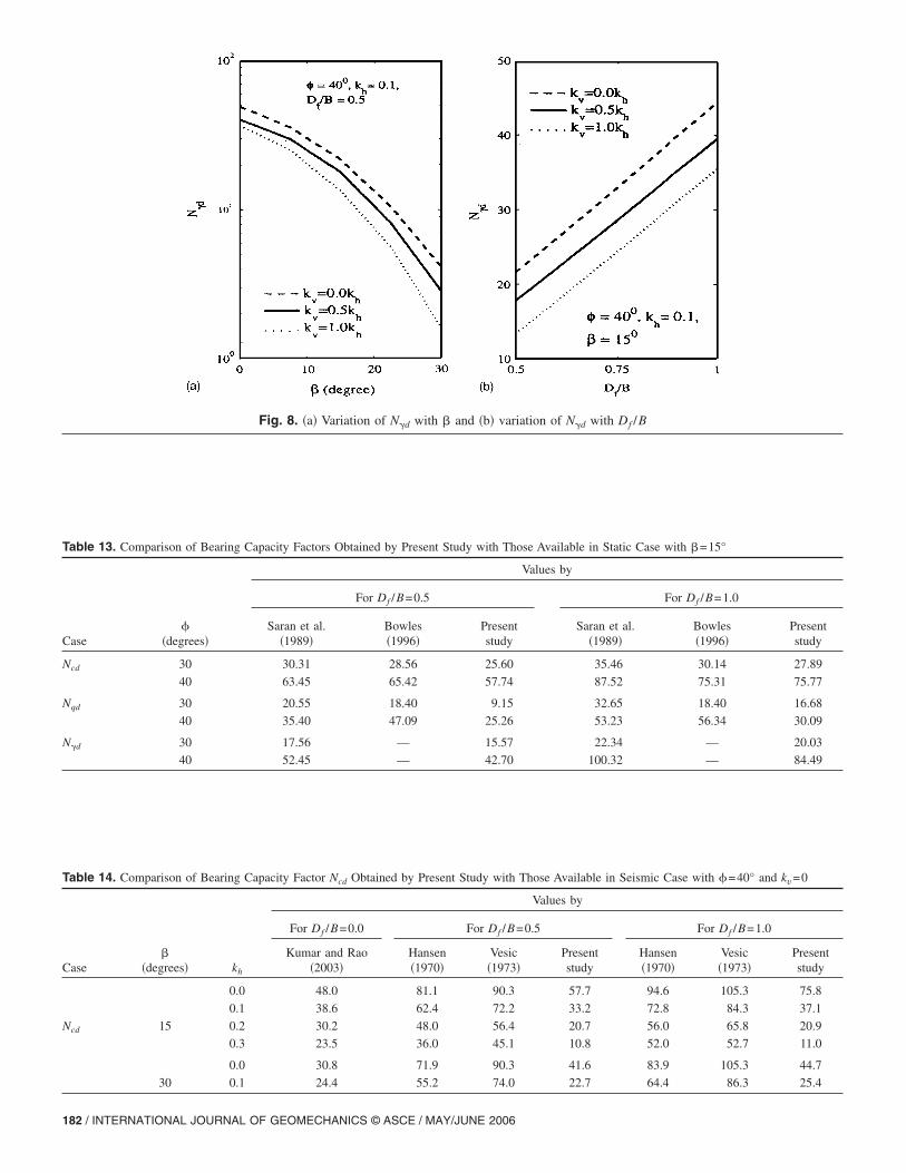
Table 13. Comparison of Bearing Capacity Factors Obtained by Present Study with Those Available in Static Case with �=15°
Case�
�degrees�
Values by
For Df /B=0.5 For Df /B=1.0
Saran et al.�1989�
Bowles�1996�
Presentstudy
Saran et al.�1989�
Bowles�1996�
Presentstudy
Ncd 30 30.31 28.56 25.60 35.46 30.14 27.89
40 63.45 65.42 57.74 87.52 75.31 75.77
Nqd 30 20.55 18.40 9.15 32.65 18.40 16.68
40 35.40 47.09 25.26 53.23 56.34 30.09
N�d 30 17.56 — 15.57 22.34 — 20.03
40 52.45 — 42.70 100.32 — 84.49
Table 14. Comparison of Bearing Capacity Factor Ncd Obtained by Present Study with Those Available in Seismic Case with �=40° and kv=0
Case�
�degrees� kh
Values by
For Df /B=0.0 For Df /B=0.5 For Df /B=1.0
Kumar and Rao�2003�
Hansen�1970�
Vesic�1973�
Presentstudy
Hansen�1970�
Vesic�1973�
Presentstudy
0.0 48.0 81.1 90.3 57.7 94.6 105.3 75.8
0.1 38.6 62.4 72.2 33.2 72.8 84.3 37.1
Ncd 15 0.2 30.2 48.0 56.4 20.7 56.0 65.8 20.9
0.3 23.5 36.0 45.1 10.8 52.0 52.7 11.0
0.0 30.8 71.9 90.3 41.6 83.9 105.3 44.7
30 0.1 24.4 55.2 74.0 22.7 64.4 86.3 25.4
Fig. 8. �a� Variation of N�d with � and �b� variation of N�d with Df /B
182 / INTERNATIONAL JOURNAL OF GEOMECHANICS © ASCE / MAY/JUNE 2006
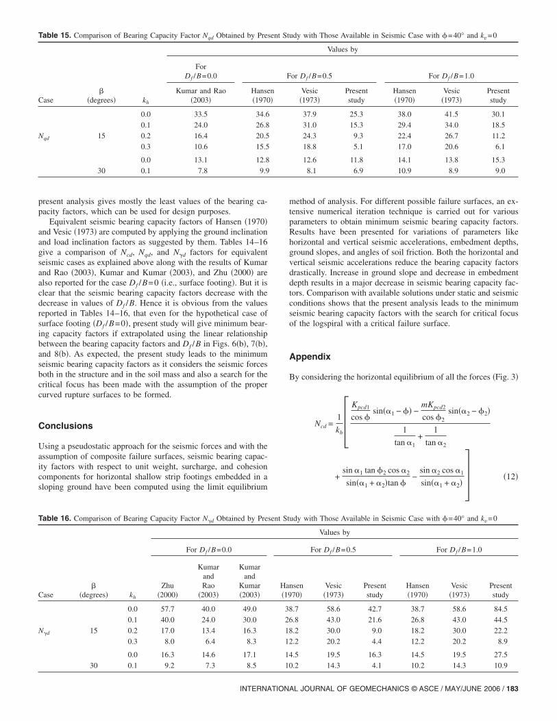
present analysis gives mostly the least values of the bearing ca-pacity factors, which can be used for design purposes.
Equivalent seismic bearing capacity factors of Hansen �1970�and Vesic �1973� are computed by applying the ground inclinationand load inclination factors as suggested by them. Tables 14–16give a comparison of Ncd, Nqd, and N�d factors for equivalentseismic cases as explained above along with the results of Kumarand Rao �2003�, Kumar and Kumar �2003�, and Zhu �2000� arealso reported for the case Df /B=0 �i.e., surface footing�. But it isclear that the seismic bearing capacity factors decrease with thedecrease in values of Df /B. Hence it is obvious from the valuesreported in Tables 14–16, that even for the hypothetical case ofsurface footing �Df /B=0�, present study will give minimum bear-ing capacity factors if extrapolated using the linear relationshipbetween the bearing capacity factors and Df /B in Figs. 6�b�, 7�b�,and 8�b�. As expected, the present study leads to the minimumseismic bearing capacity factors as it considers the seismic forcesboth in the structure and in the soil mass and also a search for thecritical focus has been made with the assumption of the propercurved rupture surfaces to be formed.
Conclusions
Using a pseudostatic approach for the seismic forces and with theassumption of composite failure surfaces, seismic bearing capac-ity factors with respect to unit weight, surcharge, and cohesioncomponents for horizontal shallow strip footings embedded in asloping ground have been computed using the limit equilibrium
Table 15. Comparison of Bearing Capacity Factor Nqd Obtained by Pres
Case�
�degrees� kh
ForDf /B=0.0
Kumar and Rao�2003�
Hanse�1970
0.0 33.5 34.6
0.1 24.0 26.8
Nqd 15 0.2 16.4 20.5
0.3 10.6 15.5
0.0 13.1 12.8
30 0.1 7.8 9.9
Table 16. Comparison of Bearing Capacity Factor N�d Obtained by Pre
Case�
�degrees� kh
For Df /B=0.0
Zhu�2000�
KumarandRao
�2003�
Kumarand
Kumar�2003�
0.0 57.7 40.0 49.0
0.1 40.0 24.0 30.0
N�d 15 0.2 17.0 13.4 16.3
0.3 8.0 6.4 8.3
0.0 16.3 14.6 17.1
30 0.1 9.2 7.3 8.5
INTERNATION
method of analysis. For different possible failure surfaces, an ex-tensive numerical iteration technique is carried out for variousparameters to obtain minimum seismic bearing capacity factors.Results have been presented for variations of parameters likehorizontal and vertical seismic accelerations, embedment depths,ground slopes, and angles of soil friction. Both the horizontal andvertical seismic accelerations reduce the bearing capacity factorsdrastically. Increase in ground slope and decrease in embedmentdepth results in a major decrease in seismic bearing capacity fac-tors. Comparison with available solutions under static and seismicconditions shows that the present analysis leads to the minimumseismic bearing capacity factors with the search for critical focusof the logspiral with a critical failure surface.
Appendix
By considering the horizontal equilibrium of all the forces �Fig. 3�
Ncd =1
khKpcd1
cos �sin��1 − �� −
mKpcd2
cos �2sin��2 − �2�
1
tan �1+
1
tan �2
+sin �1 tan �2 cos �2
sin��1 + �2�tan �−
sin �2 cos �1
sin��1 + �2� �12�
udy with Those Available in Seismic Case with �=40° and kv=0
Values by
or Df /B=0.5 For Df /B=1.0
Vesic�1973�
Presentstudy
Hansen�1970�
Vesic�1973�
Presentstudy
37.9 25.3 38.0 41.5 30.1
31.0 15.3 29.4 34.0 18.5
24.3 9.3 22.4 26.7 11.2
18.8 5.1 17.0 20.6 6.1
12.6 11.8 14.1 13.8 15.3
8.1 6.9 10.9 8.9 9.0
udy with Those Available in Seismic Case with �=40° and kv=0
Values by
For Df /B=0.5 For Df /B=1.0
nsen70�
Vesic�1973�
Presentstudy
Hansen�1970�
Vesic�1973�
Presentstudy
8.7 58.6 42.7 38.7 58.6 84.5
6.8 43.0 21.6 26.8 43.0 44.5
8.2 30.0 9.0 18.2 30.0 22.2
2.2 20.2 4.4 12.2 20.2 8.9
4.5 19.5 16.3 14.5 19.5 27.5
0.2 14.3 4.1 10.2 14.3 10.9
ent St
F
n�
sent St
Ha�19
3
2
1
1
1
1
AL JOURNAL OF GEOMECHANICS © ASCE / MAY/JUNE 2006 / 183
Nqd =1
khKpqd1
cos �sin��1 − �� −
mKpqd2
cos �2sin��2 − �2�
1
tan �1+
1
tan �2
�13�
N�d =1
khKp�d1
cos �sin��1 − �� −
mKp�d2
cos �2sin��2 − �2�
� 1
tan �1+
1
tan �2�2
−1
� 1
tan �1+
1
tan �2� �14�
and from the vertical equilibrium of all the forces �Fig. 3�
Ncd =1
1 − kvKpcd1
cos �cos��1 − �� +
mKpcd2
cos �2cos��2 − �2�
1
tan �1+
1
tan �2
+sin �1 tan �2 sin �2
sin��1 + �2�tan �+
sin �2 sin �1
sin��1 + �2� �15�
Nqd =1
1 − kvKpqd1
cos �cos��1 − �� +
mKpqd2
cos �2cos��2 − �2�
1
tan �1+
1
tan �2
�16�
N�d =1
1 − kvKp�d1
cos �cos��1 − �� +
mKp�d2
cos �2cos��2 − �2�
� 1
tan �1+
1
tan �2�2
−1
� 1
tan �1+
1
tan �2� �17�
The methodology to obtain the seismic passive earth pressurecoefficients Kpcd1, Kpqd1, Kp�d1 and Kpcd2, Kpqd2, Kp�d2 have al-ready been discussed by Subba Rao and Choudhury �2005�.
References
Askari, F., and Farzaneh, O. �2003�. “Upper-bound solution for seismic
bearing capacity of shallow foundations near slopes.” Geotechnique,184 / INTERNATIONAL JOURNAL OF GEOMECHANICS © ASCE / MAY/JUN
53�8�, 697–702.Bowles, J. E. �1996�. Foundation analysis and design, 5th Ed., McGraw–
Hill, New York.Budhu, M., and Al-Karni, A. �1993�. “Seismic bearing capacity of soils.”
Geotechnique, 43�1�, 181–187.Choudhury, D., and Subba Rao, K. S. �2005�. “Seismic bearing capacity
of shallow strip footings.” J. Manuf. Syst., 24�1�, 117–127.Dormieux, L., and Pecker, A. �1995�. “Seismic bearing capacity of foun-
dations on cohesionless soil.” J. Geotech. Eng., 121�3�, 300–303.Hansen, J. B. �1970�. “A revised and extended formula for bearing ca-
pacity.” Geoteknisk Inst., Bull., 28, 5–11.Kumar, J. �2003�. “N� for rough strip footing using the method of char-
acteristics.” Can. Geotech. J., 40�3�, 669–674.Kumar, J., and Kumar, N. �2003�. “Seismic bearing capacity of rough
footings on slopes using limit equilibrium.” Geotechnique, 53�3�,363–369.
Kumar, J., and Rao, V. B. K. M. �2002�. “Seismic bearing capacity fac-tors for spread foundations.” Geotechnique, 52�2�, 79–88.
Kumar, J., and Rao, V. B. K. M. �2003�. “Seismic bearing capacity offoundations on slopes.” Geotechnique, 53�3�, 347–361.
Meyerhof, G. G. �1957�. “The ultimate bearing capacity of foundationson slopes.” Proc., 4th Int. Conf. on Soil Mechanics and FoundationEngineering, London, Vol. 1, 334–386.
Meyerhof, G. G. �1963�. “Some recent research on the bearing capacityof foundations.” Can. Geotech. J., 1�1�, 16–26.
Morrison, E. E., Jr., and Ebeling, R. M.�1995�. “Limit equilibrium com-putation of dynamic passive earth pressure.” Can. Geotech. J., 32,481–487.
Paolucci, R., and Pecker, A. �1997�. “Seismic bearing capacity of shallowstrip foundations on dry soils.” Soils Found., 37�3�, 95–105.
Richards, R., Elms, D. G., and Budhu, M. �1990�. “Dynamic fluidizationof soils.” J. Geotech. Eng., 116�5�, 740–759.
Richards, R., Elms, D. G., and Budhu, M. �1993�. “Seismic bearing ca-pacity and settlements of foundations.” J. Geotech. Eng., 119�4�,662–674.
Saran, S., Sud, V. K., and Handa, S. C. �1989�. “Bearing capacity offootings adjacent to slopes.” J. Geotech. Eng., 115�4�, 553–573.
Sarma, S. K. �1999�. “Seismic bearing capacity of shallow strip footingsadjacent to a slope.” Proc., 2nd Int. Conf. Earthquake GeotechnicalEngineering, Lisbon, Portugal, Balkema, Rotterdam, The Nether-lands, 309–313.
Sarma, S. K., and Iossifelis, I. S. �1990�. “Seismic bearing capacity fac-tors of shallow strip footings.” Geotechnique, 40�2�, 265–273.
Sawada, T., Nomachi, S. G., and Chen, W. F. �1994�. “Seismic bearingcapacity of a mounded foundation near a downhill slope by pseudo-static analysis.” Soils Found., 34�1�, 11–17.
Soubra, A. H. �1997�. “Seismic bearing capacity of shallow strip footingsin seismic conditions.” Proc. Inst. Civ. Eng., Geotech. Eng., 125�4�,230–241.
Soubra, A. H. �1999�. “Upper bound solutions for bearing capacity offoundations.” J. Geotech. Geoenviron. Eng., 125�1�, 59–68.
Subba Rao, K. S., and Choudhury, D. �2005�. “Seismic passive earthpressures in soils.” J. Geotech. Geoenviron. Eng., 131�1�, 131–135.
Vesic, A. S. �1973�. “Analysis of ultimate loads of shallow foundations.”J. Soil Mech. Found. Div., 99�1�, 45–73.
Zhu, D. Y. �2000�. “The least upper-bound solutions for bearing capacity
factor N�.” Soils Found., 40�1�, 123–129.E 2006
Copyright © 2022 FDOKUMEN