The next-generation liquid-scintillator neutrino observatory LENA
59
The next-generation liquid-scintillator neutrino observatory LENA Michael Wurm, 1, 2, * John F. Beacom, 3 Leonid B. Bezrukov, 4 Daniel Bick, 2 Johannes Bl¨ umer, 5 Sandhya Choubey, 6 Christian Ciemniak, 1 Davide D’Angelo, 7 Basudeb Dasgupta, 3 Amol Dighe, 8 Grigorij Domogatsky, 4 Steve Dye, 9 Sergey Eliseev, 10 Timo Enqvist, 11 Alexey Erykalov, 10 Franz von Feilitzsch, 1 Gianni Fiorentini, 12 Tobias Fischer, 13 Marianne G¨ oger-Neff, 1 Peter Grabmayr, 14 Caren Hagner, 2 Dominikus Hellgartner, 1 Johannes Hissa, 11 Shunsaku Horiuchi, 3 Hans-Thomas Janka, 15 Claude Jaupart, 16 Josef Jochum, 14 Tuomo Kalliokoski, 17 Pasi Kuusiniemi, 11 Tobias Lachenmaier, 14 Ionel Lazanu, 18 John G. Learned, 19 Timo Lewke, 1 Paolo Lombardi, 7 Sebastian Lorenz, 2 Bayarto Lubsandorzhiev, 4, 14 Livia Ludhova, 7 Kai Loo, 17 Jukka Maalampi, 17 Fabio Mantovani, 12 Michela Marafini, 20 Jelena Maricic, 21 Teresa Marrod´ an Undagoitia, 22 William F. McDonough, 23 Lino Miramonti, 7 Alessandro Mirizzi, 24 Quirin Meindl, 1 Olga Mena, 25 Randolph M¨ ollenberg, 1 Rolf Nahnhauer, 26 Dmitry Nesterenko, 10 Yuri N. Novikov, 10 Guido Nuijten, 27 Lothar Oberauer, 1 Sandip Pakvasa, 28 Sergio Palomares-Ruiz, 29 Marco Pallavicini, 30 Silvia Pascoli, 31 Thomas Patzak, 20 Juha Peltoniemi, 32 Walter Potzel, 1 Tomi R¨ aih¨ a, 11 Georg G. Raffelt, 33 Gioacchino Ranucci, 7 Soebur Razzaque, 34 Kari Rummukainen, 35 Juho Sarkamo, 11 Valerij Sinev, 4 Christian Spiering, 26 Achim Stahl, 36 Felicitas Thorne, 1 Marc Tippmann, 1 Alessandra Tonazzo, 20 Wladyslaw H. Trzaska, 17 John D. Vergados, 37 Christopher Wiebusch, 36 and J¨ urgen Winter 1 1 Physik-Department, Technische Universit¨ at M¨ unchen, Germany 2 Institut f¨ ur Experimentalphysik, Universit¨ at Hamburg, Germany 3 Department of Physics, Ohio State University, Columbus, OH, USA 4 Institute for Nuclear Research, Russian Academy of Sciences, Moscow, Russia 5 Institut f¨ ur Kernphysik, Karlsruhe Institute of Technology KIT, Germany 6 Harish-Chandra Research Institute, Allahabad, India 7 Dipartimento di Fisica, Universit` a degli Studi e INFN, Milano, Italy 8 Department of Theoretical Physics, Tata Institute of Fundamental Research, Mumbai, India 9 Hawaii Pacific University, Kaneohe, HI, USA 10 Petersburg Nuclear Physics Institute, St. Petersburg, Russia 11 Oulu Southern Institute and Department of Physics, University of Oulu, Finland 12 Dipartimento di Fisica, Universit` a e INFN, Ferrara, Italy 13 GSI, Helmholtzzentrum f¨ ur Schwerionenforschung, Darmstadt, Germany 14 Kepler Center f¨ ur Astro- und Teilchenphysik, Eberhard Karls Universit¨at T¨ ubingen 15 Max-Planck-Institut f¨ ur Astrophysik, Garching, Germany 16 Institut de Physique du Globe de Paris, France 17 Department of Physics, University of Jyv¨ askyl¨a,Finland 18 Faculty of Physics, University of Bucharest, Romania 19 Department of Physics and Astronomy, University of Hawaii, Honolulu, HI, USA 20 Laboratoire Astroparticule et Cosmologie, Universit´ e Paris 7 (Diderot), France 21 Department of Physics, Drexel University, Philadelphia, PA, USA 22 Physik-Institut, Universit¨ at Z¨ urich, Switzerland 23 Department of Geology, University of Maryland, MD, USA 24 II Institut f¨ ur Theoretische Physik, Universit¨at Hamburg, Germany 25 Instituto de F´ ısica Corpuscular, University of Valencia, Spain 26 DESY, Zeuthen, Germany 27 Rockplan Ltd., Helsinki, Finland 28 Department of Physics and Astronomy, University of Hawaii, Honolulu HI, USA 29 Centro de F´ ısica Te´ orica de Part´ ıculas, Instituto Superior T´ ecnino, Lisboa, Portugal 30 Dipartimento di Fisica, Universit`a e INFN, Genova, Italy 31 IPPP, Department of Physics, Durham University, Durham, UK 32 Neutrinica Oy, Oulu, Finland 33 Max-Planck-Institut f¨ ur Physik, M¨ unchen, Germany 34 George Mason University, Fairfax, VA, USA 35 University of Helsinki and Helsinki Institute of Physics, Finland 36 III. Physikalisches Institut, RWTH Aachen University, Germany 37 Physics Department, University of Ioannina, Greece (Dated: May 2, 2011) arXiv:1104.5620v1 [astro-ph.IM] 29 Apr 2011
-
Upload
independent -
Category
Documents
-
view
1 -
download
0
Transcript of The next-generation liquid-scintillator neutrino observatory LENA

The next-generation liquid-scintillator neutrino observatory LENA
Michael Wurm,1, 2, ∗ John F. Beacom,3 Leonid B. Bezrukov,4 Daniel Bick,2 Johannes Blumer,5 Sandhya
Choubey,6 Christian Ciemniak,1 Davide D’Angelo,7 Basudeb Dasgupta,3 Amol Dighe,8 Grigorij Domogatsky,4
Steve Dye,9 Sergey Eliseev,10 Timo Enqvist,11 Alexey Erykalov,10 Franz von Feilitzsch,1 Gianni
Fiorentini,12 Tobias Fischer,13 Marianne Goger-Neff,1 Peter Grabmayr,14 Caren Hagner,2 Dominikus
Hellgartner,1 Johannes Hissa,11 Shunsaku Horiuchi,3 Hans-Thomas Janka,15 Claude Jaupart,16 Josef
Jochum,14 Tuomo Kalliokoski,17 Pasi Kuusiniemi,11 Tobias Lachenmaier,14 Ionel Lazanu,18 John G.
Learned,19 Timo Lewke,1 Paolo Lombardi,7 Sebastian Lorenz,2 Bayarto Lubsandorzhiev,4, 14 Livia
Ludhova,7 Kai Loo,17 Jukka Maalampi,17 Fabio Mantovani,12 Michela Marafini,20 Jelena Maricic,21
Teresa Marrodan Undagoitia,22 William F. McDonough,23 Lino Miramonti,7 Alessandro Mirizzi,24 Quirin
Meindl,1 Olga Mena,25 Randolph Mollenberg,1 Rolf Nahnhauer,26 Dmitry Nesterenko,10 Yuri N.
Novikov,10 Guido Nuijten,27 Lothar Oberauer,1 Sandip Pakvasa,28 Sergio Palomares-Ruiz,29 Marco
Pallavicini,30 Silvia Pascoli,31 Thomas Patzak,20 Juha Peltoniemi,32 Walter Potzel,1 Tomi Raiha,11
Georg G. Raffelt,33 Gioacchino Ranucci,7 Soebur Razzaque,34 Kari Rummukainen,35 Juho Sarkamo,11
Valerij Sinev,4 Christian Spiering,26 Achim Stahl,36 Felicitas Thorne,1 Marc Tippmann,1 Alessandra
Tonazzo,20 Wladyslaw H. Trzaska,17 John D. Vergados,37 Christopher Wiebusch,36 and Jurgen Winter1
1Physik-Department, Technische Universitat Munchen, Germany2Institut fur Experimentalphysik, Universitat Hamburg, Germany
3Department of Physics, Ohio State University, Columbus, OH, USA4Institute for Nuclear Research, Russian Academy of Sciences, Moscow, Russia
5Institut fur Kernphysik, Karlsruhe Institute of Technology KIT, Germany6Harish-Chandra Research Institute, Allahabad, India
7Dipartimento di Fisica, Universita degli Studi e INFN, Milano, Italy8Department of Theoretical Physics, Tata Institute of Fundamental Research, Mumbai, India
9Hawaii Pacific University, Kaneohe, HI, USA10Petersburg Nuclear Physics Institute, St. Petersburg, Russia
11Oulu Southern Institute and Department of Physics, University of Oulu, Finland12Dipartimento di Fisica, Universita e INFN, Ferrara, Italy
13GSI, Helmholtzzentrum fur Schwerionenforschung, Darmstadt, Germany14Kepler Center fur Astro- und Teilchenphysik, Eberhard Karls Universitat Tubingen
15Max-Planck-Institut fur Astrophysik, Garching, Germany16Institut de Physique du Globe de Paris, France
17Department of Physics, University of Jyvaskyla, Finland18Faculty of Physics, University of Bucharest, Romania
19Department of Physics and Astronomy, University of Hawaii, Honolulu, HI, USA20Laboratoire Astroparticule et Cosmologie, Universite Paris 7 (Diderot), France
21Department of Physics, Drexel University, Philadelphia, PA, USA22Physik-Institut, Universitat Zurich, Switzerland
23Department of Geology, University of Maryland, MD, USA24II Institut fur Theoretische Physik, Universitat Hamburg, Germany
25Instituto de Fısica Corpuscular, University of Valencia, Spain26DESY, Zeuthen, Germany
27Rockplan Ltd., Helsinki, Finland28Department of Physics and Astronomy, University of Hawaii, Honolulu HI, USA
29Centro de Fısica Teorica de Partıculas, Instituto Superior Tecnino, Lisboa, Portugal30Dipartimento di Fisica, Universita e INFN, Genova, Italy
31IPPP, Department of Physics, Durham University, Durham, UK32Neutrinica Oy, Oulu, Finland
33Max-Planck-Institut fur Physik, Munchen, Germany34George Mason University, Fairfax, VA, USA
35University of Helsinki and Helsinki Institute of Physics, Finland36III. Physikalisches Institut, RWTH Aachen University, Germany
37Physics Department, University of Ioannina, Greece
(Dated: May 2, 2011)
arX
iv:1
104.
5620
v1 [
astr
o-ph
.IM
] 2
9 A
pr 2
011

2
We propose the liquid-scintillator detector LENA (Low Energy Neutrino Astronomy) as a next-generation neutrino observatory on the scale of 50 kt. The outstanding successes of the Borexinoand KamLAND experiments demonstrate the large potential of liquid-scintillator detectors inlow-energy neutrino physics. LENA’s physics objectives comprise the observation of astrophysicaland terrestrial neutrino sources as well as the investigation of neutrino oscillations. In the GeVenergy range, the search for proton decay and long-baseline neutrino oscillation experimentscomplement the low-energy program. Based on the considerable expertise present in European andinternational research groups, the technical design is sufficiently mature to allow for an early startof detector realization.
Contents
1. Introduction 3
2. Low-energy physics 52.1. Galactic Supernova neutrinos 5
2.1.1. Basic picture 52.1.2. Supernova astrophysics 62.1.3. Expected neutrino signal 62.1.4. Detection channels in LENA 72.1.5. Astrophysical lessons 82.1.6. Particle physics and neutrino
properties 92.1.7. Summary 9
2.2. Diffuse Supernova neutrinos 92.2.1. Basic picture 102.2.2. DSNB signals 102.2.3. LENA detector backgrounds 122.2.4. Summary 12
2.3. Solar neutrinos 132.3.1. Introduction 132.3.2. Experimental status 132.3.3. LENA observables and capabilities 14
2.4. Geoneutrinos 162.4.1. Introduction 162.4.2. The geoneutrino signal 172.4.3. Reactor neutrino background 182.4.4. Determining the geoneutrino flux 182.4.5. Potential to measure the U/Th ratio 182.4.6. Directionality 202.4.7. Backgrounds 20
2.5. Reactor neutrinos 202.6. Neutrino oscillometry 22
2.6.1. Introduction 222.6.2. Detection principle 222.6.3. Short baseline neutrino oscillations 222.6.4. Physics case for oscillometry 232.6.5. Experimental uncertainties 242.6.6. Conclusions 25
2.7. Pion decay at-rest experiment 262.8. Indirect dark matter search 26
2.8.1. Introduction 262.8.2. Searching neutrinos from MeV DM 272.8.3. MeV Dark Matter search in LENA 27
∗Corresponding author. e-mail: [email protected]
2.8.4. Conclusions 282.9. Neutrinoless double-beta decay 28
3. GeV physics 293.1. Nucleon decay search 29
3.1.1. Theoretical predictions 293.1.2. Detection mechanism 293.1.3. Background rejection 303.1.4. Proton decay sensitivity 303.1.5. Conclusions 31
3.2. GeV event reconstruction 313.2.1. Introduction 313.2.2. Tracking in the sub-GeV range 323.2.3. Tracking in the 1−5 GeV range 323.2.4. Conclusions 34
3.3. Long-baseline neutrino beams 343.3.1. Concept and goals 343.3.2. Conventional neutrino beam 353.3.3. Beta-beams 363.3.4. Synergies and perspectives 36
3.4. Atmospheric neutrinos 38
4. Detector design 404.1. Laboratory sites 40
4.1.1. Pyhasalmi 414.1.2. Frejus 41
4.2. Detector tank 424.3. Liquid scintillator 43
4.3.1. Scintillator properties 434.3.2. Influence on detector design 444.3.3. Candidate scintillator mixtures 444.3.4. Summary and Outlook 45
4.4. Light detection 464.4.1. Photosensor requirements 464.4.2. Bialkali photomultipliers 474.4.3. Optimization of light detectors 484.4.4. Alternative photosensor types 494.4.5. Conclusions 50
4.5. Read-out electronics 504.5.1. Minimum requirements 504.5.2. Full FADC readout 514.5.3. Custom ASIC read-out 52
5. Conclusions 53
References 55

3
1 Introduction
Over the past decades, neutrinos have been firmlyestablished as astronomical messengers. The feebleinteraction strength of these elusive particles requiresunusually large detectors, but on the other hand al-lows us to investigate processes in the deep interior ofstars that are shrouded from view in other forms ofradiation. Neutrino astronomy therefore complementsobservations in the electromagnetic spectrum, chargedcosmic rays, and gravitational waves. In recognitionof this importance, the pioneering first observations ofsolar and supernova (SN) neutrinos were honored withthe Physics Nobel Prize in 2002.
Even the first solar neutrino observations about 40years ago showed an apparent deficit that today is un-ambiguously explained by flavor oscillations. In thisway neutrino astronomy has triggered an avalancheof fundamental discoveries, shedding completely newlight on the inner properties of neutrinos with ramifi-cations both for the fundamental theory of elementaryparticles and the universe at large.
With the standard three-flavor oscillation scenarioestablished, neutrinos can be used as new messengersfrom astrophysical sources. In this context, a varietyof far-reaching questions can be addressed, notably
• Is the core-collapse SN paradigm correct? Arethere substructures in the neutrino signal?
• How large is the flux of the diffuse SN neutrinobackground (DSNB) and what is its spectrum?
• What is the Sun’s metal content? Are theretime-variations in the solar fusion rate?
• How large is the concentration of radioactive el-ements in the Earth and what is their contribu-tion to its heat flow?
• What is the dark matter of the universe?
On the other hand, neutrinos remain fundamentalparticle-physics messengers and large-scale detectorswill shed new light on topics like
• What is the value of θ13?
• Is the CP symmetry violated among leptons?
• What is the neutrino mass hierarchy?
• Do sterile neutrinos exist?
• Are there non-standard neutrino interactionsand how do they affect flavor oscillations?
• Is baryon number conserved?
These question will be addressed by observing low-energy neutrinos from SNe, the Sun, Earth, reactors,and radioactive sources, by neutrino beams and at-mospheric neutrinos in the GeV range, and finally by
signatures of possible nucleon decays in the detectormaterial itself.
The small event rate of neutrino interactions or thesearch for extremely rare processes requires a largetarget mass. In the past, large-volume unsegmenteddetectors have played a dominant role in this field.Originally triggered by the search for nucleon decay,the Kamiokande and later Super-Kamiokande waterCherenkov detectors provided crucial measurementsof solar, atmospheric, SN and beam neutrinos. Itwas only the huge target mass of 50 kt that allowedSuper-Kamiokande to accrue enough statistics to mea-sure precisely the deformation of atmospheric neutrinospectra caused by flavor oscillations. In a parallel de-velopment, liquid-scintillator detectors on the kilotonscale explored neutrino fluxes at energies below 5 MeV.In particular, the KamLAND measurements of reactorneutrino oscillations tightly confine the mass-squareddifference of solar neutrino mixing, while Borexinoconfirmed solar neutrino oscillations at sub-MeV en-ergies. Both detectors provided first evidence for thefaint geoneutrino signal originating from radioactiveelements embedded in the Earth’s crust.
FIG. 1: Artist’s view of the LENA detector: The detectortank is 100 m in height and 30 m in diameter. See Fig. 24for details.

4
Based on this success, we propose a next-generationneutrino observatory LENA (“low energy neutrino as-tronomy”). It is foreseen as an unsegmented liquid-scintillator detector of 50 kt target mass (Fig. 1), com-bining the advantages of the low-energy threshold andbackground discrimination capabilities of Borexinoand KamLAND with the size of Super-Kamiokande.
LENA will profit from the virtues of the scintilla-tor technique that were impressively demonstrated byKamLAND and Borexino.
• Good energy resolution below 10 MeV.The light yield is at least 200 photoelectrons perMeV, corresponding to about 3% energy resolu-tion at 5 MeV.
• Low detection threshold. A neutrino energyof 1.8 MeV is the threshold for inverse beta de-cay. For electron scattering, the threshold canbe at a recoil energy as low as 200 keV, the limitarising from the intrinsic background of radioac-tive 14C in the scintillator.
• Excellent background discrimination. Thefinal-state neutron of inverse beta decay pro-vides a clear coincidence signature for νe de-tection. Pulse shape analysis allows for an ef-ficient discrimination against fast neutrons and,for detecting elastic neutrino-electron scattering,against alphas and even positrons.
• Radio purity. Years of development and expe-rience in Borexino have advanced the techniquesfor scintillator purification, identifying the mostefficient methods.
• Self shielding. A large monolithic detectorshields its central detection volume against ex-ternal backgrounds.
In most respects, the performance is competitive witha water Cherenkov detector of several times its size.
LENA will be a true multi-purpose facility. High-statistics measurements of strong neutrino sources likea galactic core-collapse SN, the Sun or the Earth’s in-terior will resolve energy spectra and their time evolu-tion in unprecedented detail. Reactor neutrinos enablea high-precision measurement of the “solar” neutrinomixing parameters. In addition, a strong radioactiveneutrino source can be placed close to the detectorto investigate flavor oscillations at short distances andsub-MeV energies. At the same time, the search forvery rare events becomes possible because the excel-lent background rejection allows to identify a hand-ful of events out of several years of data. Thus, thefaint flux of the predicted Diffuse Supernova NeutrinoBackground (DSNB) is well within reach. Likewise,observation of rare annihilation neutrinos allows forindirect dark matter search.
This rich low-energy program is complemented byseveral physics objectives at GeV energies. LENAwill further advance the search for proton decay andthus baryon number violation. The new lifetime sen-sitivity for the proton decay mode into kaon and an-tineutrino, favored by supersymmetric theories, willsurpass current experimental limits by about one or-der of magnitude. Moreover, recent studies indicatethat a large-volume liquid-scintillator detector can re-solve both momentum and energy of GeV particleswith a precision of a few percent. Monte Carlo sim-ulations of the complex event topologies of charged-current neutrino interactions show promising resultsfor the reconstruction capabilities. These techniquesmay offer the opportunity to use LENA as far detec-tor in long-baseline neutrino oscillation experiments,either for an accelerator-produced neutrino beam oratmospheric neutrinos.
LENA is one of three options discussed withinthe LAGUNA and the forthcoming LAGUNO-LBNOdesign studies that are sponsored by the EuropeanUnion under the 7th Framework Programme. Thisdesign study aims at the eventual construction ofa large-volume neutrino observatory in a Europeanunderground laboratory based on scintillator, waterCherenkov (MEMPHYS), or liquid argon (GLACIER)techniques. Due to the high level of expertise built upin several European and international research groupsand dedicated R&D activities over the past years, theliquid-scintillator technique can be regarded as suffi-ciently mature to allow for an early start of detectorrealization. Based on recent feasibility studies, theLENA construction time is estimated to about eightyears.
This paper lays out the science case for LENA andthe current state of R&D and detector design activ-ities. It is meant to support and justify a proposalfor the construction of a next-generation large neu-trino observatory based on the liquid-scintillator tech-nique. It provides a work of reference for future dis-cussions and decision making. The core physics ob-jectives are in the low-energy domain where a liquid-scintillator detector can play out its unique capabili-ties particularly well. The main low-energy topics re-volve around solar, supernova, reactor and geo neutri-nos that are described in Sec. 2. In addition, LENAhas convincing capabilities in the range of GeV ener-gies, where the search for nucleon decay and flavor os-cillation physics with accelerator-produced beams andatmospheric neutrinos form the main topics that arediscussed in Sec. 3. The technical detector propertiesand the state of R&D and detector design activitiesare described in Sec. 4. The paper concludes with abrief summary and outlook in Sec. 5.

5
2 Low-energy physics
LENA’s core science program is in the low-energyrange with neutrino energies up to a few tens of MeV.Most of the relevant sources are based on nuclear reac-tions defining this energy scale, in particular the Sun,Earth, and power reactors. The same energy rangeis covered by the quasi-thermal emission of neutrinosby collapsing stars. The science goals reach from abetter understanding of astrophysical sources and theEarth to the investigation of neutrino properties basedon flavor oscillations. We begin with core-collapse su-pernovae (SNe) and in particular the next galactic SNin Sec. 2.1 and the diffuse flux from all past SNe inSec. 2.2. We turn to the Sun in Sec. 2.3 and the Earthas a neutrino source in Sec. 2.4. Neutrino oscillationphysics will be the core science goal for antineutrinosfrom reactors (Sec. 2.5) that may allow for a high-precision measurement of the “solar” neutrino mixingparameters. Neutrinos from strong radioactive elec-tron capture sources may provide a unique opportu-nity to investigate flavor oscillations on a very shortbaseline, providing sensitivity to the mixing angle θ13
and especially νe disappearance into sterile neutrinos(Sec. 2.6). Alternatively, low-energy neutrinos gener-ated by a pion decay at-rest beam might offer sensitiv-ity to θ13 and the CP-violating phase δCP (Sec. 2.7).The annihilation signature of dark-matter particles isstudied in Sec. 2.8 and neutrinoless double-beta decayin Sec. 2.9.
2.1 Galactic Supernova neutrinos
Measuring neutrinos from the next galactic super-nova (SN) is at the frontier of low-energy neutrinophysics and astrophysics. LENA provides a high-statistics neutrino signal—roughly twice that of Super-Kamiokande—that can confirm, refute or extend thestandard paradigm of stellar core collapse and deter-mine detailed neutrino “light curves” and spectra. Ad-ditionally, LENA’s superior energy resolution and var-ious flavor-sensitive detection channels are particularlyadvantageous for identifying flavor oscillation effectsthat are sensitive to the unknown mixing angle θ13
and the neutrino mass hierarchy.
2.1.1 Basic picture
Core-collapse SNe are the spectacular outcome ofthe violent deaths of massive stars, including the spec-tral types II, Ib and Ic [1, 2]. The early universe aside,it is only here that neutrinos do not stream freely inspite of their weak interactions and actually dominatethe dynamics and energetics. The basic picture of corecollapse is supported by the neutrino observation fromSN 1987A [3–8]. This historical measurement and theearly solar neutrino observations were honored withthe 2002 Nobel Prize in physics and remain the onlyastrophysical sources detected in neutrinos. A high-
statistics neutrino observation of stellar core collapse isat the frontier of low-energy neutrino astronomy, pro-viding an unprecedented wealth of astrophysical andparticle-physics information [9–12].
A core collapse anywhere in the Milky Way and itssatellites (such as the Magellanic Clouds) provides adetailed neutrino light curve and spectrum. The dis-tance distribution is rather broad with an average ofaround 10 kpc [13]. At this distance, a SN producesaround 104 events in LENA from the dominant inversebeta decay reaction νe+p→ n+e+. Many existing andnear-future detectors will pick up tens to hundreds ofevents [14, 15], whereas statistics comparable to LENAis provided only by Super-Kamiokande. Moreover, thehigh-energy neutrino telescope IceCube at the SouthPole will register roughly 106 uncorrelated Cherenkovphotons in excess of background, providing superiorsensitivity to fast signal variations that are suggestedby recent multi-dimensional simulations [16–18].
Galactic SNe occur a few times per century as im-plied by SN statistics of external galaxies [19–21], thehistorical record [22, 23], and the galactic abundanceof the unstable isotope 26Al measured with the INTE-GRAL gamma-ray observatory [24]. The low-energyneutrino sky has been systematically watched since 30June 1980 when the Baksan Scintillator Telescope tookup operation. Only SN 1987A was detected over thirtyyears, beginning to provide non-trivial constraints onhypothetical “invisible” core-collapse phenomena [25].Still, the neutrinos from about a thousand galacticSNe are on their way and observing one of them is aonce-in-a-lifetime opportunity.
Readiness for a galactic SN burst is an essential de-tector capability. Reaching Andromeda (M31) andTriangulum (M33) at 750 kpc, the next large galaxiesin the local group, requires megaton-class detectors fortens of events. Multi-megaton detectors would detecta few neutrinos from SNe out to a few Mpc [26]. Onecould systematically build up an average SN neutrinospectrum, but such a project is for the more distantfuture. On a shorter term, another realistic opportu-nity to detect SN neutrinos is the diffuse SN neutrinobackground (DSNB) from all past SNe (Sec. 2.2).
LENA has about twice the signal statistics of theSuper-Kamiokande water Cherenkov detector. Moreimportantly, it has superior energy resolution, a lowerthreshold, and distinguishes inverse beta decay fromother channels by recognizing the final-state neu-trons. (Dissolved gadolinium in water Cherenkov de-tectors [27], currently studied in the EGADS projectat Super-Kamiokande [28], will also provide neutrontagging.) LENA’s excellent energy resolution is a hugeadvantage for recognizing Earth effects in SN neutrinoflavor oscillations (Sec. 2.1.6). Moreover, LENA iscomplementary to water Cherenkov detectors by in-cluding 12C as a target nucleus and by sensitivity toelastic scattering on free protons [29].

6
An increased neutron rate in LENA can signify ther-mal neutrinos from the progenitor during its last weeksof pre-SN evolution [30]. While this effect requires thestar to be close, the red supergiant Betelgeuse at about200 pc [31] is a possible candidate. The neutrino burstafter collapse would trigger about 107 events in LENA.The data acquisition system must be able to handlesuch a case without being blinded by neutrinos.
2.1.2 Supernova astrophysics
Supernovae and the related, though much rarer,long cosmic gamma-ray bursts are the strongest astro-physical sources of low-energy neutrinos. These core-collapse events are the final stages of the evolution ofmassive stars and as such play a central role in stellarand nuclear astrophysics [32]. Besides being the birthsites of neutron stars and stellar-mass black holes, theyare probably the origin of about half of the chemicalelements heavier than iron.
While the basic concept of stellar core collapse andneutron-star formation was confirmed by the histori-cal measurement of neutrinos from SN 1987A, our un-derstanding of the detailed processes driving the core’sevolution and ultimately causing the SN blast remainsincomplete and has little empirical underpinning [2].Observations of the bright electromagnetic spectaclethat accompanies stellar death provide only indirectinformation about the initiating mechanism: the cen-ter of the explosion is obscured by several solar massesof intransparent, gaseous ejecta.
The current theory of stellar explosions strongly re-lies on numerical modeling that requires empirical sup-port. While the produced heavy elements somewhatprobe the conditions around the origin of the explo-sion, only neutrinos and gravitational waves can es-cape directly from the densest regions and thus areunique messengers from the very center. Their time-dependent signal features carry detailed and comple-mentary information of the evolving thermodynamicalstate and of the dynamical motions in the compactremnant assembling at the heart of the dying star.
Neutrino measurements from a galactic SN togetherwith the detection of a gravitational-wave burst willtrigger a breakthrough in our understanding of some ofthe most important questions in stellar astrophysics:What are the conditions in collapsing cores of mas-sive stars? Is there a significant amount of rotation?Do magnetic fields play an important role? How canmassive stars succeed to reverse their catastrophic in-fall to a powerful explosion? What are the propertiesof hot nuclear matter? What are the mass, radius,and binding energy of the newly-formed neutron star?Does the compact remnant undergo a phase transi-tion to a more compressed quark-matter state or evencollapse to a black hole? Are SN explosions and new-born neutron stars the long-sought formation sites ofthe heaviest neutron-rich elements that are made bythe rapid-neutron capture process (r-process)?
2.1.3 Expected neutrino signal
In spite of many open questions, today’s numericalSN models may well provide a reasonable first guessof the signal characteristics. Spherically symmetricsimulations have recently provided robust explosionsfor small progenitor masses of 8–10 M, the classof electron-capture SNe (or O-Mg-Ne-core SNe). Formore massive stars, leading to the conventional iron-core SNe, strong deviations from spherical symmetrycaused by large-scale convection and the standing ac-cretion shock instability (SASI) are probably impor-tant, but full-fledged 3D simulations with sufficientlysophisticated neutrino transport are only beginning tocome into reach.
The expected neutrino signal consists of three mainphases (Fig. 2), testing different aspects of SN theoryand neutrino flavor oscillations.
1. Few tens of ms after bounce: Shock break-outand deleptonization of the outer core layers,emission of the “prompt νe burst.” Emissionof other flavors only begins and that of νe is atfirst suppressed. Largely independent of progen-itor mass and equation of state [34].
2. Accretion phase, few tens to several hundred ms,depending on progenitor mass and other param-eters. Shock stalls at 100–200 km, neutrino emis-sion is powered by infalling material. Fluxes ofνe and νe much larger (a factor of two is notunrealistic) than those of the other flavors. Pro-nounced hierarchy 〈Eνe〉 < 〈Eνe〉 < 〈Eνx〉 withνx representing any of νµ,τ and νµ,τ . Large-scaleconvection and SASI mode build up, leading tostrong time variation of the neutrino signal.
3. Cooling phase, up to 10–20 s. Neutrino fluxpowered by cooling of the deep core on adiffusion time scale. Approximate luminosityequipartition between all species and only a mild〈Eνe〉/〈Eνx〉 hierarchy. Larger νe number fluxdue to de-leptonization.
Of course, completely different signatures can arise ifnew phenomena occur. Examples are a late time QCDphase transition or black hole formation.
A broad range of possible spectral properties of theneutrino signal have been considered in the literature,but until recently the only numerical model of multi-flavor SN neutrino emission from bounce to long-termcooling was provided by the Livermore group [35]. Itis only during the past year that their pioneering workhas been superseded by modern long-term simulations.For the first time hydrodynamic simulations coupledwith modern neutrino Boltzmann solvers in 1D havebeen carried all the way to proto-neutron star cool-ing. The Basel group has evolved progenitors withdifferent masses up to 10 s after bounce [33]. TheGarching group has published a similar simulation foran electron-capture SN [36].

7
FIG. 2: Neutrino signal of a core-collapse SN for a 10.8M progenitor according to a numerical simulation of the Baselgroup [33]. All quantities are in the laboratory frame of a distant observer. In this spherically symmetric simulation theexplosion was triggered by hand. Left: Prompt neutrino burst. Middle: Accretion phase. Right: Cooling phase.
The emerging picture suggests smaller average en-ergies than often assumed and much less pronouncedspectral hierarchies, particularly during the coolingphase. Time-integrated values in the range 〈Eνe〉 =12–14 MeV, and somewhat larger for νµ,τ , look reason-able and are in agreement with the SN 1987A observa-tions and with analytic [37] and Monte-Carlo studiesof neutrino transport [38]. We use such relatively mod-est energies to gauge our expectations for LENA. Ofcourse, it is the very purpose of SN neutrino observa-tions to measure the neutrino flux characteristics in-dependently of theoretical predictions and it remainsquite possible that typical SNe produce much largeror very different signals. Moreover, one expects largevariations between different SNe, depending for exam-ple on different rates and amounts of accretion.
2.1.4 Detection channels in LENA
The purpose of a high-statistics SN neutrino obser-vation is to measure time-dependent features. How-ever, a first impression of the detector capabilities isgained from integrated detection rates. Detailed spec-tral studies will be important and so we assume arange of different source characteristics. To this endwe treat the SN schematically as a black-body sourcefor all neutrino species. We assume a total emittedenergy of Etot = 3 × 1053 erg, equipartitioned amongall neutrino species, and Maxwell-Boltzmann spectrawith 〈Eν〉 = 12, 14 and 16 MeV. Of course, in a realis-tic SN there are flavor-dependent differences that willbe used, for example, to search for flavor oscillations.
LENA’s golden detection channel is inverse beta de-cay νe + p→ n+ e+. The produced neutron thermal-izes and wanders in the detector until it is captured
by a proton, n+ p→ d+ γ (2.2 MeV) after an averagetime of∼250 µs. The large homogeneous detection vol-ume ensures efficient neutron capture and γ detection.Therefore, these events are tagged by the delayed co-incidence between the prompt positron and the γ-rayfrom neutron capture.
Three charged-current (CC) reactions measure νeand νe fluxes and spectra while three neutral-current(NC) processes, sensitive to all flavors, give informa-tion on the total flux. Typical event rates for a genericSN at a distance of 10 kpc are reported in Table I forour representative cases of 〈Eν〉. A LAB-based scintil-lator and a fiducial mass of 44 kt is assumed, provid-ing about 3.3× 1033 protons. The 12C reactions havea high kinematical threshold (E > 15 MeV). The re-
Reaction Type Events for 〈Eν〉 values12 MeV 14 MeV 16 MeV
νe p→ n e+ CC 1.1×10⁴ 1.3× 10⁴ 1.5× 10⁴
ν p→ p ν NC 1.3×10³ 2.6×10³ 4.4×10³
ν e→ e ν NC 6.2×10² 6.2×10² 6.2×10²
ν 12C→ 12C∗ ν12C∗ → 12C γ NC 6.0×10² 1.0×10³ 1.5×10³
νe12C→ 12B e+
12B→ 12C e− νe CC 1.8×10² 2.9×10² 4.2×10²
νe12C→ 12N e−
12N→ 12C e+ νe CC 1.9×10² 3.4×10² 5.2×10²
TABLE I: Expected event rate in LENA for a SN at adistance of 10 kpc, where ν stands for a neutrino or an-tineutrino of any flavor. The NC rates are summed over allflavor channels. Our three representative values for 〈Eν〉are taken to be equal for all flavors.

8
Eve
nts
dN/d
T' [
103 M
eV-1
]
Quenched Kinetic Energy T ' [MeV]
All flavors, 12 MeVAll flavors, 14 MeVAll flavors, 16 MeV
0
5
10
15
20
0 0.5 1 1.5
FIG. 3: Neutrino signal in the neutrino-proton elastic scat-tering channel according to Ref. [39] for the benchmarkparameters used here. The Birks constant was taken to be0.010 cm/MeV, and a threshold of 0.2 MeV was assumedto calculate total number of events.
sulting steep energy dependence in principle providesinformation on the neutrino spectra.
It is particularly difficult to detect the νµ, ντ , νµand ντ flavors and measure their energies, because,unlike νe and νe, they have only NC interactions. Onthe other hand, observing these flavors is essential todisentangling flavor mixing and correctly estimatingthe total energy emitted in neutrinos. Directly ob-serving two spectral components due to flavor mixingin the CC data, one for νe and another for the nonelectronic flavors, will only be possible if the averageenergies are significantly different. That possibility isnot strongly favored by current theory. Promisingly,one of the main strengths of LENA is its low thresholdthat should allow us to observe neutrino-proton elas-tic scattering events, which have spectral informationand a substantial yield from these neutrinos [29, 39].Other NC channels typically lack spectral informationand have lower yields. The expected spectrum of elas-tic neutrino-proton scattering events for our chosenbenchmark parameters is shown in Fig. 3. With afew thousand observed events, one could reconstructthe non electron flavor neutrino spectra with almostthe same precision as that of νe [39]. The prompt νeburst alone will produce around 50 events, dependingon the mixing scenario, by electron scattering and 90,independent of oscillations, by proton elastic scatter-ing (using the Basel model of Fig. 2).
2.1.5 Astrophysical lessons
While a gravitational-wave signal provides informa-tion on non-radial deformation and non-spherical massmotions [40], a high-statistics neutrino signal allowsus to follow directly the different stages of core col-lapse (Fig. 2). The prompt νe burst is a robust and
uniform landmark structure of all theoretical predic-tions. Because of LENA’s capability of distinguishingNC and CC events, it offers a unique possibility ofidentifying this feature. For example, one could esti-mate the SN distance in the plausible case that theoptical display is hidden behind the dense gas anddust clouds of a star-forming region [34]. Moreover,one could use the prompt νe burst in LENA for co-incidence measurements with the gravitational waveburst that may arise at core bounce. Using the promptνe burst could provide an even sharper coincidencethan can be achieved with the onset of the νe signal inSuper-Kamiokande [41] and IceCube [42]. Moreover,the prompt νe burst could help to find the SN direc-tion by neutrino triangulation [43], although the recoilelectron signal in a water Cherenkov detector providessuperior pointing capabilities [43, 44].
The magnitude of the νe and νe accretion lumi-nosities after core bounce (Fig. 2, middle) dependson the mass infall rate and thus on the progenitor-dependent structure of the stellar core, with more mas-sive cores producing higher luminosities [45, 46]. Lu-minosity variations during this phase [16–18], accom-panied by sizable gravitational-wave emission at sev-eral hundred Hz [16, 47] would confirm the presenceof violent hydrodynamic instabilities stirring the ac-cretion flow around the assembling neutron star. Suchactivity and a several hundred millisecond delay of theonset of the explosion are expected within the frame-work of the delayed neutrino-driven mechanism. Apronounced drop of the νe and νe luminosities, fol-lowed by a close similarity to those of heavy-leptonneutrinos, would finally signal the end of the accre-tion phase and the launch of the outgoing SN blastwave. The cooling signature of a nascent neutron staris characterized by a monotonic and gradual declineof the neutrino emission. It would be prolonged if ad-ditional energy was released by phase transitions inthe nuclear matter. Exotic scenarios might feature asecondary νe burst [48] or an abrupt end of neutrinoemission if the collapse to a black hole occured [49].
LENA could provide even more information: Due toits superior energy resolution it could help to disentan-gle source-imposed spectral features from those causedby neutrino-flavor conversions. Moreover, detectingsignificant numbers not only of νe but also of νe andheavy-lepton neutrinos (Table I) would yield at leasttime-averaged spectral information for different emis-sion channels. Conceivably one could extract informa-tion on the neutron-to-proton ratio in the neutrino-processed SN outflows, presently also a sensitive resultof numerical modeling of a multitude of complex pro-cesses. The relative abundance of neutrons and pro-tons determines the conditions for nucleosynthesis andare set by competing νe and νe captures, which in turndepend delicately on the relative fluxes and spectraldistributions of these neutrinos. A LENA measure-ment of a SN burst may offer the only direct empiricaltest of the possibility for r-processing in the SN core,
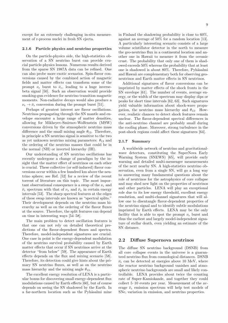
9
except for an extremely challenging in-situ measure-ment of r-process nuclei in fresh SN ejecta.
2.1.6 Particle physics and neutrino properties
On the particle-physics side, the high-statistics ob-servation of a SN neutrino burst can provide cru-cial particle-physics lessons. Numerous results derivedfrom the sparse SN 1987A data can be refined. Onecan also probe more exotic scenarios. Spin-flavor con-versions caused by the combined action of magneticfields and matter effects can transform some of theprompt νe burst to νe, leading to a huge inverse-beta signal [50]. Such an observation would providesmoking-gun evidence for neutrino transition magneticmoments. Non-radiative decays would also produce aνe → νe conversion during the prompt burst [51].
Perhaps of greatest interest are flavor oscillations.Neutrinos propagating through the SN mantle and en-velope encounter a large range of matter densities,allowing for Mikheyev-Smirnov-Wolfenstein (MSW)conversions driven by the atmospheric neutrino massdifference and the small mixing angle θ13. Therefore,in principle a SN neutrino signal is sensitive to the twoas yet unknown neutrino mixing parameters: θ13 andthe ordering of the neutrino masses that could be inthe normal (NH) or inverted hierarchy (IH).
Our understanding of SN neutrino oscillations hasrecently undergone a change of paradigm by the in-sight that the matter effect of neutrinos on each otheris crucial. These collective (or self-induced) flavor con-versions occur within a few hundred km above the neu-trino sphere; see Ref. [52] for a review of the recenttorrent of literature on this topic. The most impor-tant observational consequence is a swap of the νe andνe spectrum with that of νx and νx in certain energyintervals [53]. The sharp spectral features at the edgesof these swap intervals are known as “spectral splits.”Their development depends on the neutrino mass hi-erarchy as well as on the ordering of the flavor fluxesat the source. Therefore, the split features can dependon time in interesting ways [54–58].
The main problem to detect oscillation features isthat one can not rely on detailed theoretical pre-dictions of the flavor-dependent fluxes and spectra.Therefore, model-independent signatures are crucial.One case in point is the energy-dependent modulationof the neutrino survival probability caused by Earthmatter effects that occur if SN neutrinos arrive at thedetector “from below” [59]. The appearance of Eartheffects depends on the flux and mixing scenario [58].Therefore, its detection could give hints about the pri-mary SN neutrino fluxes, as well as on the neutrinomass hierarchy and the mixing angle θ13.
The excellent energy resolution of LENA is a partic-ular bonus for discovering small energy-dependent fluxmodulations caused by Earth effects [60], but of coursedepends on seeing the SN shadowed by the Earth. Ina far-northern location such as the Pyhasalmi mine
in Finland the shadowing probability is close to 60%,against an average of 50% for a random location [13].A particularly interesting scenario consists of a largevolume scintillator detector in the north to measurethe geo-neutrino flux in a continental location and an-other one in Hawaii to measure it from the oceaniccrust. The probability that only one of them is shad-owed exceeds 50% whereas the probability that at leastone is shadowed is about 80%. Therefore, Pyhasalmiand Hawaii are complementary both for observing geo-neutrinos and Earth matter effects in SN neutrinos.
Additional signatures of flavor conversions can beimprinted by matter effects of the shock fronts in theSN envelope [61]. The number of events, average en-ergy, or the width of the spectrum may display dips orpeaks for short time intervals [62, 63]. Such signaturesyield valuable information about shock-wave propa-gation, the neutrino mass hierarchy and θ13. How-ever, realistic chances to detect shock features remainunclear. The flavor-dependent spectral differences inthe anti-neutrino channel are probably small duringthe cooling phase. Moreover, strong turbulence in thepost-shock regions could affect these signatures [64].
2.1.7 Summary
A worldwide network of neutrino and gravitational-wave detectors, constituting the SuperNova EarlyWarning System (SNEWS) [65], will provide earlywarning and detailed multi-messenger measurementsof the next nearby SN. A high-statistics neutrino ob-servation, even from a single SN, will go a long wayto answering many fundamental questions about therole of neutrinos for the astrophysics of core collapseand may shed new light on the properties of neutrinosand other particles. LENA will play an exceptionalrole due to its low energy threshold, excellent energyresolution, and multi-channel signatures that will al-low one to disentangle flavor-dependent properties ofthe neutrino signal and to identify subtle modulationsimprinted by Earth effects. LENA may be the onlyfacility that is able to spot the prompt νe burst andthus the earliest and largely model-independent signa-ture of stellar death, even yielding an estimate of theSN distance.
2.2 Diffuse Supernova neutrinos
The diffuse SN neutrino background (DSNB) fromall core collapse events in the universe is a guaran-teed neutrino flux from cosmological distances. DSNBνe can be detected at energies above 10 MeV, wherethe reactor neutrino background vanishes and atmo-spheric neutrino backgrounds are small and likely con-trollable. LENA provides about twice the countingrate of Super-Kamiokande, and together they couldcollect 5–10 events per year. Measurement of the av-erage νe emission spectrum will help test models ofSNe, variation in emission, and neutrino properties.

10
2.2.1 Basic picture
A great and varied scientific return is expected fromthe observation of a nearby SN (Sec. 2.1), but suchevents are rare in the Milky Way. The guaranteedDSNB flux provides a way to detect SN neutrinoswithout a fortuitous burst [66–82]. DSNB signals de-pend on three ingredients. First, the cosmic core col-lapse rate, about 10 per second in the causal horizon;this is determined by astronomical measurements thatare already precise and quickly improving. Second, theaverage SN neutrino emission, which is expected to becomparable for all core collapses, including those thatfail and produce black holes (for which it may be evenlarger, as discussed below); this is the quantity of fun-damental interest. Third, the detector capabilities, in-cluding the energy dependence of the cross section anddetector backgrounds; Super-Kamiokande and LENAshould be able to detect DSNB νe.
Detecting the DSNB is important even if a MilkyWay burst is observed. DSNB νe will provide a uniquemeasurement of the average neutrino emission spec-trum to test SN simulations. Comparison to data fromSN 1987A and an eventual Milky Way SN will test thevariation between core collapses. While the statisticsof DSNB events will be low, like those of SN 1987A,this data will more effectively measure the exponen-tially falling tail of the spectrum at high energies. TheDSNB is also a new probe of stellar birth and death:its energy density is comparable to that of photonsproduced by stars, but the DSNB is unobscured andhas no known competition from astrophysical sources.Finally, the DSNB data will test flavor mixing andmore exotic particle properties.
The importance of running LENA to detect theDSNB should not be underestimated. If Super-Kamiokande does not add gadolinium, or does butencounters technical problems, LENA could be theonly experiment to detect the DSNB. If both exper-iments are successful, their data, based on detectionby inverse beta decay above 10 MeV, would be sim-ilar. Having two independent experiments would bevery valuable, as this will be a challenging measure-ment. In addition, LENA provides about twice thecounting rate of Super-Kamiokande. Collecting statis-tics at a combined three times higher rate than Super-Kamiokande alone could have a decisive impact on thephysics that could be extracted.
2.2.2 DSNB signals
The DSNB event rate spectrum follows from a lineof sight integral for the radiation intensity from a dis-tribution of distant sources. After integrating over allangles due to the isotropy of the DSNB and the trans-
parency of Earth, it is, in units s−1 MeV−1,
dNvis
dEvis(Evis) =
∫ ∞0
[RSN(z)
] [(1 + z)ϕ[Eν(1 + z)]
]×[NT σ(Eν)
] [∣∣∣∣c dtdz∣∣∣∣ dz] . (2.1)
On the right hand side, the ingredients are orderedas described above. The first is the comoving cosmiccore-collapse rate, in units Mpc−3 yr−1; it evolves withredshift. The second is the average time-integratedemission per SN, in units MeV−1; redshift reducesemitted energies and compresses spectra. The thirdis the number of targets times the detection crosssection; this does not need to be under the inte-gral. The last term is the differential distance, where|dt/dz|−1 = H0(1 + z)[ΩΛ + Ωm(1 + z)3]1/2; the cos-mological parameters are taken as H0 = 70 km s−1
Mpc−1, ΩΛ = 0.7, and Ωm = 0.3. (The cosmology andthe SN rate derived from star formation rate data arereally one combined factor proportional to the ratioof the average luminosity per galaxy in SN neutrinosrelative to stellar photons.) The left hand side is theDSNB spectrum in visible energy Evis; the relation toneutrino energy Eν depends on cross section and de-tector specifics. We next consider details of the threemain ingredients.
Cosmic SN rate. The cosmic core collapse rate isprecisely known [83–85]. The redshift range relevantfor the DSNB depends on energy, with lower energiesprobing higher redshifts. For detected energies above10 MeV, most DSNB neutrinos are emitted at red-shifts z < 1, where the astronomical data are mostprecise. The best determinations of the core collapserate come from predictions based on measured starformation rates and related observables such as theextragalactic background light [84]. As massive starsare short-lived, the redshift evolution of the core col-lapse and star formation rates must be the same. Therelative normalization depends on just the minimummass for core collapse, about 8M [86]; the predictedrate depends only weakly on the assumed stellar initialmass function because star formation data primarilysample massive stars. Comparable neutrino fluxes areexpected for ordinary SNe and those that are faint,obscured, or even failed [87–90], so the DSNB doesnot depend much on the outcomes, though it may belarger than assumed here. Measured SN and predictedcore collapse rates are in reasonable agreement, andthe data will quickly improve [85, 91, 92].
The local core collapse rate is RSN(z = 0) = (1.25±0.25)×10−4 Mpc−3 yr−1 [84]. The evolution of the co-moving rate, roughly the rate per galaxy, has a strongand clear rise of one order of magnitude between z = 0and z = 1 and then a slow and eventually steepeningdecline at higher redshift. Taking into account thevariation of the uncertainties with redshift, the uncer-tainty on the DSNB due to that on the core collapserate is presently ±40% [84]. This will decrease quickly

11
with new data, so that the focus of DSNB measure-ments will be on the neutrino emission parameters [93].
SN neutrino emission. While we have some in-formation about neutrino emission from SN 1987Aand SN simulations, detecting the DSNB is neces-sary to measure the average emission per SN. It istypically assumed that the total energy in neutrinosis 3 × 1053 erg, that each flavor carries 1/6 of this,and that the spectra are quasi-thermal with temper-atures of several MeV. But the total energy, its par-tition among flavors, and spectral distributions andaverage energies may be different or show more varia-tion than expected. Uncertainties include those due tothe collapse mechanism [94–100], the effects of progen-itor mass, rotation, and magnetic fields [101–103], theneutron star equation of state [104–107], and effectsdue to neutrino properties (Sec. 2.1.3).
The neutrino emission is parameterized here witha Maxwell-Boltzmann thermal spectrum, ϕ(Eν) =Etot [E2
ν/(2T3ν )] exp(−Eν/Tν), where the total energy
and temperature (average emitted energy 〈Eν〉 = 3Tν)are for νe after neutrino flavor oscillations, which occurin the SN and not en route. Following Sec. 2.1.3, thenominal expectation for νe might be Etot = 0.5× 1053
erg and Tν = 4 MeV, with large uncertainties. Fur-ther, we do not know if SN 1987A was a typical corecollapse or if present SN simulations are correct. Mea-surements of the DSNB are needed to help decide.
The DSNB signal may be larger than assumed here,due to unusual core collapse outcomes that could bedisproportionately important due to their larger-than-average neutrino emission. The most interesting pos-sibility is prompt black hole formation, as this is ex-pected to have a nonzero rate even in standard sce-narios [108, 109], and present constraints allow evenlarger rates [49, 85, 86, 92, 110]. Even though the neu-trino emission can be cut off, it is expected to be en-hanced before that, such that the time-integrated totaland average neutrino energies can be larger than usual[87–90]. Other possibilities include emission from thehot, magnetized corona of a proto-neutron star or ac-cretion disk [111] or from fallback [112]. The DSNBwill thus be especially valuable for probing outcomesthat may not occur for a Milky Way core collapse andthe corresponding extreme physical conditions in suchcollapses [92, 113].
Detector capabilities. The detection channel inLENA and Super-Kamiokande is inverse beta decay,νe + p → e+ + n, while other DSNB neutrino in-teractions have smaller detectable rates [114]. Thepositron kinetic energy is close to that of the neutrino,Te ' Eν − 1.8 MeV, with a nearly isotropic distribu-tion. The low-energy neutron will thermalize and thenregister its presence by radiative capture. The timeand space coincidence between positron and neutronsuppresses detector backgrounds.
LENA has 2.9 × 1033 free protons in 44 kt of scin-tillator (Super-Kamiokande has 1.5 × 1033 in 22.5 kt
0 10 20 30E
vis [MeV]
0
1
2
3
4
5
6
7
8
dN /
dEvi
s [ (
44 k
ton
10 y
r)-1
MeV
-1 ]
6 MeV MB5 MeV MB4 MeV MB
Reactor νe
FIG. 4: DSNB νe signal spectra in LENA, with labeledlines indicating assumed emission spectra. Below 10 MeV,the reactor neutrino background (spectrum not shown) isoverwhelming. At higher energies, atmospheric neutrinobackgrounds should be small and controllable.
of water). The cross section is σ(Eν) ' 9.42 ×10−44 cm2 (Eν−1.3 MeV)2 at lowest order; we use thecorrections to the cross section and kinematics fromRefs. [115, 116]. In LENA, the visible positron energyis its kinetic energy plus the annihilation energy withan electron, Evis = Te + 2mec
2 (Super-Kamiokandedefines visible energies via the positron total energy,Evis = Te +mec
2). The effects of energy resolution onthe DSNB spectrum are negligible.
Figure 4 shows the expected DSNB signal spec-trum in LENA, following the above details and as-suming perfect detection efficiency. A range of SNνe emission spectra, parameterized by changes in Tν ,are shown. There are also uncertainties due to Etot
and the assumed spectrum shape. (Astrophysicaluncertainties—those due to the SN rate alone—areneglected because they are small and quickly decreas-ing.) The minimal allowed case is close to Etot =0.5 × 1053 erg, T = 4 MeV, as this DSNB pre-diction is comparable to that obtained from a di-rect non-parametric reconstruction of the high en-ergy SN 1987A data [79] (see also Ref. [74, 78] forprevious analyses of SN 1987A data applied to theDSNB). Maximal allowed cases (not shown), based onjust the 2003 Super-Kamiokande limit, are close toEtot ∼ 1 × 1053 erg, Tν = 6 MeV, or Etot ∼ 2 × 1053
erg, Tν = 4 MeV [84].The νe emission parameters can thus be directly
measured from the DSNB spectrum if the atmosphericneutrino backgrounds can be controlled. The spectrain Fig. 4 contain 70, 55, and 35 events in the range 10–30 MeV for ten years of LENA running, correspond-ing to a statistical uncertainty of 12–17%. Data fromSuper-Kamiokande will also help, especially if it beginsrunning with gadolinium soon. The spectrum shapewill help break the degeneracy between Etot and Tν .

12
In effect, Etot will be probed best by the lower energydata, where the Tν dependence is weakest, and Tν willbe probed best by the higher energy data, where thefalloff is exponential. Precise data will also test newphysics scenarios [117, 118].
Theory and data from a future Milky Way SN willbe needed to relate these νe emission parameters withflavor mixing effects included to other SN parameterssuch as the total energy emitted by all flavors and thespectra before neutrino flavor mixing.
2.2.3 LENA detector backgrounds
As both positron and neutron emerging from an in-verse beta decay are observable in liquid scintillator,single-event backgrounds can be suppressed very ef-fectively. The only remaining backgrounds are due toother sources of νe, namely reactor and atmosphericνe that are irreducible. They limit the DSNB detec-tion window to 10–30 MeV, the exact range depend-ing on the detector site [119]. Other backgrounds aresignals mimicking the fast coincidence signal: Cosmo-genic βn-emitting isotopes, fast neutrons from the sur-rounding rocks, and NC interactions of higher-energyatmospheric neutrinos. However, these backgroundscan be identified, either by their production, locationor pulse shape. These reducible backgrounds, strate-gies for their rejection and the accompanying loss inDSNB detection efficiency are outlined below.
The delayed coincidence signal of inverse beta decayenables LENA to easily reject what is the predominantbackgrounds for DSNB detection in water Cherenkovdetectors, i.e. low energy muons produced in CC re-actions of atmospheric neutrinos, solar neutrinos andspallation products of cosmic muons.
Cosmogenic βn-emitters. are unstable isotopesproduced by cosmic muons crossing the detector.They mimic the νe coincidence by the prompt emissionof the electron followed by the emission of a neutronfrom an excited state of the daughter nucleus. For-tunately, only 9Li (T1/2 = 178 ms) has a large enoughQ-value to add to the background. If no cuts are ap-plied, the 9Li rate is of the same order of magnitudeas the DSNB signal. Due to its short half-life, 9Li iseasily associated to its parent muon: It is sufficientto veto a cylinder with 2 m radius around each muontrack for 1 s (∼5T1/2), to reduce the residual 9Li rateto about 2%, while the introduced dead time corre-sponds only to ∼ 0.1% of the total measurement time[119].
Fast neutrons. are produced in the surrounding rockby cosmic muons that pass the detector undetected.There is a chance for these neutrons to propagate intothe target volume. The coincidence is mimicked bya prompt signal due to elastic scattering of protons,while the delayed signal is caused by the capture of thestopped neutron. The fast neutron background ratewas analyzed by Monte-Carlo simulations. As mostneutrons will stop at the verge of the scintillator, a
fiducial volume cut greatly reduces the rate. For 10 mfiducial radius, ∼0.2 fast neutron events per year areexpected [120]. However, proton recoils of neutronsfeature a different typical pulse shape than positronsignals. This allows for an alternative approach todistinguish neutron events more effectively, reducingthe fast neutron background to 0.12 events per year inthe nominal fiducial volume of 12 m radius.
NC reactions of atmospheric neutrinos. mightprove to be the most dangerous background: Besidesthe intrinsic background of atmospheric νe’s, atmo-spheric neutrinos at higher energies knock out neu-trons from 12C in the scintillator. Neutron scatteringoff protons or particles emitted in the de-excitationof the remaining nucleus cause a prompt signal, whilethe neutron is later captured, mimicking the signalcoincidence. MC simulations point towards a back-ground rate about 10–20 times higher than the ex-pected DSNB signal [121]. Several strategies havebeen devised to cope with this background: A pos-sible way is to search for the delayed β+ decay of theresidual 11C that remains after the neutron knock-out.If the 11C nucleus is created in its ground state, this isa very effective strategy, reducing the background by afactor of 2. However, if an excited 11C state is created,it will mostly de-excite via proton, neutron and alphaemission. In this case, the only way of discriminationis a pulse shape analysis of the prompt signal. The dis-crimination power as well as the remaining DSNB de-tection efficiency is currently evaluated in MC studies.Preliminary results indicate that in spite of a painfulloss in efficiency, a signal-to-background ratio greaterthan unity can be obtained [120]. However, furtherMC studies as well as laboratory measurements onproton quenching in liquid scintillator are needed toquantify this result.
While the latter background is absent in waterCherenkov detectors, their inability to detect the de-layed neutron signal makes them vulnerable to solarneutrinos, the decay of invisible muons and all kindsof spallation products. Nevertheless, much improvedSuper-Kamiokande sensitivity to DSNB νe is expectedby the time LENA comes into operation. Their 2003limit is already strong and will improve with furtherdata [122]. If gadolinium is added, Super-Kamiokandewill reject detector backgrounds above 10 MeV andwill cleanly collect a few DSNB signal events peryear [27].
2.2.4 Summary
The DSNB is a very promising astrophysical neu-trino source, with at most a factor of a few improve-ment in flux sensitivity required for a first detection.This will directly probe the neutrino emission per corecollapse via the measured νe spectrum above about10 MeV. This spectrum averages over all core-collapseoutcomes, including some which may be relatively rarebut which may be of disproportionate importance due

13
to larger-than-usual neutrino emission. The main ad-vantages of LENA are its large size, native abilityto detect neutrons to tag νe + p → e+ + n events,and low detector backgrounds and consequent low en-ergy threshold. LENA may make a first detection ofthe DSNB and would significantly increase statisticsover Super-Kamiokande alone, leading to more deci-sive probes of the average neutrino emission per corecollapse, a key comparison point for SN models and aMilky Way SN.
2.3 Solar neutrinos
Solar neutrino research is a mature field that has ac-cumulated a long series of outstanding achievements.Originally conceived as a powerful tool to investigatethe Sun’s deep interior, solar neutrinos provided thefirst indication for neutrino flavor oscillations and thuscontributed in crucial ways to discover and analyzethis profound phenomenon. Solar experiments providesensitivity to ∆m2
12 and especially θ12, with the fas-cinating prospect of a possible positive indication re-garding the value of the subleading θ13 angle, connect-ing solar and atmospheric sectors of the Pontecorvo-Maki-Nakagawa-Sakata (PMNS) neutrino mixing ma-trix. These achievements are the starting point of theLENA solar neutrino program because high-statisticsmeasurements will resolve energy spectra and possibletime variations in unprecedented detail.
2.3.1 Introduction
The Standard Solar Model (SSM). The effort todevelop a model able to reproduce fairly accuratelythe solar physical characteristics, as well as the spec-tra and fluxes of the several produced neutrino com-ponents, was led for more than forty years by the lateJohn Bahcall; this effort culminated in the synthesisof the so called Standard Solar Model (SSM) [123],which represents a true triumph of the physics of 20th
century, leading to extraordinary agreements betweenpredictions and observables.
However, over the last years such previous excel-lent agreement has been seriously compromised by thedownward revision of the solar surface heavy-elementcontent from Z = 0.0229 [124] to Z = 0.0165 [125],leading to a severe discrepancy between the SSM andthe helioseismology results. Resolution of this puz-zle would imply either to revise the physical inputs ofSSM or to modify the core abundances.
In 2009 a complete revision of the solar photosphericabundances for nearly all elements have been done[126]. This revision includes a new three dimensionalhydrodynamical solar atmosphere model with an im-proved radiative transfer and opacities. The obtainedresults give a solar metallicity Z = 0.0178. In [127] thethree different sets of solar abundances: GS98 [124],AGS05 [125] and AGS09 [126] have been used originat-ing two different, low metallicity or high metallicity,
versions of the solar model.
Neutrino oscillations and the MSW effect. So-lar neutrino oscillations are governed by ∆m2
12 andθ12 of the PMNS mixing matrix. At low energies,νe survival probabilities are described well by vac-uum oscillations. However, at energies above ∼1 MeV,matter effects first pointed out by Mikheyev, Smirnovand Wolfenstein (MSW) [128, 129] enhance the con-version νe → νµ,τ , leading to a further suppressionof the νe rate observed in terrestrial detectors. Bynow, this MSW-LMA oscillation scenario is well con-firmed by solar neutrino experiments for vacuum- andmatter-dominated regimes. However, the vacuum-matter transition region from 1 to ∼5 MeV remains tobe explored and might hold evidence for non-standardneutrino physics.
2.3.2 Experimental status
For almost 40 years, solar neutrino detectors haveaccumulated a large amount of data. Beyond the con-firmation of thermonuclear fusion as the solar energysource, the comparison of the experimental results tothe accurate predictions of the SSM on solar neu-trino flux and spectrum led to the establishment ofthe LMA-MSW oscillation scenario in the solar sec-tor.
In the 70’s and the 80’s the Chlorine radiochemicalexperiment at Homestake [130] and the Cherenkov de-tector Kamiokande [131] played the fundamental roleto establish on solid rock basis what became known asthe Solar Neutrino Problem (SNP), i.e. the persistingdiscrepancy between the measured and predicted solarneutrino flux.
In the 90’s the scene was dominated by the sec-ond generation of radiochemical experiments based onGallium, GALLEX/GNO and SAGE [132–134], whichnot only reinforced the physics case of Homestake andKamiokande, thus further strengthening the SNP, butalso marked the first detection ever of the overwhelm-ing flux of the pp neutrinos. This milestone resultrepresented the first direct proof of the nuclear burn-ing mechanism as the actual stellar energy generatingengine.
Later, the decisive assault to the SNP was launchedby the three real time experiments Super-Kamiokande,SNO and Borexino, which were complemented in theireffort by the reactor neutrino experiment KamLAND:
Super-Kamiokande. Designed to detect theCherenkov light emerging from the elastic scatteringof the incoming neutrinos off the electrons of the wa-ter acting as detection medium, Super-Kamiokandestarted its operation in 1996 at the Kamioka mine inJapan. It is a gigantic detector, with its 50 ktons ofwater viewed by more than 10 000 20-inch phototubes.
Over 15 years of measurement, the experiment re-turned consistent data on the 8B-ν flux and spec-trum [135, 136] above a detection threshold of 5 MeV.For the latest phase III of data taking, a flux

14
of (2.32±0.04stat±0.05syst)×106 cm−2s−1 has beendetermined from neutrino-electron scattering [137].However, the low-energy upturn in the 8B νe spec-trum that is predicted by the MSW-LMA solution hasnot been observed. The new phase IV of data takingwill feature a lower threshold of ∼4 MeV and so willfurther explore the vacuum-matter transition region.
SNO. Located in a mine in Ontario, SNO exploitedthe same Cherenkov technique of Super-K, with thedifference that the detection medium was heavy water.The neutral and charge current neutrino reactions ondeuterium provided the experiment with a powerfultool enabling to measure concurrently the total 8B allflavor neutrino flux (neutral current) and the electronneutrino only flux (charge current). The SNO resultverified unambiguously that the SNP was due to theconversion between different neutrino flavors, as im-plied by the MSW paradigm.
The experiment provided also an accurate mea-sure of the total 8B flux. SNO progressed throughthree steps (pure heavy water, salt and 3He coun-ters) that returned consistent result. The most re-cent low energy threshold (LETA) joint analysis ofthe phase I and II data results in a 8B flux of(5.140+0.160
−0.158(stat)+0.132−0.117(syst))·106 cm−2s−1 [138], in
good agreement with both high- and low-metallicitypredictions of the SSM. The detector is now empty,ready to be filled with liquid scintillator for the futureSNO+ data taking phase.
Borexino. While the two Cherenkov experiments fo-cused their investigations to the high energy portionof the 8B spectrum, Borexino [139] at Gran Sasso low-ered for the first time the research range of a real timesolar neutrino experiment down to few hundreds keV,based on the much larger light output of the scintilla-tion technique. This allowed to test the LMA vacuumoscillations below 1 MeV, in contrast to the matter-dominated regime probed by Super-Kamiokande andSNO.
Achieving the ultra-low radioactive background con-ditions required for the detection of the 7Be-νs (0.862MeV) poses an enormous technological challenge.However, the necessary techniques for purification ofthe scintillator and the selection and assembly of low-background materials were developed in an extensiveR&D program, culminating in the clear detection ofthe 7Be-ν recoil electrons. The corresponding evalua-tion of the νe survival probability was in good agree-ment with MSW-LMA and SSM predictions, obtain-ing a value of (5.18±0.51)×109 cm−2s−1 for the total7Be flux.
As further proof of the powerful flexibility of thescintillation technique, Borexino performed a mea-surement of the 8B-ν flux above 3 MeV, achievingthe currently lowest threshold in a spectral mea-surement. The result corresponds to a flux of(2.4±0.4stat±0.1syst)×106 cm−2s−1 [140], in excellentagreement with the Super-Kamiokande measurements.
-110 1
-410
KamLAND95% C.L.99% C.L.99.73% C.L.best fit
Solar95% C.L.99% C.L.99.73% C.L.best fit
10 20 30 40
1 2 3 4 5 6
5101520
12
3
4
122tan 2
)2 (e
V212
m2
FIG. 5: Global solar and KamLAND data oscillation anal-ysis [141].
KamLAND. The current understanding of the ex-perimental solar neutrino results in term of the neu-trino oscillation paradigm heavily relies also on theoutcomes of the KamLAND [141] reactor neutrino ex-periment (Sec. 2.5). By comparing the theoreticallyexpected antineutrino spectrum from a number of nu-clear power plants at different distances to the experi-mental site, with the measured spectrum, KamLANDwas able to detect in the latter the clear imprintingof the oscillation effect, thus independently ruling outthe other possible explanations for the solar neutrinodeficit.
The collective analysis of the data from all the so-lar neutrino experiments performed so far, plus thosecoming from KamLAND, puts stringent limits on the∆m2
12 and θ12 oscillations parameters. Fig. 5, fromreference [141], shows the allowed region in the pa-rameters space, stemming from a two flavor oscilla-tion analysis. In a first approximation, the strongestconstraint on ∆m2
12 comes from KamLAND, while thelimit on the mixing angle derives from the solar data.
2.3.3 LENA observables and capabilities
Despite the impressive successes accumulated in thisfield in the past, still additional and important insightscan be expected from the detection of solar neutrinos.With a first measurement of pep and CNO neutrinofluxes, Borexino and the upcoming SNO+ experimentwill probe oscillations in the MSW transition regionand solar metallicity, respectively. Even a direct mea-surement of the fundamental pp-ν might be withinreach of Borexino.
However, the high-statistics data collected by a gi-gantic scintillation detector like LENA would allowa precise determination of SSM neutrino rates andMSW-LMA oscillation probabilities. The benchmark
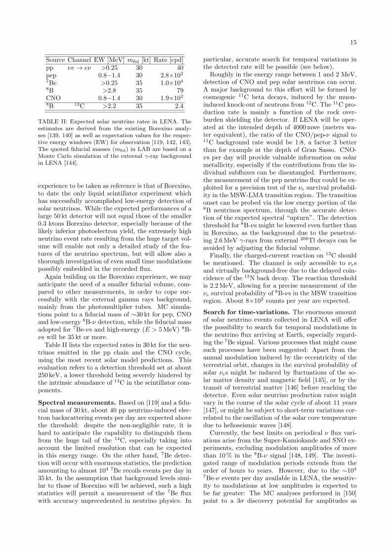
15
Source Channel EW [MeV] mfid [kt] Rate [cpd]pp νe→ eν >0.25 30 40pep 0.8−1.4 30 2.8×10²
7Be >0.25 35 1.0×10⁴
8B >2.8 35 79CNO 0.8−1.4 30 1.9×10²
8B 13C >2.2 35 2.4
TABLE II: Expected solar neutrino rates in LENA. Theestimates are derived from the existing Borexino analy-ses [139, 140] as well as expectation values for the respec-tive energy windows (EW) for observation [119, 142, 143].The quoted fiducial masses (mfid) in LAB are based on aMonte Carlo simulation of the external γ-ray backgroundin LENA [144].
experience to be taken as reference is that of Borexino,to date the only liquid scintillator experiment whichhas successfully accomplished low-energy detection ofsolar neutrinos. While the expected performances of alarge 50 kt detector will not equal those of the smaller0.3 ktons Borexino detector, especially because of thelikely inferior photoelectron yield, the extremely highneutrino event rate resulting from the huge target vol-ume will enable not only a detailed study of the fea-tures of the neutrino spectrum, but will allow also athorough investigation of even small time modulationspossibly embedded in the recorded flux.
Again building on the Borexino experience, we mayanticipate the need of a smaller fiducial volume, com-pared to other measurements, in order to cope suc-cessfully with the external gamma rays background,mainly from the photomultiplier tubes. MC simula-tions point to a fiducial mass of ∼30 kt for pep, CNOand low-energy 8B-ν detection, while the fiducial massadopted for 7Be-νs and high-energy (E > 5 MeV) 8B-νs will be 35 kt or more.
Table II lists the expected rates in 30 kt for the neu-trinos emitted in the pp chain and the CNO cycle,using the most recent solar model predictions. Thisevaluation refers to a detection threshold set at about250 keV, a lower threshold being severely hindered bythe intrinsic abundance of 14C in the scintillator com-ponents.
Spectral measurements. Based on [119] and a fidu-cial mass of 30 kt, about 40 pp neutrino-induced elec-tron backscattering events per day are expected abovethe threshold: despite the non-negligible rate, it ishard to anticipate the capability to distinguish themfrom the huge tail of the 14C, especially taking intoaccount the limited resolution that can be expectedin this energy range. On the other hand, 7Be detec-tion will occur with enormous statistics, the predictionamounting to almost 104 7Be recoils events per day in35 kt. In the assumption that background levels simi-lar to those of Borexino will be achieved, such a highstatistics will permit a measurement of the 7Be fluxwith accuracy unprecedented in neutrino physics. In
particular, accurate search for temporal variations inthe detected rate will be possible (see below).
Roughly in the energy range between 1 and 2 MeV,detection of CNO and pep solar neutrinos can occur.A major background to this effort will be formed bycosmogenic 11C beta decays, induced by the muon-induced knock-out of neutrons from 12C. The 11C pro-duction rate is mainly a function of the rock over-burden shielding the detector. If LENA will be oper-ated at the intended depth of 4000 mwe (meters wa-ter equivalent), the ratio of the CNO/pep-ν signal to11C background rate would be 1:8, a factor 3 betterthan for example at the depth of Gran Sasso. CNO-νs per day will provide valuable information on solarmetallicity, especially if the contributions from the in-dividual subfluxes can be disentangled. Furthermore,the measurement of the pep neutrino flux could be ex-ploited for a precision test of the νe survival probabil-ity in the MSW-LMA transition region. The transitiononset can be probed via the low energy portion of the8B neutrinos spectrum, through the accurate detec-tion of the expected spectral “upturn”. The detectionthreshold for 8B-νs might be lowered even further thanin Borexino, as the background due to the penetrat-ing 2.6 MeV γ-rays from external 208Tl decays can beavoided by adjusting the fiducial volume.
Finally, the charged-current reaction on 13C shouldbe mentioned. The channel is only accessible to νesand virtually background-free due to the delayed coin-cidence of the 13N back decay. The reaction thresholdis 2.2 MeV, allowing for a precise measurement of theνe survival probability of 8B-νs in the MSW transitionregion. About 8×10² counts per year are expected.
Search for time-variations. The enormous amountof solar neutrino events collected in LENA will offerthe possibility to search for temporal modulations inthe neutrino flux arriving at Earth, especially regard-ing the 7Be signal. Various processes that might causesuch processes have been suggested: Apart from theannual modulation induced by the eccentricity of theterrestrial orbit, changes in the survival probability ofsolar νes might be induced by fluctuations of the so-lar matter density and magnetic field [145], or by thetransit of terrestrial matter [146] before reaching thedetector. Even solar neutrino production rates mightvary in the course of the solar cycle of about 11 years[147], or might be subject to short-term variations cor-related to the oscillation of the solar core temperaturedue to helioseismic waves [148].
Currently, the best limits on periodical ν flux vari-ations arise from the Super-Kamiokande and SNO ex-periments, excluding modulation amplitudes of morethan 10 % in the 8B-ν signal [148, 149]. The investi-gated range of modulation periods extends from theorder of hours to years. However, due to the ∼104
7Be-ν events per day available in LENA, the sensitiv-ity to modulations at low amplitudes is expected tobe far greater: The MC analyses performed in [150]point to a 3σ discovery potential for amplitudes as

16
low as 0.5 %, covering a period range extending fromtens of minutes to a hundred years or more. This willallow to probe the high-frequency regions associatedto helioseismic g-modes, but also to test the tempo-ral uniformity of solar fusion processes on long timescales.
2.4 Geoneutrinos
Geoneutrinos (geo-νs) are νes produced inside theEarth during β-decays of naturally occurring radioac-tive elements. They are direct messengers of the abun-dances and distribution of radioactive elements withinour planet, information strongly constraining all geo-chemical and geophysical models. Geoneutrinos havebeen successfully detected by the liquid-scintillator ex-periments KamLAND and Borexino. However, the ge-ological information contained in these measurementsis still limited, mostly because of low statistics. A kt-scale detector like LENA featuring a radiopurity at thelevel already achieved by Borexino, would give defini-tive answers to several questions of extraordinary geo-logical importance. This section presents the eventand background rates expected for LENA (both inPyhasalmi and Frejus), and projects the precision atwhich the total geo-ν flux as well as the U/Th ratiocould be measured.
2.4.1 Introduction
Geo-νs originate from the β-decays of radioactiveelements in the Earth’s crust and mantle, predomi-nantly from 40K and nuclides in the chains of 238Uand 232Th. These neutrinos probe direct informa-tion about the absolute abundances and distributionof these radioactive elements inside the Earth. Theirmeasurement quantifies the radiogenic contribution tothe total heat flux of the Earth, constraining geochem-ical and geophysical models of the planet. This infor-mation provides constraints on the many and complexprocesses that operate inside the Earth, including thegeneration of the Earth’s magnetic field, mantle con-vection, and plate tectonics. In addition, determiningthe absolute abundances of refractory elements (i.e. Uand Th) in the planet provides insight into its originand formation.
Estimates of the Earth’s surface heat fluxemerge from temperature gradient measurements from∼40 000 drill holes distributed around the globe. Us-ing these data, geophysical models typically concludethat the present surface heat flux is 47±2 TW [151].This conventional view has been challenged by an al-ternative flux estimate of 31±1 TW [152]. A signifi-cant contributor to this heat flux comes from the heatproducing elements, K, Th and U, with its flux pro-portion dependent upon their absolute abundance in-side the Earth. The many models that describe thecomposition of the Earth come from cosmochemical,geochemical and geophysical observations and predict
a range of abundances and distributions of these ele-ments [153–156].
The Earth has a silicate shell, the Bulk SilicateEarth (BSE), surrounding a metallic core, with thecore being an iron-nickel mixture (with proportionsset from cosmochemical constraints) often consideredto contain negligible quantities of Th and U [157, 158].The BSE describes the primordial, non-metallic Earthcondition that followed planetary accretion and coreseparation, prior to its differentiation into a man-tle, oceanic crust, and continental crust. Elementsexcluded from the Earth’s core are referred to aslithophile and those that accreted onto the Earth inchondritic proportions are the refractory elements.
Chondritic meteorites are undifferentiated sampleswith refractory element abundances in equal propor-tion and record a high temperature condensation char-acteristic of the cooling nebular. An important guideto predicting planetary compositions is given by thecompositional match between chondritic meteoritesand the solar photosphere on a one to one basis, over5 orders of magnitude for the non-gases, based on anequal atom abundance of silicon.
Thorium and uranium are refractory lithophile ele-ments and contribute equally ∼80 % of the total radio-genic heat production of the Earth, while the remain-ing fraction is due to 40K, a volatile element. Duringmantle melting and because of their chemistry andsize, K, Th and U are quantitatively partitioned intothe melt and depleted from the mantle. Thus, the con-tinental crust, has over geologic time, been enriched inthese elements and has a sizable fraction (about half)of the planet’s inventory, producing radiogenic powerof 7.3±2.3 TW (2σ) [159].
The range of BSE models predicting the Th, U, andK abundances (Tab. III) translates to radiogenic heatcontributions of 12–30 TW, and thus allow other possi-ble heat sources to make up the total surface heat flux.Additional heat might might originate from accretion,gravitational contraction, latent heat from phase tran-sitions, or from a (rather exotic) nuclear reactor in thecore/core-mantle boundary (CMB). Systematic errorsin both geochemical and geophysical models are notvery well known and the validity of several assump-tions on which they are based is not proven. Thus, ob-servations of the planetary geo-ν flux will yield trans-formational insights into the Earth’s energy budget.
Typically, based on geophysical calculations, pa-rameterized convection models of the mantle requirehigher radiogenic heat contributions (∼70 % of the to-tal heat flux) in order to describe the Earth’s coolinghistory in terms of a balance of forces between ther-mal dissipation and mantle viscosity. In contrast, geo-chemical models using cosmochemical and geochemi-cal observations predict the BSE abundance of U andvalues for Th/U and K/U, 4 and 1.4×10⁴, respectively,with an uncertainty of ∼10 %. Consequently, a geo-chemist’s view of the Earth predicts that its budget ofheat producing elements in the BSE are up to a factor

17
Authors a(U) [ng/g] a(Th)/a(U) HM(U + Th) [TW]Turcotte and Schubert (2002) [160] 31 4.0 19Anderson (2007) [155] 28 4.0 17Palme and O’Neill (2003) [161] 22 3.8 12Allegre et al. (1995) [162] 20 3.9 11McDonough and Sun (1995) [153] 20 3.9 11Lyubetskaya and Korenaga (2007) [154] 17 3.7 7Javoy et al. (2010) [156] 12 3.5 3
TABLE III: Uranium content a(U) in the Bulk Silicate Earth, the Th/U ratio and the radiogenic heat production in themantle (HM) due to U and Th according to different authors.
of ∼3 lower than the models predicted by geophysi-cists. Thus, the relative contribution of the radioac-tive power to the total planetary heat flux is poorlyknown.
The first ideas regarding geo-νs are from the six-ties [163] but only recently the first experimental re-sults from large volume scintillator detectors are avail-able. A first experimental indication for geo-νs (∼2.5σC.L.) was reported by the KamLAND Collaboration[141, 164]. More recently, the Borexino collaborationprovided the first observation of geo-ν [165] at morethan 4σ C.L., possible due to the unprecedentedly lowlevel of radioactive contaminants and relatively smallflux of νes from nuclear reactors. In addition, bothexperiments have placed limits (<3 TW) on the po-tential contribution of a putative geo-reactor deep inthe Earth’s interior.
In spite of these first successful experimental results,it has not been possible yet to neither discriminateamong several predictions concerning the radiogenicheat production nor measure the U/Th bulk ratio.Even the case of very low background measurementperformed by Borexino has a limited power of geologi-cal predictions due to the very limited statistics. Sev-eral future experiments, as for example SNO+ projectin Canada, have among their aims geo-ν measure-ments, but the real breakthrough in this field wouldcome only with a very large volume detector at 50 ktscale, like LENA. In liquid scintillator detectors, theνe are detected via the inverse beta decay, with a kine-matic threshold of 1.8 MeV (Sect. 2.2). The character-istic time and spatial coincidence of prompt e+ anddelayed neutron events offers a clean signature. Since1 kt of liquid scintillator contains about 1032 free pro-tons (the precise value depending on the chemical com-position) and the exposure times are of order of a fewyears, the events rates are conveniently expressed interms of a Terrestrial Neutrino Unit (TNU), definedas one event per 1032 target protons per year.
The geo-ν flux produced from U and Th inside theEarth is some 106 /cm2s. Due to neutrino oscillations,the flux arriving at the detector will be smaller thanthat produced: for our calculation we have consideredan asymptotic survival probability 〈Pee〉 = 0.57 follow-ing the best fit obtained in [166]. Only a small frac-tion (about 5 %) of νe from the 238U and 232Th series
are above the inverse beta-decay reaction threshold,while those from 40K decays are below this thresh-old. Geo-νs originating from different elements canbe distinguished - at least in principle - due to theirdifferent energy spectra, as only νs from the uraniumchain contribute at energies Ee+ = 2.25 MeV. The ex-act spectrum depends on the shapes and rates of theindividual decays within U and Th chains, and on theabundances and spatial distribution of U and Th inthe crust and in the mantle.
The geo-ν signal spectrum extends to Ee+ ≈2.6 MeV. However, νe from nuclear power plants repre-sent a background for geo-ν detection, Ee+ extendingup to ∼10 MeV. In the following the expected geo-ν and reactor ν signal at Pyhasalmi and Frejus sitesare discussed. The potential of the LENA project toachieve geologically interesting results is discussed aswell.
2.4.2 The geoneutrino signal
Different calculations for geo-ν production havebeen presented in the literature [167–170]): all modelsrely on the geophysical 2×2 crustal map of [171] andon the density profile of the mantle as given by the Pre-liminary Reference Earth Model (PREM) [172]. Forthe calculation of geoneutrino signal we adopt the val-ues of U and Th abundance recommended in [173] forthe sedimentary layers and the values reported in [159]for the upper, middle and lower crust (Tab. IV). The1σ uncertainties for the upper and middle crust arefrom [159]. For the lower crust, we adopt an uncer-tainty indicative of the spread of published values.
The composition and the circulation inside theEarth’s mantle is the subject of a strong and so farunresolved debate between geochemists and geophysi-cists: assuming that a spherical symmetry holds andU and Th abundances do not decrease with depth,the extreme predictions for the signal are obtainedby placing U and Th in a thin layer at the bottomand distributing it with uniform abundance over themantle. For a fixed total U mass in the BSE model,m(U) = 0.8×10¹⁷ kg, and a fixed ratio of the elemen-tal abundance Th/U = 3.9 [157], the contribution tothe geo-ν signal from the crust and the mantle is ob-tained by using the proximity argument presented in

18
Reservoir Units a(U) a(Th)Sediments µg/g 1.68 ± 0.18 6.91 ± 0.8Upper Crust µg/g 2.7 ± 0.6 10.5 ± 1.0Middle Crust µg/g 1.3 ± 0.4 6.5 ± 0.5Lower Crust µg/g 0.6 ± 0.4 3.7 ± 2.4Oceanic Crust µg/g 0.1 ± 0.03 0.22 ± 0.07
TABLE IV: U and Th mass abundances in the Earth’sreservoirs [159, 173].
[174]: the minimal (maximal) contributed flux is ob-tained by placing uranium and thorium as far (close)as possible to the detector.
Our prediction for geoneutrino signal is obtainedby the mean of these extremes, assigning an errorso as to encompass both of them. For the cen-tral value of BSE model, the expected signal from Uand Th at Pyhasalmi is 51.3±7.1 TNU. At Frejus, itis 41.4±5.6 TNU: the accuracy of about 14 % corre-sponds to ”3σ”. In a target mass of 44 kt, correspond-ing to 2.9×1033 free protons, we expect a geo-ν signalof the order of 103 events/year. In Fig. 6, the expectedsignal S(U + Th) from U and Th geo-νs at Pyhasalmiand Frejus is shown as a function of the radiogenicheat production rate H(U + Th).
For a given total uranium mass in the Earth, m(U),corresponding to a fixed radiogenic heat productionH(U + Th), the minimal and maximal signals are pro-vided by the terrestrial models consistent with avail-able geochemical and geophysical observational dataand by proximity argument [174]. The uncertaintyband is wide because the signal is dominated by con-tribution from the crust: a refinement of the referencemodel taking into account the regional contribution isappropriate. Considering that some 50 % of the signalfrom the crust originates from a region within 200 kmfrom both detectors, a better geological and geochemi-cal description of the regions surrounding the detectorsis needed for a more precise estimate of the geoneu-trino signal.
2.4.3 Reactor neutrino background
The expected reactor νe flux was calculated basedon the same assumptions as described in [165]. Themonthly load factor of year 2009 was considered forall 493 world nuclear reactors [175]. The expected re-actor νe signal at Frejus and Pyhasalmi and shape ofthe oscillated spectrum are given in Tab. V and Fig. 7,respectively.
For Pyhasalmi site also the case of possible futurereactors was considered, assuming a typical 80 % loadfactor. In particular, the Olkiluoto-3 power plant isunder construction and should be operating in 2013with 4.3 GW thermal power. At the same site, 360 kmfrom Pyhasalmi, the construction of Olkiluoto-4 reac-tor with power up to 1.8 GW was approved. In addi-tion, the construction of additional reactor with power
Location Signal 1-10 MeV Signal 1-2.6 MeV[TNU] [TNU]
Pyhasalmi 70.9±3.8 20.8±1.1Pyhasalmi∗ 145.9±7.7 37.3±1.9Frejus 554±29.4 145±7.7
TABLE V: Expected reactor νe signal. (∗future Finnishreactors are taken into account)
Live time Pyhasalmi Pyhasalmi∗ Frejus1 yr 3% 4% 6%3 yrs 2% 2% 3%10 yrs 1% 1% 2%
TABLE VI: Expected precision in the measurement of thetotal geo-ν flux (∗future Finnish reactors are taken intoaccount). Details in text.
up to 4.9 GW is under approval (Pyhajoki site 130 kmfrom Pyhasalmi is among possible sites).
2.4.4 Determining the geoneutrino flux
LENA, thanks to its large volume, would be a realbreakthrough in the field of geo-ν detection. Withinthe first year, geologically significant results couldbe obtained. Independently from the final location,within the first year the total geo-ν flux could be mea-sured at the level of few percent, by far more precisethan the current experiments as Borexino or Kam-LAND could reach.
We simulated the expected energy spectrum atPyhasalmi (with and without future Finnish reactors)and Frejus, based on 2.9×1033 target protons and theexpected reactor νe and geo-ν fluxes described above.A light yield of 400 photoelectrons/MeV at the upperlimit of the achievable range was assumed. The ex-pected spectra were convoluted with the consequentenergy dependent resolution.
LENA aims to reach, and possible exceed the radio-purity of Borexino detector. Therefore, the no-background approximation is reasonable, since Borex-ino has shown that the final νe spectrum is almostbackground free (the total background is less than 2 %of the total νe spectrum [165]).
The shape of the expected spectra is shown in Fig. 8.The chondritic U/Th ration was assumed. The finalprecision of the geo-ν flux measurement which couldbe reached after 1, 3, and 10 years is given in Tab. VI.
2.4.5 Potential to measure the U/Th ratio
LENA would give a definitive answer about the bulkU/Th ratio of the Earth. The precision at which theU and Th fluxes, as well as their ratio, could be mea-sured at Pyhasalmi and Frejus sites is summarized inTab. VII.

19
FIG. 6: The expected geo-ν signal at Pyhasalmi (left) and Frejus (right) as function of radiogenic heat due to U andTh in the Earth H(U + Th). The area between the red and blue lines denotes the region allowed by geochemical andgeophysical constraints. The green region is allowed by the BSE model according to [157].
FIG. 7: The expected reactor νe signal at Pyhasalmi (left) and Frejus (right), assuming a light yield of 400 pe/MeV. Thered spectrum (left) is when future reactors Finnish reactors are taken into account.
FIG. 8: The expected oscillated visible energy spectrum at Pyhasalmi (left, future reactors in Finland are considered)and Frejus (right) for 1 year statistics, due to the reactor νes (filled orange area) and geo-νs (dashed blue line). Theyellow area isolates the contribution of the geo-νs in the total signal.

20
Location Live time U flux Th flux U/Th[yrs] [%] [%] [%]
Pyhasalmi 1 6 12 173 3 8 10
10 2 4 5Pyhasalmi∗ 1 7 14 21
3 4 8 1110 2 4 6
Frejus 1 14 25 353 9 12 20
10 4 7 11
TABLE VII: Expected precision in the measurement ofthe U and Th geo-ν flux and in the U/Th ratio. (∗ futureFinnish reactors are taken into account). Details in text.
The Pyhasalmi site is strongly preferred for thismeasurement. An example of a possible 5-yr energyspectrum of reactor and U and Th geo-νs is shownin Fig. 9, together with the U vs Th contour plotresulting from the fit. In these calculations, theassumptions taken into account are the same as inthe previous section.
2.4.6 Directionality
In the inverse beta decay reaction the neutron isscattered roughly in forward direction. Thus, it ispossible to obtain directional information about theνe event by measuring the displacement between theneutron and the e+ event [176]. As the average dis-placement is with 1.9±0.4 cm [177] rather small com-pared to the neutron and e+ position reconstructionuncertainty, the νe direction can only be reconstructedwith a large uncertainty. But, by analyzing a largenumber of geo-ν events, it is still possible to extractinformation about the νe angular distribution. Fromthe angular distribution of the geo-ν events, the dif-ferential radial distribution of terrestrial radio-nuclidescould be determined [178]. This would be importantto differentiate between the geo-νs coming from themantle and those from the crust.
2.4.7 Backgrounds
LENA aims to achieve a similar or even better ra-diopurity level than realized in Borexino. Here, webriefly describe the background sources relevant for νedetection.
9Li-8He: 9Li (T1/2 = 178 ms) and 8He (T1/2 =
119 ms) are β−-neutron emitters, that are producedby cosmic muons crossing the detector. Borexinomeasured 15.4 events/(100 t·yr) [165], which scales toabout 1500 events per year in LENA, considering areduced muon flux by a factor of 5. This backgroundcan be reduced to about 1 event per year in LENA,if a 2 s cut after every detected muon is applied. As9Li and 8He are produced close to the muon track,
it is possible to reduce the dead time from ∼6 % to∼0.1 %, if only a cylinder with 2 m radius around themuon track is vetoed.
Fast Neutrons: Cosmic muons that pass the detec-tor can produce fast neutrons. These neutrons have alarge range and can reach the Inner Vessel of LENAwithout triggering the muon veto. In the scintillatorthey can mimic νe events, as they give a prompt sig-nal due to scattering off protons and a delayed signalcaused by the neutron capture on a free proton. Thefast neutron background rate was analyzed with a MCsimulation [120]. In the geo-ν energy region, less than10 events per year are expected. Compared to theexpected signal this background is negligible.
13C(α,n)16O: Neutrons can also be produced inthe scintillator by 210Po α decays and subsequent13C(α,n)16O reactions. If the radio-purity level ofBorexino is reached in LENA, about 10±1 events peryear are expected in LENA [165].
2.5 Reactor neutrinos
Experiments with reactor anti-neutrinos have a longand successful tradition in neutrino physics. Kam-LAND was the first reactor neutrino experiment to ob-serve a deficit in the flux, confirming the Large MixingAngle MSW solution to the solar neutrino problem.Consequently, the experiment performed the most pre-cise measurement of the oscillation parameter ∆m2
21.A series of experiments at distances of several metersto ∼1 km to the reactor core(s) has led to the currentupper bound on the mixing angle θ13, dominated bythe result of the CHOOZ experiment [179]. A newgeneration of experiments with a multi-detector setupcomposed of detectors near and far (∼1 km) to thecores aim to measure or constrain further the value ofθ13. The use of liquid scintillator detectors for reactorneutrino detection is a perfectly established techniqueand regardless which location is finally chosen for therealization of LENA, there will be a measurable reac-tor neutrino signal.
While anti-neutrinos from nuclear reactors form aconsiderable background for the detection of geoneu-trinos and the DSNB in LENA, their signal also offersthe opportunity to perform a high-statistics study ofneutrino oscillation effects, especially to improve theknowledge on the parameters that drive solar neu-trino oscillations. Each reactor provides a high in-tensity, isotropic source of anti-neutrinos with a well-known initial spectrum, resulting from β− decays offission products (235U, 238U, 239Pu, 241Pu being thefour main isotopes). The overall emitted anti-neutrinospectrum is computed1 from measurements of beta
1 New calculations of reactor anti-neutrino spectra from thesemeasurements, including information from nuclear databases,

21
FIG. 9: Left: Expected 5-year reactor νe (orange area) and geo-ν (U: blue line, Th: red line) energy spectrum atPyhasalmi site (future Finnish reactors not considered). The chondritic U/Th ratio was assumed. Right: Corresponding1-5 σ C.L. contour plot for the absolute U and Th number of events resulting from the fit. The solid line corresponds tochondritic U/Th ratio with which the data were generated, the dashed lines correspond to the ratio ±20 %.
spectra at ILL for 235U, 239Pu, and 241Pu and the-oretical calculations for 235U (see e.g. [181] for a poly-nomial parametrization). During reactor operation,the abundance of 235U decreases, while that of 239Puand 241Pu increases. If the fuel evolution of all reac-tors is known, this burn-up effect can be taken intoaccount. For the sensitivity studies presented here,a typical averaged isotopic composition is used. Thecontribution of stored spent fuel elements to the de-tected signal is considered negligible, as they containmainly long lived emitters with a low Q value.
In the LENA detector, anti-neutrinos are detectedthrough the inverse β-decay process on free protonsνe + p → e+ + n (energy threshold of 1.8 MeV) withwell known cross section, followed by neutron capture.Experimentally, the clear signature of the coincidencesignal, formed by the prompt positron signal followedby the delayed neutron capture in spatial correlationcan be used for powerful reduction of accidental back-ground. The visible energy Evis of the prompt eventis related to the energy of the incident neutrino Eνeby Evis
∼= Eνe −mn +mp +me.In [182], the possibility of a high precision measure-
ment of the solar mixing parameters ∆m221 and sin θ12
has been investigated, assuming a LENA type liquidscintillator detector that is located at Frejus. Here,the reactor neutrino flux is highest compared to othersites under consideration. Fig. 7 shows on the right thespectrum from inverse beta decays expected at Frejus.A dominant part of the total flux (67 %) is provided
have been performed in [180]. While the shapes of the spectraand their uncertainties are comparable to that of the previousanalysis, the absolute flux normalization is shifted by about+3% on average.
by the four nearest reactors within a distance of upto 160 km in Switzerland and France. As the authorsof [182] point out, their distances are located betweenthe first and the second survival probability minimum,and hence spectral information should provide a pow-erful tool to measure the oscillation parameters.
The large flux originating from French and Su-isse nuclear power plants corresponds to a rate of of1.7×104 inverse beta decay events per year in a fidu-cial mass of 44 kt, two orders of magnitude larger thanthe KamLAND event rate. A threshold of 2.6 MeV onthe visible prompt energy was applied to eliminate thesignal from geoneutrinos for these numbers.
In this scenario, 3σ uncertainties below 3 % on∆m2
21 and of about 20 % on sin θ12 could be obtainedbased on 1 year of exposure. After 7 years of datataking, the 3σ uncertainties would diminish to 1% in∆m2
21 and 10% in sin θ12, respectively. While thiswould mean only a moderate improvement comparedto present-day accuracies in the case of sin θ12, theuncertainty in determining the value of ∆m2
21 woulddecrease by almost an order of magnitude [183].
In case of the Pyhasalmi site, the total event ratecoming from currently operating reactors is lower byalmost on order of magnitude. A third reactor core atthe Olkiluoto plant is under construction since 2005,and the permission for a fourth was approved in 2010.Approval for an additional reactor in a site at 130 kmdistance to Pyhasalmi is under discussion. The fu-ture situation with new reactors would correspondto a roughly doubled expected reactor neutrino flux.Therefore, the Pyhasalmi site will still be the preferredfor the detection of geoneutrinos and the DSNB dueto the lower reactor neutrino background. Neverthe-less, one can expect a useful total number of reactorneutrino events accumulated over the operation time

22
of LENA, improving the determination of neutrino os-cillation parameters.
2.6 Neutrino oscillometry
An extended liquid-scintillator detector LENA offersthe opportunity for neutrino oscillometry. Based ona monoenergetic νe source, the characteristic spacialpattern of νe disappearance can be detected withinthe length of detector. Radioactive elements under-going electron capture produce monoenergetic neutri-nos: Sufficiently strong sources of more than 1 MCiactivity are produced at nuclear reactors. In the three-flavor scenario, the investigation of the mixing param-eters θ13 and ∆m2
13 are the most promising due to theshort oscillation length L23. Moreover, oscillometry isa unique tool to probe the existence of oscillations intoa fourth sterile neutrino. LENA can be considered asa versatile tool for neutrino oscillation measurementsat short baselines.
2.6.1 Introduction
The most precise and unambiguous way to detectneutrino oscillations is a determination of the oscil-lation pattern in the distance-dependent flux of thegiven neutrino flavor over the entire oscillation length.Since the oscillation length is proportional to the neu-trino energy, neutrino oscillometry would require a de-tector hundreds or even thousands of kilometers longif used with the present or proposed neutrino beamsthat feature energies of several hundred MeV. As thisis unrealistic, all beam experiments aiming at neutrinooscillations consider just a single or at most a two-point measurements instead of the full oscillometricapproach. Also when using reactor neutrinos, the dis-tance from the source to the first minimum is about2 km − still beyond the technological and financialconstraints for a detector. To be able to perform neu-trino oscillometry using a realistic-size detector likeLENA (100 m long), one needs a strong source of mo-noenergetic neutrinos with an energy of a few hundredkeV. Comparable sources have already been producedby neutron irradiation in nuclear reactors [184–186].Neutrino oscillometry potentially provides a compet-itive and considerably less expensive alternative tolong-baseline neutrino beams.
2.6.2 Detection principle
In liquid scintillator, νes at sub-MeV energies aredetected by the recoil electrons from elastic neutrino-electron scattering. Any decrease in the detection ratealong the detector that exceeds the geometric factorwill give, for the first time, a continuous (oscillometric)measure of flavor disappearance.
LENA is well suited for an oscillometric measure-ment due to its large height h of 100 m, the low de-tection threshold of ∼200 keV, and the considerablefiducial volume of ∼35 kt in this energy region (com-
pare Sect. 2.3). Assuming a light yield of 200 pe/MeVfor LENA, the expected position sensitivity is ∼25 cmat 500 keV electron recoil energy [187]. The energyresolution will be ∼10% in this region [188].
As the cross-sections for ν-e scattering are tiny, avery strong neutrino source has to be used to provideadequate statistics. Fortunately, there is a variety ofradionuclei decaying via electron capture (EC). SinceEC is a two-body process, the emitted electron neu-trino is monoenergetic and carries most of the tran-sition energy. Tab. VIII lists EC isotopes featuringsuitable Q-values to produce monoenergetic neutrinosof a few hundreds of keV and with half-lives of a fewmonths allowing for convenient handling.
Sources of this kind have been produced in the pastby neutron irradiation at nuclear reactors: Usually,a lighter (A-1), stable isotope of the same elementis exposed to the intense neutron flux generated in-side a reactor. For the calibration of the GALLEXexperiment [184], a 51Cr source of an initial activ-ity of 62 PBq (1.7 MCi) [189] was produced by plac-ing 36 kg of metallic chromium, enriched in 50Cr, atthe core of the Siloe reactor in Grenoble (35 MW ther-mal power) for a period of 23.8 days. In principle,the 36 kg batch of enriched chromium is still availableand could be reused for LENA. Assuming an activ-ity of 5 MCi, about 1.9×10⁵ neutrino events would beexpected. This already enormous statistics could befurther increased either by repeating the cycle of neu-tron activation and measurement runs in LENA or bya further increase in source activity.
2.6.3 Short baseline neutrino oscillations
The survival probability of electron neutrinos in ashort baseline experiment can be approximated as
Pee(`) = 1− sin2 2θij · sin2(π · `/Lij), (2.2)
as long as the mixing effects are clearly disentangleddue to different oscillation length Lij . The length Lijcan be written to
Lij = 2.48 m · EνMeV
eV2
∆m2ji
. (2.3)
In the three-flavor scenario, the short baseline is L23 ≈L13. Assuming the value ∆m2
32 = 2.5 × 10⁻³ eV2 forthe mass squared difference that can be derived fromthe global oscillation analysis, the baseline (when ex-pressed in meters) is approximately equal to the neu-trino energy in keV:
L23[m] ≈ Eν [keV], (2.4)
about 3 % of the solar oscillation length L12. However,if a four-flavor scenario including the sterile neutrinoof the Reactor Antineutrino Anomaly (RAA) is con-sidered, the shortest baseline is due to ∆m2
41 ≥ 1.5 eV2
[191]. In this case, the oscillation length L14 for a EC

23
Nuclide T1/2 [d] Qε [keV] Eν [keV] (BR) Ee,max [keV] Material ν intensity [Bq]37Ar 35 814 811 (100%) 617 40Ca, Ar 8.3×10¹⁵
51Cr 28 753 747 (90%) 560 50Cr 2.3×10¹⁶
75Se 120 863 450 (96%) 287 Se 1.1×10¹⁴
113Sn 116 1037 617 (98%) 436 Sn 8×10¹¹
145Sm 340 616 510 (91%) 340 Sm 2×10¹²
169Yb 32 910 470 (83%) 304 Yb 1.1×10¹⁵
TABLE VIII: Potential EC νe sources that can be produced by neutron irradiation in nuclear reactors. The half-life T1/2,the Q-value of the reaction, the energy Eν of the neutrino line and the corresponding branching ratio BR, as well as themaximum electron recoil energy Ee,max are shown. The achievable neutrino source intensities have been estimated for1 kg batches of the irradiated elements, assuming natural isotope abundances and a 10-day irradiation with a neutronflux of 5×10¹⁴ n/cm2s. Neutron-capture cross sections were taken from [190].
source experiment is ∼1 m. The number of events inan differential volume dV in the cylinder can be writ-ten in the following form [186]:
dN(`) =Nν
4π`2neσ(Eν)p(Eν , `, sin
2 2θij)dV (`), (2.5)
where Nν is the νe source intensity, ` is the distance ofthe detection region from the source, ne is the detectorelectron density (ne = 3× 1029 m−3 for an LAB-basedscintillator), and σ(Eν) stands for the νe-e scatteringcross-section at the neutrino energy Eν . The detectionprobability p is a function of the distance to the source,the mixing angle θij and the oscillation length Lij :
p(`) = 1− χ(Eν) sin2 2θij · sin2(π`/Lij), (2.6)
where χ(Eν) takes into account the effect of the otherflavors. For sterile neutrinos, χ(Eν) = 1. The integralnumber of events Nint can be deduced from Eq. (2.5).It can be presented in the form:
Nint = N0
(1− g(Lij , h) · sin2 2θij
), (2.7)
where N0 is the expected event number without oscil-lations, while the fraction of ”disappearing” neutrinoevents is a function of the oscillation probability andthe geometric factor g that depends on the fraction ofthe oscillation length contained inside the detector ofheight h. Eq. (2.7) can be used as base for a sensitivityestimate for the detection of neutrino mixing.
2.6.4 Physics case for oscillometry
Neutrino oscillometry offers an elegant way to ad-dress a number of questions related to neutrino oscil-lations: a precise determination of the mixing angleθ13 and of the oscillation length L23, confirming theresults of the global analysis. Beyond the standardoscillation picture, oscillometry will be very sensitiveto νe oscillations into sterile neutrinos on the eV massscale predicted by the RAA: Based on the observedrate deficit in reactor and radiochemical neutrino ex-periments, the existence of this fourth neutrino hasbeen recently proposed in [191]. An oscillometric mea-surement in LENA will allow a precise determination
of the associated mixing parameters θ14 and L14.
Mixing parameters θ13 and L23. For a precise de-termination of θ13, an advantage of the short baselineoscillometry is the absence of matter effects. Theseeffects cause a degeneracy in the determination of theoscillation parameters in long-baseline beam experi-ments (Sect. 3.3).
The oscillometric approach to determining θ13 isa measurement of the differential rate dN/d` of ν-escattering events as a function of the distance ` fromthe neutrino source. Due to the still relatively largeoscillation length of several hundred meters, such ameasurement would require a strong EC source andmultiple measurements: Fig. 10 shows dN/d` for thecase of a 5×55 days measurement campaign based ona 51Cr source of an initial activity of 5 MCi. A detec-tion threshold of 200 keV is assumed (Sect. 2.6.5). Therates have been normalized to the full solid angle. Thedashed lines indicate the statistical 1σ uncertainties onthe differential rate, assuming a bin width of 10 m: Forlarge `, these uncertainties increase substantially dueto the geometric decrease in the detected event ratewith `2.
Alternatively, the mixing angle can be determinedby the integral number of events via Eq. (2.7): Monte-Carlo calculations return N0 = 3.8×10⁴/MCi andg = 0.65 % for 51Cr (55 days), or N0 = 2.9×10⁴/MCiand g = 2.3 % for 75Se (160 days). The achieved sen-sitivity is only a function of source strength and thenumber of measurement runs: Fig. 11 shows 90 % ex-clusion limits for oscillations for both isotopes. 75Sereaches by far better limits due to the lower neutrinoenergy and therefore larger value of g. In this way,sensitivity to sin2 2θ13 ≈ 0.1 could be reached by fiveruns with a 3.5 MCi Se-source. However, the requiredexposure will further increase when uncertainties in-troduced by the subtraction or suppression of back-grounds are considered (Sect. 2.6.5).
In principle, also the oscillation length L23 couldbe determined by oscillometry, although − even for75Se − the spacial oscillation pattern is only partiallycontained within the extensions of LENA. The resultcould be compared with the neutrino energy that isusually well known or that can be measured indepen-

24
FIG. 10: Differential ν-e scattering event rate for a measurementcampaign based on a 51Cr source installed on top of LENA (5×55 d,5 MCi). The dashed lines indicate the statistical uncertainties (1σ)assuming a bin width of 10 m. The assumed oscillation amplitudeis sin2 2θ13 = 0.17.
FIG. 11: Upper limits for sin2 2θ13 (90% C.L.) asa function of the initial source strength and mea-surement repetitions. Results for both 51Cr and75Se are shown, considering statistical uncertain-ties only.
dently very precisely [193]. For 51Cr, the neutrino en-ergy is presently known with a precision of 0.03 %.Since Eq. (2.4) is valid if the global-analysis value of∆m2
32 = 2.5 × 10⁻³ eV2 is used, this comparison willbe helpful for assessment of the global analysis itself.
Sterile neutrinos, θ14 and L14. The LENA detec-tor provides unique sensitivity for the possible fourth(sterile) neutrino that is introduced by the RAA. Sincethe new neutrino νs is sterile, its existence will man-ifest in a disappearance of νes into νs, the ampli-tude being governed by the mixing angle θ14. The νesurvival probability Pee(`, L14) is given by Eq. (2.2).The best fit values for the mixing parameters aresin2 2θ14 = 0.16 and ∆m2
42 ≥ 1.5 eV2 [191] (see also[194]).
According to Eq. (2.3), the oscillation length L14
should be rather short, L14 ≤ 1.24 m for the caseof 51Cr. Therefore, the oscillation νe ↔ νs couldbe observed several times within the first 10 m fromthe source. This opens an excellent possibility fordirect oscillometry. It is worthwhile to note herethat oscillation lengths for active and sterile neutri-nos, L23 = 742 m and L14 = 1.24 m (both for 51Cr) arefully disentangled and can be derived independently.
The differential event number dN/d` as obtainedfrom Eq. (2.5) is depicted in Fig. 12, assuming the best-fit RAA mixing parameters and a single 55-days runwith a 51Cr source. Statistical uncertainties for a binwidth of 1 m are far smaller than the disappearanceamplitude.
Like for θ13, we determine the sensitivity to theamplitude sin2 2θ14 by the integral event number inLENA, using Eq. (2.7). As the oscillation is fully con-tained within the detector, g reaches the maximumvalue of 50 %. The resulting sensitivity as a functionof source strength and runs is shown in Fig. 13 for 51Cr:
The high sensitivity of LENA is clearly demonstrated:a single run with a 5 MCi source would be sufficient toexclude the best-fit value of the RAA. Similar resultsare expected for 75Se.
The RAA analysis only gives a lower limit for∆m2
14 ≥ 1.5 eV2, and therefore an upper limit to theoscillation length L14 ≤ 1.24 m (for 51Cr). As longas L14 is large compared to the spacial resolution ofabout 25 cm, a precise determination of this parametercan be expected. Therefore, the sensitivity for L14 willvanish for ∆m2
14 ≈ 7.5 eV2. Due to the lower energyand therefore lower spacial resolution of 75Se-ν recoils,51Cr seems the better candidate for this search.
2.6.5 Experimental uncertainties
While Sect. 2.6.4 describes the optimum results foroscillometry achievable in LENA, an actual experi-ment will suffer from a number of uncertainties re-ducing the sensitivity. In the following, we discusstwo main aspects, the uncertainty of the initial sourcestrength and the subtraction of background eventsfrom the signal rate.
Source activity. In the calibration campaigns ofGALLEX/GNO and SAGE experiments that usedstrong sources based on 51Cr (∼2 MCi) and 37Ar(0.4 MCi), great care was given to an exact determi-nation of the source activity [184, 185]. Various meth-ods were used, ranging from precision measurementsof source weight and heat emission to direct count-ing of decays in aliquots of the sources. The greatestaccuracy reached for 51Cr was 0.9 % [184], 0.4 % incase of 37Ar [185]. While this uncertainty will notplay a dominant role for the detection of large oscil-lation amplitudes as in the case of θ14, it has consid-erable influence if the expected effect is of the same

25
FIG. 12: Differential ν-e scattering event rate for a 55-day run witha 5 MCi 51Cr-source installed on top of LENA. The first 10 m areshown. The dashed lines indicate the statistical uncertainties (1σ)assuming a bin width of 0.1 m. RAA best-fit mixing parametersare used.
FIG. 13: Upper limits for sin2 2θ14 (90% C.L.)as a function of the initial source strength andmeasurement repetitions. Results for 51Cr areshown, considering statistical uncertainties only.
order of magnitude, i.e. for θ13: However, since L23
is known from global analysis, a precise measurementof the neutrino rate in the first 10−20 m of LENA canbe exploited as a normalization for the search in theremaining volume, provided the number of events inthe near volume exceeds ∼104.
Background subtraction. Independent of the usedisotope, solar neutrinos pose an irreducible back-ground for all oscillometric measurements. 7Be-νs willbe detected at a rate of ∼0.5 counts per day and ton,featuring a maximum recoil energy of 665 keV, onlyslightly above the spectral maximum of 51Cr. In ad-dition, radioactive impurities inside the scintillationvolume have to be considered: 14C sets the energythreshold of detection to ∼200 keV, while traces of theisotopes 85Kr, 210Po and 210Bi dissolved in the scin-tillator will cause background contributions over thewhole energy range of the source signals [139].
In the 7Be analysis of Borexino [139], most of thebackground contributions are eliminated by pulse-shape discrimination and a spectral fit to the signalregion, separating the neutrino recoil shoulder frombackground spectra. A similar technique could beapplied in LENA, the efficiency depending on theachieved photoelectron yield and pulse shaping prop-erties. This analysis will be aided by the fact thatthe EC source can be removed from the detector, pro-viding an exact measurement of the background rates.Nevertheless, the `2 decrease of the signal rate willmean that the background rate will dominate in thefar-region of the detector, considerably enhancing thesignal rate uncertainties. This does not assail thesearch for sterile neutrinos that mainly concentrateson the parts of the detector closest to the source. How-ever, it is a serious issue for θ13-experiments in whichthe oscillation signature is limited to the far-region.
The feasibility of an oscillometric search will dependon the availability of strong sources, background con-ditions and the efficiency of spectral separation.
2.6.6 Conclusions
Thanks to its low energy detection threshold(∼200 keV) and considerable length (∼100 m), LENAis exceptionally well suited to perform determina-tion of neutrino oscillation parameters. The neededelectron-capture source emitting high-intensity mo-noenergetic and low-energy neutrinos can be producedby neutron irradiation in a nuclear reactor: currently,MCi-sources of 51Cr and 75Se seem the most promisingcandidates. The disappearance of electron neutrinoscan be monitored over the full length of the detectorby the neutrino-electron scattering event rate. How-ever, radioactive background and the signal of solar7Be neutrinos will reduce the accuracy in the far re-gion of the detector. The resulting oscillometric curveas well as the integral event number potentially allowfor an accurate determination of the mixing angles θ13
and θ14 as well as the associated oscillation lengthsL23 and L14.
LENA will achieve great sensitivity for the sterileneutrinos predicted by the RAA [191]: The best-fitmixing parameters could be conclusively tested by asingle run with a 5-MCi 51Cr-source. Also L14 canbe determined precisely, provided ∆m2
14 is not toolarge. A search for oscillations driven by θ13 will be farmore demanding: Multiple runs with strong sources aswell as excellent detector performance and backgroundconditions would be required to reach a sensitivity insin2 2θ13 that is competitive to current reactor νe andlong-baseline experiments.

26
2.7 Pion decay at-rest experiment
The DAEδALUS (Decay At-rest Experiment for δCP
studies At the Laboratory for Underground Science)concept [195] proposes a neutrino oscillation experi-ment on three comparatively short baselines of 1.5, 8and 20 km. Neutrinos are created by charged pionsdecaying at rest, which are in turn produced by high-power synchrotrons. Via the decays
π+ → µ+νµ
µ+ → e+νeνµ,
monoenergetic νµ as well as spectra of νe and νµ aregenerated (Fig. 14). The νµ energies range to a kine-matic maximum of ∼50 MeV, matching the relativelyshort oscillation baselines. The neutrinos propagatefrom three locations at different distances to a singlelarge-volume detector. The sought-for signal is the ap-pearance of νe from νµ → νe oscillations driven by thesmall mixing angle θ13. Most importantly, the rela-tive rates observed for the medium and far baselinesdepend on the size of the CP-violating phase δCP.
FIG. 14: Energy distribution of neutrinos in a π decayat-rest beam [195].
The original proposal foresees the LBNE WaterCherenkov detector(s) for the νe appearance measure-ment. However, LENA features an intrinsic capabil-ity for the identification of inverse beta decay events,offering excellent background discrimination for thischannel. The necessary cross-calibration of the neu-trino intensities from the three π-decay sources will bepossible via neutrino-electron scattering and charged-current reactions on 12C. Therefore, a combination ofthe DAEδALUS and LENA programs seems a promis-ing alternative (or extension) to the discussed long-baseline neutrino beam scenarios (Sect. 3.3). However,detailed calculations on the event and backgroundrates as well as the expected sensitivity are needed.
2.8 Indirect dark matter search
Dark matter particles might be abundantly present inthe Universe and able to annihilate (decay) efficientlyinto Standard Model particles, in particular neutrinos,in regions where they are highly concentrated. We
consider these annihilations (decays) in the galactichalo and show how LENA could be used to set generallimits on the dark matter annihilation cross sectionand on the dark matter lifetime.
2.8.1 Introduction
With the next generation of neutrino experimentswe will enter the era of precision measurements in neu-trino physics. These detectors, and specifically LENA,thanks to their great capabilities, might also be usedto test some of the properties of the dark matter (DM).
DM is copiously present in the Universe, havingbeen produced in its very first instants. In the sim-plest case, the DM particles were in equilibrium in theEarly Universe thermal plasma, decoupling when theirinteractions become too slow compared with the ex-pansion of the Universe. After decoupling, a thermaldistribution remains as a relic which constitutes theDM we observe today. For the simplest assumption ofthermal freeze-out, which holds in most of the modelsof DM, the annihilation cross section required to re-produce the observed amount of dark matter is givenby 〈σAv〉 = 3×10⁻²⁶ cm3/s. Subsequently, within theframework of cold DM, structure forms hierarchicallywith DM collapsing first into small haloes and even-tually giving rise to larger ones, as galaxies and clus-ters of galaxies. Large concentrations of DM emerge,for example in the center of galaxies, such that theDM particles could annihilate efficiently and producedetectable fluxes of Standard Model (SM) particles,such as photons, neutrinos, positrons and antipro-tons. Such particles could be produced also if DMis not stable but decays with a lifetime longer thanthe age of the Universe in order to be present to-day. Among these particles, neutrinos are the leastdetectable ones. Therefore, if we assume that the onlySM products from the DM annihilations (decays) areneutrinos, a limit on their flux, conservatively and in amodel-independent way, sets an upper (lower) boundon the DM annihilation cross section (lifetime). Thisis the most conservative assumption from the detec-tion point of view, that is, the worst possible case (see[196] for a discussion on the implications of other de-cay modes for DM decays). Any other channel (intoat least one SM particle) would produce photons andhence would give rise to a much more stringent limit.The bounds so obtained are on the total annihilationcross section (lifetime) of the DM particle and not onlyon its partial annihilation cross section (lifetime) dueto the annihilation (decay) channel into neutrinos.
In this section, and following and reviewing the ap-proach of [196–199], we consider this case and evaluatethe potential neutrino flux from DM annihilation (de-cay) in the whole Milky Way, which we compare withthe relevant backgrounds for detection. In such a way,we obtain an estimate of the sensitivity on the DMannihilation cross section (lifetime) by LENA.

27
2.8.2 Searching neutrinos from MeV DM
For energies below ∼200 MeV, information on thedirection of the incoming neutrino is very poor if thedetection is via interactions with nucleons, as is thecase in LENA. Thus, we take the flux averaged overthe entire galaxy. The differential neutrino or antineu-trino flux per flavor from DM annihilation (decay) av-eraged over the whole Milky Way is given by
dΦ
dEν= Pk(Eν ,mχ)R ρ
k0 Javg,k , (2.8)
where mχ is the DM mass, ρ0 = 0.3 GeV cm−3 is anormalizing DM density at R = 8.5 kpc (the distancefrom the Sun to the galactic center), and Javg,k isthe average over the whole galaxy of the line of sightintegration of the DM density (for decays, k = 1) orof its square (for annihilations, k = 2), which is givenby
Javg,k =1
2R ρk0
∫ 1
−1
∫ lmax
0
ρ(r)k dl d(cosψ′),
r =√R2 − 2lR cosψ′ + l2,
lmax =√
(R2vir − sin2 ψR2
) +R cosψ, (2.9)
Rvir being the halo virial radius. Commonly used pro-files [200–202] tend to agree at large scales, althoughthey may differ significantly in the inner part of galax-ies. The overall normalization of the flux is affectedby the value of Javg,k, scaling as ρk. For instance, fordifferent profiles [200–202], astrophysical uncertaintiescan induce up to a factor of ∼100 (∼6) for annihila-tions [198, 199] (decays [196]). For concreteness, inwhat follows we present results using the Navarro,Frenk and White (NFW) profile [201], with Javg,1 = 2[196] and Javg,2 = 5 [198].
All the dependence on the particle physics model isembedded in Pk as
P1 =1
3
dN1
dEν
1
mχτχfor decays and
P2 =1
3
dN2
dEν
〈σAv〉2m2
χ
for annihilations,
where the neutrino or antineutrino spectrum per flavoris given by
dN1
dEν= δ(Eν −
mχ
2) for decays and
dN2
dEν= δ(Eν −mχ) for annihilations.
The factor of 1/3 arises from the assumption that theannihilation or decay branching ratio is the same forthe three neutrino flavors. This is not a very restrictiveassumption, for even when only one flavor is produced,a flux of neutrinos in all flavors is generated by the
averaged neutrino oscillations between the source andthe detector.
The neutrinos produced in DM annihilations (de-cays) travel to the Earth where they can be revealedin present and future neutrino detectors. Importantly,the signal is monoenergetic, allowing to distinguish itfrom backgrounds continuous in energy. The numberof signal neutrino events is given by
N ' σdet φ Ntarget t ε, (2.10)
where the detection cross section σdet needs to be eval-uated at Eν = mχ (Eν = mχ/2) for annihilations (de-cays), the total flux of neutrinos or antineutrinos isgiven by φ, Ntarget indicates the number of target par-ticles in the detector, t is the total time-exposure, andε is the detector efficiency for this type of signal. FromEq. (2.10), and assuming the annihilation cross sectionrequired to reproduce the observed amount of DM,〈σAv〉 = 3 × 10⁻²⁶ cm3/s, (or a lifetime τχ ∼ 1024 s)we expect a few events for an exposure of 1 Mt·yr, re-quiring large detectors such as LENA.
2.8.3 MeV Dark Matter search in LENA
It has been shown [196, 199], particularly for Super-Kamiokande, that already present large neutrino de-tectors severely constrain the DM properties, namelyannihilation cross section and lifetime and, depend-ing on the DM profile assumed, exclude an importantpart of the parameter space (see Fig. 1 in [199], Fig. 1in [196] and also Fig. 1 in [203]).
Here we describe the analysis performed in [199] forthe physics reach of the LENA detector. The excel-lent background rejection allows for a significant im-provement on present bounds. At the energies of in-terest, few tens of MeV, the inverse beta-decay crosssection (νep → ne+) is by two orders of magnitudelarger that the ν − e elastic scattering cross section.The advantage of the LENA detector is the excellentenergy resolution and the fact that the inverse beta-decay reaction can be clearly tagged by the signal incoincidence of the positron annihilation followed by adelayed 2.2 MeV photon, which is emitted when theneutron is captured by a free proton. Thus, the onlyrelevant backgrounds for these events come from reac-tor, atmospheric and diffuse supernova νe interactingwith free protons in the detector: The flux of reac-tor νe’s below ∼ 10 MeV represents a background byorders of magnitude higher than the expected neu-trino flux from DM annihilations (decays) [204]. TheDiffuse Supernova Neutrino Background (DSNB), al-though not yet detected, might potentially represent abackground in the interval ∼10-30 MeV. Atmosphericνe’s constitute the dominant background in the en-ergy range above ∼30 MeV. The normalization of theflux depends on the location of the detector [205–208],more specifically on the geomagnetic latitude, varyingroughly within a factor of 2 [204]. Moreover, NC re-actions on carbon will create a background that is not

28
FIG. 15: Expected signal in the LENA detector, inPyhasalmi, after 10 years of running for two values of theDM mass, mχ = 20 (40) MeV and mχ = 60 (120) MeVfor annihilations (decays) for 〈σAv〉 = 3×10⁻²⁶ cm3/s(τχ = 8.9×10²³ s and τχ = 2.7 × 1024 s, respectively foreach mass). Dashed lines represent the individual contri-butions of each of the three types of background events inthis type of detector (reactor νe, DSNB and atmosphericneutrinos). The solid lines represent the backgrounds plusthe expected signal from DM annihilation (decay) in theMilky Way. Taken from [199].
yet well determined. See Sect. 2.2 for a closer discus-sion of these backgrounds.
In Fig. 15 (taken from [199]), the expected sig-nal and background spectra are shown for LENA inPyhasalmi after 10 years of data taking. Other lo-cations return similar results. The assumed scintilla-tor mixture is 20% PXE (C16H18) and 80% Dodecane(C12H26) for a fiducial volume of 50×103 m3, whichamounts to 3.3×1033 free protons. The rates and spec-tra are calculated using a gaussian energy resolutionfunction of width [204]
σLENA = 0.10 MeV√E/MeV. (2.11)
Two values for the DM mass are depicted: mχ =20 (40) MeV and mχ = 60 (120) MeV for annihilations(decays) for 〈σAv〉 = 3×10⁻²⁶ cm3/s (τχ = 8.9×10²³ sand τχ = 2.7×1024 s, respectively for each mass). Inthe case of low values of the DM mass, even with thesmall rate predicted, a rather easy discrimination be-tween signal and background could be possible. Forhigher values of the masses, the energy of the initialneutrino cannot be precisely reconstructed from themeasured positron energy. Therefore, the signal atthese masses has a spread over an interval of ∼10 MeV,degrading the sensitivity of the detector.
2.8.4 Conclusions
Determining the DM identity and its properties isone of the fundamental questions to be answered in
the future in astroparticle physics. In regions of theUniverse where DM is highly concentrated, such as thecenter of galaxies, DM particles can annihilate (decay)efficiently producing observable fluxes of SM particles.Large neutrino detectors might be able to observe theneutrino so produced providing bounds or measure-ments of the DM mass and annihilation cross section(lifetime). It should be noted that neutrinos are theleast detectable particles of the SM and therefore pro-vide the most conservative bounds on DM annihila-tions (decays). Importantly the DM neutrino signal ismono-energetic, allowing for an enhanced discrimina-tion between signal and continuous backgrounds.
LENA would be particularly suited to these searchesthanks to the large size, the excellent energy resolu-tion and the good background discrimination. For DMmasses in the few tens of MeV, it could observe a sig-nal if these MeV particles exist and the annihilationcross section is the one required to reproduce the ob-served amount of DM (or its lifetime τχ ∼ 1024 s). Inparticular, the LENA detector would have the capa-bility to find a positive signal at ∼2σ in a large partof the mass window of interest. A null signal in LENAwould indicate that, if DM particles with mass ∼10–100 MeV exist, then they must live longer than ∼1024 sand they were not produced thermally or the annihila-tion cross section at freeze-out was velocity-dependent.A positive signal would imply that DM is constitutedby particles with masses in the tens of MeVs, wouldmeasure its mass and would determine the cross sec-tion which was relevant at DM freeze-out in the EarlyUniverse (or its lifetime), for a given halo profile.
2.9 Neutrinoless double-beta decay
The huge amount of instrumented mass provided byLENA might open the possibility of a large neutrino-less double-beta (0ν2β) decay experiment, based on136Xe dissolved in the liquid scintillator. The solu-bility in organic liquid scintillators of 136Xe at atmo-spheric pressure is about 2 % in weight, allowing po-tentially an experiment with 200 tons of active massor more. The energy resolution is a very crucial pa-rameter in 0ν2β experiments. Therefore, a more densePMT coverage might be required, at least in the cen-tral region of the detector. Further studies are neededto asses the real sensitivity of such an experiment.Nevertheless, this seems the only realistic way for 0ν2βexperiments at the 100 t scale, which arguably wouldbe able to attack the normal hierarchy region of neu-trino masses.

29
3 GeV physics
While the emphasis of the LENA physics program ison low-energy neutrinos (E < 100 MeV), the exper-iment can also contribute to several aspects of neu-trino and particle physics associated to GeV energies.Actually, the search for proton decay into kaon andantineutrino was one of the first items considered toplay an integral part in the LENA concept, since thevisibility of the kaon’s energy deposition in the scin-tillator highly increases the detection efficiency sub-stantially in comparison to water Cherenkov detectors(Sect. 3.1).
In the last years, it also became evident that liquid-scintillator detectors will be a serious option for theuse as a far detector in a long-baseline neutrino beamexperiment, and for the investigation of atmosphericneutrino oscillations. Sect. 3.2 gives a short intro-duction of the basic principle of track reconstructionin liquid scintillator and presents the current statusof Monte Carlo studies performed to determine en-ergy and angular resolution. An overview of possibleneutrino beam experiments and the information thatcould be won from atmospheric neutrinos are lined outin Sects. 3.3 and 3.4, respectively.
3.1 Nucleon decay search
Due to the large target mass and the intended longmeasurement time, LENA offers the opportunity tosearch for nucleon decays. Currently, the best lim-its on proton lifetime are hold by Super-Kamiokande[209, 210], and it seems not likely that LENA will sub-stantially improve the limit for p → π0e+. However,the sensitivity for the decay mode p → K+ν is anorder of magnitude larger than in water Cherenkovdetectors. Moreover, the search in LENA is expectedto be background-free for about 10 years, allowing toset a limit of τp > 4×1034 yrs (90 % C.L.) if no event isobserved after this period [211]. This already probesa significant fraction of the proton lifetime range pre-dicted by SUSY theories [212, 213].
3.1.1 Theoretical predictions
In the standard model of particle physics, protonsare stable. This is a consequence of the baryon number(B) conservation which has actually been introducedempirically into the model. It is interesting to realizethat there is no fundamental gauge symmetry whichgenerates the conservation of B. For this reason, thevalidity of B-conservation can be considered as an ex-perimental question. However, several theories beyondthe standard model actually predict an instability ofthe proton:
GUT SU(5). In the minimal Grand Unified The-ory SU(5), Mx ∼ 1015 GeV/c2, the predicted life-time is τp→π0e+ = 1029 years. The first generationof large water-Cherenkov detectors motivated by this
prediction observed no evidence of proton decay in thep → π0e+ mode and therefore ruled out the model.The lifetime of the proton largely depends on the massscale of the super-heavy particles mediating the de-cay process (X and Y bosons). Further extensions ofthe SU(5) model predict a longer proton-decay life-time with a larger uncertainty, typically from 1030 to1036 years [214].
GUT SO(10). The proton lifetime predictedby the SO(10) extension of the SU(5) model isaround 1032±1 yrs for non-supersymmetric models and1034±1.5 yrs if Supersymmetry is included [215].
SUSY SU(5). In the minimal supersymmetric SU(5)model, the dominant decay modes of the proton in-volve pseudo-scalar bosons and anti-leptons [216]:
K+ν, π+ν, K0e+, K0µ+, π0e+... (3.1)
where the relative strengths depend on the specificexchange of the SUSY particles involved. However,in most of the models the proton-decay channel p →K+ν is favored [212, 213, 216, 217]. The predictionsconcerning the lifetime of the proton are in the orderof 1033 to 1034 years [212, 213].
3.1.2 Detection mechanism
Within the target volume of LENA, about 1.6×1034
protons, both from carbon and hydrogen nuclei, arecandidates for the decay. This number has been cal-culated for PXE (Sect. 4.3), which is assumed as ref-erence in the following. As all decay particles must becontained inside the active volume, the fiducial volumeis about 5 % smaller. In the case of LAB, the protonnumber will be further reduced by about 6 % due toits lower density (see also Tab. XI).
In the case of protons from hydrogen nuclei(∼0.25×1034 protons in the fiducial volume of LENA),the proton can be assumed at rest. Therefore, the pro-ton decay p→ K+ν can be considered as a two-bodydecay problem, where K+ and ν always receive thesame energy. The energy corresponding to the massof the proton, mp = 938.3 MeV is thereby given tothe decay products. Using relativistic kinematics, itcan be calculated that the particles receive fixed ki-netic energies, the antineutrino 339 MeV and the kaon105 MeV.
The antineutrino escapes without producing anydetectable signal. However, the large sensitivity ofLENA for this decay channel arises from the visibil-ity of the ionization signal generated by the (kinetic)energy deposition of the kaon. A water Cherenkov de-tector is blind to this signal as the kaon is producedbelow the Cherenkov threshold in water; only the sec-ondary decay particles are visible, greatly reducing thedetection sensitivity.

30
In LENA, the prompt signal of the decelerating kaonis followed by the signal arising from the decay parti-cle(s): After τK+ = 12.8 ns, the kaon decays either byK+ → µ+νµ (63.43 %) or by K+ → π+π0 (21.13 %).In 90% of these cases, the kaon decays at rest [218].If so, the second signal is again monoenergetic, eithercorresponding to the 152 MeV kinetic energy of theµ+ or 246 MeV from the kinetic energy of the π+ andthe rest mass of the π0 (which decays into two gammarays creating electromagnetic showers). A third signalarising from the decay of the muon will be observedwith a large delay (τµ+ = 2.2 µs). A more detaileddiscussion can be found in [219].
If the proton decays inside a carbon nucleus(∼1.2×1034 protons in the fiducial volume), furthernuclear effects have to be considered. First of all,since the protons are bound to the nucleus, their ef-fective mass will be reduced by the nuclear bindingenergy Eb, 37 MeV and 16 MeV for protons in s-stateand p-states, respectively. Secondly, decay kinemat-ics will be altered compared to free protons due tothe Fermi motion of the proton. The Fermi mo-menta in carbon have been measured by electron scat-tering on 12C [220]. The maximum momentum isabout 250 MeV/c. A range for the effective kineticenergy of the kaon has been derived by Monte Carlosimulations: (25.1 − 198.8) MeV for the s-state and(30.0− 207.2) MeV for the p-state [219].
In any case, the experimental signature of the pro-ton decay in LENA is not substantially affected bynuclear effects or the kaon decay mode: A coincidencesignal arising from the kinetic energy deposited by thekaon and from the delayed (τK+ = 12.8 ns) energy de-posit of its decay particles will be observed.
3.1.3 Background rejection
The main background source in the energy range ofthe proton decay are atmospheric muon neutrinos νµ.Via weak charge-current interactions, these νµ create µinside the detector, a substantial fraction in the energyrange relevant for the proton decay search. Moreover,additional kaons can be produced in deep inelasticscattering reactions at higher νµ. In the following, thearising background rates and possible rejection cutsare shortly outlined. For a thorough discussion, see[219].
Muon events. The rate of muon events from atmo-spheric neutrinos in the relevant energy range can bederived from Super-Kamiokande measurements [218].At Pyhasalmi, the rate corresponds to 1190.4 νµ-induced muons per year [219].
In order to distinguish the real proton decay signalsfrom muon background events, a pulse shape analysiscan be applied. MC simulations show that the kaondeposits its energy within 1.2 ns, leading to a fast butresolvable coincidence with the kaon decay productsafter τK+ = 12.8 ns (Sec. 3.1.2). A typical time pro-file is shown in Fig. 16. This double signature can be
FIG. 16: Signature of the proton decay into kaon and an-tineutrino in LENA. The prompt signal is generated bythe deceleration of the kaon, the delayed one by its decayparticles [219].
used to discriminate atmospheric νµ events as long asthe kaon decay is sufficiently delayed to produce a dis-cernible double signal, i.e. the delay is large comparedto the time resolution of the detector.
In the analysis presented in [219], signal and back-ground events are discriminated via the signal risetime. Based on 2×10⁴ proton decay and muon eventsin the relevant energy regime, an analysis cut can bedefined that rejects all muons and retains a detectionefficiency of εp ≈ 65 % for proton decay. The sen-sitivity εp is an order of magnitude larger than theone obtained in the Super-Kamiokande analysis, cor-responding to a similar increase in the proton lifetimelimit.
The corresponding background rejection efficiency isat least εµ ≥ 1−5×10⁻⁵. This results in an upper limitof ∼0.05 muon events per year that are misidentifiedas proton decay events.
Hadronic event. In case of charged current reactionsof atmospheric νµ’s at larger energies, hadrons canbe produced along with the final state muon. Theseevents are dangerous if they are able to mimic the dou-ble signature of the proton decay. While this is notthe case in pion and hyperon production, interactionmodes creating an additional kaon in the final statemay be mistaken as signal events [221]. In principle,these events can be discriminated by the additionaldecay electron of the muon created in the CC reac-tion. However, this signal is sometimes covered by themuon signal itself: Monte Carlo simulations return anupper limit of 0.06 irreducible background events peryear for this channel.
3.1.4 Proton decay sensitivity
Based on the efficiencies of the rise time cut, thesensitivity of LENA for the proton decay search canbe determined. The observed activity due to proton

31
decays is given by the expression:
A = εpNptm/τp (3.2)
where εp = 0.65 is the efficiency, Np = 1.45×1034 isthe number of protons in the fiducial volume, tm is themeasurement time and τp is the lifetime of the proton.
If the proton lifetime corresponds to the current bestlimit to this channel by Super-Kamiokande, (τp = 2.3 ·1033 yrs) [210], about 40.7 proton decay events will beobserved in LENA in a measurement time of ten years.
For establishing a new lower limit on proton life-time, the number of background events observed overthe measurement time is the main issue. Combin-ing the expected background rates from atmosphericneutrino-induced muon and kaon production, a rateof 0.11 background events per year or 1.1 events in 10years can be obtained. This result is an upper limiton the expected background rate [219].
In case there is no signal observed in LENA withinthese ten years, the lower limit for the lifetime of theproton will be placed at τp > 4×1034 yrs at 90 % C.L.If one candidate is detected, the lower limit will bereduced to τp > 3×1034 yrs (90 % C.L.), featuring a32 % probability that this event is due to background[219].
3.1.5 Conclusions
The MC studies carried out in [219] determine theefficiency for the proton decay search in LENA to∼65%. Based on this, a new lower limit for the pro-ton lifetime of τ > 4×1034 yrs (at 90% C.L.) can bereached if no proton decay event is observed within tenyears. The high efficiency is based on the distinct pulseshape of the proton decay mode p → K+ν in LENA.Since the values predicted by the favored theories forthe proton decay in this channel are of the order ofthe value resulting from this analysis [212, 213], it isobvious that LENA measurements would have a deepimpact on the proton decay research field.
LENA might also provide relevant sensitivity levelsto other nucleon decay channels. While the analysispresented here is independent of the tracking capabili-ties of LENA (Sect. 3.2), in others (e.g. p→ π0e+) thepossibility of reconstructing the decay vertex might benecessary to discriminate background signals. How-ever, these aspects require further studies.
3.2 GeV event reconstruction
The reconstruction of particle momenta is a prereq-uisite for the analysis of atmospheric and accelera-tor neutrinos. It was realized only recently that liq-uid scintillator detectors − opposed to general opinion− feature this capability, provided the particle tracklength exceeds several tens of centimeters. This sec-tion reflects the state-of-the-art of Monte Carlo simu-lations that investigate energy and angular resolution
both for single and multiple-particle events.
3.2.1 Introduction
The analyses of beam and atmospheric neutrinos re-quire a neutrino detector to be capable of reconstruct-ing both energy and momentum of the incoming neu-trino. Depending on the exact task, it may also be nec-essary to identify the flavor (or antiflavor). At higherenergies, charged current interactions will excite reso-nances and start to scatter inelastically, creating notonly a lepton but also pions and heavier hadrons in theend state. Moreover, background signals due to beamcontaminations or flavor-insensitive neutral current in-teractions must be identified and rejected. Detectorsthat fulfill these requirements are usually highly seg-mented or feature excellent tracking capabilities (likeliquid argon time projection chambers).
However, at energies not exceeding a few GeV, eventvertices and backgrounds are less complex, and low-energy neutrino experiments become viable candidatesfor a far detector. This is most impressively demon-strated by the Super-Kamiokande experiment, thatfound neutrino oscillations both by analyzing atmo-spheric neutrinos and the K2K neutrino beam, andis currently serving as far detector in the T2K beamexperiment searching for θ13 [222–224].
At first glance, it seems unlikely that unsegmentedliquid-scintillator detectors might be used in the sameway: An imminent feature of water Cherenkov detec-tor is the directional information coded in the orien-tation of the Cherenkov cone. Using this informationis possible even for particles close to the Cherenkovthreshold. Opposed to that, scintillation light emit-ted by low-energy events is distributed isotropically,bearing no directional information at all for the quasi-pointlike events.
However, high-energy particles deposit their energyover macroscopic distances. In liquid scintillator, theywill create a track of ionization extending for tensof cm or even meters, leading to a distortion of thespheric light front emerging from the track. As il-lustrated in Fig. 17, the superposition of sphericallight waves emitted along the particle track creates alight front which resembles the Cherenkov light cone,adding a spherical backward running front to the v-shaped forward front.
The possibility to exploit the inherent directionalityhas been neglected for a long time, as the deformationof the light front is too small for low-energy neutrinos.Only in the rejection of cosmic background, namelyin the muon track reconstruction algorithms of Kam-LAND and Borexino, the arrival time patterns pro-jected by the light front on the PMTs are exploited[225, 226]. Based on this, the orientation of the trackcan be reconstructed with an astounding accuracy:The Borexino track reconstruction achieves an angu-lar resolution of 3 for muons crossing the scintillatorvolume [226].

32
FIG. 17: Construction of the first photon surface (blue) bysuperposition of spherical waves (red) created by a particletransversing the scintillator (black)
Only recently, the basic possibility to reconstructthe track direction by exploiting the peculiar shapeof this light front has been brought to attention[227, 228]: Since then, tracking algorithms based onthe Monte Carlo simulations of GeV neutrino eventshave confirmed the basic notion that energy and mo-mentum of the end-state particles and finally of theincident neutrino can be resolved. Moreover, the stud-ies demonstrated that the accuracy of the reconstruc-tion could in principle exceed the performance of wa-ter Cherenkov detectors due to the much larger lightyield.
In the following, two different approaches to thereconstruction of GeV neutrino events in LENA arepresented: The first one is a GEANT4-based evalu-ation of tracking single electrons and muons at sub-GeV energies, the second investigates the possibilityto resolve more complex interaction vertices in the1−5 GeV range, based on a specifically written pro-totype code [228].
3.2.2 Tracking in the sub-GeV range
The reconstruction of a particle track must rely onthe projection of the Fermat surface depicted in Fig. 17on the surface composed by the PMTs mounted to thedetector walls. As a start point, the patterns of firstphoton arrival times and integrated charge per PMTcan be exploited.
Fig. 18 shows an example for a single particletrack: A 500 MeV muon traveling from the centerof the detector towards the wall. The event wascreated using a Geant4 based simulation of theLENA detector. Depicted in figure 18a) is the chargedistribution which features only a slight asymmetrydue to the displacement of the track’s center of chargewith respect to the symmetry axis of the detector.Nevertheless, the charge signal of the PMTs can beused to obtain the track’s barycenter. This allowsremoving most of the dependence of the photon arrivaltimes on the track position by a time of flight (TOF)correction with respect to the barycenter. Theresulting distribution is depicted in figure 18b).
Only the first 11 ns (from -8 ns to +3 ns of TOFcorrected hit time) are shown to enhance clarity. Theobserved distribution is clearly anisotropic and canbe used to get a rough estimate on the track direction.
A more precise reconstruction of the track isachieved by determining the track parameters usinga negative logarithmic likelihood fit to the integratedcharge and the first hit times of each PMT. This isdone employing the continuous slowing down approx-imation i.e. neglecting any kind of statistical fluctua-tions of the track. The number of parameters requiredto characterize a track is therefore reduced to seven:The kinetic energy of the particle, the start point ofthe track, the track direction and the time when theparticle was created.Fig. 19 shows the results for single 300 MeV muonstraveling from the center of the detector towards thewall. The resolution obtained for the start point ofthe track is in the order of a few centimeters and thestart time of the event can be determined with sub-nanosecond accuracy. The obtained angular resolutionis in the order of a few degrees. The results obtainedfor electrons are in the same order of magnitude buttend to be slightly worse compared to muons due tothe higher statistical fluctuations of electron tracks.Track reconstruction yields useful results for kineticenergies down to 100-200 MeV for single muons anddown to ∼250 MeV for single electrons. The perfor-mance for muons at energies of order 100 MeV is lim-ited as muons are no longer minimum ionizing whichleads to very short track lengths of a few ten centime-ters. The low energy limit for electrons on the otherhand is due to the increasing statistical deviations ofthe track from the straight line.
3.2.3 Tracking in the 1−5 GeV range
Here we consider a charged current (CC) neutrinoevent producing a charged lepton. In the lower part ofthis energy range the scattering is usually quasielas-tic, but at higher energies single and multi-pion eventsdominate. Typically a recoil nucleon is emitted butintranuclear collisions and excitations may absorb en-ergy and momentum.
The reconstruction of the 1–5 GeV event is donewith a prototype code that tries to find the test eventgiving the best fit with the recorded PMT data of the”true” event. The code simulates the scintillation lightemission from all the secondary particles but no ter-tiary particles nor nuclear physics.
We found that the single lepton tracks can be re-constructed very well. Also 2 sufficiently long (>O(50 cm)) angularly separated tracks can be distin-guished easily. Events consisting of 3 tracks can bereconstructed if the tracks are clear, long (> O(1 m))and well separated, though tracks of a few 10 cm inlength remain unseen. Almost parallel tracks are al-ways hardest to distinguish.

33
FIG. 18: A 500 MeV muon in LENA. On the left, the color coded information is the charge seen by each PMT, while thehit time of the first photon at each PMT is shown on the right, applying a time of flight correction with respect to thecharge barycenter of the track.
FIG. 19: Results obtained by reconstructing 300 MeV muons created in the center of the detector and traveling innegative x direction (500 events). The upper row shows the results for the start point of the track, the lower row showsthe reconstructed start time (left), the angular deviation of the reconstructed track from the Monte Carlo truth (center)and the kinetic energy of the muon (right).

34
Events with 4–5 tracks are very challenging, andcan be reliably reconstructed only in special cases, likewell-separated tracks longer than a meter, with addi-tional signals from particle decays. The lepton trackitself can be distinguished in almost every case.
For the studied energy range from 1 to 5 GeV, theidentification of the lepton flavor shows no ambigu-ities. No misidentification occurred throughout thetesting for straight leptons with any number of sec-ondary particles. The muon and electron signals arevery different and there is no way to confuse clear lep-ton tracks at GeV energies unless there are some raretertiary processes. Also the statistical fluctuations inphoton emission or detection cannot cause such errorswith any reasonable probability.
The position of the interaction vertex can be de-fined within a few centimeters for most event cate-gories. The length of the longest track (muon) can bemeasured at O(10 cm) accuracy or even better. Thelength scale of the electron shower is found at loweraccuracy.
The angular resolution for a long muon track is bet-ter than one degree. For electron showers it is a fewdegrees. For the additional tracks (proton, pions, gam-mas) the angular resolution is weaker, typically sometens of degrees at one meter track lengths, while fortracks shorter than O(50 cm) the directions remainundefined.
Successive studies point to O(1 %) deviations be-tween the energies of the reconstructed and the trueevents. However, the error varies remarkably withdifferent event topologies and the error distributionseems to be far from Gaussian.
For most applications we may assume 5 % energyresolution throughout the regime from 1 to 5 GeV.This value includes already the nuclear physics un-certainties of 1–2 %. For events where the neutrinodirection is known — i.e. known neutrino beams —additional kinematical information is available to im-prove the energy resolution.
The recognition of neutral current background (ν +X → ν+X∗+π) has not been fully demonstrated. Itis evident that a substantial fraction of neutral currentevents could be confused with real events (π0 → γγ asνe, π
− as νµ).
To optimize the high-energy performance furtherwe should improve the time resolution of the detec-tor. This suggest to use a faster scintillator with shortsignal decay times, phototubes of smaller time jitterand electronics featuring improved time resolution andfaster sampling frequency. This is particularly impor-tant for event recognition and background rejection.
3.2.4 Conclusions
Based on the algorithms presented above, energyand momentum reconstruction for GeV neutrinos inLENA seem well feasible. However, several other as-pects must be investigated to obtain a definite result
on the final sensitivity of LENA for a long-baselineexperiment. The imminent next step is for sure theinvestigation of neutral current and charged-currentpion backgrounds. Nevertheless, the idea of determin-ing the direction of a particle track at degree accu-racy in liquid scintillator would have seemed outra-geous even a few years ago, let alone the reconstruc-tion of multiparticle vertixes. Once again, the ver-satility of the liquid scintillation technique has beendemonstrated.
3.3 Long-baseline neutrino beams
Accelerator-based neutrino beam experiments mightprove the only viable way to determine the last un-known neutrino mixing angle θ13, the value of theCP-violating phase δCP in the leptonic sector, and theneutrino mass hierarchy. The oscillation baselines dis-cussed today range from hundreds to thousands of km,corresponding to GeV neutrino energies. In spite of itsfocus on low-energy neutrinos, LENA might serve asa far detector for such an experiment. We review gen-eral properties of future beam experiments and discussboth a conventional neutrino beam to Pyhasalmi anda beta-beam to Frejus in the context of the trackingcapabilities of LENA.
3.3.1 Concept and goals
During the last decade we witnessed drastic changesin our understanding of neutrinos. A number of ex-periments have shown that neutrinos violate leptonflavor through oscillations and therefore must havemass. But despite the large progress many fundamen-tal questions remain unanswered. Some of these ques-tions can be answered by sending an artificial neutrinobeam over a long distance (several 100 km) to LENA.This is the subject of this chapter. The questions thatcan be answered with a neutrino-beam are:
• What is the value of the last unknown mixingangle θ13
2?
• What is the hierarchy of the neutrino masses(sign of θ23)?
• Is the mixing angle θ23 maximal?
• Do neutrinos violate the CP symmetry?
A number of other experiments are trying to find thevalue of θ13. These are reactor neutrino experiments(DoubleChooz, DayaBay, Reno) and long-baseline ex-periments (NuMI, T2K). The value is important tosee the pattern of neutrino mixing and to understand
2 It is possible that θ13 will be measured before the fist beam toLENA. In this case LENA will still provide the most precisemeasurement of θ13

35
the sensitivity of most other measurements. It is notunlikely that some value will be known before the firstneutrino beam to LENA. In that case the LENA mea-surement is still important. It will provide the mostprecise measurement of θ13. Besides θ13 we can alsoachieve the most precise measurement of θ23. To ourcurrent knowledge θ23 is consistent with maximummixing for 45. Here precision is important to un-derstand whether θ23 is exactly maximal or ’just’ ac-cidentally close to 45. Furthermore we can determinethe sign of sin θ23 and therefore the mass hierarchy.
But the most important goal from these measure-ments is the search for CP-violation in neutrino oscil-lations. Today we know that two of the three mix-ing angles are substantially larger in neutrino mix-ing compared to the quark mixing, allowing for muchlarger CP-violation in the lepton sector. The relevantquantity – Jarlskog’s determinant – is approximately4 · 10−5 for the quarks and 0.028 sin δ, if we assumea value of 5 for θ13, not far below the current lim-its. The CP-violating phase δ is unknown today. Itsmeasurement will be the prime goal.
Moreover, matter effects modify the survival proba-bilities of ν and ν for beams over very long distances.The sign of this change can in principle be exploited todetermine the neutrino mass hierarchy. However, thecombined effects of CP violation and matter might behard to disentangle.
Artificial neutrino beams are produced from the de-cay of certain unstable particles, emitting neutrinos intheir decay. High intensity beams of the mother parti-cle are produced and directed towards LENA, creatinga more or less collimated neutrino beam. The neutrinobeam travels through the earth while all other beamparticles are absorbed. The technologies to produceneutrino beams may be split into three classes.
In so-called conventional neutrino beams a highintensity proton beam is directed onto a target. Inthe induced hadronic interactions pions are producedwhich subsequently decay as π → µνµ. Only thecharged pions contribute. Magnetic horns focus pionsof one charge in the direction of LENA and defocusthe other charge. By switching the polarity of thehorns one may choose between neutrinos νµ andanti-neutrinos νµ. The beam is broad in energy andhas a small contamination from electron-neutrinos.
Beta-beams emerge from the decay of radioactiveions which are accelerated and stored in a storagering with a straight section pointing towards thedetector. Accelerating β+ emitters produces a beamof νes and β− emitters νes. Producing these ions insufficient quantity is a technological challenge. Anaccelerator complex is needed to accelerate the ionsto high energies. The beam is well focused, broad inenergy and pure in flavor.
A neutrino factory produces pions in the technol-ogy of the conventional neutrino beam. But now themuons from the decay of the pions are captured, re-formed into a beam and accelerated. From the de-cay of negative muons (µ− → e−νeνµ) a neutrinobeam with two flavors is created. Accelerating pos-itive muons creates the opposite flavors. The beam ishigher in energy, somewhat less focused and pure inits two flavors.
The first two technologies are described in more de-tails in the following sections. The neutrino factory isnot pursued further as it needs a magnetized detectorto distinguish ν from ν interactions. It is unlikely thatLENA will be magnetized because of the negative ef-fect on the PMT performance. There might be thepossibility to use recoil neutrons and protons to iden-tify ν and ν. However, further MC studies are neededon this aspect.
3.3.2 Conventional neutrino beam
For the beam source, the most evident candidate isSPS at CERN, producing a beam of 400 GeV protons.The current maximum power is 300 kW, a 400 kW up-date is intended. Using the planned PS2 with SPS willalso permit to increase the proton power to 1.2 MW(by 2016). In case of other future upgrades in the pro-ton production chain, other options may be available.To produce neutrinos of 3–5 GeV by pion (and kaon)decay we need at least 20 GeV protons. Larger en-ergies may produce more flux, but on the other handthe high-energy tail may induce more neutral currentbackground.
Neutrinos are produced via decays of pions andkaons whose fractions are typically 10 pions for onekaon. The decay modes are:
π+ → µ+νµ (99.98%)e+νe (0.01%)
K+ → µ+νµ (63.4 %)e+νe (0.0015 %)π0e+νe (5 %)π0µ+νµ (3 %)
Neutrinos are also produced by the muon decay,though this is mainly background:
µ+ → e+νeνµ
Independent of the initial proton energy, the π spec-tra are always peaked at just below 500 MeV (Fig. 20).The flux depends quite linearly on both proton energyand luminosity. The resulting ν spectra feature a max-imum energy of Emax = 0.43Eπ or Emax = 0.95EK , re-spectively. The shape of the ν spectrum in forward di-rection depends also on the magnetic focusing systemfor π/K’s. It determines the number and spectrum ofthe pions entering the decay pipe. Optimizations andsimulations for the beam are being made elsewhere

36
FIG. 20: Simulated pion spectra (flux/proton energy), fordifferent proton energies from [231]. To get 4 GeV neu-trinos we need at least 10 GeV pions and consequently 15GeV protons, though at least 20 GeV proton beam wouldbe preferred. 5 GeV proton beam will give neutrinos of1–2 GeV and below.
accelerator SPS PS2old upgrade with PS2
beam enegy [GeV] 400 400 400 50pot [1019/y] 7.6 11 33EpNpot [1022 GeV pot yr] 3 4.4 13.2Beam power [MW] 0.3 0.4 1.2 0.4
TABLE IX: Assumed properties of potential acceleratorsto be used as the neutrino source: The currently runningSPS (old), a possible upgrade of SPS, SPS combined withPS2 (planned for 2016), and the PS2 on its own.
[229, 230]. Fig. 21 depicts some sample spectra fromthose simulations.
Using the CNGS beam as an example, the νµ beamis 97 % pure, with small admixtures of νe (1 %), νe(0.1 %) and νµ (2 %). The νµ would feature equal butopposite contamination. The beam will be run in twophases, one with positive focus, (CP+) and other withnegative focus (CP−). Asymmetrical running timesmight be used, e.g. 2 yrs (ν) and 6 yrs (ν), because ofthe lower cross section of νs.
3.3.3 Beta-beams
For beta-beams, the choice of isotopes depends onthe baseline. Potential ions are listed in Tab. X. 6Heand 18Ne are considered in case of the short baselinefrom CERN to Frejus. In contrast, 8Li and 8B arethe best choice for a large baselines such as CERNto Pyhasalmi as both isotopes feature relatively highQ-values of about 13 MeV. The maximum neutrino en-ergy is given by the relativistic γ factor at productiontimes Q. For example, with the SPS (450 GeV p+
type isotope Z A A/Z T1/2 Qβ 〈E∗ν〉 〈Elabν 〉[sec] [MeV] [MeV] [GeV]
(β+) 8B 5 8 1.6 0.77 13.9 7.37 4.1518Ne 10 18 1.8 1.67 3.4 1.86 0.93
(β−) 6He 2 6 3.0 0.81 3.5 1.94 0.588Li 3 8 2.7 0.84 13.0 6.72 2.27
TABLE X: Potential isotopes for the creation of a beta-beam to LENA. 〈E∗
ν 〉 is measured in the rest frame of thedecaying isotope.
energy), the baseline for a detector at the first oscil-lation maximum is 1100 km and 2100 km for the twoisotopes. The baseline from CERN to Pyhasalmi is2300 km. It is obvious that a beta beam to Pyhasalmiwould be technically very demanding, and we primar-ily consider the CERN-Frejus baseline in the following.
Fig. 22 shows the layout of a beta-beam facility atCERN [230]. Radioactive ions are produced as neutralgas, ionized in an ECR source and accelerated. Theacceleration starts with a LINAC and a rapid cyclingsynchrotron and continues with the existing PS andSPS machines. Finally, the ions are injected into adecay ring with a straight section to the detector. Ionsare continuously injected into the decay ring which isrunning at fixed energy. The intensity goal is to directin the order of 1018 neutrinos to the detector per year.
Even for short baselines, the beta-beam conceptposes technological challenges. The biggest is the pro-duction, collection and ionization of a sufficient num-ber of isotopes. A number of different concepts arediscussed. The ISOL method is considered in the EU-RISOL study, production in a ring was proposed in[232], and for some isotopes direct production with adeuteron beam is possible [233]. Other challenges arethe injection and storage of such a large number of ionsin the decay ring especially for rings with high γ andthe collimation of the decay losses in the accelerators.
3.3.4 Synergies and perspectives
At the time LENA will start data taking, the valueof θ13 might be already established. If it is not toosmall, LENA might stand a good chance to discoverCP-violation by determining the phase δCP in thePMNS matrix. In a long-baseline oscillation experi-ment, δCP exhibits itself by different oscillation prob-abilities for ν and ν.
Conventional Beam to Pyhasalmi. In a conven-tional νµ/νµ beam, P (νµ → νe) will be different fromP (νµ → νe). To discover this difference, the beam isoperated for a certain amount of time with νs andthen a matching amount with νs. For Pyhasalmi, thebeam will have to travel along a relatively long base-line (>1000 km). In this case, oscillation probabilitiesin the far detector are changes by the Earth mattereffect: In fact, νe and νe are affected differently due totheir different interaction cross sections with the elec-

37
FIG. 21: Recent spectra by Longhin, for long-distance (> 2000 km, upper panels) and medium-distance (1000 km, lowerpanels) optimization.
FIG. 22: Conceptual layout of a beta-beam facility at CERN from the EURISOL design study.

38
trons contained in terrestrial matter. The sign of thechanges depends on the neutrino mass hierarchy. Thisis a disadvantage in few of a clear determination ofδCP, but also offers the opportunity to discover bothCP violation and mass hierarchy at the same time.The possible degeneracy by two different baselines ora common analysis with other experiments.
The conventional beam is an appearance experimentνµ → νe at the far detector. As presented in Sect. 3.2,LENA features excellent flavor identification and bet-ter than 5 % energy reconstruction for energies above1 GeV. However, backgrounds due to NC π0 produc-tion play an important role in determining the sensi-tivity for δCP and the mass hierarchy. Further studieson the discrimination of this background are necessary.
Beta-Beam to Frejus. Alternatively, if one ismainly interested in δCP or θ13 turns out to be small,a beta-beam over the short distance from CERN toFrejus might prove the better option. For a beta-beam, θ13 is found by the appearance signal of µνs atthe far detector, and δCP by the comparison of theoscillation probabilities P (νe → νµ) and P (νe → νµ).Therefore, it is necessary to reliably isolate the weakνµ signal from the large number of νe events. Thereconstruction studies presented in Sect. 3.2 pointto a rejection efficiency of 99.96 % for quasi-elasticνe events and reliable νµ vertex reconstruction ifthe energy of the final state muon exceeds 200 MeV.However, the discrimination efficiencies for NC/CCbackgrounds producing a charged pion in the endstate has not been evaluated yet.
In case of a combination of conventional andbeta beam, the availability of beams of νe/νe andνµνµ allow to test even more fundamental symme-tries: T- or even CPT-invariance. T-invariance canbe tested by comparing for example P (νµ → νe) withP (νe → νµ). If CPT is conserved, a discovery ofCP-violation must be accompanied by break-down ofT-invariance. The CPT-symmetry can be tested inthe comparison of P (νµ → νe) with P (νe → νµ). Itmight be reasonable to start with either conventionalor beta-beam to search for CP-violation, and to addthe second beam if CP-violation is observed.
Extensive studies on the discovery range of CP-violation with LENA are still missing. A few beamconfigurations have been simulated with GLoBES[234, 235]. See for example [236, 237]. The existingsimulations show that for not too small values of θ13 asubstantial fraction of the parameter space (typically60 to 80 %) of the CP-violating phase δ can be covered.Typically the sensitivity is good for values of sin2 2θ13
down to 0.01 and then starts to diminish below.
3.4 Atmospheric neutrinos
Based on the current status of the tracking studies pre-sented in Sect. 3.2, LENA also offers the opportunity
to investigate atmospheric neutrinos. The large vol-ume substantially extends the sensitivity of previouslarge-volume liquid-scintillator detectors to the multi-GeV region, filling the energy-gap between previousunderground experiments and high energy neutrinotelescopes which become sensitive above 10 GeV.
Compared to Water-Cherenkov detectors a good en-ergy resolution is expected up to 20 GeV and evenabove. We therefore expect a good measurement ofthe flux and angular spectrum of atmospheric neutri-nos up to a few tens of GeV.
These measurements will depend on the ability toidentify the neutrino flavor in charged current interac-tions and to identify simultaneously the neutral cur-rent interaction rate for the total flux normalization.The separation of neutral currents from νe is basedon the separation of π0 from electrons, while the dis-crimination of charged pions from muons must rely onthe identification of the π± decay. The performanceof LENA regarding these issues is still under study(Sect. 3.2).
The phenomenology of atmospheric neutrinos is richin the multi-GeV region in particular with respect tooscillations [238, 239]. The measurement of the direc-tion and energy of the incoming neutrino will estab-lish a long baseline experiment with variable baselinesfrom a few tens kilometers for neutrinos from above tomore than 12 000 km for vertically up-going neutrinosoriginating from air showers on the other side of theEarth.
For vertical muon neutrinos the survival probabilityof muon neutrinos oscillates with a broad minimumat about 20–25 GeV and increases back to one above[238]. Towards the horizon this 1st oscillation shiftsto smaller energy down to 1 GeV and the higher or-der minima at lower energy do likewise. The goodenergy resolution and statistics of LENA may allowto measure the zebra-shaped patterns of alternatingoscillation minima and maxima with unprecedentedresolution. This will allow to measure θ23 and ∆m2
23
to a high precision and hence, to probe the oscilla-tion hypothesis in a previously not tested parameterregion.
Correlated to the disappearance of muon neutrinos,we expect the appearance of tau neutrinos. Again,this would provide a unique tool to study the parame-ter space and verify the oscillations of neutrinos. Theability to utilize the ντ detection channel strongly de-pends on the ability of LENA to identify and separatetau neutrinos, which do, however, appear at a sub-stantially higher rate than e.g. backgrounds from at-mospheric νe or neutral current interactions: Abovea few GeV, the ratio Rµe of νµ to νe fluxes increasesfrom Rµe ≈ 2 at 1 GeV to Rµe ≈ 5− 10 at a few tensof GeV.
Very interesting structures in the zenith dependentoscillation probabilities appear, if also matter oscil-lations are taken into account [239, 240]. For nadirangles θ < 33 the neutrinos have travelled through
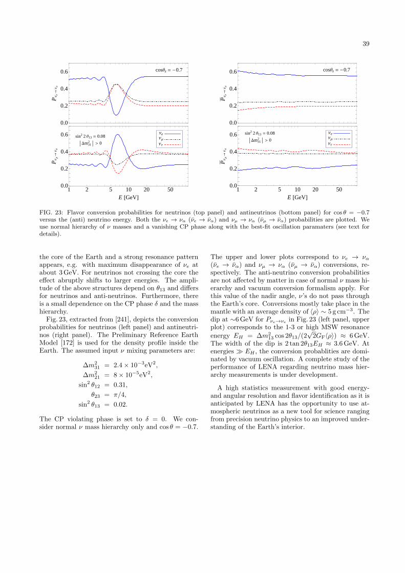
39
0.0
0.2
0.4
0.6
PΝ
e®
ΝΑ
1 2 5 10 20 500.0
0.2
0.4
0.6
E @GeVD
PΝ
Μ®
ΝΑ
ΝeΝΜ
ΝΤ
cosΘz = -0.7
sin2 2 Θ13 = 0.08
Dm312 > 0
0.0
0.2
0.4
0.6
PΝ
e®
ΝΑ
1 2 5 10 20 500.0
0.2
0.4
0.6
E @GeVD
PΝ
Μ®
ΝΑ
cosΘz = -0.7
ΝeΝΜ
ΝΤ
sin2 2 Θ13 = 0.08
Dm312 > 0
FIG. 23: Flavor conversion probabilities for neutrinos (top panel) and antineutrinos (bottom panel) for cos θ = −0.7versus the (anti) neutrino energy. Both the νe → να (νe → να) and νµ → να (νµ → να) probabilities are plotted. Weuse normal hierarchy of ν masses and a vanishing CP phase along with the best-fit oscillation paramaters (see text fordetails).
the core of the Earth and a strong resonance patternappears, e.g. with maximum disappearance of νe atabout 3 GeV. For neutrinos not crossing the core theeffect abruptly shifts to larger energies. The ampli-tude of the above structures depend on θ13 and differsfor neutrinos and anti-neutrinos. Furthermore, thereis a small dependence on the CP phase δ and the masshierarchy.
Fig. 23, extracted from [241], depicts the conversionprobabilities for neutrinos (left panel) and antineutri-nos (right panel). The Preliminary Reference EarthModel [172] is used for the density profile inside theEarth. The assumed input ν mixing parameters are:
∆m231 = 2.4× 10⁻³eV2,
∆m221 = 8× 10⁻⁵eV2,
sin2 θ12 = 0.31,
θ23 = π/4,
sin2 θ13 = 0.02.
The CP violating phase is set to δ = 0. We con-sider normal ν mass hierarchy only and cos θ = −0.7.
The upper and lower plots correspond to νe → να(νe → να) and νµ → να (νµ → να) conversions, re-spectively. The anti-neutrino conversion probabilitiesare not affected by matter in case of normal ν mass hi-erarchy and vacuum conversion formalism apply. Forthis value of the nadir angle, ν’s do not pass throughthe Earth’s core. Conversions mostly take place in themantle with an average density of 〈ρ〉 ∼ 5 g cm−3. Thedip at ∼6 GeV for Pνe→νe in Fig. 23 (left panel, upperplot) corresponds to the 1-3 or high MSW resonance
energy EH = ∆m213 cos 2θ13/(2
√2GF〈ρ〉) ≈ 6 GeV.
The width of the dip is 2 tan 2θ13EH ≈ 3.6 GeV. Atenergies EH , the conversion probablities are domi-nated by vacuum oscillation. A complete study of theperformance of LENA regarding neutrino mass hier-archy measurements is under development.
A high statistics measurement with good energy-and angular resolution and flavor identification as it isanticipated by LENA has the opportunity to use at-mospheric neutrinos as a new tool for science rangingfrom precision neutrino physics to an improved under-standing of the Earth’s interior.

40
4 Detector design
Design, construction, and operation of the LENA de-tector will be a challenging endeavor. However, thereare two neutrino detectors in operation that alreadyanticipate scale and techniques of the LENA project:The Super-Kamiokande detector is of almost the samevolume, featuring similar requirements concerning de-tector cavern, photocoverage and number of channels.On the other hand, the enormous amount of R&D thatled to the tremendous success of the Borexino experi-ment can be re-applied for LENA, covering questionsconcerning the liquid scintillator, the radiopurity ofthe used materials and their purification, requirementsfor photosensors and electronic read-out and so forth.Based on this foundation, but also on the laboratoryand design activity carried out in the last few years es-pecially for LENA, the following section describes thecurrent design draft for LENA.
Fig. 24 shows a schematic overview of the currentLENA design:
FIG. 24: Schematical view of the LENA detector [242].
Laboratory. The detector will be constructed in adedicated cavern, about 115 m in height. The shapewill depend on the laboratory site: Pyhasalmi andFrejus will be described as exemplary sites in Sec. 4.1.The aspired rock shielding above the detector corre-sponds to 4 000 mwe, a requirement fulfilled by bothsites.
Tank. The liquid-scintillator will be contained in acylindric steel or concrete tank of 100 m height and30 m diameter. Several design options are discussedin Sec. 4.2. Inside the tank, the volume is divided by
a thin nylon vessel into the buffer volume shieldingexternal radioactivity and the target volume.
Liquid scintillator. The target volume is 13 min diameter and 100 m in height, corresponding to5.3×104 m3. Depending on the exact composition ofthe liquid scintillator (Sec.4.3), the target mass rangesfrom 45 to 53 kt. The buffer volume is filled with aninactive liquid, which should have a similar density asthe scintillator in order to minimize buoyancy forceson the nylon vessel.
Photomultipliers. The intended photosensitive cov-erage is 30 % of the inner tanks walls. This requirese. g.∼45 000 eight-inch photomultiplier tubes (PMTs).Currently PMTs with a photocathode diameter be-tween 5 and 10 inch are the most likely solution. Re-flective light-concentrators mounted on the PMTs willbe used to reduce the number of PMTs (Sec.4.4).
Readout electronics. A further option to reduce thelarge number of channels is to group several PMTs intoa PMT array, featuring a common high voltage sup-ply, signal digitization and readout channel. Possiblesolutions for the read-out electronics are discussed inSec.4.5.
Muon veto. Cosmic muons crossing the main detec-tor will be identified by layers of plastic scintillatorpanels, Resistive Plate Channels (RPCs), or limitedstreamer tubes mounted above the upper lid of thedetector. A dense instrumentation featuring severallayers would offer the possibility to aid the reconstruc-tion of muon tracks in the scintillator. On the outsideof the tank, the interspace to the cavern walls is filledwith water (at least 2 m in width) shielding the in-ner detector from external radiation coming from therock and from muon-induced neutrons. The outer tankwalls can be equipped with PMTs to identify cosmicmuons passing the detector by their Cherenkov light.
4.1 Laboratory sites
No underground laboratory existing today is suffi-ciently large to host the LENA detector. This impliesthat a cavern of appropriate size must be excavated,along with additional shafts and tunnels to house theauxiliary systems for filling and operation of the de-tector. To minimize the associated costs, it seemsreasonable to construct the detector adjacent to anunderground infrastructure already existent, either anunderground science laboratory or a deep mine. In thefollowing, two exemplary sites in Europe are presentedthat would suit the depth and infrastructure require-ments of LENA. These places have been identified inthe course of the FP7 LAGUNA design study whichwill publish its conclusive results in 2011.
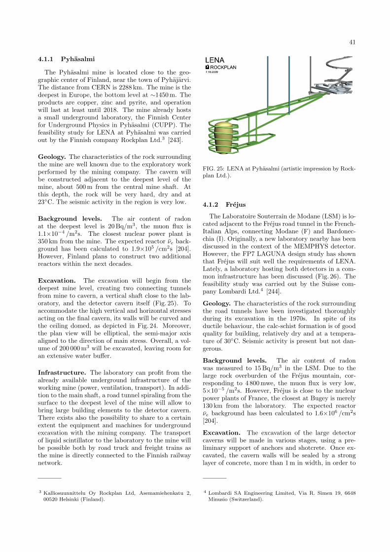
41
4.1.1 Pyhasalmi
The Pyhasalmi mine is located close to the geo-graphic center of Finland, near the town of Pyhajarvi.The distance from CERN is 2288 km. The mine is thedeepest in Europe, the bottom level at ∼1450 m. Theproducts are copper, zinc and pyrite, and operationwill last at least until 2018. The mine already hostsa small underground laboratory, the Finnish Centerfor Underground Physics in Pyhasalmi (CUPP). Thefeasibility study for LENA at Pyhasalmi was carriedout by the Finnish company Rockplan Ltd.3 [243].
Geology. The characteristics of the rock surroundingthe mine are well known due to the exploratory workperformed by the mining company. The cavern willbe constructed adjacent to the deepest level of themine, about 500 m from the central mine shaft. Atthis depth, the rock will be very hard, dry and at23C. The seismic activity in the region is very low.
Background levels. The air content of radonat the deepest level is 20 Bq/m3, the muon flux is1.1×10−4 /m2s. The closest nuclear power plant is350 km from the mine. The expected reactor νe back-ground has been calculated to 1.9×10⁵ /cm2s [204].However, Finland plans to construct two additionalreactors within the next decades.
Excavation. The excavation will begin from thedeepest mine level, creating two connecting tunnelsfrom mine to cavern, a vertical shaft close to the lab-oratory, and the detector cavern itself (Fig. 25). Toaccommodate the high vertical and horizontal stressesacting on the final cavern, its walls will be curved andthe ceiling domed, as depicted in Fig. 24. Moreover,the plan view will be elliptical, the semi-major axisaligned to the direction of main stress. Overall, a vol-ume of 200 000 m3 will be excavated, leaving room foran extensive water buffer.
Infrastructure. The laboratory can profit from thealready available underground infrastructure of theworking mine (power, ventilation, transport). In addi-tion to the main shaft, a road tunnel spiraling from thesurface to the deepest level of the mine will allow tobring large building elements to the detector cavern.There exists also the possibility to share to a certainextent the equipment and machines for undergroundexcavation with the mining company. The transportof liquid scintillator to the laboratory to the mine willbe possible both by road truck and freight trains asthe mine is directly connected to the Finnish railwaynetwork.
3 Kalliosuunnittelu Oy Rockplan Ltd, Asemamiehenkatu 2,00520 Helsinki (Finland).
FIG. 25: LENA at Pyhasalmi (artistic impression by Rock-plan Ltd.).
4.1.2 Frejus
The Laboratoire Souterrain de Modane (LSM) is lo-cated adjacent to the Frejus road tunnel in the French-Italian Alps, connecting Modane (F) and Bardonec-chia (I). Originally, a new laboratory nearby has beendiscussed in the context of the MEMPHYS detector.However, the FP7 LAGUNA design study has shownthat Frejus will suit well the requirements of LENA.Lately, a laboratory hosting both detectors in a com-mon infrastructure has been discussed (Fig. 26). Thefeasibility study was carried out by the Suisse com-pany Lombardi Ltd.4 [244].
Geology. The characteristics of the rock surroundingthe road tunnels have been investigated thoroughlyduring its excavation in the 1970s. In spite of itsductile behaviour, the calc-schist formation is of goodquality for building, relatively dry and at a tempera-ture of 30C. Seismic activity is present but not dan-gerous.
Background levels. The air content of radonwas measured to 15 Bq/m3 in the LSM. Due to thelarge rock overburden of the Frejus mountain, cor-responding to 4 800 mwe, the muon flux is very low,5×10−5 /m2s. However, Frejus is close to the nuclearpower plants of France, the closest at Bugey is merely130 km from the laboratory. The expected reactorνe background has been calculated to 1.6×10⁶ /cm2s[204].
Excavation. The excavation of the large detectorcaverns will be made in various stages, using a pre-liminary support of anchors and shotcrete. Once ex-cavated, the cavern walls will be sealed by a stronglayer of concrete, more than 1 m in width, in order to
4 Lombardi SA Engineering Limited, Via R. Simen 19, 6648Minusio (Switzerland).

42
FIG. 26: LENA and MEMPHYS at Frejus (artistic impression by Lombardi Ltd.).
compensate for plasticity of the rock. The LENA cav-ern will cylindrical with vertical walls, correspondingto an excavation volume of 100 000 m3. Two additionalcaverns would hold the MEMPHYS detector (Fig. 26).
Infrastructure. The laboratory can profit from thealready available underground infrastructure of theroad tunnel (ventilation). Currently, a safety tunnelis excavated close to the already existing road tun-nel. Excavation works and transport of materials willmainly use this safety tunnel to minimize interferencewith road traffic. Liquid scintillator will be suppliedby road trucks.
4.2 Detector tank
The Rockplan prefeasibility study on the LENA de-tector tank resulted in four options, two out of steeland two out of concrete [245]. A concrete tank willbe much more resistive to the compression generatedby the water-scintillator density difference. However,it is also significantly more radioactive. To obtain thesame fiducial volume for low-energy neutrinos, the di-ameter of the tank would have to be increased by 1-2 m. The cost saving due to the low price of concretewill roughly compensate the additional expenses fororganic solvent.
Conventional Steel Tank. A conventional tank re-quires a sizable amount of steel (driving the costs),and consists of many structural elements that wouldhave to be brought separately into the laboratory andto be joined during underground construction. A basicsteel mainframe will be erected first, followed by load-bearing plates and a final stainless steel sheet weldedon (Fig. 27). There is also only one load-bearing layerseparating scintillator and water. However, such atank could be built straightforward and will be robust.
Sandwich Steel Tank. This tank will consist of
FIG. 27: Conventional steel tank (Rockplan Ltd.)
FIG. 28: Sandwich steel tank (Rockplan Ltd.)
thin walled sandwich elements, featuring a very highstrength-to-weight ratio and providing a multiple-layerdefense against liquid leaks (Fig. 28). The elementscan be prefabricated, reducing costs and allowing forextensive quality control. They will be lifted into placeand welded together. There is also the opportunity toequip the interior of the elements with thermal insula-tion or cooling pipes, or to use it for active leak preven-tion. However, this tank will require a lot of welding(bearing the risk of radioactive contamination), and

43
the mechanical design for tangential pressure will bechallenging.
Sandwich Concrete Tank. To assure water tight-ness, the concrete tank will be a steel-concrete-steelplate sandwich, about 30 cm in width. The externalsteel plates are connected to each other with welded re-bar. In construction, rings of steel plates will be liftedin place, the concrete being cast in between. Due tothe slow curing of the concrete, construction will takea long time. Finally, an additional thin stainless steelsheet will be laser-welded on the inside for purity.
Hollow Core Concrete Tank. Based on the Sand-wich Concrete Tank, hollow cores are now added tothe concrete layer of the tank. This increases mechan-ical strength, and allows to install a cooling system oractive leak prevention. However, this option is up tonow little used in tank construction.
4.3 Liquid scintillator
The power of the liquid scintillator technology hasbeen demonstrated in the past by successful neutrinoexperiments like Borexino [187] or KamLAND [246].Large target masses, high energy resolution and a lowenergy threshold are beneficial characteristics that en-able real-time detection of rare low-energy events. Asliquid scintillator is the central component of the de-tector, this chapter will cover the main properties ofliquid scintillators as active material and their inter-play with the detector hardware. Finally in Sec. 4.3.3,the most promising scintillator mixtures are presented.At present, LAB as solvent with the admixture of PPOand Bis-MSB as solutes is favored.
4.3.1 Scintillator properties
Light output and quenching. Organic scintillatorsare excited by charged particle radiation or ultraviolet(UV) light. In the molecular deexcitation process, UVlight is emitted. Charged particles which cross a scin-tillating medium ionize and excite molecules on theirtrack. However, ionization and radiationless deexcita-tion processes lead to a loss of fluorescence efficiency.In general, processes reducing the efficiency of energyto light conversion are known as quenching.Ionization and excitation densities are high for largeenergy deposition per unit length, which is the casefor heavy particles, such as protons or αs. This affectsnot only fluorescence efficiency, but also the scintilla-tion pulse shapes and can thus be used for particleidentification.
Emission spectra. The emission spectra of a single-component scintillator has a significant overlap withits own absorption spectra. This results in multiple ab-sorption and reemission processes where an importantpart of the information gets lost. In order to preventadditional losses in the energy conversion efficiency,
usually one or multiple organic solutes are added.The solvent transfers its excitation energy mainly non-radiatively by dipole-dipole interaction to the solute(also called wavelength shifter or fluor) emitting ahigher wavelength region (usually blue light) at whichthe solvent is transparent.
Scintillation pulse shape. For excited states of thescintillator molecules, there are several processes todecay: photon emission, radiationless electronic relax-ation, inter-system crossing processes (i.e. transitionbetween singlet and triplet states), and energytransfer by collision to other molecules. As severaldeexcitation modes are possible, scintillating pulseshapes commonly show more than one radiative decayconstant. The shape of the scintillation pulse can bedescribed by the sum of several exponential functions:
n(t) =∑
nie− tτi (4.1)
In this case, τi denotes the decay constants and nithe amplitudes of the corresponding decay processes.These constants are typical parameters for each scin-tillator material; for most organic scintillator the fastdecay component dominates the emission.
The amplitudes of the time components depend onthe energy deposition per unit length. Consequently,the pulse shape can be used for particle discrimina-tion of α-particles or neutron-induced proton recoilsfrom electron signals and thus provides a fundamentalmethod for background rejection.
Attenuation length. As the scintillation photonspropagate through the medium, absorption and scat-tering processes can occur. These processes stronglydepend on the emitted wavelength; in general, thetransparency of the medium increases with the wave-length. The main contributions to scattering areRayleigh processes in the scintillator molecules andabsorption-reemission processes by impurities. Themain parameters for the description of the light propa-gation are the absorption length, the scattering length,and the self-absorption length of the solute. For shortwavelengths, the solute self-absorption dominates.
For large-volume particle detectors, long absorptionand scattering lengths are required. As absorptionprocesses decrease the total number of photons whicharrive at the photo-sensors, the effective light yield ofthe detector is reduced. However, a high effective lightyield is desirable, since it is directly connected to theenergy resolution and energy threshold of the detector.
Radiopurity. As solvents of organic liquid scintil-lators are hydrocarbons, intrinsic radioactivity of thescintillator originates mainly from the 14C β decay.The 14C β background rate by far surpasses all neu-trino signals at energies below the endpoint of the βspectrum at 156 keV. While the original solvent pro-duced in distillation plants is usually rather pure at therefinery, the surface contamination of the transporta-

44
tion and experimental containers may dissolve in theliquid scintillator. However, experiments like Borexinohave demonstrated the feasibility of ultrahigh radiop-urity levels in liquid scintillators, with contaminationlevels of 238U at the order of 10−17 g/g. The achievedconcentrations of 232Th and 40K are even at the levelof 10−18 g/g. The scintillator purification for LENAaims at the same level of radiopurity.
4.3.2 Influence on detector design
The properties of a liquid scintillator mixture di-rectly sets constraints on the technical design of thedetector and vice versa. In order to optimize the detec-tor performance, one has to take a look at the impactof the scintillator properties on the detector geometry,its demands on the photosensors, on health and onhandling issues.
Geometry. The absorption length of the liquid scin-tillator is the main defining parameter for the detectorgeometry. It strongly affects the effective light yield ofthe scintillator detector, which accounts for the energyresolution and the energy threshold. With the mostforeseen liquid scintillator compounds having absorp-tion lengths of 10-20 m (see Sec 4.3.3), it is unfeasibleto build an unsegmented spherical 50 kton detector.Still, the preferred geometry of the detector is a cylin-drical shaped tank of 15 m radius, which ensures agood effective light yield and volume to surface ratio.With a liquid-scintillator density close to 1 g/cm3, thecorresponding height of the cylinder is about 100 m incase of a 50 kton detector.
Photosensors. The photosensors are the link be-tween scintillation light and data acquisition. There-fore, their properties play a crucial role for the perfor-mance of the detector. Especially the spectral sensi-tivity of the photosensors should match the emissionspectra of the liquid scintillator, or at least be max-imal between 320-450 nm. For conventional bialkaliphotomultiplier tubes this wavelength range is quitecommon (Sect. 4.4).
Liquid handling. Liquid handling comprises mainlythe filling, pumping and storing of the liquid scintil-lator starting from its production. In this contextradiopurity, purification, chemical compatibility, andsafety issues have to be considered.
The purification of the scintillator is necessary forreaching a low-level radioactive contamination. Forexample, this can be done by water extraction andprevention of exposing the scintillator to cosmic rays,i.e. fast transport on surface and underground storage.For such a large detector as LENA, it seems most feasi-ble to put purification plants on surface. At all times,the detector has to be kept away from oxygen con-tamination, which would induce a degradation of thescintillator. Thus, ultra-clean nitrogen gas must beused to flush pipes and tanks. Moreover, any materialthat comes into contact with liquid scintillator has to
be tested on its chemical compatibility. Possible ma-terials are teflon or passivated stainless steel.
Chemically, the solvent of an organic liquid scintil-lator is a hydrocarbon. Thus, flammability is the mostimportant concern. The Hazardous Materials Identifi-cation System (HMIS) classifies the danger in handlingthe liquid (from 0 - save to 4 - dangerous) concerningflammability, reactivity and health. The HMIS ratingsfor scintillators in flammability range from 1-3, reac-tivity (almost all 0) and health (0-1) are in generalnot a big concern. The flash point5 of the material isanother characteristic parameter for its flammability.
4.3.3 Candidate scintillator mixtures
All scintillator options consist of a mixture of a sol-vent and one or more solute powders, both scintillat-ing organic compounds. This section is a compilationof properties of the most promising scintillation com-pounds and mixtures for LENA. Prospective scintilla-tor mixtures have to provide an emission spectra withλ > 400 nm in order to guarantee large absorption andscattering lengths (see Sect. 4.3.1). In addition, this isthe region where the photomultipliers are most sensi-tive. Other critical parameters of the mixture are thescintillation pulse shape and light yield, which are im-portant for the energy and time resolution of the detec-tor. Detailed studies on these parameters for variousorganic liquid scintillation mixtures have been carriedout in [247].
The mixtures under consideration are both linear-alkyl-benzene (LAB) and phenyl-o-xylylethane (PXE,with an admixture of non-scintillating dodecane) withPPO+Bis-MSB or PMP as fluors. Tabs. XI and XIIsummarize the main properties of solvents and fluors,while Tab. XIII provides an overview on the mainproperties of the resulting mixtures. Amongst thisselection, LAB with PPO (2 g/`) and Bis-MSB (20mg/`) seems most promising.
The first solvent under consideration, LAB, has firstcome to attention in the R&D studies for SNO+ [262–264]. It is very appealing due to its high transparency,high light yield, and its low cost. Moreover, it is anon-hazardous liquid with relatively high flash pointof 128C. The second scintillator solvent option PXEhas already been tested in the Counting Test Facility(CTF) of Borexino [265]. Results look very promisingas it shows a high light yield, good transparency and ahigh flash point [253]. Like LAB it has the advantageof being a non-hazardous liquid, with a flash point of145. Dodecane (C12) is a non-scintillating mineraloil which is a possible admixture to PXE. It is highlytransparent and increases the total number of freeprotons in the mixture. This is a key issue, since free
5 The flash point is the lowest temperature at which a liquidgenerates sufficient vapor to form a flammable mixture withair. Above this temperature, a spark is sufficient for ignition.

45
Solvent LAB PXE C12Physical and Chemical Data [248–252]Chemical formula C18H30 C16H18 C12H26
Molecular weight [g/mol] 241 210 170Density ρ [kg/`] 0.863 0.986 0.749Specific gravity ρ [g/cm3] 0.86 0.99 0.75Viscosity [cps] 4.2 1.3Flash point [C] 140 167 83Molecular density [1027/m3] 2.2 2.8 2.7Free protons [1028/m3] 6.6 4.7 7.0Carbon nuclei [1028/m3] 4.0 4.2 3.2Total p/e− [1029/m3] 3.0 3.2 2.6HMIS Ratings [248–250]Health 1 1 1Flammability 1 1 0Reactivity 0 0 0Optical Properties (n,L,`R@430 nm) [247, 253–260]Refractive index n 1.49 1.57 1.42Absorption maximum [nm] 260 270 -Emission maximum [nm] 283 290 -Attenuation length L [m] ∼20 12 >12Rayleigh scat. length `R [m] 45 32 (37)
TABLE XI: Overview of the solvent parameters of PXE,LAB and Dodecane (C12). The information on physicalparameters, HMIS (Hazardous Material Identification Sys-tem) rating, and refractive index are cited from materialsafety and product specification sheets of the producers[248–250]. The HMIS rating quantifies the danger in han-dling the liquid (from 0 - save to 4 - dangerous). Themolecular, proton and Carbon densities were computed us-ing this information. The absorption and emission maximaof PXE and LAB are from [247]. The attenuation lengthsL are gathered from various sources: PXE [253], LAB [259]and C12 [257], always reporting the value at 430 nm. Thescattering lengths `R are computed for the absorption max-ima for PXE and LAB, again at 430 nm [261]. For C12, thelength is derived from measurements at longer wavelength[254–256].
protons play a key role in the proton decay searchand in the inverse β decay detection channel.
The emission and absorption spectra of the scin-tillating solvents have a significant overlap. Inorder to shift the wavelength to a region where thesolvent is transparent, one or more organic solutesare commonly added. There are two very promis-ing candidates as wavelength shifters for LENA.First, a mixture of 2,5-diphenyl-oxazole (PPO)and 1,4-bis-(o-methyl-styryl)-benzene (bis-MSB)or 1-phenyl-3-mesityl-2-pyrazoline (PMP). Theirproperties are summarized in Tab. XII [247, 266].
The fluor PMP [267] is a primary solute with a largeStokes shift of about 120 nm, resulting in a marginaloverlap of the absorption and emission spectra andthus a small self-absorption. The primary fluor PPOhas a Stokes shift of ∼60 nm and is therefore usuallyused in combination with a secondary fluor, Bis-MSB.
Solute PMP PPO Bis-MSBChemical formula C18H20N2 C15H11NO C24H22
Absorption maximum 294 nm 303 nm 345 nmEmission maximum 415 nm 365 nm 420 nm
TABLE XII: Properties of the fluors PMP (1-phenyl-3-mesityle-2-pyrazolin), PPO (2,5-diphenyl-oxazole) andBis-MSB (1,4-bis-(o-methylstyryl-benzene). Absorptionand emission maxima are taken from [247, 266]
It is added in small quantities (mg/`) to avoid self-absorption at large wavelengths. The PPO absorptionspectra significantly overlaps with the emission spectraof both the solvents PXE and LAB. Bis-MSB absorbswhere the primary fluor PPO emits and produces afurther shift of ∼ 60 nm.
4.3.4 Summary and Outlook
The final choice of a suited liquid-scintillator mix-ture for the LENA experiment must be made mostcarefully. Different physics goals put different con-straints on the scintillator properties, making the op-timization process difficult. All available solutes andsolvents cannot be considered independently, but haveto be tested in specific mixtures.Studies on possiblescintillation mixtures are not yet concluded.
The most promising state-of-the-art mixtures arelisted in Tab. XIII. The solutes under considerationhave been LAB and PXE, as solvents PPO, PMP andBis-MSB have been investigated. As can be seen, thecombination of PPO and Bis-MSB provides a goodlight yield for both solutes LAB and PXE. Due to itshigh Stokes’ shift, taking PMP as solvent makes theuse of a secondary fluor needless, however the lightyield is reduced distinctly. Recently, also the solutes2,5-diisopropyl-naphtalene (DIN) and n-paraffin drewattention and first results concerning decay time con-stant and weight look competitive.
Comparing the fastest decay processes of the differ-ent mixtures, one has to take into account both timeconstant and weight relative to the total light emit-ted. Obviously, using PMP as fluor, makes the mix-ture much slower. In the case of PPO and Bis-MSBas fluors, both LAB and PXE show good timing prop-erties. PXE is slightly preferable since it is faster andthe weight of the fastest decay is higher, too.
With respect to the scintillation light yields, LABand PXE show comparable results. However, the lightpropagation properties of the liquid-scintillator mix-ture strongly influence the light collection efficiency ofthe detector. In terms of effective light yield, LAB(attenuation length L of ∼20 m) is preferable to PXE(L = 12 m).

46
Solvents Wavelength shifters Y [%] n1 [%] τ1 [ns]1st 2nd [258] [268, 269] [268, 269]
PXE + 2 g/` PMP - 79.1 ± 3.1 95.9 ± 0.02 4.15 ± 0.02+ 2 g/` PPO + 20 mg/` Bis-MSB 102.0 ± 3.3 85.3 ± 1.4 2.61 ± 0.05
LAB + 2 g/` PMP - 83.9 ± 3.0 85.1 ± 0.9 8.53 ± 0.15+ 2 g/` PPO + 20 mg/` Bis-MSB 99.7 ± 3.2 77.7 ± 0.8 5.21 ± 0.005
DIN + 1.5 g/` PPO - - 86.2 ± 0.2 6.95 ± 0.02
TABLE XIII: Summary of the scintillation properties of different scintillation mixtures. The solvents are PXE and LAB,the dissolved wavelength shifters are PMP and a combination of the fluors PPO and Bis-MSB. The relative light yieldY refers to the mixture of PXE with 2g/` PPO [253], n1 and τ1 are the weight and the decay constant of the fast pulsecomponent, respectively, as measured in a small cylindrical cell of 2.5 cm in diameter and 2 cm in length.Measurements on PXE with PPO show that adding small quantities of the secondary fluor Bis-MSB hardly affects thelight yield and fast pulse shape component of the scintillation mixture. The values of the scintillation mixtures LAB +2g/` PPO + 20mg/` Bis-MSB are expectations based on measurements of LAB + 2g/` PPO [247]. For DIN, the lightyield measurement is presently carried out.
4.4 Light detection
The photosensors used for the detection of the scin-tillation light play an important role for the possi-ble physics yield of LENA: The light detection effi-ciency affects energy resolution and detection thresh-old, while the timing influences event reconstructionand particle identification. In the following, we presenta review of the most important sensor parameters,focussing on bialkali Photomultiplier Tubes (PMTs)and the existing possibilities to enhance their perfor-mance. The properties of alternative light sensors,Silicon Photomultipliers and Hybrid Phototubes, areshortly addressed.
4.4.1 Photosensor requirements
The crucial parameters of photosensors can be split upin four aspects: sensor performance, environmentalproperties, availability until start of constructionand cost-performance ratio. The most importantproperties are:
Photo detection efficiency (PDE). The PDE isdetermined by the quantum efficiency (QE) of thephotocathode, the collection efficiency for photoelec-trons (pe) as well as backscattering losses of pe at thefirst dynode. In LENA, the baseline value for PDE is20 % at 420nm.
Spectral response. The sensitivity of the photosen-sors must match the spectrum of the scintillation lightarriving at the detector walls. A bialkali photocath-ode is arguably the best choice in case of a PMT asthe maximum PDE corresponds well to the effectivescintillator emission spectrum.
Optical coverage (OC) denotes the fraction of thedetector walls covered with photosensors. Togetherwith the detection efficiency of the PMTs, the OCdetermines the overall efficiency of light collection.Light-collecting reflective concentrators [270] might beused to increase this area beyond the active area, i.e.
the photocathodes. The present design foresees an OCof 30 %. Primarily the energy resolution, but also bothtime and spatial resolution of LENA will depend onthe product of PDE and OC.
Time jitter. The timing uncertainty for single pho-toelectrons (spe) for individual sensors is vital for theoverall timing and position resolution of the detec-tor. For PMTs, it is given by the transit time spread(TTS).
Afterpulses (AP). AP are spurious pulses occur-ring in correlation to primary pulses. Fast after-pulses appearing within several tens of ns after theprimary pulse might impede the resolution of fast dou-ble peak structures (e.g. for proton decay, Sect. 3.1).APs induced by ions produced by the initial electronavalanche occur with delays of several 100 ns to µs.These ionic APs affect the veto of cosmogenic back-grounds by lowering the detection efficiency of muon-induced neutrons [226]. Usually, the probability ofappearance is quoted as percentage of primary pulses.
Dark count (DC). The number of dark counts (perphotosensitive area) has to be low since it affects po-sition and energy resolution by introducing fake hits.In extreme cases, it might cause triggers to randomcoincidences.
Dynamic range. The dynamic range of the responseof the whole detector has to extend from low energyevents with mostly only a spe per sensor up to eventsdepositing several GeV of energy, corresponding tohundreds of pe for the sensors closest to the event.
Gain, single electron resolution (SER). The am-plification gain must be sufficiently large and the singleelectron pulse height resolution sufficient (correspond-ing to a large peak-to-valley ratio) in order to distin-guish reliably between noise and spe signals.
Pulse shape, timing effects. Short rise and falltimes of the spe voltage pulses, in the order of a few

47
Property LENA Borexino Double Chooz SNO+TTS (FWHM) [ns] 3.0 3.1 a few <4Early pulses a <1 % <1.5 %Late pulses a <4 % <4 % <1.5 %QE for λpeak >21 % >21 % >20 %λpeak [nm] 420 420 400Optical coverage 30 % 30 % 13.5 % 54 %Winston cones yes yes no yes→ effective area ×1.75 ×2.5 − ×1.75Dynamic range b spe→0.3 pe/cm2
Gain PMTs 3·106 1·107 1·107 1·107
spe p/V >2 >1.5 >2 (typ.) >1.2DC per area [Hz/cm2] <15 <62 < 25Ionic AP (0.2-200 µs)a <5 % <5% < 1.5%Fast AP (5-100 ns)a <5 %Pressure resistance [bar] >13 >3 c
238U content [g/g] <3·10−8 <3·10−8 <1.2·10−7
232Th content [g/g] <1·10−8 <1·10−8 <9·10−8
natK content [g/g] <2·10−5 <2·10−5 <2·10−4
Detector lifetime [yrs] >30 10 c
TABLE XIV: Overview of the parameter limits for photosensors in LENA and other running or upcoming liquid-scintillatordetectors [187, 271–273]. spe: single photoelectron, TTS: transit time spread for spe, QE: quantum efficiency, PDE: photodetection efficiency, λpeak: peak wavelength of spectral response, pe: photoelectrons, p/V: peak-to-valley ratio, DC: darkcount, AP: afterpulses.
ns, are advantageous for tracking and position recon-struction. Effects shifting the detection time, like earlypulses, prepulses, and to some extent also late pulses,have a detrimental influence on the reconstruction.
Photosensitive area. For a given optical coverage,the granularity of the detector increases with lowersensor areas, improving the spatial resolution of thephoton arrival pattern. Moreover, for smaller areas asmaller dynamic range of individual sensors is suffi-cient.
Environmental properties encompass radioactivepurity of the materials used in the sensors, pressureresistance of the sensors placed near the tank bot-tom, their long-term reliability over 30+ years andsusceptibility to magnetic fields. The availabil-ity until start of construction will define the candidatesensor types. To calculate the cost-performance ratio,it is necessary to know all sensor parameters and theireffect on detector performance.
Parameter constraints. Minimum requirements forthe photosensors to be used in LENA can be formu-lated based on the experimental experience gatheredin the Borexino and Double Chooz experiments, andrelying on MC studies carried out for LENA. Tab. XIV
a Probability of occurrence per primary pulseb Assuming ×1.75 Winston cones; estimate valid for large sen-
sor sizes onlyc In ultrapure water, at a water pressure of 3 bar and exposed
to earthquakes from mining activity
lists the preliminary limits for LENA in comparison tothe requirements of other liquid-scintillator detectors.MC simulations to further refine the values for LENAare ongoing.
4.4.2 Bialkali photomultipliers
A detailed description of the functionality and prop-erties of photomultiplier tubes (PMTs) can be foundin [274, 275]. In view of the requirements on photo-sensors, head-on hemispherical or plano-convex bial-kali PMTs with low-background borosilicate glass arepresumably the subtype best suited for LENA.
a) Survey of available PMT series
PMTs are the most natural choice of photosensors forLENA, fulfilling all technical requirements (pricing,availability and environmental properties). A compre-hensive study to identify the most promising commer-cially available PMT models is ongoing. Also, the nextgeneration of PMTs featuring high quantum efficiency(HQE) photocathodes are being evaluated. So far, thecharacterization has been carried out based on threetest setups:
Borexino PMT testing facility. This setup at theLNGS was originally used to screen ∼2 300 PMTsfor Borexino [276]. For LENA, it has been usedto characterize a selection of PMTs manufacturedby Hamamatsu, ranging from 3” to 10” in diameterand featuring regular bialkali photocathodes: R6091(3”), R6594-ASSY (5”), R5912 (8”) and R7081 (10”).Fig. 29 shows the transit time distribution measured

48
FIG. 29: Pulse timing effects in PMTs. Naming conven-tion as used in Borexino publications. In this example aHamamatsu R5912 (8”) with +1425V applied was mea-sured (threshold 0.2 pe) with the Borexino testing facility.A close description of the various features of the PMT re-sponse can be found in [277, 278].
for the 8” PMT with this setup: Prepulses and earlypulses that potentially compromise the arrival timesof the first photons, and therefore position and trackreconstruction, as well as late pulses are discernible.
INFN Milano. This test stand is based on a pi-cosecond 405 nm laser (Edinburgh Instruments EPL-405) as light source and an 8-bit 1GHz National In-struments FADC. Here, Hamamtsu PMTs featuringHQE Superbialkali photocathodes (QE≈35 % at peakwavelengths) have been characterized. PMTs with di-ameters from 5” to 10” were tested.
Universitat Tubingen. The test stand usesfast LED drivers and both FADCs and standardTDC+ADC read-out. Measurements of TTS and SERwere done for 3”, 8”, 10” and 20” PMTs, includ-ing HQE tubes of Hamamatsu R7081 (10”), PhotonisXP5301 (3”) and XP5312 (3”).
TU Munchen A fourth test stand using a modi-fied EPL-405 ps laser and a fast pulsed LED as lightsources and a 10-bit 8 GHz Acqiris DC282 FADC iscurrently being set up.
The results of these measurement are currently beinganalyzed and will lead to a first preselection of PMTseries.
b) Number of PMTs
Currently, the LENA reference design aims at an opti-cal coverage of 30 %. Light concentrators will be usedin order to enhance the light collection efficiency. Aconcentrator increasing the effective collection area bya factor of 1.75 seems realistic, reducing the necessaryactive photocathode area to 17 %. For 8” PMTs ofnormal QE, this corresponds to 63 000 pieces. HQEphotocathodes could be employed to further reduce
this number. The scaling of the necessary number isdemonstrated in Tab. XV.
In general, the use of smaller-sized PMTs offerssome advantages: With smaller diameter, the transittime spread, the requirements on the dynamic rangeand the rate of ionic afterpulses decrease in general.A higher sensor granularity would be beneficial forposition reconstruction and tracking. On the otherhand, smaller diameters increase the number of sen-sors and electronic channels drastically, which favorslarger PMTs from the economic point of view. Furthersimulations of the detector behavior are necessary todetermine the dependence of the physics potential onthe PMT diameter and to derive the optimum cost-performance ratio.
Diameter Unarmed Light conc. Conc. & HQE3” 943 100 538 900 384 9005” 329 300 188 200 134 4008” 110 400 63 100 45 10010” 82 300 47 000 33 60012” 53 900 30 800 22 00020” 21 600 12 300 8 800
TABLE XV: Number of PMTs necessary to achieve an OCof 30 % in LENA, depending on the photocathode diame-ter, the use of light concentrators increasing the effectivedetection area by a factor of 1.75, and HQE photocathodesof 35 % peak QE assuming a collection efficiency of 80 %without photoelectron backscattering losses.
4.4.3 Optimization of light detectors
There are various aspects beyond the selection ofan optimum PMT that enter the design of the LENAdetector instrumentation. In the following, a shortoverview of these issues is presented.
Winston cones. Compound parabolic concentratorsalso known as Winston cones are non-imaging lightconcentrators focussing incident light onto a flat orcurved surface [279]. Mounted to a PMT, they in-crease its effective light collection area (see Fig. 30).The optimum concentrator shape can be constructedmathematically by rotating the tilted positive branchof a parabola around the z-axis. The length of the re-sulting concentrator determines the area increase εA
but also the field of view of the PMT: Light incident atlarger angles than the cutoff angle θc to the z-axis ina first approximation is not collected by the PMT butreflected back into the detector. Winston cones havebeen widely used in neutrino experiments (Tab. XIV).
Assuming a fiducial volume of 11 m radius in LENA(e.g. for solar neutrinos, Sect. 2.3), the optimum valueof θc is 50 for 8” PMTs, corresponding to εA = 1.71.First MC simulations have shown that for equal OCand εA = 2.0, the average pe yield decreases only bya few percent. However, the spatial dependence of thepe yield increases substantially. Further studies are

49
FIG. 30: Winston cone type light concentrator used inBorexino, increasing the effective photon collection areaby a factor of 2.5 (courtesy of Borexino).
required.
HQE photocathodes. A further way of increasingphotocollection efficiency is the use of HQE photocath-odes. Conventional PMTs feature a peak QE of notmore than 25 %. Since a few years, ET Enterprises andHamamatsu Photonics are commercializing PMTs fea-turing HQE photocathodes. From Hamamatsu, twonew types of HQE cathodes are available, and havealready been tested in the Milano and Tubingen se-tups: Super BiAlkali (SBA) photocathodes feature apeak QE of 35 %, while Ultra BiAlkali (UBA) cath-odes reach a peak QE of up to 43 %. SBA cathodesare available for PMTs of up to 10” diameter, whilefor UBA cathodes the maximum diameter is 2” at themoment. However, 12” SBA PMTs as well as largerUBA PMTs are expected for the next years.
Currently, it is not evident whether HQE PMTslower the cost per detected pe. The considerably largerprize per PMT must be set in relation to the loweramount of cabling and electronic channels needed.Also, performance aspects like the dynamic range perchannel or increased afterpulsing probabilities must betaken into account.
Pressure resistance. The pressure tolerance re-quired for PMTs is given by the hydrostatic pres-sure at the bottom of the tank, depending on thescintillator density. The minimum requirement is aresistance to 9.8 bar for LAB and 11.1 bar for PXE(Sect. 4.3). Another 3 to 4 bar might be necessary towithstand an implosion shock wave as it occurred inSuper-Kamiokande. Simulations will be needed to de-termine precise numbers.
However, the pressure tolerance of available PMTsamounts to only ∼7 bar. The weak spots of the PMTglass bulbs are located at the sharp curvatures at thePMT neck and base. One option is to increase thethickness of the glass casing, which would increase theweight and the amount of radioactivity introduced bythe PMTs, and is deemed to be demanding by manu-facturers.
A promising alternative is the use of pressure-withstanding encapsulations housing the PMTs at at-mospheric pressure. A widely used approach in HEneutrino physics are spherical glass bulbs. However,the currently preferred solution is an adaptation of theBorexino Outer Detector PMT encapsulations. Theirdesign consists of a conically shaped metal housingenclosing the PMT body combined with a transpar-ent window7 in front of the photocathode (Fig. 31).This design also allows for an easy integration of thelight concentrators and the µ-metal shielding. Designwork based on finite element simulations has recentlystarted and will result in a prototype encapsulation forpressure testing.
FIG. 31: Illustration of a LENA PMT encapsulation.
4.4.4 Alternative photosensor types
In spite of the broad range of photosensors cur-rently available or under development, the number ofoptions for use in LENA is fairly limited. Consider-ing the requirements regarding time resolution, avail-ability within the next decade and long-term reliabil-ity, only Silicon Photomultipliers and Hybrid Photo-tubes are promising alternatives to conventional bial-kali PMTs. While their performance is mostly supe-rior, it remains uncertain whether the price per photo-sensitive area is low enough and if their performanceis sufficient in all respects.
Silicon Photomultipliers (SiPMs), also known asMulti-Pixel Photon Counters (MPPCs) are arrays ofavalanche photo diodes, operated in limited Geigermode [280]. Typically there are 100–1000 pixels permm2, which are electrically connected in parallel, sothe total signal is proportional to the number of cells
7 In the Borexino design, this window is a thin PET foil. InLENA, this window will have to absorb the external pressure,so a more resistive material like acrylic might be used.

50
hit by one or more photons.SiPMs have several advantages over conventionalPMTs: The QE of SiPMs can reach 70 to 80 %, withspectral response very close to the PPO emission spec-trum and PDEs over 70 %. spe time resolutions as lowas 60 ps have been observed [281], dominated by thejitter of photons being detected in different cells of thearray. With gain similar to conventional PMTs (105
to 106), their SER is much smaller, which allows ex-act counting of small numbers of photons at tempera-tures of 10-15C. Regarding environmental properties,SiPMs are insensitive to magnetic fields, which wouldallow to magnetize the LENA detector. Furthermoretheir radioactive contamination can be expected to beextremely low and they are very slim, possibly allow-ing to reduce the buffer thickness or even omit thebuffer, which would permit to increase the target vol-ume substantially or greatly reduce costs. In addition,the pressure tolerance of SiPMs probably is very high.Also, their bias voltage is below 100 V, allowing for amuch simpler voltage supply system.On the other hand, there are several disadvantages:The size of the active area is very small, currently 5×5 mm2 for the largest commercially available SiPMs.With larger sizes the number of channels decreasesand the PDE increases. It is reasonable to assumethat 1×1 cm2 SiPMs will become available in the nearfuture and many SiPMs could be combined into localclusters to save channels. However, if one wants topreserve the photon counting ability, the active areaper channel is limited to about 1 cm2. Another prob-lem is the dark count, which can approach MHz fre-quencies, disturbing the reconstruction of events andincreasing with active area. Also, temperature stabi-lization is necessary to prevent drifts in gain. Finally,it is not yet clear, whether the price per area will becompetitive to PMTs.
Hybrid Phototubes (HPTs). The basic design ofHPTs combines a large area hemispherical photocath-ode for photoelectron conversion, a HV field accel-erating these electrons towards a small luminescentscreen and a small diameter PMT (1”) reading outthe scintillation signal. HPTs have been used success-fully in the Lake Baikal Neutrino Telescope, featuringthe QUASAR-370 of 15” diameter produced in the1990s [282–284]. However, they are currently out ofproduction.
Compared to conventional PMTs, HPTs would fea-ture a range of advantages: The angular acceptance is2π, the transit time spread is typically less than 1 ns,prepulses, ionic AP, fast AP and late pulses occur onlyon very low levels, the DC is very low and the suscep-tibility to magnetic fields is greatly decreased. How-ever, it is currently unknown, whether the dynamicrange of HPTs is sufficient for use in LENA, as perdetected photon about 25 pe hit the small PMT. Onesolution would be to use less dynodes as it was done inthe TUNKA Air Cherenkov Array experiment for theQUASAR-370G [284], which on the other hand could
affect the discrimination from noise.
4.4.5 Conclusions
The benchmark value for the photon detection effi-ciency of LENA is 6 %, arising from the product ofoptical coverage (OC=30 %) and PMT photo detec-tion efficiency (PDE=20 %).
Bialkali PMTs currently appear to be the mostpromising choice for photosensors, basically fulfill-ing all requirements concerning detection performanceand long-term reliability, and low in cost per photoac-tive area. PMT diameters from 3” to 12” are consid-ered. It is foreseen to equip the PMTs with Winstoncones, the factor of area increase ranging from 1.6 to 2,and µ-metal shielding. If available and cost-effective,HQE PMTs might be used to reduce the necessaryOC. Furthermore, a pressure-absorbing encapsulationwill be necessary to protect the PMTs at the bottomof the detector from implosion.
Based on the interim results of the performancetests, further tests on the most promising series ofHamamatsu Photonics and ET Enterprises will beconducted with larger numbers. This study will alsoextend to new releases as the 12” PMT by Hamamatsu(R11780) and its upcoming HQE version. The middle-term aim is the development of a prototype opticalmodule consisting of PMT, encapsulation, µ-metal andlight concentrator by the end of 2014.
4.5 Read-out electronics
In view of the huge number of photosensors needed forthe next generation detector the only solution techni-cally available today are PMTs. With a properly de-signed read-out electronics, PMTs can guarantee therequired time resolution, charge resolution and dy-namic range. Two different options for readout elec-tronics are described, one relying on FADC readoutof all channels, the other featuring customized ASICboards inside the detector servicing small arrays ofPMTs.
4.5.1 Minimum requirements
The broad and rich physics scope of LENA puts rathersevere requirements on electronics and data acquisi-tion. The relevant performance parameters are sum-marized in Tab. XVI. Particularly, the goal to per-form both low energy solar neutrino physics (especiallypp neutrinos) and high energy beam neutrino physicsforce a very large dynamic range on the signal am-plitude because the system must work both on singlephotoelectron mode and with very large signals cor-responding to several hundreds of photoelectrons perchannel. Moreover, a precise determination of the rel-ative time of each PMT hit with sub-ns resolution isnecessary for the spatial reconstruction of the events,for the pulse shape analysis and in order to disentan-gle the different event topologies that are associated

51
to neutral and charged current interactions of elec-tron, muon and tau neutrinos. Zero dead time is amust to avoid the loss of interesting time correlatedevents, and a very flexible triggering system is highlydesirable, taking into account again the very broadscientific scope and the long expected lifetime of theexperiment, which may lead to unanticipated physics.
Parameter LE HENumber of channels (8” PMTs) 45 000 45 000Time resolution (pulse on-set) <1 ns <1 nsDynamic range 0-30 pe 0-300 peDead time per channel <100 ns FADCsChannel buffer size ∼100 FADCsNumber of FADC channels × 10 000Sampling rate × 500 MS/sVoltage resolution × 2×8 bit
TABLE XVI: Requirements for the electronic read-out inLENA. The table lists both the minimum requirementsfor low-energy (LE) neutrino detection and the optimalconfiguration for high-energy (HE) beam physics.
In the following we describe two very different op-tions for the readout electronics: a full FADC option,and a custom ASIC option. We believe that the firstwould be preferable, but the second could well meetthe basic scientific requirements and be less expensive.For these reasons we include both.
4.5.2 Full FADC readout
The scientific requirements can be met by the use ofsuitable FADCs with the right pulse height resolution,sampling speed, and the combination of on-board zerosuppression, software trigger and careful synchroniza-tion of the boards.
At the time of writing (many years before the be-ginning of data taking) there are several products onthe market that basically meet these requirements; 8-bits, 2 GS/s FADC boards are already available, andbetter products are very close to be. This solution isstill quite expensive today, but it is very likely that itwill not be at the time when LENA will need it.
The system could work as follows: each PMT shouldbe connected to a simple linear front end that shouldperform high-voltage decoupling, some amplificationand some shaping. The details of this rather standardfront end electronics must not be worked out here.It is probably cost-effective to imagine this front endbuilt into a custom chip mounted close to the PMTs.The output signal of this front end should be sent tothe FADC. The FADC board will sample it at thecorrect speed (1 GS/s seems appropriate but 2 GS/sis feasible) with 10-12 bit precision (14 bit is alreadyavailable and probably more than adequate), and storeinto a local memory. An on-board fast FPGA willperform the zero suppression, keeping the data onlyaround valid PMT pulses, and storing also the timestamp of the pulse. Data from each pulse will then be
stored into another internal memory ready for read-out.
Each FADC board shares a common distributedclock with all other boards, so that sampling is syn-chronous throughout the whole detector. The acquisi-tion software will read continually the time stamps(time stamps only at first), perform the triggeringfunctions and decide whether the ’event’ should beread out or not. In case the read-out is needed, a cus-tom designed protocol between the FPGA onboard,the FADC and the readout software will retrieve allsamples, and the event will be stored on disk.
This architecture should guarantee the maximumpossible information (the fully digitized shape of eachPMT pulse for the whole detector in a programmabletime window around the event), and zero dead time.Also, the use of the time stamps for triggering shouldkeep the complete data flow to a very reasonable level.This fact is easy to prove: the PMT activity is largelydominated by dark noise; physics events of any kindcontribute a much lower amount of data. A typicallarge PMT has a room temperature dark noise of theorder of 1 KHz. Assuming 2 kHz to have some contin-gency, the expected total activity of LENA is of theorder of 108 Hz (conservative). This means 400 Mb/sof time stamps to handle, a very reasonable number.The event triggering rate will be dominated by 14Cand will reach 104 Hz with a few hundreds of PMThits (again conservative); the expected data flow willbe of the order of 100 Mb/s−1 Gb/s, again an easynumber to handle.
Sufficient onboard memory is required to buffer thesampled signals and timestamps. By employing com-mercially available memory aimed at the consumermarket, available FADC modules already offer an on-board memory of 512 MB or more per channel at rea-sonable rates. If assuming a dynamic range of 12 bitand a sampling rate of 2 GHz with a time window of300 ns saved in the buffer, less than 1 kB of memoryis used per trigger. With an average trigger rate of2 kHz, 250 seconds of live data can be buffered beforedata loss occurs. Data can be read continuously fromthe memory while new events are stored at the sametime, thus leading to a dead-time free data acquisition.To prevent data loss in the case of rare cases where thetrigger rate can be up to ten times the dark noise forthe duration of several seconds (e.g. a galactic Super-nova sufficiently near), normally only a fraction of thetotal buffer size should be used before readout is ini-tiated. A further possibility is to set a programmablethreshold for the trigger rate. If it is exceeded for sev-eral seconds, the onboard logic will stop to store thefull pulse shape to prevent a buffer overflow; instead, itwill save only the timestamp and the energy depositionderived by integrating over the sampled pulses. Basedon this, complete event reconstruction is still possible,while the memory usage of each trigger is reduced to∼12 byte. In this mode, more than 400 seconds of livedata could be buffered at a trigger rate of 20 kHz, even

52
if only 100 MB are reserved for this operation mode.So, a full FADC DAQ for LENA is possible even un-der the extreme conditions of a galactic SN neutrinoburst, and should be seriously considered.
It is not crucial here to decide whether the FADCboard should be commercial or custom. Most likely,commercial boards will be cheap enough to be prefer-able, but this is not a decision for today. It is howeverimportant to distribute the FADC boards close to thePMTs, in order to minimize cable length. Data fromthe FADC chassis will be collected via optical fiberswhich are of course cheap, simple and reliable. Thedistance between front end and FADC should be min-imized to avoid spurious noise.
This architecture is good both for the main detec-tor and for the muon veto, which of course makes thesystem simpler.
A final note on dynamic range: Even with a largenumber of bits, it may be difficult to guarantee a goodlinearity for the signal range from single to hundredsof photoelectrons. In this case it should be consideredas an option to have a front end with doubled outputand two different gains. This will increase the numberof channels (not all channels must be duplicated) butwould guarantee very good performance. A trade-offbetween cost and performance is mandatory on thispoint, and a decision must be taken after a full simu-lation.
FIG. 32: On the left the demonstrator of the PMm2 R&Dprogram that is going to be tested with its electronics sys-tem in the MEMPHYNO prototype (right).
4.5.3 Custom ASIC read-out
The coverage of a large area with PMTs at a “low”cost can be met by a readout electronics integratedcircuit (called ASIC) for groups of PMTs. The devel-opment of such electronics is the aim of a dedicatedFrench R&D program, called PMm2 [285]. This R&Dprogram was initially stimulated by the MEMPHYSWater Cherenkov project [286, 287].
PMm2 intends to realize a new electronics boarddedicated to a grouped acquisition of a matrix of16 PMTs. Each matrix will have a common board(PARISROC) for the distribution of high voltage andfor the signal readout. The circuit under developmentallows to integrate for each group of PMTs: a high-speed discriminator on the single photoelectron signal,the digitization of the charge (on a 12-bit ADC) to pro-vide numerical signals, the digitization of time (on a12-bit TDC) to provide time information, a channel-to-channel gain adjustment and a common high volt-age. DAQ system, trigger and mechanical integrationof the matrix is currently under development in a jointeffort by teams of the Laboratoire de l’AccelerateurLineare (LAL), the Institut de Physique Nucleaire inOrsay (IPNO), and the APC Paris.
To test the system with real physical signals, theWater Cherenkov prototype detector MEMPHYNO ispresently under construction at the APC Laboratoryin Paris [288]. The aim is to install a complete 4×4array of PMTs and the complete electronics and ac-quisition readout chain in a cubic water tank of 2 medge length. A muon hodoscope based on four scintil-lator planes will provide the trigger for cosmic muonsas well as muon track information. Based on this,MEMPHYNO will evaluate the system trigger thresh-old, the track reconstruction performance in water andthe properties of the PMTs. Fig. 32 displays boththe PMm2 matrix and a conceptional view of MEM-PHYNO.

53
5 Conclusions
Liquid scintillator is a very attractive detection tar-get for the next generation of large-volume neutrinoobservatories:
• Availability. The organic liquids that serve asthe primary materials of the scintillator are usedin very large quantities in industry. Therefore,they are both economically produced and easilyavailable. Due to the large market, their indus-trial re-use is easy.
• Performance. The light yield of organic liquidscintillators is roughly 50 times higher than thelight emission in water by the Cherenkov effect.It was demonstrated in Borexino that extremelyhigh levels of radiopurity can be reached in liquidscintillators. This provides the opportunity tosearch for very rare events at the energy scale ofnatural radioactivity (down to 200 keV), in par-ticular for low energy neutrino astronomy andneutrino geology.
• Detection channels. Besides electrons andprotons, organic liquids offer 12C (and 13C) astarget material for neutrino interactions. Themultitude of interaction channels is the base fora spectroscopic measurement differentiating be-tween the flavors of neutrinos and anti-neutrinos.This might be crucial for investigating the com-plex neutrino signature of a Supernova explo-sion. In such an event, neutrino-matter as wellas neutrino-neutrino interactions might give riseto extensive swaps and distortions of the initialflavor spectra.
• GeV tracking. Recent investigations of thephoton arrival times for GeV particles in a ho-mogenous large-volume scintillation detector in-dicate an unexpected accuracy of directionalinformation and particle identification. Theseparameters are very well determined for tracklengths that exceed several tens of centimeters,corresponding to particle energies of several hun-dred MeV.
• Versatility. The detection sensitivity in a large-volume scintillation detector covers an energyrange reaching from sub-MeV energies to thescale of several GeV, providing access to a largerange of topics in neutrino physics, geology andastronomy.
In this work, we have presented a broad variety of sci-entific research areas that can be addressed by a liquid-scintillator detector. In the context of a EuropeanLarge Infrastructure for astro particle physics, LENAis put forward as a viable and cost effective alternativefor a next-generation neutrino detector. The fields ofresearch enclose low energy neutrino astronomy as wellas elementary particle physics, which can be accessedby the investigation of natural neutrino sources andincludes also nucleon decay search. If LENA is usedas far detector in a next-generation neutrino beam ex-periment, this will allow for a unique investigation ofneutrino oscillation parameters as well as CP-violationin the lepton sector.
Profound expertise has been obtained in construc-tion and operation of the presently running liquid-scintillator detectors KamLAND and Borexino. Theirsuccesses in neutrino physics and astronomy reflect thetechnological maturity. The results of the LAGUNAdesign study as well as of the specific design stud-ies investigating a possible realization of LENA in theFinnish Pyhasalmi mine indicate a time frame of 8to 10 years for an executive design and the detectorconstruction.
Acknowledgments
This work was supported by the Maier-Leibnitz-Laboratorium (Garching), by the DeutscheForschungsgemeinschaft DFG (Transregio 27: “Neu-trinos and Beyond”, SFB 676: “Particles, Stringsand Early Universe”, and the Munich Cluster ofExcellence “Origin and Structure of the Universe”),by the German BMBF (WTZ Project Rus 07/015),by the Russian Minobrnauky Project No. 2.2.1, bythe Council of Oulu Region, by the European UnionRegional Development Funds, by the Portuguese FCTthrough CERN/FP/109305/2009 and CFTP-FCTUNIT 777, which are partially funded through POCTI(FEDER), by the Spanish Grant FPA2008-02878 ofthe MICINN, and by the European Communityvia the “LAGUNA - Design of a pan-EuropeanInfrastructure for Large Apparatus studying GrandUnification and Neutrino Astrophysics” FP7 Grant(GA 212343).

54
List of Abbreviations
0ν2β Neutrino-less Double Beta decay
ADC Analog-to-Digital Converter
AP AfterPulses
ASIC Application-Specific Integrated Circuit
Bis-MSB BIS-o-Methyl-Styryl-Benzene, a fluor
Borexino derived from BORon EXperiment
BSE Bulk Silicate Earth model
C12 Dodecane, a hydrocarbon
CMB Core-Mantle Boundary
CNO Carbon-Nitrogen-Oxygen fusion cycle
CTF Counting Test Facility of Borexino
CUPP Center for Underground Physics in
Pyhasalmi
DAEδALUS Decay At-rest Experiment for δCP
studies At the Laboratory for
Underground Sciences
DC Dark Count
DIN DiIsopropyl-Naphtalene
DM Dark Matter
DSNB Diffuse Supernova Neutrino Background
EC Electron Capture
ECR Electron Cyclotron Resonance source
EURISOL European Isotope Separation On-Line
radioactive ion beam facility
FADC Fast Analog-to-Digital Converter
FPGA Field-Programmable Gate Array
GALLEX GALLium EXperiment
GEANT4 GEometry ANd Tracking MC platform
GLACIER Giant Liquid Argon Charge Imaging
ExpeRriment
GLoBES General LOng-Baseline Experiment
Simulator
GNO Gallium Neutrino Observatory
GUT Grand Unified Theories
HPT Hybrid Photo Tube
HQE High Quantum Efficiency
K2K KEK-to-Kamiokande neutrino beam
Kamiokande KAMIOKA Nucleon Decay Experiment
KamLAND KAMioka Liquid-scintillator
Anti-Neutrino Detector
LAGUNA Large Apparatus for Grand Unification
and Neutrino Astrophyics
LENA Low Energy Neutrino Astronomy
LETA Low Energy Threshold Analysis of SNO
LINAC LINear ACcelerator
LMA Large Mixing Angle oscillation scenario
LSM Laboratoire Souterrain de ModaneMC Monte Carlo simulation
MEMPHYS MEgaton Mass PHYSics
OC Optical Coverage
PDE Photo Detection Efficiency
pe PhotoElectron
pep Proton-Electron-Proton fusion
PMP Phenyl-Mesityl-Pyrazoline, a fluor
PMT PhotoMultiplier Tube
pot Protons On Target
pp Proton-Proton fusion
PPO diPhenyl-Oxazole, a fluor
PREM Preliminary Reference Earth Model
PXE Phenyl-Xylyl-Ethane, organic solvent
QE Quantum Efficiency
RAA Reactor Antineutrino Anomaly
RPC Resistive Plate Chamber
SAGE Sowjet-American Gallium Experiment
SER Single Electron Resolution
SiPM SIlicon Photo Multiplier
SM the Standard Model of particle physics
SN Supernova
SNO Sudbury Neutrino Observatory
SNP Solar Neutrino Problem
SPS Super Proton Synchrotron
SSM Standard Solar Model
SUSY SUper SYmmetry
T2K Tokai-to-Kamiokande neutrino beam
TDC Time-to-Digital Converter
TNU Terrestrial Neutrino Unit
TOF Time Of Flight
TTS Transit Time Spread

55
[1] A. Burrows, Nature 403, 727 (2000).[2] H.-T. Janka et al., Phys. Rept. 442, 38 (2007), astro-
ph/0612072.[3] Kamiokande-II Collaboration, K. Hirata et al., Phys.
Rev. Lett. 58, 1490 (1987).[4] K. S. Hirata et al., Phys. Rev. D38, 448 (1988).[5] R. M. Bionta et al., Phys. Rev. Lett. 58, 1494 (1987).[6] IMB Collaboration, C. B. Bratton et al., Phys. Rev.
D37, 3361 (1988).[7] E. N. Alekseev et al., JETP Lett. 45, 589 (1987).[8] E. N. Alekseev et al., Phys. Lett. B205, 209 (1988).[9] G. G. Raffelt, Ann. Rev. Nucl. Part. Sci. 49, 163
(1999), hep-ph/9903472.[10] G. G. Raffelt, (2007), astro-ph/0701677.[11] B. Dasgupta and A. Dighe, J. Phys. Conf. Ser. 136,
042072 (2008).[12] G. G. Raffelt, Prog. Part. Nucl. Phys. 64, 393 (2010).[13] A. Mirizzi, G. G. Raffelt, and P. D. Serpico, JCAP
0605, 012 (2006), astro-ph/0604300.[14] K. Scholberg, (2007), astro-ph/0701081.[15] K. Scholberg, J. Phys. Conf. Ser. 203, 012079 (2010).[16] A. Marek, H. Janka, and E. Muller, Astron. Astro-
phys. 496, 475 (2009), 0808.4136.[17] T. Lund, A. Marek, C. Lunardini, H.-T. Janka,
and G. Raffelt, Phys. Rev. D82, 063007 (2010),arXiv:1006.1889.
[18] T. D. Brandt, A. Burrows, C. D. Ott, and E. Livne,Astrophys. J. 728, 8 (2011), 1009.4654.
[19] S. van den Bergh and R. D. McClure, Astrophys. J.425, 205 (1994).
[20] E. Cappellaro, R. Evans, and M. Turatto, Astron.Astrophys. 351, 459 (1999), astro-ph/9904225.
[21] E. Cappellaro and M. Turatto, Supernova types andrates, in The Influence of Binaries on Stellar Popu-lation Studies, 2001.
[22] R. G. Strom, Astron. Astrophys. 288, L1 (1994).[23] G. A. Tammann, W. Loffler, and A. Schroder, As-
trophys. J. Suppl. 92, 487 (1994).[24] R. Diehl et al., Nature 439, 45 (2006), astro-
ph/0601015.[25] E. N. Alekseev and L. N. Alekseeva, J. Exp. Theor.
Phys. 95, 5 (2002), astro-ph/0212499.[26] M. D. Kistler, H. Yuksel, S. Ando, J. F. Beacom, and
Y. Suzuki, (2008), arXiv:0810.1959.[27] J. F. Beacom and M. R. Vagins, Phys. Rev. Lett.
93, 171101 (2004), hep-ph/0309300.[28] Super-Kamiokande Collaboration, H. Watanabe
et al., Astropart. Phys. 31, 320 (2009),arXiv:0811.0735.
[29] J. F. Beacom, W. M. Farr, and P. Vogel, Phys. Rev.D66, 033001 (2002), hep-ph/0205220.
[30] A. Odrzywolek, M. Misiaszek, and M. Kutschera, As-tropart. Phys. 21, 303 (2004), astro-ph/0311012.
[31] G. M. Harper, A. Brown, and E. F. Guinan, Astron.J. 135, 1430 (2008).
[32] S. E. Woosley, A. Heger, and T. A. Weaver, Reviewsof Modern Physics 74, 1015 (2002).
[33] T. Fischer, S. C. Whitehouse, A. Mezzacappa, F. K.Thielemann, and M. Liebendorfer, Astron. Astro-phys. 517, A80 (2010), arXiv:0908.1871.
[34] M. Kachelriess et al., Phys. Rev. D71, 063003(2005), astro-ph/0412082.
[35] T. Totani, K. Sato, H. E. Dalhed, and J. R. Wilson,Astrophys. J. 496, 216 (1998), astro-ph/9710203.
[36] L. Hudepohl, B. Muller, H.-T. Janka, A. Marek, andG. G. Raffelt, Phys. Rev. Lett. 104, 251101 (2010),arXiv:0912.0260.
[37] G. G. Raffelt, Astrophys. J. 561, 890 (2001), astro-ph/0105250.
[38] M. T. Keil, G. G. Raffelt, and H.-T. Janka, Astro-phys. J. 590, 971 (2003), astro-ph/0208035.
[39] B. Dasgupta and J. F. Beacom, (2011),arXiv:1103.2768.
[40] C. D. Ott, Classical and Quantum Gravity 26,063001 (2009), 0809.0695.
[41] G. Pagliaroli, F. Vissani, E. Coccia, and W. Fulgione,Phys. Rev. Lett. 103, 031102 (2009), 0903.1191.
[42] F. Halzen and G. G. Raffelt, Phys. Rev. D80, 087301(2009), 0908.2317.
[43] J. F. Beacom and P. Vogel, Phys. Rev. D60, 033007(1999), astro-ph/9811350.
[44] R. Tomas, D. Semikoz, G. G. Raffelt, M. Kachelriess,and A. S. Dighe, Phys. Rev. D68, 093013 (2003),hep-ph/0307050.
[45] M. Liebendorfer et al., Nuclear Physics A 719, 144(2003), arXiv:astro-ph/0211329.
[46] R. Buras, H. Janka, M. Rampp, and K. Kifoni-dis, Astron. Astrophys. 457, 281 (2006), arXiv:astro-ph/0512189.
[47] J. W. Murphy, C. D. Ott, and A. Burrows, Astro-phys. J. 707, 1173 (2009), 0907.4762.
[48] B. Dasgupta et al., Phys. Rev. D81, 103005 (2010),arXiv:0912.2568.
[49] J. F. Beacom, R. N. Boyd, and A. Mezzacappa, Phys.Rev. D63, 073011 (2001), astro-ph/0010398.
[50] E. K. Akhmedov and T. Fukuyama, JCAP 0312,007 (2003), hep-ph/0310119.
[51] S. Ando, Phys. Rev. D70, 033004 (2004), hep-ph/0405200.
[52] H. Duan, G. M. Fuller, and Y.-Z. Qian, (2010),arXiv:1001.2799.
[53] H. Duan, G. M. Fuller, J. Carlson, and Y.-Z. Qian,Phys. Rev. D74, 105014 (2006), astro-ph/0606616.
[54] G. L. Fogli, E. Lisi, A. Marrone, and A. Mirizzi,JCAP 0712, 010 (2007), arXiv:0707.1998.
[55] B. Dasgupta, A. Dighe, G. G. Raffelt, and A. Y.Smirnov, Phys. Rev. Lett. 103, 051105 (2009),arXiv:0904.3542.
[56] A. Friedland, Phys. Rev. Lett. 104, 191102 (2010),arXiv:1001.0996.
[57] B. Dasgupta, A. Mirizzi, I. Tamborra, and R. Tomas,Phys. Rev. D81, 093008 (2010), arXiv:1002.2943.
[58] S. Choubey, B. Dasgupta, A. Dighe, and A. Mirizzi,(2010), arXiv:1008.0308.
[59] C. Lunardini and A. Y. Smirnov, Nucl. Phys. B616,307 (2001), hep-ph/0106149.
[60] A. S. Dighe, M. T. Keil, and G. G. Raffelt, JCAP0306, 006 (2003), hep-ph/0304150.
[61] R. C. Schirato and G. M. Fuller, (2002), astro-ph/0205390.
[62] G. L. Fogli, E. Lisi, D. Montanino, and A. Mirizzi,Phys. Rev. D68, 033005 (2003), hep-ph/0304056.
[63] R. Tomas et al., JCAP 0409, 015 (2004), astro-ph/0407132.

56
[64] J. P. Kneller and C. Volpe, (2010), arXiv:1006.0913.[65] P. Antonioli et al., New J. Phys. 6, 114 (2004), astro-
ph/0406214.[66] G. S. Bisnovatyi-Kogan and Z. F. Seidov, New York
Academy Sciences Annals 422, 319 (1984).[67] L. M. Krauss, S. L. Glashow, and D. N. Schramm,
Nature 310, 191 (1984).[68] A. Dar, Phys. Rev. Lett. 55, 1422 (1985).[69] S. E. Woosley, J. R. Wilson, and R. Mayle, Astro-
phys. J. 302, 19 (1986).[70] T. Totani and K. Sato, Astropart. Phys. 3, 367
(1995), astro-ph/9504015.[71] R. A. Malaney, Astropart. Phys. 7, 125 (1997), astro-
ph/9612012.[72] D. H. Hartmann and S. E. Woosley, Astropart. Phys.
7, 137 (1997).[73] M. Kaplinghat, G. Steigman, and T. P. Walker,
Phys. Rev. D62, 043001 (2000), astro-ph/9912391.[74] M. Fukugita and M. Kawasaki, Mon. Not. Roy. As-
tron. Soc. 340, L7 (2003), astro-ph/0204376.[75] S. Ando and K. Sato, Phys. Lett. B559, 113 (2003),
astro-ph/0210502.[76] S. Ando, K. Sato, and T. Totani, Astropart. Phys.
18, 307 (2003), astro-ph/0202450.[77] L. E. Strigari, J. F. Beacom, T. P. Walker,
and P. Zhang, JCAP 0504, 017 (2005), astro-ph/0502150.
[78] C. Lunardini, Astropart. Phys. 26, 190 (2006), astro-ph/0509233.
[79] H. Yuksel and J. F. Beacom, Phys. Rev. D76, 083007(2007), astro-ph/0702613.
[80] S. Chakraborty, S. Choubey, B. Dasgupta, andK. Kar, JCAP 0809, 013 (2008), arXiv:0805.3131.
[81] J. F. Beacom, Ann. Rev. Nucl. Part. Sci. 60, 439(2010), arXiv:1004.3311.
[82] C. Lunardini, (2010), arXiv:1007.3252.[83] A. M. Hopkins and J. F. Beacom, Astrophys. J. 651,
142 (2006), astro-ph/0601463.[84] S. Horiuchi, J. F. Beacom, and E. Dwek, Phys. Rev.
D79, 083013 (2009), arXiv:0812.3157.[85] S. Horiuchi et al., (2011), arXiv:1102.1977.[86] S. J. Smartt, J. J. Eldridge, R. M. Crockett, and
J. R. Maund, Mon. Not. Roy. Astron. Soc. 395, 1409(2009), arXiv:0809.0403.
[87] K. Sumiyoshi, S. Yamada, and H. Suzuki, Astrophys.J. 667, 382 (2007), arXiv:0706.3762.
[88] K. Sumiyoshi, S. Yamada, and H. Suzuki, Astrophys.J. 688, 1176 (2008), arXiv:0808.0384.
[89] T. Fischer, S. C. Whitehouse, A. Mezzacappa,F. Thielemann, and M. Liebendoerfer, Astron. As-trophys. 499, 1 (2009), arXiv:0809.5129.
[90] K. Nakazato, K. Sumiyoshi, H. Suzuki, andS. Yamada, Phys.Rev. D78, 083014 (2008),arXiv:0810.3734.
[91] A. Lien and B. D. Fields, JCAP 0901, 047 (2009),arXiv:0902.0979.
[92] A. Lien, B. D. Fields, and J. F. Beacom, Phys. Rev.D81, 083001 (2010), arXiv:1001.3678.
[93] H. Yuksel, S. Ando, and J. F. Beacom, Phys. Rev.C74, 015803 (2006), astro-ph/0509297.
[94] S. A. Colgate and R. H. White, Astrophys. J. 143,626 (1966).
[95] G. S. Bisnovatyi-Kogan, I. P. Popov, and A. A.Samokhin, Astrophys. J. 41, 287 (1976).
[96] A. B. Migdal, A. I. Chernoutsan, and I. N. Mishustin,
Physics Letters B 83, 158 (1979).[97] H. A. Bethe and J. R. Wilson, Astrophys. J. 295, 14
(1985).[98] J. M. Blondin, A. Mezzacappa, and C. DeMarino,
Astrophys. J. 584, 971 (2003), astro-ph/0210634.[99] S. Akiyama, J. C. Wheeler, D. L. Meier, and I. Licht-
enstadt, Astrophys. J. 584, 954 (2003), arXiv:astro-ph/0208128.
[100] A. Burrows, E. Livne, L. Dessart, C. Ott, andJ. Murphy, Astrophys. J. 640, 878 (2006), astro-ph/0510687.
[101] S. Yamada and K. Sato, Astrophys. J. 434, 268(1994).
[102] C. L. Fryer and A. Heger, Astrophys. J. 541, 1033(2000), astro-ph/9907433.
[103] T. A. Thompson, E. Quataert, and A. Burrows, As-trophys. J. 620, 861 (2005), astro-ph/0403224.
[104] J. A. Pons, S. Reddy, M. Prakash, J. M. Lattimer,and J. A. Miralles, Astrophys. J. 513, 780 (1999),astro-ph/9807040.
[105] C. J. Horowitz, M. A. Perez-Garcia, andJ. Piekarewicz, Phys. Rev. C69, 045804 (2004),astro-ph/0401079.
[106] A. Burrows, S. Reddy, and T. A. Thompson, Nucl.Phys. A777, 356 (2006), astro-ph/0404432.
[107] K. Langanke et al., Phys. Rev. Lett. 100, 011101(2008), arXiv:0706.1687.
[108] A. Heger, C. L. Fryer, S. E. Woosley, N. Langer, andD. H. Hartmann, Astrophys. J. 591, 288 (2003),arXiv:astro-ph/0212469.
[109] E. O’Connor and C. D. Ott, Astrophys. J. 730, 70(2011), arXiv:1010.5550.
[110] C. Kochanek et al., Astrophys.J. 684, 1336 (2008),arXiv:0802.0456.
[111] E. Ramirez-Ruiz and A. Socrates, (2005),arXiv:astro-ph/0504257.
[112] C. L. Fryer, Astrophys. J. 699, 409 (2009),arXiv:0711.0551.
[113] J. G. Keehn and C. Lunardini, (2010),arXiv:1012.1274.
[114] C. Lunardini and O. L. G. Peres, JCAP 0808, 033(2008), arXiv:0805.4225.
[115] P. Vogel and J. F. Beacom, Phys. Rev. D60, 053003(1999), hep-ph/9903554.
[116] A. Strumia and F. Vissani, Phys. Lett. B564, 42(2003), astro-ph/0302055.
[117] S. Ando, Phys. Lett. B570, 11 (2003), hep-ph/0307169.
[118] G. Fogli, E. Lisi, A. Mirizzi, and D. Montanino,Phys.Rev. D70, 013001 (2004), hep-ph/0401227.
[119] M. Wurm, Cosmic Background Discrimination forthe Rare Neutrino Event Search in Borexino andLENA, PhD thesis, Technische Universitat Munchen,2009.
[120] R. Moellenberg, Monte Carlo Study of the Fast Neu-tron Background in LENA, Diploma thesis, Technis-che Universitat Munchen, 2009.
[121] Y. Efremenko, Signatures of Nucleon Disappearancein Large Underground Detectors, in Advances inNeutrino Technology, 2009.
[122] Super-Kamiokande Collaboration, M. Malek et al.,Phys. Rev. Lett. 90, 061101 (2003), hep-ex/0209028.
[123] J. N. Bahcall and M. H. Pinsonneault, Phys. Rev.Lett. 92, 121301 (2004), astro-ph/0402114.
[124] N. Grevesse and A. J. Sauval, Space Sci. Rev. 85,

57
161 (1998).[125] M. Asplund, N. Grevesse, and J. Sauval, Nucl. Phys.
A777, 1 (2006), astro-ph/0410214.[126] M. Asplund, N. Grevesse, A. J. Sauval, and P. Scott,
Ann. Rev. Astron. Astrophys. 47, 481 (2009),arXiv:0909.0948.
[127] A. Serenelli, S. Basu, J. W. Ferguson, and M. As-plund, (2009), arXiv:0909.2668.
[128] S. P. Mikheev and A. Y. Smirnov, Sov. J. Nucl. Phys.42, 913 (1985).
[129] L. Wolfenstein, Phys. Rev. D17, 2369 (1978).[130] B. T. Cleveland et al., Astrophys. J. 496, 505 (1998).[131] Kamiokande-II Collaboration, K. S. Hirata et al.,
Phys. Rev. Lett. 63, 16 (1989).[132] Gallex Collaboration, W. Hampel et al., Phys. Lett.
B447, 127 (1999).[133] GNO Collaboration, M. Altmann et al., Phys. Lett.
B616, 174 (2005), hep-ex/0504037.[134] SAGE Collaboration, J. N. Abdurashitov et al.,
Phys. Rev. Lett. 83, 4686 (1999), astro-ph/9907131.[135] Super-Kamiokande Collaboration, J. Hosaka et al.,
Phys. Rev. D73, 112001 (2006), hep-ex/0508053.[136] Super-Kamiokande Collaboration, J. P. Cravens
et al., Phys. Rev. D78, 032002 (2008),arXiv:0803.4312.
[137] Super-Kamiokande Collaboration, K. Abe et al.,(2010), arXiv:1010.0118.
[138] SNO Collaboration, B. Aharmim et al., Phys. Rev.C81, 055504 (2010), arXiv:0910.2984.
[139] Borexino Collaboration, C. Arpesella et al., Phys.Rev. Lett. 101, 091302 (2008), arXiv:0805.3843.
[140] Borexino Collaboration, G. Bellini et al., Phys. Rev.D82, 033006 (2010), arXiv:0808.2868.
[141] KamLAND Collaboration, S. Abe et al., Phys. Rev.Lett. 100, 221803 (2008), arXiv:0801.4589.
[142] D. D’Angelo, Towards the detection of low energy so-lar neutrinos in BOREXino: data readout, data re-construction and background identification, Phd the-sis, Technische Universitat Munchen, 2006.
[143] A. Ianni, D. Montanino, and F. L. Villante, Phys.Lett. B627, 38 (2005), physics/0506171.
[144] R. Mollenberg, private communication, 2010.[145] B. C. Chauhan, J. Pulido, and R. S. Raghavan,
JHEP 07, 051 (2005), hep-ph/0504069.[146] J. N. Bahcall and P. I. Krastev, Phys. Rev. C56,
2839 (1997), hep-ph/9706239.[147] L. M. Krauss, Nature 348, 403 (1990).[148] SNO Collaboration, B. Aharmim et al., Astrophys.
J. 710, 540 (2010), arXiv:0910.2433.[149] Super-Kamiokande Collaboration, J. Yoo et al.,
Phys. Rev. D68, 092002 (2003), hep-ex/0307070.[150] M. Wurm et al., Phys. Rev. D83, 032010 (2011),
arXiv:1012.3021.[151] J. H. Davies and D. R. Davies, Solid Earth 1, 5
(2010).[152] A. Hofmeister and R. Criss, Tectonophysics 395, 159
(2005).[153] W. McDonough and S.-S. Sun, Chem. Geolo. 120,
223 (1995).[154] T. Lyubetskaya and J. Korenaga, Jour. Geophys.
Res. 112, B03212 (2007).[155] D. L. Anderson, The New Theory of the Earth (Cam-
bridge University Press, 1997).[156] M. Javoy et al., Earth Planet. Sci. Lett. 293, 259
(2010).
[157] W. F. McDonough, Treatise on Geochemistry 2, 547(2003).
[158] U. Mann, D. J. Frost, and D. C. Rubie, Geoch.Cosmo. Acta 73, 7360 (2010).
[159] R. L. Rudnick and S. Gao, Treatise on Geochemistry3, 1 (2003).
[160] D. Turcotte and G. Schubert, Geodynamics (Cam-bridge University Press, 2002).
[161] H. Palme and H. S. C. O’Neill, Treatise on Geochem-istry 2, 1 (2003).
[162] C. J. Allegre et al., Earth Planet. Sci. Lett. 134, ,515526 (1995).
[163] G. Eder, Nucl. Phys. 78, 657 (1966).[164] KamLAND Collaboration, T. Araki et al., Nature
436, 499 (2005).[165] G. Bellini et al., Phys. Lett. B687, 299 (2010),
1003.0284.[166] A. Strumia and F. Vissani, Nucl. Phys. B726, 294
(2005), hep-ph/0503246.[167] F. Mantovani, L. Carmignani, G. Fiorentini, and
M. Lissia, Phys. Rev. D69, 013001 (2004), hep-ph/0309013.
[168] G. L. Fogli, E. Lisi, A. Palazzo, and A. M. Rotunno,Phys. Lett. B623, 80 (2005), hep-ph/0505081.
[169] S. Enomoto et al., Earth Planet. Sci. Lett. 258, 147(2007).
[170] S. T. Dye, Earth Planet. Sci. Lett. 297, 1 (2010),1005.4465.
[171] C. Bassin, G. Laske, and G. Masters, EOS TransAGU 81, F897 (2000).
[172] A. M. Dziewonski and D. L. Anderson, Phys. EarthPlanet. Interiors 25, 297 (1981).
[173] T. Plank and C.Langmuir, Chem. Geol. 145, 325(1998).
[174] G. Fiorentini, M. Lissia, and F. Mantovani, Phys.Rept. 453, 117 (2007), arXiv:0707.3203.
[175] Power Reactor Information System (IAEA-PRISdatabase).
[176] K. A. Hochmuth et al., Astropart. Phys. 27, 21(2007), hep-ph/0509136.
[177] Chooz Collaboration, M. Apollonio et al., Phys. Rev.D61, 012001 (2000), hep-ex/9906011.
[178] B. D. Fields and K. A. Hochmuth, Earth Moon Plan-ets 99, 155 (2006), hep-ph/0406001.
[179] CHOOZ collaboration, M. Apollonio et al., Eur.Phys. J. C27, 331 (2003), hep-ex/0301017.
[180] T. A. Mueller et al., (2011), 1101.2663.[181] P. Huber and T. Schwetz, Phys. Rev. D70, 053011
(2004), hep-ph/0407026.[182] S. T. Petcov and T. Schwetz, Phys. Lett. B642, 487
(2006), hep-ph/0607155.[183] M. C. Gonzalez-Garcia, M. Maltoni, and J. Salvado,
JHEP 04, 056 (2010), arXiv:1001.4524.[184] Gallex Collaboration, W. Hampel et al., Phys. Lett.
B420, 114 (1998).[185] J. N. Abdurashitov et al., J. Phys. Conf. Ser. 39,
284 (2006).[186] J. D. Vergados and Y. N. Novikov, Nucl. Phys.
B839, 1 (2010), arXiv:1006.3862.[187] Borexino Collaboration, G. Alimonti et al., Nucl.
Instrum. Meth. A600, 568 (2009), arXiv:0806.2400.[188] L. Oberauer, F. von Feilitzsch, and W. Potzel, Nucl.
Phys. Proc. Suppl. 138, 108 (2005).[189] M. Cribier et al., Nucl. Instrum. Meth. A378, 233
(1996).

58
[190] LBNL, The Isotope Project, ie.lbl.gov.[191] G. Mention et al., (2011), arXiv:1101.2755.[192] V. Barger and D. Marfatia, Phys. Lett. B555, 144
(2003), hep-ph/0212126.[193] K. Blaum, Y. N. Novikov, and G. Werth, Contem-
porary Phys. 51, 149 (2010), arXiv:0909.1095.[194] C. Giunti and M. Laveder, Phys. Rev. D82, 093016
(2010), arXiv:1010.1395.[195] J. Alonso et al., (2010), 1006.0260.[196] S. Palomares-Ruiz, Phys. Lett. B665, 50 (2008),
arXiv:0712.1937.[197] J. F. Beacom, N. F. Bell, and G. D. Mack, Phys.
Rev. Lett. 99, 231301 (2007), astro-ph/0608090.[198] H. Yuksel, S. Horiuchi, J. F. Beacom, and S. Ando,
Phys. Rev. D76, 123506 (2007), arXiv:0707.0196.[199] S. Palomares-Ruiz and S. Pascoli, Phys. Rev. D77,
025025 (2008), arXiv:0710.5420.[200] B. Moore, T. R. Quinn, F. Governato, J. Stadel, and
G. Lake, Mon. Not. Roy. Astron. Soc. 310, 1147(1999), astro-ph/9903164.
[201] J. F. Navarro, C. S. Frenk, and S. D. M. White, As-trophys. J. 462, 563 (1996), astro-ph/9508025.
[202] A. V. Kravtsov, A. A. Klypin, J. S. Bullock, andJ. R. Primack, Astrophys. J. 502, 48 (1998), astro-ph/9708176.
[203] S. Palomares-Ruiz, (2008), arXiv:0805.3367.[204] M. Wurm et al., Phys. Rev. D75, 023007 (2007),
astro-ph/0701305.[205] G. Barr, T. K. Gaisser, and T. Stanev, Phys. Rev.
D39, 3532 (1989).[206] M. Honda, T. Kajita, K. Kasahara, and S. Mi-
dorikawa, Phys. Rev. D52, 4985 (1995), hep-ph/9503439.
[207] Y. Liu, L. Derome, and M. Buenerd, Phys. Rev.D67, 073022 (2003), astro-ph/0211632.
[208] G. Battistoni, A. Ferrari, T. Montaruli, and P. R.Sala, Astropart. Phys. 23, 526 (2005).
[209] Super-Kamiokande Collaboration, H. Nishinoet al., Phys. Rev. Lett. 102, 141801 (2009),arXiv:0903.0676.
[210] Super-Kamiokande Collaboration, K. Kobayashiet al., Phys. Rev. D72, 052007 (2005), hep-ex/0502026.
[211] T. Marrodan Undagoitia et al., J. Phys. Conf. Ser.39, 269 (2006).
[212] J. C. Pati, Int. J. Mod. Phys. A18, 4135 (2003),hep-ph/0305221.
[213] V. Lucas and S. Raby, Phys. Rev. D55, 6986 (1997),hep-ph/9610293.
[214] P. Fileviez Perez, H. Iminniyaz, and G. Rodrigo,Phys. Rev. D78, 015013 (2008), arXiv:0803.4156.
[215] N. T. Shaban and W. J. Stirling, Phys. Lett. B291,281 (1992).
[216] P. Nath and P. Fileviez Perez, Phys. Rept. 441, 191(2007), hep-ph/0601023.
[217] R. L. Arnowitt, A. H. Chamseddine, and P. Nath,Phys. Lett. B156, 215 (1985).
[218] Super-Kamiokande Collaboration, Y. Hayato et al.,Phys. Rev. Lett. 83, 1529 (1999), hep-ex/9904020.
[219] T. Marrodan Undagoitia et al., Phys. Rev. D72,075014 (2005), hep-ph/0511230.
[220] K. Nakamura et al., Nucl. Phys. A268, 381 (1976).[221] MINERVA Collaboration, D. Drakoulakos et al.,
(2004), hep-ex/0405002.[222] Super-Kamiokande Collaboration, Y. Ashie et al.,
Phys. Rev. D71, 112005 (2005), hep-ex/0501064.[223] K2K Collaboration, M. H. Ahn et al., Phys. Rev.
D74, 072003 (2006), hep-ex/0606032.[224] T2K Collaboration, T. Le, (2009), arXiv:0910.4211.[225] KamLAND Collaboration, S. Abe et al., Phys. Rev.
C81, 025807 (2010), arXiv:0907.0066.[226] Borexino Collaboration, G. Bellini et al., (2011),
arXiv:1101.3101.[227] J. G. Learned, (2009), arXiv:0902.4009.[228] J. Peltoniemi, (2009), arXiv:0909.4974.[229] A. Longhin, AIP Conf. Proc. 1222, 339 (2010).[230] J. Bernabeu et al., (2010), arXiv:1005.3146.[231] A. Ferrari, A. Rubbia, C. Rubbia, and P. Sala, New
J. Phys. 4, 88 (2002), hep-ph/0208047.[232] C. Rubbia, A. Ferrari, Y. Kadi, and V. Vla-
choudis, Nucl. Instrum. Meth. A568, 475 (2006),hep-ph/0602032.
[233] M. Hass et al., J. Phys. G35, 014042 (2008).[234] P. Huber, M. Lindner, and W. Winter, Comput.
Phys. Commun. 167, 195 (2005), hep-ph/0407333.[235] P. Huber, J. Kopp, M. Lindner, M. Rolinec, and
W. Winter, Comput. Phys. Commun. 177, 432(2007), hep-ph/0701187.
[236] J. Peltoniemi, (2009), arXiv:0911.5234.[237] J. Peltoniemi, (2009), arXiv:0911.4876.[238] O. Mena, I. Mocioiu, and S. Razzaque, Phys. Rev.
D78, 093003 (2008), arXiv:0803.3044.[239] E. K. Akhmedov, M. Maltoni, and A. Y. Smirnov,
JHEP 06, 072 (2008), arXiv:0804.1466.[240] E. K. Akhmedov, M. Maltoni, and A. Y. Smirnov,
JHEP 05, 077 (2007), hep-ph/0612285.[241] S. Razzaque, P. Jean, and O. Mena, Phys. Rev. D82,
123012 (2010), arXiv:1008.5193.[242] Kalliossuunnittelu Oy Rockplan LTD, Prefeasibility
study for LENA, www.rockplan.fi, 2008.[243] Rockplan Ltd., FP7 LAGUNA Design Report, WP
2.1 (2010).[244] Lombardi Ltd., FP7 LAGUNA Design Report, WP
2.2 (2010).[245] Rockplan Ltd., LENA Tank Report (2010).[246] F. Suekane et al., (2004), physics/0404071.[247] T. Marrodan Undagoitia, Measurement of light emis-
sion in organic liquid scintillators and studies to-wards the search for proton decay in the future large-scale detector LENA, PhD Thesis, Technische Uni-versitat Munchen, Germany, 2008.
[248] Dixie Chemical Co., POXE, www.dixiechemical.com.[249] Petresa Canada, Linear Alkylbenzene,
www.petresa.ca.[250] Sigma-Aldrich, FLUKA 44020 Dodecane,
www.sigmaaldrich.com.[251] Merck Group, 814505 1,2,4-Trimethylbenzene,
www.merck-chemicals.com.[252] Merck Group, 102822 Cyclohexane Uvasol,
www.merck-chemicals.com.[253] Borexino Collaboration, H. O. Back et al., Nucl. Inst.
Meth. A584, 98 (2004), physics/0408032.[254] W. Kaye and J. B. McDaniel, Appl. Optics 13, 1934
(1974).[255] B. L. Sowers et al., J. Chem. Phys. 57, 167 (1972).[256] H. Wahid, J. Optics 26, 109 (1995).[257] M. Wurm, Untersuchungen zu den optis-
chen Eigenschaften eines auf PXE basierendenFlussigszintillators und zum Nachweis von ”Relic Su-pernova Neutrinos” in LENA, Diploma thesis, Tech-

59
nische Universitat Munchen, Germany, 2005.[258] J. M. A. Winter, Phenomenology of Supernova
Neutrinos, Spatial Event Reconstruction, and Scin-tillation Light Yield Measurements for the Liquid-Scintillator Detector LENA, Diploma Thesis, Tech-nische Universitat Munchen, Germany, 2007.
[259] S. E. Quirk, Purification of Liquid Scintillator andMonte Carlo Simulations of Relevant Internal Back-grounds in SNO+, PhD Thesis, Queen’s UniversityKingston, Canada, 2008.
[260] M. Shiozawa, Search for Proton Decay via p –¿ e+pi0 in a Large Water Cherenkov Detector, PhD The-sis, University of Tokyo, Japan, 1999.
[261] M. Wurm et al., Rev. Sci. Instrum. 81, 053301(2010), arXiv:1004.0811.
[262] SNO+ Collaboration, C. Kraus, Prog. Part. Nucl.Phys. 57, 150 (2006).
[263] Y. Ding et al., Nucl. Instrum. Meth. (2007).[264] C. Buck, private communication, 2007.[265] Borexino Collaboration, G. Ranucci et al., Nucl.
Phys. Proc. Suppl. 70, 377 (1999).[266] T. Marrodan Undagoitia et al., Eur. Phys. J. D57,
105 (2010), arXiv:1001.3946.[267] H. Guesten, P. Schuster, and W. Seitz, AIP Conf.
Proc. 82, 459 (1978).[268] T. Marrodan Undagoitia et al., Rev. Sci. Instrum.
80, 043301 (2009), arXiv:0904.4602.[269] P. Lombardi, private communication, 2010.[270] L. Oberauer, C. Grieb, F. von Feilitzsch, and
I. Manno, Nucl. Instrum. Meth. A530, 453 (2004),physics/0310076.
[271] Borexino Collaboration, C. Arpesella et al., As-tropart. Phys. 18, 1 (2002), hep-ex/0109031.
[272] Double-Chooz Collaboration, F. Ardellier et al.,(2006), hep-ex/0606025.
[273] SNO Collaboration, J. Boger et al., Nucl. Instrum.Meth. A449, 172 (2000), nucl-ex/9910016.
[274] R. W. Engstrom, Photomultiplier Handbook(RCA/Burle, 1980).
[275] W. R. Leo, Techniques for Nuclear and ParticlePhysics Experiments (Springer-Verlag, 1994).
[276] A. Brigatti, A. Ianni, P. Lombardi, G. Ranucci, andO. Smirnov, Nucl. Instrum. Meth. A537, 521 (2005),physics/0406106.
[277] O. Y. Smirnov, P. Lombardi, and G. Ranucci, In-strum. Exp. Tech. 47, 69 (2004), physics/0403029.
[278] A. Ianni, P. Lombardi, G. Ranucci, andO. Smirnov, Nucl. Instrum. Meth. A537, 683(2005), physics/0406138.
[279] R. Winston et al., Nonimaging Optics (Elsevier Aca-demic Press, 2005).
[280] Hamamatsu Photonics K. K., MPPC Multi-PixelPhoton Counter, 2010.
[281] A. Ronzhin et al., Nucl. Instrum. Meth. A616, 38(2010).
[282] L. Bezrukov et al., Proc. II Int. Symposium ”Under-ground Physics 87” , 230 (1987).
[283] R. I. Bagduev et al., Izv. Akadmii Nauk 57, 135(1993).
[284] BAIKAL and TUNKA Collaborations, B. K. Lub-sandorzhiev, Nucl. Instrum. Meth. A442, 368(2000).
[285] Pmm2 webpage, pmm2.in2p3.fr (ANR-06-BLAN-0186-02).
[286] A. de Bellefon et al., (2006), hep-ex/0607026.[287] Memphys webpage, www.apc.univ-
paris7.fr/apc cs/experiences/memphys.[288] J. Borne et al., Acta Physica Polonica B 41, 7 (2010).