The Nature and Use of Limit Cycles in Determining the Behavior of Certain Semideterminate Systems.
16
Copyright © 1979 American Telephone and Telegraph Company The Bell System Technical Journal Vol. 58, No. 8, October, 1979 Printed in U.S.A. The Nature and Use of Limit Cycles in Determining the Behavior of Certain Semideterminate Systems by S. V. AHAMED (Manuscript received May 3, 1 979) For some well-known systems such as speech encoders or digital filters, the excursions of the input are so dramatic and so loosely correlated that the system performance itself appears indeterminate. For these systems we present a technique of determining the system behavior by feeding a set of coherent frequency signals. For the analog inputs of any such system, we derive these inputs from coherent frequency synthesizers all synchronized to a common signaling fre- quency. For digital inputs into the system, we derive these inputs from a single master clock and set of logic functions to yield the desired bit patterns at different input ports. We present experimental evidence of the existence and utilization of these limit cycles for systems with some initial knowledge about the configuration and interconnections of components. The techniques presented here do not apply to systems for which complete initial ignorance is asserted. I. INTRODUCTION In the context of this paper, a limit cycle is defined as the periodic output into which the behavior of a system is forced by controlling one or several periodic inputs. The conditions which lead to an operation under a limit cycle vary from system to system. A perfectly linear system may exhibit a level-insensitive, limit-cycle condition whenever the input frequencies bear integral relationship (s) with respect to each other. A highly nonlinear system may exhibit several level-sensitive limit-cycle operations for each integral relationship (s) between the input signal frequencies. General techniques for using these limit cycles to evaluate and categorize system behaviors are presented. However, it is up to the ingenuity of the experimentalist to use the techniques to obtain the information sought about the system. 1869
Transcript of The Nature and Use of Limit Cycles in Determining the Behavior of Certain Semideterminate Systems.

Copyright © 1979 American Telephone and Telegraph CompanyThe Bell System Technical Journal
Vol. 58, No. 8, October, 1979
Printed in U.S.A.
The Nature and Use of Limit Cycles in
Determining the Behavior of Certain
Semideterminate Systems
by S. V. AHAMED
(Manuscript received May 3, 1 979)
For some well-known systems such as speech encoders or digital
filters, the excursions of the input are so dramatic and so loosely
correlated that the system performance itself appears indeterminate.
For these systems we present a technique of determining the system
behavior by feeding a set of coherent frequency signals. For the
analog inputs ofany such system, we derive these inputs from coherent
frequency synthesizers all synchronized to a common signaling fre-
quency. For digital inputs into the system, we derive these inputs from
a single master clock and set of logic functions to yield the desired
bitpatterns at different inputports. Wepresent experimental evidence
of the existence and utilization of these limit cycles for systems with
some initial knowledge about the configuration and interconnections
ofcomponents. The techniquespresented here do not apply to systems
for which complete initial ignorance is asserted.
I. INTRODUCTION
In the context of this paper, a limit cycle is defined as the periodic
output into which the behavior of a system is forced by controlling one
or several periodic inputs. The conditions which lead to an operation
under a limit cycle vary from system to system. A perfectly linear
system may exhibit a level-insensitive, limit-cycle condition whenever
the input frequencies bear integral relationship (s) with respect to each
other. A highly nonlinear system may exhibit several level-sensitive
limit-cycle operations for each integral relationship (s) between the
input signal frequencies. General techniques for using these limit cycles
to evaluate and categorize system behaviors are presented. However,
it is up to the ingenuity of the experimentalist to use the techniques to
obtain the information sought about the system.
1869

The coherence of the input signals is the fundamental concept
behind the generation of limit cycles. For example, consider a network
with several input ports. A set of input signals to the system would not
produce a periodic response unless the inputs were mutually coherent,
as well as individually periodic. The availability of stable frequency
synthesizers and jitter-free digital signal generators has an immenseeffect on the stability of limit cycles and thus upon the design of
experiments for evaluating the system behavior. In a sense, the tech-
nique is an extension of the single-input, single-output analysis whichprobes the system by changing the frequency and amplitude of the
input signal. With multiport systems, the concept is expanded by using
coherent, periodic, andjitter-free signals at the inputs. Phase jitter of
analog signals and timing jitters of digital signals have detrimental
effects on the stability of the limit cycles.
The determination of the behavior of semideterminate systems is
often sought by exciting it with a given input signal and measuring the
output response. Such techniques are potentially made difficult byvariations in the initial state of the system when excited and the
brevity of the measurement duration. The more suitable technique
would be to excite the system in such a manner that a periodic
response is generated. Furthermore, if a variety of input excitation
exists which generate a variety of periodic responses, several aspects
of system behavior can be probed. The basic condition for the gener-
ation of such periodic responses is that all input signals to the system
be coherent. The condition of coherence is often difficult to achieve in
real systems since random effects typically occur within the system.
The random effects which cause variations in the functions performed
by the system components are generally negligible. However, the
additive random signals due to noise generation, etc. are usually not
negligible and prevent fully coherent system signals.
Many systems exhibit the phenomenon of limit-cycle* behavior,
however. Limit-cycle behavior is basically generation of a periodic
output response with the application of a given set of periodic input
signals despite the random, aperiodic noise effects. The limit-cycle
behavior therefore allows coherent periodic input signals to be used to
generate periodic output responses in a real system contaminated byrandom effects. The excitation of a limit cycle requires that a specified
and well-controlled set of inputs be provided to the system. A some-
what stronger definition of limit-cycle behavior is used here to allow
characterization of the overall system in terms of the behavior of
* Limit cycles generally degrade the system performance and for this reason theyhave been routinely eliminated, suppressed, or controlled (see the IEEE Trans, onCircuits and Systems, CAS 24, No. 6 (June 1977), p. 291 or 300). However, under specificconditions they provide an insight into the behavior of complex systems.
1870 THE BELL SYSTEM TECHNICAL JOURNAL, OCTOBER 1979

individual components. In particular, a stable limit cycle is defined as
the condition in which the terminal voltages and currents for each
component of the system are periodic, when random noise and circuit
element parameter variations are included. Limit-cycle hopping occurs
when the random effects are sufficient to disrupt a given limit cycle
and trigger a new limit cycle with the same set of coherent signals
applied. Limit-cycle hopping may occur since there may be more than
one stable limit cycle associated with a given set of coherent input
signals.
The discussion below characterizes some properties of limit-cycle
behavior and presents examples of the use of limit cycles in determin-
ing the behavior of systems compatible with such an approach. In
presenting limit cycles as a potential probe of system behavior, an
important consideration is the variety of limit cycles which can be
excited upon variation of the input signals. Examples of changes in the
system inputs which may lead to different limit cycles are presented.
The most common method of visual and experimental observation
of the system behavior is by synchronizing the oscilloscopic sweep
with the frequency of input variation into the system. However, for a
multi-input system consisting of both digital and analog inputs, the
principle may be extended by ascertaining that the periodic repetition
of all the inputs is derived from a common source frequency. Manysuch standard common source frequencies (e.g., Cesium clock, 64-kHz
and 8-kHz standard signals, or any one of the overall Bell System
synchronization1 network frequencies at central offices) are available
within the telephone network.
The nonlinearities within the system generally cause the system
behavior to be level-sensitive after the synchronization of inputs has
been achieved. However, if hysteresis and jump effects are tentatively
ignored, then a finite set of input levels may often be achieved,* which
will force perfectly repetitive behavior from the system. The number
of components and the interaction of the nonlinearity of the various
components also influence the level at which the system would reach
a "limit cycle."
II. CHARACTERISTICS OF A LIMIT CYCLE
2. 1 Modality of the limit cycle
When a set of coherent frequencies are present at the input to a
system, then its reaction would tend, for certain parameter values, to
* In some "systems," limit cycle will never be achieved. For instance, take the case of
an unbounded system or the case where the input is open-circuited and the output is
connected to a source of arbitrary frequency or a case where the system has an infinite
memory with variable initial conditions.
NATURE AND USE OF LIMIT CYCLES 1871

stabilize itself repeatedly during that minimum duration which can
accommodate an integral number of cycles of each input frequency.
For instance, when a linear delta modulator has a clock frequency of
24 kHz and the audio frequency (generated coherently from the 24
kHz) is 1.8 kHz, then the binary pattern generated would be perfectly
repetitive every 1% ms, thereby constituting three of 1.8-kHz cycles
and 40 of 24-kHz cycles, and so on. Further, an oscilloscopic sweep
should be able to display the voltages and currents at each component
of the encoder and decoder as a stationary pattern. The nonlinearity
of the adaptive delta modulation (adm) introduces another dimension
into the problem. Whereas the binary patterns, voltages, and currents,
may be stable for selected values of the audio frequency input to a
delta modulator without any memory effects, a further restriction of
voltage levels for a limit cycle occurs for an adaptive delta modulator,
because of the multiple weighted memory effects from the past bits.
These tend to alter the final values of the currents and voltages of
each of the components of the encoder and decoder from their initial
values exactly 1% ms earlier. Hence, the stability of the limit cycle, bydefinition, is that the voltages and currents for each component of the
system do not violate the boundary condition every 1% ms, or someintegral multiple, which constitutes the duration of a limit cycle.
Section Al in the appendix describes the adm codec operation2 and
Section A2 discusses the generation and experimental existence of
such limit cycles for the adm codecs.
The relative phases of the inputs also influence the existence of a
stable limit cycle. When three coherent inputs A, B, and C, are forced
at the inputs of a system, then the boundary conditions for various
values of the phase relations between A, B, and C, would all be
different. Such a condition influences the input levels for which the
system would reach a limit cycle, especially if the former has nonlinear
feedback. Under these conditions, the phase relations between the
inputs offer another parameter to control the stability of the limit
cycle if it is difficult to achieve by level adjustment alone.
2.2 Advantages of operation under limit cycle conditions
When the performance of a system and its components must be
critically evaluated, then the limit cycle functioning presents a re-
peated picture of all the parameters within the system. Further, since
a large number of limit cycles can be generated, the observer can
obtain the parameters under a diversity of conditions, thus having an
opportunity to "freeze" the performance of the components by syn-
chronizing the inputs. Such a "frozen" picture would depict the com-
ponent performance under a given set of conditions which would
otherwise exist only as transients. (See Section A3 in the appendix.)
1872 THE BELL SYSTEM TECHNICAL JOURNAL, OCTOBER 1979

During early developmental steps of a system, these limit cycles offer
an invaluable tool in critically deriving the component values and
ascertaining their accurate performance.
These limit cycles can be used to characterize the system perform-
ance and the component values. Further, when uncertainty of perform-
ance* has to be eliminated, the inputs may be synchronized to study
the effect on performance. The concept applies to both linear and
nonlinear systems. For hybrid systems, both coherent analog and
digital inputs may be derived from frequency synthesizers which also
trigger pulse generators. While testing the coherence of a system in
the time domain, the limit cycle still offers a means of validating the
correct functioning. Coherent inputs under specific conditions produce
a coherent output from determinate systems. This principle has been
exploited to test the interfacing of a minicomputer from an adm voice
encoder. The computer clock, the adm clock, and the audio frequency
input are coherently derived with respect to a predefined frequency
synthesizer. The received binary data within the memory must form
a repetitious pattern repeating at the limit cycle frequency. When the
sequence is permitted to accumulate over several seconds or minutes,
the memory core locations at which the binary pattern repeats yields
any malfunctioning of the interfacing. In addition, the exact input
conditions which caused the error can be traced by the break in the
limit cycle. This principle is further explained and utilized in Section
A4 in the appendix.
III. STABILIZATION OF AN n INPUT SYSTEM
3. 1 Analog system
Consider the n inputs into a system to be at /i, f2 ,• • • fn Hz. The
limit cycle would have a duration of t seconds, which is the lowest
common multiple oiti,t2 • • tn seconds at the respective frequencies
of /i, h, . . . fn Hz. If the frequencies are adjusted to have no phase jitter
with respect to one another, then the initial boundary conditions at
the start of the limit cycle are such as to lead to identical final
boundary conditions at the conclusion of the limit cycle. Unless this
criterion is satisfied, there is no limit cycle every t seconds. However,
it is sometimes possible to meet these boundary conditions every 2t, 3t
seconds, etc. Under these circumstances, the limit cycle would form
not at the lowest common multiple of tu t2 . . . tn , but at its multiple
values. When the number of inputs and the complexity increases, then
* We have successfully used this principle (Ref. 3) to eliminate the idle channel noise
(which becomes worse as the clock rate diminishes) of an adm decoder by forcing a bit
pattern of 0101 •••, 00110011, 01001101, etc. (derived from the master clock) during
silence periods.
NATURE AND USE OF LIMIT CYCLES 1873

it becomes more and more frequent to see the limit cycle* itself
hopping from one period to another (say, from It to 3t seconds and so
on). Stabilization of an n input system thus becomes progressively
more difficult as n increases considerably.
When the wave shapes of various inputs are not sinusoidal, the
response of the system contains transient or higher frequency effects.
The overall criterion, even though identical to the one described
earlier, is influenced by multiple ri frequency effects* superimposed by
n" sinusoidal responses. Under these conditions of mixed inputs, the
existence of the stability is not evident, especially in the presence of
intrinsically nonlinear feedback effects within the system. However,
for experimental investigation, the control parameters (i.e., the levels
of inputs and the phase relationships), if judiciously used, may lead to
a stable limit cycle at t or multiple t second periods.
3.2 Digital systems
The n digital input signals may be coherently derived from a single
master clock and a series of n logic circuits. When the input patterns
repeat, an input cycle is created even though the bit values could vary
in any order within this input cycle. The n inputs so derived would
correspond to the n inputs of analog systems and the entire discussion
of the periodicity and stability of the limit cycle applies for digital
systems as well.
However, since far greater transients are imposed upon the system
unless it is a perfect digital system, the system is unlikely to achieve
the limit cycle within the lowest period t. Once the digital system is
functioning perfectly synchronously, out of transients, it must achieve
its limit cycle within the period t, and this test may be critically
employed to test the overall functioning of the system and to localize
any malfunctions. Hybrid systems, on the other hand, face all the
uncertainties that a perfectly analog system would face with nonsinu-
soidal inputs, and the input flexibility available for the analog system
does not exist for the n digital input hybrid system. However, the
experimentalist does have a control of the bit patterns within the input
cycle, and it may be controlled to yield a limit cycle. This principle
may be extended to study the transient behavior of a system. For
instance, when the transient response of an adm compander is to be
determined, a data pattern of a sequence of O's or l's followed by a
sequence of to 1 (which is coherent with the clock frequency) excites
* The existence of these "quasi-limit cycles" is analogous to the existence of instan-
taneous frequency. These quasi-limit cycles occur when the .stability of two or morelimit cycles becomes equally likely.
t n' is the number of the nonsinusoidal inputs and n" = n - n'.
1874 THE BELL SYSTEM TECHNICAL JOURNAL, OCTOBER 1979

the decoder. The audio frequency output (or the voltage at the output
capacitor) contains the nature and extent of the transient response
when the binary data changes from a sequence of and 1 to a long
sequence of O's or l's, and vice versa. The details are presented in
Section A4 of the appendix.
IV. DEGREE OF CHARACTERIZATION AND NUMBER OF INTERMEDIATE
POINTSMulti-input systems are generally too complex to have the overall
system performance analyzed by a single output study. Hence, a series
of intermediate points can be selected to determine the characteristics
of the elements constituting the system. Under limit cycle conditions,
the propagation of the input at each port is influenced by the character
of the input at all the other ports by a determined amount and at a
repeated interval.
If the effect of the inputs is also experimentally determined (by
studying the intermediate points limit-cycle conditions), then the
behavior of each element can be uniquely described to make up for
the overall system performance. Hence, the choice of intermediate
points and the study of the circuits and voltages at these points is
critical in determining an overall system performance. For instance, if
the characterization of an adm codec2
is necessary, the decoder,
consisting of a four-bit shift register, a compander circuit, a current
generator, a polarity selector, and an integrator capacitor, can be
modeled by (i) forcing a series of synchronous binary bit patterns at
the input and by (ii) recording the following:
(i) Compander functioning (to relate the shift register pattern and
compander action).
(ii) The compander capacitor voltage (to relate the compander
function with the extent of the change in compander capacitor voltage).
(Hi) The generated step current (to relate the compander capacitor
voltage and the size of the current).
(iv) The integrator capacitor voltage (to relate the change in audio
frequency output and the size of the step current).
If it is not already known that the polarity reverses with the binary
bit, it would also be necessary to record the polarity selector function.
These principles, used together under various limit-cycle conditions,
have led to the development of an adm decoder model.
V. CONCLUSIONS
Limit cycles are useful in (i) characterizing a system function in a
time domain, (ii) "freezing" the transient response of systems and their
components especially if there are two or more inputs, and (Hi)
debugging and testing a multi-input system operation.
NATURE AND USE OF LIMIT CYCLES 1875

System coherence is the fundamental concept behind the technique
ofgenerating and stabilizing limit cycles.
Inputs are most easily obtained by synchronous frequency synthe-
sizers and/or triggered pulse generators for the analog, hybrid, and/or
digital systems. The method has proven satisfactory for a complex
adm system and can be valuable for other coherently excited systems.
A judicious choice of intermediate points is necessary to characterize
a system and, when extreme nonlinearities are present, a study under
a series of limit cycles also becomes essential. For completely digital
systems, the pulse generators and word generators assume the role of
frequency synthesizers. However, the master clock is the most essential
component to prevent any drift in the pulse generators which com-
pletely destroys the stability of the limit cycle.
VI. ACKNOWLEDGMENTS
The author appreciates the opportunity of having discussed the
contents of this paper with H. Seidel and I. W. Sandberg. Somesuggestions and comments of both the gentlemen are incorporated
here. The comments and suggestions by S. K. Tewksbury were most
welcome in the final preparation of the paper.
APPENDIX
A1 . ADM CODEC DESCRIPTION
Adaptive delta modulation (adm) decoders are D to A converters in
which digital data are translated to an analog or an audio signal. Underideal conditions, the signal from the decoder closely approximates the
analog or audio signal originally used at the encoder to generate the
digital stream of data. Decoders consist of three main components: (i)
the compander, (ii) the polarity selector, and (Hi) the integrator. Thecompander function controls the current step size which directly
accumulates or depletes the charge on the integrator capacitor. Thepolarity selector controls the charge or depletion of the integrator
capacitor; charging it if the last bit was a one, and depleting it if the
last bit was a zero. The action of the compander is generally accom-
plished by controlling the voltage on another capacitor (step-size
capacitor). The attack time constant for syllabic companding is about
3 ms, and the decay time is about 9 ms. The history of the received
bits dictates the functioning of the compander, forcing a charge on the
step-size capacitor (thus increasing the step size) if the last four bits
were identical. In the absence of any companding, the step size of
incremental current on to the integrator capaciter decays to about '/fcoo
of the maximum current step size. The change of step size is quite
nonlinear, changing dramatically when the step size is low, and abso-
lutely saturating as the step size approaches the 46-dB range.
1876 THE BELL SYSTEM TECHNICAL JOURNAL, OCTOBER 1979
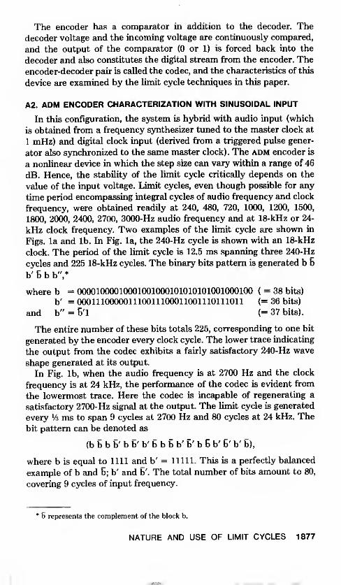
The encoder has a comparator in addition to the decoder. Thedecoder voltage and the incoming voltage are continuously compared,
and the output of the comparator (0 or 1) is forced back into the
decoder and also constitutes the digital stream from the encoder. The
encoder-decoder pair is called the codec, and the characteristics of this
device are examined by the limit cycle techniques in this paper.
A2. ADM ENCODER CHARACTERIZATION WITH SINUSOIDAL INPUT
In this configuration, the system is hybrid with audio input (which
is obtained from a frequency synthesizer tuned to the master clock at
1 mHz) and digital clock input (derived from a triggered pulse gener-
ator also synchronized to the same master clock). The adm encoder is
a nonlinear device in which the step size can vary within a range of 46
dB. Hence, the stability of the limit cycle critically depends on the
value of the input voltage. Limit cycles, even though possible for any
time period encompassing integral cycles of audio frequency and clock
frequency, were obtained readily at 240, 480, 720, 1000, 1200, 1500,
1800, 2000, 2400, 2700, 3000-Hz audio frequency and at 18-kHz or 24-
kHz clock frequency. Two examples of the limit cycle are shown in
Figs, la and lb. In Fig. la, the 240-Hz cycle is shown with an 18-kHz
clock. The period of the limit cycle is 12.5 ms spanning three 240-Hz
cycles and 225 18-kHz cycles. The binary bits pattern is generated b 5
b' 5 b b",*
where b = 00001000010001001000101010101001000100 ( = 38 bits)
b' = 000111000001110011100011001110111011 (= 36 bits)
and b" = B'l (= 37 bits).
The entire number of these bits totals 225, corresponding to one bit
generated by the encoder every clock cycle. The lower trace indicating
the output from the codec exhibits a fairly satisfactory 240-Hz wave
shape generated at its output.
In Fig. lb, when the audio frequency is at 2700 Hz and the clock
frequency is at 24 kHz, the performance of the codec is evident from
the lowermost trace. Here the codec is incapable of regenerating a
satisfactory 2700-Hz signal at the output. The limit cycle is generated
every '/•» ms to span 9 cycles at 2700 Hz and 80 cycles at 24 kHz. The
bit pattern can be denoted as
(b b b b' b b' b' b b b b' b' b b b' b' b' b),
where b is equal to 1111 and b' = 11111. This is a perfectly balanced
example of b and 6; b' and b'. The total number of bits amount to 80,
covering 9 cycles of input frequency.
6 represents the complement of the block b.
NATURE AND USE OF LIMIT CYCLES 1877

(a)
.
(b)
Fig. 1—Generation of encoder limit cycles. Top trace: Binary data. Middle trace:
Compander action. Lower trace: Output of the adm decoder, (a) Limit cycle obtained by240 Hz at the AF input and 18 kHz at the clock frequency input into a SLCQ-40 encoder,
(b) Limit cycle obtained by 2700 Hz at the AF input and 24 kHz at the clock frequencyinput into a SLC-40 encoder.
In other cases where the relation between audio frequency input and
the clock rate is a lower integer number such as (8 or 10), the binary
repeat patterns are simpler and generally far more stable than the
examples presented.
1878 THE BELL SYSTEM TECHNICAL JOURNAL, OCTOBER 1979

>50uS
^/wwww\*(a)
(b)
Fig. 2—Generation of decoder limit cycles, (a) Integrator voltage (lower trace) from
a SLC®-40 decoder for a 0101 • • • sequence of coherent data input, (b) Integrator
voltage from the decoder for a 00001111 • • • sequence of coherent data input. (Contin-
ued)
A3. ADM DECODER CHARACTERIZATION
When the clock and the binary bit pattern are synchronized, the
operation of the decoder can be made perfectly repetitive. In the three
sections of this appendix, three such models are presented (i) charac-
terization with (0101, 00110011, etc.) inputs (to study the stable step
NATURE AND USE OF LIMIT CYCLES 1879

(c)
Fig. 2 (continued)—(c) Integrator voltage for a 111111000000 • • • sequence ofcoherentdata input to the decoder, (d) Integrator voltage for a 1111111100000000 • • sequenceof binary input data.
sizes at different frequencies), (ii) characterization with (010101 • • •
00001111 00001111 • • • ) inputs (to study the decay and build-up of step
sizes) and (Hi) characterization with (0000 • • • or 1111 • • •) • • • 010101
• • • ) input (to study growth and decay to the maximum step size).
1880 THE BELL SYSTEM TECHNICAL JOURNAL, OCTOBER 1979

Fig. 3.— (a) Growth of step size at the decoder integrator capacitor by a sequence of
0101 ••• 00001111 ••• data. Limit cycle is generated by accommodating the 0101
sequence in 64 cycles of the master clock and 00001111 sequence within the 64 clock
cycles of the master adm clock. The periodicity of the limit cycle is 128 master clock
cycles, (b) Decay of step size at the decoder integrator voltage by a sequence of 0101
• • • 010000000011111111 • • • binary data. The 0101 sequence is lodged in 256 master
clock cycles at 24 kHz and 0000000011111111 sequence within the next 256 cycles. Thelimit cycle repeats every 10% ms.
NATURE AND USE OF LIMIT CYCLES 1881

(b)
Fig. 4—(a) Decay of integrator voltage from high values. The system is forced into alimit cycle by a string of 256 zeros and by a string of 0101 • • • for the next 256 clockcycles. The periodicity of the entire limit cycle is 10% ms at 24-kHz master clock, (b)
Limit cycle generated by a sequence of 0000010101010101010101 (repeat) from a 24-kHzclock showing the change in step size of the decoder at medium ranges of integratorvoltage. Three synthesizers were used in synchronization to generate the more compli-cated coherent bit patterns.
1882 THE BELL SYSTEM TECHNICAL JOURNAL, OCTOBER 1979

CORELOCATION002000002010002020002030002040002050002060002070
I 11440001377171002
001377 027762171002 020057027762 I 77440BSS53 001 377
I 77 440 I 7 1 002001377 02 7762
BINARY DATA02 7762 17/440 171002|o ?flo5*\ 001377 027762177440 171002 0200570013 77 027762 177440171002 020057 00137702 7762 177440 171002020057 001377 027762177440 171002 020057
001377 02 7762171002 020057
I 77440
001377 027762171002 020057
027762020057I 774400013 77 02 7762
I 774400013 77171002
001377 02 7762171002 020057
I 77440001377I 71002
171002 [0200571 0013 77
7762 1 77440 1 71002001377 027762171002
001377 027762 T171002 020057 0013 77
02 7762 177440 171002020057 001377 027762
ONE LIMIT CYCLE
02 7762020057
I 7744000137/171002027762020057I 77440
1 7744000137717100202 77620200571 77440001377171002
17100202776202005717744000137717100202 7762020057
10200571i 77W0013771710020277620200571774400013 77
(b)
Fig. 5—(a) Limit cycle generated in the stored data from the adm encoder for the
interface testing. Note that location (700408 to 2000H) is a perfect multiple of 5 confirming
that the intermediate locations have also received the adm data from the interface
correctly, (b) Limit cycle generated by the stored analog-to-digital converter interface
testing. Note that corresponding points on a repeating sine wave as they are scanned by
the A to D converter occupy corresponding locations in the computer core, thus implying
a properly functioning interface.
A.3. 1. Stable step size characterization
Typical voltages at the integrator of the decoder are shown in a
sequence of oscillograms, Figs. 2a through 2d. The input .is generated
by a series of simple logic circuits but activated by the same master
clock feeding into the decoder.
NATURE AND USE OF LIMIT CYCLES 1883
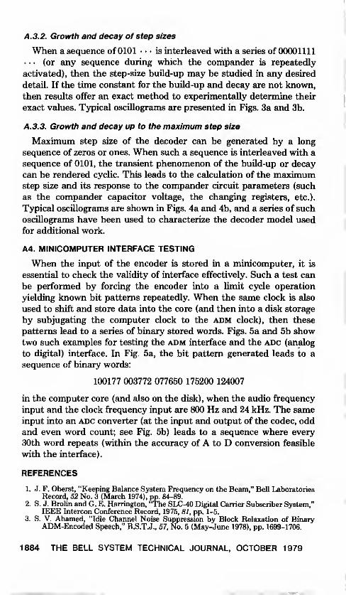
A. 3. 2. Growth and decay of step sizes
When a sequence of 0101 • • • is interleaved with a series of 00001111
• • • (or any sequence during which the compander is repeatedly
activated), then the step-size build-up may be studied in any desired
detail. If the time constant for the build-up and decay are not known,
then results offer an exact method to experimentally determine their
exact values. Typical oscillograms are presented in Figs. 3a and 3b.
A. 3. 3. Growth and decay up to the maximum step size
Maximum step size of the decoder can be generated by a long
sequence of zeros or ones. When such a sequence is interleaved with a
sequence of 0101, the transient phenomenon of the build-up or decay
can be rendered cyclic. This leads to the calculation of the maximumstep size and its response to the compander circuit parameters (such
as the compander capacitor voltage, the changing registers, etc.).
Typical oscillograms are shown in Figs. 4a and 4b, and a series of such
oscillograms have been used to characterize the decoder model used
for additional work.
A4. MINICOMPUTER INTERFACE TESTING
When the input of the encoder is stored in a minicomputer, it is
essential to check the validity of interface effectively. Such a test can
be performed by forcing the encoder into a limit cycle operation
yielding known bit patterns repeatedly. When the same clock is also
used to shift and store data into the core (and then into a disk storage
by subjugating the computer clock to the adm clock), then these
patterns lead to a series of binary stored words. Figs. 5a and 5b showtwo such examples for testing the adm interface and the adc (analog
to digital) interface. In Fig. 5a, the bit pattern generated leads to a
sequence of binary words:
100177 003772 077650 175200 124007
in the computer core (and also on the disk), when the audio frequency
input and the clock frequency input are 800 Hz and 24 kHz. The sameinput into an adc converter (at the input and output of the codec, oddand even word count; see Fig. 5b) leads to a sequence where every
30th word repeats (within the accuracy of A to D conversion feasible
with the interface).
REFERENCES
1. J. F. Oberst, "Keeping Balance System Frequency on the Beam," Bell LaboratoriesRecord, 52 No. 3 (March 1974), pp. 84-89.
2. S. J. Brolin and G. E. Harrington, "The SLC-40 Digital Carrier Subscriber System,"IEEE Intercon Conference Record, 1975, 81, pp. 1-5.
3. S. V. Ahamed, "Idle Channel Noise Suppression by Block Relaxation of BinaryADM-Encoded Speech," B.S.T.J., 57, No. 5 (May-June 1978), pp. 1699-1706.
1884 THE BELL SYSTEM TECHNICAL JOURNAL, OCTOBER 1979