Formulation of a Multifunctional Flora Composite for the ...
Upload
khangminh22Category
view
0download
0
The microleakage of composite and compomer restorations
following cavity preparation with an Erbium-YAG Laser
Elizabeth M. Roebuck B.D.S., F.D.S.(Paed)R.C.S.
Thesis subm itted for the degree o f
M aster o f Science (Medical Science)
to the Faculty o f Medicine
University o f Glasgow
The Departm ent of Child Dental Health
Glasgow Dental Hospital and School NHS Trust
Copyright'; E. M. Roebuck, October 1998

ProQuest Number: 13815583
All rights reserved
INFORMATION TO ALL USERS The quality of this reproduction is dependent upon the quality of the copy submitted.
In the unlikely event that the author did not send a com p le te manuscript and there are missing pages, these will be noted. Also, if material had to be removed,
a note will indicate the deletion.
uestProQuest 13815583
Published by ProQuest LLC(2018). Copyright of the Dissertation is held by the Author.
All rights reserved.This work is protected against unauthorized copying under Title 17, United States C ode
Microform Edition © ProQuest LLC.
ProQuest LLC.789 East Eisenhower Parkway
P.O. Box 1346 Ann Arbor, Ml 48106- 1346

GLASGOWUNIVERSITYLIBRARY
U4t5

Contents
List of T ables.........................................................................................................................vii
List of Figures.......................................................................................................................viii
A bbreviations.......................................................................................................................... x
Acknowledgem ents............................................................................................................. xii
D eclaration...........................................................................................................................xiii
Sum m ary............................................................................................................................... xiv
1 Introduction.......................................................................................................................1
1.1 Dental caries................................................................................................................1
1.2 Caries: a public health concern...............................................................................1
1.3 Barriers to dental care ...............................................................................................3
1.4 M anaging the anxious individual.......................................................................... 3
2 Literature Review ............................................................................................................5
2.1 Introduction.................................................................................................................5
2.2 Composition and structure of the dental crow n.................................................5
2.2.1 Enamel of the perm anent tooth ........................................................................ 5
2.2.1.1 The enamel prism .............................................................................................6
2.2.1.2 The mineral phase of enamel.........................................................................6
2.2.13 The organic phase of enamel.........................................................................7
2.2.2 Dentine of the perm anent to o th .......................................................................8
2.2.2.1 The mineral phase of dentine.........................................................................8
2.2.2.2 The organic phase of dentine.......................................................................10
2.2.23 The dentinal tubules.......................................................................................11
22.2.4 Dentine permeability......................................................................................11
2.2.3 Dental p u lp ..........................................................................................................12
2.3 Direct restorative materials.,..2...... 14

2.3.1 Introduction..........................................................................................................14
2.3.2 Dental am algam .................................................................................................. 15
2.3.3 Composite resin m aterials............................................................................... 16
2.3.3.1 The organic phase: resin technology.............................................................16
2.3.3.2 The dispersed phase: filler technology......................................................... 18
2.3.3.3 The interfacial phase: coupling agents........................................................ 24
2.3.4 Glass-ionomer cements......................................................................................24
2.3.5 Resin-modified glass-ionomer cem ents........................................................ 26
2.3.6 Polyacid-modified composite resins...............................................................27
2.3.7 The causes of restoration failure......................................................................28
2.4 M icroleakage..............................................................................................................29
2.5 ' M ethods of assessing microleakage......................................................................29
2.5.1 Introduction......................................................................................................... 29
2.5.2 Penetration of tracer m olecules.......................................................................30
2.5.2.1 Single section assessment of microleakage...................................................30
2.5.2.2 Organic dye penetration................................................................................32
2.5.2.3 Radioactive isotopes.......................................................................................35
2.5.2.4 Non-radioactive chemical tracers.................................................................36
2.5.3 In vivo versus in vitro microleakage.................................................................. 37
2.5.3.1 Pulpal hydrostatic pressure.......................................................................... 38
2.5.3.2 Mechanical loading.......................................................................................38
2.5.3.3 Temperature change...................................................................................... 39
2.6 Microleakage in composite resin restorations.................................................... 39
2.7 The control of polymerisation shrinkage............................................................ 40
2.7.1 The resin composition.......................................................................................41
2.7.1.1 The degree of polymerisation shrinkage.......................................................41
2.7.1.2 The degree of water absorption..................................................................... 42
2.7.1.3 Coefficient of thermal expansion and thermal diffusivity .......................... 42
2.7.2 Restorative techniques...................................................................................... 44
2.7.2.1 Increased bonding to enamel........................................................................ 44
2.7.2.2 Increased bonding to dentine........................................................................ 45
2.7.2.3 The use of low viscosity resins: intermediate bonding and glazing ..........51
2.7.2.4 Altering the cavosurface angle of the restorations......................................52
2.7.2.5 Modification of the restorative technique.................................................... 53
iii

2.8 Microleakage in polyacid-modified composite resin s ....................................55
2.8.1 Sum m ary............................................................................................................. 56
2.9 Cavity p reparation .................................................................................................. 56
2.9.1 Conventional cavity p repara tion .................................................................. 57
2.9.2 Alternative techniques for cavity p repara tion ............................................58
2.10 Lasers in den tistry ....................................................................................................59
2.10.1 Introduction........................................................................................................59
2.10.2 Lasers as optical 'd rills '....................................................................................60
2.10.3 Mechanism of laser-tissue interactions....................................................... 62
2.10.3.1 Introduction ....................................................................................................62
2.10.3.2 Interaction of absorbed light with the dental hard tissues ..........................63
2.10.3.3 Thermal interactions...................................................................................... 63
2.10.3.4 Non-linear processes.....................................................................................63
2.10.3.5 Thermomechanical processes......................................................................... 65
2.10.3.6 Laser parameters............................................................................................. 65
2.10.3.7 Optical and tissue parameters....................................................................... 66
2.10.4 The early hard tissue dental lasers................................................................67
2.10.5 The new generation of lasers......................................................................... 68
2.10.6 The Erbium:YAG laser.....................................................................................70
2.10.6.1 Introduction....................................................................................................70
2.10.6.2 Ablation...........................................................................................................71
2.10.6.3 Morphology.....................................................................................................74
2.10.6.4 Temperature....................................................................................................75
2.10.6.5 Long-term pulp reaction.................................................................................76
2.10.6.6 Patient acceptance.......................................................................................... 76
2.10.6.7 Microleakage....................................................................................................77
2.11 General sum m ary....................................................................................................81
2.12 Aims and objectives............................................................................................... 81
3 Materials and m ethod................................................................................................... 82
3.1 M aterials................................................................................................................... 82
3.1.1 Z100.....................................................................................................................82
3.1.2 Scotchbond M ulti-Purpose............................................................................. 82
3.1.3 Com poglass....................................................................................................... 84
iv
3.1.4 Compoglass Single Component A dhesive.................................................85
3.2 M ethod ........................................................................................................................85
3.2.1 Tooth selection.................................................................................................. 85
3.2.2 Cavity p repara tion ...........................................................................................85
3.2.2.1 Laser parameters............................................................................................ 88
3.2.3 Cavity restoration.............................................................................................88
3.2.4 Storage and therm ocycling............................................................................ 91
3.2.5 Microleakage assessm ent............................................................................... 91
3.2.6 Statistical analysis.............................................................................................93
4 R esults.............................................................................................................................. 98
4.1 Introduction............................................................................................................... 98
4.2 Enamel m arg ins........................................................................................................98
4.2.1 Conventionally-prepared enamel m argins.................................................98
4.2.1.1 Within-group analyses..................................................................................98
4.2.1.2 Intergroup analyses.......................................................................................98
4.2.2 Lased enamel m argins...................................................................................100
4.2.2.1 Within-group analyses............................................................................... 100
4.22.2 Intergroup analyses.................................................................................... 103
4.2.3 Conventionally-prepared versus lased enamel m arg ins....................... 103
4.3 Dentine m arg in s .................................................................................................... 106
4.3.1 Conventionally-prepared dentine m argins..............................................106
4.3.1.1 Within-group analyses............................................................................... 106
4.3.1.2 Intergroup analyses.................................................................................... 106
4.3.2 Lased dentine m argins.................................................................................. 106
4.3.2.1 Within-group analyses............................................................................... 106
4.32.2 Inter group analyses.................................................................................... 109
4.3.3 Conventionally-prepared versus lased dentine m argins....................... 109
4.4 Enamel versus dentine........................................................................................... 112
4.4.1 Conventionally-prepared m argins............................................................. 112
4.4.2 Lased m argins.................................................................................................112
4.5 Sum m ary.................................................................................................................. 115
5 Discussion......................................................................................................................117
v
5.1 Introduction............................................................................................................ 117
5.2 M ethodology.......................................................................................................... 117
5.3 Outline of d iscussion ........................................................................................... 119
5.4 The enam el/restoration in terface..................................................................... 120
5.4.1 Conventionally-prepared enamel m argins...............................................120
5.4.2 The influence of the Er:YAG laser on the enamel
cavity /restoration interface..........................................................................123
5.5 The den tine/resto ration interface..................................................................... 126
5.5.1 Conventionally-prepared dentine m arg ins...............................................126
5.5.2 The influence of the Er:YAG laser on the dentine cavity
restoration/in terface...................................................................................... 130
5.6 C onclusions............................................................................................................ 132
6 Future research ............................................................................................................134
Bibliography........................................................................................................................ 137
vi

List of TablesTable 2.1 Classification of coronal dentine by location, patterns o f mineralisation and
development........................................................................................................................ 9
Table 2.2 Chemical versus light curing................................................................................ 19
Table 2.3 Filler types found in composite resin................................................................... 20
Table 2.4 A summary of the advantages and disadvantages o f some microleakage tests..31
Table 2.5 The five generations of dentine bonding agents................................................. 48
Table 2.6 Potential soft and hard tissue applications o f lasers in dentistry ......................61
Table 2.7 Hard lasers which ablate enamel and dentine .....................................................69
Table 2.8 The range ofEr:YAG laser parameters used in referenced reports...................72
Table 4.1 Microleakage scores for all cavities...................................................................... 99
List of FiguresFigure 2.1 Classifications of composite resin materials.......................................................22
Figure 3.1 Z100 composite resin and Scotchbond Multi-Purpose bonding agent........... 83
Figure 3.2 Compoglass compomer resin and Compoglass Single Component Adhesive..83
Figure 3.3 The Erbium:YAG Twinlight Dental Laser.........................................................86
Figure 3.4 Cavity preparation using the Erbium:YAG laser.............................................86
Figure 3.5 Line drawing showing the position of the cavity at the cervical margin o f the
tooth; a) aproximal surface b) buccal surface..............................................................87
Figure 3.6 The metal templates used during cavity preparation........................................89
Figure 3.7 The control panel of the ErbiumiYAG Twinlight Dental Laser.......................89
Figure 3.8 Dentine charring during cavity preparation with the 300 m j pulse energy...90
Figure 3.9 The thermocycling u n it .......................................................................................92
Figure 3.10 The Labcut microtome used for sectioning.......................................................94
Figure 3.11 Microleakage scoring: enamel margin = 0, dentine margin = 0 ...................94
Figure 3.12 Microleakage scoring: enamel margin = 1, dentine margin = 3 with
extensive dye penetration in the dentinal tubules........................................................ 95
Figure 3.13 Microleakage scoring: enamel margin = 1, dentine margin = 2 with
minimal dye penetration in the dentinal tubules......................................................... 95
Figure 3.14 Microleakage scoring: enamel margin = 2, dentine margin = 4 with
minimal dye penetration in the dentinal tubules..........................................................96
Figure 3.15 Microleakage scoring: enamel margin = 2, dentine margin = 4 with
extensive dye penetration in the dentinal tubules........................................................ 96
Figure 4.1 Microleakage seen at the enamel margins of conventionally-prepared cavities
101
Figure 4.2a-c Microleakage seen at the enamel margins of lased cavities in groups A, B
and C ............................................................................................................................. 102
Figure 4.3 Intergroup analysis of microleakage seen at the enamel margins of lased
cavities in groups A and B ........................................................................................... 104
Figure 4.4 Intergroup analysis of microleakage seen at the enamel margins of lased
cavities in groups B and C ........................................................................................... 104
Figure 4.5a-c Analysis of the microleakage seen at the lased and conventionally-prepared
enamel margins in groups A, B and C ........................................................................ 105

Figure 4.6 Microleakage seen at the conventionally-prepared dentine margins............. 107
Figure 4.7a-c Microleakage seen at the dentine margins of lased cavities in groups A, B
and C ..............................................................................................................................108
Figure 4.8 Intergroup analysis of microleakage seen at the dentine margins o f lased
cavities in groups A and B ........................................................................................... 110
Figure 4.9 Intergroup analysis of microleakage seen at the dentine margins o f lased
cavities in groups B and C ........................................................................................... 110
Figure 4.10a-c Analysis of the microleakage seen at the lased and conventionally-
prepared dentine margins in groups A, B and C ........................................................I l l
Figure 4.11 Analysis o f the microleakage seen at the enamel and dentine margins o f
conventionally-prepared cavities..................................................................................113
Figure 4.12a-c Analysis of the microleakage seen at the enamel and dentine margins in
the lased cavities o f groups A, B and C ....................................................................... 114
ix

AbbreviationsADJ: am elodentinal junctionAr-F: argon fluorineAv: averageBisGMA: bisphenol-glycidyl methacrylateCa: calcium
CRI: cavity w all/too th restoration interface
C 0 2: carbon dioxideDCMA: dicarbonic acid dimethacrylateDia: diam eter
EDA: electronic dental anaesthesia
EGMA: ethylene glycol dimethacrylate
Er:YAG: erbium yttrium alum inium garnet
Er:Cr:YAG: erbium chrom ium yttrium aluminium garnetFDA: Food and Drug Adm inistrationHEMA: 2-hydroxyethyl-methacrylateHz: HertzHo:YAG: holm ium yttrium alum inium garnetIR: infra-redmj: millijouleMPa: megapascal
Mg: microgramsiU m micrometre / micronjL/s: microsecondmm: millimetreN H 2: am m onium
NHS: National Health Service
nm: nanometre
nsec: nanosecond
Nd:YAG: neodym ium yttrium alum inium garnetOH: hydroxyl
POp phosphate
pps: pulses per second

PRR: pulse repetition rate
PSI: pounds per square inch
SEM: scanning electron microscopy
TEGMA: triethylene glycol dimethacrylate
Th:YAG thullium yttrium alum inium garnet
UK: United Kingdom
UV: ultraviolet
W: w att
Xe-Cl: xenon chorine
YAG: yttrium alum inium garnet
xi
Acknowledgements
I w ould like to express my thanks and gratitude to the m any people who have
helped me during the research and writing of this thesis:
My supervisors, Professor W. P. Saunders, D epartm ent of A dult Dental H ealth
and Dr. C. J. W hitters, D epartm ent of Clinical Physics, both of the University of
Glasgow, for their hum our, encouragement, and guidance throughout the period
of this study and during the preparation of this thesis.
To Professor N. McKay, Postgraduate Dean of Medicine and Professor D. Wray,
Postgraduate Dean of Dental Studies for providing funding for the study.
Mr. R. Foye and Mr. A. Cum m ings for their assistance and advice in the
laboratory.
Mr. J. Davies, Mrs. K. Shepherd and Mrs. G. Drake of the D epartm ent of Medical
Illustration, University of Glasgow for the 'focused' photography.
My family and friends, for their help, support and understanding.
And lastly bu t by no means least, my husband Stuart for his love, patience and
support, for the T.T. helpline' and the regular 'meals on wheels' service. It is to
him that I dedicate this thesis.

Declaration
All the work submitted herein is the original work of the author
Elizabeth M. Roebuck
xiii

Summary
O ver the last thirty years there has been a m arked decline in the caries experience
in ch ild ren in the U nited K ingdom . H ow ever, the re su lts of recen t
ep id em io lo g ica l s tud ies have show n th a t this trend has s low ed dow n
considerably, and m ay even have reversed in some age groups. Furtherm ore,
there is an increasing cohort of children w ith significant levels of un treated
dentinal decay. Anxiety is a major barrier to the uptake of dental care in the
U nited Kingdom, the two m ost common stressors being cited as the dental drill
and the local anaesthetic needle. The use of the hard tissue laser has been
proposed as one operative mode of cavity preparation that obviates the use of
both of these anxiety-precipitating stimuli.
This in vitro study investigated the affect of one such instrum ent, the Erbium-
YAG laser, on the m icroleakage of s tan d ard ised Class V cavities a t the
am elodentinal junction in extracted hum an prem olar teeth. Extracted prem olar
teeth w ere selected and random ly divided into three groups (A, B and C). Each
tooth hosted one test cavity prepared w ith one of three laser energies (200 mj,
240 m j or 300 m j with a 100 m j finish), and one control cavity, prepared w ith a
conventional diam ond bur in a high-speed handpiece. The cavities were restored
w ith either a composite resin or a com pom er material; groups A and B were
restored w ith a fourth generation bonding agent, Scotchbond M ulti-Purpose and
Z100 composite resin and were stored in 0.12% thymol solution for 24 hours and
three m onths respectively. Cavities in group C were restored using a fifth
generation bonding agent, Com poglass Single C om ponent A dhesive and a
polyacid-m odified resin, Compoglass and were then stored for three m onths.
Follow ing storage and therm al stressing (eight hours), m icroleakage was
assessed using a dye penetration technique and single section num erical scoring
system . The data was then analysed using the Kruskal-W allis and M ann-
W hitney U tests.
For the pulse energies used, it was found that the Er:YAG laser varied in its effect
on bo th the enam el and dentine m argins w hen com pared to conventional
xiv
preparation . At the enam el m argin, preparation with either of the three pulse
energies com pared favourably to the use of the diam ond bur for both materials.
H ow ever, optim um cavity sealing was achieved with energies of at least 240 mj.
In com parison, dentine leakage following laser preparation w as com parable to
th a t fo und w ith conventional p repara tion for all laser param eters w hen
Com poglass was used. However, there were statistical differences in leakage at
the dentine m argins of Z100 restorations. Lower energies of 200 mj or higher
w ith a low finish such as the 300 mj w ith 100 mj finish used in this study
prov ided better long-term m arginal adaptation in dentine for this material. Of
these tw o laser energy subgroups, the 300 m j w ith 100 m j finish com pared
favourably w ith conventional cavity preparation.
It w as therefore concluded that, w ith in the constraints of this study, cavity
p repara tion w ith the Er:YAG laser did not have a deleterious effect on the
microleakage of Class V restoration when compared to conventional preparation,
p rovid ing care was taken w ith the choice of laser param eters for dentine and
enam el for the restorative material used.
xv
1 Introduction
1.1 Dental caries
Dental caries is defined as 'a bacterial disease of the calcified tissues of the teeth
characterised by dem ineralisation of the inorganic, and destruction of the
organic, substance of the tooth' (Soames & Southam, 1993). Several aetiological
th eo rie s have been p ro p o sed (Blackwell, 1955). H ow ev er, M ille r 's
Chem oparasitic Theory of 1889, now referred to as the acidogenic theory, is
currently the most accepted.
1.2 Caries: a public health concern
Caries is a potentially infectious and transm issible disease (Keyes, 1960) and,
along w ith its sequelae, has been recognised throughout history. Lesions have
been found in the teeth of Neolithic skulls and there are several references to
caries-related pain and discom fort in the classical and historical literature.
H ow ever, enam el caries was uncom m on and w hen it d id occur, it usually
progressed slowly. Caries of the root surface was m ore com m on and was
inevitably related to periodontal disease.
In the eighteenth century, the pattern and incidence of caries began to rise
significantly in Europe and N orth America. As w ith any change in the
prevalence or nature of a disease, several causative factors have been given for
this change. However, a significant correlation betw een the consum ption of
refined sugars and the incidence of caries has been noted (Hardwick, 1960). The
industria l revolution led to changes in lifestyle and the trad itional d ietary
patterns of m uch of the population. This, along w ith developm ents in the
m anufacture, distribution and m arketing of sucrose, led to an increase in sugar
consum ption which in 1957, was twice that of 1880 (H ardw ick, 1960). The
increasing availability of sucrose resulted in a population of children and young
1

adu lts w ho exhibited rap id ly advancing coronal caries w ith its associated
sequelae of pain and infection, to the extent that, at the inau g u ra tio n of the
National H ealth Service (NHS) in 1948, dental caries was considered a major and
increasing public health problem in the United Kingdom (UK).
The first tw enty to th irty years of dentistry in the NHS involved extensive
m anagem ent of the dam aging effects of caries and its sequelae. H ow ever, w ith
an im provem ent in the knowledge of the nature and m anagem ent of the disease,
a reduction in the incidence of caries in children and adults has been seen during
the last tw enty years (Todd & Lader, 1991c; Downer, 1994). Several factors have
been im plicated in this reduction such as im proved oral hygiene and dietary
control, and the increased use of antibiotics. However, m any experts believe that
the m ost im portant factor is the increased exposure to fluoride, particularly in
toothpaste (Bratthall et a l, 1996). While this im provem ent in the oral health of
the nation is to be applauded, the most recent surveys suggest that the decline in
caries levels has now slowed dow n considerably and m ay even have started to
reverse in younger individuals (Todd & Lader, 1991c; Downer, 1994).
Of concern also, is the volume of untreated caries. A decrease in the restorative
index in 1983 of 72% to 1993 of 58% in 12 year olds is set against the m arked rise
in the proportion of that age group which is caries free (21% to 50% during the
ten year period). This suggests that there is a core of children w ith relatively
high caries levels who are not being reached by the dental care services currently
(Downer, 1994). A similar scenario is found in the adult population of the UK.
There are several possible reasons for this, for example, poor co-operation, cost
and non-attendance. The m ost recent national adu lt and child dental health
surveys in the U nited K ingdom enquired about the frequency of dental
attendance (Todd & Lader, 1991b; O'Brien, 1994). W hen edentulous people were
excluded, only 50% of adults and 59% of 5 year-old children w ere regular
attenders. In order to further reduce the levels of decay, and to restore current
active decay, it is essential that there is an increase in the num ber of people
attending the dentist for regular care.
2

1.3 Barriers to dental care
Several barriers to regular dental care have been reported . O ther than the
dem ographic variables; gender, age, education and social class (Berggren &
Meynart, 1988), a lack of symptoms or concern and dental fear are reported as the
m ain reasons for not seeking regular dental care (Friedl et ah, 1995; M urray,
1996).
In the 1988 A dult Dental H ealth Survey in the United Kingdom , anxiety was
found to be a major barrier to dental care for non-attenders (Todd & Lader,
1991a). However, 39% of regular attenders also expressed some level of fear. In
addition, dental anxiety is associated w ith an increase in caries incidence,
un trea ted lesions (O'Brien, 1994), cancelled and m issed appo in tm en ts and
avoidance of dental care (Kleinknecht et ah, 1973). As such it is fast becoming the
dental public health problem of the twenty first century.
Studies investigating the origin of dental anxiety have h igh ligh ted learned
responses from family members and peers (Shoben & Borland, 1954), previous
traum atic dental experiences (Bernstein et al.f 1979) and personality traits as
aetiological factors. However, the greatest fear-provoking factors in the dental
environm ent have been reported as fear of the drill and local anaesthesia needle
(Rankin & Harris, 1984). In addition, surveys of dentists have highlighted the
m anagem ent of anxious patients as the m ost stress-producing feature of their
daily w ork (O'Shea et al., 1984). In light of this, in add ition to continued
m easures to reduce the levels of decay, significant resources have been invested
into the research and developm ent of alternative m ethods of treatm ent to
provide a m eans of m anaging the ever increasing cohort of dentally-anxious
individuals.
1.4 Managing the anxious individual
To date, alternative methods to manage the anxious patient have fallen into two
m ajor categories; firstly, behavioural m anagem ent techn iques such as
in fo rm a tio n p ro v is io n , d is trac tio n , b io feed b ack an d n e u ro lin g u is tic
program m ing, all of which increase the individual's coping skills, and secondly,
m odifications to conventional dental treatm ent. The la tte r has included
3
pharm acological m ethods which alter the individuals' level of consciousness to
allow conventional dental treatment. Such treatm ent m odalities have included
the use of general anaesthesia, nitrous oxide inhalation sedation and intravenous
or oral sedation. In addition, modifications to the two dental stressors, the local
anaesthetic needle (Q uarnstrom & Libed, 1994; M eechan & W inter, 1996;
M oderesi et al., 1996) and the dental drill have been investigated. The options for
the latter are considered further in Section 2.9. However, the use of a laser as an
optical cu tting device has been advocated as one m eans of m od ify in g
conventional treatm ent which does not require local analgesia (G oldm an et ah,
1965; Keller & Hibst, 1997).
To be accepted as an alternative to the dental drill, the use of the laser m ust fulfil
certain criteria. These are discussed more fully in Section 2.10, bu t one essential
quality is that the use of the laser in cavity preparation should not adversely
affect the longevity of the restoration placed. This study looks at one aspect of
this; the efficacy of an Erbium-YAG laser on the microleakage (m arginal seal) of
direct composite and compomer fillings.
4
2 Literature Review
2.1 Introduction
An investigation into the effect a laser has on the m arginal seal of restorations
requires an understanding of the physical phenom enon of microleakage and the
factors tha t influence it. This review of the literature begins w ith a brief
description of the tissues found in the crown of a tooth. A know ledge of the
structure and composition of these tissues, enamel, dentine and pulp, is essential
if the interaction of restorative m aterials and lasers w ith these tissues is to be
fully appreciated. Current direct restorative materials are then reviewed, looking
particularly at the developm ents in the field of aesthetic m aterials. Following
this, microleakage is discussed. In this section, the process of m icroleakage and
m ethods of its assessm ent are first described. Microleakage in com posite and
com pom er resins, the two materials used in this study, is then considered, w ith
particu lar em phasis on the m aterial factors and the restorative techniques
purporting to control it. Finally, a brief review of the use of lasers in dentistry is
given, before considering the Erbium YAG laser more fully.
2.2 Composition and structure of the dental crown
The dental crown is composed of two hard tissues, enam el and dentine, and a
soft tissue, the pulp. Extracted perm anent premolars were used in this study and
therefore this review will be restricted to a description of the features of the
structure and composition of these tissues in perm anent, vital crowns which are
pertinent to this study.
2.2.1 Enamel of the permanent tooth
M ature hum an enam el is a unique body tissue; it is acellular, it is the only
m ineralised epithelial tissue and is also the hardest and m ost calcified tissue in
the body. Its physical properties vary over the crown surface; thickness, of the
5
order of 2.5 mm, and hardness are greatest at the incisal/cuspal tip and decrease
steadily to the cervical m argin and fissure region. In health, enam el provides a
protective covering for the underlying dentine and pulp and consists of 96-97%
inorganic and 0.4-0.8% organic m atter and 3% w ater by w eight (86%, 2% and
12% by volume respectively).
22.1.1 The enamel prism
The basic s tructural units of hum an enam el are the enam el p rism s (rods).
Formed as a mineralised secretory product of the ameloblasts, they are 'key-hole'-
shaped in cross-section, w ith a head and tail region, and can be seen throughout
the whole of the enam el tissue except for the surface 20-40 ^m . They are thin
structures w ith an average diam eter of 5 p m and follow an undu la ting course
from the am elodentinal junction (ADJ) to the subsurface. In the cervical area,
where the enamel is thin, the rods are short and the surface enam el is prismless
(Gwinnett, 1967).
2.2.1.2 The mineral phase of enamel
The principle com ponent of the rods is the apatite crystal. W ith the exception of
the tail region, w here there is a shift in crystal orientation, these are arranged
w ith their long axis parallel to the long axis of the rod. They are elongated
hexagons, 30 nm thick, 65 nm wide and several microns in length. Their basic
crystallographic form ula is that of hydroxyapatite; Cai0(PO4)6(OH)2. However,
enam el crystals vary from other apatite crystals in the body in that they are
slightly deficient in calcium, and there are m inor substitu tions of strontium ,
carbonate, m agnesium , lead and fluoride ions in the crystal lattice. With the
exception of fluoride, these ions cause a small increase in the solubility of the
crystal at acidic pHs. The application of acid solutions to enam el results in two
changes; firstly, preferential dissolution of the crystals in the rod head area
occurs leaving a roughened surface. Secondly the enam el is partia lly
dem ineralised to several microns below the surface, leaving hollow crystal cores
and spaces between the partially demineralised crystals. W hen dry, these zones
can be penetrated w ith resins. These changes form the basis of the acid-etching
procedure used to provide micromechanical retention for composite resins and
related materials (Section 2.7.2.1). The depth of the etch pattern varies betw een
6
acids, w ith highly dissociated acids such as phosphoric p roducing deeper
patterns than w eaker acids such as polyacrylic, citric and maleic acids for the
same application time (Meryon et al., 1987; Glasspoole & Erickson, 1994).
Because of its high inorganic content, enamel is a brittle tissue and is susceptible
to fracture along the prism borders. The organic m aterial, found in the
intercrystal space, provides a netw ork for the crystals w hich strengthens the
enam el by reducing the tendency for the crystals to fracture and separate.
Nevertheless, if enamel prism s at the m argin of a cavity are left unsupported by
dentine, they are likely to fracture, resulting in breakdow n of the cavity margin.
In addition, the high inorganic content is responsible for the optical and therm al
properties of the tissue. H ydroxyapatite has absorption bands in the ultraviolet
(UV) and mid- to far-infra-red (IR) regions because of the phosphate, carbonate
and hydroxyl groups in the crystal structure. W ater also has a sim ilar absorption
pattern. Thus, on im pinging the surface of healthy enamel, the majority of light
in the visible and low- to mid-IR ranges is either reflected or transm itted. This
has significance for the appearance of a tooth, and has clinical im plications for
the use of transillum ination in the diagnosis of caries, for the therapeutic effects
of lasers on enamel, and on the polym erisation of photopolym erised restorative
materials.
2.2.13 The organic phase of enamel
The organic m atrix comprises the m inor com ponent of m ature enam el and is
distributed, w ith water, betw een the hydroxyapatite crystals to form the prism
sheath. It is made up of soluble and insoluble protein, peptides, lipids and citric
acid, the majority of which are produced by the ameloblasts. Unlike some of the
inorganic com ponents of bone, dentine and cem entum , they are not fibrous
collagen proteins and are therefore unique am ong the m ineralised tissues. In
addition to supporting the inorganic phase (Section 2.2.1.2), organic m aterial is
found as ribbon-like structures, the lamellae and tufts, found m ainly in the inner
part of the enamel.
Enamel has a low therm al conductivity and coefficient of therm al expansion
(11.4,10'6 °C'1), and a high thermal capacity. These properties serve to protect the
7
underlying structures from the environmental variations found in the oral cavity
and also have a bearing on the tissue interactions which occur w hen lasers are
used to 'cut' (ablate) enamel (Section 2.10.3).
2.2.2 Dentine of the permanent tooth
Dentine forms the bulk of the tooth, providing a cushion for the overlying brittle
enam el and pro tection to the pulp. It differs from enam el in s tructu re ,
com position and function, the most significant difference being the vital nature of
the tissue which enables continued post-eruption developm ent in response to
both physiological and pathological stim uli. The cells conveying vitality to
dentine are the odontoblasts and the sensory neurones, both of which are located,
w ith the dentinal fluid, in the lum en of the dentinal tubules. Their cell bodies are
found in the periphery of the pu lp and therefore den tine v ita lity is also
dependent on the health of this tissue. For this reason, w hen considering post-
eruptive changes, it is custom ary to consider the pulp and dentine as one entity,
the pulpodentinal complex.
Dentine is deposited incrementally throughout life in a rhythm ic m anner unless
environm ental factors stimulate a localised increase in production. Thus it can be
classified into distinct types based on the location, matrix calcification, structure
and developm ental pattern (Table 2.1). Pathological stimuli such as caries, wear,
iatrogenic and non-iatrogenic traum a, and irritant chemicals can stim ulate the
form ation of tertiary (reparative) dentine and sclerotic (translucent) dentine.
These form part of the defensive mechanism of the pulpodentinal complex and
their formation is considered further in Section 2.2.3.
M ature dentine has a low coefficient of thermal expansion (8.3, 10‘6 °C 1) and is
approxim ately 70% mineral, 20% organic matrix, and 10% w ater by w eight (50%
mineral, 30% organic and 20% water by volume).
22.2.1 The mineral phase of dentine
While trace am ounts of calcium carbonate, fluoride, m agnesium , zinc and other
m inerals are found in dentine, the principal m ineral com ponent, like enamel, is
hydroxyapatite. The organisation and m ineralisation of the tissue differs from
that of enamel. In dentine, the crystals (calcospherites) are in the form of
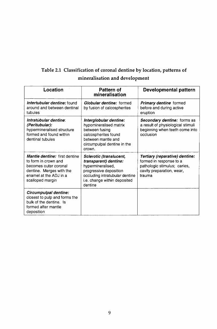
Table 2.1 Classification of coronal dentine by location, patterns of
mineralisation and development
Location Pattern of mineralisation
Developmental pattern
Intertubular dentine: found around and between dentinal tubules
Globular dentine: formed by fusion of calcospherites
Primary dentine formed before and during active eruption
Intratubular dentine: (Peritubular):hypermineralised structure formed and found within dentinal tubules
Interglobular dentine:hypomineralised matrix between fusing calcospherites found between mantle and circumpulpal dentine in the crown.
Secondary dentine: forms as a result of physiological stimuli beginning when teeth come into occlusion
Mantle dentine: first dentine to form in crown and becomes outer coronal dentine. Merges with the enamel at the ADJ in a scalloped margin
Sclerotic (translucent, transparent) dentine:hypermineralised, progressive deposition occluding intratubular dentine i.e. change within deposited dentine
Tertiary (reparative) dentine:formed in response to a pathologic stimulus; caries, cavity preparation, wear, trauma
Circumpulpal dentine:closest to pulp and forms the bulk of the dentine. Is formed after mantle deposition
9
flattened plates of approxim ate dim ension 60-70 nm in length, 20-30 nm in
w idth, and 3-4 nm in thickness. M ineralisation occurs by the fusion of num erous
crystals (globular mineralisation).
W hen com pared to the other mineralised tissues of the body, the m ineral content
of dentine makes it harder than cem entum or bone, bu t five times softer than
enamel. Furthermore, the post-eruptive changes result in variations in hardness
w ith in the tissue. For exam ple, w ith ageing, extensive d ep o sitio n of
hydroxy apatite may occur (sclerotic and intratubular dentine). This results in the
dentine becoming more brittle, harder, less resilient and m ore yellow in colour,
w hereas carious dentine is m uch softer than both sclerotic and non-sclerotic
dentine. This has clinical significance in both the diagnosis of caries and the
assessm ent of cavity preparation. The variation in mineral also has im plications
for the use of lasers as an 'optical drill' ( Section 2.10.3.7).
2.22.2 The organic phase of dentine
The odontoblast processes play an im portant role in the production of dentine in
that they are responsible for the synthesis and secretion of the com ponents of the
organic matrix. Collagen makes up approxim ately 91-92% of the m atrix and
provides the structural fram ework for dentine. It may also play a role in the
in itiation of m ineralisation. The rem aining 8-9% consists of seven broad
categories of non-collagenous macromolecules. While the detailed function of
these organic com ponents is beyond the scope of this review, it w ould appear
that they are im portant factors in the growth, developm ent and repair of the vital
m ineralised tissue (Piesco, 1994). The relatively high organic content enables
dentine, unlike enamel, to deform slightly under com pression. This and the
'hydraulic shock absorber' effect of the fluid-filled dentinal tubules dissipate the
forces of m astication, thus providing the cushioning of the overlying brittle
enamel. The organic matrix also gives resilience and strength to the dentine. In
health, this is beneficial to the pulp. However, its rigidity produces a cham ber
w ith low compliance and therefore if the pulp becomes inflamed, irreversible
pulpal damage can occur.
10
2.2.23 The dentinal tubules
The m ost prom inent feature of dentine is the dentinal tubules. In the crown, they
extend from the ADJ in an S-shaped curve. They provide a path by w hich
bacteria (Kidd & Joyston-Bechal, 1997) and other noxious stim uli can gain direct
entry to the pulp once the protective enamel layer is breached. In addition, they
are thought to act as 'optical fibres' transm itting radiation from the ADJ to the
pulpal tissues (Zijp & Ten Bosch, 1991). The tubules are tapered and branched,
the narrow est, and m ost pronounced branching occurring near the ADJ. Tubule
density also varies betw een the occlusal and cervical dentine, w ith the lowest
density found in the outer third of the latter (Fosse et a l, 1992).
The continued deposition of dentine, coupled w ith a lack of internal remodelling,
effectively reduces the size of the pu lp cham ber over tim e resu lting in an
increased density (40,000 m m '2) of w ider dentinal tubules tow ards the pulp
cham ber. The tubules therefore represent a m uch larger p roportion of the
dentine volume near the pulp (28% by volume) w hen com pared to the ADJ (4%
by volume). The clinical implications of this are obvious; the deeper the cavity,
the greater the num ber of tubules that are at risk from bacterial penetration,
cavity preparation and the application of potentially harm ful substances, and
therefore the greater the potential for causing pulpal damage.
2.2.2.4 Dentine permeability
Unlike enamel, dentine is relatively permeable; in a vital tooth, fluids can readily
flow across or through the dentine tubule complex from the pu lp to the ADJ
(transdentinal perm eability), or in the reverse direction w hen the enam el is
dam aged or lost (Brannstrom & Nyborg, 1972). The w ater content of dentine is
proportional to the cross-sectional area and density of the tubules and therefore
increases tow ards the pulp. Fluid arising from the cut surface of the dentinal
tubules is formed as a transudate of plasma and is always under slight positive
pressure. This flow of dentinal fluid has a protective function; w hen irritants
such as bacterial toxins gain access to the pulp via the tubules, an inflam m atory
response is provoked. The resulting increase in pu lpal pressure causes an
increase in dentinal fluid flow which cleanses the tubules and hinders the entry
of bacteria into the pulp. In addition, this is also indirectly responsible for
11
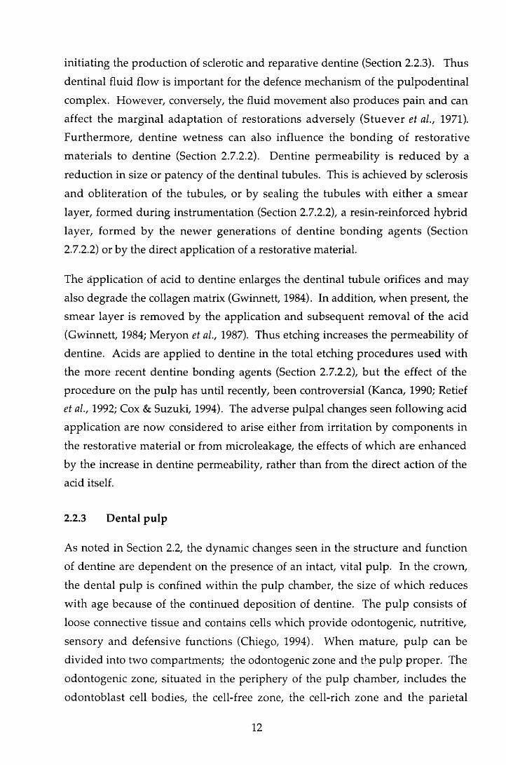
initiating the production of sclerotic and reparative dentine (Section 2.2.3). Thus
dentinal fluid flow is im portant for the defence mechanism of the pulpodentinal
complex. However, conversely, the fluid m ovem ent also produces pain and can
affect the m arginal adaptation of restorations adversely (S tuever et al., 1971).
Furtherm ore, dentine w etness can also influence the bonding of restorative
m aterials to dentine (Section 2.72.2). Dentine perm eability is reduced by a
reduction in size or patency of the dentinal tubules. This is achieved by sclerosis
and obliteration of the tubules, or by sealing the tubules w ith either a sm ear
layer, form ed during instrum entation (Section 2.72.2), a resin-reinforced hybrid
layer, form ed by the new er generations of dentine bonding agents (Section
2.7.22) or by the direct application of a restorative material.
The application of acid to dentine enlarges the dentinal tubule orifices and may
also degrade the collagen matrix (Gwinnett, 1984). In addition, w hen present, the
sm ear layer is rem oved by the application and subsequent rem oval of the acid
(Gwinnett, 1984; M eryon et al., 1987). Thus etching increases the perm eability of
dentine. Acids are applied to dentine in the total etching procedures used with
the m ore recent dentine bonding agents (Section 2.7.2.2), bu t the effect of the
procedure on the pulp has until recently, been controversial (Kanca, 1990; Retief
et al., 1992; Cox & Suzuki, 1994). The adverse pulpal changes seen following acid
application are now considered to arise either from irritation by com ponents in
the restorative m aterial or from microleakage, the effects of which are enhanced
by the increase in dentine permeability, rather than from the direct action of the
acid itself.
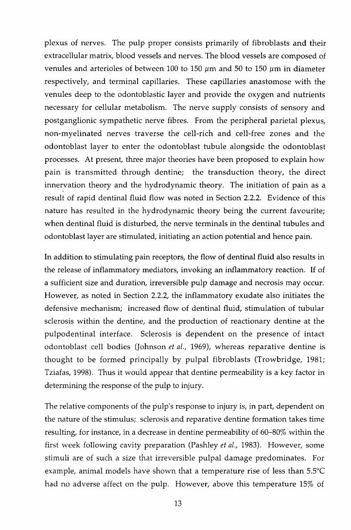
2.2.3 Dental pulp
As noted in Section 2.2, the dynamic changes seen in the structure and function
of dentine are dependent on the presence of an intact, vital pulp. In the crown,
the dental pulp is confined w ithin the pulp chamber, the size of w hich reduces
w ith age because of the continued deposition of dentine. The pu lp consists of
loose connective tissue and contains cells which provide odontogenic, nutritive,
sensory and defensive functions (Chiego, 1994). W hen m ature, pu lp can be
divided into two compartments; the odontogenic zone and the pulp proper. The
odontogenic zone, situated in the periphery of the pulp chamber, includes the
odontoblast cell bodies, the cell-free zone, the cell-rich zone and the parietal
12
plexus of nerves. The pulp proper consists prim arily of fibroblasts and their
extracellular matrix, blood vessels and nerves. The blood vessels are com posed of
venules and arterioles of betw een 100 to 150 /im and 50 to 150 ixm in diam eter
respectively, and term inal capillaries. These capillaries anastom ose w ith the
venules deep to the odontoblastic layer and provide the oxygen and nutrients
necessary for cellular metabolism. The nerve supply consists of sensory and
postganglionic sym pathetic nerve fibres. From the peripheral parietal plexus,
non-m yelinated nerves traverse the cell-rich and cell-free zones and the
odontoblast layer to enter the odontoblast tubule alongside the odontoblast
processes. At present, three major theories have been proposed to explain how
pain is transm itted th rough dentine; the transduction theory, the d irect
innervation theory and the hydrodynam ic theory. The in itiation of pain as a
result of rapid dentinal fluid flow was noted in Section 2.2.2. Evidence of this
nature has resulted in the hydrodynam ic theory being the curren t favourite;
w hen dentinal fluid is disturbed, the nerve terminals in the dentinal tubules and
odontoblast layer are stimulated, initiating an action potential and hence pain.
In addition to stim ulating pain receptors, the flow of dentinal fluid also results in
the release of inflam m atory mediators, invoking an inflam m atory reaction. If of
a sufficient size and duration, irreversible pulp dam age and necrosis m ay occur.
However, as noted in Section 2.2.2, the inflam m atory exudate also initiates the
defensive mechanism; increased flow of dentinal fluid, stim ulation of tubular
sclerosis w ithin the dentine, and the production of reactionary dentine at the
pu lpoden tinal interface. Sclerosis is d ep en d en t on the presence of in tact
odontoblast cell bodies (Johnson et al., 1969), w hereas reparative dentine is
thought to be form ed principally by pu lpal fibroblasts (Trow bridge, 1981;
Tziafas, 1998). Thus it would appear that dentine perm eability is a key factor in
determ ining the response of the pulp to injury.
The relative components of the pulp's response to injury is, in part, dependent on
the nature of the stimulus; sclerosis and reparative dentine form ation takes time
resulting, for instance, in a decrease in dentine permeability of 60-80% w ithin the
first week following cavity preparation (Pashley et al., 1983). H ow ever, some
stim uli are of such a size that irreversible pulpal dam age predom inates. For
example, animal models have show n that a tem perature rise of less than 5.5°C
had no adverse affect on the pulp. However, above this tem perature 15% of
13

pulps w ere found to necrose. This rose to alm ost 100% w ith an increase in
tem perature of 11°C (Zach & Cohen, 1965). It w ould appear therefore that pulp
tissue is sensitive to changes in temperature. This has bearing on the restoration
of teeth since it is essential that cavity preparation and m aterial setting reactions
do not result in tem perature changes in excess of 5.5°C.
2.3 Direct restorative materials
2.3.1 Introduction
On com pletion of the cavity preparation, the tooth is restored. The principal
purposes of restoring a carious tooth are to restore the integrity of the tooth
surface, to prevent further dam age from carious attack and to protect the pulp,
and to im prove function and aesthetics. To achieve this, the restoration m ust seal
the cavity herm etically against the oral environm ent. The ideal m aterial
therefore should:
• not irritate the dental pulp
• adap t well to the cavity wall w ith m inim al shrinkage during the setting
process
• not be adversely affected by moisture
• not exhibit dimensional change after placement in the cavity
• be resistant to attrition
• have the capacity to w ithstand the forces of mastication
• perm it minimal tooth tissue removal for retention purposes
Properties of secondary im portance are the colour and aesthetics, low therm al
conductivity and ease of m anipulation. In short, the m aterial should duplicate
the physicochem ical properties of the virgin tooth. A m aterial that fulfils all
these criteria has yet to be created.
A range of restorative m aterials has been developed. In this study, two direct
restorative m aterials were used and therefore the follow ing review will be
restricted to the consideration of current m aterials and developm ents in this
group.
14

2.3.2 Dental amalgam
Over the last forty years, there have been major advances in the field of direct
restorative materials. However, despite this, dental am algam rem ains one of the
m ost w idely used of the available materials. It is tried and tested, having been
used for m any years (Molin, 1992), and provides the s tan d ard for several
param eters against which all direct filling materials are compared.
Am algam is produced at the chairside by mixing liquid m ercury w ith am algam
alloy; a com bination of silver, tin, copper and som etim es zinc, palladium ,
indium , and selenium. W hen freshly titurated it is reasonably easy to use; it has
a plasticity that perm its convenient packing into a cavity and is not overly
technique-sensitive. W hen used under the correct clinical conditions, am algam
restorations m aintain anatomical form and have a reasonably adequate resistance
to m arginal fracture. In addition, they exhibit reduced m arginal leakage over
time because of the production of corrosion products (Pickard & Gayford, 1965)
and exhibit reasonable longevity. Furtherm ore, w hen com pared w ith other
direct materials, the material is inexpensive.
However, there are drawbacks to dental amalgam. It exhibits a brittleness and
toughness that are less than desirable. It is also subject to corrosion and galvanic
action: while corrosion initially reduces microleakage, prolonged corrosion will
result in m arginal breakdow n. This is exacerbated by the lack of adhesion to
tooth structure. In the past, it was thought that galvanic action was responsible
for the post-operative sensitivity experienced after the placem ent of some
am algam restorations, bu t this is now not considered an aetiological factor.
W hilst this has been of concern to the dental profession, the reported cases of
am algam toxicity related to oral galvanism and corrosion have been of greater
public concern (Molin, 1992). The validity of the claims relating to am algam
toxicity has been refuted. However, despite this several countries have placed
restrictions on the use of the material. This, and the ever increasing patien t
expectation for tooth-coloured fillings (Roulet, 1988), has added w eight to the
need for a strong aesthetic replacement for amalgam.
There are currently four categories of direct aesthetic filling m aterials on the
market; composite resins, glass-ionomer cements, resin-modified glass-ionomer
15
cements and polyacid-modified resins. While the m aterials are considered here
as four separate material types, on the basis of their setting reactions they can be
thought of as providing a continuum (Burgess et ah, 1996).
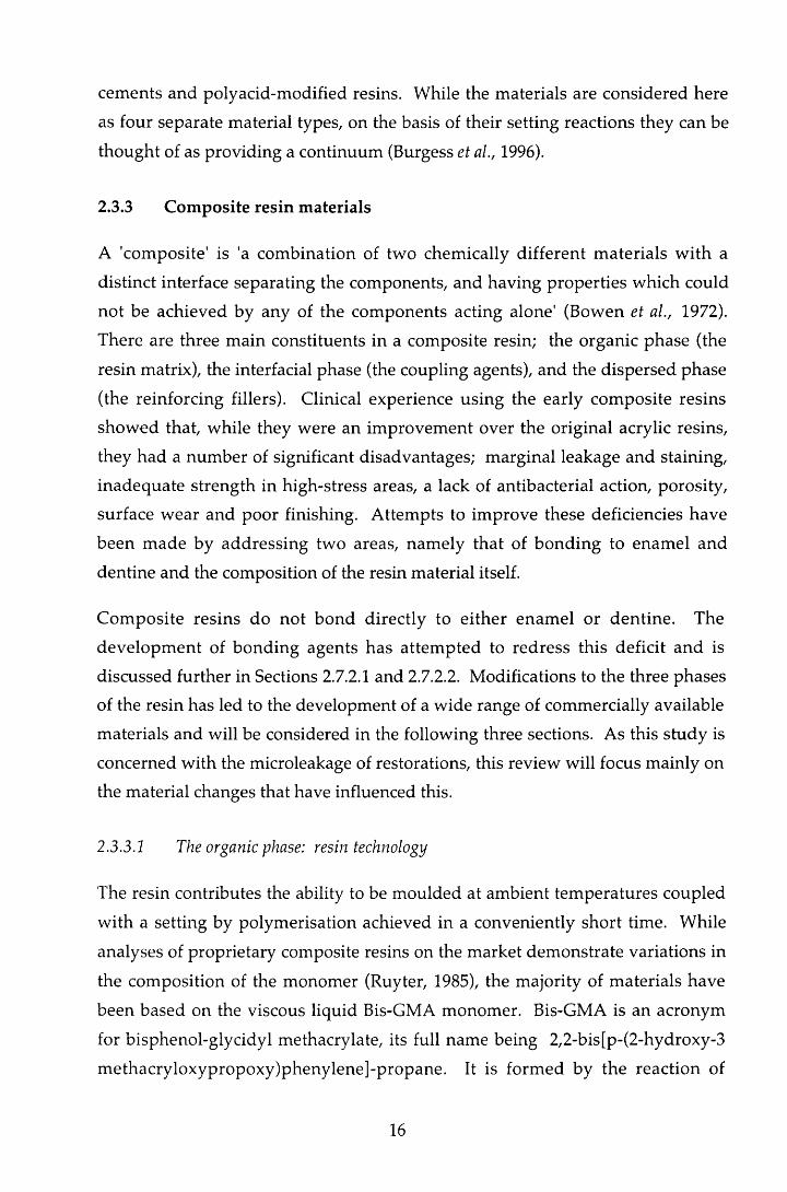
2.3.3 Composite resin materials
A 'com posite' is 'a com bination of two chemically different m aterials w ith a
distinct interface separating the components, and having properties which could
not be achieved by any of the com ponents acting alone' (Bowen et al., 1972).
There are three m ain constituents in a composite resin; the organic phase (the
resin matrix), the interfacial phase (the coupling agents), and the dispersed phase
(the reinforcing fillers). Clinical experience using the early com posite resins
show ed that, while they were an im provem ent over the original acrylic resins,
they had a num ber of significant disadvantages; m arginal leakage and staining,
inadequate strength in high-stress areas, a lack of antibacterial action, porosity,
surface w ear and poor finishing. A ttem pts to im prove these deficiencies have
been m ade by addressing two areas, nam ely that of bonding to enam el and
dentine and the composition of the resin material itself.
Com posite resins do not bond directly to either enam el or dentine. The
developm ent of bonding agents has attem pted to redress this deficit and is
discussed further in Sections 2.7.2.1 and 2.7.2.2. Modifications to the three phases
of the resin has led to the development of a w ide range of commercially available
materials and will be considered in the following three sections. As this study is
concerned with the microleakage of restorations, this review will focus mainly on
the material changes that have influenced this.
2.3.3.2 The organic phase: resin technology
The resin contributes the ability to be m oulded at am bient tem peratures coupled
w ith a setting by polym erisation achieved in a conveniently short time. While
analyses of proprietary composite resins on the m arket dem onstrate variations in
the composition of the monom er (Ruyter, 1985), the majority of m aterials have
been based on the viscous liquid Bis-GMA monomer. Bis-GMA is an acronym
for bisphenol-glycidyl methacrylate, its full name being 2,2-bis[p-(2-hydroxy-3
m ethacryloxypropoxy)phenylene]-propane. It is form ed by the reaction of
16

b isp h en o l A and glycidyl m ethacry late and is a b ifunctional arom atic
dim ethacrylate w ith two phenyl groups to increase the rigidity of the molecule,
and hydroxyl groups w hich are though t to p rov ide som e in term olecu lar
hydrogen bonding. The large molecular size and chemical structure of Bis-GMA
results in the production of a resin w ith lower volatility and polym erisation
shrinkage, m ore rapid hardening and the production of a stronger, stiffer resin
w hen com pared to the earlier materials based on m ethylm ethacrylate. Blending
of the filler particles is difficult because of the viscosity of the m aterial and
therefore, a fluid diluent m onom er such as triethylene glycol dim ethacrylate
(TEGMA) or ethylene glycol dim ethacrylate (EGMA) is used to reduce the
viscosity. TEGMA is the most commonly used. However, because of its lower
m olecular w eight, it also increases the polym erisation shrinkage (Davidson,
1986). A balance between the need for an increased filler content and im proved
han d lin g characteristics, against the de trim en tal effect of the increased
contraction on curing is therefore necessary.
O ther m onom er systems have been used in which all, or part of, the Bis-GMA
has been replaced by aliphatic or aromatic urethane dimethacrylates. These have
a low er viscosity, low er w ater absorption, greater toughness and greater
response to UV or visible light curing (Peutzfeldt, 1997).
The degree of polymerisation is crucial to the clinical performance of any resin
system and is dependent on the conversion percent of double bonds and the
netw ork formation. This is influenced by two factors; the type of resin in the
organic matrix and the mode of curing.
The size of the Bis-GMA monomer molecule coupled with the rapid increase in
viscosity means that reactive methacrylate groups find it increasingly difficult to
m igrate to the reaction site, w ith the result that a relatively high concentration of
acrylate or dim ethacrylate groups rem ain unreacted after setting. W hile this
reduces the contraction due to polymerisation, it also has a detrim ental effect on
the m echanical properties of the m aterial (Asmussen, 1982). The add ition of
carboxylic anhydrides (Peutzfeldt & Asmussen, 1991), aldehydes (Peutzfeldt &
Asmussen, 1992a) and ketones (Peutzfeldt & Asmussen, 1992b), the use of heat
treatm ent (Bausch et a l, 1981) and spiro-orthocarbons which expand on curing
17

(Cook et a l, 1984) and curing under a continuous stream of argon (Rueggeberg &
Margeson, 1990) have all been found to increase the degree of polymerisation.
The conversion of the oligomers or monomers to the polym er m atrix occurs by
free-radical addition polym erisation. In the early com posite resins, this was
initiated by chemical or photochemical means, the latter using light in the UV
range (Craig, 1981). H ow ever, since the late 1970s, polym erisation of the
m ajority of new composite resins has been achieved w ith light in the visible
spectrum . In these m aterials the initiator com prises a m ixture of a diketone,
com m only cam p h o rq u in o n e , and an am ine red u c in g a g en t such as
d im ethylam inoethyl m ethacrylate or dim ethyl-p-toludine (Taira et al., 1988).
C am phoquinone rapidly forms free radicals in the presence of the am ine and
light in the blue region of 470 nm. Materials are dispensed in pots, syringes or
compules. The w avelength initiating polym erisation is in the spectrum which
has been implicated in retinal damage (400-500 nm) and there was initial concern
that this m ight pose a health risk to operators (Davidson, 1985; Ellingson et al.,
1986). However, Moseley et al (1987) found that an exposure of betw een 40 and
100 m inutes per day was required before the risk of visual dam age w as
significant. These light cured m aterials offered several advantages over those
that were chemically cured. A summ ary of these is given in Table 2.2.
2.3.3.2 The dispersed phase: filler technology
The m ost significant changes in the commercial com posites have been m ade
th rough alterations in the filler com ponent. The filler contributes several
beneficial characteristics to the mechanical, thermal, and physical properties of
the polymer; rigidity, hardness, strength and m odulus of elasticity are increased
and the coefficient of thermal expansion and degree of polym erisation shrinkage
are reduced. In addition, a translucent filler enhances the optical properties of
the resin. These factors are controlled by the type, concentration, particle size
and distribution of the filler and to date six categories have been defined (Lutz &
Phillips, 1983; Bayne et a l, 1994). These are described in Table 2.3. The fillers
have generally been made from m ined m inerals or m elted glasses. However,
more recently, filler particles have been produced by a synthetic sol-gel process.
This process is one in which a metal carboxylate and a metal oxide sol are mixed
18
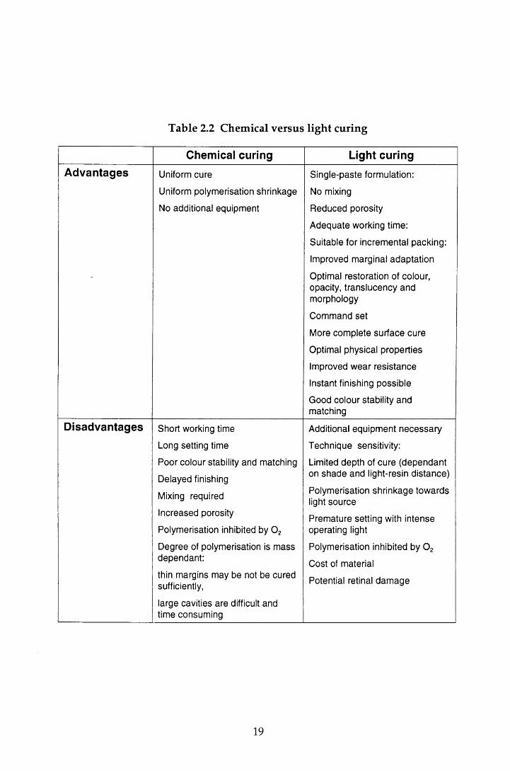
Table 2.2 Chemical versus light curing
Chemical curing Light curingAdvantages Uniform cure
Uniform polymerisation shrinkage
No additional equipment
Single-paste formulation:
No mixing
Reduced porosity
Adequate working time:
Suitable for incremental packing:
Improved marginal adaptation
Optimal restoration of colour, opacity, translucency and morphology
Command set
More complete surface cure
Optimal physical properties
Improved wear resistance
Instant finishing possible
Good colour stability and matching
Disadvantages Short working time
Long setting time
Poor colour stability and matching
Delayed finishing
Mixing required
Increased porosity
Polymerisation inhibited by 0 2
Degree of polymerisation is mass dependant:
thin margins may be not be cured sufficiently,
large cavities are difficult and time consuming
Additional equipment necessary
Technique sensitivity:
Limited depth of cure (dependant on shade and light-resin distance)
Polymerisation shrinkage towards light source
Premature setting with intense operating light
Polymerisation inhibited by 0 2
Cost of material
Potential retinal dam age
19
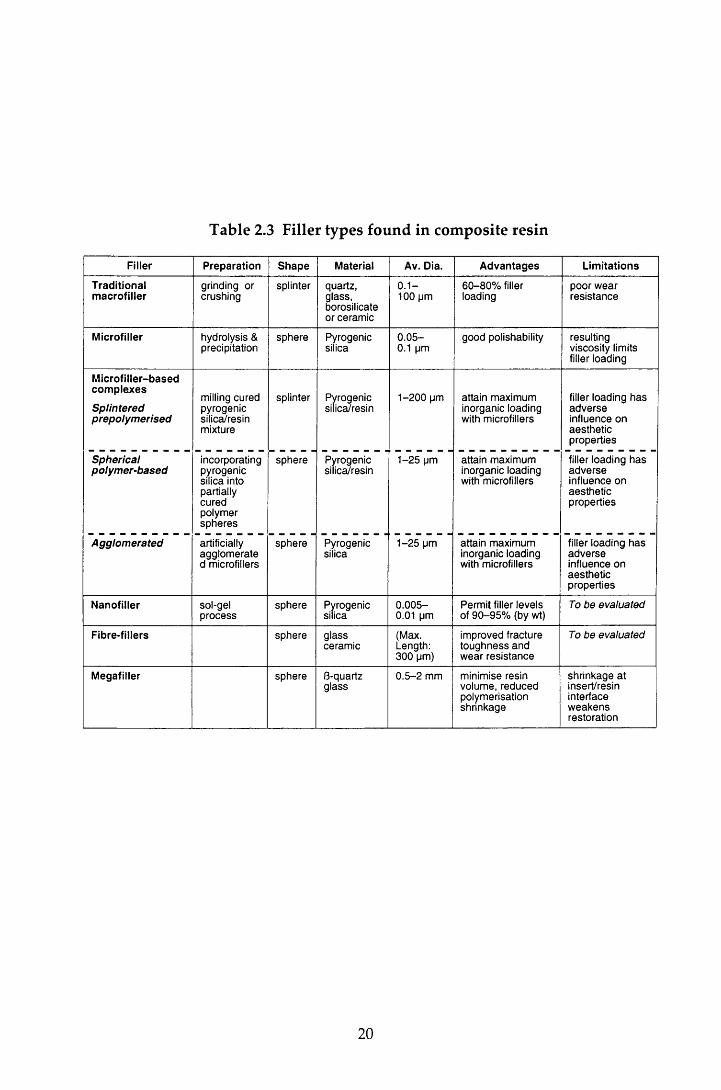
Table 2.3 Filler types found in composite resin
Filler Preparation Shape Material Av. Dia. Advantages Limitations
Traditionalmacrofiller
grinding or crushing
splinter quartz, glass, borosilicate or ceramic
0 .1 - 100 pm
60-80% filler loading
poor wear resistance
Microfiller hydrolysis & precipitation
sphere Pyrogenicsilica
0 .05- 0.1 pm
good polishability resulting viscosity limits filler loading
Microfiller-basedcomplexes
Splinteredprepolymerised
milling cured pyrogenic silica/resin mixture
splinter Pyrogenicsilica/resin
1-200 pm attain maximum inorganic loading with microfillers
filler loading has adverse influence on aesthetic properties
Sphericalpolymer-based
incorporatingpyrogenicsilica intopartiallycuredpolymerspheres
sphere Pyrogenicsilica/resin
1-25 pm attain maximum inorganic loading with microfillers
filler loading has adverse influence on aesthetic properties
Agglomerated artificially agglomerate d microfillers
sphere Pyrogenicsilica
1-25 pm attain maximum inorganic loading with microfillers
filler loading has adverse influence on aesthetic properties
Nanofiller sol-gelprocess
sphere Pyrogenicsilica
0 .005- 0.01 pm
Permit filler levels of 90-95% (by wt)
To be evaluated
Fibre-fillers sphere glassceramic
(Max. Length: 300 pm)
improved fracture toughness and wear resistance
To be evaluated
Megafiller sphere 8-quartzglass
0.5 -2 mm minimise resin volume, reduced polymerisation shrinkage
shrinkage atinsert/resininterfaceweakensrestoration
20
and form a gel by dehydration. The gel is heat treated and then ground to
produce fillers (Ferracane, 1995).
Several classifications of composite resin have been described (Lutz & Phillips,
1983; Willems et a l, 1992; Bayne et a l, 1994), based on the filler particle size and
loading (Figure 2.1). The traditional (conventional) com posites were sim ply a
m ixture of trad itional m acrofiller particles and resin m onom ers. The early
m aterials contained filler particles in the range of 1-50 jim. However, as milling
procedures have been refined, the range of sizes has increased to 0.1-100 j/m.
Q uartz was popular in these materials because of its chemically inert nature and
its favourable index of refraction (Bowen, 1979). However, its hardness m ade it
difficult to make fine particles and gave problems in composite polishing. This,
com bined w ith the radiolucent nature of the m aterial and relatively high
coefficient of expansion (Bowen, 1979), led to the demise of quartz as a filler and
to the use of glass fillers. These contributed to the radiopacity of the restoration
and, being softer than quartz , facilitated fine filler p roduction . W hile
polym erisation shrinkage was reduced, the sm ooth surface hydrolysis of the
interfacial bonds and w ear of the resin m atrix resu lted in p ro tru sio n and
eventual loss of the filler (Lambrechts et a l, 1982) and thus the w ear resistance of
these materials posed a severe limitation.
Since the early m aterials, composites have tended tow ards a decrease in filler
size. The hom ogenous m icrofilled com posite was in troduced in 1977, and
contained microfillers, extremely small diam eter silica particles (0.01 -0.1 jum).
The size of the particles, while giving a m aterial which could be polished to a
high lustre, lim ited the filler loading because of the increased viscosity of the
resin. To overcome this, an indirect m ethod of filler blending was introduced;
prepolym erised blocks of resin containing a high filler loading of silica were
g round to produce filler particles of 5-30 jum diam eter (Willems et a l, 1992).
These w ere b lended w ith resin and m ore silica filler to produce the final
heterogeneous microfilled resin (Soderholm, 1985). However, despite this, very
few of these materials attained a 50% loading (Willems et a l, 1992). The m aterials
had excellent aesthetics w ith good polishability. However, they exhibited poorer
physical properties, including a greater polym erisation shrinkage, than the
conventional composites (Lutz & Phillips, 1983).
21
To combine the physical properties of the macrofillers w ith the polishabililty of
the microfillers, hybrid m aterials were developed. These contained a blend of
conventional barium or strontium glass particles, together w ith some subm icron
particulate silica. The early hybrid materials used filler loadings of about 75% of
the m acrofiller particles (1-50 //m) and 8% of the subm icron size (average
0.04 ^m), and in so doing, achieved a total filler of 83% or greater (McCabe, 1990).
M ore recently there has been a tendency tow ards sm aller conventional filler
particles of less than 1 jum diam eter (Willems et al., 1992). While the use of the
microfillers reduces the wear difference between the conventional fillers and the
matrix, the surface of hybrid restorations is not as smooth nor as w ear resistant as
the heterogeneous microfilled materials (Lutz & Phillips, 1983).
C urrent m aterials are sophisticated formulations w ith a broad range of particle
sizes and filler loadings. The new er m aterials contain a sm aller m ean particle
size and have fewer of the macrofillers than the composites of a decade ago. The
majority of the current materials in commercial use are 'hybrid' m aterials of two
size ranges (Ferracane, 1995) and are classified as m id-way filled and compact-
filled w ith classifications of ultrafine and fine in each (Figure 2.1)(Willems et a l,
1992).
Overall, the trend in fillers in composite resins has been from relatively low to
high filler loadings, large to small particle size, and from hard to relatively soft
fillers. However, despite these changes, the problem of polym erisation shrinkage
still rem ains a concern. Providing the increase in viscosity does not have an
adverse effect, an increase in filler loading reduces the polym erisation shrinkage.
H ow ever, Shen and Sarrett (1992) dem onstrated that w hen the degree of
polym erisation shrinkage was the same, the resin composite w ith the lower filler
content was able to delay microleakage longer than the m aterial w ith the higher
filler content.
In an attem pt to further reduce the degree of polym erisation shrinkage, recent
research has focused on the developm ent of experim ental resins containing
nanofillers (Table 2.3). These fillers perm it overall filler levels of 90-95% by
weight and as a result there is a significant reduction in polym erisation shrinkage
w hen com pared to other composite resins (Bayne et a l , 1994). O ther recent
23
studies, in contrast to the trend of using fillers of decreasing size, have used glass
fibres as reinforcing fillers and have reported im provem ents in the fracture
toughness and wear resistance of the material (Li et a l, 1993)
A n a lte rn a tiv e to conven tional com posites w hich re su lts in red u ced
polym erisation shrinkage (Donly et a l, 1989; George & Richards, 1993) and
red u ced m icroleakage (Bowen & Setz, 1986) has also been developed .
'Megafilled' composite restorations are produced by filling the bulk of the cavity
w ith one of a num ber of shapes and sizes of beta-quartz glass inserts. The inserts
are su rrounded by light cured composite and bond to the resin via a silane-
coupling agent.
2.3.3.3 The interfacial phase: coupling agents
The bond between the filler and resin matrix is essential for m axim um physical,
m echanical and optical properties. Two m odes of bonding have been used;
m icromechanical and more commonly, chemical. In the former, a porous filler
surface is produced by either etching w ith strong acid (Bowen & Reed, 1976) or
sin tering the particles together (Ehrnford, 1983). The m echanical bond is
achieved by resin flow into the porosities.
Chemical bonding involves the coating of the filler particle w ith a coupling
agent. The m ost commonly used agent is y-methacryloxypropyltrimethoxy silane
(Soderholm, 1985). This is a bifunctional molecule; a methacylate group at one
end of the molecule bonds covalently w ith the resin, and a silane group at the
other end is capable of bonding ionically w ith the filler. A bifunctional coupling
agent cannot be used for microfilled composites because of the organic nature of
the filler. In these materials bonding occurs by polymerisation. However, there
is a tendency for the bond strength to be poor because there are very few
m ethacylate molecules available in the highly cured filler, and micromechanical
entanglem ent of matrix into filler is limited because of the viscosity of the matrix.
2.3.4 G lass-ionom er cements
D erived from silicate cements and polycarboxylate m aterials, glass-ionom er
cem ent has been available since 1975 and, until recently, was the only truly
chemically adhesive filling material available in dentistry. It sets via an acid-base
24
reaction betw een ion-leachable calcium alum inium fluorosilicate glass pow der
and the polym ers and copolym ers of acrylic and maleic acid. The precise
m echanism of bonding to enam el and dentine is unclear, bu t the m ost likely
theory is that it is achieved via ionic bonding of carboxylate groups in the cement
to apatite calcium ions, resulting in an ion-exchange layer betw een the cement
and the dentine. This mechanism w ould account for the greater bond strength
found w ith enamel (5 MPa) than with dentine (1-3 MPa). The bond forms in the
presence of w ater but is not stable and breaks down. However, it re-forms over
and over again, thus providing a dynamic bond betw een the tooth and cement
(Ellis et al., 1990). Additional bonding between the carboxylic acid groups of the
glass-ionomer cement and the reactive groups w ithin the dentine collagen, either
by hydrogen bonding or by metallic ion bridging, has been suggested (Craig,
1997). The setting reaction occurs in four stages; salt form ation, so l/g e l
formation, hardening (continuation of the so l/gel formation), and hydration with
w ater bound to a salt, acid groups and a gel (Wilson & McLean, 1988). This
reaction is dem onstrated by the presence of a clearly identified ion exchange
layer adjacent to the dentine in desiccated specimens.
The m aterial is dispensed as either a pow der and liquid or in an encapsulated
form. In the earliest materials, the polymer acid was incorporated in the liquid,
and the glass pow der m ade up the pow der. More recently, the handling
properties have been im proved by blending freeze-dried polym er acid and
tartaric acid w ith the glass powder, which is then mixed w ith water.
W hile the cem ents exhibit a degree of polym erisation shrinkage sim ilar to
composite resins, it occurs over a longer period of time and is com pensated for
by flow. It is therefore of less significance than the contraction experienced by
the resins. This, plus their coefficient of thermal expansion (8 -16 ,10'6 “C '1) which
is similar to that of tooth structure (8-11, 10'6 “C '1) has resulted in a m aterial that
exhibits little microleakage when compared to the composite resins (M ohanda &
Reddy, 1993). In addition, the cement matrix contains significant quantities of
fluoride ions that readily diffuse to the surface of the restoration. The fluoride
ions are either w ashed away by the saliva, or undergo a reaction w ith the
surrounding tooth substance, thereby increasing the acid resistance of the tissue
(Mukai et al., 1993). The low incidence of leakage and the slow release of fluoride
w ould suggest that glass-ionomer restorations were less likely to be subject to
25
caries. Indeed, several clinical investigations found that secondary caries rarely
developed adjacent to glass-ionom er m aterials (Knibbs, 1988; Mejare & Mjor,
1990). H ow ever, these studies w ere of short duration, and m ore recently,
secondary caries has been reported as the m ain reason for the replacem ent of
glass-ionom er restorations in general practice (Mjor, 1996; W ilson et a l, 1997).
Nevertheless, the bonding to enamel and dentine and the low microleakage are
favourable properties. In spite of this, the clinical applications of glass-ionom er
cem ents are lim ited because of their prolonged setting tim e w hich delays
finishing and polishing for approximately 24 hours, their sensitivity to m oisture
d u rin g in itia l harden ing , dehydration , their rough surface tex tu re an d
opaqueness, and their inferior strength and wear resistance.
2.3.5 Resin-modified glass-ionomer cements
The resin-m odified m aterials are a variant of the glass-ionom er m aterial and
w ere developed to im prove the handling and w orking characteristics of the
original form ulation, while utilising some of the advantageous properties of
composite resin. They are fluoride-releasing, m ulti-cured m aterials and are m ore
aesthetic and less technique sensitive than the conventional glass-ionomers. The
m aterials are predom inantly glass-ionomer, up to 80%, w ith 20% light-cured
resin and they are dispensed as two com ponent systems. The pow der is similar
to the pow der in conventional glass-ionom er system s, b u t the liquid is
hydroxyethylm ethacrylate (HEMA), w ater and a polyacid, w ith or w ithou t
pendant m ethacrylate groups. The setting reaction occurs in two stages. The
first, an acid-base reaction, produces a gel through polyvalent m etal-ion cross-
linking of the polyacid-sol. W hen placed on the tooth, free carboxylate groups
form a dynam ic bond w ith apatite. The second stage involves a photoinitiated
setting reaction betw een methacrylate molecules grafted on to the polyacrylic
acid chain and the m ethacrylate groups of the HEMA or polyHEM A. The
resultan t cross-linking causes rapid hardening and increased strength to the
material. In addition, some materials such as Vitremer (3M Dental Products, St
Paul, MN, USA) exhibit a third setting reaction. This material has an auto-cure
initiator-catalyst system for resins which starts w hen the pow der and liquid
ingred ien ts are m ixed together (Christensen, 1997). In com m on w ith the
26
conventional m aterials, desiccated specim ens show a well de lineated ion
exchange layer at the dentine interface (Hallett & Garcia-Godoy, 1993).
Resin m odified glass-ionom er m aterials have significantly better m echanical
p roperties, low er w ater solubility and m oisture sensitiv ity and reduced
brittleness than the conventional glass-ionom er m aterials. They also exhibit
com parable fluoride release (Forsten, 1995) and im proved bond strengths to
dentine (Lin et al., 1992). However, one distinct disadvantage of these m aterials
is their lim ited light-curing depth. The m axim um depth of cure is 2 m m and
therefore renew ed mixing may be necessary for materials dispensed as a pow der
and liquid w hen the material is used in deeper layers.
2.3.6 Polyacid-modified composite resins
The polyacid-m odified composite resins (compomers), introduced in 1991 as a
one-paste restorative material avoided the necessity of renewed mixing for large
cavities. Like the resin-m odified glass-ionomer cements, com pom ers combine
the favourable properties of the base material, in these materials, composite resin,
w ith those of the glass-ionomer cements. They are used in com bination w ith a
fifth generation dentine bonding agent, and therefore avoid the tim e-consum ing
techniques of the fourth generation agents.
There has been considerable confusion in the pub lished lite ra tu re over
nom enclature, w ith resin-m odified glass-ionom er cem ents referred to as
com pom ers and vice versa. McLean et al (1994) distinguished the two m aterials
by their setting characteristics. They noted that while both had an acid-base
setting reaction, the reaction for the com pom ers was not sufficient to allow
curing in the dark and therefore these materials relied on photopolym erisation to
achieve adequate curing. Moreover, these m aterials lacked the ion-exchange
bonding mechanism seen with the resin-modified glass-ionomer materials.
Containing approximately 30% glass-ionomer cement, compomers are prim arily
light-cured, low fluoride-releasing com posite resins w ith single com ponent
bonding systems. Bonding is achieved by the form ation of a hybrid layer w ith
m odification of the smear layer. In addition to this micromechanical retention,
adhesion via ionic bonds between phosphate groups in the prim er and calcium
27
ions in hydroxyapatite is also claimed for some materials, though it is not found
w ith the com pom er m aterial used in this study The m aterials also have good
handling characteristics and excellent colour matching.
Burgess et al (1996) com pared the mechanical properties of the current direct
aesthetic m aterials. W hilst the com pom er m aterials had im proved m echanical
properties over the conventional glass-ionomer cements and the resin-m odified
m aterials, they exhibited greater polym erisation shrinkage (% volum e). In
addition, the polym erisation shrinkage and w ear of the material did not compare
favourably to that of the composite resin materials. Therefore, w ith the exception
of selected clinical situations in the perm anent dentition, these m aterials are
usually recom m ended for the restoration of prim ary teeth only. Use in the
p erm an en t den tition is restricted to resto rations in low -stress areas and
provisional Class I and Class II restorations. Furthermore, in com m on w ith the
composite resins, the use of compomers is limited to areas which can be reached
by polymerising light.
2.3.7 The causes of restoration failure
The purpose of restoring a carious tooth and the ideal p roperties of direct
restorative materials were outlined in Section 2.3.1. In addition to these criteria,
it is essential that the restoration is durable. Studies investigating the reasons for
failed resto ra tions have frequently recorded d isco loration and m ateria l
degradation. The incidence of these findings has decreased as the quality of the
m aterials has im proved (Kidd et a l, 1992). However, the m ost com m on reason
cited for the replacem ent of restorations round the w orld is secondary caries
(Kidd et ah, 1992; Mjor & Toffenetti, 1992; Mjor & Um, 1993; Friedl et al., 1995;
Mjor, 1996; Wilson et a l, 1997).
Histological examination of the secondary carious lesion reveals two regions; the
'outer lesion' in the surface enamel, formed as a result of prim ary attack, and the
'wall lesion' formed in the cavity wall (Hals & Nernaes, 1971). The wall lesion is
form ed as a result of the flow of bacteria, fluids, ions and molecules etc. between
the cavity wall and the restoration. This flow, know n as m icroleakage, is
clinically undetectable. In addition to the developm ent of secondary caries,
m icroleakage has also been im plicated in the developm ent of d iscoloured
28

m argins, pulpal changes, and post-operative sensitivity (Brannstrom & Nyborg,
1972; Bauer & Henson, 1984; Brannstrom, 1986). It is essential therefore, that
microleakage is controlled if the long-term integrity of the restoration is to be
assured.
2.4 Microleakage
Microleakage arises because of the presence of a microspace (marginal gap) at the
cavity w all/re sto ra tio n interface (CRI). This gap is form ed as the resu lt of
dim ensional instability arising from polym erisation shrinkage, differences in the
coefficients of therm al expansion between the restorative material and the tooth,
and the lack of complete adaptation and adherence of the m aterial to the cavity
wall (Browne & Tobias, 1986). Thus m aterial and cavity p reparation factors
influence the degree of microleakage seen at the CRI.
In this study, microleakage is used to evaluate the influence cavity preparation
w ith the Erbium:YAG (Er:YAG) laser has on the seal of Class V composite and
com pom er restorations. The literature covering microleakage is im m ense and
therefore, unless otherwise indicated, the following review will be confined to
the assessm ent of composite and compomer restorations in Class V cavities, the
restorations under investigation in this study.
2.5 Methods of assessing microleakage
2.5.1 Introduction
A test for microleakage should fulfil certain criteria: it should be relatively
inexpensive, require minimal specialist equipm ent and should be technique and
operator insensitive. In addition, the test should provide a m easure that is both
clinically relevant and representative of the cavity as a w hole. Finally,
longitudinal assessm ent should be possible. That the ideal test has yet to be
found is reflected in the wide range of tests reported in the literature. To date,
the m arginal gap at the CRI has been assessed by m easuring the penetration of
tracer molecules and bacteria, and the flow of fluids or an electric current along
the CRI, by visual examination of the CRI, or by simulation of the carious lesion.
29
All m eet certain of the criteria, but none provide the 'ideal' test. In this study,
m icroleakage w as assessed by m easuring the penetration of an organic dye,
m ethylene blue, along the CRI. A detailed review of the other techniques is
beyond the scope of this thesis. However, a sum m ary of their advantages and
disadvantages is given in Table 2.4.2.5.2 Penetration of tracer moleculesStudies involving the use of tracer molecules are the most commonly reported in
the field of microleakage. Four types of tracer have been described; organic dyes,
radioactive isotopes, non-radioactive chemical tracers and neutron activated ions.
The latter is an expensive technique and is rarely used. The review of the
technique has therefore been lim ited to the sum m ary of its advantages and
disadvantages found in Table 2.4.
Variations in experim ental m ethodology have been reported for the other three
types of tracer, and there are also differences in the way in which the leakage is
assessed. However, by far the most recent reported studies have used an in vitro
im m ersion method: following preparation, the restored tooth is sealed by wax or
nail varnish leaving a w indow surrounding the restoration. It is then im m ersed
in the tracer solution for a predeterm ined period, before being rinsed and
assessed for microleakage. A variety of leakage 'scoring' m ethods have been
used. The most common m ethod of evaluating leakage for dye, and indeed the
m ethod used in this study, has been to m easure the tracer penetration along the
CRI in one plane of section. There are inherent errors in this which are common
to the three tracer techniques and it is therefore pertinent to consider these before
describing the individual techniques.
2.5.2.1 Single section assessment of microleakage
Following dye immersion, the tooth is sectioned through the m id-point of the
restoration and each section is exam ined under magnification. The leakage is
either m easured w ith a measuring ocular, or is assigned a numerical score which
increases w ith the degree of leakage. Several scoring system s have been
described. Routinely, both sections are scored and the w orst score is taken for
each margin.
30

Table 2.4 A summary of the advantages and disadvantages of some
microleakage tests
Technique Advantages Disadvantages
Penetration of bacteria
a . Culturing techniques
b. H is tobacterio log ica l techn iques
Of s o m e clinical re le v a n c e
P u n c h sam p lin g p e rm its a n a ly s is of s e v e ra l p o in ts a lo n g th e CRI of to o th se c tio n s
T o o th se c tio n in g is n o t re q u ire d for all te c h n iq u e s
A s s e s s e s th e viability of b a c te r ia
In vivo m a tu rin g is p o ss ib le
O f s o m e clinical re le v a n c e
M e a s u re s d e p th of p e n e tra tio n
In vivo m a tu rin g is p o ss ib le
R e q u ire s p e c ia lis e d te c h n iq u e s a n d e q u ip m e n t, a n d a tra in e d m icrob io log ist
Q u a lita tiv e m e a su r e : th e p r e s e n c e o r a b s e n c e of b a c te r ia /c lo u d in g
on ly a c c o u n ts for g a p s of > 0 .5 - 1 .0 pm
O rigin of b a c te r ia is n o t d e f in e d
S tr in g e n t sterility co n d itio n s re q u ire d
A ntibac te ria l p ro p e rtie s of m a te r ia ls will in flu en c e re s u lts
A s for cu ltu ring te c h n iq u e s , a n d :
S p e c im e n sac rifice is n e c e s s a r y a n d se ria l e x tra c tio n s re q u ire d
G ram n e g a tiv e b a c te r ia m a y n o t b e read ily d e te c te d
M ay no t d e te c t all ty p e s of o rg a n is m s
Viability of b a c te r ia is no t a s s e s s e d
B a c te ria m ay b e lost du rin g p ro c e s s in g
Artificial caries C linically re le v a n t te s t S u b je c tiv e m e a s u r e m e n t (d e p th of cavity)
S p e c im e n sac rifice is m a n d a to ry a n d th e re fo re long itud ina l a s s e s s m e n t is no t p o ss ib le
P ro c e s s Is tim e co n su m in g a n d re q u ire s sp e c ia lis t e q u ip m e n t
L im ited u s e with a c id -e tc h e d re s to ra tio n s ; m ild d e m in e ra lis a tio n s e e n with ac id e tc h in g h a s a sim ilar m ic ro sc o p ic a p p e a r a n c e to a r e a s of d e m in e ra lis a tio n s e e n in e a rly c a r io u s le s io n s r e s u lts in difficulties in in te rp re ta tio n
Neutron activation a n a ly sis
P ro v id e s a q u a n tita tiv e a n a ly s is for in vitro a n d in vivo m a tu rin g s tu d ie s
T e c h n iq u e is costly , h a z a rd o u s a n d re q u ire s sp e c ia lis t e q u ip m e n t a n d n u c le a r e n g in e e r s
T h e a r e a of le a k a g e is no t d e f in e d a n d a b so rp tio n of th e t ra c e r a t s i te s o th e r th a n th e re s to ra tiv e m a rg in s c a n n o t b e d is tin g u ish e d
In vivo im m ersio n re q u ire d s in g le -s ta n d in g te e th
Flow of flu ids or electrica l current
a. A ir p ressure
b. L iqu id p ressure
c. E lectrochem ica l
L ongitudinal a s s e s s m e n t p o ss ib le s in c e sp e c im e n sac rifice is u n n e c e s s a r y
Q u a n tita tiv e a n a ly sis .
L e ss v u ln e ra b le to p re p a ra tio n e r ro rs w hen c o m p a re d to t ra c e r m e th o d s
le a k a g e a s s e s s m e n t no t lim ited to a p la n e of se c tio n
A s a b o v e
A s a b o v e
P o ss ib le to v isu a lis e le a k a g e with a dye.
S im u la te s fluid sh ifts d u e to p e rm e ab ility of d e n tin e fo u n d in vivo
A s a b o v e
N o d ry ing effec t
D irection of le a k a g e is th e r e v e r s e to th a t s e e n clinically a n d th e re fo re 'blind- e n d in g ' l e a k a g e c h a n n e ls a r e no t d e te c te d — m a y u n d e r - re p re s e n t m ic ro le a k a g e
S p e c ia lis t e q u ip m e n t is re q u ire d
In vivo in v estig a tio n is no t p o ss ib le
p a s s a g e of air p re v e n ts th e s ta g n a tio n w hich m a y b e e x p e c te d clinically a lo n g th e CRI a n d m ay h a v e a d ry ing effec t o n th e to o th a n d re s to ra tio n . M ay g e t le a k a g e of a ir th ro u g h clinically s o u n d to o th t is s u e . L e a k a g e is difficult to lo ca lise a n d p h o to g ra p h
V aria tio n s in d e n tin e p e rm e ab ility b e c a u s e of a g e in g , follow ing cavity p re p a ra tio n a n d in ter-too th v a ria tio n s
E n am e l, d e n tin e a n d m ate ria l c o n d u c ta n c e m a y in flu en c e re su lts
D o e s n o t d iffe ren tia te b e tw e e n c o n d u c ta n c e a t CRI a n d within too th s u b s ta n c e a n d re s to ra tiv e m a te r ia ls
Visual exam ination
a. Light re flected m icroscopy
b. Scanning e lectron m icroscopy
O b s e rv e s a d a p ta tio n of re s to ra tiv e m ateria l
L ongitudinal a s s e s s m e n t is p o ss ib le if lim ited to th e m arg in a l g a p a t th e e n a m e l su rfa c e only
P h o to g ra p h s p ro v id e a p e rm a n e n t re c o rd of g a p s iz e
V isualisa tion of g a p c a n b e e n h a n c e d by u s e of f lu o re sc e n t re sin
In vivo a n d in vitro a s s e s s m e n t of e x te rn a l su rfa c e of re s to ra tio n is p o s s ib le with th e u s e of re p lic as
G re a te r d e p th of fo c u s a n d reso lu tio n th a n light m ic ro sc o p y a n d is p o ss ib le to e x a m in e la rg e s p e c im e n s th ro u g h ev e ry p o ss ib le a n g le
M icrograph p ro v id e s a p e rm a n e n t re co rd
Longitudinal s tu d y in vivo a n d in vitro is p o ss ib le u sin g re p lic as
Indirect m e a s u r e
A s s e s s m e n t of e x te rn a l s u r fa c e only g iv e s n o ind ica tion of d e p th of g a p
D ep th a s s e s s m e n t re q u ire s s a m p le sac rifice a n d p ro h ib its longitudinal a s s e s s m e n t
P o lish ing of re s to ra tio n s a n d p re p a ra tio n of sp e c im e n m a y p ro d u c e a r te fa c ts
V ery lim ited d e p th of fo c u s a n d re so lu tio n
L atter m a y b e im p ro v ed with u s e of m e ta l-s h a d o w e d re p lic a s
S m e a r p ro d u c e d du ring p o lish ing a n d se c tio n in g m a y b lock g a p or p ro d u c e a r te fa c ts
E x p e n s iv e a n d s p e c ia lis e d e q u ip m e n t re q u ired
A s s e s s m e n t of g a p d e p th n e c e s s i ta te s sp e c im e n sac rifice
A rte fac ts m ay b e p ro d u c e d du ring se c tio n in g o r a s a re su lt of d ry ing du ring p ro c e s s in g . T h e u s e of re p lic a s o r ion e tc h in g re d u c e th e s e e r ro rs
31
As noted in Section 2.5.2, there are inherent limitations and errors associated with
this m ethod of assessment: the sacrifice of the tooth precludes any longitudinal
assessm ent of microleakage for that particular specimen and the scoring, despite
being carried out by more than one examiner is somewhat subjective. Indeed, it
is im possible to obtain quantitative, objective m easurem ents w ith the scoring
systems described. However, a major problem, irrespective of the sophistication
of the m easurem ents and the statistical analysis employed, is the interpretation of
the results from a two dim ensional image into a three-dim ensional m odel.
Expressing the degree of leakage as a num bered score (Saunders et al., 1990), or a
calibrated m easurem ent (Pintado & Douglas, 1988; Douglas et al., 1989) can be
affected by the position and angle of sectioning and is unlikely to provide a true
p attern of leakage. The leakage found at one section is also not necessarily
representative of the whole cavity (Roydhouse, 1968); M ixson et al (1991)
reported an increased leakage at the end-surfaces of the restorations. Variation in
leakage is particularly likely w hen investigating dentine bonding w here the
distribution of organic and inorganic components is not uniform, the bonding is
unlikely to be a continuous uniform attachm ent. In their pilot study, using a
non-radioactive chemical tracer method, W enner et al (1988) scored six surfaces
of three sections and found that the probability of a false negative exceeded 33%
if only one random site was scored.
The use of the worst score of both sectioned surfaces attem pts to reduce the effect
of these limitations. However, other m ethods of scoring and assessm ent have
been described for each penetration technique. These will be described in the
relevant sections.
2.5.2.2 Organic dye penetration
In one of the earliest reported studies on the use of a dye, Fletcher (1895) (In
Blackwell, 1955) studied the shrinkage of amalgam using an organic dye. Since
then the technique has seen several modifications. The early studies investigating
non-com posite m aterials, used roughened glass tubes to sim ulate the dental
tissue surface (Grossman, 1939; Massler & Ostrovsky, 1954), bu t m ore recently,
extracted hum an or bovine teeth have been used.
32
The degree of dye penetration can be influenced by the experim ental conditions
and properties of the tooth and dye. For instance, dye penetration is reduced
through sclerotic and secondary dentine, whereas, the penetration of dye along
the restoration/ tooth interface in studies investigating the leakage of root fillings,
w as found to increase w hen the en trapped air w ith in the to o th /res to ra tio n
system was rem oved. This was achieved by placing the restored tooth in a
vacuum before im m ersion into the dye solution (Goldman et al., 1989; Spanberg
e ta l , 1989)
Perhaps of greater significance is the choice of dye. Dyes are p rov ided as
solutions or particle suspensions, and their behaviour is influenced by the size of
the molecule or particle, polarity and type and concentration of the dye. The
penetration time of different concentrations of the same dye have been found to
vary betw een five m inutes and one hour (Christen & M itchell, 1966). Any
interaction betw een the dye, restorative m aterial and tooth tissues is also of
im portance. Some dyes have the propensity to bind to tooth substance or the
restorative material. For example, preparations of basic fuchsin solutions have
been show n to bind preferentially w ith carious dentine (Kidd et a l, 1989). While
valuable for the m anufacture of caries-disclosing agents, the use of tracers w ith
this property confounds microleakage assessment.
M ethylene blue is one of the most commonly used dyes. It penetrates the w ater
com partm ent of the tooth easily, and is readily detected under visible light.
However, a wide variety of types and concentration of dye and im m ersion times
have been used w hich precludes direct com parisons betw een m ost studies
(Taylor & Lynch, 1992). In addition, colouration of the bonding layer m ay also
give false positive scores (Feilzer et a l, 1995b).
M odifications of the single section scoring system described in Section 2.5.2.1
have included the use of weighted scores (Glyn Jones et a l, 1979), the evaluation
of the proportion of the cavity m argin at the tooth surface which is stained (Itoh
et a l, 1981) and the average of several sections (Dejou et a l, 1996). H owever,
these systems are all limited by their qualitative nature. Several w orkers have
recently evaluated the microleakage seen with combinations of different bonding
agents and composite resins using a quantitative m ethod of dye penetrations
analysis, the dye-recovery spectrophotom etric test (Rigsby et a l, 1990; Liu et al,
33
1993). In this m ethod, first described by Douglas and Zakariasen in 1981, dye
penetrating the CRI is recovered by im m ersing a restored section of the tooth in
50% n itr ic ac id . The dye c o n c e n tra tio n is th e n d e te rm in e d
spectropho tom etrica lly and the m icroleakage scored as Vg of dye' per
re sto ra tio n . This m ethod allow s the d irect m easu rem en t of leakage
volum etrically and is easily executed, giving minimal hum an error. However, it
does not differentiate between enamel and dentine leakage and there is also the
tendency for artificially high results because the recovered dye will include any
dye penetration of the tooth tissue surrounding the restoration. Rigsby et al
(1990) com pared the quantitative leakage assessment, as evaluated by the dye-
recovery spectrophotom etric test, w ith a qualitative dye penetration technique
for three dentine bond ing /resin restorative systems and found that, despite the
use of different dyes, the rank orders for microleakage were the same for the two
tests. One variation of the dye-recovery technique is the use of im age analysis
apparatus linked to a stereomicroscope. This perm its quantification of both the
length of dye penetration at the restoration/tooth interface (Fayyad & Ball, 1987)
and the percentage area of dye penetration in dentine (Glyn Jones et al., 1988).
An alternative use of spectrophotom etry using a rhodam ine B dye tracer was
described by Harashim a et al (1992). A restored 'plate' of tooth was m ounted on a
jig w ith a thermocycling Tine' on one side and a detection 'line' on the other. Hot
and cold solutions of the dye were alternately cycled in the former, and dye
leakage in the la tter w as m easured at vary ing tim e in terva ls u sin g a
spectrometer. While there are obvious limitations in the use of a tooth 'plate', this
technique perm itted a quantitative, longitudinal analysis.
Another technique which does not require specimen sacrifice, has been described
by several w orkers and has been used for longitudinal analysis; following
exposure to the dye, the m argins of the restoration at the tooth surface were
exam ined to establish the proportion showing staining (Tsuchiya et al., 1986).
W hilst this gave an indication of m arginal adaptation of the surface, it gave no
m easure of the extent of dye penetration tow ards the pulp. It does, however,
perm it in vivo m aturation and evaluation (Itoh et a l, 1981) which is in contrast to
all the other techniques described so far.
34

In sum m ary, allowing for its limitations, dye penetration continues to be the
m ost com m only used test for microleakage. It is simple, inexpensive and, by
relying on a physical effect, does not require the success of a chemical reaction or
the use of hazardous materials. The technique also allows for the placem ent of at
least tw o restorations in one tooth, thus perm itting bo th control and test
restorations to be placed in the same tooth. This reduces some of the errors
incurred by inter-tooth variations in dentine and enamel.
2.52.3 Radioactive isotopes
Several w orkers have used autoradiography to dem onstrate isotope presence
w ith composite restorations (Oritz et a l, 1979; Hembree, 1984; Saunders et al.,
1990;- Hall et al., 1993). W ith this technique, penetration of radioactive tracers
along the CRI is detected on a radiograph. Accurate evaluation is dependent on
the experim ental technique, the choice of isotope, and the resolution of the
autoradiograph: the depth of marginal penetration of the isotope is influenced
by the ionic exchange and chemical reactivity of the ion, as well as the physical
and chemical nature of the filling material (Going et al., 1960). Several isotopes
have been used, the m ost common being 45Ca as CaCl2 because it is easily
obtained and, as weak beta emitter, produces clear autoradiographs. However,
ionic exchange w ith the calcium of apatite crystals can occur and will interfere
w ith the recognition of the true pattern of leakage. As an alternative, some
w orkers have used isotopes w ith a very long half-life such as 14C-urea. This
allows the repeat production of autoradiographs w ithout loss of activity or
change in the darkening of the film .
The resolution of the autoradiograph is influenced by:
• the choice of isotope; the use of an isotope with lower energy gives greater
resolution.
• the tooth/em ulsion distance; the smaller the distance, the better the resolution
• the length of exposure time of the film; longer exposure times result in poorer
resolution.
• the developm ent of the autoradiographs
The technique has several lim itations in its use as a detector of microleakage:
difficulties can arise in interpreting the films because the solubility of the tracer
35

solutions and the propensity for isotope absorption of m any restorative m aterials
can lead to contam ination of the specimen (Going et al., 1960). In addition, the
separation of the film from the tooth for processing m eans tha t the exact
relationship betw een the image and the underlying tooth structure is lost. The
use of a strip-on film allowing the tooth and film to rem ain in contact during
processing and assessm ent has gone some w ay to address these problem s
(Martin, 1951). In common w ith dye penetration studies, the qualitative nature
of the assessment, and the variety of exposure times to the radioisotope solution
renders direct comparison between many studies impossible.
In an attem pt to avoid the errors these, and the use of a single section technique,
incur, tw o quantita tive techniques have been described; the radiochem ical
diffusion m ethod (Soremark & Bergman, 1961; Crisp & W ilson, 1980) and the
reverse radioactive absorption technique (Vasudev et al., 1981; H errin & Shen,
1985). A lthough not w ithout their ow n limitations, both have the advantage of
allowing longitudinal analysis of the specimen.
2.5.2A Non-radioactive chemical tracers
Relying upon the reaction of two or more chemicals, the use of non-radioactive
chemical tracers is second only to dye penetration studies in popularity . In
recent studies, leakage has been detected by the sequential penetration of two
colourless chemical tracers, a silver salt, commonly silver nitrate, and an organic
radiographic developer such as benzene 1,4-diol (hydroquinone), which react to
produce an opaque precipitate. Silver grains are deposited w here the two
chemicals come into contact.
The technique is said to provide a severe test of m icroleakage because of the
small size of the silver ion (0.056 nm) (Douglas et al, 1989). How ever the extent
to w hich the silver is precipitated is lim ited to the penetration of the larger
developer molecule. Nevertheless, this technique, in combination w ith scanning
electron microscopy (SEM) has been used, more recently, to identify the exact
plane of leakage at the dentine/restoration interface (Sano et al., 1994).
M any of the characteristics of chemical tracer studies are in common w ith the dye
penetration techniques (Section 2.5.2.2). However, the ready penetration of the
36
black silver stain along the dentinal tubules of an intact den tine surface,
particularly where the dentine tubules are parallel to the cavity margin, can make
interpretation difficult (Pintado & Douglas, 1988; Douglas et al., 1989).
Several m ethods have been used to reduce the lim itations of the single section
scoring system. Various multiple-surface scorings have been tested; the average
score (Swift & Hansen, 1989) and the highest score (W enner et al., 1988) of six
surfaces have been used. Two three-dim ensional techniques have also been
described, one em ploying a computer reconstruction from digitised serial images
of parallel abraded sections (Gale et al., 1994), and the other using a clearing
m ethod involving citric acid, alcohol and glycerol or methyl salicylate (Marinelli
& Eichmiller, 1993; Tay et al., 1995).
One final technique utilising the chemical properties of a tracer m aterial is
w orthy of note because of its potential as a longitudinal in vivo detection agent.
Leinfelder et al (1986) developed a technique whereby the cavity was lined w ith a
calcium hydroxide base, and the release and 'reverse' penetration of hydroxyl
radicals was m easured at the external surface of the restoration w ith litm us
paper. This technique, although providing only qualitative data, is reliable,
biologically compatible and simple to execute. However, the sensitivity of the
test has yet to be evaluated.
2.5.3 In v ivo versus in v itro microleakage
A major limiting component of many of the techniques available for investigating
microleakage is the in vitro nature of the test. Many workers have questioned the
clinical relevance of such tests and have m odified the technique to include a
period of in vivo m aturing of the restored teeth prior to extraction and analysis.
The results of such tests, when compared to those carried out completely in vitro,
have varied. Swartz and Phillips (1961) found that the in vitro microleakage for a
num ber of restorative m aterials was com parable to that obtained w hen the
restorations had m atured in vivo (Phillips et a l, 1961). H ow ever these results
differed from those of Going et al (1968) who found that the in vivo leakage was
greater than the in vitro, and Barnes et al (1993) who found the reverse to be true.
Some of these discrepancies will be because of the differences in experim ental
m ethod and the leakage test em ployed. H ow ever other factors such as the
37

influence of pulpal hydrostatic pressure, mechanical loading and tem perature
change are also contributory. These will be considered briefly.
2.5.3.2 Pulpal hydrostatic pressure
Stuever et al (1971) investigated the effect of pulpal hydrostatic pressure on the
m icroleakage of com posite restorations. They found that vital restored teeth
w hich had been im m ersed in the tracer dye prio r to extraction exhibited
significantly lower leakage than either vital teeth im m ersed post-extraction, or
root filled teeth im m ersed in vivo. Their results com pared favourably w ith a
similar study of amalgam restorations and offered an explanation for the greater
in vitro leakage found by Going et al (1968) which was referred to in the previous
paragraph.
2.5.3.2 Mechanical loading
The in vitro developm ent of both perm anent and transitory gaps at the CRI of
am algam restorations in axially loaded teeth was first dem onstrated in 1970 by
Jorgenson et a l . This gap formation has since been associated w ith an increase in
bacterial penetra tion at the m argins of Class V com posite resto rations in
functional teeth in vivo (Qvist, 1983). This phenom enon, know n as 'mechanical
percolation' is due to differences in the viscoelastic properties of restorative
materials and enamel and dentine.
Several w orkers have investigated the influence of mechanical loading on the in
vitro m arginal adaptation of composite resins w ith conflicting results. M argins
placed entirely in etched enamel or bonded dentine were found to be able to
w ithstand mechanical stresses (Stewart et a l, 1986; M unksgaard & Irie, 1988).
However, w hen the restoration was placed at the cervical m argin and subjected
to both therm al and m echanical stresses, gap form ation was not seen at the
enam el/resin interface, but there was evidence of leakage at the d en tin e /re sin
m argin (Rigsby et a l, 1992) These results suggest that therm al and mechanical
cycling has a synergistic effect on microleakage at the resin /den tine interface.
38

2.5.3.3 Temperature change
The increase in microleakage seen w ith a change in tem perature w hich w as
reported by Rigsby et al (1992), was first described in 1952 w hen fluid was seen at
the m argins of gold, amalgam and acrylic restorations which had been w arm ed
by the fingers (N elsen et al., 1952). This phenom enon, know n as therm al
percolation, arises because of the difference in the coefficients of therm al
expansion of enamel, dentine and the restorative material, and to a lesser degree,
on the effect of the expansion of the fluid occupying the m arginal gap at the CRI.
In an attem pt to make the investigations more clinically relevant, it is common to
include a therm al stress component, thermocycling, in tests of microleakage. A
w ide range of thermocycling conditions have been reported: tem peratures have
ranged from 0-68°C, which approxim ate the m axim um range of tem peratures
to lerated in the m outh (Barclay, 1998). Im m ersion tim es have varied from
m inutes to several hours with between 1 and 5,000 cycles. However, as the teeth
are exposed to the extrem es of tem perature for a m axim um of one second
(Youngson et a l, 1998) shorter dwell times are now more commonly used.
D espite the continued use of therm ocycling in stud ies investigating the
m icroleakage of composite restorations, the effect of the therm al stressing has
yielded conflicting results. Alongside Rigsby et al (1992) several w orkers have
found that this com ponent resulted in increased leakage (Lee & Swartz, 1976;
Crim & Mattingly, 1981; Crimef a l, 1985; Eakle, 1986), which occurred gradually
rather than in a step-wise manner (Momoi et a l, 1990). However, other w orkers
have found that it had no significant effect (Kidd et a l, 1978; W endt et a l, 1992).
W hilst variations in experim ental technique m ust be taken into account w hen
com paring these results, the apparent contradiction in results reflect inherent
differences in the com posite resins, in particular the effect of hygroscopic
expansion (Asmussen, 1976; Kidd et a l, 1978; Arends et a l, 1984). This will be
discussed further in Section 2.7.1.
2.6 M icroleakage in composite resin restorations
Of all the dental m aterials ever developed, m arginal leakage is the greatest
concern for composite resins because they have no germ icidal or antibacterial
39
properties, and there is no increase in sealing w ith age. The m ain cause of gap
fo rm ation at the CRI is the significant shrinkage th a t occurs d u rin g
polym erisation. This varies between, and within, the different generations of
resins bu t has been show n to be of the order of 1.67-5.68 volum e percent
(Goldman, 1983). Polym erisation shrinkage has also been im plicated in crack
form ation at the enamel margins (Asmussen & Jorgensen, 1972; Asmussen, 1975)
although cavity preparation w ith a bur has also been found to have a sim ilar
effect (Section 2.9.1).
D uring polym erisation, shrinkage of the m aterial occurs as the long m onovalent
bonds are converted into shorter, stronger covalent bonds. This results in the
build up of internal stresses w ithin the material. In the initial stages of curing,
these'forces are balanced by adhesive forces between the m aterial and the cavity
wall. H ow ever, as soon as the internal stresses exceed these forces, gap
form ation occurs. The degree of gap form ation is therefore dependen t on the
balance betw een the forces of adhesion and contraction. In add ition , the
form ation of a gap in one area of the cavity reduces the tensile stresses w ithin the
m aterial and m ay perm it perfect adaptation at other areas of the cavity. The
contraction forces are also reduced by substantial shrinkage perpendicular to the
free surface of the restoration resulting in a wall-to-wall contraction that is less
than the volum etric contraction of a resin. Thus the m agnitude of the stresses
that develop in composite resins during curing is dependent on the volum e of
shrinkage and on the ability of the m aterial to yield and therefore flow. To
m inim ise m icroleakage, these stresses m ust kept as small as possible and
therefore it is essential that polymerisation shrinkage, is controlled.
2.7 The control of polymerisation shrinkage
Polymerisation shrinkage has been reduced by either altering the com position of
the m aterials so that certain properties can be controlled to advantage, or by
utilising certain restorative techniques. In essence they all achieve the desired
effect by either shifting the balance of the contraction /ad h esio n forces in the
curing m aterial (increasing the strength of adhesion to the cavity w all or
reducing the developm ent of tensile stresses) or by reducing the gap size after
polym erisation is complete.
40

2.7.1 The resin composition
The changes in resin and filler technology seen over the years w ere highlighted
in Section 2.3.3. A lterations to the com position of the resin can affect the
physicochem ical p roperties of the m aterial w hich in tu rn influences gap
fo rm ation at the CRI. Such m ateria l p roperties include the degree of
polym erisation shrinkage and w ater absorption, and both the coefficient of
therm al expansion and thermal diffusivity of the material.
2 .7 1 1 The degree of polymerisation shrinkage
The size of the polym erisation shrinkage for a given resin is influenced by the
type and volume of both the monomers and fillers. This was covered more fully
in Section 2.3.3, bu t a short precis is appropriate in this section: the Bis-GMA
m onom er molecules exhibit less shrinkage on polym erisation than the shorter
d iluent m onom ers such as TEGMA and therefore a volum etric increase in the
longer m olecules w ill resu lt in a reduction in po lym erisa tion shrinkage
(Asmussen, 1975). However, this will also incur an increase in the viscosity of
the m aterial, resulting in a reduction in the degree of com pensatory surface
shrinkage and material flow. Furthermore, an increase in the proportion of resin
filler reduces the volum etric contraction of the m aterial. H ow ever, it has no
effect on the wall-to-wall contraction and therefore on the size of the m arginal
gap seen at the CRI (Asmussen, 1976). This is because the higher filler volum e
results in an increase in viscosity. These factors account for the reduced
shrinkage of the conventional materials over the microfilled.
Polymerisation shrinkage is also affected by the m ethod of polym erisation, light-
cured m aterials exhibiting significantly less polym erisation shrinkage than those
that are chemically cured (Asmussen, 1975; Jacobsen, 1976; Goldm an, 1983). In
addition, variations in light intensity can also affect the integrity of the CRI;
lights of lower intensity slow the rate of polym erisation w ith the result that the
visco-elastic stage of curing is prolonged. Increased flow of the m aterial is
therefore possible w ith the resultant formation of smaller m arginal gaps (Uno &
Asmussen, 1991; Feilzer et a l, 1995a; Unterbrink & M uessner, 1995). Prolonging
the curing time of the bonding agent has a similar affect (Crim & Abbott, 1988).
41
2.7.1.2 The degree of water absorption
A reduction in microleakage is seen w hen composite restorations are stored in
w ater prior to testing (Arends et a l, 1984) because water is absorbed by the resin
resulting in hygroscopic expansion. This can take up to three m onths to reach
equilibrium (Braden et a l, 1976; Calais & Soderholm, 1988) and, if of a sufficient
size w ill resu lt in m arginal gap closure. H ygroscopic expansion varies
considerably betw een materials, being dependent on the m onom er com position
(Asmussen, 1976) and the filler content (Calais & Soderholm, 1988). For instance,
the presence of hydroxyl radicals is im portant for the uptake of water. These are
p resen t in Bis-GMA, b u t are absen t in m onom ers such as u re th a n e
dim ethacrylate whose propensity for water absorption is lower.
The filler volum e has an indirect relationship w ith the degree of hygroscopic
expansion and therefore microfilled composites show greater expansion than the
m acrofilled (Tortenson & Brannstrom, 1988). This is advantageous since the
g rea ter tendency for m icrofilled com posites to form gaps because of
po lym erisa tion shrinkage is com pensated to a degree by the increased
hygroscopic expansion. However, w ater sorption also has an adverse effect on
the strength of the m aterial, particularly those containing am orphous silica
spheres (Calais & Soderholm, 1988) and therefore the desire for greater gap
reduction m ust be balanced by the need for optimal mechanical properties.
As noted in Section 2.5.3.3, the degree of hygroscopic expansion also influences
the effect tem perature has on composite restorations. This is considered further
in the following section.
2.7.1.3 Coefficient of thermal expansion and thermal diffusivity
Composite restorations contract to a greater degree than enamel and dentine for
the same change in tem perature because of differences in both the coefficient of
therm al expansion and the therm al diffusivity. The therm al expansion of the
restorative material is affected by the filler type and volume; an increase in filler
volume reduces the effect of tem perature on the dimensions of the material. This
is particu larly so for fused quartz and the special glasses such as lith ium
alum inium silicate which have zero or negative coefficients of thermal expansion.
42

H ow ever, as no ted in Section 2.5.3.3 stud ies investigating the effect of
therm ocycling on m icroleakage have given conflicting results for com posite
resins. This is due in part to the influence of hygroscopic expansion. A change in
tem peratu re was found to have no effect on leakage of resto ra tions w hen
therm ocycling was carried out w ithin 24 hours of filling the cavity (Crim &
Garcia-G odoy, 1987). However, significant variations w ere found betw een
m ateria ls w hich h ad been allow ed to expand h y g roscop ica lly before
thermocycling (Asmussen, 1976). These apparent discrepencies occur principally
because of differences in the degree of hygroscopic expansion that occurred for
each m aterial. However, the interplay betw een polym erisation shrinkage, the
coefficient of thermal expansion, thermal conductivity, creep characteristics and
the elastic lim it of the material were also im portant. In general, w hen cooling
from a high tem perature, elastic strains in the m aterial counteract any initial
change in gap size at the CRI for m aterials that have been hygroscopically
expanded. Once this strain is eliminated further cooling results in the form ation
of m arginal gaps (Asmussen, 1974a). In contrast, some m aterials exhibit an
increased gap size w hen the m axim um tem perature is increased. This occurs
p rim arily because exposure to the h igher tem pera tu re resu lts in p lastic
deform ation of the m aterial (Asm ussen, 1974b). In addition , tem peratu re
changes in the clinical range have also been found to reduce the yield strength
and elastic m odulus of similar Bis-GMA resins (Draughn, 1981).
The apparent conflict in the results of studies which have investigated the effect
of tem perature on microleakage has led some workers to question the validity of
incorporating a thermocycling component in the experim ental regimes of in vitro
studies (Kidd et a l, 1978). However, others have concluded tha t the use of
therm ocycling leakage experim ents to analyse the effect of the coefficient of
therm al expansion should be discontinued, but that therm ocycling should be
incorporated into any experiment that was investigating the effect of hygroscopic
expansion and possible hydrolisation of the bond to dentine on m icroleakage
(W endt et a l, 1992).
43
2.7.2 Restorative techniques
A plethora of specific restorative approaches have been reported, all purporting
to control polym erisation shrinkage. These are discussed in the following five
sections.
2 .7 2 1 Increased bonding to enamel
The first reported use of an acid conditioning agent to enhance the bonding of
polym ers to enam el was by Buonocore in 1955. Since then, it has becom e a
standard technique for the adhesion of composite resin to enamel and there have
been m any studies reporting an im provem ent in bond strength (Oritz et al., 1979;
Crim & M attingly, 1980; Retief et al., 1982; Phair & Fuller, 1985). The increased
adhesion is the result of an interplay of factors. The effect of acid pre-treatm ent
on enam el w as described in Section 2.2.1. This selective rem oval of m ineral
increases the surface area, surface energy and w ettability of the conditioned
surface, resu lting in increased resin flow and tag form ation and therefore
increased m icrom echanical attachm ent. Bonding is also enhanced by the
form ation of secondary bonds between the resin and enamel. Their form ation
results in the net gain of thermodynamic free energy which increases the flow of
the resin. This, combined w ith the increased wettability of the etched surface,
enhances tag formation (Soetopo et al., 1978).
In his initial investigations, Buonocore used an 85% solution of phosphoric acid
for 60 seconds. However, a regime of 35% phosphoric acid w ith a 15 second etch
has been found to be equally effective (Crim & Shay, 1987) w ith the additional
advantages of a reduction in both the restoration time and the loss of e n a m e l.
Buonocore also considered that dry, uncontam inated enam el was im portant for
optim al bond strength, and advised that visual assessm ent of the frosted
appearance of the enamel was essential. However, the recent introduction of wet
bonding techniques (Section 2.7.22) has m eant that the enamel etch pattern is not
readily visualised. Some workers have found that drying the cavity surface to
ensure the adequacy of the enamel etch and then rewetting before applying the
dentine prim er has circumvented this problem w ithout jeopardising the bond to
dentine (Gwinnett, 1994). How ever, there is evidence to suggest tha t the
44

presence of m oisture may have an adverse affect on the enam el bond strength
(Swift & Triolo, 1992).
The degree of leakage reduction following acid pre-treatm ent is not uniform and
factors such as the location of the restoration have also been found to influence
the enam el bond. Leakage at the gingival enam el m argins of Class V cavities is
consistently worse than that seen at the occlusal m argins (Eriksen & Buonocore,
1976; Crim & Mattingly, 1980; Retief et al., 1982; M arzouk & Bhaiji, 1989). This is
because the enam el is thinner in the cervical area and therefore small enam el
fractures m ay occur during cavity preparation, polym erisation shrinkage, or
polishing the restoration (Buonocore & Sheykholeslani, 1973; A m sberry et a l,
1984). In addition, the ultrastructure of the enamel in this area has an irregular
prism atic structure in which the surface layer is frequently prism less (Gwinnett,
1967) resulting in poorer bonding characteristics.
In addition, the efficacy of the composite bond to enam el is dependan t on the
ability of the bond to resist the tensile stresses which develop in the resin as a
result of polym erisation contraction. A balance betw een the m aterial factors
outlined in Section 2.7.1 is therefore im portant (Shortall et al., 1985; Powis et al.,
1988). In light of this, m odifications of the conventional acid-etch restorative
procedure have been developed w hich reduce the m agnitude of the tensile
stresses w ithin the restoration. These m odifications can be classified into four
principal types; the use of materials to provide dentine bonding, the use of high-
viscous composite filling m aterials w ith non-composite resins of low viscosity,
changes to the cavosurface angle of the restorations, and m odification of the
restorative technique.
2.7.2.2 Increased bonding to dentine
The ideal restorative material should bond to dentine. The favourable bonding
and leakage characteristics of the glass-ionomer cements (Section 2.3.4) have been
combined w ith the positive wear resistance and strength of the composite resins
in the sandwich technique (McLean et a l, 1985). W hen care w as taken w ith the
technique, the use of both conventional and resin-m odified glass-ionom er
cements as dentine replacements resulted in a reduction in microleakage (Mount
et al., 1992). Other workers have also reported a reduction in microleakage, when
45
com pared to composite resins, w ith resin-modified glass-ionomer cements as the
sole m aterial (Hallett & Garcia-Godoy, 1993; Sidhu, 1994).
W hile these studies have given favourable results, significant resources have
been, and are still being invested into the developm ent of an agent that provides
ad eq u a te d irec t d en tin e bond ing of com posites w ith o u t affecting the
enam el/com posite bond adversely.
D entine bonding is m uch more complex than enam el bonding because of the
high w ater and protein content and the vital nature of the tissue (Section 2.2.2).
In addition, the lack of hom ogeneity seen in dentine w ithin and betw een teeth,
and the changes seen w ith ageing, lead to a lack of uniform ity both in bond
strengths and in sealing capacity. W hilst m ost bonding systems have achieved
adequate bonding to the dry, superficial dentine, m any of the earlier agents did
no t bond w ell to the m oister deeper den tine (Causton, 1984). A no ther
confounding feature is the presence of the smear layer which covers the dentine
following conventional cavity preparation. This is 1-5 jum thick and is a moist,
plastic deformable layer of cutting or grinding debris. It contains hydroxyapatite
crystals and partially denatured collagen arising m ainly from the underly ing
dentine and adheres to the calcified tissue w ith a strength of approxim ately
6 M pa (Ruse & Smith, 1991). A lthough it is partially porous, it dram atically
reduces fluid flow from the underly ing dentinal tubules follow ing cavity
p reparation (Pashley et al., 1978). In addition, it serves as a cavity liner and
dentinal tubule sealer. Most of the reduction in dentine perm eability is because
of the presence of smear plugs w ithin the tubules. However, if left intact and
unchanged, the smear layer above the plugs interferes w ith the close adaptation
of resto ra tive m aterials and p rov ides a substra te for the fo rm ation of
microleakage channels (Pashley et a l, 1989).
Dentine bonding agents differ both in the way in which adhesion is achieved and
in the treatm ent of the smear layer. However, the basic structure of the adhesive
molecule is the same for all materials; it is bifunctional and has a m ethacrylate
m olecule w hich bonds to the polym er at one end and a functional group,
designed to react with, and bond to, the dentinal surface at the o ther end.
Bonding m ay occur w ith either the inorganic com ponent of dentine, via the
calcium ion, or the organic part, via the amino and hydroxyl groups. The dentine
46

bond should be of sufficient size to overcome the tensile stresses that develop
during polym erisation. The stresses generated by polym erisation shrinkage in a
box-shaped cavity have been calculated to be of the o rder of 13-17 M Pa
(Davidson et al., 1984). It might be expected therefore that bonding agents which,
w h en tested , achieve g reater bond stren g th s th an th is w o u ld p rev en t
microleakage. However, such studies invariably m easure bond strength on a flat
surface after 24 hours storage in water. The tensile stresses of polym erisation
reach a m axim um in chemically-cured materials w ithin 15 m inutes (H egdahl &
Gjerdet, 1977) and in light-cured m aterials im m ediately (H ansen & Asm ussen,
1985) and it is the quality of the bond at these times w hich is im portan t for
m arginal adaptation. Therefore the clinical relevance of m any of the studies
reporting dentine bonding strengths m ust be questioned.
The complexity of dentine bonding is reflected in the num ber of agents that have
been developed commercially over the last thirty years. Dentine bonding agents
have been arb itrarily assigned to one of five generations, defined by the
chem istry of the materials. Fourth and fifth generation m aterials w ere used in
this study and therefore a detailed review of the earlier bonding agents is beyond
the scope of this thesis. A sum m ary of their salient characteristics is given in
Table 2.5.
In contrast to the earlier m aterials, fourth generation bonding agents have
achieved d en tin e /resin bond strengths com parable to en am el/resin bonding.
They use total etch and moist bonding techniques which enhance resin w etting
and penetration (Gwinnett & Kanca III, 1992; Kanca III, 1992): acid-etched
dentine is hydrophobic and, unlike enamel, the surface energy of dentine does
not increase following etching (Attal et al., 1994). In the fourth generation
m aterials, the wettability of the acid-etched dentine is im proved by the use of
prim ers w ith both hydrophilic and hydrophobic groups. This in tu rn facilitates
the flow and infiltration of the adhesive resin on the dentine. B onding is
achieved by hybridisation (Section 2.7.2.2.1) and, in addition to the im proved
bond strengths achieved, the m oist bonding conditions requ ired are m ore
favourable for the in vivo situation than the dry bonding conditions required by
earlier agents. Studies using these bonding agents have show n reduced
microleakage at the dentine margins (Linden & Swift, 1994) and greater retention
rates (Van Meerbeek et a l, 1994) compared to their predecessors.
47
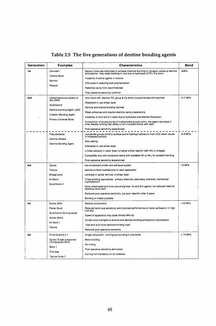
Table 2.5 The five generations of dentine bonding agents
Generation Examples Characteristics Bond
1st C erv id e n t
C o sm ic B ond
S erv ito r
P a la v a v
B ipolar m o le c u le s a t te m p te d to a c h ie v e c h e m ic a l b o n d in g to in o rg an ic p h a s e of d e n tin e a n d po lym er. V ery w e a k b o n d in g in vivo d u e to h y d ro ly sis of P 0 4- C a b o n d .
Instability of ac tiv e a g e n ts in so lu tion
Difficulties in o b ta in in g bulk p o ly m erisa tio n
R e te n tiv e cav ity form re c o m m e n d e d
P o s t-o p e ra tiv e sensitiv ity co m m o n
2 M P a
2nd Halophosphorous esters o f B is-G M A
S c o tc h b o n d
D e n tin e b o n d in g A gen t (J& S)
C re a tio n B ond ing A gent
P rism a U niversa l B ond
Ionic b o n d with re ac tiv e P O , g ro u p & C a w hich c o -p o ly m e rise s with p o ly m er
A ttem p ted to u s e s m e a r lay e r
D e n tin e a n d e n a m e l b o n d in g c la im e d
W e ak a d h e s iv e s a n d re q u ire re te n tiv e cav ity p re p a ra tio n s
Instability of ionic b o n d in w a te r d u e to h y d ro ly sis a n d th e rm a l fluctua tion .
A p roportion of d o u b le b o n d s of m e th a c ry la te g ro u p s within th e a g e n t n e u tra lis e in tim e , th e re b y limiting th e ir ability to form c o v a le n t b o n d s with re s in
P o s t-o p e ra tiv e sensitiv ity e x p e r ie n c e d
4 - 7 M P a
Polyurethanes
D e n tin e A dhesit
D e n tin e B ond ing A gen t
Iso c y a n a te g ro u p s b o n d to s u rfa c e b o u n d hydroxyl ra d ic a ls to from C 0 2 w hich re su lts in in c re a s e d po rosity
S low se ttin g
A ttem p ted to u s e s m e a r layer
Lim ited solubility in w a te r d o e s no t a llow fu rth e r re ac tio n with N H, in c o llag e n
C o m p a tib le on ly with c o m p o s ite re s in s with a v a ila b le O H o r N H 2 for c o v a le n t b o n d in g
P o s t-o p e ra tiv e sensitiv ity e x p e r ie n c e d
3 - 6 M P a
3rd G lu m a
T e n u re
M irage b o n d
All-Bond
S c o tc h b o n d II
tw o -c o m p o n e n t p rim er a n d a d h e s iv e sy s te m
d e n tin e s u rfa c e m odified p rior to re s in ap p lica tio n
c o m p le te o r partia l rem o v a l of s m e a r layer
T h re e b o n d in g a p p r o a c h e s : p rim ary ch e m ic a l, s e c o n d a ry c h e m ic a l, m e c h a n ic a l (hybrid isation )
M ore co m p lica te d a n d tim e co n su m in g th a n 1st a n d 2 n d a g e n ts , bu t re d u c e d n e e d for re te n tiv e cav ity form
R e d u c e d p o s t-o p e ra tiv e sensitiv ity , bu t p o o r re te n tio n a f te r 3 y e a r s
B ond ing to m e ta ls p o ss ib le
10 M Pa
4th G lu m a 2 0 0 0
P e r ta c B ond
S c o tc h b o n d M ulti-pu rpose
S y n ta c B ond
All B ond II
T e n u re
S e v e ra l c o m p o n e n ts
R e d u c e d te c h n iq u e sensitiv ity a n d im p ro v ed p e r fo rm a n c e o n m oist s u r f a c e s o r in high hum idity
S p e e d of a p p lica tio n m a y p o s e clinical difficulty
S im ilar b o n d s tre n g th s to e n a m e l a n d d e n tin e b o n d in g a c h ie v e d by h y b rid isa tio n
T otal e tc h a n d m oist d en tin a l b o n d in g u s e d
R e d u c e d p o s t-o p e ra tiv e sensitiv ity
> 15 M Pa
5th P rim e & B ond 2:1
S y n ta c S in g le co m p o n e n t (C o m p o g la s s SCA )
B ond 1
O n e s te p
T e n u re Q uick F
S in g le c o m p o n e n t: prim ing a n d b o n d in g in o n e bottle
M oist bond in g
No m ixing
P o s t-o p e ra tiv e sensitiv ity e lim in ated
E tch ing no t m a n d a to ry for all m a te ria ls
> 15 M P a
48
A dhesives in the fourth generation of m aterials are d istingu ished by their
num erous com ponents and the increased clinical com plexity of restorative
p rocedures. The perception of com plexity has led m ore recently , to the
developm ent of the fifth generation, one component, one bottle systems. Known
as self-etching or self-priming systems, these agents use acidic prim ing solutions
w hich diffuse through water-filled channels in the smear layer to the overlying
dentine. They enlarge the channels and dem ineralise the upper surface of the
underly ing dentine. As the prim er etches, the dem ineralised sm ear layer and
exposed collagen fibres of the dentine are sim ultaneously infiltrated w ith HEMA
and an acidic co-monomer which in turn co-polymerise to form the hybrid layer.
In the earlier bonding agents, the smear layer was a confounding factor in the
achievement of adequate bonds to dentine. However, the converse appears to be
true for the fifth generation agents because of the hydrophilic na tu re of the
prim ers which incorporate both the conditioned smear layer and dentine into the
hybrid layer. The maintenance of the smear layer and its inclusion in the hybrid
layer has three possible advantages. Firstly, the smear layer physically seals the
dentinal tubules. Secondly, there is not the increase in dentine perm eability and
dentinal fluid flow following conditioning that is seen w hen the layer is rem oved
w ith the fourth generation materials. The relevance of this is expanded further in
Section 2.7.2.2.1. Thirdly, dentine penetration by the p rim er and resin is
shallow er than that achieved by the earlier hybridising m aterials (0.5-2.0
com pared to 1-5 jum). Pashley and Carvalho (1997) speculated that this resulted
in a thinner, but more uniform hybrid layer which in turn w ould lead to a higher
quality of bond and reduced microleakage
2.7 .2 .2 .1 H ybridisation
The prim ary site of bonding in all fourth and fifth generation agents is the hybrid
layer. This zone w as first described by N akabayashi et al (1991): acid
conditioning by either the direct application of acids, or the indirect dissolution
by acidic components in the prim er removes or modifies the smear layer before
decalcifying the dentine surface. The resulting conditioned dentine surface is
p rim arily an u n su p p o rted netw ork of in ter- and in tra tu b u la r collagen.
D ecalcification of the highly calcified in tra tubu lar den tine also p roduces
funnelling of the dentinal tubules. Hydrophilic monomers penetrate the collagen
49
netw ork and dentinal tubules to a depth of 1-5 and polym erise in situ to
create the hybrid layer. The bond strength to dentine is though t to correlate
better w ith the bonded surface area rather than to the dep th or volum e of the
resin penetration (Pashley & Carvalho, 1997), and therefore tubule concentration
has a significant influence on bonding.
This resin-reinforced zone is highly acid-resistant and rem ains intact even after
the dissolution of enam el and dentine in hydrochloric acid. In add ition to
providing micromechanical retention and to sealing the tubules, the hybrid layer
effectively stops dentinal fluid flow and provides an effective barrier against
bacteria, molecules and components of the overlying composite resin (Leinfelder,
1993). The hybrid layer also has a relatively low Young's M odulus of Elasticity
and m ay play a role, albeit small, in stress relief d u rin g po lym erisa tion
shrinkage.
W ater plays an im portan t role in hybridisation. Excessive d ry in g of the
conditioned dentine surface, while possibly enhancing the bond to enam el
(Section 2.7.2.1) can lead to the collapse of the collagen network. If it is no t re
expanded by the application of water or aqueous primers, inadequate infiltration
of both the dem ineralised collagen and w idened tubules by the resin will result
in reduced bond strengths, an increased susceptibility of the exposed collagen
fibrils to slow hydrolytic degradation, and poor sealing of the tubules. All of
w hich incur an increased risk of m icroleakage and its sequelae of den tine
sensitivity and pulpal irritation. The third and fourth generation agents, w here
the dentine surface is w ashed and dried betw een conditioning and prim er
application, are at greater risk of dehydration than the self-p rim ing fifth
generation materials. Effective hybridisation with the earlier hybridising agents,
therefore relies on the maintenance of the collagen network and the use of m oist
bonding and hydrophilic primers are essential components of the procedure.
W hile the presence of w ater is im portant for the m aintenance of the collagen
netw ork, conversely, excessive w ater contam ination can have an adverse
influence on the formation of the hybrid layer. This is because of the form ation
of blister-like spaces at the prim er-dentine interface which results in incom plete
sealing of the tubules (Tay et a l, 1996). In addition, the w ater also dilutes the
prim er monomers. The source of excess water can arise from either the rinsing of
50
the conditioner or, in vivo, from the increase in dentinal fluid flow as a direct
result of etching the dentinal tubules (Pashley et al., 1993). Again, of the m ore
recent materials, it is the third and fourth generations of bonding agents that are
m ore susceptible to excesses of water. It is clear therefore, that the quantity of
w ater m ust be carefully controlled to ensure maximum hybridisation.
W hen first introduced, the application of acid to the dentine was of concern to
some w orkers (Retief et a l, 1992). How ever, this arose from errors in the
interpretation of microleakage (Kanca, 1990) and more recently, total etching has
been accepted as a m ethod that does not increase the risk of dam age to the pulp.
However, if the acid is too aggressive, it m ay expose collagen fibrils below the
hybrid layer, leaving a zone of weak dentine that is susceptible to long term
degradation. It is therefore essential that the m anufacturers' instructions are
followed closely.
2.7.2.3 The use o f low viscosity resins: intermediate bonding and glazing
The use of a low viscosity bonding resin, or an unfilled resin, p laced as an
interm ediate layer betw een the composite resin and the cavity surface has been
purported to reduce microleakage. While such a resin may im prove bonding, its
m ain functions are to act as a relatively flexible stress-absorbing layer betw een
the dentine and composite resin during polymerisation shrinkage (Kemp-Scholte
& Davidson, 1990a; Kemp-Scholte & Davidson, 1990b) and to better transm it and
distribute stresses induced by thermal changes, w ater absorption and occlusal
forces across the interface (Van Meerbeek et al., 1993).
The results of studies investigating the effect of an interm ediate bonding layer on
microleakage have been conflicting (Chow, 1980; Amsberry et al., 1984; Prevost et
al., 1984; Saunders et al, 1990). This is due to differences in the viscosity of the
m aterials used; in its unpolym erised state, a layer of m onom er in the liquid
phase is found on the resin surface. With less viscous composite resins, this layer
behaves as an 'unfilled' resin. However for the more viscous m aterials resin flow
is reduced and therefore the layer of m onom er is unable to provide the same
degree of intermediate bonding.
51
The results of the in vitro studies referenced in the above paragraph suggest that
an interm ediate bonding resin is unnecessary for some resins, but is of benefit for
others. H ow ever, there was no evidence to suggest that the use of such a
bonding resin was detrim ental to the sealing capabilities of the resin. In his in
vivo study, Q vist (1985) reported an im provem ent in m icroleakage w ith an
interm ediate bonding resin. A similar finding was reported by Chow (1980)
using a conventional resin and it may well be that bonding agents are of benefit
under the less favourable circumstances experienced in vivo.
The use of an unfilled resin applied as a glaze to the surface of the restoration has
also been investigated as another means of reducing microleakage. However, as
w ith the in term ediate bonding resin, the results of these experim ents are
conflicting (Amsberry et a l, 1984; Qvist, 1985; Reid et al., 1991).
2.7.2.4 Altering the cavosurface angle of the restorations
The cavosurface angle of a restoration can be changed by the p reparation of a
bevel at the cavity m argins or by leaving excess filling m aterial finished to a
feather-edge over the surrounding tooth surface.
The concept of a 135° bevel at the enam el m argin of conventional b u tt
p reparations has been proposed by several investigators (Welk, 1976). The
proposed advantages for the bevel include an increase in surface area, and
therefore num ber of exposed enamel rods available for acid-etching, a larger
surface of the restoration available to compensate for some of the w all-to-w all
polym erisation, the d istribu tion of the forces generated by po lym erisation
contraction over a larger area thus reducing the likelihood of surface grazing
(Bowen et al., 1983), and the developm ent of stronger resin /enam el bonds w ith
etched transverse sections of enam el prism s than w ith longitudinal sections
(Munechika et a l, 1984).
In vitro studies have yielded conflicting results w ith several w orkers concluding
that the presence of an enamel bevel does not influence the leakage pattern if
etching of the enamel is effective (Retief et a l, 1982; Hembree, 1984; Qvist, 1985).
While others have found a significant im provem ent in leakage w ith the bevelled
m argin w hen com pared to the butt-joint (Crim & M attingly, 1980; Grieve &
52
G lynn Jones, 1980). As noted in Section 2.7.2.1, the degree of leakage found at
gingival enamel margins of Class V cavities is consistently worse than at occlusal
m argins. A gingival enamel bevel has been found to reduce microleakage w hen
com pared to a sim ilar preparation at the occlusal m argin (Crim & M attingly,
1980; Hall et a l, 1993). From the results of these studies, it w as proposed that
occlusal bevelling w as not advantageous, and tooth struc tu re shou ld be
conserved in this area, bu t that bevelling in gingival enam el should be used
where sufficient enamel was available.
The difficulties encountered in achieving adequate bonding to dentine w ere
referred to in Section 2.7.2.2. The influence of a bevel at the gingival m argin in
Class V restorations placed at the cervical m argin was investigated by Uno et al
(1988). They found that the bevel increased microleakage at the dentine m argin
w hile im proving the m arginal integrity at the enamel m argin. H owever, the
differences were not statistically significant.
In addition to the use of bevels, the influence of alternative cavosurface angles
and cavity shapes on the microleakage of composite resins has been investigated;
the use of a feather-edge finish w ith a butt-joint, a rounded bu tt m argin and a
saucer-shaped cavity have been found to reduce m icroleakage considerably
w hen com pared to the conventional butt-joint restoration w ith a cavosurface
angle of 90° (Eriksen & Buonocore, 1976; M arzouk & Bhaiji, 1989).
2.7.2.5 Modification of the restorative technique
Polym erisation shrinkage has been controlled by changing the cavity shape, and
by controlling the direction of polym erisation and the volum e of polym erising
resin.
A significant im provem ent in m arginal adap ta tion has been found w ith
increasing w all/flo o r angles in dentine (Hansen, 1984) and enam el cavities
(Eriksen & Buonocore, 1976) w ith the classic attrition-shaped cavity giving the
smallest gap sizes and therefore reduced tensile stresses in the m aterial. This is
due to the increased area of the restoration free-surface compensating for wall-to-
wall contraction. Feilzer et al (1987) describe such cavities as having a low
C-factor (configuration factor). The direction of polym erisation contraction can
53
also be controlled by the application of pressure to the restoration surface via a
matrix strip (Amsberry et a l , 1984).
An increase in cavity size results in increased m arginal gap size w hen composite
resin is bonded to enam el or dentine because of the increased volum e of
polym erising resin (Brannstrbm et a l, 1984; Hansen, 1984). Several m ethods have
been advocated for the control of volume; increm ental packing (Hansen, 1986),
the use of a 'ball' of pre-cured polym er (W elbury & M urray, 1990) or a beta
quartz glass-ceramic insert (Section 2.3.3.2), and the provision of an indirect resin
restoration (Douglas et a l, 1989).
Of these methods, incremental packing is of greatest benefit for the direct Class V
resto rations used in this study. W ith this technique, the po lym erisa tion
shrinkage of each increm ent is directed tow ards the cavity walls rather than to
the restoration surface. W hen compared to bulk packing, this increases the free-
surface:volum e ratio and effectively lowers the size of the C-factor. Despite
im provem en ts in the bond achieved w ith den tine b o n d in g agents, the
den tine/resin bond has continued to be the 'weak link' in composite restorations.
Several patterns of packing have been investigated in an attem pt to reduce the
adverse influence of this and oblique increm ental packing has been found to
have the greatest positive influence on microleakage w hen com pared to bulk
packing or horizontal increm ental packing (Hansen, 1986; Saunders et a l, 1991;
Saunders & M uirhead, 1992). This is particularly so w hen the first increm ent is
placed occlusally (Crim, 1991), presum ably because the early establishm ent of the
enam el bond ensures that the gingival bond is not d isrupted . M ore recently
though, the results of studies using the new er dentine bonding agents have
suggested that increm ental filling is not a critical consideration for adhesives
which achieve strong bonds to dentine (Linden & Swift, 1994).
This review of m icroleakage has so far concentrated on the control of
polym erisation shrinkage of com posite resin m aterials. In this study , tw o
m aterials w ere used; a hybrid com posite resin, and a po lyacid-m odified
composite resin, both with their respective bonding agents. M icroleakage in the
latter group of materials will also be considered.
54
2.8 Microleakage in polyacid-modified composite resins
Because of their recent introduction into clinical dentistry, the num ber of refereed
papers on this subject is naturally limited w hen com pared to those reporting the
incidence of microleakage with composite resin restorations.
As noted in Section 2.3.6, compomers were developed to enhance the favourable
properties of composite resins, nam ely their good aesthetics, strength and wear
resistance, w ith those of the glass-ionom er cem ents i.e. low polym erisation
shrinkage, bonding to tooth structure and release of fluoride. It w ould not be
unreasonable, therefore, to expect that these m aterials w ould exhibit less
microleakage than equivalent composite m aterials and that microleakage at the
enam el and dentine m argins would be comparable. However, several w orkers
have found a greater incidence of m icroleakage at both dentine and enam el
m argins w ith compomer m aterials w hen com pared to composite resins (Uno et
al., 1997; Ow ens et al., 1998). In contrast, at the dentine m argin, Chersoni et al
(1997) and Uno et al (1997) found no significant difference in leakage w ith
cavosurface angles of 135° and 90° respectively. Studies also vary in their results
w hen the m arginal integrity at the enamel and dentine m argins of the com pom er
restorations are compared. Uno et al (1997) and Brackett et al (1998) found no
significant difference in leakage betw een the tw o m argins. H ow ever, other
w orkers have reported greater leakage at the dentine m argins (Cortes et al., 1998;
O w ens et al., 1998). These apparent contradictions reflect differences in the
composition and properties of the materials, bu t equally, restorative factors play
a role. As w ith the com posite resins (Section 2.7.2), the effect of d ifferent
restorative approaches on the microleakage of com pom er restorations has been
investigated.
As noted in Section 2.3.6, compomer materials achieve micromechanical retention
to den tine via the form ation of a resin-reinforced hybrid layer w ith the
application of fifth generation, single com ponent bonding agents. Thus the
smear layer is m odified rather than being rem oved. The application of highly
dissociated acids such as phosphoric to dentine rem oves the sm ear layer and
results in an increase in the num ber and size of the resin tags (Chersoni et al.,
1997). Studies have shown that such dentine etching prior to prim er application
reduces the incidence of m icroleakage at the co m p o m er/d en tin e interface
55
(Chersoni et a l, 1997; Vichi et a l, 1997; Ferrari et al, 1998; Owens et a l, 1998). The
same pattern of leakage was found w ith the enamel margin. However, Cortes et
al (1998) found no significant differences in leakage at either m argin betw een
etched and non-etched surfaces w ith the two compomers they tested.
In contrast to com posite resins (Sections 2.7.2.4 and 2.7.2.5), increasing the
enam el cavosurface angle at the enamel and dentine m argins by increasing the
cavity wall /floor angles, or at the enam el m argin by bevelling, was found to
have no significant effect on microleakage (Uno et a l, 1997). However, like the
com posite resins, the use of a dentine bevel at the gingival m argin influenced
m icroleakage at that m argin adversely, b u t resu lted in a reduction in the
microleakage at the bevelled enamel m argin (Owens et a l, 1998). Uno et al (1997)
also reported an increase in the microleakage at enam el and dentine m argins
w ith thermocycling.
2.8.1 Summary
From this brief review of the literature pertaining to both the com pom er and the
com posite resin m aterials (Section 2.6), it can be seen that polym erisation
shrinkage is an im portant factor w hen considering microleakage in resin-based
m aterials. Ideally such restorations should not exhibit m icroleakage and
therefore to minimise this, it is essential that both the size and direction of the
stresses arising during polymerisation shrinkage are controlled. This is achieved
by changes to the composition of the restorative material, bu t in addition, the
choice of restorative technique is important.
2.9 Cavity preparation
The cavity, m ateria l and resto rative factors influencing the contro l of
m icroleakage w ere discussed in the previous section. H ow ever, of equal
im portance for the adaptation of the m aterial is the m orphology of both the
cavity surface and the su rround ing enam el and dentine. This is, in part,
dependent on the m ethod used for cavity preparation. The microleakage studies
review ed to date have all used conventional m ethods of cavity preparation,
principally the high-speed handpiece and diam ond bur w ith w ater coolant.
56
2.9.1 Conventional cavity preparation
Early caries rem oval revolved around enamel cleaning and dentine excavation
w ith hand instrum ents. However, the developm ent of the dental treadle engine
in 1875, in troduced rotary instrum ents into clinical dentistry (Stephens, 1986).
M echanisms and handpieces were refined and the m odern slow, and high-speed
air turbine handpieces, w ith the use of carbide and diam ond burs to supplem ent
the early steel and carborundum instrum ents, have provided an efficient, fast
and reliable m eans of caries rem oval and cavity preparation , w ith reduced
discomfort and fatigue for both the patient and operator (Peyton & Arbor, 1955).
The m orphology of the resulting enamel and dentine surfaces is of interest w hen
considering the microleakage of restorations. Enamel is a brittle tissue (Section
2.2.1.3) and therefore tooth preparation using sharp d iam onds w ou ld be
expected to affect the surface. Xu et al (1997) investigated the appearance of the
enam el surface following conventional cavity preparation w ith a d iam ond bur.
M icrographs of the cut surface show ed evidence of subsurface dam age in the
form of m edian-type cracks and m icrocracks w hich ex tended along the
boundaries between the enamel rods. In addition, microcracks were seen w ithin
the ind iv idual enam el rods. The length of the m edian-type cracks was
proportional to the diam ond particle size and also varied w ith the orientation of
the enamel rods, being longer when the cutting surface was parallel to the long
axis of the rods. However, the removal rate and the force applied to the tissue
during cutting appeared to have no significant influence. These findings are of
particu lar im portance w hen considering the m arginal seal and longevity of
restorations, since the presence of these cracks at the CRI m ay influence the
adaptability of the restorative material; in their discussion, Xu et al described the
cracked enam el surface as being dam aged, thereby im plying that such an
appearance was not desirable. They found that the dam age induced by the use
of coarse diam ond burs was reduced effectively when finer diam ond burs were
used to finish cavity preparation, but etching with 33% phosphoric acid gel failed
to either rem ove or im prove the dam aged surface. As a result, the authors
concluded that these findings supported the use of fine d iam ond burs to
com plete cavity p reparation . H ow ever, the clinical significance of the
appearance of the cut surface on both the strength of the enam el and the
adaptabity of restorative materials needs further investigation.
57
The appearance of the dentine surface following conventional cavity preparation
has also been investigated. W ith SEM analysis following conventional caries
rem oval and cavity p reparation at x50 m agnification, the den tine surface
featured clear grooved m arks because of the rotary action of the burs (Aoki et a l,
1998). At higher m agnification (x3000) the surface appeared flat and a sm ear
layer (Section 2.7.2.2) w as visible. W ithin the same experim ent, Aoki et al
com pared this appearance w ith the dentine surface arising as a result of cavity
preparation w ith an Er:YAG laser. These findings are of relevance to this study
and are described in Section 2.10.6.3.
In addition, to the m orphology of the cut enamel and dentine surfaces, use of
rotary instrum ents also produces frictional heat and vibration, giving rise to pain
and a hyperaem ic increase in pulpal blood flow (N arh i et al., 1982). H eat
production and its sequelae are limited w ith the use of w ater coolants (Stanley &
Swerdlow, 1959). However, these side effects, combined w ith the noise of the
m otor, m ay cause apprehension for the patient and dam age to the pulp. In
addition, the instrum ents are not selective in their tissue rem oval, a lthough
tactile assessm ent w ith a slow speed bur in particu lar does assist in the
differentiation of healthy and carious dentine and enam el. D espite these
lim itations, the use of high and slow speed handpieces in cavity preparation
rem ains the commonest m ethod of caries removal and provides the standard by
which all other m ethods are compared.
However, as noted in Section 1.3. the dental drill is one of the com m onest fear-
provoking stressors for the anxious patient. A lternatives to conventional
m ethods of cavity preparation have been investigated in the attem pt to find a
technique that can prepare the cavity within a reasonable length of time w ithout
causing pain or affecting the CRI adversely.
2.9.2 Alternative techniques for cavity preparation
To date, four alternative techniques have been investigated; air abrasive
techniques, ultrasonic instrum ents, chemomechanical caries rem oval and lasers.
All have been reported to provide a m eans of cavity p repara tion or caries
rem oval w ithout pain or vibration for the patient (Black, 1955; O m an, 1955;
Brannstrom et a l, 1980; Keller & Hibst, 1997). H ow ever, the air abrasive
58
technique is lim ited to the teeth and surfaces in the direct vision of the operator
and conventional rotary instrum ents are required to complete cavity preparation.
Conventional instrum ents are also required for the rem oval of hard caries and
the com pletion of cavity preparation w ith the chemomechanical and ultrasonic
techniques (Oman, 1955; Brannstrom et al., 1980).
The success of lasers as a replacem ent for the conventional d rill has varied
depending on the lasing m edium em ployed. The Er:YAG laser is used in this
s tudy as an alternative to conventional cavity preparation and it is therefore
pertinent to consider this area in greater detail.
2.10 - Lasers in dentistry
2.10.1 Introduction
The w ord 'Laser' is an acronym for Light A m plification by the S tim ulated
Em ission of Radiation. The light is produced in a closed system and is a
coherent, m onochrom atic, collim ated beam of photons. The beam m ay be
continuous, pulsed or gated and the size of the focal point can be adjusted to
create a beam of electrom agnetic radiation of trem endous energy w hich is
significantly m ore intense than conventional light sources. Lasers are nam ed
according to the laser m edium employed and to date, more than 600 have been
identified, each operating at a different wavelength.
Since its conception by M aiman in 1960 , the laser has been considered for use in
m any areas of medicine and surgery. Two m ain categories of laser have been
developed for use in these fields; 'soft' and 'hard' lasers. 'Soft' lasers provide low
energy at wavelengths which activate the circulation and cellular activity (M idda
& Renton-Harper, 1991; Miller & Truhe, 1993). They are used to prom ote healing
and to reduce the pain and oedema produced by inflammation. 'H ard ' lasers are
used w idely for surgical applications. All further references to lasers in this
thesis will refer to this latter type of laser.
Research into the application of lasers in dentistry has been ongoing over the last
30 years and is alm ost as old as the laser itself, a reflection of the inherent
difficulties of producing a clinical laser system that both interacts effectively w ith
59
the hard dental tissues and is easy to use, while complying w ith health and safety
requirem ents. Several hard and soft tissue applications for h ard lasers in
dentistry have been reported (Table 2.6). However, it is the ability of lasers to cut
enam el and dentine that is of interest in this study.
2.10.2 Lasers as optical 'drills'
W hen they w ere first developed, it was hoped that lasers w ould provide an
alternative to the dental drill (Goldman et a l, 1964; G ordon, 1967; Stern et al.,
1972). The first report of the use of a laser on a vital tooth w as by G oldm an et al
(1965). Two pulses of a ruby laser were applied to a vital tooth. W ith sufficient
energy densities, the laser beam was able to penetrate sound, norm al enamel,
and the enamel surrounding the impact area showed no macroscopic evidence of
change. Furtherm ore, there was no sensation of pain. As noted in Section 2.9.1,
the pain experienced during conventional cavity preparation is usually caused by
the vibration of the bur and the heat produced from friction. It was hoped
therefore that, in addition to cutting enamel and dentine, the use of a contactless
operating laser w ould provide a more accurate and painless m eans of tooth
preparation. In so doing, the need for local analgesia w ould be reduced and
w ou ld p rov ide a w elcom e alternative for tooth p rep ara tio n for anxious
individuals.
For the laser to replace or support, conventional means of cavity preparation, it
m ust fulfil certain criteria. Laser irradiation of the tooth surface should result in:
• the removal of enamel, dentine, caries and restorations w ithout dam age to the
surrounding hard tissues and pulp or to other oral tissues
• the production of minimal tem perature change in the irradiated tissue
• a consistent and predictable effect on a defined area or tissue
• an ablation rate equivalent to the cutting rate of conventional handpieces
• the production of a cavity surface that does not influence the m arginal sealing
ability of restorative materials or the bonding of adhesive m aterials adversely.
In addition, desirable properties are that the tool should be selective for caries to
minimise hard tissue removal and damage, and should not cause pain sensation
during cavity preparation.
60

Table 2.6 Potential soft and hard tissue applications of lasers in dentistry
Soft tissue applications• incise, excise, remove or biopsy lesions such as papillomas, fibromas, and epulides
• vaporise excess tissues, for example, frenectomy, gingivoplasty and ginigivectomy
• remove or reduce hyperplastic tissue, for example epanutin hyperplasia
• remove and control haemorrhaging of vascular lesions such as haem angiom as, and inpatients with hemorrhagic disorders such a s haemophilia
• symptomatic pain relief of aphthous ulcers
Hard tissue applications• vaporise carious lesions
• desensitise exposed root surfaces
• endodontic: vaporise organic tissue, glaze canal wall surfaces and fuse an apical plug with the potential to resist fluid leakage, root canal sterilisation
• roughen tooth surfaces in lieu of acid etching
• preventive effect on enamel: arrest demineralisation, promote remineralisation and increase acid resistance
• debond ceramic orthodontic brackets
• cure composite resin (reduces polymerisation shrinkage)
• cut enamel and dentine
• scaling and root planing
• increase acid resistance of enamel
61
Contrary to the high hopes arising as a result of the first reports, further studies
using the early lasers reported that the high energy densities required to cut
through the enamel and dentine led to overheating. This caused cracking and
shattering of the enamel surface which led to irreversible pulp dam age (Stern et
a l, 1969; A drian et a l, 1971). Furtherm ore, reflected energy produced visible,
albeit less severe, changes in the enam el of adjacent teeth (Taylor et a l, 1965).
W hen used at lower energies to minimise these side effects, the lasers failed to
ablate enam el and dentine. These studies involved the use of continuous wave
ruby, carbon dioxide and NdiYAG lasers.
The significant lim itations in the use of the early lasers for the 'cutting' of enamel
and dentine led some workers to conclude that they had no role in this area.
However, over the last thirty years, there have been continued technological
developm ents in the field. As this has happened, interest in the application of
lasers to dentistry has been rekindled to the extent that, at the end of the
tw entieth century, the clinician is faced w ith an array of laser types all of which
purport to cut enamel and dentine. In order to understand which of these may
satisfy the requirem ents of an optical drill, an understanding of the w ay in which
laser light interacts w ith enamel and dentine is necessary.
2.10.3 Mechanism of laser-tissue interactions
2.10.3.1 Introduction
On im pinging a tissue surface, the laser light can be reflected, scattered, absorbed
a n d /o r transmitted. The absorbed light is responsible for the tissue effects of the
laser, and the quantity of light absorbed is influenced by the proportion in which
the other three effects occur. For instance, reflection lim its or reduces the
quantity of energy which enters the tissue and light that is reflected is dissipated
effectively resulting in very little dam age to the other oral tissues. Scattering
occurs w ithin the tissue and effectively distributes the energy over a larger
volume of tissue than the laser beam entering the tissue. In so doing, it dissipates
therm al energy. However, this may also result in an increase in collateral
dam age where the scattered radiation is absorbed. After a characteristic am ount
of scattering has occurred in the tissue, light energy is absorbed. Transm ission
62
occurs w hen the light passes beyond a given tissue boundary and m ay result in
dam age to surrounding tissues such as the pulp.
2.10.3.2 Interaction of absorbed light with the dental hard tissues
The interaction of the absorbed electromagnetic radiation w ith tissues involves
the interaction of photons w ith the atoms or molecules of the target tissue. These
interactions are followed by very complex reactions, m any of which are still not
understood fully. Four m echanisms are currently recognised: photochem ical
interactions, therm al interactions, non-linear processes and therm om echanical
processes. The first of these, photochemical processes, are not involved in the
reaction of laser light w ith the dental hard tissues and will therefore not be
considered further.
2.10.3.3 Thermal interactions
Thermal effects occur w hen the absorbed electromagnetic radiation is converted
to heat energy; absorption leads to an increase in internal lattice vibrations which
in tu rn is converted to therm al energy. While vaporisation of the irrad iated
tissue may occur, several side effects in teeth have been noted. The direct effect
of excessive heat resu lts in the form ation of cracks, zones of necrosis,
carbonisation (charring) and m elting in enam el and dentine, and irreversible
dam age to the pulp. The ability of some ruby, carbon dioxide and Nd:YAG
lasers to melt enam el has been proposed as a means to prevent carious attack
because of the increased acid-resistance seen in the tissue (Stern, 1972; Yamamoto
& Ooya, 1974; M eurm an et al., 1992). However, w ith this exception, these
therm al side effects are less than desirable, and the laser-induced alterations of
the tooth surface may have a deleterious affect on the successful bonding of
restorative m aterials. In m ost clinical situations therefore, it is desirable to
minimise these thermal changes.
2.10.3.4 Non-linear processes
W hen pulse energies lie above a certain threshold, and the pulse du ra tion is
shorter than 1ms, the laser energy is used to break bonds non-therm ally. H eat
conduction can therefore be disregarded. In the removal of enam el and dentine,
63
two m ain types of non-therm al effects are known: photoablation by either m ulti
photon stim ulation or direct electron dissociation, and photo-disruption.
2 .10 .3 .4 .1 P ho toab lation
In contrast to the thermal effects, molecules can be directly dissociated w ith laser
light of high photon energies (single photon dissociation), or w ith high energy
densities and short pulse duration (m ulti-photon processes). Only the excimer
laser em its rad iation w ith photon energies high enough for d irect electron
dissociation. The molecular bonds are broken with m inimal thermal side effects.
Photoablation is a tissue-specific process and promotes selective caries removal.
In contrast to healthy dentine, the dem ineralised zones of a carious defect are
very easy to rem ove, resulting in retentive areas in the enam el and dentine
(Frentzen & Koort, 1990).
2 .1 0 .3 .4 .2 Photod isrup tion
Very high energy and short pulsed laser light can ionise material by building up
a plasma, a sea of electrons and ions w ith tem peratures betw een 6,000-10,000 °C
w here the laser light focuses on the tooth. If this occurs, several effects m ay be
seen, depending on w here the plasm a is generated. By absorbing some of the
incident radiation, the presence of the plasm a may result in a reduction in laser
energy reaching the tooth surface. However, this is in part com pensated for by
the direct action of the plasma on the tooth surface; therm al energy is conducted
to the surface, which results in ablation and heating of the dental hard tissues. If
uncontrolled, the form ation of a plasm a at the tooth surface m ay result in an
unacceptable degree of thermal damage. If the plasm a is generated beneath the
tooth surface, pressure builds up and dissipates explosively inducing acoustic
shock waves. These resu lt in the m echanical detachm ent of various sized
particles of enam el and dentine. This effect of the plasm a is independent of
absorption and is dictated in part by the type of laser. For some lasers, the
developm ent of high pressure w aves has the potential to p roduce cracks,
microcracks and zones of debris at the cavity surface. Others, notably some of
the later Nd:YAG lasers, attem pt to use the plasm a to cut enamel and dentine by
controlling the plasm a w ith a w ater coolant (Pick, 1993). This poses some
concerns because the superhot plasm a can heat areas beyond the desired target
64

area, causing significant iatrogenic thermal damage. In addition, the plasm a is
generally difficult to control, varying rapidly in intensity, w idth and location.
2.10.3.5 Thermomechanical processes
The major absorption band of w ater is at 3.0 jum. Some of the new er infra-red
lasers that have wavelengths in this region, for example, the Er:YAG laser, are
able to ablate the den tal hard tissues via an ind irect therm om echanical
mechanism: on im pinging the dental hard tissues, the incident laser energy is
absorbed by w ater in the tissues. The w ater heats to boiling producing w ater
vapour which in turn causes a build up in pressure resulting in a microexplosion
and the ablation of a small proportion of the tissue. The majority of the energy is
expended in the process of ablation and therefore only a sm all fraction is
available to heat the tissues, thus thermal changes are minimal.
The laser-induced effects seen on enam el and dentine are the resu lt of a
com bination of one or m ore of the interactions described above. The balance
betw een these is controlled by the characteristics of the laser radiation and the
irradiated tissue. The laser param eters of concern are the w avelength, energy
density, waveform and irradiation time, while the relevant tissue factors are its
optical, thermal and mechanical properties. These param eters will be considered
further in the following two sections.
2.10.3.6 Laser parameters
The depth of penetration and absorption of radiation im pinging on a tissue is
dictated by the balance that occurs betw een the absorption, transm ission,
scattering, and reflection of the light. This balance is in turn dependent on both
the w avelength of the radiation, and the optical properties of the irradiated
tissues. The latter are considered further in Section 2.10.3.7.
Considering the laser param eters further; in addition to the w avelength, the
energy density (fluence) of the laser light is im portant. This is defined as the
quantity of energy that is distributed over a surface area. The overall energy
deposited on the tissue surface depends also on the waveform and the irradiation
65
time and this will influence the type of interaction that is seen. The w aveform is
the w ay in w hich the pow er ou tpu t varies w ith time i.e. continuous, gated or
pulsed. In general, long pulse durations are not desirable because therm al
energy develops, thereby increasing the possibility of adverse therm al changes in
the irradiated tissue. Pulse shortening, on the other hand, results in a reduced
volume of tissue that is heated because of the reduced deposition time, and also a
decreased threshold energy for ablation (W ilder-Sm ith et al., 1997). The pulse
frequency is expressed in Hertz (Hz) and is also know n as the pulse repetition
rate (PRR) or the pulses per second (PPS).
2.10.3.7 Optical and tissue parameters
As w as seen in Section 2.2, teeth are m arkedly heterogenous structures.
Absorption, the key to laser interaction is wavelength dependent, as indicated by
the absorption spectra of the tissue components. It takes place at single atoms or
molecules which have resonant absorption levels for the w avelength of the light
applied. As noted in Section 2.2.1, w ater and hydroxyapatite, com ponents of
both enamel and dentine, have strong absorption spectra at both UV and mid- to
far-IR wavelengths. Ruby and Nd:YAG laser radiations (visible and near-IR
respectively) are therefore not absorbed well in either enam el or dentine,
w hereas light from the carbon dioxide (far-IR) and Er:YAG (mid-IR) lasers are
well absorbed by both tissues.
However, absorption is not the only tissue factor dictating the characteristics of
the laser-tissue interaction. The therm al properties and the vaporisa tion
tem p era tu res of the den ta l h ard tissues also p lay an im p o rtan t role in
determ ining the ability of a laser to ablate the tissue w ith m inim al adverse
therm al effects. Both enam el and dentine have low therm al coefficients of
therm al expansion (11.4,10'6/°C and 8.3,10'6/°C respectively) and low therm al
conductivities and therefore any heat generated in the tissue, w hile creating
m inimal expansion, will diffuse slowly from the impact point of the laser beam.
If of sufficient intensity, the resulting production and retention of therm al energy
will lead to damage, the nature of which was described in Section 2.10.3.3. In
addition, the vaporisation tem perature of enamel is of sufficient size that high
energy densities are necessary for ablation. For wavelengths that ablate enamel
66
and dentine via therm al interactions, such an increase in energy density will
increase the potential for thermal damage.
Indirect irreversible pulpal changes m ay be seen by the direct heating effect of
dentine close to the pulp. However, in addition to this, the 'system ' of optical
fibres provided by the dentinal tubules (Section 2.2.2.) perm its transm ission of
electromagnetic energy to the pulp and direct pulpal dam age m ay arise from the
absorption of the transm itted light by the pulp tissue.
The influence of the tissue param eters on the laser-tissue interaction explains the
poor performance of the early dental lasers.
2.10.4 The early hard tissue dental lasers
These early lasers, carbon dioxide, ruby and Nd-YAG, were continuous-w ave or
pulsed, w ith pulse durations in the microsecond range, and therm al changes
played an im portant role in their interaction w ith the dental hard tissues.
The carbon dioxide w avelength is well absorbed by hydroxyapatite and as a
result the early prototypes thermally ablated enamel. However, because of the
shape of the laser beam (Gaussian) w ith reduced intensity tow ards the outer
lim its of the beam, the heat generated in the tissue at the p eriphery w as
insufficient to cause vaporisation. This led to the production of adverse therm al
changes (Stern et a l, 1972). Laser irradiation of dentine w ith the early carbon
dioxide laser had similar effects.
In contrast, the wavelengths emitted by the ruby and Nd:YAG lasers are not well
absorbed by hydroxyapatite. From this it may be anticipated that therm al side
effects w ould not be seen following irradiation of enamel or dentine. However,
as noted in Section 2.10.2, this was not the case and the early m odels exhibited
therm al change, w ith minimal ablation (Goldman et a l, 1964; Stern & Soggnaes,
1964; Yamamoto & Ooya, 1974). This was because large energy densities were
used in an attem pt to increase absorption and resulted in a two fold effect; the
energy density was sufficient to cause therm al dam age of the enam el w ith
minim al vaporisation, and the quantity of transm itted light increased, resulting
in increased direct pulp damage. Enamel ablation was increased following the
application of a dye to the enam el surface (Yamomoto & Sato, 1980). This
67

phenom enon (initiation) reflects the increased absorption of the Nd:YAG and
ruby laser w avelengths in p igm ented tissue and resu lted also in g reater
absorption of these w avelengths for non-sclerotic dentine, sclerotic dentine and
caries (Dederich & Zakariasen, 1984). However, while enhancing the ablative
properties of the lasers, initiation also had adverse clinical implications. D uring
ablation the bu lk of the energy was still converted to heat, w hich in tu rn
p roduced charring of the dental hard tissues. This acted as an in itiator,
increasing the absorption of the laser and resulted in the production of a laser
beam which was difficult to control (Dederich, 1991).
Further developm ents in the field of lasers has led to the developm ent of laser
param eters which ablate via the non-therm al mechanisms outlined in sections
2.10.3.4 and 2.10.3.5, thus lim iting the developm ent of adverse therm al
interactions. This has led to a generation of hard lasers which appear to have
great potential as optical drills.
2.10.5 The new generation of lasers
Experience gained w ith the early 'hard ' lasers has indicated that there are
essentially two requirem ents for laser ablation of the dental hard tissues: the
w avelength m ust be efficiently absorbed and the laser energy m ust be delivered
in short bursts w ith high peak powers. The two trains of developm ent in the
m anufacture of lasers for ablating den tal hard tissues have been to use
wavelengths in either the UV or mid- to far-IR spectral regions, and to reduce the
pulse duration and size of the impact point of the beam, thereby increasing the
peak pow er density, although the overall energy reaching the tissue m ay be
relatively low. Table 2.7 lists some of the lasers used on the dental hard tissues to
date.
The new er laser systems have given promising results. Arima and M atsum oto
(1993) dem onstrated that both sound and carious enamel and dentine could be
cut by the ArF:Excimer laser w ith a pulse duration of 10-12 nsec w ithout therm al
injury and w ith m inim um tem perature rise. However, the ablation rate (i.e.
ablated volume per pulse) of this laser was very low. This, and the general risks
of UV radiation to the patient are major disadvantages to its use in cavity
preparation. Furthermore, the high cost of these lasers limit their clinical use.
68
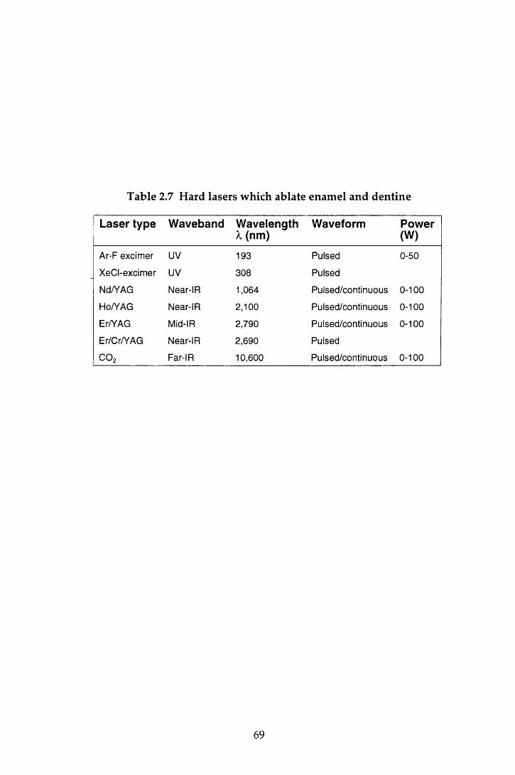
Table 2.7 Hard lasers which ablate enamel and dentine
Laser type Waveband Wavelength X (nm)
Waveform Power(W)
Ar-F excimer UV 193 Pulsed 0-50
XeCI-excimer UV 308 Pulsed
Nd/YAG Near-IR 1,064 Pulsed/continuous 0-100
Ho/YAG Near-IR 2,100 Pulsed/continuous 0-100
Er/YAG Mid-IR 2,790 Pulsed/continuous 0-100
Er/Cr/YAG Near-IR 2,690 Pulsed
C 0 2 Far-IR 10,600 Pulsed/continuous 0-100
69

Niem z (1995) reported the removal of enamel and dentine by a picosecond laser
system, a solid-state Nd:YLF laser. Very precise cavities were obtained, w ithout
severe therm al or mechanical damage, in the enam el and dentine of extracted
hum an m olar teeth, the quality of which was superior to that achieved by other
laser systems. M oreover, the laser exhibited caries-selective properties; w hen
applied to carious enamel, the ablation rate was ten times higher than that for
sound enamel. However, these lasers are not yet commercially available and are
also likely to be comparatively expensive.
Another laser which has show n great promise is the Er:YAG laser. Lasers of this
type have been in clinical use in G erm any for approxim ately five years.
Furtherm ore, the Centauri Er:YAG laser (Premier Laser Systems) was cleared for
m arketing in the United States of America by the Food and D rug A dm inistration
(FDA) on May 7 1997 for 'caries removal, cavity preparation, and m odification of
dentine and enamel before acid etching for increased bond strength ' (Cozean et
al., 1997). The laser used in this study was an Er.YAG laser, the Twinlight Dental
laser (Fotona, Ljublijana, Slovenia). Therefore this g roup of lasers w ill be
considered in greater detail in the following section.
2.10.6 The Erbium:YAG laser
2.10.6.1 Introduction
Erbium is a metallic element in the rare-earth group. The Er:YAG laser is a solid
state, pulsed laser that has a m aximum emission in the m id-infra-red region. At
2.94 /im, the wavelength of this laser coincides with the major absorption band of
w ater (-3.0 /im) and is therefore strongly absorbed in this region; the w ater
absorption coefficient for radiation produced by the Er:YAG laser is ten times
that of the radiation of the CO 2 laser. In addition , the w avelength is also well
absorbed by hydroxyapatite.
The first description of the effects of the Er:YAG laser on the dental hard tissues
was reported in 1988 and indicated that effective ablation of healthy and carious
tissue w as possible w ithout therm al injury and w ith m inim al tem peratu re
changes to the surrounding hard tissues (Hibst et a l, 1988; H ibst & Keller, 1989;
70

Keller & Hibst, 1989). The results of these studies led to the conclusion that
ablation w as achieved via thermomechanical interactions (Section 2.10.3.5) and
that the m ajority of the incident radiation was consumed in the ablative process,
leaving very little residual energy for thermal interactions to occur. However, it
is w orth noting that, w ith increasing pulse energies, small cracks surrounding the
crater w ere seen. These were thought to be artefacts arising during specim en
preparation rather than a direct effect of the incident radiation (Keller & Hibst,
1989).
The results of these early reports suggested that the Er:YAG laser had great
prom ise as a replacem ent for the dental drill, and since the late 1980's several
w orkers have investigated the use of the laser system in an attem pt to assess how
far it fulfils the properties of the ideal optical drill. A resum e of these criteria was
given in Section 2.10.2.
Close inter-study com parisons are difficult because of the range of different laser
param eters that have been chosen (Table 2.8). The following review of the
literature attem pts to summ arise the major findings reported.
2.10.6.2 Ablation
Early crater m easurem ents indicated that ablation depths of m ore than 30 jum per
pulse could be achieved for healthy enam el and dentine, w ith greater dep th
m easurem ents being recorded for carious lesions (Keller & Hibst, 1995a). The
ablation th resho ld for enam el is higher than that of dentine and w hen the
threshold is exceeded, m ass loss increases linearly w ith pulse energy (Hibst &
Keller, 1989) providing the tissue does not become desiccated (Hoke et al., 1990).
Crater depths and w idths increase w ith increasing pulse energies in both enam el
and dentine, those in dentine being larger than the craters found in enam el for
the sam e pulse conditions (Hibst & Keller, 1989). Keller and H ibst (1995a)
calculated that w ith a total pulse duration of 250 jus at 300 mj, 73 and 25 pulses
were required to ablate 1 m m 3 area of enamel and dentine respectively and that
this w ould be achieved in 20 seconds with a repetition rate of 4 Hz.
The speed in w hich enam el and dentine is rem oved is clearly of clinical
importance. The ablation rate of the laser has been compared to both high and
71
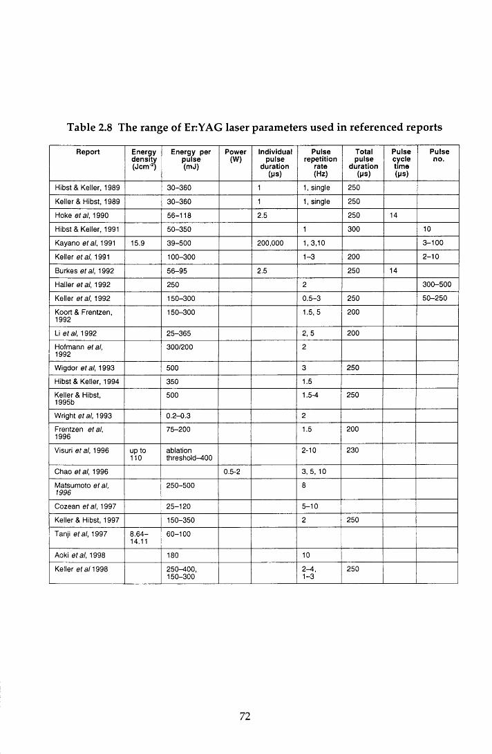
Table 2.8 The range of Er:YAG laser parameters used in referenced reports
Report Energydensity(Jem 2)
Energy per pulse (mJ)
Power(W)
Individualpulse
duration( P S )
Pulserepetition
rate(Hz)
Totalpulse
duration(MS)
Pulsecycletime(Ms)
Pulseno.
Hibst & Keller, 1989 30-360 1 1, single 250
Keller & Hibst, 1989 30-360 1 1, single 250
Hoke et al, 1990 56-118 2.5 250 14
Hibst & Keller, 1991 50-350 1 300 10
Kayano etal, 1991 15.9 39-500 200,000 1, 3,10 3 -100
Keller etal, 1991 100-300 1-3 200 2 -10
Burkes etal, 1992 56-95 2.5 250 14
Haller etal, 1992 250 2 300-500
Keller etal, 1992 150-300 0.5-3 250 50-250
Koort & Frentzen, 1992
150-300 1.5, 5 200
Li etal, 1992 25-365 2, 5 200
Hofmann etal, 1992
300/200 2
Wigdor etal, 1993 500 3 250
Hibst & Keller, 1994 350 1.5
Keller & Hibst, 1995b
500 1.5-4 250
Wright etal, 1993 0.2-0.3 2
Frentzen etal, 1996
75-200 1.5 200
Visuri etal, 1996 up to 110
ablationthreshold-400
2-10 230
Chao et al, 1996 0.5-2 3, 5, 10
Matsumoto et al, 1996
250-500 8
Cozean etal, 1997 25-120 5-10
Keller & Hibst, 1997 150-350 2 250
Tanji etal, 1997 8 .64-14.11
60-100
Aoki etal, 1998 180 10
Keller et al 1998 250-400,150-300
2-4 ,1-3
250
72
slow speed burs in conventional dental handpieces (Wigdor et a l, 1993; Chao et
a l, 1996; Keller et a l, 1998). For the laser param eters used (Table 2.8), the laser
ablated both enam el and dentine faster than the slow -speed bur, bu t w as less
efficient than the high-speed bur. Furthermore, the laser appeared to cause less
dam age to the pulp and surrounding dental hard tissues than the slow speed bur
(W igdor et al, 1993), a property that is desirable in vivo.
H ibst and K eller’s (1989) proposal that therm om echanical interactions were
responsible for enam el and dentine ablation w ere confirm ed in subsequent
studies (Hoke et al, 1990; Li et al, 1992). To achieve ablation w hen the laser beam
is applied over an area as opposed to a single spot and, or when, high energy
densities are used, w ater is required. In the absence of water, ablation occurs to a
lesser extent (Hoke et a l, 1990; Burkes et al, 1992) and the dental hard tissues
become desiccated, exhibiting areas of charring, m elting and crack form ation.
The sim ultaneous application of a w ater m ist during lasing preven ts this.
However, there is evidence to suggest that the presence of excess w ater in deep
cavities can have an adverse affect on dentine ablation w hen laser energies
approach ing the threshold value for dentine are used. This is because a
significant proportion of the laser energy is absorbed by the excess w ater leaving
insufficient energy for dentine ablation (Visuri et al, 1996).
For clinical use, it is not only essential to be able to remove enamel, dentine and
caries w ith the laser, it is also necessary to rem ove restorative m aterials. Hibst
and Keller (1991) found that the ablation efficiency of phosphate cem ent,
carboxylate cement, glass-ionom er cem ent and com posites w as only slightly
lower than that for enamel and dentine for laser param eters of 10 pulses at 1 Hz
and pulse energies of 50-350 mj. The ablation of silver am algam w as only
possible w ith energies exceeding 150 mj. However, high tem peratures were
generated during am algam ablation and, because of the high concentration of
m ercury in the plume, Keller and Hibst (1995a) recom m ended that the EriYAG
laser should not be used for the removal of these restorations. This has obvious
implications w hen considering the possibility of replacing the dental drill w ith a
laser.
73

2.10.6.3 Morphology
Several w orkers have investigated the m orphology of lased enam el and dentine
using light microscopic and SEM analysis (Keller & Hibst, 1989; Hoke et al., 1990).
Exam ination of lased tooth sections under light m icroscopy revealed slightly
rough cavosurface angles in enamel, sm ooth dentinal cavity w alls, and an
irregular topography of peaks and valleys on the pulpal floor. SEM analysis
found that enam el ablation produced an irregular surface of grooves, flakes,
shelves and pits. In addition, at num erous sites on the enam el wall there were
cone-shaped craters extending irregu larly into the surface. The surface
configuration of the dentine was sm oother and m ore ro unded than that of
enam el w ith smaller pits and grooves. At high magnifications (x3,000) the lased
dentine surface was found to lack a smear layer and the dentinal tubules were
prom inent because of selective ablation of the peritubular dentine. In addition,
the orifices of m any of the tubules were exposed, though some w ere occluded
with crystalline deposits (Aoki et al., 1998).
As noted in Section 2.10.6.1, one early study reported the absence of therm al
dam age to the ablated surface and the surrounding hard dental tissue, despite
the presence of cracks in the surrounding enam el w ith high pulse energies
(Keller & Hibst, 1989). In this study, a single spot was lased w ithout additional
w ater. Subsequent investigations using sim ilar laser param eters for cavity
preparation reported evidence of adverse thermal changes. This was prevented
w ith the application of a w ater mist during lasing (Hoke et al., 1990; Burkes et al.,
1992). H ow ever, even w ith the add itional w ater, som e changes in the
surrounding 10 jum of both enamel and dentine were noted; enam el exhibited
shelves w ith small flakes and grooves and the dentinal tubules were not intact
(Hoke et al., 1990). In a further study, evidence of acid resistance of lased enamel
w ithout crack formation, and a thin m ineralising zone in the subsurface area of
lased dentine have been reported with pulse energies of 500 m j suggesting the
presence of some thermal change, albeit minimal (Kayano et al., 1991).
However, in contrast to the lack of, or m inim al therm al change found in the
studies so far noted, other workers have reported evidence of crack form ation in
the dental hard tissues irrespective of the laser param eters used (Koort &
Frentzen, 1992; Frentzen et al., 1996). It w ould appear therefore that while laser
74

param eters are im portant for successful ablation, the m orphology of the tooth
tissue is also significant (Frentzen et a l, 1996; Visuri et al, 1996). W hile the
complete absence of therm al changes w ould appear to be unlikely, the Er:YAG
laser produces less dam age than comparable carbon dioxide , Nd:YAG, HorYAG,
Th:YAG and ArF excimer lasers (Keller & Hibst, 1989; Koort & Frentzen, 1992;
W igdor et al, 1993; Frentzen et al, 1996).
This resum e has focused on the m orphological effects of the laser radiation on
the dental hard tissues. Of equal importance is the response of the pulpal tissues
to heat produced during ablation of the dental hard tissues.
2.10.6.4 Temperature
The pulp 's sensitivity to changes in tem perature were noted in Section 2.2.3. It is
therefore essential that any changes in pulp tem perature during lasing do not
exceed 5.5°C, since an increase beyond this is likely to produce irreversible pulpal
dam age (Zach & Cohen, 1965).
Reference has already been made to the effect of applying the Er:YAG laser beam
to an enam el surface w ithout w ater coolant (Section 2.10.6.3). This was
accom panied by an increase in tem perature of at least 20°C at the pulpodentinal
junction. W hen a water mist was used simultaneously w ith the laser, the average
rise in tem perature was only 2.2°C (Hoke et al., 1990). This find ing is in
agreem ent w ith other w orkers (Burkes et al., 1992; V isuri et al., 1996). The
m easurem ents w ere m ade in vitro w hich m ay be assum ed to p rov ide m ore
stringent conditions than in vivo where blood flow accelerates the dissipation of
thermal energy. It can therefore be assumed that the sim ultaneous application of
a w ater mist while using the Er:YAG laser is sufficient to m aintain the pulp
tem perature w ithin safe limits for the laser param eters investigated. Indirect
confirmation of this has been achieved with the use of a laser D oppler flowmeter
to measure changes in the micro-circulation of the pulp of vital teeth (Keller et al.,
1991).
To minimise the thermal effects on both the dental hard tissues (Section 2.10.3.3)
and the pulp, the use of maxim um energy densities of less than 80 and 74 Jem'2
for enam el and dentine respectively (Li et a l, 1992) w ith a w ater mist for pulse
75

rep e titio n rates g rea te r than 2 Hz (Keller & H ibst, 1995b) have been
recommended.
2.10.6.5 Long-term pulp reaction
Keller et al (1992) investigated the effect of irradiation w ith the Er:YAG laser on
the histology of the dental pu lp in dogs. The laser energies ranged from
150-300 mj with pulse repetition rates of 0.5-3 Hz. No pulp reaction occurred for
any of the laser param eters when the cavity preparation stopped in enamel or in
dentine that did not approximate the pulp. For deep cavities, an increase in the
num ber of blood vessels was seen w ithin two weeks, and w hen the pu lp was
exposed w ith the laser radiation, there was evidence of necrosis near the lased
area. However, the odontoblasts adjacent to the laser defect were unchanged and
two weeks later, a layer of secondary dentine was seen in this region w hich
continued to increase in thickness over the next four weeks. These findings were
in agreem ent w ith subsequent in vivo studies reported by W igdor et al (1993)
using laser param eters w ithin the same range, and by Cozean et al (1997) using
energies of 25-120 m j w ith a PRR of 5-10 Hz. In the latter study, a group of lased
teeth were followed up for up to 36 months during which time radiographs and
routine sensitivity tests confirmed the continued vitality of the pulps.
While these studies found a favourable pulpodentinal response to Er:YAG laser
irradiation, an inflam m atory reaction followed by necrosis has been reported
with pulse energies of 500 mj for pulse repetition rates of more than 2 Hz in the
absence of additional water (Keller & Hibst, 1995b).
Thus, these findings suggest that w ith the use of suitable laser param eters and a
w ater cooling system, irreversible pulp dam age can be avoided even w ith deep
cavity preparations.
2.10.6.6 Patient acceptance
The mechanical preparation of a cavity w ith a bur in both a slow- or high-speed
dental handpiece can result in pain because of vibration, pressure, heat and
noise. For the patient's comfort, pain-free cavity p reparation w ithou t local
analgesia w ould be ideal. The absence of significant tem perature and pulpal
76

changes noted in sections 2.10.6.4 and 2.10.6.5 led workers to suggest that this
m ay be possible for the Er:YAG laser.
In their in vivo study investigating the use of the Er:YAG laser for the preparation
of small to m oderate w edge-shaped defects, M atsum oto et al (1996) found that
80% (49) of patients felt no pain or discomfort. Overall, the clinical efficacy of the
laser, taking into account pain, patient perception, and the results of sensibility
and radiographic investigations, was felt to be good in 82% of cases. Two more
recent in vivo studies (Cozean et al., 1997; Keller & Hibst, 1997) reported that
patients experienced m inim al pain during cavity preparation even w ith deep
cavities, and that less than 2% of the cavities required the adm inistration of local
analgesia for completion. In the latter study, laser preparation was found to be
com parable to the use of high-speed drill w hen pulpal changes w ere com pared.
However, the routine use of local analgesia for the control group of patients was
inferred and therefore it was not possible to compare patient comfort for the two
procedures. In a later study, 6% of patients undergo ing laser p repara tion
requ ired local analgesia com pared to 11% of patients w ith conventionally-
prepared cavities (Keller et al., 1998). This latter value is lower than w ould be
expected from anecdotal clinical experience. For 80% of patients, the bu r was
judged to be more uncomfortable, and 82% of patients stated a preference for
Er:YAG therapy in the future.
From this review, it can be seen that the Er:YAG laser has several advantageous
properties for cavity preparation. With the correct choice of laser param eters and
the use of a w ater coolant, ablation of both enamel and dentine is possible w ith
m inimal dam age to the hard dental tissues and pulp and w ith very little pain for
the patient. However, in addition to these qualities, it is also essential that the
quality of the m arginal integrity of restorations is not affected adversely.
2.10.6.7 Microleakage
While the m orphological changes seen in enamel and dentine after irradiation
w ith the Er:YAG laser have been extensively reported (Section 2.10.6.3), less
inform ation is available on the effect of the laser on m icroleakage. Some
assum ptions may be m ade by considering the ultrastructural features of lased
enam el and dentine. The roughness of the lased surface, w hile increasing
77
porosity, may increase the wettability of the surface and therefore have a positive
effect on m icrom echanical retention, effectively producing an 'etched surface'
w ithout the use of etchant. On the other hand, the converse is possible and the
ro u g h er surface m ay resu lt in increased spacing an d therefo re g rea te r
microleakage. In addition, other structural features m ay have an adverse effect
on m arg inal adap tab ility . A m om entary tem p era tu re rise in enam el of
800-1,100 °C is sufficient for the fusing and m elting of the apatite crystals
(Featherstone & Nelson, 1987). As noted in Section 2.10.3.3, by sealing pits and
fissures and reducing the potential for acid dem ineralisation of the enam el
surface, this property has been used with carbon dioxide and Nd:YAG lasers to
advantage in caries prevention (Yamamoto & Ooya, 1974; N am m our et al., 1992).
However, these structural changes serve to reduce the wettability and etchability
of the enam el surface and thus could have an adverse effect on the seal at the
CRI. In addition, the form ation of cracks m ay increase the perm eability of the
su rrounding tissue (Lobene & Ferreira, 1966; Koort & Frentzen, 1992). Thus
while the therm al side effects of the Er:YAG laser are m inim al, w hen they do
occur it m ay be assum ed that cracks and fusing of crystals m ay influence the CRI
adversely. These features are not limited to enamel: in a recent study, it w as
concluded that the Er:YAG laser prom oted acid resistance of the rem ain ing
dentine, and that a pulse energy of 100 m j w ould provide a better pa tte rn of
m icrom echanical retention w hen com pared w ith sm aller values (Tanji et al.,
1997).
Studies investigating the influence of the Er:YAG laser on the quality of the
m arginal seal of restorations have investigated three areas: cavity preparation
and enam el conditioning w ith the laser, cavity p reparation w ith the laser and
conventional enam el etching w ith phosphoric acid, and finally conventional
cavity preparation with a high-speed diam ond bur in an air-rotor handpiece and
laser conditioning. The apparent contradictions in the results of these studies is
perhaps a reflection of differences in the choice of laser param eters, restorative
m aterial and cavity shape. This review will be lim ited to the studies using
com posite resins, glass-ionom er cements and related m ateria ls in C lass V
cavities.
H ofm ann et al (1992) com pared the leakage of bevelled enam el m argins of box
shaped cavities prepared with the conventional h igh-speed diam ond b u r w ith
78

both bevelled and non-bevelled cavities p repared by the Er:YAG laser. In
addition, they also investigated the effect of om itting the acid-etching process in
the restoration of these three cavity types. Pulse energies of 300 m j and 200 m j
for enam el and dentine respectively, at a PRR of 2 Hz, were used for the lased
cavities. A fter seven days storage and therm ocycling, the conventionally-
prepared, bevelled and etched m argins exhibited significantly less leakage w hen
com pared to enamel m argins that had been prepared and bevelled w ith the laser
prior to acid-etching. W hen acid etching was omitted, an increase in leakage was
observed, though the differences were only significant for the conventionally-
p rep ared cavities. This led the au thors to conclude that the acid etching
technique had very little influence on microleakage in the laser-prepared cavities,
w ith or w ithout a bevel. As w ould be predicted, of the lased cavities, those w ith
the higher C-factor (non-bevelled) exhibited the worst leakage.
In a sim ilar study using 350 mj at 1.5 Hz for cavity preparation , 120 m j for
bevelling, and an undefined storage period, Hibst and Keller (1994) investigated
the efficacy of the enam el/com posite bond using laser etching in stead of
conventional acid preparation, w ith and w ithout thermocycling. Irrespective of
the m ethod of cavity preparation, thermocycling resulted in a significant increase
in microleakage. After thermocycling and immersion in fuchsin dye, they found
that bevelling and acid etching significantly reduced m icroleakage in the lased
cavities. Furtherm ore, for the laser-prepared m argins, w hen acid-etching was
om itted, the box-shaped cavities exhibited significantly more microleakage than
those that had been bevelled w ith the laser. This, and the influence of acid-
etching on microleakage were in contrast to the findings of H ofm ann et al (1992).
H owever, in agreem ent w ith H ofm ann et al (1992), w ith the exception of the
lased cavities w here bevelling had been achieved w ith the laser, the etched
cavities that had been conventionally prepared and bevelled exhibited the least
dye penetration. In addition, the sealing quality of laser-etched enam el m argins
im proved and approxim ated to that of acid-etched margins, when, prior to laser
etching, the enam el was roughened by a defocused Er:YAG laser application.
Hibst and Keller (1994) suggested that this was because cavity preparation w ith a
single laser energy led to a surface consisting of small, bu t separated craters
w hen com pared to the two stage procedure, and the relatively large area of
untreated enamel led to a reduced micromechanical attachment. These findings
79

led them to suggest that etching with phosphoric acid could be replaced by laser
conditioning w ith conventionally-prepared bevelled enamel margins.
W right et al (1993) com pared the efficacy of the enam el/com posite seal obtained
after acid-etching w ith that achieved w ith laser etching. They reported no
significant difference in leakage after 90 days storage betw een conventionally-
p repared cavities w ith enam el etching achieved by conventional phosphoric
acid-etching or laser-etching, and lased cavity p reparation w ith laser-etched
enam el m argins. However, very low pulse energies were used in this study;
300 ii] at 2 Hz w ith a 200 juJ etch.
To summ arise, from these studies, there w ould appear to be agreem ent that the
conventionally-prepared, bevelled and etched enam el m argins, on the whole,
produce a better com posite/enam el seal w hen compared to m argins prepared by
the laser. However, while the leakage seen at the lased m argins was influenced
by the m argin preparation, there did not appear to be any clear cut trends. It
w ould appear, therefore, that both the macro- and micro-structure of the enamel
is im portant w hen considering microleakage (Hibst & Keller, 1994). In addition,
differences in experim ental protocol and m aterial variables m ay also contribute
to these ap p aren t discrepancies. Investigations on the sealing quality of
composite restorations in dentine has highlighted the im portance of the choice of
den tine bond ing agent (H aller et al, 1993b). Using the sam e m icrofilled
composite resin, and laser param eters of 250 m j at 2 Hz, two of the seven dentine
bonding agents exhibited significantly low er m icroleakage scores for lased
cavities w hen com pared to conventional preparation. A further two show ed no
difference and the efficacy of the rem aining three agents, one of w hich was
Scotchbond M ulti-Purpose, was reduced w hen the cavities were prepared w ith
the Er:YAG laser. It w ould appear therefore that in addition to the need for
optim al laser variables, the choice of composite resin and dentine bonding agent
is also essential.
In add ition to investigating the efficacy of the too th /com posite resto ration
interface, H ofm ann et al (1992) and H aller et al (1993b) also found that the
m arginal seal of glass-ionom er cem ent m aterials and resin-m odified glass-
ionom er cem ents was superior in the conventionally-prepared cavities w hen
com pared to those prepared with the laser.
80
2.11 General summary
This review of the literature has indicated that, of the lasers developed to date,
the Er:YAG laser shows promise as an optical drill and therefore m ay have a role
to play in the dental m anagem ent of anxious individuals. It is essential that the
use of the laser does not dam age the m arginal in tegrity of the resu lting
restoration. However, w hen using the laser, the dentist is faced w ith a broad
range of operating param eters. While it is desirable to be able to rem ove caries,
enam el and dentine at rates that are at least comparable to the conventional high
speed drill and bur, it is im portant that the selected operating conditions do not
adversely affect m icroleakage at the den tine and enam el m arg ins for the
restorative m aterial being used. This study seeks to address this issue for three
pulse'energies and two currently used direct adhesive materials.
2.12 Aims and objectives
The aim of this in vitro study was to investigate whether cavity preparation w ith
an Er:YAG laser influenced the seal of Class V composite resin and com pom er
restorations at the enamel and dentine margins.
The objectives were to:
• evaluate the effect of three different laser energy densities on microleakage
• com pare the microleakage of cavities prepared w ith the Er:YAG laser w ith
those prepared conventionally with a diam ond bur in a high-speed air-rotor
handpiece
• compare the microleakage of the two materials
• assess the influence of storage on composite restorations
This w ork tests the null hypothesis that the use of the Er:YAG laser in cavity
p reparation does not have a deleterious effect on the microleakage of Class V
restorations w hen compared to cavity preparation with a diam ond bur used in a
conventional high-speed handpiece.
81
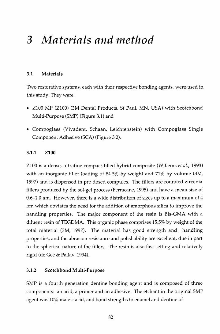
3 Materials and method
3.1 Materials
Two restorative systems, each with their respective bonding agents, were used in
this study. They were:
• Z100 MP (Z100) (3M Dental Products, St Paul, MN, USA) w ith Scotchbond
M ulti-Purpose (SMP) (Figure 3.1) and
• C om poglass (V ivadent, Schaan, Leichtenstein) w ith C om poglass Single
Com ponent Adhesive (SCA) (Figure 3.2).
3.1.1 Z100
Z100 is a dense, ultrafine compact-filled hybrid composite (Willems et al., 1993)
w ith an inorganic filler loading of 84.5% by w eight and 71% by volum e (3M,
1997) and is dispensed in pre-dosed compules. The fillers are rounded zirconia
fillers produced by the sol-gel process (Ferracane, 1995) and have a m ean size of
0.6-1.0 jum. However, there is a wide distribution of sizes up to a m axim um of 4
ium which obviates the need for the addition of am orphous silica to im prove the
handling properties. The major com ponent of the resin is Bis-GMA w ith a
d iluent resin of TEGDMA. This organic phase comprises 15.5% by w eight of the
total m aterial (3M, 1997). The m aterial has good streng th and hand ling
properties, and the abrasion resistance and polishability are excellent, due in part
to the spherical nature of the fillers. The resin is also fast-setting and relatively
rigid (de Gee & Pallav, 1994).
3.1.2 Scotchbond Multi-Purpose
SMP is a fourth generation dentine bonding agent and is com posed of three
components: an acid, a prim er and an adhesive. The etchant in the original SMP
agent was 10% maleic acid, and bond strengths to enamel and dentine of
82
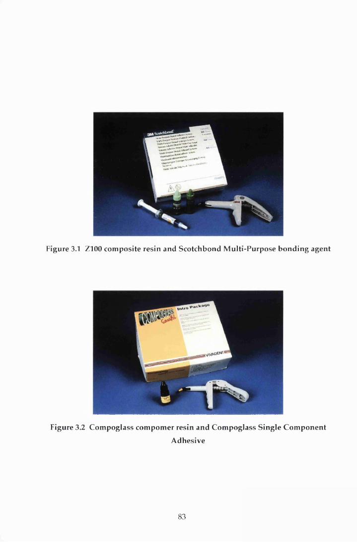
ufcdrtwntfMuU. d"*"*"sw» MW*“ S L * .
\V’V,vr' . .v .c,»v.i<W * ^ v ’
Figure 3.1 Z100 com posite resin and Scotchbond M ulti-Purpose bonding agent
inw°
Figure 3.2 Com poglass com pom er resin and Com poglass Single C om ponent
Adhesive
83

17.0 MPa and 21.8MPa respectively w ere achieved (Swift & Triolo, 1992).
M oreover, these values increased when 35% phosphoric acid was substitu ted as
the etchant w ith bond strengths of 24.5 MPa (Swift & Cloe, 1993) and 24.0 MPa
(3M, 1994) being reported for enamel and dentine respectively. The m ore recent
m aterials in the UK, and therefore in this study have used a phosphoric acid
etchant.
The prim er is com posed of the hydrophilic m onom er HEMA and an acid
copolym er, w hile the adhesive is based on Bis-GMA and HEMA and also
contains an initiator. In common w ith other fourth generation m aterials, SMP
em ploys total etch and moist bonding techniques. Successful m oist bonding is
dependent on the presence of the acid co-polymer (Gwinnett, 1992). Bonding is
achieved by the alteration of the sm ear layer and subsequent hybrid isation
(Section 2.7.2.2.1). In vitro microleakage does not appear to be affected adversely
w hen the dentine is left visibly moist (Saunders & Saunders, 1996), an advantage
w hen bonding to deeper, highly permeable dentine. The viscous adhesive results
in a relatively thick interm ediate resin layer w ith an identical stress-relaxation
buffer capacity as a low viscosity resin (Van Meerbeek et ah, 1994).
3.1.3 Compoglass
Com poglass is a single-com ponent, light-cured, fluoride-releasing com pom er
resin and is d ispensed in pre-dosed plastic com pules know n as Cavifils.
Com posite resin makes up 70% of the material, the rem ainder is glass-ionomer.
The resin is based on Bis-GMA and urethane dimethacrylate in a ratio of 1:2.3 by
w eight, and the m onom er has been m odified by add ing a cycloaliphatic
dicarboxylic acid dim ethacrylate (DCMA) (Vivadent, 1996). Com poglass has a
filler loading of 55.9% by w eight and 79% by volume. The fillers, sialinised
barium fluorosilicate glass and ytterbium trifluoride fillers, have a m ean particle
size of 1.6 Jim and are responsible for the fluoride release of the resin.
The m anufacturers claim that the resin sets via radical polym erisation and that
an auxiliary acid-base setting reaction occurs w hen the m aterial is placed in
water. However, no increase in compressive strength was found after storage in
w ater, and this secondary reaction has been questioned (Burgess et a l, 1996).
84

Bonding to enamel and dentine is purely reliant on micromechanical attachm ent
via a resin-reinforced hybrid layer form ed by the application of Com poglass
SCA.
3.1.4 Compoglass Single Component Adhesive
Com poglass SCA is a single-com ponent, light-curing, self-prim ing bonding
agent. It consists of a m ethacrylate-m odified polyacrylic acid, HEMA, water,
maleic acid, am m onium fluoride, photoinitiators and stabilisers. Acid-etching is
not required and the material bonds effectively to the dentinal sm ear layer via
the form ation of a hybrid layer. Bond strengths to enamel and dentine of 18 MPa
and 19 MPa respectively have been reported (Vivadent, 1996). In addition, the
presence of the fluoride ion results in fluoride release.
3.2 Method
3.2.1 Tooth selection
Caries- and restoration-free extracted perm anent hum an prem olar teeth, which
had been stored in 0.12% thym ol solution, were examined m acroscopically for
defects in the enamel and dentine. One hundred and eighty four were selected
and cleaned of superficial debris w ith a scalpel. They were then lightly pum iced
before being random ly allocated to three equal sized groups, A, B and C.
3.2.2 Cavity preparation
A butt-joint Class V cavity was prepared on both the buccal and lingual surfaces
of each tooth. Each tooth hosted a test and control cavity. The form er was cut
w ith a pulsed Er:YAG laser (Twinlight Dental Laser, Fotona d.d, Ljublijana,
Slovenia) (Figure 3.3) and the control cavity was cut w ith a d iam ond fissure bur
(#FG108008, Horico, Berlin, Germany) in a high-speed air-rotor handpiece. In
both cases an air / water coolant was used and the tooth and handpiece were held
by hand (Figure 3.4). The bur was changed after 20 cavities. Allocation of the
test and control surfaces was random. The cavities were prepared at the cervical
m argin of the tooth (Figure 3.5), w ith the coronal and gingival m argins in cervical
85
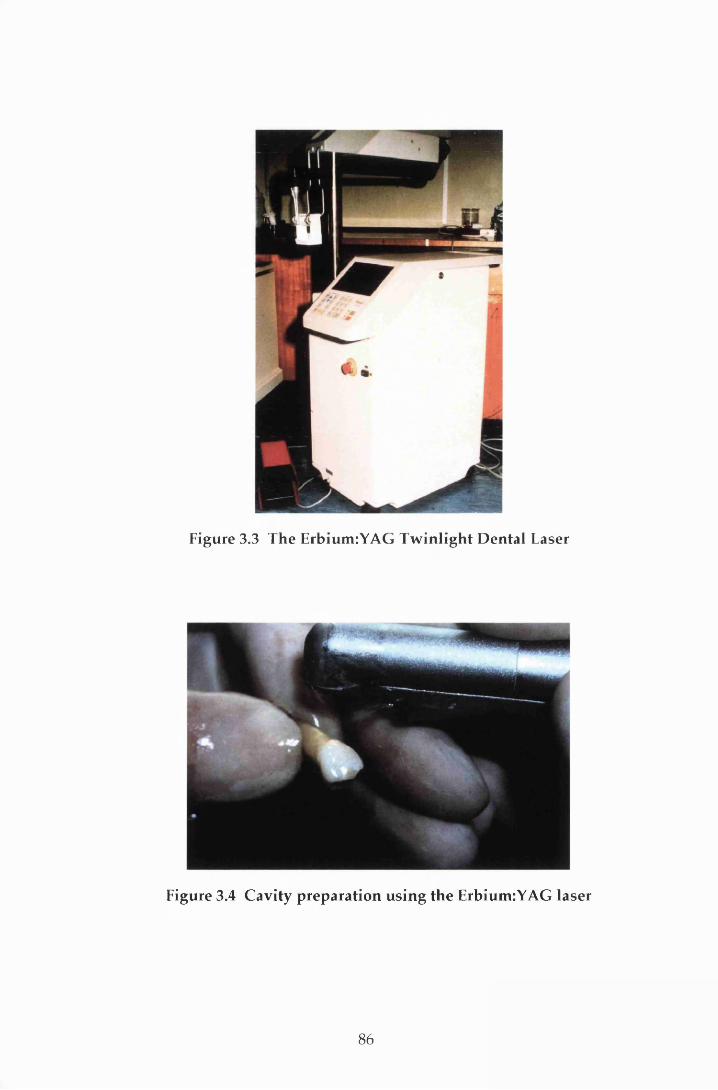
Figure 3.3 The Erbium:YAG Tw inlight D ental Laser
Figure 3.4 Cavity preparation using the Erbium:YAG laser
86
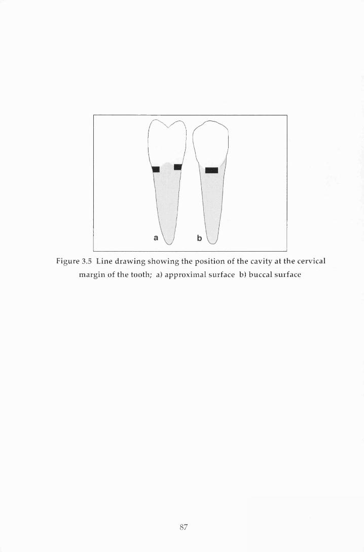
Figure 3.5 Line draw ing show ing the position of the cavity at the cervical
m argin of the tooth; a) approxim al surface b) buccal surface
87
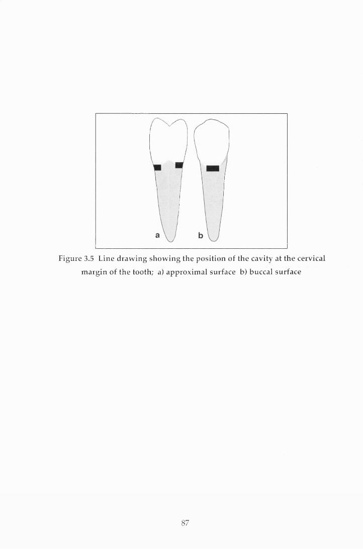
Figure 3.5 Line draw ing show ing the position of the cavity at the cervical
m argin of the tooth; a) approxim al surface b) buccal surface
87
enam el and dentine or cem entum respectively. The cavity size was m ade as
uniform as possible, 1.5 mm deep, 3 mm in w idth and 2 m m in height, using
m etal strip tem plates (Figure 3.6). A two stage im pression of each cavity was
then taken using Extrude addition cured silicone elastomeric im pression material
(Kerr, Romulus, MI, USA) in a purpose-m ade tray. These were stored for SEM
analysis in another study. On completion the teeth were returned to the thymol
solution.
3.2.2.2 Laser parameters
Local laser protection guidelines were followed during lasing. The operating
param eters were selected on the control panel (Figure 3.7). A pulse repetition
rate of 5 Hz was used. This is known to ablate enamel and dentine w ith minimal
therm al dam age (Li et al., 1992). The teeth in each of the three groups (A, B and
C) were random ly divided into three subgroups, so enabling three different laser
energies to be tested on each group; one on each subgroup w ithin a group. The
three laser energies selected were 200 mj, 240 m j and 300 mj. Charring of the
dentine was seen at the latter pulse energy (Figure 3.8) and therefore a 100 mj
dentine finish was used for the 300 mj cavities only. For clarity, the subgroups
w ere identified using the suffixes 200, 240 and 300. The air p ressure w as
m aintained at a constant 20 PSI, and the w ater mist was provided from a hand-
pum ped plastic container. The m axim um pressure for this w as selected by
qualitative assessment of the resistance felt during hand-pum ping.
3.2.3 Cavity restoration
The teeth in groups A and B were restored with SMP and Z100 resin (shade A3.5)
according to the m anufacturer's instructions: each cavity w as lightly cleaned
w ith a pum ice and w ater slurry in a rubber cup. They were then w ashed and
dried w ith compressed, oil-free water and air from a 3-in-l syringe. Total etching
was perform ed w ith the 35% phosphoric acid gel for 15 seconds, then each cavity
was w ashed copiously w ith w ater for 15 seconds before being dried gently w ith
com pressed air for 5 seconds. The prim ing agent was applied and w as lightly
dried im m ediately w ith air for 2 seconds. Following this, the adhesive was
applied with a brush and light-cured for 10 seconds with a visible light activating
88
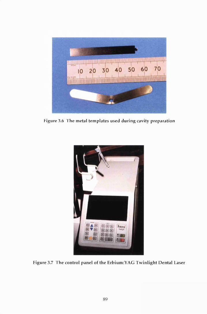
Figure 3.6 The metal templates used during cavity preparation
Figure 3.7 The control panel of the ErbiumiYAG T w inlight D ental Laser
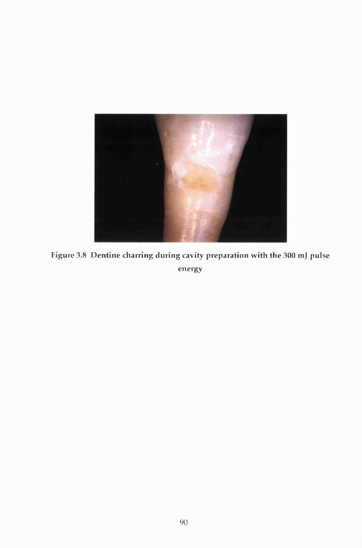
Figure 3.8 D entine charring during cavity preparation w ith the 300 mj pulse
energy
90

unit (Luxor, ICI Macclesfield, UK). The composite resin was applied in three
increm ents. The first two were applied obliquely against the occlusal and the
gingival w alls respectively. The final increm ent w as placed flush w ith the
contour of the tooth and covered with a transparent cellulose acetate m atrix strip
to both assist in packing and contouring, and reduce oxygen inhibition during
polym erisation. Each increm ent was light-cured for 40 seconds. Finishing was
carried out im m ediately after polym erisation using graded Soflex discs (3M
Dental Products, St Paul, MN, USA) according to the m anufacturer's instructions.
The initial stages of the protocol for the restoration of group C w as identical to
that described for groups A and B (i.e. cleaning w ith pum ice and w ater slurry
and w ashing and drying with compressed w ater and air). The cavities were then
restored with Compoglass SCA and Compoglass resin (shade A3.5) following the
m anufacturer's instructions. The bonding agent was applied to the cavity for 20
seconds, follow ing w hich it was d istributed w ith air and light-cured for 20
seconds. A second layer of Com poglass SCA was applied and im m ediately
distributed w ith blown air before being light-cured for 20 seconds. The resin was
applied increm entally and cured as for groups A and B and then the restoration
was finished and polished with graded Soflex discs.
3.2.4 Storage and thermocycling
Following restoration, group A was stored for 24 hours and groups B and C were
stored for 3 m onths in 0.12% thymol solution at a constant tem perature of 37 °C.
Each tooth was then thermocycled through w ater baths at 5 °C, 37 °C, 55 °C and
37 °C, w ith a 10 seconds dwell time in each bath for 240 cycles (Figure 3.9) before
being returned to the thym ol solution at 37 °C for 12 hours. Care was taken to
avoid dehydra tion at any stage of restoration and du rin g the subsequent
preparation for microleakage.
3.2.5 Microleakage assessment
M icroleakage w as assessed using a dye penetration technique w ith in vitro
im m ersion (Section 2.5.2). The teeth were dried, the root apices sealed w ith
sticky wax and coated w ith two layers of nail varnish (Max Factor D iam ond
H ard, Procter and Gamble, Surrey, UK) to within 1 mm of the restoration. Once
91

Figure 3.9 The therm ocycling un it
92
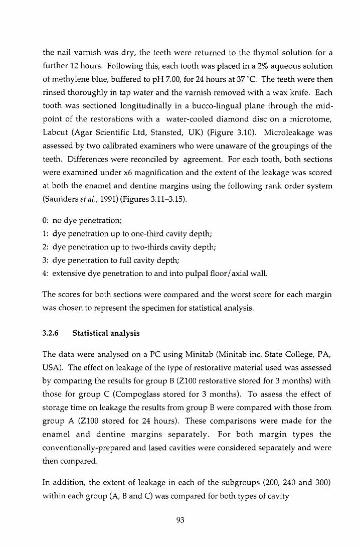
the nail varnish was dry, the teeth were returned to the thym ol solution for a
further 12 hours. Following this, each tooth was placed in a 2% aqueous solution
of m ethylene blue, buffered to pH 7.00, for 24 hours at 37 °C. The teeth w ere then
rinsed thoroughly in tap w ater and the varnish rem oved w ith a wax knife. Each
tooth w as sectioned longitudinally in a bucco-lingual plane th rough the m id
point of the restorations w ith a water-cooled diam ond disc on a m icrotom e,
Labcut (Agar Scientific Ltd, Stansted, UK) (Figure 3.10). M icroleakage w as
assessed by two calibrated examiners who were unaw are of the groupings of the
teeth. Differences were reconciled by agreement. For each tooth, both sections
w ere exam ined under x6 magnification and the extent of the leakage was scored
at both the enam el and dentine margins using the following rank order system
(Saunders et al., 1991) (Figures 3.11-3.15).
0: no dye penetration;
1: dye penetration up to one-third cavity depth;
2: dye penetration up to two-thirds cavity depth;
3: dye penetration to full cavity depth;
4: extensive dye penetration to and into pulpal floor/axial wall.
The scores for both sections were compared and the w orst score for each m argin
was chosen to represent the specimen for statistical analysis.
3.2.6 Statistical analysis
The data were analysed on a PC using Minitab (Minitab inc. State College, PA,
USA). The effect on leakage of the type of restorative m aterial used was assessed
by com paring the results for group B (Z100 restorative stored for 3 months) w ith
those for group C (Compoglass stored for 3 months). To assess the effect of
storage time on leakage the results from group B were com pared w ith those from
group A (Z100 stored for 24 hours). These com parisons w ere m ade for the
enam el and d en tin e m arg ins separate ly . For bo th m arg in types the
conventionally-prepared and lased cavities were considered separately and were
then compared.
In addition, the extent of leakage in each of the subgroups (200, 240 and 300)
w ithin each group (A, B and C) was compared for both types of cavity
93
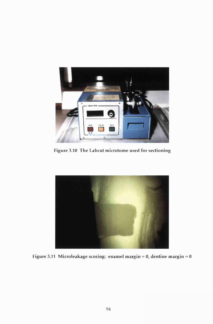
Figure 3.10 The Labcut m icrotom e used for sectioning
Figure 3.11 M icroleakage scoring: enam el m argin = 0, dentine m argin = 0
94
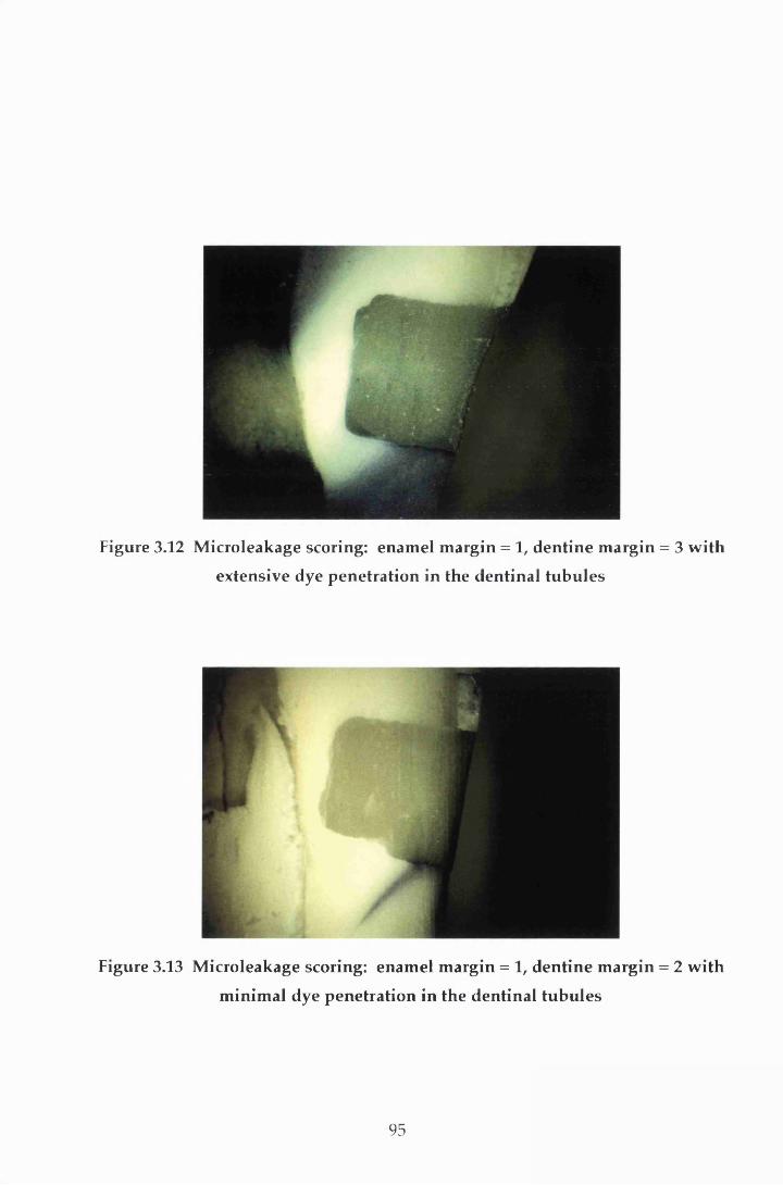
Figure 3.12 M icroleakage scoring: enam el m argin = 1, dentine m argin = 3 w ith
extensive dye penetration in the dentinal tubu les
Figure 3.13 M icroleakage scoring: enam el m argin = 1, dentine m argin = 2 w ith
m inim al dye penetration in the dentinal tubu les
95

Figure 3.14 M icroleakage scoring: enam el m argin = 2, dentine m argin = 4 w ith
m inim al dye penetration in the dentinal tubu les
Figure 3.15 M icroleakage scoring: enam el m argin = 2, dentine m argin = 4 w ith
extensive dye penetration in the dentinal tubu les
96
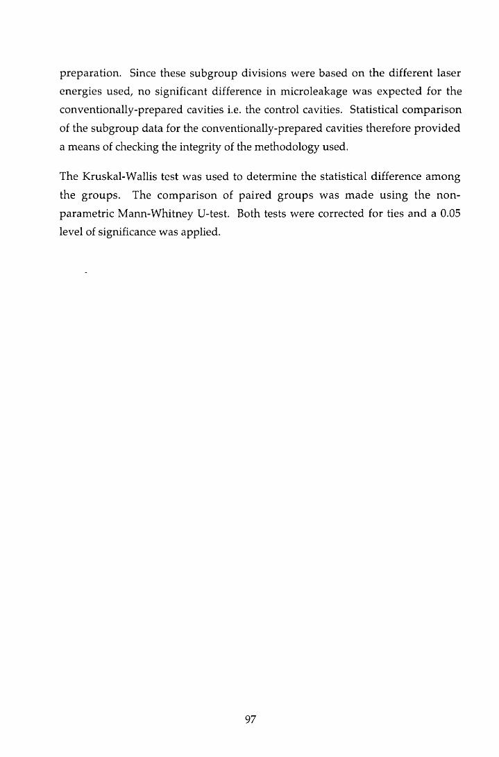
preparation. Since these subgroup divisions were based on the different laser
energies used, no significant difference in microleakage w as expected for the
conventionally-prepared cavities i.e. the control cavities. Statistical com parison
of the subgroup data for the conventionally-prepared cavities therefore provided
a means of checking the integrity of the methodology used.
The Kruskal-W allis test was used to determ ine the statistical difference am ong
the groups. The com parison of paired groups w as m ade using the non-
param etric M ann-W hitney U-test. Both tests were corrected for ties and a 0.05
level of significance was applied.
97

4 Results
4.1 Introduction
There was evidence of dye penetration, and therefore microleakage, to a greater
or lesser extent, in teeth from each of the groups (Table 4.1). As indicated in
Section 3.2.6, ranking the degree of microleakage enabled the data to be analysed
statistically. The results of these analyses are reported below for the two m argin
types following the fram ew ork described in Section 3.2.6. W here appropriate,
the results have been illustrated using graphs annotated w ith the levels of
significance.
4.2 Enamel margins
4.2.1 Conventionally-prepared enamel margins
4.2.1.1 Within-group analyses
For the conventionally-prepared enamel margins, the Kruskal-Wallis test show ed
no significant difference in leakage at the 95% significance level be tw een
subgroups 200, 240 and 300 for each of the three groups, A, B and C (p = 0.21,
p = 0.53 and p = 0.86 respectively). As indicated in Section 3.2.6, this provided an
indication of the integrity of the m ethodology used. It also m eant that these
subgroup leakage scores could be combined for further com parisons involving
only the conventionally-prepared cavities (i.e. the intergroup analysis in Section
4.2.1.2 and the enamel versus dentine analysis in Section 4.4).
4.2.1.2 Intergroup analyses
As discussed in Section 3.2.6, to assess the effect of storage time on the degree of
leakage, the group A scores were compared to those from group B. The effect of
the restorative material on the degree of leakage was assessed by com paring the
98

Table 4.1 Microleakage scores for all cavities
Restoration Group N Margin Conventionally- prepared scores
Lased scores
0 1 2 3 4 0 1 2 3 4
Group A A200 20 Enamel 3 13 3 1 0 3 11 6 0 0
Z100 and A200 20 Dentine 0 12 0 0 8 0 7 1 0 12
SMP stored A240 23 Enamel 3 7 11 1 1 4 1 16 2 0
for 24 hours A240 23 Dentine 4 11 3 0 5 1 4 4 2 12- A300 20 Enamel 5 6 6 2 1 4 5 9 1 1
A300 20 Dentine 1 8 5 1 5 0 7 6 1 6
Group B B200 20 Enamel 11 7 1 1 0 5 12 1 2 0
Z100 and B200 20 Dentine 2 4 6 2 6 0 1 1 2 16
SMP stored B240 20 Enamel 15 2 2 0 1 12 7 1 0 0
for 3 months B240 20 Dentine 1 4 3 2 10 0 1 0 0 19
B300 20 Enamel 11 7 2 0 0 13 6 1 0 0
B300 20 Dentine 8 1 4 0 7 3 3 1 1 12
Group C C200 20 Enamel 8 9 2 1 0 12 6 2 0 0
Com poglass C200 20 Dentine 7 4 7 1 1 6 7 7 0 0
and SCA C240 20 Enamel 8 8 4 0 0 18 2 0 0 0
stored C240 20 Dentine 5 7 6 1 1 9 5 3 2 1
for 3 months C300 21 Enamel 9 10 1 0 1 11 8 1 0 1
C300 21 Dentine 7 7 6 0 1 11 3 4 0 3
99
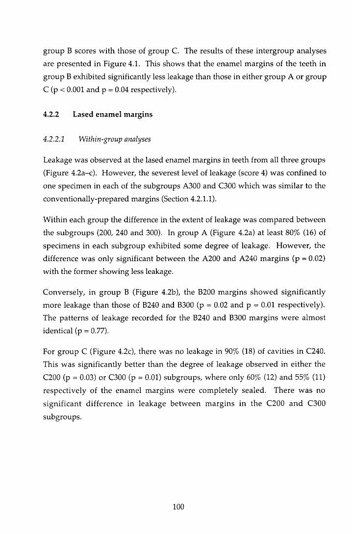
group B scores w ith those of group C. The results of these in tergroup analyses
are presented in Figure 4.1. This shows that the enam el m argins of the teeth in
group B exhibited significantly less leakage than those in either group A or group
C (p < 0.001 and p = 0.04 respectively).
4.2.2 Lased enam el m argins
4.2.2.1 Within-group analyses
Leakage was observed at the lased enamel margins in teeth from all three groups
(Figure 4.2a-c). However, the severest level of leakage (score 4) was confined to
one specimen in each of the subgroups A300 and C300 which was sim ilar to the
conventionally-prepared margins (Section 4.2.1.1).
W ithin each group the difference in the extent of leakage was com pared betw een
the subgroups (200, 240 and 300). In group A (Figure 4.2a) at least 80% (16) of
specimens in each subgroup exhibited some degree of leakage. H ow ever, the
difference w as only significant betw een the A200 and A240 m argins (p = 0.02)
w ith the former showing less leakage.
Conversely, in group B (Figure 4.2b), the B200 m argins show ed significantly
m ore leakage than those of B240 and B300 (p = 0.02 and p = 0.01 respectively).
The patterns of leakage recorded for the B240 and B300 m argins w ere alm ost
identical (p = 0.77).
For group C (Figure 4.2c), there was no leakage in 90% (18) of cavities in C240.
This was significantly better than the degree of leakage observed in either the
C200 (p = 0.03) or C300 (p = 0.01) subgroups, where only 60% (12) and 55% (11)
respectively of the enam el m argins were com pletely sealed. There w as no
significant difference in leakage betw een m argins in the C200 and C300
subgroups.
100

Num
ber
of te
eth
40 t
37
0 1 2 3 4
IIIIIII140 2 31
111! A Enamel Conventional l l l l B Enamel Conventional III! C Enamel Conventional
A v B p < 0.001 B v C p = 0.04
27
1 1■■■■■■■■mi
3 4
Microleakage scores
Figure 4.1 M icroleakage seen at the enam el m argins of conventionally-
prepared cavities
101
2994
49
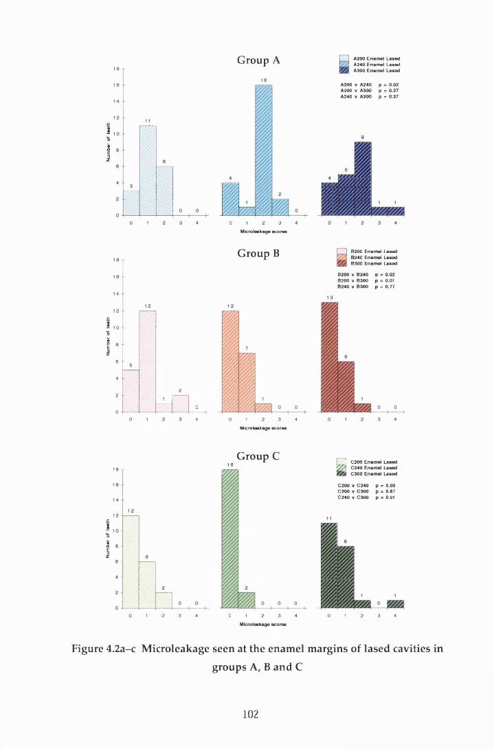
Num
ber
of te
eth
Num
ber
of te
eth
Num
ber
of te
eth
1Group A A200 Enam el Lased
A240 Enam el Lased A300 Enam el Lased
A200 V A 240 p = 0.02A200 V A300 p = 0.27A240 V A300 p = 0.37
00 2 34 1 4
Microleakage sco r es
G roup C1 8
0 1 2 3 4 0 1 2 3 4 0 1 2 3 4
Microleakage sco r es
Figure 4.2a-c Microleakage seen at the enamel margins of lased cavities in
groups A, B and C
0 1 2 3
Microleakage sco r es
G roup B I B200 Enamel Lased B240 Enamel Lased B300 Enamel Lased
B200 V B240 p = 0.02B200 V B300 p = 0.01B240 V B300 p = 0.77
j C200 Enam el Lased□ C240 Enam el Lased B S a C300 Enam el Lased
C200 V C 240 p = 0.03C200 V C 300 p = 0.67C240 V C 300 p = 0.01
102

4 2 .2 .2 Intergroup analyses
As with the conventionally-prepared cavities (Section 4.2.1.2), the group B results
w ere com pared with the leakage seen at the enamel m argins of teeth in groups A
(Figure 4.3) and C (Figure 4.4).
For all three subgroups (200, 240 and 300), the group B cavities exhibited less
extensive microleakage than those of group A. However, the difference w as only
significant for subgroups A240 compared to B240 (p < 0.001) and A300 com pared
to B300 (p < 0.001). This pattern of leakage was similar to that reported for the
conventionally-prepared margins in enamel (Section 4.2.1.2).
C om parison of the results from group B w ith those from group C show ed
significantly less leakage at the enamel m argins in subgroups C200 (p = 0.04) and
C240 (p = 0.03) com pared to subgroups B200 and B240 respectively (Figure 4.4).
In contrast, the difference in leakage betw een subgroups B300 and C300 was
insignificant (p = 0.39).
4.2.3 Conventionally-prepared versus lased enamel margins
The extent of dye penetration at the conventionally-prepared enam el m argins
was com pared to that at the enamel m argins prepared w ith the Er:YAG laser
(Figure 4.5a-c).
For group A (Figure 4.5a), the lased m argins in subgroups A200 and A240
show ed evidence of greater leakage than those in the sam e conventionally-
prepared subgroups. However, the extent of leakage in the A300 lased m argins
was less than that observed in the A300 conventionally-prepared margins. None
of the differences described above was significant (p > 0.05).
Com parison of the results from the group B lased m argins w ith those from the
group B conventionally-prepared margins (Figure 4.5b) show ed a similar pattern
to group A, i.e. greater leakage along the lased B200 and B240 m argins and less
leakage along the lased B300 m arg ins com pared to th e ir resp ectiv e
conventionally-prepared margins. Again the differences were not significant
(p > 0.05).
103
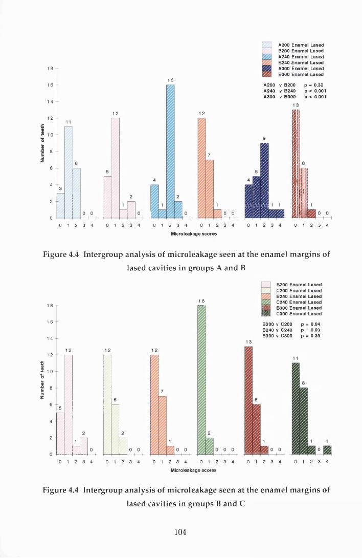
1 8
1 6
1 4
1 2
8
6
4
2
00 1 2 3 4
A200B200A240B240A300B300
EnamelEnamelEnamelEnamelEnamelEnamel
LasedLasedLasedLasedLasedLased
1 6
0 1 2 3 44
A200 v B200 A240 v B240 A300 v B300
p = 0.32 p < 0 .0 0 1 p < 0 .0 0 1
1 2
0 0 1 b0 1 2 3 4
Microleakage scores
Figure 4.4 Intergroup analysis of m icroleakage seen at the enam el m argins of
lased cavities in groups A and B
1 8
1 6
1 4
1 2
£®2 1 o
4
0 1 2 3 4 0 1 2 3 44 0 1 2 3 4
B200 Enamel Lased C200 Enamel Lased B240 Enamel Lased C240 Enamel Lased B300 Enamel Lased C300 Enamel Lased
B200 v C200 p = 0.04B240 V C240 p = 0.03B300 v C300 p = 0.39
0 1 2 3 4 0 1 2 3 4
Microleakage scores
Figure 4.4 Intergroup analysis of microleakage seen at the enamel margins of
lased cavities in groups B and C
104

Group A A200 Enamel Lased A200 Enamel Conventional A240 Enamel Lased A240 Enamel Conventional A300 Enamel Lased A300 Enamel Conventional
A200 Lased v A200 Conventional p = 0.72 A240 Lased v A240 Conventional p = 0.40 A300 Lased v A300 Conventional p = 0 .73
Microleakage scores
Group B
t=K
B200 Enamel Lased B200 Enamel Conventional B240 Enamel Lased B240 Enamel Conventional B300 Enamel Lased B300 Enamel Conventional
D 0
p = 0.08p = 0.52 p = 0.48
0 1 2 3 4 0 1 2 3 4 0 1 2 3 4
Microleakage sco res
G roup C C200 Enamel Lased 0200 Enamel Conventional C240 Enamel Lased
^ C240 Enamel Conventional rSyj C300 Enamel Lased m 0300 Enamel Conventional
C200 Lased v C2O0 Conventional p = 0.23C240 Lased v C240 C onventional p < 0.001C300 Lased v C300 Conventional p = 0.61
3 4 0 1 2 3 4
Microleakage sco r es
Figure 4.5a-c A nalysis of the m icroleakage seen at the lased and
conventionally-prepared enam el m argins in groups A, B and C
105

In contrast to groups A and B, the group C lased enam el m argins show ed
evidence of less leakage in subgroups C200 and C240 and more leakage in C300
than those prepared conventionally (Figure 4.5c). However, the differences were
only significant for the C240 subgroups (p < 0.001).
4.3 Dentine margins
4.3.1 Conventionally-prepared dentine margins
4.3.2.2 Within-group analyses
There were examples in all three groups of scores for m axim um leakage at the
den tine m argins (Figure 4.6). In group C this am ounted to 5% (3) of the
specimens but rose to 29%(18) and 38% (23) for groups A and B respectively. The
K ruskal-W allis test again (see Section 3.2.6) found no statistical difference
betw een the subgroups in each of the three groups A, B and C (p = 0.37, p = 0.18
and p = 0.76 respectively), and therefore the subgroup leakage scores w ere again
com bined for further statistical analyses involving only the conventionally-
prepared cavities.
4.3.1.2 Intergroup analyses
In contrast to the leakage seen at the enamel m argins (Section 4.2.1.2), the dentine
m argins in group C dem onstrated a significantly better seal than those of group
B (p < 0.001; Figure 4.6). No significant difference was seen betw een groups A
and B at the dentine margin.
4.3.2 Lased dentine margins
4.3.2.1 Within-group analyses
The leakage observed at the dentine margins in the three lased cavity groups is
com pared in Figure 4.7a-c. With the exception of C200, all subgroups in each
group had at least one tooth which exhibited m axim um dye penetration at the
dentine margin. In group A, there was no significant difference in microleakage
betw een the three pulse energies (p > 0.05; Figure 4.7a).
106
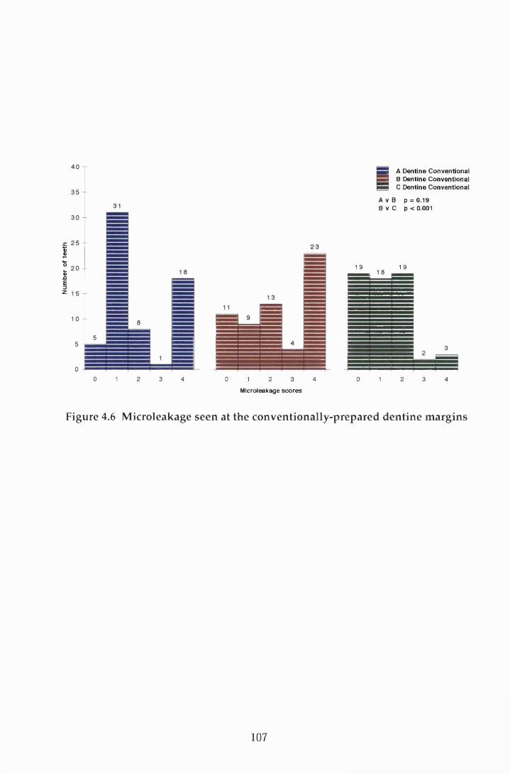
Num
ber
of te
eth
1 9
S A Dentine Conventional S B Dentine Conventional
B B C Dentine Conventional
A V B p = 0.19 B v C p < 0.001
1 9
0 1 2 3 4 0 1 2 3 4
Microleakage scores
0 1 2 3 4
Figure 4.6 M icroleakage seen at the conventionally-prepared dentine m argins
107
155579999999
3330

Num
ber
of te
eth
Num
tw
of to
oth
Num
bor
of
toot
h
2 0
8
6
4
2
08
64
2
02 30 1 4
Group A A200 Dentine Lased A240 Dentine Lased A300 Dentine Lased
A200 v A240 A200 V A300 A240 V A300
p = 0.97 p = 0.27 p = 0.16
0 1 2 3 4
Micro leakage scores
2 0
8
08
64
2
00 1 2 3 4
G roup B
a10 2 3 4
j___ 4 B200 D entine Lased! J B240 D entine Lased 9 S S B300 D entine Lased
B200 V B240 p = 0.19B200 V B300 p = 0.10B240 V B300 p = 0.01
M icroleaksge sco r es
G roup C C200 Dentine Lased C240 Dentine Lased C300 Dentine Lased
C200 v C240 C200 V C300 C240 v C300
p = 0.66 p = 0.54 p = 0.89
Figure 4.7a-c Microleakage seen at the dentine margins of lased cavities ingroups A, B and C
0 1 2 3 4
M icroieakage sco r es
108

There w as very close correlation between the degree of leakage exhibited at the
dentine m argins of the A200 and A240 subgroups (p = 0.97).
G roup B show ed similar patterns of leakage to group A (Figure 4.7b). However,
the dye penetration was m ore severe across all subgroups. The B300 m argins
exhibited less microleakage than both the B200 and B240 dentine m argins bu t the
difference was only significant for the latter (p = 0.01). Again no significant
difference was found in leakage between the B200 and B240 subgroups (p > 0.05).
C om parison of the dentine m argins w ithin the subgroups of group C (Figure
4.7c) showed no statistical difference in leakage between the three pulse energies.
4:32.2 Intergroup analyses
Intergroup analysis between the subgroups of A and B (Figure 4.8) revealed that
the leakage at the dentine m argins was m ore severe for all subgroups of B
com pared to their respective subgroups in group A. This is in contrast to the
leakage found at the enamel margins (Section 4.2.2.2). However, the difference
was only significant between A240 and B240 (p = 0.003). This pattern of leakage
was sim ilar to that reported for the conventionally-prepared dentine m argins
(Section 4.3.1.2).
Com parison of the results for groups B and C (Figure 4.9) show ed significantly
w orse leakage for B200, B240 and B300 com pared to the respective subgroups in
C (p < 0.001, p < 0.001 and p = 0.002 respectively).
4.3.3 C onventionally-prepared versus lased dentine m argins
As for the enam el margins, the extent of dye penetration in the conventionally-
prepared groups was compared to that of the lased cavities (Figure 4.10a-c).
Com parison of the dentine margins in group A (Figure 4.10a), indicated that the
extent of microleakage was less for the conventionally-prepared cavities than it
was for the lased cavities. However, the difference was only significant for the
A240 subgroup (p = 0.005).
109
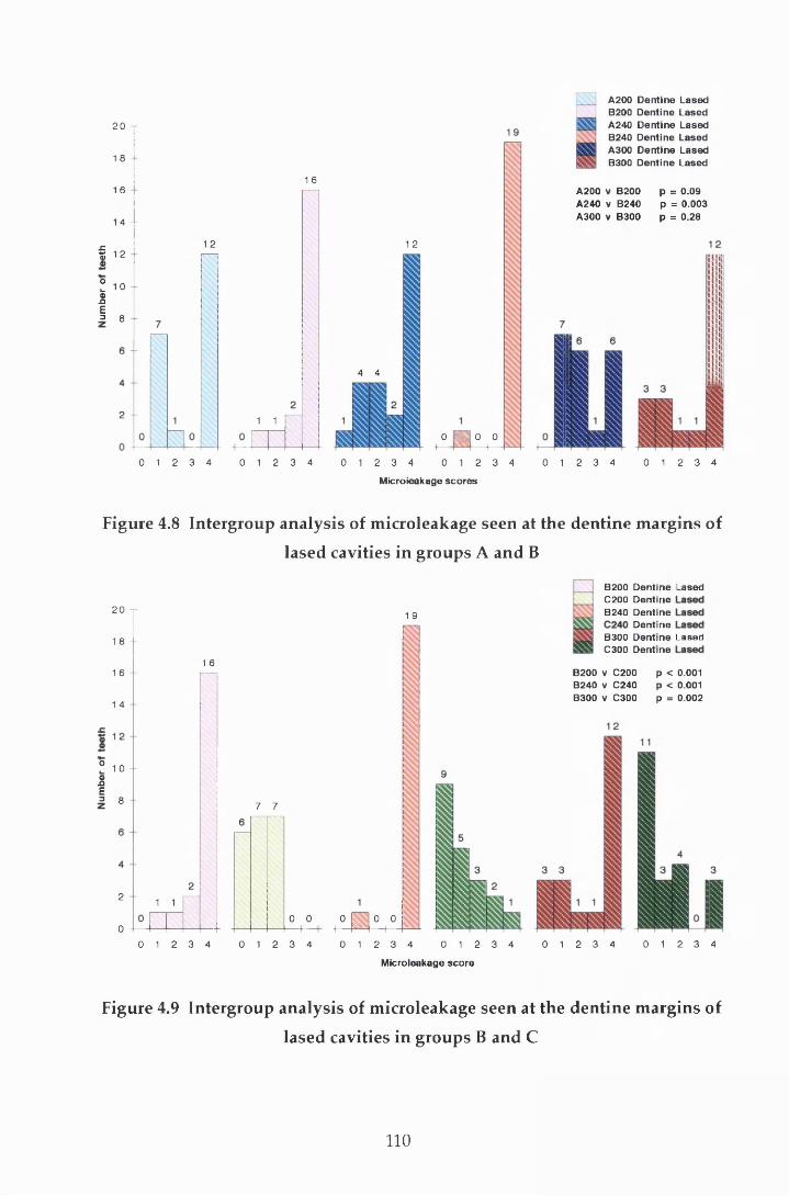
20
1 8
1 6
1 4 - -
f 12
I 10IDnE= 8
1 6
12
1 1
1 2
4 4
0 1 2 3 4 0 1 2 3 4
0 555 0 01------ f—0 1 2 3 4 0 1 2 3 4
Microieakage scores
A200 Dentine Lased B200 Dentine Lased A240 Dentine Lased B240 Dentine Lased A300 Dentine Lased B300 Dentine Lased
A200 v B200 p = 0.09A240 v B240 p = 0.003A300 v B300 p = 0.28
0 1 2 3 4 0 1 2 3 4
Figure 4.8 Intergroup analysis of m icroieakage seen at the dentine m argins of
lased cavities in groups A and B
20
1 8
1 6
1 4
Z 10£E= 8
2
0
1 9
1 6
1 1
7 7
0 0 0 „ H—ra o o— i—
B200 Dentine LasedC200 DentineB240 Dentine
DentineB300 Dentine LasedC300 Dentine
B200 V C200 p < 0.001B240 v C240 p < 0.001B300 V C300 p = 0.002
0 1 2 3 4 0 1 2 3 4 0 1 2 3 4 0 1 2 3 4
Microieakage score
0 1 2 3 4 0 1 2 3 4
Figure 4.9 Intergroup analysis of microieakage seen at the dentine margins of
lased cavities in groups B and C
110

Group A A200 Dentine Lased A200 Dentine Conventional A240 Dentine Laaed A240 Dentine Conventionai A300 Dentine Lased A300 Dentine Conventional
A200 Lased v A200 Conventional A240 Lased v A240 Conventional A300 Lased v A300 Conventional
p = 0.16p = 0.005 p = 0.51
0 1 2 3 4 0 1 2 3 4 0 1 2 3 4 0 1 2 3 4 0 1 2 3 4 0 1 2 3 4
Microieakage scores
G roup B ( B200 Dentine LasedB200 Dentine Conventional
I B240 Dentine Lased ] B240 Dentine Conventionai j B300 Dentine Lased | B300 Dentine Conventional
B200 Lased v B200 Conventional p = 04)1B240 Lased v B240 Conventional p = 04)03B300 Lased v B300 Conventional p = 04)9
Microieakage scores
G roup C [ C200 Dentine LasedI C200 Dentine ConventionalC W C240 Dentine LasedE g C240 Dentine Conventional
S C300 Dentine LasedS C300 Dentine Conventional
C200 Lased v C200 Conventional p = 0.69C240 Lased v C240 Conventional p = 0 3 5C300 Lased v C300 Conventional p = 0.59
Microieakage scores
Figure 4.10a-c A nalysis of the m icroieakage seen at the lased and
conventionally-prepared dentine m argins in groups A, B and C
111

A sim ilar pattern was observed for the group B cavities w here the extent of
leakage at the dentine m argins was less for the conventionally-prepared cavities
com pared to the lased cavities for all three subgroups. However, the difference
w as only significant for the B200 and B240 subgroups (p = 0.01 and p = 0.003
respectively; Figure 4.10 b).
In contrast to groups A and B, in group C the lased margins show ed less leakage
than those that had been conventionally prepared. However, the differences
were not significant for any of the three subgroups (p < 0.05; Figure 4.10c).
4.4 Enamel versus dentine
4.4.1 Conventionally-prepared margins
Because of the lack of statistical significance betw een the subgroups of each
group, the subgroup leakage scores w ere com bined for the analysis of the
d ifference betw een leakage at the enam el and den tine m arg ins of the
conventionally-prepared cavities for groups A, B and C (see Section 4.2.1.1) In all
three groups (Figure 4.11), the enamel m argins dem onstrated less leakage than
the dentine margins. However, despite 29% (18) of the dentine m argins in group
A scoring the m axim um of 4, the differences in m icroieakage w ere only
significant for groups B (p < 0.001) and C (p = 0.02).
4.4.2 Lased margins
Figure 4.12 illustrates the extent of microieakage observed in the lased cavities.
For all groups, the seal at the enamel margins was better than the dentine m argin
seal. Indeed, w ith the exception of the A300 subgroup, m ore than half the
dentine m argins for groups A (Figure 4.12a) and B (Figure 4.12b) exhibited
extensive dye penetration beyond the full cavity depth (i.e. score 4). This was in
m arked contrast to group C where leakage at the dentine m argin was lim ited to
the outer third of the cavity depth (i.e. score 0 or 1) in at least 65% (13) of the
samples, w ith many showing no leakage (Figure 4.12c). The difference in leakage
betw een the enam el and dentine m argins was not significant for the A300
(p = 0.08) and C300 (p = 0.51) cavities. Analysis of the other subgroups revealed
112
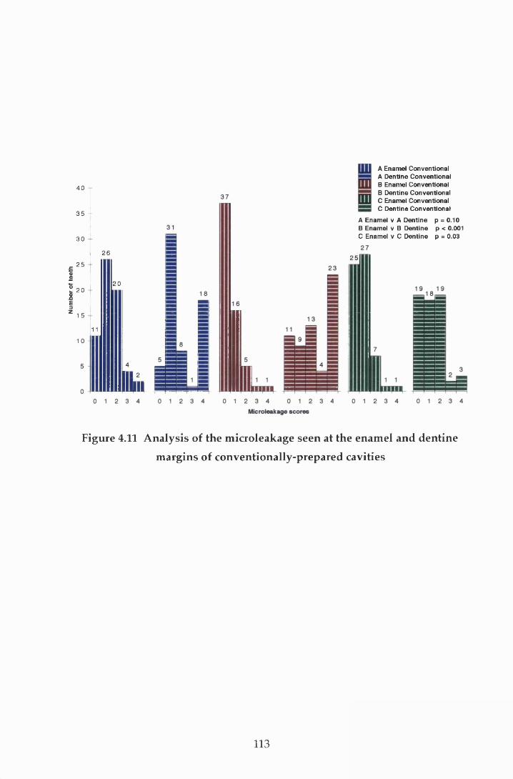
Num
ber
of te
eth
40
3 5 -
30
25
20
1 5
26
1 011
20
IHUIdl
A Enamel Conventional A Dentine Conventional B Enamel Conventional B Dentine Conventional C Enamel Conventional C Dentine Conventional
A Enamel v A Dentine p = 0.10 B Enamel v B Dentine p < 0.001 C Enamel v C Dentine p = 0.03
Figure 4.11 A nalysis of the m icroieakage seen at the enam el and dentine
m argins of conventionally-prepared cavities
113
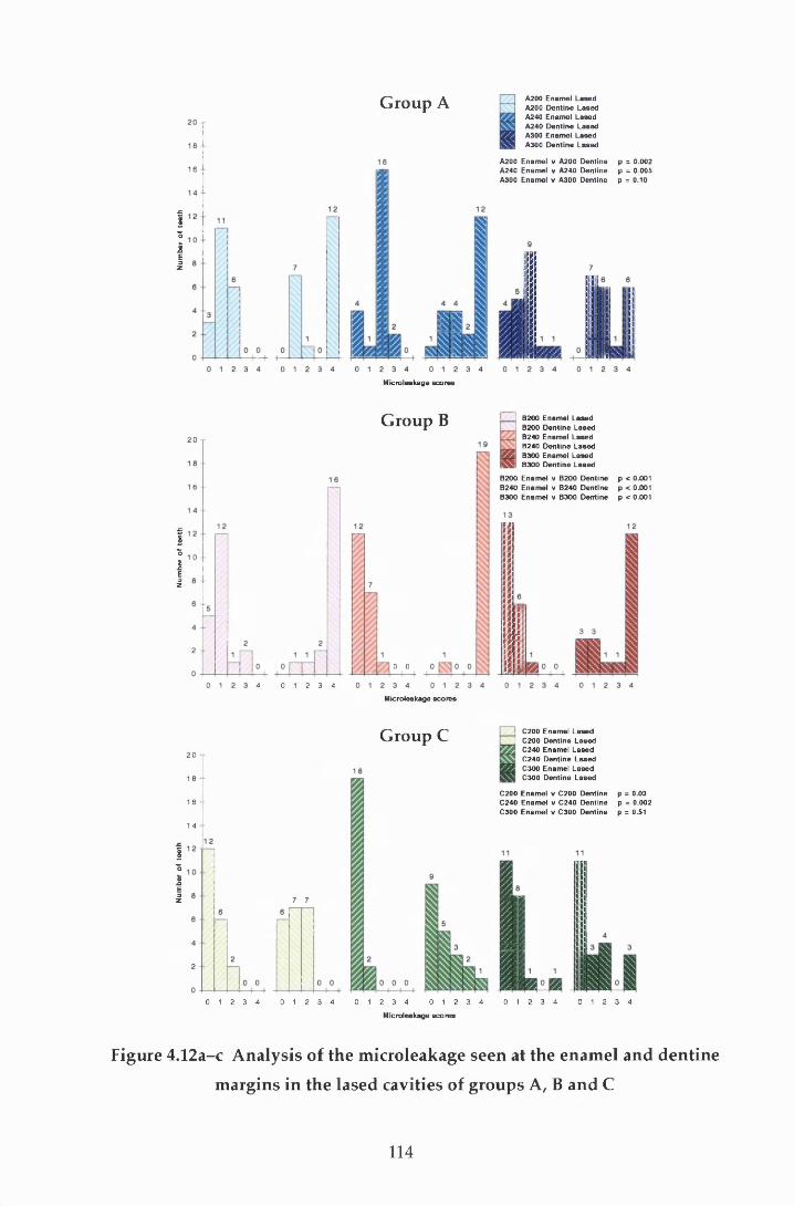
Num
ber
of te
eth
Num
ber
of te
eth
Num
ber
of te
eth
Group A A200 Enamel Lased A200 Dentine Lased A240 Enamel Lased A240 Dentine Lased A300 Enamel Lased A300 Dentine Lased
A200 Enamel v A200 Dentine A240 Enamel v A240 Dentine A300 Enamel v A300 Dentine
Microieakage scores
p = 0.002p = 0.005 p = 0.10
G roup B
4 0 1 2 3 4
0 0
B200B200B240B240B300B300
Enamel Lased Dentine Lased Enamel Lased Dentine Lased Enamel Lased Dentine Lased
B200 Enamel v B200 Dentine p < 0.001B240 Enamel v B240 Dentine p < 0.001B300 Enamel v B300 Dentine p < 0.001
Microieakage scores
G roup C2 0
18 1 6 -
1 4
C200 Enamel Lased C200 Dentine Lased C240 Enamel Lased C240 Dentine Lased C300 Enamel Lased C300 Dentine Lased
C200 Enamel v C200 Dentine p = 0.03C240 Enamel v C240 Dentine p = 0.002C300 Enamel v C300 Dentine p = 0.51
0 1 2 3 4 0 1 2 3 4 0 1 2 3 4 0 1 2 3 4 0 1 2 3 4 0 1 2 3 4
Microieakage scores
Figure 4.12a-c A nalysis of the m icroieakage seen at the enam el and dentine
m argins in the lased cavities of groups A, B and C
114
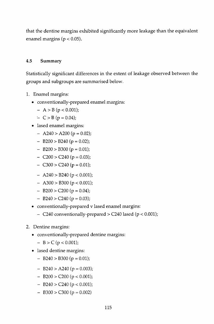
that the dentine m argins exhibited significantly more leakage than the equivalent
enamel m argins (p < 0.05).
4.5 Sum m ary
Statistically significant differences in the extent of leakage observed betw een the
groups and subgroups are summ arised below.
1. Enamel margins:
• conventionally-prepared enamel margins:
- A > B (p < 0.001);
- C > B (p = 0.04);
• lased enamel margins:
- A240 > A200 (p = 0.02);
- B200 > B240 (p = 0.02);
- B200 > B300 (p = 0.01);
- C200 > C240 (p = 0.03);
- C300 > C240 (p = 0.01);
- A240 > B240 (p < 0.001);
- A300 > B300 (p < 0.001);
- B200 > C200 (p = 0.04);
- B240 > C240 (p = 0.03);
• conventionally-prepared v lased enamel margins:
- C240 conventionally-prepared > C240 lased (p < 0.001);
2. Dentine margins:
• conventionally-prepared dentine margins:
- B > C (p < 0.001);
• lased dentine margins:
- B240 > B300 (p = 0.01);
- B240 > A240 (p = 0.003);
- B200 > C200 (p < 0.001);
- B240 > C240 (p < 0.001);
- B300 > C300 (p = 0.002)
115
• conventionally-prepared v lased dentine margins:
- A240 lased > A240 conventionally-prepared (p = 0.005);
- B200 lased > B200 conventionally-prepared (p = 0.01);
- B240 lased > B240 conventionally-prepared (p = 0.003).
3. Enamel v dentine margins
• conventionally-prepared margins:
- B dentine > B enamel (p < 0.001);
- C dentine > C enamel (p = 0.03);
• lased margins:
- A200 dentine > A200 enamel (p = 0.002)
- A240 dentine > A240 enamel (p = 0.005)
- B200 dentine > B200 enamel (p < 0.001)
- B240 dentine > B240 enamel (p < 0.001)
- B300 dentine > B300 enamel (p < 0.001)
- C200 dentine > C200 enamel (p = 0.03)
- C240 dentine > C240 enamel (p = 0.002)
116
5 Discussion
5.1 In troduction
The m ain purposes of restoring carious cavities are to arrest the disease process,
and to restore the form and function of the teeth in such a way that the health of
the dental tissues is m aintained. Adequate marginal integrity of a restoration is
therefore essential for the achievem ent of these goals. As no ted in Section
2.10.6.7, failure of the seal may contribute to staining, post-operative sensitivity,
an inflam m atory pulpal response and secondary caries, and as a result, m ay
necessitate the replacement of the restoration.
The control of m icroieakage in composite resins was discussed in Section 2.7.
From this review of the literature, it was evident that, while factors integral to the
m aterial itself w ere of relevance, of equal im portance w ere the restorative
techniques used, and the interplay betw een these and the choice of m aterial.
Underlying these factors, is the importance of good adaptation of the resin to the
cavity surface. For resin based m aterials, this is influenced by the surface
m orphology of the cavity following preparation, and the quality of the pattern
achieved following cavity etching or conditioning. The use of the Er:YAG laser
for cavity p rep ara tio n resu lts in a cavity w ith a sign ifican tly d ifferen t
m orphology to that achieved by conventional means (Aoki et al, 1998). Prior to
the introduction of the laser to routine clinical dentistry, it is essential to ensure
that its use does not affect the efficacy of the cavity seal at the enam el and
dentine m argins adversely. This study therefore sought to clarify this situation
for three laser pulse energies.
5.2 M ethodology
The study was carried out in vitro and therefore some aspects of the experim ental
w ork varied from that w hich w ould be expected clinically. N evertheless,
117
m easures w ere taken to ensure as close a rep resen ta tion as possible w as
achieved.
The laser was held by hand for the preparation of the cavities, and while care was
taken in positioning the handpiece so that the laser beam was focused, this relied
on clinical judgem ent and was more arbitrary than if the laser had been clamped
in a fixed position. O ther aspects of the experim ental set up were carefully
controlled. The water mist was provided under pressure from a hand-pum ped
plastic container. The effects of excess and insufficient w ater during the ablative
process were described in Section 2.10.6.4 and care was taken to ensure the water
pressure was m onitored and adjusted at regular intervals. However, the lack of
standardisation of this may have introduced confounding factors.
As noted in Section 2.2.2, variables in the composition and structure of dentine
occur w ith time because of ageing and environm ental influences. In addition,
w ith in vitro studies, the storage period and m edia m ay influence dentine
perm eability (G oodis et al.f 1991), dentine bonding (Sidhu et al., 1991) and
m icro ieakage (H aller et al., 1993a). In this study, because of the m ethod of
random allocation, no account was taken of either the age of the tooth, or the
storage time, w hen the teeth were placed in their groupings. In an attem pt to
lim it any errors this m ay have introduced, the teeth w ere stored in thym ol
solution. This is know n to have limited affect on microieakage w hen com pared
to teeth that are processed immediately post-extraction (Haller et al., 1993a).
The oral cavity presents a rapidly changing environm ent to any restoration.
Therm ocycling was therefore included in the sam ple processing m ethod to
provide a m easure of therm al challenge to the restorations. The tem peratures
used were w ithin the clinical range (Barclay, 1998) and the shortest dwell time
possible for the thermocycling unit was used.
The m arginal integrity at the CRI in enamel and dentine was assessed by scoring
the dep th of dye penetration of a single section in the m id-buccal plane,
perpendicular to the long axis of the tooth. This m ethod is one of the commonest
used but, as w ith all in vitro tests, it does have its lim itations. These were
discussed fully in Section 2.5.2 and so will not be considered further, other than
to note that, w hilst this m ethod gives neither a direct m easurem ent of the
118
likelihood, nor the degree of microieakage that could be expected clinically, it
does indicate a potential for leakage. Furtherm ore, as the significance of the
leakage seen in any one particular group can be related to the dye penetration
seen in the other treatm ent groups of teeth valid conclusions can be draw n.
Since Buonocore (1955) first reported the use of acid etching to produce a suitable
enam el surface for the m echanical bonding of com posite resin m aterials, a
succession of com posite m aterials and bonding agents have been developed.
These have show n an increasing im provem ent in the seal at b o th the
enam el/ restoration and dentine/restoration interfaces. A dequate sealing of the
enam el m argin has been easier to achieve than of dentine, and historically,
microieakage has been greater at the dentine m argin than that found at enamel.
In this study, microieakage was evident in some specimens at the enam el a n d /o r
dentine m argins in all groups of teeth (Table 4.1). This is in agreem ent w ith
previous studies reporting the microieakage of cavities restored w ith Z100 and
SMP (Vargas & Swift, 1994; Saunders & Saunders, 1996). However, the leakage
found at both the enamel and dentine margins in this study was greater than that
rep o rted in these earlier studies. R eports in the lite ra tu re describ ing
microieakage in Class V cavities at the cervical m argin which were restored with
the original com position of Compoglass, the com pom er used in this study, are
limited. However, in agreem ent w ith this study, in vitro studies em ploying this
m aterial have reported leakage at both the dentine and enamel m argins (Cortes et
a l, 1998; Ferrari et al, 1998).
5.3 O utline of discussion
The following discussion will first consider the results of the enam el/restoration
interface, looking initially at the conventionally -prepared m arg ins before
considering those prepared by the laser. Following this, the leakage seen at the
dentine/restoration interface is evaluated for both m ethods of cavity preparation.
119

5.4 The enamel/restoration interface
W hen considering the extent of dye penetration found at the enam el m argin, it is
pertinent to note that, because of the w idth of the enam el in the cervical region
and the criteria for scoring, a score of T is likely to indicate complete failure of
the enam el/restoration bond. Scores greater than this therefore represent failure
of both the enam el/restoration and dentine/ restoration bonds. Thus the severity
of leakage seen at the enamel CRI is, in some part, due to dentine leakage. The
stresses at the dentine /restoration bond at the coronal m argin are likely to have
differed to those at the cervical m argin because of the m ethod of increm ental
packing used. However, all other factors contributing tow ards microieakage will
have been similar. Therefore, for clarity, discussion on the possible reasons for
the leakage seen at the coronal m argin is confined to the consideration of the
enam el/resto ra tion interface only. Leakage at the cervical dentine m argin is
discussed in Section 5.5 and this section is confined to issues relating to the
enam el/restoration bond only.
5.4.1 Conventionally-prepared enamel margins
Despite the lack of uniform ity in the morphology of enamel found at the cervical
m argin, conventionally-prepared bevelled enam el m argins w hich have been
etched w ith 35% phosphoric acid (Saunders & M uirhead, 1992; Vargas & Swift,
1994) or prim ed w ith an acidic prim er (Saunders et al, 1991) have resulted in an
absence of leakage. However, in this study, leakage was found at the enam el CRI
in all groups of teeth with conventionally-prepared enamel m argins (Figure 4.1).
Several factors may account for this apparent reduction in the efficacy of the
enam el seal. A box-shaped cavity was used in an attem pt to standardise cavity
shape, since a uniform bevel preparation with the laser could not be guaranteed
for all samples. However, such a cavity has a high C-factor (Feilzer et al., 1987)
and therefore it p rov ided an unfavourable cavity shape for the control of
microieakage. As noted in Section 2.7.2.2, the stress generated by polym erisation
contraction in a cavity of this shape has been calculated to be of the order of
13-17 MPa (Davidson et a l, 1984). The enam el/SM P bond strength using 35%
phosphoric acid as etchant is has been reported as being 24.5 MPa (Swift & Cloe,
1993) and for Compoglass as 18.0 MPa (Vivadent, 1996). At first glance, it w ould
seem reasonable to assum e that these w ere of sufficient size to resist
120
polym erisation stresses. However, these values were m easured on a flat surface
i.e. low C-factor, after 24 hours and are therefore higher than w ould be expected
at the time of curing in an unfavourable cavity shape. The developm ent of
significant polym erisation stresses arising as a result of this factor m ay therefore
m ean that the enam el/com posite bond could not survive the polym erisation
stresses. The use of increm ental packing, in reducing the C-factor, w ill have
reduced the stresses that developed during curing, bu t it is unlikely tha t this
w ould have completely com pensated for the effect of the 90° cavosurface angle
and the cavity shape for the materials tested.
M aterial factors may also have played a role in the leakage seen at the enam el
m argin. Looking first at the factors relating to Z100/SMP, the high filler content
of Z1€0 has resulted in a material w ith a polym erisation shrinkage of 6% after
one hour (M cConnell et al, 1994). While this is an im provem ent on the earlier
m aterials, the resulting rigidity of the material combined w ith its rap id curing
reaction, results in a reduction in the com pensatory flow of the m aterial during
curing and will therefore influence the incidence of microieakage. The positive
effect of hygroscopic expansion on storage in reducing microieakage w as noted
in Section 2.7.1.2. and w ould account for the significant im provem ent in
m icroieakage seen at the enam el m argins in group B, after 3 m onths storage
com pared to group A.
In add ition to the effect the com position of the Z100 resin m ay have had on
microieakage, three aspects of the application technique m ay have influenced the
results. Firstly, while the m anufacturer’s instructions were carefully followed,
Saunders and Saunders (1996) postulated that the 'total etch' technique using
acids of either lower concentration, or of norm al concentration for shorter
periods m ay result in inadequate etching of the enamel. Traditionally , the
adequacy of the enamel etch has been assessed visually. However, this was not
possible in this study because a wet-bonding technique was used. M odification
of the m anufacturer's technique to perm it visual examination of the enam el prior
to re-wetting the surface to re-expand the decalcified dentine netw ork m ay have
served to im prove the enam el seal w ithout detrim ent to the dentine m argin
(Gwinnett, 1994). Secondly, the application of SMP prim er to enamel can have an
adverse influence on the bond w ith enam el etched w ith phosphoric acid
(Barkmeier & Erickson, 1994). The relationship of bond strength m easured on a
121
flat surface 24 hours after polym erisation and microieakage has already been
discussed (Section 2.7.2.2). However, the effect on bond strength suggests that
the p rim er m ay influence the adap tation of the resin to the etched enam el
surface, and this, combined with the am orphous structure of the cervical enamel,
w ould not have enhanced the enamel seal. Finally, it has been suggested that the
bond to dentine using this combination of bonding agent and com posite resin is
of such m agnitude to cause disruption of the enamel bond during polym erisation
(Saunders & Saunders, 1996). The likelihood of this being a significant factor in
this study is questionable in view of the extensive leakage seen at the dentine
m argins. H owever, if it were, an im provem ent in the leakage found at the
enam el m argins w ould be expected by reversing the order in which the first two
increm ents were applied i.e. placing and polym erising the cervical increm ent
before the occlusal.
M aterial factors are also relevant to the degree of leakage seen at the enam el
m argins restored w ith the com pom er m aterial (Figure 4.1). Com poglass has a
high filler content and exhibits a polym erisation shrinkage of 2-3% on curing
(personal com m unication w ith Vivadent). It achieves m axim um hygroscopic
expansion w ith in one week. H ow ever, because of the poor p ropensity of
u re th an e d im ethacry la te for w ater, this does not fully com pensate for
polym erisation shrinkage and will result in residual m arginal gaps, particularly
w ith the stringent cavity conditions used in this study.
As noted in Section 2.3.6, compomers were developed to provide a m aterial that
incorporated the positive qualities of composite resins w ith those of the glass-
ionom er cem ents. Polym erisation shrinkage was one of the less desirable
properties of composites which was hoped w ould be reduced w ith the addition
of glass-ionomer to the material. It is therefore of interest to note that there was
significantly g reater leakage at the enam el m argins of the C om poglass
restorations (Group C) com pared to the Z100 stored for a similar period (Group
B) (Figure 4.1). This trend is in agreement w ith the results of earlier studies (Uno
et a l, 1997; Ow ens et al, 1998). In addition to the differences in hygroscopic
expansion, these differences can be accounted for by the m ethod of prim ing and
cavity preparation. The enam el seal is dependen t on the m icrom echanical
retention achieved by the resin tags. Com poglass SCA is a fifth generation
bonding agent and as such, etching is achieved by the acidic com ponents in the
122

prim er (m ethacrylate-m odified polyacrylic and maleic acids). These w eaker
acids produce a shallow er etch pattern w hen com pared to phosphoric acid
(M eryon et al., 1987; Glasspoole & Erickson, 1994), and in addition the acid salts
produced during etching are not washed away. These factors lead to a reduction
in resin tag form ation and w ould account for the increase in leakage found for
the drill margins. The use of phosphoric acid, applied and w ashed away, prior to
prim er application has been show n to im prove the m arginal sealing ability of
Com poglass restorations after two to three m onths storage (Vichi et al., 1997).
This is p resum ab ly because of the increased w ettab ility and area for
m icrom echanical retention afforded by the etched enamel surface and suggests
tha t the use of SCA alone, does not provide the optim um etch p a tte rn for
m icrom echanical retention at conventionally-prepared enam el m argins. This
combined w ith the material factors could account for the greater incidence of dye
penetration seen at the C om poglass/enam el interface w hen com pared to the
enam el m argins in group B. The use of phosphoric acid prior to SCA application
in th is s tu d y m ay have im p ro v ed the m arg in a l in te g rity of the
Com poglass/enam el margins.
This d iscussion has so far been confined to the leakage seen a t the
conventionally-prepared enamel margins. The factors discussed are of relevance
to the lased groups also. However, the aim of this study was to evaluate the
in fluence th a t cavity p rep ara tio n using the Er:YAG laser has on the
cavity /resto ration interface. This will be considered for the enamel m argins in
the following section.
5.4.2 The influence of the Er:YAG laser on the enamel cavity/restoration
interface
Before considering the results in detail, it is pertinent to note that, because of the
experim ental design, it was likely that the enamel m argin in the 300 m j lased
group w ould have been influenced by the 100 mj during dentine finishing.
Enamel ablation is harder than dentine ablation for the same laser param eters
(Section 2.10.6.2) and therefore the 100 mj will not have affected the surface
m orphology to the same degree when com pared to dentine. However, it could
be speculated that the resultant crater pattern will have been shallow er and
123
possibly more regular than that seen when the enamel was ablated w ith 300 mj
only.
Looking first at the results for the com posite/enam el interface (groups A and B),
there was a tendency for the conventionally-prepared m argins to exhibit less
leakage than those prepared w ith the laser. However, the differences w ere not
statistically significant. Thus it can be concluded that all the laser param eters
used in this study produced an enamel surface that, w hen acid-etched, provided
b o n d in g characteristics tha t w ere com parab le to those ach ieved w ith
conventional preparation and etching. This finding is not in agreem ent w ith the
previous studies using sim ilar pulse energies (H ofm ann et al., 1992; H ibst &
Keller, 1994) review ed in section 2.10.6.7. However, the studies differ in the
choice of cavosurface angle and cavity position relative to cervical m argin, and in
the restorative material and pulse repetition rate used. All these factors influence
the distribution and size of the stresses that could be expected to develop w ithin
the resin m aterial during polym erisation and may account for the differences in
leakage performance.
The laser can be operated at one of a range of pulse energies, all of w hich
influence the morphology of the cavity surface and the ablation rate. Clinically, a
fast ablation rate w ithout detrim ental effects on the hard tissues and pu lp is
desirable. In this study, three pulse energies were used to assess w hether the
choice of pulse energy influenced microieakage. While all three resulted in levels
of m icroieakage that were com parable to conventionally-prepared m argins,
statistical differences were seen between the different subgroups. After tw enty
four hours storage (group A; Figure 4.2a), the marginal adaptation at the enamel
m argins prepared by the 200 mj energy was better than both the 240 m j and 300
mj. However, after three m onths storage (Figure 4.2b), the seal of the 200 mj
m argins had not im proved and, while the seal had not degraded, the m argins
exhibited significantly more microieakage than the other two laser subgroups. It
w ould therefore appear that the deeper crater patterns produced by the higher
pulse energies in com bination w ith acid-etching provided a m ore favourable
surface for long-term adaptation of this particular com bination of com posite
resin and bonding agent. The lack of im provem ent w ith the 200 m j subgroup
after three m onths is difficult to explain on the basis of this theory.
124
For the Compoglass restorations (Figure 4.5c), laser preparation did not have an
adverse affect on m icroieakage w hen com pared to the seal p ro v id ed by
conventionally-prepared enamel margins. However, in contrast to Z100 w here
there w as no significant difference betw een the tw o m ethods of cavity
p reparation for any of the pulse energies used, the m argins p repared by the
240 m j pulse energy show ed statistically less leakage than the equ ivalen t
conventionally-prepared subgroup. The use of this laser energy also resulted in
significantly less microieakage than the other two laser subgroups (Figure 4.4c).
Thus, of the param eters investigated, a pulse energy of 240 m j w ould appear to
provide the best surface for sealing the enamel m argin w ith Compoglass.
W hen the m icroieakage at the conventionally-prepared enam el m arg ins in
groups B and C was analysed (Figure 4.1), leakage was greater for the m argins
restored w ith Com poglass (group C) than those restored w ith Z100 (group B).
An explanation for this difference was given in Section 5.4.1. However, w hen the
lased enam el m argins w ere considered the reverse w as found for m argins
p repared w ith the 200 m j or 240 m j pulse energies i.e. Com poglass exhibited
significantly less m icroieakage than Z100 for these energies bu t there w as no
statistically significant difference betw een the two m aterials w hen the 300 m j
energy was used. These differences are difficult to explain and perhaps m erely
reflect the poor performance of the enamel margins prepared by the 200 m j laser
energy and resto red w ith Z100 and the low leakage seen w ith the
C om poglass/240 mj group.
In sum m ary, the use of the laser at the three pulse energies did not adversely
influence microieakage at the enamel m argin for either m aterial tested. Indeed,
the perform ance of Com poglass was im proved w ith the use of the laser at
240 mj. Furtherm ore, pulse energies of at least 240 m j enhanced the long-term
m arginal seal of the composite resin tested. These results suggest tha t laser
energies below 240 m j do not provide the optim um surface for adap ta tion of
either material to the enamel margin.
125
5.5 The dentine/restoration interface
The cavity and material factors described for the enamel m argins (Section 5.4.1)
apply equally well to the CRI in dentine and therefore will not be discussed
further in this section.
5.5.1 Conventionally-prepared dentine margins
For the conventionally-prepared cavities, dye penetration was m ore severe at the
dentine m argin than at the enam el m argin in all three groups (Figure 4.11).
However, these differences were only significant for the two groups stored for
three months, groups B and C. This is in agreem ent w ith previous studies using
Z100 and SMP (Vargas & Swift, 1994; Saunders & Saunders, 1996), bu t is in
contrast to the findings of Crim (1993). These apparent discrepancies could be
because of m aterial and cavity factors outlined in Section 5.4.1.
Considering first the dentine leakage at m argins restored w ith Z100 and SMP
(groups A and B), the severity of the leakage seen in this study, w hen com pared
to sim ilar reports, is of concern. As noted in Section 2.7.2.2, dentine bonding
w ith SMP is achieved by the removal of the smear layer prior to the form ation of
both the resin-reinforced hybrid layer and the resin tags in the w idened dentinal
tubules. Leakage at the dentine CRI can occur in a variety of planes; below or
w ithin the hybrid layer, betw een the hybrid layer and the com posite resin, or
w ith in the restorative m aterial itself. The dye penetration and m agnification
techniques used in this study did not differentiate between the layers, or between
adhesive and cohesive failure and therefore it was impossible to locate the exact
plane of leakage for the specimens w ith m inim um leakage. The use of silver
nitrate staining techniques w ith SEM analysis described by Sano et al (1994)
w ould be necessary to achieve this level of resolution. H ow ever, w ith a
know ledge of the structure and function of the hybrid layer (Section 2.7.2.2.1)
some assum ptions can be m ade by analysing the pattern of dye penetration seen
in the specimens: where leakage occurred, dye penetration was seen along the
CRI, and in some cases this appeared to be confined to the CRI. Examples of this
can be seen at the dentine portion of the enamel margins in Figures 3.14 and 3.15.
However, in a proportion of specimens, dye penetration appeared to follow the
path of the dentinal tubules. W here this occurred, there appeared to be two
126
patterns of leakage. The distinction betw een the two was in the proportion of
tubules involved. In 2% (1) and 13% (8) of specim ens in groups A and B
respectively, the area of tubule penetration did not correspond to the leakage at
the CRI (Figures 3.13 and 3.14). W hereas in 27% (17) of group A specimens and
58% (35) group B, tubule penetration appeared to m atch the extent of the dye
penetration along the CRI (Figures 3.12 and 3.15). W here the dye was confined to
the CRI, it can be assum ed that the dentinal tubules had been adequately
occluded by the formation of the resin-reinforced hybrid layer. The leakage seen
therefore represented cohesive failure w ithin the restoration, m ost likely at the
hybrid la y e r/re s in interface. However, the presence of dye in the dentinal
tubules w ould suggest that the hybrid layer was not intact in these areas. The
two patterns of tubule penetration indicating partial or com plete failure of the
hybrid layer. This could arise because of inadequate form ation of a n d /o r , poor
stability of the hybrid layer during storage. It is not possible to differentiate
betw een the two mechanisms with the m ethodology used in this study, but the
proportion of specimens exhibiting the two patterns of leakage in both groups A
and B w ould suggest that both were involved.
There are several factors which may have contributed to the microieakage and
failure of the hybrid layer seen at the dentine CRI: firstly, after phosphoric acid
conditioning, the dentine surface has been shown to be completely dem ineralised
w ith exposure of the collagen fibrils to a dep th of 4 jum (Prati et al, 1993).
Secondly, SEM exam ination of the hybrid layer formed by SMP found that the
resin tags are conical in shape. This may be because of physical characteristics of
the bonding resin such as viscosity and surface tension w hich serve to reduce
penetration along the tubule before polymerisation. Thirdly, the hybrid layer has
been found to be more porous than several other dentine bonding agents (Sano et
al, 1994). These factors suggest that physical properties of SMP m ay provide a
constraining influence on optim um wetting of the denatured dentine surface and
subsequent micromechanical retention.
The role of w ater in hybridisation w ith fourth generation bonding agents w as
discussed in Section 2.7.2.2.1. The m anufacturers of SMP claim that it can
produce strong bonds to dentine under conditions of 95% hum idity (3M, 1994).
O ptim um adaptation of SMP to a dentine surface is seen w hen the surface is left
visibly moist after the etch has been rinsed off (Swift & Triolo, 1992), presum ably
127

because the collagen netw ork is m ain tained in an ex panded state. The
m anufacturers of SMP state that, after the acid etch has been rinsed off the tooth
surface, the tooth should be either lightly dried w ith com pressed air, or 'blot
dried ', for 2 seconds. In this study, the form er technique was used. A lthough
care was taken to avoid excessive drying, the possibility of such an occurrence
cannot be ignored because of the drying m ethod employed. This w ould result in
in adequate resin in filtra tion of the dem ineralised collagen and increased
susceptibility to hydrolytic degradation w ith poor sealing of the tubules. The
influence of excessive drying has been investigated in previous studies. Swift
and Triolo (1992) reported a reduction in bond strength to dry dentine w hen
com pared to that achieved when the surface was left visibly moist, although their
results were not statistically significant. However, other w orkers could detect no
significant difference in microieakage w hen the surface w as left w et or dry
(Saunders & Saunders, 1996). These studies w ould suggest that w ith SMP,
excessive drying was not a risk factor for microieakage. However, in this study,
the stringent cavity factors may have increased the polym erisation stresses
experienced w ithin the restoration resulting in disruption of a weakened, porous
hybrid layer. This sensitivity to w ater is partly overcome by the use of self
prim ing agents such as Compoglass SCA. The use of an interm ediate bonding
resin w ith Z100/SM P has also been show n to reduce the m icroieakage at the
dentine/restoration interface (Swift et al., 1996) and if used, may have served to
reduce the extent of dye penetration seen in this study.
Earlier work, using maleic acid conditioning, has shown that a storage period of
ninety days d id not affect the bond strength of SMP (Miears et al., 1995) or
microieakage (Crim, 1993) adversely. Indeed, as seen w ith the enam el m argins
(Section 5.4.1), it w ould be reasonable to expect hygroscopic expansion of the
resin to result in a reduction in m icroieakage w ith time. H ow ever, w here
inadequacies of the hybrid layer are im plicated in microieakage, this increase
m ay be balanced by an increase in leakage over time because of fu rther
hydrolytic breakdow n of the layer. In this study, although m ore specimens
exhibited maxim um dye penetration in group B w hen com pared to group A, the
differences in leakage were not found to be significant at the conventionally-
p repared dentine margins (Figure 4.8). This may purely be a reflection in the
high levels of leakage seen in group A. However, as noted earlier, the incidence
128
of tubule penetration by the dye was higher in group B w hen com pared to group
A (72% and 29% respectively). This w ould suggest that there was greater failure
of the hybrid layer in group B w hen compared to group A. The role of hydrolytic
breakdow n has already been referred to in this context. Conversely hygroscopic
expansion may also have had an adverse effect on the hybrid layer: although this
has been reported to compensate, in part, for polym erisation shrinkage (Section
2.7.1.2), it is essential to rem em ber that this does not occur im m ediately, bu t
rather develops slowly over a period. Furthermore, by the very process of w ater
sorption, the resin exposed to the oral cavity will absorb w ater in advance of the
bulk of the material. This in itself adds new stresses to the restoration (Davidson
& Feilzer, 1997) which w ould result in greater strain on an already w eakened
hybrid layer. Thus, while only speculation, several factors m ay account for the
lack of statistical difference three m onths storage appeared to have on the
dentine bond w hen compared to that seen at the enamel margin.
The application of SMP involves a num ber of sequential steps which is both time
consuming and, from the results of this study, technique sensitive. The use of the
single p rim er/bond ing system of Compoglass led to a significant im provem ent
in dentine leakage at conventionally-prepared m argins w hen com pared to the
m argins restored with Z100 and stored for a similar period (group B; Figure 4.6).
In contrast to the leakage seen in group B, only 36% (22) exhibited evidence of
dye penetration dow n the tubules and, of these, 64% (14) w ere sim ilar in
appearance to Figures 3.13 and 3.14 rather than Figures 3.12 and 3.15. Fifth
generation bonding agents such as SCA incorporate a m odified smear layer into
the hybrid layer (Section 2.7.22). In addition, the application of the acidic prim er
p roduces a dem ineralised surface to a dep th of 5jum w ith partia lly opened
dentinal tubules and a porous collagen netw ork covering the surface of the
in tertubular and peritubular dentine (N ortheast & Della Bonna, 1998). This is
similar in appearance and depth to the hybrid layer formed with SMP (Prati et al.,
1993). The incidence of microieakage and the pattern of dye penetration seen in
this study w ould therefore suggest that the hybrid layer w ith SCA was m ore
hom ogenous than that achieved with SMP.
The factors outlined in this section are also of relevance w hen considering the
lased dentine margins.
129

5 .5 .2 The influence of the Er:YAG laser on the dentine cavity
restoration/interface
Looking first at the leakage seen with the different laser energies in groups A and
B, in the form er, Z100/SM P stored for 24 hours, the absence of significant
differences in m icroieakage betw een the different laser energies (Figure 4.7a)
suggests that all three pulse energies produced surfaces that, w hen etched, were
com parable to each other. However, in group B, Z100/SM P stored for three
m onths, the use of 240 mj appeared to result in greater levels of microieakage,
although the differences were only significant when com pared w ith the 300 mj
group (Figure 4.7b). From these results, it w ould appear that, w hen considering
long-term performance, the use of laser param eters of 200 m j and, in particular,
300 mj w ould be preferable to 240 mj. These findings were reinforced when the
resu lts of the in terg roup com parisons w ere review ed (Figure 4.8). The
differences can be explained by postulating on the shape of the crater patterns
that are likely to be produced by the different pulse energies. The crater patterns
in dentine, w hile deeper and w ider than those found in enam el, will tend
tow ards a shallower, less rough pattern w ith reducing laser energies (Hibst &
Keller, 1989). As noted in the previous paragraph , etching of the surface
increases the depth of the crater pattern significantly, because of the absence of
the smear layer. Thus w ith deeper crater patterns, the likelihood of incomplete
penetration of the viscous SMP resin occurring will increase, resulting in the
form ation of a poorer hybrid layer. This explains the slight trend in leakage seen
w ith the 200 mj and 240 mj energies in group B, althought the differences were
not statistically significant. As such, the 300 mj group w ould be expected to
exhibit the w orst levels of microieakage, but this was not seen. The 100 mj finish
w ith the 300 mj pulse energy was an im portant factor in this study. Dentine
ablation using the 300 mj energy was completed with 100 m j to rem ove charred
tissue on the dentine surface. By doing this, the lower energy w ould have also
had the effect of 'smoothing' the dentine surface and in so doing w ould provide a
surface that allow ed closer adaptation of the resin than the higher energy of
240 mj.
In this study, the performance of the laser in relation to that of the conventional
technique is of interest. W hen the com posite/dentine interface in groups A and
B are considered, the laser-prepared dentine m argins tended to exhibit m ore
130

m icroieakage than those prepared conventionally. H ow ever, the differences
w ere only significant for the m argins prepared with a pulse energy of 240 m j in
group A and 200mJ and 240mJ in group B. This is in agreem ent w ith an earlier
report using Scotchbond M ulti-Purpose and pulse energies of 250 m j w ith a
storage time of 24 hours (H aller et a l, 1993b). Therefore, in contrast to the
findings at the enam el/com posite margin, it w ould appear that the perform ance
of the laser is not satisfactory for all the pulse energies investigated in this study.
Speculation as to the reason for this can be m ade by considering the m orphology
of the den tinal surface produced by lasing. This w as described in Section
2.10.6.3. In addition to the scaly, cratered surface, SEM analysis of the dentine
surface following laser preparation w ith pulse energies of 100 m j and 180 mj
found it to be devoid of a smear layer, the dentine tubules were p ro trud ing and
the tubule orifices were exposed (Tanji et a l, 1997; Aoki et a l, 1998). W ith the
higher pulse energies used in this study, sim ilar appearances of the dentine
surface w ould be expected, but w ith deeper crater patterns. The absence of the
sm ear layer m ay resu lt in excessive dem ineralisation of the den tine and
w idening of the tubules following the application of phosphoric acid in the total
etch procedure. Considering the viscous nature of the SMP bonding resin noted
in the p rev ious section, this p a tte rn of dem ineralisation could resu lt in
inadequate infiltration of the dem ineralised tissue and therefore a m ore porous
hybrid layer. This may account for the increase in microieakage seen w ith the
laser and, if true, would suggest that conditioning w ith either a less dissociated
acid, or the laser only may be indicated for this material w ith cavity preparation
by the laser. SEM analysis of the m orphology of the lased surface before and
after application of the phosphoric acid is required to support these conclusions.
Thus while both the 200 mj and 300 mj with 100 mj finish appeared to give the
m ore favourable long-term microieakage results w hen com pared to a 240 mj
pulse energy, of the three energies tested, the 300 mj lased dentine m argins in
group B were the only subgroup that did not exhibit significantly w orse dye
penetration than the equivalent conventional margins.
In group C (Compoglass), the dentine m argins p repared by the three laser
energies perform ed equally well (Figure 4.7c). Furtherm ore, all three pulse
energies appeared to provide favourable surfaces for wetting and penetration of
Com poglass SCA w hen com pared to conventionally-prepared m argins (Figure
131
4.10c). Thus it w ould appear that the hybrid layer formed with Com poglass SCA
is of a similar quality irrespective of the presence of the smear layer for the three
pulse energies. From this, it can be postulated that dentine conditioning w ith the
w eak o rgan ic acids in C om poglass SCA does no t cause excessive
dem ineralisation in the absence of a smear layer. In addition, it w ould appear
that the penetration and adapatability of Compoglass SCA was not influenced by
the different surface morphologies produced by the three pulse energies.
These factors are of relevance w hen the perform ance of the tw o m aterials is
com pared. Like the conventionally-prepared cavities, Compoglass gave a better
long-term seal at the dentine margins than Z100. This difference was significant
for all three pulse energies (Figure 4.9). As noted in section 5.5.1, it w ould appear
that Com poglass SCA resulted in a more hom ogenous hybrid layer than SMP,
w ith or w ithout the presence of the smear layer. W ettability and adaptability
characteristics of the two materials and the cavity surface are of relevance here.
Furthermore, w hen applied to lased dentine surfaces, it is unlikely that the weak
o rg an ic acids fo u n d in C om poglass w o u ld p ro d u ce the e x ten t of
dem ineralisation seen w ith more dissociated acids such as phosphoric.
In sum m ary, laser ablation of dentine had a varied effect on microieakage w hen
Z100/SM P w ere used to restore the cavities, w ith the 300 m j energy w ith a
100 m j finish providing the more favourable results. However, all three laser
param eters were equally effective for Compoglass.
5.6 Conclusions
The effects the acid-etching of dentine has on the pulp have been controversial
(Kanca, 1990; Retief et a l, 1992) though recent consensus has agreed that the
procedure is biologically safe where adequate dentine hybridisation is achieved.
Indeed, it has been suggested that the current hybridisation adhesive system s
could replace conventional liners and bases for pulp protection (Cox & Suzuki,
1994). However, in this study, sealing of the dentine tubules was not guaranteed
w ith either material, but particularly so with the combination of SMP/Z100. This
is of concern, especially in situations w here the adhesive system is the only
132

means of pulp protection. On the basis of the results of this study it is concluded
that further m easures are necessary if pulp protection is to be guaranteed.
In conclusion, the results of this study suggest that for the laser param eters used,
the Er:YAG laser can vary in its effect on the efficacy of the m arginal seal at both
the enam el and dentine margins. It would appear that, w ithin the lim itations of
the range of param eters investigated in this study, optim um cavity sealing is
achieved w ith different laser energies for dentine and enam el. For both
Z100/SM P and Com poglass/SCA, laser energies of at least 240 m j are preferable
to low er ones for enam el ablation. While lower energies of 200 m j or m ore
particularly, higher but with a lower energy for finishing (300 m j-100 mj), appear
to provide a better long-term m arginal seal for dentine w ith Z100/SM P. All
th reelaser energies are equally effective at the dentine m argin for Compoglass.
Thus it w ould appear that w ith care in the choice of laser param eters, tailored to
the choice of restorative material, the Er:YAG laser does not have an adverse
effect on microieakage at enamel and dentine margins and therefore this could be
considered as a potential tool to replace the use of the conventional drill for
anxious individuals. W ithin the constraints of this study, and for the two
m aterials used, the null hypothesis was therefore found to be true for certain
pulse energies.
133
6 Future research
This study has concentrated on one aspect of the use of the Er:YAG laser, nam ely
that of microleakage. As w ith all studies, the results of this study have led to
further questions which should be answered before the laser can be accepted for
routine use in the UK.
As no ted in Section 2.11, the clinician is faced w ith a b road choice of
com binations of operating variables w hen using the Er:YAG laser. While this
study investigated the influence on microleakage of three pulse energies at the
sam e pulse repetition rate, it may be that a higher energy or a different pulse
repetition rate w ould result in at least as good a seal w ith the additional benefit
of operating at a faster ablation rate. Further w ork is necessary in this area. In
addition, the results of this study have indicated that satisfactory enam el and
dentine ablation may require different laser parameters, and that this m ay further
be dependent on the restorative material to be used.
In addition to finding the optim um combination of laser param eters for ablation
w ith respect to microleakage, it is essential that the choice gives a clinically
acceptable ablation rate w ith minimal thermal damage to the dental hard tissues
or pulp. These areas need further evaluation. In this study, im pressions of the
cavities were taken prior to restoring the teeth. SEM examination of these is to be
carried out to evaluate the resulting surface m orphology for all three laser
energies. Such examination will give an indication as to the incidence of thermal
changes that occurred during the lasing process. In addition, com parison of the
m orphology w ith the leakage patterns will give inform ation on the adhesion
characteristics of the surface for optim um sealing for the tw o m aterials
investigated. This, and the extent of the leakage seen, particularly at the dentine
m argins w ith Z100 also raises the question as to w hether, for the correct
com bination of variables, laser etching and conditioning m ay obviate the need
for acid etching and conditioning.
134
Satisfactory ablation w ith the Er:YAG laser requires an adequate w ater supply.
In the in vitro conditions of this study, this was obtained from the w ater m ist
produced by the laser and from residual m oisture in the tooth from storage.
However, in vivo, cavity preparation results in an increased outflow of dentinal
flu id from the opened dentinal tubules. Theoretically, this, and the m oist
environm ent of the oral cavity should reduce the potential for tissue desiccation
during lasing and may also influence microleakage. As w ith all new techniques,
the acceptability of the use of the Er:YAG laser requires fu rth er in vivo
assessment.
Finally, clinical acceptability of the laser for the optim al param eters should be
assessed. Lasers are expensive items of equipm ent and it is therefore essential
th a t th ey are fully evaluated from both the p a tien t's and the clin ician 's
perspective. To date, in vivo studies to assess patient com fort during cavity
preparation w ith the laser have reported favourable results, particularly w hen
com pared to conventional preparation (Section 2.10.6.6) However, in their in vivo
assessm ent of an Er:YAG laser, Evans et al (1998) found that the clinicians
themselves preferred conventional rotary handpieces. The reasons for this were
not evaluated, bu t can be speculated from recent work by Aoki et al (1998) and
the experience gained during this in vitro study. The Erbium:YAG laser operates
at a w avelength which is readily reflected by the intra-oral m irrors in current
clinical use and if absorbed by the eye, perm anent damage may ensue. To limit
the possibility of this, the use of intra-oral m irrors is contra-indicated and the
clinician m ust w ear tinted protective glasses, specific for this w avelength. Both
affect visibility in the oral cavity, although a high intensity operating light w ould
be of help in minimising this effect. Intra-oral access can also be problematic; the
anterior teeth, and buccal surfaces of the posterior teeth are readily accessible to
the laser, bu t lasing other surfaces can be difficult. This has im plications w hen
considering the laser as an alternative to the conventional handpiece and bur
w hen m anaging the anxious individual.
Finally, ablation with the Er:YAG laser is not tissue specific and thus may result
in excessive tissue removal during cavity preparation. W hen using conventional
m ethods of cavity preparation , the experienced clinician relies on tactile
sensation and visual examination, often with reflected or transillum inated light
to assess the cavity. As noted in the previous paragraph, the use of reflected or
135

transillum inated light while lasing is contra-indicated. In addition, the lack of
tactile sensation associated with a non-contact laser such as the one used in this
s tudy could be perceived as a disadvantage to the experienced clinician. The
in troduction of all new techniques into clinical dentistry requires a period of
tra in ing and adjustm ent. The in troduction of the Er:YAG laser in to clinical
practice is no exception. Experienced operators of the Er:YAG laser report a
difference in the quality of the sound produced w hen ablating dentine, enam el or
caries and suggest that this is a useful aid for cavity preparation. Furtherm ore,
there are reports in the literature of the use of Er:YAG lasers that operate in the
contact m ode (Chao et al., 1996; Aoki et a l, 1998). This w ould be expected to
provide a m easure of tactile sensation. However, Aoki et al reported that there
was insufficient feedback w ith the contact laser to enable differentiation to be
m ade betw een enamel, dentine and caries. They relied on tactile exam ination
w ith the probe and caries disclosing procedures to assess the caries-status of the
cavity. The latter was not w ithout its difficulties; because of staining differences
betw een the lased and conventionally-prepared surfaces, the clinician was not
able to judge complete caries removal w ith laser treatm ent. It w ould therefore
appear that cavity assessm ent m ay be problem atic and should be considered
further.
In conclusion, while there are an increasing num ber of reports being published
on the effectiveness of the Erbium:YAG laser as an optical drill, the advantages
and lim itations of the laser for clinical treatm ent have yet to be fully evaluated.
A reliable procedure for the clinical use of the laser m ust be established. To
achieve this, the further studies outlined above should be completed.
136

Bibliography3M (1994) 3M Scotchbond™ M ulti-Purpose Plus Dental Adhesive System. 3M
Dental Products Laboratory, St. Paul, pp. 1-40.
3M (1997) 3M restorative™ Z100 MP; Product information. 3M D ental Products
Laboratory, St. Paul, pp. 1-7.
Adrian, J. C , Bernier, J. L. and Sprague, W. G. (1971) Laser and the dental pulp.
Journal of The American Dental Association, 83:113-117.
Am sberry, W., von Fraunhofer, J. A., Hoots, J. and Rogers, H. (1984) M arginal
leakage of several acid-etch composite resin restorative systems. Journal of
Prosthetic Dentistry, 525:647-653.
Aoki, A., Ishikawa, I., Yamada, T., Otsuki, M., Watanabe, H., Tagami, J., Ando, Y.
and Y am om oto, H. (1998) C om parison betw een Er:YAG lase r and
conventional technique for root caries in vitro. Journal o f Dental Research,
77:1404-1414.
A rends, J., Van der Veen, G., Van G roeningen, G. and Schuthof, J. (1984)
Q u an tified m arg ina l leakage of com posites in vitro. Journal o f Oral
Rehabilitation, 12:229-234.
Arima, M. and M atsumoto, K. (1993) Effects of ArF:Excimer laser irradiation on
hum an enamel and dentine. Lasers in Surgery and Medicine, 13:97-105.
Asm ussen, E. (1975) Composite restorative resins: com position versus wall-to-
wall polym erization contraction. Acta Odontologica Scandinavia, 33:337-344.
Asm ussen, E. (1976) M arginal adaptation of restorative resins in acid etched
cavities. Acta Odontologica Scandinavia, 35:125-134.
Asm ussen, E. (1982) Restorative resins: hardness and strength vs. quantity of
rem aining bonds. Scandinavian Journal of Dental Research, 90:484-489.
A sm ussen, E. and Jorgensen, K. D. (1972) A microscopic investigation of the
adap ta tion of some plastic filling m aterials to dental cavity walls. A cta
Odontologica Scandinavia, 30:3-21.
Asmussen, E. R. (1974a) The effect of tem perature changes on the adap tation of
resin fillings. I. Acta Odontologica Scandinavia, 32:161-171.
Asmussen, E. R. (1974b) The effect of tem perature changes on the adaptation of
resin fillings. II. Acta Odontologica Scandinavia, 32:292-297.
137
Attal, J. P., Asmussen, G. and Derange, M. (1994) Effects of surface treatm ent on
the free surface of dentine. Dental Materials, 10:259-264.
Barclay, C. W. (1998) Thermocycling: an unrealistic technique for sim ulating
clinical conditions? Journal of Dental Research, 77:901 (abstr 2155).
Barkmeier, W. W. and Erickson, R. L. (1994) Shear bond strength of composite to
enam el and den tin using Scotchbond M ulti-Purpose. American Journal o f
Dentistry, 7:175-179.
Barnes, D. M., Thom pson, V. P., Blank, L. W. and M cDonald, N. J. (1993)
M icroleakage in Class V in vivo, and in vitro com posite resin restorations.
Journal of Dental Research, 86:114 (abstr 186).
Bauer, J. G. and Henson, J. C. (1984) Microleakage; a m easure of the perform ance
of direct filling materials. Operative Dentistry, 9:2-9.
Bausch, J. R., De Lange, C. and D avidson, C. L. (1981) The influence of
tem perature on some physical properties of dental composites. Journal o f Oral
Rehabilitation, 8:309-317.
Bayne, S. C., Heym ann, H. O. and Swift, E. J. (1994) Update on dental composite
restorations. Journal of the American Dental Association, 125:687-701.
Berggren, U. and M eynart, G. (1988) D ental fear and avoidance; causes,
sym ptom s and consequences. Journal o f The American Dental Association,
116:641-647.
Bernstein, D. A., Kleinknecht, R. A. and Alexander, L. D. (1979) A ntecedents of
dental fear. Journal of Public Health in Dentistry, 34:113-124.
Black, R. B. (1955) Application and revaluation of air abrasive technic. Journal of
The American Dental Association, 50:408-414.
Blackwell, R. E. (1955) Caries of the teeth: Etiology. In Black's Operative Dentistry
Vol I: Pathlogy of the Hard Tissues of the Teeth, Oral Diagnosis, Edico-Dental
Publishing Co., London, pp. 181-219.
Bowen, R. L. (1979) Compatability of various materials w ith oral tissues. I: The
com ponents in composite resins. Journal of Dental Research, 58:1493-1503.
Bowen, R. L., Barton, J. A. J. and Mullineaux, A. L. (1972) Composite restorative
materials. In Dental Materials Research. Nat But Stand Special Publ 354, National
Bureau of Standards, Gaithersburg, Md, pp. 93-100.
Bowen, R. L., Nemoto, K. and Rapson, J. E. (1983) Adhesive bonding of various
m aterials to hard tooth tissues: forces developing in com posite m aterials
during hardening. Journal of The American Dental Association, 106:475-477.
138
Bowen, R. L. and Reed, R. E. (1976) Semi-porous reinforcing fillers for composite
resins. II: H eat treatm ent and etching characteristics. Journal o f Dental
Research, 55:748-756.
Bowen, R. L. and Setz, L. E. (1986) Posterior composite restorations w ith novel
stucture. Journal of Dental Education, 65:797 (abstr 642).
Braden, M., C austen, E. E. and Clarke, R. L. (1976) D iffusion of w ater in
composite filling materials. Journal of Dental Research, 55:730-732.
Brannstrom, M. (1986) The cause of postoperative sensitivity and its prevention.
Journal of Endodontics, 12:475-481.
Brannstrom, M., Johnson, G. and Friskopp, J. (1980) Microscopic observations of
the dentin under carious lesions excavated w ith the GK-101 technique. Journal
of Dentistry for Children, 47:46^9.
B rannstrom , M. and N yborg, H. (1972) Pulp reaction to com posite resin
restoration. Journal of Prosthetic Dentistry, 27:181-189.
Brannstrom, M., Tortenson, B. and Nordenvall, K. J. (1984) The initial gap around
large com posite restorations in vitro: the effect of etching enam el walls.
Journal o f Dental Research, 63:681-684.
Bratthall, D., Hansel Petersson, G. and Sundberg, H. (1996) Reasons for the caries
decline: w hat do the experts believe? European Journal o f Oral Science,
104:416-422.
Browne, R. M. and Tobias, R. S. (1986) M icrobial m icroleakage and pulpal
inflammation: A review. Endodontics and Dental Traumatology, 2:177-183.
Buonocore, M. G. (1955) A simple m ethod of increasing the adhesion of acrylic
filling materials to enamel surfaces. Journal of Dental Research, 346:849-853.
Buonocore, M. G. and Sheykholeslani, Z. (1973) E valuation of an enam el
adhesive to prevent m arginal leakage: An in vitro study. Journal o f Dentistry
for Children, 40:119-124.
Burgess, J. O., Norling, B. K., Rawls, H. R. and Ong, J. L. (1996) Directly placed
esthetic restorative m aterials—The continuum . Compendium of Continuing
Education in Dentistry, 17:731-746.
Burkes, E. J., Hoke, J., Gomes, E. and W olbarsht, M. (1992) W et versus dry
enamel ablation by Er:YAG laser. Journal of Prosthetic Dentistry, 67:847-851.
Calais, J. G. and Soderholm, K.-J. M. (1988) Influence of filler type and w ater
exposure on flexural strength of experim ental com posite resins. Journal of
Dental Research, 67:836-840.
139
Causton, B. E. (1984) Im proved bonding of composite restoratives to dentin: A
study in vitro of the use of commercial halogenated phosphate ester. British
Dental Journal, 156:93-95.
Chao, W. S., Shen, B. I. and White, J. M. (1996) Ablation of dentin and enam el
utilizing contact Er:YAG. Journal of Dental Research, 75:91 (abstr 587).
Chersoni, S., Lorenzi, R., Ferrieri, P. and Prati, C. (1997) Laboratory evaluation of
com pom ers in Class V restorations. American Journal o f Dentistry, 10:147-151.
Chiego, D. J. (1994) Histology of pulp. In Oral Development and Histology, (Ed,
Avery, J. K.) Thieme Medical Publishers, Inc., pp. 262-281.
Chow, M. H. (1980) Effects of sealants placed over composite resin restorations.
Journal of Prosthetic Dentistry, 44:531-535.
Christen, A. G. and M itchell, D. F. (1966) A fluorescent dye m ethod for
dem onstrating leakage around dental restorations. Journal o f Dental Research,
45:1485-1492.
Christensen, G. J. (1997) Compomers vs. resin-reinforced glass ionomers. Journal
of the American Dental Association, 128:479-480.
Cook, W. D., Beech, D. R. and Tyas, M. J. (1984) Resin based restorative
m aterials—a review. Australian Dental Journal, 29:291-295.
Cortes, O., Garcia, C., Perez, L. and Perez, D. (1998) M arginal m icroleakage
around enam el and cementum surfaces of two compomers. Journal o f Clinical
Pediatric Dentistry, 22:307-310.
Cox, C. F. and Suzuki, S. (1994) Re-evaluating pu lp protection: calcium
hydroxide liners vs cohesive hybridization. Journal o f the American Dental
Association, 125.
Cozean, C., Arcoria, C. J., Pelagalli, J. and Powell, G. L. (1997) Dentistry for the
21st century? Erbium:YAG laser for teeth. Journal o f the American Dental
Association, 128:1080-1087.
Craig, R. E. (1997) Direct Esthetic Restorative m aterials. In Restorative Dental
Materials, Mosby-Year Book, inc., pp. 244-280.
Craig, R. G. (1981) Composition and properties of composite resins. Dental Clinics
of North America, 25:219-239.
Crim, G. A. (1991) Microleakage of three resin placem ent techniques. American
Journal of Dentistry, 4:69-72.
Crim, G. A. (1993) Effect of aging on m icroleakage of restorative systems.
American Journal of Dentistry, 6:192-194.
140
Crim, G. A. and Abbott, L. J. (1988) Effect of curing time on m arginal sealing by
four dentin bonding agents. American Journal of Dentistry, 1:12-14.
Crim, G. A. and Garcia-Godoy, F. (1987) Microleakage: the effect of storage and
cycling duration. Journal of Prosthetic Dentistry, 37:574-576.
Crim, G. A. and M attingly, S. L. (1980) Microleakage and the ClassV composite
cavosurface. Journal of Dentistry for Children, 47:333-336.
Crim, G. A. and Mattingly, S. L. (1981) Evaluation of two m ethods for assessing
m arginal leakage. Journal of Prosthetic Dentistry, 45:160-163.
Crim, G. A. and Shay, J. S. (1987) Effect of etchant time on microleakage. Journal
of Dentistry for Children, 545:339-340.
Crim , G. A., Sw artz, M. L. and Philips, R. W. (1985) C om parison of four
thermocycling techniques. Journal of Prosthetic Dentistry, 53:50-53.
Crisp, S. and Wilson, A. D. (1980) Radioactive tracer technique for m onitoring of
m icroleakage: An interim report. Journal o f Biomedical Materials Research,
14:373-382.
D avidson, C. L. (1985) Conflicting interests w ith posterior use of com posite
m aterials. In International symposium on Posterior Composite Resin Dental
Restorative Materials, (Eds, Vanherle, G. and Smith, D. C.) Peter Szulc, Utrecht,
pp. 61-66.
Davidson, C. L. (1986) Resisting the curing contraction w ith adhesive composites.
Journal of Prosthetic Dentistry, 55:446-447.
Davidson, C. L., de Gee, A. }. and Feilzer, A. (1984) The com petition betw een the
com posite-dentin bond strength and the polym erization contraction stress.
Journal of Dental Research, 63:1396-1399.
D avidson, C. L. and Feilzer, A. J. (1997) Polym erization shrinkage and
polym erization shrinkage stress in polym er-based restoratives. Journal of
Dentistry, 25:435-440.
de Gee, A. J. and Pallav, P. (1994) Occlusal wear sim ulation w ith the ACTA wear
machine. Journal of Dentistry, 22:S21-27.
Dederich, D. N. (1991) Laser tissue interaction. AO Vol 84 Scientific, :33-36.
D ederich, D. N. and Zakariasen, T. J. (1984) Scanning electron m icroscope
analysis of canal wall dentin following neodym ium :yttrium -alum inium -
garnet laser irradiation. Journal of Endodontics, 10:428-431.
Dejou, J., Sindres, V. and Camps, J. (1996) Influence of criteria on the results of in
vitro evaluation of microleakage. Dental Materials, 12:342-349.
141
Donly, K. J., W ild, T. W., Bowen, R. L. and Jensen, M. E. (1989) An in vitro
investigation of the effects of glass inserts on the effective com posite resin
polym erisation shrinkage. Journal of Dental Research, 68:1234-1237.
Douglas, W. H., Fields, R. P. and Fundlingsland, J. (1989) A com parison betw een
the microleakage of direct and indirect composite restorative systems. Journal
of Dentistry, 17:184-188.
Douglas, W. H. and Zakariassen, K. L. (1981) Volumetric assessm ent of apical
leakage utilising a spectrophotometric, dye recovery m ethod. Journal o f Dental
Research, 60:438 (abstr 512).
D owner, M. C. (1994) Caries prevalence in the U nited Kingdom. International
Dental Journal, 44:365-370.
D raughn, R. A. (1981) Effects of tem perature on m echanical p roperties of
composite dental restorative materials. Journal of Biomedical Materials Research,
15:489-495.
Eakle, W. S. (1986) Effect of therm al cycling on fracture s tren g th and
m icroleakage on teeth restored w ith a bonded com posite resin. D ental
Materials, 2:114-117.
Ehrnford, L. (1983) Dental composites reinforced w ith m icroporous sintered
glassfiber networks. Swedish Dental Journal (Supplement), 18:1-45.
Ellingson, O. L., Landry, R. L. and Bostram, R. G. (1986) An evaluation of optical
radiation emissions from dental visible polym erisation devices. Journal of the
American Dental Association, 112.
Ellis, J., Jackson, A. M., Scott, R. P. and W ilson, A. D. (1990) A dhesion of
carboxylate cements to hydroxyapatite. Ill Absorption of poly(alkenoic acids).
Biomaterials, 11:379-384.
Eriksen, FI. M. and Buonocore, M. G. (1976) M arginal leakage w ith different
composite restorative materials in vitro: Effect of cavity design. Journal of Oral
Rehabilitation, 3:315-322.
Evans, D. J., M athews, S., Pitts, N. B., Nugent, Z. and Longbottom, C. (1998) A
clinical evaluation of an Erbium:YAG laser for cavity preparation. Journal of
Dental Research, 77:955 (abstr 2591).
Fayyad, M. A. and Ball, P. C. (1987) Bacterial penetration around am algam
restorations. Journal of Prosthetic Dentistry, 575:571-574.
Featherstone, J. D. B. and Nelson, G. G. A. (1987) Laser effects on dental hard
tissues. Advances in Dental Research, 1:21-26.
142
Feilzer, A. J., de Gee, A. J. and Davidson, C. L. (1987) Setting stress in com posite
resin in relation to the configuration of the restoration. Journal o f Dental
Research, 66:1636-1639.
Feilzer, A. J., De Gee, A. J. and Davidson, C. L. (1995a) Influence of light intensity
on polym erisation shrinkage and integrity of restoration-cavity interface.
European Journal of Oral Sciences, 103:322-326.
Feilzer, A. J., Dooren, L. H., de Gee, A. J., Verhey, J. C. and D avidson, C. L.
(1995b) D ifferences betw een two test m ethods for evaluating m arg ina l
integrity. Journal o f Dental Research, 74:930 (abstr 1154).
Ferracane, J. L. (1995) Current trends in dental composites. Critical Reviews in Oral
Biology and Medicine, 6:302-318.
Ferrari, M., Vichi, A., Mannocci, F. and Davidson, C. L. (1998) Sealing ability of
two "compomers" applied w ith and w ithout phosphoric acid treatm ent for
Class V restorations in vivo. Journal of Prosthetic Dentistry, 79:131-135.
Forsten, L. (1995) Resin-modified glass ionom er cements: Fluoride release and
uptake. Acta Odontologica Scandinavia, 53:222-225.
Fosse, G., Saele, P. K. and Eide, R. (1992) Num erical density and d istributional
pattern of dentin tubules. Acta Odontologica Scandinavia, 50:201-210.
Frentzen, M. and Koort, H. J. (1990) Lasers in dentistry: new possibilities w ith
advancing laser technology? International Dental Journal, 40:323-332.
Frentzen, M., W inkelstrater, C., van Benthem, H. and Koort, H.-J. (1996) The
effects of pulsed ultraviolet and infra-red lasers on dental enamel. European
Journal o f Prosthodontics and Restorative Dentistry, 4:99-104.
Friedl, K. H., Hiller, K. A. and Schmalz, G. (1995) Placement and replacem ent of
composite restorations in Germany. Operative Dentistry, 20:34-38.
Gale, M. S., D arvell, B. W. and Cheung, G. S. (1994) T hree-d im ensional
reconstruction of microleakage pattern using a sequential grinding technique.
Journal of Dentistry, 22:370-375.
George, L. A. and Richards, N. D. (1993) Polymerisation shrinkage in a composite
restoration involving a glass-ceramic insert. Journal of Dental Research, 72:351
(abstr 1979).
Glasspoole, E. A. and Erickson, R. L. (1994) The effect of various acid treatem ents
on enamel: D em ineralization, SEM and bond strength. Journal o f Dental
Research, 73:387 (abstr 2281).
143

G lyn Jones, J. C., Grieve, A. R. and H arrington, E. (1979) A m achine for
thermocycling in the investigation of marginal leakage. British Dental Journal,
146:207-211.
G lyn Jones, J. C., Grieve, A. R. and Youngson, C. C. (1988) M arginal leakage
associated w ith three posterior restorative m aterials. Journal o f D entistry,
16:130-134.
Going, R., M assler, M. and Dute, H. L. (1960) M arginal penetration of dental
resto rations by different radioactive isotopes. Journal o f Dental Research,
39:273-284.
Going, R. E., Myers, H. M. and Prussin, S. G. (1968) Q uantitative m ethods for
s tu d y in g m icroleakage in vivo and in vitro. Journal o f Dental Research,
47:1128-1132.
Goldm an, L., Gray, J. A., Goldman, J., Goldman, B. and Meyer, R. (1965) Effect of
laser beam im pacts on teeth. Journal o f the American Dental Association,
70:601-606.
Goldm an, L., Hornby, P., Meyer, R. and Goldman, B. (1964) Im pact of the laser
on dental caries. Nature, 203:417.
G oldm an, M. (1983) Polym erization shrinkage of resin -based resto ra tive
materials. Australian Dental Journal, 28:156-161.
G oldm an, M., Sim m onds, S. and Rush, R. (1989) The usefu lness of dye-
penetra tion studies re-exam ined. Oral Surgery, Oral M edicine and Oral
Pathology, 67:327-332.
Goodis, H. E., M arshall, G. W., Jr. and White, J. M. (1991) The effects of storage
after extraction of the teeth on hum an dentine permeability in vitro. Archives of
Oral Biology, 36:561-566.
G ordon, T. E. (1967) Single surface cutting of norm al tooth w ith a ruby laser.
Journal of the American Dental Association, 74:398^02.
Grieve, A. R. and Glynn Jones, J. C. (1980) An in vitro study of m arginal leakage
associated w ith composite restorations using acidified agar technique. Journal
of Oral Rehabilitation, 7:215-223.
Grossm an, L. I. (1939) A study of tem porary fillings as herm etic sealing agents.
Journal of Dental Research, 18:67-71.
Gw innett, A. J. (1967) The ultrastructure of the prism less enam el of perm anent
hum an teeth. Archives of Oral Biology, 12:381-387.
144

G w innett, A. J. (1984) Smear layer: M orphological considerations. Operative
Dentistry, 3:2-12.
Gwinnett, A. J. (1992) Moist versus dry dentin: Its effect on shear bond strength.
American Journal of Dentistry, 5:127-129.
G w innett, A. J. (1994) D entin bond strength after air drying and rew etting.
American Journal of Dentistry, 7:144-148.
Gwinnett, A. J. and Kanca III, J. (1992) M icromorphological relationship between
resin and dentin in vivo and in vitro. American Journal of Dentistry, 5:19-23.
Hall, L. H. S., Cochran, M. A. and Swartz, M. L. (1993) Class 5 com posite resin
restorations: m argin configurations and the distance from the CEJ. Operative
Dentistry, 18:246-250.
Haller, B., Hofm ann, N., Klaiber, B. and Bloching, U. (1993a) Effect of storage
m edia on m icroleakage of five den tin bonding agents. D ental Materials,
9:191-19 7.
H aller, B., H ofm ann, N., Klemen, J. and Klaiber, B. (1993b) Er.YAG-
Laserpraparation und K om posit-D entinhaftung in vitro. Deutsch Zahnarztl,
48:707-712.
Hallett, K. B. and Garcia-Godoy, F. (1993) Microleakage of resin-m odified glass
ionomer cement restorations: an in vitro study. Dental Materials, 9:306-311.
Hals, E. and Nernaes, A . (1971) H istopathology of in vitro caries developing
around silver amalgam fillings. Caries Research, 5:58-77.
Hansen, E. K. (1984) Effect of Scotchbond dependent on cavity cleaning, cavity
diam eter and cavosurface angle. Scandinavian Journal o f Dental Research,
92:141-147.
Hansen, E. K. (1986) Effect of cavity depth and application technique on m arginal
adaptation of resins in dentin cavities. Journal of Dental Research, 65:1319-1321.
Hansen, E. K. and Asmussen, E. (1985) Com parative study of dentin adhesives.
Scandinavian Journal of Dental Research, 93:280-287.
Harashim a, I., Takashi, U. and Hirasawa, T. (1992) A new m ethod for assessment
of m arginal sealability of dental restorations. Dental Materials, 11:150-156.
H ardw ick, J. L. (1960) The incidence and distribution of caries th roughout the
ages in relation to the Englishman's diet. British Dental Journal, 108:9-17.
H egdahl, T. and Gjerdet, N. R. (1977) Contraction stresses of com posite resin
filling materials. Acta Odontologica Scandinavia, 35:191-195.
145

H em bree, J. H. (1984) M icroleakage of microfilled composite resin restorations
w ith different cavosurface designs. Journal of Prosthetic Dentistry, 52:653-656.
H errin , H. K. and Shen, C. (1985) M icroleakage of root caries restorations.
Gerodontics, 1:156-159.
Hibst, R. and Keller, U. (1989) Experim ental studies of the application of the
Er:YAG laser on dental hard substances: I. M easurem ent of the ablation rate.
Lasers in Surgery and Medicine, 9:338-344.
Hibst, R. and Keller, U. (1991) Removal of dental filling m aterials by Er.YAG
laser radiation. Lasers in orthopedic, Dental and Veterinary Medicine. Proc SPIE,
1424:120-126.
Hibst, R. and Keller, U. (1994) Sealing quality of composites after Er:YAG laser
enam el conditioning. In Lasers Surgery: Advanced Characterization, Therapeutics
and Systems IV. Proceedings o f Biomedical Optics Conference, Vol. 2128 (Eds,
Anderson, R. R. and Katzir, A.) Los Angeles, pp. 260-266.
H ibst, R., Keller, U. and Steiner, R. (1988) The effect of pulsed Er:YAG laser
radiation on dental tissues. Lasers in Medicine and Surgery, 4:163-165.
H ofm ann, N., Haller, B., Klaiber, B. and Kasdorf, A. (1992) Fiillungsrandschlufi
nach laserpraparation. Deutsch Zahndrztl, 47:711-713.
Hoke, J. A., Burkes, E., Gomes, E. D. and W olbarsht, M. L. (1990) ErbiumiYAG
(294 jum) laser effects on dental tissues. Journal o f Laser Applications, 2:62-65.
Itoh, K., Iwaku, M. and Fusayama, T. (1981) Effectiveness of glazing composite
resin restorations. Journal of Prosthetic Dentistry, 45:606-613.
Jacobsen, P. H. (1976) W orking time of polymeric restorative m aterials. Journal of
Dental Research, 55:244-251.
Johnson, N. W., Taylor, B. R. and Berman, D. S. (1969) The response of deciduous
dentine to caries studied by correlated light and electron microscopy. Caries
Research, 3:348-368.
Jorgensen, K. D., Matono, R. and Shimokobe, H. (1976) D eform ation of cavities
and resin fillings in loaded teeth. Scandinavian Journal o f Dental Research,
84:46-50.
Kanca III, J. (1992) Resin bonding to w et substrate. I. B onding to dentin .
Quintessence International, 23:39-41.
Kanca, J. (1990) An alternative hypothesis to the cause of pulpal inflam m ation in
teeth treated with phosphoric acid on the dentin. Quintessence International,
21:83-86.
146

Kayano, T., Ochiai, S., Kiyono, K., Yamamoto, H., Nakajima, S. and Mochizuki, T.
(1991) Effect of Er:YAG laser irradiation on hum an extracted teeth. Journal of
Clinical Laser Medicine and Surgery, 9:147-150.
Keller, U. and Hibst, R. (1989) Experimental studies on the application of the
Er:YAG laser on dental hard substances: II. Light m icroscopic and SEM
investigations. Lasers in Surgery and Medicine, 9:345-351.
Keller, U. and Hibst, R. (1995a) Er:YAG laser effects on oral hard and soft tssues.
In Lasers in dentistry, (Eds, M iserendino, L. J. and Pick, R. M.) Q uintessence
Publishing Co. Inc, Carol Stream, pp. 161-172.
Keller, U. and Hibst, R. (1995b) Histological findings of pu lpal changes after
Er.'YAG irradiation. Journal of Dental Research, 74:545 (abstr 1159).
Keller, U. and Hibst, R. (1997) Effects of Er:YAG laser in caries treatm ent: A
clinical pilot study. Lasers in Surgery and Medicine, 20:32-38.
Keller, U., Hibst, R., Geursten, W., Schilke, R., Heidem ann, D., Klaiber, B. and
Raab, W. H. M. (1998) Erbium:YAG laser application in caries therapy.
E valuation of patien t perception and acceptance. Journal o f D entistry,
26:649-656.
Keller, U., Hibst, R. and Mohr, W. (1992) H istologische U ntersuchungen der
Pulpareaktion nach Er:YAG-Laserbestrahlung. Deutsch Zahnaerztl, 47:222-224.
Keller, U., Raab, W. H. and Hibst, R. (1991) Die Pulpareaktion w ahrend der
Bestrahlung von Zahnhartsubstanzen m it dem Erbium-YAG-Laser. Deutsch
Zahnarztl, 46:158-160.
Kemp-Scholte, C. M. and Davidson, C. L. (1990a) Com plete m arginal seal of
ClassV resin composite restorations effected by increased flexiblity. Journal of
Dental Research, 69:1240-1243.
Kemp-Scholte, C. M. and Davidson, C. L. (1990b) M arginal integrity related to
bond strength and strain capacity of composite resin restorative systems.
Journal of Prosthetic Dentistry, 64:658-664.
Keyes, P. H. (1960) The infectious and transm issible nature of experim ental
caries: Findings and implications. Archives o f Oral Biology, 1:304-320.
Kidd, E. A. M., Harrington, E. and Grieve, A. R. (1978) The cavity sealing ability
of com posite resto rations subjected to therm al stress. Journal o f Oral
Rehabilitation, 5:279-286.
147

Kidd, E. A. M. and Joyston-Bechal, S. (1997) Fluoride Supplem entation . In
Essentials o f Dental Caries: The disease and its management, Vol. 2 Oxford
University Press, Oxford, pp. 83-102.
Kidd, E. A. M., Joyston-Bechal, S., Smith, M. M., Allan, R., Howe, L. and Smith, S.
R. (1989) The use of a caries detector dye in cavity preparation. British Dental
Journal, 167:132-134.
Kidd, E. A. M., Toffenetti, F. and Mjor, I. A. (1992) Secondary caries. International
Dental Journal, 42:127-138.
K leinknecht, R. A., Klepac, R. K. and A lexander, L. D. (1973) O rigins and
characteristics of fear of dentisrty. Journal o f the American Dental Association,
86:842-848.
Knibbs, P. J. (1988) Glass ionomer cement: 10 years of clinical use. Journal of Oral
Rehabilitation, 15:103-115.
Koort, H. J. and Frentzen, M. (1992) YAG-lasers in restorative dentistry: A
histological investigation. Laser Surgery SPIE, 1643:403-411.
Lambrechts, P., Jochum, P. and Hiibner, H.-J. (1982) Observation and com parison
of polished composite surfaces with the aid of SEM and profilom eter. Journal
of Oral Rehabilitation, 9:169-182.
Lee, H. L. and Swartz, M. L. (1976) Scanning electron m icroscope s tudy of
composite restorative materials. Journal of Dental Research, 491:149-158.
Leinfelder, K. F. (1993) Current developments in dentin bonding systems. Journal
of the American Dental Association, 124:40-42.
Leinfelder, K. F., O 'Neal, S. J. and Mueninghoff, L. A. (1986) Use of Ca(OH)2 for
m easuring microleakage. Dental Materials, 2:121-124.
Li, X., Edw ards, K. and Yee, A. F. (1993) Reducing cure stress and im proving
w ear resistance in dental composites. Journal of Dental Research, 72:113 (abstr
179).
Li, Z., Code, J. E., Willem, P. and Van De Merwe, P. (1992) Er:YAG laser ablation
of enam el and dentin of hum an teeth: D eterm ination of ablation rates at
various fluences and pulse repetition rates. Lasers in Surgery and Medicine,
12:625-630.
Lin, A., McIntyre, S. and Davidson, R. D. (1992) Studies on the adhesion of glass-
ionomer cements to dentine. Journal of Dental Research, 71:1836-1841.
Linden, J. J. and Swift, E. J. (1994) Microleakage of two new dentin adhesives.
American Journal of Dentistry, 7:31-34.
148

Liu, H., Retief, D. H., Salza, M. H. and Russell, C. M. (1993) Shear bond strengths
and quantitative microleakage of Prism a Universal Bond 3 /A P H . Journal of
Dental Research, 72:115 (abstr 189).
Lobene, R. R. and Ferreira, S. (1966) Interaction of laser rad ia tion w ith oral
tissues. Journal of Prosthetic Dentistry, 16:589-597.
Lutz, F. and Phillips, R. W. (1983) A classification and evaluation of com posite
resin systems. Journal of Prosthetic Dentistry, 504:480-488.
M aiman, T. M. (1960) Stimulated optical radiation in ruby. Nature, 187:493-494.
M arinelli, S. M. and Eichmiller, F. (1993) Com paring three D im ensional vs. two
dim ensional evaluation of microleakage in composite restorations. Journal of
Dental Research, 72:197 (abstr 748).
M artin, S. D. (1951) The perm eability of Dentin to P32 using the direct tissue
rad ioau tography technique. Oral Surgery, Oral Medicine and Oral Pathololgy,
4:1461-1464.
M arzouk, M. A. and Bhaiji, A. H. F. (1989) Influence of enam el cavosurface
configuration on m arginal leakage in Class V com posite resin restorations.
American Journal o f Dentistry, 2:165-169.
Massler, M. and Ostrovsky, A. (1954) Sealing qualities of various filling materials.
Journal of Dentistry for Children, 21:228-234.
McCabe, J. F. (1990) Silicate filling materials (Silicate cements). In Aplied Dental
Materials, Blackwell Scientific Productions, Oxford, pp. 141-144.
McConnell, R. J., Johnson, L., Corazza, L. and Gratton, D. R. (1994) Dim ensional
change during setting of composite resins. Journal o f Dental Research, 73:126
(abstract 196).
McLean, J. W., Nicholson, J. W. and Wilson, A. D. (1994) Proposed nom enclature
for g lass-ionom er den ta l cem ents and related m ateria ls . Quintessence
International, 25:587-589.
McLean, J. W., Powis, G. R., Prosser, H. J. and et al. (1985) The use of glass-
ionom er cem ents in bonding com posite resins to dentine. British Dental
Journal, 158:410^414.
Meechan, J. G. and Winter, R. A. (1996) A comparison of topical anaesthesia and
electronic nerve stim ulation for reducing the pain of in tra-oral injections.
British Dental Journal, 181:333-335.
Mejare, I. and Mjor, I. A. (1990) Glass ionomer and resin-based fissure sealants: a
clinical study. Scandinavian Journal of Dental Research, 98:345-350.
149

M eryon, S. D., Tobias, R. S. and Jakeman, K. J. (1987) Smear rem oval agents; A
q u a n tita tiv e s tu d y in vivo and in vitro . Journal o f Prosthetic D entistry,
1987:174-179.
M eurm an, J. H., Voegel, J. C., Rauhamaa-M akinen, R. and et al. (1992) Effects of
cabon dioxide, Nd:YAG and carbon dioxide-Nd:YAG com bination lasers at
high energy densities on synthetic hydroxyapatite. Caries Research, 26:77-83.
M idda, M. and Renton-H arper, P. (1991) Lasers in D entistry. British Dental
Journal, 170:343-346.
Miears, J. R., Charlton, D. G. and Hermesch, C. B. (1995) Effect of dentin m oisture
and storage time on resin bonding. American Journal o f Dentistry, 1995:80-92.
Miller, M. and Truhe, T. (1993) Lasers in dentistry: An overview. Journal of The
American Dental Association, 124:32-35.
Mixson, J. M., Eick, J. D., Chappell, R. P., Tira, D. E. and Moore, D. L. (1991)
Com parison of two-surface and multiple-surface scoring m ethodologies for in
vitro microleakage studies. Dental Materials, 7:191-196.
Mjor, I. A. (1996) Glass-ionomer cement restorations and secondary caries: A
prelim inary report. Quintessence International, 27:171-174.
Mjor, I. A. and Toffenetti, F. (1992) Placement and replacem ent of resin-based
composite restorations in Italy. Operative Dentistry, 17:82-85.
Mjor, I. A. and Um, C. M. (1993) Survey of amalgam and composite restorations
in Korea. International Dental Journal, 43:311-316.
M oderesi, A., Lindsay, S. J., Gould, A. and Smith, P. (1996) A partial double
blind, placebo-controlled study of electronic dental anaesthesia in children.
International Journal o f Paediatric Dentistry, 6:245-251.
M ohanda, U. and Reddy, V. V. S. (1993) In vitro evaluation of m icrom arginal
leakage of three filling systems - an autoradiographic analysis using radio
isotope S35 as a tracer. Journal of the Indian Society of Pedodontics and Preventive
Dentistry, 111:4-8.
M olin, C. (1992) A m algam —Fact or fiction. Scandinavian Journal o f Dental
Research, 100:66-73.
M omoi, Y., Iwase, Y., Kohno, A., A sanum a, A. and Yanagisaw a, K. (1990)
G radual increase in marginal leakage of resin com posite restorations w ith
thermal stress. Journal of Dental Research, 69:1659-1663.
150
Moseley, H., Strang, R. and MacDonald, I. (1987) Evaluation of the risk associated
w ith the use of b lue light polym erising sources. Journal o f D entistry,
1987:12-15.
M ount, G. J., Papaeorgiou, A. and M akinson, O. F. (1992) M icroleakage in the
sandw ich technique. American Journal of Dentistry, 5:195-198.
M ukai, M., Ikeda, M., Yanagihara, T., Hara, G., Kato, K., N akagaki, H. and
Robinson, C. (1993) Fluoride uptake in hum an dentine from glass-ionom er
cem ent in vivo. Archives of Oral Biology, 38:1093-1098.
M unechika, T., Suzuki, K., Nishiyama, M., Ohashi, M. and Horie, K. (1984) A
com parison of the tensile bond strengths of composite resins to longitudinal
and transverse sections of enamel prism s in hum an teeth. Journal o f Dental
Research, 63:1079-1082.
M unksgaard, E. C. and Irie, M. (1988) Effect of load cycling on bond betw een
com posite fillings and dentine established by Glum a and various resins.
Scandinavian Journal of Dental Research, 96:579-583.
M urray, J. J. (1996) A ttendance patterns and oral health. British Dental Journal,
181:339-342.
Nakabayashi, N., Nakam ura, M. and Yasuda, N. (1991) Hybrid layer as a dentin-
bonding mechanism. Journal of Esthetic Dentistry, 3:133-138.
N am m our, S., Renneboog-Suilbin, C. and Nyssen-Behets, C. (1992) Increased
resistance to artificial caries-like lesions in dentin treated w ith CC>2 laser.
Caries Research, 26:107-175.
N arhi, M. V. O., Jyvasjarvi, E., H irvonen, T. and H uopaniem i, T. (1982)
A ctivation of heat-sensitive nerve fibres in the dental pu lp of the cat. Pain,
14:317-326.
Nelsen, R. J., Wolcott, R. D. and Paffenbarger, G. C. (1952) Fluid exchange at the
m argins of dental restorations. Journal o f the American Dental Association,
44:288-295.
Niem z, M. H. (1995) Cavity preparation w ith the Nd:YLF picosecond laser.
Journal of Dental Research, 74:1194-1199.
N ortheast, S. E. and Della Bonna, A. (1998) Ultrastructure of dentine treated w ith
prim ers for com pom ers and resin-m odified GICs. Journal of Dental Research,
77:635 (abstract 627).
O'Brien, M. (1994) Dental treatm ent and care. In Children's dental health in the
United Kingdom, HMSO, London, pp. 55-62.
151

O'Shea, R. M., Corah, N. L. and Ayer, W. A. (1984) Sources of dentist's stress.
Journal of the American Dental Association, 109:48-51.
Oman, C. R. (1955) Ultrasonic cavity preparation II. Progress report. Journal o f the
American Dental Association, 50:414-417.
Oritz, R. F., Phillips, R. W., Swartz, M. S. and Osborne, J. W. (1979) Effect of
composite resin bonding agent on microleakage and bond strength. Journal of
Prosthetic Dentistry, 41:51-57.
Owens, B. M., Halter, T. K. and Brown, D. M. (1998) M icroleakage of tooth-
co lo red re s to ra tio n s w ith a beveled g ing iva l m arg in . Quintessence
International, 29:356-361.
Pashley, D. H. and Carvalho, R. M. (1997) Dentine perm eability and dentine
adhesion. Journal of Dentistry, 25:355-372.
Pashley, D. H., Ciucchi, B., Sano, H. and Homer, J. A. (1993) Perm eability of
dentine to adhesive agents. Quintessence International, 249:618-631.
Pashley, D. H., Depew, D. D. and Galloway, S. E. (1989) M icroleakage channels:
SEM observation. Operative Dentistry, 14:68-72.
Pashley, D. H., Kepler, E., William, S. E. L. and Okabe, A. (1983) Progressive
decrease in dentin permeability following cavity preparation. Archives o f Oral
Biology, 28:853-858.
Pashley, D. H., Livingston, M. J. and Greenhill, J. D. (1978) Regional resistances to
fluid flow in hum an dentine in vitro. Archives of Oral Biology, 23:807-810.
Peutzfeldt, A. (1997) Resin composites in dentistry: the m onom er system s.
European Journal of Oral Science, 105:97-116.
Peutzfeldt, A. and Asmussen, E. (1991) Influence of carboxylic anhydrides on
selected m echanical properties of heat cured resin com posites. Journal o f
Dental Research, 70:1537-1541.
Peutzfeldt, A. and Asmussen, E. (1992a) Influence of aldehydes on selected
m echanical p roperties of resin com posites. Journal o f Dental Research,
71:1522-1524.
Peutzfeldt, A. and Asm ussen, E. (1992b) Influence of ketones on selected
m echanical p roperties of resin com posites. Journal o f Dental Research,
71:1847-1850.
Peyton, F. A. and Arbor, A. (1955) Evaluation of dental handpieces for high
speed operations. Journal of the American Dental Association, 50:383-391.
152

Phair, C. B. and Fuller, J. L. (1985) Microleakage of composite resin restorations
w ith cem entum margins. Journal of Prosthetic Dentistry, 53:361-364.
Phillips, R. W., G ilm ore, H. W., Swartz, M. L. and Schenker, S. I. (1961)
A daptation of in vivo restorations as assessed by Ca45. Journal o f the American
Dental Association, 62:9-20.
Pick, R. M. (1993) Using lasers in clinical dental practice. Journal o f the American
Dental Association, 124:37-47.
Pickard, H. M. and Gayford, J. J. (1965) Leakage at the m argins of am algam .
British Dental Journal, 119:69-77.
Piesco, N. P. (1994) Histology of dentine. In Oral Development and histology, (Ed,
J.K., A.) Thieme Medical Publishers, Inc., pp. 242-260.
Pintado, M. R. and Douglas, W. H. (1988) The com parison of m icroleakage
b e tw een tw o d ifferen t den tine d o n d in g resin system s. Quintessence
International, 19:905-907.
Powis, D. R., Prosser, H. J., Shortall, A. C. and Wilson, A. D. (1988) Long term
m onitoring of microleakage of composites. Part I: Radiochemical diffusion
technique. Journal o f Prosthetic Dentistry, 60:304-307.
Prati, C., M ongiorgi, R., Pareschi, A., Galloni, C. and Ferrieri, P. (1993)
Correlation between bond strength of bonding agents and dentin conditions.
Journal of Dental Research, 72:386 (abstract 2266).
Prevost, A. P., Fuller, J. L. and Peterson, L. C. (1984) Composite and interm ediate
resin tag form ation in acid-etched enamel: A scanning electron m icroscopy
evaluation. Journal of Prosthetic Dentistry, 52:204-207.
Q uarnstrom , F. and Libed, E. N. (1994) Electronic anesthesia versus topical
anesthesia for the control of injection pain. Q uintessence International,
25:713-716.
Qvist, V. (1983) The effect of mastication on m arginal adaptation of composite
restorations in vivo . Journal of Dental Research, 62:904-906.
Qvist, V. (1985) M arginal adaptation in vivo with different acid-etch restorative
procedures. Scandinavian Journal of Dental Research, 93:68-75.
Rankin, J. A. and Harris, M. B. (1984) Dental anxiety: the patient's point of view.
Journal of the American Dental Association, 109:43-47.
Reid, J. S., Saunders, W. P. and Chen, Y. Y. (1991) The effect of bonding agent and
fissure sealant on microleakage of composite resin restorations. Quintessence
International, 4:295-298.
153
Retief, D. H., M andras, R. S., Russell, C. M. and Denys, F. R. (1992) Phosphoric
acid as a dentin etchant. American Journal of Dentistry, 5:24-28.
Retief, D. H., W oods, E. and Jamieson, H. C. (1982) The effect of cavosurface
treatm ent on m arginal leakage in ClassV composite resin restorations. Journal
of Prosthetic Dentistry, 47:496-501.
Rigsby, D. F., Retief, D. H., Bidez, M. W. and Russell, C. M. (1992) Effect of axial
load and tem perature cycling on microleakage of resin restorations. American
Journal of Dentistry, 5:155-159.
Rigsby, D. F., Retief, D. H., Russell, C. M. and Denys, F. R. (1990) M arginal
leakage and m arginal gap dim ensions of three dentinal bonding systems.
American Journal of Dentistry, 3:289-294.
Roulet, J. F. (1988) The problems associated w ith substituting com posite resins
for am algam: a status report on posterior composites. Journal o f Dentistry,
16:101-113.
Roydhouse, R. H. (1968) Penetration aound the margins of restorations. 2. N ature
and significance. Journal of the Canadian Dental Association, 34:21-28.
Rueggeberg, F. A. and Margeson, D. H. (1990) The effect of oxygen inhibition on
an unfilled/filled composite system. Journal of Dental Research, 69:1652-1658.
Ruse, N. D. and Smith, D. C. (1991) A dhesion to bovine den tine—surface
characteristics. Journal of Dental Research, 70:1002-1008.
Ruyter, I. E. (1985) M onom er system s and polym erization. In In ternational
symposiu?n on Posterior Composite Resin Dental Restorative Materials., (Eds,
Vanherle, G. and Smith, D. C.) Peter Szulc, Utrecht, pp. 109-135.
Sano, H., Shono, T., Takatsu, T. and Hosoda, H. (1994) M icroporous dentin zone
beneath resin-im pregnated layer. Operative Dentistry, 19:59-64.
S aunders, W. P. and M uirhead, J. M. (1992) M icroleakage of com posite
restorations w ith Syntac Bond and Denthesive. American Journal o f Dentistry,
5:255-257.
Saunders, W. P. and Saunders, E. M. (1996) Microleakage of bonding agents with
wet and dry bonding techniques. American Journal of Dentistry, 9:34-36.
Saunders, W. P., Strang, R. and Ahm ad, I. (1990) Effect of com posite resin
placem ent and use of an unfilled resin on the m icroleakage of two dentin
bonding agents. American Journal of Dentistry, 3:153-156.
154
Saunders, W. P., Strang, R. and Ahmad, I. (1991) Effect of Mirage Bond prim er on
m icroleakage of resin composite restorations. American Journal o f Dentistry,
4:211-213.
Shen, C. and Sarrett, D. (1992) Effect of cavity design on the m icroleakage of
composite resins. Journal of Dental Research, 71:209 (abstr 826).
Shoben, E. J. and Borland, L. (1954) An empirical study of the etiology of dental
fears. Journal of Clinical Psychology, 10:171-174.
Shortall, A. C., Powis, D. R., Prosser, H. J. and Wilson, A. D. (1985) Q uantitative
in vitro assessm ent of m arginal leakage and cavity w all ad ap ta tion of
com posite resin restorative materials. Journal of Dental Research, 64:663 (abstr
661).
Sidhu, S. K. (1994) M arginal contraction gap form ation of light-cured glass
ionomers. American Journal of Dentistry, 7:115-118.
Sidhu, S. K., Soh, G. and H enderson, L. J. (1991) Effect of d en tin age on
effectiveness of dentin bonding agents. Operative Dentistry, 16:218-222.
Soames, J. V. and Southam, J. C. (1993) Dental Caries. In Oral Pathology, Vol. 2
Oxford University Press, Oxford, pp. 19-33.
Soderholm , K. J. M. (1985) Filler systems and resin interface. In International
symposium on Posterior Composite Resin Dental Restorative Materials, (Eds,
Vanherle, G. and Smith, D. C.) Peter Szulc, Utrecht, pp. 139-159.
Soetopo, Beech, D. R. and Hardw ick, J. L. (1978) M echanism of adhesion of
polym ers to acid-etched enamel: effect of acid concentration and w ashing on
bond strength. Journal of Rehabilitation, 5:69-80.
Soremark, R. and Bergman, B. (1961) Studies on the permeability of acrylic facing
m aterial in gold crowns. A laboratory investigation using N a22. A c ta
Odontologica Scandinavia, 19:267-305.
Spanberg, L. S., Acierno, T. G. and Yonbum Cha, B. (1989) Influence of entrapped
air on the accuracy of leakage studies using dye penetration m ethods. Journal
of Endodontics, 1511:548-551.
Stanley, H. R. and Swerdlow, H. (1959) Reaction of the hum an pu lp to cavity
p rep ara tio n : resu lts p roduced by eigh t d ifferen t opera tive g rin d in g
techniques. Journal of the American Dental Association, 58:49-59.
Stephens, R. R. (1986) The dental handpiece - a history of its developm ent.
Australian Dental Journal, 31:165-180.
155
Stern, R. H. (1972) Laser inhibition of dental caries suggested by first tests in vivo.
Journal o f the American Dental Association, 85:1087-1090.
Stern, R. H., Renger, H. L. and Howell, F. V. (1969) Laser effects on vital dental
pulps. British Dental Journal, 148:26-28.
Stern, R. H. and Soggnaes, R. F. (1964) Laser beam effect on dental hard tissues.
Journal o f Dental Research, 43:873 (abstr 307).
Stern, R. H., Vahl, J. and Sognnaes, R. F. (1972) Lased enamel: U ltrastructural
observations of pulsed carbon dioxide laser effects. Journal o f Dental Research,
51:455-460.
Stewart, G. P., Baida, B. A. and Norman, R. D. (1986) The effects of m echanical
loading on m arginal integrity of com posite restorations. Dental Materials,
2:151-152.
Stuever, C. H., Goldberg, A. F. and Gross, R. L. (1971) The effect of pulpal tissues
on microleakage around dental restorations. Oral Surgery, 314:568-570.
Swartz, M. L. and Phillips, R. W. (1961) In vitro studies on the m arginal leakage of
restorative materials. Journal of the American Dental Association, 62:14-25.
Swift, E. J. and Cloe, B. C. (1993) Shear bond strengths of new enam el etchants.
American Journal of Dentistry, 6:162-164.
Swift, E. J. and H ansen, S. E. (1989) Effect of new b o nd ing system s on
microleakage. American Journal of Dentistry, 2:77-80.
Swift, E. J. and Triolo, P. T. (1992) Bond strengths of Scotchbond M ulti-Purpose to
moist enamel and dentine. American Journal of Dentistry, 5:318-320.
Swift, E. J., Triolo, P. T., Barkmeier, W. W., Bird, J. L. and Bounds, S. J. (1996)
Effect of low -viscosity resins on the perform ance of den tal adhesives.
American Journal of Dentistry, 9:100-104.
Taira, M., Urabe, H., Hirose, T., Wakasa, K. and Yamaki, M. (1988) Analysis of
photoinitiators in visible light cured dental composite resins. Journal o f Dental
Research, 67:24-28.
Tanji, E. Y., M atsum oto, K. and Eduardo, C. P. (1997) Study of dentin surface
conditioning with Er:YAG laser. Journal of Dental Research, 76:987 (abstr 213).
Tay, F. R., Gwinnett, A. J. and Wei, S. H. Y. (1996) The overwet phenom enon: An
optical, m icrom orpholog ical s tudy of surface m oistu re in the acid-
conditioned, resin-dentin interface. American Journal of Dentistry, 9:43-48.
156

Tay, F. R., Pang, K. M., Gwinnett, A. J. and Wei, S. H. Y. (1995) A m ethod for
m icroleakage evaluation along the d en tin /res to ra tiv e interface. American
Journal of Dentistry, 8:105-108.
Taylor, M. J. and Lynch, E. (1992) Microleakage. Journal o f Dentistry, 20:3-10.
Taylor, R., Shklar, G. and Roeber, B. S. (1965) The effects of laser radiation on
teeth, dental pulp, and oral m ucosa of experim ental anim als. Oral Surgery,
Oral Medicine and Oral Pathology, 19:786-795.
Todd, J. E. and Lader, D. (1991a) Barriers to dental care. In A dult dental health
1988. United Kingdom, HMSO, London, pp. 217-234.
Todd, J. E. and Lader, D. (1991b) Dental a tten d an ce patterns. In A dult dental
health 1988. United Kingdom, HMSO, London, pp. 203-216.
Todd, J. E. and Lader, D. (1991c) Lifetime treatm ent experience. In A dult dental
health 1988. United Kingdom, HMSO, London, pp. 187-193.
Tortenson, B. and Brannstrom, M. (1988) Contraction gap under composite resin
restorations: effect of hygroscopic expansion and therm al stress. Operative
Dentistry, 13:24-31.
Trow bridge, H. O. (1981) Pathogenesis of pulpitis resulting from dental caries.
Journal o f Endodontics, 7:52-60.
Tsuchiya, T., Zidan, O. and Gomez-Marin, O. (1986) M arginal gaps in ClassV
cavities: Com parative study of dentinal bonding agents and application
techniques. Journal of Dental Research, 65:765 (abstr 353).
Tziafas, D. (1998) Patho-biology of the dental pulp. In Reparative Dentinogenesis:
A monograph on the dentinogenic potential of pulp, U niversity Studio Press,
Thessaloniki, pp. 11-55.
Uno, S. and A sm ussen, E. (1991) M arginal adap tation of a restorative resin
polym erised at a reduced rate. Scandinavian Journal o f Dental Research,
99:440-444.
Uno, S., Finger, W. J. and Fritz, U. B. (1997) Effect of cavity design on
microleakage of resin-modified glass ionomer restorations. American Journal of
Dentistry, 10:32-35.
U nterbrink, G. L. and M uessner, R. (1995) Influence of light intensity on two
restorative systems. Journal of Dentistry, 23:183-189.
Van M eerbeek, B., Peum ans, M., Verschueren, M., G ladys, S., Braem, M.,
Lambrechts, P. and Vanherle, G. (1994) Clincal status of ten dentin adhesive
systems. Journal of Dental Research, 73:1690-1702.
157
Van Meerbeek, B., Willems, G., Celis, J. P., Roos, J. R., Braem, M., Lambrechts, P.
and et al. (1993) A ssessm ent by nano-indentation of the hardness and
elastic ity of the resin -den tin bond ing aea. Journal o f Dental Research,
72:1434-1442.
Vargas, M. A. and Swift, E. J. (1994) Microleakage of resin com posites w ith w et
versus dry bonding. American Journal of Dentistry, 7:187-189.
V asudev, U. B., M oham m ed, H. and Shen, C. (1981) Real time quantitation of
m icroleakage around dental restorations. Journal o f Dental Research, 60:521
(abstr 847).
Vichi, A., Ferrari, M. and Davidson, C. L. (1997) In vivo m icroleakage of resin
m odified glass ionom er cements. Journal o f Dental Research, 76:1146 (abstr
1412).
Visuri, S. R., Walsh, J. T. and Wigdor, H. A. (1996) Erbium laser ablation of dental
hard tissue: Effect of water cooling. Lasers in Surgery and Medicine, 18:294-300.
V iv ad en t (1996) C om poglass p ro d u c t d o cu m en ta tio n . R esearch and
D evelopm ent Scientific Service, Vivadent, Schaan, pp. 1-30.
W elbury, R. R. and M urray, J. J. (1990) A clinical trial of the glass ionom er
cement-composite resin 'sandw ich' technique in Class 2 cavities in perm anent
prem olar and molar teeth. Quintessence International, 21:507-512.
W elk (1976) Rationale for designing cavity p reparations in light of current
know ledge and technology. In The Dental Clinics of North America: Operative
Dentistry, Vol. 20 (Ed, Collard, E. W.) W. B. Saunders Company, Philadelphia,
London, Toronto, pp. 231-239.
W endt, S. L., M clnnes, P. M. and D ickinson, G. L. (1992) The effect of
themocycling in microleakage analysis. Dental Materials, 8:181-184.
W enner, K. K., Fairhurst, C. W., Morris, C. F., Hawkins, I. K. and Ringle, R. D.
(1988) M icroleakage of root restorations. Journal o f the American Dental
Association, 117:825-828.
W igdor, H., Abt, E., Ashrafi, M. S. and Walsh, J. T. (1993) The effect of lasers on
dental hard tissues. Journal of the American Dental Association, 124:65-70.
W ilder-Smith, P., Nguyen, A., Lin, S. and Berns, M. W. (1997) Effects of cavity
preparation using a nanosecond-pulsed Nd-YAG laser on tooth -restoration
interface. Lasers in Medical Science, 12:11-19.
158
W illems, G., Lambrechts, P., Braem, M., Celis, J. P. and Vanherle, G. (1992) A
classification of dental com posites according to their m orphological and
mechanical characteristics. Dental Materials, 8:310-319.
Willems, G., Lambrechts, P., Braem, M. and Vanherle, G. (1993) Composite resins
in the 21st century. Quintessence International, 24:641-658.
W ilson, A. D. and McLean, J. W. (1988) The setting reaction and its clinical
consequences. In Glass-ionomer cements, Quintessence Publishing Co. Inc.,
Chicago, Illinois, pp. 43-54.
W ilson, N. H. F., Burke, F. J. and Mjor, I. A. (1997) Reasons for placem ent and
replacem ent of restorations of direct restorative materials by a selected group
of practitioners in the United Kingdom. Quintessence International, 28:245-248.
W right, G. Z., McConnell, R. J. and Keller, U. (1993) M icroleakage of ClassV
composite restorations prepared conventionally w ith those prepared with an
Er-YAG laser: pilot study. Paediatric Dentistry, 156:425-426.
Xu, H. H., Kelly, J. R., Jahanmir, S., Thompson, V. P. and Rekow, E. D. (1997)
Enamel subsurface dam age due to tooth preparation w ith diam onds. Journal
of Dental Research, 76:1698-1706.
Yamamoto, H. and Ooya, K. (1974) Potential of yttrium -alum inium -garnet laser
in caries prevention. Journal of Oral Pathology, 3:7-15.
Yamomoto, S. and Sato, K. (1980) Prevention of dental caries by Nd:YAG laser
irradiation. Journal o f Dental Research, 59:2171-2177.
Youngson, C. C., Glyn Jones, J. C., Smith, I. and Fox, K. (1998) In vivo tem perature
changes during a standardised thermal challenge. Journal o f Dental Research,
77:955 (abstr 2585).
Zach, L. and Cohen, G. (1965) Pulp response to externally app lied heat.
Endodontics, 19:515-530.
Zijp, J. R. and Ten Bosch, J. J. (1991) A ngular dependence of HeNe-laser light
scattering by bovine and hum an dentine. Archives of Oral Biology, 36:283-289.
159
Copyright © 2022 FDOKUMEN


![[Composite Cultures] - CORE](https://static.fdokumen.com/doc/165x107/6325e67de491bcb36c0a86c0/composite-cultures-core.jpg)