Systematic Bioesthetic Dental Restorations - MB ...
23
dd TECHNIK 2 dental dialogue 5. JAHRGANG 2004 © T he revised layering scheme described in the following article has only one purpose: to cre- ate the most perfect copy of a natural tooth. Instead of producing another extravagant build-up technique, it is based on precisely observing natur- al teeth, to analyze and create the most exact copy possible (1). This is accomplished through simple and logical steps based on a natural tooth model resulting in a bioesthetic restoration. The Natural Way In the past, we all learned to build porcelain in the following way: apply opaque, build dentin, layer enamel and add translucent material. Unfortunately this procedure has little correlation with a natural tooth. Of course, there is transparen- cy on the surface of a natural tooth, but transparen- cy is found primarily inside all natural teeth -in the When making dental restorations there is only one role model to take seriously: the cor- responding natural tooth. Covering a metal frame with porcelain and converting it into a bioesthetic restoration requires building a crown exactly as nature has 'built' a natural tooth. Fifteen years ago, Michael Brüsch MDT, and Ralf Dahl MDT developed a simple and sys- tematic concept, which can be applied to all systems. Existing ceramic systems, tried and true in the classical sense, have been only marginally successful at producing bioesthetic restorations. The demands of today's enlightened dentists and patients have spurred the authors to seek new ceramic systems. The resulting ceramic system is not a snapshot idea, but a philosophy that has grown over the past four years through cooperation with GC Europe/Klema. Indication: Bioesthetics, Chroma, Fluorescence, Morphology, Transparent Dentin A Ceramic solution with overlapping systems. Part 1 Systematic Bioesthetic Dental Restorations A contribution from Ztm. Michael Brüsch and Ztm. Ralf Dahl, Düsseldorf Germany transparent dentin. Transparent dentin is a 0.2 -0.3 mm layer found in every tooth. In anterior teeth, abrasion and wear over time caus- es this transparent layer covering the dentin to appear at the incisal edge. This changes the trans- parency of natural teeth considerably depending upon the angle of light. The teeth appear at times lighter, grayer, darker or even deeper in chroma. The amount of light reflecting into or through the transparent dentin also changes the perception of depth. It is interesting that this internal transparent layer comes to the surface at the junction of the root and cervical margin, completely covering the root and influencing the value of the gingiva. It therefore makes no sense to use opaque margin materials in this area where nature shows us otherwise. In a nat- ural tooth, a unique arc of light can be seen in this area. GC Initial's highly chromatic and fluorescent
-
Upload
khangminh22 -
Category
Documents
-
view
4 -
download
0
Transcript of Systematic Bioesthetic Dental Restorations - MB ...

dd T E C H N I K
2 dental dialogue 5. JAHRGANG 2004 ©
The revised layering scheme described in thefollowing article has only one purpose: to cre-ate the most perfect copy of a natural tooth.
Instead of producing another extravagant build-uptechnique, it is based on precisely observing natur-al teeth, to analyze and create the most exact copypossible (1). This is accomplished through simpleand logical steps based on a natural tooth modelresulting in a bioesthetic restoration.
The Natural Way
In the past, we all learned to build porcelain in thefollowing way: apply opaque, build dentin, layerenamel and add translucent material.Unfortunately this procedure has little correlationwith a natural tooth. Of course, there is transparen-cy on the surface of a natural tooth, but transparen-cy is found primarily inside all natural teeth -in the
When making dental restorations there is only one role model to take seriously: the cor-responding natural tooth. Covering a metal frame with porcelain and converting it intoa bioesthetic restoration requires building a crown exactly as nature has 'built' a naturaltooth.Fifteen years ago, Michael Brüsch MDT, and Ralf Dahl MDT developed a simple and sys-tematic concept, which can be applied to all systems. Existing ceramic systems, tried andtrue in the classical sense, have been only marginally successful at producing bioestheticrestorations. The demands of today's enlightened dentists and patients have spurred theauthors to seek new ceramic systems. The resulting ceramic system is not a snapshotidea, but a philosophy that has grown over the past four years through cooperation withGC Europe/Klema.
Indication: Bioesthetics, Chroma, Fluorescence, Morphology, Transparent Dentin
A Ce ram i c so l u t i on w i t h o ve r l app i ng s y s t ems . Pa r t 1
SystematicBioesthetic DentalRestorations A contribution from Ztm. Michael Brüsch and Ztm. Ralf Dahl, Düsseldorf Germany
transparent dentin. Transparent dentin is a 0.2 -0.3mm layer found in every tooth.In anterior teeth, abrasion and wear over time caus-es this transparent layer covering the dentin toappear at the incisal edge. This changes the trans-parency of natural teeth considerably dependingupon the angle of light. The teeth appear at timeslighter, grayer, darker or even deeper in chroma.The amount of light reflecting into or through thetransparent dentin also changes the perception ofdepth.It is interesting that this internal transparent layercomes to the surface at the junction of the root andcervical margin, completely covering the root andinfluencing the value of the gingiva. It thereforemakes no sense to use opaque margin materials inthis area where nature shows us otherwise. In a nat-ural tooth, a unique arc of light can be seen in thisarea. GC Initial's highly chromatic and fluorescent
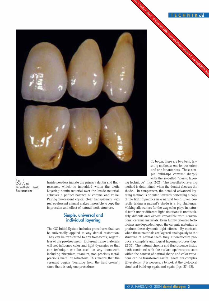
Inside powders imitate the primary dentin and fluo-rescence, which lie imbedded within the teeth.Layering dentin material over the Inside material,achieves a perfect balance of chroma and value.Pairing fluorescent crystal clear transparency withreal opalescent enamel makes it possible to copy theimpression and effect of natural tooth structure.
Simple, universal and individual layering
The GC Initial System includes procedures that canbe universally applied to any dental restoration.They can be transferred to any framework, regard-less of the pre-treatment. Different frame materialswill not influence color and light dynamics so thatone technique can be used on any frameworkincluding zirconium, titanium, non precious metal,precious metal or refractory. This means that theceramist begins “learning from the first crown”,since there is only one procedure.
To begin, there are two basic lay-ering methods: one for posteriorsand one for anteriors. These sim-ple build-ups contrast sharplywith the so-called “classic layer-
ing technique” (figs. 2-21). The bioesthetic layeringmethod is determined when the dentist chooses theshade. In comparison, the detailed advanced lay-ering method is oriented towards perfecting a copyof the light dynamics in a natural tooth. Even cor-rectly taking a patient's shade is a big challenge.Making allowances for the way color plays in natur-al teeth under different light situations is unmistak-ably difficult and almost impossible with conven-tional ceramic materials. Even highly talented tech-nicians are dependent upon the ceramic materials toproduce these dynamic light effects. By contrast,when these materials are layered analogously to thestructure of natural teeth they automatically pro-duce a complete and logical layering process (figs.22-35). The natural chroma and fluorescence insideteeth combined with the surface opalescence seenwithin the context of natural shape and color varia-tions can be transferred easily. Teeth are complex3D-systems. It is necessary to look at the biologicalstructural build-up again and again (figs. 37 -43).
T E C H N I K dd
© 5. JAHRGANG 2004 dental dialogue 3
Fig. 1Our Aim:Bioesthetic DentalRestorations
dd T E C H N I K
4 dental dialogue 5. JAHRGANG 2004 ©
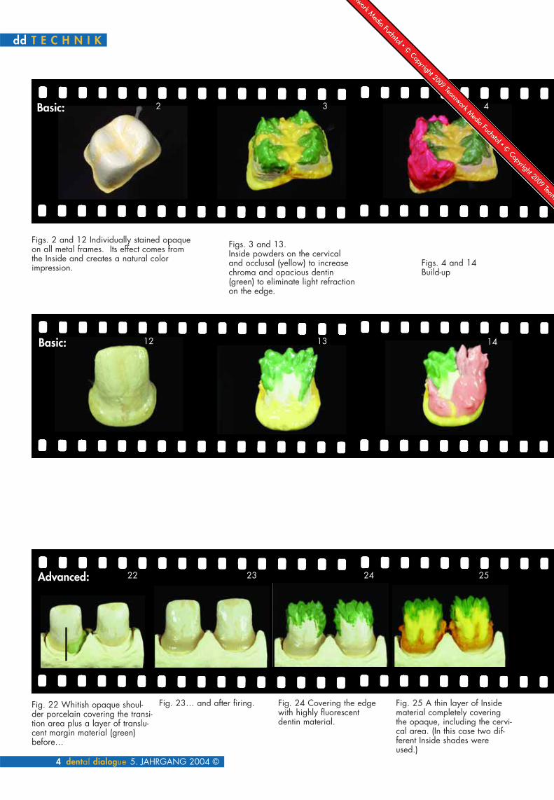
Figs. 2 and 12 Individually stained opaqueon all metal frames. Its effect comes fromthe Inside and creates a natural colorimpression.
Figs. 3 and 13.Inside powders on the cervicaland occlusal (yellow) to increasechroma and opacious dentin(green) to eliminate light refractionon the edge.
Figs. 4 and 14Build-up
2 3 4
12
22 23 24 25
13 14
Fig. 22 Whitish opaque shoul-der porcelain covering the transi-tion area plus a layer of translu-cent margin material (green)before…
Fig. 23… and after firing. Fig. 24 Covering the edgewith highly fluorescentdentin material.
Fig. 25 A thin layer of Insidematerial completely coveringthe opaque, including the cervi-cal area. (In this case two dif-ferent Inside shades wereused.)
Basic:
Basic:
Advanced:

T E C H N I K dd
© 5. JAHRGANG 2004 dental dialogue 5
Figs.6 and 16Step by step the wholedentin surface is…
Figs. 5 and 15...and the final dentinbuild-up
5 6
26 27 28
15 16
Figs. 26 and 27 Thin dentin layer and Incisal table to determine theincisal and proximal edges.
Fig. 28 Dentin cutbacks in the incisal thirddown to the highly fluorescent dentin (FD-91, FD-92 or FD-93)
7
17
Figs. 7 and 17covered with CLF powder(clear fluorescent) to imitatethe transparent dentin.

dd T E C H N I K
6 dental dialogue 5. JAHRGANG 2004 ©
8 9 10
18 19 20
29 30 31
Figs. 8 and 18 Cover layerand…
Figs. 9 and 19…final build-up of the morphol-ogy with opalescent powders.
Fig. 20The opaque on the palatal is coveredwith the corresponding Inside shadeand completed with white enamel.
Fig. 10Surface characterizationwith whitish opaque enam-el (cusp ridges, edges andgrooves.
Fig. 29 Layering over the incisaltable (in this case with FD-91)
Fig. 30 Colored mamelon structurewith Inside material
Fig. 31 The internal build-up iscompletely covered with a layer ofCLF material.

T E C H N I K dd
© 5. JAHRGANG 2004 dental dialogue 7
32 33 34
Fig. 32 Alternate layering of enam-els with various opalescent, translu-cent and transparent enamels.
Fig. 33 Final shape build-up withopalescent materials.
Fig. 34 The palatal surface is cov-ered with EO-15 imitating the”bony” effect of functional edges.
Fig. 11Final result of thebasic layeringmethod.
Fig. 21Result of the basiclayering method.

Figs. 35 and 36Advanced
layering result
An almost perfect deception
Anterior teeth pose the greatest esthetic challenge.The incisal build up is very sensitive, since all opti-cal light phenomena join in this small space. In par-ticular the layering over the incisal table is very crit-ical (Fig. 27) because the most light is transmittedhere. This area also highlights the greatest differ-ence between feldspathic and synthetic ceramics. Atotally different optical appearance can result. Thebiggest problem occurs when dissimilar framematerials are used side by side or in proximity toone another. The differences can be neutralizedwith the high fluorescent dentins (FD 91-93) and theInside powders (see figs. 24+25).The light flooded incisal third is also covered withthe white fluorescent FD-91 (see fig. 29). As inpainting, the base for the mamelon structure is neu-tralized. Since incoming light always reflects offthis “blocking layer” in the same light wave spec-trum, the colors applied on top always appear the
same. These optical “illusions”, allow differenttypes of restorations to be used successfully next toeach other. Special attention should be paid whenapplying fluorescent transparent material (CLF),because this layer has the most influence on theappearance of color and depth in a ceramic restora-tion. Transparent dentin (CLF) comes to the surfacemore through abrasion in a natural incisal edge.Because of this, light influence in a tooth is clearlyincreased (raised) and can produce, depending onthe light situation, a radical change in the colorresult. The spectrum ranges from gray transparentto amber to a compact, almost opaque effect. TheCLF layer makes it possible to correct the trans-parency in a crown after firing without changing theintricate morphology built up. If, when the crown istried in, there is not enough transparent, the incisaledge is simply reduced more on the palatal side(figs. 35-37).
8 dental dialogue 5. JAHRGANG 2004 ©
dd T E C H N I K
Fig. 37A critical zone, theincisal zone
35
36

At the same time more light influence in the CLFlayer provides a definite increase in transparencywithin the restoration. If there is too much trans-parency, the CLF layer can be covered with stainalong the incisal edge until the desired effect isachieved and then glazed. In the mouth, too muchtransparency often appears as an ugly, unnaturalgray, flat effect. Opalescent enamels compensate forthis impression very well (figs. 38-43). When com-pared to conventional enamels, the difference is
enormous. The latter correlates well with the VitaLumin shade guide, but not with the dynamics ofnatural teeth. Opalescent effect on the surface, fluo-rescence coming from the inside creates a highlynatural appearance setting it apart from ready-made shade guides. The light, very natural bright-ness of the crowns, due to the opal materials, differsfrom the grayish Vita shades. Unfortunately mostdental technicians usually orient their porcelainbuild-up to the Vita shade guide.
T E C H N I K dd
© 5. JAHRGANG 2004 dental dialogue 9
Figs. 38 to 41The variety and color dynamics of natural
teeth are always a challenge. They exhibithighly fluorescent chromatic internal areas
paired with opalescent enamel parts.
Figs. 42 and 43Sectioned viewscan help identifythe natural toothbuild-up.
38 39
40
41
42 43
First Patient Case
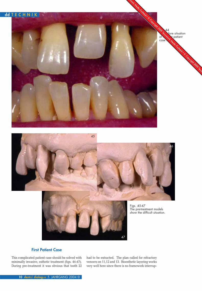
This complicated patient case should be solved withminimally invasive, esthetic treatment (figs. 44-47).During pre-treatment it was obvious that tooth 22
had to be extracted. The plan called for refractoryveneers on 11,12 and 13. Bioesthetic layering worksvery well here since there is no framework interrup-
10 dental dialogue 5. JAHRGANG 2004 ©
Fig. 44The before situationof the first patientcase in situ.
Figs. 45-47The pre-treatment modelsshow the difficult situation.
dd T E C H N I K
45
46
47

tion. To restore the 2nd quadrant, porcelain fused tometal was indicated (fig. 48). The gap presented aproblem because it was too large to be properlyfilled. During pre-treatment the gingiva for 22 wasprepared with the long-term provisional. Duringthis time the large gap between 21 and 23 was veryproblematic. To make the visible tooth 22 appearmore separated it was decided to make the connec-tions relatively narrow and very close to the mar-gins. Unfortunately, this type of connection made it
impossible to use a full ceramic restoration with zir-conium oxide (fig. +50)this usually denotes multiplefig. but only one is listed here; there isn't a captionlisted, either). With the porcelain facings we pro-ceeded step-by-step using the advanced procedure.The bridge and the single units were built at thesame time using the same process. For the support-ing firings highly fluorescent dentin and Insidematerials were used on the refractory dies as well ason the metal frame. The light reflecting edges of thedies and the crowns were covered with high fluo-rescing materials, on the proximal areas and bodyInside material was used. In this way the respectivebases or frameworks are properly neutralized by thestrongly reflective fluorescing materials allowingthe next layers of body shade and enamels to beconsistent across the restorations. Gingival powderswere necessary in this situation to hide the veryatrophied ridge and the bridge connections (fig. 51).
© 5. JAHRGANG 2004 dental dialogue 11
T E C H N I K dd
Fig. 49The full ceramic partial crowns were built onthe refractory dies. The bridge had to be rein-forced with low framework connectors; theplan was to place the tooth with gaps becauseof its extreme width.
Fig. 51This picture clearlyshows that the twomaterials (refractorydies and metalceramic bridge)received exactly thesame treatment:Inside materials andhighly fluorescentdentin were usedfor the first support-ing bake.
Fig. 50 The bridge in detail. The pontics hadalready been pre-treated with long-term pro-
visionals and given effects.
Fig. 48The crowns on 11 to 13were prepped for a full
ceramic restoration. Theplan called for a rein-forced metal ceramic
bridge to span 21 to 23.

The next step shows the first complete build-up ofthe restoration (fig. 52). In this system shoulderporcelain and the appropriate amount of Insidematerial can be fired together in the first bake. Thissaves an enormous amount of time. All the followinglayering parameters are according to the advancedlayering method (figs. 20-32). The correction bake(fig. 53) is followed by the glaze bake (fig. 54).Since full ceramic restorations are made to fit pas-sively and cemented adhesively, it is necessary tocheck the proximal contacts on a solid model (fig.55). At this point it is clear that the color adjustmentbetween the full ceramic and the metal ceramicrestorations is perfect. After the restorations were
12 dental dialogue 5. JAHRGANG 2004 ©
dd T E C H N I K
Fig. 55Checking the proximal contacts onthe solid model. The pronouncedShadow-ridge situation is shown
clearly. There is no visual differenceto be seen between the full ceramicand the metal ceramic restorations.
Fig. 52First firing, completeceramic build-up
Fig. 53The restoration
after the first cor-rection bake...
Fig. 54… and after theglaze firing.

completed it was noted that the interproximal areas(especially between the central incisors) shouldhave been a little lighter. Because of the shadoweffect there was a small dark triangle. In this caseapplying a lighter Inside shade would have beenmore pleasing. From the lingual it is easy to see theproblems encountered with this restoration: the lowframework connectors reinforced on the palatalside, 22 placed with gaps and the required overlapin the first quadrant due to very tight spacing
between preps. The extreme shadow ridgesbetween 11 and 21 were neutralized using fluores-cent and Inside material. Later the interproximalspace between 11 and 21 was opened slightly tomake a more harmonious appearance. This is cer-tainly not an ideal restoration, but considering thepre-treatment situation, and the resulting difficul-ties, it is a pleasing result. The patient was morethan satisfied with her new appearance.
T E C H N I K dd
© 5. JAHRGANG 2004 dental dialogue 13
Fig. 56View from the lin-gual, note theminimally invasivepreparation.
Fig. 57 and 58Lateral view of therestoration on the
model.
Fig. 59 and 60The restoration inharmony with itsoral environment.

dd T E C H N I K
14 dental dialogue 5. JAHRGANG 2004 ©
Fig. 61The situationbefore…
Fig. 62…and after treat-ment. Consideringthe pre-treatmentsituation, a verypleasant result.Later, a small gapbetween 11 and21 was opened toimprove the esthe -tic result

Sectioned views of teeth as a model
Worldwide the internal tooth structure is identical.Only the shape, the internal shading and thealways-present anomalies make them infinitelyindividual. With guidelines for esthetics, morpholo-gy and gnathology, we have for many decadesattempted to come closer to our model of a naturaltooth Choosing the shade is always a very individualproblem. During the past 16 years, we have tried todevelop some standardization in this area. Afterevaluating over 2500 tooth shades before and afterpreparation it can be said, that there is a correlationbetween internal and external shade effects. Theseresults are purely empirical and not scientificallyconfirmed. Consistent, practical success has led usto recommend the following working method. Theconcept for the (GC Initial) Inside system was creat-ed with this basic philosophy:A natural color effect can only result from theInside out.
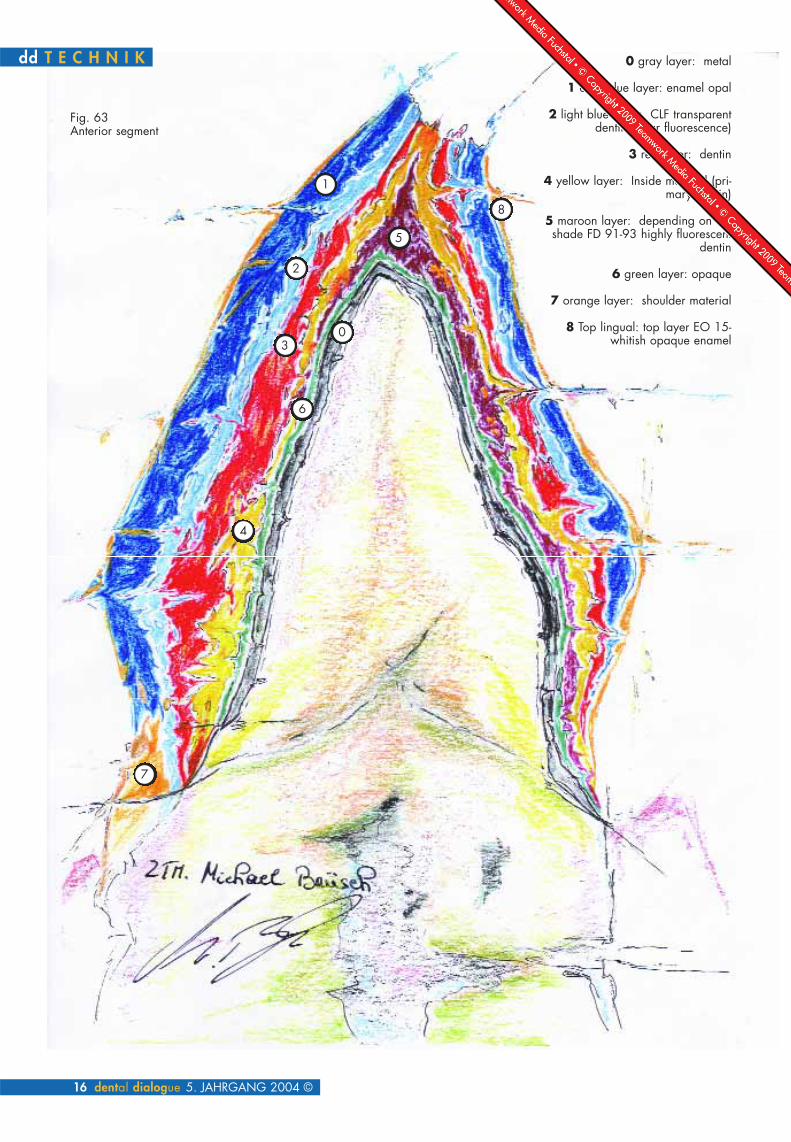
The main purpose of the Inside powders is tostrengthen the chroma from the depths, allowing forapproximately.1 mm of transparent or Opal enamelanalogous to the structure of a natural tooth. Thedentin body can then be layered very thinly over ametal frame. In full ceramics, these materials pro-duce a true-to-nature build up (Fig. 63-64).Sectioned views illustrate exactly where the layersmust be placed (fig. 65-66). In a full ceramic inlay,the preparation depth provides the reference pointfor the powders for each layer. The selectiondecreases from bottom to top producing first-rateresults. Simply stated: Observe exactly.The structure of a tooth is ingenious (and especial-ly) ingeniously simple (figs. 67-72). In veneerrestorations (figs. 73-79) the interaction between thematerial and a systematic build-up is clear.Extraordinarily different layer thicknesses are visu-ally bridged and converted to an esthetic success
© 5. JAHRGANG 2004 dental dialogue 15
T E C H N I K dd
16 dental dialogue 5. JAHRGANG 2004 ©
Fig. 63Anterior segment
0 gray layer: metal
1 dark blue layer: enamel opal
2 light blue layer: CLF transparentdentin (clear fluorescence)
3 red layer: dentin
4 yellow layer: Inside material (pri-mary dentin)
5 maroon layer: depending on theshade FD 91-93 highly fluorescent
dentin
6 green layer: opaque
7 orange layer: shoulder material
8 Top lingual: top layer EO 15-whitish opaque enamel
dd T E C H N I K
0
1
2
3
4
5
6
7
8

T E C H N I K dd The following anterior segments show thesystematic layering:
Fig. 63a metal frame Fig. 63b opaque Fig. 63c FD 91-93 Highly fluorescentdentin to disguise the incisal edge ofthe framework
Fig. 63d Inside material and primarydentin to increase chroma and createdepth
Fig. 63e Dentin build-up
Fig. 63g Completing the shape withenamel opal, EO 15 and shouldermaterial.
Fig. 63f Building the transparent dentinfound in natural teeth with CLF (clearfluorescence) and an enamel layer.
© 5. JAHRGANG 2004 dental dialogue 17

dd T E C H N I K
18 dental dialogue 5. JAHRGANG 2004 ©
Fig. 64Posterior segment
1 yellow: primary dentin
2 red: dentin
3 light blue: CLF layer transparent dentin layer
4 dark blue: opal enamel
5 orange: EO 15 whitish opaque enamel
1
2
3
4
5

© 5. JAHRGANG 2004 dental dialogue 19
Fig. 70 The opaque enamel as a finalcover (EO 15) reinforces depth and imi-tates the reflection of the dentin analo-gous to natural enamel ridges.
Fig. 68 Analogous to natural tooth struc-ture, the dentin layer is covered withtransparent material (CLF)
Fig. 69 and covered with enamel opal.
Fig. 67c Additive dentin layering up toapproximately 1mm below the prep mar-gin.
Fig. 67 to 70 Sectioned views with layering illustrates the structure of the full ceramic inlay. The preparation depth provides thereference point for the materials used in each layer. The natural tooth is our model. The uppermost reference point is theocclusal prep margin, which serves as a guide for layering thickness and use of materials. Yellow: primary dentin, red: dentin,green: CLF, blue: enamel opal
Fig. 65 In this segment the black outline indicates the primarydentin body.
Fig. 67 a and b depending upon the depth of the cavity, Inside and dentin materialsare used.
Fig. 66 The layering structure of a natural tooth
Fig. 71 Gold crown versus full ceramic Fig. 72 These individually layered ceramic inlays are not visi-ble. This technique is also very suitable for veneers.
dd T E C H N I K
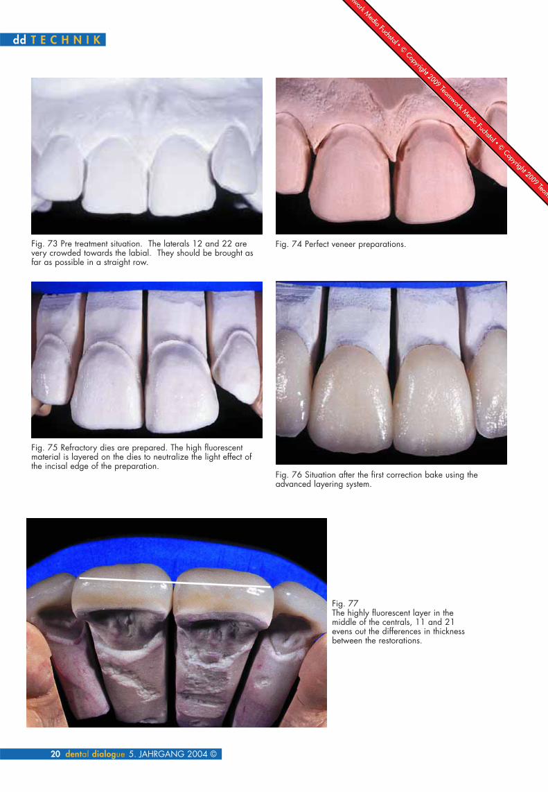
Fig. 76 Situation after the first correction bake using theadvanced layering system.
Fig. 73 Pre treatment situation. The laterals 12 and 22 arevery crowded towards the labial. They should be brought asfar as possible in a straight row.
Fig. 75 Refractory dies are prepared. The high fluorescentmaterial is layered on the dies to neutralize the light effect ofthe incisal edge of the preparation.
Fig. 74 Perfect veneer preparations.
20 dental dialogue 5. JAHRGANG 2004 ©
Fig. 77The highly fluorescent layer in themiddle of the centrals, 11 and 21evens out the differences in thicknessbetween the restorations.

T E C H N I K dd
© 5. JAHRGANG 2004 dental dialogue 21
Fig. 78Clearly visible bioesthetic layering.The highly fluorescent internal struc-
ture paired with opalescent material.
Fig. 79 The restoration in the mouth with a definite shade correction. At the patient's request, the lower anteriors will be adaptedin shade and position to the uppers.
Second Patient case
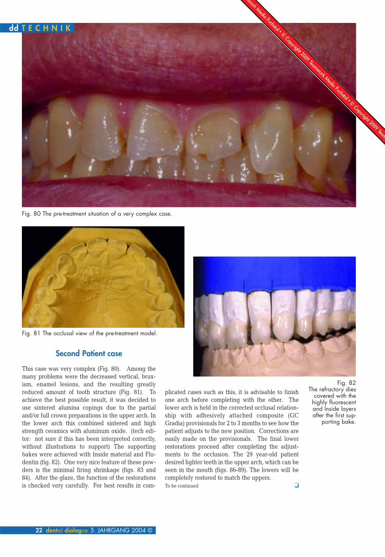
This case was very complex (Fig. 80). Among themany problems were the decreased vertical, brux-ism, enamel lesions, and the resulting greatlyreduced amount of tooth structure (Fig. 81). Toachieve the best possible result, it was decided touse sintered alumina copings due to the partialand/or full crown preparations in the upper arch. Inthe lower arch this combined sintered and highstrength ceramics with aluminum oxide. (tech edi-tor: not sure if this has been interpreted correctly,without illustrations to support) The supportingbakes were achieved with Inside material and Flu-dentin (fig. 82). One very nice feature of these pow-ders is the minimal firing shrinkage (figs. 83 and84). After the glaze, the function of the restorationsis checked very carefully. For best results in com-
plicated cases such as this, it is advisable to finishone arch before completing with the other. Thelower arch is held in the corrected occlusal relation-ship with adhesively attached composite (GCGradia) provisionals for 2 to 3 months to see how thepatient adjusts to the new position. Corrections areeasily made on the provisionals. The final lowerrestorations proceed after completing the adjust-ments to the occlusion. The 29 year-old patientdesired lighter teeth in the upper arch, which can beseen in the mouth (figs. 86-89). The lowers will becompletely restored to match the uppers.To be continued q
22 dental dialogue 5. JAHRGANG 2004 ©
Fig. 80 The pre-treatment situation of a very complex case.
Fig. 81 The occlusal view of the pre-treatment model.
dd T E C H N I K
Fig. 82The refractory dies
covered with thehighly fluorescentand Inside layersafter the first sup-
porting bake.

T E C H N I K dd
© 5. JAHRGANG 2004 dental dialogue 23
Fig. 83 The layering after the first complete build up and…
Fig. 85The restorations afterglazing on the mastermodel with the preparedlower provisionals.
Fig. 87The anteriors
in detail.
Fig. 86Checking the contacts
on the solid model.
Fig. 84 … after firing.
Fig. 88The provisionals willremain in the mouthapproximately 4months.

dd T E C H N I K
BiographyMichael Brüsch completed his training as a dental technician. In 1986 he acquired his Masters certification inDüsseldorf and from 1986 until 1989 was employed as laboratory manager with an emphasis on full ceram-ics. In 1989 he open his own dental laboratory and specialized in functional and esthetic dental work withemphasis on polychromatic layering for composite and full ceramic facings. He is an active member of the“Deutschen Gesellschaft für Ästhetische Zahnheilkunde (DGÄZ) and the “Dental Excellence-InternationalLaboratory Group“ He is also known for his unusual 3D presentations.
Ralf Dahl absorbed his dental training program from 1981 until 1985. From 1985 until 1988 he increasedhis knowledge in a commercial laboratory specializing in precious metal, ceramics and attachment work. Hewas employed as a technician in a private practice from 1988 until 1989 and as a supervisor until 1990. In1991 he completed his Masters certification at the Masters School in Düsseldorf. Since 1994 he is the coowner and managing director of the MB Dentaltechnik GmbH. He is a member of the “Dental ExcellenceInternational Laboratory Group” and the DGÄZ. Ralf Dahl is a lecturer and co lecturer in hands-on coursesnationally and internationally. He specializes in lectures on Build-up Technique in Ceramic-composite: func-tional and esthetic procedures for full ceramic inlays, onlays, veneers and full crowns as well as facings forcrown and bridges in oxide ceramics.
Contact address:Ztm. Michael Brüsch and Ztm. Ralf Dahl Schanzenstr. 20 • 40549 DüsseldorfFon +49 (0) 2 11. 58 80 21 • Fax +49 (0) 2 11. 58 80 22E-mail: [email protected]
P r o d u c t L i s t s
Indication Name Manufacturer/DistríbutorCAD/CAM System Lava 3M ESPEInvestment material Cosmotec Vest GC EuropeMilling Al2O3 Procera Nobel BiocareMilling ZrO2 Digident GirrbachMilling ZrO2 Everest KaVoMilling ZrO2 Cercon DegudentCeramic Powders GC Initial GC EuropeComposite Gradia GC Europe
24 dental dialogue 5. JAHRGANG 2004 ©
Fig. 89The restorations with therequested lighter shade.


![Download [ 3.87 MB ] - e-Gyanagar](https://static.fdokumen.com/doc/165x107/63174a78c72bc2f2dd056813/download-387-mb-e-gyanagar.jpg)


![Download [ 12.18 MB ] - e-Gyanagar](https://static.fdokumen.com/doc/165x107/632776a96d480576770d498f/download-1218-mb-e-gyanagar.jpg)

![Download [ 72.13 MB ] - e-Gyanagar](https://static.fdokumen.com/doc/165x107/63223e97aa6c954bc7079c51/download-7213-mb-e-gyanagar.jpg)

![Download [ 5,2 MB ] - e-Gyanagar](https://static.fdokumen.com/doc/165x107/6316c6e79076d1dcf80b8d47/download-52-mb-e-gyanagar.jpg)


![Download [ 2.34 MB ] - e-Gyanagar](https://static.fdokumen.com/doc/165x107/63275f63cedd78c2b50d8b0d/download-234-mb-e-gyanagar.jpg)