
THE INTERNAL OPERATING SYSTEM - Kean University
61
CHAPTER 18 THE INTERNAL OPERATING SYSTEM Thomas Sperling
-
Upload
khangminh22 -
Category
Documents
-
view
4 -
download
0
Transcript of THE INTERNAL OPERATING SYSTEM - Kean University

CHAPTER 18
THE INTERNAL OPERATINGSYSTEM
Thomas Sperling

18.0 INTRODUCTIONIn Chapter 15 we presented an overview of the role of the operating system as a primarycomputer system component and observed that it is possible to represent the archi-tecture of the operating system as a hierarchy, consisting of several layers of programsthat interact with each other to handle the routine tasks of command processing,file management, I/O, resource management, communication, and scheduling. Wecontinued the discussion in Chapter 16 by starting with the most familiar layer, theuser interface. Chapter 17 moved inward to the next layer and presented the featuresand organization of the file management system. The file manager converts the logicalrepresentation of files as seen by the user or the user’s programs to the physicalrepresentation stored and manipulated within the computer.
Now we are ready to examine major features of the remaining inner layers. Theselayers are designed primarily to manage the hardware and software resources of thecomputer and its interactions with other computers. In this chapter, we will lookat how these internal operations are performed; we will consider how the operatingsystem programs manage processes, memory, I/O, secondary storage, CPU time, andmore for the convenience, security, and efficiency of the users.
We will briefly review the concepts from Chapter 15 first. Then we expand ourfocus to look at the various components, features, and techniques that are characteristicof modern operating systems. We will show you a simple example in which the differentpieces have been put together to form a complete system.
A modern system must have the means to decide which programs are to beadmitted into memory and when, where programs should reside in memory, howCPU time is to be allocated to the various programs, how to resolve conflictingrequirements for I/O services, and how to share programs and yet maintain securityand program and data integrity, plus resolve many other questions and issues. It isnot uncommon for the operating system to require several hundreds of megabytes ofmemory just for itself.
In this chapter, we consider the basic operations performed by the operatingsystem. We introduce individually the various tasks that are to be performed by theoperating system and consider and compare some of the methods and algorithms usedto perform these tasks in an effective manner. We discuss the basic procedure of loadingand executing a program, the boot procedure, the management of processes, memorymanagement, process scheduling and CPU dispatch, secondary storage management,and more.
As we have mentioned previously, the modern computer includes additional CPUhardware features that work in coordination with the operating system software tosolve some of the more challenging operating system problems. Virtual storage isarguably the most important of these advances. Virtual storage is a powerful techniquefor solving many of the difficulties of memory management. Section 18.7 is devotedto a detailed introduction to virtual storage. It also serves as a clear example of the
593

594 PART FIVE THE SOFTWARE COMPONENT
integration of hardware and operating system software that is characteristic of moderncomputer systems.
Other examples include the layering of the instruction set to include certain protectedinstructions for use only by the operating system, which we presented in Chapter 7, andmemory limit checking, which the operating system can use to protect programs from eachother.
The subject of operating systems can easily fill a large textbook and an entire course allby itself. There are many interesting questions and problems related to operating systemsand many different solutions to the problem of creating a useful and efficient operatingsystem. Obviously, we won’t be able to cover this subject in a great amount of detail, butat least you’ll get a feeling for some of the more important and interesting aspects of howoperating systems work.
The many tasks that a modern operating system is expected to perform also expandthe overhead required by the operating system, both in terms of memory and in the timerequired to perform the different functions. We will also look at some of the measuresthat are used to determine the effectiveness of an operating system. Finally, you’ll have achance to read about a few of the more interesting problems, especially those that can havea significant effect on the user.
18.1 FUNDAMENTAL OS REQUIREMENTSAlways keep in mind that the fundamental purpose of any operating system is to loadand execute programs. This is true regardless of the specific goals, design features, andcomplexity of the particular operating system that you happen to be looking at.
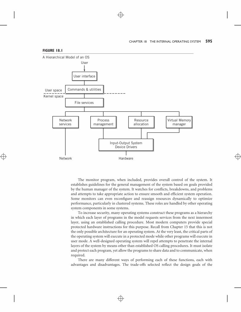
With this fundamental idea in mind, look again at the various functions that areprovided within the operating system. To assist with this task, the hierarchical model isshown again for your convenience in Figure 18.1.
Recall that to load and execute a program, the system must provide a method of gettingthe program from its storage location on some I/O device, such as disk, into memory; itmust provide locations in memory for the program and its data; it must provide CPU timefor the program to execute; and it must provide access to the I/O facilities that the programneeds during its execution. Since multiple programs are normally sharing the system andits resources, it must do all this in a way that is fair and meets the sometimes conflictingrequirements of the different programs.
The lower layers of the model provide programs that fulfill these requirements. Thefile manager layer translates logical file requests from the command shell or the user’sprograms into specific physical I/O requests that are then performed by the appropriate I/Odevice management programs. Resource allocation management is also provided in thislayer to resolve conflicts between different programs that may require I/O services at thesame time. The I/O device management and resource allocation programs are sometimesknown collectively as an I/O control system, or more commonly, IOCS.
The memory management and scheduling operations within the resource allocationfunction determine if it is possible to load programs and data into memory, and, if so, wherein memory the program is to be loaded. Once the program is in memory, the schedulerallocates time for the program to execute. If there are multiple programs in memory, thescheduler attempts to allocate time for each of them in some fair way.
CHAPTER 18 THE INTERNAL OPERATING SYSTEM 595
FIGURE 18.1
A Hierarchical Model of an OS
User
User interface
Commands & utilitiesUser space
Kernel space
File services
Networkservices
Processmanagement
Resourceallocation
Virtual Memorymanager
Input-Output SystemDevice Drivers
HardwareNetwork
The monitor program, when included, provides overall control of the system. Itestablishes guidelines for the general management of the system based on goals providedby the human manager of the system. It watches for conflicts, breakdowns, and problemsand attempts to take appropriate action to ensure smooth and efficient system operation.Some monitors can even reconfigure and reassign resources dynamically to optimizeperformance, particularly in clustered systems. These roles are handled by other operatingsystem components in some systems.
To increase security, many operating systems construct these programs as a hierarchyin which each layer of programs in the model requests services from the next innermostlayer, using an established calling procedure. Most modern computers provide specialprotected hardware instructions for this purpose. Recall from Chapter 15 that this is notthe only possible architecture for an operating system. At the very least, the critical parts ofthe operating system will execute in a protected mode while other programs will execute inuser mode. A well-designed operating system will repel attempts to penetrate the internallayers of the system by means other than established OS calling procedures. It must isolateand protect each program, yet allow the programs to share data and to communicate, whenrequired.
There are many different ways of performing each of these functions, each withadvantages and disadvantages. The trade-offs selected reflect the design goals of the

596 PART FIVE THE SOFTWARE COMPONENT
particular system. To give you a simple example, a computer that operates strictly in abatch mode might use a simple CPU scheduling algorithm that allows each program torun without interruption as long as the program does not have to stop processing to waitfor I/O. This strategy would not be acceptable on an interactive system that requires fastscreen response when a user clicks the mouse or types something into the keyboard. In thelatter case, a more sophisticated scheduling algorithm is clearly required.
Before we continue with discussions of the individual resource managers, you shouldbe aware that these managers are not totally independent of each other. For example,if there are more programs in the memory of an interactive system, the scheduler mustgive each program a shorter period of time if satisfactory user response is to be achieved.Similarly, more programs in memory will increase the workload on a disk manager, makingit more likely that there will be several programs waiting for disk I/O at the same time.A well-designed operating system will attempt to balance the various requirements tomaximize productive use of the system.
Before proceeding to detailed discussions of each of the major modules in a multitaskingoperating system, it may provide some insight to introduce you to a simple example ofa system, a sort of ‘‘Little Man multitasking operating system’’, if you will. The systemdiscussed here does not run on the Little Man Computer, however. It was designed for a real,working computer system. This example illustrates many of the important requirementsand operations of a multitasking system.
Example: A Simple Multitasking Operating System
The miniature operating system (hereafter referred to as MINOS) is an extremely small andsimple multitasking system with many of the important internal features of larger systems.It is based on a real operating system that was developed by the author in the 1970s for avery early and primitive microcomputer that was used primarily to measure data in remoterural locations. Calculations were performed on the data and the results telecommunicatedback to a larger computer for further processing. The original goals of the design were
■ First and foremost, simplicity. Memory was very expensive in those days, so wedidn’t want to use much for the operating system. There was only 8 KB ofmemory in the machine.
■ Real-time support for one very important program that was run frequently andhad to operate very fast. This was the data measurement program. The systemtherefore features a priority scheduling system in choosing which program is torun.
The internal design of MINOS was of more interest and importance to the designersthan the user interface or the file system. There was no disk on this computer, only anaudio cassette tape recorder, modified to hold computer data, so the file system was simple.(Disks were too expensive, too large, and too fragile for this type of system back then!)There was a keyboard/printer user interface, but no CRT display interface. Security was nota concern.
The features of particular interest to us here are the operation of memory management,process scheduling, and dispatching. Despite their simplicity, the design of these modules
CHAPTER 18 THE INTERNAL OPERATING SYSTEM 597
is characteristic of the way current operating systems work. These were the importantspecifications for MINOS:
■ Keyboard/printer command line user interface. To keep things simple, therewere only a few commands, most of which could be entered by typing a singlecharacter. For example, the letter ‘‘l’’ was used to load a program from tape, theletter ‘‘s’’ to save a program to tape.
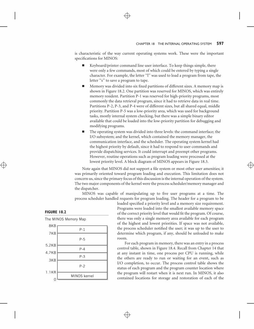
■ Memory was divided into six fixed partitions of different sizes. A memory map isshown in Figure 18.2. One partition was reserved for MINOS, which was entirelymemory resident. Partition P-1 was reserved for high-priority programs, mostcommonly the data retrieval program, since it had to retrieve data in real time.Partitions P-2, P-3, and P-4 were of different sizes, but all shared equal, middlepriority. Partition P-5 was a low-priority area, which was used for backgroundtasks, mostly internal system checking, but there was a simple binary editoravailable that could be loaded into the low-priority partition for debugging andmodifying programs.
■ The operating system was divided into three levels: the command interface; theI/O subsystem; and the kernel, which contained the memory manager, thecommunication interface, and the scheduler. The operating system kernel hadthe highest priority by default, since it had to respond to user commands andprovide dispatching services. It could interrupt and preempt other programs.However, routine operations such as program loading were processed at thelowest priority level. A block diagram of MINOS appears in Figure 18.3.
Note again that MINOS did not support a file system or most other user amenities; itwas primarily oriented toward program loading and execution. This limitation does notconcern us, since the primary focus of this discussion is the internal operation of the system.The two major components of the kernel were the process scheduler/memory manager andthe dispatcher.
MINOS was capable of manipulating up to five user programs at a time. Theprocess scheduler handled requests for program loading. The header for a program to be
FIGURE 18.2
The MINOS Memory Map
8KBP-1
P-5
P-4
P-3
P-2
MINOS kernel
7KB
5.2KB
4.2KB
3KB
1.1KB
0
loaded specified a priority level and a memory size requirement.Programs were loaded into the smallest available memory spaceof the correct priority level that would fit the program. Of course,there was only a single memory area available for each programof the highest and lowest priorities. If space was not available,the process scheduler notified the user; it was up to the user todetermine which program, if any, should be unloaded to makeroom.
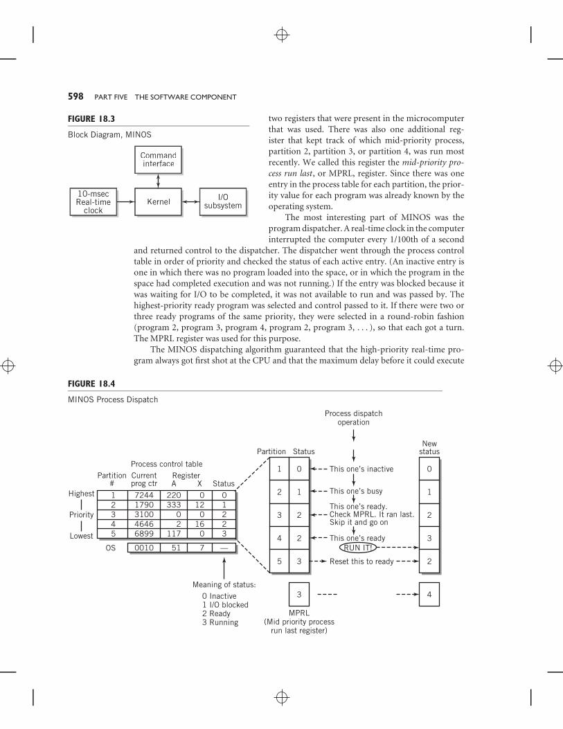
For each program in memory, there was an entry in a processcontrol table, shown in Figure 18.4. Recall from Chapter 14 thatat any instant in time, one process per CPU is running, whilethe others are ready to run or waiting for an event, such asI/O completion, to occur. The process control table shows thestatus of each program and the program counter location wherethe program will restart when it is next run. In MINOS, it alsocontained locations for storage and restoration of each of the
598 PART FIVE THE SOFTWARE COMPONENT
FIGURE 18.3
Block Diagram, MINOS
10-msecReal-time
clockKernel
Commandinterface
I/Osubsystem
two registers that were present in the microcomputerthat was used. There was also one additional reg-ister that kept track of which mid-priority process,partition 2, partition 3, or partition 4, was run mostrecently. We called this register the mid-priority pro-cess run last, or MPRL, register. Since there was oneentry in the process table for each partition, the prior-ity value for each program was already known by theoperating system.
The most interesting part of MINOS was theprogram dispatcher. A real-time clock in the computerinterrupted the computer every 1/100th of a second
and returned control to the dispatcher. The dispatcher went through the process controltable in order of priority and checked the status of each active entry. (An inactive entry isone in which there was no program loaded into the space, or in which the program in thespace had completed execution and was not running.) If the entry was blocked because itwas waiting for I/O to be completed, it was not available to run and was passed by. Thehighest-priority ready program was selected and control passed to it. If there were two orthree ready programs of the same priority, they were selected in a round-robin fashion(program 2, program 3, program 4, program 2, program 3, . . . ), so that each got a turn.The MPRL register was used for this purpose.
The MINOS dispatching algorithm guaranteed that the high-priority real-time pro-gram always got first shot at the CPU and that the maximum delay before it could execute
FIGURE 18.4
MINOS Process Dispatch
Process control table
Priority
Highest
Lowest
Meaning of status:0 Inactive1 I/O blocked2 Ready3 Running
Currentprog ctr
Partition#
Partition Status
Process dispatchoperation
This one’s inactive
New status
A X StatusRegister
12345
7244 1790 3100 4646 6899
220 333
0 2
117
0 12
0 16
0
0 1 2 2 3
OS 0010 51 7
1
2
3
4
5
0
1
2
2
3
0
1
2
3
3 4
2
—
This one’s busy
This one’s ready.Check MPRL. It ran last.Skip it and go on
This one’s readyRUN IT!
Reset this to ready
MPRL(Mid priority process
run last register)

CHAPTER 18 THE INTERNAL OPERATING SYSTEM 599
was 1/100th of a second. The ready bit for this program was actually set by a small interruptroutine controlled by the measuring device. Figure 18.4 illustrates the dispatching process.
The background task represented the lowest priority. By default, this partition con-tained software routines for testing various aspects of the hardware. Thus, when no otherprogram was selected, MINOS defaulted to the hardware diagnostic routines.
With MINOS as a background, the next nine sections of Chapter 18 consider variousaspects of a multitasking operating system in more detail. You may also wish to reviewSection 15.3 of Chapter 15, which introduces the various services and modules present in amodern multitasking system, before proceeding.
18.2 STARTING THE COMPUTER SYSTEM:THE BOOTSTRAP
As a first step, we need to consider what is required to get the computer started. Youwill recall that when the computer is first turned on, the contents of RAM are unknown.Furthermore, you know that there must be a program in memory for CPU execution totake place. These two considerations are contradictory; therefore, special means must beincluded to get the system into an operating state.
Initial program loading and start-up is performed by using a bootstrap programthat is built permanently into a read-only part of memory for the computer. Thisbootstrap program begins execution as soon as the machine is powered up. The bootstrapprogram contains a program loader that automatically loads a selected program fromsecondary storage into normal memory and transfers control to it. The process is knownas bootstrapping, or more simply, as booting the computer. IBM calls the process InitialProgram Load, or IPL. Figure 18.5 illustrates the bootstrapping operation.
FIGURE 18.5
Bootstrapping a Computer
RAM
Bootstraploader
ROM1. When computer is started, execution begins with bootstrap loader, permanently stored in ROM.
2. Bootstrap loader locates operating system kernel program, usually at a fixed disk location.
4. Transfers control to starting location of operating system program with a JMP instruction.
3. Loads it into RAM.
Note: Loader program in OS can then be used to load and execute user programs.

600 PART FIVE THE SOFTWARE COMPONENT
Since the bootstrap is a read-only program, the program that it loads must bepredetermined and must be found in a known secondary storage location, usually at aparticular track and sector on a hard disk, although the bootstrap can be tailored tostart the computer from another device, or even from another computer if the system isconnected to a network. Usually the bootstrap loads a program that is itself capable ofloading programs. (This is the reason that the initial program loader is called a bootstrap.)Ultimately, the program loaded contains the operating system kernel. In other words, whenthe boot procedure is complete, the kernel is loaded, and the computer is ready for normaloperation. The resident operating system services are present and ready to go. Commandscan be accepted, and other programs loaded and executed. The bootstrap operation isusually performed in two or more stages of loading to increase flexibility in the location ofthe kernel and to keep the initial bootstrap program small.
EXAMPLEThe PC serves as an appropriate and familiar example of the bootstrap start-up procedure.Although the PC uses a multistep start-up procedure, the method is essentially identical tothat we have just described.
The PC bootstrap loader is permanently located in the system BIOS, read-only memoryincluded as part of the computer, and introduced previously in Chapter 15. When thepower switch for the computer is turned on, or when the reset button is pushed, control istransferred to the first address of the bootstrap loader program. The PC bootstrap begins byperforming a thorough test of the components of the computer. The test verifies that variouscomponents of the system are active and working. It checks for the presence of a monitor,of a hard drive if installed, and of a keyboard. It checks the instructions in ROM for errorsby calculating an algebraic function of the 1s and 0s, known as a checksum, and comparingthat value with a predetermined correct value. It checks RAM by loading known data intoevery location and reading it back. Finally, it resets the segment registers, the instructionpointer, flags, and various address lines. (The 386, 486, P5, and P6 CPUs set many otherregisters as well.) The results of these tests appear on the monitor screen.
At the completion of this test, the bootstrap loader determines which disk is the systemdisk. This location is a setting stored permanently in a special memory, modifiable by theuser at startup time. On modern PCs, the system may be booted from a hard disk, a floppydisk, a CD or DVD, or many USB-pluggable devices. The system disk contains a sector knownas a boot record, and the boot record is loaded next.
The boot record now takes control. It also contains a loader, which is tailored to theI/O requirements for the particular disk. Assuming that Windows 2000, NT, or XP is to beloaded, the boot record then loads a sequence of files, including the kernel and executiveprogram, NTOSKRNL.EXE; the registry; the hardware interface; various kernel, subsystem,and API libraries; and a number of other components. The items loaded are based on entriesin the registry. The user has little control over this process while it is happening. Next, alogon program, WINLOGON.EXE is initiated. Assuming that the user is authorized and thatthe logon is successful, the kernel sets the user parameters defined in the registry, theWindows GUI is displayed, and control of the system is turned over to the user.
Different BIOSes vary slightly in their testing procedures, and some allow the userto change some PC setup settings when testing takes place. The user can also force the

CHAPTER 18 THE INTERNAL OPERATING SYSTEM 601
bootstrap to occur one step at a time to remedy serious system problems. Other thanthat, the user or system administrator controls the PC environment with standard toolsprovided by the operating system.
As noted, the procedure described here takes place when power is first applied to thecomputer. This procedure is also known as a cold boot. The PC also provides an alternateprocedure known as a warm boot, for use when the system must be restarted for somereason. The warm boot, which is initiated from a selection on the shutdown menu, causesan interrupt call that reloads the operating system, but it does not retest the system and itdoes not reset the various registers to their initial values.
EXAMPLEIt is important to realize that basic computer procedures are not dependent on the size of thecomputer. The boot procedure for a large IBM mainframe computer is quite similar to that ofa PC. IBM mainframe computers are bootstrapped using the Initial Program Load procedure.IPL works very similarly to the PC bootstrap procedure. Whenever power is applied to an IBMmainframe computer, the computer is in one of four operating states: operating, stopped,load, and check stop. The operating and stopped states are already familiar to you. Thecheck stop state is a special state used for diagnosing hardware errors. The load state is thestate corresponding to IPL.
The system operator causes the system to enter load state by setting load-unit-addresscontrols and activating the load-clear or load-normal key on the operator’s console. Theload-unit-address controls establish a particular channel and I/O device that will be used forthe IPL. The load normal key performs an initial CPU reset that sets the various registers inthe CPU to their initial values and validates proper operation. The load-clear key does thesame, but also performs a clear reset, which sets the contents of main storage and manyregisters to zero.
Following the reset operation, IPL performs the equivalent of a START I/O channelcommand, as discussed in Chapter 11. The first channel command word is not read frommemory, since memory may have been reset to zero. Instead, a built-in READ command isused, which reads the IPL channel program into memory for execution. The IPL channelprogram then reads in the appropriate operating system code and transfers control to it.
18.3 PROCESSES AND THREADSWhen considering a multitasking system, it is easiest to think of each executing task as aprogram. This representation is not inaccurate, but it is not sufficiently inclusive, precise,or general to explain all the different situations that can occur within a computer system.Instead, we may define each executing task more usefully as a process. A process is definedto include a program, together with all the resources that are associated with that programas it is executed. Those resources may include I/O devices that have been assigned to theparticular process, keyboard input data, files that have been opened, memory that has beenassigned as a buffer for I/O data or as a stack, memory assigned to the program, CPU time,and many other possibilities.
602 PART FIVE THE SOFTWARE COMPONENT
Another way of viewing a process is to consider it as a program in execution. A programis viewed passively: it’s a file or a listing, for example. A process is viewed actively: it is beingprocessed or executed.
In batch systems, a different terminology is sometimes used. A user submits a jobto the system for processing; the job is made up of job steps, each of which representsa single task. It is not difficult to see the relationship among jobs, tasks, and processes.When the job is admitted to the system, a process is created for the job. Each of the taskswithin the job also represent processes, specifically, processes that will be created as eachstep in the job is executed. In this book we tend to use the words job, task, and processinterchangeably.
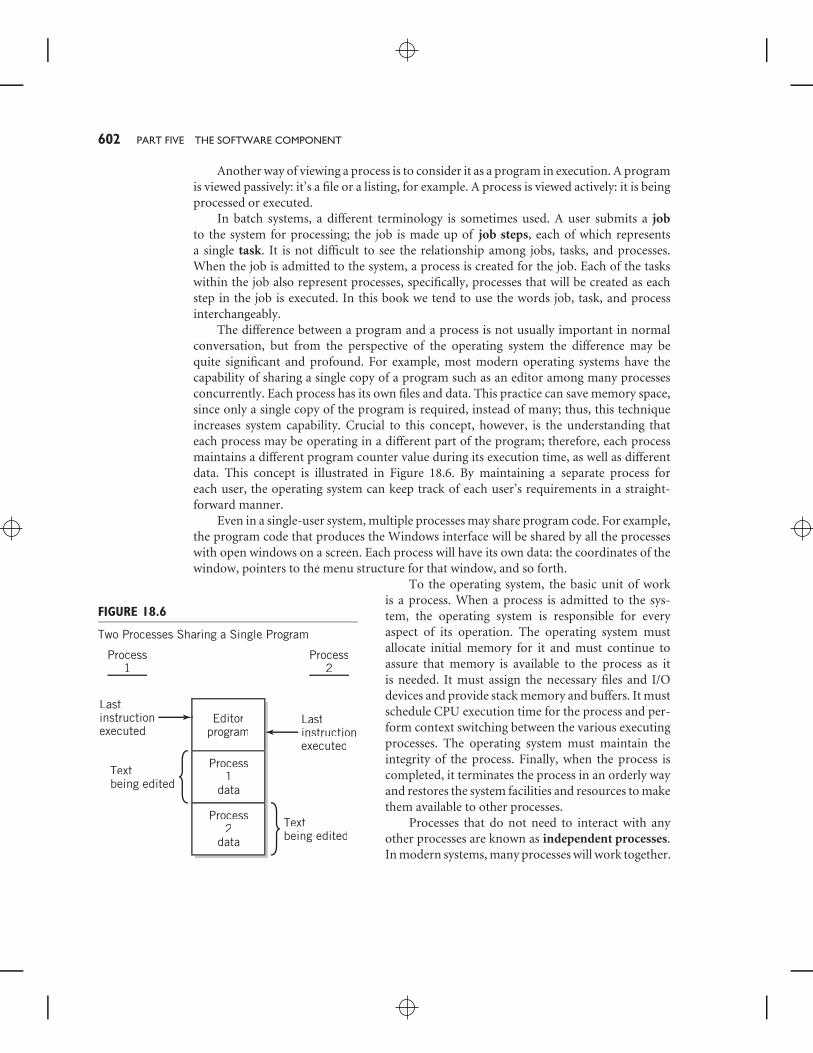
The difference between a program and a process is not usually important in normalconversation, but from the perspective of the operating system the difference may bequite significant and profound. For example, most modern operating systems have thecapability of sharing a single copy of a program such as an editor among many processesconcurrently. Each process has its own files and data. This practice can save memory space,since only a single copy of the program is required, instead of many; thus, this techniqueincreases system capability. Crucial to this concept, however, is the understanding thateach process may be operating in a different part of the program; therefore, each processmaintains a different program counter value during its execution time, as well as differentdata. This concept is illustrated in Figure 18.6. By maintaining a separate process foreach user, the operating system can keep track of each user’s requirements in a straight-forward manner.
Even in a single-user system, multiple processes may share program code. For example,the program code that produces the Windows interface will be shared by all the processeswith open windows on a screen. Each process will have its own data: the coordinates of thewindow, pointers to the menu structure for that window, and so forth.
FIGURE 18.6
Two Processes Sharing a Single Program
Editorprogram
Lastinstructionexecuted
Textbeing edited
Lastinstructionexecuted
Process1
Process2
Process1
data
Process2
data
Textbeing edited
To the operating system, the basic unit of workis a process. When a process is admitted to the sys-tem, the operating system is responsible for everyaspect of its operation. The operating system mustallocate initial memory for it and must continue toassure that memory is available to the process as itis needed. It must assign the necessary files and I/Odevices and provide stack memory and buffers. It mustschedule CPU execution time for the process and per-form context switching between the various executingprocesses. The operating system must maintain theintegrity of the process. Finally, when the process iscompleted, it terminates the process in an orderly wayand restores the system facilities and resources to makethem available to other processes.
Processes that do not need to interact with anyother processes are known as independent processes.In modern systems, many processes will work together.
CHAPTER 18 THE INTERNAL OPERATING SYSTEM 603
They will share information and files. A large task will often be modularized by splittingit into subtasks, so that each process will only handle one aspect of the task. Processesthat work together are known as cooperating processes. The operating system providesmechanisms for synchronizing and communicating between processes that are relatedin some way. (If one process needs the result from another, for example, it must knowwhen the result is available so that it can proceed. This is known as synchronization.It must also be able to receive the result from the other process. This is communi-cation.) The operating system acts as the manager and conduit for these interprocessevents.
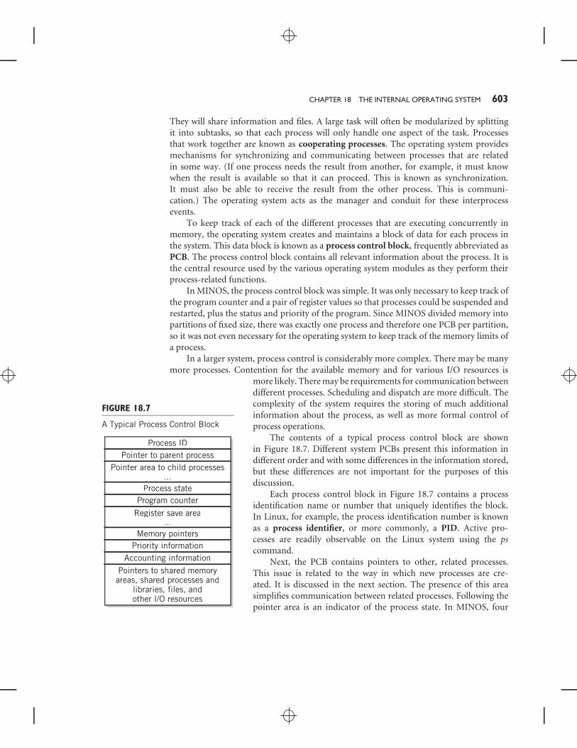
To keep track of each of the different processes that are executing concurrently inmemory, the operating system creates and maintains a block of data for each process inthe system. This data block is known as a process control block, frequently abbreviated asPCB. The process control block contains all relevant information about the process. It isthe central resource used by the various operating system modules as they perform theirprocess-related functions.
In MINOS, the process control block was simple. It was only necessary to keep track ofthe program counter and a pair of register values so that processes could be suspended andrestarted, plus the status and priority of the program. Since MINOS divided memory intopartitions of fixed size, there was exactly one process and therefore one PCB per partition,so it was not even necessary for the operating system to keep track of the memory limits ofa process.
In a larger system, process control is considerably more complex. There may be manymore processes. Contention for the available memory and for various I/O resources is
FIGURE 18.7
A Typical Process Control Block
Process IDPointer to parent process
Pointer area to child processes...
Register save area...
Process stateProgram counter
Memory pointersPriority information
Accounting information
Pointers to shared memoryareas, shared processes and
libraries, files, andother I/O resources
more likely. There may be requirements for communication betweendifferent processes. Scheduling and dispatch are more difficult. Thecomplexity of the system requires the storing of much additionalinformation about the process, as well as more formal control ofprocess operations.
The contents of a typical process control block are shownin Figure 18.7. Different system PCBs present this information indifferent order and with some differences in the information stored,but these differences are not important for the purposes of thisdiscussion.
Each process control block in Figure 18.7 contains a processidentification name or number that uniquely identifies the block.In Linux, for example, the process identification number is knownas a process identifier, or more commonly, a PID. Active pro-cesses are readily observable on the Linux system using the pscommand.
Next, the PCB contains pointers to other, related processes.This issue is related to the way in which new processes are cre-ated. It is discussed in the next section. The presence of this areasimplifies communication between related processes. Following thepointer area is an indicator of the process state. In MINOS, four

604 PART FIVE THE SOFTWARE COMPONENT
process states were possible: inactive, ready, blocked, and running. In larger systems, thereare other possible states; processor states are discussed later in this section. The programcounter and register save areas in the process control block are used to save and restore theexact context of the CPU when the process gives up and regains the CPU.
Memory limits establish the legal areas of memory that the process may access. Thepresence of this data simplifies the task of security for the operating system. Similarly,priority and accounting information is used by the operating system for scheduling and forbilling purposes.
Finally, the process control block often contains pointers to shared program code anddata, open files, and other resources that the process uses. This simplifies the tasks of theI/O and file management systems.
Process Creation
A little thought should make it clear to you that a process is created when you issue acommand that requests execution of a program, either by double-clicking on an icon orby typing an appropriate command. There are also many other ways in which a processis created. Particularly on interactive systems, process creation is one of the fundamentaltasks performed by the operating system. Processes in a computer system are continuallybeing created and destroyed.
Since any executing program is a process, almost any command that you enter intoa multitasking interactive system normally creates a process. Even logging in creates aprocess, since logging in requires providing a program that serves as your interface, givingyou a prompt or GUI, monitoring your keystrokes, and responding to your requests. Inmany systems, this is known as a user process. In some systems, all processes that are notmodules of the operating system are known as user processes.
It should also be remembered that the operating system itself is made up of programmodules. These modules, too, must share the use of the CPU to perform their duties. Thus,the active parts of the operating system are, themselves, processes. When a process requestsI/O or operating system services, for example, processes are created for the various operatingsystem program modules that will service the request, as well as for any additional processesresulting from the request. These processes are sometimes known as system processes.
In batch systems, jobs are submitted to the system for processing. These jobs arecopied, or spooled, to a disk and placed in a queue to await admission to the system.A long-term scheduler in the operating system, discussed in Section 18.5, selects jobs asresources become available and loads them into memory for execution. A process is createdwhen the long-term scheduler determines that it is able to accept a batch job and admits itto the system.
For convenience, operating systems generally associate processes with the process thatcreated them. Creating a new process from an older one is commonly called forking orspawning. The spawning process is called a parent. The spawned process is known as achild. Many systems simply assign priorities, resources, and other characteristics to thechild process by cloning the parent process. This means creating a process control blockthat is a duplicate of itself. Once the child process begins to execute, it goes by way of itsown path. It can request its own resources and change whatever characteristics it needs to.
As an example of process creation, a C++ program compiler might create childprocesses that perform the different stages of compilation, editing, and debugging. Each
CHAPTER 18 THE INTERNAL OPERATING SYSTEM 605
child process is created when the specific task is needed and killed when the task is complete.Incidentally, note the synchronization between processes that is suggested by this example.If the compile process encounters an error, for example, the parent is notified so that it canactivate an editor process. A successful compile will result in a load process that will loadthe new program for execution. And so on.
Removing a parent process usually kills all the child processes associated with it.Since a child process can itself have children, the actual process structure may be severalgenerations deep. Pointers are used within the process control block to help keep track ofthe relationships between different processes.
When the process is created, the operating system gives it a unique name or identi-fication number, creates a process control block for it, allocates the memory and otherinitial resources that the process needs, and performs other operating system bookkeepingfunctions. When the process exits, its resources are returned to the system pool, and itsPCB is removed from the process table.
Process States
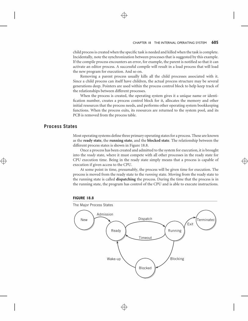
Most operating systems define three primary operating states for a process. These are knownas the ready state, the running state, and the blocked state. The relationship between thedifferent process states is shown in Figure 18.8.
Once a process has been created and admitted to the system for execution, it is broughtinto the ready state, where it must compete with all other processes in the ready state forCPU execution time. Being in the ready state simply means that a process is capable ofexecution if given access to the CPU.
At some point in time, presumably, the process will be given time for execution. Theprocess is moved from the ready state to the running state. Moving from the ready state tothe running state is called dispatching the process. During the time that the process is inthe running state, the program has control of the CPU and is able to execute instructions.
FIGURE 18.8
The Major Process States
New
Ready
Dispatch
Timeout
Wake-up Blocking
Exit
Admission
Blocked
Terminated
Running
606 PART FIVE THE SOFTWARE COMPONENT
Of course, only one process can be in the running state at a time for a uniprocessor system.If there are multiple processors or a cluster under the operating system’s control, the OS isresponsible for dispatching a process to run in each available CPU. In a typical multitaskingsystem, there may be many processes in blocked or ready states at any given time.
When I/O or other services are required for the continuation of program execution,the running process can no longer do any further useful work until its requirement issatisfied. Some operating systems will suspend the program when this occurs; others willallow the program to remain in the running state, even though the program is unable toproceed. In the latter case, most well designed programs will suspend themselves, unless theinterruption is expected to be extremely brief. This state transition is known as blocking,and the process remains in a blocked state until its I/O requirement is complete. When theI/O operation is complete, the operating system moves the process from the blocked stateback to the ready state. This state transition is frequently called wake-up. Blocking can alsooccur when a process is waiting for some event other than I/O to occur, for example, acompletion signal or a data result from another process.
Nonpreemptive systems will allow a running process to continue running until it iscompleted or blocked. Preemptive systems will limit the time that the program remainsin the running state to a fixed length of time corresponding to one or more quanta. If theprocess remains in the running state when its time limit has occurred, the operating systemwill return the process to the ready state to await further time for processing. The transitionfrom the running state to the ready state is known as time-out.
When the process completes execution, control returns to the operating system, andthe process is destroyed or killed or terminated.
Some operating systems provide one or more additional states, which are used toimprove the efficiency of the computer system. Some processes make heavy demands onparticular resources, say, a disk drive or a printer, or even the CPU, in such a way thatother processes are unable to complete their work in an efficient manner. In this case theoperating system may place a process in a suspended state until the required resourcescan be made available. When this occurs, the process is returned to a ready state. Thetransition from the suspended state to the ready state is known as resumption. Someoperating systems also allow a user to suspend a process. On UNIX systems, for example,typing Control-z is one way in which to suspend a process. The process may be resumedby issuing the command fg, together with the process identification number of the process.Some operating systems will also swap out a suspended process from memory to secondarystorage when the system becomes overloaded and will swap it back in when the load islighter. Particularly in small systems, the use of swap files for this purpose is common.Even in large computer systems, transaction processing software often contains interactiveprocesses that are used infrequently. These processes are often swapped out when they arenot being used and returned to memory when they are activated by a user request. Thistechnique is called roll-out, roll-in. The suspend, resume, and swap states have been left offthe diagram for clarity.
Threads
It is common in modern systems to provide capability for a sort of miniprocess, knownas a thread. A thread represents a piece of a process that can be executed independentlyof other parts of the process. (Think of the spell-checker in a word processor that checks
CHAPTER 18 THE INTERNAL OPERATING SYSTEM 607
words as you type, for example.) Each thread has its own context, consisting of a programcounter value, register set, and stack space, but shares program code, and data, and othersystem resources such as open files with the other member threads in the process. Threadscan operate concurrently. Like processes, threads can be created and destroyed and can bein ready, running, and blocked states. Context switching among threads is easier for theoperating system to manage because there is no need to manage memory, files, and otherresources and no need for synchronization or communication within the process, sincethis is handled within the process itself. This advantage suggests, however, that more careneeds to be taken when the program is written, to assure that threads do not interact witheach other in subtle ways that can create conditions that cause the program to fail. Notethat there is no protection among the threads of a process, since all the threads are usingthe same program code and data space.
Some systems even provide a mechanism for context switching of threads independentof the process switching mechanism. This means that in these systems threads can beswitched without the involvement of the operating system kernel. If a process becomesI/O blocked, it cannot proceed until the block is resolved. On the other hand, if a threadbecomes blocked, other threads in the process may be able to continue execution within theprocess’s allotted time, resulting in more rapid execution. Because the inner layers of theoperating system are not even aware of thread context switching in these systems, threadswitching is extremely rapid and efficient. Threads in these systems are commonly knownas user-level threads.
Threads came about as a result of the advent of event-driven programs. In olderprograms with traditional text-based displays and keyboard input, there was a single flowof control. Event-driven programs differ in that the flow of control depends in a muchmore dramatic way on user input. With a modern graphical user interface, a user can pulldown a menu and select an action to be performed at almost any time. Selecting an itemfrom a menu or clicking a mouse in a particular place in a particular way is known as anevent. The program must be able to respond to a variety of different events, at unknowntimes, and in unknown order of request.
Most such events are too small to justify creation of a new process. Instead, the actionfor each event is treated as a thread. The thread can be executed independently, but withoutthe overhead of a process. There is no control block, no separate memory, no separateresources. The primary requirement for a thread is a context storage area to store theprogram counter and registers when context switching takes place. A very simple threadcontrol block is adequate for this purpose. Threads are processed in much the same way asprocesses.
18.4 BASIC LOADING AND EXECUTIONOPERATIONS
Since the CPU’s capability is limited to the execution of instructions, every operation ina computer system ultimately arises from the fundamental ability to load and executeprograms. Application programs do the users’ work. Operating system programs andutilities manage files, control I/O operations, process interrupts, provide system security,manage the user interface, log operations for the system administrator to analyze, andmuch more. Except for programs that permanently reside in ROM, every one of theseprograms must be loaded into memory before it can be executed.

608 PART FIVE THE SOFTWARE COMPONENT
In general-purpose computer systems, the only programs permanently resident inROM are usually just the few that are needed to boot the system. All other programs areloaded after the system is operational. Many of these programs are loaded into memoryat start-up time and remain resident as long as the computer is on; others are loaded asthey are requested or needed, but in either case, the program loading operation is centralto system operation. Observing the steps in the loading process exposes the workings andinteractions of many of the basic operating system components.
Incidentally, the program loader itself is a program that generally must be loaded; aswe already noted in Section 18.2, this initial load occurs during the boot process. After that,the loader process remains resident in memory, ready for use.
In the previous section, you saw how processes are created from programs adminis-tratively by the process management component of the operating system. You are alreadyaware, therefore, that requests for program loads are spawned from application or systemprograms that are already running. Now we take a brief look at the next step: what happensafter the process is created but before it is loaded into memory and executed. This willprepare you for more detailed discussions of the memory management and schedulingissues that follow.
Figure 18.9 shows the basic steps required to load the program and ready it forexecution.
18.5 CPU SCHEDULING AND DISPATCHINGCPU scheduling provides mechanisms for the acceptance of processes into the system andfor the actual allocation of CPU time to execute those processes. A fundamental objectiveof multitasking is to optimize use of the computer system resources, both CPU and I/O,by allowing multiple processes to execute concurrently. CPU scheduling is the means formeeting this objective. There are many different algorithms that can be used for CPUscheduling. The selection of a CPU scheduling algorithm can have a major effect on theperformance of the system.
As a way to optimize system performance, the CPU scheduling task is separated intotwo different phases. The high-level, or long-term, scheduler is responsible for admittingprocesses to the system. The dispatcher provides short-term scheduling, specifically, theinstant-by-instant decision as to which one of the processes that are ready should begiven CPU execution time. The dispatcher also performs context switching. Some systemsalso include a third, middle-level scheduler, which monitors system performance. Whenpresent, the middle-level scheduler can suspend, or swap out, a process by removing itfrom memory temporarily and replace it with another waiting process. This operation isknown as swapping. Swapping is done to improve overall system performance. It wouldbe used if a particular process were hogging a resource in such a way as to prevent otherprocesses from executing.
High-Level Scheduler
The high-level scheduler determines which processes are to be admitted to the system.The role of the high-level scheduler is minimal for processes created in an interactiveenvironment. Such processes are usually admitted to the system automatically. If a user

CHAPTER 18 THE INTERNAL OPERATING SYSTEM 609
FIGURE 18.9
Loading and Executing a Process
Processmgmt
Fileservices
Allocatespace
Requestprogram
buffer space
Loadprogram
Retrievedirectory
Retrieveprogram
Setprocessstatus to“ready”
Processstarts
Readprogram
into memory
Read directoryfrom disk
Memorymgmt Dispatcher I/O
services
requests a service that requires the creation of a new process, the high-level scheduler willattempt to do so unless the system is seriously overloaded. To refuse the user in the middleof her or his work would be undesirable. The high-level scheduler will refuse a login process,however, if it appears that doing so would overload the system. The high-level schedulerwill refuse admission to the system if there is no place to put the program in memory or ifother resources are unattainable. If the request is a user login request, the user will have towait until later to try again. Otherwise, requests are usually accepted, even though it may

610 PART FIVE THE SOFTWARE COMPONENT
slow down the system. You may have experienced such slowdowns when working withWindows. You may have even gotten an ‘‘out-of-memory’’ message if you tried to do toomany things at once!
For batch processes, the high-level scheduler has a much more important role. Sincemost modern systems are predominately interactive, the use of batch processes is generallylimited to processes with demanding resource requirements, for example, a monthly billingprogram for a large utility or department store chain, or an economics problem with hugeamounts of data and complex calculations to be performed on the data. Processes of thistype can make it difficult for regular users to get their work done if the process is executedduring a busy time of day.
With batch processes, a delay in processing is usually acceptable to the user; therefore,the high-level scheduler has more flexibility in deciding when to admit the process to thesystem. The high-level scheduler can use its power to balance system resource use as anattempt to maximize the efficiency of the system and minimize disruption to the regularusers.
Dispatching
Conceptually, the dispatching process is simple. Whenever a process or thread gives upthe CPU, the dispatcher selects another candidate that is ready to run, performs a contextswitch, and sets the program counter to the program counter value stored in the processcontrol block to start execution. In reality, dispatching is much more complex than it firstappears. There are a number of different conditions that might cause a process to give upthe CPU, some voluntary and some involuntary, as established by the operating system.Presumably, the goal of the dispatcher is to select the next candidate in such a way as tooptimize system use. But, in fact, there are a number of different measurement criteria thatcan be used to define ‘‘optimum’’ system performance. Frequently, these criteria are inconflict with each other, and the characteristics of the candidates in contention as well asdifferent conditions within the system can also affect the selection of a particular candidatefor CPU execution at any given time.
Similarly, processes vary in their requirements. Processes can be long or short in theirrequirement for CPU execution time, they can require many resources, or just a few, andthey can vary in their ratio of CPU to I/O execution time. Different scheduling algorithmsfavor different types of processes or threads and meet different optimization criteria. Forexample, an algorithm that maximizes throughput by consistently placing short jobs at thefront of the queue is clearly not fair to a longer job that keeps getting delayed.
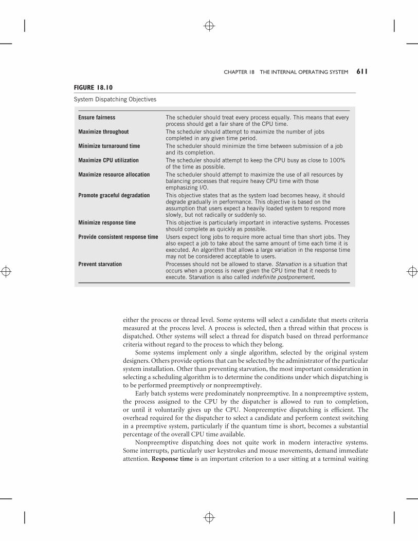
As a result, there are a number of different scheduling algorithms that can be used. Thechoice of scheduling algorithm then depends on the optimization objective(s) chosen, alongwith the expected mix of process types. Analysis requires consideration of a wide varietyof process mix possibilities and dynamic situations. Some of the objectives considered areshown in the table in Figure 18.10. Of the various objectives in the table, the prevention ofstarvation is particularly noticeable. Some algorithms with otherwise desirable propertieshave a potential to cause starvation under certain conditions. It is particularly importantthat the algorithm selected not permit starvation to occur.
With operating systems that support threads, dispatching normally takes place at thethread level. As an additional criterion, the candidate selection decision can be made at
CHAPTER 18 THE INTERNAL OPERATING SYSTEM 611
FIGURE 18.10
System Dispatching Objectives
Ensure fairness
Maximize throughout
Minimize turnaround time
Maximize CPU utilization
Maximize resource allocation
Promote graceful degradation
Minimize response time
Provide consistent response time
Prevent starvation
The scheduler should treat every process equally. This means that every process should get a fair share of the CPU time.The scheduler should attempt to maximize the number of jobs completed in any given time period.The scheduler should minimize the time between submission of a job and its completion.The scheduler should attempt to keep the CPU busy as close to 100% of the time as possible.The scheduler should attempt to maximize the use of all resources by balancing processes that require heavy CPU time with those emphasizing I/O.This objective states that as the system load becomes heavy, it should degrade gradually in performance. This objective is based on the assumption that users expect a heavily loaded system to respond more slowly, but not radically or suddenly so.This objective is particularly important in interactive systems. Processes should complete as quickly as possible.Users expect long jobs to require more actual time than short jobs. They also expect a job to take about the same amount of time each time it is executed. An algorithm that allows a large variation in the response time may not be considered acceptable to users.Processes should not be allowed to starve. Starvation is a situation that occurs when a process is never given the CPU time that it needs to execute. Starvation is also called indefinite postponement.
either the process or thread level. Some systems will select a candidate that meets criteriameasured at the process level. A process is selected, then a thread within that process isdispatched. Other systems will select a thread for dispatch based on thread performancecriteria without regard to the process to which they belong.
Some systems implement only a single algorithm, selected by the original systemdesigners. Others provide options that can be selected by the administrator of the particularsystem installation. Other than preventing starvation, the most important consideration inselecting a scheduling algorithm is to determine the conditions under which dispatching isto be performed preemptively or nonpreemptively.
Early batch systems were predominately nonpreemptive. In a nonpreemptive system,the process assigned to the CPU by the dispatcher is allowed to run to completion,or until it voluntarily gives up the CPU. Nonpreemptive dispatching is efficient. Theoverhead required for the dispatcher to select a candidate and perform context switchingin a preemptive system, particularly if the quantum time is short, becomes a substantialpercentage of the overall CPU time available.
Nonpreemptive dispatching does not quite work in modern interactive systems.Some interrupts, particularly user keystrokes and mouse movements, demand immediateattention. Response time is an important criterion to a user sitting at a terminal waiting

612 PART FIVE THE SOFTWARE COMPONENT
for a result. A long process executing nonpreemptively can cause the system to ‘‘hang’’ fora while. An additional disadvantage of nonpreemptive processing is that a buggy programwith an infinite loop can hang the system indefinitely. Most nonpreemptive systems actuallyhave a time-out built in for this purpose. A compromise position uses nonpreemptiveprocessing for executing processes that do not require immediate responses, but allowscritical processes to interrupt temporarily, always returning control to the nonpreemptiveprocess. Earlier versions of Windows, through Version 3.1, presented another compromisethat was dependent on the cooperation of the processes themselves. This position assumedthat processes would voluntarily relinquish control on a regular basis, to allow otherprocesses a chance to execute. To a large measure, this approach worked, although lesswell than true preemptive multitasking; however, it is subject to errors that may occur inindividual processes that can prevent the execution of other processes.
Linux presents another compromise approach: user processes (i.e., regular programs)run preemptively, but operating system programs run nonpreemptively. An importantrequirement to this approach is that operating system processes run quickly and veryreliably. The advantage to this approach is that critical operating system processes can gettheir work done efficiently without interruption from user processes.
The next section introduces a few typical examples of dispatching algorithms. Thereare many other possibilities, including algorithms that use combinations of these examples.
Nonpreemptive Dispatch Algorithms
FIRST-IN, FIRST-OUT Probably the simplest possible dispatch algorithm, first-in,first-out (FIFO) simply assumes that processes will be executed as they arrive, in order.Starvation cannot occur with this method, and the method is certainly fair in a generalsense; however, it fails to meet other objectives. In particular, FIFO penalizes short jobsand I/O-bound jobs, and often results in underutilized resources. As an illustration of thesubtle difficulties presented when analyzing the behavior of an algorithm, consider whathappens when one or more short, primarily I/O-based jobs are next in line behind a verylong CPU-bound job in a FIFO queue. We assume that the scheduler is nonpreemptive butthat it will allow another job to have the CPU when the executing job blocks for I/O. Thisassumption is essential to the full utilization of the CPU.
At the start of our observation, the long job is executing. While this happens, the shortjob(s) must sit and wait, unable to do anything. Eventually, the long job requires I/O andblocks. This finally allows the short jobs access to the CPU. Because they are predominatelyI/O-based jobs, they execute quickly and block, waiting to do I/O. Now, the short jobs mustwait again, because the long job is using the I/O resources. Meanwhile, the CPU is idle,because the long job is doing I/O, and the short jobs are also idle, waiting to do I/O. Thus,FIFO can result in long waits and poorly balanced use of resources, both CPU and I/O.
SHORTEST JOB FIRST The shortest job first (SJF) method will maximize throughputby selecting jobs that require only a small amount of CPU time. The dispatcher uses asits basis time estimates provided with the jobs when they are submitted. To prevent theuser from lying, systems that use this algorithm generally inflict a severe penalty on jobsthat run more than a small percentage over their estimate. Since short jobs will be pushedahead of longer jobs, starvation is possible. When SJF is implemented, it generally includes

CHAPTER 18 THE INTERNAL OPERATING SYSTEM 613
a dynamic priority factor that raises the priority of jobs as they wait, until they reach apriority where they will be processed next regardless of length. Although SJF maximizesthroughput, you might note that its turnaround time is particularly inconsistent, since thetime required to complete a job depends entirely on the mix of the jobs submitted bothbefore it, and possibly after it.
PRIORITY SCHEDULING Priority scheduling assumes that each job has a priorityassigned to it. The dispatcher will assign the CPU to the job with the highest priority. Ifthere are multiple jobs with the same priority, the dispatcher will select among them on aFIFO basis.
Priorities can be assigned in different ways. On some systems that charge their users forCPU time, users select the priority. The fee is scaled to the priority, so that higher prioritiescost more. In other systems, the priority is assigned by the system. Many factors can beused to affect performance, and the priorities may be assigned statically or dynamically.For example, a system may assign priority on the basis of the resources that the processis requesting. If the system is presently CPU-bound, it can assign an I/O-bound process ahigh priority to equalize the system.
Another variation on priority scheduling is basically nonpreemptive, but adds apreemptive element. As the process executes, it is periodically interrupted by the dispatcher,which reduces its priority, a little at a time, based on its CPU time used. If its priority fallsbelow that of a waiting process, it is replaced by the higher-priority process.
Preemptive Dispatch Algorithms
ROUND ROBIN The simplest preemptive algorithm, round robin gives each process aquantum of CPU time. If the process is not completed within its quantum, it is returned tothe back of the ready queue to await another turn. The round-robin algorithm is simpleand inherently fair. Since shorter jobs get processed quickly, it is reasonably good onmaximizing throughput. Round robin does not attempt to balance the system resourcesand, in fact, penalizes processes when they use I/O resources, by forcing them to reenterthe ready queue. A variation on round robin that is used by some UNIX systems calculatesa dynamic priority based on the ratio of CPU time to total time that the process has been inthe system. The smallest ratio is treated as the highest priority and is assigned the CPU next.If no process is using I/O, this algorithm reduces back to round robin, since the processthat had the CPU most recently will have the lowest priority, and the priority will climb asit waits. The round-robin technique is illustrated in Figure 18.11.
MULTILEVEL FEEDBACK QUEUES The multilevel feedback queue algorithmattempts to combine some of the best features of several different algorithms. Thisalgorithm favors short jobs by providing jobs brief, but almost immediate, access tothe system. It favors I/O-bound jobs, resulting in good resource utilization. It provideshigh throughput, with reasonably consistent response time. The technique is shown inFigure 18.12. The dispatcher provides a number of queues. The illustration shows three.A process initially enters the queue at the top level. The queue at the top level has toppriority, so a new process will quickly receive a quantum of CPU time. Short processeswill complete at this point. Since I/O-bound processes often require just a short amount

614 PART FIVE THE SOFTWARE COMPONENT
FIGURE 18.11
Round-Robin Scheduling
Newprocesses P P CPU
P P P
P
FIGURE 18.12
Multilevel Feedback Queue
Newprocesses P
Level 1
P CPU
P
Level 2
P
P
P P PP
Level N
CPU
CPU
q = 1q
q = 2q
q = 2q n
of initialization to establish their I/O needs, many I/O-bound processes will be quicklyinitialized and sent off for I/O.
Processes that are not completed are sent to a second-level queue. Processes inthe second-level queue receive time only when the first-level queue is empty. Althoughstarvation is possible, it is unlikely, because new processes pass through the first queue soquickly. When processes in the second level reach the CPU, they generally receive moretime. A rule of thumb doubles the number of quanta issued at each succeeding level. Thus,CPU-bound processes eventually receive longer time slots in which to complete execution.This method continues for as many levels as the system provides.
The final level is a round robin, which will continue to provide time until the process iscomplete. Some multilevel feedback queues provide a good behavior upgrade to processesthat meet certain criteria.
DYNAMIC PRIORITY SCHEDULING As noted above, the technique of dynamicpriority recalculation can also be used as a preemptive dispatching technique. BothWindows 2000 and Linux use a dynamic priority algorithm as their primary criterion

CHAPTER 18 THE INTERNAL OPERATING SYSTEM 615
for dispatch selection. The algorithms on both systems adjust priority based on their useof resources. Details of the Windows and Linux dispatch algorithms are presented inSupplemental Chapter 2.
18.6 MEMORY MANAGEMENTMemory management is the planned organization of programs and data into memory.The goal of memory management is to make it as simple as possible for programs to findspace, so that they may be loaded and executed, together with the additional space thatmay be required for various buffers. A secondary and related goal is to maximize the use ofmemory, that is, to waste as little memory as possible.
Today, nearly all memory management is performed using virtual storage, a method-ology that makes it appear that a system has a much larger amount of memory than actuallyexists physically. Virtual storage is discussed in Section 18.7.
Until the advent of virtual storage, however, effective memory management was adifficult problem. There may be more programs than can possibly fit into the given amountof physical memory space. Even a single program may be too large to fit the amount ofmemory provided. Compounding the difficulty, recall that most programs are written to beloaded contiguously into a single space, so that each of the spaces must be large enough tohold its respective program. Fitting multiple programs into the available physical memorywould require considerable juggling by the memory management module.
In passing, we point out to you that there is also a potential relationship betweenscheduling and memory management. The amount of memory limits the number ofprograms that can be scheduled and dispatched. As an extreme example, if the memoryis only large enough to hold a single program, then the dispatch algorithm is reduced tosingle tasking, simply because there is no other program available in memory to run. Asmore programs can be fit into memory, the system efficiency increases. More programs getexecuted, concurrently, in the same period of time, since the time that would be wastedwhen programs are blocked is now used productively. As the number of programs increasesstill further, beyond a certain point the resident time of each program starts to increase,because the available CPU time is being divided among programs that can all use it, andnew programs are continually being added that demand CPU time.
Nonetheless within reason, it is considered desirable to be able to load new processesas they occur, particularly in interactive systems. A slight slowdown is usually consideredpreferable to a user being told that no resources are available to continue his or her work.As we have hinted a number of times, virtual storage provides an effective and worthwhilesolution to the problem of memory management, albeit at the cost of additional hardware,program execution speed, disk usage, and operating system complexity. Before we explainthe process of memory management using virtual storage, however, it is useful to offera brief introduction to traditional memory management techniques to set the issues ofmemory management in perspective.
Memory Partitioning
The simplest form of memory management divides the memory space into a number ofseparate partitions. This was the method used prior to the introduction of virtual storage.

616 PART FIVE THE SOFTWARE COMPONENT
Today, it is used only in small embedded systems, where the number of programs runningat a given time is small and well controlled. Each partition is used for a separate program.
Two different forms of memory partitioning can be used. Fixed partitioning dividesmemory into fixed spaces. The MINOS memory was managed using fixed partitioning.Variable partitioning loads programs wherever enough memory space is available, usinga best-fit, first-fit, or largest-fit algorithm. The best-fit algorithm uses the smallest spacethat will fit the program. The first-fit algorithm simply grabs the first space available thatfits the program. The largest-fit algorithm, sometimes called worst-fit, uses the largestspace available, on the theory that this will leave the maximum possible space for anotherprogram. Figure 18.13 shows variable partitioning at work. Note that the starting positionsof programs shift as space becomes available for new programs.
Realistically, partitionining is not suitable for modern general-purpose computingsystems. There are two reasons for this:
■ First, no matter which method is used, memory partitioning results infragmentation of memory. This is seen in Figure 18.13. Fragmentation meansthat memory is being used in such a way that there are small pieces of memoryavailable that, if pushed together, would be sufficient to load one or moreadditional programs. Internal fragmentation means that there is memory thathas been assigned to a program that does not need it, but can’t be used elsewhere.Fixed partitioning results in internal fragmentation. External fragmentationmeans that there is memory that is not assigned, but is too small to use. Variablepartitioning will, after a while, result in external fragmentation, since thereplacement of one program in an available space with another will almost alwaysresult in a bit of space left over. Eventually, it may be necessary to have thememory manager move programs around to reclaim the space. Internal andexternal fragmentation are shown in Figure 18.14.
FIGURE 18.13
Variable Partitioning of Memory at Three Different Times
0
Process 5
Process 4
Top
Process 3
Process 2
Process 1
0
Process 5Empty
Process 3
Process 8
Process 6
Process 70
Process 12
Process 9
Process 13
Process 8
Process 10
Process 11
Empty Empty
Empty
Empty
Empty
Empty
Empty
Empty
Empty

CHAPTER 18 THE INTERNAL OPERATING SYSTEM 617
FIGURE 18.14
Internal and External Fragmentation
Assignedspace
Assignedspace
Used space
Used space
Internalfragmentation
Fragment
Fragment
Externalfragmentation
Fragment
Fragment
Fragment
Assignedspace
Assignedspace
Although fragmentation is manageable when the number of programs to beloaded is small, and the size of each program known in advance, this is not thecase for any general-purpose system.
■ Second, the size of most modern programs is sufficiently large that partitioningmemory will make it even more difficult to find memory spaces large enough toaccommodate all of the programs and data that the average user routinely expectsto run concurrently. (You have already seen, in Chapter 17, similar fragmentationand partitioning problems that occur in the storage of files on disk.)
18.7 VIRTUAL STORAGE
Overview
There are three major problems inherent in the traditional (now outdated) memorymanagement schemes described in the previous section:
1. As the system runs, fragmentation makes it harder and harder to find openspaces large enough to fit new programs as they are introduced into the system.
2. From Chapters 6 and 7, you should recall that Little Man programs, and indeed,all, programs, are coded on the assumption that they will be loaded into memoryand executed starting from memory location 0. The address field in many, butnot all, instructions points to an address where data is found or to the targetaddress of a branch. Of course in reality, it is only possible to load one programat that location in memory. All other programs must be loaded into memorystarting from some other address. That means that the operating system’sprogram loader must carefully adjust the address field of all affected instructionsto compensate for the actual addresses where the data or the branch target willactually be found.
3. There is often not enough memory to load all of the programs and theirresources that we wish to execute at once.

618 PART FIVE THE SOFTWARE COMPONENT
Virtual storage (or virtual memory—the words are synonymous), is the near-universally accepted solution to the problems inherent in memory management. Virtualstorage uses a combination of operating system software and special purpose hardware tosimulate a memory that meets the management needs of a modern system. The primarymethod of implementing virtual storage is called paging.
Pages and Frames
To begin, assume that memory is divided into blocks. These blocks are called frames.Usually, all the frames are of equal size, typically 1 KB–4 KB. The exception, an alternativemethod called segmentation is used more rarely, and will be described later. The size ofthe blocks is permanently set as a design parameter of the particular hardware architecture,based on a number of factors. The most important criterion for the block size is that itmust correspond exactly to a particular number of address bits. This guarantees that everyaddress within the block is expressed by the same number of digits. In the Little ManComputer, for example, a block size of 10 would be the only reasonable choice, since everyaddress within the block would be expressed with one digit (0–9). Similarly, in a real,binary-based computer, a 12-bit address can access an address space of exactly 4 KB.
The number of blocks depends on the amount of memory installed in the machine,but, of course, can’t exceed the largest memory address possible, as determined by thearchitecture of the instruction set. We could install 60 mailboxes in the Little ManComputer, for example; this would give us six frames within the constraint that the addressfield of the LMC instructions limits us to a maximum of 100 mailboxes, or ten frames.
The blocks are numbered, starting from 0. Because the block size was selected to usea specific, fixed number of bits (or decimal digits for the Little Man Computer), an actualmemory address consists simply of the block number concatenated with the address withinthe block. By selecting a frame size that corresponds exactly to a given number of digits, wecan simply concatenate to get the whole address.
EXAMPLESuppose that a Little Man memory consisted of 6010 mailboxes, divided into 6 frames. Eachframe is a one-digit block of size 10. The frames would be numbered from 0 through 5,and the address of a particular location within the frame would be a number from 0 to 9.Then, location number 6 in frame 3 would correspond to location 36 in memory. Similarly,memory address 49 would be in frame 4; the address would correspond to location 9 in thatframe. Figure 18.15(a) illustrates this example.
EXAMPLENow consider a binary computer with 1 GB of memory divided into 4 KB frames. There willbe 256 K, or approximately a quarter of a million, frames. (We divided 1 G by 4 K to get256 K.) Another way to look at this is to realize that to address 1 GB of memory requiresa 30-bit address. 4 KB frames will require 12 bits for addresses; therefore the number offrames will correspond to 18 bits, or 256 K frames.
For convenience, we will illustrate the example in hexadecimal. Remember that eachhexadecimal digit represents 4 bits. Memory location 3A874BD716 would then be located in
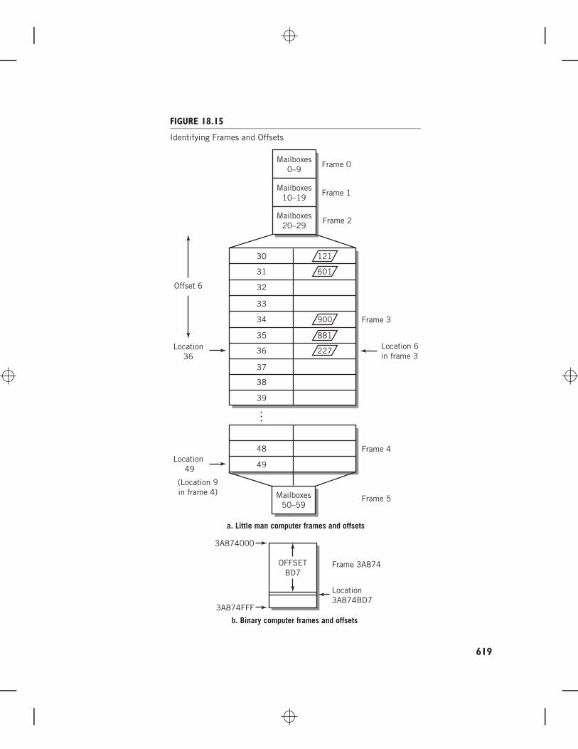
FIGURE 18.15
Identifying Frames and Offsets
a. Little man computer frames and offsets
b. Binary computer frames and offsets
Location 6in frame 3
(Location 9in frame 4)
Location 49
Offset 6
Location36
Frame 0
12130
31
32
33
34
35
36
37
38
39
Frame 1
Frame 2
Frame 3
Frame 4
Frame 5
Frame 3A874
Location3A874BD7
3A874000
3A874FFF
Mailboxes50–59
Mailboxes0–9
Mailboxes10–19
Mailboxes20–29
OFFSETBD7
601
900
881
227
48
49
…
619

620 PART FIVE THE SOFTWARE COMPONENT
the frame block numbered 3A87416, and specifically found at location BD716 of that frame.Notice that the frame block number requires a maximum of 18 bits and that the locationwithin the frame uses 12 bits. See Figure 18.15(b) for clarification. Similarly, locationnumber 02016 within frame number 15A316 corresponds to memory location 15A302016.
Effectively, we are dividing each memory address into two parts: a frame number andthe specific address within the particular frame. The address within the frame is called anoffset, because it represents the offset from the beginning of the frame. (It should be clearto you that the first address in a frame, which is the beginning of the frame, is 0, with thecorrect number of digits of course, so address 1 is offset by 1 from the beginning, and so on.)
It is not immediately obvious why we are dividing memory into frame blocks, butthe reason will become clear shortly. Here’s a hint: note the similarity between the frameblocks that make up the memory space and the blocks that make up the space on a harddisk. Then, recall that we can find data within a file even if we store the files on a hard disknoncontiguously.
Suppose we also divide a program into blocks, where each block in the program isthe same size as a frame. The blocks in a program are called pages. See Figure 18.16. Thenumber of pages in a program obviously depends on the size of the program. We willrefer to the instruction and data memory address references in a program as ‘‘logical’’ or‘‘virtual’’ memory references, as opposed to the physical memory references that actuallygo out to memory and store and retrieve instructions and data. The words logical andvirtual are used interchangeably.
Like frames, the number of pages is also constrained by the instruction set architecture,but, as we will show you later, it is not limited to the size of installed memory. Stateddifferently, a program can be larger than the amount of memory installed in a computer,and still execute successfully, although possibly slowly.
The key to this magical sleight-of-hand is a technique called dynamic addresstranslation (DAT). Dynamic address translation is built into the CPU hardware of
FIGURE 18.16
Frames and Pages
Page 0
Programpages
Memoryframes
1
2
3
4
5
0
4KB
8KB
12KB
16KB
20KB
24KB
Frame 0
1
2
3
4
5
6
7
0
4KB
8KB
12KB
16KB
20KB
24KB
28KB
32KB
every modern computer. The hardware automatically andinvisibly translates every individual address in a program (thevirtual addresses) to a different corresponding physical location(the physical addresses). This allows the operating system’s pro-gram loader to place the pages of a program into any availableframes of physical memory, page by page, noncontiguously,so that it is not necessary to find a contiguous space largeenough to fit the entire program. Any page of any program canbe placed into any available frame of physical memory. Sinceevery frame is essentially independent, the only fragmentationwill be the small amount of space left over at the end of the lastpage of each individual program.
For each program, the operating system creates a pagetable, which keeps track of the corresponding frame location inphysical memory where each page is stored. There is one entryin the table for each page of the program. The entry containsthe page number and its corresponding frame number.

CHAPTER 18 THE INTERNAL OPERATING SYSTEM 621
Since each page fits exactly into a frame, the offset of a particular address from thebeginning of a page is also exactly the same as the offset from the beginning of the framewhere the page is physically loaded. To translate a virtual address to a physical address, thevirtual address is separated into its page number and an offset; a look-up in the program’spage table locates the entry in the table for the page number, then translates, or maps, thevirtual memory reference into a physical memory location consisting of the correspondingframe number and the same offset. We remind you again: this operation is implementedin hardware. Every memory reference in a fetch-execute cycle goes through the sametranslation process. The address that would normally be sent to the memory addressregister (MAR) is mapped through the page table and then sent to the MAR. It is alsoimportant to remember that the translation process is entirely invisible to the program. Asfar as the program can tell, every memory reference is exactly where the program says it is.
A simple example illustrates the translation process.
EXAMPLEConsider a program that fits within one page of virtual memory. Placement of the programis shown in Figure 18.17a. The page for the program would be numbered 0, of course. Ifwe assume a page size of 4 KB, then any logical memory location in this program would bebetween 0000 and 0FFF. Suppose frame 3 is available in which to place this program inphysical memory. Then the physical addresses for this program to execute properly must allbe between 3000 and 3FFF. We obtain the correct address in each case by changing thepage number (0) to the frame number (3), keeping the offset the same as it was. A LOAD
instruction, LOAD 028A, for example, would be translated to find its data in physical memoryat 328A.
FIGURE 18.17(a)
A Simple Page Table Translation
OK
OFFF
O000
Logicalprogramspace Page table
0000
Frame 0
1000
2000
3000
4000
Physicalspace
328A
Frame 1
Frame 2
Frame 3
Page frame
0 3
O28APage 0
4K
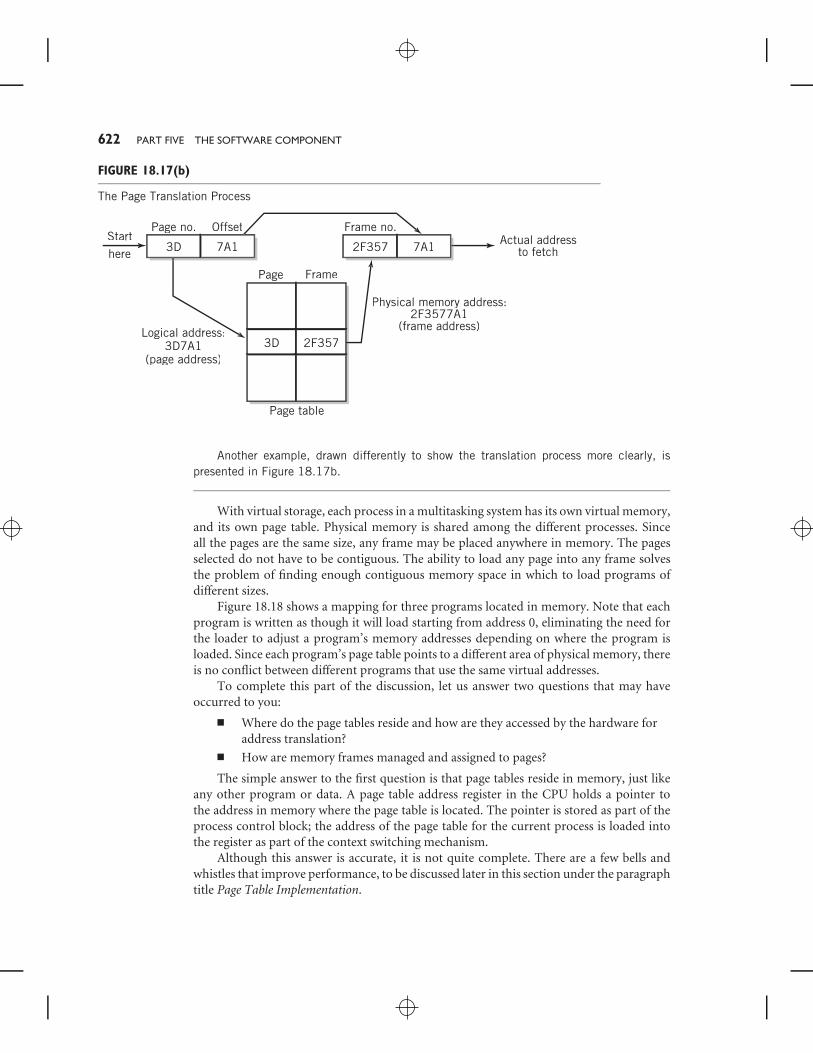
622 PART FIVE THE SOFTWARE COMPONENT
FIGURE 18.17(b)
The Page Translation Process
3D
3D
Page no.Starthere
Page
Logical address:3D7A1
(page address)
Physical memory address:2F3577A1
(frame address)
Page table
7A1
Offset
2F357
2F357
Frame no.Actual address
to fetch
Frame
7A1
Another example, drawn differently to show the translation process more clearly, ispresented in Figure 18.17b.
With virtual storage, each process in a multitasking system has its own virtual memory,and its own page table. Physical memory is shared among the different processes. Sinceall the pages are the same size, any frame may be placed anywhere in memory. The pagesselected do not have to be contiguous. The ability to load any page into any frame solvesthe problem of finding enough contiguous memory space in which to load programs ofdifferent sizes.
Figure 18.18 shows a mapping for three programs located in memory. Note that eachprogram is written as though it will load starting from address 0, eliminating the need forthe loader to adjust a program’s memory addresses depending on where the program isloaded. Since each program’s page table points to a different area of physical memory, thereis no conflict between different programs that use the same virtual addresses.
To complete this part of the discussion, let us answer two questions that may haveoccurred to you:
■ Where do the page tables reside and how are they accessed by the hardware foraddress translation?
■ How are memory frames managed and assigned to pages?
The simple answer to the first question is that page tables reside in memory, just likeany other program or data. A page table address register in the CPU holds a pointer tothe address in memory where the page table is located. The pointer is stored as part of theprocess control block; the address of the page table for the current process is loaded intothe register as part of the context switching mechanism.
Although this answer is accurate, it is not quite complete. There are a few bells andwhistles that improve performance, to be discussed later in this section under the paragraphtitle Page Table Implementation.

CHAPTER 18 THE INTERNAL OPERATING SYSTEM 623
FIGURE 18.18
Mapping for Three Processes
Frame 10
Frame 0
Process 1 – Page 0Process 3 – Page 3
Process 1Page Frame
Page Frame
Page Frame
Process 3 – Page 4
Process 3 – Page 0Process 2 – Page 1
Process 1 – Page 2Process 3 – Page 2
Process 1 – Page 1Process 2 – Page 0
Process 3 – Page 1
1
0
1
8
2 3
2
Process 3
1
0
4
3 9
4 10
0
5
Process 2
0 2
1 6
Physical memory
FIGURE 18.19
Inverted Page Table for Process Page Tables Shown inFigure 18.18
Page
Free page frame
Process #Frame
0
1
2
3
4
5
6
7
3
1
2
1
3
3
2
1
1
0
2
2
0
1
8 1 0
9 3 3
10 3 4
The answer to the second question is thatphysical memory is shared among all of the activeprocesses in a system. Since each process has itsown page table, it is not practical to identifyavailable memory frames by accumulating datafrom all of the tables. Rather, there must be asingle resource that identifies the entire pool ofavailable memory frames from which the memorymanager may draw, when required. There are twocommon approaches in use. One is to providean inverted page table, which lists every memoryframe with its associated process and page. Thistable shows the actual use of physical memory atevery instant. Any frame without an associatedpage entry is available for allocation. Figure 18.19illustrates an inverted page table. We’ll leave it asa simple exercise for you to identify the availableframes.
A second method maintains a list of availableframes, usually as a simple linked list. When aprocess needs frames, it takes them from the topof the list. When a process exits, its frames are
added to the end of the list. Since frame contiguity is unimportant, this is an effective wayto manage the free frame pool.
The Concept of Virtual Storage
The first two issues of memory management that we raised initially are thus solved. But, asthe TV infomercials say, ‘‘Wait—there’s still more!’’

624 PART FIVE THE SOFTWARE COMPONENT
As we noted before, the third major challenge for memory management is the limitedtotal quantity of physical memory available. Even hundreds of megabytes of memory canonly hold a few modern programs. Up to this point, we have assumed that there is a frameavailable for every page that needs one. While page-to-frame translation has eliminatedthe question of how to fit programs into existing memory space, the next step is moreimportant and useful: we will show you how the concept of virtual storage allows the systemto extend the address space far beyond the actual physical memory that exists. As you willsee, the additional address space required to store a large number of programs is actuallyprovided in an auxiliary form of storage, usually disk, although some systems now make itpossible to use flash memory for this purpose.
So far we have assumed that all the pages of an executing program are located in framessomewhere in physical memory. Suppose that this were not the case—that there are notenough frames available to populate the page table when the program is loaded. Instead,only some pages of the program are present in physical memory. Page table entries withouta corresponding frame are simply left empty. Can the program execute?
The answer depends on which pages are actually present in corresponding frames ofphysical memory. To execute a program instruction or access data, two requirements mustbe met.
■ The instruction or data must be in physical memory.■ The page table for that program must contain an entry that maps the virtual
address being accessed to the physical location containing the instruction or data.
These two requirements are related. The existence of a page listing in the page tableimplies that the required value is in memory and vice versa. If these two conditions aremet, then the instruction can execute as usual. This suggests, correctly, that instructionsand data that are not being accessed do not have to be in memory. At any given time inthe execution of a program, there are active pages and inactive pages. Only the active pagesrequire corresponding frames in the page table and in physical memory. Thus, it is possibleto load only a small part of a program and have it execute.
Page Faults
The real question is what happens when an instruction or data reference is on a pagethat does not have a corresponding frame in memory. The memory management softwaremaintains the page tables for each program. If a page table entry is missing when thememory management hardware attempts to access it, the fetch-execute cycle will not beable to complete.
In this case, the CPU hardware causes a special type of interrupt called a page fault ora page fault trap. This situation sounds like an error, but actually it isn’t. The page faultconcept is part of the overall design of virtual storage.
When the program is loaded, an exact, page-by-page image of the program is alsostored in a known auxiliary storage location. The auxiliary storage area is known as abacking store or, sometimes, as a swap space or a swap file. It is usually found on disk,but some recent systems use flash memory for this purpose. Also assume that the page sizeand the size of the physical blocks on the auxiliary storage device are integrally related, sothat a page within the image can be rapidly identified, located, and transferred between theauxiliary storage and a frame in memory.

CHAPTER 18 THE INTERNAL OPERATING SYSTEM 625
When a page fault interrupt occurs, the operating system memory manager answersthe interrupt. And now the important relationship between the hardware and the operatingsystem software becomes clearer. In response to the interrupt, the memory managementsoftware selects a memory frame in which to place the required page. It then loads thepage from its program image in auxiliary storage. If every memory frame is already in use,the software must pick a page in memory to be replaced. If the page being replaced hasbeen altered, it must first be stored back into its own image, before the new page can beloaded. Page replacement algorithms are discussed later in this section. The process of pagereplacement is also known as page swapping. The steps involved in handling a page faultare shown in Figure 18.20.
FIGURE 18.20
Steps in Handling a Page Fault
Load M
Load M
None
Pagetable
Physicalmemory
Trap
1. The page table is checked for memory reference M. That page is presently not in memory, which causes a page fault trap.
2. OS memory manager locates desired page on auxiliary storage and loads it into free memory frame.
3. Resets the page table, and restarts the instruction.
Page faulttrapM
kM
k Free frame
OSMemorymanager
626 PART FIVE THE SOFTWARE COMPONENT
Most systems perform page swapping only when it is required as a result of a pagefault. This procedure is called demand paging. A few systems attempt to anticipate pageneeds before they occur, so that a page is swapped in before it is needed. This technique iscalled prepaging. To date, prepaging algorithms have not been very successful at predictingaccurately the future page needs of programs.
When the page swap is complete, the process may be started again where it left off. Mostsystems return to the beginning of the fetch-execute cycle where the page fault occurred,but a few systems restart the instruction in the middle of its cycle. Regardless of whichway is used, the required page is now present, and the instruction can be completed. Theimportance of page swapping is that it means that a program does not have to be loadedinto memory in its entirety to execute. In fact, the number of pages that must be loadedinto memory to execute a process is quite small. This issue is discussed further in the nextsection.
Therefore, virtual storage can be used to store a large number of programs in a smallamount of physical memory and makes it appear that the computer has more memorythan is physically present. Parts of each program are loaded into memory. Page swappinghandles the situations when required pages are not physically present. Furthermore, sincethe virtual memory mapping assures that any program page can be loaded anywhere intomemory, there is no need to be concerned about allocating particular locations in memory.Any free frame will do.
Working Sets and the Concept of Locality
How many pages should be assigned to a new process just entering the system? It wouldseem that the more pages that are initially assigned to a process, the less likely it would bethat a page fault would occur during execution of the process. Conversely, the more pagesassigned to a process, the fewer the number of processes that will fit into memory. There isa lower limit on the number of pages to be assigned, which is determined by the instructionaddressing modes used by the particular computer. Executing a single instruction in anindirect addressing machine, for example, requires at least three pages, the page where theinstruction resides, the page where the indirect address is stored, and the page where thedata is found. This assumes that each item is on a different page, but it is necessary tomake the worst-case assumption to prevent instructions from failing in this way. Otherinstruction sets can be analyzed similarly.
More practically, experimentation performed in the early 1970s showed that duringexecution programs exhibit a tendency to stay within small areas of memory duringany given period of time. Although the areas themselves change over time, the propertycontinues to hold throughout the execution of the program. This property is called theconcept of locality. An illustration of the concept at work is shown in Figure 18.21.The concept of locality makes sense intuitively. Most well-written programs are writtenmodularly. During the initial phase of execution of a program, a small part of the programinitializes variables and generally gets the program going. During the main body of theprogram, the likely operations consist of small loops and subroutine calls. These representthe different area of memory being executed at different times.
An effective compromise would allocate a sufficient number of pages to satisfy thelocality of a particular program. This number of pages would be sufficient to run the

CHAPTER 18 THE INTERNAL OPERATING SYSTEM 627
FIGURE 18.21
Memory Use with Time, Exhibiting Locality
34
32
30
28
26
24
22
20
18
Execution time
Pag
e nu
mbe
rs
Source: Operating Systems 2/e by Stallings, W. 1995. Reprinted bypermission of Prentice-Hall, Upper Saddle River, NJ.
program normally. Page faults wouldonly occur when the local area beingused by the program moves to adifferent part of the program. Thenumber of pages that meets therequirement of locality is called aworking set. It differs somewhatfrom program to program, but itis possible to establish a reasonablepage quantity that meets the needsof most programs without an unduenumber of page faults. Some systemsgo further and monitor the numberof page faults that actually occur foreach process. They then dynamicallyadjust the size of the working set foreach process to try to meet its needs.
Page Sharing
An additional feature of virtualstorage is the ability to share pagesamong different processes that areexecuting the same program. Aslong as the code is not modified, thatis, the code is pure, there is no needto have duplicate program codestored in memory. Instead, eachprocess shares the same programcode page frames and provides itsown work space for data. The pagetables for each process will simply
point to the same physical memory frames. This simplifies the management of multipleprocesses executing the same program.
Page Replacement Algorithms
There will be times on a heavily loaded system when every available page in memory is inuse. When a page fault occurs, the memory manager must pick a page to be eliminatedfrom memory to make room for the new page that is needed. The goal, of course, is toreplace a page that will not be needed in the near future. There are a number of differentalgorithms that are used. As usual with operating system algorithms, each has advantagesand disadvantages, so selecting an algorithm is a matter of trade-offs. Some systems selectpages to be replaced from the same process. Others allow replacement from any processin the system. The former is known as local page replacement; the latter is called globalpage replacement. Global page replacement is more flexible, since there are a much larger
628 PART FIVE THE SOFTWARE COMPONENT
number of pages to choose from. However, global page replacement affects the working setsize of different processes and must be managed carefully.
As an additional consideration, some pages must never be removed from memorybecause doing so could eventually make the system inoperable. For example, removing thedisk driver would make it impossible to swap in any new pages, including the disk driver! Toprevent this situation, the frames corresponding to critical pages are locked into memory.These frames are called locked frames. An additional bit in each row of the page table is setto indicate that a frame is locked. Locked frames are never eligible for replacement.
FIRST-IN, FIRST-OUT PAGE REPLACEMENT The simplest page replacement algo-rithm is a first-in, first-out algorithm. The oldest page remaining in the page table is selectedfor replacement. FIFO does not take into account usage of the page. Logically, a page thathas been in memory for a long period of time is probably there because it is heavily used.The page being removed may be in current use, which would result in a second page faultand force the system to reload the page almost immediately. FIFO has a second, interestingdeficiency. You would assume that increasing the number of pages available to a processwould reduce the number of page faults for that process. However, it has been shown thatunder certain conditions, use of the FIFO page replacement algorithm results in more pagefaults with an increased number of pages, instead of fewer. This condition is known asBelady’s anomaly. If you are interested, examples of Belady’s anomaly can be found in thereferences by Deitel [DEIT03] and Silberschatz et al. [SILB08]. For these reasons, FIFO isnot considered a good page replacement algorithm.
LEAST RECENTLY USED PAGE REPLACEMENT The least recently used (LRU)algorithm replaces the page that has not been used for the longest time, on the assumptionthat the page probably will not be needed again. This algorithm performs fairly well, butrequires a considerable amount of overhead. To implement the LRU algorithm, the pagetables must record the time every time the page is referenced. Then, when page replacementis required, every page must be checked to find the page with the oldest recorded time. Ifthe number of pages is large, this can take a considerable amount of time.
LEAST FREQUENTLY USED PAGE REPLACEMENT Another possibility is to select thepage that has been used the least frequently. Intuitively, this algorithm has appeal, since itwould seem that a page not used much is more replaceable than one that has received a lotof use. The flaw with this algorithm is that a page that has just been brought into memoryhas not been used much, compared to a page that has been in memory for a while. Still,the new page was brought into memory because it was needed, and it is likely that it will beneeded again.
NOT USED RECENTLY PAGE REPLACEMENT The not used recently (NUR) algo-rithm is a simplification of the least recently used algorithm. In this method, the computersystem hardware provides two additional bits for each entry in the page tables. One bit isset whenever the page is referenced (used). The other bit is set whenever the data on thepage is modified, that is, written to. This second bit is called a dirty bit. Periodically, thesystem resets all the reference bits.
The memory manager will attempt to find a page with both bits set to 0. Presumably,this is a page that has not been used for a while. Furthermore, it is a page that has not been
CHAPTER 18 THE INTERNAL OPERATING SYSTEM 629
modified, so it is necessary only to write the new page over it. The page being replaced doesnot have to be saved back to the backing store, since it has not been modified. The secondchoice will be a page whose dirty bit is set, but whose reference bit is unset.
This situation can occur if the page has not been accessed for a while, but was modifiedwhen it was accessed, prior to the resetting of the reference bits. This page must be writtenback to the backing store before a new frame can be read into its spot. Third choice will bea page that has been referenced, but not modified. And finally, least desirable will be a pagethat has been recently referenced and modified. This is a commonly used algorithm.
One difficulty with this algorithm is that gradually all the used bits fill up, makingselection difficult or impossible. There are a number of variations on this algorithm thatsolve this problem by selectively resetting used bits at regular intervals or each time a pagereplacement occurs. The most common approach pictures the process pages as numeralson a clock. When a page replacement must be found, the clock hand moves until it findsan unset used bit and the corresponding page is replaced. Pages with set used bits that thehand passes over are reset. The hand remains at the found replacement page awaiting thenext replacement requirement. This variation on NUR is called the clock page replacementalgorithm.
SECOND CHANCE PAGE REPLACEMENT ALGORITHMS One second chance algo-rithm uses an interesting variation on FIFO, using a referenced bit similar to that of NUR.When the oldest page is selected for replacement, its referenced bit is checked. If thereferenced bit is set, the bit is reset, and the time is upgraded, as though the page hadjust entered memory. This gives the page a second pass through the list of pages. If thereferenced bit is not set, then the page is replaced, since it is safe to assume that it has notbeen referenced in some time.
Another second chance algorithm keeps a small pool of free pages that are not assigned.When a page is replaced, it is not removed from memory but, instead, is moved into thefree pool. The oldest page in the free pool is removed to make room. If the page is accessedwhile in the free pool, it is moved out of the free pool and back into the active pages byreplacing another page.
Both second chance algorithms reduce the number of disk swaps by keeping whatwould otherwise be swapped-out pages in memory. However, the first of these algorithmshas the potential of keeping a page beyond its usefulness, and the second decreases thenumber of possible pages in memory by using some of those pages for the free pool.
Thrashing
A condition that can arise when a system is heavily loaded is called thrashing. Thrashing isevery system administrator’s nightmare. Thrashing occurs when every frame of memory isin use, and programs are allocated just enough pages to meet their minimum requirement.A page fault occurs in a program, and the page is replaced by another page that will itselfbe needed for replacement almost immediately. Thrashing is most serious when globalpage replacement is used. In this case, the stolen page may come from another program.When the second program tries to execute, it is immediately faced with its own page fault.Unfortunately, the time required to swap a page from the disk is long compared to CPUexecution time, and as the page fault is passed around from program to program, no

630 PART FIVE THE SOFTWARE COMPONENT
program is able to execute, and the system as a whole slows to a crawl or crashes. Theprograms simply continue to steal pages from each other. With local page replacement, thenumber of thrashing programs is more limited, but thrashing can still have a serious effecton system performance.
Page Table Implementation
As we mentioned previously, the data in the page table must be stored in memory. Youshould realize that data in the page table must be accessed during the fetch-execute cycle,possibly several times, if the fetch-execute cycle is executing an instruction with a complexaddressing mode. Thus, it is important that the page table be accessed as quickly as possible,since the use of paging can negatively affect the performance of the system in a majorway otherwise. To improve access, many systems provide a small amount of a special typeof memory called associative memory. Associative memory differs from regular memoryin that the addresses in associative memory are not consecutive. Instead, the addresses inassociative memory are assigned to each location as labels. When associative memory isaccessed, every address is checked at the same time, but only the location whose addresslabel matches the address to be accessed is activated. Then the data at that location can beread or written. (Cache memory lines are accessed similarly.)
A mailbox analogy might be useful in helping you to understand associative memory.Instead of having mailboxes that are numbered consecutively, picture mailboxes that havethose little brass inserts that you slide a paper label into. On each label is written theaddress of that particular box. By looking at all the boxes, you can find the one thatcontains your mail. For a human, this technique would be slower than going directly to amailbox in a known location. The computer, however, is able to look at every address labelsimultaneously.
Suppose, then, that the most frequently used pages are stored in this associativememory. They may be stored in any order, since the address labels of all locations arechecked simultaneously. The page number is used as the address label that is being accessed.Then, the only frame number that will be read is the one that corresponds to that page. A pagetable that is constructed this way is known as a translation lookaside buffer (TLB), table.
The number of locations available in a TLB table is small because associative memoryis expensive. There must be a second, larger, page table that contains all the page entries forthe program. When the desired page is found in the TLB table, known as a hit, the framecan be used without further delay. When the desired page is not found in the TLB table,called a miss, the memory management unit defaults to conventional memory, where thelarger page table is stored. Access to the table in memory does, in fact, require an extramemory access, which will significantly slow down the fetch-execute cycle, but that can’tbe helped.
To locate the correct entry in the larger page table, most computers provide a specialregister in the memory management unit that stores the address of the origin of the pagetable in memory. Then, the nth page can be located quickly, since its address in memoryis the address of the origin plus the offset. The process of page table lookup is shown inFigure 18.22. Figure 18.22a shows how the page is accessed when the page is found inassociative memory; Figure 18.22b shows the procedure when the TLB does not containthe desired page.

CHAPTER 18 THE INTERNAL OPERATING SYSTEM 631
FIGURE 18.22
Frame Lookup Procedures: (a) Page in TLB, (b) Page Not in TLB
+
12
7 15
14 175 1
12 42 12
Page no.
Page no.(associative
address) Frame no.
500
500512Miss
Frame no.
Page table origin register
Pagetable
Memory
a. Page in TLB
b. Page not in TLB
Hit frame no.
12
7 15
14 175 1
21 112 12
Page no.
Page no.(associative
address) Frame no.
Beyond the requirement that the frame or page size conform exactly to a fixed numberof bits, the size of a frame or page is determined by the computer system designer as afundamental characteristic of the system. It is not changeable. There are several trade-offsin the determination of page size. The page table for a program must contain an entryfor every page in the program. The number of pages is inversely proportional to the pagesize, so as the page size is decreased, the number of page table entries required increases.

632 PART FIVE THE SOFTWARE COMPONENT
FIGURE 18.23
Internal Fragmentation
0
2048
4096
6144
897 bytesinternal
fragmentation2KBpage
4096
8192
2945 bytesinternal
fragmentation
4KBpage
Program size: 5247 bytes
On the other hand, we have assumed thatthe size of the program corresponds ex-actly to the amount of memory occupiedby the pages required for the program.This is not usually true. More com-monly, the last page is partly empty. Thewasted space is internal fragmentation.An example is shown in Figure 18.23.
Also, if the pages are small, mem-ory will consist of more pages, whichallows more programs to be resident.Conversely, smaller pages will requiremore swapping, since each program willhave less code and data available to it atany given time. Experimentally, designershave determined that 2 KB or 4 KB pagesseem to optimize overall performance.
Page tables on large machines can, themselves, require considerable memory space.One solution is to store the page tables in virtual memory. Page tables, or portions of pagetables, in current use will occupy frames, as usual. Other portions or tables will reside onlyin virtual memory until needed.
Segmentation
Segmentation is essentially similar to paging conceptually, but differs in many details. Asegment is usually defined as a logically self-contained part of a program, as determinedby a programmer or by a compiler translation program. Thus, in most systems, segmentscan be variable in size. (A few systems define segments instead as large pages, of fixed size,but of 1 MB, 2 MB, or 4 MB, or even more. This definition does not interest us here, sincethe previous discussion of paging applies in this case. When a fixed size segment is furtherdivided into pages, the program address is divided into three parts, a segment, a page, andan offset, and the mapping process takes place in two steps, but the procedure is otherwiseidentical to our previous discussion.) Program segments can represent parts of a programsuch as main routines and subroutines or functions, or they can represent program codeand data, even separate data tables. The crucial difference between segments and pages isthat due to their variability in size, the boundaries between segments do not fall on naturalborders, as pages do.
Therefore, in the segment table, it is necessary to provide the entire physical addressfor the start of the segment instead of just a page number. It is also necessary to recordthe size or upper limit location of the segment, so that the system can check to make surethat the requested location does not fall outside the limit of the segment. Otherwise, itwould be possible to read or write data to a location belonging to another segment, whichwould compromise the integrity of the system. This is not a problem with paging, since itis impossible for the offset to exceed the size of a page.
The program segment numbers are stored with each segment and are treated similarlyto page numbers. For each segment number, there is an entry in the segment table

CHAPTER 18 THE INTERNAL OPERATING SYSTEM 633
containing the starting location of the segment in physical memory plus the limit of thesegment. The physical address is calculated by adding the program segment offset fromthe start of the segment to the memory starting location and checking this value against thelimit. As with the page table, part of the segment table can be stored in associative memoryfor faster access. When segmentation and paging are both provided, there may be two TLBtables, one for each. When both are provided, the translation process performs its mappingin two steps. First, the segment table is used to determine the location of the pages thatmake up the segment. Then, the page table locates the desired frame. Since the programmerestablishes the segments, segmentation is less invisible to the programmer than paging,even though during operation it is still invisible. This provides a few advantages to theprogrammer, stemming from the fact that each segment can be treated independently. Thismeans that a particular segment could be shared among different programs, for example.Nonetheless, segmentation is harder to operate and maintain than paging and has rapidlyfallen out of favor as a virtual storage technique.
Process Separation
The use of virtual storage offers one additional benefit that should be mentioned. Undernormal program execution without virtual storage, every memory access has the potentialto address a portion of memory that belongs to a different process. This would violatesystem security and data integrity; for example, a program in a partitioned memory couldaccess data belonging to another process simply by overflowing an array. Prior to virtualstorage memory management, this was a difficult problem. It was necessary to implementmemory access limits for each process in hardware, because there is no way for operatingsystem software to check every attempted memory access while a program is executing.With virtual storage, every memory access request points to a logical address, not a physicalone. Since the logical address is within the space of the process itself, the translation processassures that it is not possible to point to a physical address belonging to another process,unless the page tables have been set up intentionally to share frames between the processes.Thus, virtual storage provides simple, effective separation protection between processes.
18.8 SECONDARY STORAGE SCHEDULINGOn a busy system, it is common to have a number of disk requests pending at any giventime. The operating system software will attempt to process these requests in a way thatenhances the performance of the system. As you might expect by now, there are severaldifferent disk scheduling algorithms in use.
First-Come, First-Served Scheduling
First-come, first-served (FCFS) scheduling is the simplest algorithm. As requests arrive,they are placed in a queue and are satisfied in order. Although this may seem like a fairalgorithm, its inefficiency may result in poorer service to every request in the queue. Theproblem is that seek time on a disk is long and somewhat proportional to the distance thatthe head has to move. With FCFS, one can expect the head to move all over the disk tosatisfy requests. It would be preferable to use an algorithm that minimizes seek distances.

634 PART FIVE THE SOFTWARE COMPONENT
This would suggest processing requests that are on nearby tracks first. The other algorithmsin use attempt to do so.
Shortest Distance First Scheduling
The shortest distance first (SDF) scheduling algorithm looks at all the requests in thequeue and processes the one nearest to the current location of the head. This algorithmsuffers from the possibility of indefinite postponement. If the head is near the middle trackon the disk, a request near the edge of the disk may never get serviced if requests continueto join the queue.
Scan Scheduling
The scan scheduling algorithm attempts to satisfy the limitation of SDF scheduling. Thehead scans back and forth across the disk surface, processing requests as it goes. Althoughthis method is fairer than SDF, it suffers from a different limitation, namely, that blocksnear the middle tracks are processed twice as often as blocks near the edge. To see thismore clearly, consider the diagram in Figure 18.24. Consider the head moving smoothlyback and forth across the disk at a constant speed. The diagram shows the time at whichthe head crosses various tracks. Note that the middle track is crossed in both directions, atabout equal intervals. Tracks near either the inside or outside track, however, are crossedtwice in quick succession. Then there is a long interval in which they are not touched. A
FIGURE 18.24
Scan Scheduling Algorithm
In
Out
Track 38
a. Disk layout
b. Timing chart
Track 20
TimeInOutIn
Trackcrossed
3820 38 38 20 0 20 38
Track 0
Source: Copyright 1971 International Business Machines Corporation. Reprinted withpermission from IBM Systems Journal, Vol. 10, No 3.
CHAPTER 18 THE INTERNAL OPERATING SYSTEM 635
track at the very edge, inside or outside, is touched only once for every two times that atrack in the middle is touched.
N-STEP C-SCAN Scheduling
Two changes improve the n-step c-scan scheduling algorithm. One is to cycle in only onedirection, then return to the other end before accessing blocks again. This assures that eachblock is treated equally, even though a bit of time is wasted returning the head to its originalposition. The other change is to maintain two separate queues. Once the head has startedto traverse the disk, it will read only blocks that were already waiting when the traversestarted. This prevents block requests that are just ahead of the head from jumping into thequeue. Instead, such a block would be placed in the alternate queue to wait for the nextpass. This approach is fairer to requests that have already been waiting. Practically, there isno reason to move the head beyond the last block sought, and reversal will take place atthat time. Some writers refer to this as c-look scheduling.
Figure 18.25 compares the head movement for different scheduling algorithms. Thesedrawings, based on an example and drawings by Silberschatz et al. [SILB08], assume a diskqueue containing blocks in tracks 98, 183, 37, 122, 14, 124, 65, and 67. The head starts attrack 53.
18.9 NETWORK OPERATING SYSTEM SERVICESTo take advantage of networking, the operating system must include services that supportnetworking and provide the features offered by networking capability. These servicesinclude implementation of network software protocols, augmentation of the file systemto support the transfer and use of files from other locations, remote login capability, andadditional utilities and tools. Modern operating systems include networking facilities aspart of the base system.
OS Protocol Support and Other Services
The operating system implements the protocols that are required for network communica-tion and provides a variety of additional services to the user and to application programs.Most operating systems recognize and support a number of different protocols. Thiscontributes to open system connectivity, since the network can then pass packets withless concern for the protocols available on the network stations. In addition to standardcommunication protocol support, the operating system commonly provides some or all ofthe following services:
■ File services transfer programs and data files from one computer on the networkto another. Network file services require that identification of the network nodeoccur ahead of the file manager in the operating system hierarchy. This allows filerequests to be directed to the appropriate file manager. Local requests are passedon to the local file manager; other requests go to the network for service by thefile manager on the machine where the file resides. This concept is shown inFigure 18.26.

FIGURE 18.25
Comparison of Different Disk Algorithms
(a) FCFS
(b) SDF
1993714 53 6567 98 1220 124 183
1993714 53 6567 98 1220 124 183
1993714 53 6567 98 1220 124 183
1993714 53 6567 98 1220 124 183
(c) SCAN
(d) N-STEP SCAN
Source: A. Silberschatz, J. Peterson, P. Galvin, Operating Systems Concepts, 5/e. 1998 by John Wiley & Sons, Inc.Reprinted by permission of John Wiley & Sons, Inc.
636

CHAPTER 18 THE INTERNAL OPERATING SYSTEM 637
FIGURE 18.26
The Access for a Networked Operating System
Local system
Remote system
File request
Steering
Localrequest
Local OSfile manager
Networkmanager
Remote OSfile manager
■ Some file services require a logical name for the machine to be included onnetwork file requests. For example, Windows assigns pseudodrive letters to filesystems accessible through the network. To the user, a file might reside on drive‘‘M:’’. Although this system is simple, it has one potential shortcoming: differentcomputers on the network might access the same drive by different letters if careisn’t taken to prevent this situation. This can make it difficult for users to findtheir network-based files when they move between computers. Other systemsallow the network administrator to assign names to each machine. Many BentleyUniversity machines, for example, are named after Greek gods. To access a file onthe ‘‘zeus’’ computer, the user types ‘‘zeus:’’ ahead of the file path name.
■ Some operating systems provide transparent access to files on the network. Onthese systems, network files are mounted to the file system in such a way thatnetwork files simply appear in the directory structure like any other file. Theoperating system uses whatever method is appropriate, local or network, toaccess the requested files. The user need not know the actual location of the file.
■ Print services work similarly to file services. Print requests are redirected by theoperating system to the network station that manages the requested printer. Thisallows users to share expensive printer resources.
■ Other peripherals and facilities can also be managed as network services.System-intensive operations, such as database services, can be processed on largecomputers with the capability and then passed over the network to othercomputers. This technique places the processing burden on the system that ismost qualified to handle it and has the additional benefit of making the dataavailable wherever it is needed.
■ Web services accept requests from the network connections and return answersin the form of HTML files, image files, and more. Frequently, Web pages requiredata processing on the server to prepare dynamically created pages. Operating

638 PART FIVE THE SOFTWARE COMPONENT
system scripts and servers are often used for this purpose. The common gatewayinterface (CGI) protocol provides a standard connection between the Web serverand the scripts and operating system services.
■ Messaging services allow users and application programs to pass messages fromone to another. The most familiar application of messaging services is e-mail andchat facilities. The network operating system not only passes these messages, italso formats them for display on different systems.
■ Application program interface services allow a program to access networkservices. Some network operating systems also provide access to services onremote machines that might not be available locally. These services are calledremote procedure calls (RPCs). RPCs can be used to implement distributedcomputing.
■ Security and network management services provide security across the networkand allow users to manage and control the network from computers on thenetwork. These services also include protection against data loss that can occurwhen multiple computers access data simultaneously.
■ Remote processing services allow a user or application to log in to another systemon the network and use its facilities for processing. Thus, the processingworkload can be distributed among computers on the network, and users haveaccess to remote computers from their own system. The most familiar services ofthis type are probably telnet, and SSH.
When considered together, the network services provided by a powerful networkoperating system transform a user’s computer into a distributed system. Tanenbaum[TAN95] defines a distributed system as follows:
A distributed system is a collection of independent computers that appear tothe users of the system as a single computer.
Network operating systems are characterized by the distribution of control that theyprovide. Client-server systems centralize control in the server computer. Client computershave their network access limited to services provided by the server(s). Novell NetWareis an example of a client-server system. The operating system software on the server cancommunicate with every computer on the network, but client software communicatesonly with the server. In contrast, peer-to-peer network software permits communicationbetween any two computers on the network, within security constraints, of course.
18.10 OTHER OPERATING SYSTEM ISSUESThere are many challenges in the design of an operating system. In this section we make afew comments about one of the more interesting operating system issues, deadlock.
Deadlock
It is not unusual for more than one process to need the same computer resource. If theresource is capable of handling multiple concurrent requests, then there is no problem.However, some resources can operate with only one process at a time. A printer is one

CHAPTER 18 THE INTERNAL OPERATING SYSTEM 639
example. If one process is printing, it is not acceptable to allow other processes access tothe printer at that time.
When one process has a resource that another process needs to proceed, and the otherprocess has a resource that the first process needs, then both are waiting for an event thatcan never occur, namely, the release by the other process of the needed resource. Thissituation can be extended to any number of processes, arranged in a circle.
This situation is called deadlock, and it is not unfamiliar to you in other forms. Themost familiar example is the automobile gridlock situation depicted in Figure 18.27. Eachvehicle is waiting for the one to its right to move, but of course no one can move.
In a computer system, deadlock is a serious problem. Much theoretical study has beendone on deadlock. This has resulted in three basic ways in which deadlock is managed. Theseare deadlock prevention, deadlock avoidance, and deadlock detection and recovery.
Deadlock prevention is the safest method; however, it also has the most severe effect onsystem performance. Deadlock prevention works by eliminating in general any conditionthat could create a deadlock. It is equivalent to closing one of the streets.
Deadlock avoidance provides a somewhat weaker form of protection. It works bycontinually monitoring the resource requirements, looking for situations in which adeadlock potential exists and then not allowing that situation to occur. If the fourth car isnot allowed into the street because there are three other cars already in the intersection,that is deadlock avoidance. In a computer system, the equivalent would be a refusal by theoperating system to allocate a resource because doing so would have a potential to causedeadlock.
FIGURE 18.27
A Familiar Deadlock Situation

640 PART FIVE THE SOFTWARE COMPONENT
Deadlock detection and recovery is the simplest method to implement, but the mostcostly when things go wrong. This methodology allows deadlocks to occur. The operatingsystem monitors the resources. If everything stops, it assumes that a deadlock has occurred.It may take some time to notice the condition, time that is lost to productive system work.Recovery techniques include terminating processes and preempting resources. Terminatedprocesses must be rerun. Much work could be lost and require re-creation. Deadlockrecovery is generally considered the least satisfactory solution. To drivers too!
Other Issues
There are other issues that must be considered in the design of an operating system.Operating systems require a method for communication between processes. In somesystems, interprocess communication may be as simple as sharing variables in a specialpool or sending semaphore messages that indicate completion of a task. In others, theremay be a complex message passing arrangement, with mailboxes set up for each process.Interprocess communication has increased in importance over the past few years, due to thedesire to move data and program execution more easily from one application to another.
One form of communication that is sometimes very important is the ability tosynchronize processes with each other. Two or more processes may be cooperating on thesolution of a complex problem, and one may be dependent on the solution provided byanother. Furthermore, both may be required to access the same data, the order and timingin which access takes place can be critical, and these conditions can affect the overall results.This requires a solution to the problem of process synchronization.
As a simple example, consider an address card file shared by you and your roommateor partner. A friend calls to tell you that she has moved and to give you her new phonenumber. You place a new card with this information in the card file box. Meanwhile, yourroommate has taken the old card from the box and has used it to write a letter. He returnsto the box, sees the new card, figures that it must be obsolete, and so throws it away andreplaces it with the original. The new data is now lost. Similar situations can occur withdata being shared by more than one process.
As another simple example, consider two processes, with the goal to produce the resultc, where process 1 solves the program statement
a = a+ b
with initial values a = 2 and b = 3.The second process solves the statement
c = a+ 5
where the value of a is to be taken from the first process.Clearly, it is important that the first process complete before the value of a is used by
process 2. If process 2 looks at the value of a too early, the result, c, will be 2 + 5 = 7.The correct value is 5 + 5 = 10. The solutions to the problems of interprocess communi-cation and process synchronization are beyond the scope of this textbook. They are bothdifficult and interesting. Various books, such as Stallings [STAL08], Silberschatz et al.[SILB08], and Tanenbaum [TAN07], discuss these issues at length.

CHAPTER 18 THE INTERNAL OPERATING SYSTEM 641
18.11 VIRTUAL MACHINESFrom Chapter 11, you’re aware that it is possible to combine the processing power of anumber of computers to form a cluster that acts as a single, more powerful computer.The inverse is also true. It is possible to use a powerful computer to simulate a numberof smaller computers. The process for doing so is called virtualization. The individualsimulations that result are called virtual machines. Each virtual machine has its own accessto the hardware resources of the host machine and an operating system that operates as aguest of the host machine. On a desktop or laptop computer, the user interface for eachvirtual machine typically appears in a separate GUI window on a display. A user can switchfrom one to another simply by clicking in a different window.
The use of virtualization has increased rapidly in volume and importance in recentyears. There are a number of factors that account for this:
■ Although computer hardware is relatively inexpensive to purchase, the overheadcosts—software, networking, power consumption, space requirements, andsupport costs of various kinds—make the overall cost of ownership of eachadditional machine a significant burden.
■ Modern computers generally have processing capability far in excess of usage orneed.
■ The development of virtualization technology has reached the state that evensmall computers can be virtualized easily, effectively, and securely, with completeisolation between virtual machines operating on the same host. Recentvirtualization software and hardware also supports a wider range of differentoperating systems.
The obvious application for virtual machines is the ability to consolidate servers byoperating multiple servers on the same hardware platform, but there are a number of otheruseful purposes as well:
■ A server can be set up to create a separate virtual machine for each client. Thisprotects the underlying system and other clients from malware and otherclient-generated problems.
■ A system analyst can evaluate software on a virtual machine without concern forits behavior. If the software crashes or damages the operating system, the analystcan simply kill the virtual machine without damage to the underlying system orany other virtual machine that is running on the host.
■ A software developer or Web developer can test his software on differentoperating systems, with different configurations, all running on the same host.For example, a database specialist can test changes to the database withoutaffecting the production system and then place them into production easily andefficiently.
■ A user can operate in a sandbox. A sandbox is a user environment in which allactivity is confined to the sandbox itself. A virtual machine is a sandbox. Forexample, a user can access dangerous resources on the Internet for testing asystem against malware safely. Malware loaded into a virtual machine disappears

642 PART FIVE THE SOFTWARE COMPONENT
when the virtual machine is closed. The sandbox is also useful for Web research,where the safety of the Web sites accessed is not assured.
Virtualization creates an important illusion. The virtualization mechanism makes itappear that each virtual machine has the computer system entirely to itself. It allocatesphysical resources on a shared basis, processes on different machines can communicatewith each other using built-in networking protocols, and there is a common set of interruptroutines, controlled by the virtualization software. In effect, each virtual machine offers anexact duplicate of the system hardware, providing the appearance of multiple machines,each the equivalent of a separate, fully configured system. The virtual machines can executeany operating system software that is compatible with the hardware. Each virtual machinesupports its own operating system, isolated both from the actual hardware and from othervirtual machines. The virtual machine mechanism is invisible to the software executing ona virtual machine.
As an example, the IBM z/VM operating system simulates multiple copies of allthe hardware resources of the IBM mainframe computer, registers, program counter,interrupts, I/O, and all. This allows the system to load and run one or more operatingsystems on top of z/VM, including even other copies of z/VM. The loaded operating systemseach think that they are interacting with the hardware, but actually they are interactingwith z/VM. Using virtualization, an IBM mainframe can support hundreds of virtual Linuxmachines simultaneously.
Figure 18.28 shows the basic design of virtualization. An additional layer called ahypervisor separates one or more operating systems from the hardware. The hypervisormay consist of software or a mixture of software and hardware, if the CPU provideshardware virtualization support. Most recent CPUs do so. There are two basic types ofhypervisors.
■ A native, or type 1, hypervisor is software that interfaces directly with thecomputer hardware. The hypervisor provides required software drivers, managesinterrupts, and directs the results to the correct results of its work to the propervirtual machine. To the operating system or systems, the hypervisor looks like a
FIGURE 18.28
Virtual Machine Configuration
GuestOS
GuestOS
GuestOS
Hypervisor
Computer hardware

CHAPTER 18 THE INTERNAL OPERATING SYSTEM 643
hardware interface. One way to implement a type 1 hypervisor is to use thefacilities of a stripped-down operating system.
■ A hosted or type 2 hypervisor is software that runs as a program on a standardoperating system. Some operating systems routinely provide hypervisor softwareas part of the standard package. Guest operating systems then run on top of thehypervisor.
SUMMARY AND REVIEWAn operating system is quite complex internally. This chapter has considered some of themore important components of the operating system in some detail. We began by lookingat the critical components of a simple multitasking system, particularly scheduling andmemory management.
Turning our attention to more general multitasking systems, we discussed the conceptsof processes and threads. We showed you how the operating system creates and managesprocesses, including description of the standard process states. Threads are important incurrent systems, and we discussed threads as simplified processes, without the overhead.
Next, we introduced the two, and sometimes three, types of CPU scheduling. Wedescribed the difference between preemptive and nonpreemptive multitasking, describedthe different objectives that can be used to measure performance, and introducedseveral CPU dispatching algorithms, comparing the way in which these met differentobjectives.
The focus of memory management is to load programs in such a way as to enhancesystem performance. We briefly discussed the shortcomings of partitioning methods as away to introduce virtual storage. The emphasis in this chapter is on the symbiosis betweenthe hardware and the operating system to provide a memory management technique thataddresses many of the shortcomings of other memory management techniques. The virtualstorage methodology eliminates the requirement that the sum of programs to be loaded asa whole must fit all at once into available memory; instead, the active parts of each programare sufficient. It allows each program to exist in the same virtual memory space. It allowsprograms to be loaded anywhere in memory, and noncontiguously. And it eliminates theneed for relocation procedures.
We explained the page fault procedure and discussed several page replacementalgorithms. We considered the number of pages that are required to execute a programsuccessfully and efficiently, and we considered the problem of thrashing.
Next, we discussed the algorithms used for secondary storage. Following that, wepresented the operating system components that support networking. We next introducedbriefly the issues of deadlock, process synchronization, and interprocess communication.These issues are representative of some of the more complex problems that must be facedby operating system designers and administrators. Finally, we introduced the concept of avirtual machine. We explained why virtualization is so important, explained how it’s used,and showed how it works. The VM operating system provides virtual machines that canbe treated as independent machines, each with its own operating system, applications, andusers.

644 PART FIVE THE SOFTWARE COMPONENT
FOR FURTHER READINGAny of the references mentioned in the For Further Reading section of Chapter 15 alsoaddress the topics in this chapter. If you have become intrigued by operating systemsand would like to know more, there are a large number of interesting problems andalgorithms with intriguing names like ‘‘the dining philosophers problem.’’ We have onlybarely touched upon the surface of operating system design and operation, especiallyin the areas of deadlock, process synchronization, and interprocess communication. Wehighly recommend the textbooks by Deitel [DEIT03], Tanenbaum [TAN07], Silberschatz,et al. [SILB08], and Stallings [STAL08] for thorough and detailed treatment of these andother topics. Information about network and distributed operating systems can be foundin Tanenbaum [TAN/WOOD06, TAN/VANS06] and in most recent operating systemsand networking texts. See the For Further Reading section in Chapter 13 for additionalreferences.
Virtualization is currently a hot topic. Much information, including readable intro-ductions, can be found at the vmware.com, xen.org, and sun.com websites. There are alsonumerous books and magazine articles on virtualization. Some of these are listed in thereferences at the back of this book.
KEY CONCEPTS AND TERMS
associative memorybacking storeBelady’s anomalybest-fit algorithmblocked stateblockingchild processclient-server systemclock page replacement
algorithmcloningconcept of localitycooperating processesdeadlockdeadlock avoidancedeadlock detection and
recoverydeadlock preventiondemand pagingdirty bitdispatcherdispatchingdistributed system
dynamic addresstranslation (DAT)
dynamic priorityscheduling
eventevent-driven programexternal fragmentationfirst-come, first-served
(FCFS) disk schedulingfirst-fit algorithmfirst-in, first-out (FIFO)fixed partitioningforkingfragmentationframe (memory)global page replacementguesthigh-level (long-term)
schedulerhithypervisorindefinite postponementindependent processes
internal fragmentationjobjob stepslargest-fit algorithmleast recently used (LRU)
page replacementalgorithm
local page replacementlocked framemissmultilevel feedback queue
algorithmn-step c-scan scheduling
algorithmnonpreemptive systemsnot used recently (NUR)
page replacementalgorithm
offsetpage fault (trap)page swappingpage replacement algorithmpage table

CHAPTER 18 THE INTERNAL OPERATING SYSTEM 645
pagingparent processpeer-to-peer network
softwarepreemptive systemsprepagingpriority schedulingprocessprocess control block
(PCB)process identifier
(PID)process stateprocess synchronizationready stateremote procedure call
(RPC)response time
resumptionroll-out, roll-inround robinrunning statesandboxscan disk schedulingsegmentationsegment tableshortest job first (SJF)shortest distance first (SDF)
disk schedulingspawningstarvationsuspended stateswap fileswap outswap spaceswapping
system processtaskthrashingthreadtime-outtranslation lookaside buffer
(TLB)turnaround timeuser-level threaduser processvariable partitioningvirtualizationvirtual machine (VM)virtual memoryvirtual storagewake-upworking setworst-fit algorithm
READING REVIEW QUESTIONS18.1 What is the fundamental purpose of any operating system? What is the role of
the file manager? What other basic functions must the operating system be ableto perform?
18.2 Where is the first stage of a bootstrap loader for a computer stored? What tasksdoes it perform?
18.3 What are the major items found in a process control block?
18.4 How does a process differ from a program?
18.5 What are user processes? What are system processes?
18.6 Explain the purpose of a spawning operation. What is the result when thespawning operation is complete?
18.7 Draw and label the process state diagram used for dispatching work to the CPU.Explain each state and the role of each connector.
18.8 What features characterize threads? How are threads used?
18.9 What is an event-driven program?
18.10 What are the potential difficulties that can occur when nonpreemptive dispatch-ing is used in an interactive system?
18.11 Explain the first-in-first-out dispatch algorithm. Discuss the advantages anddisadvantages of this algorithm. Is this a preemptive or nonpreemptive algorithm?
18.12 Explain how the shortest job first algorithm can result in starvation.
18.13 UNIX systems use a dynamic priority algorithm where the priority is based onthe ratio of CPU time to the total time a process has been in the system. Explainhow this reduces to round robin in the absence of any I/O.

646 PART FIVE THE SOFTWARE COMPONENT
18.14 What is the basic problem that memory management is supposed to solve? Whatis the shortcoming of memory partitioning as a solution?
18.15 What is a page in virtual storage? What is the relationship between a programand pages?
18.16 What is a frame in virtual storage? What is the relationship between a frame andphysical memory?
18.17 What are the contents of a page table? Explain how a page table relates pages andframes.
18.18 Explain how page translation makes it possible to execute a program that isstored in memory noncontiguously.
18.19 A program’s page table is shown in Figure 18Q.1. Assume that each page is 4 KBin size. (4 KB = 12 bits). The instruction currently being executed is to load datafrom location 5E2416. Where is the data located in physical memory?
18.20 Virtual storage makes it possible to execute a program that is larger than theavailable amount of memory. What obvious characteristic of program codemakes this possible?
18.21 Describe the process that takes place when a page fault occurs? What happens ifthere are no frames available when a page fault occurs?
18.22 Explain the concept of a working set.
18.23 The not used recently page replacement algorithm stores two bits with each page todetermine a page that is suitable for replacement. What does each bit represent?Which combination of bits makes a page the most desirable for replacement?Justify your answer. What combination would be second best?
18.24 Explain thrashing.
18.25 Describe at least three network services offered by most operating systems inaddition to protocol services.
18.26 Explain deadlock. What are the three possible ways that an operating system canhandle the issue of deadlock?
FIGURE 18Q.1
Page Frame
0
1
2
3
4
5
6
2A
2B
5
17
18
2E
1F

CHAPTER 18 THE INTERNAL OPERATING SYSTEM 647
18.27 State at least three advantages that result from the use of virtual machines.
18.28 Describe the tasks that are performed by a hypervisor.
EXERCISES18.1 Describe, in step-by-step form, the procedure that the operating system would
use to switch from one user to another in a multiuser time sharing system.
18.2 What values would you expect to find in the process state entry in a processcontrol block? What purpose is served by the program counter and register saveareas in a process control block? (Note that the program counter entry in a PCBis not the same as the program counter!)
18.3 Discuss the steps that take place when a process is moved (a) from ready state torunning state, (b) from running state to blocked state, (c) from running state toready state, and (d) from blocked state to ready state.
18.4 Why is there no path on the process diagram from blocked state to running state?
18.5 Describe what occurs when a user types a keystroke on a terminal connected toa multitasking system. Does the system respond differently for a preemptive ornonpreemptive system? Why or why not? If the response is different, how is itdifferent?
18.6 The multilevel feedback queue scheduling method looks like FIFO at the upperlevels and like round robin at the lowest level, yet it frequently behaves betterthan either in terms of the performance objectives mentioned in the text. Whyis this so?
18.7 Discuss the shortest-job-first scheduling method in terms of the various objectivesgiven in the text.
18.8 What is the risk that can result from the mixed nonpreemptive-preemptivescheduling system taken by Linux, as discussed in the text?
18.9 A VSOS (very simple operating system) uses a very simple approach to scheduling.Scheduling is done on a straight round-robin basis, where each job is given atime quantum sufficient to complete very short jobs. Upon completion by ajob, another job is admitted to the system and immediately given one quantum.Thereafter, it enters the round-robin queue. Consider the scheduling objectivesgiven in the text. Discuss the VSOS scheduling approach in terms of theseobjectives.
18.10 Earlier versions of Windows used an essentially nonpreemptive dispatchingtechnique that Microsoft called ‘‘cooperative multitasking.’’ In cooperativemultitasking, each program was expected to voluntarily give up the CPUperiodically to give other processes a chance to execute. Discuss. What potentialdifficulties can this method cause?
18.11 In the memory management schemes used in earlier operating systems, it wasnecessary to modify the addresses of most programs when they were loadedinto memory because they were usually not loaded into memory starting atlocation 0. The OS program loader was assigned this task, which was called

648 PART FIVE THE SOFTWARE COMPONENT
program relocation. Why is program relocation unnecessary when virtual storageis used for memory management?
18.12 Discuss the impact of virtual storage on the design of an operating system.Consider the tasks that must be performed, the various methods of performingthose tasks, and the resulting effect on system performance.
18.13 There are a number of different factors, both hardware and OS software, thataffect the operating speed of a virtual storage system. Explain carefully each ofthe factors and its resulting impact on system performance.
18.14 Show in a drawing similar to Figure 18.18 how two different programs with thesame logical address space can be transformed by virtual storage into independentparts of physical memory.
18.15 Show in a drawing similar to Figure 18.18 how two different programs withthe same logical address space can be transformed by virtual storage partiallyinto the same part of physical memory and partially into independent parts ofphysical memory. Assume that the two programs use the same program code,located from logical addresses 0 to 100, and that they each have their own dataregion, located from logical addresses 101 to 165.
18.16 Create a page table that meets the translation requirements of Figure 18.E1.Assume a page size of 10.
FIGURE 18.E1
0
200
150
100
Logicalmemory
Program
Physicalmemory
A
A
B
CB
C
0
500
80
500
130
310
410450
18.17 Explain why the installation of additional physical memory in a virtual memorysystem often results in substantial improvement in overall system performance.
18.18 Develop an example that explains thrashing clearly.
18.19 What kind of fragmentation would you find in virtual storage? Is this a seriousproblem? Justify your answer. Discuss the relationship between fragmentationand page size.
18.20 Explain why page sharing can reduce the number of page faults that occur in avirtual storage system.
18.21 The manual for a popular operating system points out that the number ofconcurrent users on the system can be increased if the users are sharing

CHAPTER 18 THE INTERNAL OPERATING SYSTEM 649
programs, such as editors, mail readers, or compilers. What characteristics ofvirtual storage make this possible?
18.22 Explain deadlocking.
18.23 The CPU scheduling algorithm (in UNIX) is a simple priority algorithm. Thepriority for a process is computed as the ratio of the CPU time actually used bythe process to the real time that has passed. The lower the figure, the higher thepriority. Priorities are recalculated every tenth of a second.
a. What kind of jobs are favored by this type of algorithm?
b. If there is no I/O being performed, this algorithm reduces to a round-robinalgorithm. Explain.
c. Discuss this algorithm in terms of the scheduling objectives given in thetext.
18.24 Explain the working set concept. What is the relationship between the workingset concept and the principle of locality?
18.25 Why is the working set concept much more effective if it is implementeddynamically, that is, recalculated while a process is executing?
18.26 What are the differences, trade-offs, advantages, and disadvantages betweenan OS that implements deadlock prevention versus deadlock avoidance versusdeadlock detection and recovery?
18.27 Figure 18.E2 shows that, for a given process, the page fault rate in a virtualstorage system increases as the page size is increased and then decreases to 0 asthe page size approaches P, the size of the process. Explain the various parts ofthe curve.
FIGURE 18.E2
page
fau
lt r
ate
page size P
18.28 Assume that you have a program to run on a Little Man-type computer thatprovides virtual storage paging. Each page holds ten locations (in other words,one digit). The system can support up to one hundred pages of memory. AsFigure 18.E3 shows, your program is sixty-five instructions long. The availableframes in physical memory are also shown in the diagram. All blocked-in areasare already occupied by other programs that are sharing the use of the Little Man.
a. Create a starting page table for your program. Assume that your programwill start executing at its location 0.
b. Suppose a page fault occurs in your program. The OS has to decide whetherto swap out one of your older pages, or one of somebody else’s pages.Which strategy is less likely to cause thrashing? Why?

650 PART FIVE THE SOFTWARE COMPONENT
FIGURE 18.E3
0
20
40
60
0
90100
230
250
670680
999
65
18.29 What is a real-time system? Discuss the impact of a real-time system on the designof the operating systems, paying particular note to the various components andalgorithms to be used.
18.30 Consider the operation of a jukebox. Each table has a jukebox terminal wherecustomers can feed coins to play songs (50 cents apiece, three for a dollar). Priorto the iPod era, the queue to hear your songs in a busy restaurant could be quitelong, sometimes longer than the average dining time, in fact.
Discuss the various disk scheduling algorithms as methods of selecting theorder in which to play the requested songs. Be sure to consider the advantagesand disadvantages of each method in terms of fairness, probability that each dinerwill get to hear their songs, ease of implementation, and any other importantissues that you feel should be considered. You might note that multiple dinerswould sometimes request the same song.
18.31 Tanenbaum notes that the problem of scheduling an elevator in a tall building issimilar to that of scheduling a disk arm. Requests come in continuously, callingthe elevator to floors at random. One difference is that once inside, riders requestthat the elevator move to a different floor. Discuss the various disk schedulingalgorithms as options for scheduling the elevator in terms of fairness, service,and ease of implementation.
18.32 Discuss possible tape scheduling algorithms for a tape controller. Assume thatfiles are stored contiguously on tape. What effect would noncontiguous, linkedfiles have on your algorithm?
18.33 You may have noticed a number of similarities between virtual storage pagingand cache memory paging. One major difference, of course, is that main memoryis much faster than disk access.
Consider the applicability and performance of the various paging algorithmsin a memory caching system, and discuss the advantages and disadvantages ofeach.
18.34 The designer of a new operating system to be used especially for real-timeapplications has proposed the use of virtual storage memory management sothat the system can handle programs too large to fit in the limited memory
CHAPTER 18 THE INTERNAL OPERATING SYSTEM 651
space sometimes provided on real-time systems. What are the implications ofthis decision in terms of the way that virtual storage works?
18.35 Discuss the various trade-offs and decisions involved in task dispatching and theoptions and methods used for implementing those trade-offs and decisions.
18.36 A system status report for a virtual storage operating system shows that between2 p.m. and 4 p.m. CPU usage and I/O usage both climbed steadily. At 4 p.m.,the I/O usage reached 100 percent, but continued to increase. After 4 p.m., theCPU usage, however, dropped off dramatically. What is the explanation for thisbehavior?
18.37 Discuss the network features and services provided in an operating system.Which services are mandatory? Why?
18.38 Explain the bootstrap procedure for a diskless workstation.
18.39 Consider the operation of an OS dispatcher on a computer with multiple coresoperating under symmetric multiprocessing. Assuming that there are moreprocesses being executed than there are cores, the dispatcher is responsible formaximizing the work load by keeping every core as busy as possible. In additionto the usual dispatch criteria and algorithms, there are two options for selectingin which core a process is to execute. The first option is to allow a process toexecute in any core that is available each time it is selected to run; with thisoption, a process might execute in several different cores during its run. Thesecond option is to require that the process run in the same core each time it isselected.
a. What are the advantages of the first option?
b. What are the advantages of the second option? (Hint: consider the inter-action between a process and the cache memory that is assigned to eachcore.)
18.40 [courtesy of W. Wong] Assume that a program is to be executed on a computerwith virtual storage. The machine supports 10,000 words of logical memoryoverall, broken into pages of 100 words each. This particular machine contains400 physical memory locations. Suppose that the machine starts to execute aprogram. The page table is initially empty, and is filled as necessary. Supposethat the program references the following sequence of memory locations:
start 951, 952, 4730, 955, 2217, 3663, 2217, 4785, 957, 2401,959, 2496, 3510, 962 end
a. Indicate each of the points where page faults occur.
b. Show the page table at the end of the sequence for each of the followingdemand page replacement algorithms:
i. first in first out
ii. least recently used
iii. least frequently used (using FIFO as a tie breaker)

652 PART FIVE THE SOFTWARE COMPONENT