Supporting Realistic OpenMP Applications on a Commodity Cluster of Workstations
lndoor Air 1996; 6: 188-203 Printed in Denmark. All rights reserved
Copyright 0 Munksgaard 1996
INDOOR AIR ISSN 0905-6947
The Influence of Office Furniture, 'Workstation Layouts, Diffuser Types and Location on Indoor Air Quality and Thermal Comfort Conditions at Workstations FARIBORZ HAG HIGH AT^, YAN Huol, JIANSHUN ZHANG' AND CHIA-YU SHAW~
Abstract Many factors affect the airflow patterns, contaminant removal efficiency and the indoor air quality at individual work- stations in office buildings. The effects of office furniture design and workstation layouts on ventilation performance, contami- nant removal efficiency and thermal comfort conditions at work- stations were studied. The range of furniture configurations and environmental parameters investigated included: 1) partition heights, 2) partition gap size, 3) diffuser types, 4) supply air dif- fuser location relative to the workstation, 5) return air grill loca- tion relative to the workstation, 6) heat source locations, 7) pres- ence of furniture, 8) supply air temperatures, 9) adjacent worksta- tions, 10) contaminant source locations, 11) supply air flow rates, and 12) outdoor air flow rates. The tracer gas technique was used to study experimentally the relative impact of these parameters on the air distribution and ventilation performance, as well as contaminant removal efficiency. Thermal environmental par- ameters such as air velocity and temperature were monitored at several locations to characterize the impact of these parameters on the thermal comfort conditions. The results showed that the outdoor air flow rate had a signifi- cant influence on the mean age of air. The air distributions at all the workstations were good even when the supply air flow rate was relatively low (i.e 5 L/s). At the same time, most of the par- ameters tested had a significant influence on contaminant re- moval efficiency when there was a contaminant source present somewhere in the office.
Key words Workstation, Ventilation, Indoor air quality, Thermal comfort, Contaminant removal efficiency
Received 17 Nouember 1994. Acceptedfor publication 2 June 1995 0 lndoor Air (1996)
Introduction Recently, there has been increasing concern regarding the quality of the indoor environment in non-industrial
buildings, and an increased awareness of the role of contaminants and thermal comfort for occupants' health and productivity. In particular, there are many indoor air quality complaints from people working in partitioned offices which are mechanically ventilated. Typically, the office is divided into workstations by partitions. Each workstation needs to be adequately ventilated.
Indoor air quality and thermal comfort in this type of office are strongly influenced by the ventilation air distribution in the room. It is essential to be aware of the influence of various design parameters on the per- formance of a heating, ventilating and air-conditioning (HVAC) system in a partitioned office. It is important to study carefully the ventilation air distribution and indoor air quality problems in such an office.
The purpose of ventilating a building is to distribute ventilation air efficiently to the occupied zones and re- move indoor contaminants. The performance of a HVAC system is judged by its air exchange efficiency, contaminant removal efficiency and its thermal con- dition. The distribution of ventilation air within build- ings is influenced by many parameters such as the type of supply air diffuser, the dimension and location of the supply and exhaust openings, the geometry of the room, the internal heat load, and the room layout.
Haghighat et al. (1991) studied numerically the ef- fects of door locations in a partition on contaminant removal efficiency and thermal comfort in a two-zone enclosure. Haghighat et al. ( 3 994) also studied numeri- cally the indoor air quality in a newly painted office and assessed the effects of ventilation rate and par- tition layout on the pre-ventilation time required to allow the contaminant concentration level to drop to an acceptable level. Bauman et al. (1991) investigated
'Centre for Building Studies, Concordia University, Montreal, Quebec H3G 1M8, Canada. 'Institute for Research irr Construction, National Research Council, Canada

The Influence of Office Furniture and Workstation Layouts on Thermal Comfort
experimentally the air quality at workstations formed by partitions. They found that the heating sources strongly influenced the airflow pattern in a partitioned office. Other parameters also influenced the airflow pattern at the workstations. Shaw et al. (1993a, 199313) examined the air distribution, the mean age of air and ventilation efficiency for workstations, taking into con- sideration the partition gap, the surrounding areas and other parameters. It was found that the parameters studied have minimal influence on the air distribution at the workstation.
Little work has been conducted in this area. Re- search of the ventilation impact on partitioned offices is still in its initial stage. Only simple cases were studied by the above-mentioned researchers.
This paper reports on the results of detailed experi- mental work studying the effect of office furniture and workstation layouts on ventilation performance, con- taminant removal effectiveness and thermal comfort conditions at workstations. The range of furniture con- figurations and environmental parameters investigated included: 1) partition heights, 2) partition gap size, 3) diffuser types, 4) supply air diffuser position relative to workstation, 5) return air grill position relative to workstation, 6) heat source locations, 7) presence of furniture, 8) supply air temperatures, 9) adjacent work- stations, 10) contaminant source locations, 11) supply air flow rates, and 12) fresh air flow rates. The tracer gas technique was used to study experimentally the influence of these parameters on the air distribution
and ventilation performance, as well as contaminant removal efficiency. Thermal environmental parameters such as air velocity and temperature were monitored at several locations to characterize the impact of these parameters on the thermal comfort conditions.
Experimental Procedure The experiments were conducted in a controlled en- vironmental test facility at the Institute for Research in Construction of the National Research Council Canada. The test facility consists of two interconnected rooms (Shaw et al., 1993a, 1993b). The dimensions of each room were 4.9 mX4.8 mX2.9 m high. These two rooms could be transformed into one larger space by remov- ing the wall between them. Each room was equipped with an independent HVAC system, and furnished with two basic designs of supply air outlets and return air inlets: recessed air light fixtures (slot diffusers, 1.2 m or 4 ft long) and square ceiling diffusers, as shown in Figure 1. The slot diffusers were fixed but the square diffusers could be moved from one location to another.
Dampers and orifice plates were installed in the sup- ply, return, outdoor air supply as well as in the exhaust ducts to control and measure the airflow rates through the ducts.
The rooms were located in the interior of the build- ing. They were surrounded by other air-conditioned rooms.
Based on the parameters identified, three different
24007 1 t- 2 0 0 0 ~ 2 3 0 0 I I t I I
r Light Forblalion 2 Workstation 1 Workstation 5 I
Square Supply (big room) - Workstation 3 Workstation 4
1 4 8 0 0 d 1 4 8 0 0
Fig. 1 Plan of the test room
Haghighat, Zhang and Shaw
set-ups were considered in this investigation, and a total of 21 tests were carried out.
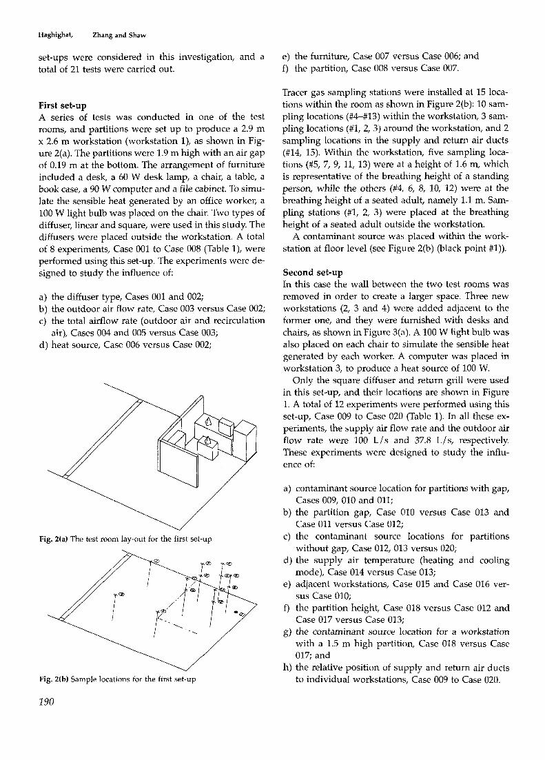
First set-up A series of tests was conducted in one of the test rooms, and partitions were set up to produce a 2.9 m x 2.6 m workstation (workstation l), as shown in Fig- ure 2(a). The partitions were 1.9 m high with an air gap of 0.19 m at the bottom. The arrangement of furniture included a desk, a 60 W desk lamp, a chair, a table, a book case, a 90 W computer and a file cabinet. To simu- late the sensible heat generated by an office worker, a 100 W light bulb was placed on the chair. Two types of diffuser, linear and square, were used in this study. The diffusers were placed outside the workstation. A total of 8 experiments, Case 001 to Case 008 (Table l), were performed using this set-up. The experiments were de- signed to study the influence of:
a) the diffuser type, Cases 001 and 002; b) the outdoor air flow rate, Case 003 versus Case 002; c) the total airflow rate (outdoor air and recirculation
d) heat source, Case 006 versus Case 002; air), Cases 004 and 005 versus Case 003;
Fig. 2(a) The test room lay-out for the first set-up
Fig. 2(b) Sample locations for the first set-up
e) the furniture, Case 007 versus Case 006; and f ) the partition, Case 008 versus Case 007.
Tracer gas sampling stations were installed at 15 loca- tions within the room as shown in Figure 2(b): 10 sam- pling locations (#4-#13) within the workstation, 3 sam- pling locations (#I, 2,3) around the workstation, and 2 sampling locations in the supply and return air ducts (#14, 15). Within the workstation, five sampling loca- tions (#5, 7, 9, 11, 13) were at a height of 1.6 m, which is representative of the breathing height of a standing person, while the others (#4, 6, 8, 10, 12) were at the breathing height of a seated adult, namely 1.1 m. Sam- pling stations (#I, 2, 3) were placed at the breathing height of a seated adult outside the workstation.
A contaminant source was placed within the work- station at floor level (see Figure 2(b) (black point #l)).
Second set-up In this case the wall between the two test rooms was removed in order to create a larger space. Three new workstations (2, 3 and 4) were added adjacent to the former one, and they were furnished with desks and chairs, as shown in Figure 3(a). A 100 W light bulb was also placed on each chair to simulate the sensible heat generated by each worker. A computer was placed in workstation 3, to produce a heat source of 100 W.
Only the square diffuser and return grill were used in this set-up, and their locations are shown in Figure 1. A total of 12 experiments were performed using this set-up, Case 009 to Case 020 (Table 1). In all these ex- periments, the supply air flow rate and the outdoor air flow rate were 100 L / s and 37.8 L/s, respectively. These experiments were designed to study the influ- ence of
a) contaminant source location for partitions with gap, Cases 009, 010 and 011;
b) the partition gap, Case 010 versus Case 013 and Case 011 versus Case 012;
c) the contaminant source locations for partitions without gap, Case 012, 013 versus 020;
d) the supply air temperature (heating and cooling mode), Case 014 versus Case 013;
e) adjacent workstations, Case 015 and Case 016 ver- sus Case 010;
f ) the partition height, Case 018 versus Case 012 and Case 017 versus Case 013;
g) the contaminant source location for a workstation with a 1.5 m high partition, Case 018 versus Case 017; and
h) the relative position of supply and return air ducts to individual workstations, Case 009 to Case 020.
190

The Influence of Office Furniture and Workstation Layouts on Thermal Comfort
Table 1 The conditions of test cases - Case Room Workstation Diffuser- Supply
size present type air flow rate
Fresh Contami Partition Partition Heat Furniture Supply Thermal air flow nant height gap size source present air comfort
rate source temp. test
001 002 003 004 005 006 007 008 009 010 011 012 013 014 015 016 017 018 019 020 021
small small small small small small small small big big big big big big big big big big big big big
WS#1 WS#1 WS#1 WS#1 WS#1 WS#l WS#l WS#1
WS#1,2,3,4 WS#1,2,3,4 WS#1,2,3,4 WS#1,2,3,4 WS#1,2,3,4 WS#1,2,3,4
WS#4 WS#4
WS#1,2,3,4 WS#1,2,3,4 WS#1,2,3,4 WS#1,2,3,4
WS#5
linear square square square square square square square square square square square square square square square square square square square square
30 L l s 30 L l s 30 L / s
73.8 L I S 100 L I S 30 L l s 30 L l s 30 L / s
100 L I S 100 L I S 100 LIS 100 LIS 100 LIS 100 L I S 100 LIS 100 L I S 100 L I S 100 LIS 100 LIS 100 L I S 100 LIS
1OLIs #1 1OLIs #1 5 L / s #1
7.4 LIS #1 1OLIs #1 1OL/s #1 1OLIs #1 1OLIs #1
37.8 L / s #1 37.8 L I S #3 37.8 LIS #2 37.8Lls #2 37.8LIs #3 37.8Lls #3 37.8 L / s #3 37.8 L I S #3 37.8 L / s #3 37.8LIs #2 37.8 L / s #4 37.8L/s #4 37.8 LIS #5
1.9 m 1.9 m 1.9 m 1.9 m 1.9 m 1.9 m 1.9 m
Om 1.9 m 1.9 m 1.9 m 1.9 m 1.9 m 1.9 m 1.9 m 1.9 m 1.5 m 1.5 m 1.9 m 1.9 m 1.9 m
0.19 m yes 0.19 m yes 0.19 m yes 0.19 m yes 0.19 m yes 0.19 m no 0.19 m no
Om no 0.19 m yes 0.19 m yes 0.19 m yes
0 m yes 0 m yes Om yes
0.19 m yes 0.19 m no
Om yes 0 m yes
0.19 m yes Om yes
0.19 m yes
17°C 17°C 17°C 17°C 17°C 17°C 17°C 17°C 17°C 17°C 17°C 17°C 17°C 30°C 17°C 17°C 17°C 17°C 17°C 17°C 17°C
WS#l WS#l WS#1 WS#l WS#l WS#l
I I /
WS#2,3 WS#1,4
1 WS#2
I WS#2
I
WS#
Figure 3(b) shows the tracer gas sampling stations in- stalled at 16 locations: 12 sampling locations (#3414) within the workstations (3 sampling locations per workstation), 2 sampling locations (#l, 2) around the workstations, and 2 sampling locations in the supply and return air ducts. As shown in Figure 3(b), two of the sampling stations in each workstation were at the breathing height of a seated person (#3, 4, 6, 8, 9, 10, 12, 14), and the others (#5, 7, 11, 13) were at the nose height of a standing person. The two sampling loca- tions (#l, 2) around the workstations were at the breathing height of a seated person.
The contaminant source (Figure 3(b)), was placed at four different positions within the workstations (black points #1-#4). Position #I was the same as in the first set-up. Positions #2 and #3 were on the floor within workstation 2 and workstation 4, respectively, while
within workstation 4.
Third set-up The purpose of this set-up, Case 021, was to study the impact of the locations of supply air diffuser, return air grill, and the workstation on the ventilation perform- ance. For this purpose, workstation 5 was placed in a location where the ventilation conditions would be worst, as shown in Figure 4(a). As in the former set- up, the workstation was furnished with a desk, a chair, a 60 W desk lamp, a 100 W computer and a 100 W light bulb on the chair to simulate the sensible heat generated by an office worker. The results were com-
pared with those obtained from the cases included in the second set-up. The locations of the supply air dif- fuser and the return air grill were the same as in the
Position #4 was at a height Of above the Fig. 3(a) The test room lay-out for the second set-up
Fig. 3(b) Sample locations for the second set-up
191

Haghighat, Huo, Zhang and Shaw
second set-up, and the supply air flow rate and the outdoor air flow rate also remained the same.
Thirteen sampling stations (Fiwithin 4(b)) were used for this experiment: 6 sampling locations (#1-#6) inside the workstation, 5 locations (#7-#11) around the work- station, and 2 locations in the supply and return air ducts (#12, 13). As shown in Figure 4(b), the sampling locations at the workstation were at two different heights, as in the second set-up.
The contaminant source, black point #5 in Figure 4(a), was placed within workstation 5 at a height of 1 m above the floor.
Each sampling station, for all experiments, consisted of two tubes: one was used to collect the tracer gas samples (both SF6 and CH4), while the other was used to inject tracer gas, SF6, into the room to perform the mean age of air test.
Measurement Techniques All experiments were carried out under steady-state conditions. To achieve these conditions, the HVAC sys- tem was turned on before the test started and was allowed to reach the expected condition for the upcom- ing experiment.
Fig. 4(a) The test room lay-out for the third set-up
Fig. 4(b) Sample locations for the third set-up
An automated sampling system, with a 16-port mul- ti-position sample valve, was used to collect the tracer gas samples. Two tracer gases were used: SF6 and CH4. SF6 was analyzed by a gas chromatograph (GC) with an electron capture detector and CH4 was analyzed by a gas analyzer with a flame ionization detector.
The GC was calibrated prior to testing using 20 dif- ferent SF6 concentrations ranging from 0 to 400 ppb. The CH4 gas analyzer was also calibrated against com- mercially available calibration gases before testing.
A total of 21 tests were conducted. In each test, measurements were made to assess three key par- ameters characterizing ventilation performance: air distribution, mean age of air and contaminant removal efficiency. SF6 was used as the tracer gas to determine the air distribution and mean age of air and CH4 was used to measure contaminant removal efficiency. As SF6 and CH4 do not react with each other, air distri- bution and contaminant removal efficiency measure- ments were conducted at the same time using the same sampling tubes.
The contaminant removal efficiency measurement was conducted for all 21 cases. Air distribution and mean age of air measurements were performed only when the air diffuser / grill locations relative to the workstation were changed. As an example, for Cases 009,010 and 011, except for the contaminant source po- sition, all other conditions were unchanged. For the three cases, only one air distribution measurement and one mean age of air measurement were performed.
Air Distribution For assessing the air distribution within a space, a small amount of SF6 (14 ml for the small room and 20 ml for the large room) was injected into the supply air duct to create a point source. Immediately following the injection, tracer gas samples were taken at all the sampling locations at half-minute intervals for a period of two to three hours. The spatial uniformity of the tracer gas concentrations was used to assess the effec- tiveness of the HVAC system in distributing the venti- lation air.
The uniformity of tracer gas concentrations at time t can be calculated from the following expression (Shaw et al. 1993a):
U,,(t)=(1-2Cstd(t)/ C,",(t))X 100% (1)
where Urm(t) =uniformity of tracer gas concentration at t, % Cst,(t) =standard deviation of tracer gas concentration
C,,,(t) =average tracer gas concentration at t, ppb. at different locations at t, ppb,
192

The Influence of Office Furniture and Workstation Layouts on 'Thermal Comfort
A linear interpolation technique was used to calculate the concentrations, at the different locations at the time t, in order to compute the U,(t) from the measured concentration data.
Local Mean Age of Air The age of air concept was used to evaluate the venti- lation performance and the spatial variability of the ventilated space. To measure the mean age of air, a tracer gas, SF6, was injected into the test room at sev- eral locations. Several small mixing fans were used to assist in mixing the tracer gas with the room air. Five minutes after tracer gas injection, the mixing fans were turned off and tracer gas samples were taken at all sampling locations at 4-minute intervals for a period of approximately 3 hours.
The results obtained were used to calculate the local mean age of air at all sampling locations in the room (within the workstations, and around the worksta- tions), and at the supply and return air ducts using the Nordtest method (Nordtest, 1983):
where, Be =slope of the exponential decay, Ci =concentration reading number i, C, =initial concentration reading, CM = final concentration reading, Fz =sampling interval, and M =number of concentration readings.
Contaminant Removal Efficiency To measure the contaminant removal efficiency, the tracer gas, CH,, was injected continuously into the workstation at a predetermined location to simulate a point contaminant source. The CH4 flow rate was very small and the outlet was capped with a perforated ping-pong ball to minimize the effect of the injection on the surrounding airflow. Tracer gas samples were taken, from all the sampling locations and at the sup- ply and return ducts, at 4-minute intervals for a period of approximately 4 hours. The contaminant removal ef- ficiency was calculated from the equation (Liddament 1987):
where, C,, =steady-state concentration at the return air duct, C =steady-state concentration at sampling location,
C, =steady-state concentration at the supply duct, E =contaminant removal efficiency.
Time average data in the steady-state region were used for the calculation.
Thermal Comfort Temperature and air velocity were measured at the breathing height of a seated person within the work- stations. A climate analyzer was placed at the work- ing area in one workstation to record the data while the tracer gas test was in progress. The samples were automatically recorded every 24 minutes for 4 hours. Additional parameters, such as air velocity standard deviation and relative humidity were also measured.
The thermal comfort tests were performed within workstation 1 in the first set-up, Case 001 to Case 006, to examine the influence of diffuser type, outdoor air flow rate, total air flow rate and furniture within the workstation. In the second set-up, Cases 009, 010 and 021, measurements were performed within worksta- tions 1, 2, 3, 4 and 5, to examine the influence of loca- tions of the supply air diffuser and return air grill rela- tive to the workstation. In addition, tests were also per- formed within workstation 2 in Cases 010,013 and 017 to examine the influence of partition height and par- tition gap.
The following mathematical model was used to as- sess the overall thermal comfort based on the measure- ment results (Fanger, 1989):
(4) PD= (34 -T,)(V- 0.05)0.6223(3.143 + 0.37VT.J
where T, =air temperature, "C V =mean air velocity, m/ s, T, =turbulence intensity, %, and PD =the percentage of dissatisfied people due to draft
(%).
Airflow Patterns Flow visualization tests were performed, for both lin- ear and square diffusers, to determine the airflow pat- terns around the diffuser, return grills and partition gaps. The visualization tests were conducted after the air distribution tests.
Helium bubbles were used for this purpose. The he- lium bubbles were injected into each area of interest. Four slide projectors were used to produce a vertical plane of light to illuminate the bubble movement. The results were recorded using video tapes, pictures and slides.
193

Haghighat, Huo, Zhang and Shaw
240
200
s v & 160 C 0 a Q) 0 C
.- c. L c c 120
00 80
v)
40
0
0
Linear Diffuser i Supply Air Return Air
....____.._.
x POS.1 e POS.2 0 POS.3
POS.4 Q, = 30 L/s POS.5
0 Pnsfi
A Pos.8 . POS.9
POS.10 v POS.11 0 POS.12
V
0 P n s l R
0 30 60 90 120
Elapsed Time (min)
Results and Discussions The results are discussed below in terms of air distri- bution, local mean age of air, contaminant removal ef- ficiency, thermal comfort level and airflow patterns.
Air Distribution First set-up A total of 8 tests (Cases 001-008) were conducted with linear and square diffusers. The test conditions of these tests are given in Table 1. For this series of tests, the air supply temperature was 17°C (cooling mode). Except for Case 008 (empty room), the partition height and gap were 1.9 m and 0.15 m, respectively.
Figure 5 shows the air distribution pattern within the workstation and its surrounding area for the case with a linear diffuser (Case 001). It shows that the tracer gas concentrations were uniformly distributed throughout the room (within and outside the worksta- tion) and were almost the same as the tracer gas con- centration measured in the return air duct. Similar air distribution patterns were observed for the other cases listed in Table 1. Specifically for all tests, the tracer gas concentrations in the return air duct were almost the same as the tracer gas concentrations within the work- station and its surrounding area, suggesting that no short-circuiting between the supply and return air ducts occurred. The results suggest that the type of supply air diffuser (Case 001 vs. 002), the supply air
150 180
Fig. 5 Air distribution test result for Case 001
flow rate (Case 002 vs. 004 and 005), the presence of heat source (Case 005 vs. 006), the presence of furniture (Case 006 vs. 007), and finally the presence of partitions (Case 007 vs. 008), have no significant effect on the air distribution patterns within and around the worksta- tion.
Table 2 compares the air distribution profiles for these tests in terms of their uniformity of air distri- bution. Equation 1 was used to calculate the uniformity of air distribution. The results show that the uniformit- ies for all the cases were similar.
Table 2 Uniformity of air distribution test results (first set-up)
Case 001 002 004 005 006 007 00s Time (min)
10 0.97 0.98 0.97 0.96 0.95 0.96 20 0.96 0.97 0.99 0.98 0.96 0.95 0.97 30 0.95 0.97 0.99 0.98 0.96 0.96 0.96 40 0.96 0.97 0.99 0.98 0.95 0.95 0.97 50 0.96 0.97 0.99 0.98 0.95 0.95 0.96 60 0.97 0.96 0.99 0.99 0.96 0.96 0.97 70 0.96 0.97 0.98 0.99 0.95 0.96 0.97 80 0.97 0.97 0.97 0.98 0.95 0.96 0.97 90 0.96 0.97 0.98 0.99 0.96 0.96 0.97
100 0.96 0.97 0.99 0.96 0.98 110 0.97 0.97 0.98 0.95 0.97 120 0.97 0.97 0.97 0.97 130 0.96 0.99 0.97 140 0.95 0.99 150 0.99
Small room, T,,,,~,=17°C, Only workstation 1 presented.
194
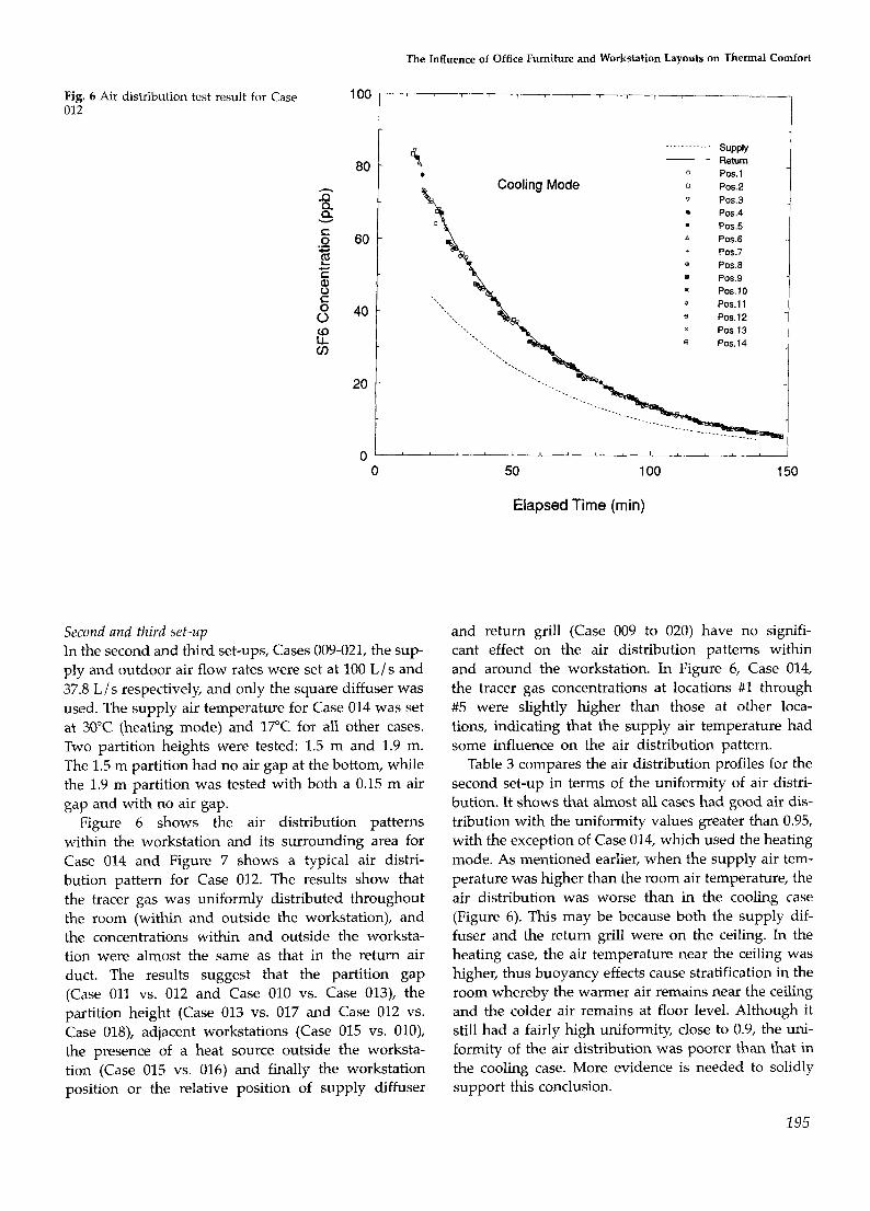
Fig. 6 Air distribution test result for Case 012
3 Q Q
C 0 m
Y
.- c L c C
C 8 8 to LL (I)
1 00
80
60
40
20
0 0
Second and third set-up In the second and third set-ups, Cases 009-021, the sup- ply and outdoor air flow rates were set at 100 L / s and 37.8 L / s respectively, and only the square diffuser was used. The supply air temperature for Case 014 was set at 30°C (heating mode) and 17°C for all other cases. Two partition heights were tested: 1.5 m and 1.9 m. The 1.5 m partition had no air gap at the bottom, while the 1.9 m partition was tested with both a 0.15 m air gap and with no air gap.
Figure 6 shows the air distribution patterns within the workstation and its surrounding area for Case 014 and Figure 7 shows a typical air distri- bution pattern for Case 012. The results show that the tracer gas was uniformly distributed throughout the room (within and outside the workstation), and the concentrations within and outside the worksta- tion were almost the same as that in the return air duct. The results suggest that the partition gap (Case 011 vs. 012 and Case 010 vs. Case 013), the partition height (Case 013 vs. 017 and Case 012 vs. Case OlS), adjacent workstations (Case 015 vs. OlO), the presence of a heat source outside the worksta- tion (Case 015 vs. 016) and finally the workstation position or the relative position of supply diffuser
The Influence of Office Furniture and Workstation Layouts on Thermal Comfort
m supply
............
Return e 0 P0S.l
POS.3 POS.4
POS.5
$ Cooling Mode 0 Pos.2
A Pos.6 + POS.7 e Pos.8
Pos.9 Pos.10
0 Pos.11 e Pos.12
POS.13 a POS.14
I I
50 100
Elapsed Time (min)
150
and return grill (Case 009 to 020) have no signifi- cant effect on the air distribution patterns within and around the workstation. In Figure 6, Case 014, the tracer gas concentrations at locations #1 through #5 were slightly higher than those at other loca- tions, indicating that the supply air temperature had some influence on the air distribution pattern.
Table 3 compares the air distribution profiles for the second set-up in terms of the uniformity of air distri- bution. It shows that almost all cases had good air dis- tribution with the uniformity values greater than 0.95, with the exception of Case 014, which used the heating mode. As mentioned earlier, when the supply air tem- perature was higher than the room air temperature, the air distribution was worse than in the cooling case (Figure 6). This may be because both the supply dif- fuser and the return grill were on the ceiling. In the heating case, the air temperature near the ceiling was higher, thus buoyancy effects cause stratification in the room whereby the warmer air remains near the ceiling and the colder air remains at floor level. Although it still had a fairly high uniformity, close to 0.9, the uni- formity of the air distribution was poorer than that in the cooling case. More evidence is needed to solidly support this conclusion.
2 95

Haghighat, Huo, Zhang and Shaw
. b
5 0 _..__.._..__
P0S.G POS.7 POS.8 POS.9 POS.10 POS.11 POS.12 POS.13 POS.14
" 0 50 100
Elapsed Time (min)
Local Mean Age of Air Table 4 shows the local mean age of air, for the first set- up, at different locations within the workstation and its surroundings. It indicates that the measured local mean ages of air at all sampling locations in the room and the local mean age of air at the return air duct were similar. The maximum difference between the two was less than 2%. The results also indicate that the mean age of air increased with decreased outdoor air flow rates, suggesting that it is very sensitive to the outdoor air flow rate (Cases 003 and 004). Other par- ameters such as diffuser type, supply flow rate, heat source, furniture and partition, however, appeared to have little influence on the local mean age of air.
The results of the mean age of air for the large-room
Table 3 Uniformity of air distribution test results (second set-up)
Case 009 012 014 015 016 017 021 Time (min)
10 0.97 0.86 0.98 0.97 0.93 20 0.96 0.94 0.86 0.98 0.97 0.96 0.96 30 0.96 0.94 0.87 0.97 0.98 0.96 0.97 40 0.96 0.95 0.88 0.97 0.98 0.96 0.97 50 0.96 0.95 0.88 0.98 0.97 0.96 0.97 60 0.96 0.89 0.98 0.98 0.97 0.97 70 0.88 0.97 80 0.97
Big room, Q,,ppl,=lOOL/ s, Qfresh=37.8L / s, Square diffuser.
Fig. 7 Air distribution test result for Case 014
150
test (second set-up) are shown in Table 5. It indicates that the mean age of air in almost all cases was very close since the same outdoor air flow rate was used for all the tests. Parameters such as partition gap, partition height, heating or cooling mode and different worksta- tion locations, did not appear to have a significant in- fluence on the mean age of air.
Contaminant Removal Efficiency First set-up The values of contaminant removal efficiency for the first set-up are shown in Table 6. As mentioned, the results show a large variation in the contaminant re- moval efficiency values for different measurement locations both for a given case, and for different cases. An attempt was made to identify the reasons for these differences, by comparing the results and test con- ditions of some of the cases.
Diffuser Types. The results of Case 001, using a linear diffuser, and Case 002, using a square diffuser, were compared to determine the effect of diffuser type. Fig- ure 8 shows the contaminant removal efficiencies for Cases 001 and 002 for different sampling locations. The results indicate that Case 002, using a square diffuser, had a consistently higher efficiency than Case 001, using a linear diffuser. Figures 9 and 10 show the con- centration profiles of CH4 for these two cases. As
196

The Influence of Office Furniture and Workstation Layouts on Thermal Comfort
Table 4 Mean age of air test results (first set-up)
Sample location Case 001 002 003 004 005 007 008
Outside workstation 1 84 97 220 114 84 98 97 min 2 87 97 220 115 84 99 98 min 3 83 97 220 115 80 99 97 min
Inside workstation 4 85 98 221 115 80 94 99 min 5 80 98 221 111 80 94 99 min 6 83 98 219 311 81 95 99 min 7 83 98 221 111 81 95 100 min 8 84 99 221 112 81 96 99 min 9 86 99 217 112 82 96 100 min
10 87 100 222 112 82 96 100 min 11 83 100 223 112 82 96 100 min 12 86 95 222 112 82 97 101 min 13 82 96 223 113 82 97 101 min supply 84 96 226 114 84 95 98 min return 87 97 222 114 84 98 101 min
Small room, Tsupply= lTC, Only workstation 1 presented.
Table 5 Mean age of air test results (second set-up)
Sample location Case 009 012 014 015 016 017 019 020
Outside workstation 1 62 61 58 65 64 64 66 65 min 2 62 62 58 65 65 64 66 65 min
Workstation 2 3 62 57 58 65 59 64 62 65 min 4 62 57 58 66 59 64 62 66 min 5 58 58 54 65 60 64 62 66 min
Workstation 1 6 59 58 55 66 60 64 62 61 min 7 59 58 55 66 60 65 63 62 min 8 59 59 55 66 61 65 63 62 min
Workstatioin 3 9 59 59 56 67 61 65 63 62 min 10 60 60 56 67 62 61 64 63 min 11 60 60 56 68 62 62 64 63 min
Workstation 4 12 60 60 56 62 62 62 64 63 min 13 61 60 56 63 63 62 64 64 min 14 61 61 57 63 63 62 65 64 min
62 61 57 64 63 64 65 64 min return 61 61 58 64 63 63 66 65 min supply
Big room, Qs,p,l,=lOOL/s, Qfresh=37.8L/s, Square diffuser.
Table 6 Contaminant removal efficiency test results (first set-up)
Sample Location Case 001 002 003 004 005 006 007 008
Outside workstation 1 1.1 1.2 1.6 1.8 1.8 1.4 2.4 1.3 2 1.1 1.2 1.5 1.8 2.1 1.3 2.1 1.1 3 1.1 1.2 1.4 1.8 2.0 1.3 2.0 1.1
Inside workstation 4 0.9 1.2 1.4 1.4 0.9 0.9 0.9 1.1 5 0.8 1.0 1.0 1.1 0.9 0.9 1.0 1.1 6 0.6 0.9 1.3 0.7 0.6 0.6 1.4 1.1 7 0.6 1.0 1.5 0.8 0.7 0.6 1.3 0.9 8 0.9 1.2 1.5 1.5 1.7 0.9 0.6 0.9 9 1.0 1.2 1.4 1.5 1.3 1.1 1.0 0.9
10 0.9 1.1 1.5 1.0 0.9 0.5 1.5 0.8 11 0.9 1.1 1.4 1.2 1.0 0.6 1.5 0.8 12 1.0 1.2 1.5 1.4 1.6 1.1 1.2 0.5 13 1.1 1.2 1.4 1.6 1.4 1.1 1.7 0.6
Small room, Tsupply= 17"C, Only workstation 1 presented.
197

Haghighat, Huo, Zhang and Shaw
Fig. 8 Influence of diffuser type on con- taminant removal efficiency
Linear Diffuser
Q 80 Q, = 30 US Y
c rr(
.- 70 1 c Q f = l O U s
x POS.1 e POS.2 0 POS.3 x POS.4
POS.5 m Pos.6
A Pos.6 ' Pos.9
+ POS.7
Pos.10 L'
a,
L= 50 0 POS.13
c
K 60 v Pos.11
00 0 0 Pos.12
* 40 I 0
30
20
10
0 0 30 60 90 120 750 180 210 240 270 300 330 360
Elapsed Time (min)
shown in Figures 9 and 10, a much greater scatter in CH4 concentrations was observed for Case 001 than for Case 002. In general, the contaminant removal ef- ficiency was approximately 10% higher for the square diffuser than for the linear diffuser.
Airpow Rate. As indicated in Table 6, a higher supply air flow rate (Case 004 and Case 005) did not improve the efficiency within the workstation area. The ef- ficiency was improved only for the sampling locations
Fig. 9 Contaminant distribution test re- sults for Case 001
close to the diffuser, locations #2 and #3, as compared to Case 002.
Heat Source. A comparison of the results between Case 002 (with heat sources) and Case 006 (without heat sources) indicates that the heat sources led to an in- crease in the contaminant removal efficiency for the measurement locations within the workstation (Table 6). However, the efficiency for the sampling locations outside the workstation (locations #1, 2 and 3) de-
198

The Influence of Office Furniture and Workstation Layouts on Thermal Comfort
110
100
90
80
70
60
Fig. 10 Contaminant distribution test re- sults for Case 002
1 2 0 - ' l ' 1 ' l ' l ' 1 8 I @ I ' I
-
-
Square Diffuser -
Qs = 30 US
Q,=lOUS
-
-
-
Fig. 11 Contaminant distribution test re- sults for Case 006
1 ' 1 ' 1 '
Supply - .__.........
Return .
x P0S.l
e POS.2 Q POS.3
POS.4 POS.5 -
+ POS.7 - A POS.0 - . Pos.9
POS.10 0 POS.11 -
a Pos.6 -
d I 0
110
100
-
Square Diffuser - (no heat source) - - - - - -. supply b i Return
0 Pos.12 50 0 POS.13
40
30
20
10
o ~ , l , i , l , l , i , l " , " l , , ' l , 0 30 60 90 120 150 180 210 240 270 300 330 360
Elapsed Time (min)
E, v - a 80 " 1 x P 0 S . l
e e ~ 0 s . 2 POS.3
& * POS.4
Q, = 30 US Q,=lOL/S
t i
o ' o m " " I ' I ' " " " " " " " J
Elapsed Time (min)
0 30 60 90 120 150 180 210 240 270 300 330 360
POS.5
POS.6
POS.7
POS.8 POS.9
POS.10 POS. 1 1 POS. 1 2 POS.13
creased when the heat source was present. This means that the heat source caused the contaminant to move out of the workstation faster, which caused in turn a decrease in the efficiency for the sampling locations outside the workstation. Figures 10 and 11 show the concentration profiles for Cases 002 and 006, respec- tively. As shown in Figure 11, a greater variation in
CH4 concentration was observed for Case 006 than for Case 002.
Furniture. Table 6 also compares the contaminant re- moval efficiency results of Cases 006 and 007 to show the effect of office furniture. Figures 11 and 12 show the CH4 concentration profiles for these two cases. It
199

Haghighat, Huo, Zhang and Shaw
100 Square Diffuser . O
90 1 1 (empty workstation)
d d Q, = 30 LIS " 1 Q,=lOL/s
o ' @ " " " " " " " " " " " ' 0 30 60 90 120 150 180 210 240 270 300 330 360
Elapsed Time (min)
will be seen that the contaminant distribution within the workstation varied considerably between these two cases. With furniture, Case 006, the sampling locations 6 and 10 had a higher contaminant concentration than the case without furniture (Case 007). Without furni- ture, on the other hand, the sampling location 8 had higher contaminant concentration than the case with furniture. The contaminant concentration in the work- station's surrounding area also changed when there was furniture within the workstation. The presence of furniture totally changed the contaminant distribution in the test room.
Partition. Comparing the contaminant removal ef- ficiencies of Cases 007 and 008 in Table 6, it could be
Table 7 Contaminant removal efficiency test results (second set-up)
Fig. 12 Contaminant distribution test re- sults for Case 007
- - ~ supply . ~.
Refurn x POS.1 e POS.2
0 POS.3 * ~ o s . 4
POS.5 * Pos.6 + POS.7 * POS.8
POS.9 P0S.iO
v POS.11 u PO9.12 0 POS.i3
concluded that the partition around the workstation also influenced the contaminant distribution. The con- taminant could be blocked by the partition.
Second Set-up The values of contaminant removal efficiency for the second set-up are shown in Table 7. As in the first set- up, the values in Table 7 indicate a large variation in the contaminant removal efficiency for different cases. The parameters which are expected to influence the contaminant removal efficiency are discussed below.
Location of Contaminant Source. Cases 009, 010 and 011 were designed to study the influence of the contaminant source location for partitions with a gap. These three
Sample location Case 009 010 011 012 013 014 015 016 017 018 019 020
Outside workstation 1 1.6 2.2 1.8 1.2 2.6 2.5 1.2 1.6 2.3 1.3 1.6 2.7 2 1.6 2.1 1.7 0.8 2.5 2.5 1.2 1.6 2.3 1.3 1.5 3.0
Workstation 2 3 1.7 2.0 1.8 0.6 2.5 2.4 1.0 1.2 2.2 0.8 1.5 2.5 4 1.7 2.1 1.8 0.9 2.5 2.5 1.1 1.4 2.3 0.6 1.5 2.4 5 1.7 2.0 1.8 0.6 2.4 1.9 1.1 1.4 2.2 0.6 1.5 2.5
Workstation 1 6 0.4 1.4 0.6 0.9 1.1 0.5 1.0 1.2 1.0 1.0 1.0 1.1 7 0.7 0.9 0.8 0.7 1.3 1.2 1.0 1.2 1.2 0.7 0.6 1.4 8 1.0 1.0 1.4 1.0 0.9 0.4 0.9 1.2 0.8 1.3 0.7 1.2
Workstation 3 9 1.7 1.5 1.8 1.2 1.9 2.5 0.8 1.1 1.5 1.4 1.1 2.8 10 1.7 1.7 1.8 1.2 2.3 2.6 0.9 1.1 1.9 1.4 1.3 2.2 11 1.7 1.8 1.8 1.2 2.3 2.4 0.8 1.0 1.9 1.4 1.3 3.6
Workstation 4 12 1.7 0.3 1.8 1.2 0.4 0.5 0.3 0.5 0.4 1.4 0.6 1.9 13 1.6 0.3 1.7 1.2 0.8 1.2 0.5 0.5 0.6 1.4 0.5 2.0 14 1.7 1.0 1.8 1.2 0.8 0.3 0.8 1.0 0.7 1.4 0.3 1.3
Big room, Qsupp~y=lOOL/ s, Qfresh=37.8L/ s, Square diffuser.
200

The Influence of Office Furniture and Workstation Layouts on Thermal Comfort
Fig. 13 Influence of location of contami- nant source on contaminant removal ef- ficiency
0 2 4 6 8 10 12 I4 16
Sample Location
cases had similar set-ups, the only difference being that the contaminant source was located at workstation 1 for Case 009, at workstation 2 for Case 010, and at worksta- tion 4 for Case 011. Figure 13 compares the contaminant removal efficiency of these three cases. It indicates that no matter where the contaminant source was located, the sampling locations at workstation 1 had low ef- ficiency. This was because the return grill was located right above workstation 1. All the contaminants were re- moved through the return grill from workstation 1. The relative position of the return grill is very important when there is a contaminant source present in the office. The closer the contaminant source to the return grill, the lesser will the contaminant source spread to other parts of the office. Similar results could be found by com- paring the results of Cases 012, 013 and 020 in Table 7, which was designed to study the influence of contami- nant source location for partitions with a gap.
Gap Height at the Bottom of the Workstation Partitions. Cases 010 and 013 had the same set-up except for the size of the partition gap. For Case 010, the partition had a 0.19 m air gap, while the partition in Case 013 had no gap. Table 7 shows the contaminant removal efficiency of these two cases to determine the effect of the size of the partition gap. The results indicate that for workstation 1 where the return air grill was located (sampling stations 6, 7 and 8) and workstation 4 where the contaminant source was located (sampling stations 12, 13 and 14), the partition gap had no clear effect on the contaminant removal efficiency. However, for the other two workstations, the contaminant removal ef- ficiency was consistently greater for partitions without gaps (Case 013) than with gaps (Case 010). Similar con- clusions could be reached by comparing the results of
Case 011 (with a gap) and Case 012 (without gap) (Table 7).
Height of the Workstation Partitions. A short (1.5 m) par- tition appeared to provide a better condition than a tall partition (1.9 m) for removing contaminants from the workstation. The difference between Case 012, with a 1.9 m partition, and Case 018, with a 1.5 m partition, was the partition height. The partitions in these two cases had no gap at the bottom. As indicated in Table 7, the contaminant removal efficiency for the workstation with a short partition, Case 018, was higher than that for a workstation with a tall partition, Case 012. Similar results could be found by comparing the results of Case 017 and Case 013 in Table 7.
Adjacent Workstations. Figure 14 compares the contami- nant removal efficiency for Cases 010, 015 and 016. Case 010 had 4 workstations and Cases 015 and 016 had one workstation. The contaminant source was located on the floor in workstation 4 for all three cases. In addition, there were heat sources located outside workstation 4 for Case 015, but no heat sources were located outside workstation 4 for Case 016. The results showed that the presence or absence of other worksta- tions had little or no effect on the contaminant removal efficiency in workstation 4. A similar conclusion was reached for the heat sources outside workstation 4. The results, however, show that contaminant removal ef- ficiency in other parts of the test room changed dra- matically.
Operation Mode. The contaminant removal efficiency for different supply air temperature set-ups, Case 013 (cool- ing mode) and Case 014 (heating mode), are compared
201

Haghighat, Huo, Zhang and Shaw
--I1 2.5
0 2 4 6 8 10 12 I4 16
Sample Location
2 a 301 Q v C 0 I- - 2 E 20- 8 s K
...... I ......... ....... ............ ...........
1
Elapsed Time (min)
in Table 7. A slight difference can be seen between these two cases. The supply air temperature had some influ- ence on the contaminant distribution, although not strong.
Third set-up Figure 15 shows the CH4 concentration profile for Case 021. For this case, workstation #5 was placed at a loca- tion where it would be expected to have the worst ven- tilation conditions. As expected, Figure 15 shows that the CH4 concentration everywhere within the test room was higher than that in the return duct and that the concentrations within workstation #5 were greater
0
supply Return POS.1 POS.2 POS.3 POS.4 POS.5 POS.6 POS.7
POS.8 POS.9 POS.10 POS.11
Fig. 14 Influence of adjacent workstations on contamination removal efficiency
Fig. 15 Contaminant distribution test re- sults for Case 022
than those outside the workstation. This suggests that at this particular workstation location, the contaminant within the area would not be removed as efficiently as for a workstation placed at other locations in the test room.
Air Temperature, Relative Humidity and Air Speed Selected parameters relating to thermal comfort con- ditions were measured. The results indicate that air temperatures, relative humidity and air speeds within the workstation for all cases were within the limits of ASHRAE Standards. The air temperature and relative humidity were very stable. The temperature change in
202

The Influence of Office Furniture and Workstation Layouts on Thermal Comfort
the working area was 21°C. The relative humidity change in the working area was 25%. The airflow speed in the working area was less than 0.3 m/s in all cases. The PD values (the percentage of dissatisfied people for draft) were all less than 10%.
Airflow Patterns The flow visualisation results showed that turbulent eddies existed in the airflow around the supply air dif- fuser. The fluctuation of the air in this area was con- siderable. For the square diffuser, the air appeared to cling to the ceiling as it left the diffuser. The airflow pattern in this area was very complicated.
The airflow pattern around the return grills was rela- tively simple. The influence of the return air grill ap- peared to be restricted to the airflow immediately around the grill. This suggests that the return air grills did not have a strong effect on the airflow pattern in the test room.
In recent years, many questions have been raised re- garding whether or not the gaps at the bottom of priv- acy partitions could have a significant influence on the airflow patterns in a room. The results suggest that when both the supply air diffuser and the return grill are located on the ceiling, the airflow through the par- tition gap will be very small. Such a small air move- ment is not expected to have a significant influence on the air distribution within the workstation. However, if a contaminant source is located close to the partition gap, the small airflow through the partition gap could have a significant influence on the contaminant re- moval efficiency.
Summary and Recommendations The results of the tests led to the following conclusions and recommendations.
1. Under the test conditions, the air distribution within the test workstation was not affected by the fol- lowing parameters: diffuser type, airflow rate, work- station partitions, partition heights, partition bottom gap, adjacent workstations, the locations of diffuser and return grill relative to the workstation.
2. Under the test conditions, the mean age of air in the test workstation was not affected by the following parameters: the diffuser type, diffuser and return grill position, total supply air flow rate (with a constant out- door air supply), heat source, furniture, workstation partition height and partition bottom gap.
3. The mean age of air was strongly influenced by the outdoor air flow rate. Adequate outdoor air should be introduced into each office to maintain acceptable indoor air quality.
4. Under the test conditions, the contaminant re- moval efficiency was affected by the following par- ameters: the diffuser type, heat source and furniture in the workstation, partitions, partition height, heating or cooling mode and different workstation locations.
5. Supply air flow rate (with the same percent of out- door air flow rate) did not have a significant influence on the contaminant removal efficiency, although it did affect the contaminant concentrations at the worksta- tion.
6. The airflow pattern had a significant influence on the contaminant distribution. The partition gap had a significant effect on the contaminant movement inside a partitioned office.
7. The workstation closest to the return grill ap- peared to have poorer contaminant removal efficiency than the adjacent workstations, even if the contaminant source was not located within this workstation, due to the migration of the contaminants from adjacent areas. Efforts should be made to place known contaminant sources at workstations where the return grill is located.
8. Under the test conditions, the thermal comfort was acceptable for all the cases studied.
References Bauman, F.S, Faulker, D., Arens, E.A., Fisk, W.J., Johnston,
L.P., McNeel, P.J., Pih, D. and Zhang H. (1991) "Air move- ment, comfort and ventilation in workstations". In: Final Report for Contract No. DE-ACU3-76SFU0098, Indoor Environ- ment Program, Applied Science, Lawrence Berkeley Labora- tory.
Fanger, P.O., Melikov, A.K., Hanzawa, H. and Ring, J. (1989) "Turbulence and draft: the turbulence of airflow has a sig- nificant impact on the sensation of draft", ASHRAE Journal,
Haghighat, F., Jiang, J. and Wang, J.C.Y. (1991) "A CFD analy- sis of ventilation effectiveness in a partitioned room", In- door Air, 1(3), 606-615.
Haghighat, F., Jiang, J. and Zhang, Y. (1994) "The impact of ventilation rate and partition layout on the VOC emission rate: time-dependent contaminant removal", Indoor Air,
Liddament, M.W. (1987) "A review and bibliography of venti- lation effectiveness - definitions, measurement, design and calculation". In: AIVC, Technical Note 21, Air Infiltration and Ventilation Centre, UK.
Nordtest (1983) "Buildings: local mean age". In: Nordtest Method NTVVSU19, Finland.
Shaw, C.Y., Zhang, J.S., Said, M.N. and Vaculik, P.E. (1993a) "Effect of air diffuser layout on the ventilation conditions of a workstation - Part I: air distribution patterns", ASH- RAE Transactions, 99, pt 2, 125-132.
Shaw, C.Y, Zhang, J.S., Said, M.N. and Vaculik, F. (199313) "Ef- fect of air diffuser layout on the ventilation conditions of a workstation - Part 11: air change efficiency and ventilation efficiency", ASHRAE Transactions, 99, pt 2, 133-142.
31, 18-23.
4(4), 276-283.
203
Copyright © 2022 FDOKUMEN