The fracture energy of metal fibre reinforced ceramic composites (MFCs
11
This article appeared in a journal published by Elsevier. The attached copy is furnished to the author for internal non-commercial research and education use, including for instruction at the authors institution and sharing with colleagues. Other uses, including reproduction and distribution, or selling or licensing copies, or posting to personal, institutional or third party websites are prohibited. In most cases authors are permitted to post their version of the article (e.g. in Word or Tex form) to their personal website or institutional repository. Authors requiring further information regarding Elsevier’s archiving and manuscript policies are encouraged to visit: http://www.elsevier.com/copyright
Transcript of The fracture energy of metal fibre reinforced ceramic composites (MFCs
This article appeared in a journal published by Elsevier. The attachedcopy is furnished to the author for internal non-commercial researchand education use, including for instruction at the authors institution
and sharing with colleagues.
Other uses, including reproduction and distribution, or selling orlicensing copies, or posting to personal, institutional or third party
websites are prohibited.
In most cases authors are permitted to post their version of thearticle (e.g. in Word or Tex form) to their personal website orinstitutional repository. Authors requiring further information
regarding Elsevier’s archiving and manuscript policies areencouraged to visit:
http://www.elsevier.com/copyright
Author's personal copy
The fracture energy of metal fibre reinforced ceramic composites (MFCs)
S.R. Pemberton a, E.K. Oberg a, J. Dean a, D. Tsarouchas b, A.E. Markaki b, L. Marston c, T.W. Clyne a,⇑a Department of Materials Science & Metallurgy, Cambridge University, Pembroke Street, Cambridge CB2 3QZ, UKb Department of Engineering, Cambridge University, Trumpington Street, Cambridge CB2 1PZ, UKc Fibrestone Products Ltd., Brookhill Road, Pinxton, Nottingham NG16 6NT, UK
a r t i c l e i n f o
Article history:Received 7 July 2010Received in revised form 9 October 2010Accepted 27 October 2010Available online 13 November 2010
Keywords:A. Ceramic–matrix composites (CMCs)A. Short-fibre compositesB. Fracture toughnessB. Fibre/matrix bondC. Modelling
a b s t r a c t
A model is presented for prediction of the fracture energy of ceramic–matrix composites containing dis-persed metallic fibres. It is assumed that the work of fracture comes entirely from pull-out and/or plasticdeformation of fibres bridging the crack plane. Comparisons are presented between these predictionsand experimental measurements made on a commercially-available composite material of this type,containing stainless steel (304) fibres in a matrix predominantly comprising alumina and alumino-silicatephases. Good agreement is observed, and it’s noted that there is scope for the fracture energy levels to behigh (�20 kJ m�2). Higher toughness levels are both predicted and observed for coarser fibres, up to apractical limit for the fibre diameter of the order of 0.5 mm. Other deductions are also made concerningstrategies for optimisation of the toughness of this type of material.
� 2010 Elsevier Ltd. All rights reserved.
1. Introduction
There are many applications in which the hardness, corrosionresistance and/or thermal stability of ceramics are required incombination with good toughness. There have thus been many at-tempts to produce ceramic–matrix composites exhibiting hightoughness, although most have been unsuccessful. Probably themost promising approach is to introduce a dispersed metallic rein-forcement of some type. This can result in some loss of high tem-perature stability, although in practice it’s often possible for such acomposite to retain integrity and strength, even if the metallic con-stituent has become very soft or molten, particularly if the expo-sure to such temperatures is of limited duration. There have beenvarious attempts to introduce particulate [1–4] or layered [5–11]metallic constituents into ceramics, but in general the most effec-tive toughening is expected to result from the incorporation of anetwork of metallic fibres.
In fact, several types of metal fibre reinforced ceramic compos-ite (MFC) have been developed. These include systems based onlow alloy steel fibres in cement [12–17] and stainless steel fibresin an alumino-silicate matrix [18]. Many such composites havebeen manufactured by the infiltration of a ceramic slurry into thespaces between a network of fibres, leading to material with a fibrecontent of between about 5 and 20 vol.%. Higher fibre contents thanthis usually require the fibres to be unidirectionally aligned, mak-ing the material strongly anisotropic, and the infiltration process
more difficult. With an approximately random fibre orientationdistribution, however, such slurry-based manufacturing routesare convenient, economical and highly versatile in terms of compo-nent size and shape. This has made such materials commerciallyattractive, and much more viable than (ceramic matrix) compositesmade by more cumbersome and expensive routes, such as vapourdeposition, sol–gel precipitation or powder blending and sintering.
Despite the increasing usage of such MFCs, and the centralimportance of their fracture toughness, there has in fact been onlyrather limited study of energy absorption and its optimisation dur-ing fracture of these materials. Of course, it is well known [19] thatfrictional fibre pull-out can contribute substantially to the fractureenergy of various types of fibre composite, including those withbrittle matrices (and brittle fibres). Much of the effort dedicatedpreviously to the development of ceramic composites has centredon the introduction of ceramic fibres, at least partly with the objec-tive of promoting fibre pull-out. Unfortunately, manufacturing ofsuch composites has often proved to be problematic, with a partic-ular difficulty in controlling (limiting) the interfacial bondstrength, so as to ensure that substantial pull-out occurs. In anyevent, toughness levels have almost invariably been disappointingwith such composites.
If the fibre is metallic, however, then there is the potential forenergy absorption, not only from fibre pull-out, but also as a resultof plastic deformation of the fibre (assuming that fracture occurssuch that fibres bridge the crack plane, which in general will re-quire a certain minimum fibre aspect ratio and also at least somefibre debonding). This potential for energy absorption via fibreplasticity has been highlighted by several researchers [20–25],
0266-3538/$ - see front matter � 2010 Elsevier Ltd. All rights reserved.doi:10.1016/j.compscitech.2010.10.011
⇑ Corresponding author. Tel.: +44 1223 334332; fax: +44 1223 762836.E-mail address: [email protected] (T.W. Clyne).
Composites Science and Technology 71 (2011) 266–275
Contents lists available at ScienceDirect
Composites Science and Technology
journal homepage: www.elsevier .com/ locate /compsci tech

Author's personal copy
with particular attention having been drawn by Ashby and co-workers [20] to the concept of the constraint imposed by the sur-rounding matrix having an influence on the volume of fibre inwhich plastic deformation can occur, and hence on its effectiveductility (and on the total plastic work). This is clearly dependenton the interfacial bond strength, which thus affects both fibrepull-out and fibre plasticity. There have been various observations,over an extended period [16,18,20,21,24–32], concerning the ex-tent and nature of fibre pull-out and plastic deformation in MFCs.In general, it is recognised [20–22,24] that strong interfacial bond-ing is likely to impose greater constraint on fibre plasticity, andhence limit the plastic work done. On the other hand, it is by nomeans universally accepted that fibre plastic deformation is likelyto play a significant role in energy absorption during fracture ofMFCs, with several researchers [16,33–36] proposing or assumingthat pull-out is entirely dominant.
In addition to the limited work on fracture of ceramic reinforcedwith steel fibres, there have been studies of fibre network materi-als, oriented towards acoustic damping [37], heat exchangers [38],cores of lightweight panels [39] and bioactive layers on prostheticimplants [40]. There has also been tomographic characterisation offibre orientation distributions [41] and use of the fibre work offracture (per unit length) to obtain network fracture energies[42,43]. There has also been study of magneto-mechanical charac-teristics of such networks in the presence of a polymeric matrix[44] (without investigation of fracture behaviour). The currentwork is partly built on these studies.
The only published model focussed on the plastic deformationand rupture of fibres during fracture of MFCs appears to be thatof Hoffman et al. [45], which is based on partial debonding at thefibre–matrix interface. For high levels of constraint, the peak stressin the fibre is high, but its fracture strain is relatively low, whereasfor low constraint (weakly bonded interface or matrix crackingnearby), the peak fibre stress is lower, but the strain to failure in-creases. An expression was derived for the stress in the fibre,involving the debonding length, and FEM modelling of the fibreplastic deformation was carried out. Some agreement with exper-iment was observed, but in general the predictive power of themodel appears to be very limited. Furthermore, there appear tobe no analytical models of MFC fracture involving both fibre pull-out and fibre plasticity, and certainly none with any capacity forprediction of the fracture energy.
In the present paper, a simple model is outlined for simulationof the main energy-absorbing mechanisms operative during frac-ture of MFCs, leading to prediction of the fracture energy of thematerial. While the model should be applicable to a range of suchcomposites, the fracture energy predictions are oriented towards acommercially-available product (‘‘FiberstoneTM’’), and requirecharacterisation of the tensile and pull-out behaviour of the indi-vidual fibres used in this system.
2. Experimental procedures
2.1. Material and specimen production
2.1.1. Fibre production by melt extractionThe fibres employed were all of 304 stainless steel, supplied by
Fibrestone Products Ltd. and produced at their Pinxton plant, usingthe melt extraction process [46]. This involves solidification of thefibres onto surface protrusions on a water-cooled, rapidly rotatingcopper drum, which is in contact with a steel melt. This process ismore economical than routes involving mechanical reduction insection (extrusion, drawing, swaging etc.) and often gives a prod-uct with a higher strength (as a consequence of the rapidly-solidi-fied microstructure). The surfaces of melt-extracted fibres areusually less smooth and uniform than those produced by drawing
etc., but this is often considered to be advantageous in terms ofpromoting good fibre/matrix bonding and giving desirable fibrepull-out and deformation characteristics [47]. Both coarse(�500 lm diameter, 25 mm long) and fine (�50 lm diameter,5 mm long) fibres were employed in the current work.
2.1.2. Composite production by slurry castingThe composite materials used in this work are effectively com-
mercial products, marketed by Fibretech under the tradename of‘‘Fiberstone™’’. Normally, however, such products are supplied inthe form of a finished (‘‘cast’’) components, rather than as stockmaterial. (In fact, Fiberstone™ is difficult to cut or machine.) Thestandard specimen size employed in the current study was asquare section rod (30 � 30 � 110 mm). These were produced (atFibrestone Products Ltd.) by packing fibres into a wooden mouldand pouring a slurry into the cavity. The axis of the rod was verticalduring this operation, so that the microstructure is expected to beisotropic transverse to this direction.
The ceramic powder used is a commercial product. The averageparticle size is around 200 lm, although it does contain some fines.It was mixed with 10 wt.% of water and blended to a smooth slurryprior to casting. During casting, the mould was subjected to vibra-tion, in order to promote the escape of entrapped air bubbles. Thecasting was then held at 30�C for 12 h, prior to removal from themould. It was then subjected to a heat treatment at 450�C for a fur-ther 12 h. This removed any residual unbound water from the com-posite. After this treatment, the matrix is not fully dense, but theporosity level within it is relatively low (�few%). The matrix densitywas measured to be about 2.5 Mg m�3. The volume fraction of fibrein individual castings was obtained simply by (accurate) weighing,using the matrix density and that of the fibres (7.8 Mg m�3). In mostcases, the fibre contents of composites made in this way are in therange 7–15 vol.%. The phase constitution of the matrix, which wasconfirmed using X-ray diffraction, is predominantly corrundum(a-alumina), with significant levels of mullite (an alumino-silicatewith the approximate formula Al4.5Si1.5O10).
2.1.3. Specimen preparation proceduresSpecimens for mechanical testing (§2.3.3) were used in the ‘‘as-
cast’’ form. Both (low magnification) optical microscopy and scan-ning electron microscopy were employed to study fracture surfaces.Polished sections were electrolytically etched with a 60% aqueoussolution of HNO3, at 1.1 V DC for 10 s, using a stainless steel cathode.Etched sections were examined using optical microscopy.
Tomographic data were obtained on specimens cut from a cast-ing to dimensions of 20 � 20 � 50 mm. An X-Tek Computed Tomog-raphy scanner was employed, using 125 kV, 35 lA X-rays in adivergent cone beam. A stainless steel (316) filter was used to pre-harden the beam and reduce beam hardening and ring artefacts.The specimen was rotated through 360�, by 0.5�increments, collect-ing 720 radiographs that were recorded using a CCD detector with apixel size of 130 lm. The specimen was sampled at 37.7 mm (isotro-pic voxels). Serial sections of the sample were obtained by means offiltered back-projection. The back-projections were then deconvo-luted, to account for finite resolution effects, and a local threshold-ing technique was employed to produce binary images. Thesebinary images were then used to create a representation of the fibrenetwork within the composite. The surfaces were smoothed toeliminate noise and artefacts in the reconstructed slices.
2.2. Microstructural characterisation
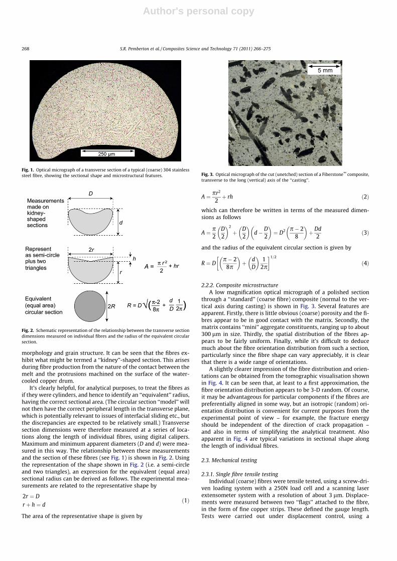
2.2.1. Fibre microstructure and dimensionsThe morphology and microstructure of the fibres are illustrated
in Fig. 1, which shows, for a standard (coarse) fibre, a typicalsectional shape, and also gives an indication of the dendrite
S.R. Pemberton et al. / Composites Science and Technology 71 (2011) 266–275 267
Author's personal copy
morphology and grain structure. It can be seen that the fibres ex-hibit what might be termed a ‘‘kidney’’-shaped section. This arisesduring fibre production from the nature of the contact between themelt and the protrusions machined on the surface of the water-cooled copper drum.
It’s clearly helpful, for analytical purposes, to treat the fibres asif they were cylinders, and hence to identify an ‘‘equivalent’’ radius,having the correct sectional area. (The circular section ‘‘model’’ willnot then have the correct peripheral length in the transverse plane,which is potentially relevant to issues of interfacial sliding etc., butthe discrepancies are expected to be relatively small.) Transversesection dimensions were therefore measured at a series of loca-tions along the length of individual fibres, using digital calipers.Maximum and minimum apparent diameters (D and d) were mea-sured in this way. The relationship between these measurementsand the section of these fibres (see Fig. 1) is shown in Fig. 2. Usingthe representation of the shape shown in Fig. 2 (i.e. a semi-circleand two triangles), an expression for the equivalent (equal area)sectional radius can be derived as follows. The experimental mea-surements are related to the representative shape by
2r ¼ D
r þ h ¼ dð1Þ
The area of the representative shape is given by
A ¼ pr2
2þ rh ð2Þ
which can therefore be written in terms of the measured dimen-sions as follows
A ¼ p2
D2
� �2
þ D2
� �d� D
2
� �¼ D2 p� 2
8
� �þ Dd
2ð3Þ
and the radius of the equivalent circular section is given by
R ¼ Dp� 2
8p
� �þ d
D
� �1
2p
� �1=2
ð4Þ
2.2.2. Composite microstructureA low magnification optical micrograph of a polished section
through a ‘‘standard’’ (coarse fibre) composite (normal to the ver-tical axis during casting) is shown in Fig. 3. Several features areapparent. Firstly, there is little obvious (coarse) porosity and the fi-bres appear to be in good contact with the matrix. Secondly, thematrix contains ‘‘mini’’ aggregate constituents, ranging up to about300 lm in size. Thirdly, the spatial distribution of the fibres ap-pears to be fairly uniform. Finally, while it’s difficult to deducemuch about the fibre orientation distribution from such a section,particularly since the fibre shape can vary appreciably, it is clearthat there is a wide range of orientations.
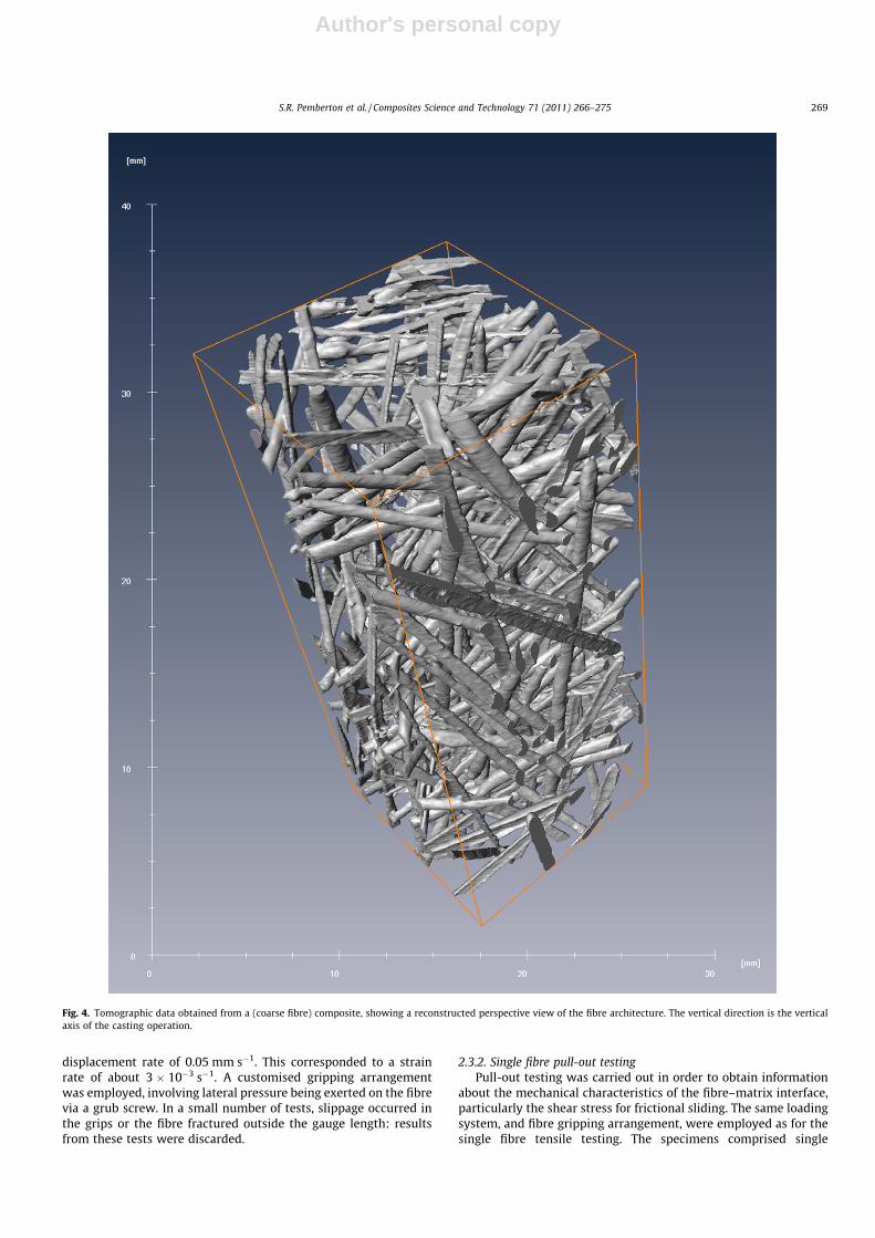
A slightly clearer impression of the fibre distribution and orien-tations can be obtained from the tomographic visualisation shownin Fig. 4. It can be seen that, at least to a first approximation, thefibre orientation distribution appears to be 3-D random. Of course,it may be advantageous for particular components if the fibres arepreferentially aligned in some way, but an isotropic (random) ori-entation distribution is convenient for current purposes from theexperimental point of view – for example, the fracture energyshould be independent of the direction of crack propagation –and also in terms of simplifying the analytical treatment. Alsoapparent in Fig. 4 are typical variations in sectional shape alongthe length of individual fibres.
2.3. Mechanical testing
2.3.1. Single fibre tensile testingIndividual (coarse) fibres were tensile tested, using a screw-dri-
ven loading system with a 250N load cell and a scanning laserextensometer system with a resolution of about 3 lm. Displace-ments were measured between two ‘‘flags’’ attached to the fibre,in the form of fine copper strips. These defined the gauge length.Tests were carried out under displacement control, using a
Fig. 1. Optical micrograph of a transverse section of a typical (coarse) 304 stainlesssteel fibre, showing the sectional shape and microstructural features.
Fig. 2. Schematic representation of the relationship between the transverse sectiondimensions measured on individual fibres and the radius of the equivalent circularsection.
Fig. 3. Optical micrograph of the cut (unetched) section of a Fiberstone™ composite,transverse to the long (vertical) axis of the ‘‘casting’’.
268 S.R. Pemberton et al. / Composites Science and Technology 71 (2011) 266–275
Author's personal copy
displacement rate of 0.05 mm s�1. This corresponded to a strainrate of about 3 � 10�3 s�1. A customised gripping arrangementwas employed, involving lateral pressure being exerted on the fibrevia a grub screw. In a small number of tests, slippage occurred inthe grips or the fibre fractured outside the gauge length: resultsfrom these tests were discarded.
2.3.2. Single fibre pull-out testingPull-out testing was carried out in order to obtain information
about the mechanical characteristics of the fibre–matrix interface,particularly the shear stress for frictional sliding. The same loadingsystem, and fibre gripping arrangement, were employed as for thesingle fibre tensile testing. The specimens comprised single
Fig. 4. Tomographic data obtained from a (coarse fibre) composite, showing a reconstructed perspective view of the fibre architecture. The vertical direction is the verticalaxis of the casting operation.
S.R. Pemberton et al. / Composites Science and Technology 71 (2011) 266–275 269
Author's personal copy
(coarse) fibres partially embedded (to a length of 5 mm) in a com-posite ‘‘matrix’’. This matrix was in the form of a cylinder of length20 mm and diameter 25 mm. A customised tubular gripping devicewas used to secure this cylinder during loading. The cylinder wasmade by blending short, randomly cut (2–10 mm length) coarse fi-bres into the ceramic slurry, and carrying out the casting operationwith this mixture contained in a cylindrical rubber mould and thefibre (25 mm long) held coaxially. The fibre content in the castingwas about 5 vol.% and the fibre orientation distribution wasapproximately random (isotropic). During testing, the distance be-tween the fibre ‘‘flag’’ and the top of the tubular grip was moni-tored, again using the scanning laser extensometer.
2.3.3. Composite fracture energy evaluation by Izod testingThe nominal fracture energy of the composite material (for both
coarse and fine fibre composites) was obtained using a conven-tional pendulum-based 160 J Izod testing arrangement. The energyabsorbed during fracture was measured from the residual height ofthe pendulum, and divided by the sectional area of the specimenthat underwent fracture. The specimens were notched to a depthof 4 mm, using a diamond saw with a width of 0.6 mm.
3. Fracture characteristics
3.1. Single fibre plastic deformation and rupture behaviour
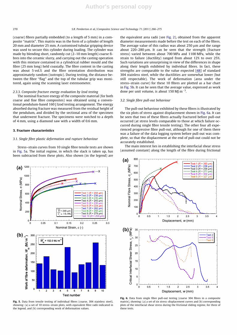
Stress–strain curves from 10 single fibre tensile tests are shownin Fig. 5a. The initial regime, in which the slack is taken up, hasbeen subtracted from these plots. Also shown (in the legend) are
the equivalent area radii (see Fig. 2), obtained from the apparentdiameter measurements made before the test on each of the fibres.The average value of this radius was about 250 lm and the rangeabout 220–280 lm. It can be seen that the strength (fracturestress) varied between about 700 MPa and 1100 MPa, while thestrain to failure (ductility) ranged from about 12% to over 25%.Such variations are unsurprising in view of the differences in shapealong their length exhibited by individual fibres. In fact, thesestrengths are comparable to the value expected [48] of standard304 stainless steel, while the ductilities are somewhat lower (butstill respectable). The work of deformation (area under thestress–strain curve) for these 10 fibres are plotted as a bar chartin Fig. 5b. It can be seen that the average value, expressed as workdone per unit volume, is about 150 MJ m�3.
3.2. Single fibre pull-out behaviour
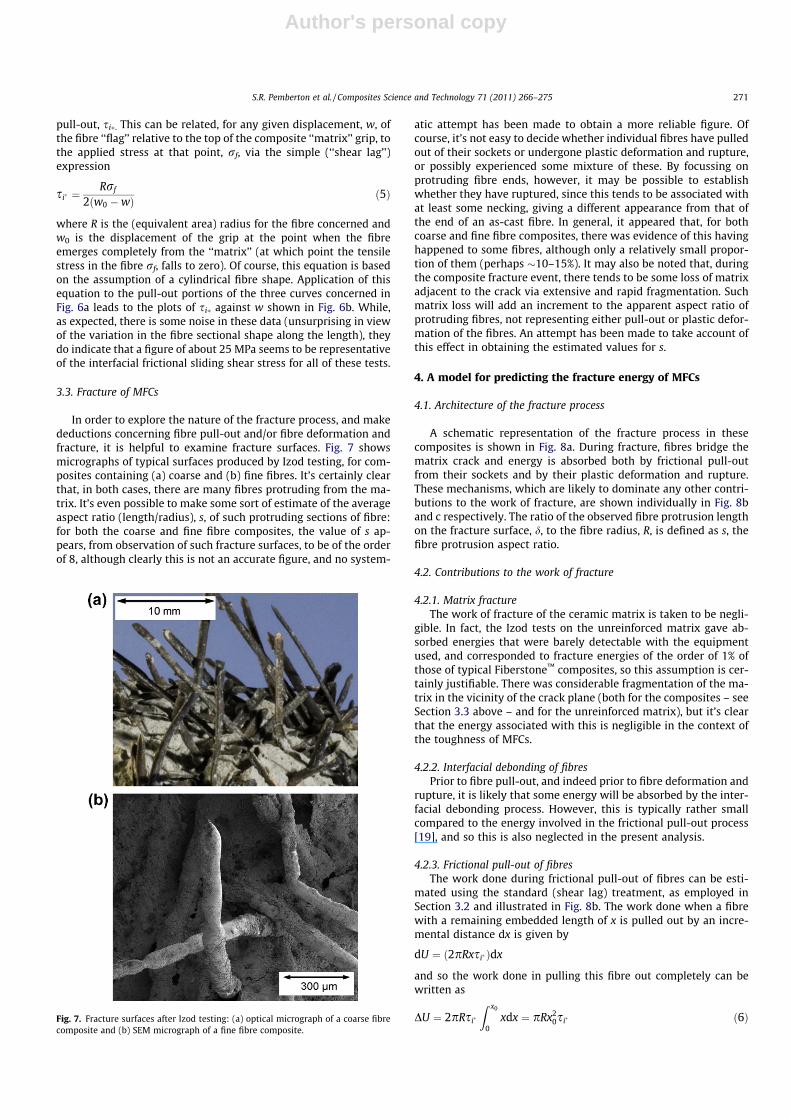
The pull-out behaviour exhibited by these fibres is illustrated bythe six plots of stress against displacement shown in Fig. 6a. It canbe seen that two of these fibres actually fractured before pull-outoccurred (at stress levels comparable to those at which failure oc-curred during single fibre tensile testing). The other four all expe-rienced progressive fibre pull-out, although for one of them therewas a failure of the data logging system before pull-out was com-plete, so that the displacement at the end of pull-out could not beaccurately established.
The main interest lies in establishing the interfacial shear stress(assumed constant) along the length of the fibre during frictional
Fig. 5. Data from tensile testing of individual fibres (coarse, 304 stainless steel),showing: (a) a set of 10 stress–strain plots, with equivalent fibre radii indicated inthe legend, and (b) corresponding work of deformation values.
Fig. 6. Data from single fibre pull-out testing (coarse 304 fibres in a compositematrix), showing: (a) a set of six stress–displacement curves and (b) correspondingplots of the interfacial shear stress during the frictional sliding regime, for three ofthese tests.
270 S.R. Pemberton et al. / Composites Science and Technology 71 (2011) 266–275
Author's personal copy
pull-out, si�. This can be related, for any given displacement, w, ofthe fibre ‘‘flag’’ relative to the top of the composite ‘‘matrix’’ grip, tothe applied stress at that point, rf, via the simple (‘‘shear lag’’)expression
si� ¼Rrf
2ðw0 �wÞ ð5Þ
where R is the (equivalent area) radius for the fibre concerned andw0 is the displacement of the grip at the point when the fibreemerges completely from the ‘‘matrix’’ (at which point the tensilestress in the fibre rf, falls to zero). Of course, this equation is basedon the assumption of a cylindrical fibre shape. Application of thisequation to the pull-out portions of the three curves concerned inFig. 6a leads to the plots of si� against w shown in Fig. 6b. While,as expected, there is some noise in these data (unsurprising in viewof the variation in the fibre sectional shape along the length), theydo indicate that a figure of about 25 MPa seems to be representativeof the interfacial frictional sliding shear stress for all of these tests.
3.3. Fracture of MFCs
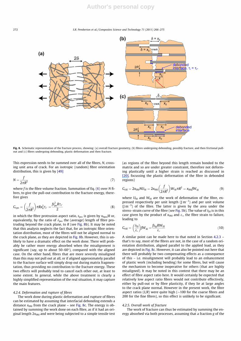
In order to explore the nature of the fracture process, and makedeductions concerning fibre pull-out and/or fibre deformation andfracture, it is helpful to examine fracture surfaces. Fig. 7 showsmicrographs of typical surfaces produced by Izod testing, for com-posites containing (a) coarse and (b) fine fibres. It’s certainly clearthat, in both cases, there are many fibres protruding from the ma-trix. It’s even possible to make some sort of estimate of the averageaspect ratio (length/radius), s, of such protruding sections of fibre:for both the coarse and fine fibre composites, the value of s ap-pears, from observation of such fracture surfaces, to be of the orderof 8, although clearly this is not an accurate figure, and no system-
atic attempt has been made to obtain a more reliable figure. Ofcourse, it’s not easy to decide whether individual fibres have pulledout of their sockets or undergone plastic deformation and rupture,or possibly experienced some mixture of these. By focussing onprotruding fibre ends, however, it may be possible to establishwhether they have ruptured, since this tends to be associated withat least some necking, giving a different appearance from that ofthe end of an as-cast fibre. In general, it appeared that, for bothcoarse and fine fibre composites, there was evidence of this havinghappened to some fibres, although only a relatively small propor-tion of them (perhaps �10–15%). It may also be noted that, duringthe composite fracture event, there tends to be some loss of matrixadjacent to the crack via extensive and rapid fragmentation. Suchmatrix loss will add an increment to the apparent aspect ratio ofprotruding fibres, not representing either pull-out or plastic defor-mation of the fibres. An attempt has been made to take account ofthis effect in obtaining the estimated values for s.
4. A model for predicting the fracture energy of MFCs
4.1. Architecture of the fracture process
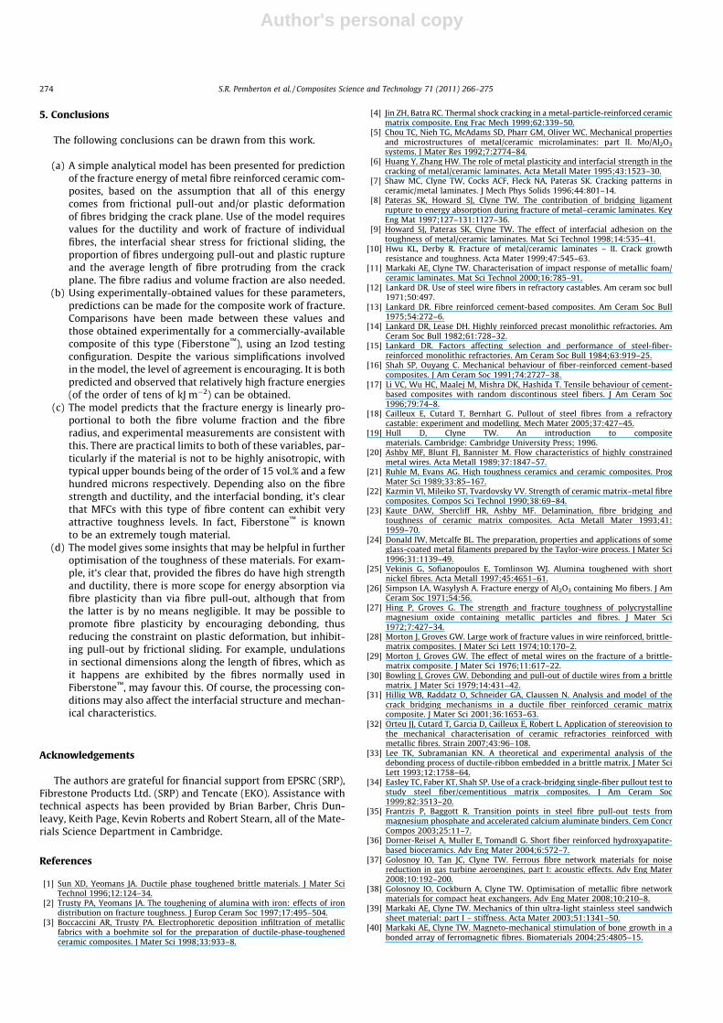
A schematic representation of the fracture process in thesecomposites is shown in Fig. 8a. During fracture, fibres bridge thematrix crack and energy is absorbed both by frictional pull-outfrom their sockets and by their plastic deformation and rupture.These mechanisms, which are likely to dominate any other contri-butions to the work of fracture, are shown individually in Fig. 8band c respectively. The ratio of the observed fibre protrusion lengthon the fracture surface, d, to the fibre radius, R, is defined as s, thefibre protrusion aspect ratio.
4.2. Contributions to the work of fracture
4.2.1. Matrix fractureThe work of fracture of the ceramic matrix is taken to be negli-
gible. In fact, the Izod tests on the unreinforced matrix gave ab-sorbed energies that were barely detectable with the equipmentused, and corresponded to fracture energies of the order of 1% ofthose of typical Fiberstone™ composites, so this assumption is cer-tainly justifiable. There was considerable fragmentation of the ma-trix in the vicinity of the crack plane (both for the composites – seeSection 3.3 above – and for the unreinforced matrix), but it’s clearthat the energy associated with this is negligible in the context ofthe toughness of MFCs.
4.2.2. Interfacial debonding of fibresPrior to fibre pull-out, and indeed prior to fibre deformation and
rupture, it is likely that some energy will be absorbed by the inter-facial debonding process. However, this is typically rather smallcompared to the energy involved in the frictional pull-out process[19], and so this is also neglected in the present analysis.
4.2.3. Frictional pull-out of fibresThe work done during frictional pull-out of fibres can be esti-
mated using the standard (shear lag) treatment, as employed inSection 3.2 and illustrated in Fig. 8b. The work done when a fibrewith a remaining embedded length of x is pulled out by an incre-mental distance dx is given by
dU ¼ ð2pRxsi� Þdx
and so the work done in pulling this fibre out completely can bewritten as
DU ¼ 2pRsi�
Z x0
0xdx ¼ pRx2
0si� ð6ÞFig. 7. Fracture surfaces after Izod testing: (a) optical micrograph of a coarse fibrecomposite and (b) SEM micrograph of a fine fibre composite.
S.R. Pemberton et al. / Composites Science and Technology 71 (2011) 266–275 271
Author's personal copy
This expression needs to be summed over all of the fibres, N, cross-ing unit area of crack. For an isotropic (random) fibre orientationdistribution, this is given by [49]
N ¼ f
2pR2 ð7Þ
where f is the fibre volume fraction. Summation of Eq. (6) over N fi-bres, to give the pull-out contribution to the fracture energy, there-fore gives
Gcpo ¼f
2pR2
� �pRx2
0si� ¼fs2
poRsi�
2ð8Þ
in which the fibre protrusion aspect ratio, spo, is given by x0po/R or,equivalently, by the ratio of dpo, the (average) length of fibre pro-truding beyond the crack plane, to R (see Fig. 8b). It may be notedthat this analysis neglects the fact that, for an isotropic fibre orien-tation distribution, most of the fibres will not be aligned normal tothe crack plane, as they are depicted in Fig. 8b. However, this is un-likely to have a dramatic effect on the work done. There will prob-ably be rather more energy absorbed when the misalignment issignificant (say, up to about 50–60�), compared with the alignedcase. On the other hand, fibres that are more severely misalignedthan this may not pull out at all, or if aligned approximately parallelto the fracture surface will simply drop out during matrix fragmen-tation, thus providing no contribution to the fracture energy. Thesetwo effects will probably tend to cancel each other out, at least tosome extent. In general, while the above treatment is clearly ahighly simplified representation of the real situation, it may capturethe main features.
4.2.4. Deformation and rupture of fibresThe work done during plastic deformation and rupture of fibres
can be estimated by assuming that interfacial debonding extends adistance x0fd from the crack plane – see Fig. 8c. The energy is ob-tained by summing the work done on each fibre, as if it had an ori-ginal length 2x0fd and were being subjected to a simple tensile test
(as regions of the fibre beyond this length remain bonded to thematrix and so are under greater constraint, therefore not deform-ing plastically until a higher strain is reached as discussed in[20], focussing the plastic deformation of the fibre in debondedregions)
Gcfd ¼ 2x0fdNUfd ¼ 2x0fdf
2pR2
� �W fdpR2 ¼ x0fdfW fd ð9Þ
where Ufd and Wfd are the work of deformation of the fibre, ex-pressed respectively per unit length (J m�1) and per unit volume(J m�3) of the fibre. The latter is given by the area under thestress–strain curve of the fibre (see Fig. 5b). The value of dfd is in thiscase given by the product of x0fd and e�, the fibre strain to failure,leading to
Gcfd ¼dfd
e�
� �fW fd ¼
fsfdRW fd
e�ð10Þ
A similar point can be made here to that noted in Section 4.2.3 –that’s to say, most of the fibres are not, in the case of a random ori-entation distribution, aligned parallel to the applied load, as theyare depicted in Fig. 8c. However, it can also be pointed out here thatthere will probably be two compensating effects as a consequenceof this – i.e. misalignment will probably lead to an enhancementof plastic work (including bending) for some fibres, but will causethe mechanism to become inoperative for others (that are highlymisaligned). It may be noted in this context that there may be aneffect of fibre aspect ratio here. It would certainly be expected thatrelatively low aspect ratio fibres would not contribute effectively,either by pull-out or by fibre plasticity, if they lie at large anglesto the crack plane normal. However in the present work, the fibreaspect ratios (L/R) were quite high (�100 for the coarse fibres and200 for the fine fibres), so this effect is unlikely to be significant.
4.2.5. Overall work of fractureThe work of fracture can thus be estimated by summing the en-
ergy absorbed via both processes, assuming that a fraction g of the
Fig. 8. Schematic representation of the fracture process, showing: (a) overall fracture geometry, (b) fibres undergoing debonding, possibly fracture, and then frictional pull-out and (c) fibres undergoing debonding, plastic deformation and then fracture.
272 S.R. Pemberton et al. / Composites Science and Technology 71 (2011) 266–275

Author's personal copy
fibres bridging the crack plane undergo pull-out and the remainder(1 � g) undergo plastic deformation and rupture.
Gcnet ¼ gGcpo þ ð1� gÞGcfd ¼ gfs2
poRsi�
2þ ð1� gÞ fsfdRW fd
e�ð11Þ
Of course, there are certainly many simplifications incorporated inthis equation, including the one that all fibres are assumed to un-dergo either pull-out or plastic rupture, but not both. In practice,it is certainly possible that the majority experience both, at leastto some degree, depending, of course, on the fibre strength and duc-tility, and the interfacial bond strength. However, it may well bethat the behaviour can still be approximately represented by a mod-el in which the fibres are sub-divided in this way.
4.3. Comparisons between predicted and observed fracture energies
Use of Eq. (11) allows prediction of the composite fracture en-ergy, although it requires measurements or assumptions to bemade concerning several parameters. In addition to the single fibrework of deformation, Wfd, the failure strain, e�, and the interfacialfrictional sliding stress, si�, estimates are required for the propor-tion of fibres undergoing pull-out, g, and the (average) length of fi-bre extending beyond the crack plane, dpoorfd, and hence the‘‘protrusion’’ aspect ratio, spoorfd (=dpoorfd/R). Nevertheless, predic-tions can be made, using values for these parameters obtainedvia separate experiments or observations. They can then be com-pared with measured composite fracture energies.
The model can also be used to compare the predicted signifi-cance of the two energy-absorbing mechanisms being considered,using the assumption that all fibres intersecting the crack planeexperience either one or the other. For example, Fig. 9a demon-strates that, using estimated values for all of the variables involved(for the standard coarse fibre composite), the contributions fromthe two mechanisms are predicted to be approximately equalwhen 90% the fibres experience only pull-out. This illustrates thevery high potential for energy absorption by fibre plasticity, partic-ularly if, as in the present case, the work of plastic rupture of thefibres is high. However, it should be noted that the value of sfd usedin the model (sfd � 8), while broadly consistent with observed frac-ture surfaces, would require the x0 value for plastic deformation(Fig. 8c) to be large (�12 mm). This might be possible if the bond-ing were not very strong, and this highlights the importance of themechanics of the interface, which probably needs to have somesort of intermediate strength for optimal toughness.
A comparison is shown in Fig. 9b between experimental (Izod)Gc values and those obtained from the model. Data are shown forboth coarse and fine fibre composites. It is clear that there is, ingeneral, good agreement between predicted and measured data.It’s also worth noting that, for the coarse fibre composite, both ob-served and predicted fracture energies are in a range correspond-ing to a genuinely tough material. Of course, the model certainlyincorporates some gross simplifications, and it may be possibleto refine some of these so as to reflect more closely the behaviourof real composite material. Nevertheless, it looks likely that themain effects have been captured in this simple version, at leastapproximately.
The model can be used to explore various sensitivities. Forexample, it is clear that, for a given fibre protrusion aspect ratio,s (=d/R), both pull-out and plastic deformation contributions in-crease linearly with the absolute scale (fibre radius). The compos-ites reinforced with coarser fibres are both observed and predictedto be considerably tougher than those reinforced with fine fibres.Of course, this conclusion might have to be modified if the finer fi-bres were stronger and/or more ductile than coarser ones. How-ever, this is not the case for the fibres used in the current study
and, indeed, such an effect is not really expected for materials, suchas most metals, that exhibit good toughness, particularly if themicrostructures are similar. It can therefore be concluded thatthe toughness of MFCs is improved by using coarser fibres. Ofcourse, there are practical limits to this, since manufacturing ofthese materials would become difficult if the fibres were verycoarse, and hence highly inflexible. There is also the issue of homo-geneity, particularly in relatively thin sections of composite, whichis clearly likely to become problematic if the fibres are very coarse.In general, the fibre diameter range for ‘‘standard’’ Fiberstone™
composites, which is around 0.5 mm, appears to be optimal formost current applications.
Other conclusions can also be drawn concerning optimisation ofthe toughness. An obvious one is that high fibre strength and duc-tility (giving a large value for the work of fracture of the fibre) arebeneficial, provided fibre plastic deformation is significant duringfracture of the composite. This will be favoured by a relatively highfibre aspect ratio, but it’s probably the interfacial bond strengththat is most important in this respect. Extensive debonding willfacilitate fibre plasticity, but very poor bonding may lead to pull-out being entirely dominant, and not absorbing very much energy.Probably some sort of intermediate bond strength is best, and itmay also be preferable for debonding to occur readily, but fric-tional sliding to be more difficult. It seems likely that the variationsin sectional shape along the length of the fibres used in Fiber-stone™ composites are beneficial in this respect.
Fig. 9. Predicted (Eq. (11)) and measured (Izod) fracture energies of Fiberstone™
composites, as a function of fibre content: (a) predicted contributions from fibrepull-out and fibre deformation, for coarse fibre composites, and (b) comparisonbetween predicted and measured data, for coarse and fine fibre composites.
S.R. Pemberton et al. / Composites Science and Technology 71 (2011) 266–275 273
Author's personal copy
5. Conclusions
The following conclusions can be drawn from this work.
(a) A simple analytical model has been presented for predictionof the fracture energy of metal fibre reinforced ceramic com-posites, based on the assumption that all of this energycomes from frictional pull-out and/or plastic deformationof fibres bridging the crack plane. Use of the model requiresvalues for the ductility and work of fracture of individualfibres, the interfacial shear stress for frictional sliding, theproportion of fibres undergoing pull-out and plastic ruptureand the average length of fibre protruding from the crackplane. The fibre radius and volume fraction are also needed.
(b) Using experimentally-obtained values for these parameters,predictions can be made for the composite work of fracture.Comparisons have been made between these values andthose obtained experimentally for a commercially-availablecomposite of this type (Fiberstone™), using an Izod testingconfiguration. Despite the various simplifications involvedin the model, the level of agreement is encouraging. It is bothpredicted and observed that relatively high fracture energies(of the order of tens of kJ m�2) can be obtained.
(c) The model predicts that the fracture energy is linearly pro-portional to both the fibre volume fraction and the fibreradius, and experimental measurements are consistent withthis. There are practical limits to both of these variables, par-ticularly if the material is not to be highly anisotropic, withtypical upper bounds being of the order of 15 vol.% and a fewhundred microns respectively. Depending also on the fibrestrength and ductility, and the interfacial bonding, it’s clearthat MFCs with this type of fibre content can exhibit veryattractive toughness levels. In fact, Fiberstone™ is knownto be an extremely tough material.
(d) The model gives some insights that may be helpful in furtheroptimisation of the toughness of these materials. For exam-ple, it’s clear that, provided the fibres do have high strengthand ductility, there is more scope for energy absorption viafibre plasticity than via fibre pull-out, although that fromthe latter is by no means negligible. It may be possible topromote fibre plasticity by encouraging debonding, thusreducing the constraint on plastic deformation, but inhibit-ing pull-out by frictional sliding. For example, undulationsin sectional dimensions along the length of fibres, which asit happens are exhibited by the fibres normally used inFiberstone™, may favour this. Of course, the processing con-ditions may also affect the interfacial structure and mechan-ical characteristics.
Acknowledgements
The authors are grateful for financial support from EPSRC (SRP),Fibrestone Products Ltd. (SRP) and Tencate (EKO). Assistance withtechnical aspects has been provided by Brian Barber, Chris Dun-leavy, Keith Page, Kevin Roberts and Robert Stearn, all of the Mate-rials Science Department in Cambridge.
References
[1] Sun XD, Yeomans JA. Ductile phase toughened brittle materials. J Mater SciTechnol 1996;12:124–34.
[2] Trusty PA, Yeomans JA. The toughening of alumina with iron: effects of irondistribution on fracture toughness. J Europ Ceram Soc 1997;17:495–504.
[3] Boccaccini AR, Trusty PA. Electrophoretic deposition infiltration of metallicfabrics with a boehmite sol for the preparation of ductile-phase-toughenedceramic composites. J Mater Sci 1998;33:933–8.
[4] Jin ZH, Batra RC. Thermal shock cracking in a metal-particle-reinforced ceramicmatrix composite. Eng Frac Mech 1999;62:339–50.
[5] Chou TC, Nieh TG, McAdams SD, Pharr GM, Oliver WC. Mechanical propertiesand microstructures of metal/ceramic microlaminates: part II. Mo/Al2O3
systems. J Mater Res 1992;7:2774–84.[6] Huang Y, Zhang HW. The role of metal plasticity and interfacial strength in the
cracking of metal/ceramic laminates. Acta Metall Mater 1995;43:1523–30.[7] Shaw MC, Clyne TW, Cocks ACF, Fleck NA, Pateras SK. Cracking patterns in
ceramic/metal laminates. J Mech Phys Solids 1996;44:801–14.[8] Pateras SK, Howard SJ, Clyne TW. The contribution of bridging ligament
rupture to energy absorption during fracture of metal–ceramic laminates. KeyEng Mat 1997;127–131:1127–36.
[9] Howard SJ, Pateras SK, Clyne TW. The effect of interfacial adhesion on thetoughness of metal/ceramic laminates. Mat Sci Technol 1998;14:535–41.
[10] Hwu KL, Derby R. Fracture of metal/ceramic laminates – II. Crack growthresistance and toughness. Acta Mater 1999;47:545–63.
[11] Markaki AE, Clyne TW. Characterisation of impact response of metallic foam/ceramic laminates. Mat Sci Technol 2000;16:785–91.
[12] Lankard DR. Use of steel wire fibers in refractory castables. Am ceram soc bull1971;50:497.
[13] Lankard DR. Fibre reinforced cement-based composites. Am Ceram Soc Bull1975;54:272–6.
[14] Lankard DR, Lease DH. Highly reinforced precast monolithic refractories. AmCeram Soc Bull 1982;61:728–32.
[15] Lankard DR. Factors affecting selection and performance of steel-fiber-reinforced monolithic refractories. Am Ceram Soc Bull 1984;63:919–25.
[16] Shah SP, Ouyang C. Mechanical behaviour of fiber-reinforced cement-basedcomposites. J Am Ceram Soc 1991;74:2727–38.
[17] Li VC, Wu HC, Maalej M, Mishra DK, Hashida T. Tensile behaviour of cement-based composites with random discontinous steel fibers. J Am Ceram Soc1996;79:74–8.
[18] Cailleux E, Cutard T, Bernhart G. Pullout of steel fibres from a refractorycastable: experiment and modelling. Mech Mater 2005;37:427–45.
[19] Hull D, Clyne TW. An introduction to compositematerials. Cambridge: Cambridge University Press; 1996.
[20] Ashby MF, Blunt FJ, Bannister M. Flow characteristics of highly constrainedmetal wires. Acta Metall 1989;37:1847–57.
[21] Ruhle M, Evans AG. High toughness ceramics and ceramic composites. ProgMater Sci 1989;33:85–167.
[22] Kazmin VI, Mileiko ST, Tvardovsky VV. Strength of ceramic matrix–metal fibrecomposites. Compos Sci Technol 1990;38:69–84.
[23] Kaute DAW, Shercliff HR, Ashby MF. Delamination, fibre bridging andtoughness of ceramic matrix composites. Acta Metall Mater 1993;41:1959–70.
[24] Donald IW, Metcalfe BL. The preparation, properties and applications of someglass-coated metal filaments prepared by the Taylor-wire process. J Mater Sci1996;31:1139–49.
[25] Vekinis G, Sofianopoulos E, Tomlinson WJ. Alumina toughened with shortnickel fibres. Acta Metall 1997;45:4651–61.
[26] Simpson LA, Wasylysh A. Fracture energy of Al2O3 containing Mo fibers. J AmCeram Soc 1971;54:56.
[27] Hing P, Groves G. The strength and fracture toughness of polycrystallinemagnesium oxide containing metallic particles and fibres. J Mater Sci1972;7:427–34.
[28] Morton J, Groves GW. Large work of fracture values in wire reinforced, brittle-matrix composites. J Mater Sci Lett 1974;10:170–2.
[29] Morton J, Groves GW. The effect of metal wires on the fracture of a brittle-matrix composite. J Mater Sci 1976;11:617–22.
[30] Bowling J, Groves GW. Debonding and pull-out of ductile wires from a brittlematrix. J Mater Sci 1979;14:431–42.
[31] Hillig WB, Raddatz O, Schneider GA, Claussen N. Analysis and model of thecrack bridging mechanisms in a ductile fiber reinforced ceramic matrixcomposite. J Mater Sci 2001;36:1653–63.
[32] Orteu JJ, Cutard T, Garcia D, Cailleux E, Robert L. Application of stereovision tothe mechanical characterisation of ceramic refractories reinforced withmetallic fibres. Strain 2007;43:96–108.
[33] Lee TK, Subramanian KN. A theoretical and experimental analysis of thedebonding process of ductile-ribbon embedded in a brittle matrix. J Mater SciLett 1993;12:1758–64.
[34] Easley TC, Faber KT, Shah SP. Use of a crack-bridging single-fiber pullout test tostudy steel fiber/cementitious matrix composites. J Am Ceram Soc1999;82:3513–20.
[35] Frantzis P, Baggott R. Transition points in steel fibre pull-out tests frommagnesium phosphate and accelerated calcium aluminate binders. Cem ConcrCompos 2003;25:11–7.
[36] Dorner-Reisel A, Muller E, Tomandl G. Short fiber reinforced hydroxyapatite-based bioceramics. Adv Eng Mater 2004;6:572–7.
[37] Golosnoy IO, Tan JC, Clyne TW. Ferrous fibre network materials for noisereduction in gas turbine aeroengines, part I: acoustic effects. Adv Eng Mater2008;10:192–200.
[38] Golosnoy IO, Cockburn A, Clyne TW. Optimisation of metallic fibre networkmaterials for compact heat exchangers. Adv Eng Mater 2008;10:210–8.
[39] Markaki AE, Clyne TW. Mechanics of thin ultra-light stainless steel sandwichsheet material: part I – stiffness. Acta Mater 2003;51:1341–50.
[40] Markaki AE, Clyne TW. Magneto-mechanical stimulation of bone growth in abonded array of ferromagnetic fibres. Biomaterials 2004;25:4805–15.
274 S.R. Pemberton et al. / Composites Science and Technology 71 (2011) 266–275

Author's personal copy
[41] Tan JC, Elliott JA, Clyne TW. Analysis of tomography images of bonded fibrenetworks to measure distributions of fibre segment length and fibreorientation. Adv Eng Mater 2006;8:495–500.
[42] Markaki AE, Gergely V, Cockburn A, Clyne TW. Production of a highly porousmaterial by liquid phase sintering of short ferritic stainless steel fibres and apreliminary study of its mechanical behaviour. Compos Sci Technol 2003;63:2345–51.
[43] Tan JC, Clyne TW. Ferrous fibre network materials for noise reduction in gasturbine aeroengines, part II: thermomechanical stability. Adv Eng Mater2008;10:201–9.
[44] Clyne TW, Markaki AE, Tan JC. Mechanical and magnetic properties of metalfibre networks, with and without a polymeric matrix. Compos Sci Technol2005;65:2492–9.
[45] Hoffman M, Fiedler B, Emmel T, Prielipp H, Claussen N, Gross D, et al.Fracture behaviour in metal fibre reinforced ceramics. Acta Mater 1997;45:3609–23.
[46] Maringer RE, Mobley CE. Casting of metallic filament and fiber. J Vac SciTechnol 1974;11:1067–71.
[47] Marston LW, Rooney P. The effect of fibre dosage levels on the performance ofcastable refractory materials. Refract Eng 2003:2–9.
[48] Byun TS, Hashimoto N, Farrell K. Temperature dependence of strain hardeningand plastic instability behaviors in austenitic stainless steels. Acta Mater2004;52:3889–99.
[49] Underwood EE. Quantitative stereology. Reading: Addison-Wesley PublishingCompany; 1970.
S.R. Pemberton et al. / Composites Science and Technology 71 (2011) 266–275 275