Laboratory tests of thermoplastic piping assemblies subjected ...
Upload
independentCategory
view
0download
0
The Effects of Thermal Cycles on the Impact FatigueProperties of Thermoplastic Matrix Composites
Tamer Sınmazçelik & Onur Çoban &
Mustafa Özgür Bora & Volkan Günay & İsmail Cürgül
Received: 5 December 2007 /Accepted: 25 June 2008 /Published online: 8 July 2008# Springer Science + Business Media B.V. 2008
Abstract The effects of thermal cycles on the impact fatigue properties of unidirectionalcarbon fibre reinforced polyetherimide (PEI) matrix composites were investigated. Duringthe thermal cycles, samples were immersed into boiling water (100 °C) and subsequently toice water (0 °C), 50, 200 and 500 times. The changes in viscoelastic properties of thecomposites were investigated by means of dynamic mechanical thermal analyzer (DMTA).At the second step, thermal cycled composites were subjected to repeated impact loadings,with different impact energies. Instrumented impact test results were presented as a functionof force, energy, deformation during the experiments. The scanning electron microscope(SEM) studies were done in order to understand the morphology of fractured samples afterimpact fatigue loading. The number of thermal cycles and applied impact energy of thehammer are found to have a great importance on the fracture morphology of repeatedlyimpacted material, as expected.
Keywords Polymer–matrix composites (PMCs) . Thermal properties .
Dynamic mechanical thermal analysis (DMTA) . Scanning electron microscopy (SEM) .
Impact behaviour
1 Introduction
Carbon fibre-reinforced polymer composites are widely used in aeronautics and aerospaceindustry, due to their high stiffness and strength as well as low density [1]. Mechanical andstructural parts made of polymer composite materials may suffer environmental effectsduring the flights. When polymer composites are used in aircrafts, thermal cycling andmoisture exposure are inevitable [2]. On the other hand, repeated low energy impacts, such
Appl Compos Mater (2008) 15:99–113DOI 10.1007/s10443-008-9060-8
T. Sınmazçelik (*) : O. Çoban :M. Ö. Bora : İ. CürgülMechanical Engineering Department, Kocaeli University, Veziroglu Campus, 41040 Izmit, Turkeye-mail: [email protected]
T. Sınmazçelik :V. GünayMaterials Institute, TUBITAK-MRC, P.O. Box 21, 41470 Gebze, Turkey

as the impact of a stone threw by the tires of a plane during landing or the drop of ahandling tool can occur without externally damaging the material and their long term effectshouldn’t be disregarded [3]. Also, thermal cycled components of a plane may suffer fromthese low energy impacts during service and maintenance conditions. These effects are veryimportant for the impact fatigue life of the thermoplastic composites.
There are only limited studies in literature focussed on this problem. The influence ofthermal cycling on the variation of mechanical properties and the fatigue behavior of low-energy impacted carbon/PEEK composites were studied by Tai et al. [4]. They reported thatboth low-energy impact and thermal loading reduced the fatigue life of these materialssignificantly and cyclic thermal loading affects the fatigue life more obviously than the low-energy impact. Bankim [5] reported the remarkable drop in interlaminar shear strength(ILSS) of thermally conditioned glass/epoxy laminates followed by ice-cold waterquenching from the conditioning temperature. Sınmazçelik et al. [6] investigated thethermal cycle and water absorption effects on unidirectional carbon fibre reinforcedPolyetherimide (PEI) composites. They reported that interlaminar shear strength (ILSS) andimpact strength of the thermal cycled composites were decreased as a function of thermalcycles. They observed that thermal cycling result in weak fibre–matrix and interlaminarinterfacial strength. This causes remarkable difference in fracture morphology. After theinvestigations of fractured cross sections, it was observed that the fracture morphology ofmaterial changed from brittle to tough manner. The impact performance and the effect oflong term exposure to high temperatures for carbon fibre reinforced bismaleimidecomposite materials were evaluated by Akay et al. [7]. They reported that thermal ageingresults in matrix loss and fibre–matrix interface degradation. Effects of thermal cycling onthe mechanical properties of ultra-high modulus carbon fibre reinforced Mg–alloycomposites were investigated by Stevens et al. [8] and they found that matrix micro voidsand interfacial sliding were the sources of composite damage and were essentiallyresponsible for the change in mechanical properties. Another study in an acceleratedenvironment of the mechanical properties of glass–fibre reinforced thermoplasticcomposites based on polyamide 66, poly (ethylene terephthalate) and poly (butyleneterephthalate) were reported by Bergeret et al. [9]. Results showed a decrease of −90%to −50% in ultimate stress to failure and impact strength with ageing according to the natureof the matrix. Boinard et al. concerned with the evaluation of the characteristics of thepolymer during ageing in distilled water and brine as studied by dynamic mechanicalthermal analysis (DMTA) and differential scanning calorimetry (DSC) [10]. The resultsshowed that the water uptake had an effect on the characteristics of the material as shownby a decrease of its bending modulus up to 40% and a decrease in glass transitiontemperature, both of which were consistent with a decrease in the crystallinity of thepolymer. Biernacki et al. investigated the effects of temperature cycling on the structuralintegrity of polyester matrix composite by using a large scale composite model [11]. Theyhave reported that a combination of the radial and axial stresses generated at the free surfaceduring the thermal cycles caused a mechanism of fibre protrusion and crack formation.Effect of hot water immersion on the performance of carbon reinforced unidirectionalpolyetheretherketone (PEEK) composites was studied by Bismarck et al. [12]. The resultsobtained have shown that the fracture behaviour under endloaded conditions was clearlyaffected by the water ingress as shown exemplarily for CF/PEEK-450 and APC-2Acomposite profiles. Combined effect of water immersion and low velocity impact behaviourhas been studied for epoxy resin composites reinforced with woven aramid and glass fibresby Imielinska and Guillaumat [13]. They have found that the delamination threshold loadand impact energy absorption were significantly affected by the absorbed water. Ray
100 Appl Compos Mater (2008) 15:99–113

investigated thermal shock on interfacial adhesion of thermally conditioned glass fibre/epoxy composites and it was found that thermal stresses were built up in the composites byupthermal shock cycles (negative to positive temperature exposure) for different durationsand also by downthermal shock cycles (positive to negative temperature exposure) [14].The results of an investigation of thermal-oxidative ageing effects on the properties of acarbon fibre-reinforced high-performance phenylethynyl-terminated polyetherimide werereported by Bullions et al. [15]. Five thousand hours of ageing resulted in a glass transitiontemperature increase.
The result of a research on impacted sandwich composites with Kevlar/hybrid andcarbon facesheets subjected to different temperatures were presented by Salehi-Khojin et al.[16]. They have found that temperature have significant effects on the impact behaviour ofgraphite and combinations of graphite with hybrid and Kevlar. Microscopic damagedevelopment in high temperature CFRP, AS4/PEEK cross-ply laminates under thermalcycling has been investigated by Kobayashi et al. [17]. The results showed that matrixcracks initiated in both 0° and 90° plies and the number of cracks increased as the numberof cycles increased. The changes in damping spectra, moduli and thermal expansion due tothe moisture absorption have been investigated in the broad temperature range of 4.2–320 K [18]. As reported in ref. [18], a large increase of thermal expansion occurredespecially in the vicinity of the main glass transition when shifted to much lowertemperatures by attachment of water. Thermal effects on polymer matrix composites werealso investigated by Hancox [19]. It was reported that mainly matrix cracking resulted inreduced flexural and transverse properties as a result of thermal cycling. Effects of naturaland accelerated ageing on the static and dynamic behaviour of glass–fibre-reinforcedpolyetherimide were studied by Vina et al. [20]. Glass fibre reinforced PEI compositesshowed excellent behaviour after natural and accelerated ageing in their mechanicalproperties, that is, tensile strength, shear strength and fatigue properties.
Srivastava [21] investigated the effects of water immersion on mechanical propertiessuch as flexural strength, interlaminar shear strength and impact energy of aluminum tri-hydrate and polyethylene filled and unfilled quasi-isotropic glass fibre reinforced epoxyvinylester resin composites (GFRP). Immersion in water resulted in as significant increaseof flexural strength, interlaminar shear strength and impact energy, increasing withimmersion time. Tai and Yu [22] examined the effects of low energy impact loading andthermal cycling on fatigue behaviour of carbon fibre reinforced epoxy laminates. Thereduction in fatigue life due to the impact was observed to be more significant than that ofcyclic thermal loading. Although many studies have reported thermal cycling effect ofwater absorption and low energy impact fatigue loading of polymer compositesindividually, very limited studies have focused on the combined effects of thermal cyclingand impact fatigue for thermoplastic composites. In this study, the influence of thermalcycling and repeated low-energy impact fatigue on unidirectional carbon fibre-reinforcedpolyetherimide composites were investigated. Also the fractographic investigations weredone by Scanning Electron Microscope (SEM) to understand the failure mechanism offractured materials.
2 Experimental Setup
Unidirectional carbon fibre reinforced Polyetherimide (PEI) composites were kindlysupplied by TenCate Advanced Composites (Nijverdal, The Netherlands) in the form of
Appl Compos Mater (2008) 15:99–113 101

hot pressed plaques. Fibre volume content was 60%. Plaques manufactured from 14 plieswith a ply thickness of 0.14 mm and the areal weight of 222 g/m2. The commercial code ofthe laminate was CD5150.
Thermal cycling was performed in a test rig composed of two full separate tanks ofboiling water and an ice-water. The temperature of water was kept at 100 °C (±1 °C) for theboiling water tank and 0 °C (±1 °C) for the ice-water tank. Impact samples were placed intothe sample holder and immersed into the boiling water tank. After waiting for 5 s in boilingwater tank the sample holder was immediately immersed into the ice-water tank and kept init for 5 s. This operation took 10 s in total and corresponded to one thermal cycle. At the50th, 200th, 500th thermal cycles, ten of the impact samples were separated from thesample holder. In order to investigate the effects of thermal cycles on impact fatigueproperties of the materials, samples were tested under low energy repeated impact loadsusing instrumented impact tester.
Impact tests were performed by pendulum type instrumented impact tester (CEAST-Resil 25). The test samples were prepared according to ISO 180 standards. Un-notched izodsamples were used with the dimensions of 10×2×65 mm. Figure 1 illustrates the samplegeometry, insertion and testing procedure.
Preliminary experiments were performed in order to find the optimum drop angle. Thisangle was found as 70°, which has minimum inertial oscillations in the contact loadbetween striker (hammer) and sample during the impact. The original sample fractured withsingle impact at 70°. The maximum available impact energy of the striker was 2.65 J for70°. Hammer length and mass were 0.327 m and 1.254 kg, respectively. Sampling time waschosen as 8 μs. At an angle of 70° (2.65 J) the hammer hit the sample with the velocity of2.05 m/s.
Instrumented impact tester (Resil 25) also had a data acquisition system (DAS 2000).Striker was instrumented by using gauge bridge that enabled sampling frequency of0.125 MHz. Two thousand points could be collected in each test.
X.e.v(mm.)
α
Fig. 1 The illustration of sample geometry, insertion and testing procedure
102 Appl Compos Mater (2008) 15:99–113

It is important to understand the approach used in the analysis of force–time curves,which is critical in determining the impact characteristics of materials. Upon impact of thependulum, the force rises sharply to a maximum value (Fmax) and gradually decays to zerodue to catastrophic failure (fracture) (Fig. 2). The total area under the force–time curvegives the impact energy of the system (Emax). These curves can be divided into two regions.The first region is the crack initiation (elastic deformation) and the second is the crackpropagation (plastic deformation) regions. The areas under each region give the energy forthese processes, which are defined as energy for crack initiation (Ei or E .Fmax) and energyfor crack propagation (Ep). The spikes in the first region are due to inertial oscillations ofthe sample. The X .e .v. values represent the total deformation at each impact. Results of lowvelocity repeated impact study are reported in terms of peak load, absorbed energy andnumber of impacts and deformation rates.
After thermal cycling, variations in viscoelastic properties of polyetherimide matrixcomposites were investigated by means of dynamic mechanical thermal analysis (DMTA).DMTA tests were performed on original and thermal aged samples according to ASTMD4065, 2004. The sample dimension was 15×5×2 mm. Samples were tested in three-pointbending mode. The loading frequency was 1 Hz and heating rate was 5 °C/min between 25and 300 °C. Determination of thermal and viscoelastic properties were done according tothe test parameters of storage modulus, loss modulus, tanδ and the glass transitiontemperature (Tg).
The fractured composite samples were gold sputtered as a standard procedure before thefractographic investigations. After this procedure fractured surfaces of the impact testsamples were examined by JOEL JSM-6335F, field emission scanning electron microscope(SEM). Also optical microscope studies were performed by Leica-Stereo ×80 microscope.
3 Result and Discussions
Repeated low-energy impact fatigue tests were performed on thermal cycled samples.impact fatigue tests were done at the energy levels ranging between 0.54–0.94 J. Impactenergies were chosen as: 0.54, 0.57, 0.61, 0.65, 0.69, 0.73, 0.77, 0.81, 0.90 and 0.94 J.
0
20
40
60
80
100
120
140
0 4 6 8 10 12
E max.= Ei+Ep= The maximum energy that was absorbed
x (mm)
F (
N)
EI=Crack initiation energy
Fmax.
Ep= Crack propagation energy
X.e.v. =The quantity of deformation
E.Fmax.= Ei= The maximum elastic energy that was absorbed
2
·
Fig. 2 Instrumented impact testparameters
Appl Compos Mater (2008) 15:99–113 103

Thermal cycled samples were subjected to repeated impacts until they fractured. Thenumber of impacts up to fracture of the samples are shown in Fig. 3.
At the energy level of 0.54 J, original sample fractured after 3,580 repeated impacts. Onthe other hand; 50, 200 and 500 times thermal cycled samples fractured after 2,856, 1,873and 218 repeated impacts, respectively. It should be noted that the increase in the thermalcycle number results in a decrease in the repeated impact number of the sample to fracture.
As illustrated in Fig. 3, four curves represent the variation of repeated impact number tofracture as a function of impact energy. In Fig. 3, original sample’s curve ends at the impactnumber of 3,580. Increase in thermal cycle number result in shifting of impact fatigue lifecurves to the left as reported by ref. [22]. As a result of this shifting, samples werefractured at lower impact numbers. Also at higher impact energy levels, as expected, lowernumber of impacts up to fractures were observed. Not only the number of impacts up tofracture but also impact characteristics of the samples determined by means of E .Fmax,Fmax, Emax, X .e .v data, which were collected from the computer during the tests.
Very similar to residual stress distribution, thermal stress distribution through thethickness of the laminate is described in detail in ref. [23]. Gradient in cooling rate,temperature or moisture conditions throughout the thickness of the composite laminate orstructure may result in a thermal stress distribution through the thickness of the laminate. Ingeneral, a thick laminate will experience slower cooling rate in the centre of the laminatethan at the surface plies. This will often result in a parabolic distribution of compressivethermal stresses in the surface plies and tensile stresses in the centre plies. In literature thesestresses are referred to as thermal skin-core stresses. Similar to fibre–matrix interfacebetween the each laminates, interfacial stresses and deformations are expected.
Due to mismatch in coefficient of thermal expansion between the fibres and the matrixresult in thermal stress in micromechanical level. This represents an important driving forcefor the development of thermal strain in the fibres and the surrounding matrix. Since thefibres are loaded in compression along their length due to the thermal strains, the tendencyfor fibre buckling increases and interfacial shear stresses are produced. This may lead tointerface debonding and eventually microcracking [23, 24].
Briefly, thermal cycling would be expected to show up as resin or transverse laminatecracking, since both of these components have a low-tensile strength, and possibly fibreresin debonding, ply delamination or fibre failure [19, 23].
0,50
0,55
0,60
0,65
0,70
0,75
0,80
0,85
0,90
0,95
1,00
1 501 1001 1501 2001 2501 3001 3501 4001
Original Sample
50 Thermal Cycles
200 Thermal Cycles
500 Thermal Cycles
Number of impacts to fracture (n)
Impa
ct e
nerg
y (J
)
Fig. 3 Impact fatigue test resultsfor each thermal cycle numberand original sample
104 Appl Compos Mater (2008) 15:99–113
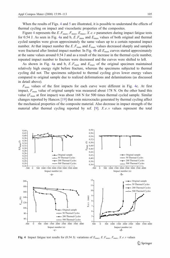
When the results of Figs. 4 and 5 are illustrated, it is possible to understand the effects ofthermal cycling on impact and viscoelastic properties of the composites.
Figure 4 represents the E .Fmax, Fmax, Emax, X .e .v parameters during impact fatigue testsfor 0.54 J. As seen in Fig. 4a and b, E .Fmax and Emax values of both original and thermalcycled samples were given approximately the same values up to a certain repeated impactnumber. At that impact number the E .Fmax and Emax values decreased sharply and sampleswere fractured after limited impact number. In Fig. 4b all Emax curves started approximatelyat the same values around 0.54 J and as a result of the increase in the thermal cycle number,repeated impact number to fracture were decreased and the curves were shifted to left.
As shown in Fig. 4a and b, E .Fmax and Emax of the original specimen maintainedrelatively high energy right before fracture, whereas the specimens subjected to thermalcycling did not. The specimens subjected to thermal cycling gives lower energy valuescompared to original sample due to realized deformations and delaminations (as discussedin detail above).
Fmax values of the first impacts for each curve were different in Fig. 4c. At firstimpact, Fmax value of original sample was measured about 178 N. On the other hand thisvalue (Fmax at first impact) was about 168 N for 500 times thermal cycled sample. Similarchanges reported by Hancox [19] that resin microcracks generated by thermal cycling affectthe mechanical properties of the composite material. Also decrease in impact strength of thematerial after thermal cycling reported by ref. [9]. X .e .v values represent the total
-500 0 500 1000 1500 2000 2500 3000 3500 40000,160,180,200,220,240,260,280,300,320,340,360,380,400,420,44
Impact number (n)
E.F
max
(J)
Original sample 50 Thermal Cycles 200 Thermal Cycles 500 Thermal Cycles
-a-
-500 0 500 1000 1500 2000 2500 3000 3500 4000
0,360,380,400,420,440,460,480,500,520,540,560,58
Impact number (n)
Em
ax (
J)
-b-
-500 0 500 1000 1500 2000 2500 3000 3500 4000
60
80
100
120
140
160
180
200
Original sample
50 Thermal Cycles
200 Thermal Cycles
500 Thermal Cycles
Impact number (n)
F max
(N
)
-c-
-500 0 500 1000 1500 2000 2500 3000 3500 40004
5
6
7
8
9
10
11
12 Original sample
50 Thermal Cycles
200 Thermal Cycles
500 Thermal Cycles
Impact number (n)
X.e
.v.
(mm
)
-d-
Original sample 50 Thermal Cycles 200 Thermal Cycles 500 Thermal Cycles
Fig. 4 Impact fatigue test results for (0.54 J): variations of Emax, E .Fmax, Fmax, X .e .v values
Appl Compos Mater (2008) 15:99–113 105
deformations of the samples for each impact energy level. It is possible to see in Fig. 4d thattotal impact numbers of the samples to fracture decrease at higher number of thermalcycles. Repeated low energy impacts and thermal cycles are the parameters, whichdominantly affect the impact fatigue life time.
Consequently, coupling effects of repeated low energy impacts and thermal cycles resultin matrix, fibre–matrix interface degradation and delaminations. Finally the impact fatiguelife time of composite material was decreased similar to ref. [22].
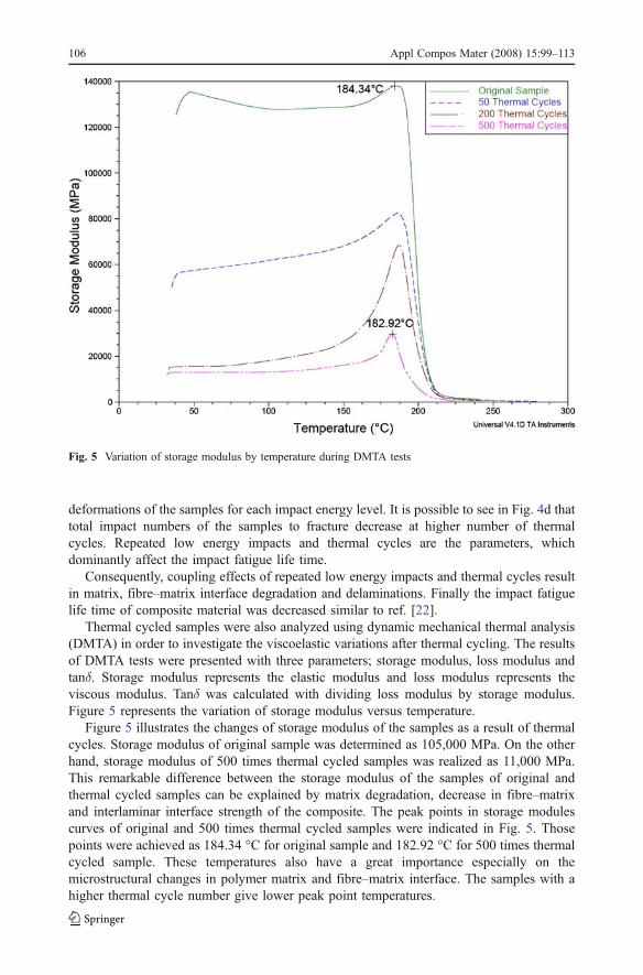
Thermal cycled samples were also analyzed using dynamic mechanical thermal analysis(DMTA) in order to investigate the viscoelastic variations after thermal cycling. The resultsof DMTA tests were presented with three parameters; storage modulus, loss modulus andtanδ. Storage modulus represents the elastic modulus and loss modulus represents theviscous modulus. Tanδ was calculated with dividing loss modulus by storage modulus.Figure 5 represents the variation of storage modulus versus temperature.
Figure 5 illustrates the changes of storage modulus of the samples as a result of thermalcycles. Storage modulus of original sample was determined as 105,000 MPa. On the otherhand, storage modulus of 500 times thermal cycled samples was realized as 11,000 MPa.This remarkable difference between the storage modulus of the samples of original andthermal cycled samples can be explained by matrix degradation, decrease in fibre–matrixand interlaminar interface strength of the composite. The peak points in storage modulescurves of original and 500 times thermal cycled samples were indicated in Fig. 5. Thosepoints were achieved as 184.34 °C for original sample and 182.92 °C for 500 times thermalcycled sample. These temperatures also have a great importance especially on themicrostructural changes in polymer matrix and fibre–matrix interface. The samples with ahigher thermal cycle number give lower peak point temperatures.
Fig. 5 Variation of storage modulus by temperature during DMTA tests
106 Appl Compos Mater (2008) 15:99–113

Fig. 7 Variation of tanδ values by temperature during DMTA tests
Fig. 6 Variation of loss modulus by temperature during DMTA tests
Appl Compos Mater (2008) 15:99–113 107

DMTA results of thermal cycled and original samples in Fig. 5 give importantinformation on the mechanical properties of the samples. As discussed in ref. [25] duringthe thermal cycling both matrix and fibre expand or contract according to their coefficientsof linear thermal expansion. As they are internally constrained, temperature fluctuationscause stress build-up at the interface. Because of this stress, it is possible to have plasticdeformations of the ductile matrix or failure of fibre–matrix interface.
As already seen in Fig. 4c, the maximum forces are remarkably lower at thermal cycledsamples compared to the original sample. Because of the reasons summarized above, lowerFmax values were obtained at the first impacts of the thermal cycled samples compared tooriginal sample. Also Fmax values at last impacts (final impact) higher than Fmax values ofthermal cycled samples. Also this Fmax values are getting smaller at higher thermal cyclenumbers.
Lower Fmax values of thermal cycled samples are one of the evidence of overall stiffnessloss due to the thermal cycles. Deformations and failures as summarized above areresponsible for lower impact fatigue properties.
–a- –b-
–c- –d-
Fig. 8 Fractured surfaces of original and thermal cycled samples after impact fatigue at the same energylevel of 0.54 J. a Original sample fractured after 3,580 impact at 0.54 J, b 50 thermal cycled sample fracturedafter 2,856 impact at 0.54 J, c 200 thermal cycled sample fractured after 1,873 impact at 0.54 J, d 500thermal cycled sample fractured after 218 impact at 0.54 J
108 Appl Compos Mater (2008) 15:99–113

Hammer impacts during the tests, result in shear loading between the laminaes(interlaminar shear stress). These stresses forced to each interlaminar interfaces todeformation.
Figure 6 represents the variation of the loss modulus by temperature during the dynamicmechanical thermal analysis. As known, loss modulus represents viscous modulus of thesamples. As seen in Fig. 6, for the original sample and 500 times thermal cycled samples,loss modulus values were realized as 7,000 and 900 MPa, respectively. Peak points of eachcurve (original and 500 times thermal cycled samples) were illustrated. Original sample’speak temperature was 196.50 °C, on the other hand 500 times thermal cycled sample had apeak temperature of 185.92 °C. As a result of the increase in the thermal cycle number, theloss modulus and peak temperatures were decreased.
In order to show the changes in the viscoelastic nature of the samples, the variation oftanδ by temperature was illustrated in Fig. 7. Tanδ represents the loss factor. As seen inFig. 7, the tanδ values were decreased with the thermal cycle number. Similar to the resultsof Fig. 6, the curves in Fig. 7 shifts to the left by the increasing thermal cycle number. Thepeak temperatures of original and 500 times thermal cycled samples were achieved as
–a- –b-
-c- –d-
Fig. 9 SEM images of compression regions of fractured samples at repeated impacts of 0.54 J. a Originalsample fractured after 3,580 impacts, b 50 thermal cycled sample fractured after 2,856 impacts, c 200thermal cycled sample fractured after 1,873 impacts, d 500 thermal cycled sample fractured after 218 impacts
Appl Compos Mater (2008) 15:99–113 109

approximately 211.81 and 207.91 °C, respectively. In contrast to Bullions et al. [15] glasstransition temperature (Tg) is decreased remarkably after thermal cycles. It is possible to saythat, as a result of thermal cycles, there is a remarkable microstructural changes in polymermatrix which results in remarkable decrease in glass transition temperature as well. As aresult of thermal cycles, the shoulder formation was observed in tanδ curve of 500 timescycled sample. Also this shoulder gives a peak at temperature of 189.17 °C. Lower Tg valueappeared like a shoulder in the tanδ curve which occurred at a temperature slightly lowerthan the main peak. This phenomenon attributable to a plasticised and then separated phasein the material as a result of water ingress [26, 27]. Similar results were also reported byother researchers [28, 29].
After impact fatigue tests of the thermal cycled samples, fractographic investigationswere done in order to understand the deformation characteristics and fracture mechanismsduring the repeated impact loadings. Cross sections of the fractured samples were illustratedin Fig. 8. The delaminations at the compression region were indicated with right arrows ineach SEM images in Fig. 8a,b and c. The size and the number of these delaminations wasincreased due to the increase in thermal cycle number. Additionally, it is possible to explainthe increase in the size and the number of the delaminations by the expansion of the airwithin delaminations which were realized very fast after we immersed the cold compositesinto the boiling water tank generating a force outward due to the rapid expansion of thetrapped air [22]. Delamination in tensile region of the cross section is indicated with leftarrow in Fig. 8d.
The compression regions of fractured surfaces of the samples were illustrated in Fig. 9.As a result of increase in the thermal cycle number, the repeated impact number up tofracture was decreased. During the crack propagation, slippages occurred between thesurfaces of the cracks at each impact. As a result of this slippage, a thin layer of PEI resin(including small matrix and fibre fragments) covered the whole compression region similarto ref. [30]. Compared to original sample (Fig. 9a), 200 and 500 times thermal cycledsamples were fractured at remarkably lower impact numbers. Due to this decrease in impactnumber, the rate of slippage was reduced, therefore the amount of matrix covering was also
Original sample fractured after 3580
impacts –a- 500 thermal cycled sample fractured
after 10 impacts –b-
Fig. 10 The side view illustration of the samples of original and thermal cycled samples fractured underrepeated impacts at 0.54 J. a Original sample fractured after 3,580 impacts, b 500 thermal cycled samplefractured after 10 impacts
110 Appl Compos Mater (2008) 15:99–113

reduced (Fig. 9c and d). Each impact of the hammer results in interlaminar shear stresses,which forces the laminate to interlaminar debondings. This is the main reason of initiationand growth of delaminations. Because of the large number of hammer impacts, manydelaminations (interlaminar debondings) were occurred at the compression region oforiginal sample indicated with right arrows in Fig. 9a. On the other hand, largerdelaminations are observed in the thermal cycled samples (indicated with left arrow inFig. 9b). Beside the effect of impacts of the hammer, the effects of the thermal cyclesenhance the initiation and growth of the delaminations. It is possible to observe thedifference in delamination formation between the original and thermal cycled sample inmacro scale in Fig. 10. The damage propagation during the repeated impact loadings can besummarized as: compressional deformations (includes fibre micro-buckling, shear fracturesof the fibres) followed by initiation and propagation of delaminations and finally tensionalfractures of the fibres. In Fig. 10 arrows are indicated the delaminations in tensile region.
The morphological difference of the original and the thermal cycled samples fracturedafter repeated impacts illustrated in Fig. 11. Both energy level of the impacts and thenumber of thermal cycles remarkably affect the fracture morphology of the materials.
-a- -b-
-c- -d-
Fig. 11 SEM images of tensile regions of fractured samples at repeated impacts of 0.54 and 0.94 J. aOriginal sample fractured after 3580 impact at 0.54 J, ba original sample fractured after 21 impact at 0.94 J, c500 thermal cycled sample fractured after 218 impact at 0.54 J, d 500 thermal cycled sample fractured after10 impact at 0.94 J
Appl Compos Mater (2008) 15:99–113 111

Original sample which fractured after large number of impacts was compared to the thermalcycled samples. Large number of low energy repeated impacts results in large number ofshear loadings at the fibre–matrix and interlaminar interfaces. As a result of this loadingsand deformations, there are many longer pull-out fibres, indicated with right arrows infractured original samples (Fig. 11a and b). On the other hand, the thermal cycled sampleshave a shorter pull-out fibres (Fig. 11c and d) compared to the original sample. Similar toFig. 10, interlaminar delaminations observed at tensile region of the thermal cycledsamples, indicated with right arrows, Fig. 11c and d.
4 Conclusion
In this study, thermal cycling effects on impact fatigue and viscoelastic properties of athermoplastic composite material were investigated. It was observed that, an increase in thethermal cycle number resulted in decrease in the repeated impact number of the sample tothe fracture. Also higher impact energy levels resulted in lower repeated impact number ofthe sample to fracture. An increase in the thermal cycle number resulted in a decrease in thestorage modulus due to the degradation of matrix and fibre–matrix interface. As a result ofthe increase in the thermal cycle number, the loss modulus and peak temperaturesdecreased. Therefore, it is possible to say that, thermal cycles causes a remarkablemicrostructural changes in the polymer matrix, which also results in a remarkable decreasein the glass transition temperature. The size and number of the delaminations wereexpanded due to the increase in the thermal cycle number. Thermal cycling causes thermalstresses, which are the main reasons of propagating non-obvious delaminations from thedelamination tip. Besides the effect of impacts of the hammer, the effects of the thermalcycles enhance the initiation and growth of the delaminations. It is possible to concludethat, during the repeated impacts in original samples, the mechanical loading at fibre–matrixinterface are higher compared to the interfaces of the plies (laminates). Delaminated crosssections with a shorter pull-out fibre length are observed in tensile regions of fracturedsamples.
References
1. Gómez-del Río, T., Zaera, R., Barbero, E., Navarro, C.: Damage in CFRPs due to low velocity impact atlow temperature. Compos. Part B Eng. 36, 41–50 (2005). doi:10.1016/j.compositesb.2004.04.003
2. Tai, N.H., Yip, M.C., Lin, J.L.: Effects of low-energy impact on the fatigue behavior of carbon/epoxycomposites. Compos. Sci. Technol. 58, 1–8 (1998). doi:10.1016/S0266-3538(97)00075-4
3. De Morais, W.A., Monterio, S.N., d’Almeida, J.R.M.: Evaluation of repeated low energy impact damagein carbon–epoxy composite materials. Compos. Struct. 67, 307–315 (2005). doi:10.1016/j.compstruct.2004.01.012
4. Tai, N.H., Yip, M.C., Tseng, C.M.: Influences of thermal cycling and low-energy impact on the fatiguebehavior of carbon/PEEK laminates. Compos. Part B Eng. 30, 849–865 (1999). doi:10.1016/S1359-8368(99)00048-7
5. Bankim, ChR.: Effect of thermal shock on interlaminar strength of thermally aged glass fibre reinforcedepoxy composites. J. Appl. Polym. Sci. 100, 2062–2066 (2005). doi:10.1002/app.23019
6. Sınmazçelik, T., Arıcı, A.A., Günay, V.: Impact–fatigue behaviour of unidirectional carbon fibrereinforced polyetherimide (PEI) composites. J. Mater. Sci. 41, 6237–6244 (2006). doi:10.1007/s10853-006-0720-5
7. Akay, M., Spratt, G.R., Meenan, B.: The effects of long-term exposure to high temperatures on the ILSSand impact performance of carbon fibre reinforced bismaleimide. Compos. Sci. Technol. 63, 1053–1059(2003). doi:10.1016/S0266-3538(03)00018-6
112 Appl Compos Mater (2008) 15:99–113
8. Stevens, M.R., Todd, R., Papakyriacou, M.: The effect of thermal cycling on the properties of a carbonfibre reinforced magnesium composite. Mater. Sci. Eng. A. 397, 249–256 (2005)
9. Bergeret, A., Pires, I., Foule, M.P., Abadie, B., Ferry, L., Crespy, A.: The hygrothermal behaviour ofglass–fibre-reinforced thermoplastic composites: a prediction of the composite lifetime. Polym. Test. 20,753–763 (2001). doi:10.1016/S0142-9418(01)00030-7
10. Boinard, E., Pethrick, R.A., MacFarlane, C.J.: The influence of thermal history on the dynamicmechanical and dielectric studies of polyetheretherketone exposed water and brine. Polymer 41, 1063–1066 (2000). doi:10.1016/S0032-3861(99)00259-1
11. Biernacki, K., Szyszkowski, W., Yannacopoulos, S.: An experimental study of large scale modelcomposite materials under thermal fatigue. Compos. Part A Appl. Sci. Manuf. 30, 1027–1034 (1999)
12. Bismarck, A., Hofmeier, M., Dörner, G.: Effect of hot water immersion on the performance of carbonreinforced unidirectional PEEK composites: stress rupture under end-loaded bending. Compos. Part AAppl. Sci. Manuf. 38, 407–426 (2007)
13. Imielinska, K., Guillaumat, L.: The effect of water immersion ageing on low velocity impact behaviourof woven aramid–glass fibre/ epoxy composites. Compos. Sci. Technol. 64, 2271–2278 (2004).doi:10.1016/j.compscitech.2004.03.002
14. Ray, B.C.: Thermal shock on interfacial adhesion of thermally conditioned glass fibre/epoxy composites.Mater. Lett. 58, 2175–2177 (2004). doi:10.1016/j.matlet.2004.01.035
15. Bullions, T.A., McGrath, J.E., Loos, A.C.: Thermal-oxidative ageing effects on the properties of a carbonfibre-reinforced phenylethynyl-terminated polyetherimide. Compos. Sci. Technol. 63, 1737–1748(2003). doi:10.1016/S0266-3538(03)00089-7
16. Salehi-Khojin, A., Mahinfallah, M., Bashirzadeh, R., Freeman, B.: Temperature effects on Kevlar/Hybridand carbon fibre composite sandwiches under impact loading. Compos. Struct. 78, 197–206 (2007).doi:10.1016/j.compstruct.2005.09.005
17. Kobayashi, S., Terada, K., Ogihara, S., Takeda, N.: Damage-mechanics analysis of matrix cracking incross-ply CFRP laminates under thermal fatigue. Compos. Sci. Technol. 61, 1735–1742 (2001).doi:10.1016/S0266-3538(01)00077-X
18. Baschek, G., Hartwig, G., Zahradnik, F.: Effects of water absorption in polymers at low and hightemperatures. Polymer 40, 3433–3441 (1999). doi:10.1016/S0032-3861(98)00560-6
19. Hancox, N.L.: Thermal effects on polymer matrix composites: part 1. Thermal cycling. Mater. Des. 19,85–91 (1998)
20. Vina, J., Castrillo, M.A., Argüelles, A., Vina, I.: Effects of natural and accelerated ageing on the staticand dynamic behavior of glass–fibre-reinforced polyetherimide. J. Mater. Sci. Lett. 17, 1711–1713(1998). doi:10.1023/A:1006666916778
21. Srivastava, V.K.: Influence of water immersion on mechanical properties of quasi-isotropic glass fibrereinforced epoxy vinylester resin composites. Mater. Sci. Eng. A 263, 56–63 (1999)
22. Tai, N.H., Yu, H.C.: Effects of low-energy impact and thermal cycling loadings on fatigue behavior ofthe quasi-isotropic carbon/epoxy composites. J. Polym. Res. 5, 143–151 (1998). doi:10.1007/s10965-006-0050-y
23. Parlevliet, P.P., Bersee, H.E.N., Beukers, A.: Residual stresses in thermoplastic composites—a study ofthe literature—part I: formation of residual stresses. Compos. Part A Appl. Sci. Manuf. 37, 1847–1857(2006). doi:10.1016/j.compositesa.2005.12.025
24. Parlevliet, P.P., Bersee, H.E.N., Beukers, A.: Residual stresses in thermoplastic composites—a study ofthe literature—part III: effects of thermal residual stresses. Compos. Part A Appl. Sci. Manuf. 38, 1581–1596 (2007). doi:10.1016/j.compositesa.2006.12.005
25. Sinmazcelik, T., Arıcı, A.: Thermal cycles effect on interlaminar shear strength (ILSS) and impact behaviourof carbon/PEI composites. J. Mater. Sci. 41, 1233–1241 (2006). doi:10.1007/s10853-005-3661-5
26. Earl, J.S., Shenoi, R.A.: Hygrothermal ageing effects on FRP laminate and structural foam materials.Compos. Part A Appl. Sci. Manuf. 35, 1237–1247 (2004)
27. Xu, S.: Evaluating thermal and mechanical properties of electrically conductive adhesives for electronicapplications. Thesis, Faculty of the Virginia Polytechnic Institute and State University, Blacksburg,Virginia (2001)
28. Hiltz, J.A., Kuzak, S.G., Waitkus, P.A.: Effect of thermal exposure on the properties of phenoliccomposites: dynamic mechanical analysis. J. Appl. Polym. Sci. 79, 385–395 (2001). doi:10.1002/1097-4628(20010118)79:3<385::AID-APP10>3.0.CO;2-J
29. Georget, D.M.R., Smith, A.C., Waldron, K.W.: Low moisture thermo-mechanical properties of carrot cellwall components. Thermochim. Acta 315, 51–60 (1998). doi:10.1016/S0040-6031(98)00276-7
30. Çoban, O., Bora, M.Ö., Sınmazçelik, T., Cürgül, İ., Günay, V.: Fracture morphology and deformationcharacteristics of repeatedly impacted thermoplastic matrix composites. Mater. Des. doi:10.1016/j.matdes.2008.05.042
Appl Compos Mater (2008) 15:99–113 113
Copyright © 2022 FDOKUMEN