The effects of reflection coefficient of the harbour sidewall on the performance of floating...
12
This article appeared in a journal published by Elsevier. The attached copy is furnished to the author for internal non-commercial research and education use, including for instruction at the authors institution and sharing with colleagues. Other uses, including reproduction and distribution, or selling or licensing copies, or posting to personal, institutional or third party websites are prohibited. In most cases authors are permitted to post their version of the article (e.g. in Word or Tex form) to their personal website or institutional repository. Authors requiring further information regarding Elsevier’s archiving and manuscript policies are encouraged to visit: http://www.elsevier.com/copyright
Transcript of The effects of reflection coefficient of the harbour sidewall on the performance of floating...
This article appeared in a journal published by Elsevier. The attachedcopy is furnished to the author for internal non-commercial researchand education use, including for instruction at the authors institution
and sharing with colleagues.
Other uses, including reproduction and distribution, or selling orlicensing copies, or posting to personal, institutional or third party
websites are prohibited.
In most cases authors are permitted to post their version of thearticle (e.g. in Word or Tex form) to their personal website orinstitutional repository. Authors requiring further information
regarding Elsevier’s archiving and manuscript policies areencouraged to visit:
http://www.elsevier.com/copyright
Author's personal copy
The effects of reflection coefficient of the harbour sidewall on theperformance of floating breakwaters
Ghassan Elchahal a,�, Rafic Younes b, Pascal Lafon a
a University of Technology of Troyes, 12 Rue marie Curie, Troyes 10010, Franceb Lebanese University, Rafic Harriri Campus, Beirut, Lebanon
a r t i c l e i n f o
Article history:
Received 12 June 2007
Accepted 27 April 2008Available online 9 May 2008
Keywords:
Diffraction–radiation
Floating breakwater
Partial reflective sidewall
Linear waves
a b s t r a c t
This paper studies the interaction of linear water waves with a moored floating breakwater with a
leeward boundary composed from a vertical wall. This describes a real modelling for the case of ports in
contrary to the problems of unbounded domains. It involves the application of a partial reflection
boundary condition for this sidewall. In fact, the partial reflection problem in practical application is of
great importance in the design of a harbour or breakwater and mainly for short waves. The reflection
coefficient of the harbour boundary (sidewall) plays an important role in modifying the performance of
the floating breakwater. Moreover, it reduces the resonant peaks appearing inside the ports due to the
energy accumulation in an enclosed domain. The effects of the variation of structural parameters of the
breakwater on the transmitted wave height are discussed in details for various values of partial
reflection.
& 2008 Elsevier Ltd. All rights reserved.
1. Introduction
Floating structures are often used in ocean engineering, such asbreakwaters, wave energy devices and ocean platforms. Over thepast two decades, interest in the study of the behaviour of floatingbreakwaters, FBWs, has increased owing to the requirement forthe development of large number of new marinas and recreationalharbours. The lower initial investment and the mobility of thestructure of FBWs is attractive to the designer, where they areevaluated as a viable alternative when the cost of a fixed structureexceeds the economic return to be gained at that locationand especially in sites with a large water depth and worsebottom foundation conditions. In addition, the floating break-waters are ecologically advantageous because they have littleinteraction with water circulation, biological exchange, andsediment transport.
Many research papers have been involved in the hydrody-namics of floating structures to investigate their performancebased on numerical and analytical methods; for example: Adee(1975), Yamamoto et al. (1980), Isaacon and Byres (1988),Williams (1994), Williams and Abul-azm (1997), Sannasiraj et al.(1998), Sannasiraj et al. (2000), Williams et al. (2000), Lee and Cho(2003), Shen et al. (2005), Loukogeorgaki and Angelides (2005),Gesraha (2006). From the researches of the scholars as above, we
find most of them focus attention on floating structures oscillationwith periodic motion on water surface of deep water withunbounded domain, and almost very few researches attempt tostudy the problem of floating structures oscillation on watersurface of finite deep water and one side of the boundary withvertical sidewall; which assimilates a real practical model for portsites. When a ship is parked in the port, the waves are reflecteddue to a vertical sidewall. So it is different to the problems ofstructures oscillation on water surface with unbounded domain.The problem considered in this paper is similar to that of Hsu andWu (1997), where they developed the boundary element methodand applied it to study the heave and sway problem only, wheresharp peaks in the damping and resonant behaviour have beenfound in comparison with unbounded problems. Later, Zhenget al. (2004) continued the problem by considering the threemodes of radiation and also the diffraction problem, where thetheoretical formulation was developed by deriving analyticalexpressions for the diffraction–radiation problem and the resultswere obtained for hydrodynamic coefficients only.
Since numerical models based on the linear potential theoryhave proven to be efficient tools to predict the sea keepingbehaviour of floating breakwaters; it is useful to apply it in thispaper for the diffraction–radiation model and then to use it inevaluating the hydrodynamic coefficients and wave excitingforces. In order to proceed forward and determine the transmis-sion coefficient, an analytical modelling for the vibrating structureis developed based on Lagrange’s Theorem. The equations ofmotions are solved to evaluate structure responses in the three
ARTICLE IN PRESS
Contents lists available at ScienceDirect
journal homepage: www.elsevier.com/locate/oceaneng
Ocean Engineering
0029-8018/$ - see front matter & 2008 Elsevier Ltd. All rights reserved.
doi:10.1016/j.oceaneng.2008.04.015
� Corresponding author. Tel.: +33 3 25 7156 55; fax: +33 3 25 7156 75.
E-mail address: [email protected] (G. Elchahal).
Ocean Engineering 35 (2008) 1102– 1112

Author's personal copy
modes of motion, and hence vibrational effects are determinedand discussed. Finally, the elaborated model is used to identify theinfluence of the structural parameters on the wave attenuatingcapacity of the moored floating breakwater; and also to examinethe effects of partial reflection sidewall on the performance of thebreakwater by considering various reflection coefficient values. Infact, this constitutes advanced steps for the previous studies,where Zheng et al. (2004) have developed only an analyticalsolution for a freely floating breakwater, and did not continuetheir study to compromise the effect of the diffraction problem,neither the effect of the mooring lines stiffness and their angle ofinclination. But, they limited their study on the influence ofstructural parameters on the hydrodynamic coefficients only;where the diffraction seems to play an important factor inmagnifying the resonant peaks beside the wave’s radiation inthe bounded domain. Moreover, neither Zheng et al. (2004) norHsu and Wu (1997) have analysed the dynamic motion of thebreakwater.
In addition, it is the first time where a partial reflectionboundary condition is applied with the floating breakwater modelinstead of the complete reflection condition. A partial reflectingboundary inside the harbour will improve the performance of thefloating breakwater by minimizing the resonant peaks inside theharbour. Moreover, neither the complete reflection nor the zeroreflection at the harbour boundaries is really appropriate since inreality partial reflection at the boundaries within a port invariablyoccurs. Usually, this partial reflection condition has been usedonly in the problems that predict the wave height inside a harbourprotected by fixed bottom floating breakwaters. For example,Isaacon and Qu (1990) utilized the boundary element method topredict the wave field in a harbour of arbitrary shape and uniformdepth with partially reflecting boundaries, based on the work ofBerkhoff (1976). Chou and Han (1993) calculated the wave field ina harbour of variable depth with partially reflecting boundaries bya boundary element approach for a unidirectional incident wavespectrum. Hammanaka (1997) studied the wave field in a harbourfor a range of boundary conditions, including partial reflection.Lee and Williams (2002) presented a numerical model for theprediction of the wave field due to the diffraction of multi-directional random waves in a harbour of arbitrary shape withpartially reflecting boundaries.
2. Partial reflecting boundaries
The previous studies of many scholars, however, suffer somedeficiencies; in other words, they are applicable either tocomplete reflection or to zero reflection. In fact, reflectingboundaries are not always vertical nor are fully reflecting. Inorder to treat these boundaries in the present model, they areschematized as vertical, and partial reflection is introduced intothe model by using a mixed boundary condition instead of the fullreflection condition in the manner proposed by Berkhoff (1976).That is
qFqnþ akF ¼ 0 (1)
in which n is distance into the fluid region measured normal to theboundary and a(a ¼ a1+ia2) is a complex transmission coefficient.This coefficient may be interpreted in a number of ways, asindicated by Berkhoff (1976) and summarized by Isaacon and Qu(1990). These relates to
a. its relation to the rate of transfer of energy at the boundary;b. its relation to the height and phase of the wave field at the
boundary; and
c. its relation to the conventional reflection coefficient.
The transmission coefficient a may be related to the reflectioncoefficient kr which is commonly used and which is defined as theratio of a reflected wave height to an incident wave height. Theincident potential is given as follows:
Fi ¼ Afexp½ikðx cos gþ y sin gÞ�g
Assuming that a wave train undergoes oblique partial reflectionfrom a vertical wall located at x ¼ 0, such that the incident wavedirection makes an angle g with the normal to the wall, the totalpotential of the combined wave field corresponds to a three-dimensional wave pattern and may be written as the sum of theincident and reflected wave potentials:
F ¼ Afexp½ikðx cos gþ y sin gÞ�
þ kr exp½�ikðx cos g� y sin gÞ þ ib�g (2)
In such a case it is possible to relate the transmission coefficienta to the conventional reflection coefficient kr and a phase shift bassociated with the reflection, and the angle g that the incidentwave train makes with the wall. Solving for a1 and a2, we obtain
a1 ¼2kr sinb cos g
1þ k2r þ 2kr cosb
a1 ¼ð1� k2
r Þ cos g
1þ k2r þ 2kr cosb
Isaacon and Qu (1990) assumed that the partial reflection has noinfluence upon the form of a reflected wave, and that the numericaltests on the reflection phase angle have indicated that the resultsare not particularly sensitive to the value of b, so that a value ofb ¼ 0 was chosen. Therefore, they assumed that there is no phaseshift between the incoming waves and the reflected waves. Also,Isaacon and Qu (1990) provided an initial approximation to theincident wave direction, g ¼ 0. Hence, for b ¼ 0 and g ¼ 0, theyindicated that a1 ¼ 0 and a2 ¼ (1�kr)/(1+kr). Finally, the partialreflection boundary condition can be expressed as follows:
qFqn¼ ik
kr � 1
kr þ 1F
This expression denotes the fully reflective boundary for thevalue kr ¼ 1.
3. Wave modelling: Theoretical formulation
3.1. Formulation of boundary value problem
Fluid is assumed to be ideal, flow is considered as irrotational,so we can apply a linear wave theory. The body is assumed to berigid. It is assumed that no flow of energy takes place through thebottom surface or the free surface. Energy is gained or lost by thesystem only through waves arriving or departing at infinity or dueto the external forces acting on the body. The motions areassumed to be small, so that the body boundary conditions aresatisfied very close to the equilibrium position of the body.A Cartesian coordinate system is used, with the origin at themean free surface, Oz directed positive upwards and Ox directedpositive in the direction of propagation of waves. The state of thefluid can be completely described by the velocity potential,fðx; z; tÞ ¼ Re½Fðx; zÞ e�iot �, where Re denotes the real part of thecomplex expression i ¼
ffiffiffiffiffiffiffi�1p
and t is the time. For the two-dimensional problem considered here, the time independentcomplex velocity potential F(x, z) satisfies the Laplace equation:
r2Fðx; zÞ ¼ 0 (3)
ARTICLE IN PRESS
G. Elchahal et al. / Ocean Engineering 35 (2008) 1102–1112 1103
Author's personal copy
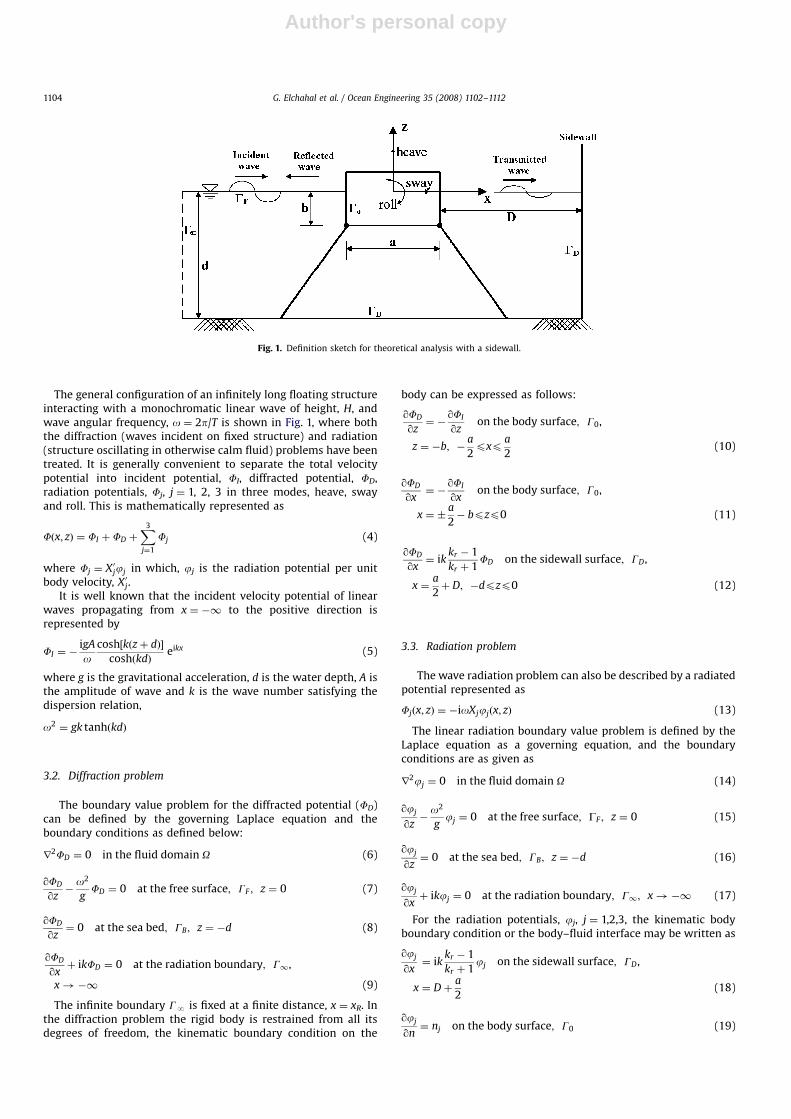
The general configuration of an infinitely long floating structureinteracting with a monochromatic linear wave of height, H, andwave angular frequency, o ¼ 2p/T is shown in Fig. 1, where boththe diffraction (waves incident on fixed structure) and radiation(structure oscillating in otherwise calm fluid) problems have beentreated. It is generally convenient to separate the total velocitypotential into incident potential, FI, diffracted potential, FD,radiation potentials, Fj, j ¼ 1, 2, 3 in three modes, heave, swayand roll. This is mathematically represented as
Fðx; zÞ ¼ FI þ FD þX3
j¼1
Fj (4)
where Fj ¼ X0jjj in which, jj is the radiation potential per unitbody velocity, X0j.
It is well known that the incident velocity potential of linearwaves propagating from x ¼ �1 to the positive direction isrepresented by
FI ¼ �igA
ocosh½kðzþ dÞ�
coshðkdÞeikx (5)
where g is the gravitational acceleration, d is the water depth, A isthe amplitude of wave and k is the wave number satisfying thedispersion relation,
o2 ¼ gk tanhðkdÞ
3.2. Diffraction problem
The boundary value problem for the diffracted potential (FD)can be defined by the governing Laplace equation and theboundary conditions as defined below:
r2FD ¼ 0 in the fluid domain O (6)
qFD
qz�
o2
gFD ¼ 0 at the free surface; GF ; z ¼ 0 (7)
qFD
qz¼ 0 at the sea bed; GB; z ¼ �d (8)
qFD
qxþ ikFD ¼ 0 at the radiation boundary; G1,
x!�1 (9)
The infinite boundary GN is fixed at a finite distance, x ¼ xR. Inthe diffraction problem the rigid body is restrained from all itsdegrees of freedom, the kinematic boundary condition on the
body can be expressed as follows:
qFD
qz¼ �
qFI
qzon the body surface; G0,
z ¼ �b; �a
2pxp
a
2(10)
qFD
qx¼ �
qFI
qxon the body surface; G0,
x ¼ �a
2� bpzp0 (11)
qFD
qx¼ ik
kr � 1
kr þ 1FD on the sidewall surface; GD,
x ¼a
2þ D; �dpzp0 (12)
3.3. Radiation problem
The wave radiation problem can also be described by a radiatedpotential represented as
Fjðx; zÞ ¼ �ioXjjjðx; zÞ (13)
The linear radiation boundary value problem is defined by theLaplace equation as a governing equation, and the boundaryconditions are as given as
r2jj ¼ 0 in the fluid domain O (14)
qjj
qz�
o2
gjj ¼ 0 at the free surface; GF ; z ¼ 0 (15)
qjj
qz¼ 0 at the sea bed; GB; z ¼ �d (16)
qjj
qxþ ikjj ¼ 0 at the radiation boundary; G1; x!�1 (17)
For the radiation potentials, jj, j ¼ 1,2,3, the kinematic bodyboundary condition or the body–fluid interface may be written as
qjj
qx¼ ik
kr � 1
kr þ 1jj on the sidewall surface; GD,
x ¼ Dþa
2(18)
qjj
qn¼ nj on the body surface; G0 (19)
ARTICLE IN PRESS
Fig. 1. Definition sketch for theoretical analysis with a sidewall.
G. Elchahal et al. / Ocean Engineering 35 (2008) 1102–11121104
Author's personal copy
where n1 and n2 are the x and z components of the unit inwardnormal to the body and n3 ¼ ðx� xcÞn2 � ðz� zcÞn1, in which (xc,zc) are the coordinates of the centre of rotation.
3.4. Hydrodynamic forces
The hydrodynamic pressure at any point in the fluid can beexpressed as
Pðx; z; tÞ ¼ �rqfqt¼ iorf (20)
where r is mass density of fluid. The hydrodynamic forces can bedetermined by integrating the pressure over the wetted bodysurface G0:
Fjðx; z; tÞ ¼ iorZG0
fnj dG (21)
The hydrodynamic forces thus calculated can be separated intowave exciting forces governed by the diffraction problem and thehydrodynamic restoring forces governed by the radiation pro-blem. The wave exciting forces, Fe
j due to the diffracted potentialcan be expressed as
Fej ðx; z; tÞ ¼ ior
ZG0
ðfI þ fDÞnj dG (22)
where j ¼ 1, 2, 3 correspond to heave, sway, and roll modesrespectively.
Concerning the hydrodynamic restoring forces, a chain ofprogressive outgoing waves is generated on the free surfacefrom an oscillating floating body. The energy of these waves isthat taken away from the energy supplied to the body tosustain its motion. The energy loss to the surrounding fluid ischaracterized as hydrodynamic damping of the body. This wavedamping force constitutes a harmonic conjugate to the addedmass force for the oscillating floating body. Then from theradiation potential, the hydrodynamic restoring forces, Fh
j can beevaluated as
Fhj ¼
ZG0
iorX0kjnj dG ¼ �mjkX00k � ljkX0k (23)
where mjk is the added mass coefficient proportional to thebody acceleration and ljk is the damping coefficient proportionalto the body velocity. Then, mjk and ljk are evaluated from thereal and imaginary parts of the complex radiation potential,respectively:
mjk ¼ r Re
ZG0
jknj dG� �
(24)
ljk ¼ ro Im
ZG0
jknj dG� �
(25)
In order to solve the above diffraction and radiation boundaryvalue problem, a finite element method is used. Then, all thehydrodynamic parameters and coefficients are calculated due tothis model.
4. Structural dynamic response
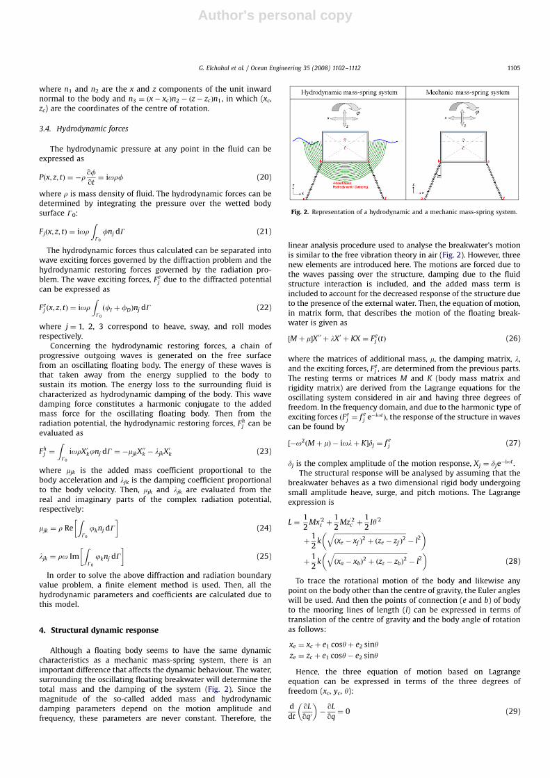
Although a floating body seems to have the same dynamiccharacteristics as a mechanic mass-spring system, there is animportant difference that affects the dynamic behaviour. The water,surrounding the oscillating floating breakwater will determine thetotal mass and the damping of the system (Fig. 2). Since themagnitude of the so-called added mass and hydrodynamicdamping parameters depend on the motion amplitude andfrequency, these parameters are never constant. Therefore, the
linear analysis procedure used to analyse the breakwater’s motionis similar to the free vibration theory in air (Fig. 2). However, threenew elements are introduced here. The motions are forced due tothe waves passing over the structure, damping due to the fluidstructure interaction is included, and the added mass term isincluded to account for the decreased response of the structure dueto the presence of the external water. Then, the equation of motion,in matrix form, that describes the motion of the floating break-water is given as
½M þ m�X00 þ lX0 þ KX ¼ Fej ðtÞ (26)
where the matrices of additional mass, m, the damping matrix, l,and the exciting forces, Fe
j , are determined from the previous parts.The resting terms or matrices M and K (body mass matrix andrigidity matrix) are derived from the Lagrange equations for theoscillating system considered in air and having three degrees offreedom. In the frequency domain, and due to the harmonic type ofexciting forces ðFe
j ¼ f ej e�iotÞ, the response of the structure in waves
can be found by
½�o2ðM þ mÞ � iolþ K�dj ¼ f ej (27)
dj is the complex amplitude of the motion response, Xj ¼ dje�iot .
The structural response will be analysed by assuming that thebreakwater behaves as a two dimensional rigid body undergoingsmall amplitude heave, surge, and pitch motions. The Lagrangeexpression is
L ¼1
2Mx
02c þ
1
2Mz
02c þ
1
2Iy02
þ1
2k
ffiffiffiffiffiffiffiffiffiffiffiffiffiffiffiffiffiffiffiffiffiffiffiffiffiffiffiffiffiffiffiffiffiffiffiffiffiffiffiffiffiffiffiffiffiðxe � xf Þ
2þ ðze � zf Þ
2q
� l2� �
þ1
2k
ffiffiffiffiffiffiffiffiffiffiffiffiffiffiffiffiffiffiffiffiffiffiffiffiffiffiffiffiffiffiffiffiffiffiffiffiffiffiffiffiffiffiffiffiffiffiðxa � xbÞ
2þ ðzz � zbÞ
2q
� l2� �
(28)
To trace the rotational motion of the body and likewise anypoint on the body other than the centre of gravity, the Euler angleswill be used. And then the points of connection (e and b) of bodyto the mooring lines of length (l) can be expressed in terms oftranslation of the centre of gravity and the body angle of rotationas follows:
xe ¼ xc þ e1 cosyþ e2 siny
ze ¼ zc þ e1 cosy� e2 siny
Hence, the three equation of motion based on Lagrangeequation can be expressed in terms of the three degrees offreedom (xc, yc, y):
d
dt
qL
qq0
� ��
qL
qq¼ 0 (29)
ARTICLE IN PRESS
Fig. 2. Representation of a hydrodynamic and a mechanic mass-spring system.
G. Elchahal et al. / Ocean Engineering 35 (2008) 1102–1112 1105
Author's personal copy
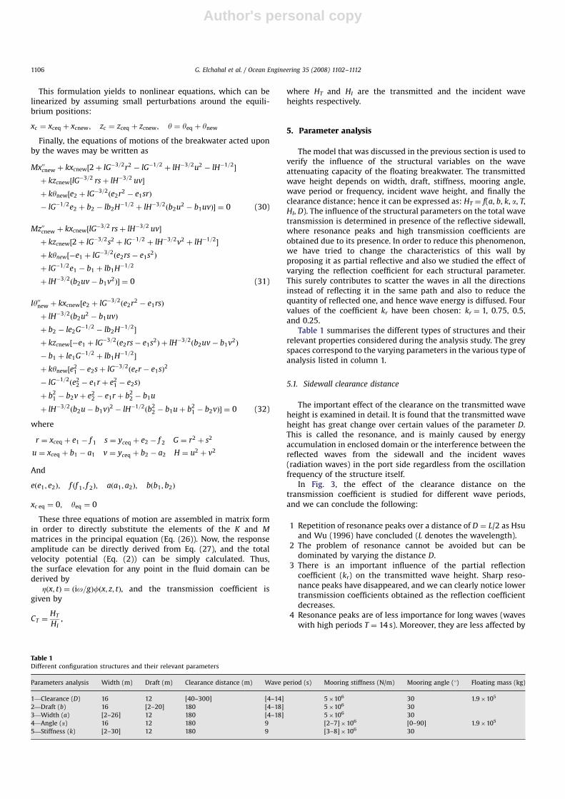
This formulation yields to nonlinear equations, which can belinearized by assuming small perturbations around the equili-brium positions:
xc ¼ xceq þ xcnew; zc ¼ zceq þ zcnew; y ¼ yeq þ ynew
Finally, the equations of motions of the breakwater acted uponby the waves may be written as
Mx00cnew þ kxcnew½2þ lG�3=2r2 � lG�1=2þ lH�3=2u2 � lH�1=2
�
þ kzcnew½lG�3=2 rsþ lH�3=2 uv�
þ kynew½e2 þ lG�3=2ðe2r2 � e1srÞ
� lG�1=2e2 þ b2 � lb2H�1=2þ lH�3=2
ðb2u2 � b1uvÞ� ¼ 0 (30)
Mz00cnew þ kxcnew½lG�3=2 rsþ lH�3=2 uv�
þ kzcnew½2þ lG�3=2s2 þ lG�1=2þ lH�3=2v2 þ lH�1=2
�
þ kynew½�e1 þ lG�3=2ðe2rs� e1s2Þ
þ lG�1=2e1 � b1 þ lb1H�1=2
þ lH�3=2ðb2uv� b1v2Þ� ¼ 0 (31)
Iy00new þ kxcnew½e2 þ lG�3=2ðe2r2 � e1rsÞ
þ lH�3=2ðb2u2 � b1uvÞ
þ b2 � le2G�1=2� lb2H�1=2
�
þ kzcnew½�e1 þ lG�3=2ðe2rs� e1s2Þ þ lH�3=2
ðb2uv� b1v2Þ
� b1 þ le1G�1=2þ lb1H�1=2
�
þ kynew½e21 � e2sþ lG�3=2
ðeer � e1sÞ2
� lG�1=2ðe2
2 � e1r þ e21 � e2sÞ
þ b21 � b2vþ e2
2 � e1r þ b22 � b1u
þ lH�3=2ðb2u� b1vÞ2 � lH�1=2
ðb22 � b1uþ b2
1 � b2vÞ� ¼ 0 (32)
where
r ¼ xceq þ e1 � f 1 s ¼ yceq þ e2 � f 2 G ¼ r2 þ s2
u ¼ xceq þ b1 � a1 v ¼ yceq þ b2 � a2 H ¼ u2 þ v2
And
eðe1; e2Þ; f ðf 1; f 2Þ; aða1; a2Þ; bðb1; b2Þ
xc eq ¼ 0; yeq ¼ 0
These three equations of motion are assembled in matrix formin order to directly substitute the elements of the K and M
matrices in the principal equation (Eq. (26)). Now, the responseamplitude can be directly derived from Eq. (27), and the totalvelocity potential (Eq. (2)) can be simply calculated. Thus,the surface elevation for any point in the fluid domain can bederived by
Zðx; tÞ ¼ ðio=gÞfðx; z; tÞ, and the transmission coefficient isgiven by
CT ¼HT
HI,
where HT and HI are the transmitted and the incident waveheights respectively.
5. Parameter analysis
The model that was discussed in the previous section is used toverify the influence of the structural variables on the waveattenuating capacity of the floating breakwater. The transmittedwave height depends on width, draft, stiffness, mooring angle,wave period or frequency, incident wave height, and finally theclearance distance; hence it can be expressed as: HT ¼ f(a, b, k, a, T,HI, D). The influence of the structural parameters on the total wavetransmission is determined in presence of the reflective sidewall,where resonance peaks and high transmission coefficients areobtained due to its presence. In order to reduce this phenomenon,we have tried to change the characteristics of this wall byproposing it as partial reflective and also we studied the effect ofvarying the reflection coefficient for each structural parameter.This surely contributes to scatter the waves in all the directionsinstead of reflecting it in the same path and also to reduce thequantity of reflected one, and hence wave energy is diffused. Fourvalues of the coefficient kr have been chosen: kr ¼ 1, 0.75, 0.5,and 0.25.
Table 1 summarises the different types of structures and theirrelevant properties considered during the analysis study. The greyspaces correspond to the varying parameters in the various type ofanalysis listed in column 1.
5.1. Sidewall clearance distance
The important effect of the clearance on the transmitted waveheight is examined in detail. It is found that the transmitted waveheight has great change over certain values of the parameter D.This is called the resonance, and is mainly caused by energyaccumulation in enclosed domain or the interference between thereflected waves from the sidewall and the incident waves(radiation waves) in the port side regardless from the oscillationfrequency of the structure itself.
In Fig. 3, the effect of the clearance distance on thetransmission coefficient is studied for different wave periods,and we can conclude the following:
1 Repetition of resonance peaks over a distance of D ¼ L/2 as Hsuand Wu (1996) have concluded (L denotes the wavelength).
2 The problem of resonance cannot be avoided but can bedominated by varying the distance D.
3 There is an important influence of the partial reflectioncoefficient (kr) on the transmitted wave height. Sharp reso-nance peaks have disappeared, and we can clearly notice lowertransmission coefficients obtained as the reflection coefficientdecreases.
4 Resonance peaks are of less importance for long waves (waveswith high periods T ¼ 14 s). Moreover, they are less affected by
ARTICLE IN PRESS
Table 1Different configuration structures and their relevant parameters
Parameters analysis Width (m) Draft (m) Clearance distance (m) Wave period (s) Mooring stiffness (N/m) Mooring angle (1) Floating mass (kg)
1—Clearance (D) 16 12 [40–300] [4–14] 5�106 30 1.9�105
2—Draft (b) 16 [2–20] 180 [4–18] 5�106 30
3—Width (a) [2–26] 12 180 [4–18] 5�106 30
4—Angle (a) 16 12 180 9 [2–7]�106 [0–90] 1.9�105
5—Stiffness (k) [2–30] 12 180 9 [3–8]�106 30
G. Elchahal et al. / Ocean Engineering 35 (2008) 1102–11121106

Author's personal copy
the reflection coefficient of the sidewall than the relativelyshorter waves.
Finally, we can deduce that the effect of the clearance distancecan be controlled by a partial sidewall for a two-dimensionalmodel to reduce the energy accumulation in the bounded regionof the port. Also, this approaches it from the real case of a threedimensional port, where the clearance distance varies from pointto other (Fig. 4). Hence, this will automatically diffuse the energywaves inside the port even though total reflective walls areconsidered.
5.2. Draft
The influence of the draft on the transmission coefficientof the floating breakwater is presented in Fig. 5; a variabledraft with a large range of wave periods is considered. Themass automatically changes when the draft is changed and the
width is kept constant, this causes a change in the naturalfrequency of the body and influences also the hydrodynamiccoefficients.
From Fig. 5, we can deduce the following:
1. Resonance peaks mainly occurring at 6, 10, and 16 s, where thisreturns to the considered value of clearance distance D. Thiscan be verified from the data in Fig. 3.
2. Increasing the draft yields to decrease the transmissioncoefficient and especially in the resonance bands, since aheavier structure is hard to put it into oscillation. Thereforeoptimal solution exists.
3. A draft of 2 m is the worse over all the range of wave periods.4. Decreasing the value of kr will decrease the values of the
transmission coefficients over all the range.5. Moreover, the importance of increasing the draft appears
clearly with decreasing the reflection coefficient.6. At longer periods, all the curves intersect around a value of
75%. This is due to the small variation of the incident potential
ARTICLE IN PRESS
Fig. 3. Effect of clearance distance on the transmitted wave height.
G. Elchahal et al. / Ocean Engineering 35 (2008) 1102–1112 1107

Author's personal copy
inside the fluid domain over the vertical direction, and hencethe major part of the underflow is being transmitted to the portside. This verifies that the floating breakwaters are lessefficient for long wave periods.
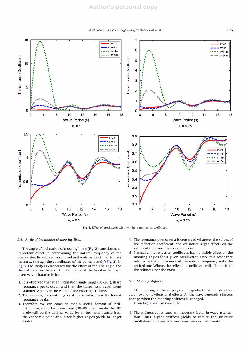
5.3. Width
The influence of the width on the wave transmission dependson the draft and the weight of the structure. When the struc-tural width is increased while the draft is kept constant, themass will increase too. Although the horizontal wave force onthe structure will not change, the increase of the mass is thereason why the motion amplitude decreases. The decrease ofthe resonance peak for structures with a large width is due tothe large hydrodynamic damping. Similar to draft analysis,important reductions in the transmission values and resonancelimitations are obtained by reducing the reflection coefficient(Fig. 6).
ARTICLE IN PRESS
Fig. 4. Variation of clearance distance in a real port.
Fig. 5. Effect of breakwater draft on the transmission coefficient.
G. Elchahal et al. / Ocean Engineering 35 (2008) 1102–11121108
Author's personal copy
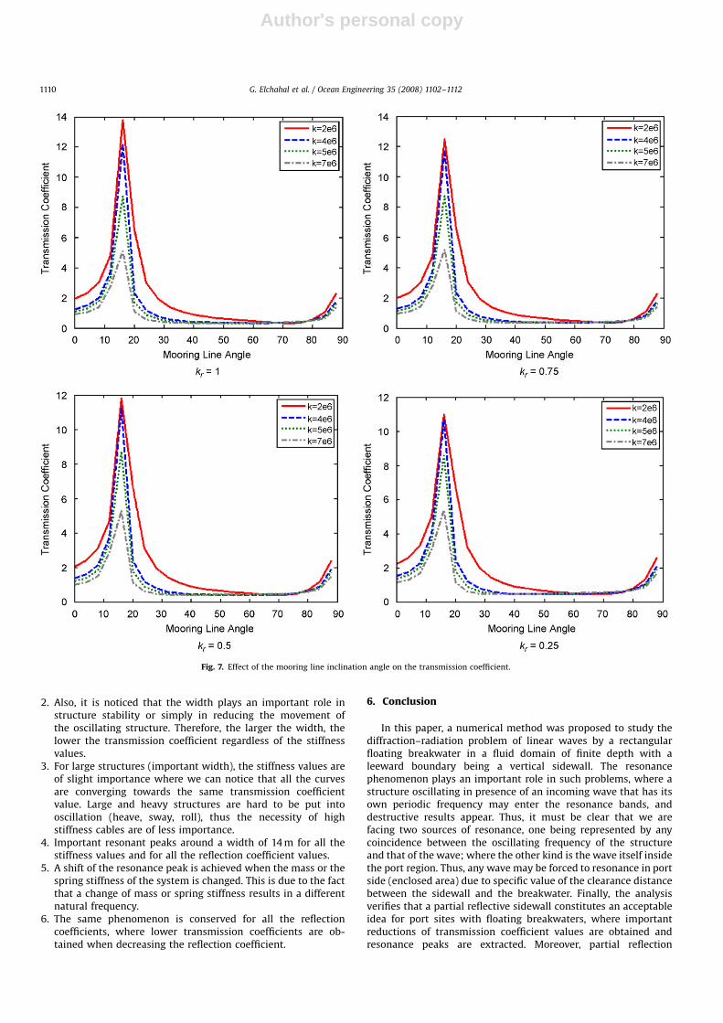
5.4. Angle of inclination of mooring lines
The angle of inclination of mooring line a (Fig. 2) constitutes animportant effect in determining the natural frequency of thebreakwater. Its value is introduced in the elements of the stiffnessmatrix K, through the coordinates of the points a and f (Fig. 2). InFig. 7, the study is elaborated for the effect of the line angle andthe stiffness on the structural motions of the breakwater for agiven wave characteristics:
1. It is observed that at an inclination angle range (10–201), sharpresonance peaks occur, and then the transmission coefficientstabilize whatever the value of the mooring stiffness.
2. The mooring lines with higher stiffness values have the lowestresonance peaks.
3. Therefore, we can conclude that a useful domain of incli-nation angle can be taken from (30–801), but surely the 301angle will be the optimal value for an inclination angle fromthe economic point also, since higher angles yields to longercables.
4. The resonance phenomena is conserved whatever the values ofthe reflection coefficient, and we notice slight effects on thevalues of the transmission coefficient.
5. Normally, the reflection coefficient has no visible effect on themooring angles for a given breakwater, since this resonancereturns to the coincidence of the natural frequency with theexcited one. Where, the reflection coefficient will affect neitherthe stiffness nor the mass.
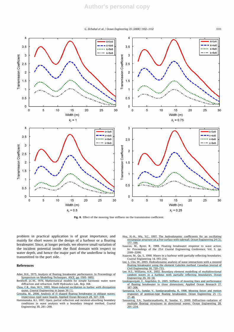
5.5. Mooring stiffness
The mooring stiffness plays an important role in structurestability and its vibrational effects. All the wave generating factorschange when the mooring stiffness is changed.
From Fig. 8 we can conclude:
1. The stiffness constitutes an important factor in wave attenua-tion. Thus, higher stiffness yields to reduce the structureoscillations and hence lower transmission coefficients.
ARTICLE IN PRESS
Fig. 6. Effect of breakwater width on the transmission coefficient.
G. Elchahal et al. / Ocean Engineering 35 (2008) 1102–1112 1109
Author's personal copy
2. Also, it is noticed that the width plays an important role instructure stability or simply in reducing the movement ofthe oscillating structure. Therefore, the larger the width, thelower the transmission coefficient regardless of the stiffnessvalues.
3. For large structures (important width), the stiffness values areof slight importance where we can notice that all the curvesare converging towards the same transmission coefficientvalue. Large and heavy structures are hard to be put intooscillation (heave, sway, roll), thus the necessity of highstiffness cables are of less importance.
4. Important resonant peaks around a width of 14 m for all thestiffness values and for all the reflection coefficient values.
5. A shift of the resonance peak is achieved when the mass or thespring stiffness of the system is changed. This is due to the factthat a change of mass or spring stiffness results in a differentnatural frequency.
6. The same phenomenon is conserved for all the reflectioncoefficients, where lower transmission coefficients are ob-tained when decreasing the reflection coefficient.
6. Conclusion
In this paper, a numerical method was proposed to study thediffraction–radiation problem of linear waves by a rectangularfloating breakwater in a fluid domain of finite depth with aleeward boundary being a vertical sidewall. The resonancephenomenon plays an important role in such problems, where astructure oscillating in presence of an incoming wave that has itsown periodic frequency may enter the resonance bands, anddestructive results appear. Thus, it must be clear that we arefacing two sources of resonance, one being represented by anycoincidence between the oscillating frequency of the structureand that of the wave; where the other kind is the wave itself insidethe port region. Thus, any wave may be forced to resonance in portside (enclosed area) due to specific value of the clearance distancebetween the sidewall and the breakwater. Finally, the analysisverifies that a partial reflective sidewall constitutes an acceptableidea for port sites with floating breakwaters, where importantreductions of transmission coefficient values are obtained andresonance peaks are extracted. Moreover, partial reflection
ARTICLE IN PRESS
Fig. 7. Effect of the mooring line inclination angle on the transmission coefficient.
G. Elchahal et al. / Ocean Engineering 35 (2008) 1102–11121110
Author's personal copy
problem in practical application is of great importance, andmainly for short waves in the design of a harbour or a floatingbreakwater. Since, at longer periods, we observe small variation ofthe incident potential inside the fluid domain with respect towater depth, and hence the major part of the underflow is beingtransmitted to the port side.
References
Adee, B.H., 1975. Analysis of floating breakwater performance. In Proceedings ofSymposium on Modelling Techniques, ASCE, pp. 1585–1602.
Berkhoff, J.C.W., 1976. Mathematical models for simple harmonic water wavediffraction and refraction. Delft Hydraulics Lab., Rep. 168.
Chou, C.R., Han, W.Y., 1993. Wave-induced oscillation in harbor with dissipationquays. Coastal Engineering in Japan 36 (1).
Gesraha, M., 2006. Analysis of P shaped floating breakwater in oblique waves:impervious rigid wave boards. Applied Ocean Research 28, 327–338.
Hammanaka, K.I., 1997. Open, partial reflection and incident-absorbing boundaryconditions in wave analysis with a boundary integral method. CoastalEngineering 30, 281–298.
Hsu, H.-H., Wu, Y.C., 1997. The hydrodynamic coefficients for an oscillatingrectangular structure on a free surface with sidewall. Ocean Engineering 24 (2),177–199.
Isaacon, M., Byres, R., 1988. Floating breakwater response to wave action.In: Proceedings of the 21st Coastal Engineering Conference, Vol. 3, pp.2189–2200.
Isaacon, M., Qu, S., 1990. Waves in a harbour with partially reflecting boundaries.Coastal Engineering 14, 193–214.
Lee, J., Cho, W., 2003. Hydrodynamic analysis of wave interactions with a mooredfloating breakwater using the element Galerkin method. Canadian Journal ofCivil Engineering 30, 720–733.
Lee, H.S., Williams, A.N., 2002. Boundary element modelling of multidirectionalrandom waves in a harbour with partially reflecting boundaries. OceanEngineering 29, 39–58.
Loukogeorgaki, E., Angelides, D., 2005. Stiffness of mooring lines and performanceof floating breakwater in three dimensions. Applied Ocean Research 27,187–208.
Sannasiraj, S.A., Sundar, V., Sundarravadivelu, R., 1998. Mooring forces and motionresponses of pontoon-type floating breakwaters. Ocean Engineering 25 (1),27–48.
Sannasiraj, S.A., Sundaravadivelu, R., Sundar, V., 2000. Diffraction–radiation ofmultiple floating structures in directional waves. Ocean Engineering 28,201–234.
ARTICLE IN PRESS
Fig. 8. Effect of the mooring line stiffness on the transmission coefficient.
G. Elchahal et al. / Ocean Engineering 35 (2008) 1102–1112 1111

Author's personal copy
Shen, Y.M., Zheng, Y.H., You, Y.G., 2005. On the radiation and diffraction of linearwater waves by a rectangular structure over a sill. Part I. Infinite domain offinite water depth. Ocean Engineering 32, 1073–1097.
Williams, A.N., 1994. Froude–Krylov force coefficients for bodies of rectangular sectionin the vicinity of the free-surface and sea-bed. Ocean Engineering 21 (7), 663–682.
Williams, A.N., Abul-Azm, A.G., 1997. Dual Pontoon floating breakwater. OceanEngineering 24 (5), 465–478.
Williams, A.N., Lee, H.S., Huang, Z., 2000. Floating pontoon breakwaters. OceanEngineering 27, 221–240.
Yamamoto, T., Yoshida, A., Ijima, T., 1980. Dynamics of elastically moored floatingobjects. Applied Ocean Research 2, 85–92.
Zheng, Y.H., Shen, Y.M., You, Y.G., Wu, B.J., Jie, D.S., 2004. On the radiation anddiffraction of water waves by a rectangular structure with a sidewall. OceanEngineering 31, 2087–2104.
ARTICLE IN PRESS
G. Elchahal et al. / Ocean Engineering 35 (2008) 1102–11121112