The EBEX Experiment
13
arXiv:astro-ph/0501111v1 6 Jan 2005 The EBEX Experiment P. Oxley a , P. Ade b , C. Baccigalupi c , P. deBernardis d , H–M. Cho e , M. J. Devlin f , S. Hanany a , B. R. Johnson a , T. Jones a , A. T. Lee e,g , T. Matsumura a , A. D. Miller h , M. Milligan a , T. Renbarger a , H. G. Spieler g , R. Stompor i , G. S. Tucker j , M. Zaldarriaga k a Dept. of Physics and Astronomy, University of Minnesota, Minneapolis, MN 55455, U.S.A.; b Dept. of Physics and Astronomy, University of Wales, Cardiff, CF24 3YB, Wales; c International School for Advanced Studies, 34014 Trieste, Italy; d Dipartimento di Fisica, Universita di Roma La Sapienza, 00185 Rome, Italy; e Dept. of Physics, University of California, Berkeley, CA 94720, U.S.A.; f Dept. of Physics, University of Pennsylvania, Philadelphia, PA 19104, U.S.A.; g Physics Division, Lawrence Berkeley Nat. Lab., Berkeley, CA 94720, U.S.A.; h Dept. of Physics, Columbia University, New York, NY 10027, U.S.A.; i Computational Research Division, Lawrence Berkeley Nat. Lab., Berkeley, CA 94720, U.S.A.; j Dept. of Physics, Brown University, Providence, RI 02912, U.S.A; k Astronomy Department, Harvard University, Cambridge, MA 02138, U.S.A; ABSTRACT EBEX is a balloon-borne polarimeter designed to measure the intensity and polarization of the cosmic microwave background radiation. The measurements would probe the inflationary epoch that took place shortly after the big bang and would significantly improve constraints on the values of several cosmological parameters. EBEX is unique in its broad frequency coverage and in its ability to provide critical information about the level of polarized Galactic foregrounds which will be necessary for all future CMB polarization experiments. EBEX consists of a 1.5 m Dragone-type telescope that provides a resolution of less than 8 arcminutes over four focal planes each of 4 ◦ diffraction limited field of view at frequencies up to 450 GHz. The experiment is designed to accommodate 330 transition edge bolometric detectors per focal plane, for a total of up to 1320 detectors. EBEX will operate with frequency bands centered at 150, 250, 350, and 450 GHz. Polarimetry is achieved with a rotating achromatic half-wave plate. EBEX is currently in the design and construction phase, and first light is scheduled for 2008. Keywords: EBEX, CMB, TES, bolometers, polarimetry, magnetic bearing 1. INTRODUCTION EBEX (E and B EXperiment) is a long duration balloon-borne experiment equipped with arrays of hundreds of bolometric transition edge sensors (TES) at the focal plane of a 1.5 m aperture telescope. It will measure the temperature and polarization of the cosmic microwave background (CMB) radiation. EBEX has four primary scientific goals, (1) to detect the B-mode inflationary gravitational-wave background signal, or set an upper bound that is a factor of ∼15 more restrictive than current bounds, (2) to provide critical information about the polarization of Galactic foregrounds, particularly of dust emission, at the micro-Kelvin level, (3) to measure the yet undetected signature of lensing of the polarization of the CMB, and (4) to improve the determination of several cosmological parameters by up to a factor of six. All of these goals are of fundamental importance for physics and astrophysics. EBEX will provide an important milestone in the implementation and testing of detector, detector readout, optics, and polarimetry techniques that are being considered for a future NASA CMB polarization satellite, and is unique in its foreground determination capability compared to all current and proposed CMB experiments. In Sec. 2 we review the cosmology that will be probed with the EBEX measurements and in Sec. 3 we describe the EBEX instrument. Send correspondence to P. Oxley: E-mail: [email protected], Telephone: +1 612 624 0673 1
-
Upload
independent -
Category
Documents
-
view
1 -
download
0
Transcript of The EBEX Experiment
arX
iv:a
stro
-ph/
0501
111v
1 6
Jan
200
5
The EBEX Experiment
P. Oxleya, P. Adeb, C. Baccigalupic, P. deBernardisd, H–M. Choe, M. J. Devlinf, S. Hananya,
B. R. Johnsona, T. Jonesa, A. T. Leee,g, T. Matsumuraa, A. D. Millerh, M. Milligana,
T. Renbargera, H. G. Spielerg, R. Stompori, G. S. Tuckerj, M. Zaldarriagak
a Dept. of Physics and Astronomy, University of Minnesota, Minneapolis, MN 55455, U.S.A.;b Dept. of Physics and Astronomy, University of Wales, Cardiff, CF24 3YB, Wales;
c International School for Advanced Studies, 34014 Trieste, Italy;d Dipartimento di Fisica, Universita di Roma La Sapienza, 00185 Rome, Italy;
e Dept. of Physics, University of California, Berkeley, CA 94720, U.S.A.;f Dept. of Physics, University of Pennsylvania, Philadelphia, PA 19104, U.S.A.;g Physics Division, Lawrence Berkeley Nat. Lab., Berkeley, CA 94720, U.S.A.;
h Dept. of Physics, Columbia University, New York, NY 10027, U.S.A.;i Computational Research Division, Lawrence Berkeley Nat. Lab., Berkeley, CA 94720, U.S.A.;
j Dept. of Physics, Brown University, Providence, RI 02912, U.S.A;k Astronomy Department, Harvard University, Cambridge, MA 02138, U.S.A;
ABSTRACT
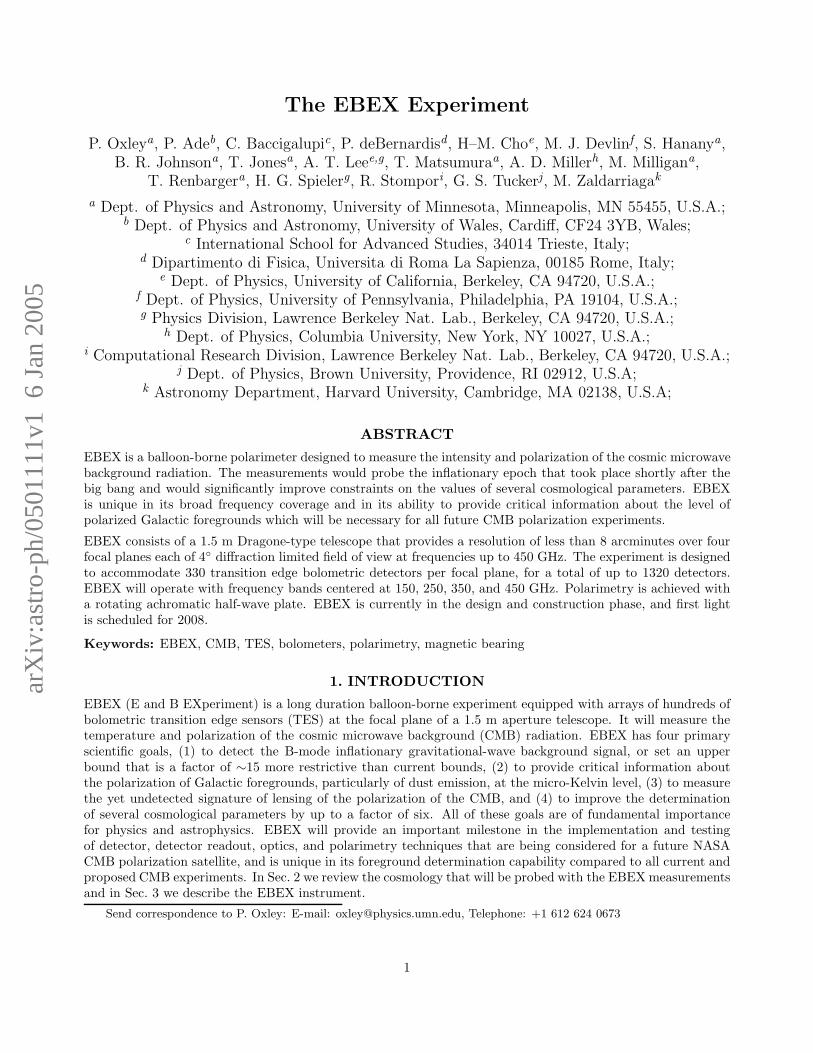
EBEX is a balloon-borne polarimeter designed to measure the intensity and polarization of the cosmic microwavebackground radiation. The measurements would probe the inflationary epoch that took place shortly after thebig bang and would significantly improve constraints on the values of several cosmological parameters. EBEXis unique in its broad frequency coverage and in its ability to provide critical information about the level ofpolarized Galactic foregrounds which will be necessary for all future CMB polarization experiments.
EBEX consists of a 1.5 m Dragone-type telescope that provides a resolution of less than 8 arcminutes over fourfocal planes each of 4◦ diffraction limited field of view at frequencies up to 450 GHz. The experiment is designedto accommodate 330 transition edge bolometric detectors per focal plane, for a total of up to 1320 detectors.EBEX will operate with frequency bands centered at 150, 250, 350, and 450 GHz. Polarimetry is achieved witha rotating achromatic half-wave plate. EBEX is currently in the design and construction phase, and first lightis scheduled for 2008.
Keywords: EBEX, CMB, TES, bolometers, polarimetry, magnetic bearing
1. INTRODUCTION
EBEX (E and B EXperiment) is a long duration balloon-borne experiment equipped with arrays of hundreds ofbolometric transition edge sensors (TES) at the focal plane of a 1.5 m aperture telescope. It will measure thetemperature and polarization of the cosmic microwave background (CMB) radiation. EBEX has four primaryscientific goals, (1) to detect the B-mode inflationary gravitational-wave background signal, or set an upperbound that is a factor of ∼15 more restrictive than current bounds, (2) to provide critical information aboutthe polarization of Galactic foregrounds, particularly of dust emission, at the micro-Kelvin level, (3) to measurethe yet undetected signature of lensing of the polarization of the CMB, and (4) to improve the determinationof several cosmological parameters by up to a factor of six. All of these goals are of fundamental importancefor physics and astrophysics. EBEX will provide an important milestone in the implementation and testingof detector, detector readout, optics, and polarimetry techniques that are being considered for a future NASACMB polarization satellite, and is unique in its foreground determination capability compared to all current andproposed CMB experiments. In Sec. 2 we review the cosmology that will be probed with the EBEX measurementsand in Sec. 3 we describe the EBEX instrument.
Send correspondence to P. Oxley: E-mail: [email protected], Telephone: +1 612 624 0673
1

2. SCIENCE
Since its discovery in 1965 the cosmic microwave background radiation has been one of the pillars of the BigBang model.1 Measurements of its spectrum firmly established the hot big bang model as the basis of ourunderstanding of cosmology.2 Measurements of the anisotropy of the CMB over the last fifteen years haveenabled us to determine cosmological parameters such as the age, density and composition of the universe3, 4 tounprecedented accuracy. Recent measurements of the polarization of the CMB provide strong support for ourmodel of the CMB.5, 6
As a result of these and other astrophysical observations we have a very successful model for how structureshave formed in our universe. Gravitational instability makes fluctuations grow with time, but the fluctuationsrequire initial seeds. The CMB temperature power spectrum and the angular dependence of the cross-correlationbetween temperature and polarization7 imply that these seeds had to be created very early in the evolution ofthe universe.8–10
The leading scenario for the creation of the primordial seeds is the paradigm of inflation.11–14 The fluctuationswe see today are the direct result of quantum fluctuations of a very light scalar field, the inflaton, during a periodof accelerated expansion or “inflation”, a small fraction of a second after the big bang.15–21 However, manyof the details of the inflationary scenario are uncertain and perhaps more importantly, the paradigm currentlylacks any strong confirmation.
A promising way to confirm the inflationary scenario is via its prediction of a stochastic background of gravitywaves,18, 19, 22–24 which we call the inflationary gravitational-wave background (IGB). The best known way tosearch for the IGB is through its signature on the CMB polarization.25, 26 Thomson scattering of an anisotropicradiation field leads to linear polarization. The temperature anisotropy produced by density perturbations andby gravity waves both lead to linear polarization through this mechanism. However, the pattern of the inducedpolarization on the sky should be very different in each case. Density perturbations produce a curl-free or E-modepattern of polarization vectors. Gravity waves produce a curl or B-mode pattern of polarization vectors thatdensity perturbations cannot produce.27, 28 Thus if polarization can be mapped and decomposed into E and Bcomponents (Fig. 1, left panel), the B component will be an unambiguous signature of the IGB and thereforefor inflation. Detection of this IGB signal is a primary goal of the EBEX experiment.
The IGB signal is extremely faint – with a similar or smaller amplitude than expected foreground signals. Itis anticipated that the most significant foreground signal will be from polarized Galactic dust29 (Fig. 1, leftpanel). However, there is currently very little information about the level of polarized dust and its orientation asa function of position on the sky, or about its E and B power spectra. No information exists for any region of thesky at the accuracies required for a B-mode signal detection. A primary goal of EBEX will be to characterizethe polarized dust emission and determine its angular power spectra in both E and B-type polarizations.
The dust signal increases with increasing frequency, while the CMB signal is at a maximum at ≈150 GHz. Themeasurements at 250, 350, and 450 GHz will be primarily sensitive to dust emission, and by extrapolating thesemeasurements to 150 GHz the dust foreground will be subtracted from the primary CMB band at 150 GHz.The predicted uncertainty in the determination of the dust signal at 150 GHz is shown in the right panel ofFig. 1. The dust measurements will also provide the community with critical information about the polarizeddust fraction and orientation as a function of frequency. Given the expected magnitude of the polarized dustforeground, this information is essential for all future CMB polarization experiments.
We have chosen a balloon-borne platform for EBEX because this allows measurements over a broad frequencyrange and reduces atmospheric effects by three orders of magnitude.32 At frequencies higher than ∼150 GHzatmospheric emission becomes significant and broad-band observations from the ground are difficult becauseof a combination of lower detector sensitivity (a result of increased incident power) and higher noise (due tofluctuations in sky emission). Broad-band, ground-based observations are essentially impossible from anywhereon Earth at the higher frequency bands. EBEX is unique among CMB polarization experiments in that it willhave four frequency bands between 150 and 450 GHz. This is the broadest frequency coverage of all current andproposed bolometric CMB polarimeters and gives EBEX an unprecedented capability to measure the polarizationof the dust emission (Fig. 1, right panel).
2
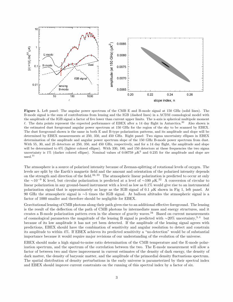
Figure 1. Left panel: The angular power spectrum of the CMB E and B-mode signal at 150 GHz (solid lines). TheB-mode signal is the sum of contributions from lensing and the IGB (dashed lines) in a ΛCDM cosmological model withthe amplitude of the IGB signal a factor of five lower than current upper limits. The x-axis is spherical multipole momentℓ. The data points represent the expected performance of EBEX after a 14 day flight in Antarctica.30 Also shown isthe estimated dust foreground angular power spectrum at 150 GHz for the region of the sky to be scanned by EBEX.The dust foreground shown is the same in both E and B-type polarization patterns, and its amplitude and slope will bedetermined by EBEX measurements at 250, 350, and 450 GHz. Right panel: Two sigma uncertainty ellipses in EBEXdetermination of the amplitude and angular power spectrum slope of the 150 GHz B-mode power spectrum from dust.With 55, 30, and 25 detectors at 250, 350, and 450 GHz, respectively, and for a 14 day flight, the amplitude and slopewill be determined to 6% (lighter colored ellipse). With 330, 180, and 150 detectors at these frequencies the two sigmauncertainty is 1% (darker colored ellipse). Nominal values of 0.00759 µK2 and 0.235 for the amplitude and slope areused.31
The atmosphere is a source of polarized intensity because of Zeeman-splitting of rotational levels of oxygen. Thelevels are split by the Earth’s magnetic field and the amount and orientation of the polarized intensity dependson the strength and direction of the field.32, 33 The atmospheric linear polarization is predicted to occur at onlythe ∼10−9 K level, but circular polarization is predicted at a level of ∼100 µK.32 A conversion of circular tolinear polarization in any ground-based instrument with a level as low as 0.1% would give rise to an instrumentalpolarization signal that is approximately as large as the IGB signal of 0.1 µK shown in Fig 1, left panel. At90 GHz the atmospheric signal is ∼5 times the IGB signal. At balloon altitudes the atmospheric signal is afactor of 1000 smaller and therefore should be negligible for EBEX.
Gravitational lensing of CMB photons along their path gives rise to an additional effective foreground. The lensingis the result of the deflection of the path of CMB photons by intermediate mass and energy structures, and itcreates a B-mode polarization pattern even in the absence of gravity waves.34 Based on current measurementsof cosmological parameters the magnitude of the lensing B signal is predicted with ∼20% uncertainty,3, 4 butbecause of its low amplitude it has not yet been detected. If the amplitude of the lensing signal agrees withpredictions, EBEX should have the combination of sensitivity and angular resolution to detect and constrainits amplitude to within 4%. If EBEX achieves its predicted sensitivity a “no-detection” would be of substantialimportance because it would require major revisions of our understanding of the evolution of the universe.
EBEX should make a high signal-to-noise ratio determination of the CMB temperature and the E-mode polar-ization spectrum, and the spectrum of the correlation between the two. The E-mode measurement will allow afactor of between two and three improvement in current estimates of the density of dark energy, the density ofdark matter, the density of baryonic matter, and the amplitude of the primordial density fluctuations spectrum.The spatial distribution of density perturbations in the early universe is parameterized by their spectral indexand EBEX should improve current constraints on the running of this spectral index by a factor of six.
3

Figure 2. Solid model of the EBEX experiment and balloon gondola showing the telescope primary and secondary mirrorsand the cryostat which contains re-imaging optics and the TES detectors.
3. EXPERIMENTAL DETAILS
3.1. Summary of Approach
EBEX will employ a 1.5 m telescope to focus radiation on up to four separate focal planes, each containing up to330 TES spider web bolometers cooled to 300 mK. The experiment will operate at four frequency bands, centeredon 150, 250, 350, and 450 GHz. The unpolarized (T ) and linearly polarized (Q and U) Stokes parameters of theCMB radiation will be measured by the well-tested technique of rotating an achromatic half-wave plate at theaperture stop of the telescope and analyzing the radiation with a wire grid polarizer. The telescope will scan apatch of sky 350 deg2 with a resolution of 8 arcminutes at 150 GHz (Table 1).
EBEX is carefully optimized to achieve its science goals. The balloon-borne platform and the broad frequencycoverage will provide critical information about the dust foreground. The large number of detectors will give therequired combined sensitivity that will allow detection of the IGB signal. Figure 2 shows the EBEX payload.
3.1.1. Detectors and Readout
The detection of the IGB signal requires high sensitivity. However, detector technologies have matured to thepoint that the noise of a bolometric detector is dominated by noise in the background optical loading and thereforethe sensitivity of a single detector cannot be improved. To improve sensitivity it is essential to implement arraysof detectors.
We have chosen to use arrays of transition edge sensors for EBEX for several compelling reasons. They areproduced by thin film deposition and optical lithography, which is ideal for producing large detector arrays. Dueto a strong negative electrothermal feedback effect, they are extremely linear and the responsivity is determinedonly by the bias voltage, insensitive to fluctuations in the incident optical power and bath temperature. Theelectrothermal feedback also strongly reduces Johnson and 1/f noise in the TES. TES bolometers are low-impedance devices, which results in a lower vibration sensitivity than that of high-impedance semiconductorbolometer technologies. SQUID amplifiers will be used to read out the TES bolometers. These amplifiers areinherently low noise devices and there is the possibility to use multiplexed SQUID amplifiers, which will simplifyour cryogenic design and facilitate the use of the full 1320 detector capability of EBEX.
4

Figure 3. Left panel: Montage image of a photograph of a single real TES “wedge” of spider bolometers replicatedelectronically to show how a final array will look. Each wedge is designed to be identical and has 55 bolometers. Theentire array will have 330 bolometers and be 17 cm in diameter. Center panel: Photograph of wedge of 55 spider webTES bolometers. Wedge is 8 cm on a side. Suspended spider web absorbers are fabricated from 1 µm thick silicon nitride.The membrane is released from the front side using a gaseous xenon diflouride etch. Bolometers are 3.5 mm diameterwith 0.5 mm long legs. Wiring layer is superconducting aluminum. This array was fabricated in the U.C. Berkeleymicrofabrication facility. Right panel: Close up of 55 element bolometer wedge. Sensors are an Al/Ti proximity effectsandwich TES, located at the edge of the membrane and electrically connected with superconducting leads.
In our TES spider web bolometer CMB radiation is absorbed by a metalized silicon nitride mesh in a patternsimilar to that of a spider’s web (Fig. 3, right panel). EBEX will use arrays of 55 TES bolometers fabricated byour collaborators at UC Berkeley using standard microlithographic techniques. A 330 element TES array is builtby tiling six 55 element arrays (Fig. 3, left panel) and will fill the EBEX focal plane. The arrays are identical inmany of their construction parameters to the arrays that will be used for the ground-based experiment APEX35
and for the South-Pole Telescope (SPT).36 However, compared to the APEX TES the thermal conductance ofthe EBEX TES will be reduced to 10 pWK−1 to match the lower optical loading at balloon altitudes.
The responsivity, noise properties and time constants of individual TES bolometers have been studied exten-sively.37–41 The measured noise has been shown to reach the fundamental thermal-fluctuation noise limit (Fig. 4),and the responsivities and time constants match theory closely. Table 1 gives the expected noise equivalent power(NEP) of the EBEX detectors at each frequency.
Initially EBEX will use individual SQUIDs to read the current from each TES bolometer using the readouttechnique that has been developed for the APEX and SPT receivers. This technique uses a single series-arraySQUID coupled to a single room-temperature op-amp. The TES bolometer is ac-biased with a direct-digitalsynthesis generator and the signal is demodulated with an analog mixer circuit. Since SQUIDs are sensitive tostray magnetic fields the TES and SQUID will be enclosed in a Cryoperm shield.
The above readout system is fully compatible with the frequency-domain multiplexing readout that is beingdeveloped by our collaborators at UC Berkeley and Lawrence Berkeley National Lab. The principle of thistechnique has already been demonstrated by monitoring the current passing through 8 mock TES.42 Two realTES have also been multiplexed43 and experiments are underway to further test the technique with greaternumbers of TES bolometers. With multiplexed readouts we will use one SQUID readout circuit to read 20detectors, thereby reducing the number of SQUID wires reaching cryogenic temperatures by the same factor.This substantially reduces the heat load on the cryostat allowing use of the full 1320 detector capability ofEBEX. When individual SQUIDs are used to read out each TES the number of detectors will be limited to 715,distributed between the four focal planes. Multiplexed readouts will allow more detectors to be allocated to the250, 350, and 450 GHz frequency bands, improving the determination of the dust foreground compared to thecase of non-multiplexed readouts (Fig. 1, right panel).
The TES bolometers will operate from a bath temperature of ∼300 mK provided by a 3He fridge. The fridgewill work off of a standard liquid helium/liquid nitrogen cryostat with two vapor cooled shields connected to
5

Frequency (Hz)
0 50 100 150 200
Curr
ent nois
e a
t S
QU
ID input (p
W/H
z1/2
)
0
5
10
15
20
Figure 4. Noise performance of an individual spider web TES bolometer with no incident optical power. The noise isat the fundamental thermal noise limit as indicated by the horizontal dashed line, and the time constant is 0.6 ms. Thefeature at 140 Hz is a mechanical resonance of the table upon which the bolometer is mounted.
Table 1. Expected TES noise and angular resolution for EBEX. The TES noise is dominated by photon and thermalnoise. Photon noise is due to fluctuations in the number of CMB photons arriving at the TES and thermal noise is causedby fluctuations in the number of phonons in the heat link between the TES and the low temperature bath used to coolthe TES. The angular resolution is determined by the telescope 1.5 m aperture primary mirror.
Frequency NEP Angular Resolution
(GHz) ×10−17 WHz−1/2 (FWHM, arcminutes)150 1.12 8250 1.28 4.8350 1.48 3.4450 1.71 2.7
the boil-off gases of each of the liquids. A detailed thermal model of the cryostat has been made, including allanticipated major heat loads such as radiation, wires, heat load through the 15 cm diameter cryostat window,and parasitic heat loads on the different thermal stages. The modelling predicts that 105 l of liquid helium and140 l of liquid nitrogen will be sufficient for a hold time of 20 days.
3.1.2. Telescope and Cold Optics
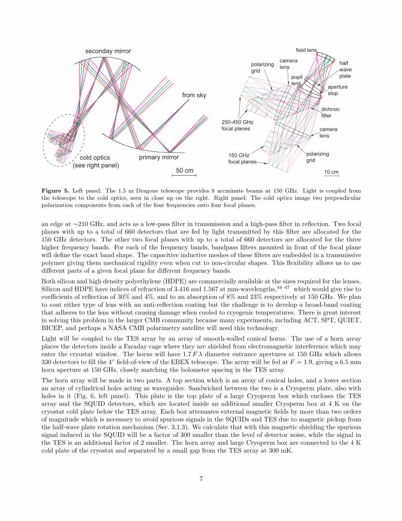
The EBEX optical system is based on the existing well-characterized telescope from the Archeops experiment.It consists of the Archeops 1.5 m aperture primary mirror and a new 1.2 m elliptical secondary that togethermake a Dragone telescope (Fig. 5, left panel). This design provides a 4◦ field of view and beam resolutions givenin Table 1.
Figure 5, right panel, shows the optics of EBEX contained within the cryostat receiver of Fig. 2. Four coldlenses, a dichroic filter and two polarizing grids couple radiation from the telescope into four independent focalplanes. The lenses, which will be made of either silicon or high density polyethylene, provide both a cold aperturestop, where the rotating half-wave plate is mounted, and a flat and telecentric focal plane suitable for the TESarrays. This configuration provides a 4◦ field of view for each focal plane with Strehl ratios of at least 0.966 atall frequencies across the entire field of view, and a Strehl ratio better than 0.991 across the full field of view for150 GHz. To enable CMB observations to be made in four distinct frequency bands the incident light will befiltered, and different frequencies fed to different parts of the four focal planes. A reflecting metal-mesh low-passfilter with an edge at ∼510 GHz will be mounted near the aperture stop of the system. The dichroic filter has
6
primary mirror
from sky
seconday mirror
cold optics
(see right panel)50 cm
150 GHz
focal planes
field lens
pupil
lensaperture
stop
dichroic
filter
polarizing
grid
polarizing
grid
250-450 GHz
focal planes
10 cm
camera
lens
camera
lenshalf
wave
plate
Figure 5. Left panel: The 1.5 m Dragone telescope provides 8 arcminute beams at 150 GHz. Light is coupled fromthe telescope to the cold optics, seen in close up on the right. Right panel: The cold optics image two perpendicularpolarization components from each of the four frequencies onto four focal planes.
an edge at ∼210 GHz, and acts as a low-pass filter in transmission and a high-pass filter in reflection. Two focalplanes with up to a total of 660 detectors that are fed by light transmitted by this filter are allocated for the150 GHz detectors. The other two focal planes with up to a total of 660 detectors are allocated for the threehigher frequency bands. For each of the frequency bands, bandpass filters mounted in front of the focal planewill define the exact band shape. The capacitive inductive meshes of these filters are embedded in a transmissivepolymer giving them mechanical rigidity even when cut to non-circular shapes. This flexibility allows us to usedifferent parts of a given focal plane for different frequency bands.
Both silicon and high density polyethylene (HDPE) are commercially available at the sizes required for the lenses.Silicon and HDPE have indices of refraction of 3.416 and 1.567 at mm-wavelengths,44–47 which would give rise tocoefficients of reflection of 30% and 4%, and to an absorption of 8% and 23% respectively at 150 GHz. We planto coat either type of lens with an anti-reflection coating but the challenge is to develop a broad-band coatingthat adheres to the lens without causing damage when cooled to cryogenic temperatures. There is great interestin solving this problem in the larger CMB community because many experiments, including ACT, SPT, QUIET,BICEP, and perhaps a NASA CMB polarimetry satellite will need this technology.
Light will be coupled to the TES array by an array of smooth-walled conical horns. The use of a horn arrayplaces the detectors inside a Faraday cage where they are shielded from electromagnetic interference which mayenter the cryostat window. The horns will have 1.7 F λ diameter entrance apertures at 150 GHz which allows330 detectors to fill the 4◦ field-of-view of the EBEX telescope. The array will be fed at F = 1.9, giving a 6.5 mmhorn aperture at 150 GHz, closely matching the bolometer spacing in the TES array.
The horn array will be made in two parts. A top section which is an array of conical holes, and a lower sectionan array of cylindrical holes acting as waveguides. Sandwiched between the two is a Cryoperm plate, also withholes in it (Fig. 6, left panel). This plate is the top plate of a large Cryoperm box which encloses the TESarray and the SQUID detectors, which are located inside an additional smaller Cryoperm box at 4 K on thecryostat cold plate below the TES array. Each box attenuates external magnetic fields by more than two ordersof magnitude which is necessary to avoid spurious signals in the SQUIDs and TES due to magnetic pickup fromthe half-wave plate rotation mechanism (Sec. 3.1.3). We calculate that with this magnetic shielding the spurioussignal induced in the SQUID will be a factor of 300 smaller than the level of detector noise, while the signal inthe TES is an additional factor of 2 smaller. The horn array and large Cryoperm box are connected to the 4 Kcold plate of the cryostat and separated by a small gap from the TES array at 300 mK.
7
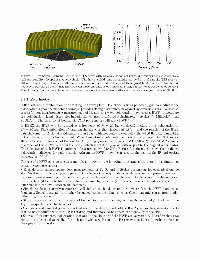
Figure 6. Left panel: Coupling light to the TES array with an array of conical horns and waveguides separated by ahigh permeability Cryoperm magnetic shield. The horns, shield, and waveguides are held at 4 K and the TES array at300 mK. Right panel: Predicted efficiency of a stack of one (dashed line) and three (solid line) HWP as a function offrequency. For the 2.84 cm thick AHWP, each 0.946 cm plate is optimized as a single HWP for a frequency of 50 GHz.The efficiency function has the same shape and therefore the same bandwidth near the odd-harmonic peaks of 50 GHz.
3.1.3. Polarimetry
EBEX will use a combination of a rotating half-wave plate (HWP) and a fixed polarizing grid to modulate thepolarization signal because this technique provides strong discrimination against systematic errors. To date allsuccessful non-interferometric measurements of IR and mm-wave polarization have used a HWP to modulatethe polarization signal. Examples include the Minnesota Infrared Polarimeter,48 Stokes,49 Millipol,50 andSCUBA.51 The majority of bolometric CMB polarimeters will use a HWP.52–54
In EBEX the HWP will be rotated at a frequency of f0 = 20 Hz which will modulate the polarization at4f0 = 80 Hz. The combination of scanning the sky with the telescope at 1.8◦s−1 and the rotation of the HWPputs the signal in 15 Hz wide sidebands around 4f0. This frequency is well below the ∼160 Hz 3 dB bandwidthof the TES with a 1 ms time constant. We will maintain a polarization efficiency that is larger than 95% over a40 GHz bandwidth for each of the four bands by employing an achromatic HWP (AHWP). The AHWP is madeof a stack of three HWP’s the middle one of which is rotated by 57.5◦ with respect to the aligned outer plates.The thickness of each HWP is optimized for a frequency of 50 GHz. Figure. 6, right panel, shows the predictedpolarization efficiency for such a stack. Achromatic HWP’s have been used in the past at the IR and opticalwavelengths.48, 55, 56
The use of a HWP as a polarization modulation provides the following important advantages in discriminationagainst systematic errors:• Each detector makes independent measurements of T , Q, and U Stokes parameters for each pixel on thesky. No detector differencing is required. All schemes that rely on detector differencing are prone to errors orincreased noise arising from, (a) uncertainty in the difference in gain between the detectors, (b) differences inbeam pattern (if the detectors do not share the same light train), (c) difference in absolute calibration, and (d)difference in noise level between the detectors.• Signals reside in relatively narrow and well defined sidebands around 4f0, where f0 is the HWP modulationfrequency. Spurious signals at all other frequency bands, including spurious effects that might arise from modu-lation at f0, are rejected.• Sky signals are constrained to a band of frequencies that is much higher than the expected <
∼1 Hz knee in the
1/f noise spectrum of the detectors.• Sources of instrumental polarization that are on the detector side of the HWP give rise to systematic effectsthat do not modulate with the HWP rotation and therefore do not affect the signals from the sky.• Sources of instrumental polarization that are on the sky side of the HWP are very stable. Therefore they giverise to a stable signal at 80 Hz. A notch filter with a width of ∼0.1 Hz removes such signals without affectingthe signals from the sky.
8

Figure 7. The superconducting magnetic bearing consists of a ring shaped magnet (rotor) and tiles of YBCO (stator)which are superconducting at temperatures below ∼90 K. The HWP (not shown) is mounted inside the ring magnet. Attemperatures above Tc the rotor is held by mechanical means above the stator. At temperatures below Tc the mechanicalconstraints are removed and the rotor maintains its position with respect to the stator irrespective of the orientation of
the acceleration vector due to gravity. In this picture the stator was cooled to liquid nitrogen temperature with the rotormechanically spaced ∼4 mm above the tiles. Once cooled the spacing constraints were removed, the configuration liftedfrom the liquid nitrogen and the rotor was set spinning. The bearing was then abruptly tilted by ∼70◦ with respect to thegravity vector. No change in the relative orientation of the rotor and stator and no oscillations of the rotor were observed.Stiff spring constants of 2.0 × 10³ Nm−1 and 4.2 × 10³ Nm−1 have been measured in the radial and axial directions, andthe oscillation amplitude at the SMB characteristic frequency is less than 10 µm.61
We are currently investigating a number of options for rotating the HWP. One option is to mount the HWP on ahigh-temperature superconducting magnetic bearing (SMB) turned with an induction motor (Fig. 7). Bolometersare sensitive to microphonic pickup and the SMB technique completely eliminates stick-slip friction, which is theprimary source of microphonic noise in mechanical bearings. SMBs have been operating for many years57–60 andhave been shown to reduce friction in bearings by more than 4 orders of magnitude. We plan to measure thenoise properties and systematic effects associated with the SMB rotation mechanism. If the SMB is shown to beunsuitable then we have already demonstrated with the MAXIPOL experiment that through the use of specialmaterials, such as vespel, teflon, or rulon, it is possible to reduce microphonic noise associated with mechanicalbearings to the level appropriate for measurements of the E-mode polarization.53 Since TES should havesubstantially less sensitivity to microphonic noise than thermistor bolometers35 used in MAXIPOL, mechanicalbearings may be suitable for a B-mode polarization experiment such as EBEX. In the unlikely event that neitherof these techniques is suitable we will simply step-and-integrate with the HWP.
3.2. Control of Systematic Errors
The B-mode signal either from inflation or from lensing is expected to appear at the ∼0.1 µK level at a maximum(Fig. 1, left panel) and therefore a command of the sources of systematic errors is critical. We have checkedthat EBEX can meet specific goals that are necessary for extraction of the B-mode signal. Hu et al.62 have setbenchmarks for the level of residual systematic errors in an experiment attempting to extract a B-mode signalwith a given amplitude. The benchmarks calculated for EBEX for detecting an amplitude that is a factor of
five lower than EBEX’s 2σ upper limit are given in Table 2. EBEX calibration uncertainty in Stokes Q and Uparameters is expected to be 1% – lower than the 6% benchmark, and we expect a maximum level of QU mixingof 0.8% at the edge of the focal plane. We expect a pointing uncertainty that is about a factor of ∼3 smallerthan the benchmark for 8 arcminute beams. In-flight measurements of Venus (Jupiter) will provide the shapeparameters of the beam at each polarization state to an accuracy of 0.2% (0.1%) of the FWHM of the beam.
9

Table 2. Types of systematic uncertainties and residual uncertainty benchmarks for EBEX in order to detect a B-modesignal that is five times smaller than EBEX 2σ upper limit (following Hu et al.62). These benchmarks represent residualuncertainties after all known corrections have been applied. The calibration term is the accuracy with which the TESbolometer response must be calibrated, and the QU term sets a limit on the allowable level of mixing between the Q
and U polarization states caused by the telescope and optics. The pointing, monopole and dipole terms correspond touncertainties in the pointing, in the size of beams in two orthogonal polarization states, and in the alignment of thesebeams, respectively, expressed as a fraction of the beam size. The quadrupole corresponds to uncertainty in the beamdifferential ellipticity.
Type Calibration QU Pointing Monopole Dipole QuadrupoleUnit (%) (%) fraction of beam diff. ell.Level 6.4 1.6 0.11 0.002 0.007 0.017
We have designed these planet scans to achieve the benchmark required by the monopole term of Table 2. Thedipole and differential ellipticity benchmarks are less restrictive and will already be satisfied by the planet scans.
4. CONCLUSIONS
EBEX will measure the CMB temperature and polarization anisotropy on angular scales from 8 arcminutes to15◦, thus finding, or setting a substantially improved limit, on the IGB signal of inflation. To achieve this EBEXwill accurately characterize the foreground signal from Galactic dust which will also provide the CMB communitywith critical information about the polarized dust fraction and orientation as a function of frequency. EBEXshould also detect the predicted, but as yet undetected, gravitational lensing of CMB radiation and significantlyimprove measurements of many cosmological parameters.
REFERENCES
1. A. A. Penzias and R. W. Wilson, “A Measurement of Excess Antenna Temperature at 4080 Mc/s.,” Ap. J.
142, pp. 419–421, July 1965.
2. J. C. Mather, E. S. Cheng, D. A. Cottingham, R. E. Eplee, D. J. Fixsen, T. Hewagama, R. B. Isaacman,K. A. Jensen, S. S. Meyer, P. D. Noerdlinger, S. M. Read, L. P. Rosen, R. A. Shafer, E. L. Wright, C. L.Bennett, N. W. Boggess, M. G. Hauser, T. Kelsall, S. H. Moseley, R. F. Silverberg, G. F. Smoot, R. Weiss,and D. T. Wilkinson, “Measurement of the cosmic microwave background spectrum by the COBE FIRASinstrument,” Ap. J. 420, pp. 439–444, Jan. 1994.
3. D. N. Spergel, L. Verde, H. V. Peiris, E. Komatsu, M. R. Nolta, C. L. Bennett, M. Halpern, G. Hinshaw,N. Jarosik, A. Kogut, M. Limon, S. S. Meyer, L. Page, G. S. Tucker, J. L. Weiland, E. Wollack, andE. L. Wright, “First-Year Wilkinson Microwave Anisotropy Probe (WMAP) Observations: Determinationof Cosmological Parameters,” Ap. J. Suppl. 148, pp. 175–194, Sept. 2003.
4. M. Tegmark, M. Strauss, M. Blanton, K. Abazajian, S. Dodelson, H. Sandvik, X. Wang, D. Weinberg,I. Zehavi, N. Bahcall, F. Hoyle, D. Schlegel, R. Scoccimarro, M. Vogeley, A. Berlind, T. Budavari, A. Con-nolly, D. Eisenstein, D. Finkbeiner, J. Frieman, J. Gunn, L. Hui, B. Jain, D. Johnston, S. Kent, H. Lin,R. Nakajima, R. Nichol, J. Ostriker, A. Pope, R. Scranton, U. Seljak, R. Sheth, A. Stebbins, A. Szalay,I. Szapudi, Y. Xu, and . others, “Cosmological parameters from SDSS and WMAP,” ArXiv Astrophysics
e-prints , Oct. 2003. astro-ph/0310723.
5. J. M. Kovac, E. M. Leitch, C. Pryke, J. E. Carlstrom, N. W. Halverson, and W. L. Holzapfel, “Detectionof polarization in the cosmic microwave background using DASI,” Nature 420, p. 772, December 2002.astro-ph/0209478.
6. E. M. Leitch, J. M. Kovac, C. Pryke, J. E. Carlstrom, N. W. Halverson, W. L. Holzapfel, B. Reddall, andE. S. Sandberg, “Measurement of polarization with the degree angular scale interferometer,” Nature 420,p. 763, December 2002. astro-ph/0209476.
10
7. A. Kogut, D. N. Spergel, C. Barnes, C. L. Bennett, M. Halpern, G. Hinshaw, N. Jarosik, M. Limon, S. S.Meyer, L. Page, G. S. Tucker, E. Wollack, and E. L. Wright, “First-Year Wilkinson Microwave AnisotropyProbe (WMAP) Observations: Temperature-Polarization Correlation,” Ap. J. Suppl. 148, pp. 161–173,Sept. 2003. astro-ph/0302213.
8. W. Hu and M. White, “A new test of inflation,” Phys. Rev. Lett. 77, p. 1687, Aug. 1996.
9. D. N. Spergel and M. Zaldarriaga, “Cosmic microwave background polarization as a direct test of inflation,”Phys. Rev. Lett. 79, p. 2180, 1997.
10. H. V. Peiris, E. Komatsu, L. Verde, D. N. Spergel, C. L. Bennett, M. Halpern, G. Hinshaw, N. Jarosik,A. Kogut, M. Limon, S. S. Meyer, L. Page, G. S. Tucker, W. E., and W. E. L., “First-Year Wilkin-son Microwave Anisotropy Probe (WMAP) Observations: Implications For Inflation,” Ap. J. Suppl. 148,pp. 213–232, 2003.
11. A. H. Guth, “Inflationary universe: A possible solution to the horizon and flatness problems,” Phys. Rev. D.
23, pp. 347–356, Jan. 1981.
12. A. D. Linde, “A new inflationary universe scenario: A possible solution of the horizon, flatness, homogeneity,isotropy and primordial monopole problems,” Phys. Lett. B108, pp. 389–393, 1982.
13. A. Albrecht and P. J. Steinhardt, “Cosmology for grand unified theories with radiatively induced symmetrybreaking,” Phys. Rev. Lett. 48, pp. 1220–1223, 1982.
14. K. Sato, “First-order phase transition of a vacuum and the expansion of the Universe,” MNRAS 195,pp. 467–479, May 1981.
15. V. F. Mukhanov and G. V. Chibisov, “Quantum fluctuations and a nonsingular universe,” JETP Letters
33, pp. 532–535, May 1981.
16. S. W. Hawking, “The development of irregularities in a single bubble inflationary universe,” Phys. Lett. B
115, pp. 295–297, 1982.
17. A. H. Guth and S. Pi, “Fluctuations in the new inflationary universe,” Phys. Rev. Lett. 49, pp. 1110–1113,Oct. 1982.
18. A. A. Starobinsky, “Dynamics of phase transition in the new inflationary universe scenario and generationof perturbations,” Phys. Lett. B117, pp. 175–178, 1982.
19. A. A. Starobinskii, “The perturbation spectrum evolving from a nonsingular initially De-Sitter cosmologyand the microwave background anisotropy,” Soviet Astronomy Letters 9, pp. 302–+, June 1983.
20. J. M. Bardeen, P. J. Steinhardt, and M. S. Turner, “Spontaneous creation of almost scale-free densityperturbations in an inflationary universe,” Phys. Rev. D. 28, p. 679, Aug. 1983.
21. V. F. Mukhanov, F. A. Feldman, and R. H. Brandenberger, “Theory of cosmological perturbations,” Phys.
Reports 215, pp. 203–333, June 1992.
22. V. A. Rubakov, M. V. Sazhin, and A. V. Veryaskin, “Graviton creation in the inflationary universe and thegrand unification scale,” Phys. Lett. B. 115, pp. 189–192, Sept. 1982.
23. L. P. Grishchuk, “Amplification of gravitational waves in an istropic universe,” Sov. Phys. JETP 40, pp. 409–415, 1975.
24. L. F. Abbott and M. B. Wise, “Constraints on generalized inflationary cosmologies,” Nuclear Physics B
244, pp. 541–+, Oct. 1984.
25. M. Kamionkowski, A. Kosowsky, and A. Stebbins, “A Probe of Primordial Gravity Waves and Vorticity,”Phys. Rev. Lett. 78, pp. 2058–2061, Mar. 1997. astro-ph/9609132.
26. U. Seljak and M. Zaldarriaga, “Signature of Gravity Waves in the Polarization of the Microwave Back-ground,” Phys. Rev. Lett. 78, pp. 2054–2057, Mar. 1997. astro-ph/9609169.
27. M. Kamionkowski and A. Loeb, “Getting around cosmic variance,” Phys. Rev. D. 56, p. 4511, Oct. 1997.
28. M. Zaldarriaga and U. Seljak, “All-sky analysis of polarization in the microwave background,” Phys. Rev. D.
55, pp. 1830–1840, 1997.
29. C. Baccigalupi, “Cosmic microwave background polarisation: foreground contrast and component separa-tion,” New Astronomy Review 47, pp. 1127–1134, Dec. 2003.
30. D. Ball, (NSBF Head of Operations) 2004. Private communication: Average length Antarctica balloon flightof 14 days.
31. C. Baccigalupi 2004. Private communication.
11

32. S. Hanany and P. Rosenkranz, “Polarization of the atmosphere as a foreground for cosmic microwavebackground polarization experiments,” New Astronomy Review 47, pp. 1159–1165, Dec. 2003.
33. B. Keating, P. Timbie, P. Polnarev, and J. Steinberger, “Large angular scale polarization of the cosmicmicrowave background and the feasibility of its detection,” Ap. J. 496, p. 580, 1998.
34. M. Zaldarriaga and U. Seljak, “Gravitational lensing effect on cosmic microwave background polarization,”Phys. Rev. D. 58, p. 23003 (6 pages), July 1998.
35. D. Schwan, F. Bertoldi, S. Cho, M. Dobbs, R. Guesten, N. W. Halverson, W. L. Holzapfel, E. Kreysa,T. M. Lanting, A. T. Lee, M. Lueker, J. Mehl, K. Menten, D. Muders, M. Myers, T. Plagge, A. Raccanelli,P. Schilke, P. L. Richards, H. Spieler, and M. White, “APEX-SZ a Sunyaev-Zel’dovich galaxy cluster survey,”New Astronomy Review 47, pp. 933–937, Dec. 2003.
36. http://astro.uchicago.edu/spt.
37. A. T. Lee, P. L. Richards, S. W. Nam, B. Cabrera, and K. D. Irwin, “A Superconducting Bolometer withStrong Electrothermal Feedback,” Applied Physics Letters 69, pp. 1801–1803, Sept. 1996.
38. S. Lee, J. M. Gildemeister, W. Holmes, A. T. Lee, and P. L. Richards, “Voltage-Biased SuperconductingTransition-Edge Bolometer with Strong Electrothermal Feedback Operated at 370 mK,” Appl. Optics 37,pp. 3391–3397, June 1998.
39. J. M. Gildemeister, A. T. Lee, and P. L. Richards, “A Fully Lithographed Voltage-biased SuperconductingSpiderweb Bolometer,” Applied Physics Letters 74, pp. 868–870, Feb. 1999.
40. J. M. Gildemeister, A. T. Lee, and P. L. Richards, “Monolithic Arrays of Absorber-coupled Voltage-biasedSuperconducting Bolometers ,” Applied Physics Letters 77, pp. 4040–4042, Dec. 2000.
41. J. M. Gildemeister, Voltage-Biased Superconducting Bolometers for Infrared and mm-Waves. PhD thesis,University of California, Berkeley, 2000.
42. J. Yoon, J. Clarke, J. M. Gildemeister, A. T. Lee, M. J. Myers, P. L. Richards, and J. T. Skidmore,“Single Superconducting Quantum Interference Device Multiplexer for Arrays of Low-Temperature Sensors,”Applied Physics Letters 78, pp. 371–373, Jan. 2001.
43. M. F. Cunningham, J. N. Ullom, T. Miyazaki, S. E. Labov, J. Clarke, T. M. Lanting, A. T. Lee, P. L.Richards, J. Yoon, and H. Spieler, “High-resolution operation of frequency-multiplexed transition-edge pho-ton sensors,” Applied Physics Letters 81, pp. 159–161, July 2002.
44. J. R. Birch and Kong Fan Ping, “An interferometer for the determination of the temperature variation ofthe complex refraction spectra of reasonably transparent solids at near-millimetre wavelengths,” Infrared
Physics 24, pp. 309–314, May 1984.
45. J. R. Birch, “Systematic errors in dispersive fourier transform spectroscopy in a non-vacuum environment,”Infrared Physics 34, pp. 89–93, 1993.
46. V. V. Parshin, R. Heidinger, B. A. Andreev, A. V. Gusev, and V. B. Shmagin, “Silicon as an advancedwindow material for high power gyrotrons,” Int. J. Infrared and Millimeter Waves 16, pp. 864–877, 1995.
47. M. N. Afsar and E. A. Nichol, “Millimeter wave complex refractive index, complex dielectric permittivityand loss tangent of extra high purity and compensated silicon,” Int. J. Infrared and Millimeter Waves 15,pp. 1181–1188, 1994.
48. T. J. Jones and D. Klebe, “A simple infrared polarimeter,” Proc. Ast. Soc. Pac. 100, pp. 1158–1161, Sept.1988.
49. S. R. Platt, R. H. Hildebrand, R. J. Pernic, J. A. Davidson, and G. Novak, “100-micron array polarimetryfrom the Kuiper Airborne Observatory - Instrumentation, techniques, and first results,” Proc. Ast. Soc. Pac.
103, pp. 1193–1210, Nov. 1991.
50. R. W. Leach, D. P. Clemens, B. D. Kane, and R. Barvainis, “Polarimetric mapping of Orion using MILLIPOL- Magnetic activity in BN/KL,” Ap. J. 370, pp. 257–262, Mar. 1991.
51. A. G. Murray, R. Nartallo, C. V. Haynes, F. Gannaway, and P. A. R. Ade, “An Imaging Polarimeter forSCUBA,” in ESA SP-401: The Far Infrared and Submillimetre Universe, pp. 405–+, 1997.
52. S. Church, P. Ade, J. Bock, M. Bowden, J. Carlstrom, K. Ganga, W. Gear, J. Hinderks, W. Hu, B. Keating,J. Kovac, A. Lange, E. Leitch, O. Mallie, S. Melhuish, A. Murphy, B. Rusholme, C. O’Sullivan, L. Piccirillo,C. Pryke, A. Taylor, and K. Thompson, “QUEST on DASI: A South Pole CMB polarization experiment,”New Astronomy Review 47, pp. 1083–1089, Dec. 2003.
12
53. B. R. Johnson, M. E. Abroe, P. Ade, J. Bock, J. Borrill, J. S. Collins, P. Ferreira, S. Hanany, A. H.Jaffe, T. Jones, A. T. Lee, L. Levinson, T. Matsumura, B. Rabii, T. Renbarger, P. L. Richards, G. F.Smoot, R. Stompor, H. T. Tran, and C. D. Winant, “MAXIPOL: a balloon-borne experiment for measuringthe polarization anisotropy of the cosmic microwave background radiation,” New Astronomy Review 47,pp. 1067–1075, Dec. 2003. astro-ph/0308259.
54. http://bolo.berkeley.edu/polarbear/.
55. C. J. Koester, “Achromatic combinations of half-wave plates,” J. Opt. Soc. Am. 49, pp. 405–409, 1959.
56. S. Pancharatnam, “Achromatic combinations of birefringent plates,” Raman Research Inst. Bangalore, Mem-
oir , 1955.
57. A. Rivetti, G. Martini, R. Goria, and S. Lorefice, “Turbine flowmeter for liquid helium with the rotormagnetically levitated,” Cryogenics 27, pp. 8–11, 1987.
58. R. Decher, P. N. Peters, R. C. Sisk, E. W. Urban, M. Vlasse, and D. K. Rao, “High temperature supercon-ducting bearing for rocket engine turbopumps,” Applied Superconductivity 1, pp. 1265–1278, 1993.
59. J. R. Hull, “Flywheels on a roll,” Spectrum, IEEE. 34, pp. 20–25, 1997.
60. Y. Zhang, Y. Postrekhin, K. B. Ma, and W. K. Chu, “Reaction wheel with HTS bearings for mini-satelliteattitude control,” Supercond. Sci. Technol. 15, pp. 823–825, May 2002.
61. S. Hanany, T. Matsumura, B. Johnson, T. Jones, J. R. Hull, and K. B. Ma, “A cosmic microwave backgroundradiation polarimeter using superconducting bearings,” IEEE Transactions on Applied Superconductivity 13,pp. 2128–2133, 2003.
62. W. Hu, M. M. Hedman, and M. Zaldarriaga, “Benchmark parameters for CMB polarization experiments,”Phys. Rev. D. 67, pp. 043004–+, Feb. 2003. astro-ph/0210096.
13